KR20220000929A - Pattern calculation apparatus, pattern calculation method, mask, exposure apparatus, device production method, computer program, and recording medium - Google Patents
Pattern calculation apparatus, pattern calculation method, mask, exposure apparatus, device production method, computer program, and recording medium Download PDFInfo
- Publication number
- KR20220000929A KR20220000929A KR1020217042410A KR20217042410A KR20220000929A KR 20220000929 A KR20220000929 A KR 20220000929A KR 1020217042410 A KR1020217042410 A KR 1020217042410A KR 20217042410 A KR20217042410 A KR 20217042410A KR 20220000929 A KR20220000929 A KR 20220000929A
- Authority
- KR
- South Korea
- Prior art keywords
- mask pattern
- exposure
- pattern
- mask
- region
- Prior art date
- Legal status (The legal status is an assumption and is not a legal conclusion. Google has not performed a legal analysis and makes no representation as to the accuracy of the status listed.)
- Ceased
Links
Images


Classifications
-
- G—PHYSICS
- G03—PHOTOGRAPHY; CINEMATOGRAPHY; ANALOGOUS TECHNIQUES USING WAVES OTHER THAN OPTICAL WAVES; ELECTROGRAPHY; HOLOGRAPHY
- G03F—PHOTOMECHANICAL PRODUCTION OF TEXTURED OR PATTERNED SURFACES, e.g. FOR PRINTING, FOR PROCESSING OF SEMICONDUCTOR DEVICES; MATERIALS THEREFOR; ORIGINALS THEREFOR; APPARATUS SPECIALLY ADAPTED THEREFOR
- G03F7/00—Photomechanical, e.g. photolithographic, production of textured or patterned surfaces, e.g. printing surfaces; Materials therefor, e.g. comprising photoresists; Apparatus specially adapted therefor
- G03F7/70—Microphotolithographic exposure; Apparatus therefor
- G03F7/70483—Information management; Active and passive control; Testing; Wafer monitoring, e.g. pattern monitoring
- G03F7/70605—Workpiece metrology
- G03F7/70616—Monitoring the printed patterns
-
- G—PHYSICS
- G03—PHOTOGRAPHY; CINEMATOGRAPHY; ANALOGOUS TECHNIQUES USING WAVES OTHER THAN OPTICAL WAVES; ELECTROGRAPHY; HOLOGRAPHY
- G03F—PHOTOMECHANICAL PRODUCTION OF TEXTURED OR PATTERNED SURFACES, e.g. FOR PRINTING, FOR PROCESSING OF SEMICONDUCTOR DEVICES; MATERIALS THEREFOR; ORIGINALS THEREFOR; APPARATUS SPECIALLY ADAPTED THEREFOR
- G03F1/00—Originals for photomechanical production of textured or patterned surfaces, e.g., masks, photo-masks, reticles; Mask blanks or pellicles therefor; Containers specially adapted therefor; Preparation thereof
- G03F1/68—Preparation processes not covered by groups G03F1/20 - G03F1/50
- G03F1/70—Adapting basic layout or design of masks to lithographic process requirements, e.g., second iteration correction of mask patterns for imaging
-
- G—PHYSICS
- G03—PHOTOGRAPHY; CINEMATOGRAPHY; ANALOGOUS TECHNIQUES USING WAVES OTHER THAN OPTICAL WAVES; ELECTROGRAPHY; HOLOGRAPHY
- G03F—PHOTOMECHANICAL PRODUCTION OF TEXTURED OR PATTERNED SURFACES, e.g. FOR PRINTING, FOR PROCESSING OF SEMICONDUCTOR DEVICES; MATERIALS THEREFOR; ORIGINALS THEREFOR; APPARATUS SPECIALLY ADAPTED THEREFOR
- G03F7/00—Photomechanical, e.g. photolithographic, production of textured or patterned surfaces, e.g. printing surfaces; Materials therefor, e.g. comprising photoresists; Apparatus specially adapted therefor
- G03F7/20—Exposure; Apparatus therefor
-
- G—PHYSICS
- G03—PHOTOGRAPHY; CINEMATOGRAPHY; ANALOGOUS TECHNIQUES USING WAVES OTHER THAN OPTICAL WAVES; ELECTROGRAPHY; HOLOGRAPHY
- G03F—PHOTOMECHANICAL PRODUCTION OF TEXTURED OR PATTERNED SURFACES, e.g. FOR PRINTING, FOR PROCESSING OF SEMICONDUCTOR DEVICES; MATERIALS THEREFOR; ORIGINALS THEREFOR; APPARATUS SPECIALLY ADAPTED THEREFOR
- G03F7/00—Photomechanical, e.g. photolithographic, production of textured or patterned surfaces, e.g. printing surfaces; Materials therefor, e.g. comprising photoresists; Apparatus specially adapted therefor
- G03F7/70—Microphotolithographic exposure; Apparatus therefor
- G03F7/70216—Mask projection systems
- G03F7/70258—Projection system adjustments, e.g. adjustments during exposure or alignment during assembly of projection system
-
- G—PHYSICS
- G03—PHOTOGRAPHY; CINEMATOGRAPHY; ANALOGOUS TECHNIQUES USING WAVES OTHER THAN OPTICAL WAVES; ELECTROGRAPHY; HOLOGRAPHY
- G03F—PHOTOMECHANICAL PRODUCTION OF TEXTURED OR PATTERNED SURFACES, e.g. FOR PRINTING, FOR PROCESSING OF SEMICONDUCTOR DEVICES; MATERIALS THEREFOR; ORIGINALS THEREFOR; APPARATUS SPECIALLY ADAPTED THEREFOR
- G03F7/00—Photomechanical, e.g. photolithographic, production of textured or patterned surfaces, e.g. printing surfaces; Materials therefor, e.g. comprising photoresists; Apparatus specially adapted therefor
- G03F7/70—Microphotolithographic exposure; Apparatus therefor
- G03F7/70216—Mask projection systems
- G03F7/70275—Multiple projection paths, e.g. array of projection systems, microlens projection systems or tandem projection systems
-
- G—PHYSICS
- G03—PHOTOGRAPHY; CINEMATOGRAPHY; ANALOGOUS TECHNIQUES USING WAVES OTHER THAN OPTICAL WAVES; ELECTROGRAPHY; HOLOGRAPHY
- G03F—PHOTOMECHANICAL PRODUCTION OF TEXTURED OR PATTERNED SURFACES, e.g. FOR PRINTING, FOR PROCESSING OF SEMICONDUCTOR DEVICES; MATERIALS THEREFOR; ORIGINALS THEREFOR; APPARATUS SPECIALLY ADAPTED THEREFOR
- G03F7/00—Photomechanical, e.g. photolithographic, production of textured or patterned surfaces, e.g. printing surfaces; Materials therefor, e.g. comprising photoresists; Apparatus specially adapted therefor
- G03F7/70—Microphotolithographic exposure; Apparatus therefor
- G03F7/70216—Mask projection systems
- G03F7/703—Non-planar pattern areas or non-planar masks, e.g. curved masks or substrates
-
- G—PHYSICS
- G03—PHOTOGRAPHY; CINEMATOGRAPHY; ANALOGOUS TECHNIQUES USING WAVES OTHER THAN OPTICAL WAVES; ELECTROGRAPHY; HOLOGRAPHY
- G03F—PHOTOMECHANICAL PRODUCTION OF TEXTURED OR PATTERNED SURFACES, e.g. FOR PRINTING, FOR PROCESSING OF SEMICONDUCTOR DEVICES; MATERIALS THEREFOR; ORIGINALS THEREFOR; APPARATUS SPECIALLY ADAPTED THEREFOR
- G03F7/00—Photomechanical, e.g. photolithographic, production of textured or patterned surfaces, e.g. printing surfaces; Materials therefor, e.g. comprising photoresists; Apparatus specially adapted therefor
- G03F7/70—Microphotolithographic exposure; Apparatus therefor
- G03F7/70216—Mask projection systems
- G03F7/70358—Scanning exposure, i.e. relative movement of patterned beam and workpiece during imaging
-
- G—PHYSICS
- G03—PHOTOGRAPHY; CINEMATOGRAPHY; ANALOGOUS TECHNIQUES USING WAVES OTHER THAN OPTICAL WAVES; ELECTROGRAPHY; HOLOGRAPHY
- G03F—PHOTOMECHANICAL PRODUCTION OF TEXTURED OR PATTERNED SURFACES, e.g. FOR PRINTING, FOR PROCESSING OF SEMICONDUCTOR DEVICES; MATERIALS THEREFOR; ORIGINALS THEREFOR; APPARATUS SPECIALLY ADAPTED THEREFOR
- G03F7/00—Photomechanical, e.g. photolithographic, production of textured or patterned surfaces, e.g. printing surfaces; Materials therefor, e.g. comprising photoresists; Apparatus specially adapted therefor
- G03F7/70—Microphotolithographic exposure; Apparatus therefor
- G03F7/70483—Information management; Active and passive control; Testing; Wafer monitoring, e.g. pattern monitoring
- G03F7/70491—Information management, e.g. software; Active and passive control, e.g. details of controlling exposure processes or exposure tool monitoring processes
- G03F7/70508—Data handling in all parts of the microlithographic apparatus, e.g. handling pattern data for addressable masks or data transfer to or from different components within the exposure apparatus
-
- G—PHYSICS
- G03—PHOTOGRAPHY; CINEMATOGRAPHY; ANALOGOUS TECHNIQUES USING WAVES OTHER THAN OPTICAL WAVES; ELECTROGRAPHY; HOLOGRAPHY
- G03F—PHOTOMECHANICAL PRODUCTION OF TEXTURED OR PATTERNED SURFACES, e.g. FOR PRINTING, FOR PROCESSING OF SEMICONDUCTOR DEVICES; MATERIALS THEREFOR; ORIGINALS THEREFOR; APPARATUS SPECIALLY ADAPTED THEREFOR
- G03F7/00—Photomechanical, e.g. photolithographic, production of textured or patterned surfaces, e.g. printing surfaces; Materials therefor, e.g. comprising photoresists; Apparatus specially adapted therefor
- G03F7/70—Microphotolithographic exposure; Apparatus therefor
- G03F7/70483—Information management; Active and passive control; Testing; Wafer monitoring, e.g. pattern monitoring
- G03F7/70605—Workpiece metrology
- G03F7/706835—Metrology information management or control
-
- H—ELECTRICITY
- H01—ELECTRIC ELEMENTS
- H01L—SEMICONDUCTOR DEVICES NOT COVERED BY CLASS H10
- H01L21/00—Processes or apparatus adapted for the manufacture or treatment of semiconductor or solid state devices or of parts thereof
- H01L21/02—Manufacture or treatment of semiconductor devices or of parts thereof
- H01L21/027—Making masks on semiconductor bodies for further photolithographic processing not provided for in group H01L21/18 or H01L21/34
-
- H10P76/00—
Landscapes
- Physics & Mathematics (AREA)
- General Physics & Mathematics (AREA)
- Exposure And Positioning Against Photoresist Photosensitive Materials (AREA)
- Engineering & Computer Science (AREA)
- Preparing Plates And Mask In Photomechanical Process (AREA)
- Liquid Crystal (AREA)
- Exposure Of Semiconductors, Excluding Electron Or Ion Beam Exposure (AREA)
- Condensed Matter Physics & Semiconductors (AREA)
- Manufacturing & Machinery (AREA)
- Computer Hardware Design (AREA)
- Microelectronics & Electronic Packaging (AREA)
- Power Engineering (AREA)
- Devices For Indicating Variable Information By Combining Individual Elements (AREA)
- Manufacturing Optical Record Carriers (AREA)
Abstract
패턴 산출 장치 (2) 는, 단위 디바이스 패턴부 (1511u) 가 복수 배열되어 있는 디바이스 패턴을 노광 광 (EL) 으로 기판 (151) 에 형성하기 위한 마스크 (131) 에 형성되는 마스크 패턴 (1311d) 을 산출하는 패턴 산출 장치이다. 패턴 산출 장치는, 하나의 단위 디바이스 패턴부를 형성하기 위한 단위 마스크 패턴부 (1311u) 를 산출하고, 또한, 산출한 단위 마스크 패턴부를 복수 배열함으로써 마스크 패턴을 산출하고, 단위 마스크 패턴부를 산출할 때에, 단위 마스크 패턴부의 적어도 일부에 상당하는 특정 마스크 패턴부 (1311n) 가 단위 마스크 패턴부에 인접하고 있다고 가정한 다음에, 단위 마스크 패턴부를 산출한다.The pattern calculating apparatus 2 generates a mask pattern 1311d formed on a mask 131 for forming a device pattern in which a plurality of unit device pattern portions 1511u are arranged on the substrate 151 by exposure light EL. It is a pattern calculating device that calculates. The pattern calculating apparatus calculates a unit mask pattern portion 1311u for forming one unit device pattern portion, and calculates a mask pattern by arranging a plurality of the calculated unit mask pattern portions, and when calculating the unit mask pattern portion, Assuming that the specific mask pattern portion 1311n corresponding to at least a part of the unit mask pattern portion is adjacent to the unit mask pattern portion, the unit mask pattern portion is calculated.
Description
본 발명은, 예를 들어, 노광 장치에 사용되는 마스크에 형성되는 마스크 패턴을 산출하는 패턴 산출 장치 및 패턴 산출 방법의 기술 분야에 관한 것이며, 또한, 마스크, 노광 장치 및 노광 방법, 디바이스 제조 방법, 컴퓨터 프로그램, 그리고, 기록 매체의 기술 분야에 관한 것이다.The present invention relates to a technical field of a pattern calculation apparatus and a pattern calculation method for calculating a mask pattern formed on a mask used in an exposure apparatus, for example, and further relates to a mask, an exposure apparatus and an exposure method, a device manufacturing method, It relates to the technical field of computer programs and recording media.
마스크에 형성된 마스크 패턴의 이미지로 기판 (예를 들어, 레지스트가 도포된 유리 기판 등) 을 노광하는 노광 장치가 사용되고 있다. 노광 장치는, 예를 들어, 액정 디스플레이나 유기 EL (Electro Luminescence) 디스플레이 등의 플랫 패널 디스플레이를 제조하기 위해서 사용된다. 이와 같은 노광 장치에서는, 마스크를 제조하기 위해서, 마스크 패턴을 적절히 산출하는 (요컨대, 결정하는) 것이 요구되고 있다.An exposure apparatus for exposing a substrate (eg, a glass substrate coated with a resist, etc.) with an image of a mask pattern formed on a mask is used. The exposure apparatus is used, for example, in order to manufacture flat panel displays, such as a liquid crystal display and an organic EL (Electro Luminescence) display. In such an exposure apparatus, in order to manufacture a mask, it is calculated|required (that is, to determine) a mask pattern suitably.
제 1 양태에 의하면, 단위 디바이스 패턴부가 복수 배열되어 있는 디바이스 패턴을 노광 광으로 기판에 형성하기 위한 마스크에 형성되는 마스크 패턴을 산출하는 패턴 산출 장치로서, 상기 마스크 패턴 중 하나의 상기 단위 디바이스 패턴부를 상기 기판에 형성하기 위한 단위 마스크 패턴부를 산출하고, 또한, 상기 산출한 단위 마스크 패턴부를 복수 배열함으로써 상기 마스크 패턴을 산출하고, 상기 단위 마스크 패턴부를 산출할 때에, 상기 단위 마스크 패턴부의 적어도 일부에 상당하는 특정 마스크 패턴부가 상기 단위 마스크 패턴부에 인접하고 있다고 가정한 다음에, 상기 단위 마스크 패턴부를 산출하는 패턴 산출 장치가 제공된다.According to a first aspect, there is provided a pattern calculating apparatus for calculating a mask pattern formed in a mask for forming a device pattern in which a plurality of unit device pattern portions are arranged on a substrate by exposure light, wherein the unit device pattern portion of one of the mask patterns is When calculating the unit mask pattern portion for forming on the substrate, and arranging a plurality of the calculated unit mask pattern portions, the mask pattern is calculated, and when calculating the unit mask pattern portion, it corresponds to at least a part of the unit mask pattern portion A pattern calculating apparatus is provided for calculating the unit mask pattern part after assuming that the specific mask pattern part is adjacent to the unit mask pattern part.
제 2 양태에 의하면, 디바이스 패턴을 노광 광으로 기판에 형성하기 위한 마스크에 형성되는 마스크 패턴을 산출하는 패턴 산출 장치로서, 상기 마스크는, 상기 디바이스 패턴의 적어도 일부를 형성하기 위해서 상기 노광 광이 적어도 2 회 조사되는 제 1 마스크 영역과, 상기 디바이스 패턴의 적어도 다른 일부를 형성하기 위해서 상기 노광 광이 1 회 조사되는 제 2 마스크 영역을 포함하고, 상기 디바이스 패턴에 기초하여 산출한 상기 마스크 패턴의 적어도 일부를, 상기 제 1 및 제 2 마스크 영역과 상기 마스크 패턴의 대응 관계에 기초하여 보정하는 패턴 산출 장치가 제공된다.According to a second aspect, there is provided a pattern calculating apparatus for calculating a mask pattern formed on a mask for forming a device pattern on a substrate with exposure light, wherein the mask includes at least the exposure light to form at least a part of the device pattern. a first mask region irradiated twice, and a second mask region irradiated with the exposure light once to form at least another part of the device pattern; A pattern calculating device for correcting a portion based on a correspondence relationship between the first and second mask regions and the mask pattern is provided.
제 3 양태에 의하면, 디바이스 패턴을 노광 광으로 기판에 형성하기 위한 마스크에 형성되는 마스크 패턴을 산출하는 패턴 산출 장치로서, 상기 마스크는, 상기 디바이스 패턴의 적어도 일부를 형성하기 위해서 상기 노광 광이 적어도 2 회 조사되는 제 1 마스크 영역을 포함하고, 상기 디바이스 패턴에 기초하여 산출한 상기 마스크 패턴의 적어도 일부를, 상기 제 1 마스크 영역을 개재한 상기 노광 광에 의한 노광 특성의 상기 기판 상에서의 편차에 기초하여 보정하는 패턴 산출 장치가 제공된다.According to a third aspect, there is provided a pattern calculating apparatus for calculating a mask pattern formed on a mask for forming a device pattern on a substrate with exposure light, wherein the mask includes at least the exposure light for forming at least a part of the device pattern. a first mask region irradiated twice, and at least a part of the mask pattern calculated based on the device pattern is applied to the deviation on the substrate of the exposure characteristic by the exposure light through the first mask region. A pattern calculating device for correcting based on the pattern is provided.
제 4 양태에 의하면, 디바이스 패턴을 노광 광으로 기판에 형성하기 위한 마스크에 형성되는 마스크 패턴을 산출하는 패턴 산출 장치로서, 상기 마스크는, 제 1 투영 광학계를 통해서 상기 기판을 노광하기 위한 상기 노광 광이 조사되는 제 3 마스크 영역과, 제 2 투영 광학계를 통해서 상기 기판을 노광하기 위한 상기 노광 광이 조사되는 제 4 마스크 영역을 포함하고, 상기 디바이스 패턴에 기초하여 산출한 상기 마스크 패턴의 적어도 일부를, 상기 제 3 및 제 4 마스크 영역과 상기 마스크 패턴의 대응 관계에 기초하여 보정하는 패턴 산출 장치가 제공된다.According to a fourth aspect, there is provided a pattern calculating apparatus for calculating a mask pattern formed on a mask for forming a device pattern on a substrate with exposure light, wherein the mask includes the exposure light for exposing the substrate through a first projection optical system a third mask region to be irradiated, and a fourth mask region to which the exposure light for exposing the substrate is irradiated through a second projection optical system, wherein at least a part of the mask pattern calculated based on the device pattern , and a pattern calculating device for correcting the third and fourth mask regions and the corresponding relation between the mask patterns.
제 5 양태에 의하면, 디바이스 패턴을 노광 광으로 기판에 형성하기 위한 마스크에 형성되는 마스크 패턴을 산출하는 패턴 산출 장치로서, 상기 마스크는, 원하는 투영 광학계를 통해서 상기 기판을 노광하기 위한 상기 노광 광이 조사되는 제 5 마스크 영역을 포함하고, 상기 디바이스 패턴에 기초하여 산출한 상기 마스크 패턴의 적어도 일부를, 상기 제 5 마스크 영역을 개재한 상기 노광 광에 의한 노광 특성의 상기 기판 상에서의 편차에 기초하여 보정하는 패턴 산출 장치가 제공된다.According to a fifth aspect, there is provided a pattern calculating apparatus for calculating a mask pattern to be formed on a mask for forming a device pattern on a substrate with exposure light, wherein the mask includes the exposure light for exposing the substrate through a desired projection optical system. at least a part of the mask pattern calculated based on the device pattern, including a fifth mask region to be irradiated, based on deviations on the substrate in exposure characteristics by the exposure light through the fifth mask region A pattern calculating device for correcting is provided.
제 6 양태에 의하면, 단위 디바이스 패턴부가 복수 배열되어 있는 디바이스 패턴을 노광 광으로 기판에 형성하기 위한 마스크에 형성되는 마스크 패턴을 산출하는 패턴 산출 방법으로서, 상기 마스크 패턴 중 하나의 상기 단위 디바이스 패턴부를 상기 기판에 형성하기 위한 단위 마스크 패턴부를 산출하고, 또한, 상기 산출한 단위 마스크 패턴부를 복수 배열함으로써 상기 마스크 패턴을 산출하고, 상기 단위 마스크 패턴부를 산출할 때에, 상기 단위 마스크 패턴부의 적어도 일부에 상당하는 특정 마스크 패턴부가 상기 단위 마스크 패턴부에 인접하고 있다고 가정한 다음에, 상기 단위 마스크 패턴부를 산출하는 패턴 산출 방법이 제공된다.According to a sixth aspect, there is provided a pattern calculation method for calculating a mask pattern formed in a mask for forming a device pattern in which a plurality of unit device pattern portions are arranged on a substrate by exposure light, wherein the unit device pattern portion of one of the mask patterns is When calculating the unit mask pattern portion for forming on the substrate, and arranging a plurality of the calculated unit mask pattern portions, the mask pattern is calculated, and when calculating the unit mask pattern portion, it corresponds to at least a part of the unit mask pattern portion A pattern calculation method is provided for calculating the unit mask pattern part after assuming that the specific mask pattern part is adjacent to the unit mask pattern part.
제 7 양태에 의하면, 디바이스 패턴을 노광 광으로 기판에 형성하기 위한 마스크에 형성되는 마스크 패턴을 산출하는 패턴 산출 방법으로서, 상기 마스크는, 상기 디바이스 패턴의 적어도 일부를 형성하기 위해서 상기 노광 광이 적어도 2 회 조사되는 제 1 마스크 영역과, 상기 디바이스 패턴의 적어도 다른 일부를 형성하기 위해서 상기 노광 광이 1 회 조사되는 제 2 마스크 영역을 포함하고, 상기 디바이스 패턴에 기초하여 산출한 상기 마스크 패턴의 적어도 일부를, 상기 제 1 및 제 2 마스크 영역과 상기 마스크 패턴의 대응 관계에 기초하여 보정하는 패턴 산출 방법이 제공된다.According to a seventh aspect, there is provided a pattern calculation method for calculating a mask pattern formed on a mask for forming a device pattern on a substrate with exposure light, wherein the mask includes at least the exposure light to form at least a part of the device pattern. a first mask region irradiated twice, and a second mask region irradiated with the exposure light once to form at least another part of the device pattern; A pattern calculation method is provided for correcting a portion based on a correspondence relationship between the first and second mask regions and the mask pattern.
제 8 양태에 의하면, 디바이스 패턴을 노광 광으로 기판에 형성하기 위한 마스크에 형성되는 마스크 패턴을 산출하는 패턴 산출 방법으로서, 상기 마스크는, 상기 디바이스 패턴의 적어도 일부를 형성하기 위해서 상기 노광 광이 적어도 2 회 조사되는 제 1 마스크 영역을 포함하고, 상기 디바이스 패턴에 기초하여 산출한 상기 마스크 패턴의 적어도 일부를, 상기 제 1 마스크 영역을 개재한 상기 노광 광에 의한 노광 특성의 상기 기판 상에서의 편차에 기초하여 보정하는 패턴 산출 방법이 제공된다.According to an eighth aspect, there is provided a pattern calculating method for calculating a mask pattern formed on a mask for forming a device pattern on a substrate with exposure light, wherein the mask includes at least the exposure light to form at least a part of the device pattern. a first mask region irradiated twice, and at least a part of the mask pattern calculated based on the device pattern is applied to the deviation on the substrate of the exposure characteristic by the exposure light through the first mask region. A pattern calculation method for correcting based on the pattern is provided.
제 9 양태에 의하면, 디바이스 패턴을 노광 광으로 기판에 형성하기 위한 마스크에 형성되는 마스크 패턴을 산출하는 패턴 산출 방법으로서, 상기 마스크는, 제 1 투영 광학계를 통해서 상기 기판을 노광하기 위한 상기 노광 광이 조사되는 제 3 마스크 영역과, 제 2 투영 광학계를 통해서 상기 기판을 노광하기 위한 상기 노광 광이 조사되는 제 4 마스크 영역을 포함하고, 상기 디바이스 패턴에 기초하여 산출한 상기 마스크 패턴의 적어도 일부를, 상기 제 3 및 제 4 마스크 영역과 상기 마스크 패턴의 대응 관계에 기초하여 보정하는 패턴 산출 방법이 제공된다.According to a ninth aspect, there is provided a pattern calculation method for calculating a mask pattern formed on a mask for forming a device pattern on a substrate with exposure light, wherein the mask includes the exposure light for exposing the substrate through a first projection optical system a third mask region to be irradiated, and a fourth mask region to which the exposure light for exposing the substrate is irradiated through a second projection optical system, wherein at least a part of the mask pattern calculated based on the device pattern , and a pattern calculation method for correcting based on a correspondence relationship between the third and fourth mask regions and the mask pattern.
제 10 양태에 의하면, 디바이스 패턴을 노광 광으로 기판에 형성하기 위한 마스크에 형성되는 마스크 패턴을 산출하는 패턴 산출 방법으로서, 상기 마스크는, 원하는 투영 광학계를 통해서 상기 기판을 노광하기 위한 상기 노광 광이 조사되는 제 5 마스크 영역을 포함하고, 상기 디바이스 패턴에 기초하여 산출한 상기 마스크 패턴의 적어도 일부를, 상기 제 5 마스크 영역을 개재한 상기 노광 광에 의한 노광 특성의 상기 기판 상에서의 편차에 기초하여 보정하는 패턴 산출 방법이 제공된다.According to a tenth aspect, there is provided a pattern calculating method for calculating a mask pattern formed on a mask for forming a device pattern on a substrate with exposure light, wherein the mask includes the exposure light for exposing the substrate through a desired projection optical system. at least a part of the mask pattern calculated based on the device pattern, including a fifth mask region to be irradiated, based on deviations on the substrate in exposure characteristics by the exposure light through the fifth mask region A pattern calculating method for correcting is provided.
제 11 양태에 의하면, 상기 서술한 패턴 산출 방법의 제 6 양태 내지 제 10 양태 중 어느 것을 사용하여 제조된 마스크가 제공된다.According to an 11th aspect, the mask manufactured using any of the 6th aspect - 10th aspect of the above-mentioned pattern calculation method is provided.
제 12 양태에 의하면, 상기 서술한 패턴 산출 방법의 제 6 양태 내지 제 10 양태 중 어느 것에서 산출한 마스크 패턴이 형성된 마스크가 제공된다.According to a twelfth aspect, the mask with which the mask pattern computed in any one of the 6th aspect of the above-mentioned pattern calculation method - 10th aspect was formed is provided.
제 13 양태에 의하면, 상기 서술한 마스크의 제 11 또는 제 12 양태를 통해서 상기 노광 광을 상기 기판에 조사함으로써, 상기 기판에 상기 디바이스 패턴을 형성하는 노광 장치가 제공된다.According to a 13th aspect, the exposure apparatus which forms the said device pattern in the said board|substrate by irradiating the said exposure light to the said board|substrate through the 11th or 12th aspect of the above-mentioned mask is provided.
제 14 양태에 의하면, 상기 서술한 노광 장치의 제 13 양태를 사용하여 감광제가 도포된 상기 기판을 노광하고, 당해 기판에 상기 디바이스 패턴을 형성하고, 노광된 상기 감광제를 현상하여, 상기 디바이스 패턴에 대응하는 노광 패턴층을 형성하고, 상기 노광 패턴층을 통해서 상기 기판을 가공하는 디바이스 제조 방법이 제공된다.According to a fourteenth aspect, using the thirteenth aspect of the exposure apparatus described above, the substrate coated with a photosensitive agent is exposed, the device pattern is formed on the substrate, the exposed photosensitive agent is developed, and the device pattern is A device manufacturing method is provided for forming a corresponding exposure pattern layer and processing the substrate through the exposure pattern layer.
제 15 양태에 의하면, 컴퓨터에 상기 서술한 패턴 산출 방법의 제 6 양태 내지 제 10 양태 중 어느 것을 실행시키는 컴퓨터 프로그램이 제공된다.According to a fifteenth aspect, there is provided a computer program for causing a computer to execute any of the sixth to tenth aspects of the pattern calculation method described above.
제 16 양태에 의하면, 상기 서술한 컴퓨터 프로그램의 제 15 양태가 기록된 기록 매체가 제공된다.According to a sixteenth aspect, there is provided a recording medium in which the fifteenth aspect of the above-described computer program is recorded.
제 17 양태에 의하면, 조명계로부터의 조사량이, 제 1 방향의 위치에 따라, 상기 제 1 방향으로 교차하는 상기 제 2 방향을 따라 변화하는 제 1 영역과, 상기 제 1 영역과는 상이한 제 2 영역을 갖는 조사 영역에 의해 조사되는 마스크에 있어서, 상기 조사 영역 중 상기 제 1 영역에 대응하는 영역에 형성된 제 1 회로 패턴과, 상기 제 2 영역에 대응하는 영역에 형성되고, 상기 제 1 회로 패턴에 기초하여 형성된 제 2 회로 패턴을 구비하는 마스크가 제공된다.According to a seventeenth aspect, a first area in which the amount of irradiation from the illumination system changes along the second direction intersecting in the first direction according to a position in the first direction, and a second area different from the first area In the mask irradiated by an irradiation area having A mask having a second circuit pattern formed thereon is provided.
제 18 양태에 의하면, 광학 특성이 상이한 복수의 투영 광학계에 의해 물체 상에 노광되는 소정 패턴을 갖는 마스크에 있어서, 상기 복수의 투영 광학계 중 제 1 광학계의 광학 특성에 기초하여 형성된 제 1 회로 패턴과, 상기 제 1 광학계와는 상이한 제 2 광학계의 광학 특성에 기초하여 형성된 제 2 회로 패턴을 구비하는 마스크가 제공된다.According to an eighteenth aspect, in a mask having a predetermined pattern exposed on an object by a plurality of projection optical systems having different optical properties, a first circuit pattern formed based on the optical properties of the first optical system among the plurality of projection optical systems; , a mask having a second circuit pattern formed based on an optical characteristic of a second optical system different from the first optical system is provided.
본 발명의 작용 및 다른 이득은 다음에 설명하는 실시하기 위한 구체적인 내용으로부터 분명해진다.Actions and other advantages of the present invention will become apparent from the detailed description set forth below.
도 1 은, 본 실시형태의 노광 장치의 전체 구조의 일례를 나타내는 사시도이다.
도 2(a) 는, 기판 상에 설정되는 투영 영역을 나타내는 평면도이고, 도 2(b) 는, 마스크 상에 설정되는 조명 영역을 나타내는 평면도이고, 도 2(c) 는, 마스크상에 반복 형성되는 복수의 단위 마스크 패턴부를 나타내는 평면도이다.
도 3(a) 는, 표시 패널을 제조하기 위해서 사용되는 마스크의 일 구체예를 나타내는 평면도이고, 도 3(b) 는, 도 3(a) 에 나타내는 마스크의 일부를 나타내는 평면도이다.
도 4 는, 마스크 패턴 산출 장치의 구조를 나타내는 블록도이다.
도 5 는, 마스크 패턴 산출 장치가 실시하는 마스크 패턴의 산출 동작의 흐름을 나타내는 플로우 차트이다.
도 6 은, 도 5 의 스텝 S3 에 있어서, 복수의 단위 마스크 패턴부가 마스크에 포함되는 것을 이용하여 마스크 패턴을 산출하는 처리의 흐름을 나타내는 플로우 차트이다.
도 7 은, 어느 하나의 단위 마스크 패턴부의 패턴 레이아웃의 일 구체예를 나타내는 평면도이다.
도 8(a) 내지 도 8(d) 의 각각은, 서로 이웃하는 2 개의 단위 마스크 패턴부의 위치 관계를 나타내는 평면도이다.
도 9 는, 단위 마스크 패턴부에, 당해 단위 마스크 패턴부의 일부가 인접하고 있다고 가정한 상황을 나타내는 평면도이다.
도 10 은, 단위 마스크 패턴부에, 당해 단위 마스크 패턴부의 일부가 인접하고 있다고 가정한 상황을 나타내는 평면도이다.
도 11 은, 단위 마스크 패턴부를 복수 배열함으로써 얻어지는 마스크 패턴을 나타내는 평면도이다.
도 12 는, 마스크 패턴을 복수 배열함으로써 얻어지는 마스크 패턴군을 나타내는 평면도이다.
도 13 은, 인접하는 영역의 패턴 레이아웃의 차이에 기초하여 구별 가능한 복수 종류의 단위 마스크 패턴군을 나타내는 평면도이다.
도 14 는, 단위 마스크 패턴부와 당해 단위 마스크 패턴부에 인접하는 주변 마스크 패턴부의 적어도 일부를 포함하는 복합 마스크 패턴부를 나타내는 평면도이다.
도 15 는, 제 2 변형예에 있어서 마스크 패턴을 산출하는 처리의 흐름을 나타내는 플로우 차트이다.
도 16 은, 마스크 패턴에, 당해 마스크 패턴의 일부가 인접하고 있다고 가정한 상황을 나타내는 평면도이다.
도 17 은, 마스크 패턴을 복수 배열함으로써 얻어지는 마스크 패턴군을 나타내는 평면도이다.
도 18 은, 제 3 변형예에 있어서 마스크 패턴을 산출하는 처리의 흐름을 나타내는 플로우 차트이다.
도 19(a) 는, 기판 상에 형성되는 디바이스 패턴의 일례를 나타내는 평면도이고, 도 19(b) 내지 도 19(d) 의 각각은, 도 19(a) 에 나타내는 디바이스 패턴을 형성하기 위한 마스크 패턴의 일례를 나타내는 평면도이다.
도 20 은, 제 4 변형예에 있어서 마스크 패턴을 산출하는 처리의 흐름을 나타내는 플로우 차트이다.
도 21 은, 이음 노광 영역과 당해 이음 노광 영역을 이중으로 노광하는 2 개의 투영 영역의 위치 관계를 나타내는 평면도이다.
도 22 는, 도 19(a) 에 나타내는 디바이스 패턴을 형성하기 위한 마스크 패턴의 일례를 나타내는 평면도이다.
도 23 은, 제 5 변형예에 있어서 마스크 패턴을 산출하는 처리의 흐름을 나타내는 플로우 차트이다.
도 24(a) 내지 도 24(c) 는, 투영 광학계의 이미지면 및 투영 영역과 왜곡 수차의 관계를 나타내는 평면도이다.
도 25(a) 는, 왜곡 수차가 발생하고 있는 투영 광학계 및 왜곡 수차가 발생하고 있지 않은 투영 광학계가 존재하는 경우에 기판 상에 설정되는 투영 영역을 나타내는 평면도이고, 도 25(b) 는, 도 25(a) 에 나타내는 왜곡 수차가 발생하고 있는 경우에 있어서의 마스크 패턴의 보정 내용의 일례를 나타내는 평면도이고,
도 26(a) 는, 이미지면 만곡이 발생하고 있지 않은 투영 광학계의 투영 영역과 노광량의 관계를 나타내는 평면도이고, 도 26(b) 는, 이미지면 만곡이 발생하고 있는 투영 광학계의 투영 영역과 노광량의 관계를 나타내는 평면도이다.
도 27(a) 는, 이미지면 만곡이 발생하고 있는 투영 광학계 및 이미지면 만곡이 발생하고 있지 않은 투영 광학계가 존재하는 경우에 기판 상에 설정되는 투영 영역을 나타내는 평면도이고, 도 27(b) 는, 도 27(a) 에 나타내는 이미지면 만곡이 발생하고 있는 경우에 있어서의 마스크 패턴의 보정 내용의 일례를 나타내는 평면도이고,
도 28 은, 노광 장치를 사용하여 표시 패널을 제조하는 디바이스 제조 방법의 흐름을 나타내는 플로우 차트이다.1 : is a perspective view which shows an example of the whole structure of the exposure apparatus of this embodiment.
Fig. 2(a) is a plan view showing a projection area set on a substrate, Fig. 2(b) is a plan view showing an illumination area set on a mask, and Fig. 2(c) is a repeat formation on the mask It is a top view which shows the some unit mask pattern part used.
Fig. 3(a) is a plan view showing a specific example of a mask used for manufacturing a display panel, and Fig. 3(b) is a plan view showing a part of the mask shown in Fig. 3(a) .
4 is a block diagram showing the structure of a mask pattern calculating device.
5 : is a flowchart which shows the flow of the calculation operation|movement of the mask pattern which a mask pattern calculation apparatus implements.
FIG. 6 : is a flowchart which shows the flow of the process which calculates a mask pattern using what several unit mask pattern part is contained in a mask in step S3 of FIG.
7 is a plan view showing a specific example of a pattern layout of any one unit mask pattern part.
Each of FIG.8(a) - FIG.8(d) is a top view which shows the positional relationship of two mutually adjacent unit mask pattern parts.
9 : is a top view which shows the situation which assumes that a part of the said unit mask pattern part adjoins to a unit mask pattern part.
10 : is a top view which shows the situation which assumes that a part of the said unit mask pattern part adjoins to a unit mask pattern part.
11 : is a top view which shows the mask pattern obtained by arranging two or more unit mask pattern parts.
12 : is a top view which shows the mask pattern group obtained by arranging a plurality of mask patterns.
13 is a plan view showing a plurality of types of unit mask pattern groups that can be distinguished based on a difference in pattern layout in adjacent regions.
14 is a plan view showing a composite mask pattern portion including a unit mask pattern portion and at least a part of a peripheral mask pattern portion adjacent to the unit mask pattern portion.
15 is a flowchart showing a flow of processing for calculating a mask pattern in the second modification.
16 : is a top view which shows the situation where it is assumed that a part of the said mask pattern adjoins to a mask pattern.
It is a top view which shows the mask pattern group obtained by arranging a plurality of mask patterns.
18 is a flowchart showing the flow of processing for calculating a mask pattern in the third modification.
Fig. 19 (a) is a plan view showing an example of a device pattern formed on a substrate, and each of Figs. 19 (b) to 19 (d) is a mask for forming the device pattern shown in Fig. 19 (a). It is a top view which shows an example of a pattern.
20 is a flowchart showing the flow of processing for calculating a mask pattern in the fourth modification.
21 : is a top view which shows the positional relationship of a joint exposure area|region and two projection areas which expose the said joint exposure area|region doubly.
Fig. 22 is a plan view showing an example of a mask pattern for forming the device pattern shown in Fig. 19A.
23 is a flowchart showing a flow of processing for calculating a mask pattern in the fifth modification.
24(a) to 24(c) are plan views showing the relationship between the image plane and the projection area of the projection optical system and the distortion aberration.
Fig. 25(a) is a plan view showing a projection area set on a substrate when there are a projection optical system in which distortion aberration is occurring and a projection optical system in which distortion aberration is not occurring. It is a plan view showing an example of correction contents of a mask pattern in the case where the distortion aberration shown in 25(a) occurs,
Fig. 26 (a) is a plan view showing the relationship between the exposure amount and the projection area of the projection optical system in which the image plane curvature is not occurring, and Fig. 26 (b) is the projection region and the exposure amount of the projection optical system in which the image plane curvature is occurring. It is a plan view showing the relationship between
Fig. 27(a) is a plan view showing a projection area set on a substrate when there are a projection optical system in which image plane curvature is occurring and a projection optical system in which image plane curvature is not occurring, and Fig. 27(b) is , a plan view showing an example of correction contents of the mask pattern in the case where the image plane curvature shown in Fig. 27(a) occurs;
28 is a flowchart showing the flow of a device manufacturing method for manufacturing a display panel using an exposure apparatus.
이하, 도면을 참조하면서, 패턴 산출 장치, 패턴 산출 방법, 마스크, 노광 장치, 디바이스 제조 방법, 컴퓨터 프로그램, 및, 기록 매체에 대해서 설명한다. 단, 본 발명이 이하에 설명하는 실시형태에 한정되는 경우는 없다.Hereinafter, a pattern calculation apparatus, a pattern calculation method, a mask, an exposure apparatus, a device manufacturing method, a computer program, and a recording medium are demonstrated, referring drawings. However, the present invention is not limited to the embodiments described below.
이하의 설명에서는, 서로 직교하는 X 축, Y 축 및 Z 축으로부터 정의되는 XYZ 직교 좌표계를 사용하여, 마스크 및 노광 장치를 구성하는 구성 요소의 위치 관계에 대해서 설명한다. 또한, 이하의 설명에서는, 설명의 편의상, X 축 방향 및 Y 축 방향의 각각이 수평 방향 (요컨대, 수평면 내의 소정 방향) 이고, Z 축 방향이 연직 방향 (요컨대, 수평면에 직교하는 방향이며, 실질적으로는 상하 방향) 인 것으로 한다. 또, +Z 축 방향측이 상방 (상측) 이고, -Z 축 방향측이 하방 (하측) 인 것으로 한다. 또, X 축, Y 축 및 Z 축 둘레의 회전 방향 (바꿔 말하면, 경사 방향) 을, 각각, θX 방향, θY 방향 및 θZ 방향이라고 칭한다.In the following description, the positional relationship of the components constituting the mask and the exposure apparatus will be described using the XYZ rectangular coordinate system defined from the X-axis, the Y-axis, and the Z-axis orthogonal to each other. In addition, in the following description, for convenience of explanation, each of the X-axis direction and the Y-axis direction is a horizontal direction (that is, a predetermined direction in a horizontal plane), and the Z-axis direction is a vertical direction (that is, a direction orthogonal to the horizontal plane, substantially in the up-down direction). It is assumed that the +Z axis direction side is upward (upper side), and the -Z axis direction side side is downward (lower side). In addition, the rotation directions (in other words, an oblique direction) around the X axis, the Y axis, and the Z axis are referred to as θX direction, θY direction, and θZ direction, respectively.
(1) 본 실시형태의 노광 장치 (1)(1) Exposure apparatus (1) of this embodiment
도 1 및 도 2 를 참조하면서, 본 실시형태의 노광 장치 (1) 에 대해서 설명한다. 본 실시형태의 노광 장치 (1) 는, 포토레지스트 (요컨대, 감광제) 가 도포된 평판 유리인 기판 (151) 을, 마스크 (131) 에 형성된 마스크 패턴의 이미지로 노광한다. 노광 장치 (1) 에 의해 노광된 기판 (151) 은, 예를 들어, 표시 장치 (예를 들어, 액정 디스플레이나, 유기 EL 디스플레이 등) 의 표시 패널을 제조하기 위해서 사용된다.The
(1-1) 본 실시형태의 노광 장치 (1) 의 구조(1-1) Structure of
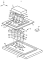
먼저, 도 1 을 참조하면서, 본 실시형태의 노광 장치 (1) 의 구조에 대해서 설명한다. 도 1 은, 본 실시형태의 노광 장치 (1) 의 전체 구조의 일례를 나타내는 사시도이다.First, the structure of the
도 1 에 나타내는 바와 같이, 노광 장치 (1) 는, 광원 유닛 (11) 과, 복수의 조명 광학계 (12) 와, 마스크 스테이지 (13) 와, 복수의 투영 광학계 (14) 와, 기판 스테이지 (15) 와, 제어 장치 (16) 를 구비한다.As shown in FIG. 1 , the
광원 유닛 (11) 은, 노광 광 (EL) 을 사출한다. 노광 광 (EL) 은, 예를 들어, g 선, h 선 및 i 선 중 적어도 하나의 파장 대역의 광이다. 특히, 광원 유닛 (11) 은, 노광 광 (EL) 을, 마스크 (131) 의 유효 영역 (131p) (후술하는 도 2 참조) 상에 설정되는 복수의 조명 영역 (IR) 을 각각 조명 가능한 복수의 노광 광 (EL) 으로 분기한다. 도 1 에 나타내는 예에서는, 광원 유닛 (11) 은, 노광 광 (EL) 을, 7 개의 조명 영역 (IR) (요컨대, 조명 영역 (IRa), 조명 영역 (IRb), 조명 영역 (IRc), 조명 영역 (IRd), 조명 영역 (IRe), 조명 영역 (IRf) 및 조명 영역 (IRg)) 을 각각 조명 가능한 7 개의 노광 광 (EL) 으로 분기한다. 복수의 노광 광 (EL) 은, 복수의 조명 광학계 (12) 에 각각 입사한다.The
복수의 조명 광학계 (12) 는, 멀티 렌즈형의 조명 광학계를 구성한다. 도 1 에 나타내는 예에서는, 노광 장치 (1) 는, 7 개의 조명 광학계 (12) (요컨대, 조명 광학계 (12a), 조명 광학계 (12b), 조명 광학계 (12c), 조명 광학계 (12d), 조명 광학계 (12e), 조명 광학계 (12f) 및 조명 광학계 (12g)) 를 구비한다. 조명 광학계 (12a), 조명 광학계 (12c), 조명 광학계 (12e) 및 조명 광학계 (12g) 는, Y 축 방향을 따라 등간격으로 늘어서도록 배치된다. 조명 광학계 (12b), 조명 광학계 (12d) 및 조명 광학계 (12f) 는, Y 축 방향을 따라 등간격으로 늘어서도록 배치된다. 조명 광학계 (12a), 조명 광학계 (12c), 조명 광학계 (12e) 및 조명 광학계 (12g) 는, 조명 광학계 (12b), 조명 광학계 (12d) 및 조명 광학계 (12f) 에 대하여, X 축 방향을 따라 소정량만큼 떨어진 위치에 배치된다. 조명 광학계 (12a), 조명 광학계 (12c), 조명 광학계 (12e) 및 조명 광학계 (12g) 와, 조명 광학계 (12b), 조명 광학계 (12d) 및 조명 광학계 (12f) 는, 지그재그 형상으로 배열되어 있다.The plurality of illumination
각 조명 광학계 (12) 는, 광원 유닛 (11) 의 하방에 배치되어 있다. 각 조명 광학계 (12) 는, 각 조명 광학계 (12) 에 대응하는 조명 영역 (IR) 에, 노광 광 (EL) 을 조사한다. 구체적으로는, 조명 광학계 (12a 내지 12g) 는, 조명 영역 (IRa 내지 IRg) 에 노광 광 (EL) 을 각각 조사한다. 이 때문에, 마스크 (131) 상에 설정되는 조명 영역 (IR) 의 수는, 노광 장치 (1) 가 구비하는 조명 광학계 (12) 의 수와 동일하다.Each illumination
마스크 스테이지 (13) 는, 복수의 조명 광학계 (12) 의 하방에 배치되어 있다. 마스크 스테이지 (13) 는, 마스크 (131) 를 유지 가능하다. 마스크 스테이지 (13) 는, 유지한 마스크 (131) 를 릴리스 가능하다. 마스크 (131) 는, 예를 들어, 한 변 또는 대각이 500 ㎜ 이상인 사각형 유리판으로 구성되어 있다. 마스크 (131) 에는, 기판 (151) 에 전사되어야 할 디바이스 패턴에 대응하는 마스크 패턴이 형성되어 있다. 보다 구체적으로는, 마스크 (131) 에는, 디바이스 패턴을 기판 (151) 에 형성하도록 기판 (151) 을 노광하기 위한 이미지 (예를 들어, 공간 이미지 내지는 노광 패턴) 를 형성 가능한 마스크 패턴이 형성되어 있다.The
마스크 스테이지 (13) 는, 마스크 (131) 를 유지한 상태로, 복수의 조명 영역 (IR) 을 포함하는 평면 (예를 들어, XY 평면) 을 따라 이동 가능하다. 마스크 스테이지 (13) 는, X 축 방향을 따라 이동 가능하다. 예를 들어, 마스크 스테이지 (13) 는, 임의의 모터를 포함하는 마스크 스테이지 구동계의 동작에 의해, X 축 방향을 따라 이동 가능하다. 마스크 스테이지 (13) 는, X 축 방향을 따라 이동 가능한 것에 더하여, Y 축 방향, Z 축 방향, θX 방향, θY 방향 및 θZ 방향 중 적어도 하나를 따라 이동 가능해도 된다.The
복수의 투영 광학계 (14) 는, 멀티 렌즈형의 투영 광학계를 구성한다. 도 1 에 나타내는 예에서는, 노광 장치 (1) 는, 7 개의 투영 광학계 (14) (요컨대, 투영 광학계 (14a), 투영 광학계 (14b), 투영 광학계 (14c), 투영 광학계 (14d), 투영 광학계 (14e), 투영 광학계 (14f) 및 투영 광학계 (14g)) 를 구비한다. 노광 장치 (1) 가 구비하는 투영 광학계 (14) 의 수는, 노광 장치 (1) 가 구비하는 조명 광학계 (12) 의 수와 동일하다. 투영 광학계 (14a), 투영 광학계 (14c), 투영 광학계 (14e) 및 투영 광학계 (14g) 는, Y 축 방향을 따라 거의 등간격으로 늘어서도록 배치된다. 투영 광학계 (14b), 투영 광학계 (14d) 및 투영 광학계 (14f) 는, Y 축 방향을 따라 거의 등간격으로 늘어서도록 배치된다. 투영 광학계 (14a), 투영 광학계 (14c), 투영 광학계 (14e) 및 투영 광학계 (14g) 는, 투영 광학계 (14b), 투영 광학계 (14d) 및 투영 광학계 (14f) 에 대하여, X 축 방향을 따라 소정량만큼 떨어진 위치에 배치된다. 투영 광학계 (14a), 투영 광학계 (14c), 투영 광학계 (14e) 및 투영 광학계 (14g) 와, 투영 광학계 (14b), 투영 광학계 (14d) 및 투영 광학계 (14f) 는, 지그재그 형상으로 배열되어 있다.The plurality of projection
각 투영 광학계 (14) 는, 마스크 스테이지 (13) 의 하방에 배치되어 있다. 각 투영 광학계 (14) 는, 각 투영 광학계 (14) 에 대응하는 조명 영역 (IR) 에 조사된 노광 광 (EL) (요컨대, 조명 영역 (IR) 이 설정되어 있는 마스크 (131) 의 유효 영역 (131p) 에 형성되어 있는 마스크 패턴의 이미지) 을, 각 투영 광학계 (14) 에 대응하여 기판 (151) 상에 설정되는 투영 영역 (PR) 에 대하여 투영한다. 구체적으로는, 투영 광학계 (14a) 는, 조명 영역 (IRa) 에 조사된 노광 광 (EL) (요컨대, 조명 영역 (IRa) 이 설정되어 있는 마스크 (131) 의 유효 영역 (131p) 에 형성되어 있는 마스크 패턴의 이미지) 을, 기판 (151) 상에 설정되는 투영 영역 (PRa) 에 대하여 투영한다. 투영 광학계 (14b) 로부터 투영 광학계 (14g) 에 대해서도 동일하다.Each projection
각 투영 광학계 (14) 는, 시야 조리개 (144) 를 구비하고 있다. 시야 조리개 (144) 는, 기판 (151) 상에 투영 영역 (PR) 을 설정한다. 시야 조리개 (144) 에는, Y 축 방향으로 평행한 상변 및 저변을 갖는 사다리꼴 형상의 개구가 형성되어 있다. 그 결과, 기판 (151) 상에는, Y 축 방향으로 평행한 상변 및 저변을 갖는 사다리꼴 형상의 투영 영역 (PR) 이 설정된다.Each projection
기판 스테이지 (15) 는, 복수의 투영 광학계 (14) 의 하방에 배치되어 있다. 기판 스테이지 (15) 는, 기판 (151) 을 유지 가능하다. 기판 스테이지 (15) 는, 기판 (151) 의 상면이 XY 평면에 평행하게 되도록 기판 (151) 을 유지 가능하다. 기판 스테이지 (15) 는, 유지한 기판 (151) 을 릴리스 가능하다. 기판 (151) 은, 예를 들어, 가로세로 수 m 의 유리 기판이다.The
기판 스테이지 (15) 는, 기판 (151) 을 유지한 상태로, 투영 영역 (PR) 을 포함하는 평면 (예를 들어, XY 평면) 을 따라 이동 가능하다. 기판 스테이지 (15) 는, X 축 방향을 따라 이동 가능하다. 예를 들어, 기판 스테이지 (15) 는, 임의의 모터를 포함하는 기판 스테이지 구동계의 동작에 의해, X 축 방향을 따라 이동해도 된다. 기판 스테이지 (15) 는, X 축 방향을 따라 이동 가능한 것에 더하여, Y 축 방향, Z 축 방향, θX 방향, θY 방향 및 θZ 방향 중 적어도 하나를 따라 이동 가능해도 된다.The
제어 장치 (16) 는, 노광 장치 (1) 의 동작을 제어 가능하다. 제어 장치 (16) 는, 예를 들어, CPU (Central Processing Unit) 나, ROM (Read Only Memory) 이나, RAM (Rondom Access Memory) 등을 구비하고 있다.The
제어 장치 (16) 는, 마스크 스테이지 (13) 가 원하는 제 1 이동 양태로 이동 (그 결과, 마스크 (131) 가 원하는 제 1 이동 양태로 이동) 하도록, 마스크 스테이지 구동계를 제어한다. 제어 장치 (16) 는, 기판 스테이지 (15) 가 원하는 제 2 이동 양태로 이동 (그 결과, 기판 (151) 이 원하는 제 2 이동 양태로 이동) 하도록, 기판 스테이지 구동계를 제어한다. 예를 들어, 제어 장치 (16) 는, 스텝·앤드·스캔 방식의 노광이 실시되도록, 마스크 스테이지 구동계 및 기판 스테이지 구동계를 제어한다. 요컨대, 제어 장치 (16) 는, 마스크 (131) 상의 조명 영역 (IR) 에 대하여 노광 광 (EL) 이 조사되고 있는 상태에서 마스크 (131) 를 유지하는 마스크 스테이지 (13) 와 기판 (151) 을 유지하는 기판 스테이지 (15) 가 동기하여 소정의 주사 방향을 따라 이동하도록, 마스크 스테이지 구동계 및 기판 스테이지 구동계를 제어한다. 그 결과, 마스크 (131) 에 형성되어 있는 마스크 패턴이, 기판 (151) 에 전사된다. 이하의 설명에서는, 마스크 스테이지 (13) 및 기판 스테이지 (15) 가 동기하여 이동하는 주사 방향이 X 축 방향이고, X 축 방향에 직교하는 Y 축 방향을, 적절히 “비주사 방향” 이라고 칭한다.The
또한, 도 1 및 도 2 를 이용하여 설명한 노광 장치 (1) 의 구조는 일례이다. 따라서, 노광 장치 (1) 의 구조의 적어도 일부가 적절히 개변되어도 된다. 예를 들어, 노광 장치 (1) 는, 6 개 이하의 또는 8 개 이상의 조명 광학계 (12) 를 구비하고 있어도 된다. 예를 들어, 노광 장치 (1) 는, 6 개 이하의 또는 8 개 이상의 투영 광학계 (14) 를 구비하고 있어도 된다.In addition, the structure of the
혹은, 노광 장치 (1) 는, 단일의 조명 광학계 (12) 를 구비하고 있어도 된다. 노광 장치 (1) 는, 단일의 투영 광학계 (14) 를 구비하고 있어도 된다. 단, 노광 장치 (1) 가 단일의 투영 광학계 (14) 를 구비하고 있는 경우에는, 마스크 (131) 상에는, 후술하는 이음 패턴 영역 (131a) 및 비이음 패턴 영역 (131b) 이 설정되지 않아도 되고, 기판 (151) 상에는, 후술하는 이음 노광 영역 (151a) 및 비이음 노광 영역 (151b) 이 설정되지 않아도 된다.Alternatively, the
(1-2) 조명 영역 (IR) 및 투영 영역 (PR) 의 배치(1-2) Arrangement of illumination region (IR) and projection region (PR)
계속해서, 도 2(a) 내지 도 2(c) 를 참조하면서, 마스크 (131) 상에 설정되는 조명 영역 (IR) 및 기판 (151) 상에 설정되는 투영 영역 (RP) 에 대해서 설명한다. 도 2(a) 는, 기판 (151) 상에 설정되는 투영 영역 (PR) 을 나타내는 평면도이다. 도 2(b) 는, 마스크 (131) 상에 설정되는 조명 영역 (IR) 을 나타내는 평면도이다. 도 2(c) 는, 마스크 (131) 상에 반복 형성되는 단위 마스크 패턴부 (MPp) 를 나타내는 평면도이다.Then, the illumination area|region IR set on the
도 2(a) 에 나타내는 바와 같이, 기판 (151) 상에는, 노광 장치 (1) 가 구비하는 투영 광학계 (14) 의 수와 동일한 수의 투영 영역 (PR) 이 설정된다. 본 실시형태에서는, 노광 장치 (1) 가 7 개의 투영 광학계 (14) 를 구비하고 있기 때문에, 기판 (151) 상에는, 7 개의 투영 영역 (PR) (요컨대, 투영 영역 (PRa), 투영 영역 (PRb), 투영 영역 (PRc), 투영 영역 (PRd), 투영 영역 (PRe), 투영 영역 (PRf) 및 투영 영역 (PRg)) 이 설정된다. 투영 광학계 (14a) 는, 조명 영역 (IRa) 에 조사된 노광 광 (EL) 이 투영 광학계 (14a) 에 의해 투영되는 투영 영역 (PRa) 을 설정한다. 투영 광학계 (14b) 는, 조명 영역 (IRb) 에 조사된 노광 광 (EL) 이 투영 광학계 (14b) 에 의해 투영되는 투영 영역 (PRb) 을 설정한다. 투영 광학계 (14c) 는, 조명 영역 (IRc) 에 조사된 노광 광 (EL) 이 투영 광학계 (14c) 에 의해 투영되는 투영 영역 (PRc) 을 설정한다. 투영 광학계 (14d) 는, 조명 영역 (IRd) 에 조사된 노광 광 (EL) 이 투영 광학계 (14d) 에 의해 투영되는 투영 영역 (PRd) 을 설정한다. 투영 광학계 (14e) 는, 조명 영역 (IRe) 에 조사된 노광 광 (EL) 이 투영 광학계 (14e) 에 의해 투영되는 투영 영역 (PRe) 을 설정한다. 투영 광학계 (14f) 는, 조명 영역 (IRf) 에 조사된 노광 광 (EL) 이 투영 광학계 (14f) 에 의해 투영되는 투영 영역 (PRf) 을 설정한다. 투영 광학계 (14g) 는, 조명 영역 (IRg) 에 조사된 노광 광 (EL) 이 투영 광학계 (14g) 에 의해 투영되는 투영 영역 (PRg) 을 설정한다.As shown to Fig.2 (a), on the board|
투영 영역 (PRa), 투영 영역 (PRc), 투영 영역 (PRe) 및 투영 영역 (PRg) 은, +X 측의 변이 저변이 되는 사다리꼴 형상의 영역이다. 투영 영역 (PRb), 투영 영역 (PRd) 및 투영 영역 (PRf) 은, -X 측의 변이 저변이 되는 사다리꼴 형상의 영역이다. 투영 영역 (PRa), 투영 영역 (PRc), 투영 영역 (PRe) 및 투영 영역 (PRg) 은, 투영 영역 (PRb), 투영 영역 (PRd) 및 투영 영역 (PRf) 에 대하여, X 축 방향을 따라 제 1 소정량만큼 떨어진 위치에 설정된다. 투영 영역 (PRa), 투영 영역 (PRc), 투영 영역 (PRe) 및 투영 영역 (PRg) 과, 투영 영역 (PRb), 투영 영역 (PRd) 및 투영 영역 (PRf) 은, 지그재그 형상으로 설정된다.Projection area|region PRa, projection area|region PRc, projection area|region PRe, and projection area|region PRg are trapezoid-shaped areas|regions from which the side by the side of +X becomes a base. Projection area|region PRb, projection area|region PRd, and projection area|region PRf are trapezoid-shaped areas|regions from which the side by the side of -X becomes a base. The projection region PRa, the projection region PRc, the projection region PRe, and the projection region PRg are along the X-axis direction with respect to the projection region PRb, the projection region PRd, and the projection region PRf. It is set at a position separated by a first predetermined amount. Projection region PRa, projection region PRc, projection region PRe, and projection region PRg, and projection region PRb, projection region PRd, and projection region PRf are set in a zigzag shape.
각 투영 영역 (PR) 은, X 축 방향에 대하여 경사진 변에 의해 규정되는 2 개 의 단부 (端部) (이후, 적절히 “경사부” 라고 칭한다) 를 포함한다. 단, 투영 영역 (PRa) 의 -Y 측의 변 및 투영 영역 (PRg) 의 +Y 측의 변은, 마스크 (131) 의 유효 영역 (131p) 을 둘러싸는 차광대 (131s) (도 2(b) 참조) 에 의해 노광 광 (EL) 이 차광되고 있는 것에 기인하여, X 축 방향에 대하여 경사져 있지 않다. 따라서, 투영 영역 (PRa) 및 투영 영역 (PRg) 의 각각은, 단일의 경사부를 포함한다.Each projection region PR includes two end portions (hereinafter, appropriately referred to as “slanted portions”) defined by a side inclined with respect to the X-axis direction. However, the -Y side side of the projection area|region PRa and the +Y side side of the projection area|region PRg are light-shielding
투영 영역 (PRa) 의 +Y 측의 경사부는, X 축 방향을 따라, 투영 영역 (PRb) 의 -Y 측의 경사부와 겹친다 (바꿔 말하면, 인접한다, 이하 동일). 투영 영역 (PRb) 의 +Y 측의 경사부는, X 축 방향을 따라, 투영 영역 (PRc) 의 -Y 측의 경사부와 겹친다. 투영 영역 (PRc) 의 +Y 측의 경사부는, X 축 방향을 따라, 투영 영역 (PRd) 의 -Y 측의 경사부와 겹친다. 투영 영역 (PRd) 의 +Y 측의 경사부는, X 축 방향을 따라, 투영 영역 (PRe) 의 -Y 측의 경사부와 겹친다. 투영 영역 (PRe) 의 +Y 측의 경사부는, X 축 방향을 따라, 투영 영역 (PRf) 의 -Y 측의 경사부와 겹친다. 투영 영역 (PRf) 의 +Y 측의 경사부는, X 축 방향을 따라, 투영 영역 (PRg) 의 -Y 측의 경사부와 겹친다.The inclined part on the +Y side of the projection region PRa overlaps with the inclined part on the -Y side of the projection region PRb along the X-axis direction (in other words, it is adjacent to, the same hereinafter). The inclined portion on the +Y side of the projection region PRb overlaps with the inclined portion on the -Y side of the projection region PRc along the X-axis direction. The inclined portion on the +Y side of the projection region PRc overlaps with the inclined portion on the -Y side of the projection region PRd along the X-axis direction. The inclined portion on the +Y side of the projection region PRd overlaps with the inclined portion on the -Y side of the projection region PRe along the X-axis direction. The inclined portion on the +Y side of the projection region PRe overlaps with the inclined portion on the -Y side of the projection region PRf along the X-axis direction. The inclined portion on the +Y side of the projection region PRf overlaps with the inclined portion on the -Y side of the projection region PRg along the X-axis direction.
X 축 방향을 따라 겹치는 2 개의 경사부는, 1 회의 주사 노광 동작 중에 당해 2 개의 경사부에 의해 노광 광 (EL) 이 2 회 투영되는 이음 노광 영역 (151a) 을, 기판 (151) 상에서 규정한다. 요컨대, X 축 방향을 따라 겹치는 2 개의 경사부는, 1 회의 주사 노광 동작 중에 당해 2 개의 경사부에 의해 이중으로 노광되는 이음 노광 영역 (151a) 을, 기판 (151) 상에서 규정한다. 한편, 기판 (151) 의 표면 중 이음 노광 영역 (151a) 이외의 비이음 노광 영역 (151b) 은, 1 회의 주사 노광 동작 중에 노광 광 (EL) 이 1 회 투영되는 영역이 된다. 각 투영 영역 (PR) 의 경사부는, X 축 방향을 따라 겹치는 2 개의 경사부의 X 축 방향을 따른 폭의 총합이, 각 투영 영역 (PR) 의 X 축 방향을 따른 폭 (요컨대, 경사부 이외의 영역 부분의 X 축 방향을 따른 폭) 과 동일해지도록, 설정된다. 그 결과, 이중으로 노광되는 이음 노광 영역 (151a) 의 노광량은, 이중으로 노광되지 않는 비이음 노광 영역 (151b) 의 노광량과 실질적으로 동일해진다. 따라서, 복수의 투영 영역 (PR) 에 대하여 투영되는 마스크 패턴의 이미지가 상대적으로 고정밀도로 이어진다.Two inclined portions overlapping along the X-axis direction define a
이음 노광 영역 (151a) 은, 사각형의 영역이다. 이음 노광 영역 (151a) 은, X 축 방향 (요컨대, 주사 방향) 이 길이 방향이 되고 또한 Y 축 방향 (요컨대, 비주사 방향) 이 폭 방향이 되는 영역이다. 이음 노광 영역 (151a) 은, X 축 방향을 따라 연신하는 영역이다. 기판 (151) 상에는, Y 축 방향을 따라 등간격으로 늘어서는 복수의 이음 노광 영역 (151a) (도 2(a) 에 나타내는 예에서는, 6 개의 이음 노광 영역 (151a)) 이 설정된다.The
비이음 노광 영역 (151b) 은, 사각형의 영역이다. 비이음 노광 영역 (151b) 은, X 축 방향이 길이 방향이 되고 또한 Y 축 방향이 폭 방향이 되는 영역이다. 비이음 노광 영역 (151b) 은, X 축 방향을 따라 연신하는 영역이다. 기판 (151) 상에는, Y 축 방향을 따라 등간격으로 늘어서는 복수의 비이음 노광 영역 (151b) (도 2(a) 에 나타내는 예에서는, 7 개의 비이음 노광 영역 (151b)) 이 설정된다.The
한편, 도 2(b) 에 나타내는 바와 같이, 마스크 (131) 상에는, 노광 장치 (1) 가 구비하는 조명 광학계 (12) 의 수와 동일한 수의 조명 영역 (IR) 이 설정된다. 본 실시형태에서는, 노광 장치 (1) 가 7 개의 조명 광학계 (14) 를 구비하고 있기 때문에, 마스크 (131) 상에는, 7 개의 조명 영역 (IR) (요컨대, 조명 영역 (IRa), 조명 영역 (IRb), 조명 영역 (IRc), 조명 영역 (IRd), 조명 영역 (IRe), 조명 영역 (IRf) 및 조명 영역 (IRg)) 이 설정된다. 조명 광학계 (12a) 는, 조명 영역 (IRa) 에 노광 광 (EL) 을 조사한다. 조명 광학계 (12b) 는, 조명 영역 (IRb) 에 노광 광 (EL) 을 조사한다. 조명 광학계 (12c) 는, 조명 영역 (IRc) 에 노광 광 (EL) 을 조사한다. 조명 광학계 (12d) 는, 조명 영역 (IRd) 에 노광 광 (EL) 을 조사한다. 조명 광학계 (12e) 는, 조명 영역 (IRe) 에 노광 광 (EL) 을 조사한다. 조명 광학계 (12f) 는, 조명 영역 (IRf) 에 노광 광 (EL) 을 조사한다. 조명 광학계 (12g) 는, 조명 영역 (IRg) 에 노광 광 (EL) 을 조사한다.On the other hand, as shown in FIG.2(b), on the
각 투영 광학계 (14) 의 물체면측의 시야는, 각 투영 광학계 (14) 가 구비하는 시야 조리개 (144) 에 의해 규정된다. 이 때문에, 각 조명 영역 (IR) 은, 시야 조리개 (144) 와 광학적으로 공액인 영역을 의미하고 있다.A field of view on the object plane side of each projection
본 실시형태에서는, 각 투영 광학계 (14) 는, 마스크 패턴의 등배의 정립정상 (正立正像) 을 기판 (151) 상에 투영한다. 이 때문에, 조명 영역 (IRa) 으로부터 조명 영역 (IRg) 의 형상 및 배열은, 투영 영역 (PRa) 으로부터 투영 영역 (PRg) 의 형상 및 배열과 각각 동일하다. 이 때문에, 각 조명 영역 (IR) 은, X 축 방향에 대하여 경사진 변에 의해 규정되는 2 개의 단부 (이후, 적절히 “경사부” 라고 칭한다) 를 포함한다. X 축 방향을 따라 겹치는 2 개의 경사부는, 1 회의 주사 노광 동작 중에 당해 2 개의 경사부에 의해 노광 광 (EL) 이 2 회 조명되는 이음 패턴 영역 (131a) 을, 마스크 (131) 상에서 규정한다. 요컨대, X 축 방향을 따라 겹치는 2 개의 조명 영역 (IR) 의 2 개의 경사부는, 1 회의 주사 노광 동작 중에 당해 2 개의 경사부에 의해 이중으로 조명되는 이음 패턴 영역 (131a) 을, 마스크 (131) 상에서 규정한다. 한편, 유효 영역 (131p) 중 이음 패턴 영역 (131a) 이외의 비이음 패턴 영역 (131b) 은, 1 회의 주사 노광 동작 중에 노광 광 (EL) 이 1 회 조명되는 영역이 된다.In the present embodiment, each projection
이음 패턴 영역 (131a) 은, 이음 노광 영역 (151a) 에 대응하는 영역이다. 요컨대, 이음 패턴 영역 (131a) 을 조명한 노광 광 (EL) 은, 이음 패턴 영역 (131a) 을 통과하고, 이음 노광 영역 (151a) 에 조사된다. 한편, 비이음 패턴 영역 (131b) 은, 비이음 노광 영역 (151b) 에 대응하는 영역이다. 요컨대, 비이음 패턴 영역 (131b) 을 조명한 노광 광 (EL) 은, 비이음 패턴 영역 (131b) 을 통과하고, 비이음 노광 영역 (151b) 에 조사된다.The
이음 패턴 영역 (131a) 은, 사각형의 영역이다. 이음 패턴 영역 (131a) 은, X 축 방향 (요컨대, 주사 방향) 이 길이 방향이 되고 또한 Y 축 방향 (요컨대, 비주사 방향) 이 폭 방향이 되는 영역이다. 이음 패턴 영역 (131a) 은, X 축 방향을 따라 연신하는 영역이다. 마스크 (131) 상에는, Y 축 방향을 따라 등간격으로 늘어서는 복수의 이음 패턴 영역 (131a) (도 3(b) 에 나타내는 예에서는, 6 개의 이음 패턴 영역 (131a)) 이 설정된다.The
비이음 패턴 영역 (131b) 은, 사각형의 영역이다. 비이음 패턴 영역 (131b) 은, X 축 방향이 길이 방향이 되고 또한 Y 축 방향이 폭 방향이 되는 영역이다. 비이음 패턴 영역 (131b) 은, X 축 방향을 따라 연신하는 영역이다. 마스크 (131) 상에는, Y 축 방향을 따라 등간격으로 늘어서는 복수의 비이음 패턴 영역 (131b) (도 3(b) 에 나타내는 예에서는, 7 개의 비이음 패턴 영역 (131b)) 이 설정된다.The
마스크 (131) 상에 형성되어 있는 마스크 패턴은, 예를 들어 도 2(c) 에 나타내는 바와 같이, Y 축 방향을 따라 반복 규칙적으로 형성되고 또한 각각이 동일한 마스크 패턴인 복수의 단위 마스크 패턴부 (1311u) 를 포함하고 있다. 복수의 단위 마스크 패턴부 (1311u) 는, 유효 영역 (131p) 의 적어도 일부에 형성되어 있다. 요컨대, 유효 영역 (131p) 의 적어도 일부는, 복수의 단위 마스크 패턴부 (1311u) 가 X 축 방향 및 Y 축 방향의 적어도 일방을 따라 반복 규칙적으로 형성되어 있는 반복 영역을 포함한다. 또한, 도 2(c) 에 나타내는 예에서는, 복수의 단위 마스크 패턴부 (1311u) 는, X 축 방향 및 Y 축 방향의 쌍방을 따라 반복 규칙적으로 형성되어 있다.The mask pattern formed on the
이 경우, Y 축 방향을 따라 서로 이웃하는 2 개의 이음 패턴 영역 (131a) 의 간격 (D1) 은, Y 축 방향을 따라 서로 이웃하는 2 개의 단위 마스크 패턴부 (1311u) 의 간격 (D2) 보다 길다. Y 축 방향을 따라 이음 패턴 영역 (131a) 이 나타나는 빈도는, Y 축 방향을 따라 단위 마스크 패턴부 (1311u) 가 나타나는 빈도보다 낮다. Y 축 방향을 따른 이음 패턴 영역 (131a) 의 배열 주기는, Y 축 방향을 따른 단위 마스크 패턴부 (1311u) 의 배열 주기보다 길다.In this case, the interval D1 between the two
단위 마스크 패턴부 (1311u) 를 개재한 노광 광 (EL) 에 의해, 기판 (151) 상에는, 단위 마스크 패턴부 (1311u) 에 대응하는 단위 디바이스 패턴부 (1511u) 가 형성된다. 따라서, 반복 규칙적으로 형성된 (요컨대, 배열된) 복수의 단위 마스크 패턴부 (1311u) 를 포함하는 마스크 (131) 를 개재한 노광 광 (EL) 에 의해, 기판 (151) 상에는, 반복 규칙적으로 배열된 복수의 단위 디바이스 패턴부 (1511u) 를 포함하는 디바이스 패턴이 형성된다. The unit
상기 서술한 바와 같이, 노광 장치 (1) 에 의해 노광된 기판 (151) 은, 예를 들어, 표시 패널을 제조하기 위해서 사용된다. 이 경우, 단위 마스크 패턴부 (1311u) 는, 표시 패널을 구성하는 각 화소 (요컨대, 각 표시 화소) 를 기판 (151) 상에 형성하기 위한 마스크 패턴이다. 요컨대, 단위 마스크 패턴부 (1311u) 는, 각 화소 내에 형성되는 TFT (Thin Film Transistor) 소자 등의 회로 소자, 컬러 필터, 블랙 매트릭스, 터치 패널 회로 소자 등을 기판 (151) 상에 형성하기 위한 마스크 패턴이다. 또한, 단위 디바이스 패턴부 (1511u) 는, 각 화소의 디바이스 패턴이다.As described above, the
이와 같은 표시 패널을 제조하기 위해서 사용되는 마스크 (131) 의 일 구체예에 대해, 도 3(a) 및 도 3(b) 를 참조하면서 설명한다. 도 3(a) 는, 표시 패널을 제조하기 위해서 사용되는 마스크 (131) 의 일 구체예를 나타내는 평면도이다. 도 3(b) 는, 도 3(a) 에 나타내는 마스크 (131) 의 일부를 나타내는 평면도이다.A specific example of the
도 3(a) 에 나타내는 바와 같이, 마스크 (131) 에는 (특히, 차광 영역 (131s) 에 의해 둘러싸인 유효 영역 (131p) 에는), 복수의 동일한 마스크 패턴 (1311d) 을 포함하는 마스크 패턴군 (1311g) 이 형성되어 있다. 각 마스크 패턴 (1311d) 은, 1 대의 표시 패널을 제조하기 위한 마스크 패턴이다. 요컨대, 각 마스크 패턴 (1311d) 은, 1 대의 표시 패널의 디바이스 패턴에 대응하는 마스크 패턴이다. 따라서, 도 3(a) 에 나타내는 마스크 (131) 는, 1 매의 기판 (151) 으로부터 복수의 동일 표시 패널을 제조하기 위해서 사용된다. 도 3(a) 에 나타내는 예에서는, 마스크 (131) 에는, 8 개의 마스크 패턴 (1311d) 이 형성되어 있다. 따라서, 도 3(a) 에 나타내는 마스크 (131) 는, 1 매의 기판 (151) 으로부터 8 개의 동일 표시 패널을 제조하기 위해서 사용된다.As shown in Fig. 3(a), a
각 마스크 패턴 (1311d) 은, 도 3(b) 에 나타내는 바와 같이, 1 대의 표시 패널의 복수의 화소를 기판 (151) 상에 각각 형성하기 위한 복수의 단위 마스크 패턴부 (1311u) 를 포함한다. 이후, 복수의 단위 마스크 패턴부 (1311u) 의 집합을, 적절히 “화소 마스크 패턴부 (1311p)” 라고 칭한다. 각 마스크 패턴 (1311d) 은 또한, 복수의 화소가 배치되는 화소 영역의 주변에 배치되는 주변 회로 등을 기판 (151) 상에 형성하기 위한 주변 마스크 패턴부 (1311s) 를 포함한다. 도 3(b) 는, 주변 마스크 패턴부 (1311s) 가, 복수의 화소로부터 인출되는 배선 (예를 들어, 복수의 화소와 구동 회로를 접속하는 배선) 을 형성하기 위한 마스크 패턴을 포함하는 예를 나타내고 있다. 또한, 도 3(b) 에 나타내는 예에서는, 주변 마스크 패턴부 (1311s) 가 화소 마스크 패턴부 (1311p) 의 ―X 측에 배치되어 있다. 그러나, 주변 회로 등의 배치 위치에 맞추어, 주변 마스크 패턴부 (1311s) 는, 화소 마스크 패턴부 (1311p) 의 +X 측, -Y 측 및 +Y 측 중 적어도 하나에 배치되어 있어도 된다.Each
이와 같은 마스크 (131) 는, 이하와 같이 제조된다. 먼저, 후술하는 마스크 패턴 산출 장치 (2) 에 의해, 디바이스 패턴에 대응하는 마스크 패턴 (도 3(a) 내지 도 3(b) 에 나타내는 예에서는, 복수의 마스크 패턴 (1311d) 을 포함하는 마스크 패턴군 (1311g)) 이 산출된다. 또한, 여기서 말하는 「마스크 패턴의 산출」이란, 마스크 패턴의 내용 (요컨대, 패턴 레이아웃) 을 결정하는 것을 의미하고 있고, 실질적으로는, 마스크 패턴의 내용을 나타내는 마스크 패턴 데이터의 생성과 등가이다. 그 후, 산출된 마스크 패턴이, 마스크 패턴이 형성되어 있지 않은 마스크 블랭크스에 대하여 실제로 형성된다. 구체적으로는, 예를 들어, 산출된 마스크 패턴에 기초하여, 전자선 빔 노광 장치 등이, 감광재가 도포된 마스크 블랭크스를 노광한다. 그 후, 노광된 마스크 블랭크스가 현상됨으로써, 마스크 블랭크스 상에는, 마스크 패턴에 대응하는 감광재의 패턴층이 형성된다. 그 후, 감광재의 패턴층을 통해서 마스크 블랭크스 (특히, 마스크 블랭크스가 구비하는 차광막) 가 가공된다. 그 결과, 디바이스 패턴에 대응하는 마스크 패턴이 형성된 마스크 (131) 가 제조된다.Such a
(2) 본 실시형태의 마스크 패턴 산출 장치 (2)(2) Mask pattern calculation apparatus (2) of this embodiment
계속해서, 도 4 내지 도 12 를 참조하면서, 마스크 (131) 에 형성되는 마스크 패턴을 산출하는 마스크 패턴 산출 장치 (2) 에 대해서 설명한다.Then, the mask
(2-1) 마스크 패턴 산출 장치 (2) 의 구조(2-1) Structure of mask pattern calculating device (2)
먼저, 도 4 를 참조하면서, 마스크 패턴 산출 장치 (2) 의 구조에 대해서 설명한다. 도 4 는, 마스크 패턴 산출 장치 (2) 의 구조를 나타내는 블록도이다.First, the structure of the mask
도 4 에 나타내는 바와 같이, 마스크 패턴 산출 장치 (2) 는, CPU (Central Processing Unit) (21) 와, 메모리 (22) 와, 입력부 (23) 와, 조작 기기 (24) 와, 표시 기기 (25) 를 구비한다.As shown in FIG. 4 , the mask
CPU (21) 는, 마스크 패턴 산출 장치 (2) 의 동작을 제어한다. CPU (21) 는, 마스크 패턴을 산출하여, 마스크 패턴 데이터를 생성한다. 요컨대, CPU (21) 는, 마스크 레이아웃을 설계한다. 구체적으로는, CPU (21) 는, 디바이스 패턴의 내용 (요컨대, 패턴 레이아웃) 을 나타내는 디바이스 패턴 데이터에 기초하여, 원하는 산출 조건을 만족하는 마스크 패턴을 산출한다. 구체적으로는, CPU (21) 는, 원하는 산출 조건을 만족하는 마스크 패턴을 산출하기 위한 최적화 문제 또는 수리 계획 문제를 풀음으로써, 마스크 패턴을 산출한다. 원하는 산출 조건의 일 구체예로서, 노광량 (DOSE 량) 및 초점 심도 (DOF:Depth Of Focus) 를 최적화한다 (이른바, 프로세스 윈도우를 최적화한다) 는 조건을 들 수 있다. 또한, 노광량 및 초점 심도를 최적화한다는 조건은, 노광량을 제 1 소망량으로 설정하고 또한 초점 심도를 제 2 소망량으로 설정한다는 조건을 의미한다.The
CPU (21) 는, 실질적으로는, EDA (Electronic Design Automation) 툴로서 기능해도 된다. 예를 들어, CPU (21) 는, 상기 서술한 마스크 패턴의 산출 동작을 CPU (21) 에 실시시키기 위한 컴퓨터 프로그램을 실행함으로써, EDA 툴로서 기능해도 된다.The
메모리 (22) 는, 마스크 패턴의 산출 동작을 CPU (21) 에 실시시키기 위한 컴퓨터 프로그램을 격납한다. 단, 마스크 패턴의 산출 동작을 CPU (21) 에 실시시키기 위한 컴퓨터 프로그램은, 외부의 기억 장치 (예를 들어, 하드 디스크나 광 디스크) 등에 기록되어 있어도 된다. 메모리 (22) 는, 또한, CPU (21) 가 마스크 패턴의 산출 동작을 실시하고 있는 동안에 생성되는 중간 데이터를 일시적으로 격납한다.The
입력부 (23) 는, CPU (21) 가 마스크 패턴의 산출 동작을 실시하기 위해서 사용되는 각종 데이터의 입력을 접수한다. 이와 같은 데이터의 일례로서, 기판 (151) 에 대하여 형성해야 할 디바이스 패턴을 나타내는 디바이스 패턴 데이터 등을 들 수 있다. 단, 마스크 패턴 산출 장치 (2) 는, 입력부 (23) 를 구비하고 있지 않아도 된다.The
조작 기기 (24) 는, 마스크 패턴 산출 장치 (2) 에 대한 사용자의 조작을 접수한다. 조작 기기 (24) 는, 예를 들어, 키보드, 마우스 및 터치 패널의 적어도 하나를 포함하고 있어도 된다. CPU (21) 는, 조작 기기 (24) 가 접수한 사용자의 조작에 기초하여, 마스크 패턴의 산출 동작을 실시해도 된다. 단, 마스크 패턴 산출 장치 (2) 는, 조작 기기 (24) 를 구비하고 있지 않아도 된다.The
표시 기기 (25) 는, 원하는 정보를 표시 가능하다. 예를 들어, 표시 기기 (25) 는, 마스크 패턴 산출 장치 (2) 의 상태를 나타내는 정보를 직접적으로 또는 간접적으로 표시해도 된다. 예를 들어, 표시 기기 (25) 는, 마스크 패턴 산출 장치 (2) 가 산출하고 있는 마스크 패턴을 직접적으로 또는 간접적으로 표시해도 된다. 예를 들어, 표시 기기 (25) 는, 마스크 패턴의 산출 동작에 관한 임의의 정보를 직접적으로 또는 간접적으로 표시해도 된다. 단, 마스크 패턴 산출 장치 (2) 는, 표시 기기 (25) 를 구비하고 있지 않아도 된다.The
(2-2) 마스크 패턴의 산출 동작(2-2) Mask pattern calculation operation
계속해서, 도 5 를 참조하면서, 마스크 패턴 산출 장치 (2) 가 실시하는 마스크 패턴의 산출 동작에 대해서 설명한다. 도 5 는, 마스크 패턴 산출 장치 (2) 가 실시하는 마스크 패턴의 산출 동작의 흐름을 나타내는 플로우 차트이다.Then, referring FIG. 5, the calculation operation|movement of the mask pattern which the mask
도 5 에 나타내는 바와 같이, 마스크 패턴 산출 장치 (2) 가 구비하는 CPU (21) 는, 디바이스 패턴을 나타내는 디바이스 패턴 데이터를 취득한다 (스텝 S1). 디바이스 패턴 데이터는, 소정의 설계 룰을 만족하도록 조정된 디바이스 패턴의 내용 (요컨대, 패턴 레이아웃) 을 나타내는 데이터이며, 이른바 디바이스 설계 (바꿔 말하면, 회로 설계) 의 결과로서 취득된다. 소정의 설계 룰로서, 예를 들어, 라인 또는 홀의 최소 폭이나, 2 개의 라인 또는 2 개의 홀 사이의 최소 공간을 일례로서 들 수 있다.As shown in FIG. 5, CPU21 with which the mask
스텝 1 의 처리와 병행하여, CPU (21) 는, 마스크 (131) 를 개재한 노광 광 (EL) 으로 디바이스 패턴을 기판 (151) 에 형성할 때의 노광 장치 (1) 의 상태를 나타내는 상태 변수를 설정한다 (스텝 S2).In parallel with the process of
예를 들어, CPU (21) 는, 조명 광학계 (12) 에 관한 상태 변수를 설정해도 된다. 조명 광학계 (12) 에 관한 상태 변수는, 광원 유닛 (11) 의 상태 (예를 들어, 조명 광학계 (12) 의 동면 (瞳面) 에서의 광 강도 분포, 조명 광학계 (12) 의 동면에서의 광의 편광 상태의 분포 등) 를 규정하는, 조정 가능한 또는 고정된 파라미터이다. 이와 같은 조명 광학계 (12) 에 관한 상태 변수의 일 구체예로서, 조명 광학계 (12) 에 의한 조명 패턴의 형상 (요컨대, 노광 광 (EL) 의 사출 패턴의 형상) 에 관한 상태 변수, σ 값에 관한 상태 변수 및 노광 광 (EL1) 의 광 강도에 관한 상태 변수 중 적어도 하나를 들 수 있다.For example, the
예를 들어, CPU (21) 는, 투영 광학계 (14) 에 관한 상태 변수를 설정해도 된다. 투영 광학계 (14) 에 관한 상태 변수는, 투영 광학계 (14) 의 상태 (예를 들어, 수차나 리타데이션 등의 광학 특성) 를 규정하는, 조정 가능한 또는 고정된 파라미터이다. 이와 같은 투영 광학계 (14) 에 관한 상태 변수의 일 구체예로서, 투영 광학계 (14) 가 투영하는 노광 광 (EL) 의 파면 (波面) 형상에 관한 상태 변수, 투영 광학계 (14) 가 투영하는 노광 광 (EL) 의 강도 분포에 관한 상태 변수 및 투영 광학계 (14) 가 투영하는 노광 광 (EL) 의 위상 시프트량 (혹은, 위상) 에 관한 상태 변수 중 적어도 하나를 들 수 있다.For example, the
그 후, CPU (21) 는, 스텝 S1 에서 취득한 디바이스 패턴 데이터가 나타내는 디바이스 패턴을 기판 (151) 에 형성하는 이미지를 형성 가능한 마스크 패턴을 산출한다 (스텝 S3). 이 때, CPU (21) 는, 스텝 S2 에서 설정한 상태 변수가 나타내는 상태에 있는 노광 장치 (1) 가 노광 광 (EL) 을 조사한다는 상황하에서 상기 서술한 산출 조건을 만족하는 것이 가능한 마스크 패턴을 산출한다. 이 때문에, CPU (21) 는, 마스크 패턴을 산출할 때마다, 당해 산출한 마스크 패턴이 산출 조건을 만족하는지 여부를 판정한다. 산출한 마스크 패턴이 산출 조건을 만족하지 않는 경우에는, CPU (21) 는, 마스크 패턴을 변경하는 (바꿔 말하면, 산출한 마스크 패턴을 조정하는) 동작을, 산출 조건이 만족될 때까지 반복한다. 단, CPU (21) 는, 마스크 패턴을 변경하는 것에 더하여 또는 대신하여, 상태 변수를 변경해도 된다. 이 경우에는, CPU (21) 는, 변경 후 상태 변수가 나타내는 상태에 있는 노광 장치 (1) 가 노광 광 (EL) 을 조사한다는 상황하에서 상기 서술한 산출 조건을 만족하는 것이 가능한 마스크 패턴을 산출하게 된다.Thereafter, the
본 실시형태에서는 특히, CPU (21) 는, 도 5 의 스텝 S3 에 있어서 마스크 패턴을 산출할 때에, 복수의 단위 마스크 패턴부 (1311u) 가 마스크 (131) 에 포함되는 (요컨대, 형성되는) 것을 이용하여, 상대적으로 효율적으로 마스크 패턴을 산출한다. 이하, 도 6 을 참조하면서, 도 5 의 스텝 S3 에 있어서, 복수의 단위 마스크 패턴부 (1311u) 가 마스크 (131) 에 포함되는 것을 이용하여 마스크 패턴을 산출하는 처리에 대해서 더 설명한다. 도 6 은, 도 5 의 스텝 S3 에 있어서, 복수의 단위 마스크 패턴부 (1311u) 가 마스크 (131) 에 포함되는 것을 이용하여 마스크 패턴을 산출하는 처리의 흐름을 나타내는 플로우 차트이다. 또한, 설명의 편의상, 도 6 을 사용한 설명에서는, 도 3(a) 내지 도 3(b) 에 나타내는 마스크 패턴을 산출하는 동작을 사용하여 설명을 진행하지만, 도 6 에 나타내는 처리는, 임의의 마스크 패턴을 산출할 때에 적용 가능하다.In this embodiment, in particular, when the
도 6 에 나타내는 바와 같이, CPU (21) 는, 디바이스 패턴 데이터에 기초하여, 단위 디바이스 패턴부 (1511u) 의 패턴 레이아웃을 취득한다 (스텝 S311). 또한, 디바이스 패턴에는, 복수의 단위 디바이스 패턴부 (1511u) 가 포함되어 있지만, 복수의 단위 디바이스 패턴부 (1511u) 의 패턴 레이아웃이 동일하기 때문에, CPU (21) 는, 하나의 단위 디바이스 패턴부 (1511u) 의 패턴 레이아웃을 취득하면 된다.As shown in FIG. 6 , the
그 후, CPU (21) 는, 스텝 S311 에서 취득한 하나의 단위 디바이스 패턴부 (1511u) 의 패턴 레이아웃에 기초하여, 하나의 단위 마스크 패턴부 (1311u) 의 패턴 레이아웃을 산출한다 (스텝 S312). 요컨대, CPU (21) 는, 복수의 단위 마스크 패턴부 (1311u) 를 포함하는 화소 마스크 패턴부 (1311p) 를 정리하여 산출하는 것 대신에, 우선, 하나의 단위 마스크 패턴부 (1311u) 의 패턴 레이아웃을 산출한다.Then, the
본 실시형태에서는, CPU (21) 는, 스텝 S312 에 있어서 하나의 단위 마스크 패턴부 (1311u) 의 패턴 레이아웃을 산출할 때에, 복수의 단위 마스크 패턴부 (1311u) 가 마스크 (131) 에 포함되는 것을 이용한다. 구체적으로는, 상기 서술한 바와 같이, CPU (21) 가 산출해야 할 마스크 패턴에는, 반복 규칙적으로 배열된 복수의 단위 마스크 패턴부 (1311u) 가 포함되어 있다. 복수의 단위 마스크 패턴부 (1311u) 의 패턴 레이아웃은 동일하다. 그렇다면, 마스크 (131) 상에서는, 어느 단위 마스크 패턴부 (1311u) 에는, 당해 어느 단위 마스크 패턴부 (1311u) 자체의 일부가 인접하고 있을 것이다.In the present embodiment, when the
예를 들어, 도 7 은, 표시 패널의 하나의 화소에 대응하는 어느 하나의 단위 디바이스 패턴부 (1511u) 를 형성하기 위한 어느 하나의 단위 마스크 패턴부 (1311u) 의 패턴 레이아웃을 나타내고 있다. 어느 하나의 화소에 포함되는 TFT 소자를 형성하기 위한 마스크 패턴, 및, 어느 하나의 화소에 포함되고 또한 당해 TFT 소자에 이어지는 신호선 (예를 들어, 게이트선이나 데이터선 등) 을 형성하기 위한 마스크 패턴이 포함되어 있다. 단, TFT 소자를 형성하기 위한 주사 노광 동작과 신호선을 형성하기 위한 주사 노광 동작은, 상이한 마스크 (131) 를 사용하여 따로 따로 실시되는 것이 일반적이다. 따라서, 패턴 산출 장치 (2) 는, 실제로는, TFT 소자를 형성하기 위한 단위 마스크 패턴부 (1311u) 를 포함하는 마스크 패턴과, 신호선을 형성하기 위한 단위 마스크 패턴부 (1311u) 를 포함하는 마스크 패턴을 별개로 산출한다. 그러나, 본 실시형태에서는, 설명의 편의상, 도 7 (나아가서는, 이하의 도 8(a) 내지 도 10) 에 있어서, 복수의 단위 마스크 패턴부 (1311u) 의 반복 배열을 알기 쉽게 도시할 목적으로, TFT 소자를 형성하기 위한 마스크 패턴 및 신호선을 형성하기 위한 마스크 패턴을 포함하는 단위 마스크 패턴부 (1311u) 를 사용하여 설명을 진행한다.For example, FIG. 7 shows the pattern layout of any one unit
도 7 에 나타내는 예에서는, 단위 마스크 패턴부 (1311u) 의 XY 평면 상에 있어서의 형상은, 사각형 (예를 들어, 장방형 또는 정방형) 이 된다. 요컨대, 마스크 (131) 상에서 단위 마스크 패턴부 (1311u) 가 차지하는 영역의 XY 평면 상에 있어서의 형상은, 사각형이 된다. 마스크 (131) 상에서는, 이와 같은 단위 마스크 패턴부 (1311u) 가, X 축 방향 및 Y 축 방향의 쌍방을 따라 반복 규칙적으로 복수 배열된다. 요컨대, 마스크 (131) 상에서는, 이와 같은 단위 마스크 패턴부 (1311u) 가, 매트릭스 형상으로 복수 배열된다.In the example shown in FIG. 7, the shape on the XY plane of the unit
이 경우, 도 8(a) 에 나타내는 바와 같이, 단위 마스크 패턴부 (1311u-1) 의 +X 측에는, 단위 마스크 패턴부 (1311u-2) 가 인접하고 있다. 단위 마스크 패턴부 (1311u-2) 의 패턴 레이아웃은, 단위 마스크 패턴부 (1311u-1) 의 패턴 레이아웃과 동일하다. 이 때문에, 실질적으로는, 단위 마스크 패턴부 (1311u-1) 의 +X 측의 외연 (外緣) (혹은, 변, 이하 동일) 에는, 당해 단위 마스크 패턴부 (1311u-1) 의 ―X 측의 외연을 포함하는 단위 마스크 패턴부 (1311u-1) 의 일부인 인접 마스크 패턴부 (1311n) 가 인접한다.In this case, as shown to Fig.8 (a), the unit
마찬가지로, 도 8(b) 에 나타내는 바와 같이, 단위 마스크 패턴부 (1311u-1) 의 ―X 측에는, 단위 마스크 패턴부 (1311u-3) 가 인접하고 있다. 단위 마스크 패턴부 (1311u-3) 의 패턴 레이아웃은, 단위 마스크 패턴부 (1311u-1) 의 패턴 레이아웃과 동일하다. 이 때문에, 실질적으로는, 단위 마스크 패턴부 (1311u-1) 의 ―X 측의 외연에는, 당해 단위 마스크 패턴부 (1311u-1) 의 +X 측의 외연을 포함하는 단위 마스크 패턴부 (1311u-1) 의 일부인 인접 마스크 패턴부 (1311n) 가 인접한다.Similarly, as shown in FIG.8(b), the unit
마찬가지로, 도 8(c) 에 나타내는 바와 같이, 단위 마스크 패턴부 (1311u-1) 의 -Y 측에는, 단위 마스크 패턴부 (1311u-4) 가 인접하고 있다. 단위 마스크 패턴부 (1311u-4) 의 패턴 레이아웃은, 단위 마스크 패턴부 (1311u-1) 의 패턴 레이아웃과 동일하다. 이 때문에, 실질적으로는, 단위 마스크 패턴부 (1311u-1) 의 -Y 측의 외연에는, 당해 단위 마스크 패턴부 (1311u-1) 의 +Y 측의 외연을 포함하는 단위 마스크 패턴부 (1311u-1) 의 일부인 인접 마스크 패턴부 (1311n) 가 인접한다.Similarly, as shown in FIG.8(c), the unit
마찬가지로, 도 8(d) 에 나타내는 바와 같이, 단위 마스크 패턴부 (1311u-1) 의 +Y 측에는, 단위 마스크 패턴부 (1311u-5) 가 인접하고 있다. 단위 마스크 패턴부 (1311u-5) 의 패턴 레이아웃은, 단위 마스크 패턴부 (1311u-1) 의 패턴 레이아웃과 동일하다. 이 때문에, 실질적으로는, 단위 마스크 패턴부 (1311u-1) 의 +Y 측의 외연에는, 당해 단위 마스크 패턴부 (1311u-1) 의 -Y 측의 외연을 포함하는 단위 마스크 패턴부 (1311u-1) 의 일부인 인접 마스크 패턴부 (1311n) 가 인접한다.Similarly, as shown in FIG.8(d), the unit
이와 같은 단위 마스크 패턴부 (1311u) 의 일부가 당해 단위 마스크 패턴부 (1311u) 에 인접하는 인접 마스크 패턴부 (1311n) 가 될 수 있는 것을 고려하여, CPU (21) 는, 산출하고자 하고 있는 하나의 단위 마스크 패턴부 (1311u) 의 일부가, 인접 마스크 패턴부 (1311n) 로서 당해 하나의 단위 마스크 패턴부 (1311u) 에 인접하고 있다고 가정한다 (바꿔 말하면, 간주한다). 예를 들어, 도 9 에 나타내는 바와 같이, CPU (21) 는, 단위 마스크 패턴부 (1311) 의 각 변이 연장되는 방향 (요컨대, X 축 방향 및 Y 축 방향의 적어도 일방) 을 따라 인접 마스크 패턴부 (1311n) 가 단위 마스크 패턴부 (1311u) 에 인접하고 있다고 가정해도 된다. 구체적으로는, CPU (21) 는, (i) 단위 마스크 패턴부 (1311u) 의 +X 측의 외연에는, 당해 단위 마스크 패턴부 (1311u) 의 ―X 측의 외연을 포함하는 인접 마스크 패턴부 (1311n-1) 가 인접하고, (ii) 단위 마스크 패턴부 (1311u) 의 ―X 측의 외연에는, 당해 단위 마스크 패턴부 (1311u) 의 +X 측의 외연을 포함하는 인접 마스크 패턴부 (1311n-2) 가 인접하고, (iii) 단위 마스크 패턴부 (1311u) 의 +Y 측의 외연에는, 당해 단위 마스크 패턴부 (1311u) 의 -Y 측의 외연을 포함하는 인접 마스크 패턴부 (1311n-3) 가 인접하고, (iv) 단위 마스크 패턴부 (1311u) 의 -Y 측의 외연에는, 당해 단위 마스크 패턴부 (1311u) 의 +Y 측의 외연을 포함하는 인접 마스크 패턴부 (1311n-4) 가 인접하고 있다고 가정해도 된다. 혹은, 도 10 에 나타내는 바와 같이, CPU (21) 는, 도 9 에 나타내는 단위 마스크 패턴부 (1311) 의 각 변이 연장되는 방향에 더하여 (혹은, 대신하여), 단위 마스크 패턴부 (1311u) 의 대각 방향 (요컨대, XY 평면 상에서 X 축 방향 및 Y 축 방향의 쌍방에 교차하는 방향) 을 따라 인접 마스크 패턴부 (1311n) 가 단위 마스크 패턴부 (1311u) 에 인접하고 있다고 가정해도 된다. 구체적으로는, CPU (21) 는, (i) 단위 마스크 패턴부 (1311u) 의 대각 방향을 따라, 단위 마스크 패턴부 (1311u) 의 +X 측 또한 +Y 측의 외연 (예를 들어, 정점, 이하 이 문장에 있어서 동일) 에는, 당해 단위 마스크 패턴부 (1311u) 의 ―X 측 또한 -Y 측의 외연을 포함하는 인접 마스크 패턴부 (1311n-5) 가 인접하고, (ii) 단위 마스크 패턴부 (1311u) 의 ―X 측 또한 +Y 측의 외연에는, 당해 단위 마스크 패턴부 (1311u) 의 +X 측 또한 -Y 측의 외연을 포함하는 인접 마스크 패턴부 (1311n-6) 가 인접하고, (iii) 단위 마스크 패턴부 (1311u) 의 +X 측 또한 -Y 측의 외연에는, 당해 단위 마스크 패턴부 (1311u) 의 ―X 측 또한 +Y 측의 외연을 포함하는 인접 마스크 패턴부 (1311n-7) 가 인접하고, (iv) 단위 마스크 패턴부 (1311u) 의 ―X 측 또한 -Y 측의 외연에는, 당해 단위 마스크 패턴부 (1311u) 의 +X 측 또한 +Y 측의 외연을 포함하는 인접 마스크 패턴부 (1311n-8) 가 인접하고 있다고 가정해도 된다.Considering that a part of such a unit
이와 같은 가정의 상황하에서, CPU (21) 는, 인접 마스크 패턴부 (1311n) 의 영향을 고려하여, 하나의 단위 마스크 패턴부 (1311u) 의 패턴 레이아웃을 산출한다. 일례로서, CPU (21) 는, 단위 디바이스 패턴부 (1511u) 에 기초하여, 우선, 상기 서술한 산출 조건을 만족하도록, 당해 단위 디바이스 패턴부 (1511u) 에 대응하는 단위 마스크 패턴부 (1311u) 를 산출한다. 요컨대, CPU (21) 는, 우선, 복수의 단위 마스크 패턴부 (1311u) 의 반복 배열을 고려하는 일 없이, 단위 마스크 패턴부 (1311u) 를 산출한다. 이 시점에서는, 마스크 패턴부 (1311u) 는, 인접 마스크 패턴부 (1311n) 의 존재를 고려하는 일 없이 (요컨대, 인접 마스크 패턴부 (1311n) 가 단위 마스크 패턴부 (1311u) 에 인접하고 있지 않다고 가정한 다음에) 산출되고 있다. 그러나, 실제로는, 단위 마스크 패턴부 (1311u) 에는, 인접 마스크 패턴부 (1311n) (요컨대, 다른 단위 마스크 패턴부 (1311u) 의 일부) 가 인접하고 있다. 따라서, 단위 마스크 패턴부 (1311u) 를 개재한 노광 광 (EL) 은, 노광 광 (EL) 자체가 통과한 단위 마스크 패턴부 (1311u) 뿐만 아니라, 인접 마스크 패턴부 (1311n) 의 영향을 받을 가능성이 있다. 이 때문에, 인접 마스크 패턴부 (1311n) 의 존재를 고려하는 일 없이 산출된 단위 마스크 패턴부 (1311u) 를 개재한 노광 광 (EL) 은, 인접 마스크 패턴부 (1311n) 의 영향에 기인하여, 단위 디바이스 패턴부 (1511u) 를 형성 가능한 이미지를 기판 (151) 상에 형성할 수 없을 가능성이 있다. 그래서, CPU (21) 는, 산출한 단위 마스크 패턴부 (1311u) 의 일부가, 산출한 단위 마스크 패턴부 (1311u) 에 인접 마스크 패턴부 (1311n) 로서 인접하고 있다고 가정한다. 그 후, CPU (21) 는, 인접 마스크 패턴부 (1311n) 의 존재가 단위 마스크 패턴부 (1311u) 를 개재한 노광 광 (EL) 에 의한 단위 디바이스 패턴부 (1511u) 의 형성에 주는 영향을 추정하고, 당해 영향을 상쇄하면서도 상기 서술한 산출 조건을 만족하도록, 단위 마스크 패턴부 (1311u) 의 적어도 일부를 보정한다. 요컨대, CPU (21) 는, 인접 마스크 패턴부 (1311n) 가 존재하고 있는 경우이더라도, 인접 마스크 패턴부 (1311n) 가 존재하고 있지 않는 경우와 마찬가지로 적절한 단위 디바이스 패턴부 (1511u) 를 형성 가능한 이미지를 형성할 수 있도록, 단위 마스크 패턴부 (1311u) 의 적어도 일부를 보정한다. 또한, 단위 마스크 패턴부 (1311u) 의 적어도 일부의 보정은, 단위 마스크 패턴부 (1311u) 의 적어도 일부의 선폭의 조정, 단위 마스크 패턴부 (1311u) 의 적어도 일부의 연신 방향의 조정, 단위 마스크 패턴부 (1311u) 의 적어도 일부의 제거, 및, 단위 마스크 패턴부 (1311u) 의 적어도 일부에 대한 새로운 마스크 패턴의 추가를 포함하고 있다.Under such assumption conditions, the
다시 도 6 에 있어서, 단위 마스크 패턴부 (1311u) 의 산출 후 (혹은, 전 또는 병행하여), CPU (21) 는, 디바이스 패턴 데이터에 기초하여, 주변 회로의 디바이스 패턴에 상당하는 주변 디바이스 패턴부 (1511s) 의 패턴 레이아웃을 취득한다 (스텝 S313). 그 후, CPU (21) 는, 스텝 S313 에서 취득한 주변 디바이스 패턴부 (1511s) 에 기초하여, 주변 마스크 패턴부 (1311s) 의 패턴 레이아웃을 산출한다 (스텝 S314).6 again, after (or before, or in parallel) calculating the unit
그 후, CPU (21) 는, 스텝 S312 에서 산출한 단위 마스크 패턴부 (1311u) 를 반복 규칙적으로 복수 배열한다 (스텝 S315). 구체적으로는, CPU (21) 는, 도 5 의 스텝 S1 에서 취득한 디바이스 패턴 데이터에 기초하여, 디바이스 패턴에 포함되는 복수의 단위 디바이스 패턴부 (1511u) 의 배열 양태를 특정한다. 그 후, CPU (21) 는, 특정한 복수의 단위 디바이스 패턴부 (1511u) 의 배열 양태에 맞추어, 복수의 단위 마스크 패턴부 (1311u) 를 배열한다. 그 결과, 복수의 단위 마스크 패턴부 (1311u) 를 포함하는 화소 마스크 패턴부 (1311p) (도 3(b) 참조) 의 패턴 레이아웃이 산출된다. 그 후, CPU (21) 는, 산출한 화소 마스크 패턴부 (1311p) 에 대하여, 스텝 S314 에서 산출한 주변 마스크 패턴부 (1311s) 를 배치한다 (스텝 S315). 그 결과, 도 11 에 나타내는 바와 같이, 복수의 단위 마스크 패턴부 (1311u) 를 포함하는 마스크 패턴 (1311d) 의 패턴 레이아웃이 산출된다 (스텝 S315).Then, CPU21 arranges the unit
그 후, CPU (21) 는, 스텝 S315 에서 산출한 마스크 패턴 (1311d) 을 복수 배열한다 (스텝 S316). 그 결과, 도 12 에 나타내는 바와 같이, 복수의 마스크 패턴 (1311d) 을 포함하는 마스크 패턴군 (1311g) (요컨대, 마스크 (131) 상의 마스크 패턴) 이 산출된다.Thereafter, the
이상 설명한 바와 같이, 본 실시형태에서는, CPU (21) 는, 복수의 단위 마스크 패턴부 (1311u) 가 마스크 (131) 에 포함되는 것을 이용하여 마스크 패턴을 산출할 수 있다. 따라서, CPU (21) 는, 마스크 패턴을 효율적으로 산출할 수 있다.As described above, in the present embodiment, the
또한, 상기 서술한 도 6 의 스텝 S316 의 처리는, 복수의 단위 마스크 패턴부 (1311u) 를 포함하는 마스크 패턴 (1311d) 을 복수 포함하는 마스크 (131) 의 마스크 패턴을 산출할 때에 실시되는 처리이다. 그러나, 패턴 산출 장치 (2) 는, 복수의 단위 마스크 패턴부 (1311u) 를 포함하는 마스크 패턴 (1311d) 을 단 하나 포함하는 마스크 (131) 의 마스크 패턴을 산출해도 된다. 이 경우에는, 상기 서술한 도 6 의 스텝 S316 의 처리가 실시되지 않아도 된다.In addition, the process of step S316 of FIG. 6 mentioned above is a process performed when calculating the mask pattern of the
(3) 변형예(3) Modifications
계속해서, 상기 서술한 마스크 패턴의 산출 동작의 변형예에 대해서 설명한다. Then, the modified example of the calculation operation|movement of the above-mentioned mask pattern is demonstrated.
(3-1) 제 1 변형예(3-1) First Modification Example
상기 서술한 설명에서는, CPU (21) 는, 하나의 단위 마스크 패턴부 (1311u) 를 산출하고, 당해 산출한 단위 마스크 패턴부 (1311u) 를 복수 배열함으로써, 마스크 패턴 (1311d) 을 산출하고 있다. 한편, 제 1 변형예에서는, CPU (21) 는, 서로 상이한 복수 종류의 단위 마스크 패턴부 (1311u) 를 산출한다.In the above-mentioned description, CPU21 is calculating one unit
구체적으로는, 도 13 에 나타내는 바와 같이, 마스크 패턴 (1311d) 에 포함되는 복수의 단위 마스크 패턴부 (1311u) 의 각각은, 다른 단위 마스크 패턴부 (1311u) 의 인접 위치의 차이에 기초하여 구별 가능한 복수 종류의 단위 마스크 패턴군 (1311ud) 으로 분류 가능하다. 도 13 에 나타내는 예에서는, 예를 들어, 복수의 단위 마스크 패턴부 (1311u) 의 각각은, 9 종류의 단위 마스크 패턴군 (1311ud-1 내지 1311ud-9) 중 어느 것으로 분류 가능하다. 단위 마스크 패턴군 (1311ud-1) 에는, +X 측, -X 측, +Y 측 및 -Y 측의 각각에 다른 단위 마스크 패턴부 (1311u) 가 인접하는 단위 마스크 패턴부 (1311u) 가 속한다. 단위 마스크 패턴군 (1311ud-2) 에는, +X 측, -X 측 및 +Y 측의 각각에 다른 단위 마스크 패턴부 (1311u) 가 인접하는 한편, -Y 측에 다른 단위 마스크 패턴부 (1311u) 가 인접하지 않는 단위 마스크 패턴부 (1311u) 가 속한다. 단위 마스크 패턴군 (1311ud-3) 에는, +X 측, -X 측 및 -Y 측의 각각에 다른 단위 마스크 패턴부 (1311u) 가 인접하는 한편, +Y 측에 다른 단위 마스크 패턴부 (1311u) 가 인접하지 않는 단위 마스크 패턴부 (1311u) 가 속한다. 단위 마스크 패턴군 (1311ud-4) 에는, -X 측, +Y 측 및 -Y 측의 각각에 다른 단위 마스크 패턴부 (1311u) 가 인접하는 한편, +X 측에 다른 단위 마스크 패턴부 (1311u) 가 인접하지 않는 단위 마스크 패턴부 (1311u) 가 속한다. 단위 마스크 패턴군 (1311ud-5) 에는, +X 측, +Y 측 및 -Y 측의 각각에 다른 단위 마스크 패턴부 (1311u) 가 인접하는 한편, -X 측에 다른 단위 마스크 패턴부 (1311u) 가 인접하지 않는 단위 마스크 패턴부 (1311u) 가 속한다. 단위 마스크 패턴군 (1311ud-6) 에는, +X 측 및 +Y 측의 각각에 다른 단위 마스크 패턴부 (1311u) 가 인접하는 한편, -X 측 및 -Y 측의 각각에 다른 단위 마스크 패턴부 (1311u) 가 인접하지 않는 단위 마스크 패턴부 (1311u) 가 속한다. 단위 마스크 패턴군 (1311ud-7) 에는, +X 측 및 -Y 측의 각각에 다른 단위 마스크 패턴부 (1311u) 가 인접하는 한편, -X 측 및 +Y 측의 각각에 다른 단위 마스크 패턴부 (1311u) 가 인접하지 않는 단위 마스크 패턴부 (1311u) 가 속한다. 단위 마스크 패턴군 (1311ud-8) 에는, -X 측 및 +Y 측의 각각에 다른 단위 마스크 패턴부 (1311u) 가 인접하는 한편, +X 측 및 -Y 측의 각각에 다른 단위 마스크 패턴부 (1311u) 가 인접하지 않는 단위 마스크 패턴부 (1311u) 가 속한다. 단위 마스크 패턴군 (1311ud-9) 에는, -X 측 및 -Y 측의 각각에 다른 단위 마스크 패턴부 (1311u) 가 인접하는 한편, +X 측 및 +Y 측의 각각에 다른 단위 마스크 패턴부 (1311u) 가 인접하지 않는 단위 마스크 패턴부 (1311u) 가 속한다.Specifically, as shown in FIG. 13 , each of the plurality of unit
CPU (21) 는, 상이한 복수 종류의 단위 마스크 패턴군 (1311ud) 에 속하는 복수 종류의 단위 마스크 패턴부 (1311u) 를 산출한다. 도 13 에 나타내는 예에서는, CPU (21) 는, 단위 마스크 패턴군 (1311ud-1) 에 속하는 하나의 단위 마스크 패턴부 (1311u-11), 단위 마스크 패턴군 (1311ud-2) 에 속하는 하나의 단위 마스크 패턴부 (1311u-12), 단위 마스크 패턴군 (1311ud-3) 에 속하는 하나의 단위 마스크 패턴부 (1311u-13), 단위 마스크 패턴군 (1311ud-4) 에 속하는 하나의 단위 마스크 패턴부 (1311u-14), 단위 마스크 패턴군 (1311ud-5) 에 속하는 하나의 단위 마스크 패턴부 (1311u-15), 단위 마스크 패턴군 (1311ud-6) 에 속하는 하나의 단위 마스크 패턴부 (1311u-16), 단위 마스크 패턴군 (1311ud-7) 에 속하는 하나의 단위 마스크 패턴부 (1311u-17), 단위 마스크 패턴군 (1311ud-8) 에 속하는 하나의 단위 마스크 패턴부 (1311u-18), 및, 단위 마스크 패턴군 (1311ud-9) 에 속하는 하나의 단위 마스크 패턴부 (1311u-19) 를 산출한다.The
복수 종류의 단위 마스크 패턴부 (1311u) 의 각각을 산출하는 처리 자체는, 상기 서술한 단위 마스크 패턴부 (1311u) 를 산출하는 처리와 동일하다. 따라서, CPU (21) 는, 각 종류의 단위 마스크 패턴부 (1311u) 의 X 측, -X 측, +Y 측 및 -Y 측의 각각의 외연 중 다른 단위 마스크 패턴부 (1311u) 가 인접하는 외연에, 각 종류의 단위 마스크 패턴부 (1311u) 의 적어도 일부가 인접하고 있다고 가정한 다음에, 각 종류의 단위 마스크 패턴부 (1311u) 를 산출한다. 예를 들어, CPU (21) 는, 단위 마스크 패턴부 (1311u-11) 의 +X 측, -X 측, +Y 측 및 -Y 측의 각각의 외연에 단위 마스크 패턴부 (1311u-11) 의 적어도 일부가 인접하고 있다고 가정한 다음에, 단위 마스크 패턴부 (1311u-11) 를 산출한다. 예를 들어, CPU (21) 는, 단위 마스크 패턴부 (1311u-12) 의 +X 측, -X 측 및 +Y 측의 각각의 외연에 단위 마스크 패턴부 (1311u-12) 의 적어도 일부가 인접하고 있다고 가정한 다음에, 단위 마스크 패턴부 (1311u-12) 를 산출한다. 예를 들어, CPU (21) 는, 단위 마스크 패턴부 (1311u-13) 의 +X 측, -X 측 및 -Y 측의 각각의 외연에 단위 마스크 패턴부 (1311u-13) 의 적어도 일부가 인접하고 있다고 가정한 다음에, 단위 마스크 패턴부 (1311u-13) 를 산출한다. 예를 들어, CPU (21) 는, 단위 마스크 패턴부 (1311u-14) 의 ―X 측, +Y 측 및 -Y 측의 각각의 외연에 단위 마스크 패턴부 (1311u-14) 의 적어도 일부가 인접하고 있다고 가정한 다음에, 단위 마스크 패턴부 (1311u-14) 를 산출한다. 예를 들어, CPU (21) 는, 단위 마스크 패턴부 (1311u-15) 의 +X 측, +Y 측 및 -Y 측의 각각의 외연에 단위 마스크 패턴부 (1311u-15) 의 적어도 일부가 인접하고 있다고 가정한 다음에, 단위 마스크 패턴부 (1311u-15) 를 산출한다. 예를 들어, CPU (21) 는, 단위 마스크 패턴부 (1311u-16) 의 +X 측 및 +Y 측의 각각의 외연에 단위 마스크 패턴부 (1311u-16) 의 적어도 일부가 인접하고 있다고 가정한 다음에, 단위 마스크 패턴부 (1311u-16) 를 산출한다. 예를 들어, CPU (21) 는, 단위 마스크 패턴부 (1311u-17) 의 +X 측 및 -Y 측의 각각의 외연에 단위 마스크 패턴부 (1311u-17) 의 적어도 일부가 인접하고 있다고 가정한 다음에, 단위 마스크 패턴부 (1311u-17) 를 산출한다. 예를 들어, CPU (21) 는, 단위 마스크 패턴부 (1311u-18) 의 ―X 측 및 +Y 측의 각각의 외연에 단위 마스크 패턴부 (1311u-18) 의 적어도 일부가 인접하고 있다고 가정한 다음에, 단위 마스크 패턴부 (1311u-18) 를 산출한다. 예를 들어, CPU (21) 는, 단위 마스크 패턴부 (1311u-19) 의 ―X 측 및 -Y 측의 각각의 외연에 단위 마스크 패턴부 (1311u-19) 의 적어도 일부가 인접하고 있다고 가정한 다음에, 단위 마스크 패턴부 (1311u-19) 를 산출한다.The process itself which calculates each of the several types of unit
그 후, CPU (21) 는, 산출한 복수 종류의 단위 마스크 패턴부 (1311u) 및 주변 마스크 패턴부 (1311s) 를 배열함으로써, 마스크 패턴을 산출한다.Then, CPU21 calculates a mask pattern by arranging the calculated multiple types of unit
이와 같은 제 1 변형예에 의하면, CPU (21) 는, 단위 마스크 패턴부 (1311u) 마다 인접 마스크 패턴부 (1311n) 로부터의 영향이 상이한 것도 고려하여, 단위 마스크 패턴부 (1311u) 를 산출할 수 있다. 이 때문에, CPU (21) 는, 원하는 디바이스 패턴을 상대적으로 고정밀도로 형성 가능한 마스크 패턴을, 상대적으로 효율적으로 산출할 수 있다. 또한, 이와 같은 제 1 변형예에 의해 산출된 마스크 패턴이 형성된 마스크 (131) 를 사용하여 기판 (151) 을 노광하는 노광 장치 (1) 는, 원하는 디바이스 패턴을 상대적으로 고정밀도로 형성하도록 기판 (151) 을 노광할 수 있다.According to such a first modification, the
또한, 주변 마스크 패턴부 (1311s) 에 인접하고 있는 단위 마스크 패턴부 (1311u) 를 산출할 때에는, CPU (21) 는, 주변 마스크 패턴부 (1311s) 의 적어도 일부가 인접 마스크 패턴부 (1311n) 로서 단위 마스크 패턴부 (1311u) 에 인접하고 있다고 가정한 다음에, 단위 마스크 패턴부 (1311u) 를 산출해도 된다. 예를 들어, 도 13 에 나타내는 예에서는, CPU (21) 는, 단위 마스크 패턴부 (1311u-15) 의 ―X 측의 외연에 주변 마스크 패턴부 (1311s) 의 적어도 일부가 인접하고 있다고 가정한 다음에, 단위 마스크 패턴부 (1311u-15) 를 산출해도 된다. 단위 마스크 패턴부 (1311u-16 및 1311ud-17) 에 대해서도 동일하다. 이 경우에는, CPU (21) 는, 단위 마스크 패턴부 (1311u) 를 산출하기 전에, 주변 마스크 패턴부 (1311s) 를 산출해 두어도 된다. 그 결과, CPU (21) 는, 단위 마스크 패턴부 (1311u) 를 개재한 노광 광 (EL) 이 주변 마스크 패턴부 (1311s) 로부터 받는 영향도 고려하여, 단위 마스크 패턴부 (1311u) 를 산출할 수 있다. 이 때문에, CPU (21) 는, 원하는 디바이스 패턴을 상대적으로 고정밀도로 형성 가능한 마스크 패턴을, 상대적으로 효율적으로 산출할 수 있다.In addition, when calculating the unit
동일한 이유에서, 단위 마스크 패턴부 (1311u) 에 인접하고 있는 주변 마스크 패턴부 (1311s) 를 산출할 때에는, CPU (21) 는, 단위 마스크 패턴부 (1311u) 의 적어도 일부가 인접 마스크 패턴부 (1311n) 로서 주변 마스크 패턴부 (1311s) 에 인접하고 있다고 가정한 다음에, 주변 마스크 패턴부 (1311s) 를 산출해도 된다.For the same reason, when calculating the peripheral
혹은, 주변 마스크 패턴부 (1311s) 에 인접하고 있는 단위 마스크 패턴부 (1311u) 를 산출할 때에는, CPU (21) 는, 도 14 에 나타내는 바와 같이, 단위 마스크 패턴부 (1311u) 와 당해 단위 마스크 패턴부 (1311u) 에 인접하는 주변 마스크 패턴부 (1311s) 의 적어도 일부를 포함하는 복합 마스크 패턴부 (1311c) 를 산출해도 된다. 이와 같은 복합 마스크 패턴부 (1311c) 를 산출하는 경우이더라도, 단위 마스크 패턴부 (1311u) 에 주변 마스크 패턴부 (1311s) 의 적어도 일부가 인접하고 있다고 가정한 다음에 단위 마스크 패턴부 (1311u) 를 산출하는 경우와 마찬가지로, CPU (21) 는, 원하는 디바이스 패턴을 상대적으로 고정밀도로 형성 가능한 마스크 패턴을, 상대적으로 효율적으로 산출할 수 있다.Or when calculating the unit
(3-2) 제 2 변형예(3-2) Second Modification Example
상기 서술한 설명에서는, CPU (21) 는, 복수의 마스크 패턴 (1311d) 을 배열함으로써, 마스크 패턴군 (1311g) 을 산출하고 있다. 한편, 제 2 변형예에서는, CPU (21) 는, 복수의 마스크 패턴 (1311d) 을 배열한 후에, 또한, 복수의 마스크 패턴 (1311d) 의 배열 양태에 따라 복수의 마스크 패턴 (1311d) 의 적어도 일부를 보정함으로써, 마스크 패턴군 (1311g) 을 산출한다. 이하, 제 2 변형예에 있어서의 마스크 패턴의 산출 동작에 대해서, 도 15 를 참조하면서 설명한다. 또한, 상기 서술한 실시형태에 있어서 실시되는 처리와 동일한 처리에 대해서는, 동일한 스텝 번호를 붙여 그 상세한 설명을 생략한다.In the above-mentioned description, CPU21 is calculating the
도 15 에 나타내는 바와 같이, 제 2 변형예에 있어서도, 상기 서술한 실시형태와 마찬가지로, 스텝 S311 부터 스텝 S316 까지의 처리가 실시한다. 제 2 변형예에서는, 스텝 S316 에 있어서 복수의 마스크 패턴 (1311d) 이 배열된 후에, CPU (21) 는, 복수의 마스크 패턴 (1311d) 이 마스크 (131) 에 포함되는 (요컨대, 복수의 마스크 패턴 (1311d) 이 배열된다) 것을 이용하여, 복수의 마스크 패턴 (1311d) 의 적어도 일부를 보정한다 (스텝 S321). 또한, 복수의 마스크 패턴 (1311d) 의 적어도 일부의 보정은, 복수의 마스크 패턴 (1311d) 의 적어도 일부의 선폭의 조정, 복수의 마스크 패턴 (1311d) 의 적어도 일부의 연신 방향의 조정, 복수의 마스크 패턴 (1311d) 의 적어도 일부의 제거, 및, 복수의 마스크 패턴 (1311d) 의 적어도 일부에 대한 새로운 마스크 패턴의 추가를 포함하고 있다.As shown in FIG. 15, also in a 2nd modification, the process from step S311 to step S316 is performed similarly to embodiment mentioned above. In the second modification, after the plurality of
구체적으로는, 상기 서술한 바와 같이, 마스크 패턴군 (1311g) 에 포함되는 복수의 마스크 패턴 (1311d) 의 패턴 레이아웃은 동일하다. 그렇다면, 마스크 (131) 상에서는, 어느 마스크 패턴 (1311d) 에는, 당해 어느 마스크 패턴 (1311d) 자체의 일부가 인접하고 있을 것이다. 이 때문에, CPU (21) 는, 단위 마스크 패턴부 (1311u) 의 일부가 당해 단위 마스크 패턴부 (1311u) 에 인접하고 있다고 가정한 다음에 단위 마스크 패턴부 (1311u) 를 산출하는 동작과 동일한 방법으로, 각 마스크 패턴 (1311d) 에 당해 각 마스크 패턴 (1311d) 자체의 일부가 인접하고 있다고 가정한 다음에 각 마스크 패턴 (1311d) 의 적어도 일부를 보정한다.Specifically, as described above, the pattern layout of the plurality of
예를 들어, 도 16 에 나타내는 바와 같이, CPU (21) 는, 마스크 패턴 (1311d-1) 의 ―X 측의 외연에, 당해 마스크 패턴 (1311d-1) 의 +X 측의 외연을 포함하는 마스크 패턴 (1311d-1) 의 적어도 일부가 인접하고, 마스크 패턴 (1311d-1) 의 +Y 측의 외연에, 당해 마스크 패턴 (1311d-1) 의 -Y 측의 외연을 포함하는 마스크 패턴 (1311d-1) 의 적어도 일부가 인접한다고 가정한다. 그 위에, CPU (21) 는, 인접하고 있다고 가정한 마스크 패턴의 존재가 각 마스크 패턴 (1311d-1) 을 개재한 노광 광 (EL) 에 의한 디바이스 패턴의 형성에 주는 영향을 추정하고, 당해 영향을 상쇄하면서 상기 서술한 산출 조건을 만족하도록, 마스크 패턴 (1311d-1) 의 적어도 일부를 보정한다.For example, as shown in FIG. 16 , the
또한, 도면의 번잡화를 피하기 위해서 도시하지 않기는 하지만, CPU (21) 는, 마스크 패턴 (1311d-2) 의 ―X 측의 외연에, 당해 마스크 패턴 (1311d-2) 의 +X 측의 외연을 포함하는 마스크 패턴 (1311d-2) 의 적어도 일부가 인접하고, 마스크 패턴 (1311d-2) 의 -Y 측의 외연에, 당해 마스크 패턴 (1311d-2) 의 +Y 측의 외연을 포함하는 마스크 패턴 (1311d-2) 의 적어도 일부가 인접한다고 가정한 다음에, 마스크 패턴 (1311d-2) 을 보정한다. CPU (21) 는, 마스크 패턴 (1311d-3) 의 +X 측의 외연에, 당해 마스크 패턴 (1311d-3) 의 ―X 측의 외연을 포함하는 마스크 패턴 (1311d-3) 의 적어도 일부가 인접하고, 마스크 패턴 (1311d-3) 의 ―X 측의 외연에, 당해 마스크 패턴 (1311d-3) 의 +X 측의 외연을 포함하는 마스크 패턴 (1311d-3) 의 적어도 일부가 인접하고, 마스크 패턴 (1311d-3) 의 +Y 측의 외연에, 당해 마스크 패턴 (1311d-3) 의 -Y 측의 외연을 포함하는 마스크 패턴 (1311d-3) 의 적어도 일부가 인접한다고 가정한 다음에, 마스크 패턴 (1311d-3) 을 보정한다. 마스크 패턴 (1311d-5) 에 대해서는, 마스크 패턴 (1311d-3) 과 동일하다. 이 때문에, CPU (21) 는, 마스크 패턴 (1311d-5) 을, 마스크 패턴 (1311d-3) 과 동일한 보정 양태로 보정하면 된다. CPU (21) 는, 마스크 패턴 (1311d-4) 의 +X 측의 외연에, 당해 마스크 패턴 (1311d-4) 의 ―X 측의 외연을 포함하는 마스크 패턴 (1311d-4) 의 적어도 일부가 인접하고, 마스크 패턴 (1311d-4) 의 ―X 측의 외연에, 당해 마스크 패턴 (1311d-4) 의 +X 측의 외연을 포함하는 마스크 패턴 (1311d-4) 의 적어도 일부가 인접하고, 마스크 패턴 (1311d-4) 의 -Y 측의 외연에, 당해 마스크 패턴 (1311d-4) 의 +Y 측의 외연을 포함하는 마스크 패턴 (1311d-4) 의 적어도 일부가 인접한다고 가정한 다음에, 마스크 패턴 (1311d-4) 을 보정한다. 마스크 패턴 (1311d-6) 에 대해서는, 마스크 패턴 (1311d-4) 과 동일하다. 이 때문에, CPU (21) 는, 마스크 패턴 (1311d-6) 을, 마스크 패턴 (1311d-4) 과 동일한 보정 양태로 보정하면 된다. CPU (21) 는, 마스크 패턴 (1311d-7) 의 +X 측의 외연에, 당해 마스크 패턴 (1311d-7) 의 ―X 측의 외연을 포함하는 마스크 패턴 (1311d-7) 의 적어도 일부가 인접하고, 마스크 패턴 (1311d-7) 의 +Y 측의 외연에, 당해 마스크 패턴 (1311d-7) 의 -Y 측의 외연을 포함하는 마스크 패턴 (1311d-7) 의 적어도 일부가 인접한다고 가정한 다음에, 마스크 패턴 (1311d-7) 을 보정한다. CPU (21) 는, 마스크 패턴 (1311d-8) 의 +X 측의 외연에, 당해 마스크 패턴 (1311d-8) 의 ―X 측의 외연을 포함하는 마스크 패턴 (1311d-8) 의 적어도 일부가 인접하고, 마스크 패턴 (1311d-8) 의 -Y 측의 외연에, 당해 마스크 패턴 (1311d-8) 의 +Y 측의 외연을 포함하는 마스크 패턴 (1311d-8) 의 적어도 일부가 인접한다고 가정한 다음에, 마스크 패턴 (1311d-8) 을 보정한다.In addition, although not illustrated in order to avoid complication of the drawing, the
이와 같은 제 2 변형예에 의하면, CPU (21) 는, 마스크 패턴 (1311d) 마다 인접하는 다른 마스크 패턴으로부터의 영향이 상이한 것도 고려하여, 마스크 패턴 (1311d) 을 보정할 수 있다. 이 때문에, CPU (21) 는, 원하는 디바이스 패턴을 상대적으로 고정밀도로 형성 가능한 마스크 패턴을, 상대적으로 효율적으로 산출할 수 있다. 또한, 이와 같은 제 2 변형예에 의해 산출된 마스크 패턴이 형성된 마스크 (131) 를 사용하여 기판 (151) 을 노광하는 노광 장치 (1) 는, 원하는 디바이스 패턴을 상대적으로 고정밀도로 형성하도록 기판 (151) 을 노광할 수 있다.According to such a 2nd modification, CPU21 can correct|amend the
또한, CPU (21) 는, 도 17 에 나타내는 바와 같이, 인접하는 2 개의 마스크 패턴 (1311d) 이 주변 마스크 패턴부 (1311s) 를 개재하여 인접하도록, 복수의 마스크 패턴 (1311d) 을 배열해도 된다. 이 경우, CPU (21) 는, 복수의 마스크 패턴 (1311d) 을 배열하기 전에, 주변 마스크 패턴부 (1311s) 끼리가 인접하는 것으로 인식할 수 있다. 이 때문에, 이 경우에는, CPU (21) 는, 단위 마스크 패턴부 (1311u) 의 일부가 당해 단위 마스크 패턴부 (1311u) 에 인접하고 있다고 가정한 다음에 단위 마스크 패턴부 (1311u) 를 산출하는 동작과 동일한 방법으로, 주변 마스크 패턴부 (1311s) 의 일부가 당해 주변 마스크 패턴부 (1311s) 에 인접한다고 가정한 다음에, 주변 마스크 패턴부 (1311s) 를 산출해도 된다.In addition, as shown in FIG. 17, CPU21 may arrange the some
(3-3) 제 3 변형예(3-3) Third modified example
제 3 변형예에서는, CPU (21) 는, 복수의 마스크 패턴 (1311d) 을 배열한 후에, 상기 서술한 이음 패턴 영역 (131a) 및 비이음 패턴 영역 (131b) 과 복수의 마스크 패턴 (1311d) 의 사이의 대응 관계에 기초하여 복수의 마스크 패턴 (1311d) 의 적어도 일부를 보정함으로써, 마스크 패턴군 (1311g) 을 산출한다. 이음 패턴 영역 (131a) 및 비이음 패턴 영역 (131b) 은, 각각, 기판 (151) 상의 이음 노광 영역 (151a) 및 비이음 노광 영역 (151b) 에 대응하고 있다. 이 때문에, CPU (21) 는, 이음 노광 영역 (151a) 및 비이음 노광 영역 (151b) 과 복수의 마스크 패턴 (1311d) 의 사이의 대응 관계에 기초하여 복수의 마스크 패턴 (1311d) 의 적어도 일부를 보정한다고도 말할 수 있다. 이하, 제 3 변형예에 있어서의 마스크 패턴의 산출 동작에 대해서, 도 18 을 참조하면서 설명한다. 또한, 상기 서술한 실시형태에 있어서 실시되는 처리와 동일한 처리에 대해서는, 동일한 스텝 번호를 붙여 그 상세한 설명을 생략한다.In the third modification, after the
도 18 에 나타내는 바와 같이, 제 3 변형예에 있어서도, 상기 서술한 실시형태와 마찬가지로, 스텝 S311 부터 스텝 S316 까지의 처리가 실시한다. 제 3 변형예에서는, 스텝 S316 에 있어서 복수의 마스크 패턴 (1311d) 이 배열된 후에, CPU (21) 는, 이음 패턴 영역 (131a) 을 개재한 노광 광 (EL) 에 의한 이음 노광 영역 (151a) 에 있어서의 노광량과 비이음 패턴 영역 (131b) 을 개재한 노광 광 (EL) 에 의한 비이음 노광 영역 (151b) 에 있어서의 노광량에 기초하여, 복수의 마스크 패턴 (1311d) 의 적어도 일부를 보정한다 (스텝 S331).As shown in FIG. 18, also in a 3rd modification, the process from step S311 to step S316 is performed similarly to embodiment mentioned above. In the third modification, after the plurality of
구체적으로는, 상기 서술한 바와 같이, 이음 노광 영역 (151a) 을 규정하는 각 투영 영역 (PR) 의 경사부는, X 축 방향을 따라 겹치는 2 개의 경사부의 X 축 방향을 따른 폭의 총합이, 각 투영 영역 (PR) 의 X 축 방향을 따른 폭 (요컨대, 경사부 이외의 영역 부분의 X 축 방향을 따른 폭) 과 동일해지도록, 설정된다. 이 때문에, 이론적으로는, 이중으로 노광되는 이음 노광 영역 (151a) 의 노광량은, 이중으로 노광되지 않는 비이음 노광 영역 (151b) 의 노광량과 실질적으로 동일해진다. 그러나, 이음 노광 영역 (151a) 이 이중으로 노광되는 한편으로 비이음 영역 (151b) 이 이중으로 노광되지 않는다고 하는 차이가 존재하기 때문에, 어떠한 요인에 의해 이음 노광 영역 (151a) 의 노광량이 비이음 노광 영역 (151b) 의 노광량과 동일하게 되지 않을 가능성이 있다.Specifically, as described above, the sum of the widths along the X-axis direction of the two inclined portions overlapping the inclined portion of each projection region PR defining the
그래서, 제 3 변형예에서는, CPU (21) 는, 복수의 마스크 패턴 (1311d) 의 적어도 일부를 보정하기 전과 비교하여 이음 노광 영역 (151a) 의 노광량과 비이음 노광 영역 (151b) 의 노광량의 차이 (요컨대, 차분) 가 작아지도록 또는 제로가 되도록, 복수의 마스크 패턴 (1311d) 의 적어도 일부를 보정한다. 예를 들어, 이음 노광 영역 (151a) 의 노광량이 비이음 노광 영역 (151b) 의 노광량보다 큰 경우에는, CPU (21) 는, 이음 노광 영역 (151a) 의 노광량이 작아지거나 및/또는 비이음 노광 영역 (151b) 의 노광량이 커지도록, 복수의 마스크 패턴 (1311d) 의 적어도 일부를 보정해도 된다. 예를 들어, 이음 노광 영역 (151a) 의 노광량이 비이음 노광 영역 (151b) 의 노광량보다 작은 경우에는, CPU (21) 는, 이음 노광 영역 (151a) 의 노광량이 커지거나 및/또는 비이음 노광 영역 (151b) 의 노광량이 작아지도록, 복수의 마스크 패턴 (1311d) 의 적어도 일부를 보정해도 된다.Therefore, in the third modification, the
CPU (21) 는, 복수의 마스크 패턴 (1311d) 중 이음 패턴 영역 (131a) 에 형성되는 이음 마스크 패턴부 (1311a) (예를 들어, 이음 패턴 영역 (131a) 에 포함되는 단위 마스크 패턴부 (1311u) 나 주변 마스크 패턴부 (1311s)) 의 적어도 일부를 보정해도 된다. 요컨대, CPU (21) 는, 복수의 마스크 패턴 (1311d) 중 이음 노광 영역 (151a) 을 노광하기 위한 노광 광 (EL) 이 조사되는 이음 마스크 패턴부 (1311a) 의 적어도 일부를 보정해도 된다. 예를 들어, CPU (21) 는, 복수의 마스크 패턴 (1311d) 중 비이음 패턴 영역 (131b) 에 포함되는 비이음 마스크 패턴부 (1311b) (예를 들어, 비이음 패턴 영역 (131b) 에 포함되는 단위 마스크 패턴부 (1311u) 나 주변 마스크 패턴부 (1311s)) 의 적어도 일부를 보정해도 된다. 요컨대, CPU (21) 는, 복수의 마스크 패턴 (1311d) 중 비이음 노광 영역 (151b) 을 노광하기 위한 노광 광 (EL) 이 조사되는 비이음 마스크 패턴부 (1311b) 의 적어도 일부를 보정해도 된다.The
CPU (21) 가 이음 마스크 패턴부 (1311a) 및 비이음 마스크 패턴부 (1311b) 의 쌍방을 보정하는 경우에는, 이음 마스크 패턴부 (1311a) 의 보정 내용은, 비이음 마스크 패턴부 (1311b) 의 보정 내용과 상이하다. 단, 이음 마스크 패턴부 (1311a) 의 보정 내용은, 비이음 마스크 패턴부 (1311b) 의 보정 내용과 동일해도 된다.When CPU21 corrects both of the joint mask pattern part 1311a and the non-joint
여기서, 도 19(a) 내지 도 19(d) 를 참조하면서, 이음 노광 영역 (151a) 의 노광량과 비이음 노광 영역 (151b) 의 노광량의 차이가 작아지도록 복수의 마스크 패턴 (1311d) 의 적어도 일부를 보정하는 처리의 일 구체예에 대해서 설명한다.Here, referring to FIGS. 19A to 19D , at least a portion of the plurality of
도 19(a) 에 나타내는 바와 같이, 기판 (151) 에 형성되어야 할 디바이스 패턴이, 이음 노광 영역 (151a) 및 비이음 노광 영역 (151b) 의 사이에서 선폭 (보다 구체적으로는, 기준이 되는 선폭) 이 동일해지는 디바이스 패턴인 경우를 예로 들어 설명을 진행한다.As shown in Fig. 19(a) , the device pattern to be formed on the
이 경우, 이음 노광 영역 (151a) 에 있어서의 노광량과 비이음 노광 영역 (151b) 에 있어서의 노광량의 차분을 고려하지 않으면, CPU (21) 는, 도 19(b) 에 나타내는 바와 같이, 이음 패턴 영역 (131a) 에 포함되는 이음 마스크 패턴부 (1311a) 의 선폭이, 비이음 패턴 영역 (131b) 에 포함되는 비이음 마스크 패턴부 (1311b) 의 선폭과 동일해지도록 마스크 패턴을 산출한다. 이 경우, 이음 마스크 패턴부 (1311a) 의 선폭과 비이음 마스크 패턴부 (1311b) 의 선폭이 동일해지는 상황하에서 이음 노광 영역 (151a) 의 노광량과 비이음 노광 영역 (151b) 의 노광량이 동일해지는 것이면, CPU (21) 는, 복수의 마스크 패턴 (1311d) 의 적어도 일부를 보정하지 않아도 된다.In this case, if the difference between the exposure amount in the
그러나, 경우에 따라서는, 이음 마스크 패턴부 (1311a) 의 선폭과 비이음 마스크 패턴부 (1311b) 의 선폭이 동일해지는 상황하에서, 이음 노광 영역 (151a) 의 노광량과 비이음 노광 영역 (151b) 의 노광량이 동일해지지 않을 가능성이 있다. 이 경우, CPU (21) 는, 이음 노광 영역 (151a) 의 노광량과 비이음 노광 영역 (151b) 의 노광량의 차이를 작게 하도록, CPU (21) 는, 복수의 마스크 패턴 (1311d) 의 적어도 일부를 보정한다. 구체적으로는, CPU (21) 는, 이음 마스크 패턴부 (1311a) 및 비이음 마스크 패턴부 (1311b) 의 적어도 일방의 선폭을 조정하도록, 복수의 마스크 패턴 (1311d) 의 적어도 일부를 보정해도 된다. 요컨대, CPU (21) 는, 이음 마스크 패턴부 (1311a) 의 선폭과 비이음 마스크 패턴부 (1311b) 의 선폭이 상이한 것이 되도록 이음 마스크 패턴부 (1311a) 및 비이음 마스크 패턴부 (1311b) 의 적어도 일부를 보정해도 된다. 보다 구체적으로는, 예를 들어, 기판 (151) 에 네거티브 레지스트가 도포되는 경우에는, CPU (21) 는, 이음 마스크 패턴부 (1311a) 중 노광 광 (EL) 을 통과시키는 투광 패턴 (1311a-1) 및 비이음 마스크 패턴부 (1311b) 중 노광 광 (EL) 을 통과시키는 투광 패턴 (1311b-1) 의 적어도 일부의 선폭을 조정해도 된다. 예를 들어, 기판 (151) 에 포지티브 레지스트가 도포되는 경우에는, CPU (21) 는, 이음 마스크 패턴부 (1311a) 중 노광 광 (EL) 을 차광하는 차광 패턴 (1311a-2) 및 비이음 마스크 패턴부 (1311b) 중 노광 광 (EL) 을 차광하는 차광 패턴 (1311b-2) 의 적어도 일부의 선폭을 조정해도 된다. 이하에서는, 설명의 편의상, 기판 (151) 에 네거티브 레지스트가 도포되어 있는 예를 이용하여 설명을 진행한다. 요컨대, 이하의 설명에서는, 마스크 패턴 (1311a) 및 마스크 패턴 (1311b) 의 적어도 일부의 조정이, 투광 패턴 (1311a-1 및 1311b-1) 의 적어도 일부의 선폭의 조정에 상당하는 예를 이용하여 설명을 진행한다.However, in some cases, under the condition that the line width of the joint mask pattern portion 1311a and the line width of the non-joint
예를 들어, 이음 노광 영역 (151a) 의 노광량이 비이음 노광 영역 (151b) 의 노광량보다 클 가능성이 있다. 이 경우, 이음 노광 영역 (151a) 에 형성되는 디바이스 패턴이, 비이음 노광 영역 (151b) 에 형성되는 디바이스 패턴보다 굵어져 버릴 가능성이 있다. 그래서, CPU (21) 는, 상기 서술한 바와 같이, 이음 노광 영역 (151a) 의 노광량이 작아지거나 및/또는 비이음 노광 영역 (151b) 의 노광량이 커지도록, 투광 패턴 (1311a-1 및 1311b-1) 의 적어도 일부의 선폭을 조정한다. 구체적으로는, 도 19(c) 에 나타내는 바와 같이, CPU (21) 는, 예를 들어, 투광 패턴 (1311a-1) 의 선폭이 투광 패턴 (1311b-1) 의 선폭보다 가늘어지도록, 투광 패턴 (1311a-1 및 1311b-1) 의 적어도 일부의 선폭을 조정한다.For example, there is a possibility that the exposure amount of the
혹은, 예를 들어, 이음 마스크 패턴부 (1311a) 의 선폭과 비이음 마스크 패턴부 (1311b) 의 선폭이 동일해지는 상황하에서, 이음 노광 영역 (151a) 의 노광량이 비이음 노광 영역 (151b) 의 노광량보다 작아질 가능성이 있다. 이 경우, 이음 노광 영역 (151a) 에 형성되는 디바이스 패턴이, 비이음 노광 영역 (151b) 에 형성되는 디바이스 패턴보다 가늘어져 버릴 가능성이 있다. 그래서, CPU (21) 는, 상기 서술한 바와 같이, 이음 노광 영역 (151a) 의 노광량이 커지거나 및/또는 비이음 노광 영역 (151b) 의 노광량이 작아지도록, 투광 패턴 (1311a-1 및 1311b-1) 의 적어도 일부의 선폭을 조정한다. 구체적으로는, 도 19(d) 에 나타내는 바와 같이, CPU (21) 는, 예를 들어, 투광 패턴 (1311a-1) 의 선폭이 투광 패턴 (1311b-1) 의 선폭보다 굵어지도록, 투광 패턴 (1311a-1 및 1311b-1) 의 적어도 일부의 선폭을 조정한다.Alternatively, for example, under the condition that the line width of the joint mask pattern portion 1311a and the line width of the non-joint
이와 같은 투광 패턴 (1311a-1 및 1311b-1) 의 적어도 일부의 선폭의 조정의 결과, 이음 노광 영역 (151a) 의 노광량과 비이음 노광 영역 (151b) 의 노광량의 차이가 작아지거나 또는 제로가 된다. 이 때문에, 이음 노광 영역 (151a) 에 형성되는 디바이스 패턴의 선폭과 비이음 노광 영역 (151b) 에 형성되는 디바이스 패턴의 선폭의 차이도 또한 작아지거나 또는 제로가 된다. 요컨대, 이와 같은 제 3 변형예에 의하면, CPU (21) 는, 원하는 디바이스 패턴을 상대적으로 고정밀도로 형성 가능한 마스크 패턴을, 상대적으로 효율적으로 산출할 수 있다. 또한, 이와 같은 제 3 변형예에 의해 산출된 마스크 패턴이 형성된 마스크 (131) 를 사용하여 기판 (151) 을 노광하는 노광 장치 (1) 는, 원하는 디바이스 패턴을 상대적으로 고정밀도로 형성하도록 기판 (151) 을 노광할 수 있다.As a result of such adjustment of the line widths of at least a portion of the transmissive patterns 1311a-1 and 1311b-1, the difference between the exposure amount of the
또한, 이음 노광 영역 (151a) 의 노광량과 비이음 노광 영역 (151b) 의 노광량의 차이는, 노광 장치 (1) 의 특성이나, 기판 (151) 에 도포되는 레지스트의 특성 등에 의존하여 변동한다. 이 때문에, 패턴 산출 장치 (2) 는, 메모리 (22) 내에, 이음 노광 영역 (151a) 의 노광량과 비이음 노광 영역 (151b) 의 노광량의 차이와, 노광 장치 (1) 의 특성 및 기판 (151) 에 도포되는 레지스트의 특성 등의 사이의 상관 관계를 나타내는 제 1 상관 정보를 미리 격납해 두어도 된다. 이와 같은 제 1 상관 정보는, 노광 장치 (1) 가 실제로 노광한 기판 (151) 의 계측 결과에 기초하여 생성되어도 되고, 노광 장치 (1) 의 동작의 시뮬레이션의 결과에 기초하여 생성되어도 된다. 제 1 상관 정보가 메모리 (22) 에 미리 격납되어 있는 경우에는, CPU (21) 는, 당해 제 1 상관 정보에 기초하여, 패턴 산출 장치 (2) 가 산출한 마스크 패턴이 형성된 마스크 (131) 를 실제로 사용하는 노광 장치 (1) 에 있어서의 이음 노광 영역 (151a) 과 비이음 노광 영역 (151b) 의 사이에서의 노광량의 차이를 특정해도 된다. 그 후, CPU (21) 는, 특정한 차이가 작아지거나 또는 제로가 되도록, 복수의 마스크 패턴 (1311d) 의 적어도 일부를 보정해도 된다.In addition, the difference between the exposure amount of the
또, 이음 노광 영역 (151a) 과 비이음 노광 영역 (151b) 의 사이에서의 노광량의 차이의 보정량은, 복수의 마스크 패턴 (1311d) 의 적어도 일부의 보정 내용 (예를 들어, 선폭의 조정량) 에 의존한다. 이 때문에, 패턴 산출 장치 (2) 는, 메모리 (22) 내에, 이음 노광 영역 (151a) 과 비이음 노광 영역 (151b) 의 사이에서의 노광량의 차이의 보정량과, 복수의 마스크 패턴 (1311d) 의 적어도 일부의 보정 내용의 사이의 상관 관계를 나타내는 제 2 상관 정보를 미리 격납해 두어도 된다. 이와 같은 제 2 상관 정보는, 노광 장치 (1) 가 실제로 노광한 기판 (151) 의 계측 결과에 기초하여 생성되어도 되고, 노광 장치 (1) 의 동작의 시뮬레이션의 결과에 기초하여 생성되어도 된다. 제 2 상관 정보가 메모리 (22) 에 미리 격납되어 있는 경우에는, CPU (21) 는, 이음 노광 영역 (151a) 과 비이음 노광 영역 (151b) 의 사이에서의 노광량의 차이를 작게 하거나 또는 제로로 하기 위해서 필요한 보정량을 특정함과 함께, 제 2 상관 정보에 기초하여, 특정한 보정량만큼 노광량의 차이를 보정하기 위해서 필요한 복수의 마스크 패턴 (1311d) 의 적어도 일부의 보정 내용을 특정해도 된다.In addition, the correction amount of the difference in exposure amount between the
또, CPU (21) 는, 이음 노광 영역 (151a) 의 노광량과 비이음 노광 영역 (151b) 의 노광량에 기초하는 것에 더하여 또는 대신하여, 이음 노광 영역 (151a) 에 있어서의 임의의 노광 특성과 비이음 노광 영역 (151b) 에 있어서의 임의의 노광 특성에 기초하여, 복수의 마스크 패턴 (1311d) 의 적어도 일부를 보정해도 된다. 예를 들어, CPU (21) 는, 이음 노광 영역 (151a) 에 있어서의 임의의 노광 특성과 비이음 노광 영역 (151b) 에 있어서의 임의의 노광 특성의 차이 (요컨대, 차분) 이 작아지거나 또는 제로가 되도록, 복수의 마스크 패턴 (1311d) 의 적어도 일부를 보정해도 된다.Moreover, CPU21 is based on the exposure amount of the joint exposure area|
또, 상기 서술한 설명에서는, 이음 노광 영역 (151a) 은, 복수의 투영 광학계 (14) 가 각각 설정하는 복수의 투영 영역 (PR) 에 의해 규정되어 있다. 그러나, 노광 장치 (1) 가 단일의 투영 광학계 (14) 를 구비하고 있는 (요컨대, 단일의 투영 영역 (PR) 이 설정되는) 경우이더라도, 기판 (151) 상에 이음 노광 영역 (151a) 이 규정 가능하다. 예를 들어, 어느 디바이스 패턴의 적어도 일부를 형성하기 위한 N1 (단, N1 은, 1 이상의 정수) 회째의 주사 노광 동작에 의해 노광 광 (EL) 이 투영되는 영역의 적어도 일부와, 동일한 디바이스 패턴의 적어도 일부를 형성하기 위한 N2 (단, N2 는, N1 과는 상이한 1 이상의 정수) 회째의 주사 노광 동작에 의해 노광 광 (EL) 이 투영되는 영역의 적어도 일부가 중복하는 경우에는, 기판 (151) 상에는, 동일한 디바이스 패턴 (예를 들어, 동일 레이어의 디바이스 패턴) 을 형성하기 위해서 노광 광 (EL) 이 2 회 이상 노광되는 영역이 존재한다. 이 노광 광 (EL) 이 2 회 이상 노광되는 영역은, 상기 서술한 이음 노광 영역 (151a) 에 상당한다. 한편, 예를 들어, N1 번째의 주사 노광 동작에 의해 노광 광 (EL) 이 투영되는 영역의 적어도 일부가, N2 (단, N2 는, N1 과는 상이한 1 이상의 정수) 회째의 주사 노광 동작에 의해 노광 광 (EL) 이 투영되는 영역과 중복하지 않는 경우에는, 기판 (151) 상에는, 동일한 디바이스 패턴을 형성하기 위해서 노광 광 (EL) 이 1 회 밖에 노광되지 않는 영역이 존재한다. 이 노광 광 (EL) 이 1 회 밖에 노광되지 않는 영역은, 상기 서술한 비이음 노광 영역 (151b) 에 상당한다. 따라서, 패턴 산출 장치 (2) 는, 제 3 변형예의 산출 방법을 이용하여, 단일의 투영 광학계 (14) 를 구비하고 있는 (요컨대, 단일의 투영 영역 (PR) 이 설정된다) 노광 장치 (1) 가 사용하는 마스크 (131) 의 마스크 패턴도 산출할 수 있다.In addition, in the description mentioned above, the joint exposure area|
또, 제 3 변형예에서는, CPU (21) 는, 단위 마스크 패턴부 (1311u) 를 산출한 후에 당해 산출한 단위 마스크 패턴부 (1311u) 를 복수 배열함으로써 마스크 패턴을 산출하지 않아도 된다. 이 경우, CPU (21) 는, 임의의 방법으로 디바이스 패턴에 대응하는 마스크 패턴을 산출하고, 그 후, 당해 산출한 마스크 패턴을, 이음 패턴 영역 (131a) 및 비이음 패턴 영역 (131b) 과 복수의 마스크 패턴 (1311d) 의 사이의 대응 관계에 따라 보정해도 된다. 이 경우이더라도, CPU (21) 는, 원하는 디바이스 패턴을 상대적으로 고정밀도로 형성 가능한 마스크 패턴을 산출할 수 있는 것에 변함은 없다.Moreover, in a 3rd modification, after calculating the unit
(3-4) 제 4 변형예(3-4) 4th modification
상기 서술한 제 3 변형예에서는, CPU (21) 는, 이음 노광 영역 (151a) 에 있어서의 노광량과 비이음 노광 영역 (151b) 에 있어서의 노광량의 차이가 작아지거나 또는 제로가 되도록, 복수의 마스크 패턴 (1311d) 의 적어도 일부를 보정함으로써, 마스크 패턴군 (1311g) 을 산출한다. 한편, 제 4 변형예에서는, CPU (21) 는, 복수의 마스크 패턴 (1311d) 을 배열한 후에, 이음 노광 영역 (151a) 에 있어서의 노광량의 편차가 작아지거나 또는 제로가 되도록, 복수의 마스크 패턴 (1311d) 의 적어도 일부를 보정함으로써, 마스크 패턴군 (1311g) 을 산출한다. 이하, 제 4 변형예에 있어서의 마스크 패턴의 산출 동작에 대해서, 도 20 을 참조하면서 설명한다. 또한, 상기 서술한 실시형태에 있어서 실시되는 처리와 동일한 처리에 대해서는, 동일한 스텝 번호를 붙여 그 상세한 설명을 생략한다. 또, 이하의 설명에서 특별히 설명하지 않는 처리 내용에 대해서는, 제 3 변형예에서의 처리 내용과 동일해도 된다.In the third modification described above, the
도 20 에 나타내는 바와 같이, 제 4 변형예에 있어서도, 상기 서술한 실시형태와 마찬가지로, 스텝 S311 부터 스텝 S316 까지의 처리가 실시한다. 제 4 변형예에서는, 스텝 S316 에 있어서 복수의 마스크 패턴 (1311d) 이 배열된 후에, CPU (21) 는, 이음 패턴 영역 (131a) 을 개재한 노광 광 (EL) 에 의한 이음 노광 영역 (151a) 에 있어서의 노광량에 기초하여, 복수의 마스크 패턴 (1311d) 의 적어도 일부를 보정한다 (스텝 S341).As shown in FIG. 20, also in a 4th modification, the process from step S311 to step S316 is performed similarly to embodiment mentioned above. In the fourth modification, after the plurality of
구체적으로는, 상기 서술한 바와 같이, 이음 노광 영역 (151a) 을 규정하도록 X 축 방향을 따라 겹치는 2 개의 투영 영역 (PR) 의 경사부의 X 축 방향을 따른 폭의 총합은, 일정값 (구체적으로는, 경사부 이외의 영역 부분의 X 축 방향을 따른 폭) 이 되도록, 설정된다. 이 때문에, 이론적으로는, 2 개의 투영 영역 (PR) 에 의해 이중으로 노광되는 이음 노광 영역 (151a) 내에 있어서, 노광량에 편차가 발생하는 경우는 없다. 그러나, 어느 이음 노광 영역 (151a) 내에 있어서, 2 개의 투영 영역 (PR) 중 일방에 의한 노광량과 2 개의 투영 영역 (PR) 중 타방에 의한 노광량의 비율 (R) 이 바뀔 수 있다. 구체적으로는, 도 21 에 나타내는 바와 같이, Y 축 방향을 따른 이음 노광 영역 (151a) 의 중심을 지나 X 축 방향을 따라 연장되는 영역 (151ar-1) 에서는, 일방의 투영 영역 (PR) (도 21 에 나타내는 예에서는, 투영 영역 (PRa)) 에 의한 노광량과 타방의 투영 영역 (PR) (도 21 에 나타내는 예에서는, 투영 영역 (PRb)) 에 의한 노광량의 비율 (R) 은, 대체로 50:50 이 된다. 한편, Y 축 방향을 따른 이음 노광 영역 (151a) 의 중심보다 -Y 측으로 소정량만큼 시프트 한 위치를 지나 X 축 방향을 따라 연장되는 영역 (151ar-2) 에서는, 일방의 투영 영역 (PRa) 에 의한 노광량과 타방의 투영 영역 (PRb) 에 의한 노광량의 비율 (R) 은, 대체로 R1 (단, R1 > 50):R2 (단, R2 < 50) 가 된다. Y 축 방향을 따른 이음 노광 영역 (151a) 의 중심보다 +Y 측으로 소정량만큼 시프트 한 위치를 지나 X 축 방향을 따라 연장되는 영역 (151ar-3) 에서는, 일방의 투영 영역 (PRa) 에 의한 노광량과 타방의 투영 영역 (PRb) 에 의한 노광량의 비율 (R) 은, 대체로 R3 (단, R3 < 50):R4 (단, R4 > 50) 가 된다. 이와 같은 이음 노광 영역 (151a) 내에 있어서의 비율 (R) 의 변동에 기인하여, 이음 노광 영역 (151a) 내에 있어서 노광량에 편차가 발생할 가능성이 있다.Specifically, as described above, the sum of the widths along the X-axis direction of the inclined portions of the two projection regions PR overlapping along the X-axis direction to define the
그래서, 제 4 변형예에서는, CPU (21) 는, 복수의 마스크 패턴 (1311d) 의 적어도 일부를 보정하기 전과 비교하여 이음 노광 영역 (151a) 내의 노광량의 편차가 작아지도록, 복수의 마스크 패턴 (1311d) (예를 들어, 이음 마스크 패턴부 (1311a) 나, 투광 패턴 (1311a-1) 이나, 차광 패턴 (1311a-2)) 의 적어도 일부를 보정한다. 혹은, CPU (21) 는, 복수의 마스크 패턴 (1311d) 의 적어도 일부를 보정하기 전과 비교하여 이음 노광 영역 (151a) 내의 노광량의 편차가 제로가 되도록 (요컨대, 노광량이 균일해지도록), 복수의 마스크 패턴 (1311d) 의 적어도 일부를 보정한다. 예를 들어, 이음 노광 영역 (151a) 내의 제 1 영역의 노광량이 이음 노광 영역 (151a) 내의 제 2 영역의 노광량보다 큰 경우에는, CPU (21) 는, 제 1 영역의 노광량이 작아지거나 및/또는 제 2 영역의 노광량이 커지도록, 복수의 마스크 패턴 (1311d) 의 적어도 일부를 보정해도 된다. 예를 들어, 이음 노광 영역 (151a) 내의 제 1 영역의 노광량이 이음 노광 영역 (151a) 내의 제 2 영역의 노광량보다 작은 경우에는, CPU (21) 는, 제 1 영역의 노광량이 커지거나 및/또는 제 2 영역의 노광량이 작아지도록, 복수의 마스크 패턴 (1311d) 의 적어도 일부를 보정해도 된다.Therefore, in the fourth modification, the
일례로서, 이음 노광 영역 (151a) 내의 어느 영역에 있어서의 비율 (R) 이 50:50 (= 1) 에 가까워지면 가까워질수록, 당해 어느 영역에 있어서의 노광량이 커질 가능성이 있다. 보다 구체적으로는, 도 21 에 나타내는 예에서는, 도 21 의 우측의 그래프에 나타내는 바와 같이, 이음 노광 영역 (151a) 내에 있어서, 영역 (151ar-1) 에 있어서의 노광량이 최대가 되고, Y 축 방향을 따라 노광 영역 (151ar-1) 으로부터 보다 많이 떨어진 영역일수록 노광량이 작아질 가능성이 있다. 요컨대, 이음 노광 영역 (151a) 내에 있어서, Y 축 방향을 따른 이음 노광 영역 (151a) 의 중심부에 있어서의 노광량이 최대가 되고, 당해 중심부로부터의 Y 축 방향을 따라 보다 많이 떨어진 영역일수록 노광량이 작아질 가능성이 있다. 이 경우에는, CPU (21) 는, Y 축 방향을 따른 이음 노광 영역 (151a) 의 중심부로부터 Y 축 방향을 따라 보다 많이 떨어진 영역일수록, 복수의 마스크 패턴 (1311d) 의 적어도 일부의 보정에 의해 노광량이 보다 많이 증가하도록, 복수의 마스크 패턴 (1311d) 의 적어도 일부를 보정해도 된다. 혹은, CPU (21) 는, Y 축 방향을 따른 이음 노광 영역 (151a) 의 중심부로부터 Y 축 방향을 따라 보다 많이 떨어진 영역일수록, 복수의 마스크 패턴 (1311d) 의 적어도 일부의 보정에 의해 노광량이 잘 감소되지 않도록, 복수의 마스크 패턴 (1311d) 의 적어도 일부를 보정해도 된다. 보다 구체적으로는, 예를 들어, 도 22 에 나타내는 바와 같이, CPU (21) 는, 이음 패턴 영역 (131a) 내에 있어서, Y 축 방향을 따른 이음 노광 영역 (151a) 의 중심부로부터 Y 축 방향을 따라 보다 많이 떨어진 영역일수록, 이음 마스크 패턴부 (1311a) 의 선폭이 굵어지도록, 이음 마스크 패턴부 (1311a) 의 적어도 일부를 조정해도 된다. 또한, 도 22 에 나타내는 마스크 패턴은, 이음 노광 영역 (151a) 및 비이음 노광 영역 (151b) 의 사이에서 선폭이 동일해지는 디바이스 패턴 (요컨대, 도 19(a) 에 나타내는 디바이스 패턴) 을 형성하기 위한 마스크 패턴이다.As an example, as the ratio R in a certain area|region in the joint exposure area|
이와 같은 복수의 마스크 패턴 (1311d) 의 적어도 일부의 보정의 결과, 이음 노광 영역 (151a) 에 있어서의 노광량의 편차가 작아지거나 또는 제로가 된다. 이 때문에, 이음 노광 영역 (151a) 에 형성되는 디바이스 패턴의 선폭의 편차도 또한 작아지거나 또는 제로가 된다. 요컨대, 이와 같은 제 4 변형예에 의하면, CPU (21) 는, 원하는 디바이스 패턴을 상대적으로 고정밀도로 형성 가능한 마스크 패턴을, 상대적으로 효율적으로 산출할 수 있다. 또한, 이와 같은 제 4 변형예에 의해 산출된 마스크 패턴이 형성된 마스크 (131) 를 사용하여 기판 (151) 을 노광하는 노광 장치 (1) 는, 원하는 디바이스 패턴을 상대적으로 고정밀도로 형성하도록 기판 (151) 을 노광할 수 있다.As a result of correction of at least one part of such a plurality of
또한, 이음 노광 영역 (151a) 에 있어서의 노광량의 편차는, 노광 장치 (1) 의 특성이나, 기판 (151) 에 도포되는 레지스트의 특성 등에 의존하여 변동한다. 이 때문에, 패턴 산출 장치 (2) 는, 메모리 (22) 내에, 이음 노광 영역 (151a) 에 있어서의 노광량의 편차와, 노광 장치 (1) 의 특성 및 기판 (151) 에 도포되는 레지스트의 특성 등의 사이의 상관 관계를 나타내는 제 3 상관 정보를 미리 격납해 두어도 된다. 이와 같은 제 3 상관 정보는, 노광 장치 (1) 가 실제로 노광한 기판 (151) 의 계측 결과에 기초하여 생성되어도 되고, 노광 장치 (1) 의 동작의 시뮬레이션의 결과에 기초하여 생성되어도 된다. 제 3 상관 정보가 메모리 (22) 에 미리 격납되어 있는 경우에는, CPU (21) 는, 당해 제 3 상관 정보에 기초하여, 패턴 산출 장치 (2) 가 산출한 마스크 패턴이 형성된 마스크 (131) 를 실제로 사용하는 노광 장치 (1) 에서의 이음 노광 영역 (151a) 에 있어서의 노광량의 편차를 특정해도 된다. 그 후, CPU (21) 는, 특정한 편차가 작아지거나 또는 제로가 되도록, 복수의 마스크 패턴 (1311d) 의 적어도 일부를 보정해도 된다.In addition, the fluctuation|variation of the exposure amount in the joint exposure area|
또, 이음 노광 영역 (151a) 에 있어서의 노광량의 편차의 보정량은, 복수의 마스크 패턴 (1311d) 의 적어도 일부의 보정 내용 (예를 들어, 선폭의 조정량) 에 의존한다. 이 때문에, 패턴 산출 장치 (2) 는, 메모리 (22) 내에, 이음 노광 영역 (151a) 에 있어서의 노광량의 편차의 보정량과, 복수의 마스크 패턴 (1311d) 의 적어도 일부의 보정 내용의 사이의 상관 관계를 나타내는 제 4 상관 정보를 미리 격납해 두어도 된다. 이와 같은 제 4 상관 정보는, 노광 장치 (1) 가 실제로 노광한 기판 (151) 의 계측 결과에 기초하여 생성되어도 되고, 노광 장치 (1) 의 동작의 시뮬레이션의 결과에 기초하여 생성되어도 된다. 제 4 상관 정보가 메모리 (22) 에 미리 격납되어 있는 경우에는, CPU (21) 는, 이음 노광 영역 (151a) 에 있어서의 노광량의 편차를 작게 하거나 또는 제로로 하기 위해서 필요한 보정량을 특정함과 함께, 제 4 상관 정보에 기초하여, 특정한 보정량만큼 노광량의 편차를 보정하기 위해서 필요한 복수의 마스크 패턴 (1311d) 의 적어도 일부의 보정 내용을 특정해도 된다.Moreover, the correction amount of the dispersion|variation in the exposure amount in the joint exposure area|
또, CPU (21) 는, 이음 노광 영역 (151a) 에 있어서의 노광량의 편차에 기초하는 것에 더하여 또는 대신하여, 이음 노광 영역 (151a) 에 있어서의 임의의 노광 특성의 편차에 기초하여, 복수의 마스크 패턴 (1311d) 의 적어도 일부를 보정해도 된다. 예를 들어, CPU (21) 는, 이음 노광 영역 (151a) 에 있어서의 임의의 노광 특성의 편차가 작아지거나 또는 제로가 되도록, 복수의 마스크 패턴 (1311d) 의 적어도 일부를 보정해도 된다.Moreover, CPU21 is based on the dispersion|variation of arbitrary exposure characteristics in the
또, 제 4 변형예에서는, CPU (21) 는, 단위 마스크 패턴부 (1311u) 를 산출한 후에 당해 산출한 단위 마스크 패턴부 (1311u) 를 복수 배열함으로써 마스크 패턴을 산출하지 않아도 된다. 이 경우, CPU (21) 는, 임의의 방법으로 디바이스 패턴에 대응하는 마스크 패턴을 산출하고, 그 후, 당해 산출한 마스크 패턴을, 이음 노광 영역 (151a) 에 있어서의 노광량의 편차가 작아지거나 또는 제로가 되도록 보정해도 된다. 이 경우이더라도, CPU (21) 는, 원하는 디바이스 패턴을 상대적으로 고정밀도로 형성 가능한 마스크 패턴을 산출할 수 있는 것에 변함은 없다.Moreover, in a 4th modification, after calculating the unit
(3-5) 제 5 변형예(3-5) Fifth modification
제 5 변형예에서는, CPU (21) 는, 복수의 마스크 패턴 (1311d) 을 배열한 후에, 복수의 투영 광학계 (14) 와 복수의 마스크 패턴 (1311d) 의 사이의 대응 관계에 따라 복수의 마스크 패턴 (1311d) 의 적어도 일부를 보정함으로써, 마스크 패턴군 (1311g) 을 산출한다. 복수의 투영 광학계 (14) 는, 복수의 조명 영역 (IR) (혹은, 복수의 투영 영역 (PR)) 에 각각 대응한다. 따라서, CPU (21) 는, 복수의 조명 영역 (IR) (혹은, 복수의 투영 영역 (PR)) 과 복수의 마스크 패턴 (1311d) 의 사이의 대응 관계에 따라 복수의 마스크 패턴 (1311d) 의 적어도 일부를 보정한다고도 말할 수 있다. 이하, 제 5 변형예에 있어서의 마스크 패턴의 산출 동작에 대해, 도 23 을 참조하면서 설명한다. 또한, 상기 서술한 실시형태에 있어서 실시되는 처리와 동일한 처리에 대해서는, 동일한 스텝 번호를 붙여 그 상세한 설명을 생략한다.In the fifth modification, after arranging the plurality of
도 23 에 나타내는 바와 같이, 제 5 변형예에 있어서도, 상기 서술한 실시형태와 마찬가지로, 스텝 S311 부터 스텝 S316 까지의 처리가 실시한다. 제 5 변형예에서는, 스텝 S316 에 있어서 복수의 마스크 패턴 (1311d) 이 배열된 후에, CPU (21) 는, 복수의 투영 광학계 (14) 로부터 각각 투영되는 복수의 노광 광 (EL) 에 의한 노광량의 편차에 기초하여, 복수의 마스크 패턴 (1311d) 의 적어도 일부를 보정한다 (스텝 S351).As shown in FIG. 23, also in a 5th modification, the process from step S311 to step S316 is performed similarly to embodiment mentioned above. In the fifth modification, after the plurality of
구체적으로는, 복수의 투영 광학계 (14) 는, 복수의 투영 광학계 (14) 의 사이에서 광학 특성 (예를 들어, 수차 등) 이 동일해지도록 제조된다. 이 경우, 복수의 투영 광학계 (14) 로부터의 복수의 노광 광 (EL) 에 의한 노광량은, 모두 동일하게 될 것이다. 그러나, 실제로는, 제조 오차 등에 기인하여, 복수의 투영 광학계 (14) 의 사이에서 광학 특성의 편차가 발생할 가능성이 있다. 예를 들어, 하나의 투영 광학계 (14) 의 광학 특성이, 다른 투영 광학계 (14) 의 광학 특성과 동일해지지 않을 가능성이 있다. 이 경우, 하나의 투영 광학계 (14) 로부터 투영되는 하나의 노광 광 (EL) 에 의한 노광량은, 다른 투영 광학계 (14) 로부터 투영되는 다른 노광 광 (EL) 에 의한 노광량과 동일해지지 않을 가능성이 있다. 그 결과, 기판 (151) 상에 있어서, 하나의 투영 광학계 (14) 로부터 투영되는 하나의 노광 광 (EL) 에 의해 노광되는 하나의 노광 영역에 있어서의 노광량은, 다른 투영 광학계 (14) 로부터 투영되는 다른 노광 광 (EL) 에 의해 노광되는 다른 노광 영역에 있어서의 노광량과 동일해지지 않을 가능성이 있다. 보다 구체적으로는, 하나의 투영 광학계 (14) 에 대응하는 하나의 투영 영역 (PR) 이 설정되는 기판 (151) 상의 하나의 노광 영역에 있어서의 노광량은, 다른 투영 광학계 (14) 에 대응하는 다른 투영 영역 (PR) 이 설정되는 기판 (151) 상의 다른 노광 영역에 있어서의 노광량과 동일해지지 않을 가능성이 있다.Specifically, the plurality of projection
그래서, 제 5 변형예에서는, CPU (21) 는, 복수의 마스크 패턴 (1311d) 의 적어도 일부를 보정하기 전과 비교하여 복수의 투영 광학계 (14) 로부터 각각 투영되는 복수의 노광 광 (EL) 에 의한 노광량의 편차가 작아지도록, 복수의 마스크 패턴 (1311d) 의 적어도 일부를 보정한다. 혹은, CPU (21) 는, 복수의 마스크 패턴 (1311d) 의 적어도 일부를 보정하기 전과 비교하여 복수의 투영 광학계 (14) 로부터의 복수의 노광 광 (EL) 에 의한 노광량의 편차가 제로가 되도록 (요컨대, 복수의 노광 광 (EL) 에 의한 노광량이 모두 동일해지도록), 복수의 마스크 패턴 (1311d) 의 적어도 일부를 보정한다. 바꿔 말하면, CPU (21) 는, 복수의 마스크 패턴 (1311d) 의 적어도 일부를 보정하기 전과 비교하여 복수의 투영 광학계 (14) 로부터 각각 투영되는 복수의 노광 광 (EL) 에 의해 각각 노광되는 기판 (151) 상의 복수의 노광 영역에 있어서의 노광량의 편차가 작아지거나 또는 제로가 되도록, 복수의 마스크 패턴 (1311d) 의 적어도 일부를 보정한다. 예를 들어, 하나의 투영 광학계 (14) 로부터 투영되는 하나의 노광 광 (EL) 에 의해 노광되는 하나의 노광 영역의 노광량이 다른 투영 광학계 (14) 로부터 투영되는 다른 노광 광 (EL) 에 의해 노광되는 다른 노광 영역의 노광량보다 큰 경우에는, CPU (21) 는, 하나의 노광 영역의 노광량이 작아지거나 및/또는 다른 노광 영역의 노광량이 커지도록, 복수의 마스크 패턴 (1311d) 의 적어도 일부를 보정해도 된다. 예를 들어, 하나의 투영 광학계 (14) 로부터 투영되는 하나의 노광 광 (EL) 에 의해 노광되는 하나의 노광 영역의 노광량이 다른 투영 광학계 (14) 로부터 투영되는 다른 노광 광 (EL) 에 의해 노광되는 다른 노광 영역의 노광량보다 작은 경우에는, CPU (21) 는, 하나의 노광 영역의 노광량이 커지거나 및/또는 다른 노광 영역의 노광량이 작아지도록, 복수의 마스크 패턴 (1311d) 의 적어도 일부를 보정해도 된다.Therefore, in the fifth modification, the
하나의 투영 광학계 (14) 로부터 투영되는 하나의 노광 광 (EL) 에 의해 노광되는 기판 (151) 상의 하나의 노광 영역은, 기판 (151) 상에 있어서 하나의 투영 광학계 (14) 에 대응하는 투영 영역 (PR) 이 설정되는 영역 (보다 구체적으로는, 기판 (151) 의 이동에 수반하여 투영 영역 (PR) 이 통과하는 영역) 이다. 어느 투영 영역 (PR) 이 설정되는 기판 (151) 상의 영역을 노광하는 노광 광 (EL) 은, 당해 어느 투영 영역 (PR) 에 대응하는 조명 영역 (IR) 이 설정되는 마스크 (131) 상의 영역 (보다 구체적으로는, 마스크 (131) 의 이동에 수반하여 조명 영역 (IR) 이 통과하는 영역) 을 통해서 기판 (151) 에 투영되는 노광 광 (EL) 이다. 이 때문에, CPU (21) 는, 하나의 투영 광학계 (14) 로부터 투영되는 하나의 노광 광 (EL) 에 의해 노광되는 하나의 노광 영역의 노광량을 조정하기 위해서, 당해 하나의 투영 광학계 (14) 에 대응하는 조명 영역 (IR) (요컨대, 하나의 투영 광학계 (14) 에 의해 투영되는 노광 광 (EL) 이 조사되는 조명 영역 (IR)) 이 통과하는 마스크 (131) 상의 영역에 포함되는 마스크 패턴을 보정해도 된다. 예를 들어, CPU (21) 는, 투영 광학계 (14a) 로부터 투영되는 노광 광 (EL) 에 의해 노광되는 노광 영역의 노광량을 조정하기 위해서, 조명 영역 (IRa) 이 설정되는 마스크 (131) 상의 영역에 포함되는 마스크 패턴 (예를 들어, 조명 영역 (IRa) 이 설정되는 영역에 포함되는 단위 마스크 패턴부 (1311u) 나, 주변 마스크 패턴부 (1311s) 등) 을 보정해도 된다. 예를 들어, CPU (21) 는, 투영 광학계 (14b) 로부터 투영되는 노광 광 (EL) 에 의해 노광되는 노광 영역의 노광량을 조정하기 위해서, 조명 영역 (IRb) 이 설정되는 마스크 (131) 상의 영역에 포함되는 마스크 패턴 (예를 들어, 조명 영역 (IRb) 이 설정되는 영역에 포함되는 단위 마스크 패턴부 (1311u) 나, 주변 마스크 패턴부 (1311s) 등) 을 보정해도 된다. 투영 광학계 (14c 내지 14g) (조명 영역 (IRa 내지 IRg)) 에 대해서도 동일하다.One exposure area on the
CPU (21) 는, 하나의 조명 영역 (IR) 이 설정되는 마스크 (131) 상의 영역에 포함되는 하나의 마스크 패턴의 보정 내용과, 다른 조명 영역 (IR) 이 설정되는 마스크 (131) 상의 영역에 포함되는 다른 마스크 패턴의 보정 내용이 상이하도록, 복수의 마스크 패턴 (1311d) 의 적어도 일부를 보정한다. 왜냐하면, 노광량 편차의 원인 중 하나가 복수의 투영 광학계 (14) 의 사이에서의 광학 특성의 편차이기 때문에, 하나의 마스크 패턴의 보정 내용과 다른 마스크 패턴의 보정 내용을 다르게 하면 복수의 투영 광학계 (14) 의 사이에서의 광학 특성의 편차가 마스크 패턴에 의해 보정 가능하기 (그 결과, 노광량의 불규칙도 보정 가능하다) 때문이다. 단, CPU (21) 는, 하나의 조명 영역 (IR) 이 설정되는 마스크 (131) 상의 영역에 포함되는 마스크 패턴의 보정 내용과, 다른 조명 영역 (IR) 이 설정되는 마스크 (131) 상의 영역에 포함되는 마스크 패턴의 보정 내용이 동일해지도록, 복수의 마스크 패턴 (1311d) 의 적어도 일부를 보정해도 된다.The
계속해서, 도 24(a) 내지 도 24(c) 및 도 25(a) 내지 도 25(b) 를 참조하면서, 복수의 투영 광학계 (14) 로부터 각각 투영되는 복수의 노광 광 (EL) 에 의한 노광량의 편차가 작아지도록 복수의 마스크 패턴 (1311d) 의 적어도 일부를 보정하는 처리의 일 구체예에 대해서 설명한다.Subsequently, referring to FIGS. 24(a) to 24(c) and FIGS. 25(a) to 25(b), the plurality of exposure lights EL projected from the plurality of projection
상기 서술한 바와 같이, 복수의 투영 광학계 (14) 로부터 각각 투영되는 복수의 노광 광 (EL) 에 의한 노광량의 편차가 발생하는 원인의 하나는, 복수의 투영 광학계 (14) 의 사이에서의 광학 특성의 편차이다. 이와 같은 광학 특성의 일례로서, 수차 (특히, 왜곡 수차) 를 들 수 있다. 왜곡 수차는, 투영 광학계 (14) 가 이미지면에 형성하는 이미지가 변형되는 현상이다.As described above, one of the causes of the deviation of the exposure amount by the plurality of exposure lights EL projected from the plurality of projection
예를 들어, 도 24(a) 는, 왜곡 수차가 발생하고 있지 않은 투영 광학계 (14) 의 이미지면 (141) 과 당해 이미지면 (141) 내에 설정되는 투영 영역 (PR) 을 나타낸다. 또한, 이미지면 (141) 내의 점선은, 이미지면 (141) 의 왜곡을 표현하기 위한 보조선이다. 또한, 도 24(a) 는, 왜곡 수차가 발생하고 있지 않은 투영 광학계 (14) 의 투영 영역 (PR) 에 투영된 노광 광 (EL) 으로 주사 노광된 기판 (151) 상의 어느 위치에 있어서의 노광량을 나타내고 있다. 특히, 도 24(a) 는, 기판 (151) 상에 있어서 Y 축 방향을 따라 늘어서는 3 개의 위치 A, 위치 B 및 위치 C 에 있어서의 노광량을 나타내고 있다. 위치 A 는, 투영 영역 (PR) 의 Y 축 방향에 있어서의 중앙부보다 -Y 측에 있어서 X 축을 따라 연장되는 영역 (a) 에 투영되는 노광 광 (EL) 의 일부 (도 24(a) 에서는, 편의상, “노광 광 ((ELa(1)), 노광 광 (ELa(2)), …, 노광 광 ((ELa(n))” 이라고 표기한다) 에 의해 순차 주사 노광된다. 위치 B 는, 투영 영역 (PR) 의 Y 축 방향에 있어서의 중앙부에 있어서 X 축을 따라 연장되는 영역 (b) 에 투영되는 노광 광 (EL) 의 일부 (도 24(a) 에서는, 편의상, “노광 광 ((ELb(1)), 노광 광 ((ELb(2)), …, 노광 광 ((ELb(n))” 이라고 표기한다) 에 의해 순차 주사 노광된다. 위치 C 는, 투영 영역 (PR) 의 Y 축 방향에 있어서의 중앙부보다 +Y 측에 있어서 X 축을 따라 연장되는 영역 c 에 투영되는 노광 광 (EL) 의 일부 (도 24(a) 에서는, 편의상, “노광 광 ((ELc(1)), 노광 광 ((ELc(2)), …, 노광 광 ((ELc(n))” 이라고 표기한다) 에 의해 순차 주사 노광된다. 도 24(a) 에 나타내는 바와 같이, 왜곡 수차가 발생하고 있지 않은 경우에는, 위치 A 내지 위치 C 에 있어서의 노광량 (특히, 그 분포 패턴) 은 동일해진다. 그 결과, 동일 선폭의 마스크 패턴을 통해서 노광 광 (EL) 이 위치 A 내지 위치 C 에 투영되면, 위치 A 내지 위치 C 에 동일 선폭의 디바이스 패턴이 형성된다.For example, Fig. 24(a) shows an
한편, 도 24(b) 는, 왜곡 수차 (특히, 이미지면의 중앙에서 외측을 향하여 부풀어 오르는 변형이 발생하는, 통형의 왜곡 수차) 가 발생하고 있는 투영 광학계 (14) 의 이미지면 (141) 과 당해 이미지면 (141) 내에 설정되는 투영 영역 (PR) 을 나타낸다. 또한, 도 24(b) 는, 통형의 왜곡 수차가 발생하고 있는 투영 광학계 (14) 의 투영 영역 (PR) 에 투영된 노광 광 (EL) 으로 주사 노광된 기판 (151) 상의 어느 위치에 있어서의 노광량도 나타내고 있다. 도 24(c) 는, 왜곡 수차 (특히, 이미지면의 외측에서 중앙을 향하여 움푹 패인 변형이 발생하는, 실패형의 왜곡 수차) 가 발생하고 있는 투영 광학계 (14) 의 이미지면 (141) 과 당해 이미지면 (141) 내에 설정되는 투영 영역 (PR) 을 나타낸다. 또한, 도 24(c) 는, 실패형의 왜곡 수차가 발생하고 있는 투영 광학계 (14) 의 투영 영역 (PR) 에 투영된 노광 광 (EL) 으로 주사 노광된 기판 (151) 상의 어느 위치에 있어서의 노광량도 나타내고 있다. 도 24(b) 내지 도 24(c) 로부터 알 수 있는 바와 같이, 왜곡 수차가 발생하고 있는 경우에는, 왜곡 수차에 의한 이미지면 (141) 의 변형에 따라, 노광 광 ((ELa(1)), 노광 광 (ELa(2)), …, 노광 광 ((ELa(n)) 이 투영되는 영역 (a) 및 노광 광 (ELc(1)), 노광 광 ((ELc(2)), …, 노광 광 ((ELc(n)) 이 투영되는 영역 (c) 도 또한 만곡한다. 이 때문에, 위치 A 및 C 에 있어서의 노광량 (특히, 그 분포 패턴) 은, 위치 B 에 있어서의 노광량 (특히, 그 분포 패턴) 과 상이한 것이 된다. 구체적으로는, 위치 A 및 C 에 있어서의 노광량의 피크값이 위치 B 에 있어서의 노광량의 피크값보다 작아지고, 또한, 위치 A 및 C 에 있어서의 노광량의 감소 구배가 위치 B 에 있어서의 노광량의 감소 구배보다 작아진다. 그 결과, 동일 선폭의 마스크 패턴을 통해서 노광 광 (EL) 이 위치 A 내지 위치 C 에 투영되었다고 해도, 위치 A 및 C 에 형성되는 디바이스 패턴의 선폭은, 위치 B 에 형성되는 디바이스 패턴의 선폭보다 굵어질 가능성이 있다.On the other hand, Fig. 24(b) shows an
복수의 투영 광학계 (14) 모두에 왜곡 수차가 발생하지 않거나 또는 동일한 왜곡 수차가 발생할 가능성은 제로가 아니기는 하지만, 현실적으로는, 복수의 투영 광학계 (14) 의 각각에 상이한 왜곡 수차가 발생하거나 또는 복수의 투영 광학계 (14) 의 일부에만 왜곡 수차가 발생할 가능성이 높다. 이 때문에, 이와 같은 왜곡 수차를 복수의 투영 광학계 (14) 의 조정에 의해 해소하는 것은 용이하지 않다. 따라서, 왜곡 수차의 해소가 용이하지 않은 이상, 이와 같은 왜곡 수차에 기인하여, 복수의 투영 광학계 (14) 로부터 각각 투영되는 복수의 노광 광 (EL) 에 의한 노광량의 편차가 발생한다. 예를 들어, 도 25(a) 는, 투영 광학계 (14a) 에 통형의 왜곡 수차가 발생하고, 투영 광학계 (14b) 에 실패형의 왜곡 수차가 발생하고, 투영 광학계 (14c) 에 왜곡 수차가 발생하고 있지 않은 경우에 기판 (151) 상에 설정되는 투영 영역 (PRa 내지 PRc) 을 나타낸다. 도 25(a) 에 나타내는 바와 같이, 투영 영역 (PRa) 은, 비이음 노광 영역 (151b-a) 및 이음 노광 영역 (151a-ab) 에 걸쳐 설정된다. 투영 영역 (PRc) 은, 이음 노광 영역 (151a-ab), 비이음 노광 영역 (151b-b) 및 이음 노광 영역 (151a-bc) 에 걸쳐 설정된다. 투영 영역 (PRc) 은, 이음 노광 영역 (151a-bc) 및 비이음 노광 영역 (151b-c) 에 설정된다. 이 때문에, 도 25(a) 의 우측에 나타내는 바와 같이, 이음 노광 영역 (151a-ab 내지 151a-bc) 및 비이음 노광 영역 (151b-a 내지 151b-c) 의 사이에서, 노광량에 편차가 발생한다. 그 결과, 이음 노광 영역 (151a-ab 내지 151a-bc) 및 비이음 노광 영역 (151b-a 내지 151b-c) 의 사이에서, 형성되는 디바이스 패턴의 선폭에도 편차가 발생한다. 나아가서는, 이음 노광 영역 (151a-ab 내지 151a-bc) 및 비이음 노광 영역 (151b-a 내지 151b-b) 의 각각의 내부에 있어서도, 노광량에 편차가 발생한다. 그 결과, 이음 노광 영역 (151a-ab 내지 151a-bc) 및 비이음 노광 영역 (151b-a 내지 151b-b) 의 내부에 있어서도, 형성되는 디바이스 패턴의 선폭에 편차가 발생한다.Although the possibility that distortion aberration does not occur in all of the plurality of projection
그래서, CPU (21) 는, 도 25(b) 에 나타내는 바와 같이, 이와 같은 노광량의 편차를 작게 하도록 (특히, 형성되는 디바이스 패턴의 선폭의 편차를 작게 하도록), 이음 노광 영역 (151a-ab) 에 대응하는 이음 패턴 영역 (131a-ab), 이음 노광 영역 (151a-bc) 에 대응하는 이음 패턴 영역 (131a-bc), 비이음 노광 영역 (151b-a) 에 대응하는 비이음 패턴 영역 (131b-a), 비이음 노광 영역 (151b-b) 에 대응하는 비이음 패턴 영역 (131b-b), 및, 비이음 노광 영역 (151b-c) 에 대응하는 비이음 패턴 영역 (131b-c) 중 적어도 하나에 포함되는 마스크 패턴의 적어도 일부를 보정한다. 예를 들어, CPU (21) 는, 제 3 변형예로부터 제 4 변형예와 마찬가지로, 마스크 패턴의 적어도 일부의 선폭을 조정하도록, 마스크 패턴을 보정해도 된다. 또한, CPU (21) 는, 마스크 패턴의 보정 내용 (예를 들어, 선폭의 조정량) 이, 마스크 패턴을 보정하기 전의 노광량에 따른 양이 되도록, 마스크 패턴을 보정해도 된다. 그 결과, 도 25(b) 의 우측에 나타내는 바와 같이, 보정된 마스크 패턴에 의하면, 이음 노광 영역 (151a-ab 내지 151a-bc) 및 비이음 노광 영역 (151b-a 내지 151b-c) 의 사이에서의 노광량의 편차가 작아진다 (도 25(b) 에 나타내는 예에서는, 제로가 된다). 이 때문에, 이음 노광 영역 (151a-ab 내지 151a-bc) 및 비이음 노광 영역 (151b-a 내지 151b-c) 의 사이에서, 형성되는 디바이스 패턴의 선폭의 편차가 작아진다 (도 25(b) 에 나타내는 예에서는, 제로가 된다). 나아가서는, 도 25(b) 에 나타내는 예에서는, 이음 노광 영역 (151a-ab 내지 151a-bc) 및 비이음 노광 영역 (151b-a 내지 151b-b) 의 각각의 내부에 있어서의 노광량의 편차도 또한 작아진다. 그 결과, 이음 노광 영역 (151a-ab 내지 151a-bc) 및 비이음 노광 영역 (151b-a 내지 151b-b) 의 내부에 있어서도, 형성되는 디바이스 패턴의 선폭의 편차가 작아진다.Then, as shown in Fig. 25(b) , the
또한, 도 26(a) 내지 도 26(b) 및 도 27(a) 내지 도 27(b) 를 참조하면서, 복수의 투영 광학계 (14) 로부터 각각 투영되는 복수의 노광 광 (EL) 에 의한 노광량의 편차가 작아지도록 복수의 마스크 패턴 (1311d) 의 적어도 일부를 보정하는 처리의 다른 구체예에 대해서 설명한다.Further, with reference to Figs. 26(a) to 26(b) and Figs. 27(a) to 27(b), the exposure amount by the plurality of exposure lights EL respectively projected from the plurality of projection
상기 서술한 바와 같이, 복수의 노광 광 (EL) 에 의한 노광량의 편차가 발생하는 원인의 하나는, 복수의 투영 광학계 (14) 의 사이에서의 광학 특성의 편차이다. 이와 같은 광학 특성의 일례로서, 수차 (특히, 이미지면 만곡) 를 들 수 있다. 이미지면 만곡은, 투영 광학계 (14) 의 이미지면 (141) 이, 투영 광학계 (14) 에 대하여 오목면 또는 볼록면이 되도록 만곡하는 현상이다. 이미지면 (141) 이 만곡하고 있기 때문에, 기판 (151) 에서는, 이미지면 만곡이 발생하고 있는 투영 광학계 (14) 로부터 투영되는 노광 광 (EL) 은, 실질적으로는 디포커스 한 상태에 있다.As described above, one of the causes of occurrence of variations in exposure amounts by the plurality of exposure lights EL is variation in optical properties among the plurality of projection
예를 들어, 도 26(a) 는, 이미지면 만곡이 발생하고 있지 않은 투영 광학계 (14) 의 이미지면 (141) 과 당해 이미지면 (141) 내에 설정되는 투영 영역 (PR) 을 나타낸다. 또한, 도 26(a) 는, 이미지면 만곡이 발생하고 있지 않은 투영 광학계 (14) 의 투영 영역 (PR) 에 투영된 노광 광 (EL) 으로 주사 노광된 기판 (151) 상의 어느 위치 (상기 서술한 위치 A 내지 위치 C) 에 있어서의 노광량을 나타내고 있다. 도 24(a) 에 나타내는 바와 같이, 이미지면 만곡이 발생하고 있지 않은 경우에는, 위치 A 내지 위치 C 에 있어서의 노광량 (특히, 그 분포 패턴) 은 동일해진다. 그 결과, 동일 선폭의 마스크 패턴을 통해서 노광 광 (EL) 이 위치 A 내지 위치 C 에 투영되면, 위치 A 내지 위치 C 에 동일 선폭의 디바이스 패턴이 형성된다.For example, Fig. 26(a) shows an
한편, 도 26(b) 는, 이미지면 만곡이 발생하고 있는 투영 광학계 (14) 의 이미지면 (141) 과 당해 이미지면 (141) 내에 설정되는 투영 영역 (PR) 을 나타낸다. 또한, 도 26(b) 는, 이미지면 만곡이 발생하고 있는 투영 광학계 (14) 의 투영 영역 (PR) 에 투영된 노광 광 (EL) 으로 주사 노광된 기판 (151) 상의 어느 위치 (위치 A 내지 위치 C) 에 있어서의 노광량을 나타내고 있다. 도 26(b) 에 나타내는 예에서는, 위치 B 에 있어서, 이미지면 (141) 이 기판 (151) 의 표면에 일치하고 있는 (요컨대, 핀트가 맞고 있는) 것으로 한다. 이 경우, 위치 B 에 있어서 노광 광 (EL) 이 적절히 집광되기는 하지만, 위치 A 및 C 에 있어서는, 노광 광 (EL) 이 디포커스 한 상태에 있다. 이 때문에, 위치 A 및 C 에 있어서의 노광량 (특히, 그 분포 패턴) 은, 위치 B 에 있어서의 노광량 (특히, 그 분포 패턴) 과 상이한 것이 된다. 구체적으로는, 위치 A 및 C 에 있어서의 노광량의 피크값이 위치 B 에 있어서의 노광량의 피크값보다 작아지고, 또한, 위치 A 및 C 에 있어서의 노광량의 감소 구배가 위치 B 에 있어서의 노광량의 감소 구배보다 작아진다. 그 결과, 동일 선폭의 마스크 패턴을 통해서 노광 광 (EL) 이 위치 A 내지 위치 C 에 투영되었다고 해도, 위치 A 및 C 에 형성되는 디바이스 패턴의 선폭은, 위치 B 에 형성되는 디바이스 패턴의 선폭보다 굵어질 가능성이 있다.On the other hand, Fig. 26(b) shows the
복수의 투영 광학계 (14) 모두에 이미지면 만곡이 발생하지 않거나 또는 동일한 이미지면 만곡이 발생할 가능성이 제로가 아니기는 하지만, 현실적으로는, 복수의 투영 광학계 (14) 의 각각에 상이한 이미지면 만곡이 발생하거나 또는 복수의 투영 광학계 (14) 의 일부에만 이미지면 만곡이 발생할 가능성이 높다. 이 때문에, 이와 같은 이미지면 만곡을 복수의 투영 광학계 (14) 의 조정에 의해 해소하는 것은 용이하지 않다. 따라서, 이미지면 만곡의 해소가 용이하지 않은 이상, 이와 같은 이미지면 만곡에 기인하여, 복수의 투영 광학계 (14) 로부터 각각 투영되는 복수의 노광 광 (EL) 에 의한 노광량의 편차가 발생한다. 예를 들어, 도 27(a) 는, 투영 광학계 (14a) 에 이미지면 (141) 이 오목면이 되도록 만곡하는 이미지면 만곡이 발생하고, 투영 광학계 (14b) 에 이미지면 (141) 이 볼록면이 되도록 만곡하는 이미지면 만곡이 발생하고, 투영 광학계 (14c) 에 이미지면 만곡이 발생하고 있지 않은 경우에 기판 (151) 상에 설정되는 투영 영역 (PRa 내지 PRc) 을 나타낸다. 도 26(a) 에 나타내는 바와 같이, 이음 노광 영역 (151a-ab 내지 151a-bc) 및 비이음 노광 영역 (151b-a 내지 151b-c) 의 사이에서, 노광량에 편차가 발생한다. 그 결과, 이음 노광 영역 (151a-ab 내지 151a-bc) 및 비이음 노광 영역 (151b-a 내지 151b-c) 의 사이에서, 형성되는 디바이스 패턴의 선폭에도 편차가 발생한다. 나아가서는, 이음 노광 영역 (151a-ab 내지 151a-bc) 및 비이음 노광 영역 (151b-a 내지 151b-b) 의 각각의 내부에 있어서도, 노광량에 편차가 발생한다. 그 결과, 이음 노광 영역 (151a-ab 내지 151a-bc) 및 비이음 노광 영역 (151b-a 내지 151b-b) 의 내부에 있어서도, 형성되는 디바이스 패턴의 선폭에 편차가 발생한다.Although the possibility that the image plane curvature does not occur in all of the plurality of projection
그래서, CPU (21) 는, 도 27(b) 에 나타내는 바와 같이, 이와 같은 노광량의 편차를 작게 하도록 (특히, 형성되는 디바이스 패턴의 선폭의 편차를 작게 하도록), 이음 패턴 영역 (131a-ab), 이음 패턴 영역 (131a-bc), 비이음 패턴 영역 (131b-a), 비이음 패턴 영역 (131b-b), 및, 비이음 패턴 영역 (131b-c) 의 적어도 하나에 포함되는 마스크 패턴의 적어도 일부를 보정한다. 그 결과, 도 27(b) 의 우측에 나타내는 바와 같이, 보정된 마스크 패턴에 의하면, 이음 노광 영역 (151a-ab 내지 151a-bc) 및 비이음 노광 영역 (151b-a 내지 151b-c) 의 사이에서의 노광량의 편차가 작아진다 (도 27(b) 에 나타내는 예에서는, 제로가 된다). 이 때문에, 이음 노광 영역 (151a-ab 내지 151a-bc) 및 비이음 노광 영역 (151b-a 내지 151b-c) 의 사이에서, 형성되는 디바이스 패턴의 선폭의 편차가 작아진다 (도 27(b) 에 나타내는 예에서는, 제로가 된다). 나아가서는, 도 27(b) 에 나타내는 예에서는, 이음 노광 영역 (151a-ab 내지 151a-bc) 및 비이음 노광 영역 (151b-a 내지 151b-b) 의 각각의 내부에 있어서의 노광량의 편차도 또한 작아진다. 그 결과, 이음 노광 영역 (151a-ab 내지 151a-bc) 및 비이음 노광 영역 (151b-a 내지 151b-b) 의 내부에 있어서도, 형성되는 디바이스 패턴의 선폭의 편차가 작아진다.Then, as shown in Fig. 27(b) , the
이와 같이, 제 5 변형예에 의하면, 복수의 투영 광학계 (14) 로부터 각각 투영되는 복수의 노광 광 (EL) 에 의한 노광량의 편차가 작아지거나 또는 제로가 된다. 이 때문에, 상이한 투영 광학계 (14) 로부터 투영되는 상이한 노광 광 (EL) 이 각각 투영되는 기판 (151) 상의 상이한 영역에 형성되는 디바이스 패턴의 선폭의 편차도 또한 작아지거나 또는 제로가 된다. 요컨대, 이와 같은 제 5 변형예에 의하면, CPU (21) 는, 원하는 디바이스 패턴을 상대적으로 고정밀도로 형성 가능한 마스크 패턴을, 상대적으로 효율적으로 산출할 수 있다. 또한, 이와 같은 제 5 변형예에 의해 산출된 마스크 패턴이 형성된 마스크 (131) 를 사용하여 기판 (151) 을 노광하는 노광 장치 (1) 는, 원하는 디바이스 패턴을 상대적으로 고정밀도로 형성하도록 기판 (151) 을 노광할 수 있다.In this way, according to the fifth modification, the variation in the exposure amount by the plurality of exposure lights EL each projected from the plurality of projection
또한, 복수의 투영 광학계 (14) 로부터 각각 투영되는 복수의 노광 광 (EL) 에 의한 노광량의 편차는, 노광 장치 (1) 의 특성이나, 기판 (151) 에 도포되는 레지스트의 특성 등에 의존하여 변동한다. 이 때문에, 패턴 산출 장치 (2) 는, 메모리 (22) 내에, 복수의 투영 광학계 (14) 로부터 각각 투영되는 복수의 노광 광 (EL) 에 의한 노광량의 편차와, 노광 장치 (1) 의 특성 및 기판 (151) 에 도포되는 레지스트의 특성 등의 사이의 상관 관계를 나타내는 제 5 상관 정보를 미리 격납해 두어도 된다. 이와 같은 제 5 상관 정보는, 노광 장치 (1) 가 실제로 노광한 기판 (151) 의 계측 결과에 기초하여 생성되어도 되고, 노광 장치 (1) 의 동작의 시뮬레이션의 결과에 기초하여 생성되어도 된다. 제 5 상관 정보가 메모리 (22) 에 미리 격납되어 있는 경우에는, CPU (21) 는, 당해 제 5 상관 정보에 기초하여, 패턴 산출 장치 (2) 가 산출한 마스크 패턴이 형성된 마스크 (131) 를 실제로 사용하는 노광 장치 (1) 에서의 복수의 노광 광 (EL) 에 의한 노광량의 편차를 특정해도 된다. 그 후, CPU (21) 는, 특정한 편차가 작아지거나 또는 제로가 되도록, 복수의 마스크 패턴 (1311d) 의 적어도 일부를 보정해도 된다.In addition, the variation in the exposure amount due to the plurality of exposure lights EL projected from the plurality of projection
또, 복수의 노광 광 (EL) 에 의한 노광량의 편차의 보정량은, 복수의 마스크 패턴 (1311d) 의 적어도 일부의 보정 내용 (예를 들어, 선폭의 조정량) 에 의존한다. 이 때문에, 패턴 산출 장치 (2) 는, 메모리 (22) 내에, 복수의 노광 광 (EL) 에 의한 노광량의 편차의 보정량과, 복수의 마스크 패턴 (1311d) 의 적어도 일부의 보정 내용의 사이의 상관 관계를 나타내는 제 6 상관 정보를 미리 격납해 두어도 된다. 이와 같은 제 6 상관 정보는, 노광 장치 (1) 가 실제로 노광한 기판 (151) 의 계측 결과에 기초하여 생성되어도 되고, 노광 장치 (1) 의 동작의 시뮬레이션의 결과에 기초하여 생성되어도 된다. 제 6 상관 정보가 메모리 (22) 에 미리 격납되어 있는 경우에는, CPU (21) 는, 복수의 노광 광 (EL) 에 의한 노광량의 편차를 작게 하거나 또는 제로로 하기 위해서 필요한 보정량을 특정함과 함께, 제 6 상관 정보에 기초하여, 특정한 보정량만큼 노광량의 편차를 보정하기 위해서 필요한 복수의 마스크 패턴 (1311d) 의 적어도 일부의 보정 내용을 특정해도 된다.Moreover, the correction amount of the dispersion|variation in the exposure amount by the some exposure light EL depends on the correction content of at least one part of the some
또, CPU (21) 는, 복수의 투영 광학계 (14) 로부터 각각 투영되는 복수의 노광 광 (EL) 에 의한 노광량의 편차에 기초하는 것에 더하여 또는 대신하여, 당해 복수의 노광 광 (EL) 에 의한 임의의 노광 특성의 편차에 기초하여, 복수의 마스크 패턴 (1311d) 의 적어도 일부를 보정해도 된다. 예를 들어, CPU (21) 는, 복수의 노광 광 (EL) 에 의한 임의의 노광 특성의 편차가 작아지거나 또는 제로가 되도록, 복수의 마스크 패턴 (1311d) 의 적어도 일부를 보정해도 된다.Further, the
또, 제 5 변형예에서는, CPU (21) 는, 단위 마스크 패턴부 (1311u) 를 산출한 후에 당해 산출한 단위 마스크 패턴부 (1311u) 를 복수 배열함으로써 마스크 패턴을 산출하지 않아도 된다. 이 경우, CPU (21) 는, 임의의 방법으로 디바이스 패턴에 대응하는 마스크 패턴을 산출하고, 그 후, 당해 산출한 마스크 패턴을, 복수의 투영 광학계 (14) 로부터 각각 투영되는 복수의 노광 광 (EL) 에 의한 노광량의 편차가 작아지거나 또는 제로가 되도록 보정해도 된다. 이 경우이더라도, CPU (21) 는, 원하는 디바이스 패턴을 상대적으로 고정밀도로 형성 가능한 마스크 패턴을 산출할 수 있는 것에 변함은 없다.Moreover, in a 5th modification, after calculating the unit
또, 제 5 변형예에서는, CPU (21) 는, 복수의 투영 광학계 (14) 로부터 각각 투영되는 복수의 노광 광 (EL) 에 의한 노광 특성의 편차에 기초하여, 복수의 마스크 패턴 (1311d) 의 적어도 일부를 보정하고 있다. 그러나, CPU (21) 는, 이것에 더하여 또는 대신하여, 어느 하나의 투영 광학계 (14) 로부터 투영되는 노광 광 (EL) 에 의한 노광 특성의 편차 (요컨대, 하나의 투영 광학계 (14) 에 대응하는 1 의 투영 영역 (PR) 내에서의 노광 특성의 편차) 에 기초하여, 복수의 마스크 패턴 (1311d) 의 적어도 일부를 보정해도 된다. 요컨대, CPU (21) 는, 복수의 투영 광학계 (14) 로부터 각각 투영되는 복수의 노광 광 (EL) 에 의한 노광 특성의 편차를 고려하는 일 없이, 복수의 마스크 패턴 (1311d) 의 적어도 일부를 보정하고 있다. 구체적으로는, 도 24(b) 및 도 24(c) 에 나타내는 바와 같이, 왜곡 수차가 발생하고 있는 투영 광학계 (14) 의 투영 영역 (PR) 내에서는, 노광 특성에 편차가 발생하고 있다 (요컨대, 위치 A 및 C 에 있어서의 노광량이 위치 B 에 있어서의 노광량과 상이한 상태를 일으키는 노광 특성의 편차가 발생하고 있다). 이미지면 왜곡이 발생하는 경우도 동일하다. 나아가서는, 투영 광학계 (14) 의 광학 특성에 따라서는, 왜곡 수차 및 이미지면 왜곡이 발생하고 있지 않은 투영 광학계 (14) 의 투영 영역 (PR) 내에 있어서도, 노광 특성에 편차가 발생할 가능성이 있다. 이 때문에, CPU (21) 는, 이와 같은 단일의 투영 광학계 (14) 로부터 투영되는 노광 광 (EL) 에 의한 노광 특성의 편차 (요컨대, 단일의 투영 광학계 (14) 에 대응하는 단일의 투영 영역 (PR) 내에서의 노광 특성의 편차) 를 작게 하거나 또는 제로가 되도록, 복수의 마스크 패턴 (1311d) 의 적어도 일부를 보정해도 된다.In addition, in the fifth modification, the
(4) 디바이스 제조 방법(4) Device manufacturing method
계속해서, 도 28 을 참조하면서, 상기 서술한 노광 장치 (1) 를 사용하여 표시 패널을 제조하는 방법에 대해서 설명한다. 도 28 은, 상기 서술한 노광 장치 (1) 를 사용하여 표시 패널을 제조하는 디바이스 제조 방법의 흐름을 나타내는 플로우 차트이다. 또한, 이하에서는, 설명의 편의상, 표시 패널의 일례인 액정 표시 패널을 제조하는 디바이스 제조 방법에 대해서 설명한다. 단, 그 밖의 표시 패널도 또한, 도 28 에 나타내는 디바이스 제조 방법의 적어도 일부를 개변한 디바이스 제조 방법을 이용하여 제조 가능하다.Then, with reference to FIG. 28, the method of manufacturing a display panel using the
도 28 의 스텝 S200 (마스크 제조 공정) 에서는, 먼저, 마스크 (131) 가 제조된다. 요컨대, 마스크 패턴 산출 장치 (2) 에 의해 마스크 패턴이 산출됨과 함께, 산출된 마스크 패턴이 형성된 마스크 (131) 가 제조된다. 그 후, 스텝 S201 (패턴 형성 공정) 에서는, 노광 대상의 기판 (151) 상에 레지스트를 도포하는 도포 공정, 상기 서술한 노광 장치 (1) 를 사용하여 표시 패널용의 마스크 패턴을 기판 (151) 에 전사하는 노광 공정, 및, 당해 기판 (151) 을 현상하는 현상 공정이 실행된다. 이 도포 공정, 노광 공정, 및 현상 공정을 포함하는 리소그래피 공정에 의해, 기판 (151) 상에, 마스크 패턴 (혹은, 디바이스 패턴) 에 대응하는 레지스트 패턴이 형성된다. 리소그래피 공정에 이어서, 레지스트 패턴을 마스크로 한 에칭 공정 및 레지스트 패턴을 제거하는 박리 공정 등이 실행된다. 그 결과, 기판 (151) 상에 디바이스 패턴이 형성된다. 이와 같은 리소그래피 공정 등은, 기판 (151) 에 형성되는 레이어의 수에 따라 복수 회 실행된다.In step S200 (mask manufacturing process) of FIG. 28, the
스텝 S202 (컬러 필터 형성 공정) 에서는, 컬러 필터가 형성된다. 스텝 S203 (셀 조립공정) 에서는, 스텝 S201 에 있어서 디바이스 패턴이 형성된 기판 (151) 과 스텝 S202 에 있어서 형성된 컬러 필터의 사이에 액정이 주입된다. 그 결과, 액정 셀이 제조된다.In step S202 (color filter formation process), a color filter is formed. In step S203 (cell assembly step), liquid crystal is injected between the
그 후의 스텝 S204 (모듈 조립 공정) 에서는, 스텝 S203 에 있어서 제조된 액정 셀에 원하는 표시 동작을 실시시키기 위한 부품 (예를 들어, 전기 회로 및 백라이트 등) 이 장착된다. 그 결과, 액정 표시 패널이 완성된다.In subsequent step S204 (module assembly process), components (for example, an electric circuit, a backlight, etc.) for making the liquid crystal cell manufactured in step S203 perform a desired display operation|movement are attached. As a result, the liquid crystal display panel is completed.
상기 서술한 각 실시형태의 구성 요건의 적어도 일부는, 상기 서술한 각 실시형태의 구성 요건의 적어도 다른 일부와 적절히 조합할 수 있다. 상기 서술한 각 실시형태의 구성 요건 중 일부가 사용되지 않아도 된다. 또, 법령으로 허용되는 한에 있어서, 상기 서술한 각 실시형태에서 인용한 노광 장치 등에 관한 모든 공개 공보 및 미국 특허의 개시를 원용하여 본문의 기재된 일부로 한다.At least a part of the structural requirements of each embodiment described above can be appropriately combined with at least another part of the structural requirements of each embodiment described above. Some of the constituent requirements of each embodiment described above do not have to be used. In addition, to the extent permitted by law, all publications relating to exposure apparatuses and the like cited in the above-described embodiments and disclosures of US patents are incorporated herein by reference.
본 발명은, 상기 서술한 실시예에 한정되는 것이 아니라, 특허 청구의 범위 및 명세서 전체로부터 판독할 수 있는 발명의 요지 혹은 사상에 반하지 않는 범위에서 적절히 변경 가능하고, 그러한 변경을 수반하는 패턴 산출 장치, 패턴 산출 방법, 마스크, 노광 장치, 디바이스 제조 방법, 컴퓨터 프로그램, 및, 기록 매체도 또한 본 발명의 기술적 범위에 포함되는 것이다.This invention is not limited to the above-mentioned Example, It can change suitably in the range which does not go against the gist or spirit of the invention which can be read from the claims and the whole specification, and pattern calculation accompanying such a change An apparatus, a pattern calculating method, a mask, an exposure apparatus, a device manufacturing method, a computer program, and a recording medium are also included in the technical scope of the present invention.
1 : 노광 장치
131 : 마스크
131a : 이음 패턴 영역
131b : 비이음 패턴 영역
1311u : 단위 마스크 패턴부
1311p : 화소 마스크 패턴부
1311s : 주변 마스크 패턴부
1311d : 마스크 패턴
1311g : 마스크 패턴군
14 : 투영 광학계
15 : 기판 스테이지
151 : 기판
151a : 이음 영역
151b : 비이음 영역
1511u : 단위 디바이스 패턴부
EL : 노광 광
IR : 조명 영역
PR : 투영 영역1: exposure device
131: mask
131a: seam pattern area
131b: non-joint pattern area
1311u: unit mask pattern part
1311p: pixel mask pattern part
1311s: surrounding mask pattern part
1311d : mask pattern
1311g: Mask pattern group
14: projection optical system
15: substrate stage
151: substrate
151a: joint area
151b: non-joint area
1511u: unit device pattern part
EL: exposure light
IR: Illuminated area
PR: Projection area
Claims (1)
상기 마스크 패턴 중 하나의 상기 단위 디바이스 패턴부를 상기 기판에 형성하기 위한 단위 마스크 패턴부를 산출하고, 또한, 상기 산출한 단위 마스크 패턴부를 복수 배열함으로써 상기 마스크 패턴을 산출하고,
상기 단위 마스크 패턴부를 산출할 때에, 상기 단위 마스크 패턴부의 적어도 일부에 상당하는 특정 마스크 패턴부가 상기 단위 마스크 패턴부에 인접하고 있다고 가정한 다음에, 상기 단위 마스크 패턴부를 산출하는
것을 특징으로 하는 패턴 산출 장치.A pattern calculating apparatus for calculating a mask pattern formed in a mask for forming a device pattern in which a plurality of unit device pattern portions are arranged on a substrate by exposure light, comprising:
calculating a unit mask pattern part for forming the unit device pattern part of one of the mask patterns on the substrate, and calculating the mask pattern by arranging a plurality of the calculated unit mask pattern parts;
When calculating the unit mask pattern portion, it is assumed that a specific mask pattern portion corresponding to at least a part of the unit mask pattern portion is adjacent to the unit mask pattern portion, and then calculating the unit mask pattern portion
A pattern calculating device, characterized in that.
Priority Applications (1)
| Application Number | Priority Date | Filing Date | Title |
|---|---|---|---|
| KR1020237013989A KR102685228B1 (en) | 2017-03-31 | 2018-03-30 | Pattern calculation apparatus, pattern calculation method, mask, exposure apparatus, device production method, computer program, and recording medium |
Applications Claiming Priority (4)
| Application Number | Priority Date | Filing Date | Title |
|---|---|---|---|
| JP2017073024 | 2017-03-31 | ||
| JPJP-P-2017-073024 | 2017-03-31 | ||
| KR1020197030978A KR102345078B1 (en) | 2017-03-31 | 2018-03-30 | A pattern calculating apparatus, a pattern calculating method, a mask, an exposure apparatus, a device manufacturing method, a computer program, and a recording medium |
| PCT/JP2018/013852 WO2018181985A1 (en) | 2017-03-31 | 2018-03-30 | Pattern calculation apparatus, pattern calculation method, mask, exposure apparatus, device production method, computer program, and recording medium |
Related Parent Applications (1)
| Application Number | Title | Priority Date | Filing Date |
|---|---|---|---|
| KR1020197030978A Division KR102345078B1 (en) | 2017-03-31 | 2018-03-30 | A pattern calculating apparatus, a pattern calculating method, a mask, an exposure apparatus, a device manufacturing method, a computer program, and a recording medium |
Related Child Applications (1)
| Application Number | Title | Priority Date | Filing Date |
|---|---|---|---|
| KR1020237013989A Division KR102685228B1 (en) | 2017-03-31 | 2018-03-30 | Pattern calculation apparatus, pattern calculation method, mask, exposure apparatus, device production method, computer program, and recording medium |
Publications (1)
| Publication Number | Publication Date |
|---|---|
| KR20220000929A true KR20220000929A (en) | 2022-01-04 |
Family
ID=63678035
Family Applications (3)
| Application Number | Title | Priority Date | Filing Date |
|---|---|---|---|
| KR1020217042410A Ceased KR20220000929A (en) | 2017-03-31 | 2018-03-30 | Pattern calculation apparatus, pattern calculation method, mask, exposure apparatus, device production method, computer program, and recording medium |
| KR1020237013989A Active KR102685228B1 (en) | 2017-03-31 | 2018-03-30 | Pattern calculation apparatus, pattern calculation method, mask, exposure apparatus, device production method, computer program, and recording medium |
| KR1020197030978A Active KR102345078B1 (en) | 2017-03-31 | 2018-03-30 | A pattern calculating apparatus, a pattern calculating method, a mask, an exposure apparatus, a device manufacturing method, a computer program, and a recording medium |
Family Applications After (2)
| Application Number | Title | Priority Date | Filing Date |
|---|---|---|---|
| KR1020237013989A Active KR102685228B1 (en) | 2017-03-31 | 2018-03-30 | Pattern calculation apparatus, pattern calculation method, mask, exposure apparatus, device production method, computer program, and recording medium |
| KR1020197030978A Active KR102345078B1 (en) | 2017-03-31 | 2018-03-30 | A pattern calculating apparatus, a pattern calculating method, a mask, an exposure apparatus, a device manufacturing method, a computer program, and a recording medium |
Country Status (5)
| Country | Link |
|---|---|
| JP (3) | JP6915680B2 (en) |
| KR (3) | KR20220000929A (en) |
| CN (2) | CN118689033A (en) |
| TW (3) | TW202503405A (en) |
| WO (1) | WO2018181985A1 (en) |
Families Citing this family (2)
| Publication number | Priority date | Publication date | Assignee | Title |
|---|---|---|---|---|
| JP2020109440A (en) * | 2019-01-04 | 2020-07-16 | 株式会社Joled | Photomask manufacturing method, display panel manufacturing method, and photomask |
| CN121127205A (en) | 2023-05-16 | 2025-12-12 | 吴海硕 | Breast implants and their manufacturing methods |
Citations (1)
| Publication number | Priority date | Publication date | Assignee | Title |
|---|---|---|---|---|
| US20100266961A1 (en) | 2009-04-21 | 2010-10-21 | Nikon Corporation | Movable body apparatus, exposure apparatus, exposure method, and device manufacturing method |
Family Cites Families (29)
| Publication number | Priority date | Publication date | Assignee | Title |
|---|---|---|---|---|
| JPS6318352A (en) * | 1986-07-11 | 1988-01-26 | Agency Of Ind Science & Technol | Mask for split exposure |
| US5437946A (en) * | 1994-03-03 | 1995-08-01 | Nikon Precision Inc. | Multiple reticle stitching for scanning exposure system |
| JPH08297692A (en) * | 1994-09-16 | 1996-11-12 | Mitsubishi Electric Corp | Optical proximity correction device and method, and pattern forming method |
| JP2001068398A (en) * | 1999-08-27 | 2001-03-16 | Hitachi Ltd | Method of manufacturing semiconductor integrated circuit device and method of manufacturing mask |
| KR100827874B1 (en) * | 2000-05-22 | 2008-05-07 | 가부시키가이샤 니콘 | Exposure apparatus, method for manufacturing thereof, method for exposing, method for manufacturing microdevice, and method for manufacturing device |
| JP2003043667A (en) * | 2001-07-30 | 2003-02-13 | Ricoh Opt Ind Co Ltd | Method of manufacturing density distribution mask |
| WO2004066371A1 (en) * | 2003-01-23 | 2004-08-05 | Nikon Corporation | Exposure device |
| JP2004233861A (en) * | 2003-01-31 | 2004-08-19 | Nikon Corp | Mask, exposure method and device manufacturing method |
| JP4886169B2 (en) * | 2003-02-21 | 2012-02-29 | キヤノン株式会社 | Mask, design method thereof, exposure method, and device manufacturing method |
| JP2004294977A (en) * | 2003-03-28 | 2004-10-21 | Nikon Corp | Pattern production method and pattern production system, mask production method and mask production system, mask, exposure method and exposure apparatus, and device production method |
| JP2004303951A (en) | 2003-03-31 | 2004-10-28 | Nikon Corp | Exposure apparatus and exposure method |
| JP4514427B2 (en) * | 2003-10-03 | 2010-07-28 | リコー光学株式会社 | Method for producing dense structure article, exposure mask used therefor, and microlens array |
| JP2005183600A (en) * | 2003-12-18 | 2005-07-07 | Canon Inc | Semiconductor device, solid-state imaging device, amplification type solid-state imaging device, imaging system, mask device, and exposure apparatus |
| JP2006171113A (en) * | 2004-12-13 | 2006-06-29 | Toshiba Corp | Mask data creation apparatus, mask data creation method, exposure mask, semiconductor device manufacturing method, and mask data creation program |
| TWI299110B (en) * | 2005-07-06 | 2008-07-21 | Chunghwa Picture Tubes Ltd | Exposure process |
| US20070031764A1 (en) * | 2005-08-03 | 2007-02-08 | Meng-Chi Liou | Exposure process |
| JP4961750B2 (en) * | 2006-01-16 | 2012-06-27 | 富士通セミコンダクター株式会社 | Semiconductor device manufacturing method and exposure method |
| JP4984810B2 (en) * | 2006-02-16 | 2012-07-25 | 株式会社ニコン | Exposure method, exposure apparatus, and photomask |
| JPWO2007142350A1 (en) * | 2006-06-09 | 2009-10-29 | 株式会社ニコン | Pattern forming method and pattern forming apparatus, exposure method and exposure apparatus, and device manufacturing method |
| JP2007049208A (en) | 2006-11-21 | 2007-02-22 | Nikon Corp | Exposure apparatus, exposure method, and device manufacturing method |
| JP2008185908A (en) * | 2007-01-31 | 2008-08-14 | Nikon Corp | Mask manufacturing method, exposure method, exposure apparatus, and electronic device manufacturing method |
| US20080299499A1 (en) * | 2007-05-30 | 2008-12-04 | Naomasa Shiraishi | Exposure method, method of manufacturing plate for flat panel display, and exposure apparatus |
| JP5077656B2 (en) * | 2007-06-18 | 2012-11-21 | 株式会社ニコン | Pattern data processing method and system, and exposure method and apparatus |
| JP2009170832A (en) * | 2008-01-21 | 2009-07-30 | Seiko Epson Corp | Layout pattern calculation method, photomask, semiconductor device manufacturing method, semiconductor device, and electronic apparatus |
| JP2012054302A (en) * | 2010-08-31 | 2012-03-15 | V Technology Co Ltd | Exposure method and exposure device |
| JP2013195583A (en) * | 2012-03-16 | 2013-09-30 | Nikon Corp | Mask, exposure method, exposure device and device manufacturing method |
| JP5677356B2 (en) * | 2012-04-04 | 2015-02-25 | キヤノン株式会社 | Generation method of mask pattern |
| JP6108693B2 (en) * | 2012-06-08 | 2017-04-05 | キヤノン株式会社 | Pattern creation method |
| JP6136354B2 (en) * | 2013-02-22 | 2017-05-31 | 大日本印刷株式会社 | Exposure mask manufacturing method, exposure method using exposure mask, reference mask used for manufacturing exposure mask, and exposure mask |
-
2018
- 2018-03-30 KR KR1020217042410A patent/KR20220000929A/en not_active Ceased
- 2018-03-30 CN CN202410928426.7A patent/CN118689033A/en active Pending
- 2018-03-30 JP JP2019509403A patent/JP6915680B2/en active Active
- 2018-03-30 TW TW113132204A patent/TW202503405A/en unknown
- 2018-03-30 WO PCT/JP2018/013852 patent/WO2018181985A1/en not_active Ceased
- 2018-03-30 TW TW107111251A patent/TWI808078B/en active
- 2018-03-30 TW TW112121544A patent/TWI888843B/en active
- 2018-03-30 KR KR1020237013989A patent/KR102685228B1/en active Active
- 2018-03-30 KR KR1020197030978A patent/KR102345078B1/en active Active
- 2018-03-30 CN CN201880022622.0A patent/CN110476121B/en active Active
-
2021
- 2021-07-14 JP JP2021116439A patent/JP7215528B2/en active Active
-
2023
- 2023-01-19 JP JP2023006335A patent/JP7494957B2/en active Active
Patent Citations (1)
| Publication number | Priority date | Publication date | Assignee | Title |
|---|---|---|---|---|
| US20100266961A1 (en) | 2009-04-21 | 2010-10-21 | Nikon Corporation | Movable body apparatus, exposure apparatus, exposure method, and device manufacturing method |
Also Published As
| Publication number | Publication date |
|---|---|
| CN110476121B (en) | 2024-08-09 |
| WO2018181985A1 (en) | 2018-10-04 |
| TWI888843B (en) | 2025-07-01 |
| TW202503405A (en) | 2025-01-16 |
| KR102685228B1 (en) | 2024-07-15 |
| KR20190124799A (en) | 2019-11-05 |
| KR102345078B1 (en) | 2021-12-29 |
| JP2021167972A (en) | 2021-10-21 |
| KR20230062883A (en) | 2023-05-09 |
| CN110476121A (en) | 2019-11-19 |
| JP6915680B2 (en) | 2021-08-04 |
| JPWO2018181985A1 (en) | 2019-12-26 |
| TW201903515A (en) | 2019-01-16 |
| JP7494957B2 (en) | 2024-06-04 |
| CN118689033A (en) | 2024-09-24 |
| JP7215528B2 (en) | 2023-01-31 |
| TW202340854A (en) | 2023-10-16 |
| JP2023052499A (en) | 2023-04-11 |
| TWI808078B (en) | 2023-07-11 |
Similar Documents
| Publication | Publication Date | Title |
|---|---|---|
| JP5289343B2 (en) | Exposure amount determination method, semiconductor device manufacturing method, exposure amount determination program, and exposure amount determination apparatus | |
| US7926002B2 (en) | Selective optical proximity layout design data correction | |
| US8119308B2 (en) | Photomask, apparatus for manufacturing semiconductor device having the photomask, and method of manufacturing semiconductor device using the photomask | |
| US8234596B2 (en) | Pattern data creating method, pattern data creating program, and semiconductor device manufacturing method | |
| JP7494957B2 (en) | Pattern calculation apparatus, pattern calculation method, mask, exposure apparatus, device manufacturing method, computer program, and recording medium | |
| US7855776B2 (en) | Methods of compensating lens heating, lithographic projection system and photo mask | |
| JP2018010211A (en) | Mask, measurement method, exposure method, and article production method | |
| TWI752059B (en) | Photomask, method for manufacturing photomask, and method for manufacturing color filter using photomask | |
| JP2012133280A (en) | Manufacturing method of board pattern, and exposure device | |
| US20240280911A1 (en) | Digital lithography exposure unit boundary smoothing | |
| KR100875361B1 (en) | Pattern Writing Apparatus and Pattern Writing Method | |
| JP4760198B2 (en) | Exposure mask, exposure mask design method, and exposure mask design program | |
| JP6774269B2 (en) | Measuring method, measuring device, exposure device and manufacturing method of articles | |
| CN112949242B (en) | Shading tape layout drawing method, photomask layout drawing method and photomask layout | |
| JP7635029B2 (en) | Exposure apparatus, exposure method, and article manufacturing method | |
| JP2007150354A (en) | Pattern prediction method and program | |
| JP2011123271A (en) | Method for manufacturing display device, and display device | |
| KR20230122317A (en) | A method for generating an optional exposure path and semiconductor exposure apparatus using the same | |
| JP2009180873A (en) | Circuit pattern transfer mask, mask pattern creation method, mask pattern creation program, mask pattern creation device, semiconductor device manufacturing method, and semiconductor device manufacturing device | |
| CN117170190A (en) | Exposure apparatus, method for producing article, and exposure method | |
| JP2007163918A (en) | Design method of phase shift mask | |
| JP2014187076A (en) | Exposure system and exposure method |
Legal Events
| Date | Code | Title | Description |
|---|---|---|---|
| A107 | Divisional application of patent | ||
| PA0104 | Divisional application for international application |
St.27 status event code: A-0-1-A10-A18-div-PA0104 St.27 status event code: A-0-1-A10-A16-div-PA0104 |
|
| PA0201 | Request for examination |
St.27 status event code: A-1-2-D10-D11-exm-PA0201 |
|
| PG1501 | Laying open of application |
St.27 status event code: A-1-1-Q10-Q12-nap-PG1501 |
|
| P11-X000 | Amendment of application requested |
St.27 status event code: A-2-2-P10-P11-nap-X000 |
|
| P13-X000 | Application amended |
St.27 status event code: A-2-2-P10-P13-nap-X000 |
|
| E902 | Notification of reason for refusal | ||
| PE0902 | Notice of grounds for rejection |
St.27 status event code: A-1-2-D10-D21-exm-PE0902 |
|
| T11-X000 | Administrative time limit extension requested |
St.27 status event code: U-3-3-T10-T11-oth-X000 |
|
| T11-X000 | Administrative time limit extension requested |
St.27 status event code: U-3-3-T10-T11-oth-X000 |
|
| T11-X000 | Administrative time limit extension requested |
St.27 status event code: U-3-3-T10-T11-oth-X000 |
|
| T11-X000 | Administrative time limit extension requested |
St.27 status event code: U-3-3-T10-T11-oth-X000 |
|
| P11-X000 | Amendment of application requested |
St.27 status event code: A-2-2-P10-P11-nap-X000 |
|
| P13-X000 | Application amended |
St.27 status event code: A-2-2-P10-P13-nap-X000 |
|
| E601 | Decision to refuse application | ||
| PE0601 | Decision on rejection of patent |
St.27 status event code: N-2-6-B10-B15-exm-PE0601 |
|
| T11-X000 | Administrative time limit extension requested |
St.27 status event code: U-3-3-T10-T11-oth-X000 |
|
| T13-X000 | Administrative time limit extension granted |
St.27 status event code: U-3-3-T10-T13-oth-X000 |
|
| T13-X000 | Administrative time limit extension granted |
St.27 status event code: U-3-3-T10-T13-oth-X000 |
|
| PA0104 | Divisional application for international application |
St.27 status event code: A-0-1-A10-A18-div-PA0104 St.27 status event code: A-0-1-A10-A16-div-PA0104 |
|
| P22-X000 | Classification modified |
St.27 status event code: A-2-2-P10-P22-nap-X000 |
|
| R18-X000 | Changes to party contact information recorded |
St.27 status event code: A-3-3-R10-R18-oth-X000 |
|
| P22-X000 | Classification modified |
St.27 status event code: A-2-2-P10-P22-nap-X000 |