KR20210076384A - Washing machine - Google Patents
Washing machine Download PDFInfo
- Publication number
- KR20210076384A KR20210076384A KR1020190167511A KR20190167511A KR20210076384A KR 20210076384 A KR20210076384 A KR 20210076384A KR 1020190167511 A KR1020190167511 A KR 1020190167511A KR 20190167511 A KR20190167511 A KR 20190167511A KR 20210076384 A KR20210076384 A KR 20210076384A
- Authority
- KR
- South Korea
- Prior art keywords
- tub
- cabinet
- door
- hook
- washing machine
- Prior art date
- Legal status (The legal status is an assumption and is not a legal conclusion. Google has not performed a legal analysis and makes no representation as to the accuracy of the status listed.)
- Pending
Links
- 238000005406 washing Methods 0.000 title claims abstract description 78
- 239000002184 metal Substances 0.000 claims description 15
- 238000003780 insertion Methods 0.000 claims description 7
- 230000037431 insertion Effects 0.000 claims description 7
- 238000000034 method Methods 0.000 claims description 4
- 239000000725 suspension Substances 0.000 description 5
- XLYOFNOQVPJJNP-UHFFFAOYSA-N water Substances O XLYOFNOQVPJJNP-UHFFFAOYSA-N 0.000 description 5
- 230000009471 action Effects 0.000 description 3
- 238000001514 detection method Methods 0.000 description 3
- 230000000694 effects Effects 0.000 description 3
- 230000005540 biological transmission Effects 0.000 description 2
- 238000010586 diagram Methods 0.000 description 2
- 230000004048 modification Effects 0.000 description 2
- 238000012986 modification Methods 0.000 description 2
- 238000007789 sealing Methods 0.000 description 2
- 239000012780 transparent material Substances 0.000 description 2
- 239000000356 contaminant Substances 0.000 description 1
- 230000008878 coupling Effects 0.000 description 1
- 238000010168 coupling process Methods 0.000 description 1
- 238000005859 coupling reaction Methods 0.000 description 1
- 230000018044 dehydration Effects 0.000 description 1
- 238000006297 dehydration reaction Methods 0.000 description 1
- 239000003599 detergent Substances 0.000 description 1
- 238000001035 drying Methods 0.000 description 1
- 238000004945 emulsification Methods 0.000 description 1
- 238000005516 engineering process Methods 0.000 description 1
- 230000008569 process Effects 0.000 description 1
Images


Classifications
-
- D—TEXTILES; PAPER
- D06—TREATMENT OF TEXTILES OR THE LIKE; LAUNDERING; FLEXIBLE MATERIALS NOT OTHERWISE PROVIDED FOR
- D06F—LAUNDERING, DRYING, IRONING, PRESSING OR FOLDING TEXTILE ARTICLES
- D06F37/00—Details specific to washing machines covered by groups D06F21/00 - D06F25/00
- D06F37/42—Safety arrangements, e.g. for stopping rotation of the receptacle upon opening of the casing door
-
- D—TEXTILES; PAPER
- D06—TREATMENT OF TEXTILES OR THE LIKE; LAUNDERING; FLEXIBLE MATERIALS NOT OTHERWISE PROVIDED FOR
- D06F—LAUNDERING, DRYING, IRONING, PRESSING OR FOLDING TEXTILE ARTICLES
- D06F37/00—Details specific to washing machines covered by groups D06F21/00 - D06F25/00
- D06F37/26—Casings; Tubs
- D06F37/28—Doors; Security means therefor
-
- D—TEXTILES; PAPER
- D06—TREATMENT OF TEXTILES OR THE LIKE; LAUNDERING; FLEXIBLE MATERIALS NOT OTHERWISE PROVIDED FOR
- D06F—LAUNDERING, DRYING, IRONING, PRESSING OR FOLDING TEXTILE ARTICLES
- D06F23/00—Washing machines with receptacles, e.g. perforated, having a rotary movement, e.g. oscillatory movement, the receptacle serving both for washing and for centrifugally separating water from the laundry
- D06F23/06—Washing machines with receptacles, e.g. perforated, having a rotary movement, e.g. oscillatory movement, the receptacle serving both for washing and for centrifugally separating water from the laundry and rotating or oscillating about an inclined axis
-
- D—TEXTILES; PAPER
- D06—TREATMENT OF TEXTILES OR THE LIKE; LAUNDERING; FLEXIBLE MATERIALS NOT OTHERWISE PROVIDED FOR
- D06F—LAUNDERING, DRYING, IRONING, PRESSING OR FOLDING TEXTILE ARTICLES
- D06F33/00—Control of operations performed in washing machines or washer-dryers
- D06F33/30—Control of washing machines characterised by the purpose or target of the control
- D06F33/48—Preventing or reducing imbalance or noise
-
- D—TEXTILES; PAPER
- D06—TREATMENT OF TEXTILES OR THE LIKE; LAUNDERING; FLEXIBLE MATERIALS NOT OTHERWISE PROVIDED FOR
- D06F—LAUNDERING, DRYING, IRONING, PRESSING OR FOLDING TEXTILE ARTICLES
- D06F34/00—Details of control systems for washing machines, washer-dryers or laundry dryers
- D06F34/14—Arrangements for detecting or measuring specific parameters
- D06F34/20—Parameters relating to constructional components, e.g. door sensors
-
- D—TEXTILES; PAPER
- D06—TREATMENT OF TEXTILES OR THE LIKE; LAUNDERING; FLEXIBLE MATERIALS NOT OTHERWISE PROVIDED FOR
- D06F—LAUNDERING, DRYING, IRONING, PRESSING OR FOLDING TEXTILE ARTICLES
- D06F37/00—Details specific to washing machines covered by groups D06F21/00 - D06F25/00
- D06F37/02—Rotary receptacles, e.g. drums
- D06F37/04—Rotary receptacles, e.g. drums adapted for rotation or oscillation about a horizontal or inclined axis
- D06F37/10—Doors; Securing means therefor
-
- D—TEXTILES; PAPER
- D06—TREATMENT OF TEXTILES OR THE LIKE; LAUNDERING; FLEXIBLE MATERIALS NOT OTHERWISE PROVIDED FOR
- D06F—LAUNDERING, DRYING, IRONING, PRESSING OR FOLDING TEXTILE ARTICLES
- D06F39/00—Details of washing machines not specific to a single type of machines covered by groups D06F9/00 - D06F27/00
- D06F39/12—Casings; Tubs
- D06F39/14—Doors or covers; Securing means therefor
-
- D—TEXTILES; PAPER
- D06—TREATMENT OF TEXTILES OR THE LIKE; LAUNDERING; FLEXIBLE MATERIALS NOT OTHERWISE PROVIDED FOR
- D06F—LAUNDERING, DRYING, IRONING, PRESSING OR FOLDING TEXTILE ARTICLES
- D06F2103/00—Parameters monitored or detected for the control of domestic laundry washing machines, washer-dryers or laundry dryers
- D06F2103/40—Opening or locking status of doors
-
- D—TEXTILES; PAPER
- D06—TREATMENT OF TEXTILES OR THE LIKE; LAUNDERING; FLEXIBLE MATERIALS NOT OTHERWISE PROVIDED FOR
- D06F—LAUNDERING, DRYING, IRONING, PRESSING OR FOLDING TEXTILE ARTICLES
- D06F2105/00—Systems or parameters controlled or affected by the control systems of washing machines, washer-dryers or laundry dryers
- D06F2105/44—Opening, closing or locking of doors
-
- D—TEXTILES; PAPER
- D06—TREATMENT OF TEXTILES OR THE LIKE; LAUNDERING; FLEXIBLE MATERIALS NOT OTHERWISE PROVIDED FOR
- D06F—LAUNDERING, DRYING, IRONING, PRESSING OR FOLDING TEXTILE ARTICLES
- D06F37/00—Details specific to washing machines covered by groups D06F21/00 - D06F25/00
- D06F37/20—Mountings, e.g. resilient mountings, for the rotary receptacle, motor, tub or casing; Preventing or damping vibrations
- D06F37/22—Mountings, e.g. resilient mountings, for the rotary receptacle, motor, tub or casing; Preventing or damping vibrations in machines with a receptacle rotating or oscillating about a horizontal axis
-
- Y—GENERAL TAGGING OF NEW TECHNOLOGICAL DEVELOPMENTS; GENERAL TAGGING OF CROSS-SECTIONAL TECHNOLOGIES SPANNING OVER SEVERAL SECTIONS OF THE IPC; TECHNICAL SUBJECTS COVERED BY FORMER USPC CROSS-REFERENCE ART COLLECTIONS [XRACs] AND DIGESTS
- Y02—TECHNOLOGIES OR APPLICATIONS FOR MITIGATION OR ADAPTATION AGAINST CLIMATE CHANGE
- Y02B—CLIMATE CHANGE MITIGATION TECHNOLOGIES RELATED TO BUILDINGS, e.g. HOUSING, HOUSE APPLIANCES OR RELATED END-USER APPLICATIONS
- Y02B40/00—Technologies aiming at improving the efficiency of home appliances, e.g. induction cooking or efficient technologies for refrigerators, freezers or dish washers
Landscapes
- Engineering & Computer Science (AREA)
- Textile Engineering (AREA)
- Main Body Construction Of Washing Machines And Laundry Dryers (AREA)
- Polarising Elements (AREA)
Abstract
본 발명은 세탁장치에 관한 것으로, 캐비닛 투입구가 형성되는 전방 캐비닛을 포함하는 캐비닛과, 상기 캐비닛 내에 설치되며, 상기 캐비닛 투입구와 연장선상에 위치치하는 터브 투입구가 형성되는 터브와, 상기 캐비닛에 설치되며 상기 캐비닛 투입구를 개폐하는 캐비닛 도어와, 상기 터브에 설치되며 상기 터브 투입구를 개폐하는 터브 도어와, 상기 캐비닛 도어의 잠금상태를 설정함과 동시에 상기 캐비닛 도어의 개폐상태를 감지하는 캐비닛 도어락과, 상기 캐비닛 도어의 개폐에 따라 상기 터브 도어의 잠금상태를 설정하는 터브 도어락을 구비한다. The present invention relates to a washing machine, comprising: a cabinet including a front cabinet in which a cabinet inlet is formed; a tub installed in the cabinet and having a tub inlet positioned on an extension line from the cabinet inlet; and installed in the cabinet; a cabinet door for opening and closing the cabinet inlet; a tub door installed on the tub to open and close the tub inlet; and a cabinet door lock configured to set a lock state of the cabinet door and detect an open/close state of the cabinet door; and a tub door lock configured to set a locked state of the tub door according to the opening and closing of the cabinet door.
Description
본 발명은 세탁장치에 관한 것으로, 세탁장치의 도어 구조를 개선하여 세탁장치의 작동시 터브에서 발생되는 진동 및 소음이 세탁장치의 케이스로 전달되는 것을 방지할 수 있는 세탁장치에 관한 것이다. The present invention relates to a washing machine, and to a washing machine capable of preventing vibration and noise generated from a tub from being transmitted to a case of the washing machine when the washing machine is operated by improving the door structure of the washing machine.
일반적으로 세탁장치는 세제의 유화작용과 펄세이터 또는 드럼의 회전에 따른 수류의 마찰작용 및 세탁물에 가하는 충격작용 등을 이용하여 의복 및 침구 등에 부착된 각종 오염물질을 제거하는 제품이다. 최근에 등장하는 전자동 세탁장치는 중간에 사용자의 조작 없이 세탁코스, 헹굼코스, 탈수코스 등으로 이어지는 일련의 행정을 자동으로 진행한다.In general, a washing machine is a product that removes various contaminants attached to clothes and bedding by using the emulsification action of detergent, the friction action of the water flow according to the rotation of the pulsator or drum, and the impact action applied to the laundry. A fully automatic washing machine that appears recently automatically proceeds with a series of strokes leading to a washing course, a rinsing course, a spin-drying course, etc. without a user's intervention in the middle.
최근에는 세탁조가 세워진 상태로 회전하는 펄세이터 세탁장치에 비해 전체 높이를 줄일 수 있을 뿐만 아니라, 세탁물이 꼬이고 세탁물에 주름이 많이 생기는 문제가 거의 발생되지 않는 드럼형 세탁장치의 수요가 점점 늘어나고 있는 추세에 있다.Recently, the demand for a drum-type washing machine that can reduce the overall height compared to a pulsator washing machine that rotates with the washing tub in an upright state, and rarely causes problems of kinking and wrinkling of laundry is increasing. is in
한편, 일반적인 세탁장치의 구조를 간략히 설명하면, 일반적인 세탁장치는 외형을 형성하는 본체 캐비닛과, 본체 캐비닛의 내측에 위치하며 댐퍼와 스프링에 의해 지지되고 세탁수가 저장되는 터브와, 터브의 내측에 위치하며 세탁물을 넣을 수 있는 원통형상의 드럼과, 드럼을 회전시키기 위한 구동부를 구비한다. Meanwhile, briefly describing the structure of a general washing machine, a general washing machine includes a main body cabinet forming an external shape, a tub located inside the main body cabinet, supported by a damper and a spring, and storing washing water, and the washing machine is located inside the tub and a cylindrical drum into which laundry can be placed, and a driving unit for rotating the drum.
이러한, 일반적인 세탁장치의 경우 터브 내에 저수되는 세탁수의 누수를 방지하기 위하여 터브의 개구부와 본체 캐비닛 사이에 가스켓이 필수적으로 구비된다.In the case of such a general washing machine, a gasket is essentially provided between the opening of the tub and the body cabinet in order to prevent leakage of wash water stored in the tub.
상술한 바와 같은 일반적인 세탁장치는 드럼에 투입된 세탁물을 세탁 및 탈수하기 위하여 드럼이 회전될 때 드럼의 회전력 및 세탁물의 편심 등의 원인에 의해 필연적으로 진동을 유발하게 되고, 드럼의 회전에 의해 발생되는 진동은 터브를 통해 캐비닛으로 전달될 수 있다. In the general washing machine as described above, when the drum is rotated to wash and spin-dry the laundry put into the drum, it inevitably causes vibration due to the rotational force of the drum and the eccentricity of the laundry, and is generated by the rotation of the drum. Vibration can be transmitted to the cabinet through the tub.
여기서, 터브로 전달되는 진동 및 소음의 경우 캐비닛과 터브 사이의 수밀을 유지하는 가스켓을 통하여 캐비닛으로 전달되며, 캐비닛의 진동 및 소음으로 발생될 수 있다. Here, the vibration and noise transmitted to the tub are transmitted to the cabinet through a gasket that maintains watertightness between the cabinet and the tub, and may be generated by vibration and noise of the cabinet.
한편 상술한 바와 같은 일반적인 세탁장치의 문제점을 해결하기 위하여 대한민국 특허공개공보 제10-2011-0057920호(이하, '특허문헌1'이라 함)와 같은 '드럼세탁기'가 공개되었다. Meanwhile, a 'drum washing machine' such as Korean Patent Laid-Open Publication No. 10-2011-0057920 (hereinafter referred to as 'Patent Document 1') has been disclosed in order to solve the problems of the general washing machine as described above.
상기 특허문헌1은 일반적인 세탁장치에서의 진동전달의 문제점으로 제시되는 가스켓을 생략하고, 캐비닛과 터브에 개별적으로 제 1도어(캐비닛 도어)와 제 2도어(터브 도어)를 구비하여 가스켓에 의한 진동의 전달을 방지하기 위한 것이다.The patent document 1 omits the gasket, which is presented as a problem of vibration transmission in a general washing machine, and provides a first door (cabinet door) and a second door (tub door) separately for the cabinet and the tub, so that vibration caused by the gasket to prevent the transmission of
이러한, 특허문헌 1의 경우 제 1도어와 제 2도어가 각각 캐비닛과 터브에 개별적으로 잠금 설정되어 개폐하여야 하며, 세탁장치의 작동시 제 1도어 및 제 2도어를 개별적으로 잠금상태로 유지하여야 한다. In the case of Patent Document 1, the first door and the second door must be individually locked on the cabinet and the tub to open and close, and the first door and the second door must be individually locked when the washing machine is operated. .
이와 같이 종래 기술에 따른 세탁장치의 경우 제 1도어 및 제 2도어가 별도로 구비됨으로 제 1도어와 제 2도어의 잠금상태를 설정할 수 있는 새로운 구조가 필요하다. As described above, in the case of the washing machine according to the prior art, since the first door and the second door are separately provided, a new structure capable of setting the locking state of the first door and the second door is required.
본 발명에 따른 세탁장치는 터브의 진동이 가스켓을 통하여 캐비닛으로 전달되는 것을 방지하도록 터브와 캐비닛 사이의 구조를 개선하여 터브의 진동 및 소음이 캐비닛으로 전달되는 것을 방지할 수 있는 세탁장치를 제공함에 그 목적이 있다.The washing machine according to the present invention provides a washing machine capable of preventing the vibration and noise of the tub from being transmitted to the cabinet by improving the structure between the tub and the cabinet to prevent the vibration of the tub from being transmitted to the cabinet through the gasket. There is a purpose.
또한, 본 발명에 따른 세탁장치는 캐비닛과 터브 사이의 내부 구조를 개선하여 기존 구조에 비하여 터브 용량을 대용량화 할 수 있는 세탁장치를 제공함에 그 목적이 있다. Another object of the washing machine according to the present invention is to provide a washing machine capable of increasing the capacity of the tub compared to the existing structure by improving the internal structure between the cabinet and the tub.
또한, 본 발명에 따른 세탁장치는 캐비닛 도어의 잠금/해제구조를 개선하여 캐비닛 도어 및 터브 도어의 개폐를 용이하게 할 수 있는 세탁장치를 제공함에 그 목적이 있다.Another object of the washing machine according to the present invention is to provide a washing machine capable of facilitating opening and closing of a cabinet door and a tub door by improving the locking/unlocking structure of the cabinet door.
또한, 본 발명에 따른 세탁장치는 캐비닛 도어가 닫힘에 따라 연동되어 터브 도어가 닫히도록 할 수 있는 세탁장치를 제공함에 그 목적이 있다. Another object of the washing machine according to the present invention is to provide a washing machine capable of closing the tub door by interlocking with the closing of the cabinet door.
또한, 본 발명에 따른 세탁장치는 캐비닛 도어가 닫힘에 따라 연동되어 터브 도어의 잠금을 설정할 수 있는 세탁장치를 제공함에 그 목적이 있다. Another object of the washing machine according to the present invention is to provide a washing machine capable of setting the lock of the tub door by interlocking with the closing of the cabinet door.
상기의 목적을 달성하기 위한 본 발명의 일실시예에 따른 세탁장치는 캐비닛 투입구가 형성되는 전방 캐비닛을 포함하는 캐비닛과, 상기 캐비닛 내에 설치되며, 상기 캐비닛 투입구와 연장선상에 위치치하는 터브 투입구가 형성되는 터브와, 상기 캐비닛에 설치되며 상기 캐비닛 투입구를 개폐하는 캐비닛 도어와, 상기 터브에 설치되며 상기 터브 투입구를 개폐하는 터브 도어와, 상기 캐비닛 도어의 잠금상태를 설정함과 동시에 상기 캐비닛 도어의 개폐상태를 감지하는 캐비닛 도어락과, 상기 캐비닛 도어의 개폐에 따라 상기 터브 도어의 잠금상태를 설정하는 터브 도어락을 구비하는 것이 바람직하다.In order to achieve the above object, a washing machine according to an embodiment of the present invention includes a cabinet including a front cabinet in which a cabinet inlet is formed, and a tub inlet installed in the cabinet and positioned on an extension line with the cabinet inlet. A tub is formed, a cabinet door installed in the cabinet to open and close the cabinet inlet, a tub door installed in the tub to open and close the tub inlet, and at the same time setting the lock state of the cabinet door and closing the cabinet door It is preferable to include a cabinet door lock that detects an open/close state, and a tub door lock that sets a lock state of the tub door according to the opening and closing of the cabinet door.
여기서, 상기 캐비닛 도어의 개폐에 따라 상기 터브 도어락을 작동시키는 터브 도어락 릴리서를 더 구비하는 것이 바람직하다.Here, it is preferable to further include a tub door lock releaser that operates the tub door lock according to the opening and closing of the cabinet door.
한편, 상기 캐비닛 도어락은 상기 캐비닛 도어의 개폐 상태를 감지하여 전달하는 감지부를 구비하는 것이 바람직하다.On the other hand, it is preferable that the cabinet door lock includes a sensing unit that detects and transmits an open/close state of the cabinet door.
또한, 상기 터브 도어락 릴리서는 상기 감지부의 신호에 따라 작동되는 솔레노이드와, 상기 솔레노이드의 작동에 따라 연동되는 회동부 및 상기 회동부에 연결되는 인장 케이블을 구비하는 것이 바람직하다.In addition, it is preferable that the tub door lock releaser includes a solenoid operated according to a signal of the sensing unit, a rotating unit interlocked according to the operation of the solenoid, and a tension cable connected to the rotating unit.
여기서, 상기 터브 도어락과 상기 터브 도어락 릴리서는 상기 인장케이블에 의해 연결되는 것이 바람직하다.Here, it is preferable that the tub door lock and the tub door lock releaser are connected by the tension cable.
또한, 상기 터브 도어는 걸림후크를 구비하며, 상기 터브 도어락은 상기 걸림후크에 삽입되어 상기 터브 도어를 상기 터브 투입구 측으로 가압하는 것이 바람직하다.In addition, it is preferable that the tub door includes a hook, and the tub door lock is inserted into the hook to press the tub door toward the tub inlet.
또한, 상기 터브 도어락은 상기 터브에 상기 터브에 구비되는 몸체부와, 상기 몸체부에 회전 가능하게 구비되며 상기 걸림후크에 삽입되는 회전 후크를 구비하는 것이 바람직하다.In addition, the tub door lock preferably includes a body portion provided in the tub in the tub, and a rotation hook rotatably provided in the body portion and inserted into the engaging hook.
한편, 상기 회전 후크는 상기 터브 도어의 잠금상태를 해제하는 방향으로 회전되도록 탄성 지지되며, 상기 인장 케이블에 의해 상기 터브 도어의 잠금상태가 설정되는 방향으로 회전되는 것이 바람직하다.On the other hand, the rotation hook is elastically supported so as to rotate in a direction to unlock the lock state of the tub door, and preferably rotates in a direction in which the lock state of the tub door is set by the tension cable.
여기서, 상기 회전 후크는 상기 회전 후크의 회전 중심으로 이동될수록 반경이 작아지는 후크 돌기를 구비하는 것이 바람직하다.Here, it is preferable that the rotating hook has a hook protrusion whose radius becomes smaller as it moves toward the rotation center of the rotating hook.
한편, 상기 걸림후크는 걸림홈이 형성되며, 상기 후크 돌기는 상기 회전 후크가 회전됨에 따라 상기 걸림홈에 삽입되는 것이 바람직하다.On the other hand, it is preferable that the locking hook is formed with a locking groove, and the hook projection is inserted into the locking groove as the rotating hook is rotated.
또한, 상기 캐비닛 도어는 상기 캐비닛 도어락에 삽입되는 후크를 구비하며, 상기 감지부는 상기 후크의 삽입 및 이탈을 감지하는 것이 바람직하다.Preferably, the cabinet door includes a hook inserted into the cabinet door lock, and the sensing unit detects insertion and departure of the hook.
한편, 상기 캐비닛 도어는 상기 후크가 구비되며 상기 캐비닛 투입구에 접하는 내측면을 형성하는 내측 프레임과, 상기 내측 프레임에 체결되어 외측면을 형성하며 상기 후크를 회동시키는 해제 레버가 구비되는 손잡이부가 포함되는 외측 프레임을 포함하는 것이 바람직하다.On the other hand, the cabinet door includes an inner frame provided with the hook and forming an inner surface in contact with the cabinet inlet, and a handle portion coupled to the inner frame to form an outer surface and provided with a release lever for rotating the hook It is preferred to include an outer frame.
한편, 상기 터브 도어는 상기 터브 투입구에 접하는 내측면을 형성하고, 상기 터브 도어락에 거치되는 걸림후크를 구비하는 터브 내측 프레임과, 상기 터브 내측 프레임에 체결되어 외측면을 형성하는 터브 외측 프레임을 포함하는 것이 바람직하다.On the other hand, the tub door includes a tub inner frame that forms an inner surface in contact with the tub inlet and has a hook hook mounted on the tub door lock, and a tub outer frame that is fastened to the tub inner frame to form an outer surface. It is preferable to do
또한, 상기 내측 프레임 또는 상기 터브 외측 프레임 중 하나에 자기력을 형성하는 마그네틱이 구비되며, 상기 터브 외측 프레임 또는 상기 내측 프레임 중 하나에 금속플레이트가 구비되는 것이 바람직하다.In addition, it is preferable that a magnet for forming a magnetic force is provided on one of the inner frame or the outer frame of the tub, and a metal plate is provided on one of the outer frame of the tub or the inner frame.
본 발명에 따른 세탁장치에 따르면 터브와 캐비닛 사이의 구조를 개선하여 터브의 진동 및 소음이 캐비닛으로 전달되는 것을 방지함으로써 캐비닛에서 발생되는 진동 및 소음을 저감하여 사용자에게 불쾌한 진동 및 소음이 전해지는 것으로 방지할 수 있는 효과가 있다. According to the washing machine according to the present invention, the structure between the tub and the cabinet is improved to prevent the vibration and noise of the tub from being transmitted to the cabinet, thereby reducing the vibration and noise generated in the cabinet so that unpleasant vibration and noise are transmitted to the user. It has a preventable effect.
또한, 본 발명에 따른 세탁장치에 따르면 터브와 캐비닛 사이의 구조를 개선하여 터브의 용량이 증대될 수 있는 효과가 있다 In addition, according to the washing machine according to the present invention, there is an effect that the capacity of the tub can be increased by improving the structure between the tub and the cabinet.
또한, 본 발명에 따른 세탁장치에 따르면 캐비닛 도어의 잠금/해제구조를 개선하여 캐비닛 도어 및 터브 도어의 개폐를 용이하게 할 수 있는 효과가 있다.In addition, according to the washing machine according to the present invention, the locking/unlocking structure of the cabinet door is improved to facilitate opening and closing of the cabinet door and the tub door.
또한, 본 발명에 따른 세탁장치에 따르면 캐비닛 도어가 닫힘에 따라 연동되어 터브 도어가 닫히도록 할 수 있는 효과가 있다. In addition, according to the washing machine according to the present invention, there is an effect that the tub door can be closed by interlocking as the cabinet door is closed.
또한, 본 발명에 따른 세탁장치에 따르면 캐비닛 도어가 닫힘에 따라 연동되어 터브 도어의 잠금을 설정할 수 있는 세탁장치를 제공함에 그 목적이 있다. In addition, according to the washing machine according to the present invention, it is an object of the present invention to provide a washing machine capable of setting the lock of the tub door by interlocking with the closing of the cabinet door.
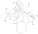
도 1은 본 발명의 실시예에 따른 세탁장치를 나타낸 사시도이다.
도 2는 본 발명의 일실시예에 따른 세탁장치의 내부구조를 나타낸 단면도이다.
도 3은 본 발명의 일실시예에 따른 세탁장치의 주요부를 나타낸 분해 사시도이다.
도 4는 본 발명의 일실시예에 따른 캐비닛 도어락 및 터브 도어락을 나타낸 단면도이다.
도 5는 본 발명의 일실시예에 따른 캐비닛 도어락을 나타낸 단면도이다.
도 6은 본 발명의 일실시예에 따른 캐비닛 도어락 및 터브 도어락의 연동구조를 나타낸 간략도이다.
도 7은 본 발명의 일실시예에 따른 터브 도어락을 나타낸 사시도이다.
도 8은 본 발명의 일실시예에 따른 터브 도어락을 나타낸 분해 사시도이다.
도 9 내지 도 11은 본 발명의 일실시예에 따른 세탁장치의 도어 개폐를 나타낸 작동도이다.1 is a perspective view showing a washing machine according to an embodiment of the present invention.
2 is a cross-sectional view showing the internal structure of a washing machine according to an embodiment of the present invention.
3 is an exploded perspective view showing a main part of a washing machine according to an embodiment of the present invention.
4 is a cross-sectional view showing a cabinet door lock and a tub door lock according to an embodiment of the present invention.
5 is a cross-sectional view showing a cabinet door lock according to an embodiment of the present invention.
6 is a simplified diagram showing the interlocking structure of the cabinet door lock and the tub door lock according to an embodiment of the present invention.
7 is a perspective view showing a tub door lock according to an embodiment of the present invention.
8 is an exploded perspective view showing a tub door lock according to an embodiment of the present invention.
9 to 11 are operational views showing opening and closing the door of the washing machine according to an embodiment of the present invention.
본 발명의 이점 및 특징, 그리고 그것들을 달성하는 방법은 첨부되는 도면과 함께 상세하게 후술되어 있는 실시예들을 참조하면 명확해질 것이다. 그러나 본 발명은 이하에서 개시되는 실시예들에 한정되는 것이 아니라 서로 다른 다양한 형태로 구현될 수 있으며, 단지 본 실시예들은 본 발명의 개시가 완전하도록 하고, 본 발명이 속하는 기술분야에서 통상의 지식을 가진 자에게 발명의 범주를 완전하게 알려주기 위해 제공되는 것이며, 본 발명은 청구항의 범주에 의해 정의될 뿐이다. 명세서 전체에 걸쳐 동일 참조 부호는 동일 구성 요소를 지칭한다.Advantages and features of the present invention and methods of achieving them will become apparent with reference to the embodiments described below in detail in conjunction with the accompanying drawings. However, the present invention is not limited to the embodiments disclosed below, but may be implemented in various different forms, and only these embodiments allow the disclosure of the present invention to be complete, and common knowledge in the art to which the present invention pertains It is provided to fully inform those who have the scope of the invention, and the present invention is only defined by the scope of the claims. Like reference numerals refer to like elements throughout.
이하, 첨부된 도면을 참조하여 본 발명의 일실시예에 따른 세탁장치를 상세히 설명한다.Hereinafter, a washing machine according to an embodiment of the present invention will be described in detail with reference to the accompanying drawings.
본 발명을 설명함에 있어서, 정의되는 각 구성요소들의 명칭은 본 발명에서의 기능을 고려하여 정의 내려진 것이다. 따라서 본 발명의 기술적 구성요소를 한정하는 의미로 이해되어서는 아니 될 것이다. 또한, 각 구성요소에 정의된 각각의 명칭들은 당업계에서 다른 명칭으로 호칭 될 수 있다. In describing the present invention, the names of each defined component are defined in consideration of functions in the present invention. Therefore, it should not be construed as limiting the technical components of the present invention. In addition, each name defined for each component may be called another name in the art.
먼저 첨부한 도면을 참조하여 본 발명의 일실시예에 따른 세탁장치를 간략히 설명한다. First, a washing machine according to an embodiment of the present invention will be briefly described with reference to the accompanying drawings.
도 1은 본 발명의 실시예에 따른 세탁장치를 나타낸 사시도이고, 도 2는 본 발명의 일실시예에 따른 세탁장치의 내부구조를 나타낸 단면도이고, 도 3은 본 발명의 일실시예에 따른 세탁장치의 주요부를 나타낸 분해 사시도이다.1 is a perspective view showing a washing machine according to an embodiment of the present invention, FIG. 2 is a cross-sectional view showing the internal structure of the washing machine according to an embodiment of the present invention, and FIG. 3 is a washing machine according to an embodiment of the present invention. It is an exploded perspective view showing the main part of the device.
도시한 바와 같이 본 발명에 따른 세탁장치(100)는 외형을 형성하는 캐비닛(110)과, 캐비닛(110) 내측에 댐퍼/스프링과 같은 서스펜션(미도시)에 의해 지지되며 세탁수가 저장되는 터브(150)와, 터브(150) 내측에 세탁물이 적재되며 회전가능하게 구비되는 드럼(180)과, 드럼(180)을 회전시키는 구동부(190)를 구비한다. As shown, the
캐비닛(110)은 세탁장치의 전방을 형성하는 전방 캐비닛(111), 좌/우측을 형성하는 측면 캐비닛(116), 상면을 형성하는 상면 캐비닛(117) 등으로 구비될 수 있다.The
여기서 전방 캐비닛(111)의 중앙부에는 드럼(180)의 적재공간으로 세탁물을 투입하기 위한 캐비닛 투입구(113) 및 캐비닛 투입구(113)를 개폐하기 위한 캐비닛 도어(120)가 구비된다. 여기서, 캐비닛 투입구(113)의 일측에는 캐비닛 도어의 잠금 상태를 설정하는 캐비닛 도어락(130)(도 4참고)이 구비된다.Here, a
한편, 전방 캐비닛(111)의 상측(즉, 캐비닛 투입구(113)의 상측)에는 세탁장치(100)의 전반적인 작동을 제어 및 표시하기 위한 조작부 및 표시부가 구비되는 컨트롤 패널(112)이 더 구비될 수 있다.On the other hand, on the upper side of the front cabinet 111 (that is, the upper side of the cabinet inlet 113), a
터브(150)는 캐비닛(110)의 캐비닛 투입구(113)와 분리된 상태로 캐비닛 투입구(113)의 연장선상에 위치하여 세탁물의 투입을 위한 터브 투입구(151)가 형성되며, 터브 투입구(151)의 일측에는 터브 투입구(151)를 개폐하는 터브 도어(160)가 구비된다. The
본 발명은 캐비닛 도어(120) 및 터브 도어(160)에 관련된 것으로, 다른 구성부(예를 들어 드럼(180), 서스펜션, 급수부, 배수부 등)에 대한 상세한 설명은 생략하도록 한다. The present invention relates to the
캐비닛 도어(120)는 캐비닛 투입구(113)의 일측에 회동되어 개방되도록 힌지 결합되며, 캐비닛 도어(120)의 힌지 결합되는 부분의 대향되는 측에는 사용자가 캐비닛 도어(120)를 개폐하기 위한 손잡이부(123)가 형성된다.The
터브(150)는 전방 상/하부로 터브(150)의 질량을 증가시켜 터브(150)의 진동을 방지하기 위한 상/하부 웨이트 밸런서(153a, 153b)가 구비되며, 터브(150)의 전방에 형성된 터브 투입구(151)의 일측에는 캐비닛(110)과 분리되어 터브(150)의 터브 투입구(151)를 개폐하는 터브 도어(160)가 회동 가능하게 구비된다.The
터브 투입구(151)는 전방 캐비닛(111) 측으로 돌출되는 링 형태의 림부(152)가 형성된다. 한편, 터브 도어(160)는 림부(152)의 일측에 회동 가능하도록 힌지 결합되며, 림부(152)의 타측에는 터브 도어(160)의 잠금 상태를 설정하는 터브 도어락(170)(도 4 참고)이 구비된다.The
한편, 캐비닛 도어락(130)과 터브 도어락(170)의 사이에는 터브 도어락(170)의 잠금 상태를 해제하는 터브 도어락 릴리서(140)(도 6 참고)가 구비된다. 터브 도어락 릴리서(140)에 대해서는 캐비닛 도어(120)와 터브 도어(160)의 개폐구조 설명시 상세히 설명하도록 한다. On the other hand, between the
상술한 터브 도어(160), 터브 도어락(170)의 경우 캐비닛(110)과의 구조적으로 연결되는 것은 아니며, 터브(150)는 캐비닛(110)과 구조적으로 서스펜션(미도시)에 의해 독립적으로 지지된다. The above-described
즉, 기존의 세탁장치(100)에서와 같이 터브(150)와 캐비닛(110) 사이에 서스펜션 이외의 가스켓이 구비되지 않아 터브(150)의 진동이 온전히 서스펜션만으로 지지하여 터브(150)의 진동이 캐비닛(110)으로 전달되는 것을 현저히 줄일 수 있다. That is, as in the
이하, 첨부한 도면을 참고하여 본 발명의 일실시예 따른 캐비닛 도어와 터브 도어의 개폐구조를 상세히 설명하도록 한다. Hereinafter, an opening and closing structure of a cabinet door and a tub door according to an embodiment of the present invention will be described in detail with reference to the accompanying drawings.
도 4는 본 발명의 일실시예에 따른 캐비닛 도어락 및 터브 도어락을 나타낸 단면도이고, 도 5는 본 발명의 일실시예에 따른 캐비닛 도어락을 나타낸 단면도이고, 도 6은 본 발명의 일실시예에 따른 캐비닛 도어락 및 터브 도어락의 연동구조를 나타낸 간략도이다. Figure 4 is a cross-sectional view showing a cabinet door lock and a tub door lock according to an embodiment of the present invention, Figure 5 is a cross-sectional view showing a cabinet door lock according to an embodiment of the present invention, Figure 6 is according to an embodiment of the present invention It is a simplified diagram showing the interlocking structure of a cabinet door lock and a tub door lock.
도시한 바와 같이 캐비닛 도어(120)는 전방 캐비닛(111)의 캐비닛 투입구(113)의 일측에 회동가능하게 구비되어 캐비닛 투입구(113)를 개폐하기 위한 것으로, 캐비닛 도어(120)의 외측을 형성하는 외측 프레임(122)과, 캐비닛 도어(120)의 내측을 형성하는 내측 프레임(121)과, 캐비닛 도어(120)를 전방 캐비닛에 대하여 회동 가능하게 지지하는 캐비닛 힌지부(미도시)를 구비한다. As shown, the
여기서, 캐비닛 도어(120)의 외측 프레임(122)과 내측 프레임(121)은 볼트 등의 체결부재(미도시)에 의해 결합된다. 또한, 캐비닛 도어(120)의 외측 프레임(122)과 내측 프레임(121)은 세탁장치(100)의 내부 작동상태를 확인할 수 있도록 투명재질로 형성될 수 있다, 다르게는 캐비닛 도어(120)의 외측 프레임(122)과 내측 프레임(121)에 별도의 투광창(미도시)이 더 구비될 수도 있다.Here, the
한편, 캐비닛 도어(120)의 외측면(즉, 외측 프레임(122)은 외측면)은 전방 캐비닛(111)의 외형을 따라 전방 캐비닛(111)의 연장면으로 형성되는 것이 바람직하며, 힌지부의 대향되는 측에는 캐비닛 도어(120)를 개방하기 위한 손잡이부(123)가 형성될 수 있다. On the other hand, the outer surface of the cabinet door 120 (that is, the
여기서, 캐비닛 도어(120)의 외측 프레임(122)에 형성되는 손잡이부(123)의 내측에는 캐비닛 도어(120)가 캐비닛 투입구(113)를 폐쇄할 때 캐비닛 도어락(130)에 거치되어 고정되고, 사용자의 작동에 의해 캐비닛 도어락(130)의 잠김을 해제하는 해제 레버(124)가 구비된다.Here, on the inside of the
한편, 해제 레버(124)에는 캐비닛 도어락(130)에 삽입되어 고정되는 후크(125)가 구비되며, 해제 레버(124)는 사용자가 캐비닛 도어(120)를 개방되는 방향으로 힘을 가함에 따라 캐비닛 도어(120)의 후크(125)를 회동시켜 캐비닛 도어락(130)에서 이탈시키도록 구비된다.On the other hand, the
즉, 해제 레버(124)와 후크(125)는 동일한 하나의 회전축에 의해 힌지 결합되며 회전축에 구비되는 탄성 스프링(미도시)에 의해 후크(125)가 후크 고정부(132)에 거치되는 방향으로 탄성 지지되고, 해제 레버(124)는 후크(125)가 후크 고정부(132)에 거치되는 방향으로 회동된 상태로 탄성 지지되도록 구비된다. That is, the
여기서, 해제 레버(124)에는 해제 레버(124)가 캐비닛 도어(120)를 개방하는 방향으로 회전될 때만 후크(125)에 회전력을 전달하도록 후크에 거치되는 후크 지지부(126)가 형성된다. Here, the
한편, 캐비닛 도어(120)의 외측 프레임(122)에 형성되는 손잡이부(123)의 위치에 대응되어 내측 프레임에는 자기력을 발생시키는 마그네틱(121a)이 더 구비될 수 있다. 여기서, 마그네틱(121a)은 후술할 터브 도어(160)의 금속플레이트(164a)에 자기력을 형성하기 위한 것으로, 마그네틱(121a)의 자기력이 터브 도어(160)의 금속플레이트(164a)에 작용함에 따라 터브 도어(160)가 캐비닛 도어(120)에 부착되어 캐비닛 도어(120)와 같이 회동되도록 한다. Meanwhile, a magnetic 121a for generating a magnetic force may be further provided in the inner frame corresponding to the position of the
캐비닛 도어락(130)은 캐비닛 도어락 장착부(115)의 내측에 설치되어 캐비닛 도어가 닫혔을 경우 전방 캐비닛(110)의 외부로 노출되지 않도록 설치된다. The
한편, 캐비닛 도어락(130)은 전방 캐비닛(110)의 캐비닛 도어락 장착부(115) 내부에 고정되는 후크 고정부(132)와, 캐비닛 도어락 장착부(115) 외측에 캐비닛 도어(120)의 후크(125)의 삽입방향으로 유동 가능하게 후크 고정부(132)에 체결되는 후크 삽입부(131)와 후크 삽입부(131)를 캐비닛 도어(120)의 후크(125)의 삽입방향의 반대 방향으로 탄성 지지하는 스프링(127) 및 후크 고정부(132)에 고정된 캐비닛 도어(120)의 후크(125)의 잠금 상태가 해제될 때 캐비닛 도어(120)의 후크(125)의 삽입 및 이탈을 감지하는 감지부(133)를 구비한다. 여기서 감지부(133)는 터브 도어락 릴리서(140)의 작동을 위한 전기적 신호를 발생한다.On the other hand, the
터브 도어(160)는 터브(150)의 터브 투입구(151)의 일측에 회동가능하게 구비되어 터브 투입구(151)를 개폐하기 위한 것으로, 터브 도어(160)의 외측을 형성하는 외측 프레임(164)과, 캐비닛 도어(120)의 내측을 형성하는 내측 프레임(121)과, 내측 프레임(121)의 외주면에 구비되어 터브 투입구(151)와의 씰링을 형성하는 가스켓(161a)이 구비될 수 있다. 또한, 터브 도어(160)를 터브 투입구(151)에 대하여 회동 가능하게 지지하는 터브 힌지부(미도시)를 구비한다. The
여기서, 터브 도어(160)의 외측 프레임(164)과 내측 프레임(161)은 볼트 등의 체결부재(미도시)에 의해 결합된다. 또한, 터브 도어(160)의 외측 프레임(164)과 내측 프레임(161)은 드럼(180)의 내부 상태를 확인할 수 있도록 투명재질로 형성될 수 있다, 다르게는 터브 도어(160)의 외측 프레임(164)과 내측 프레임(161)에 별도의 투광창(미도시)이 더 구비될 수도 있다.Here, the
한편, 터브 도어(160)의 힌지부의 대향되는 내측 프레임(161)에는 터브 도어락(170)에 체결되는 걸림홀이 형성되는 걸림 후크(162)가 구비된다. 걸림 후크(162)는 터브 도어(160)의 내측 프레임(161)에서 터브 도어락(170) 측으로 소정 거리 연장되어 형성된다. On the other hand, the
또한, 터브 도어(160)의 내측 프레임(161)의 걸림 후크(162)에 대향되는 터브 도어(160)의 외측 프레임(164)에는 캐비닛 도어(120)의 마그네틱(121a)에 대응하는 금속플레이트(164a)가 구비된다. 여기서, 터브 도어(160)의 금속플레이트(164a)는 캐비닛 도어(120)와 터브 도어(160)가 각각 캐비닛 투입구(113)와 터브 투입구(151)를 폐쇄하고 있을 때 캐비닛 도어(120)의 마그네틱(121a)의 자기력이 미치는 위치에 설치될 수 있다. In addition, the
따라서, 캐비닛 도어(120)와 터브 도어(160)가 각각 캐비닛 투입구(113)와 터브 투입구(151)를 폐쇄하고 있을 때 캐비닛 도어(120)와 터브 도어(160)의 잠금 상태가 해제될 경우 터브 도어(160)의 금속플레이트(164a)가 캐비닛 도어(120)의 마그네틱(121a)의 자기력에 의해 이동되어 마그네틱(121a)에 부착될 수 있다.Therefore, when the
즉, 캐비닛 도어(120)와 터브 도어(160)의 잠금 상태가 해제되면, 터브 도어(160)의 금속플레이트(164a)가 캐비닛 도어(120)의 마그네틱(121a)에 부착되고, 터브 도어(160)가 캐비닛 도어(120) 측으로 회동되면서 캐비닛 도어(120)와 터브 도어(160)가 같이 회동 될 수 있다. That is, when the lock state of the
여기서, 캐비닛 도어(120)에 마그네틱(121a)이 구비되고, 터브 도어(160)에 금속플레이트(164a)가 구비되는 것으로 설명되었으나, 터브 도어(160)에 마그네틱(121a)이 구비되고, 캐비닛 도어(120)에 금속플레이트(164a)가 구비되도록 할 수도 있을 것이다. Here, it has been described that the magnetic 121a is provided in the
한편, 터브 도어락 릴리서(140)는 캐비닛 도어락(130)의 감지부(133)에서 캐비닛 도어(120)의 개방이 감지됨에 따라 작동되는 솔레노이드(141)와 솔레노이드(141)의 작동에 따라 회동되는 회동부(142)와, 회동부(142)의 회전에 따라 회동부(142)의 회전력을 터브 도어락(170)으로 전달하는 인장 케이블(143)을 구비한다. On the other hand, the tub
이러한, 터브 도어락 릴리서(140)는 캐비닛 도어(120)가 개폐됨에 따라 캐비닛 도어락(130)의 감지부(133)에서 감지하는 캐비닛 도어(120)의 개폐에 따라 솔레노이드(141)가 작동되어 인장 케이블(143)에 연결된 터브 도어락의 회전 후크를 회전시킨다. In the tub
한편, 상술한 설명에서는 터브 도어락 릴리서(140)와 터브 도어락(170)을 분리하여 설명하였으나, 터브 도어락 릴리서(140)의 솔레노이드(141)를 터브 도어락(170)에 직접 구비하도록 하여 캐비닛 도어락(130)의 감지부(133)의 신호를 이용하여 직접 터브 도어락(170)이 연동되도록 할 수도 있을 것이다. Meanwhile, in the above description, the tub
이하, 첨부한 도면을 참조하여 터브 도어락에 대하여 상세히 설명하도록 한다. Hereinafter, the tub door lock will be described in detail with reference to the accompanying drawings.
도 7은 본 발명의 일실시예에 따른 터브 도어락을 나타낸 사시도이고, 도 8은 본 발명의 일실시예에 따른 터브 도어락을 나타낸 분해 사시도이다. 7 is a perspective view showing a tub door lock according to an embodiment of the present invention, Figure 8 is an exploded perspective view showing a tub door lock according to an embodiment of the present invention.
터브 도어락(170)은 터브 투입구(151)의 일측에 구비되어 캐비닛 도어(120)의 개폐에 따라 터브 도어(160)의 잠금상태를 설정하기 위한 것이다. 이러한 터브 도어락(170)은 터브(150)의 전방 일측에 체결되기 위한 고정 몸체부(171)와, 고정 몸체부(171)에 회전가능하게 구비되어 터브 도어(160)에 구비되는 걸림 후크(162)의 걸림홀(162a)에 거치되는 회전 후크(174)가 구비된다. 여기서 회전 후크(174)는 터브 도어락 릴리서(140)에 구비되는 인장 케이블(143)이 연결된다. The
한편, 고정 몸체부(171)는 터브(150)에 고정됨과 동시에 회전 후크(174)가 회전되도록 회동공간(172)을 형성하는 회전축단(173)이 구비된다, 회전축단(173)은 고정 몸체부(171)가 터브(150)에 체결되었을 때 터브 투입구(151) 중심방향으로 연장되어 형성된다. 회전축단(173)의 중앙측에는 회전 후크(174)가 회전가능 하게 결합되기 위한 고정홀(173b)이 형성된다.On the other hand, the fixed
고정 몸체부(171)의 상부에는 고정 몸체부(171)가 터브(150)에 체결될 때 터브(150)와의 간격을 유지하기 위한 걸림턱이 형성되며, 회전축단(173)에 대향되는 방향으로 인장 케이블(143)의 이동을 안내하기 위한 케이블 가이드(171a)가 연장되어 형성된다. 케이블 가이드(171a)에는 인장 케이블(143)이 삽입되는 가이드 홈(171b)이 더 형성될 수 있다. At the upper portion of the fixed
또한, 회전축단(173)의 일측에는 회전 후크(174)가 인장 케이블(143)에 의해 회전될 때 일정 각도 이상 회전되지 않도록 회전 후크(174)가 거치되는 걸림돌기(173a)가 더 형성될 수 있다. In addition, at one side of the
한편, 회전 후크(174)는 회전축단(173)의 고정홀(173b)에 회전가능하게 체결되며, 일측에 터브 도어(160)에 구비되는 걸림 후크(162)의 걸림홀(162a)에 삽입되는 후크 돌기(174a)를 구비한다. 여기서, 후크 돌기(174a)는 회전 후크(174)의 외측면에서 걸림홀(162a)측으로 회전될수록 반경이 작아지는 만곡 형태로 형성된다. On the other hand, the
여기서, 회전 후크(174)의 중심에는 회전홀(175)이 형성되며, 회전 후크(174)는 회전홀(175)에 삽입되어 고정홀(173b)에 체결되는 회전축(176)에 의해 회전축단(173)에 회전 가능하게 체결된다. 또한, 회전 후크(174)의 상면 중 후크 돌기(174a)에 대향되는 방향에는 터브 도어락 릴리서(140)의 인장 케이블(143)이 연결되는 걸림부(152)가 구비된다. Here, a rotation hole 175 is formed in the center of the
한편, 회전 후크(174)는 고정 몸체부(171)에 형성되는 회전축단(173)에 회전 가능하게 회전축(176)에 의해 회전 가능하게 체결됨과 동시에 회전축(176)과 회전 후크(174) 사이에 회전 후크(174)가 일방향(터브 도어(160)의 잠금을 해제하는 방향)으로 탄성력을 부여하는 토션 스프링(178)이 구비된다. On the other hand, the
따라서, 회전 후크(174)는 토션 스프링(178)에 의해 회전 후크(174)의 후크 돌기(174a)가 터브 도어(160)의 걸림 후크(162)에서 이탈되는 방향으로 항시 탄성지지된다. 그리고, 터브 도어락 릴리서(140)의 작동에 의해 인장 케이블(143)에 인장력이 작용함에 따라 회전 후크(174)의 후크 돌기(174a)가 터브 도어의 걸림 후크(162)에 삽입되는 방향으로 회전된다. Accordingly, the
여기서, 후크 돌기(174a)는 회전 후크(174)의 외측면에서 걸림홀(162a)측으로 회전될수록 반경이 작아지도록 만곡되어 형성된다. 따라서 회전 후크(174)가 일방향(터브 도어(160)가 잠기는 방향)으로 회전될 수 록 터브 도어(160)를 보다 강한 체결력으로 체결할 수 있다.Here, the
즉, 후크 돌기(174a)는 터브 도어(160)의 걸림 후크(162)에 거치되었을 때 후크 돌기(174a)와 걸림 후크(162)가 접하는 위치는 회전 후크(174)의 중심을 기준으로 회전 후크(174)가 회전될 수 록 회전 후크(174)의 중심에 가까워지게 된다. That is, when the
따라서, 회전 후크(174)가 걸림 후크(162)에 삽입되는 방향으로 회전될 수로 터브 도어(160)가 터브 투입구(151)를 닫는 방향으로 더욱 가압되며, 터브 도어(160)는 더욱 강한 밀폐력으로 터브 투입구(151)를 밀폐하게 된다.Therefore, as the
한편, 터브 도어락(170)은 터브 도어(160)의 잠금 상태를 해제하기 위하여 인장 케이블에 인장력을 발생시키는 별도의 작동체(예를 들어 솔레노이드 등)가 구비될 수 있으며, 작동체는 캐비닛 도어락(130)의 감지부(미도시)와 전기적으로 연결되어 캐비닛 도어락(130)의 캐비닛 도어(120) 잠금 해제에 연동되어 터브 도어(160)의 잠금을 해제할 수도 있다. On the other hand, the
이하, 첨부한 도면을 참조하여 본 발명의 일실시예에 따른 세탁장치의 도어 개폐과정을 상세히 설명하도록 한다. Hereinafter, a door opening and closing process of a washing machine according to an embodiment of the present invention will be described in detail with reference to the accompanying drawings.
한편, 본 발명의 일실시예에 따른 세탁장치(100)의 작동을 첨부한 도면을 통하여 상세히 설명한다. 이하에서 언급되는 각각의 요소들은 상술한 설명과 도면을 참조하여 이해하여야 한다. 한편, 본 발명의 주요 요지는 캐비닛 도어(120)와 터브 도어(160)의 잠금/해제에 있다. 따라서 세탁장치(100)의 일반적인 작동 설명(예를 들어 세탁행정, 헹굼행정, 탈수행정 등)은 생략하도록 한다.Meanwhile, the operation of the
도 9 내지 도 10은 본 발명의 일실시예에 따른 세탁장치의 도어 개폐를 나타낸 작동도이다. 여기서, 도 9는 캐비닛 도어(120)와 터브 도어(160)가 개방된 상태를 나타낸 것이며, 도 10은 캐비닛 도어(120)는 폐쇄되고 터브 도어(160)는 폐쇄되기 전 상태를 나타낸 것이며, 도 11은 캐비닛 도어(120)와 터브 도어(160) 모두가 폐쇄된 상태를 나타낸 것이다. 9 to 10 are operational views showing the door opening and closing of the washing machine according to an embodiment of the present invention. Here, FIG. 9 shows a state in which the
도 9에 도시한 바와 같이 캐비닛 도어(120)와 터브 도어(160)는 각각 캐비닛 투입구(113)와 터브 투입구(151)를 개방한 상태로 세탁장치(100)의 외측 방향으로 회동된 상태이다. As shown in FIG. 9 , the
이에 사용가가 캐비닛 도어(120)를 캐비닛 투입구(113)를 폐쇄하는 방향으로 회전시킴에 따라 캐비닛 도어(120)의 내측 프레임(121)에 구비된 마그네틱(121a)에 터브 도어(160)의 외측 프레임(164)에 구비된 금속플레이트(164a)가 마그네틱(121a)의 자기력에 의해 부착된다. Accordingly, as the user rotates the
따라서 캐비닛 도어(120)와 터브 도어(160)가 마그네틱(121a)과 금속플레이트(164a)에 의해 밀착된 상태에서 캐비닛 투입구(113)와 터브 투입구(151)를 폐쇄하는 방향으로 회전될 수 있다. Accordingly, the
이후, 도 10 내지 도 11에 도시한 바와 같이 캐비닛 도어(120)와 터브 도어(160)가 회동됨에 따라 캐비닛 도어(120)의 후크(125)가 먼저 도어 장착부(114)에 구비되는 캐비닛 도어락(130)에 삽입되면서 캐비닛 도어락(130)에 의해 고정된다. 이때, 터브 도어(160)는 터브 도어(160)의 금속플레이트(164a)가 캐비닛 도어(120)의 마그네틱(121a)의 자기력에 캐비닛 도어(120)에 부착된 상태를 유지한다. Thereafter, as the
한편, 캐비닛 도어(120)의 후크(125)가 캐비닛 도어락(130)에 삽입됨에 따라 캐비닛 도어락(130)의 감지부(133)가 캐비닛 도어(120)의 후크(125)가 삽입되는 것을 감지하고, 터브 도어락 릴리서(140)는 감지부(133)의 감지에 따라 솔레노이드(141)가 작동하며, 솔레노이드(141)가 작동함에 따라 회동부(142)가 회동되어 인장 케이블(143)에 인장력을 부여한다. On the other hand, as the
인장 케이블(143)에 인장력이 부여됨에 따라 인장 케이블(143)이 연결된 터브 도어락(170)의 회전 후크(174)가 회전되면서, 회전 후크(174)의 후크 돌기(174a)의 끝 단부가 터브 도어(160)의 걸림 후크(162)로 근접하게 되며, 회전 후크(174)의 후크 돌기(174a)가 걸림 후크(162)의 걸림홀(162a)에 삽입된다. As the tensile force is applied to the
여기서, 걸림홀(162a)에 삽입된 회전 후크(174)의 후크 돌기(174a)는 반경방향 가장 끝단부터 삽입되며, 터브 도어락 릴리서(140)의 작동에 의해 회전 후크(174)가 회전됨에 따라 후크 돌기(174a)의 끝단에서 후크 돌기(174a)의 반경방향 내측으로 이동된다. Here, the
한편, 후크 돌기(174a)의 경우 회전 후크(174)의 외측면에서 걸림홀(162a)측으로 이동될수록 반경이 작아지도록 만곡되어 형성되어 있다. 따라서 회전 후크(174)가 더 회정될 수 록 터브 도어(160)를 보다 강한 체결력으로 체결할 수 있다.On the other hand, in the case of the
한편, 사용자가 세탁장치(100)의 캐비닛 도어(120)를 개방하기 위해서는 전방 캐비닛(111)의 캐비닛 도어(120)에 형성된 손잡이부(123)를 취부하여 캐비닛 도어(120)를 개방하는 방향으로 압력을 가한다. On the other hand, in order for the user to open the
이에 손잡이부(123)의 내측에 구비되는 손잡이부(123)의 해제 레버(124)가 회동되면서 캐비닛 도어(120)의 후크(125)의 잠금상태가 해제되고, 캐비닛 도어락(130)의 감지부(133)가 캐비닛 도어(120)의 후크(125)의 잠금 해제를 감지한다. Accordingly, as the
이에, 터브 도어락 릴리서(140)의 솔레노이드(141)가 감지부(133)의 감지에 따라 작동이 중지되면서 회동부(142)가 원래의 위치로 회동된다. 회동부(142)가 회동됨에 따라 회동부(142)와 인장 케이블(143)에 연결된 터브 도어락(170)의 회전 후크(174)가 토션 스프링(178)에 의해 터브 도어(160)의 걸림 후크(162)에서 이탈되는 방향으로 회전되면서 터브 도어(160)의 잠금상태가 해제된다. Accordingly, as the
여기서, 터브 도어락(170)에 의한 터브 도어(160)의 잠금 상태가 해제됨에 따라 터브 도어(160)는 터브 도어(160)의 금속플레이트(164a)가 캐비닛 도어(120)의 마그네틱(121a)의 자기력에 캐비닛 도어(120) 측으로 회전되면서, 캐비닛 도어(120)와 밀착되어 회전될 수 있다.Here, as the locking state of the
즉, 사용자가 캐비닛 도어(120)의 손잡이부(123)를 취부하여 캐비닛 도어(120)의 잠금 상태를 해제함에 따라 터브 도어(160)의 잠금 상태가 연동되어 해제되고, 잠금 상태가 해제된 터브 도어(160)는 캐비닛 도어(120)에 구비되는 마그네틱(121a)에 의해 캐비닛 도어(120)에 밀착되어 캐비닛 도어(120)와 같이 회동되어 캐비닛 투입구(113)와, 터브 투입구(151)가 개방될 수 있다. That is, as the user releases the lock state of the
상술한 바와 같은 본 발명의 일실시예에 따른 세탁장치에 따르면, 터브의 진동 및 소음이 캐비닛으로 전달되는 것을 방지함으로써 캐비닛에서 발생되는 진동 및 소음을 저감하여 사용자에게 불쾌한 진동 및 소음이 전해지는 것으로 방지할 수 있다. According to the washing machine according to an embodiment of the present invention as described above, by preventing the vibration and noise of the tub from being transmitted to the cabinet, the vibration and noise generated in the cabinet are reduced so that unpleasant vibration and noise are transmitted to the user. can be prevented
또한, 본 발명의 일실시예에 따른 세탁장치에 따르면 캐비닛 도어의 잠금/해제구조를 개선하여 캐비닛 도어 및 터브 도어의 개폐를 용이하게 함과 동시에 캐비닛 도어에 연동되어 터브 도어가 개폐될 수 있다. In addition, according to the washing machine according to an embodiment of the present invention, the locking/unlocking structure of the cabinet door is improved to facilitate opening and closing of the cabinet door and the tub door, and at the same time, the tub door can be opened and closed by interlocking with the cabinet door.
이상에서 살펴본 바와 같이 본 발명의 바람직한 실시예에 대해 상세히 기술되었지만, 본 발명이 속하는 기술분야에 있어서 통상의 지식을 가진 사람이라면, 첨부된 청구 범위에 정의된 본 발명의 정신 및 범위를 벗어나지 않으면서 본 발명을 여러 가지로 변형하여 실시할 수 있을 것이다. 따라서 본 발명의 앞으로의 실시예들의 변경은 본 발명의 기술을 벗어날 수 없을 것이다.Although the preferred embodiment of the present invention has been described in detail as described above, those of ordinary skill in the art to which the present invention pertains, without departing from the spirit and scope of the present invention as defined in the appended claims The present invention may be practiced with various modifications. Accordingly, modifications of future embodiments of the present invention will not depart from the technology of the present invention.
100: 세탁장치 110: 캐비닛
111: 전방 캐비닛 114: 도어 장착부
115: 캐비닛 도어락 장착부 120: 캐비닛 도어
121: 내측 프레임 121a: 마그네틱
122: 외측 프레임 123: 손잡이부
124: 해제 레버 125: 후크
130: 캐비닛 도어락 133: 감지부
140: 터브 도어락 릴리서 143: 인장 케이블
150: 터브 152: 림부
160: 터브 도어 161: 내측 프레임
162: 걸림 후크 164: 외측 프레임
164a: 금속플레이트 170: 터브 도어락
171: 고정 몸체부 173: 회전축단
171a: 케이블 가이드 174: 회전 후크
174a: 후크 돌기 178; 토션 스프링100: washing machine 110: cabinet
111: front cabinet 114: door mounting portion
115: cabinet door lock mounting portion 120: cabinet door
121:
122: outer frame 123: handle portion
124: release lever 125: hook
130: cabinet door lock 133: detection unit
140: tub door lock releaser 143: tension cable
150: tub 152: rim
160: tub door 161: inner frame
162: hook hook 164: outer frame
164a: metal plate 170: tub door lock
171: fixed body 173: rotation shaft end
171a: cable guide 174: rotating hook
174a:
Claims (14)
상기 캐비닛 내에 설치되며, 상기 캐비닛 투입구와 연장선상에 위치치하는 터브 투입구가 형성되는 터브와,
상기 캐비닛에 설치되며 상기 캐비닛 투입구를 개폐하는 캐비닛 도어와,
상기 터브에 설치되며 상기 터브 투입구를 개폐하는 터브 도어와,
상기 캐비닛 도어의 잠금상태를 설정함과 동시에 상기 캐비닛 도어의 개폐상태를 감지하는 캐비닛 도어락과,
상기 캐비닛 도어의 개폐에 따라 상기 터브 도어의 잠금상태를 설정하는 터브 도어락을 구비하는 것을 특징으로 하는 세탁장치.A cabinet including a front cabinet in which the cabinet inlet is formed;
a tub installed in the cabinet and having a tub inlet positioned on an extension line from the cabinet inlet;
a cabinet door installed in the cabinet and opening and closing the cabinet inlet;
a tub door installed in the tub to open and close the tub inlet;
a cabinet door lock configured to set a lock state of the cabinet door and detect an open/close state of the cabinet door;
and a tub door lock configured to set a locking state of the tub door according to the opening and closing of the cabinet door.
상기 후크가 구비되며 상기 캐비닛 투입구에 접하는 내측면을 형성하는 내측 프레임과,
상기 내측 프레임에 체결되어 외측면을 형성하며 상기 후크를 회동시키는 해제 레버가 구비되는 손잡이부가 포함되는 외측 프레임을 포함하는 것을 특징으로 하는 세탁장치. The method of claim 1, wherein the cabinet door is
an inner frame provided with the hook and forming an inner surface in contact with the cabinet inlet;
and an outer frame fastened to the inner frame to form an outer surface and including a handle portion provided with a release lever for rotating the hook.
상기 터브 투입구에 접하는 내측면을 형성하고, 상기 터브 도어락에 거치되는 걸림후크를 구비하는 터브 내측 프레임과,
상기 터브 내측 프레임에 체결되어 외측면을 형성하는 터브 외측 프레임을 포함하는 것을 특징으로 하는 세탁장치.13. The method of claim 12, wherein the tub door
a tub inner frame forming an inner surface in contact with the tub inlet and having a hook hook mounted on the tub door lock;
and a tub outer frame fastened to the inner frame of the tub to form an outer surface.
Priority Applications (6)
| Application Number | Priority Date | Filing Date | Title |
|---|---|---|---|
| KR1020190167511A KR20210076384A (en) | 2019-12-16 | 2019-12-16 | Washing machine |
| PCT/KR2020/018411 WO2021125773A1 (en) | 2019-12-16 | 2020-12-16 | Laundry device |
| CN202080080183.6A CN114729491B (en) | 2019-12-16 | 2020-12-16 | Washing device |
| EP20902728.3A EP4079957A4 (en) | 2019-12-16 | 2020-12-16 | Laundry device |
| US17/769,184 US11885060B2 (en) | 2019-12-16 | 2020-12-16 | Laundry device |
| AU2020409825A AU2020409825B2 (en) | 2019-12-16 | 2020-12-16 | Laundry device |
Applications Claiming Priority (1)
| Application Number | Priority Date | Filing Date | Title |
|---|---|---|---|
| KR1020190167511A KR20210076384A (en) | 2019-12-16 | 2019-12-16 | Washing machine |
Publications (1)
| Publication Number | Publication Date |
|---|---|
| KR20210076384A true KR20210076384A (en) | 2021-06-24 |
Family
ID=76477532
Family Applications (1)
| Application Number | Title | Priority Date | Filing Date |
|---|---|---|---|
| KR1020190167511A Pending KR20210076384A (en) | 2019-12-16 | 2019-12-16 | Washing machine |
Country Status (6)
| Country | Link |
|---|---|
| US (1) | US11885060B2 (en) |
| EP (1) | EP4079957A4 (en) |
| KR (1) | KR20210076384A (en) |
| CN (1) | CN114729491B (en) |
| AU (1) | AU2020409825B2 (en) |
| WO (1) | WO2021125773A1 (en) |
Cited By (2)
| Publication number | Priority date | Publication date | Assignee | Title |
|---|---|---|---|---|
| WO2025135651A1 (en) * | 2023-12-22 | 2025-06-26 | 엘지전자 주식회사 | Clothing treatment apparatus |
| WO2025135648A1 (en) * | 2023-12-22 | 2025-06-26 | 엘지전자 주식회사 | Clothing treatment apparatus |
Citations (1)
| Publication number | Priority date | Publication date | Assignee | Title |
|---|---|---|---|---|
| KR20110057920A (en) | 2009-11-25 | 2011-06-01 | 삼성전자주식회사 | Drum washing machine |
Family Cites Families (13)
| Publication number | Priority date | Publication date | Assignee | Title |
|---|---|---|---|---|
| JP2735943B2 (en) | 1990-11-21 | 1998-04-02 | 三洋電機株式会社 | Drum type washing machine |
| AU2003222525C1 (en) | 2002-04-10 | 2010-04-08 | Fisher & Paykel Appliances Limited | A laundry appliance |
| JP3968363B2 (en) * | 2004-12-27 | 2007-08-29 | 株式会社東芝 | Washing machine |
| IT1390904B1 (en) | 2008-07-01 | 2011-10-19 | Indesit Co Spa | MACHINE FOR THE TREATMENT OF TEXTILE HEADS, IN PARTICULAR A WASHING MACHINE |
| ATE528433T1 (en) | 2008-08-26 | 2011-10-15 | Electrolux Home Prod Corp | WASHING MACHINE |
| JP4711267B2 (en) * | 2008-08-28 | 2011-06-29 | シャープ株式会社 | Drum washing machine |
| KR101708679B1 (en) | 2009-09-14 | 2017-02-21 | 엘지전자 주식회사 | Drum type washing machine |
| KR101231027B1 (en) | 2010-10-26 | 2013-02-19 | 주식회사 대창 | washer |
| CN203782428U (en) * | 2014-01-26 | 2014-08-20 | 温州天健电器有限公司 | Door lock for washing machine |
| KR102390026B1 (en) | 2015-03-20 | 2022-04-25 | 엘지전자 주식회사 | Washing machine |
| JP6650135B2 (en) | 2015-08-25 | 2020-02-19 | 青島海爾洗衣机有限公司QingDao Haier Washing Machine Co.,Ltd. | Washing machine |
| KR20170135209A (en) | 2016-05-30 | 2017-12-08 | 엘지전자 주식회사 | Laundry Treating Apparatus and Control Method thereof |
| KR20180136106A (en) | 2017-06-14 | 2018-12-24 | 주식회사 대우전자 | Wall mounted washing machine and device for opening and closing door thereof |
-
2019
- 2019-12-16 KR KR1020190167511A patent/KR20210076384A/en active Pending
-
2020
- 2020-12-16 WO PCT/KR2020/018411 patent/WO2021125773A1/en unknown
- 2020-12-16 US US17/769,184 patent/US11885060B2/en active Active
- 2020-12-16 AU AU2020409825A patent/AU2020409825B2/en active Active
- 2020-12-16 EP EP20902728.3A patent/EP4079957A4/en active Pending
- 2020-12-16 CN CN202080080183.6A patent/CN114729491B/en active Active
Patent Citations (1)
| Publication number | Priority date | Publication date | Assignee | Title |
|---|---|---|---|---|
| KR20110057920A (en) | 2009-11-25 | 2011-06-01 | 삼성전자주식회사 | Drum washing machine |
Cited By (2)
| Publication number | Priority date | Publication date | Assignee | Title |
|---|---|---|---|---|
| WO2025135651A1 (en) * | 2023-12-22 | 2025-06-26 | 엘지전자 주식회사 | Clothing treatment apparatus |
| WO2025135648A1 (en) * | 2023-12-22 | 2025-06-26 | 엘지전자 주식회사 | Clothing treatment apparatus |
Also Published As
| Publication number | Publication date |
|---|---|
| EP4079957A4 (en) | 2024-01-24 |
| WO2021125773A1 (en) | 2021-06-24 |
| AU2020409825B2 (en) | 2024-01-04 |
| EP4079957A1 (en) | 2022-10-26 |
| US20230030540A1 (en) | 2023-02-02 |
| CN114729491B (en) | 2024-04-16 |
| CN114729491A (en) | 2022-07-08 |
| US11885060B2 (en) | 2024-01-30 |
| AU2020409825A1 (en) | 2022-08-11 |
Similar Documents
| Publication | Publication Date | Title |
|---|---|---|
| KR102390026B1 (en) | Washing machine | |
| US9951458B2 (en) | Washing machine | |
| KR102390027B1 (en) | Washing machine | |
| CA2711295C (en) | Washing machine lid assembly | |
| US10100457B2 (en) | Washing machine | |
| KR102317037B1 (en) | Washing machine | |
| KR20210076384A (en) | Washing machine | |
| US20070251023A1 (en) | Drum type washing machine and method for controlling the same | |
| KR20120043262A (en) | Washing machine | |
| KR20060040891A (en) | Drum door automatic switchgear of washing machine | |
| CN101280499A (en) | front load washing machine | |
| EP1842951B1 (en) | Locking device for the drum door of a laundry washing machine. | |
| KR102317036B1 (en) | Washing machine | |
| KR102390037B1 (en) | Washing machine | |
| KR102411843B1 (en) | Washing machine | |
| RU2796284C1 (en) | Laundry washing device | |
| US7290413B2 (en) | Washing machine having transient vibration sensor assembly | |
| KR102390028B1 (en) | Washing machine | |
| RU2798248C1 (en) | Device for treatment of laundry | |
| KR20210076385A (en) | Washing machine | |
| KR20040058997A (en) | Drum type washing machine with united cabinet/tub |
Legal Events
| Date | Code | Title | Description |
|---|---|---|---|
| PA0109 | Patent application |
Patent event code: PA01091R01D Comment text: Patent Application Patent event date: 20191216 |
|
| PG1501 | Laying open of application | ||
| A201 | Request for examination | ||
| PA0201 | Request for examination |
Patent event code: PA02012R01D Patent event date: 20221130 Comment text: Request for Examination of Application Patent event code: PA02011R01I Patent event date: 20191216 Comment text: Patent Application |
|
| E902 | Notification of reason for refusal | ||
| PE0902 | Notice of grounds for rejection |
Comment text: Notification of reason for refusal Patent event date: 20250221 Patent event code: PE09021S01D |