KR20190065324A - Method for producing cathode active material particles and cathode active material particles - Google Patents
Method for producing cathode active material particles and cathode active material particles Download PDFInfo
- Publication number
- KR20190065324A KR20190065324A KR1020197011875A KR20197011875A KR20190065324A KR 20190065324 A KR20190065324 A KR 20190065324A KR 1020197011875 A KR1020197011875 A KR 1020197011875A KR 20197011875 A KR20197011875 A KR 20197011875A KR 20190065324 A KR20190065324 A KR 20190065324A
- Authority
- KR
- South Korea
- Prior art keywords
- region
- active material
- magnesium
- secondary battery
- fluorine
- Prior art date
- Legal status (The legal status is an assumption and is not a legal conclusion. Google has not performed a legal analysis and makes no representation as to the accuracy of the status listed.)
- Abandoned
Links
Images


Classifications
-
- H—ELECTRICITY
- H01—ELECTRIC ELEMENTS
- H01M—PROCESSES OR MEANS, e.g. BATTERIES, FOR THE DIRECT CONVERSION OF CHEMICAL ENERGY INTO ELECTRICAL ENERGY
- H01M4/00—Electrodes
- H01M4/02—Electrodes composed of, or comprising, active material
- H01M4/36—Selection of substances as active materials, active masses, active liquids
- H01M4/362—Composites
- H01M4/366—Composites as layered products
-
- C—CHEMISTRY; METALLURGY
- C01—INORGANIC CHEMISTRY
- C01G—COMPOUNDS CONTAINING METALS NOT COVERED BY SUBCLASSES C01D OR C01F
- C01G51/00—Compounds of cobalt
- C01G51/40—Complex oxides containing cobalt and at least one other metal element
- C01G51/42—Complex oxides containing cobalt and at least one other metal element containing alkali metals, e.g. LiCoO2
-
- H—ELECTRICITY
- H01—ELECTRIC ELEMENTS
- H01G—CAPACITORS; CAPACITORS, RECTIFIERS, DETECTORS, SWITCHING DEVICES, LIGHT-SENSITIVE OR TEMPERATURE-SENSITIVE DEVICES OF THE ELECTROLYTIC TYPE
- H01G11/00—Hybrid capacitors, i.e. capacitors having different positive and negative electrodes; Electric double-layer [EDL] capacitors; Processes for the manufacture thereof or of parts thereof
- H01G11/22—Electrodes
- H01G11/24—Electrodes characterised by structural features of the materials making up or comprised in the electrodes, e.g. form, surface area or porosity; characterised by the structural features of powders or particles used therefor
-
- H—ELECTRICITY
- H01—ELECTRIC ELEMENTS
- H01G—CAPACITORS; CAPACITORS, RECTIFIERS, DETECTORS, SWITCHING DEVICES, LIGHT-SENSITIVE OR TEMPERATURE-SENSITIVE DEVICES OF THE ELECTROLYTIC TYPE
- H01G11/00—Hybrid capacitors, i.e. capacitors having different positive and negative electrodes; Electric double-layer [EDL] capacitors; Processes for the manufacture thereof or of parts thereof
- H01G11/22—Electrodes
- H01G11/30—Electrodes characterised by their material
- H01G11/50—Electrodes characterised by their material specially adapted for lithium-ion capacitors, e.g. for lithium-doping or for intercalation
-
- H—ELECTRICITY
- H01—ELECTRIC ELEMENTS
- H01G—CAPACITORS; CAPACITORS, RECTIFIERS, DETECTORS, SWITCHING DEVICES, LIGHT-SENSITIVE OR TEMPERATURE-SENSITIVE DEVICES OF THE ELECTROLYTIC TYPE
- H01G11/00—Hybrid capacitors, i.e. capacitors having different positive and negative electrodes; Electric double-layer [EDL] capacitors; Processes for the manufacture thereof or of parts thereof
- H01G11/54—Electrolytes
- H01G11/58—Liquid electrolytes
- H01G11/60—Liquid electrolytes characterised by the solvent
-
- H—ELECTRICITY
- H01—ELECTRIC ELEMENTS
- H01G—CAPACITORS; CAPACITORS, RECTIFIERS, DETECTORS, SWITCHING DEVICES, LIGHT-SENSITIVE OR TEMPERATURE-SENSITIVE DEVICES OF THE ELECTROLYTIC TYPE
- H01G11/00—Hybrid capacitors, i.e. capacitors having different positive and negative electrodes; Electric double-layer [EDL] capacitors; Processes for the manufacture thereof or of parts thereof
- H01G11/84—Processes for the manufacture of hybrid or EDL capacitors, or components thereof
- H01G11/86—Processes for the manufacture of hybrid or EDL capacitors, or components thereof specially adapted for electrodes
-
- H—ELECTRICITY
- H01—ELECTRIC ELEMENTS
- H01M—PROCESSES OR MEANS, e.g. BATTERIES, FOR THE DIRECT CONVERSION OF CHEMICAL ENERGY INTO ELECTRICAL ENERGY
- H01M10/00—Secondary cells; Manufacture thereof
- H01M10/05—Accumulators with non-aqueous electrolyte
- H01M10/052—Li-accumulators
-
- H—ELECTRICITY
- H01—ELECTRIC ELEMENTS
- H01M—PROCESSES OR MEANS, e.g. BATTERIES, FOR THE DIRECT CONVERSION OF CHEMICAL ENERGY INTO ELECTRICAL ENERGY
- H01M4/00—Electrodes
- H01M4/02—Electrodes composed of, or comprising, active material
- H01M4/04—Processes of manufacture in general
- H01M4/0471—Processes of manufacture in general involving thermal treatment, e.g. firing, sintering, backing particulate active material, thermal decomposition, pyrolysis
-
- H—ELECTRICITY
- H01—ELECTRIC ELEMENTS
- H01M—PROCESSES OR MEANS, e.g. BATTERIES, FOR THE DIRECT CONVERSION OF CHEMICAL ENERGY INTO ELECTRICAL ENERGY
- H01M4/00—Electrodes
- H01M4/02—Electrodes composed of, or comprising, active material
- H01M4/13—Electrodes for accumulators with non-aqueous electrolyte, e.g. for lithium-accumulators; Processes of manufacture thereof
- H01M4/131—Electrodes based on mixed oxides or hydroxides, or on mixtures of oxides or hydroxides, e.g. LiCoOx
-
- H—ELECTRICITY
- H01—ELECTRIC ELEMENTS
- H01M—PROCESSES OR MEANS, e.g. BATTERIES, FOR THE DIRECT CONVERSION OF CHEMICAL ENERGY INTO ELECTRICAL ENERGY
- H01M4/00—Electrodes
- H01M4/02—Electrodes composed of, or comprising, active material
- H01M4/36—Selection of substances as active materials, active masses, active liquids
- H01M4/48—Selection of substances as active materials, active masses, active liquids of inorganic oxides or hydroxides
- H01M4/485—Selection of substances as active materials, active masses, active liquids of inorganic oxides or hydroxides of mixed oxides or hydroxides for inserting or intercalating light metals, e.g. LiTi2O4 or LiTi2OxFy
-
- H—ELECTRICITY
- H01—ELECTRIC ELEMENTS
- H01M—PROCESSES OR MEANS, e.g. BATTERIES, FOR THE DIRECT CONVERSION OF CHEMICAL ENERGY INTO ELECTRICAL ENERGY
- H01M4/00—Electrodes
- H01M4/02—Electrodes composed of, or comprising, active material
- H01M4/36—Selection of substances as active materials, active masses, active liquids
- H01M4/48—Selection of substances as active materials, active masses, active liquids of inorganic oxides or hydroxides
- H01M4/50—Selection of substances as active materials, active masses, active liquids of inorganic oxides or hydroxides of manganese
- H01M4/505—Selection of substances as active materials, active masses, active liquids of inorganic oxides or hydroxides of manganese of mixed oxides or hydroxides containing manganese for inserting or intercalating light metals, e.g. LiMn2O4 or LiMn2OxFy
-
- H—ELECTRICITY
- H01—ELECTRIC ELEMENTS
- H01M—PROCESSES OR MEANS, e.g. BATTERIES, FOR THE DIRECT CONVERSION OF CHEMICAL ENERGY INTO ELECTRICAL ENERGY
- H01M4/00—Electrodes
- H01M4/02—Electrodes composed of, or comprising, active material
- H01M4/36—Selection of substances as active materials, active masses, active liquids
- H01M4/48—Selection of substances as active materials, active masses, active liquids of inorganic oxides or hydroxides
- H01M4/52—Selection of substances as active materials, active masses, active liquids of inorganic oxides or hydroxides of nickel, cobalt or iron
- H01M4/525—Selection of substances as active materials, active masses, active liquids of inorganic oxides or hydroxides of nickel, cobalt or iron of mixed oxides or hydroxides containing iron, cobalt or nickel for inserting or intercalating light metals, e.g. LiNiO2, LiCoO2 or LiCoOxFy
-
- H—ELECTRICITY
- H01—ELECTRIC ELEMENTS
- H01M—PROCESSES OR MEANS, e.g. BATTERIES, FOR THE DIRECT CONVERSION OF CHEMICAL ENERGY INTO ELECTRICAL ENERGY
- H01M4/00—Electrodes
- H01M4/02—Electrodes composed of, or comprising, active material
- H01M4/62—Selection of inactive substances as ingredients for active masses, e.g. binders, fillers
-
- C—CHEMISTRY; METALLURGY
- C01—INORGANIC CHEMISTRY
- C01P—INDEXING SCHEME RELATING TO STRUCTURAL AND PHYSICAL ASPECTS OF SOLID INORGANIC COMPOUNDS
- C01P2004/00—Particle morphology
- C01P2004/80—Particles consisting of a mixture of two or more inorganic phases
-
- H—ELECTRICITY
- H01—ELECTRIC ELEMENTS
- H01M—PROCESSES OR MEANS, e.g. BATTERIES, FOR THE DIRECT CONVERSION OF CHEMICAL ENERGY INTO ELECTRICAL ENERGY
- H01M10/00—Secondary cells; Manufacture thereof
- H01M10/05—Accumulators with non-aqueous electrolyte
- H01M10/052—Li-accumulators
- H01M10/0525—Rocking-chair batteries, i.e. batteries with lithium insertion or intercalation in both electrodes; Lithium-ion batteries
-
- H—ELECTRICITY
- H01—ELECTRIC ELEMENTS
- H01M—PROCESSES OR MEANS, e.g. BATTERIES, FOR THE DIRECT CONVERSION OF CHEMICAL ENERGY INTO ELECTRICAL ENERGY
- H01M4/00—Electrodes
- H01M4/02—Electrodes composed of, or comprising, active material
- H01M2004/026—Electrodes composed of, or comprising, active material characterised by the polarity
- H01M2004/028—Positive electrodes
-
- H—ELECTRICITY
- H01—ELECTRIC ELEMENTS
- H01M—PROCESSES OR MEANS, e.g. BATTERIES, FOR THE DIRECT CONVERSION OF CHEMICAL ENERGY INTO ELECTRICAL ENERGY
- H01M4/00—Electrodes
- H01M4/02—Electrodes composed of, or comprising, active material
- H01M4/62—Selection of inactive substances as ingredients for active masses, e.g. binders, fillers
- H01M4/628—Inhibitors, e.g. gassing inhibitors, corrosion inhibitors
-
- Y—GENERAL TAGGING OF NEW TECHNOLOGICAL DEVELOPMENTS; GENERAL TAGGING OF CROSS-SECTIONAL TECHNOLOGIES SPANNING OVER SEVERAL SECTIONS OF THE IPC; TECHNICAL SUBJECTS COVERED BY FORMER USPC CROSS-REFERENCE ART COLLECTIONS [XRACs] AND DIGESTS
- Y02—TECHNOLOGIES OR APPLICATIONS FOR MITIGATION OR ADAPTATION AGAINST CLIMATE CHANGE
- Y02E—REDUCTION OF GREENHOUSE GAS [GHG] EMISSIONS, RELATED TO ENERGY GENERATION, TRANSMISSION OR DISTRIBUTION
- Y02E60/00—Enabling technologies; Technologies with a potential or indirect contribution to GHG emissions mitigation
- Y02E60/10—Energy storage using batteries
-
- Y—GENERAL TAGGING OF NEW TECHNOLOGICAL DEVELOPMENTS; GENERAL TAGGING OF CROSS-SECTIONAL TECHNOLOGIES SPANNING OVER SEVERAL SECTIONS OF THE IPC; TECHNICAL SUBJECTS COVERED BY FORMER USPC CROSS-REFERENCE ART COLLECTIONS [XRACs] AND DIGESTS
- Y02—TECHNOLOGIES OR APPLICATIONS FOR MITIGATION OR ADAPTATION AGAINST CLIMATE CHANGE
- Y02P—CLIMATE CHANGE MITIGATION TECHNOLOGIES IN THE PRODUCTION OR PROCESSING OF GOODS
- Y02P70/00—Climate change mitigation technologies in the production process for final industrial or consumer products
- Y02P70/50—Manufacturing or production processes characterised by the final manufactured product
-
- Y—GENERAL TAGGING OF NEW TECHNOLOGICAL DEVELOPMENTS; GENERAL TAGGING OF CROSS-SECTIONAL TECHNOLOGIES SPANNING OVER SEVERAL SECTIONS OF THE IPC; TECHNICAL SUBJECTS COVERED BY FORMER USPC CROSS-REFERENCE ART COLLECTIONS [XRACs] AND DIGESTS
- Y02—TECHNOLOGIES OR APPLICATIONS FOR MITIGATION OR ADAPTATION AGAINST CLIMATE CHANGE
- Y02T—CLIMATE CHANGE MITIGATION TECHNOLOGIES RELATED TO TRANSPORTATION
- Y02T10/00—Road transport of goods or passengers
- Y02T10/60—Other road transportation technologies with climate change mitigation effect
- Y02T10/70—Energy storage systems for electromobility, e.g. batteries
Landscapes
- Chemical & Material Sciences (AREA)
- Engineering & Computer Science (AREA)
- Chemical Kinetics & Catalysis (AREA)
- Electrochemistry (AREA)
- General Chemical & Material Sciences (AREA)
- Power Engineering (AREA)
- Materials Engineering (AREA)
- Inorganic Chemistry (AREA)
- Microelectronics & Electronic Packaging (AREA)
- Composite Materials (AREA)
- Manufacturing & Machinery (AREA)
- Organic Chemistry (AREA)
- Battery Electrode And Active Subsutance (AREA)
- Secondary Cells (AREA)
- Inorganic Compounds Of Heavy Metals (AREA)
- Electric Double-Layer Capacitors Or The Like (AREA)
Abstract
리튬 이온 이차 전지에 사용한 경우, 충방전 사이클로 인한 용량의 감소를 억제하는 양극 활물질을 제공한다. 양극 활물질의 표층부에 편석에 의하여 피복층을 형성한다. 양극 활물질은 제 1 영역 및 제 2 영역을 포함한다. 제 1 영역은 양극 활물질의 내부에 존재한다. 제 2 영역은 양극 활물질의 표층부 및 그 내부의 일부에 존재한다. 제 1 영역은 리튬, 전이 금속, 및 산소를 포함한다. 제 2 영역은 마그네슘, 플루오린, 및 산소를 포함한다.The present invention provides a positive electrode active material for suppressing a decrease in capacity due to a charge / discharge cycle when used in a lithium ion secondary battery. A coating layer is formed on the surface layer portion of the positive electrode active material by segregation. The cathode active material includes a first region and a second region. The first region is present inside the cathode active material. The second region is present in the surface layer portion of the cathode active material and a part of the inside thereof. The first region comprises lithium, a transition metal, and oxygen. The second region comprises magnesium, fluorine, and oxygen.
Description
본 발명의 일 형태는 물건, 방법, 또는 제작 방법에 관한 것이다. 본 발명은 공정(process), 기계(machine), 제품(manufacture), 또는 조성물(composition of matter)에 관한 것이다. 본 발명의 일 형태는 반도체 장치, 표시 장치, 발광 장치, 축전 장치, 조명 장치, 전자 기기, 또는 그 제작 방법에 관한 것이다. 특히, 본 발명의 일 형태는 이차 전지에 사용할 수 있는 양극 활물질, 이차 전지, 및 이차 전지를 포함하는 전자 기기에 관한 것이다.One aspect of the present invention relates to a thing, a method, or a manufacturing method. The present invention relates to a process, a machine, a manufacture, or a composition of matter. One aspect of the present invention relates to a semiconductor device, a display device, a light emitting device, a power storage device, a lighting device, an electronic device, or a method of manufacturing the same. In particular, one aspect of the present invention relates to an electronic device including a cathode active material, a secondary battery, and a secondary battery that can be used in a secondary battery.
본 명세서에서, 축전 장치는 축전 기능을 갖는 유닛 및 장치를 나타내는 총칭이다. 예를 들어, 축전 장치의 범주에는 리튬 이온 이차 전지 등의 축전지(이차 전지라고도 함), 리튬 이온 커패시터, 및 전기 이중층 커패시터가 포함된다.In this specification, a power storage device is a generic term indicating a unit and a device having a power storage function. For example, the category of a power storage device includes a battery (also referred to as a secondary battery) such as a lithium ion secondary battery, a lithium ion capacitor, and an electric double layer capacitor.
또한, 본 명세서에서 전자 기기란, 축전 장치를 포함하는 모든 장치를 의미하고, 축전 장치를 포함하는 전기 광학 장치 및 축전 장치를 포함하는 정보 단말 장치 등은 모두 전자 기기이다.In the present specification, an electronic device means all devices including a power storage device, and an electro-optical device including a power storage device and an information terminal device including a power storage device are all electronic devices.
근년, 리튬 이온 이차 전지, 리튬 이온 커패시터, 및 공기 전지 등의 다양한 축전 장치가 활발히 개발되고 있다. 특히, 휴대 전화, 스마트폰, 및 노트북 컴퓨터 등의 휴대 정보 단말기, 휴대 음악 플레이어, 및 디지털 카메라; 의료 기기; 및 하이브리드 전기 자동차(HEV), 전기 자동차(EV), 및 플러그인 하이브리드 전기 자동차(PHEV) 등의 차세대 클린 에너지 자동차 등을 위한, 고출력 및 고용량의 리튬 이온 이차 전지에 대한 수요가 반도체 산업의 발전과 아울러 급격히 확대되고 있다. 리튬 이온 이차 전지는 현대의 정보화 사회에 있어 재충전 가능한 에너지 공급원으로서 필수적이다.2. Description of the Related Art In recent years, various electrical storage devices such as a lithium ion secondary battery, a lithium ion capacitor, and an air battery have been actively developed. In particular, portable information terminals such as cellular phones, smart phones, and notebook computers, portable music players, and digital cameras; Medical Equipment; Demand for high power and high capacity lithium ion secondary batteries for next generation clean energy vehicles such as hybrid electric vehicles (HEV), electric vehicles (EV), and plug-in hybrid electric vehicles (PHEV) Is rapidly expanding. Lithium ion secondary batteries are essential as a rechargeable energy source in the modern information society.
현재, 리튬 이온 이차 전지에 요구되는 성능에는, 높아진 용량, 향상된 사이클 특성, 다양한 환경하에서의 안전한 동작, 및 더 장기적인 신뢰성이 포함된다.At present, the performance required for a lithium ion secondary battery includes increased capacity, improved cycle characteristics, safe operation in various environments, and longer-term reliability.
충전 전압을 높임으로써 리튬 이온 이차 전지의 용량이 증가되는 것이 알려져 있다. 예를 들어, 리튬 이온 이차 전지의 양극 활물질로서 자주 사용되는 코발트산 리튬의 용량은, 충전 전압이 4.3V인 경우에는 155mAh/g이고, 충전 전압을 4.6V까지 높이는 경우에는 220mAh/g이다(도 21의 (A) 참조).It is known that the capacity of the lithium ion secondary battery is increased by increasing the charging voltage. For example, the capacity of lithium cobalt oxide frequently used as a positive electrode active material of a lithium ion secondary battery is 155 mAh / g when the charging voltage is 4.3 V and 220 mAh / g when the charging voltage is increased to 4.6 V 21 (A)).
그러나, 높아진 충전 전압으로 인하여 사이클 특성이 악화되는 것이 알려져 있다. 예를 들어 일반적으로, 코발트산 리튬의 용량 유지율(維持率)은, 충전 전압이 4.4V인 경우의 30사이클 후에는 95% 이상이지만, 충전 전압을 4.6V까지 높이는 경우의 30사이클 후에는 50% 이하까지 저하된다(도 21의 (B) 참조).However, it is known that cycle characteristics are deteriorated due to the increased charging voltage. For example, in general, the capacity retention rate (retention rate) of lithium cobalt oxide is 95% or more after 30 cycles when the charging voltage is 4.4 V, but is 50% or less after 30 cycles when the charging voltage is increased to 4.6 V. [ (See Fig. 21 (B)).
따라서, 리튬 이온 이차 전지의 사이클 특성을 높이며 용량을 증가시키기 위하여 양극 활물질의 개량이 검토되고 있다(특허문헌 1 및 특허문헌 2).Therefore, improvement of the positive electrode active material has been studied to increase the cycle characteristics and increase the capacity of the lithium ion secondary battery (
즉, 리튬 이온 이차 전지 및 이에 사용되는 양극 활물질의 개발은, 용량, 사이클 특성, 충방전 특성, 신뢰성, 안전성, 및 비용 등의 관점에서 개량의 여지가 있다.That is, development of a lithium ion secondary battery and a cathode active material used therefor may be improved in terms of capacity, cycle characteristics, charge / discharge characteristics, reliability, safety, and cost.
본 발명의 일 형태의 과제는 리튬 이온 이차 전지에 사용한 경우에 충방전 사이클로 인하여 용량이 감소되는 것을 억제하는 양극 활물질을 제공하는 것이다. 본 발명의 일 형태의 다른 과제는 고용량의 이차 전지를 제공하는 것이다. 본 발명의 일 형태의 다른 과제는 충방전 특성이 우수한 이차 전지를 제공하는 것이다. 본 발명의 일 형태의 다른 과제는 안전성이 높고 신뢰성이 높은 이차 전지를 제공하는 것이다.A problem to be solved by the present invention is to provide a positive electrode active material which suppresses a decrease in capacity due to a charge / discharge cycle when used in a lithium ion secondary battery. Another object of one embodiment of the present invention is to provide a high capacity secondary battery. Another object of one embodiment of the present invention is to provide a secondary battery having excellent charge / discharge characteristics. Another object of one embodiment of the present invention is to provide a secondary battery having high safety and high reliability.
본 발명의 일 형태의 다른 과제는 신규 물질, 활물질, 축전 장치, 또는 그 제작 방법을 제공하는 것이다.Another object of one embodiment of the present invention is to provide a novel material, an active material, a power storage device, or a manufacturing method thereof.
또한, 이들 과제의 기재는 다른 과제의 존재를 방해하지 않는다. 본 발명의 일 형태에서는, 과제 모두를 달성할 필요는 없다. 다른 과제는 명세서, 도면, 및 청구항의 기재로부터 추출될 수 있다.Further, the description of these tasks does not hinder the existence of other problems. In an aspect of the present invention, it is not necessary to achieve all of the problems. Other tasks may be extracted from the specification, the drawings, and the description of the claims.
상기 과제를 달성하기 위하여, 본 발명의 일 형태는 편석에 의하여 양극 활물질의 표층부에 피복층을 형성하는 것을 특징으로 한다.According to an aspect of the present invention, a coating layer is formed on a surface layer of a cathode active material by segregation.
본 발명의 일 형태는 양극 활물질이다. 양극 활물질은 제 1 영역 및 제 2 영역을 포함한다. 제 1 영역은 양극 활물질의 내부에 존재한다. 제 2 영역은 양극 활물질의 표층부 및 양극 활물질의 내부의 일부에 존재한다. 제 1 영역은 리튬, 전이 금속, 및 산소를 포함한다. 제 2 영역은 마그네슘, 플루오린, 및 산소를 포함한다.One aspect of the present invention is a cathode active material. The cathode active material includes a first region and a second region. The first region is present inside the cathode active material. The second region is present in the surface layer portion of the cathode active material and a part of the inside of the cathode active material. The first region comprises lithium, a transition metal, and oxygen. The second region comprises magnesium, fluorine, and oxygen.
본 발명의 일 형태는 양극 활물질이다. 양극 활물질은 리튬, 전이 금속, 산소, 마그네슘, 및 플루오린을 포함한다. X선 광전자 분광법에 의하여 측정되는, 양극 활물질의 표면에서의 리튬, 전이 금속, 산소, 마그네슘, 및 플루오린의 원자의 총량을 100atomic%로 간주한다. X선 광전자 분광법에 의하여 측정되는, 양극 활물질의 표면에서의 마그네슘의 농도는 1atomic% 이상 16atomic% 이하이다. X선 광전자 분광법에 의하여 측정되는, 양극 활물질의 표면에서의 플루오린의 농도는 0.2atomic% 이상 4atomic% 이하이다.One aspect of the present invention is a cathode active material. The cathode active material includes lithium, transition metal, oxygen, magnesium, and fluorine. The total amount of atoms of lithium, transition metal, oxygen, magnesium, and fluorine on the surface of the positive electrode active material, as measured by X-ray photoelectron spectroscopy, is regarded as 100 atomic%. The concentration of magnesium on the surface of the positive electrode active material, as measured by X-ray photoelectron spectroscopy, is 1 atomic% or more and 16 atomic% or less. The concentration of fluorine on the surface of the positive electrode active material, as measured by X-ray photoelectron spectroscopy, is 0.2 atomic% or more and 4 atomic% or less.
본 발명의 일 형태는 양극 활물질이다. 양극 활물질은 리튬, 전이 금속, 산소, 마그네슘, 및 플루오린을 포함한다. X선 광전자 분광법에 의하여 측정되는, 양극 활물질의 표면에서의 마그네슘과 플루오린의 농도의 비율은 Mg:F=y:1(3≤y≤5)이다.One aspect of the present invention is a cathode active material. The cathode active material includes lithium, transition metal, oxygen, magnesium, and fluorine. The ratio of the concentration of magnesium to the concentration of fluorine on the surface of the positive electrode active material, as measured by X-ray photoelectron spectroscopy, is Mg: F = y : 1 (3? Y ?
본 발명의 일 형태는 양극 활물질이다. 양극 활물질은 리튬, 전이 금속, 산소, 마그네슘, 및 플루오린을 포함한다. X선 광전자 분광법에 의하여 측정되는, 양극 활물질의 표면에서의 플루오린의 결합 에너지의 피크 위치는 682eV 이상 685eV 미만이다.One aspect of the present invention is a cathode active material. The cathode active material includes lithium, transition metal, oxygen, magnesium, and fluorine. The peak position of the binding energy of fluorine at the surface of the positive electrode active material, as measured by X-ray photoelectron spectroscopy, is 682 eV or more and less than 685 eV.
상기에서, 전이 금속은 코발트를 포함하는 것이 바람직하다. 또는, 전이 금속은 망가니즈, 코발트, 및 니켈을 포함하는 것이 바람직하다.In the above, the transition metal preferably includes cobalt. Alternatively, the transition metal preferably comprises manganese, cobalt, and nickel.
본 발명의 일 형태는 제 1 영역 및 제 2 영역을 포함하는 양극 활물질이다. 제 1 영역은 양극 활물질의 내부에 존재한다. 제 1 영역은 리튬, 전이 금속, 및 산소를 포함한다. 제 1 영역은 층상 암염 결정 구조를 갖는다. 제 2 영역은 양극 활물질의 표층부 및 양극 활물질의 내부의 일부에 존재한다. 제 2 영역은 마그네슘, 플루오린, 및 산소를 포함한다. 제 2 영역은 암염 결정 구조를 갖는다. 제 1 영역의 결정 및 제 2 영역의 결정의 배향은 서로 일치한다. X선 광전자 분광법에 의하여 측정되는, 양극 활물질의 표면에서의 마그네슘과 플루오린의 농도의 비율은 Mg:F=y:1(3≤y≤5)이다.One aspect of the present invention is a cathode active material including a first region and a second region. The first region is present inside the cathode active material. The first region comprises lithium, a transition metal, and oxygen. The first region has a layered rock salt crystal structure. The second region is present in the surface layer portion of the cathode active material and a part of the inside of the cathode active material. The second region comprises magnesium, fluorine, and oxygen. The second region has a rock salt crystal structure. The crystals of the first region and the crystals of the second region coincide with each other. The ratio of the concentration of magnesium to the concentration of fluorine on the surface of the positive electrode active material, as measured by X-ray photoelectron spectroscopy, is Mg: F = y : 1 (3? Y ?
상기에서, X선 광전자 분광법에 의하여 측정되는, 양극 활물질의 표면에서의 플루오린의 결합 에너지의 피크 위치는 682eV 이상 685eV 미만인 것이 바람직하다.In the above, the peak position of the binding energy of fluorine on the surface of the positive electrode active material, as measured by X-ray photoelectron spectroscopy, is preferably 682 eV or more and less than 685 eV.
본 발명의 일 형태는 리튬원, 전이 금속원, 마그네슘원, 및 플루오린원을 혼합하는 단계, 800℃ 이상 1100℃ 이하에서 2시간 이상 20시간 이하로 가열하는 단계, 및 산소 함유 분위기에서 500℃ 이상 1200℃ 이하에서 유지 시간 50시간 이하로 가열하는 단계를 포함하는 양극 활물질의 제작 방법이다. 플루오린원에 포함되는 플루오린과 마그네슘원에 포함되는 마그네슘의 원자수비는 Mg:F=1:x(1.5≤x≤4)이다.In one embodiment of the present invention, there is provided a method for producing a lithium secondary battery, comprising the steps of mixing a lithium source, a transition metal source, a magnesium source, and a fluorine source, heating at 800 DEG C to 1100 DEG C for 2 hours to 20 hours, And a step of heating at a temperature of 1200 DEG C or lower and a holding time of 50 hours or lower. The atomic ratio of the fluorine contained in the fluorine source to the magnesium contained in the magnesium source is Mg: F = 1: x (1.5? X? 4).
본 발명의 일 형태는 제 1 영역 및 제 2 영역을 포함하는 양극 활물질이다. 제 1 영역은 양극 활물질의 내부에 존재한다. 제 1 영역은 리튬, 코발트, 및 산소를 포함한다. 제 2 영역은 코발트, 마그네슘, 플루오린, 및 산소를 포함한다. 양극 활물질을 전자 에너지 손실 분광법에 의하여 측정하는 경우, 제 1 영역에 포함되는 코발트의 L3/L2는 3.8 미만이고, 제 2 영역에 포함되는 코발트의 L3/L2는 3.8 이상이다.One aspect of the present invention is a cathode active material including a first region and a second region. The first region is present inside the cathode active material. The first region comprises lithium, cobalt, and oxygen. The second region includes cobalt, magnesium, fluorine, and oxygen. When the cathode active material is measured by electron energy loss spectroscopy, L 3 / L 2 of cobalt contained in the first region is less than 3.8, and L 3 / L 2 of cobalt contained in the second region is not less than 3.8.
본 발명의 일 형태에 따르면, 리튬 이온 이차 전지에 사용한 경우에, 충방전 사이클로 인하여 용량이 감소되는 것을 억제하는 양극 활물질이 제공된다. 고용량의 리튬 이차 전지를 제공할 수 있다. 충방전 특성이 우수한 이차 전지를 제공할 수 있다. 안전성이 높고 신뢰성이 높은 이차 전지를 제공할 수 있다. 신규 물질, 활물질, 축전 장치, 또는 이들의 형성 방법을 제공할 수 있다.According to one aspect of the present invention, there is provided a positive electrode active material for suppressing a decrease in capacity due to charge / discharge cycles when used in a lithium ion secondary battery. A high capacity lithium secondary battery can be provided. It is possible to provide a secondary battery excellent in charging and discharging characteristics. A secondary battery having high safety and high reliability can be provided. A novel material, an active material, a storage device, or a method of forming the same.
도 1의 (A) 내지 (C)는 양극 활물질의 예를 나타낸 것이다.
도 2는 양극 활물질의 제작 방법의 예를 나타낸 것이다.
도 3의 (A) 및 (B)는 도전조제로서 그래핀 화합물을 포함하는 활물질층의 단면도이다.
도 4의 (A) 및 (B)는 코인형 이차 전지를 나타낸 것이다.
도 5의 (A) 내지 (D)는 원통형 이차 전지를 나타낸 것이다.
도 6의 (A) 및 (B)는 이차 전지의 예를 도시한 것이다.
도 7의 (A1) 내지 (B2)는 이차 전지의 예를 도시한 것이다.
도 8의 (A) 및 (B)는 이차 전지의 예를 도시한 것이다.
도 9는 이차 전지의 예를 도시한 것이다.
도 10의 (A) 내지 (C)는 래미네이트 이차 전지를 도시한 것이다.
도 11의 (A) 및 (B)는 래미네이트 이차 전지를 도시한 것이다.
도 12는 이차 전지의 외관도이다.
도 13은 이차 전지의 외관도이다.
도 14의 (A) 내지 (C)는 이차 전지의 제작 방법을 도시한 것이다.
도 15의 (A) 및 (D)는 구부릴 수 있는 이차 전지를 도시한 것이다.
도 16의 (A) 및 (B)는 구부릴 수 있는 이차 전지를 도시한 것이다.
도 17의 (A) 내지 (G)는 전자 기기의 예를 도시한 것이다.
도 18의 (A) 내지 (C)는 전자 기기의 예를 도시한 것이다.
도 19는 전자 기기의 예를 도시한 것이다.
도 20의 (A) 내지 (C)는 전자 기기의 예를 도시한 것이다.
도 21의 (A) 및 (B)는 종래의 이차 전지의 특성을 나타낸 것이다.
도 22의 (A) 내지 (C)는 실시예 1의 양극 활물질의 STEM 이미지 및 EDX 매핑이다.
도 23의 (A) 내지 (C)는 실시예 1의 양극 활물질의 STEM 이미지 및 EDX 매핑이다.
도 24는 실시예 1의 양극 활물질의 표면 근방의 마그네슘 함유량을 나타낸 그래프이다.
도 25의 (A) 및 (B)는 실시예 1의 이차 전지의 사이클 특성을 나타낸 그래프이다.
도 26은 실시예 1의 이차 전지의 사이클 특성을 나타낸 그래프이다.
도 27은 실시예 1의 이차 전지의 사이클 특성을 나타낸 그래프이다.
도 28의 (A) 및 (B)는 실시예 1의 이차 전지의 사이클 특성을 나타낸 그래프이다.
도 29의 (A) 및 (B)는 실시예 2의 양극 활물질의 STEM 이미지이다.
도 30의 (A) 및 (B)는 실시예 2의 양극 활물질의 STEM 이미지이다.
도 31의 (A) 내지 (C)는 실시예 2의 이차 전지의 충방전 특성을 나타낸 그래프이다.
도 32의 (A) 및 (B)는 실시예 2의 이차 전지의 사이클 특성을 나타낸 그래프이다.
도 33의 (A) 내지 (C)는 실시예 3의 양극 활물질의 STEM 이미지 및 FFT 이미지이다.
도 34의 (A) 내지 (C)는 실시예 3의 양극 활물질의 STEM 이미지 및 FFT 이미지이다.
도 35의 (A) 내지 (C)는 실시예 3의 양극 활물질의 STEM 이미지 및 EDX 매핑이다.
도 36은 실시예 3의 양극 활물질의 TEM 이미지이다.
도 37의 (A1) 내지 (B2)는 실시예 3의 양극 활물질의 STEM 이미지 및 EDX 매핑이다.
도 38은 실시예 3의 양극 활물질의 ToF-SIMS 깊이 분석을 나타낸 것이다.
도 39는 실시예 3의 양극 활물질의 XPS 스펙트럼을 나타낸 것이다.
도 40의 (A) 및 (B)는 실시예 4의 이차 전지의 사이클 특성을 나타낸 그래프이다.
도 41의 (A) 내지 (C)는 실시예 4의 이차 전지의 사이클 특성을 나타낸 그래프이다.
도 42의 (A) 내지 (C)는 실시예 4의 이차 전지의 사이클 특성을 나타낸 그래프이다.
도 43의 (A) 및 (B)는 실시예 6의 이차 전지의 사이클 특성을 나타낸 그래프이다.
도 44의 (A) 및 (B)는 실시예 6의 양극 활물질의 STEM 이미지이다.
도 45의 (A) 및 (B)는 실시예 6의 양극 활물질의 STEM 이미지이다.
도 46의 (A) 내지 (D)는 실시예 6의 양극 활물질의 STEM 이미지 및 FFT 이미지이다.
도 47은 실시예 6의 양극 활물질의 STEM 이미지 및 결정 구조의 추정 모델이다.
도 48의 (A1) 내지 (B2)는 실시예 6의 양극 활물질의 STEM 이미지 및 EDX 매핑이다.
도 49의 (A1) 내지 (B2)는 실시예 6의 양극 활물질의 STEM 이미지 및 EDX 매핑이다.
도 50은 실시예 7의 양극 활물질의 EELS 분석 결과를 나타낸 그래프이다.
도 51은 실시예 7의 양극 활물질의 EELS 분석 결과를 나타낸 그래프이다.1 (A) to 1 (C) show examples of a positive electrode active material.
2 shows an example of a method for producing a positive electrode active material.
3 (A) and 3 (B) are cross-sectional views of an active material layer containing a graphene compound as a conductive auxiliary agent.
4 (A) and 4 (B) show a coin type secondary battery.
5 (A) to 5 (D) show a cylindrical secondary battery.
6 (A) and 6 (B) show examples of secondary batteries.
Figs. 7 (A1) to (B2) show examples of secondary batteries.
8 (A) and 8 (B) show examples of secondary batteries.
9 shows an example of a secondary battery.
10 (A) to 10 (C) show a laminate secondary battery.
11 (A) and 11 (B) show a laminate secondary battery.
12 is an external view of a secondary battery.
13 is an external view of a secondary battery.
Figs. 14A to 14C show a method of manufacturing a secondary battery.
15 (A) and 15 (D) show a bendable secondary battery.
16 (A) and 16 (B) show a bendable secondary battery.
17 (A) to 17 (G) show examples of electronic devices.
18 (A) to 18 (C) show examples of electronic apparatuses.
19 shows an example of an electronic apparatus.
20 (A) to 20 (C) show examples of electronic devices.
21 (A) and 21 (B) show the characteristics of a conventional secondary battery.
22 (A) to (C) are STEM images and EDX mapping of the cathode active material of Example 1. Fig.
23A to 23C are STEM images and EDX mapping of the cathode active material of Example 1. Fig.
24 is a graph showing the magnesium content in the vicinity of the surface of the positive electrode active material of Example 1. Fig.
25 (A) and 25 (B) are graphs showing the cycle characteristics of the secondary battery of Example 1. Fig.
26 is a graph showing the cycle characteristics of the secondary battery of Example 1. Fig.
FIG. 27 is a graph showing the cycle characteristics of the secondary battery of Example 1. FIG.
28A and 28B are graphs showing the cycle characteristics of the secondary battery of Example 1. Fig.
29 (A) and 29 (B) are STEM images of the positive electrode active material of Example 2. Fig.
30 (A) and 30 (B) are STEM images of the cathode active material of Example 2. Fig.
31 (A) to 31 (C) are graphs showing the charge-discharge characteristics of the secondary battery of Example 2. Fig.
32 (A) and 32 (B) are graphs showing the cycle characteristics of the secondary battery of the second embodiment.
33 (A) to 33 (C) are STEM images and FFT images of the cathode active material of Example 3.
34 (A) to (C) are STEM images and FFT images of the cathode active material of Example 3. Fig.
FIGS. 35A to 35C are STEM images and EDX mapping of the cathode active material of Example 3. FIG.
36 is a TEM image of the positive electrode active material of Example 3. Fig.
37 (A1) to (B2) are STEM images and EDX mapping of the cathode active material of Example 3. Fig.
38 shows the ToF-SIMS depth analysis of the cathode active material of Example 3. Fig.
39 shows an XPS spectrum of the cathode active material of Example 3. Fig.
40 (A) and 40 (B) are graphs showing the cycle characteristics of the secondary battery of Example 4. Fig.
Figs. 41A to 41C are graphs showing the cycle characteristics of the secondary battery of Example 4. Fig.
Figures 42 (A) to 42 (C) are graphs showing the cycle characteristics of the secondary battery of Example 4;
43A and 43B are graphs showing the cycle characteristics of the secondary battery of Example 6. Fig.
44 (A) and 44 (B) are STEM images of the cathode active material of Example 6. Fig.
45 (A) and 45 (B) are STEM images of the cathode active material of Example 6. Fig.
46 (A) to (D) are STEM images and FFT images of the cathode active material of Example 6. Fig.
47 is an estimation model of the STEM image and the crystal structure of the cathode active material of Example 6. Fig.
48 (A1) to (B2) are STEM images and EDX mapping of the cathode active material of Example 6. Fig.
49 (A1) to (B2) are STEM images and EDX mapping of the cathode active material of Example 6. Fig.
50 is a graph showing the results of EELS analysis of the cathode active material of Example 7. Fig.
51 is a graph showing the results of EELS analysis of the cathode active material of Example 7. Fig.
이하에서 본 발명의 실시형태에 대하여 첨부 도면을 참조하여 자세히 설명한다. 또한, 본 발명의 일 형태는 이하의 설명에 한정되지 않고, 본 발명의 형태 및 자세한 사항을 다양하게 변경할 수 있다는 것은 통상의 기술자에 의하여 쉽게 이해된다. 또한, 본 발명은 이하에 제시하는 실시형태의 설명에 한정하여 해석되지 말아야 한다.BEST MODE FOR CARRYING OUT THE INVENTION Hereinafter, embodiments of the present invention will be described in detail with reference to the accompanying drawings. It is to be understood that one form of the present invention is not limited to the following description, and that the form and details of the present invention can be variously modified by those skilled in the art. The present invention should not be construed as being limited to the description of the embodiments described below.
또한, 본 명세서에서 사용되는 도면에서, 양극, 음극, 활물질층, 세퍼레이터, 외장체 등의 구성 요소의 크기 및 두께 등은, 명료화를 위하여 과장되어 있는 경우가 있다. 따라서, 구성 요소의 크기는 도면에서의 크기 및 구성 요소들 간의 상대적인 크기에 한정되지 않는다.Further, in the drawings used in this specification, the size and thickness of constituent elements such as an anode, a cathode, an active material layer, a separator, and an external body may be exaggerated for clarity. Accordingly, the size of the component is not limited to the size in the drawing and the relative size between the components.
또한, 본 명세서 등에서 설명하는 본 발명의 구조에서는, 같은 부분 또는 비슷한 기능을 갖는 부분을 다른 도면에서 공통적인 부호로 나타내고, 그 설명은 반복하지 않는다. 또한, 비슷한 기능을 갖는 부분에 같은 해칭 패턴을 적용하고, 그 부분을 특별히 부호로 나타내지 않는 경우가 있다.In the structure of the present invention described in this specification or the like, portions having the same or similar functions are denoted by common reference numerals in the other drawings, and description thereof will not be repeated. The same hatching pattern may be applied to a portion having a similar function, and the portion may not be specifically designated by a sign.
본 명세서 등에서는, 결정면 및 배향의 표기에 밀러 지수(Miller index)를 사용한다. 결정학에서는, 밀러 지수를 사용한 표기에서 어깨 글자의 바를 숫자 위에 배치하지만, 본 명세서 등에서는 표기의 제한 때문에 숫자 앞에 마이너스 기호(-)를 배치함으로써 결정면 및 배향을 나타낸다. 또한, 결정 내의 배향을 나타내는 각 방향은 "[]"로 나타내고, 모든 등가 배향을 나타내는 집합 방향은 "<>"로 나타내고, 결정면을 나타내는 각 방향은 "()"로 나타내고, 등가 대칭성을 갖는 집합면은 "{}"로 나타낸다.In the present specification and the like, a Miller index is used for notation of crystal plane and orientation. In the crystallography, a bar of a shoulder character is placed on a number in a notation using a Miller index, but in the present specification and the like, a minus sign (-) is placed before a number because of the limitation of the notation. In addition, the direction indicating the orientation in the crystal is represented by "[]", the direction of aggregation representing all the equivalent orientations is represented by "<>", each direction representing the crystal face is represented by "()", The face is denoted by "{}".
본 명세서 등에서, 편석이란 복수의 원소(예를 들어, A, B, 및 C)로 이루어지는 고체에서 어떤 원소(예를 들어, B)가 불균일하게 분포되는 현상을 말한다.In this specification and the like, segregation refers to a phenomenon in which an element (for example, B) is unevenly distributed in a solid composed of a plurality of elements (for example, A, B and C).
본 명세서 등에서, 리튬 및 전이 금속을 포함하는 복합 산화물에 포함되는 층상 암염 결정 구조란, 양이온과 음이온이 번갈아 배열되는 암염 이온 배열을 포함하고, 리튬과 전이 금속이 규칙적으로 배열되어 2차원 평면을 형성하기 때문에, 리튬이 2차원적으로 확산될 수 있는 결정 구조를 말한다. 또한, 양이온 또는 음이온의 결손 등의 결함이 존재할 수 있다. 층상 암염 결정 구조에서는, 엄밀하게 말하자면 암염 결정의 격자가 변형되어 있는 경우가 있다.In the present specification and the like, the layered rock salt crystal structure contained in the composite oxide containing lithium and transition metal includes a rock salt ion arrangement in which cations and anions are alternately arranged, and lithium and a transition metal are regularly arranged to form a two- , It means a crystal structure in which lithium can be two-dimensionally diffused. In addition, defects such as cation or anion deficiency may exist. In the layered rock salt crystal structure, strictly speaking, the lattice of the rock salt crystals may be deformed.
암염 결정 구조란, 양이온과 음이온이 번갈아 배열되는 구조를 말한다. 또한, 양이온 또는 음이온의 결손이 존재하여도 좋다.The rock salt crystal structure refers to a structure in which cations and anions are alternately arranged. In addition, a cation or an anion defect may be present.
층상 암염 결정의 음이온 및 암염 결정의 음이온은, 각각 입방 최조밀 쌓임 구조(cubic closest packed structure)(면심 입방 격자 구조)를 형성한다. 층상 암염 결정과 암염 결정이 서로 접촉할 때, 음이온으로 형성되는 입방 최조밀 쌓임 구조의 방향이 서로 일치하는 결정면이 있다. 또한, 층상 암염 결정의 공간군은 R-3m이고, 이는 암염 결정의 공간군 Fm-3m과 상이하기 때문에, 층상 암염 결정에서 상술한 조건을 만족시키는 결정면의 지수는 암염 결정과는 상이하다. 본 명세서에서는, 층상 암염 결정 및 암염 결정에서, 음이온으로 형성되는 입방 최조밀 쌓임 구조의 배향이 서로 일치하는 상태란, 결정 배향이 실질적으로 서로 일치하는 상태를 말할 수 있다.The anions of the stratified rock salt crystals and the anions of the rock salt crystals each form a cubic closest packed structure (face-centered cubic lattice structure). When the layered rock salt crystals and the rock salt crystals are in contact with each other, there is a crystal plane in which the directions of the cubic tightly packed structures formed of anions coincide with each other. Further, since the space group of the layered rock salt crystals is R-3m, which is different from the space group Fm-3m of the rock salt crystals, the index of crystal planes satisfying the above-mentioned conditions in the layered rock salt crystals is different from the rock salt crystals. In the present specification, in the case of the layered rock salt crystals and the rock salt crystals, the states in which the orientations of the cubic tightly packed structures formed of anions coincide with each other can refer to a state in which crystal orientations substantially coincide with each other.
예를 들어, 층상 암염 결정 구조를 갖는 코발트산 리튬과 암염 결정 구조를 갖는 산화 마그네슘이 서로 접촉할 때, 결정의 배향은, 코발트산 리튬의 (1-1-4)면이 산화 마그네슘의 {001}면과 접촉하는 경우, 코발트산 리튬의 (104)면이 산화 마그네슘의 {001}면과 접촉하는 경우, 코발트산 리튬의 (0-14)면이 산화 마그네슘의 {001}면과 접촉하는 경우, 코발트산 리튬의 (001)면이 산화 마그네슘의 {111}면과 접촉하는 경우, 및 코발트산 리튬의 (012)면이 산화 마그네슘의 {111}면과 접촉하는 경우 등에서 실질적으로 일치한다.For example, when lithium cobalt oxide having a layered rock salt crystal structure and magnesium oxide having a rock salt crystal structure are in contact with each other, the crystal orientation is such that (1-1-4) plane of lithium cobalt oxide is {001 (104) plane of the lithium cobalt oxide is in contact with the {001} plane of the magnesium oxide, the (0-14) plane of the lithium cobalt oxide is in contact with the {001} plane of the magnesium oxide , The case where the (001) plane of the lithium cobalt oxide is in contact with the {111} plane of the magnesium oxide and the case where the (012) plane of the lithium cobalt oxide is in contact with the {111} plane of the magnesium oxide.
2개의 영역의 결정 배향이 실질적으로 서로 일치할지 여부는, TEM(transmission electron microscope) 이미지, STEM(scanning transmission electron microscope) 이미지, HAADF-STEM(high-angle annular dark field scanning transmission electron microscopy) 이미지, 및 ABF-STEM(annular bright-field scan transmission electron microscopy) 이미지 등에 의하여 판단할 수 있다. X선 회절, 전자 회절, 및 중성자 회절 등을 판단에 사용할 수 있다. TEM 이미지 등에서는, 양이온과 음이온의 배열이 밝은 선과 어두운 선의 반복으로서 관찰될 수 있다. 층상 암염 결정과 암염 결정의 입방 최조밀 쌓임 구조의 배향이 서로 일치하면, 층상 암염 결정의 밝은 선과 어두운 선의 반복과, 암염 결정의 밝은 선과 어두운 선의 반복 사이의 각도가 5° 이하, 바람직하게는 2.5° 이하인 상태가 관찰된다. 또한, TEM 이미지 등에서는 산소 또는 플루오린 등의 가벼운 원소가 명확하게 관찰되지 않는 경우가 있지만, 이러한 경우에는 금속 원소의 배열에 의하여 배향의 일치를 판단할 수 있다.Whether or not the crystal orientations of the two regions are substantially coincident with each other can be determined by a transmission electron microscope (TEM) image, a scanning transmission electron microscope (STEM) image, a high-angle annular dark field scanning transmission electron microscopy (HAADF-STEM) And an ABF-STEM (annular bright-field scan transmission electron microscopy) image. X-ray diffraction, electron diffraction, and neutron diffraction can be used for the determination. In TEM images and the like, the arrangement of cations and anions can be observed as repeating bright and dark lines. If the orientations of the cubic tightly packed structures of the stratified rock salt crystals and the rock salt crystals coincide, the angle between the repetition of the bright and dark lines of the layered rock salt crystals and the repetition of the bright and dark lines of the rock salt crystals is 5 ° or less, preferably 2.5 Deg.] Is observed. Further, in TEM images and the like, light elements such as oxygen or fluorine are sometimes not clearly observed. In such a case, the alignment of the metal elements can be determined.
또한, 본 명세서 등에서 2차원 계면의 구조가 유사성을 갖는 상태를 "에피택시(epitaxy)"라고 한다. 2차원 계면의 구조가 유사성을 갖는 결정 성장을 "에피택셜 성장(epitaxial growth)"이라고 한다. 또한, 3차원 구조가 유사성을 갖거나 결정학상 배향이 같은 상태를 "토포택시(topotaxy)"라고 한다. 그러므로, 토포택시의 경우, 단면의 일부를 관찰하면, 2개의 영역(예를 들어, 하지로서 기능하는 영역 및 성장하여 형성된 영역)의 결정 배향이 실질적으로 서로 일치한다.In the present specification and the like, a state in which the structure of the two-dimensional interface has similarity is called "epitaxy ". The crystal growth in which the structure of the two-dimensional interface has similarity is called "epitaxial growth ". A state in which a three-dimensional structure has similarity or a crystal orientation is referred to as "topotaxy ". Therefore, in the case of topotaxy, when a part of the cross section is observed, the crystal orientations of the two regions (for example, the regions functioning as a base and the regions formed by growth) substantially coincide with each other.
(실시형태 1)(Embodiment 1)
[양극 활물질의 구조][Structure of cathode active material]
우선, 본 발명의 일 형태인 양극 활물질(100)에 대하여 도 1의 (A) 내지 (C)를 참조하여 설명한다. 도 1의 (A)에 나타낸 바와 같이, 양극 활물질(100)은 제 1 영역(101) 및 제 2 영역(102)을 포함한다. 제 2 영역(102)은, 제 1 영역(101) 위에 위치할 수 있고, 또는 제 1 영역(101)의 적어도 일부를 피복할 수 있다.First, the cathode
제 1 영역(101)은 제 2 영역(102)과 상이한 조성을 갖는다. 제 2 영역(102)은, 특정한 원소의 편석이 관찰되는 영역인 것이 바람직하다. 따라서, 2개의 영역 간의 경계는 명확하지 않는 경우가 있다. 도 1의 (A)에서, 제 1 영역(101)과 제 2 영역(102) 사이의 경계는 점선으로 나타내어지고, 점선에 걸친 명암은 농도 기울기를 의미한다. 도 1의 (B) 이후의 도면에서는, 제 1 영역(101)과 제 2 영역(102) 사이의 경계를 편의상 점선만으로 나타낸다. 제 1 영역(101) 및 제 2 영역(102)의 자세한 사항에 대해서는 나중에 설명한다.The
도 1의 (B)에 도시된 바와 같이, 제 2 영역(102)은 양극 활물질의 내부에 존재하여도 좋다. 예를 들어, 제 1 영역(101)이 다결정인 경우, 특정한 원소의 편석이 결정립계 또는 그 근방에서 제 2 영역(102)을 형성하도록 관찰되어도 좋다. 또한, 특정한 원소의 편석이 양극 활물질의 결정 결함을 포함하는 부분 또는 그 근방에서 제 2 영역(102)을 형성하도록 관찰되어도 좋다. 또한, 본 명세서 등에서, 결정 결함이란, TEM 이미지 등으로부터 관찰할 수 있는 결함, 즉 다른 원소가 결정에 들어가는 구조를 말한다.As shown in Fig. 1 (B), the
도 1의 (B)에 도시된 바와 같이, 제 2 영역(102)은 제 1 영역(101) 전체를 반드시 피복할 필요는 없다.As shown in FIG. 1 (B), the
바꿔 말하면, 제 1 영역(101)은 양극 활물질(100)의 내부에 존재하고, 제 2 영역(102)은 양극 활물질(100)의 표층부에 존재한다. 또한, 제 2 영역(102)은 양극 활물질(100)의 내부에 존재하여도 좋다.In other words, the
예를 들어, 제 1 영역(101) 및 제 2 영역(102)은 각각, 고체상 A 및 고체상 B라고 할 수 있다.For example, the
양극 활물질(100)의 입자 크기가 지나치게 크면, 리튬의 확산이 어려워지는 것, 및 집전체에 도포하는 경우의 활물질층의 표면의 거칠기 등, 문제가 일어난다. 반면, 입자 크기가 지나치게 작으면, 집전체에 도포하는 경우에 활물질층을 지지하는 것이 어려워지는 것, 및 전해액과의 과잉 반응 등, 문제가 일어난다. 이러한 이유로, D50(중앙 직경(median diameter)이라고도 함)이 0.1μm 이상 100μm 이하인 것이 바람직하고, 1μm 이상 40μm 이하인 것이 더 바람직하다.If the particle size of the positive electrode
<제 1 영역(101)>≪
제 1 영역(101)은 리튬, 전이 금속, 및 산소를 포함한다. 바꿔 말하면, 제 1 영역(101)은 리튬 및 전이 금속을 포함하는 복합 산화물을 포함한다.The
제 1 영역(101)에 포함되는 전이 금속으로서, 리튬 및 층상 암염 복합 산화물을 형성할 수 있는 금속을 사용하는 것이 바람직하다. 예를 들어, 망가니즈, 코발트, 및 니켈 중 하나 또는 복수를 사용할 수 있다. 즉, 제 1 영역(101)에 포함되는 전이 금속으로서는, 코발트만을 사용하여도 좋고, 코발트 및 망가니즈를 사용하여도 좋고, 또는 코발트, 망가니즈, 및 니켈을 사용하여도 좋다. 전이 금속에 더하여, 제 1 영역(101)은 알루미늄 등, 전이 금속 외의 금속을 포함하여도 좋다.As the transition metal contained in the
바꿔 말하면, 제 1 영역(101)은, 코발트산 리튬, 니켈산 리튬, 코발트의 일부를 망가니즈로 치환한 코발트산 리튬, 및 니켈-망가니즈-코발트산 리튬 등, 그리고 니켈-코발트-알루미늄산 등과 같은, 리튬과 전이 금속의 복합 산화물을 포함할 수 있다.In other words, the
제 1 영역(101)은 양극 활물질(100)에서 충방전 반응에 특히 기여하는 영역으로서 기능한다. 양극 활물질(100)을 포함하는 이차 전지의 용량을 증가시키기 위해서는, 제 1 영역(101)의 체적이 제 2 영역(102)의 체적보다 큰 것이 바람직하다.The
층상 암염 결정 구조는 리튬이 2차원적으로 확산되기 쉽기 때문에 제 1 영역(101)에 바람직하다. 또한, 제 1 영역(101)이 층상 암염 결정 구조를 갖는 경우, 뜻밖에, 나중에 설명하는 마그네슘 등의 주족 원소의 편석이 일어나기 쉽다. 또한, 제 1 영역(101) 전체가 층상 암염 결정 구조를 반드시 가질 필요는 없다. 예를 들어, 제 1 영역(101)의 일부는 결정 결함을 가져도 좋고, 비정질이어도 좋고, 다른 결정 구조를 가져도 좋다.The layered rock salt crystal structure is preferable for the
<제 2 영역(102)>≪
제 2 영역(102)은 마그네슘, 플루오린, 및 산소를 포함한다. 예를 들어, 제 2 영역(102)은 산화 마그네슘을 포함하여도 좋고, 산소의 일부가 플루오린으로 치환되어도 좋다.The
제 2 영역(102)은 제 1 영역(101)의 적어도 일부를 피복한다. 제 2 영역(102)에 포함되는 산화 마그네슘은, 충방전이 반복되어도 열화되기 어려운 전기 화학적으로 안정적인 재료이기 때문에, 제 2 영역(102)은 피복층에 적합하다.The
제 2 영역(102)의 두께가 지나치게 얇으면, 피복층으로서의 기능이 저하되지만, 제 2 영역(102)의 두께가 지나치게 두꺼우면, 용량이 감소된다. 따라서, 제 2 영역의 두께는 0.5nm 이상 50nm 이하가 바람직하고, 0.5nm 이상 3nm 이하가 더 바람직하다.If the thickness of the
제 2 영역(102)이 암염 결정 구조를 가지면, 결정의 배향이 제 1 영역(101)의 결정의 배향과 일치되기 쉽고, 제 2 영역(102)은 안정적인 피복층으로서 기능하기 쉽기 때문에 바람직하다. 또한, 제 2 영역(102) 전체가 암염 결정 구조를 반드시 가질 필요는 없다. 예를 들어, 제 2 영역(102)의 일부는 비정질이어도 좋고, 다른 결정 구조를 가져도 좋다.When the
일반적으로, 충방전이 반복되면, 양극 활물질에서 부반응이 일어나므로, 예를 들어 망가니즈 또는 코발트 등의 전이 금속이 전해액에 용출되고, 산소가 방출되고, 결정 구조가 불안정해지므로, 양극 활물질이 열화된다. 그러나, 본 발명의 일 형태의 양극 활물질(100)은 표층부에 제 2 영역(102)을 포함하기 때문에, 제 1 영역(101)에 포함되는 리튬과 전이 금속의 복합 산화물의 결정 구조를 더 안정적으로 할 수 있다.In general, when charge and discharge are repeated, a side reaction occurs in the cathode active material, for example, transition metal such as manganese or cobalt is eluted into the electrolytic solution, oxygen is released, and the crystal structure becomes unstable, do. However, since the cathode
제 2 영역(102)은 마그네슘, 플루오린, 및 산소를 포함하고, 제 1 영역(101)에 포함되는 전이 금속과 같은 것이 바람직하다. 제 1 영역(101) 및 제 2 영역(102)이 같은 전이 금속을 포함하는 경우, 이들 2개의 영역 간에서 전이 금속의 원자가가 상이한 것이 바람직하다. 구체적으로, 제 1 영역(101)에 포함되는 전이 금속에서는, 3가의 원자의 수가 다른 원자가를 나타내는 원자의 수보다 많은 것이 바람직하고, 제 2 영역(102)에 포함되는 전이 금속에서는, 2가의 원자의 수가 다른 원자가를 나타내는 원자의 수보다 많은 것이 바람직하다.The
제 2 영역(102)이 2가의 전이 금속을 많이 포함하는 경우, 이는 CoO(II), MnO(II), 및 Ni(II) 등, 원자수비가 전이 금속:산소=1:1의 금속 산화물을 많이 포함한다. 금속 산화물은, 마찬가지로 2가의 금속 산화물인, 산화 마그네슘과 안정적인 고용체를 형성할 수 있다. 따라서, 제 2 영역(102)을 더 안정적이고 양호한 피복층으로 할 수 있다.In the case where the
전이 금속의 원자가는 EELS(energy loss spectroscopy), XAFS(X-ray absorption fine structure), XPS(X-ray photoelectron spectroscopy measurement), ESR(electron spin resonance), 또는 뫼스바우어 분광법 등에 의하여 분석할 수 있다. 이들 중에서, EELS는 공간 분해능이 높기 때문에 바람직하다. 제 2 영역(102)이 약 수nm의 두께의 얇은 층이더라도, 분석을 수행할 수 있다.The valence of the transition metal can be analyzed by energy loss spectroscopy (EELS), X-ray absorption fine structure (XAFS), X-ray photoelectron spectroscopy (XPS), electron spin resonance (ESR) or Mossbauer spectroscopy. Of these, EELS is preferred because of its high spatial resolution. Even if the
전이 금속의 원자가를 EELS에 의하여 분석하는 경우, 원자가는 L3과 L2의 비율(L3/L2)로부터 판정할 수 있다. L3/L2가 클수록, 2가의 전이 금속의 비율이 높아진다. 예를 들어, 제 1 영역(101) 및 제 2 영역(102)에 포함되는 전이 금속이 EELS에 의하여 분석되는 경우, 제 1 영역(101) 및 제 2 영역(102)에 포함되는 전이 금속의 L3/L2는 각각 3.8 미만 및 3.8 이상인 것이 바람직하다.When the valence of the transition metal to analysis by EELS, atoms can be determined from the ratio of L 3 and L 2 (L 3 / L 2 ). The larger the ratio L 3 / L 2 , the higher the ratio of the divalent transition metal. For example, when the transition metal contained in the
제 2 영역(102)은 상술한 원소에 더하여 리튬을 더 포함하여도 좋다.The
도 1의 (B)에 나타낸 바와 같이, 제 2 영역(102)이 제 1 영역(101)에도 존재하면, 제 1 영역(101)에 포함되는 리튬 및 전이 금속을 포함하는 복합 산화물의 결정 구조를 더 안정적으로 할 수 있기 때문에 바람직하다.1B, when the
또한, 제 2 영역(102)에 포함되는 플루오린은 MgF2 및 LiF 외의 결합 상태에서 존재하는 것이 바람직하다. 구체적으로는, 양극 활물질(100)의 표면에 XPS 분석을 수행하는 경우, 플루오린과 다른 원소의 결합 에너지의 피크 위치는 682eV 이상 685eV 미만인 것이 바람직하고, 약 684.3eV인 것이 더 바람직하다. 이 결합 에너지는 MgF2 및 LiF와 일치하지 않는다.Further, the fluorine contained in the
본 명세서 등에서, XPS 분석에서의 어떤 원소와의 결합 에너지의 피크 위치란, 그 원소의 결합 에너지에 상당하는 범위에서, 에너지 스펙트럼의 최대 강도가 얻어지는 결합 에너지의 값을 말한다.In the present specification and the like, the peak position of the binding energy with an element in the XPS analysis refers to the value of binding energy at which the maximum intensity of the energy spectrum is obtained in a range corresponding to the binding energy of the element.
<제 1 영역(101)과 제 2 영역(102)의 경계>≪ Boundaries between the
제 1 영역(101)과 제 2 영역(102)의 조성의 차이는 TEM 이미지, STEM 이미지, FFT(fast Fourier transform) 분석, EDX(energy dispersive X-ray spectrometry), ToF-SIMS(time-of-flight secondary ion mass spectrometry)에 의한 깊이 방향에서의 분석, XPS(X선 광전자 분광법), 오제 전자 분광법, 또는 TDS(thermal desorption spectroscopy) 등을 사용하여 관찰할 수 있다. 예를 들어, 양극 활물질(100)의 단면 TEM 이미지 및 STEM 이미지에서는, 구성 원소의 차이가 밝기의 차이로서 관찰되기 때문에, 제 1 영역(101) 및 제 2 영역(102)의 구성 원소의 차이를 관찰할 수 있다. 또한, 제 1 영역(101) 및 제 2 영역(102)이 상이한 원소를 포함하는 것을 EDX 원소 분포 이미지로부터도 관찰할 수 있다. 그러나, 상기 분석에 의하여 제 1 영역(101)과 제 2 영역(102)의 명확한 경계가 반드시 관찰될 필요는 없다.The difference between the compositions of the
본 명세서 등에서, 양극 활물질(100)의 표층부에 존재하는 제 2 영역(102)의 범위란, 양극 활물질(100)의 가장 바깥쪽의 표면으로부터, 깊이 방향에서의 분석에 의하여 검출되는 마그네슘 등의 주족 원소의 농도가 피크의 1/5인 영역까지의 영역을 말한다. 깊이 방향에서의 분석으로서는, 상술한 EDX의 선분석 또는 ToF-SIMS를 사용한 깊이 방향에서의 분석 등을 사용할 수 있다. 또한, 마그네슘의 농도의 피크는, 양극 활물질(100)의 표면으로부터 중심을 향한 깊이 2nm까지의 영역에 존재하는 것이 바람직하고, 깊이 1nm까지가 더 바람직하고, 깊이 0.5nm까지가 더욱 바람직하다. 마그네슘의 농도가 피크의 1/5이 되는 깊이, 즉 제 2 영역(102)의 범위는 제작 방법에 따라 상이하다. 그러나, 나중에 설명하는 제작 방법의 경우, 깊이는 양극 활물질의 표면으로부터 약 2nm 내지 5nm이다.In the present specification and the like, the range of the
제 1 영역(101)에 존재하는 제 2 영역(102)에서도, 제 2 영역(102)의 범위란, 깊이 방향에서의 분석에 의하여 검출되는 마그네슘의 농도가 피크의 1/5 이상인 범위를 말한다.Also in the
양극 활물질(100)의 플루오린의 분포는 마그네슘의 분포와 중첩되는 것이 바람직하다. 따라서, 플루오린의 농도의 피크는 양극 활물질(100)의 표면으로부터 중심을 향한 깊이 2nm까지의 영역에 존재하는 것이 바람직하고, 깊이 1nm까지가 더 바람직하고, 깊이 0.5nm까지가 더욱 바람직하다.The distribution of fluorine in the cathode
이러한 이유로, 제 2 영역(102)은, 양극 활물질(100)의 표면으로부터 내부를 향하여 마그네슘 및 플루오린의 농도가 감소되는 농도 경사 영역이라고 할 수 있다.For this reason, the
마그네슘 및 플루오린의 농도를 ToF-SIMS, XPS, 오제 전자 분광법, 또는 TDS 등에 의하여 분석할 수 있다.The concentration of magnesium and fluorine can be analyzed by ToF-SIMS, XPS, Auger electron spectroscopy, TDS or the like.
또한, XPS의 측정 범위는, 양극 활물질(100)의 표면으로부터 깊이 약 5nm의 영역까지이다. 따라서, 표면으로부터 깊이 약 5nm에서의 원소의 농도를 정량적으로 분석할 수 있다. 이러한 이유로, 제 2 영역(102)의 두께가 5nm 미만인 경우, 제 2 영역(102)과, 제 1 영역(101)의 일부의 원소 농도의 합계를 정량적으로 분석할 수 있다. 제 2 영역(102)의 두께가 표면으로부터 5nm 이상인 경우, 제 2 영역(102)의 원소 농도를 정량적으로 분석할 수 있다. 양극 활물질(100)의 표면에 XPS 분석을 수행하고, 리튬, 제 1 영역(101)에 포함되는 전이 금속, 산소, 플루오린, 및 마그네슘을 포함하는 원자의 총량이 100atomic%인 경우, 마그네슘 농도는 1atomic% 이상 16atomic% 이하이고, 플루오린 농도는 0.2atomic% 이상 4atomic% 이하인 것이 바람직하다. 또한, 마그네슘 대 플루오린의 농도의 비율은 Mg:F=y:1(3≤y≤5)(원자수비)인 것이 바람직하고, Mg:F=4:1 정도인 것이 더 바람직하다. 마그네슘 농도와 플루오린 농도가 이들 범위 내에 있는 경우, 이차 전지에 사용하는 경우에 매우 양호한 사이클 특성을 나타내는 양극 활물질(100)을 얻을 수 있다.The measurement range of the XPS is from the surface of the cathode
상술한 바와 같이, 마그네슘 및 플루오린의 농도는 표면으로부터 내부를 향하여 서서히 감소되므로, 제 1 영역(101)은 마그네슘 등, 제 2 영역(102)에 포함되는 원소를 포함하여도 좋다. 마찬가지로, 제 2 영역(102)은 제 1 영역(101)에 포함되는 원소를 포함하여도 좋다. 또한, 제 1 영역(101)은 탄소, 황, 실리콘, 소듐, 칼슘, 염소, 또는 지르코늄 등의 다른 원소를 포함하여도 좋다. 제 2 영역(102)은 탄소, 황, 실리콘, 소듐, 칼슘, 염소, 또는 지르코늄 등의 다른 원소를 포함하여도 좋다.As described above, since the concentration of magnesium and fluorine is gradually reduced from the surface toward the inside, the
[편석][Segregation]
제 2 영역(102)은 스퍼터링법, 고상법, 또는 졸겔법 등의 액상법 등에 의하여 형성할 수 있다. 그러나 본 발명자들은, 마그네슘원과 플루오린원을 출발 물질과 혼합하고 나서 혼합물을 가열하면, 마그네슘이 편석되어 제 2 영역(102)이 형성된다는 것을 발견하였다. 또한 그들은, 이러한 식으로 형성된 제 2 영역(102)을 포함하는 양극 활물질이 더 양호한 특성을 갖는 것을 발견하였다.The
예를 들어, 특허문헌 2(특개2016-076454호)의 실시예 4에서는, 마그네슘을 포함하는 복합 산화물을 합성하고 나서, 상기 복합 산화물의 분말과 플루오린화 리튬을 혼합 및 가열함으로써, 플루오린화되며 리튬화된 표면 산화물을 복합 산화물의 표면에 형성한다. 실시예 4에 따르면, 마그네슘은 이 방법으로 형성된 표면 산화물로부터 검출되지 않는다.For example, in Example 4 of Patent Document 2 (JP-A-2016-076454), a composite oxide containing magnesium is synthesized and then the powder of the composite oxide is mixed with the fluorinated lithium and heated to form a fluorinated lithium To form a surface oxide on the surface of the composite oxide. According to Example 4, magnesium is not detected from the surface oxides formed in this way.
그러나, 본 발명자들은, 마그네슘원 및 플루오린원을 출발 물질과 혼합시킴으로써 양극 활물질(100)의 표층부에 산화 마그네슘을 편석시키는 데 성공하였다. 본 발명자들은, 출발 물질에 첨가된 플루오린이 마그네슘을 편석시키는 뜻밖의 효과를 나타낸다는 것을 발견하였다.However, the present inventors succeeded in segregating magnesium oxide in the surface layer portion of the cathode
제 2 영역(102)을 마그네슘의 편석에 의하여 형성하기 때문에, 마그네슘의 편석은 양극 활물질(100)의 표층부뿐만 아니라, 결정립계 및 그 근방, 그리고 결정 결함 및 그 근방에서도 일어날 수 있다. 결정립계 및 그 근방, 그리고 결정 결함 및 그 근방에 형성된 제 2 영역(102)은 제 1 영역(101)에 포함되는 리튬과 전이 금속을 포함하는 복합 산화물의 결정 구조의 안정성을 더 향상시키는 데 기여할 수 있다.Since the
출발 물질에서의 마그네슘과 플루오린의 농도의 비율이 Mg:F=1:x(1.5≤x≤4)(원자수비)의 범위 내에 있으면 제 2 영역(102)에서의 편석이 효과적으로 일어나기 때문에 바람직하고, Mg:F=1:2(원자수비)인 것이 더 바람직하다.If the ratio of the concentration of magnesium and fluorine in the starting material is in the range of Mg: F = 1: x (1.5? X? 4) (atomic ratio), segregation in the
편석에 의하여 형성된 제 2 영역(102)에 포함되는 마그네슘과 플루오린의 농도의 비율은, 예를 들어 Mg:F=y:1(3≤y≤5)(원자수비)의 범위 내에 있는 것이 바람직하고, Mg:F=4:1(원자수비) 정도인 것이 더 바람직하다.The ratio of the concentration of magnesium and fluorine contained in the
편석에 의하여 형성된 제 2 영역(102)은 에피택셜 성장에 의하여 형성되기 때문에, 제 1 영역(101) 및 제 2 영역(102)의 결정 배향은 부분적으로, 그리고 실질적으로 서로 일치하는 경우가 있다. 즉, 제 1 영역(101) 및 제 2 영역(102)이 토포택시가 되는 경우가 있다. 제 1 영역(101) 및 제 2 영역(102)의 결정 배향이 실질적으로 서로 일치하는 경우, 제 2 영역(102)은 더 양호한 피복층으로서 기능할 수 있다.Since the
<제 3 영역(103)>≪
양극 활물질(100)이 제 1 영역(101) 및 제 2 영역(102)을 포함하는 예에 대하여 지금까지 설명하였지만, 본 발명의 일 형태가 이에 한정되지 않는다는 것을 유의하여야 한다. 예를 들어, 도 1의 (C)에 도시된 바와 같이, 양극 활물질(100)은 제 3 영역(103)을 포함하여도 좋다. 제 3 영역(103)은, 예를 들어 제 2 영역(102)의 적어도 일부와 접촉하도록 제공할 수 있다. 제 3 영역(103)이 그래핀 화합물 등의 탄소를 포함하는 피막이어도 좋고, 리튬 또는 전해액의 분해 생성물을 포함하는 피막이어도 좋다. 제 3 영역(103)이 탄소를 포함하는 피막인 경우, 양극 활물질(100) 간 및 양극 활물질(100)과 집전체 사이에서의 도전성을 높일 수 있다. 제 3 영역(103)이 리튬 또는 전해액의 분해 생성물을 갖는 피막인 경우, 전해액과의 과잉 반응을 억제할 수 있고, 이차 전지에 사용하는 경우에 사이클 특성을 향상시킬 수 있다.It should be noted that although the cathode
또한, 제 1 영역(101)과 제 2 영역(102) 사이에 버퍼 영역을 제공하여도 좋다. 버퍼 영역은 예를 들어 리튬, 전이 금속, 및 산소에 더하여, 타이타늄, 알루미늄, 지르코늄, 및 바나듐 등의 금속을 포함하는 것이 바람직하다. 버퍼 영역은 제 1 영역(101) 및 제 2 영역(102)과 중첩되어도 좋다. 버퍼 영역을 갖는 양극 활물질(100)을 사용하면, 제 1 영역(101) 및 제 2 영역(102)의 결정 구조를 더 안정화시킬 수 있고, 사이클 특성이 우수한 양극 활물질을 얻을 수 있어 바람직하다.In addition, a buffer area may be provided between the
[제작 방법][Production method]
제 1 영역(101) 및 제 2 영역(102)을 포함하는 양극 활물질(100)의 제작 방법에 대하여 도 2를 참조하여 설명한다. 이 방법에서는, 제 2 영역(102)을 편석에 의하여 형성한다. 본 실시형태의 설명에서, 제 1 영역(101)에 포함되는 전이 금속은 코발트이고, 즉 제 1 영역(101)은 코발트산 리튬을 포함한다. 또한, 산화 마그네슘 및 플루오린을 포함하는 제 2 영역(102)은 편석에 의하여 형성된다.A method for manufacturing the positive electrode
우선, 출발 물질을 준비한다(S11). 구체적으로는, 리튬원, 코발트원, 마그네슘원, 및 플루오린원을 각각 칭량하였다. 리튬원으로서는, 예를 들어 탄산 리튬, 플루오린화 리튬, 또는 수산화 리튬을 사용할 수 있다. 코발트원으로서는, 예를 들어 산화 코발트, 수산화 코발트, 옥시수산화 코발트, 탄산 코발트, 옥살산 코발트, 또는 황산 코발트 등을 사용할 수 있다. 마그네슘원으로서는, 예를 들어 산화 마그네슘 또는 플루오린화 마그네슘 등을 사용할 수 있다. 플루오린원으로서는, 예를 들어 플루오린화 리튬 또는 플루오린화 마그네슘 등을 사용할 수 있다. 즉, 플루오린화 리튬은 리튬원 및 플루오린원의 양쪽 모두로서 사용할 수 있다. 플루오린화 마그네슘은 마그네슘원 또는 플루오린원으로서 사용할 수 있다.First, a starting material is prepared (S11). Specifically, a lithium source, a cobalt source, a magnesium source, and a fluorine source were respectively weighed. As the lithium source, for example, lithium carbonate, lithium fluoride, or lithium hydroxide can be used. As the cobalt source, for example, cobalt oxide, cobalt hydroxide, cobalt oxyhydroxide, cobalt carbonate, cobalt oxalate, cobalt sulfate, or the like can be used. As the magnesium source, for example, magnesium oxide, magnesium fluoride and the like can be used. As the fluorine source, for example, lithium fluoride or magnesium fluoride may be used. That is, lithium fluoride can be used as both a lithium source and a fluorine source. Magnesium fluoride can be used as a magnesium source or as a fluorine source.
본 실시형태에서, 리튬원으로서 탄산 리튬(Li2CO3)을 사용하고, 코발트원으로서 산화 코발트(Co3O4)를 사용하고, 마그네슘원으로서 산화 마그네슘(MgO)을 사용하고, 리튬원 및 플루오린원으로서 플루오린화 리튬(LiF)을 사용한다.In this embodiment, lithium carbonate (Li 2 CO 3 ) is used as a lithium source, cobalt oxide (Co 3 O 4 ) is used as a cobalt source, magnesium oxide (MgO) is used as a magnesium source, Fluorinated lithium (LiF) is used as the fluorine source.
원료로서의 마그네슘과 플루오린의 원자수비는 Mg:F=1:x(1.5≤x≤4)(원자수비)인 것이 바람직하고, Mg:F=1:2(원자수비) 정도인 것이 더 바람직하다. 따라서, 산화 마그네슘 대 플루오린화 리튬의 비율은 MgO:LiF=1:x(1.5≤x≤4)(몰비)인 것이 바람직하고, MgO:LiF=1:2(원자수비) 정도인 것이 더 바람직하다.The atomic ratio of magnesium and fluorine as raw materials is preferably Mg: F = 1: x (1.5? X? 4) (atomic ratio), more preferably Mg: F = 1: 2 . Therefore, the ratio of magnesium oxide to lithium fluoride is preferably MgO: LiF = 1: x (1.5? X? 4) (molar ratio), and more preferably about MgO: LiF = 1: 2 .
예를 들어, 재료 간의 몰비를 이하와 같이 나타낼 수 있다:For example, the molar ratio between the materials can be expressed as:
1/2·Li2CO3+((1-z)/3)·Co3O4+z·MgO+2z·LiF1/2. Li 2 CO 3 + ((1 - z ) / 3) Co 3 O 4 + z MgO 2 z LiF
(z=0.01)( z = 0.01)
다음으로, 칭량한 출발 물질을 혼합한다(S12). 예를 들어, 혼합에는 볼밀 또는 비드 밀(bead mill) 등을 사용할 수 있다.Next, the weighed starting materials are mixed (S12). For example, a ball mill or a bead mill may be used for mixing.
다음으로, S12에서 혼합한 재료를 가열한다(S13). 나중에 수행되는 가열 단계와 이 단계를 구별하기 위하여, 이 단계를 제 1 가열 또는 소성이라고 할 수 있다. 제 1 가열은 800℃ 이상 1050℃ 이하에서 수행되는 것이 바람직하고, 900℃ 이상 1000℃ 이하에서 수행되는 것이 더 바람직하다. 가열 시간은 2시간 이상 20시간 이하로 하는 것이 바람직하다. 제 1 가열은 건조 공기 등의 건조한 분위기에서 수행되는 것이 바람직하다. 건조한 분위기에서는, 예를 들어 이슬점이 -50℃ 이하가 바람직하고, -100℃ 이하가 더 바람직하다. 본 실시형태에서는, 가열을 1000℃에서 10시간 동안 수행하고, 승온 속도를 200℃/h로 하고, 이슬점이 -109℃인 건조 공기를 10L/min으로 흘린다.Next, the mixed material is heated in S12 (S13). This step may be referred to as first heating or firing to distinguish this step from the subsequent heating step. The first heating is preferably performed at 800 ° C or higher and 1050 ° C or lower, and more preferably 900 ° C or higher and 1000 ° C or lower. The heating time is preferably from 2 hours to 20 hours. The first heating is preferably performed in a dry atmosphere such as dry air. In a dry atmosphere, for example, the dew point is preferably -50 占 폚 or lower, more preferably -100 占 폚 or lower. In the present embodiment, the heating is carried out at 1000 占 폚 for 10 hours, the heating rate is 200 占 폚 / h, and the dry air having a dew point of -109 占 폚 is flowed at 10 L / min.
S13에서의 제 1 가열에 의하여, 제 1 영역(101)에 포함되는, 리튬 및 전이 금속을 포함하는 복합 산화물을 합성할 수 있다. 또한, 제 1 가열에 의하여, 출발 물질에 포함되는 마그네슘 및 플루오린의 일부가 리튬 및 전이 금속을 포함하는 복합 산화물의 표층부에 편석된다. 또한, 이 단계에서의 마그네슘 및 플루오린의 대부분은 리튬 및 전이 금속을 포함하는 복합 산화물에 고용체를 형성한다.By the first heating in S13, a composite oxide containing lithium and a transition metal contained in the
다음으로, S13에서 가열된 재료를 실온까지 냉각시킨다(S14). 냉각 시간은 승온 시간 이상, 예를 들어 10시간 이상 15시간 이하인 것이 바람직하다. 냉각 후, 합성된 재료를 체로 치는 것이 바람직하다. 본 실시형태에서는, 53μm의 메시의 체를 사용한다.Next, the material heated in S13 is cooled to room temperature (S14). The cooling time is preferably not less than the temperature rise time, for example, not less than 10 hours and not more than 15 hours. After cooling, it is preferable to sieve the synthesized material. In this embodiment, a mesh body of 53 mu m is used.
또한, 출발 물질로서, 미리 합성된 리튬, 코발트, 플루오린, 및 마그네슘을 포함하는 복합 산화물의 입자를 사용하여도 좋다. 이 경우, 단계 12 내지 단계 14를 생략할 수 있다.As a starting material, particles of a composite oxide including lithium, cobalt, fluorine, and magnesium that have been synthesized in advance may be used. In this case, steps 12 to 14 may be omitted.
다음으로, S14에서 냉각시킨 재료에 제 2 가열을 수행한다(S15). 먼저 수행되는 가열 단계와 이 단계를 구별하기 위하여, 이 단계를 제 2 가열 또는 어닐링이라고 할 수 있다. 제 2 가열을 위한 최적의 조건은 리튬, 코발트, 플루오린, 및 마그네슘을 포함하는 복합 산화물의 입자 크기 및 조성 등에 따라 변화한다. 그러나, 제 2 가열은 규정된 온도에서의 유지 시간 50시간 이하로 수행되는 것이 바람직하고, 2시간 이상 10시간 이하가 더 바람직하다. 규정된 온도는 500℃ 이상 1200℃ 이하가 바람직하고, 700℃ 이상 1000℃ 이하가 더 바람직하고, 약 800℃가 더욱 바람직하다. 가열은 산소 함유 분위기에서 수행되는 것이 바람직하다. 본 실시형태에서는, 가열을 800℃에서 2시간 동안 수행하고, 승온 속도를 200℃/h로 하고, 이슬점이 -109℃인 건조 공기를 10L/min으로 흘린다.Next, the second heating is performed on the material cooled in S14 (S15). This step can be referred to as a second heating or annealing in order to distinguish this step from the heating step to be performed first. Optimum conditions for the second heating vary depending on the particle size and composition of the composite oxide including lithium, cobalt, fluorine, and magnesium. However, the second heating is preferably carried out at a holding time of 50 hours or less at a prescribed temperature, more preferably 2 hours to 10 hours. The prescribed temperature is preferably 500 deg. C or higher and 1200 deg. C or lower, more preferably 700 deg. C or more and 1000 deg. C or less, and still more preferably about 800 deg. The heating is preferably carried out in an oxygen-containing atmosphere. In this embodiment, the heating is carried out at 800 占 폚 for 2 hours, the heating rate is 200 占 폚 / h, and the dry air having a dew point of -109 占 폚 is flowed at 10 L / min.
S15에서의 제 2 가열은, 리튬 및 전이 금속을 포함하는 복합 산화물의 표층부에서의, 출발 물질에 포함되는 마그네슘 및 플루오린의 편석을 촉진한다.The second heating in S15 promotes segregation of magnesium and fluorine contained in the starting material in the surface layer portion of the composite oxide containing lithium and transition metal.
마지막으로, S15에서 가열된 재료를 실온까지 냉각시킨다. 냉각 시간은 승온 시간 이상인 것이 바람직하다. 그리고, 냉각된 재료를 회수하여(S16), 제 1 영역(101) 및 제 2 영역(102)을 포함하는 양극 활물질(100)을 얻을 수 있다.Finally, the heated material is cooled to room temperature in S15. The cooling time is preferably equal to or higher than the temperature rise time. The cooled material is recovered (S16) to obtain the cathode
본 실시형태에서 설명한 양극 활물질을 사용함으로써, 고용량이며 사이클 특성이 우수한 이차 전지를 제공할 수 있다. 본 실시형태는 다른 실시형태 중 임의의 것과 적절히 조합하여 실시할 수 있다.By using the cathode active material described in this embodiment mode, a secondary battery having a high capacity and excellent cycle characteristics can be provided. The present embodiment can be carried out by appropriately combining any of the other embodiments.
(실시형태 2)(Embodiment 2)
본 실시형태에서는, 상술한 실시형태에서 설명한 양극 활물질(100)을 포함하는 이차 전지에 사용될 수 있는 재료의 예에 대하여 설명한다. 본 실시형태에서는, 양극, 음극, 및 전해액이 외장체로 감싸여 있는 이차 전지를 예로서 설명한다.In the present embodiment, an example of a material that can be used for a secondary battery including the cathode
[양극][anode]
양극은 양극 활물질층 및 양극 집전체를 포함한다.The anode includes a cathode active material layer and a cathode current collector.
<양극 활물질층><Cathode Active Material Layer>
양극 활물질층은 양극 활물질을 포함한다. 양극 활물질층은 도전조제 및 바인더를 포함하여도 좋다.The cathode active material layer includes a cathode active material. The positive electrode active material layer may include a conductive auxiliary agent and a binder.
양극 활물질로서는, 상술한 실시형태에서 설명한 양극 활물질(100)을 사용할 수 있다. 상술한 양극 활물질(100)을 사용하면, 고용량이며 사이클 특성이 우수한 이차 전지를 얻을 수 있다.As the positive electrode active material, the positive electrode
도전조제의 예에는, 탄소 재료, 금속 재료, 및 도전성 세라믹 재료가 포함된다. 또는, 도전조제로서 섬유 재료를 사용하여도 좋다. 활물질층의 총량에 대한 도전조제의 함유량은 1wt% 이상 10wt% 이하가 바람직하고, 1wt% 이상 5wt% 이하가 더 바람직하다.Examples of the conductive additives include carbon materials, metal materials, and conductive ceramic materials. Alternatively, a fiber material may be used as the conductive agent. The content of the conductive additive relative to the total amount of the active material layer is preferably 1 wt% or more and 10 wt% or less, more preferably 1 wt% or more and 5 wt% or less.
도전조제에 의하여, 전극에 전기 전도의 네트워크를 형성할 수 있다. 도전조제에 의하여, 양극 활물질 입자 간의 전기 전도의 경로를 유지할 수도 있다. 활물질층에 도전조제를 첨가하면, 활물질층의 전기 전도성이 높아진다.By the conductive additive, a network of electric conduction can be formed on the electrode. The conduction path between the cathode active material particles can be maintained by the conductive auxiliary agent. When the conductive auxiliary agent is added to the active material layer, the electrical conductivity of the active material layer is increased.
도전조제의 예에는, 천연 흑연, 메소카본 마이크로비즈 등의 인조 흑연, 및 탄소 섬유가 포함된다. 탄소 섬유의 예에는, 메소페이스 피치계 탄소 섬유, 등방성 피치계 탄소 섬유, 카본 나노섬유, 및 카본 나노튜브가 포함된다. 카본 나노튜브는, 예를 들어 기상 증착법(vapor deposition method)에 의하여 형성할 수 있다. 도전조제의 다른 예에는 카본 블랙(예를 들어, 아세틸렌 블랙(AB)), 그래파이트(흑연) 입자, 그래핀, 및 풀러렌 등의 탄소 재료가 포함된다. 또는, 구리, 니켈, 알루미늄, 은, 또는 금 등의 금속 분말 또는 금속 섬유, 또는 도전성 세라믹 재료 등을 사용할 수 있다.Examples of the conductive additives include artificial graphite such as natural graphite, mesocarbon microbeads, and carbon fibers. Examples of the carbon fibers include mesophase pitch based carbon fibers, isotropic pitch based carbon fibers, carbon nanofibers, and carbon nanotubes. The carbon nanotubes can be formed by, for example, a vapor deposition method. Other examples of conductive additives include carbon materials such as carbon black (e.g., acetylene black (AB)), graphite (graphite) particles, graphene, and fullerene. Alternatively, a metal powder or metal fiber such as copper, nickel, aluminum, silver, or gold, or a conductive ceramic material may be used.
또는, 도전조제로서 그래핀 화합물을 사용하여도 좋다.Alternatively, a graphene compound may be used as the conductive auxiliary agent.
그래핀 화합물은 도전성이 높은 우수한 전기 특성과, 유연성이 높고 기계적 강도가 높은 우수한 물리 특성을 갖는다. 또한, 그래핀 화합물은 평면 형상을 갖는다. 그래핀 화합물은 저항이 낮은 면접촉을 가능하게 한다. 또한, 그래핀 화합물은 두께가 얇아도 도전성이 매우 높은 경우가 있기 때문에, 소량이어도 활물질층 내에서 도전 경로를 효율적으로 형성할 수 있다. 이러한 이유로, 도전조제로서 그래핀 화합물을 사용하면, 활물질과 도전조제가 서로 접촉하는 면적을 크게 할 수 있기 때문에 바람직하다. 여기서, 예를 들어 그래핀, 다층 그래핀, 또는 환원된 산화 그래핀(reduced graphene oxide)(이하, RGO)을 그래핀 화합물로서 사용하는 것이 특히 바람직하다. 또한, RGO란, 예를 들어 산화 그래핀(graphene oxide)(GO)을 환원함으로써 얻어지는 화합물을 말한다.The graphene compound has excellent electrical properties with high conductivity, excellent flexibility with high mechanical strength, and excellent physical properties. Further, the graphene compound has a planar shape. Graphene compounds allow low surface contact with low resistance. Further, even if the graphene compound has a small thickness, the conductivity may be very high, so that the conductive path can be efficiently formed even in a small amount of the active material layer. For this reason, it is preferable to use a graphene compound as the conductive auxiliary agent because the area in which the active material and the conductive auxiliary agent are in contact with each other can be increased. Here, it is particularly preferable to use, for example, graphene, multilayer graphene, or reduced graphene oxide (hereinafter referred to as RGO) as a graphene compound. Further, RGO refers to a compound obtained by reducing graphene oxide (GO), for example.
입경이 작은 활물질(예를 들어, 1μm 이하)을 사용하는 경우에는, 활물질의 비표면적이 크기 때문에 활물질 입자들을 위한 더 많은 도전 경로가 필요하다. 그러므로, 도전조제의 양이 많아지는 경향이 있고, 활물질의 담지량이 상대적으로 감소되는 경향이 있다. 활물질의 담지량이 감소되면, 이차 전지의 용량도 감소된다. 이러한 경우, 소량이어도 도전 경로를 효율적으로 형성할 수 있는 그래핀 화합물을 도전조제로서 사용하면, 활물질의 담지량이 감소되지 않으므로 특히 바람직하다.In the case of using a small-particle-size active material (for example, 1 μm or less), the larger specific surface area of the active material requires more conductive paths for the active material particles. Therefore, the amount of the conductive additive tends to increase and the amount of the active material to be supported tends to be relatively reduced. When the loading amount of the active material is reduced, the capacity of the secondary battery is also reduced. In this case, if a graphene compound capable of efficiently forming a conductive path even in a small amount is used as a conductive auxiliary agent, the loading amount of the active material is not particularly reduced.
이하에서는, 도전조제로서 그래핀 화합물을 포함하는 활물질층(200)의 단면 구조예에 대하여 설명한다.Hereinafter, an example of the sectional structure of the
도 3의 (A)는 활물질층(200)의 종단면도를 나타낸 것이다. 활물질층(200)은 양극 활물질 입자(100), 도전조제로서 기능하는 그래핀 화합물(201), 및 바인더(미도시)를 포함한다. 여기서는, 그래핀 화합물(201)로서 예를 들어, 그래핀 또는 다층 그래핀을 사용하여도 좋다. 그래핀 화합물(201)은 시트 형상을 갖는 것이 바람직하다. 그래핀 화합물(201)은, 부분적으로 서로 중첩된 다층 그래핀의 복수의 시트 및/또는 그래핀의 복수의 시트로 형성된 시트 형상을 가져도 좋다.Fig. 3 (A) is a vertical cross-sectional view of the
도 3의 (A)의 활물질층(200)의 종단면도는, 시트 형상의 그래핀 화합물(201)이 활물질층(200)에 실질적으로 균일하게 분산되어 있음을 나타낸 것이다. 도 3의 (A)에서는 그래핀 화합물(201)을 굵은 선으로 모식적으로 나타내었지만, 실제로는 탄소 분자의 단층 또는 다층의 두께에 상당하는 두께를 각각 갖는 박막이다. 복수의 그래핀 화합물(201)은, 복수의 양극 활물질 입자(100)를 부분적으로 피복하도록 또는 그의 표면에 접착되도록 형성되기 때문에, 그래핀 화합물(201)은 양극 활물질 입자(100)와 면접촉한다.3 (A) shows that the sheet-
여기서, 복수의 그래핀 화합물이 서로 결합되어 그물 형상의 그래핀 화합물 시트(이하, 그래핀 화합물 네트 또는 그래핀 네트라고 함)가 형성된다. 활물질을 피복하는 그래핀 네트는 활물질을 결합하는 바인더로서 기능할 수 있다. 따라서, 바인더의 양을 줄일 수 있거나, 바인더를 사용하지 않아도 된다. 이에 의하여, 전극의 체적 또는 중량에서의 활물질의 비율을 높일 수 있다. 즉, 축전 장치의 용량을 증가시킬 수 있다.Here, a plurality of graphene compounds are bonded to each other to form a net-like graphene compound sheet (hereinafter referred to as graphene compound net or graphene net). The graphene net covering the active material can function as a binder for binding the active material. Therefore, the amount of the binder can be reduced, or the binder can be omitted. Thereby, the ratio of the active material in the volume or weight of the electrode can be increased. That is, the capacity of the power storage device can be increased.
여기서, 산화 그래핀을 그래핀 화합물(201)로서 사용하고 활물질과 혼합하는 식으로 활물질층(200)이 되는 층을 형성한 후, 환원하는 것이 바람직하다. 극성 용매에서의 분산성이 매우 높은 산화 그래핀을 그래핀 화합물(201)의 형성에 사용하는 경우, 그래핀 화합물(201)을 활물질층(200)에 실질적으로 균일하게 분산할 수 있다. 산화 그래핀이 균일하게 분산된 분산매로부터 휘발에 의하여 용매를 제거하여 산화 그래핀을 환원하기 때문에, 활물질층(200)에 남는 그래핀 화합물(201)이 서로 부분적으로 중첩되고 면접촉하도록 분산됨으로써, 3차원적인 도전 경로가 형성된다. 또한, 산화 그래핀은 예를 들어, 가열 처리에 의해서도, 환원제의 사용에 의해서도 환원될 수 있다.Here, it is preferable to form a layer to be the
활물질과 점접촉하는 아세틸렌 블랙 등의 입자 형상의 도전조제와 달리, 그래핀 화합물(201)은 저항이 낮은 면접촉을 가능하게 하기 때문에, 일반적인 도전조제보다 소량의 그래핀 화합물(201)에 의하여, 양극 활물질 입자(100)와 그래핀 화합물(201) 사이의 전기 전도성을 향상시킬 수 있다. 이에 의하여, 활물질층(200)에서의 양극 활물질(100)의 비율이 증가되어, 축전 장치의 방전 용량이 증가된다.Since the
바인더로서는, 예를 들어 스타이렌 뷰타다이엔 고무(SBR), 스타이렌 아이소프렌 스타이렌 고무, 아크릴로나이트릴 뷰타다이엔 고무, 뷰타다이엔 고무, 또는 에틸렌 프로필렌 다이엔 공중합체 등의 고무 재료를 사용할 수 있다. 또는, 바인더로서 플루오린 고무를 사용할 수 있다.Examples of the binder include a rubber material such as styrene butadiene rubber (SBR), styrene isoprene styrene rubber, acrylonitrile butadiene rubber, butadiene rubber, or ethylene propylene diene copolymer Can be used. Alternatively, a fluorine rubber may be used as the binder.
바인더에는, 예를 들어 수용성 폴리머를 사용하는 것이 바람직하다. 수용성 폴리머로서는 다당류 등을 사용할 수 있다. 다당류로서는 카복시메틸 셀룰로스(CMC), 메틸 셀룰로스, 에틸 셀룰로스, 하이드록시프로필 셀룰로스, 다이아세틸 셀룰로스, 또는 재생 셀룰로스 등의 셀룰로스 유도체, 또는 전분(starch) 등을 사용할 수 있다. 이러한 수용성 폴리머를 상기 고무 재료 중 임의의 것과 조합하여 사용하는 것이 더 바람직하다.As the binder, for example, a water-soluble polymer is preferably used. As the water-soluble polymer, polysaccharides and the like can be used. Examples of the polysaccharide include cellulose derivatives such as carboxymethyl cellulose (CMC), methyl cellulose, ethyl cellulose, hydroxypropyl cellulose, diacetyl cellulose and regenerated cellulose, starch and the like. It is more preferred to use such a water-soluble polymer in combination with any of the rubber materials.
또는, 바인더로서는 폴리스타이렌, 폴리(아크릴산 메틸), 폴리(메타크릴산 메틸)(PMMA), 폴리아크릴산 소듐, 폴리바이닐 알코올(PVA), 폴리에틸렌 옥사이드(PEO), 폴리프로필렌 옥사이드, 폴리이미드, 폴리 염화 바이닐, 폴리테트라플루오로에틸렌, 폴리에틸렌, 폴리프로필렌, 폴리아이소뷰틸렌, 폴리에틸렌테레프탈레이트, 나일론, 폴리플루오린화바이닐리덴(PVdF), 폴리아크릴로나이트릴(PAN), 에틸렌-프로필렌-다이엔 폴리머, 폴리아세트산바이닐, 또는 나이트로셀룰로스 등의 재료를 사용하는 것이 바람직하다.As the binder, polystyrene, poly (methyl acrylate), poly (methyl methacrylate) (PMMA), sodium polyacrylate, polyvinyl alcohol (PVA), polyethylene oxide (PEO), polypropylene oxide, polyimide, polyvinyl chloride , Polytetrafluoroethylene, polyethylene, polypropylene, polyisobutylene, polyethylene terephthalate, nylon, polyvinylidene fluoride (PVdF), polyacrylonitrile (PAN), ethylene- Polyvinyl acetate, or nitrocellulose is preferably used.
복수의 상술한 재료를 조합하여 바인더에 사용하여도 좋다.A plurality of the above-described materials may be used in combination for the binder.
예를 들어, 점도 조정 효과가 아주 큰 재료와 다른 재료를 조합하여 사용하여도 좋다. 예를 들어, 고무 재료 등은 접착력 또는 탄력성이 높지만, 용매에 혼합시킨 경우에 점도 조정이 어려울 수 있다. 이러한 경우에는, 예를 들어 고무 재료 등을 점도 조정 효과가 아주 큰 재료와 혼합시키는 것이 바람직하다. 점도 조정 효과가 아주 큰 재료로서는, 예를 들어 수용성 폴리머를 사용하는 것이 바람직하다. 점도 조정 효과가 특히 아주 큰 수용성 폴리머의 예로서는 상술한 다당류가 있으며, 예를 들어 카복시메틸 셀룰로스(CMC), 메틸 셀룰로스, 에틸 셀룰로스, 하이드록시프로필 셀룰로스, 다이아세틸 셀룰로스, 또는 재생 셀룰로스 등의 셀룰로스 유도체, 또는 전분을 사용할 수 있다.For example, a material having a very large viscosity adjusting effect may be used in combination with another material. For example, a rubber material or the like has high adhesive strength or elasticity, but viscosity adjustment may be difficult when mixed with a solvent. In such a case, it is preferable to mix, for example, a rubber material or the like with a material having a very large viscosity adjusting effect. As a material having a very large viscosity adjusting effect, for example, a water-soluble polymer is preferably used. Examples of water-soluble polymers having a particularly high viscosity-adjusting effect are the above-mentioned polysaccharides, for example, cellulose derivatives such as carboxymethyl cellulose (CMC), methyl cellulose, ethyl cellulose, hydroxypropyl cellulose, diacetyl cellulose and regenerated cellulose, Or starch may be used.
또한, 카복시메틸 셀룰로스 등의 셀룰로스 유도체는 카복시메틸 셀룰로스의 소듐염 또는 암모늄염 등의 염으로 바뀌면 용해도가 높아져, 점도 조정제로서의 효과를 발휘하기 쉬워진다. 용해도가 높아지면, 전극의 슬러리를 형성할 때 활물질 및 다른 구성 요소의 분산성을 높일 수도 있다. 본 명세서에서, 전극의 바인더로서 사용되는 셀룰로스 및 셀룰로스 유도체는 그 염을 포함한다.Further, when the cellulose derivative such as carboxymethyl cellulose is changed to a salt such as sodium salt or ammonium salt of carboxymethyl cellulose, the solubility is increased and the effect as a viscosity adjuster is easily exhibited. When the solubility is increased, the dispersibility of the active material and other components may be increased when the slurry of the electrode is formed. In the present specification, the cellulose and the cellulose derivative used as the binder of the electrode include salts thereof.
수용성 폴리머는 물에 용해됨으로써 점도를 안정화시키고, 활물질, 및 스타이렌 뷰타다이엔 고무 등 바인더로서 조합되는 다른 재료를 수용액에 안정적으로 분산시킬 수 있다. 또한, 수용성 폴리머는 관능기를 갖기 때문에 활물질 표면에 쉽게, 그리고 안정적으로 흡착될 것으로 기대된다. 카복시메틸 셀룰로스 등의 많은 셀룰로스 유도체는 수산기 및 카복실기 등의 관능기를 갖는다. 관능기 때문에, 폴리머들이 상호 작용하여 활물질 표면을 크게 덮을 것으로 기대된다.The water-soluble polymer is dissolved in water to stabilize the viscosity, and the active material and other materials combined as a binder such as styrene-butadiene rubber can be stably dispersed in an aqueous solution. Further, since the water-soluble polymer has a functional group, it is expected that the water-soluble polymer adsorbs easily and stably on the surface of the active material. Many cellulose derivatives such as carboxymethyl cellulose have functional groups such as hydroxyl group and carboxyl group. Due to the functional groups, the polymers are expected to interact and greatly cover the surface of the active material.
활물질 표면을 덮거나 그와 접촉하는 바인더가 막을 형성하는 경우, 이 막은 패시베이션막으로서 기능하여 전해액의 분해를 억제할 것으로 기대된다. 여기서, 패시베이션막이란, 전기 전도성이 없는 막 또는 전기 전도성이 매우 낮은 막을 말하고, 예를 들어 활물질 표면에 패시베이션막이 형성된 경우에는 전지 반응이 일어나는 전위에서 전해액의 분해를 억제할 수 있다. 패시베이션막은 전기 전도성을 억제하면서 리튬 이온을 전도할 수 있는 것이 바람직하다.When the binder covering or covering the surface of the active material forms a film, it is expected that this film functions as a passivation film and inhibits decomposition of the electrolyte solution. Here, the passivation film refers to a film having no electrical conductivity or a film having a very low electrical conductivity. For example, when a passivation film is formed on the surface of an active material, decomposition of the electrolytic solution at a potential at which a cell reaction occurs can be suppressed. It is preferable that the passivation film is capable of conducting lithium ions while suppressing electrical conductivity.
<양극 집전체>≪ anode current collector &
양극 집전체는, 스테인리스강, 금, 백금, 알루미늄, 또는 타이타늄과 같은 금속, 또는 그 합금 등, 도전성이 높은 재료를 사용하여 형성될 수 있다. 양극 집전체에 사용하는 재료는 양극의 전위에서 용출되지 않는 것이 바람직하다. 또는, 양극 집전체는 실리콘, 타이타늄, 네오디뮴, 스칸듐, 또는 몰리브데넘 등 내열성을 향상시키는 원소가 첨가된 알루미늄 합금을 사용하여 형성될 수 있다. 또는, 실리콘과 반응하여 실리사이드를 형성하는 금속 원소를 사용할 수 있다. 실리콘과 반응하여 실리사이드를 형성하는 금속 원소의 예에는, 지르코늄, 타이타늄, 하프늄, 바나듐, 나이오븀, 탄탈럼, 크로뮴, 몰리브데넘, 텅스텐, 코발트, 및 니켈이 포함된다. 집전체는 박(foil) 형상, 판 형상(시트 형상), 그물 형상, 펀칭 메탈 형상, 및 강망(expanded-metal) 형상을 포함한 다양한 형상 중 임의의 것을 가질 수 있다. 집전체는 두께가 5μm 내지 30μm인 것이 바람직하다.The positive electrode current collector may be formed using a material having high conductivity, such as a metal such as stainless steel, gold, platinum, aluminum, or titanium, or an alloy thereof. It is preferable that the material used for the positive electrode collector is not eluted from the potential of the positive electrode. Alternatively, the cathode current collector may be formed using an aluminum alloy to which an element for improving heat resistance is added, such as silicon, titanium, neodymium, scandium, or molybdenum. Alternatively, a metal element which reacts with silicon to form a silicide can be used. Examples of the metal element that reacts with silicon to form a silicide include zirconium, titanium, hafnium, vanadium, niobium, tantalum, chromium, molybdenum, tungsten, cobalt, and nickel. The current collector may have any of various shapes including a foil shape, a plate shape (sheet shape), a net shape, a punching metal shape, and an expanded-metal shape. The current collector preferably has a thickness of 5 mu m to 30 mu m.
[음극][cathode]
음극은 음극 활물질층 및 음극 집전체를 포함한다. 음극 활물질층은 도전조제 및 바인더를 포함하여도 좋다.The negative electrode includes a negative electrode active material layer and a negative electrode current collector. The negative electrode active material layer may include a conductive auxiliary agent and a binder.
<음극 활물질>≪ Negative electrode active material &
음극 활물질로서는, 예를 들어 합금계 재료 또는 탄소계 재료를 사용할 수 있다.As the negative electrode active material, for example, an alloy-based material or a carbon-based material can be used.
음극 활물질에는, 리튬과의 합금 반응 및 탈합금 반응에 의하여 충방전 반응이 가능한 원소를 사용할 수 있다. 예를 들어, 실리콘, 주석, 갈륨, 알루미늄, 저마늄, 납, 안티모니, 비스무트, 은, 아연, 카드뮴, 및 인듐 등 중 적어도 하나를 포함하는 재료를 사용할 수 있다. 이러한 원소는 탄소보다 용량이 크다. 특히, 실리콘은 이론 용량이 4200mAh/g로 매우 크다. 이러한 이유로, 실리콘을 음극 활물질로서 사용하는 것이 바람직하다. 또는, 상술한 원소 중 임의의 것을 포함하는 화합물을 사용하여도 좋다. 상기 화합물의 예에는 SiO, Mg2Si, Mg2Ge, SnO, SnO2, Mg2Sn, SnS2, V2Sn3, FeSn2, CoSn2, Ni3Sn2, Cu6Sn5, Ag3Sn, Ag3Sb, Ni2MnSb, CeSb3, LaSn3, La3Co2Sn7, CoSb3, InSb, 및 SbSn이 포함된다. 여기서, 리튬과의 합금 반응 및 탈합금 반응에 의하여 충방전 반응이 가능한 원소, 및 상기 원소를 포함하는 화합물 등을 합금계 재료라고 할 수 있다.As the negative electrode active material, an element capable of charge / discharge reaction by an alloy reaction with lithium and a de-alloy reaction can be used. For example, a material containing at least one of silicon, tin, gallium, aluminum, germanium, lead, antimony, bismuth, silver, zinc, cadmium, indium and the like can be used. These elements have greater capacity than carbon. In particular, silicon has a theoretical capacity of 4200 mAh / g, which is very large. For this reason, it is preferable to use silicon as the negative electrode active material. Alternatively, a compound containing any of the above-mentioned elements may be used. Examples of the compound include SiO, Mg 2 Si, Mg 2 Ge, SnO, SnO 2 , Mg 2 Sn, SnS 2 , V 2 Sn 3 , FeSn 2 , CoSn 2 , Ni 3 Sn 2 , Cu 6 Sn 5 , Ag 3 Sn, Ag 3 Sb, Ni 2 MnSb, CeSb 3 , LaSn 3 , La 3 Co 2 Sn 7 , CoSb 3 , InSb, and SbSn. Here, an element capable of performing a charge-discharge reaction by an alloy reaction with lithium and a de-alloy reaction, and a compound containing the element can be referred to as an alloy-based material.
본 명세서 등에서, SiO란 예를 들어, 일산화 실리콘을 말한다. SiO는 대신에 SiO x 라고 나타낼 수도 있다. 여기서, x는 약 1의 값을 갖는 것이 바람직하다. 예를 들어, x는 0.2 이상 1.5 이하가 바람직하고, 0.3 이상 1.2 이하가 더 바람직하다.In this specification and the like, SiO refers to, for example, silicon monoxide. SiO may be denoted instead of SiO x . Here, x preferably has a value of about 1. For example, x is preferably 0.2 or more and 1.5 or less, more preferably 0.3 or more and 1.2 or less.
탄소계 재료로서는, 흑연, 흑연화 탄소(소프트 카본), 비흑연화 탄소(하드 카본), 카본 나노튜브, 그래핀, 및 카본 블랙 등을 사용할 수 있다.As the carbon-based material, graphite, graphitized carbon (soft carbon), non-graphitized carbon (hard carbon), carbon nanotubes, graphene, and carbon black can be used.
흑연의 예에는 인조 흑연 및 천연 흑연이 포함된다. 인조 흑연의 예에는 메소카본 마이크로비즈(MCMB), 코크스계 인조 흑연, 및 피치계 인조 흑연이 포함된다. 인조 흑연으로서는, 구상형(spherical shape)을 갖는 구상 흑연을 사용할 수 있다. 예를 들어, MCMB는 구상형을 가질 수 있기 때문에 적합하게 사용된다. 또한, MCMB는 표면적을 비교적 쉽게 작게 할 수 있기 때문에 적합하게 사용할 수 있다. 천연 흑연의 예에는 인편상 흑연(flake graphite) 및 구상 천연 흑연이 포함된다.Examples of graphite include artificial graphite and natural graphite. Examples of artificial graphite include mesocarbon microbeads (MCMB), coke artificial graphite, and pitch artificial graphite. As artificial graphite, spherical graphite having a spherical shape can be used. For example, the MCMB is suitably used because it can have a spherical shape. In addition, MCMB can be suitably used because the surface area can be relatively easily reduced. Examples of natural graphite include flake graphite and spherical natural graphite.
흑연은 리튬 이온이 흑연에 삽입되었을 때(리튬 흑연 층간 화합물이 형성되었을 때), 리튬 금속과 실질적으로 같은 낮은 전위를 갖는다(0.05V 이상 0.3V 이하 vs. Li/Li+). 이러한 이유로, 리튬 이온 이차 전지는 높은 작동 전압을 가질 수 있다. 또한, 흑연은 단위 체적당 용량이 비교적 크고, 체적 팽창이 비교적 작고, 저렴하고, 리튬 금속보다 안전성이 높은 등의 장점 때문에 바람직하다.Graphite has a low potential (0.05 V or more and 0.3 V or less vs. Li / Li + ) that is substantially the same as lithium metal when lithium ions are inserted into graphite (when a lithium graphite intercalation compound is formed). For this reason, a lithium ion secondary battery can have a high operating voltage. Graphite is preferred because of its advantages such as relatively large capacity per unit volume, relatively small volume expansion, low cost, high safety than lithium metal, and the like.
또는, 음극 활물질에, 이산화 타이타늄(TiO2), 리튬 타이타늄 산화물(Li4Ti5O12), 리튬 흑연 층간 화합물(Li x C6), 오산화 나이오븀(Nb2O5), 산화 텅스텐(WO2), 또는 산화 몰리브데넘(MoO2) 등의 산화물을 사용할 수 있다.Alternatively, the negative active material may be doped with at least one selected from the group consisting of titanium dioxide (TiO 2 ), lithium titanium oxide (Li 4 Ti 5 O 12 ), lithium graphite intercalation compound (Li x C 6 ), niobium pentoxide (Nb 2 O 5 ) 2 ), or molybdenum oxide (MoO 2 ) may be used.
또는, 음극 활물질에, 리튬 및 전이 금속을 포함하는 질화물인 Li3N 구조의 Li3- x M x N(M=Co, Ni, 또는 Cu)을 사용할 수 있다. 예를 들어, Li2 . 6Co0 . 4N3은 충방전 용량이 크기(900mAh/g 및 1890mAh/cm3) 때문에 바람직하다.Alternatively, a Li 3 N structure Li 3- x M x N (M = Co, Ni, or Cu) which is a nitride containing lithium and a transition metal may be used for the negative electrode active material. For example, Li 2 . 6 Co 0 . 4 N 3 is preferable because the charge and discharge capacity is large (900 mAh / g and 1890 mAh / cm 3 ).
리튬 및 전이 금속을 포함하는 질화물을 사용하면, 음극 활물질에 리튬 이온이 포함되기 때문에, V2O5 또는 Cr3O8 등, 리튬 이온을 포함하지 않는 양극 활물질용 재료와 조합하여 음극 활물질을 사용할 수 있어 바람직하다. 양극 활물질로서 리튬 이온을 포함하는 재료를 사용하는 경우에는, 양극 활물질에 포함되는 리튬 이온을 미리 추출함으로써, 리튬 및 전이 금속을 포함하는 질화물을 음극 활물질에 사용할 수 있다.When a nitride containing lithium and a transition metal is used, since the negative electrode active material contains lithium ions, it is preferable to use a negative electrode active material in combination with a material for a positive electrode active material not containing lithium ions such as V 2 O 5 or Cr 3 O 8 . When a lithium ion-containing material is used as the positive electrode active material, a lithium ion and a transition metal-containing nitride can be used for the negative electrode active material by previously extracting lithium ions contained in the positive electrode active material.
또는, 컨버전(conversion) 반응을 일으키는 재료를 음극 활물질에 사용할 수 있으며, 예를 들어 산화 코발트(CoO), 산화 니켈(NiO), 및 산화 철(FeO) 등, 리튬과의 합금을 형성하지 않는 전이 금속 산화물을 사용하여도 좋다. 컨버전 반응을 일으키는 재료의 다른 예에는, Fe2O3, CuO, Cu2O, RuO2, 및 Cr2O3 등의 산화물, CoS0.89, NiS, 및 CuS 등의 황화물, Zn3N2, Cu3N, 및 Ge3N4 등의 질화물, NiP2, FeP2, 및 CoP3 등의 인화물, 및 FeF3 및 BiF3 등의 플루오린화물이 포함된다.Alternatively, a material that causes a conversion reaction may be used for the negative electrode active material. For example, a transition metal such as CoO, NiO, and FeO, which does not form an alloy with lithium, Metal oxides may also be used. Other examples of the material causing the conversion reaction include oxides such as Fe 2 O 3 , CuO, Cu 2 O, RuO 2 and Cr 2 O 3 , sulfides such as CoS 0.89 , NiS and CuS, Zn 3 N 2 , Cu 3 N, and Ge 3 N 4 , phosphides such as NiP 2 , FeP 2 , and CoP 3 , and fluorides such as FeF 3 and BiF 3 .
음극 활물질층에 포함될 수 있는 도전조제 및 바인더에는, 양극 활물질층에 포함될 수 있는 도전조제 및 바인더와 비슷한 재료를 사용할 수 있다.As the conductive auxiliary agent and binder that can be included in the negative electrode active material layer, a conductive auxiliary agent and a binder-like material that can be contained in the positive electrode active material layer can be used.
<음극 집전체>≪ anode collector >
음극 집전체에는, 양극 집전체와 비슷한 재료를 사용할 수 있다. 또한, 음극 집전체에는, 리튬 등 캐리어 이온과 합금화하지 않는 재료를 사용하는 것이 바람직하다.As the anode current collector, a material similar to that of the anode current collector can be used. It is preferable to use a material which does not alloy with carrier ions such as lithium for the negative electrode current collector.
[전해액][Electrolytic solution]
전해액은 용매 및 전해질을 포함한다. 전해액의 용매로서는, 비양성자성 유기 용매를 사용하는 것이 바람직하다. 예를 들어, 에틸렌 카보네이트(EC), 프로필렌 카보네이트(PC), 뷰틸렌 카보네이트, 클로로에틸렌 카보네이트, 바이닐렌 카보네이트, γ-뷰티로락톤, γ-발레로락톤, 다이메틸 카보네이트(DMC), 다이에틸 카보네이트(DEC), 에틸 메틸 카보네이트(EMC), 폼산 메틸, 아세트산 메틸, 아세트산 에틸, 프로피온산 메틸, 프로피온산 에틸, 프로피온산 프로필, 뷰티르산 메틸, 1,3-다이옥세인, 1,4-다이옥세인, 다이메톡시에테인(DME), 다이메틸 설폭사이드, 다이에틸 에터, 메틸 다이글라임, 아세토나이트릴, 벤조나이트릴, 테트라하이드로퓨란, 설폴레인, 및 설톤 중 하나를 사용할 수 있고, 또는 이들 용매 중 2개 이상을 적절히 조합하여 적절한 비율로 사용할 수 있다.The electrolytic solution includes a solvent and an electrolyte. As the solvent of the electrolytic solution, it is preferable to use an aprotic organic solvent. Examples of the solvent include ethylene carbonate (EC), propylene carbonate (PC), butylene carbonate, chloroethylene carbonate, vinylene carbonate,? -Butyrolactone,? -Valerolactone, dimethyl carbonate (DMC) (DEC), ethylmethyl carbonate (EMC), methyl formate, methyl acetate, ethyl acetate, methyl propionate, ethyl propionate, propyl propionate, methyl butyrate, 1,3-dioxane, 1,4-dioxane, dimethoxy It is possible to use one of ethane (DME), dimethyl sulfoxide, diethyl ether, methyl diglyme, acetonitrile, benzonitrile, tetrahydrofuran, sulfolane, and sultone, or two or more May be appropriately combined and used in an appropriate ratio.
전해액의 용매로서 겔화된 고분자 재료를 사용하면, 누액(漏液) 등에 대한 안전성이 향상된다. 또한, 이차 전지를 더 얇고 더 가볍게 할 수 있다. 겔화된 고분자 재료의 대표적인 예에는, 실리콘(silicone) 겔, 아크릴 겔, 아크릴로나이트릴 겔, 폴리에틸렌옥사이드계 겔, 폴리프로필렌옥사이드계 겔, 및 플루오린계 폴리머의 겔 등이 포함된다.The use of a gelled polymer material as a solvent for an electrolytic solution improves safety against leakage (leakage) and the like. Further, the secondary battery can be made thinner and lighter. Representative examples of the gelled polymer material include a silicone gel, an acrylic gel, an acrylonitrile gel, a polyethylene oxide-based gel, a polypropylene oxide-based gel, and a fluorine-based polymer gel.
또는, 전해액의 용매로서 비인화성 및 비휘발성의 특징을 갖는 이온성 액체(상온 용융염)를 1종류 이상 사용하면, 이차 전지가 내부 단락되거나, 과충전 등에 의하여 내부 온도가 상승되더라도, 이차 전지가 폭발되거나 발화되는 것을 방지할 수 있다. 이온성 액체는 양이온 및 음이온을 포함한다. 이온성 액체는 유기 양이온 및 음이온을 포함한다. 전해액에 사용하는 유기 양이온의 예에는 4급 암모늄 양이온, 3급 설포늄 양이온, 및 4급 포스포늄 양이온 등의 지방족 오늄 양이온, 및 이미다졸륨 양이온 및 피리디늄 양이온 등의 방향족 양이온이 포함된다. 전해액에 사용하는 음이온의 예에는 1가 아마이드계 음이온, 1가 메티드계 음이온, 플루오로설폰산 음이온, 퍼플루오로알킬설폰산 음이온, 테트라플루오로붕산 음이온, 퍼플루오로알킬붕산 음이온, 헥사플루오로인산 음이온, 및 퍼플루오로알킬인산 음이온이 포함된다.Alternatively, if one or more kinds of ionic liquid (room temperature molten salt) having nonflammable and nonvolatile characteristics as a solvent of the electrolytic solution are used, even if the internal temperature of the secondary battery is short-circuited or overcharged, Or to be ignited. The ionic liquid includes cations and anions. Ionic liquids include organic cations and anions. Examples of organic cations used in the electrolytic solution include aliphatic onium cations such as quaternary ammonium cations, tertiary sulfonium cations and quaternary phosphonium cations, and aromatic cations such as imidazolium cations and pyridinium cations. Examples of the anions used in the electrolytic solution include monoamidic anions, monovalent methide anions, fluorosulfonic acid anions, perfluoroalkylsulfonic acid anions, tetrafluoroboric acid anions, perfluoroalkylboric acid anions, hexafluoro And a perfluoroalkylphosphoric acid anion.
상술한 용매에 용해되는 전해질로서는 LiPF6, LiClO4, LiAsF6, LiBF4, LiAlCl4, LiSCN, LiBr, LiI, Li2SO4, Li2B10Cl10, Li2B12Cl12, LiCF3SO3, LiC4F9SO3, LiC(CF3SO2)3, LiC(C2F5SO2)3, LiN(CF3SO2)2, LiN(C4F9SO2)(CF3SO2), 및 LiN(C2F5SO2)2 등의 리튬염 중 하나를 사용할 수 있고, 또는 이들 리튬염 중 2개 이상을 적절히 조합하여 적절한 비율로 사용할 수 있다.Examples of the electrolyte dissolved in the solvent include LiPF 6 , LiClO 4 , LiAsF 6 , LiBF 4 , LiAlCl 4 , LiSCN, LiBr, LiI, Li 2 SO 4 , Li 2 B 10 Cl 10 , Li 2 B 12 Cl 12 ,
축전 장치에 사용하는 전해액은, 고순도화되고, 먼지 입자, 및 전해액의 구성 원소 이외의 원소(이하에서, 단순히 불순물이라고도 함)의 함유량이 적은 것이 바람직하다. 구체적으로는, 전해액에 대한 불순물의 중량비가 1% 이하, 바람직하게는 0.1% 이하, 더 바람직하게는 0.01% 이하이다.The electrolytic solution used in the electrical storage device is preferably high in purity, and it is preferable that the content of the dust particles and the elements other than the constituent elements of the electrolytic solution (hereinafter, simply referred to as impurities) is small. Specifically, the weight ratio of the impurities to the electrolytic solution is 1% or less, preferably 0.1% or less, more preferably 0.01% or less.
또한, 바이닐렌 카보네이트, 프로페인 설톤(PS), tert-뷰틸벤젠(TBB), 플루오로에틸렌 카보네이트(FEC), LiBOB, 또는 석시노나이트릴 또는 아디포나이트릴 등의 다이나이트릴 화합물 등의 첨가제를 전해액에 첨가하여도 좋다. 용매 전체에 대한 첨가되는 재료의 농도는 예를 들어 0.1wt% 이상 5wt% 이하이다.It is also possible to add additives such as vinylene carbonate, propane sultone (PS), tert -butylbenzene (TBB), fluoroethylene carbonate (FEC), LiBOB or a dinitrile compound such as succinonitrile or adiponitrile May be added to the electrolytic solution. The concentration of the added material to the entire solvent is, for example, 0.1 wt% or more and 5 wt% or less.
또는, 폴리머가 전해액으로 부풀어 얻어진 겔 전해질을 사용하여도 좋다. 폴리머 겔 전해질을 사용하면, 액체 누설 등에 대한 안전성이 향상된다. 또한, 이차 전지를 더 얇고 더 가볍게 할 수 있다.Alternatively, a gel electrolyte obtained by swelling the polymer with an electrolytic solution may be used. When the polymer gel electrolyte is used, safety against liquid leakage or the like is improved. Further, the secondary battery can be made thinner and lighter.
겔화되는 폴리머로서는, 실리콘 겔, 아크릴 겔, 아크릴로나이트릴 겔, 폴리에틸렌 옥사이드계 겔, 폴리프로필렌 옥사이드계 겔, 또는 플루오린계 폴리머 겔 등을 사용할 수 있다.As the polymer to be gelated, a silicone gel, an acrylic gel, an acrylonitrile gel, a polyethylene oxide gel, a polypropylene oxide gel, or a fluorine polymer gel can be used.
폴리머의 예에는, 폴리에틸렌 옥사이드(PEO) 등의 폴리알킬렌 옥사이드 구조를 갖는 폴리머; PVDF; 폴리아크릴로나이트릴; 및 이들 중 임의의 것을 포함하는 공중합체가 포함된다. 예를 들어, PVDF와 헥사플루오로프로필렌(HFP)의 공중합체인 PVDF-HFP를 사용할 수 있다. 형성된 폴리머는 다공성(多孔性)이어도 좋다.Examples of the polymer include a polymer having a polyalkylene oxide structure such as polyethylene oxide (PEO); PVDF; Polyacrylonitrile; And copolymers comprising any of these. For example, PVDF-HFP, which is a copolymer of PVDF and hexafluoropropylene (HFP), can be used. The formed polymer may be porous.
또는, 전해액 대신에, 황화물계 무기 재료 또는 산화물계 무기 재료 등의 무기 재료를 포함하는 고체 전해질, 또는 폴리에틸렌 옥사이드(PEO)계 고분자 재료 등의 고분자 재료를 포함하는 고체 전해질을 사용하여도 좋다. 고체 전해질을 사용하는 경우, 세퍼레이터 및 스페이서가 불필요하다. 또한, 전지를 전체적으로 고체화할 수 있기 때문에, 액체 누설의 가능성이 없으므로 전지의 안전성이 극적으로 높아진다.Alternatively, a solid electrolyte including a solid electrolyte containing an inorganic material such as a sulfide-based inorganic material or an oxide-based inorganic material, or a polymer material such as a polyethylene oxide (PEO) -based polymer material may be used instead of the electrolyte. When a solid electrolyte is used, a separator and a spacer are unnecessary. Further, since the battery can be entirely solidified, there is no possibility of liquid leakage, and the safety of the battery is dramatically increased.
[세퍼레이터][Separator]
이차 전지는 세퍼레이터를 포함하는 것이 바람직하다. 세퍼레이터로서는 예를 들어, 종이; 부직포; 유리 섬유; 세라믹; 또는 나일론(폴리아마이드), 바이닐론(폴리바이닐 알코올계 섬유), 폴리에스터, 아크릴, 폴리올레핀, 또는 폴리우레탄을 사용한 합성 섬유를 사용할 수 있다. 세퍼레이터는 봉투 형상을 갖도록 형성되어, 양극 및 음극 중 한쪽을 감싸는 것이 바람직하다.The secondary battery preferably includes a separator. As the separator, for example, paper; Non-woven; glass fiber; ceramic; Or synthetic fibers using nylon (polyamide), vinylon (polyvinyl alcohol fiber), polyester, acrylic, polyolefin, or polyurethane can be used. It is preferable that the separator is formed to have an envelope shape so as to surround one of the positive electrode and the negative electrode.
세퍼레이터는 다층 구조를 가져도 좋다. 예를 들어, 세라믹계 재료, 플루오린계 재료, 폴리아마이드계 재료, 또는 그 혼합물 등으로 폴리프로필렌 또는 폴리에틸렌 등의 유기 재료 필름을 피복할 수 있다. 세라믹계 재료의 예에는 산화 알루미늄 입자 및 산화 실리콘 입자가 포함된다. 플루오린계 재료의 예에는 PVDF 및 폴리테트라플루오로에틸렌이 포함된다. 폴리아마이드계 재료의 예에는 나일론 및 아라미드(메타계 아라미드 및 파라계 아라미드)가 포함된다.The separator may have a multilayer structure. For example, a film of an organic material such as polypropylene or polyethylene can be coated with a ceramic-based material, a fluorine-based material, a polyamide-based material, or a mixture thereof. Examples of the ceramic-based material include aluminum oxide particles and silicon oxide particles. Examples of fluorine-based materials include PVDF and polytetrafluoroethylene. Examples of polyamide-based materials include nylon and aramid (meta-based aramid and para-based aramid).
세퍼레이터를 세라믹계 재료로 피복하면 내산화성이 향상되기 때문에, 높은 전압에서의 충방전 시에 세퍼레이터가 열화되는 것을 억제할 수 있어, 이차 전지의 신뢰성을 향상시킬 수 있다. 또한, 세퍼레이터를 플루오린계 재료로 피복하면, 세퍼레이터는 전극과 밀착하기 쉬워지기 때문에, 출력 특성이 높아진다. 세퍼레이터를 폴리아마이드계 재료, 특히 아라미드로 피복하면, 내열성이 향상되기 때문에 이차 전지의 안전성이 향상된다.When the separator is coated with a ceramic material, oxidation resistance is improved, deterioration of the separator during charging / discharging at a high voltage can be suppressed, and reliability of the secondary battery can be improved. Further, when the separator is coated with a fluorine-based material, the separator is easy to adhere to the electrode, and therefore the output characteristics are enhanced. When the separator is coated with a polyamide-based material, in particular, aramid, the heat resistance is improved and the safety of the secondary battery is improved.
예를 들어, 폴리프로필렌 필름의 양쪽 면을 산화 알루미늄과 아라미드의 혼합 재료로 피복하여도 좋다. 또는, 폴리프로필렌 필름 중 양극과 접촉하는 면을 산화 알루미늄과 아라미드의 혼합 재료로 피복하고, 폴리프로필렌 필름 중 음극과 접촉하는 면을 플루오린계 재료로 피복하여도 좋다.For example, both sides of the polypropylene film may be coated with a mixed material of aluminum oxide and aramid. Alternatively, a surface of the polypropylene film that is in contact with the anode may be coated with a mixed material of aluminum oxide and aramid, and a surface of the polypropylene film that is in contact with the cathode may be coated with a fluorine-based material.
다층 구조를 갖는 세퍼레이터를 사용하면, 세퍼레이터의 총두께가 얇더라도 이차 전지의 안전성을 유지할 수 있기 때문에, 이차 전지의 체적당 용량을 증가시킬 수 있다.When the separator having a multilayer structure is used, the safety of the secondary battery can be maintained even if the total thickness of the separator is small, so that the capacity per unit volume of the secondary battery can be increased.
(실시형태 3)(Embodiment 3)
본 실시형태에서는, 상술한 실시형태에서 설명한 양극 활물질(100)을 포함하는 이차 전지의 형상의 예에 대하여 설명한다. 본 실시형태에서 설명하는 이차 전지에 사용하는 재료에 대해서는, 상술한 실시형태의 설명을 참조할 수 있다.In the present embodiment, an example of the shape of the secondary battery including the positive electrode
[코인형 이차 전지][Coin-type secondary battery]
우선, 코인형 이차 전지의 예에 대하여 설명한다. 도 4의 (A)는 코인형(단층 편평형(flat type)) 이차 전지의 외관도이고, 도 4의 (B)는 그 단면도이다.First, an example of a coin type secondary battery will be described. FIG. 4A is an external view of a coin-type (flat-type) secondary battery, and FIG. 4B is a cross-sectional view thereof.
코인형 이차 전지(300)에서는, 양극 단자로서의 기능을 겸하는 양극 캔(301)과 음극 단자로서의 기능을 겸하는 음극 캔(302)이 폴리프로필렌 등으로 이루어진 개스킷(303)에 의하여 서로 절연되고 밀봉되어 있다. 양극(304)은 양극 집전체(305), 및 양극 집전체(305)와 접촉하여 제공된 양극 활물질층(306)을 포함한다. 음극(307)은 음극 집전체(308), 및 음극 집전체(308)와 접촉하여 제공된 음극 활물질층(309)을 포함한다.In the coin type
또한, 코인형 이차 전지(300)에 사용하는 양극(304) 및 음극(307) 각각의 한쪽 면에만 활물질층을 제공한다.An active material layer is provided on only one side of each of the
양극 캔(301) 및 음극 캔(302)에는, 니켈, 알루미늄, 또는 타이타늄 등, 전해액에 대하여 내부식성을 갖는 금속, 이러한 금속의 합금, 또는 이러한 금속과 다른 금속의 합금(예를 들어, 스테인리스강)을 사용할 수 있다. 또는, 전해액으로 인한 부식을 방지하기 위하여 양극 캔(301) 및 음극 캔(302)을 니켈 또는 알루미늄 등으로 피복하는 것이 바람직하다. 양극 캔(301) 및 음극 캔(302)은 각각 양극(304) 및 음극(307)과 전기적으로 접속된다.The positive electrode can 301 and the negative electrode can 302 are made of a metal such as nickel, aluminum, or titanium that has corrosion resistance against an electrolyte, an alloy of such a metal, or an alloy of such a metal and another metal ) Can be used. Alternatively, it is preferable to coat the anode can 301 and the anode can 302 with nickel or aluminum or the like in order to prevent corrosion due to the electrolytic solution. The anode can 301 and the cathode can 302 are electrically connected to the
음극(307), 양극(304), 및 세퍼레이터(310)를 전해액에 담근다. 그리고, 도 4의 (B)에 도시된 바와 같이 양극 캔(301)이 밑에 위치한 상태로 양극(304), 세퍼레이터(310), 음극(307), 및 음극 캔(302)을 이 순서대로 적층하고, 개스킷(303)을 개재(介在)하여 양극 캔(301)과 음극 캔(302)을 압착한다. 이러한 식으로 코인형 이차 전지(300)를 제작할 수 있다.The
상술한 실시형태에서 설명한 양극 활물질을 양극(304)에 사용하면, 고용량이며 사이클 특성이 우수한 코인형 이차 전지(300)를 얻을 수 있다.When the positive electrode active material described in the above embodiment is used for the
[원통형 이차 전지][Cylindrical secondary battery]
다음으로, 원통형 이차 전지의 예에 대하여 도 5의 (A) 내지 (D)를 참조하여 설명한다. 원통형 이차 전지(600)는 도 5의 (A)에 도시된 바와 같이, 상면에 양극 캡(전지 뚜껑)(601)을, 그리고 측면 및 저면에 전지 캔(외부 캔)(602)을 포함한다. 양극 캡 및 전지 캔(외부 캔)(602)은 개스킷(절연 패킹)(610)에 의하여 서로 절연되어 있다.Next, an example of a cylindrical secondary battery will be described with reference to Figs. 5 (A) to 5 (D). 5A, the cylindrical
도 5의 (B)는 원통형 이차 전지의 단면 모식도이다. 중공 원통형의 전지 캔(602) 내에는, 스트립(strip) 형상의 양극(604) 및 스트립 형상의 음극(606)이 스트립 형상의 세퍼레이터(605)를 개재하여 감긴 전지 소자가 제공되어 있다. 도시하지 않았지만, 전지 소자는 센터 핀을 중심으로 하여 감긴다. 전지 캔(602)의 한쪽 끝은 닫혀 있고, 그 다른 쪽 끝은 열려 있다. 전지 캔(602)에는 니켈, 알루미늄, 또는 타이타늄 등 전해액에 대하여 내부식성을 갖는 금속, 이러한 금속의 합금, 또는 이러한 금속과 다른 금속의 합금(예를 들어, 스테인리스강)을 사용할 수 있다. 또는, 전해액으로 인한 부식을 방지하기 위하여 전지 캔(602)을 니켈 또는 알루미늄 등으로 피복하는 것이 바람직하다. 전지 캔(602) 내에는, 양극, 음극, 및 세퍼레이터가 감긴 전지 소자가, 마주 보는 한 쌍의 절연판(608 및 609) 사이에 제공되어 있다. 또한, 전지 소자가 제공된 전지 캔(602) 내에 비수 전해액(미도시)이 주입되어 있다. 비수 전해액으로서는, 코인형 이차 전지와 비슷한 비수 전해액을 사용할 수 있다.5 (B) is a schematic sectional view of a cylindrical secondary battery. In the hollow cylindrical can 602, a battery element in which a strip-shaped
원통형 이차 전지의 양극 및 음극은 감기기 때문에, 집전체의 양측에 활물질이 형성되는 것이 바람직하다. 양극(604)에 양극 단자(양극 집전 리드)(603)가 접속되고, 음극(606)에 음극 단자(음극 집전 리드)(607)가 접속된다. 양극 단자(603) 및 음극 단자(607)는 모두 알루미늄 등의 금속 재료를 사용하여 형성될 수 있다. 양극 단자(603) 및 음극 단자(607)는 각각 안전 밸브 기구(612) 및 전지 캔(602) 바닥에 저항 용접된다. 안전 밸브 기구(612)는 PTC(positive temperature coefficient) 소자(611)를 통하여 양극 캡(601)에 전기적으로 접속된다. 안전 밸브 기구(612)는 전지의 내부 압력이 소정의 문턱값을 넘었을 때 양극 캡(601)과 양극(604) 사이의 전기적인 접속을 차단한다. 온도가 상승될 때 저항이 커지는 서미스터(thermally sensitive resistor)로서 기능하는 PTC 소자(611)는, 저항을 크게 함으로써 전류량을 제한하여 비정상적인 발열을 방지한다. PTC 소자에는 타이타늄산 바륨(BaTiO3)계 반도체 세라믹을 사용할 수 있다.Since the positive and negative electrodes of the cylindrical secondary battery are wound, the active material is preferably formed on both sides of the current collector. A positive electrode terminal (positive electrode current collector lead) 603 is connected to the
또는, 도 5의 (C)에 도시된 바와 같이, 도전판(613)과 도전판(614) 사이에 복수의 이차 전지(600)를 끼워 모듈(615)을 형성하여도 좋다. 복수의 이차 전지(600)는 서로 병렬로 접속되어도 좋고, 직렬로 접속되어도 좋고, 또는 서로 병렬로 접속된 후에 직렬로 접속되어도 좋다. 복수의 이차 전지(600)를 포함하는 모듈(615)에 의하여, 큰 전력을 추출할 수 있다.Alternatively, a
도 5의 (D)는 모듈(615)의 상면도이다. 도면의 명료화를 위하여 도전판(613)을 점선으로 나타내었다. 도 5의 (D)에 도시된 바와 같이, 모듈(615)은 복수의 이차 전지(600)를 서로 전기적으로 접속시키는 배선(616)을 포함하여도 좋다. 배선(616) 위에 도전판(613)을 서로 중첩하도록 제공할 수 있다. 또한, 복수의 이차 전지(600) 간에 온도 제어 장치(617)를 제공하여도 좋다. 이차 전지(600)가 과열된 경우에는, 온도 제어 장치(617)에 의하여 냉각될 수 있고, 이차 전지(600)가 지나치게 냉각된 경우에는, 온도 제어 장치(617)에 의하여 가열될 수 있다. 그러므로, 모듈(615)의 성능이 외기 온도에 의하여 쉽게 영향을 받지 않는다.Fig. 5D is a top view of the
상술한 실시형태에서 설명한 양극 활물질을 양극(604)에 사용하면, 고용량이며 사이클 특성이 우수한 원통형 이차 전지(600)를 얻을 수 있다.When the positive electrode active material described in the above embodiment is used for the
[이차 전지의 구조예][Structural Example of Secondary Battery]
이차 전지의 다른 구조예에 대하여 도 6의 (A) 및 (B), 도 7의 (A-1), (A-2), (B-1), 및 (B-2), 도 8의 (A) 및 (B), 그리고 도 9를 참조하여 설명한다.(A-1), (A-2), (B-1), and (B-2) (A) and (B), and Fig. 9.
도 6의 (A) 및 (B)는 전지 팩의 외관도이다. 전지 팩은 회로 기판(900) 및 이차 전지(913)를 포함한다. 이차 전지(913)는 단자(951) 및 단자(952)를 포함하고, 라벨(910)에 의하여 덮여 있다. 전지 팩은 안테나(914)를 포함하여도 좋다.6 (A) and 6 (B) are external views of the battery pack. The battery pack includes a
회로 기판(900)은 실재(915)로 고정된다. 회로 기판(900)은 회로(912)를 포함한다. 단자(911)는 회로 기판(900)을 개재하여 이차 전지(913)의 단자(951 및 952)와 전기적으로 접속된다. 단자(911)는 회로 기판(900)을 개재하여 안테나(914) 및 회로(912)와 전기적으로 접속된다. 또한, 제어 신호 입력 단자 및 전원 단자 등으로서 기능하는 복수의 단자(911)를 제공하여도 좋다.The
예를 들어, 회로(912)는 과충전, 과방전, 및 과전류로부터 이차 전지(913)를 보호하는 보호 회로로서 기능한다. 회로(912)는 회로 기판(900) 배후면에 제공되어도 좋다. 또한, 안테나(914)의 형상은 코일 형상에 한정되지 않고, 선 형상 또는 판 형상이어도 좋다. 또한, 평면 안테나, 개구 안테나, 진행파 안테나, EH 안테나, 자기장 안테나, 또는 유전체 안테나를 사용하여도 좋다. 안테나(914)는 예를 들어, 외부 장치와 데이터 통신을 하는 기능을 갖는다. 안테나(914)를 사용한, 전지 팩과 다른 장치 사이의 통신 시스템으로서는, NFC 등, 축전지와 다른 장치 사이에서 사용할 수 있는 응답 방식을 채용할 수 있다.For example, the
전지 팩은 이차 전지(913)와 안테나(914) 사이에 층(916)을 포함한다. 층(916)은 예를 들어, 이차 전지(913)로부터의 전자기장을 차단하는 기능을 갖는다. 층(916)으로서는 예를 들어, 자기체(magnetic body)를 사용할 수 있다.The battery pack includes a
또한, 전지 팩의 구조는 도 6의 (A) 및 (B)에 나타낸 것에 한정되지 않는다.The structure of the battery pack is not limited to those shown in Figs. 6A and 6B.
예를 들어, 도 7의 (A-1) 및 (A-2)에 나타낸 바와 같이, 도 6의 (A) 및 (B)의 이차 전지(913)에서 마주 보는 2개의 표면에 안테나를 각각 제공하여도 좋다. 도 7의 (A-1)은 이 마주 보는 표면들 중 한쪽을 나타낸 외관도이고, 도 7의 (A-2)는 이 마주 보는 표면들 중 다른 쪽을 나타낸 외관도이다. 도 6의 (A) 및 (B)와 비슷한 부분에 대해서는 도 6의 (A) 및 (B)에 도시된 전지 팩의 설명을 적절히 참조할 수 있다.For example, as shown in (A-1) and (A-2) in FIG. 7, the antenna is provided on two opposing surfaces of the
도 7의 (A-1)에 도시된 바와 같이, 이차 전지(913)의 마주 보는 표면들 중 한쪽에 층(916)을 개재하여 안테나(914)가 제공되고, 도 7의 (A-2)에 도시된 바와 같이, 이차 전지(913)의 마주 보는 표면들 중 다른 쪽에 층(917)을 개재하여 안테나(918)가 제공된다. 층(917)은 예를 들어, 이차 전지(913)로부터의 전자기장을 차단하는 기능을 갖는다. 층(917)으로서는 예를 들어, 자기체를 사용할 수 있다.7 (A-1), an
상술한 구조에 의하여, 전지 팩은 2개의 안테나를 가질 수 있고, 안테나(914 및 918)의 양쪽 모두의 크기를 크게 할 수 있다.With the above-described structure, the battery pack can have two antennas, and the sizes of both of the
안테나(918)로서는 안테나(914)에 적용될 수 있는 형상을 갖는 안테나를 사용할 수 있다. 안테나(918)는 평판 도체이어도 좋다. 이 평판 도체는 전계 결합용 도체 중 하나로서 기능할 수 있다. 즉, 안테나(914)는 용량 소자의 2개의 도체 중 한쪽으로서 기능할 수 있다. 따라서, 전자기장 또는 자기장뿐만 아니라 전계에 의해서도 전력을 송수신할 수 있다.As the
또는, 도 7의 (B-1)에 도시된 바와 같이, 도 6의 (A) 및 (B)의 전지 팩에 표시 장치(920)가 제공되어도 좋다. 표시 장치(920)는 단자(911)에 전기적으로 접속된다. 도 6의 (A) 및 (B)와 비슷한 부분에 대해서는 도 6의 (A) 및 (B)에 도시된 전지 팩의 설명을 적절히 참조할 수 있다.Alternatively, as shown in FIG. 7B-1, the
표시 장치(920)는 예를 들어, 충전이 수행되는 중인지 여부를 나타내는 화상 또는 축전량을 나타내는 화상 등을 표시할 수 있다. 표시 장치(920)로서는 전자 종이, 액정 표시 장치, 또는 EL(electroluminescent) 표시 장치 등을 사용할 수 있다. 예를 들어, 전자 종이를 사용하면 표시 장치(920)의 소비전력을 저감시킬 수 있다.The
또는, 도 7의 (B-2)에 도시된 바와 같이, 도 6의 (A) 및 (B)에 도시된 이차 전지(913)에 센서(921)가 제공되어도 좋다. 센서(921)는 단자(922) 및 회로 기판(900)을 통하여 단자(911)에 전기적으로 접속된다. 도 6의 (A) 및 (B)와 비슷한 부분에 대해서는 도 6의 (A) 및 (B)에 도시된 축전 장치의 설명을 적절히 참조할 수 있다.Alternatively, the
센서(921)는, 예를 들어 변위, 위치, 속도, 가속도, 각속도, 회전 진동수, 거리, 광, 액체, 자력, 온도, 화학 물질, 소리, 시간, 경도(硬度), 전계, 전류, 전압, 전력, 방사선, 유량, 습도, 경사도, 진동, 냄새, 또는 적외선을 측정하는 기능을 갖는다. 센서(921)에 의하여, 예를 들어, 축전 장치가 놓여 있는 환경(예를 들어, 온도)에 관한 데이터를 판정하고 회로(912) 내의 메모리에 저장할 수 있다.The
또한, 이차 전지(913)의 구조예에 대하여 도 8의 (A) 및 (B), 그리고 도 9를 참조하여 설명한다.An example of the structure of the
도 8의 (A)에 도시된 이차 전지(913)는 단자(951 및 952)가 제공된 권회체(wound body)(950)를 하우징(930) 내에 포함한다. 권회체(950)는 하우징(930) 내에서 전해액에 담긴다. 단자(952)는 하우징(930)과 접촉한다. 절연체 등에 의하여 단자(951)와 하우징(930) 사이의 접촉을 억제한다. 또한, 도 8의 (A)에는 편의상 2개로 분리된 하우징(930)을 도시하였지만, 실제의 구조에서는 권회체(950)가 하우징(930)으로 덮여 있고, 단자(951 및 952)가 하우징(930) 외부로 연장되어 있다. 하우징(930)에는, 금속 재료(알루미늄 등) 또는 수지 재료를 사용할 수 있다.The
또한, 도 8의 (B)에 도시된 바와 같이, 도 8의 (A)의 하우징(930)을 복수의 재료를 사용하여 형성하여도 좋다. 예를 들어, 도 8의 (B)의 이차 전지(913)에서는, 하우징(930a)과 하우징(930b)이 서로 접합되고, 하우징(930a)과 하우징(930b)으로 둘러싸인 영역에 권회체(950)가 제공되어 있다.8 (B), the
하우징(930a)에는 유기 수지 등의 절연 재료를 사용할 수 있다. 특히, 안테나가 형성되는 측에 유기 수지 등의 재료를 사용하면, 이차 전지(913)로부터의 전계의 차단을 억제할 수 있다. 하우징(930a)에 의하여 전계가 크게 차단되지 않는 경우에는, 안테나(914 및 918) 등의 안테나를 하우징(930a) 내에 제공하여도 좋다. 하우징(930b)에는, 예를 들어 금속 재료를 사용할 수 있다.An insulating material such as an organic resin may be used for the
도 9는 권회체(950)의 구조를 도시한 것이다. 권회체(950)는 음극(931), 양극(932), 및 세퍼레이터(933)를 포함한다. 권회체(950)는, 음극(931)이 세퍼레이터(933)를 개재하여 양극(932)과 중첩되는 적층의 시트를 감음으로써 얻어진다. 또한, 음극(931), 양극(932), 및 세퍼레이터(933)를 각각 포함하는 복수의 적층을 적층하여도 좋다.Fig. 9 shows the structure of the winding 950. Fig. The winding 950 includes a
음극(931)은 단자(951 및 952) 중 한쪽을 통하여 도 6의 (A) 및 (B)의 단자(911)와 접속된다. 양극(932)은 단자(951 및 952) 중 다른 쪽을 통하여 도 6의 (A) 및 (B)의 단자(911)와 접속된다.The
상술한 실시형태에서 설명한 양극 활물질을 양극(932)에 사용하면, 고용량이며 사이클 특성이 우수한 이차 전지(913)를 얻을 수 있다.When the positive electrode active material described in the above embodiment is used for the
[래미네이트 이차 전지][Laminate secondary battery]
다음으로, 래미네이트 이차 전지의 예에 대하여 도 10의 (A) 내지 (C), 도 11의 (A) 및 (B), 도 12, 도 13, 도 14의 (A) 내지 (C), 도 15의 (A), (B1), (B2), (C), 및 (D), 그리고 도 16의 (A) 및 (B)를 참조하여 설명한다. 래미네이트 이차 전지가 가요성을 갖고, 적어도 일부에 가요성을 갖는 전자 기기에 사용되는 경우에는, 전자 기기가 구부러짐에 따라 이차 전지를 구부릴 수 있다.10 (A) to (C), 11 (A) and (B), 12, 13, 14A to 14C, and 14A to 14C show examples of the laminate secondary battery, Will be described with reference to Figs. 15A, B1, B2, C, and D and Figs. 16A and 16B. When the laminate secondary battery has flexibility and is used in an electronic device having flexibility at least in part, the secondary battery can be bent as the electronic device is bent.
도 10의 (A) 내지 (C)를 참조하여 래미네이트 이차 전지(980)에 대하여 설명한다. 래미네이트 이차 전지(980)는 도 10의 (A)에 도시된 권회체(993)를 포함한다. 권회체(993)는 음극(994), 양극(995), 및 세퍼레이터(996)를 포함한다. 권회체(993)는, 도 9에 도시된 권회체(950)와 같이, 음극(994)이 세퍼레이터(996)를 개재하여 양극(995)과 중첩되는 적층의 시트를 감음으로써 얻어진다.The laminate
또한, 음극(994), 양극(995), 및 세퍼레이터(996)를 각각 포함하는 적층수는, 필요한 용량 및 소자 체적에 따라 적절히 결정될 수 있다. 음극(994)은 리드 전극(997) 및 리드 전극(998) 중 한쪽을 통하여 음극 집전체(미도시)와 접속된다. 양극(995)은 리드 전극(997) 및 리드 전극(998) 중 다른 쪽을 통하여 양극 집전체(미도시)와 접속된다.The number of stacked layers including the
도 10의 (B)에 도시된 바와 같이, 외장체로서 기능하는, 필름(981) 및 오목부를 갖는 필름(982)을 열 압착 등에 의하여 접합하여 형성되는 공간에 권회체(993)가 수납됨으로써, 도 10의 (C)에 도시된 바와 같이 이차 전지(980)를 형성할 수 있다. 권회체(993)는 리드 전극(997) 및 리드 전극(998)을 포함하고, 필름(981) 및 오목부를 갖는 필름(982)으로 둘러싸인 공간 내에서 전해액에 담긴다.As shown in Fig. 10 (B), the winding
필름(981) 및 오목부를 갖는 필름(982)에는, 예를 들어 알루미늄 등의 금속 재료 또는 수지 재료를 사용할 수 있다. 필름(981) 및 오목부를 갖는 필름(982)에 수지 재료를 사용하면, 외력이 가해졌을 때 필름(981) 및 오목부를 갖는 필름(982)을 변형시킬 수 있어, 가요성 이차 전지를 제작할 수 있다.As the
도 10의 (B) 및 (C)는 2개의 필름에 의하여 공간이 형성되는 예를 도시한 것이지만, 하나의 필름을 구부려서 형성된 공간에 권회체(993)를 배치하여도 좋다.10B and 10C show an example in which a space is formed by two films, but a winding
상술한 실시형태에서 설명한 양극 활물질을 양극(995)에 사용하면, 고용량이며 사이클 특성이 우수한 이차 전지(980)를 얻을 수 있다.When the positive electrode active material described in the above embodiment is used for the
도 10의 (A) 내지 (C)에서는, 외장체로서 기능하는 필름에 의하여 형성된 공간에 이차 전지(980)가 권회체를 포함하는 예를 설명하였지만, 도 11의 (A) 및 (B)에 도시된 바와 같이 예를 들어, 외장체로서 기능하는 필름에 의하여 형성된 공간에 이차 전지가 복수의 스트립 형상의 양극, 복수의 스트립 형상의 세퍼레이터, 및 복수의 스트립 형상의 음극을 포함하여도 좋다.10A to 10C, an example in which the
도 11의 (A)에 도시된 래미네이트 이차 전지(500)는 양극 집전체(501) 및 양극 활물질층(502)을 포함하는 양극(503), 음극 집전체(504) 및 음극 활물질층(505)을 포함하는 음극(506), 세퍼레이터(507), 전해액(508), 및 외장체(509)를 포함한다. 세퍼레이터(507)는 외장체(509) 내의 양극(503)과 음극(506) 사이에 제공된다. 외장체(509)는 전해액(508)으로 채워져 있다. 실시형태 2에서 설명한 전해액을 전해액(508)에 사용할 수 있다.11A includes a
도 11의 (A)에 도시된 래미네이트 이차 전지(500)에서, 양극 집전체(501) 및 음극 집전체(504)는 외부와의 전기적인 접촉을 위한 단자로서도 기능한다. 이러한 이유로, 양극 집전체(501) 및 음극 집전체(504)는 외장체(509)의 외부로 부분적으로 노출되도록 배치되어도 좋다. 또는, 리드 전극과, 양극 집전체(501) 또는 음극 집전체(504)를 초음파 용접에 의하여 서로 접합하여도 좋고, 양극 집전체(501) 및 음극 집전체(504) 대신에 리드 전극을 외장체(509)의 외측으로 노출시켜도 좋다.In the laminate
래미네이트 이차 전지(500)의 외장체(509)로서는, 예를 들어 폴리에틸렌, 폴리프로필렌, 폴리카보네이트, 이오노머, 또는 폴리아마이드 등의 재료로 형성되는 막 위에 알루미늄, 스테인리스강, 구리, 또는 니켈 등 가요성이 높은 금속 박막을 제공하고, 상기 금속 박막 위에 외장체의 외측면으로서 폴리아마이드계 수지 또는 폴리에스터계 수지 등의 절연성 합성 수지막을 제공한 3층 구조를 갖는 래미네이트 필름을 채용할 수 있다.As the
도 11의 (B)는 래미네이트 이차 전지(500)의 단면 구조의 예를 도시한 것이다. 도 18의 (A)에는 간략화를 위하여 2개의 집전체만을 포함하는 예를 도시하였지만, 실제의 전지는 복수의 전극층을 포함한다.11 (B) shows an example of the sectional structure of the laminate
도 11의 (B)의 예는 16개의 전극층을 포함한다. 래미네이트 이차 전지(500)는 16개의 전극층을 포함하지만 가요성을 갖는다. 도 11의 (B)에는 음극 집전체(504) 8층과 양극 집전체(501) 8층, 즉 총 16층을 포함하는 구조를 도시하였다. 또한, 도 11의 (B)는 음극의 리드 부분의 단면을 도시한 것이고, 8개의 음극 집전체(504)가 초음파 용접에 의하여 서로 접합되어 있다. 전극층의 수가 16개에 한정되지 않는 것은 말할 나위 없고, 16개보다 많아도 좋고 16개보다 적어도 좋다. 전극층의 수가 많으면, 용량이 큰 이차 전지로 할 수 있다. 한편, 전극층의 수가 적으면, 두께가 얇고 가요성이 높은 이차 전지로 할 수 있다.The example of Fig. 11 (B) includes 16 electrode layers. The laminate
도 12 및 도 13은 각각 래미네이트 이차 전지(500)의 외관도의 예를 도시한 것이다. 도 12 및 도 13에서는, 양극(503), 음극(506), 세퍼레이터(507), 외장체(509), 양극 리드 전극(510), 및 음극 리드 전극(511)이 포함된다.12 and 13 show examples of external views of the laminate
도 14의 (A)는 양극(503) 및 음극(506)의 외관도를 도시한 것이다. 양극(503)은 양극 집전체(501)를 포함하고, 양극 활물질층(502)은 양극 집전체(501) 표면에 형성되어 있다. 양극(503)은 양극 집전체(501)가 부분적으로 노출된 영역(이하, 탭 영역(tab region)이라고 함)도 포함한다. 음극(506)은 음극 집전체(504)를 포함하고, 음극 활물질층(505)은 음극 집전체(504) 표면에 형성되어 있다. 음극(506)은 음극 집전체(504)가 부분적으로 노출된 영역, 즉 탭 영역도 포함한다. 양극 및 음극에 포함되는 탭 영역의 면적 및 형상은 도 14의 (A)에 도시된 것에 한정되지 않는다.Fig. 14 (A) shows an external view of the
[래미네이트 이차 전지의 제작 방법][Production method of laminate secondary battery]
여기서, 도 12에 외관도가 도시된 래미네이트 이차 전지의 제작 방법의 예에 대하여 도 14의 (B) 및 (C)를 참조하여 설명한다.Here, an example of a manufacturing method of the laminate secondary battery in which the external view is shown in Fig. 12 will be described with reference to Figs. 14 (B) and 14 (C).
우선, 음극(506), 세퍼레이터(507), 및 양극(503)을 적층한다. 도 14의 (B)는 음극(506), 세퍼레이터(507), 및 양극(503)을 포함하는 적층을 도시한 것이다. 여기서 설명하는 예는 5개의 음극과 4개의 양극을 포함한다. 다음으로, 양극(503)의 탭 영역들을 서로 접합하고, 가장 바깥쪽의 표면 상의 양극의 탭 영역과 양극 리드 전극(510)을 서로 접합한다. 접합은, 예를 들어 초음파 용접에 의하여 수행될 수 있다. 비슷한 식으로, 음극(506)의 탭 영역들을 서로 접합하고, 가장 바깥쪽의 표면 상의 음극의 탭 영역과 음극 리드 전극(511)을 접합한다.First, the
그 후, 음극(506), 세퍼레이터(507), 및 양극(503)을 외장체(509) 위에 배치한다.Thereafter, the
이어서, 도 14의 (C)에 도시된 바와 같이, 외장체(509)를 파선(dashed line)을 따라 접는다. 그리고, 외장체(509)의 외주를 접합한다. 접합은 예를 들어, 열압착에 의하여 수행될 수 있다. 이때, 나중에 전해액(508)을 도입할 수 있도록 외장체(509)의 일부(또는 한 변)를 접합되지 않은 상태로 한다(주입구를 제공함).Subsequently, as shown in Fig. 14C, the
다음으로, 외장체(509)의 주입구로부터 외장체(509) 내로 전해액(508)을 도입한다. 전해액(508)은 감압 분위기 또는 불활성 가스 분위기에서 도입되는 것이 바람직하다. 마지막에 주입구를 접합한다. 상술한 식으로, 래미네이트 이차 전지(500)를 제작할 수 있다.Next, the
상술한 실시형태에서 설명한 양극 활물질을 양극(503)에 사용하면, 고용량이며 사이클 특성이 우수한 이차 전지(500)를 얻을 수 있다.When the positive electrode active material described in the above embodiment is used for the
[구부릴 수 있는 이차 전지][Bendable secondary battery]
다음으로, 구부릴 수 있는 이차 전지의 예에 대하여 도 15의 (A), (B1), (B2), (C), 및 (D), 그리고 도 16의 (A) 및 (B)를 참조하여 설명한다.Next, an example of a bendable secondary battery will be described with reference to Figs. 15A, B1, B2, C, and D, and Figs. 16A and 16B Explain.
도 15의 (A)는 구부릴 수 있는 이차 전지(250)의 상면 모식도이다. 도 15의 (B1), (B2), 및 (C)는 각각 도 15의 (A)의 절단선 C1-C2, 절단선 C3-C4, 및 절단선 A1-A2를 따라 취한 단면 모식도이다. 전지(250)는 외장체(251), 및 외장체(251) 내부에 수용된 양극(211a) 및 음극(211b)을 포함한다. 양극(211a)과 전기적으로 접속되는 리드(212a) 및 음극(211b)과 전기적으로 접속되는 리드(212b)는 외장체(251)의 외측으로 연장된다. 외장체(251)로 둘러싸인 영역에는, 양극(211a) 및 음극(211b)에 더하여 전해액(미도시)이 밀봉되어 있다.15 (A) is a schematic top view of a bendable
도 16의 (A) 및 (B)는 전지(250)에 포함되는 양극(211a) 및 음극(211b)을 도시한 것이다. 도 16의 (A)는 양극(211a), 음극(211b), 및 세퍼레이터(214)의 적층 순서를 도시한 사시도이다. 도 16의 (B)는 양극(211a) 및 음극(211b)에 더하여 리드(212a) 및 리드(212b)를 도시한 사시도이다.FIGS. 16A and 16B show a
도 16의 (A)에 도시된 바와 같이, 전지(250)는 복수의 스트립 형상의 양극(211a), 복수의 스트립 형상의 음극(211b), 및 복수의 세퍼레이터(14)를 포함한다. 양극(211a) 및 음극(211b)은 각각 돌출된 탭부(tab portion) 및 탭 이외의 부분을 포함한다. 양극 활물질층은 양극(211a)의 한쪽 면에서 탭부 이외에 형성되고, 음극 활물질층은 음극(211b)의 한쪽 면에서 탭부 이외에 형성된다.As shown in Fig. 16A, the
양극(211a) 중 양극 활물질층이 각각 형성되지 않은 면들이 서로 접촉하고, 음극(211b) 중 음극 활물질층이 각각 형성되지 않은 면들이 서로 접촉하도록, 양극(211a)과 음극(211b)이 적층된다.The
또한, 양극(211a) 중 양극 활물질이 형성된 면과, 음극(211b) 중 음극 활물질이 형성된 면 사이에 세퍼레이터(214)가 제공된다. 도 16의 (A)에서는, 보기 쉽게 세퍼레이터(214)를 점선으로 나타내었다.A
또한, 도 16의 (B)에 도시된 바와 같이, 복수의 양극(211a)은 접합부(215a)에서 리드(212a)와 전기적으로 접속되어 있다. 복수의 음극(211b)은 접합부(215b)에서 리드(212b)와 전기적으로 접속되어 있다.Further, as shown in Fig. 16B, a plurality of the
다음으로, 외장체(251)에 대하여 도 15의 (B1), (B2), (C), 및 (D)를 참조하여 설명한다.Next, the
외장체(251)는 필름 형상을 갖고, 양극(211a)과 음극(211b)을 외장체(251)의 마주 보는 부분들 사이에 개재하여 반으로 접혀 있다. 외장체(251)는 접힌 부분(261), 한 쌍의 밀봉부(262), 및 밀봉부(263)를 포함한다. 한 쌍의 밀봉부(262)는 양극(211a) 및 음극(211b)을 개재하여 제공되기 때문에, 사이드 실(side seal)이라고 할 수도 있다. 밀봉부(263)는 리드(212a) 및 리드(212b)와 중첩되는 부분을 갖고, 톱 실(top seal)이라고 할 수도 있다.The
외장체(251)에서 양극(211a) 및 음극(211b)과 중첩되는 부분은, 능선(271)과 골짜기선(272)이 교대로 배치된 물결 형상을 갖는 것이 바람직하다. 외장체(251)의 밀봉부(262) 및 밀봉부(263)는 평평한 것이 바람직하다.It is preferable that the portion of the
도 15의 (B1)는 능선(271)과 중첩되는 부분을 따라 자른 단면을 나타낸 것이다. 도 15의 (B2)는 골짜기선(272)과 중첩되는 부분을 따라 자른 단면을 나타낸 것이다. 도 15의 (B1) 및 (B2)는 전지(250), 양극(211a), 및 음극(211b)의 폭 방향의 단면에 대응한다.FIG. 15 (B1) shows a section cut along the
음극(211b)의 폭 방향의 단부와, 밀봉부(262) 사이의 거리를 거리 La라고 한다. 전지(250)가 변형될 때, 예를 들어 구부러질 때, 나중에 설명하는 바와 같이 양극(211a) 및 음극(211b)은 그 위치가 길이 방향으로 서로 움직이도록 변형된다. 이때, 거리 La가 지나치게 짧으면, 외장체(251)와 양극(211a) 및 음극(211b)이 서로 강하게 마찰되어, 외장체(251)가 손상되는 경우가 있다. 특히, 외장체(251)의 금속 필름이 노출되면, 상기 금속 필름이 전해액에 의하여 부식될 우려가 있다. 따라서, 거리 La는 가능한 한 길게 설정되는 것이 바람직하다. 그러나, 거리 La가 지나치게 길면, 전지(250)의 체적이 커진다.The distance between the end in the width direction of the
적층된 양극(211a) 및 음극(211b)의 총두께가 두꺼울수록, 음극(211b)의 단부와 밀봉부(262) 사이의 거리 La가 커지는 것이 바람직하다.The larger the total thickness of the
구체적으로는, 적층된 양극(211a) 및 음극(211b), 및 세퍼레이터(214)(미도시)의 총두께를 두께 t라고 하는 경우, 거리 La는 두께 t의 0.8배 이상 3.0배 이하가 바람직하고, 0.9배 이상 2.5배 이하가 더 바람직하고, 1.0배 이상 2.0배 이하가 더욱 바람직하다. 거리 La를 상술한 범위 내로 하면, 구부러짐에 대한 신뢰성이 높은 소형의 전지를 얻을 수 있다.Specifically, when the total thickness of the stacked
또한, 한 쌍의 밀봉부(262) 간의 거리를 거리 Lb라고 하는 경우, 거리 Lb를 음극(211b)의 폭 Wb보다 충분히 길게 하는 것이 바람직하다. 이 경우, 반복적으로 구부러지는 등 전지(250)가 변형되어 양극(211a) 및 음극(211b)이 외장체(251)와 접촉되더라도, 양극(211a) 및 음극(211b)의 일부의 위치가 폭 방향으로 움직일 수 있기 때문에, 양극(211a) 및 음극(211b)과 외장체(251)가 서로 마찰되는 것을 효과적으로 방지할 수 있다.When the distance between the pair of sealing
예를 들어, 거리 Lb(즉, 한 쌍의 밀봉부(262) 간의 거리)와 음극(211b)의 폭 Wb의 차이는, 양극(211a) 및 음극(211b)의 총두께 t의 1.6배 이상 6.0배 이하가 바람직하고, 1.8배 이상 5.0배 이하가 더 바람직하고, 2.0배 이상 4.0배 이하가 더욱 바람직하다.For example, the difference between the distance Lb (that is, the distance between the pair of the sealing portions 262) and the width Wb of the
바꿔 말하면, 거리 Lb, 폭 Wb, 및 두께 t는 이하의 식 1의 관계를 만족시키는 것이 바람직하다.In other words, it is preferable that the distance Lb, the width Wb, and the thickness t satisfy the following relationship of the expression (1).
![]()
![]()
상기 식에서, a는 0.8 이상 3.0 이하, 바람직하게는 0.9 이상 2.5 이하, 더 바람직하게는 1.0 이상 2.0 이하이다.In the above formula, a is 0.8 or more and 3.0 or less, preferably 0.9 or more and 2.5 or less, more preferably 1.0 or more and 2.0 or less.
도 15의 (C)는 리드(212a)를 포함하는 단면을 도시한 것이고, 전지(250), 양극(211a), 및 음극(211b)의 길이 방향의 단면에 대응한다. 도 15의 (C)에 도시된 바와 같이, 접힌 부분(261)에서, 양극(211a) 및 음극(211b)의 길이 방향의 단부와, 외장체(251) 사이에 공간(273)을 제공하는 것이 바람직하다.15C shows a cross section including the
도 15의 (D)는 구부러진 상태의 전지(250)의 단면 모식도이다. 도 15의 (D)는 도 15의 (A)의 절단선 B1-B2를 따르는 단면에 대응한다.FIG. 15D is a schematic cross-sectional view of the
전지(250)를 구부리면, 구부림의 외측에 위치하는 외장체(251)의 일부는 펴지고, 내측에 위치하는 다른 일부는 줄어들도록 변형된다. 더 구체적으로는, 구부림의 외측에 위치하는 외장체(251)의 일부는, 파진폭이 작아지고 파도 주기의 길이가 길어지도록 변형된다. 한편, 구부림의 내측에 위치하는 외장체(251)의 일부는, 파진폭이 커지고 파도 주기의 길이가 짧아지도록 변형된다. 이러한 식으로 외장체(251)가 변형되면, 구부림으로 인하여 외장체(251)에 가해지는 응력이 완화되기 때문에, 외장체(251)를 형성하는 재료 자체가 팽창 및 수축될 필요가 없다. 이 결과, 외장체(251)에 대한 손상 없이 약한 힘으로 전지(250)를 구부릴 수 있다.When the
또한, 도 15의 (D)에 도시된 바와 같이, 전지(250)를 구부리면, 양극(211a) 및 음극(211b)의 위치가 상대적으로 움직인다. 이때, 밀봉부(263) 측에 있는, 적층된 양극들(211a) 및 음극들(211b)의 단부가 고정 부재(217)에 의하여 고정되어 있다. 따라서, 복수의 양극(211a) 및 복수의 음극(211b)은 위치가 접힌 부분(261)에 가까워질수록 더 움직인다. 따라서, 양극(211a) 및 음극(211b)에 가해지는 응력이 완화되고, 양극(211a) 및 음극(211b) 자체가 팽창 및 수축될 필요가 없다. 이 결과, 양극(211a) 및 음극(211b)에 대한 손상 없이 전지(250)를 구부릴 수 있다.15 (D), when the
또한, 양극(211a) 및 음극(211b)의 단부와, 외장체(251) 사이에 공간(273)을 제공함으로써, 전지(250)를 구부렸을 때 내측에 위치하는 양극(211a) 및 음극(211b)의 단부가 외장체(251)와 접촉하지 않고, 양극(211a) 및 음극(211b)의 상대적인 위치가 움직일 수 있다.The
도 15의 (A), (B1), (B2), (C), 및 (D), 그리고 도 16의 (A) 및 (B)에 도시된 전지(250)에서는, 전지(250)를 반복적으로 구부렸다가 폈다가 하여도 외장체, 양극(211a), 및 음극(211b)이 손상되기 어렵고, 전지의 특성이 저하되기 어렵다. 전지(250)에 포함되는 양극(211a)에 상술한 실시형태에서 설명한 양극 활물질을 사용하면, 사이클 특성이 더 우수한 전지를 얻을 수 있다.In the
(실시형태 4)(Fourth Embodiment)
본 실시형태에서는, 본 발명의 일 형태의 이차 전지를 포함하는 전자 기기의 예에 대하여 설명한다.In this embodiment, an example of an electronic apparatus including a secondary battery of one embodiment of the present invention will be described.
우선, 실시형태 3에서 설명한 구부릴 수 있는 이차 전지를 포함하는 전자 기기의 예를 도 17의 (A) 내지 (G)에 나타내었다. 가요성 이차 전지를 포함하는 전자 기기의 예에는, 텔레비전 장치(텔레비전 또는 텔레비전 수신기라고도 함), 컴퓨터 등의 모니터, 디지털 카메라 또는 디지털 비디오 카메라, 디지털 액자, 휴대 전화(휴대 전화기 또는 휴대 전화 장치라고도 함), 휴대용 게임기, 휴대 정보 단말기, 오디오 재생 장치, 및 파친코기 등의 대형 게임기가 포함된다.First, an example of an electronic apparatus including the bendable secondary battery described in
또한, 가요성 이차 전지는 집 또는 빌딩의 만곡된 내벽/외벽의 표면, 또는 자동차의 만곡된 내장/외장의 표면을 따라 포함될 수 있다.The flexible secondary cell may also be included along the curved inner wall / outer wall surface of the house or building, or along the curved inner / outer surface of the car.
도 17의 (A)는 휴대 전화의 예를 도시한 것이다. 휴대 전화(7400)에는, 하우징(7401)에 포함된 표시부(7402), 조작 버튼(7403), 외부 접속 포트(7404), 스피커(7405), 및 마이크로폰(7406) 등이 제공되어 있다. 또한, 휴대 전화(7400)는 이차 전지(7407)를 포함한다. 본 발명의 일 형태의 이차 전지를 이차 전지(7407)로서 사용하면, 수명이 길고 가벼운 휴대 전화를 제공할 수 있다.17 (A) shows an example of a cellular phone. The
도 17의 (B)는 구부러진 휴대 전화(7400)를 도시한 것이다. 휴대 전화(7400) 전체가 외력으로 만곡되면, 휴대 전화(7400)에 포함되는 이차 전지(7407)도 만곡된다. 도 17의 (C)는 만곡된 이차 전지(7407)를 도시한 것이다. 이차 전지(7407)는 박형 축전지이다. 이차 전지(7407)는 만곡되고 고정된다. 또한, 이차 전지(7407)는 집전체(7409)와 전기적으로 접속된 리드 전극(7408)을 포함한다.FIG. 17B shows a bent
도 17의 (D)는 뱅글형 표시 장치의 예를 도시한 것이다. 휴대용 표시 장치(7100)는 하우징(7101), 표시부(7102), 조작 버튼(7103), 및 이차 전지(7104)를 포함한다. 도 17의 (E)는 구부러진 이차 전지(7104)를 도시한 것이다. 만곡된 이차 전지(7104)가 사용자의 팔 상에 있을 때, 하우징이 변형되고 이차 전지(7104)의 일부 또는 전체의 곡률이 변화된다. 또한, 어느 지점에서의 곡선의 곡률 반경이란, 그 지점에서의 곡선에 가장 근사한 원호의 반경을 말한다. 곡률 반경의 역수는 곡률이다. 구체적으로는, 하우징 또는 이차 전지(7104)의 주된 표면의 일부 또는 전체가 곡률 반경 40mm 내지 150mm의 범위에서 변화된다. 이차 전지(7104)의 주된 표면의 곡률 반경이 40mm 이상 150mm 이하이면, 신뢰성을 높게 유지할 수 있다. 본 발명의 일 형태의 이차 전지를 이차 전지(7104)로서 사용하면, 수명이 길고 가벼운 휴대용 표시 장치를 제공할 수 있다.FIG. 17D shows an example of a bangled display device. The
도 17의 (F)는 손목시계형 휴대 정보 단말기의 예를 도시한 것이다. 휴대 정보 단말기(7200)는 하우징(7201), 표시부(7202), 밴드(7203), 버클(7204), 조작 버튼(7205), 및 입출력 단자(7206) 등을 포함한다.17 (F) shows an example of a wristwatch-type portable information terminal. The
휴대 정보 단말기(7200)는 휴대 전화 통화, 전자 메일, 문장 열람 및 편집, 음악 재생, 인터넷 통신, 및 컴퓨터 게임 등의 다양한 애플리케이션을 실행할 수 있다.The
표시부(7202)의 표시면은 만곡되어 있고, 만곡된 표시면에 화상을 표시할 수 있다. 또한, 표시부(7202)는 터치 센서를 포함하고, 손가락 또는 스타일러스 등으로 화면을 터치함으로써 조작을 할 수 있다. 예를 들어, 표시부(7202)에 표시된 아이콘(7207)을 터치함으로써 애플리케이션을 기동할 수 있다.The display surface of the
조작 버튼(7205)에 의하여, 시각 설정, 전원의 온/오프, 무선 통신의 온/오프, 매너 모드의 설정 및 해제, 및 절전 모드의 설정 및 해제 등 다양한 기능을 수행할 수 있다. 예를 들어, 휴대 정보 단말기(7200)에 포함된 운영 체계를 설정함으로써, 조작 버튼(7205)의 기능을 자유로이 설정할 수 있다.Various functions such as time setting, power on / off, wireless communication on / off, setting and canceling of the silent mode, setting and releasing of the power saving mode, and the like can be performed by the
휴대 정보 단말기(7200)는 기존의 통신 표준에 따른 통신 방식인 근거리 무선 통신을 채용할 수 있다. 예를 들어, 무선 통신이 가능한 헤드 셋과 휴대 정보 단말기(7200) 간의 상호 통신을 수행할 수 있어 핸즈프리로 통화할 수 있다.The
또한, 휴대 정보 단말기(7200)는 입출력 단자(7206)를 포함하고, 커넥터를 통하여 다른 정보 단말기에 데이터를 직접 송신하거나 다른 정보 단말기로부터 데이터를 직접 수신할 수 있다. 또한, 입출력 단자(7206)를 통한 충전이 가능하다. 또한, 충전 동작은 입출력 단자(7206)를 사용하지 않고 무선 급전으로 수행하여도 좋다.In addition, the
휴대 정보 단말기(7200)의 표시부(7202)는 본 발명의 일 형태의 이차 전지를 포함한다. 본 발명의 일 형태의 이차 전지를 사용하면, 수명이 길고 가벼운 휴대 정보 단말기를 제공할 수 있다. 예를 들어, 만곡된 상태에 있는 도 17의 (E)에 도시된 이차 전지(7104)를 하우징(7201)에 제공할 수 있다. 또는, 도 17의 (E)에 도시된 이차 전지(7104)를 만곡시킬 수 있도록 밴드(7203)에 제공할 수 있다.The
휴대 정보 단말기(7200)는 센서를 포함하는 것이 바람직하다. 센서로서는, 예를 들어 지문 센서, 맥박 센서, 또는 온도 센서 등의 인체 센서, 터치 센서, 감압 센서, 또는 가속도 센서 등이 탑재되는 것이 바람직하다.The
도 17의 (G)는 완장형 표시 장치의 예를 도시한 것이다. 표시 장치(7300)는 표시부(7304)와, 본 발명의 일 형태의 이차 전지를 포함한다. 표시 장치(7300)는 표시부(7304)에 터치 센서를 포함할 수 있고, 휴대 정보 단말기로서 기능할 수 있다.17 (G) shows an example of an armband display device. The
표시부(7304)의 표시면은 구부러지고, 구부러진 표시면에 화상을 표시할 수 있다. 표시 장치(7300)의 표시 상태는 예를 들어, 기존의 통신 표준에 따른 통신 방식인 근거리 무선 통신에 의하여 변경할 수 있다.The display surface of the
표시 장치(7300)는 입출력 단자를 포함하고, 커넥터를 통하여 다른 정보 단말기에 데이터를 직접 송신하거나 다른 정보 단말기로부터 데이터를 직접 수신할 수 있다. 또한, 입출력 단자를 통한 충전이 가능하다. 또한, 충전 동작은 입출력 단자를 사용하지 않고 무선 급전으로 수행하여도 좋다.The
본 발명의 일 형태의 이차 전지를 표시 장치(7300)에 포함되는 이차 전지로서 사용하면, 수명이 길고 가벼운 표시 장치를 제공할 수 있다.When a secondary battery of one embodiment of the present invention is used as a secondary battery included in the
다음으로, 도 18의 (A) 및 (B)에 폴더블 태블릿 단말기의 예를 도시하였다. 도 18의 (A) 및 (B)에 도시된 태블릿 단말기(9600)는 하우징(9630a), 하우징(9630b), 하우징들(9630a 및 9630b)을 접속시키는 가동부(9640), 표시부(9631), 표시 모드 전환 스위치(9626), 전원 스위치(9627), 절전 모드 전환 스위치(9625), 잠금장치(9629), 및 조작 스위치(9628)를 포함한다. 플렉시블 패널을 표시부(9631)에 사용함으로써, 더 큰 표시부를 갖는 태블릿 단말기를 제공할 수 있다. 도 18의 (A)는 펼쳐진 태블릿 단말기(9600)를 도시한 것이고, 도 18의 (B)는 닫힌 태블릿 단말기(9600)를 도시한 것이다.Next, FIGS. 18A and 18B show examples of the folder-type tablet terminal. The
태블릿 단말기(9600)는 하우징(9630a 및 9630b)의 내부에 축전 유닛(9635)을 포함한다. 축전 유닛(9635)은 가동부(9640)를 통하여 하우징(9630a)과 하우징(9630b)에 걸쳐 제공된다.The
표시부(9631)의 일부를 터치 패널 영역으로 할 수 있고, 표시된 조작 키를 터치하면 데이터를 입력할 수 있다. 터치 패널의 키보드를 표시하거나 숨기는 전환 버튼을 손가락 또는 스타일러스 등으로 터치하면, 표시부(9631)에 키보드 버튼을 표시할 수 있다.Part of the
표시 모드 스위치(9626)는 예를 들어, 세로 모드와 가로 모드 사이, 및 흑백 표시와 컬러 표시 사이에서 표시를 전환할 수 있다. 절전 모드 전환 스위치(9625)는, 태블릿 단말기(9600)에 내장된 광학 센서에 의하여 측정되는, 태블릿 단말기(9600) 사용 시의 외광의 양에 따라 표시 휘도를 제어할 수 있다. 광학 센서에 더하여, 자이로스코프 센서 또는 가속도 센서 등 기울기를 검출하는 센서를 포함하는 다른 검출 장치가 태블릿 단말기에 내장되어도 좋다.The
도 18의 (B)에서 태블릿 단말기는 닫혀 있다. 태블릿 단말기는 하우징(9630), 태양 전지(9633), 및 DC-DC 컨버터(9636)를 포함하는 충방전 제어 회로(9634)를 포함한다. 본 발명의 일 형태의 이차 전지를 축전 유닛(9635)으로서 사용한다.In Fig. 18 (B), the tablet terminal is closed. The tablet terminal includes a charge /
태블릿 단말기(9600)는 사용하지 않을 때는 하우징(9630a)과 하우징(9630b)이 서로 중첩되도록 접을 수 있다. 이에 의하여, 표시부(9631)를 보호할 수 있어, 태블릿 단말기(9600)의 내구성이 높아진다. 고용량이며 사이클 특성이 우수한, 본 발명의 일 형태의 이차 전지를 포함하는 축전 유닛(9635)에 의하여, 장기간에 걸쳐 장시간 사용할 수 있는 태블릿 단말기(9600)를 제공할 수 있다.When the
도 18의 (A) 및 (B)에 도시된 태블릿 단말기는 다양한 종류의 데이터(예를 들어, 정지 화상, 동영상, 및 텍스트 화상)를 표시하는 기능, 달력, 날짜, 또는 시각을 표시부에 표시하는 기능, 표시부에 표시된 데이터를 터치 입력에 의하여 조작 또는 편집하는 터치 입력 기능, 및 다양한 종류의 소프트웨어(프로그램)에 의하여 처리를 제어하는 기능 등을 가질 수도 있다.The tablet terminal shown in Figs. 18A and 18B has a function of displaying various kinds of data (for example, still images, moving images, and text images), a calendar, a date, A touch input function for operating or editing data displayed on the display unit by touch input, and a function for controlling processing by various types of software (programs).
태블릿 단말기의 표면에 부착된 태양 전지(9633)는 터치 패널, 표시부, 및 화상 신호 처리부 등에 전력을 공급한다. 또한, 태양 전지(9633)는 하우징(9630)의 한쪽 면 또는 양쪽 면에 제공될 수 있고, 축전 유닛(9635)을 효율적으로 충전할 수 있다.The
도 18의 (B)에 도시된 충방전 제어 회로(9634)의 구조 및 동작에 대하여 도 18의 (C)의 블록도를 참조하여 설명한다. 도 18의 (C)에는 태양 전지(9633), 축전 유닛(9635), DC-DC 컨버터(9636), 컨버터(9637), 스위치(SW1 내지 SW3), 및 표시부(9631)를 도시하였고, 축전 유닛(9635), DC-DC 컨버터(9636), 컨버터(9637), 및 스위치(SW1 내지 SW3)는 도 18의 (B)에서의 충방전 제어 회로(9634)에 대응한다.The structure and operation of charge /
우선, 외광을 사용하여 태양 전지(9633)에 의하여 전력이 발생되는 경우의 동작의 예에 대하여 설명한다. 태양 전지에 의하여 발생된 전력의 전압은, 축전 유닛(9635)을 충전하기 위한 전압으로 DC-DC 컨버터(9636)에 의하여 상승 또는 강하된다. 태양 전지(9633)로부터의 전력이 표시부(9631)의 동작에 사용되는 경우에는, 스위치(SW1)를 온으로 하고, 전력의 전압을 표시부(9631)를 동작하는 데 필요한 전압으로 컨버터(9637)에 의하여 상승 또는 강하시킨다. 표시부(9631)에서의 표시를 수행하지 않는 경우에는, 스위치(SW1)를 오프로 하고 스위치(SW2)를 온으로 하여 축전 유닛(9635)을 충전할 수 있다.First, an example of an operation in the case where power is generated by the
또한, 태양 전지(9633)에 대하여 발전 수단의 예로서 설명하였지만, 본 발명의 일 형태는 이 예에 한정되지 않는다. 축전 유닛(9635)은 압전 소자 또는 열전 변환 소자(펠티에 소자) 등 다른 발전 수단을 사용하여 충전되어도 좋다. 예를 들어, 무선으로(접촉 없이) 전력을 송수신하여 전지를 충전하는 무접점 전력 전송 모듈에 의하여, 또는 다른 충전 수단과 조합하여 축전 유닛(9635)을 충전하여도 좋다.Although the
도 19는 전자 기기의 다른 예를 도시한 것이다. 도 19에서, 표시 장치(8000)는 본 발명의 일 형태의 이차 전지(8004)를 포함하는 전자 기기의 예이다. 구체적으로, 표시 장치(8000)는 TV 방송 수신용 표시 장치에 상당하며, 하우징(8001), 표시부(8002), 스피커부(8003), 및 이차 전지(8004) 등을 포함한다. 본 발명의 일 형태의 이차 전지(8004)는 하우징(8001)에 제공된다. 표시 장치(8000)는 상용 전원으로부터 전력을 수신할 수 있다. 또는, 표시 장치(8000)는 이차 전지(8004)에 저장된 전력을 사용할 수 있다. 그러므로, 정전 등으로 인하여 상용 전원으로부터 전력을 공급받을 수 없는 경우에도, 본 발명의 일 형태의 이차 전지(8004)를 무정전 전원으로서 사용함으로써 표시 장치(8000)를 동작시킬 수 있다.Fig. 19 shows another example of the electronic device. In Fig. 19, the
표시부(8002)에는 액정 표시 장치, 각 화소에 유기 EL 소자 등의 발광 소자가 제공된 발광 장치, 전기 영동 표시 장치, DMD(digital micromirror device), PDP(plasma display panel), 또는 FED(field emission display) 등의 반도체 표시 장치를 사용할 수 있다.The
또한, 표시 장치는, TV 방송 수신용 이외에, 퍼스널 컴퓨터용 및 광고 표시용 등 모든 정보 표시 장치를 그 범주에 포함한다.The display device includes all information display devices such as a personal computer and an advertisement display device in addition to the TV broadcast reception.
도 19에서, 설치형 조명 장치(8100)는 본 발명의 일 형태의 이차 전지(8103)를 사용한 전자 기기의 예이다. 구체적으로, 조명 장치(8100)는 하우징(8101), 광원(8102), 및 이차 전지(8103) 등을 포함한다. 도 19에는 하우징(8101) 및 광원(8102)이 설치된 천장(8104)에 이차 전지(8103)가 제공되는 경우를 도시하였지만, 이차 전지(8103)는 하우징(8101)에 제공되어도 좋다. 조명 장치(8100)는 상용 전원으로부터 전력을 공급받을 수 있다. 또는, 조명 장치(8100)는 이차 전지(8103)에 저장된 전력을 사용할 수 있다. 그러므로, 정전 등으로 인하여 상용 전원으로부터 전력을 공급받을 수 없는 경우에도 본 발명의 일 형태의 이차 전지(8103)를 무정전 전원으로서 사용함으로써 조명 장치(8100)를 동작시킬 수 있다In Fig. 19, an installation
또한, 도 19에는 천장(8104)에 제공된 설치형 조명 장치(8100)를 예로서 도시하였지만, 본 발명의 일 형태의 이차 전지는 천장(8104) 이외에, 예를 들어 벽(8105), 바닥(8106), 또는 창문(8107) 등에 제공된 설치형 조명 장치로서 사용할 수 있다. 또는, 이차 전지를 탁상 조명 장치 등에 사용할 수 있다.19 shows an example of the installed
광원(8102)으로서는, 전력을 사용하여 광을 인공적으로 방출하는 인공 광원을 사용할 수 있다. 구체적으로는, 백열등, 형광등 등의 방전등, 및 LED 또는 유기 EL 소자 등의 발광 소자를 상기 인공 광원의 예로서 든다.As the
도 19에서, 실내기(8200) 및 실외기(8204)를 포함하는 에어컨은 본 발명의 일 형태의 이차 전지(8203)를 포함하는 전자 기기의 예이다. 구체적으로는, 실내기(8200)는 하우징(8201), 송풍구(8202), 및 이차 전지(8203) 등을 포함한다. 도 19는, 이차 전지(8203)가 실내기(8200)에 제공되는 경우를 도시한 것이지만, 이차 전지(8203)는 실외기(8204)에 제공되어도 좋다. 또는, 이차 전지(8203)는 실내기(8200) 및 실외기(8204)의 양쪽 모두에 제공되어도 좋다. 에어컨은 상용 전원으로부터 전력을 공급받을 수 있다. 또는, 에어컨은 이차 전지(8203)에 저장된 전력을 사용할 수 있다. 특히 실내기(8200) 및 실외기(8204)의 양쪽 모두에 이차 전지(8203)가 제공되는 경우, 정전 등으로 인하여 상용 전원으로부터 전력을 공급받을 수 없는 경우에도 본 발명의 일 형태의 이차 전지(8203)를 무정전 전원으로서 사용함으로써 에어컨을 동작시킬 수 있다.19, an air conditioner including an
또한, 도 19에는 실내기 및 실외기를 포함하는 스플릿형(split-type) 에어컨을 예로서 도시하였지만, 본 발명의 일 형태의 이차 전지는 실내기의 기능과 실외기의 기능이 하나의 하우징에 통합된 에어컨에 사용될 수 있다.19, a split-type air conditioner including an indoor unit and an outdoor unit is shown as an example. However, a secondary battery according to an embodiment of the present invention includes an indoor unit and an air conditioner having a function of an outdoor unit Can be used.
도 19에서, 전기 냉동 냉장고(8300)는 본 발명의 일 형태의 이차 전지(8304)를 사용한 전자 기기의 예이다. 구체적으로는 전기 냉동 냉장고(8300)는 하우징(8301), 냉장고용 도어(8302), 냉동고용 도어(8303), 및 이차 전지(8304) 등을 포함한다. 도 19에서는 이차 전지(8304)가 하우징(8301)에 제공되어 있다. 전기 냉동 냉장고(8300)는 상용 전원으로부터 전력을 공급받을 수 있다. 또는, 전기 냉동 냉장고(8300)는 이차 전지(8304)에 저장된 전력을 사용할 수 있다. 그러므로, 정전 등으로 인하여 상용 전원으로부터 전력을 공급받을 수 없는 경우에도 본 발명의 일 형태의 이차 전지(8304)를 무정전 전원으로서 사용함으로써 전기 냉동 냉장고(8300)를 동작시킬 수 있다.In Fig. 19, an
또한, 전자 기기가 사용되지 않는 시간대, 특히 상용 전원으로부터 공급 가능한 총전력량에 대한 실제로 사용되는 전력량의 비율(이러한 비율을 전력의 사용률이라고 함)이 낮을 때, 이차 전지에 전력을 저장할 수 있기 때문에, 전자 기기가 사용되는 시간대에 전력의 사용률을 저감시킬 수 있다. 예를 들어, 전기 냉동 냉장고(8300)의 경우에는, 기온이 낮고 냉장고용 도어(8302) 및 냉동고용 도어(8303)가 자주 개폐되지 않는 야간에 이차 전지(8304)에 전력을 저장할 수 있다. 한편, 기온이 높고 냉장고용 도어(8302) 및 냉동고용 도어(8303)가 자주 개폐되는 낮에 이차 전지(8304)를 보조 전원으로서 사용함으로써, 낮의 전력의 사용률을 저감시킬 수 있다.Further, since power can be stored in the secondary battery when the ratio of the actually used power amount to the total power amount that can be supplied from the commercial power source (this ratio is referred to as the power use rate) is low, The usage rate of electric power can be reduced in a time zone in which the electronic device is used. For example, in the case of the
본 발명의 일 형태에 따르면, 사이클 특성이 우수한 이차 전지로 할 수 있다. 또한, 본 발명의 일 형태에 따르면, 용량이 큰 이차 전지를 얻을 수 있기 때문에, 이차 전지 자체를 더 소형으로, 그리고 더 가볍게 할 수 있다. 그러므로, 본 발명의 일 형태의 이차 전지를 본 실시형태에서 설명하는 전자 기기에 사용함으로써, 수명이 더 길고 더 가벼운 전자 기기를 얻을 수 있다. 본 실시형태는 다른 실시형태 중 임의의 것과 적절히 조합하여 실시할 수 있다.According to one aspect of the present invention, a secondary battery having excellent cycle characteristics can be provided. Further, according to one aspect of the present invention, since a secondary battery having a large capacity can be obtained, the secondary battery itself can be made smaller and lighter. Therefore, by using a secondary battery according to an embodiment of the present invention in an electronic device described in this embodiment, it is possible to obtain an electronic device having a longer life and lighter. The present embodiment can be carried out by appropriately combining any of the other embodiments.
(실시형태 5)(Embodiment 5)
본 실시형태에서는, 본 발명의 일 형태의 이차 전지를 포함하는 차량의 예에 대하여 설명한다.In this embodiment, an example of a vehicle including a secondary battery according to an embodiment of the present invention will be described.
이차 전지를 차량에 사용하면, 하이브리드 전기 자동차(HEV), 전기 자동차(EV), 및 플러그인 하이브리드 전기 자동차(PHEV) 등 차세대 클린 에너지 차량을 생산할 수 있다.By using secondary batteries in vehicles, it is possible to produce next-generation clean energy vehicles such as hybrid electric vehicles (HEV), electric vehicles (EV), and plug-in hybrid electric vehicles (PHEV).
도 20의 (A) 내지 (C)는 본 발명의 일 형태의 이차 전지를 사용한 차량의 예를 각각 도시한 것이다. 도 20의 (A)에 도시된 자동차(8400)는 전기 모터의 동력으로 달리는 전기 자동차이다. 또는, 자동차(8400)는 전기 모터 및 엔진 중 어느 한쪽을 적절히 사용하여 구동될 수 있는 하이브리드 전기 자동차이다. 본 발명의 일 형태는 연비가 좋은 차량을 제공할 수 있다. 자동차(8400)는 이차 전지를 포함한다. 이차 전지로서는, 도 12의 (C) 및 (D)에 도시된 이차 전지의 모듈을 자동차의 바닥 부분에 배열하여 사용할 수 있다. 또는, 도 17의 (A) 내지 (C)에 도시된 복수의 이차 전지 각각을 조합한 전지 팩을 자동차의 바닥 부분에 설치하여도 좋다. 이차 전지는 전기 모터(8406)를 구동할 뿐만 아니라, 전조등(8401) 또는 실내 전등(미도시) 등의 발광 장치에 전력을 공급하기 위해서도 사용된다.20A to 20C each show an example of a vehicle using a secondary battery according to an embodiment of the present invention. The
이차 전지는 자동차(8400)에 포함되는 속도계 또는 태코미터 등의 표시 장치에 전력을 공급할 수도 있다. 또한, 이차 전지는 내비게이션 시스템 등, 자동차(8400)에 포함되는 반도체 장치에 전력을 공급할 수 있다.The secondary battery may supply power to a display device such as a speedometer or a tachometer included in the
도 20의 (B)는 이차 전지를 포함하는 자동차(8500)를 도시한 것이다. 플러그인 시스템 또는 비접촉 급전 시스템 등에 의하여 외부의 충전 설비를 통하여 이차 전지에 전력이 공급될 때, 자동차(8500)가 충전될 수 있다. 도 20의 (B)에서는, 케이블(8022)을 통하여 지상 충전 기기(8021)를 사용하여 자동차(8500)에 포함된 이차 전지(8024)가 충전된다. 충전 시, 충전 방법 또는 커넥터의 규격 등으로서 CHAdeMO(등록 상표) 또는 Combined Charging System 등의 소정의 방법을 적절히 채용할 수 있다. 지상 충전 기기(8021)는 상용 시설에 제공된 충전 스테이션 또는 가정용 전원이어도 좋다. 예를 들어, 플러그인 기술을 이용하여, 외부로부터 전력이 공급됨으로써 자동차(8500)에 포함된 이차 전지(8024)를 충전할 수 있다. 충전은 AC-DC 컨버터 등의 컨버터를 통하여 AC 전력을 DC 전력으로 변환함으로써 수행할 수 있다.FIG. 20B shows a
또한, 도시하지 않았지만, 상기 차량은, 지상 송전 장치로부터 전력을 비접촉 방식으로 공급받아 충전될 수 있도록 수전 장치를 포함하여도 좋다. 비접촉 급전 시스템의 경우, 도로 또는 외벽에 송전 장치를 설치함으로써 전기 자동차가 멈출 때뿐만 아니라 움직일 때도 충전을 수행할 수 있다. 또한, 이 비접촉 급전 시스템은 차량 간에서 전력의 송수신을 수행하는 데 이용되어도 좋다. 자동차의 외장에 태양 전지를 제공하여, 자동차가 멈출 때 또는 움직일 때, 이차 전지를 충전하여도 좋다. 이러한 비접촉 방식으로 전력을 공급하기 위해서는 전자기 유도 방식 또는 자기 공명 방식을 사용할 수 있다.Although not shown in the drawings, the vehicle may include a water receiving device so as to be supplied with electric power from a ground-level transmission device in a non-contact manner. In the case of a non-contact power supply system, charging can be performed not only when the electric vehicle stops, but also when the electric vehicle is moving, by installing a transmission device on a road or an outer wall. Further, the non-contact power supply system may be used to perform transmission and reception of power between vehicles. The secondary battery may be charged when the vehicle stops or moves by providing solar cells to the exterior of the vehicle. An electromagnetic induction method or a magnetic resonance method can be used to supply electric power in this noncontact manner.
도 20의 (C)는 본 발명의 일 형태의 이차 전지를 사용한 오토바이의 예를 나타낸 것이다. 도 20의 (C)에 도시된 모터 스쿠터(8600)는 이차 전지(8602), 사이드미러(8601), 및 방향 지시기(8603)를 포함한다. 이차 전지(8602)는 방향 지시기(8603)에 전력을 공급할 수 있다.Fig. 20C shows an example of a motorcycle using a secondary battery according to an embodiment of the present invention. The
또한, 도 20의 (C)에 도시된 모터 스쿠터(8600)에서는, 이차 전지(8602)를 시트 아래의 수납 부분(8604)에서 보관할 수 있다. 시트 아래의 수납 부분(8604)이 소형이어도 이차 전지(8602)를 보관할 수 있는 것이 바람직하다. 이차 전지(8602)는 떼어낼 수 있기 때문에, 충전 시에는 이차 전지(8602)를 실내로 옮기고, 오토바이를 운전하기 전에 수납하는 것이 바람직하다.Further, in the
본 발명의 일 형태에 따르면, 사이클 특성이 향상된 이차 전지로 할 수 있고, 이차 전지의 용량을 증가시킬 수 있다. 그러므로, 이차 전지 자체를 더 소형으로, 그리고 더 가볍게 할 수 있다. 소형이고 가벼운 이차 전지는 차량의 중량 감소에 기여하기 때문에, 운전 거리가 증가된다. 또한, 차량에 포함되는 이차 전지를 차량 이외의 제품에 전력을 공급하는 전원으로서 사용할 수 있다. 이러한 경우, 예를 들어 전력이 요구되는 피크 시에 상용 전원을 사용하는 것을 피할 수 있다. 전력이 요구되는 피크 시에 상용 전원의 사용을 피할 수 있으면, 에너지 절약 및 이산화탄소 배출의 삭감에 기여할 수 있다. 또한, 사이클 특성이 우수하면, 이차 전지를 장기간 사용할 수 있기 때문에, 코발트 등의 희금속의 사용량을 줄일 수 있다.According to one aspect of the present invention, a secondary battery having improved cycle characteristics can be provided, and the capacity of the secondary battery can be increased. Therefore, the secondary battery itself can be made smaller and lighter. Since the small and light secondary battery contributes to the weight reduction of the vehicle, the driving distance is increased. Further, the secondary battery included in the vehicle can be used as a power source for supplying electric power to products other than the vehicle. In this case, for example, it is possible to avoid using a commercial power supply at a peak at which power is required. If the use of a commercial power source can be avoided at the peak when electric power is required, it can contribute to energy saving and reduction of carbon dioxide emission. Further, when the cycle characteristics are excellent, since the secondary battery can be used for a long period of time, the amount of the rare metal such as cobalt can be reduced.
본 실시형태는 다른 실시형태와 적절히 조합하여 실시할 수 있다.The present embodiment can be implemented in appropriate combination with other embodiments.
(실시예 1)(Example 1)
본 실시예에서는, 양극 활물질의 제 1 영역에 포함되는 전이 금속에 코발트를 사용하였다. 그리고, 출발 물질에 마그네슘 및 플루오린을 첨가함으로써 준비한 양극 활물질, 및 비교예로서 마그네슘 및 플루오린을 첨가하지 않고 준비한 양극 활물질을 준비하고, 이들의 특성을 분석하였다. 또한, 출발 물질에 첨가되는 마그네슘 및 플루오린의 농도를 변경하여 사이클 특성을 평가하였다.In this embodiment, cobalt was used as a transition metal contained in the first region of the positive electrode active material. Then, a cathode active material prepared by adding magnesium and fluorine to the starting material, and a cathode active material prepared without adding magnesium and fluorine as comparative examples were prepared, and their characteristics were analyzed. The cycle characteristics were also evaluated by changing the concentrations of magnesium and fluorine added to the starting material.
<양극 활물질의 시료 1 내지 시료 6의 제작>≪ Preparation of
마그네슘원 및 플루오린원의 농도가 다른, 양극 활물질의 시료 1 내지 시료 6을 준비하였다. 공통 출발 물질로서 탄산 리튬 및 산화 코발트를 사용하였다. 시료마다 상이한 첨가 출발 물질로서 산화 마그네슘 및 플루오린화 리튬을 사용하였다.
시료 1에서는, 공통 출발 물질에 포함되는 코발트에 대하여 0.5atomic%의 마그네슘 및 1atomic%의 플루오린이 포함되도록, 산화 마그네슘 및 플루오린화 리튬을 출발 물질에 첨가하였다. 이하, 이를 "시료 1에서 0.5mol%의 MgO 및 1mol%의 LiF를 첨가 출발 물질로서 사용하였다"라고 한다.In
상술한 바와 같이 본 명세서 등에서는, 첨가 출발 물질의 양을 공통 출발 물질에 포함되는 전이 금속에 대한 atomic% 또는 mol%로 나타낸다. 시료 2 이후에 대해서도 마찬가지로 적용된다.As described above, in the present specification and the like, the amount of the additive starting material is represented by atomic% or mol% with respect to the transition metal contained in the common starting material. The same applies to sample 2 and later.
시료 2에는, 코발트에 대하여 0.5mol%의 MgO 및 0.5mol%의 LiF를 첨가 출발 물질로서 사용하였다. 시료 3에는, 0.5mol%의 MgO 및 2mol%의 LiF를 첨가 출발 물질로서 사용하였다. 비교예인 시료 4에는, 1mol%의 LiF를 첨가 출발 물질로서 사용하고, 마그네슘은 첨가하지 않았다. 비교예인 시료 5에는, 0.5mol%의 MgO를 첨가 출발 물질로서 사용하고, 플루오린은 첨가하지 않았다. 비교예인 시료 6에는, 마그네슘도 플루오린도 첨가하지 않았다. 각 시료의 공통 출발 물질 및 첨가 출발 물질을 표 1에 나타낸다.In

실시형태 1에서 설명한 제작 방법과 같이, 이하의 공정에서 상술한 6개의 시료 각각으로부터 양극 활물질을 얻었다: 출발 물질의 혼합, 제 1 가열, 냉각, 체로 치기, 제 2 가열, 냉각, 및 회수. 이 공정의 도중의 입자 및 이 공정 후의 양극 활물질에 대하여, 이하의 분석을 실시하였다.As in the fabrication method described in
<STEM-EDX><STEM-EDX>
시료 1 및 시료 5(비교예)에 대하여, 제 2 가열 전의 입자의 표면 근방의 단면을 STEM-EDX를 사용하여 분석하였다. 도 22의 (A) 내지 (C)는 제 2 가열 전의 시료 1의 STEM-EDX 이미지를 나타낸 것이다. 도 23의 (A) 내지 (C)는 제 2 가열 전의 시료 5(비교예)의 STEM-EDX 이미지를 나타낸 것이다. 도 22의 (A) 및 도 23의 (A)는 STEM 이미지를 나타낸 것이다. 도 22의 (B) 및 도 23의 (B)는 마그네슘의 매핑을 나타낸 것이다. 도 22의 (C) 및 도 23의 (C)는 플루오린의 매핑을 나타낸 것이다.With respect to the
도 22의 (B)에 나타낸 바와 같이, 출발 물질로서 마그네슘 및 플루오린을 포함하는 시료 1에서는, 제 2 가열을 수행하기 전에 마그네슘이 입자의 표면 근방에 어느 정도 편석되는 것이 관찰되었다. 편석된 영역은 입자의 표면으로부터 약 1nm 내지 2nm이었다.As shown in Fig. 22 (B), in
한편, 도 23의 (B)의 EDX 매핑에 나타낸 바와 같이, 출발 물질로서 마그네슘을 포함하지만 플루오린은 포함하지 않는 시료 5에서는, 표면 근방에 마그네슘이 편석되는 것이 관찰되지 않았다.On the other hand, as shown in the EDX mapping in FIG. 23 (B), in the
또한 도 22의 (C) 및 도 23의 (C)에 나타낸 바와 같이, 시료 1 및 시료 5의 양쪽에서, 양극 활물질의 내부에서 플루오린이 거의 관찰되지 않았다. 이는, EDX가 가벼운 원소인 플루오린을 검출하기 어렵기 때문이라고 생각된다.As shown in FIG. 22C and FIG. 23C, fluorine was hardly observed in both of the
<XPS(X-ray photoelectron spectroscopy)>≪ X-ray photoelectron spectroscopy (XPS)
다음으로, 시료 1 및 시료 5(비교예)에 대하여, 제 2 가열 전후의 양극 활물질의 표면 근방의 마그네슘의 양을 분석하였다.Next, with respect to the
XPS 분석의 조건은 이하와 같다.The conditions of the XPS analysis are as follows.
측정 장치: PHI, Inc. 제조의 Quantera IIMeasuring device: PHI, Inc. Quantera II of Manufacturing
X선원: 단색화 A1(1486.6eV)X-ray source: monochromatic Al (1486.6 eV)
검출 영역: 100μmφDetection area:
검출 깊이: 약 4nm 내지 5nm(추출각 45°)Detection depth: about 4 nm to 5 nm (
측정 스펙트럼: 와이드(wide), Li1s, Co2p, Ti2p, O1s, C1s, F1s, S2p, Ca2p, Mg1s, Na1s, Zr3dMeasurement spectrum: wide, Li1s, Co2p, Ti2p, O1s, C1s, F1s, S2p, Ca2p, Mg1s, Na1s, Zr3d
XPS를 사용하여 각 원소의 농도를 정량화시킨 결과를 표 2에 나타낸다. 정량적 정확도는 약 ±1atomic%이다. 검출 하한은 약 1atomic%이고, 원소에 따른다. Ca에서는, 파형으로 분리된 Mg Auger 피크가 제거되어, 정량적 오차가 보통보다 크다.Table 2 shows the results of quantifying the concentration of each element using XPS. The quantitative accuracy is about ± 1 atomic%. The lower limit of detection is about 1 atomic% and depends on the element. In Ca, the Mg Auger peak separated by the waveform is removed and the quantitative error is larger than usual.
표 3은, 코발트가 1인 경우의 각 원소의 존재비의 계산 결과를 나타낸 것이다.Table 3 shows calculation results of abundance ratios of the respective elements when cobalt is 1.


표 3에 나타낸 원소의 존재비 중, 마그네슘의 그래프를 도 24에 나타내었다.A graph of magnesium among the abundance ratios of the elements shown in Table 3 is shown in Fig.
표 2, 표 3, 및 도 24에 나타낸 바와 같이, 첨가 출발 물질로서 마그네슘 및 플루오린을 포함하는 시료 1에서는, 제 2 가열 전에도, XPS에 의하여 측정 가능한 양극 활물질의 표면 근방에 마그네슘이 존재하였다. 제 2 가열 후, 양극 활물질의 표면 근방의 마그네슘의 양은 더 증가하였다.As shown in Tables 2, 3 and 24, in
바꿔 말하면, 양극 활물질의 표면에서의 마그네슘의 편석은 제 2 가열에 의하여 진행되었다고 생각된다. 따라서, 시료 1의 양극 활물질은 내부에 제 1 영역, 그리고 표층부에 제 2 영역을 갖는 것, 및 제 1 영역은 코발트산 리튬을 포함하고 제 2 영역은 마그네슘을 포함하는 것이 확인되었다.In other words, it is believed that the segregation of magnesium at the surface of the positive electrode active material has proceeded by the second heating. Therefore, it was confirmed that the positive electrode active material of
한편, 첨가 출발 물질로서 플루오린을 포함하지 않고, 마그네슘만을 포함하는 시료 5에서는, 양극 활물질의 표면 근방의 마그네슘의 양이 제 2 가열 전후 모두에서 검출 하한보다 낮았다. 바꿔 말하면, 출발 물질에 포함되는 플루오린은 놀랍게도 양극 활물질의 표층부에 마그네슘을 편석시키는 효과가 있다는 것이 판명되었다.On the other hand, in
<사이클 특성><Cycle characteristics>
다음으로, 제 2 가열 전후의 시료 1의 양극 활물질, 제 1 가열 전후의 시료 5의 양극 활물질, 그리고 시료 2, 시료 3, 시료 4, 및 시료 6의 양극 활물질을 사용하여, CR2032(직경 20mm, 높이 3.2mm)의 코인형 이차 전지를 제작하였다. 이들의 사이클 특성을 평가하였다.Next, using the cathode active material of
양극에는, 형성된 양극 활물질과, 아세틸렌 블랙(AB)과, 폴리플루오린화바이닐리덴(PVDF)을 양극 활물질:AB:PVDF=95:2.5:2.5의 중량비에서 혼합한 슬러리를 집전체에 도포함으로써 형성한 양극을 사용하였다.A slurry obtained by mixing the formed positive electrode active material, acetylene black (AB) and polyfluorinated vinylidene (PVDF) at a weight ratio of the positive electrode active material: AB: PVDF = 95: 2.5: 2.5 was applied to the positive electrode One anode was used.
대향 전극에는 리튬 금속을 사용하였다.And lithium metal was used for the counter electrode.
전해액에 포함되는 전해질로서는 1mol/L의 헥사플루오로 인산 리튬(LiPF6)을 사용하고, 전해액으로서는 에틸렌 카보네이트(EC)와 다이에틸 카보네이트(DEC)가 체적비 EC:DEC=3:7에서, 그리고 바이닐렌 카보네이트(VC)가 2wt%에서 혼합된 용액을 사용하였다.1 mol / L of lithium hexafluorophosphate (LiPF 6 ) was used as the electrolyte contained in the electrolytic solution and ethylene carbonate (EC) and diethyl carbonate (DEC) were used as the electrolytic solution at the volume ratio EC: DEC = 3: (VC) was mixed at 2 wt%.
양극 캔 및 음극 캔은 스테인리스강(SUS)으로 형성하였다.The anode can and the anode can were made of stainless steel (SUS).
사이클 특성 시험을 위한 측정 온도는 25℃이었다. 충전을 활물질 중량당 전류 밀도 68.5mA/g의 정전류, 그리고 상한 전압 4.6V에서 수행한 후, 전류 밀도가 1.4mA/g에 도달될 때까지 정전압 충전을 하였다. 방전은 활물질 중량당 전류 밀도 68.5mA/g의 정전류, 그리고 하한 전압 2.5V에서 수행하였다. 30사이클의 충방전이 수행되었다.The measurement temperature for the cycle characteristic test was 25 占 폚. Charging was performed at a constant current of 68.5 mA / g current density per active material weight and an upper limit voltage of 4.6 V, followed by constant voltage charging until the current density reached 1.4 mA / g. The discharge was carried out at a constant current of 68.5 mA / g per active material weight and a lower voltage of 2.5 V. 30 charge / discharge cycles were performed.
도 25의 (A) 및 (B)는, 시료 1의 제 2 가열 전후 및 시료 5의 제 1 가열 전후의 양극 활물질을 사용한 이차 전지의 사이클 특성을 나타낸 그래프이다. 도 25의 (A)는 4.6V 충전에서의 에너지 밀도이다. 도 25의 (B)는 4.6V 충전에서의 에너지 밀도 유지율의 그래프이다. 에너지 밀도는 방전 용량과 방전 평균 전압의 적이다.25 (A) and 25 (B) are graphs showing the cycle characteristics of the secondary battery using the cathode active material before and after the second heating of the
도 25의 (A) 및 (B)에 나타낸 바와 같이, 출발 물질로서 첨가된 마그네슘 및 플루오린을 포함하는 시료 1에서는, 제 2 가열을 수행함으로써 사이클 성능이 크게 향상되었다. 에너지 밀도도 양호하였다.As shown in Fig. 25 (A) and (B), in the
이는, 상술한 XPS 결과로부터 명백한 바와 같이, 양극 활물질의 표면 근방에 존재하는 마그네슘의 양이 제 2 가열을 수행함으로써 증가하였기 때문이라고 생각된다.This is probably because the amount of magnesium present in the vicinity of the surface of the positive electrode active material increased as a result of the second heating, as is clear from the above XPS results.
한편, 첨가 출발 물질로서 마그네슘만을 포함하는 시료 5에서는, 제 2 가열 전후에서 사이클 특성의 큰 차이는 관찰되지 않았다.On the other hand, in the
도 26 및 도 27은, 제 2 가열 후의 시료 1 내지 시료 6의 양극 활물질을 사용한 이차 전지의 사이클 특성의 그래프를 나타낸 것이다. 도 26은 4.6V 충전에서의 에너지 밀도의 그래프이고, 도 27은 4.6V 충전에서의 에너지 밀도 유지율의 그래프이다.26 and 27 are graphs showing the cycle characteristics of the secondary battery using the cathode active materials of
도 26 및 도 27에 나타낸 바와 같이, 출발 물질에 플루오린만이 첨가된 시료 4(비교예) 및 마그네슘만이 첨가된 시료 5(비교예)는, 마그네슘도 플루오린도 첨가되지 않은 시료 6(비교예)보다 낮은 사이클 특성을 나타내었다.As shown in Fig. 26 and Fig. 27, Sample 4 (Comparative Example) in which only fluorine was added to the starting material and Sample 5 (Comparative Example) to which only magnesium was added had
한편, 출발 물질에 마그네슘 및 플루오린이 첨가된 시료 1 내지 시료 3은 양호한 사이클 특성을 나타내었다. 가장 양호한 사이클 특성은 마그네슘 대 플루오린의 원자수비가 1:2인 시료 1에서 나타내어졌다. 마그네슘 대 플루오린의 함유비가 1:4의 시료 2는 양호한 사이클 특성을 나타내었다. 도 26으로부터 명백한 바와 같이, 사이클 특성뿐만 아니라 에너지 밀도도 양호하였다.On the other hand,
이러한 식으로, 출발 물질에 마그네슘 및 플루오린을 첨가함으로써, 양호한 사이클 특성을 나타내는 양극 활물질을 얻을 수 있다는 것이 밝혀졌다. 또한, 출발 물질에 포함되는 마그네슘 대 플루오린의 원자수비는 Mg:F=1:x(1.5≤x≤4)인 것이 바람직하고, Mg:F=1:2 정도가 가장 바람직하다는 것이 밝혀졌다.In this way, it has been found that by adding magnesium and fluorine to the starting material, a positive electrode active material exhibiting good cycle characteristics can be obtained. It has also been found that the ratio of the atomic ratio of magnesium to fluorine contained in the starting material is preferably Mg: F = 1: x (1.5? X? 4) and most preferably Mg: F = 1:
<시료 7 및 시료 8의 양극 활물질의 제작>≪ Preparation of cathode active material of
다음으로, 마그네슘과 플루오린의 비율을 일정하게(Mg:F=1:2) 유지하면서 첨가량을 변경한, 시료 7 및 시료 8의 양극 활물질을 준비하였다.Next, the cathode active materials of
시료 7에는, 1mol%의 MgO 및 2mol%의 LiF를 첨가 출발 물질로서 사용하였다. 시료 8에는, 2mol%의 MgO 및 4mol%의 LiF를 첨가 출발 물질로서 사용하였다. 시료 7 및 시료 8 각각에 대하여, 실시형태 1에서 설명한 제작 방법과 마찬가지로, 출발 물질을 혼합하고, 제 1 가열을 수행하고, 냉각시키고, 체로 치고, 제 2 가열을 수행하고, 냉각시키고, 회수하였다. 이러한 식으로, 양극 활물질 및 이차 전지를 제작하였다.In
표 4는, 원료로서의 마그네슘 대 플루오린의 원자수비가 Mg:F=1:2인, 시료 1, 시료 7, 및 시료 8, 그리고 비교예로서 마그네슘 및 플루오린이 첨가되지 않는 시료 6의, 공통 출발 물질 및 첨가 출발 물질을 나타낸 것이다.Table 4 shows the results of

<사이클 특성><Cycle characteristics>
도 28의 (A) 및 (B)는, 시료 1, 시료 7, 시료 8, 및 시료 6(비교예)의 양극 활물질을 사용한 이차 전지의 사이클 특성의 그래프이다. 도 28의 (A)는 4.6V 충전에서의 에너지 밀도의 그래프이고, 도 28의 (B)는 4.6V 충전에서의 에너지 밀도 유지율의 그래프이다.28A and 28B are graphs showing the cycle characteristics of a secondary battery using the positive electrode active materials of
도 28의 (A) 및 (B)에 나타낸 바와 같이, 원료로서의 마그네슘 대 플루오린의 원자수비가 Mg:F=1:2의 시료는 모두 양호한 사이클 특성을 나타내었다. 이들 중에서, 첨가 출발 물질로서 1mol%의 MgO 및 2mol%의 LiF를 사용한 시료 7은 가장 양호한 사이클 특성을 나타내었고, 30사이클 후의 에너지 밀도 유지율은 93%이었다. 도 28의 (A)로부터도 명백한 바와 같이, 사이클 특성뿐만 아니라 에너지 밀도도 양호하였다.As shown in Figs. 28 (A) and 28 (B), samples having an atomic ratio of Mg: F = 1: 2 of magnesium to fluorine as raw materials all showed good cycle characteristics. Among them, the
(실시예 2)(Example 2)
본 실시예에는, 마그네슘의 편석에 의하여 형성된 제 2 영역을 갖는 양극 활물질과, 외부로부터의 피복에 의하여 형성된 산화 마그네슘층을 갖는 양극 활물질의 비교 결과를 나타낸다.This example shows the comparison results between the cathode active material having the second region formed by segregation of magnesium and the cathode active material having the magnesium oxide layer formed from the outside.
<편석에 의하여 형성된 제 2 영역을 갖는 양극 활물질>≪ Positive electrode active material having second region formed by segregation >
마그네슘의 편석에 의하여 형성된 제 2 영역을 갖는 양극 활물질로서는, 1mol%의 MgO 및 2mol%의 LiF를 첨가 출발 물질로서 사용한, 실시예 1의 시료 7을 사용하였다.As the cathode active material having the second region formed by segregation of magnesium,
<외부로부터의 피복에 의하여 형성된 MgO를 갖는 양극 활물질>≪ Cathode active material having MgO formed by coating from the outside &
외부로부터의 피복에 의하여 형성된 산화 마그네슘층을 갖는 양극 활물질로서는, 다각형 배럴(barrel) 스퍼터링을 사용하여 코발트산 리튬을 산화 마그네슘으로 피복한 시료 9(비교예) 및 시료 10(비교예)의 양극 활물질을 사용하였다. 시료 9(비교예) 및 시료 10(비교예)의 제작 방법에 대하여 이하에서 설명한다.Examples of the positive electrode active material having a magnesium oxide layer formed by coating from the outside were a sample 9 (comparative example) in which lithium cobalt oxide was coated with magnesium oxide using polygonal barrel sputtering and a positive electrode active material Were used. The production method of sample 9 (comparative example) and sample 10 (comparative example) will be described below.
NIPPON CHEMICAL INDUSTRIAL CO., LTD.가 제조한 코발트산 리튬(제품명: C-10N)을 사용하였다. 다각형 배럴 스퍼터링에는, 타깃으로서 산화 마그네슘을 사용하고, 전력을 450W로 설정하고, Ar 및 O2를 스퍼터링 가스로서 사용하여 막을 형성하였다. Ar 및 O2의 분압을 0.6Pa 및 0.5Pa로 각각 설정하였다. 처리 시간은, 시료 9에 대해서는 36분, 시료 10에 대해서는 180분으로 하였다.Lithium cobaltate (trade name: C-10N) manufactured by NIPPON CHEMICAL INDUSTRIAL CO., LTD. Was used. For the polygonal barrel sputtering, magnesium oxide was used as a target, power was set to 450 W, and Ar and O 2 were used as a sputtering gas to form a film. The partial pressures of Ar and O 2 were set to 0.6 Pa and 0.5 Pa, respectively. The treatment time was 36 minutes for
다각형 배럴 스퍼터링 처리 후의 STEM 관찰에 의하여, 약 1nm 내지 3nm의 산화 마그네슘층이 시료 9의 양극 활물질의 표면에 부착되었다는 것이 밝혀졌다. 시료 10에서는, 약 6nm 내지 8nm의 산화 마그네슘층이 양극 활물질의 표면에 부착되었다.It was found by STEM observation after the polygonal barrel sputtering treatment that a magnesium oxide layer of about 1 nm to 3 nm adhered to the surface of the cathode active material of Sample 9. In
그 후, 실시형태 1에서 설명한 제 2 가열과 마찬가지로, 시료 9 및 시료 10을 2시간 동안 800℃에서 가열하였다. 승온이 200℃/h, 이슬점이 -109℃인 건조 공기를 10L/min으로 흘렸다.Thereafter, as in the second heating described in
본 실시예에서 비교하는 시료 7, 시료 9(비교예), 및 시료 10(비교예)의 조건을 표 5에 나타낸다.Table 5 shows the conditions of

<STEM><STEM>
시료 7 및 시료 10(비교예)의 양극 활물질의 단면을 STEM을 사용하여 관찰하였다. 도 29의 (A) 및 (B)에는, 편석에 의하여 형성된 제 2 영역을 갖는 시료 7의 STEM 이미지를 나타낸다. 도 30의 (A) 및 (B)에는, 외부로부터의 피복에 의하여 형성된 산화 마그네슘층을 갖는 시료 10(비교예)의 STEM 이미지를 나타낸다.The cross sections of the cathode active materials of
시료 7에서는, 제 1 영역과 제 2 영역이 상이한 영역인 것을 화상의 밝기의 차이 등으로부터 관찰할 수 있었다. 도 29의 (A) 및 (B)에 나타낸 바와 같이, 편석에 의하여 형성된 제 2 영역을 갖는 시료 7에서는, 약 1nm 내지 2nm의 제 2 영역이 관찰되었다.In
시료 10(비교예)에서도, 도 30의 (A) 및 (B)에 나타낸 바와 같이, 산화 마그네슘층이 코발트산 리튬 상에 형성된 것을 화상의 밝기의 차이 등으로부터 관찰할 수 있었다. 시료 10(비교예)에서는, 약 8nm의 산화 마그네슘층이 관찰되었다.Also in Sample 10 (Comparative Example), as shown in Figs. 30A and 30B, the magnesium oxide layer formed on lithium cobalt oxide could be observed from the difference in brightness of images and the like. In Sample 10 (Comparative Example), a magnesium oxide layer of about 8 nm was observed.
시료 7 및 시료 10(비교예)의 양쪽 모두에서, 상이한 층 간에서의 양이온 및 음이온의 배열의 적어도 일부는 정렬되고, 제 1 영역의 결정 및 제 2 영역의 결정의 배향은 일치하였다.In both of
<충방전 특성><Charge-discharge characteristics>
시료 7, 시료 9(비교예), 및 시료 10(비교예)의 양극 활물질을 사용하여, 실시예 1과 마찬가지로 이차 전지를 제작하여, 충방전 특성을 평가하였다. 도 31의 (A), (B), 및 (C)는 각각, 시료 7, 시료 9(비교예), 및 시료 10(비교예)의 양극 활물질을 사용한 이차 전지의 충방전 특성을 나타낸 것이다.Using the cathode active material of
도 31의 (A) 내지 (C)에 나타낸 바와 같이, 마그네슘의 편석에 의하여 형성된 제 2 영역을 갖는 시료 7은, 다각형 배럴 스퍼터링에 의하여 형성된 산화 마그네슘층을 갖는 시료 9 및 시료 10보다 용량이 크고, 더 양호한 사이클 특성을 나타내었다.As shown in Figs. 31 (A) to 31 (C), the
다음으로, 시료 7, 시료 9(비교예), 및 시료 10(비교예)의 양극 활물질을 사용한 이차 전지의 사이클 특성의 평가 결과를 도 32의 (A) 및 (B)에 나타내었다. 사이클 특성 시험은 실시예 1과 마찬가지로 수행되었다.Next, the results of evaluation of the cycle characteristics of the secondary battery using the cathode active material of
도 32의 (A)는 4.6V 충전에서의 에너지 밀도의 그래프이고, 도 32의 (B)는 4.6V 충전에서의 에너지 밀도 유지율의 그래프이다. 도 32의 (B)에 나타낸 바와 같이, 편석에 의하여 형성된 제 2 영역을 갖는 시료 7은, 다각형 배럴 스퍼터링에 의하여 형성된 산화 마그네슘층을 각각 갖는 시료 9 및 시료 10보다 사이클 특성이 매우 양호하다. 도 32의 (A)에 나타낸 바와 같이, 에너지 밀도도 시료 7에서 더 양호하였다.32 (A) is a graph of energy density at 4.6 V charging, and FIG. 32 (B) is a graph of energy density retention at 4.6 V charging. As shown in FIG. 32 (B), the
따라서, 마그네슘의 편석에 의하여 형성된 제 2 영역은, 다각형 배럴 스퍼터링에 의하여 형성된 산화 마그네슘층보다 더 양호한 충방전 특성 및 사이클 특성에 기여하는 것이 밝혀졌다.Thus, it has been found that the second region formed by segregation of magnesium contributes to better charge-discharge and cycle characteristics than the magnesium oxide layer formed by polygonal barrel sputtering.
이들 결과로부터, 출발 물질에 미리 포함된 마그네슘이 표면에 편석된 결과로서 형성된 마그네슘 함유 영역은, 코발트산 리튬 입자의 외부로부터 피복된 산화 마그네슘층보다 코발트산 리튬의 결정 구조의 안정화에 기여하는 것이 추정되었다.From these results, it is presumed that the magnesium-containing region formed as a result of the magnesium contained in the starting material segregated on the surface contributes to the stabilization of the crystal structure of lithium cobalt oxide more than the magnesium oxide layer coated from the outside of the lithium cobalt oxide particle .
(실시예 3)(Example 3)
본 실시예에서는, 마그네슘의 편석에 의하여 형성된 제 2 영역을 갖는 양극 활물질의 특성이 다양한 분석으로 밝혀졌다.In this embodiment, the characteristics of the cathode active material having the second region formed by segregation of magnesium were found by various analyzes.
<분석된 양극 활물질><Analyzed Cathode Active Material>
첨가 출발 물질로서 1mol%의 MgO 및 2mol%의 LiF를 사용한 실시예 1의 시료 7을 본 실시예의 분석 시료로서 사용하였다.
<STEM, FFT><STEM, FFT>
도 33의 (A) 내지 (C) 및 도 34의 (A) 내지 (C)에는, 편석에 의하여 형성된 제 2 영역을 갖는 시료 7의 양극 활물질의 표면 근방의 단면의 STEM-FFT 이미지를 나타내었다. 도 33의 (A)는 양극 활물질의 표면 근방의 STEM 이미지이고, 도 33의 (B)는 도 33의 (A)에서 FFT1로 나타내어진 영역의 FFT(Fast Fourier Transform) 이미지이다. 도 33의 (B)의 FFT 이미지의 휘점의 일부를 도 33의 (C)에 나타낸 바와 같이, A, B, C, O라고 부른다.Figs. 33A to 33C and Figs. 34A to 34C show STEM-FFT images of a section near the surface of the cathode active material of the
FFT1로 나타내어진 영역의 FFT 이미지의 휘점에 관하여, 측정값은 OA에 대해서는 d=0.20nm, OB에 대해서는 d=0.24nm, 그리고 OC에 대해서는 d=0.25nm이었다. 또한, ∠AOB=53°, ∠BOC=74°, 및 ∠AOC=127°이다.With respect to the focal spot of the FFT image of the area represented by FFT1, the measured values were d = 0.20 nm for OA, d = 0.24 nm for OB, and d = 0.25 nm for OC. In addition, ∠AOB = 53 °, ∠BOC = 74 °, and ∠AOC = 127 °.
이 결과는, ICDD(International Centre for Diffraction Data)에서의 산화 마그네슘(MgO)의 데이터(ICDD45-0945)로부터 얻어지는, OA(200)의 d=0.21nm, OB(1-11)의 d=0.24nm, OC(-1-11)의 d=0.24nm, ∠AOB=55°, ∠BOC=70°, 및 ∠AOC=125°와 가깝다. 그러므로, FFT1로 나타내어진 영역은 암염 결정 구조를 갖는 영역이고, [011] 입사의 이미지인 것이 밝혀졌다.This result shows that d = 0.21 nm of
도 34의 (A)는 도 33의 (A)의 양극 활물질의 표면 근방의 STEM 이미지이다. 도 34의 (B)는, 도 34의 (A)에서 FFT2로 나타내어진 영역의 FFT 이미지를 나타낸 것이다. 도 34의 (B)의 FFT 이미지의 휘점의 일부를 도 34의 (C)에 나타낸 바와 같이, A, B, C, O라고 부른다.Fig. 34 (A) is an STEM image of the vicinity of the surface of the positive electrode active material of Fig. 33 (A). FIG. 34 (B) shows an FFT image of the area indicated by FFT2 in FIG. 34 (A). Some of the bright spots of the FFT image in FIG. 34 (B) are referred to as A, B, C, and O as shown in FIG. 34 (C).
FFT2로 나타내어진 영역의 FFT 이미지의 휘점에 관하여, 측정값은 OA에 대해서는 d=0.24nm, OB에 대해서는 d=0.20nm, 그리고 OC에 대해서는 d=0.45nm이었다. 또한, ∠AOB=25°, ∠BOC=53°, 및 ∠AOC=78°이다.With respect to the focal spot of the FFT image of the area indicated by FFT2, the measured values were d = 0.24 nm for OA, d = 0.20 nm for OB and d = 0.45 nm for OC. Also, ∠AOB = 25 °, ∠BOC = 53 °, and ∠AOC = 78 °.
이 결과는, ICDD 데이터 베이스에서의 코발트산 리튬(LiCoO2)의 데이터(ICDD50-0653)로부터 얻어지는, OA(101)의 d=0.24nm, OB(104)의 d=0.20nm, OC(003)의 d=0.47nm, ∠AOB=25°, ∠BOC=55°, 및 ∠AOC=80°와 가깝다. 그러므로, FFT2로 나타내어진 영역은 코발트산 리튬을 포함하는 영역이고, [010] 입사의 이미지인 것이 밝혀졌다.The results show that d = 0.24 nm of
또한, 도 33의 (A) 및 도 34의 (A)의 STEM 이미지로부터, 화상의 밝기가 제 1 영역과 제 2 영역 사이에서 상이하다는 것, 그리고 제 1 영역의 결정 및 제 2 영역의 결정의 배향이 일치하다는 것이 관찰되었다.From the STEM image of Figs. 33A and 34A, it can be understood that the brightness of the image is different between the first region and the second region, and that the brightness of the image of the first region and that of the second region The alignment was observed to be consistent.
<STEM-EDX><STEM-EDX>
다음으로, STEM-EDX를 사용한, 시료 7의 표면 근방 및 결정 결함 근방의 분석 결과를 도 35의 (A) 내지 (C), 도 36, 및 도 37의 (A1) 내지 (B2)에 나타내었다.Next, the analysis results of the vicinity of the surface of the
도 35의 (A) 내지 (C)는 시료 7의 양극 활물질의 표면 근방의 STEM-EDX 분석 결과를 나타낸 것이다. 도 35의 (A)에는 STEM 이미지를 나타내고, 도 35의 (B)에는 마그네슘의 매핑을 나타내고, 도 35의 (C)에는 플루오린의 매핑을 나타내었다.35 (A) to (C) show the results of STEM-EDX analysis of the vicinity of the surface of the positive electrode active material of
양극 활물질의 표면 근방의 마그네슘은, 실시예 1에서 설명한 출발 물질로서 0.5mol%의 MgO 및 1mol%의 LiF를 첨가한 시료 1(도 22의 (A) 내지 (C))보다, 출발 물질로서 1mol%의 MgO 및 2mol%의 LiF를 첨가한 시료 7(도 35의 (A) 내지 (C))에서 더 명확하게 관찰되었다. 이는, 양극 활물질의 표면 근방의 마그네슘의 양이 많을수록, 사이클 특성이 양호하다는 실시예 1의 결과를 지지하는 것이다.Magnesium in the vicinity of the surface of the positive electrode active material contained 1 mol (as a starting material) as the starting material, and 2 mol% of MgO as a starting material than the sample 1 (Fig. 35 (A) to (C)) to which MgO and MgF2 were added and MgF2 and MgF2 were added. This is to support the result of Example 1 that the larger the amount of magnesium in the vicinity of the surface of the positive electrode active material, the better the cycle characteristics.
도 36은 시료 7의 양극 활물질의 결정 결함 근방의 단면 TEM 이미지이다. 도 36의 결정 결함(1001)에서, 다른 부분과 밝기가 상이한, 결정 결함이라고 생각되는 부분이 관찰되었다.36 is a cross-sectional TEM image of the vicinity of crystal defects of the cathode active material of
도 37의 (A1) 내지 (B2)는 도 36의 결정 결함(1001)의 STEM-EDX 분석 결과를 나타낸 것이다.37. (A1) to (B2) in FIG. 37 show the STEM-EDX analysis results of the
도 37의 (A1)에는 결정 결함(1001)의 STEM 이미지를 나타내었다. 도 37의 (A2)에는 마그네슘의 매핑을 나타내었다. 도 37의 (B1)에는 플루오린의 매핑을 나타내었다. 도 37의 (B2)에는 지르코늄의 매핑을 나타내었다.FIG. 37A1 shows an STEM image of the
도 37의 (A2)에 나타낸 바와 같이, 마그네슘의 편석이 시료 7의 양극 활물질의 결정 결함 및 그 근방에서 관찰되었다. 이는, 시료 7이 표면 근방뿐만 아니라 내부에도 제 2 영역을 갖는 양극 활물질인 것을 나타낸다. 또한, 도 37의 (B2)에 나타낸 바와 같이, 지르코늄의 편석도 제 2 영역의 내부에서 관찰되었다. 볼밀에 의하여 출발 물질을 혼합하는 단계가 수행되고 볼밀의 재료에 지르코늄이 사용되기 때문에, 지르코늄이 시료 7에 들어갈 가능성이 있다. 또한, 도 37의 (B1)에 나타낸 바와 같이, 플루오린은 제 2 영역의 내부에서 거의 검출되지 않는다. 이는, EDX에 의해서는 가벼운 원소인 플루오린이 검출되기 어렵기 때문이라고 생각된다.As shown in Fig. 37 (A2), the segregation of magnesium was observed at and near the crystal defects of the cathode active material of the
<ToF-SIMS><ToF-SIMS>
다음으로, 깊이 방향에서의 마그네슘 및 플루오린의 분포를 조사하기 위하여, 편석에 의하여 형성된 제 2 영역을 갖는 시료 7의 양극 활물질을, ToF-SIMS를 사용하여 분석하고, 그 분석 결과를 도 38에 나타내었다.Next, in order to investigate the distribution of magnesium and fluorine in the depth direction, the cathode active material of the
시료로서 복수의 양극 활물질을 사용하여, ToF-SIMS 분석 및 스퍼터링을 교대로 반복함으로써, 양극 활물질의 표면으로부터 깊이 방향에서 분석을 수행하였다. 측정 장치로서 TOF.SIMS5-300(ION-TOF GmbH 제조)을 사용하였다. 스퍼터링의 이온원으로서 Cs를 사용하였다. 분석은 약 50μm×50μm의 범위에서 수행하였다.Analysis was performed in the depth direction from the surface of the positive electrode active material by alternately repeating ToF-SIMS analysis and sputtering using a plurality of positive electrode active materials as a sample. TOF.SIMS5-300 (manufactured by ION-TOF GmbH) was used as a measuring device. Cs was used as an ion source for sputtering. The analysis was carried out in the range of about 50 탆 x 50 탆.
도 38은, 산화 마그네슘 이온([MgO2]2-) 및 플루오린화 이온(F-)의 강도의 그래프를 나타낸 것이다. 가로축은 측정 횟수(사이클 수)를 나타낸다. 이 측정에서는 음 이온에 대한 분석이 수행되기 때문에, 마그네슘의 분포는 [MgO2]2-의 강도로 평가되었다. 또한, 각 강도는 최대값을 1로 설정함으로써 정규화되었다.38 shows graphs of the intensities of magnesium oxide ions ([MgO 2 ] 2- ) and fluorinated ions (F - ). And the horizontal axis represents the number of times of measurement (number of cycles). Since the anion is analyzed in this measurement, the distribution of magnesium was evaluated as the intensity of [MgO 2 ] 2- . Also, each intensity was normalized by setting the maximum value to one.
도 38에 나타낸 바와 같이, 마그네슘의 편석에 의하여 형성된 제 2 영역을 갖는 시료 7에서는, 깊이 방향에서의 마그네슘 및 플루오린의 분포가 피크와 중첩된다는 것이 밝혀졌다.As shown in Fig. 38, it was found that in the
<XPS><XPS>
다음으로, 표 6 및 도 39에는, 제 2 가열 전후에 XPS를 사용하여 시료 7의 양극 활물질을 분석한 결과를 나타내었다. XPS 분석은 실시예 1과 마찬가지로 수행되었다.Next, Table 6 and FIG. 39 show the results of analyzing the cathode active material of
XPS를 사용하여 시료 7의 각 원소의 농도를 정량화시킨 결과를 표 6에 나타낸다. 또한, 정량적 정확도는 약 ±1atomic%이고, 검출 하한은 약 1atomic%이고 원소에 따른다. Ca에서는, 곡선 맞춤된 Mg Auger 피크가 제거되어, 정량적 오차가 보통보다 크다.Table 6 shows the results of quantifying the concentration of each element of

표 6의 정량값은, XPS에 의하여 분석할 수 있는, 양극 활물질의 표면으로부터 중심을 향한 깊이 4nm 내지 5nm의 범위에 있고, 그리고 리튬, 코발트, 타이타늄, 산소, 탄소, 플루오린, 황, 칼슘, 마그네슘, 소듐, 및 지르코늄의 총량을 100atomic%로 간주할 때의 값이다.The quantitative value in Table 6 is a value in the range of from 4 nm to 5 nm from the surface toward the center of the cathode active material which can be analyzed by XPS and is in the range of from 4 nm to 5 nm and that of lithium, Magnesium, sodium, and zirconium is regarded as 100 atomic%.
표 6에 나타낸 바와 같이, 제 2 가열 후의, 편석에 의하여 형성된 제 2 영역을 갖는 시료 7의 표면으로부터 중심을 향한 깊이 4nm 내지 5nm의 범위에서, 리튬, 코발트, 타이타늄, 산소, 탄소, 플루오린, 황, 칼슘, 마그네슘, 소듐, 및 지르코늄의 총량을 100%로 간주하였을 때, 마그네슘 농도는 5.5atomic%이고, 플루오린 농도는 1.4atomic%이었다.Cobalt, titanium, oxygen, carbon, fluorine, and the like in the range of the depth from the surface of the
리튬, 코발트, 산소, 플루오린, 및 마그네슘의 총량을 100%로 간주하였을 때, 마그네슘 농도는 6.7%인 것으로 계산되고, 플루오린 농도는 1.7%인 것으로 계산되었다.When the total amount of lithium, cobalt, oxygen, fluorine and magnesium was regarded as 100%, the magnesium concentration was calculated to be 6.7%, and the fluorine concentration was calculated to be 1.7%.
마그네슘 대 플루오린의 농도의 비율은 Mg:F=y:1(3≤y≤5)의 범위 내에 있고, 더 정확하게는 Mg:F=3.9:1 정도이었다.The ratio of the concentration of magnesium to fluorine was in the range of Mg: F = y : 1 (3? Y ? 5), more precisely about Mg: F = 3.9: 1.
다음으로, 표면 XPS 분석에 의하여 제 2 가열 후의 시료 7에서의 플루오린의 결합 상태를 분석한 결과를 도 39에 나타내었다. 비교예로서, 첨가 출발 물질로서 10mol%의 LiF를 사용하고 마그네슘을 첨가하지 않은 것을 제외하고, 시료 7과 마찬가지로 준비한 시료의 결과를 나타낸다. MgF2 및 LiF의 표준 시료의 XPS 스펙트럼도 나타낸다.Next, FIG. 39 shows the result of analyzing the binding state of fluorine in the
도 39에 나타낸 바와 같이, 첨가 출발 물질로서 10mol%의 LiF를 사용하고 마그네슘을 첨가하지 않은 시료에서는, 플루오린의 결합 에너지의 피크는 LiF와 동등한 약 685eV이고, 양극 활물질의 표층부의 플루오린에 대해서는 LiF가 주된 결합 상태인 것으로 생각되었다. 한편, 출발 물질로서 첨가된 1mol%의 MgO 및 2mol%의 LiF를 가지며 제 2 영역을 갖는 시료 7에서, 양극 활물질의 표층부의 플루오린의 결합 에너지의 피크는 682eV 이상 685eV 미만, 더 정확하게는 684.3eV이었고, 이는 MgF2 또는 LiF와 일치하지 않았다. 바꿔 말하면, 양극 활물질의 제 2 영역에 포함된 플루오린은 MgF2 또는 LiF의 어느 쪽도 아닌 결합 상태에서 존재한다는 것이 추정되었다.As shown in Fig. 39, in a sample in which 10 mol% of LiF was used as an additive starting material and magnesium was not added, the peak of the binding energy of fluorine was about 685 eV, which is equivalent to LiF. As for the fluorine in the surface layer of the positive electrode active material LiF was considered to be the main bonding state. On the other hand, in
(실시예 4)(Example 4)
본 실시예에서는, 편석에 의하여 형성된 제 2 영역을 갖는 양극 활물질을 형성한 경우의, 제 2 가열의 온도 및 제 2 가열 시의 분위기의 검토 결과에 대하여 설명한다.In this embodiment, the examination result of the temperature of the second heating and the atmosphere of the second heating in the case where the cathode active material having the second region formed by segregation is formed will be described.
<<제 2 가열의 온도>><< Temperature of the second heating >>
<시료 11 내지 시료 13의 양극 활물질의 준비>≪ Preparation of cathode active material of samples 11 to 13 >
제 2 가열의 온도가 변경된 시료 11 내지 시료 13의 양극 활물질을 준비하였다. 모든 출발 물질에, 공통 출발 물질로서 탄산 리튬 및 산화 코발트를 사용하고, 첨가 출발 물질로서 1mol%의 MgO 및 2mol%의 LiF를 사용하였다.The cathode active materials of the samples 11 to 13, in which the temperature of the second heating was changed, were prepared. Lithium carbonate and cobalt oxide were used as common starting materials for all starting materials, and 1 mol% of MgO and 2 mol% of LiF were used as an additive starting material.
제 2 가열의 온도가 시료 11에 대해서는 700℃, 시료 12에 대해서는 900℃, 시료 13에 대해서는 1000℃인 것을 제외하여, 실시예 1의 시료 7과 마찬가지로 양극 활물질을 준비하였다. 또한, 시료 7의 제 2 가열의 온도는 800℃이었다. 각 시료의 제 2 가열의 온도를 표 7에 나타낸다.The cathode active material was prepared in the same manner as in the

시료 7 및 시료 11 내지 시료 13의 양극 활물질을 사용하여, 실시예 1과 마찬가지로 이차 전지를 준비하여, 사이클 특성을 평가하였다. 시료 7 및 시료 11 내지 시료 13의 사이클 특성을 도 40의 (A) 및 (B)에 나타내었다. 충방전 조건은 실시예 1과 같았다.Using the positive electrode active materials of
도 40의 (A)는 4.6V 충전에서의 에너지 밀도의 그래프이고, 도 40의 (B)는 4.6V 충전에서의 에너지 밀도 유지율의 그래프이다. 도 40의 (B)에서 나타낸 바와 같이, 제 2 가열 온도가 800℃의 시료 7이 가장 양호한 사이클 특성을 나타내었다. 제 2 가열 온도가 700℃의 시료 11 및 900℃의 시료 12는 두 번째로 가장 양호한 사이클 특성을 갖는다. 제 2 가열 온도가 1000℃의 시료 13에서도, 20사이클 후의 에너지 밀도 유지율은 76%이었다. 이는, 첨가 출발 물질을 갖지 않고 20사이클 후의 에너지 밀도 유지율이 63%인, 도 26에 나타낸 시료 6과 비교하여, 시료 13이 양호한 사이클 특성을 나타내었다고 할 수 있다.40 (A) is a graph of energy density at 4.6 V charging, and FIG. 40 (B) is a graph of energy density maintaining rate at 4.6 V charging. As shown in FIG. 40 (B), the
따라서, 제 2 가열의 온도는 700℃ 이상 1000℃ 이하인 것이 바람직하고, 700℃ 이상 900℃ 이하인 것이 더 바람직하고, 약 800℃인 것이 더욱 바람직하다.Therefore, the temperature of the second heating is preferably 700 ° C or more and 1000 ° C or less, more preferably 700 ° C or more and 900 ° C or less, further preferably 800 ° C or less.
<<제 2 가열의 분위기>><< Atmosphere of the second heating >>
<시료 14 내지 시료 16의 양극 활물질의 준비>≪ Preparation of cathode active material of
시료 14 내지 시료 16의 양극 활물질은, 제 2 가열의 분위기를 건조 공기로부터 100% 산소로 변경함으로써 준비하였다. 모든 출발 물질에, 공통 출발 물질로서 탄산 리튬 및 산화 코발트를 사용하고, 첨가 출발 물질로서 1mol%의 MgO 및 2mol%의 LiF를 사용하였다. 제 2 가열을 산소 분위기로 변경한 것을 제외하여, 시료 7, 시료 12, 및 시료 13과 마찬가지로 양극 활물질을 준비하였다.The cathode active materials of
시료 14 내지 시료 16의 양극 활물질을 사용하여, 실시예 1과 마찬가지로 이차 전지를 제작하고, 시료 7, 시료 12, 및 시료 13과 함께 사이클 특성을 평가하였다.Using the positive electrode active materials of
시료 7 및 시료 12 내지 시료 16의 에너지 밀도 및 사이클 특성의 그래프를 도 41의 (A) 내지 (C) 및 도 42의 (A) 내지 (C)에 나타내었다. 도 41의 (A) 내지 (C)는 에너지 밀도의 그래프이고, 도 42의 (A) 내지 (C)는 사이클 특성의 그래프이다. 도 41의 (A) 및 도 42의 (A)는, 제 2 가열 온도가 800℃의 시료 14 및 시료 7의 에너지 밀도 및 사이클 특성을 나타낸 것이다. 도 41의 (B) 및 도 42의 (B)는, 제 2 가열 온도가 900℃의 시료 15 및 시료 12의 에너지 밀도 및 사이클 특성을 나타낸 것이다. 도 41의 (C) 및 도 42의 (C)는, 제 2 가열 온도가 1000℃의 시료 16 및 시료 13의 에너지 밀도 및 사이클 특성을 나타낸 것이다. 도 41의 (A) 내지 (C) 및 도 42의 (A) 내지 (C)에 나타낸 각 시료의 제 2 가열 분위기 및 제 2 가열 온도를 표 8에 나타낸다.Graphs of energy density and cycle characteristics of
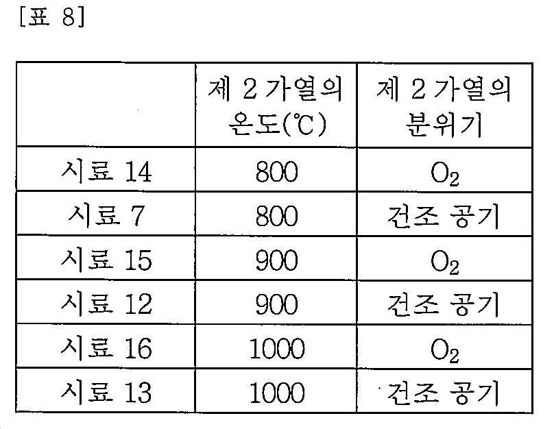
도 41의 (A) 내지 (C)에 나타낸 바와 같이, 800℃, 900℃, 및 1000℃의 제 2 가열이 수행된 경우, 산소 분위기에서 수행된 제 2 가열은 건조 공기에서 수행된 제 2 가열보다 더 양호한 사이클 특성에 기여하였다.As shown in Figs. 41A to 41C, when the second heating at 800 ° C, 900 ° C, and 1000 ° C is performed, the second heating performed in the oxygen atmosphere is performed by the second heating Contributing to better cycle characteristics.
(실시예 5)(Example 5)
본 실시예에서는, 첨가 출발 물질로서 마그네슘 및 플루오린을 사용한 경우의 사이클 특성과, 마그네슘 또는 플루오린 외의 원소를 사용한 경우의 사이클 특성을 비교하였다.In this example, the cycle characteristics in the case of using magnesium and fluorine as the starting materials for addition and the cycle characteristics in the case of using elements other than magnesium or fluorine were compared.
<<플루오린과 염소의 비교>><< Comparison of fluorine and chlorine >>
우선, 첨가 출발 물질로서 마그네슘 및 플루오린을 사용한 경우와, 플루오린 대신에 염소를 사용한 경우에서 사이클 특성을 비교하였다.First, the cycle characteristics were compared in the case of using magnesium and fluorine as the starting materials for addition and in the case of using chlorine in place of fluorine.
<시료 17 및 시료 18의 양극 활물질의 준비><Preparation of Cathode Active Material of Sample 17 and
시료 7에는, 코발트에 대하여 1mol%의 MgO 및 2mol%의 LiF를 첨가 출발 물질로서 사용하였다. 시료 17에는, 1mol%의 MgO, 1mol%의 LiF, 및 1mol%의 LiCl을 사용하였다. 비교예로서의 시료 18에는, 1mol%의 MgO 및 2mol%의 LiCl을 사용하였다. 비교예로서의 시료 6에는, 마그네슘도 플루오린도 염소도 첨가하지 않았다.In
시료 7, 시료 17, 시료 18, 및 시료 6에는, 실시예 2와 마찬가지로 양극 활물질을 준비하고, 이들을 사용한 이차 전지를 준비하여, 사이클 특성을 평가하였다. 사이클 특성 시험은 실시예 1과 마찬가지로 수행되었다.
<사이클 특성><Cycle characteristics>
표 9는, 각 시료의 첨가 출발 물질 및 20사이클 후의 에너지 밀도 유지율을 나타낸 것이다.Table 9 shows the starting materials for addition of each sample and the energy density retention after 20 cycles.

표 9에 나타낸 바와 같이, 플루오린 대신에 염소를 첨가하면 사이클 특성이 저하되는 경향이 있었다. 그러나, 1mol%의 플루오린 및 1mol%의 염소를 갖는 시료 17에서, 20사이클 후의 에너지 밀도 유지율은 80% 이상이었다. 이는, 마그네슘도 플루오린도 염소도 갖지 않는 시료 6과 비교하여 양호한 사이클 특성이었다.As shown in Table 9, the addition of chlorine in place of fluorine tended to lower cycle characteristics. However, in the sample 17 having 1 mol% of fluorine and 1 mol% of chlorine, the energy density retention after 20 cycles was 80% or more. This was a favorable cycle characteristic as compared to
<<마그네슘과, 다른 금속의 비교>><< Comparison of magnesium and other metals >>
다음으로, 첨가 출발 물질로서 마그네슘과 플루오린을 사용한 경우와, 마그네슘 대신에 다른 금속을 사용한 경우에서, 사이클 특성을 비교하였다.Next, the cycle characteristics were compared in the case of using magnesium and fluorine as the starting materials for addition and in the case of using other metals in place of magnesium.
<시료 19 내지 시료 29의 양극 활물질의 준비>≪ Preparation of cathode active material of sample 19 to sample 29 >
첨가 출발 물질로서 마그네슘 및 플루오린을 사용한 시료로서, 실시예 1의 시료 7을 사용하였다. 비교예로서의 시료 19에는, 1mol%의 MgO, 1mol%의 TiO2, 및 2mol%의 LiF를 첨가 출발 물질로서 사용하였다. 비교예로서의 시료 20에는, 1mol%의 ZrO2 및 2mol%의 LiF를 첨가 출발 물질로서 사용하였다. 비교예로서의 시료 21에는, 1mol%의 TiO2 및 2mol%의 LiF를 첨가 출발 물질로서 사용하였다. 비교예로서의 시료 22에는, 1mol%의 V2O5 및 2mol%의 LiF를 첨가 출발 물질로서 사용하였다. 비교예로서의 시료 23에는, 1mol%의 ZnO 및 2mol%의 LiF를 첨가 출발 물질로서 사용하였다. 비교예로서의 시료 24에는, 1mol%의 CaO 및 2mol%의 LiF를 첨가 출발 물질로서 사용하였다. 비교예로서의 시료 25에는, 1mol%의 Al2O3 및 2mol%의 LiF를 첨가 출발 물질로서 사용하였다. 비교예로서의 시료 26에는, 1mol%의 MoO2 및 2mol%의 LiF를 첨가 출발 물질로서 사용하였다. 비교예로서의 시료 27에는, 1mol%의 SrO 및 2mol%의 LiF를 첨가 출발 물질로서 사용하였다. 비교예로서의 시료 28에는, 1mol%의 NaF 및 1mol%의 LiF를 첨가 출발 물질로서 사용하였다. 비교예로서의 시료 29에는, 1mol%의 BaO 및 2mol%의 LiF를 첨가 출발 물질로서 사용하였다. 플루오린도 어떤 금속도 첨가되지 않은 비교예로서, 실시예 1의 시료 6을 사용하였다.
시료 6, 시료 7, 및 시료 19 내지 시료 29에는, 실시예 1과 마찬가지로 양극 활물질을 준비하고, 이들을 사용한 이차 전지를 준비하여, 사이클 특성을 평가하였다.As
<사이클 특성><Cycle characteristics>
표 10은, 각 시료의 첨가 출발 물질 및 20사이클 후의 에너지 밀도 유지율을 나타낸 것이다.Table 10 shows the starting materials for addition of each sample and the energy density retention after 20 cycles.
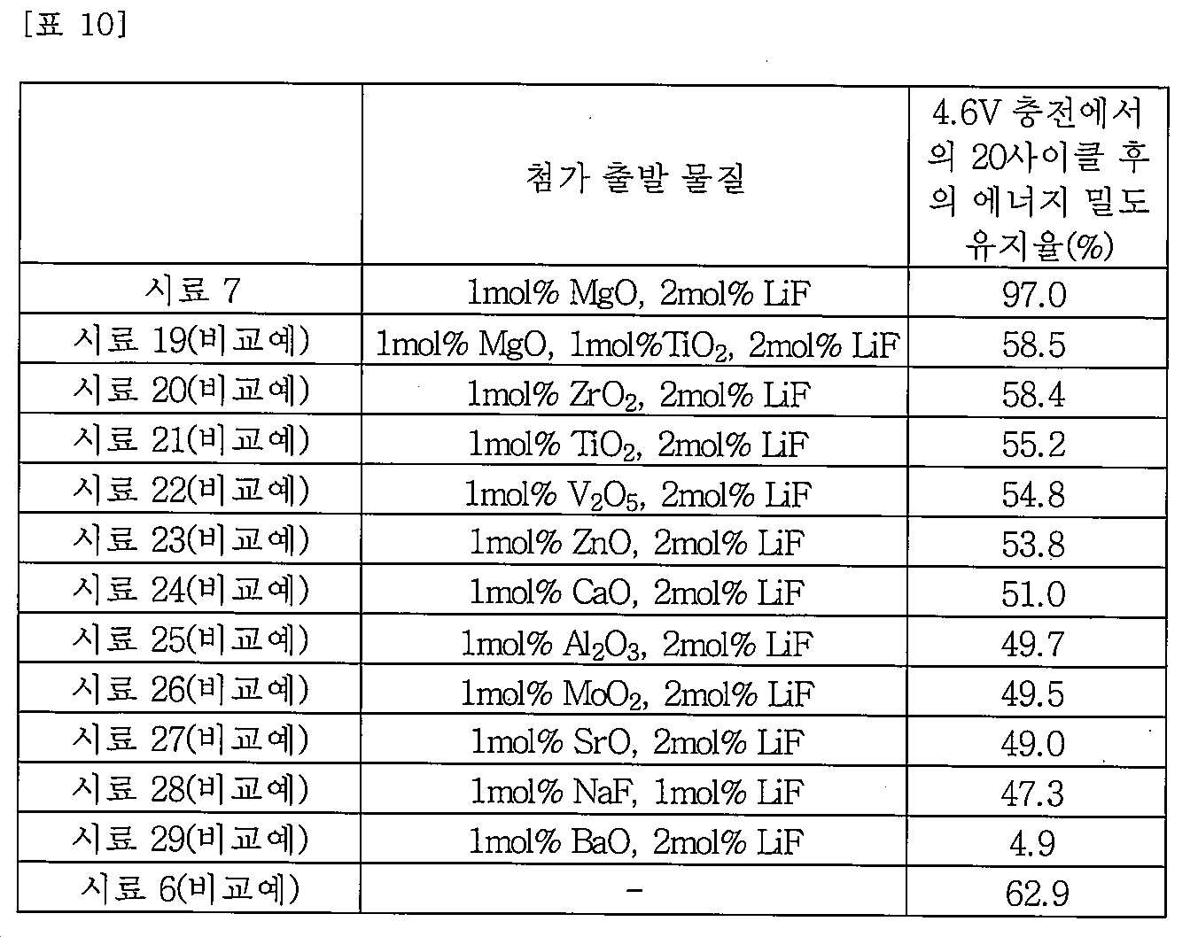
표 10에 나타낸 바와 같이, 마그네슘 대신에 다른 금속을 첨가하면 사이클 특성이 저하되는 경향이 있었다.As shown in Table 10, when other metals were added instead of magnesium, the cycle characteristics tended to be lowered.
이들 결과로부터, 첨가 출발 물질로서 마그네슘과 플루오린을 조합하여 사용하는 것은 매우 효과적인 방법이라는 것이 밝혀졌다.From these results, it has been found that the use of a combination of magnesium and fluorine as an additive starting material is a very effective method.
앞의 실시예로부터, 양극 활물질의 출발 물질로서 마그네슘과 플루오린을 첨가함으로써, 마그네슘이 양극 활물질의 표면에 편석되는 것이 밝혀졌다. 또한, 편석에 의하여 형성된 양호한 피복층을 갖기 때문에, 고용량이며 사이클 특성이 우수한 양극 활물질로 할 수 있다는 것이 밝혀졌다.From the foregoing examples, it has been found that by adding magnesium and fluorine as starting materials for the positive electrode active material, magnesium segregates on the surface of the positive electrode active material. Further, it has been found that a positive electrode active material having a high capacity and excellent cycle characteristics can be obtained because it has a good coating layer formed by segregation.
이러한 양극 활물질을 갖는 이차 전지는 고용량 및 장수명이기 때문에, 휴대용 전자 기기에 적합하다. 또한, 자동차 및 다른 차량에 사용하면, 전력 수요의 피크 시에 상용 전원을 사용하는 것을 피하는 것도 가능하므로, 에너지 절약 및 이산화탄소 배출 삭감에 기여할 수 있다.Since the secondary battery having such a cathode active material has a high capacity and a long life, it is suitable for a portable electronic device. In addition, when used in automobiles and other vehicles, it is possible to avoid using a commercial power source at the peak of power demand, which can contribute to energy saving and carbon dioxide emission reduction.
(실시예 6)(Example 6)
본 실시예에서는, 니켈, 망가니즈, 및 코발트를 제 1 영역의 전이 금속으로서 사용하여 준비된 양극 활물질의 평가 결과에 대하여 설명한다.In this embodiment, evaluation results of a cathode active material prepared by using nickel, manganese, and cobalt as a transition metal in the first region will be described.
<시료 31, 시료 32><Sample 31 and Sample 32>
마그네슘 및 플루오린을 갖는 시료 31, 및 비교예로서 마그네슘도 플루오린도 갖지 않는 시료 32를 준비하였다.A sample 31 having magnesium and fluorine, and a sample 32 having no magnesium defluorine as a comparative example were prepared.
시료 31은, 출발 물질로서의 니켈, 망가니즈, 및 코발트의 합에 대하여, 1atomic%의 마그네슘 및 2atomic%의 플루오린을 첨가함으로써 얻어진 시료이었다. 또한, 출발 물질로서의 니켈, 망가니즈, 및 코발트의 원자수비는 Ni:Mn:Co=1:1:1이었다.Sample 31 was a sample obtained by adding 1 atomic% of magnesium and 2 atomic% of fluorine to the sum of nickel, manganese, and cobalt as starting materials. The atomic ratio of nickel, manganese, and cobalt as starting materials was Ni: Mn: Co = 1: 1: 1.
우선, 공통 출발 물질의 리튬원으로서, 탄산 리튬(Li2CO3)을 사용하였다. 니켈원으로서는, 산화 니켈(NiO)을 사용하였다. 망가니즈원으로서는, 산화 망가니즈(MnO2)를 사용하였다. 코발트원으로서는, 산화 코발트(Co3O4)를 사용하였다. 첨가 출발 물질의 마그네슘원으로서는, 산화 마그네슘(MgO)을 사용하였다. 플루오린원으로서는, 플루오린화 리튬(LiF)을 사용하였다.First, lithium carbonate (Li 2 CO 3 ) was used as the lithium source of the common starting material. As the nickel source, nickel oxide (NiO) was used. As manganese source, manganese oxide (MnO 2 ) was used. As the cobalt source, cobalt oxide (Co 3 O 4 ) was used. As the magnesium source of the additive starting material, magnesium oxide (MgO) was used. Fluorinated lithium (LiF) was used as the fluorine source.
각 출발 물질을, 원자수비가 LiCo0 . 323Mn0 . 333Ni0 . 333O2+MgO0 . 01LiF0 .02가 되도록 칭량하였다.Each starting material was dissolved in a solution of LiCo 0 . 323 Mn 0 . 333 Ni 0 . 333 O 2 + MgO 0 . 01 LiF was weighed such that 0 .02.
다음으로, 칭량한 출발 물질을 볼밀을 사용하여 혼합하였다.Next, the weighed starting materials were mixed using a ball mill.
그리고, 혼합한 출발 물질을 소성하였다. 소성은 승온 속도를 200℃/h로 하고, 건조 공기 분위기의 유량을 10L/min으로 한 조건하에서, 950℃에서 10시간 동안 수행하였다.Then, the mixed starting material was calcined. The firing was carried out at 950 占 폚 for 10 hours under the conditions of a heating rate of 200 占 폚 / h and a flow rate of 10 L / min in a dry air atmosphere.
상술한 공정을 거쳐, 리튬, 니켈, 망가니즈, 코발트, 플루오린, 및 마그네슘을 포함하는 복합 산화물의 입자를 합성하였다.Through the above-described processes, particles of composite oxides containing lithium, nickel, manganese, cobalt, fluorine, and magnesium were synthesized.
합성된 복합 산화물의 입자를 실온까지 냉각하였다.The synthesized composite oxide particles were cooled to room temperature.
다음으로, 복합 산화물의 입자를 가열하였다. 가열은 온도를 800℃로 하고(승온 속도를 200℃/h로 함), 유지 시간을 2시간으로 한 조건하에서, 건조 공기 분위기에서 수행하였다.Next, the particles of the composite oxide were heated. The heating was carried out in a dry air atmosphere under the conditions of a temperature of 800 ° C (heating rate of 200 ° C / h) and a holding time of 2 hours.
가열한 입자를 실온까지 냉각시키고 해쇄 처리를 실시하였다. 해쇄 처리에서는, 입자를 체눈의 크기가 53μm의 체로 치었다.The heated particles were cooled to room temperature and crushed. In the crushing treatment, the particles were sieved with a mesh size of 53 μm.
해쇄 처리를 실시한 입자를 시료 31의 양극 활물질로서 사용하였다.The particles subjected to the crushing treatment were used as the positive electrode active material of the sample 31.
시료 32에는, 각 출발 물질을 원자수비가 LiCo0 . 333Mn0 . 333Ni0 . 333O2가 되도록 칭량하였다. 또한, 소성을 1000℃에서 수행하였다. 그 외에는, 시료 31의 제작 방법을 참조할 수 있다.In the sample 32, each starting material was changed to LiCo 0 . 333 Mn 0 . 333 Ni 0 . 333 O 2 . The firing was performed at 1000 占 폚. Otherwise, the production method of the sample 31 can be referred to.
표 11은 시료 31 및 시료 32의 제작 조건을 나타낸 것이다.Table 11 shows the production conditions of the sample 31 and the sample 32.

<사이클 특성><Cycle characteristics>
다음으로, 상술한 식으로 형성한 시료 31 및 시료 32의 양극 활물질을 사용하여 CR2032 코인형 이차 전지(직경 20mm 및 높이 3.2mm)를 제작하였다. 이들의 사이클 특성을 평가하였다.Next, CR2032 coin-type secondary batteries (
시료 31 및 시료 32의 양극 활물질과, 아세틸렌 블랙(AB)과, 폴리플루오린화바이닐리덴(PVDF)을 양극 활물질:AB:PVDF=95:2.5:2.5의 중량비에서 혼합한 슬러리를 알루미늄박 집전체에 도포함으로써 형성한 양극을 사용하였다. 용매로서 N-메틸-2-피롤리돈(NMP)을 사용하였다.A slurry obtained by mixing the positive electrode active materials of samples 31 and 32, acetylene black (AB) and polyfluorinated vinylidene (PVDF) at a weight ratio of the positive electrode active material: AB: PVDF = 95: 2.5: Was used as the positive electrode. N-methyl-2-pyrrolidone (NMP) was used as a solvent.
대향 전극에는 리튬 금속을 사용하였다.And lithium metal was used for the counter electrode.
전해액에 포함되는 전해질로서는 1mol/L의 헥사플루오로 인산 리튬(LiPF6)을 사용하였다. 전해액으로서는, 체적비 EC:DEC=3:7의 에틸렌 카보네이트(EC)와 다이에틸 카보네이트(DEC)와, 2wt%의 바이닐렌 카보네이트(VC)를 혼합한 용액을 사용하였다.As the electrolyte contained in the electrolytic solution, 1 mol / L of lithium hexafluorophosphate (LiPF 6 ) was used. As the electrolytic solution, a solution obtained by mixing ethylene carbonate (EC), diethyl carbonate (DEC) and 2 wt% of vinylene carbonate (VC) having a volume ratio of EC: DEC = 3: 7 was used.
양극 캔 및 음극 캔은 스테인리스강(SUS)으로 형성하였다.The anode can and the anode can were made of stainless steel (SUS).
사이클 특성 시험에서의 측정 온도는 25℃이었다. 충전을 활물질 중량당 전류 밀도 68.5mA/g의 정전류, 그리고 상한 전압 4.6V에서 수행하였다. 그 후, 전류 밀도가 1.4mA/g에 도달될 때까지 정전압 충전을 수행하였다. 방전을 활물질 중량당 전류 밀도 68.5mA/g의 정전류, 그리고 하한 전압 2.5V에서 수행하였다.The measurement temperature in the cycle characteristic test was 25 占 폚. Charging was performed at a constant current density of 68.5 mA / g per active material weight and an upper limit voltage of 4.6V. Thereafter, constant-voltage charging was performed until the current density reached 1.4 mA / g. Discharge was performed at a constant current of 68.5 mA / g per active material weight and a lower voltage of 2.5 V.
도 43의 (A)는, 4.6V 충전에서의, 시료 31 및 시료 32의 양극 활물질을 사용한 이차 전지의 방전 용량을 나타낸 것이다. 도 43의 (B)는 그 방전 용량 유지율을 나타낸 것이다.43 (A) shows the discharge capacity of the secondary battery using the positive electrode active materials of sample 31 and sample 32 at 4.6 V charging. Figure 43 (B) shows the discharge capacity retention rate.
마그네슘 또는 플루오린을 첨가하지 않은 시료 32와 비교하여, 마그네슘 및 플루오린을 첨가한 시료 31은 매우 양호한 사이클 특성을 나타내었다.Sample 31, to which magnesium and fluorine had been added, exhibited very good cycle characteristics, as compared to sample 32 without addition of magnesium or fluorine.
다음으로, 시료 31의 각종 분석 결과를 이하에 나타낸다.Next, various analysis results of the sample 31 are shown below.
<STEM-FFT><STEM-FFT>
시료 31의 양극 활물질의 표면 근방의 단면의 STEM 이미지를 도 44의 (A) 및 (B), 그리고 도 45의 (A) 및 (B)에 나타내었다. 도 44의 (B)는 도 44의 (A)의 일부를 확대함으로써 얻어진 STEM 이미지이다. 도 45의 (A) 및 (B)는 도 44의 (A)의 일부를 확대함으로써 얻어진 HAADF-STEM 이미지이다.The STEM image of the section near the surface of the positive electrode active material of the sample 31 is shown in FIGS. 44A and 44B and FIGS. 45A and 45B. FIG. 44 (B) is an STEM image obtained by enlarging a part of FIG. 44 (A). 45A and 45B are HAADF-STEM images obtained by enlarging a part of FIG. 44A.
도 45의 (A) 및 (B)로부터 명백한 바와 같이, 양극 활물질의 표면으로부터 약 0.5nm의 영역에서는, 다른 영역과 밝기가 상이한 상태가 관찰되었다. 이는, 전이 금속보다 가벼운 원소인 마그네슘의 양이 많기 때문이라고 생각된다.As is clear from Figs. 45 (A) and 45 (B), in a region of about 0.5 nm from the surface of the positive electrode active material, a state in which the brightness differs from that of the other region was observed. This is presumably because the amount of magnesium, which is lighter than the transition metal, is large.
또한, 양극 활물질의 표면으로부터 약 0.5nm 내지 5nm의 영역에서는, 내부 영역과 규칙성이 상이한 상태가 관찰되었다. 이는, 표면으로부터 약 0.5nm 내지 5nm의 영역과 내부 영역 사이에서 결정의 배향이 상이하기 때문이라고 생각되었다.Further, in a region of about 0.5 nm to 5 nm from the surface of the positive electrode active material, a state where the regularity differs from that of the internal region was observed. This is thought to be because the orientation of crystals differs between the region of about 0.5 nm to 5 nm from the surface and the inner region.
도 46의 (A)는, 도 45의 (B)와 같은 범위에서의 명시야 STEM 이미지이다. 도 46의 (B)는, 도 46의 (A)에서 FFT1로 나타낸 영역의 FFT(fast Fourier transform) 이미지를 나타낸 것이다. 도 46의 (B)에 나타낸 바와 같이, FFT1 이미지의 휘점의 일부를 A, B, C, O라고 부른다.FIG. 46A is a bright field STEM image in the same range as FIG. 45B. FIG. 46B shows an FFT (fast Fourier transform) image of the area indicated by FFT1 in FIG. 46A. As shown in FIG. 46 (B), some of the bright spots of the FFT1 image are called A, B, C, and O. FIG.
FFT1로 나타내어진 영역의 FFT 이미지의 휘점에 관하여, 측정값은 OA에 대해서는 d=0.22nm, OB에 대해서는 d=0.25nm, 그리고 OC에 대해서는 d=0.23nm이었다. 또한, ∠AOB=58°, ∠BOC=69°, 및 ∠AOC=127°이다.With respect to the focal spot of the FFT image in the area represented by FFT1, the measured values were d = 0.22 nm for OA, d = 0.25 nm for OB, and d = 0.23 nm for OC. Also, ∠AOB = 58 °, ∠BOC = 69 °, and ∠AOC = 127 °.
이 결과는, ICDD(International Centre for Diffraction Data)에서의 산화 마그네슘(MgO)의 데이터(ICDD45-0945)로부터 얻어지는, OA(200)의 d=0.21nm, OB(1-11)의 d=0.24nm, OC(-1-11)의 d=0.24nm, ∠AOB=55°, ∠BOC=70°, ∠AOC=125°와 가깝다. 그러므로, FFT1로 나타내어진 영역은 암염 결정 구조를 갖는 영역이고, [011] 입사의 이미지인 것이 밝혀졌다.This result shows that d = 0.21 nm of
도 46의 (C)는, 도 46의 (A)의 FFT2로 나타내어진 영역의 FFT 이미지를 나타낸 것이다. 도 46의 (C)에 나타낸 바와 같이, FFT2 이미지의 휘점의 일부를 A, B, C, O라고 부른다.FIG. 46C shows an FFT image of the area indicated by FFT2 in FIG. 46A. As shown in Fig. 46C, some of the bright spots of the FFT2 image are called A, B, C, and O. [
FFT2로 나타내어진 영역의 FFT 이미지의 휘점에 관하여, 측정값은 OA에 대해서는 d=0.25nm, OB에 대해서는 d=0.21nm, 그리고 OC에 대해서는 d=0.49nm이었다. 또한, ∠AOB=26°, ∠BOC=57°, ∠AOC=83°이다.With respect to the focal point of the FFT image of the area represented by FFT2, the measured values were d = 0.25 nm for OA, d = 0.21 nm for OB, and d = 0.49 nm for OC. In addition, ∠AOB = 26 °, ∠BOC = 57 °, and ∠AOC = 83 °.
이 결과는, ICDD 데이터 베이스에서의 코발트산 리튬(LiCoO2)의 데이터(ICDD50-0653)로부터 얻어지는, OA(10-11)의 d=0.24nm, OB(10-14)의 d=0.20nm, OC(0003)의 d=0.47nm, ∠AOB=25°, ∠BOC=55°, ∠AOC=80°와 가깝다. 그러므로, FFT2로 나타내어진 영역은 층상 암염 결정 구조를 갖는 영역이고, [-12-10] 입사의 이미지인 것이 밝혀졌다.This result is, of ICDD database lithium cobalt oxide (LiCoO 2) of data, OA (10-11) d = 0.24nm , OB (10-14) obtained from the (ICDD50-0653) at d = 0.20nm, D = 0.47 nm of OC (0003), ∠AOB = 25 °, ∠BOC = 55 °, and ∠AOC = 80 °. Therefore, the region represented by FFT2 is a region having a layered rock salt crystal structure, and it has been found that it is an image of [-12-10] incidence.
도 46의 (D)는, 도 46의 (A)에서 FFT3으로 나타내어진 영역의 FFT 이미지를 나타낸 것이다. 도 46의 (D)에 나타낸 바와 같이, FFT3 이미지의 휘점의 일부를 A, B, C, O라고 부른다.FIG. 46D shows an FFT image of the area indicated by FFT3 in FIG. 46A. As shown in FIG. 46 (D), some of the bright spots of the FFT3 image are called A, B, C, and O. FIG.
FFT3으로 나타내어진 영역의 FFT 이미지의 휘점에 관하여, 측정값은 OA에 대해서는 d=0.21nm, OB에 대해서는 d=0.26nm, 그리고 OC에 대해서는 d=0.24nm이었다. 또한, ∠AOB=56°, ∠BOC=72°, ∠AOC=128°이다.Regarding the focal spot of the FFT image of the area represented by FFT3, the measured values were d = 0.21 nm for OA, d = 0.26 nm for OB, and d = 0.24 nm for OC. In addition, ∠AOB = 56 °, ∠BOC = 72 °, and ∠AOC = 128 °.
이 결과는, ICDD 데이터 베이스에서의 코발트산 리튬(LiCoO2)의 데이터(ICDD50-0653)로부터 얻어지는, OA(01-14)의 d=0.20nm, OB(10-1-2)의 d=0.23nm, OC(1-102)의 d=0.23nm, ∠AOB=55°, ∠BOC=70°, ∠AOC=125°와 가깝다. 그러므로, FFT2로 나타내어진 영역은 층상 암염 결정 구조를 갖는 영역이고, [02-21] 입사의 이미지인 것이 밝혀졌다.The results, obtained from the ICDD data (ICDD50-0653) of lithium cobalt oxide (LiCoO 2) in the data base, d = 0.23 in OA (01-14) d = 0.20nm, OB (10-1-2) of nm, d = 0.23 nm of OC (1-102), ∠AOB = 55 °, ∠BOC = 70 °, and ∠AOC = 125 °. Therefore, the region represented by FFT2 is a region having a layered rock salt crystal structure, and it has been found that this is an incident image of [02-21].
바꿔 말하면, FFT2 및 FFT3으로 나타내어진 영역은, 같은 층상 암염 결정 구조를 갖지만, 결정축의 방향이 서로 상이하다는 것이 발견되었다.In other words, it has been found that the regions represented by FFT2 and FFT3 have the same layered rock salt crystal structure, but the directions of crystal axes are different from each other.
도 45의 (A), (B), 및 도 46의 (A)에서 관찰할 수 있는 범위에서는, 밝기가 상이하더라도 결정 배향은 서로 대략 일치하는 것이 관찰되었다.It was observed that, in the range that can be observed in FIGS. 45A, 45B, and 46A, the crystal orientations approximately agree with each other even when the brightness is different.
도 47은, STEM-FFT 결과로부터 추정되는, 양극 활물질의 표면 근방의 구조를 STEM 이미지와 함께 나타낸 것이다. 도 47에서의 M은 니켈, 망가니즈, 및 코발트 중 어느 하나를 나타낸다.Fig. 47 shows the structure near the surface of the positive electrode active material, which is estimated from the STEM-FFT result, together with the STEM image. In Fig. 47, M represents any one of nickel, manganese, and cobalt.
양극 활물질의 내부의 영역인 FFT3은 층상 암염 결정 구조를 갖는다. 또한, 이는 리튬과 M의 원자가 서로 중첩되는 경우에 관찰되는 [02-21] 입사의 이미지이다.FFT3, which is an area inside the cathode active material, has a layered rock salt crystal structure. In addition, this is the image of the incident [02-21] observed when the atoms of lithium and M overlap each other.
또한, 양극 활물질의 표층부의 영역인 FFT2는 층상 암염 결정 구조를 갖는다. FFT2는, 산소 원자의 층, M(니켈, 망가니즈, 및 코발트 중 하나) 원자의 층, 및 리튬 원자의 층이 반복되는 상태를 나타낸 [-12-10] 입사의 이미지이다. M의 층과 산소 및 리튬의 층이 반복되기 때문에 명시야 STEM 이미지에서 더 어두운 층과 더 밝은 층이 반복된다고 생각된다. 즉, FFT3 및 FFT2는 같은 층상 암염 결정 구조를 갖지만, 결정축의 방향은 서로 상이하다.Further, FFT2 which is a region of the surface layer portion of the positive electrode active material has a layered rock salt crystal structure. FFT2 is an image of [-12-10] incidence showing a state in which a layer of oxygen atoms, a layer of M (one of nickel, manganese, and cobalt) atoms, and a layer of lithium atoms are repeated. It is believed that darker and lighter layers repeat bright field STEM images because layers of M and layers of oxygen and lithium are repeated. That is, FFT3 and FFT2 have the same layered rock salt crystal structure, but the directions of crystal axes are different from each other.
또한, 양극 활물질의 표층부의 영역에서, FFT2보다 표면에 가까운 영역인 FFT1은 암염 결정 구조를 갖고, [011] 입사의 이미지이다.In the region of the surface layer portion of the positive electrode active material, FFT1, which is a region closer to the surface than FFT2, has a rock salt crystal structure and is an image of incidence.
<EDX><EDX>
다음으로, 표면 근방의 시료 31의 양극 활물질의 단면을 EDX를 사용하여 분석하고, 그 결과를 도 48의 (A1) 내지 (B2) 및 도 49의 (A1) 내지 (B2)에 나타내었다.Next, the cross section of the positive electrode active material of the sample 31 in the vicinity of the surface was analyzed using EDX, and the results are shown in (A1) to (B2) of FIG. 48 and (A1) to (B2) of FIG.
도 48의 (A1)은 HAADF-STEM 이미지이고, 도 48의 (A2)는 산소의 매핑이고, 도 48의 (B1)은 마그네슘의 매핑이고, 도 48의 (B2)는 플루오린의 매핑이다. 도 49의 (A1)은 도 48의 (A1)과 같은 HAADF-STEM 이미지이고, 도 49의 (A2)는 망가니즈의 매핑이고, 도 49의 (B1)은 니켈의 매핑이고, 도 49의 (B2)는 코발트의 매핑이다.FIG. 48A1 is an HAADF-STEM image, FIG. 48A2 is a mapping of oxygen, FIG. 48B1 is a mapping of magnesium, and FIG. 48B2 is mapping of fluorine. 49A1 is an HAADF-STEM image as in FIG. 48A1, FIG. 49A2 is a mapping of Manganese, FIG. 49B1 is a mapping of nickel, and FIG. B2) is the mapping of cobalt.
도 48의 (B1)로부터, 양극 활물질의 표면으로부터 약 3nm의 영역에서 마그네슘이 편석되는 것이 관찰되었다. 도 49의 (A2), (B1), 및 (B2)를 비교함으로써, 양극 활물질의 표층부에, 내측보다 망가니즈는 적게, 니켈 및 코발트는 많이 포함하는 영역이 있는 것이 관찰되었다. 이 영역은 표면으로부터 약 5nm이고, STEM 이미지에서 내부와 상이한 규칙성이 관찰된 영역과 거의 중첩하였다.From FIG. 48 (B1), it was observed that magnesium segregated in a region of about 3 nm from the surface of the positive electrode active material. By comparing (A2), (B1), and (B2) in FIG. 49, it was observed that the surface layer portion of the positive electrode active material had regions containing nickel and cobalt in a smaller amount of manganese than in the inside. This region was about 5 nm from the surface and almost overlapped with the region where regularity different from the inside was observed in the STEM image.
그러므로, 시료 31의 양극 활물질이, 표층부에 마그네슘을 포함하는 영역, 그리고 내부의 일부에 망가니즈의 함유량이 적은 영역을 갖는 양극 활물질인 것이 확인되었다.Therefore, it was confirmed that the positive electrode active material of Sample 31 was a positive electrode active material having a region containing magnesium in the surface layer portion and a region having a small content of manganese in the internal portion.
상술한 결과로부터, 출발 물질의 몰비를 LiNi1 / 3Mn1 / 3Co1 / 3O2+1mol%MgO+2mol%LiF로 설정하고 800℃에서 가열함으로써 준비한, 시료 31의 양극 활물질이 이하의 특성을 갖는 것이 밝혀졌다.From the above results, in the molar ratio of the starting material LiNi 1/3 positive electrode active material of Mn 1/3 Co 1/3
우선, 시료 31의 양극 활물질은 표층부에 산화 마그네슘을 갖는 제 2 영역을 포함한다. 양극 활물질의 내부에는, 중심부와 더 가까운 부분에 층상 암염 결정 구조를 갖는 LiNixMnyCozO2(x+y+z=1)를 포함하는 영역, 및 표면과 더 가까운 부분에 층상 암염 결정 구조를 갖는 LiNiaMnbCocO2(a+b+c=1)를 포함하는 영역이 포함된다.First, the positive electrode active material of the sample 31 includes a second region having magnesium oxide in the surface layer portion. In the inside of the cathode active material, a region containing LiNi x Mn y Co z O 2 (x + y + z = 1) having a layered rock salt crystal structure at a portion closer to the center portion, (A + b + c = 1) having a structure of LiNi a Mn b Co c O 2 .
내부의 LiNixMnyCozO2 및 LiNiaMnbCocO2는 같은 층상 암염 결정 구조를 갖지만, 결정축의 방향이 상이한 경우가 있다.The internal LiNi x Mn y Co z O 2 and LiNi a Mn b Co c O 2 have the same layered rock salt crystal structure, but the crystal axes may have different directions.
각 원소의 함유량은 y>b이고, 니켈, 망가니즈, 및 코발트의 합에 대한 망가니즈의 함유량은 표면에 가까운 영역에서 낮을 수 있다.The content of each element is y > b, and the content of manganese to the sum of nickel, manganese, and cobalt can be low in the region close to the surface.
상술한 특성을 갖는 시료 31의 양극 활물질은, 이차 전지에 사용되는 경우에 매우 양호한 사이클 특성을 나타낸다.The positive electrode active material of the sample 31 having the above-described characteristics exhibits excellent cycle characteristics when used in a secondary battery.
(실시예 7)(Example 7)
본 실시예에서는, 전이 금속으로서 코발트를 첨가하고, 출발 물질로서 마그네슘 및 플루오린을 첨가함으로써 준비한 양극 활물질의, EELS를 사용한 분석 결과에 대하여 설명한다.In this embodiment, the analysis results of the positive electrode active material prepared by adding cobalt as a transition metal and magnesium and fluorine as a starting material, using EELS, will be described.
1mol%의 MgO 및 2mol%의 LiF를 첨가 출발 물질로서 사용한 실시예 1의 시료 7을 본 실시예의 분석 시료로서 사용하였다.
시료 7의 단면의 *1 내지 *6의 6개의 분석점에서의 코발트의 상태를 EELS를 사용하여 분석하였다. 도 50은 EELS 분석에 사용된 시료 7의 양극 활물질의 표면 근방의 단면의 STEM 이미지이고, 여기에는 *1(표면으로부터의 깊이가 약 1nm), *2(약 2.5nm), 및 *3(약 5nm)의 분석점이 나타내어졌다. 또한, *4는 양극 활물질의 표면으로부터 약 10nm이고, *5는 양극 활물질의 표면으로부터 약 100nm이고, *6은 양극 활물질의 입자의 중심 근방이다.The state of cobalt at six analysis points * 1 to * 6 of the cross section of
표 12 및 도 51은 각 분석점에서의 코발트의 L2 준위 및 L3 준위의 EELS 스펙트럼의 강도비를 나타낸 것이다. L3/L2가 높아질수록, 코발트의 원자가는 낮아진다.Table 12 and FIG. 51 show the intensity ratios of the L 2 and C 3 levels of the cobalt EELS spectra at the respective analysis points. The higher L 3 / L 2 , the lower the valence of cobalt.

표 12 및 도 51로부터 명백한 바와 같이, 양극 활물질의 표면과 가장 가까운 분석점 *1의 L3/L2가 가장 높은 4.6이었다. 분석점 *2 내지 분석점 *6에서, L3/L2는 분석점 *1의 L3/L2보다 낮으며 2.9 내지 3.2의 범위 내에 있고, 큰 차이는 관찰되지 않았다.As is clear from Table 12 and Figure 51, L 3 / L 2 of the analysis point * 1 closest to the surface of the positive electrode active material was the highest 4.6. In the analysis point * 2 to * 6 point analysis, L 3 / L 2 is lower than L 3 / L 2 of the analysis point * 1 in the range of 2.9 to 3.2, a large difference was not observed.
이들 결과로부터, 분석점 *1에서는 산화 코발트(CoO)로서 존재하는 2가의 코발트의 양이 많고, 분석점 *2 내지 분석점 *6에서는 코발트산 리튬(LiCoO2)으로서 존재하는 3가의 코발트의 양이 많다는 것이 추정되었다.From these results, it was found that the amount of divalent cobalt existing as cobalt oxide (CoO) was large in analysis point * 1 and the amount of trivalent cobalt existing as lithium cobalt oxide (LiCoO 2 ) Was estimated.
100: 양극 활물질, 101: 제 1 영역, 102: 제 2 영역, 103: 제 3 영역, 200: 활물질층, 201: 그래핀 화합물, 211a: 양극, 211b: 음극, 212a: 리드, 212b: 리드, 214: 세퍼레이터, 215a: 접합부, 215b: 접합부, 217: 고정 부재, 250: 이차 전지, 251: 외장체, 261: 접힌 부분, 262: 밀봉부, 263: 밀봉부, 271: 능선, 272: 골짜기선, 273: 공간, 300: 이차 전지, 301: 양극 캔, 302: 음극 캔, 303: 개스킷, 304: 양극, 305: 양극 집전체, 306: 양극 활물질층, 307: 음극, 308: 음극 집전체, 309: 음극 활물질층, 310: 세퍼레이터, 500: 이차 전지, 501: 양극 집전체, 502: 양극 활물질층, 503: 양극, 504: 음극 집전체, 505: 음극 활물질층, 506: 음극, 507: 세퍼레이터, 508: 전해액, 509: 외장체, 510: 양극 리드 전극, 511: 음극 리드 전극, 600: 이차 전지, 601: 양극 캡, 602: 전지 캔, 603: 양극 단자, 604: 양극, 605: 세퍼레이터, 606: 음극, 607: 음극 단자, 608: 절연판, 609: 절연판, 611: PTC 소자, 612: 안전 밸브 기구, 900: 회로 기판, 910: 라벨, 911: 단자, 912: 회로, 913: 이차 전지, 914: 안테나, 915: 실재, 916: 층, 917: 층, 918: 안테나, 920: 표시 장치, 921: 센서, 922: 단자, 930: 하우징, 930a: 하우징, 930b: 하우징, 931: 음극, 932: 양극, 933: 세퍼레이터, 950: 권회체, 951: 단자, 952: 단자, 980: 이차 전지, 993: 권회체, 994: 음극, 995: 양극, 996: 세퍼레이터, 997: 리드 전극, 998: 리드 전극, 1001: 결정 결함, 7100: 휴대용 표시 장치, 7101: 하우징, 7102: 표시부, 7103: 조작 버튼, 7104: 이차 전지, 7200: 휴대 정보 단말기, 7201: 하우징, 7202: 표시부, 7203: 밴드, 7204: 버클, 7205: 조작 버튼, 7206: 입출력 단자, 7207: 아이콘, 7300: 표시 장치, 7304: 표시부, 7400: 휴대 전화, 7401: 하우징, 7402: 표시부, 7403: 조작 버튼, 7404: 외부 접속 포트, 7405: 스피커, 7406: 마이크로폰, 7407: 이차 전지, 7408: 리드 전극, 7409: 집전체, 8000: 표시 장치, 8001: 하우징, 8002: 표시부, 8003: 스피커부, 8004: 이차 전지, 8021: 충전 기기, 8022: 케이블, 8024: 이차 전지, 8100: 조명 장치, 8101: 하우징, 8102: 광원, 8103: 이차 전지, 8104: 천장, 8105: 벽, 8106: 바닥, 8107: 창문, 8200: 실내기, 8201: 하우징, 8202: 송풍구, 8203: 이차 전지, 8204: 실외기, 8300: 전기 냉동 냉장고, 8301: 하우징, 8302: 냉장고용 도어, 8303: 냉동고용 도어, 8304: 이차 전지, 8400: 자동차, 8401: 전조등, 8406: 전기 모터, 8500: 자동차, 8600: 모터 스쿠터, 8601: 사이드미러, 8602: 이차 전지, 8603: 방향 지시기, 8604: 시트 아래의 수납 부분, 9600: 태블릿 단말기, 9625: 스위치, 9626: 스위치, 9627: 전원 스위치, 9628: 조작 스위치, 9629: 잠금장치, 9630: 하우징, 9630a: 하우징, 9630b: 하우징, 9631: 표시부, 9633: 태양 전지, 9634: 충방전 제어 회로, 9635: 축전 유닛, 9636: DC-DC 컨버터, 9637: 컨버터, 9640: 가동부
본 출원은 2016년 10월 12일에 일본 특허청에 출원된 일련 번호 2016-200835의 일본 특허 출원, 2017년 3월 17일에 일본 특허청에 출원된 일련 번호 2017-052309의 일본 특허 출원, 및 2017년 5월 22일에 일본 특허청에 출원된 일련 번호 2017-100619의 일본 특허 출원에 기초하고, 본 명세서에 그 전문이 참조로 통합된다.The present invention relates to a positive electrode active material and a method for manufacturing the same which are capable of forming a positive electrode active material and a negative electrode active material. The present invention relates to a secondary battery including a secondary battery and a secondary battery including the secondary battery, the secondary battery, the secondary battery, the secondary battery, and the secondary battery. A positive electrode can and a negative electrode can be used as a negative electrode can and a positive electrode can as a negative electrode can. The present invention relates to an anode active material layer and a method of manufacturing the same, and more particularly, to an anode active material layer, a separator, and a separator. And a positive electrode lead terminal and a positive electrode lead terminal are formed on the positive electrode lead terminal and the positive lead terminal of the positive electrode lead terminal, respectively. 606: negative electrode, 607: negative electrode terminal, The present invention relates to a PTC device and a method of manufacturing the same and a method of manufacturing the same and a method of manufacturing the same. 921: antenna, 920: display, 921: sensor, 922: terminal, 930: housing, 930a: housing, 931: negative electrode, 932: positive electrode, 933: separator, 950: A lead electrode, a lead electrode, 1001: a crystal defect, 7100: a negative electrode, 995: a positive electrode, 996: a separator, 997: a lead electrode, 998: A portable display device includes a housing having a housing and a housing, a housing, and a display unit, wherein the housing includes an operation button, a plurality of operation buttons, a plurality of battery cells, An input / output terminal 7207, an icon 7300, a display device 7304, a display unit 7400, a cellular phone 7401, a housing 7402 a display unit 7403 an operation button 7404 an external connection port 7405 a speaker 7406 a microphone 7407 : A secondary battery, 7408 a lead electrode, 7409 a current collector, 8000 a display, 8001 a housing, 8002 a display, 8003 a speaker, 8004 a secondary battery, 8021 charging devices, 8022 cables, 8024 secondary batteries, 8201: housing 8202: light source 8103: secondary battery 8104: ceiling 8105: wall 8106: floor 8107: window 8200: indoor unit 8201: housing 8202: 8204 outdoor refrigerator 8300 electric refrigerator 8301 housing 8302 refrigerator door 8303 refrigerator door 8304 secondary battery 8400 car 8401 headlight 8406 electric motor 8500 automobile : Motor scooter, 8601: side mirror, 8602: secondary battery, 8603: direction indicator, 8604: storage portion under the seat, 9600: tablet terminal, 9625: switch, 9626: switch, 9627: 9630: housing, 9630a: housing, 9630b: housing, 9631: display, 9633: solar cell, 9634: charge / discharge control circuit, 9635: Power storage unit, 9636: DC-DC converter, 9637: Converter, 9640:
The present application is based on Japanese patent application serial number 2016-200835 filed with the Japanese Patent Office on October 12, 2016, Japanese patent application serial number 2017-052309 filed with the Japanese Patent Office on March 17, 2017, Based on the Japanese patent application serial no. 2017-100619 filed on May 22 with the Japanese Patent Office, which is incorporated herein by reference in its entirety.
Claims (16)
상기 활물질 입자의 내부에 위치하는 제 1 영역; 및
상기 활물질 입자의 외부에 위치하는 제 2 영역을 포함하고,
상기 제 1 영역은 리튬, 전이 금속, 및 산소를 포함하고,
상기 제 2 영역은 마그네슘, 플루오린, 및 산소를 포함하는, 활물질 입자.As the active material particles,
A first region located inside the active material particle; And
And a second region located outside the active material particle,
Wherein the first region comprises lithium, a transition metal, and oxygen,
Wherein the second region comprises magnesium, fluorine, and oxygen.
100atomic%로 간주되는 상기 제 2 영역의 리튬, 상기 전이 금속, 산소, 마그네슘, 및 플루오린의 원자의 총량에 대하여, X선 광전자 분광법에 의하여 측정되는 상기 제 2 영역의 마그네슘의 농도는 1atomic% 이상 16atomic% 이하이고,
100atomic%로 간주되는 상기 제 2 영역의 리튬, 상기 전이 금속, 산소, 마그네슘, 및 플루오린의 원자의 상기 총량에 대하여, X선 광전자 분광법에 의하여 측정되는 상기 제 2 영역의 플루오린의 농도는 0.2atomic% 이상 4atomic% 이하인, 활물질 입자.The method according to claim 1,
The concentration of magnesium in the second region measured by X-ray photoelectron spectroscopy, relative to the total amount of atoms of lithium, the transition metal, oxygen, magnesium, and fluorine in the second region, which is regarded as 100 atomic%, is at least 1 atomic% 16 atomic% or less,
The concentration of fluorine in the second region measured by X-ray photoelectron spectroscopy, relative to the total amount of atoms of lithium, the transition metal, oxygen, magnesium, and fluorine in the second region, which is considered to be 100 atomic% atomic% or more and 4 atomic% or less.
X선 광전자 분광법에서, 상기 제 2 영역의 마그네슘 대 플루오린의 농도의 비율은 Mg:F=y:1이고 3≤y≤5인, 활물질 입자.The method according to claim 1,
In X-ray photoelectron spectroscopy, the ratio of the concentration of magnesium to fluorine in the second region is Mg: F = y : 1 and 3? Y ? 5.
X선 광전자 분광법에서, 상기 제 2 영역의 플루오린의 결합 에너지의 피크 위치는 682eV 이상 685eV 미만인, 활물질 입자.The method according to claim 1,
In X-ray photoelectron spectroscopy, the peak position of binding energy of fluorine in the second region is less than 682 eV and less than 685 eV.
전자 에너지 손실 분광법에서, 상기 제 1 영역의 코발트의 L3/L2는 3.8 미만이고,
전자 에너지 손실 분광법에서, 상기 제 2 영역의 코발트의 L3/L2는 3.8 이상인, 활물질 입자.The method according to claim 1,
In electron energy loss spectroscopy, L 3 / L 2 of cobalt in the first region is less than 3.8,
Wherein in the electron energy loss spectroscopy, L 3 / L 2 of cobalt in the second region is 3.8 or more.
상기 전이 금속은 코발트를 포함하는, 활물질 입자.The method according to claim 1,
Wherein the transition metal comprises cobalt.
상기 전이 금속은 망가니즈, 코발트, 및 니켈을 포함하는, 활물질 입자.The method according to claim 1,
Wherein the transition metal comprises manganese, cobalt, and nickel.
제 1 항에 따른 활물질 입자를 포함하는, 양극.As an anode,
An anode comprising the active material particle according to claim 1.
제 8 항에 따른 양극; 및
음극을 포함하는, 축전 장치.A power storage device comprising:
A positive electrode according to claim 8; And
And a negative electrode.
상기 활물질 입자의 내부에 위치하고, 리튬, 전이 금속, 및 산소를 포함하는 제 1 영역; 및
상기 활물질 입자의 외부에 위치하고, 마그네슘, 플루오린, 및 산소를 포함하는 제 2 영역을 포함하고,
상기 제 1 영역은 층상 암염 결정 구조를 갖는 제 1 결정을 포함하고,
상기 제 2 영역은 암염 결정 구조를 갖는 제 2 결정을 포함하고,
상기 제 1 영역의 상기 제 1 결정 및 상기 제 2 영역의 상기 제 2 결정의 결정 배향은 서로 일치하고,
X선 광전자 분광법에서, 상기 제 2 영역의 마그네슘 대 플루오린의 농도의 비율은 Mg:F=y:1이고 3≤y≤5인, 활물질 입자.As the active material particles,
A first region located inside the active material particle and containing lithium, a transition metal, and oxygen; And
And a second region located outside the active material particle and containing magnesium, fluorine, and oxygen,
Wherein the first region comprises a first crystal having a layered rock salt crystal structure,
Wherein the second region comprises a second crystal having a rock salt crystal structure,
The crystal orientation of the first crystal of the first region and the crystal orientation of the second region of the second region coincide with each other,
In X-ray photoelectron spectroscopy, the ratio of the concentration of magnesium to fluorine in the second region is Mg: F = y : 1 and 3? Y ? 5.
X선 광전자 분광법에서, 상기 제 2 영역의 플루오린의 결합 에너지의 피크 위치는 682eV 이상 685eV 미만인, 활물질 입자.11. The method of claim 10,
In X-ray photoelectron spectroscopy, the peak position of binding energy of fluorine in the second region is less than 682 eV and less than 685 eV.
전자 에너지 손실 분광법에서, 상기 제 1 영역의 코발트의 L3/L2는 3.8 미만이고,
전자 에너지 손실 분광법에서, 상기 제 2 영역의 코발트의 L3/L2는 3.8 이상인, 활물질 입자.11. The method of claim 10,
In electron energy loss spectroscopy, L 3 / L 2 of cobalt in the first region is less than 3.8,
Wherein in the electron energy loss spectroscopy, L 3 / L 2 of cobalt in the second region is 3.8 or more.
제 10 항에 따른 활물질 입자를 포함하는, 양극.As an anode,
An anode comprising the active material particle according to claim 10.
제 13 항에 따른 양극; 및
음극을 포함하는, 축전 장치.A power storage device comprising:
A cathode according to claim 13; And
And a negative electrode.
제 1 혼합물을 얻기 위하여, 리튬원, 전이 금속원, 마그네슘원, 및 플루오린원을 혼합하는 단계;
상기 제 1 혼합물에 대하여 800℃ 이상 1100℃ 이하에서 2시간 이상 20시간 이하로 제 1 가열을 수행함으로써 제 2 혼합물을 얻는 단계; 및
상기 제 1 가열 후에 상기 제 2 혼합물에 대하여 산소 함유 분위기에서 500℃ 이상 1200℃ 이하에서 유지 시간 50시간 이하로 제 2 가열을 수행하는 단계를 포함하고,
상기 플루오린원의 플루오린 원자 대 상기 마그네슘원의 마그네슘 원자의 원자수비는 Mg:F=1:x이고 1.5≤x≤4인, 양극 활물질의 제작 방법.As a method for producing a positive electrode active material,
Mixing a lithium source, a transition metal source, a magnesium source, and a fluorine source to obtain a first mixture;
Obtaining a second mixture by subjecting the first mixture to a first heating at 800 DEG C or more and 1100 DEG C or less for 2 hours to 20 hours or less; And
And performing a second heating with the holding time of 50 hours or less at 500 DEG C or more and 1200 DEG C or less in an oxygen-containing atmosphere for the second mixture after the first heating,
Wherein the atomic ratio of the fluorine atom of the fluorine source to the magnesium atom of the magnesium source is Mg: F = 1: x and 1.5? X? 4.
상기 제 2 가열의 온도는 700℃ 이상 1000℃ 이하이고,
상기 제 2 가열의 상기 온도는 상기 제 1 가열의 온도보다 낮은, 양극 활물질의 제작 방법.16. The method of claim 15,
The temperature of the second heating is 700 ° C or more and 1000 ° C or less,
Wherein the temperature of the second heating is lower than the temperature of the first heating.
Priority Applications (7)
| Application Number | Priority Date | Filing Date | Title |
|---|---|---|---|
| KR1020237014444A KR102676051B1 (en) | 2016-10-12 | 2017-10-06 | Positive electrode active material particle and manufacturing method of positive electrode active material particle |
| KR1020197038231A KR102398195B1 (en) | 2016-10-12 | 2017-10-06 | Positive electrode active material particle and manufacturing method of positive electrode active material particle |
| KR1020197038230A KR102392937B1 (en) | 2016-10-12 | 2017-10-06 | Positive electrode active material particle and manufacturing method of positive electrode active material particle |
| KR1020237021585A KR102702963B1 (en) | 2016-10-12 | 2017-10-06 | Positive electrode active material particle and manufacturing method of positive electrode active material particle |
| KR1020227008260A KR20220038810A (en) | 2016-10-12 | 2017-10-06 | Positive electrode active material particle and manufacturing method of positive electrode active material particle |
| KR1020227008258A KR102530225B1 (en) | 2016-10-12 | 2017-10-06 | Positive electrode active material particle and manufacturing method of positive electrode active material particle |
| KR1020237021584A KR102697171B1 (en) | 2016-10-12 | 2017-10-06 | Positive electrode active material particle and manufacturing method of positive electrode active material particle |
Applications Claiming Priority (7)
| Application Number | Priority Date | Filing Date | Title |
|---|---|---|---|
| JPJP-P-2016-200835 | 2016-10-12 | ||
| JP2016200835 | 2016-10-12 | ||
| JPJP-P-2017-052309 | 2017-03-17 | ||
| JP2017052309 | 2017-03-17 | ||
| JP2017100619 | 2017-05-22 | ||
| JPJP-P-2017-100619 | 2017-05-22 | ||
| PCT/IB2017/056168 WO2018069799A1 (en) | 2016-10-12 | 2017-10-06 | Positive electrode active material particle and manufacturing method of positive electrode active material particle |
Related Child Applications (7)
| Application Number | Title | Priority Date | Filing Date |
|---|---|---|---|
| KR1020227008258A Division KR102530225B1 (en) | 2016-10-12 | 2017-10-06 | Positive electrode active material particle and manufacturing method of positive electrode active material particle |
| KR1020197038231A Division KR102398195B1 (en) | 2016-10-12 | 2017-10-06 | Positive electrode active material particle and manufacturing method of positive electrode active material particle |
| KR1020227008260A Division KR20220038810A (en) | 2016-10-12 | 2017-10-06 | Positive electrode active material particle and manufacturing method of positive electrode active material particle |
| KR1020237021584A Division KR102697171B1 (en) | 2016-10-12 | 2017-10-06 | Positive electrode active material particle and manufacturing method of positive electrode active material particle |
| KR1020197038230A Division KR102392937B1 (en) | 2016-10-12 | 2017-10-06 | Positive electrode active material particle and manufacturing method of positive electrode active material particle |
| KR1020237021585A Division KR102702963B1 (en) | 2016-10-12 | 2017-10-06 | Positive electrode active material particle and manufacturing method of positive electrode active material particle |
| KR1020237014444A Division KR102676051B1 (en) | 2016-10-12 | 2017-10-06 | Positive electrode active material particle and manufacturing method of positive electrode active material particle |
Publications (1)
| Publication Number | Publication Date |
|---|---|
| KR20190065324A true KR20190065324A (en) | 2019-06-11 |
Family
ID=61830113
Family Applications (10)
| Application Number | Title | Priority Date | Filing Date |
|---|---|---|---|
| KR1020197011875A Abandoned KR20190065324A (en) | 2016-10-12 | 2017-10-06 | Method for producing cathode active material particles and cathode active material particles |
| KR1020247029388A Active KR102877966B1 (en) | 2016-10-12 | 2017-10-06 | Positive electrode active material particle and manufacturing method of positive electrode active material particle |
| KR1020197038230A Active KR102392937B1 (en) | 2016-10-12 | 2017-10-06 | Positive electrode active material particle and manufacturing method of positive electrode active material particle |
| KR1020237014444A Active KR102676051B1 (en) | 2016-10-12 | 2017-10-06 | Positive electrode active material particle and manufacturing method of positive electrode active material particle |
| KR1020257035440A Pending KR20250155625A (en) | 2016-10-12 | 2017-10-06 | Positive electrode active material particle and manufacturing method of positive electrode active material particle |
| KR1020227008258A Active KR102530225B1 (en) | 2016-10-12 | 2017-10-06 | Positive electrode active material particle and manufacturing method of positive electrode active material particle |
| KR1020227008260A Ceased KR20220038810A (en) | 2016-10-12 | 2017-10-06 | Positive electrode active material particle and manufacturing method of positive electrode active material particle |
| KR1020197038231A Active KR102398195B1 (en) | 2016-10-12 | 2017-10-06 | Positive electrode active material particle and manufacturing method of positive electrode active material particle |
| KR1020237021584A Active KR102697171B1 (en) | 2016-10-12 | 2017-10-06 | Positive electrode active material particle and manufacturing method of positive electrode active material particle |
| KR1020237021585A Active KR102702963B1 (en) | 2016-10-12 | 2017-10-06 | Positive electrode active material particle and manufacturing method of positive electrode active material particle |
Family Applications After (9)
| Application Number | Title | Priority Date | Filing Date |
|---|---|---|---|
| KR1020247029388A Active KR102877966B1 (en) | 2016-10-12 | 2017-10-06 | Positive electrode active material particle and manufacturing method of positive electrode active material particle |
| KR1020197038230A Active KR102392937B1 (en) | 2016-10-12 | 2017-10-06 | Positive electrode active material particle and manufacturing method of positive electrode active material particle |
| KR1020237014444A Active KR102676051B1 (en) | 2016-10-12 | 2017-10-06 | Positive electrode active material particle and manufacturing method of positive electrode active material particle |
| KR1020257035440A Pending KR20250155625A (en) | 2016-10-12 | 2017-10-06 | Positive electrode active material particle and manufacturing method of positive electrode active material particle |
| KR1020227008258A Active KR102530225B1 (en) | 2016-10-12 | 2017-10-06 | Positive electrode active material particle and manufacturing method of positive electrode active material particle |
| KR1020227008260A Ceased KR20220038810A (en) | 2016-10-12 | 2017-10-06 | Positive electrode active material particle and manufacturing method of positive electrode active material particle |
| KR1020197038231A Active KR102398195B1 (en) | 2016-10-12 | 2017-10-06 | Positive electrode active material particle and manufacturing method of positive electrode active material particle |
| KR1020237021584A Active KR102697171B1 (en) | 2016-10-12 | 2017-10-06 | Positive electrode active material particle and manufacturing method of positive electrode active material particle |
| KR1020237021585A Active KR102702963B1 (en) | 2016-10-12 | 2017-10-06 | Positive electrode active material particle and manufacturing method of positive electrode active material particle |
Country Status (6)
| Country | Link |
|---|---|
| US (7) | US11094927B2 (en) |
| JP (15) | JP2018190700A (en) |
| KR (10) | KR20190065324A (en) |
| CN (11) | CN116454360A (en) |
| DE (4) | DE202017007644U1 (en) |
| WO (1) | WO2018069799A1 (en) |
Families Citing this family (27)
| Publication number | Priority date | Publication date | Assignee | Title |
|---|---|---|---|---|
| CN110957479A (en) | 2016-07-05 | 2020-04-03 | 株式会社半导体能源研究所 | Positive active material |
| US12308421B2 (en) | 2016-09-12 | 2025-05-20 | Semiconductor Energy Laboratory Co., Ltd. | Electrode and power storage device comprising graphene compound |
| US20180145317A1 (en) * | 2016-11-18 | 2018-05-24 | Semiconductor Energy Laboratory Co., Ltd. | Positive electrode active material, method for manufacturing positive electrode active material, and secondary battery |
| CN115966677A (en) | 2016-11-24 | 2023-04-14 | 株式会社半导体能源研究所 | Positive electrode active material particle and method for producing positive electrode active material particle |
| JP6883655B2 (en) | 2017-02-03 | 2021-06-09 | エーエスエムエル ネザーランズ ビー.ブイ. | Exposure device |
| CN118412521A (en) * | 2017-05-12 | 2024-07-30 | 株式会社半导体能源研究所 | Positive electrode active material particles |
| KR20240023214A (en) | 2017-05-19 | 2024-02-20 | 가부시키가이샤 한도오따이 에네루기 켄큐쇼 | Positive electrode active material, method for manufacturing positive electrode active material, and secondary battery |
| CN110337744B (en) | 2017-06-26 | 2024-06-04 | 株式会社半导体能源研究所 | Method for producing positive electrode active material, and secondary battery |
| KR20210035206A (en) * | 2018-08-03 | 2021-03-31 | 가부시키가이샤 한도오따이 에네루기 켄큐쇼 | Positive electrode active material and manufacturing method of positive electrode active material |
| KR20250164321A (en) * | 2018-09-28 | 2025-11-24 | 가부시키가이샤 한도오따이 에네루기 켄큐쇼 | Positive electrode material for lithium ion secondary battery, secondary battery, electronic device and vehicle, and method for manufacturing positive electrode material for lithium ion secondary battery |
| JP7493455B2 (en) | 2018-11-21 | 2024-05-31 | 株式会社半導体エネルギー研究所 | Positive electrode active material and secondary battery |
| CN111384350B (en) * | 2018-12-29 | 2024-10-15 | 宁德时代新能源科技股份有限公司 | Secondary battery and battery module |
| WO2020245701A1 (en) | 2019-06-07 | 2020-12-10 | 株式会社半導体エネルギー研究所 | Secondary cell, electronic device, and vehicle |
| DE112020005049T5 (en) | 2019-10-18 | 2022-11-03 | Semiconductor Energy Laboratory Co., Ltd. | Secondary battery and manufacturing method therefor |
| US11936036B2 (en) | 2019-11-28 | 2024-03-19 | Semiconductor Energy Laboratory Co., Ltd. | Positive electrode active material, secondary battery, and electronic device |
| US12392555B2 (en) | 2019-12-10 | 2025-08-19 | Semiconductor Energy Laboratory Co., Ltd. | Method of forming positive electrode active material, kiln, and heating furnace |
| DE112020006354T5 (en) * | 2019-12-27 | 2022-10-27 | Semiconductor Energy Laboratory Co., Ltd. | Positive electrode active material, secondary battery and electronic device |
| KR102749968B1 (en) * | 2020-06-12 | 2025-01-03 | 주식회사 에코프로비엠 | Positive active material and lithium secondary battery comprising the same |
| JP7638634B2 (en) * | 2020-07-03 | 2025-03-04 | 株式会社半導体エネルギー研究所 | Secondary battery |
| WO2022024439A1 (en) | 2020-07-27 | 2022-02-03 | 株式会社村田製作所 | Positive electrode active material for secondary batteries, positive electrode for secondary batteries, and secondary battery |
| JP7683189B2 (en) * | 2020-10-28 | 2025-05-27 | 住友金属鉱山株式会社 | Negative electrode mixture containing graphite particles and sulfide solid electrolyte and all-solid-state battery having the same |
| CN116130651A (en) * | 2021-11-12 | 2023-05-16 | 宁德时代新能源科技股份有限公司 | Pole piece, lithium ion battery, battery module, battery pack and electricity utilization device |
| CN114430037B (en) * | 2022-04-06 | 2022-07-15 | 比亚迪股份有限公司 | A kind of positive electrode material and its application |
| TW202345443A (en) * | 2022-05-12 | 2023-11-16 | 國立清華大學 | High-entropy transition metal layered oxides, positive electrode material, and sodium ion battery |
| EP4507030A4 (en) * | 2022-05-20 | 2025-07-30 | Lg Chemical Ltd | CATHODE ACTIVE MATERIAL AND PREPARATION METHOD THEREOF |
| WO2023248047A1 (en) * | 2022-06-24 | 2023-12-28 | 株式会社半導体エネルギー研究所 | Positive electrode active material, method for manufacturing same, and secondary battery |
| JP2024097693A (en) * | 2023-01-06 | 2024-07-19 | エルジー エナジー ソリューション リミテッド | Positive electrode active material, positive electrode active material slurry, positive electrode, lithium ion secondary battery, and method for producing positive electrode active material |
Citations (2)
| Publication number | Priority date | Publication date | Assignee | Title |
|---|---|---|---|---|
| JP2012018914A (en) | 2010-06-02 | 2012-01-26 | Semiconductor Energy Lab Co Ltd | Power storage device |
| JP2016076454A (en) | 2014-10-09 | 2016-05-12 | 日立化成株式会社 | Positive electrode active material for lithium ion secondary battery, and lithium ion secondary battery |
Family Cites Families (338)
| Publication number | Priority date | Publication date | Assignee | Title |
|---|---|---|---|---|
| JPS4739780Y1 (en) | 1970-09-10 | 1972-12-01 | ||
| EP0017400B1 (en) | 1979-04-05 | 1984-05-30 | United Kingdom Atomic Energy Authority | Electrochemical cell and method of making ion conductors for said cell |
| DE3680249D1 (en) | 1985-05-10 | 1991-08-22 | Asahi Chemical Ind | SECONDARY BATTERY. |
| GB2251119B (en) | 1990-12-20 | 1995-06-07 | Technology Finance Corp | Electrochemical cell |
| JPH05314965A (en) | 1992-05-06 | 1993-11-26 | Nippon Telegr & Teleph Corp <Ntt> | Battery positive electrode sheet, manufacture thereof and totally solid secondary battery |
| JPH05314995A (en) | 1992-05-07 | 1993-11-26 | Japan Energy Corp | Electrolyte composite body |
| JP3238954B2 (en) | 1992-09-25 | 2001-12-17 | 三洋電機株式会社 | Non-aqueous secondary battery |
| US5604396A (en) | 1993-07-30 | 1997-02-18 | Toshiba Lighting & Technology Corporation | Luminescent material for mercury discharge lamp including phosphor and a continuous protective layer |
| JP3498345B2 (en) * | 1994-01-27 | 2004-02-16 | 宇部興産株式会社 | Non-aqueous secondary battery |
| JP3550783B2 (en) | 1994-05-16 | 2004-08-04 | 東ソー株式会社 | Lithium-containing transition metal composite oxide, method for producing the same, and use thereof |
| JP3584501B2 (en) | 1994-09-30 | 2004-11-04 | 大日本インキ化学工業株式会社 | Composite of epoxy resin and metal oxide and method for producing the same |
| JP3172388B2 (en) | 1995-02-27 | 2001-06-04 | 三洋電機株式会社 | Lithium secondary battery |
| JPH08310802A (en) | 1995-03-15 | 1996-11-26 | Takeshi Yao | Production of perovskite-structure multiple oxide deposit |
| US5834139A (en) | 1995-07-05 | 1998-11-10 | Nippon Telegraph And Telephone Corporation | Negative electrode material for use in lithium secondary batteries and lithium secondary batteries incorporating this material |
| US5705291A (en) | 1996-04-10 | 1998-01-06 | Bell Communications Research, Inc. | Rechargeable battery cell having surface-treated lithiated intercalation positive electrode |
| US5910382A (en) | 1996-04-23 | 1999-06-08 | Board Of Regents, University Of Texas Systems | Cathode materials for secondary (rechargeable) lithium batteries |
| US6514640B1 (en) | 1996-04-23 | 2003-02-04 | Board Of Regents, The University Of Texas System | Cathode materials for secondary (rechargeable) lithium batteries |
| JP3031546U (en) | 1996-05-09 | 1996-11-29 | 新日本製鐵株式会社 | Bending machine |
| TW363940B (en) | 1996-08-12 | 1999-07-11 | Toda Kogyo Corp | A lithium-nickle-cobalt compound oxide, process thereof and anode active substance for storage battery |
| US5871866A (en) | 1996-09-23 | 1999-02-16 | Valence Technology, Inc. | Lithium-containing phosphates, method of preparation, and use thereof |
| US5783333A (en) | 1996-11-27 | 1998-07-21 | Polystor Corporation | Lithium nickel cobalt oxides for positive electrodes |
| US6085015A (en) | 1997-03-25 | 2000-07-04 | Hydro-Quebec | Lithium insertion electrode materials based on orthosilicate derivatives |
| US6127065A (en) | 1997-04-25 | 2000-10-03 | Sony Corporation | Method of manufacturing cathode active material and nonaqueous electrolyte secondary battery |
| US6277521B1 (en) | 1997-05-15 | 2001-08-21 | Fmc Corporation | Lithium metal oxide containing multiple dopants and method of preparing same |
| JPH1125983A (en) | 1997-07-04 | 1999-01-29 | Japan Storage Battery Co Ltd | Active materials for lithium batteries |
| US6458487B1 (en) | 1997-07-25 | 2002-10-01 | Kabushiki Kaisha Toshiba | Positive active material and non-aqueous secondary cell made by using the same |
| JP3882285B2 (en) | 1997-09-22 | 2007-02-14 | トヨタ自動車株式会社 | Negative electrode for lithium ion secondary battery |
| JP3949303B2 (en) | 1998-03-20 | 2007-07-25 | 三星エスディアイ株式会社 | Carbon material for negative electrode of lithium secondary battery and lithium secondary battery using the same |
| DK1137598T3 (en) | 1998-11-13 | 2003-08-18 | Fmc Corp | Layered lithium metal oxides free of local cubic spinel-like structural phases and processes for making the same |
| JP3031546B1 (en) | 1998-11-13 | 2000-04-10 | 宇部興産株式会社 | Lithium transition metal halide oxide, method for producing the same and use thereof |
| JP3703667B2 (en) * | 1998-12-24 | 2005-10-05 | 株式会社エスアイアイ・マイクロパーツ | Nonaqueous electrolyte secondary battery |
| JP3670875B2 (en) | 1999-02-09 | 2005-07-13 | 三洋電機株式会社 | Lithium secondary battery |
| CA2270771A1 (en) | 1999-04-30 | 2000-10-30 | Hydro-Quebec | New electrode materials with high surface conductivity |
| JP4270645B2 (en) * | 1999-05-17 | 2009-06-03 | 三井金属鉱業株式会社 | Nonaqueous electrolyte secondary battery positive electrode material and nonaqueous electrolyte secondary battery using the same |
| US6737195B2 (en) | 2000-03-13 | 2004-05-18 | Samsung Sdi Co., Ltd. | Positive active material for rechargeable lithium battery and method of preparing same |
| JP4559587B2 (en) | 2000-05-08 | 2010-10-06 | 独立行政法人産業技術総合研究所 | Solid lithium polymer battery |
| US6541112B1 (en) | 2000-06-07 | 2003-04-01 | Dmc2 Degussa Metals Catalysts Cerdec Ag | Rare earth manganese oxide pigments |
| US6680143B2 (en) | 2000-06-22 | 2004-01-20 | The University Of Chicago | Lithium metal oxide electrodes for lithium cells and batteries |
| US6984469B2 (en) | 2000-09-25 | 2006-01-10 | Samsung Sdi Co., Ltd. | Positive active material for rechargeable lithium batteries and method of preparing same |
| KR100696619B1 (en) | 2000-09-25 | 2007-03-19 | 삼성에스디아이 주식회사 | Cathode active material for lithium secondary battery and manufacturing method thereof |
| CN1263182C (en) | 2000-09-25 | 2006-07-05 | 三星Sdi株式会社 | Positive active material for rechargeable lithium cell and preparation process thereof |
| JP3921931B2 (en) | 2000-09-29 | 2007-05-30 | ソニー株式会社 | Cathode active material and non-aqueous electrolyte battery |
| US7138209B2 (en) | 2000-10-09 | 2006-11-21 | Samsung Sdi Co., Ltd. | Positive active material for rechargeable lithium battery and method of preparing same |
| JP3777988B2 (en) | 2001-01-23 | 2006-05-24 | 日亜化学工業株式会社 | Positive electrode active material for lithium secondary battery and method for producing the same |
| JP3695366B2 (en) | 2001-03-21 | 2005-09-14 | 日亜化学工業株式会社 | Positive electrode active material for lithium ion secondary battery and method for producing the same |
| KR100728108B1 (en) | 2001-04-02 | 2007-06-13 | 삼성에스디아이 주식회사 | Positive electrode for lithium secondary batteries and its manufacturing method |
| US7239800B2 (en) | 2001-05-02 | 2007-07-03 | David H. Sitrick | Portable player for personal video recorders |
| JP3870846B2 (en) | 2001-06-13 | 2007-01-24 | 三菱化学株式会社 | Layered lithium nickel manganese composite oxide |
| CN100459242C (en) | 2001-08-07 | 2009-02-04 | 3M创新有限公司 | Improved positive electrode composition for lithium ion batteries |
| US6878490B2 (en) | 2001-08-20 | 2005-04-12 | Fmc Corporation | Positive electrode active materials for secondary batteries and methods of preparing same |
| JP3959333B2 (en) | 2001-11-20 | 2007-08-15 | 日本化学工業株式会社 | Lithium cobalt based composite oxide, method for producing the same, lithium secondary battery positive electrode active material, and lithium secondary battery |
| US7393476B2 (en) | 2001-11-22 | 2008-07-01 | Gs Yuasa Corporation | Positive electrode active material for lithium secondary cell and lithium secondary cell |
| TW565961B (en) | 2001-11-30 | 2003-12-11 | Sanyo Electric Co | Nonaqueous electrolyte secondary battery and its manufacturing method |
| JP4111806B2 (en) | 2001-11-30 | 2008-07-02 | 三洋電機株式会社 | Non-aqueous electrolyte secondary battery and manufacturing method thereof |
| JP2003217667A (en) | 2002-01-16 | 2003-07-31 | Japan Storage Battery Co Ltd | Non-aqueous electrolyte secondary battery |
| KR100441524B1 (en) | 2002-01-24 | 2004-07-23 | 삼성에스디아이 주식회사 | Positive active material slurry composition for rechargeable lithium battery |
| KR100989537B1 (en) | 2002-02-15 | 2010-10-25 | 에이지씨 세이미 케미칼 가부시키가이샤 | Particulate positive electrode active material for lithium secondary battery |
| US9391325B2 (en) | 2002-03-01 | 2016-07-12 | Panasonic Corporation | Positive electrode active material, production method thereof and non-aqueous electrolyte secondary battery |
| JP4258170B2 (en) | 2002-05-10 | 2009-04-30 | 日本電気株式会社 | Positive electrode for secondary battery and secondary battery using the same |
| JP2004014381A (en) | 2002-06-10 | 2004-01-15 | Ise Chemicals Corp | Electrode active material for non-aqueous electrolyte secondary battery and non-aqueous electrolyte secondary battery |
| JP3687665B2 (en) * | 2002-07-16 | 2005-08-24 | 日亜化学工業株式会社 | Cathode active material for non-aqueous electrolyte secondary battery and non-aqueous electrolyte secondary battery |
| JP4221371B2 (en) | 2002-09-25 | 2009-02-12 | Agcセイミケミカル株式会社 | Positive electrode material for lithium secondary battery and method for producing the same |
| WO2004030125A1 (en) | 2002-09-26 | 2004-04-08 | Seimi Chemical Co., Ltd. | Positive electrode active substance for lithium secondary battery and process for producing the same |
| US20060121352A1 (en) | 2002-11-18 | 2006-06-08 | Kejha Joseph B | Cathode compositions and method for lithium-ion cell construction having a lithum compound additive, eliminating irreversible capacity loss |
| TW200423458A (en) * | 2002-11-29 | 2004-11-01 | Seimi Chem Kk | Method for preparing positive electrode active material for lithium secondary cell |
| JP4156358B2 (en) | 2002-12-19 | 2008-09-24 | 日本化学工業株式会社 | Lithium cobaltate composite compound, method for producing the same, and nonaqueous electrolyte secondary battery |
| JP4274801B2 (en) | 2003-01-09 | 2009-06-10 | パナソニック株式会社 | Method for producing positive electrode active material for non-aqueous electrolyte secondary battery |
| JP2006318928A (en) | 2003-03-25 | 2006-11-24 | Hitachi Metals Ltd | Cathode active substance for lithium secondary battery, and nonaqueous lithium secondary battery |
| JP4919147B2 (en) | 2003-03-25 | 2012-04-18 | 日立金属株式会社 | Method for producing positive electrode active material for non-aqueous lithium secondary battery |
| TWI286849B (en) | 2003-03-25 | 2007-09-11 | Nichia Corp | Positive electrode active material for nonaqueous electrolyte secondary battery and nonaqueous electrolyte secondary battery |
| JP4404564B2 (en) | 2003-03-25 | 2010-01-27 | 三洋電機株式会社 | Non-aqueous electrolyte secondary battery, positive electrode active material |
| US7294435B2 (en) | 2003-05-15 | 2007-11-13 | Nichia Corporation | Positive electrode active material for nonaqueous electrolyte secondary battery, positive electrode mixture for nonaqueous electrolyte secondary battery, and nonaqueous electrolyte secondary battery |
| JP4271488B2 (en) * | 2003-05-19 | 2009-06-03 | 日本化学工業株式会社 | Lithium cobalt based composite oxide, method for producing the same, lithium secondary battery positive electrode active material, and lithium secondary battery |
| JP4170145B2 (en) * | 2003-05-19 | 2008-10-22 | 日本化学工業株式会社 | Method for producing positive electrode active material for lithium secondary battery |
| KR20060041241A (en) | 2003-07-18 | 2006-05-11 | 토소가부시키가이샤 | Lithium-Nickel-Manganese Composite Oxide and Method and Use of Manufacturing the Same |
| WO2005018027A1 (en) * | 2003-08-19 | 2005-02-24 | Seimi Chemical Co., Ltd. | Positive electrode material for lithium secondary cell and process for producing the same |
| JP4318313B2 (en) * | 2003-08-21 | 2009-08-19 | Agcセイミケミカル株式会社 | Positive electrode active material powder for lithium secondary battery |
| JP3729193B2 (en) * | 2003-09-11 | 2005-12-21 | 宇部興産株式会社 | Non-aqueous secondary battery |
| JP2005158612A (en) | 2003-11-27 | 2005-06-16 | Nichia Chem Ind Ltd | Non-aqueous electrolyte secondary battery positive electrode active material, non-aqueous electrolyte secondary battery positive electrode active material, non-aqueous electrolyte secondary battery, and non-aqueous electrolyte secondary battery manufacturing method |
| JP2005225734A (en) | 2004-02-16 | 2005-08-25 | Nippon Chem Ind Co Ltd | Fluorine-containing lithium cobalt composite oxide and method for producing the same |
| JP2005302510A (en) | 2004-04-12 | 2005-10-27 | Rikogaku Shinkokai | Lithium-ion secondary battery |
| JP2005332629A (en) | 2004-05-18 | 2005-12-02 | Matsushita Electric Ind Co Ltd | Cathode active material for non-aqueous electrolyte secondary battery and method for producing the same |
| CN100398454C (en) | 2004-06-28 | 2008-07-02 | 南通奥克赛德新材料有限公司 | A new method for preparing high-quality cobalt tetroxide |
| CN1981396A (en) | 2004-07-20 | 2007-06-13 | 清美化学股份有限公司 | Positive electrode active material for lithium secondary battery and method for producing same |
| US8080340B2 (en) | 2004-09-03 | 2011-12-20 | Uchicago Argonne, Llc | Manganese oxide composite electrodes for lithium batteries |
| CN101080830B (en) | 2004-09-03 | 2015-01-28 | 芝加哥大学阿尔贡有限责任公司 | Manganese oxide composite electrode for lithium battery |
| US7635536B2 (en) | 2004-09-03 | 2009-12-22 | Uchicago Argonne, Llc | Manganese oxide composite electrodes for lithium batteries |
| JP4582579B2 (en) | 2004-12-07 | 2010-11-17 | Agcセイミケミカル株式会社 | Positive electrode material for lithium secondary battery |
| US7811707B2 (en) | 2004-12-28 | 2010-10-12 | Boston-Power, Inc. | Lithium-ion secondary battery |
| JP4739780B2 (en) | 2005-03-11 | 2011-08-03 | 三洋電機株式会社 | Non-aqueous electrolyte battery |
| KR101347671B1 (en) | 2005-06-07 | 2014-01-03 | 히다치 막셀 가부시키가이샤 | A secondary battery with nonaqueous electrolyte |
| JP5260821B2 (en) | 2005-07-11 | 2013-08-14 | パナソニック株式会社 | Lithium ion secondary battery |
| JP5124933B2 (en) | 2005-11-02 | 2013-01-23 | 日亜化学工業株式会社 | Positive electrode active material for non-aqueous electrolyte secondary battery and non-aqueous electrolyte secondary battery |
| KR100944137B1 (en) | 2005-11-02 | 2010-02-24 | 에이지씨 세이미 케미칼 가부시키가이샤 | Lithium-containing complex oxides and method for producing same |
| KR100728783B1 (en) | 2005-11-02 | 2007-06-19 | 삼성에스디아이 주식회사 | Anode active material for lithium secondary battery, preparation method thereof and lithium secondary battery comprising same |
| KR100728160B1 (en) | 2005-11-30 | 2007-06-13 | 삼성에스디아이 주식회사 | Anode active material for lithium secondary battery, preparation method thereof and lithium secondary battery comprising same |
| JP5078334B2 (en) | 2005-12-28 | 2012-11-21 | 三洋電機株式会社 | Nonaqueous electrolyte secondary battery |
| JP2007184145A (en) | 2006-01-06 | 2007-07-19 | Hitachi Vehicle Energy Ltd | Lithium secondary battery |
| JP5223166B2 (en) | 2006-02-07 | 2013-06-26 | 日産自動車株式会社 | Battery active material and secondary battery |
| JP2007250198A (en) | 2006-03-13 | 2007-09-27 | Sanyo Electric Co Ltd | Nonaqueous electrolyte secondary battery |
| JP4586991B2 (en) * | 2006-03-24 | 2010-11-24 | ソニー株式会社 | Positive electrode active material, method for producing the same, and secondary battery |
| JP4736943B2 (en) | 2006-05-17 | 2011-07-27 | 日亜化学工業株式会社 | Positive electrode active material for lithium secondary battery and method for producing the same |
| JP2008060033A (en) | 2006-09-04 | 2008-03-13 | Sony Corp | Positive electrode active material, positive electrode and non-aqueous electrolyte secondary battery using the same, and method for producing positive electrode active material |
| CN101148263A (en) | 2006-09-19 | 2008-03-26 | 上海杉杉新材料研究院有限责任公司 | Method for preparing high voltage lithium ion battery positive electrode material lithium-nickel-manganese-oxygen |
| US7935270B2 (en) | 2006-10-04 | 2011-05-03 | Samsung Sdi Co., Ltd | Cathode active material and lithium battery using the same |
| US7927506B2 (en) | 2006-10-04 | 2011-04-19 | Samsung Sdi Co., Ltd. | Cathode active material and lithium battery using the same |
| KR100814826B1 (en) | 2006-11-20 | 2008-03-20 | 삼성에스디아이 주식회사 | Lithium secondary battery |
| JP4788579B2 (en) * | 2006-11-30 | 2011-10-05 | 東ソー株式会社 | Lithium-nickel-manganese composite oxide, method for producing the same, and use thereof |
| KR101447453B1 (en) | 2006-12-26 | 2014-10-06 | 가부시키가이샤 산도쿠 | Positive electrode active material for non-aqueous electrolyte secondary battery, positive electrode and secondary battery |
| JP2008166156A (en) | 2006-12-28 | 2008-07-17 | Tdk Corp | Storage element |
| US9728809B2 (en) | 2007-01-04 | 2017-08-08 | Kabushiki Kaisha Toshiba | Nonaqueous electrolyte battery, battery pack and vehicle |
| US10665892B2 (en) | 2007-01-10 | 2020-05-26 | Eocell Limited | Lithium batteries with nano-composite positive electrode material |
| WO2008123038A1 (en) | 2007-03-19 | 2008-10-16 | Mitsubishi Chemical Corporation | Nonaqueous electrolyte solution and nonaqueous electrolyte battery |
| JP5014218B2 (en) | 2007-03-22 | 2012-08-29 | 三洋電機株式会社 | Nonaqueous electrolyte secondary battery |
| TW200840121A (en) * | 2007-03-30 | 2008-10-01 | Nippon Chemical Ind | Lithium transition metal complex oxide for lithium ion secondary battery cathode active material and method for producing the same, lithium ion secondary battery cathode active material, and lithium ion secondary battery |
| US20080241693A1 (en) | 2007-03-30 | 2008-10-02 | Minoru Fukuchi | Lithium transition metal complex oxide for lithium ion secondary battery cathode active material and method for producing the same, lithium ion secondary battery cathode active material, and lithium ion secondary battery |
| JP2009004285A (en) | 2007-06-25 | 2009-01-08 | Sanyo Electric Co Ltd | Positive electrode active material, method for producing positive electrode active material, and non-aqueous electrolyte secondary battery |
| KR101502440B1 (en) | 2007-07-12 | 2015-03-13 | 에이일이삼 시스템즈 인코포레이티드 | Multifunctional mixed metal olivines for lithium ion batteries |
| JP5172231B2 (en) | 2007-07-20 | 2013-03-27 | 日本化学工業株式会社 | Positive electrode active material for lithium secondary battery, method for producing the same, and lithium secondary battery |
| JP2009048981A (en) | 2007-08-23 | 2009-03-05 | Sony Corp | Non-aqueous electrolyte secondary battery |
| US20090087731A1 (en) | 2007-09-27 | 2009-04-02 | Atsushi Fukui | Lithium secondary battery |
| JP4715830B2 (en) * | 2007-10-19 | 2011-07-06 | ソニー株式会社 | Positive electrode active material, positive electrode and non-aqueous electrolyte secondary battery |
| JP5193189B2 (en) | 2007-11-01 | 2013-05-08 | Agcセイミケミカル株式会社 | Method for producing positive electrode active material for lithium ion secondary battery |
| EP2278642B1 (en) | 2007-11-12 | 2013-01-16 | GS Yuasa International Ltd. | Method for producing an active material for lithium secondary battery and a lithium secondary battery |
| JP5516926B2 (en) | 2008-01-30 | 2014-06-11 | 独立行政法人産業技術総合研究所 | Monoclinic Lithium Manganese Composite Oxide with Regular Structure and Method for Producing the Same |
| JP5189384B2 (en) | 2008-02-29 | 2013-04-24 | 株式会社日立製作所 | Lithium secondary battery |
| KR20090111130A (en) | 2008-04-21 | 2009-10-26 | 엘에스엠트론 주식회사 | Cathode active material for lithium secondary battery, manufacturing method thereof and lithium secondary battery using same |
| JP2010080407A (en) | 2008-09-29 | 2010-04-08 | Sony Corp | Positive electrode active material, positive electrode, and non-aqueous electrolyte secondary battery |
| US8916294B2 (en) | 2008-09-30 | 2014-12-23 | Envia Systems, Inc. | Fluorine doped lithium rich metal oxide positive electrode battery materials with high specific capacity and corresponding batteries |
| JP5290699B2 (en) | 2008-10-22 | 2013-09-18 | シャープ株式会社 | Lithium secondary battery |
| US8945770B2 (en) | 2008-11-10 | 2015-02-03 | Lg Chem, Ltd. | Cathode active material exhibiting improved property in high voltage |
| JP5199844B2 (en) | 2008-11-21 | 2013-05-15 | 株式会社日立製作所 | Lithium secondary battery |
| US9172086B2 (en) | 2008-12-05 | 2015-10-27 | Samsung Sdi Co., Ltd. | Cathode and lithium battery using the same |
| US8795898B2 (en) | 2008-12-24 | 2014-08-05 | Ngk Insulators, Ltd. | Plate-like particle for cathode active material of a lithium secondary battery, a cathode active material film of a lithium secondary battery, and a lithium secondary battery |
| KR101681950B1 (en) | 2009-01-15 | 2016-12-05 | 삼성전자주식회사 | Method for modifying graphene edge and graphene obtained thereby |
| CN102282701B (en) | 2009-01-20 | 2014-01-29 | 户田工业株式会社 | Positive electrode active material for secondary batteries with nonaqueous electrolytic solution, process for the production of the active material, and secondary batteries with nonaqueous electrolytic solution |
| JP5312099B2 (en) | 2009-02-26 | 2013-10-09 | 国立大学法人東京工業大学 | Method for producing positive electrode active material and positive electrode active material |
| JP5111421B2 (en) * | 2009-03-27 | 2013-01-09 | 株式会社日立製作所 | Positive electrode material for lithium secondary battery, lithium secondary battery, and secondary battery module using the same |
| US20120064406A1 (en) | 2009-04-01 | 2012-03-15 | Namics Corporation | Electrode material, method for producing same, and lithium ion secondary battery |
| JP5602380B2 (en) | 2009-04-06 | 2014-10-08 | トヨタ自動車株式会社 | Solid electrolyte material |
| JP5487719B2 (en) | 2009-05-19 | 2014-05-07 | トヨタ自動車株式会社 | Manufacturing method of all-solid lithium secondary battery, and all-solid lithium secondary battery obtained by the manufacturing method |
| JP5671831B2 (en) * | 2009-05-21 | 2015-02-18 | トヨタ自動車株式会社 | Method for producing lithium nitride-transition metal composite oxide, lithium nitride-transition metal composite oxide, and lithium battery |
| WO2010101306A2 (en) * | 2009-06-25 | 2010-09-10 | 日本碍子株式会社 | Positive electrode active material and lithium secondary battery |
| JP5526636B2 (en) | 2009-07-24 | 2014-06-18 | ソニー株式会社 | Non-aqueous electrolyte secondary battery positive electrode active material, non-aqueous electrolyte secondary battery positive electrode and non-aqueous electrolyte secondary battery |
| CN102024950B (en) | 2009-09-09 | 2018-05-25 | 株式会社村田制作所 | Positive electrode active material and preparation method thereof, positive electrode and non-aqueous electrolyte battery |
| JP5589536B2 (en) | 2009-09-09 | 2014-09-17 | ソニー株式会社 | Positive electrode active material, positive electrode, nonaqueous electrolyte battery, and method for producing positive electrode active material |
| JP5644176B2 (en) | 2009-11-18 | 2014-12-24 | ソニー株式会社 | Positive electrode active material and lithium ion secondary battery |
| JP5791877B2 (en) | 2009-09-30 | 2015-10-07 | 三洋電機株式会社 | Positive electrode active material, method for producing the positive electrode active material, and nonaqueous electrolyte secondary battery using the positive electrode active material |
| KR101751768B1 (en) | 2009-10-05 | 2017-06-28 | 닛본 가가쿠고교가부시키가이샤 | Positive electrode active material for lithium secondary battery, method for manufacturing the same, and lithium secondary battery |
| CN102770989B (en) | 2009-12-22 | 2016-01-13 | 石原产业株式会社 | Lithium titanate, production method thereof, slurry used in the production method, electrode active material containing the lithium titanate, and lithium secondary battery using the electrode active material |
| CN103025654B (en) | 2009-12-29 | 2015-10-14 | 济宁利特纳米技术有限公司 | The preparation method and application of the Graphene that coordinating group is modified |
| JP2011138718A (en) * | 2009-12-29 | 2011-07-14 | Sony Corp | Positive electrode active material, positive electrode, and nonaqueous electrolyte secondary battery |
| JP5474597B2 (en) | 2010-02-16 | 2014-04-16 | 三洋電機株式会社 | Non-aqueous electrolyte secondary battery and manufacturing method thereof |
| JP5149927B2 (en) | 2010-03-05 | 2013-02-20 | 株式会社日立製作所 | Positive electrode material for lithium secondary battery, lithium secondary battery, and secondary battery module using the same |
| KR101428498B1 (en) | 2010-03-09 | 2014-08-08 | 가부시키가이샤 도요다 지도숏키 | Production process for composite oxide, positive-electrode active material for lithium-ion secondary battery, lithium ion secondary battery and vehicle |
| JP2011210694A (en) | 2010-03-12 | 2011-10-20 | Sanyo Electric Co Ltd | Nonaqueous electrolyte secondary battery |
| WO2011114842A1 (en) | 2010-03-19 | 2011-09-22 | Semiconductor Energy Laboratory Co., Ltd. | Power storage device |
| JP5193248B2 (en) | 2010-03-31 | 2013-05-08 | ナミックス株式会社 | Lithium ion secondary battery |
| JP5534595B2 (en) | 2010-04-19 | 2014-07-02 | 日立マクセル株式会社 | Positive electrode for lithium secondary battery and lithium secondary battery |
| JP5455766B2 (en) | 2010-04-23 | 2014-03-26 | トヨタ自動車株式会社 | Composite positive electrode active material, all solid state battery, and production method thereof |
| CN102859765B (en) | 2010-04-28 | 2017-09-19 | 株式会社半导体能源研究所 | power storage device |
| WO2011155781A2 (en) | 2010-06-09 | 2011-12-15 | 주식회사 루트제이제이 | Positive electrode active material for a lithium secondary battery, method for producing same and lithium secondary battery comprising same |
| EP2399869B1 (en) * | 2010-06-25 | 2015-07-29 | Evonik Degussa GmbH | Mixed oxide powder containing the elements lithium, manganese, nickel and cobalt and method for producing same |
| JP5516732B2 (en) | 2010-07-05 | 2014-06-11 | 独立行政法人産業技術総合研究所 | ELECTRODE MATERIAL AND ELECTRODE CONTAINING THE SAME, BATTERY, METHOD FOR PRODUCING ELECTRODE MATERIAL PRECURSOR, AND METHOD FOR PRODUCING ELECTRODE MATERIAL USING SAME |
| CN102339998B (en) | 2010-07-21 | 2016-06-22 | 北京当升材料科技股份有限公司 | A kind of anode material for lithium-ion batteries and preparation method thereof |
| DE102010032207B4 (en) | 2010-07-26 | 2014-02-13 | Süd-Chemie Ip Gmbh & Co. Kg | Process for reducing magnetic and / or oxidic impurities in lithium-metal-oxygen compounds |
| EP2421077B1 (en) | 2010-08-17 | 2013-10-23 | Umicore | Positive electrode materials combining high safety and high power in a Li rechargeable battery |
| DE112011102750T5 (en) | 2010-08-19 | 2013-07-04 | Semiconductor Energy Laboratory Co., Ltd. | Electric device |
| JP5758743B2 (en) | 2010-09-02 | 2015-08-05 | 日本化学工業株式会社 | Cobalt hydroxide and method for producing the same, and cobalt oxide and method for producing the same |
| JP5732351B2 (en) | 2010-09-02 | 2015-06-10 | 日本化学工業株式会社 | Method for producing lithium cobalt oxide |
| US9558860B2 (en) | 2010-09-10 | 2017-01-31 | Samsung Electronics Co., Ltd. | Graphene-enhanced anode particulates for lithium ion batteries |
| JP5724269B2 (en) | 2010-09-21 | 2015-05-27 | 株式会社豊田自動織機 | Method for producing composite oxide |
| GB201016925D0 (en) | 2010-10-07 | 2010-11-24 | Univ Manchester | Graphene oxide |
| JP5552685B2 (en) | 2010-10-07 | 2014-07-16 | 株式会社豊田自動織機 | Method for producing composite oxide, positive electrode active material for lithium ion secondary battery, and lithium ion secondary battery |
| CN106229475B (en) | 2010-10-08 | 2019-12-17 | 株式会社半导体能源研究所 | method for producing positive electrode active material for energy storage device, and energy storage device |
| US20120088151A1 (en) | 2010-10-08 | 2012-04-12 | Semiconductor Energy Laboratory Co., Ltd. | Positive-electrode active material and power storage device |
| US8980213B2 (en) | 2010-10-28 | 2015-03-17 | Board Of Trustees Of Northern Illinois University | Ceramic materials for gas separation and oxygen storage |
| EP2635525A2 (en) | 2010-11-03 | 2013-09-11 | Massachusetts Institute Of Technology | Compositions comprising functionalized carbon-based nanostructures and related methods |
| CN103262326A (en) | 2010-11-16 | 2013-08-21 | 日立麦克赛尔株式会社 | Non-aqueous secondary battery |
| WO2012091015A1 (en) | 2010-12-27 | 2012-07-05 | 株式会社Gsユアサ | Positive electrode material for nonaqueous electrolyte rechargeable batteries, method for producing positive electrode material, electrode for nonaqueous electrolyte rechargeable batteries, nonaqueous electrolyte rechargeable batteries and method of production therefor |
| JP2012142155A (en) | 2010-12-28 | 2012-07-26 | Sony Corp | Lithium secondary battery, positive electrode active material, positive electrode, power tool, electric vehicle, and power storage system |
| CN103339767B (en) | 2011-02-02 | 2016-01-06 | 丰田自动车株式会社 | The manufacture method of active material, active material and battery |
| JP2012169217A (en) | 2011-02-16 | 2012-09-06 | Asahi Glass Co Ltd | Positive electrode active material for lithium ion secondary battery, and method for manufacturing the same |
| JP5768967B2 (en) | 2011-03-07 | 2015-08-26 | 日産自動車株式会社 | Negative electrode active material for lithium ion secondary battery, negative electrode for lithium ion secondary battery, and lithium ion secondary battery |
| WO2012124242A1 (en) | 2011-03-14 | 2012-09-20 | 株式会社豊田自動織機 | Cathode active material for non-aqueous electrolyte secondary battery, method for producing same, and non-aqueous electrolyte secondary battery using same |
| CN103443971B (en) | 2011-03-25 | 2016-06-08 | 株式会社半导体能源研究所 | Lithium-ion secondary battery |
| WO2012132387A1 (en) | 2011-03-28 | 2012-10-04 | 株式会社豊田自動織機 | Electrode material, method for producing same, electrode, secondary battery, and vehicle |
| JP5838579B2 (en) * | 2011-03-29 | 2016-01-06 | 株式会社豊田中央研究所 | Positive electrode active material, lithium secondary battery, and method for producing positive electrode active material |
| WO2012137533A1 (en) | 2011-04-07 | 2012-10-11 | 日本碍子株式会社 | Cathode active material precursor particle, method for producing same, and method for producing cathode active material particle for lithium secondary battery |
| WO2012137391A1 (en) | 2011-04-07 | 2012-10-11 | 日本碍子株式会社 | Cathode active material for lithium secondary battery and lithium secondary battery |
| JPWO2012137535A1 (en) | 2011-04-07 | 2014-07-28 | 日本碍子株式会社 | Positive electrode active material precursor particles, positive electrode active material particles of lithium secondary battery, and lithium secondary battery |
| JP5255138B2 (en) | 2011-05-18 | 2013-08-07 | 富士重工業株式会社 | Electric storage device and positive electrode for electric storage device |
| US20140079995A1 (en) | 2011-05-31 | 2014-03-20 | Zeon Corporation | Composite particles for lithium secondary battery positive electrodes, method for producing composite particles for lithium secondary battery positive electrodes, method for producing positive electrode for lithium secondary batteries, positive electrode for lithium secondary batteries, and lithium secondary battery |
| CN105680049B (en) | 2011-06-03 | 2020-05-05 | 株式会社半导体能源研究所 | Manufacturing method of electrodes |
| CN102244258B (en) * | 2011-06-16 | 2013-06-05 | 中南大学 | Multiphase Mn (manganese)-base anode material and preparation method thereof |
| CN103635431B (en) * | 2011-06-17 | 2016-06-01 | 尤米科尔公司 | Lithium metal oxide particles coated with a mixture of elements of a core material and one or more metal oxides |
| US9218916B2 (en) | 2011-06-24 | 2015-12-22 | Semiconductor Energy Laboratory Co., Ltd. | Graphene, power storage device, and electric device |
| CN105174252B (en) | 2011-06-24 | 2018-12-14 | 株式会社半导体能源研究所 | Multi-layer graphene and electrical storage device |
| JP2013012410A (en) | 2011-06-29 | 2013-01-17 | Tanaka Chemical Corp | Cathode material for nonaqueous electrolyte secondary battery and method for producing the same |
| JP5970978B2 (en) | 2011-07-04 | 2016-08-17 | 日産自動車株式会社 | Positive electrode active material for electric device, positive electrode for electric device and electric device |
| WO2013027561A1 (en) | 2011-08-19 | 2013-02-28 | Semiconductor Energy Laboratory Co., Ltd. | Method for manufacturing graphene-coated object, negative electrode of secondary battery including graphene-coated object, and secondary battery including the negative electrode |
| JP6025284B2 (en) | 2011-08-19 | 2016-11-16 | 株式会社半導体エネルギー研究所 | Electrode for power storage device and power storage device |
| JP2013048061A (en) | 2011-08-29 | 2013-03-07 | Sony Corp | Secondary cell, battery pack, electric vehicle, power storage system, power tool, and electronic apparatus |
| KR102100352B1 (en) | 2011-08-29 | 2020-04-13 | 가부시키가이샤 한도오따이 에네루기 켄큐쇼 | Method of manufacturing positive electrode active material for lithium ion battery |
| JP5734793B2 (en) | 2011-08-31 | 2015-06-17 | 株式会社半導体エネルギー研究所 | Power storage device |
| JP6000017B2 (en) | 2011-08-31 | 2016-09-28 | 株式会社半導体エネルギー研究所 | Power storage device and manufacturing method thereof |
| JP6029898B2 (en) | 2011-09-09 | 2016-11-24 | 株式会社半導体エネルギー研究所 | Method for producing positive electrode for lithium secondary battery |
| JP2013062082A (en) | 2011-09-12 | 2013-04-04 | Nec Corp | Secondary battery |
| US9099735B2 (en) | 2011-09-13 | 2015-08-04 | Wildcat Discovery Technologies, Inc. | Cathode for a battery |
| JP5675540B2 (en) | 2011-09-22 | 2015-02-25 | 信越化学工業株式会社 | Anode material for non-aqueous electrolyte secondary battery and non-aqueous electrolyte secondary battery |
| KR20130033154A (en) | 2011-09-26 | 2013-04-03 | 전자부품연구원 | Positive active material, preparation method thereof and lithium secondary battery comprising the same |
| CN103858259B (en) | 2011-09-30 | 2018-03-06 | 株式会社半导体能源研究所 | Graphene, electricity storage device, and their manufacturing method |
| JP2013093316A (en) | 2011-10-04 | 2013-05-16 | Semiconductor Energy Lab Co Ltd | Manufacturing method of secondary particles and manufacturing method of electrode of power storage device |
| CN103035922B (en) | 2011-10-07 | 2019-02-19 | 株式会社半导体能源研究所 | Electrical storage device |
| CN102779976B (en) | 2011-10-10 | 2015-05-20 | 北大先行泰安科技产业有限公司 | Preparation method of cathode material of LCO (lithium cobaltate)-based lithium ion battery |
| KR101669111B1 (en) | 2011-10-11 | 2016-10-26 | 삼성에스디아이 주식회사 | Electrode active material for lithium secondary battery, preparing method thereof, electrode for lithium secondary battery including the same, and lithium secondary battery using the same |
| CN102447107A (en) | 2011-10-17 | 2012-05-09 | 江苏科捷锂电池有限公司 | High-density lithium ion battery anode material lithium cobaltate and preparation method thereof |
| JP2013087040A (en) | 2011-10-21 | 2013-05-13 | Toyota Motor Corp | Lithium compound oxide and production method of the same, and lithium ion secondary battery |
| JP5741371B2 (en) | 2011-10-25 | 2015-07-01 | トヨタ自動車株式会社 | Lithium composite oxide, method for producing the same, and lithium ion secondary battery |
| CN103094576B (en) * | 2011-10-31 | 2015-09-30 | 北京有色金属研究总院 | A kind of nickel-base anode material and preparation method thereof and battery |
| JP5958926B2 (en) | 2011-11-08 | 2016-08-02 | 国立研究開発法人産業技術総合研究所 | Lithium manganese composite oxide and method for producing the same |
| KR102014983B1 (en) | 2011-11-18 | 2019-08-28 | 삼성전자주식회사 | Cathode and lithium battery using same |
| US9487880B2 (en) | 2011-11-25 | 2016-11-08 | Semiconductor Energy Laboratory Co., Ltd. | Flexible substrate processing apparatus |
| JP6016597B2 (en) | 2011-12-16 | 2016-10-26 | 株式会社半導体エネルギー研究所 | Method for producing positive electrode for lithium ion secondary battery |
| CN102569775B (en) | 2011-12-23 | 2017-01-25 | 东莞新能源科技有限公司 | Lithium-ion secondary battery and positive electrode active material thereof |
| JP6009343B2 (en) | 2011-12-26 | 2016-10-19 | 株式会社半導体エネルギー研究所 | Secondary battery positive electrode and method for producing secondary battery positive electrode |
| US20130183579A1 (en) | 2012-01-17 | 2013-07-18 | Seung-Mo Kim | Positive active material for rechargeable lithium battery and rechargeable lithium battery including the same |
| US9899709B2 (en) | 2012-01-20 | 2018-02-20 | Toyota Jidosha Kabushiki Kaisha | Production method for non-aqueous electrolyte secondary battery, and non-aqueous electrolyte secondary battery |
| US9070489B2 (en) | 2012-02-07 | 2015-06-30 | Envia Systems, Inc. | Mixed phase lithium metal oxide compositions with desirable battery performance |
| US9680272B2 (en) | 2012-02-17 | 2017-06-13 | Semiconductor Energy Laboratory Co., Ltd. | Method for forming negative electrode and method for manufacturing lithium secondary battery |
| CN102569722B (en) * | 2012-02-20 | 2016-09-07 | 宁德新能源科技有限公司 | A kind of lithium rechargeable battery and positive pole thereof |
| CN102610806B (en) | 2012-02-27 | 2014-11-12 | 宁德新能源科技有限公司 | Lithium ion battery and anode active material thereof |
| US9384904B2 (en) | 2012-04-06 | 2016-07-05 | Semiconductor Energy Laboratory Co., Ltd. | Negative electrode for power storage device, method for forming the same, and power storage device |
| JP6077347B2 (en) | 2012-04-10 | 2017-02-08 | 株式会社半導体エネルギー研究所 | Method for producing positive electrode for non-aqueous secondary battery |
| JP2013246936A (en) | 2012-05-24 | 2013-12-09 | Hitachi Ltd | Positive-electrode active material for nonaqueous secondary batteries |
| CN102694201A (en) | 2012-06-04 | 2012-09-26 | 东莞新能源科技有限公司 | Lithium ion battery |
| US9225003B2 (en) | 2012-06-15 | 2015-12-29 | Semiconductor Energy Laboratory Co., Ltd. | Method for manufacturing storage battery electrode, storage battery electrode, storage battery, and electronic device |
| US20140004412A1 (en) | 2012-06-29 | 2014-01-02 | Semiconductor Energy Laboratory Co., Ltd. | Secondary battery |
| TWI441947B (en) | 2012-07-20 | 2014-06-21 | Academia Sinica | Electrochemical graphene and electrode composite materials and lithium ion battery including the same |
| US20140023920A1 (en) | 2012-07-20 | 2014-01-23 | Semiconductor Energy Laboratory Co., Ltd. | Secondary battery |
| KR101666879B1 (en) | 2012-08-14 | 2016-10-17 | 삼성에스디아이 주식회사 | Cathode active material for lithium secondary battery, method for preparing cathode active material for lithium secondary battery and lithium secondary battery including cathode active material |
| JP6207923B2 (en) | 2012-08-27 | 2017-10-04 | 株式会社半導体エネルギー研究所 | Method for producing positive electrode for secondary battery |
| JP6083505B2 (en) | 2012-08-28 | 2017-02-22 | 株式会社Gsユアサ | Positive electrode active material for lithium secondary battery, method for producing the positive electrode active material, electrode for lithium secondary battery, and lithium secondary battery |
| JP6175763B2 (en) | 2012-08-28 | 2017-08-09 | 株式会社Gsユアサ | Positive electrode active material for lithium secondary battery, method for producing the positive electrode active material, electrode for lithium secondary battery, and lithium secondary battery |
| JP5846446B2 (en) | 2012-08-30 | 2016-01-20 | 株式会社Gsユアサ | Positive electrode active material for lithium secondary battery, electrode for lithium secondary battery, lithium secondary battery |
| US9754728B2 (en) | 2012-10-09 | 2017-09-05 | Semiconductor Energy Laboratory Co., Ltd. | Material for electrode of power storage device, power storage device, and electrical appliance |
| WO2014061653A1 (en) | 2012-10-17 | 2014-04-24 | 戸田工業株式会社 | Li-Ni COMPOSITE OXIDE PARTICLE POWDER AND METHOD FOR MANUFACTURING SAME, AND NONAQUEOUS ELECTROLYTE SECONDARY CELL |
| KR101658503B1 (en) * | 2012-11-06 | 2016-09-21 | 주식회사 엘지화학 | Cathode Active Material for Secondary Battery and Secondary Battery Containing the Same |
| JP6159228B2 (en) | 2012-11-07 | 2017-07-05 | 株式会社半導体エネルギー研究所 | Method for producing positive electrode for non-aqueous secondary battery |
| DE112013005307T5 (en) | 2012-11-07 | 2015-07-23 | Semiconductor Energy Laboratory Co., Ltd. | Electrode for energy storage device, energy storage device and method of manufacturing the electrode for energy storage device |
| JP6303260B2 (en) | 2012-12-06 | 2018-04-04 | 株式会社村田製作所 | Positive electrode active material and manufacturing method thereof, positive electrode, battery, battery pack, electronic device, electric vehicle, power storage device, and power system |
| CN103022502A (en) | 2012-12-19 | 2013-04-03 | 天津巴莫科技股份有限公司 | Compounding and coating method of anode material for lithium ion cell |
| JP2014139119A (en) | 2012-12-20 | 2014-07-31 | Tosoh Corp | Nickel-cobalt-manganese complex oxide and production method and application thereof |
| JP2014143185A (en) * | 2012-12-28 | 2014-08-07 | Semiconductor Energy Lab Co Ltd | Power storage device and charging method thereof |
| EP2950374B1 (en) | 2013-01-23 | 2019-08-28 | Toray Industries, Inc. | Positive electrode active material/graphene composite particles, positive electrode material for lithium ion cell, and method for manufacturing positive electrode active material/graphene composite particles |
| JP5979251B2 (en) | 2013-01-25 | 2016-08-24 | 株式会社豊田自動織機 | Active material with excellent high voltage characteristics |
| US9673454B2 (en) | 2013-02-18 | 2017-06-06 | Semiconductor Energy Laboratory Co., Ltd. | Sodium-ion secondary battery |
| US10128495B2 (en) | 2013-02-28 | 2018-11-13 | Sanyo Electric Co., Ltd. | Positive electrode for nonaqueous electrolyte secondary battery and nonaqueous electrolyte secondary battery that uses the positive electrode |
| US9391322B2 (en) | 2013-03-15 | 2016-07-12 | E I Du Pont De Nemours And Company | Cathode material and battery |
| US9490472B2 (en) | 2013-03-28 | 2016-11-08 | Semiconductor Energy Laboratory Co., Ltd. | Method for manufacturing electrode for storage battery |
| DE112014002346B4 (en) | 2013-05-10 | 2021-07-29 | Semiconductor Energy Laboratory Co., Ltd. | Lithium manganese oxide composite storage battery and its use |
| CN105378985B (en) | 2013-05-31 | 2019-03-01 | 汉阳大学校产学协力团 | Positive electrode active material for lithium battery and method for producing the same |
| CN105359312A (en) | 2013-07-15 | 2016-02-24 | 株式会社半导体能源研究所 | Positive electrode active material and secondary battery |
| TWI661600B (en) | 2013-07-15 | 2019-06-01 | 日商半導體能源研究所股份有限公司 | Lithium-manganese composite oxide, secondary battery, and electric device |
| CN104584283B (en) | 2013-08-28 | 2017-03-29 | 株式会社Lg 化学 | Positive active material comprising lithium transition metal phosphates particle, its preparation method and the lithium secondary battery comprising it |
| JP6302322B2 (en) | 2013-09-26 | 2018-03-28 | 積水化学工業株式会社 | Lithium ion secondary battery |
| EP2854204B1 (en) | 2013-09-30 | 2017-06-14 | Samsung Electronics Co., Ltd | Composite, carbon composite including the composite, electrode, lithium battery, electroluminescent device, biosensor, semiconductor device, and thermoelectric device including the composite and/or the carbon composite |
| JP6207329B2 (en) | 2013-10-01 | 2017-10-04 | 日立マクセル株式会社 | Positive electrode material for non-aqueous secondary battery and method for producing the same, positive electrode mixture layer for non-aqueous secondary battery using positive electrode material for non-aqueous secondary battery, positive electrode for non-aqueous secondary battery, and non-aqueous secondary battery |
| US9865867B2 (en) * | 2013-10-04 | 2018-01-09 | Semiconductor Energy Laboratory Co., Ltd. | Lithium manganese composite oxide, secondary battery, and electrical device |
| WO2015050176A1 (en) * | 2013-10-04 | 2015-04-09 | Semiconductor Energy Laboratory Co., Ltd. | Lithium manganese composite oxide, secondary battery, electronic device, and method for forming layer |
| CN103490060A (en) | 2013-10-11 | 2014-01-01 | 宁德新能源科技有限公司 | Lithium nickel cobalt manganese positive electrode material and preparation method thereof |
| KR102124052B1 (en) * | 2013-10-18 | 2020-06-17 | 삼성전자주식회사 | Positive electrode active material, preparing method thereof, and lithium battery employing positive electrode including the same |
| JP2015082374A (en) | 2013-10-22 | 2015-04-27 | 株式会社半導体エネルギー研究所 | Method for manufacturing electrode, electrode of secondary battery, and secondary battery using the same |
| JP6194235B2 (en) | 2013-11-20 | 2017-09-06 | 日本化学工業株式会社 | Positive electrode active material for lithium secondary battery, method for producing positive electrode active material for lithium secondary battery, and lithium secondary battery |
| CN106030872B (en) | 2013-11-29 | 2018-12-18 | 株式会社半导体能源研究所 | Lithium manganese composite oxide and secondary battery |
| WO2015083901A1 (en) | 2013-12-02 | 2015-06-11 | 주식회사 엘앤에프신소재 | Cathode active material for lithium secondary battery, method for producing same, and lithium secondary battery containing same |
| WO2015083900A1 (en) * | 2013-12-02 | 2015-06-11 | 주식회사 엘앤에프신소재 | Positive electrode active material for lithium secondary battery, method for manufacturing same, and lithium secondary battery including same |
| US20150166348A1 (en) | 2013-12-18 | 2015-06-18 | Semiconductor Energy Laboratory Co., Ltd. | Graphene, graphene-including layer, electrode, and power storage device |
| JP6246109B2 (en) | 2014-01-20 | 2017-12-13 | マクセルホールディングス株式会社 | Lithium / cobalt-containing composite oxide and method for producing the same, electrode for non-aqueous secondary battery using the lithium / cobalt-containing composite oxide, and non-aqueous secondary battery using the same |
| JP6517703B2 (en) | 2014-01-24 | 2019-05-22 | マクセルホールディングス株式会社 | Non-aqueous secondary battery |
| WO2015115699A1 (en) | 2014-01-29 | 2015-08-06 | 주식회사 엘앤에프신소재 | Cathode active material for lithium secondary battery, manufacturing method therefor and lithium secondary battery comprising same |
| TWI600202B (en) | 2014-03-06 | 2017-09-21 | 烏明克公司 | Doped and coated lithium transition metal oxide cathode material for battery packs in automotive applications |
| JP6414589B2 (en) | 2014-03-11 | 2018-10-31 | 三洋電機株式会社 | Nonaqueous electrolyte secondary battery |
| CN111403683B (en) | 2014-03-13 | 2024-02-23 | 株式会社半导体能源研究所 | Electrode, power storage device, electronic equipment, and method of manufacturing electrode |
| JP2015201432A (en) | 2014-03-31 | 2015-11-12 | 戸田工業株式会社 | Positive electrode active material particle powder for nonaqueous electrolyte secondary battery, method of manufacturing the same, and nonaqueous electrolyte secondary battery |
| JPWO2015163356A1 (en) | 2014-04-22 | 2017-04-20 | 三菱化学株式会社 | Cathode active material for non-aqueous secondary battery and non-aqueous secondary battery |
| CN105024047B (en) | 2014-04-23 | 2017-06-16 | 宁德时代新能源科技股份有限公司 | Lithium ion secondary battery, composite positive electrode active material thereof and preparation method |
| DE112015002190T5 (en) | 2014-05-09 | 2017-02-02 | Semiconductor Energy Laboratory Co., Ltd. | Lithium ion secondary battery and electronic device |
| JP6007942B2 (en) | 2014-05-19 | 2016-10-19 | トヨタ自動車株式会社 | Non-aqueous electrolyte secondary battery and manufacturing method thereof |
| JP6471025B2 (en) * | 2014-06-27 | 2019-02-13 | 住友化学株式会社 | Lithium-containing composite oxide and method for producing the same |
| JP6172529B2 (en) * | 2014-07-22 | 2017-08-02 | トヨタ自動車株式会社 | Cathode active material for lithium ion secondary battery and use thereof |
| JP2016033901A (en) * | 2014-07-31 | 2016-03-10 | ソニー株式会社 | Positive electrode active material, positive electrode and battery |
| JP2016033902A (en) * | 2014-07-31 | 2016-03-10 | ソニー株式会社 | Positive electrode active material, positive electrode and battery |
| KR102849139B1 (en) | 2014-08-27 | 2025-08-25 | 가부시키가이샤 한도오따이 에네루기 켄큐쇼 | Storage battery electrode, manufacturing method thereof, storage battery, electronic device, and graphene |
| KR101758992B1 (en) | 2014-10-02 | 2017-07-17 | 주식회사 엘지화학 | Positive electrode active material for lithium secondary battery, method for preparing the same, and lithium secondary battery comprising the same |
| KR101762508B1 (en) * | 2014-10-02 | 2017-07-27 | 주식회사 엘지화학 | Positive electrode active material for lithium secondary battery, method for preparing the same, and lithium secondary battery comprising the same |
| CN104347880A (en) | 2014-10-14 | 2015-02-11 | 东莞新能源科技有限公司 | Fast-charge Li-ion battery |
| JP6666107B2 (en) | 2014-10-24 | 2020-03-13 | 株式会社半導体エネルギー研究所 | Method for producing storage battery electrode, and storage battery electrode |
| WO2016067142A1 (en) * | 2014-10-27 | 2016-05-06 | Semiconductor Energy Laboratory Co., Ltd. | Particle, electrode, power storage device, electronic device, and method for manufacturing electrode |
| US10854874B2 (en) * | 2015-01-23 | 2020-12-01 | Umicore | Lithium metal oxide cathode powders for high voltage lithium-ion batteries |
| KR101788561B1 (en) | 2015-01-28 | 2017-10-20 | 주식회사 엘 앤 에프 | Positive active material for rechargeable lithium battery, method of preparing the same, and rechargeable lithium battery including the same |
| US20180034112A1 (en) | 2015-02-27 | 2018-02-01 | Sanyo Electric Co., Ltd. | Non-aqueous electrolyte secondary battery |
| JP6536939B2 (en) * | 2015-03-05 | 2019-07-03 | 住友金属鉱山株式会社 | Positive electrode active material for non-aqueous electrolyte secondary battery and non-aqueous electrolyte secondary battery using the same |
| US10243215B2 (en) | 2015-03-27 | 2019-03-26 | Tdk Corporation | Positive electrode active material including lithium transition metal particles with graphene coating layer positive electrode and lithium ion secondary battery including the same |
| CN104701534A (en) | 2015-03-31 | 2015-06-10 | 南通瑞翔新材料有限公司 | High-energy-density Ni-Co-based lithium ion positive electrode material and preparation method thereof |
| WO2016178117A1 (en) | 2015-05-06 | 2016-11-10 | Semiconductor Energy Laboratory Co., Ltd. | Secondary battery and electronic device |
| JP2016222526A (en) | 2015-05-29 | 2016-12-28 | 株式会社半導体エネルギー研究所 | Film formation method and element |
| US10784516B2 (en) | 2015-06-25 | 2020-09-22 | Semiconductor Energy Laboratory Co., Ltd. | Conductor, power storage device, electronic device, and method for forming conductor |
| JP6707568B2 (en) * | 2015-07-02 | 2020-06-10 | ユミコア | Cobalt-based lithium metal oxide cathode material |
| US10686207B2 (en) | 2015-07-03 | 2020-06-16 | Semiconductor Energy Laboratory Co., Ltd. | Lithium-ion storage battery and electronic device |
| JP6560917B2 (en) | 2015-07-09 | 2019-08-14 | マクセルホールディングス株式会社 | Positive electrode material and non-aqueous electrolyte secondary battery using the positive electrode material |
| JP6604080B2 (en) * | 2015-08-04 | 2019-11-13 | 日立化成株式会社 | Positive electrode active material for lithium ion secondary battery, positive electrode material for lithium ion secondary battery, and lithium ion secondary battery |
| JP2017045726A (en) | 2015-08-27 | 2017-03-02 | 株式会社半導体エネルギー研究所 | Electrode, manufacturing method thereof, storage battery, and electronic device |
| JP2017052309A (en) | 2015-09-07 | 2017-03-16 | トヨタ紡織株式会社 | Vehicular seat |
| WO2017061633A1 (en) | 2015-10-09 | 2017-04-13 | 住友金属鉱山株式会社 | Lithium-nickel-containing composite oxide and method for producing same, and nonaqueous electrolyte secondary battery |
| US20170117589A1 (en) | 2015-10-27 | 2017-04-27 | Semiconductor Energy Laboratory Co., Ltd. | Power storage device electronic device |
| JP6578189B2 (en) | 2015-11-09 | 2019-09-18 | マクセルホールディングス株式会社 | Positive electrode material for non-aqueous secondary battery, method for producing the same, positive electrode for non-aqueous secondary battery using the positive electrode material for non-aqueous secondary battery, and non-aqueous secondary battery using the same |
| JP6357459B2 (en) | 2015-12-03 | 2018-07-11 | オートリブ ディベロップメント エービー | Seat belt retractor |
| WO2017149405A1 (en) | 2016-03-02 | 2017-09-08 | Semiconductor Energy Laboratory Co., Ltd. | Graphene compound, method for forming graphene compound, and lithium-ion storage battery |
| JP6659439B2 (en) * | 2016-04-25 | 2020-03-04 | 国立研究開発法人農業・食品産業技術総合研究機構 | Sex attractant of the foot insect scale |
| CN105938917A (en) * | 2016-07-01 | 2016-09-14 | 深圳市振华新材料股份有限公司 | Lithium cobalt oxide positive electrode material for lithium ion secondary battery and its preparation method and application |
| CN110957479A (en) | 2016-07-05 | 2020-04-03 | 株式会社半导体能源研究所 | Positive active material |
| CN106099098B (en) | 2016-07-07 | 2020-06-16 | 电子科技大学 | A high-voltage cathode material for lithium ion battery LiδCo1-xMgxO2@AlF3 and preparation method thereof |
| WO2018011675A1 (en) | 2016-07-13 | 2018-01-18 | Semiconductor Energy Laboratory Co., Ltd. | Graphene compound, method for forming graphene compound, and power storage device |
| KR102256299B1 (en) | 2016-08-02 | 2021-05-26 | 삼성에스디아이 주식회사 | Lithium cobalt composite oxide for lithium secondary battery and lithium secondary battery including positive electrode comprising the same |
| KR102256296B1 (en) | 2016-08-02 | 2021-05-26 | 삼성에스디아이 주식회사 | Lithium cobalt composite oxide for lithium secondary battery and lithium secondary battery including positive electrode comprising the same |
| JP6264408B2 (en) | 2016-08-10 | 2018-01-24 | 東洋紡株式会社 | Polarizer |
| US12308421B2 (en) | 2016-09-12 | 2025-05-20 | Semiconductor Energy Laboratory Co., Ltd. | Electrode and power storage device comprising graphene compound |
| US10707524B2 (en) | 2016-10-19 | 2020-07-07 | Semiconductor Energy Laboratory Co., Ltd. | Graphene compound and manufacturing method thereof, electrolyte, and power storage device |
| US20180145317A1 (en) | 2016-11-18 | 2018-05-24 | Semiconductor Energy Laboratory Co., Ltd. | Positive electrode active material, method for manufacturing positive electrode active material, and secondary battery |
| CN115966677A (en) | 2016-11-24 | 2023-04-14 | 株式会社半导体能源研究所 | Positive electrode active material particle and method for producing positive electrode active material particle |
| JP7097690B2 (en) | 2016-12-02 | 2022-07-08 | 株式会社半導体エネルギー研究所 | Electrodes and storage batteries |
| JP6760140B2 (en) | 2017-03-06 | 2020-09-23 | トヨタ自動車株式会社 | Manufacturing method of positive electrode material for lithium ion secondary battery and positive electrode material for lithium ion secondary battery |
| US20200152961A1 (en) | 2017-05-03 | 2020-05-14 | Semiconductor Energy Laboratory Co., Ltd. | Method for Manufacturing Positive Electrode Active Material Particles and Secondary Battery |
| CN118412521A (en) | 2017-05-12 | 2024-07-30 | 株式会社半导体能源研究所 | Positive electrode active material particles |
| KR20240023214A (en) | 2017-05-19 | 2024-02-20 | 가부시키가이샤 한도오따이 에네루기 켄큐쇼 | Positive electrode active material, method for manufacturing positive electrode active material, and secondary battery |
| CN110337744B (en) | 2017-06-26 | 2024-06-04 | 株式会社半导体能源研究所 | Method for producing positive electrode active material, and secondary battery |
| JP7110756B2 (en) * | 2018-06-22 | 2022-08-02 | 日油株式会社 | Fatty acid magnesium salt composition |
-
2017
- 2017-10-06 KR KR1020197011875A patent/KR20190065324A/en not_active Abandoned
- 2017-10-06 CN CN202310122746.9A patent/CN116454360A/en active Pending
- 2017-10-06 KR KR1020247029388A patent/KR102877966B1/en active Active
- 2017-10-06 CN CN202310121045.3A patent/CN116435580A/en active Pending
- 2017-10-06 CN CN201780060660.0A patent/CN109792049B/en active Active
- 2017-10-06 DE DE202017007644.6U patent/DE202017007644U1/en active Active
- 2017-10-06 CN CN202310126252.8A patent/CN116387601A/en active Pending
- 2017-10-06 KR KR1020197038230A patent/KR102392937B1/en active Active
- 2017-10-06 DE DE202017007645.4U patent/DE202017007645U1/en active Active
- 2017-10-06 CN CN202310149198.9A patent/CN116387603A/en active Pending
- 2017-10-06 KR KR1020237014444A patent/KR102676051B1/en active Active
- 2017-10-06 US US15/726,520 patent/US11094927B2/en active Active
- 2017-10-06 KR KR1020257035440A patent/KR20250155625A/en active Pending
- 2017-10-06 KR KR1020227008258A patent/KR102530225B1/en active Active
- 2017-10-06 KR KR1020227008260A patent/KR20220038810A/en not_active Ceased
- 2017-10-06 CN CN201911410508.8A patent/CN111446424B/en active Active
- 2017-10-06 CN CN202210232027.8A patent/CN115188932A/en active Pending
- 2017-10-06 KR KR1020197038231A patent/KR102398195B1/en active Active
- 2017-10-06 DE DE202017007622.5U patent/DE202017007622U1/en active Active
- 2017-10-06 KR KR1020237021584A patent/KR102697171B1/en active Active
- 2017-10-06 WO PCT/IB2017/056168 patent/WO2018069799A1/en not_active Ceased
- 2017-10-06 CN CN202310128036.7A patent/CN116154269A/en active Pending
- 2017-10-06 DE DE112017005164.9T patent/DE112017005164T5/en active Pending
- 2017-10-06 CN CN202210231207.4A patent/CN115188931A/en active Pending
- 2017-10-06 CN CN201911410550.XA patent/CN111446425B/en active Active
- 2017-10-06 CN CN202310146825.3A patent/CN116387602A/en active Pending
- 2017-10-06 KR KR1020237021585A patent/KR102702963B1/en active Active
- 2017-10-11 JP JP2017197444A patent/JP2018190700A/en not_active Withdrawn
-
2019
- 2019-12-02 JP JP2019218330A patent/JP7088898B2/en active Active
- 2019-12-02 JP JP2019218328A patent/JP7198193B2/en active Active
- 2019-12-04 US US16/702,862 patent/US20200106093A1/en active Granted
-
2021
- 2021-06-11 US US17/345,565 patent/US20210305553A1/en not_active Abandoned
-
2022
- 2022-03-07 US US17/687,782 patent/US20220199983A1/en not_active Abandoned
- 2022-03-09 US US17/690,073 patent/US20220285673A1/en not_active Abandoned
- 2022-07-04 JP JP2022107970A patent/JP7590377B2/en active Active
-
2023
- 2023-03-10 JP JP2023037534A patent/JP7692945B2/en active Active
- 2023-03-17 JP JP2023043306A patent/JP7692947B2/en active Active
- 2023-05-18 JP JP2023082049A patent/JP7656651B2/en active Active
- 2023-05-19 JP JP2023083387A patent/JP7546725B2/en active Active
- 2023-05-25 US US18/201,818 patent/US20230299274A1/en not_active Abandoned
- 2023-06-01 US US18/204,439 patent/US20230327088A1/en active Pending
- 2023-07-06 JP JP2023111517A patent/JP7759362B2/en active Active
- 2023-08-24 JP JP2023135973A patent/JP7787852B2/en active Active
-
2024
- 2024-11-14 JP JP2024198843A patent/JP2025015646A/en active Pending
-
2025
- 2025-05-16 JP JP2025082724A patent/JP7788028B2/en active Active
- 2025-05-16 JP JP2025082726A patent/JP7788029B2/en active Active
- 2025-06-20 JP JP2025104615A patent/JP2025126231A/en active Pending
- 2025-06-20 JP JP2025104626A patent/JP2025126232A/en active Pending
Patent Citations (2)
| Publication number | Priority date | Publication date | Assignee | Title |
|---|---|---|---|---|
| JP2012018914A (en) | 2010-06-02 | 2012-01-26 | Semiconductor Energy Lab Co Ltd | Power storage device |
| JP2016076454A (en) | 2014-10-09 | 2016-05-12 | 日立化成株式会社 | Positive electrode active material for lithium ion secondary battery, and lithium ion secondary battery |
Also Published As
Similar Documents
| Publication | Publication Date | Title |
|---|---|---|
| US20230299274A1 (en) | Positive electrode active material particle and manufacturing method of positive electrode active material particle | |
| KR102223712B1 (en) | Method for manufacturing positive electrode active material, and secondary battery | |
| KR20190142300A (en) | Positive electrode active material particle and method for manufacturing positive electrode active material particle | |
| KR20220111735A (en) | Positive electrode active material, method for manufacturing positive electrode active material, and secondary battery | |
| KR20180056367A (en) | Positive electrode active material, method for manufacturing positive electrode active material, and secondary battery | |
| KR20210151153A (en) | Method of manufacturing a cathode active material |
Legal Events
| Date | Code | Title | Description |
|---|---|---|---|
| PA0105 | International application |
St.27 status event code: A-0-1-A10-A15-nap-PA0105 |
|
| PG1501 | Laying open of application |
St.27 status event code: A-1-1-Q10-Q12-nap-PG1501 |
|
| A107 | Divisional application of patent | ||
| PA0104 | Divisional application for international application |
St.27 status event code: A-0-1-A10-A18-div-PA0104 St.27 status event code: A-0-1-A10-A16-div-PA0104 |
|
| A201 | Request for examination | ||
| P11-X000 | Amendment of application requested |
St.27 status event code: A-2-2-P10-P11-nap-X000 |
|
| P13-X000 | Application amended |
St.27 status event code: A-2-2-P10-P13-nap-X000 |
|
| PA0201 | Request for examination |
St.27 status event code: A-1-2-D10-D11-exm-PA0201 |
|
| PA0104 | Divisional application for international application |
St.27 status event code: A-0-1-A10-A18-div-PA0104 St.27 status event code: A-0-1-A10-A16-div-PA0104 |
|
| E902 | Notification of reason for refusal | ||
| PE0902 | Notice of grounds for rejection |
St.27 status event code: A-1-2-D10-D21-exm-PE0902 |
|
| T11-X000 | Administrative time limit extension requested |
St.27 status event code: U-3-3-T10-T11-oth-X000 |
|
| P22-X000 | Classification modified |
St.27 status event code: A-2-2-P10-P22-nap-X000 |
|
| T11-X000 | Administrative time limit extension requested |
St.27 status event code: U-3-3-T10-T11-oth-X000 |
|
| T11-X000 | Administrative time limit extension requested |
St.27 status event code: U-3-3-T10-T11-oth-X000 |
|
| P11-X000 | Amendment of application requested |
St.27 status event code: A-2-2-P10-P11-nap-X000 |
|
| P13-X000 | Application amended |
St.27 status event code: A-2-2-P10-P13-nap-X000 |
|
| E701 | Decision to grant or registration of patent right | ||
| PE0701 | Decision of registration |
St.27 status event code: A-1-2-D10-D22-exm-PE0701 |
|
| PA0104 | Divisional application for international application |
St.27 status event code: A-0-1-A10-A18-div-PA0104 St.27 status event code: A-0-1-A10-A16-div-PA0104 |
|
| A107 | Divisional application of patent | ||
| PA0104 | Divisional application for international application |
St.27 status event code: A-0-1-A10-A18-div-PA0104 St.27 status event code: A-0-1-A10-A16-div-PA0104 |
|
| PC1904 | Unpaid initial registration fee |
St.27 status event code: A-2-2-U10-U14-oth-PC1904 St.27 status event code: N-2-6-B10-B12-nap-PC1904 |