KR20180075675A - 베어링 하우징을 밀봉하기 위한 장치, 및 이러한 장치를 갖는 배기가스 터보차저 - Google Patents
베어링 하우징을 밀봉하기 위한 장치, 및 이러한 장치를 갖는 배기가스 터보차저 Download PDFInfo
- Publication number
- KR20180075675A KR20180075675A KR1020187016571A KR20187016571A KR20180075675A KR 20180075675 A KR20180075675 A KR 20180075675A KR 1020187016571 A KR1020187016571 A KR 1020187016571A KR 20187016571 A KR20187016571 A KR 20187016571A KR 20180075675 A KR20180075675 A KR 20180075675A
- Authority
- KR
- South Korea
- Prior art keywords
- cover
- rotor
- oil
- bearing housing
- chamber
- Prior art date
- Legal status (The legal status is an assumption and is not a legal conclusion. Google has not performed a legal analysis and makes no representation as to the accuracy of the status listed.)
- Granted
Links
- 238000007789 sealing Methods 0.000 title claims abstract description 98
- 239000003921 oil Substances 0.000 claims abstract description 113
- 239000010687 lubricating oil Substances 0.000 claims abstract description 38
- 238000000926 separation method Methods 0.000 claims description 20
- 238000000034 method Methods 0.000 claims description 8
- 238000007599 discharging Methods 0.000 claims 1
- 230000005484 gravity Effects 0.000 abstract description 16
- 239000007789 gas Substances 0.000 description 11
- 239000000314 lubricant Substances 0.000 description 5
- 238000002485 combustion reaction Methods 0.000 description 4
- 238000001816 cooling Methods 0.000 description 4
- 230000006872 improvement Effects 0.000 description 3
- 238000005461 lubrication Methods 0.000 description 2
- 230000008569 process Effects 0.000 description 2
- 238000009736 wetting Methods 0.000 description 2
- 230000009471 action Effects 0.000 description 1
- 230000002411 adverse Effects 0.000 description 1
- 230000000903 blocking effect Effects 0.000 description 1
- 239000000567 combustion gas Substances 0.000 description 1
- 230000006835 compression Effects 0.000 description 1
- 238000007906 compression Methods 0.000 description 1
- 238000011109 contamination Methods 0.000 description 1
- 230000001419 dependent effect Effects 0.000 description 1
- 239000000446 fuel Substances 0.000 description 1
- 230000008595 infiltration Effects 0.000 description 1
- 238000001764 infiltration Methods 0.000 description 1
- 230000003993 interaction Effects 0.000 description 1
- 239000000203 mixture Substances 0.000 description 1
Images


Classifications
-
- F—MECHANICAL ENGINEERING; LIGHTING; HEATING; WEAPONS; BLASTING
- F01—MACHINES OR ENGINES IN GENERAL; ENGINE PLANTS IN GENERAL; STEAM ENGINES
- F01D—NON-POSITIVE DISPLACEMENT MACHINES OR ENGINES, e.g. STEAM TURBINES
- F01D25/00—Component parts, details, or accessories, not provided for in, or of interest apart from, other groups
- F01D25/18—Lubricating arrangements
- F01D25/183—Sealing means
-
- F—MECHANICAL ENGINEERING; LIGHTING; HEATING; WEAPONS; BLASTING
- F01—MACHINES OR ENGINES IN GENERAL; ENGINE PLANTS IN GENERAL; STEAM ENGINES
- F01D—NON-POSITIVE DISPLACEMENT MACHINES OR ENGINES, e.g. STEAM TURBINES
- F01D25/00—Component parts, details, or accessories, not provided for in, or of interest apart from, other groups
- F01D25/16—Arrangement of bearings; Supporting or mounting bearings in casings
-
- F—MECHANICAL ENGINEERING; LIGHTING; HEATING; WEAPONS; BLASTING
- F02—COMBUSTION ENGINES; HOT-GAS OR COMBUSTION-PRODUCT ENGINE PLANTS
- F02C—GAS-TURBINE PLANTS; AIR INTAKES FOR JET-PROPULSION PLANTS; CONTROLLING FUEL SUPPLY IN AIR-BREATHING JET-PROPULSION PLANTS
- F02C6/00—Plural gas-turbine plants; Combinations of gas-turbine plants with other apparatus; Adaptations of gas-turbine plants for special use
- F02C6/04—Gas-turbine plants providing heated or pressurised working fluid for other apparatus, e.g. without mechanical power output
- F02C6/10—Gas-turbine plants providing heated or pressurised working fluid for other apparatus, e.g. without mechanical power output supplying working fluid to a user, e.g. a chemical process, which returns working fluid to a turbine of the plant
- F02C6/12—Turbochargers, i.e. plants for augmenting mechanical power output of internal-combustion piston engines by increase of charge pressure
-
- F—MECHANICAL ENGINEERING; LIGHTING; HEATING; WEAPONS; BLASTING
- F05—INDEXING SCHEMES RELATING TO ENGINES OR PUMPS IN VARIOUS SUBCLASSES OF CLASSES F01-F04
- F05D—INDEXING SCHEME FOR ASPECTS RELATING TO NON-POSITIVE-DISPLACEMENT MACHINES OR ENGINES, GAS-TURBINES OR JET-PROPULSION PLANTS
- F05D2220/00—Application
- F05D2220/40—Application in turbochargers
-
- F—MECHANICAL ENGINEERING; LIGHTING; HEATING; WEAPONS; BLASTING
- F05—INDEXING SCHEMES RELATING TO ENGINES OR PUMPS IN VARIOUS SUBCLASSES OF CLASSES F01-F04
- F05D—INDEXING SCHEME FOR ASPECTS RELATING TO NON-POSITIVE-DISPLACEMENT MACHINES OR ENGINES, GAS-TURBINES OR JET-PROPULSION PLANTS
- F05D2260/00—Function
- F05D2260/98—Lubrication
Landscapes
- Engineering & Computer Science (AREA)
- Mechanical Engineering (AREA)
- General Engineering & Computer Science (AREA)
- Chemical & Material Sciences (AREA)
- Chemical Kinetics & Catalysis (AREA)
- General Chemical & Material Sciences (AREA)
- Combustion & Propulsion (AREA)
- Supercharger (AREA)
- Sealing Using Fluids, Sealing Without Contact, And Removal Of Oil (AREA)
Abstract
Description
도 2a 는 중공의 원뿔대 형태의 섹션을 구비하는 커버를 갖는 도 1 에 따른 밀봉부분의 부분영역을 나타내고,
도 2b 는 비스듬한 중공 원통 (hollow cylinder) 형태의 섹션을 구비하는 커버를 갖는 도 1 에 따른 밀봉부분의 부분영역을 나타내고,
도 2c 는 중공의 원통 형태의 섹션을 구비하는 커버를 갖는 도 1 에 따른 밀봉부분의 부분영역을 나타내고, 이 섹션의 벽두께는 축방향에 있어서 실링 디스크로부터 중간벽의 방향으로 압축기 하우징 쪽으로 테이퍼된다,
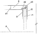
도 3a 는 커버와 실링 디스크의 도식적인 도면을, 이 부품들이 서로 인접하는 영역에서 나타내고,
도 3b 는 커버와 실링 디스크의 가능한 배치의 그 밖의 도식적인 도면을, 이 부품들이 서로 인접하는 영역에서 나타내고,
도 3c 는 도 3b 에 따른 부품들의 배치의 개선을 나타내고,
도 4 는 내부 오일 수집 챔버의 내부에 수집된 윤활유를 위한 배출구를 갖는 커버의 도식적인 아이소메트릭 단면도를 나타낸다.
D : 로터의 회전방향
1 : 하우징
10 : 베어링 하우징
11 : 중간벽
12 : 큰 오일챔버
13 : 휠 후방 챔버
111 : 벽 연장부
121 : 외부 오일 수집 챔버
122 : 내부 오일 수집 챔버
2 : 로터
20 : 샤프트
21 : 압축기휠
3 : 베어링
4 : 시일
5 : 실링 디스크
6 : 커버
61 : 내부 오일 수집 챔버의 배출구
7 : 제 1 분리틈
8 : 제 2 분리틈
81 : 제 2 분리틈의 방사상으로 연장된 부분
82 : 제 2 분리틈의 축방향으로 연장된 부분
9 : 헤비 다월 핀
d1 : 커버의 제 1 두께
d2 : 커버의 제 2 두께
d3 : 커버의 제 3 두께
r1 : 실링 디스크의 제 1 의 보다 작은 반지름
r2 : 실링 디스크의 제 2 의 보다 큰 반지름
Claims (8)
- 로터 (2) 를 갖는 배기가스 터보차저의, 윤활유를 수용하는 베어링 하우징 (10) 을 밀봉하기 위한 장치로서,
상기 로터는 상기 베어링 하우징을 관통하여 인접한, 질량유량으로 부하를 받을 수 있는 압축기 하우징 안으로 안내되고,
상기 베어링 하우징으로 둘러싸인 큰 오일챔버 (12) 와 상기 압축기 하우징의 휠 후방 챔버 (13) 를 서로 분리하고, 축방향으로 연장되고, 고리 모양으로 상기 로터 둘레로 안내된 벽 연장부 (111) 를 구비하는 중간벽 (11),
상기 로터 (2) 의 샤프트 (20) 위에 고정되고 상기 큰 오일챔버 (12) 안으로 돌출하는 고리 모양의 실링 디스크 (5),
상기 실링 디스크 (5) 와 상기 벽 연장부 (111) 사이에 배치된 제 1 분리틈 (7),
로터 (2) 와 중간벽 (11) 사이에 배치된 시일 (seal, 4) 을 포함하고,
주로 축방향으로 연장된 커버 (6) 가 상기 큰 오일챔버 (12) 안에 배치되고,
상기 커버는 상기 축방향으로 연장된 벽 연장부 (111) 에 대해 방사상으로 바깥으로 오프셋되고 (offset), 상기 큰 오일챔버 (12) 를 상기 실링 디스크 (5) 와 함께 내부 오일 수집 챔버 (122) 와 외부 오일 수집 챔버 (121) 로 분할하는 것을 특징으로 하는, 베어링 하우징을 밀봉하기 위한 장치. - 제 1 항에 있어서,
상기 커버 (6) 는 상기 로터 (2) 의 축 (A) 의 수평 정렬과 관련하여 상기 로터 아래에 있는 영역에서 배출구 (61) 를 구비하고,
상기 배출구는 상기 커버의 개구부의 형태로 형성되고, 상기 내부 오일 수집 챔버 (122) 의 내부에 수집된 윤활유를 배출하기 위해 쓰이는 것을 특징으로 하는, 베어링 하우징을 밀봉하기 위한 장치. - 제 2 항에 있어서,
상기 내부 오일 수집 챔버 (122) 의 상기 배출구 (61) 는 중력과 관련하여 상기 내부 오일 수집 챔버 (122) 의 가장 깊은 지점에 대해 상기 로터 (2) 의 회전방향과 반대로 오프셋되어 배치되는 것을 특징으로 하는, 베어링 하우징을 밀봉하기 위한 장치. - 제 1 항에 있어서,
상기 커버 (6) 는 상기 중간벽 (11) 위에 가압되고, 그리고/또는 헤비 다월 핀 (9) 에 의해 정렬되고 그리고/또는 적어도 부분링 모양으로 상기 로터 (2) 둘레로 안내되는 것을 특징으로 하는, 베어링 하우징을 밀봉하기 위한 장치. - 제 1 항에 있어서,
상기 커버 (6) 는 주로 축방향으로 연장된 제 1 섹션과 주로 축방향으로 연장된 제 2 섹션을 구비하며,
상기 주로 축방향으로 연장된 제 1 섹션은 상기 중간벽 (11) 으로부터 상기 실링 디스크 (5) 의 방향으로 상기 큰 오일챔버 (12) 안으로 연장되고,
상기 주로 축방향으로 연장된 제 2 섹션은 상기 주로 축방향으로 연장된 제 1 섹션보다 상기 로터 (20) 의 상기 축 (A) 으로부터의 보다 큰 방사상 간격을 가지며 상기 실링 디스크 (5) 의 외부 가장자리를 방사상으로 밖으로부터 차폐하고,
상기 주로 축방향으로 연장된 제 1 섹션과 상기 주로 축방향으로 연장된 제 2 섹션은 상기 커버 (6) 의 주로 방사상으로 연장된 섹션을 통해 서로 연결되고,
제 2 분리틈 (8) 은 상기 실링 디스크 (5) 와 상기 주로 방사상으로 연장된 섹션 사이에 그리고 상기 커버 (6) 의 상기 주로 축방향으로 연장된 제 2 섹션 사이에 배치되는 것을 특징으로 하는, 베어링 하우징을 밀봉하기 위한 장치. - 제 2 항에 있어서,
상기 주로 축방향으로 연장된 커버 (6) 의 상기 중간벽 (11) 에 인접하는 섹션은 중공의 원뿔대의 형태를 가지며,
상기 중공의 원뿔대의 축은 상기 로터 (2) 의 상기 축 (A) 과 일치하고, 상기 중공의 원뿔대의 가장 큰 지름은 상기 중간벽 (11) 을 향한 상기 커버의 단부에 위치하고,
상기 배출구 (61) 는 상기 내부 오일 수집 챔버 안에 수집된 윤활유를 위해 축방향으로 오프셋되어 상기 실링 디스크 (5) 로부터 상기 중간벽 (11) 의 방향으로 배치되는 것을 특징으로 하는, 베어링 하우징을 밀봉하기 위한 장치. - 제 2 항에 있어서,
상기 주로 축방향으로 연장된 커버 (6) 의 상기 중간벽 (11) 에 인접하는 섹션은 비스듬한 중공 원통의 형태를 가지며,
상기 비스듬한 중공 원통의 축은 상기 로터 (2) 의 상기 축 (A) 에 대해 수직선의 방향으로 상기 중간벽 (11) 으로부터 상기 베어링 하우징 (10) 의 방향으로 볼 때 위로 기울어져 있는 것을 특징으로 하는, 베어링 하우징을 밀봉하기 위한 장치. - 제 1 항 내지 제 7 항 중 어느 한 항에 따른 장치를 갖는 배기가스 터보차저.
Applications Claiming Priority (3)
| Application Number | Priority Date | Filing Date | Title |
|---|---|---|---|
| DE102015119602.6A DE102015119602A1 (de) | 2015-11-13 | 2015-11-13 | Wellendichtung |
| DE102015119602.6 | 2015-11-13 | ||
| PCT/EP2016/076688 WO2017080924A1 (de) | 2015-11-13 | 2016-11-04 | Vorrichtung zur abdichtung eines lagergehäuses und abgasturbolader mit einer solchen vorrichtung |
Publications (2)
| Publication Number | Publication Date |
|---|---|
| KR20180075675A true KR20180075675A (ko) | 2018-07-04 |
| KR102646179B1 KR102646179B1 (ko) | 2024-03-12 |
Family
ID=57223717
Family Applications (1)
| Application Number | Title | Priority Date | Filing Date |
|---|---|---|---|
| KR1020187016571A Active KR102646179B1 (ko) | 2015-11-13 | 2016-11-04 | 베어링 하우징을 밀봉하기 위한 장치, 및 이러한 장치를 갖는 배기가스 터보차저 |
Country Status (6)
| Country | Link |
|---|---|
| EP (1) | EP3374602B1 (ko) |
| JP (1) | JP6868620B2 (ko) |
| KR (1) | KR102646179B1 (ko) |
| CN (1) | CN108474266B (ko) |
| DE (1) | DE102015119602A1 (ko) |
| WO (1) | WO2017080924A1 (ko) |
Families Citing this family (2)
| Publication number | Priority date | Publication date | Assignee | Title |
|---|---|---|---|---|
| DE102017202687A1 (de) | 2017-02-20 | 2018-08-23 | BMTS Technology GmbH & Co. KG | Lagergehäuse und ein Abgasturoblader mit einem solchen Gehäuse |
| FR3090786B1 (fr) * | 2018-12-21 | 2020-12-04 | Safran Trans Systems | Distributeur d’huile de lubrification pour un reducteur mecanique de turbomachine d’aeronef |
Citations (2)
| Publication number | Priority date | Publication date | Assignee | Title |
|---|---|---|---|---|
| JP2012510583A (ja) * | 2008-11-28 | 2012-05-10 | アーベーベー ターボ システムズ アクチエンゲゼルシャフト | 排気ガス・ターボチャージャの軸受ハウジングをシールするための装置 |
| US20140234075A1 (en) * | 2013-02-21 | 2014-08-21 | Bosch Mahle Turbo Systems Gmbh & Co. Kg | Exhaust gas turbocharger |
Family Cites Families (11)
| Publication number | Priority date | Publication date | Assignee | Title |
|---|---|---|---|---|
| DE1077007B (de) * | 1958-11-14 | 1960-03-03 | Daimler Benz Ag | Anordnung der Lager von Wellen od. dgl. umlaufenden Maschinenteilen |
| JPH0216037Y2 (ko) * | 1984-12-20 | 1990-05-01 | ||
| JP3252046B2 (ja) * | 1994-02-02 | 2002-01-28 | 大豊工業株式会社 | ターボチャージャの非接触シール装置 |
| JPH07217441A (ja) * | 1994-02-02 | 1995-08-15 | Taiho Kogyo Co Ltd | ターボチャージャの非接触シール装置 |
| JPH08135458A (ja) * | 1994-11-09 | 1996-05-28 | Toyota Motor Corp | 過給機のオイルシール構造 |
| JPH09264151A (ja) * | 1996-03-29 | 1997-10-07 | Aisin Seiki Co Ltd | ターボチャージャのオイル漏れ防止機構 |
| GB0720478D0 (en) * | 2007-10-13 | 2007-11-28 | Cummins Turbo Tech Ltd | Turbomachine |
| GB2469101B (en) * | 2009-04-02 | 2015-10-21 | Cummins Turbo Tech Ltd | A rotating machine with shaft sealing arrangement |
| WO2013145078A1 (ja) * | 2012-03-26 | 2013-10-03 | トヨタ自動車 株式会社 | 排気タービン過給機 |
| WO2014014791A1 (en) * | 2012-07-15 | 2014-01-23 | Honeywell International Inc. | Turbocharger with lubricant deflector |
| CN204402646U (zh) * | 2014-12-04 | 2015-06-17 | 湖南天雁机械有限责任公司 | 涡轮增压器压气机端密封结构 |
-
2015
- 2015-11-13 DE DE102015119602.6A patent/DE102015119602A1/de not_active Withdrawn
-
2016
- 2016-11-04 EP EP16790406.9A patent/EP3374602B1/de active Active
- 2016-11-04 CN CN201680078972.XA patent/CN108474266B/zh active Active
- 2016-11-04 KR KR1020187016571A patent/KR102646179B1/ko active Active
- 2016-11-04 WO PCT/EP2016/076688 patent/WO2017080924A1/de active Application Filing
- 2016-11-04 JP JP2018524426A patent/JP6868620B2/ja active Active
Patent Citations (2)
| Publication number | Priority date | Publication date | Assignee | Title |
|---|---|---|---|---|
| JP2012510583A (ja) * | 2008-11-28 | 2012-05-10 | アーベーベー ターボ システムズ アクチエンゲゼルシャフト | 排気ガス・ターボチャージャの軸受ハウジングをシールするための装置 |
| US20140234075A1 (en) * | 2013-02-21 | 2014-08-21 | Bosch Mahle Turbo Systems Gmbh & Co. Kg | Exhaust gas turbocharger |
Also Published As
| Publication number | Publication date |
|---|---|
| CN108474266A (zh) | 2018-08-31 |
| JP2018533689A (ja) | 2018-11-15 |
| DE102015119602A1 (de) | 2017-05-18 |
| KR102646179B1 (ko) | 2024-03-12 |
| EP3374602A1 (de) | 2018-09-19 |
| JP6868620B2 (ja) | 2021-05-12 |
| CN108474266B (zh) | 2020-10-23 |
| WO2017080924A1 (de) | 2017-05-18 |
| EP3374602B1 (de) | 2020-05-20 |
Similar Documents
| Publication | Publication Date | Title |
|---|---|---|
| KR101270843B1 (ko) | 배기가스 터보차저의 베어링 하우징을 밀봉하기 위한 장치 | |
| US9897005B2 (en) | Oil distributor | |
| CN100393984C (zh) | 涡轮增压器 | |
| EP1724445B1 (en) | Apparatus for scavenging lubricating oil | |
| KR101519868B1 (ko) | 스러스트 베어링 구조 및 상기 스러스트 베어링 구조를 구비하는 과급기 | |
| JP5277901B2 (ja) | 車両用過給機の潤滑油シール構造 | |
| US20170298769A1 (en) | Bearing structure of turbocharger | |
| CN101845987A (zh) | 废气涡轮增压器的压缩机侧轴密封装置 | |
| US20150125263A1 (en) | Flinger oil seal and turbocharger incorporating the same | |
| KR20110113569A (ko) | 샤프트 밀봉재 | |
| US20170335717A1 (en) | Bearing structure of turbocharger | |
| US10669891B2 (en) | Bearing structure and turbocharger | |
| US20160097293A1 (en) | Compressor seal assembly for a turbocharger | |
| US20170292405A1 (en) | Bearing structure of turbocharger | |
| KR20180075675A (ko) | 베어링 하우징을 밀봉하기 위한 장치, 및 이러한 장치를 갖는 배기가스 터보차저 | |
| US10865833B2 (en) | Bearing structure and turbocharger | |
| CN209818381U (zh) | 具有压缩机插件或背板中的再循环失速的涡轮增压器 | |
| US10393170B2 (en) | Bearing structure and turbocharger | |
| CN103867236B (zh) | 轴密封件 | |
| CN101506529A (zh) | 轴密封 | |
| KR102642204B1 (ko) | 윤활유 흐름 분리 장치 및 그러한 장치를 갖는 배기가스 터보 과급기 | |
| US11959388B2 (en) | Turbocharger having improved shaft seal | |
| JP7139055B2 (ja) | 排気ターボ過給機の軸受の構造 | |
| KR20240055096A (ko) | 오일-냉각식 배기 터빈 장치 | |
| CN117940653A (zh) | 油冷却废气涡轮机设备 |
Legal Events
| Date | Code | Title | Description |
|---|---|---|---|
| PA0105 | International application |
Patent event date: 20180611 Patent event code: PA01051R01D Comment text: International Patent Application |
|
| PG1501 | Laying open of application | ||
| PN2301 | Change of applicant |
Patent event date: 20201116 Comment text: Notification of Change of Applicant Patent event code: PN23011R01D |
|
| PA0201 | Request for examination |
Patent event code: PA02012R01D Patent event date: 20211015 Comment text: Request for Examination of Application |
|
| PN2301 | Change of applicant |
Patent event date: 20221125 Comment text: Notification of Change of Applicant Patent event code: PN23011R01D |
|
| E902 | Notification of reason for refusal | ||
| PE0902 | Notice of grounds for rejection |
Comment text: Notification of reason for refusal Patent event date: 20230801 Patent event code: PE09021S01D |
|
| E701 | Decision to grant or registration of patent right | ||
| PE0701 | Decision of registration |
Patent event code: PE07011S01D Comment text: Decision to Grant Registration Patent event date: 20240109 |
|
| GRNT | Written decision to grant | ||
| PR0701 | Registration of establishment |
Comment text: Registration of Establishment Patent event date: 20240306 Patent event code: PR07011E01D |
|
| PR1002 | Payment of registration fee |
Payment date: 20240307 End annual number: 3 Start annual number: 1 |
|
| PG1601 | Publication of registration |