KR20170128337A - Seismic Retention Device - Google Patents
Seismic Retention Device Download PDFInfo
- Publication number
- KR20170128337A KR20170128337A KR1020177026229A KR20177026229A KR20170128337A KR 20170128337 A KR20170128337 A KR 20170128337A KR 1020177026229 A KR1020177026229 A KR 1020177026229A KR 20177026229 A KR20177026229 A KR 20177026229A KR 20170128337 A KR20170128337 A KR 20170128337A
- Authority
- KR
- South Korea
- Prior art keywords
- circumferential surface
- thermal conductivity
- rubber
- layer
- inner circumferential
- Prior art date
- Legal status (The legal status is an assumption and is not a legal conclusion. Google has not performed a legal analysis and makes no representation as to the accuracy of the status listed.)
- Withdrawn
Links
- 230000014759 maintenance of location Effects 0.000 title 1
- 239000004020 conductor Substances 0.000 claims abstract description 51
- 230000002093 peripheral effect Effects 0.000 claims abstract description 29
- 239000010410 layer Substances 0.000 claims description 141
- 229920001971 elastomer Polymers 0.000 claims description 74
- 239000005060 rubber Substances 0.000 claims description 74
- OKTJSMMVPCPJKN-UHFFFAOYSA-N Carbon Chemical compound [C] OKTJSMMVPCPJKN-UHFFFAOYSA-N 0.000 claims description 47
- 239000000945 filler Substances 0.000 claims description 34
- 229910000831 Steel Inorganic materials 0.000 claims description 29
- 239000010959 steel Substances 0.000 claims description 29
- 238000013016 damping Methods 0.000 claims description 28
- 229920000642 polymer Polymers 0.000 claims description 21
- 238000000034 method Methods 0.000 claims description 17
- 229910052751 metal Inorganic materials 0.000 claims description 15
- 239000002184 metal Substances 0.000 claims description 15
- 229920002725 thermoplastic elastomer Polymers 0.000 claims description 12
- 239000002470 thermal conductor Substances 0.000 claims description 11
- 229920001169 thermoplastic Polymers 0.000 claims description 10
- 239000011247 coating layer Substances 0.000 claims description 9
- 229920005989 resin Polymers 0.000 claims description 9
- 239000011347 resin Substances 0.000 claims description 9
- 229920001187 thermosetting polymer Polymers 0.000 claims description 9
- 229920003002 synthetic resin Polymers 0.000 claims description 6
- 239000000057 synthetic resin Substances 0.000 claims description 6
- 239000004416 thermosoftening plastic Substances 0.000 claims description 6
- 229910052799 carbon Inorganic materials 0.000 claims description 5
- 239000000919 ceramic Substances 0.000 claims description 5
- 239000005011 phenolic resin Substances 0.000 claims description 4
- 229920001955 polyphenylene ether Polymers 0.000 claims description 4
- 239000004634 thermosetting polymer Substances 0.000 claims description 4
- XQUPVDVFXZDTLT-UHFFFAOYSA-N 1-[4-[[4-(2,5-dioxopyrrol-1-yl)phenyl]methyl]phenyl]pyrrole-2,5-dione Chemical compound O=C1C=CC(=O)N1C(C=C1)=CC=C1CC1=CC=C(N2C(C=CC2=O)=O)C=C1 XQUPVDVFXZDTLT-UHFFFAOYSA-N 0.000 claims description 2
- 239000003822 epoxy resin Substances 0.000 claims description 2
- 229920003192 poly(bis maleimide) Polymers 0.000 claims description 2
- 229920000647 polyepoxide Polymers 0.000 claims description 2
- 229920001721 polyimide Polymers 0.000 claims description 2
- 239000009719 polyimide resin Substances 0.000 claims description 2
- 229920006337 unsaturated polyester resin Polymers 0.000 claims description 2
- 238000002955 isolation Methods 0.000 abstract description 6
- 229910002804 graphite Inorganic materials 0.000 description 30
- 239000010439 graphite Substances 0.000 description 28
- 239000002245 particle Substances 0.000 description 16
- 239000000853 adhesive Substances 0.000 description 14
- 229920000049 Carbon (fiber) Polymers 0.000 description 13
- 239000004917 carbon fiber Substances 0.000 description 13
- 230000001070 adhesive effect Effects 0.000 description 12
- 239000011241 protective layer Substances 0.000 description 11
- 239000000203 mixture Substances 0.000 description 10
- 238000007747 plating Methods 0.000 description 10
- 244000043261 Hevea brasiliensis Species 0.000 description 9
- 239000000463 material Substances 0.000 description 9
- VNWKTOKETHGBQD-UHFFFAOYSA-N methane Chemical compound C VNWKTOKETHGBQD-UHFFFAOYSA-N 0.000 description 9
- 229920003052 natural elastomer Polymers 0.000 description 9
- 229920001194 natural rubber Polymers 0.000 description 9
- -1 ethylene- Chemical class 0.000 description 8
- 239000000835 fiber Substances 0.000 description 8
- 238000004073 vulcanization Methods 0.000 description 8
- 229920005549 butyl rubber Polymers 0.000 description 7
- 239000006229 carbon black Substances 0.000 description 7
- 239000003795 chemical substances by application Substances 0.000 description 7
- 229920000181 Ethylene propylene rubber Polymers 0.000 description 6
- 229910052782 aluminium Inorganic materials 0.000 description 6
- XAGFODPZIPBFFR-UHFFFAOYSA-N aluminium Chemical compound [Al] XAGFODPZIPBFFR-UHFFFAOYSA-N 0.000 description 6
- 239000011295 pitch Substances 0.000 description 6
- 229920006324 polyoxymethylene Polymers 0.000 description 6
- PZNSFCLAULLKQX-UHFFFAOYSA-N Boron nitride Chemical compound N#B PZNSFCLAULLKQX-UHFFFAOYSA-N 0.000 description 5
- 229930182556 Polyacetal Natural products 0.000 description 5
- ATJFFYVFTNAWJD-UHFFFAOYSA-N Tin Chemical compound [Sn] ATJFFYVFTNAWJD-UHFFFAOYSA-N 0.000 description 5
- 238000004519 manufacturing process Methods 0.000 description 5
- 239000011135 tin Substances 0.000 description 5
- 229910052718 tin Inorganic materials 0.000 description 5
- 229910052582 BN Inorganic materials 0.000 description 4
- RYGMFSIKBFXOCR-UHFFFAOYSA-N Copper Chemical compound [Cu] RYGMFSIKBFXOCR-UHFFFAOYSA-N 0.000 description 4
- PXHVJJICTQNCMI-UHFFFAOYSA-N Nickel Chemical compound [Ni] PXHVJJICTQNCMI-UHFFFAOYSA-N 0.000 description 4
- 229920000459 Nitrile rubber Polymers 0.000 description 4
- PPBRXRYQALVLMV-UHFFFAOYSA-N Styrene Chemical compound C=CC1=CC=CC=C1 PPBRXRYQALVLMV-UHFFFAOYSA-N 0.000 description 4
- 235000010724 Wisteria floribunda Nutrition 0.000 description 4
- 238000010521 absorption reaction Methods 0.000 description 4
- 230000000052 comparative effect Effects 0.000 description 4
- 229910052802 copper Inorganic materials 0.000 description 4
- 239000010949 copper Substances 0.000 description 4
- 230000005284 excitation Effects 0.000 description 4
- 239000007788 liquid Substances 0.000 description 4
- 229920001084 poly(chloroprene) Polymers 0.000 description 4
- 229920006122 polyamide resin Polymers 0.000 description 4
- 239000000843 powder Substances 0.000 description 4
- 239000005062 Polybutadiene Substances 0.000 description 3
- NINIDFKCEFEMDL-UHFFFAOYSA-N Sulfur Chemical compound [S] NINIDFKCEFEMDL-UHFFFAOYSA-N 0.000 description 3
- 238000009825 accumulation Methods 0.000 description 3
- 239000003963 antioxidant agent Substances 0.000 description 3
- 238000010073 coating (rubber) Methods 0.000 description 3
- 239000010960 cold rolled steel Substances 0.000 description 3
- 229920003049 isoprene rubber Polymers 0.000 description 3
- 239000000395 magnesium oxide Substances 0.000 description 3
- CPLXHLVBOLITMK-UHFFFAOYSA-N magnesium oxide Inorganic materials [Mg]=O CPLXHLVBOLITMK-UHFFFAOYSA-N 0.000 description 3
- AXZKOIWUVFPNLO-UHFFFAOYSA-N magnesium;oxygen(2-) Chemical compound [O-2].[Mg+2] AXZKOIWUVFPNLO-UHFFFAOYSA-N 0.000 description 3
- 238000002844 melting Methods 0.000 description 3
- 230000008018 melting Effects 0.000 description 3
- TWNQGVIAIRXVLR-UHFFFAOYSA-N oxo(oxoalumanyloxy)alumane Chemical compound O=[Al]O[Al]=O TWNQGVIAIRXVLR-UHFFFAOYSA-N 0.000 description 3
- 229920002857 polybutadiene Polymers 0.000 description 3
- 229920001707 polybutylene terephthalate Polymers 0.000 description 3
- 239000010734 process oil Substances 0.000 description 3
- 229920003048 styrene butadiene rubber Polymers 0.000 description 3
- 229910052717 sulfur Inorganic materials 0.000 description 3
- 239000011593 sulfur Substances 0.000 description 3
- YXIWHUQXZSMYRE-UHFFFAOYSA-N 1,3-benzothiazole-2-thiol Chemical compound C1=CC=C2SC(S)=NC2=C1 YXIWHUQXZSMYRE-UHFFFAOYSA-N 0.000 description 2
- KXGFMDJXCMQABM-UHFFFAOYSA-N 2-methoxy-6-methylphenol Chemical compound [CH]OC1=CC=CC([CH])=C1O KXGFMDJXCMQABM-UHFFFAOYSA-N 0.000 description 2
- 229910018072 Al 2 O 3 Inorganic materials 0.000 description 2
- 229920002943 EPDM rubber Polymers 0.000 description 2
- XEEYBQQBJWHFJM-UHFFFAOYSA-N Iron Chemical compound [Fe] XEEYBQQBJWHFJM-UHFFFAOYSA-N 0.000 description 2
- 239000004698 Polyethylene Substances 0.000 description 2
- 239000004734 Polyphenylene sulfide Substances 0.000 description 2
- 239000004743 Polypropylene Substances 0.000 description 2
- 239000004372 Polyvinyl alcohol Substances 0.000 description 2
- 235000021355 Stearic acid Nutrition 0.000 description 2
- HCHKCACWOHOZIP-UHFFFAOYSA-N Zinc Chemical compound [Zn] HCHKCACWOHOZIP-UHFFFAOYSA-N 0.000 description 2
- 239000006096 absorbing agent Substances 0.000 description 2
- 239000006230 acetylene black Substances 0.000 description 2
- 230000003078 antioxidant effect Effects 0.000 description 2
- 239000002041 carbon nanotube Substances 0.000 description 2
- 229910021393 carbon nanotube Inorganic materials 0.000 description 2
- POULHZVOKOAJMA-UHFFFAOYSA-N dodecanoic acid Chemical compound CCCCCCCCCCCC(O)=O POULHZVOKOAJMA-UHFFFAOYSA-N 0.000 description 2
- 230000000694 effects Effects 0.000 description 2
- 239000005038 ethylene vinyl acetate Substances 0.000 description 2
- 230000008020 evaporation Effects 0.000 description 2
- 238000001704 evaporation Methods 0.000 description 2
- 229920005555 halobutyl Polymers 0.000 description 2
- IPCSVZSSVZVIGE-UHFFFAOYSA-N hexadecanoic acid Chemical compound CCCCCCCCCCCCCCCC(O)=O IPCSVZSSVZVIGE-UHFFFAOYSA-N 0.000 description 2
- 238000004898 kneading Methods 0.000 description 2
- 229910044991 metal oxide Inorganic materials 0.000 description 2
- 150000004706 metal oxides Chemical class 0.000 description 2
- 238000002156 mixing Methods 0.000 description 2
- 238000000465 moulding Methods 0.000 description 2
- 229910052759 nickel Inorganic materials 0.000 description 2
- 229920003986 novolac Polymers 0.000 description 2
- QIQXTHQIDYTFRH-UHFFFAOYSA-N octadecanoic acid Chemical compound CCCCCCCCCCCCCCCCCC(O)=O QIQXTHQIDYTFRH-UHFFFAOYSA-N 0.000 description 2
- OQCDKBAXFALNLD-UHFFFAOYSA-N octadecanoic acid Natural products CCCCCCCC(C)CCCCCCCCC(O)=O OQCDKBAXFALNLD-UHFFFAOYSA-N 0.000 description 2
- 239000008188 pellet Substances 0.000 description 2
- 229920001568 phenolic resin Polymers 0.000 description 2
- 229920003023 plastic Polymers 0.000 description 2
- 239000004033 plastic Substances 0.000 description 2
- 229920001200 poly(ethylene-vinyl acetate) Polymers 0.000 description 2
- 229920002492 poly(sulfone) Polymers 0.000 description 2
- 229920002239 polyacrylonitrile Polymers 0.000 description 2
- 229920002647 polyamide Polymers 0.000 description 2
- 239000004417 polycarbonate Substances 0.000 description 2
- 229920000573 polyethylene Polymers 0.000 description 2
- 229920000069 polyphenylene sulfide Polymers 0.000 description 2
- 229920001155 polypropylene Polymers 0.000 description 2
- 229920002635 polyurethane Polymers 0.000 description 2
- 239000004814 polyurethane Substances 0.000 description 2
- 239000011118 polyvinyl acetate Substances 0.000 description 2
- 229920002689 polyvinyl acetate Polymers 0.000 description 2
- 229920002451 polyvinyl alcohol Polymers 0.000 description 2
- 229920000036 polyvinylpyrrolidone Polymers 0.000 description 2
- 239000001267 polyvinylpyrrolidone Substances 0.000 description 2
- 235000013855 polyvinylpyrrolidone Nutrition 0.000 description 2
- 239000008117 stearic acid Substances 0.000 description 2
- 239000000126 substance Substances 0.000 description 2
- XLYOFNOQVPJJNP-UHFFFAOYSA-N water Substances O XLYOFNOQVPJJNP-UHFFFAOYSA-N 0.000 description 2
- 229910052725 zinc Inorganic materials 0.000 description 2
- 239000011701 zinc Substances 0.000 description 2
- LTPBRCUWZOMYOC-UHFFFAOYSA-N Beryllium oxide Chemical compound O=[Be] LTPBRCUWZOMYOC-UHFFFAOYSA-N 0.000 description 1
- 229910001369 Brass Inorganic materials 0.000 description 1
- 229910000906 Bronze Inorganic materials 0.000 description 1
- XMWRBQBLMFGWIX-UHFFFAOYSA-N C60 fullerene Chemical compound C12=C3C(C4=C56)=C7C8=C5C5=C9C%10=C6C6=C4C1=C1C4=C6C6=C%10C%10=C9C9=C%11C5=C8C5=C8C7=C3C3=C7C2=C1C1=C2C4=C6C4=C%10C6=C9C9=C%11C5=C5C8=C3C3=C7C1=C1C2=C4C6=C2C9=C5C3=C12 XMWRBQBLMFGWIX-UHFFFAOYSA-N 0.000 description 1
- 239000004709 Chlorinated polyethylene Substances 0.000 description 1
- VYZAMTAEIAYCRO-UHFFFAOYSA-N Chromium Chemical compound [Cr] VYZAMTAEIAYCRO-UHFFFAOYSA-N 0.000 description 1
- 229920000089 Cyclic olefin copolymer Polymers 0.000 description 1
- 239000005639 Lauric acid Substances 0.000 description 1
- FYYHWMGAXLPEAU-UHFFFAOYSA-N Magnesium Chemical compound [Mg] FYYHWMGAXLPEAU-UHFFFAOYSA-N 0.000 description 1
- 235000021314 Palmitic acid Nutrition 0.000 description 1
- 229920012266 Poly(ether sulfone) PES Polymers 0.000 description 1
- 239000004952 Polyamide Substances 0.000 description 1
- 229920000297 Rayon Polymers 0.000 description 1
- 229910052581 Si3N4 Inorganic materials 0.000 description 1
- XUIMIQQOPSSXEZ-UHFFFAOYSA-N Silicon Chemical compound [Si] XUIMIQQOPSSXEZ-UHFFFAOYSA-N 0.000 description 1
- BQCADISMDOOEFD-UHFFFAOYSA-N Silver Chemical compound [Ag] BQCADISMDOOEFD-UHFFFAOYSA-N 0.000 description 1
- GWEVSGVZZGPLCZ-UHFFFAOYSA-N Titan oxide Chemical compound O=[Ti]=O GWEVSGVZZGPLCZ-UHFFFAOYSA-N 0.000 description 1
- 229920006311 Urethane elastomer Polymers 0.000 description 1
- BZHJMEDXRYGGRV-UHFFFAOYSA-N Vinyl chloride Chemical compound ClC=C BZHJMEDXRYGGRV-UHFFFAOYSA-N 0.000 description 1
- 229910000611 Zinc aluminium Inorganic materials 0.000 description 1
- XLOMVQKBTHCTTD-UHFFFAOYSA-N Zinc monoxide Chemical compound [Zn]=O XLOMVQKBTHCTTD-UHFFFAOYSA-N 0.000 description 1
- 230000001133 acceleration Effects 0.000 description 1
- 229920000800 acrylic rubber Polymers 0.000 description 1
- 150000001336 alkenes Chemical class 0.000 description 1
- 229910045601 alloy Inorganic materials 0.000 description 1
- 239000000956 alloy Substances 0.000 description 1
- HXFVOUUOTHJFPX-UHFFFAOYSA-N alumane;zinc Chemical compound [AlH3].[Zn] HXFVOUUOTHJFPX-UHFFFAOYSA-N 0.000 description 1
- CAVCGVPGBKGDTG-UHFFFAOYSA-N alumanylidynemethyl(alumanylidynemethylalumanylidenemethylidene)alumane Chemical compound [Al]#C[Al]=C=[Al]C#[Al] CAVCGVPGBKGDTG-UHFFFAOYSA-N 0.000 description 1
- SNAAJJQQZSMGQD-UHFFFAOYSA-N aluminum magnesium Chemical compound [Mg].[Al] SNAAJJQQZSMGQD-UHFFFAOYSA-N 0.000 description 1
- 229910021383 artificial graphite Inorganic materials 0.000 description 1
- 125000003118 aryl group Chemical group 0.000 description 1
- 230000005540 biological transmission Effects 0.000 description 1
- 230000015572 biosynthetic process Effects 0.000 description 1
- INAHAJYZKVIDIZ-UHFFFAOYSA-N boron carbide Chemical compound B12B3B4C32B41 INAHAJYZKVIDIZ-UHFFFAOYSA-N 0.000 description 1
- 239000010951 brass Substances 0.000 description 1
- 239000010974 bronze Substances 0.000 description 1
- 238000003490 calendering Methods 0.000 description 1
- 239000002134 carbon nanofiber Substances 0.000 description 1
- 239000011304 carbon pitch Substances 0.000 description 1
- 239000006231 channel black Substances 0.000 description 1
- 238000000576 coating method Methods 0.000 description 1
- 150000001875 compounds Chemical class 0.000 description 1
- 229920001577 copolymer Polymers 0.000 description 1
- KUNSUQLRTQLHQQ-UHFFFAOYSA-N copper tin Chemical compound [Cu].[Sn] KUNSUQLRTQLHQQ-UHFFFAOYSA-N 0.000 description 1
- 229910003460 diamond Inorganic materials 0.000 description 1
- 239000010432 diamond Substances 0.000 description 1
- AFZSMODLJJCVPP-UHFFFAOYSA-N dibenzothiazol-2-yl disulfide Chemical compound C1=CC=C2SC(SSC=3SC4=CC=CC=C4N=3)=NC2=C1 AFZSMODLJJCVPP-UHFFFAOYSA-N 0.000 description 1
- 235000014113 dietary fatty acids Nutrition 0.000 description 1
- 238000006073 displacement reaction Methods 0.000 description 1
- 238000009713 electroplating Methods 0.000 description 1
- 230000001747 exhibiting effect Effects 0.000 description 1
- 238000001125 extrusion Methods 0.000 description 1
- 239000000194 fatty acid Substances 0.000 description 1
- 229930195729 fatty acid Natural products 0.000 description 1
- 150000004665 fatty acids Chemical class 0.000 description 1
- 229920001973 fluoroelastomer Polymers 0.000 description 1
- 229910003472 fullerene Inorganic materials 0.000 description 1
- 229910021389 graphene Inorganic materials 0.000 description 1
- 230000017525 heat dissipation Effects 0.000 description 1
- 238000010438 heat treatment Methods 0.000 description 1
- 229920002674 hyaluronan Polymers 0.000 description 1
- KIUKXJAPPMFGSW-MNSSHETKSA-N hyaluronan Chemical compound CC(=O)N[C@H]1[C@H](O)O[C@H](CO)[C@@H](O)C1O[C@H]1[C@H](O)[C@@H](O)[C@H](O[C@H]2[C@@H](C(O[C@H]3[C@@H]([C@@H](O)[C@H](O)[C@H](O3)C(O)=O)O)[C@H](O)[C@@H](CO)O2)NC(C)=O)[C@@H](C(O)=O)O1 KIUKXJAPPMFGSW-MNSSHETKSA-N 0.000 description 1
- 229940099552 hyaluronan Drugs 0.000 description 1
- 229920002681 hypalon Polymers 0.000 description 1
- 229910052742 iron Inorganic materials 0.000 description 1
- 239000003273 ketjen black Substances 0.000 description 1
- 229910052749 magnesium Inorganic materials 0.000 description 1
- 239000011777 magnesium Substances 0.000 description 1
- 150000001247 metal acetylides Chemical class 0.000 description 1
- 150000002739 metals Chemical class 0.000 description 1
- 239000012778 molding material Substances 0.000 description 1
- 239000002048 multi walled nanotube Substances 0.000 description 1
- DEQZTKGFXNUBJL-UHFFFAOYSA-N n-(1,3-benzothiazol-2-ylsulfanyl)cyclohexanamine Chemical compound C1CCCCC1NSC1=NC2=CC=CC=C2S1 DEQZTKGFXNUBJL-UHFFFAOYSA-N 0.000 description 1
- WQEPLUUGTLDZJY-UHFFFAOYSA-N n-Pentadecanoic acid Natural products CCCCCCCCCCCCCCC(O)=O WQEPLUUGTLDZJY-UHFFFAOYSA-N 0.000 description 1
- 239000002736 nonionic surfactant Substances 0.000 description 1
- JRZJOMJEPLMPRA-UHFFFAOYSA-N olefin Natural products CCCCCCCC=C JRZJOMJEPLMPRA-UHFFFAOYSA-N 0.000 description 1
- 229920003207 poly(ethylene-2,6-naphthalate) Polymers 0.000 description 1
- 229920000058 polyacrylate Polymers 0.000 description 1
- 229920000515 polycarbonate Polymers 0.000 description 1
- 239000011112 polyethylene naphthalate Substances 0.000 description 1
- 229920000139 polyethylene terephthalate Polymers 0.000 description 1
- 239000005020 polyethylene terephthalate Substances 0.000 description 1
- 229920000346 polystyrene-polyisoprene block-polystyrene Polymers 0.000 description 1
- 239000004800 polyvinyl chloride Substances 0.000 description 1
- 239000005033 polyvinylidene chloride Substances 0.000 description 1
- 238000002360 preparation method Methods 0.000 description 1
- 238000003825 pressing Methods 0.000 description 1
- 239000004065 semiconductor Substances 0.000 description 1
- 238000010008 shearing Methods 0.000 description 1
- 239000010703 silicon Substances 0.000 description 1
- 229910052710 silicon Inorganic materials 0.000 description 1
- HBMJWWWQQXIZIP-UHFFFAOYSA-N silicon carbide Chemical compound [Si+]#[C-] HBMJWWWQQXIZIP-UHFFFAOYSA-N 0.000 description 1
- HQVNEWCFYHHQES-UHFFFAOYSA-N silicon nitride Chemical compound N12[Si]34N5[Si]62N3[Si]51N64 HQVNEWCFYHHQES-UHFFFAOYSA-N 0.000 description 1
- 229910052709 silver Inorganic materials 0.000 description 1
- 239000004332 silver Substances 0.000 description 1
- 239000002109 single walled nanotube Substances 0.000 description 1
- 239000002904 solvent Substances 0.000 description 1
- 238000005507 spraying Methods 0.000 description 1
- 235000001508 sulfur Nutrition 0.000 description 1
- 238000010998 test method Methods 0.000 description 1
- WFKWXMTUELFFGS-UHFFFAOYSA-N tungsten Chemical compound [W] WFKWXMTUELFFGS-UHFFFAOYSA-N 0.000 description 1
- 229910052721 tungsten Inorganic materials 0.000 description 1
- 239000010937 tungsten Substances 0.000 description 1
Images


Classifications
-
- F—MECHANICAL ENGINEERING; LIGHTING; HEATING; WEAPONS; BLASTING
- F16—ENGINEERING ELEMENTS AND UNITS; GENERAL MEASURES FOR PRODUCING AND MAINTAINING EFFECTIVE FUNCTIONING OF MACHINES OR INSTALLATIONS; THERMAL INSULATION IN GENERAL
- F16F—SPRINGS; SHOCK-ABSORBERS; MEANS FOR DAMPING VIBRATION
- F16F1/00—Springs
- F16F1/36—Springs made of rubber or other material having high internal friction, e.g. thermoplastic elastomers
- F16F1/3605—Springs made of rubber or other material having high internal friction, e.g. thermoplastic elastomers characterised by their material
-
- F—MECHANICAL ENGINEERING; LIGHTING; HEATING; WEAPONS; BLASTING
- F16—ENGINEERING ELEMENTS AND UNITS; GENERAL MEASURES FOR PRODUCING AND MAINTAINING EFFECTIVE FUNCTIONING OF MACHINES OR INSTALLATIONS; THERMAL INSULATION IN GENERAL
- F16F—SPRINGS; SHOCK-ABSORBERS; MEANS FOR DAMPING VIBRATION
- F16F1/00—Springs
- F16F1/36—Springs made of rubber or other material having high internal friction, e.g. thermoplastic elastomers
- F16F1/40—Springs made of rubber or other material having high internal friction, e.g. thermoplastic elastomers consisting of a stack of similar elements separated by non-elastic intermediate layers
-
- C—CHEMISTRY; METALLURGY
- C08—ORGANIC MACROMOLECULAR COMPOUNDS; THEIR PREPARATION OR CHEMICAL WORKING-UP; COMPOSITIONS BASED THEREON
- C08K—Use of inorganic or non-macromolecular organic substances as compounding ingredients
- C08K3/00—Use of inorganic substances as compounding ingredients
- C08K3/18—Oxygen-containing compounds, e.g. metal carbonyls
- C08K3/20—Oxides; Hydroxides
- C08K3/22—Oxides; Hydroxides of metals
-
- E—FIXED CONSTRUCTIONS
- E04—BUILDING
- E04H—BUILDINGS OR LIKE STRUCTURES FOR PARTICULAR PURPOSES; SWIMMING OR SPLASH BATHS OR POOLS; MASTS; FENCING; TENTS OR CANOPIES, IN GENERAL
- E04H9/00—Buildings, groups of buildings or shelters adapted to withstand or provide protection against abnormal external influences, e.g. war-like action, earthquake or extreme climate
- E04H9/02—Buildings, groups of buildings or shelters adapted to withstand or provide protection against abnormal external influences, e.g. war-like action, earthquake or extreme climate withstanding earthquake or sinking of ground
- E04H9/021—Bearing, supporting or connecting constructions specially adapted for such buildings
- E04H9/022—Bearing, supporting or connecting constructions specially adapted for such buildings and comprising laminated structures of alternating elastomeric and rigid layers
-
- F—MECHANICAL ENGINEERING; LIGHTING; HEATING; WEAPONS; BLASTING
- F16—ENGINEERING ELEMENTS AND UNITS; GENERAL MEASURES FOR PRODUCING AND MAINTAINING EFFECTIVE FUNCTIONING OF MACHINES OR INSTALLATIONS; THERMAL INSULATION IN GENERAL
- F16F—SPRINGS; SHOCK-ABSORBERS; MEANS FOR DAMPING VIBRATION
- F16F15/00—Suppression of vibrations in systems; Means or arrangements for avoiding or reducing out-of-balance forces, e.g. due to motion
- F16F15/02—Suppression of vibrations of non-rotating, e.g. reciprocating systems; Suppression of vibrations of rotating systems by use of members not moving with the rotating systems
- F16F15/04—Suppression of vibrations of non-rotating, e.g. reciprocating systems; Suppression of vibrations of rotating systems by use of members not moving with the rotating systems using elastic means
-
- C—CHEMISTRY; METALLURGY
- C08—ORGANIC MACROMOLECULAR COMPOUNDS; THEIR PREPARATION OR CHEMICAL WORKING-UP; COMPOSITIONS BASED THEREON
- C08K—Use of inorganic or non-macromolecular organic substances as compounding ingredients
- C08K3/00—Use of inorganic substances as compounding ingredients
- C08K3/18—Oxygen-containing compounds, e.g. metal carbonyls
- C08K3/20—Oxides; Hydroxides
- C08K3/22—Oxides; Hydroxides of metals
- C08K2003/2217—Oxides; Hydroxides of metals of magnesium
- C08K2003/222—Magnesia, i.e. magnesium oxide
-
- C—CHEMISTRY; METALLURGY
- C08—ORGANIC MACROMOLECULAR COMPOUNDS; THEIR PREPARATION OR CHEMICAL WORKING-UP; COMPOSITIONS BASED THEREON
- C08K—Use of inorganic or non-macromolecular organic substances as compounding ingredients
- C08K3/00—Use of inorganic substances as compounding ingredients
- C08K3/18—Oxygen-containing compounds, e.g. metal carbonyls
- C08K3/20—Oxides; Hydroxides
- C08K3/22—Oxides; Hydroxides of metals
- C08K2003/2227—Oxides; Hydroxides of metals of aluminium
-
- C—CHEMISTRY; METALLURGY
- C08—ORGANIC MACROMOLECULAR COMPOUNDS; THEIR PREPARATION OR CHEMICAL WORKING-UP; COMPOSITIONS BASED THEREON
- C08K—Use of inorganic or non-macromolecular organic substances as compounding ingredients
- C08K3/00—Use of inorganic substances as compounding ingredients
- C08K3/10—Metal compounds
- C08K3/14—Carbides
-
- C—CHEMISTRY; METALLURGY
- C08—ORGANIC MACROMOLECULAR COMPOUNDS; THEIR PREPARATION OR CHEMICAL WORKING-UP; COMPOSITIONS BASED THEREON
- C08K—Use of inorganic or non-macromolecular organic substances as compounding ingredients
- C08K3/00—Use of inorganic substances as compounding ingredients
- C08K3/34—Silicon-containing compounds
-
- C—CHEMISTRY; METALLURGY
- C08—ORGANIC MACROMOLECULAR COMPOUNDS; THEIR PREPARATION OR CHEMICAL WORKING-UP; COMPOSITIONS BASED THEREON
- C08L—COMPOSITIONS OF MACROMOLECULAR COMPOUNDS
- C08L65/00—Compositions of macromolecular compounds obtained by reactions forming a carbon-to-carbon link in the main chain; Compositions of derivatives of such polymers
- C08L65/02—Polyphenylenes
-
- C—CHEMISTRY; METALLURGY
- C08—ORGANIC MACROMOLECULAR COMPOUNDS; THEIR PREPARATION OR CHEMICAL WORKING-UP; COMPOSITIONS BASED THEREON
- C08L—COMPOSITIONS OF MACROMOLECULAR COMPOUNDS
- C08L93/00—Compositions of natural resins; Compositions of derivatives thereof
Landscapes
- Engineering & Computer Science (AREA)
- General Engineering & Computer Science (AREA)
- Architecture (AREA)
- Mechanical Engineering (AREA)
- Emergency Management (AREA)
- Environmental & Geological Engineering (AREA)
- Business, Economics & Management (AREA)
- Acoustics & Sound (AREA)
- Aviation & Aerospace Engineering (AREA)
- Physics & Mathematics (AREA)
- Civil Engineering (AREA)
- Structural Engineering (AREA)
- Chemical & Material Sciences (AREA)
- Health & Medical Sciences (AREA)
- Chemical Kinetics & Catalysis (AREA)
- Medicinal Chemistry (AREA)
- Polymers & Plastics (AREA)
- Organic Chemistry (AREA)
- Vibration Prevention Devices (AREA)
- Springs (AREA)
- Buildings Adapted To Withstand Abnormal External Influences (AREA)
Abstract
면진 지지 장치(1)는, 교대로 적층되어 이루어지는 탄성층(2) 및 강성층(3)을 가진 적층체(4)와, 적층체(4)의 중공부(6)에 배치된 납 플러그(7)와, 납 플러그(7)의 외주면(8) 및 내주면(5) 사이에 배치되어 있는 열전도체(9)를 구비하고 있다.The seismic isolation device 1 comprises a laminate 4 having an elastic layer 2 and a rigid layer 3 alternately stacked and a lead plug 4 disposed in the hollow portion 6 of the laminate 4 7 and a heat conductor 9 disposed between the outer peripheral surface 8 and the inner peripheral surface 5 of the lead plug 7. [
Description
본 발명은, 2개의 구조물 사이에 배치되어 두 구조물 사이의 상대적인 수평 방향의 진동 에너지를 흡수하여 구조물에의 진동 가속도를 저감하기 위한 장치, 특히 지진 에너지를 감쇠하여 지진 입력 가속도를 저감하고 건축물, 교량 등의 구조물 손괴를 방지하는 면진 지지 장치에 관한 것이다.The present invention relates to an apparatus for reducing vibration acceleration to a structure by absorbing relative horizontal vibration energy between two structures disposed between two structures, and more particularly, to an apparatus for attenuating earthquake energy, And the like.
교대로 적층된 탄성층 및 강성층을 가진 적층체와, 이 적층체의 내주면에 의해 규정된 원기둥형의 중공부에 충전된 납 플러그로 이루어지는 감쇠체를 가진 면진 지지 장치는, 특허문헌 1, 특허문헌 2 및 특허문헌 3에 의해 알려져 있는 바와 같이, 구조물의 하중을 지지한 다음에 지진 등에 의한 지반 진동의 구조물에의 전달을 적층체에 의해 가능한 한 저지함과 아울러 구조물에 전달된 진동을 납 플러그에 의해 가급적 신속하게 감쇠시키도록 지반과 구조물 사이에 설치된다.A seismic support apparatus having a stacked body having alternately stacked elastic layers and stiffness layers and a damping body made of a lead plug filled in a cylindrical hollow defined by the inner circumferential surface of the stacked body is disclosed in Patent Document 1, As is known from
이러한 면진 지지 장치는, 지진에 있어서 적층체가 전단 변형될 때에 납 플러그도 소성 변형됨으로써 진동 에너지를 흡수하게 되어 있고, 납 플러그는 진동 에너지를 바람직하게 흡수하여 소성 변형 후도 진동 에너지 흡수에 따라 발생하는 열에 의해 용이하게 재결정하여 기계적 피로를 초래하지 않기 때문에 진동 에너지 흡수체로서 매우 우수하다.In such an earthquake-resistant supporting device, when the laminated body is subjected to shear deformation in an earthquake, the lead plug is also plastically deformed to absorb the vibration energy, and the lead plug preferably absorbs the vibration energy, And is very excellent as a vibration energy absorber since it is easily recrystallized by heat and does not cause mechanical fatigue.
그러나, 큰 진폭으로 장시간 반복되는 장주기 지진동을 면진 지지 장치가 받았을 때에는, 납 플러그에는 소성 변형됨에 의한 진동 에너지 흡수에 따라 온도 상승이 생기고, 이러한 온도 상승은 납의 융점 근처까지 상승할 가능성이 있는 것이 지적되어 있다. 납 플러그가 온도 상승하면, 납 플러그의 변형에 대한 진동 에너지의 흡수 능력이 저하될 뿐만 아니라, 납 플러그에 접촉하는 적층체의 탄성층의 재료 물성값, 특히 탄성 계수의 열화를 발생시킬 우려가 있다.However, when the seismic support device receives a long-period earthquake-like vibration with a large amplitude for a long time, it is pointed out that there is a possibility that the temperature rise is caused by the absorption of vibration energy due to plastic deformation in the lead plug, . When the temperature of the lead plug rises, not only the ability to absorb vibrational energy due to the deformation of the lead plug is deteriorated but also the material properties of the elastic layer of the laminate contacting the lead plug, particularly the elastic modulus, may be deteriorated.
납의 온도 상승을 방지하기 위해, 예를 들어 특허문헌 4에는, 납 부재 중에 열의 흡수재로서 납보다 융점이 낮은 금속, 이른바 저융점 금속을 분산하여 배치함으로써, 지진시에 납 부재로부터 발생하는 열을 저융점 금속의 융해열로서 흡수하여 납 부재의 과도한 온도 상승을 방지하는 기술, 또는 납 부재 중에 액체(물)를 분산하여 배치함으로써, 지진시에 납 부재로부터 발생하는 열을 액체의 증발열로서 흡수하여 납 부재의 과도한 온도 상승을 방지하는 기술이 제안되어 있다.In order to prevent the temperature rise of the lead, for example, in
그러나, 특허문헌 4에서 제안된 기술, 특히 납 부재 중에 액체(물)를 분산하여 배치하는 기술에서는, 액체의 증발이나 누설을 고려할 필요가 있고, 언제 발생할지 예상이 되지 않는 지진에 대해서는 실용적이라고는 하기 어렵다.However, in the technique proposed in
이상의 문제는, 납을 이용한 납 플러그 및 주석을 이용한 주석 플러그에 한정되지 않는 것이고, 요점은 온도 상승으로 진동 에너지의 흡수 능력이 저하되는 감쇠체에서 발생할 수 있는 것이다.The above problems are not limited to tin plugs using lead and tin using lead, and the point is that they can occur in a damping body in which the ability of absorbing vibration energy is lowered due to temperature rise.
본 발명은 상기 여러 가지 점을 감안하여 이루어진 것으로, 그 목적으로 하는 바는, 장주기 지진동을 받았을 때도 진동 에너지의 흡수 능력을 저하시키는 감쇠체의 온도 상승을 최대한 저하시킬 수 있고, 장주기 지진동에서도 면진 기능을 유효하게 발휘할 수 있는 면진 지지 장치를 제공하는 것에 있다.SUMMARY OF THE INVENTION The present invention has been made in view of the above-described various points, and it is an object of the present invention to provide a vibration damping device capable of minimizing the temperature rise of a damping body, Which is capable of effectively exerting an effect of the present invention.
본 발명의 면진 지지 장치는, 복수의 탄성층 및 강성층을 갖는 적층체와, 이 적층체의 내주면에 의해 규정된 기둥형의 중공부에 배치되어 있는 감쇠체와, 감쇠체의 외주면 및 적층체의 내주면 사이에 배치되어 있음과 아울러 탄성층의 열전도율보다 높은 열전도율을 가진 열전도체를 구비하고 있고, 이 열전도체는, 감쇠체의 통형의 외주면에 접촉한 내주면과, 적층체의 내주면에 접촉한 외주면을 가지고 있으며, 강성층 각각은 탄성층의 열전도율보다 높은 열전도율을 갖는 환상의 강판을 구비하고 있다.The present invention provides an isolator supporting apparatus comprising a laminate having a plurality of elastic layers and a rigid layer, a damping body disposed in a columnar hollow defined by the inner circumferential surface of the laminate, an outer peripheral surface of the damping body, And the heat conductor has an inner circumferential surface in contact with the cylindrical outer circumferential surface of the damping body and an outer circumferential surface in contact with the inner circumferential surface of the laminate, Each of the rigid layers is provided with an annular steel plate having a thermal conductivity higher than the thermal conductivity of the elastic layer.
본 발명의 면진 지지 장치에 의하면, 열전도체는, 감쇠체의 통형의 외주면에 접촉한 내주면과, 적층체의 내주면에 접촉한 외주면을 가지고 있으며, 강성층 각각은 탄성층의 열전도율보다 높은 열전도율을 갖는 환상의 강판을 구비하고 있기 때문에, 장주기 지진동에 의한 감쇠체의 전단 변형에 기초한 진동 에너지 흡수에 따라 상기 감쇠체에 발생하는 열은, 감쇠체의 외주면 및 적층체의 내주면 사이에 배치된 열전도체를 통해 강성층에 효율적으로 전달되어 상기 강성층을 통해 방출되는 결과, 열의 축적에 의한 감쇠체의 온도 상승을 회피할 수 있고, 온도 상승에 기인하는 감쇠체의 진동 에너지의 흡수 능력을 저하시키지 않고 지진 에너지를 효과적으로 흡수할 수 있다.According to the present invention, the heat conductor has an inner circumferential surface in contact with the cylindrical outer circumferential surface of the damping body and an outer circumferential surface in contact with the inner circumferential surface of the laminate, and each of the rigid layers has a thermal conductivity higher than that of the elastic layer The heat generated in the damping body due to the absorption of the vibration energy based on the shearing deformation of the damping body due to the long-period earthquake excitation can be reduced by the heat conductor disposed between the outer peripheral surface of the damping body and the inner peripheral surface of the laminate It is possible to avoid the temperature rise of the damping body due to the accumulation of heat and to prevent the increase of the vibration energy of the damping body due to the temperature rise, Energy can be effectively absorbed.
본 발명의 면진 지지 장치에 있어서, 바람직한 예에서는, 열전도체, 열전도체의 내주면 및 열전도체의 외주면 각각은 통형이며, 열전도체는, 적어도 폴리머와, 탄성층의 열전도율보다 높은 열전도율을 가진 충전제를 포함하고 있고, 이 경우, 폴리머는 열경화성 폴리머 및 열가소성 폴리머 중 적어도 하나를 포함하고 있어도 된다.In the preferred embodiment of the present invention, the heat conductor, the inner circumferential surface of the heat conductor, and the outer circumferential surface of the heat conductor are each cylindrical, and the heat conductor includes at least a polymer and a filler having a thermal conductivity higher than that of the elastic layer In this case, the polymer may include at least one of a thermosetting polymer and a thermoplastic polymer.
열경화성 폴리머는, 바람직한 예에서는, 가교 고무, 에폭시 수지, 폴리이미드 수지, 비스말레이미드 수지, 페놀 수지, 불포화 폴리에스테르 수지, 열경화형 폴리페닐렌에테르 수지 및 열경화형 변성 폴리페닐렌에테르 수지 중 적어도 하나를 포함하고 있다.In a preferred example, the thermosetting polymer is at least one of a crosslinked rubber, an epoxy resin, a polyimide resin, a bismaleimide resin, a phenol resin, an unsaturated polyester resin, a thermosetting polyphenylene ether resin and a thermosetting modified polyphenylene ether resin .
가교 고무로서는 천연 고무(NR), 부타디엔 고무(BR), 이소프렌 고무(IR), 니트릴 고무(NBR), 수소 첨가 니트릴 고무(HNBR), 클로로프렌 고무(CR), 에틸렌 프로필렌 고무(EPR, EPDM), 염소화 폴리에틸렌(CM), 클로로술폰화 폴리에틸렌(CSM), 부틸 고무(IIR), 할로겐화 부틸 고무, 불소 고무, 우레탄 고무, 아크릴 고무(ACM), 스티렌 부타디엔 고무(SBR) 및 실리콘 고무(VMQ, FVMQ) 등을 바람직한 예로서 들 수 있다.Examples of the crosslinked rubber include natural rubber (NR), butadiene rubber (BR), isoprene rubber (IR), nitrile rubber (NBR), hydrogenated nitrile rubber (HNBR), chloroprene rubber (CR), ethylene propylene rubber (EPR, EPDM) (CMM), chlorosulfonated polyethylene (CSM), butyl rubber (IIR), halogenated butyl rubber, fluororubber, urethane rubber, acrylic rubber (ACM), styrene butadiene rubber (SBR) And the like can be mentioned as preferable examples.
열가소성 폴리머는, 열가소성 합성 수지 또는 열가소성 엘라스토머 중 적어도 하나를 포함하고 있으면 좋다.The thermoplastic polymer may contain at least one of a thermoplastic synthetic resin and a thermoplastic elastomer.
열가소성 합성 수지로서는 특별히 제한은 없고, 목적에 따라 적절히 선택할 수 있으며, 예를 들어 폴리에틸렌(PE), 폴리프로필렌(PP) 및 에틸렌-프로필렌 공중합체 등의 에틸렌-α-올레핀 공중합체, 폴리메틸펜텐(PMP), 폴리염화비닐(PVC), 폴리염화비닐리덴(PVDC), 폴리아세트산비닐(PVAc), 에틸렌-아세트산비닐 공중합체(EVA), 폴리비닐알코올(PVA), 폴리아세탈(POM), 폴리불화비닐리덴(PVDF), 폴리에틸렌테레프탈레이트(PET), 폴리부틸렌테레프탈레이트(PBT), 폴리에틸렌나프탈레이트(PEN), 폴리스티렌(PS), 폴리아크릴로니트릴(PAN), 폴리아미드(PA), 폴리카보네이트(PC), 폴리페닐렌설파이드(PPS), 폴리설폰(PSU) 및 폴리에테르설폰(PES) 등을 들 수 있다.The thermoplastic synthetic resin is not particularly limited and may be appropriately selected according to the purpose. Examples of the thermoplastic synthetic resin include ethylene-? -Olefin copolymers such as polyethylene (PE), polypropylene (PP) and ethylene-propylene copolymer, PMP), polyvinyl chloride (PVC), polyvinylidene chloride (PVDC), polyvinyl acetate (PVAc), ethylene-vinyl acetate copolymer (EVA), polyvinyl alcohol (PVA), polyacetal (PA), polyamide (PA), polycarbonate (PA), polyethylene terephthalate (PBT), polyethylene naphthalate (PC), polyphenylene sulfide (PPS), polysulfone (PSU) and polyethersulfone (PES).
열가소성 엘라스토머로서는, 예를 들어 스티렌-부타디엔 공중합체 또는 그 수소 첨가 폴리머, 스티렌-이소프렌 블록 공중합체 또는 그 수소 첨가 폴리머 등의 스티렌계 열가소성 엘라스토머, 올레핀계 열가소성 엘라스토머, 염화 비닐계 열가소성 엘라스토머, 폴리에스테르계 열가소성 엘라스토머, 폴리우레탄계 열가소성 엘라스토머 및 폴리아미드계 열가소성 엘라스토머 등을 들 수 있다.Examples of the thermoplastic elastomer include a styrene-based thermoplastic elastomer such as a styrene-butadiene copolymer or a hydrogenated polymer thereof, a styrene-isoprene block copolymer or a hydrogenated polymer thereof, an olefin thermoplastic elastomer, a vinyl chloride thermoplastic elastomer, A thermoplastic elastomer, a polyurethane-based thermoplastic elastomer, and a polyamide-based thermoplastic elastomer.
본 발명에 있어서, 바람직한 예에서는, 충전제는 카본계 충전제, 금속계 충전제 및 세라믹계 충전제 중 적어도 하나를 포함하고 있다.In a preferred embodiment of the present invention, the filler includes at least one of a carbon-based filler, a metal-based filler, and a ceramic filler.
카본계 충전제로서는, 케첸 블랙 등의 퍼네스 블랙, 아세틸렌 블랙, 채널 블랙 및 가스 블랙 등의 카본 블랙, 폴리아크릴로니트릴계 탄소 섬유 및 피치계 탄소 섬유 등의 카본 파이버, 인조 흑연, 구상 흑연, 인편상 흑연, 괴상 흑연, 토상 흑연 등의 그래파이트, 다이아몬드, 플러렌, 카본 마이크로 코일, 카본 나노 튜브(기상 성장 탄소 섬유)와 그래핀 등을 들 수 있다.Examples of the carbon-based filler include carbon fibers such as permeable black such as Ketjen black, carbon black such as acetylene black, channel black and gas black, carbon fibers such as polyacrylonitrile carbon fiber and pitch carbon fiber, artificial graphite, Graphite such as graphite, graphite, graphite such as graphite, graphite, and graphite, diamond, fullerene, carbon micro-coil, carbon nanotube (vapor grown carbon fiber) and graphene.
카본 블랙 또는 그래파이트의 입자 크기는, 분산성 및 열전도체의 두께 등을 고려하여 결정하면 된다. 카본 블랙의 평균 입경은 10nm~700nm, 그래파이트의 평균 입경은 5~150μm인 것이 바람직하고, 더욱이 유동성을 향상시켜 성형 가공성을 향상시킬 수 있는 관점에서는, 그래파이트의 평균 입경은 30~150μm인 것이 바람직하다. 카본 파이버는 섬유 직경 5~20μm, 섬유 길이 2~8mm의 단섬유(chopped fiber), 섬유 직경 5~20μm, 섬유 길이 20~400μm의 밀드 섬유(milled fiber) 등을 이용할 수 있다. 카본 나노 튜브의 경우, 단층 나노 튜브의 단체(單體)는 직경 1~2.5nm, 길이 방향으로 5~10nm이고, 다층 나노 튜브는 직경 10~40nm, 길이 방향으로 10nm인 것이 바람직하다.The particle size of the carbon black or graphite may be determined in consideration of the dispersibility and the thickness of the heat conductor. The average particle size of carbon black is preferably 10 nm to 700 nm and the average particle size of graphite is preferably 5 to 150 μm. From the viewpoint of improving fluidity and improving moldability, the average particle size of graphite is preferably 30 to 150 μm . The carbon fiber may be a chopped fiber having a fiber diameter of 5 to 20 μm and a fiber length of 2 to 8 mm, a milled fiber having a fiber diameter of 5 to 20 μm, and a fiber length of 20 to 400 μm. In the case of carbon nanotubes, the single-walled nanotubes are preferably 1 to 2.5 nm in diameter and 5 to 10 nm in length, and the multi-walled nanotubes preferably have a diameter of 10 to 40 nm and a length of 10 nm.
케첸 블랙의 구체예로서는 라이온사 제품의 「EC300J, EC600DJ(상품명)」 등을, 아세틸렌 블랙의 구체예로서는 덴키 카가쿠 공업사 제품의 「덴카블랙(상품명)」 등을, 인편상 흑연의 구체예로서는 추에츠 흑연 공업사 제품의 「BF-3AK, CPB-6S(상품명)」, 후지 흑연 공업사 제품의 「UF-2(상품명)」, 니시무라 흑연사 제품의 「PS-99(평균 입경 7μm)」, TIMCAL사 제품의 「KS15(상품명), 평균 입자경 8μm)」, 니폰 흑연 공업사 제품의 「CB150(상품명), 평균 입경 40μm 또는 평균 입경 130μm) 등을, 토상 흑연의 구체예로서는 추에츠 흑연 공업사 제품의 「APR(상품명)」 및 후지 흑연 공업사 제품의 「FAG-1(상품명)」 등을, 인조 흑연의 구체예로서는 추에츠 흑연 공업사 제품의 「G-6S(상품명)」 및 후지 흑연 공업사 제품의 「FGK-1(상품명)」 등을, 구상 흑연의 구체예로서는 추에츠 흑연 공업사 제품의 「WF-15C(상품명)」 및 후지 흑연 공업사 제품의 「WF-010, WF-015(상품명)」 등을 들 수 있다.Specific examples of the acetylene black include "Denka Black (trade name)" manufactured by Denki Kagaku Kogyo Co., Ltd., and specific examples of scintigraphic graphite include Chuetsu Graphite UF-2 (trade name) "manufactured by Fuji Graphite Industries Co., Ltd.," PS-99 (
카본 파이버의 구체예로서는, 폴리아크릴로니트릴계 탄소 섬유는 토레이사 제품의 「토레카촙(상품명)」, 미츠비시 레이온사 제품의 「파이로필(상품명)」 및 토호 테낙스사 제품의 「베스파이트(상품명)」 등을, 피치계 탄소 섬유는 미츠비시 화학 산자사 제품의 「다이아리드(상품명)」, 오사카 가스 케미컬사 제품의 「도나카보(상품명)」, 쿠레하사 제품의 「쿠레카촙(상품명)」 및 니폰 그래파이트 파이버사 제품의 「GRANOC 밀드 파이버(상품명)」 등을 들 수 있다.As a specific example of the carbon fiber, the polyacrylonitrile-based carbon fiber can be obtained by a method such as "Torekka" (trade name) of Torayisa Co., "Pyrophyl (trade name)" of Mitsubishi Rayon Co., (Trade name) manufactured by Mitsubishi Chemical Industries, Ltd., "Dia Reid (trade name)" manufactured by Mitsubishi Chemical Corporation, "Donacabo (trade name)" manufactured by Osaka Gas Chemical Co., And GRANOC " Mud Fiber (trade name) " manufactured by Nippon Graphite Fiber Co., Ltd., and the like.
금속계 충전제로서는 알루미늄, 구리, 은, 철, 니켈, 규소, 아연, 마그네슘, 텅스텐 및 주석으로 이루어지는 군에서 선택되는 1종 이상의 금속 분말 또는 이들 금속의 합금 분말(알루미늄 청동, 칠삼황동, 네이벌 황동 등)을 이용하는 것이 바람직하다. 이들의 금속계 충전제는 평균 입경 0.1~200μm, 바람직하게는 평균 입경 0.1~50μm의 입자상이 좋다. 특히, 평균 입경이 0.1μm를 밑돌면 열전도성의 향상 효과가 떨어져 성형하기 어려워지기 때문에 바람직하지 않다.Examples of the metal filler include at least one metal powder selected from the group consisting of aluminum, copper, silver, iron, nickel, silicon, zinc, magnesium, tungsten and tin or an alloy powder of these metals (aluminum bronze, ) Is preferably used. These metal fillers are preferably granular particles having an average particle diameter of 0.1 to 200 占 퐉, preferably an average particle diameter of 0.1 to 50 占 퐉. Particularly, when the average particle diameter is less than 0.1 占 퐉, the effect of improving the thermal conductivity is lost and molding becomes difficult, which is not preferable.
세라믹계 충전제로서는 산화 알루미늄(Al2O3), 산화 마그네슘(MgO), 산화 베릴륨(BeO) 및 산화 티타늄(TiO2) 등의 금속 산화물, 질화 붕소(육방정 BN 또는 입방정 BN), 질화 알루미늄(AlN) 및 질화 규소(Si3N4) 등의 금속 질화물, 탄화 붕소(B4C), 탄화 알루미늄(Al4C3), 탄화 규소(SiC) 등의 금속 탄화물 등을 들 수 있다.Examples of the ceramic filler include metal oxides such as aluminum oxide (Al 2 O 3 ), magnesium oxide (MgO), beryllium oxide (BeO) and titanium oxide (TiO 2 ), boron nitride (hexagonal BN or cubic BN) AlN) and silicon nitride (Si 3 N 4 ), metal carbides such as boron carbide (B 4 C), aluminum carbide (Al 4 C 3 ) and silicon carbide (SiC).
세라믹계 충전제는 평균 입경 3~50μm, 바람직하게는 5~40μm를 가진 분말로 이루어져 있으면, 열전도율, 내열성 및 내습성의 성능 향상의 관점에서 바람직하다.The ceramic filler is preferably composed of a powder having an average particle size of 3 to 50 탆, preferably 5 to 40 탆, from the viewpoint of improving the thermal conductivity, heat resistance and moisture resistance.
이들 카본계 충전제, 금속계 충전제 및 세라믹계 충전제 중 적어도 하나로 이루어지는 충전제의 폴리머에의 배합량으로서는, 목적으로 하는 열전도율 및 강도에 따라 넓은 범위에서 선택 가능하다. 바람직한 예에서는, 폴리머 100질량부에 대해 충전제는 20~500질량부이다. 충전제의 배합량이 너무 적으면 열전도체의 열전도율이 낮아지고, 너무 많으면 열전도체의 형성에서의 가공성이 저하되기 때문에 바람직하지 않다.The amount of the filler comprising at least one of the carbon-based filler, the metal filler and the ceramic filler added to the polymer can be selected within a wide range depending on the intended thermal conductivity and strength. In a preferred example, the filler is 20 to 500 parts by mass based on 100 parts by mass of the polymer. If the amount of the filler is too small, the thermal conductivity of the heat conductor becomes low, whereas if it is too large, the workability in the formation of the heat conductor is deteriorated.
열전도체는 0.3mm 이상의 두께를 가지고 있으면, 감쇠체에 발생한 열을 유효하게 강성층에 전달할 수 있어 감쇠체에서의 열의 축적을 회피할 수 있는 반면, 1.0mm를 넘는 두께를 가지고 있으면, 감쇠체의 전단 변형능을 저하시킬 우려가 있으므로, 0.3~1.0mm의 두께를 가지고 있는 것이 바람직하다.If the heat conductor has a thickness of 0.3 mm or more, the heat generated in the damping body can be effectively transmitted to the rigid layer, so that heat accumulation in the damping body can be avoided. On the other hand, There is a risk of lowering the shear deformability. Therefore, it is preferable that the thickness has a thickness of 0.3 to 1.0 mm.
열전도체는, 감쇠체에 발생한 열의 강성층으로의 방출을 신속하게 행하기 위해 적어도 1W/m·K 이상, 바람직하게는 10W/m·K 이상, 더욱 바람직하게는 30W/m·K 이상의 열전도율을 가지고 있는 것이 바람직하다.The heat conductor has a thermal conductivity of at least 1 W / m · K or more, preferably 10 W / m · K or more, more preferably 30 W / m · K or more in order to rapidly discharge heat generated in the damping body to the rigid layer It is desirable to have.
열전도체가 1W/m·K 이상의 열전도율을 갖기 위해서는, 폴리머 100질량부에 대해 충전제를 20~500질량부의 비율로 함유시키면 좋다.In order for the thermal conductor to have a thermal conductivity of 1 W / m · K or more, 20 to 500 parts by mass of the filler may be added to 100 parts by mass of the polymer.
본 발명의 면진 지지 장치에 있어서, 각 강판은, 바람직한 예에서는 냉간 압연 강판(SPCC) 등으로 이루어지고, 각 탄성층은, 바람직한 예에서는 에틸렌 프로필렌 고무, 니트릴 고무, 부틸 고무, 할로겐화 부틸 고무, 클로로프렌 고무, 천연 고무, 이소프렌 고무, 스티렌 부타디엔 고무, 부타디엔 고무 등의 고무재로 형성된 고무판으로 이루어진다.In preferred embodiments of the present invention, each of the steel plates is made of cold rolled steel sheet (SPCC) or the like, and each of the elastic layers is made of ethylene propylene rubber, nitrile rubber, butyl rubber, halogenated butyl rubber, Rubber, natural rubber, isoprene rubber, styrene butadiene rubber, and butadiene rubber.
본 발명에 있어서, 복수의 강성층 각각은, 강판에 더하여, 바람직하게는 강판을, 바람직하게는 그 전체 표면을 피복하고 있음과 아울러 강판의 열전도율보다 높은 열전도율을 가지며 대략 0.1~100μm의 두께의 피복층을 구비하고 있어도 되고, 이 경우 바람직한 예에서는, 열전도체는 그 외주면에서 적층체의 내주면이 되는 피복층의 면에 접촉하고 있고, 이러한 피복층은 강판에 전기 도금 또는 용융 도금 등의 도금, 예를 들어 아연 도금, 알루미늄 도금, 구리 도금, 주석 도금, 니켈 도금, 크롬 도금, 놋쇠(황동) 도금 등을 실시함으로써 또는 강판에 아연, 알루미늄, 아연 알루미늄, 알루미늄 마그네슘의 금속 용사를 실시함으로써 형성할 수 있고, 복수의 강성층 각각이 이러한 강판과 피복층을 구비하고 있으면, 감쇠체의 열의 강판에의 전달을 피복층을 통해 신속하게 행하게 할 수 있으므로, 감쇠체에서의 열 축적이 최대한 회피되고, 감쇠체의 온도 상승에 기인하는 진동 에너지의 흡수 능력 저하를 효과적으로 막을 수 있다.In the present invention, each of the plurality of rigid layers preferably includes a steel sheet, preferably a steel sheet, preferably a cover layer having a thermal conductivity higher than the thermal conductivity of the steel sheet and having a thickness of about 0.1 to 100 mu m, In this case, in a preferred example, the heat conductor is in contact with the surface of the coating layer which becomes the inner circumferential surface of the laminate on the outer circumferential surface thereof. Such a coating layer is formed by plating the steel sheet with electroplating or hot- Or by performing metal spraying of zinc, aluminum, zinc aluminum, or aluminum magnesium on the steel sheet by performing plating, aluminum plating, copper plating, tin plating, nickel plating, chrome plating, brass plating, Each of the stiffness layers of the damping body is provided with the steel plate and the cover layer, Can be performed rapidly, the heat accumulation in the damping members can be avoided as much as possible, effectively prevent the lowering of the absorption capacity of the vibration energy due to the temperature rise of the damping members.
복수의 강성층 각각이 이러한 피복층을 구비하지 않는 경우에는, 열전도체는 그 외주면에서 적층체의 내주면이 되는 강판의 면에 접촉하고 있어도 된다.When each of the plurality of rigid layers does not have such a coating layer, the heat conductor may contact the surface of the steel sheet which becomes the inner circumferential surface of the laminate on the outer circumferential surface thereof.
본 발명의 면진 지지 장치에 있어서, 적층체의 내주면에 의해 규정된 기둥형의 중공부는 하나라도 되지만, 복수개로도 되고, 복수개의 중공부 각각이 적층체의 복수개의 내주면 각각에 의해 규정되어 있는 경우로서, 복수의 중공부 각각에 감쇠체가 배치되어 있는 경우, 모든 감쇠체의 외주면 및 적층체의 내주면 사이에 열전도체가 배치되어 있으면 기둥형체의 방열을 효과적으로 행할 수 있지만, 적어도 하나의 감쇠체의 외주면 및 적층체의 내주면 사이에 열전도체가 배치되어 있어도 되고, 바람직한 예에서는, 감쇠체는 원통형의 외주면을 가진 원기둥형의 형태로 이루어지고, 이 경우 중공부도 원통형의 내주면에 의해 규정되어 원기둥형이 되며, 나아가 적층체는, 강성층 및 탄성층의 내주면에 접촉하고 있음과 아울러 탄성층과 동등한 고무재로 이루어지는 고무 피복층을 구비하고 있어도 되고, 이러한 고무 피복층을 적층체가 구비하고 있는 경우에는 상기 고무 피복층의 내주면이 적층체의 내주면이 되지만, 고무 피복층을 적층체가 구비하지 않는 경우에는 강성층 및 탄성층의 내주면이 적층체의 내주면이 된다. 또한, 감쇠체는, 바람직한 예에서는 납 플러그 또는 주석 플러그이지만, 이에 한정되지 않고, 그 밖의 온도 상승으로 진동 에너지의 흡수 능력이 저하되는 플러그, 예를 들어 일본공개특허 2015-7468호 공보에 기재된 열전도성 필러, 흑연 및 열경화성 수지 등을 포함하고 있는 플러그이어도 된다.In the case of the present invention, the number of columnar hollow portions defined by the inner circumferential surface of the laminate may be one, but a plurality of hollow portions may be provided, and each of the plurality of hollow portions may be defined by a plurality of inner circumferential surfaces of the laminate When the attenuator is disposed in each of the plurality of hollow portions, if the heat conductor is disposed between the outer peripheral surface of all the dampers and the inner peripheral surface of the laminate, the heat dissipation of the columnar body can be effectively performed. However, In the preferred example, the damping body has a cylindrical shape with a cylindrical outer peripheral surface. In this case, the hollow portion is also defined by a cylindrical inner peripheral surface to be a cylindrical shape, and furthermore, The laminate is made of a rubber material which is in contact with the inner circumferential surfaces of the rigid layer and the elastic layer and is equivalent to the elastic layer The inner circumferential surface of the rubber covering layer becomes the inner circumferential surface of the laminate. However, when the rubber covering layer is not provided, the rigidity layer and the elastic layer The inner circumferential surface becomes the inner circumferential surface of the laminate. The damping body is preferably a lead plug or a tin plug in a preferred example, but the damping body is not limited to this, and may be a plug whose absorption ability of vibration energy is lowered due to other temperature rise, for example, A plastic filler, graphite, a thermosetting resin, or the like.
바람직하게는 탄성층과 동등한 고무재로 이루어짐과 아울러 강성층 및 탄성층 각각의 내주면과 열전도체의 외주면을 결합하는 고무 피복층의 층두께는 0.3~0.5mm인 것이 바람직하고, 0.3mm 미만의 층두께에서는 결합층으로서의 고무 피복층의 역할이 충분히 발휘되지 않는 반면, 0.5mm를 넘는 층두께에서는 감쇠체로부터 강성층으로의 효과적인 전열이 고무 피복층에서 방해될 우려가 있다.Preferably, the layer thickness of the rubber covering layer which bonds the inner circumferential surface of each of the rigid layer and the elastic layer with the outer circumferential surface of the heat conductor is 0.3 to 0.5 mm, and the thickness of the layer is less than 0.3 mm The rubber covering layer as a bonding layer does not sufficiently exhibit. On the other hand, when the layer thickness exceeds 0.5 mm, effective heat transfer from the damping body to the rigid layer may be disturbed in the rubber covering layer.
본 발명의 바람직한 예에서는, 강성층, 탄성층, 열전도체 및 고무 피복층과는 이들 서로의 접촉면에서, 예를 들어 가황 접착 혹은 접착제에 의해 강고하게 접합된다.In a preferred example of the present invention, the rigid layer, the elastic layer, the heat conductor and the rubber covering layer are firmly bonded to each other at their contact surfaces, for example, by vulcanization bonding or an adhesive.
본 발명의 면진 지지 장치는, 적층체의 외주면에 내후성 등의 향상을 목적으로 하여 천연 고무, 바람직하게는 내후성이 우수한 고무재로 이루어짐과 아울러 적층체의 외주면을 덮고 있는 외주 보호층을 더 구비하고 있어도 된다.The present invention further provides an outer support for an outer circumferential surface of a laminate which is made of a natural rubber, preferably a rubber material having excellent weather resistance, for the purpose of improving weatherability and the like, .
외주 보호층용 고무재로서는 천연 고무도 좋지만, 내후성이 우수한 고무상 폴리머가 바람직하고, 예를 들어 부틸 고무, 폴리우레탄, 에틸렌 프로필렌 고무, 하이파론, 염소화 폴리에틸렌, 에틸렌아세트산비닐 고무, 클로로프렌 고무가 내후성의 면에서는 바람직하며, 또한 탄성층을 형성하는 고무와의 접착성을 고려한 경우에는 부틸 고무, 에틸렌 프로필렌 고무, 클로로프렌 고무가 바람직하고, 이러한 외주 보호층은 5~10mm 정도의 층두께를 가지고 있으면 좋다.As the rubber material for the outer protective layer, a natural rubber may be used, but a rubber-like polymer having an excellent weather resistance is preferable. For example, butyl rubber, polyurethane, ethylene propylene rubber, hyaluronan, chlorinated polyethylene, ethylene-vinyl acetate rubber and chloroprene rubber Butyl rubber, ethylene propylene rubber and chloroprene rubber are preferable in view of the adhesion with the rubber forming the elastic layer. The outer protective layer may have a layer thickness of about 5 to 10 mm.
본 발명에 의하면, 장주기 지진동을 받았을 때도 감쇠체에 발생하는 온도 상승을 최대한 저하시킬 수 있고, 면진 기능을 유효하게 발휘할 수 있는 면진 지지 장치를 제공할 수 있다.According to the present invention, it is possible to provide an anti-vibration support apparatus capable of minimizing a temperature rise occurring in a damping body even when receiving a long-period earthquake, and capable of effectively exhibiting an anti-seismic function.
도 1은, 본 발명의 면진 지지 장치의 바람직한 구체예의 종단면 설명도이다.
도 2는, 도 1의 II-II선 단면 설명도이다.
도 3은, 도 1의 주요부 확대 단면 설명도이다.
도 4는, 도 1의 주요부 확대 단면 설명도이다.
도 5는, 도 1에 도시된 열전도체의 사시 설명도이다.BRIEF DESCRIPTION OF THE DRAWINGS Fig. 1 is a longitudinal cross-sectional explanatory view of a preferred embodiment of the present invention.
2 is a sectional explanatory view taken along the line II-II in Fig.
3 is an enlarged cross-sectional explanatory view of a main part of Fig.
4 is an enlarged cross-sectional explanatory view of the main part of Fig.
Fig. 5 is an explanatory view of the heat conductor shown in Fig. 1. Fig.
다음에, 본 발명을 도면에 나타내는 바람직한 구체예 및 실시예에 기초하여 더욱 상세하게 설명한다. 또, 본 발명은 이들 구체예 및 실시예에 전혀 한정되지 않는 것이다.Next, the present invention will be described in more detail based on preferred embodiments and examples shown in the drawings. The present invention is not limited to these specific examples and examples at all.
도 1부터 도 5에서, 본 구체예의 면진 지지 장치(1)는, 적층 방향(V)에서 교대로 적층되어 이루어지는 복수의 원환상의 탄성층(2) 및 복수의 원환상의 강성층(3)을 가진 원통형의 적층체(4)와, 적층체(4)의 원통형의 내주면(5)에 의해 규정된 원기둥형의 중공부(6)에 배치된 감쇠체로서의 원기둥형의 납 플러그(7)와, 중공부(6)에서 납 플러그(7)의 원통형의 외주면(8) 및 내주면(5) 사이에 배치되어 있음과 아울러 탄성층(2)의 열전도율보다 높은 열전도율, 예를 들어 적어도 1W/m·K를 가진 원통형의 열전도체(9)와, 내후성이 우수한 고무재로 이루어짐과 아울러 적층체(4)의 원통형의 외주면(10)을 덮고 있는 외주 보호층(11)과, 강성층(3) 중 최상부의 강성층(3) 및 강성층(3) 중 최하부의 강성층(3) 각각에 볼트(12)를 통해 연결된 상부 장착판(13) 및 하부 장착판(14)과, 최상부의 강성층(3)의 원형상의 오목한 곳(15) 및 상부 장착판(13)의 원형상의 오목한 곳(16)에 끼워 부착된 원판형의 전단 키(17)와, 최하부의 강성층(3)의 원형상의 오목한 곳(18) 및 하부 장착판(14)의 원형상의 오목한 곳(19)에 끼워 부착된 원판형의 전단 키(20)를 구비하고 있다.1 to 5, the seismic support apparatus 1 of the present embodiment comprises a plurality of annular
탄성층(2) 각각은, 탄성을 가진 원환상의 고무판으로 이루어짐과 아울러 원통형의 내주면(31), 원통형의 외주면(32), 원환상의 상면(33) 및 원환상의 하면(34)을 가지고 있다.Each of the
최상부 및 최하부의 강성층(3)은, 탄성층(2)과 상기 최상부 및 최하부의 강성층(3) 사이의 각 강성층(3)보다 두꺼운 두께이며 강성을 가진 원환상의 두꺼운 두께 강판(후육 강판)으로 이루어지고, 최상부의 강성층(3)은, 원환상의 상면(41)과, 원환상의 하면(42)과, 원통형의 내주면(43)과, 원통형의 외주면(44)과, 오목한 곳(15)을 규정함과 아울러 내주면(43)보다 대직경인 내주면(45)과, 내주면(45)과 협동하여 오목한 곳(15)을 규정하는 원환상의 상면(46)을 가지고 있고, 최하부의 강성층(3)은, 원환상의 상면(51)과, 원환상의 하면(52)과, 원통형의 내주면(53)과, 원통형의 외주면(54)과, 오목한 곳(18)을 규정함과 아울러 내주면(53)보다 대직경인 내주면(55)과, 내주면(55)과 협동하여 오목한 곳(18)을 규정하는 원환상의 하면(56)을 가지고 있으며, 최상부 및 최하부의 강성층(3) 사이의 각 강성층(3)은, 최상부 및 최하부의 강성층(3) 사이의 각 강성층(3)보다 얇은 두께이며 강성을 가진 원환상의 얇은 두께 강판(박육 강판)으로 이루어짐과 아울러 원환상의 상면(57) 및 하면(58)에 더하여 원통형의 내주면(59)과 원통형의 외주면(60)을 가지고 있고, 최상부 및 최하부의 강성층(3)과 최상부 및 최하부의 강성층(3) 사이의 각 강성층(3)의 강판 각각은, 탄성층(2)의 열전도율(W/m·K)보다 높은 열전도율을 가지고 있다.The uppermost and
최상부의 강성층(3)은, 그 하면(42)에서 적층 방향(V)으로 인접한 탄성층(2)의 상면(33)에 밀착 접촉되어 있고, 최하부의 강성층(3)은, 그 상면(51)에서 적층 방향(V)으로 인접한 탄성층(2)의 하면(34)에 밀착 접촉되어 있으며, 최상부 및 최하부의 강성층(3) 사이의 강성층(3) 각각은, 그 상면(57)에서 적층 방향(V)으로 인접하는 탄성층(2)의 하면(34)에, 그 하면(58)에서 적층 방향(V)으로 인접하는 탄성층(2)의 상면(33)에 각각 밀착 접촉되어 있다.The uppermost
적층체(4)는, 탄성층(2) 및 강성층(3)에 더하여 탄성층(2)과 동등한 고무재로 이루어지는 고무 피복층(65)을 더 가지고 있고, 고무 피복층(65)은, 내주면(43), 복수의 내주면(31 및 59) 및 내주면(53)에 밀착 접촉하는 원통형의 외주면(66)과 중공부(6)를 규정하는 내주면(5)을 구비하고 있다.The
중공부(6)는, 내주면(5)에 더하여, 전단 키(17)의 원형 하면(71)과 전단 키(20)의 원형 상면(72)에 의해 규정되어 있고, 하면(71)은 납 플러그(7)의 원형 상단면(73), 고무 피복층(65)의 원환상의 상단면(74) 및 열전도체(9)의 원환상의 상단면(75) 각각에 밀착 접촉되어 있고, 상면(72)은 납 플러그(7)의 원형 하단면(76), 고무 피복층(65)의 원환상의 하단면(77) 및 열전도체(9)의 원환상의 하단면(78)에 밀착 접촉되어 있다.The
0.3~1.0mm의 두께를 가지고 있음과 아울러 적어도 1W/m·K의 열전도율을 가지고 있는 열전도체(9)는, 상단면(75) 및 하단면(78)에 더하여, 외주면(8)에 밀착 접촉된 내주면(81)과, 내주면(5)에 밀착 접촉된 외주면(82)을 구비하고 있다.The
탄성층(2) 각각과 강성층(3) 각각은, 이들의 상면(33, 51 및 57) 및 하면(34, 42 및 58) 각각이 서로 접촉하는 접촉면에서, 예를 들어 가황 접착 또는 접착제에 의해 서로 강고하게 접합되어 있고, 고무 피복층(65)과 탄성층(2) 및 강성층(3) 각각은, 그 외주면(66) 및 내주면(31, 43, 53 및 59) 각각이 서로 접촉하는 접촉면에서 가황 접착 또는 접착제에 의해 서로 강고하게 접합되어 있으며, 고무 피복층(65)과 열전도체(9) 각각은, 그 내주면(5) 및 외주면(82) 각각이 서로 접촉하는 접촉면에서 가황 접착 또는 접착제에 의해 서로 강고하게 접합되어 있다.Each of the
외주면(10)은, 복수의 외주면(32 및 60)과 외주면(44 및 54)으로 이루어져 있고, 원통형의 외주면(85)에 더하여 원통형의 내주면(86)을 가진 외주 보호층(11)과 탄성층(2) 및 강성층(3) 각각은, 그 내주면(86) 및 외주면(32, 44, 54 및 60) 각각의 서로의 접촉면에서 가황 접착 또는 접착제에 의해 서로 강고하게 접합되어 있다.The outer
고무 피복층(65) 및 외주 보호층(11) 중 적어도 한쪽은, 적층체(4)의 가압 가황 성형시의 탄성층(2)의 밀려나옴에 의해 탄성층(2)과 일체가 되어 형성되어도 된다.At least one of the
면진 지지 장치(1)는, 상부 장착판(13)에서 구조물(91)에, 하부 장착판(14)에서 기초(92)에 각각 볼트(93)를 통해 연결되어 있고, 적층체(4)와 납 플러그(7)에 의해 구조물(91)의 적층 방향(연직 방향)(V)의 하중을 지지하도록 이용된다.The seismic isolation device 1 is connected to the
열전도체(9)는 이하의 (1), (2) 또는 (3)과 같이 하여 제조되어도 된다.The
<(1) 폴리머로서 천연 고무를 사용하는 경우>≪ (1) When natural rubber is used as a polymer >
가교 고무에, 충전제 중 적어도 하나와, 필요에 따라 가황 촉진제(예를 들어, N-시클로헥실-2-벤조티아질·설펜아미드, 2-메르캅토벤조티아졸 및 디벤조티아질 디설파이드 등의 티아졸계 및 디페닐구아디닌 등의 구아디닌계), 가황 촉진 조제(아연화(ZnO)) 및 산화 마그네슘 등의 금속 산화물 및 스테아린산, 라우린산 및 팔미틴산 등의 지방산), 가황제(예를 들어, 유황 및 유황 함유 화합물 등), 프로세스 오일(예를 들어, 파라핀계, 나프텐계 및 방향족계 등) 및 노화 방지제〔N-이소프로필-N'-페닐-P-페닐렌디아민 및 N-(1,3-디메틸부틸)-N'-페닐-P-페닐렌디아민 등〕를 배합한 후 소련(素練) 및 혼련 공정을 거쳐 제작한 열전도체 조성물을, 다음으로 캘린더 롤기를 이용하여 균일한 두께, 소정 폭의 긴 시트로 압연 가공한다. 이 시트를 납 플러그의 외주면(8)을 일주하는 길이로 절단하여 이를 열전도체(9)용 미가황 시트로 한다.The crosslinked rubber may be mixed with at least one of a filler and, if necessary, a vulcanization accelerator (for example, a tie such as N-cyclohexyl-2-benzothiazyl sulfenamide, 2-mercaptobenzothiazole and dibenzothiazyl disulfide) Metal oxides such as magnesium oxide, and fatty acids such as stearic acid, lauric acid and palmitic acid), vulcanizing agents (e.g., polyvinylpyrrolidone, polyvinylpyrrolidone, Sulfur-containing compounds, etc.), process oils (such as paraffinic, naphthenic and aromatic), and antioxidants (such as N-isopropyl-N'- 3-dimethylbutyl) -N'-phenyl-P-phenylenediamine] was added to the thermocoupler composition, and the thermoconductor composition prepared through the Soviet Union and the kneading process was then subjected to a calender roll machine, Rolled into a long sheet of a predetermined width. This sheet is cut into a length of the circumference of the outer
<(2) 폴리머로서 노볼락형 페놀 수지를 사용하는 경우>≪ (2) When a novolac phenolic resin is used as a polymer >
노볼락형 페놀 수지 분말에 충전제 중 적어도 하나와 필요에 따라 경화제, 이형제, 경화 촉진제를 더하여 혼합하고, 이들을 적당량의 용제와 함께 헨셸 믹서 등의 혼합기로 균일하게 교반 혼합하여 제작한 혼합물을 혼련기에 투입하고 가열하면서 혼련한 혼련물을 냉각 고화한 후, 냉각 고화한 혼련물을 적당한 크기로 분쇄한 성형 재료를 금형에 균일하게 넣고 압력과 열을 가하여 압축 성형하여 균일한 두께와 소정의 폭을 갖는 긴 시트로 가공한다. 이 시트를 납 플러그(7)의 외주면을 일주하는 길이로 절단하여 이를 열전도체(9)용 시트로 한다.A kneader is prepared by adding a curing agent, a releasing agent and a curing accelerator to a novolak type phenolic resin powder, adding at least one of the filler and, if necessary, a curing agent, a releasing agent and a curing accelerator, and mixing the mixture with an appropriate amount of solvent with a mixer such as a Henschel mixer The kneaded material thus kneaded is heated and cooled. The kneaded material, which has been cooled and solidified, is pulverized to an appropriate size. The molding material is uniformly placed in a mold. The kneaded material is compression-molded under pressure and heat to form a long The sheet is processed. This sheet is cut into a length of the circumference of the outer peripheral surface of the
<(3) 폴리머로서 열가소성 합성 수지 또는 열가소성 엘라스토머를 사용하는 경우>≪ (3) When thermoplastic synthetic resin or thermoplastic elastomer is used as the polymer >
열가소성 합성 수지 또는 열가소성 엘라스토머와 충전제 중 적어도 하나를 헨셸 믹서 등의 혼합기로 혼합하여 제작한 혼합물을 스크류식 압출기로 스트랜드 형상으로 압출하고, 압출한 스트랜드 형상의 혼합물을 절단하여 열전도체 조성물의 펠렛을 제작하고, 이 펠렛을 T다이를 구비한 압출 성형기에 공급하고 압출 성형하여 균일한 두께와 소정의 폭을 갖는 긴 시트로 가공한다. 이 시트를 납 플러그(7)의 외주면을 일주하는 길이로 절단하여 이를 열전도체(9)용 시트로 한다.A mixture prepared by mixing at least one of a thermoplastic synthetic resin or a thermoplastic elastomer and a filler with a mixer such as a Henschel mixer is extruded into a strand shape by a screw extruder and the extruded stranded mixture is cut to produce a pellet of a thermoconductive composition The pellets are fed to an extrusion molding machine equipped with a T-die and extruded to form a long sheet having a uniform thickness and a predetermined width. This sheet is cut into a length of the circumference of the outer peripheral surface of the
이러한 열전도체(9)를 포함한 면진 지지 장치(1)는 이하와 같이 하여 제조되어도 된다.The seismic support apparatus 1 including such a
<탄성층(2)용 고무판의 제작>≪ Fabrication of Rubber Sheet for Elastic Layer (2)
가교 고무에 가황 촉진제, 가황 촉진 조제, 가황제, 프로세스 오일, 노화 방지제를 배합하고, 소련 및 혼련 공정을 거쳐 고무 조성물을 제작하고, 다음으로 캘린더 롤기를 이용하여 고무 조성물을 압연 가공하여 균일한 두께, 소정 폭의 긴 미가황 고무 시트로부터 탄성층(2)용 미가황 고무판을 잘라낸다.Vulcanizing accelerating assistant, vulcanizing agent, process oil and antioxidant are added to the crosslinked rubber, the rubber composition is produced through the Soviet Union and the kneading process, and then the rubber composition is rolled by calendering rollers to obtain a uniform thickness , An unvulcanized rubber sheet for the
<강성층(3)용 강판의 제작>≪ Fabrication of Steel Sheet for Rigid Layer (3)
얇은 두께의 냉간 압연 강판(SPCC)으로부터 프레스 가공에 의해 최상부 및 최하부의 강성층(3) 사이의 강성층(3)용 원환상의 얇은 두께 강판과, 두꺼운 두께의 냉간 압연 강판(SPCC)으로부터 동일하게 프레스 가공에 의해 최상부 및 최하부의 강성층(3)용 원환상의 두꺼운 두께 강판을 제작한다.Rolled steel sheet (SPCC) of the thickness of the annular shape for the stiffness layer (3) between the uppermost and lowermost stiffness layer (3) by press working and the same thickness from the thin-walled cold-rolled steel sheet , A circular thick steel plate for the uppermost and
<적층체(4) 및 면진 지지 장치(1)의 제작><Fabrication of
금형 내에 설치된 원기둥체의 외주면에 상기 (1), (2) 또는 (3)으로 얻어진 열전도체(9)용 시트를 원통형으로 한 바퀴 감아 그 시트를 고정함과 아울러 상기 열전도체(9)용 원통형 시트의 외주면에 필요에 따라 고무 피복층(65)용 0.3~0.5mm 두께의 미가황 고무 시트를 원통형으로 한 바퀴 감고, 이 원통형 고무 시트를 고정함과 아울러 상기 고무 피복층(65)용 원통형 고무 시트의 외주면에 최하부의 강성층(3)용 두꺼운 두께 강판을 오목한 곳(18)을 하향으로 하여 내주면(53)에 의해 규정되는 관통공을 통해 끼워 삽입하고 상기 두꺼운 두께 강판의 상면(51)에 접착제를 도포한다. 접착제로서는, 상면(51)에 프라이머로서 초벌칠 접착제를 도포한 후, 다시 덧칠 접착제를 도포하는 접착제 2액 도공식이 바람직하다. 다음으로, 탄성층(2)용 미가황 고무판을 내주면(31)에 의해 규정된 관통공을 통해 열전도체(9)용 원통형 시트의 외주면에, 필요에 따라 설치되는 경우에는, 고무 피복층(65)용 원통형 고무 시트의 외주면에 끼워 삽입하여 접착제가 도포된 최하부의 강성층(3)용 두꺼운 두께 강판의 상면(51)에 올려놓고, 이하, 상면(57) 및 하면(58)에 접착제를 도포한 최상부 및 최하부의 강성층(3) 사이의 각 강성층(3)용 얇은 두께 강판과 탄성층(2)용 미가황 고무판을 교대로 금형 내에 설치된 원기둥체의 외주면에 고정된 열전도체(9)용 원통형 시트의 주위에, 필요에 따라 설치되는 경우에는, 고무 피복층(65)용 원통형 고무 시트의 주위에 복수개 겹쳐 쌓고, 마지막으로 금형 내에 설치된 원기둥체의 외주면에 고정된 열전도체(9)용 원통형 시트의 주위에, 필요에 따라 설치되는 경우에는, 고무 피복층(65)용 원통형 고무 시트의 주위에 교대로 쌓인 최하부의 강성층(3), 최상부 및 최하부의 강성층(3) 사이의 각 강성층(3)용 얇은 두께 강판 및 탄성층(2)용 미가황 고무판에 최상부의 강성층(3)용 두꺼운 두께 강판이 더 놓이도록, 금형 내에 설치된 열전도체(9)용 원통형 시트에, 필요에 따라 설치되는 경우에는, 고무 피복층(65)용 원통형 고무 시트에, 하면(42)에 접착제를 도포한 최상부의 강성층(3)용 두꺼운 두께 강판을 끼워 삽입하여 열전도체(9)용 원통형 시트, 필요에 따라 설치된 고무 피복층(65)용 원통형 고무 시트를 구비한 미가황 적층체(4)를 제작하고, 이 미가황 적층체(4)의 외주면(10)에 외주 보호층(11)용 내후성이 우수한 얇은 두께의 미가황 고무 시트를 원통형으로 감고, 이 미가황 적층체(4)를 가열 가압하여 열전도체(9)용 원통형 고무 시트, 탄성층(2)용 미가황 고무판과 외주 보호층(11)용 미가황 원통형 고무 시트 및 필요에 따라 설치된 고무 피복층(65)용 원통형 고무 시트의 가황화를 행함과 아울러 서로를 가황 접착하여 열전도체(9), 외주 보호층(11) 및 고무 피복층(65)을 구비한 적층체(4)를 제작한다.A sheet for a
이 적층체(4)를 금형 내에 설치된 원기둥체로부터 취출함과 아울러 내주면(81)에 의해 규정된 원기둥형의 중공부에 납 플러그(7)를 압입한 후, 오목한 곳(15 및 18) 각각에 전단 키(17 및 20)를 끼워맞춤하는 반면, 볼트(12)를 통해 최상부의 강성층(3) 및 최하부의 강성층(3) 각각에 상부 장착판(13) 및 하부 장착판(14)을 연결하여 면진 지지 장치(1)를 제작한다.The
이러한 면진 지지 장치(1)의 제작에 있어서, 고무 피복층(65)용 및 외주 보호층(11)용 고무 시트의 감아붙임을 생략하고, 적층체(4)의 가열 가압에서의 탄성층(2)용 미가황 고무판의 내주측 및 외주측의 팽출에 의해 고무 피복층(65) 및 외주 보호층(11)을 형성하도록 해도 된다.The rubber sheet for the
실시예Example
<탄성층(2)용 미가황 고무 시트의 제작>≪ Preparation of unvulcanized rubber sheet for elastic layer (2) >
가교 고무로서 천연 고무와, 카본 블랙과, 아연화(ZnO)와, 스테아린산과, 노화 방지제와, 프로세스 오일을 범용 혼련기에 투입하고 혼련하였다. 다음으로, 이것에 가황 촉진제 및 가황제를 투입하고, 오픈 롤을 사용하여 혼련하고, 혼련한 고무 조성물을 압연 가공하여 미가황 두께 5mm의 고무 시트를 제작하였다.As the crosslinked rubber, natural rubber, carbon black, zinc oxide (ZnO), stearic acid, an antioxidant and a process oil were put into a universal kneader and kneaded. Next, a vulcanization accelerator and a vulcanizing agent were added thereto, kneaded using an open roll, and the kneaded rubber composition was rolled to produce a rubber sheet having an unvulcanized thickness of 5 mm.
<강성층(3)용 얇은 두께 강판과 두꺼운 두께 강판의 제작>≪ Fabrication of Thin Steel Plate and Thick Steel Plate for Rigid Layer (3)
최상부 및 최하부의 강성층(3) 사이의 강성층(3)으로서, 외경 1000mm, 두께 3.9mm를 가짐과 아울러 중앙부에 직경 202mm의 내주면(59)에 의해 규정되는 관통공을 갖는 냉간 압연 강판(SPCC)으로 이루어지는 원판형의 얇은 두께 강판과, 최상부 및 최하부의 강성층(3)으로서, 외경 1000mm, 두께 40mm를 가짐과 아울러 중앙부에 직경 240mm의 오목한 곳(15 및 18) 각각과, 오목한 곳(15 및 18) 각각의 중앙부에 직경 202mm의 내주면(43 및 53) 각각에 의해 규정되는 관통공을 각각 갖는 각각 냉간 압연 강판(SPCC)으로 이루어지는 2장의 두꺼운 두께 강판을 준비하였다.Rolled steel sheet (SPCC) having an outer diameter of 1000 mm and a thickness of 3.9 mm and a through hole defined by an inner
실시예 1Example 1
폴리머로서의 천연 고무(NR) 100질량부와, 충전제로서의 카본 블랙 5질량부 및 피치계 탄소 섬유(니폰 그래파이트 파이버사 제품의 GRANOC 밀드 파이버 「XN-100(상품명)」, 평균 길이 50μm, 평균 섬유 직경 7μm) 20질량부로부터 상기 (1)의 방법으로 두께 0.5mm의 열전도체(9)용 미가황 시트를 제작하는 반면, 탄성층(2)용 미가황 고무 시트로부터, 직경 1000mm의 원형 고무판을 잘라냄과 아울러 이 고무판의 중앙부에 직경 202mm의 내주면(31)에 의해 규정되는 관통공을 잘라내어 탄성층(2)용 미가황 고무판을 제작하였다.100 parts by mass of natural rubber (NR) as a polymer, 5 parts by mass of carbon black as a filler, and pitch-based carbon fiber (GRANOC milled fiber "XN-100 (trade name)" available from Nippon Graphite Fiber Co., 7 mm), an unvulcanized sheet for a
이러한 열전도체(9)용 미가황 시트 및 탄성층(2)용 미가황의 32장의 고무판과, 탄성층(2)용 미가황 고무 시트와 마찬가지의 고무 조성물로 이루어지는 고무 피복층(65)용 두께 0.5mm의 미가황 고무 시트와, 외주 보호층(11)용 두께 5mm의 미가황 고무 시트로부터 면진 지지 장치(1)를 제작하였다. 제작한 면진 지지 장치(1)에서의 열전도체(9)는, 1W/m·K의 열전도율을 나타내었다.Thirty-two rubber plates of unvulcanized sulfur for the
실시예 2Example 2
충전제로서 실시예 1의 피치계 탄소 섬유 30질량부와, 인편상 흑연(1)(니시무라 흑연사 제품의 「PS-99(상품명)」, 평균 입경 7μm) 30질량부를 이용한 것 이외에는 실시예 1과 마찬가지의 방법으로 면진 지지 장치(1)를 제작하였다. 제작한 면진 지지 장치(1)에서의 열전도체(9)는, 10W/m·K의 열전도율을 나타내었다.Except that 30 parts by mass of the pitch-based carbon fiber of Example 1 and 30 parts by mass of flaky graphite (1) (PS-99 (trade name), product of Nishimura Graphite Co., Ltd.,
실시예 3Example 3
폴리머로서의 부틸 고무(폴리사부틸)(IIR) 100질량부와, 충전제로서의 실시예 1의 카본 블랙 50질량부, 피치계 탄소 섬유 15질량부 및 인편상 흑연(2)(TIMCAL사 제품의 「KS15(상품명), 평균 입자경 8μm) 75질량부를 이용한 것 이외에는 실시예 1과 마찬가지의 방법으로 면진 지지 장치(1)를 제작하였다. 제작한 면진 지지 장치(1)에서의 열전도체(9)는, 14W/m·K의 열전도율을 나타내었다., 100 parts by mass of butyl rubber (polystabutyl) (IIR) as a polymer, 50 parts by mass of carbon black of Example 1 as a filler, 15 parts by mass of pitch-based carbon fiber and flaky graphite 2 ("KS15 (Product name),
실시예 4Example 4
폴리머로서의 에틸렌 프로필렌 고무(EPDM) 100질량부와, 충전제로서의 카본 블랙 40질량부, 육방정 질화 붕소(BN)(덴키 카가쿠 공업사 제품, 평균 입경 15μm) 96질량부를 이용한 것 이외에는 실시예 1과 마찬가지의 방법으로 면진 지지 장치(1)를 제작하였다. 제작한 면진 지지 장치(1)에서의 열전도체(9)는, 5W/m·K의 열전도율을 나타내었다.Except that 100 parts by mass of ethylene propylene rubber (EPDM) as a polymer, 40 parts by mass of carbon black as a filler, and 96 parts by mass of hexagonal boron nitride (BN) (manufactured by Denki Kagaku Kogyo K.K., average particle size of 15 μm) The seismic isolation device 1 was manufactured. The
실시예 5Example 5
폴리머로서의 폴리아세탈 수지(POM) 100질량부와, 충전제로서의 피치계 탄소 섬유 150질량부 및 산화 알루미늄(Al2O3)(쇼와 덴코사 제품) 30질량부로부터 상기 (3)의 방법으로 미가황의 두께 0.5mm의 열전도체(9)용 시트를 제작한 것 이외에는 실시예 1과 마찬가지의 방법으로 면진 지지 장치(1)를 제작하였다. 제작한 면진 지지 장치(1)에서의 열전도체(9)는, 2W/m·K의 열전도율을 나타내었다.By the method of (3) from the polyacetal resin (POM) 100 parts by weight as a polymer, a pitch-based 150 parts by weight and aluminum oxide, the carbon fibers as a filler (Al 2 O 3) (Showa den WAKO Co., Ltd.) 30 parts by mass Micah Except that a sheet for a
실시예 6Example 6
폴리머로서의 폴리아미드 수지(PA6) 100질량부와, 충전제로서의 인편상 흑연(3)(니폰 흑연사 제품, 평균 입경 130μm) 132질량부로부터 실시예 5와 마찬가지로 하여 두께 0.5mm의 미가황의 열전도체(9)용 시트를 제작한 것 이외에는 실시예 1과 마찬가지로 하여 면진 지지 장치(1)를 제작하였다. 제작한 면진 지지 장치(1)에서의 열전도체(9)는, 20W/m·K의 열전도율을 나타내었다.100 parts by mass of a polyamide resin (PA6) as a polymer and 132 parts by mass of flaky graphite (3) (product of Nippon Graphite Industries, average particle diameter 130 占 퐉) as a filler were coated with an unvulcanized thermoconductor 9) sheets were produced in the same manner as in Example 1, except that the sheet for the seismic isolation was prepared. The
실시예 7Example 7
폴리머로서의 폴리아미드 수지(PA6) 100질량부와, 충전제로서의 인편상 흑연(3) 203질량부로부터 실시예 5와 마찬가지로 하여 두께 0.5mm의 미가황의 열전도체(9)용 시트를 제작한 것 이외에는 실시예 1과 마찬가지로 하여 면진 지지 장치(1)를 제작하였다. 제작한 면진 지지 장치(1)에서의 열전도체(9)는, 30W/m·K의 열전도율을 나타내었다.Except that a sheet for an unvulcanized
실시예 8Example 8
폴리머로서의 폴리부틸렌테레프탈레이트 수지(PBT) 100질량부와, 충전제로서의 실시예 3의 인편상 흑연(2) 50질량부 및 실시예 1의 피치계 탄소 섬유 20질량부로부터 실시예 5와 마찬가지로 하여 두께 0.5mm의 미가황의 열전도체(9)용 시트를 제작한 것 이외에는 실시예 1과 마찬가지로 하여 면진 지지 장치(1)를 제작하였다. 제작한 면진 지지 장치(1)에서의 열전도체(9)는, 12W/m·K의 열전도율을 나타내었다.100 parts by mass of a polybutylene terephthalate resin (PBT) as a polymer, 50 parts by mass of scratched graphite (2) of Example 3 as a filler, and 20 parts by mass of pitch-based carbon fibers of Example 1 were obtained in the same manner as in Example 5 Except that a sheet for an unvulcanized
실시예 9Example 9
폴리머로서의 저경도의 스티렌계 열가소성 엘라스토머 100질량부와, 충전제로서의 실시예 1의 피치계 탄소 섬유 100질량부, 실시예 4의 육방정 질화 붕소 20질량부 및 실시예 5의 산화 알루미늄 20질량부로부터 실시예 5와 마찬가지로 하여 두께 0.5mm의 미가황의 열전도체(9)용 시트를 제작한 것 이외에는 실시예 1과 마찬가지로 하여 면진 지지 장치(1)를 제작하였다. 제작한 면진 지지 장치(1)에서의 열전도체(9)는, 2W/m·K의 열전도율을 나타내었다.100 parts by mass of styrene-based thermoplastic elastomer as a polymer, 100 parts by mass of pitch-based carbon fiber of Example 1 as a filler, 20 parts by mass of hexagonal boron nitride of Example 4 and 20 parts by mass of aluminum oxide of Example 5 A seismic counter support 1 was prepared in the same manner as in Example 1 except that a sheet for an unvulcanized
실시예 10Example 10
실시예 1과 마찬가지의 열전도체(9)용 미가황 시트 및 탄성층(2)용 미가황 고무판과, 용융 알루미늄 도금에 의해 표면에 두께 60μm의 알루미늄 피복층이 전체면에 형성된 강성층(3)용 얇은 두께 및 두꺼운 두께 강판으로부터 실시예 1과 마찬가지로 하여 면진 지지 장치(1)를 제작하였다. 제작한 면진 지지 장치(1)에서의 열전도체(9)는, 1W/m·K의 열전도율을 나타내었다.An unvulcanized rubber sheet for the
실시예 11Example 11
실시예 2와 마찬가지의 열전도체(9)용 미가황 시트 및 탄성층(2)용 미가황 고무판과, 무전해 구리 도금에 의해 표면에 두께 30μm의 구리 피복층이 전체면에 형성된 강성층(3)용 얇은 두께 및 두꺼운 두께 강판으로부터 실시예 1과 마찬가지로 하여 면진 지지 장치(1)를 제작하였다. 제작한 면진 지지 장치(1)에서의 열전도체(9)는, 10W/m·K의 열전도율을 나타내었다.An unvulcanized rubber sheet for an
비교예Comparative Example
비교예로서, 열전도체(9)용 시트를 이용하지 않고 각 실시예와 마찬가지로 하여 면진 지지 장치(1)를 제작하였다.As a comparative example, the seismic counter support 1 was manufactured in the same manner as in each of the examples without using the sheet for the
다음에, 실시예 1 내지 실시예 11 및 비교예에서 얻은 면진 지지 장치(1)에 대해, 거대 지진시에 복수회 반복하여 받는 수평 변위(H)로 납 플러그(7)의 온도 상승에 대한 시험을 행하였다. 그 시험 결과를 표 1 및 표 2에 나타낸다.Next, with respect to the seismic support apparatus 1 obtained in Examples 1 to 11 and Comparative Example, a test for temperature rise of the
<시험 조건><Test Conditions>
면압(面壓) 15N/㎟(706.9kN)Surface pressure 15 N / mm 2 (706.9 kN)
전단 변형(γ) 250%(120mm)Shear strain (γ) 250% (120 mm)
진동수 0.3HzFrequency 0.3Hz
최대 속도 22.6kineMaximum speed 22.6kine
가진(加振) 파수 50사이클Excitation (excitation) frequency 50 cycles
<시험 방법><Test Method>
300톤의 2축 시험기를 이용하여 상기 시험 조건에 나타내는 정현파형 가진을 50사이클 행하고, 납 플러그(7)에 장착한 열전쌍 센서에 의해 50사이클 가진 후의 납 플러그(7)의 온도를 측정하였다.A sinusoidal excitation shown in the above test conditions was performed for 50 cycles using a 300-ton two-axis tester, and the temperature of the
표 1 내지 표 3 중의 납 플러그 온도 지수는, 실시예 1 내지 실시예 11의 납 플러그(7)의 50사이클 가진 후의 온도를 비교예의 납 플러그(7)의 50사이클 가진 후의 온도 값을 100으로 하여 이것과의 비로 나타낸 것이다.The lead-plug temperature index in Tables 1 to 3 is obtained by setting the temperature after 50 cycles of the lead plugs 7 of Examples 1 to 11 to be 100 after 50 cycles of the
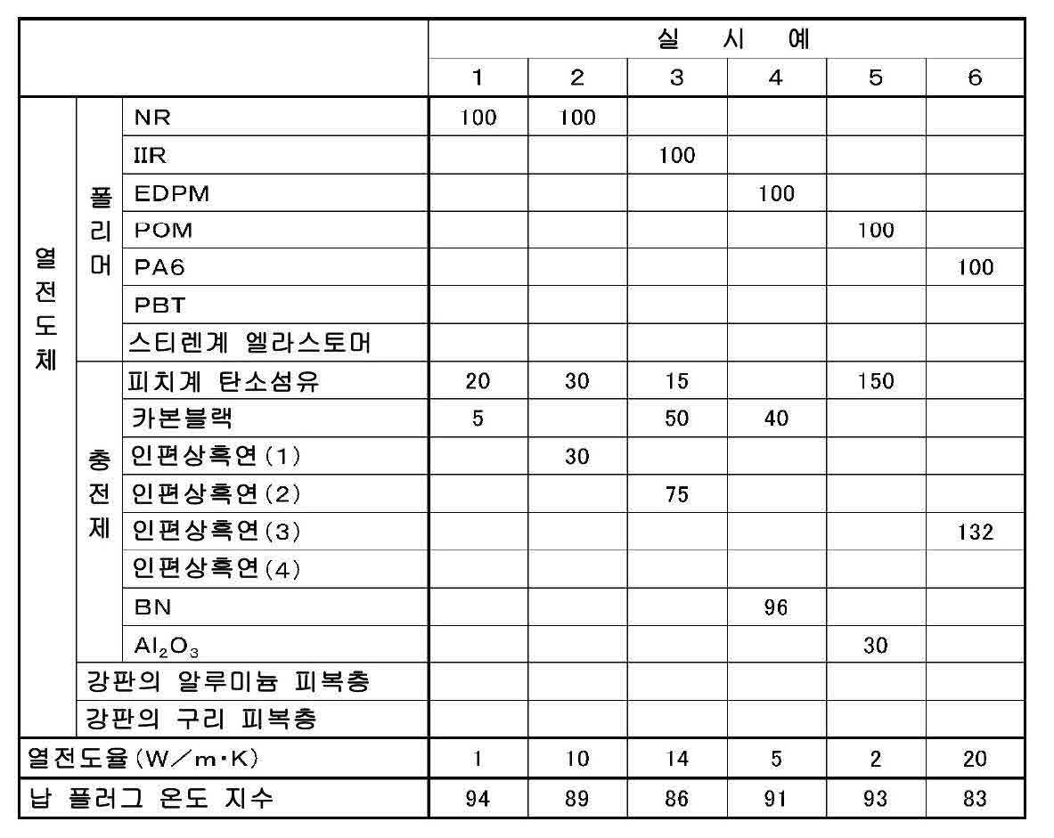
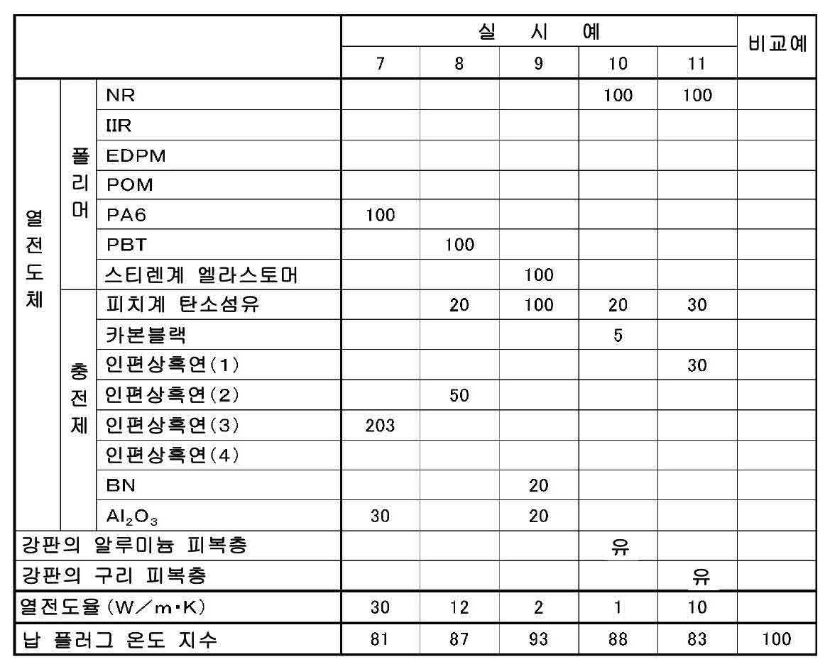
시험 결과로부터 알 수 있는 바와 같이, 본 실시예의 면진 지지 장치(1)에서는, 납 플러그(7)에 발생하는 온도 상승을 열전도체(9)를 통해 강성층(3)으로 방출시킬 수 있으므로 지진시 등의 납 플러그(7)의 과도한 온도 상승을 방지할 수 있다.As can be seen from the test results, in the seismic bracket 1 of the present embodiment, since the temperature rise generated in the
1 면진 지지 장치
2 탄성층
3 강성층
4 적층체
5 내주면
6 중공부
7 납 플러그
8, 10 외주면
9 열전도체1 Face Support
2 elastic layer
3 stiffness layer
4 laminate
5 inner circumferential surface
6 hollow part
7 Lead Plug
8 and 10,
9 thermocouple
Claims (10)
열전도체, 열전도체의 내주면 및 열전도체의 외주면 각각은 통형인 면진 지지 장치.The method according to claim 1,
Wherein the heat conductor, the inner circumferential surface of the heat conductor, and the outer circumferential surface of the heat conductor are each cylindrical.
열전도체는, 적어도 폴리머와, 탄성층의 열전도율보다 높은 열전도율을 가진 충전제를 포함하고 있는 면진 지지 장치.The method according to claim 1 or 2,
Wherein the thermal conductor includes at least a polymer and a filler having a higher thermal conductivity than the thermal conductivity of the elastic layer.
폴리머는, 열경화성 폴리머 및 열가소성 폴리머 중 적어도 하나를 포함하고 있는 면진 지지 장치.The method of claim 3,
Wherein the polymer comprises at least one of a thermosetting polymer and a thermoplastic polymer.
열경화성 폴리머는, 가교 고무, 에폭시 수지, 폴리이미드 수지, 비스말레이미드 수지, 페놀 수지, 불포화 폴리에스테르 수지, 열경화형 폴리페닐렌에테르 수지 및 열경화형 변성 폴리페닐렌에테르 수지 중 적어도 하나를 포함하고 있는 면진 지지 장치.The method of claim 4,
The thermosetting polymer includes at least one of a crosslinked rubber, an epoxy resin, a polyimide resin, a bismaleimide resin, a phenol resin, an unsaturated polyester resin, a thermosetting polyphenylene ether resin and a thermosetting modified polyphenylene ether resin Seismic support device.
열가소성 폴리머는, 열가소성 합성 수지 및 열가소성 엘라스토머 중 적어도 하나를 포함하고 있는 면진 지지 장치.The method according to claim 4 or 5,
Wherein the thermoplastic polymer comprises at least one of a thermoplastic synthetic resin and a thermoplastic elastomer.
충전제는, 카본계 충전제, 금속계 충전제 및 세라믹계 충전제 중 적어도 하나를 포함하고 있는 면진 지지 장치.The method according to any one of claims 3 to 6,
The filler includes at least one of a carbon-based filler, a metal-based filler, and a ceramic filler.
열전도체는, 적어도 1W/m·K의 열전도율을 가지고 있는 면진 지지 장치.The method according to any one of claims 1 to 7,
Wherein the thermal conductor has a thermal conductivity of at least 1 W / m 占..
열전도체는, 그 외주면에서 적층체의 내주면이 되는 강판의 면에 접촉하고 있는 면진 지지 장치.The method according to any one of claims 1 to 8,
Wherein the heat conductor is in contact with the surface of the steel sheet which becomes the inner circumferential surface of the laminate at the outer circumferential surface thereof.
복수의 강성층 각각은, 강판을 피복하고 있음과 아울러 강판의 열전도율보다 높은 열전도율을 갖는 피복층을 구비하고 있고, 열전도체는 그 외주면에서 적층체의 내주면이 되는 피복층의 면에 접촉하고 있는 면진 지지 장치.The method according to any one of claims 1 to 8,
Each of the plurality of rigid layers is provided with a coating layer covering the steel sheet and having a thermal conductivity higher than that of the steel sheet and the thermal conductive member being in contact with the surface of the coating layer which becomes the inner circumferential surface of the layered product on the outer circumferential surface thereof, .
Applications Claiming Priority (3)
| Application Number | Priority Date | Filing Date | Title |
|---|---|---|---|
| JP2015058680A JP6540134B2 (en) | 2015-03-20 | 2015-03-20 | Seismic isolation support device |
| JPJP-P-2015-058680 | 2015-03-20 | ||
| PCT/JP2016/001162 WO2016152041A1 (en) | 2015-03-20 | 2016-03-03 | Seismic base isolation support device |
Publications (1)
| Publication Number | Publication Date |
|---|---|
| KR20170128337A true KR20170128337A (en) | 2017-11-22 |
Family
ID=56977191
Family Applications (1)
| Application Number | Title | Priority Date | Filing Date |
|---|---|---|---|
| KR1020177026229A Withdrawn KR20170128337A (en) | 2015-03-20 | 2016-03-03 | Seismic Retention Device |
Country Status (7)
| Country | Link |
|---|---|
| US (1) | US20180051764A1 (en) |
| EP (1) | EP3273090A4 (en) |
| JP (1) | JP6540134B2 (en) |
| KR (1) | KR20170128337A (en) |
| CN (1) | CN107429783A (en) |
| TW (1) | TWI693325B (en) |
| WO (1) | WO2016152041A1 (en) |
Families Citing this family (10)
| Publication number | Priority date | Publication date | Assignee | Title |
|---|---|---|---|---|
| US9869084B2 (en) * | 2014-10-14 | 2018-01-16 | Emeh, Inc. | Stair expansion joint system with freedom of movement between landings |
| JP2017194098A (en) * | 2016-04-19 | 2017-10-26 | オイレス工業株式会社 | Seismic isolator |
| US10927920B2 (en) * | 2017-10-04 | 2021-02-23 | Illinois Tool Works, Inc | Passive damping system for mass flow controller |
| PT3540151T (en) * | 2018-03-15 | 2025-02-28 | Soletanche Freyssinet | Enhanced seismic isolation lead rubber bearings |
| KR102634353B1 (en) * | 2018-11-26 | 2024-02-08 | 현대자동차주식회사 | Vibration proof rubber for vehicle |
| CN109853722A (en) * | 2019-03-20 | 2019-06-07 | 华北水利水电大学 | A shock-absorbing and seismic-resistant steel structure building |
| CN109898564B (en) * | 2019-04-14 | 2020-11-13 | 骆红所 | Multi-dimensional shock isolation device for building |
| CN110154732B (en) * | 2019-06-11 | 2020-03-17 | 湖南机电职业技术学院 | Novel automobile power assembly suspension device |
| GB202009430D0 (en) * | 2020-06-19 | 2020-08-05 | Ocado Innovation Ltd | A grid framework structure |
| US12201227B2 (en) * | 2022-06-03 | 2025-01-21 | Apple Inc. | Product display stand with reduced movement |
Family Cites Families (14)
| Publication number | Priority date | Publication date | Assignee | Title |
|---|---|---|---|---|
| NZ201015A (en) * | 1982-06-18 | 1986-05-09 | New Zealand Dev Finance | Building support:cyclic shear energy absorber |
| JP2883219B2 (en) * | 1990-10-17 | 1999-04-19 | オイレス工業株式会社 | Seismic isolation support device |
| JPH08326840A (en) * | 1995-05-26 | 1996-12-10 | Bridgestone Corp | Base isolation structure |
| US5765322A (en) * | 1995-09-29 | 1998-06-16 | Bridgestone Corporation | Seismic isolation apparatus |
| JP3749761B2 (en) * | 1995-10-02 | 2006-03-01 | 株式会社エコ・トゥエンティーワン | Air conditioning ventilator |
| JP3168411B2 (en) * | 1997-08-06 | 2001-05-21 | ニッタ株式会社 | Laminate preheating method |
| JP2003214493A (en) * | 2001-10-22 | 2003-07-30 | Toyo Tire & Rubber Co Ltd | Laminated rubber bearing device and its manufacturing method |
| JP2003191253A (en) * | 2001-12-28 | 2003-07-08 | Toyo Tire & Rubber Co Ltd | Manufacturing method of laminated rubber |
| MY152660A (en) * | 2009-12-25 | 2014-10-31 | Yokohama Rubber Co Ltd | Rubber-made support device |
| JP2011141002A (en) * | 2010-01-08 | 2011-07-21 | Bridgestone Corp | Base isolation device |
| JP5481365B2 (en) * | 2010-12-21 | 2014-04-23 | 株式会社ブリヂストン | Seismic isolation device |
| JP5884612B2 (en) * | 2012-04-10 | 2016-03-15 | 住友電気工業株式会社 | Air spring |
| TWI426168B (en) * | 2012-06-14 | 2014-02-11 | Chong-Shien Tsai | Can prevent the temperature rise of the support pad |
| JP5541329B2 (en) * | 2012-09-03 | 2014-07-09 | オイレス工業株式会社 | Seismic isolation device |
-
2015
- 2015-03-20 JP JP2015058680A patent/JP6540134B2/en active Active
-
2016
- 2016-03-03 US US15/557,231 patent/US20180051764A1/en not_active Abandoned
- 2016-03-03 EP EP16767952.1A patent/EP3273090A4/en not_active Withdrawn
- 2016-03-03 KR KR1020177026229A patent/KR20170128337A/en not_active Withdrawn
- 2016-03-03 WO PCT/JP2016/001162 patent/WO2016152041A1/en not_active Ceased
- 2016-03-03 CN CN201680016770.2A patent/CN107429783A/en not_active Withdrawn
- 2016-03-16 TW TW105108132A patent/TWI693325B/en active
Also Published As
| Publication number | Publication date |
|---|---|
| EP3273090A4 (en) | 2018-11-14 |
| CN107429783A (en) | 2017-12-01 |
| TWI693325B (en) | 2020-05-11 |
| EP3273090A1 (en) | 2018-01-24 |
| US20180051764A1 (en) | 2018-02-22 |
| JP2016176577A (en) | 2016-10-06 |
| WO2016152041A1 (en) | 2016-09-29 |
| TW201641790A (en) | 2016-12-01 |
| JP6540134B2 (en) | 2019-07-10 |
Similar Documents
| Publication | Publication Date | Title |
|---|---|---|
| JP6458516B2 (en) | Seismic isolation support device | |
| KR20170128337A (en) | Seismic Retention Device | |
| US11326843B2 (en) | Thermal interface materials | |
| CN106810877B (en) | A thermally conductive interface material and its application | |
| KR102455995B1 (en) | heat conduction sheet | |
| CN107871721A (en) | Heat conductive sheet and preparation method thereof and semiconductor device | |
| WO2018030430A1 (en) | Heat transfer sheet and method for producing same | |
| KR20120018740A (en) | Thermally conductive foam product | |
| WO2014083890A1 (en) | Heat-conducting foam sheet for electronic instruments and heat-conducting laminate for electronic instruments | |
| CN107002813B (en) | Seismic isolation device | |
| JP5290539B2 (en) | RUBBER COMPOSITION, RUBBER MOLDED BODY, HEAT-RELEASING SHEET AND METHOD FOR PRODUCING THE SAME | |
| CN111923524A (en) | Vibrating diaphragm and sound generating device | |
| KR101926907B1 (en) | The thermal interface material and production method thereof | |
| JP6266890B2 (en) | Thermally conductive foam sheet for electronic equipment | |
| JP7312515B2 (en) | Heat dissipation material | |
| JP2011082423A (en) | Heat conductive sheet | |
| JP2005248076A (en) | Polymer composition and molded product thereof | |
| JP6540114B2 (en) | Seismic isolation support device | |
| JP2021166140A (en) | Heat dissipation member, heat dissipation structure and battery | |
| JP2021123661A (en) | Thermally conductive resin sheet | |
| JP2011183563A (en) | Carbon fiber-reinforced plastic molded body | |
| EP2907658A1 (en) | Composite structure capable of changing viscosity of liquid medium | |
| JP2011094088A (en) | High-density elastomeric material | |
| JP2005290018A (en) | Rubber molded body | |
| JP2019073594A (en) | Thermal storage thermally conductive particle and resin composition |
Legal Events
| Date | Code | Title | Description |
|---|---|---|---|
| PA0105 | International application |
Patent event date: 20170918 Patent event code: PA01051R01D Comment text: International Patent Application |
|
| PG1501 | Laying open of application | ||
| PC1203 | Withdrawal of no request for examination |