JP6540134B2 - Seismic isolation support device - Google Patents
Seismic isolation support device Download PDFInfo
- Publication number
- JP6540134B2 JP6540134B2 JP2015058680A JP2015058680A JP6540134B2 JP 6540134 B2 JP6540134 B2 JP 6540134B2 JP 2015058680 A JP2015058680 A JP 2015058680A JP 2015058680 A JP2015058680 A JP 2015058680A JP 6540134 B2 JP6540134 B2 JP 6540134B2
- Authority
- JP
- Japan
- Prior art keywords
- seismic isolation
- rubber
- layer
- peripheral surface
- heat conductor
- Prior art date
- Legal status (The legal status is an assumption and is not a legal conclusion. Google has not performed a legal analysis and makes no representation as to the accuracy of the status listed.)
- Active
Links
Images


Classifications
-
- F—MECHANICAL ENGINEERING; LIGHTING; HEATING; WEAPONS; BLASTING
- F16—ENGINEERING ELEMENTS AND UNITS; GENERAL MEASURES FOR PRODUCING AND MAINTAINING EFFECTIVE FUNCTIONING OF MACHINES OR INSTALLATIONS; THERMAL INSULATION IN GENERAL
- F16F—SPRINGS; SHOCK-ABSORBERS; MEANS FOR DAMPING VIBRATION
- F16F1/00—Springs
- F16F1/36—Springs made of rubber or other material having high internal friction, e.g. thermoplastic elastomers
- F16F1/3605—Springs made of rubber or other material having high internal friction, e.g. thermoplastic elastomers characterised by their material
-
- F—MECHANICAL ENGINEERING; LIGHTING; HEATING; WEAPONS; BLASTING
- F16—ENGINEERING ELEMENTS AND UNITS; GENERAL MEASURES FOR PRODUCING AND MAINTAINING EFFECTIVE FUNCTIONING OF MACHINES OR INSTALLATIONS; THERMAL INSULATION IN GENERAL
- F16F—SPRINGS; SHOCK-ABSORBERS; MEANS FOR DAMPING VIBRATION
- F16F15/00—Suppression of vibrations in systems; Means or arrangements for avoiding or reducing out-of-balance forces, e.g. due to motion
- F16F15/02—Suppression of vibrations of non-rotating, e.g. reciprocating systems; Suppression of vibrations of rotating systems by use of members not moving with the rotating systems
- F16F15/04—Suppression of vibrations of non-rotating, e.g. reciprocating systems; Suppression of vibrations of rotating systems by use of members not moving with the rotating systems using elastic means
-
- C—CHEMISTRY; METALLURGY
- C08—ORGANIC MACROMOLECULAR COMPOUNDS; THEIR PREPARATION OR CHEMICAL WORKING-UP; COMPOSITIONS BASED THEREON
- C08K—Use of inorganic or non-macromolecular organic substances as compounding ingredients
- C08K3/00—Use of inorganic substances as compounding ingredients
- C08K3/18—Oxygen-containing compounds, e.g. metal carbonyls
- C08K3/20—Oxides; Hydroxides
- C08K3/22—Oxides; Hydroxides of metals
-
- E—FIXED CONSTRUCTIONS
- E04—BUILDING
- E04H—BUILDINGS OR LIKE STRUCTURES FOR PARTICULAR PURPOSES; SWIMMING OR SPLASH BATHS OR POOLS; MASTS; FENCING; TENTS OR CANOPIES, IN GENERAL
- E04H9/00—Buildings, groups of buildings or shelters adapted to withstand or provide protection against abnormal external influences, e.g. war-like action, earthquake or extreme climate
- E04H9/02—Buildings, groups of buildings or shelters adapted to withstand or provide protection against abnormal external influences, e.g. war-like action, earthquake or extreme climate withstanding earthquake or sinking of ground
- E04H9/021—Bearing, supporting or connecting constructions specially adapted for such buildings
- E04H9/022—Bearing, supporting or connecting constructions specially adapted for such buildings and comprising laminated structures of alternating elastomeric and rigid layers
-
- F—MECHANICAL ENGINEERING; LIGHTING; HEATING; WEAPONS; BLASTING
- F16—ENGINEERING ELEMENTS AND UNITS; GENERAL MEASURES FOR PRODUCING AND MAINTAINING EFFECTIVE FUNCTIONING OF MACHINES OR INSTALLATIONS; THERMAL INSULATION IN GENERAL
- F16F—SPRINGS; SHOCK-ABSORBERS; MEANS FOR DAMPING VIBRATION
- F16F1/00—Springs
- F16F1/36—Springs made of rubber or other material having high internal friction, e.g. thermoplastic elastomers
- F16F1/40—Springs made of rubber or other material having high internal friction, e.g. thermoplastic elastomers consisting of a stack of similar elements separated by non-elastic intermediate layers
-
- C—CHEMISTRY; METALLURGY
- C08—ORGANIC MACROMOLECULAR COMPOUNDS; THEIR PREPARATION OR CHEMICAL WORKING-UP; COMPOSITIONS BASED THEREON
- C08K—Use of inorganic or non-macromolecular organic substances as compounding ingredients
- C08K3/00—Use of inorganic substances as compounding ingredients
- C08K3/18—Oxygen-containing compounds, e.g. metal carbonyls
- C08K3/20—Oxides; Hydroxides
- C08K3/22—Oxides; Hydroxides of metals
- C08K2003/2217—Oxides; Hydroxides of metals of magnesium
- C08K2003/222—Magnesia, i.e. magnesium oxide
-
- C—CHEMISTRY; METALLURGY
- C08—ORGANIC MACROMOLECULAR COMPOUNDS; THEIR PREPARATION OR CHEMICAL WORKING-UP; COMPOSITIONS BASED THEREON
- C08K—Use of inorganic or non-macromolecular organic substances as compounding ingredients
- C08K3/00—Use of inorganic substances as compounding ingredients
- C08K3/18—Oxygen-containing compounds, e.g. metal carbonyls
- C08K3/20—Oxides; Hydroxides
- C08K3/22—Oxides; Hydroxides of metals
- C08K2003/2227—Oxides; Hydroxides of metals of aluminium
-
- C—CHEMISTRY; METALLURGY
- C08—ORGANIC MACROMOLECULAR COMPOUNDS; THEIR PREPARATION OR CHEMICAL WORKING-UP; COMPOSITIONS BASED THEREON
- C08K—Use of inorganic or non-macromolecular organic substances as compounding ingredients
- C08K3/00—Use of inorganic substances as compounding ingredients
- C08K3/10—Metal compounds
- C08K3/14—Carbides
-
- C—CHEMISTRY; METALLURGY
- C08—ORGANIC MACROMOLECULAR COMPOUNDS; THEIR PREPARATION OR CHEMICAL WORKING-UP; COMPOSITIONS BASED THEREON
- C08K—Use of inorganic or non-macromolecular organic substances as compounding ingredients
- C08K3/00—Use of inorganic substances as compounding ingredients
- C08K3/34—Silicon-containing compounds
-
- C—CHEMISTRY; METALLURGY
- C08—ORGANIC MACROMOLECULAR COMPOUNDS; THEIR PREPARATION OR CHEMICAL WORKING-UP; COMPOSITIONS BASED THEREON
- C08L—COMPOSITIONS OF MACROMOLECULAR COMPOUNDS
- C08L65/00—Compositions of macromolecular compounds obtained by reactions forming a carbon-to-carbon link in the main chain; Compositions of derivatives of such polymers
- C08L65/02—Polyphenylenes
-
- C—CHEMISTRY; METALLURGY
- C08—ORGANIC MACROMOLECULAR COMPOUNDS; THEIR PREPARATION OR CHEMICAL WORKING-UP; COMPOSITIONS BASED THEREON
- C08L—COMPOSITIONS OF MACROMOLECULAR COMPOUNDS
- C08L93/00—Compositions of natural resins; Compositions of derivatives thereof
Landscapes
- Engineering & Computer Science (AREA)
- General Engineering & Computer Science (AREA)
- Architecture (AREA)
- Mechanical Engineering (AREA)
- Emergency Management (AREA)
- Environmental & Geological Engineering (AREA)
- Business, Economics & Management (AREA)
- Acoustics & Sound (AREA)
- Aviation & Aerospace Engineering (AREA)
- Physics & Mathematics (AREA)
- Civil Engineering (AREA)
- Structural Engineering (AREA)
- Chemical & Material Sciences (AREA)
- Health & Medical Sciences (AREA)
- Chemical Kinetics & Catalysis (AREA)
- Medicinal Chemistry (AREA)
- Polymers & Plastics (AREA)
- Organic Chemistry (AREA)
- Vibration Prevention Devices (AREA)
- Springs (AREA)
- Buildings Adapted To Withstand Abnormal External Influences (AREA)
Description
本発明は、二つの構造物間に配されて両構造物間の相対的な水平方向の振動エネルギを吸収し、構造物への振動加速度を低減するための装置、特に地震エネルギを減衰して地震入力加速度を低減し、建築物、橋梁等の構造物の損壊を防止する免震支持装置に関する。 The invention relates to a device arranged between two structures for absorbing relative horizontal vibrational energy between the two structures and for reducing vibrational acceleration to the structures, in particular for damping seismic energy. The present invention relates to a seismic isolation support device that reduces earthquake input acceleration and prevents damage to structures such as buildings and bridges.
交互に積層された弾性層及び剛性層を有した積層体とこの積層体の内周面で規定された円柱状の中空部に充填された鉛プラグからなる減衰体とを有した免震支持装置は、特許文献1、特許文献2及び特許文献3により知られているように、構造物の荷重を支持した上で、地震等による地盤振動の構造物への伝達を積層体によりできるだけ阻止すると共に構造物に伝達された振動を鉛プラグにより可及的に速やかに減衰させるように、地盤と構造物との間に設置される。
Seismic isolation supporting device comprising: a laminate having elastic layers and rigid layers alternately stacked; and a damping body comprising a lead plug filled in a cylindrical hollow portion defined by the inner circumferential surface of the laminate. As known from
斯かる免震支持装置は、地震において積層体が剪断変形するときに、鉛プラグも塑性変形することで振動エネルギを吸収するようになっており、鉛プラグは、振動エネルギを好ましく吸収して塑性変形後も振動エネルギ吸収に伴って発生する熱により容易に再結晶して機械的疲労を招来しないために、振動エネルギ吸収体として極めて優れている。 Such a seismic isolation support device absorbs vibration energy by plastic deformation of the lead plug when the laminate is sheared in an earthquake, and the lead plug preferably absorbs vibration energy to be plastic It is extremely excellent as a vibration energy absorber because it does not easily recrystallize and cause mechanical fatigue due to heat generated along with vibration energy absorption even after deformation.
しかしながら、大きな振幅で長時間繰り返される長周期地震動を免震支持装置が受けた時には、鉛プラグには、塑性変形することによる振動エネルギ吸収に伴い温度上昇が生じ、当該温度上昇は鉛の融点近くまで上昇する可能性があることが指摘されている。鉛プラグが温度上昇すると、鉛プラグの変形に対する振動エネルギの吸収能力が低下するばかりでなく、鉛プラグに接触している積層体の弾性層の材料物性値、特に弾性係数の劣化を生ぜしめる虞がある。 However, when the seismic isolation support device receives long-period ground motion repeated with a large amplitude for a long time, the lead plug undergoes temperature rise due to the absorption of vibrational energy due to plastic deformation, and the temperature rise is close to the melting point of lead It is pointed out that there is a possibility of rising. When the temperature of the lead plug rises, not only the ability to absorb vibrational energy due to the deformation of the lead plug is reduced, but also the physical property value of the elastic layer of the laminate in contact with the lead plug may deteriorate. There is.
鉛の温度上昇を防止するべく、例えば、特許文献4には、鉛部材の中に熱の吸収材として鉛より融点が低い金属、所謂低融点金属を分散して配置することにより、地震時に鉛部材から発生する熱を低融点金属の融解熱として吸収し、鉛部材の過度の温度上昇を防止する技術又は鉛部材の中に液体(水)を分散して配置することにより、地震時に鉛部材から発生する熱を液体の蒸発熱として吸収し、鉛部材の過度の温度上昇を防止する技術が提案されている。
In order to prevent the temperature rise of lead, for example,
しかしながら、特許文献4において提案された技術、特に鉛部材の中に液体(水)を分散して配置する技術においては、液体の蒸発や漏洩を考慮する必要があり、いつ発生するか予想がつかない地震に対しては実用的であるとは言い難い。
However, in the technique proposed in
以上の問題は、鉛を用いた鉛プラグ及び錫を用いた錫プラグに限らないのであって、要は、温度上昇で振動エネルギの吸収能力が低下する減衰体で生じ得るのである。 The above problems are not limited to the lead plug using lead and the tin plug using tin, and the main problem may occur with an attenuator whose absorption capacity of vibrational energy decreases with temperature rise.
本発明は、前記諸点に鑑みてなされたもので、その目的とするところは、長周期地震動を受けた時でも、振動エネルギの吸収能力を低下させる減衰体の温度上昇を極力低下させることができ、長周期地震動でも免震機能を有効に発揮することができる免震支持装置を提供することにある。 The present invention has been made in view of the above-mentioned points, and the object of the present invention is to reduce as much as possible the temperature rise of the attenuating body which lowers the absorbing ability of vibrational energy even when receiving long period earthquake motion. An object of the present invention is to provide a seismic isolation supporting device capable of effectively exhibiting the seismic isolation function even in long-period seismic motion.
本発明の免震支持装置は、複数の弾性層及び剛性層を有する積層体と、この積層体の内周面で規定された柱状の中空部に配されている減衰体と、減衰体の外周面及び積層体の内周面間に配されていると共に弾性層の熱伝導率よりも高い熱伝導率を有した熱伝導体とを具備しており、この熱伝導体は、減衰体の筒状の外周面に接触した内周面と、積層体の内周面に接触した外周面とを有しており、剛性層の夫々は、弾性層の熱伝導率よりも高い熱伝導率を有する環状の鋼板を具備している。 The seismic isolation supporting device of the present invention comprises a laminate having a plurality of elastic layers and rigid layers, a damping body disposed in a columnar hollow portion defined by an inner circumferential surface of the laminate, and an outer periphery of the damping body. And a heat conductor disposed between the surface and the inner circumferential surface of the laminate and having a thermal conductivity higher than the thermal conductivity of the elastic layer, the heat conductor comprising a cylinder of a damping body And the outer peripheral surface in contact with the inner peripheral surface of the laminate, each of the rigid layers has a thermal conductivity higher than the thermal conductivity of the elastic layer It has an annular steel plate.
本発明の免震支持装置によれば、熱伝導体は、減衰体の筒状の外周面に接触した内周面と、積層体の内周面に接触した外周面とを有しており、剛性層の夫々は、弾性層の熱伝導率よりも高い熱伝導率を有する環状の鋼板を具備しているため、長周期地震動による減衰体の剪断変形に基づく振動エネルギ吸収に伴い当該減衰体発生する熱は、減衰体の外周面及び積層体の内周面間に配された熱伝導体を介して剛性層に効率よく伝達されて当該剛性層を介して放出される結果、熱の蓄積による減衰体の温度上昇を回避し得、温度上昇に起因する減衰体の振動エネルギの吸収能力を低下させることがなく、地震エネルギを効果的に吸収することができる。 According to the seismic isolation support device of the present invention, the heat conductor has an inner circumferential surface in contact with the cylindrical outer circumferential surface of the damping body, and an outer circumferential surface in contact with the inner circumferential surface of the laminate. Each of the rigid layers comprises an annular steel plate having a thermal conductivity higher than the thermal conductivity of the elastic layer, so that the damping body is generated along with the absorption of vibrational energy based on the shear deformation of the damping body due to the long period earthquake motion. Heat is efficiently transferred to the rigid layer through the heat conductor disposed between the outer peripheral surface of the attenuating body and the inner peripheral surface of the laminate and released through the rigid layer, resulting in the accumulation of heat. The temperature rise of the damping body can be avoided, and the seismic energy can be effectively absorbed without reducing the vibration energy absorbing ability of the damping body due to the temperature rise.
本発明の免震支持装置において、好ましい例では、熱伝導体、熱伝導体の内周面及び熱伝導体の外周面の夫々は、筒状であり、熱伝導体は、少なくともポリマーと、弾性層の熱伝導率よりも高い熱伝導率を有した充填剤とを含んでおり、この場合、ポリマーは、熱硬化性ポリマー及び熱可塑性ポリマーのうちの少なくとも一つを含んでいてもよい。 In a preferred example of the seismic isolation support device of the present invention, the heat conductor, the inner circumferential surface of the heat conductor, and the outer circumferential surface of the heat conductor are cylindrical, and the heat conductor is at least a polymer, and And a filler having a thermal conductivity higher than the thermal conductivity of the layer, wherein the polymer may include at least one of a thermosetting polymer and a thermoplastic polymer.
熱硬化性ポリマーは、好ましい例では、架橋ゴム、エポキシ樹脂、ポリイミド樹脂、ビスマレイミド樹脂、フェノール樹脂、不飽和ポリエステル樹脂、熱硬化型ポリフェニレンエーテル樹脂及び熱硬化型変性ポリフェニレンエーテル樹脂のうちの少なくとも一つを含んでいる。 In a preferable example, the thermosetting polymer is at least one of crosslinked rubber, epoxy resin, polyimide resin, bismaleimide resin, phenol resin, unsaturated polyester resin, thermosetting polyphenylene ether resin, and thermosetting modified polyphenylene ether resin. Contains one.
架橋ゴムとしては、天然ゴム(NR)、ブタジエンゴム(BR)、イソプレンゴム(IR)、ニトリルゴム(NBR)、水添ニトリルゴム(HNBR)、クロロプレンゴム(CR)、エチレンプロピレンゴム(EPR、EPDM)、塩素化ポリエチレン(CM)、クロロスルホン化ポリエチレン(CSM)、ブチルゴム(IIR)、ハロゲン化ブチルゴム、フッ素ゴム、ウレタンゴム、アクリルゴム(ACM)、スチレンブタジエンゴム(SBR)及びシリコーンゴム(VMQ、FVMQ)等を好ましい例として挙げることができる。 Crosslinked rubbers include natural rubber (NR), butadiene rubber (BR), isoprene rubber (IR), nitrile rubber (NBR), hydrogenated nitrile rubber (HNBR), chloroprene rubber (CR), ethylene propylene rubber (EPR, EPDM) ), Chlorinated polyethylene (CM), chlorosulfonated polyethylene (CSM), butyl rubber (IIR), halogenated butyl rubber, fluoro rubber, urethane rubber, acrylic rubber (ACM), styrene butadiene rubber (SBR) and silicone rubber (VMQ, FVMQ etc. can be mentioned as a preferable example.
熱可塑性ポリマーは、熱可塑性合成樹脂又は熱可塑性エラストマーのうちの少なくとも一つを含んでいるとよい。 The thermoplastic polymer may include at least one of a thermoplastic synthetic resin or a thermoplastic elastomer.
熱可塑性合成樹脂としては、特に制限はなく、目的に応じて適宜選択することができ、例えばポリエチレン(PE)、ポリプロピレン(PP)及びエチレン−プロピレン共重合体等のエチレン−α−オレフィン共重合体、ポリメチルペンテン(PMP)、ポリ塩化ビニル(PVC)、ポリ塩化ビニリデン(PVDC)、ポリ酢酸ビニル(PVAc)、エチレン−酢酸ビニル共重合体(EVA)、ポリビニルアルコール(PVA)、ポリアセタール(POM)、ポリフッ化ビニリデン(PVDF)、ポリエチレンテレフタレート(PET)、ポリブチレンテレフタレート(PBT)、ポリエチレンナフタレート(PEN)、ポリスチレン(PS)、ポリアクリロニトリル(PAN)、ポリアミド(PA)、ポリカーボネート(PC)、ポリフェニレンスルフィド(PPS)、ポリサルホン(PSU)及びポリエーテルサルホン(PES)等を挙げることができる。 There is no restriction | limiting in particular as a thermoplastic synthetic resin, According to the objective, it can select suitably, For example, ethylene-alpha-olefin copolymers, such as polyethylene (PE), a polypropylene (PP), and an ethylene-propylene copolymer , Polymethylpentene (PMP), polyvinyl chloride (PVC), polyvinylidene chloride (PVDC), polyvinyl acetate (PVAc), ethylene-vinyl acetate copolymer (EVA), polyvinyl alcohol (PVA), polyacetal (POM) , Polyvinylidene fluoride (PVDF), polyethylene terephthalate (PET), polybutylene terephthalate (PBT), polyethylene naphthalate (PEN), polystyrene (PS), polyacrylonitrile (PAN), polyamide (PA), polycarbonate (PC), polyphen Rensurufido (PPS), can be mentioned polysulfone (PSU) and polyether sulfone (PES) and the like.
熱可塑性エラストマーとしては、例えばスチレン−ブタジエン共重合体又はその水添ポリマー、スチレン−イソプレンブロック共重合体又はその水添ポリマー等のスチレン系熱可塑性エラストマー、オレフィン系熱可塑性エラストマー、塩化ビニル系熱可塑性エラストマー、ポリエステル系熱可塑性エラストマー、ポリウレタン系熱可塑性エラストマー及びポリアミド系熱可塑性エラストマー等を挙げることができる。 As the thermoplastic elastomer, for example, styrene-butadiene copolymer or hydrogenated polymer thereof, styrene-based thermoplastic elastomer such as styrene-isoprene block copolymer or hydrogenated polymer thereof, olefin-based thermoplastic elastomer, vinyl chloride-based thermoplastic resin Elastomers, polyester thermoplastic elastomers, polyurethane thermoplastic elastomers and polyamide thermoplastic elastomers can be mentioned.
本発明において、好ましい例では、充填剤は、カーボン系充填剤、金属系充填剤及びセラミック系充填剤のうちの少なくとも一つを含んでいる。 In the present invention, in a preferred example, the filler contains at least one of a carbon-based filler, a metal-based filler and a ceramic-based filler.
カーボン系充填剤としては、ケッチェンブラック等のファーネスブラック、アセチレンブラック、チャンネルブラック及びガスブラック等のカーボンブラック、ポリアクリロニトリル系炭素繊維及びピッチ系炭素繊維等のカーボンファイバー、人造黒鉛、球状黒鉛、鱗片状黒鉛、塊状黒鉛、土状黒鉛等のグラファイト、ダイヤモンド、フラーレン、カーボンマイクロコイル、カーボンナノチューブ(気相成長炭素繊維)並びにグラフェン等を挙げることができる。 As carbon-based fillers, carbon black such as furnace black such as ketjen black, acetylene black, channel black and gas black, carbon fibers such as polyacrylonitrile-based carbon fibers and pitch-based carbon fibers, artificial graphite, spherical graphite, flakes Graphite, massive graphite, graphite such as earthy graphite, diamond, fullerene, carbon micro coil, carbon nanotube (gas phase grown carbon fiber), graphene and the like.
カーボンブラック又はグラファイトの粒子の大きさは、分散性及び熱伝導体の厚さ等を考慮して決定すればよい。カーボンブラックは、平均粒径が10nm〜700nm、グラファイトの平均粒径は、5〜150μmであることが好ましく、更には流動性を向上させ、成形加工性を向上させることができる観点からは、グラファイトの平均粒径は、30〜150μmであることが好ましい。カーボンファイバーは、繊維径5〜20μm、繊維長2〜8mmのチョップドファイバー、繊維径5〜20μm、繊維長20〜400μmのミルドファイバー等を用いることができる。カーボンナノチューブの場合、単層ナノチューブの単体は、直径1〜2.5nm、長さ方向で5〜10nmであり、多層ナノチューブは、直径10〜40nm、長さ方向で10nmであることが好ましい。 The size of the carbon black or graphite particles may be determined in consideration of the dispersibility and the thickness of the heat conductor. The carbon black preferably has an average particle diameter of 10 nm to 700 nm, and an average particle diameter of graphite of 5 to 150 μm, and further, from the viewpoint of improving the flowability and improving the formability, graphite The average particle size of is preferably 30 to 150 μm. The carbon fiber may be a chopped fiber having a fiber diameter of 5 to 20 μm and a fiber length of 2 to 8 mm, and a milled fiber having a fiber diameter of 5 to 20 μm and a fiber length of 20 to 400 μm. In the case of a carbon nanotube, it is preferable that the single layer nanotube has a diameter of 1 to 2.5 nm and 5 to 10 nm in the longitudinal direction, and the multilayer nanotube has a diameter of 10 to 40 nm and 10 nm in the longitudinal direction.
ケッチェンブラックの具体例としては、ライオン社製の「EC300J、EC600JD(商品名)」等が、アセチレンブラックの具体例としては、電気化学工業社製の「デンカブラック(商品名)」等が、鱗片状黒鉛の具体例としては、中越黒鉛工業所社製の「BF−3AK、CPB−6S(商品名)」、富士黒鉛工業社製の「UF−2(商品名)」、西村黒鉛社製の「PS−99(平均粒径7μm)」、TIMCAL社製の「KS15(商品名)、平均粒子径8μm)」、日本黒鉛工業社製の「CB150(商品名)、平均粒径40μm又は平均粒径130μm)等が、土状黒鉛の具体例としては、中越黒鉛工業所社製の「APR(商品名)」及び富士黒鉛工業社製の「FAG−1(商品名)」等が、人造黒鉛の具体例としては、中越黒鉛工業所社製の「G−6S(商品名)」及び富士黒鉛工業社製の「FGK−1(商品名)」が、そして、球状黒鉛の具体例としては、中越黒鉛工業所社製の「WF−15C(商品名)」及び富士黒鉛工業社製の「WF−010、WF−015(商品名)」等が挙げられる。
As a specific example of ketjen black, "EC300J, EC600JD (trade name)" manufactured by Lion Corporation, etc., and as a specific example of acetylene black, "Denka black (trade name)" manufactured by Denki Kagaku Kogyo Co., Ltd., etc. Specific examples of flake graphite include “BF-3AK, CPB-6S (trade name)” manufactured by Chuetsu Graphite Kogyosho Co., Ltd., “UF-2 (trade name)” manufactured by Fuji Graphite Industry Co., Ltd., manufactured by Nishimura Graphite Co., Ltd. “PS-99 (
カーボンファイバーの具体例として、ポリアクリロニトリル系炭素繊維では、東レ社製の「トレカチョップ(商品名)」、三菱レイヨン社製の「パイロフィル(商品名)」及び東邦テナックス社製の「ベスファイト(商品名)」等が、ピッチ系炭素繊維では、三菱化学産資社製の「ダイアリード(商品名)」、大阪ガスケミカル社製の「ドナカーボ(商品名)」、クレハ社製の「クレカチョップ(商品名)」及び日本グラファイトファイバー社製の「GRANOCミルドファイバー(商品名)〕等が挙げられる。 Specific examples of the carbon fiber include polyacrylonitrile-based carbon fibers such as "Trecachop (trade name)" manufactured by Toray Industries, "Pyrofill (trade name)" manufactured by Mitsubishi Rayon Co., and "Vesfight (trade name) manufactured by Toho Tenax Etc.) are pitch-based carbon fibers such as “Dyaleed (trade name)” manufactured by Mitsubishi Chemical Corporation, “Donacarbo (trade name)” manufactured by Osaka Gas Chemical Co., Ltd., “Kreka Chop (manufactured by Kureha) "Trade name)" and "GRANOC milled fiber (trade name)" manufactured by Nippon Graphite Fiber Co., Ltd., and the like.
金属系充填剤としては、アルミニウム、銅、銀、鉄、ニッケル、珪素、亜鉛、マグネシウム、タングステン及び錫からなる群より選択される1種以上の金属粉末又はこれら金属の合金粉末(アルミ青銅、七三黄銅、ネーバル黄銅等)を用いることが好ましい。これらの金属系充填剤は、平均粒径0.1〜200μm、好ましくは平均粒径0.1〜50μmの粒子状物がよい。特に、平均粒径が0.1μmを下回ると熱伝導性の向上効果に劣り、成形し難くなるため好ましくない。 As the metal-based filler, at least one metal powder selected from the group consisting of aluminum, copper, silver, iron, nickel, silicon, zinc, magnesium, tungsten and tin or alloy powder of these metals (aluminum bronze, It is preferable to use tri-brass, naval brass etc.). These metal-based fillers preferably have a particle size of 0.1 to 200 [mu] m, preferably 0.1 to 50 [mu] m. In particular, when the average particle size is less than 0.1 μm, the effect of improving the thermal conductivity is inferior, and it becomes difficult to form, which is not preferable.
セラミック系充填剤としては、酸化アルミニウム(Al 2 O 3 )、酸化マグネシウム(MgO)、酸化ベリリウム(BeO)及び酸化チタン(TiO 2 )等の金属酸化物、窒化ホウ素(六方晶BN又は立方晶BN)、窒化アルミニウム(AlN)及び窒化ケイ素(Si 3 N 4 )等の金属窒化物並びに炭化ホウ素(B 4 C)、炭化アルミニウム(Al 4 C 3 )、炭化ケイ素(SiC)等の金属炭化物等を挙げることができる。 Ceramic fillers include metal oxides such as aluminum oxide (Al 2 O 3 ), magnesium oxide (MgO), beryllium oxide (BeO) and titanium oxide (TiO 2 ), boron nitride (hexagonal BN or cubic BN) Metal nitrides such as aluminum nitride (AlN) and silicon nitride (Si 3 N 4 ), and metal carbides such as boron carbide (B 4 C), aluminum carbide (Al 4 C 3 ), silicon carbide (SiC), etc. It can be mentioned.
セラミック系充填剤は、平均粒径3〜50μm、好ましくは5〜40μmをもった粉末からなっていると、熱伝導率、耐熱性及び耐湿性の性能向上の観点から望ましい。 The ceramic filler is preferably composed of a powder having an average particle diameter of 3 to 50 μm, preferably 5 to 40 μm, from the viewpoint of improving the thermal conductivity, the heat resistance and the moisture resistance.
これらカーボン系充填剤、金属系充填剤及びセラミック系充填剤の少なくとも一つからなる充填剤のポリマーへの配合量としては、目的とする熱伝導率及び強度に応じて広い範囲から選択可能である。好ましい例では、ポリマー100質量部に対して、充填剤は、20〜500質量部である。充填剤の配合量が過少であると、熱伝導体の熱伝導率が低くなり、過多であると熱伝導体の形成における加工性が低下するため好ましくない。 The compounding amount of the filler consisting of at least one of the carbon-based filler, the metal-based filler and the ceramic-based filler in the polymer can be selected from a wide range according to the desired thermal conductivity and strength. . In a preferred example, the filler is 20 to 500 parts by mass with respect to 100 parts by mass of the polymer. If the blending amount of the filler is too small, the thermal conductivity of the thermal conductor becomes low, and if it is too large, the processability in forming the thermal conductor decreases, which is not preferable.
熱伝導体は、0.3mm以上の肉厚を有していれば、減衰体に生じた熱を、有効に剛性層に伝達でき、減衰体での熱の蓄積を回避することができる一方、1.0mmを超える肉厚を有していると、減衰体の剪断変形能を低下させる虞があるので、0.3〜1.0mmの肉厚を有していることが好ましい。 If the heat conductor has a thickness of 0.3 mm or more, the heat generated in the damping body can be effectively transferred to the rigid layer, and the heat accumulation in the damping body can be avoided, If the wall thickness exceeds 1.0 mm, the shear deformability of the damping body may be reduced, so it is preferable to have a wall thickness of 0.3 to 1.0 mm.
熱伝導体は、減衰体に生じた熱の剛性層への放出を速やかに行うべく、少なくとも1W/m・K以上、好ましくは10W/m・K以上、更に好ましくは30W/m・K以上の熱伝導率を有していることが好ましい。 The heat conductor is at least 1 W / m · K or more, preferably 10 W / m · K or more, more preferably 30 W / m · K or more, in order to rapidly release the heat generated in the attenuating body to the rigid layer. It is preferable to have thermal conductivity.
熱伝導体が1W/m・K以上の熱伝導率を有するためには、ポリマー100質量部に対して、充填剤を20〜500質量部の割合で含有させるとよい。 In order to have a thermal conductivity of 1 W / m · K or more, the filler may be contained in a proportion of 20 to 500 parts by mass with respect to 100 parts by mass of the polymer.
本発明の免震支持装置において、各鋼板は、好ましい例では、冷間圧延鋼板(SPCC)等からなり、各弾性層は、好ましい例では、エチレンプロピレンゴム、ニトリルゴム、ブチルゴム、ハロゲン化ブチルゴム、クロロプレンゴム、天然ゴム、イソプレンゴム、スチレンブタジエンゴム、ブタジエンゴム等のゴム材で形成されたゴム板からなる。 In the seismic isolation supporting device of the present invention, each steel plate is made of a cold rolled steel plate (SPCC) or the like in a preferable example, and each elastic layer is made of ethylene propylene rubber, nitrile rubber, butyl rubber, halogenated butyl rubber, in a preferable example. It comprises a rubber plate formed of a rubber material such as chloroprene rubber, natural rubber, isoprene rubber, styrene butadiene rubber, butadiene rubber and the like.
本発明において、複数の剛性層の夫々は、鋼板に加えて、好ましくは、鋼板を、好ましくは、その全表面を被覆していると共に鋼板の熱伝導率よりも高い熱伝導率を有しておおよそ0.1〜100μmの厚さの被覆層を具備していてもよく、この場合、好ましい例では、熱伝導体は、その外周面で積層体の内周面となる被覆層の面に接触しており、斯かる被覆層は、鋼板に電気メッキ又は溶融メッキ等のメッキ、例えば、亜鉛メッキ、アルミニウムメッキ、銅メッキ、錫メッキ、ニッケルメッキ、クロムメッキ、真鍮(黄銅)メッキ等を施すことにより又は鋼板へ亜鉛、アルミニウム、亜鉛アルミニウム、アルミニウムマグネシウムの金属溶射を施すことにより形成し得、複数の剛性層の夫々が斯かる鋼板と被覆層とを具備していると、減衰体の熱の鋼板への伝達を被覆層を介して速やかに行わせることができるので、減衰体での熱の蓄積が極力回避され、減衰体の温度上昇に起因する振動エネルギの吸収能力の低下を効果的に防ぐことができる。 In the present invention, each of the plurality of rigid layers, in addition to the steel plate, preferably covers the steel plate, preferably its entire surface and has a thermal conductivity higher than the thermal conductivity of the steel plate The coating layer may have a thickness of approximately 0.1 to 100 μm, and in this case, in a preferred example, the heat conductor is in contact with the surface of the coating layer which is the inner circumferential surface of the laminate at its outer circumferential surface Such coating layer is plated on the steel plate by electroplating or hot-dip plating, for example, galvanizing, aluminum plating, copper plating, tin plating, nickel plating, chromium plating, brass (brass) plating, etc. Or by applying a metal spray of zinc, aluminum, zinc aluminum, or aluminum magnesium to the steel plate, with each of the plurality of rigid layers comprising such a steel plate and a cover layer, damping Because heat can be transferred to the steel plate quickly through the coating layer, heat buildup in the damping body is avoided as much as possible, and the ability to absorb vibrational energy due to the temperature rise of the damping body is reduced. It can be effectively prevented.
複数の剛性層の夫々が斯かる被覆層を具備しない場合には、熱伝導体は、その外周面で積層体の内周面となる鋼板の面に接触していてもよい。 When each of the plurality of rigid layers does not have such a covering layer, the heat conductor may be in contact with the surface of the steel plate which is the inner peripheral surface of the laminate on its outer peripheral surface.
本発明の免震支持装置において、積層体の内周面で規定された柱状の中空部は、一個でもよいが、複数個でもよく、複数個の中空部の夫々が積層体の複数個の内周面の夫々で規定されている場合であって、複数の中空部の夫々に減衰体が配されている場合、全ての減衰体の外周面及び積層体の内周面間に熱伝導体が配されていると柱状体の放熱を効果的に行い得るが、少なくとも一つの減衰体の外周面及び積層体の内周面間に熱伝導体が配されていてもよく、好ましい例では、減衰体は、円筒状の外周面を有した円柱状の形態からなり、この場合、中空部も円筒状の内周面で規定されて円柱状となり、更に、積層体は、剛性層及び弾性層の内周面に接触していると共に弾性層と同等のゴム材からなるゴム被覆層を具備していてもよく、斯かるゴム被覆層を積層体が具備している場合には、当該ゴム被覆層の内周面が積層体の内周面となるが、ゴム被覆層を積層体が具備しない場合には、剛性層及び弾性層の内周面が積層体の内周面となる。また、減衰体は、好ましい例では、鉛プラグ又は錫プラグであるが、これに限定されず、その他の温度上昇で振動エネルギの吸収能力が低下するプラグ、例えば、特開2015−7468号公報に記載の熱伝導性フィラー、黒鉛及び熱硬化性樹脂等を含んでいるプラグであってもよい。 In the seismic isolation support device of the present invention, the number of the hollow portions defined by the inner circumferential surface of the laminate may be one, but a plurality of hollow portions may be provided. In the case where a damping body is disposed in each of the plurality of hollow portions, a heat conductor is provided between the outer circumferential surface of all the damping bodies and the inner circumferential surface of the laminated body when each of the plurality of hollow portions is defined. If disposed, heat dissipation of the columnar body can be effectively performed, but a heat conductor may be disposed between the outer peripheral surface of at least one attenuating body and the inner peripheral surface of the laminate, and in a preferred example, the attenuation is The body is in the form of a cylinder having a cylindrical outer peripheral surface, in which case the hollow portion is also defined by the cylindrical inner peripheral surface and becomes cylindrical, and further, the laminate comprises a rigid layer and an elastic layer. A rubber coating layer may be provided which is in contact with the inner circumferential surface and is made of a rubber material equivalent to the elastic layer. When the laminate includes a rubber coating layer, the inner circumferential surface of the rubber coating layer is the inner circumferential surface of the laminate, but when the rubber coating layer is not included, the rigid layer The inner circumferential surface of the elastic layer is the inner circumferential surface of the laminate. The damping body is, in a preferred example, a lead plug or a tin plug, but is not limited to this, and other plugs in which the absorption capacity of vibrational energy decreases with temperature rise, for example, JP-A-2015-7468. It may be a plug containing the thermally conductive filler described above, graphite, a thermosetting resin and the like.
好ましくは弾性層と同等のゴム材からなると共に剛性層及び弾性層の夫々の内周面と熱伝導体の外周面とを結合するゴム被覆層の層厚は、0.3〜0.5mmであることが好ましく、0.3mm未満の層厚では、結合層としてのゴム被覆層の役割が十分発揮されない一方、0.5mmを超える層厚では、減衰体から剛性層への効果的な伝熱がゴム被覆層で妨げられる虞がある。 The layer thickness of the rubber coating layer preferably made of a rubber material equivalent to the elastic layer and joining the inner peripheral surface of each of the rigid layer and the elastic layer to the outer peripheral surface of the heat conductor is 0.3 to 0.5 mm. If the layer thickness is less than 0.3 mm, the role of the rubber coating layer as the bonding layer is not sufficiently exhibited, while if the layer thickness is more than 0.5 mm, the effective heat transfer from the damping body to the rigid layer May be hindered by the rubber coating layer.
本発明の好ましい例では、剛性層、弾性層、熱伝導体及びゴム被覆層とは、それらの相互の接触面で、例えば、加硫接着あるいは接着剤により強固に貼り合わされる。 In a preferred embodiment of the present invention, the rigid layer, the elastic layer, the heat conductor and the rubber coating layer are firmly bonded to each other at their contact surfaces, for example by means of a vulcanized adhesive or an adhesive.
本発明の免震支持装置は、積層体の外周面に耐候性等の向上を目的として、天然ゴム、好ましくは、耐候性に優れたゴム材からなると共に積層体の外周面を覆っている外周保護層を更に具備していてもよい。 In the seismic isolation support device of the present invention, the outer peripheral surface of the laminate is made of natural rubber, preferably a rubber material excellent in weather resistance, for the purpose of improving the weather resistance etc., and the outer periphery covering the outer peripheral surface of the laminate. It may further comprise a protective layer.
外周保護層用のゴム材としては、天然ゴムでもよいが、耐候性の優れたゴム状ポリマーが望ましく、例えば、ブチルゴム、ポリウレタン、エチレンプロピレンゴム、ハイパロン、塩素化ポリエチレン、エチレン酢酸ビニルゴム、クロロプレンゴムが耐候性の面からは好ましく、更に、弾性層を形成するゴムとの接着性を考慮した場合には、ブチルゴム、エチレンプロピレンゴム、クロロプレンゴムが好ましく、斯かる外周保護層は、5〜10mm程度の層厚を有しているとよい。 The rubber material for the outer circumferential protective layer may be a natural rubber, but a rubbery polymer having excellent weather resistance is desirable. For example, butyl rubber, polyurethane, ethylene propylene rubber, HYPARON, chlorinated polyethylene, ethylene vinyl acetate rubber, chloroprene rubber From the viewpoint of weatherability, butyl rubber, ethylene propylene rubber and chloroprene rubber are preferable in consideration of adhesion to the rubber forming the elastic layer, and such an outer peripheral protective layer is about 5 to 10 mm It is preferable to have a layer thickness.
本発明によれば、長周期地震動を受けた時でも、減衰体に生じる温度上昇を極力低下させることができ、免震機能を有効に発揮することができる免震支持装置を提供することができる。 ADVANTAGE OF THE INVENTION According to this invention, even when receiving a long period ground motion, the temperature rise which arises in a damping body can be reduced as much as possible, and the seismic isolation support apparatus which can exhibit the seismic isolation function effectively can be provided. .
次に、本発明を図に示す好ましい具体例及び実施例に基づいて更に詳細に説明する。なお、本発明はこれらの具体例及び実施例に何等限定されないのである。 The present invention will now be described in more detail based on the preferred embodiments and examples shown in the drawings. The present invention is by no means limited to these specific examples and examples.
図1から図5において、本具体例の免震支持装置1は、積層方向Vにおいて交互に積層されてなる複数の円環状の弾性層2及び複数の円環状の剛性層3を有した円筒状の積層体4と、積層体4の円筒状の内周面5で規定された円柱状の中空部6に配された減衰体としての円柱状の鉛プラグ7と、中空部6において鉛プラグ7の円筒状の外周面8及び内周面5間に配されていると共に弾性層2の熱伝導率よりも高い熱伝導率、例えば少なくとも1W/m・kを有した円筒状の熱伝導体9と、耐候性に優れたゴム材からなると共に積層体4の円筒状の外周面10を覆っている外周保護層11と、剛性層3のうちの最上部の剛性層3及び剛性層3のうちの最下部の剛性層3の夫々にボルト12を介して連結された上取付板13及び下取付板14と、最上部の剛性層3の円形状の凹所15及び上取付板13の円形状の凹所16に嵌着された円板状の剪断キー17と、最下部の剛性層3の円形状の凹所18及び下取付板14の円形状の凹所19に嵌着された円板状の剪断キー20とを具備している。
1 to 5, the seismic
弾性層2の夫々は、弾性を有した円環状のゴム板からなると共に円筒状の内周面31、円筒状の外周面32、円環状の上面33及び円環状の下面34を有している。
Each of the
最上部及び最下部の剛性層3は、弾性層2並びに当該最上部及び最下部の剛性層3間の各剛性層3よりも厚肉であって剛性を有した円環状の厚肉の鋼板からなり、最上部の剛性層3は、円環状の上面41と、円環状の下面42と、円筒状の内周面43と、円筒状の外周面44と、凹所15を規定すると共に内周面43よりも大径の内周面45と、内周面45と協働して凹所15を規定する円環状の上面46とを有しており、最下部の剛性層3は、円環状の上面51と、円環状の下面52と、円筒状の内周面53と、円筒状の外周面54と、凹所18を規定すると共に内周面53よりも大径の内周面55と、内周面55と協働して凹所18を規定する円環状の下面56とを有しており、最上部及び最下部の剛性層3間の各剛性層3は、最上部及び最下部の剛性層3間の各剛性層3よりも薄肉であって剛性を有した円環状の薄肉の鋼板からなると共に円環状の上面57及び下面58に加えて円筒状の内周面59と円筒状の外周面60とを有しており、最上部及び最下部の剛性層3並びに最上部及び最下部の剛性層3間の各剛性層3の鋼板の夫々は、弾性層2の熱伝導率(W/m・K)よりも高い熱伝導率を有している。
The uppermost and lowermost
最上部の剛性層3は、その下面42で積層方向Vで隣接した弾性層2の上面33に密に接触しており、最下部の剛性層3は、その上面51で積層方向Vで隣接した弾性層2の下面34に密に接触しており、最上部及び最下部の剛性層3間の剛性層3の夫々は、その上面57で積層方向Vで隣接する弾性層2の下面34に、その下面58で積層方向Vで隣接する弾性層2の上面33に夫々密に接触している。
The uppermost
積層体4は、弾性層2及び剛性層3に加えて、弾性層2と同等のゴム材からなるゴム被覆層65を更に有しており、ゴム被覆層65は、内周面43、複数の内周面31及び59並びに内周面53に密に接触する円筒状の外周面66と中空部6を規定する内周面5とを具備している。
In addition to the
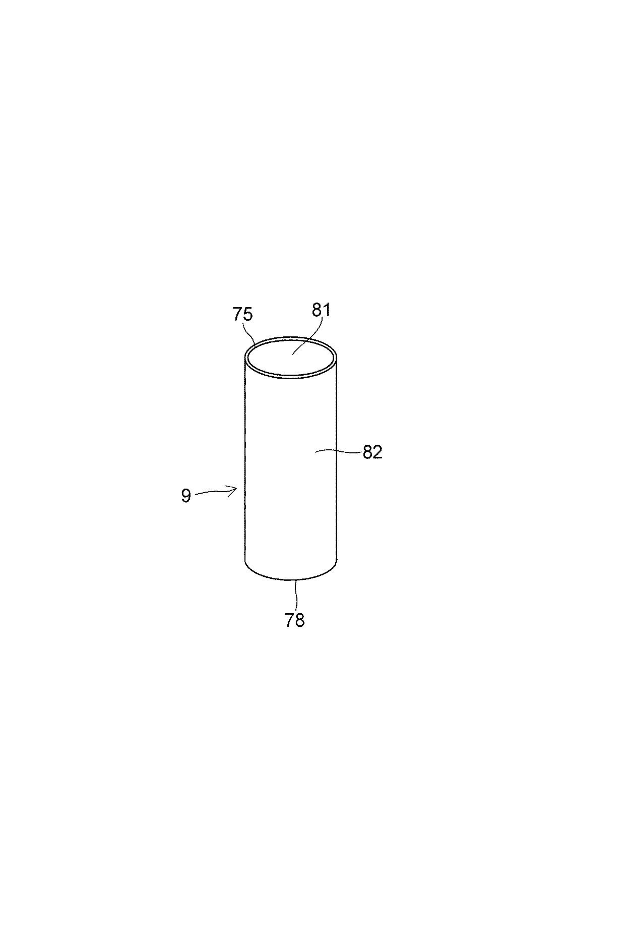
中空部6は、内周面5に加えて、剪断キー17の円形の下面71と剪断キー20の円形の上面72とによって規定されており、下面71は、鉛プラグ7の円形の上端面73、ゴム被覆層65の円環状の上端面74及び熱伝導体9の円環状の上端面75の夫々に密に接触しており、上面72は、鉛プラグ7の円形の下端面76、ゴム被覆層65の円環状の下端面77及び熱伝導体9の円環状の下端面78に密に接触している。
The
0.3〜1.0mmの肉厚を有していると共に少なくとも1W/m・Kの熱伝導率を有している熱伝導体9は、上端面75及び下端面78に加えて、外周面8に密に接触した内周面81と、内周面5に密に接触した外周面82とを具備している。
The
弾性層2の夫々と剛性層3の夫々とは、それらの上面33、51及び57並びに下面34、42及び58の夫々の互いに接触する接触面で、例えば、加硫接着又は接着剤により互いに強固に貼り合わされており、ゴム被覆層65と弾性層2及び剛性層3の夫々とは、その外周面66並びに内周面31、43、53及び59の夫々の互いに接触する接触面で加硫接着又は接着剤により互いに強固に貼り合わされており、ゴム被覆層65と熱伝導体9の夫々とは、その内周面5及び外周面82の夫々の互いに接触する接触面で、加硫接着又は接着剤により互いに強固に貼り合わされている。
Each of the
外周面10は、複数の外周面32及び60と外周面44及び54とからなっており、円筒状の外周面85に加えて円筒状の内周面86を有した外周保護層11と弾性層2及び剛性層3の夫々とは、その内周面86及び外周面32、44、54及び60の夫々の互いの接触面で、加硫接着又は接着剤により互いに強固に貼り合わされている。
The outer
ゴム被覆層65及び外周保護層11の少なくとも一方は、積層体4の加圧加硫成形時の弾性層2のはみ出しにより弾性層2と一体となって形成されてもよい。
At least one of the
免震支持装置1は、上取付板13で構造物91に、下取付板14で基礎92に夫々ボルト93を介して連結されており、積層体4と鉛プラグ7とによって構造物91の積層方向(鉛直方向)Vの荷重を支持するように用いられる。
The seismic
熱伝導体9は、以下の(1)、(2)又は(3)のようにして製造されてもよい。
The
<(1)ポリマーとして天然ゴムを使用する場合>
架橋ゴムに、充填剤のうちの少なくとも一つと、必要に応じて加硫促進剤(例えば、N−シクロヘキシル−2−ベンゾチアジル・スルフェンアミド、2−メルカプトベンゾチアゾール及びジベンゾチアジルジサルファイド等のチアゾール系並びにジフェニルグアジニン等のグアジニン系)、加硫促進助剤(亜鉛華(ZnO)及び酸化マグネシウム等の金属酸化物及びステアリン酸、ラウリン酸及びパルミチン酸等の脂肪酸)、加硫剤(例えば、硫黄及び硫黄含有化合物等)、プロセスオイル(例えば、パラフィン系、ナフテン系及び芳香族系等)及び老化防止剤〔N−イソプロピル−N′−フェニル−P−フェニレンジアミン及びN−(1、3−ジメチルブチル)−N′−フェニル−P−フェニレンジアミン等〕とを配合した後、素練り及び混練り工程を経て作製した熱伝導体組成物を、ついで、カレンダーロール機を用いて均一な厚さ、所定の幅の長いシートに圧延加工する。このシートを鉛プラグの外周面8を一周する長さに切断して、これを熱伝導体9用の未加硫のシートとする。
<(1) When using natural rubber as a polymer>
In the crosslinked rubber, at least one of the fillers and, if necessary, a vulcanization accelerator (for example, N-cyclohexyl-2-benzothiazylsulfenamide, 2-mercaptobenzothiazole, and a thiazole such as dibenzothiazyldisulfide) Systems and guanines such as diphenyl guanine), vulcanization acceleration assistants (metal oxides such as zinc oxide (ZnO) and magnesium oxide and fatty acids such as stearic acid, lauric acid and palmitic acid), vulcanizing agents (eg, Sulfur and sulfur-containing compounds etc.), process oils (eg paraffinic, naphthenic and aromatic etc.) and anti-aging agents [N-isopropyl-N'-phenyl-P-phenylenediamine and N- (1,3-3 After mixing with dimethylbutyl) -N'-phenyl-P-phenylenediamine etc. The heat conductor composition produced through the kneading step is then rolled into a sheet of uniform thickness and a predetermined width using a calender roll machine. This sheet is cut into a length that goes around the outer
<(2)ポリマーとしてノボラック型フェノール樹脂を使用する場合>
ノボラック型フェノール樹脂粉末に充填剤のうちの少なくとも一つと必要に応じて、硬化剤、離型剤、硬化促進剤とを加えて混合し、これらを適量の溶剤とともにヘンシェルミキサー等の混合機にて均一に撹拌混合して作製した混合物を混練機に投入し、加熱しながら混練した混練物を冷却固化した後、冷却固化した混練物を適当な大きさに粉砕した成形材料を金型に均一に入れ、圧力と熱をかけて圧縮成形し、均一な厚さと所定の幅を有する長いシートに加工する。このシートを鉛プラグ7の外周面を一周する長さに切断して、これを熱伝導体9用のシートとする。
<(2) When using novolac type phenol resin as polymer>
In a novolak-type phenolic resin powder, at least one of the fillers and, if necessary, a curing agent, a mold release agent and a curing accelerator are added and mixed, and these are mixed with an appropriate amount of solvent using a mixer such as a Henschel mixer A mixture prepared by uniformly stirring and mixing is introduced into a kneader, and the kneaded material kneaded while heating is cooled and solidified, and then the molding material obtained by cooling and solidifying the cooled and solidified material is crushed into an appropriate size uniformly in a mold. Put in, apply pressure and heat and compression mold and process into long sheets with uniform thickness and predetermined width. This sheet is cut into a length that goes around the outer peripheral surface of the
<(3)ポリマーとして熱可塑性合成樹脂又は熱可塑性エラストマーを使用する場合>
熱可塑性合成樹脂又は熱可塑性エラストマーと充填剤のうちの少なくとも一つとをヘンシェルミキサー等の混合機で混合して作製した混合物をスクリュー式押出機でストランド状に押し出し、押し出したストランド状の混合物を切断して熱伝導体組成物のペレットを作製し、このペレットを、Tダイを備えた押出成形機に供給し、押出成形して均一な厚さと所定の幅を有する長いシートに加工する。このシートを鉛プラグ7の外周面を一周する長さに切断して、これを熱伝導体9用のシートとする。
<(3) When using thermoplastic synthetic resin or thermoplastic elastomer as polymer>
A mixture produced by mixing a thermoplastic synthetic resin or a thermoplastic elastomer and at least one of a filler with a mixer such as a Henschel mixer is extruded into a strand by a screw extruder, and the extruded strand is cut Then, a pellet of the heat conductor composition is prepared, and the pellet is fed to an extruder equipped with a T-die, and extruded to be processed into a long sheet having a uniform thickness and a predetermined width. This sheet is cut into a length that goes around the outer peripheral surface of the
斯かる熱伝導体9を含む免震支持装置1は、以下のようにして製造されてもよい。
The seismic
<弾性層2用のゴム板の作製>
架橋ゴムに加硫促進剤、加硫促進助剤、加硫剤、プロセスオイル、老化防止剤を配合し、素練り及び混練り工程を経てゴム組成物を作製し、ついで、カレンダーロール機を用いてゴム組成物を圧延加工して均一な厚さ、所定の幅の長い未加硫のゴムシートから弾性層2用の未加硫のゴム板を切り抜く。
<Production of rubber plate for
A cross-linked rubber is compounded with a vulcanization accelerator, a vulcanization acceleration auxiliary agent, a vulcanizing agent, a process oil, an antiaging agent, and after a process of mastication and kneading, a rubber composition is produced, and then a calender roll machine is used. The rubber composition is rolled to cut out an unvulcanized rubber plate for the
<剛性層3用の鋼板の作製>
薄肉の冷間圧延鋼板(SPCC)からプレス加工により最上部及び最下部の剛性層3間の剛性層3用の円環状の薄肉の鋼板と、厚肉の冷間圧延鋼板(SPCC)から同じくプレス加工により最上部及び最下部の剛性層3用の円環状の厚肉の鋼板とを作製する。
<Fabrication of steel plate for
A thin-walled cold-rolled steel plate (SPCC) is pressed to form an annular thin-walled steel plate for the
<積層体4及び免震支持装置1の作製>
金型内に設けられた円柱体の外周面に上記(1)、(2)又は(3)で得られた熱伝導体9用のシートを円筒状に一周巻き付けて当該シートを固定すると共に当該熱伝導体9用の円筒状のシートの外周面に、必要に応じて、ゴム被覆層65用の0.3〜0.5mmの厚さの未加硫のゴムシートを円筒状に一周巻き付け、この円筒状のゴムシートを固定すると共に当該ゴム被覆層65用の円筒状のゴムシートの外周面に、最下部の剛性層3用の厚肉の鋼板を凹所18を下向きにして内周面53で規定される貫通孔を介して嵌挿し、当該厚肉の鋼板の上面51に接着剤を塗布する。接着剤としては、上面51にプライマーとして下塗り接着剤を塗布した後、さらに上塗り接着剤を塗布する接着剤二液塗工式が好ましい。ついで、弾性層2用の未加硫のゴム板を内周面31で規定された貫通孔を介して熱伝導体9用の円筒状のシートの外周面に、必要に応じて設けられる場合には、ゴム被覆層65用の円筒状のゴムシートの外周面に嵌挿して接着剤が塗布された最下部の剛性層3用の厚板の鋼板の上面51に載置し、以下、上面57及び下面58に接着剤を塗布した最上部及び最下部剛性層3間の各剛性層3用の薄板の鋼板と弾性層2用の未加硫のゴム板とを交互に金型内に設けられた円柱体の外周面に固定された熱伝導体9用の円筒状のシートの周りに、必要に応じて設けられる場合には、ゴム被覆層65用の円筒状のゴムシートの周りに複数個積み重ね、最後に、金型内に設けられた円柱体の外周面に固定された熱伝導体9用の円筒状のシートの周りに、必要に応じて設けられる場合には、ゴム被覆層65用の円筒状のゴムシートの周りに交互に積み重ねられた最下部の剛性層3、最上部及び最下部の剛性層3間の各剛性層3用の薄肉の鋼板及び弾性層2用の未加硫のゴム板に最上部の剛性層3用の厚肉の鋼板が更に載置されるように、金型内に設けられた熱伝導体9用の円筒状のシートに、必要に応じて設けられる場合には、ゴム被覆層65用の円筒状のゴムシートに、下面42に接着剤を塗付した最上部の剛性層3用の厚肉の鋼板を嵌挿して、熱伝導体9用の円筒状のシート、必要に応じて設けられたゴム被覆層65用の円筒状のゴムシートを備えた未加硫の積層体4を作製し、この未加硫の積層体4の外周面10に、外周保護層11用の耐候性に優れた薄肉の未加硫のゴムシートを円筒状に巻き付け、この未加硫の積層体4を加熱加圧して、熱伝導体9用の円筒状のゴムシート、弾性層2用の未加硫のゴム板並びに外周保護層11用の未加硫の円筒状のゴムシート及び必要に応じて設けられたゴム被覆層65用の円筒状のゴムシートの加硫化を行うと共に相互を加硫接着して熱伝導体9、外周保護層11及びゴム被覆層65を備えた積層体4を作製する。
<Fabrication of
The sheet for the
この積層体4を金型内に設けられた円柱体から取り出すと共に内周面81で規定された円柱状の中空部に鉛プラグ7を圧入した後、凹所15及び18の夫々に剪断キー17及び20を嵌合する一方、ボルト12を介して最上部の剛性層3及び最下部の剛性層3の夫々に上取付板13及び下取付板14を連結して免震支持装置1を作製する。
The
斯かる免震支持装置1の作製において、ゴム被覆層65用及び外周保護層11用のゴムシートの捲き付けを省略して、積層体4の加熱加圧での弾性層2用の未加硫のゴム板の内周側及び外周側の膨出でゴム被覆層65及び外周保護層11を形成するようにしてもよい。
In the production of such a seismic
<弾性層2用の未加硫のゴムシートの製作>
架橋ゴムとして天然ゴムと、カーボンブラックと、亜鉛華(ZnO)と、ステアリン酸と、老化防止剤と、プロセスオイルとを汎用の混練機に投入し、混練りした。ついで、これに加硫促進剤及び加硫剤を投入し、オープンロールを使用して混練りし、混練りしたゴム組成物を圧延加工して未加硫の厚さ5mmのゴムシートを作製した。
<Production of Unvulcanized Rubber Sheet for
Natural rubber, carbon black, zinc white (ZnO), stearic acid, an anti-aging agent, and a process oil were introduced into a general-purpose kneader as a cross-linked rubber and kneaded. Then, a vulcanization accelerator and a vulcanizing agent were added thereto, and the mixture was kneaded using an open roll, and the kneaded rubber composition was rolled to prepare an unvulcanized rubber sheet having a thickness of 5 mm. .
<剛性層3用の薄肉の鋼板と厚肉の鋼板との製作>
最上部及び最下部の剛性層3間の剛性層3として、外径1000mm、厚さ3.9mmを有すると共に中央部に直径202mmの内周面59で規定される貫通孔を有する冷間圧延鋼板(SPCC)からなる円板状の薄肉の鋼板と、最上部及び最下部の剛性層3として、外径1000mm、厚さ40mmを有すると共に中央部に直径240mmの凹所15及び18の夫々と、凹所15及び18の夫々の中央部に直径202mmの内周面43及び53の夫々で規定される貫通孔を夫々有する夫々冷間圧延鋼板(SPCC)からなる二枚の厚肉の鋼板を準備した。
<Fabrication of thin steel plate for
A cold-rolled steel plate having an outer diameter of 1000 mm and a thickness of 3.9 mm as a
実施例1
ポリマーとしての天然ゴム(NR)100質量部と、充填剤としてのカーボンブラック5質量部及びピッチ系炭素繊維(日本グラファイトファイバー社製のGRANOCミルドファイバー「XN−100(商品名)」、平均長さ50μm、平均繊維径7μm)20質量部とから上記(1)の方法をもって厚さ0.5mmの熱伝導体9用の未加硫のシートを作製する一方、弾性層2用の未加硫のゴムシートから、直径1000mmの円形のゴム板を切り抜くと共にこのゴム板の中央部に直径202mmの内周面31で規定される貫通孔を切り抜き、弾性層2用の未加硫のゴム板を作製した。
Example 1
100 parts by mass of natural rubber (NR) as a polymer, 5 parts by mass of carbon black as a filler and a pitch-based carbon fiber (GRANOC milled fiber "XN-100 (trade name)" manufactured by Nippon Graphite Fiber Co., Ltd.), average length An unvulcanized sheet for the
斯かる熱伝導体9用の未加硫のシート及び弾性層2用の未加硫の32枚のゴム板と、弾性層2用の未加硫のゴムシートと同様のゴム組成物からなるゴム被覆層65用の厚さ0.5mmの未加硫のゴムシートと、外周保護層11用の厚さ5mmの未加硫のゴムシートとから免震支持装置1を作製した。作製した免震支持装置1における熱伝導体9は、1W/m・Kの熱伝導率を示した。
A rubber comprising the same rubber composition as the unvulcanized sheet for the
実施例2
充填剤として実施例1のピッチ系炭素繊維30質量部と、鱗片状黒鉛(1)(西村黒鉛社製の「PS−99(商品名)」、平均粒径7μm)30質量部とを用いた以外は実施例1と同様の方法で免震支持装置1を作製した。作製した免震支持装置1における熱伝導体9は、10W/m・Kの熱伝導率を示した。
Example 2
As a filler, 30 parts by mass of pitch-based carbon fiber of Example 1 and 30 parts by mass of scale-like graphite (1) ("PS-99 (trade name)" manufactured by Nishimura Graphite Co., Ltd.,
実施例3
ポリマーとしてのブチルゴム(ポリサーブチル)(IIR)100質量部と、充填剤としての実施例1のカーボンブラック50質量部、ピッチ系炭素繊維15質量部及び鱗片状黒鉛(2)(TIMCAL社製の「KS15(商品名)、平均粒子径8μm)75質量部とを用いた以外は実施例1と同様の方法で免震支持装置1を作製した。作製した免震支持装置1における熱伝導体9は、14W/m・Kの熱伝導率を示した。
Example 3
100 parts by mass of butyl rubber (polycerbutyl) (IIR) as a polymer, 50 parts by mass of carbon black of Example 1 as a filler, 15 parts by mass of pitch-based carbon fiber, and scaly graphite (2) (manufactured by TIMCAL Co.) The seismic
実施例4
ポリマーとしてのエチレンプロピレンゴム(EPDM)100質量部と、充填剤としてのカーボンブラック40質量部、六方晶窒化ホウ素(BN)(電気化学工業社製、平均粒径15μm)96質量部とを用いた以外は実施例1と同様の方法で免震支持装置1を作製した。作製した免震支持装置1における熱伝導体9は、5W/m・Kの熱伝導率を示した。
Example 4
100 parts by mass of ethylene propylene rubber (EPDM) as a polymer, 40 parts by mass of carbon black as a filler, 96 parts by mass of hexagonal boron nitride (BN) (manufactured by Denki Kagaku Kogyo Co., Ltd.,
実施例5
ポリマーとしてのポリアセタール樹脂(POM)100質量部と、充填剤としてのピッチ系炭素繊維150質量部及び酸化アルミニウム(Al2O3)(昭和電工社製)30質量部とから上記(3)の方法をもって未加硫の厚さ0.5mmの熱伝導体9用のシートを作製した以外は、実施例1と同様の方法で免震支持装置1を作製した。作製した免震支持装置1における熱伝導体9は、2W/m・Kの熱伝導率を示した。
Example 5
Method of the above (3) from 100 parts by mass of polyacetal resin (POM) as polymer, 150 parts by mass of pitch based carbon fiber as filler and 30 parts by mass of aluminum oxide (Al 2 O 3 ) (manufactured by Showa Denko KK) The seismic isolation and
実施例6
ポリマーとしてのポリアミド樹脂(PA6)100質量部と、充填剤としての鱗片状黒鉛(3)(日本黒鉛社製、平均粒径130μm)132質量部とから実施例5と同様にして厚さ0.5mmの未加硫の熱伝導体9用のシートを作製した以外は、実施例1と同様にして免震支持装置1を作製した。作製した免震支持装置1における熱伝導体9は、20W/m・Kの熱伝導率を示した。
Example 6
In the same manner as in Example 5, 100 parts by mass of a polyamide resin (PA6) as a polymer and 132 parts by mass of flaky graphite (3) (manufactured by Nippon Graphite Co., Ltd., average particle diameter 130 μm) as a filler. The seismic
実施例7
ポリマーとしてのポリアミド樹脂(PA6)100質量部と、充填剤としての鱗片状黒鉛(3)203質量部とから実施例5と同様にして厚さ0.5mmの未加硫の熱伝導体9用のシートを作製した以外は、実施例1と同様にして免震支持装置1を作製した。作製した免震支持装置1における熱伝導体9は、30W/m・Kの熱伝導率を示した。
Example 7
From 100 parts by mass of polyamide resin (PA6) as a polymer and 203 parts by mass of scale-like graphite (3) as a filler in the same manner as in Example 5 for an unvulcanized
実施例8
ポリマーとしてのポリブチレンテレフタレート樹脂(PBT)100質量部と、充填剤としての実施例3の鱗片状黒鉛(2)50質量部及び実施例1のピッチ系炭素繊維20質量部とから実施例5と同様にして厚さ0.5mmの未加硫の熱伝導体9用のシートを作製した以外は、実施例1と同様にして免震支持装置1を作製した。作製した免震支持装置1における熱伝導体9は、12W/m・Kの熱伝導率を示した。
Example 8
Example 5 from 100 parts by mass of polybutylene terephthalate resin (PBT) as a polymer, 50 parts by mass of scale-like graphite (2) of Example 3 as a filler, and 20 parts by mass of pitch-based carbon fibers of Example 1 A seismic isolation and
実施例9
ポリマーとしての低硬度のスチレン系熱可塑性エラストマー100質量部と、充填剤としての実施例1のピッチ系炭素繊維100質量部、実施例4の六方晶窒化ホウ素20質量部及び実施例5の酸化アルミニウム20質量部とから実施例5と同様にして厚さ0.5mmの未加硫の熱伝導体9用のシートを作製し対外は、実施例1と同様にして免震支持装置1を作製した。作製した免震支持装置1における熱伝導体9は、2W/m・Kの熱伝導率を示した。
Example 9
100 parts by mass of a low-hardness styrenic thermoplastic elastomer as a polymer, 100 parts by mass of the pitch-based carbon fiber of Example 1 as a filler, 20 parts by mass of hexagonal boron nitride of Example 4 and aluminum oxide of Example 5 A sheet for an unvulcanized
実施例10
実施例1と同様の熱伝導体9用の未加硫のシート及び弾性層2用の未加硫のゴム板と、溶融アルミニウムメッキにより表面に厚さ60μmのアルミニウム被覆層が全面に形成された剛性層3用の薄肉及び厚肉の鋼板とから実施例1と同様にして免震支持装置1を作製した。作製した免震支持装置1における熱伝導体9は、1W/m・Kの熱伝導率を示した。
Example 10
An unvulcanized sheet for the
実施例11
実施例2と同様の熱伝導体9用の未加硫のシート及び弾性層2用の未加硫のゴム板と、無電解銅メッキにより表面に厚さ30μmの銅被覆層が全面に形成された剛性層3用の薄肉及び厚肉の鋼板とから実施例1と同様にして免震支持装置1を作製した。作製した免震支持装置1における熱伝導体9は、10W/m・Kの熱伝導率を示した。
Example 11
The unvulcanized sheet for the
比較例
比較例として、熱伝導体9用のシートを用いないで各実施例と同様にして免震支持装置1を作製した。
Comparative Example As a comparative example, the seismic
次に、実施例1から実施例11及び比較例で得た免震支持装置1について、巨大地震時において多数回繰り返して受ける水平変位Hで鉛プラグ7の温度上昇について行った試験した。その試験結果を表1及び表2に示す。
Next, with regard to the seismic isolation and
<試験条件>
面圧 15N/mm2(706.9kN)
剪断歪み(γ) 250%(120mm)
振動数 0.3Hz
最大速度 22.6kine
加振波数 50サイクル
<試験方法>
300トンの二軸試験機を用いて、上記試験条件に示す正弦波形の加振を50サイクル行い、鉛プラグ7に取り付けた熱電対センサにより、50サイクル加振後の鉛プラグ7の温度を測定した。
<Test conditions>
Surface pressure 15 N / mm 2 (706.9 kN)
Shear strain (γ) 250% (120 mm)
Frequency 0.3Hz
Maximum speed 22.6kine
Excitation wave number 50 cycles <Test method>
Using a 300 ton biaxial tester, perform 50 cycles of sinusoidal vibration shown in the above test conditions, and measure the temperature of the
表1ないし表3中の鉛プラグ温度指数は、実施例1から実施例11の鉛プラグ7の50サイクル加振後の温度を比較例の鉛プラグ7の50サイクル加振後の温度の値を100として、これとの比で表したものである。
The lead plug temperature index in Tables 1 to 3 is the temperature after 50 cycles of the
試験結果から分かるように、本実施例の免震支持装置1においては、鉛プラグ7に生じる温度上昇を、熱伝導体9を介して剛性層3に放出させることができるので地震時等の鉛プラグ7の過度の温度上昇を防止できる。
As can be understood from the test results, in the seismic
1 免震支持装置
2 弾性層
3 剛性層
4 積層体
5 内周面
6 中空部
7 鉛プラグ
8、10 外周面
9 熱伝導体
REFERENCE SIGNS
Claims (8)
Priority Applications (7)
| Application Number | Priority Date | Filing Date | Title |
|---|---|---|---|
| JP2015058680A JP6540134B2 (en) | 2015-03-20 | 2015-03-20 | Seismic isolation support device |
| EP16767952.1A EP3273090A4 (en) | 2015-03-20 | 2016-03-03 | Seismic base isolation support device |
| PCT/JP2016/001162 WO2016152041A1 (en) | 2015-03-20 | 2016-03-03 | Seismic base isolation support device |
| KR1020177026229A KR20170128337A (en) | 2015-03-20 | 2016-03-03 | Seismic Retention Device |
| CN201680016770.2A CN107429783A (en) | 2015-03-20 | 2016-03-03 | Shock insulation support meanss |
| US15/557,231 US20180051764A1 (en) | 2015-03-20 | 2016-03-03 | Seismic base isolation support apparatus |
| TW105108132A TWI693325B (en) | 2015-03-20 | 2016-03-16 | Base isolation supporting device |
Applications Claiming Priority (1)
| Application Number | Priority Date | Filing Date | Title |
|---|---|---|---|
| JP2015058680A JP6540134B2 (en) | 2015-03-20 | 2015-03-20 | Seismic isolation support device |
Publications (2)
| Publication Number | Publication Date |
|---|---|
| JP2016176577A JP2016176577A (en) | 2016-10-06 |
| JP6540134B2 true JP6540134B2 (en) | 2019-07-10 |
Family
ID=56977191
Family Applications (1)
| Application Number | Title | Priority Date | Filing Date |
|---|---|---|---|
| JP2015058680A Active JP6540134B2 (en) | 2015-03-20 | 2015-03-20 | Seismic isolation support device |
Country Status (7)
| Country | Link |
|---|---|
| US (1) | US20180051764A1 (en) |
| EP (1) | EP3273090A4 (en) |
| JP (1) | JP6540134B2 (en) |
| KR (1) | KR20170128337A (en) |
| CN (1) | CN107429783A (en) |
| TW (1) | TWI693325B (en) |
| WO (1) | WO2016152041A1 (en) |
Families Citing this family (10)
| Publication number | Priority date | Publication date | Assignee | Title |
|---|---|---|---|---|
| US9869084B2 (en) * | 2014-10-14 | 2018-01-16 | Emeh, Inc. | Stair expansion joint system with freedom of movement between landings |
| JP2017194098A (en) * | 2016-04-19 | 2017-10-26 | オイレス工業株式会社 | Seismic isolator |
| US10927920B2 (en) * | 2017-10-04 | 2021-02-23 | Illinois Tool Works, Inc | Passive damping system for mass flow controller |
| PT3540151T (en) * | 2018-03-15 | 2025-02-28 | Soletanche Freyssinet | Enhanced seismic isolation lead rubber bearings |
| KR102634353B1 (en) * | 2018-11-26 | 2024-02-08 | 현대자동차주식회사 | Vibration proof rubber for vehicle |
| CN109853722A (en) * | 2019-03-20 | 2019-06-07 | 华北水利水电大学 | A shock-absorbing and seismic-resistant steel structure building |
| CN109898564B (en) * | 2019-04-14 | 2020-11-13 | 骆红所 | Multi-dimensional shock isolation device for building |
| CN110154732B (en) * | 2019-06-11 | 2020-03-17 | 湖南机电职业技术学院 | Novel automobile power assembly suspension device |
| GB202009430D0 (en) * | 2020-06-19 | 2020-08-05 | Ocado Innovation Ltd | A grid framework structure |
| US12201227B2 (en) * | 2022-06-03 | 2025-01-21 | Apple Inc. | Product display stand with reduced movement |
Family Cites Families (14)
| Publication number | Priority date | Publication date | Assignee | Title |
|---|---|---|---|---|
| NZ201015A (en) * | 1982-06-18 | 1986-05-09 | New Zealand Dev Finance | Building support:cyclic shear energy absorber |
| JP2883219B2 (en) * | 1990-10-17 | 1999-04-19 | オイレス工業株式会社 | Seismic isolation support device |
| JPH08326840A (en) * | 1995-05-26 | 1996-12-10 | Bridgestone Corp | Base isolation structure |
| US5765322A (en) * | 1995-09-29 | 1998-06-16 | Bridgestone Corporation | Seismic isolation apparatus |
| JP3749761B2 (en) * | 1995-10-02 | 2006-03-01 | 株式会社エコ・トゥエンティーワン | Air conditioning ventilator |
| JP3168411B2 (en) * | 1997-08-06 | 2001-05-21 | ニッタ株式会社 | Laminate preheating method |
| JP2003214493A (en) * | 2001-10-22 | 2003-07-30 | Toyo Tire & Rubber Co Ltd | Laminated rubber bearing device and its manufacturing method |
| JP2003191253A (en) * | 2001-12-28 | 2003-07-08 | Toyo Tire & Rubber Co Ltd | Manufacturing method of laminated rubber |
| MY152660A (en) * | 2009-12-25 | 2014-10-31 | Yokohama Rubber Co Ltd | Rubber-made support device |
| JP2011141002A (en) * | 2010-01-08 | 2011-07-21 | Bridgestone Corp | Base isolation device |
| JP5481365B2 (en) * | 2010-12-21 | 2014-04-23 | 株式会社ブリヂストン | Seismic isolation device |
| JP5884612B2 (en) * | 2012-04-10 | 2016-03-15 | 住友電気工業株式会社 | Air spring |
| TWI426168B (en) * | 2012-06-14 | 2014-02-11 | Chong-Shien Tsai | Can prevent the temperature rise of the support pad |
| JP5541329B2 (en) * | 2012-09-03 | 2014-07-09 | オイレス工業株式会社 | Seismic isolation device |
-
2015
- 2015-03-20 JP JP2015058680A patent/JP6540134B2/en active Active
-
2016
- 2016-03-03 US US15/557,231 patent/US20180051764A1/en not_active Abandoned
- 2016-03-03 EP EP16767952.1A patent/EP3273090A4/en not_active Withdrawn
- 2016-03-03 KR KR1020177026229A patent/KR20170128337A/en not_active Withdrawn
- 2016-03-03 WO PCT/JP2016/001162 patent/WO2016152041A1/en not_active Ceased
- 2016-03-03 CN CN201680016770.2A patent/CN107429783A/en not_active Withdrawn
- 2016-03-16 TW TW105108132A patent/TWI693325B/en active
Also Published As
| Publication number | Publication date |
|---|---|
| EP3273090A4 (en) | 2018-11-14 |
| CN107429783A (en) | 2017-12-01 |
| TWI693325B (en) | 2020-05-11 |
| EP3273090A1 (en) | 2018-01-24 |
| US20180051764A1 (en) | 2018-02-22 |
| JP2016176577A (en) | 2016-10-06 |
| KR20170128337A (en) | 2017-11-22 |
| WO2016152041A1 (en) | 2016-09-29 |
| TW201641790A (en) | 2016-12-01 |
Similar Documents
| Publication | Publication Date | Title |
|---|---|---|
| JP6540134B2 (en) | Seismic isolation support device | |
| JP6458516B2 (en) | Seismic isolation support device | |
| KR102455995B1 (en) | heat conduction sheet | |
| JP6891305B2 (en) | Seismic isolation device | |
| KR20210021931A (en) | Cooling element for battery module, battery module comprising the same | |
| KR20160013270A (en) | Thermally conductive sheet, method for producing same, and semiconductor device | |
| WO2018030430A1 (en) | Heat transfer sheet and method for producing same | |
| KR20150090079A (en) | Heat-conducting foam sheet for electronic instruments and heat-conducting laminate for electronic instruments | |
| JP6473846B1 (en) | Resin sheet and resin sheet with adhesive layer | |
| CN114930448A (en) | Sound insulation structure | |
| KR20210094063A (en) | Heat dissipation structure and battery having same | |
| JP2022012195A (en) | Heat dissipation structure and battery with it | |
| KR101926907B1 (en) | The thermal interface material and production method thereof | |
| JP6266890B2 (en) | Thermally conductive foam sheet for electronic equipment | |
| DE102010005020A1 (en) | Composite material useful in moldings, which are useful e.g. for conducting and dissipating heat and as heat conductive materials, comprises a polymer, copolymer or a mixture of several polymers and/or copolymers, and a first filler | |
| JP5089417B2 (en) | Thermally conductive sheet and heat dissipation device | |
| JP2011082423A (en) | Heat conductive sheet | |
| KR20170087893A (en) | Seismic isolation device | |
| JP7312515B2 (en) | Heat dissipation material | |
| JP6540114B2 (en) | Seismic isolation support device | |
| JP2022106327A (en) | Heat dissipation structure and battery with the same | |
| JP2021123661A (en) | Thermally conductive resin sheet | |
| US20030064606A1 (en) | Electrically-conductive thermal insulator | |
| JP2013225541A (en) | Heat conduction sheet | |
| Manwar et al. | Failure Analysis Ceramic/Fibrous Filler-Based Polymer Composites |
Legal Events
| Date | Code | Title | Description |
|---|---|---|---|
| A621 | Written request for application examination |
Free format text: JAPANESE INTERMEDIATE CODE: A621 Effective date: 20180221 |
|
| A131 | Notification of reasons for refusal |
Free format text: JAPANESE INTERMEDIATE CODE: A131 Effective date: 20181120 |
|
| A521 | Request for written amendment filed |
Free format text: JAPANESE INTERMEDIATE CODE: A523 Effective date: 20190118 |
|
| TRDD | Decision of grant or rejection written | ||
| A01 | Written decision to grant a patent or to grant a registration (utility model) |
Free format text: JAPANESE INTERMEDIATE CODE: A01 Effective date: 20190514 |
|
| A61 | First payment of annual fees (during grant procedure) |
Free format text: JAPANESE INTERMEDIATE CODE: A61 Effective date: 20190527 |
|
| R150 | Certificate of patent or registration of utility model |
Ref document number: 6540134 Country of ref document: JP Free format text: JAPANESE INTERMEDIATE CODE: R150 |
|
| R250 | Receipt of annual fees |
Free format text: JAPANESE INTERMEDIATE CODE: R250 |
|
| R250 | Receipt of annual fees |
Free format text: JAPANESE INTERMEDIATE CODE: R250 |
|
| R250 | Receipt of annual fees |
Free format text: JAPANESE INTERMEDIATE CODE: R250 |
|
| R250 | Receipt of annual fees |
Free format text: JAPANESE INTERMEDIATE CODE: R250 |