KR20160132908A - Ophthalmic lens and method for designing ophthalmic lens - Google Patents
Ophthalmic lens and method for designing ophthalmic lens Download PDFInfo
- Publication number
- KR20160132908A KR20160132908A KR1020167027721A KR20167027721A KR20160132908A KR 20160132908 A KR20160132908 A KR 20160132908A KR 1020167027721 A KR1020167027721 A KR 1020167027721A KR 20167027721 A KR20167027721 A KR 20167027721A KR 20160132908 A KR20160132908 A KR 20160132908A
- Authority
- KR
- South Korea
- Prior art keywords
- lens
- eye
- toric
- formula
- spherical aberration
- Prior art date
- Legal status (The legal status is an assumption and is not a legal conclusion. Google has not performed a legal analysis and makes no representation as to the accuracy of the status listed.)
- Granted
Links
Images


Classifications
-
- G—PHYSICS
- G02—OPTICS
- G02C—SPECTACLES; SUNGLASSES OR GOGGLES INSOFAR AS THEY HAVE THE SAME FEATURES AS SPECTACLES; CONTACT LENSES
- G02C7/00—Optical parts
- G02C7/02—Lenses; Lens systems ; Methods of designing lenses
- G02C7/024—Methods of designing ophthalmic lenses
- G02C7/028—Special mathematical design techniques
-
- A—HUMAN NECESSITIES
- A61—MEDICAL OR VETERINARY SCIENCE; HYGIENE
- A61F—FILTERS IMPLANTABLE INTO BLOOD VESSELS; PROSTHESES; DEVICES PROVIDING PATENCY TO, OR PREVENTING COLLAPSING OF, TUBULAR STRUCTURES OF THE BODY, e.g. STENTS; ORTHOPAEDIC, NURSING OR CONTRACEPTIVE DEVICES; FOMENTATION; TREATMENT OR PROTECTION OF EYES OR EARS; BANDAGES, DRESSINGS OR ABSORBENT PADS; FIRST-AID KITS
- A61F2/00—Filters implantable into blood vessels; Prostheses, i.e. artificial substitutes or replacements for parts of the body; Appliances for connecting them with the body; Devices providing patency to, or preventing collapsing of, tubular structures of the body, e.g. stents
- A61F2/02—Prostheses implantable into the body
- A61F2/14—Eye parts, e.g. lenses or corneal implants; Artificial eyes
- A61F2/16—Intraocular lenses
- A61F2/1613—Intraocular lenses having special lens configurations, e.g. multipart lenses; having particular optical properties, e.g. pseudo-accommodative lenses, lenses having aberration corrections, diffractive lenses, lenses for variably absorbing electromagnetic radiation, lenses having variable focus
- A61F2/1637—Correcting aberrations caused by inhomogeneities; correcting intrinsic aberrations, e.g. of the cornea, of the surface of the natural lens, aspheric, cylindrical, toric lenses
- A61F2/1645—Toric lenses
-
- G—PHYSICS
- G02—OPTICS
- G02C—SPECTACLES; SUNGLASSES OR GOGGLES INSOFAR AS THEY HAVE THE SAME FEATURES AS SPECTACLES; CONTACT LENSES
- G02C7/00—Optical parts
- G02C7/02—Lenses; Lens systems ; Methods of designing lenses
-
- G—PHYSICS
- G02—OPTICS
- G02C—SPECTACLES; SUNGLASSES OR GOGGLES INSOFAR AS THEY HAVE THE SAME FEATURES AS SPECTACLES; CONTACT LENSES
- G02C7/00—Optical parts
- G02C7/02—Lenses; Lens systems ; Methods of designing lenses
- G02C7/022—Ophthalmic lenses having special refractive features achieved by special materials or material structures
-
- G—PHYSICS
- G02—OPTICS
- G02C—SPECTACLES; SUNGLASSES OR GOGGLES INSOFAR AS THEY HAVE THE SAME FEATURES AS SPECTACLES; CONTACT LENSES
- G02C7/00—Optical parts
- G02C7/02—Lenses; Lens systems ; Methods of designing lenses
- G02C7/024—Methods of designing ophthalmic lenses
-
- G—PHYSICS
- G02—OPTICS
- G02C—SPECTACLES; SUNGLASSES OR GOGGLES INSOFAR AS THEY HAVE THE SAME FEATURES AS SPECTACLES; CONTACT LENSES
- G02C7/00—Optical parts
- G02C7/02—Lenses; Lens systems ; Methods of designing lenses
- G02C7/04—Contact lenses for the eyes
-
- A—HUMAN NECESSITIES
- A61—MEDICAL OR VETERINARY SCIENCE; HYGIENE
- A61F—FILTERS IMPLANTABLE INTO BLOOD VESSELS; PROSTHESES; DEVICES PROVIDING PATENCY TO, OR PREVENTING COLLAPSING OF, TUBULAR STRUCTURES OF THE BODY, e.g. STENTS; ORTHOPAEDIC, NURSING OR CONTRACEPTIVE DEVICES; FOMENTATION; TREATMENT OR PROTECTION OF EYES OR EARS; BANDAGES, DRESSINGS OR ABSORBENT PADS; FIRST-AID KITS
- A61F2230/00—Geometry of prostheses classified in groups A61F2/00 - A61F2/26 or A61F2/82 or A61F9/00 or A61F11/00 or subgroups thereof
- A61F2230/0002—Two-dimensional shapes, e.g. cross-sections
- A61F2230/0004—Rounded shapes, e.g. with rounded corners
- A61F2230/0006—Rounded shapes, e.g. with rounded corners circular
-
- G—PHYSICS
- G02—OPTICS
- G02B—OPTICAL ELEMENTS, SYSTEMS OR APPARATUS
- G02B3/00—Simple or compound lenses
- G02B3/02—Simple or compound lenses with non-spherical faces
- G02B3/06—Simple or compound lenses with non-spherical faces with cylindrical or toric faces
-
- G—PHYSICS
- G02—OPTICS
- G02C—SPECTACLES; SUNGLASSES OR GOGGLES INSOFAR AS THEY HAVE THE SAME FEATURES AS SPECTACLES; CONTACT LENSES
- G02C2202/00—Generic optical aspects applicable to one or more of the subgroups of G02C7/00
- G02C2202/22—Correction of higher order and chromatic aberrations, wave front measurement and calculation
Landscapes
- Health & Medical Sciences (AREA)
- Ophthalmology & Optometry (AREA)
- Physics & Mathematics (AREA)
- General Health & Medical Sciences (AREA)
- General Physics & Mathematics (AREA)
- Optics & Photonics (AREA)
- Biomedical Technology (AREA)
- Life Sciences & Earth Sciences (AREA)
- Transplantation (AREA)
- Engineering & Computer Science (AREA)
- Cardiology (AREA)
- Heart & Thoracic Surgery (AREA)
- Vascular Medicine (AREA)
- Oral & Maxillofacial Surgery (AREA)
- Animal Behavior & Ethology (AREA)
- Public Health (AREA)
- Veterinary Medicine (AREA)
- Mathematical Physics (AREA)
- Prostheses (AREA)
- Eyeglasses (AREA)
- Lenses (AREA)
Abstract
렌즈면 전체에 걸쳐서 토릭면 및 구면ㆍ비구면 등을 규정할 수 있는 안용 렌즈 및 안용 렌즈의 설계 방법을 실현한다. 안용 렌즈를 안용 렌즈의 렌즈면 위의 임의의 경선 방향에 있어서의 단면 형상이 식 (1)을 포함하는 식으로 표현되고, c는 안용 렌즈에 있어서의 근축 곡률이고, r은 안용 렌즈의 렌즈 중심으로부터의 거리이고, k는 안용 렌즈에 있어서의 렌즈 광축에 회전 대칭인 면의 코닉 상수이고, c, r, k는 렌즈면 위의 경선 방향에 대해 공통이고, A(θ) 및 B(θ)는 경선 방향의 각도에 의존하는 함수로 표현되는 파라미터인 안내 렌즈로 한다.

Description
본 발명은 난시 교정용의 안용 렌즈 및 안용 렌즈의 설계 방법에 관한 것이다.The present invention relates to an eye lens for astigmatism correction and a method for designing the eye lens.
난시 교정용의 안용 렌즈의 예로서는, 안경이나 콘택트 렌즈, 안내 렌즈 등을 들 수 있다. 이들 안용 렌즈에 있어서는, 렌즈면이 비구면 형상을 갖는 경우나 토릭(Toric)면이라고 불리는 광학면을 갖는 경우가 있다. 토릭면이란, 럭비 볼이나 도넛의 측면과 같이, 적어도 2개의 경선의 곡률 반경이 상이한 렌즈의 면 형상을 가리킨다. 그리고, 종래는 렌즈축 방향 및 주경선 방향의 렌즈 단면 형상만을 규정하는 식이나, 렌즈의 광축으로부터의 거리 및 주경선과 자오선이 이루는 각도에 따라 렌즈 단면 형상을 규정하는 식 등을 사용하여 난시 교정용의 안용 렌즈가 설계, 제조되고 있었다(특허문헌 1 및 특허문헌 2).Examples of the ophthalmic lens for correction of astigmatism include glasses, contact lenses, and guide lenses. In these eye lenses, there are cases where the lens surface has an aspherical shape or an optical surface called a toric surface. A toric surface refers to a surface shape of a lens in which at least two meridians have different radius of curvature, such as a side surface of a rugby ball or a donut. Conventionally, astigmatism correction is performed using an equation that defines only the lens cross-sectional shape in the lens axial direction and the principal meridian direction, an equation that defines the lens cross-sectional shape according to the distance from the optical axis of the lens and the angle formed by the meridian (Patent Document 1 and Patent Document 2) have been designed and manufactured.
그러나, 종래와 같이 주경선 방향의 렌즈 단면 형상만을 규정하는 난시 교정용의 안용 렌즈의 설계 방법으로는 렌즈 전체의 단면 형상을 규정할 수 없다. 또한, 렌즈 단면 형상을 규정할 때에 채용하는 방향 이외에 있어서의 형상을 규정하는 것도 어렵다. 또한, 주경선과 자오선이 이루는 각도 등의 각도를 변수로 사용해도, 당해 변수는 렌즈의 광축에 수직인 평면에 있어서의 강주경선(强主經線) 방향 및 약주경선(弱主經線) 방향에 있어서의 형상을 정하면 일의적으로 결정되는 값이므로, 결과적으로 설계상의 자유도에 제한이 생긴다. 이로 인해, 이들 설계 방법을 사용하여 렌즈를 제작해도, 렌즈 전체에 걸쳐서 적정하게 수차를 보정할 수 없을 가능성이 있었다.However, the cross-sectional shape of the entire lens can not be defined by the design method of the eye lens for astigmatism correction that defines only the cross-sectional shape of the lens in the direction of the principal meridian, as in the prior art. It is also difficult to specify the shape other than the direction to be employed when defining the lens cross-sectional shape. In addition, even when an angle, such as an angle formed by the principal meridian and the meridian, is used as a variable, the above-mentioned variable can be expressed in the direction of the strong main line in the plane perpendicular to the optical axis of the lens and in the direction of the weak main line It is a value that is uniquely determined when the shape is determined. As a result, the degree of freedom in design is limited. Therefore, even if a lens is manufactured using these design methods, there is a possibility that the aberration can not be properly corrected over the entire lens.
근년, 수차 측정 장치의 발전에 의해, 근시, 원시, 난시 등의 저차의 수차뿐만 아니라, 고차의 수차까지 적합하게 제어할 수 있는 렌즈가 요구되고 있다. 특히, 비구면 안용 렌즈가 실용에 제공되고, 당해 렌즈에 있어서 구면 수차의 제어를 보다 적합하게 행할 수 있는 렌즈 설계 방법이 요구되고 있다. 이 구면 수차는 회전 대칭형의 수차이지만, 토릭 렌즈에 있어서도 동일한 현상이 발생한다고 생각된다.2. Description of the Related Art In recent years, a lens capable of appropriately controlling not only low-order aberrations such as nearsightedness, primacy, and astigmatism but also high-order aberration due to development of an aberration measuring device is required. In particular, there is a demand for a lens designing method in which an aspheric lens is provided for practical use, and spherical aberration can more appropriately be controlled in the lens. This spherical aberration is a rotationally symmetric aberration, but it is considered that the same phenomenon occurs in the toric lens as well.
즉, 렌즈에 있어서 광축으로부터 이격된 위치를 지나는 광은 강주경선의 방향과 약주경선의 방향에 있어서, 근축 초점과는 다른 위치에서 광축과 교차한다고 생각된다. 따라서, 토릭 렌즈에서는 근축에 있어서의 원주 굴절력과 광축으로부터 이격된 부분에서의 원주 굴절력은 반드시 일치하는 것으로는 한정되지 않는다. 오히려 일치하고 있지 않다고 생각하는 쪽이 자연스럽다. 그러나, 종래 기술에 있어서는, 렌즈 전체에 걸쳐서 토릭면을 규정하면서 근축 영역과 비근축 영역에 있어서 적합하게 원주 굴절력을 제어 가능한 식을 사용한 렌즈의 설계 방법은 제안되어 있지 않다.That is, it is considered that the light passing through the position separated from the optical axis in the lens crosses the optical axis at a position different from the paraxial focal point in the direction of the meridian and the meridional meridian. Therefore, in the toric lens, the cylindrical refracting power on the paraxial axis and the cylindrical refracting power on the portion apart from the optical axis do not always coincide with each other. It is natural to think that they are not in agreement. However, in the prior art, there is not proposed a lens designing method using a formula that can control the cylindrical refractive power appropriately in the paraxial area and the non-paraxial area while defining the toric surface over the entire lens.
본건 개시의 기술은 상기의 사정을 감안하여 이루어진 것으로, 그 목적으로 하는 바는 렌즈면 전체에 걸쳐서 토릭면 및 구면ㆍ비구면 등을 규정할 수 있는 안용 렌즈 및 안용 렌즈의 설계 방법을 실현하는 것이다.SUMMARY OF THE INVENTION The present invention has been made in view of the above circumstances, and it is an object of the present invention to realize a design method of an eye lens and an eye lens that can define a toric surface and a spherical surface and an aspherical surface over the entire lens surface.
본건 개시의 안용 렌즈는 안용 렌즈의 렌즈면 위의 임의의 경선 방향에 있어서의 단면 형상이The eye lens of the present disclosure has a cross-sectional shape in an arbitrary meridian direction on the lens surface of the eye lens

를 포함하는 식으로 표현되고, c는 안용 렌즈에 있어서의 근축 곡률이고, r은 안용 렌즈의 렌즈 중심으로부터의 거리이고, k는 안용 렌즈에 있어서의 렌즈 광축에 회전 대칭인 면의 코닉 상수이고, c, r, k는 렌즈면 위의 어떤 경선 방향에 대해 공통이고, A(θ) 및 B(θ)는 경선 방향의 각도에 의존하는 함수로 표현되는 파라미터이다. 또한, 안용 렌즈는 토릭 렌즈이다. 이에 의해, 렌즈 중심으로부터 임의의 방향에 대해 렌즈면 전체에 걸쳐서 원주 굴절력을 제어하면서 안용 렌즈를 설계할 수 있다. 즉, 임의의 방향의 단면 형상이 일반적인 비구면의 식으로 표현되므로, 그 방향의 단면 내에 있어서, 용이하고 또한 엄밀하게 근축 굴절력이나 수차의 계산, 특히 구면 수차를 구할 수 있다., C is the paraxial curvature of the eye lens, r is the distance from the center of the lens of the eye lens, k is the conic constant of the plane rotationally symmetric with respect to the lens optical axis in the eye lens, c, r, and k are common to certain meridians on the lens surface, and A (?) and B (?) are parameters represented by functions that depend on the angle in the meridional direction. In addition, the eye lens is a toric lens. Thereby, it is possible to design the eye lens while controlling the cylindrical refracting power from the lens center to the entire lens surface in an arbitrary direction. That is, since the cross-sectional shape in an arbitrary direction is expressed by a general aspheric expression, it is possible to easily and precisely calculate the paraxial refractive power and the aberration, particularly, the spherical aberration in the section in the direction.
또한, 식 (1)에 있어서 제2항 이후에 있는 rn의 계수는 광축 주위의 각도에 대해 180° 주기의 함수이다. 또한, 식 (1)에 있어서의 A(θ)는 180° 주기 함수이고, B(θ)는 180° 주기 함수 또는 180° 주기 함수와 90° 주기 함수의 합이다. 또는, 렌즈의 광축에 대해 회전 대칭의 렌즈면을 규정하는 정의식에,Further, the coefficient of r n in the expression (1) after the second term is a function of the cycle of 180 ° with respect to the angle around the optical axis. A (?) In the equation (1) is a 180 ° cycle function, and B (?) Is a 180 ° cycle function or a sum of a 180 ° cycle function and a 90 ° cycle function. Alternatively, in a definition formula defining the rotationally symmetrical lens surface with respect to the optical axis of the lens,
![]()
![]()
에 기초하는 토릭면의 정의식을 가산한 식을 사용하여 안용 렌즈의 렌즈 형상을 규정하고, n=1, 2…이고, X는 안용 렌즈의 제1 방향에 있어서의 렌즈 중심으로부터의 거리이고, Y는 안용 렌즈의 제2 방향에 있어서의 렌즈 중심으로부터의 거리이다. 따라서, 구면 렌즈 또는 비구면 렌즈 등의 렌즈 광축에 대해 회전 대칭의 렌즈면을 규정하는 식에 상기의 토릭면의 정의식을 더함으로써, 렌즈 중심으로부터 임의의 방향에 대해 렌즈면 전체에 걸쳐서 원주 굴절력을 제어하면서 안용 렌즈를 제작할 수 있다. 또한, (X2+Y2)n의 계수를 0으로 하는 것만으로, 새로운 식을 사용하지 않고 구면 렌즈 또는 비구면 렌즈 등의 렌즈 광축에 대해 회전 대칭의 렌즈면을 제작할 수도 있다.The lens shape of the ophthalmic lens is defined by using a formula obtained by adding a definition formula of a toric surface based on X is the distance from the center of the lens in the first direction of the eye lens, and Y is the distance from the center of the lens in the second direction of the eye lens. Therefore, by adding the above formula for defining the rotationally symmetric lens surface with respect to the lens optical axis of a spherical lens or an aspheric lens, it is possible to control the cylindrical lens power from the center of the lens to the entire lens surface And can produce an eye lens. Further, it is also possible to produce a rotationally symmetric lens surface with respect to the lens optical axis, such as a spherical lens or an aspherical lens, without using a new equation simply by setting the coefficient of (X 2 + Y 2 ) n to zero.
또한, 토릭면의 정의식을 가산한 식은In addition, the formula of the toric surface plus the formula

으로 부여되고, c는 토릭면을 부가하기 전의 안용 렌즈에 있어서의 렌즈 광축에 회전 대칭인 기준면의 곡률이고, r은 안용 렌즈의 렌즈 중심으로부터의 거리이고, k는 토릭면을 부가하기 전의 안용 렌즈에 있어서의 렌즈 광축에 회전 대칭인 기준면의 코닉 상수이고, a2jx2(n-j)y는 토릭면을 부가하는 파라미터인 안용 렌즈로 할 수 있다. 또한, 안용 렌즈의 광축 주위에 있어서의 에지 두께의 변화가 약주경선 부근과 강주경선 부근에서 상이하도록 안용 렌즈의 렌즈 형상이 규정되도록 할 수 있다. 여기서, m은 설계의 최대 차수를 표현하지만, 6차까지(m=3)로 하거나, 혹은 4차까지(m=2)로 할 수 있다. n은 m 이하의 자연수, j는 0 이상 n 이하의 정수이다.C is a curvature of a reference surface rotationally symmetric with respect to a lens optical axis of the eye lens before the toric surface is added, r is a distance from the lens center of the eye lens, and k is a distance between the eye lens And a 2jx2 (nj) y is a parameter for adding a toric surface. In addition, the lens shape of the eye lens can be defined so that the change in the edge thickness around the optical axis of the eye lens is different in the vicinity of the median meridian and near the median meridian. Here, m represents the maximum degree of the design, but it can be up to the sixth order (m = 3) or up to the fourth order (m = 2). n is a natural number of m or less, and j is an integer of 0 or more and n or less.
또한, 식 (3)에 있어서,Further, in the formula (3)
![]()
![]()

를 만족시키고, n은 m 이하의 자연수, j는 0 이상 n 이하의 정수인 안용 렌즈로 할 수 있다., N is a natural number equal to or less than m, and j is an eye lens that is an integer equal to or greater than 0 and equal to or less than n.
이에 의해, 식 (2) 내지 (5)를 사용하여 렌즈면 형상을 비구면으로 할 수 있으므로, 식 (2)를 사용하여 상기에 따라 제작하는 안용 렌즈와 비구면 렌즈의 비교를 용이하게 행할 수 있다. 또한, 제르니케(Zernike) 수차 중, 테트라 포일(tetra foil)의 제어를 목적으로 한 안내 렌즈로 할 수 있다. 또한, 식 (3)에 있어서, m≥2이고, a2xa2y≠0 또는 a4x≠-a4y인 안내 렌즈로 할 수 있다. 구면 수차의 제어에 의해, 토릭 렌즈축과 난시축에 어긋남이 발생한 경우라도 상(像)의 열화를 경감할 수 있는 안내 렌즈로 할 수 있다. 구면 수차는 안용 렌즈를 삽입하는 안구의 각막의 구면 수차와 합하여 +0.2㎛부터 +0.5㎛인 안내 렌즈로 할 수 있다. 그리고, 구면 수차는 φ5.2㎜의 광선을 안내 렌즈에 통과시켰을 때에 -0.08㎛부터 +0.22㎛인 안내 렌즈로 할 수 있다. 또한, 구면 수차는 수중에서 수렴광을 안내 렌즈에 입사시켰을 때의 구면 수차로 할 수 있다. 보다 바람직하게는, 구면 수차는 안용 렌즈를 삽입하는 안구의 각막의 구면 수차와 합하여 +0.2㎛부터 +0.3㎛인 안내 렌즈로 할 수 있다. 그리고, 구면 수차는 φ5.2㎜의 광선을 안내 렌즈에 통과시켰을 때에 -0.08㎛부터 +0.02㎛인 안내 렌즈로 할 수 있다.Thereby, since the lens surface shape can be made aspherical by using the formulas (2) to (5), it is possible to easily compare the eye lens and the aspheric lens manufactured according to the above using the equation (2). Further, it can be a guide lens for controlling tetrafoil in Zernike aberration. Further, in the formula (3), it is possible to make an information lens having m? 2 , a 2x a 2y ? 0 or a 4x ? -A 4y . The control of the spherical aberration makes it possible to reduce the deterioration of the image even if a deviation occurs between the toric lens axis and the astigmatic axis. The spherical aberration can be an intraocular lens of +0.2 mu m to +0.5 mu m in combination with the spherical aberration of the cornea of the eye for inserting the intraocular lens. The spherical aberration can be a guide lens of -0.08 탆 to +0.22 탆 when a light beam of? 5.2 mm is passed through the guide lens. Further, the spherical aberration can be the spherical aberration when the convergent light is made incident on the guide lens in the water. More preferably, the spherical aberration can be an intraocular lens of +0.2 mu m to +0.3 mu m combined with the spherical aberration of the cornea of the eye to which the intraocular lens is inserted. The spherical aberration can be a guide lens of -0.08 탆 to +0.02 탆 when a light beam of? 5.2 mm is passed through the guide lens.
또한, 본건 개시의 안용 렌즈의 설계 방법은 상기의 특징을 갖는 안용 렌즈의 설계 방법이다. 또한, 식 (3)에 있어서,The method of designing an eye lens of the present disclosure is a method of designing an eye lens having the above features. Further, in the formula (3)

에 의해 얻어지는 X' 및 Y'를 X, Y 대신에 사용하고, θ는 렌즈의 광축 주위의 회전 각도, X', Y', Z'는 변환 후의 계수 및 변수이고, X, Y, Z는 회전전의 변수인 안용 렌즈의 설계 방법으로 할 수 있다.X ', Y', Z 'are the coefficients and variables after the conversion, and X, Y, and Z are the rotation angles around the optical axis of the lens, It is possible to use a design method of the eye lens as the variable before.
이에 의해, 식 (3)을 사용한 안용 렌즈의 설계 시에 있어서, 렌즈를 임의의 각도로 회전시키는 경우에, 다른 식을 사용하지 않고 렌즈 형상을 평가할 수 있다.Thus, in designing the eye lens using Equation (3), when the lens is rotated at an arbitrary angle, the lens shape can be evaluated without using another equation.
본건 개시의 기술에 의하면, 렌즈면 전체에 걸쳐서 토릭면 및 구면ㆍ비구면 등을 규정할 수 있는 안용 렌즈 및 안용 렌즈의 설계 방법을 실현할 수 있다. 또한, 효과적으로 고차의 수차(특히, 구면 수차나 테트라 포일)를 저감 또는 제어할 수 있다.According to the technique of the present disclosure, it is possible to realize a design method of an eye lens and an eye lens that can define a toric surface, a spherical surface, an aspherical surface, and the like over the entire lens surface. In addition, it is possible to effectively reduce or control the higher order aberrations (in particular, spherical aberration or tetrafoil).
도 1은 렌즈의 구면 수차를 나타내는 모식도이다.
도 2는 토릭 렌즈의 구면 수차를 나타내는 모식도이다.
도 3은 토릭 렌즈에 있어서의 구면 수차의 계산 방법을 나타내는 모식도이다.
도 4는 일 실시예에 있어서의 토릭 안내 렌즈와 종래의 토릭 안내 렌즈의 시뮬레이션 결과의 일례를 나타내는 표이다.
도 5는 일 실시예에 있어서의 토릭 안내 렌즈의 평가용의 모형안의 개략 구성을 나타내는 도면이다.
도 6은 도 4에 나타내는 모형안의 평가 결과의 일례를 나타내는 표이다.
도 7의 (a) 내지 도 7의 (c)는 일 실시예에 있어서의 토릭 안내 렌즈의 MTF의 측정 결과의 일례를 나타내는 그래프이다.
도 8의 (a) 내지 도 8의 (c)는 종래의 토릭 안내 렌즈의 MTF의 측정 결과의 일례를 나타내는 그래프이다.
도 9는 일 실시예에 있어서의 토릭 안내 렌즈의 토릭면의 새그(sag)량의 변화를 나타내는 그래프이다.
도 10은 일 실시예에 있어서의 토릭 렌즈의 축 어긋남에 대한 평가 결과의 일례를 나타내는 표이다.
도 11은 일 실시예에 있어서의 토릭 렌즈의 축 어긋남에 대한 광학 시뮬레이션의 결과의 일례를 나타내는 표이다.
도 12a는 일 실시예에 있어서의 토릭 렌즈의 축 어긋남에 대한 광학 시뮬레이션의 결과의 일례를 나타내는 표이다.
도 12b는 일 실시예에 있어서의 토릭 렌즈의 축 어긋남에 대한 광학 시뮬레이션의 결과의 일례를 나타내는 표이다.Fig. 1 is a schematic diagram showing the spherical aberration of the lens.
2 is a schematic diagram showing the spherical aberration of the toric lens.
3 is a schematic diagram showing a calculation method of spherical aberration in the toric lens.
4 is a table showing an example of simulation results of the toric guide lens and the conventional toric guide lens in one embodiment.
5 is a view showing a schematic configuration of a model for evaluation of a toric guide lens according to an embodiment.
6 is a table showing an example of the evaluation result in the model shown in Fig.
Figs. 7A to 7C are graphs showing an example of measurement results of the MTF of the toric guide lens in one embodiment. Fig.
Figs. 8A to 8C are graphs showing an example of measurement results of MTF of a conventional toric guide lens. Fig.
9 is a graph showing a change in the sag amount of the toric surface of the toric guide lens according to the embodiment.
10 is a table showing an example of the evaluation result of the axial misalignment of the toric lens in the embodiment.
Fig. 11 is a table showing an example of the result of optical simulation of the axis shift of the toric lens in the embodiment. Fig.
12A is a table showing an example of a result of an optical simulation of an axis shift of a toric lens in one embodiment.
FIG. 12B is a table showing an example of the result of optical simulation of the axial misalignment of the toric lens in the embodiment.
이하에, 본 발명의 실시 형태에 대해 설명한다. 이하의 설명에서는 토릭 안내 렌즈에 대해 설명하지만, 본 발명은 안내 렌즈로 한정되지 않고 콘택트 렌즈 등의 다양한 안용 렌즈에도 적용할 수 있다.Hereinafter, embodiments of the present invention will be described. In the following description, the toric guide lens is described, but the present invention is not limited to the guide lens but can be applied to various eye lenses such as contact lenses.
먼저, 상기의 특허문헌을 참조하면서 종래의 토릭 안내 렌즈의 설계에 사용되는 식에 대해 설명한다. 토릭 안내 렌즈에서는 토릭면에 의해, 면 위에 설정된 서로 직교하는 방향(제1 경선 방향과 제2 경선 방향)에 있어서 렌즈의 굴절력에 차가 발생한다. 이 굴절력의 차를 이용함으로써 난시를 교정할 수 있다. 일반적으로, 이 굴절력의 차는 원주 굴절력이라고 불린다. 토릭면에 있어서, 굴절력이 큰 방향의 경선은 강주경선이라고 불리고, 굴절력이 작은 방향의 경선은 약주경선이라고 불린다. 또한, 이들 2개의 경선에 있어서의 굴절력의 평균값은 등가 구면 도수(혹은 단순히 구면 도수)라고 불린다. 또한, 통상, 난시 교정용의 안용 렌즈에서는 그 광학적 성능을 나타내는 지표로서, 등가 구면 도수 및 원주 굴절력이 사용된다.First, the formula used in the design of the conventional toric guide lens will be described with reference to the above patent document. In the toric guide lens, by the toric surface, a difference occurs in the refractive powers of the lens in the mutually orthogonal directions (the first meridian direction and the second meridional direction) set on the surface. This astigmatism can be corrected by using the difference in refractive power. Generally, this difference in refractive power is called a cylindrical refractive power. In the toric surface, a meridian in a direction with a large refracting power is called a meridian meridian, and a meridian in a direction with a small refracting power is called meridian meridian. In addition, the average value of the refractive powers in these two meridians is called an equivalent spherical power (or simply spherical power). In general, in an eye lens for correction of astigmatism, an equivalent spherical power and a cylindrical refractive power are used as an index showing the optical performance.
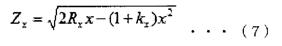
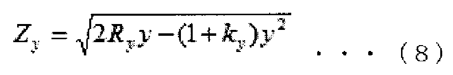
이하의 설명에 있어서, 토릭 안내 렌즈의 강주경선 방향을 X방향, 약주경선 방향을 Y방향으로 하지만, X와 Y는 역이어도 되는 것은 자명하다. 또한, 이하에 설명하는 식의 도출의 상세에 대해서는, 각 특허문헌에 기재되어 있으므로, 설명을 생략한다. 종래의 토릭면을 규정하는 식으로서, X축과 광축을 포함하는 평면에 의한 렌즈 단면의 형상을 나타내는 식 (7)과, Y축과 광축을 포함하는 평면에 의한 렌즈 단면을 나타내는 식 (8)을 들 수 있다. 여기서, Rx 및 Ry는 X축과 광축을 포함하는 평면에 의한 렌즈 단면의 곡률 반경 및 Y축과 광축을 포함하는 평면에 의한 렌즈 단면의 곡률 반경을 각각 나타낸다. 또한, Rx≠Ry이다. cx 및 cy는 X축과 광축을 포함하는 평면에 의한 렌즈 단면의 곡률 및 Y축과 광축을 포함하는 평면에 의한 렌즈 단면의 곡률을 각각 나타낸다. 여기서, cx=1/Rx, cy=1/Ry이다. kx 및 ky는 X방향에 있어서의 코닉 상수(원추 상수) 및 Y방향에 있어서의 코닉 상수를 각각 나타낸다. 또한, 일본 특허 제4945558호에는 kx≠ky의 기재가 있다.In the following description, it is clear that the toric guide lens has the radial direction of the steel guide in the X direction and the direction of the meridian in the Y direction, and X and Y may be reversed. The details of the derivation of the formulas described below are described in the respective patent documents, and a description thereof will be omitted. (7) representing the shape of the lens section by the plane including the X-axis and the optical axis and the equation (8) representing the lens section by the plane including the Y-axis and the optical axis, . Here, Rx and Ry represent the radius of curvature of the lens section by the plane including the X-axis and the optical axis, and the radius of curvature of the lens section by the plane including the Y-axis and the optical axis, respectively. Also, Rx? Ry. cx and cy represent the curvature of the lens section by the plane including the X-axis and the optical axis, and the curvature of the lens section by the plane including the Y-axis and the optical axis, respectively. Here, cx = 1 / Rx and cy = 1 / Ry. kx and ky represent a conic constant (conical constant) in the X direction and a conic constant in the Y direction, respectively. In Japanese Patent No. 4945558, there is a description of kx? Ky.
또한, 종래의 토릭 안내 렌즈의 설계에 사용되는 식으로서, 식 (7), (8) 대신에 식 (9), (10)을 들 수 있다. 또한, Rx≠Ry이다. 또한, 일본 특허 제4945558호에는 kx≠ky의 기재가 있다.The equations (9) and (10) can be used instead of the equations (7) and (8) as the equations used in the design of the conventional toric guide lens. Also, Rx? Ry. In Japanese Patent No. 4945558, there is a description of kx? Ky.


식 (7) 및 (8), 혹은 식 (9) 및 (10)을 사용하는 경우, X방향 및 Y방향의 렌즈 단면의 형상을 규정할 수 있을 뿐이고, 렌즈 전체의 단면 형상은 규정할 수 없다.In the case of using the equations (7) and (8) or the equations (9) and (10), only the shapes of the lens sections in the X direction and the Y direction can be specified and the whole cross sectional shape of the lens can not be specified .
혹은 식 (11)을 사용하여 토릭 안내 렌즈를 설계하는 방법도 있다.Alternatively, there is a method of designing the toric guide lens using Equation (11).
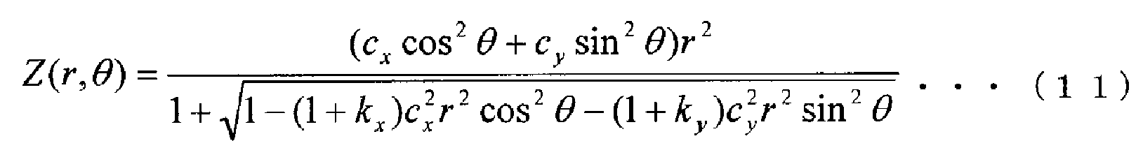
그러나, 식 (11)을 사용하는 경우라도, X방향 및 Y방향의 형상이 결정되면, 즉 cx, cy, kx, ky가 결정되면, 일의적으로 그 2방향 이외의 형상도 정해지므로, 렌즈 전체의 단면 형상을 규정할 때의 자유도가 작다.However, even in the case of using the equation (11), when the shapes in the X and Y directions are determined, that is, when cx, cy, kx, and ky are determined, shapes other than the two directions are uniquely determined, The degree of freedom in defining the cross-sectional shape of the cross section is small.
따라서, 본 발명에서는 이하의 식 (12)에 의해 렌즈면을 규정하여 안내 렌즈를 제작한다. 또한, 식 (12)의 제1항은 렌즈의 광축에 대해 회전 대칭의 렌즈면을 규정하고, 제2항 이후는 토릭면을 규정한다.Therefore, in the present invention, the lens surface is defined by the following formula (12) to manufacture the guide lens. The first term of the expression (12) defines the rotationally symmetrical lens surface with respect to the optical axis of the lens, and the second and the following terms define the toric surface.
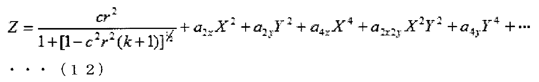
여기서, c는 식 (12)의 제2항 이후에 의해 규정되는 토릭면을 부가하기 전의 렌즈의 회전 대칭의 기준면의 곡률이다. X와 Y는 제1 방향 및 제2 방향에 있어서의 렌즈 중심으로부터의 거리이고, 예를 들어 강주경선 방향 및 약주경선 방향에 있어서의 렌즈 중심으로부터의 거리이다. 또한, r은 직경 방향의 거리(r2=X2+Y2)이다. 또한, k는 식 (12)의 제2항 이후에 의해 규정되는 토릭면을 부가하기 전의 회전 대칭의 기준면의 코닉 상수이고, c, r 및 k는 X방향과 Y방향에서 공통이 되어 있다. 또한, a는 토릭면을 부가하는 파라미터이다. 식 (12)의 제2항 이후의 항은 (X2+Y2)n(n=1, 2…)을 전개했을 때의 각 항을 나타낸다. 또한, 제2항 이후의 각 항의 계수는 토릭면을 부가하기 위한 파라미터를 나타낸다. 또한, 식 (12)의 제1항이, 렌즈의 광축에 대해 회전 대칭의 렌즈면을 규정하는 소정의 정의식의 일례이다. 또한, 식 (12)의 제1항과 동등한 렌즈면을 규정하는 식이라면, 당해 제1항은 다른 식이어도 된다.Here, c is the curvature of the rotationally symmetric reference surface of the lens before the addition of the toric surface defined by the second and the following terms in Eq. (12). X and Y are distances from the center of the lens in the first direction and the second direction, and are distances from the center of the lens in the direction of the principal meridian and the direction of the principal meridian, for example. R is the distance in the radial direction (r 2 = X 2 + Y 2 ). Also, k is a conic constant of a rotationally symmetric reference surface before adding the toric surface defined by the second and the following terms of Eq. (12), and c, r and k are common in the X and Y directions. Also, a is a parameter for adding a toric surface. The terms of the second and subsequent clauses of the expression (12) represent the respective terms when the (X 2 + Y 2 ) n (n = 1, 2, ...) is developed. The coefficients of the respective items from the second and the following items represent parameters for adding the toric surface. In addition, the first term in the expression (12) is an example of a predetermined definition formula defining the rotationally symmetrical lens surface with respect to the optical axis of the lens. Further, the expression (1) may be a different expression as long as it is a formula which defines the lens surface equivalent to the first term of the expression (12).
상기의 식을 사용하면 렌즈 전체에 걸쳐서 렌즈면을 규정할 수 있다. 이에 의해, 종래에 비해 높은 자유도를 갖고 렌즈면을 규정할 수 있다. 특히, 상기와 같이 종래의 식에서는 규정할 수 없었던 X방향 및 Y방향 이외(예를 들어, X=Y가 되는 방향)의 형상도 자유롭게 규정할 수 있다.Using the above equation, the lens surface can be defined over the entire lens. As a result, the lens surface can be defined with a higher degree of freedom than in the prior art. In particular, the shapes other than the X direction and the Y direction (for example, a direction in which X = Y) that can not be defined in the conventional equation can be freely defined.
또한, 식 (12)의 제1항은 구면 렌즈의 식 혹은 코닉 상수만에 의한 비구면 렌즈의 식과 동일한 형태가 되어 있다. 이로 인해, 식 (12)를 사용하여 토릭 안내 렌즈를 설계하는 경우, 토릭 안내 렌즈의 베이스 형상을 종래와 마찬가지로 회전 대칭 렌즈로 할 수 있다. 따라서, 식 (12)를 사용하여 렌즈 설계를 행하여 제작한 토릭 안내 렌즈는 종래의 삽입기에도 지장없이 장전할 수 있다.In addition, the first term of the expression (12) has the same form as that of the aspherical lens by the expression of the spherical lens or only the conic constant. Therefore, when the toric guide lens is designed using the equation (12), the base shape of the toric guide lens can be a rotationally symmetric lens as in the conventional case. Therefore, the toric guide lens manufactured by performing the lens design using the equation (12) can be loaded without hindrance to the conventional insertion device.
또한, 종래에는 렌즈의 45° 방향의 에지 두께를 회전 대칭 렌즈와 통일하는 방법이 제안되어 있지만(예를 들어, 특허문헌 2 등), 에지 두께의 계산은 토릭면의 파라미터가 결정된 후가 아니면 계산할 수 없다. 한편, 본 발명의 식 (12)를 사용한 설계 방법에서는, X2jY2 (n-j)(단, j는 n 이외의 자연수)의 계수를 0으로 하거나, 혹은 a2qx=-a2qy, a2qxa2py=0(p, q는 자연수)으로 하면 에지 두께의 계산은 필요 없고, 45° 방향의 에지 두께를 회전 대칭 렌즈와 동등한 형상을 설계할 수 있다.Further, in the related art, a method of unifying the edge thickness of the lens with the rotationally symmetric lens has been proposed (for example,
또한, 렌즈를 소위 몰드 방식으로 제작하는 경우, 렌즈 재료의 수축에 의한 렌즈 형상의 변화를 고려할 필요가 있다. 본 발명의 식 (12)를 사용하여 렌즈를 설계함으로써, 렌즈의 베이스 형상이 회전 대칭 렌즈와 동일하면, 수축률을 회전 대칭 렌즈와 동등하다고 간주할 수 있다. 따라서, 본 발명의 렌즈 설계 방법에 의하면, 비회전 대칭 렌즈인 토릭 안내 렌즈로 수축률을 평가하는 종래의 방법보다도 효율적으로 수축률을 평가할 수 있다.Further, when the lens is manufactured by the so-called mold method, it is necessary to consider the change of the lens shape due to the shrinkage of the lens material. By designing the lens using Equation (12) of the present invention, if the base shape of the lens is the same as that of the rotationally symmetric lens, the shrinkage rate can be regarded as equivalent to the rotationally symmetric lens. Therefore, according to the lens designing method of the present invention, the shrinkage ratio can be evaluated more efficiently than the conventional method of evaluating the shrinkage percentage with the toric guide lens which is a non-rotationally symmetric lens.
또한, 후술하는 바와 같이 X방향 및 Y방향의 근축 곡률도 용이하게 계산할 수 있으므로, 근축 굴절력의 계산도 용이해진다. 따라서, 식 (12)의 함수로부터 근축 파워의 계산을 용이하게 행할 수도 있다. 또한, 식 (12)를 사용함으로써 토릭 안내 렌즈의 X방향 및 Y방향에 있어서의 구면 수차를 제어할 수 있다. 이와 같이, 식 (12)를 사용하여 렌즈 설계를 함으로써, 토릭 안내 렌즈의 토릭면을 규정하는 파라미터의 자유도가 높아져, 다양한 수차를 종래보다도 적합하게 보정하는 렌즈면 형상을 설계할 수 있다.Also, as described later, the paraxial curvature in the X direction and the Y direction can be easily calculated, so that the calculation of the paraxial refractive power becomes easy. Therefore, the paraxial power can be easily calculated from the function of equation (12). Further, by using the equation (12), the spherical aberration in the X direction and the Y direction of the toric guide lens can be controlled. Thus, by designing the lens using Equation (12), the degree of freedom of the parameter defining the toric surface of the toric guide lens is increased, and a lens surface shape that more appropriately corrects various aberrations than in the past can be designed.
이하에, 상기의 식 (12)를 사용한 안내 렌즈 및 안내 렌즈의 설계 방법에 관한 실시예에 대해 설명한다.Hereinafter, examples of a method of designing the guide lens and the guide lens using the above formula (12) will be described.
(실시예 1)(Example 1)
실시예 1에 대해 이하에 설명한다. 안내 렌즈에 대해, 근축 광학에 의하면 굴절력 P(D)는 이하의 식 (13)으로 표현된다.Embodiment 1 will be described below. With respect to the guide lens, according to paraxial optics, the refractive power P (D) is expressed by the following equation (13).

ne는 안내 렌즈의 e선(λ=546㎚)에 있어서의 굴절률, ne medium은 렌즈를 둘러싸는 매질의 e선에 있어서의 굴절률, R1은 안내 렌즈 전방면에 있어서의 렌즈의 중심 곡률 반경, R2는 안내 렌즈 후방면에 있어서의 렌즈의 중심 곡률 반경, t는 안내 렌즈의 중심 두께이다.n e is the refractive index, n e is the refractive index of the medium in the line e of the medium surrounding the lens, R1 is a radius of center curvature of the lens at the front face of the intraocular lens according to the e-ray (λ = 546㎚) of an intraocular lens , R2 is the radius of curvature of the center of the lens at the rear surface of the guide lens, and t is the center thickness of the guide lens.
토릭 안내 렌즈의 경우, 상기의 R1 혹은 R2의 값이 X방향과 Y방향에서 상이하다. 즉, R2면을 토릭면이라고 가정한 경우, X방향, Y방향의 파워는 각각 이하의 식 (14), (15)로 표현된다.In the case of the toric guide lens, the values of R1 and R2 are different in the X direction and the Y direction. That is, assuming that the R2 surface is a toric surface, the powers in the X and Y directions are represented by the following equations (14) and (15), respectively.


또한, Px와 Py의 차가 원주 굴절력이고, (Px+Py)/2가 등가 구면 도수이다.Further, the difference between Px and Py is the cylindrical refractive power, and (Px + Py) / 2 is the equivalent spherical power.
또한, 식 (12)로부터 X방향 및 Y방향의 곡률은 다음과 같이 구할 수 있다. 먼저, 곡률 c는 곡률 반경 R의 역수로서 식 (16)으로 나타낼 수 있다.From the equation (12), the curvatures in the X direction and the Y direction can be obtained as follows. First, the curvature c can be expressed by the equation (16) as the inverse of the radius of curvature R. [
또한, 어느 함수 f(x)의 점 x에 있어서의 곡률 반경 R은 이하의 식 (17)로 표현된다.The radius of curvature R at a point x of a certain function f (x) is expressed by the following equation (17).

일반적으로 광학 렌즈의 표면을 나타내는 함수 f(x)는 렌즈면과 렌즈의 광축과의 교점인 원점을 지나고, 광축에 대해 대칭인 함수라고 간주할 수 있다. 여기서 광축을 Z축으로 한다. 즉, 식 (17)에 x=0을 대입하면 곡률 반경 R을 구할 수 있고, R의 역수로서 곡률을 구할 수 있다.In general, the function f (x) representing the surface of the optical lens can be regarded as a function that is symmetrical with respect to the optical axis, passing the origin, which is the intersection of the lens surface and the optical axis of the lens. Here, the optical axis is defined as the Z axis. That is, if x = 0 is substituted into the equation (17), the radius of curvature R can be obtained and the curvature can be obtained as the reciprocal of R.
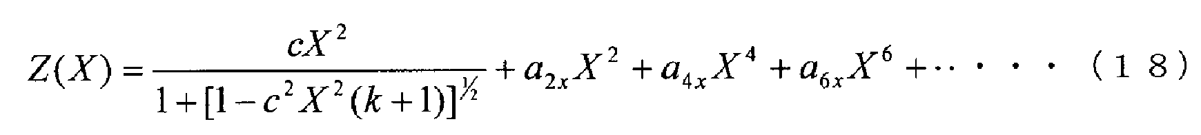
예를 들어, 이하의 식 (18)로 표현되는 비구면 Z(X)에 있어서의 곡률 c'를 구한다.For example, the curvature c 'in the aspherical surface Z (X) expressed by the following equation (18) is obtained.
먼저, Z(X)의 1계 미분값 Z'(X)에 대해, 1계 미분해도 변수 X는 모든 항에서 남는다. 그로 인해, X=0을 대입하면 Z'(0)=0이다.First, for the first order differential value Z '(X) of Z (X), the first order differential derivative X remains in all the terms. Therefore, when X = 0 is substituted, Z '(0) = 0.
이어서, Z(X)의 2계 미분값 Z"(X)는 식 (19)로 부여된다.Next, the binary differential value Z "(X) of Z (X) is given by equation (19).

여기서, X=0을 대입하면 이하의 식 (20)이 얻어진다.Here, if X = 0 is substituted, the following expression (20) is obtained.
![]()
![]()
이상으로부터, 곡률 c'는 식 (21)로 표현된다.From the above, the curvature c 'is expressed by equation (21).
![]()
![]()
마찬가지로 본 발명에 의한 렌즈면의 식 (12)에 있어서, X방향 및 Y방향의 곡률 cx, cy는 각각 식 (22), (23)으로 표현된다.Similarly, in the expression (12) of the lens surface according to the present invention, the curvatures cx and cy in the X direction and the Y direction are expressed by the equations (22) and (23), respectively.

이와 같이 a2x, a2y, c로부터 직접 cx, cy를 계산할 수 있으므로, Rx 및 Ry도 계산할 수 있다. 따라서, 식 (12)를 사용함으로써, 임의로 X방향 및 Y방향의 굴절력(근축)을 지정하여 토릭 안내 렌즈를 설계 및 제공할 수 있다.Since cx and cy can be calculated directly from a 2x , a 2y , and c, Rx and Ry can be calculated as well. Therefore, by using the equation (12), the toric guide lens can be designed and provided by designating the refractive power (paraxial axis) in the X direction and the Y direction arbitrarily.
(실시예 2)(Example 2)
다음에 실시예 2에 대해 설명한다. 본 발명의 식 (12)에 있어서, 제2항 이후의 파라미터를 모두 0으로 하면, 제1항으로부터 회전 대칭의 렌즈를 나타내는 식이 얻어진다. 즉, 본 발명의 식 (12)는 곡률 c, 코닉 상수 k의 회전 대칭면을 베이스 형상으로 하는 토릭면을 규정한다. 따라서, a2qx=-a2qy, a2qx2py=0(p, q는 자연수)으로 하면, 토릭 안내 렌즈의 강주경선 및 약주경선의 평균인 등가 구면 도수는 곡률 c, 코닉 상수 k를 갖는 회전 대칭면에 의해 발생하는 굴절력으로서 규정할 수 있다. 즉, 식 (12)의 제1항으로부터 토릭면의 등가 구면 도수를 규정하는 근축 곡률이 용이하게 구해지므로, 등가 구면 굴절력도 용이하게 산출할 수 있다. 이와 같이, 식 (12)에 있어서, 기준면 형상의 곡률 반경 R(c=1/R)과, 절댓값이 동일하고 정부의 부호만을 역으로 한 한 쌍의 계수(a2qx=-a2qy)의, 2개의 파라미터를 설정하는 것만으로, 등가 구면 도수와 원주 굴절력을 지정하여 토릭 안내 렌즈를 설계할 수 있다.Next, a second embodiment will be described. In the equation (12) of the present invention, when all the parameters after the second term are 0, the equation representing the rotationally symmetric lens is obtained from the first term. That is, the equation (12) of the present invention defines the toric surface having the rotational symmetry plane of the curvature c and the conic constant k as the base shape. Therefore, if a 2qx = -a 2qy and a 2qx2py = 0 (p, q are natural numbers), the equivalent spherical power, which is the average of the radial meridian and the meridian meridian of the toric guide lens, Can be defined as the refracting power generated by the lens. That is, since the paraxial curvature defining the equivalent spherical power of the toric surface can be easily obtained from the first term of the equation (12), the equivalent spherical refractive power can be easily calculated. In this way, in the equation (12), the curvature radius R (c = 1 / R) of the reference surface shape and the pair of coefficients a 2qx = -a 2qy , It is possible to design the toric guide lens by designating the equivalent spherical power and the cylindrical power simply by setting two parameters.
또한, 강주경선 및 약주경선의 굴절력은 등가 구면 도수로부터 할당된 굴절력이 되고, 그 굴절력은 각각 이하의 식 (24), (25)에 의해 표현되는 곡률을 사용하여 계산된다.Further, the refractive power of the steel meridian and the meridional meridian becomes the assigned refracting power from the equivalent spherical power, and the refracting power is calculated using the curvature expressed by the following equations (24) and (25), respectively.
![]()
![]()
![]()
![]()
상기는 파라미터를 설정하는 것만으로 복잡한 계산을 필요로 하지 않는 경우이지만, 본 발명의 식 (12)에 있어서, a2qx≠-a2qy, a2qx2py≠0이라도 회전 대칭면의 곡률 c에 a2x와 a2y를 더한다는 단순한 계산을 행함으로써, 등가 구면 도수를 규정하는 곡률을 계산할 수도 있다.Above, but does not require complex calculations, simply by setting the parameters, in the formula 12 of the present invention, a 2qx ≠ -a 2qy, a 2qx2py ≠ 0 even if the curvature c of the rotation plane of symmetry a 2x and a 2y is added to calculate the curvature defining the equivalent spherical power.
이상과 같이 식 (12)를 사용하여 토릭 안내 렌즈의 등가 구면 굴절력을 계산할 수 있는 것은 백내장 수술에 있어서 요구되는 렌즈 설계에 유리하다. 이유는 다음과 같다. 먼저, 토릭 안내 렌즈는 난시 저감을 위해 환자의 안구에 삽입된다. 그리고, 일반적으로 안과에서 실시되는 시기능 검사의 결과는 구면 도수와 난시 도수로 출력된다. 예를 들어, 검사 결과가 「S+5.00C-1.00Ax90°」인 경우, 이 결과는 구면 도수(등가 구면 도수)가 +5.00D, 난시 도수가 -1.00D, 난시축이 90°인 것을 나타내고 있다. 따라서, 시기능 검사의 결과가 구면 도수 및 난시 도수(난시축 각도)로 부여되는 것을 근거로 하면, 식 (12)를 사용하여 (등가) 구면 도수와 난시 도수를 인풋으로 하여 토릭 안내 렌즈를 설계할 수 있는 것은 유용하다.The ability to calculate the equivalent spherical power of the toric guide lens using equation (12) is advantageous for lens design required for cataract surgery. The reason is as follows. First, the toric guide lens is inserted into the patient's eye to reduce astigmatism. In general, the result of visual inspection performed in ophthalmology is outputted as spherical power and astigmatic power. For example, when the test result is "S + 5.00C-1.00Ax90 °", this result indicates that the spherical power (equivalent spherical power) is +5.00D, the astigmatic power is -1.00D, and the astigmatic axis is 90 ° have. Therefore, based on the results of the visual ability test being given by the spherical power and the astigmatic power (the astigmatic axis angle), the toric guide lens is designed with (equivalent) spherical power and astigmatic power as input What you can do is useful.
(실시예 3)(Example 3)
다음에 실시예 3에 대해 설명한다. 최초에, 자이델(Seidel)의 5수차의 하나인 구면 수차에 대해, 도 1을 참조하면서 설명한다. 구면 수차가 발생하면, 회전 대칭형의 렌즈에 있어서의 중심부(근축부)와 주변부에 있어서의 파워에 차가 생긴다. 구면 수차란, 렌즈의 중심부를 투과하는 광과 주변부를 투과하는 광이 동일한 초점에 모이지 않는 현상이다.Next, a third embodiment will be described. First, spherical aberration, which is one of the five aberrations of Seidel, will be described with reference to Fig. When spherical aberration occurs, there is a difference in power between the central portion (paraxial portion) and the peripheral portion of the rotationally symmetric lens. The spherical aberration is a phenomenon in which light passing through the center portion of the lens and light passing through the peripheral portion are not collected at the same focal point.
도 1에 나타낸 바와 같이, 렌즈 L1의 후방측 주점을 H'로 하고, 근축 초점을 F, 초점 거리를 f, 후방측 주점 H'로부터 주변 광선(렌즈의 주변부를 투과하는 광)의 초점까지의 거리를 f'로 하면, 근축에서의 렌즈 L1의 굴절력 P는 초점 거리 f를 사용하여 이하의 식 (26)으로 표현된다. 단, 렌즈 앞뒤는 공기로 하고, 굴절률은 1로서 설명하지만, 한정되는 것은 아니다.As shown in Fig. 1, the paraxial focal point is F, the focal distance is f, and the distance from the rear side principal point H 'to the focal point of the ambient light (light passing through the periphery of the lens) is H' Assuming that the distance is f ', the refractive power P of the lens L1 on the paraxial axis is expressed by the following equation (26) using the focal length f. However, the front and back of the lens will be described as air and the refractive index will be described as 1, but it is not limited thereto.
여기서, 구면 수차가 발생하고 있는 경우란, 주변 광선의 초점 F'의 위치와 근축 초점 F의 위치는 상이하고, 렌즈 L1의 주변부의 굴절력 P'는 거리 f'를 사용하여 이하의 식 (27)로 표현된다.Here, the case where the spherical aberration occurs means that the position of the focal point F 'of the peripheral ray is different from the position of the paraxial focal point F, and the refractive power P' of the peripheral portion of the lens L1 is expressed by the following equation (27) Lt; / RTI >

도 1에서는 근축 초점 F보다 주변 광선의 초점 F'의 쪽이 후방측 주점 H'에 가까우므로, 이하의 식 (28)이 성립된다. 즉, 렌즈 L1에서 구면 수차가 발생하고 있으면, 렌즈 L1의 중심부와 주변부는 굴절력에 차가 발생한다.1, since the focal point F 'of the peripheral light ray is closer to the backward principal point H' than the paraxial focal point F, the following expression (28) is established. That is, if spherical aberration is generated in the lens L1, a difference occurs in the refractive power between the central portion and the peripheral portion of the lens L1.
![]()
![]()
이어서, 토릭 렌즈 L2에 있어서의 구면 수차에 대해, 도 2를 참조하면서 설명한다. 여기서는 설명의 편의상, 토릭 렌즈 L2의 광축을 Z축으로 하고, 광축에 직교하는 XY 평면을 설정하고, X축과 Y축이 서로 직교하는 것으로 하여 설명한다. 단, X축과 Y축은 반드시 서로 직교하지 않아도 되고, X축이 XY 평면의 제1 방향으로 연장되고, Y축이 제1 방향과는 다른 제2 방향으로 연장되도록 구성되어 있을 수 있다. 도 2의 (a) 및 도 2의 (b)는 각각 토릭 렌즈 L2의 X방향 및 Y방향에 있어서의 광선의 집광 상태를 나타낸다. 도 2의 (a)에 나타낸 바와 같이, 토릭 렌즈 L2의 후방측 주점을 H'로 하고, 렌즈의 X방향에 대한 근축 초점을 Fx, 렌즈의 X방향에 대한 초점 거리를 fx, 렌즈의 X방향에 대해 후방측 주점 H'로부터 주변 광선의 초점까지의 거리를 fx'로 한다. 마찬가지로, 도 2의 (b)에 나타낸 바와 같이, 렌즈의 Y방향에 대해서도, Fy, fy, fy'를 각각 정한다.Next, spherical aberration in the toric lens L2 will be described with reference to Fig. Here, for convenience of explanation, it is assumed that the optical axis of the toric lens L2 is the Z axis, the XY plane orthogonal to the optical axis is set, and the X axis and the Y axis are perpendicular to each other. However, the X axis and the Y axis may not necessarily be orthogonal to each other, and the X axis may extend in the first direction of the XY plane, and the Y axis may extend in the second direction different from the first direction. 2 (a) and 2 (b) show light condensing states of the toric lens L2 in the X and Y directions, respectively. As shown in FIG. 2A, when the paraxial focal point of the lens in the X direction is Fx, the focal length of the lens in the X direction is fx, the X direction of the lens in the X direction The distance from the rear side principal point H 'to the focal point of the ambient light is fx'. Likewise, as shown in Fig. 2 (b), Fy, fy, and fy 'are also determined for the Y direction of the lens.
이때, 도 1에 있어서 설명한 바와 같이, 이하의 식 (29) 내지 (32)가 성립된다.At this time, as described in Fig. 1, the following equations (29) to (32) are established.


여기서, SAx, SAy는 각각 렌즈의 X방향, Y방향에 대한 구면 수차량의 거리를 나타낸다. 예를 들어, 도 2에 나타내는 토릭 렌즈 L2에 있어서의 SAx, SAy는 음의 값으로 한다.Here, SAx and SAy represent the distances of the spherical aberration amounts to the X and Y directions of the lens, respectively. For example, SAx and SAy in the toric lens L2 shown in Fig. 2 are negative values.
또한, 토릭 렌즈 L2의 근축부에 있어서의 원주 굴절력 Pc와 주변부에 있어서의 원주 굴절력 Pc'는 이하의 식 (33), (34)로 표현된다.The cylindrical refractive power Pc in the paraxial portion of the toric lens L2 and the cylindrical refractive power Pc 'in the peripheral portion are expressed by the following equations (33) and (34).
![]()
![]()
![]()
![]()
일반적인 광학 소프트웨어에 있어서는, 구면 수차는 Y방향에 있어서 계산된다. 그로 인해, X방향의 구면 수차를 계산하는 경우, 렌즈 데이터를 90° 회전시키거나, 토릭면의 파라미터를 교체할 필요가 있다. 또한, X방향의 계산을 행하는 경우에는 Y방향의 계산은 할 수 없다. 그러나, X방향과 Y방향의 계산을 동시에 할 수 없는 경우, 토릭 안내 렌즈의 설계의 작업 효율이 저하될 가능성이 있다. 따라서, 본 실시예에서는 X방향의 구면 수차 SA를 이하와 같이 구할 것을 제안한다.In general optical software, spherical aberration is calculated in the Y direction. Therefore, when calculating the spherical aberration in the X direction, it is necessary to rotate the lens data by 90 degrees or replace the parameters of the toric surface. Further, in the case of performing calculation in the X direction, calculation in the Y direction can not be performed. However, when calculation in the X and Y directions can not be performed at the same time, there is a possibility that the working efficiency of the design of the toric guide lens is lowered. Therefore, in this embodiment, it is proposed that the spherical aberration SA in the X direction is determined as follows.
렌즈 주변부의 원주 굴절력을 계산하기 위해, 도 3에 나타낸 바와 같이 각 파라미터를 정의한다. 도 3에 있어서, X방향의 근축 초점을 Fx, Y방향의 근축 초점을 Fy, Fx와 Fy의 차를 dF로 한다. 또한, X방향의 근축 초점 거리를 fx, 임의의 주변 광선과 가상면 O의 교점을 M으로 한다. 그리고, 교점 M의 가상면 O에 따른 광축으로부터의 높이를 h, 근축 초점면에 있어서의 근축 초점 Fx와 주변 광선 A의 거리를 COM, 근축 초점 Fx와 주변 광선 A의 초점 Fx'의 거리를 SA(=구면 수차)로 한다. 또한, 가상면 O는 렌즈 후방면으로부터 초점까지의 사이라면, 어디에든 설치할 수 있다. 또한, 주변 광선은 입사동공 직경의 1/2보다 낮은 높이의 광선이라면, 임의로 선택할 수 있다. 또한, 렌즈의 소재 및 렌즈 주위의 매질은 임의로 설정할 수 있다.In order to calculate the peripheral refractive power of the peripheral portion of the lens, each parameter is defined as shown in Fig. In Fig. 3, the paraxial focal point in the X direction is Fx, the paraxial focal point in the Y direction is Fy, and the difference between Fx and Fy is dF. In addition, the near-axis focal distance in the X direction is denoted by fx, and the intersection point of the arbitrary peripheral ray and the virtual surface O is denoted by M. The distance from the optical axis along the virtual plane O of the intersection M to the optical axis is h, the distance between the paraxial focal point Fx and the peripheral ray A on the paraxial focal plane is COM, the distance between the paraxial focal point Fx and the focal point Fx ' (= Spherical aberration). Further, the imaginary plane O can be provided anywhere if it is between the lens rear surface and the focal point. Further, the peripheral ray can be arbitrarily selected as long as it is a ray having a height lower than 1/2 of the diameter of the entrance pupil. Further, the material of the lens and the medium around the lens can be arbitrarily set.
도 3으로부터, 이하의 식 (35)가 성립된다.From Fig. 3, the following equation (35) is established.
식 (35)로부터 이하의 식 (36)이 얻어진다.From the equation (35), the following equation (36) is obtained.
식 (36)에 있어서의 SA를 SAx로 하여, 식 (30)에 대입하면, 렌즈의 주변(임의의 입사동공 높이)에 있어서의 X방향의 파워를 계산할 수 있다. 또한, X방향의 근축 파워는 x로부터 구하거나, 또한 Fy와 dF의 합으로서 구할 수 있다.By substituting SA in Equation (36) for SAx into Equation (30), the power in the X direction at the periphery of the lens (arbitrary incident pupil height) can be calculated. Further, the paraxial power in the X direction can be obtained from x, or can be obtained as the sum of Fy and dF.
식 (35), (36)에 있어서의 값 L, COM, h는 일반적인 광학 소프트웨어로 계산할 수 있는 것이고, 상기 계산을 설계 시에 평가하는 것은 용이한 작업이다. 또한, dF에 대해서도 일반적인 광학 소프트웨어로 계산할 수 있는 것이다. 본 변형예에서는 식 (12)를 사용하여 규정된 렌즈면에 대해, X방향과 Y방향의 굴절력 분포를 동시에 계산 평가하여, 토릭 안내 렌즈를 설계할 수 있다. 또한, 주변 광선은 입사동공을 지나는 광선이라면, 자유롭게 설정할 수 있고, 광축으로부터 일정 거리 떨어진 위치에서 렌즈에 입사하는 광선에 대해 동시에 계산하고, 파워의 변화를 계산 및 평가하면서 설계할 수 있다.The values L, COM and h in the equations (35) and (36) can be calculated by general optical software, and it is an easy task to evaluate the above calculation at the time of designing. Also, dF can be calculated by general optical software. In this modification, the toric guide lens can be designed by simultaneously calculating and evaluating the refractive power distributions in the X and Y directions with respect to the lens surface defined by using the equation (12). Further, the peripheral light rays can be freely set if they are light rays passing through the entrance pupil, and can be designed while simultaneously calculating light rays incident on the lens at a position distant from the optical axis, and calculating and evaluating a change in power.
이어서, 본 실시예의 일례로서, 식 (12)를 사용하여 규정된 렌즈면에 대해, 식 (29) 내지 (32)를 사용한 X방향 및 Y방향의 파워의 평가 결과에 대해 설명한다. 당해 렌즈의 렌즈 데이터는 이하의 표 1과 같다. 여기서, R은 곡률 반경, t는 두께, n은 굴절률, D는 반경, k는 코닉 상수, A는 토릭면을 부가하는 파라미터를 나타낸다.Next, as an example of this embodiment, evaluation results of powers in the X and Y directions using the equations (29) to (32) will be described for the lens surface defined by using the equation (12). The lens data of this lens is shown in Table 1 below. Where R is the radius of curvature, t is the thickness, n is the refractive index, D is the radius, k is the conic constant, and A is the parameter that adds the toric surface.
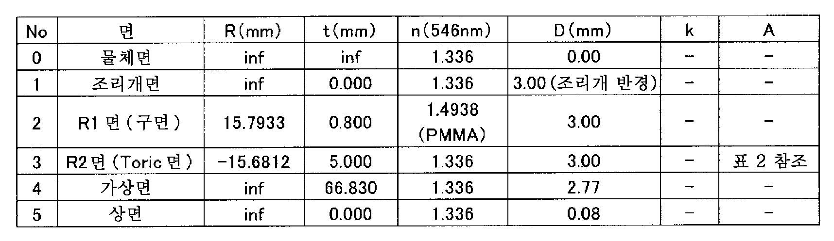
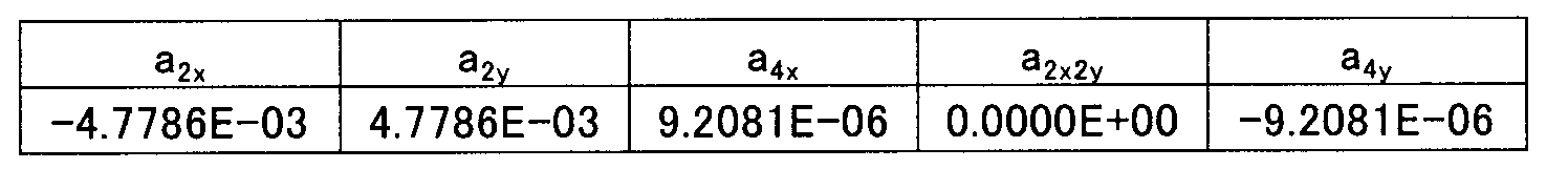
또한, 식 (12)에 있어서 계수를 이하의 표 2와 같이 설정한다.In Expression (12), coefficients are set as shown in Table 2 below.
이 경우, X방향 및 Y방향의 렌즈의 파워는 동공 직경에 대해, 이하의 표 3과 같이 된다.In this case, the powers of the lenses in the X direction and the Y direction are as shown in Table 3 with respect to the pupil diameter.
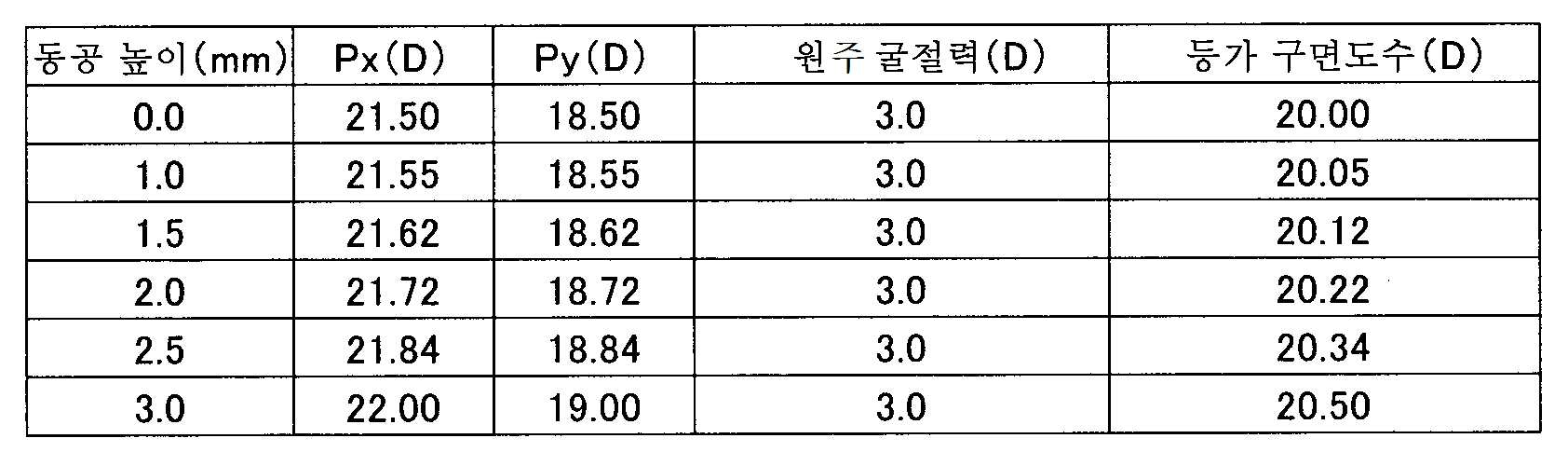
이 경우, 원주 굴절력은 동공 직경에 따르지 않고 일정하다. 그리고, X방향 및 Y방향의 파워는 동공 직경에 따라 변화되고 있고, 렌즈의 중심으로부터 주변에 걸쳐서 0.5D씩 커지고 있다. 또한, X방향과 Y방향의 파워의 평균인 등가 구면 도수도 렌즈의 중심으로부터 주변에 걸쳐서 0.5D 커지고 있다.In this case, the cylindrical power is constant regardless of the pupil diameter. The power in the X direction and the Y direction is changed in accordance with the pupil diameter, and is increased by 0.5D from the center of the lens to the periphery. The equivalent spherical power, which is the average of the powers in the X and Y directions, also increases by 0.5D from the center of the lens to the periphery.
이어서, 본 실시예의 다른 예로서 이하의 표 4에 나타내는 렌즈 데이터를 갖는 렌즈를 사용한다.Next, as another example of this embodiment, a lens having lens data shown in Table 4 below is used.
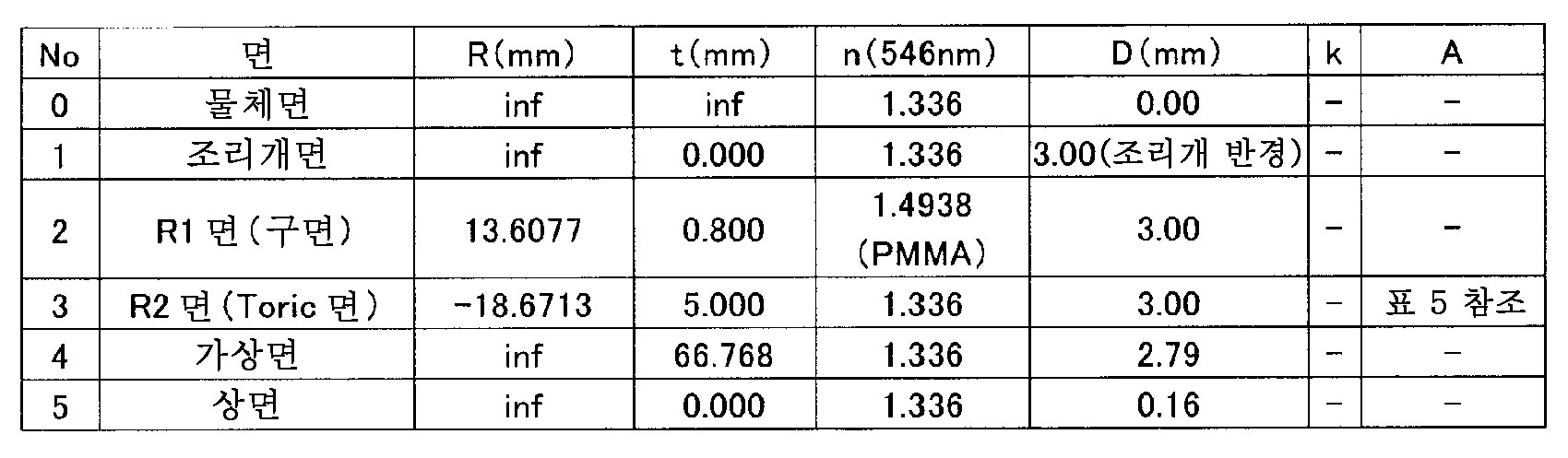
또한, 식 (12)에 있어서 계수를 이하의 표 5와 같이 설정한다.In Expression (12), the coefficients are set as shown in Table 5 below.
이때, X방향 및 Y방향의 렌즈의 파워는 동공 직경에 대해, 이하의 표 6과 같이 된다.At this time, the powers of the lenses in the X direction and the Y direction are as shown in Table 6 below with respect to the pupil diameter.

이 경우, X방향의 파워는 동공에 따르지 않고 일정하고 21.5D이다. 그리고, Y방향의 파워는 동공에 따라 작아지고 있고, 원주 굴절력은 중심으로부터 주변에 걸쳐서 1D 커지고 있다. 또한, 등가 구면 도수는 중심으로부터 주변에 걸쳐서, 원주 굴절력의 변화분의 1/2인 0.5D만큼 작아지고 있다.In this case, the power in the X direction is constant regardless of the pupil and is 21.5 D. The power in the Y direction decreases along with the pupil, and the cylindrical refractive power increases by 1D from the center to the periphery. In addition, the equivalent spherical power is reduced from the center to the periphery by 0.5D which is half of the change of the cylindrical refractive power.
이상의 예에 나타낸 바와 같이, 본 실시예에 의하면, 식 (12)를 사용하여 렌즈 설계를 행하는 경우, 렌즈의 X방향 및 Y방향의 파워 변화를 용이하게 제어할 수 있고, 다양한 파워 분포를 갖는 토릭 안내 렌즈를 설계 및 제공할 수 있다.As described above, according to the present embodiment, when the lens design is performed using the equation (12), it is possible to easily control the power variation in the X and Y directions of the lens, The guide lens can be designed and provided.
또한, 안과 업계에서는, 상기 도수 분포는 도수 맵이나 파워 맵이라고 부르며, 환자의 각막 형상의 이상을 검출할 때에 사용하고 있다. 예를 들어, Pentacam(등록 상표)(OCULUS사제)이나 TMS-5(토메이 코포레이션사제) 등의 전안부 형상 해석 장치에서는 각막의 형상을 측정함으로써, 각막의 중심으로부터 주변에 걸쳐서 어떻게 파워가 분포되어 있는 것인지를 파악할 수 있다. 또한, IOLA plus(ROTLEX사제) 등의 안내 렌즈 검사 장치에서는 렌즈의 파워 맵을 측정할 수 있다. 따라서, 이들 장치에 의해 환자의 안구의 파워 분포가 얻어지고, 얻어진 파워 분포에 기초하여, 상기의 식 (12)를 사용함으로써 최적의 토릭 안내 렌즈를 설계 및 제공할 수 있다.Further, in the ophthalmic industry, the frequency distribution is called a frequency map or a power map and is used for detecting an abnormality in corneal shape of a patient. For example, in the anterior segment shape analyzer such as Pentacam (registered trademark) (manufactured by OCULUS) or TMS-5 (manufactured by Tomei Corporation), the shape of the cornea is measured to see how power is distributed from the center of the cornea to the periphery . In addition, the power lens of the lens can be measured by an information lens inspection apparatus such as IOLA plus (manufactured by ROTLEX). Therefore, by using these devices, the power distribution of the eyeball of the patient is obtained, and based on the obtained power distribution, the optimal toric guide lens can be designed and provided by using the above equation (12).
계속해서, 본 실시예에 있어서, 식 (12)를 사용하여 토릭 안내 렌즈를 설계한 경우에, 당해 토릭 안내 렌즈에 의해 얻어지는 란돌트 고리의 상에 대한 시뮬레이션 결과를, 도 4를 참조하면서 설명한다. 도 4는 종래의 토릭 렌즈와 본 실시예에 있어서의 토릭 렌즈를 안내 렌즈로서 소정 조건의 난시안에 처방한 경우의, 소위 베스트 포커스에서의 란돌트 고리의 상과, 시뮬레이션에 있어서 상면(像面)을 0.04㎜만큼 렌즈로부터 멀리 떨어지게 한 경우(+)와 렌즈에 근접시킨 경우(-)에 있어서의 란돌트 고리의 상을 나타낸다.Next, in the present embodiment, the simulation result of the image of the Landolt ring obtained by the toric guide lens when the toric guide lens is designed by using the equation (12) will be described with reference to Fig. 4 . FIG. 4 is a graph showing the relationship between the image of a so-called best-fit Landor ring in the case where the conventional toric lens and the toric lens in the present embodiment are prescribed in the astigmatism of a predetermined condition as a guide lens, (+) When the lens is moved away from the lens by 0.04 mm, and (-) when the lens is brought close to the lens by 0.04 mm.
도 4의 베스트 포커스 시의 란돌트 고리로 나타낸 바와 같이, 본 실시예의 토릭 안내 렌즈에서는 난시가 적합하게 저감되어, 명료한 란돌트 고리의 상이 얻어진다. 한편, 종래의 토릭 안내 렌즈에서는 인식 가능한 정도의 란돌트 고리의 상을 확인할 수 있지만, 란돌트 고리의 주변에, 소위 번짐(blurring)이 발생하고 있다.4, the astigmatism is suitably reduced in the tricyclic guide lens of the present embodiment, and a clear image of the Landolt ring is obtained. On the other hand, in the conventional toric guide lens, an image of a recognizable degree of the Landolt ring can be confirmed, but a so-called blurring occurs around the Landolt ring.
또한, 상면을 이동시켜 핀트를 어긋나게 했을 때에도 차이가 나타난다. 도 4에 나타낸 바와 같이, 본 실시예의 토릭 안내 렌즈에서는 상면이 베스트 포커스의 위치로부터 어긋나도 회전 대칭의 번짐이 발생하고 있다고, 즉 난시는 거의 완전히 제거되어 있다고 할 수 있다. 한편, 종래의 토릭 안내 렌즈는 번짐이 종방향(지면 상하 방향)으로 신장되고 있거나(상면: +0.04㎜), 횡방향(지면 좌우 방향)으로 신장되고 있거나(상면: -0.04㎜) 하기 때문에, 난시가 완전히는 제거되어 있지 않은 것을 알 수 있다. 이상으로부터, 본 실시예의 토릭 안내 렌즈는 종래와 비교하여 난시 교정에 보다 효과가 있다고 할 수 있다.A difference also appears when the upper surface is shifted and the focus is shifted. As shown in Fig. 4, in the tricyclic guide lens according to the present embodiment, even if the image plane is deviated from the best focus position, blurring of rotational symmetry occurs, that is, astigmatism is almost completely eliminated. On the other hand, the conventional toric guide lens is elongated in the longitudinal direction (upper surface: +0.04 mm) or in the horizontal direction (left side in the drawing) (top surface: -0.04 mm) It can be seen that astigmatism is not completely removed. From the above, it can be said that the tricycle guide lens of this embodiment is more effective for astigmatic correction than the conventional one.
이어서, 렌즈의 중심부와 주변부에서 난시량이 다른 난시 각막 렌즈를 제작한 경우의 평가 결과에 대해 설명한다. 도 5에 당해 평가에 사용하는 모형안의 개략 구성을 나타낸다. 도 5에 나타내는 모형안에서는, 난시 각막 렌즈 L3은 광축 주위에 적절히 회전 가능하게 되어 있다. 따라서, 난시 각막 렌즈 L3과 토릭 안내 렌즈 L4 사이에서 난시축을 일치시킬 수 있다. 도 5에서는, 난시 각막 렌즈 L3의 형상은 양 볼록 렌즈이지만, 렌즈 형상은 메니스커스 렌즈이거나 양 오목 렌즈일 수 있다.Next, evaluation results in the case where a astigmatism cornea lens having different astigmatic magnitudes at the central portion and the peripheral portion of the lens are produced will be described. Fig. 5 shows a schematic structure of a model used for the evaluation. In the model shown in Fig. 5, the astigmatism cornea lens L3 is appropriately rotatable around the optical axis. Therefore, the astigmatism axis can be made to coincide with the astigmatic cornea lens L3 and the toric guide lens L4. 5, the shape of the astigmatism cornea lens L3 is a biconvex lens, but the lens shape may be a meniscus lens or a biconcave lens.
도 5에 나타내는 모형안에서는, 토릭 안내 렌즈 L4는 안내를 상정하여 수중에 배치하고 있지만, 난시를 갖는 각막 렌즈를 적절하게 설계, 제작하면 공기 중에 배치하는 구성으로 할 수 있다. 도 5의 모형안에 있어서 관찰하는 지표로서는, 3m 시력표의 란돌트 고리를 사용한다. 촬영하는 지표는 시력 1.0으로 한다. 또한, 광원인 할로겐 램프에는 546㎚의 필터를 설치하여, 시력표의 이면으로부터, 필터를 통과한 광을 조사한다. 카메라(10)는 핀트 조절을 위해, 토릭 안내 렌즈 L4의 광축에 대해 전후로 이동할 수 있다. 또한, 도 5에 나타낸 바와 같이, 토릭 안내 렌즈 L4는 양면이 평면 유리(101, 101)로 구성된 대략 직육면체의 케이스(100) 내에 위치 결정되어 있다. 또한, 케이스(100) 내는 전술한 바와 같이 물로 채워져 있고, 토릭 안내 렌즈 L4의 난시 각막 렌즈 L3측에 조리개 S가 설치되어 있다.In the model shown in Fig. 5, the toric guide lens L4 is placed underwater assuming guiding. However, when the cornea lens having astigmatism is appropriately designed and manufactured, the toric guide lens L4 can be arranged in the air. As an index to be observed in the model of Fig. 5, a Landolt ring of a 3m visual acuity chart is used. The index to be photographed shall be 1.0. A halogen lamp, which is a light source, is provided with a filter of 546 nm, and the light passing through the filter is irradiated from the back surface of the visual acuity table. The
도 6에, 도 5에 나타내는 모형안을 사용한 경우에, 지표인 란돌트 고리를 카메라로 촬영한 결과를 나타낸다. 도 6에 나타낸 바와 같이, 도 4에 나타내는 시뮬레이션 결과와 마찬가지로, 본 실시예의 토릭 안내 렌즈 L4에서는 베스트 포커스에 있어서, 란돌트 고리를 명료하게 촬영할 수 있다. 또한, 카메라(10)를 토릭 안내 렌즈 L4의 광축 방향으로 이동시켜, 의도적으로 디포커스(defocus)시킨 상에 대해서도, 번짐이 회전 대칭으로 발생하고 있고, 난시가 적합하게 저감되는 것을 알 수 있다. 한편, 종래의 토릭 안내 렌즈에서는, 베스트 포커스에 있어서는 란돌트 고리를 인식할 수 있지만, 의도적으로 디포커스시킨 경우에 상이 현저하게 열화되어 있어, 난시가 충분히 저감되어 있지 않은 것을 알 수 있다.Fig. 6 shows the results of photographing a Landolt ring, which is an index, with a camera when the model shown in Fig. 5 is used. As shown in Fig. 6, in the same manner as the simulation result shown in Fig. 4, in the toric guide lens L4 of the present embodiment, in the best focus, the random rings can be clearly photographed. It can also be seen that the
도 7은 도 6에 나타내는 모형안의 구성을 사용하여, 본 실시예의 토릭 안내 렌즈의 MTF(Modulation Transfer Function)를 측정한 결과를 나타낸다. 도면 중, 횡축은 피사체로서 사용하는 줄무늬 모양의 줄무늬의 간격을 나타내는 공간 주파수이고, 종축은 토릭 안내 렌즈에 의해 카메라의 수광면에 결상되는 줄무늬 모양의 화상의 MTF의 값을 나타낸다. 또한, 점선은 토릭 안내 렌즈의 시상(방사) 방향(여기서는 0도 방향)에 있어서의 수치를 나타내고, 파선은 토릭 안내 렌즈의 경선(동심원) 방향(여기서는 90도 방향)에 있어서의 수치를 나타낸다. 도 7에 나타낸 바와 같이, 본 실시예의 토릭 안내 렌즈를 삽입한 모형안의 경우, 베스트 포커스 시에는 0도 방향과 90도 방향 모두 양호한 것을 알 수 있다. 또한, 디포커스 시라도, MTF의 값은 저하되지만 0도 방향과 90도 방향에 있어서 동일한 변화를 나타내고 있으므로, 난시는 거의 발생하고 있지 않다고 할 수 있다.Fig. 7 shows the result of measuring the MTF (Modulation Transfer Function) of the tricycle guide lens of the present embodiment, using the configuration in the model shown in Fig. In the figure, the abscissa indicates the spatial frequency indicating the interval of the striped stripes used as the subject, and the ordinate indicates the value of the MTF of the stripe-shaped image formed on the light receiving surface of the camera by the toric guide lens. The dotted line represents the numerical value in the sagittal (radial) direction (here, 0 degree direction) of the toric guide lens and the broken line represents the numerical value in the direction of the meridian (concentric circle) of the toric guide lens. As shown in Fig. 7, in the case of the model in which the tricyclic guide lens of this embodiment is inserted, it can be seen that both the 0 degree direction and the 90 degree direction are good at the time of the best focus. Also, even in the case of the defocus, the value of the MTF decreases, but the astigmatism hardly occurs because the same change occurs in the 0 degree direction and the 90 degree direction.
이어서, 도 8에, 도 6에 나타내는 모형안의 구성을 사용하여, 종래의 토릭 안내 렌즈의 MTF를 측정한 결과를 나타낸다. 도 8에 나타낸 바와 같이, 종래의 토릭 안내 렌즈에서는 베스트 포커스에 있어서 공간 주파수 100개/㎜에 있어서의 MTF는 0.2이상이므로, 시력 1.0은 보인다고 생각할 수 있지만, 도 7로부터 알 수 있는 바와 같이 본 실시예의 토릭 안내 렌즈에 비교하여 MTF는 낮은 값을 나타내고 있다. 또한, 도 8에 나타낸 바와 같이, 종래의 토릭 안내 렌즈에서는 디포커스 시에도 0도 방향과 90도 방향에 있어서 서로 다른 변화를 나타내고 있으므로, 난시가 잔존하고 있다고 할 수 있다. 이상으로부터, 본 실시예와 같이, 렌즈의 중심부뿐만 아니라 주변부의 난시량을 고려하여 상기와 같이 설계된 토릭 안내 렌즈를 사용함으로써 종래와 비교하여 난시 교정을 보다 적합하게 행할 수 있다.Next, FIG. 8 shows the results of measurement of the MTF of a conventional toric guide lens using the structure in the model shown in FIG. As shown in Fig. 8, in the conventional toric guide lens, the MTF at the spatial frequency of 100 pieces / mm in the best focus is 0.2 or more. Therefore, it can be considered that the visual acuity of 1.0 is seen. However, MTF is lower than that of the conventional tricycle guide lens. In addition, as shown in Fig. 8, in the conventional toric guide lens, astigmatism remains even in the case of defocusing, because it shows different changes in the 0 degree direction and the 90 degree direction. As described above, astigmatism correction can be performed more favorably than in the conventional art by using the toric guide lens designed as described above in consideration of the amount of astigmatism of the peripheral portion as well as the central portion of the lens, as in this embodiment.
(실시예 4)(Example 4)
다음에 실시예 4에 대해 설명한다. 실시예 4에서는 이하의 사양으로 토릭 안내 렌즈를 설계한다.Next, a fourth embodiment will be described. In Example 4, the toric guide lens is designed with the following specifications.
<설계 사양><Design specifications>
입사 광선 직경 : φ6㎜Incident ray diameter : φ6 mm
X방향 굴절력(수중) : +21.5D(근축), +22.0D(주변)X-directional refractive power (underwater) : + 21.5D (paraxial), + 22.0D (peripheral)
Y방향 굴절력(수중) : +18.5D(근축), +18.0D(주변)Y-direction refractive power (underwater) : + 18.5D (paraxial), + 18.0D (peripheral)
구면 수차 Z {4, 0} RMS : 0.1λ 이하The spherical aberration Z {4, 0} RMS : 0.1 or less
렌즈 타입 : 양 볼록 렌즈(R1면: 구면, R2면: 토릭면)Lens type : Positive convex lens (R1 surface: spherical surface, R2 surface: toric surface)
단, |R1|<|R2| However, | R1 | <| R2 |
렌즈 재질 : PMMALens Material : PMMA
렌즈 중심 두께 : 0.8㎜Lens center thickness : 0.8 mm
물의 굴절률 : 1.333(λ=546㎚)Refractive index of water : 1.333 ([lambda] = 546 nm)
광원 파장 : 546㎚Light source wavelength : 546 nm
여기서, 상기의 설명에서 나타낸 식 (11)에 있어서, x=rcosθ, y=rsinθ로 두면, 이하의 식 (37)이 얻어진다.Here, in the equation (11) shown in the above description, if x = rcos? And y = r sin ?, the following equation (37) is obtained.
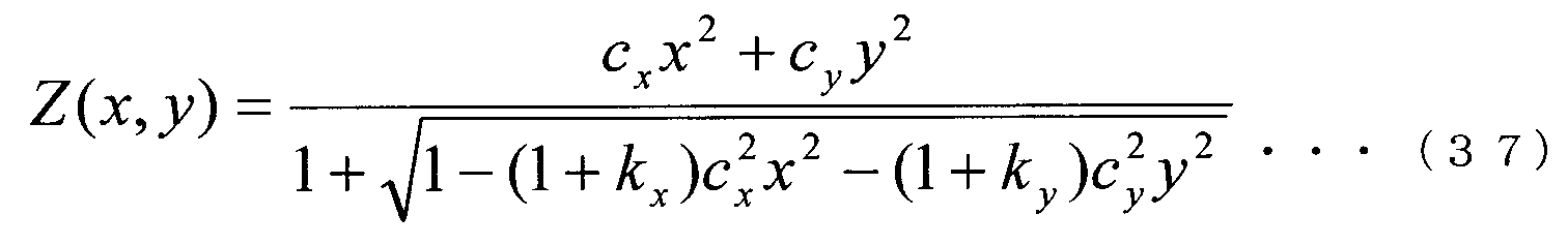
이 식은 바이코닉면을 나타낸다.This equation represents the biconical surface.
따라서, 식 (37)을 사용하여 토릭 안내 렌즈를 설계한 경우와, 식 (12)를 사용하여 토릭 안내 렌즈를 설계한 경우에 있어서의, 제르니케 수차의 비교에 대해 이하 설명한다.Therefore, comparison of the Zernike aberration in the case of designing the toric guide lens using the equation (37) and the design of the toric guide lens using the equation (12) will be described below.
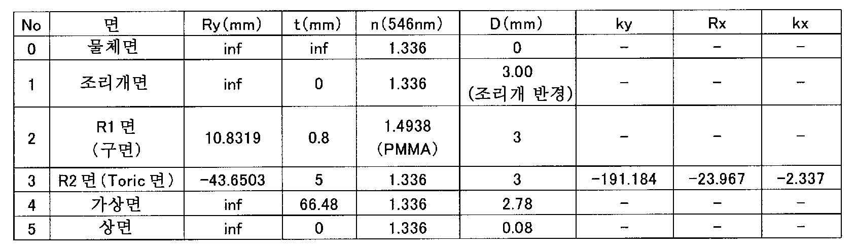
식 (37)을 사용하여 설계한 경우의 렌즈 데이터는 이하의 표 7과 같다. 여기서, Ry는 y방향의 곡률 반경, t는 두께, n은 굴절률, D는 반경, ky는 y방향의 코닉 상수, Rx는 x방향의 곡률 반경, kx는 x방향의 코닉 상수를 나타낸다.Lens data when designed using equation (37) are shown in Table 7 below. Where Ry is the radius of curvature in the y direction, t is the thickness, n is the refractive index, D is the radius, ky is the kornic constant in the y direction, Rx is the radius of curvature in the x direction and kx is the kornic constant in the x direction.
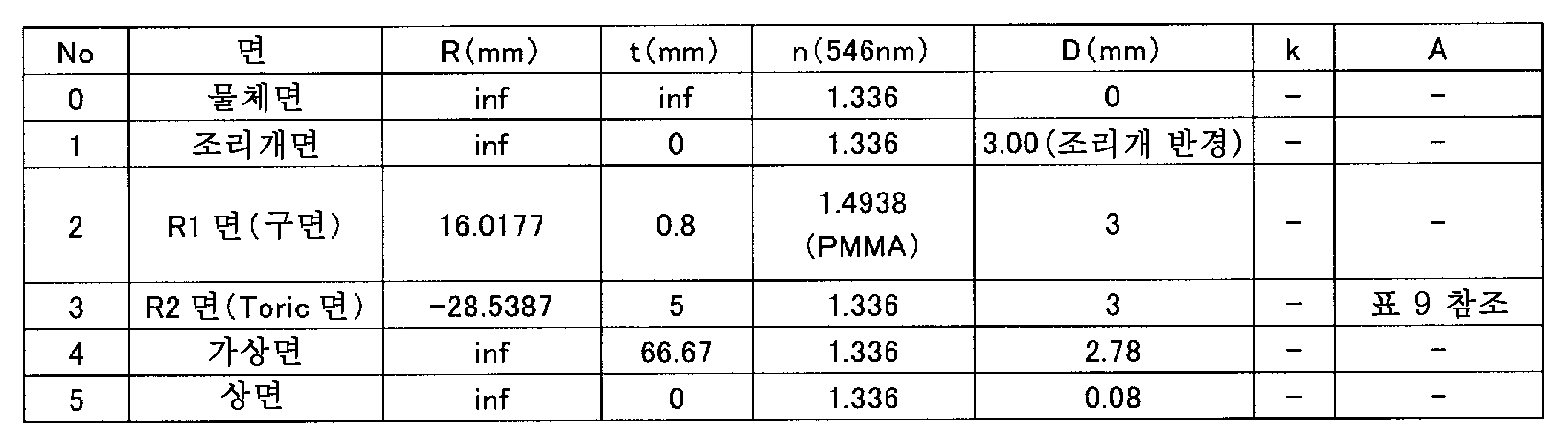
또한, 식 (12)를 사용하여 설계한 경우의 렌즈 데이터는 이하의 표 8과 같다.The lens data in the case of designing using Equation (12) are shown in Table 8 below.
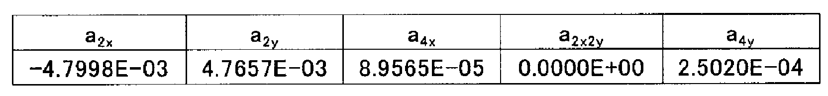
또한, 식 (12)에 있어서 계수를 이하의 표 9와 같이 설정한다.In Expression (12), the coefficients are set as shown in Table 9 below.

상기의 조건에 있어서, 각각 설계한 렌즈의 제르니케 수차는 이하의 표 10과 같다. 또한, 제르니케 수차는 RMS(Root Mean Square)값(단위 λ)으로 나타낸다. 또한, 수차의 순서는 Zernike Standard Order를 따랐다.Under the above conditions, the Zernike aberration of the designed lens is shown in Table 10 below. The Zernike aberration is expressed by a Root Mean Square (RMS) value (unit λ). In addition, the order of the aberrations followed the Zernike Standard Order.

상기의 계산에 있어서, 디포커스는 10-3 이하로 하였다. 표 10에 나타낸 바와 같이, 본 발명에 있어서의 식 (12)를 사용하여 설계한 렌즈와 식 (37)에 나타나는 바이코닉면을 사용하여 설계한 렌즈의 수차를 비교하면, No.14(테트라 포일)의 수차에 있어서, 큰 차가 있고, 본 발명의 쪽을 작게 할 수 있다. 또한, 설계 시에 필요로 하는 수렴 시간도 본 발명에 의한 식의 쪽이 빠르고, 효율적으로 설계를 행할 수 있다. 이 현상은 굴절력 차가 큰 안용 렌즈를 설계하는 경우에, 보다 현저해진다. 또한, 몰드 제법으로 제작하는 경우, 회전 대칭 렌즈와 R1을 공통화하는 경우가 있지만, 그 경우에서도 식 (12)를 사용하여 설계하면 자유롭게 토릭 렌즈를 설계할 수 있다.In the above calculations, the defocus was set to 10 -3 or less. As shown in Table 10, when the aberrations of the lens designed using the equation (12) and the lens designed using the biconical surface represented by the equation (37) are compared, ), There is a large difference, and the present invention can be made smaller. In addition, the convergence time necessary for designing is also faster in the equation according to the present invention, and the design can be performed efficiently. This phenomenon becomes more remarkable when an eye lens having a large refractive power difference is designed. In addition, in the case of the mold manufacturing method, there is a case where the rotational symmetric lens and the R1 are made common. In this case, however, the toric lens can be freely designed by using the equation (12).
이유는 다음과 같다. 상기의 바이코닉면에 의한 설계에서는 파라미터가 Rx, Ry, kx, ky의 4개밖에 없어, X방향과 Y방향에 있어서의 형상밖에 규정할 수 없으므로, XY방향, 즉 X방향과 Y방향 사이의 임의의 방향에 있어서의 수차를 억제할 수 없다. 한편, 본 발명에 있어서의 식 (12)를 사용한 설계에서는, 예를 들어 X2Y2 등의 변수 X 및 Y를 포함하는 항이 있으므로, X방향과 Y방향 사이의 방향에 대해서도 렌즈의 면 형상을 규정할 수 있고, 이 결과, 불필요한 수차를 제거할 수 있다. 또한, 테트라 포일이라고 불리는 수차는 cos4θ(sin4θ)의 함수형을 갖는 수차이지만, 후술하는 바와 같이 식 (12)는 n≥2일 때에는 4차의 항을 포함하고, 즉 cos4θ형의 함수를 포함하여, 파라미터에 의해 독립적으로 토릭면에 부가할 수 있으므로, 효과적으로 수차를 제거할 수 있다.The reason is as follows. In the design by the biconical surface, there are only four parameters Rx, Ry, kx, and ky, and only the shape in the X direction and the Y direction can be defined. Therefore, the XY direction, that is, The aberration in an arbitrary direction can not be suppressed. On the other hand, in the design using the equation (12) in the present invention, for example, there are terms including variables X and Y such as X 2 Y 2 , As a result, unnecessary aberrations can be removed. The aberration referred to as tetrafoil is an aberration having a functional form of
근년에는 안과용 측정 기기의 발달에 의해, 눈의 수차를 종래보다도 상세하게 측정하는 것이 가능하게 되어 있다. 그로 인해, 렌즈면 전체에 걸쳐서 수차를 적정하게 보정하는 기능을 갖는 렌즈를 제작하는 중요성이 높아지고 있다. 따라서, 본 실시예에 의해 식 (11)을 사용하여 토릭 안내 렌즈를 설계함으로써, 수차를 적정하게 보정하는 기능을 갖는 렌즈를 제작할 수 있다.In recent years, development of an ophthalmologic measuring instrument has made it possible to measure the eye aberration more precisely than in the past. Therefore, it is becoming increasingly important to manufacture a lens having a function of properly correcting aberration over the entire lens surface. Therefore, by designing the toric guide lens using the equation (11) by this embodiment, it is possible to manufacture a lens having a function of properly correcting the aberration.
(실시예 5)(Example 5)
다음에 실시예 5에 대해 설명한다. 본 실시예에서는 식 (12)가 이하의 식 (38)로 표현되는 것에 주목한다.Next,
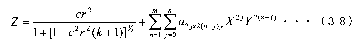
여기서, m은 자연수이고, n은 m 이하의 자연수이고, j는 0 이상 n 이하의 정수이다. 여기서, X는 제1 방향에 있어서의 렌즈 중심으로부터의 거리이고, Y는 제2 방향에 있어서의 렌즈 중심으로부터의 거리이다. 이 식 (38)에 의하면, 토릭 렌즈로 한정되지 않고, 이하에 설명하는 2개의 조건을 만족시키면, 구면 렌즈나 비구면 렌즈 등의 회전 대칭의 렌즈를 설계할 수도 있다. 즉, 식 (12)를 사용하여 렌즈 설계를 행하는 경우, 파라미터를 변경하는 것만으로, 회전 대칭형의 렌즈와 토릭 렌즈의 비교를 용이하게 실현할 수 있다. 예를 들어, 광학 소프트웨어 ZEMAX에서는 렌즈식을 변경하는 경우, 하나의 렌즈 데이터를 유용할 수는 없어, 신규로 렌즈 데이터를 작성해야 한다. 그러나, 본 실시예에 의하면, 식 (12)로부터 얻어지는 식에서 렌즈의 비교를 행할 수 있으므로, 예를 들어 ZEMAX의 멀티 컨피규레이션(multi-configuration)이라는 기능을 사용하면, 파라미터의 변경을 용이하게 행할 수 있다.Here, m is a natural number, n is a natural number of m or less, and j is an integer of 0 or more and n or less. Here, X is the distance from the lens center in the first direction, and Y is the distance from the lens center in the second direction. According to the equation (38), a rotationally symmetric lens such as a spherical lens or an aspherical lens can be designed if it is not limited to a toric lens and satisfies the following two conditions. That is, in the case of designing the lens using Equation (12), comparison between the rotationally symmetric lens and the toric lens can be easily realized simply by changing the parameters. For example, in optical software ZEMAX, when changing the lens equation, one lens data can not be useful, and new lens data must be created. However, according to the present embodiment, since comparison of the lens can be performed in the equation obtained from the equation (12), the parameter can be changed easily by using, for example, a function of multi-configuration of ZEMAX .
본 실시예에서는, 식 (38)에 있어서 이하의 식 (39), (40)을 만족시키는 것을 조건으로 한다.In this embodiment, the condition (39) and (40) below are satisfied in the equation (38).
![]()
![]()
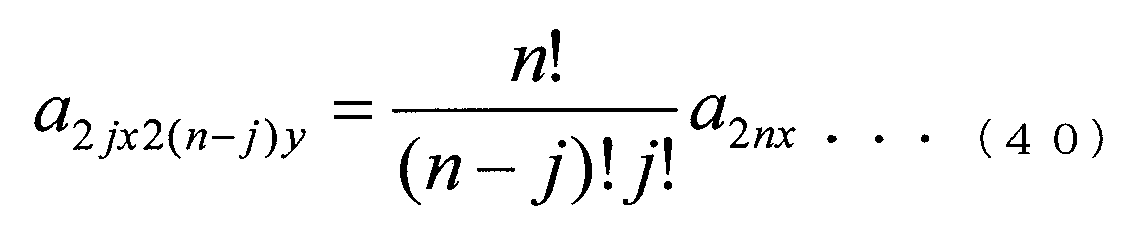
여기서, n은 m 이하의 자연수, j는 0 이상 n 이하의 정수로 한다.Here, n is a natural number of m or less, and j is an integer of 0 or more and n or less.
일례로서, 이하의 식 (41)로 표현되는 비구면 형상의 렌즈를 생각한다.As an example, a lens of an aspherical shape expressed by the following formula (41) is considered.

이 렌즈의 경우, 이하의 표 11에 나타내는 바와 같이 식 (12)의 각 파라미터에 「계수의 값」란에 나타내는 값을 설정함으로써, 식 (12)에 의해 나타나는 렌즈면 형상을 식 (41)에 의해 나타나는 렌즈면 형상에 일치시킬 수 있다.In the case of this lens, the lens surface shape represented by the equation (12) can be expressed by the equation (41) by setting the values shown in the column of " coefficient value " Can be matched to the lens surface shape represented by the lens surface.
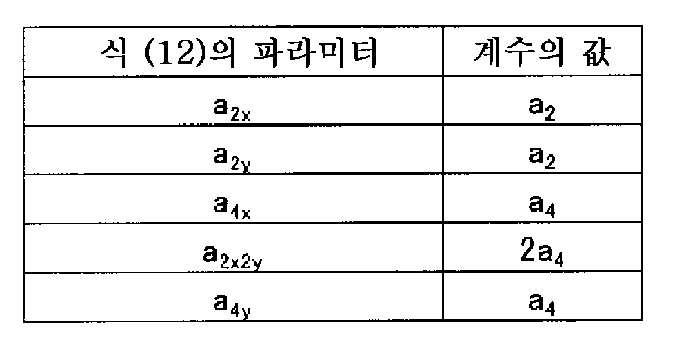
또한, R=10.000, a2=0.001, a4=0.0001로 하여 얻어지는 비구면 렌즈는 R=10.000, a2x=a2y=0.001, a4x=a4y=0.0001, a2x2y=0.0002로 하여 얻어지는 토릭 렌즈와 동일면 형상으로 간주할 수 있다. Further, R = 10.000, a 2 = 0.001, a by 4 = 0.0001 aspherical lens obtained by the toric lens which is obtained by a R = 10.000, a 2x = a 2y = 0.001, a 4x = a 4y = 0.0001, a 2x2y = 0.0002 It can be regarded as the same surface shape as that of FIG.
또한, X=Y가 되는 방향의 새그량은 이하의 표 12에 나타내는 바와 같이, 식 (12)를 사용하여 설계한 경우와 식 (41)을 사용하여 설계한 경우에서 일치하고 있는 것을 알 수 있다.It can be seen that the new amount in the direction in which X = Y coincides with the case of designing using equation (12) and the case of designing using equation (41) as shown in Table 12 below .
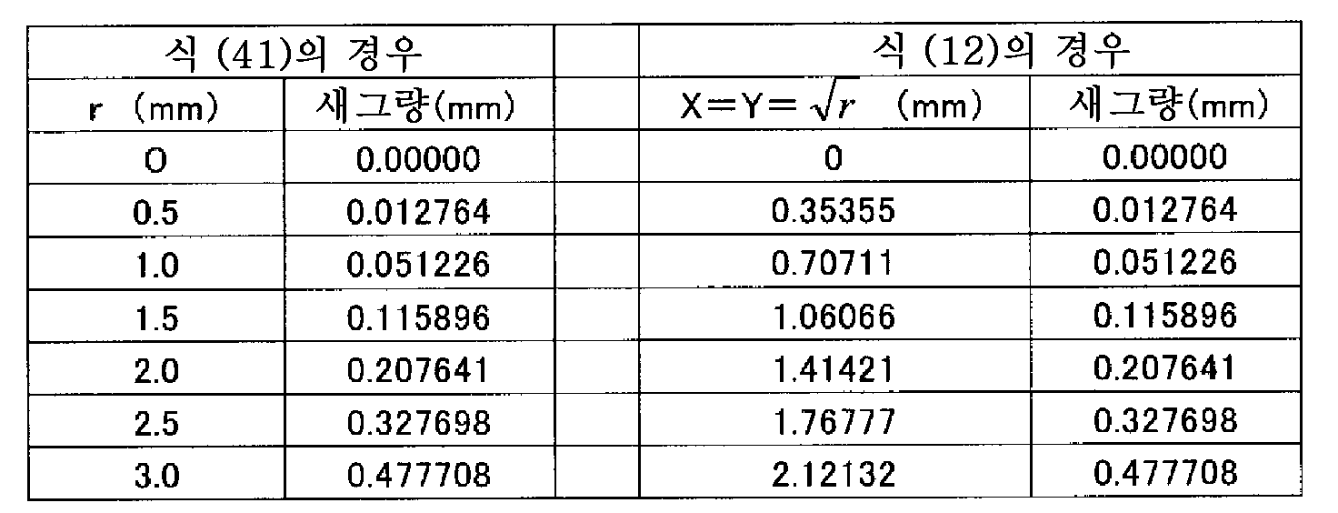
또한, 일례로서 X=Y가 되는 방향의 새그량을 나타냈지만, 임의의 방향에 있어서도 일치하고 있는 것을 알 수 있다. 따라서, 식 (39), (40)에 의해 식 (12)의 제2항 이후에 있어서 X2n 및 Y2n의 항만을 사용하도록 설정하면, 45도 방향(즉, X=Y)은 토릭면을 부가하지 않는 기준면 형상과 동등해지거나, 식 (12)를 사용하여 렌즈 설계를 행한 복수의 제품군(구면, 비구면, 토릭면 등)의 상호의 관련지음이나 평가가 용이해진다. 또한, 다른 실시예에 있어서도 식 (12) 대신에, 식 (38)을 사용할 수 있다.As an example, although a new amount in a direction in which X = Y is shown, it can be seen that they coincide with each other in any direction. Therefore, if the equations (39) and (40) are set to use the ports of X 2n and Y 2n after the second term of the equation (12), the 45 ° direction (i.e., X = Y) (Spherical surface, aspherical surface, toric surface, and the like) in which the lens design is performed using Equation (12) can be easily made and evaluated. Also, in another embodiment, the equation (38) can be used instead of the equation (12).
(실시예 6)(Example 6)
다음에 실시예 6에 대해 설명한다. 이 실시예에서는 식 (12)에 (X+Y)2n-1에 기초하는 정의식(n은 자연수)을 가한 토릭면을 사용한다. 토릭 안내 렌즈의 설계에 있어서는, 난시축과 토릭축의 축 맞춤이 중요하다. 따라서, 난시축과 토릭축의 어긋남을 평가할 필요도 있다. 또한, 토릭 안내 렌즈의 에지 두께는 일정하지 않고 변화된다. 그러나, 일반적인 광학 소프트웨어로는 X방향 또는 Y방향의 에지 두께밖에 계산할 수 없다. 그로 인해, 소프트웨어 내에서 렌즈의 광학계를 회전시키는 작업을 행하거나, 토릭면의 새그량을 계산하여 렌즈의 중심 두께와의 차로부터 에지 두께를 계산하거나 할 필요가 있다.Next, a sixth embodiment will be described. In this embodiment, a toric surface to which a defining equation based on (X + Y) 2n-1 (n is a natural number) is added to the equation (12). In the design of the toric guide lens, alignment between the astigmatism axis and the toric axis is important. Therefore, it is also necessary to evaluate the deviation between the astigmatic axis and the toric axis. Further, the edge thickness of the toric guide lens is not constant but changed. However, in general optical software, only the edge thickness in the X direction or the Y direction can be calculated. Therefore, it is necessary to perform an operation of rotating the optical system of the lens in the software, or to calculate the new thickness of the toric surface and to calculate the edge thickness from the difference from the center thickness of the lens.
본 실시예에서는 이하와 같이 파라미터의 변환을 행함으로써, 렌즈를 임의로 회전시킬 수 있다. 이와 같이 함으로써, 소프트웨어 내에서 X축 및 Y축에 원하는 각도의 경선(직경)을 설정할 수 있으므로, 렌즈 설계 시의 계산량을 억제할 수 있다. 예를 들어, 식 (12)에 있어서 X2의 계수와 Y2의 계수 각각의 차를 XY의 계수로 하면, 렌즈를 45°(또는 -45°) 회전시킬 수 있다.In the present embodiment, the lens can be rotated arbitrarily by changing the parameters as follows. By doing so, the meridian (diameter) of a desired angle can be set in the X and Y axes in the software, so that the amount of calculation at the time of lens design can be suppressed. For example, if the difference between the coefficients of X 2 and Y 2 in Expression (12) is a coefficient of XY, the lens can be rotated by 45 ° (or -45 °).
또한, 이하의 식 (42)를 사용하여 변수를 변환함으로써, 자유롭게 렌즈의 회전을 행할 수 있다.In addition, the lens can be freely rotated by changing the parameters using the following formula (42).
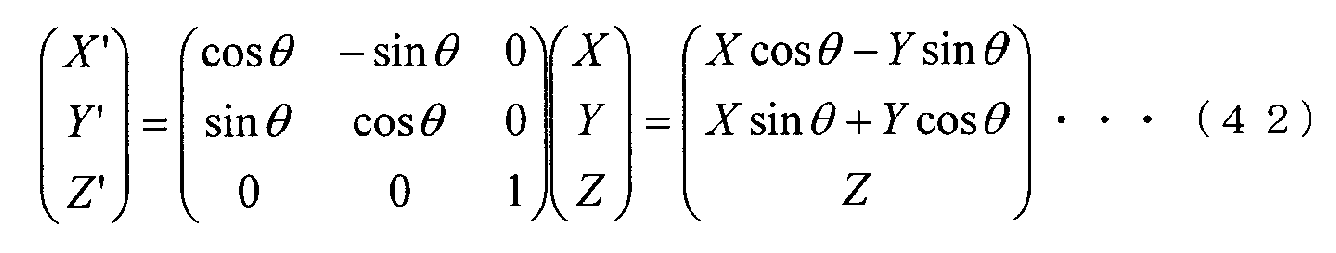
여기서, θ는 회전 각도, X', Y', Z'는 변환 후의 계수 및 변수, X, Y, Z는 회전 전의 변수이다.Here, θ is the rotation angle, X ', Y', Z 'are coefficients and variables after conversion, and X, Y, and Z are variables before rotation.
일례로서, 식 (12)로부터 얻어지는 이하의 식 (43)에 의해 표현되는 토릭면을 생각한다.As an example, a toric surface expressed by the following equation (43) obtained from the equation (12) is considered.
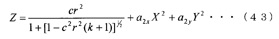
이 토릭면을 θ만큼 회전시키는 경우, 식 (43)의 제2항 및 제3항에 대해, 이하의 식 (44)와 같이 변환된다. 또한, 식 (43)의 제1항은 회전 대칭의 렌즈 형상을 나타내므로 변환의 설명은 생략한다.When the toric surface is rotated by?, The second and third terms of the equation (43) are transformed as shown in the following equation (44). In addition, since the first term of the equation (43) represents a rotationally symmetrical lens shape, the description of the conversion is omitted.
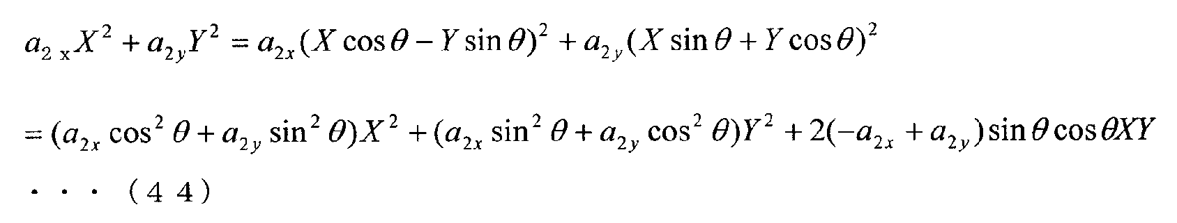
또한, 상기에서는 2차의 차수의 변수까지를 변환의 대상으로 하고 있지만, 더욱 고차의 계수를 갖는 식에 의해 표현되는 렌즈 형상이라도, 상기와 마찬가지로 계산함으로써, 렌즈를 임의의 각도로 회전시킬 수 있다.In the above example, the variables up to the order of the second order are regarded as objects of conversion. Even in the case of a lens shape represented by an expression having a higher order coefficient, the lens can be rotated at an arbitrary angle by calculation in the same manner as described above .
일례로서, R=10.000, k=0, a2x=0.001, a2y=-0.001로 하여 얻어지는 토릭면을 갖는 렌즈를 30° 회전시키는 경우, 회전 후의 토릭면은 R=10.000, k=0, a2x=0.0005, axy=-0.0017321, a2x2y=-0.0005로 하여 표현된다. 또한, 마찬가지로 -15° 회전시키는 경우, 회전 후의 토릭면은 R=10.000, k=0, a2x=0.00086603, axy=0.001, a2x2y=-0.00086603으로 하여 표현된다.As an example, when a lens having a toric surface obtained by R = 10.000, k = 0, a 2x = 0.001, and a 2y = -0.001 is rotated by 30 degrees, the toric surface after rotation is R = 10.000, k = 0, a 2x = 0.0005, a xy = -0.0017321, and a 2x2y = -0.0005. Also, as in the case of -15 ° rotation, after rotation toric surface is expressed as R = 10.000, k = 0, a 2x = 0.00086603, a xy = 0.001, a 2x2y = -0.00086603.
토릭 안내 렌즈의 경우, 통상 에지 두께는 광축 주위에 180° 주기로 주기적으로 변동된다. 종래의 토릭, 예를 들어 일본 특허 공표 제2011-519682호 공보에 나타낸 바와 같이 에지 두께가 광축 주위에 정현적으로 변화되는 경우, 정현 함수(sin 함수)의 특징에 의해 90° 위상을 어긋나게 한 함수는 cos 함수와 일치하므로, 강주경선 부근의 에지 두께 변화와 약주경선 부근의 에지 두께 변화는 동등하다. 이와 같이 정현적인 토릭의 에지 두께는 sin2θ(또는 cos2θ)로 변화되는 한편, 식 (12)에 의한 토릭 안용 렌즈의 경우, X4, Y4, X2Y2의 항이 있으므로 에지는 cos2θ+cos4θ로 변화된다. 그로 인해, 주기는 180°이지만, 강주경선 부근의 에지 두께 변화와 약주경선 부근의 에지 두께 변화가 상이하다.In the case of the toric guide lens, the edge thickness usually fluctuates periodically with a period of 180 DEG around the optical axis. When the edge thickness is sinusoidally changed around the optical axis as shown in a conventional toric, for example, Japanese Patent Laid-Open Publication No. 2011-519682, a function that shifts the phase by 90 degrees due to the feature of the sine function (sin function) Is the same as the cos function, the edge thickness variation near the steel meridian and the edge thickness variation near the meridional meridian are equal. Since the edge thickness of the sagittal toric is changed to sin 2? (Or
일례로서, 도 9에 식 (12)에 있어서 R10.000, k=0, a2x=0.001, a4x=0.0003으로 하여 얻어지는 토릭면에 대해, φ6㎜의 점에서의 새그량을 플롯한 결과를 나타낸다. 도 9에 나타낸 바와 같이, 90°와 270° 부근에 있어서는, 새그량의 변화가 급준한 것에 비해, 0°, 180°, 360°에 있어서는 새그량의 변화가 완만하게 되어 있다. 이와 같이 변화되는 함수는 일반적인 정현적으로 변화되는 함수와 달리, 0°부터 270°의 범위에 있어서의 함수가 그 범위의 중간인 135°를 중심으로 회전 대칭이 되어 있지 않다. 에지 두께의 변화량이 작다는 것은, 렌즈 형상이 회전 대칭에 가까워지는 것을 의미한다. 즉, 0°, 180°, 360° 부근에 있어서는 에지 두께의 변화가 작아, 회전 대칭 렌즈에 가까운 거동을 하는 토릭 안내 렌즈를 설계할 수 있다. 따라서, 본 실시예에 의하면, 렌즈의 약주경선 또는 강주경선 부근에 있어서의 에지 두께의 변화량을 작게 할 수 있고, 절첩하여 안내에 삽입할 때에 회전 대칭 렌즈와 마찬가지로 삽입기에도 장전이 용이해 안정적으로 반송하는 것이 가능해지는 토릭 안내 렌즈를 설계할 수 있다.As an example, in Fig. 9 (12) according to R10.000, k = 0, a 2x = 0.001, with a 4x = 0.0003 by the results of plotting the new geuryang in terms of, for φ6㎜ obtained toric surface . As shown in Fig. 9, in the vicinity of 90 deg. And 270 deg., The change in the new amount is steep, whereas in the case of 0 deg., 180 deg., And 360 deg., The change in the new amount is gentle. Unlike general sinusoidally varying functions, the functions that change in this way are not rotationally symmetric around 135 °, which is the middle of the range, from 0 ° to 270 °. The fact that the variation amount of the edge thickness is small means that the lens shape approaches rotational symmetry. That is, it is possible to design a toric guide lens that has a small change in the edge thickness in the vicinity of 0 deg., 180 deg., And 360 deg., And exhibits a behavior close to that of the rotationally symmetric lens. Therefore, according to the present embodiment, it is possible to reduce the change amount of the edge thickness in the vicinity of the meridional meridian or the meridional meridian of the lens, and when the meridian is folded and inserted into the guide, It is possible to design a toric guide lens.
(실시예 7)(Example 7)
다음에 실시예 7에 대해 설명한다. 일반적으로, 광학 부품의 제조에 있어서는 부품의 검품을 행하는 공정이 설치되어 있다. 일반적인 회전 대칭계의 광학면은 이하의 식 (45)로 부여된다.Next, a seventh embodiment will be described. Generally, in the production of an optical component, a step of inspecting the component is provided. The optical surface of a general rotational symmetry system is given by the following equation (45).
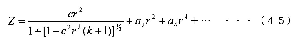
이 식 (45)로 부여되는 광학면은 광축에 대해 회전 대칭이므로, 어떤 직경 방향에서 평가해도 동일한 평가 결과가 얻어진다. 그러나, 토릭 렌즈와 같은 비회전 대칭의 광학면을 평가하는 경우, 종래의 토릭면의 경우는 축방향(X=0 또는 Y=0) 이외의 방향에 있어서의 평가는 매우 곤란했다. 한편, 본 발명의 식 (12)를 사용하여 면 형상을 정의하면, 종래의 토릭면 형상에 비해 임의의 방향의 단면 형상을 용이하게 추측 및 표현할 수 있다.Since the optical surface given by this formula (45) is rotationally symmetric with respect to the optical axis, evaluation results identical to those obtained in any radial direction can be obtained. However, when evaluating a non-rotationally symmetric optical surface such as a toric lens, evaluation in a direction other than the axial direction (X = 0 or Y = 0) was very difficult in the case of the conventional toric surface. On the other hand, when the surface shape is defined by using the equation (12) of the present invention, a cross-sectional shape in an arbitrary direction can be easily guessed and expressed as compared with the conventional toric surface shape.
여기서, 식 (12)에 대해, 렌즈의 광학면의 임의의 방향(각도 θ)에 있어서의 단면 형상의 표현식을 도출한다. 여기서는, 일례로서 최대 차수 4차의 경우를 생각한다. 식 (12)에 있어서 x=rcosθ, y=rsinθ로 하면, 이하와 같이 변환하여 식 (46)이 얻어진다.Here, for expression (12), the expression of the sectional shape in an arbitrary direction (angle?) Of the optical surface of the lens is derived. Here, as an example, the case of the fourth order maximum degree is considered. If x = rcos? And y = rsin? In the equation (12), the following conversion is performed to obtain the equation (46).
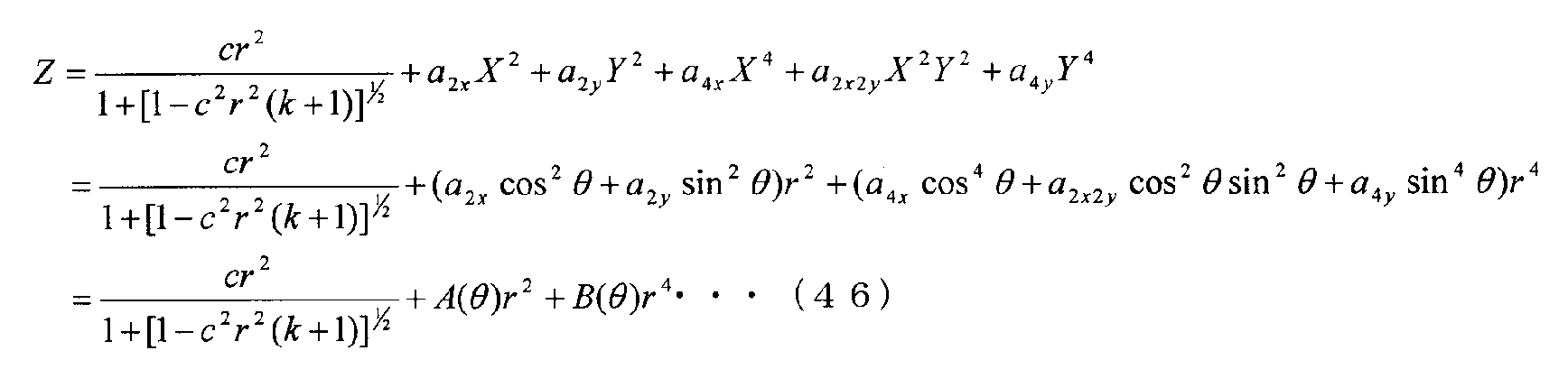
여기서,here,
![]()
![]()
이다.to be.
또한,Also,
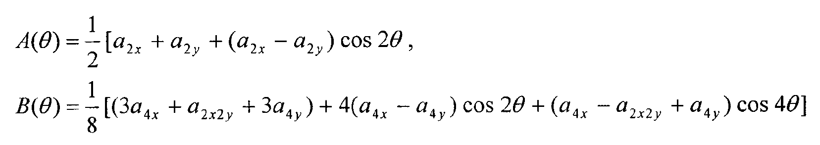
이다.to be.
식 (46)으로부터 알 수 있는 바와 같이, 식 (12)를 사용하면, 렌즈면에 있어서의 임의의 방향(임의의 θ)의 단면 형상을 일반적인 광학면 정의식으로 표현할 수 있다. 이는, 렌즈의 평가에 있어서 매우 편리하다. 왜냐하면, 예를 들어 시판되고 있는 미타카 고키제 비접촉 삼차원 측정 장치 NH-3SP에 조립되어 있는 소프트웨어에서는 측정된 단면 형상을 상기의 식 (45)의 형상으로 피팅할 수 있기 때문이다. 또한, 설계값과의 비교나 실제로 제조된 렌즈의 임의의 단면 내에 있어서의 광학 시뮬레이션을 용이하게 행하는 것이 가능해지기 때문이다.As can be seen from equation (46), by using equation (12), the sectional shape of an arbitrary direction (arbitrary?) On the lens surface can be expressed by a general optical surface definition formula. This is very convenient in the evaluation of the lens. This is because, for example, in the software assembled on a commercially available non-contact three-dimensional measuring device NH-3SP manufactured by Mitaka Koki Co., Ltd., the measured cross-sectional shape can be fitted into the shape of the above-mentioned formula (45). Further, it is possible to easily perform comparison with a design value or optical simulation within an arbitrary section of a lens actually manufactured.
한편, 종래의 토릭 광학면(식 (11) 또는 식 (37))의 경우, X=0 또는 Y=0(θ=0°또는 θ=90°)에서는 단면 형상이 일반적인 식 (45)의 제1항에 일치하지만, X≠0 또한 Y≠0의 경우는 일반적인 식 (45)의 형태로 표현하는 것, 즉 식 (45)에 해당하는 k, c 및 a를 구하는 것은 매우 곤란하다.On the other hand, in the case of the conventional toric optical surface (formula (11) or formula (37)), when X = 0 or Y = 0 (θ = 0 ° or θ = 90 °) 1, but when X ≠ 0 and Y ≠ 0, it is very difficult to express in the form of the general formula (45), that is, to obtain k, c and a corresponding to the equation (45).
따라서, 종래 사용되고 있던 렌즈의 표현식을 사용하여 제조된 렌즈의 축 위 이외의 단면 형상을 평가하는 경우, 렌즈의 단면 형상이 매우 복잡하기 때문에 특수한 형상 평가 소프트웨어를 준비해야 한다. 또한, 식 (7) 내지 식 (10)으로 나타나는 토릭면에 있어서는, X=0 또는 Y=0의 경우 이외에, 렌즈가 어떤 형상이 되어 있는지는 가공 방법에 따라 바뀌므로, 형상의 조정은 매우 곤란하다.Therefore, when evaluating a cross-sectional shape other than on the axis of a lens manufactured using a conventionally used expression of a lens, special shape evaluation software must be prepared because the cross-sectional shape of the lens is very complicated. In addition to the case where X = 0 or Y = 0 in the toric surface represented by the formulas (7) to (10), the shape of the lens changes depending on the processing method, so adjustment of the shape is extremely difficult .
또한, 렌즈면에 대해 광학적인 계산을 행하는 경우는, 임의의 위치에 있어서의 렌즈면의 기울기를 계산해야 하고, 기울기를 계산하기 위해 함수의 미분이 필요해진다. 식 (12) 또는 식 (38)에 나타내는 본 발명의 정의식에서는 제곱근 중에 다른 함수(예를 들어, 삼각 함수)가 포함되어 있지 않으므로 용이하게 미분 계산을 행할 수 있다. 또한, 본 발명의 정의식을 사용하여 제작한 안내 렌즈를 렌즈 삽입기에 장전해도 렌즈 삽입기의 조작에 지장이 발생하지 않는 것을 확인하는 경우에도, 당해 정의식에 대해 용이하게 적분 계산을 행하여 렌즈의 단면적을 산출할 수 있다.In addition, when optical calculation is performed on the lens surface, the slope of the lens surface at an arbitrary position must be calculated, and the derivative of the function is required to calculate the slope. In the definition formula of the present invention shown in the equation (12) or the equation (38), different functions (for example, trigonometric functions) are not included in the square root, so that the differential calculations can be easily performed. Even in the case where it is confirmed that the operation of the lens inserter does not occur even if the guide lens manufactured by using the defining formula of the present invention is loaded in the lens inserter, the integral calculation is easily performed with respect to the definition formula, Can be calculated.
또한, 본 발명의 식 (12) 또는 식 (38)로 정의되는 면에 대해서는 임의의 렌즈면을 조합할 수 있다. 예를 들어, 적당한 비구면을 조합함으로써 구면 수차를 적절하게 설정함으로써, 토릭 렌즈의 축이 난시축과 어긋나도 상의 열화를 경감하도록 할 수 있다. 또한, 이와 같은 구면 수차의 설정은 본 발명의 정의식으로 정의되는 면으로 행할 수 있다. 예를 들어, 식 (12) 또는 식 (38)에 있어서의 제1항 부분에 있어서, 그와 같은 구면 수차의 설정을 실현할 수 있다. 혹은, 식 (12) 또는 식 (38)에 있어서의 제2항 이후의 파라미터로 실현할 수 있다.Any lens surface can be combined with respect to the surface defined by the formula (12) or (38) of the present invention. For example, by appropriately setting the spherical aberration by appropriately combining the aspherical surfaces, the axis of the toric lens can be shifted from the axis of the astigmatic axis to reduce the deterioration of the image. Such setting of the spherical aberration can be performed by the surface defined by the definition formula of the present invention. For example, in the first term of the expression (12) or (38), the setting of the spherical aberration can be realized. Alternatively, it can be realized by the parameters of the second and the following expressions in Expression (12) or Expression (38).
여기서, 구면 수차를 제어하는 비구면과 조합한 토릭 렌즈에 있어서의, 축 어긋남에 대한 평가 결과를 나타낸다. 평가는 도 5에 나타내는 모형안을 사용하여 행하였다. 도 10에, 도 5에 나타내는 모형안을 사용하여 축 어긋남을 일으킨 경우에, 지표인 란돌트 고리를 카메라로 촬영한 결과를 나타낸다. 도 10은 IOL(Intraocular Lens)을 삽입한 모형안으로서의 구면 수차량을 변화시켰을 때에, 각막 렌즈의 난시축과 토릭 IOL의 축을 일치시킨 상태로부터 ±5° 회전시켜 촬영한 란돌트 고리의 모습을 나타낸다. 여기서, 도 10의 시험 조건을 이하에 나타낸다.Here, evaluation results of the axial misalignment in the toric lens combined with the aspheric surface for controlling the spherical aberration are shown. The evaluation was made using the model shown in Fig. Fig. 10 shows the result of photographing a Landolt ring, which is an index, with a camera when an axis shift is caused by using the model shown in Fig. 10 shows a state of a Landolt ring photographed by rotating the corneal lens at an angle of ± 5 ° from the state in which the axis of the toric IOL coincided with the axis of the cornea lens when the spherical aberration as the model with the IOL (Intraocular Lens) is changed . Here, the test conditions of FIG. 10 are shown below.
각막 렌즈 : PMMA Corneal lens : PMMA
각막 굴절력 : 약주경선 40.4D, 강주경선 42.4D Corneal refractive power : 40.4D for the meridian, 42.4D for the meridian
각막 구면 수차 : +0.28㎛(@φ6㎜)Corneal spherical aberration : + 0.28 占 퐉 (@? 6 mm)
조리개 직경 : φ5.2㎜(@IOL 전방면)Aperture diameter : φ5.2㎜ (@ IOL front face)
IOL : 원주 굴절력 3.0D, 등가 구면 도수 20DIOL : Circumferential power 3.0D, equivalent spherical power 20D
도 10에 나타낸 바와 같이, IOL의 구면 수차와 IOL을 삽입하는 안구의 각막의 구면 수차를 합한 구면 수차가 대략 0(도 10에서는 +0.03㎛)인 경우, IOL의 구면 수차가 대략 -0.28㎛인 경우, 축이 일치하고 있는 상태에서는 란돌트 고리를 선명하게 관찰할 수 있지만, 회전하여 축이 어긋나 버리면 란돌트 고리의 상이 현저하게 열화되어 육안으로는 란돌트 고리를 인식할 수 없다. 한편, IOL의 구면 수차와 IOL을 삽입하는 안구의 각막의 구면 수차를 합한 구면 수차가 0.2㎛ 내지0.3㎛의 범위(도 10에서는 +0.26㎛)인 경우, IOL의 구면 수차가 -0.08㎛ 내지 +0.02㎛인 경우, 축이 일치하고 있는 상태에서 란돌트 고리를 인식할 수 있고, 또한 회전하여 축이 어긋나도 란돌트 고리를 인식할 수 있다. 도 10에 있어서 비교예의 IOL(+0.13㎛)의 구면 수차의 경우, 축이 일치하고 있는 상태에서는 상기 2종의 대략 중간 정도의 상이 되어 있다. 그러나, 렌즈가 회전하여 축이 어긋난 경우, 란돌트 고리가 세로나 가로로 겹친 상이 되어 있어, 육안에 있어서 란돌트 고리를 인식할 수 있는 상태라고는 하기 어렵다.10, when the spherical aberration of the sum of the spherical aberration of the IOL and the spherical aberration of the cornea of the eye that inserts the IOL is approximately 0 (+0.03 mu m in Fig. 10), the spherical aberration of the IOL is approximately -0.28 mu m In the case where the axes coincide with each other, it is possible to clearly observe the rare-earth rings, but if the axes are displaced by rotation, the phase of the rare-earth rings is remarkably deteriorated and the naked eye can not recognize the rare-earth rings. On the other hand, when the spherical aberration of the spherical aberration of the IOL and the spherical aberration of the cornea of the eye that inserts the IOL is in the range of 0.2 mu m to 0.3 mu m (+0.26 mu m in Fig. 10), the spherical aberration of the IOL becomes- 0.02 탆, it is possible to recognize the rare-earth ring in the state where the axes coincide with each other, and to recognize the rare-wheel ring even if the axis rotates and the axis deviates. In Fig. 10, in the case of the spherical aberration of the IOL (+0.13 mu m) of the comparative example, in the state where the axes coincide with each other, the spherical aberration of the IOL (+0.13 mu m) However, when the lens is rotated and the axis is shifted, the Landolt rings are vertically or horizontally overlapped, and it is hard to say that the state can recognize the Landolt rings in the naked eye.
이어서, 상기의 모형안에 있어서의 망막상의 광학 시뮬레이션을 실시한 결과를 도 11에 나타낸다. 도 11에 나타낸 바와 같이, IOL의 구면 수차와 IOL을 삽입하는 안구의 각막의 구면 수차를 합한 구면 수차가 0인 경우, 즉 IOL의 구면 수차가 대략 -0.28㎛인 경우, 축이 일치하고 있는 상태에서는 란돌트 고리를 선명하게 관찰할 수 있지만, 회전하여 축이 어긋나 버리면 란돌트 고리의 상이 현저하게 열화되어 육안으로는 란돌트 고리를 인식할 수 없다. 이는 도 10에서 나타낸 실기에서의 평가 결과와 일치하고 있으므로, 본 광학 시뮬레이션의 정확성을 확인할 수 있었다고 생각된다.Next, FIG. 11 shows the result of optical simulation on the retina in the above model. As shown in Fig. 11, when the spherical aberration of the spherical aberration of the IOL and the spherical aberration of the cornea of the eye that inserts the IOL is 0, that is, when the spherical aberration of the IOL is approximately -0.28 mu m, , It is possible to observe the Landolt ring clearly, but if the axis is shifted by rotation, the phase of the Landolt ring deteriorates remarkably and the Landolt ring can not be recognized visually. This is in agreement with the evaluation result in the practical period shown in Fig. 10, so that it is considered that the accuracy of the optical simulation can be confirmed.
따라서, 또한 도 12a, 도 12b에 나타내는 광학 시뮬레이션의 결과를 보면, IOL의 구면 수차와 IOL을 삽입하는 안구의 각막의 구면 수차를 합한 구면 수차가 0.2㎛ 내지 0.3㎛의 범위인 경우, 즉 IOL의 구면 수차가 -0.08㎛ 내지 +0.02㎛인 경우, 축이 일치하고 있는 상태에서 란돌트 고리를 인식할 수 있고, 또한 회전하여 축이 어긋나도 란돌트 고리를 인식할 수 있는 것을 알 수 있다. 또한, IOL의 구면 수차와 IOL을 삽입하는 안구의 각막의 구면 수차를 합한 구면 수차가 0.5㎛보다 큰 경우, 즉 IOL의 구면 수차가 +0.22㎛보다 큰 경우, 축 어긋남에 대한 란돌트간의 열화는 적지만, 축이 일치하고 있는 상태에 있어서의 콘트라스트가 저하되어, 전체적으로 상질이 저하될 우려가 있는 것을 알 수 있었다.12A and 12B, when the spherical aberration obtained by adding the spherical aberration of the IOL and the spherical aberration of the cornea of the eye into which the IOL is inserted is in the range of 0.2 mu m to 0.3 mu m, that is, When the spherical aberration is -0.08 탆 to +0.02 탆, the grating can be recognized in the state where the axes coincide with each other, and the grating can be recognized even if the axis rotates and the axis is shifted. When the spherical aberration of the spherical aberration of the IOL plus the spherical aberration of the cornea of the cornea to which the IOL is inserted is larger than 0.5 mu m, that is, when the spherical aberration of the IOL is larger than +0.22 mu m, The contrast in the state where the axes coincide with each other is lowered, and it is found that there is a fear that the quality of the whole body is lowered.
본건 개시의 안용 렌즈는 몰드 제법으로 제작하거나 절삭 가공 제법으로 제작할 수 있다. 단, 토릭면의 가공은 회전 속도와 동기시키면서 가공 툴을 광축 방향으로 이동 가능한 선반 가공기로 행하는 것이 바람직하다.The lens of the present disclosure may be manufactured by a molding process or by a cutting process. However, it is preferable that the machining of the toric surface is performed by a lathe machining machine capable of moving the machining tool in the optical axis direction while synchronizing with the rotation speed.
L4 : 토릭 안내 렌즈L4: Toric guide lens
Claims (20)
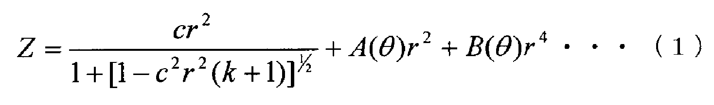
를 포함하는 식으로 표현되고, c는 상기 안용 렌즈에 있어서의 근축 곡률이고, r은 상기 안용 렌즈의 렌즈 중심으로부터의 거리이고, k는 상기 안용 렌즈에 있어서의 렌즈 광축에 회전 대칭인 면의 코닉 상수이고, 상기 c, r, k는 상기 렌즈면 위의 상기 경선 방향에 대해 공통이고, A(θ) 및 B(θ)는 상기 경선 방향의 각도에 의존하는 함수로 표현되는 파라미터인 것
을 특징으로 하는 안용 렌즈.The cross-sectional shape in an arbitrary meridian direction on the lens surface of the eye lens
, C is a paraxial curvature of the eye lens, r is a distance from the center of the lens of the eye lens, and k is a radius of curvature of the rotationally symmetric plane of the lens optic axis of the eye lens. And c, r, k are common to the meridian direction on the lens surface, and A (?) And B (?) Are parameters expressed by a function depending on the angle of the meridional direction
Wherein the lens is a lens.
에 기초하는 토릭면의 정의식을 가산한 식을 사용하여 상기 안용 렌즈의 렌즈 형상을 규정하고, n=1, 2…이고, X는 상기 안용 렌즈의 제1 방향에 있어서의 렌즈 중심으로부터의 거리이고, Y는 상기 안용 렌즈의 제2 방향에 있어서의 렌즈 중심으로부터의 거리인 것을 특징으로 하는 안용 렌즈.3. The lens system according to claim 1 or 2, wherein in a definition formula defining a lens surface of rotational symmetry with respect to an optical axis of the lens,
The lens shape of the ophthalmic lens is defined by using a formula obtained by adding a definition formula of the toric surface based on , X is a distance from the center of the lens in the first direction of the eye lens, and Y is a distance from the center of the lens in the second direction of the eye lens.
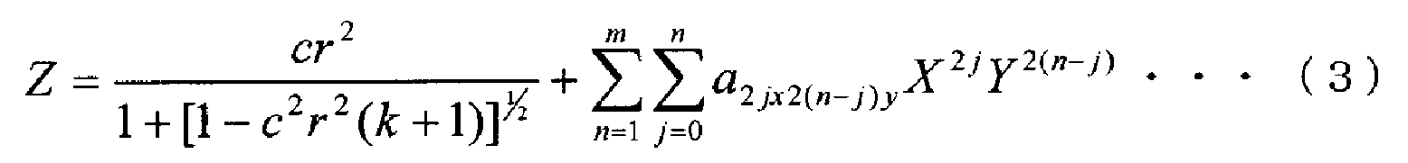
로 부여되고, c는 상기 토릭면을 부가하기 전의 상기 안용 렌즈에 있어서의 렌즈 광축에 회전 대칭인 기준면의 곡률이고, r은 상기 안용 렌즈의 렌즈 중심으로부터의 거리이고, k는 상기 토릭면을 부가하기 전의 상기 안용 렌즈에 있어서의 렌즈 광축에 회전 대칭인 기준면의 코닉 상수이고, a2jx2(n-j)y는 상기 토릭면을 부가하는 파라미터인 것을 특징으로 하는 안용 렌즈.6. The method of claim 5, wherein the formula for adding the definition formula of the toric surface is
C is a curvature of a reference plane rotationally symmetric with respect to a lens optical axis of the eye lens before the toric surface is added, r is a distance from the center of the lens of the eye lens, and k is a distance Wherein the second lens is a conic constant of a reference plane rotationally symmetric with respect to the optical axis of the lens in the eye lens before the step a2jx2 (nj) y is a parameter for adding the toric surface.

를 만족시키고, n은 m 이하의 자연수, j는 0 이상 n 이하의 정수인 것을 특징으로 하는 안용 렌즈.The method according to claim 6, wherein in the formula (3)
Wherein n is a natural number of m or less, and j is an integer of 0 or more and n or less.
에 기초하는 토릭면의 정의식을 가산한 식을 사용하여 상기 렌즈의 렌즈 형상을 규정하고, n=1, 2…이고, X는 상기 렌즈의 제1 방향에 있어서의 렌즈 중심으로부터의 거리이고, Y는 상기 렌즈의 제2 방향에 있어서의 렌즈 중심으로부터의 거리
인 것을 특징으로 하는 안용 렌즈의 설계 방법.In a predetermined definition formula defining a rotationally symmetrical lens surface with respect to the optical axis of the lens,
The lens shape of the lens is defined by using a formula obtained by adding a definition formula of a toric surface based on X is a distance from the center of the lens in the first direction of the lens, and Y is a distance from the center of the lens in the second direction of the lens
Wherein the lens is a lens.

로 부여되고, c는 상기 토릭면을 부가하기 전의 상기 안용 렌즈에 있어서의 렌즈 광축에 회전 대칭인 기준면의 곡률이고, r은 상기 안용 렌즈의 렌즈 중심으로부터의 거리이고, k는 상기 토릭면을 부가하기 전의 상기 안용 렌즈에 있어서의 렌즈 광축에 회전 대칭인 기준면의 코닉 상수이고, a2jx2(n-j)y는 상기 토릭면을 부가하는 파라미터인 것을 특징으로 하는 안용 렌즈의 설계 방법.18. The method of claim 17, wherein the formula for adding the definition formula of the toric surface is
C is a curvature of a reference plane rotationally symmetric with respect to a lens optical axis of the eye lens before the toric surface is added, r is a distance from the center of the lens of the eye lens, and k is a distance Wherein the second lens is a conic constant of a reference plane rotationally symmetric with respect to the optical axis of the lens in the eye lens before use, and a 2jx2 (nj) y is a parameter to which the toric surface is added.
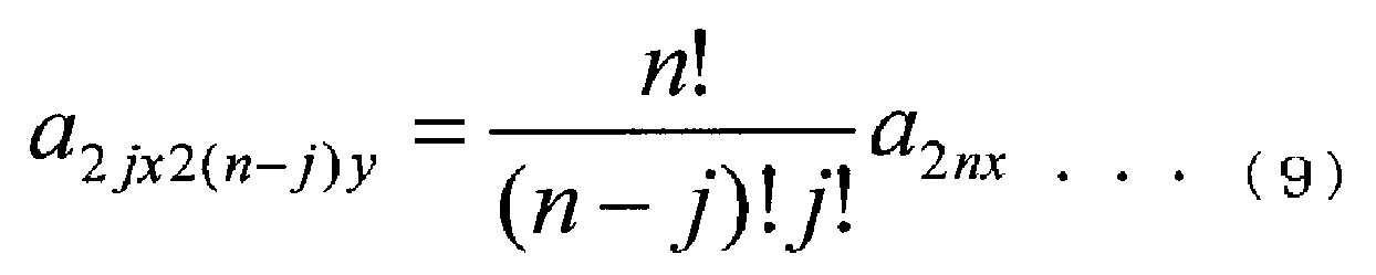
를 만족시키고, n은 m 이하의 자연수, j는 0 이상 n 이하의 정수인 것을 특징으로 하는 안용 렌즈의 설계 방법.The method according to claim 18, wherein in the formula (7)
Wherein n is a natural number of m or less, and j is an integer of 0 or more and n or less.

에 의해 얻어지는 X' 및 Y'를 X, Y 대신에 사용하고, θ는 상기 렌즈의 광축 주위의 회전 각도, X', Y', Z'는 변환 후의 계수 및 변수이고, X, Y, Z는 회전 전의 변수인 것을 특징으로 하는 안용 렌즈의 설계 방법.The method according to claim 17 or 18, wherein in the formula (7)
X ', Y', Z 'are the coefficients and variables after the conversion, and X, Y, Z are the rotation angles around the optical axis of the lens, Wherein the variable is a variable before the rotation.
Applications Claiming Priority (3)
| Application Number | Priority Date | Filing Date | Title |
|---|---|---|---|
| JPJP-P-2014-048026 | 2014-03-11 | ||
| JP2014048026 | 2014-03-11 | ||
| PCT/JP2015/052409 WO2015136997A1 (en) | 2014-03-11 | 2015-01-28 | Ophthalmic lens and method for designing ophthalmic lens |
Publications (2)
| Publication Number | Publication Date |
|---|---|
| KR20160132908A true KR20160132908A (en) | 2016-11-21 |
| KR102302427B1 KR102302427B1 (en) | 2021-09-15 |
Family
ID=54071451
Family Applications (1)
| Application Number | Title | Priority Date | Filing Date |
|---|---|---|---|
| KR1020167027721A Active KR102302427B1 (en) | 2014-03-11 | 2015-01-28 | Ophthalmic lens and method for designing ophthalmic lens |
Country Status (9)
| Country | Link |
|---|---|
| US (3) | US20170045756A1 (en) |
| EP (1) | EP3118671B1 (en) |
| JP (1) | JP6049939B2 (en) |
| KR (1) | KR102302427B1 (en) |
| CN (1) | CN106575047B (en) |
| ES (1) | ES2910013T3 (en) |
| PL (1) | PL3118671T3 (en) |
| SG (1) | SG11201607593VA (en) |
| WO (1) | WO2015136997A1 (en) |
Cited By (2)
| Publication number | Priority date | Publication date | Assignee | Title |
|---|---|---|---|---|
| KR20200101444A (en) * | 2017-12-28 | 2020-08-27 | 브리제 유니버시타이트 브루셀 | Optical design method for imaging system and optical system designed therefrom |
| KR20210112291A (en) * | 2019-12-31 | 2021-09-14 | 주식회사 인터로조 | Contact Lenses with Spherical Aberration Control Design for Improved Visual Performance |
Families Citing this family (6)
| Publication number | Priority date | Publication date | Assignee | Title |
|---|---|---|---|---|
| RU2674479C2 (en) * | 2014-02-24 | 2018-12-11 | ДжиИ ОЙЛ ЭНД ГЭС ЭСП, ИНК. | Downhole wet gas compressor processor |
| CN108882977B (en) | 2016-04-08 | 2021-05-25 | 兴和株式会社 | Toric intraocular lens and intraocular lens insertion apparatus |
| HUE065765T2 (en) | 2016-12-07 | 2024-06-28 | Kowa Co | Toric ocular lens |
| CN107684478A (en) * | 2017-10-13 | 2018-02-13 | 天津世纪康泰生物医学工程有限公司 | Region spherical aberration profile astigmatism correction intraocular lens |
| CN113040976B (en) * | 2021-03-04 | 2022-06-28 | 天津世纪康泰生物医学工程有限公司 | Ultrathin zero-spherical-aberration implantable myopia lens |
| CN114740634B (en) * | 2022-05-07 | 2023-11-17 | 江苏圣谱光学技术有限公司 | Free-form surface lens based on toroidal surface and design method thereof |
Citations (6)
| Publication number | Priority date | Publication date | Assignee | Title |
|---|---|---|---|---|
| JPS4945558B1 (en) | 1963-03-29 | 1974-12-04 | ||
| JP2002122823A (en) * | 2000-10-17 | 2002-04-26 | Asahi Optical Co Ltd | Aspherical spectacle lens and processing method thereof |
| WO2002088828A1 (en) * | 2001-04-26 | 2002-11-07 | Hoya Corporation | Eyeglass lens desigining method and eyeglass lens |
| JP2004133024A (en) * | 2002-10-08 | 2004-04-30 | Nikon-Essilor Co Ltd | Eyeglass lens design method, eyeglass lens manufacturing method, and computer program |
| JP2008221720A (en) * | 2007-03-14 | 2008-09-25 | Ito Kogaku Kogyo Kk | Glass mold for eyeglass lens, its manufacturing process, and manufacturing process of eyeglass lens |
| JP2011519682A (en) | 2008-05-06 | 2011-07-14 | アルコン,インコーポレイティド | Aspheric toric intraocular lens |
Family Cites Families (23)
| Publication number | Priority date | Publication date | Assignee | Title |
|---|---|---|---|---|
| US4680998A (en) * | 1984-08-28 | 1987-07-21 | Bausch & Lomb Incorporated | Toric lenses, method and apparatus for making same |
| US4947715A (en) * | 1988-11-22 | 1990-08-14 | Citycrown, Inc. | Method and apparatus for cutting an aspheric surface on a workpiece |
| DE69232283T2 (en) * | 1991-10-09 | 2002-05-23 | Seiko Epson Corp., Tokio/Tokyo | Lens for glasses. |
| US5767939A (en) * | 1991-10-09 | 1998-06-16 | Seiko Epson Corporation | Eyeglass lens |
| US6122999A (en) * | 1997-04-17 | 2000-09-26 | Novartis Ag | Lathe apparatus and method |
| JP2002040373A (en) * | 1997-06-19 | 2002-02-06 | Hoya Corp | Aspheric spectacle lens |
| US6012813A (en) * | 1997-06-19 | 2000-01-11 | Hoya Corporation | Aspherical spectacle lens |
| US6364481B1 (en) * | 1997-07-18 | 2002-04-02 | Sola International Holdings Ltd. | Lens with surface correction |
| US6000798A (en) * | 1997-10-06 | 1999-12-14 | Innotech Inc. | Ophthalmic optic devices |
| EP2332495B1 (en) * | 2000-05-23 | 2014-04-23 | AMO Groningen B.V. | Methods of obtaining ophthalmic lenses providing the eye with reduced aberrations |
| US6802607B2 (en) * | 2002-10-31 | 2004-10-12 | Johnson & Johnson Vision Care, Inc. | Progressive cylinder ophthalmic lenses |
| US7300152B2 (en) * | 2004-06-14 | 2007-11-27 | Johnson & Johnson Vision Care, Inc. | Contact lenses and methods for their design |
| JP4537134B2 (en) * | 2004-07-12 | 2010-09-01 | セイコーオプティカルプロダクツ株式会社 | Aspheric eyeglass lens design method |
| US20070255401A1 (en) * | 2006-05-01 | 2007-11-01 | Revision Optics, Inc. | Design of Inlays With Intrinsic Diopter Power |
| JP5041739B2 (en) * | 2006-06-14 | 2012-10-03 | Hoya株式会社 | Intraocular lens |
| AR062067A1 (en) * | 2006-07-17 | 2008-10-15 | Novartis Ag | TORICAS CONTACT LENSES WITH CONTROLLED OPTICAL POWER PROFILE |
| DE102008003770A1 (en) * | 2008-01-10 | 2009-07-16 | Rodenstock Gmbh | Shield/protective glass for e.g. correction of ametropia, has continuous front surface bending without breaking, and left eyeglass lens region and right eyeglass lens region connected with each other without interspace |
| US7780290B2 (en) * | 2008-02-21 | 2010-08-24 | Abbott Medical Optics Inc. | Toric intraocular lens with spatially-variant astigmatism |
| WO2010064278A1 (en) * | 2008-12-03 | 2010-06-10 | Kashiwagi Toyohiko | Ophthalmic lens design method, ophthalmic lens, and refraction correcting operation device |
| US8256896B2 (en) * | 2010-02-25 | 2012-09-04 | Abbott Medical Optic Inc. | Toric optic for ophthalmic use |
| US10456026B2 (en) * | 2010-12-15 | 2019-10-29 | Amo Wavefront Sciences, Llc | Apparatus, system, and method for intraocular lens power calculation using a regression formula incorporating corneal spherical aberration |
| US9046698B2 (en) * | 2012-02-28 | 2015-06-02 | Johnson & Johnson Vision Care, Inc. | Multi-axis lens design for astigmatism |
| CA2942198C (en) * | 2014-03-10 | 2023-08-01 | Amo Groningen B.V. | Enhanced toric lens that improves overall vision where there is a local loss of retinal function |
-
2015
- 2015-01-28 JP JP2016507389A patent/JP6049939B2/en active Active
- 2015-01-28 PL PL15761883.6T patent/PL3118671T3/en unknown
- 2015-01-28 WO PCT/JP2015/052409 patent/WO2015136997A1/en not_active Ceased
- 2015-01-28 US US15/125,097 patent/US20170045756A1/en not_active Abandoned
- 2015-01-28 KR KR1020167027721A patent/KR102302427B1/en active Active
- 2015-01-28 SG SG11201607593VA patent/SG11201607593VA/en unknown
- 2015-01-28 EP EP15761883.6A patent/EP3118671B1/en active Active
- 2015-01-28 ES ES15761883T patent/ES2910013T3/en active Active
- 2015-01-28 CN CN201580024754.3A patent/CN106575047B/en active Active
-
2020
- 2020-11-12 US US17/096,718 patent/US20210063768A1/en not_active Abandoned
-
2022
- 2022-04-15 US US17/659,401 patent/US20220244568A1/en not_active Abandoned
Patent Citations (6)
| Publication number | Priority date | Publication date | Assignee | Title |
|---|---|---|---|---|
| JPS4945558B1 (en) | 1963-03-29 | 1974-12-04 | ||
| JP2002122823A (en) * | 2000-10-17 | 2002-04-26 | Asahi Optical Co Ltd | Aspherical spectacle lens and processing method thereof |
| WO2002088828A1 (en) * | 2001-04-26 | 2002-11-07 | Hoya Corporation | Eyeglass lens desigining method and eyeglass lens |
| JP2004133024A (en) * | 2002-10-08 | 2004-04-30 | Nikon-Essilor Co Ltd | Eyeglass lens design method, eyeglass lens manufacturing method, and computer program |
| JP2008221720A (en) * | 2007-03-14 | 2008-09-25 | Ito Kogaku Kogyo Kk | Glass mold for eyeglass lens, its manufacturing process, and manufacturing process of eyeglass lens |
| JP2011519682A (en) | 2008-05-06 | 2011-07-14 | アルコン,インコーポレイティド | Aspheric toric intraocular lens |
Cited By (2)
| Publication number | Priority date | Publication date | Assignee | Title |
|---|---|---|---|---|
| KR20200101444A (en) * | 2017-12-28 | 2020-08-27 | 브리제 유니버시타이트 브루셀 | Optical design method for imaging system and optical system designed therefrom |
| KR20210112291A (en) * | 2019-12-31 | 2021-09-14 | 주식회사 인터로조 | Contact Lenses with Spherical Aberration Control Design for Improved Visual Performance |
Also Published As
| Publication number | Publication date |
|---|---|
| US20220244568A1 (en) | 2022-08-04 |
| EP3118671B1 (en) | 2022-03-23 |
| EP3118671A4 (en) | 2017-11-15 |
| SG11201607593VA (en) | 2016-10-28 |
| US20170045756A1 (en) | 2017-02-16 |
| EP3118671A1 (en) | 2017-01-18 |
| ES2910013T3 (en) | 2022-05-11 |
| CN106575047A (en) | 2017-04-19 |
| CN106575047B (en) | 2020-05-26 |
| PL3118671T3 (en) | 2022-07-18 |
| WO2015136997A1 (en) | 2015-09-17 |
| KR102302427B1 (en) | 2021-09-15 |
| JPWO2015136997A1 (en) | 2017-04-06 |
| JP6049939B2 (en) | 2016-12-27 |
| US20210063768A1 (en) | 2021-03-04 |
Similar Documents
| Publication | Publication Date | Title |
|---|---|---|
| KR102302427B1 (en) | Ophthalmic lens and method for designing ophthalmic lens | |
| US10799338B2 (en) | Wide depth of focus vortex intraocular lenses and associated methods | |
| JP2021039387A (en) | Toric ophthalmic lens | |
| KR20110067142A (en) | Toric ophthalmic lens with selected spherical aberration characteristics | |
| CN102662252B (en) | Aspheric glasses lens determination method for myopic presbyopia correction | |
| EP3577518B1 (en) | Method and apparatus for measuring add power of a contact lens | |
| WO2013168201A1 (en) | Lens power measurement device and measurement method | |
| Jia et al. | Measurement of spectacle lenses using wavefront aberration in real view condition | |
| KR101971747B1 (en) | Intraocular lens design method and intraocular lens | |
| Xiang et al. | Comparison and applications of spherocylindrical, toroidal, and ellipsoidal surfaces for the correction of astigmatism in spectacle lenses | |
| KR20070038463A (en) | Contact lens and its design method | |
| Jiménez et al. | Retinal image quality in myopic subjects after refractive surgery | |
| O’Neal et al. | Optical calibration system for refractometers | |
| HK1236627A1 (en) | Ophthalmic lens and method for designing ophthalmic lens | |
| Cuellar et al. | Optical and simulated visual outcomes of two presbyopia-correcting intraocular lenses tested in clinically relevant decentration and tilt conditions | |
| Amaral et al. | Alternative methodology for intraocular lens characterisation | |
| Shuker et al. | Electro-Optic Designing and Construction to test the Tilting and the Decentering | |
| Trindade et al. | Versatile optical setup customized to verify the quality of spherical and aspheric intraocular lenses | |
| Chen et al. | Systematic design of myopic ophthalmic lens | |
| HK1236627B (en) | Ophthalmic lens and method for designing ophthalmic lens | |
| HK1229009A1 (en) | Toric intraocular lens | |
| Yu et al. | Wavefront aberration measurement of freeform spectacle lens–eye system | |
| Trindade et al. | Optical parameters and charts | |
| Choi | Optical performance test & analysis of intraocular lenses | |
| Garzón et al. | Power profile and optical performance of two extended range of vision intraocular lens designs |
Legal Events
| Date | Code | Title | Description |
|---|---|---|---|
| E13-X000 | Pre-grant limitation requested |
St.27 status event code: A-2-3-E10-E13-lim-X000 |
|
| PA0105 | International application |
St.27 status event code: A-0-1-A10-A15-nap-PA0105 |
|
| PG1501 | Laying open of application |
St.27 status event code: A-1-1-Q10-Q12-nap-PG1501 |
|
| A201 | Request for examination | ||
| E13-X000 | Pre-grant limitation requested |
St.27 status event code: A-2-3-E10-E13-lim-X000 |
|
| P11-X000 | Amendment of application requested |
St.27 status event code: A-2-2-P10-P11-nap-X000 |
|
| P13-X000 | Application amended |
St.27 status event code: A-2-2-P10-P13-nap-X000 |
|
| PA0201 | Request for examination |
St.27 status event code: A-1-2-D10-D11-exm-PA0201 |
|
| E902 | Notification of reason for refusal | ||
| PE0902 | Notice of grounds for rejection |
St.27 status event code: A-1-2-D10-D21-exm-PE0902 |
|
| P11-X000 | Amendment of application requested |
St.27 status event code: A-2-2-P10-P11-nap-X000 |
|
| P13-X000 | Application amended |
St.27 status event code: A-2-2-P10-P13-nap-X000 |
|
| E701 | Decision to grant or registration of patent right | ||
| PE0701 | Decision of registration |
St.27 status event code: A-1-2-D10-D22-exm-PE0701 |
|
| GRNT | Written decision to grant | ||
| PR0701 | Registration of establishment |
St.27 status event code: A-2-4-F10-F11-exm-PR0701 |
|
| PR1002 | Payment of registration fee |
St.27 status event code: A-2-2-U10-U12-oth-PR1002 Fee payment year number: 1 |
|
| PG1601 | Publication of registration |
St.27 status event code: A-4-4-Q10-Q13-nap-PG1601 |
|
| R18-X000 | Changes to party contact information recorded |
St.27 status event code: A-5-5-R10-R18-oth-X000 |
|
| PR1001 | Payment of annual fee |
St.27 status event code: A-4-4-U10-U11-oth-PR1001 Fee payment year number: 4 |
|
| PR1001 | Payment of annual fee |
St.27 status event code: A-4-4-U10-U11-oth-PR1001 Fee payment year number: 5 |
|
| U11 | Full renewal or maintenance fee paid |
Free format text: ST27 STATUS EVENT CODE: A-4-4-U10-U11-OTH-PR1001 (AS PROVIDED BY THE NATIONAL OFFICE) Year of fee payment: 5 |