KR20140036178A - Laboratory product transport element and path arrangement - Google Patents
Laboratory product transport element and path arrangement Download PDFInfo
- Publication number
- KR20140036178A KR20140036178A KR1020137029973A KR20137029973A KR20140036178A KR 20140036178 A KR20140036178 A KR 20140036178A KR 1020137029973 A KR1020137029973 A KR 1020137029973A KR 20137029973 A KR20137029973 A KR 20137029973A KR 20140036178 A KR20140036178 A KR 20140036178A
- Authority
- KR
- South Korea
- Prior art keywords
- laboratory product
- transfer element
- product transfer
- laboratory
- signal
- Prior art date
- Legal status (The legal status is an assumption and is not a legal conclusion. Google has not performed a legal analysis and makes no representation as to the accuracy of the status listed.)
- Ceased
Links
Images


Classifications
-
- G—PHYSICS
- G01—MEASURING; TESTING
- G01N—INVESTIGATING OR ANALYSING MATERIALS BY DETERMINING THEIR CHEMICAL OR PHYSICAL PROPERTIES
- G01N35/00—Automatic analysis not limited to methods or materials provided for in any single one of groups G01N1/00 - G01N33/00; Handling materials therefor
- G01N35/00584—Control arrangements for automatic analysers
-
- G—PHYSICS
- G01—MEASURING; TESTING
- G01N—INVESTIGATING OR ANALYSING MATERIALS BY DETERMINING THEIR CHEMICAL OR PHYSICAL PROPERTIES
- G01N35/00—Automatic analysis not limited to methods or materials provided for in any single one of groups G01N1/00 - G01N33/00; Handling materials therefor
- G01N35/02—Automatic analysis not limited to methods or materials provided for in any single one of groups G01N1/00 - G01N33/00; Handling materials therefor using a plurality of sample containers moved by a conveyor system past one or more treatment or analysis stations
- G01N35/04—Details of the conveyor system
- G01N2035/0401—Sample carriers, cuvettes or reaction vessels
- G01N2035/0418—Plate elements with several rows of samples
- G01N2035/0422—Plate elements with several rows of samples carried on a linear conveyor
-
- G—PHYSICS
- G01—MEASURING; TESTING
- G01N—INVESTIGATING OR ANALYSING MATERIALS BY DETERMINING THEIR CHEMICAL OR PHYSICAL PROPERTIES
- G01N35/00—Automatic analysis not limited to methods or materials provided for in any single one of groups G01N1/00 - G01N33/00; Handling materials therefor
- G01N35/02—Automatic analysis not limited to methods or materials provided for in any single one of groups G01N1/00 - G01N33/00; Handling materials therefor using a plurality of sample containers moved by a conveyor system past one or more treatment or analysis stations
- G01N35/04—Details of the conveyor system
- G01N2035/046—General conveyor features
- G01N2035/0467—Switching points ("aiguillages")
-
- G—PHYSICS
- G01—MEASURING; TESTING
- G01N—INVESTIGATING OR ANALYSING MATERIALS BY DETERMINING THEIR CHEMICAL OR PHYSICAL PROPERTIES
- G01N35/00—Automatic analysis not limited to methods or materials provided for in any single one of groups G01N1/00 - G01N33/00; Handling materials therefor
- G01N35/02—Automatic analysis not limited to methods or materials provided for in any single one of groups G01N1/00 - G01N33/00; Handling materials therefor using a plurality of sample containers moved by a conveyor system past one or more treatment or analysis stations
- G01N35/04—Details of the conveyor system
- G01N2035/0474—Details of actuating means for conveyors or pipettes
- G01N2035/0489—Self-propelled units
Landscapes
- Physics & Mathematics (AREA)
- Health & Medical Sciences (AREA)
- Life Sciences & Earth Sciences (AREA)
- Chemical & Material Sciences (AREA)
- Analytical Chemistry (AREA)
- Biochemistry (AREA)
- General Health & Medical Sciences (AREA)
- General Physics & Mathematics (AREA)
- Immunology (AREA)
- Pathology (AREA)
- Non-Mechanical Conveyors (AREA)
- Automatic Analysis And Handling Materials Therefor (AREA)
- Platform Screen Doors And Railroad Systems (AREA)
- Control Of Position, Course, Altitude, Or Attitude Of Moving Bodies (AREA)
Abstract
본 발명은 구동력을 제공하는 에너지 수신기 및/또는 에너지 축적기, 제어 신호를 수신하는 적어도 하나의 신호 수신기, 상기 적어도 하나의 수신기로부터 얻은 적어도 하나의 제어 신호의 함수로서 구동 신호를 발생시키는 제어 유닛, 상기 제어 유닛의 구동 신호의 함수로서 상기 실험실 제품 이송 요소가 이송 경로 상에서 독립적으로 이동할 수 있도록 하는 이동 기구, 및 이송되는 실험실 제품을 유지하는 적어도 하나의 홀더를 갖는 실험실 이송 시스템용의 실험실 제품 이송 요소에 관한 것이다. 본 발명은 또한, 본 발명의 실시예에 따른 적어도 하나의 실험실 제품 이송 요소 및 이송 경로 배열 구조체를 구비한 실험실 이송 시스템에 관한 것이다. 본 발명은 또한, 본 발명의 일 실시예에 따른 실험실 이송 시스템의 작동 방법에 관한 것이다.The invention provides an energy receiver and / or an energy accumulator for providing a driving force, at least one signal receiver for receiving a control signal, a control unit for generating a drive signal as a function of at least one control signal obtained from the at least one receiver, Laboratory product transfer element for a laboratory transfer system having a moving mechanism that allows the laboratory product transfer element to move independently on a transfer path as a function of a drive signal of the control unit, and at least one holder for holding the laboratory product to be transferred. It is about. The invention also relates to a laboratory transfer system having at least one laboratory product transfer element and a transfer path arrangement structure according to an embodiment of the invention. The invention also relates to a method of operating a laboratory transfer system according to one embodiment of the invention.
Description
관련 출원에 대한 교차 참조Cross-reference to related application
본원은 2011년 5월 13일자에 출원된 미국 가출원 번호 제 61/486,108 호의 본 출원으로서, 상기 가특허 출원을 우선권 주장하며, 상기 가특허 출원은 모든 목적을 위해 그 전체가 인용에 의해 본 명세서에 통합되어 있다. This application is the application of US Provisional Application No. 61 / 486,108, filed May 13, 2011, which claims priority to the provisional patent application, which is incorporated herein by reference in its entirety for all purposes. It is integrated.
본 발명의 실시예는 환자의 샘플을 처리하기 위해 자동화된 의료 실험실 체외 진단 시스템에서 사용되는 실험실 이송 시스템에 관한 것이다. 본 발명의 이송 시스템은 적어도 하나의 이송 경로 배열 구조체와, 환자의 샘플과 같은 실험실 제품을 이송하는 적어도 하나의 실험실 제품 이송 요소와, 그 작동 방법을 포함한다. 또한, 본 발명의 실시예는 실험실 제품 이송 요소와, 실험실 이송 시스템의 이송 경로 배열 구조체에 관한 것이다. Embodiments of the present invention relate to a laboratory transfer system used in an automated medical laboratory in vitro diagnostic system for processing a patient's sample. The transfer system of the present invention comprises at least one transfer path arrangement structure, at least one lab product transfer element for transferring a laboratory product, such as a sample of a patient, and a method of operation thereof. Embodiments of the present invention also relate to laboratory product transfer elements and transfer path arrangement structures of laboratory transfer systems.
그리퍼(gripper) 시스템과 같은 실험실 이송 시스템은 하나의 처리 스테이션에서 다른 처리 스테이션으로 샘플 튜브를 이송하기 위해 의료 실험실에서 사용된다. 이러한 샘플 튜브는 혈액과 같은 샘플 유체를 포함할 수 있으며, 샘플 유체는 화학적, 생물학적 또는 물리적 검사를 위해 처리될 수 있다. Laboratory transfer systems, such as gripper systems, are used in medical laboratories to transfer sample tubes from one processing station to another. Such sample tubes may comprise sample fluid, such as blood, and the sample fluid may be processed for chemical, biological or physical examination.
공지의 시스템에서, 각 튜브는 능동적 이송 시스템 상에서 이동하는 수동적 실험실 제품 이송 요소("퍽")에 의해 이송된다. "수동적"이라 함은 퍽이 자체적으로 이동할 수 없다는 의미이다. 하나의 스테이션에서 다른 스테이션으로 퍽을 이동시키기 위한 능동적 이송 시스템은 퍽이 배치되는 이송 경로, 또는 미리 정해진 경로를 따라 퍽을 밀거나 당기는 다른 메커니즘을 포함한다. 이송 경로의 예에는 체인 또는 벨트 컨베이어가 포함된다. 별도의 체인이나 벨트 컨베이어에 의해 각각의 가능한 경로가 형성된다. 이에 따르면, 레이아웃이 복잡해지며, 기계 및 전자 부품이 많이 필요하게 된다. 컨베이어 구동 기구는 흔히 매우 공간 집약적이다. 컨베이어를 구동시키기 위해 모터를 사용하는 경우, 예를 들어, 실제 이송 기하학적 구조보다 측방향으로 모터가 초과하여 돌출하면, 제 1 컨베이어에 인접하여 제 2 컨베이어를 배치할 수 없게 된다. 미리 정해진 경로를 따라 퍽을 이동시키는 유형의 시스템의 다른 예가 미국 특허 번호 제 7,028,831 호 및 제 7,264,111 호에 개시되어 있다. 이 후자의 시스템은 미리 정해진 경로를 따라 자석을 이동시키기 위해 복잡한 메커니즘을 사용해야 한다. 이러한 기존의 시스템은 퍽 경로에 인접하거나 그 아래에 있는 공간을 차지하는 크고 복잡한 메커니즘을 필요로 한다. 컨베이어 구동 시스템은 퍽의 이송을 위해 사용할 수 없는 넓은 면적을 체인/벨트의 전환부에 갖고 있다. 따라서, 직각으로 분기시키기가 곤란하다. 또한, 하나의 체인이나 벨트에서 다른 체인이나 다른 벨트로 퍽이 바뀌는 도중에, 많은 샘플 물질들이 견딜 수 없는 큰 진동이 퍽에 발생할 수 있다.In known systems, each tube is transported by a passive laboratory product transport element ("puck") that moves on an active transport system. "Passive" means that the puck cannot move on its own. Active transfer systems for moving the puck from one station to another include a transfer path in which the puck is placed, or other mechanisms for pushing or pulling the puck along a predetermined path. Examples of transport paths include chain or belt conveyors. Each possible path is formed by a separate chain or belt conveyor. This complicates the layout and requires a lot of mechanical and electronic components. Conveyor drive mechanisms are often very space intensive. When using a motor to drive the conveyor, for example, if the motor protrudes laterally than the actual transport geometry, it becomes impossible to place the second conveyor adjacent to the first conveyor. Another example of a type of system for moving a puck along a predetermined route is disclosed in US Pat. Nos. 7,028,831 and 7,264,111. This latter system must use a complex mechanism to move the magnet along a predetermined path. Such existing systems require large and complex mechanisms to occupy space adjacent to or below the puck path. Conveyor drive systems have a large area in the chain / belt transition that cannot be used to transport the puck. Therefore, it is difficult to branch at right angles. In addition, during the changeover of a puck from one chain or belt to another chain or another belt, large vibrations may occur in the puck that many sample materials cannot tolerate.
기존의 시스템에서, 체인 또는 벨트 컨베이어 시스템 또는 자기 이송 시스템을 작동시키기 위해 필요한 기계 부품들은 복잡하다. 스위치, 브레이크 또는 센서와 같은 요소가 기존의 시스템에서 고장나면, 서비스 기술자가 장애를 해결할 때까지, 전체 이송 시스템의 운전 정지로 이어질 수 있다.In existing systems, the mechanical parts needed to operate a chain or belt conveyor system or a magnetic conveying system are complex. If an element such as a switch, brake or sensor fails in an existing system, it can lead to a shutdown of the entire transport system until the service technician resolves the fault.
마지막으로, 기존의 컨베이어 시스템에서 경로를 변경하는 일은 기계적으로 부담이 클 수 있으며, 많은 비용이 소요될 수 있다. 즉, 기존의 컨베이어 시스템을 사용하는 경우, 이러한 컨베이어 시스템에 의해 제공되는 물리적 제약 때문에, 여러 가지 프로토콜에 따라 샘플을 이송할 수 있는 능력이 제한된다. Finally, rerouting in existing conveyor systems can be mechanically expensive and expensive. In other words, when using existing conveyor systems, the physical constraints provided by such conveyor systems limit the ability to transfer samples according to various protocols.
본 발명의 실시예의 목적은 간단하고 신뢰할 수 있게 작동하며 설계 부담이 적은 실험실 이송 시스템, 그 작동 방법, 실험실 제품 이송 요소 및 이송 경로 배열 구조체를 제공하는 것이다. 본 발명의 실시예들은 개별적으로 그리고 집단적으로 여타 문제점들을 해소한다. It is an object of embodiments of the present invention to provide a laboratory transfer system that operates simply, reliably and with low design burden, a method of operation thereof, a laboratory product transfer element and a transfer path arrangement structure. Embodiments of the present invention solve other problems individually and collectively.
일부 실시예들에서, 실험실 이송 시스템을 위한 실험실 제품 이송 요소가 제공되며, 상기 실험실 제품 이송 요소는 자체 추진된다. 실험실 제품 이송 요소는 구동력을 제공하는 에너지원을 포함한다. 제어 신호를 수신하는 적어도 하나의 신호 수신기가 제공된다. 상기 적어도 하나의 신호 수신기로부터 취득한 적어도 하나의 제어 신호의 함수로서 구동 신호를 발생시키는 제어 유닛이 제공된다. 실험실 제품 이송 요소는 실험실 제품 이송 요소가 이송 경로 상에서 독립적으로 이동할 수 있도록 하는 적어도 하나의 이동 기구를 또한 포함한다. 상기 제어 유닛의 구동 신호의 함수로서 상기 이동 기구를 구동시키는 적어도 하나의 구동 기구가 제공된다. 상기 구동 기구는 상기 구동력에 의해 구동될 수 있다. 실험실 제품 이송 요소는 이송되는 실험실 제품을 유지하는 적어도 하나의 홀더를 또한 포함한다. In some embodiments, a laboratory product transfer element for a laboratory transfer system is provided, the laboratory product transfer element being self-propelled. The laboratory product transport element includes an energy source that provides the driving force. At least one signal receiver is provided for receiving a control signal. A control unit is provided for generating a drive signal as a function of at least one control signal obtained from said at least one signal receiver. The laboratory product transfer element also includes at least one moving mechanism that allows the laboratory product transfer element to move independently on the transfer path. At least one drive mechanism is provided for driving the moving mechanism as a function of the drive signal of the control unit. The driving mechanism may be driven by the driving force. The laboratory product conveying element also includes at least one holder for holding the laboratory product to be conveyed.
일부 실시예들은 실험실 제품 이송 요소에 목표(objective)가 규정되어 있는 실험실 이송 시스템의 작동 방법을 포함한다. 상기 실험실 제품 이송 요소의 제어 유닛은 입력된 목표와 실험실 제품 이송 요소의 메모리에 저장된 이송 경로의 기하학적 구조에 따라 실험실 제품 이송 요소의 구동 기구를 위한 구동 신호를 발생시킨다. Some embodiments include a method of operating a laboratory transfer system in which an objective is defined for a laboratory product transfer element. The control unit of the laboratory product transport element generates a drive signal for the drive mechanism of the laboratory product transport element according to the input target and the geometry of the transport path stored in the memory of the laboratory product transport element.
일부 실시예들은 실험실 제품 이송 요소의 메모리에 구동 신호의 시퀀스가 저장되어 있는 실험실 이송 시스템의 작동 방법을 포함한다. 이들은 상기 적어도 하나의 이송 경로 상에서 원하는 경로에 대응하며, 상기 실험실 제품 이송 요소의 구동 기구는 상기 구동 신호의 함수로서 상기 이동 기구에 의해 당해 실험실 제품 이송 요소를 이동시킨다.Some embodiments include a method of operating a laboratory transfer system in which a sequence of drive signals is stored in a memory of a laboratory product transfer element. These correspond to the desired path on the at least one transfer path, wherein the drive mechanism of the lab product transfer element moves the lab product transfer element by the transfer mechanism as a function of the drive signal.
일부 실시예들은 실험실 제품 이송 요소가 실시간으로 제어되는 실험실 이송 시스템의 작동 방법을 포함한다. Some embodiments include a method of operating a laboratory transfer system in which laboratory product transfer elements are controlled in real time.
일부 실시예들은 실험실 제품 이송 요소가 이송 경로 배열 구조체 상의 능동적 또는 수동적 배향 특징부(orientation features)에 의해 배향되는 실험실 이송 시스템의 작동 방법을 포함한다. Some embodiments include a method of operating a laboratory transfer system in which the laboratory product transfer element is oriented by active or passive orientation features on the transfer path arrangement structure.
본 발명의 다른 실시예들은 미리 정해진 실험실 제품 이송 요소 이동 프로파일, 자가 진단, 약취 방지, 미세 위치 결정 및 리프트-오프 방지, 교차부에서의 처리량, 에너지 절약 기구, 및 샘플 품질 보호와 관련될 수 있다.Other embodiments of the present invention may relate to predetermined laboratory product transfer element movement profiles, self-diagnostics, anti-doughness, fine positioning and lift-off prevention, throughput at intersections, energy saving mechanisms, and sample quality protection. .
이하, 첨부 도면과 상세한 설명을 참조하여, 본 발명의 여타 실시예들을 더 상세하게 설명하기로 한다. Hereinafter, other embodiments of the present invention will be described in more detail with reference to the accompanying drawings and detailed description.
이하의 도면을 참조하면, 여러 가지 실시예들의 특성과 장점을 더 잘 이해할 수 있을 것이다. 첨부 도면에서, 유사한 부품이나 특징부들에 대해서는 동일한 참조 부호를 부여하였다. 또한, 동일한 유형의 다양한 부품들은 참조 부호 다음에 대시(-)와 유사한 부품들을 구분하는 제 2 부호를 기입하여 구분될 수 있도록 하였다. 명세서에 제 1 참조 부호만 사용되면, 상세한 설명은 제 2 참조 부호와는 무관하게 동일한 제 1 참조 부호를 가진 유사한 부품들 중 임의의 부품에 적용될 수 있다.
도 1a는 다양한 실시예들에 따른 실험실 이송 시스템의 변형을 나타낸 부분 사시도이다.
도 1b는 다양한 실시예들에 따른 실험실 제품 이송 요소의 변형을 나타낸 사시도이다.
도 1c는 다양한 실시예들에 따른 실험실 제품 이송의 변형을 나타낸 측단면도이다.
도 1d는 아래에서 본 다양한 실시예들에 따른 실험실 제품 이송 요소의 변형을 나타낸 사시도이다.
도 1e는 측면이 보호되지 않은 다양한 실시예들에 따른 실험실 제품 이송 요소의 변형을 나타낸 도면이다.
도 1f는 다양한 실시예들에 따른 실험실 이송 시스템의 이송 경로로부터의 절단부를 나타내고 있다.
도 2a 내지 도 2g는 다양한 실시예들에 따른 미리 정해진 이동 프로파일의 사용례를 나타낸 도면이다.
도 3은 다양한 실시예들에 따른 미리 정해진 이동 프로파일의 다른 사용례를 나타낸 도면이다.
도 4a, 도 4b 및 도 4c는 다양한 실시예들에 따른 실험실 이송 시스템의 자가 진단의 예를 나타낸 도면이다.
도 5a 및 도 5b는 다양한 실시예들에 따른 실험실 제품 이송 요소의 위치 결정의 일 예를 나타낸 도면이다.
도 6a, 도 6b, 도 6c 및 도 6d는 다양한 실시예들에 따른 실험실 제품 이송 요소의 정밀한 위치 결정의 다른 예를 나타낸 도면이다.
도 7a 내지 도 7d는 다양한 실시예들에 따른 실험실 제품 이송 요소의 리프트-오프(lift-off) 방지의 예를 나타낸 도면이다.
도 8a 내지 도 8d는 다양한 실시예들에 따른 실험실 제품 이송 요소의 리프트 오프 방지의 다른 예를 나타낸 도면이다.
도 9a 내지 도 9j는 다양한 실시예들에 따른 교차부에서의 처리량 제어의 예를 나타낸 도면으로서, 이 경우에서는 전환의 예를 나타낸 도면이다.
도 10a 내지 도 10f는 다양한 실시예들에 따른 교차부에서의 처리량 제어의 다른 예를 나타낸 도면으로서, 이 경우에서는 합류의 예를 나타낸 도면이다.
도 11a 내지 도 11e는 다양한 실시예들에 따른 교차부에서의 처리량 제어의 다른 예를 나타낸 도면으로서, 이 경우에서는 인출(pull-off)의 예를 나타낸 도면이다.
도 12a 내지 도 12f는 다양한 실시예들에 따른 교차부에서의 처리량 제어의 다른 예를 나타낸 도면으로서, 이 경우에서는 지름길의 예를 나타낸 도면이다.
도 13a 및 도 13b는 다양한 실시예들에 따른 RFID 태그를 활용한 교차부에서의 처리량 제어의 다른 예를 나타낸 도면이다.
도 14는 실험실 제품 이송 요소의 요소들을 나타낸 블록도이다.
도 15는 실험실 제품을 제어하기 위한 시스템의 블록도이다. Referring to the drawings below, it will be better to understand the characteristics and advantages of the various embodiments. In the accompanying drawings, like parts or features have been given the same reference numerals. In addition, various parts of the same type can be distinguished by writing a second reference character separating the parts similar to dashes after the reference character. If only the first reference numeral is used in the specification, the description may be applied to any of the similar components having the same first reference numeral regardless of the second reference numeral.
1A is a partial perspective view of a modification of a laboratory transfer system, in accordance with various embodiments.
1B is a perspective view of a modification of a laboratory product transport element in accordance with various embodiments.
1C is a side cross-sectional view illustrating a variation of laboratory product transfer in accordance with various embodiments.
1D is a perspective view of a modification of a laboratory product transport element according to various embodiments seen below.
FIG. 1E illustrates a variation of a laboratory product transport element according to various embodiments where the side is not protected.
1F illustrates a cut from a transfer path of a laboratory transfer system in accordance with various embodiments.
2A-2G illustrate examples of using a predetermined movement profile according to various embodiments.
3 is a diagram illustrating another example of use of a predetermined movement profile according to various embodiments.
4A, 4B and 4C illustrate examples of self-diagnosis of a laboratory transfer system, in accordance with various embodiments.
5A and 5B illustrate an example of positioning of a laboratory product transport element according to various embodiments.
6A, 6B, 6C and 6D illustrate another example of precise positioning of a laboratory product transport element according to various embodiments.
7A-7D illustrate examples of lift-off prevention of laboratory product transfer elements in accordance with various embodiments.
8A-8D illustrate another example of lifting off prevention of laboratory product transfer elements in accordance with various embodiments.
9A to 9J are diagrams illustrating an example of throughput control at an intersection according to various embodiments, and in this case, an example of switching.
10A to 10F illustrate another example of throughput control at an intersection according to various embodiments, and in this case, an example of confluence.
11A-11E illustrate another example of throughput control at an intersection according to various embodiments, in which case an example of pull-off is shown.
12A to 12F illustrate another example of throughput control at an intersection according to various embodiments, and in this case, an example of a shortcut.
13A and 13B illustrate another example of throughput control at an intersection using an RFID tag according to various embodiments.
14 is a block diagram illustrating elements of a laboratory product transport element.
15 is a block diagram of a system for controlling a laboratory product.
여러 실시예의 다양한 양태를 설명하기 위해, 아래에 제공된 바와 같은 용어들이 이하의 상세한 설명에서 사용될 수 있다. To illustrate various aspects of the various embodiments, the terms as provided below may be used in the following detailed description.
"실험실 제품"은 실험실 이송 시스템 내에서 이송될 수 있는 다양한 여러 가지 용기를 의미할 수 있다. 그러한 용기의 예에는, 이에 한정되는 것은 아니지만, 시험관, 샘플 튜브, 샘플 용기, 또는 실험실 샘플을 유지하도록 구성될 수 있는 임의의 용기가 포함된다. 또한, 실험실 제품은 여러 가지 상황에서 캡으로 덮이거나 덮이지 않을 수 있다. 또한, 본 발명의 일부 실시예들에서, 실험실 제품은 이송되기 전에 미리 원심 분리될 수도 있다. "Laboratory product" can mean a variety of different containers that can be transported within a laboratory transport system. Examples of such containers include, but are not limited to, test tubes, sample tubes, sample containers, or any container that can be configured to hold a laboratory sample. In addition, the laboratory product may or may not be covered with a cap in various situations. In addition, in some embodiments of the present invention, the laboratory product may be centrifuged before delivery.
"실험실 제품 이송 요소"는 실험실 이송 시스템 내에서 실험실 제품을 이송하도록 구성된 다양한 여러 가지 이송 요소를 포함할 수 있다. 실험실 제품 이송 요소는 임의의 적당한 이송 모드를 사용하여 실험실 제품(예를 들어, 샘플 튜브)을 이송할 수 있다. 예시적 실험실 제품 이송 요소는 바퀴와 같이 요소의 이동을 용이하게 하는 기구를 포함할 수 있다. 이송 요소는 하나 이상의 실험실 제품(예를 들어, 샘플 용기와 그 내부의 샘플)을 이송할 수 있다.The "lab product transfer element" may include a variety of different transfer elements configured to transfer laboratory products within a lab transfer system. The laboratory product transfer element can transfer laboratory products (eg, sample tubes) using any suitable transfer mode. Exemplary laboratory product transport elements may include mechanisms to facilitate movement of the elements, such as wheels. The transfer element may transfer one or more laboratory products (eg, sample vessels and samples therein).
본 발명의 실시예에 따른 "실험실 이송 시스템"은 본 발명의 실시예에 따른 적어도 하나의 실험실 제품 이송 요소와, 이송 경로 배열 구조체를 포함할 수 있다. 실험실 이송 시스템은 다양한 여러 가지 하위 시스템을 포함할 수 있다. 예를 들어, 일부 실험실 이송 시스템들은 이송 경로 배열 구조체와, 하나 이상의 실험실 제품 이송 요소를 포함할 수 있다. 일부 실험실 이송 시스템들은 능동적 이송 시스템일 수 있는 반면, 다른 실험실 이송 시스템들은 수동적 이송 시스템일 수 있다. 능동적 이송 시스템은, 실험실 제품 이송 요소가 그 위에서 이동하게 되거나, 미리 정해진 경로를 따라 이동하는 하나 이상의 자석의 자력에 의해 소정 경로를 따라 이송 요소가 이동하게 되는 체인 또는 벨트 컨베이어를 포함할 수 있다. 수동적 이송 시스템은, 체인 또는 벨트 컨베이어 또는 이동식 자석의 사용을 피하는 대신, 실험실 제품 이송 요소 자체의 일부인 다른 이동 부품을 이용하여 이송 표면을 따라 이동할 수 있는 자체 추진 이송 요소를 사용한다.An "lab transfer system" according to an embodiment of the present invention may include at least one laboratory product transfer element and a transfer path arrangement structure according to an embodiment of the present invention. The laboratory transfer system may include a variety of different subsystems. For example, some laboratory transfer systems may include a transfer path arrangement structure and one or more lab product transfer elements. Some laboratory transfer systems may be active transfer systems, while other laboratory transfer systems may be passive transfer systems. The active conveying system may comprise a chain or belt conveyor in which the laboratory product conveying element is moved thereon or the conveying element is moved along a predetermined path by the magnetic force of one or more magnets moving along a predetermined path. Passive conveying systems use self-propelled conveying elements that can move along the conveying surface using other moving parts that are part of the laboratory product conveying element itself, instead of avoiding the use of chain or belt conveyors or movable magnets.
"이송 경로"는 실험실 제품 이송 요소가 그 위에서 이동할 수 있는 실험실 이송 시스템 내의 다양한 여러 가지 표면을 의미할 수 있다. 일부 경우들에서, 이송 경로는 평활한 표면을 포함할 수 있다. 이송 경로는, 일부 경우들에서, 다른 특징부와 함께 하나 이상의 이송 경로를 포함할 수 있는 이송 경로 배열 구조체의 일부일 수 있다. 이송 경로의 적당한 예에는, 실험실 제품 이송 요소의 운동을 제한할 수 있는 측면 제한부(예를 들어, 벽체)를 구비한 수평 웨브가 포함될 수 있다. 일부 경우들에서, 이송 경로는 실험실 제품 이송 요소가 추종할 수 있는 마커(예를 들어, 라인)를 가질 수 있다. 이송 경로는 하나 이상의 방향으로 향할 수 있다. "Transfer path" can mean a variety of different surfaces within a laboratory transfer system within which a laboratory product transfer element may move. In some cases, the transport path may comprise a smooth surface. The transport path may in some cases be part of a transport path arrangement structure that may include one or more transport paths along with other features. Suitable examples of transport paths may include horizontal webs with side restraints (eg, walls) that may limit the movement of laboratory product transport elements. In some cases, the transfer path may have a marker (eg, a line) that the lab product transfer element can follow. The conveying path may be directed in one or more directions.
"이송 경로 배열 구조체"는 추가적인 특징부를 포함할 수 있으며, 그 중 일부는 능동적인 반면, 다른 것들은 수동적일 수 있다. 이송 경로 배열 구조체는, 이에 한정되는 것은 아니지만, 배리어, 마커, 표식, 센서, 송신기, 수신기, 전도체, 전원, 전자기 방사선 소오스 및/또는 광학 기구를 포함할 수 있다.The "travel path arrangement structure" may include additional features, some of which may be active while others may be passive. The transport path arrangement structure may include, but is not limited to, barriers, markers, markers, sensors, transmitters, receivers, conductors, power supplies, electromagnetic radiation sources, and / or optical instruments.
"센서"는 실험실 이송 시스템 내부의 양태 또는 신호를 검출하도록 구성된 다양한 여러 가지 센서를 의미할 수 있다. 센서는, 이에 한정되는 것은 아니지만, 실험실 이송 시스템 내부의 라인 마커를 검출하도록 구성된 라인 추종 센서; 마커, 장애물 및/또는 다른 실험실 제품 이송 요소를 검출하도록 구성된 충돌 센서; 및 하나 이상의 위치 표식을 검출하도록 구성된 반사 센서를 포함할 수 있다. 일부 경우들에서, 센서는 RFID 리더기 및/또는 근거리 통신 기구를 포함할 수 있다. "Sensor" may refer to a variety of different sensors configured to detect aspects or signals within a laboratory transfer system. The sensor may include, but is not limited to, a line following sensor configured to detect a line marker inside a laboratory transfer system; A collision sensor configured to detect markers, obstructions and / or other laboratory product transport elements; And a reflection sensor configured to detect one or more location markers. In some cases, the sensor may include an RFID reader and / or a near field communication device.
"에너지원"은 실험실 이송 시스템의 부품을 위한 다양한 전원을 의미할 수 있다. 에너지원은 하나 이상의 실험실 제품 이송 요소를 위한 구동력 소오스를 포함할 수 있다. 에너지원은, 일부 경우들에서, 에너지 수신기와 에너지 축적기를 포함할 수 있다. 에너지 축적기는, 이에 한정되는 것은 아니지만, 하나 이상의 배터리 및/또는 연료 전지를 포함할 수 있다. 에너지원은, 이에 한정되는 것은 아니지만, 이송 경로 배열 구조체에 에너지를 제공할 수 있는 전압 소오스를 포함할 수도 있다. "Energy source" can mean various power sources for components of a laboratory transfer system. The energy source may comprise a driving force source for one or more laboratory product transfer elements. The energy source may in some cases include an energy receiver and an energy accumulator. Energy accumulators may include, but are not limited to, one or more batteries and / or fuel cells. The energy source may include, but is not limited to, a voltage source capable of providing energy to the transfer path arrangement structure.
"이동 기구"는 실험실 제품 이송 요소가 이송 경로를 따라 독립적으로 이동하기 위해 활용할 수 있는 다양한 여러 가지 부품을 의미할 수 있다. 이동 기구는, 이에 한정되는 것은 아니지만, 바퀴, 볼 등을 포함할 수 있다. A "moving mechanism" can mean a variety of different parts that a laboratory product transport element can utilize to independently move along a transport path. The moving mechanism may include, but is not limited to, wheels, balls, and the like.
"구동 기구"는 이동 기구를 구동시킬 수 있는 다양한 여러 가지 부품을 의미할 수 있다. 구동 기구는, 일부 경우들에서, 제어 유닛을 포함한 다양한 여러 가지 소오스로부터 구동 신호를 수신할 수 있다. 구동 기구는, 이에 한정되는 것은 아니지만, 직류 전기 모터와 같은 여러 가지 모터를 포함할 수 있다."Drive mechanism" can mean a variety of different components that can drive a movement mechanism. The drive mechanism may in some cases receive drive signals from a variety of different sources, including a control unit. The drive mechanism may include various motors such as, but not limited to, a direct current electric motor.
본 발명의 실시예에 따른 "실험실 제품 이송 요소"는 구동력을 제공하는 에너지 수신기 및/또는 에너지 축적기를 가질 수 있다. 적어도 하나의 신호 수신기가 제어 신호를 수신하는 역할을 하며, 제어 신호의 함수로서 제어 유닛이 구동 신호를 발생시킬 수 있다. 제어 신호에 따라, 구동 기구는 이동 기구를 구동시키며, 상기 이동 기구에 의해 실험실 제품 이송 요소가 이송 경로 상에서 독립적으로 이동할 수 있게 된다. 구동 기구는 에너지 수신기로부터 수신한 구동력 및/또는 실험실 제품 이송 요소의 에너지를 축적기에 저장된 구동력에 의해 작동된다. 마지막으로, 실험실 제품 이송 요소는 이송되는 실험실 제품을 유지하는 적어도 하나의 홀더를 갖는다. An "laboratory product transfer element" according to an embodiment of the invention may have an energy receiver and / or an energy accumulator that provides driving force. At least one signal receiver serves to receive the control signal and the control unit can generate a drive signal as a function of the control signal. According to the control signal, the drive mechanism drives the moving mechanism, which enables the laboratory product transfer element to move independently on the transfer path. The drive mechanism is actuated by the driving force stored in the accumulator and the driving force received from the energy receiver and / or the energy of the laboratory product transport element. Finally, the laboratory product conveying element has at least one holder for holding the laboratory product to be conveyed.
"에너지 수신기"는 에너지를 수신할 수 있으며 실험실 제품 이송 요소에 그 에너지를 제공할 수 있는 임의의 적당한 기구를 포함할 수 있다. 에너지 수신기의 예에는, 유도 코일, 감광 요소(예를 들면, 광전지), 광 수신기, 무선 신호 수신기 등이 포함된다. An "energy receiver" may include any suitable device capable of receiving energy and providing that energy to a laboratory product transport element. Examples of energy receivers include induction coils, photosensitive elements (eg, photovoltaic cells), optical receivers, wireless signal receivers, and the like.
"신호 송신기"는 실험실 제품 이송 요소로부터 외부 신호 수신기로 신호를 송신할 수 있는 임의의 적당한 기구일 수 있다. 이러한 신호 송신기는 광학, 전기 및 자기 기술을 포함한 임의의 적당한 기술을 사용하여 신호를 송신할 수 있다. 신호 송신기의 예에는, 무선 신호 송신기, 적외선 송신기 등이 포함될 수 있다. The "signal transmitter" can be any suitable instrument capable of transmitting signals from the laboratory product transport element to an external signal receiver. Such signal transmitters may transmit signals using any suitable technique, including optical, electrical and magnetic techniques. Examples of signal transmitters may include wireless signal transmitters, infrared transmitters, and the like.
실험실 제품 이송 요소의 "홀더"는 샘플 용기를 이송할 때 샘플 용기(예컨대, 튜브)를 견고하게 유지하기에 적당한 구조를 포함할 수 있다. 예시적 홀더에는, 하나 이상의 샘플 용기와 협력하여 구성되도록 형성될 수 있는 하우징과 같은 구조를 포함할 수 있다. 일부 실시예들에서, 홀더는 단일의 실험실 제품(예를 들어, 단일의 샘플 튜브와 그 내부의 샘플)만 유지할 수 있다. The “holder” of the laboratory product transfer element may comprise a structure suitable for firmly holding the sample vessel (eg, tube) when transferring the sample vessel. Exemplary holders may include structures such as housings that may be configured to cooperate with one or more sample containers. In some embodiments, the holder can only hold a single laboratory product (eg, a single sample tube and a sample therein).
실험실 제품 이송 요소는 에너지 수신기로부터 취득한 에너지나 에너지 축적기에 저장된 에너지에 의해 이송 경로 상에서 능동적이면서 독립적으로 이동할 수 있다. 그리고, 외부로부터 실험실 제품 이송 요소의 신호 수신기에 제공되어 실험실 제품 이송 요소의 제어 유닛에 의해 변환된 신호를 통해 제어가 이루어진다. 이러한 방식에 의하면, 실험실 제품 이송 요소가 그 목적지, 예를 들어, 처리 스테이션이나 로딩 또는 언로딩 스테이션으로 자동으로 이동할 수 있으며, 이상적인 루트를 독립적으로 취할 수 있다. The laboratory product transfer element can be moved actively and independently on the transfer path by energy obtained from the energy receiver or energy stored in the energy accumulator. The control is then effected via a signal provided from outside to the signal receiver of the laboratory product transport element and converted by the control unit of the laboratory product transport element. In this way, the laboratory product transport element can automatically move to its destination, for example a processing station or loading or unloading station, and can take the ideal route independently.
이러한 실험실 제품 이송 요소를 이송하는 역할을 하는 이송 경로 배열 구조체는 단일의 실험실 제품 이송 요소 또는 다수의 실험실 제품 이송 요소들의 이동을 위한 평활한 이송 경로를 가질 수 있다. The transfer path arrangement structure, which serves to transfer these laboratory product transfer elements, may have a smooth transfer path for the movement of a single laboratory product transfer element or multiple laboratory product transfer elements.
본 발명의 실시예에서, 실험실 제품 이송 요소에 결함이 있는 경우, 그 요소가 이송 경로로부터 제거되고 신품으로 대체될 수 있다. 따라서, 시스템에 대한 장애가 항상 국소적으로만 활성화되며, 수분 이내에 해결될 수 있다. 적당한 제어 또는 신호에 의해, 실험실 제품 이송 요소는, 장애를 우회할 수 있도록, 결함이 있어 정지한 실험실 제품 이송 요소의 주위를 독립적으로 벗어나게 될 수도 있다. In an embodiment of the invention, if a laboratory product transfer element is defective, the element can be removed from the transfer path and replaced with a new one. Thus, disturbances to the system are always only locally activated and can be resolved within minutes. By appropriate control or signal, the laboratory product transfer element may be independently moved around the defective and stationary laboratory product transfer element to bypass the fault.
서로 다른 실험실 제품들이 이송되는 경우, 서로 다른 실험실 제품 이송 요소들이 제공될 수 있다. 서로 다른 실험실 제품들은 크기가 다른 용기, 샘플의 종류가 서로 다른 용기 등을 포함할 수 있다. If different laboratory products are to be transferred, different laboratory product transfer elements may be provided. Different laboratory products may include containers of different sizes, containers of different types of samples, and the like.
본 발명의 실시예에 따른 실험실 이송 시스템은 체외 진단 실험실에서 샘플 튜브의 이송에 특히 적합하며, 특히, 체외 진단 시스템의 여러 부분들 사이에서 환자의 유체 샘플을 이송하기에 적합하다. 적어도 하나의 이송 경로와 그 위에서 이동하는 자체 구동식의 지능형 실험실 제품 이송 요소를 포함하는 본 발명의 실시예에 따른 실험실 이송 시스템은 저렴하고 매우 유연하며 매우 공간 절약적인 시스템을 나타낸다.Laboratory transfer systems according to embodiments of the present invention are particularly suitable for the transfer of sample tubes in in vitro diagnostic laboratories, and in particular for the transfer of fluid samples from a patient between different parts of the in vitro diagnostic system. A laboratory transfer system according to an embodiment of the present invention comprising at least one transfer path and a self-driven intelligent laboratory product transfer element moving above represents an inexpensive, very flexible and very space saving system.
임의의 적당한 구동 기구가 본 발명의 실시예에 사용될 수 있다. 실험실 제품 이송 요소의 이동 기구로서 바퀴가 사용될 수 있다. 일부 실시예들에서, 실험실 제품 이송 요소는 병렬로 배치된 2개의 바퀴를 가질 수 있다. 실험실 제품 이송 요소를 조향하기 위해 제 3 바퀴가 사용될 수 있으나, 제 3 바퀴가 반드시 구동될 필요는 없다. Any suitable drive mechanism can be used in embodiments of the present invention. Wheels may be used as the moving mechanism of the laboratory product transport element. In some embodiments, the laboratory product transport element may have two wheels arranged in parallel. A third wheel may be used to steer the laboratory product transport element, but the third wheel does not necessarily have to be driven.
다른 실시예들에서, 실험실 제품 이송 요소는 개별적으로 구동되는 이동 기구를 가질 수 있다. 실험실 제품 이송 요소가 곡선 주위로 이동할 수 있도록, 2개의 병렬 바퀴들 중 하나를 다른 하나보다 더 빨리 구동시킬 수 있다. 2개의 병렬 바퀴들을 반대 방향으로 구동시킴으로써, 실험실 제품 이송 요소가 자신의 축을 중심으로 회전할 수 있다. 이동 기구가 적어도 2개의 개별적으로 구동하는 병렬 바퀴를 포함하는 이러한 유형의 구동 시스템은 고도의 유연성을 제공한다. 실험실 제품 이송 요소는 이송 제품을 원하는 처리 스테이션에 정밀하게 전달하고, 원하는 위치에 넣을 수 있다. In other embodiments, the laboratory product transport element may have a individually driven movement mechanism. One of the two parallel wheels can be driven faster than the other so that the laboratory product transport element can move around the curve. By driving the two parallel wheels in the opposite direction, the laboratory product transport element can rotate about its axis. This type of drive system provides a high degree of flexibility in which the moving mechanism comprises at least two individually driven parallel wheels. The laboratory product conveying element can deliver the conveyed product precisely to the desired processing station and put it in the desired position.
실험실 제품 이송 요소는 임의의 적당한 구동 기구를 포함할 수도 있다. 예를 들어, 바퀴의 구동 기구로서 전기 모터가 사용될 수 있다.The laboratory product transport element may comprise any suitable drive mechanism. For example, an electric motor may be used as the driving mechanism of the wheel.
본 발명의 일 실시예에서, 실험실 제품 이송 요소의 에너지 수신기는 교번 전자기장(예를 들어, 고주파수 장(high-frequency field))으로부터 에너지를 취할 수 있는 유도 코일을 포함한다.In one embodiment of the invention, the energy receiver of the laboratory product transport element comprises an induction coil that can take energy from an alternating electromagnetic field (eg, a high-frequency field).
본 발명의 일 실시예에서, 실험실 제품 이송 요소를 위한 이송 경로 배열 구조체는 단일의 실험실 제품 이송 요소 또는 다수의 실험실 제품 이송 요소들이 그 위에서 이동하기 위한 적어도 하나의 본질적으로 평활한 이송 경로를 포함한다. 또한, 이송 경로 배열 구조체는 교번 전자기장을 발생시키도록 구성된 적어도 하나의 전도체를 포함할 수 있으며, 상기 전도체는, 당해 전도체에 의해 발생된 전자기장이 이송 경로 상에 배치된 실험실 제품 이송 요소의 유도 코일에 교류 전압을 유도하도록, 적어도 하나의 이송 경로에 통합되거나 인접 배치된다. 상기 이송 경로 배열 구조체는 상기 적어도 하나의 전도체에 교류 전압을 커플링하는 교류 전압 소오스를 더 포함할 수 있다. In one embodiment of the invention, the transfer path arrangement structure for a laboratory product transfer element comprises at least one essentially smooth transfer path for a single laboratory product transfer element or a plurality of laboratory product transfer elements to move thereon. . The transfer path arrangement structure may also comprise at least one conductor configured to generate an alternating electromagnetic field, the conductor being connected to an induction coil of a laboratory product transfer element in which the electromagnetic field generated by the conductor is disposed on the transfer path. In order to induce an alternating voltage, it is integrated or arranged in at least one conveying path. The transfer path arrangement structure may further comprise an alternating voltage source coupling the alternating voltage to the at least one conductor.
이러한 유형의 이송 경로 배열 구조체는 교번 전자기장을 발생시킬 수 있는 적어도 하나의 전도체를 가지며, 상기 전도체는 이송 경로에 통합되거나 이송 경로에 인접 배치된다. 전도체에 의해 발생된 전자기장은 교류 전압으로 이송 경로 상에 배치된 실험실 제품 이송 요소의 에너지 수신기에 유도된다. 또한, 이송 경로 배열 구조체는 적어도 하나의 전도체에 AC 신호를 커플링하기 위한 AC 소오스(예를 들어, 고주파 전압 소오스)를 가질 수 있다. 이송 경로 배열 구조체의 적어도 하나의 전도체에 의해 발생된 고주파수 장은 이송 경로 배열 구조체를 위한 전원 역할을 하며, 구동 기구를 구동시키기 위해, 자기 유도를 통해 에너지 수신기를 이용하여 교번 전자기장으로부터 에너지를 취한다. This type of transfer path arrangement has at least one conductor capable of generating alternating electromagnetic fields, which conductors are integrated into or disposed adjacent to the transfer path. The electromagnetic field generated by the conductors is induced at an alternating voltage in the energy receiver of the laboratory product transport element disposed on the transport path. In addition, the transport path arrangement structure may have an AC source (eg, a high frequency voltage source) for coupling an AC signal to at least one conductor. The high frequency field generated by the at least one conductor of the transfer path arrangement structure acts as a power source for the transfer path arrangement structure and takes energy from the alternating electromagnetic field using an energy receiver via magnetic induction to drive the drive mechanism.
실험실 제품 이송 요소의 전원이 교번 전자기장으로부터 유래되는 시스템의 경우, 실험실 제품 이송 요소의 특별히 가능한 경로를 따라 이송 경로 내에 또는 이송 경로 상에 전도체가 제공될 수 있다. 그러나, 실험실 제품 이송 요소는 독립적으로 이동하기 때문에, 해당하는 실험실 제품 이송 요소의 위치에 있는 전도체에 의해 발생된 교번 전자기장이 해당하는 에너지를 전달하는데 있어서 충분히 크거나, 실험실 제품 이송 요소가 과도하게 낮은 전원들과 영역들을 브리징(bridge)하기 위해 추가적인 에너지 축적기를 갖는다면, 실험실 제품 이송 요소는 전도체에 의해 규정되는 기하학적 구조에 구속되지 않는다. In the case of systems in which the power source of the laboratory product transport element is derived from an alternating electromagnetic field, a conductor may be provided in or on the transport path along a particularly possible path of the laboratory product transport element. However, because the laboratory product transport element moves independently, the alternating electromagnetic field generated by the conductor at the location of the corresponding laboratory product transport element is large enough to deliver the corresponding energy, or the laboratory product transport element is excessively low. If there is an additional energy accumulator to bridge power sources and regions, the laboratory product transport element is not constrained by the geometry defined by the conductor.
실험실 제품 이송 요소의 다른 실시예는 에너지 수신기로서 적어도 하나의 감광 요소를 갖는다. 이송 경로 배열 구조체 상의 적당한 광 유닛을 통해, 구동 기구를 구동시키는 전력이 적어도 하나의 감광 요소를 경유하여 실험실 제품 이송 요소에 공급될 수 있다. 일부 실시예들에서, 실험실 제품 이송 요소는 본 발명의 실시예에 따른 이송 경로 배열 구조체의 표면에 배치된 광 경로로부터 전력을 수신할 수 있는 하나 이상의 감광 요소를 하부에 갖는다. 광 경로는 대응하여 배열된 발광 다이오드에 의해 형성될 수 있다.Another embodiment of a laboratory product transport element has at least one photosensitive element as an energy receiver. Through a suitable light unit on the transfer path arrangement structure, power for driving the drive mechanism can be supplied to the laboratory product transfer element via at least one photosensitive element. In some embodiments, the laboratory product transport element has at least one photosensitive element capable of receiving power from an optical path disposed on the surface of the transport path arrangement structure in accordance with an embodiment of the present invention. The light path can be formed by correspondingly arranged light emitting diodes.
광으로부터 전력을 수신하는 실험실 제품 이송 요소의 실시예에서, 실험실 제품 이송 요소가 취할 수 있는 특별히 가능한 경로를 따라 광 경로가 제공될 수 있다. 그러나, 실험실 제품 이송 요소는 독립적으로 이동하기 때문에, 감광 요소의 충분한 조명이 제공되거나, 실험실 제품 이송 요소가 과도하게 낮은 조명과 영역들을 브리징하기 위해 에너지 축적기를 갖는다면, 실험실 제품 이송 요소는 광 경로에 의해 규정되는 기하학적 구조에 구속되지 않는다. In an embodiment of a laboratory product transport element that receives power from light, an optical path may be provided along specially possible paths that the laboratory product transport element can take. However, since the laboratory product transport element moves independently, if sufficient illumination of the photosensitive element is provided, or if the laboratory product transport element has an energy accumulator to bridge excessively low light and areas, the laboratory product transport element is a light path. It is not bound to the geometry defined by it.
외부로부터 공급되는 에너지가 충분하지 않으면, 영역들을 낮은 외부 전원과 브리징하기 위해, 본 발명의 실시예에 따른 실험실 제품 이송 요소는 구동력을 제공하는 역할을 하는 에너지 축적기를 갖는다. 이는, 예를 들어, 자기 유도를 통해 에너지가 공급되는 실시예에서, 실험실 제품 이송 요소가 이송 경로 배열 구조체의 전도체에 충분히 가깝게 배치되지 않은 경우에, 발생할 수 있다. 전도체는 실험실 제품 이송 요소를 구동하기 위해 필요한 에너지를 공급하는 교번 전자기장을 제공할 수 있다. 에너지 축적기는 에너지 수신기에 의해 흡수된 전력을 사용하여 충전될 수도 있다. If there is not enough energy supplied from the outside, in order to bridge the regions with a low external power source, the laboratory product transport element according to an embodiment of the present invention has an energy accumulator which serves to provide driving force. This may occur, for example, in embodiments where energy is supplied via magnetic induction, where the laboratory product transport element is not disposed close enough to the conductor of the transport path arrangement structure. The conductor may provide an alternating electromagnetic field that supplies the energy needed to drive the laboratory product transport element. The energy accumulator may be charged using power absorbed by the energy receiver.
추가적인 에너지 축적기를 가진 실험실 제품 이송 요소의 실시예는, 실험실 제품 이송 요소가 외부 전원으로부터 더 큰 독립성을 갖기 때문에, 유리하다. 이러한 실험실 제품 이송 요소에 의하면, 분기, 곡선 또는 회피 기동이 더 용이하게 구현된다. Embodiments of laboratory product transfer elements with additional energy accumulators are advantageous because the laboratory product transfer elements have greater independence from external power sources. With this laboratory product transfer element, branching, curves or avoidance maneuvers are made easier.
예컨대, 이송 경로 배열 구조체 상에 교번 전자기장을 발생시키도록 배열된 직선형 전도체 조각들을 따라, 자기 유도를 통해 전력 공급이 이루어지는 실시예에서 충전 처리가 실시될 수 있다. 이송 경로 배열 구조체 내의 광 경로에 의한 실험실 제품 이송 요소의 감광 요소의 조명을 통해 전력 공급이 이루어지는 예시적 배열 구조에서, 직선형 광 경로를 가진 영역에서 충전 처리가 실시될 수도 있다. For example, a charging process may be performed in embodiments where power is supplied through magnetic induction along pieces of straight conductors arranged to generate alternating electromagnetic fields on the transfer path arrangement structure. In an exemplary arrangement in which power is supplied via illumination of the photosensitive element of the laboratory product transfer element by the light path in the transfer path arrangement structure, charging treatment may be carried out in an area with a straight light path.
실험실 제품 이송 요소의 다른 실시예는 에너지 축적기에 저장된 에너지로부터 독점적으로 구동 기구를 구동시키기 위한 에너지를 취한다. 이 실시예는 개별 실험실 제품 이송 요소에 대해 더 큰 독립성을 제공한다. 에너지 축적기는 처리 스테이션이 배치될 수도 있는 이송 경로 배열 구조체 상의 충전 스테이션에서 충전될 수 있다. 구동력을 공급하기 위해, 에너지 수신기에 부가적으로 제공되거나 독점적으로 제공되는 상술한 에너지 축적기는 배터리 또는 연료 전지를 포함할 수 있다.Another embodiment of the laboratory product transport element takes energy to drive the drive mechanism exclusively from the energy stored in the energy accumulator. This embodiment provides greater independence for individual laboratory product transfer elements. The energy accumulator may be charged at the charging station on the transfer path arrangement structure where the processing station may be disposed. In order to supply the driving force, the above-described energy accumulator additionally provided or exclusively provided to the energy receiver may include a battery or a fuel cell.
본 발명의 실시예에서, 신호는 적어도 하나의 신호 수신기를 통해 실험실 제품 이송 요소에 공급될 수 있다. 상기 신호 수신기는, 예를 들면, 광 수신기(예를 들어, 적외선 수신기) 또는 무선 신호 수신기일 수 있다. 이 경우, 이송 경로 배열 구조체는 실험실 제품 이송 요소의 신호 수신기에 신호를 송신하기 위해 대응하는 신호 송신기를 포함할 수 있다. 신호 송신기는, 예를 들어, 광 송신기(예를 들면, 적외선 송신기) 또는 무선 신호 송신기일 수 있다.In an embodiment of the invention, the signal may be supplied to the laboratory product transport element via at least one signal receiver. The signal receiver may be, for example, an optical receiver (eg an infrared receiver) or a wireless signal receiver. In this case, the transfer path arrangement structure may comprise a corresponding signal transmitter for transmitting signals to the signal receiver of the laboratory product transfer element. The signal transmitter may be, for example, an optical transmitter (eg, an infrared transmitter) or a wireless signal transmitter.
실험실 제품 이송 요소는 적어도 하나의 신호 수신기(예를 들면, 코일)를 포함할 수도 있다. 이 실시예에서, 전자기 유도에 의해 신호가 공급될 수 있다. 이러한 실시예에서 신호를 수신하기 위해 제공되는 코일은 교번 전자기장으로부터 에너지를 픽업하는 역할을 하는 코일로 형성될 수도 있다. 이 경우, 송신되는 신호는, 전원용 교번 전자기장과는 구별될 수 있는, 주파수 변조 신호 또는 진폭 변조 신호일 수 있다. The laboratory product transport element may comprise at least one signal receiver (eg a coil). In this embodiment, the signal can be supplied by electromagnetic induction. In such an embodiment, the coil provided to receive the signal may be formed as a coil that serves to pick up energy from an alternating electromagnetic field. In this case, the transmitted signal may be a frequency modulated signal or an amplitude modulated signal, which can be distinguished from an alternating electromagnetic field for the power supply.
실험실 제품 이송 요소는 임의의 적당한 형상을 가질 수 있다. 실험실 제품 이송 요소는, 측방향 한계를 따라 제어하기도 쉽고 가능한 한 진동 없이 충돌이 발생하도록, 수평 단면에 날카로운 모서리나 가장자리를 갖지 않는 것이 바람직하다. 일부 실시예들에서, 실험실 제품 이송 요소는 라운드형 수평 단면을 가질 수 있다.The laboratory product conveying element can have any suitable shape. The laboratory product conveying element is preferably free of sharp edges or edges in the horizontal cross section so that it is easy to control along the lateral limits and collisions occur as far as possible without vibration. In some embodiments, the laboratory product transport element may have a rounded horizontal cross section.
이송되는 실험실 제품을 유지하기 위해, 각 실험실 제품 이송 요소는 적어도 하나의 홀더를 가질 수 있다. 샘플 튜브를 이송할 때, 실험실 제품 이송 요소는 상단이 개방된 원통형 리세스를 가질 수 있다. 리세스는 이송되는 샘플 튜브에 적합한 치수를 가질 수 있다. 일부 경우들에서, 고정식 그리퍼 시스템은 리세스에 대해 샘플 튜브를 쉽게 삽입하거나 제거할 수 있다. 리세스가 실험실 제품 이송 요소의 거의 중앙에 제공되는 경우, 샘플 튜브가 최적으로 고정된다. 서로 다른 실험실 제품 이송 요소들에서 이러한 리세스의 서로 다른 치수들은 서로 다른 샘플 튜브들의 이송과 처리를 가능하게 한다. 해당 실험실 제품 이송 요소를 대체함으로써, 여러 가지 샘플 튜브의 치수에 맞게 시스템을 조정할 수 있다. In order to maintain the laboratory product to be conveyed, each laboratory product conveying element may have at least one holder. When transferring the sample tube, the laboratory product transport element may have a cylindrical recess with the top open. The recess may have dimensions suitable for the sample tube to be conveyed. In some cases, the fixed gripper system can easily insert or remove the sample tube relative to the recess. If the recess is provided near the center of the laboratory product transport element, the sample tube is optimally fixed. Different dimensions of this recess in different laboratory product transfer elements enable the transfer and processing of different sample tubes. By replacing the corresponding laboratory product transfer element, the system can be adapted to the dimensions of the various sample tubes.
본 발명의 다른 실시예는 서로 다른 치수의 샘플 튜브 또는 실험실 제품을 유지하기에 적합한 범용 실험실 제품 이송 요소에 관한 것이다. 이는 실험실 제품 이송 요소에 가변 리세스를 제공함으로써 구현될 수 있다. 리세스는 상단이 개방될 수 있다. 상단이 개방되도록 성형된 리세스의 가장자리는 가요성 물질(예를 들어, 발포재)로 제조될 수 있다.Another embodiment of the present invention is directed to a universal laboratory product transfer element suitable for holding sample tubes or laboratory products of different dimensions. This can be achieved by providing a variable recess in the laboratory product transport element. The recess may be open at the top. The edge of the recess shaped to open the top can be made of a flexible material (eg foam).
원칙적으로, 실험실 제품 이송 요소는 다수의 상이하거나 동일한 실험실 제품들(예를 들어, 샘플을 구비한 샘플 튜브들)을 위한 다수의 홀더들을 가질 수 있다. 이러한 방식으로, 실험실 제품 이송 요소는 더 큰 이송 용량을 갖는다. 한편, 실험실 제품 이송 요소가 정확하게 하나의 홀더만을 가진 경우에는, 개별 이송 계획을 사용할 수 있다. 단일의 홀더만을 구비한 실험실 제품 이송 요소는 다수의 홀더를 구비한 실험실 제품 이송 요소보다 작다.In principle, the laboratory product transport element may have a plurality of holders for a number of different or identical laboratory products (eg sample tubes with a sample). In this way, the laboratory product transport element has a larger transport capacity. On the other hand, if the laboratory product transfer element has exactly one holder, an individual transfer plan can be used. The laboratory product transfer element with only a single holder is smaller than the laboratory product transfer element with multiple holders.
적어도 하나의 리세스를 가진 하나의 실험실 제품 이송 요소 실시예는 사이드 슬릿(side slit)과 같은 측면 개구를 가질 수 있다. 이 개구를 통해, 해당 광학 기구 또는 사용자는 샘플 튜브가 해당 실험실 제품 이송 요소에 삽입되었는지의 여부를 쉽게 인식할 수 있다. 광학 기구는 리세스 내부에 튜브가 얼마나 가득 차 있는지를 결정할 수도 있다. 또한, 샘플 물질의 광학적 조사도 개구를 통해 쉽게 실행될 수 있다. 마지막으로, 개구 또는 슬릿을 통해, 이송되는 샘플 튜브의 하부에 있는 마킹을 인식하여 확인할 수 있다. One laboratory product transfer element embodiment having at least one recess may have a side opening, such as a side slit. Through this opening, the optics or user can easily recognize whether the sample tube has been inserted into the corresponding laboratory product transfer element. The optics may determine how full the tube is inside the recess. In addition, optical irradiation of the sample material can also be easily performed through the aperture. Finally, through an opening or slit, the marking at the bottom of the sample tube to be conveyed can be recognized and confirmed.
본 발명의 다른 실시예에서, 실험실 이송 시스템은 실험실 제품 이송 요소를 탐색하고 이동시키기 위해 광학적 라인 추종(optical line following) 또는 가이딩 와이어(guiding wire)를 실시할 수 있다. 광학적 라인 추종은 연속적인 끊김 없는 라인을 제공하며, 광학 센서가 이 라인을 판독하여 이동 방향을 결정하게 된다. 마찬가지로, 가이딩 와이어는 실험실 제품 이송 요소가 결속되어 추종하는 물리적인 와이어를 제공한다. In another embodiment of the present invention, the laboratory transfer system may implement optical line following or guiding wire to navigate and move the laboratory product transfer element. Optical line tracking provides a continuous seamless line, which the optical sensor reads to determine the direction of travel. Likewise, the guiding wire provides a physical wire that the lab product transport element is bound to and follows.
다른 실험실 이송 시스템의 실시예에서, 이송 경로는 실험실 제품 이송 요소의 해당 센서에 의해 검출될 수 있는 하나 이상의 배향 특징부를 갖는다. 이러한 배향 특징부는 바코드, 2차원(2D) 코드, 유색 마크, RFID(무선 주파수 ID) 태그 또는 반사 필름 형태로 수동적으로 구성될 수 있다. 이러한 수동적 특징부를 검출하기 위해 적어도 하나의 해당 센서(예를 들어, 스캐너)를 구비한 실험실 제품 이송 요소는, 정확한 시간에 이미 수신되거나 및/또는 프로그래밍된 제어 신호를 실행하기 위해, 이 배향 특징부들에 의해 배향될 수 있다. 또한, 이러한 배향 특징부에 의해, 실험실 제품 이송 요소가 위치한 개소에서 정확하게 배향이 확립될 수도 있다. 이러한 경우에 있어서, 실험실 제품 이송 요소는 해당 정보를 송신할 수 있도록 하기 위해 광 송신기 또는 무선 신호 송신기 형태의 해당 신호 송신기를 가질 수도 있다. In an embodiment of another laboratory transfer system, the transfer path has one or more orientation features that can be detected by corresponding sensors of the laboratory product transfer element. Such orientation features may be manually configured in the form of bar codes, two dimensional (2D) codes, colored marks, RFID (radio frequency ID) tags or reflective films. The laboratory product transport element with at least one corresponding sensor (eg scanner) to detect this passive feature may be configured to execute these orientation features in order to execute a control signal already received and / or programmed at the correct time. Can be oriented by. In addition, by this orientation feature, the orientation may be accurately established at the location where the laboratory product transport element is located. In such a case, the laboratory product transport element may have a corresponding signal transmitter in the form of an optical transmitter or a wireless signal transmitter in order to be able to transmit the information.
배향 특징부의 속성이 능동적일 수도 있다. 능동적 배향 특징부는 실험실 제품 이송 요소가 지나칠 때 실험실 제품 이송 요소의 해당 센서와 통신할 수 있는 적외선 또는 무선 신호 송신기를 포함할 수 있다. The nature of the orientation feature may be active. The active orientation feature may comprise an infrared or wireless signal transmitter capable of communicating with the corresponding sensor of the laboratory product transport element when the laboratory product transport element passes by.
본 발명의 실시예에 따른 실험실 제품 이송 요소는 정보를 표시하는 디스플레이 유닛을 가질 수도 있다. 디스플레이 유닛은 실험실 제품 이송 요소가 현재 무엇을 이송하고 있는지, 현재 어떤 이송 경로를 취했는지, 그 상태가 어떠한지, 기능적 용량이 어떠한지 등에 대한 정보를 제공할 수 있도록 허용한다. 디스플레이 유닛에 의해 제공되는 정보는 이동시 실험실 제품 이송 요소에 의해 발생되거나, 이동하기 전에 실험실 제품 이송 요소에 미리 저장되거나, 또는 외부 신호로부터 수신될 수 있다. 일부 실시예들에서, 실험실 이송 시스템의 이송 경로 배열 구조체가 디스플레이 유닛에 표시되는 정보를 기록하기 위한 기록 유닛을 가질 수도 있다.The laboratory product transfer element according to the embodiment of the present invention may have a display unit for displaying information. The display unit allows to provide information about what the laboratory product transport element is currently transferring, what transport path is currently taken, what is its condition, what is its functional capacity, and so on. The information provided by the display unit may be generated by the laboratory product transfer element during movement, prestored in the laboratory product transfer element before movement, or received from an external signal. In some embodiments, the transfer path arrangement structure of the laboratory transfer system may have a recording unit for recording the information displayed on the display unit.
실험실 제품 이송 요소의 디스플레이 유닛은 다른 실험실 제품 이송 요소 또는 그 특성을 표시할 수도 있다. 예를 들어, 디스플레이 유닛은 인접한 실험실 제품 이송 요소의 상태나 경로를 나타낼 수 있다. 이 실시예에서, 실험실 제품 이송 요소는 그 앞에 있거나 그 다음에 있는 실험실 제품 이송 요소에 결함이 있는지를 인식할 수 있으며, 그 요소를 통과하는 등의 적절한 조치를 취할 수 있다. 예를 들어, 제 1 실험실 제품 이송 요소의 프로세서는 앞에 있는 제 2 실험실 제품 이송 요소까지의 거리와 그 위치를 자동으로 결정할 수 있으며, 제 1 실험실 제품 이송 요소가 제 2 실험실 제품 이송 요소를 회피하도록 메모리 내의 코드를 실행시킬 수 있다. The display unit of the laboratory product transfer element may display another laboratory product transfer element or its characteristics. For example, the display unit can indicate the state or path of adjacent laboratory product transfer elements. In this embodiment, the laboratory product transfer element can recognize that the laboratory product transfer element before or after it is defective, and can take appropriate measures such as passing through the element. For example, the processor of the first lab product transfer element can automatically determine the distance and position of the second lab product transfer element in front of it, such that the first lab product transfer element avoids the second lab product transfer element. Can execute code in memory
실험실 제품 이송 요소는 데이터의 송신 및 수신을 위해 사용될 수도 있는 적어도 하나의 신호 수신기 및/또는 송신기를 포함할 수도 있다. 이러한 데이터에는 이송되는 샘플에 관한 데이터, 실험실 제품 이송 요소의 이동에 관한 데이터, 실험실 제품 이송 요소의 작동 상태에 관한 데이터 등이 포함될 수 있다. 실험실 제품 이송 요소에 의해 수신되는 모든 데이터는 실험실 제품 이송 요소의 기록 유닛에 존재하는 메모리에 저장될 수 있다.The laboratory product transport element may comprise at least one signal receiver and / or transmitter that may be used for the transmission and reception of data. Such data may include data about the sample being transferred, data about the movement of the laboratory product transfer element, data about the operational state of the laboratory product transfer element, and the like. All data received by the laboratory product transfer element can be stored in a memory present in the recording unit of the laboratory product transfer element.
정보를 표시하는 디스플레이 유닛과 정보를 기록하는 해당 기록 유닛 또는 해당 신호 수신기 및/또는 송신기를 가진 실험실 제품 이송 요소의 변형은, 유리하게, 개별 실험실 제품 이송 요소들이 서로 통신할 수 있도록 허용한다. 이러한 통신은 실험실 이송 시스템의 스테이션과의 통신 없이 다양한 실험실 제품 이송 요소들 사이에서 직접 발생할 수 있다. 이는 시스템 내의 통신 채널의 개수를 유리하게 저감할 수 있다.A variant of the laboratory product transport element with a display unit for displaying information and the corresponding recording unit or corresponding signal receiver and / or transmitter for recording the information advantageously allows the individual laboratory product transport elements to communicate with each other. Such communication can occur directly between the various laboratory product transfer elements without communication with the station of the laboratory transfer system. This can advantageously reduce the number of communication channels in the system.
본 발명의 실시예에 따른 실험실 제품 이송 요소는 실험실 이송 시스템의 이송 경로 배열 구조체 상의 처리 스테이션들과 통신할 수도 있다. 이는 해당 처리 스테이션에 대해 실험실 제품 이송 요소 및/또는 실험실 제품 이송 요소가 이송하는 샘플에 관한 정보를 제공하기 위해 실시될 수 있다. 이 정보는 이송되는 실험실 제품을 처리하기 위해 사용되거나, 이송되는 실험실 제품의 상태에 관한 정보를 제공하기 위해 사용될 수 있다.The laboratory product transfer element according to an embodiment of the present invention may be in communication with processing stations on the transfer path arrangement structure of the laboratory transfer system. This may be done to provide the processing station with information about the laboratory product transfer element and / or the sample that the laboratory product transfer element transfers. This information may be used to process the laboratory product being transported or may be used to provide information about the status of the laboratory product being transported.
실험실 제품 이송 요소는 제어 유닛과 아울러, 데이터를 저장하기 위한 정전으로부터 보호된 영구 데이터 메모리를 가질 수도 있다. 제어 유닛은 구동 기구를 위해 실시간으로 구동 신호를 발생시킬 수 있다. 제어 유닛은 실험실 제품 이송 요소의 신호 수신기로부터 제어 신호를 수신할 수 있다. 따라서, 외부 제어 신호를 사용하여 실험실 제품 이송 요소의 운동을 직접 제어할 수 있다. The laboratory product transport element may have a control unit as well as a permanent data memory that is protected from power outages for storing data. The control unit can generate a drive signal in real time for the drive mechanism. The control unit can receive the control signal from the signal receiver of the laboratory product transport element. Thus, external control signals can be used to directly control the movement of the laboratory product transport element.
실험실 제품 이송 요소는 구동 신호의 시퀀스를 컴퓨터 코드로 저장할 수 있는 프로그램 메모리를 가질 수도 있다. 구동 신호의 시퀀스는 실험실 제품 이송 요소의 경로(예를 들어, 기하학적 경로) 및/또는 운동(예를 들어, 속도 또는 가속도)을 규정할 수 있다. 저장된 구동 신호는 실제로 이송하기 전에 프로그램 메모리 내에 프로그래밍될 수 있으며, 이 구동 신호는 프로그래밍된 실험실 제품 이송 요소에 의해 자동으로 실행될 수 있다. 일부 경우들에서, 이송 경로 상의 배향 특징부와 상호 작용한 후 구동 신호가 실행되거나, 구동 신호와는 독립적으로 실행될 수 있다. 이러한 실시예들에서, 실험실 제품 이송 요소의 신호 수신기는, 실험실 제품 이송 요소의 이동이나 경로를 쉽게 프로그래밍할 수 있는 능력을 사용자에게 제공하기 위해, 무선 프로그래밍 인터페이스를 가질 수 있다.The laboratory product transfer element may have a program memory capable of storing a sequence of drive signals in computer code. The sequence of drive signals may define the path (eg, geometric path) and / or motion (eg, speed or acceleration) of the laboratory product transport element. The stored drive signal can be programmed into the program memory before actually transferring it and this drive signal can be automatically executed by the programmed laboratory product transfer element. In some cases, the drive signal may be executed after interacting with the orientation feature on the transfer path, or may be executed independently of the drive signal. In such embodiments, the signal receiver of the laboratory product transport element may have a wireless programming interface to provide the user with the ability to easily program the movement or path of the laboratory product transport element.
이송 처리를 개시할 때, 제어하는 목표에 대응하는 제어 신호가 신호 수신기를 통해 실험실 제품 이송 요소에 제공될 수 있다. 메모리에 저장된 이송 경로의 기하학적 구조로부터, 제어 유닛은 이송 경로 상의 배향 특징부에 의해 실험실 제품 이송 요소가 어떤 경로를 취하여 자동으로 이동할지를 결정한다. 따라서, 이 실시예는 독립적으로 탐색할 수 있다.When initiating the transfer process, a control signal corresponding to the controlling target can be provided to the laboratory product transfer element via the signal receiver. From the geometry of the transfer path stored in the memory, the control unit determines which path the laboratory product transfer element takes and moves automatically by the orientation feature on the transfer path. Thus, this embodiment can be explored independently.
본 발명의 실시예에 따른 실험실 제품 이송 요소는 냉각 또는 가열을 위한 하나 이상의 펠티에 요소를 가질 수 있다. 또한, 실험실 제품 이송 요소는, 이송되는 실험실 제품이 소정의 온도로 유지되거나, 반응을 실시하기 위해 이송시 온도가 제어될 수 있도록, (예를 들어, 저항 와이어로 설계된) 가열 요소를 가질 수도 있다. 일부 실시예들에서, 실험실 제품 이송 요소의 구동 전력을 제공하는 전원과 동일한 전원 시스템을 통해 온도 제어 기능을 위한 전력 공급이 구현될 수 있다. Laboratory product transfer elements according to embodiments of the invention may have one or more Peltier elements for cooling or heating. In addition, the laboratory product conveying element may have a heating element (eg, designed with a resistance wire) such that the laboratory product to be conveyed is kept at a predetermined temperature or the temperature can be controlled at the time of conveying to effect the reaction. . In some embodiments, the power supply for the temperature control function can be implemented through the same power supply system as the power supply providing the drive power of the laboratory product transport element.
본 발명의 실시예에 따른 실험실 제품 이송 요소는 이송시 그 위치를 추종할 수 있도록 하는 위치 검출기를 가질 수도 있다. 일부 실시예들에서, 이 위치 검출기는 이동한 경로로부터 위치를 결정하는 위치 검출기일 수 있다. 예를 들어, 컴퓨터 마우스에 사용되는 것과 같은 위치 검출 기구가 본 발명의 일부 실시예들에 사용될 수 있다.The laboratory product transfer element according to an embodiment of the present invention may have a position detector that allows it to follow its position during transfer. In some embodiments, this location detector may be a location detector that determines a location from the traveled path. For example, position detection mechanisms such as those used in computer mice can be used in some embodiments of the present invention.
일부 실시예들에서, 위치 결정을 위한 배향 특징부나 바코드가 이송 경로 배열 구조체 상에 제공될 수 있다. 예를 들어, 커버로 덮인 경로로부터 위치를 결정하는 위치 검출기를 사용함으로써, 다른 배향 특징부에 도달할 때까지, 해당하는 배향 특징부를 기록한 후, 실험실 제품 이송 요소의 위치를 결정할 수 있다. In some embodiments, an orientation feature or barcode for positioning may be provided on the transfer path arrangement structure. For example, by using a position detector to determine the position from the path covered by the cover, the corresponding orientation feature can be recorded until reaching another orientation feature, and then the position of the laboratory product transport element can be determined.
마지막으로, 본 발명의 실시예에 따른 실험실 제품 이송 요소는 방향 탐지로 위치를 결정하는 위치 결정 기구를 가질 수도 있다. 방향 탐지 기구는 무선 신호를 평가하는 무선 방향 탐지를 이용할 수 있다. 이송 경로 배열 구조체 상의 무선 신호 송신기에 의해 무선 신호가 발생될 수 있다.Finally, the laboratory product transport element according to the embodiment of the present invention may have a positioning mechanism for determining the position by the direction detection. The direction finding mechanism may use wireless direction detection to evaluate the wireless signal. The wireless signal may be generated by a wireless signal transmitter on the transport path arrangement structure.
본 발명의 실시예에 따른 실험실 이송 시스템은 적어도 하나의 이송 경로 배열 구조체와, 상기 이송 경로 배열 구조체의 적어도 하나의 이송 경로 상에서 이동하기 위한 적어도 하나의 실험실 제품 이송 요소를 포함할 수도 있다. 상기 적어도 하나의 실험실 제품 이송 요소로 실험실 제품을 이송할 수 있다. 실험실 이송 시스템은 액체 샘플과 같은 샘플 용기의 이송에 적합하다.The laboratory transfer system according to an embodiment of the present invention may include at least one transfer path arrangement structure and at least one lab product transfer element for moving on at least one transfer path of the transfer path arrangement structure. The laboratory product may be transferred to the at least one laboratory product transfer element. The laboratory transfer system is suitable for the transfer of sample containers such as liquid samples.
본 발명의 실시예에 따른 실험실 이송 시스템의 이송 경로 배열 구조체는 개별 처리 스테이션들 사이의 이송 경로를 유리하게 포함한다. 처리 스테이션에서, 샘플 용기 또는 그 내부에 수용된 샘플을 처리하고 및/또는 조사(investigated)할 수 있다.The transfer path arrangement structure of the laboratory transfer system according to the embodiment of the present invention advantageously includes a transfer path between individual processing stations. At the processing station, the sample container or samples contained therein can be processed and / or investigated.
실험실 이송 시스템은 실험실 제품 이송 요소를 로딩하거나 언로딩하기 위한 로딩 스테이션 또는 언로딩 스테이션을 포함하는 적어도 하나의 처리 스테이션을 유리하게 포함할 수 있다. 이러한 스테이션들에서, 샘플 용기가 실험실 제품 이송 요소에 대해 삽입되거나 제거될 수 있다.The laboratory transfer system may advantageously comprise at least one processing station comprising a loading station or an unloading station for loading or unloading a laboratory product transfer element. In these stations, the sample container can be inserted or removed for the laboratory product transport element.
실험실 이송 시스템은 실험실 제품을 조사하는 기구에 적합할 수 있다. 샘플 용기를 이송하는 경우, 본 발명의 실시예에 따른 하나의 실험실 이송 시스템은 샘플 용기에 수용된 샘플을 조사하기 위한 적어도 하나의 처리 스테이션을 갖는다. 샘플의 조사는 샘플의 물리적, 화학적 또는 생물학적 검사일 수 있다.The laboratory transfer system may be suitable for instruments that examine laboratory products. When transferring a sample vessel, one laboratory transfer system according to an embodiment of the present invention has at least one processing station for inspecting a sample contained in the sample vessel. Irradiation of the sample may be a physical, chemical or biological test of the sample.
실험실 이송 시스템을 작동시키기 위한 본 발명의 실시예에 따른 제 1 방법에서는, 실험실 제품 이송 요소에 목표가 제공될 수 있다(예를 들어, 메모리에 프로그래밍될 수 있다). 실험실 제품 이송 요소의 제어 유닛은 입력된 목표와 실험실 제품 이송 요소의 메모리에 저장된 이송 경로의 기하학적 구조를 이용하여 구동 기구를 위한 구동 신호를 발생시킨다. 구동 기구는 이렇게 발생된 구동 신호의 함수로서 실험실 제품 이송 요소의 이동 기구를 구동시킴으로써, 실험실 제품 이송 요소를 목표로 이동시킨다. 이 실시예에서, 실험실 제품 이송 요소는 저장된 이송 경로의 기하학적 구조를 이용하여 규정된 목표를 자동으로 탐색할 수 있다.In a first method according to an embodiment of the present invention for operating a laboratory transfer system, a target may be provided (eg, programmed in a memory) to a laboratory product transfer element. The control unit of the laboratory product transport element generates a drive signal for the drive mechanism using the input target and the geometry of the transport path stored in the memory of the laboratory product transport element. The drive mechanism drives the laboratory product transfer element to the target by driving the movement mechanism of the laboratory product transfer element as a function of the drive signal thus generated. In this embodiment, the laboratory product transfer element can automatically search for a defined goal using the geometry of the stored transfer path.
실험실 이송 시스템을 작동시키기 위한 본 발명의 실시예에 따른 다른 방법에서는, 구동 신호의 시퀀스를 실험실 제품 이송 요소의 메모리에 저장한다. 구동 신호는 저장된 구동 신호의 함수로서 이동 기구를 이용하여 실험실 제품 이송 요소를 이동시키기 위해 사용될 수 있다. 구동 신호는 이송 경로 상의 원하는 경로에 대응할 수 있다. In another method according to an embodiment of the present invention for operating a laboratory transfer system, a sequence of drive signals is stored in a memory of a laboratory product transfer element. The drive signal can be used to move the laboratory product transport element using a moving mechanism as a function of the stored drive signal. The drive signal may correspond to the desired path on the transport path.
실험실 이송 시스템을 작동시키기 위한 본 발명의 실시예에 따른 다른 방법에서는, 실험실 제품 이송 요소를 실시간으로 제어할 수 있다. 실험실 제품 이송 요소는 이송 경로 배열 구조체 상의 배향 특징부에 의해 제어될 수 있다. 본 발명의 실시예에 따른 방법은 실험실 제품 이송 요소의 독립적이고 지능적인 이동을 허용한다. In another method according to an embodiment of the present invention for operating a laboratory transfer system, the laboratory product transfer element can be controlled in real time. The laboratory product transfer element can be controlled by the orientation features on the transfer path arrangement structure. The method according to an embodiment of the present invention allows for independent and intelligent movement of laboratory product transfer elements.
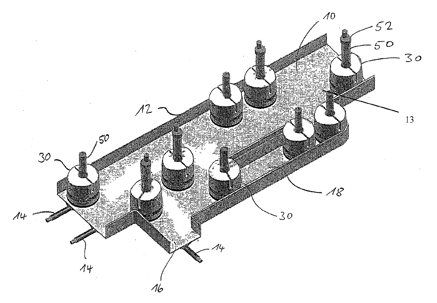
본 발명의 실시예에 따른 실험실 이송 시스템의 이송 경로 배열 구조체의 일부가 도 1a에 도시되어 있다. 특히, 측면 제한부(12)와 평탄한 수평 웨브(13)를 구비한 이송 경로(10)를 볼 수 있다. 이 예에서, 측면 제한부(12)는 이송 경로(10)를 적어도 부분적으로 획정할 수 있는 융기된 벽체의 형태일 수 있다. 이 실시예에서는, 평탄한 수평 웨브(13)의 양 측면에 2개의 융기된 벽체가 있고, 이 벽체들과 웨브(13)가 이송 경로(10)를 획정할 수 있다. 이러한 벽체들은 실험실 제품 이송 요소의 높이와 그 내부에 담긴 샘플에 따라 임의의 적당한 높이를 가질 수 있으며, 통상적인 높이는 약 20㎜ 이하이다. 또한, 웨브(13)는 임의의 적당한 측방향 치수를 가질 수 있다. A portion of the transfer path arrangement structure of a laboratory transfer system according to an embodiment of the present invention is shown in FIG. 1A. In particular, it is possible to see a conveying
본 발명의 실시예에 따른 이송 경로는 다른 영역으로 이어질 수 있는 하나 이상의 분기를 가질 수도 있다. 예를 들면, 도 1의 이송 경로(10)는 별도의 처리 스테이션, 버퍼 스테이션 또는 어떤 다른 스테이션으로 이어지는 측방향 분기(16)를 가질 수 있다. The transport path according to an embodiment of the invention may have one or more branches which can lead to other areas. For example, the
실험실 이송 시스템은 실험실 제품 이송 요소의 안내 또는 이동을 도울 수 있는 임의의 적당한 개수 또는 유형의 기구를 사용할 수 있다. 도 1a에 도시된 바와 같이, 이송 경로(10) 아래에 전도체(14)(또는 유도 도체)가 배치될 수 있다. 전도체(14)는 고주파 교번 전자기장을 발생시키기 위해 고주파 전압을 공급받을 수 있도록, 고주파 전압 소오스(미도시)에 전기적으로 커플링될 수 있다. The laboratory transfer system can use any suitable number or type of instruments that can assist in the guidance or movement of laboratory product transfer elements. As shown in FIG. 1A, a conductor 14 (or inductive conductor) may be disposed below the
샘플 용기(50)(예를 들어, 샘플 튜브)를 이송하는 다수의 실험실 제품 이송 요소(30)가 이송 경로(10)상에서 이동할 수 있다. 실험실 제품 이송 요소(30)에 대해서는, 도 1b 내지 도 1f를 참조하여 이후에 더 설명한다. A number of laboratory
그러나, 도 1a를 참조하면, 실험실 제품 이송 요소(30)는, 예를 들어, 샘플 용기(50)에 수용된 샘플 물질의 광학적 조사를 수행할 수 있도록 하기 위해, 일렬로 규정된 방식으로 처리 트랙(18)으로 이송될 수 있다. However, referring to FIG. 1A, the laboratory
실험실 제품 이송 요소(30)의 특별히 가능한 경로를 따라 전도체 (14)가 제공될 수 있다. 그러나, 실험실 제품 이송 요소(30)는 독립적으로 이동할 수 있기 때문에, 실험실 제품 이송 요소는 전도체(14)에 의해 규정되는 기하학적 구조에 구속되지 않는다. 실험실 제품 이송 요소(30)의 위치에 있는 전도체(14)에 의해 발생된 고주파 전자기장이 해당하는 에너지를 전달하는데 있어서 충분하거나, 실험실 제품 이송 요소(30)가 브리징을 위한 에너지 축적기(44)(이하의 도 1e 참조)를 갖는다면, 실험실 제품 이송 요소의 이동은 전도체(14)에 좌우되지 않는다. A
샘플 용기(50)는 임의의 적당한 형상이나 구성을 가질 수 있다. 일부 실시예들에서, 샘플 용기(50)는 튜브의 형태일 수 있다. 일부 경우들에서, 어떤 샘플 용기에는 커버(52)가 있을 수 있는 반면, 다른 샘플 용기는 커버 없이 개방된 상태로 이송된다. The
도 1b는 본 발명의 실시예에 따른 실험실 제품 이송 요소(30)의 측면 사시도를 도시하고 있다. 실험실 제품 이송 요소(30)는 실험실 제품 이송 요소 하우징(31)을 포함하며, 원통형일 수 있는 하우징(31)의 상단에는 원통형 리세스(33)가 형성될 수 있다. 원통형 리세스(33)에는 커버(52)를 위에 구비하고 있는 샘플 용기(50)가 수용될 수 있다. 하우징(31)의 측면에는 슬릿(31)이 형성될 수 있다. 슬릿(31)은 샘플 용기(50)에 수용된 샘플 물질의 광학적 조사를 허용할 수 있고, 리세스(33)와 동일한 공간을 차지할 수 있다. 다른 실시예에서는, 슬릿(31)이 리세스(33)와 동일한 공간을 차지할 필요가 없으며, 리세스(33)와는 독립적으로 형성될 수 있다. 또한, 다른 실시예에서는, 슬릿(31)이 어떤 다른 형태(예를 들어, 원형)의 통공일 수 있다. 1B shows a side perspective view of a laboratory
이 예에서, 실험실 제품 이송 요소(30)는 라운드형 수평 단면을 갖고 있으며, 이송 경로(10)의 측면 제한부(12) 또는 다른 실험실 제품 이송 요소(30)에 대한 충격 보호 역할을 하는 고무 스트립(34)을 갖고 있다.In this example, the laboratory
도 1c는 도 1b에 도시된 관측 방향(Ⅲ)에서의 실험실 제품 이송 요소(30)의 측단면을 도시하고 있다. 참조 번호 "36"은 고무 바퀴 또는 고무 타이어 바퀴(38)를 구동시키는 전기 모터(또는 구동 모터)를 나타낸다. 2개의 대향하는 바퀴(38)들이 제공되며, 이들은 각각 하나의 전기 모터(36)에 의해 개별적으로 구동된다. 바퀴(38)들은 이동 기구의 예일 수 있다. FIG. 1C shows a side cross section of the laboratory
리세스(33)로부터 상방향으로 샘플 용기(50)를 뽑고자 할 때, 실험실 제품 이송 요소(30)를 하방향으로 유지하기 위해, 예컨대, 다소 좁게 구성된 이송 경로 채널에서, 이송 경로(10)의 측면 제한부(12)에 선택적으로 존재하는 측면 돌출부와 협력할 수 있는 견부(shoulder)(35)가 도 3에 도시되어 있다. 도 1c에 도시된 견부(35)의 용도에 대해서는 "미세 위치 결정 및 리프트 오프" 항목에서 보다 구체적으로 설명할 수 있다. 일부 실시예들에서, 실험실 제품 이송 요소(30)는 앵커형 요소를 가질 수 있다. 앵커형 요소는, 처리 스테이션에 머무는 동안 실험실 제품 이송 요소(30)를 고정하기 위해, 처리 스테이션에 진입할 때 이송 경로의 대응하는 결합편(mating piece)에 맞물린다. When attempting to withdraw the
실험실 제품 이송 요소(30)는 거리 센서(37)를 포함할 수도 있다. 도 3에서, 거리 센서(37)는 서로에 대해 소정 각도를 이루며 고무 스트립(34)의 후방에 배치된 4개의 거리 센서를 포함할 수 있다. 하나의 바람직한 실시예는 모든 센서들이 전방을 향하며, 서로에 대해 10°내지 30°의 각도 관계를 갖는 것이며, 더 바람직한 실시예에서는 20°의 각도 관계를 갖는 것이다. The laboratory
도 1d는 본 발명의 실시예에 따른 실험실 제품 이송 요소(30)의 저면 사시도를 도시하고 있다. 유도 코일(40)은 이송 경로 아래에 있는 전도체(14)로부터 발생될 수 있는 고주파수 장으로부터 전자기 에너지를 수신하는 역할을 한다.1D shows a bottom perspective view of a laboratory
일부 실시예들에서, 실험실 제품 이송 요소(30)가 다수의 바퀴로 구르도록, 구동 고무 바퀴(38) 이외에, 하나 이상의 지지 바퀴가 제공될 수 있다. 그러나, 다른 실시예들에서는, 이동시, 실험실 제품 이송 요소의 일측이 끌릴 수 있도록, 추가적인 바퀴들이 제공되지 않는다. 이는 자신의 축을 중심으로 한 회전이나 곡선 운동을 용이하게 할 수 있다.In some embodiments, one or more support wheels may be provided in addition to the driving
본 발명의 다른 실시예(미도시)에서, 실험실 제품 이송 요소(30)는, 이송 경로 상에서의 끌림을 방지하기 위해, 2개의 구동 바퀴(38)에 대해 오프셋되게 배열되어 모든 방향으로 회전할 수 있는 볼에 의해 지지된다. 이러한 볼은, 컴퓨터 마우스에서와 같이, 위치 검출을 위해 사용될 수도 있다. In another embodiment of the invention (not shown), the laboratory
도 4에 도시된 실시예에서, 참조 번호 "42"는, 레이저 광을 사용하는 컴퓨터 마우스에서와 같이, 실험실 제품 이송 요소(30)의 이동을 결정하는 위치 검출기를 나타낸다. 합체되어 있는 광원에 의해 이동한 표면이 조사되고 광학 센서에 의해 반사광이 수광되며, 반사광으로부터 상응하는 화상 처리 알고리즘을 이용하여 실험실 제품 이송 요소(30)의 이동을 결정한다. 위치 검출기(42)는 CCD 카메라와 해당 소프트웨어, 레이저 마우스에서와 같이, 레이저, 또는 볼 타입 마우스에서와 같이, 볼과 센서를 포함할 수 있다.In the embodiment shown in FIG. 4,
도 1d는 외측면이 보호되지 않은 실험실 제품 이송 요소(30)를 도시하고 있다. 즉, 실험실 제품 이송 요소(30)의 내부 요소가 보이도록 하우징을 제거할 수 있다. 도 5에 도시된 바와 같이, 실험실 제품 이송 요소(30)는 에너지 축적기(44)(예를 들어, 배터리)를 포함할 수 있다. 에너지 축적기(44)는, 도 1에 도시된 전도체(14)의 고주파수 장에 의해 발생되어 도 4에 도시된 바와 같은 유도 코일(40)로 전달되는 에너지가 사용불가능하거나, 너무 제한되어 실험실 제품 이송 요소(30)를 구동시킬 수 없는 경우, 실험실 제품 이송 요소(30)를 구동시키기 위한 에너지를 저장하는 역할을 할 수 있다. 이러한 경우는, 예컨대, 곡선이나 통과 구역에서 그러할 수 있다. FIG. 1D shows a lab
실험실 제품 이송 요소(30)는 제어 유닛(미도시), 예를 들어, 신호 수신기(미도시)로부터의 신호를 수신하는 해당 마이크로프로세서도 포함한다. 신호 수신기는, 제어 신호를 수신하기 위해, 외부 적외선 송신기와 협력하는 적외선 수신기를 포함할 수 있다. 신호 수신기의 다른 예에는 무선 센서가 포함될 수 있다.The laboratory
그러나, 제어 신호는, 해당 제어 신호가 도 1에 도시된 바와 같은 전도체(14)에 공급되는 경우, 도 4에 도시된 바와 같은 유도 코일(40)을 통해 수신될 수도 있다. 이러한 제어 신호는 상응하는 주파수 또는 진폭 변조에 의해 에너지를 제공하는 고주파수 장과 구분될 수 있다. However, the control signal may be received via the
실험실 제품 이송 요소(30)는 정보와 신호를 생성하기 위해 신호 송신기(미도시)를 선택적으로 가질 수도 있다. 이는, 예를 들어, 선택된 개별 실험실 제품 이송 요소(30)의 정밀한 위치 측정을 허용한다. 신호 송신기는 임의의 적당한 주파수 및 임의의 적당한 통신 프로토콜을 사용하여 신호를 송신할 수 있다.Laboratory
실험실 제품 이송 요소(30)는, 처리 스테이션에서의 위치 인식 및 정밀한 위치 결정, 이송 경로 제한부 또는 다른 실험실 제품 이송 요소의 인식 또는 정보 교환을 가능하게 하는 다수의 센서를 가질 수도 있다. 예를 들어, 도 1에 도시된 이송 경로(10)에서 측면 제한부(12) 또는 평탄한 수평 웨브(13) 상에 확실하게 식별할 수 있는 바코드가 제공될 수 있다. 바코드는, 처리 스테이션의 정확한 위치 또는 분기의 정확한 위치를 인식하기 위해, 스캐너로 구성된 하나 이상의 센서를 구비한 실험실 제품 이송 요소(30)에 의해 주사될 수 있다. 도 1f에는 이송 경로(10)의 절단부를 이용하여 일례가 도시되어 있다. 바코드(60)는 분기(16)에 배치되어 있으며, 실험실 제품 이송 요소의 해당 스캐너에 의해 인식 및 식별될 수 있다. 이러한 방식으로, 실험실 제품 이송 요소는 그 위치에 관한 정보를 얻는다. 분기, 처리 트랙, 처리 스테이션 등을 명확하게 식별하는 다수의 이러한 코드가 이송 경로(10) 상에 제공될 수 있다.The laboratory
다른 가능한 이러한 배향 특징부에는 2D 코드, 유색 마크, 반사 필름, 트랜스폰더 시스템 또는 적외선 송신기가 포함된다. 이러한 배향 특징부를 감지할 수 있는 적당한 센서가 실험실 제품 이송 요소에 통합될 수 있다.Other possible such orientation features include 2D codes, colored marks, reflective films, transponder systems or infrared transmitters. Appropriate sensors capable of sensing these orientation features can be integrated into the laboratory product transport element.
실험실 제품 이송 요소(30)는 디스플레이 유닛을 가질 수 있다. 디스플레이 유닛은 실험실 제품 이송 요소가 취하는 경로, 이송하고 있는 실험실 제품 또는 결함의 존재 여부에 대한 정보를 표시할 수 있다. 또한, 신호 송신기와 수신기 또는 디스플레이 유닛과 기록 유닛을 구비한 실험실 제품 이송 요소(30)는 내부 통신 송신기를 통해 직접적으로, 또는 중앙 프로세서를 경유하여, 서로 정보를 교환할 수도 있다.The laboratory
실험실 제품 이송 요소(30)의 내부에는 현재의 오류로부터 보호된 영구 데이터 메모리가 제공될 수 있으며, 영구 데이터 메모리에는 이송되는 실험실 제품에 대한 데이터 또는 이동하는 경로에 대한 데이터가 입력될 수 있다. The laboratory
도 1a 내지 도 1e에 도시된 실험실 제품 이송 요소(30)의 직경은 약 5.5㎝의 높이에서 약 6㎝이다. 바퀴(38)는 실험실 제품 이송 요소(30)로부터 하방향으로 약 1㎜ 돌출되어 있다. 실험실 제품 이송 요소와 그 특징부들은 본 발명의 다른 실시예에서 다른 적당한 치수를 가질 수 있다. The diameter of the laboratory
본 발명의 실시예에 따른 실험실 제품 이송 요소(30)는 가열 기구(미도시)를 가질 수도 있다. 가열 기구는 이송시 샘플을 소정의 온도로 유지하거나, 이송시 이송되는 샘플에 대해 소정의 온도 처리를 실시할 수 있다. 이러한 가열 기구에는, 예컨대, 적절한 배열 구조로 제공된 저항 와이어가 포함될 수 있다. Laboratory
도시된 변형의 본 발명의 실시예에 따른 실험실 이송 시스템은, 예를 들어, 다음과 같이 사용될 수 있다. A laboratory transfer system according to an embodiment of the invention of the variant shown can be used, for example, as follows.
고정식 그리퍼 시스템 또는 다른 용기 이송 시스템을 사용하여, 로딩 스테이션에서 실험실 제품 이송 요소(30) 속에 샘플 용기(50)가 삽입된다. 실험실 제품 이송 요소(30)에는 그 신호 수신기를 통해 목표가 규정된다. 실제 이송 경로(10)의 기하학적 구조가 엔코딩되어 실험실 제품 이송 요소(30)의 메모리에 입력될 수 있다. 실험실 제품 이송 요소(30)의 제어 유닛은, 메모리에 입력된 이송 경로의 기하학적 구조에 대한 데이터를 사용하여 규정된 목표를 확인할 수 있으며, 이 목표까지 이상적인 경로를 독립적으로 확립할 수 있다. 배향 특징부, 예컨대, 바코드(60)의 위치도 메모리에 입력됨으로써, 실험실 제품 이송 요소(30)는 경로를 따라 이동하는 동안 자체 배향할 수 있으며, 필요한 경우, 자신의 현재 위치를 확인하거나 보정할 수 있다.Using a fixed gripper system or other vessel transfer system, the
실험실 제품 이송 요소(30)에 개시 신호가 유도된 후, 실험실 제품 이송 요소(30)는 그 메모리에 확립되어 있는 미리 정해진 경로로 이동한다. 실험실 제품 이송 요소가 방향 전환이 예정된 바코드(60)를 지나면, 원하는 방향으로 방향 전환하기 위해, 스캐너에 의해 기록된 바코드(60)가 신호로서 제어 유닛에 의해 사용된다. After the start signal is induced in the laboratory
예컨대, 실험실 제품 이송 요소(30)가 방향 전환이 예정된 위치에 도달하면, 구동 모터(36) 중 하나가 정지되거나 감속됨으로써, 대응하는 바퀴(38)가 정지하거나 더 저속으로 회전하게 된다. 이러한 방식으로, 실험실 제품 이송 요소(30)가 곡선을 따라 이동하게 된다.For example, when the laboratory
실험실 로봇이 실험실 제품 이송 요소(30)로부터 이송된 샘플 용기(50)를 제거하도록 적절하게 프로그래밍되어 있는 그 목적지(예를 들어, 언로딩 스테이션)에 실험실 제품 이송 요소(30)가 도달하면, 모터(36)는 정지하게 된다. 샘플 용기(50)를 실험실 제품 이송 요소(30)의 리세스(33)로부터 제거할 때, 이송 경로(10)로부터 실험실 제품 이송 요소(30)가 들어 올려지는 것을 방지하기 위해, 이송 경로(10)의 측면(즉, 측방향) 제한부(12)는 실험실 제품 이송 요소(30)의 견부(35)와 협력하는 내향 돌출부를 가질 수 있다. 이 측방향의 내향 돌출부는, 샘플 용기(50)와 실험실 제품 이송 요소(30)의 리세스(33) 사이에 마찰이 있으면, 실험실 제품 이송 요소(30)가 상방향으로 들어 올려지는 것을 방지할 수 있다.When the laboratory
일부 실시예들에서, 실험실 제품 이송 요소(30)는, 샘플에 대한 물리적, 화학적 또는 생물학적 조사를 실시하기 위해, 처리 또는 조사 스테이션으로 샘플 용기(50)를 운반한다. 광학적 조사의 경우, 실험실 제품 이송 요소(30)는 샘플 용기(50)의 측면에 있는 광원에 도달하게 된다. 광원은 슬릿(32)을 통해 샘플 용기(50)의 하부 영역을 조명할 수 있으며, 샘플로부터 방출되는 광을 그 반대측에 배치된 검출기로 검출할 수 있다. 검출기 또는 검출기와 연관된 전자 장치는 샘플의 흡수 또는 형광 특성을 결정할 수 있다. 슬릿(32)이 적절하게 배열된 광원의 반대측에 정확하게 놓일 수 있도록 하기 위해, 실험실 제품 이송 요소가 적절하게 정렬될 수 있다. 이는 고무 바퀴(38)를 반대 방향으로 회전하도록 구동시킴으로써 구현될 수 있다. 이에 따라, 슬릿이 조사를 위해 해당 광원의 반대측에 배열될 때까지, 실험실 제품 이송 요소(30)는 자신의 축을 중심으로 회전하게 된다. 슬릿은 샘플 용기(50)의 충진 높이를 확립하거나, 샘플 용기(50)(예를 들어, 샘플 튜브)의 하부 영역에 선택적으로 제공되어 이송되는 제품에 대한 정보를 포함하고 있는 바코드를 판독하기 위해 사용될 수도 있다. In some embodiments, laboratory
실험실 제품 이송 요소(30)는 샘플 용기(50)를 하나 이상의 처리 스테이션으로 운반할 수 있다. 적당한 처리 스테이션에는, 분취(aliquoting) 스테이션, 샘플 용기(50)를 개폐하기 위한 스테이션, 및 광학적 조사 등을 실시하기 위한 스테이션이 포함된다. 실험실 이송 시스템은, 예컨대, 그리퍼 기구(미도시)를 사용하여 실험실 제품 이송 요소(30)로부터 샘플 용기를 능동적 이송 시스템(예를 들어, 컨베이어 벨트)으로 이동시킴으로써, 실험실 제품 이송 요소(30)와 상호 작용하는 능동적 이송 시스템을 포함할 수 있음을 유의하여야 한다. Laboratory
대안적으로 또는 부가적으로, 실험실 제품 이송 요소가 외부 제어에 의해 제어될 수 있도록, 실험실 제품 이송 요소(30)를 구성할 수도 있다. 이 목적을 위해, 실시간으로 제어 신호를 전기 모터(36)에 의해 사용되는 구동 신호로 변환시키도록 구성된 제어 유닛이 사용될 수 있다. 이러한 방식으로, 자동화된 실험실 처리에 대해 외부로부터 개입할 수 있으며, 실험실 제품 이송 요소(30)를 전환 또는 선별할 수 있다. Alternatively or additionally, the laboratory
예컨대, 무선 프로그램 인터페이스로 실험실 제품 이송 요소(30)의 경로를 완전히 규정할 수도 있다. 실험실 제품 이송 요소(30)의 데이터 메모리에 해당 프로그램이 입력될 수 있다. 프로그램 데이터는 실험실 제품 이송 요소(30)가 그 방향을 전환하기 위해 이송 경로(10)의 측면 제한부(12)에 제공된 어떤 배향 특징부(예를 들면, 바코드(60))를 이용하여야 하는지에 대한 정보를 포함할 수 있다. 이러한 방식으로, 해당 샘플 용기(50)와 실험실 제품 이송 요소(30)의 전체 경로가 확립되어, 실험실 제품 이송 요소(30)에 프로그래밍된다. For example, the wireless program interface may fully define the path of the laboratory
실험실 제품 이송 요소(30)에 결함이 있거나 작동할 수 없게 되면, 그 실험실 제품 이송 요소는 사용자에 의해 이송 경로(10)로부터 제거될 수 있으며, 선택적으로, 새로운 실험실 제품 이송 요소(30)로 대체될 수 있다. 이러한 경우에는, 시스템 중단이 유리하게 단축되며 국소화된다. 또한, 개입이 불가능한 경우에도, 시스템은 차단되지 않는다. 다른 실험실 제품 이송 요소(30)는 작동할 수 없는 실험실 제품 이송 요소(30)의 주위에서 이동할 수 있다. 다른 실험실 제품 이송 요소(30)는, 중앙 프로세서로부터의 해당 제어 신호에 의해, 또는 다른 이러한 요소(30)들과 통신하도록 된 개별 실험실 제품 이송 요소(30)의 프로그래밍을 통해, 자극받을 수 있다. 예를 들면, 실험실 제품 이송 요소(30)는, 결함이 있거나 정지한 실험실 제품 이송 요소(30)의 존재를 검출할 수 있는 대응하는 센서를 가질 수 있으며, 내부 제어 프로세서의 프로그래밍을 통해 그 주위에서 이동할 수 있다. If the laboratory
실험실 제품 이송 요소가 이송 경로 상에 있을 때, 개별 실험실 제품 이송 요소(30)는 광신호 송신기 및 수신기를 통해 서로 통신할 수도 있다. 이러한 통신은 직접적으로 이루어질 수 있으며, 실험실 이송 시스템의 중앙에 제공된 통신 사이트를 통해 실시될 필요가 없다. 이러한 방식으로, 특히 민감한 샘플을 구비한 실험실 제품 이송 요소는 다른 실험실 제품 이송 요소에 대해 자신이 우선권을 갖고 있음을 알릴 수 있다. When the laboratory product transport element is on the transport path, the individual laboratory
실험실 제품 이송 요소(30)를 이동시키기 위해 필요한 에너지는 전도체(14)에 인가되는 고주파 전압에 의해 발생된 전자기장으로부터 유도 코일(40)을 통해 얻을 수 있다. 실험실 제품 이송 요소(30)가 전도체(14)를 정밀하게 추종할 필요는 없다. 바퀴(38)를 구동시키는 구동 모터(36)를 구동시키기 위해 전자기장으로부터 충분한 에너지가 픽업될 수 있도록, 충분한 기간 동안만 상호 작용하면 된다. 이것이 불가능한 경우, 실험실 제품 이송 요소(30)는, 전도체(14)의 전자기장이 충분하지 않은 이송 경로(10)의 개소에 구동 모터(36)에 전력을 공급하는 에너지 축적기(44)를 가질 수 있다. 한편, 실험실 제품 이송 요소(30)가 전도체(14)에 가깝게 이동할 수 있는 직선 구역에서는, 전자기장으로부터의 과다한 에너지가 에너지 축적기(44)를 충전하기 위해 활용될 수 있다. The energy required to move the laboratory
본 발명의 다른 실시예들은 실험실 제품 이송 요소(30)의 하단에 감광 요소를 가질 수 있다. 감광 요소는 이송 경로(10) 상에 배치된 광 밴드에 의해 조명될 수 있다. 감광 요소는 전기적 구동력을 제공하기 위해 사용될 수 있다.Other embodiments of the invention may have a photosensitive element at the bottom of the laboratory
실험실 제품 이송 요소(30)가 에너지 축적기(44)로부터 자신의 구동력을 완전히 얻을 수도 있다. 에너지 축적기(44)는 처리 스테이션에 있을 수 있는 해당 충전 스테이션에서 충전될 수 있다. The laboratory
미리 정해진 이동 프로파일Predetermined movement profile
일부 실시예들은 미리 정해진 이동 프로파일을 기초로 실험실 제품 이송 요소의 이동을 제어하기 위한 방법, 시스템 및/또는 기구를 포함할 수 있다. 이러한 실시예는 실험실 제품 이송 요소가 주요 루트와는 다를 수 있는 이동을 실시하도록 하는 방법을 포함한다. 본 발명의 이러한 실시예는 이송 경로 상의 라인만을 추종할 수 있는 실험실 제품 이송 요소에게는 일상적일 수 있는 불요성(不撓性)을 극복할 수 있다.Some embodiments may include a method, system and / or instrument for controlling the movement of a laboratory product transport element based on a predetermined movement profile. This embodiment includes a method for causing the laboratory product transport element to undergo a movement that may be different from the main route. This embodiment of the present invention overcomes the inefficiencies that may be common for laboratory product transfer elements that can only follow the lines on the transfer path.
미리 정해진 이동 프로파일을 포함하는 일부 실시예들은 도 2a 내지 도 2g에 도시된 바와 같이, 라인 추종 센서와 같은 라인 추종 기술을 활용할 수 있는 실험실 제품 이송 요소(30 및/또는 730)와 같은 실험실 제품 이송 요소를 활용할 수 있다. 실시예들은, 실험실 제품 이송 요소의 메모리에 저장될 수 있으며, 일시적으로 라인을 가이드로 이용하지 않고 및/또는 미세 조정 이동하기 위해 라인을 이용하는, 미리 정해진 동작의 사용을 포함할 수 있다. 실험실 제품 이송 요소의 엔코더는 동작 제어기에 피드백을 제공하기 위해 구동 기구로부터의 신호를 제공할 수 있다. Some embodiments that include a predetermined movement profile may include laboratory product transfer elements such as laboratory
실시예들은 다양한 기능을 제공하는 미리 정해진 이동 프로파일을 포함할 수 있다. 예를 들어, 미리 정해진 이동 프로파일은 실험실 제품 이송 요소가 일시적으로 레인 또는 라인을 떠나 다른 가능한 경로 또는 이동을 추종하도록 허용할 수 있다. 미리 정해진 이동 프로파일은 하나 이상의 속도, 가속도, 거리 및/또는 방향에 기초한 정보를 포함할 수 있다. 어떤 경우들에서는, 미리 정해진 이동 프로파일은 물리적인 레인을 필요로 하지 않고 이동을 정지 및/또는 중단하지 않고 실험실 제품 이송 요소가 평행한 라인들 사이로 전환하도록 허용할 수 있다. 다른 예에서, 미리 정해진 이동 프로파일은, 대기 행렬(queue)의 끝이 아니라 기능적 지점에 가까운 대기 행렬에 진입하는 것과 같은, 큐 점핑 동작을 실시하도록 허용할 수 있다. 이는 STAT(짧은 전환 시간) 샘플에 특히 적용가능하다. 미리 정해진 이동 프로파일은, 많은 다른 선입선출식(FIFO) 대기 행렬에서와 같이, 도착 시간에 의해서만 우선권이 정렬되지 않는 대기 행렬을 구축하기 위해 활용될 수도 있다.Embodiments may include a predetermined movement profile that provides various functions. For example, a predetermined movement profile may allow the laboratory product transport element to temporarily leave a lane or line to follow another possible path or movement. The predetermined movement profile may include information based on one or more speeds, accelerations, distances, and / or directions. In some cases, the predetermined movement profile may allow the laboratory product transfer element to switch between parallel lines without requiring a physical lane and without stopping and / or stopping movement. In another example, the predetermined movement profile may allow to perform a queue jumping operation, such as entering a queue close to a functional point rather than at the end of the queue. This is particularly applicable to STAT (short conversion time) samples. The predetermined movement profile may be utilized to build a queue whose priorities are not aligned solely by arrival time, as in many other first-in, first-out (FIFO) queues.
일부 경우들에서, 미리 정해진 이동 프로파일은 실험실 제품 이송 요소가 고장난 실험실 제품 이송 요소를 지나치거나 느리게 이동하는 실험실 제품 이송 요소를 추월할 수 있도록 활용될 수 있다. 도 2a 내지 도 2g는 이러한 예를 제공하고 있다. 도 2a에서, 제 1 실험실 제품 이송 요소(730)는 라인(1310)을 추종하며 충돌 센서(들)(737)을 활용하고 있다. 제 1 실험실 제품 이송 요소(730)의 전방에 제 2 실험 제품 이송 요소(1330)가 있을 수 있다. 도 2b에서, 제 1 실험실 제품 이송 요소(730)는 충돌 센서(들)(737)로 제 2 실험실 제품 이송 요소(1330)를 검출한다. 충돌 센서는 제 2 실험실 제품 이송 요소(1330)가 이동하지 않고 있는지, 고장났는지 또는 제 1 실험실 제품 이송 요소(730)보다 느린 속도로 가고 있는지를 결정할 수도 있다. 미리 정해진 이동 프로파일을 이용하여, 제 1 실험실 제품 이송 요소(730)는 라인(1310)을 떠날 수 있으며, 미리 정해진 이동 프로파일이 제공하는 지시를 추종할 수 있다. 미리 정해진 이동 프로파일은 반원, 원호 및 다른 형상을 포함할 수 있다.In some cases, a predetermined movement profile may be utilized to allow the laboratory product transfer element to overtake a laboratory product transfer element that passes over or slowly moves over a failed laboratory product transfer element. 2A-2G provide this example. In FIG. 2A, the first laboratory
도 2c 내지 도 2f는 제 1 실험실 제품 이송 요소가 원호 형태의 미리 정해진 이동 프로파일을 사용하여 제 2 실험실 제품 이송 요소(1330)의 주위로 이동하고 있을 때의 제 1 실험실 제품 이송 요소(730)를 도시하고 있다. 도 2g에 도시된 바와 같이, 제 1 실험실 제품 이송 요소(730)가 라인(1310)으로 복귀하면, 제 1 실험실 제품 이송 요소는 충돌 센서(들)(737)와 함께 라인 추종 센서(들)를 이용하여 라인(1310)을 계속 추종할 수 있다. 미리 정해진 이동 프로파일은 레인이나 라인없이 실시될 수도 있으나, 부드러운 이동을 위한 (라인 추종과 미리 정해진 이동을 조합하는) 미세 조정으로서 레인이나 라인을 사용하는 것이 유리할 수 있다. 2C-2F illustrate the first laboratory
일부 실시예들에서, 미리 정해진 이동 프로파일은, 실험실 제품 이송 요소가 그 경로 상에 90°만곡부와 같은 만곡부가 있는지를 결정할 때, 활용될 수 있다. 실험실 제품 이송 요소가 그 경로 상에 만곡부가 존재하는지를 인지할 수 있도록 하기 위해, 근거리 통신 기술 및/또는 RFID 태그가 활용될 수 있다. 도 3은 만곡부를 탐색하기 위해 미리 정해진 이동 프로파일을 활용하는 예를 도시하고 있다. 통상적으로, 실험실 제품 이송 요소(730)가 만곡부(1440)를 통과한다는 것을 인지하지 못하면, 실험실 제품 이송 요소는 직선 세그먼트를 이동하려고 시도할 것이다. 라인 추종 센서(742)는 상이한 반사를 검출할 수 있으며, 실험실 제품 이송 요소(730)는 보정 회전 운동을 실시한다. 이는 경로(1430)로 표시되어 있다. 다음 직선 세그먼트에 도달할 때까지, 이러한 시퀀스가 반복된다. 데이터 교환 속도가 높으면, 더 많은 교정 동작이 이루어질 수 있으며, 더 부드럽게 이동하게 된다. In some embodiments, a predetermined movement profile can be utilized when determining whether a laboratory product transport element is curved, such as a 90 ° curved portion, on its path. Near field communication technology and / or RFID tags may be utilized to enable the laboratory product transport element to recognize whether a bend is present on its path. 3 illustrates an example of utilizing a predetermined movement profile to search for the curved portion. Typically, if the laboratory
일부 실시예들에서, 실험실 제품 이송 요소(730)의 원활한 회전 동작을 생성하기 위하여, 미리 정해진 이동 프로파일이 대신 활용될 수 있다. 생성될 수 있는 경로의 일례가 경로(1435)로서 도시되어 있다. 미리 정해진 이동 프로파일은, 내측 바퀴를 감속하면서 외측 바퀴를 소정의 속도로 가속하라는 지시를 제공함으로써, 실험실 제품 이송 요소(730)에 대해 이러한 이동을 안내할 수 있다. 만곡부 반경과 바퀴의 직경을 알면, 실험실 제품 이송 요소(730)는 모터 엔코더 신호를 이용하여 라인을 추종하지 않고 선회를 실시할 수 있다. 일부 경우들에서, 미끄러짐 효과나 작은 바퀴 직경의 차이를 보상하기 위해, 라인 추종 센서(742)를 이용하여 미리 정해진 운동을 조정할 수 있다. 실험실 제품 이송 요소(730)가 미리 정해진 (저장된) 궤도를 추종하는 경우, 직선 트랙에서와 동일한 데이터 교환 빈도로 이동을 미세 조정하기 위해, 라인 추종 센서(742)가 이용될 수 있다. 직선 레인을 떠나거나 직선 레인에 합류될 때, 이동 속도의 증가는 처리량에 미치는 영향을 최소화하는 데 도움이 될 수 있다.In some embodiments, to create a smooth rotational motion of laboratory
미리 정해진 이동 프로파일이 다른 이유로 사용될 수도 있다. 실험실 제품 이송 요소가 U턴을 실시하기 위해, 미리 정해진 이동 프로파일이 활용될 수 있다. 이는 반대 이동 방향으로의 레인이나 라인 사이의 전환을 포함할 수 있다. 스플라인 형상의 궤도와 같은 정교한 궤도가 미리 정해진 이동 프로파일에 의해 규정될 수 있다. 예를 들어, 미리 정해진 이동 프로파일은 고속 레인이나 섹션으로의 및/또는 고속 레인이나 섹션으로부터의 고속 램프에 활용될 수 있다. 미리 정해진 이동 프로파일은, 실험실 제품 이송 요소가 떠나기 전에 180°이동하여야 하는 작은 한 지점의 막다른 길, 주차장을 진입하고 진출할 때와 같이, 실험실 제품 이송 요소가 이송 시스템의 특정 부분에 진입 또는 진출하기 위한 이동 방향을 제공하기 위해 활용될 수도 있다. The predetermined movement profile may be used for other reasons. In order for the laboratory product transfer element to make a U-turn, a predetermined movement profile can be utilized. This may include switching between lanes or lines in the opposite direction of movement. Sophisticated trajectories, such as spline-shaped trajectories, can be defined by predetermined movement profiles. For example, a predetermined movement profile may be utilized for a fast ramp to and / or from a fast lane or section. Predetermined movement profiles allow the laboratory product transport element to enter or exit a specific part of the transport system, such as when entering and exiting a small dead end road, a parking lot, where the laboratory product transport element must move 180 ° before leaving. It may be utilized to provide a direction of movement for.
미리 정해진 이동 프로파일은 충돌 센서와 함께 활용될 수도 있다. 예를 들어, 충돌 센서는 의외의 장애물에 대응하기 위해 미리 정해진 이동 프로파일에 기초하여 실험실 제품 이송 요소가 이동하는 동안 활성 상태로 유지될 수 있다. 미리 정해진 이동 프로파일은 모터 엔코더만으로 이동을 제어함으로써 발생할 수 있는 부정확성을 보상하기 위해 라인으로 실험실 제품 이송 요소를 다시 안내할 수 있다.The predetermined movement profile may be utilized with the collision sensor. For example, the collision sensor can remain active while the laboratory product transport element is moving based on a predetermined movement profile to counteract unexpected obstacles. The predetermined movement profile can guide the laboratory product transfer element back into the line to compensate for inaccuracies that may arise from controlling movement with only the motor encoder.
자가 진단Self-diagnosis
일부 실시예들은 자가 진단을 위해 구성된 방법, 기구 및/또는 시스템을 포함할 수 있다. 예를 들어, 실험실 제품 이송 요소(30 및/또는 730)와 같은 실험실 제품 이송 요소는 실험실 제품 이송 요소 자체의 다양한 양태를 자가 진단하기 위해 그 센서들 또는 다른 부품들 중 하나 이상을 활용할 수 있다. 일부 경우들에서, 실험실 제품 이송 요소는, 실험실 제품 이송 요소가 작동될 수 있는 이송 경로 배열 구조체와 같은 시스템 또는 샘플 튜브와 같은 실험실 제품의 문제를 결정하기 위해 활용될 수도 있다. Some embodiments may include methods, instruments, and / or systems configured for self diagnostics. For example, a lab product transfer element such as lab
이송 경로 배열 구조체나 샘플 이송 시스템과 같은 시스템은 최대의 신뢰성과 가동 시간을 가질 필요가 있을 수 있다. 고장을 완벽하게 회피할 수 없기 때문에, 사용자 또는 시스템 또는 시스템의 요소에 대해 가능성이 있는 문제점을 알리거나, 문제점의 잠재적인 원인을 제거하는 방법에 대한 조언을 제공하는 데, 자가 진단을 제공하는 일부 실시예가 도움이 될 수 있다. 다른 실시예들은 문제점이나 처리 중단을 초래하기 전에 오류를 검출하는 방법, 기구 및/또는 시스템을 제공한다. 실시예들은 너무 비용이 비싸거나 추가적인 센서를 필요로 하거나 진단 기능을 전혀 제공할 수 없는 일부 해법의 문제점을 극복할 수 있다. 진단 기능이 누락되면, 특히, 접근이 용이하지 않은 영역에서 검사가 등한시될 수 있기 때문에, 시스템 중단으로 흔히 이어질 수 있다.Systems such as transfer path arrangement structures or sample transfer systems may need to have maximum reliability and uptime. Because failures cannot be completely avoided, some self-diagnostics are provided to inform you of possible problems for the user or system or elements of the system, or to provide advice on how to eliminate potential causes of the problems. Examples may be helpful. Other embodiments provide a method, apparatus and / or system for detecting an error prior to causing a problem or interruption of processing. Embodiments may overcome the problem of some solutions that are too expensive, require additional sensors, or cannot provide diagnostic functionality at all. Missing diagnostics can often lead to system outages, especially because tests can be neglected in areas that are not easily accessible.
일부 실시예들은, 실험실 제품 이송 요소의 이동과 라인 추종을 위해 이미 제공되어 있을 수 있는 실험실 제품 이송 요소 또는 시스템의 센서 및/또는 다른 요소만을 활용할 수 있는 방법, 기구 및/또는 시스템을 제공할 수 있다. 예를 들어, 실험실 제품 이송 요소는 소정 영역에서 라인 추종 센서 및/또는 충돌 센서의 기능을 점검하기 위해 초기화 루틴을 수행하여 자가 진단을 실시할 수 있다. 일부 경우들에서, 실험실은 하나 이상의 충전 지점에서 자가 진단 작업을 실시할 수 있다. 실험실 제품 이송 요소는 모든 라인 추종 센서가 백색 및 흑색 영역 위를 지나는 360°회전을 실시할 수 있다. 센서들 중 하나 이상에 결함이 있거나 매우 더러운 경우, 센서가 흑색 영역에서 백색 영역으로 또는 그 역으로 이동할 때 신호 변화를 전혀 나타내지 않을 수 있다. 이러한 정보는 시스템의 서로 다른 통신 기구를 통해 사용자에게 송신될 수 있다. 하나 이상의 센서가 부분적으로 더러워질 수 있는 경우, 센서로부터의 신호가 저감되거나 및/또는 불분명한 신호 변화를 제공할 수 있다. 일부 실시예들에서, 충분한 신호 변화가 남는 경우, 센서의 오염이나 다른 문제점을 보상하기 위해 센서의 보정이 실시될 수 있다. 일부 경우들에서, 사용자가 실험실 제품 이송 요소에 대해 접근하여 실험실 제품 이송 요소를 세척하거나 및/또는, 그렇지 않으면, 수리할 수 있는 사용자 인터페이스 위치로 실험실 제품 이송 요소를 이동할 수 있다. 일부 경우들에서, 실험실 제품 이송 요소 또는 시스템은 더럽거나 결함이 있는 실험실 제품 이송 요소의 위치를 사용자에게 알리는 신호를 송신할 수 있다. 이 신호는 하나 이상의 센서를 세척하거나 수리하여야 한다는 필요성에 대한 정보를 포함할 수 있다.Some embodiments may provide a method, apparatus and / or system that can utilize only sensors and / or other elements of a laboratory product transfer element or system that may already be provided for movement and line following of the laboratory product transfer element. have. For example, the laboratory product transport element may perform a self-diagnosis by performing an initialization routine to check the function of the line following sensor and / or the collision sensor in a given area. In some cases, the laboratory may perform a self test operation at one or more filling points. The lab product transfer element is capable of 360 ° rotation with all line tracking sensors passing over the white and black areas. If one or more of the sensors are defective or very dirty, they may show no signal change when the sensor moves from the black area to the white area or vice versa. Such information may be transmitted to the user through different communication mechanisms of the system. If one or more sensors may be partially dirty, the signals from the sensors may be reduced and / or provide an unclear signal change. In some embodiments, when sufficient signal change remains, calibration of the sensor may be performed to compensate for contamination or other problems of the sensor. In some cases, a user may access the laboratory product transfer element to clean the laboratory product transfer element and / or otherwise move the laboratory product transfer element to a user interface location that may be repaired. In some cases, the laboratory product transfer element or system may transmit a signal informing the user of the location of a dirty or defective laboratory product transfer element. This signal may include information about the need to clean or repair one or more sensors.
일부 실시예들은 이송 경로 배열 구조체와 같은 시스템 내의 레인, 표면 또는 다른 위치들 상의 의외의 간극, 변형 또는 다른 문제점을 인식하기 위해 실험실 제품 이송 요소의 센서를 활용할 수 있다. 중앙 제어기 또는 사용자에게 그 위치를 다시 제공하는 정보가 보고될 수 있다. 여러 실험실 제품 이송 요소가 동일한 이상을 검출하는 경우, 사용자는 보고된 트랙의 섹션을 제어하라는 통지를 받을 수 있다. 단일의 실험실 제품 이송 요소가 이상을 발견하는 경우, 사용자는 특정 실험실 제품 이송 요소를 제어하라는 정보를 얻을 수 있다.Some embodiments may utilize sensors of laboratory product transfer elements to recognize unexpected gaps, deformations or other problems on lanes, surfaces or other locations within a system, such as a transfer path arrangement structure. Information may be reported providing the location back to the central controller or user. If several laboratory product transfer elements detect the same abnormality, the user may be notified to control the section of the reported track. If a single laboratory product transfer element finds an abnormality, the user may be informed to control a particular laboratory product transfer element.
도 4a 내지 도 4c는 실험실 제품 이송 요소 자체 또는 실험실 제품 이송 요소가 이동할 수 있는 표면의 문제점을 인식하기 위해 실험실 제품 이송 요소(730)의 라인 추종 센서(742)가 활용될 수 있는 방법의 예를 제공하고 있다. 도 4a는 다수의 라인 추종 센서(742)를 구비한 실험실 제품 이송 요소(730)의 하단면을 도시하고 있다. 실험실 제품 이송 요소(730)는 이하의 방식들을 포함하여 다양한 방식으로 비정상적인 센서 신호를 인식할 수 있다. 도 4b에서, 라인 추종 센서(742-a, 742-b 및 742-c)는 좌측에서 우측으로 50%-0%-50% 반사되는 정상적인 신호 상태를 검출한다(이 예에서는, 2개의 외측 센서(742-a, 742-b)들이 추가되었을 때 100% 신호를 가질 수 있다). 도 4c는 일시적인 20%-0%-50% 비율이 레인의 좌측 가장자리에서의 변형(1550)을 표시할 수 있는 예를 나타내고 있다. 다른 비율은 실험실 제품 이송 요소의 표면의 다른 문제점을 반영할 수 있다. 예를 들어, 소정 기간 동안 외측 센서(742-a, 742-c)들 간의 비율이 다르면, 이는 라인 추종 센서들 중 하나의 라인 추종 센서 자체의 문제점을 반영할 수 있다. 4A-4C illustrate an example of how the
실험실 제품 이송 요소의 자가 진단은 실험실 제품 이송 요소의 구동 기구 및/또는 이동 기구와 같은 기구의 다른 양태를 활용할 수 있다. 예를 들어, 하나 이상의 구동 기구 엔코더 신호와 라인 추종 센서 신호를 비교하면, 이동 기구의 마모를 발견할 수 있다. 바퀴와 같은 이동 기구의 서로 다른 직경은 알려진 직선 트랙 세그먼트에서 서로 다른 구동 기구 속도를 이용할 수 있다. 차이가 한정할 수 있는 임계값에 도달하는 경우, 사용자는 이동 기구를 교환하라는 통지를 받을 수 있다. 일부 경우들에서, 구동 기구는 이동 기구에서 발견된 마모에 적합한 속도로 변경될 수 있다. Self-diagnosis of the laboratory product transport element may utilize other aspects of the instrument, such as drive and / or movement mechanisms of the laboratory product transport element. For example, comparing one or more drive mechanism encoder signals with a line follow sensor signal may find wear of the moving mechanism. Different diameters of the moving mechanism, such as wheels, may utilize different drive mechanism speeds in known straight track segments. When the difference reaches a threshold that can be defined, the user may be notified to change the mobile device. In some cases, the drive mechanism can be changed at a speed suitable for wear found in the moving mechanism.
마찬가지로, 실험실 제품 이송 요소는 잘 알려진 거리를 따라 이동하며, 구동 기구 엔코더 단계를 카운트할 수 있다. 마모된 이동 기구는 외경을 더 작게함으로써, 거리당 엔코더 단계가 더 많아지게 할 수 있다. 엔코더 단계가 한정할 수 있는 임계값을 초과하는 경우, 사용자는 마모와 이동 기구를 교환할 필요성에 대해 다시 통지받게 될 수 있다. 일부 경우들에서, 구동 기구는 이동 기구의 마모를 보상할 수 있다.Similarly, the laboratory product transport element moves along a well known distance and can count the drive instrument encoder steps. Worn moving mechanisms can make the outer diameter smaller, resulting in more encoder steps per distance. If the encoder step exceeds a definable threshold, the user may be notified again of wear and the need to change the moving mechanism. In some cases, the drive mechanism can compensate for wear of the moving mechanism.
일부 실시예들은 이송 경로 배열 구조체의 표면 또는 실험실 제품 이송 요소의 점착도 측정 또는 다른 기능 측정을 제공하기 위해 구동 기구 전류 또는 전력 사용량을 측정하거나, 그렇지 않으면, 결정할 수 있다. 예를 들어, 넘친 혈청 및/또는 혈액은 실험실 제품 이송 요소를 이동시키기 위해 필요한 구동 기구의 힘을 증대시키는 일종의 "끈적한" 표면을 생성할 수 있다. 구동 기구에 전력을 공급하기 위해 사용되는 전류 또는 전력 소비량의 측정된 변화가 이송 경로 배열 구조체의 하나 이상의 표면의 그러한 잠재적인 문제점를 결정하기 위해 활용될 수 있다. Some embodiments may measure or otherwise determine drive mechanism current or power usage to provide a tack measurement or other functional measurement of the surface of the transfer path arrangement structure or laboratory product transfer element. For example, the overflowed serum and / or blood can create a kind of “sticky” surface that increases the force of the drive mechanism needed to move the laboratory product transport element. The measured change in current or power consumption used to power the drive mechanism can be utilized to determine such potential problem of one or more surfaces of the transfer path arrangement structure.
자가 진단 실시예는 이송 경로 또는 실험실 제품 이송 요소의 문제점에 대한 실시간 피드백을 제공할 수 있다. 그 결과, 오염이나 다른 문제점을 최소한으로 저감할 수 있다.Self-diagnostic embodiments can provide real-time feedback on problems with transfer paths or laboratory product transfer elements. As a result, contamination and other problems can be minimized.
강제 제거(Force removal ( kidnappingkidnapping ) 검출) detection
일부 실시예들은 샘플 용기(50)와 같은 실험실 제품 및/또는 실험실 제품 이송 요소(30 및/또는 730)와 같은 실험실 제품 이송 요소의 강제 제거 또는 의외의 제거를 검출하기 위한 방법, 시스템 및/또는 기구를 포함할 수 있다. 또한, 원심 분리된 튜브의 의외의 제거 또는 진동은 이후의 처리 단계에서 오작동을 유발할 수 있으므로, 강제 제거 검출은 이러한 오작동을 방지할 수 있다. 본 발명의 일부 실시예들은 불법적인 사용자의 개입 및/또는 예측가능한 오용에 의해 유발되는 자동화된 실험실 환경에서의 불일치 또는 처리 문제를 저감할 수 있다. 본 발명의 다른 실시예들은 이송 경로 배열 구조체 상의 실험실 제품 이송 요소의 존재와 아울러, 실험실 제품 이송 요소 내의 실험실 제품의 존재에 대한 지속적인 제어를 제공할 수 있다. Some embodiments provide methods, systems, and / or for detecting forced or unexpected removal of laboratory products, such as
강제 제거 검출을 포함한 일부 실시예들은, 실험실 제품의 존재를 단순히 확인하고 및/또는 전환부, 공간 내의 지점, 로딩 및 언로딩 위치와 같은 시스템 내의 기능적 지점에서 실험실 제품 바코드를 판독할 수 있는 다른 실험실 이송 시스템보다 장점을 제공할 수 있다. 예를 들어, 실험실 제품의 존재가 특정 장소에서 시스템에 의해 확인되는 경우에는, 실험실 제품의 일시적인 제거는 검출되지 않을 수 있다. 모든 전환부와 기능적 지점에서 바코드를 판독하면, 이러한 문제점을 해소할 수 있으나, 비용이 많이 소요될 수 있다. 또한, 일부 실시예들은 유입되는 실험실 제품에 대해 사용자가 액세스할 수 없는 것에 단순히 의존하는 시스템보다 장점을 제공할 수 있다. Some embodiments, including forced removal detection, may be used to simply verify the presence of a laboratory product and / or read other laboratory product barcodes at functional points within the system, such as transitions, points in space, loading and unloading positions. It can offer advantages over transport systems. For example, if the presence of a laboratory product is confirmed by the system at a particular location, temporary removal of the laboratory product may not be detected. Reading the bar code at all transitions and functional points can solve this problem, but can be expensive. In addition, some embodiments may provide an advantage over a system that simply relies on what the user does not have access to incoming laboratory products.
실시예들은 실험실 제품 이송 요소 내의 실험실 제품의 존재 및/또는 실험실 제품 이송 요소와 이송 경로 배열 구조체 사이의 부단한 접촉을 제어하는 센서 시스템 및/또는 기구를 포함할 수 있다. 실험실 제품 이송 요소가 자체 프로세서를 가질 수 있기 때문에, 캐시가 다양한 상황에 관한 정보를 검출하여 및/또는 그 메모리에 저장할 수 있으며, 하나 이상의 오류 신호나 메시지를 통신할 수 있다. 이러한 오류 신호는, 이에 한정되는 것은 아니지만, 근거리 통신 지점과 같은 무선 연결을 포함하여 다양한 여러 채널들을 사용하여 송신될 수 있다. Embodiments may include sensor systems and / or instruments that control the presence of a laboratory product in a laboratory product transfer element and / or uninterrupted contact between the laboratory product transfer element and the transfer path arrangement structure. Since the laboratory product transport element can have its own processor, the cache can detect and / or store information about various situations and communicate one or more error signals or messages. Such error signals may be transmitted using a variety of different channels, including but not limited to wireless connections such as near field communication points.
실험실 제품이 실험실 제품 이송 요소로부터 제거될 수 있는 경우에, 그러한 제거를 검출하기 위해 다양한 방법, 시스템 및 기구가 활용될 수 있다. 일 실시예에서, 광학 센서가 활용될 수 있다. 광학 센서는, 예컨대, 실험실 제품 이송 요소의 실험실 제품 홀더와 커플링될 수 있다. 이러한 광학 센서는 일부 경우들에서 실험실 제품 홀더 내의 광 배리어를 포함할 수 있다. 다른 실시예에서, 기계적 센서가 활용될 수 있다. 예컨대, 홀더 내에 실험실 제품이 있을 때, 기계적 센서가 활성화될 수 있다. 실험실 제품이 제거되면, 기계적 센서가 비활성화될 수 있으며, 이에 따라, 실험실 제품이 홀더로부터 제거되었음을 나타내는 신호를 송신한다. 일부 경우들에서, RFID 태그 또는 다른 표식이 실험실 제품에 커플링될 수 있다. 실험실 제품 이송 요소는 홀더 내의 그 존재를 결정하기 위해 태그 또는 표식을 판독하도록 구성될 수 있으며, 홀더 내의 태그 또는 표식을 더 이상 확인하지 못할 때에는 오류 신호를 제공할 수 있다. Where a laboratory product can be removed from a laboratory product transport element, various methods, systems and instruments can be utilized to detect such removal. In one embodiment, optical sensors may be utilized. The optical sensor can be coupled, for example, with a laboratory product holder of the laboratory product transport element. Such an optical sensor may in some cases include a light barrier in a laboratory product holder. In other embodiments, mechanical sensors may be utilized. For example, when there is a laboratory product in the holder, the mechanical sensor can be activated. Once the laboratory product is removed, the mechanical sensor can be deactivated, thus sending a signal indicating that the laboratory product has been removed from the holder. In some cases, an RFID tag or other marker may be coupled to the laboratory product. The laboratory product transfer element can be configured to read a tag or mark to determine its presence in the holder and can provide an error signal when the tag or mark in the holder can no longer be identified.
일부 실시예들은, 이송 경로 배열 구조체의 표면으로부터와 같이, 실험실 이송 시스템으로부터 실험실 제품 이송 요소의 제거를 결정하도록 구성될 수 있다. 일례로, 실험실 제품 이송 요소 센서의 라인 추종 센서(737)와 같은 라인 추종 센서가 실험실 제품 이송 요소의 제거를 검출하기 위해 활용될 수 있다. 예를 들어, 센서에서 반사가 검출되지 않거나, 및/또는 반사 패턴이 미리 정해진 시간(예를 들어, 1초) 동안 감지되지 않으면, 이는 실험실 제품 이송 요소가 제거되었음을 나타낼 수 있다. 다른 예에서, 구동 기구 측정(예를 들면, 전류 측정)이 활용될 수 있다. 예를 들어, 실제 구동 기구 전류가 실험실 제품 이송 요소를 이동시키기 위해 일반적으로 필요한 것보다 훨씬 낮은 경우, 이는 실험실 제품 이송 요소가 그 순간에 들어 올려졌음을 나타낼 수 있다. 일부 경우들에서, 실험실 제품 이송 요소의 제거를 검출하기 위해, 중앙 제어기가 활용될 수 있다. 예를 들어, 중앙 제어기는 시스템의 노드에서 예정된 실험실 제품 이송 요소의 시퀀스를 확인할 수 있다. 실험실 제품 이송 요소가 특정(설정가능한) 시간 내에 나타나지 않을 경우, 시스템은 실험실 제품 이송 요소가 제거된 것으로 인식할 수 있다. 일부 경우들에서, 실험실 제품 이송 요소가 후에 실험실 제품 이송 시스템에 나타나는 경우에도, 실험실 제품 이송 요소의 상태가 불분명할 수 있다. 이는, 사용자가 이송 경로 배열 구조체 상에 실험실 제품 이송 요소를 다시 올려놓는 경우에, 발생할 수 있다. Some embodiments may be configured to determine the removal of a lab product transfer element from a lab transfer system, such as from the surface of a transfer path arrangement structure. In one example, a line follow sensor, such as
실험실 제품 및/또는 실험실 제품 이송 요소가 제거되었다고 시스템이 나타내는 경우, 실험실 제품 또는 실험실 제품 이송 요소의 상태가 불분명하다고 할 수 있다. 그 결과, 실험실 제품에 대해 계획된 처리가 중단될 수 있다. 일부 경우들에서, 실험실 제품 이송 요소 및/또는 실험실 제품은 오류 작업대(error workplace), 특수 검사 지점 또는 사용자가 그 실험실 제품을 가지고 계속하여야 하는지를 결정할 필요가 있는 다른 위치로 전송될 수 있다. 일례로, 이중 바코드가 없는 경우, 실험실 제품 이송 요소는 실험실 바코드를 검증할 수 있는 장소로 이동될 수 있으며, 이에 따라, 일시적으로 제거된 실험실 제품이 보다 즉시 처리될 수 있다. If the system indicates that the laboratory product and / or laboratory product transfer element has been removed, it may be said that the state of the laboratory product or laboratory product transfer element is unclear. As a result, the planned treatment for the laboratory product can be stopped. In some cases, the laboratory product transfer element and / or laboratory product may be sent to an error workplace, special inspection point, or other location where the user needs to determine whether to continue with the laboratory product. In one example, in the absence of a double barcode, the laboratory product transfer element can be moved to a location where the laboratory barcode can be verified, so that the temporarily removed laboratory product can be processed more immediately.
일부 실시예들에서, 실험실 제품 이송 요소는 그 실험실 제품의 제거 또는 그러한 제거가 발생한 위치를 기억할 수 있다. 실험실 제품 이송 요소는 중앙 제어기로 그 정보를 송신할 수 있으며, 일부 경우들에서, 이는 근거리 통신 지점에서 발생할 수 있다. 이는, 수초 후에 사용자에게 통지될 수 있으며 가능한 오염 물질의 광범위한 확산을 방지할 수 있는, 사용자 상호 작용 없는 실험실 제품의 소실(예를 들어, 실험실 제품의 붕괴)을 허용할 수 있다. In some embodiments, the laboratory product transfer element may remember the removal of the laboratory product or the location where such removal occurred. The laboratory product transport element may transmit its information to a central controller, which in some cases may occur at a near field communication point. This may allow for the loss of the laboratory product (eg, collapse of the laboratory product) without user interaction, which may be notified to the user after a few seconds and may prevent the widespread spread of possible contaminants.
제거된 실험실 제품 및/또는 실험실 제품 이송 요소의 검출을 허용할 수 있는 실시예들은 성공적인 처리를 확인하기 위해서도 활용될 수 있다. 예를 들어, 일부 경우들에서, 빈 상태에서 로딩된 상태로의 변화를 통해, 성공적인 실험실 제품의 로딩을 확인하기 위해, 실험실 제품의 제거를 검출하는 방법 및 기구가 활용될 수도 있다. 마찬가지로, 로딩된 상태로부터 빈 상태로의 변화에 의해, 실험실 제품의 성공적인 제거가 나타날 수 있다. 일부 경우들에서, 실시예들은 실험실 제품의 캡이 성공적으로 제거되었는지를 확인할 수도 있다. 이는 캡만이 아닌 실험실 제품 전체가 제거된 경우에 샘플의 소실을 피하는 데 도움이 될 수 있다. 일부 실시예들은 실험실 제품 이송 요소가 시스템에 다시 삽입될 수 있는 개소에 대한 정보를 결정할 수 있다. 실험실 제품 이송 요소가 시스템으로부터 제거되는 일부 경우들에서, 실험실 제품 이송 요소가 시스템의 임의의 개소에 반환될 수 있다. 실험실 제품 이송 요소는 자신의 "불분명한" 상태를 알 수 있기 때문에, 실험실 제품 이송 요소는 시스템 내의 적절한 개소로 라우팅될 수 있다. 일부 경우들에서, 이러한 라우팅은, 실험실 제품 이송 요소가 근거리 통신 지점과 같은 시스템 내의 통신 기구와 접촉할 때, 개시될 수 있다. Embodiments that may allow detection of removed laboratory products and / or laboratory product transfer elements may also be utilized to confirm successful processing. For example, in some cases, methods and apparatus for detecting removal of a laboratory product may be utilized to confirm successful loading of the laboratory product through a change from empty to loaded state. Likewise, by changing from loaded state to empty state, successful removal of the laboratory product can be indicated. In some cases, embodiments may confirm that the cap of the laboratory product was successfully removed. This may help to avoid sample loss when the entire lab product is removed, not just the cap. Some embodiments may determine information about where a laboratory product transport element may be inserted back into the system. In some cases where the laboratory product transfer element is removed from the system, the laboratory product transfer element may be returned to any point in the system. Since the lab product transfer element can know its "unclear" state, the lab product transfer element can be routed to the appropriate location in the system. In some cases, such routing may be initiated when the laboratory product transport element is in contact with a communication instrument in the system, such as a near field communication point.
실험실 제품 및/또는 실험실 제품 이송 요소의 제거 및/또는 교체를 검출하기 위한 실시예들은 이송 경로 배열 구조체와 같은 시스템과 함께 기존의 실험실 이송 시스템에서 사용될 수도 있다. 일부 경우들에서, 실험실 제품 및/또는 실험실 제품 이송 요소는, 실험실 제품 이송 요소 내부의 제어기가 상태 변화를 기록할 수 있는 RFID 태그와 같은 어떤 표식을 가질 수 있다. 실험실 제품의 일시적인 제거에 대한 정보는 다음 RFID 지점에서 검출될 수 있다. 일부 실시예들에서, 기록용 전력은 실험실 제품 이송 요소 내의 배터리와 같은 에너지 축적기에 의해 제공되거나, 제어기가 RFID에 상태 변화를 기록할 수 있도록 충분한 전력을 생산하기 위해 실험실 제품 홀더의 요소의 운동을 이용할 수 있는 피에조 요소에 의해 공급될 수 있다. 일부 실시예들은 외부에서 생성되거나 배터리에 의해 생성된 전원과는 독립적으로 정보를 저장하는 전원과 실험실 제품 이송 요소의 센서들 중 하나 이상의 센서를 조합할 수 있다. Embodiments for detecting removal and / or replacement of laboratory products and / or laboratory product transfer elements may be used in existing laboratory transfer systems in conjunction with systems such as transfer path arrangement structures. In some cases, the laboratory product and / or laboratory product transfer element may have some marker, such as an RFID tag, by which a controller inside the laboratory product transfer element can record a change in state. Information about the temporary removal of laboratory products can be detected at the next RFID point. In some embodiments, the recording power may be provided by an energy accumulator, such as a battery in the laboratory product transfer element, or the movement of the element of the laboratory product holder to produce sufficient power for the controller to record the state change in the RFID. It can be supplied by the piezo elements available. Some embodiments may combine one or more of the sensors of a laboratory product transport element with a power source that stores information independently of an externally generated or battery generated power source.
미세 위치 결정 및 리프트 Fine positioning and lift 오프off 방지 Prevention
일부 실시예들은 실험실 제품 이송 요소(30 및/또는 730)와 같은 실험실 제품 이송 요소의 미세 위치 결정 및/또는 리프트 오프 방지를 위한 방법, 시스템 및/또는 기구를 제공한다. 어떤 상황들에서는, 이송 경로 배열 구조체와 같은 실험실 이송 시스템 내의 실험실 제품 이송 요소가 시스템 내부의 하나 이상의 위치에 매우 정밀하게 또는 적어도 고도의 재현가능한 정확도로 배치되어야 할 필요가 있을 수 있다. 다수의 실시예들은 미세 위치 결정을 구현하기 위해 필요한 정확도로 위치 결정을 실시한다. 또한, 실험실 제품 이송 요소의 리프트 오프의 방지가 필요할 수 있는 시스템 내의 위치 또는 상황이 있다. 예를 들어, 실험실 제품의 접히거나 손상된 라벨이 실험실 제품 이송 요소의 샘플 홀더 내부에 너무 견고하게 점착되어, 실험실 제품을 제거할 때, 실험실 제품 이송 요소가 시스템의 표면에 머무르도록 하기에는 실험실 제품 이송 요소의 중량이 충분하지 않을 수 있다. Some embodiments provide methods, systems, and / or instruments for fine positioning and / or lift off prevention of laboratory product transfer elements, such as laboratory
미세 위치 결정과 리프트 오프 방지 방법과 기술은 개별적으로 또는 조합하여 활용될 수 있다. 일부 경우들에서, 실험실 제품 이송 요소는 미세 위치 결정 및/또는 리프트 오프 방지를 용이하게 하기 위해 실험실 제품 이송 요소의 하나 이상의 측면에 돌출부를 포함할 수 있다. 돌출부와 커플링될 수 있는 슬롯이나 다른 요소들이 이송 경로 배열 구조체와 같은 실험실 이송 시스템의 다양한 양태에 제공될 수 있다. 예를 들면, 실험실 제품 이송 요소는, 특정 지점에 도달한 후 회전을 실시할 때까지, 표면을 따라 이동할 수 있다. 돌출부가 이송 경로 배열 구조체의 슬롯과 접촉하게 되면, 실험실 제품 이송 요소는 소정의 위치에 자신을 구속할 수 있다. 돌출부가 적당한 방식으로 성형되었다고 가정하면, X 및 Y 위치 모두에 한 번에 도달할 수 있다. 무엇보다, 그 지점에서 실험실 제품이 제거되는 경우, 이송 경로 배열 구조체의 슬롯의 상부가 실험실 제품 이송 요소의 리프트 오프를 방지할 수 있다.Fine positioning and lift off prevention methods and techniques can be utilized individually or in combination. In some cases, the laboratory product transfer element may include protrusions on one or more sides of the laboratory product transfer element to facilitate fine positioning and / or lift off prevention. Slots or other elements that may be coupled with the protrusions may be provided in various aspects of a laboratory transfer system, such as a transfer path arrangement structure. For example, the laboratory product transport element can move along the surface until it reaches a certain point and rotates. When the protrusions come into contact with the slots of the transfer path arrangement structure, the laboratory product transfer element can restrain itself in a predetermined position. Assuming that the protrusions are shaped in a suitable manner, both X and Y positions can be reached at one time. First of all, when the laboratory product is removed at that point, the upper portion of the slot of the transfer path arrangement structure can prevent the lift off of the laboratory product transfer element.
일부 경우들에서, 라인을 추종하면서 교정 동작을 하기 위한 약간의 공간을 실험실 제품 이송 요소에 제공하기 위해, 실험실 제품 이송 요소의 측면과 이송 경로 배열 구조체의 일부 사이에 간극이 있을 수 있다. 불필요한 마찰과 마모를 발생시킬 수 있기 때문에, 물리적인 접촉은 필요하지 않거나 바람직하지 않을 수 있다. 일부 실시예들에서는, 기능적 지점 전방에서, 실험실 제품 이송 요소는 여전히 통과할 수 있도록 하여, 이송 경로 배열 구조체의 일부가 좁아질 수 있다. 라인 추종이 충분히 정밀하다면, 실험실 제품 이송 요소와 이송 경로 배열 구조체의 측부 사이에 접촉이 이루어지지 않을 수 있다. In some cases, there may be a gap between the side of the laboratory product transfer element and a portion of the transfer path arrangement structure to provide the laboratory product transfer element with some space for the calibration operation while following the line. Since physical friction may cause unnecessary friction and wear, physical contact may not be necessary or desirable. In some embodiments, in front of the functional point, the laboratory product transfer element can still pass through, so that a portion of the transfer path arrangement structure can be narrowed. If the line following is sufficiently accurate, no contact may be made between the laboratory product transfer element and the side of the transfer path arrangement structure.
이송 방향에서의 실제 위치 결정은 다음의 방법들 중 하나 또는 조합에 의해 실현될 수 있다. 일부 실시예들에서는, 리프트 오프 방지가 추가적으로, 그러나 기능적 지점과 같은 다양한 위치에서, 실시될 수 있다. 그러나, 미세 위치 결정이 활용될 수 있는 실험실 제품 이송 요소에 대해서는 리프트 오프 방지가 필요하지 않을 수 있다. Actual positioning in the conveying direction can be realized by one or a combination of the following methods. In some embodiments, lift off prevention may additionally be implemented, but at various locations, such as functional points. However, lift off prevention may not be necessary for laboratory product transfer elements where fine positioning may be utilized.
미세 위치 결정은 일부 실시예들에서 실험실 제품 이송 요소의 라인 추종 센서를 이용하여 구현될 수 있다. 예를 들면, 중앙 라인(1611)의 윈도우(1670)와 같은 위치 표식이 도 5a 및 도 5b에 도시된 바와 같이 제공될 수 있다. 실험실 제품 이송 요소(730)는 윈도우(1670)의 테두리를 검출할 수 있는 센서(742-a, 742-b)들과 같이 일렬로 배열된 다수의 라인 추종 센서(742)를 포함할 수 있다. 양 센서(742-a, 742-b)들이 동일한 신호를 전달할 때, 미세 위치 결정에 도달할 수 있다. 이러한 라인 추종 센서(742)와 윈도우(1670)의 사용은 시간이 경과함에 따라 감소할 수 있는 절대 반사율과는 독립적인 시스템을 제공할 수 있다. 일부 경우들에서, 정확한 회전 정렬을 위해 라인의 가장자리에 있는 센서(742-c, 742-d)와 같은 2개의 센서를 사용하는 것이 바람직할 수 있다. 일부 실시예들에서, 센서(742-e 및/또는 742-f)와 같은 외측 센서들을 위한 마커를 제공하는 이송 경로 배열 구조체의 라인 외부에 마커가 배치될 수 있다. 하나 이상의 외측 센서가 이송 경로 배열 구조체의 표면의 마커를 검출했을 때, 실험실 제품 이송 요소가 정지할 수 있다. 다른 경우에서는, 라인 센서가 미세 위치 결정을 위한 위치를 검출하고 결정하도록 하는 기능적 지점을 표시하는 "1-0-1-0-1"과 같은 독특한 마커 패턴이 이송 경로 배열 구조체의 표면에 제공될 수 있다. Fine positioning can be implemented in some embodiments using a line follow sensor of a laboratory product transport element. For example, a location marker such as
근거리 통신 기구가 일부 실시예들의 미세 위치 결정에 활용될 수 있다. 실험실 제품 이송 요소(730)와 같은 실험실 제품 이송 요소는 필드 신호 강도를 측정하거나 근거리 통신 기구의 통신 시점을 검출하여, 실험 제품 이송 요소의 위치를 결정할 수 있다. 일부 경우들에서, 근거리 통신 기구와의 통신을 통해 제공되는 위치 결정 정보는 대략적인 위치 결정을 제공할 수 있다. 이러한 위치 결정은 일부 경우들에서 라인 추종 센서(742)와 같은 라인 추종 센서와 결합하여 조정됨으로써, 미세 위치 결정을 제공할 수 있다. 예를 들면, 근거리 통신은 실험실 제품 이송 요소를 감속한 다음, 라인 추종 센서의 데이터 교환 빈도를 증대시키기 시작하는 것과 같은 처리를 개시하여 미세 위치 결정이 구현되도록 할 수 있다. A near field communication mechanism may be utilized for fine positioning of some embodiments. A lab product transfer element, such as lab
충돌 센서(737)와 같은 실험실 제품 이송 요소의 하나 이상의 충돌 센서가 일부 경우들에서 미세 위치 결정을 위해 활용될 수도 있다. 충돌 센서는 소정의 장애물을 검출하여 미세 위치 결정을 수행하기 위해 활용될 수 있다. 예를 들어, 실험실 제품 이송 요소가 막다른 길의 슬롯으로 이동하여, 시스템의 벽체 또는 다른 배리어 구조에 대해 소정의 거리를 두고 정지할 수 있다. 처리가 완료되면, 실험실 제품 이송 요소는 일부 경우들에서 다음 실험실 제품 이송 요소가 이용할 수 있는 위치를 만들기 위해 후진할 수 있다.One or more collision sensors of a laboratory product transport element, such as
일부 실시예들에서, 실험실 제품 이송 요소의 LED 수신기는 이송 경로 배열 구조체의 LED로부터 위치 결정을 수신할 수 있다. 예를 들어, LED(예컨대, 가시광 또는 적외선(IR))는 이송 경로 배열 구조체의 하단 또는 경계에 있는 기능적 지점에 배치될 수 있다. 실험실 제품 이송 요소는 어레이의 광 강도를 측정할 수 있는 감광 어레이를 포함할 수 있다. 어레이의 중앙 필드(들)에 최대의 신호가 나타나면, 실험실 제품 이송 요소가 정확한 위치에 있을 수 있다. 일부 경우들에서는, 실험실 제품 이송 요소가 최대값을 찾기 위해 전후로 이동하는 능력을 가질 수 있다. 바람직한 실시예에서, 실험실 제품 이송 요소는 미세 위치 결정을 구현하기 위해 필요한 시간의 양을 줄이기 위해 교정 동작을 최소로 저감하도록 구성될 수 있다. In some embodiments, the LED receiver of the laboratory product transfer element can receive a position determination from the LEDs of the transfer path arrangement structure. For example, an LED (eg, visible or infrared (IR)) may be placed at a functional point at the bottom or boundary of the transfer path arrangement structure. The laboratory product transport element may comprise a photosensitive array capable of measuring the light intensity of the array. If the maximum signal appears in the center field (s) of the array, the laboratory product transfer element may be in the correct position. In some cases, the laboratory product transport element may have the ability to move back and forth to find the maximum value. In a preferred embodiment, the laboratory product transport element may be configured to minimize the calibration operation to reduce the amount of time needed to implement fine positioning.
일부 실시예들에서, 실험실 제품 이송 요소의 하나 이상의 측면에 있는 하나 이상의 광학 센서를 사용하여 미세 위치 결정을 구현할 수도 있다. 실험실 제품 이송 요소의 측면에 배치된 광학 센서는, 실험실 이송 시스템의 표면으로부터 독립될 수 있으므로 위치 마커의 조정이 용이하기 때문에, 약간의 장점을 제공할 수 있다. 일 실시예에서, 센서는 트랙의 측면에 있는 마커에서 간극을 검출하도록 구성된 2개 이상의 반사 센서를 포함한다. 도 6a 내지 도 6c는 그러한 일례를 도시하고 있다. 도 6a는 하나 이상의 미세 위치 결정 마커(1720)를 포함한 미세 위치 결정 구조(1710)를 포함하는 이송 경로 배열 구조체(1700)를 도시하고 있다. 이 예에서, 미세 위치 결정 마커(1720)는 실험실 제품 이송 요소(730)의 반사 센서(1725)에 의해 검출될 수 있는 간극을 포함하는 패턴을 활용한다. 도 6b 및 도 6c는 위치 결정 마커(1720)를 검출했을 때의 위치에 있는 실험실 제품 이송 요소(730)를 도시하고 있다. 일부 경우들에서, 간극은 흡수면들에 의해 분할된 고도의 반사면일 수 있다. 미세 위치 결정 구조(1710)는 일부 경우들에서 이동가능할 수 있다. 다른 실시예에서는, 트랙의 측면으로부터 캔틸레버 조각에 의해 중단되는 포크 광 배리어가 제공될 수 있다. 다른 실시예에서는, 이송 경로 배열 구조체의 측면 브라켓의 자석과 실험실 제품 요소의 홀 효과 센서가 미세 위치 결정을 제공할 수 있다. 또한, 이송 경로 배열 구조체의 측면 브라켓의 능동 LED와 실험실 제품 이송 요소의 IR 검출기가 일부 실시예들에서 미세 위치 결정을 위해 활용될 수 있다. 도 6d는 미세 위치 결정 구조(1710)를 구비한 이송 경로 배열 구조체(1700)와 실험실 제품 이송 요소(730)의 측면도를 도시하고 있다. 위치 결정 구조의 상단은 리프트 오프를 방지하는 역할을 한다.In some embodiments, one or more optical sensors on one or more sides of the laboratory product transport element may be used to implement fine positioning. The optical sensor disposed on the side of the laboratory product transport element can provide some advantages because it can be independent of the surface of the laboratory transport system and thus the adjustment of the position marker is easy. In one embodiment, the sensor includes two or more reflective sensors configured to detect gaps in markers on the side of the track. 6A-6C illustrate one such example. FIG. 6A shows a transport
일부 실시예들은 리프트 오프도 방지하도록 구성된 실험실 제품 이송 요소를 포함할 수 있다. 도 7a 내지 도 7d는, 예를 들어, 미세 위치 결정과 리프트 오프 방지를 모두 제공할 수 있는 실시예를 제공한다. 도 7a는 다수의 측면 돌출부(1810)를 포함한 실험실 제품 이송 요소(730)를 도시하고 있다. 이 실시예에 있어서, 측면 돌출부(1810)는 측면 레일일 수 있다. 다른 실시예들은 측면 포스트와 같은 다른 구성의 측면 돌출부(1810)를 포함할 수 있다. 측면 돌출부(1810)는 실험실 제품 이송 요소(730)의 하우징(1805)과 커플링될 수 있다. 일부 경우들에서, 측면 돌출부(1810)는 하우징(1805)에 고정되거나, 그 일부를 구성할 수 있다. 일부 실시예들에서, 측면 돌출부(1810)는 하우징(1805)에 대해 연결 및 분리되도록 구성될 수 있다. Some embodiments may include a laboratory product transport element configured to prevent lift off as well. 7A-7D provide an embodiment that can provide both fine positioning and lift off prevention, for example. FIG. 7A shows a laboratory
도 7b는 이송 경로 배열 구조체 상의 라인(1811)을 추종하는 실험실 제품 이송 요소(730)의 예를 도시하고 있다. 도 7b는 이송 경로 배열 구조체의 일부인 레일 요소(1820)를 도시하고 있다. 일부 실시예들에서, 레일 요소(1820)는 이송 경로 배열 구조체에 대해 부착가능하도록 및/또는 제거가능하도록 이송 경로 배열 구조체 상에 장착될 수 있다. 레일 요소(1820)는 측면 돌출부(1810)를 수용함으로써 측면 돌출부(1810)와 협력하여 작동하도록 구성될 수 있는 하나 이상의 슬롯(1830)을 포함한다. 일부 실시예들은 측면 돌출부(1810)와 커플링되도록 구성될 수 있는 레일 요소(1820)와 커플링된 다른 요소를 포함할 수 있다. 도 7c는 실험실 제품 이송 요소(730)가 자신이 미세 위치 결정 위치에 있다는 것을 결정할 수 있는 위치를 도시하고 있다. 이 지점에서, 실험실 제품 이송 요소(730)는, 측면 돌출부(1810)가 레일 요소(1820)의 슬롯(1830)과 커플링될 수 있도록, 회전(1840)을 개시할 수 있다. 도 18d는 측면 돌출부(1810)가 레일 요소(1820)의 부분(1850)과 만나는 위치를 도시하고 있으며, 상기 부분은 실험실 제품 이송 요소(730)가 더 이상 회전하지 못하도록 효과적으로 정지시키는 슬롯(1830)의 일부를 규정한다. 이 위치는 실험실 제품 이송 요소(730)에 대해 미리 정해진 위치일 수 있다. 또한, 슬롯(1830)과 커플링된 측면 돌출부(1810)는 이제 실험실 제품 이송 요소(730)에 대해 리프트 오프 방지를 제공할 수 있다.7B shows an example of a laboratory
도 8a 내지 도 8d는 미세 위치 결정과 리프트 오프 방지를 모두 제공할 수 있는 다른 실시예를 제공한다. 도 8a는 다수의 그루브 구조(1912)를 포함한 실험실 제품 이송 요소(730)를 도시하고 있다. 일부 실시예들에 있어서, 그루브 구조(1912)는 후크 구조일 수 있다. 다른 실시예들은 다른 구성의 그루브 또는 후크 구조(1912)를 포함할 수 있다. 그루브 구조(1912)는 실험실 제품 이송 요소(730)의 하우징(1905)의 일부일 수 있다. 8A-8D provide another embodiment that can provide both fine positioning and lift off prevention. 8A shows a laboratory
도 8b는 이송 경로 배열 구조체 상의 라인(1911)을 추종하는 실험실 제품 이송 요소(730)의 예를 도시하고 있다. 도 8b는 이송 경로 배열 구조체의 일부인 레일 요소(1920)를 도시하고 있다. 일부 실시예들에서, 레일 요소(1920)는 이송 경로 배열 구조체에 대해 부착가능하도록 및/또는 제거가능하도록 이송 경로 배열 구조체 상에 장착될 수 있다. 레일 요소(1920)는 실험실 제품 이송 요소(730)의 그루브 구조(1912)와 커플링될 수 있는 돌출 요소(1921)를 포함한다. 돌출 요소(1921)는 일부 실시예들에서 레일 요소(1920)에 대해 부착가능하도록 및/또는 제거가능하도록 구성될 수도 있다. 8B shows an example of a lab
도 8c는 실험실 제품 이송 요소(730)가 자신이 미세 위치 결정 위치에 있다는 것을 결정할 수 있는 위치를 도시하고 있다. 이 지점에서, 실험실 제품 이송 요소(730)는, 그루브 구조(1912)가 돌출 요소(1921)와 커플링될 수 있도록, 회전을 개시할 수 있다. 8C illustrates a location where laboratory
도 8d는 실험실 제품 이송 요소(730)가 더 이상 회전하지 못하도록 효과적으로 정지시키는, 그루브 구조(1912)가 레일 요소(1920)의 돌출 요소(1921)와 만나는 위치를 도시하고 있다. 이 위치는 실험실 제품 이송 요소(730)에 대해 미리 정해진 위치일 수 있다. 또한, 돌출 요소(1921)와 커플링된 그루브 구조(1912)는 실험실 제품 이송 요소(730)에 대해 리프트 오프 방지를 제공할 수 있다.FIG. 8D shows the location where the
일부 실시예들에서, 실험실 제품 이송 요소의 실제 위치를 결정하여 이 정보를 중앙 제어기에 송신하기 위해, 라인 추종 센서의 신호가 이용될 수도 있다. 그리고, 제어 유닛은 이 값을 사용하여 로봇이나 다른 액세스 기구를 새로운 위치에 재배치할 수 있다. 이러한 경우, 실험실 제품 이송 요소는 위치 결정 운동을 전혀 실시할 필요가 없게 된다. 일부 실시예들은 실험실 제품 이송 요소를 정확한 위치에 압박하여 처리시 견고하게 유지하는 능동 구동 클램프와 같은 능동 트랙 부품들을 이용할 수 있다. In some embodiments, the signal of the line following sensor may be used to determine the actual position of the laboratory product transport element and send this information to the central controller. The control unit can then use this value to reposition the robot or other access mechanism to a new location. In this case, the laboratory product transport element does not need to perform any positioning motion at all. Some embodiments may utilize active track components, such as active drive clamps, which force the laboratory product transport element into the correct position and remain rigid during processing.
교차부에서의 처리량 제어Throughput Control at the Intersection
일부 실시예들은 교차부에서의 처리량 제어를 관리하는 방법, 시스템 및/또는 기구를 제공한다. 실시예들은 여러 가지 실험실 제품에 대해 최소의 응력으로 최대의 처리량 제어를 달성하는 실험실 이송 시스템을 제공할 수 있다. 본 발명의 실시예들은 실험실 제품 이송 요소들 간에 잠재적인 충돌이 있을 수 있는 교차부에서의 트래픽 처리를 제공할 수 있다. 본 발명의 실시예들은 근거리 통신 기구와 충돌 센서의 조합을 이용하여 최대의 처리량을 얻기 위한 기술을 제공할 수 있다.Some embodiments provide a method, system and / or apparatus for managing throughput control at an intersection. Embodiments can provide a laboratory transfer system that achieves maximum throughput control with minimal stress on various laboratory products. Embodiments of the present invention may provide traffic handling at intersections where there may be potential collisions between laboratory product transfer elements. Embodiments of the present invention may provide a technique for obtaining maximum throughput using a combination of a near field communication mechanism and a collision sensor.
교차부는 흔히 실험실 이송 시스템에서 처리량의 병목이다. 예를 들어, 실험실 제품 이송 요소들은 교차부에서 불필요하게 또는 필요한 것보다 적어도 더 오래 정지할 수 있으며, 이는, 실험실 제품 이송 요소가 대기 행렬의 끝에 있는 다른 이송 요소와 만날 때, 실험실 제품의 대기 행렬과 바람직하지 않은 운동으로 이어질 수 있다. 실시예들은 교차부에 다수의 실험실 제품 이송 요소를 허용할 수 있다.Intersections are often a bottleneck of throughput in laboratory transfer systems. For example, the laboratory product transport elements may stop at least longer than unnecessarily or necessary at the intersection, which is when the laboratory product transport element encounters another transport element at the end of the queue. And undesirable exercise. Embodiments may allow multiple laboratory product transfer elements at the intersection.
실시예들은 근거리 통신과 충돌 제어 센서의 조합을 활용할 수 있는 방법, 시스템 및 기구를 제공한다. 일부 경우들에서, 충돌 센서는 아날로그 센서일 수 있다. 특정 시점 및/또는 특정 지점에서, 실험실 제품 이송 요소는 근거리 통신 제어에서 충돌 센서 제어로, 그리고 그 역으로 전환될 수 있다. 실시예들은 2개의 실험실 제품 이송 요소들이 다른 하나가 사라지는 것을 각각 대기하는 교착 상황을 2개의 충돌 센서들이 회피할 수 있는 방식으로 제어될 수 있다. 또한, 떠나거나 합류되는 실험실 제품 이송 요소들이 차례대로 더 높은 속도를 사용하는 경우, 처리량에 미치는 영향이 더 최소화될 수 있다.Embodiments provide methods, systems, and apparatus that can utilize a combination of near field communication and collision control sensors. In some cases, the collision sensor can be an analog sensor. At a particular point in time and / or at a particular point, the laboratory product transport element can be switched from near field communication control to collision sensor control and vice versa. Embodiments can be controlled in such a way that two collision sensors can avoid a deadlock situation where two laboratory product transfer elements each wait for the other to disappear. In addition, if the laboratory product transfer elements that are leaving or joining use higher speeds in turn, the impact on throughput can be further minimized.
충돌 제어가 적절하게 작용할 때, 실시예들은 교차부에 2개 이상의 실험실 제품 이송 요소를 허용할 수 있다. 일부 경우들에서, 결정 지점에서 안전한 위치로 교차부에서 출구로 나가는 이동 시간은 통신 지연 없이 일정 시간(예를 들어, 1초 이상)이 걸릴 수 있다. 제 1 근거리 통신 기구 접촉 순간에 서로 다른 실험실 제품 이송 요소들의 실제 위치의 재현가능성은 다양한 상황들에서 중요할 수 있다. 예를 들어, 근거리 통신 기구가 "정지" 또는 "대기" 위치를 표시할 필요가 있다. 실험실 제품 이송 요소는 정지 위치에서 근거리 통신 기구를 통해 통신할 필요가 있다. 실험실 이송 시스템의 트랙에서 근거리 통신 기구(일부 경우들에서, 근거리 통신 코일이라 할 수 있음)의 위치가 처리량에 큰 영향을 미칠 수 있다. 의무적으로 정지하지 않고 전환부가 제어될 수 있다. 충돌 센서는 흐름을 제어할 수 있다.When collision control is in place, embodiments may allow more than one laboratory product transfer element at the intersection. In some cases, the travel time from the intersection to the exit from the decision point to a safe location may take some time (eg, 1 second or more) without communication delay. The reproducibility of the actual location of the different laboratory product transfer elements at the moment of first near field communication device contact may be important in a variety of situations. For example, the near field communication apparatus needs to indicate a "stop" or "standby" position. The laboratory product transfer element needs to communicate via a near field communication instrument at the stop position. The location of the near field communication device (in some cases, the near field communication coil) on the track of the laboratory transport system can have a significant impact on throughput. The switching unit can be controlled without mandatory stopping. The collision sensor can control the flow.
근거리 통신 기구는 다른 기능들을 가질 수 있다. 예를 들어, 근거리 통신 기구는, 전환부 전방에서 실험실 제품 이송 요소가 트랙에 머물지 또는 출구로 나갈지를 결정하여야 하는 랜드마크 기능을 포함할 수 있다. 다른 기능은 교착을 피하고 우선권을 제어하기 위해 합류부 전방에서 활용될 수 있는 주문형 정지 전용 기능일 수 있다. 또 다른 기능은 (예를 들어, 대기 행렬의 크기 등을 산출하기 위해) 교차부 이후 트래픽 제어를 위한 정보를 제공할 수 있는 출구 확인일 수 있다. 또 다른 기능은 다음 실험실 제품 이송 요소가 합류-영역으로 진입할 수 있도록 허용하는 합류 기능 이후의 출구 확인일 수 있다. 일부 기능들은 정지 기능의 역할을 할 수도 있는 특정 기능적 지점(튜브 장착, 캡 분리, 캡 재장착 등)을 참조할 수 있다.The near field communication device may have other functions. For example, the near field communication mechanism may include a landmark function that must determine whether the laboratory product transport element stays on the track or exits in front of the transition. Another function may be a custom stop-only function that can be utilized in front of the confluence to avoid deadlocks and control priority. Another function may be exit identification, which may provide information for traffic control after the intersection (eg, to calculate the size of the queue, etc.). Another function may be an exit check after the joining function that allows the next laboratory product transfer element to enter the joining-zone. Some functions may refer to specific functional points (tube mounting, cap removal, cap replacement, etc.) that may serve as a stop function.
실험실 제품 이송 요소는 자신의 라인 추종 센서와 충돌 센서를 활용할 수 있다. 실험실 제품 이송 요소가 실험실 이송 시스템의 근거리 통신 기구에 충분히 가깝게 이동하면, 실험실 제품 이송 요소는 교차부를 통해 당해 실험실 제품 이송 요소를 안내하는 데 도움이 될 수 있는 다양한 신호를 수신할 수 있다. 이 신호는 정지 신호를 포함할 수 있다. 근거리 통신 기구로부터의 신호는 실험실 제품 이송 요소의 충돌 센서로부터의 충돌 제어 검출 결과를 좌우할 수 있으며, 이는 다른 실험실 제품 이송 요소가 교차부에 진입하는 과정에 있을 수 있지만 충돌 센서의 범위를 벗어난다는 것을 인식하지 않고 개방된 통로를 나타낼 수 있다. 에너지 절약을 이유로, 실험실 제품 이송 요소가 근거리 통신 기구로부터의 신호에 의해 정지될 수 있는 시간 동안, 충돌 센서는 스위치 오프될 수 있음을 유의하여야 한다. 실험실 제품 이송 요소의 라인 추종 센서에 대해 유사한 기술이 활용될 수 있다. Laboratory product transfer elements can utilize their line tracking sensors and collision sensors. Once the laboratory product transfer element has moved close enough to the near field communication instrument of the laboratory transfer system, the laboratory product transfer element may receive various signals that may help guide the laboratory product transfer element through the intersection. This signal may comprise a stop signal. The signal from the near field communication instrument may influence the result of collision control detection from the collision sensor of the laboratory product transport element, indicating that other laboratory product transport elements may be in the process of entering the intersection but are outside the range of the collision sensor. It can represent an open passage without awareness. It should be noted that for reasons of energy saving, the collision sensor can be switched off during the time when the laboratory product transport element can be stopped by a signal from the near field communication instrument. Similar techniques can be utilized for the line tracking sensor of the laboratory product transport element.
실험실 제품 이송 요소와 실험실 이송 시스템 내부의 여러 위치에 배치되어 있는 근거리 통신 기구들은 이 기구들 간의 양방향 통신을 허용한다. 일부 실시예들에서, 실험실 이송 시스템의 근거리 통신 기구들은 서로 및/또는 중앙 제어기와 통신할 수 있다. 이 실시예들이 양방향 통신을 제공하거나 제공하지 않을 수도 있지만, 이하의 실시예들은 근거리 통신 기구를 구비한 예를 제공하고 있는 반면, 일부 실시예들은 RFID 태그, 바코드, 교호하는 라인 패턴 등을 활용할 수 있다. Near field communication devices located at various locations within the laboratory product transport element and the laboratory transport system allow for bidirectional communication between these devices. In some embodiments, near field communication instruments of a laboratory transfer system may be in communication with each other and / or with a central controller. While these embodiments may or may not provide bidirectional communication, the following embodiments provide examples with near field communication mechanisms, while some embodiments may utilize RFID tags, bar codes, alternating line patterns, and the like. have.
도 9a 내지 도 9h는 다양한 실시예들에 따른 처리량 제어 방법들을 활용하는 일례를 도시하고 있다. 도 9a 내지 도 9h는 실험실 이송 시스템의 하나 이상의 교차부와 연관된 근거리 통신 기구와 하나 이상의 실험실 제품 이송 요소(730)가 통신할 수 있는 예를 제공하고 있다. 9A-9H illustrate an example of utilizing throughput control methods according to various embodiments. 9A-9H provide an example in which one or more laboratory
도 9a 내지 도 9h는 본 발명의 다양한 실시예들에 따른 교차부에서의 처리량 제어의 예를 도시하고 있다. 이 예는 전환 실시예라 할 수 있다. 도 9a에는, 라인(2011-a)을 추종하여 이송 경로를 따라 이동하고 있는 다수의 실험실 제품 이송 요소(730)가 도시되어 있다. 다수의 근거리 통신 기구(2010)가 교차부(2020) 전후에 배치되어 있다. 9A-9H illustrate an example of throughput control at an intersection in accordance with various embodiments of the present invention. This example may be referred to as a switching embodiment. 9A, a number of laboratory
도 9a는 라인(2011-a)을 따라 배치된 근거리 통신 기구(2010-a)와 통신하는 실험실 제품 이송 요소(730-a)를 도시하고 있으며, 여기서, 상기 실험실 제품 이송 요소는 정보를 수신할 수 있다. 실험실 제품 이송 요소(730)는 근거리 통신 기구(2010)와 같은 근거리 통신 기구에 대해 송수신할 수 있는 근거리 통신 기구 또는 부품을 포함할 수 있다. 이 경우에서, 실험실 제품 이송 요소(730-a)는 교차부(2020)를 통해 진행하라는 지시를 수신할 수 있다. 9A illustrates a laboratory product transfer element 730-a in communication with a near field communication instrument 2010-a disposed along line 2011-a, where the laboratory product transfer element is to receive information. Can be. Laboratory
도 9b는 방향 라인(2011-a) 상에 자신을 유지하면서 교차부(2020)를 통해 진행하고 있는 실험실 제품 이송 요소(730-a)를 도시하고 있다. 또한, 실험실 제품 이송 요소(730-b)는 근거리 통신 기구(2010-a)와의 통신을 개시한다. 실험실 제품 이송 요소(730-b)는 위치에 대한 정보 수신을 개시할 수 있다. 이 예에서, 실험실 제품 이송 요소(730-b)는 다음 출구 또는 교차부(2020)에서 우회전하라는 정보를 갖고 있을 수 있다. FIG. 9B shows the lab product transfer element 730-a running through the
도 9c는 근거리 통신 기구(2010-a)를 지나 더 진행한 실험실 제품 이송 요소(730-b)를 도시하고 있으며, 여기서, 상기 실험실 제품 이송 요소는 근거리 통신 기구(2010-a)로부터 정보를 수신하였다. FIG. 9C illustrates a lab product transfer element 730-b further advanced past the near field communication instrument 2010-a, where the lab product transfer element receives information from the near field communication instrument 2010-a. It was.
도 9d는, 실험실 제품 이송 요소(730-b)가 너무 멀리 진행하여 근거리 통신 기구(2010-a)와 통신할 수 없게 되기 전에, 실험실 제품 이송 요소(730-b)가 근거리 통신 기구(2010-a)와 통신할 수 있는 지점에 있는 시점을 도시하고 있다. 이는 교차부(2020)를 통과하는 실험실 제품 이송 요소(730-b)의 노선 계획을 갱신하는 마지막 지점이 될 수 있다. 9D illustrates that the laboratory product transfer element 730-b may not be in communication with the near field communication device 2010-a before the laboratory product transfer element 730-b travels too far. It shows the point in time at which it can communicate with a). This may be the last point to update the route plan of the laboratory product transfer element 730-b passing through the
도 9e에서, 실험실 제품 이송 요소(730-a)는 근거리 통신 기구(2010-b)와 통신할 수 있으며, 여기서, 실험실 제품 이송 요소는 자신이 교차부(2020) 영역을 빠져나가고 있는지를 확인할 수 있다. 이는 트래픽 제어를 통보하는 데 도움이 될 수 있다.In FIG. 9E, the laboratory product transfer element 730-a may be in communication with the near field communication instrument 2010-b, where the laboratory product transfer element may verify that it is exiting the region of the
도 9f에서, 실험실 제품 이송 요소(730-c)는 근거리 통신 기구(2010-a)와 통신을 개시할 수 있는 반면, 실험실 제품 이송 요소(730-b)는 교차부(2020)에서 라인(2011-b)으로 계속 선회한다. In FIG. 9F, the laboratory product transfer element 730-c may initiate communication with the near field communication instrument 2010-a, while the laboratory product transfer element 730-b may communicate with the
도 9g는 실험실 제품 이송 요소(730-b)가 교차부(2020)로부터 자신이 빠져나왔음을 확인하면서 라인(2011-b)을 따라 근거리 통신 기구(2010-c)와 통신할 수 있는 지점을 도시하고 있다. FIG. 9G illustrates a point at which a laboratory product transport element 730-b may communicate with the near field communication instrument 2010-c along line 2011-b, confirming that it exited from the
도 9h는 실험실 제품 이송 요소(730-b)가 교차부(2020)를 완전히 빠져나온 이후에 시간이 더 경과하여 라인(2011-b)을 따라 계속 진행한 예를 도시하고 있다. FIG. 9H illustrates an example of further progress along line 2011-b after a longer period of time after laboratory product transfer element 730-b completely exited
도 9i 및 도 9j는 실험실 제품 이송 요소(730-b)에 후속할 수 있는 실험실 제품 이송 요소(730-c)의 속도와 소실 거리를 반영한 그래프를 도시하고 있다. 9I and 9J illustrate graphs reflecting the speed and disappearance distance of laboratory product transfer element 730-c that may follow laboratory product transfer element 730-b.
도 10a 내지 도 10f는 다양한 실시예들에 따른 교차부에서의 처리량 제어의 다른 예를 도시하고 있다. 이 예는 합류 예라 할 수 있다. 합류는 실험실 제품 이송 요소(730)의 다수의 정지 위치를 필요로 할 수 있다. 이들은 교착을 피하기 위해 라인(2111-a)을 따르는 것과 같은 메인 레인 중 하나일 수 있다. 근거리 통신 기구(2110-b)와 같은 공용 출구 근거리 통신 기구가 사용될 수도 있다. 다른 레인 또는 라인에 실험실 제품 이송 요소(730)가 존재하지 않는 경우, 실험실 제품 이송 요소(730)는 일시 정지하지 않고 지나갈 수 있다. 10A-10F illustrate another example of throughput control at an intersection in accordance with various embodiments. This example is a joining example. Joining may require multiple stop positions of laboratory
이러한 합류의 예에서, 2개의 실험실 제품 이송 요소(730-a, 730-b)들이, 하나는 라인(2111-a) 상에서 그리고 다른 하나는 라인(2111-b) 상에서, 정지할 수 있다. 도 10a에서, 실험실 제품 이송 요소(730-a)는 근거리 통신 기구(2110-a)와의 통신을 개시할 수 있다. 도 10b에서, 실험실 제품 이송 요소(730-a)는 합류 영역(2120)에 진입하기 위해 근거리 통신 기구(2110-a)로부터 허가를 받을 수 있다. 또한, 실험실 제품 이송 요소(730-b)는 근거리 통신 기구(2110-c)와의 통신을 개시할 수 있다. 도 10c에서, 실험실 제품 이송 요소(730-b)는 근거리 통신 기구(2110-c)로부터 정지하라는 정보를 수신하며, 이에 따라, 정지한다. In this example of confluence, two laboratory product transfer elements 730-a, 730-b may stop, one on line 211 1-a and the other on line 211 1-b. In FIG. 10A, laboratory product transfer element 730-a may initiate communication with near field communication instrument 2110-a. In FIG. 10B, laboratory product transfer element 730-a may be authorized by short-range communication instrument 2110-a to enter
도 10d는 실험실 제품 이송 요소(730-a)가 합류 영역(2120)에 있는 근거리 통신 지점(2110-b)과 통신을 개시할 수 있는 시점을 도시하고 있다. 실험실 제품 이송 요소(730-a)는 자신이 합류 영역(2120)을 빠져나가고 있는지를 확인할 수 있다. 이 시점에서, 실험실 제품 이송 요소(730-a)는 이제 실험실 제품 이송 요소(730-b)의 충돌 제어 영역 내에 있게 된다. 그 결과, 실험실 제품 이송 요소(730-b)는 근거리 통신 지점(2110-c)으로부터 진행 허가를 받을 수 있다. 근거리 통신 지점(2110-a)이 라인(2111-a)을 따라 더 좌측에 배치되어 실험실 제품 이송 요소(730-c)와 이미 통신하고 있다면, 트래픽 제어는 실험실 제품 이송 요소(730-c)에게 우선권을 줄 수 있다는 것을 유의하여야 한다. 이 예에서는, 실험실 제품 이송 요소(730-c)가 근거리 통신 기구(2110-a)와의 통신을 이제 막 개시하였으며, 여기서, 실험실 제품 이송 요소(730-b)가 합류 영역(2120)에 진입하고 있을 때, 실험실 제품 이송 요소(730-c)는 정지 신호를 수신하게 된다. FIG. 10D illustrates a point in time where laboratory product transfer element 730-a may initiate communication with near field communication point 2110-b in
도 10e는 합류 영역(2120)에 진입하고 있는 실험실 제품 이송 요소(730-b)를 도시하고 있으며, 여기서, 실험실 제품 이송 요소(730-b)는 라인(2111-a) 추종을 개시할 수 있다. 실험실 제품 이송 요소(730-b)는 근거리 통신 기구(2110-b)와의 통신을 개시할 수 있다. 실험실 제품 이송 요소(730-b)가 근거리 통신 지점(2110-b)에 출구 확인을 제공할 수 있게 되자마자, 실험실 제품 이송 요소(730-c)는 근거리 통신 기구(2110-a)로부터 허가 신호를 수신할 수 있다. 실험실 제품 이송 요소(730-c)가 진행할 수는 있지만, 그 충돌 센서가 실험실 제품 이송 요소(730-b)로부터 소정 거리를 유지하도록 할 수 있기 때문에, 저속으로 갈 수 있다. 10E shows a lab product transfer element 730-b entering the
도 10f는 이제 완전히 라인(2111-a) 상에 있으며 실험실 제품 이송 요소(730-a)를 추종하고 있는 실험실 제품 이송 요소(730-b)를 도시하고 있다. 이러한 합류 과정으로 인해, 실험실 제품 이송 요소(730-b)와 실험실 제품 이송 요소(730-a) 사이의 거리가 실험실 제품 이송 요소(730-b)와 실험실 제품 이송 요소(730-c) 사이의 거리보다 더 클 수 있음을 유의하여야 한다. 10F shows a lab product transfer element 730-b which is now fully on line 211-a and is following the lab product transfer element 730-a. Due to this joining process, the distance between the laboratory product transfer element 730-b and the laboratory product transfer element 730-a is such that the distance between the laboratory product transfer element 730-b and the laboratory product transfer element 730-c. Note that it may be larger than the distance.
도 11a 내지 도 11e는 다양한 실시예들에 따른 교차부에서의 처리량 제어의 다른 예를 도시하고 있다. 이 예는 전환-합류 또는 인출(pull-off)의 예라 할 수 있다. 인출의 예는 최고의 처리량을 달성하기 위해 전환 영역과 합류 영역 사이에 정지 위치를 필요로 할 수 있다. 11A-11E illustrate another example of throughput control at an intersection in accordance with various embodiments. This example may be an example of a conversion-join or pull-off. An example of withdrawal may require a stop position between the transition zone and the confluence zone to achieve the highest throughput.
도 11a에서, 실험실 제품 이송 요소(730-c)는 근거리 통신 지점(2210-d)과 통신할 수 있으며, 여기서, 실험실 제품 이송 요소(730-c)는 합류 영역(2220)에 진입하기 전에 정지 신호를 수신하게 된다. 실험실 제품 이송 요소(730-b)가 합류 영역으로 가고 있기 때문에, 실험실 제품 이송 요소(730-c)는 이 정지 신호를 수신할 수 있다. 다른 경우에서는, 실험실 제품 이송 요소(730-c)가 진행하도록 허가받을 수 있으며, 이 경우, 실험실 제품 이송 요소(730-b)는 근거리 통신 기구(2210-b)에서 강제로 정지하게 될 수 있으며, 그 뒤의 다른 실험실 제품 이송 요소의 대기 행렬을 정지시킬 수 있다. 실험실 제품 이송 요소(730-b) 뒤에 떠나는 실험실 제품 이송 요소(730-a)가 있을 수 있으므로, 실험실 제품 이송 요소(730-b)는 진행하도록 하고 합류하는 실험실 제품 이송 요소(730-c)를 위해 떠나는 실험실 제품 이송 요소(730-a)로부터의 간극을 이용하는 것이 더 나은 결정일 수 있다. In FIG. 11A, the laboratory product transfer element 730-c may be in communication with a near field communication point 2210-d, where the laboratory product transfer element 730-c stops before entering the
도 11b에서, 실험실 제품 이송 요소(730-b)는 근거리 통신 기구(2120-c)와 통신함으로써 합류 영역(2220)으로부터 그 출구를 확인할 수 있다. 이 지점에서, 근거리 통신 기구(2210-d)는 실험실 제품 이송 요소(730-c)와 통신하여 진행하도록 허가할 수 있다. 도 11c는 근거리 통신 기구(2210-c)와 통신을 개시하여 출구를 확인하는 실험실 제품 이송 요소(730-c)를 도시하고 있다. 그 결과, 이들은, 충돌 센서가 감속의 필요성에 대해 통보할 것이기 때문에, 실험실 제품 이송 요소(730-e)에 정지 신호를 송신할 필요가 없을 수 있다. In FIG. 11B, the laboratory product transfer element 730-b may identify its exit from the
도 11d는 실험실 제품 이송 요소(730-b, 730-e)들 사이의 간극으로 슬며시 합류하는 실험실 제품 이송 요소(730-c)를 도시하고 있다. 그리고, 도 11e는 실험실 제품 이송 요소(730-f)가 그 출구를 근거리 통신 기구(2210-c)에 통보할 때, 다음에 합류하는 실험실 제품 이송 요소(730-g)가 진행하도록 허가받는 상태를 도시하고 있다. FIG. 11D shows the lab product transfer element 730-c sneaking into the gap between the lab product transfer elements 730-b, 730-e. And FIG. 11E shows a state where the laboratory product transfer element 730-g is allowed to proceed next when the laboratory product transfer element 730-f notifies the near field communication mechanism 2210-c of its exit. It is shown.
도 12a 내지 도 12f는 다양한 실시예들에 따른 교차부에서의 처리량 제어의 다른 예를 도시하고 있다. 이 예는 지름길의 예라 할 수 있다. 도 23a에서, 실험실 제품 이송 요소(730-a)는 라인(2311-a)을 따라 이동하며 근거리 통신 기구(2310-c)와 통신하여 허가 신호를 수신한다. 실험실 제품 이송 요소(730-b)는 라인(2311-b)을 추종하며 오직 직진만하고, 근거리 통신 기구(2310-a)로부터 신호를 수신한다. 도 12b에서, 실험실 제품 이송 요소(730-c)는 근거리 통신 기구(2310-a)에 도달한다. 트래픽 제어를 위해서는, 실험실 제품 이송 요소의 어떤 레인 또는 라인이 우선권을 가져야 하는지를 결정해야 할 필요가 있을 수 있다. 이 예에서는, 라인(2311-a)을 추종하는 실험실 제품 이송 요소(730)에게 더 높은 우선권이 주어졌으며, 이는 라인(2311-a)에서 처리량에 미치는 영향이 라인(2311-b)보다 낮을 수 있고, 가능한 한 낮을 수 있다는 것을 의미한다. 라인(2311-a) 상의 실험실 제품 이송 요소(730-d)는 근거리 통신 기구(2310-c)로부터 허가 신호를 수신할 수 있다. 라인(2311-b)을 따르는 하위 레인(2311-b)에 우선권이 주어졌으면, 실험실 제품 이송 요소(730-d)에 대해서는 정지 신호가 주어졌을 수 있다. 도 12c는 라인(2311-a)에 합류하려고 시도하고 있는 실험실 제품 이송 요소(730-c)를 도시하고 있다. 실험실 제품 이송 요소(730-c)는 근거리 통신 지점(2310-d)과 통신하고 있으며, 여기서, 자신들의 높은 우선권 때문에 실험실 제품 이송 요소(730)들이 라인(2311-a)을 따라 진행할 수 있도록 허용하기 위해, 실험실 제품 이송 요소(730-c)는 정지 신호를 수신할 수 있다. 12A-12F illustrate another example of throughput control at an intersection in accordance with various embodiments. This example is an example of a shortcut. In FIG. 23A, laboratory product transfer element 730-a travels along line 2331-a and communicates with local area communications instrument 2310-c to receive a permission signal. The lab product transfer element 730-b follows line 2331-b and only goes straight and receives a signal from the near field communication instrument 2310-a. In FIG. 12B, the laboratory product transfer element 730-c reaches the near field communication instrument 2310-a. For traffic control, it may be necessary to determine which lanes or lines of laboratory product transport elements should have priority. In this example, a higher priority was given to the laboratory
도 12d는 실험실 제품 이송 요소(730-d)가 근거리 통신 기구(2310-b) 위를 통과하며 출구를 확인할 때, 근거리 통신 기구(2310-d)로부터 허가 신호를 수신하는 실험실 제품 이송 요소(730-c)를 도시하고 있다. 실험실 제품 이송 요소(730-e)는 근거리 통신 기구(2310-c)에서 정지할 수 있다. 도 12e는 근거리 통신 기구(2310-b)와 통신하며 합류 영역으로부터 그 출구를 확인하는 실험실 제품 이송 요소(730-c)를 도시하고 있다. 이 지점에서, 실험실 제품 이송 요소(730-e)는 허가를 받아 진행할 수 있으며, 실험실 제품 이송 요소(730-c)와 같은 다른 실험실 제품 이송 요소과 자신 간의 거리를 자신의 충돌 센서를 활용하여 제어한다. 12D illustrates a laboratory
도 12f는 모든 실험실 제품 이송 요소(730)들이 자신들이 추종하고 있으며 이동 속도에 다시 도달할 수 있는 라인(2311) 상에서 계속되고 있는 시점을 도시하고 있다. 우선권에 따라, 실험실 제품 이송 요소를 받아들이는 레인은 수직 합류와 마찬가지로 많은 처리량을 소실하지 않을 수 있다. 선회하는 실험실 제품 이송 요소가 나오는 레인은 처리량을 소실할 수 있다. 예를 들어, 모든 두 번째 실험실 제품 이송 요소(730)가 지름길을 택하는 비율이 1:1인 경우, 하위 레인의 나머지 처리량이 상위 레인의 처리량보다 적을 수 있다. 실험실 제품 이송 요소의 직경보다 더 큰 것과 같이, 레인들 간의 거리가 크면, 일부 경우들에서 도움이 될 수 있다. 지름길은 전환과 합류 같은 2개의 독립적인 교차부로서 간주될 수 있다. FIG. 12F shows a point in time where all laboratory
도 13a 및 도 13b는 다양한 실시예들에 따른 하나 이상의 교차부에서의 처리량 제어의 2개의 추가적인 예를 도시하고 있다. 이 예들은 RFID 태그(2411, 2424)를 활용한다. "2411"과 같은 이러한 RFID 태그들 중 일부가 "2420" 및 "2421"과 같은 교차부 앞에 배치될 수 있으며, 이 RFID 태그들을 입구 RFID 태그 또는 진입 스위치-RFID 태그라 할 수 있다. "2424"와 같은 RFID 태그들 중 일부가 "2420" 및 "2421"과 같은 교차부 후에 배치될 수 있으며, 이 RFID 태그들을 출구 RFID 태그 또는 진출 스위치-RFID 태그라 할 수 있다. 실험실 제품 이송 요소(730)는, 교차부 전 및/또는 후에 배치된 RFID 태그를 판독할 수 있으며 "2411" 및/또는 "2424"와 같은 개별 RFID 태그로부터의 정보를 판독하여 교차부와 관련한 실험실 제품 이송 요소(730)의 상태를 결정하는 RFID 리더기를 포함할 수 있다. 교차부에서의 처리량 제어는 다양한 방식으로 이루어질 수 있다. 일부 실시예들에서, 라인 제어기와 같은 중앙 제어기는 막히거나 비어있다는 것과 같은 교차부 상태에 대한 요구를 수신할 수 있다. 일부 실시예들에서, 교차부가 막히거나 비어있을 때 자율적으로 신호를 제공하는 로컬 교차부 제어기가 활용될 수 있다. 13A and 13B illustrate two additional examples of throughput control at one or more intersections in accordance with various embodiments. These examples utilize
에너지 절약Saving energy
일부 실시예들은 실험실 제품 이송 요소에 대해 에너지 절약을 제공할 수 있는 방법, 시스템 및/또는 기구를 포함한다. 실험실 제품 이송 요소는 배터리나 연료 전지와 같은 에너지 축적기를 활용할 수 있다. 그 결과, 전력을 절약하게 되므로, 낮은 충전 빈도가 여러 가지 시스템들에 유리할 수 있다. 실험실 제품 이송 요소는 이송 경로 배열 구조체와 같은 자신의 이송 환경에 관한 정보를 활용할 수 있다. 이 정보는 일부 경우들에서 전력 저감 조치를 효과적으로 이용하기 위해 활용될 수 있다. Some embodiments include methods, systems, and / or instruments that can provide energy savings for laboratory product transfer elements. Laboratory product transfer elements may utilize energy accumulators such as batteries or fuel cells. As a result, power savings can be achieved, so a low charging frequency can be beneficial for various systems. The laboratory product transfer element may utilize information about its transfer environment, such as the transfer path arrangement structure. This information may be utilized in some cases to effectively use power reduction measures.
실시예들은 전력 소비를 최소화하기 위해 다양한 기술을 활용할 수 있다. 일부 실시예들에서, 전력 소비를 저감하는 기술은 적절한 데이터 교환 빈도를 활용할 수 있다. 처리 중의 다른 상황이나, 이송 경로 배열 구조체와 같은 실험실 이송 시스템에서의 위치에 따라, 센서의 데이터 교환 빈도가 조절될 수 있다. 센서의 데이터 교환 빈도가 낮을수록, 전력 소비가 낮을 수 있다. 다양한 각종 센서 또는 기구가 이와 같이 조절가능한 데이터 교환 빈도 접근법을 활용할 수 있다. 예를 들면, 충돌 센서가 조절가능한 데이터 교환 빈도를 활용할 수 있다. 예를 들어, 충돌 센서는 실험실 제품 이송 요소들의 대기 행렬에서 자신의 데이터 교환 빈도를 줄일 수 있다. 일부 경우들에서, 실험실 제품 이송 요소의 속도에 적합한 데이터 교환 빈도로 빈도를 조절하기 위해, 충돌 센서의 속도에 기초하여, 충돌 센서의 데이터 교환 빈도를 줄이는 것을 포함하여, 충돌 센서의 데이터 교환 빈도를 조절할 수 있다. 라인 추종 센서는 적용 가능한 교환 빈도법을 사용할 수도 있다. 일부 경우에서, 실험실 제품 이송 요소의 속도에 적합한 데이터 교환 빈도로 빈도를 조절하기 위해, 라인 추종 센서의 속도에 기초하여, 라인 추종 센서의 데이터 교환 빈도를 줄이는 것을 포함하여, 라인 추종 센서의 데이터 교환 빈도를 조절할 수 있다. 통신이 발생하여야 하는 빈도에 기초하여, 통신 모듈이 조절가능한 데이터 교환 빈도 방법을 활용할 수도 있다. 일부 실험실 제품 이송 요소는 실험실 제품의 존재를 검출할 수 있는 홀더를 포함할 수 있다. 홀더가 비었을 때 데이터 교환 빈도를 저감 및/또는 최소화함으로써, 조절가능한 데이터 교환 빈도 방법을 활용할 수 있다. Embodiments may utilize various techniques to minimize power consumption. In some embodiments, a technique for reducing power consumption may utilize an appropriate data exchange frequency. Depending on other situations during processing or location in a laboratory transfer system, such as a transfer path arrangement, the frequency of data exchange of the sensors may be adjusted. The lower the frequency of data exchange with the sensor, the lower the power consumption may be. A variety of different sensors or instruments can utilize this adjustable data exchange frequency approach. For example, a collision sensor may utilize an adjustable data exchange frequency. For example, a collision sensor can reduce its frequency of data exchange in a queue of laboratory product transfer elements. In some cases, in order to adjust the frequency to a data exchange frequency suitable for the speed of the laboratory product transport element, based on the speed of the collision sensor, reducing the data exchange frequency of the collision sensor, including reducing the data exchange frequency of the collision sensor I can regulate it. The line following sensor may use the applicable exchange frequency method. In some cases, the data exchange of the line following sensor, including reducing the frequency of data exchange of the line following sensor, based on the speed of the line following sensor, to adjust the frequency to a data exchange frequency suitable for the speed of the laboratory product transport element. Frequency can be adjusted. Based on the frequency with which communication should occur, the communication module may utilize an adjustable data exchange frequency method. Some laboratory product transfer elements may include a holder that can detect the presence of a laboratory product. By reducing and / or minimizing the frequency of data exchange when the holder is empty, an adjustable data exchange frequency method can be utilized.
전자 부품의 선택적 활성화 및/또는 비활성화를 이용하여, 일부 실시예들에서 에너지 절약이 달성될 수도 있다. 어떤 상황에서는, 일부 부품들이 심지어 완전히 스위치 오프될 수 있다. 예를 들어, 실험실 제품 이송 요소가 정지하고 있을 때는, 일반적으로, 동작 제어가 필요하지 않기 때문에, 실험실 제품 이송 요소가 이동하지 않을 때는 구동 기구 제어기를 선택적으로 활성화 및/또는 비활성화할 수 있다. 여러 가지 센서들도 선택적으로 활성화 및/또는 비활성화될 수 있다. 예를 들어, 충돌 센서가 다른 실험실 제품 이송 요소를 검출할 필요가 없을 때에는, 충돌 센서를 비활성화할 수 있다. 이는, 예컨대, 실험실 제품 이송 요소가 처리 스테이션과 같은 여러 위치들에 있을 때, 또는 대기 행렬에서 정지하고 있을 때, 발생할 수 있다. 그리고, 충돌 센서가 다시 필요할 때, 예컨대, 실험실 제품 이송 요소가 다시 이동을 개시할 때 또는 이송 경로 배열 구조체의 특정 부분을 떠날 때, 충돌 센서가 선택적으로 활성화될 수 있다. 마찬가지로, 라인 추종 센서가 선택적으로 활성화 및/또는 비활성화될 수 있다. 에너지 절약을 위해 통신 유닛이 선택적으로 활성화 및/또는 비활성화될 수도 있다. 예를 들면, 실험실 제품 이송 요소가 대기 행렬에 있는 경우, 실험실 제품 이송 요소가 이동할 때까지, 통신 유닛이 스위치 오프될 수 있다. 실험실 제품 이송 요소의 다른 센서, 유닛 및/또는 양태들이 선택적 활성화 및/또는 비활성화를 활용할 수 있으며, 이는 에너지 소비를 줄이는 데 도움이 될 수 있다. Using selective activation and / or deactivation of the electronic component, energy savings may be achieved in some embodiments. In some situations, some parts may even be completely switched off. For example, when the laboratory product transport element is stationary, typically no motion control is required, so that the drive mechanism controller can be selectively activated and / or deactivated when the laboratory product transport element is not moving. Various sensors may also be selectively activated and / or deactivated. For example, the collision sensor can be deactivated when the collision sensor does not need to detect another laboratory product transport element. This may occur, for example, when the laboratory product transport element is at various locations, such as a processing station, or when stationary in the queue. And the collision sensor can optionally be activated when the collision sensor is needed again, for example when the laboratory product transport element starts moving again or leaves a particular portion of the transport path arrangement structure. Similarly, the line following sensor can be selectively activated and / or deactivated. The communication unit may optionally be activated and / or deactivated for energy saving. For example, if the laboratory product transport element is in the queue, the communication unit can be switched off until the laboratory product transport element moves. Other sensors, units and / or aspects of laboratory product transfer elements may utilize selective activation and / or deactivation, which may help to reduce energy consumption.
실험실 제품 이송 요소의 운동 및/또는 동작 제어를 통해 에너지 절약이 구현될 수도 있다. 예를 들어, 에너지 소비를 줄이기 위해 구동 기구가 여러 가지 속도로 작동될 수 있다. 대기 행렬에 있는 실험실 제품 이송 요소의 부드러운 가속이 에너지 소비를 줄이는 데 도움이 될 수 있다. 공지의 대기 행렬로서 트랙 세그먼트에 진입할 때 감속된 실험실 제품 이송 요소도 에너지 절약을 제공할 수 있다. 일부 경우들에서, 전력 소비를 줄이기 위해 소정 시간 동안 고속을 유지해야 하는 어떤 개연성이 있는 경우에만 고속이 사용될 수 있다. 실험실 제품 이송 요소의 다른 운동 및/또는 동작 제어가 에너지 절약을 구현할 수 있다. Energy savings may also be realized through movement and / or motion control of the laboratory product transport element. For example, the drive mechanism can be operated at various speeds to reduce energy consumption. Smooth acceleration of laboratory product transfer elements in the queue can help reduce energy consumption. The slowed down laboratory product transfer element can also provide energy savings when entering a track segment with a known queue. In some cases, high speed may only be used if there is some probability that it must remain high for some time to reduce power consumption. Other motion and / or motion control of the laboratory product transport element can implement energy savings.
샘플 품질 보호Sample quality protection
일부 실시예들은 샘플의 품질 보호를 위한 방법, 시스템 및/또는 기구를 제공한다. 예를 들어, 자동화된 시스템 상의 샘플들은, 이에 한정되는 것은 아니지만, 개방(캡 분리)/폐쇄(캡 장착); 튜브마다 다른 액체 충진 높이; 혈청, 혈장, 소변 등과 같은 다른 유형의 물질; 젤이 있거나 젤이 없는 튜브; 및/또는 혈소판 빈약 혈장/무혈소판 혈장을 포함하여, 많은 다양한 상태를 가질 수 있다. 이 샘플들 중 일부는 리믹싱, 유출 또는 다른 품질 소실을 방지하기 위해 이송시 어떤 주의를 필요로 할 수 있는 반면, 다른 샘플들은 주의 깊은 이송을 필요로 하지 않을 수 있다. 일반적으로는, 움직임이 적을수록, 샘플 품질이 우수하다고 할 수 있다. 일부 실시예들은 모든 단일 샘플의 개별적 요구에 맞게 개별 이송 매개 변수(예컨대, 속도, 가속도, 감속도)를 조절할 수 있는 가능성을 제공한다. Some embodiments provide a method, system and / or instrument for quality protection of a sample. For example, samples on automated systems may include, but are not limited to, open (cap detach) / close (cap mount); Different liquid filling heights per tube; Other types of substances such as serum, plasma, urine and the like; Tubes with or without gel; And / or platelet poor plasma / platelet free plasma. Some of these samples may require some care during transfer to prevent remixing, spillage or other loss of quality, while others may not require careful transfer. In general, the less movement, the better the sample quality. Some embodiments offer the possibility of adjusting individual transport parameters (eg, speed, acceleration, deceleration) to suit the individual needs of every single sample.
일부 실시예들은 요소(30) 및/또는 요소(730)와 같은 다른 실험실 제품 이송 요소들에 대한 이동 매개 변수를 포함할 수 있다. 일부 실시예들은 이동 매개 변수의 조합을 포함할 수 있다.Some embodiments may include movement parameters for other laboratory product transfer elements, such as
일부 실시예들에서, 이동 매개 변수는 실험실 제품 이송 요소에 저장될 수 있다. 실험실 제품(50)이 실험실 제품 이송 요소(730)의 홀더에 삽입될 때, 중앙 제어기는 실험실 제품 이송 요소(730)로 실험실 제품(50)의 속성을 전송할 수 있다. 실험실 제품 이송 요소(730)는 내부에 저장된 목록으로부터 적당한 이동 매개 변수를 자체적으로 결정하여 자율적으로 이동을 실시할 수 있다. 실험실 제품 이송 요소(730)는 이송 경로 배열 구조체 또는 실험실 이송 시스템의 물리적 레이아웃과 토폴로지(topology)를 인지할 수 있으며, 이동 매개 변수를 실시하기 위해 충분한 메모리 크기와 CPU 성능을 가질 수 있다.In some embodiments, movement parameters may be stored in a laboratory product transport element. When the
일부 실시예들에서, 이동 매개 변수는 이송 경로 배열 구조체 내의 다양한 위치나 노드에서 갱신될 수 있다. 이 기술은 지연이 매우 작은 고속 통신과 중앙 제어기의 충분한 계산 성능을 모두 포함할 수 있다. 이 접근법은 실제 트랙 상황에 대해 반응하고 그에 따라 매개 변수를 조정할 수 있다는 면에서 장점을 제공할 수 있다. 예를 들어, 다음 노드 앞에 대기 행렬이 있는 경우, 매우 고속으로 가속하도록 하는 것은 타당하지 않다. 강력한 스케줄러와 조합하면, 이 옵션은 가장 부드러운 가능한 제어를 제공할 수 있다. In some embodiments, movement parameters may be updated at various locations or nodes within the transport path arrangement structure. This technique can include both high speed communications with very low latency and sufficient computational power of the central controller. This approach can provide advantages in that it can react to actual track conditions and adjust parameters accordingly. For example, if there is a queue before the next node, it is not reasonable to allow it to accelerate very fast. In combination with a powerful scheduler, this option can provide the smoothest possible control.
일부 실시예들은, 실험실 제품 이송 요소가 이송 경로 배열 구조체의 주위를 이동하면서 수신하는 이동 매개 변수와 함께 실험실 제품 이송 요소에 저장된 이동 매개 변수의 조합을 활용할 수 있다. 예를 들어, 일부 실시예들은 실험실 제품 이송 요소의 메모리 유닛에 저장될 수 있는 하나 이상의 이동 매개 변수 테이블을 포함할 수 있다. 테이블의 예가 이하의 표 1에 개시되어 있다. 실험실 제품 이송 요소는 이송 경로 배열 구조체의 여러 위치나 노드에서 사용될 수 있는 이동 매개 변수의 번호 또는 ID를 취득할 수 있으며, 이 번호 또는 ID는 중앙 제어기에 의해 선택될 수 있다. 실험실 제품 이송 요소의 메모리 유닛은, 실험실 제품 이송 요소가 이송 경로 배열 구조체상의 한 경로로 이동하도록 하는 단계를 포함하는 방법을 실시하기 위해, 제어 유닛에 의해 실행될 수 있는 코드를 가질 수 있고, 상기 경로는 당해 경로와 연관된 복수의 노드를 가지며, 상기 실험실 제품 이송 요소는 노드와 연관된 이동 프로파일과 이동 매개 변수에 따라 이동한다. 본 발명의 실시예들은 낮은 데이터 송신과 같은 장점을 제공할 수 있지만, 트랙 상황에 따라 매개 변수를 선택할 수 있는 옵션을 여전히 갖고 있다.Some embodiments may utilize a combination of movement parameters stored in a laboratory product transfer element along with movement parameters that the laboratory product transfer element receives while moving around the transfer path arrangement structure. For example, some embodiments may include one or more moving parameter tables that may be stored in a memory unit of a laboratory product transfer element. Examples of tables are shown in Table 1 below. The laboratory product transfer element can obtain a number or ID of a moving parameter that can be used at various locations or nodes of the transfer path arrangement structure, which number or ID can be selected by a central controller. The memory unit of the laboratory product transport element may have code that may be executed by the control unit to implement a method comprising causing the laboratory product transport element to move to a path on a transport path arrangement structure, wherein the path Has a plurality of nodes associated with the path, and the laboratory product transport element moves according to the movement profile and the movement parameters associated with the node. Embodiments of the present invention may provide advantages such as low data transmission, but still have the option of selecting parameters depending on the track situation.
위의 표 1은 이송 경로 배열 구조체의 여러 지점에서 여러 노드들과 연관될 수 있는 미리 정해진 이동 프로파일과 이동 매개 변수의 일부 예들을 나타내고 있다. 본 발명의 실시예들은 이러한 특정 이동 프로파일 또는 이동 매개 변수에 한정되지는 않는다. Table 1 above shows some examples of predefined movement profiles and movement parameters that may be associated with various nodes at various points in the transport path arrangement structure. Embodiments of the present invention are not limited to this particular movement profile or movement parameters.
위의 표 1에서 알 수 있는 바와 같이, 실험실 제품 이송 요소의 속도는 트랙의 기하학적 구조를 포함한 다수의 요인에 따라 달라질 수 있다. 속도(또는 다른 제어 매개 변수)는 실험실 제품 내의 샘플의 유형 또는 실험실 제품 내의 샘플의 존재에 따라 좌우될 수도 있다. 예를 들어, 샘플이 원심 분리된 경우, 실험실 제품 이송 요소는 실험실 제품 내에서 성분 분리가 잘못되게 하지 않도록 저속으로 이동할 수 있다. 샘플이 존재하지 않는 경우, 실험실 제품 이송 요소는 처리량을 향상시키기 위해 고속으로 이동하도록 프로그래밍될 수 있다.As can be seen in Table 1 above, the speed of the laboratory product transport element can vary depending on a number of factors including the track geometry. The rate (or other control parameter) may depend on the type of sample in the laboratory product or the presence of the sample in the laboratory product. For example, if the sample is centrifuged, the laboratory product transfer element can move at a low speed to avoid misalignment of components in the laboratory product. If no sample is present, the laboratory product transfer element can be programmed to move at high speed to improve throughput.
실시예들은, 특정 실험실 제품을 운반할 수 있는 특정 실험실 제품 이송 요소에 대해 속도 정보와 같은 개별 이동 매개 변수를 제공함으로써, 다양한 장점을 제공할 수 있다. 예를 들어, 빈 실험실 제품 이송 요소 또는 빈 실험실 제품을 구비한 실험실 제품 이송 요소들은 최고 속도, 가속도 및/또는 감속도로 이동할 수 있다. 이동 매개 변수는, 비생산적인 빈-시간(empty-time)을 최소화할 수 있기 때문에, 필요한 실험실 제품 이송 요소의 개수를 줄이는 데 도움이 될 수 있다. Embodiments can provide various advantages by providing individual movement parameters, such as speed information, for a particular laboratory product transport element capable of carrying a particular laboratory product. For example, empty laboratory product transfer elements or laboratory product transfer elements with empty laboratory products may move at full speed, acceleration and / or deceleration. Movement parameters can help reduce the number of laboratory product transfer elements required, as they can minimize unproductive empty-time.
일부 경우들에서, 조절가능한 속도 매개 변수들은 직선 섹션에서 고속으로 이동하고 만곡부 앞에서 감속할 수 있는 가능성을 제공할 수 있다. 이는 굽힘 반경에 의해 제한되지 않는 고속 트랙 섹션 및/또는 속도 매개 변수를 허용할 수 있다. 일부 경우들에서는, 누적되는 대기 행렬에서, 가속도 및 감속도가 최소로 저감될 수 있다. 이는 전력 소비를 최소화함과 아울러, 샘플 보호를 제공할 수 있다.In some cases, the adjustable speed parameters may offer the possibility of moving at high speed in a straight section and decelerating in front of the curve. This may allow for fast track sections and / or speed parameters that are not limited by the bend radius. In some cases, in an accumulating queue, acceleration and deceleration may be reduced to a minimum. This can provide power protection while minimizing power consumption.
일부 경우들에서, 배터리 상태가 이동 매개 변수에 영향을 미칠 수도 있다. 예를 들어, 배터리 또는 에너지 축적기가 일반적으로 낮은 경우, 에너지 절약을 위해 속도, 가속도 및/또는 감속도가 저감될 수 있다. 이 경우, 실험실 제품 이송 요소의 에너지 고갈은 매우 드물게 된다. In some cases, battery condition may affect movement parameters. For example, if the battery or energy accumulator is generally low, speed, acceleration and / or deceleration may be reduced to save energy. In this case, energy depletion of the laboratory product transport element is very rare.
도 14는 본 발명의 실시예에 따른 실험실 제품 이송 요소의 일부 부품들의 블록도를 도시하고 있다. 도 14의 많은 부품들을 위에서 이미 상세하게 설명하였으며, 상술한 설명은 여기에 인용에 의해 통합되어 있다. 도 14는 하나 이상의 마이크로프로세서와 같은 하나 이상의 프로세서 형태일 수 있는 중앙 제어 유닛(3010)을 도시하고 있다. 제어 유닛(3010)에 메모리 유닛(3018)이 커플링될 수 있다. 메모리 유닛(3018)은, 이에 한정되는 것은 아니지만, 미세 위치 결정, 리프트 오프 방지, 자가 진단, 충돌 회피 등을 포함하여, 위에서 설명한 상기 기능들을 실시하기 위해 제어 유닛(3010)의 프로세서에 의해 실행될 수 있는 코드를 포함하여 저장할 수 있다. 14 shows a block diagram of some components of a laboratory product transport element according to an embodiment of the invention. Many of the components of FIG. 14 have already been described in detail above, and the foregoing description is hereby incorporated by reference. 14 illustrates a
에너지원(3040)(예를 들어, 에너지 축적기 및/또는 에너지 수신기)는, 이동 기구(3038)(예를 들어, 바퀴)에 커플링될 수 있는 구동 기구(3036)(예를 들어, 모터)에 전력을 제공할 수 있다. 위에서 설명하고 도시한 바와 같이, 위치 검출기(3042), 디스플레이 유닛(3052) 및 기록 유닛(3062)도 제어 유닛(3010)에 함께 작용가능하게 커플링(예를 들어, 전기적으로 커플링)될 수 있다. The energy source 3040 (eg, energy accumulator and / or energy receiver) may be coupled to a drive mechanism 3036 (eg, a motor) that may be coupled to a moving mechanism 3038 (eg, a wheel). ) Can provide power. As described and shown above, the
그 외부 환경과 통신하기 위해, 하나 이상의 센서(3044)가 제어 유닛(3010)에 함께 작용가능하게 커플링될 수 있으며, 하나 이상의 신호 수신기와 송신기(3106)가 제어 유닛(3010)에 커플링될 수 있다. 센서(3044)는 이송 경로 상의 근거리 통신 기구와 같은 기구와 통신할 수 있다. 신호 수신기(들)(3016)는 호스트 제어 시스템으로부터 실험실 제품 이송 요소를 위한 제어 및/또는 구동 신호를 수신한다. 신호 송신기(3016)는 자신의 상태(예를 들어, 자신의 내부 상태, 다른 실험실 제품 이송 요소에 대한 자신의 상태 등)에 대한 신호를 호스트 제어 시스템에 송신할 수 있다. In order to communicate with its external environment, one or more sensors 3044 may be operatively coupled to the
도 15는 본 발명의 실시예에 따른 호스트 제어 시스템의 일부 부품을 도시한 블록도를 나타내고 있다. 도 15의 많은 부품들을 위에서 이미 상세하게 설명하였으며, 상술한 설명은 여기에 인용에 의해 통합되어 있다. 이 도면은 에너지원(3138)에 의해 전력을 받을 수 있는 중앙 프로세서(3100)를 포함할 수 있다. 호스트 제어 시스템의 사용자에게 정보 및 제어를 제공하기 위해, 제어 프로세서(3100)에 디스플레이 유닛(3152)과 사용자 인터페이스(3150)가 커플링될 수 있다. 메모리 유닛(3158)이 중앙 프로세서(3100)에 커플링될 수 있으며, 상기 메모리 유닛은, 충돌 회피, 트래픽 제어, 상태 등을 포함하여, 위에서 설명한 여러 실험실 제품 이송 요소들의 이동을 제어 또는 관리하기 위해 상기 기능들을 중앙 프로세서(3100)가 실시하도록 하기 위한 코드를 저장할 수 있다. 15 is a block diagram illustrating some components of a host control system according to an embodiment of the present invention. Many of the components of FIG. 15 have already been described in detail above, and the foregoing description is hereby incorporated by reference. This figure may include a central processor 3100 capable of being powered by an
실험실 제품 이송 요소와 통신하기 위해, 실험실 제품 이송 요소에 제어 신호를 송신하는 신호 송신기(3140), 실험실 제품 이송 요소로부터 신호를 수신하는 신호 수신기(3142) 및 근거리 통신 기구(3048)가 중앙 프로세서(3100)에 의해 제어되며 상기 중앙 프로세서와 함께 작용가능하게 통신할 수 있다. In order to communicate with the laboratory product transport element, a
상기 설명은 단지 예시적인 실시예만을 제공하는 것이고, 개시 내용의 사상, 적용성 또는 구성을 한정하도록 의도된 것은 아니다. 오히려, 예시적인 실시예의 상기 설명은 하나 이상의 예시적인 실시예를 구현하기 위한 가능한 설명을 당 기술 분야의 숙련자들에게 제공할 것이다. 다양한 변경이 본 발명의 사상 및 범주로부터 벗어나지 않고 요소의 기능 및 배열에 행해질 수도 있다는 것이 이해된다. 다수의 실시예가 본 명세서에 설명되었고 다양한 특징이 다양한 실시예에 속하는 것으로 간주되지만, 일 실시예와 관련하여 설명된 특징은 다른 실시예에도 통합될 수도 있다는 것을 이해하여야 한다. 그러나, 게다가, 본 발명의 다른 실시예가 이러한 특징들을 생략할 수도 있기 때문에, 임의의 설명된 실시예의 어떠한 단일의 특징 또는 특징들도 본 발명의 모든 실시예에 본질적인 것으로 고려되어서는 안된다.The description above provides only exemplary embodiments and is not intended to limit the spirit, applicability, or configuration of the disclosure. Rather, the foregoing description of example embodiments will provide those skilled in the art with a possible description for implementing one or more example embodiments. It is understood that various modifications may be made to the function and arrangement of elements without departing from the spirit and scope of the invention. While a number of embodiments have been described herein and various features are deemed to belong to various embodiments, it should be understood that the features described in connection with one embodiment may be incorporated into other embodiments. In addition, however, no other single feature or features of any described embodiment should be considered essential to all embodiments of the present invention, as other embodiments of the present invention may omit these features.
특정 상세가 실시예의 철저한 이해를 제공하기 위해 상기 설명에 제공되어 있다. 그러나, 실시예는 이들 특정 상세 없이 실시될 수도 있다는 것이 당 기술 분야의 숙련자는 이해할 수 있을 것이다. 예를 들어, 본 발명의 회로, 시스템, 네트워크, 공정 및 다른 요소는 불필요한 상세로 실시예를 불명료하게 하지 않기 위해 블록도 형태의 구성 요소로서 도시될 수도 있다. 다른 경우들에서, 공지의 회로, 공정, 알고리즘, 구조 및 기술은 실시예를 불명료하게 하는 것을 회피하기 위해 불필요한 상세 없이 도시될 수도 있다.Specific details are provided in the above description to provide a thorough understanding of the embodiments. However, it will be understood by those skilled in the art that the embodiments may be practiced without these specific details. For example, the circuits, systems, networks, processes and other elements of the invention may be shown as block diagram form elements in order not to obscure the embodiments in unnecessary detail. In other instances, well-known circuits, processes, algorithms, structures and techniques may be shown without unnecessary detail in order to avoid obscuring the embodiments.
또한, 개별 실시예는 플로차트, 흐름도, 데이터 흐름도, 구성도 또는 블록도로서 도시된 공정으로 설명될 수도 있다는 것을 주목하여야 한다. 플로차트는 순차적인 처리로서 작업을 설명할 수도 있지만, 다수의 작업은 병렬로 또는 동시에 수행될 수 있다. 게다가, 작업의 순서는 재배열될 수도 있다. 공정은 그 작업이 완료될 때 종료될 수도 있지만, 도면에 설명되거나 포함되지 않은 부가의 단계 또는 작업을 또한 포함할 수 있다. 더욱이, 임의의 구체적으로 설명된 공정의 모든 작업이 모든 실시예에서 발생할 수 있는 것은 아니다. 공정은 방법, 함수, 절차, 서브루틴, 서브프로그램 등에 대응할 수도 있다. 공정이 함수에 대응할 때, 그 종료는 호출 함수 또는 메인 함수로의 함수의 복귀에 대응한다.In addition, it should be noted that individual embodiments may be described in the processes shown as flowcharts, flowcharts, data flow diagrams, schematic diagrams, or block diagrams. Although a flowchart may describe a task as a sequential process, many of the tasks can be performed in parallel or concurrently. In addition, the order of operations may be rearranged. The process may end when the work is completed, but may also include additional steps or tasks not described or included in the figures. Moreover, not all operations of any specifically described process may occur in all embodiments. The process may correspond to a method, function, procedure, subroutine, subprogram, or the like. When the process corresponds to a function, the termination corresponds to the return of the function to the calling or main function.
더욱이, 실시예는 적어도 부분적으로는 수동으로 또는 자동으로 구현될 수도 있다. 수동 또는 자동 구현은 기계, 하드웨어, 소프트웨어, 펌웨어, 미들웨어, 마이크로코드, 하드웨어 기술 언어 또는 이들의 임의의 조합의 사용을 통해 실행되거나 적어도 지원될 수도 있다. 소프트웨어, 펌웨어, 미들웨어 또는 마이크로코드에서 구현될 때, 필요한 작업을 수행하기 위한 프로그램 코드 또는 코드 세그먼트가 기계로 판독 가능한 매체에 저장될 수도 있다. 프로세서(들)는 필요한 작업을 수행할 수도 있다.Moreover, embodiments may be implemented at least in part manually or automatically. Manual or automated implementations may be implemented or at least supported through the use of machines, hardware, software, firmware, middleware, microcode, hardware description languages, or any combination thereof. When implemented in software, firmware, middleware or microcode, program code or code segments for performing the necessary work may be stored on a machine-readable medium. The processor (s) may perform the necessary tasks.
하나 이상의 실시예의 상세한 설명이 상기에 제공되어 있지만, 다양한 대안, 수정 및 등가물이 본 발명의 사상으로부터 벗어나지 않고 당 기술 분야의 숙련자들에게 명백할 것이다. 더욱이, 명백하게 부적당하거나 달리 명시적으로 주지되는 경우를 제외하고는, 다양한 실시예의 특징부, 기구 및/또는 부품들은 대체되고 그리고/또는 조합될 수도 있다는 것이 고려되어야 한다. 따라서, 상기 설명은 본 발명의 범주를 한정하는 것으로서 취해지는 것은 아니다. 마지막으로, 하나 이상의 실시예의 하나 이상의 요소는 본 발명의 범주로부터 벗어나지 않고 하나 이상의 다른 실시예의 하나 이상의 요소와 조합될 수도 있다. While a detailed description of one or more embodiments has been provided above, various alternatives, modifications, and equivalents will be apparent to those skilled in the art without departing from the spirit of the invention. Moreover, it should be contemplated that features, instruments, and / or parts of the various embodiments may be replaced and / or combined, except where expressly inadequate or otherwise explicitly noted. Accordingly, the above description is not to be taken as limiting the scope of the present invention. Finally, one or more elements of one or more embodiments may be combined with one or more elements of one or more other embodiments without departing from the scope of the present invention.
Claims (68)
구동력을 제공하는 에너지원;
제어 신호를 수신하는 적어도 하나의 신호 수신기;
상기 적어도 하나의 수신기로부터 얻은 적어도 하나의 제어 신호의 함수로서 구동 신호를 발생시키는 제어 유닛;
상기 실험실 제품 이송 요소가 이송 경로 상에서 독립적으로 이동할 수 있도록 하는 적어도 하나의 이동 기구;
상기 구동력에 의해 구동되는 적어도 하나의 구동 기구로서, 상기 제어 유닛의 상기 구동 신호의 함수로서 상기 적어도 하나의 이동 기구를 구동시키는 적어도 하나의 구동 기구;
이송되는 실험실 제품을 유지하는 적어도 하나의 홀더; 및
상기 제어 유닛에 커플링되는 메모리 유닛
을 포함하고,
상기 메모리 유닛은 실험실 제품 이송 요소가 미리 정해진 이동 프로파일을 추종하게 하도록 적어도 구동 기구를 제어하는 단계를 포함하는 방법을 실시하기 위해, 상기 제어 유닛에 의해 실행될 수 있는 코드를 포함하는
실험실 제품 이송 요소. As a laboratory product transport element,
An energy source providing a driving force;
At least one signal receiver for receiving a control signal;
A control unit for generating a drive signal as a function of at least one control signal obtained from said at least one receiver;
At least one moving mechanism for allowing said laboratory product transfer element to move independently on a transfer path;
At least one driving mechanism driven by the driving force, the at least one driving mechanism driving the at least one moving mechanism as a function of the driving signal of the control unit;
At least one holder for holding a laboratory product being transported; And
A memory unit coupled to the control unit
/ RTI >
The memory unit comprises code executable by the control unit to implement a method comprising controlling at least a drive mechanism to cause a laboratory product transport element to follow a predetermined movement profile.
Laboratory product transfer element.
상기 미리 정해진 이동 프로파일은 트랙 상의 라인에 의해 규정되는
실험실 제품 이송 요소. The method of claim 1,
The predetermined movement profile is defined by the line on the track.
Laboratory product transfer element.
상기 미리 정해진 이동 프로파일은 제 1의 미리 정해진 이동 프로파일이며, 상기 방법은,
이벤트가 발생하면, 상기 실험실 제품 이송 요소가 제 2의 미리 정해진 이동 프로파일을 추종하게 하도록 상기 적어도 하나의 구동 기구를 제어하는 단계를 더 포함하는
실험실 제품 이송 요소. 3. The method of claim 2,
The predetermined movement profile is a first predetermined movement profile, and the method includes:
When the event occurs, controlling the at least one drive mechanism to cause the laboratory product transport element to follow a second predetermined movement profile.
Laboratory product transfer element.
상기 이벤트는 상기 실험실 제품 이송 요소의 전방에서 상기 라인 상에 존재하는 장애물인
실험실 제품 이송 요소. The method of claim 3, wherein
The event is an obstacle present on the line in front of the laboratory product transport element.
Laboratory product transfer element.
상기 장애물은 고장난 실험실 제품 이송 요소인
실험실 제품 이송 요소. The method of claim 5, wherein
The obstacle is a failed laboratory product transport element
Laboratory product transfer element.
상기 장애물은 상기 실험실 제품 이송 요소보다 저속으로 이동하는 다른 실험실 제품 이송 요소인
실험실 제품 이송 요소. 5. The method of claim 4,
The obstacle is another laboratory product transport element that moves at a slower speed than the laboratory product transport element.
Laboratory product transfer element.
상기 미리 정해진 이동 프로파일은 제 1의 미리 정해진 이동 프로파일이며, 상기 방법은,
하나 이상의 다른 실험실 제품 이송 요소들의 대기 행렬(queue)의 특정 위치에 상기 실험실 제품 이송 요소를 배치하기 위해, 상기 실험실 제품 이송 요소가 제 2의 미리 정해진 이동 프로파일을 추종하게 하도록 상기 적어도 하나의 구동 기구를 제어하는 단계를 더 포함하는
실험실 제품 이송 요소. 3. The method of claim 2,
The predetermined movement profile is a first predetermined movement profile, and the method includes:
The at least one drive mechanism to cause the laboratory product transfer element to follow a second predetermined movement profile for placing the laboratory product transfer element at a particular location in a queue of one or more other laboratory product transfer elements. Further comprising the step of controlling
Laboratory product transfer element.
상기 특정 위치는 우선권에 기초하는
실험실 제품 이송 요소. The method of claim 7, wherein
The specific location is based on priority
Laboratory product transfer element.
상기 미리 정해진 이동 프로파일은 제 1의 미리 정해진 이동 프로파일이며, 상기 방법은,
상기 실험실 제품 이송 요소가 만곡부에 의해 규정되는 제 2의 미리 정해진 이동 프로파일을 추종하게 하도록 상기 적어도 하나의 구동 기구를 제어하는 단계를 더 포함하는
실험실 제품 이송 요소. 3. The method of claim 2,
The predetermined movement profile is a first predetermined movement profile, and the method includes:
Controlling the at least one drive mechanism to cause the laboratory product transport element to follow a second predetermined movement profile defined by the bend;
Laboratory product transfer element.
상기 적어도 하나의 구동 기구를 제어하는 단계는 적어도 제 1 이동 기구의 속도를 높이거나 제 2 이동 기구의 속도를 낮추는 단계를 포함하는
실험실 제품 이송 요소. The method of claim 9,
Controlling the at least one drive mechanism includes speeding up at least the first movement mechanism or lowering the speed of the second movement mechanism.
Laboratory product transfer element.
상기 방법은,
적어도 근거리 통신(NFC) 기구 또는 무선 주파수 식별(RFID) 태그로부터 상기 제 1의 미리 정해진 이동 프로파일에서 90°선회를 나타내는 신호를 수신하는 단계를 더 포함하는
실험실 제품 이송 요소. The method of claim 9,
The method comprises:
Receiving a signal indicating a 90 ° turn in the first predetermined movement profile from at least a near field communication (NFC) instrument or a radio frequency identification (RFID) tag
Laboratory product transfer element.
상기 미리 정해진 이동 프로파일은 제 1의 미리 정해진 이동 프로파일이고, 상기 트랙의 라인은 상기 트랙 상의 제 1 라인이며, 상기 방법은,
상기 실험실 제품 이송 요소가 제 2의 미리 정해진 이동 프로파일을 추종하게 하도록 상기 적어도 하나의 구동 기구를 제어하는 단계로서, 상기 제 2의 미리 정해진 이동 프로파일은 상기 실험실 제품 이송 요소를 상기 트랙 상의 제 1 라인으로부터 상기 트랙 상의 제 2 라인으로 전향시키는, 단계를 더 포함하는
실험실 제품 이송 요소. 3. The method of claim 2,
The predetermined movement profile is a first predetermined movement profile, the line of the track is a first line on the track, and the method further comprises:
Controlling the at least one drive mechanism to cause the laboratory product transfer element to follow a second predetermined movement profile, the second predetermined movement profile directing the laboratory product transfer element to a first line on the track Redirecting from to a second line on the track.
Laboratory product transfer element.
상기 방법은,
상기 실험실 제품 이송 요소가 상기 트랙 상의 제 1 라인에서 상기 실험실 제품 이송 요소의 이동 방향에 대해 상기 트랙 상의 제 2 라인에서 상기 실험실 제품 이송 요소의 이동 방향을 역전시키도록 상기 적어도 하나의 구동 기구를 제어하는 단계를 더 포함하는
실험실 제품 이송 요소. 13. The method of claim 12,
The method comprises:
Control the at least one drive mechanism such that the laboratory product conveying element reverses the direction of movement of the laboratory product conveying element in the second line on the track relative to the direction of movement of the laboratory product conveying element in the first line on the track. Further comprising the step of
Laboratory product transfer element.
상기 미리 정해진 이동 프로파일은 제 1의 미리 정해진 이동 프로파일이고, 상기 방법은,
상기 실험실 제품 이송 요소를 주차 구조체 내에 배치하기 위해, 상기 실험실 제품 이송 요소가 제 2의 미리 정해진 이동 프로파일을 추종하게 하도록 상기 적어도 하나의 구동 기구를 제어하는 단계를 더 포함하는
실험실 제품 이송 요소. 3. The method of claim 2,
The predetermined movement profile is a first predetermined movement profile, and the method includes:
Controlling the at least one drive mechanism to cause the laboratory product transport element to follow a second predetermined movement profile, to place the laboratory product transport element in the parking structure.
Laboratory product transfer element.
상기 실험실 제품 이송 요소를 주차 구조체로부터 배출시키기 위해, 상기 실험실 제품 이송 요소가 제 3의 미리 정해진 이동 프로파일을 추종하게 하도록 상기 적어도 하나의 구동 기구를 제어하는 단계를 더 포함하는
실험실 제품 이송 요소. 15. The method of claim 14,
Controlling the at least one drive mechanism to cause the laboratory product transport element to follow a third predetermined movement profile to discharge the laboratory product transport element from the parking structure;
Laboratory product transfer element.
구동력을 제공하는 에너지원;
제어 신호를 수신하는 적어도 하나의 신호 수신기;
상기 적어도 하나의 수신기로부터 얻은 적어도 하나의 제어 신호의 함수로서 구동 신호를 발생시키는 제어 유닛;
상기 실험실 제품 이송 요소가 이송 경로 상에서 독립적으로 이동할 수 있도록 하는 적어도 하나의 이동 기구;
상기 구동력에 의해 구동되는 적어도 하나의 구동 기구로서, 상기 제어 유닛의 상기 구동 신호의 함수로서 상기 적어도 하나의 이동 기구를 구동시키는 적어도 하나의 구동 기구;
이송되는 실험실 제품을 유지하는 적어도 하나의 홀더; 및
상기 제어 유닛에 커플링되는 메모리 유닛
을 포함하고,
상기 메모리 유닛은 상기 실험실 제품 이송 요소의 자가 진단을 실시하여 상기 실험실 제품 이송 요소 또는 상기 이송 경로의 하나 이상의 문제점을 식별하는 단계를 포함하는 방법을 실시하기 위해, 상기 제어 유닛에 의해 실행될 수 있는 코드를 포함하는
실험실 제품 이송 요소. As a laboratory product transport element,
An energy source providing a driving force;
At least one signal receiver for receiving a control signal;
A control unit for generating a drive signal as a function of at least one control signal obtained from said at least one receiver;
At least one moving mechanism for allowing said laboratory product transfer element to move independently on a transfer path;
At least one driving mechanism driven by the driving force, the at least one driving mechanism driving the at least one moving mechanism as a function of the driving signal of the control unit;
At least one holder for holding a laboratory product being transported; And
A memory unit coupled to the control unit
/ RTI >
The memory unit is executable by the control unit to implement a method comprising performing a self-diagnosis of the laboratory product transfer element to identify one or more problems of the laboratory product transfer element or the transfer path. Containing
Laboratory product transfer element.
상기 하나 이상의 문제점을 식별하는 단계는 상기 실험실 제품 이송 요소와 커플링된 하나 이상의 센서의 적어도 라인 추종 기능 또는 충돌 기능을 점검하는 단계를 포함하는
실험실 제품 이송 요소. 17. The method of claim 16,
Identifying the one or more problems includes checking at least line following or collision functions of one or more sensors coupled with the laboratory product conveying element.
Laboratory product transfer element.
상기 라인 추종 기능을 점검하는 단계는,
트랙 상의 라인 위에서 상기 실험실 제품 이송 요소의 회전을 실시하는 단계; 및
상기 실험실 제품 이송 요소가 회전하는 동안 적어도 상기 적어도 하나의 센서의 신호 변화 또는 신호 변화의 부족을 결정하는 단계를 포함하는
실험실 제품 이송 요소. The method of claim 17,
Checking the line following function,
Performing rotation of the laboratory product transport element over a line on a track; And
Determining a signal change or lack of signal change of at least one sensor while the laboratory product transport element is rotating.
Laboratory product transfer element.
상기 제어 유닛에 커플링된 메모리 유닛을 더 포함하고, 상기 메모리 유닛은, 상기 실험실 제품 이송 요소를 이용한 상기 이송 경로의 진단을 실시하여 상기 이송 경로의 문제점을 식별하는 단계를 포함하는 방법을 실시하기 위해, 상기 제어 유닛에 의해 실행될 수 있는 코드를 포함하는
실험실 제품 이송 요소. 17. The method of claim 16,
Further comprising a memory unit coupled to the control unit, wherein the memory unit comprises diagnosing the transfer path using the laboratory product transfer element to identify a problem with the transfer path. To include code executable by the control unit
Laboratory product transfer element.
상기 문제점은 적어도 상기 이송 경로의 간극 또는 변형을 포함하는
실험실 제품 이송 요소. The method of claim 19,
The problem includes at least a gap or deformation of the conveying path.
Laboratory product transfer element.
상기 방법은,
상기 문제점을 보고하는 단계를 더 포함하는
실험실 제품 이송 요소. 19. The method according to any one of claims 16 to 18,
The method comprises:
Further comprising reporting the problem
Laboratory product transfer element.
상기 방법은,
상기 이동 기구 중 적어도 하나로 상기 하나 이상의 문제점을 식별하기 위해 이송 경로 상의 공지의 거리를 활용하는 단계를 더 포함하는
실험실 제품 이송 요소. 17. The method of claim 16,
The method comprises:
Utilizing a known distance on a transport path to identify the one or more problems with at least one of the moving mechanisms;
Laboratory product transfer element.
상기 방법은,
상기 하나 이상의 문제점을 식별하기 위해 상기 구동 기구로부터의 신호와 센서로부터의 신호를 비교하는 단계를 더 포함하는
실험실 제품 이송 요소. 17. The method of claim 16,
The method comprises:
Comparing the signal from the drive and the signal from the sensor to identify the one or more problems.
Laboratory product transfer element.
상기 방법은,
하나 이상의 문제점을 식별하기 위해 엔코더 단계들까지 공지의 거리를 비교하는 단계를 더 포함하는
실험실 제품 이송 요소. 23. The method of claim 22,
The method comprises:
Further comprising comparing known distances to encoder steps to identify one or more problems.
Laboratory product transfer element.
상기 방법은,
상기 이송 경로의 문제점을 결정하기 위해 구동 기구의 신호를 측정하는 단계를 더 포함하는
실험실 제품 이송 요소. 17. The method of claim 16,
The method comprises:
Measuring a signal of a drive mechanism to determine a problem with the conveying path
Laboratory product transfer element.
구동력을 제공하는 에너지원;
제어 신호를 수신하는 적어도 하나의 신호 수신기;
상기 적어도 하나의 수신기로부터 얻은 적어도 하나의 제어 신호의 함수로서 구동 신호를 발생시키는 제어 유닛;
상기 실험실 제품 이송 요소가 이송 경로 상에서 독립적으로 이동할 수 있도록 하는 적어도 하나의 이동 기구;
상기 구동력에 의해 구동되는 적어도 하나의 구동 기구로서, 상기 제어 유닛의 상기 구동 신호의 함수로서 상기 적어도 하나의 이동 기구를 구동시키는 적어도 하나의 구동 기구; 및
이송되는 실험실 제품을 유지하는 적어도 하나의 홀더
를 포함하며,
상기 실험실 제품 이송 요소는 외부 통신 인터페이스, 출력 기구 및 상기 제어 유닛에 커플링된 메모리 유닛을 더 포함하고, 상기 메모리 유닛은, 상기 실험실 제품이 상기 적어도 하나의 홀더로부터 부적절하게 제거되면, 오류 신호를 발생시키는 단계를 포함하는 방법을 실시하기 위해, 상기 제어 유닛에 의해 실행될 수 있는 코드를 포함하는
실험실 제품 이송 요소. As a laboratory product transport element,
An energy source providing a driving force;
At least one signal receiver for receiving a control signal;
A control unit for generating a drive signal as a function of at least one control signal obtained from said at least one receiver;
At least one moving mechanism for allowing said laboratory product transfer element to move independently on a transfer path;
At least one driving mechanism driven by the driving force, the at least one driving mechanism driving the at least one moving mechanism as a function of the driving signal of the control unit; And
At least one holder for holding the laboratory product being transported
Including;
The laboratory product transfer element further comprises an external communication interface, an output instrument and a memory unit coupled to the control unit, wherein the memory unit is configured to receive an error signal if the laboratory product is improperly removed from the at least one holder. A code executable by the control unit to implement a method comprising the step of generating
Laboratory product transfer element.
광학 센서로 상기 실험실 제품의 부적절한 제거를 검출하는 단계를 더 포함하는
실험실 제품 이송 요소. 27. The method of claim 26,
Detecting an improper removal of the laboratory product with an optical sensor.
Laboratory product transfer element.
기계적 센서로 상기 실험실 제품의 부적절한 제거를 검출하는 단계를 더 포함하는
실험실 제품 이송 요소. 27. The method of claim 26,
Detecting improper removal of the laboratory product with a mechanical sensor;
Laboratory product transfer element.
상기 실험실 제품과 커플링된 무선 주파수 식별(RFID) 태그로 상기 실험실 제품의 부적절한 제거를 검출하는 단계를 더 포함하는
실험실 제품 이송 요소. 27. The method of claim 26,
Detecting improper removal of the laboratory product with a radio frequency identification (RFID) tag coupled with the laboratory product;
Laboratory product transfer element.
외부 통신 인터페이스, 출력 기구 및 상기 제어 유닛에 커플링된 메모리 유닛을 더 포함하고, 상기 메모리 유닛은, 상기 실험실 제품 이송 요소가 추종하도록 의도된 미리 정해진 경로로부터 상기 실험실 제품 이송 요소가 부적절하게 제거되면, 오류 신호를 발생시키는 단계를 포함하는 방법을 실시하기 위해, 상기 제어 유닛에 의해 실행될 수 있는 코드를 포함하는
실험실 제품 이송 요소. 27. The method of claim 26,
And an external communication interface, an output mechanism and a memory unit coupled to the control unit, wherein the memory unit is inadequately removed from the predetermined path intended for the laboratory product transfer element to follow. A code executable by the control unit to carry out a method comprising generating an error signal.
Laboratory product transfer element.
상기 방법은,
상기 실험실 제품 이송 요소와 커플링된 라인 추종 센서로 상기 실험실 제품 이송 요소의 부적절한 제거를 검출하는 단계를 더 포함하는
실험실 제품 이송 요소. 31. The method of claim 30,
The method comprises:
Detecting improper removal of the laboratory product transfer element with a line follow sensor coupled with the laboratory product transfer element.
Laboratory product transfer element.
상기 방법은,
구동 신호로 상기 실험실 제품 이송 요소의 부적절한 제거를 검출하는 단계를 더 포함하는
실험실 제품 이송 요소. 31. The method of claim 30,
The method comprises:
Detecting improper removal of the laboratory product transport element with a drive signal;
Laboratory product transfer element.
상기 방법은,
중앙 제어를 이용하여 상기 실험실 제품 이송 요소의 부적절한 제거를 검출하는 단계를 더 포함하는
실험실 제품 이송 요소. 31. The method of claim 30,
The method comprises:
Detecting improper removal of the laboratory product conveying element using central control;
Laboratory product transfer element.
상기 하나 이상의 오류 신호를 보고하는 신호를 송신하는 단계를 더 포함하는
실험실 제품 이송 요소. The method according to any one of claims 26 to 33,
Transmitting a signal reporting the one or more error signals;
Laboratory product transfer element.
상기 방법은,
하나 이상의 확인 신호를 발생시키는 단계를 더 포함하고, 상기 확인 신호는 성공적인 샘플 제품 로딩, 성공적인 샘플 제품 언로딩 또는 성공적인 샘플 제품 캡 분리를 반영하는
실험실 제품 이송 요소. 27. The method of claim 26,
The method comprises:
Generating one or more confirmation signals, wherein the confirmation signals reflect successful sample product loading, successful sample product unloading, or successful sample product cap detachment.
Laboratory product transfer element.
상기 방법은,
상기 오류 신호를 발생시킨 후 특정 위치로 상기 실험실 제품 이송 요소를 안내하는 단계를 더 포함하는
실험실 제품 이송 요소. 27. The method of claim 26,
The method comprises:
Guiding the laboratory product transfer element to a specific location after generating the error signal;
Laboratory product transfer element.
원형 단면을 가진 하우징을 더 포함하는
실험실 제품 이송 요소. 27. The method of claim 26,
Further comprising a housing having a circular cross section
Laboratory product transfer element.
구동력을 제공하는 에너지원;
제어 신호를 수신하는 적어도 하나의 신호 수신기;
상기 적어도 하나의 수신기로부터 얻은 적어도 하나의 제어 신호의 함수로서 구동 신호를 발생시키는 제어 유닛;
상기 실험실 제품 이송 요소가 이송 경로 상에서 독립적으로 이동할 수 있도록 하는 적어도 하나의 이동 기구;
상기 구동력에 의해 구동되는 적어도 하나의 구동 기구로서, 상기 제어 유닛의 상기 구동 신호의 함수로서 상기 적어도 하나의 이동 기구를 구동시키는 적어도 하나의 구동 기구;
이송되는 실험실 제품을 유지하는 적어도 하나의 홀더; 및
이송 경로 배열 구조체 상의 표식을 검출하거나 이송 경로 배열 구조체 상의 지정된 위치를 식별하는 신호를 수신하도록 구성된 하나 이상의 센서
를 포함하는
실험실 제품 이송 요소. As a laboratory product transport element,
An energy source providing a driving force;
At least one signal receiver for receiving a control signal;
A control unit for generating a drive signal as a function of at least one control signal obtained from said at least one receiver;
At least one moving mechanism for allowing said laboratory product transfer element to move independently on a transfer path;
At least one driving mechanism driven by the driving force, the at least one driving mechanism driving the at least one moving mechanism as a function of the driving signal of the control unit;
At least one holder for holding a laboratory product being transported; And
One or more sensors configured to receive a signal that detects a mark on the transfer path arrangement structure or identifies a specified location on the transfer path arrangement structure.
Containing
Laboratory product transfer element.
상기 표식 또는 상기 신호는 적어도 근거리 통신(NFC) 신호, 무선 주파수 식별(RFID) 태그, 물리적 장애물, 라인의 윈도우 또는 발광 기구를 포함하는
실험실 제품 이송 요소. The method of claim 38,
The marker or signal includes at least a near field communication (NFC) signal, a radio frequency identification (RFID) tag, a physical obstruction, a window of lines or a light emitting mechanism.
Laboratory product transfer element.
상기 제어 유닛을 수용하는 하우징을 더 포함하고, 상기 하우징은 상기 실험실 제품 이송 요소의 경로를 규정하는 레일 요소와 협력하도록 구성된 측면 돌출부를 포함하는
실험실 제품 이송 요소. The method of claim 1,
And a housing for receiving the control unit, wherein the housing includes a side protrusion configured to cooperate with a rail element defining a path of the laboratory product transport element.
Laboratory product transfer element.
상기 측면 돌출부는 측면 레일인
실험실 제품 이송 요소. 41. The method of claim 40,
The side protrusion is a side rail
Laboratory product transfer element.
상기 측면 돌출부는 측면 포스트인
실험실 제품 이송 요소. 41. The method of claim 40,
The lateral protrusion is a side post
Laboratory product transfer element.
각각의 레일 요소는 상기 측면 돌출부들 중 하나를 수용하도록 구성된 하나 이상의 슬롯을 포함하는
실험실 제품 이송 요소. 41. The method of claim 40,
Each rail element includes one or more slots configured to receive one of the side protrusions.
Laboratory product transfer element.
상기 제어 유닛에 커플링된 메모리 유닛을 더 포함하고, 상기 메모리 유닛은, 적어도 하나의 측면 돌출부가 적어도 하나의 슬롯과 커플링될 때까지, 상기 실험실 제품 이송 요소가 회전하게 하도록 적어도 구동 기구를 제어하는 단계를 포함하는 방법을 실시하기 위해, 상기 제어 유닛에 의해 실행될 수 있는 코드를 포함하는
실험실 제품 이송 요소. 44. The method of claim 43,
And a memory unit coupled to the control unit, the memory unit controlling at least a drive mechanism to cause the laboratory product transport element to rotate until at least one side protrusion is coupled with at least one slot. Including a code executable by the control unit to implement a method comprising the steps of:
Laboratory product transfer element.
상기 실험실 제품 이송 요소를 회전시킴으로써, 상기 실험실 제품 이송 요소가 미리 정해진 위치에 배치되는
실험실 제품 이송 요소. 44. The method of claim 43,
By rotating the laboratory product transport element, the laboratory product transport element is placed in a predetermined position.
Laboratory product transfer element.
상기 적어도 하나의 슬롯과 커플링된 측면 돌출부는 상기 실험실 제품 이송 요소가 미리 정해진 위치에 있을 때 상기 실험실 제품 이송 요소가 상기 이송 경로로부터 제거되지 않도록 방해하는
실험실 제품 이송 요소. 46. The method of claim 45,
The side protrusion coupled with the at least one slot prevents the laboratory product transfer element from being removed from the transfer path when the laboratory product transfer element is in a predetermined position.
Laboratory product transfer element.
상기 측면 돌출부는 상기 하우징에 대해 탈부착가능하도록 구성되는
실험실 제품 이송 요소. 41. The method of claim 40,
The lateral protrusion is configured to be detachable with respect to the housing
Laboratory product transfer element.
상기 레일 요소는 이송 경로 배열 구조체에 장착되도록 구성되는
실험실 제품 이송 요소. 41. The method of claim 40,
The rail element is configured to be mounted to a transfer path arrangement structure.
Laboratory product transfer element.
상기 제어 유닛을 수용하는 하우징을 더 포함하고, 상기 하우징은 이송 경로 배열 구조체와 커플링되는 돌출 요소와 협력하도록 구성된 그루브 구조체를 포함하는
실험실 제품 이송 요소. The method of claim 1,
Further comprising a housing for receiving the control unit, the housing including a groove structure configured to cooperate with the protruding element coupled with the transfer path arrangement structure.
Laboratory product transfer element.
구동력을 제공하는 에너지원;
제어 신호를 수신하는 적어도 하나의 신호 수신기;
상기 적어도 하나의 수신기로부터 얻은 적어도 하나의 제어 신호의 함수로서 구동 신호를 발생시키는 제어 유닛;
상기 실험실 제품 이송 요소가 이송 경로 상에서 독립적으로 이동할 수 있도록 하는 적어도 하나의 이동 기구;
상기 구동력에 의해 구동되는 적어도 하나의 구동 기구로서, 상기 제어 유닛의 상기 구동 신호의 함수로서 상기 적어도 하나의 이동 기구를 구동시키는 적어도 하나의 구동 기구;
이송되는 실험실 제품을 유지하는 적어도 하나의 홀더;
상기 제어 유닛과 통신하는 하나 이상의 충돌 센서;
상기 제어 유닛과 통신하는 하나 이상의 라인 추종 센서;
상기 제어 유닛과 통신하는 하나 이상의 근거리 통신 기구; 및
상기 제어 유닛에 커플링된 메모리 유닛
을 포함하며,
상기 메모리 유닛은, 적어도 상기 충돌 센서, 상기 라인 추종 센서 또는 상기 근거리 통신 기구로부터의 신호를 활용하여 상기 실험실 제품 이송 요소의 이동을 제어하는 단계를 포함하는 방법을 실시하기 위해, 상기 제어 유닛에 의해 실행될 수 있는 코드를 포함하는
실험실 제품 이송 요소. As a laboratory product transport element,
An energy source providing a driving force;
At least one signal receiver for receiving a control signal;
A control unit for generating a drive signal as a function of at least one control signal obtained from said at least one receiver;
At least one moving mechanism for allowing said laboratory product transfer element to move independently on a transfer path;
At least one driving mechanism driven by the driving force, the at least one driving mechanism driving the at least one moving mechanism as a function of the driving signal of the control unit;
At least one holder for holding a laboratory product being transported;
One or more collision sensors in communication with the control unit;
One or more line following sensors in communication with the control unit;
One or more short range communication mechanisms in communication with the control unit; And
A memory unit coupled to the control unit
/ RTI >
The memory unit is configured to control a movement of the laboratory product conveying element by utilizing at least signals from the collision sensor, the line following sensor or the near field communication instrument. Contains code that can be executed
Laboratory product transfer element.
적어도 상기 충돌 센서, 상기 라인 추종 센서 또는 상기 근거리 통신 기구로부터의 신호로 상기 실험실 제품 이송 요소의 이동을 제어하는 단계는 이송 경로 배열 구조체 상의 하나 이상의 위치에 배치된 하나 이상의 근거리 통신 기구로부터 하나 이상의 신호를 수신하는 단계를 포함하는
실험실 제품 이송 요소. 51. The method of claim 50,
Controlling movement of the laboratory product transfer element with at least the signal from the collision sensor, the line following sensor or the near field communication device may comprise one or more signals from one or more near field communication devices disposed at one or more locations on the transfer path arrangement structure. Receiving a step
Laboratory product transfer element.
상기 이송 경로 배열 구조체의 하나 이상의 위치에 배치된 하나 이상의 근거리 통신 기구로부터 하나 이상의 신호를 수신하는 단계는 상기 이송 경로 배열 구조체의 교차부를 표시하는 하나 이상의 신호를 수신하는 단계를 포함하는
실험실 제품 이송 요소. 52. The method of claim 51,
Receiving one or more signals from one or more short range communication devices disposed at one or more locations of the transport path arrangement structure includes receiving one or more signals indicative of an intersection of the transport path arrangement structures.
Laboratory product transfer element.
상기 이송 경로 배열 구조체의 하나 이상의 위치에 배치된 하나 이상의 근거리 통신 기구로부터 하나 이상의 신호를 수신하는 단계는 상기 교차부를 통해 상기 실험실 제품 이송 요소의 이동을 안내하기 위한 정보를 제공하는 하나 이상의 신호를 수신하는 단계를 더 포함하는
실험실 제품 이송 요소. 53. The method of claim 52,
Receiving one or more signals from one or more short range communication devices disposed in one or more locations of the transfer path arrangement structure receives one or more signals that provide information for guiding movement of the laboratory product transfer element through the intersection. Further comprising the step of
Laboratory product transfer element.
상기 교차부를 통해 상기 실험실 제품 이송 요소의 이동을 안내하기 위한 정보를 제공하는 하나 이상의 신호를 수신하는 단계는 상기 교차부에서 적어도 하나의 다른 실험실 제품 이송 요소에 대한 우선권에 기초하는
실험실 제품 이송 요소. 54. The method of claim 53,
Receiving one or more signals providing information for guiding movement of the laboratory product transfer element through the intersection may be based on a priority for at least one other laboratory product transfer element at the intersection.
Laboratory product transfer element.
상기 방법은,
상기 이송 경로 배열 구조체의 근거리 통신 기구들 중 하나로부터 상기 교차부의 끝을 표시하는 신호를 수신하는 단계를 더 포함하는
실험실 제품 이송 요소. 55. The method of claim 54,
The method comprises:
Receiving a signal indicative of the end of the intersection from one of the near field communication mechanisms of the transfer path arrangement structure;
Laboratory product transfer element.
상기 방법은,
상기 실험실 제품 이송 요소의 근거리 통신 기구로부터의 신호를 송신하는 단계를 더 포함하고, 상기 신호는 적어도 상기 실험실 제품 이송 요소 또는 상기 홀더 내부에 유지된 실험실 제품을 식별하는
실험실 제품 이송 요소. 56. The method of claim 55,
The method comprises:
Transmitting a signal from a near field communication instrument of the laboratory product transport element, wherein the signal identifies at least the laboratory product transport element or a laboratory product retained inside the holder.
Laboratory product transfer element.
상기 이송 경로 배열 구조체의 하나 이상의 위치에 배치된 하나 이상의 근거리 통신 기구로부터 하나 이상의 신호를 수신하는 단계는 상기 이송 경로 배열 구조체의 처리 세그먼트를 표시하는 하나 이상의 신호를 수신하는 단계를 포함하는
실험실 제품 이송 요소. 52. The method of claim 51,
Receiving one or more signals from one or more short range communication devices disposed at one or more locations of the transfer path arrangement structure includes receiving one or more signals indicative of a processing segment of the transfer path arrangement structure.
Laboratory product transfer element.
구동력을 제공하는 에너지원;
제어 신호를 수신하는 적어도 하나의 신호 수신기;
상기 적어도 하나의 수신기로부터 얻은 적어도 하나의 제어 신호의 함수로서 구동 신호를 발생시키는 제어 유닛;
상기 실험실 제품 이송 요소가 이송 경로 상에서 독립적으로 이동할 수 있도록 하는 적어도 하나의 이동 기구;
상기 구동력에 의해 구동되는 적어도 하나의 구동 기구로서, 상기 제어 유닛의 상기 구동 신호의 함수로서 상기 적어도 하나의 이동 기구를 구동시키는 적어도 하나의 구동 기구;
이송되는 실험실 제품을 유지하는 적어도 하나의 홀더; 및
상기 제어 유닛에 커플링된 메모리 유닛
을 포함하고,
상기 메모리 유닛은, 상기 실험실 제품 이송 요소에 의한 에너지 소비를 최소화하는 단계를 포함하는 방법을 실시하기 위해, 상기 제어 유닛에 의해 실행될 수 있는 코드를 포함하는
실험실 제품 이송 요소. As a laboratory product transport element,
An energy source providing a driving force;
At least one signal receiver for receiving a control signal;
A control unit for generating a drive signal as a function of at least one control signal obtained from said at least one receiver;
At least one moving mechanism for allowing said laboratory product transfer element to move independently on a transfer path;
At least one driving mechanism driven by the driving force, the at least one driving mechanism driving the at least one moving mechanism as a function of the driving signal of the control unit;
At least one holder for holding a laboratory product being transported; And
A memory unit coupled to the control unit
/ RTI >
The memory unit includes code executable by the control unit to implement a method comprising minimizing energy consumption by the laboratory product transfer element.
Laboratory product transfer element.
상기 에너지 소비를 최소화하는 단계는 적어도 하나의 센서의 데이터 교환 빈도(polling frequency)를 줄이는 단계를 포함하는
실험실 제품 이송 요소. 59. The method of claim 58,
Minimizing the energy consumption includes reducing the data polling frequency of the at least one sensor.
Laboratory product transfer element.
상기 적어도 하나의 센서는 적어도 충돌 센서, 라인 추종 센서, 통신 모듈, 또는 실험실 제품의 존재를 검출하도록 구성된 센서를 포함하는
실험실 제품 이송 요소. 60. The method of claim 59,
The at least one sensor comprises at least a collision sensor, a line following sensor, a communication module, or a sensor configured to detect the presence of a laboratory product.
Laboratory product transfer element.
상기 에너지 소비를 최소화하는 단계는 적어도 상기 제어 유닛, 상기 적어도 하나의 구동 기구, 상기 적어도 하나의 센서 또는 통신 유닛을 선택적으로 활성화 또는 비활성화하는 단계를 포함하는
실험실 제품 이송 요소. 59. The method of claim 58,
Minimizing the energy consumption includes selectively activating or deactivating at least the control unit, the at least one drive mechanism, the at least one sensor or communication unit.
Laboratory product transfer element.
상기 에너지 소비를 최소화하는 단계는 상기 실험실 제품 이송 요소의 이동을 제어하는 단계를 포함하는
실험실 제품 이송 요소. 59. The method of claim 58,
Minimizing the energy consumption includes controlling the movement of the laboratory product transport element.
Laboratory product transfer element.
상기 실험실 제품 이송 요소의 이동을 제어하는 단계는 대기 행렬에서 상기 실험실 제품 이송 요소의 속도를 계속 높이는 단계를 포함하는
실험실 제품 이송 요소. 63. The method of claim 62,
Controlling the movement of the laboratory product transfer element comprises continuously increasing the speed of the laboratory product transfer element in a queue.
Laboratory product transfer element.
상기 실험실 제품 이송 요소의 이동을 제어하는 단계는 다른 실험실 제품 이송 요소들의 공지의 대기 행렬로 상기 이송 경로의 세그먼트에 진입하는 상기 실험실 제품 이송 요소의 속도를 줄이는 단계를 포함하는
실험실 제품 이송 요소. 63. The method of claim 62,
Controlling the movement of the laboratory product transfer element comprises reducing the speed of the laboratory product transfer element entering a segment of the transfer path with a known queue of other laboratory product transfer elements.
Laboratory product transfer element.
상기 실험실 제품 이송 요소의 이동을 제어하는 단계는 상기 실험실 제품 이송 요소의 속도를 설정된 기간 동안 특정 속도로 설정하는 단계를 포함하는
실험실 제품 이송 요소. 63. The method of claim 62,
Controlling the movement of the laboratory product transport element includes setting the speed of the laboratory product transport element to a specific speed for a set period of time.
Laboratory product transfer element.
상기 특정 속도는 상기 실험실 제품 이송 요소의 이동 평균 속도를 초과하는 속도인
실험실 제품 이송 요소. 66. The method of claim 65,
The specific speed is a speed that exceeds the moving average speed of the laboratory product transport element.
Laboratory product transfer element.
구동력을 제공하는 에너지원;
제어 신호를 수신하는 적어도 하나의 신호 수신기;
상기 적어도 하나의 수신기로부터 얻은 적어도 하나의 제어 신호의 함수로서 구동 신호를 발생시키는 제어 유닛;
상기 실험실 제품 이송 요소가 이송 경로 상에서 독립적으로 이동할 수 있도록 하는 적어도 하나의 이동 기구;
상기 구동력에 의해 구동되는 적어도 하나의 구동 기구로서, 상기 제어 유닛의 상기 구동 신호의 함수로서 상기 적어도 하나의 이동 기구를 구동시키는 적어도 하나의 구동 기구;
이송되는 실험실 제품을 유지하는 적어도 하나의 홀더; 및
상기 제어 유닛에 커플링된 메모리 유닛
을 포함하고,
상기 메모리 유닛은 미리 정해진 이동 프로파일, 이동 매개 변수 및 노드에 대응하는 표식들을 포함한 테이블을 저장하는
실험실 제품 이송 요소. As a laboratory product transport element,
An energy source providing a driving force;
At least one signal receiver for receiving a control signal;
A control unit for generating a drive signal as a function of at least one control signal obtained from said at least one receiver;
At least one moving mechanism for allowing said laboratory product transfer element to move independently on a transfer path;
At least one driving mechanism driven by the driving force, the at least one driving mechanism driving the at least one moving mechanism as a function of the driving signal of the control unit;
At least one holder for holding a laboratory product being transported; And
A memory unit coupled to the control unit
/ RTI >
The memory unit stores a table including predetermined movement profiles, movement parameters and markers corresponding to the nodes.
Laboratory product transfer element.
상기 메모리 유닛은, 상기 실험실 제품 이송 요소가 이송 경로 배열 구조체 상의 경로로 이동하게 하는 단계를 포함하는 방법을 실시하기 위해, 상기 제어 유닛에 의해 실행될 수 있는 코드를 포함하고, 상기 경로는 당해 경로와 연관된 복수의 노드를 구비하며, 상기 실험실 제품 이송 요소는 상기 노드와 연관된 이동 프로파일 및 이동 매개 변수에 따라 이동하는
실험실 제품 이송 요소.68. The method of claim 67,
The memory unit includes code executable by the control unit to implement a method comprising causing the laboratory product transfer element to move in a path on a transfer path arrangement structure, the path being associated with the path. A plurality of nodes associated therewith, said laboratory product conveying element being moved in accordance with a movement profile and movement parameters associated with said node.
Laboratory product transfer element.
Applications Claiming Priority (3)
| Application Number | Priority Date | Filing Date | Title |
|---|---|---|---|
| US201161486108P | 2011-05-13 | 2011-05-13 | |
| US61/486,108 | 2011-05-13 | ||
| PCT/US2012/037527 WO2012158520A1 (en) | 2011-05-13 | 2012-05-11 | Laboratory product transport element and path arrangement |
Publications (1)
| Publication Number | Publication Date |
|---|---|
| KR20140036178A true KR20140036178A (en) | 2014-03-25 |
Family
ID=46148993
Family Applications (1)
| Application Number | Title | Priority Date | Filing Date |
|---|---|---|---|
| KR1020137029973A Ceased KR20140036178A (en) | 2011-05-13 | 2012-05-11 | Laboratory product transport element and path arrangement |
Country Status (8)
| Country | Link |
|---|---|
| US (3) | US9459273B2 (en) |
| EP (1) | EP2707725B1 (en) |
| JP (1) | JP6014123B2 (en) |
| KR (1) | KR20140036178A (en) |
| CN (1) | CN103547926B (en) |
| BR (1) | BR112013029236A2 (en) |
| ES (1) | ES2687448T3 (en) |
| WO (1) | WO2012158520A1 (en) |
Cited By (1)
| Publication number | Priority date | Publication date | Assignee | Title |
|---|---|---|---|---|
| KR20200053744A (en) * | 2018-11-09 | 2020-05-19 | 삼성전자주식회사 | Driving system, automatic vehicle included therein and method of preventing collision at crossing position |
Families Citing this family (93)
| Publication number | Priority date | Publication date | Assignee | Title |
|---|---|---|---|---|
| DE102010028769A1 (en) | 2010-05-07 | 2011-11-10 | Pvt Probenverteiltechnik Gmbh | System for transporting containers between different stations and container carriers |
| KR20140036178A (en) | 2011-05-13 | 2014-03-25 | 베크만 컬터, 인코포레이티드 | Laboratory product transport element and path arrangement |
| KR20140036177A (en) | 2011-05-13 | 2014-03-25 | 베크만 컬터, 인코포레이티드 | System and method including laboratory product transport element |
| EP2589968A1 (en) | 2011-11-04 | 2013-05-08 | Roche Diagnostics GmbH | Laboratory sample distribution system, laboratory system and method of operating |
| EP2589966A1 (en) | 2011-11-04 | 2013-05-08 | Roche Diagnostics GmbH | Laboratory sample distribution system and corresponding method of operation |
| EP2589967A1 (en) | 2011-11-04 | 2013-05-08 | Roche Diagnostics GmbH | Laboratory sample distribution system and corresponding method of operation |
| US9469309B2 (en) | 2012-02-03 | 2016-10-18 | Siemens Healthcare Diagnostics Inc. | Power source for an automation system mechanism |
| JP6177895B2 (en) * | 2012-05-24 | 2017-08-09 | シーメンス・ヘルスケア・ダイアグノスティックス・インコーポレーテッドSiemens Healthcare Diagnostics Inc. | Non-contact optical encoding scheme for intelligent automation pack |
| CA2897988C (en) * | 2013-01-17 | 2021-05-25 | Siemens Healthcare Diagnostics Inc. | Hybrid method for collision avoidance and object carrier management |
| US9684006B2 (en) | 2013-03-08 | 2017-06-20 | Siemens Healthcare Diagnostics Inc. | Surface markings for an optically guided device |
| DE102014202838B3 (en) | 2014-02-17 | 2014-11-06 | Roche Pvt Gmbh | Transport device, sample distribution system and laboratory automation system |
| DE102014202843B3 (en) | 2014-02-17 | 2014-11-06 | Roche Pvt Gmbh | Transport device, sample distribution system and laboratory automation system |
| EP2927695B1 (en) | 2014-03-31 | 2018-08-22 | Roche Diagniostics GmbH | Sample distribution system and laboratory automation system |
| EP2927167B1 (en) | 2014-03-31 | 2018-04-18 | F. Hoffmann-La Roche AG | Dispatch device, sample distribution system and laboratory automation system |
| EP2927163B1 (en) | 2014-03-31 | 2018-02-28 | Roche Diagnostics GmbH | Vertical conveyor, sample distribution system and laboratory automation system |
| EP2927168A1 (en) | 2014-03-31 | 2015-10-07 | Roche Diagniostics GmbH | Transport device, sample distribution system and laboratory automation system |
| EP2927625A1 (en) | 2014-03-31 | 2015-10-07 | Roche Diagniostics GmbH | Sample distribution system and laboratory automation system |
| JP6628368B2 (en) * | 2014-05-06 | 2020-01-08 | ベックマン コールター, インコーポレイテッド | Method and system for forming a site network |
| EP2957914B1 (en) | 2014-06-17 | 2018-01-03 | Roche Diagnostics GmbH | Laboratory sample distribution system and laboratory automation system |
| US9460323B2 (en) * | 2014-06-23 | 2016-10-04 | Sony Corporation | Tag powersave |
| EP2977766A1 (en) | 2014-07-24 | 2016-01-27 | Roche Diagniostics GmbH | Laboratory sample distribution system and laboratory automation system |
| EP2995580A1 (en) | 2014-09-09 | 2016-03-16 | Roche Diagniostics GmbH | Laboratory sample distribution system and laboratory automation system |
| EP2995960B1 (en) * | 2014-09-09 | 2020-07-15 | Roche Diagniostics GmbH | Laboratory sample distribution system and method for calibrating magnetic sensors |
| US9952242B2 (en) | 2014-09-12 | 2018-04-24 | Roche Diagnostics Operations, Inc. | Laboratory sample distribution system and laboratory automation system |
| EP2995958A1 (en) | 2014-09-15 | 2016-03-16 | Roche Diagniostics GmbH | Method of operating a laboratory sample distribution system, laboratory sample distribution system and laboratory automation system |
| EP3006943B1 (en) | 2014-10-07 | 2020-04-22 | Roche Diagniostics GmbH | Module for a laboratory sample distribution system, laboratory sample distribution system and laboratory automation system |
| EP3016116A1 (en) | 2014-11-03 | 2016-05-04 | Roche Diagniostics GmbH | Printed circuit board arrangement, coil for a laboratory sample distribution system, laboratory sample distribution system and laboratory automation system |
| JP6283753B2 (en) * | 2014-12-26 | 2018-02-28 | 株式会社日立製作所 | Transport vehicle and transport system |
| EP3070479B1 (en) | 2015-03-16 | 2019-07-03 | Roche Diagniostics GmbH | Transport carrier, laboratory cargo distribution system and laboratory automation system |
| EP3073270B1 (en) | 2015-03-23 | 2019-05-29 | Roche Diagniostics GmbH | Laboratory sample distribution system and laboratory automation system |
| LU92703B1 (en) * | 2015-04-29 | 2016-10-31 | Stratec Biomedical Ag | Intelligent rack |
| EP3095739A1 (en) | 2015-05-22 | 2016-11-23 | Roche Diagniostics GmbH | Method of operating a laboratory sample distribution system, laboratory sample distribution system and laboratory automation system |
| EP3096145B1 (en) | 2015-05-22 | 2019-09-04 | Roche Diagniostics GmbH | Method of operating a laboratory automation system and laboratory automation system |
| EP3096146A1 (en) | 2015-05-22 | 2016-11-23 | Roche Diagniostics GmbH | Method of operating a laboratory sample distribution system, laboratory sample distribution system and laboratory automation system |
| EP3139175B1 (en) | 2015-09-01 | 2021-12-15 | Roche Diagnostics GmbH | Laboratory cargo distribution system, laboratory automation system and method of operating a laboratory cargo distribution system |
| CN105203782B (en) * | 2015-09-25 | 2017-08-29 | 深圳市新产业生物医学工程股份有限公司 | Real-time self checking method, simulation sample-adding self-inspection module and its application method |
| EP3153867B1 (en) | 2015-10-06 | 2018-11-14 | Roche Diagniostics GmbH | Method of configuring a laboratory automation system, laboratory sample distribution system and laboratory automation system |
| EP3153866A1 (en) | 2015-10-06 | 2017-04-12 | Roche Diagnostics GmbH | Method of determining a handover position and laboratory automation system |
| EP3156352B1 (en) | 2015-10-13 | 2019-02-27 | Roche Diagniostics GmbH | Laboratory sample distribution system and laboratory automation system |
| EP3156353B1 (en) | 2015-10-14 | 2019-04-03 | Roche Diagniostics GmbH | Method of rotating a sample container carrier, laboratory sample distribution system and laboratory automation system |
| EP3211428A1 (en) | 2016-02-26 | 2017-08-30 | Roche Diagnostics GmbH | Transport device unit for a laboratory sample distribution system |
| EP3211429A1 (en) | 2016-02-26 | 2017-08-30 | Roche Diagnostics GmbH | Transport device having a tiled driving surface |
| EP3211430A1 (en) | 2016-02-26 | 2017-08-30 | Roche Diagnostics GmbH | Transport device with base plate modules |
| JP6698399B2 (en) * | 2016-03-29 | 2020-05-27 | 北陽電機株式会社 | Transfer control device and method for passing a confluence point of a carrier |
| CN109196363A (en) | 2016-06-03 | 2019-01-11 | 豪夫迈·罗氏有限公司 | Laboratory sample distribution system and laboratory automation system |
| EP3255519B1 (en) | 2016-06-09 | 2019-02-20 | Roche Diagniostics GmbH | Laboratory sample distribution system and method of operating a laboratory sample distribution system |
| EP3260867A1 (en) | 2016-06-21 | 2017-12-27 | Roche Diagnostics GmbH | Method of setting a handover position and laboratory automation system |
| JP6754888B2 (en) | 2016-07-21 | 2020-09-16 | シーメンス・ヘルスケア・ダイアグノスティックス・インコーポレーテッドSiemens Healthcare Diagnostics Inc. | Redundant power management of the container movement subsystem of the modular IVD analyzer |
| CN109564232B (en) | 2016-08-04 | 2022-08-02 | 豪夫迈·罗氏有限公司 | Laboratory sample distribution system and laboratory automation system |
| JP6755751B2 (en) * | 2016-08-26 | 2020-09-16 | シャープ株式会社 | Autonomous driving system |
| JP6756910B2 (en) | 2016-09-09 | 2020-09-16 | ザ プロクター アンド ギャンブル カンパニーThe Procter & Gamble Company | Orbital system for manufacturing final products |
| CA3035965C (en) | 2016-09-09 | 2022-01-11 | The Procter & Gamble Company | System and method for simultaneously filling containers with different fluent compositions |
| CN109689304B (en) | 2016-09-09 | 2021-03-26 | 宝洁公司 | Vacuum holder and carrier with autonomous vacuum |
| PH12019500509B1 (en) | 2016-09-09 | 2024-02-02 | Procter & Gamble | System and method for simultaneously filling containers of different shapes and/or sizes |
| WO2018049123A2 (en) | 2016-09-09 | 2018-03-15 | The Procter & Gamble Company | System and method for independently routing container-loaded vehicles to create different finished products |
| EP4194378B1 (en) | 2016-09-09 | 2024-11-20 | The Procter & Gamble Company | System and method for independently routing vehicles and delivering containers and closures to unit operation stations |
| CN109661623A (en) | 2016-09-09 | 2019-04-19 | 宝洁公司 | Method for the simultaneous production of different products on a single production line |
| US10558201B2 (en) | 2016-09-09 | 2020-02-11 | The Procter & Gamble Company | System and method for producing products based upon demand |
| EP3330717B1 (en) | 2016-12-01 | 2022-04-06 | Roche Diagnostics GmbH | Laboratory sample distribution system and laboratory automation system |
| EP3343232B1 (en) | 2016-12-29 | 2021-09-15 | Roche Diagnostics GmbH | Laboratory sample distribution system and laboratory automation system |
| EP3357842B1 (en) | 2017-02-03 | 2022-03-23 | Roche Diagnostics GmbH | Laboratory automation system |
| EP3388839B1 (en) * | 2017-04-10 | 2023-08-30 | F. Hoffmann-La Roche AG | Centering unit for diagnostics laboratory transporting compartment |
| EP3410123B1 (en) * | 2017-06-02 | 2023-09-20 | Roche Diagnostics GmbH | Method of operating a laboratory sample distribution system, laboratory sample distribution system and laboratory automation system |
| EP3642754A1 (en) * | 2017-06-20 | 2020-04-29 | HP Indigo B.V. | Rfid device programming |
| EP3428653B1 (en) | 2017-07-13 | 2021-09-15 | Roche Diagnostics GmbH | Method of operating a laboratory sample distribution system, laboratory sample distribution system and laboratory automation system |
| EP3457144B1 (en) | 2017-09-13 | 2021-10-20 | Roche Diagnostics GmbH | Sample container carrier, laboratory sample distribution system and laboratory automation system |
| EP3456415B1 (en) | 2017-09-13 | 2021-10-20 | Roche Diagnostics GmbH | Sample container carrier, laboratory sample distribution system and laboratory automation system |
| JP7152484B2 (en) | 2017-11-17 | 2022-10-12 | エシティ・ハイジーン・アンド・ヘルス・アクチエボラグ | Sanitary monitoring system and method |
| WO2019096412A1 (en) | 2017-11-17 | 2019-05-23 | Essity Hygiene And Health Aktiebolag | A hygiene monitoring system |
| CN119871380A (en) * | 2018-01-09 | 2025-04-25 | 富默乐国际控股有限公司 | Rover-based integrated laboratory system including autonomous mobile robot |
| WO2019152604A1 (en) * | 2018-02-01 | 2019-08-08 | Beckman Coulter, Inc. | Image-based deck verification |
| EP3537159B1 (en) | 2018-03-07 | 2022-08-31 | Roche Diagnostics GmbH | Method of operating a laboratory sample distribution system, laboratory sample distribution system and laboratory automation system |
| EP3540443B1 (en) | 2018-03-16 | 2023-08-30 | Roche Diagnostics GmbH | Laboratory system, laboratory sample distribution system and laboratory automation system |
| EP3774552B1 (en) | 2018-04-10 | 2023-03-22 | The Procter & Gamble Company | Method and apparatus for flexibly assembling packages of absorbent articles |
| LU100790B1 (en) | 2018-05-09 | 2019-11-12 | Stratec Biomedical Ag | Tube Carrier |
| LU100791B1 (en) | 2018-05-09 | 2019-11-12 | Stratec Biomedical Ag | Handling system for tube carrier |
| CN113242971B (en) * | 2018-11-16 | 2024-07-23 | 埃佩多夫欧洲股份公司 | Laboratory system comprising at least partially networked laboratory equipment and method for controlling a laboratory system comprising at least partially networked laboratory equipment |
| JP7139253B2 (en) * | 2019-01-15 | 2022-09-20 | 株式会社日立ハイテク | Specimen carrier |
| US11880196B2 (en) | 2019-06-20 | 2024-01-23 | Karl F. Hirsch | Multi-sensor suite and interactive software platform for real-time visualization and analysis of distributed environment conditions |
| US11958183B2 (en) | 2019-09-19 | 2024-04-16 | The Research Foundation For The State University Of New York | Negotiation-based human-robot collaboration via augmented reality |
| CN111257580B (en) * | 2020-01-20 | 2020-11-10 | 沈阳美德因妇儿医院股份有限公司 | Blood automatic detection and analysis system |
| US20230129582A1 (en) * | 2020-02-24 | 2023-04-27 | Siemens Healthcare Diagnostics Inc. | System for transporting and mixing samples |
| JP7606066B2 (en) * | 2020-02-27 | 2024-12-25 | 澁谷工業株式会社 | Cell Culture Systems |
| EP3925911B1 (en) | 2020-06-19 | 2023-05-24 | Roche Diagnostics GmbH | Laboratory sample distribution system and corresponding method of operation |
| EP3940388B1 (en) | 2020-07-15 | 2024-04-10 | Roche Diagnostics GmbH | Laboratory sample distribution system and method for operating the same |
| CN116249659A (en) * | 2020-09-22 | 2023-06-09 | 豪夫迈·罗氏有限公司 | distribution system |
| EP4001923B1 (en) | 2020-11-23 | 2024-06-05 | Roche Diagnostics GmbH | Laboratory sample distribution system and laboratory automation system |
| US11747356B2 (en) | 2020-12-21 | 2023-09-05 | Roche Diagnostics Operations, Inc. | Support element for a modular transport plane, modular transport plane, and laboratory distribution system |
| EP4074635A1 (en) | 2021-04-13 | 2022-10-19 | Roche Diagnostics GmbH | Method for operating a laboratory automation system, laboratory automation system, and laboratory in-vitro diagnostic system |
| EP4356145A4 (en) * | 2021-06-15 | 2024-10-23 | Siemens Healthcare Diagnostics, Inc. | Apparatus and methods of monitoring items in diagnostic laboratory systems |
| EP4155737A1 (en) | 2021-09-28 | 2023-03-29 | F. Hoffmann-La Roche AG | Distribution system and method for distributing carriers |
| US12540031B2 (en) | 2023-11-29 | 2026-02-03 | Optum, Inc. | Continuous motion systems and methods for automatic object loading and transportation |
| JP2025097689A (en) * | 2023-12-19 | 2025-07-01 | 株式会社日立ハイテク | Specimen conveying device, specimen analysis system, and specimen pretreatment device |
Family Cites Families (131)
| Publication number | Priority date | Publication date | Assignee | Title |
|---|---|---|---|---|
| US4401189A (en) | 1981-11-23 | 1983-08-30 | St. Charles Manufacturing Co. | Start/stop control system for conveyor means |
| US4530056A (en) | 1982-10-28 | 1985-07-16 | Modular Automation Corp. | Automated guided vehicle system |
| JPS6063618A (en) | 1983-09-17 | 1985-04-12 | Tsubakimoto Chain Co | Run controlling method of unmanned running car |
| JPS6063617A (en) | 1983-09-17 | 1985-04-12 | Tsubakimoto Chain Co | Run controlling method of unmanned running car |
| JPS60204250A (en) | 1984-03-26 | 1985-10-15 | Toshiba Corp | Conveying apparatus |
| JPH0785205B2 (en) | 1985-08-30 | 1995-09-13 | テキサス インスツルメンツインコ−ポレイテツド | Fail-safe braking system for multi-wheel vehicles whose steering is controlled by a motor |
| US4703558A (en) | 1986-02-18 | 1987-11-03 | Maekinen Matti | Assembly system |
| US4780817A (en) | 1986-09-19 | 1988-10-25 | Ndc Technologies, Inc. | Method and apparatus for providing destination and vehicle function information to an automatic guided vehicle |
| US4947094A (en) | 1987-07-23 | 1990-08-07 | Battelle Memorial Institute | Optical guidance system for industrial vehicles |
| US5283174A (en) | 1987-09-21 | 1994-02-01 | Gen-Probe, Incorporated | Homogenous protection assay |
| US5075853A (en) | 1989-02-17 | 1991-12-24 | Whs Robotics, Inc. | Replaceable vehicle control prom |
| US5179329A (en) | 1989-04-25 | 1993-01-12 | Shinko Electric Co., Ltd. | Travel control method, travel control device, and mobile robot for mobile robot systems |
| FR2659142B1 (en) | 1990-03-02 | 1992-06-05 | Gespac Instr Sa | ANALYZER FOR BLOOD GROUPING. |
| US5118191A (en) | 1990-05-29 | 1992-06-02 | The United States Of America As Represented By The Secretary Of The Air Force | High contrast switchable target discriminator |
| DE4022163A1 (en) | 1990-07-12 | 1992-01-16 | Licentia Gmbh | DEVICE FOR ELEVATING AND INLETING SMALL GOODS FROM A CONVEYOR BELT |
| JPH04223505A (en) | 1990-12-25 | 1992-08-13 | Makome Kenkyusho:Kk | Magnetic guidance apparatus |
| CA2050121C (en) | 1991-03-04 | 2005-04-19 | Glen A. Carey | Automated analyzer |
| US5366896A (en) | 1991-07-30 | 1994-11-22 | University Of Virginia Alumni Patents Foundation | Robotically operated laboratory system |
| US5612525A (en) | 1992-06-02 | 1997-03-18 | Elpatronic Ag | Apparatus for marking refillable containers, more especially plastic bottles |
| DE4229067A1 (en) | 1992-09-01 | 1994-03-03 | Bosch Gmbh Robert | Flexible transport system |
| JP2576417Y2 (en) | 1992-10-27 | 1998-07-09 | 花王株式会社 | Article holder |
| US5351801A (en) | 1993-06-07 | 1994-10-04 | Board Of Regents - Univ. Of Nebraska | Automated laboratory conveyor system |
| JPH0749346A (en) | 1993-08-06 | 1995-02-21 | Hitachi Ltd | Urine sediment inspection device |
| JP2565653B2 (en) | 1994-01-31 | 1996-12-18 | 照明 伊藤 | Dispensing test tube feeder |
| US5388682A (en) | 1994-02-23 | 1995-02-14 | Peco Controls Corporation | Diverter for diverting articles transported along a conveyor belt |
| US5504345A (en) | 1994-04-14 | 1996-04-02 | Hama Laboratories, Inc. | Dual beam sensor and edge detection system and method |
| JPH07301637A (en) | 1994-04-29 | 1995-11-14 | Syst Sutatsuku:Kk | Testee conveyor device |
| DE4415561A1 (en) | 1994-05-03 | 1995-11-09 | Piepenbrock Verpackungstech | Delivery and distribution system for objects |
| JP3296105B2 (en) | 1994-08-26 | 2002-06-24 | ミノルタ株式会社 | Autonomous mobile robot |
| DE19504457A1 (en) | 1995-02-10 | 1996-08-14 | Bosch Gmbh Robert | Modular flow production plant |
| US5623415A (en) | 1995-02-16 | 1997-04-22 | Smithkline Beecham Corporation | Automated sampling and testing of biological materials |
| JP2899535B2 (en) | 1995-02-20 | 1999-06-02 | 照明 伊藤 | Sample container holder and holder transporter |
| JPH08286749A (en) | 1995-04-12 | 1996-11-01 | Oki Electric Ind Co Ltd | Automated guided vehicle guide system of automatic carrying route change type |
| JP3519163B2 (en) | 1995-04-13 | 2004-04-12 | 株式会社東芝 | Chemical analysis system |
| JPH0921805A (en) | 1995-07-06 | 1997-01-21 | Olympus Optical Co Ltd | Blood examining device |
| US5720377A (en) | 1995-07-14 | 1998-02-24 | Chiron Diagnostics Corporation | Magnetic conveyor system |
| JP3813648B2 (en) | 1995-09-12 | 2006-08-23 | 高電工業株式会社 | Particle reaction pattern determination device |
| JP3624199B2 (en) | 1995-09-21 | 2005-03-02 | アークレイ株式会社 | Automatic blood analyzer |
| JP3574939B2 (en) | 1995-09-21 | 2004-10-06 | アークレイ株式会社 | Automatic blood analyzer |
| US5697409A (en) | 1996-02-21 | 1997-12-16 | Biomerieux Vitek, Inc. | Diluting and pipetting stations for sample testing machine |
| US5814276A (en) | 1996-04-25 | 1998-09-29 | Riggs; Robert C. | Automated blood sample processing system |
| US7141213B1 (en) | 1996-07-05 | 2006-11-28 | Beckman Coulter, Inc. | Automated sample processing system |
| AU3651497A (en) | 1996-07-05 | 1998-02-02 | Beckman Coulter, Inc. | Automated sample processing system |
| US5814008A (en) | 1996-07-29 | 1998-09-29 | Light Sciences Limited Partnership | Method and device for applying hyperthermia to enhance drug perfusion and efficacy of subsequent light therapy |
| JP2895000B2 (en) | 1996-09-03 | 1999-05-24 | 山口日本電気株式会社 | Guidance control device for automatic guided vehicles |
| US6049745A (en) | 1997-02-10 | 2000-04-11 | Fmc Corporation | Navigation system for automatic guided vehicle |
| FR2764704B1 (en) | 1997-06-16 | 1999-08-20 | Stago Diagnostica | DEVICE FOR THE AUTOMATIC READING OF AN IDENTIFICATION CODE CARRIED BY TUBULAR CONTAINERS |
| US6586255B1 (en) | 1997-07-21 | 2003-07-01 | Quest Diagnostics Incorporated | Automated centrifuge loading device |
| US6011508A (en) | 1997-10-31 | 2000-01-04 | Magnemotion, Inc. | Accurate position-sensing and communications for guideway operated vehicles |
| US5897090A (en) | 1997-11-13 | 1999-04-27 | Bayer Corporation | Puck for a sample tube |
| US6024204A (en) | 1997-11-14 | 2000-02-15 | Bayer Corporation | Conveyor system for clinical test apparatus |
| US6374989B1 (en) | 1997-11-14 | 2002-04-23 | Bayer Corporation | Conveyor system for clinical test apparatus |
| AUPP058197A0 (en) | 1997-11-27 | 1997-12-18 | A.I. Scientific Pty Ltd | Pathology sample tube distributor |
| AR020419A1 (en) | 1998-09-14 | 2002-05-08 | Webb Int Co Jerwis B | MAGNETICALLY DRIVED TRANSPORTER SYSTEM AND METHOD TO DO IT. |
| US6212448B1 (en) | 1998-11-13 | 2001-04-03 | Paul G. Angott | RF only guidance system |
| CH698240B1 (en) | 1998-11-17 | 2009-06-30 | Tecan Trading Ag | A method for weighing sample tubes, feeding and workstation. |
| WO2000038046A1 (en) | 1998-12-22 | 2000-06-29 | Quest Diagnostics Investments Incorporated | Automated centrifuge loading device |
| DE19902601A1 (en) * | 1999-01-23 | 2000-07-27 | Roche Diagnostics Gmbh | Method and device for removing analytical consumables from a storage container |
| US6429016B1 (en) * | 1999-10-01 | 2002-08-06 | Isis Pharmaceuticals, Inc. | System and method for sample positioning in a robotic system |
| US6368872B1 (en) | 1999-10-22 | 2002-04-09 | Tecan Trading Ag | Apparatus and method for chemical processing |
| FI116487B (en) | 1999-11-15 | 2005-11-30 | Thermo Electron Oy | Apparatus and method for the treatment of laboratory test tubes |
| US6370452B1 (en) | 1999-12-08 | 2002-04-09 | Samuel T. Pfister | Autonomous vehicle transit system |
| CH695000A5 (en) | 2000-01-31 | 2005-10-31 | Swan Analytische Instr Ag | A method for the detection of serum and for detecting its quality and arrangements for this purpose. |
| JP2001221746A (en) | 2000-02-03 | 2001-08-17 | Suntory Ltd | Imaging method of liquid filling container and device |
| US6377888B1 (en) | 2000-04-03 | 2002-04-23 | Disney Enterprises, Inc. | System for controlling movement of a vehicle |
| US6629028B2 (en) | 2000-06-29 | 2003-09-30 | Riken | Method and system of optical guidance of mobile body |
| FR2812088B1 (en) | 2000-07-21 | 2003-01-24 | Abx Sa | DEVICE FOR PROCESSING SAMPLES OF BLOOD PRODUCTS |
| WO2002026386A2 (en) | 2000-09-29 | 2002-04-04 | Avantium International B.V. | Assembly of an integrated vessel transporter and at least one reaction vessel for transporting a chemical substance |
| WO2002033498A2 (en) | 2000-10-16 | 2002-04-25 | Matsushita Electric Industrial Co., Ltd. | Automated guided vehicle, operation control system and method for the same, and automotive vehicle |
| US6836692B2 (en) | 2001-08-09 | 2004-12-28 | Johnson & Johnson Vision Care, Inc. | System and method for intelligent lens transfer |
| JP3588067B2 (en) * | 2001-08-31 | 2004-11-10 | 照明 伊藤 | Sample transport system |
| US7473897B2 (en) | 2001-09-12 | 2009-01-06 | Tecan Trading Ag | System, method, and computer program for conducting optical transmission measurements and evaluating determined measuring variables |
| US7185552B2 (en) | 2001-11-27 | 2007-03-06 | Renishaw Plc | Movable sample holder |
| EP1466160B1 (en) | 2002-01-19 | 2010-12-22 | PVT Probenverteiltechnik GmbH | Method and device for the analysis of body fluids |
| US6770883B2 (en) | 2002-01-30 | 2004-08-03 | Beckman Coulter, Inc. | Sample level detection system |
| JP3694490B2 (en) * | 2002-03-29 | 2005-09-14 | アロカ株式会社 | Sample pretreatment system |
| US7174836B2 (en) | 2002-04-05 | 2007-02-13 | Jervis B. Webb Company | Station control system for a driverless vehicle |
| US7867444B2 (en) | 2002-05-30 | 2011-01-11 | Siemens Healthcare Diagnostics, Inc. | Lab cell centrifuging module |
| US7380654B2 (en) | 2002-07-26 | 2008-06-03 | Abbott Laboratories | Conveyor track drive |
| JP2004061456A (en) | 2002-07-31 | 2004-02-26 | Teruaki Ito | Specimen pretreatment carrying system |
| DE10242695A1 (en) | 2002-09-13 | 2004-03-18 | Sick Ag | Detection system and detection method |
| JP2004212216A (en) | 2002-12-27 | 2004-07-29 | Teruaki Ito | Specimen detection device |
| SE526913C2 (en) | 2003-01-02 | 2005-11-15 | Arnex Navigation Systems Ab | Procedure in the form of intelligent functions for vehicles and automatic loading machines regarding mapping of terrain and material volumes, obstacle detection and control of vehicles and work tools |
| FR2865330A1 (en) | 2004-01-20 | 2005-07-22 | Ass Pour La Promotion Et Le De | User guiding device for e.g. public institution, has radio frequency identification reader allowing user to select destination to be reached and indicating direction to be taken for reaching destination based on received code |
| US7028831B2 (en) | 2004-03-05 | 2006-04-18 | Beckman Coulter, Inc. | Magnetic specimen-transport system for automated clinical instrument |
| FR2867860B1 (en) | 2004-03-16 | 2006-07-14 | Abx Sa | DEVICE FOR SUPPLYING BLOOD TUBE ANALYZERS ON BLOOD |
| US7362258B2 (en) | 2004-03-31 | 2008-04-22 | Honda Motor Co., Ltd. | Transponder detection system using radio and light wave signals |
| CN1965236A (en) | 2004-04-07 | 2007-05-16 | 泰肯贸易股份公司 | Apparatus and method for identifying, locating and tracking objects on laboratory equipment |
| JP3905094B2 (en) * | 2004-04-07 | 2007-04-18 | 株式会社アイディエス | Self-propelled specimen holder transport system |
| US20060020370A1 (en) | 2004-07-22 | 2006-01-26 | Shai Abramson | System and method for confining a robot |
| WO2006021052A1 (en) | 2004-08-27 | 2006-03-02 | Hatch Associates Pty Ltd | Control system for a material handling facility |
| NL1027879C2 (en) | 2004-12-24 | 2006-06-27 | Vanderlande Ind Nederland | Device for selectively diverting products sideways from a conveyor. |
| US7499581B2 (en) | 2005-02-10 | 2009-03-03 | Forhealth Technologies, Inc. | Vision system to calculate a fluid volume in a container |
| JP4281067B2 (en) | 2005-04-11 | 2009-06-17 | 村田機械株式会社 | Transport vehicle system |
| JP4621073B2 (en) | 2005-05-23 | 2011-01-26 | 本田技研工業株式会社 | Robot controller |
| CN101489849A (en) | 2005-07-22 | 2009-07-22 | 麦克纳莫绅有限公司 | Guideway activated magnetic switching of vehicles |
| JP4375320B2 (en) | 2005-10-27 | 2009-12-02 | 株式会社日立製作所 | Mobile robot |
| JP4751192B2 (en) | 2005-12-12 | 2011-08-17 | 本田技研工業株式会社 | Mobile robot |
| US7991521B2 (en) | 2006-02-01 | 2011-08-02 | Jervis B. Webb Company | Variable path automated guided vehicle |
| JP5168794B2 (en) | 2006-02-21 | 2013-03-27 | 村田機械株式会社 | Transport device |
| US7860589B2 (en) | 2006-03-02 | 2010-12-28 | Rockwell Automation Technologies, Inc. | Programmatic access to controller construct and variable names |
| JP4467534B2 (en) | 2006-03-16 | 2010-05-26 | 富士通株式会社 | A mobile robot that moves autonomously in an environment with obstacles and a method for controlling the mobile robot. |
| JP4475247B2 (en) | 2006-03-27 | 2010-06-09 | 株式会社豊田自動織機 | Travel control system for traveling vehicles |
| JP4635930B2 (en) | 2006-03-27 | 2011-02-23 | 株式会社豊田自動織機 | Traveling vehicle driving control system and traveling vehicle |
| US8074578B2 (en) | 2006-07-05 | 2011-12-13 | Magnemotion, Inc. | Linear synchronous motor power control system and methods |
| EP2074431B1 (en) | 2006-10-10 | 2011-04-27 | Inpeco IP Ltd | Conveyor of specimen containers with spur units in laboratory automation systems |
| US7900658B2 (en) * | 2006-10-20 | 2011-03-08 | Fht, Inc. | Automated drug preparation apparatus including drug vial handling, venting, cannula positioning functionality |
| ES2411506T3 (en) | 2006-12-04 | 2013-07-05 | Inpeco Holding Ltd | Container transfer apparatus with automatic positioning compensation |
| US20080167817A1 (en) | 2007-01-06 | 2008-07-10 | Transbotics Corporation | Automated cargo loading systems and methods |
| US7688448B2 (en) | 2007-06-01 | 2010-03-30 | University Of Utah Research Foundation | Through-container optical evaluation system |
| US8874261B2 (en) | 2007-07-25 | 2014-10-28 | Deere & Company | Method and system for controlling a mobile robot |
| ITMI20072254A1 (en) | 2007-11-30 | 2009-06-01 | Dachi S R L | "PLANT FOR IDENTIFICATION, TRANSPORT AND AUTOMATIC ADDRESSING OF SAMPLES OF BIOLOGICAL MATERIAL" |
| US8248590B2 (en) | 2008-01-28 | 2012-08-21 | Siemens Healthcare Diagnostics Inc. | Method and apparatus for auxiliary illumination for detecting an object |
| JP4522463B2 (en) | 2008-04-21 | 2010-08-11 | 株式会社アイディエス | Sample transport apparatus and sample processing apparatus |
| US8170271B2 (en) | 2008-06-25 | 2012-05-01 | Jadak Llc | System and method for test tube and cap identification |
| ES2402225T3 (en) | 2008-07-25 | 2013-04-29 | F. Hoffmann-La Roche Ag | A method and a laboratory system for handling sample tubes and an image analysis unit |
| CN106408237A (en) | 2008-08-08 | 2017-02-15 | 实耐宝公司 | Image-based inventory control system |
| US9417253B2 (en) * | 2008-10-30 | 2016-08-16 | Sysmex Corporation | Specimen processing system and specimen container classifying apparatus |
| JP5315044B2 (en) * | 2008-12-26 | 2013-10-16 | シスメックス株式会社 | Sample testing equipment |
| EP2373957B1 (en) | 2009-01-06 | 2020-04-01 | Siemens Healthcare Diagnostics Inc. | Methods for determining a liquid level in a container using imaging |
| DE102009005252A1 (en) | 2009-01-14 | 2010-07-15 | Pvt Probenverteiltechnik Gmbh | Method and device for determining the position of an interface |
| DE102009047405A1 (en) | 2009-12-02 | 2011-06-09 | Endress + Hauser Conducta Gesellschaft für Mess- und Regeltechnik mbH + Co. KG | Device for determining a process variable of a liquid in a process plant |
| BE1018828A3 (en) * | 2009-07-16 | 2011-09-06 | Praet Peter Van | INTELLIGENT RACK FOR SPECIMEN TUBES AND METHOD OF LOADING THE TUBES INTO THE RACK. |
| SE534735C2 (en) | 2009-09-04 | 2011-12-06 | Flexlink Components Ab | Bärarpuck |
| US8607961B2 (en) | 2010-03-17 | 2013-12-17 | Flexlink Components Ab | Locating station |
| EP2743705B1 (en) * | 2010-07-23 | 2016-10-12 | Beckman Coulter, Inc. | System or method of including analytical units |
| US20140155397A1 (en) | 2011-04-01 | 2014-06-05 | Board Of Regents | Emt signatures and predictive markers and method of using the same |
| KR20140036178A (en) | 2011-05-13 | 2014-03-25 | 베크만 컬터, 인코포레이티드 | Laboratory product transport element and path arrangement |
| KR20140036177A (en) | 2011-05-13 | 2014-03-25 | 베크만 컬터, 인코포레이티드 | System and method including laboratory product transport element |
| US8973736B2 (en) | 2011-11-07 | 2015-03-10 | Beckman Coulter, Inc. | Magnetic damping for specimen transport system |
| ES2606369T3 (en) | 2012-02-15 | 2017-03-23 | Glp Systems Gmbh | Transport system for material samples, in particular medical samples |
-
2012
- 2012-05-11 KR KR1020137029973A patent/KR20140036178A/en not_active Ceased
- 2012-05-11 WO PCT/US2012/037527 patent/WO2012158520A1/en not_active Ceased
- 2012-05-11 CN CN201280022973.4A patent/CN103547926B/en active Active
- 2012-05-11 EP EP12723329.4A patent/EP2707725B1/en active Active
- 2012-05-11 ES ES12723329.4T patent/ES2687448T3/en active Active
- 2012-05-11 BR BR112013029236A patent/BR112013029236A2/en not_active IP Right Cessation
- 2012-05-11 JP JP2014510496A patent/JP6014123B2/en not_active Expired - Fee Related
- 2012-05-11 US US14/117,573 patent/US9459273B2/en active Active
-
2016
- 2016-09-30 US US15/282,599 patent/US9658239B2/en active Active
-
2017
- 2017-05-04 US US15/587,112 patent/US10473676B2/en active Active
Cited By (1)
| Publication number | Priority date | Publication date | Assignee | Title |
|---|---|---|---|---|
| KR20200053744A (en) * | 2018-11-09 | 2020-05-19 | 삼성전자주식회사 | Driving system, automatic vehicle included therein and method of preventing collision at crossing position |
Also Published As
| Publication number | Publication date |
|---|---|
| US9658239B2 (en) | 2017-05-23 |
| JP2014520018A (en) | 2014-08-21 |
| ES2687448T3 (en) | 2018-10-25 |
| US20170234899A1 (en) | 2017-08-17 |
| US20140277699A1 (en) | 2014-09-18 |
| EP2707725A1 (en) | 2014-03-19 |
| JP6014123B2 (en) | 2016-10-25 |
| US20170067927A1 (en) | 2017-03-09 |
| US10473676B2 (en) | 2019-11-12 |
| EP2707725B1 (en) | 2018-07-11 |
| WO2012158520A1 (en) | 2012-11-22 |
| CN103547926B (en) | 2016-08-31 |
| BR112013029236A2 (en) | 2017-09-26 |
| US9459273B2 (en) | 2016-10-04 |
| CN103547926A (en) | 2014-01-29 |
Similar Documents
| Publication | Publication Date | Title |
|---|---|---|
| KR20140036178A (en) | Laboratory product transport element and path arrangement | |
| JP6109156B2 (en) | Systems and methods including laboratory product transport elements | |
| JP6113193B2 (en) | Bar code reading tube holder | |
| JP6177895B2 (en) | Non-contact optical encoding scheme for intelligent automation pack | |
| CA2903012C (en) | Surface markings for an optically guided device | |
| EP3172633B1 (en) | Laboratory sample distribution system and laboratory automation system | |
| US9927450B2 (en) | Tube characterization station | |
| US9804181B2 (en) | Automation tube positioning methodology | |
| CA2897988C (en) | Hybrid method for collision avoidance and object carrier management | |
| JP6308951B2 (en) | Code arrangement embedded in an automated orbital surface |
Legal Events
| Date | Code | Title | Description |
|---|---|---|---|
| PA0105 | International application |
Patent event date: 20131112 Patent event code: PA01051R01D Comment text: International Patent Application |
|
| PG1501 | Laying open of application | ||
| PA0201 | Request for examination |
Patent event code: PA02012R01D Patent event date: 20170511 Comment text: Request for Examination of Application |
|
| E902 | Notification of reason for refusal | ||
| PE0902 | Notice of grounds for rejection |
Comment text: Notification of reason for refusal Patent event date: 20190122 Patent event code: PE09021S01D |
|
| E601 | Decision to refuse application | ||
| PE0601 | Decision on rejection of patent |
Patent event date: 20190806 Comment text: Decision to Refuse Application Patent event code: PE06012S01D Patent event date: 20190122 Comment text: Notification of reason for refusal Patent event code: PE06011S01I |