KR20130136063A - Thin film transistor, thin film transistor array panel including the same and manufacturing method thereof - Google Patents
Thin film transistor, thin film transistor array panel including the same and manufacturing method thereof Download PDFInfo
- Publication number
- KR20130136063A KR20130136063A KR1020120059605A KR20120059605A KR20130136063A KR 20130136063 A KR20130136063 A KR 20130136063A KR 1020120059605 A KR1020120059605 A KR 1020120059605A KR 20120059605 A KR20120059605 A KR 20120059605A KR 20130136063 A KR20130136063 A KR 20130136063A
- Authority
- KR
- South Korea
- Prior art keywords
- region
- thin film
- film transistor
- channel region
- gate electrode
- Prior art date
- Legal status (The legal status is an assumption and is not a legal conclusion. Google has not performed a legal analysis and makes no representation as to the accuracy of the status listed.)
- Ceased
Links
Images


Classifications
-
- H—ELECTRICITY
- H10—SEMICONDUCTOR DEVICES; ELECTRIC SOLID-STATE DEVICES NOT OTHERWISE PROVIDED FOR
- H10D—INORGANIC ELECTRIC SEMICONDUCTOR DEVICES
- H10D30/00—Field-effect transistors [FET]
- H10D30/01—Manufacture or treatment
- H10D30/021—Manufacture or treatment of FETs having insulated gates [IGFET]
- H10D30/031—Manufacture or treatment of FETs having insulated gates [IGFET] of thin-film transistors [TFT]
-
- H—ELECTRICITY
- H10—SEMICONDUCTOR DEVICES; ELECTRIC SOLID-STATE DEVICES NOT OTHERWISE PROVIDED FOR
- H10D—INORGANIC ELECTRIC SEMICONDUCTOR DEVICES
- H10D30/00—Field-effect transistors [FET]
- H10D30/60—Insulated-gate field-effect transistors [IGFET]
- H10D30/67—Thin-film transistors [TFT]
- H10D30/674—Thin-film transistors [TFT] characterised by the active materials
- H10D30/6755—Oxide semiconductors, e.g. zinc oxide, copper aluminium oxide or cadmium stannate
-
- H—ELECTRICITY
- H10—SEMICONDUCTOR DEVICES; ELECTRIC SOLID-STATE DEVICES NOT OTHERWISE PROVIDED FOR
- H10D—INORGANIC ELECTRIC SEMICONDUCTOR DEVICES
- H10D30/00—Field-effect transistors [FET]
- H10D30/60—Insulated-gate field-effect transistors [IGFET]
- H10D30/67—Thin-film transistors [TFT]
- H10D30/6704—Thin-film transistors [TFT] having supplementary regions or layers in the thin films or in the insulated bulk substrates for controlling properties of the device
- H10D30/6713—Thin-film transistors [TFT] having supplementary regions or layers in the thin films or in the insulated bulk substrates for controlling properties of the device characterised by the properties of the source or drain regions, e.g. compositions or sectional shapes
-
- H—ELECTRICITY
- H10—SEMICONDUCTOR DEVICES; ELECTRIC SOLID-STATE DEVICES NOT OTHERWISE PROVIDED FOR
- H10D—INORGANIC ELECTRIC SEMICONDUCTOR DEVICES
- H10D30/00—Field-effect transistors [FET]
- H10D30/60—Insulated-gate field-effect transistors [IGFET]
- H10D30/67—Thin-film transistors [TFT]
- H10D30/6757—Thin-film transistors [TFT] characterised by the structure of the channel, e.g. transverse or longitudinal shape or doping profile
-
- H—ELECTRICITY
- H10—SEMICONDUCTOR DEVICES; ELECTRIC SOLID-STATE DEVICES NOT OTHERWISE PROVIDED FOR
- H10D—INORGANIC ELECTRIC SEMICONDUCTOR DEVICES
- H10D62/00—Semiconductor bodies, or regions thereof, of devices having potential barriers
- H10D62/10—Shapes, relative sizes or dispositions of the regions of the semiconductor bodies; Shapes of the semiconductor bodies
- H10D62/13—Semiconductor regions connected to electrodes carrying current to be rectified, amplified or switched, e.g. source or drain regions
- H10D62/149—Source or drain regions of field-effect devices
- H10D62/151—Source or drain regions of field-effect devices of IGFETs
-
- H—ELECTRICITY
- H10—SEMICONDUCTOR DEVICES; ELECTRIC SOLID-STATE DEVICES NOT OTHERWISE PROVIDED FOR
- H10D—INORGANIC ELECTRIC SEMICONDUCTOR DEVICES
- H10D64/00—Electrodes of devices having potential barriers
- H10D64/01—Manufacture or treatment
-
- H10D64/01354—
-
- H—ELECTRICITY
- H10—SEMICONDUCTOR DEVICES; ELECTRIC SOLID-STATE DEVICES NOT OTHERWISE PROVIDED FOR
- H10D—INORGANIC ELECTRIC SEMICONDUCTOR DEVICES
- H10D64/00—Electrodes of devices having potential barriers
- H10D64/20—Electrodes characterised by their shapes, relative sizes or dispositions
- H10D64/27—Electrodes not carrying the current to be rectified, amplified, oscillated or switched, e.g. gates
- H10D64/311—Gate electrodes for field-effect devices
- H10D64/411—Gate electrodes for field-effect devices for FETs
- H10D64/511—Gate electrodes for field-effect devices for FETs for IGFETs
- H10D64/512—Disposition of the gate electrodes, e.g. buried gates
-
- H—ELECTRICITY
- H10—SEMICONDUCTOR DEVICES; ELECTRIC SOLID-STATE DEVICES NOT OTHERWISE PROVIDED FOR
- H10D—INORGANIC ELECTRIC SEMICONDUCTOR DEVICES
- H10D86/00—Integrated devices formed in or on insulating or conducting substrates, e.g. formed in silicon-on-insulator [SOI] substrates or on stainless steel or glass substrates
- H10D86/40—Integrated devices formed in or on insulating or conducting substrates, e.g. formed in silicon-on-insulator [SOI] substrates or on stainless steel or glass substrates characterised by multiple TFTs
- H10D86/60—Integrated devices formed in or on insulating or conducting substrates, e.g. formed in silicon-on-insulator [SOI] substrates or on stainless steel or glass substrates characterised by multiple TFTs wherein the TFTs are in active matrices
-
- H—ELECTRICITY
- H10—SEMICONDUCTOR DEVICES; ELECTRIC SOLID-STATE DEVICES NOT OTHERWISE PROVIDED FOR
- H10D—INORGANIC ELECTRIC SEMICONDUCTOR DEVICES
- H10D99/00—Subject matter not provided for in other groups of this subclass
-
- H10P14/668—
-
- H10P34/422—
-
- H10P50/695—
-
- H—ELECTRICITY
- H10—SEMICONDUCTOR DEVICES; ELECTRIC SOLID-STATE DEVICES NOT OTHERWISE PROVIDED FOR
- H10D—INORGANIC ELECTRIC SEMICONDUCTOR DEVICES
- H10D1/00—Resistors, capacitors or inductors
- H10D1/40—Resistors
-
- H—ELECTRICITY
- H10—SEMICONDUCTOR DEVICES; ELECTRIC SOLID-STATE DEVICES NOT OTHERWISE PROVIDED FOR
- H10D—INORGANIC ELECTRIC SEMICONDUCTOR DEVICES
- H10D30/00—Field-effect transistors [FET]
- H10D30/60—Insulated-gate field-effect transistors [IGFET]
- H10D30/67—Thin-film transistors [TFT]
- H10D30/674—Thin-film transistors [TFT] characterised by the active materials
- H10D30/6755—Oxide semiconductors, e.g. zinc oxide, copper aluminium oxide or cadmium stannate
- H10D30/6756—Amorphous oxide semiconductors
Landscapes
- Engineering & Computer Science (AREA)
- Physics & Mathematics (AREA)
- Manufacturing & Machinery (AREA)
- Computer Hardware Design (AREA)
- Microelectronics & Electronic Packaging (AREA)
- Condensed Matter Physics & Semiconductors (AREA)
- General Physics & Mathematics (AREA)
- Power Engineering (AREA)
- Thin Film Transistor (AREA)
- High Energy & Nuclear Physics (AREA)
- Health & Medical Sciences (AREA)
- Electromagnetism (AREA)
- Optics & Photonics (AREA)
- Devices For Indicating Variable Information By Combining Individual Elements (AREA)
- Liquid Crystal (AREA)
- Toxicology (AREA)
- Electroluminescent Light Sources (AREA)
Abstract
본 발명은 박막 트랜지스터, 이를 포함하는 박막 트랜지스터 표시판 및 그 제조 방법에 관한 것이다. 본 발명의 한 실시예에 따른 박막 트랜지스터는 게이트 전극, 상기 게이트 전극의 위 또는 아래에 위치하는 게이트 절연막, 상기 게이트 절연막을 사이에 두고 상기 게이트 전극과 중첩하는 채널 영역, 그리고 상기 채널 영역과 동일층에 위치하고 상기 채널 영역과 연결되어 있으며 상기 채널 영역을 중심으로 서로 마주하는 소스 영역 및 드레인 영역을 포함하고, 상기 채널 영역, 상기 소스 영역 및 상기 드레인 영역은 산화물 반도체를 포함하고, 상기 소스 영역 및 상기 드레인 영역의 캐리어 농도가 상기 채널 영역의 캐리어 농도보다 크다.The present invention relates to a thin film transistor, a thin film transistor array panel including the same, and a method of manufacturing the same. A thin film transistor according to an exemplary embodiment of the present invention may include a gate electrode, a gate insulating layer positioned above or below the gate electrode, a channel region overlapping the gate electrode with the gate insulating layer interposed therebetween, and the same layer as the channel region. A source region and a drain region positioned at and connected to the channel region and facing each other with respect to the channel region, wherein the channel region, the source region and the drain region include an oxide semiconductor, the source region and the The carrier concentration in the drain region is greater than the carrier concentration in the channel region.
Description
본 발명은 박막 트랜지스터, 이를 포함하는 박막 트랜지스터 표시판 및 그 제조 방법에 관한 것이다.The present invention relates to a thin film transistor, a thin film transistor array panel including the same, and a method of manufacturing the same.
박막 트랜지스터(thin film transistor; TFT)는 평판 표시 장치 등 다양한 전자 장치에 사용되고 있다. 예를 들어, 박막 트랜지스터는 액정 표시 장치(liquid crystal display; LCD), 유기 발관 표시 장치(organic light emitting diode display; OLED Display), 전기 영동 표시 장치(electrophoretic display) 등의 평판 표시 장치에서 스위칭 소자 또는 구동 소자로서 이용되고 있다.Thin film transistors (TFTs) are used in various electronic devices such as flat panel displays. For example, the thin film transistor may be a switching element in a flat panel display device such as a liquid crystal display (LCD), an organic light emitting diode display (OLED display), an electrophoretic display, or the like. It is used as a drive element.
박막 트랜지스터는 주사 신호를 전달하는 게이트선에 연결되어 있는 게이트 전극, 화소 전극에 인가될 신호를 전달하는 데이터선에 연결되어 있는 소스 전극, 소스 전극과 마주하는 드레인 전극, 그리고 소스 전극 및 드레인 전극에 전기적으로 연결되어 있는 반도체를 포함한다.The thin film transistor includes a gate electrode connected to a gate line for transmitting a scan signal, a source electrode connected to a data line for transmitting a signal to be applied to the pixel electrode, a drain electrode facing the source electrode, And includes an electrically connected semiconductor.
이 중 반도체는 박막 트랜지스터의 특성을 결정하는 중요한 요소이다. 이러한 반도체로는 규소(Si)가 가장 많이 사용되고 있다. 규소는 결정 형태에 따라 비정질 규소 및 다결정 규소로 나누어지는데, 비정질 규소는 제조 공정이 단순한 반면 전하 이동도가 낮아 고성능 박막 트랜지스터를 제조하는데 한계가 있고 다결정 규소는 전하 이동도가 높은 반면 규소를 결정화하는 단계가 요구되어 제조 비용 및 공정이 복잡하다.Among them, the semiconductor is an important factor in determining the characteristics of the thin film transistor. Silicon (Si) is the most used as such a semiconductor. Silicon is divided into amorphous silicon and polycrystalline silicon according to the crystalline form.Amorphous silicon has a simple manufacturing process but has low charge mobility, and thus has limitations in producing high performance thin film transistors. Steps are required to complicate manufacturing costs and processes.
이러한 비정질 규소와 다결정 규소를 보완하기 위하여 비정질 실리콘보다 전자 이동도가 높고 ON/OFF 비율이 높으며 다결정 실리콘보다 원가가 저렴하고 균일도가 높은 산화물 반도체(oxide semiconductor)를 이용하는 박막 트랜지스터에 대한 연구가 진행되고 있다.In order to supplement such amorphous silicon and polycrystalline silicon, researches on thin film transistors using oxide semiconductors having higher electron mobility, higher ON / OFF ratio than amorphous silicon, and lower cost and higher uniformity than polycrystalline silicon are being conducted. have.
한편, 박막 트랜지스터의 게이트 전극이 소스 전극 또는 드레인 전극과 기생 용량을 형성할 경우, 이러한 기생 용량에 의해 박막 트랜지스터의 스위칭 소자로서의 특성이 저하될 수 있다.On the other hand, when the gate electrode of the thin film transistor forms a parasitic capacitance with the source electrode or the drain electrode, the parasitic capacitance may deteriorate the characteristics of the thin film transistor as a switching element.
본 발명이 해결하고자 하는 과제는 산화물 반도체를 포함하는 박막 트랜지스터의 특성을 향상시키는 것이다. 또한 박막 트랜지스터를 포함하는 박막 트랜지스터 표시판에서 기생 용량에 의한 킥백 전압을 줄이고 신호 지연을 줄이는 것이다.An object of the present invention is to improve the characteristics of a thin film transistor including an oxide semiconductor. In addition, in a thin film transistor array panel including a thin film transistor, a kickback voltage due to parasitic capacitance and a signal delay are reduced.
본 발명의 한 실시예에 따른 박막 트랜지스터는 게이트 전극, 상기 게이트 전극의 위 또는 아래에 위치하는 게이트 절연막, 상기 게이트 절연막을 사이에 두고 상기 게이트 전극과 중첩하는 채널 영역, 그리고 상기 채널 영역과 동일층에 위치하고 상기 채널 영역과 연결되어 있으며 상기 채널 영역을 중심으로 서로 마주하는 소스 영역 및 드레인 영역을 포함하고, 상기 채널 영역, 상기 소스 영역 및 상기 드레인 영역은 산화물 반도체를 포함하고, 상기 소스 영역 및 상기 드레인 영역의 캐리어 농도가 상기 채널 영역의 캐리어 농도보다 크다.A thin film transistor according to an exemplary embodiment of the present invention may include a gate electrode, a gate insulating layer positioned above or below the gate electrode, a channel region overlapping the gate electrode with the gate insulating layer interposed therebetween, and the same layer as the channel region. A source region and a drain region positioned at and connected to the channel region and facing each other with respect to the channel region, wherein the channel region, the source region and the drain region include an oxide semiconductor, the source region and the The carrier concentration in the drain region is greater than the carrier concentration in the channel region.
상기 소스 영역 및 상기 드레인 영역은 환원된 상기 산화물 반도체를 포함할 수 있다.The source region and the drain region may include the reduced oxide semiconductor.
상기 소스 영역 및 상기 드레인 영역은 불소(F), 수소(H) 및 황(S) 중 적어도 하나를 더 포함할 수 있다.The source region and the drain region may further include at least one of fluorine (F), hydrogen (H), and sulfur (S).
상기 소스 영역 및 상기 드레인 영역이 포함하는 불소(F), 수소(H) 및 황(S) 중 적어도 하나의 농도는 1015 개/cm3 이상일 수 있다.The concentration of at least one of fluorine (F), hydrogen (H), and sulfur (S) included in the source region and the drain region may be 10 15 pcs / cm 3 or more.
상기 채널 영역의 캐리어 농도가 1018 개/cm3 미만이고, 상기 소스 영역 및 상기 드레인 영역의 캐리어 농도는 1018 개/cm3 이상일 수 있다.The carrier concentration of the channel region may be less than 10 18 pieces / cm 3 , and the carrier concentration of the source region and the drain area may be 10 18 pieces / cm 3 or more.
상기 소스 영역과 연결된 소스 전극, 그리고 상기 드레인 영역과 연결된 드레인 전극을 더 포함할 수 있다.The display device may further include a source electrode connected to the source region, and a drain electrode connected to the drain region.
상기 채널 영역을 덮는 에치 스토퍼를 더 포함하고, 상기 에치 스토퍼는 상기 소스 영역 및 상기 드레인 영역과 실질적으로 중첩하지 않을 수 있다.The method may further include an etch stopper covering the channel region, wherein the etch stopper may not substantially overlap the source region and the drain region.
상기 에치 스토퍼의 가장자리 경계와 상기 게이트 전극의 가장자리 경계는 서로 정렬되어 실질적으로 일치할 수 있다.The edge boundary of the etch stopper and the edge boundary of the gate electrode may be aligned and substantially coincide with each other.
상기 채널 영역, 상기 소스 영역 및 상기 드레인 영역 위에 위치하는 보호막, 그리고 상기 보호막 위에 위치하며 상기 채널 영역과 중첩하는 상부 게이트 전극을 더 포함할 수 있다.The display device may further include a passivation layer on the channel region, the source region and the drain region, and an upper gate electrode on the passivation layer and overlapping the channel region.
상기 게이트 절연막 및 상기 게이트 전극은 상기 채널 영역 위에 위치하고, 상기 게이트 전극의 가장자리 경계, 상기 게이트 절연막의 가장자리 경계 및 상기 채널 영역의 가장자리 경계는 정렬되어 실질적으로 일치할 수 있다.The gate insulating layer and the gate electrode may be positioned on the channel region, and an edge boundary of the gate electrode, an edge boundary of the gate insulating layer, and an edge boundary of the channel region may be aligned to substantially coincide with each other.
본 발명의 한 실시예에 따른 박막 트랜지스터 표시판의 제조 방법은 절연 기판 위에 게이트 전극을 형성하는 단계, 상기 게이트 전극 위에 게이트 절연막을 적층하는 단계, 상기 게이트 절연막 위에 반도체 패턴을 형성하는 단계, 상기 반도체 패턴 위에 상기 반도체 패턴을 가로지르며 중첩하는 에치 스토퍼를 형성하는 단계, 그리고 상기 에치 스토퍼에 의해 덮이지 않고 드러난 상기 반도체 패턴을 처리하여 상기 에치 스토퍼에 의해 덮인 채널 영역 및 상기 채널 영역을 중심으로 마주하는 소스 영역 및 드레인 영역을 형성하는 단계를 포함하고, 상기 소스 영역 및 상기 드레인 영역의 캐리어 농도가 상기 채널 영역의 캐리어 농도보다 크다.A method of manufacturing a thin film transistor array panel according to an exemplary embodiment of the present invention includes forming a gate electrode on an insulating substrate, stacking a gate insulating film on the gate electrode, forming a semiconductor pattern on the gate insulating film, and forming the semiconductor pattern. Forming an etch stopper overlapping the semiconductor pattern and overlapping the semiconductor pattern, and processing the semiconductor pattern exposed without being covered by the etch stopper and a source facing the channel region covered by the etch stopper. Forming a region and a drain region, wherein a carrier concentration of the source region and the drain region is greater than a carrier concentration of the channel region.
본 발명의 한 실시예에 따른 박막 트랜지스터 표시판의 제조 방법은 절연 기판 위에 산화물 반도체를 포함하는 반도체 패턴을 형성하는 단계, 상기 반도체 패턴 위에 절연 물질을 적층하여 절연 물질층을 형성하는 단계, 상기 절연 물질층 위에 게이트 전극을 형성하는 단계, 상기 게이트 전극을 식각 마스크로 하여 상기 절연 물질층을 패터닝하여 게이트 절연층을 형성하고 상기 반도체 패턴의 일부를 드러내는 단계, 그리고 상기 드러난 반도체 패턴을 처리하여 상기 게이트 전극으로 덮인 채널 영역 및 상기 채널 영역을 중심으로 마주하는 소스 영역 및 드레인 영역을 형성하는 단계를 포함하고, 상기 소스 영역 및 상기 드레인 영역의 캐리어 농도가 상기 채널 영역의 캐리어 농도보다 크다.A method of manufacturing a thin film transistor array panel according to an exemplary embodiment of the present invention may include forming a semiconductor pattern including an oxide semiconductor on an insulating substrate, forming an insulating material layer by laminating an insulating material on the semiconductor pattern, and forming the insulating material. Forming a gate insulating layer on the layer, patterning the insulating material layer using the gate electrode as an etching mask to form a gate insulating layer and exposing a portion of the semiconductor pattern, and processing the exposed semiconductor pattern to process the gate electrode And forming a source region and a drain region facing the channel region and the channel region covered with each other, wherein carrier concentrations of the source region and the drain region are greater than carrier concentrations of the channel region.
상기 반도체 패턴을 처리하는 단계는 상기 반도체 패턴을 환원 처리하는 단계를 포함할 수 있다.Processing the semiconductor pattern may include reducing the semiconductor pattern.
상기 반도체 패턴을 처리하는 단계는 사불화탄소(CF4), 삼불화질소(NF3), 육불화황(SF6), 메탄(CH4) 중 적어도 하나를 포함하는 가스를 이용하여 상기 반도체 패턴을 불소(F), 수소(H), 황(S) 중 적어도 하나로 도핑하는 단계를 포함할 수 있다.The semiconductor pattern may be processed by using a gas including at least one of carbon tetrafluoride (CF 4 ), nitrogen trifluoride (NF 3 ), sulfur hexafluoride (SF 6 ), and methane (CH 4 ). Doping with at least one of fluorine (F), hydrogen (H), sulfur (S).
상기 소스 영역 및 상기 드레인 영역이 포함하는 불소(F), 수소(H) 및 황(S) 중 적어도 하나의 농도는 1015 개/cm3 이상일 수 있다.The concentration of at least one of fluorine (F), hydrogen (H), and sulfur (S) included in the source region and the drain region may be 10 15 pcs / cm 3 or more.
상기 채널 영역의 캐리어 농도가 1018 개/cm3 미만이고, 상기 소스 영역 및 상기 드레인 영역의 캐리어 농도는 1018 개/cm3 이상일 수 있다.The carrier concentration of the channel region may be less than 10 18 pieces / cm 3 , and the carrier concentration of the source region and the drain area may be 10 18 pieces / cm 3 or more.
상기 채널 영역, 상기 소스 영역 및 상기 드레인 영역 위에 보호막을 적층하는 단계, 그리고 상기 보호막 위에 상기 채널 영역과 중첩하는 상부 게이트 전극을 형성하는 단계를 더 포함할 수 있다.The method may further include stacking a passivation layer on the channel region, the source region and the drain region, and forming an upper gate electrode overlapping the channel region on the passivation layer.
상기 에치 스토퍼를 형성하는 단계는 상기 반도체 패턴 위에 무기 물질 또는 유기 물질을 적층하여 에치 스토퍼층을 형성하는 단계, 상기 에치 스토퍼층 위에 감광막을 도포하고 상기 절연 기판의 뒷면 쪽에서 빛을 조사하여 상기 게이트 전극과 중첩하는 감광막 패턴을 형성하는 단계, 그리고 상기 감광막 패턴을 마스크로 하여 상기 에치 스토퍼층을 식각하여 상기 에치 스토퍼를 형성하는 단계를 포함할 수 있다.The forming of the etch stopper may include forming an etch stopper layer by stacking an inorganic material or an organic material on the semiconductor pattern, applying a photoresist layer on the etch stopper layer, and irradiating light from a back side of the insulating substrate to the gate electrode. And forming a photoresist pattern overlapping the photoresist layer, and etching the etch stopper layer using the photoresist pattern as a mask to form the etch stopper.
상기 감광막은 양의 감광성을 가질 수 있다.The photosensitive film may have positive photosensitivity.
본 발명의 실시예에 따르면 박막 트랜지스터의 게이트 전극과 반도체층의 소스 영역 또는 드레인 영역 사이의 기생 용량을 줄일 수 있고 박막 트랜지스터의 특성이 향상될 수 있다. 또한 박막 트랜지스터를 포함하는 박막 트랜지스터 표시판에서 기생 용량에 의한 킥백 전압을 줄이고 신호 지연 및 왜곡을 줄일 수 있다.According to the exemplary embodiment of the present invention, the parasitic capacitance between the gate electrode of the thin film transistor and the source region or the drain region of the semiconductor layer may be reduced, and the characteristics of the thin film transistor may be improved. In addition, the thin film transistor array panel including the thin film transistor may reduce kickback voltage due to parasitic capacitance and reduce signal delay and distortion.
도 1은 본 발명의 한 실시예에 따른 박막 트랜지스터 표시판의 단면도이고,
도 2a는 본 발명의 한 실시예에 따른 박막 트랜지스터 표시판의 단면도이고,
도 2b는 도 2a에 도시한 박막 트랜지스터 표시판의 평면도이고,
도 3a는 본 발명의 한 실시예에 따른 박막 트랜지스터 표시판의 단면도이고,
도 3b는 도 3a에 도시한 박막 트랜지스터 표시판의 평면도이고,
도 4a는 본 발명의 한 실시예에 따른 박막 트랜지스터 표시판의 단면도이고,
도 4b는 도 4a에 도시한 박막 트랜지스터 표시판의 평면도이고,
도 5는 본 발명의 한 실시예에 따른 박막 트랜지스터 표시판을 본 발명의 한 실시예에 따라 제조하는 방법을 차례대로 나타낸 단면도이고,
도 6은 본 발명의 한 실시예에 따른 박막 트랜지스터 표시판의 단면도이고,
도 7은 도 6에 도시한 박막 트랜지스터 표시판의 평면도이고,
도 8은 본 발명의 한 실시예에 따른 박막 트랜지스터 표시판을 본 발명의 한 실시예에 따라 제조하는 방법을 차례대로 나타낸 단면도이고,
도 9는 본 발명의 한 실시예에 따른 박막 트랜지스터 표시판의 단면도이고,
도 10은 도 9에 도시한 박막 트랜지스터 표시판의 평면도이고,
도 11은 도 9 및 도 10에 도시한 박막 트랜지스터 표시판을 본 발명의 한 실시예에 따라 제조하는 방법을 차례대로 나타낸 단면도이고,
도 12는 본 발명의 한 실시예에 따른 박막 트랜지스터 표시판의 단면도이고,
도 13은 본 발명의 한 실시예에 따른 박막 트랜지스터 표시판의 단면도(a) 및 평면도(b)이고,
도 14 내지 도 19는 도 13에 도시한 박막 트랜지스터 표시판을 본 발명의 한 실시예에 따라 제조하는 방법을 차례대로 나타낸 단면도이고,
도 20은 본 발명의 한 실시예에 따른 박막 트랜지스터 표시판의 단면도이고,
도 21 내지 도 28은 도 20에 도시한 박막 트랜지스터 표시판을 본 발명의 한 실시예에 따라 제조하는 방법을 차례대로 나타낸 단면도이다.1 is a cross-sectional view of a thin film transistor array panel according to an exemplary embodiment of the present invention.
2A is a cross-sectional view of a thin film transistor array panel according to an exemplary embodiment of the present invention.
FIG. 2B is a plan view of the thin film transistor array panel illustrated in FIG. 2A;
3A is a cross-sectional view of a thin film transistor array panel according to an exemplary embodiment of the present invention.
FIG. 3B is a plan view of the thin film transistor array panel illustrated in FIG. 3A,
4A is a cross-sectional view of a thin film transistor array panel according to an exemplary embodiment of the present invention.
FIG. 4B is a plan view of the thin film transistor array panel illustrated in FIG. 4A.
5 is a cross-sectional view sequentially illustrating a method of manufacturing a thin film transistor array panel according to an exemplary embodiment of the present invention,
6 is a cross-sectional view of a thin film transistor array panel according to an exemplary embodiment of the present invention.
FIG. 7 is a plan view of the thin film transistor array panel illustrated in FIG. 6.
8 is a cross-sectional view sequentially illustrating a method of manufacturing a thin film transistor array panel according to an exemplary embodiment of the present invention,
9 is a cross-sectional view of a thin film transistor array panel according to an exemplary embodiment of the present invention.
FIG. 10 is a plan view of the thin film transistor array panel illustrated in FIG. 9,
11 is a cross-sectional view sequentially illustrating a method of manufacturing the thin film transistor array panel illustrated in FIGS. 9 and 10 according to an exemplary embodiment of the present invention.
12 is a cross-sectional view of a thin film transistor array panel according to an exemplary embodiment of the present invention.
13 is a cross-sectional view (a) and a plan view (b) of a thin film transistor array panel according to an exemplary embodiment of the present invention.
14 to 19 are cross-sectional views sequentially illustrating a method of manufacturing the thin film transistor array panel illustrated in FIG. 13 according to an embodiment of the present invention.
20 is a cross-sectional view of a thin film transistor array panel according to an exemplary embodiment of the present invention.
21 to 28 are cross-sectional views sequentially illustrating a method of manufacturing the thin film transistor array panel illustrated in FIG. 20 according to an exemplary embodiment of the present invention.
그러면 첨부한 도면을 참고로 하여 본 발명의 실시예에 대하여 본 발명이 속하는 기술 분야에서 통상의 지식을 가진 자가 용이하게 실시할 수 있도록 상세히 설명한다. 그러나 본 발명은 여러 가지 상이한 형태로 구현될 수 있으며 여기에서 설명하는 실시예에 한정되지 않는다.DETAILED DESCRIPTION Hereinafter, exemplary embodiments of the present invention will be described in detail with reference to the accompanying drawings so that those skilled in the art may easily implement the present invention. The present invention may, however, be embodied in many different forms and should not be construed as limited to the embodiments set forth herein.
도면에서 여러 층 및 영역을 명확하게 표현하기 위하여 두께를 확대하여 나타내었다. 명세서 전체를 통하여 유사한 부분에 대해서는 동일한 도면 부호를 붙였다. 층, 막, 영역, 판 등의 부분이 다른 부분 "위에" 있다고 할 때, 이는 다른 부분 "바로 위에" 있는 경우 뿐만 아니라 그 중간에 또 다른 부분이 있는 경우도 포함한다. 반대로 어떤 부분이 다른 부분 "바로 위에" 있다고 할 때에는 중간에 다른 부분이 없는 것을 뜻한다.In the drawings, the thickness is enlarged to clearly represent the layers and regions. Like parts are designated with like reference numerals throughout the specification. Whenever a portion of a layer, film, region, plate, or the like is referred to as being "on" another portion, it includes not only the case where it is "directly on" another portion, but also the case where there is another portion in between. Conversely, when a part is "directly over" another part, it means that there is no other part in the middle.
먼저, 도 1을 참조하여 본 발명의 한 실시예에 따른 박막 트랜지스터 및 박막 트랜지스터 표시판에 대하여 설명한다.First, a thin film transistor and a thin film transistor array panel according to an exemplary embodiment of the present invention will be described with reference to FIG. 1.
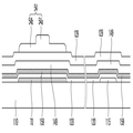
도 1은 본 발명의 한 실시예에 따른 박막 트랜지스터 표시판의 단면도이다.1 is a cross-sectional view of a thin film transistor array panel according to an exemplary embodiment of the present invention.
플라스틱, 유리 등의 절연성 물질을 포함하는 절연 기판(110) 위에 게이트 전극(124)을 포함하는 게이트선(121)이 위치한다. 게이트선(121)은 게이트 온 전압(Von)과 게이트 오프 전압(Voff)을 포함하는 게이트 신호를 전달할 수 있다.The
게이트선(121)은 알루미늄(Al)이나 알루미늄 합금 등 알루미늄 계열 금속, 은(Ag)이나 은 합금 등 은계열 금속, 구리(Cu)나 구리 합금 등 구리 계열 금속, 몰리브덴(Mo)이나 몰리브덴 합금 등 몰리브덴 계열 금속, 크롬(Cr), 탄탈륨(Ta) 및 티타늄(Ti) 따위로 만들어질 수 있다. 그러나 게이트 전극(124)은 물리적 성질이 다른 적어도 두 개의 도전막을 포함하는 다중막 구조를 가질 수도 있다.The
게이트선(121) 위에는 게이트 절연막(140)이 위치한다. 게이트 절연막(140)은 산화 규소(SiOx), 질화 규소(SiNx), 또는 산질화 실리콘(SiON) 등의 절연 물질을 포함할 수 있다. 게이트 절연막(140)은 스퍼터링 방법 등을 사용하여 형성할 수 있다.A
게이트 절연막(140) 위에는 채널 영역(154), 소스 영역(153) 및 드레인 영역(155)을 포함하는 반도체층이 위치한다.The semiconductor layer including the
채널 영역(154)은 게이트 전극(124)과 중첩한다. 채널 영역(154)과 소스 영역(153) 또는 드레인 영역(155) 사이의 경계는 게이트 전극(124)의 가장자리 경계와 실질적으로 일치하거나 게이트 전극(124)의 가장자리 경계 바깥쪽 또는 안쪽에 위치할 수 있다. 이 중, 채널 영역(154)의 가장자리 경계는 게이트 전극(124)의 가장자리 경계와 실질적으로 일치하거나 정렬되어 있는 것이 박막 트랜지스터의 특성 향상 및 박막 트랜지스터 표시판에서의 신호 지연을 막기 위해 바람직하다.The
채널 영역(154)은 산화물 반도체를 포함할 수 있다. 산화물 반도체는 금속 산화물 반도체로서, 아연(Zn), 인듐(In), 갈륨(Ga), 주석(Sn), 티타늄(Ti) 등의 금속의 산화물 또는 아연(Zn), 인듐(In), 갈륨(Ga), 주석(Sn), 티타늄(Ti) 등의 금속과 이들의 산화물의 조합으로 이루어질 수 있다. 예를 들어, 산화물 반도체는 산화 아연(ZnO), 아연-주석 산화물(ZTO), 아연-인듐 산화물(ZIO), 인듐 산화물(InO), 티타늄 산화물(TiO), 인듐-갈륨-아연 산화물(IGZO), 인듐-아연-주석 산화물(IZTO) 중 적어도 하나를 포함할 수 있다.The
소스 영역(153) 및 드레인 영역(155)은 채널 영역(154)을 중심으로 양쪽에 각각 위치하며 서로 분리되어 있다. 소스 영역(153) 및 드레인 영역(155)은 게이트 전극(124)과 중첩할 수도 있고 실질적으로 중첩하지 않을 수도 있다.The
소스 영역(153) 및 드레인 영역(155)은 채널 영역(154)과 물리적으로, 전기적으로 연결되어 있다. The
구체적으로, 소스 영역(153) 및 드레인 영역(155)은 채널 영역(154)을 이루는 산화물 반도체를 포함하나, 소스 영역(153) 및 드레인 영역(155)의 캐리어(carrier) 농도는 채널 영역(154)의 캐리어 농도와 다르다. 구체적으로, 채널 영역(154)의 캐리어 농도가 1018 개/cm3 미만일 때, 소스 영역(153) 및 드레인 영역(155)의 캐리어 농도는 1018 개/cm3 이상일 수 있다. 소스 영역(153) 또는 드레인 영역(155)과 채널 영역(154) 사이의 경계에 캐리어 농도의 구배(gradient)가 존재한다.In detail, the
본 발명의 한 실시예에 따르면, 소스 영역(153) 및 드레인 영역(155)은 채널 영역(154)을 이루는 산화물 반도체 및 환원된 산화물 반도체를 포함할 수 있다. 예를 들어, 소스 영역(153) 및 드레인 영역(155)은 산화물 반도체와 불소(F), 수소(H) 및 황(S) 중 적어도 하나를 더 포함할 수 있다. 이때, 소스 영역(153) 및 드레인 영역(155)이 포함하는 불소(F), 수소(H) 및 황(S) 중 적어도 하나의 농도는 1015 개/cm3 이상일 수 있다. 소스 영역(153) 또는 드레인 영역(155)과 채널 영역(154) 사이의 경계에서 불소(F), 수소(H) 및 황(S) 중 적어도 하나의 농도의 구배가 존재할 수 있다.According to an embodiment of the present invention, the
이러한 소스 영역(153) 및 드레인 영역(155)은 채널 영역(154)을 이루는 산화물 반도체를 플라즈마 처리 등의 방법으로 환원시켜 형성할 수 있다. 예를 들어, 산화물 반도체를 챔버 내에서 불소(F), 수소(H) 및 황(S) 중 적어도 하나를 포함하는 기체를 사용하여 불소(F), 수소(H) 및 황(S) 중 적어도 하나로 도핑함으로써 본 발명의 한 실시예에 따른 소스 영역(153) 및 드레인 영역(155)을 형성할 수 있다.The
산화물 반도체는 n형 반도체이므로, 불소(F), 수소(H), 황(S) 중 적어도 하나의 기체로 도핑된 소스 영역(153) 및 드레인 영역(155)은 n+층이 된다. 이 경우, 소스 영역(153) 및 드레인 영역(155)은 전극과 반도체층 사이에서 오믹 컨택 (ohmic contact) 기능을 수행할 수 있다. Since the oxide semiconductor is an n-type semiconductor, the
다른 실시예에 따르면, 소스 영역(153) 및 드레인 영역(155)은 도전성을 갖는 소스 전극, 드레인 전극 기능을 수행할 수도 있다.According to another exemplary embodiment, the
채널 영역(154) 위에는 에치 스토퍼(식각 방지막이라고도 함)(etch stopper)(164)가 위치한다. 에치 스토퍼(164)의 좌우 가장자리 경계와 채널 영역(154)의 좌우 가장자리 경계는 실질적으로 일치하여 정렬되어 있을 수 있다. 따라서 에치 스토퍼(164)는 소스 영역(153) 또는 드레인 영역(155)과 실질적으로 중첩하지 않을 수 있다.An etch stopper 164 (also referred to as an etch stopper) 164 is positioned over the
에치 스토퍼(164)는 채널 영역(154)을 덮어 후속 공정에서 박막 트랜지스터의 채널이 되는 채널 영역(154)이 식각액 등에 의해 손상되는 것을 방지할 수 있다. 또한 에치 스토퍼(164)는 채널 영역(154) 상부에 위치하는 보호막(180) 등의 절연층 또는 외부로부터 채널 영역(154)으로 수소(H)와 같은 불순물이 확산되는 것을 차단하여 채널 영역(154)의 성질이 바뀌는 것을 막을 수 있다.The
에치 스토퍼(164)의 두께는 3000Å 이하일 수 있으며, SiOx, SiNx, SiOCx 또는 SiONx 중 적어도 어느 한 물질을 포함하는 무기막이거나, 유기물 또는 고분자 유기물을 포함하는 유기막으로 형성될 수 있다.The
소스 영역(153) 및 드레인 영역(155)이 소스 전극, 드레인 전극 기능을 수행하는 경우, 게이트 전극(124), 반도체층의 소스 영역(153) 및 드레인 영역(155)은 채널 영역(154)과 함께 박막 트랜지스터(thin film transistor, TFT)를 이루며, 박막 트랜지스터의 채널(channel)은 채널 영역(154)에 형성된다.When the
박막 트랜지스터의 채널 길이(L)는 소스 영역(153)과 드레인 영역(155) 사이의 거리, 즉 채널 영역(154)의 가로 방향 폭으로 정의될 수 있다. 또한 박막 트랜지스터의 채널 폭(도시하지 않음)은 소스 영역(153) 또는 드레인 영역(155)과 채널 영역(154) 사이의 경계의 길이로 정의될 수 있다. 본 발명의 한 실시예에 따르면 박막 트랜지스터의 채널 길이(L)는 에치 스토퍼(164)의 가로 방향 폭에 의존하며, 에치 스토퍼(164)를 사진 식각 공정으로 형성할 경우 노광기의 노광 한계까지 채널 길이(L)를 줄일 수 있다. 예를 들어, 노광기의 노광 한계가 3㎛인 경우 박막 트랜지스터의 채널 길이(L)를 3㎛까지 줄일 수 있으므로 박막 트랜지스터의 이동도를 높일 수 있어 박막 트랜지스터의 특성을 향상시킬 수 있다.The channel length L of the thin film transistor may be defined as a distance between the
또한 본 발명의 한 실시예에 따르면, 박막 트랜지스터의 채널 길이(L)는 에치 스토퍼(164)의 가로 방향 폭과 대략 동일하므로 에치 스토퍼(164)의 가로 방향 폭을 조절하여 박막 트랜지스터의 채널 길이(L)를 조절할 수 있다. 따라서 채널 영역(154)과 소스 영역(153) 또는 드레인 영역(155) 사이의 경계의 게이트 전극(124)의 가장자리 경계에 대한 위치를 자유롭게 설정할 수 있다. 채널 영역(154)과 소스 영역(153) 또는 드레인 영역(155) 사이의 경계를 게이트 전극(124)의 가장자리 경계와 실질적으로 일치시키거나 약간 바깥쪽에 위치시키면 소스 영역(153) 및 드레인 영역(155)이 게이트 전극(124)과 실질적으로 중첩하지 않을 수 있으므로 게이트 전극(124)과 소스 영역(153) 또는 드레인 영역(155) 사이의 기생 용량을 현저히 줄일 수 있다. 따라서 박막 트랜지스터 표시판에서 게이트 전극(124)과 소스 영역(153) 또는 드레인 영역(155) 사이의 기생 용량에 의한 킥백 전압 및 신호 지연 또는 왜곡을 줄일 수 있다. 이에 따라, 소비 전력을 감소할 수 있고, 데이터선 등의 신호 전달 배선(도시하지 않음)의 두께를 더욱 줄일 수 있으며 배선 재료 선택에 있어서 자유도가 커진다.In addition, according to an embodiment of the present invention, since the channel length L of the thin film transistor is substantially equal to the width of the
소스 영역(153) 및 드레인 영역(155), 그리고 에치 스토퍼(164) 위에는 보호막(passivation layer)(180)이 위치한다. 보호막(180)은 산화 규소(SiOx), 질화 규소(SiNx), 질산화 규소(SiON), 불산화 규소(SiOF) 등의 절연 물질로 이루어질 수 있다.A
그러면 도 2a 및 도 2b, 그리고 3a 및 도 3b를 참조하여 본 발명의 실시예에 따른 박막 트랜지스터 및 박막 트랜지스터 표시판에 대하여 설명한다.Next, a thin film transistor and a thin film transistor array panel according to an exemplary embodiment of the present invention will be described with reference to FIGS. 2A and 2B and 3A and 3B.
도 2a는 본 발명의 한 실시예에 따른 박막 트랜지스터 표시판의 단면도이고, 도 2b는 도 2a에 도시한 박막 트랜지스터 표시판의 평면도이고, 도 3a는 본 발명의 다른 실시예에 따른 박막 트랜지스터 표시판의 단면도이고, 도 3b는 도 3a에 도시한 박막 트랜지스터 표시판의 평면도이다.FIG. 2A is a cross-sectional view of a thin film transistor array panel according to an exemplary embodiment of the present invention, FIG. 2B is a plan view of the thin film transistor array panel illustrated in FIG. 2A, and FIG. 3A is a cross-sectional view of a thin film transistor array panel according to another exemplary embodiment of the present invention. 3B is a plan view of the thin film transistor array panel illustrated in FIG. 3A.
도 2a 및 도 2b에 도시한 실시예는 앞에서 설명한 도 1에 도시한 실시예와 대부분 동일하나, 소스 영역(153)과 연결되어 있는 데이터선(171) 및 드레인 영역(155)과 연결되어 있는 화소 전극(191)을 더 포함할 수 있다.2A and 2B are substantially the same as the embodiment illustrated in FIG. 1, but are connected to the
데이터선(171)은 데이터 신호를 전달하며 게이트선(121)과 교차하며 뻗을 수 있다. 데이터선(171)은 소스 영역(153)과 전기적으로 연결되어 있다.The
도 2a 및 도 2b를 참조하면, 데이터선(171)은 소스 영역(153)과 직접 접촉하여 전기적으로 연결될 수 있다. 2A and 2B, the
이때 데이터선(171)은 보호막(180) 아래에 위치할 수 있다. 또한 데이터선(171)은 소스 영역(153)을 향하여 돌출한 돌출부(도시하지 않음)를 포함하여 이 돌출부가 소스 영역(153)과 접촉할 수도 있다.In this case, the
도 3a 및 도 3b를 참조하면, 데이터선(171)은 연결 다리(88)를 통해 소스 영역(153)과 전기적으로 연결될 수도 있다. 이때 데이터선(171)은 보호막(180) 아래에 위치할 수 있고, 보호막(180)은 데이터선(171)을 드러내는 접촉 구멍(187) 및 소스 영역(153)을 드러내는 접촉 구멍(188)을 포함할 수 있다. 연결 다래(88)는 접촉 구멍(187, 188)을 통해 데이터선(171)과 소스 영역(153)을 전기적으로 연결할 수 있다. 데이터선(171)은 게이트 절연막(140)과 보호막(180) 사이에 위치할 수도 있고, 보호막(180) 위에 위치할 수도 있다. 데이터선(171)이 보호막(180) 아래에 위치할 경우 연결 다리(88)는 화소 전극(191)과 동일한 층에 동일한 물질로 이루어질 수 있다.3A and 3B, the
화소 전극(191)은 보호막(180) 위에 위치하며 ITO, IZO 등의 투명한 도전 물질로 이루어질 수 있다. 화소 전극(191)은 보호막(180)의 접촉 구멍(185)을 통해 드레인 영역(155)과 전기적으로 연결될 수 있다. 화소 전극(191)은 드레인 영역(155)으로부터 데이터 전압을 인가받아 영상 표시를 제어할 수 있다.The
본 발명의 한 실시예에 따른 박막 트랜지스터 표시판이 액정 표시 장치에 포함될 경우 화소 전극(191)은 대향 전극(도시하지 않음)과 함께 액정층(도시하지 않음)에 전기장을 형성하여 액정 분자의 배열 방향을 제어함으로써 영상을 표시할 수 있다. 박막 트랜지스터 표시판이 유기 발광 표시 장치에 포함될 경우 화소 전극(191)과 대향 전극(도시하지 않음) 사이에 발광층(도시하지 않음)이 위치하여 발광 다이오드를 형성할 수도 있다.When the thin film transistor array panel according to the exemplary embodiment of the present invention is included in the liquid crystal display, the
본 발명의 한 실시예에서, 데이터선(171) 또는 화소 전극(191)이 박막 트랜지스터의 채널 영역(154)과 직접 접촉할 필요가 없다. 따라서 데이터선(171) 및 화소 전극(191)과 채널 영역(154) 사이에 어느 정도 거리를 둘 수 있으므로 특히 데이터선(171)이 구리(Cu) 등의 금속을 포함할 때 채널 영역(154)으로 금속 성분이 확산되는 것을 막을 수 있다. 따라서 박막 트랜지스터의 특성이 떨어지는 것을 막을 수 있다.In one embodiment of the present invention, the
다음 도 4a 및 도 4b를 참조하여 본 발명의 한 실시예에 따른 박막 트랜지스터 및 박막 트랜지스터 표시판에 대하여 설명한다.Next, a thin film transistor and a thin film transistor array panel according to an exemplary embodiment of the present invention will be described with reference to FIGS. 4A and 4B.
도 4a는 본 발명의 한 실시예에 따른 박막 트랜지스터 표시판의 단면도이고, 도 4b는 도 4a에 도시한 박막 트랜지스터 표시판의 평면도이다.4A is a cross-sectional view of a thin film transistor array panel according to an exemplary embodiment of the present invention, and FIG. 4B is a plan view of the thin film transistor array panel illustrated in FIG. 4A.
도 4a 및 도 4b에 도시한 실시예는 앞에서 설명한 도 1에 도시한 실시예와 대부분 동일하나, 소스 영역(153) 위에 위치하는 소스 전극(173), 드레인 영역(155) 위에 위치하는 드레인 전극(175), 그리고 드레인 전극(175)과 전기적으로 연결되어 있는 화소 전극(191)을 더 포함할 수 있다. 여기서, 소스 전극(173)은 소스 영역(153)과 직접 접촉하여 전기적으로 연결되고, 드레인 전극(175)은 드레인 영역(155)과 직접 접촉하여 전기적으로 연결될 수 있다.4A and 4B are substantially the same as the above-described embodiment of FIG. 1, but the
산화물 반도체 영역을 플라즈마 처리 등의 방법으로 환원시켜 소스 영역(153) 및 드레인 영역(155)을 형성하면, 불소(F), 수소(H), 황(S) 중 적어도 하나의 기체로 도핑된 소스 영역(153) 및 드레인 영역(155)은 n+층이 되어 소스 전극(173), 드레인 전극(175)과 채널층(154) 사이에서 오믹 컨택 (ohmic contact) 기능을 수행할 수 있다.When the oxide semiconductor region is reduced by a plasma treatment method to form the
도 4a에는 소스 전극(173)과 드레인 전극(175)이 소스 영역(153)과 드레인 영역(155)보다 더 두껍게 도시되어 있으나, 이는 하나의 실시예에 불과하며, 소스 전극(173)과 드레인 전극(175)은 소스 영역(153), 드레인 영역(155)의 두께와 같거나 그보다 얇게 형성될 수도 있다.Although the
소스 전극(173)은 데이터 신호를 전달하며 게이트선(121)과 교차하며 뻗는 데이터선(171)과 연결되어 있다. 예를 들어, 소스 전극(173)은 도 4b에 도시한 바와 같이 데이터선(171)의 길게 뻗는 부분으로부터 돌출한 부분일 수 있다. 다른 예로, 소스 전극(173)은 데이터선(171)과는 별개로 형성되어 데이터선(171)과 접속할 수도 있다.The source electrode 173 transmits a data signal and is connected to the
화소 전극(191)은 보호막(180) 위에 위치하며 ITO, IZO 등의 투명한 도전 물질로 이루어질 수 있다. 화소 전극(191)은 보호막(180)의 접촉 구멍(185)을 통해 드레인 전극(175)과 전기적으로 연결될 수 있다. 화소 전극(191)은 드레인 전극(175)으로부터 데이터 전압을 인가받아 영상 표시를 제어할 수 있다.The
소스 전극(173) 및 드레인 전극(175)은 알루미늄이나 알루미늄 합금 등 알루미늄 계열 금속, 은이나 은 합금 등 은 계열 금속, 구리나 구리망간과 같은 구리 합금 등 구리 계열 금속, 몰리브덴이나 몰리브덴 합금 등 몰리브덴 계열 금속, 크롬, 탄탈륨 및 티타늄 따위로 만들어질 수 있다. 예를 들어, 몰리브덴 합금으로 Mo-Nb, Mo-Ti가 있다. 또는 소스 전극(173) 및 드레인 전극(175)은 ITO, IZO, AZO 등의 투명성 도전 물질로 만들어질 수도 있다. 소스 전극(173) 및 드레인 전극(175)은 두 개 이상의 도전막(도시하지 않음)을 포함하는 다중막 구조를 가질 수도 있다. 예를 들어, 소스 전극(173) 및 드레인 전극(175)은 Mo/Al/Mo, Mo/Al, Mo/Cu, CuMn/Cu, Ti/Cu 등의 다중막 구조를 가질 수 있다.The
본 실시예에서도, 소스 전극(173) 및 드레인 전극(175)이 채널 영역(154)과 접촉할 필요가 없다. 따라서 소스 전극(173) 및 드레인 전극(175)과 채널 영역(154) 사이에 어느 정도 거리를 둘 수 있으므로 소스 전극(173) 및 드레인 전극(175)이 구리(Cu) 등의 금속을 포함할 때 채널 영역(154)으로 금속 성분이 확산되는 것을 막을 수 있다. 따라서 박막 트랜지스터의 특성이 떨어지는 것을 막을 수 있다.Also in this embodiment, the
그러면 본 발명의 한 실시예에 따른 박막 트랜지스터 표시판의 제조 방법에 대해 도 5를 참조하여 설명한다.Next, a method of manufacturing the thin film transistor array panel according to the exemplary embodiment of the present invention will be described with reference to FIG. 5.
도 5는 본 발명의 한 실시예에 따른 박막 트랜지스터 표시판을 본 발명의 한 실시예에 따라 제조하는 방법을 차례대로 나타낸 단면도이다.5 is a cross-sectional view sequentially illustrating a method of manufacturing a thin film transistor array panel according to an exemplary embodiment of the present invention.
본 실시예에서는 앞에서 설명한 도 4a 및 도 4b에 도시한 박막 트랜지스터 표시판을 예로 들어 설명하나 이에 한정되지 않고 본 발명의 한 실시예에 따른 제조 방법은 다른 여러 실시예에도 동일하게 적용될 수 있다.In the present exemplary embodiment, the thin film transistor array panel illustrated in FIGS. 4A and 4B described above will be described as an example, but the present inventive concept is not limited thereto. The manufacturing method according to the exemplary embodiment of the present invention may be equally applied to other exemplary embodiments.
먼저 도 5(a)를 참조하면, 유리 또는 플라스틱 등으로 만들어질 수 있는 절연 기판(110) 위에 금속 등의 도전성 물질을 적층하고 패터닝하여 게이트 전극(124)을 형성한다.First, referring to FIG. 5A, a
다음, 게이트 전극(124) 위에 산화 규소(SiOx), 질화 규소(SiNx), 또는 산질화 실리콘(SiON) 등의 절연 물질을 포함하는 게이트 절연막(140)을 적층한다.Next, a
이어서, 게이트 절연막(140) 위에 산화 아연(ZnO), 아연-주석 산화물(ZTO), 아연-인듐 산화물(ZIO), 인듐 산화물(InO), 티타늄 산화물(TiO), 인듐-갈륨-아연 산화물(IGZO), 인듐-아연-주석 산화물(IZTO) 등의 산화물 반도체 물질을 포함하는 반도체 물질층(도시하지 않음)을 도포하고 그 위에 포토레지스트 등의 감광막을 도포하고 노광하여 감광막 패턴(51)을 형성한다.Subsequently, zinc oxide (ZnO), zinc-tin oxide (ZTO), zinc-indium oxide (ZIO), indium oxide (InO), titanium oxide (TiO), and indium-gallium-zinc oxide (IGZO) are formed on the
다음, 감광막 패턴(51)을 마스크로 하여 반도체 물질층을 식각하여 반도체 패턴(150)을 형성한다.Next, the semiconductor material layer is etched using the
다음 도 5(b)를 참조하면, 감광막 패턴(51)을 제거하고 반도체 패턴(150) 위에 에치 스토퍼(164)를 형성한다. 에치 스토퍼(164)는 게이트 전극(124)과 중첩하고, 반도체 패턴(150)의 가운데 부분을 가로지르며 중첩할 수 있으며, 에치 스토퍼(164)에 덮이지 않은 반도체 패턴(150)의 두 부분이 에치 스토퍼(164)를 사이에 두고 분리되어 위치한다. 에치 스토퍼(164)는 SiOx, SiNx, SiOCx 또는 SiONx 중 적어도 어느 한 물질을 포함하는 무기막, 유기물 또는 고분자 유기물을 포함하는 유기막을 화학 기상 증착법(CVD)이나 스퍼터링 방법 등에 의해 증착한 후 사진 공정으로 형성할 수 있다. 이때 건식 식각 방법을 사용할 수 있으며, 반도체 패턴(150)이 식각되지 않도록 충분한 식각비를 가지는 식각 기체를 사용할 수 있다.Next, referring to FIG. 5B, the
다음 도 5(c)를 참조하면, 에치 스토퍼(164)의 양쪽에서 노출된 반도체 패턴(150)의 두 부분을 처리하여 소스 영역(153) 및 드레인 영역(155)을 형성한다. 또한 에치 스토퍼(164)에 덮여 있는 반도체 패턴(150)은 채널 영역(154)이 된다. 이에 따라, 게이트 전극(124), 소스 영역(153) 및 드레인 영역(155)은 채널 영역(154)과 함께 박막 트랜지스터를 이룬다.Next, referring to FIG. 5C, two portions of the
노출된 반도체 패턴(150)를 처리하는 방법으로 채버 내의 환원 분위기에서의 열처리하는 방법, 수소(H2), 헬륨(He), 포스핀(PH3), 암모니아(NH3), 실란(SiH4), 메탄(CH4), 아세틸렌(C2H2), 디보란(B2H6), 이산화탄소(CO2), 저메인(GeH4), 셀렌화수소(H2Se), 황화수소(H2S), 아르곤(Ar), 질소(N2), 산화 질소(N2O), 플루오르포름(CHF3) 등 기체 플라즈마를 이용한 플라즈마 처리 방법 등이 있을 수 있다.A method of treating the exposed
특히, 본 발명의 한 실시예에 따르면, 사불화탄소(CF4), 삼불화질소(NF3), 육불화황(SF6), 메탄(CH4) 중 적어도 하나를 포함하는 가스를 이용하여 노출된 반도체 패턴(150)를 불소(F), 수소(H), 황(S) 중 적어도 하나로 도핑하거나는 환원 처리하는 방법을 사용할 수 있다. 이에 따르면, 앞에서 설명한 바와 같이 채널 영역(154)의 산화물 반도체와 함께 불소(F), 수소(H), 황(S) 중 적어도 하나를 포함하는 소스 영역(153) 및 드레인 영역(155)을 형성할 수 있다. 이때 소스 영역(153) 및 드레인 영역(155)에 도핑된 불소(F), 수소(H) 및 황(S) 중 적어도 하나의 농도는 1015 개/cm3 이상일 수 있다.In particular, according to one embodiment of the present invention, exposure using a gas containing at least one of carbon tetrafluoride (CF 4 ), nitrogen trifluoride (NF 3 ), sulfur hexafluoride (SF 6 ), methane (CH 4 ) The
다음 도 5(d)를 참조하면, 소스 영역(153) 및 드레인 영역(155) 위에 소스 전극(173) 및 드레인 전극(175)을 더 형성할 수도 있다.Next, referring to FIG. 5D, a
다음 도 5(e)를 참조하면, 소스 전극(173) 및 드레인 전극(175), 소스 영역(153) 및 드레인 영역(155), 에치 스토퍼(164) 위에 절연 물질을 도포하여 보호막(180)을 형성한다. 이어서, 보호막(180)을 패터닝하여 드레인 전극(175)을 드러내는 접촉 구멍(185)을 형성할 수 있다.Next, referring to FIG. 5E, an insulating material is coated on the
다음 도 2a, 도 2b, 도 3a, 도 3b, 도 4a 및 도 4b에 도시한 바와 같이, 보호막(180) 위에 드레인 전극(175) 또는 드레인 영역(155)과 전기적으로 연결된 화소 전극(191)을 형성할 수 있다.Next, as illustrated in FIGS. 2A, 2B, 3A, 3B, 4A, and 4B, the
이와 같은 본 발명의 한 실시예에 따른 제조 방법으로 제조된 박막 트랜지스터에서 에치 스토퍼(164)의 폭을 노광 한계 내에서 조절하여 반도체층의 소스 영역(153) 및 드레인 영역(155)이 게이트 전극(124)과 실질적으로 중첩하지 않도록 할 수 있으므로 게이트 전극(124)과 소스 영역(153) 또는 드레인 영역(155) 사이의 기생 용량 줄일 수 있고, 박막 트랜지스터의 스위칭 소자로서의 on/off 특성이 향상될 수 있다. 또한 박막 트랜지스터의 소비 전력을 감소할 수 있고, 신호 전달 배선의 두께를 줄일 수 있으며 배선 재료 선택의 자유도가 커질 수 있다.In the thin film transistor manufactured by the manufacturing method according to the exemplary embodiment of the present invention, the width of the
또한 박막 트랜지스터의 채널 길이(L)를 노광기의 노광 한계까지 채널 길이(L)를 줄일 수 있으므로 이동도를 높여 박막 트랜지스터의 특성을 향상시킬 수 있다.In addition, since the channel length L of the thin film transistor can be reduced to the exposure limit of the exposure machine, the mobility can be improved to improve the characteristics of the thin film transistor.
다음, 도 6 및 도 7을 참조하여 본 발명의 한 실시예에 따른 박막 트랜지스터 및 박막 트랜지스터 표시판에 대하여 설명한다. 앞에서 설명한 실시예와 동일한 구성 요소에 대해서는 동일한 도면 부호를 부여하고, 동일한 설명은 생략하며 차이점을 중심으로 설명한다. 이는 이후 설명에서 동일하게 적용된다.Next, a thin film transistor and a thin film transistor array panel according to an exemplary embodiment of the present invention will be described with reference to FIGS. 6 and 7. The same reference numerals are given to the same constituent elements as those of the above-described embodiment, and the same explanations will be omitted and differences will be mainly described. This applies equally in the following description.
도 6은 본 발명의 한 실시예에 따른 박막 트랜지스터 표시판의 단면도이고, 도 7은 도 6에 도시한 박막 트랜지스터 표시판의 평면도이다.6 is a cross-sectional view of a thin film transistor array panel according to an exemplary embodiment of the present invention, and FIG. 7 is a plan view of the thin film transistor array panel illustrated in FIG. 6.
본 실시예는 앞에서 설명한 도 2a 내지 도 4b에 도시한 실시예에 따른 박막 트랜지스터 표시판과 대부분 동일하나 섬형인 에치 스토퍼(164)와 연결되어 있으며 게이트선(121)을 따라 나란히 뻗는 선형 에치 스토퍼(161)를 더 포함한다.This embodiment is a
에치 스토퍼(164)를 포함한 선형 에치 스토퍼(161)의 가장자리 경계는 게이트 전극(124)을 포함한 게이트선(121)의 가장자리 경계와 정렬되어 실질적으로 일치하거나 게이트선(121)의 가장자리 경계의 약간 안쪽 또는 바깥쪽에 위치할 수 있다. 즉, 에치 스토퍼(164)를 포함한 선형 에치 스토퍼(161)의 평면 모양과 게이트 전극(124)을 포함한 게이트선(121)의 평면 모양은 대략 일치하거나 서로 닮은꼴일 수 있다.The edge boundary of the
한편, 채널 영역(154)은 에치 스토퍼(164)에 의해 덮여 있으며 채널 영역(154)의 가장자리 경계, 더 정확히는 채널 영역(154)과 소스 영역(153) 또는 드레인 영역(155) 사이의 경계는 에치 스토퍼(164)의 가장자리 경계와 실질적으로 일치하거나 에치 스토퍼(164)의 가장자리 경계의 약간 안쪽에 위치할 수 있다.Meanwhile, the
본 실시예에 따르면, 게이트 전극(124)과 소스 영역(153) 또는 드레인 영역(155)이 중첩하는 면적을 최소화할 수 있으므로 게이트 전극(124)과 소스 영역(153) 또는 드레인 영역(155) 사이의 기생 용량을 현저히 줄일 수 있다.According to the present exemplary embodiment, since the overlapping area between the
그러면, 본 발명의 한 실시예에 따른 박막 트랜지스터 표시판의 제조 방법에 대해 도 8을 참조하여 설명한다.Next, a method of manufacturing the thin film transistor array panel according to the exemplary embodiment of the present invention will be described with reference to FIG. 8.
도 8은 본 발명의 한 실시예에 따른 박막 트랜지스터 표시판을 본 발명의 한 실시예에 따라 제조하는 방법을 차례대로 나타낸 단면도이다.8 is a cross-sectional view sequentially illustrating a method of manufacturing a thin film transistor array panel according to an exemplary embodiment of the present invention.
먼저 도 8(a)를 참조하면, 유리 또는 플라스틱 등으로 만들어질 수 있는 절연 기판(110) 위에 금속 등의 도전성 물질을 적층하고 패터닝하여 게이트 전극(124)을 형성한다.First, referring to FIG. 8A, a
다음, 게이트 전극(124) 위에 산화 규소(SiOx), 질화 규소(SiNx), 또는 산질화 실리콘(SiON) 등의 절연 물질을 포함하는 게이트 절연막(140)을 적층한다.Next, a
이어서, 게이트 절연막(140) 위에 산화물 반도체 물질을 포함하는 반도체 패턴(150)을 형성하고, 그 위에 SiOx, SiNx, SiOCx 또는 SiONx 중 적어도 어느 한 물질을 포함하는 무기막, 유기물 또는 고분자 유기물을 포함하는 유기막을 화학 기상 증착법(CVD)이나 스퍼터링 방법 등에 의해 증착하여 에치 스토퍼층(160)을 적층한다.Subsequently, a
이어서, 에치 스토퍼층(160) 위에 포토레지스트 등의 감광막(50)을 도포하고 절연 기판(110)의 뒷면 쪽에서 빛을 조사한다. 이때 감광막(50)은 노광된 부분이 제거되는 양의 감광성을 가지는 것이 바람직하다. 그러면 불투명한 게이트 전극(124)에 의해 가려지지 않은 감광막(50)이 노광되어 제거될 수 있다.Subsequently, a
다음 도 8(b)를 참조하면, 노광된 감광막(50)을 제거하여 게이트 전극(124)과 대응하는 감광막 패턴(52)을 형성한다. 이때 감광막 패턴(52)의 가장자리 경계는 게이트 전극(124)의 가장자리 경계와 일치할 수도 있고 게이트 전극(124)의 가장자리 경계의 약간 안쪽 또는 바깥쪽에 위치할 수도 있다. 이는 노광기에 사용된 빛의 파장이나 빛이 투과하는 물질의 종류 등의 여러 설계 요소에 의해 결정될 수 있다.Next, referring to FIG. 8B, the exposed
다음 도 8(c)를 참조하면, 감광막 패턴(52)을 마스크로 에치 스토퍼층(160)을 식각하여 반도체 패턴(150)을 가로지르며 덮는 에치 스토퍼(164)를 형성한다.Referring to FIG. 8C, the
다음 도 8(d)를 참조하면, 에치 스토퍼(164)에 의해 가려지지 않고 드러난 반도체 패턴(150)의 노출된 두 부분에 이온을 도핑하여 도전성을 가지는 소스 영역(153) 및 드레인 영역(155)을 형성한다. 에치 스토퍼(164)에 덮여 있는 반도체 패턴(150)은 채널 영역(154)이 된다. 이에 따라, 게이트 전극(124), 소스 영역(153) 및 드레인 영역(155)은 채널 영역(154)과 함께 박막 트랜지스터를 이룬다.Referring to FIG. 8 (d), the
노출된 반도체 패턴(150)를 처리하는 방법은 앞에서 설명한 실시예와 동일하므로 여기서 상세한 설명은 생략한다.Since the method of processing the exposed
다음 도 8(e)를 참조하면, 소스 영역(153) 및 드레인 영역(155) 위에 소스 전극(173) 및 드레인 전극(175)을 더 형성할 수도 있다. Next, referring to FIG. 8E, the
다음 도 8(f)를 참조하면, 소스 전극(173) 및 드레인 전극(175), 소스 영역(153) 및 드레인 영역(155), 에치 스토퍼(164) 위에 절연 물질을 도포하여 보호막(180)을 형성한다. 이어서, 보호막(180)을 패터닝하여 드레인 전극(175)을 드러내는 접촉 구멍(185)을 형성한다다음 도 6 및 도 7에 도시한 바와 같이, 보호막(180) 위에 드레인 전극(175) 또는 드레인 영역(155)과 전기적으로 연결된 화소 전극(191)을 형성할 수 있다.Next, referring to FIG. 8F, an insulating material is coated on the
다음, 도 9 및 도 10을 참조하여 본 발명의 한 실시예에 따른 박막 트랜지스터 및 박막 트랜지스터 표시판에 대하여 설명한다.Next, a thin film transistor and a thin film transistor array panel according to an exemplary embodiment of the present invention will be described with reference to FIGS. 9 and 10.
도 9는 본 발명의 한 실시예에 따른 박막 트랜지스터 표시판의 단면도이고, 도 10은 도 9에 도시한 박막 트랜지스터 표시판의 평면도이다.9 is a cross-sectional view of a thin film transistor array panel according to an exemplary embodiment of the present invention, and FIG. 10 is a plan view of the thin film transistor array panel illustrated in FIG. 9.
본 실시예는 앞에서 설명한 도 2a 내지 도 4b에 도시한 실시예에 따른 박막 트랜지스터 표시판과 대부분 동일하나 보호막(180) 위에 게이트 전극(124)과 마주하는 상부 게이트 전극(194)을 더 포함한다. 상부 게이트 전극(194)은 화소 전극(191)과 동일한 물질을 포함할 수 있으며, 화소 전극(191)과 동시에 형성될 수 있다.The present embodiment is substantially the same as the thin film transistor array panel according to the exemplary embodiment illustrated in FIGS. 2A to 4B, but further includes an
도 10을 참조하면, 상부 게이트 전극(194)은 게이트선(121)과 접촉하여 전기적으로 연결될 수 있으며, 게이트선(121)으로부터 게이트 신호를 전달받을 수 있다. 이때, 보호막(180) 및 게이트 절연막(140)은 게이트선(121)을 드러내는 접촉 구멍(184)을 포함하고, 접촉 구멍(184)을 통해 상부 게이트 전극(194)이 게이트선(121)과 연결될 수 있다. 상부 게이트 전극(194)의 가로 방향 폭은 채널 영역(154)의 가로 방향 폭과 대략 동일하거나 작을 수 있다.Referring to FIG. 10, the
그러면, 도 9 및 도 10에 도시한 박막 트랜지스터 표시판의 본 발명의 한 실시예에 따른 제조 방법에 대해 도 11을 참조하여 설명한다.Next, a manufacturing method according to an exemplary embodiment of the present invention of the thin film transistor array panel illustrated in FIGS. 9 and 10 will be described with reference to FIG. 11.
도 11은 도 9 및 도 10에 도시한 박막 트랜지스터 표시판을 본 발명의 한 실시예에 따라 제조하는 방법을 차례대로 나타낸 단면도이다.11 is a cross-sectional view sequentially illustrating a method of manufacturing the thin film transistor array panel illustrated in FIGS. 9 and 10 according to an exemplary embodiment of the present invention.
본 실시예에 따른 박막 트랜지스터의 제조 방법은 앞에서 설명한 도 8에 도시한 실시예에 따른 박막 트랜지스터의 제조 방법과 대부분 동일하므로 상세한 설명은 생략한다. 다만, 도 11(f)를 참조하면 ITO, IZO 등의 투명 도전 물질로 화소 전극(191)을 형성할 때 채널 영역(154) 위에 위치하는 상부 게이트 전극(194)도 함께 형성할 수 있다.Since the manufacturing method of the thin film transistor according to the present exemplary embodiment is almost the same as the manufacturing method of the thin film transistor according to the exemplary embodiment illustrated in FIG. 8, the detailed description thereof will be omitted. However, referring to FIG. 11F, when the
다음, 도 12를 참조하여 본 발명의 한 실시예에 따른 박막 트랜지스터 및 박막 트랜지스터 표시판에 대하여 설명한다.Next, a thin film transistor and a thin film transistor array panel according to an exemplary embodiment of the present invention will be described with reference to FIG. 12.
도 12는 본 발명의 한 실시예에 따른 박막 트랜지스터 표시판의 단면도이다.12 is a cross-sectional view of a thin film transistor array panel according to an exemplary embodiment of the present invention.
도 12를 참조하면, 본 실시예는 앞에서 설명한 도 4a 및 도 4b에 도시한 실시예에 따른 박막 트랜지스터 표시판과 대부분 동일하나, 소스 전극(173) 및 드레인 전극(175) 중 일부는 직접 소스 영역(153) 및 드레인 영역(155)과 접촉하지 않고 보호막(180) 위에 위치할 수 있다. 이때, 보호막(180)은 소스 영역(153)을 드러내는 접촉 구멍(183)과 드레인 영역(155)을 드러내는 접촉 구멍(185)을 가지고, 소스 전극(173) 및 드레인 전극(175)은 보호막(180)의 접촉 구멍(183, 185)을 통해 각각 소스 영역(153) 및 드레인 영역(155)과 전기적으로 연결될 수 있다.Referring to FIG. 12, the present embodiment is mostly the same as the thin film transistor array panel according to the exemplary embodiment illustrated in FIGS. 4A and 4B, but some of the
다음, 도 13을 참조하여 본 발명의 한 실시예에 따른 박막 트랜지스터 및 박막 트랜지스터 표시판에 대하여 설명한다.Next, a thin film transistor and a thin film transistor array panel according to an exemplary embodiment of the present invention will be described with reference to FIG. 13.
도 13은 본 발명의 한 실시예에 따른 박막 트랜지스터 표시판의 단면도(a) 및 평면도(b)이다.13 is a cross-sectional view (a) and a plan view (b) of a thin film transistor array panel according to an exemplary embodiment of the present invention.
도 13(a)를 참조하면, 절연 기판(110) 위에 광 차단막(70)이 위치할 수 있다. 광 차단막(70)은 후에 적층될 산화물 반도체에 빛이 도달하는 것을 막아 산화물 반도체가 반도체로서의 성질을 잃는 것을 막을 수 있다. 따라서 광 차단막(70)은 산화물 반도체에 도달하지 않도록 차단할 파장대의 광을 투과시키지 않는 재료로 만들어지는 것이 바람직하다. 광 차단막(70)은 유기 절연 물질, 무기 절연 물질, 금속 등의 도전성 물질 등으로 만들어질 수 있으며, 단일막 또는 다중막으로 만들어질 수 있다. 그러나, 광 차단막(70)은 조건에 따라 생략될 수도 있다. 구체적으로, 절연 기판(110)의 아래쪽에서 빛이 조사되지 않는 경우, 예를 들어 본 발명의 한 실시예에 따른 박막 트랜지스터가 유기 발광 표시 장치 등에 사용될 경우, 광 차단막(70)은 생략될 수도 있다.Referring to FIG. 13A, a
광 차단막(70) 위에는 버퍼층(120)이 위치할 수 있다. 버퍼층(120)은 산화 실리콘(SiOx), 산화 알루미늄(Al2O3), 산화 하프늄(HfO3), 산화 이트륨(Y2O3) 등의 절연성 산화물을 포함할 수 있다. 버퍼층(120)은 후에 적층될 반도체에 절연 기판(110)으로부터의 불순물이 유입되는 것을 막아 반도체를 보호하고 반도체의 계면 특성을 향상시킬 수 있다.The
버퍼층(120) 위에는 채널 영역(154), 소스 영역(153) 및 드레인 영역(155)을 포함하는 반도체층이 위치한다. 광 차단막(70)이 존재할 경우 채널 영역(154)은 광 차단막(70)으로 가려질 수 있다. 채널 영역(154), 소스 영역(153) 및 드레인 영역(155)에 대한 설명은 앞선 실시예에와 동일하므로 여기서 상세한 설명은 생략한다.The semiconductor layer including the
특히, 소스 영역(153) 및 드레인 영역(155)은 채널 영역(154)을 이루는 산화물 반도체와 동일한 물질을 포함하나, 소스 영역(153) 및 드레인 영역(155)의 캐리어 농도는 채널 영역(154)의 캐리어 농도와 다르다. 구체적으로, 채널 영역(154)의 캐리어 농도가 1018 개/cm3 미만일 때, 소스 영역(153) 및 드레인 영역(155)의 캐리어 농도는 1018 개/cm3 이상일 수 있다. 소스 영역(153) 또는 드레인 영역(155)과 채널 영역(154) 사이의 경계에 캐리어 농도의 구배가 존재한다.In particular, the
본 발명의 한 실시예에 따르면, 소스 영역(153) 및 드레인 영역(155)은 산화물 반도체와 도핑된 불소(F), 수소(H) 및 황(S) 중 적어도 하나를 포함할 수 있다. 이때, 소스 영역(153) 및 드레인 영역(155)이 포함하는 불소(F), 수소(H) 및 황(S) 중 적어도 하나의 농도는 1015 개/cm3 이상일 수 있다. 소스 영역(153) 또는 드레인 영역(155)과 채널 영역(154) 사이의 경계에서 불소(F), 수소(H) 및 황(S) 중 적어도 하나의 농도의 구배가 존재할 수 있다.According to an embodiment of the present invention, the
채널 영역(154) 위에는 게이트 절연층(142)이 위치한다. 게이트 절연층(142)은 채널 영역(154)을 덮을 수 있다. 또한 게이트 절연층(142)은 소스 영역(153) 또는 드레인 영역(155)과 실질적으로 중첩하지 않을 수 있다.The
게이트 절연층(142)은 단일막 또는 이중막 이상의 다중막일 수 있다. 게이트 절연층(142)이 단일막인 경우, 게이트 절연층(142)은 산화 실리콘(SiOx), 산화 알루미늄(Al2O3), 산화 하프늄(HfO3), 산화 이트륨(Y2O3) 등의 절연성 산화물을 포함할 수 있다. 게이트 절연층(142)은 채널 영역(154)의 계면 특성을 향상시키고 채널 영역(154)에 불순물이 침투하는 것을 막을 수 있다.The
게이트 절연층(142)이 다중막일 경우, 게이트 절연층(142)은 도 13(a)에 도시한 바와 같이 하부막(142a) 및 상부막(142b)을 포함할 수 있다. 하부막(142a)은 산화 실리콘(SiOx), 산화 알루미늄(Al2O3), 산화 하프늄(HfO3), 산화 이트륨(Y2O3) 등의 절연성 산화물을 포함하여 채널 영역(154)의 계면 특성을 향상시키고 채널 영역(154)에 불순물이 침투하는 것을 막을 수 있다. 상부막(142b)은 질화 실리콘(SiNx), 산화 실리콘(SiOx) 등의 다양한 절연 물질로 만들어질 수 있다.When the
게이트 절연층(142) 위에는 게이트 전극(124)이 위치한다. 게이트 전극(124)의 가장자리 경계와 게이트 절연층(142)의 가장자리 경계는 실질적으로 일치하여 정렬되어 있을 수 있다.The
도 13(a) 및 도13(b)를 참조하면, 게이트 전극(124)은 채널 영역(154)과 중첩하는 부분을 포함하며, 채널 영역(154)은 게이트 전극(124)에 의해 덮여 있다. 게이트 전극(124)을 중심으로 채널 영역(154)의 양쪽에는 소스 영역(153) 및 드레인 영역(155)이 위치하며, 소스 영역(153) 및 드레인 영역(155)은 게이트 전극(124)과 실질적으로 중첩하지 않을 수 있다. 따라서 게이트 전극(124)과 소스 영역(153) 사이의 기생 용량 또는 게이트 전극(124)과 드레인 영역(155) 사이의 기생 용량이 작아질 수 있다.Referring to FIGS. 13A and 13B, the
본 발명의 실시예에 따르면, 채널 영역(154)과 소스 영역(153) 사이의 경계 또는 채널 영역(154)과 드레인 영역(155) 사이의 경계는 게이트 전극(124) 및 게이트 절연층(142)의 가장자리 경계와 실질적으로 정렬되어 일치할 수 있다. 그러나 채널 영역(154)과 소스 영역(153) 또는 드레인 영역(155) 사이의 경계가 게이트 전극(124) 및 게이트 절연층(142)의 가장자리 경계보다 약간 안쪽에 위치할 수도 있다.According to an embodiment of the present invention, the boundary between the
게이트 전극(124), 소스 영역(153) 및 드레인 영역(155)은 채널 영역(154)과 함께 박막 트랜지스터를 이루며, 박막 트랜지스터의 채널은 채널 영역(154)에 형성된다.The
게이트 전극(124), 소스 영역(153), 드레인 영역(155), 그리고 버퍼층(120) 위에는 보호막(180)이 위치한다. 보호막(180)은 소스 영역(153)을 드러내는 접촉 구멍(183) 및 드레인 영역(155)을 드러내는 접촉 구멍(185)을 포함할 수 있다.The
보호막(180) 위에는 소스 전극(173) 및 드레인 전극(175)이 위치할 수 있다. 소스 전극(173)은 보호막(180)의 접촉 구멍(183)을 통해 박막 트랜지스터의 소스 영역(153)과 전기적으로 연결되고, 드레인 전극(175)은 보호막(180)의 접촉 구멍(185)을 통해 박막 트랜지스터의 드레인 영역(155)과 전기적으로 연결될 수 있다.The
이와 달리 보호막(180) 위에 색필터(도시하지 않음) 또는 유기 물질로 이루어진 유기막(도시하지 않음)이 더 위치하고, 그 위에 소스 전극(173) 및 드레인 전극(175)이 위치할 수도 있다.Alternatively, a color filter (not shown) or an organic film (not shown) made of an organic material may be further disposed on the
그러면 도 13에 도시한 박막 트랜지스터 표시판의 본 발명의 한 실시예에 따른 제조 방법에 대해 앞에서 설명한 도 13과 함께 도 14 내지 도 19를 참조하여 설명한다.Next, a method of manufacturing the thin film transistor array panel shown in FIG. 13 according to an exemplary embodiment of the present invention will be described with reference to FIGS. 14 to 19 along with FIG. 13 described above.
도 14 내지 도 19는 도 13에 도시한 박막 트랜지스터 표시판을 본 발명의 한 실시예에 따라 제조하는 방법을 차례대로 나타낸 단면도이다.14 to 19 are cross-sectional views sequentially illustrating a method of manufacturing the thin film transistor array panel illustrated in FIG. 13 according to an exemplary embodiment of the present invention.
먼저 도 14를 참조하면, 유리 또는 플라스틱 등으로 만들어질 수 있는 절연 기판(110) 위에 유기 절연 물질, 무기 절연 물질, 금속 등의 도전성 물질 등으로 이루어진 광 차단막(70)을 형성한다. 광 차단막(70)의 형성 단계는 조건에 따라 생략될 수 있다.First, referring to FIG. 14, a
이어서, 광 차단막(70) 위에 화학 기상 증착법 등의 방법으로 산화 실리콘(SiOx), 산화 알루미늄(Al2O3), 산화 하프늄(HfO3), 산화 이트륨(Y2O3) 등의 산화물을 포함하는 절연 물질로 이루어진 버퍼층(120)을 형성한다. 버퍼층(120)의 두께는 500Å 이상 1㎛ 이하일 수 있으나 이에 한정되는 것은 아니다.Subsequently, oxides such as silicon oxide (SiOx), aluminum oxide (Al 2 O 3 ), hafnium oxide (HfO 3 ), and yttrium oxide (Y 2 O 3 ) are included on the
이어서, 버퍼층(120) 위에 산화 아연(ZnO), 아연-주석 산화물(ZTO), 아연-인듐 산화물(ZIO), 인듐 산화물(InO), 티타늄 산화물(TiO), 인듐-갈륨-아연 산화물(IGZO), 인듐-아연-주석 산화물(IZTO) 등의 산화물 반도체 물질로 이루어질 수 있는 반도체 물질층을 도포하고, 그 위에 포토레지스트 등의 감광막을 도포한다. 다음 감광막을 노광하여 감광막 패턴(53)을 형성한다. 감광막 패턴(53)은 광 차단막(70)의 적어도 일부와 중첩할 수 있다.Subsequently, zinc oxide (ZnO), zinc-tin oxide (ZTO), zinc-indium oxide (ZIO), indium oxide (InO), titanium oxide (TiO), indium-gallium-zinc oxide (IGZO) on the
이어서, 감광막 패턴(53)을 마스크로 반도체 물질층을 식각하여 반도체 패턴(150)을 형성한다.Subsequently, the semiconductor material layer is etched using the
다음, 도 15를 참조하면, 반도체 패턴(150) 및 버퍼층(120) 위에 게이트 절연막(140)을 적층한다. 게이트 절연막(140)은 산화 실리콘(SiOx) 등의 절연성 산화물을 포함하는 단일층으로 형성할 수도 있고, 도 15에 도시한 바와 같이 산화 실리콘(SiOx) 등의 절연성 산화물을 포함하는 하부막(140a)과 절연 물질을 포함하는 상부막(140b)을 포함하는 다중막으로 형성할 수도 있다. 본 실시예에서 게이트 절연막(140)의 두께는 1000 이상 5000 이하일 수 있으나, 이에 한정되는 것은 아니다.Next, referring to FIG. 15, a
다음 도 16을 참조하면, 게이트 절연막(140) 위에 금속 등의 도전성 물질을 적층하고 패터닝하여 게이트 전극(124)을 형성한다. 게이트 전극(124)은 반도체 패턴(150)의 가운데 부분을 가로지르며 통과하도록 형성하여, 게이트 전극(124)과 반도체 패턴(150)의 중첩 부분의 양쪽에 위치하는 반도체 패턴(150)의 두 부분이 게이트 전극(124)에 의해 덮이지 않도록 한다.Next, referring to FIG. 16, a
다음 도 17을 참조하면, 게이트 전극(124)을 식각 마스크로 하여 게이트 절연막(140)을 패터닝하여 게이트 절연층(142)을 형성한다. 게이트 절연층(142)은 단일막으로 이루어질 수도 있고, 절연성 산화물을 포함하는 하부막(142a)과 절연 물질을 포함하는 상부막(142b)으로 이루어질 수도 있다.Next, referring to FIG. 17, the
이에 따라 게이트 전극(124)과 게이트 절연층(142)은 실질적으로 동일한 평면 모양을 가질 수 있다. 또한 반도체 패턴(150) 중 게이트 전극(124)으로 덮이지 않은 양쪽 두 부분이 드러난다.Accordingly, the
다음 도 18을 참조하면, 드러난 반도체 패턴(150)의 노출된 두 부분을 처리하여 도전성을 가지는 소스 영역(153) 및 드레인 영역(155)을 형성한다. 노출된 반도체 패턴(150)의 처리 방법은 앞에서 설명한 실시예와 동일하므로 여기서 상세한 설명은 생략한다.Next, referring to FIG. 18, two exposed portions of the exposed
특히, 본 발명의 한 실시예에 따르면, 사불화탄소(CF4), 삼불화질소(NF3), 육불화황(SF6), 메탄(CH4) 중 적어도 하나를 포함한 가스를 이용하여 노출된 반도체 패턴(150)를 도핑 또는 환원 처리하는 방법을 사용할 수 있다. 소스 영역(153) 및 드레인 영역(155)에 도핑된 불소(F), 수소(H) 및 황(S) 중 적어도 하나의 농도는 1015 개/cm3 이상일 수 있으며, 소스 영역(153) 또는 드레인 영역(155)과 채널 영역(154) 사이의 경계에서 불소(F), 수소(H) 및 황(S) 중 적어도 하나의 농도의 구배가 존재할 수 있다.In particular, according to one embodiment of the invention, exposed using a gas containing at least one of carbon tetrafluoride (CF 4 ), nitrogen trifluoride (NF 3 ), sulfur hexafluoride (SF 6 ), methane (CH 4 ) A method of doping or reducing the
게이트 절연층(142)에 덮여 환원되지 않은 반도체 패턴(150)은 박막 트랜지스터의 채널인 채널 영역(154)이 된다. 이에 따라, 게이트 전극(124), 소스 영역(153) 및 드레인 영역(155)은 채널 영역(154)과 함께 박막 트랜지스터를 이룬다.The
다음 도 19를 참조하면, 게이트 전극(124), 소스 영역(153), 드레인 영역(155), 그리고 버퍼층(120) 위에 절연 물질을 도포하여 보호막(180)을 형성한다. 이어서, 보호막(180)을 패터닝하여 소스 영역(153)을 드러내는 접촉 구멍(183) 및 드레인 영역(155)을 드러내는 접촉 구멍(185)을 형성한다.Next, referring to FIG. 19, an insulating material is coated on the
마지막어로, 도 13에 도시한 바와 같이, 보호막(180) 위에 소스 전극(173) 및 드레인 전극(175)을 형성할 수 있다.Finally, as shown in FIG. 13, the
본 발명의 실시예에 따른 박막 트랜지스터에서 게이트 전극(124)과 소스 영역(153) 또는 드레인 영역(155)이 실질적으로 중첩하지 않으므로 게이트 전극(124)과 소스 영역(153) 사이의 기생 용량 또는 게이트 전극(124)과 드레인 영역(155) 사이의 기생 용량이 매우 작아질 수 있다. 따라서 박막 트랜지스터의 스위칭 소자로서의 on/off 특성이 향상될 수 있다.In the thin film transistor according to the exemplary embodiment of the present invention, since the
다음, 도 20을 참조하여 본 발명의 한 실시예에 따른 박막 트랜지스터 및 박막 트랜지스터 표시판에 대하여 설명한다.Next, a thin film transistor and a thin film transistor array panel according to an exemplary embodiment of the present invention will be described with reference to FIG. 20.
도 20은 본 발명의 한 실시예에 따른 박막 트랜지스터 표시판의 단면도이다.20 is a cross-sectional view of a thin film transistor array panel according to an exemplary embodiment of the present invention.
도 20을 참조하면, 절연 기판(110) 위에 광 차단막(70) 및 데이터 신호를 전달하는 데이터선(115)이 위치할 수 있다. 데이터선(115)은 알루미늄(Al), 은(Ag), 구리(Cu), 몰리브덴(Mo), 크롬(Cr), 탄탈륨(Ta), 티타늄(Ti) 등의 금속 또는 이들의 합금 등의 도전성 물질로 만들어질 수 있다.Referring to FIG. 20, the
광 차단막(70) 및 데이터선(115) 위에는 버퍼층(120)이 위치하고, 그위에는 채널 영역(154), 소스 영역(153) 및 드레인 영역(155)이 위치한다.The
채널 영역(154)은 산화물 반도체 물질을 포함할 수 있다. 광 차단막(70)이 존재할 경우 채널 영역(154)은 광 차단막(70)으로 가려질 수 있다.The
소스 영역(153) 및 드레인 영역(155)은 채널 영역(154)을 중심으로 양쪽에 각각 마주하며 위치하고, 서로 분리되어 있다. 또한 소스 영역(153) 및 드레인 영역(155)은 채널 영역(154)과 연결되어 있다. 이 밖에 앞에서 설명한 실시예의 채널 영역(154), 소스 영역(153) 및 드레인 영역(155)에 대한 설명이 본 실시예에도 동일하게 적용될 수 있다.The
채널 영역(154) 위에는 게이트 절연층(142)이 위치한다. 게이트 절연층(142)은 채널 영역(154)을 덮을 수 있다. 또한 게이트 절연층(142)은 소스 영역(153) 또는 드레인 영역(155)과 거의 중첩하지 않을 수 있다.The
게이트 절연층(142) 위에는 게이트 전극(124)이 위치한다. 게이트 전극(124)의 가장자리 경계와 게이트 절연층(142)의 가장자리 경계는 실질적으로 정렬되어 일치할 수 있다.The
게이트 전극(124)은 채널 영역(154)과 중첩하는 부분을 포함하며, 채널 영역(154)은 게이트 전극(124)에 의해 덮여 있다. 게이트 전극(124)을 중심으로 채널 영역(154)의 양쪽에는 소스 영역(153) 및 드레인 영역(155)이 위치하며, 소스 영역(153) 및 드레인 영역(155)은 게이트 전극(124)과 실질적으로 중첩하지 않을 수 있다. 따라서 게이트 전극(124)과 소스 영역(153) 사이의 기생 용량 또는 게이트 전극(124)과 드레인 영역(155) 사이의 기생 용량이 매우 작아질 수 있다.The
게이트 전극(124), 소스 영역(153), 드레인 영역(155), 그리고 버퍼층(120) 위에는 보호막(180a)이 위치하고, 그 위에 유기막(180b)이 더 위치할 수 있다.The
유기막(180b)은 유기 절연 물질 또는 색필터 물질을 포함할 수 있다. 유기막(180b)의 표면은 평탄할 수 있다.The
보호막(180a) 및 유기막(180b)은 소스 영역(153)을 드러내는 접촉 구멍(183) 및 드레인 영역(155)을 드러내는 접촉 구멍(185)을 포함할 수 있다. 또한 버퍼층(120), 보호막(180a) 및 유기막(180b)은 데이터선(115)을 드러내는 접촉 구멍(181)을 포함할 수 있다.The
유기막(180b) 위에는 소스 전극(173) 및 드레인 전극(175)이 위치할 수 있다. 소스 전극(173)은 접촉 구멍(183)을 통해 소스 영역(153)과 전기적으로 연결되고, 드레인 전극(175)은 접촉 구멍(185)을 통해 드레인 영역(155)과 전기적으로 연결될 수 있다. 또한 소스 전극(173)은 접촉 구멍(181)을 통해 데이터선(115)과 연결될 수 있다. 따라서 소스 영역(153)은 데이터선(115)으로부터 데이터 신호를 입력받을 수 있다. 한편, 드레인 전극(175)은 그 자체가 화소 전극을 이루어 영상 표시를 제어할 수도 있고, 별도의 화소 전극(도시하지 않음)과 연결되어 있을 수도 있다.The
그러면 도 20에 도시한 박막 트랜지스터 표시판의 본 발명의 한 실시예에 따른 제조 방법에 대해 앞에서 설명한 도 20과 함께 도 21 내지 도 28을 참조하여 설명한다.Next, a method of manufacturing the thin film transistor array panel shown in FIG. 20 according to an exemplary embodiment of the present invention will be described with reference to FIGS. 21 to 28 along with FIG. 20 described above.
도 21 내지 도 28은 도 18에 도시한 박막 트랜지스터 표시판을 본 발명의 한 실시예에 따라 제조하는 방법을 차례대로 나타낸 단면도이다.21 to 28 are cross-sectional views sequentially illustrating a method of manufacturing the thin film transistor array panel illustrated in FIG. 18 according to an exemplary embodiment of the present invention.
먼저 도 21을 참조하면, 절연 기판(110) 위에 유기 절연 물질, 무기 절연 물질, 금속 등의 도전성 물질 등으로 이루어진 광 차단막(70)을 형성한다. 광 차단막(70)의 형성 단계는 조건에 따라 생략될 수 있다.First, referring to FIG. 21, a
이어서, 절연 기판(110) 위에 금속 등을 적층하고 패터닝하여 데이터선(115)을 형성한다. 광 차단막(70) 및 데이터선(115)의 형성 순서는 바뀔 수 있다.Subsequently, a metal line or the like is stacked and patterned on the insulating
다음 도 22를 참조하면, 광 차단막(70) 및 데이터선(115) 위에 버퍼층(120), 반도체 물질층(159), 절연 물질층(149), 그리고 게이트층(129)을 차례대로 적층한다.Next, referring to FIG. 22, the
반도체 물질층(159)은 산화 아연(ZnO), 아연-주석 산화물(ZTO), 아연-인듐 산화물(ZIO), 인듐 산화물(InO), 티타늄 산화물(TiO), 인듐-갈륨-아연 산화물(IGZO), 인듐-아연-주석 산화물(IZTO) 등의 산화물 반도체 물질을 적층하여 형성할 수 있다.The
절연 물질층(149)은 산화 실리콘(SiOx) 등의 절연성 산화물을 포함하는 절연 물질로 형성할 수 있다.The insulating
게이트층(129)은 알루미늄(Al) 등의 도전성 물질을 적층하여 형성할 수 있다.The
이어서, 게이트층(129) 위에 포토레지스트 등의 감광막을 도포하고 노광하여 감광막 패턴(54)을 형성한다. 감광막 패턴(54)은 도 22에 도시한 바와 같이 두께가 상대적 두꺼은 제1 부분(54a)과 두께가 상대적으로 얇은 제2 부분(54b)을 포함한다. 감광막 패턴(54)의 제1 부분(54a)은 광 차단막(70)과 중첩하는 곳에 위치할 수 있다. 또한 감광막 패턴(54)의 제1 부분(54a)의 양쪽에는 제1 부분(54a)을 중심으로 분리되어 마주하고 있는 한 쌍의 제2 부분(54b)이 연결되어 있다.Subsequently, a photoresist such as a photoresist is applied and exposed on the
이러한 감광막 패턴(54)은 반투과 영역을 포함하는 광 마스크(도시하지 않음)를 통해 노광하여 형성할 수 있다. 구체적으로, 감광막 패턴(54) 형성을 위한 광 마스크는 빛이 투과하는 투과 영역, 빛이 투과하지 않는 차광 영역, 그리고 빛이 일부만 투과하는 반투과 영역을 포함할 수 있다. 반투과 영역은 슬릿, 반투명막 등을 이용하여 형성할 수 있다.The photoresist pattern 54 may be formed by exposing through a photomask (not shown) including a transflective region. In detail, the photomask for forming the photoresist layer pattern 54 may include a transmission region through which light passes, a shielding region through which light does not pass, and a semitransmissive region where only part of light passes. The semi-transmissive region can be formed using a slit, a translucent film, or the like.
이러한 반투과 영역을 포함하는 광 마스크를 이용하여 노광하면, 음성의 감광막을 이용하는 경우, 광 마스크의 투과 영역에 대응하는 부분은 빛이 조사되어 감광막이 남아 두께가 상대적으로 두꺼운 제1 부분(54a)이 형성되고, 광 마스크의 차광 영역에 대응하는 부분은 빛이 조사되지 않아 감광막이 제거되며, 광 마스크의 반투과 영역에 대응하는 부분은 빛이 일부 조사되어 상대적으로 두께가 얇은 제2 부분(54b)이 형성된다. 양성의 감광막을 이용하는 경우는 위의 경우와 반대가 되나, 광 마스크의 반투과 영역에 대응하는 부분은 여전히 빛의 일부가 조사되어 감광막 패턴(54)의 제2 부분(54b)이 형성된다.When exposure is performed using a photomask including such a semi-transmissive region, when a negative photosensitive film is used, the portion corresponding to the transmissive region of the photomask is irradiated with light so that the photosensitive film remains to have a relatively thick
다음 도 23을 참조하면, 감광막 패턴(54)을 식각 마스크로 하여 게이트층(129)과 절연 물질층(149)을 차례대로 식각한다. 이때 게이트층(129)은 습식 식각 방법을 이용하여 식각할 수 있고, 절연 물질층(149)은 건식 식각 방법을 이용하여 식각할 수 있다. 이에 따라 감광막 패턴(54)의 하부에 동일한 평면 모양을 가지는 게이트 패턴(122) 및 절연 패턴(141)이 형성될 수 있다. 감광막 패턴(54)에 의해 덮이지 않은 반도체 물질층(159)은 드러날 수 있다.Next, referring to FIG. 23, the
다음 도 24를 참조하면, 게이트 패턴(122) 및 절연 패턴(141)을 식각 마스크로 하여 드러난 반도체 물질층(159)을 제거하여 반도체 패턴(150)을 형성한다. 반도체 패턴(150)은 게이트 패턴(122) 및 절연 패턴(141)과 동일한 평면 모양을 가질 수 있다.Next, referring to FIG. 24, the
다음 도 25를 참조하면, 감광막 패턴(54)을 산소 플라즈마를 이용한 애싱(ashing) 방법 따위로 전면 식각하여 두께를 줄임으로써 제2 부분(54b)을 제거한다. 이로써 두께가 줄어든 제1 부분(54a)을 남겨 감광막 패턴(55)을 형성할 수 있다.Next, referring to FIG. 25, the
다음 도 26을 참조하면, 감광막 패턴(55)을 식각 마스크로 하여 게이트 패턴(122) 및 절연 패턴(141)을 차례대로 식각한다. 이에 따라 감광막 패턴(55)으로 가려지지 않은 반도체 패턴(150)이 드러나고 게이트 전극(124) 및 게이트 절연층(142)이 형성된다. 드러난 반도체 패턴(150)은 감광막 패턴(55)으로 덮인 반도체 패턴(150)을 중심으로 양쪽에 위치하며 서로 분리되어 있다.Next, referring to FIG. 26, the
다음 도 27을 참조하면, 드러난 반도체 패턴(150)을 환원 처리하여 도전성을 가지는 소스 영역(153) 및 드레인 영역(155)을 형성한다. 환원 처리 방법은 앞에서 설명한 실시예와 동일하므로 여기서 상세한 설명은 생략한다.Next, referring to FIG. 27, the exposed
게이트 절연층(142)에 덮여 환원되지 않은 반도체 패턴(150)은 채널 영역(154)이 된다. 게이트 전극(124), 소스 영역(153) 및 드레인 영역(155)은 채널 영역(154)과 함께 박막 트랜지스터를 이룬다.The
다음 도 28을 참조하면, 감광막 패턴(55)을 제거한 후, 게이트 전극(124), 소스 영역(153), 드레인 영역(155), 그리고 버퍼층(120) 위에 절연 물질을 도포하여 보호막(180a)을 형성한다. 이어서, 보호막(180a) 위에 유기 절연 물질을 도포하여 유기막(180b)을 추가로 형성할 수 있다.Next, referring to FIG. 28, after removing the
다음, 도 20에 도시한 바와 같이 보호막(180a) 및 유기막(180b)에 접촉 구멍(183, 185, 181)을 형성하고, 유기막(180b) 위에 소스 전극(173) 및 드레인 전극(175)을 형성할 수 있다.Next, as shown in FIG. 20, contact holes 183, 185, and 181 are formed in the
이와 같이 본 발명의 실시예에 따르면, 박막 트랜지스터의 게이트 전극(124)과 소스 영역(153) 또는 드레인 영역(155)이 거의 중첩하지 않거나 중첩하는 부분이 매우 작을 수 있으므로 게이트 전극(124)과 소스 영역(153) 사이의 기생 용량 또는 게이트 전극(124)과 드레인 영역(155) 사이의 기생 용량이 매우 작을 수 있다. 따라서 박막 트랜지스터의 on 전류 및 이동도가 높아질 수 있고, 박막 트랜지스터의 스위칭 소자로서의 on/off 특성이 향상될 수 있다. 결국, 이러한 박막 트랜지스터가 적용된 표시 장치에서 RC 지연을 줄일 수 있다. 따라서 신호 전달 배선의 두께를 감소할 수 있는 마진이 생겨 제조 원가를 줄일 수 있다. 또한 박막 트랜지스터 자체의 특성이 좋아지므로 박막 트랜지스터의 사이즈를 줄이고 미세 채널을 형성할 수 있는 마진을 더 확보할 수 있다.As described above, according to the exemplary embodiment of the present invention, since the
이상에서 본 발명의 바람직한 실시예에 대하여 상세하게 설명하였지만 본 발명의 권리범위는 이에 한정되는 것은 아니고 다음의 청구범위에서 정의하고 있는 본 발명의 기본 개념을 이용한 당업자의 여러 변형 및 개량 형태 또한 본 발명의 권리범위에 속하는 것이다.Although the preferred embodiments of the present invention have been described in detail above, the scope of the present invention is not limited thereto, and various modifications and improvements of those skilled in the art using the basic concepts of the present invention defined in the following claims are also provided. It belongs to the scope of rights.
51,51, 53, 54, 55: 감광막 패턴 70: 광 차단막
110: 절연 기판 120: 버퍼층
122: 게이트 패턴 124: 게이트 전극
140: 게이트 절연막 159: 반도체 물질층
150: 반도체 패턴 153: 소스 영역
154: 채널 영역 155: 드레인 영역
149: 절연 물질층 141: 절연 패턴
142: 절연층 150: 게이트층
164: 에치 스토퍼 181, 183, 185: 접촉 구멍
173: 소스 전극 175: 드레인 전극
180, 180a: 보호막 180b: 유기막
191: 화소 전극51, 51, 53, 54, 55: Photosensitive film pattern 70: Light blocking film
110: insulating substrate 120: buffer layer
122: gate pattern 124: gate electrode
140: gate insulating film 159: semiconductor material layer
150: semiconductor pattern 153: source region
154: channel region 155: drain region
149: insulating material layer 141: insulating pattern
142: insulating layer 150: gate layer
164:
173: source electrode 175: drain electrode
180, 180a:
191:
Claims (35)
상기 게이트 전극의 위 또는 아래에 위치하는 게이트 절연막,
상기 게이트 절연막을 사이에 두고 상기 게이트 전극과 중첩하는 채널 영역, 그리고
상기 채널 영역과 동일층에 위치하고 상기 채널 영역과 연결되어 있으며 상기 채널 영역을 중심으로 서로 마주하는 소스 영역 및 드레인 영역
을 포함하고,
상기 채널 영역, 상기 소스 영역 및 상기 드레인 영역은 산화물 반도체를 포함하고,
상기 소스 영역 및 상기 드레인 영역의 캐리어 농도가 상기 채널 영역의 캐리어 농도보다 큰
박막 트랜지스터.Gate electrode,
A gate insulating layer positioned above or below the gate electrode,
A channel region overlapping the gate electrode with the gate insulating layer interposed therebetween, and
Source and drain regions on the same layer as the channel region and connected to the channel region and facing each other with respect to the channel region.
/ RTI >
The channel region, the source region and the drain region include an oxide semiconductor,
The carrier concentration of the source region and the drain region is greater than the carrier concentration of the channel region.
Thin film transistor.
상기 소스 영역 및 상기 드레인 영역은 환원된 상기 산화물 반도체를 포함하는 박막 트랜지스터.In claim 1,
And the source region and the drain region include the reduced oxide semiconductor.
상기 소스 영역 및 상기 드레인 영역은 불소(F), 수소(H) 및 황(S) 중 적어도 하나를 더 포함하는 박막 트랜지스터.3. The method of claim 2,
The source region and the drain region further include at least one of fluorine (F), hydrogen (H), and sulfur (S).
상기 소스 영역 및 상기 드레인 영역이 포함하는 불소(F), 수소(H) 및 황(S) 중 적어도 하나의 농도는 1015 개/cm3 이상인 박막 트랜지스터.4. The method of claim 3,
And a concentration of at least one of fluorine (F), hydrogen (H), and sulfur (S) included in the source region and the drain region is 10 15 atoms / cm 3 or more.
상기 채널 영역의 캐리어 농도가 1018 개/cm3 미만이고, 상기 소스 영역 및 상기 드레인 영역의 캐리어 농도는 1018 개/cm3 이상인 박막 트랜지스터.5. The method of claim 4,
The carrier concentration of the channel region is less than 10 18 / cm 3 , the carrier concentration of the source region and the drain region is 10 18 / cm 3 or more.
상기 소스 영역과 연결된 소스 전극 및 상기 드레인 영역과 연결된 드레인 전극을 더 포함하는 박막 트랜지스터.The method of claim 5,
And a source electrode connected to the source region and a drain electrode connected to the drain region.
상기 채널 영역을 덮는 에치 스토퍼를 더 포함하고,
상기 에치 스토퍼는 상기 소스 영역 및 상기 드레인 영역과 실질적으로 중첩하지 않는
박막 트랜지스터.The method of claim 6,
And an etch stopper covering the channel region,
The etch stopper does not substantially overlap the source region and the drain region.
Thin film transistor.
상기 에치 스토퍼의 가장자리 경계와 상기 게이트 전극의 가장자리 경계는 서로 정렬되어 실질적으로 일치하는 박막 트랜지스터.In claim 7,
And the edge boundary of the etch stopper and the edge boundary of the gate electrode are substantially aligned with each other.
상기 채널 영역, 상기 소스 영역 및 상기 드레인 영역 위에 위치하는 보호막, 그리고
상기 보호막 위에 위치하며 상기 채널 영역과 중첩하는 상부 게이트 전극
을 더 포함하는 박막 트랜지스터.9. The method of claim 8,
A passivation layer on the channel region, the source region and the drain region, and
An upper gate electrode on the passivation layer and overlapping the channel region
Thin film transistor further comprising.
상기 게이트 절연막 및 상기 게이트 전극은 상기 채널 영역 위에 위치하고,
상기 게이트 전극의 가장자리 경계, 상기 게이트 절연막의 가장자리 경계 및 상기 채널 영역의 가장자리 경계는 정렬되어 실질적으로 일치하는
박막 트랜지스터.The method of claim 5,
The gate insulating layer and the gate electrode are positioned on the channel region,
An edge boundary of the gate electrode, an edge boundary of the gate insulating layer, and an edge boundary of the channel region are aligned to substantially coincide with each other.
Thin film transistor.
상기 소스 영역 및 상기 드레인 영역은 불소(F), 수소(H) 및 황(S) 중 적어도 하나를 더 포함하는 박막 트랜지스터.In claim 1,
The source region and the drain region further include at least one of fluorine (F), hydrogen (H), and sulfur (S).
상기 소스 영역 및 상기 드레인 영역이 포함하는 불소(F), 수소(H) 및 황(S) 중 적어도 하나의 농도는 1015 개/cm3 이상인 박막 트랜지스터.12. The method of claim 11,
And a concentration of at least one of fluorine (F), hydrogen (H), and sulfur (S) included in the source region and the drain region is 10 15 atoms / cm 3 or more.
상기 채널 영역의 캐리어 농도가 1018 개/cm3 미만이고, 상기 소스 영역 및 상기 드레인 영역의 캐리어 농도는 1018 개/cm3 이상인 박막 트랜지스터.In claim 1,
The carrier concentration of the channel region is less than 10 18 / cm 3 , the carrier concentration of the source region and the drain region is 10 18 / cm 3 or more.
상기 채널 영역을 덮는 에치 스토퍼를 더 포함하고,
상기 에치 스토퍼는 상기 소스 영역 및 상기 드레인 영역과 실질적으로 중첩하지 않는
박막 트랜지스터.In claim 1,
And an etch stopper covering the channel region,
The etch stopper does not substantially overlap the source region and the drain region.
Thin film transistor.
상기 에치 스토퍼의 가장자리 경계와 상기 게이트 전극의 가장자리 경계는 서로 정렬되어 실질적으로 일치하는 박막 트랜지스터.The method of claim 14,
And the edge boundary of the etch stopper and the edge boundary of the gate electrode are substantially aligned with each other.
상기 채널 영역, 상기 소스 영역 및 상기 드레인 영역 위에 위치하는 보호막, 그리고
상기 보호막 위에 위치하며 상기 채널 영역과 중첩하는 상부 게이트 전극
을 더 포함하는 박막 트랜지스터.In claim 1,
A passivation layer on the channel region, the source region and the drain region, and
An upper gate electrode on the passivation layer and overlapping the channel region
Thin film transistor further comprising.
상기 게이트 절연막 및 상기 게이트 전극은 상기 채널 영역 위에 위치하고,
상기 게이트 전극의 가장자리 경계, 상기 게이트 절연막의 가장자리 경계 및 상기 채널 영역의 가장자리 경계는 정렬되어 실질적으로 일치하는
박막 트랜지스터.In claim 1,
The gate insulating layer and the gate electrode are positioned on the channel region,
An edge boundary of the gate electrode, an edge boundary of the gate insulating layer, and an edge boundary of the channel region are aligned to substantially coincide with each other.
Thin film transistor.
상기 게이트 전극 위에 게이트 절연막을 적층하는 단계,
상기 게이트 절연막 위에 반도체 패턴을 형성하는 단계,
상기 반도체 패턴 위에 상기 반도체 패턴을 가로지르며 중첩하는 에치 스토퍼를 형성하는 단계, 그리고
상기 에치 스토퍼에 의해 덮이지 않고 드러난 상기 반도체 패턴을 처리하여 상기 에치 스토퍼에 의해 덮인 채널 영역 및 상기 채널 영역을 중심으로 마주하는 소스 영역 및 드레인 영역을 형성하는 단계
를 포함하고,
상기 소스 영역 및 상기 드레인 영역의 캐리어 농도가 상기 채널 영역의 캐리어 농도보다 큰
박막 트랜지스터 표시판의 제조 방법.Forming a gate electrode on the insulating substrate,
Stacking a gate insulating film on the gate electrode;
Forming a semiconductor pattern on the gate insulating layer;
Forming an etch stopper intersecting and overlapping the semiconductor pattern on the semiconductor pattern, and
Processing the semiconductor pattern exposed without being covered by the etch stopper to form a channel region covered by the etch stopper and a source region and a drain region facing the channel region;
Lt; / RTI >
The carrier concentration of the source region and the drain region is greater than the carrier concentration of the channel region.
A method of manufacturing a thin film transistor display panel.
상기 반도체 패턴을 처리하는 단계는 상기 반도체 패턴을 환원 처리하는 단계를 포함하는 박막 트랜지스터 표시판의 제조 방법.The method of claim 18,
The processing of the semiconductor pattern may include reducing the semiconductor pattern.
상기 반도체 패턴을 처리하는 단계는 사불화탄소(CF4), 삼불화질소(NF3), 육불화황(SF6), 메탄(CH4) 중 적어도 하나를 포함하는 가스를 이용하여 상기 반도체 패턴을 불소(F), 수소(H), 황(S) 중 적어도 하나로 도핑하는 단계를 포함하는 박막 트랜지스터 표시판의 제조 방법.20. The method of claim 19,
The semiconductor pattern may be processed by using a gas including at least one of carbon tetrafluoride (CF 4 ), nitrogen trifluoride (NF 3 ), sulfur hexafluoride (SF 6 ), and methane (CH 4 ). A method of manufacturing a thin film transistor array panel comprising doping with at least one of fluorine (F), hydrogen (H), and sulfur (S).
상기 소스 영역 및 상기 드레인 영역이 포함하는 불소(F), 수소(H) 및 황(S) 중 적어도 하나의 농도는 1015 개/cm3 이상인 박막 트랜지스터 표시판의 제조 방법.20. The method of claim 20,
And a concentration of at least one of fluorine (F), hydrogen (H), and sulfur (S) included in the source region and the drain region is 10 15 atoms / cm 3 or more.
상기 채널 영역의 캐리어 농도가 1018 개/cm3 미만이고, 상기 소스 영역 및 상기 드레인 영역의 캐리어 농도는 1018 개/cm3 이상인 박막 트랜지스터 표시판의 제조 방법.22. The method of claim 21,
The carrier concentration of the channel region is less than 10 18 / cm 3 , and the carrier concentration of the source region and the drain region is 10 18 / cm 3 or more.
상기 소스 영역 및 상기 드레인 영역 위에 소스 전극 및 드레인 전극을 각각 형성하는 단계를 더 포함하는 박막 트랜지스터 표시판의 제조 방법.The method of claim 22,
And forming a source electrode and a drain electrode on the source region and the drain region, respectively.
상기 채널 영역, 상기 소스 영역 및 상기 드레인 영역 위에 보호막을 적층하는 단계, 그리고
상기 보호막 위에 상기 채널 영역과 중첩하는 상부 게이트 전극을 형성하는 단계
를 더 포함하는 박막 트랜지스터 표시판의 제조 방법.24. The method of claim 23,
Stacking a passivation layer on the channel region, the source region and the drain region, and
Forming an upper gate electrode overlapping the channel region on the passivation layer
Wherein the method further comprises the steps of:
상기 에치 스토퍼를 형성하는 단계는
상기 반도체 패턴 위에 무기 물질 또는 유기 물질을 적층하여 에치 스토퍼층을 형성하는 단계,
상기 에치 스토퍼층 위에 감광막을 도포하고 상기 절연 기판의 뒷면 쪽에서 빛을 조사하여 상기 게이트 전극과 중첩하는 감광막 패턴을 형성하는 단계, 그리고
상기 감광막 패턴을 마스크로 하여 상기 에치 스토퍼층을 식각하여 상기 에치 스토퍼를 형성하는 단계
를 포함하는 박막 트랜지스터 표시판의 제조 방법.25. The method of claim 24,
Forming the etch stopper
Stacking an inorganic material or an organic material on the semiconductor pattern to form an etch stopper layer,
Coating a photoresist film on the etch stopper layer and irradiating light from a back side of the insulating substrate to form a photoresist pattern overlapping the gate electrode; and
Etching the etch stopper layer using the photoresist pattern as a mask to form the etch stopper
And forming a thin film transistor on the substrate.
상기 감광막은 양의 감광성을 가지는 박막 트랜지스터 표시판의 제조 방법.26. The method of claim 25,
And the photosensitive film has a positive photosensitivity.
상기 반도체 패턴을 처리하는 단계는 사불화탄소(CF4), 삼불화질소(NF3), 육불화황(SF6), 메탄(CH4) 중 적어도 하나를 포함하는 가스를 이용하여 상기 반도체 패턴을 불소(F), 수소(H), 황(S) 중 적어도 하나로 도핑하는 단계를 포함하는 박막 트랜지스터 표시판의 제조 방법.The method of claim 18,
The semiconductor pattern may be processed by using a gas including at least one of carbon tetrafluoride (CF 4 ), nitrogen trifluoride (NF 3 ), sulfur hexafluoride (SF 6 ), and methane (CH 4 ). A method of manufacturing a thin film transistor array panel comprising doping with at least one of fluorine (F), hydrogen (H), and sulfur (S).
상기 소스 영역 및 상기 드레인 영역이 포함하는 불소(F), 수소(H) 및 황(S) 중 적어도 하나의 농도는 1015 개/cm3 이상인 박막 트랜지스터 표시판의 제조 방법.28. The method of claim 27,
And a concentration of at least one of fluorine (F), hydrogen (H), and sulfur (S) included in the source region and the drain region is 10 15 atoms / cm 3 or more.
상기 채널 영역의 캐리어 농도가 1018 개/cm3 미만이고, 상기 소스 영역 및 상기 드레인 영역의 캐리어 농도는 1018 개/cm3 이상인 박막 트랜지스터 표시판의 제조 방법.The method of claim 18,
The carrier concentration of the channel region is less than 10 18 / cm 3 , and the carrier concentration of the source region and the drain region is 10 18 / cm 3 or more.
상기 채널 영역, 상기 소스 영역 및 상기 드레인 영역 위에 보호막을 적층하는 단계, 그리고
상기 보호막 위에 상기 채널 영역과 중첩하는 상부 게이트 전극을 형성하는 단계
를 더 포함하는 박막 트랜지스터 표시판의 제조 방법.The method of claim 18,
Stacking a passivation layer on the channel region, the source region and the drain region, and
Forming an upper gate electrode overlapping the channel region on the passivation layer
Wherein the method further comprises the steps of:
상기 에치 스토퍼를 형성하는 단계는
상기 반도체 패턴 위에 무기 물질 또는 유기 물질을 적층하여 에치 스토퍼층을 형성하는 단계,
상기 에치 스토퍼층 위에 감광막을 도포하고 상기 절연 기판의 뒷면 쪽에서 빛을 조사하여 상기 게이트 전극과 중첩하는 감광막 패턴을 형성하는 단계, 그리고
상기 감광막 패턴을 마스크로 하여 상기 에치 스토퍼층을 식각하여 상기 에치 스토퍼를 형성하는 단계
를 포함하는 박막 트랜지스터 표시판의 제조 방법.The method of claim 18,
Forming the etch stopper
Stacking an inorganic material or an organic material on the semiconductor pattern to form an etch stopper layer,
Coating a photoresist film on the etch stopper layer and irradiating light from a back side of the insulating substrate to form a photoresist pattern overlapping the gate electrode; and
Etching the etch stopper layer using the photoresist pattern as a mask to form the etch stopper
And forming a thin film transistor on the substrate.
상기 감광막은 양의 감광성을 가지는 박막 트랜지스터 표시판의 제조 방법.32. The method of claim 31,
And the photosensitive film has a positive photosensitivity.
상기 반도체 패턴 위에 절연 물질을 적층하여 절연 물질층을 형성하는 단계,
상기 절연 물질층 위에 게이트 전극을 형성하는 단계,
상기 게이트 전극을 식각 마스크로 하여 상기 절연 물질층을 패터닝하여 게이트 절연층을 형성하고 상기 반도체 패턴의 일부를 드러내는 단계, 그리고
상기 드러난 반도체 패턴을 처리하여 상기 게이트 전극으로 덮인 채널 영역 및 상기 채널 영역을 중심으로 마주하는 소스 영역 및 드레인 영역을 형성하는 단계
를 포함하고,
상기 소스 영역 및 상기 드레인 영역의 캐리어 농도가 상기 채널 영역의 캐리어 농도보다 큰
박막 트랜지스터 표시판의 제조 방법.Forming a semiconductor pattern including an oxide semiconductor on the insulating substrate,
Forming an insulating material layer by laminating an insulating material on the semiconductor pattern,
Forming a gate electrode over the insulating material layer,
Patterning the insulating material layer using the gate electrode as an etching mask to form a gate insulating layer and exposing a portion of the semiconductor pattern; and
Processing the exposed semiconductor pattern to form a channel region covered with the gate electrode and a source region and a drain region facing the channel region;
Lt; / RTI >
The carrier concentration of the source region and the drain region is greater than the carrier concentration of the channel region.
A method of manufacturing a thin film transistor display panel.
상기 반도체 패턴을 처리하는 단계는 사불화탄소(CF4), 삼불화질소(NF3), 육불화황(SF6), 메탄(CH4) 중 적어도 하나를 포함하는 가스를 이용하여 상기 반도체 패턴을 불소(F), 수소(H), 황(S) 중 적어도 하나로 도핑하는 단계를 포함하는 박막 트랜지스터 표시판의 제조 방법.The method of claim 33,
The semiconductor pattern may be processed by using a gas including at least one of carbon tetrafluoride (CF 4 ), nitrogen trifluoride (NF 3 ), sulfur hexafluoride (SF 6 ), and methane (CH 4 ). A method of manufacturing a thin film transistor array panel comprising doping with at least one of fluorine (F), hydrogen (H), and sulfur (S).
상기 소스 영역 및 상기 드레인 영역이 포함하는 불소(F), 수소(H) 및 황(S) 중 적어도 하나의 농도는 1015 개/cm3 이상인 박막 트랜지스터 표시판의 제조 방법.35. The method of claim 34,
And a concentration of at least one of fluorine (F), hydrogen (H), and sulfur (S) included in the source region and the drain region is 10 15 atoms / cm 3 or more.
Priority Applications (7)
| Application Number | Priority Date | Filing Date | Title |
|---|---|---|---|
| KR1020120059605A KR20130136063A (en) | 2012-06-04 | 2012-06-04 | Thin film transistor, thin film transistor array panel including the same and manufacturing method thereof |
| US13/683,468 US9093540B2 (en) | 2012-06-04 | 2012-11-21 | Oxide semicondutor thin film transistor |
| CN201310009134.5A CN103456793B (en) | 2012-06-04 | 2013-01-10 | Thin film transistor (TFT), thin-film transistor display panel and its manufacturing method |
| JP2013027373A JP6184122B2 (en) | 2012-06-04 | 2013-02-15 | THIN FILM TRANSISTOR, THIN FILM TRANSISTOR DISPLAY PANEL HAVING THE SAME, AND METHOD FOR MANUFACTURING THE SAME |
| US14/808,769 US9793377B2 (en) | 2012-06-04 | 2015-07-24 | Thin film transistor, thin film transistor array panel including the same, and manufacturing method thereof |
| US14/809,830 US9455333B2 (en) | 2012-06-04 | 2015-07-27 | Thin film transistor array panel |
| US16/130,107 USRE48290E1 (en) | 2012-06-04 | 2018-09-13 | Thin film transistor array panel |
Applications Claiming Priority (1)
| Application Number | Priority Date | Filing Date | Title |
|---|---|---|---|
| KR1020120059605A KR20130136063A (en) | 2012-06-04 | 2012-06-04 | Thin film transistor, thin film transistor array panel including the same and manufacturing method thereof |
Related Child Applications (1)
| Application Number | Title | Priority Date | Filing Date |
|---|---|---|---|
| KR1020190045552A Division KR20190043127A (en) | 2019-04-18 | 2019-04-18 | Thin film transistor, thin film transistor array panel including the same and manufacturing method thereof |
Publications (1)
| Publication Number | Publication Date |
|---|---|
| KR20130136063A true KR20130136063A (en) | 2013-12-12 |
Family
ID=49669116
Family Applications (1)
| Application Number | Title | Priority Date | Filing Date |
|---|---|---|---|
| KR1020120059605A Ceased KR20130136063A (en) | 2012-06-04 | 2012-06-04 | Thin film transistor, thin film transistor array panel including the same and manufacturing method thereof |
Country Status (4)
| Country | Link |
|---|---|
| US (4) | US9093540B2 (en) |
| JP (1) | JP6184122B2 (en) |
| KR (1) | KR20130136063A (en) |
| CN (1) | CN103456793B (en) |
Cited By (13)
| Publication number | Priority date | Publication date | Assignee | Title |
|---|---|---|---|---|
| KR20150070491A (en) * | 2013-12-16 | 2015-06-25 | 삼성디스플레이 주식회사 | Thin film transistor array panel and method of manufacturing the same |
| KR20150084256A (en) * | 2014-01-13 | 2015-07-22 | 삼성디스플레이 주식회사 | Display panel |
| KR20150107655A (en) * | 2014-03-13 | 2015-09-23 | 도쿄엘렉트론가부시키가이샤 | Semiconductor device, manufacturing method thereof, and manufacturing apparatus |
| KR20160053239A (en) * | 2014-10-31 | 2016-05-13 | 엘지디스플레이 주식회사 | Thin Film Transistor Substrate Including Metal Oxide Semiconductor having Capping Layer |
| US9530894B2 (en) | 2014-02-07 | 2016-12-27 | Semiconductor Energy Laboratory Co., Ltd. | Semiconductor device |
| KR20170072438A (en) * | 2015-12-16 | 2017-06-27 | 삼성디스플레이 주식회사 | Transistor array panel and manufacturing method thereof |
| KR20170113739A (en) * | 2016-03-24 | 2017-10-13 | 삼성디스플레이 주식회사 | Thin film transistor array panel and manufacturing method thereof |
| KR20170126535A (en) * | 2016-05-09 | 2017-11-20 | 삼성디스플레이 주식회사 | Thin film transistor array panel |
| US9837547B2 (en) | 2015-05-22 | 2017-12-05 | Semiconductor Energy Laboratory Co., Ltd. | Semiconductor device comprising oxide conductor and display device including the semiconductor device |
| US10217771B2 (en) | 2016-06-23 | 2019-02-26 | Samsung Display Co., Ltd. | Thin film transistor array panel and manufacturing method thereof |
| KR20210006139A (en) * | 2019-07-08 | 2021-01-18 | 삼성전자주식회사 | Thin film transistor and method of manufacturing the same and thin film transistor array panel and electronic device |
| US10903295B2 (en) | 2018-04-20 | 2021-01-26 | Samsung Display Co., Ltd. | Display apparatus and method of manufacturing the same |
| US20230084388A1 (en) * | 2021-09-10 | 2023-03-16 | Samsung Electronics Co., Ltd. | Semiconductor device and method of manufacturing the same |
Families Citing this family (54)
| Publication number | Priority date | Publication date | Assignee | Title |
|---|---|---|---|---|
| CN104124277B (en) * | 2013-04-24 | 2018-02-09 | 北京京东方光电科技有限公司 | A kind of thin film transistor (TFT) and preparation method thereof and array base palte |
| KR102044667B1 (en) * | 2013-05-28 | 2019-11-14 | 엘지디스플레이 주식회사 | Flat panel display device having oxide thin film transistor and method for fabricating thereof |
| KR102131195B1 (en) * | 2013-07-16 | 2020-07-08 | 삼성디스플레이 주식회사 | Display substrate having a thin film transistor and method of manufacturing the same |
| KR102130516B1 (en) * | 2013-11-26 | 2020-07-06 | 엘지디스플레이 주식회사 | Oxide thin film transitor and method of fabricating the same |
| JP6506545B2 (en) * | 2013-12-27 | 2019-04-24 | 株式会社半導体エネルギー研究所 | Semiconductor device |
| US9401432B2 (en) * | 2014-01-16 | 2016-07-26 | Semiconductor Energy Laboratory Co., Ltd. | Semiconductor device and electronic device |
| US9653487B2 (en) * | 2014-02-05 | 2017-05-16 | Semiconductor Energy Laboratory Co., Ltd. | Semiconductor device, manufacturing method thereof, module, and electronic device |
| US9929279B2 (en) * | 2014-02-05 | 2018-03-27 | Semiconductor Energy Laboratory Co., Ltd. | Semiconductor device and manufacturing method thereof |
| JP6173246B2 (en) * | 2014-03-27 | 2017-08-02 | 三菱電機株式会社 | Thin film transistor and manufacturing method thereof |
| TWI695502B (en) * | 2014-05-09 | 2020-06-01 | 日商半導體能源研究所股份有限公司 | Semiconductor device |
| WO2015186602A1 (en) * | 2014-06-03 | 2015-12-10 | シャープ株式会社 | Semiconductor device and method for manufacturing same |
| US20170090229A1 (en) * | 2014-06-06 | 2017-03-30 | Sharp Kabushiki Kaisha | Semiconductor device, display device and method for manufacturing semiconductor device |
| WO2016038823A1 (en) * | 2014-09-10 | 2016-03-17 | 株式会社Joled | Thin film transistor and thin film transistor manufacturing method |
| TW201622158A (en) * | 2014-12-10 | 2016-06-16 | 中華映管股份有限公司 | Thin film transistor and manufacturing method thereof |
| CN107112364B (en) * | 2014-12-16 | 2020-09-08 | 夏普株式会社 | Semiconductor device, method for manufacturing the same, and display device provided with the semiconductor device |
| KR20160086016A (en) * | 2015-01-08 | 2016-07-19 | 삼성디스플레이 주식회사 | Thin film transistor array panel and manufacturing method therfor |
| JP6506973B2 (en) * | 2015-01-21 | 2019-04-24 | 株式会社ジャパンディスプレイ | Display device |
| US20160240563A1 (en) * | 2015-02-13 | 2016-08-18 | Electronics And Telecommunications Research Institute | Semiconductor device and method of fabricating the same |
| TWI577032B (en) * | 2015-04-24 | 2017-04-01 | 群創光電股份有限公司 | Display device |
| CN106158976A (en) * | 2015-04-24 | 2016-11-23 | 群创光电股份有限公司 | Display device |
| TWI578546B (en) * | 2015-05-28 | 2017-04-11 | 鴻海精密工業股份有限公司 | Method for manufacturing thin film transistor |
| JP2017005064A (en) * | 2015-06-08 | 2017-01-05 | 株式会社半導体エネルギー研究所 | Semiconductor device, and display device having the same |
| JP6457896B2 (en) * | 2015-07-09 | 2019-01-23 | 株式会社ジャパンディスプレイ | Semiconductor device and manufacturing method of semiconductor device |
| WO2017111929A1 (en) * | 2015-12-22 | 2017-06-29 | Intel Corporation | P-channel oxide semiconductor thin film transistor |
| CN105977205B (en) * | 2016-05-10 | 2019-10-15 | 京东方科技集团股份有限公司 | Thin film transistor, preparation method of array substrate, array substrate and display device |
| KR102643111B1 (en) * | 2016-07-05 | 2024-03-04 | 삼성디스플레이 주식회사 | Thin film transistor, thin film transistor array panel including the same and manufacturing method thereof |
| KR102586938B1 (en) | 2016-09-05 | 2023-10-10 | 삼성디스플레이 주식회사 | Thin film transistor array panel and method for manufacturing the same |
| KR102770511B1 (en) * | 2016-11-01 | 2025-02-19 | 삼성디스플레이 주식회사 | Color conversion panel, method of manufacturing the same and display device including the same |
| CN106356306A (en) * | 2016-11-14 | 2017-01-25 | 深圳市华星光电技术有限公司 | Top gate type thin film transistor and production method thereof |
| JP2018101681A (en) * | 2016-12-20 | 2018-06-28 | 株式会社Joled | Semiconductor device and display device |
| KR102607697B1 (en) * | 2017-02-07 | 2023-11-29 | 삼성디스플레이 주식회사 | Display device and manufacturing method thereof |
| US10224432B2 (en) | 2017-03-10 | 2019-03-05 | Applied Materials, Inc. | Surface treatment process performed on devices for TFT applications |
| CN109216395B (en) * | 2017-07-06 | 2023-08-04 | 乐金显示有限公司 | Light emitting structure, light emitting transistor and manufacturing method thereof |
| US20190097063A1 (en) * | 2017-09-28 | 2019-03-28 | Shenzhen China Star Optoelectronics Semiconductor Display Technology Co., Ltd. | Esl tft substrate and fabrication method thereof |
| US11923371B2 (en) * | 2017-09-29 | 2024-03-05 | Intel Corporation | Voltage regulator circuit including one or more thin-film transistors |
| US10797123B2 (en) * | 2017-10-13 | 2020-10-06 | Samsung Display Co., Ltd. | Display panel and method of fabricating the same |
| JP2019145562A (en) * | 2018-02-16 | 2019-08-29 | 株式会社Joled | Thin film transistor and display device |
| JPWO2020012276A1 (en) | 2018-07-09 | 2021-08-12 | 株式会社半導体エネルギー研究所 | Semiconductor device |
| JP7256189B2 (en) * | 2018-08-09 | 2023-04-11 | 株式会社半導体エネルギー研究所 | semiconductor equipment |
| CN110890386B (en) | 2018-09-11 | 2023-08-25 | 夏普株式会社 | Thin film transistor substrate, liquid crystal display device, and organic electroluminescent display device |
| US10957716B2 (en) | 2018-09-12 | 2021-03-23 | Sharp Kabushiki Kaisha | Array substrate, liquid crystal display panel, and organic electroluminescence display panel |
| CN109346411A (en) * | 2018-09-21 | 2019-02-15 | 深圳市华星光电技术有限公司 | A kind of preparation method of TFT |
| CN112186004A (en) * | 2019-07-04 | 2021-01-05 | 乐金显示有限公司 | Display device |
| KR20210004795A (en) | 2019-07-04 | 2021-01-13 | 엘지디스플레이 주식회사 | Display apparatus having an oxide semiconductor pattern |
| KR102651064B1 (en) | 2019-07-30 | 2024-03-25 | 삼성디스플레이 주식회사 | Display device |
| KR102727034B1 (en) * | 2019-09-03 | 2024-11-07 | 삼성디스플레이 주식회사 | Display device and method of manufacturing display device |
| JP7471075B2 (en) * | 2019-12-17 | 2024-04-19 | シャープ株式会社 | Active matrix substrate and its manufacturing method |
| CN114792694A (en) * | 2021-01-08 | 2022-07-26 | 华为技术有限公司 | Thin film transistor array substrate, preparation method thereof and display panel |
| CN112786453A (en) * | 2021-01-18 | 2021-05-11 | 合肥鑫晟光电科技有限公司 | Thin film transistor and manufacturing method thereof, and display device and manufacturing method thereof |
| CN113589612B (en) * | 2021-07-07 | 2023-07-25 | 昆山龙腾光电股份有限公司 | Array substrate, manufacturing method and display panel |
| CN113568230B (en) * | 2021-07-27 | 2023-07-25 | 昆山龙腾光电股份有限公司 | Array substrate, manufacturing method and display panel |
| CN114236931B (en) * | 2021-12-29 | 2024-01-30 | 昆山龙腾光电股份有限公司 | Array substrate, manufacturing method and display panel |
| CN115377119A (en) * | 2022-08-01 | 2022-11-22 | 武汉华星光电技术有限公司 | Semiconductor devices, sensor devices and electronic equipment |
| CN118414574A (en) * | 2022-11-30 | 2024-07-30 | 京东方科技集团股份有限公司 | Pixel unit structure and manufacturing method thereof, display panel and manufacturing method thereof |
Family Cites Families (89)
| Publication number | Priority date | Publication date | Assignee | Title |
|---|---|---|---|---|
| US4876582A (en) * | 1983-05-02 | 1989-10-24 | Ncr Corporation | Crystallized silicon-on-insulator nonvolatile memory device |
| JPH01302768A (en) * | 1988-05-30 | 1989-12-06 | Seikosha Co Ltd | Inverted staggered silicon thin film transistor |
| US5017983A (en) | 1989-08-03 | 1991-05-21 | Industrial Technology Research Institute | Amorphous silicon thin film transistor with a depletion gate |
| JPH053320A (en) | 1990-08-10 | 1993-01-08 | Fuji Xerox Co Ltd | Thin film semiconductor device |
| JPH0824193B2 (en) | 1990-10-16 | 1996-03-06 | 工業技術院長 | Manufacturing method of semiconductor device for driving flat plate type light valve |
| US5372958A (en) * | 1990-11-16 | 1994-12-13 | Seiko Epson Corporation | Process for fabricating a thin film semiconductor device |
| JP3489217B2 (en) | 1994-09-16 | 2004-01-19 | カシオ計算機株式会社 | Method for manufacturing thin film transistor |
| JP3210196B2 (en) | 1994-12-22 | 2001-09-17 | シャープ株式会社 | Thin film transistor and manufacturing method thereof |
| US5828084A (en) * | 1995-03-27 | 1998-10-27 | Sony Corporation | High performance poly-SiGe thin film transistor |
| JP3286152B2 (en) | 1995-06-29 | 2002-05-27 | シャープ株式会社 | Thin film transistor circuit and image display device |
| KR100214460B1 (en) | 1995-08-14 | 1999-08-02 | 구본준 | Method of manufacturing thin film transistor |
| JP3036452B2 (en) | 1997-01-20 | 2000-04-24 | 日本電気株式会社 | Method for manufacturing semiconductor device |
| JPH10275913A (en) | 1997-03-28 | 1998-10-13 | Sanyo Electric Co Ltd | Semiconductor device, method of manufacturing semiconductor device, and method of manufacturing thin film transistor |
| KR100328847B1 (en) | 1998-06-26 | 2002-08-14 | 주식회사 현대 디스플레이 테크놀로지 | Manufacturing Method of Thin Film Transistor |
| US6501098B2 (en) * | 1998-11-25 | 2002-12-31 | Semiconductor Energy Laboratory Co, Ltd. | Semiconductor device |
| US6590229B1 (en) | 1999-01-21 | 2003-07-08 | Semiconductor Energy Laboratory Co., Ltd. | Semiconductor device and process for production thereof |
| US7821065B2 (en) | 1999-03-02 | 2010-10-26 | Semiconductor Energy Laboratory Co., Ltd. | Semiconductor device comprising a thin film transistor comprising a semiconductor thin film and method of manufacturing the same |
| US6882102B2 (en) | 2000-02-29 | 2005-04-19 | Semiconductor Energy Laboratory Co., Ltd. | Light emitting device and manufacturing method thereof |
| US6542205B2 (en) | 2000-08-04 | 2003-04-01 | Semiconductor Energy Laboratory Co., Ltd. | Display device |
| SG148819A1 (en) | 2000-09-14 | 2009-01-29 | Semiconductor Energy Lab | Semiconductor device and manufacturing method thereof |
| KR100809750B1 (en) | 2001-03-31 | 2008-03-04 | 비오이 하이디스 테크놀로지 주식회사 | Manufacturing Method of Thin Film Transistor |
| KR100968496B1 (en) | 2002-04-15 | 2010-07-07 | 가부시키가이샤 한도오따이 에네루기 켄큐쇼 | Display device and manufacturing method |
| KR100675631B1 (en) | 2003-06-27 | 2007-02-01 | 엘지.필립스 엘시디 주식회사 | Transverse electric field liquid crystal display device and manufacturing method thereof |
| KR20050001253A (en) | 2003-06-27 | 2005-01-06 | 엘지.필립스 엘시디 주식회사 | Method fabricating liquid crystal display device |
| KR100936908B1 (en) * | 2003-07-18 | 2010-01-18 | 삼성전자주식회사 | Thin film transistor of electroluminescent device, electroluminescent device using same and manufacturing method thereof |
| CN100568457C (en) * | 2003-10-02 | 2009-12-09 | 株式会社半导体能源研究所 | Manufacturing method of semiconductor device |
| KR100611154B1 (en) | 2003-11-27 | 2006-08-09 | 삼성에스디아이 주식회사 | Thin film transistor using metal induced crystallization method, manufacturing method thereof, and active matrix flat panel display using same |
| TWI236153B (en) | 2004-01-05 | 2005-07-11 | Quanta Display Inc | Method for fabricating self-aligned TFT |
| US7211825B2 (en) | 2004-06-14 | 2007-05-01 | Yi-Chi Shih | Indium oxide-based thin film transistors and circuits |
| JP2006108425A (en) * | 2004-10-06 | 2006-04-20 | Seiko Epson Corp | Semiconductor device and manufacturing method thereof |
| KR100744086B1 (en) | 2005-04-29 | 2007-08-01 | 주식회사 하이닉스반도체 | Manufacturing method of semiconductor device |
| KR101186291B1 (en) * | 2005-05-24 | 2012-09-27 | 삼성전자주식회사 | Germanium on insulator structure and semiconductor device using the same |
| TWI340607B (en) | 2005-08-12 | 2011-04-11 | Au Optronics Corp | Organic electroluminescent display panel and fabricating method thereof |
| JP2007188936A (en) | 2006-01-11 | 2007-07-26 | Epson Imaging Devices Corp | Display device |
| JP2007220818A (en) * | 2006-02-15 | 2007-08-30 | Kochi Prefecture Sangyo Shinko Center | Thin film transistor and manufacturing method thereof |
| JP2007248987A (en) | 2006-03-17 | 2007-09-27 | Toshiba Matsushita Display Technology Co Ltd | Array substrate for display device |
| JP5110803B2 (en) * | 2006-03-17 | 2012-12-26 | キヤノン株式会社 | FIELD EFFECT TRANSISTOR USING OXIDE FILM FOR CHANNEL AND METHOD FOR MANUFACTURING THE SAME |
| EP2025004A1 (en) * | 2006-06-02 | 2009-02-18 | Kochi Industrial Promotion Center | Semiconductor device including an oxide semiconductor thin film layer of zinc oxide and manufacturing method thereof |
| US8796125B2 (en) | 2006-06-12 | 2014-08-05 | Kovio, Inc. | Printed, self-aligned, top gate thin film transistor |
| JP4179393B2 (en) | 2006-09-14 | 2008-11-12 | エプソンイメージングデバイス株式会社 | Display device and manufacturing method thereof |
| JP4748456B2 (en) * | 2006-09-26 | 2011-08-17 | カシオ計算機株式会社 | Pixel drive circuit and image display device |
| KR20080094300A (en) * | 2007-04-19 | 2008-10-23 | 삼성전자주식회사 | Thin film transistors and methods of manufacturing the same and flat panel displays comprising thin film transistors |
| WO2009075281A1 (en) * | 2007-12-13 | 2009-06-18 | Idemitsu Kosan Co., Ltd. | Field effect transistor using oxide semiconductor and method for manufacturing the same |
| FR2930073B1 (en) * | 2008-04-11 | 2010-09-03 | Centre Nat Rech Scient | METHOD FOR MANUFACTURING COMPLEMENTARY P AND N TYPE MOSFET TRANSISTORS, AND ELECTRONIC DEVICE COMPRISING SUCH TRANSISTORS, AND PROCESSOR COMPRISING AT LEAST ONE SUCH DEVICE. |
| KR100982311B1 (en) * | 2008-05-26 | 2010-09-15 | 삼성모바일디스플레이주식회사 | Thin film transistor, manufacturing method thereof and organic light emitting display device comprising same |
| KR101495348B1 (en) | 2008-06-09 | 2015-02-25 | 엘지디스플레이 주식회사 | Fabricating method of transparent thin film transistor |
| JP5322530B2 (en) * | 2008-08-01 | 2013-10-23 | 富士フイルム株式会社 | Thin film field effect transistor manufacturing method and thin film field effect transistor manufactured by the manufacturing method |
| KR101497425B1 (en) | 2008-08-28 | 2015-03-03 | 삼성디스플레이 주식회사 | Liquid crystal display device and manufacturing method thereof |
| KR101516415B1 (en) * | 2008-09-04 | 2015-05-04 | 삼성디스플레이 주식회사 | Thin film transistor substrate, method of manufacturing the same, and display apparatus having the same |
| WO2010071183A1 (en) | 2008-12-19 | 2010-06-24 | Semiconductor Energy Laboratory Co., Ltd. | Method for manufacturing semiconductor device |
| JP4844627B2 (en) * | 2008-12-24 | 2011-12-28 | ソニー株式会社 | Thin film transistor manufacturing method and display device manufacturing method |
| JP5504008B2 (en) * | 2009-03-06 | 2014-05-28 | 株式会社半導体エネルギー研究所 | Semiconductor device |
| US7977151B2 (en) | 2009-04-21 | 2011-07-12 | Cbrite Inc. | Double self-aligned metal oxide TFT |
| US8273600B2 (en) * | 2009-04-21 | 2012-09-25 | Chan-Long Shieh | Self-aligned metal oxide TFT with reduced number of masks |
| JP5760298B2 (en) | 2009-05-21 | 2015-08-05 | ソニー株式会社 | Thin film transistor, display device, and electronic device |
| TW201103090A (en) | 2009-07-01 | 2011-01-16 | Univ Nat Chiao Tung | Method for manufacturing a self-aligned thin film transistor and a structure of the same |
| KR101820176B1 (en) | 2009-07-10 | 2018-01-18 | 가부시키가이샤 한도오따이 에네루기 켄큐쇼 | Method for manufacturing semiconductor device |
| KR101638978B1 (en) | 2009-07-24 | 2016-07-13 | 삼성전자주식회사 | Thin film transistor and manufacturing method of the same |
| WO2011013596A1 (en) * | 2009-07-31 | 2011-02-03 | Semiconductor Energy Laboratory Co., Ltd. | Semiconductor device and manufacturing method thereof |
| WO2011027656A1 (en) * | 2009-09-04 | 2011-03-10 | Semiconductor Energy Laboratory Co., Ltd. | Transistor and display device |
| KR20220038542A (en) | 2009-10-21 | 2022-03-28 | 가부시키가이샤 한도오따이 에네루기 켄큐쇼 | Analog circuit and semiconductor device |
| WO2011077607A1 (en) * | 2009-12-21 | 2011-06-30 | シャープ株式会社 | Active matrix substrate, display panel provided with same, and method for manufacturing active matrix substrate |
| US8759917B2 (en) * | 2010-01-04 | 2014-06-24 | Samsung Electronics Co., Ltd. | Thin-film transistor having etch stop multi-layer and method of manufacturing the same |
| KR101675113B1 (en) * | 2010-01-08 | 2016-11-11 | 삼성전자주식회사 | Transistor and method of manufacturing the same |
| KR101117737B1 (en) * | 2010-03-02 | 2012-02-24 | 삼성모바일디스플레이주식회사 | Organic light emitting display apparatus |
| JP5708910B2 (en) | 2010-03-30 | 2015-04-30 | ソニー株式会社 | THIN FILM TRANSISTOR, MANUFACTURING METHOD THEREOF, AND DISPLAY DEVICE |
| KR101351219B1 (en) | 2010-04-06 | 2014-01-13 | 가부시키가이샤 히타치세이사쿠쇼 | Thin-film transistor and method for manufacturing the same |
| JP2011222649A (en) * | 2010-04-07 | 2011-11-04 | Sharp Corp | Method for manufacturing semiconductor apparatus and method for manufacturing display panel |
| WO2011145632A1 (en) * | 2010-05-21 | 2011-11-24 | Semiconductor Energy Laboratory Co., Ltd. | Semiconductor device and method of manufacturing the same |
| KR101293130B1 (en) | 2010-05-28 | 2013-08-12 | 엘지디스플레이 주식회사 | Array substrate and its manufacturing method |
| KR101710179B1 (en) | 2010-06-03 | 2017-02-27 | 삼성디스플레이 주식회사 | Flat panel display apparatus and manufacturing method of the same |
| CN101894760B (en) * | 2010-06-10 | 2012-06-20 | 友达光电股份有限公司 | Thin film transistor and manufacturing method thereof |
| KR101793047B1 (en) * | 2010-08-03 | 2017-11-03 | 삼성디스플레이 주식회사 | flexible display and Method for manufacturing the same |
| JP5658978B2 (en) | 2010-11-10 | 2015-01-28 | 株式会社ジャパンディスプレイ | Thin film transistor circuit board and manufacturing method thereof |
| KR20120065854A (en) * | 2010-12-13 | 2012-06-21 | 엘지디스플레이 주식회사 | Method of fabricating oxide thin film transistor |
| US20130264568A1 (en) * | 2010-12-22 | 2013-10-10 | Sharp Kabushiki Kaisha | Semiconductor device, color filter substrate, display device provided with color filter substrate, and method for manufacturing semiconductor device |
| JP5975635B2 (en) * | 2010-12-28 | 2016-08-23 | 株式会社半導体エネルギー研究所 | Semiconductor device |
| US8941112B2 (en) * | 2010-12-28 | 2015-01-27 | Semiconductor Energy Laboratory Co., Ltd. | Semiconductor device and method for manufacturing the same |
| US9443984B2 (en) * | 2010-12-28 | 2016-09-13 | Semiconductor Energy Laboratory Co., Ltd. | Semiconductor device and manufacturing method thereof |
| CN103299430A (en) * | 2010-12-30 | 2013-09-11 | 周星工程股份有限公司 | Thin-film transistor and method for manufacturing same |
| US20130300968A1 (en) * | 2011-01-27 | 2013-11-14 | Sharp Kabushiki Kaisha | Substrate for liquid crystal display panel and liquid crystal display device |
| KR101799048B1 (en) * | 2011-02-25 | 2017-11-20 | 삼성디스플레이 주식회사 | Thin film transistor array panel and manufacturing method thereof |
| EP2685505B1 (en) * | 2011-03-11 | 2016-12-21 | Sharp Kabushiki Kaisha | Thin-film transistor and display device |
| JP5977569B2 (en) * | 2011-04-22 | 2016-08-24 | 株式会社神戸製鋼所 | THIN FILM TRANSISTOR STRUCTURE, AND THIN FILM TRANSISTOR AND DISPLAY DEVICE HAVING THE STRUCTURE |
| KR101854197B1 (en) * | 2011-05-12 | 2018-06-21 | 삼성디스플레이 주식회사 | Array substrate and method of manufacturing the same |
| JP6005401B2 (en) | 2011-06-10 | 2016-10-12 | 株式会社半導体エネルギー研究所 | Method for manufacturing semiconductor device |
| KR101877448B1 (en) * | 2011-06-30 | 2018-07-12 | 엘지디스플레이 주식회사 | Array substrate for fringe field switching mode liquid crystal display device and method of fabricating the same |
| KR101851567B1 (en) * | 2011-07-04 | 2018-04-25 | 삼성전자주식회사 | Transistor, electronic device including transistor and manufacturing methods thereof |
| US20130037793A1 (en) * | 2011-08-11 | 2013-02-14 | Qualcomm Mems Technologies, Inc. | Amorphous oxide semiconductor thin film transistor fabrication method |
-
2012
- 2012-06-04 KR KR1020120059605A patent/KR20130136063A/en not_active Ceased
- 2012-11-21 US US13/683,468 patent/US9093540B2/en active Active
-
2013
- 2013-01-10 CN CN201310009134.5A patent/CN103456793B/en active Active
- 2013-02-15 JP JP2013027373A patent/JP6184122B2/en active Active
-
2015
- 2015-07-24 US US14/808,769 patent/US9793377B2/en active Active
- 2015-07-27 US US14/809,830 patent/US9455333B2/en not_active Ceased
-
2018
- 2018-09-13 US US16/130,107 patent/USRE48290E1/en active Active
Cited By (25)
| Publication number | Priority date | Publication date | Assignee | Title |
|---|---|---|---|---|
| KR20150070491A (en) * | 2013-12-16 | 2015-06-25 | 삼성디스플레이 주식회사 | Thin film transistor array panel and method of manufacturing the same |
| KR20150084256A (en) * | 2014-01-13 | 2015-07-22 | 삼성디스플레이 주식회사 | Display panel |
| US10367013B2 (en) | 2014-02-07 | 2019-07-30 | Semiconductor Energy Laboratory Co., Ltd. | Semiconductor device |
| US9530894B2 (en) | 2014-02-07 | 2016-12-27 | Semiconductor Energy Laboratory Co., Ltd. | Semiconductor device |
| US12057459B2 (en) | 2014-02-07 | 2024-08-06 | Semiconductor Energy Laboratory Co., Ltd. | Semiconductor device |
| US11355529B2 (en) | 2014-02-07 | 2022-06-07 | Semiconductor Energy Laboratory Co., Ltd. | Semiconductor device |
| US10763282B2 (en) | 2014-02-07 | 2020-09-01 | Semiconductor Energy Laboratory Co., Ltd. | Semiconductor device |
| US9847358B2 (en) | 2014-02-07 | 2017-12-19 | Semiconductor Energy Laboratory Co., Ltd. | Semiconductor device |
| KR20150107655A (en) * | 2014-03-13 | 2015-09-23 | 도쿄엘렉트론가부시키가이샤 | Semiconductor device, manufacturing method thereof, and manufacturing apparatus |
| KR101851431B1 (en) * | 2014-03-13 | 2018-06-11 | 도쿄엘렉트론가부시키가이샤 | Semiconductor device, manufacturing method thereof, and manufacturing apparatus |
| KR20160053239A (en) * | 2014-10-31 | 2016-05-13 | 엘지디스플레이 주식회사 | Thin Film Transistor Substrate Including Metal Oxide Semiconductor having Capping Layer |
| US10903368B2 (en) | 2015-05-22 | 2021-01-26 | Semiconductor Energy Laboratory Co., Ltd. | Semiconductor device and display device including semiconductor device |
| US10319861B2 (en) | 2015-05-22 | 2019-06-11 | Semiconductor Energy Laboratory Co., Ltd. | Semiconductor device comprising oxide conductor |
| US11695078B2 (en) | 2015-05-22 | 2023-07-04 | Semiconductor Energy Laboratory Co., Ltd. | Semiconductor device and display device including semiconductor device |
| US9837547B2 (en) | 2015-05-22 | 2017-12-05 | Semiconductor Energy Laboratory Co., Ltd. | Semiconductor device comprising oxide conductor and display device including the semiconductor device |
| US10861981B2 (en) | 2015-05-22 | 2020-12-08 | Semiconductor Energy Laboratory Co., Ltd. | Semiconductor device comprising an oxide semiconductor |
| KR20170072438A (en) * | 2015-12-16 | 2017-06-27 | 삼성디스플레이 주식회사 | Transistor array panel and manufacturing method thereof |
| KR20170113739A (en) * | 2016-03-24 | 2017-10-13 | 삼성디스플레이 주식회사 | Thin film transistor array panel and manufacturing method thereof |
| KR20170126535A (en) * | 2016-05-09 | 2017-11-20 | 삼성디스플레이 주식회사 | Thin film transistor array panel |
| US10396101B2 (en) | 2016-06-23 | 2019-08-27 | Samsung Display Co., Ltd. | Thin film transistor array panel and manufacturing method thereof |
| US10217771B2 (en) | 2016-06-23 | 2019-02-26 | Samsung Display Co., Ltd. | Thin film transistor array panel and manufacturing method thereof |
| US10903295B2 (en) | 2018-04-20 | 2021-01-26 | Samsung Display Co., Ltd. | Display apparatus and method of manufacturing the same |
| US11581381B2 (en) | 2018-04-20 | 2023-02-14 | Samsung Display Co., Ltd. | Display apparatus and method of manufacturing the same |
| KR20210006139A (en) * | 2019-07-08 | 2021-01-18 | 삼성전자주식회사 | Thin film transistor and method of manufacturing the same and thin film transistor array panel and electronic device |
| US20230084388A1 (en) * | 2021-09-10 | 2023-03-16 | Samsung Electronics Co., Ltd. | Semiconductor device and method of manufacturing the same |
Also Published As
| Publication number | Publication date |
|---|---|
| US20150333154A1 (en) | 2015-11-19 |
| CN103456793A (en) | 2013-12-18 |
| US20150333184A1 (en) | 2015-11-19 |
| USRE48290E1 (en) | 2020-10-27 |
| JP2013251526A (en) | 2013-12-12 |
| JP6184122B2 (en) | 2017-08-23 |
| CN103456793B (en) | 2018-06-22 |
| US9455333B2 (en) | 2016-09-27 |
| US20130320328A1 (en) | 2013-12-05 |
| US9793377B2 (en) | 2017-10-17 |
| US9093540B2 (en) | 2015-07-28 |
Similar Documents
| Publication | Publication Date | Title |
|---|---|---|
| USRE48290E1 (en) | Thin film transistor array panel | |
| US9343583B2 (en) | Thin film transistor and thin film transistor array panel including the same | |
| US10707236B2 (en) | Array substrate, manufacturing method therefor and display device | |
| KR102650692B1 (en) | Thin film transistor, thin film transistor array panel including the same and manufacturing method thereof | |
| KR20140087693A (en) | Thin film transistor, thin film transistor array panel including the same and manufacturing method thereof | |
| KR20170125179A (en) | Thin film transistor array panel and manufacturing method thereof | |
| KR102867885B1 (en) | Thin film transistor, thin film transistor array panel including the same and manufacturing method thereof | |
| US20150069381A1 (en) | Semiconductor device and method for manufacturing same | |
| KR102333756B1 (en) | Thin film transistor, thin film transistor array panel including the same and manufacturing method thereof | |
| KR20190043127A (en) | Thin film transistor, thin film transistor array panel including the same and manufacturing method thereof | |
| KR102923319B1 (en) | Thin film transistor, thin film transistor array panel including the same and manufacturing method thereof | |
| KR20140081413A (en) | Thin film transistor array panel and manufacturing method thereof | |
| KR102130548B1 (en) | Thin film transistor, thin film transistor array panel including the same and manufacturing method thereof |
Legal Events
| Date | Code | Title | Description |
|---|---|---|---|
| PA0109 | Patent application |
Patent event code: PA01091R01D Comment text: Patent Application Patent event date: 20120604 |
|
| PG1501 | Laying open of application | ||
| A201 | Request for examination | ||
| PA0201 | Request for examination |
Patent event code: PA02012R01D Patent event date: 20170526 Comment text: Request for Examination of Application Patent event code: PA02011R01I Patent event date: 20120604 Comment text: Patent Application |
|
| E902 | Notification of reason for refusal | ||
| PE0902 | Notice of grounds for rejection |
Comment text: Notification of reason for refusal Patent event date: 20180820 Patent event code: PE09021S01D |
|
| E601 | Decision to refuse application | ||
| PE0601 | Decision on rejection of patent |
Patent event date: 20190318 Comment text: Decision to Refuse Application Patent event code: PE06012S01D Patent event date: 20180820 Comment text: Notification of reason for refusal Patent event code: PE06011S01I |
|
| A107 | Divisional application of patent | ||
| PA0107 | Divisional application |
Comment text: Divisional Application of Patent Patent event date: 20190418 Patent event code: PA01071R01D |