KR20080102647A - Cyclone Dust Collector for Vacuum Cleaner - Google Patents
Cyclone Dust Collector for Vacuum Cleaner Download PDFInfo
- Publication number
- KR20080102647A KR20080102647A KR1020070049343A KR20070049343A KR20080102647A KR 20080102647 A KR20080102647 A KR 20080102647A KR 1020070049343 A KR1020070049343 A KR 1020070049343A KR 20070049343 A KR20070049343 A KR 20070049343A KR 20080102647 A KR20080102647 A KR 20080102647A
- Authority
- KR
- South Korea
- Prior art keywords
- dust collecting
- dust
- cyclone
- unit
- air
- Prior art date
- Legal status (The legal status is an assumption and is not a legal conclusion. Google has not performed a legal analysis and makes no representation as to the accuracy of the status listed.)
- Ceased
Links
Images


Classifications
-
- B—PERFORMING OPERATIONS; TRANSPORTING
- B04—CENTRIFUGAL APPARATUS OR MACHINES FOR CARRYING-OUT PHYSICAL OR CHEMICAL PROCESSES
- B04C—APPARATUS USING FREE VORTEX FLOW, e.g. CYCLONES
- B04C3/00—Apparatus in which the axial direction of the vortex flow following a screw-thread type line remains unchanged ; Devices in which one of the two discharge ducts returns centrally through the vortex chamber, a reverse-flow vortex being prevented by bulkheads in the central discharge duct
-
- A—HUMAN NECESSITIES
- A47—FURNITURE; DOMESTIC ARTICLES OR APPLIANCES; COFFEE MILLS; SPICE MILLS; SUCTION CLEANERS IN GENERAL
- A47L—DOMESTIC WASHING OR CLEANING; SUCTION CLEANERS IN GENERAL
- A47L9/00—Details or accessories of suction cleaners, e.g. mechanical means for controlling the suction or for effecting pulsating action; Storing devices specially adapted to suction cleaners or parts thereof; Carrying-vehicles specially adapted for suction cleaners
- A47L9/10—Filters; Dust separators; Dust removal; Automatic exchange of filters
- A47L9/16—Arrangement or disposition of cyclones or other devices with centrifugal action
-
- A—HUMAN NECESSITIES
- A47—FURNITURE; DOMESTIC ARTICLES OR APPLIANCES; COFFEE MILLS; SPICE MILLS; SUCTION CLEANERS IN GENERAL
- A47L—DOMESTIC WASHING OR CLEANING; SUCTION CLEANERS IN GENERAL
- A47L9/00—Details or accessories of suction cleaners, e.g. mechanical means for controlling the suction or for effecting pulsating action; Storing devices specially adapted to suction cleaners or parts thereof; Carrying-vehicles specially adapted for suction cleaners
- A47L9/02—Nozzles
-
- A—HUMAN NECESSITIES
- A47—FURNITURE; DOMESTIC ARTICLES OR APPLIANCES; COFFEE MILLS; SPICE MILLS; SUCTION CLEANERS IN GENERAL
- A47L—DOMESTIC WASHING OR CLEANING; SUCTION CLEANERS IN GENERAL
- A47L9/00—Details or accessories of suction cleaners, e.g. mechanical means for controlling the suction or for effecting pulsating action; Storing devices specially adapted to suction cleaners or parts thereof; Carrying-vehicles specially adapted for suction cleaners
- A47L9/10—Filters; Dust separators; Dust removal; Automatic exchange of filters
- A47L9/102—Dust separators
- A47L9/104—Means for intercepting small objects
-
- A—HUMAN NECESSITIES
- A47—FURNITURE; DOMESTIC ARTICLES OR APPLIANCES; COFFEE MILLS; SPICE MILLS; SUCTION CLEANERS IN GENERAL
- A47L—DOMESTIC WASHING OR CLEANING; SUCTION CLEANERS IN GENERAL
- A47L9/00—Details or accessories of suction cleaners, e.g. mechanical means for controlling the suction or for effecting pulsating action; Storing devices specially adapted to suction cleaners or parts thereof; Carrying-vehicles specially adapted for suction cleaners
- A47L9/10—Filters; Dust separators; Dust removal; Automatic exchange of filters
- A47L9/16—Arrangement or disposition of cyclones or other devices with centrifugal action
- A47L9/1608—Cyclonic chamber constructions
-
- A—HUMAN NECESSITIES
- A47—FURNITURE; DOMESTIC ARTICLES OR APPLIANCES; COFFEE MILLS; SPICE MILLS; SUCTION CLEANERS IN GENERAL
- A47L—DOMESTIC WASHING OR CLEANING; SUCTION CLEANERS IN GENERAL
- A47L9/00—Details or accessories of suction cleaners, e.g. mechanical means for controlling the suction or for effecting pulsating action; Storing devices specially adapted to suction cleaners or parts thereof; Carrying-vehicles specially adapted for suction cleaners
- A47L9/10—Filters; Dust separators; Dust removal; Automatic exchange of filters
- A47L9/16—Arrangement or disposition of cyclones or other devices with centrifugal action
- A47L9/165—Construction of inlets
-
- A—HUMAN NECESSITIES
- A47—FURNITURE; DOMESTIC ARTICLES OR APPLIANCES; COFFEE MILLS; SPICE MILLS; SUCTION CLEANERS IN GENERAL
- A47L—DOMESTIC WASHING OR CLEANING; SUCTION CLEANERS IN GENERAL
- A47L9/00—Details or accessories of suction cleaners, e.g. mechanical means for controlling the suction or for effecting pulsating action; Storing devices specially adapted to suction cleaners or parts thereof; Carrying-vehicles specially adapted for suction cleaners
- A47L9/10—Filters; Dust separators; Dust removal; Automatic exchange of filters
- A47L9/16—Arrangement or disposition of cyclones or other devices with centrifugal action
- A47L9/1658—Construction of outlets
-
- A—HUMAN NECESSITIES
- A47—FURNITURE; DOMESTIC ARTICLES OR APPLIANCES; COFFEE MILLS; SPICE MILLS; SUCTION CLEANERS IN GENERAL
- A47L—DOMESTIC WASHING OR CLEANING; SUCTION CLEANERS IN GENERAL
- A47L9/00—Details or accessories of suction cleaners, e.g. mechanical means for controlling the suction or for effecting pulsating action; Storing devices specially adapted to suction cleaners or parts thereof; Carrying-vehicles specially adapted for suction cleaners
- A47L9/10—Filters; Dust separators; Dust removal; Automatic exchange of filters
- A47L9/16—Arrangement or disposition of cyclones or other devices with centrifugal action
- A47L9/1683—Dust collecting chambers; Dust collecting receptacles
-
- A—HUMAN NECESSITIES
- A47—FURNITURE; DOMESTIC ARTICLES OR APPLIANCES; COFFEE MILLS; SPICE MILLS; SUCTION CLEANERS IN GENERAL
- A47L—DOMESTIC WASHING OR CLEANING; SUCTION CLEANERS IN GENERAL
- A47L9/00—Details or accessories of suction cleaners, e.g. mechanical means for controlling the suction or for effecting pulsating action; Storing devices specially adapted to suction cleaners or parts thereof; Carrying-vehicles specially adapted for suction cleaners
- A47L9/10—Filters; Dust separators; Dust removal; Automatic exchange of filters
- A47L9/16—Arrangement or disposition of cyclones or other devices with centrifugal action
- A47L9/1691—Mounting or coupling means for cyclonic chamber or dust receptacles
-
- A—HUMAN NECESSITIES
- A47—FURNITURE; DOMESTIC ARTICLES OR APPLIANCES; COFFEE MILLS; SPICE MILLS; SUCTION CLEANERS IN GENERAL
- A47L—DOMESTIC WASHING OR CLEANING; SUCTION CLEANERS IN GENERAL
- A47L9/00—Details or accessories of suction cleaners, e.g. mechanical means for controlling the suction or for effecting pulsating action; Storing devices specially adapted to suction cleaners or parts thereof; Carrying-vehicles specially adapted for suction cleaners
- A47L9/24—Hoses or pipes; Hose or pipe couplings
- A47L9/248—Parts, details or accessories of hoses or pipes
-
- B—PERFORMING OPERATIONS; TRANSPORTING
- B01—PHYSICAL OR CHEMICAL PROCESSES OR APPARATUS IN GENERAL
- B01D—SEPARATION
- B01D45/00—Separating dispersed particles from gases or vapours by gravity, inertia, or centrifugal forces
- B01D45/12—Separating dispersed particles from gases or vapours by gravity, inertia, or centrifugal forces by centrifugal forces
- B01D45/16—Separating dispersed particles from gases or vapours by gravity, inertia, or centrifugal forces by centrifugal forces generated by the winding course of the gas stream, the centrifugal forces being generated solely or partly by mechanical means, e.g. fixed swirl vanes
-
- B—PERFORMING OPERATIONS; TRANSPORTING
- B04—CENTRIFUGAL APPARATUS OR MACHINES FOR CARRYING-OUT PHYSICAL OR CHEMICAL PROCESSES
- B04C—APPARATUS USING FREE VORTEX FLOW, e.g. CYCLONES
- B04C3/00—Apparatus in which the axial direction of the vortex flow following a screw-thread type line remains unchanged ; Devices in which one of the two discharge ducts returns centrally through the vortex chamber, a reverse-flow vortex being prevented by bulkheads in the central discharge duct
- B04C3/06—Construction of inlets or outlets to the vortex chamber
-
- B—PERFORMING OPERATIONS; TRANSPORTING
- B04—CENTRIFUGAL APPARATUS OR MACHINES FOR CARRYING-OUT PHYSICAL OR CHEMICAL PROCESSES
- B04C—APPARATUS USING FREE VORTEX FLOW, e.g. CYCLONES
- B04C3/00—Apparatus in which the axial direction of the vortex flow following a screw-thread type line remains unchanged ; Devices in which one of the two discharge ducts returns centrally through the vortex chamber, a reverse-flow vortex being prevented by bulkheads in the central discharge duct
- B04C2003/003—Shapes or dimensions of vortex chambers
Landscapes
- Engineering & Computer Science (AREA)
- Mechanical Engineering (AREA)
- Chemical & Material Sciences (AREA)
- Chemical Kinetics & Catalysis (AREA)
- Filters For Electric Vacuum Cleaners (AREA)
- Cyclones (AREA)
Abstract
진공청소기용 사이클론 집진유닛이 개시된다. 사이클론 집진유닛은, 흡입노즐을 통해 흡입된 공기를 회전시키는 회전기류발생부, 및 개방단부와 밀폐단부를 구비하고, 회전기류발생부에 의해 발생된 회전기류에 의해 원심분리된 먼지나 오물을 수거하는 먼지포집통을 포함한다. 회전기류발생부와 먼지포집통은 각각 독립된 관부재로 형성되고, 회전기류발생부는 공기유입구를 형성한 제1단부와 공기배출구를 형성한 제2단부를 포함하는 사이클론 몸체, 사이클론 몸체 내의 제1단부측에 배치되고 공기유입구를 통해 유입된 공기를 가이드하는 나선형 가이드부재, 사이클론 몸체 내의 제2단부측에 배치되고 공기배출구를 관통하여 사이클론 몸체 외부로 연장된 배출파이프, 및 사이클론 몸체의 제2단부 일측에 형성된 먼지배출개구와 먼지포집통의 개방단부를 연결하고, 먼지배출개구를 통해 배출되는 먼지를 먼지포집통의 개방단부로 가이드하는 먼지가이드를 포함하는 것을 특징으로 한다.A cyclone dust collecting unit for a vacuum cleaner is disclosed. The cyclone dust collecting unit includes a rotary airflow generation unit for rotating the air sucked through the suction nozzle, and an open end and a closed end, and collects dust or dirt centrifuged by the rotary airflow generated by the rotary airflow generation unit. Includes a dust collector. The rotary airflow generating unit and the dust collecting container are each formed by independent pipe members, and the rotary airflow generating unit includes a first end forming an air inlet and a second end forming an air outlet, and a first end in the cyclone body. A helical guide member disposed at the side and guiding the air introduced through the air inlet, a discharge pipe disposed at the second end side in the cyclone body and extending out of the cyclone body through the air outlet, and one end of the second end of the cyclone body And a dust guide connecting the dust discharge opening formed in the open end of the dust collecting container to guide the dust discharged through the dust discharge opening to the open end of the dust collecting container.
Description
도 1은 본 발명의 양호한 일실시예에 따른 진공청소기용 사이클론 집진유닛을 도시한 결합 단면도,1 is a cross-sectional view illustrating a cyclone dust collecting unit for a vacuum cleaner according to a preferred embodiment of the present invention;
도 2는 도 1에 도시한 진공청소기용 사이클론 집진유닛의 분해 단면도,2 is an exploded cross-sectional view of the cyclone dust collecting unit for the vacuum cleaner shown in FIG.
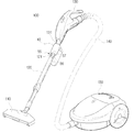
도 3은 도 1에 도시한 진공청소기용 사이클론 집진유닛이 적용된 진공청소기를 예시하는 사시도,3 is a perspective view illustrating a vacuum cleaner to which the cyclone dust collecting unit for the vacuum cleaner shown in FIG. 1 is applied;
도 4은 도 1에 도시한 진공청소기용 사이클론 집진유닛이 일체로 결합된 흡입노즐을 예시하는 사시도,4 is a perspective view illustrating a suction nozzle in which a cyclone dust collecting unit for a vacuum cleaner shown in FIG.
도 5a 및 도 5b는 도 1에 도시한 진공청소기용 사이클론 집진유닛이 내부에 설치된 진공청소기의 청소기 본체를 예시하는 평단면도 및 측단면도, 및5A and 5B are a plan sectional view and a side sectional view illustrating a cleaner body of a vacuum cleaner in which a cyclone dust collecting unit for a vacuum cleaner shown in FIG. 1 is installed; and
도 6은 도 1에 도시한 진공청소기용 사이클론 집진유닛이 내부에 설치된 진공청소기의 흡입노즐을 예시하는 부분 평단면도이다.FIG. 6 is a partial cross-sectional view illustrating a suction nozzle of a vacuum cleaner in which the cyclone dust collecting unit for the vacuum cleaner shown in FIG. 1 is installed.
*도면의 주요부분에 대한 부호의 설명** Description of the symbols for the main parts of the drawings *
10; 사이클론 집진유닛 13; 사이클론 몸체10; Cyclone
11: 회전기류발생부 15; 가이드부재 11: rotary air
17; 흡입관 21; 배출파이프17;
28; 먼지가이드 40; 먼지포집통 28;
55, 59; 록킹부 110, 110'; 흡입노즐55, 59;
120; 연장관 130; 조작핸들120;
150, 150'; 청소기 본체150, 150 '; Cleaner body
본 발명은 진공청소기에 관한 것으로, 보다 상세하게는 청소시 흡입노즐을 통해 흡입되는 공기로부터 먼지를 분리하여 수거하는 진공청소기용 사이클론 집진유닛에 관한 것이다. The present invention relates to a vacuum cleaner, and more particularly, to a cyclone dust collecting unit for vacuum cleaner to separate and collect dust from the air sucked through the suction nozzle during cleaning.
일반적으로, 진공청소기는 흡입모터를 이용하여 강한 흡입력을 발생시켜, 피 청소면에 있는 먼지나 오물(이하 '먼지'라함)을 빨아들여 피 청소면을 청소한다. 이러한 진공청소기는 통상 흡입되는 공기로부터 먼지를 수거하기 위한 먼지주머니, 또는 사이클론, 먼지통, 및 필터를 구비한 집진부를 포함한다. 따라서, 흡입모터의 흡입력에 의해 흡입된 먼지를 함유하는 공기는 집진부를 통과하면서 먼지가 제거된 후 외부로 배출된다. In general, a vacuum cleaner generates a strong suction force by using a suction motor, and sucks dust or dirt (hereinafter referred to as 'dust') on the cleaning surface to clean the cleaning surface. Such vacuum cleaners typically include a dust bag for collecting dust from inhaled air, or a dust collector with a cyclone, a dust bin, and a filter. Therefore, the air containing the dust sucked by the suction force of the suction motor is discharged to the outside after the dust is removed while passing through the dust collector.
하지만, 이러한 종래의 진공청소기는 청소를 수행함에 따라 집진부의 먼지 주머니 또는 필터에 먼지가 쌓이게 되면, 흡입모터의 흡입력이 저하되어 집진효율이 저하된다. 특히, 먼지 주머니에 먼지가 가득 차 있거나 필터가 먼지에 의해 막 힐 경우, 흡입모터는 과부하를 받게 되어 수명이 단축될 수 있다. 따라서, 사용자는 청소기 본체에 장착된 먼지 주머니 또는 먼지통과 필터를 청소기 본체로부터 분리하여 교환하거나 청소해야 하는 번거로운 작업을 자주 수행해야하는 불편함이 있다. However, when such a vacuum cleaner is cleaned, when dust is accumulated in the dust bag or the filter of the dust collecting unit, the suction power of the suction motor is lowered and the dust collection efficiency is lowered. In particular, if the dust bag is full of dust or the filter is clogged by the dust, the suction motor is overloaded and may shorten its life. Therefore, the user is inconvenient to frequently perform the cumbersome work of separating or replacing the dust bag or dust container and filter mounted on the cleaner body from the cleaner body.
이러한 문제점을 해결하기 위해, 최근에는 흡입노즐과 청소기 본체를 연결하는 연결관에 사이클론 집진유닛을 설치하여 보조적으로 먼지를 포집하여 제거할 수 있도록 한 진공청소기가 제안되어 있다. 이러한 사이클론 집진 장치를 채용한 진공청소기의 예로는 국내 실용신안 등록출원 제1993-4891호(명칭: 사이클론이 구비된 진공청소기), 국내 특허출원 제1993-5099호(명칭: 진공청소기), 특허출원 제 1999-20704호(사이클론 집진장치를 가지는 진공청소기) 등이 있다. In order to solve this problem, a vacuum cleaner has recently been proposed in which a cyclone dust collecting unit is installed at a connection pipe connecting a suction nozzle and a cleaner body to collect and remove dust. Examples of vacuum cleaners employing such cyclone dust collectors include domestic utility model registration application No. 193-4891 (name: vacuum cleaner with cyclone), domestic patent application No. 1993-5099 (name: vacuum cleaner), patent application No. 1999-20704 (a vacuum cleaner having a cyclone dust collector) and the like.
하지만, 위에서 서술한 진공청소기의 사이클론 집진유닛들은 회전기류발생부와 먼지 포집통이 별도로 구성되지 않고 하나의 원통으로 구성되어 집진효율이 낮고 먼지의 재비산이 심할 뿐 아니라, 구성이 복잡하여 수거된 먼지를 비우기가 불편한 문제점이 있다. However, the cyclone dust collecting units of the vacuum cleaner described above are composed of a single cylinder instead of the rotary air generating unit and the dust collecting unit, and have low dust collection efficiency and severe dust scattering. There is a problem that it is inconvenient to empty the dust.
본 발명은 상기와 같은 문제점을 감안하여 안출된 것으로, 본 발명의 한 목적은 비교적 간단한 구조를 가지면서도 집진효율을 향상시키고 먼지의 재비산을 보다 확실히 방지하도록 한 진공청소기용 사이클론 집진유닛을 제공하는 있다. The present invention has been made in view of the above problems, and one object of the present invention is to provide a cyclone dust collecting unit for a vacuum cleaner, which has a relatively simple structure and improves dust collecting efficiency and prevents dust from scattering more reliably. have.
본 발명의 다른 목적은 회전기류 발생부와 먼지포집통을 쉽게 분리할 수 있도록 하여, 내부에 수거된 먼지를 쉽게 버릴 수 있을 뿐 아니라, 제작, 유지 및 보 수를 쉽도록 한 진공청소기용 사이클론 집진유닛을 제공하는 있다. Another object of the present invention is to easily separate the rotary air generating unit and the dust collector, to easily discard the dust collected therein, cyclone dust collection for the vacuum cleaner to facilitate the production, maintenance and maintenance There is to provide a unit.
상기와 같은 목적을 달성하기 위한 본 발명의 실시예에 따른 진공청소기용 사이클론 집진유닛은, 흡입노즐을 통해 흡입된 공기를 회전시키는 회전기류발생부; 및 개방단부와 밀폐단부를 구비하고, 회전기류발생부에 의해 발생된 회전기류에 의해 원심분리된 먼지를 수거하는 먼지포집통을 포함하는 것을 특징으로 한다. 회전기류발생부와 먼지포집통은 각각 독립된 관부재로 형성되고, 회전기류발생부는 공기유입구를 형성한 제1단부와 공기배출구를 형성한 제2단부를 포함하는 사이클론 몸체, 사이클론 몸체 내의 제1단부측에 배치되고 공기유입구를 통해 유입된 공기를 가이드하는 나선형 가이드부재, 사이클론 몸체 내의 제2단부측에 배치되고 공기배출구를 관통하여 사이클론 몸체 외부로 연장된 배출파이프, 및 사이클론 몸체의 제2단부 일측에 형성된 먼지배출개구와 먼지포집통의 개방단부를 연결하고, 먼지배출개구를 통해 배출되는 먼지를 먼지포집통의 개방단부로 가이드하는 먼지 가이드를 포함한다. Cyclone dust collecting unit for a vacuum cleaner according to an embodiment of the present invention for achieving the above object, a rotary air flow generating unit for rotating the air sucked through the suction nozzle; And a dust collecting container having an open end and a closed end, for collecting dust centrifuged by the rotary airflow generated by the rotary airflow generation unit. The rotary airflow generating unit and the dust collecting container are each formed by independent pipe members, and the rotary airflow generating unit includes a first end forming an air inlet and a second end forming an air outlet, and a first end in the cyclone body. A helical guide member disposed at the side and guiding the air introduced through the air inlet, a discharge pipe disposed at the second end side in the cyclone body and extending out of the cyclone body through the air outlet, and one end of the second end of the cyclone body And a dust guide connecting the dust discharge opening formed in the open end of the dust collecting container to guide the dust discharged through the dust discharge opening to the open end of the dust collecting container.
여기서, 회전기류발생부는 흡입노즐과 청소기 본체 사이, 바람직하게는, 흡입노즐과 연장관 사이, 연장관과 조작핸들 사이, 및 흡입호스와 청소기 본체 사이 중 한 곳에 탈착할 수 있게 설치될 수 있다. 이를 위해, 사이클론 몸체는, 각각 제1단부 및 배출파이프에 설치되고, 사이클론 몸체를 흡입노즐과 연장관, 연장관과 조작핸들, 또는 흡입호스와 청소기 본체에 탈착 할 수 있게 록킹하는 제1 및 제2록킹부를 포함하는 것이 바람직하다. Here, the rotary air flow generating unit may be installed to be detachable between one of the suction nozzle and the cleaner body, preferably between the suction nozzle and the extension tube, between the extension tube and the operation handle, and between the suction hose and the cleaner body. To this end, the cyclone body is installed at the first end and the discharge pipe, respectively, and the first and second locking locking the cyclone body to be detachable to the suction nozzle and the extension tube, the extension tube and the operation handle or the suction hose and the cleaner body It is preferable to include a part.
선택적으로, 회전기류발생부는 흡입노즐, 연장관, 조작핸들, 또는 흡입호스와 일체로 형성될 수 있다. 또한, 위와 같은 구성의 회전기류발생부와 먼지포집통은 청소기 본체 또는 흡입노즐내에서 먼지를 수거하여 포집하도록 배치될 수 있다. Optionally, the rotary airflow generation unit may be integrally formed with the suction nozzle, the extension tube, the operation handle, or the suction hose. In addition, the rotary airflow generating unit and the dust collecting container of the above configuration may be arranged to collect and collect the dust in the cleaner body or the suction nozzle.
회전기류발생부의 사이클론 몸체와 먼지포집통은 각각 원통형 관과 통으로 형성되고, 서로 나란하게 배치된 것이 바람직하다. The cyclone body and the dust collecting cylinder of the rotary airflow generating unit are each formed of a cylindrical tube and a cylinder, and are preferably arranged in parallel with each other.
회전기류발생부의 사이클론 몸체는 먼지포집통과 같거나 작은 세로방향 길이를 가지는 것이 바람직하다.It is preferable that the cyclone body of the rotary airflow generator has a longitudinal length that is equal to or smaller than the dust collecting container.
회전기류발생부의 사이클론 몸체 또는 먼지포집통은 투명한 플라스틱 재료로 형성된 것이 바람직하다.It is preferable that the cyclone body or the dust collector of the rotary airflow generating unit is formed of a transparent plastic material.
또, 공기흡입구를 형성한 제1단부는 별도의 흡입관으로 형성되어 사이클론 몸체에 착탈할 수 있게 결합되도록 구성될 수 있다. 이 경우, 흡입관은 사이클론 몸체와 나사식으로 결합된 것이 바람직하다.In addition, the first end forming the air intake port may be formed as a separate suction pipe can be configured to be detachably coupled to the cyclone body. In this case, the suction tube is preferably screwed with the cyclone body.
배출파이프는 사이클론 몸체의 공기배출구와 착탈 할 수 있게 결합될 수 있다. 이때, 배출파이프는 공기배출구와 나사식으로 결합된 것이 바람직하다. The exhaust pipe may be detachably coupled with the air outlet of the cyclone body. At this time, the discharge pipe is preferably coupled to the air outlet port.
먼지포집통은 개방단부에서 먼지가이드와 착탈 할 수 있게 결합될 수 있다. 이때, 먼지 포집통의 개방단부는 먼지가이드와 나사식으로 결합된 것이 바람직하다. The dust collector can be detachably combined with the dust guide at the open end. At this time, the open end of the dust collector is preferably coupled to the dust guide screw.
이하, 첨부된 도면을 참조하여 본 발명의 양호한 실시예들에 따른 진공청소기용 사이클론 집진유닛에 대하여 상세히 설명하기로 한다.Hereinafter, a cyclone dust collecting unit for a vacuum cleaner according to preferred embodiments of the present invention will be described in detail with reference to the accompanying drawings.
도 3은 본 발명의 양호한 일실시예에 따른 진공청소기용 사이클론 집진유 닛(10)이 적용되는 진공청소기(100)의 일 예를 나타낸 도면이다. 3 is a view showing an example of a
도 3을 참조하면, 진공청소기(100)는 먼지나 오물 등이 함유된 공기를 흡입하는 흡입노즐(110), 흡입노즐(110)에 연결된 다단식 연장관(120), 조작핸들(130), 조작핸들(130)과 다단식 연장관(120) 사이에 설치된 사이클론 집진유닛(10), 조작핸들(130)에 연결된 흡입호스(140), 및 흡입호스(140)에 연결되고 집진실(도시하지 않음)과 모터실(도시하지 않음)로 분리 구획된 청소기 본체(150)를 포함한다.Referring to FIG. 3, the
도 1 및 도 2는 본 발명의 일실시예에 따른 진공청소기용 사이클론 집진유닛(10)을 도시한 결합 및 분해 단면도이다. 1 and 2 are combined and exploded cross-sectional view showing a cyclone
도 1, 도 2 및 도 3에 도시한 바와 같이, 진공청소기용 먼지감지 유닛(10)은 다단식 연장관(120)과 조작핸들(130) 사이에 탈착할 수 있게 설치되고, 회전기류발생부(11), 및 먼지포집통(40)을 포함한다. 1, 2 and 3, the
회전기류발생부(11)는 연장관(120)과 조작핸들(130) 사이에 연결되고, 흡입노즐(110)을 통해 흡입된 공기를 회전시켜 흡입노즐(110)을 통해 흡입된 먼지 등이 함유된 공기를 원심분리한다. 회전기류발생부(11)는 사이클론 몸체(13), 가이드부재(15), 배출파이프(21), 및 먼지가이드(28)를 포함한다.The rotary
사이클론 몸체(13)는 원통형 관(14)으로 구성된다. 원통형 관(14)은 외부에서 먼지에 의한 막힘 등을 파악할 수 있도록 투명한 플라스틱 재료로 형성된다. 원통형 관(14)은 상단부(13a)에서 공기유입구(18)를 형성한 흡입관(17)과 나사식으로 결합된다. 이를 위해, 상단부(14a)의 내측에는 암나사홈(14c; 도 2참조)이 형성되고 흡입관(17)의 상응하는 단부에는 수나사홈(17a; 도 2참조)이 형성되어 있다. The
가이드부재(15)는 흡입관(17)의 공기유입구(18)를 통해 유입된 공기를 가이드 하기 위한 것으로, 원통형 관(14) 내에서 하단부(14a)의 암나사홈(14c) 위쪽에 배치된다. 가이드부재(15)는 원통부재(15a)와 나선형 블레이드(15b)를 구비하여 원통형 관(14)내로 흡입된 공기가 나선형태로 선회하는 회전기류를 형성하도록 가이드한다. The
원통형 관(14)의 상단부(14b)에서는 후술하는 배출파이프(21)가 관통 결합되는 공기배출구(19)를 형성하고 있다. 공기배출구(19)는 내주면에 암사사홈(19a; 도 2 참조)을 형성하고 있다. In the
배출파이프(21)는 원통형 관(14) 내의 상단부(14b) 측에 배치되고 공기배출구(19)를 관통하여 원통형 관(14) 외부로 연장된다. 배출파이프(21)는 가이드부재(15)에 의해 나선형태로 선회하는 공기를 외주면을 따라 나선형 형태로 가이드하여 먼지를 원심분리함과 동시에 원통형 관(14)내의 공기를 조작핸들(130) 쪽으로 배출되도록 가이드한다. 배출파이프(21)는 공기배출구(19)와 결합 및 분리될 수 있도록 공기배출구(19)와 대응하는 상단부의 외부면에 공기배출구(19)의 암사사홈(19a)과 결합되는 수나사홈(21a)을 형성하고 있다. The
원통형 관(14)의 상단부(14b)의 일측에는 먼지배출개구(29)가 먼지가이드(28)와 대향하게 형성된다. On one side of the
먼지가이드(28)는 원심력에 의해 먼지배출개구(29)를 통해 배출되는 먼지를 후술하는 먼지포집통(40)의 원통형 통(41)으로 가이드한다. 먼지 가이드(28)는, 일측에서 먼지배출개구(29)와 연통하고 하단에서 원통형 통(41)의 개방단부(41a)와 연통하도록, 원통형 관(14)과 일체로 형성된 슬리이브(30)로 구성된다. 슬리이브(30)의 하단 내주면에는 암사사홈(30a)이 형성되어 있다.The
먼지포집통(40)은 먼지배출개구(29)를 통해 먼지가이드(28)를 따라 배출되는 먼지를 수거한다. 먼지포집통(40)은 먼지가이드(28)의 슬리이브(30)의 하단부에 분리될 수 있게 결합된 원통형 통(41)으로 구성된다. 원통형 통(41)은 개방단부(41a)와 밀폐단부(41b)를 구비한다. 개방단부(41a)는 외주면에 슬리이브(30)의 암나사홈(30a)와 결합되는 수나사홈(41c)을 형성하고 있다. 따라서, 개방단부(41a)의 수나사홈(41c)이 슬리이브(30)의 암나사홈(30a)에 결합될 때, 원통형 통(41)은 원통형 관(14)과 나란하게 배치된다. The
원통형 통(41)은 사용자가 원통형 통(41)내에 먼지가 가득찼는지를 알 수 있도록 투명한 플라스틱 재료로 구성된 것이 바람직하다. 또한, 원통형 통(41)은, 먼지를 수거하는 공간을 충분히 확보하고 먼지가 원통형 관(14)으로 역류하는 것을 방지하기 위해, 원통형 관(14)과 같거나 큰 세로방향 길이를 가지는 것이 바람직하다.
도 1 및 도 3을 참조하면, 사이클론 집진유닛(10)을 다단식 연장관(120)과 조작핸들(130) 사이에 탈착할 수 있게 고정하기 위해, 사이클론 집진유닛(10)의 흡입관(18)과 배출파이프(21)에는 제1 및 제2록킹부(55, 59)가 각각 형성되어 있다. 이때, 흡입관(18)의 하단부는 다단식 연장관(120)의 상단부(도시하지 않음)를 수용하도록 다단식 연장관(120)의 상단부 보다 큰 직경을 가지며, 배출파이프(21)의 상단부는 조작핸들(130)의 하단부(131)에 삽입되도록 조작핸들(130)의 하단부(131) 보다 보다 작은 직경을 가진다.1 and 3, in order to fix the cyclone
흡입관(18)에 형성된 제1록킹부(55)는 다단식 연장관(120)의 상단부에 형성된 제1대응록킹부(도시하지 않음)의 제1 대응 가요성 돌기(121; 도 3 참조)를 수용하는 제1고정홈(56), 및 제1대응록킹부로부터의 분리시 제1고정홈(56)에 삽입된 제1대응 가요성돌기(121)를 탄력적으로 아래로 눌러 제1대응 가요성 돌기가 제1고정홈(56)으로부터 쉽게 빠지도록 하는 누름부(57a)를 갖는 제1버튼(57)으로 구성된다. The
배출파이프(21)에 형성된 제2록킹부(58)는 조작핸들(130)의 하단부(131)에 형성된 제2대응록킹부(도시하지 않음)와의 접속시 제2대응록킹부의 제2고정홈(도시하지 않음)에 삽입되는 제2가요성 돌기(59)로 구성된다. 제2가요성 돌기(59)는 제2록킹부(58)가 제2대응록킹로부터의 분리될 때, 제2대응접속부의 제2버튼(도시하지 않음)에 의해 눌러져 제2고정홈으로부터 빠지게 된다. The
이상에서, 사이클론 집진유닛(10)은 제1 및 제2록킹부(55, 58)에 의해 다단식 연장관(120) 및 조작핸들(130)의 제1 및 제2대응록킹부에 탈착할 수 있게 장착된 것으로 예시하였지만, 본 발명은 이것으로 한정하지 않는다. 예를들면, 사이클론 집진유닛(10)은 동일한 구성의 제1 및 제2접속부(55, 58)와 제1 및 제2대응접속부에 의해 흡입노즐(110)과 연장관(120) 사이, 또는 흡입호스(140)와 청소기 본체(150) 사이에서도 탈착할 수 있게 설치될 수 있음은 물론이다. In the above, the cyclone
또, 사이클론 집진유닛(10)은 흡입노즐(110), 다단식 연장관(120), 조작핸들(130) 및 청소기 본체(150)들 사이에 탈착할 수 있게 설치되는 대신, 흡입 노 즐(110), 연장관(120), 조작핸들(130) 또는 흡입 호스(140)(도 4 참조)에 일체로 형성될 수 있다. 이 경우, 배출파이프(11)의 상단부에는 대응접속부에 상응하는 하나의 접속부(55, 또는 58)만 형성된다. In addition, the cyclone
또한, 도 5a 내지 도 6에 도시한 바와 같이, 본 발명에 따른 사이클론 집진유닛(10)의 회전기류발생부(11)와 먼지포집통(40)은 동일한 구성과 원리로, 필터(165)와 흡입모터(151)를 구비하는 청소기 본체(150'; 도 5a 및 도 5b 참조), 또는 흡입노즐(110'; 도 6 참조)에도 설치될 수도 있을 것이다. In addition, as shown in Figures 5a to 6, the rotary
이상에서 설명한 바와 같이, 본 발명의 일실시예에 따른 사이클론 집진유닛(10)은 도 2에 도시한 바와 같이 4 개의 부품, 즉 흡입관(17), 사이클론 몸체(13). 배출파이프(21), 및 먼지포집통(40)이 서로 결합 또는 분리될 수 있게 구성된다. 따라서, 사이클론 집진유닛(10)은 4 개의 부품만 결합하면 조립이 완성되므로 제작이 쉬울 뿐 아니라, 회전기류발생부(11)가 먼지 등에 의해 막힐 경우에는 흡입관(17)과 배출파이프(21)를 사이클론 몸체(13)로부터 분리하여 먼지 등을 제거하면, 해결되고, 먼지포집통(40)에 먼지가 가득 찬 경우에는 먼지포집통(40)만을 연결부재(28)로부터 분리하여 먼지를 버리면 되므로, 유지 및 보수가 편리하다. As described above, the cyclone
이상과 같이 구성된 본 발명의 양호한 일시예에 따른 사이클론 집진유닛(10)의 동작을 도 1 내지 도 3을 참조하여 상세히 설명하면 다음과 같다.The operation of the cyclone
청소기에 전원을 인가함과 함께, 흡입노즐(110)을 피청소면을 따라 이동시키면, 피청소면에 묻어있는 먼지가 포함된 공기는 흡입노즐(110)의 공기흡입구(도시하지 않음), 연장관(120), 및 흡입관(17)을 통해 사이클론 몸체(13) 내부로 유입된 다. 유입된 공기는 가이드부재(15) 및 배출파이프(21)를 통해 선회기류를 형성하며, 그 결과 공기속에 포함된 비교적 큰 오물은 원심력에 의해 먼지배출개구(29)를 통해 배출되어 먼지가이드(28)를 통해 오물포집통(40)에 수거된다. When power is supplied to the cleaner and the
그리고, 큰 오물이 제거된 공기는 배출파이프(21)를 통과하여 조작핸들(130)과 흡입호스(140)을 통해 청소기 본체(150)로 유입된다. 청소기 본체(150)내로 유입된 공기는 집진실에서 다시 오물이 분리된 후 모터실을 통해 외부로 배출된다. Then, the large dirt is removed air is passed through the
청소가 완료된 후, 먼지포집통(40)에 먼지가 일정수준 이상 채워져서 먼지포집통(40)내의 먼지를 비우고자 할 경우, 사용자는 먼지포집통(40)을 수나사홈(41c)이 암나사홈(30a)로부터 풀리는 방향으로 회전시켜 먼지가이드(28)로부터 분리한 다음 먼지포집통(40)의 먼지를 버리고, 다시 먼지포집통(40)을 수나사홈(41c)이 암나사홈(30a)에 말물리는 방향으로 회전시켜 먼지가이드(28)에 결합한다. After the cleaning is completed, when the
이상에서 설명한 바와 같이, 본 발명에 따른 진공청소기용 사이클론 집진유닛은, 먼지를 원심분리하는 회전기류발생부가 원통형 관, 나선형 가이드부재, 및 배출파이프로 구성되고, 먼지를 수거하는 먼지포집통이 원통형 관과 별도의 원통형 통으로 구성된다. 따라서, 사이클론 집진유닛은 비교적 간단한 구조를 가지면서도 집진효율을 향상시키고 먼지의 재비산을 보다 확실히 방지하도록 할 수 있다. As described above, the cyclone dust collecting unit for a vacuum cleaner according to the present invention includes a rotary airflow generation unit for centrifuging dust, consisting of a cylindrical tube, a spiral guide member, and a discharge pipe, and a dust collecting cylinder for collecting dust. It consists of a tube and a separate cylindrical barrel. Therefore, the cyclone dust collecting unit can have a relatively simple structure and improve dust collection efficiency and more reliably prevent dust re-spreading.
또, 본 발명에 따른 진공청소기용 사이클론 집진유닛은, 흡입관, 사이클론 몸체. 배출파이프, 및 먼지포집통이 서로 결합 또는 분리될 수 있게 구성된다. 따라서, 사이클론 집진유닛은 4 개의 부품만 결합하면 조립이 완성되므로 제작이 쉬 울 뿐 아니라, 회전기류발생부가 먼지 등에 의해 막힐 경우에는 흡입관과 배출파이프를 사이클론 몸체로부터 분리하여 먼지 등을 제거하면, 해결되고, 먼지포집통에 먼지가 가득 찬 경우에는 먼지포집통만을 연결부재로부터 분리하여 먼지를 버리면 되므로, 유지 및 보수가 편리하다. In addition, the vacuum cleaner cyclone dust collecting unit according to the present invention, the suction pipe, the cyclone body. The discharge pipe and the dust collector are configured to be coupled or separated from each other. Therefore, the cyclone dust collecting unit is easy to manufacture because only four parts are combined, and if the rotary airflow generating unit is blocked by dust, the suction pipe and the discharge pipe are separated from the cyclone body to remove the dust. When the dust collector is full of dust, only the dust collector can be separated from the connecting member to discard the dust, which is convenient for maintenance and repair.
또한, 본 발명에 따른 진공청소기용 사이클론 집진유닛은 사이클론 몸체 및/또는 먼지 포집통이 투명한 플라스틱으로 구성되므로, 사용자가 사이클론 몸체의 막힘이나 먼지제거 주기를 쉽게 파악할 수 있다. 그 결과, 사이클론 몸체를 막히게 하거나 먼지포집통에 수거된 먼지를 적절한 시기에 제거할 수 있으며, 그에 따라 먼지에 의한 사이클론 몸체의 막힘 및/또는 먼지포집통에 수거된 먼지의 재비산으로 인한 먼지제거효율 저하를 방지할 수 있다. In addition, the cyclone dust collecting unit for a vacuum cleaner according to the present invention is composed of a transparent plastic cyclone body and / or dust collector, the user can easily identify the clogging or dust removal cycle of the cyclone body. As a result, the cyclone body can be clogged or dust collected in the dust collector can be removed in a timely manner, thereby eliminating dust due to clogging of the cyclone body by dust and / or re-flying of the dust collected in the dust collector. The fall of efficiency can be prevented.
이상에서, 본 발명을 본 발명의 원리를 예시하기 위한 바람직한 실시예와 관련하여 도시하고 설명하였으나, 본 발명은 그와 같이 도시되고 설명된 그대로의 구성 및 작용으로 한정되는 것이 아니다. 즉, 본 발명이 속하는 기술분야에서 통상의 지식을 가진자라면 첨부된 특허청구범위의 사상 및 범주를 일탈함이 없이 본 발명에 대한 다수의 변경 및 수정이 가능하다는 것을 잘 이해할 수 있을 것이다. 따라서, 그러한 모든 적절한 변경 및 수정과 균등물들도 본 발명의 범위에 속하는 것으로 간주되어야 할 것이다.While the invention has been shown and described in connection with preferred embodiments for illustrating the principles of the invention, the invention is not limited to the configuration and operation as such is shown and described. That is, those skilled in the art to which the present invention pertains will appreciate that many changes and modifications can be made to the present invention without departing from the spirit and scope of the appended claims. Accordingly, all such suitable changes and modifications and equivalents should be considered to be within the scope of the present invention.
Claims (15)
Priority Applications (7)
| Application Number | Priority Date | Filing Date | Title |
|---|---|---|---|
| KR1020070049343A KR20080102647A (en) | 2007-05-21 | 2007-05-21 | Cyclone Dust Collector for Vacuum Cleaner |
| US11/899,595 US20080289306A1 (en) | 2007-05-21 | 2007-09-06 | Cyclone dust-separating unit for use in vacuum cleaner |
| JP2008011519A JP2008284339A (en) | 2007-05-21 | 2008-01-22 | Cyclone dust collection unit for vacuum cleaner |
| AU2008200453A AU2008200453B2 (en) | 2007-05-21 | 2008-01-30 | Cyclone dust-separating unit for use in vacuum cleaner |
| EP08101478.9A EP1994870A3 (en) | 2007-05-21 | 2008-02-11 | Cyclone dust-separating unit for use in vacuum cleaner |
| CNA200810005795XA CN101310668A (en) | 2007-05-21 | 2008-02-14 | Cyclonic dust separation unit for vacuum cleaners |
| RU2008105219/12A RU2370201C1 (en) | 2007-05-21 | 2008-02-14 | Cyclone dust separation component meant for vacuum cleaner |
Applications Claiming Priority (1)
| Application Number | Priority Date | Filing Date | Title |
|---|---|---|---|
| KR1020070049343A KR20080102647A (en) | 2007-05-21 | 2007-05-21 | Cyclone Dust Collector for Vacuum Cleaner |
Publications (1)
| Publication Number | Publication Date |
|---|---|
| KR20080102647A true KR20080102647A (en) | 2008-11-26 |
Family
ID=39683709
Family Applications (1)
| Application Number | Title | Priority Date | Filing Date |
|---|---|---|---|
| KR1020070049343A Ceased KR20080102647A (en) | 2007-05-21 | 2007-05-21 | Cyclone Dust Collector for Vacuum Cleaner |
Country Status (7)
| Country | Link |
|---|---|
| US (1) | US20080289306A1 (en) |
| EP (1) | EP1994870A3 (en) |
| JP (1) | JP2008284339A (en) |
| KR (1) | KR20080102647A (en) |
| CN (1) | CN101310668A (en) |
| AU (1) | AU2008200453B2 (en) |
| RU (1) | RU2370201C1 (en) |
Cited By (5)
| Publication number | Priority date | Publication date | Assignee | Title |
|---|---|---|---|---|
| KR101369234B1 (en) * | 2010-05-31 | 2014-03-04 | 삼성전자주식회사 | Cyclone dust collecting apparatus and a handy-type cleaner having the same |
| US8671510B2 (en) | 2010-05-31 | 2014-03-18 | Samsung Electronics Co., Ltd. | Hand-held and stick vacuum cleaner |
| KR20160074258A (en) * | 2014-12-18 | 2016-06-28 | 삼성전자주식회사 | Cleaning Apparatus |
| US10517449B2 (en) | 2010-05-31 | 2019-12-31 | Samsung Electronics Co., Ltd. | Cyclone dust collecting apparatus and hand-held cleaner having the same |
| US11938491B2 (en) | 2016-12-27 | 2024-03-26 | Omachron Intellectual Property Inc. | Surface cleaning apparatus |
Families Citing this family (30)
| Publication number | Priority date | Publication date | Assignee | Title |
|---|---|---|---|---|
| KR101471026B1 (en) * | 2008-03-05 | 2014-12-11 | 삼성전자주식회사 | Vacuum cleaner for optional dust bag or cyclone dust collector |
| KR101082023B1 (en) | 2009-02-16 | 2011-11-10 | 주식회사 리트코 | Non-powered Air Filtering Apparatus using Cyclone Structure |
| US11612288B2 (en) * | 2009-03-13 | 2023-03-28 | Omachron Intellectual Property Inc. | Surface cleaning apparatus |
| US10722086B2 (en) | 2017-07-06 | 2020-07-28 | Omachron Intellectual Property Inc. | Handheld surface cleaning apparatus |
| US8661607B2 (en) * | 2009-11-04 | 2014-03-04 | Lg Electronics Inc. | Visualization device for dust collection of vacuum cleaner |
| JP5710203B2 (en) * | 2010-01-29 | 2015-04-30 | サムスン エレクトロニクス カンパニー リミテッド | Vacuum cleaner brush assembly |
| CN102334954B (en) * | 2011-10-18 | 2013-10-02 | 江苏美的春花电器股份有限公司 | Dust cup of dust collector and dust collector |
| CN102362802B (en) * | 2011-10-18 | 2013-10-02 | 江苏美的春花电器股份有限公司 | Dust cup of dust collector and duct collector |
| CN102334955B (en) * | 2011-10-18 | 2013-06-05 | 江苏美的春花电器股份有限公司 | Dust cup device of dust collector and dust collector |
| KR101197908B1 (en) * | 2011-10-31 | 2012-11-05 | 박현정 | A container for centrifugal separation |
| KR101197974B1 (en) | 2011-11-01 | 2012-11-05 | 박현정 | A container for centrifugal separator capable of rapid centrifugal separation |
| US10631697B2 (en) | 2014-02-14 | 2020-04-28 | Techtronic Industries Co. Ltd. | Separator configuration |
| US10117551B2 (en) | 2014-10-22 | 2018-11-06 | Techtronic Industries Co. Ltd. | Handheld vacuum cleaner |
| CN107205603B (en) | 2014-10-22 | 2020-10-13 | 创科实业有限公司 | Vacuum cleaner with cyclone |
| CN106714643B (en) | 2014-10-22 | 2019-05-21 | 创科实业有限公司 | Vacuum cleaner with cyclone |
| GB201507588D0 (en) * | 2015-05-01 | 2015-06-17 | Hubble Justin L And Gamble Robert | Vacuum storage box |
| EP3387978B1 (en) | 2015-12-10 | 2024-04-24 | Jiangsu Midea Cleaning Appliances Co., Ltd. | Upright vacuum cleaner |
| JP6434923B2 (en) * | 2016-01-25 | 2018-12-05 | 本田技研工業株式会社 | Internal combustion engine |
| GB2554929B (en) * | 2016-10-14 | 2022-03-02 | Techtronic Floor Care Tech Ltd | Cyclonic separation device |
| US11529035B2 (en) | 2017-02-06 | 2022-12-20 | Aktiebolaget Electrolux | Separation system for vacuum cleaner and vacuum cleaner comprising the separation system |
| US10537216B2 (en) | 2017-07-06 | 2020-01-21 | Omachron Intellectual Property Inc. | Handheld surface cleaning apparatus |
| US10631693B2 (en) | 2017-07-06 | 2020-04-28 | Omachron Intellectual Property Inc. | Handheld surface cleaning apparatus |
| US10506904B2 (en) | 2017-07-06 | 2019-12-17 | Omachron Intellectual Property Inc. | Handheld surface cleaning apparatus |
| US10750913B2 (en) | 2017-07-06 | 2020-08-25 | Omachron Intellectual Property Inc. | Handheld surface cleaning apparatus |
| US10842330B2 (en) | 2017-07-06 | 2020-11-24 | Omachron Intellectual Property Inc. | Handheld surface cleaning apparatus |
| US10702113B2 (en) | 2017-07-06 | 2020-07-07 | Omachron Intellectual Property Inc. | Handheld surface cleaning apparatus |
| JP7257798B2 (en) * | 2019-01-24 | 2023-04-14 | 株式会社マキタ | Cyclone unit |
| CN213046752U (en) * | 2020-06-23 | 2021-04-27 | 无锡睿米信息技术有限公司 | an emptying station |
| CN112316570B (en) * | 2020-10-15 | 2022-05-20 | 中国石油大学(华东) | A compact industrial exhaust fine particulate matter efficient removal and cooling device and method |
| GB2601788B (en) * | 2020-12-10 | 2023-08-16 | Dyson Technology Ltd | Vacuum cleaner |
Family Cites Families (20)
| Publication number | Priority date | Publication date | Assignee | Title |
|---|---|---|---|---|
| US1360349A (en) * | 1920-04-21 | 1920-11-30 | Wright William Lincoln | Steam and oil separator |
| US2594805A (en) * | 1945-06-26 | 1952-04-29 | Garrett Corp | Air cleaner |
| FR1414781A (en) * | 1964-02-06 | 1965-10-22 | Prec Mecanique Labinal | Improvements to filters for gaseous fluids |
| US5350432A (en) * | 1992-04-23 | 1994-09-27 | Goldstar Co., Ltd. | Dirt filtering and collecting apparatus for vacuum cleaner |
| JPH08322768A (en) * | 1995-06-02 | 1996-12-10 | Sharp Corp | Electric vacuum cleaner |
| GB9711364D0 (en) * | 1997-06-02 | 1997-07-30 | Arnold Arthur J | Vacuum cleaners |
| US6003196A (en) * | 1998-01-09 | 1999-12-21 | Royal Appliance Mfg. Co. | Upright vacuum cleaner with cyclonic airflow |
| KR20010026685A (en) * | 1999-09-08 | 2001-04-06 | 구자홍 | Cyclone dust collector |
| KR100317117B1 (en) | 1998-12-02 | 2001-12-22 | 이충전 | Vacuum cleaner having cyclone dust-collecting apparatus |
| US20040139710A1 (en) * | 1999-05-21 | 2004-07-22 | Lewis Illingworth | Passive transfer chamber separator |
| US6048249A (en) * | 1999-07-19 | 2000-04-11 | Vandenberg; Anthony Peter | Plastic building block toy cleanup vacuum attachment |
| KR100437371B1 (en) * | 2000-07-26 | 2004-06-25 | 삼성광주전자 주식회사 | Cyclone dust-collecting apparatus for Vaccum Cleaner |
| DE60236192D1 (en) * | 2001-10-12 | 2010-06-10 | Arcelik As | |
| KR100478641B1 (en) * | 2002-06-04 | 2005-03-24 | 삼성광주전자 주식회사 | Cyclone-type dust collect apparatus for vacuum cleaner |
| WO2005053494A2 (en) * | 2003-11-26 | 2005-06-16 | Electrolux Home Care Products, Ltd. | Dust separation system |
| JP2005177288A (en) * | 2003-12-22 | 2005-07-07 | Toshiba Tec Corp | Electric vacuum cleaner |
| JP2005211546A (en) * | 2004-02-02 | 2005-08-11 | Sanyo Electric Co Ltd | Dust collection device |
| GB2417702B (en) * | 2004-09-01 | 2007-10-24 | Bissell Homecare Inc | Cyclone separator with fine particle separation member |
| KR100615360B1 (en) * | 2005-04-18 | 2006-08-28 | 삼성광주전자 주식회사 | Vacuum cleaner with cyclone dust collector and cyclone dust collector |
| JP4844071B2 (en) * | 2005-09-30 | 2011-12-21 | 積水ハウス株式会社 | Air purification device for residential ventilation unit |
-
2007
- 2007-05-21 KR KR1020070049343A patent/KR20080102647A/en not_active Ceased
- 2007-09-06 US US11/899,595 patent/US20080289306A1/en not_active Abandoned
-
2008
- 2008-01-22 JP JP2008011519A patent/JP2008284339A/en active Pending
- 2008-01-30 AU AU2008200453A patent/AU2008200453B2/en not_active Ceased
- 2008-02-11 EP EP08101478.9A patent/EP1994870A3/en not_active Withdrawn
- 2008-02-14 CN CNA200810005795XA patent/CN101310668A/en active Pending
- 2008-02-14 RU RU2008105219/12A patent/RU2370201C1/en not_active IP Right Cessation
Cited By (6)
| Publication number | Priority date | Publication date | Assignee | Title |
|---|---|---|---|---|
| KR101369234B1 (en) * | 2010-05-31 | 2014-03-04 | 삼성전자주식회사 | Cyclone dust collecting apparatus and a handy-type cleaner having the same |
| US8671510B2 (en) | 2010-05-31 | 2014-03-18 | Samsung Electronics Co., Ltd. | Hand-held and stick vacuum cleaner |
| US10517449B2 (en) | 2010-05-31 | 2019-12-31 | Samsung Electronics Co., Ltd. | Cyclone dust collecting apparatus and hand-held cleaner having the same |
| US11484164B2 (en) | 2010-05-31 | 2022-11-01 | Samsung Electronics Co., Ltd. | Cyclone dust collecting apparatus and handheld cleaner having the same |
| KR20160074258A (en) * | 2014-12-18 | 2016-06-28 | 삼성전자주식회사 | Cleaning Apparatus |
| US11938491B2 (en) | 2016-12-27 | 2024-03-26 | Omachron Intellectual Property Inc. | Surface cleaning apparatus |
Also Published As
| Publication number | Publication date |
|---|---|
| AU2008200453B2 (en) | 2010-01-21 |
| RU2370201C1 (en) | 2009-10-20 |
| AU2008200453A1 (en) | 2008-12-11 |
| US20080289306A1 (en) | 2008-11-27 |
| EP1994870A3 (en) | 2015-08-19 |
| JP2008284339A (en) | 2008-11-27 |
| RU2008105219A (en) | 2009-08-20 |
| EP1994870A2 (en) | 2008-11-26 |
| CN101310668A (en) | 2008-11-26 |
Similar Documents
| Publication | Publication Date | Title |
|---|---|---|
| KR20080102647A (en) | Cyclone Dust Collector for Vacuum Cleaner | |
| KR100392606B1 (en) | cyclone dust-collecting apparatus for vacuum cleaner | |
| RU2437611C2 (en) | Portable cleaning device | |
| RU2332920C2 (en) | Multicyclonic dust separating device (variants) | |
| KR100500833B1 (en) | Dust collecting apparatus of vacuum cleaner having plural cyclones | |
| US7065826B1 (en) | Cyclonic bagless vacuum cleaner with slotted baffle | |
| US6332239B1 (en) | Vacuum cleaner with tangential separation of trash | |
| US8016902B2 (en) | Cyclonic utility vacuum | |
| KR100648959B1 (en) | Multi Cyclone Separator | |
| RU2266034C2 (en) | Filtering unit for cyclone-type dust collecting apparatus of vacuum cleaner | |
| US7419522B2 (en) | Dirt separation and collection assembly for vacuum cleaner | |
| KR100623915B1 (en) | Dust separator | |
| KR20040110883A (en) | Dust separator for cyclone cieaner | |
| US6732405B2 (en) | Vacuum cleaner | |
| JP2004358210A (en) | Cyclone dust collector for vacuum cleaner | |
| TWI576081B (en) | Vacuum cleaner | |
| GB2396098A (en) | Frustoconical deflecting apparatus of vacuum cleaner filter assembly | |
| JP4169735B2 (en) | Vacuum cleaner | |
| CN108618705A (en) | Cyclone separator | |
| EP1632162A2 (en) | Cyclonic separator for a suction cleaner and assembly of such separators | |
| CN1744844A (en) | Dust separator and collector arrangement for suction cleaner | |
| CN113260294A (en) | Debris compactor for vacuum cleaner and vacuum cleaner with debris compactor | |
| KR200342947Y1 (en) | Cyclone dust-collecting apparatus for a vacuum cleaner | |
| KR101208492B1 (en) | Dust Collector for Vacuum Cleaner | |
| KR0133762B1 (en) | Wet and dry type vacuum cleaner |
Legal Events
| Date | Code | Title | Description |
|---|---|---|---|
| A201 | Request for examination | ||
| PA0109 | Patent application |
Patent event code: PA01091R01D Comment text: Patent Application Patent event date: 20070521 |
|
| PA0201 | Request for examination | ||
| E902 | Notification of reason for refusal | ||
| PE0902 | Notice of grounds for rejection |
Comment text: Notification of reason for refusal Patent event date: 20080228 Patent event code: PE09021S01D |
|
| AMND | Amendment | ||
| E902 | Notification of reason for refusal | ||
| PE0902 | Notice of grounds for rejection |
Comment text: Notification of reason for refusal Patent event date: 20080822 Patent event code: PE09021S01D |
|
| AMND | Amendment | ||
| PG1501 | Laying open of application | ||
| E601 | Decision to refuse application | ||
| PE0601 | Decision on rejection of patent |
Patent event date: 20090216 Comment text: Decision to Refuse Application Patent event code: PE06012S01D Patent event date: 20080822 Comment text: Notification of reason for refusal Patent event code: PE06011S01I Patent event date: 20080228 Comment text: Notification of reason for refusal Patent event code: PE06011S01I |
|
| AMND | Amendment | ||
| J201 | Request for trial against refusal decision | ||
| PJ0201 | Trial against decision of rejection |
Patent event date: 20090318 Comment text: Request for Trial against Decision on Refusal Patent event code: PJ02012R01D Patent event date: 20090216 Comment text: Decision to Refuse Application Patent event code: PJ02011S01I Appeal kind category: Appeal against decision to decline refusal Decision date: 20110302 Appeal identifier: 2009101002476 Request date: 20090318 |
|
| PB0901 | Examination by re-examination before a trial |
Comment text: Amendment to Specification, etc. Patent event date: 20090318 Patent event code: PB09011R02I Comment text: Request for Trial against Decision on Refusal Patent event date: 20090318 Patent event code: PB09011R01I Comment text: Amendment to Specification, etc. Patent event date: 20081002 Patent event code: PB09011R02I Comment text: Amendment to Specification, etc. Patent event date: 20080320 Patent event code: PB09011R02I |
|
| B601 | Maintenance of original decision after re-examination before a trial | ||
| E801 | Decision on dismissal of amendment | ||
| PB0601 | Maintenance of original decision after re-examination before a trial |
Comment text: Report of Result of Re-examination before a Trial Patent event code: PB06011S01D Patent event date: 20090428 |
|
| PE0801 | Dismissal of amendment |
Patent event code: PE08012E01D Comment text: Decision on Dismissal of Amendment Patent event date: 20090428 Patent event code: PE08011R01I Comment text: Amendment to Specification, etc. Patent event date: 20090318 Patent event code: PE08011R01I Comment text: Amendment to Specification, etc. Patent event date: 20081002 Patent event code: PE08011R01I Comment text: Amendment to Specification, etc. Patent event date: 20080320 |
|
| J301 | Trial decision |
Free format text: TRIAL DECISION FOR APPEAL AGAINST DECISION TO DECLINE REFUSAL REQUESTED 20090318 Effective date: 20110302 |
|
| PJ1301 | Trial decision |
Patent event code: PJ13011S01D Patent event date: 20110302 Comment text: Trial Decision on Objection to Decision on Refusal Appeal kind category: Appeal against decision to decline refusal Request date: 20090318 Decision date: 20110302 Appeal identifier: 2009101002476 |