KR20080007383A - Exposure method and exposure apparatus, and device manufacturing method - Google Patents
Exposure method and exposure apparatus, and device manufacturing method Download PDFInfo
- Publication number
- KR20080007383A KR20080007383A KR1020077027412A KR20077027412A KR20080007383A KR 20080007383 A KR20080007383 A KR 20080007383A KR 1020077027412 A KR1020077027412 A KR 1020077027412A KR 20077027412 A KR20077027412 A KR 20077027412A KR 20080007383 A KR20080007383 A KR 20080007383A
- Authority
- KR
- South Korea
- Prior art keywords
- liquid
- optical system
- exposure
- energy
- energy beam
- Prior art date
- Legal status (The legal status is an assumption and is not a legal conclusion. Google has not performed a legal analysis and makes no representation as to the accuracy of the status listed.)
- Withdrawn
Links
Images


Classifications
-
- G—PHYSICS
- G03—PHOTOGRAPHY; CINEMATOGRAPHY; ANALOGOUS TECHNIQUES USING WAVES OTHER THAN OPTICAL WAVES; ELECTROGRAPHY; HOLOGRAPHY
- G03F—PHOTOMECHANICAL PRODUCTION OF TEXTURED OR PATTERNED SURFACES, e.g. FOR PRINTING, FOR PROCESSING OF SEMICONDUCTOR DEVICES; MATERIALS THEREFOR; ORIGINALS THEREFOR; APPARATUS SPECIALLY ADAPTED THEREFOR
- G03F7/00—Photomechanical, e.g. photolithographic, production of textured or patterned surfaces, e.g. printing surfaces; Materials therefor, e.g. comprising photoresists; Apparatus specially adapted therefor
- G03F7/70—Microphotolithographic exposure; Apparatus therefor
- G03F7/70216—Mask projection systems
- G03F7/70341—Details of immersion lithography aspects, e.g. exposure media or control of immersion liquid supply
-
- G—PHYSICS
- G03—PHOTOGRAPHY; CINEMATOGRAPHY; ANALOGOUS TECHNIQUES USING WAVES OTHER THAN OPTICAL WAVES; ELECTROGRAPHY; HOLOGRAPHY
- G03F—PHOTOMECHANICAL PRODUCTION OF TEXTURED OR PATTERNED SURFACES, e.g. FOR PRINTING, FOR PROCESSING OF SEMICONDUCTOR DEVICES; MATERIALS THEREFOR; ORIGINALS THEREFOR; APPARATUS SPECIALLY ADAPTED THEREFOR
- G03F7/00—Photomechanical, e.g. photolithographic, production of textured or patterned surfaces, e.g. printing surfaces; Materials therefor, e.g. comprising photoresists; Apparatus specially adapted therefor
- G03F7/20—Exposure; Apparatus therefor
- G03F7/2041—Exposure; Apparatus therefor in the presence of a fluid, e.g. immersion; using fluid cooling means
-
- G—PHYSICS
- G03—PHOTOGRAPHY; CINEMATOGRAPHY; ANALOGOUS TECHNIQUES USING WAVES OTHER THAN OPTICAL WAVES; ELECTROGRAPHY; HOLOGRAPHY
- G03F—PHOTOMECHANICAL PRODUCTION OF TEXTURED OR PATTERNED SURFACES, e.g. FOR PRINTING, FOR PROCESSING OF SEMICONDUCTOR DEVICES; MATERIALS THEREFOR; ORIGINALS THEREFOR; APPARATUS SPECIALLY ADAPTED THEREFOR
- G03F7/00—Photomechanical, e.g. photolithographic, production of textured or patterned surfaces, e.g. printing surfaces; Materials therefor, e.g. comprising photoresists; Apparatus specially adapted therefor
- G03F7/70—Microphotolithographic exposure; Apparatus therefor
- G03F7/70216—Mask projection systems
- G03F7/70258—Projection system adjustments, e.g. adjustments during exposure or alignment during assembly of projection system
-
- G—PHYSICS
- G03—PHOTOGRAPHY; CINEMATOGRAPHY; ANALOGOUS TECHNIQUES USING WAVES OTHER THAN OPTICAL WAVES; ELECTROGRAPHY; HOLOGRAPHY
- G03F—PHOTOMECHANICAL PRODUCTION OF TEXTURED OR PATTERNED SURFACES, e.g. FOR PRINTING, FOR PROCESSING OF SEMICONDUCTOR DEVICES; MATERIALS THEREFOR; ORIGINALS THEREFOR; APPARATUS SPECIALLY ADAPTED THEREFOR
- G03F7/00—Photomechanical, e.g. photolithographic, production of textured or patterned surfaces, e.g. printing surfaces; Materials therefor, e.g. comprising photoresists; Apparatus specially adapted therefor
- G03F7/70—Microphotolithographic exposure; Apparatus therefor
- G03F7/70483—Information management; Active and passive control; Testing; Wafer monitoring, e.g. pattern monitoring
- G03F7/70491—Information management, e.g. software; Active and passive control, e.g. details of controlling exposure processes or exposure tool monitoring processes
- G03F7/705—Modelling or simulating from physical phenomena up to complete wafer processes or whole workflow in wafer productions
-
- G—PHYSICS
- G03—PHOTOGRAPHY; CINEMATOGRAPHY; ANALOGOUS TECHNIQUES USING WAVES OTHER THAN OPTICAL WAVES; ELECTROGRAPHY; HOLOGRAPHY
- G03F—PHOTOMECHANICAL PRODUCTION OF TEXTURED OR PATTERNED SURFACES, e.g. FOR PRINTING, FOR PROCESSING OF SEMICONDUCTOR DEVICES; MATERIALS THEREFOR; ORIGINALS THEREFOR; APPARATUS SPECIALLY ADAPTED THEREFOR
- G03F7/00—Photomechanical, e.g. photolithographic, production of textured or patterned surfaces, e.g. printing surfaces; Materials therefor, e.g. comprising photoresists; Apparatus specially adapted therefor
- G03F7/70—Microphotolithographic exposure; Apparatus therefor
- G03F7/70483—Information management; Active and passive control; Testing; Wafer monitoring, e.g. pattern monitoring
- G03F7/7055—Exposure light control in all parts of the microlithographic apparatus, e.g. pulse length control or light interruption
- G03F7/70558—Dose control, i.e. achievement of a desired dose
-
- G—PHYSICS
- G03—PHOTOGRAPHY; CINEMATOGRAPHY; ANALOGOUS TECHNIQUES USING WAVES OTHER THAN OPTICAL WAVES; ELECTROGRAPHY; HOLOGRAPHY
- G03F—PHOTOMECHANICAL PRODUCTION OF TEXTURED OR PATTERNED SURFACES, e.g. FOR PRINTING, FOR PROCESSING OF SEMICONDUCTOR DEVICES; MATERIALS THEREFOR; ORIGINALS THEREFOR; APPARATUS SPECIALLY ADAPTED THEREFOR
- G03F7/00—Photomechanical, e.g. photolithographic, production of textured or patterned surfaces, e.g. printing surfaces; Materials therefor, e.g. comprising photoresists; Apparatus specially adapted therefor
- G03F7/70—Microphotolithographic exposure; Apparatus therefor
- G03F7/70483—Information management; Active and passive control; Testing; Wafer monitoring, e.g. pattern monitoring
- G03F7/70605—Workpiece metrology
- G03F7/706835—Metrology information management or control
-
- G—PHYSICS
- G03—PHOTOGRAPHY; CINEMATOGRAPHY; ANALOGOUS TECHNIQUES USING WAVES OTHER THAN OPTICAL WAVES; ELECTROGRAPHY; HOLOGRAPHY
- G03F—PHOTOMECHANICAL PRODUCTION OF TEXTURED OR PATTERNED SURFACES, e.g. FOR PRINTING, FOR PROCESSING OF SEMICONDUCTOR DEVICES; MATERIALS THEREFOR; ORIGINALS THEREFOR; APPARATUS SPECIALLY ADAPTED THEREFOR
- G03F7/00—Photomechanical, e.g. photolithographic, production of textured or patterned surfaces, e.g. printing surfaces; Materials therefor, e.g. comprising photoresists; Apparatus specially adapted therefor
- G03F7/70—Microphotolithographic exposure; Apparatus therefor
- G03F7/70483—Information management; Active and passive control; Testing; Wafer monitoring, e.g. pattern monitoring
- G03F7/70605—Workpiece metrology
- G03F7/706843—Metrology apparatus
- G03F7/706849—Irradiation branch, e.g. optical system details, illumination mode or polarisation control
-
- G—PHYSICS
- G03—PHOTOGRAPHY; CINEMATOGRAPHY; ANALOGOUS TECHNIQUES USING WAVES OTHER THAN OPTICAL WAVES; ELECTROGRAPHY; HOLOGRAPHY
- G03F—PHOTOMECHANICAL PRODUCTION OF TEXTURED OR PATTERNED SURFACES, e.g. FOR PRINTING, FOR PROCESSING OF SEMICONDUCTOR DEVICES; MATERIALS THEREFOR; ORIGINALS THEREFOR; APPARATUS SPECIALLY ADAPTED THEREFOR
- G03F7/00—Photomechanical, e.g. photolithographic, production of textured or patterned surfaces, e.g. printing surfaces; Materials therefor, e.g. comprising photoresists; Apparatus specially adapted therefor
- G03F7/70—Microphotolithographic exposure; Apparatus therefor
- G03F7/708—Construction of apparatus, e.g. environment aspects, hygiene aspects or materials
- G03F7/70858—Environment aspects, e.g. pressure of beam-path gas, temperature
- G03F7/70866—Environment aspects, e.g. pressure of beam-path gas, temperature of mask or workpiece
- G03F7/70875—Temperature, e.g. temperature control of masks or workpieces via control of stage temperature
Landscapes
- Physics & Mathematics (AREA)
- General Physics & Mathematics (AREA)
- Health & Medical Sciences (AREA)
- Life Sciences & Earth Sciences (AREA)
- Atmospheric Sciences (AREA)
- Toxicology (AREA)
- Engineering & Computer Science (AREA)
- Environmental & Geological Engineering (AREA)
- Epidemiology (AREA)
- Public Health (AREA)
- Exposure And Positioning Against Photoresist Photosensitive Materials (AREA)
Abstract
노광 장치 (100) 는, 액체 (Lq1) 를 포함하는 광학계와, 액체에 입사되는 에너지 빔 (IL) 의 에너지 정보를 취득하기 위한 센서 시스템 (46) 과, 그 센서 시스템을 사용하여 취득된 에너지 정보에 기초하여, 액체의 에너지 흡수에서 기인되는, 액체를 포함하는 광학계의 광학 특성의 변동을 예측하고, 그 예측 결과에 기초하여, 물체 (W) 에 대한 노광 동작을 제어하는 제어 장치 (50) 를 구비하고 있다. 이 노광 장치에 의하면, 액체의 에너지 흡수에서 기인되는 그 액체를 포함하는 광학계의 광학 특성의 변동에 영향을 받지 않는 노광 동작이 가능해진다.The exposure apparatus 100 includes an optical system including the liquid Lq1, a sensor system 46 for acquiring energy information of the energy beam IL incident on the liquid, and energy information acquired using the sensor system. On the basis of the control device 50 for predicting the variation of the optical characteristics of the optical system including the liquid resulting from the energy absorption of the liquid, and controlling the exposure operation on the object W based on the prediction result. Equipped. According to this exposure apparatus, the exposure operation which is not influenced by the fluctuation | variation of the optical characteristic of the optical system containing the liquid resulting from energy absorption of a liquid is attained.
Description
본 발명은 노광 방법 및 노광 장치, 그리고 디바이스 제조 방법에 관한 것으로, 더욱 상세하게는, 반도체 소자 (집적 회로), 액정 표시 소자 등의 전자 디바이스를 제조하는 리소그래피 공정에서 사용되는 노광 방법 및 노광 장치, 그리고 이들을 이용하는 디바이스 제조 방법에 관한 것이다.The present invention relates to an exposure method, an exposure apparatus, and a device manufacturing method, and more particularly, an exposure method and an exposure apparatus used in a lithography process for manufacturing an electronic device such as a semiconductor element (integrated circuit), a liquid crystal display element, And a device manufacturing method using the same.
종래부터, 반도체 소자 (집적 회로 등), 액정 표시 소자 등의 전자 디바이스를 제조하는 리소그래피 공정에서는, 마스크 (또는 레티클) 의 패턴 이미지를 투영 광학계를 통하여, 레지스트 (감응재) 가 도포된 웨이퍼 또는 유리 플레이트 등의 감응성 물체 (이하, 「웨이퍼」 라고 총칭한다) 상의 복수의 쇼트 영역 각각에 투영하는 스텝·앤드·리피트 방식의 축소 투영 노광 장치 (이른바 스테퍼) 나, 스텝·앤드·스캔 방식의 투영 노광 장치 (이른바 스캐닝·스테퍼) 등이 주로 사용되고 있다.Conventionally, in a lithography process for manufacturing electronic devices such as semiconductor elements (integrated circuits), liquid crystal display elements, etc., a wafer or glass to which a resist (sensitizer) is coated with a pattern image of a mask (or reticle) through a projection optical system. Step-and-repeat type reduction projection exposure apparatus (so-called stepper) projected onto each of a plurality of shot regions on a sensitive object such as a plate (hereinafter referred to collectively as "wafer"), or projection exposure of a step-and-scan method Devices (so-called scanning and steppers) are mainly used.
이런 종류의 투영 노광 장치에서는, 집적 회로의 고집적화에 의한 패턴의 미세화에 따라, 보다 높은 해상력 (해상도) 이 매년 요구되어, 최근에는 액침법을 이용한 노광 장치가 주목받게 되었다. 이 액침법을 이용한 노광 장치로서, 투영 광학계의 하면과 웨이퍼 표면 사이를 물 또는 유기 용매 등의 액체로 국소적으로 채운 상태에서 노광을 실시하는 것이 알려져 있다 (예를 들어, 하기 특허 문헌 1 참조). 이 특허 문헌 1 에 기재된 노광 장치에서는, 액체 중에서의 노광광의 파장이, 공기 중의 1/n 배 (n 은 액체의 굴절률로 통상 1.2 ∼ 1.6 정도) 가 되는 것을 이용하여 해상도를 향상시킴과 함께, 공기 중에 비해 초점 심도를 실질적으로 n 배로 확대시킬 수 있다.In this type of projection exposure apparatus, a higher resolution (resolution) is required every year as the pattern becomes smaller due to the higher integration of integrated circuits, and recently, an exposure apparatus using an immersion method has attracted attention. As the exposure apparatus using this liquid immersion method, it is known to perform exposure in a state where the bottom surface of the projection optical system and the wafer surface are locally filled with a liquid such as water or an organic solvent (see, for example, Patent Document 1 below). . In the exposure apparatus described in Patent Document 1, the wavelength of the exposure light in the liquid is increased by 1 / n times in the air (n is usually about 1.2 to 1.6 by the refractive index of the liquid), while improving the resolution, The depth of focus can be substantially increased by n times compared to the middle.
그런데, 액침 노광 장치에서는, 노광광의 조사에 의한 액체의 굴절률 변화에 의해 투영 광학계 및 액체 (예를 들어, 물) 를 포함하는 전체 광학계의 광학 특성 (예를 들어 수차) 이 변동될 가능성이 있다. 또한, 액체가 대기에 접촉함으로써 노광광에 대한 액체의 투과율이 변동될 가능성도 있다. 예를 들어, 액체 중의 TOC (Total Organic Carbon : 전체 유기체 탄소) 및/또는 액체 중의 용존 산소량의 증가에 의해 액체 투과율이 저하될 가능성이 있다.By the way, in the liquid immersion exposure apparatus, the optical characteristic (for example, aberration) of the whole optical system including a projection optical system and a liquid (for example, water) may change by the refractive index change of the liquid by irradiation of exposure light. In addition, there is a possibility that the transmittance of the liquid with respect to the exposure light is changed when the liquid contacts the atmosphere. For example, liquid permeability may decrease by increasing TOC (Total Organic Carbon) in a liquid and / or the amount of dissolved oxygen in a liquid.
이 결과, 노광 장치에서 허용되는 수차, 요구되는 각종 정밀도 등을 유지 또는 확보하는 것이 곤란해질 우려가 있다.As a result, it may become difficult to maintain or secure the aberration allowed by the exposure apparatus, the various precisions required, and the like.
특허 문헌 1 : 일본 공개특허공보 평6-252022호Patent Document 1: Japanese Patent Application Laid-Open No. 6-252022
발명의 개시Disclosure of the Invention
과제를 해결하기 위한 수단Means to solve the problem
본 발명은, 상기 서술한 사정하에서 이루어진 것으로, 제 1 관점으로 하면, 에너지 빔을, 액체를 포함하는 광학계를 통하여 물체에 조사하고, 그 물체를 노광하는 노광 방법으로서, 상기 액체에 입사되는 상기 에너지 빔의 에너지 정보에 기초하여, 상기 액체의 에너지 흡수에서 기인되는, 상기 액체를 포함하는 광학계의 광학 특성의 변동을 예측하는 공정과; 그 예측 결과에 기초하여, 상기 물체에 대한 노광 동작을 실시하는 공정을 포함하는 제 1 노광 방법이다.The present invention has been made under the above-described circumstances, and in a first aspect, an exposure method for irradiating an energy beam to an object through an optical system containing a liquid and exposing the object, wherein the energy incident on the liquid is provided. Predicting a change in optical characteristics of an optical system including the liquid, based on energy information of the beam, resulting from energy absorption of the liquid; It is a 1st exposure method including the process of performing the exposure operation | movement with respect to the said object based on the prediction result.
이것에 의하면, 액체의 에너지 흡수에서 기인되는 그 액체를 포함하는 광학계의 광학 특성의 변동의 영향을 억제하며 노광 동작을 실행하는 것이 가능해진다.According to this, it becomes possible to suppress the influence of the fluctuation | variation of the optical characteristic of the optical system containing the liquid resulting from energy absorption of a liquid, and to perform an exposure operation.
본 발명은, 제 2 관점으로 하면, 에너지 빔을 액체를 통하여 물체에 조사하고, 그 물체를 노광하는 노광 방법으로서, 상기 에너지 빔에 대한 상기 액체의 투과율에 관련된 물리량의 변동에 기초하여 상기 물체에 대한 적산 노광량을 제어하면서, 상기 물체를 노광하는 제 2 노광 방법이다.According to a second aspect of the present invention, there is provided an exposure method for irradiating an object with an energy beam through a liquid and exposing the object, wherein the object is exposed to the object based on a variation in physical quantity related to the transmittance of the liquid with respect to the energy beam. It is a 2nd exposure method which exposes the said object, controlling the integrated exposure amount with respect to.
이것에 의하면, 액체의 투과율이 변동되어도, 이 투과율 변동의 영향을 억제하며 물체를 노광하는 것이 가능해진다.According to this, even if the transmittance | permeability of a liquid fluctuates, it becomes possible to suppress the influence of this fluctuation | variation of a transmittance, and to expose an object.
리소그래피 공정에 있어서, 본 발명의 제 1, 제 2 노광 방법 중 어느 하나에 따라, 물체를 노광하고 그 물체 상에 디바이스 패턴을 형성함으로써, 물체 상에 디바이스 패턴을 양호한 정밀도로 형성하는 것이 가능해진다. 따라서, 본 발명은, 제 3 관점으로 하면, 본 발명의 제 1, 제 2 노광 방법 중 어느 하나를 사용하는 디바이스 제조 방법이라고도 할 수 있다.In the lithography step, according to any one of the first and second exposure methods of the present invention, by exposing an object and forming a device pattern on the object, it is possible to form the device pattern on the object with good accuracy. Therefore, when this invention is set as a 3rd viewpoint, it can also be called the device manufacturing method which uses any one of the 1st, 2nd exposure method of this invention.
본 발명은, 제 4 관점으로 하면, 에너지 빔을 액체를 통하여 물체에 조사하고, 그 물체를 노광하는 노광 장치로서, 상기 액체를 포함하는 광학계와 ; 상기 액체에 입사되는 상기 에너지 빔의 에너지 정보를 취득하기 위한 센서 시스템과; 그 센서 시스템을 사용하여 취득된 에너지 정보에 기초하여, 상기 액체의 에너지 흡수에서 기인되는, 상기 액체를 포함하는 광학계의 광학 특성의 변동을 예측하고, 그 예측 결과에 기초하여, 상기 물체에 대한 노광 동작을 제어하는 제어 장치를 구비하는 제 1 노광 장치이다.According to a fourth aspect of the present invention, there is provided an exposure apparatus for irradiating an object with an energy beam through a liquid and exposing the object, comprising: an optical system including the liquid; A sensor system for acquiring energy information of the energy beam incident on the liquid; Based on the energy information acquired using the sensor system, the variation of the optical characteristic of the optical system containing the liquid, which is caused by the energy absorption of the liquid, is predicted, and based on the prediction result, the exposure to the object It is a 1st exposure apparatus provided with the control apparatus which controls an operation.
이것에 의하면, 액체의 에너지 흡수에서 기인되는 그 액체를 포함하는 광학계의 광학 특성 변동의 영향을 억제하며 노광 동작을 실행하는 것이 가능해진다.According to this, it becomes possible to perform an exposure operation | movement, suppressing the influence of the optical characteristic variation of the optical system containing the liquid resulting from energy absorption of a liquid.
본 발명은, 제 5 관점으로 하면, 에너지 빔을 액체를 통하여 물체에 조사하고, 그 물체를 노광하는 노광 장치로서, 상기 에너지 빔을 출사하는 빔원과; 상기 물체를 노광할 때에, 상기 빔원으로부터 출사된 에너지 빔에 대한 상기 액체의 투과율에 관련된 물리량의 변동에 기초하여 상기 물체에 대한 적산 노광량을 제어하는 제어 장치를 구비하는 제 2 노광 장치이다.According to a fifth aspect, the present invention provides an exposure apparatus for irradiating an energy beam to an object through a liquid and exposing the object, comprising: a beam source for emitting the energy beam; And a second exposure apparatus including a control device for controlling the integrated exposure amount for the object based on a change in physical quantity related to the transmittance of the liquid with respect to the energy beam emitted from the beam source when exposing the object.
이것에 의하면, 액체의 투과율이 변동되어도, 이 투과율 변동의 영향을 억제하며 물체를 노광하는 것이 가능해진다.According to this, even if the transmittance | permeability of a liquid fluctuates, it becomes possible to suppress the influence of this fluctuation | variation of a transmittance, and to expose an object.
리소그래피 공정에 있어서, 본 발명의 제 1, 제 2 노광 장치 중 어느 하나에 의해 물체를 노광하고, 그 물체 상에 디바이스 패턴을 형성함으로써, 물체 상에 디바이스 패턴을 양호한 정밀도로 형성하는 것이 가능해진다. 따라서, 본 발명은, 제 6 관점으로 하면, 본 발명의 제 1, 제 2 노광 장치 중 어느 하나를 사용하는 디바이스 제조 방법이라고도 할 수 있다.In the lithography process, by exposing an object by any one of the 1st, 2nd exposure apparatus of this invention, and forming a device pattern on the object, it becomes possible to form a device pattern on an object with favorable precision. Therefore, when this invention is set as a 6th viewpoint, it can also be called the device manufacturing method which uses any one of the 1st, 2nd exposure apparatus of this invention.
본 발명은, 제 7 관점으로 하면, 에너지 빔을, 액체를 포함하는 광학계를 통하여 물체에 조사함으로써 그 물체를 노광하고, 그 물체 상에 디바이스 패턴을 형성하는 리소그래피 공정을 포함하는 디바이스 제조 방법으로서, 상기 액체에 입사되는 상기 에너지 빔의 에너지 정보에 기초하여, 상기 액체의 에너지 흡수에서 기인되는, 상기 광학계의 광학 특성의 변동을 예측하는 공정과; 그 예측 결과에 기초하여, 상기 물체에 대한 노광 동작을 실시하는 공정을 포함하는 디바이스 제조 방법이다.According to a seventh aspect of the present invention, there is provided a device manufacturing method comprising a lithography step of exposing an object to an object through an optical system including a liquid and exposing the energy beam to form a device pattern on the object. Predicting a change in the optical characteristic of the optical system due to energy absorption of the liquid, based on energy information of the energy beam incident on the liquid; It is a device manufacturing method including the process of performing the exposure operation | movement with respect to the said object based on the prediction result.
이것에 의하면, 액체의 에너지 흡수에서 기인되는 그 액체를 포함하는 광학계의 광학 특성 변동의 영향을 억제하며 물체에 대한 노광 동작을 실행하는 것이 가능해져, 물체 상에 디바이스 패턴을 양호한 정밀도로 형성하는 것이 가능해진다.According to this, it becomes possible to perform the exposure operation | movement to an object, suppressing the influence of the optical characteristic fluctuations of the optical system containing the liquid resulting from energy absorption of a liquid, and forming a device pattern on an object with good precision. It becomes possible.
본 발명은, 제 8 관점으로 하면, 에너지 빔을 액체를 통하여 물체에 조사함으로써 그 물체를 노광하고, 그 물체 상에 디바이스 패턴을 형성하는 리소그래피 공정을 포함하는 디바이스 제조 방법으로서, 상기 에너지 빔을 빔원으로부터 발사하는 공정과; 상기 에너지 빔에 대한 상기 액체의 투과율에 관련된 물리량의 변동에 기초하여 상기 물체에 대한 적산 노광량을 제어하면서, 상기 물체를 노광 처리하는 공정을 포함하는 노광 방법이다.According to an eighth aspect, the present invention provides a device manufacturing method comprising a lithography step of exposing an object by irradiating an energy beam through a liquid to form the device pattern on the object, wherein the energy beam is a beam source. Firing from; And exposing the object while controlling the integrated exposure amount of the object based on a change in physical quantity related to the transmittance of the liquid with respect to the energy beam.
이것에 의하면, 액체의 투과율이 변동되어도, 이 투과율 변동의 영향을 억제하며 물체를 노광하는 것이 가능해져, 물체 상에 디바이스 패턴을 양호한 정밀도로 형성하는 것이 가능해진다.According to this, even if the liquid transmittance fluctuates, it becomes possible to suppress the influence of this fluctuation | variation of this transmittance and to expose an object, and it becomes possible to form a device pattern on an object with favorable precision.
본 발명은, 제 9 관점으로 하면, 에너지 빔을, 액체를 포함하는 광학계를 통하여 물체에 조사함으로써 그 물체를 노광하고, 그 물체 상에 디바이스 패턴을 형성하는 리소그래피 공정을 포함하는 디바이스 제조 방법으로서, 센서 시스템을 사용하여, 상기 액체에 입사되는 상기 에너지 빔의 에너지 정보를 취득하는 공정과; 그 센서 시스템을 사용하여 취득된 에너지 정보에 기초하여, 상기 액체의 에너지 흡수에서 기인되는, 상기 액체를 포함하는 광학계의 광학 특성의 변동을 예측하는 공정과; 그 예측 결과에 기초하여, 상기 물체에 대한 노광 동작을 실행하는 공정을 포함하는 디바이스 제조 방법이다.According to a ninth aspect, the present invention provides a device manufacturing method comprising a lithography step of exposing an energy beam to an object through an optical system including a liquid to expose the object and forming a device pattern on the object. Acquiring energy information of the energy beam incident on the liquid using a sensor system; Predicting a change in an optical characteristic of an optical system including the liquid, based on energy information acquired using the sensor system; A device manufacturing method comprising a step of performing an exposure operation on the object based on the prediction result.
이것에 의하면, 액체의 에너지 흡수에서 기인되는 그 액체를 포함하는 광학계의 광학 특성 변동의 영향을 억제하며 물체에 대한 노광 동작을 실행하는 것이 가능해져, 물체 상에 디바이스 패턴을 양호한 정밀도로 형성하는 것이 가능해진다.According to this, it becomes possible to perform the exposure operation | movement to an object, suppressing the influence of the optical characteristic fluctuations of the optical system containing the liquid resulting from energy absorption of a liquid, and forming a device pattern on an object with good precision. It becomes possible.
본 발명은, 제 10 관점으로 하면, 에너지 빔을 액체를 통하여 물체에 조사함으로써 그 물체를 노광하고, 그 물체 상에 디바이스 패턴을 형성하는 리소그래피 공정을 포함하는 디바이스 제조 방법으로서, 빔원으로부터 상기 에너지 빔을 출사하는 공정과; 상기 빔원으로부터 출사된 에너지 빔에 대한 상기 액체의 투과율에 관련된 물리량의 변동에 기초하여 상기 물체에 대한 적산 노광량을 제어하면서, 상기 빔원으로부터 상기 에너지 빔으로 상기 물체를 노광하는 공정을 포함하는 디바이스 제조 방법이다.According to a tenth aspect of the present invention, there is provided a device manufacturing method comprising a lithography step of exposing an object by irradiating an object with an energy beam through a liquid and forming a device pattern on the object. Step of exiting; Exposing the object with the energy beam from the beam source while controlling an integrated exposure amount for the object based on a variation in physical quantity related to the transmittance of the liquid with respect to the energy beam emitted from the beam source. to be.
이것에 의하면, 액체의 투과율이 변동되어도, 이 투과율 변동의 영향을 억제하며 물체를 노광하는 것이 가능해져, 물체 상에 디바이스 패턴을 양호한 정밀도로 형성하는 것이 가능해진다.According to this, even if the liquid transmittance fluctuates, it becomes possible to suppress the influence of this fluctuation | variation of this transmittance and to expose an object, and it becomes possible to form a device pattern on an object with favorable precision.
도 1 은 일 실시형태의 노광 장치의 구성을 개략적으로 도시하는 도면이다.1 is a diagram schematically showing a configuration of an exposure apparatus of one embodiment.
도 2 는 투영 광학계의 이미지면측 및 노즐 부재 근방을 도시하는 단면도이다.2 is a cross-sectional view showing the image plane side of the projection optical system and the vicinity of the nozzle member.
도 3 은 노즐 부재를 아래에서 본 도면이다.3 is a view of the nozzle member seen from below;
도 4 는 투영 광학계의 구성을 도시하는 도면이다.4 is a diagram illustrating a configuration of a projection optical system.
도 5 는 도 1 의 장치의 제어계의 주요부를 도시하는 블록도이다.FIG. 5 is a block diagram showing main parts of a control system of the apparatus of FIG. 1. FIG.
도 6 의 (A) ∼ (D) 는 일 실시형태의 노광 장치의 효과를 설명하기 위한 도면이다.FIG. 6: (A)-(D) is a figure for demonstrating the effect of the exposure apparatus of one Embodiment.
발명을 실시하기Implement the invention 위한 최선의 형태 Best form for
이하, 본 발명의 일 실시형태를 도 1 ∼ 도 6 의 (D) 에 기초하여 설명한다.EMBODIMENT OF THE INVENTION Hereinafter, one Embodiment of this invention is described based on FIG. 1-6 (D).
도 1 에는 일 실시형태에 관련된 노광 장치 (100) 의 구성이 개략적으로 도시되어 있다. 이 노광 장치 (100) 는 스텝·앤드·스캔 방식의 주사형 노광 장치, 즉 이른바 스캐너이다.1 schematically shows a configuration of an
노광 장치 (100) 는 광원 (16) 및 조명 광학계 (12) 를 포함하는 조명계, 그 조명계로부터 출사되는 노광용 에너지 빔으로서의 조명광 (IL) 에 의해 조명되는 레티클 (R) 을 유지하며 소정의 주사 방향 (여기에서는, 도 1 에 있어서의 지면 내 좌우 방향인 Y 축 방향으로 한다) 으로 이동하는 레티클 스테이지 (RST), 레티클 (R) 의 패턴을 웨이퍼 (W) 상에 투영하는 투영 광학계 (PL) 를 포함하는 투영 유닛 (PU), 웨이퍼 (W) 를 유지하며 수평면 (XY 평면 내) 을 이동하는 웨이퍼 스테이지 (WST) 및 액침 기구, 그리고 이들을 제어하는 제어계 등을 구비하고 있다.The
광원 (16) 으로는, 일례로서 파장 200㎚ ∼ 170㎚ 의 진공 자외역의 광을 발하는 펄스 광원인 ArF 엑시머 레이저 (출력 파장 193㎚) 가 사용되고 있다.As the
상기 조명 광학계 (12) 는, 소정의 위치 관계로 배치된 빔 정형 광학계 (18), 에너지 조도 조절기 (粗調器) (20), 옵티컬·인터그레이터 (유니포마이저 또는 호모지나이저) (22), 조명계 개구 조리개판 (24), 빔 스플리터 (26), 제 1 릴레이 렌즈 (28A), 제 2 릴레이 렌즈 (28B), 고정 레티클 블라인드 (30A), 가동 레티클 블라인드 (30B), 광로 절곡용 미러 (M) 및 콘덴서 렌즈 (32) 등을 포함한다. 또한, 옵티컬·인터그레이터 (22) 로는, 플라이 아이 렌즈, 내면 반사형 인터그레이터 또는 회절 광학 소자 등이 사용되지만, 도 1 에서는 플라이 아이 렌즈를 사용하고 있으므로, 이하에서는 「플라이 아이 렌즈」 라고도 부른다.The illumination
상기 에너지 조도 조절기 (20) 는, 광원 (16) 으로부터 입사된 레이저 빔 (LB) 의 단면 형상을 정형하는 빔 정형 광학계 (18) 후방의 레이저 빔 (LB) 의 광로 상에 배치되고, 회전판 (레보르바) (34) 주위에 투과율 (= 1 - 감광율) 이 상이한 복수 개 (예를 들어 6 개) 의 ND 필터 (도 1 에서는 그 중 2 개의 ND 필터가 도시되어 있다) 를 배치하고, 그 회전판 (34) 을 구동 모터 (38) 로 회전시킴으로써, 입사되는 레이저 빔 (LB) 에 대한 투과율을 100% 에서부터 복수 단계에서 전환시킬 수 있다. 구동 모터 (38) 는 주제어 장치 (50) 에 의해 제어된다. 또한, 에너지 조도 조절기 (20) 를, 복수 개의 ND 필터를 구비한 2 단의 레보르바, 또는 투과율이 상이한 복수의 메시 필터 등을 구비한 1 단 혹은 복수 단의 필터 교환 부재에 의해 구성해도 된다.The
에너지 조도 조절기 (20) 의 후방에서는, 원판 형상 부재로 이루어지는 조명계 개구 조리개판 (24) 이 플라이 아이 렌즈 (22) 를 사이에 두고 배치되어 있다. 이 조명계 개구 조리개판 (24) 에는 거의 등각도 간격으로, 예를 들어 통상의 원형 개구로 이루어지는 개구 조리개 (통상, 조리개), 작은 원형 개구로 이루어지고 코히어런스 팩터인 σ 값을 작게 하기 위한 개구 조리개 (소 σ 조리개), 윤대(輪帶) 조명용 윤대 형상의 개구 조리개, 및 변형 광원 광원법용으로 복수의 개구를 편심시켜 배치하여 이루어지는 변형 개구 조리개 (도 1 에서는 이 중 2 종류의 개구 조리개만이 도시되어 있다) 등이 배치되어 있다. 이 조명계 개구 조리개판 (24) 은, 주제어 장치 (50) 에 의해 제어되는 모터 등의 구동 장치 (40) 에 의해 회전되고, 이로써 몇 개의 개구 조리개가 조명광 (IL) 의 광로 상에 선택적으로 설정된다.In the rear of the
또한, 본 실시형태에 있어서는, 조명계 개구 조리개판 (24) 을 사용하여 조명 조건을 변경하고 있지만, 조명 조건을 변경하는 광학 소자 (광학계) 는 이것에 한정되지 않는다. 예를 들어 미국 특허 제6,563,567호 명세서에 개시되어 있는 바와 같은 광학계를 사용하여 조명 조건을 변경해도 된다. 또한, 본 국제출원에서 지정한 지정국 (또는 선택한 선택국) 의 국내 법령이 허용하는 한에서, 상기 미국 특허의 개시를 원용하여 본 명세서의 기재의 일부로 한다.In addition, in this embodiment, although the illumination condition is changed using the illumination system
상기 조명계 개구 조리개판 (24) 후방의 조명광 (IL) 의 광로 상에, 반사율이 작고 투과율이 큰 빔 스플리터 (26) 가 배치되고, 또한 이 후방의 광로 상에, 고정 레티클 블라인드 (고정 시야 조리개) (30A) 및 가동 레티클 블라인드 (가동 시야 조리개) (30B) 를 개재시켜 제 1 릴레이 렌즈 (28A) 및 제 2 릴레이 렌즈 (28B) 를 포함하는 릴레이 광학계가 배치되어 있다.On the optical path of the illumination light IL behind the illumination system
고정 레티클 블라인드 (30A) 는, 레티클 (R) 의 패턴면에 대한 공액면으로부터 약간 디포커싱된 면에 배치되고, 레티클 (R) 상의 조명 영역 (IAR) 을 규정하는 직사각형 개구가 형성되어 있다. 또한, 이 고정 레티클 블라인드 (30A) 근방에 가변 개구부를 갖는 가동 레티클 블라인드 (30B) 가 배치되고, 주사 노광의 개시시 및 종료시에 그 가동 레티클 블라인드 (30B) 를 사용하여 조명 영역 (IAR) 을 더욱 제한함으로써, 불필요한 노광이 방지된다.The fixed
제 2 릴레이 렌즈 (28B) 후방의 조명광 (IL) 의 광로 상에는, 상기 제 2 릴레이 렌즈 (28B) 를 통과한 조명광 (IL) 을 레티클 (R) 을 향하여 반사시키는 절곡 미러 (M) 가 배치되고, 이 미러 (M) 후방의 조명광 (IL) 의 광로 상에 콘덴서 렌즈 (32) 가 배치되어 있다.On the optical path of illumination light IL behind
한편, 빔 스플리터 (26) 의 일방면 (표면) 에서 반사된 조명광 (IL) 은, 집광 렌즈 (44) 를 통하여 광전변환 소자로 이루어지는 인터그레이터 센서 (46) 에서 수광되고, 인터그레이터 센서 (46) 의 광전변환 신호가, 도시되지 않은 홀드 회로 및 A/D 변환기 등을 통하여 출력 DS (digit/pulse) 로서 주제어 장치 (50) 에 공급된다. 인터그레이터 센서 (46) 로는, 예를 들어 원자외역이나 진공 자외역에서 감도가 있고, 또한 광원 (16) 으로부터의 펄스 광을 검출하기 위해 높은 응답 주파수를 갖는 PIN 형 포토다이오드 등을 사용할 수 있다.On the other hand, the illumination light IL reflected from one surface (surface) of the
또한, 빔 스플리터 (26) 의 타방면 (이면) 에서 반사된 광을 수광하기 위해, 조명 광학계 (12) 의 동공면과 공액인 위치에 광전변환 소자로 이루어지는 반사량 모니터 (47) 가 배치되어 있다. 본 실시형태에서는, 웨이퍼 (W) 에서 반사된 조명광 (IL) (반사광) 은, 투영 광학계 (PL), 콘덴서 렌즈 (32), 미러 (M), 릴레이 광학계를 통하여 빔 스플리터 (26) 로 되돌아오고, 빔 스플리터 (26) 에서 반사된 광이 반사량 모니터 (47) 에서 수광되고, 반사량 모니터 (47) 의 검출 신호가 주제어 장치 (50) 에 공급된다. 반사량 모니터 (47) 는, 후술하는 광학계의 조명광 흡수에 의한 결상 특성 (여러 수차) 의 변동, 이른바 조사 변동을 산출하기 위한 기초가 되는 웨이퍼 반사율의 측정에 사용된다.In addition, in order to receive the light reflected from the other side (rear surface) of the
따라서, 노광 중에는, 인터그레이터 센서 (46) 의 출력 신호로부터 레티클 (R) 을 통하여 투영 광학계 (PL) 및 그 투영 광학계 (PL) 와 웨이퍼 (W) 사이에 채워진 액체 (Lq1) 를 통과하는 조명광 (IL) 의 광량 (제 1 광량으로 한다) 이 모니터되고, 반사량 모니터 (47) 의 검출 신호로부터 웨이퍼 (W) 에서 반사되어 액체 (Lq1) 및 투영 광학계 (PL) 를 다시 통과하는 반사광의 광량 (제 2 광량으로 한다) 을 모니터할 수 있기 때문에, 그 제 1 광량과 제 2 광량에 기초하여, 투영 광학계 (PL) 및 액체 (Lq1) 를 통과하는 광의 전체 광량을 보다 정확하게 모니터할 수 있게 되어 있다. 후술하는 바와 같이, 본 실시형태에서는, 투영 광학계 (PL) 의 일부를 구성하는 가장 이미지면에 가까운 광학 소자와 이것에 인접하는 광학 소자 사이의 공간에도 액체 (Lq2) (도 2 참조) 가 채워지는데, 액체 (Lq2) 는 투영 광학계 (PL) 를 구성하는 광학 소자의 일부로 보며, 여기에서는, 액체 (Lq1) 만을 투영 광학계 (PL) 와는 별도로 설명한 것이다.Therefore, during exposure, the illumination light passing through the projection optical system PL and the liquid Lq1 filled between the projection optical system PL and the wafer W through the reticle R from the output signal of the integrator sensor 46 ( The amount of light (regarding the first light amount) of IL is monitored and reflected from the detection signal of the reflection amount monitor 47 on the wafer W to pass through the liquid Lq1 and the projection optical system PL again (first 2 light quantity), the total light quantity of the light passing through the projection optical system PL and the liquid Lq1 can be more accurately monitored based on the first light quantity and the second light quantity. As described later, in the present embodiment, the liquid Lq2 (see FIG. 2) is also filled in the space between the optical element closest to the image plane constituting part of the projection optical system PL and the optical element adjacent thereto. The liquid Lq2 is regarded as a part of the optical element constituting the projection optical system PL. Here, only the liquid Lq1 is described separately from the projection optical system PL.
상기 레티클 스테이지 (RST) 상에는 레티클 (R) 이 탑재되고, 도시를 생략한 진공척 등을 사용하여 흡착 유지되어 있다. 레티클 스테이지 (RST) 는, 예를 들어 리니어 모터 방식의 레티클 스테이지 구동계 (48) 에 의해, 수평면 (XY 평면) 내에서 미소 구동시킬 수 있음과 함께, 주사 방향 (여기에서는 도 1 의 지면 내 좌우 방향인 Y 축 방향으로 한다) 으로 소정 스트로크 범위에서 주사된다. 레티클 스테이지 (RST) 의 위치는, 레티클 스테이지 (RST) 의 경면 가공된 측면 (반사면) 을 사용하여 외부의 레티클 레이저 간섭계 (53) 에 의해 계측되고, 이 레티클 레이저 간섭계 (53) 의 계측값이 주제어 장치 (50) 에 공급된다.On the reticle stage RST, a reticle R is mounted and held by suction using a vacuum chuck or the like not shown. The reticle stage RST can be minutely driven in the horizontal plane (XY plane) by, for example, the reticle
본 실시형태에서는, 상기 투영 유닛 (PU) 은 도 1 에 도시하는 바와 같이 레티클 스테이지 (RST) 의 하방에 배치되어 있다. 투영 유닛 (PU) 은 경통 (140) 과, 그 경통 (140) 내에 소정의 위치 관계로 유지된 복수의 광학 소자를 갖는 투영 광학계 (PL) 를 포함한다. 또한, 본 실시형태에서는, 상기 투영 광학계 (PL) 로는 반사 굴절계 (카타디·옵트릭 (catadioptric) 계) 가 사용되고 있다.In this embodiment, the said projection unit PU is arrange | positioned under the reticle stage RST as shown in FIG. The projection unit PU includes a
본 실시형태의 노광 장치 (100) 에서는, 후술하는 바와 같이 액침법을 적용한 노광이 실시되기 때문에, 개구수 NA 가 실질적으로 증대됨에 따라 레티클 측의 개구가 커진다. 이 때문에, 렌즈만으로 구성되는 굴절 광학계에 있어서는, 페츠발의 조건을 만족시키는 것이 곤란해져, 투영 광학계가 대형화되는 경향이 있다. 이러한 투영 광학계의 대형화를 피하기 위해, 투영 광학계 (PL) 로서 반사 굴절계를 채용한 것이다.In the
도 4 에는 투영 광학계 (PL) 의 구성예가, 레티클 (R) (레티클 스테이지 (RST)) 및 웨이퍼 (W) (웨이퍼 스테이지 (WST)) 와 함께 도시되어 있다. 이 투영 광학계 (PL) 는, 전술한 경통 (140) 내부에 소정의 위치 관계로 배치된 3 개의 결상 광학계 (G1, G2, G3) 등을 포함하고, 전체적으로 축소 광학계 (투영 배율은 예를 들어 1/4 배, 1/5 배 또는 1/8 배) 이다.An example of the configuration of the projection optical system PL is shown in FIG. 4 together with a reticle R (reticle stage RST) and a wafer W (wafer stage WST). This projection optical system PL includes three imaging optical systems G1, G2, G3 and the like arranged in a predetermined positional relationship inside the
투영 광학계 (PL) 는, 레티클 (R) 에 형성된 패턴의 1 차 이미지를 형성하는 굴절형의 제 1 결상 광학계 (G1) 와, 상기 1 차 이미지를 재결상하여 2 차 이미지를 형성하는 반사 굴절형의 제 2 결상 광학계 (G2) 와, 상기 2 차 이미지를 웨이퍼 상에 재결상하여 최종 이미지를 형성하는 제 3 결상 광학계 (G3) 를 구비한다. 제 1 결상 광학계 (G1) 와 제 2 결상 광학계 (G2) 사이의 광로 중 및 제 2 결상 광학계 (G2) 와 제 3 결상 광학계 (G3) 사이의 광로 중에는, 광로 절곡경 (FM) 이 배치된다. 제 1 결상 광학계 (G1) 의 광축 (AX1) 과 제 3 결상 광학계 (G3) 의 광축 (AX3) 은 공축이고, 이들 광축 (AX1, AX3) 과 제 2 결상 광학계 (G2) 의 광축 (AX2) 은 한 점에서 교차한다. 이 교차점에는, 광로 절곡경 (FM) 이 갖는 2 개의 반사면의 가상적인 정점 (능선) 이 위치한다.The projection optical system PL is of a refracting type first imaging optical system G1 for forming a primary image of a pattern formed on the reticle R, and a reflection refracting type for reimagingizing the primary image to form a secondary image. A second imaging optical system G2 and a third imaging optical system G3 for reimagingizing the secondary image on the wafer to form a final image. The optical path bend mirror FM is disposed in the optical path between the first imaging optical system G1 and the second imaging optical system G2 and in the optical path between the second imaging optical system G2 and the third imaging optical system G3. The optical axis AX1 of the first imaging optical system G1 and the optical axis AX3 of the third imaging optical system G3 are coaxial, and the optical axes AX2 of these optical axes AX1 and AX3 and the second imaging optical system G2 are Intersect at one point. At this intersection, the imaginary vertices (ridge lines) of the two reflecting surfaces of the optical path bending mirror FM are located.
이 투영 광학계 (PL) 에서는, 제 2 결상 광학계 (G2) 의 일부를 구성하는 오목면 반사경 (M1) 이 플러스의 굴절력을 가지면서 페츠발 합에 대한 기여는 마이너스 렌즈와 동일하게 때문에, 오목면 반사경 (M1) 과 플러스 렌즈의 조합에 의해 페츠발 합을 용이하게 보정할 수 있고, 상면만곡을 양호하게 보정할 수 있다. 이로써, 큰 이미지측 개구수 NA 이어도, 유효 결상 영역 (실효 노광 영역) 전체에 걸쳐 구면 수차 및/또는 코마 수차를 양호하게 보정할 수 있다. 그리고, 제 2 결상 광학계 (G2) 중에는 하나 이상의 마이너스 렌즈가 배치되어 있고, 이들 마이너스 렌즈와 오목면 반사경 (M1) 의 협동에 의해, 제 1 결상 광학계 (G1) 및 제 3 결상 광학계 (G3) 에서 발생하는 색수차를 보상하고 있다.In this projection optical system PL, while the concave reflecting mirror M1 constituting a part of the second imaging optical system G2 has a positive refractive power, the contribution to the Petzval sum is the same as that of the negative lens, so the concave reflecting mirror By combining the M1 and the positive lens, the Petzval sum can be easily corrected, and the image curvature can be corrected well. This makes it possible to satisfactorily correct spherical aberration and / or coma aberration over the entire effective imaging region (effective exposure region) even with a large image-side numerical aperture NA. In addition, at least one negative lens is arranged in the second imaging optical system G2, and in cooperation with these negative lenses and the concave reflecting mirror M1, the first imaging optical system G1 and the third imaging optical system G3 are used. Compensating for chromatic aberration that occurs.
이 투영 광학계 (PL) 와 같은 반사 굴절계를 사용하는 경우에는, 오목면 반사경 (M1) 을 향하여 나아가는 광과 오목면 반사경 (M1) 에서 반사되어 되돌아오는 광을 어떻게 분리할지가 과제가 된다. 본 실시형태의 투영 광학계 (PL) 는, 도 3 에 도시하는 바와 같이 광축 (AX) (즉 광축 (AX1, AX3)) 에 대하여 -Y 측으로 거리 A 만큼 편심한 실효 노광 영역 (유효 결상 영역) (IA) 을 갖고 있고, 광로 중에 2 개의 중간 이미지를 형성하고 있다. 그리고, 2 개의 중간 이미지의 근방에 광로 분리용 평면 반사경, 즉 광로 절곡경 (FM) 의 2 개의 반사면을 배치하여, 오목면 반사경 (M1) 을 향하여 나아가는 광과 오목면 반사경 (M1) 에서 반사되어 되돌아오는 광을 용이하게 분리하고 있다. 이 구성에 의해, 노광 영역 (즉 실효 노광 영역) (IA) 의 광축 (AX) 으로부터의 거리 (A), 즉 축 일탈량을 작게 설정할 수 있다. 이것은 수차 보정면에서 유리해질 뿐만 아니라, 투영 광학계 (PL) 의 소형화, 광학 조정, 기계 설계, 제조 비용 등의 점에서도 유리해진다. 그리고, 2 개의 중간 이미지를 광로 절곡경 (FM) 보다 오목면 반사경 (M1) 측에 형성함으로써, 더욱 축 일탈량을 작게 설정할 수 있다.In the case of using a reflection refractometer such as the projection optical system PL, the problem is how to separate the light traveling toward the concave reflector M1 and the light reflected by the concave reflector M1 and returned. As shown in FIG. 3, the projection optical system PL of the present embodiment has an effective exposure area (effective imaging area) eccentric to the -Y side with respect to the optical axis AX (that is, the optical axes AX1 and AX3) ( IA) and two intermediate images are formed in the optical path. Then, in the vicinity of the two intermediate images, two reflecting surfaces of the optical path separation plane reflector, that is, the optical path bending mirror FM, are disposed and reflected from the light traveling toward the concave reflecting mirror M1 and the concave reflecting mirror M1. The light coming back is easily separated. By this structure, the distance A from the optical axis AX of the exposure area | region (namely, effective exposure area | region) IA, ie, the amount of axial deviation, can be set small. This is advantageous not only in terms of aberration correction, but also in terms of miniaturization of the projection optical system PL, optical adjustment, mechanical design, manufacturing cost, and the like. Then, by forming two intermediate images on the concave reflecting mirror M1 side than the optical path bending mirror FM, the amount of axial deviation can be further set smaller.
또한, 레티클 (R) 상에서는, 상기의 실효 노광 영역 (IA) 의 편심에 대응하여, 광축 (AX) 으로부터 ―Y 방향으로 축 일탈량 (A) 에 대응하는 소정 거리만큼 떨어진 위치에, 실효 노광 영역 (IA) 에 대응한 크기 및 형상을 갖는 직사각형 상 의 조명 영역 (즉 실효 조명 영역) (IAR) 이 형성된다 (도 4 참조).Moreover, on the reticle R, the effective exposure area | region is located in the position away from the optical axis AX by the predetermined distance corresponding to the axial deviation amount A in the -Y direction corresponding to the eccentricity of the said effective exposure area | region IA. A rectangular illumination area (ie, an effective illumination area) IAR having a size and shape corresponding to (IA) is formed (see FIG. 4).
투영 광학계 (PL) 의 복수의 광학 소자 중, 종단 광학 소자 (191) 를 제외한, 가장 웨이퍼에 가까운 위치에 배치된 광학 소자인 경계 렌즈 (192) (이하, 적절하게 「광학 소자 (192)」 라고도 기술한다) 는 레티클측에 볼록면을 갖는다. 바꿔 말하면, 경계 렌즈 (192) 의 레티클측 면은 플러스의 굴절력을 갖는다. 그리고, 경계 렌즈 (192) 와 웨이퍼 (W) 사이의 광로 중에는, 평행 평면판으로 이루어지는 종단 광학 소자 (191) 가 배치되어 있다. 또한, 경계 렌즈 (192) 와 종단 광학 소자 (191) 사이의 광로 및 종단 광학 소자 (191) 와 웨이퍼 (W) 사이의 광로는, 1.1 보다 큰 굴절률을 갖는 액체로 채워져 있다. 본 실시형태에서는 ArF 엑시머 레이저광 즉 파장 193㎚ 의 조명광 (IL) 에 대한 굴절률이 1.44 인 순수한 물로 각각의 광로가 채워져 있다. 순수한 물은 ArF 엑시머 레이저광뿐만 아니라, 예를 들어 수은 램프로부터 출사되는 자외역의 휘선 (g 선, h 선, i 선) 및 KrF 엑시머 레이저광 (파장 248㎚) 등의 원자외광 (DUV 광) 도 투과할 수 있다.Among the plurality of optical elements of the projection optical system PL, the
본 실시형태에서는, 투영 광학계 (PL) 의 복수의 렌즈 중 특정 복수 렌즈, 예를 들어 제 1 결상 광학계 (G1) 에 포함되는 복수의 렌즈 중 일부 (예를 들어 5 장) 렌즈 (이하, 「가동 렌즈」 라고 부른다) 는, 주제어 장치 (50) 로부터의 지령에 기초하여, 도 1 에 도시되는 결상 특성 보정 컨트롤러 (52) 에 의해 구동되어, 투영 광학계 (PL) 를 포함하는 광학계의 광학 특성 (결상 특성을 포함한다), 예를 들어 배율, 왜곡, 코마 수차 및 상면만곡 (이미지면 경사를 포함한다) 등을 조정할 수 있게 되어 있다.In the present embodiment, a part of the plurality of lenses (for example, five) included in a specific plurality of lenses of the plurality of lenses of the projection optical system PL, for example, the first imaging optical system G1 (hereinafter, referred to as “moving” Lens ") is driven by the imaging
도 1 에 도시하는 바와 같이, 상기 웨이퍼 스테이지 (WST) 는 투영 광학계 (PL) 의 하방에서 도시를 생략한 베이스 상방에 배치되고, 리니어 모터 등을 포함하는 웨이퍼 스테이지 구동계 (56) 에 의해 XY 면 내 (θz 회전을 포함한다) 에서 자유롭게 이동된다. 또한, 웨이퍼 스테이지 (WST) 는 웨이퍼 스테이지 구동계 (56) 의 일부인 액츄에이터에 의해, Z 축 방향 및 XY 면에 대한 경사 방향 (X 축 둘레의 회전 방향 (θx 방향) 및 Y 축 둘레의 회전 방향 (θy 방향)) 으로 미소 이동된다. 또한, 웨이퍼 스테이지 구동계 (56) 는 Z 축 방향 및 XY 평면에 대한 경사 방향에 부가하여, 웨이퍼 스테이지 (WST) 를 XY 면 내에서 미소 이동시키는 액츄에이터를 구비하고 있어도 된다.As shown in FIG. 1, the wafer stage WST is disposed above the base not shown below the projection optical system PL, and is in-XY plane by the wafer
웨이퍼 스테이지 (WST) 의 XY 평면 내에서의 위치 및 회전 (요잉 (Z 축 둘레의 회전인 θz 회전), 피칭 (X 축 둘레의 회전인 θx 회전), 롤링 (Y 축 둘레의 회전인 θy 회전)) 은, 웨이퍼 스테이지 (WST) 에 형성된 반사면을 사용하여, 웨이퍼 레이저 간섭계 (54) 에 의해 상시 검출되고 있다.Position and rotation in the XY plane of the wafer stage WST (yawing (θz rotation, rotation around the Z axis), pitching (θx rotation, rotation around the X axis), rolling (θy rotation, rotation around the Y axis) ) Is always detected by the
웨이퍼 스테이지 (WST) 의 위치 정보 (또는 속도 정보) 는 주제어 장치 (50) 에 공급된다. 주제어 장치 (50) 는, 웨이퍼 스테이지 (WST) 의 상기 위치 정보 (또는 속도 정보) 에 기초하여, 웨이퍼 스테이지 구동계 (56) 를 통하여 웨이퍼 스테이지 (WST) 를 제어한다.The positional information (or velocity information) of the wafer stage WST is supplied to the
웨이퍼 스테이지 (WST) 상의 소정 위치에는, 복수의 기준 마크를 갖는 기준 부재 (도시 생략) 가 형성되어 있다. 또한, 웨이퍼 스테이지 (WST) 상의 웨이퍼 (W) 근방에 예를 들어 일본 공개특허공보 소57-117238호 및 이것에 대응하는 미 국특허 제4,465,368호 명세서 등에 개시되어 있는 바와 같은 조도 편차 센서 (21P) 가 설치되어 있다. 조도 편차 센서 (21P) 의 수광면은 웨이퍼 (W) 의 표면과 동일한 높이로 설정되고, 핀 홀 형상의 수광부 (도시 생략) 가 형성되어 있다. 또한, 웨이퍼 스테이지 (WST) 상에는, 노광 영역 (IA) 보다 넓은 수광부 (도시 생략) 가 형성된 예를 들어 일본 공개특허공보 평11-16816호 및 이것에 대응하는 미국 특허출원공개 제 2002/0061469호 명세서 등에 개시되어 있는 바와 같은 조사량 모니터 (58) 가 그 수광면이 웨이퍼 (W) 표면과 거의 동일면에 위치하는 상태에서 설치되어 있다. 조사량 모니터 (58) 및 조도 편차 센서 (21P) 에 의해, 투영 광학계 (PL) 를 통과한 조명광 (IL) 을 투영 광학계 (PL) 의 이미지면 또는 그 근방의 면 상에서 수광할 수 있다. 본 국제출원에서 지정한 지정국 (또는 선택한 선택국) 의 국내 법령이 허용하는 한에서, 상기 각 공보 및 대응 미국특허 또는 미국 특허출원공개 명세서에 있어서의 개시를 원용하여 본 명세서의 기재의 일부로 한다.At a predetermined position on the wafer stage WST, a reference member (not shown) having a plurality of reference marks is formed. In addition, in the vicinity of the wafer W on the wafer stage WST, for example, the
조사량 모니터 (58) 및 조도 편차 센서 (21P) 로는, 조명광 (IL) 과 동일한 파장역 (예를 들어 파장 300㎚ ∼ 100㎚ 정도) 에 대하여 감도가 있고, 또한 조명광 (IL) 을 검출하기 위해 높은 응답 주파수를 갖는 포토다이오드, 또는 포토멀티 프라이어 튜브 등의 광전변환 소자를 사용할 수 있다. 조사량 모니터 (58) 및 조도 편차 센서 (21P) 의 검출 신호 (광전변환 신호) 가 도시를 생략한 홀드 회로, 및 아날로그/디지털 (A/D) 변환기 등을 통하여 주제어 장치 (50) 에 공급되고 있다.The irradiation amount monitor 58 and the
상기 투영 유닛 (PU) 의 근방 (예를 들어 +Y 측) 에는, 웨이퍼 (W) 상의 얼라인먼트 마크 등의 검출 대상 마크를 광학적으로 검출하는 오프 액세스·얼라인먼트계 (이하, 「얼라인먼트계」 라고 약술한다) (ALG) (도 1 에서는 도시 생략, 도 5 참조) 가 설치되어 있다. 또한, 얼라인먼트계 (ALG) 로는, 각종 방식의 센서를 사용할 수 있지만, 본 실시형태에서는 화상 처리 방식의 센서가 사용되고 있다. 또한, 화상 처리 방식의 센서는, 예를 들어 일본 공개특허공보 평4-65603호 및 이것에 대응하는 미국특허 제5,493,403호 명세서 등에 개시되어 있으며, 여기에서는 상세 설명을 생략한다. 얼라인먼트계 (ALG) 로부터의 촬상 신호는 주제어 장치 (50) 에 공급된다 (도 5 참조). 본 국제출원에서 지정한 지정국 (또는 선택한 선택국) 의 국내 법령이 허용하는 한에서, 상기 공보 및 대응 미국특허 명세서에 있어서의 개시를 원용하여 본 명세서의 기재의 일부로 한다.In the vicinity of the projection unit PU (for example, the + Y side), an off-access alignment system for optically detecting a detection target mark such as an alignment mark on the wafer W (hereinafter, abbreviated as "alignment system") (ALG) (not shown in FIG. 1, see FIG. 5) is provided. In addition, although the sensor of various systems can be used as alignment system ALG, the sensor of an image processing system is used in this embodiment. In addition, the sensor of an image processing system is disclosed, for example in Unexamined-Japanese-Patent No. 4-65603, US Patent No. 5,493,403 corresponding to this, etc., A detailed description is abbreviate | omitted here. The image pickup signal from the alignment system ALG is supplied to the main controller 50 (see FIG. 5). As long as the national legislation of the designated country (or selected selected country) specified in this International Application allows, the disclosures in this publication and the corresponding US patent specification are incorporated herein by reference.
또한, 도 1 에서는 도시를 생략하나, 레티클 (R) 의 상방에는, 투영 광학계 (PL) 를 통하여 레티클 (R) 상의 한 쌍의 레티클 얼라인먼트 마크와 이들에 대응하는 전술한 웨이퍼 스테이지 (WST) 상의 기준 부재에 형성된 한 쌍의 기준 마크의 위치 관계를 노광 파장의 광을 사용하여 검출하는 한 쌍의 TTR (Through The Reticle) 얼라인먼트계 (RAa, RAb) (도 5 참조) 가 X 축 방향으로 소정 거리를 두고 설치되어 있다. 레티클 얼라인먼트계 (RAa, RAb) 로는, 예를 들어 일본 공개특허공보 평7-176468호 및 이것에 대응하는 미국특허 제5,646,413호 명세서 등에 개시된 것과 동일한 구성의 것이 사용되고 있다. 본 국제출원에서 지정한 지정국 (또는 선택한 선택국) 의 국내 법령이 허용하는 한에서, 상기 공보 및 대응 미 국특허 명세서에 있어서의 개시를 원용하여 본 명세서의 기재의 일부로 한다.In addition, although illustration is abbreviate | omitted in FIG. 1, the pair of reticle alignment marks on the reticle R and the reference | standard on the above-mentioned wafer stage WST corresponding to these above the reticle R via the projection optical system PL. A pair of TTR (Through The Reticle) alignment systems (RAa, RAb) (see Fig. 5) for detecting the positional relationship of a pair of reference marks formed on the member using light of an exposure wavelength has a predetermined distance in the X-axis direction. It is installed. As the reticle alignment systems (RAa, RAb), for example, those having the same configuration as those disclosed in Japanese Patent Application Laid-open No. Hei 7-176468 and US Pat. No. 5,646,413 and the like are used. As long as the national legislation of the designated country (or selected selected country) designated in this international application permits, the disclosure in the above publication and the corresponding US patent specification are used as part of the description of the present specification.
도 1 로 돌아가, 상기 액침 기구는 제 1 액체 공급 유닛 (68), 제 2 액체 공급 유닛 (72), 제 1 액체 회수 유닛 (69), 제 2 액체 회수 유닛 (73) 및 노즐 부재 (70), 그리고 이들 각 부에 접속된 배관계 등을 구비하고 있다.Returning to FIG. 1, the liquid immersion mechanism includes a first
상기 노즐 부재 (70) 는, 웨이퍼 (W) (웨이퍼 스테이지 (WST)) 상방에 있어서 경통 (140) 의 하단부 둘레를 둘러싸도록 설치된 고리 형상 부재이다. 이 노즐 부재 (70) 는, 투영 유닛 (PU) 을 방진 장치 (도시 생략) 를 통하여 유지하는 도시를 생략한 메인 칼럼에 도시를 생략한 지지 부재를 통하여 지지되어 있다.The
상기 제 1 액체 공급 유닛 (68) 은 공급관 (66) 을 통하여 노즐 부재 (70) 에 접속되어 있다. 이 제 1 액체 공급 유닛 (68) 은, 공급관 (66) 을 통하여 액체 (Lq1) 를 투영 광학계 (PL) 의 가장 이미지면에 가까운 종단 광학 소자 (191) (도 2 참조) 와 웨이퍼 (W) (웨이퍼 스테이지 (WST)) 사이의 제 1 공간 (K1) (도 2 참조) 에 공급한다. 이 제 1 액체 공급 유닛 (68) 은 액체 (Lq1) 를 수용하는 탱크, 공급하는 액체 (Lq1) 의 온도를 조정하는 온도 조정 장치, 액체 (Lq1) 중의 이물질을 제거하는 필터 장치 및 가압 펌프, 그리고 공급하는 액체 (Lq1) 의 유량을 제어하는 유량 제어 밸브 등을 포함한다. 이 제 1 액체 공급 유닛 (68) 은 주제어 장치 (50) 로 제어되고, 웨이퍼 (W) 상에 액침 영역 (AR) (도 2 참조) 을 형성할 때, 액체 (Lq1) 를 웨이퍼 (W) 상에 공급한다. 또한, 노광 장치 (100) 의 제 1 액체 공급 유닛 (68) 에 탱크, 온도 조정 장치, 필터 장치, 가압 펌프 전부를 설치하지 않고, 그것들 중 적어도 일부를 노광 장치 (100) 가 설치되는 공장 등의 설비로 대용해도 된다.The first
상기 제 1 액체 회수 유닛 (69) 은 회수관 (67) 을 통하여 노즐 부재 (70) 에 접속되어 있다. 이 제 1 액체 회수 유닛 (69) 은 상기 제 1 공간 (K1) 에 공급된 액체 (Lq1) 를 회수한다. 이 제 1 액체 회수 유닛 (69) 은, 예를 들어 진공 펌프 등의 진공계 (흡인 장치), 회수된 액체 (Lq1) 와 기체를 분리하는 기액 분리기, 및 회수한 액체 (Lq1) 를 수용하는 탱크, 회수되는 액체의 유량을 제어하기 위한 유량 제어 밸브 등을 포함한다. 또한, 노광 장치 (100) 에 진공계, 기액 분리기, 탱크, 유량 제어 밸브 전부를 설치하지 않고, 그것들 중 적어도 일부를 노광 장치 (100) 가 배치되는 공장의 설비로 대용해도 된다. 제 1 액체 회수 유닛 (69) 은 주제어 장치 (50) 로 제어되고, 웨이퍼 (W) 상에 액침 영역 (AR) 을 형성하기 위해, 제 1 액체 공급 유닛 (68) 으로부터 공급된 웨이퍼 (W) 상의 액체 (Lq1) 를 소정량 회수한다.The first
상기 제 2 액체 공급 유닛 (72) 은, 공급관 (74) 을 통하여 노즐 부재 (70) 보다 약간 상방의 위치에서 경통 (140) 의 +Y 측 측면에 접속되어 있다. 이 제 2 액체 공급 유닛 (72) 은, 액체 (Lq2) 를 투영 광학계 (PL) 의 종단 광학 소자 (191) 의 상면측에 형성된 제 2 공간 (K2) (도 2 참조) 에 공급한다. 이 제 2 액체 공급 유닛 (72) 은 액체 (Lq2) 를 수용하는 탱크, 공급하는 액체 (Lq2) 의 온도를 조정하는 온도 조정 장치, 액체 (Lq2) 중의 이물질을 제거하는 필터 장치 및 가압 펌프 등을 구비하고 있다. 또한, 노광 장치 (100) 의 제 2 액체 공급 유닛 (72) 에 탱크, 온도 조정 장치, 필터 장치, 가압 펌프 전부를 설치하지 않고, 그것들 중 적어도 일부를 노광 장치 (100) 가 설치되는 공장 등의 설비로 대용해도 된다.The second
상기 제 2 액체 회수 유닛 (73) 은, 회수관 (75) 을 통하여 노즐 부재 (70) 보다 약간 상방의 위치에서 경통 (140) 의 ―Y 측 측면에 접속되어 있다. 이 제 2 액체 회수 유닛 (73) 은 상기 제 2 공간 (K2) 에 공급된 액체 (Lq2) 를 회수한다. 이 제 2 액체 회수 유닛은, 예를 들어 진공 펌프 등의 진공계 (흡인 장치), 회수된 액체 (Lq2) 와 기체를 분리하는 기액 분리기, 및 회수한 액체 (Lq2) 를 수용하는 탱크 등을 구비하고 있다. 또한, 노광 장치 (100) 에 진공계, 기액 분리기, 탱크 전부를 설치하지 않고, 노광 장치 (100) 가 배치되는 공장 등의 설비를 대용해도 된다.The second
도 2 에는 투영 광학계 (PL) 의 이미지면측 및 노즐 부재 (70) 근방의 단면도가 나타나 있고, 도 3 에는 노즐 부재 (70) 를 아래에서 본 도면이 나타나 있다. 여기서, 이들 도 2 및 도 3 에 기초하여, 노즐 부재 (70) 근방의 구성 등에 대해 설명한다.2 is a cross-sectional view of the image plane side of the projection optical system PL and the vicinity of the
도 2 및 도 3 에 있어서, 종단 광학 소자 (191) 및 그 상방에 배치된 경계 렌즈 (192) 는 경통 (140) 에 지지되어 있다. 종단 광학 소자 (191) 는 평행 평면판으로, 그 종단 광학 소자 (191) 의 하면 (191a) 은 경통 (140) 의 하면 (140a) 과 거의 동일한 높이로 되어 있다. 경통 (140) 에 지지된 종단 광학 소자 (191) 의 상면 (191b) 및 하면 (191a) 은 XY 평면과 거의 평행으로 되어 있다. 또한, 종단 광학 소자 (평행 평면판) (191) 는 거의 수평으로 지지되어 있고, 무굴절력이다. 또한, 경통 (140) 과 종단 광학 소자 (191) 의 갭은 밀봉되어 있다. 즉, 종단 광학 소자 (191) 하측의 제 1 공간 (K1) 과 종단 광학 소자 (191) 상측의 제 2 공간 (K2) 은 서로 독립된 공간으로, 제 1 공간 (K1) 과 제 2 공간 (K2) 사이에서의 액체의 유통이 저지되고 있다. 상기 서술한 바와 같이, 제 1 공간 (K1) 은 종단 광학 소자 (191) 와 웨이퍼 (W) (또는 웨이퍼 스테이지 (WST)) 사이의 공간으로서, 그 제 1 공간 (K1) 의 액체 (Lq1) 로 액침 영역 (AR) 이 형성된다. 한편, 제 2 공간 (K2) 은 경통 (140) 내부 공간의 일부로서, 종단 광학 소자 (191) 의 상면 (191b) 과 그 상방에 배치된 경계 렌즈 (192) 의 하면 (192a) 사이의 공간이다.2 and 3, the terminal
또한, 도 2 에 있어서는, 종단 광학 소자 (191) 의 상면 (191b) 의 면적은, 그 상면 (191b) 과 대향하는 경계 렌즈 (192) 의 하면 (192a) 의 면적과 거의 동일, 또는 하면 (192a) 의 면적보다 작고, 제 2 공간 (K2) 을 액체 (Lq2) 로 채운 경우, 종단 광학 소자 (191) 의 상면 (191b) 의 거의 전체면이 액체 (Lq2) 로 덮인다. 그러나, 종단 광학 소자 (191) 의 상면 (191b) 의 면적을, 경계 렌즈 (192) 의 하면 (192a) 의 면적보다 크게 해도 된다. 이 경우, 종단 광학 소자 (191) 의 상면 (191b) 의 일부만을 액체 (Lq2) 로 덮도록 해도 된다.In addition, in FIG. 2, the area of the
또한, 종단 광학 소자 (191) 는 경통 (140) 에 대하여 용이하게 장착·분리할 수 있게 되어 있다. 즉, 종단 광학 소자 (191) 가 교환 가능한 구성이 채용되고 있다.In addition, the terminal
노즐 부재 (70) 는 도 2 에 도시하는 바와 같이, 웨이퍼 (W) (웨이퍼 스테이 지 (WST)) 의 상방에서 경통 (140) 의 하단부를 둘러싸도록 배치되어 있다. 이 노즐 부재 (70) 는, 그 중앙부에 투영 유닛 (PU) (경통 (140)) 의 하단부를 소정 간극을 사이에 두고 배치할 수 있는 구멍부 (70h) 를 갖고 있다. 본 실시형태에서는, 투영 광학계 (PL) 의 투영 영역, 즉 실효 노광 영역 (IA) 은, 도 3 에 도시하는 바와 같이, X 축 방향 (비주사 방향) 을 길이 방향으로 하는 직사각형상으로 설정되어 있다.The
웨이퍼 (W) 에 대향하는 노즐 부재 (70) 의 하면 (70a) 에는, 그 중앙부에 X 축 방향을 길이 방향으로 하는 오목부 (78) 가 형성되어 있다. 이 오목부 (78) 의 내부 저면 (78a) 의 중앙부에 전술한 구멍부 (70h) 의 개구단이 형성되어 있다. 오목부 (78) 의 내부 저면 (78a) 은 XY 평면과 거의 평행이고, 웨이퍼 스테이지 (WST) 에 지지된 웨이퍼 (W) 와 대향하는 캐비티면으로 되어 있다. 또한, 오목부 (78) 의 측벽 내면 (78b) 은 XY 평면에 대하여 거의 직교하도록 형성되어 있다.The recessed
노즐 부재 (70) 의 하면 (70a) 에 형성된 오목부 (78) 의 측벽 내면 (78b) 에는, 투영 광학계 (PL) 의 종단 광학 소자 (191) (투영 영역 (IA)) 를 사이에 두고 Y 축 방향의 일측과 타측에 제 1 공급구 (80a, 80b) 가 각각 형성되어 있다. 제 1 공급구 (80a, 80b) 는, 노즐 부재 (70) 의 내부에 형성된 제 1 공급 유로 (82) 의 일 단부에 각각 접속되어 있다. 이 제 1 공급 유로 (82) 는, 복수 (2 개) 의 제 1 공급구 (80a, 80b) 각각에 그 타단부를 접속할 수 있도록 도중에서부터 분기되어 있다. 또한, 상기 제 1 공급 유로 (82) 의 타단부는 전술한 공급관 (66) 의 일단에 접속되어 있다.On the
제 1 액체 공급 유닛 (68) 의 액체 공급 동작은 주제어 장치 (50) 에 의해 제어된다. 액침 영역 (AR) 를 형성하기 위해, 주제어 장치 (50) 는 제 1 액체 공급 유닛 (68) 으로부터 액체 (Lq1) 를 송출시킨다. 제 1 액체 공급 유닛 (68) 으로부터 송출된 액체 (Lq1) 는 공급관 (66) 을 흐른 후, 노즐 부재 (70) 의 내부에 형성된 제 1 공급 유로 (82) 의 일 단부에 유입된다. 그리고 제 1 공급 유로 (82) 의 일 단부에 유입된 액체 (Lq1) 는, 노즐 부재 (70) 에 형성된 복수 (2 개) 의 제 1 공급구 (80a, 80b) 로부터, 종단 광학 소자 (191) 와 웨이퍼 (W) 사이의 제 1 공간 (K1) 에 공급된다. 또한, 본 실시형태에 있어서는, 제 1 공급구 (80a, 80b) 로부터 공급되는 액체 (Lq1) 는 웨이퍼 (W) 표면과 거의 평행하게 들어오게 되어 있지만, 하향으로 액체 (Lq1) 가 공급되도록 제 1 공급구를 형성해도 된다.The liquid supply operation of the first
또한, 제 1 공급구를 종단 광학 소자 (191) 의 X 축 방향의 양측에 형성해도 되고, 제 1 공급구는 1 지점이어도 된다.The first supply port may be formed on both sides in the X axis direction of the terminal
노즐 부재 (70) 의 하면 (70a) 에 있어서, 투영 광학계 (PL) 의 투영 영역 (IA) 을 기준으로 하여 오목부 (78) 의 외측에는 제 1 회수구 (81) 가 형성되어 있다. 이 제 1 회수구 (81) 는, 웨이퍼 (W) 에 대향하는 노즐 부재 (70) 의 하면 (70a) 에 있어서 투영 광학계 (PL) 의 투영 영역 (IA) 에 대하여 제 1 공급구 (80a, 80b) 외측에 형성되어 있고, 투영 영역 (IA) 및 제 1 공급구 (80a, 80b) 를 둘러싸도록 고리 형상으로 형성되어 있다. 또한, 제 1 회수구 (81) 에는 다공체 (81P) 가 형성되어 있다.In the
전술한 회수관 (67) 의 일 단부는 도 2 에 도시하는 바와 같이, 노즐 부재 (70) 내부에 형성된 제 1 회수 유로 (83) 의 일부를 구성하는 매니폴드 유로 (83M) 의 일 단부에 접속되어 있다. 한편, 매니폴드 유로 (83M) 의 타단부는 제 1 회수구 (81) 에 접속되고, 제 1 회수 유로 (83) 의 일부를 구성하는 고리 형상 유로 (83K) 의 일부에 접속되어 있다.One end of the above-mentioned
제 1 액체 회수 유닛 (69) 의 액체 회수 동작은 주제어 장치 (50) 로 제어된다. 주제어 장치 (50) 는 액체 (Lq1) 를 회수하기 위해 제 1 액체 회수 유닛 (69) 를 구동시킨다. 제 1 액체 회수 유닛 (69) 의 구동에 의해, 웨이퍼 (W) 상의 액체 (Lq1) 는, 그 웨이퍼 (W) 의 상방에 형성되어 있는 제 1 회수구 (81) 를 통하여 유로 (83) 를 흐른다. 그 후, 회수관 (67) 을 통하여 제 1 액체 회수 유닛 (69) 에 흡인 회수된다.The liquid recovery operation of the first
경통 (140) 의 측벽 내면 (140c) 에는 제 2 공급구 (86) 가 형성되어 있다. 제 2 공급구 (86) 는 제 2 공간 (K2) 의 근방 위치에 형성되어 있고, 투영 광학계 (PL) 의 광축 (AX) 에 대하여 +Y 측에 형성되어 있다. 이 제 2 공급구 (86) 는, 경통 (140) 의 측벽 내부에 형성된 제 2 공급 유로 (84) 의 일단에 접속되고, 제 2 공급 유로 (84) 의 타단부에 전술한 공급관 (74) 의 일단이 접속되어 있다.The
또한, 경통 (140) 의 측벽 내면 (140c) 의 제 2 공급구 (86) 에 거의 대향하는 위치에는 제 2 회수구 (87) 가 형성되어 있다. 제 2 회수구 (87) 는 제 2 공간 (K2) 의 근방 위치에 형성되어 있고, 투영 광학계 (PL) 의 광축 (AX) 에 대하 여 ―Y 측에 형성되어 있다. 이 제 2 회수구 (87) 는 경통 (140) 측벽에 형성된 제 2 회수 유로 (85) 의 일단에 접속되고, 제 2 회수 유로 (85) 의 타단부에 전술한 회수관 (75) 의 일단이 접속되어 있다.In addition, a
제 2 액체 공급 유닛 (72) 의 액체 공급 동작은 주제어 장치 (50) 에 의해 제어된다. 주제어 장치 (50) 가 제 2 액체 공급 유닛 (72) 으로부터 액체 (Lq2) 를 송출하면, 그 송출된 액체 (Lq2) 는 공급관 (74) 을 흐른 후, 경통 (140) 내부에 형성된 제 2 공급 유로 (84) 의 일 단부에 유입된다. 그리고, 제 2 공급 유로 (84) 의 일 단부에 유입된 액체 (Lq2) 는, 경통 (140) 의 측벽 내면 (140c) 에 형성된 제 2 공급구 (86) 로부터, 광학 소자 (192) 와 종단 광학 소자 (191) 사이의 제 2 공간 (K2) 에 공급된다. 이 경우, 제 2 공급구 (86) 로부터는, 종단 광학 소자 (191) 의 상면 (191b) 과 거의 평행, 즉 XY 평면과 거의 평행하게 (가로 방향으로) 액체 (Lq2) 가 들어온다.The liquid supply operation of the second
제 2 액체 회수 유닛 (73) 의 액체 회수 동작은 주제어 장치 (50) 로 제어된다. 주제어 장치 (50) 는 액체 (Lq2) 를 회수하기 위해 제 2 액체 회수 유닛 (73) 을 구동시킨다. 제 2 액체 회수 유닛 (73) 의 구동에 의해, 제 2 공간 (K2) 의 액체 (Lq2) 는 제 2 회수구 (87) 를 통하여 제 2 회수 유로 (85) 에 유입되고, 그 후, 회수관 (75) 을 통하여 제 2 액체 회수 유닛 (73) 에 흡인 회수된다.The liquid recovery operation of the second
또한, 본 실시형태에서는, 경통 (140) 의 측벽 내부에 유로 (84, 85) 가 각각 형성되어 있지만, 경통 (140) 일부에 관통공을 형성해 두고, 거기에 유로가 되는 배관을 통과시키도록 해도 된다. 또한, 본 실시형태에서는, 공급관 (74) 및 회수관 (75) 은 노즐 부재 (70) 와는 별도로 형성되어 있지만, 공급관 (74) 및 회수관 (75) 대신에 노즐 부재 (70) 내부에 공급로 및 회수로를 형성하고, 경통 (140) 내부에 형성된 유로 (84, 85) 각각과 접속되도록 해도 된다.In addition, in this embodiment, although the
또한, 액침 기구 (노즐 부재 (70), 액체 공급 유닛 (68, 72), 액체 회수 유닛 (69, 73) 등) 의 구조 및 배치는 상기 서술한 것에 한정되지 않고, 조명광 (IL) 의 광로 중의 소정 공간을 액체로 채울 수 있으면, 다양한 형태의 액침 기구를 적용할 수 있다.In addition, the structure and arrangement of the liquid immersion mechanism (the
경계 렌즈 (192) 의 하면 (192a) 및 종단 광학 소자 (191) 의 상면 (191b) 에는 제 2 공간 (K2) 에 채워진 액체 (Lq2) 가 접촉되고, 종단 광학 소자 (191) 의 하면 (191a) 에는 제 1 공간 (K1) 의 액체 (Lq1) 가 접촉된다. 본 실시형태에 있어서는, 적어도 광학 소자 (191, 192) 는 석영에 의해 형성되어 있다. 석영은 액체 (Lq1, Lq2) 즉 순수한 물과의 친화성이 높기 때문에, 액체 접촉면인 경계 렌즈 (192) 의 하면 (192a), 종단 광학 소자 (191) 의 상면 (191b) 및 하면 (191a) 의 거의 전체면에 액체 (Lq1, Lq2) 를 밀착시킬 수 있다. 따라서, 광학 소자 (192, 191) 의 액체 접촉면 (192a, 191b 및 191a) 에 액체 (Lq2, Lq1) 를 밀착시킴으로써, 광학 소자 (192) 와 종단 광학 소자 (191) 사이의 광로, 및 종단 광학 소자 (191) 와 웨이퍼 (W) 사이의 광로를 액체 (Lq2, Lq1) 로 확실하게 채울 수 있다. The liquid Lq2 filled in the second space K2 is in contact with the
또한, 광학 소자 (192, 191) 의 적어도 일방은 물과의 친화성이 높은 형석이어도 된다. 또한, 예를 들어 나머지 광학 소자를 형석으로 형성하고, 광학 소 자 (192, 191) 를 석영으로 형성해도 되고, 모든 광학 소자를 석영 (또는 형석) 으로 형성해도 된다.In addition, at least one of the
또한, 광학 소자 (192, 191) 의 액체 접촉면 (192a, 191b, 191a) 에 친수화 (친액화) 처리를 실시하여, 액체 (Lq2, Lq1) 와의 친화성을 보다 높이도록 해도 된다.In addition, the
또한, 본 실시형태에 있어서는, 경통 (140) 의 측벽 내면 (140c) 및 경계 렌즈 (192) 의 측면 (192b) 각각은, 발액화 (撥液化) 처리되어 발액성을 갖고 있다. 경통 (140) 의 측벽 내면 (140c) 및 경계 렌즈 (192) 의 측면 (192b) 각각을 발액성으로 함으로써, 측벽 내면 (140c) 과 측면 (192b) 사이에 형성되는 간극에 제 2 공간 (K2) 의 액체 (Lq2) 가 침입하는 것이 방지된다.In addition, in this embodiment, each of the side wall
상기 발액화 처리로는, 예를 들어, 폴리사불화에틸렌 등의 불소계 수지 재료, 아크릴계 수지 재료, 실리콘계 수지 재료 등의 발액성 재료를 도포, 또는 상기 발액성 재료로 이루어지는 박막을 점착하거나 하는 처리를 들 수 있다.As the liquid-repellent treatment, for example, a process of applying a liquid-repellent material such as a fluorine-based resin material such as polytetrafluoroethylene, an acrylic resin material, a silicone-based resin material, or adhering a thin film made of the liquid-repellent material Can be mentioned.
또한, 경통 (140) 의 측벽 외면 (140b) 과 노즐 부재 (70) 의 구멍부 (70h) 의 측벽 내면 (70k) 각각에 발액 처리를 실시해도 된다. 측벽 외면 (140b) 과 측벽 내면 (70k) 을 발액성으로 함으로써, 측벽 외면 (140b) 과 측벽 내면 (70k) 사이에 형성되는 간극에 제 1 공간 (K1) 의 액체 (Lq1) 가 침입하는 것이 방지된다.The liquid repellent treatment may be performed on each of the side wall outer surface 140b of the
본 실시형태의 노광 장치 (100) 에서는, 제 2 공간 (K2) 의 +Y 측의 단부 근방, -Y 측의 단부 근방에, 액체 (Lq2) 의 온도를 각각 검출하는 제 1 온도 센서 (62) 및 제 2 온도 센서 (63) (도 2, 도 5 참조) 가 각각 설치되어 있다. 이들 온도 센서 (62, 63) 의 검출값은 주제어 장치 (50) 에 공급된다.In the
또한, 노광 장치 (100) 에서는, 제 2 공간 (K2) 내부의 액체 (Lq2) 중의 용존 산소 농도를 검출하는 산소 농도계 (64) (도 2, 도 5 참조) 가 설치되고, 이 산소 농도 센서 (64) 의 검출값은 주제어 장치 (50) 에 공급된다.Moreover, in the
또한, 제 1 공간 (K1) 의 액체 (Lq1) 온도를 검출하는 온도 센서 및/또는 액체 (Lq1) 중의 용존 산소 농도를 검출하는 산소 농도 센서를 설치해도 되지만, 본 실시형태에서는 이들 센서를 설치하지 않는다.In addition, although the temperature sensor which detects the temperature of the liquid Lq1 of the 1st space K1, and / or the oxygen concentration sensor which detects the dissolved oxygen concentration in the liquid Lq1, you may provide these sensors in this embodiment. Do not.
또한, 본 실시형태의 노광 장치 (100) 에서는, 도 1 에서는 도시를 생략하지만, 조사계 (110a) 및 수광계 (110b) (도 5 참조) 를 포함하고, 예를 들어 일본 공개특허공보 평6-283403호 및 이것에 대응하는 미국특허 제5,448,332호 명세서 등에 개시된 것과 같은 사입사 방식의 다점 초점 위치 검출계가 설치되어 있다. 본 국제출원에서 지정한 지정국 (또는 선택한 선택국) 의 국내 법령이 허용하는 한에서, 상기 공보 및 대응 미국특허 명세서에 있어서의 개시를 원용하여 본 명세서의 기재의 일부로 한다. 또한, 다점 초점 위치 검출계는 웨이퍼 (W) 표면의 위치 조정을 실시하기 위해, 웨이퍼 (W) 의 노광 중에 웨이퍼 (W) 표면의 위치 정보 검출을 실시해도 되고, 웨이퍼 (W) 의 노광을 개시하기 전에, 웨이퍼 (W) 표면의 위치 정보를 검출하고, 웨이퍼 (W) 의 노광 중에 다점 초점 위치 검출계를 사용하지 않고 웨이퍼 (W) 표면의 위치 조정을 실시하도록 해도 된다. 이 경우, 웨이퍼 (W) 가 투영 유닛 (PU) 의 바로 아래에 배치되어 있지 않은 상태에서, 다점 초점 위치 검출계에 의한 웨이퍼 (W) 표면의 위치 정보 검출을 실시해도 된다.In addition, in the
제어계는 도 1 중 주제어 장치 (50) 를 포함하고, 주제어 장치 (50) 는 CPU (중앙 연산 처리 장치), ROM (리드·온리·메모리), RAM (랜덤·액세스·메모리) 등으로 이루어지는 이른바 마이크로 컴퓨터 (또는 미니 컴퓨터) 를 포함하고, 장치 전체를 통괄적으로 제어한다. 주제어 장치 (50) 에는 메모리 (51) 가 접속되어 있다.The control system includes the
다음으로, 투영 광학계 (PL) (제 2 액체 (Lq2) 를 포함한다) 의 조명광 (IL) 의 흡수에서 기인되는, 투영 광학계 (PL) (제 2 액체 (Lq2) 를 포함한다) 및 제 1 액체 (Lq1) 를 포함하는 광학계 (이하, 적절하게 「광학계 (PLL)」 라고 기술한다 (도 4 참조)) 의 결상 특성의 조사 변동의 추정 연산에 대하여 설명한다.Next, the projection optical system PL (including the second liquid Lq2) and the first liquid resulting from the absorption of the illumination light IL of the projection optical system PL (including the second liquid Lq2). An estimation operation of the irradiation variation of the imaging characteristic of the optical system (hereinafter, appropriately described as "optical system (PLL)" (see FIG. 4)) including (Lq1) will be described.
〈조사량의 측정〉<Measurement of irradiation amount>
먼저, 전제가 되는 조명광 (IL) 의 조사량 P 측정 방법에 대해 설명한다.First, the irradiation amount P measuring method of illumination light IL which becomes a premise is demonstrated.
노광에 사용하는 레티클 (R) 을 레티클 스테이지 (RST) 에 탑재함과 함께, 레티클 (R) 을 사용한 노광에 적절한 조명 조건을 설정한다. 이 조명 조건의 설정은, 예를 들어 주제어 장치 (50) 에 의해, 플라이 아이 렌즈 (22) 의 출사단 근방에 형성된 조명계 개구 조리개판 (24) 상의 개구 조리개를 레티클 (R) 에 따라 선택함으로써 실시된다.The reticle R used for exposure is mounted on the reticle stage RST, and illumination conditions suitable for exposure using the reticle R are set. Setting of this illumination condition is performed by selecting the aperture stop on the illumination system
다음으로, 주제어 장치 (50) 는, 조사량 모니터 (58) 가 투영 광학계 (PL) 의 바로 아래에 오도록 웨이퍼 스테이지 (WST) 를 구동시킨다. 이 때, 제 1 액체 공급 유닛 (68) 과 제 1 액체 회수 유닛 (69) 을 동작시킴으로써, 전술한 제 1 공간 (K1) 이 액체 (Lq1) 로 채워지고, 또한 액체 (Lq1) 의 교체가 상시 실시되고 있다. 또한, 투영 유닛 (PU) 내의 제 2 공간 (K2) 은 액체 (Lq2) 로 채워져 있다.Next, the
다음으로, 주제어 장치 (50) 는 광원 (16) 의 발광을 개시함과 함께, 레티클 스테이지 (RST) 를 실제 노광과 동일한 조건에서 이동시키면서 조사량 모니터 (58) 의 출력 P0 및 인터그레이터 센서 (46) 의 출력 I0 을 소정의 샘플링 간격 Δt 로 동시에 얻음으로써, 레티클 스테이지 (RST) 의 이동 위치 (주사 위치) 에 따른 조사량 모니터 (58) 의 출력 P0 (조사량 P0), 및 이것에 대응하는 인터그레이터 센서 (46) 의 출력 I0 을 내부 메모리 내에 기억한다. 즉, 조사량 P0 및 인터그레이터 센서 출력 I0 이 레티클 (R) 의 주사 위치에 따른 함수로서, 내부 메모리 내에 기억된다.Next, the
이러한 준비 작업을 주제어 장치 (50) 는 노광에 앞서 실행해 둔다. 그리고, 실제 노광시에는 레티클 (R) 의 주사 위치에 따라 기억해 둔 조사량 P0 과 인터그레이터 센서 (46) 의 출력 I0 및 노광시의 인터그레이터 센서 (46) 의 출력 I1 에 기초하여, 그 때의 조사량 (단위시간 당의 조사량) PEXP 를 하기 식 (1) 에 기초하여 산출하고, 조명광 흡수의 계산에 사용한다.This preparatory work is performed before the
PEXP = P0 × I1/I0 …… (1)P EXP = P 0 × I 1 / I 0 . … (One)
이 식 (1) 에 따르면, 인터그레이터 센서 (46) 의 출력비를 계산에 사용하고 있으므로, 광원 (16) 의 파워가 변동된 경우에도 조사량을 오차 없이 산출할 수 있다. 또한, 레티클 (R) 의 주사 위치에 따른 함수로 되어 있으므로, 예를 들어 레티클 패턴이 면 내에서 편향되어 있는 경우에도 정확하게 조사량을 산출할 수 있다.According to this formula (1), since the output ratio of the
또한, 위의 설명에서는, 준비 작업으로서 실제 노광시의 조명 조건하에서 조사량 모니터 (58) 의 출력을 얻는 것으로 하였으나, 예를 들어 조사량 모니터 (58) 의 특성에 의해 신호가 포화되어 버리는 경우에는, 에너지 조도 조절기 (20) 의 ND 필터 중 하나를 조명 광로 상에 선택적으로 넣거나 하여 조명 광량을 의식적으로 감광시킨 조명 조건하에서, 상기의 준비 작업을 실행해도 된다. 이 경우에는, ND 필터의 감광률을 고려하여 실제 노광시에 있어서의 상기 조사량 PEXP 의 계산을 실시하면 된다.In addition, in the above description, the output of the
〈웨이퍼 반사율의 측정〉<Measurement of Wafer Reflectance>
다음으로, 마찬가지로 전제가 되는 웨이퍼 반사율 RW 의 측정 방법에 대해 설명한다. 웨이퍼 스테이지 (WST) 상에는, 이미 알려진 반사율 RH, 반사율 RL 을 각각 갖는 2 장의 반사판 (도시 생략) 이 설치되어 있다. 먼저, 상기 서술한 조사 광량 측정과 동일하게, 주제어 장치 (50) 는, 실제 노광시와 동일하게 노광 조건 (레티클 (R), 레티클 블라인드, 조명 조건) 을 설정하고, 웨이퍼 스테이지 (WST) 를 구동시켜 반사율 RH 의 반사판을 투영 광학계 (PL) 바로 아래로 이동시킨다. 이 때에도, 전술한 제 1 공간 (K1) 은 액체 (Lq1) 로 채워지고, 또한 상시 액체 (Lq1) 의 교체가 실시되고 있다. 또한, 투영 유닛 (PU) 내의 제 2 공간 (K2) 은 액체 (Lq2) 로 채워져 있다.Next, a description will be given of a method of measuring the wafer reflectivity, like R W is a prerequisite. On the wafer stage WST, two reflecting plates (not shown) each having a known reflectance R H and a reflectance R L are provided. First, in the same manner as the above-described irradiation light quantity measurement, the
다음으로, 주제어 장치 (50) 는 광원 (16) 의 발광을 개시함과 함께, 레티클 스테이지 (RST) 를 실제 노광과 동일한 조건에서 이동시키면서 반사량 모니터 (47) 의 출력 VH0 및 인터그레이터 센서 (46) 의 출력 IH0 을 소정의 샘플링 간격으로 동시에 얻음으로써, 레티클 스테이지 (RST) 의 이동 위치 (주사 위치) 에 따른 반사량 모니터 (47) 의 출력 VH0, 및 이것에 대응하는 인터그레이터 센서 (46) 의 출력 IH0 을 내부 메모리 내에 기억한다. 이로써, 반사량 모니터 (47) 의 출력 VH0 및 인터그레이터 센서 (46) 의 출력 IH0 이, 레티클 (R) 의 주사 위치에 따른 함수로서 내부 메모리 내에 기억된다. 다음으로, 주제어 장치 (50) 는, 웨이퍼 스테이지 (WST) 를 구동시켜 설치된 반사율 RL 의 반사판을 투영 광학계 (PL) 바로 아래로 이동시키고, 상기와 동일하게 하여, 반사량 모니터 (47) 의 출력 VL0 및 인터그레이터 센서 (46) 의 출력 IL0 을, 레티클 (R) 의 주사 위치에 따른 함수로서 내부 메모리 내에 기억한다.Next, the
이러한 준비 작업을 주제어 장치 (50) 는 노광에 앞서 실행해 둔다. 그리고, 실제 노광시에는 레티클 (R) 의 주사 위치에 따라 기억해 둔 반사량 모니터 (47) 의 출력과 인터그레이터 센서 (46) 의 출력, 및 노광시의 반사량 모니터 (47) 의 출력 V1 과 인터그레이터 센서 (46) 의 출력 I1 에 기초하여, 웨이퍼 반사율 REXPW 를 하기 식 (2) 에 기초하여 산출하고, 조명광 흡수의 계산에 사용한다.This preparatory work is performed before the

이 식 (2) 에 따르면, 인터그레이터 센서 (46) 의 출력비를 계산에 사용하고 있으므로, 광원 (16) 의 파워가 변동된 경우에도 웨이퍼 반사율을 정확하게 산출할 수 있다.According to this formula (2), since the output ratio of the
또한, 상기 서술한 바와 같은 조사량 계산 및 반사율 계산에 필요한 기초 데이터의 계측을 레티클 상의 패턴에 대한 조명 조건마다 실시하고, 그 계측 결과를 미리 메모리 (51) 내에 조명 조건마다 기억해 두어도 된다.In addition, the measurement of the basic data required for the dose calculation and the reflectance calculation as described above may be performed for each illumination condition for the pattern on the reticle, and the measurement result may be stored in advance for each illumination condition in the
〈조명광 흡수에 따른 결상 특성의 변화량 산출〉<Calculation of the amount of change in imaging characteristics according to light absorption>
다음으로, 투영 광학계 (PL) (제 2 공간 (K2) 내의 액체 (Lq2) 를 포함한다) 의 조명광 흡수에 따른 광학계 (PLL) 의 결상 특성 변동의 산출 방법에 대해, 일례로서 포커스의 변동을 들어 설명한다.Next, the variation of focus is given as an example about the calculation method of the imaging characteristic variation of the optical system PLL according to the absorption of illumination light of the projection optical system PL (including the liquid Lq2 in the second space K2). Explain.
상기 서술한 바와 같이 하여 구해진 조사량 PEXP, 웨이퍼 반사율 REXPW 로부터 하기 식 (3) 으로 표기되는 모델 함수를 사용하여 투영 광학계 (PL) (제 2 공간 (K2) 내의 액체 (Lq2) 를 포함한다) 의 조명광 흡수에 따른 광학계 (PLL) 의 포커 스 변동 FHEAT 를 산출한다.Projection optical system PL (including liquid Lq2 in second space K2) using a model function represented by the following formula (3) from the irradiation dose P EXP and wafer reflectance R EXPW calculated as described above: F HEAT of the focus fluctuation of the optical system PLL according to the absorption of illumination light is calculated.
FHEAT (t) = FEXP (t) + FW (t) …… (3)F HEAT (t) = F EXP (t) + F W (t). … (3)
여기서, FHEAT (t) 는 시각 t 에 있어서의 광학계 (PLL) 의 조사에 따른 포커스 변동, 즉 포커스의 조사 변동 〔m〕이다. 또한, FEXP (t) 는 시각 t 에 있어서의 제 2 공간 (K2) 내의 액체 (Lq2) 를 제외한 투영 광학계 (PL) 의 조명광 흡수에 따른 광학계 (PLL) 의 포커스 변동〔m〕이다. 또한, FW (t) 는 시각 t 에 있어서의 제 2 공간 (K2) 내의 액체 (Lq) 의 조명광 흡수에 따른 광학계 (PLL) 의 포커스 변동〔m〕이다. 여기서, 상기 식 (3) 에, 제 1 공간 (K1) 내의 액체 (Lq1) 의 조명광 흡수에 따른 광학계 (PLL) 의 포커스 변동의 함수 항이 포함되지 않는 것은, 제 1 공간 내의 액체 (Lq1) 는 상시 교체되고 있기 때문에, 액체 (Lq1) 의 조명광 흡수에 따른 광학계의 결상 특성의 변동량은 매우 작아, 무시할 수 있는 정도로 되기 때문이다.Here, F HEAT (t) is the focus variation according to the irradiation of the optical system PLL at time t, that is, the irradiation variation [m] of the focus. In addition, F EXP (t) is the focus variation [m] of the optical system PLL according to the absorption of illumination light of the projection optical system PL except for the liquid Lq2 in the second space K2 at the time t. In addition, F W (t) is the focus variation [m] of the optical system PLL according to the absorption of illumination light of the liquid Lq in the second space K2 at the time t. Here, the formula (3) does not include the function term of the focus fluctuation of the optical system PLL according to the absorption of the illumination light of the liquid Lq1 in the first space K1, and the liquid Lq1 in the first space is always This is because the amount of change in the imaging characteristic of the optical system due to the absorption of the illumination light of the liquid Lq1 is very small and becomes negligible.
또한, 상기 식 (3) 중의 FEXP (t), FW (t) 는 각각 하기의 식 (4), 식 (5) 로 표기되는 함수이다.In addition, F EXP (t) and F W (t) in said Formula (3) are functions represented by following formula (4) and formula (5), respectively.

여기서, Δt 는 조명광 흡수에 따른 상기 광학계의 결상 특성 변동의 계산 간격, 즉 전술한 샘플링 간격이고, TFEXPk 는 제 2 공간 (K2) 내의 액체 (Lq) 를 제외한 투영 광학계 (PL) 의 조명광 흡수에 따른 광학계 (PLL) 의 포커스 변동 (이하, 「투영 광학계 (PL) 의 조명광 흡수에 따른 광학계의 포커스 조사 변동」이라고 약술한다) 의 시정수〔sec〕(k = A, B, C) 이다. 또한, FEXPk (t - Δt) 는, 시각 (t - Δt) 에 있어서의 제 2 공간 (K2) 내의 액체 (Lq) 를 제외한 투영 광학계 (PL) 의 조명광 흡수에 따른 광학계의 포커스 조사 변동의 시정수 TFEXPk 성분〔m〕(k = A, B, C) 이고, CFEXPk 는 제 2 공간 (K2) 내의 액체 (Lq) 를 제외한 투영 광학계 (PL) 의 조명광 흡수에 따른 광학계의 포커스 조사 변동의 포화값〔m/W〕(k = A, B, C) 이고, αFEXP 는 제 2 공간 (K2) 내의 액체 (Lq) 를 제외한 투영 광학계 (PL) 의 조명광 흡수에 따른 광학계의 포커스 조사 변동의 웨이퍼 반사율 의존성이다. 또한, A, B, C = X, Y, Z 이다.Here, Δt is a calculation interval of variation in the imaging characteristics of the optical system according to the absorption of illumination light, that is, the sampling interval described above, and T FEXPk is applied to the illumination light absorption of the projection optical system PL excluding the liquid Lq in the second space K2. The time constant [sec] (k = A, B, C) of the focus fluctuation of the optical system PLL (hereinafter, abbreviated as “focus irradiation fluctuation of the optical system due to absorption of illumination light of the projection optical system PL”). In addition, F EXPk (t-Δt) is a correction of the focus irradiation variation of the optical system according to the absorption of illumination light of the projection optical system PL except for the liquid Lq in the second space K2 at the time t-Δt. The number T FEXPk component [m] (k = A, B, C), and C FEXPk is a variation of the focus irradiation variation of the optical system according to the absorption of illumination light of the projection optical system PL excluding the liquid Lq in the second space K2. The saturation value [m / W] (k = A, B, C), and α FEXP is the variation of the focus irradiation variation of the optical system according to the absorption of illumination light of the projection optical system PL excluding the liquid Lq in the second space K2. Wafer reflectance dependence. In addition, A, B, C = X, Y, Z.
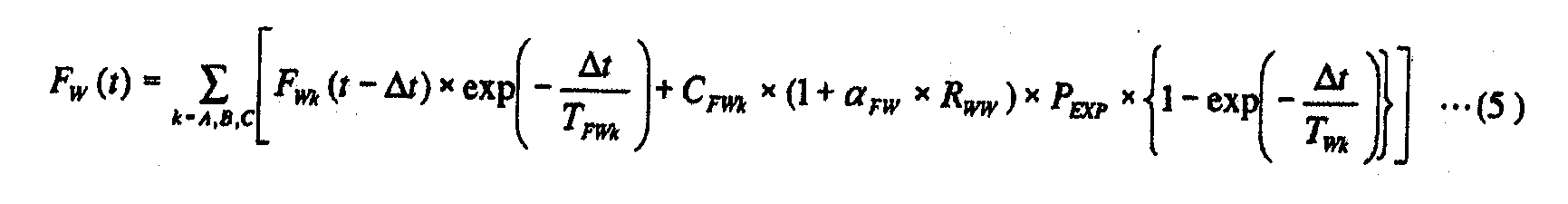
여기서, Δt 는 전술한 샘플링 간격 (조명광 흡수에 따른 광학계 (PLL) 의 결상 특성 변동의 계산 간격) 이고, TFWk 는 제 2 공간 (K2) 내의 액체 (Lq2) 의 조명광 흡수에 따른 광학계 (PLL) 의 포커스 변동 (이하, 「액체 (Lq2) 의 조명광 흡수에 따른 광학계 (PLL) 의 포커스 조사 변동」 이라고 약술한다) 의 시정수〔sec 〕(k = A, B, C) 이다. 또한, FWk (t - Δt) 는 시각 (t - Δt) 에 있어서의 액체 (Lq2) 의 조명광 흡수에 따른 광학계 (PLL) 의 포커스 조사 변동의 시정수 TFWk 성분〔m〕(k = A, B, C) 이고, CFWk 는 액체 (Lq2) 의 조명광 흡수에 따른 광학계 (PLL) 의 포커스 조사 변동의 포화값〔m/W〕(k = A, B, C) 이다. 또한, RWW 는 웨이퍼 반사율로, 전술한 웨이퍼 반사율 REXPW 가 그대로 사용된다. 또한, αFW 는 액체 (Lq2) 의 조명광 흡수에 따른 광학계 (PLL) 의 포커스 조사 변동의 웨이퍼 반사율 의존성이다.Here, Δt is the aforementioned sampling interval (calculation interval of the variation of the imaging characteristics of the optical system PLL according to the illumination light absorption), and T FWk is the optical system PLL according to the illumination light absorption of the liquid Lq2 in the second space K2. Is the time constant [sec] (k = A, B, C) of the focus fluctuation (hereinafter, abbreviated as "focus irradiation fluctuation of the optical system PLL according to absorption of illumination light of the liquid Lq2"). Moreover, F Wk (t-Δt) is the time constant T FWk component [m] (k = A,) of the focus irradiation variation of the optical system PLL according to the absorption of the illumination light of the liquid Lq2 at the time t-Δt. B, C), and C FWk is the saturation value [m / W] (k = A, B, C) of the focus irradiation variation of the optical system PLL according to the absorption of the illumination light of the liquid Lq2. In addition, R WW is the reflectance of the wafer, the above-described wafer reflectivity R EXPW is used as it is. In addition, (alpha) FW is wafer reflectance dependence of the focus irradiation fluctuation | variation of the optical system PLL according to absorption of the illumination light of the liquid Lq2.
상기 식 (4), 식 (5) 의 모델 함수는, 모두 조사량 PEXP 를 입력, 포커스 변동을 출력으로 보았을 때에, 1 차 지연계 3 개의 합 형태로 되어 있다. 또한, 모델 함수에 관해서는 투영 광학계 (PL), 액체 (Lq2) 의 조명광 흡수량과 필요시되는 정밀도로부터 변경해도 된다. 예를 들어, 조명광 흡수량이 비교적 작으면, 1 차 지연계 2 개의 합이어도 되고, 1 차 지연계 1 개이어도 된다. 또한, 투영 광학계 (PL), 액체 (Lq2) 가 조명광을 흡수한 후 결상 특성 변화로서 나타날 때까지 열전도에 의해 시간이 걸리면, 쓸데없는 시간계의 모델 함수를 채용해도 된다. 또한, 포커스 조사 변동의 시정수, 포커스 조사 변동의 포화값 및 웨이퍼 반사율 의존성은 모두 실험에 의해 구해진다. 또는, 고정밀도 열해석 시뮬레이션에 의해 계산으로 구해도 된다. 또는, 그 양방으로부터 구해도 된다.The model functions of the above formulas (4) and (5) are all in the form of a sum of three primary delay systems when the dose P EXP is input and the focus change is viewed as an output. In addition, you may change a model function from the illumination light absorption amount of the projection optical system PL and the liquid Lq2, and the precision required. For example, when illumination light absorption amount is comparatively small, the sum of two primary delay systems may be sufficient and one primary delay system may be sufficient. If the projection optical system PL and the liquid Lq2 take time by heat conduction after absorbing the illumination light and appear as a change in imaging characteristics, a model function of a useless time system may be employed. In addition, the time constant of the focus irradiation variation, the saturation value of the focus irradiation variation, and the wafer reflectance dependence are all obtained by experiment. Alternatively, the calculation may be performed by high precision thermal analysis simulation. Or you may obtain from both.
상기 포커스와 동일한 수법에 의해, 다른 결상 특성, 즉 상면만곡, 배율, 왜 곡, 코마 수차, 구면 수차에 대해서도, 조명광 흡수에 따른 변동을 계산할 수 있다. 즉, 조명광 흡수에 따른 상면만곡 변화 CUHEAT, 조명광 흡수에 따른 배율 변화 MHEAT, 조명광 흡수에 따른 왜곡 변화 DHEAT, 조명광 흡수에 따른 코마 수차 변화 COHEAT 및 조명광 흡수에 따른 구면 수차 변화 SAHEAT 를, 상기 식 (3) (그리고 식 (4) 및 식 (5)) 과 동일한 모델 함수에 기초하여 산출하면 된다.By the same technique as the above-mentioned focus, it is possible to calculate variations due to absorption of illumination light also for other imaging characteristics, namely, image curvature, magnification, distortion, coma aberration and spherical aberration. That is, the curvature of field changes CU HEAT, magnification change according to the illumination light absorption M HEAT, illumination spherical aberration change following the coma change CO HEAT and the illumination light absorption according to the distortion change D HEAT, the illumination light absorption according to the absorption SA HEAT according to the illumination light absorption What is necessary is just to calculate based on the same model function as said Formula (3) (and Formula (4) and Formula (5)).
또한, 상기 서술한 포커스에서는 1 차 지연계 3 개의 합의 모델 함수가 필요하였으나, 예를 들어 상면만곡의 계산에는 1 차 지연계 1 개로 충분한 경우도 생각할 수 있으므로, 요구되는 정밀도에 따라 각 결상 특성마다 조명광 흡수의 모델 함수를 변경해도 된다. 1 차 지연계가 2 개 또는 1 개인 모델 함수를 사용하는 경우에는 계산 시간 단축의 효과가 있다.In addition, in the above-described focus, a consensus model function of three primary delay systems was required. However, for example, one primary delay system may be sufficient to calculate the top surface curvature. You may change the model function of illumination light absorption. Using a model function with two or one primary delay system has the effect of reducing computation time.
본 실시형태에서는, 상기 식 (3), (4), (5) 등의 모델 함수는, 주제어 장치 (50) 에 의해, 메모리 (51) 내에 기억되어 있는 전술한 조명 조건마다의 조사량 계산 및 반사율 계산에 필요한 기초 데이터의 계측 결과를 사용하여, 조명 조건마다 설정된다.In the present embodiment, the model functions such as the formulas (3), (4), and (5) are calculated by the
다음으로, 투영 광학계 (PL) 의 회전 대칭인 6 종류의 결상 특성, 구체적으로는 포커스, 상면만곡, 배율, 왜곡, 코마 수차, 구면 수차의 보정 방법에 대하여 설명한다.Next, six types of imaging characteristics that are rotationally symmetrical of the projection optical system PL, specifically, focus, image curvature, magnification, distortion, coma aberration and spherical aberration correction methods will be described.
먼저, 포커스, 상면만곡, 배율, 왜곡, 코마 수차, 구면 수차의 6 종류의 결상 특성의 변화량은, 그것들의 변화량을 각 요소로 하는 6 행 1 열의 제 1 매트릭 스 (A 로 한다) 가, 각 가동 렌즈에 있어서의 상기 6 종류의 결상 특성 변화 계수를 각 요소로 하는 6 행 5 열의 제 2 매트릭스 (B 로 한다) 와 5 개의 가동 렌즈의 이동량을 각 요소로 하는 5 행 1 열의 제 3 매트릭스 (C 로 한다) 의 곱으로 나타낼 수 있다. 즉, 하기 식 (6) 이 성립한다.First, the amount of change in the six types of imaging characteristics of focus, image curvature, magnification, distortion, coma aberration, and spherical aberration is the first matrix (set A) in each of 6 rows and 1 columns, each of which is the change amount. A second matrix (set B) of six rows and five columns having each of the six types of imaging characteristic change coefficients of the movable lens as a component, and a third matrix of five rows and one column having an amount of movement of the five movable lenses as each element ( Can be expressed as a product of C). That is, following formula (6) holds.
A = B · C …… (6)A = B, C... … (6)
거기서, 먼저 초기 조정 단계에서, 주제어 장치 (50) 는, 결상 특성 보정 컨트롤러 (52) 를 통하여 전술한 5 개의 가동 렌즈를 1 개씩 구동시키면서, 포커스, 상면만곡, 배율, 왜곡, 코마 수차, 구면 수차의 6 종류의 결상 특성에 대하여 측정을 실시하고, 상기 제 2 매트릭스의 각 요소인 각 가동 렌즈에 있어서의 상기 6 종류의 결상 특성 변화 계수 (C11 ∼ C65 로 한다) 를 구한다. 또한, 이들의 결상 특성 변화 계수 C11 ∼ C65 는, 고정밀도 광학 시뮬레이션에 의해 계산으로 구해도 된다.Thereafter, in the initial adjustment step, the
그리고, 상기의 결상 특성 변화 계수 중, 포커스를 제외한 5 종류의 결상 특성 변화 계수 C21 ∼ C65 와 5 개의 가동 렌즈의 이동량 (구동량) 을 사용하여, 각 가동 렌즈의 이동량 (구동량) 을 요소로 하는 5 행 1 열의 매트릭스 C 가, 포커스를 제외한 5 종류의 결상 특성 변화 계수 C21 ∼ C65 를 각 요소로 하는 5 행 5 열의 행렬 (B' 로 한다) 의 역행열과, 상면만곡, 배율, 왜곡, 코마 수차, 구면 수차의 5 종류의 결상 특성의 변동량을 각 요소로 하는 5 행 1 열의 매트릭스 (A' 로 한다) 의 곱으로 표시되게 하는, 하기의 5 원 1 차 연립 방정식을 성립시킨다.In addition, among the above-described imaging characteristic change coefficients, the movement amount (drive amount) of each movable lens is determined by using the five kinds of imaging characteristic change coefficients C 21 to C 65 excluding the focus and the movement amount (driving amount) of the five movable lenses. Matrix C of 5 rows and 1 columns as elements is the inverse of the matrix of 5 rows and 5 columns (referred to as B ') with 5 types of imaging characteristic change coefficients C 21 to C 65 excluding the focus, and upper surface curvature and magnification. The following five-membered first-order system of equations, which is expressed by the product of a matrix of five rows and one column (referred to as A ') as the variation of five types of imaging characteristics of distortion, coma aberration, and spherical aberration, is formed. .
C =〔B'〕-1 · A' …… (7)C = [B '] -1 A'. … (7)
상기 식 (7) 의 5 원 1 차의 연립 방정식이 미리 작성되어, 메모리 (51) 내부에 저장되어 있다.The five-membered linear equation of the above formula (7) is prepared in advance and stored in the
그리고, 상기의 연립 방정식을 사용함으로써, 예를 들어, 소정의 배율로 변화시키고자 하는 경우에는, 그 식 중의 배율의 결상 특성 변화 계수에 소정량을 넣고, 다른 4 종류의 결상 특성 변화 계수에 「0」 을 넣은 새로운 연립 방정식을 성립시키고, 이 연립 방정식을 풀어 각 가동 렌즈의 구동량을 구하고, 이 구동량에 따라 각 가동 렌즈를 구동시킴으로써, 상면만곡, 왜곡, 코마 수차, 구면 수차에 영향을 주지 않고, 배율만을 소정의 값으로 제어하는 것이 가능해진다. 여기에서는, 배율을 변화시키는 경우에 대하여 설명하였으나, 상면만곡, 왜곡, 코마 수차 및 구면 수차에 대해서도 상기와 동일하게, 기타에 영향을 주지 않고 개별적으로 값을 변화시킬 수 있다.In addition, when using the above simultaneous equations, for example, to change at a predetermined magnification, a predetermined amount is added to the imaging characteristic change coefficient of the magnification in the formula, and the other four types of imaging characteristic change coefficients are " By establishing a new system of equations with "0", solving this system of equations to find the driving amount of each movable lens, and driving each movable lens according to the driving amount, the influence on the image curvature, distortion, coma aberration and spherical aberration is influenced. It is possible to control only the magnification to a predetermined value without giving. Here, although the case where the magnification is changed, the values of the upper surface curvature, the distortion, the coma aberration and the spherical aberration can be changed individually without affecting the other as described above.
그런데, 상기의 연립 방정식에서 포커스를 제외하는 것은, 배율 등의 다른 결상 특성을 보정하기 위해 가동 렌즈를 구동시키면, 그것에 부수하여 포커스가 변동되므로, 포커스의 보정에는 이 영향도 고려할 필요가 있기 때문이다.However, the focus is excluded from the above simultaneous equations because when the movable lens is driven in order to correct other imaging characteristics such as magnification, the focus fluctuates along with it, and therefore, the influence of the focus needs to be taken into consideration. .
상기 5 종류의 결상 특성을 보정하기 위해, 5 개의 렌즈군을 이동시킴으로써 부가적 작용으로 발생하는 포커스 변화를 FG 로 하면, FG 는 포커스의 변화 계수 C11 ∼ C15 를 각 요소로 하는 1 행 5 열의 매트릭스와, 위에서 구한 각 가동 렌즈의 구동량을 요소로 하는 5 행 1 열의 매트릭스의 곱으로서 구할 수 있다.In order to correct the above five types of imaging characteristics, if FG is the focus change generated by the additional action by moving the five lens groups, FG is a single row 5 having each of the focus change coefficients C 11 to C 15 as elements. It can obtain | require as a product of the matrix of a column and the matrix of 5 rows and 1 column which uses the drive amount of each movable lens calculated | required above as an element.
결국, 광학계 자체적인 포커스 변화 FL 은, 조명광 흡수 변화, 렌즈 이동 변화를 합쳐 하기 식 (8) 과 같이 된다.As a result, the focus change FL of the optical system itself is equal to the following formula (8) in which the illumination light absorption change and the lens shift change are added together.
FL = FHEAT + FG …… (8)FL = F HEAT + FG. … (8)
가 된다.Becomes
이 FL 을, 웨이퍼 스테이지 (WST) 의 구동에 의한 소정의 포커스 보정의 식에 대입하여 포커스 오차가 0 이 되도록 웨이퍼 스테이지 (WST) 를 Z 축 방향으로 구동시킴으로써, 레티클 (R) 과 웨이퍼 (W) 의 공액 관계 (광학적 거리) 가 유지된다.By substituting this FL into a formula of predetermined focus correction by driving the wafer stage WST, the wafer stage WST is driven in the Z-axis direction so that the focus error becomes 0, thereby reticle R and wafer W The conjugate relationship (optical distance) of is maintained.
다음으로, 본 실시형태의 노광 장치 (100) 에 있어서의 노광시의 동작에 대하여 설명한다.Next, operation | movement at the time of exposure in the
웨이퍼 (W) 에 대한 노광을 실시할 때에, 주제어 장치 (50) 는 제 2 액체 공급 유닛 (72) 을 제어하여 제 2 공간 (K2) 에 액체 (Lq2) 를 공급한다. 이 때, 주제어 장치 (50) 는, 제 2 액체 공급 유닛 (72) 에 의한 단위시간 당의 액체 (Lq2) 공급량 및 제 2 액체 회수 유닛 (73) 에 의한 단위시간 당의 액체 (Lq2) 회수량을 최적으로 제어하면서, 제 2 액체 공급 유닛 (72) 및 제 2 액체 회수 유닛 (73) 에 의한 액체 (Lq2) 의 공급 및 회수를 실시하여, 제 2 공간 (K2) 중, 적어도 조명광 (IL) 의 광로 상을 액체 (Lq2) 로 채운다.When performing exposure to the wafer W, the
또한, 로딩 포지션 (웨이퍼 교환 위치) 에서 웨이퍼 스테이지 (WST) 상에 웨이퍼 (W) 가 로딩된 후, 주제어 장치 (50) 는, 웨이퍼 (W) 를 유지한 웨이퍼 스테 이지 (WST) 를 투영 광학계 (PL) 의 아래, 즉 노광 위치로 이동시킨다. 그리고, 웨이퍼 스테이지 (WST) 와 투영 광학계 (PL) 의 종단 광학 소자 (191) 를 대향시킨 상태에서, 주제어 장치 (50) 는, 제 1 액체 공급 유닛 (68) 에 의한 단위시간 당의 액체 (Lq1) 공급량 및 제 1 액체 회수 유닛 (69) 에 의한 단위시간 당의 액체 (Lq1) 회수량을 최적으로 제어하면서, 제 1 액체 공급 유닛 (68) 및 제 1 액체 회수 유닛 (69) 에 의한 액체 (Lq1) 의 공급 및 회수를 실시하여, 제 1 공간 (K1) 중, 적어도 조명광 (IL) 의 광로 상에 액체 (Lq1) 의 액침 영역 (AR) 을 형성하고, 그 조명광 (IL) 의 광로를 액체 (Lq1) 로 채운다.In addition, after the wafer W is loaded on the wafer stage WST in the loading position (wafer exchange position), the
여기서, 주제어 장치 (50) 는 웨이퍼 (W) 의 노광 처리를 실시하기 전에, 웨이퍼 스테이지 (WST) 상에 형성된 기준 부재 상의 마크 계측이나, 전술한 조도 편차 센서 (21P) 또는 조사량 모니터 (58) 등을 사용한 각종 계측 동작 (전술한 조사량 측정을 위한 사전 준비 및 웨이퍼 반사율 측정을 위한 사전 준비를 적어도 포함한다) 을 실시하고, 그 계측 결과에 기초하여, 웨이퍼 (W) 의 얼라인먼트 처리나 투영 광학계 (PL) 의 결상 특성 조정 등의 캘리브레이션 (calibration) 처리를 실시한다. 예를 들어 조도 편차 센서 (21P) 또는 조사량 모니터 (58) 등을 사용한 계측 동작을 실시하는 경우에는, 주제어 장치 (50) 는, 웨이퍼 스테이지 (WST) 를 XY 방향으로 이동시킴으로써 액체 (Lq1) 의 액침 영역 (AR) 에 대하여 웨이퍼 스테이지 (WST) 를 상대적으로 이동시키고, 그것들의 센서의 수광면 상에 액체 (Lq1) 의 액침 영역 (AR) 을 형성하고, 그 상태에서 액체 (Lq1) 및 액체 (Lq2) 를 통한 계측 동작을 실시한다.Here, the
상기 얼라인먼트 처리 및 캘리브레이션 처리를 실시한 후, 주제어 장치 (50) 는, 제 1 액체 공급 유닛 (68) 에 의한 웨이퍼 (W) 상에 대한 액체 (Lq1) 의 공급과 병행하여, 제 1 액체 회수 유닛 (69) 에 의한 웨이퍼 (W) 상의 액체 (Lq1) 의 회수를 실시하면서, 웨이퍼 (W) 를 지지하는 웨이퍼 스테이지 (WST) 를 Y 축 방향 (주사 방향) 으로 이동시키면서, 레티클 (R) 의 패턴 이미지를, 투영 광학계 (PL) (액체 (Lq2) 를 포함한다) 및 제 1 공간 (K1) 의 액체 (Lq1) (즉 액침 영역 (AR) 의 액체) 를 통하여 표면에 레지스트가 도포된 웨이퍼 (W) 상에 투영한다. 여기서, 제 2 액체 공급 유닛 (72) 에 의한 액체 공급 동작 및 제 2 액체 회수 유닛 (73) 에 의한 액체 회수 동작은 늦어도 노광이 개시되는 시점에서는 주제어 장치 (50) 에 의해 정지되어 있고, 제 2 공간 (K2) 중, 적어도 조명광 (IL) 의 광로 상을 액체 (Lq2) 로 채워진 상태로 되어 있다.After performing the alignment process and the calibration process, the
본 실시형태의 노광 장치 (100) 는, 레티클 (R) 과 웨이퍼 (W) 를 Y 축 방향 (주사 방향) 으로 이동시키면서 레티클 (R) 의 패턴 이미지를 웨이퍼 (W) 에 투영하는 것으로서, 주사 노광 중, 투영 광학계 (PL) (액체 (Lq2) 를 포함한다), 및 제 1 공간의 액체 (Lq1) 를 통하여 레티클 (R) 일부의 패턴 이미지가 투영 영역 (IA) 내에 투영되고, 레티클 (R) 이 ―Y 방향 (또는 +Y 방향) 으로 속도 V 로 이동하는 것에 동기 (同期) 하여, 웨이퍼 (W) 가 투영 영역 (IA) 에 대하여 +Y 방향 (또는 ―Y 방향) 으로 속도 β·V (β 는 투영 배율) 로 이동한다. 웨이퍼 (W) 상에는 복수의 쇼트 영역이 설정되어 있고, 1 개의 쇼트 영역에 대한 노광 종료 후에, 웨이퍼 (W) 의 스텝 이동에 의해 다음 쇼트 영역이 주사 개시 위치로 이동하고, 이 하, 스텝·앤드·스캔 방식으로 웨이퍼 (W) 를 이동시키면서 각 쇼트 영역에 대한 주사 노광 처리가 순차적으로 실시된다.The
본 실시형태에서는, 주제어 장치 (50) 에 의해, 전술한 투영 광학계 (PL) (액체 (Lq2) 를 포함한다) 의 조명광 흡수에서 기인되는 광학계 (PLL) 의 결상 특성 (여러 수차 (포커스를 포함한다)) 의 조사 변동 추정 연산 (식 (3) 및 동등의 연산) 이 시간 Δt 마다 실행되고, 그 결상 특성의 추정 연산 결과에 기초하여, 노광 동작이 제어되고 있다.In the present embodiment, the
예를 들어, 주제어 장치 (50) 는, 예를 들어 시간 Δt 마다 식 (3) 의 연산을 실행함과 함께, 식 (3) 과 동일한 추정 연산을 시간 Δt 마다 실행하여 포커스 이외의 상면만곡, 배율, 왜곡, 코마 수차, 구면 수차의 조사 변동 추정 연산을 실행하고, 이 추정 연산의 결과와 전술한 연립 방정식을 사용하고, 전술한 바와 같이 하여, 그 결상 특성의 변화를 보정하기 위한 각 가동 렌즈의 구동량을 구하고, 이 구동량에 따라 각 가동 렌즈를 구동시킴으로써, 광학계의 상면만곡, 배율, 왜곡, 코마 수차, 구면 수차 중 적어도 하나의 결상 특성의 조사 변동을 순차적으로 보정하고 있다.For example, the
또한, 주제어 장치 (50) 는, 포커스를 제외한 결상 특성의 조사 변동이 결상 특성 보정 컨트롤러 (52) 를 통하여 보정될 때마다, 전술한 식 (6) 을 사용하여 광학계 자체의 포커스 변화 FL 을 산출하고, 이 FL 을 소정의 포커스 보정식 (이 보정식에는, 다점 초점 위치 검출계 (110a, 110b) 에 의해 계측되는 디포커스량이 항으로서 포함된다) 에 대입하여 포커스 오차가 0 이 되도록 웨이퍼 스테이지 (WST) 를 Z 축 방향으로 구동시키는, 웨이퍼 (W) 의 오토 포커스 제어를 실행한다.Further, the
그런데, 본 실시형태의 노광 장치 (100) 와 같은 액침 노광 장치에서는, 액체를 계속 사용하고 있으면, 액체 (순수한 물) 의 순도가 저하되어 박테리아가 발생할 가능성이 있다. 그래서 본 실시형태에서는, 이러한 사태가 최대한 발생하지 않도록, 제 2 공간 (K2) 내의 액체 (Lq2) 를 정기적으로 교환하도록 하고 있다. 단, 액체 (Lq2) 의 교환은 스루풋 저하의 요인이 되므로, 지나치게 빈번하게 실시할 수도 없다. 그래서, 본 실시형태에서는, 주제어 장치 (50) 가, 각 로트 선두의 웨이퍼의 노광 개시 직전마다 (또는, 소정 매수의 웨이퍼의 노광 종료마다) 제 2 액체 공급 유닛 (72) 및 제 2 액체 회수 유닛 (73) 을 사용하여, 제 2 공간 (K2) 내의 액체 (Lq2) 를 교환한다.By the way, in the liquid immersion exposure apparatus like the
그리고 주제어 장치 (50) 는 이 액체 (Lq2) 를 교환할 때마다, 그 교환 직후에 전술한 식 (5) 중의 FWk (t - Δt) = 0 으로 하여 전술한 식 (3) 의 연산을 실행하는 것으로 하고 있다. 이 경우, 노광 중이 아니므로, 조사량 PEXP = 0 이기 때문에 FW (t) = 0 이고, 그 결과, 액체 (Lq2) 의 교환 직후에는 FHEAT (t) = FEXP (t) 가 되어, 식 (3) 은 식 (4) 와 동일한 연산이 된다.Each time the
이와 같이, 본 실시형태에 있어서는, 액체 (Lq2) 를 제외한 투영 광학계 (PL) 의 조명광 흡수에서 기인되는 광학계 (PLL) 의 결상 특성의 조사 변동 모델식과, 액체 (Lq2) 의 조명광 흡수에서 기인되는 광학계 (PLL) 의 결상 특성의 조사 변동 모델식이 각각 준비되어 있으므로, 액체 (Lq2) 를 교환하였을 때에도, 투영 광학계 (PL) (액체 (Lq2) 를 포함한다) 및 액체 (Lq1) 를 포함하는 전체 광학계 (PLL) 의 포커스 등의 결상 특성의 조사 변동을 정확하게 추정 연산할 수 있어, 그 광학계의 결상 특성의 고정밀도 조정이 가능해진다.Thus, in this embodiment, the irradiation variation model formula of the imaging characteristic of the optical system PLL resulting from illumination light absorption of the projection optical system PL except liquid Lq2, and the optical system resulting from illumination light absorption of the liquid Lq2. Since the irradiation variation model equation of the imaging characteristic of PLL is prepared, respectively, even when the liquid Lq2 is replaced, the entire optical system including the projection optical system PL (including the liquid Lq2) and the liquid Lq1 ( Irradiation fluctuations in imaging characteristics such as the focus of the PLL) can be accurately estimated and calculated, and high precision adjustment of the imaging characteristics of the optical system can be performed.
예를 들어, 도 6 의 (A) 에 도시하는 바와 같이, 시각 (t0) 에서부터 시각 (t1) 동안에 웨이퍼의 노광을 실시하고, 시각 (t1) 이후는 노광을 정지하는 경우를 생각한다. 이 도 6 의 (A) 에 있어서, 종축은 광학계 (PLL) 에 조사되는 조명광의 에너지 강도 (Power) 이다.For example, as illustrated in FIG. 6A, a case is disclosed in which the wafer is exposed from time t 0 to time t 1 , and the exposure is stopped after time t 1 . . In this FIG. 6A, the vertical axis is the energy intensity Power of the illumination light irradiated to the optical system PLL.
이 경우의 투영 광학계 (PL) (액체 (Lq2) 를 제외한다) 의 조명광 흡수에서 기인되는 광학계 (PLL) 의 결상 특성 변동 (ABLEN) 은, 전술한 식 (4) 의 모델식으로부터 예를 들어 도 6 의 (B) 와 같이 되고, 액체 (Lq2) 의 조명광 흡수에서 기인되는 광학계 (PLL) 의 결상 특성 변동 (ABW) 은, 전술한 식 (5) 의 모델식으로부터 도 6 의 (C) 중의 가는 실선과 같이 된다. 또한, 시각 (t1) 에서 액체 (Lq2) 의 교환이 실시된 경우에는, 조명광 (IL) 이 조사된 사용 후의 액체 (Lq2) 가, 조명광 (IL) 이 조사되지 않은 사용 전의 액체 (Lq2) 로 교환되기 때문에, 액체 (Lq2) 의 조명광 흡수에서 기인되는 광학계 (PLL) 의 결상 특성 변동 (ABW) 은 시각 (t1) 이후에는 굵은 실선으로 나타내는 바와 같이 제로가 된다.The imaging characteristic variation AB LEN of the optical system PLL caused by the absorption of the illumination light of the projection optical system PL (except the liquid Lq2) in this case is, for example, from the model formula of the above formula (4). As shown in FIG. 6B, the imaging characteristic variation AB W of the optical system PLL caused by the absorption of the illumination light of the liquid Lq2 is shown in FIG. It becomes like a thin solid line. In addition, when the liquid Lq2 is exchanged at the time t 1 , the liquid Lq2 after use to which the illumination light IL is irradiated is the liquid Lq2 before use to which the illumination light IL is not irradiated. Since it is exchanged, the imaging characteristic variation AB W of the optical system PLL resulting from the absorption of the illumination light of the liquid Lq2 becomes zero after time t 1 , as indicated by the thick solid line.
따라서, 시각 (t1) 에서 액체 (Lq2) 의 교환이 실시된 경우에, 액체 (Lq2) 를 제외한 투영 광학계 (PL) 의 조명광 흡수에서 기인되는 광학계 (PLL) 의 결상 특성의 조사 변동 모델식과, 액체 (Lq2) 의 조명광 흡수에서 기인되는 광학계 (PLL) 의 결상 특성의 조사 변동 모델식을 사용하여 구한 광학계 (PLL) 의 전체 조사 변동 (AB) 은, 도 6 의 (D) 중의 굵은 실선과 같이 된다. 한편, 모델식으로서, 투영 광학계 (PL) 전체 (액체 (Lq2) 를 포함한다) 의 조명광 흡수에서 기인되는 광학계 (PLL) 의 결상 특성의 변동 모델식만 가지는 경우에는, 액체 (Lq2) 의 교환이 있는 경우에도 그것을 고려할 수 없기 때문에, 시각 (t1) 에서 액체 (Lq2) 의 교환이 실시된 경우라도, 교환이 실시되지 않은 경우와 동일하게 도 6 의 (D) 중의 가는 실선과 같이 된다. 따라서, 결상 특성의 조사 변동 추정 연산의 결과에 가는 실선과 굵은 실선의 차이에 상당하는 오차가 발생하게 된다.Therefore, in the case where the liquid Lq2 is exchanged at the time t 1 , the irradiation variation model equation of the imaging characteristic of the optical system PLL resulting from absorption of illumination light of the projection optical system PL except for the liquid Lq2, and The total irradiation variation AB of the optical system PLL obtained using the irradiation variation model equation of the imaging characteristic of the optical system PLL resulting from the absorption of illumination light of the liquid Lq2 is the same as the thick solid line in FIG. 6D. do. On the other hand, as a model formula, when only the variation model formula of the imaging characteristic of the optical system PLL resulting from the absorption of illumination light of the whole projection optical system PL (including liquid Lq2) is exchanged, the liquid Lq2 is exchanged. because even if it may be considered, even if the replacement of the time (t 1) liquid (Lq2) in the embodiment, is as shown in the thin solid line in (D) of Fig. 6 as in the case the exchange is not carried out. Therefore, an error corresponding to the difference between the solid line and the thick solid line in the result of the irradiation variation estimation calculation of the imaging characteristic is generated.
상기 서술한 바와 같이, 본 실시형태에 따르면, 액체 (Lq2) 를 제외한 투영 광학계 (PL) 의 조명광 흡수에서 기인되는 광학계 (PLL) 의 결상 특성의 조사 변동 모델식과, 액체 (Lq2) 의 조명광 흡수에서 기인되는 광학계 (PLL) 의 결상 특성의 조사 변동 모델식이 각각 준비되어 있으므로, 액체 (Lq2) 의 교환을 실행한 경우에도, 광학계 (PLL) 의 결상 특성의 조사 변동 추정 연산의 결과에 상기의 오차가 발생하지 않는다. 따라서, 고정밀도 광학계 (PLL) 의 결상 특성의 조사 변동 추정 연산, 및 이것에 기초하는 광학계 (PLL) 의 결상 특성의 고정밀도 조정이 가능해진다.As described above, according to this embodiment, in the irradiation variation model equation of the imaging characteristic of the optical system PLL resulting from the absorption of the illumination light of the projection optical system PL except for the liquid Lq2, and the illumination light absorption of the liquid Lq2, Since the irradiation variation model equations for the imaging characteristics of the optical system PLL are prepared, respectively, even when the liquid Lq2 is exchanged, the above error appears in the result of the irradiation variation estimation calculation of the imaging characteristics of the optical system PLL. Does not occur. Therefore, the irradiation variation estimation calculation of the imaging characteristic of the high precision optical system PLL, and the high precision adjustment of the imaging characteristic of the optical system PLL based on this are attained.
또한, 상기 서술한 바와 같이, 본 실시형태에 있어서는, 제 1 공간 (K1) 내의 액체 (Lq1) 는, 액체 중에 대한 레지스트 용해 등에 의한 영향을 작게 하기 위 해 상시 교환하고 있으므로, 액체 (Lq1) 에 의한 조명광 흡수에서 기인되는 광학계의 결상 특성의 변동은 문제시 하지 않는다.In addition, in the present embodiment, as described above, the liquid Lq1 in the first space K1 is constantly exchanged in order to reduce the influence of resist dissolution and the like in the liquid. The variation of the imaging characteristics of the optical system due to the absorption of the illumination light by the light does not matter.
또한, 주제어 장치 (50) 는, 전술한 바와 같이, 산소 농도계 (64) 의 계측 결과에 기초하여 액체 (Lq2) 중의 용존 산소 농도의 변화에서 기인되는, 조명광 (IL) 에 대한 액체 (Lq2) 의 투과율 변동량을 구하고, 그 투과율 변동량에 기초하여 웨이퍼 (W) 에 대한 적산 노광량 제어 (도스 제어) 를 실시하고 있다.In addition, as mentioned above, the
액체 (Lq2) 는 예를 들어 경계 렌즈 (192) 와 경통 (140) 사이의 갭의 기체 (산소) 와 접촉하고 있기 때문에, 제 2 액체 공급 유닛 (72) 의 공급 동작과 제 2 액체 회수 유닛 (73) 의 회수 동작을 정지하고 있는 동안에, 액체 (Lq2) 중에 산소가 용해되어, 조명광 (IL) 에 대한 액체 (Lq2) 의 투과율이 변화 (저하) 될 가능성이 있다.Since the liquid Lq2 is in contact with, for example, the gas (oxygen) in the gap between the
조명광 (IL) 에 대한 액체 (Lq2) 의 투과율이 변화 (저하) 된 경우, 인터그레이터 센서 (46) 의 출력에 기초하여 산출되는 조명광 (IL) 의 광량 (펄스 강도) 과, 실제로 웨이퍼 (W) 에 도달하는 조명광 (IL) 의 광량 (펄스 강도) 사이에 차이가 발생하여, 웨이퍼 (W) 에 대한 도스 제어 오차가 발생할 우려가 있다.When the transmittance of the liquid Lq2 with respect to the illumination light IL is changed (decreased), the amount of light (pulse intensity) of the illumination light IL calculated based on the output of the
그래서 주제어 장치 (50) 는, 액체 (Lq2) 중의 용존 산소 농도의 변화량과 조명광 (IL) 에 대한 액체 (Lq2) 의 투과율 변화량의 관계를 나타내는 투과율 데이터를 미리 기억하고 있다. 또한 주제어 장치 (50) 는, 교환 직후의 액체 (Lq2) 의 용존 산소 농도를 산소 농도계 (64) 를 사용하여 취득하고 기억함과 함께, 액체 (Lq2) 의 교환 후, 제 2 액체 공급 유닛 (72) 및 제 2 액체 회수 유닛 (73) 의 동 작을 정지하고 있는 동안, 액체 (Lq2) 의 용존 산소 농도를 산소 농도계 (64) 를 사용하여 상시 모니터한다. 그리고 주제어 장치 (50) 는, 산소 농도계 (64) 의 계측 결과와 기억되고 있는 투과율 데이터에 기초하여, 액체 (Lq2) 의 투과율 변동량을 구하고, 그 변동량을 웨이퍼 (W) 에 대한 도스 제어에 반영시키고 있다. 보다 구체적으로는, 액체 (Lq2) 의 투과율 변동량에 기초하여, 조명광 (IL) 의 광량 (펄스 강도), 웨이퍼 (W) 의 주사 속도, 노광 영역 (IA) 의 주사 방향 (Y 축 방향) 의 폭, 및 광원 (16) 의 펄스광 발사 주기 중 적어도 하나를 미세 조정한다. 이로써, 조명광 (IL) 에 대한 액체 (Lq2) 의 투과율 변화가 발생한 경우에도, 웨이퍼 (W) 에 대한 도스 제어를 고정밀도로 실행할 수 있게 된다.The
이상 설명한 바와 같이, 본 실시형태의 노광 장치 (100) 에 의하면, 주제어 장치 (50) 에 의해, 인터그레이터 센서 (46) 등을 사용하여 취득된 조사량 (에너지 정보) 에 기초하여, 투영 유닛 (PU) 내부의 제 2 공간 (K2) 내의 액체 (Lq2) 의 에너지 흡수에서 기인되는, 그 액체 (Lq2) 를 포함하는 투영 광학계 및 제 1 공간 (K1) 내의 액체 (Lq1) 를 포함하는 광학계 (PLL) 의 광학 특성의 일종인 결상 특성의 변동이 예측되고, 그 예측 결과에 기초하여 웨이퍼 (W) 에 대한 노광 동작이 제어된다.As explained above, according to the
본 실시형태에서는, 주제어 장치 (50) 는 조사량 (에너지 정보) 을 파라미터로서 포함하는 식 (5) 를 사용하여, 액체 (Lq2) 의 에너지 흡수에서 기인되는 광학계 (PLL) 의 결상 특성의 변동을 예측한다. 또한, 주제어 장치 (50) 는 조사량 (상기 에너지 정보) 을 파라미터로서 포함하는, 식 (5) 와는 다른 식 (4) 를 사용 하여, 투영 광학계 (PL) (액체 (Lq2) 를 제외한다) 에 의한 조명광 (IL) 의 에너지 흡수에서 기인되는 광학계 (PLL) 의 광학 특성 (결상 특성) 의 변동도 예측한다. 그리고, 주제어 장치 (50) 는 식 (5) 와 식 (4) 의 합인 식 (3) 에 기초하여, 광학계의 결상 특성의 조사 변동을 추정 연산에 의해 구하고, 이 연산 결과에 기초하여 노광 동작을 제어한다. 따라서, 액체 (Lq2) 와 투영 광학계 (PL) (액체 (Lq2) 를 제외한다) 각각의 조명광의 에너지 흡수를 각각 고려하여 광학계 (PLL) 의 광학 특성 (결상 특성) 의 변동을 예측할 수 있게 된다.In the present embodiment, the
또한, 주제어 장치 (50) 는 전술한 액침 기구를 제어하여, 조명광 (IL) 이 조사된 액체 (Lq2) 를 조명광 (IL) 이 조사되지 않은 액체 (Lq2) 와 교환함과 함께, 액침 기구에 의한 액체 (Lq2) 의 교환을 실시하였을 때, 그 액체 (Lq2) 의 에너지 흡수에서 기인되는 광학계 (PLL) 의 광학 특성의 변동은 없어진 것으로 한다. 즉, 전술한 바와 같이 FWk (t - Δt) = 0, 나아가서는 FW (t) = 0 으로 한다.In addition, the
따라서, 액체 (Lq2) 의 교환 직후 등에 있어서, 액체 (Lq2) 의 에너지 흡수에서 기인되는 광학계 (PLL) 의 광학 특성의 변동을 고려하지 않고 노광 동작을 실행할 수 있게 된다.Therefore, immediately after the replacement of the liquid Lq2 or the like, the exposure operation can be performed without taking into account the variation in the optical characteristics of the optical system PLL due to the energy absorption of the liquid Lq2.
또한, 본 실시형태의 노광 장치 (100) 에 의하면, 주제어 장치 (50) 에 의해, 웨이퍼 (W) 를 노광할 때에 광원 (16) 으로부터 출사된 조명광 (IL) 에 대한 투영 광학계 (PL) 내부의 제 2 공간 내의 액체 (Lq2) 의 투과율 변동에 기초하여, 웨이퍼 (W) 에 대한 적산 노광량이 제어된다. 본 실시형태에서는, 산소 농도계 (64) 에 의해 액체 (Lq2) 중의 용존 산소 농도의 변화에 기초하여 투과율의 변동을 간접적으로 모니터하고 있다. 즉, 본 실시형태에서는, 주제어 장치 (50) 에 의해, 광원 (16) 으로부터의 조명광 (IL) 을 웨이퍼 (W) 에 조사하여 웨이퍼 (W) 를 노광할 때, 산소 농도계 (64) 에 의해 계측되는 액체 (Lq2) 중의 용존 산소 농도의 변화에 기초하여 웨이퍼 (W) 에 대한 적산 노광량이 제어되고 있다고 할 수 있다. 따라서, 액체 (Lq2) 의 용존 산소 농도의 변화에서 기인되어 액체 (Lq2) 의 투과율이 변동되고, 인터그레이터 센서 (46) 의 출력에 기초하여 산출되는 조명광 (IL) 의 광량 (펄스 강도) 과, 실제로 웨이퍼 (W) 에 도달하는 조명광 (IL) 의 광량 (펄스 강도) 사이에 차이가 발생하는 경우에도, 웨이퍼 (W) 에 대한 도스 제어를 고정밀도로 실행할 수 있게 된다.Moreover, according to the
또한, 본 실시형태에서는, 렌즈 작용을 갖는 경계 렌즈 (192) 아래에, 평행 평면판으로 이루어지는 종단 광학 소자 (191) 가 배치되어 있지만, 종단 광학 소자 (191) 의 하면 (191a) 측 및 상면 (191c) 측의 제 1, 제 2 공간 (K1, K2) 각각에 액체 (Lq1, Lq2) 를 채움으로써, 경계 렌즈 (192) 의 하면 (192a) 이나 종단 광학 소자 (191) 의 상면 (191b) 에서의 반사 손실이 저감되어, 큰 이미지측 개구수를 확보한 상태에서 웨이퍼 (W) 를 양호하게 노광할 수 있다. 또한, 종단 광학 소자 (191) 는 무굴절력의 평행 평면판이므로, 예를 들어, 액체 (Lq1) 중의 오염 물질이 종단 광학 소자 (191) 의 하면 (191a) 에 부착된 경우에도 용이하게 교환할 수 있다.In addition, in this embodiment, although the terminal
또한, 종단 광학 소자 (191) 의 교환 등을 고려하지 않는 경우에는, 종단 광 학 소자 (191) 는 굴절력을 갖는 렌즈이어도 된다.In addition, when the replacement | exchange of the terminal
본 실시형태의 노광 장치 (100) 에 의하면, 웨이퍼 (W) 에 대해 고정밀도이고 또한 선폭 제어성이 양호한 노광이 실시되어, 웨이퍼 (W) 상의 각 쇼트 영역에 레티클 (R) 의 패턴이 양호한 정밀도로 전사된다. 또한, 본 실시형태의 노광 장치 (100) 에서는, 액침 노광에 의해 고해상도이고 또한 공기 중에 비해 대초점 심도인 노광을 실시함으로써, 레티클 (R) 의 패턴을 양호한 정밀도로 웨이퍼 상에 전사할 수가 있으며, 예를 들어 ArF 엑시머 레이저 광으로, 디바이스 룰로서 45 ∼ 100㎚ 정도의 미세 패턴의 전사를 실현시킬 수 있다.According to the
또한, 상기 실시형태에서는, 주제어 장치 (50) 는 인터그레이터 센서 (46) 등을 사용하여 구해지는 조명광 (IL) 의 조사량 (에너지 정보) 을 파라미터로서 포함하는 식 (5) 를 사용하여, 액체 (Lq2) 의 에너지 흡수에서 기인되는 광학계 (PLL) 의 광학 특성의 변동을 예측하는 경우에 대해 설명하였으나, 본 발명이 이것에 한정되는 것은 아니다. 예를 들어, 식 (4), 식 (5) 대신, 각각의 우변에, 식 (4), 식 (5) 의 우변에 더하여 또는 대신하여, 액체 (Lq2) 의 온도에 관한 파라미터, 및 조명광 (IL) 에 대한 액체 (Lq2) 의 투과율에 관한 파라미터 중 적어도 일방을 포함하는 항을 포함하는 모델식을 사용해도 된다. 조명광 (IL) 에 대한 액체 (Lq2) 의 투과율에 관한 파라미터로는, 액체 (Lq2) 의 투과율에 영향을 주는 액체 (Lq2) 중의 용존 산소 농도를 사용해도 된다.In addition, in the said embodiment, the
상기의 액체 (Lq2) 의 온도에 관한 파라미터로는, 예를 들어 온도 센서 (62, 63) 의 검출값을 채용할 수 있다. 또한, 액체 (Lq2) 의 투과율에 관한 파라미 터로서 산소 농도계 (64) 의 계측값을 채용할 수 있다. 또한 액체 (Lq2) 의 투과율에 관한 파라미터는, 액체 (Lq2) 의 용존 산소 농도에 한정되지 않고, 액체 (Lq2) 의 투과율에 영향을 끼칠 가능성이 있는 다른 파라미터 (TOC 등) 를 모델식에 포함해도 된다.As a parameter regarding the temperature of said liquid Lq2, the detection value of the
또한, 본 실시형태의 노광 장치 (100) 는 제 2 공간 (K2) 에 온도 센서 (62, 63) 가 설치되어 있지만, 상기 서술한 바와 같이, 인터그레이터 센서 (46) 등을 사용하여 구해지는 조명광 (IL) 의 조사량에 기초하여 광학계 (PLL) 의 광학 특성의 변동을 예측하는 경우에는, 제 2 공간 (K2) 에 배치된 온도 센서 (62, 63) 를 생략해도 된다.In addition, although the
또한, 액체 (Lq2) 의 투과율 변동을 고려하지 않는 경우 (예를 들어, 제 2 액체 공급 유닛 (72) 및 제 2 액체 회수 유닛 (73) 을 사용하여 액체 (Lq2) 의 상시 교체를 실시하는 경우) 에는, 제 2 공간 (K2) 에 배치된 산소 농도계 (64) 를 생략해도 된다.In addition, when the permeability fluctuation of the liquid Lq2 is not taken into consideration (for example, when the regular replacement of the liquid Lq2 is performed using the second
또한, 주제어 장치 (50) 는, 온도 센서 (62, 63) 의 검출값에 기초하여 액체 (Lq2) 의 좌우 (Y 축 방향의 일측과 타측) 의 온도차를 감시하고, 그 온도차에서 기인되는 광학계 (PLL) 의 파면 수차의 1θ 성분을 필요에 따라 보정하는 것으로 해도 된다. 도 4 에 도시되는 바와 같이, 본 실시형태에서는, 투영 광학계 (PL) 로서 반사 굴절계를 사용하고 있고, 제 2 공간 (K2) 에서 조명광 (IL) 이 광축 (AX3) 에 대하여 ―Y 방향으로 편향된 위치를 통과하기 때문에, 제 2 공간 (K2) 내에서 광축 (AX3) 의 ―Y 측의 액체 (Lq2) 와 +Y 측의 액체 (Lq2) 에 온도차가 발생할 가능성이 있는데, 주제어 장치 (50) 는 온도 센서 (62, 63) 를 사용하여 이 온도차를 검지할 수 있으므로, 그 온도차에서 기인되는 광학계 (PLL) 의 수차를 보정할 수 있다.In addition, the
또한, 상기 서술한 실시형태에 있어서는, 제 1 공간 (K1) 내의 액체 (Lq1) 는 상시 교체를 실시하고 있으므로, 액체 (Lq1) 의 조명광 흡수 (에너지 흡수) 에서 기인되는 광학계 (PLL) 의 광학 특성의 조사 변동을 고려하지 않고 웨이퍼 (W) 의 노광을 실시하고 있지만, 예를 들어, 제 1 공간 (K1) 의 액체 (Lq1) 의 교환을 정기적으로 실시하는 경우, 및/또는 액체 (Lq1) 의 조명광 흡수가 큰 경우에는, 액체 (Lq1) 의 조명광 흡수에서 기인되는 광학계 (PLL) 의 광학 특성의 조사 변동을 고려해도 된다. 이 경우, 액체 (Lq2) 와 동일하게, 액체 (Lq1) 의 조명광 흡수에서 기인되는 광학계 (PLL) 의 광학 특성의 변동을 예측하기 위한 모델식을 추가로 준비해도 된다.In addition, in the above-mentioned embodiment, since the liquid Lq1 in the 1st space K1 is always replaced, the optical characteristic of the optical system PLL resulting from illumination light absorption (energy absorption) of the liquid Lq1 is carried out. Although the exposure of the wafer W is performed without taking into account the irradiation fluctuation of, for example, when the liquid Lq1 of the first space K1 is regularly exchanged, and / or the liquid Lq1 When illumination light absorption is large, you may consider the irradiation variation of the optical characteristic of the optical system PLL resulting from absorption of the illumination light of the liquid Lq1. In this case, similarly to liquid Lq2, you may further prepare the model formula for estimating the fluctuation | variation of the optical characteristic of the optical system PLL resulting from absorption of the illumination light of liquid Lq1.
또한, 액체 (Lq1) 의 용존 산소 농도가 변동되어, 조명광 (IL) 에 대한 액체 (Lq1) 의 투과율이 변동되는 경우에는, 액체 (Lq1) 의 투과율 (용존 산소 농도) 을 고려하여, 광학계 (PLL) 의 광학 특성의 조정과 웨이퍼 (W) 에 대한 도스 제어 중 적어도 일방을 실시하도록 해도 된다.In addition, when the dissolved oxygen concentration of the liquid Lq1 is changed and the transmittance of the liquid Lq1 with respect to the illumination light IL is varied, the optical system PLL is considered in consideration of the transmittance (dissolved oxygen concentration) of the liquid Lq1. At least one of the adjustment of the optical characteristics of the () and the dose control for the wafer (W) may be performed.
또한, 액체 (Lq1) 의 조명광 흡수 및 액체 (Lq1) 의 투과율 중 적어도 일방을 고려하는 경우에는, 액체 (Lq1) 의 온도를 계측하는 온도 센서 및 액체 (Lq1) 의 용존 산소 농도를 검출하는 산소 농도계 중 적어도 일방을 제 1 공간 (K1) 의 근방 등에 배치해도 된다.In addition, when considering at least one of the illumination light absorption of the liquid Lq1 and the transmittance | permeability of the liquid Lq1, the temperature sensor which measures the temperature of the liquid Lq1, and the oxygen concentration meter which detects the dissolved oxygen concentration of the liquid Lq1. At least one of them may be arranged in the vicinity of the first space K1 or the like.
또한, 상기 실시형태에서는, 광학계의 적어도 일부를 구성하는 종단 광학 소자 (191) 의 빔 출사측에 웨이퍼 (W) 를 배치하고, 종단 광학 소자의 빔 입사측의 제 2 공간 (K2) 중 적어도 조명광 (IL) 의 광로 (빔로) 를 액체 (Lq2) 로 채우고, 또한 종단 광학 소자 (191) 와 웨이퍼 (W) 사이의 제 1 공간 (K1) 을 액체 (Lq1) 로 채우는 경우에 대해 설명하였다. 그러나 본 발명이 이것에 한정되지 않는 것은 물론이다. 예를 들어, 종단 광학 소자 (191) 와 웨이퍼 (W) 사이의 제 1 공간 (K1) 만을 액체, 예를 들어 순수한 물로 채우는 것으로 해도 된다. 이 경우에, 주제어 장치 (50) 는, 에너지 정보를 파라미터로서 포함하는, 식 (5) 와는 다른 모델식을 사용하여, 그 액체의 조명광 흡수 (에너지 흡수) 에서 기인되는 광학계 (PLL) 의 광학 특성의 변동을 예측하는 것으로 해도 된다.Moreover, in the said embodiment, the wafer W is arrange | positioned at the beam exit side of the terminal
또한, 이 경우에도 액체 (Lq1) 의 투과율 (용존 산소 농도) 을 고려하여, 광학계 (PLL) 의 광학 특성의 조정과 웨이퍼 (W) 에 대한 도스 제어 중 적어도 일방을 실시하도록 해도 되고, 액체 (Lq1) 의 조명광 흡수 및 액체 (Lq1) 의 투과율 중 적어도 일방을 고려하는 경우에는, 액체 (Lq1) 의 온도를 계측하는 온도 센서 및 액체 (Lq1) 의 용존 산소 농도를 검출하는 산소 농도계 중 적어도 일방을 제 1 공간 (K1) 의 근방 등에 배치해도 된다.Also in this case, in consideration of the transmittance (dissolved oxygen concentration) of the liquid Lq1, at least one of the adjustment of the optical characteristics of the optical system PLL and the dose control for the wafer W may be performed. In consideration of at least one of the absorption of the illumination light and the transmittance of the liquid Lq1, at least one of the temperature sensor measuring the temperature of the liquid Lq1 and the oxygen concentration meter detecting the dissolved oxygen concentration of the liquid Lq1 is removed. You may arrange | position in vicinity of 1 space K1.
또한, 상기 실시형태에 있어서, 전술한 조사량 계측의 준비 작업과 동일하게, 광학계 (PLL) 를 통과한 조명광 (IL) 의 에너지 강도를 소정의 타이밍으로 계측하고, 그 계측 결과에 기초하여 전술한 식 (3) 에 포함되는 부분 중 적어도 식 (5) 부분 중, 단위시간 당의 조사량 PEXP 산출의 기초가 되는 I0/I1 (즉 광학계의 투과율), 나아가서는 그것을 사용한 식 (5) 를 갱신하는 것으로 해도 된다. 이러한 경우에는, 결상 특성의 조사 변동의 연산에 광학계 투과율의 경시적인 변화를 반영시킬 수 있게 된다.In addition, in the said embodiment, the energy intensity of the illumination light IL which passed the optical system PLL at the predetermined timing is measured similarly to the preparation operation of the above-mentioned irradiation amount measurement, and the above-mentioned formula is based on the measurement result. Of the parts included in (3), I 0 / I 1 (that is, the transmittance of the optical system) which is the basis of the calculation of the dose P EXP per unit time in at least part of the formula (5), and further update the equation (5) using the same You may use it. In such a case, the change over time of the optical system transmittance can be reflected in the calculation of the irradiation variation of the imaging characteristic.
또한, 상기 실시형태에서는 액체 (Lq1, Lq2) 로서 동일한 순수한 물을 공급하고 있지만, 제 1 공간에 공급되는 순수한 물 (액체 (Lq1)) 과 제 2 공간에 공급되는 순수한 물 (액체 (Lq2)) 의 품질을 상이하게 해도 된다. 순수한 물의 품질로는, 예를 들어 온도 균일성, 온도 안정성, 비저항값 또는 TOC (total organic carbon) 값 등을 들 수 있다.Further, in the above embodiment, the same pure water is supplied as the liquids Lq1 and Lq2, but pure water (liquid Lq1) supplied to the first space and pure water (liquid Lq2) supplied to the second space. The quality of may be different. Examples of the quality of pure water include temperature uniformity, temperature stability, resistivity value or TOC (total organic carbon) value.
예를 들어, 제 2 공간 (K2) 에 공급되는 순수한 물보다, 투영 광학계 (PL) 의 이미지면에 가까운 제 1 공간 (K1) 에 공급되는 순수한 물의 품질을 높게 해도 된다. 또한, 제 1 공간과 제 2 공간에 서로 상이한 종류의 액체를 공급하고, 제 1 공간 (K1) 에 채우는 액체 (Lq1) 와 제 2 공간 (K2) 에 채우는 액체 (Lq2) 를 서로 상이한 종류로 해도 된다. 예를 들어, 제 2 공간 (K2) 에 불소계 오일을 비롯한 순수한 물 이외의 소정의 액체를 채울 수 있다. 오일은 박테리아 등의 세균이 번식할 확률이 낮은 액체이기 때문에, 제 2 공간 (K2) 이나 액체 (Lq2) (불소계 오일) 가 흐르는 유로의 청정도를 유지할 수 있다.For example, the quality of pure water supplied to the first space K1 close to the image plane of the projection optical system PL may be higher than the pure water supplied to the second space K2. In addition, even if the liquid different from each other is supplied to a 1st space and a 2nd space, and the liquid Lq1 to fill the 1st space K1 and the liquid Lq2 to fill the 2nd space K2 are mutually different types, do. For example, the second space K2 can be filled with a predetermined liquid other than pure water including fluorine oil. Since the oil is a liquid having a low probability of propagation of bacteria such as bacteria, the cleanliness of the flow path through which the second space K2 and the liquid Lq2 (fluorine-based oil) flow can be maintained.
또한, 액체 (Lq1, Lq2) 의 쌍방을 물 이외의 액체로 해도 된다. 예를 들어, 조명광 (IL) 의 광원이 F2 레이저인 경우, F2 레이저광은 물을 투과하지 않기 때문에, 액체 (Lq1, Lq2) 로는 F2 레이저광을 투과할 수 있는 예를 들어, 과불화 폴리에테르 (PFPE) 나 불소계 오일 등의 불소계 유체이어도 된다. 이 경우, 액체 (Lq1, Lq2) 와 접촉하는 부분에는, 예를 들어 불소를 포함하는 극성이 작은 분자 구조의 물질로 박막을 형성함으로써 친액화 처리한다. 또한, 액체 (Lq1, Lq2) 로는, 그 밖에도, 조명광 (IL) 에 대한 투과성이 있어 가능한 한 굴절률이 높고, 투영 광학계 (PL) 나 웨이퍼 (W) 표면에 도포되어 있는 포토레지스트에 대하여 안정적인 것 (예를 들어 시더 오일) 을 사용할 수도 있다. 이 경우에도 표면 처리는 사용하는 액체 (Lq1, Lq2) 의 극성에 따라 실시된다.In addition, both of liquids Lq1 and Lq2 may be used as liquids other than water. For example, when the light source of the illumination light IL is an F 2 laser, since the F 2 laser light does not penetrate water, the liquid Lq1 and Lq2 can transmit the F 2 laser light, for example, overlight. Fluorine fluids, such as fluorinated polyether (PFPE) and fluorine oil, may be sufficient. In this case, the part which contacts liquid Lq1, Lq2 is lyophilic-treated by forming a thin film with the substance of the molecular structure with small polarity containing fluorine, for example. In addition, the liquids Lq1 and Lq2 also have a transparency to the illumination light IL, and have a refractive index as high as possible and stable to the photoresist applied to the projection optical system PL or the wafer W surface ( Cedar oil, for example. Also in this case, surface treatment is performed according to the polarity of the liquids Lq1 and Lq2 to be used.
또한, 상기 서술한 바와 같은 액침법에서는, 투영 광학계의 개구수 NA 가 0.9 ∼ 1.3 이 되는 경우도 있다. 이와 같이 투영 광학계의 개구수 NA 가 커지는 경우에는, 종래부터 노광광으로서 사용되고 있는 랜덤 편광광으로는 편광 효과에 의해 결상 성능이 악화되는 경우도 있으므로, 편광 조명을 사용하는 것이 바람직하다. 그 경우, 마스크 (레티클) 의 라인·앤드·스페이스 패턴의 라인 패턴의 길이 방향에 맞춘 직선 편광 조명을 실시하고, 마스크 (레티클) 의 패턴으로부터는 S 편광 성분 (TE 편광 성분), 즉 라인 패턴의 길이 방향을 따른 편광 방향 성분의 회절광이 많이 출사되도록 하면 된다. 투영 광학계 (PL) 와 웨이퍼 (W) 표면에 도포된 레지스트 사이가 액체로 채워져 있는 경우, 투영 광학계 (PL) 와 웨이퍼 (W) 표면에 도포된 레지스트 사이가 공기 (기체) 로 채워져 있는 경우에 비해, 콘트라스트 향상에 기여하는 S 편광 성분 (TE 편광 성분) 의 회절광의 레지스 트 표면에서의 투과율이 높아지기 때문에, 투영 광학계의 개구수 NA 가 1.0 을 초과하는 경우에도 높은 결상 성능을 얻을 수 있다. 또한, 위상 시프트 마스크나 일본 공개특허공보 평6-188169호에 개시되어 있는 바와 같은 라인 패턴의 길이 방향에 맞춘 사입사 조명법 (특히 다이 볼 조명법) 등을 적절하게 조합하면 더욱 효과적이다.In addition, in the above-described liquid immersion method, the numerical aperture NA of the projection optical system may be 0.9 to 1.3. Thus, when the numerical aperture NA of a projection optical system becomes large, since the imaging performance may deteriorate by the polarization effect with the randomly polarized light conventionally used as exposure light, it is preferable to use polarized illumination. In that case, linearly polarized light illumination is performed according to the longitudinal direction of the line pattern of the line and space pattern of the mask (reticle), and from the pattern of the mask (reticle) of the S polarization component (TE polarization component), that is, the line pattern What is necessary is just to let the diffraction light of the polarization direction component along a longitudinal direction exit much. The case where the liquid applied between the projection optical system PL and the resist applied to the surface of the wafer W is filled with liquid, as compared with the case where the air between the projection optical system PL and the resist applied to the surface of the wafer W is filled with air. Since the transmittance at the resist surface of the diffracted light of the S-polarized component (TE polarized component), which contributes to the contrast improvement, becomes high, high imaging performance can be obtained even when the numerical aperture NA of the projection optical system exceeds 1.0. Moreover, it is more effective if a combination of the inclination illumination method (especially the die ball illumination method) etc. which suited the longitudinal direction of the line pattern as disclosed in a phase shift mask and Unexamined-Japanese-Patent No. 6-188169 is performed suitably.
또한, 마스크 (레티클) 의 라인 패턴의 길이 방향에 맞춘 직선 편광 조명 (S 편광 조명) 뿐만 아니라, 일본 공개특허공보 평6-53120호 등에 개시되어 있는 바와 같이, 광축을 중심으로 한 원의 접선 (주 (周)) 방향으로 직선 편광하는 편광 조명법과 사입사 조명법의 조합도 효과적이다. 본 국제출원에서 지정한 지정국 (또는 선택한 선택국) 의 국내 법령이 허용하는 한에서, 상기 공보에 있어서의 개시를 원용하여 본 명세서의 기재의 일부로 한다.Further, as disclosed in Japanese Unexamined Patent Publication No. Hei 6-53120 and the like, as well as linearly polarized light illumination (S polarized light illumination) adapted to the longitudinal direction of the line pattern of the mask (reticle), the tangent of the circle around the optical axis ( The combination of the polarization illumination method and the incidence illumination method which linearly polarize in the main direction is also effective. As long as the national legislation of the designated country (or selected selected country) designated in this international application permits, the disclosure in the above publication is incorporated herein by reference as part of the description.
또한, 상기 서술한 실시형태에서는, 투영 광학계 (PL) 로서 반사 굴절계를 채용하고 있지만, 반사 소자를 포함하지 않는 굴절계를 채용할 수도 있다. 또한, 투영 광학계 (PL) 로서 예를 들어 미국 특허 제6,636,350호 명세서, 미국 특허 제6,873,476호 명세서, 및 미국 특허출원공개 제2004/0160666호 명세서에 개시되어 있는 타입의 반사 굴절계를 사용할 수도 있다. 본 국제출원에서 지정한 지정국 (또는 선택한 선택국) 의 국내 법령이 허용하는 한에서, 상기 각 미국 특허 명세서 또는 미국 특허출원공개 명세서에 있어서의 개시를 원용하여 본 명세서의 기재의 일부로 한다.In addition, although the reflection refractometer is employ | adopted as projection optical system PL in embodiment mentioned above, the refractometer which does not contain a reflection element can also be employ | adopted. As the projection optical system PL, a reflection refractometer of the type disclosed in, for example, US Patent No. 6,636,350, US Patent No. 6,873,476, and US Patent Application Publication No. 2004/0160666 may be used. As long as the national legislation of the designated country (or selected selected country) specified in this international application permits, the disclosure in each of the above-described U.S. patent specifications or U.S. patent application publications is incorporated herein by reference.
또한, 상기 서술한 실시형태에서는, 광학계 (PLL) 의 광학 특성으로서 포커 스뿐만 아니라, 배율, 왜곡 등의 조사 변동을 예측하고, 조정하도록 하고 있지만, 필요에 따라 그들 중 적어도 하나를 선택하여 예측 및 조정을 실행해도 된다.In addition, in the above-described embodiment, not only the focus but also the irradiation fluctuations such as magnification, distortion, etc. are predicted and adjusted as the optical characteristics of the optical system PLL. You may make adjustments.
또한, 상기 실시형태에서는, 본 발명이 스캐너에 적용된 경우에 대해 설명하였으나, 이것에 한정하지 않고, 스텝·앤드·리피트 방식의 노광 장치 (스테퍼) 등의 정지 노광형의 노광 장치, 또한, 스텝·앤드·스티치 방식의 노광 장치, 또는 프록시미티 방식의 노광 장치 등이어도 액침 영역을 통하여 노광을 실시하는 것이면, 본 발명은 적용이 가능하다. 이 경우도, 상기 실시형태와 동일한 광학계의 결상 특성의 조사 변동 연산, 및 조정을 실시하도록 하면 된다. 단, 투영 광학계를 가지지 않는 프록시미티 방식의 노광 장치의 경우, 액침 영역을 형성하는 액체가 광학계에 상당한다.In addition, although the said embodiment demonstrated the case where this invention was applied to the scanner, it is not limited to this, The exposure apparatus of the stationary exposure type, such as an exposure apparatus (stepper) of a step and repeat system, Furthermore, a step and end The present invention can be applied as long as the exposure is performed through the liquid immersion region, even if it is a stitch type exposure apparatus or a proximity type exposure apparatus. Also in this case, what is necessary is just to perform irradiation variation calculation and adjustment of the imaging characteristic of the optical system similar to the said embodiment. However, in the case of the proximity type exposure apparatus which does not have a projection optical system, the liquid which forms a liquid immersion area corresponds to an optical system.
또한, 본 발명은 일본 공개특허공보 평10-163099호, 일본 공개특허공보 평10-214783호 (대응 미국 특허 제6,341,007호 명세서, 제6,400,441호 명세서, 제6,549,269호 명세서 및 제6,590,634호 명세서), 일본 공표특허공보 제2000-505958호 (대응 미국 특허 제5,969,441호 명세서) 또는 미국 특허 제6,208,407호 명세서 등에 개시되어 있는 바와 같은 웨이퍼를 유지하는 웨이퍼 스테이지를 복수 구비한 멀티 스테이지형의 노광 장치에도 적용할 수 있다. 또한, 본 발명은 일본 공개특허공보 제2000-164504호 (대응 미국 특허 제6,897,963호 명세서 등에 개시되어 있는 바와 같이, 웨이퍼 스테이지 (WST) 와는 별도로 계측 스테이지를 구비한 노광 장치에도 적용할 수 있다. 이 경우, 조사량 모니터 (58) 나 조도 편차 센서 (21P) 를 계측 스테이지에 설치해도 된다. 본 국제출원에서 지정한 지정국 (또 는 선택한 선택국) 의 국내 법령이 허용하는 한에서, 상기 각 공보 및 대응 미국 특허 명세서에 있어서의 개시를 원용하여 본 명세서의 기재의 일부로 한다.In addition, the present invention is Japanese Patent Application Laid-Open No. Hei 10-163099, Japanese Patent Application Laid-Open No. Hei 10-214783 (corresponding to U.S. Patent Nos. 6,341,007, 6,400,441, 6,549,269 and 6,590,634), Japan The present invention can also be applied to a multi-stage type exposure apparatus having a plurality of wafer stages for holding a wafer as disclosed in Japanese Patent Application Laid-Open No. 2000-505958 (corresponding US Pat. No. 5,969,441) or US Pat. No. 6,208,407. have. Moreover, this invention is applicable also to the exposure apparatus provided with the measurement stage separately from wafer stage WST, as disclosed in Unexamined-Japanese-Patent No. 2000-164504 (corresponding US patent 6,897,963 specification etc.). In this case, the irradiation dose monitor 58 or the
또한, 상기 서술한 실시형태에 있어서는, 투영 광학계 (PL) 와 웨이퍼 (W) 사이에 국소적으로 액체를 채우는 노광 장치를 채용하고 있지만, 본 발명은 일본 공개특허공보 평6-124873호, 일본 공개특허공보 평10-303114호, 미국 특허 제5,825,043호 명세서 등에 개시되어 있는 바와 같은 노광 대상의 웨이퍼 등의 표면 전체가 액체 중에 잠겨 있는 상태에서 노광을 실시하는 액침 노광 장치에도 적용할 수 있다. 본 국제출원에서 지정한 지정국 (또는 선택한 선택국) 의 국내 법령이 허용하는 한에서, 상기 각 공보 및 미국 특허 명세서에 있어서의 개시를 원용하여 본 명세서의 기재의 일부로 한다.Moreover, in the above-mentioned embodiment, although the exposure apparatus which fills a liquid locally between projection optical system PL and wafer W is employ | adopted, this invention is Unexamined-Japanese-Patent No. 6-124873, Unexamined-Japanese-Patent. It is also applicable to the liquid immersion exposure apparatus which performs exposure in the state in which the whole surface, such as a wafer to be exposed, is submerged in liquid, as disclosed by Unexamined-Japanese-Patent No. 10-303114, US Patent 5,825,043 specification, etc .. As long as the national legislation of the designated country (or selected selected country) designated in this international application allows, the disclosures in the above publications and US patent specifications are incorporated herein by reference.
또한, 상기 서술한 실시형태에 있어서는, 광투과성 기판 상에 소정의 차광 패턴 (또는 위상 패턴·감광 패턴) 을 형성한 광투과형 마스크를 사용하였으나, 이 마스크 대신, 예를 들어 미국 특허 제6,778,257호 명세서에 개시되어 있는 바와 같이, 노광해야 할 패턴의 전자 데이터에 기초하여 투과 패턴 또는 반사 패턴, 또는 발광 패턴을 형성하는 전자 마스크를 사용해도 된다. 본 국제출원에서 지정한 지정국 (또는 선택한 선택국) 의 국내 법령이 허용하는 한에서, 상기 미국 특허 명세서에 있어서의 개시를 원용하여 본 명세서의 기재의 일부로 한다.In addition, in the above-mentioned embodiment, although the light transmissive mask which provided the predetermined light shielding pattern (or phase pattern and photosensitive pattern) on the light transmissive substrate was used, it replaces this mask, for example, US patent 6,778,257 specification As disclosed in, an electronic mask for forming a transmission pattern, a reflection pattern, or a light emission pattern may be used based on the electronic data of the pattern to be exposed. As long as the national legislation of the designated country (or selected selected country) specified in this international application permits, the disclosure in the above-described US patent specification is incorporated herein by reference as part of the description herein.
또한, 국제공개공보 제2001/035168호 팜플렛에 개시되어 있는 바와 같이, 간섭 줄무늬를 웨이퍼 (W) 상에 형성함으로써, 웨이퍼 (W) 상에 라인·앤드·스페이스 패턴을 형성하는 노광 장치 (리소그래피 시스템) 에도 본 발명을 적용할 수 있다. 본 국제출원에서 지정한 지정국 (또는 선택한 선택국) 의 국내 법령이 허용하는 한에서, 상기 국제공개공보 팜플렛에 있어서의 개시를 원용하여 본 명세서의 기재의 일부로 한다.Moreover, as disclosed in the international publication 2001/035168 pamphlet, the exposure apparatus which forms a line and space pattern on the wafer W by forming interference fringes on the wafer W (lithography system) The present invention can also be applied to As long as the national legislation of the designated country (or selected selected country) specified in this international application permits, the disclosure in the above-mentioned International Publication pamphlet is used as part of the description herein.
노광 장치의 용도로는 반도체 제조용의 노광 장치에 한정되지 않고, 예를 들어, 각형의 유리 플레이트에 액정 표시 소자 패턴을 전사하는 액정용 노광 장치나, 유기 EL, 박막 자기 헤드, 촬상 소자 (CCD 등), 마이크로 머신 및 DNA 칩 등을 제조하기 위한 노광 장치에도 넓게 적용할 수 있다. 또한, 반도체 소자 등의 마이크로 디바이스뿐만 아니라, 광 노광 장치, EUV 노광 장치, X 선 노광 장치 및 전자선 노광 장치 등에서 사용되는 레티클 또는 마스크를 제조하기 위해, 유리 기판 또는 실리콘 웨이퍼 등에 회로 패턴을 전사하는 노광 장치에도 본 발명을 적용할 수 있다.The application of the exposure apparatus is not limited to the exposure apparatus for semiconductor manufacturing, and for example, an exposure apparatus for a liquid crystal which transfers a liquid crystal display element pattern to a rectangular glass plate, an organic EL, a thin film magnetic head, an imaging element (CCD, etc.). ), And can also be widely applied to exposure apparatus for manufacturing micro machines, DNA chips, and the like. In addition, exposure to transfer a circuit pattern to a glass substrate or silicon wafer or the like for manufacturing a reticle or a mask used in not only a micro device such as a semiconductor element but also an optical exposure apparatus, an EUV exposure apparatus, an X-ray exposure apparatus, an electron beam exposure apparatus, and the like. The present invention can also be applied to an apparatus.
또한, 상기 실시형태의 노광 장치의 광원은, ArF 엑시머 레이저에 한정하지 않고, KrF 엑시머 레이저 (출력 파장 248㎚), F2 레이저 (출력 파장 157㎚), Ar2 레이저 (출력 파장 126㎚), Kr2 레이저 (출력 파장 146㎚) 등의 펄스 레이저 광원이나, g 선 (파장 436㎚), i 선 (파장 365㎚) 등의 휘선을 발하는 초고압 수은 램프 등을 사용할 수도 있다. 또한, YAG 레이저의 고조파 발생 장치 등을 사용할 수도 있다. 이 밖에, DFB 반도체 레이저 또는 화이버 레이저로부터 발진되는 적외역 또는 가시역의 단일 파장 레이저광을, 예를 들어 에르븀 (또는 에르븀과 이테르븀의 양방) 이 도핑된 화이버 앰프로 증폭시키고, 비선형 광학 결정을 사용하여 자외광으로 파장 변환시킨 고조파를 사용해도 된다. 또한, 투영 광학계는 축소계뿐만 아니라 등배 및 확대계 중 어느 것이어도 된다.In addition, the light source, is not limited to ArF excimer laser, KrF excimer laser (output wavelength 248㎚), F 2 laser (output wavelength 157㎚), Ar 2 laser (output wavelength 126㎚) of the exposure apparatus of the above embodiment, a pulsed laser light source, such as a Kr 2 laser (output wavelength 146㎚), g-line (wavelength 436㎚), may be used in the i-line (wavelength 365㎚), such as extra-high pressure mercury lamp that emits bright lines such as. In addition, a harmonic generator of a YAG laser or the like can also be used. In addition, an infrared or visible single wavelength laser light oscillated from a DFB semiconductor laser or fiber laser is amplified with, for example, a fiber amplifier doped with erbium (or both of erbium and ytterbium), and a nonlinear optical crystal is used. Harmonics wavelength-converted into ultraviolet light may be used. The projection optical system may be any of the equal magnification and the magnification system as well as the reduction system.
또한, 복수의 렌즈로 구성되는 조명 광학계, 투영 광학계를 노광 장치 본체에 장착하여 광학 조정함과 함께, 다수의 기계 부품으로 이루어지는 레티클 스테이지나 웨이퍼 스테이지를 노광 장치 본체에 장착하고 배선이나 배관을 접속하여, 추가로 종합 조정 (전기 조정, 동작 확인 등) 을 함으로써, 상기 각 실시형태의 노광 장치를 제조할 수 있다. 또한, 노광 장치의 제조는 온도 및 클린도 등이 관리된 클린 룸에서 실시하는 것이 바람직하다.In addition, the illumination optical system and the projection optical system composed of a plurality of lenses are mounted on the exposure apparatus main body for optical adjustment, and a reticle stage or wafer stage composed of a plurality of mechanical components is mounted on the exposure apparatus main body, and wiring and piping are connected. Furthermore, the exposure apparatus of each said embodiment can be manufactured by comprehensive adjustment (electrical adjustment, operation | movement confirmation, etc.). In addition, it is preferable to perform manufacture of exposure apparatus in the clean room where temperature, a clean degree, etc. were managed.
또한, 반도체 디바이스는 디바이스의 기능·성능 설계를 실시하는 단계, 이 설계 단계에 기초한 레티클을 제작하는 단계, 실리콘 재료로부터 웨이퍼를 제작하는 단계, 웨이퍼 등의 물체 상에 레지스트 등의 감응재를 도포하는 코트 처리, 상기 실시형태의 노광 장치로, 전술한 액침 노광에 의해 감응재가 도포된 웨이퍼 등의 물체를 노광하는 노광 처리, 및 노광 후의 웨이퍼를 현상하는 현상 처리를 포함하는 리소그래피 단계, 디바이스 조립 단계 (다이싱 공정, 본딩 공정, 패키지 공정을 포함한다), 검사 단계 등을 거쳐 제조된다. 이 경우, 리소그래피 단계에서, 상기 실시형태의 노광 장치를 사용하고 전술한 액침 노광 방법이 실행되어, 물체 상에 디바이스 패턴이 형성되므로, 고집적도의 디바이스를 양호한 수율로 제조할 수 있다.In addition, the semiconductor device includes the steps of performing a function and performance design of the device, manufacturing a reticle based on the design step, manufacturing a wafer from a silicon material, and applying a sensitive material such as a resist onto an object such as a wafer. A lithography step comprising a coating process, an exposure process of exposing an object such as a wafer coated with a sensitizing material by the above-described liquid immersion exposure, and a developing process of developing a wafer after exposure, and a device assembling step ( And a dicing step, a bonding step, a package step), and an inspection step. In this case, in the lithography step, using the exposure apparatus of the above embodiment and the above-described liquid immersion exposure method are executed, a device pattern is formed on the object, whereby a device of high density can be manufactured with good yield.
이상 설명한 바와 같이, 본 발명의 노광 방법 및 노광 장치는 물체를 노광하 는데 적합하다. 본 발명의 디바이스 제조 방법은 마이크로 디바이스의 제조에 적합하다.As described above, the exposure method and the exposure apparatus of the present invention are suitable for exposing an object. The device manufacturing method of this invention is suitable for manufacture of a micro device.
Claims (49)
Applications Claiming Priority (2)
| Application Number | Priority Date | Filing Date | Title |
|---|---|---|---|
| JPJP-P-2005-00151562 | 2005-05-24 | ||
| JP2005151562 | 2005-05-24 |
Publications (1)
| Publication Number | Publication Date |
|---|---|
| KR20080007383A true KR20080007383A (en) | 2008-01-18 |
Family
ID=37451947
Family Applications (1)
| Application Number | Title | Priority Date | Filing Date |
|---|---|---|---|
| KR1020077027412A Withdrawn KR20080007383A (en) | 2005-05-24 | 2006-05-23 | Exposure method and exposure apparatus, and device manufacturing method |
Country Status (5)
| Country | Link |
|---|---|
| US (1) | US8253924B2 (en) |
| EP (1) | EP1895570A4 (en) |
| JP (1) | JP4596191B2 (en) |
| KR (1) | KR20080007383A (en) |
| WO (1) | WO2006126522A1 (en) |
Families Citing this family (16)
| Publication number | Priority date | Publication date | Assignee | Title |
|---|---|---|---|---|
| KR101135232B1 (en) | 2004-01-20 | 2012-04-12 | 칼 짜이스 에스엠테 게엠베하 | Microlithographic projection exposure apparatus |
| US9188974B1 (en) * | 2004-02-13 | 2015-11-17 | Kla-Tencor Technologies Corp. | Methods for improved monitor and control of lithography processes |
| DE102006021797A1 (en) | 2006-05-09 | 2007-11-15 | Carl Zeiss Smt Ag | Optical imaging device with thermal damping |
| US8027023B2 (en) | 2006-05-19 | 2011-09-27 | Carl Zeiss Smt Gmbh | Optical imaging device and method for reducing dynamic fluctuations in pressure difference |
| WO2008003442A1 (en) | 2006-07-03 | 2008-01-10 | Carl Zeiss Smt Ag | Method for revising/repairing a lithographic projection objective |
| EP2097789B1 (en) | 2006-12-01 | 2012-08-01 | Carl Zeiss SMT GmbH | Optical system with an exchangeable, manipulable correction arrangement for reducing image aberrations |
| NL1035757A1 (en) | 2007-08-02 | 2009-02-03 | Asml Netherlands Bv | Lithographic apparatus and device manufacturing method. |
| JP2009071193A (en) * | 2007-09-14 | 2009-04-02 | Canon Inc | Exposure apparatus and device manufacturing method |
| US8953143B2 (en) * | 2009-04-24 | 2015-02-10 | Nikon Corporation | Liquid immersion member |
| JP5469527B2 (en) * | 2010-05-10 | 2014-04-16 | パナソニック株式会社 | Imaging device |
| WO2012060410A1 (en) * | 2010-11-02 | 2012-05-10 | 株式会社ニコン | Liquid supply device, liquid supply method, management device, management method, exposure equipment, exposure method, system for producing devices, method for producing devices, program, and recording medium |
| CN103915318A (en) * | 2014-03-17 | 2014-07-09 | 京东方科技集团股份有限公司 | Laser annealing device, polycrystalline silicon thin film and manufacturing method thereof |
| JP7301695B2 (en) * | 2019-09-19 | 2023-07-03 | キヤノン株式会社 | Control apparatus, control method, lithographic apparatus and method of manufacturing an article |
| US11270950B2 (en) * | 2019-09-27 | 2022-03-08 | Taiwan Semiconductor Manufacturing Company, Ltd. | Apparatus and method for forming alignment marks |
| JP7535116B2 (en) * | 2020-01-09 | 2024-08-15 | ライカ マイクロシステムズ シーエムエス ゲゼルシャフト ミット ベシュレンクテル ハフツング | Oblique microscope and method for correcting aberrations in an oblique microscope |
| WO2025162957A1 (en) * | 2024-01-30 | 2025-08-07 | Resolve Biosciences Gmbh | Image acquisition method and image acquisition system |
Family Cites Families (45)
| Publication number | Priority date | Publication date | Assignee | Title |
|---|---|---|---|---|
| JPS57117238A (en) | 1981-01-14 | 1982-07-21 | Nippon Kogaku Kk <Nikon> | Exposing and baking device for manufacturing integrated circuit with illuminometer |
| JP2897355B2 (en) * | 1990-07-05 | 1999-05-31 | 株式会社ニコン | Alignment method, exposure apparatus, and position detection method and apparatus |
| JP3246615B2 (en) | 1992-07-27 | 2002-01-15 | 株式会社ニコン | Illumination optical device, exposure apparatus, and exposure method |
| JPH06188169A (en) | 1992-08-24 | 1994-07-08 | Canon Inc | Imaging method, exposure apparatus using the method, and device manufacturing method using the method |
| JPH06124873A (en) | 1992-10-09 | 1994-05-06 | Canon Inc | Immersion projection exposure system |
| KR100300618B1 (en) * | 1992-12-25 | 2001-11-22 | 오노 시게오 | EXPOSURE METHOD, EXPOSURE DEVICE, AND DEVICE MANUFACTURING METHOD USING THE DEVICE |
| JP3316833B2 (en) | 1993-03-26 | 2002-08-19 | 株式会社ニコン | Scanning exposure method, surface position setting device, scanning type exposure device, and device manufacturing method using the method |
| JP3235078B2 (en) | 1993-02-24 | 2001-12-04 | 株式会社ニコン | Scanning exposure method, exposure control device, scanning type exposure device, and device manufacturing method |
| JP3412704B2 (en) * | 1993-02-26 | 2003-06-03 | 株式会社ニコン | Projection exposure method and apparatus, and exposure apparatus |
| US5883704A (en) * | 1995-08-07 | 1999-03-16 | Nikon Corporation | Projection exposure apparatus wherein focusing of the apparatus is changed by controlling the temperature of a lens element of the projection optical system |
| US5825043A (en) * | 1996-10-07 | 1998-10-20 | Nikon Precision Inc. | Focusing and tilting adjustment system for lithography aligner, manufacturing apparatus or inspection apparatus |
| JP4029183B2 (en) | 1996-11-28 | 2008-01-09 | 株式会社ニコン | Projection exposure apparatus and projection exposure method |
| IL130137A (en) * | 1996-11-28 | 2003-07-06 | Nikon Corp | Exposure apparatus and an exposure method |
| JP4029182B2 (en) | 1996-11-28 | 2008-01-09 | 株式会社ニコン | Exposure method |
| DE69717975T2 (en) | 1996-12-24 | 2003-05-28 | Asml Netherlands B.V., Veldhoven | POSITIONER BALANCED IN TWO DIRECTIONS, AND LITHOGRAPHIC DEVICE WITH SUCH A POSITIONER |
| JP3747566B2 (en) | 1997-04-23 | 2006-02-22 | 株式会社ニコン | Immersion exposure equipment |
| JP3817836B2 (en) * | 1997-06-10 | 2006-09-06 | 株式会社ニコン | EXPOSURE APPARATUS, ITS MANUFACTURING METHOD, EXPOSURE METHOD, AND DEVICE MANUFACTURING METHOD |
| JPH1116816A (en) * | 1997-06-25 | 1999-01-22 | Nikon Corp | Projection exposure apparatus, exposure method using the apparatus, and method for manufacturing circuit device using the apparatus |
| US6897963B1 (en) | 1997-12-18 | 2005-05-24 | Nikon Corporation | Stage device and exposure apparatus |
| JP4264676B2 (en) | 1998-11-30 | 2009-05-20 | 株式会社ニコン | Exposure apparatus and exposure method |
| US6208407B1 (en) * | 1997-12-22 | 2001-03-27 | Asm Lithography B.V. | Method and apparatus for repetitively projecting a mask pattern on a substrate, using a time-saving height measurement |
| US6563567B1 (en) * | 1998-12-17 | 2003-05-13 | Nikon Corporation | Method and apparatus for illuminating a surface using a projection imaging apparatus |
| US6850313B2 (en) * | 1999-10-01 | 2005-02-01 | Nikon Corporation | Exposure method, exposure apparatus and its making method, device manufacturing method, and device |
| WO2001035168A1 (en) | 1999-11-10 | 2001-05-17 | Massachusetts Institute Of Technology | Interference lithography utilizing phase-locked scanning beams |
| TW538256B (en) * | 2000-01-14 | 2003-06-21 | Zeiss Stiftung | Microlithographic reduction projection catadioptric objective |
| JP2004514943A (en) * | 2000-11-28 | 2004-05-20 | カール・ツアイス・エスエムテイ・アーゲー | Catadioptric projection system for 157nm lithography |
| TW529172B (en) * | 2001-07-24 | 2003-04-21 | Asml Netherlands Bv | Imaging apparatus |
| US6897962B2 (en) * | 2002-04-18 | 2005-05-24 | Agilent Technologies, Inc. | Interferometer using beam re-tracing to eliminate beam walk-off |
| CN101872135B (en) * | 2002-12-10 | 2013-07-31 | 株式会社尼康 | Exposure system and device producing method |
| JP4232449B2 (en) * | 2002-12-10 | 2009-03-04 | 株式会社ニコン | Exposure method, exposure apparatus, and device manufacturing method |
| JP5143331B2 (en) * | 2003-05-28 | 2013-02-13 | 株式会社ニコン | Exposure method, exposure apparatus, and device manufacturing method |
| KR101548832B1 (en) * | 2003-05-28 | 2015-09-01 | 가부시키가이샤 니콘 | Exposure method, exposure device, and device manufacturing method |
| CN104122760B (en) * | 2003-07-28 | 2017-04-19 | 株式会社尼康 | Exposure apparatus and device manufacturing method |
| JP2005051147A (en) | 2003-07-31 | 2005-02-24 | Nikon Corp | Exposure method and exposure apparatus |
| TWI245163B (en) * | 2003-08-29 | 2005-12-11 | Asml Netherlands Bv | Lithographic apparatus and device manufacturing method |
| US6954256B2 (en) * | 2003-08-29 | 2005-10-11 | Asml Netherlands B.V. | Gradient immersion lithography |
| TW200513809A (en) * | 2003-09-29 | 2005-04-16 | Nippon Kogaku Kk | Liquid-soaked lens system and projecting exposure apparatus as well as component manufacturing method |
| JP4470433B2 (en) | 2003-10-02 | 2010-06-02 | 株式会社ニコン | Exposure apparatus, exposure method, and device manufacturing method |
| EP1524558A1 (en) * | 2003-10-15 | 2005-04-20 | ASML Netherlands B.V. | Lithographic apparatus and device manufacturing method |
| WO2006041086A1 (en) * | 2004-10-13 | 2006-04-20 | Nikon Corporation | Exposure device, exposure method, and device manufacturing method |
| US7262831B2 (en) * | 2004-12-01 | 2007-08-28 | Asml Netherlands B.V. | Lithographic projection apparatus and device manufacturing method using such lithographic projection apparatus |
| JP4752286B2 (en) * | 2004-12-28 | 2011-08-17 | 株式会社ニコン | Position adjustment apparatus control method, position adjustment apparatus, and exposure apparatus |
| JP2006303193A (en) * | 2005-04-20 | 2006-11-02 | Canon Inc | Exposure apparatus, calibration method, and device manufacturing method |
| US8045134B2 (en) * | 2006-03-13 | 2011-10-25 | Asml Netherlands B.V. | Lithographic apparatus, control system and device manufacturing method |
| JP5472101B2 (en) * | 2008-04-30 | 2014-04-16 | 株式会社ニコン | Exposure apparatus and device manufacturing method |
-
2006
- 2006-05-23 KR KR1020077027412A patent/KR20080007383A/en not_active Withdrawn
- 2006-05-23 US US11/919,669 patent/US8253924B2/en not_active Expired - Fee Related
- 2006-05-23 EP EP06756474A patent/EP1895570A4/en not_active Withdrawn
- 2006-05-23 JP JP2007517829A patent/JP4596191B2/en not_active Expired - Fee Related
- 2006-05-23 WO PCT/JP2006/310218 patent/WO2006126522A1/en not_active Ceased
Also Published As
| Publication number | Publication date |
|---|---|
| JP4596191B2 (en) | 2010-12-08 |
| JPWO2006126522A1 (en) | 2008-12-25 |
| US20080218714A1 (en) | 2008-09-11 |
| US8253924B2 (en) | 2012-08-28 |
| WO2006126522A1 (en) | 2006-11-30 |
| EP1895570A1 (en) | 2008-03-05 |
| EP1895570A4 (en) | 2011-03-09 |
Similar Documents
| Publication | Publication Date | Title |
|---|---|---|
| CN101164144B (en) | Exposure method, exposure apparatus, and device manufacturing method | |
| JP5218517B2 (en) | Exposure apparatus, control method, and device manufacturing method | |
| JP2009105414A (en) | Exposure method and device manufacturing method | |
| JP5143331B2 (en) | Exposure method, exposure apparatus, and device manufacturing method | |
| JP2004301825A (en) | Surface position detecting device, exposure method, and device manufacturing method | |
| JP5099530B2 (en) | Focus calibration method and exposure apparatus | |
| JP4515209B2 (en) | Exposure apparatus, exposure method, and device manufacturing method | |
| JP4596191B2 (en) | Exposure method, exposure apparatus, and device manufacturing method | |
| US7616290B2 (en) | Exposure apparatus and method | |
| JP2005116570A (en) | Exposure apparatus and device manufacturing method | |
| JP4582344B2 (en) | Calibration method, prediction method, exposure method, reflectance calibration method and reflectance measurement method, exposure apparatus, and device manufacturing method | |
| JPWO2009133704A1 (en) | Exposure apparatus, exposure method, and device manufacturing method | |
| KR20090034736A (en) | Exposure apparatus, exposure method and device manufacturing method | |
| JP2007005571A (en) | Exposure apparatus and device manufacturing method | |
| HK1114691A (en) | Exposure method, exposure apparatus and device manufacturing method | |
| HK1143213A (en) | Exposure method, exposure device, and device manufacturing method | |
| HK1118953A (en) | Exposure method, exposure device, and device manufacturing method | |
| JP2010087532A (en) | Exposure system, exposure method, and method for manufacturing device |
Legal Events
| Date | Code | Title | Description |
|---|---|---|---|
| PA0105 | International application |
St.27 status event code: A-0-1-A10-A15-nap-PA0105 |
|
| PG1501 | Laying open of application |
St.27 status event code: A-1-1-Q10-Q12-nap-PG1501 |
|
| R18-X000 | Changes to party contact information recorded |
St.27 status event code: A-3-3-R10-R18-oth-X000 |
|
| PC1203 | Withdrawal of no request for examination |
St.27 status event code: N-1-6-B10-B12-nap-PC1203 |
|
| WITN | Application deemed withdrawn, e.g. because no request for examination was filed or no examination fee was paid | ||
| R18-X000 | Changes to party contact information recorded |
St.27 status event code: A-3-3-R10-R18-oth-X000 |
|
| P22-X000 | Classification modified |
St.27 status event code: A-2-2-P10-P22-nap-X000 |
|
| R18-X000 | Changes to party contact information recorded |
St.27 status event code: A-3-3-R10-R18-oth-X000 |
|
| P22-X000 | Classification modified |
St.27 status event code: A-2-2-P10-P22-nap-X000 |