[go: up one dir, main page]

KR20070012658A - Ultrasound treatment apparatus and method for assembling, disassembling, and ultrasonic treatment system - Google Patents

Ultrasound treatment apparatus and method for assembling, disassembling, and ultrasonic treatment system Download PDF

Info

Publication number
KR20070012658A
KR20070012658A KR1020067020092A KR20067020092A KR20070012658A KR 20070012658 A KR20070012658 A KR 20070012658A KR 1020067020092 A KR1020067020092 A KR 1020067020092A KR 20067020092 A KR20067020092 A KR 20067020092A KR 20070012658 A KR20070012658 A KR 20070012658A
Authority
KR
South Korea
Prior art keywords
assembly
treatment
probe
proximal end
detachable
Prior art date
Legal status (The legal status is an assumption and is not a legal conclusion. Google has not performed a legal analysis and makes no representation as to the accuracy of the status listed.)
Withdrawn
Application number
KR1020067020092A
Other languages
Korean (ko)
Inventor
에이지 무라까미
Original Assignee
올림푸스 가부시키가이샤
Priority date (The priority date is an assumption and is not a legal conclusion. Google has not performed a legal analysis and makes no representation as to the accuracy of the date listed.)
Filing date
Publication date
Priority claimed from JP2004098227A external-priority patent/JP4535760B2/en
Priority claimed from JP2004098226A external-priority patent/JP4602681B2/en
Priority claimed from JP2004098228A external-priority patent/JP4477395B2/en
Application filed by 올림푸스 가부시키가이샤 filed Critical 올림푸스 가부시키가이샤
Publication of KR20070012658A publication Critical patent/KR20070012658A/en
Withdrawn legal-status Critical Current

Links

Images

Classifications

    • AHUMAN NECESSITIES
    • A61MEDICAL OR VETERINARY SCIENCE; HYGIENE
    • A61BDIAGNOSIS; SURGERY; IDENTIFICATION
    • A61B17/00Surgical instruments, devices or methods
    • A61B17/32Surgical cutting instruments
    • AHUMAN NECESSITIES
    • A61MEDICAL OR VETERINARY SCIENCE; HYGIENE
    • A61BDIAGNOSIS; SURGERY; IDENTIFICATION
    • A61B17/00Surgical instruments, devices or methods
    • A61B17/32Surgical cutting instruments
    • A61B17/320068Surgical cutting instruments using mechanical vibrations, e.g. ultrasonic
    • A61B17/320092Surgical cutting instruments using mechanical vibrations, e.g. ultrasonic with additional movable means for clamping or cutting tissue, e.g. with a pivoting jaw
    • AHUMAN NECESSITIES
    • A61MEDICAL OR VETERINARY SCIENCE; HYGIENE
    • A61BDIAGNOSIS; SURGERY; IDENTIFICATION
    • A61B17/00Surgical instruments, devices or methods
    • A61B17/28Surgical forceps
    • AHUMAN NECESSITIES
    • A61MEDICAL OR VETERINARY SCIENCE; HYGIENE
    • A61BDIAGNOSIS; SURGERY; IDENTIFICATION
    • A61B18/00Surgical instruments, devices or methods for transferring non-mechanical forms of energy to or from the body
    • AHUMAN NECESSITIES
    • A61MEDICAL OR VETERINARY SCIENCE; HYGIENE
    • A61BDIAGNOSIS; SURGERY; IDENTIFICATION
    • A61B18/00Surgical instruments, devices or methods for transferring non-mechanical forms of energy to or from the body
    • A61B18/04Surgical instruments, devices or methods for transferring non-mechanical forms of energy to or from the body by heating
    • A61B18/12Surgical instruments, devices or methods for transferring non-mechanical forms of energy to or from the body by heating by passing a current through the tissue to be heated, e.g. high-frequency current
    • A61B18/14Probes or electrodes therefor
    • A61B18/1442Probes having pivoting end effectors, e.g. forceps
    • AHUMAN NECESSITIES
    • A61MEDICAL OR VETERINARY SCIENCE; HYGIENE
    • A61BDIAGNOSIS; SURGERY; IDENTIFICATION
    • A61B17/00Surgical instruments, devices or methods
    • A61B2017/0046Surgical instruments, devices or methods with a releasable handle; with handle and operating part separable
    • A61B2017/00464Surgical instruments, devices or methods with a releasable handle; with handle and operating part separable for use with different instruments
    • AHUMAN NECESSITIES
    • A61MEDICAL OR VETERINARY SCIENCE; HYGIENE
    • A61BDIAGNOSIS; SURGERY; IDENTIFICATION
    • A61B17/00Surgical instruments, devices or methods
    • A61B17/28Surgical forceps
    • A61B17/29Forceps for use in minimally invasive surgery
    • A61B2017/2926Details of heads or jaws
    • A61B2017/2927Details of heads or jaws the angular position of the head being adjustable with respect to the shaft
    • A61B2017/2929Details of heads or jaws the angular position of the head being adjustable with respect to the shaft with a head rotatable about the longitudinal axis of the shaft
    • AHUMAN NECESSITIES
    • A61MEDICAL OR VETERINARY SCIENCE; HYGIENE
    • A61BDIAGNOSIS; SURGERY; IDENTIFICATION
    • A61B17/00Surgical instruments, devices or methods
    • A61B17/32Surgical cutting instruments
    • A61B17/320068Surgical cutting instruments using mechanical vibrations, e.g. ultrasonic
    • A61B2017/320072Working tips with special features, e.g. extending parts
    • A61B2017/320073Working tips with special features, e.g. extending parts probe
    • AHUMAN NECESSITIES
    • A61MEDICAL OR VETERINARY SCIENCE; HYGIENE
    • A61BDIAGNOSIS; SURGERY; IDENTIFICATION
    • A61B17/00Surgical instruments, devices or methods
    • A61B17/32Surgical cutting instruments
    • A61B17/320068Surgical cutting instruments using mechanical vibrations, e.g. ultrasonic
    • A61B17/320092Surgical cutting instruments using mechanical vibrations, e.g. ultrasonic with additional movable means for clamping or cutting tissue, e.g. with a pivoting jaw
    • A61B2017/320093Surgical cutting instruments using mechanical vibrations, e.g. ultrasonic with additional movable means for clamping or cutting tissue, e.g. with a pivoting jaw additional movable means performing cutting operation

Landscapes

  • Health & Medical Sciences (AREA)
  • Life Sciences & Earth Sciences (AREA)
  • Surgery (AREA)
  • Engineering & Computer Science (AREA)
  • Animal Behavior & Ethology (AREA)
  • General Health & Medical Sciences (AREA)
  • Biomedical Technology (AREA)
  • Heart & Thoracic Surgery (AREA)
  • Medical Informatics (AREA)
  • Molecular Biology (AREA)
  • Nuclear Medicine, Radiotherapy & Molecular Imaging (AREA)
  • Veterinary Medicine (AREA)
  • Public Health (AREA)
  • Otolaryngology (AREA)
  • Dentistry (AREA)
  • Mechanical Engineering (AREA)
  • Ophthalmology & Optometry (AREA)
  • Physics & Mathematics (AREA)
  • Plasma & Fusion (AREA)
  • Surgical Instruments (AREA)

Abstract

초음파 처치구(10)는 초음파 진동을 발하는 진동자 어셈블리(16)와, 이 진동자 어셈블리에 착탈 가능하고, 선단부에 생체 조직을 처치하는 처치부(46)를 갖는 프로브(14)와, 진동자 어셈블리 및 프로브가 착탈 가능하고, 프로브가 장착된 상태에서 의사에게 조작되면 처치부에서 생체 조직이 처치되는 본체 유닛 어셈블리(12)를 구비하고 있다. 본체 유닛 어셈블리는, 프로브의 처치부에 대치되는 작용부(134)를 선단부에 갖는 처치 어셈블리(26)와, 이 처치 어셈블리의 기단부에 착탈 가능하고, 장착된 상태에서 작용부를 프로브의 처치부에 대하여 접촉 분리시키는 핸들 어셈블리(22)를 구비하고 있다.The ultrasonic treatment instrument 10 includes a probe 14 having an oscillator assembly 16 for generating ultrasonic vibration, a treatment portion 46 detachable from the vibrator assembly, and having a treatment portion 46 for treating a living tissue at its tip, and the vibrator assembly and the probe. Is detachable, and the main body unit assembly 12 is provided in which the living tissue is treated at the treatment unit when the doctor is operated while the probe is attached. The main body unit assembly is detachable from the treatment assembly 26 having the action portion 134 opposed to the treatment portion of the probe at the distal end portion and the proximal portion of the treatment assembly, and the action portion is attached to the treatment portion of the probe in a mounted state. The handle assembly 22 which isolates a contact is provided.

Description

초음파 처치 장치 및 이 장치의 조립, 분해 방법, 및 초음파 처치 시스템{ULTRASONIC TREATMENT DEVICE AND ASSEMBLING/DISASSEMBLING METHOD THEREFOR, AND ULTRASONIC TREATMENT SYSTEM} ULTRASONIC TREATMENT DEVICE AND ASSEMBLING / DISASSEMBLING METHOD THEREFOR, AND ULTRASONIC TREATMENT SYSTEM

본 발명은, 초음파 프로브에 전달되는 초음파 진동을 이용하여 생체 조직을 처치 가능한 초음파 처치 장치 및 이 장치의 조립 방법, 및 초음파 처치 시스템에 관한 것이다.The present invention relates to an ultrasonic treatment apparatus capable of treating living tissue using ultrasonic vibrations transmitted to an ultrasonic probe, a method of assembling the apparatus, and an ultrasonic treatment system.

예를 들어 일본 특허 공개 제2002-224133호 공보에는, 생체 조직을 파지한 상태에서, 초음파 진동에 의해 그 생체 조직에 대하여 응고나 절개 등의 처치를 행하는 초음파 처치구가 개시되어 있다. 이 초음파 처치구는 크게는 본체 유닛, 프로브 및 진동자 유닛을 구비하고 있다. 이들 본체 유닛, 프로브 및 진동자 유닛은, 각각 세정하기 쉽고, 반복 사용 가능하도록 분해 가능하다.For example, Japanese Unexamined Patent Application Publication No. 2002-224133 discloses an ultrasonic treatment tool that performs coagulation, incision, or the like on the living tissue by ultrasonic vibration while the living tissue is held. This ultrasonic treatment instrument is largely provided with a main body unit, a probe, and a vibrator unit. These main body units, the probe, and the vibrator unit are each easy to clean and can be disassembled so that they can be repeatedly used.

이러한 종류의 초음파 처치구는, 체강 내에 삽입하여 처치를 행하기 위한 가로로 긴 삽입부와, 이 삽입부의 기단부에 마련된 조작부를 본체 유닛에 구비하고 있다. 이 삽입부의 선단부에는, 생체 조직을 꽉 쥐기 위한 선단부 처치부가 설치되어 있다. 이 선단부 처치부는, 죠오와 프로브의 처치부를 구비하고 있다. 죠오는, 삽입부의 선단부에서 핀에 의해 프로브의 처치부에 대치한 상태에서 회전 가능 하게 부착되어 있다. 이로 인해, 죠오는 삽입부의 선단부에서 프로브의 처치부에 대하여 개폐 가능하다.This kind of ultrasonic treatment instrument includes a horizontally long insertion portion for insertion into a body cavity and an operation portion provided at the base end of the insertion portion in the main body unit. The distal end treatment part for holding a living tissue is provided in the distal end of this insertion part. This distal end treatment portion includes a treatment portion of a jaw and a probe. The jaws are rotatably attached to the treatment section of the probe by pins at the distal end of the insertion section. As a result, the jaws can be opened and closed with respect to the treatment section of the probe at the distal end of the insertion section.

일반적으로, 죠오 중, 프로브의 처치부와 접촉하는 부위에는, 프로브의 초음파 진동에 의한 마모 등을 방지하기 위해, 저마찰 계수의 PTFE 등의 수지재로 형성된 파지 부재가 설치되어 있다. 조작부에는, 죠오를 개폐 조작하기 위한 조작 핸들이 핀에 의해 회전 가능하게 부착되어 있다. 이 조작 핸들과 죠오는, 삽입부 내의 채널을 지나는 구동축에 의해 연결되어 있다. 이 구동축은 조작 핸들을 조작함으로써 삽입부의 축 방향으로 진퇴하고, 그 구동력을 죠오에 전달함으로써 죠오를 개폐 동작시킨다.In general, a holding member formed of a resin material such as PTFE having a low friction coefficient is provided at a portion of the jaw in contact with the treatment portion of the probe in order to prevent wear due to ultrasonic vibration of the probe. An operation handle for opening and closing the jaws is attached to the operation unit so as to be rotatable by a pin. This operation handle and the jaw are connected by the drive shaft which passes through the channel in the insertion part. The drive shaft retreats in the axial direction of the insertion portion by operating the operation handle, and opens and closes the jaw by transmitting the driving force to the jaw.

조작부의 기단부 측에는 고주파 전류를 초음파 진동으로 변환하는 소자가 조립된 진동자 유닛이 착탈 가능하며, 이 진동자 유닛에는 초음파 진동을 전달하는 프로브가 나사 삽입 등에 의해 착탈 가능하게 접속되어 있다. 프로브는 본체 유닛의 조작부 및 삽입부 내에 있는 구동축과는 다른 채널에 삽입 통과된다. 본체 유닛에 프로브를 조립 부착한 상태에서는, 프로브의 선단부에 있는 처치부가 삽입부의 선단보다도 돌출하여 죠오와 대치된다.On the proximal end side of the operation unit, a vibrator unit in which an element for converting high frequency current into ultrasonic vibration is assembled is detachable, and a probe for transmitting ultrasonic vibration is detachably connected to the vibrator unit by screw insertion or the like. The probe is inserted and passed through a channel different from the drive shaft in the operation portion and insertion portion of the body unit. In the state where the probe is assembled to the main body unit, the treatment portion at the distal end of the probe protrudes from the distal end of the insertion portion to be replaced with the jaw.

이러한 초음파 처치구는, 반복 사용되므로 죠오의 파지 부재가 마모된다. 이 파지 부재가 완전히 마모된 시점에서 수명이 다한다. 이때, 새로운 본체 유닛과 교환함으로써, 전체를 교환하는 경우에 비해 비용을 억제하고 있다. 또한, 사용 후의 세정에는, 브러시의 삽입 통과가 불가능한 구동축의 채널에 세정액을 세차게 방출하기 위한 전용 세정 어댑터로 세정을 행한다.Since the ultrasonic treatment tool is used repeatedly, the grip member of the jaw wears out. The life ends when this gripping member is completely worn out. At this time, the cost is reduced compared with the case where the whole is replaced by replacing with a new main body unit. In addition, for cleaning after use, cleaning is performed with a dedicated cleaning adapter for intensively discharging the cleaning liquid into the channel of the drive shaft, through which the brush cannot be inserted.

상기 일본 특허 공개 제2002-224133호 공보에 개시된 초음파 처치구의 본체 유닛은, 대략 일체적으로 형성되어 있다. 이로 인해, 죠오의 파지 부재가 마모된 시점이나 부품의 일부가 파손된 것만으로 본체 유닛의 전체를 새로운 본체 유닛으로 교환할 필요가 있다. 따라서, 약간의 파손에 의해서도 교환에 드는 비용이 상승하게 된다. 또한, 초음파 처치구의 세정 시에는, 전용 세정 어댑터를 필요로 하므로, 그 어댑터를 준비하는 등의 비용이 든다(이들을 제1 과제라 함).The main body unit of the ultrasonic treatment tool disclosed in Japanese Patent Laid-Open No. 2002-224133 is formed substantially integrally. For this reason, it is necessary to replace the whole main body unit with a new main body unit only when the holding | gripping tool of a jaw or a part of parts were damaged. Therefore, the cost of replacement also increases due to slight breakage. In addition, when cleaning the ultrasonic treatment instrument, since a dedicated cleaning adapter is required, it is expensive to prepare the adapter (these are called first problems).

상기 일본 특허 공개 제2002-224133호 공보에 개시된 초음파 처치구를 사용할 때에는, 구동축에 첫 번째 힘이 가해진다. 초음파 처치구에 상정 이상의 큰 힘이 가해진 경우, 초음파 처치구의 파손에 의한 체강 내에의 부품의 탈락을 방지하기 위해, 예를 들어 구동축의 선단부 측의 접속부의 핀이 파손되기 훨씬 이전에, 구동축의 기단부 측의 핸들 내의 접속부가 파손된다. 본체 유닛을 다시 핸들 유닛과, 구동축을 갖는 삽입부 유닛(처치 유닛) 등으로 분해 가능하게 하는 경우, 이들 유닛의 분해나 조립을 쉽게 하기 위해, 구동축의 기단부 측의 핸들 유닛과의 접속부의 강도를 높일 필요가 있다. 이와 같이 한 경우, 예를 들어 핸들 내의 접속부보다도 이전에 구동축의 선단부에서 파손되는 것이 예상된다. 따라서 구동축의 선단부 측에서 파손이 생겨도 부품 등의 탈락이 방지되는 것이 요구되고 있다(이것을 제2 과제라 함).When using the ultrasonic treatment tool disclosed in Japanese Patent Laid-Open No. 2002-224133, the first force is applied to the drive shaft. In the case where the ultrasonic treatment instrument is subjected to a large force, the proximal end portion of the driving shaft, for example, long before the pin of the connecting portion on the distal end side of the driving shaft is damaged, in order to prevent the component from falling into the body cavity due to the damage of the ultrasonic treatment instrument. The connection part in the side handle is broken. When the main body unit can be disassembled into a handle unit, an insertion unit (processing unit) having a drive shaft, or the like, the strength of the connection portion between the handle unit and the handle unit on the proximal end of the drive shaft is increased to facilitate disassembly and assembly of these units. Need to increase In this case, for example, it is expected that the tip of the drive shaft is broken before the connection in the handle. Therefore, it is required to prevent the fall of parts and the like even if a breakage occurs at the tip end side of the drive shaft (this is called a second problem).

일본 특허 공개 제2002-224133호 공보에 개시된 프로브는, 선단부의 처치부의 형상에 따라 길이가 다르다. 이로 인해, 본체 유닛은 프로브의 길이나 선단부의 형상에 따라서 각각 필요하다. 한편, 프로브에 적합하지 않은 본체 유닛에 그 프로브가 장착되어 버릴 우려가 있다. 이러한 초음파 처치구를 사용하면, 본체 유닛이나 프로브에 무리한 힘이 가해지는 경우가 있는 등, 제품의 수명을 줄이는 경우가 있다(이것을 제3 과제라 함).The probe disclosed in Unexamined-Japanese-Patent No. 2002-224133 has a length different according to the shape of the treatment part of the tip part. For this reason, the main body unit is required according to the length of the probe and the shape of the tip portion, respectively. On the other hand, the probe may be attached to the main body unit which is not suitable for the probe. When such an ultrasonic treatment instrument is used, an excessive force may be applied to the main unit or the probe, and the life of the product may be reduced (this is referred to as the third problem).

본 발명은, 적어도 상기 제1 과제를 해결하기 위한 것으로, 본체 유닛 어셈블리를 다시 복수의 어셈블리로 분해 가능하게 함으로써, 전용 세정 어댑터 등을 사용하지 않아도 용이하게 세정 가능하게 하는 동시에, 본체 유닛 어셈블리의 파지 부재가 마모되거나, 부품에 파손이 발생된 경우라도, 그 어셈블리만을 교환함으로써 보다 저비용으로 재사용 가능해지는 초음파 처치 장치, 및 그 본체 유닛 어셈블리의 조립 방법, 분해 방법을 제공하는 것을 제1 목적으로 한다.The present invention solves at least the first problem, and by disassembling the main body unit assembly into a plurality of assemblies, the main body unit assembly can be easily cleaned without using a dedicated cleaning adapter or the like, and the main body unit assembly is gripped. It is a first object of the present invention to provide an ultrasonic treatment apparatus that can be reused at a lower cost by replacing only the assembly, and a method of assembling and disassembling the body unit assembly even when a member is worn or a part is damaged.

본 발명은, 상기 제1 및 제2 과제를 해결하기 위한 것으로, 어셈블리의 일부가 파손되어도, 부품의 탈락을 방지 가능한 초음파 처치 장치를 제공하는 것을 제2 목적으로 한다.The present invention has been made to solve the above-mentioned first and second problems, and a second object of the present invention is to provide an ultrasonic treatment apparatus capable of preventing the component from falling off even if a part of the assembly is damaged.

본 발명은, 상기 제3 과제를 해결하기 위한 것으로, 상호 어셈블리끼리를 조립하는 경우 등에, 잘못된 조합으로 장착되는 것을 방지 가능한 초음파 처치 시스템을 제공하는 것을 제3 목적으로 한다.It is a third object of the present invention to solve the above-mentioned third problem, and to provide an ultrasonic treatment system which can be prevented from being mounted in a wrong combination, for example, when assembling mutual assemblies.

상기 과제를 해결하기 위해, 본 발명의 초음파 처치 장치는 초음파 진동을 발하는 진동자 어셈블리와, 프로브와, 본체 유닛 어셈블리를 구비하고 있다. 프로브는 상기 진동자 어셈블리에 착탈 가능한 기단부와, 상기 진동자 어셈블리에 장착된 상태에서 상기 진동자 어셈블리에 의해 초음파 진동이 상기 기단부로부터 전달되는 선단부를 구비하고, 상기 선단부에 생체 조직을 처치하는 처치부를 갖는다. 본체 유닛 어셈블리는, 상기 진동자 어셈블리 및 상기 프로브를 각각 착탈 가능하다. 상기 진동자 어셈블리 및 상기 프로브가 본체 유닛 어셈블리에 장착된 상태에서 상기 진동자 어셈블리로부터 상기 프로브에 초음파 진동을 전달시켰을 때에 조작되면, 상기 처치부와 협동하여 생체 조직을 처치한다. 상기 본체 유닛 어셈블리는, 핸들 어셈블리와 처치 어셈블리를 구비하고 있다. 핸들 어셈블리는, 상기 진동자 어셈블리 및 상기 프로브를 각각 착탈 가능하며, 생체 조직을 처치할 때에 조작된다. 처치 어셈블리는, 구동 부재와 작용부를 구비하고 있다. 구동 부재는, 선단부와 기단부를 구비하고, 상기 기단부에서 상기 핸들 어셈블리에 착탈 가능하며, 상기 핸들 어셈블리에 장착된 상태에서 상기 핸들 어셈블리가 조작되면 구동된다. 작용부는 상기 구동 부재의 선단부에서 상기 프로브의 상기 처치부가 대치되는 위치에 배치되고, 상기 구동 부재의 상기 기단부가 상기 핸들 어셈블리에 장착된 상태에서 상기 핸들 어셈블리가 조작되면 상기 구동 부재가 구동되어 상기 구동 부재의 선단부에서 회전하고, 상기 처치부와의 사이에 생체 조직을 파지한다.MEANS TO SOLVE THE PROBLEM In order to solve the said subject, the ultrasonic treatment apparatus of this invention is equipped with the vibrator assembly which makes an ultrasonic vibration, a probe, and a main body unit assembly. The probe has a proximal end detachable to the vibrator assembly, a proximal end through which ultrasonic vibration is transmitted from the proximal end by the vibrator assembly in a state in which the oscillator assembly is mounted, and a treatment unit for treating living tissue at the distal end. The main body unit assembly is detachable to the vibrator assembly and the probe, respectively. When the vibrator assembly and the probe are manipulated when the ultrasonic vibration is transmitted from the vibrator assembly to the probe in a state in which the vibrator assembly and the probe are mounted on the vibrator assembly, the vibrating tissue is cooperatively treated with the treatment unit. The body unit assembly includes a handle assembly and a treatment assembly. The handle assembly is detachable from the vibrator assembly and the probe, respectively, and is operated when treating the living tissue. The treatment assembly includes a drive member and an action portion. The drive member is provided with a distal end and a proximal end, and detachable from the proximal end to the handle assembly, and are driven when the handle assembly is operated in a state of being mounted on the handle assembly. The acting portion is disposed at a position where the treatment portion of the probe is opposed at the distal end of the driving member, and the driving member is driven when the handle assembly is operated with the proximal end of the driving member mounted to the handle assembly. It rotates at the front-end | tip part of a member, and hold | maintains biological tissue between the said treatment parts.

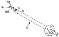
도1은 제1 실시 형태에 관한 초음파 처치구의 개략적인 측면도이다.1 is a schematic side view of the ultrasonic treatment instrument according to the first embodiment.

도2A는 제1 실시 형태에 관한 초음파 처치구를 본체 유닛 어셈블리, 프로브 및 진동자 어셈블리로 분해하고, 본체 유닛 어셈블리를 다시 핸들 어셈블리, 시스 어셈블리, 및 죠오 어셈블리로 분해한 상태를 도시하는 개략적인 측면도이다.FIG. 2A is a schematic side view illustrating a state where the ultrasonic treatment instrument according to the first embodiment is disassembled into a main body unit assembly, a probe and a vibrator assembly, and the main body unit assembly is disassembled into a handle assembly, a sheath assembly, and a jaw assembly. .

도2B는 제1 실시 형태에 관한 초음파 처치구에 있어서의 프로브의 도2A 중의 2B-2B선을 따른 단면도이다.2B is a cross-sectional view taken along the line 2B-2B in FIG. 2A of the probe in the ultrasonic treatment instrument according to the first embodiment.

도3은 제1 실시 형태에 관한 초음파 처치구에 있어서의 본체 유닛 어셈블리의 사시도이다.3 is a perspective view of a main body unit assembly in the ultrasonic treatment tool according to the first embodiment.

도4는 제1 실시 형태에 관한 초음파 처치구에 있어서의 본체 유닛 어셈블리의 핸들 어셈블리의 분해 사시도이다.4 is an exploded perspective view of the handle assembly of the main body unit assembly in the ultrasonic treatment instrument according to the first embodiment.

도5는 제1 실시 형태에 관한 초음파 처치구에 있어서의 본체 유닛 어셈블리의 핸들 어셈블리의 종단면도이다.Fig. 5 is a longitudinal sectional view of the handle assembly of the main body unit assembly in the ultrasonic treatment instrument according to the first embodiment.

도6A는 제1 실시 형태에 관한 초음파 처치구에 있어서의 본체 유닛 어셈블리의 핸들 어셈블리의 횡단면도를 도시한 도5 중의 6A-6A선을 따른 단면도이다.6A is a cross-sectional view taken along a line 6A-6A in FIG. 5 showing a cross-sectional view of the handle assembly of the main body unit assembly in the ultrasonic treatment instrument according to the first embodiment.

도6B는 제1 실시 형태에 관한 초음파 처치구에 있어서의 본체 유닛 어셈블리의 핸들 어셈블리의 횡단면도를 도시한 도5 중의 6B-6B선을 따른 단면도이다.FIG. 6B is a cross-sectional view taken along a line 6B-6B in FIG. 5 showing a cross-sectional view of the handle assembly of the body unit assembly in the ultrasonic treatment instrument according to the first embodiment. FIG.

도7A는 제1 실시 형태에 관한 초음파 처치구에 있어서의 본체 유닛 어셈블리의 핸들 어셈블리의 횡단면도를 도시한 도5 중의 7A-7A선을 따른 단면도이다.FIG. 7A is a cross-sectional view taken along a line 7A-7A in FIG. 5 showing a cross-sectional view of the handle assembly of the main body unit assembly in the ultrasonic treatment instrument according to the first embodiment. FIG.

도7B는 제1 실시 형태에 관한 초음파 처치구에 있어서의 본체 유닛 어셈블리의 핸들 어셈블리의 횡단면도를 도시한 도5 중의 7B-7B선을 따른 단면도이다.FIG. 7B is a cross-sectional view taken along a line 7B-7B in FIG. 5 showing a cross-sectional view of the handle assembly of the main body unit assembly in the ultrasonic treatment instrument according to the first embodiment.

도7C는 제1 실시 형태에 관한 초음파 처치구에 있어서의 본체 유닛 어셈블리의 핸들 어셈블리의 횡단면도를 도시한 도5 중의 7C-7C선을 따른 단면도이다.FIG. 7C is a cross-sectional view taken along a line 7C-7C in FIG. 5 showing a cross-sectional view of the handle assembly of the body unit assembly in the ultrasonic treatment instrument according to the first embodiment. FIG.

도8은 제1 실시 형태에 관한 초음파 처치구에 있어서의 본체 유닛 어셈블리의 시스 어셈블리의 분해 사시도이다.8 is an exploded perspective view of the sheath assembly of the main body unit assembly in the ultrasonic treatment instrument according to the first embodiment.

도9는 제1 실시 형태에 관한 초음파 처치구에 있어서의 본체 유닛 어셈블리 의 죠오 어셈블리의 분해 사시도이다.9 is an exploded perspective view of the jaw assembly of the main unit unit assembly in the ultrasonic treatment instrument according to the first embodiment.

도10A는 제1 실시 형태에 관한 초음파 처치구에 있어서의 본체 유닛 어셈블리의 선단부를 도시하는 종단면도이다.FIG. 10A is a longitudinal sectional view showing the distal end portion of the main body unit assembly in the ultrasonic treatment tool according to the first embodiment. FIG.

도10B는 제1 실시 형태에 관한 초음파 처치구에 있어서의 본체 유닛 어셈블리의 선단부의 도10A 중의 10B-10B선을 따른 횡단면도이다.Fig. 10B is a cross sectional view along the line 10B-10B in Fig. 10A of the distal end portion of the main body unit assembly in the ultrasonic treatment instrument according to the first embodiment.

도11A는 제1 실시 형태에 관한 초음파 처치구에 있어서의 본체 유닛 어셈블리의 죠오 어셈블리의 선단부 작용부의 죠오 본체를 도시하는 개략적인 사시도이다.Fig. 11A is a schematic perspective view showing the jaw body of the distal end portion of the jaw assembly of the body unit assembly in the ultrasonic treatment instrument according to the first embodiment.

도11B는 제1 실시 형태에 관한 초음파 처치구에 있어서의 죠오 어셈블리의 선단부 작용부의 죠오 본체의 돌기부를 죠오 지지 부재의 돌출부로부터 분리된 상태를 도시하는 개략적인 측면도이다.Fig. 11B is a schematic side view showing a state where the projection of the jaw body of the distal end acting portion of the jaw assembly in the ultrasonic treatment instrument according to the first embodiment is separated from the projection of the jaw supporting member.

도11C는 제1 실시 형태에 관한 초음파 처치구에 있어서의 죠오 어셈블리의 선단부 작용부의 죠오 본체의 돌기부를 죠오 지지 부재의 돌출부에 접촉시킨 상태를 도시하는 개략적인 측면도이다.Fig. 11C is a schematic side view showing a state where the projection of the jaw body of the distal end acting portion of the jaw assembly in the ultrasonic treatment instrument according to the first embodiment is brought into contact with the projection of the jaw supporting member.

도12는 제1 실시 형태에 관한 초음파 처치구의 핸들 본체에 시스 어셈블리, 죠오 어셈블리 및 프로브를 착탈하는 상태를 도시하는 개략적인 사시도이다.12 is a schematic perspective view showing a state where a sheath assembly, a jaw assembly, and a probe are attached to and detached from the handle body of the ultrasonic treatment instrument according to the first embodiment.

도13A는 제1 실시 형태에 관한 초음파 처치구의 조립 순서를 나타내고, 죠오 어셈블리를 시스 어셈블리에 대하여 화살표 α 방향으로 이동시켜 죠오 어셈블리와 시스 어셈블리를 조립 부착하는 상태를 도시하는 개략적인 사시도이다.Fig. 13A is a schematic perspective view showing the assembling procedure of the ultrasonic treatment tool according to the first embodiment and showing a state in which the jaw assembly is moved in the arrow α direction with respect to the sheath assembly to assemble and attach the jaw assembly and the sheath assembly.

도13B는 제1 실시 형태에 관한 초음파 처치구의 조립 순서를 나타내고, 시스 어셈블리에 대하여 죠오 어셈블리를 화살표 β 방향으로 회전시켜서 조립 부착하는 상태를 도시하는 개략적인 사시도이다.Fig. 13B is a schematic perspective view showing the assembling procedure of the ultrasonic treatment tool according to the first embodiment, and showing a state of assembling and attaching the jaw assembly by rotating the jaw assembly in the direction of the arrow? With respect to the sheath assembly.

도13C는 제1 실시 형태에 관한 초음파 처치구의 조립 순서를 나타내고, 시스 어셈블리에 대하여 죠오 어셈블리를 조립 부착한 상태를 도시하는 개략적인 사시도이다.Fig. 13C is a schematic perspective view showing the assembling procedure of the ultrasonic treatment tool according to the first embodiment and showing a state in which the jaw assembly is assembled to the sheath assembly.

도14A는 제1 실시 형태에 관한 초음파 처치구의 조립 순서를 나타내고, 시스 어셈블리 및 죠오 어셈블리를 일체화시킨 삽입부 유닛 어셈블리를 본체 유닛 어셈블리에 대하여 화살표 γ 방향으로 이동시켜서 삽입부 유닛 어셈블리와 핸들 어셈블리를 조립 부착하는 상태를 도시하는 개략적인 사시도이다.Fig. 14A shows the assembling procedure of the ultrasonic treatment tool according to the first embodiment, and moves the insert unit assembly in which the sheath assembly and the jaw assembly are integrated in the direction of arrow γ with respect to the main body unit assembly to assemble the insert unit assembly and the handle assembly. It is a schematic perspective view which shows the state to attach.

도14B는 제1 실시 형태에 관한 초음파 처치구의 조립 순서를 나타내고, 핸들 어셈블리에 대하여 삽입부 유닛 어셈블리를 화살표 δ 방향으로 회전시켜서 조립 부착하는 상태를 도시하는 개략적인 사시도이다.Fig. 14B is a schematic perspective view showing the assembling procedure of the ultrasonic treatment tool according to the first embodiment, and showing a state of assembling and attaching the insert unit unit assembly by rotating the insert unit unit with respect to the handle assembly in the direction of the arrow?.

도14C는 제1 실시 형태에 관한 초음파 처치구의 조립 순서를 나타내고, 조립된 본체 유닛 어셈블리를 도시하는 개략적인 사시도이다.Fig. 14C is a schematic perspective view showing the assembling procedure of the ultrasonic treatment tool according to the first embodiment and showing the assembled body unit assembly.

도15A는 제1 실시 형태에 관한 초음파 처치구의 분해 순서를 나타내고, 핸들 어셈블리의 회전 손잡이를 화살표 ε 방향으로 이동시켜, 삽입부 유닛 어셈블리를 핸들 어셈블리에 대하여 화살표 ζ 방향으로 회전시키는 상태를 도시하는 개략적인 사시도이다.Fig. 15A shows a disassembly procedure of the ultrasonic treatment instrument according to the first embodiment, and shows a state in which the rotary knob of the handle assembly is moved in the direction of arrow ε to rotate the insert unit assembly in the direction of arrow ζ with respect to the handle assembly. It is a perspective view.

도15B는 제1 실시 형태에 관한 초음파 처치구의 분해 순서를 나타내고, 핸들 어셈블리에 대하여 삽입부 유닛 어셈블리를 도15A 중의 화살표 ζ 방향으로 회전시 킨 상태를 도시하는 개략적인 사시도이다.Fig. 15B is a schematic perspective view showing a disassembly procedure of the ultrasonic treatment instrument according to the first embodiment, and showing a state in which the insertion unit unit assembly is rotated in the direction of arrow? In Fig. 15A with respect to the handle assembly.

도15C는 제1 실시 형태에 관한 초음파 처치구의 분해 순서를 나타내고, 핸들 어셈블리에 대하여 삽입부 유닛 어셈블리를 화살표 η 방향으로 빼내어 분해하는 상태를 도시하는 개략적인 사시도이다.Fig. 15C is a schematic perspective view showing a disassembly procedure of the ultrasonic treatment instrument according to the first embodiment, and showing a state in which the insertion unit unit assembly is pulled out in the direction of arrow? With respect to the handle assembly and disassembled.

도16A는 제2 실시 형태에 관한 초음파 처치구에 있어서의 프로브의 개략적인 측면도이다.Fig. 16A is a schematic side view of a probe in the ultrasonic treatment instrument according to the second embodiment.

도16B는 제2 실시 형태에 관한 초음파 처치구에 있어서의 프로브의 도16A 중의 16B-16B선을 따른 단면도이다.16B is a cross-sectional view taken along a line 16B-16B in FIG. 16A of the probe in the ultrasonic treatment instrument according to the second embodiment.

도17은 제2 실시 형태에 관한 초음파 처치구에 있어서의 프로브, 죠오 어셈블리, 시스 어셈블리, 핸들 어셈블리의 각 구성의 일례를 도시한 개략도이다.17 is a schematic diagram showing an example of each configuration of a probe, a jaw assembly, a sheath assembly, and a handle assembly in the ultrasonic treatment instrument according to the second embodiment.

도18A는 제2 실시 형태에 관한 초음파 처치구에 있어서의 본체 유닛 어셈블리의 핸들 어셈블리의 종단면도이다.18A is a longitudinal sectional view of the handle assembly of the body unit assembly in the ultrasonic treatment instrument according to the second embodiment.

도18B는 제2 실시 형태에 관한 초음파 처치구에 있어서의 본체 유닛 어셈블리의 도18A 중의 화살표 18B-18B선을 따른 단면도이다.FIG. 18B is a cross-sectional view taken along a line 18B-18B in FIG. 18A of the main body unit assembly in the ultrasonic treatment instrument according to the second embodiment.

이하, 도면을 참조하면서 본 발명을 실시하기 위한 최량의 형태에 대해 설명한다.EMBODIMENT OF THE INVENTION Hereinafter, the best form for implementing this invention is demonstrated, referring drawings.

우선, 제1 실시 형태에 대하여 도1 내지 도15C를 이용하여 설명한다.First, the first embodiment will be described with reference to FIGS. 1 to 15C.

도1에 도시하는 초음파 처치구(초음파 처치 장치)(10)는, 도2A에 도시한 바와 같이 서로 착탈 가능한 본체 유닛 어셈블리(12)와, 프로브(14)와, 진동자 어셈 블리(16)를 구비하고 있다. 본체 유닛 어셈블리(12)는 핸들 어셈블리(22)와, 시스 어셈블리(24)와, 죠오 어셈블리(처치 어셈블리)(26)를 구비하고 있다. 시스 어셈블리(24) 및 죠오 어셈블리(26)는 핸들 어셈블리(22)에 착탈 가능하다. 죠오 어셈블리(26)는 시스 어셈블리(24)에 착탈 가능하다. 시스 어셈블리(24)와 죠오 어셈블리(26)를 조합하면, 삽입부 유닛 어셈블리(28)(도1 참조)가 조립된다. 삽입부 유닛 어셈블리(28)와 핸들 어셈블리(22)를 조합하면, 도3에 도시한 바와 같이 본체 유닛 어셈블리(12)가 조립된다.The ultrasonic treatment instrument (ultrasound treatment apparatus) 10 shown in FIG. 1 includes a main body unit assembly 12 detachable from each other, a probe 14, and a vibrator assembly 16 as shown in FIG. 2A. Doing. The body unit assembly 12 includes a handle assembly 22, a sheath assembly 24, and a jaw assembly (treatment assembly) 26. The sheath assembly 24 and the jaw assembly 26 are removable from the handle assembly 22. The jaw assembly 26 is detachable from the sheath assembly 24. Combining the sheath assembly 24 and the jaw assembly 26, the insert unit assembly 28 (see FIG. 1) is assembled. When the insert unit assembly 28 and the handle assembly 22 are combined, the main unit assembly 12 is assembled as shown in FIG.

도1 및 도2A에 도시한 바와 같이, 프로브(14)는 진동자 어셈블리(16)에 착탈 가능하다. 진동자 어셈블리(16)는, 본체 유닛 어셈블리(12)의 핸들 어셈블리(22)에 착탈 가능하다. 이로 인해, 프로브(14)와 진동자 어셈블리(16)가 조합된 유닛 어셈블리는, 본체 유닛 어셈블리(12)에 착탈 가능하다. 즉, 이들 본체 유닛 어셈블리(12)와, 프로브(14)와, 진동자 어셈블리(16)를 조합하면, 도1에 도시한 바와 같이 초음파 처치구(10)가 조립된다.As shown in Figures 1 and 2A, the probe 14 is detachable from the vibrator assembly 16. The vibrator assembly 16 is detachable from the handle assembly 22 of the main body unit assembly 12. For this reason, the unit assembly in which the probe 14 and the vibrator assembly 16 are combined is detachable from the main body unit assembly 12. That is, when these main body unit assembly 12, the probe 14, and the vibrator assembly 16 are combined, the ultrasonic treatment instrument 10 is assembled as shown in FIG.

도2A에 도시한 바와 같이, 진동자 어셈블리(16)는 원통형의 진동자 커버(30)와, 이 진동자 커버(30)의 내부에 내장되어, 초음파 진동을 발생시키는 초음파 진동자(도시하지 않음)를 구비하고 있다. 초음파 진동자는, 발생시킨 진동의 진폭을 확대하는 혼(도시하지 않음)을 선단부에 구비하고 있다. 이 혼에는, 프로브(14)의 기단부가 착탈 가능하다. 즉, 진동자 어셈블리(16)의 선단부에는, 프로브(14)의 기단부가 착탈 가능하다.As shown in Fig. 2A, the vibrator assembly 16 includes a cylindrical vibrator cover 30 and an ultrasonic vibrator (not shown) which is built into the vibrator cover 30 to generate ultrasonic vibrations. have. The ultrasonic vibrator includes a horn (not shown) at the distal end that enlarges the amplitude of the generated vibration. The base end of the probe 14 is detachable from this horn. That is, the proximal end of the probe 14 is detachable from the distal end of the vibrator assembly 16.

진동자 커버(30)는 본체 유닛 어셈블리(12)의 후술하는 조작부 본체(54)의 진동자 접속부(99)(도5 참조)에 착탈 가능한 어셈블리 연결부(32)를 선단부에 구비하고 있다. 이 어셈블리 연결부(32)의 외주면에는, 일부가 절결된 C자 형상의 결합 링(C링)(34)이 장착되어 있다. 도1에 도시한 바와 같이, 진동자 커버(30)의 후단부에는, 도시하지 않은 진동자용 플러그가 배치된 전원 접속용 코드(36)가 접속되어 있다.The vibrator cover 30 is provided with the assembly connection part 32 which can be attached or detached to the vibrator connection part 99 (refer FIG. 5) of the operation part main body 54 mentioned later of the main body unit assembly 12 at the front-end | tip. On the outer circumferential surface of the assembly connecting portion 32, a C-shaped engaging ring (C ring) 34 having a portion cut out is mounted. As shown in Fig. 1, a power supply connecting cord 36 on which a vibrator plug (not shown) is arranged is connected to the rear end of the vibrator cover 30.

도2A에 도시한 바와 같이, 프로브(14)는 가늘고 긴 막대 형상의 진동 전달 부재(프로브)(40)와, 이 진동 전달 부재(40)의 기단부에 설치된 혼부(42)와, 이 혼부(42)의 기단부에 배치된 최대경부(44)와, 진동 전달 부재(40)의 선단부에 배치된 처치부(46)를 구비하고 있다. 혼부(42)와 최대경부(44)와의 연결부에는, 도2B에 도시한 바와 같이 단면 형상이 원형과는 다른 플랜지 형상의 이형 단면 형상부(제1 착탈 기구)(48)가 배치되어 있다. 이 이형 단면 형상부(48)에 의해, 프로브(14)는 후술하는 위치 결정 부재(제1 착탈 기구)(90)의 평행평면(90a, 90b)(도7C 참조)에 대하여 위치 결정된다.As shown in Fig. 2A, the probe 14 includes an elongated rod-shaped vibration transmission member (probe) 40, a horn 42 provided at the proximal end of the vibration transmission member 40, and this horn 42 The maximum diameter part 44 arrange | positioned at the proximal end of (), and the treatment part 46 arrange | positioned at the front-end | tip part of the vibration transmission member 40 are provided. In the connecting portion between the horn portion 42 and the largest diameter portion 44, as shown in Fig. 2B, a release cross-sectional shape portion (first attachment and detachment mechanism) 48 having a flange shape different from the circular shape is disposed. By this release cross-sectional shape part 48, the probe 14 is positioned with respect to the parallel planes 90a and 90b (refer FIG. 7C) of the positioning member (1st attachment / detachment mechanism) 90 mentioned later.

도2A에 도시한 바와 같이, 진동 전달 부재(40)의 외주면에는 각각 링 형상을 갖는 복수의 지지 부재(50)가 배치되어 있다. 이들 지지 부재(150)는, 예를 들어 고무재 등의 탄성 부재로 형성되어 있다. 이들 지지 부재(50)는, 진동 전달 부재(40)의 외주면의 기단부 측으로부터 선단부 측을 향해 전달되는 초음파 진동의 정재파의 절(이하, 진동의 절이라 함)의 위치에 배치되어 있다. As shown in Fig. 2A, a plurality of support members 50 each having a ring shape are arranged on the outer circumferential surface of the vibration transmission member 40. Figs. These support members 150 are formed from elastic members, such as a rubber material, for example. These support members 50 are arrange | positioned at the position of the section | piece of the standing wave of ultrasonic vibration (henceforth a section of vibration) transmitted from the base end side of the outer peripheral surface of the vibration transmission member 40 toward the front end side.

최대경부(44)의 기단부에는 부착 나사(44a)가 배치되어 있다. 이 부착 나사(44a)는 진동자 어셈블리(16)의 혼의 선단부의 프로브 부착부의 나사 구멍부에 나사 결합된다. 이로 인해, 프로브(14)와 진동자 어셈블리(16)는 일체적으로 조합 가능하다. 최대경부(44)와 진동 전달 부재(40) 사이의 혼부(42)는 진동자 어셈블리(16)로부터 전달되는 초음파 진동의 진폭을 확대한다. 진동 전달 부재(40)는, 혼부(42)에서 확대된 초음파 진동을 처치부(46)를 향해 전달한다.An attachment screw 44a is disposed at the proximal end of the largest diameter portion 44. The attachment screw 44a is screwed into the screw hole of the probe attachment portion of the tip of the horn of the vibrator assembly 16. For this reason, the probe 14 and the vibrator assembly 16 can be combined integrally. The horn 42 between the largest neck 44 and the vibration transmitting member 40 enlarges the amplitude of the ultrasonic vibration transmitted from the vibrator assembly 16. The vibration transmission member 40 transmits the ultrasonic vibration enlarged in the horn part 42 toward the treatment part 46.

처치부(46)는 생체 조직에 접촉하여 처치를 행하기 위해 설치되고, 진동 전달 부재(40)의 중심축으로부터 벗어나는 방향으로 만곡된 비대칭 형상, 예를 들어 원호 형상으로 형성되어 있다. 처치부(46)의 형상에 대해서는 후술하지만, 목적에 따라서 적당한 것이 사용된다(도16A 및 도17 참조).The treatment part 46 is provided in contact with a living tissue, and is formed in an asymmetrical shape, for example, an arc shape, curved in a direction deviating from the central axis of the vibration transmission member 40. Although the shape of the treatment part 46 is mentioned later, what is suitable is used according to the objective (refer FIG. 16A and FIG. 17).

도4에 도시한 바와 같이, 핸들 어셈블리(22)는 절연성을 갖는 조작부 본체(54)를 구비하고 있다. 이 조작부 본체(54)는, 대략 원통형의 하우징으로서 형성되어 있다. 조작부 본체(54)의 외주면에는, 고정 핸들(56)이 일체적으로 성형되어 있다. 고정 핸들(56)의 조작단부(하단부)에는, 엄지 손가락 이외의 손가락을 선택적으로 걸 수 있는 손가락 걸이 구멍(56a)이 형성되어 있다. 이 조작부 본체(54)에는, 고정 핸들(56)에 대하여 회전 가능한 가동 핸들(58)이 설치되어 있다. 가동 핸들(58)의 조작단부(하단부)에는, 같은 손의 엄지 손가락을 걸 수 있는 손가락 걸이 구멍(58a)이 형성되어 있다.As shown in FIG. 4, the handle assembly 22 is provided with the operation part main body 54 with insulation. This operation part main body 54 is formed as a substantially cylindrical housing. The fixed handle 56 is integrally molded on the outer circumferential surface of the operation unit main body 54. At the operation end (lower end) of the fixed handle 56, a finger hook hole 56a capable of selectively hooking fingers other than the thumb is formed. The operation part main body 54 is provided with the movable handle 58 which can be rotated with respect to the fixed handle 56. At the operation end (lower end) of the movable handle 58, a finger hook hole 58a capable of engaging the thumb of the same hand is formed.

조작부 본체(54)의 외주면에는, 각각 한 쌍의 지지점 핀 받침부(54a)와, 작용 핀 동작 창(54b)이 형성되어 있다. 작용 핀 동작 창(54b)은 조작부 본체(54)의 벽부를 관통하고 있으므로, 조작부 본체(54)는 측부로부터의 조작부 본체(54)의 내강에 연통되어 있다(도7C 참조). 가동 핸들(58)의 상단부에는, 두 갈래 형상으로 분기된 연결부(58b)가 형성되어 있다. 가동 핸들(58)의 상단부에는, 지지점 핀 받침부(54a)에 배치된 지지점 핀(60)이 장착되어 있다. 이들 지지점 핀(60)은, 시스 어셈블리(24)의 후술하는 절연 튜브(116)가 핸들 어셈블리(22)에 장착되었을 때의 축선보다도 도5 중의 상측에서 조작부 본체(54)에 연결되어 있다. 이들 지지점 핀(60)은, 가동 핸들(58)을 원활하게 회전시키는 저마찰 계수의 부재로 형성된 컬러(절연 캡)(54c)를 통과시켜서 지지점 핀 받침부(54a)에 장착되어 있다. 이로 인해, 가동 핸들(58)은 고정 핸들(56)에 대하여 개폐 가능하다.On the outer circumferential surface of the operation part main body 54, a pair of support point pin receiving part 54a and the action pin operation window 54b are formed, respectively. Since the action pin operation window 54b penetrates the wall part of the operation part main body 54, the operation part main body 54 communicates with the lumen of the operation part main body 54 from the side part (refer FIG. 7C). At the upper end of the movable handle 58, a connecting portion 58b branched into two branches is formed. The support point pin 60 arrange | positioned at the support point pin base 54a is attached to the upper end part of the movable handle 58. As shown in FIG. These supporting point pins 60 are connected to the operation unit main body 54 on the upper side in FIG. 5 than the axis when the insulating tube 116 described later of the sheath assembly 24 is mounted on the handle assembly 22. These support point pins 60 are attached to the support point pin support part 54a by passing through the color (insulation cap) 54c formed by the member of the low friction coefficient which smoothly rotates the movable handle 58. For this reason, the movable handle 58 can be opened and closed with respect to the fixed handle 56.

가동 핸들(58)의 상단부에서, 지지점 핀(60)의 하부에는 작용 핀 동작 창(54b)에 배치된 작용 핀(62)이 장착되어 있다. 이 작용 핀(62)의 조작부 본체(54)의 내부측에 배치된 단부는, 후술하는 슬라이더(86)의 핀 받침부(86a)에 배치되어 있다. 이로 인해, 고정 핸들(56)에 대하여 가동 핸들(58)이 지지점 핀(60)을 지점으로 하여 개폐되면, 작용 핀(62)에 의해 슬라이더(86)가 전후로 진퇴된다.At the upper end of the movable handle 58, an actuating pin 62 disposed on the actuating pin actuating window 54b is attached to the lower portion of the support point pin 60. The end part arrange | positioned inside the operation part main body 54 of this action pin 62 is arrange | positioned at the pin support part 86a of the slider 86 mentioned later. For this reason, when the movable handle 58 opens and closes with respect to the fixed handle 56, and the support | pinning point 60 is a point, the slider 86 advances back and forth by the action pin 62. FIG.

도4 및 도5에 도시한 바와 같이, 조작부 본체(54)의 선단부의 내주면 가장자리에는, 고정 링(64)이 장착되어 있다. 이 고정 링(64)의 내주면에는, 너트부가 형성되어 있다. 이 고정 링(64)의 내측에는, 통 형상의 회전 연결 부재(66)가 배치되어 있다. 이 회전 연결 부재(66)는 선단부에 소경부를, 기단부에 대경부를 각각 지니고, 이들 소경부 및 대경부 사이에 단차를 갖는다. 회전 연결 부재(66)의 선단부의 소경부의 외주면에서, 단차에 근접하는 위치에는 볼트부가 형성되어 있다. 회전 연결 부재(66)의 볼트부는, 고정 링(64)의 너트부에 나사 결합되어 있다.As shown in FIG. 4 and FIG. 5, the fixing ring 64 is attached to the inner peripheral surface edge of the front end of the operation part main body 54. As shown in FIG. The nut part is formed in the inner peripheral surface of this fixing ring 64. Inside this fixing ring 64, the cylindrical rotation connecting member 66 is arrange | positioned. The rotary connecting member 66 has a small diameter portion at the distal end portion and a large diameter portion at the proximal end, respectively, and has a step between these small diameter portions and the large diameter portion. On the outer circumferential surface of the small diameter portion of the distal end portion of the rotary connecting member 66, a bolt portion is formed at a position close to the step. The bolt part of the rotary connection member 66 is screwed to the nut part of the fixing ring 64.

회전 연결 부재(66)의 소경부의 외주면에서, 볼트부보다도 선단부 측에는 회전 연결 부재(66)의 축 방향을 따라, 서로 대향한 한 쌍의 긴 구멍(661a)이 형성되어 있다. 회전 연결 부재(66)의 소경부의 내측에는, 회전 연결 부재(66)의 축 방향으로 미끄럼 이동 가능한 통 형상의 회전 고정 부재(68)가 배치되어 있다. 이 회전 고정 부재(68)에는, 회전 연결 부재(66)의 긴 구멍(66a)을 각각 관통한 상태에서 한 쌍의 제1 핀(70a)이 배치되어 있다. 즉, 이들 제1 핀(70a)은 회전 연결 부재(66)의 긴 구멍(66a)에 각각 협지되어 있다. 이로 인해, 회전 고정 부재(68)는 제1 핀(70a)에 의해 회전 연결 부재(66)의 긴 구멍(66a)의 긴 축을 따라 이동 가능하다. 이 회전 고정 부재(68)의 선단부에는, 도6A에 도시한 바와 같이 서로 대향한 한 쌍의 슬릿부(제1 장착 기구)(68a, 68b)가 형성되어 있다.On the outer circumferential surface of the small diameter portion of the rotary coupling member 66, a pair of long holes 661a opposed to each other are formed along the axial direction of the rotary coupling member 66 at the tip end side than the bolt portion. Inside the small diameter part of the rotation connection member 66, the cylindrical rotation fixing member 68 which can slide to the axial direction of the rotation connection member 66 is arrange | positioned. In this rotation fixing member 68, a pair of 1st pin 70a is arrange | positioned in the state which penetrated the elongate hole 66a of the rotation connection member 66, respectively. That is, these first pins 70a are sandwiched by the elongated holes 66a of the rotation connecting member 66, respectively. For this reason, the rotation fixing member 68 is movable along the long axis of the long hole 66a of the rotation connection member 66 by the 1st pin 70a. At the distal end of the rotation fixing member 68, as shown in Fig. 6A, a pair of slit portions (first mounting mechanisms) 68a and 68b facing each other are formed.

이 회전 고정 부재(68)의 외측에서, 제1 핀(70a)이 설치된 위치보다도 선단부 측에서, 회전 연결 부재(66)의 소경부의 내측에는 통 형상의 시스 접속 부재(72)가 설치되어 있다. 즉, 회전 고정 부재(68)의 선단부의 외측에는, 회전 연결 부재(66)와 함께 통 형상의 시스 접속 부재(72)가 배치되어 고정되어 있다.On the outside of the rotation fixing member 68, a cylindrical sheath connecting member 72 is provided inside the small diameter portion of the rotation connecting member 66 from the tip end side than the position where the first pin 70a is provided. . That is, the cylindrical sheath connection member 72 is arrange | positioned and fixed to the outer side of the front-end | tip part of the rotation fixing member 68 with the rotation connection member 66.

이 시스 접속 부재(72)의 선단부의 내주면에는, 도6A에 도시한 바와 같이 단면이 원 형상인 개구 모서리부에, 서로 대향하는 위치에 슬릿(72a, 72b)이 형성되어 있다. 이들 슬릿(72a, 72b)은, 시스 접속 부재(72)의 중심에 대하여 각각 60° 기울어진 위치에 대향한 상태로 형성되어 있다. 도4에 도시한 바와 같이, 시스 접속 부재(72)의 기단부에는 조립 부착 시, 시스 접속 부재(72)의 내주면의 구멍에 대하여 회전 고정 부재(68)를 위치 결정하기 위해, 한 쌍의 아암(72c, 72d)이 형성 되어 있다.Slit 72a, 72b is formed in the inner peripheral surface of the front-end | tip part of this sheath connecting member 72 in the position which opposes each other in the opening edge part which has a circular cross section as shown in FIG. 6A. These slits 72a and 72b are formed in the state facing the position inclined by 60 degrees with respect to the center of the sheath connecting member 72, respectively. As shown in Fig. 4, at the proximal end of the sheath connecting member 72, a pair of arms (A) is used to position the rotation fixing member 68 with respect to the hole of the inner circumferential surface of the sheath connecting member 72 at the time of assembly attachment. 72c, 72d) are formed.

도5에 도시한 바와 같이, 시스 접속 부재(72)의 기단부면의 일부는 회전 고정 부재(68)에 접촉됨으로써 위치 결정되어 있다. 도6B에 도시한 바와 같이, 회전 고정 부재(68)의 기단부의 외주면에는, 서로 대향하는 평행평면(68c, 68d)이 형성되어 있다. 시스 접속 부재(72)의 아암(72c, 72d)의 기단부의 내주면에는, 평행평면(68c, 68d)에 접촉되는 평면이 형성되어 있다. 시스 접속 부재(72)의 아암(72c, 72d)의 기단부의 외주면은, 회전 연결 부재(66)의 내주면 형상을 따른 형상으로 형성되어 있다.As shown in FIG. 5, a part of the base end surface of the sheath connecting member 72 is positioned by contacting the rotation fixing member 68. As shown in Fig. 6B, parallel planes 68c and 68d facing each other are formed on the outer circumferential surface of the proximal end of the rotation fixing member 68. Figs. On the inner circumferential surface of the base end portions of the arms 72c and 72d of the sheath connecting member 72, planes contacting the parallel planes 68c and 68d are formed. The outer circumferential surface of the base end portions of the arms 72c and 72d of the sheath connecting member 72 is formed in a shape along the shape of the inner circumferential surface of the rotation connecting member 66.

도4 및 도5에 도시한 바와 같이, 회전 연결 부재(66)의 외주면에는, 외주면에 미끄럼 방지부(74a)를 구비한 링 형상이나 통 형상의 회전 손잡이(74)가 회전 연결 부재(66)에 대하여 축 방향으로 미끄럼 이동 가능하게 장착되어 있다. 도6B에 도시한 바와 같이, 이 회전 손잡이(74)의 내측에는, 제1 핀(70a)과 결합하는 한 쌍의 핀 받침부(74a)가 형성되어 있다. 이로 인해, 회전 손잡이(74)는 회전 고정 부재(68) 및 회전 연결 부재(66)에 대하여 회전이 방지된 상태로 고정된다. 즉, 회전 손잡이(74)를 회전시키면, 회전 연결 부재(616)도 추종하여 회전한다.As shown in Figs. 4 and 5, on the outer circumferential surface of the rotary connecting member 66, a ring-shaped or cylindrical rotary knob 74 having a non-slip portion 74a on the outer circumferential surface thereof is provided with a rotary connecting member 66. It is mounted so as to be able to slide in the axial direction with respect to the. As shown in Fig. 6B, inside the rotary knob 74, a pair of pin receiving portions 74a that engage with the first pin 70a are formed. For this reason, the rotary knob 74 is fixed in the state which rotation was prevented with respect to the rotation fixing member 68 and the rotation connection member 66. As shown in FIG. That is, when the rotary knob 74 is rotated, the rotary connecting member 616 also follows and rotates.

회전 연결 부재(66)와 회전 손잡이(74)와의 선단부면을 덮는 위치에는, 링 형상의 고정 부재(76)가 배치되어 있다. 이 고정 부재(76)의 외주면에는, 볼트부가 형성되어 있다. 회전 연결 부재(66)의 내주면에는, 고정 부재(76)의 외주면의 볼트부와 나사 결합 가능한 너트부가 형성되어 있다. 이로 인해, 고정 부재(76)와 회전 연결 부재(66)는, 상호 나사부에 의해 나사 결합되어 있다.The ring-shaped fixing member 76 is arrange | positioned in the position which covers the front-end | tip surface of the rotary connection member 66 and the rotary knob 74. As shown in FIG. The bolt part is formed in the outer peripheral surface of this fixing member 76. On the inner circumferential surface of the rotary connection member 66, a nut portion that can be screwed with the bolt portion of the outer circumferential surface of the fixing member 76 is formed. For this reason, the fixing member 76 and the rotation connection member 66 are screwed together by the mutual thread part.

도5에 도시한 바와 같이, 회전 연결 부재(66)의 단차의 내주면에는 직경 방향 안쪽으로 돌출한 플랜지부(66b)가 형성되어 있다. 회전 고정 부재(68)의 기단부와 회전 연결 부재(66)의 플랜지부(66b)와의 사이에는, 코일 스프링(78)이 배치되어 있다. 한 쌍의 제1 핀(70a)은, 회전 고정 부재(68)가 회전 연결 부재(66)의 선단부 측으로 압박되고 있다. 이로 인해, 통상 회전 연결 부재(66)의 긴 구멍(66a)의 선단부에 배치되어 있다. 회전 손잡이(74)도 핀 받침부(74a)에서 한 쌍의 제1 핀(70a)에 결합하고 있다. 이로 인해, 회전 손잡이(74)가 장착된 위치의 기단부는, 회전 연결 부재(66)의 긴 구멍(66a)의 선단부에 일치한다. 따라서, 회전 손잡이(74)를 코일 스프링(78)의 장비 역량 이상의 힘으로 기단부 측으로 당기면, 회전 연결 부재(66)의 긴 구멍(66a)의 길이 범위로 회전 손잡이(74) 및 회전 고정 부재(68)가 긴 구멍(66a)의 축 방향을 따라 미끄럼 이동한다.As shown in Fig. 5, the flange portion 66b protruding inward in the radial direction is formed on the inner circumferential surface of the step of the rotary connecting member 66. A coil spring 78 is disposed between the proximal end of the rotation fixing member 68 and the flange portion 66b of the rotation connecting member 66. As for the pair of 1st pins 70a, the rotation fixing member 68 is urged to the front end side of the rotation connection member 66. For this reason, it is normally arrange | positioned at the front-end | tip part of the long hole 66a of the rotation connection member 66. As shown in FIG. The rotary knob 74 is also coupled to the pair of first pins 70a at the pin support portion 74a. For this reason, the base end part of the position in which the rotary knob 74 was mounted corresponds with the front end part of the elongate hole 66a of the rotation connection member 66. As shown in FIG. Accordingly, when the rotary knob 74 is pulled toward the proximal end with a force greater than the equipment capacity of the coil spring 78, the rotary knob 74 and the rotary fixing member 68 in the length range of the long hole 66a of the rotary connecting member 66. ) Slides along the axial direction of the long hole 66a.

회전 고정 부재(68)의 기단부 측에는 통 형상의 구동 파이프 접속 부재(구동축 접속 부재)(80)가 회전 연결 부재(66)에 대하여 축 방향으로 미끄럼 이동 가능하게 배치되어 있다. 이 구동 파이프 접속 부재(80)의 선단부에는 한 쌍의 구동 파이프 접속 핀(제1 장착 기구)(80a)이 배치되어 있다. 이들 구동 파이프 접속 핀(80a)은, 직경 방향 안쪽으로 돌출하고, 상술한 죠오 어셈블리(26)의 후술하는 한 쌍의 캠 홈(제2 장착 기구)(126a)에 결합 가능하다. 이 구동 파이프 접속 부재(80)의 후단부 측에는 다시 슬라이더 받침 부재(82)가 한 쌍의 제2 핀(70b)에 의해 접속되어 있다. 스라이더 받침 부재(82)의 선단부는 구동 파이프 접속 부재(80)의 내측에 배치되어 있다. 슬라이더 받침 부재(82)의 선단부의 내측에는 프 로브(14)가 본체 유닛 어셈블리(12)에 조립 부착되었을 때에 주위의 딱딱한 부분에 접촉하지 않도록 PTFE 등의 저마찰로 절연성 재료로 이루어지는 보호 링(84)이 장착되어 있다.On the base end side of the rotation fixing member 68, a cylindrical drive pipe connecting member (drive shaft connecting member) 80 is arranged to be slidable in the axial direction with respect to the rotary connecting member 66. A pair of drive pipe connection pins (first mounting mechanism) 80a is disposed at the tip end of the drive pipe connection member 80. These drive pipe connection pins 80a protrude radially inwardly and can be coupled to a pair of cam grooves (second mounting mechanism) 126a described later of the above-described jaw assembly 26. The slider support member 82 is connected to the rear end side of the drive pipe connecting member 80 again by a pair of second pins 70b. The tip end of the slider support member 82 is disposed inside the drive pipe connecting member 80. A protective ring 84 made of a low friction, insulating material such as PTFE, so as not to come into contact with a hard part of the surroundings when the probe 14 is assembled and attached to the body unit assembly 12, inside the tip portion of the slider support member 82. ) Is installed.

도7A 및 도7B에 도시한 바와 같이, 이 구동 파이프 접속 부재(80)에는 중간부와 후단부에 직경 방향 외측으로 돌출한 플랜지부(80b, 80c)가 형성되어 있다. 플랜지부(80b, 80c)는 원주상 몇 군데에 원호형으로 절결부가 형성되어 있다. 이로 인해, 핸들 어셈블리(22)를 세정할 경우, 세정액을 용이하게 플랜지부(80b, 80c)의 사이나 그 선단부 측, 후단부 측에 도달시킬 수 있는 동시에, 세정액을 용이하게 배출시킬 수 있다. 구동 파이프 접속 부재(80)의 질량을 경감시킬 수 있다.As shown in Figs. 7A and 7B, the drive pipe connecting member 80 is formed with flange portions 80b and 80c protruding radially outwardly in the middle portion and the rear end portion. The flange portions 80b and 80c have arcuate cuts formed in several places on the circumference. For this reason, when cleaning the handle assembly 22, the cleaning liquid can be easily reached between the flange portions 80b and 80c, its front end side, and the rear end side, and the cleaning liquid can be easily discharged. The mass of the drive pipe connecting member 80 can be reduced.

구동 파이프 접속 부재(80)의 플랜지부(80c)에는 제3 핀(70c)이 부착되어 있다. 이 제3 핀(70c)은, 회전 연결 부재(66)의 후단부 측에 있는 축 방향으로 연장된 슬릿(66c)에 결합하고, 축 방향으로는 슬릿(66c)을 따라 미끄럼 이동 가능하다. 한편, 제3 핀(70c)은 축 주위 회전 방향으로는 회전 연결 부재(66)의 회전에 추종하여 회전한다. 회전 연결 부재(66)와 구동 파이프 접속 부재(80)는, 전술한 회전 연결 부재(66)의 플랜지부(66b)에 대하여 구동 파이프 접속 부재(80)의 외주가 접촉되어 있다. 전술한 플랜지부(80b, 80c)의 외주와 회전 연결 부재(66)의 내주는 접촉되어 있다. 이로써, 구동 파이프 접속 부재(80)는 덜걱거림 등의 발생을 억제한 상태에서 축 방향으로 미끄럼 이동 가능하다.A third pin 70c is attached to the flange portion 80c of the drive pipe connecting member 80. The third pin 70c is engaged with the slit 66c extending in the axial direction on the rear end side of the rotation connecting member 66, and is slidable along the slit 66c in the axial direction. On the other hand, the third pin 70c rotates following the rotation of the rotation connecting member 66 in the rotational direction around the axis. The outer circumference of the drive pipe connection member 80 is in contact with the flange portion 66b of the rotation connection member 66 and the drive pipe connection member 80 described above. The outer periphery of the above-mentioned flange parts 80b and 80c and the inner periphery of the rotation connection member 66 contact. As a result, the drive pipe connecting member 80 can slide in the axial direction while suppressing occurrence of rattling or the like.

슬라이더 받침 부재(82)의 기단부에는, 직경 방향 외측으로 돌출한 플랜지 부(82a)가 형성되어 있다. 슬라이더 받침 부재(82)의 외주면에는, 절연성을 갖는 대략 링 형상의 슬라이더(86)가 배치되어 있다. 이 슬라이더(86)는, 구동 파이프 접속 부재(80)의 플랜지부(80c)와, 슬라이더 받침 부재(82)의 플랜지부(82a)와의 사이에서, 슬라이더 받침 부재(82)의 축 방향을 따라 이동 가능하다. 슬라이더(86)의 외주면에는, 상술한 가동 핸들(58)의 작용 핀(62)의 단부가 배치된 홈 형상의 핀 받침부(86a)가 형성되어 있다.At the base end of the slider support member 82, a flange portion 82a protruding radially outward is formed. On the outer circumferential surface of the slider support member 82, an approximately ring-shaped slider 86 having insulation is disposed. This slider 86 moves along the axial direction of the slider support member 82 between the flange part 80c of the drive pipe connection member 80, and the flange part 82a of the slider support member 82. FIG. It is possible. On the outer circumferential surface of the slider 86, a groove-shaped pin base portion 86a in which an end of the action pin 62 of the movable handle 58 described above is disposed is formed.

슬라이더 받침 부재(82)의 외측에는, 코일 형상의 구동력 제한 스프링(88)이 배치되어 있다. 이 구동력 제한 스프링(88)은, 구동 파이프 접속 부재(80)의 플랜지부(80c)와, 슬라이더(86)와의 사이에 자유 길이보다도 짧게 한 상태로 배치되어 있다. 슬라이더(86)는 기단부 측의 슬라이더 받침 부재(82)의 플랜지부(82a)에 일정한 힘으로 압박되고 있다. 이로 인해, 가동 핸들(58)이 고정 핸들(56)에 대하여 개폐되면, 작용 핀(62)으로부터 축 방향 선단부 측으로 전달되는 역량이 구동력 제한 스프링(88)의 장비 역량 이하인 경우에는 슬라이더(86), 슬라이더 받침 부재(82) 및 구동 파이프 접속 부재(80)는 일체적으로 진퇴한다. 작용 핀(62)으로부터 축 방향 선단부 측으로 전달되는 역량이 구동력 제한 스프링(88)의 장비 역량 이상이 된 경우에는 슬라이더(86)가 구동력 제한 스프링(88)의 압박력에 대항하여/따라서 슬라이더 받침 부재(82)의 외주면을 따라 진퇴하고, 일정 이상의 힘이 축 방향 선단부 측으로 전달되는 것이 방지된다.On the outer side of the slider support member 82, a coil-type driving force limiting spring 88 is disposed. The driving force limiting spring 88 is disposed between the flange portion 80c of the drive pipe connecting member 80 and the slider 86 in a state shorter than the free length. The slider 86 is pressed by the constant force to the flange portion 82a of the slider support member 82 on the proximal end side. For this reason, when the movable handle 58 opens and closes with respect to the fixed handle 56, when the capability transmitted from the action pin 62 to the axial tip side is less than the equipment capability of the driving force limiting spring 88, the slider 86, The slider support member 82 and the drive pipe connecting member 80 retreat integrally. When the capacity transmitted from the acting pin 62 to the axial distal end side is equal to or greater than the equipment capacity of the driving force limiting spring 88, the slider 86 opposes / thus the pressing force of the driving force limiting spring 88 and thus the slider support member ( Retreating along the outer circumferential surface of 82), it is prevented that a predetermined force is transmitted to the axial tip side.

슬라이더 받침 부재(82)의 내주면에는, 프로브(14)가 위치 결정되는 도전성을 갖는 통 형상의 위치 결정 부재(제1 착탈 기구)(90)가 배치되어 있다. 이 위치 결정 부재(90)는 슬라이더 받침 부재(82)의 플랜지부(82a)의 다른 기단부 측에서 제4 핀(70d)에 의해 고정되어 있다. 도7C에 도시한 바와 같이, 위치 결정 부재(90)의 내주면에는 서로 대향하는 평행평면(90a, 90b)이 형성되어 있다. 이로 인해, 도2B에 도시하는 프로브(14)의 이형 단면 형상부(48)의 평행평면(48a, 48b)이 소정의 위치에서 위치 결정된 상태로 장착된다.On the inner circumferential surface of the slider support member 82, a cylindrical positioning member (first attachment and detachment mechanism) 90 having a conductivity in which the probe 14 is positioned is disposed. This positioning member 90 is fixed by the fourth pin 70d on the other base end side of the flange portion 82a of the slider support member 82. As shown in Fig. 7C, parallel planes 90a and 90b are formed on the inner circumferential surface of the positioning member 90 to face each other. For this reason, the parallel planes 48a and 48b of the deformed cross-sectional shape part 48 of the probe 14 shown in FIG. 2B are mounted in the state positioned at the predetermined position.

도4 및 도5에 도시한 바와 같이, 위치 결정 부재(90)의 기단부의 외주면에는 도전성을 갖는 접점 파이프(92)의 선단부가 끼워 맞춤에 의해 연결되어 있다. As shown in FIG. 4 and FIG. 5, the tip of the conductive contact pipe 92 is connected to the outer circumferential surface of the base of the positioning member 90 by fitting.

조작부 본체(54)의 기단부 상방에는, 고주파 전원(전기 메스용 전원)에 접속되는 고주파 접속 핀(94)이 절연 커버(94a)를 거쳐서 후방으로 기울어진 상태로 부착되어 있다. 절연 커버(94a)는, 예를 들어 불완전한 상태로 고주파 전원에 고주파 접속 핀(94)이 배치된 경우의 전기적 안전성을 높이기 위해 배치되어 있다.Above the proximal end of the operation part main body 54, the high frequency connection pin 94 connected to the high frequency power supply (power supply for electric scalpel) is attached in the state inclined back through the insulating cover 94a. The insulation cover 94a is arrange | positioned, for example in order to improve the electrical safety, when the high frequency connection pin 94 is arrange | positioned at a high frequency power supply in an incomplete state.

조작부 본체(54)의 기단부의 내주면에는, 고주파 접속 핀(94)의 하단부가 접촉되는 동시에, 전기적으로 접속된 상태에서 진동자 어셈블리 가이드(96)가 장착되어 있다. 이 진동자 어셈블리 가이드(96)의 기단부의 외주면에는, 도2에 도시하는 결합 링(34)을 받는 C링 받침 부재(98)가 조작부 본체(54)의 내주면에 나사 결합되어 있다. 이로 인해, C링 받침 부재(98)와 가이드(96)에 의해, 진동자 어셈블리(16)의 어셈블리 연결부(32)가 결합되는 진동자 접속부(99)가 형성되어 있다.On the inner circumferential surface of the base end of the operation unit main body 54, the vibrator assembly guide 96 is attached while the lower end of the high frequency connection pin 94 is in contact with and electrically connected. On the outer circumferential surface of the proximal end of the vibrator assembly guide 96, a C ring support member 98 which receives the engagement ring 34 shown in Fig. 2 is screwed to the inner circumferential surface of the operation unit main body 54. For this reason, the vibrator connecting part 99 which the assembly connection part 32 of the vibrator assembly 16 couple | bonds is formed by the C ring support member 98 and the guide 96. As shown in FIG.

이 가이드(96)의 기단부에는, 단면이 L자 형상인 커넥터(92a)가 제5 핀(70e)에 의해 장착되어 있다. 커넥터(92a)는 접점 파이프(92)의 외주면에 탄성 변형한 상태에서 일정한 힘으로 압박되어 접촉하고 있다. 이 커넥터(92a)의 선단부는, 단 면이 U자 형상으로 형성되고, U자 형상의 바닥부는 접점 파이프(92)의 외측보다도 내측이 되도록 설계되어 있다. 이로 인해, 커넥터(92a)는 접점 파이프(92)의 외주면에 대하여 외측 방향으로 탄성 변형하여 선 접촉되어 있다. 이러한 구성에서는, 예를 들어 프로브(14)를 핸들 어셈블리(22)의 조작부 본체(54)에 장착하는 경우, 접점 파이프(92)나 위치 결정 부재(90)에 직경 방향 안쪽으로 돌출한 부재가 설치되어 있지 않다. 이로 인해, 이러한 경우, 프로브(14)의 처치부(46)의 선단부 등을 걸어 두는 일없이, 용이하면서도 또한 확실하게 장착하는 것이 가능하다.The connector 92a having an L-shaped cross section is attached to the proximal end of the guide 96 by a fifth pin 70e. The connector 92a is pressed against the outer circumferential surface of the contact pipe 92 by a constant force in contact with it. The front end of the connector 92a is designed so that its end face is U-shaped, and the bottom of the U-shaped is inside the outer side of the contact pipe 92. For this reason, the connector 92a is elastically deformed in the outward direction with respect to the outer peripheral surface of the contact pipe 92, and is line-contacted. In such a structure, when attaching the probe 14 to the operation part main body 54 of the handle assembly 22, the member which protruded in the radial direction inward to the contact pipe 92 or the positioning member 90 is installed, for example. It is not. For this reason, in such a case, it is possible to mount easily and reliably, without hanging the tip of the treatment part 46 of the probe 14, etc.

상술한 고주파 접속 핀(94)은, 진동자 어셈블리 가이드(96)의 커넥터(92a)에 의해 접점 파이프(92)에 전기적으로 접속되어 있다. 또한, 접점 파이프(92)와 위치 결정 부재(90)가 끼워 맞춤에 의해 연결되어 있다. 이로 인해, 고주파 접속 핀(94)은 위치 결정 부재(90)에도 전기적으로 접속되어 있다.The high frequency connection pin 94 mentioned above is electrically connected to the contact pipe 92 by the connector 92a of the vibrator assembly guide 96. Moreover, the contact pipe 92 and the positioning member 90 are connected by fitting. For this reason, the high frequency connection pin 94 is also electrically connected to the positioning member 90.

이러한 방식으로, 핸들 어셈블리(22)가 구성되어 있다(도2A 참조). In this way, the handle assembly 22 is constructed (see Figure 2A).

도8에 도시한 바와 같이, 시스 어셈블리(24)는 손잡이(112)와, 시스 어셈블리용 접속 부재(114)와, 절연 튜브(116)와, 긴 파이프(118)와, 선단부 커버(120)를 구비하고 있다.As shown in FIG. 8, the sheath assembly 24 includes a handle 112, a sheath assembly connecting member 114, an insulation tube 116, an elongated pipe 118, and a tip cover 120. Equipped.

시스 어셈블리용 접속 부재(114)의 기단부에는, 두 갈래로 분기된 한 쌍의 고정 아암(114a, 114b)이 연장되어 있다. 이들 고정 아암(114a, 114b)의 기단부에는, 직경 방향 외측으로 돌출된 외측 돌출부로서 고정부(제4 장착 기구)(114c, 114d)가 형성되어 있다. 이들 고정부(114c, 114d)는 핸들 어셈블리(22)의 상술한 시스 접속 부재(72)에 걸림 이탈 가능하다.At a proximal end of the connecting member 114 for sheath assembly, a pair of fixed arms 114a and 114b bifurcated are extended. At the proximal ends of these fixing arms 114a and 114b, fixing portions (fourth mounting mechanisms) 114c and 114d are formed as outer protrusions protruding radially outward. These fixing parts 114c and 114d are separable from the sheath connecting member 72 of the handle assembly 22.

도6A 및 도8에 도시한 바와 같이, 고정 아암(114a, 114b)의 기단부에는 직경 방향 안쪽으로 돌출한 안쪽 돌출부(114e, 114f)가 형성되어 있다. 도8에 도시한 바와 같이, 시스 어셈블리용 접속 부재(114)의 내측에는, 링 형상의 패킹(114g)이 장착되어 있다. 이 패킹(114g)은, 상술한 죠오 어셈블리(26)의 후술하는 죠오 어셈블리용 접속 부재(126)(도9 참조)의 외주면에 밀착하여 기밀을 확보한다. 이로 인해, 조립 부착 상태에서는 시스 어셈블리(24)와 죠오 어셈블리(26)와의 간극으로부터, 예를 들어 내시경 외과 수술에서 사용되는 기복(氣腹) 가스가 핸들(56, 58) 측으로 빠지는 것이 방지된다.As shown in Figs. 6A and 8, inner protruding portions 114e and 114f protruding radially inward are formed at the proximal ends of the fixed arms 114a and 114b. As shown in Fig. 8, a ring-shaped packing 114g is mounted inside the connection member 114 for sheath assembly. The packing 114g is in close contact with the outer circumferential surface of the jaw assembly connecting member 126 (see Fig. 9) of the above-described jaw assembly 26 to secure airtightness. For this reason, in the assembling and attaching state, the relief gas used in, for example, endoscopic surgery from the gap between the sheath assembly 24 and the jaw assembly 26 is prevented from falling out to the handles 56 and 58 side.

도8에 도시한 바와 같이, 시스 어셈블리용 접속 부재(114)의 선단부 측에는, 긴 파이프(118)가 장착되어 있다. 이 긴 파이프(118)의 선단부에는, 한 쌍의 캠 홈(제2 오목부)(118a)이 형성되어 있다. 이들 캠 홈(118a)은, 대략 L자 형상으로 형성되어 있다. 이로 인해, 캠 홈(118a)은 긴 파이프(118)의 선단부로부터 기단부 측을 향해 축 방향으로 연장된 부위와, 이 부위의 기단부 측 단부에 대하여 직교하여, 긴 파이프(118)의 축 중심에 대하여 약 60°기울어진 위치까지 연장된 부위를 구비하고 있다. 이들 캠 홈(제5 장착 기구)(118a)에는, 죠오 어셈블리(26)(도9 참조)의 후술하는 죠오 지지 부재(작용부 지지 부재)(132)의 아암(132c, 132d)의 외측 돌출부(제3 장착 기구)(132i, 132j)(도8 및 도10B 참조)가 결합된다. 긴 파이프(118)의 선단부의 외주에는, 캠 홈(118a)을 덮는 선단부 커버(120)가 배치되어 있다. 이 선단부 커버(120)의 선단부면은, 직경 방향 외측으로 돌출한 가장자리부를 구비하고 있다.As shown in FIG. 8, the elongate pipe 118 is attached to the front end side of the connecting member 114 for sheath assembly. A pair of cam grooves (second recesses) 118a are formed at the tip end of the long pipe 118. These cam grooves 118a are formed in substantially L shape. For this reason, the cam groove 118a orthogonally extends from the distal end of the elongated pipe 118 toward the proximal end and perpendicular to the proximal end of the proximal end of the elongated pipe 118 with respect to the axis center of the elongated pipe 118. It has a portion extending up to a position of about 60 degrees. In these cam grooves (fifth mounting mechanism) 118a, the outer protrusions of the arms 132c and 132d of the jaw supporting member (actuating member supporting member) 132 described later of the jaw assembly 26 (see FIG. 9) ( Third mounting mechanisms 132i and 132j (see Figs. 8 and 10B) are coupled. A tip cover 120 covering the cam groove 118a is disposed on the outer circumference of the tip of the long pipe 118. The distal end face of the distal end cover 120 has an edge portion protruding radially outward.

시스 어셈블리용 접속 부재(114)의 외주에는 볼트부가 설치되어 있다. 이 볼트부는 원통형의 손잡이(112)의 내주에 있는 너트부와 나사 결합되어 있다. 손잡이(112)의 외주면에는 미끄럼 방지부(112a)가 형성되어 있다. 선단부 커버(120)와 긴 파이프(118)의 외주에는 절연 튜브(116)가 피복되어 있다. 도10A에 도시한 바와 같이, 절연 튜브(116)의 선단부 측은 선단부 커버(120)의 선단부에 있는 가장자리부에 접촉되어 있다. 도5에 도시한 바와 같이, 절연 튜브(116)의 기단부는 손잡이(112)의 내주면까지 연장되어 있다. 이러한 방식으로, 시스 어셈블리(24)가 구성되어 있다(도2A 참조). The bolt part is provided in the outer periphery of the connection member 114 for sheath assembly. This bolt portion is screwed with the nut portion on the inner circumference of the cylindrical handle 112. On the outer circumferential surface of the handle 112, a slipper 112a is formed. An insulating tube 116 is coated on the outer circumference of the tip cover 120 and the long pipe 118. As shown in FIG. 10A, the tip end side of the insulating tube 116 is in contact with the edge portion at the tip end of the tip cover 120. As shown in FIG. As shown in FIG. 5, the proximal end of the insulating tube 116 extends to the inner circumferential surface of the handle 112. In this way, the sheath assembly 24 is constructed (see Figure 2A).

도9에 도시한 바와 같이, 죠오 어셈블리(26)는 죠오 어셈블리용 접속 부재(126)와, 구동 파이프(구동축)(128)와, 보호 부재(130)와, 죠오 지지 부재(132)와, 선단부 작용부(134)를 구비하고 있다.As shown in Fig. 9, the jaw assembly 26 includes a jaw assembly connecting member 126, a drive pipe (drive shaft) 128, a protective member 130, a jaw supporting member 132, and a tip end portion. The action part 134 is provided.

죠오 지지 부재(132)는 통 형상을 갖고, 선단부 및 기단부에 각각 한 쌍의 아암(132a, 132b, 132c, 132d)을 구비하고 있다. 선단부 측의 아암(132a, 132b)을 제1 아암이라 하고, 기단부 측의 아암(132c, 132d)을 제2 아암이라 한다. 제2 아암(132c, 132d)의 기단부에는, 돌출부(132e, 132f)가 형성되어 있다. 도10B에 도시한 바와 같이, 이들 돌출부(132e, 132f)는 각각 죠오 지지 부재(132)의 제2 아암(132c, 132d)의 안쪽으로 돌출한 안쪽 돌출부(132g, 132h)와, 외측으로 돌출한 외측 돌출부(132i, 132j)를 구비하고 있다. 안쪽 돌출부(132g, l32h)는, 구동 파이프(128)의 후술하는 긴 구멍(제1 오목부)(128a)에 결합되어 있다. 한편, 외측 돌출부(132i, 132j)는 시스 어셈블리(24)의 긴 파이프(118)의 선단부의 캠 홈(118a)(도8 참조)에 결합된다.The jaw support member 132 has a cylindrical shape and is provided with a pair of arms 132a, 132b, 132c, and 132d at the distal end and the proximal end, respectively. The arms 132a and 132b on the distal end side are called first arms, and the arms 132c and 132d on the proximal end side are called second arms. Protrusions 132e and 132f are formed at the proximal ends of the second arms 132c and 132d. As shown in Fig. 10B, these protrusions 132e and 132f respectively protrude inwardly of the second arms 132c and 132d of the jaw support member 132, and protrude outwards. The outer protrusions 132i and 132j are provided. The inner protrusions 132g and l32h are coupled to the long holes (first recesses) 128a described later of the drive pipe 128. On the other hand, the outer protrusions 132i and 132j are coupled to the cam groove 118a (see Fig. 8) of the tip of the elongated pipe 118 of the sheath assembly 24.

죠오 어셈블리용 접속 부재(126)는, 원통형으로 형성되어 있다. 이 접속 부재(126)의 기단부에는, 한 쌍의 캠 홈(126a)이 형성되어 있다. 이들 캠 홈(126a)은, 죠오 어셈블리용 접속 부재(126)의 기단부로부터 선단부 측을 향해 비스듬히 연장된 부위와, 이 부위의 선단부 측단부로부터, 접속 부재(126)의 축 방향에 대하여 직교하는 방향으로 연장된 부위에 의해 형성되어 있다. 이들 캠 홈(126a)에는, 상술한 핸들 어셈블리(22)의 구동 파이프 접속 부재(80)의 구동 파이프 접속 핀(80a)(도5 참조)이 각각 걸림 이탈 가능하다. 죠오 어셈블리용 접속 부재(126)의 기단부 부근에는, 이 접속 부재(126)의 축 방향을 따라 한 쌍의 긴 구멍(126b)이 형성되어 있다. 이들 긴 구멍(126b)에는, 시스 어셈블리(24)의 접속 부재(114)의 고정 아암(114a, 114b)의 안쪽 돌출부(114e, 114f)(도8 참조)가 걸림 이탈 가능하다.The jaw assembly connecting member 126 is formed in a cylindrical shape. A pair of cam grooves 126a are formed at the proximal end of the connecting member 126. These cam grooves 126a extend in a direction orthogonal to the axial direction of the connecting member 126 from a portion extending obliquely from the proximal end of the jaw assembly connecting member 126 toward the distal end side and from the distal end side end of this portion. It is formed by the extended site. In these cam grooves 126a, the drive pipe connecting pins 80a (see Fig. 5) of the drive pipe connecting member 80 of the handle assembly 22 described above can be detached from each other. In the vicinity of the proximal end of the connecting member 126 for jaw assembly, a pair of long holes 126b is formed along the axial direction of the connecting member 126. In these long holes 126b, the inner protrusions 114e and 114f (see Fig. 8) of the fixing arms 114a and 114b of the connecting member 114 of the sheath assembly 24 are separable.

죠오 어셈블리용 접속 부재(126)의 선단부의 내주면에는, 구동 파이프(128)의 기단부의 외주면이 예를 들어 접착이나 용접 등에 의해 고정되어 있다. 구동 파이프(128)의 선단부는, 죠오 지지 부재(132)의 내측에서 길이 방향으로 미끄럼 이동 가능하게 배치되어 있다. 이 구동 파이프(128)의 선단부 근방에는, 구동 파이프(128)의 축 방향을 따라 한 쌍의 긴 구멍(128a)이 형성되어 있다. 이들 긴 구멍(128a)은, 상술한 바와 같이 외측으로부터 죠오 지지 부재(132)의 제2 아암(132c, 132d)의 안쪽 돌출부(132g, 132h)가 끼워 맞추어져 있다. 이로 인해, 구동 파이프(128)는 죠오 지지 부재(132)에 대하여 길이 축 방향으로 미끄럼 이동 가 능하지만, 회전 방향으로는 고정되어 있다. The outer circumferential surface of the base end portion of the drive pipe 128 is fixed to the inner circumferential surface of the distal end portion of the jaw assembly connecting member 126 by, for example, adhesion or welding. The tip end of the drive pipe 128 is arranged to be slidable in the longitudinal direction from the inside of the jaw support member 132. In the vicinity of the distal end of the drive pipe 128, a pair of long holes 128a are formed along the axial direction of the drive pipe 128. These long holes 128a are fitted with the inner protrusions 132g and 132h of the second arms 132c and 132d of the jaw support member 132 from the outside as described above. For this reason, the drive pipe 128 can slide in the longitudinal axis direction with respect to the jaw support member 132, but is being fixed in the rotation direction.

도10A에 도시한 바와 같이, 구동 파이프(128)의 내주면에서, 긴 구멍(128a)보다도 약간 선단부 부근에는, 직경 방향 안쪽으로 돌출한 안쪽 돌출부(128b)가 형성되어 있다. 구동 파이프(128)의 선단부의 내주면에는, 통 형상의 보호 부재(통 형상 부재)(130)의 외주면이 예를 들어 접착에 의해 고정되어 있다. 이 보호 부재(130)의 외주면에는, 환형 홈(홈부)(130a)이 형성되어 있다. 이 환형 홈(130a)에는, 구동 파이프(128)의 안쪽 돌출부(128b)가 결합되어 있다.As shown in Fig. 10A, on the inner circumferential surface of the drive pipe 128, an inner protruding portion 128b protruding inward in the radial direction is formed near the distal end portion rather than the long hole 128a. The outer circumferential surface of the cylindrical protective member (cylindrical member) 130 is fixed to the inner circumferential surface of the tip portion of the drive pipe 128 by, for example, adhesion. An annular groove (groove) 130a is formed on the outer circumferential surface of the protective member 130. The inner projection 128b of the drive pipe 128 is coupled to the annular groove 130a.

구동 파이프(128)의 선단부에는, 구동 파이프(128)의 선단부 가장자리부로부터 구동 파이프(128)에 일체적으로 선단부 측으로 연장된 핀 받침부(128c)가 형성되어 있다. 즉, 이 핀 받침부(128c)는 구동 파이프(128)의 선단부 가장자리부로부터 태브 형상으로 일부가 연장되어 있다. 이 핀 받침부(128c)의 선단부는, 구동 파이프(128)의 직경 방향 안쪽으로 라운딩되어 있다. 이로 인해, 이 핀 받침부(128c)에서 후술하는 연결핀(142)이 배치되는 동시에, 이 연결핀(142)이 죠오 본체(136)에 배치되어, 구동 파이프(128)와 죠오 본체(136)가 연결되어 있다.At the distal end of the drive pipe 128, a pin support portion 128c extending from the distal edge of the drive pipe 128 to the distal end of the drive pipe 128 is formed. That is, a part of this pin support part 128c is extended in tab shape from the front-end | tip edge part of the drive pipe 128. FIG. The tip end of the pin support portion 128c is rounded inward in the radial direction of the drive pipe 128. For this reason, the connecting pin 142 mentioned later is arrange | positioned at this pin support part 128c, and this connecting pin 142 is arrange | positioned at the jaw main body 136, and the drive pipe 128 and the jaw main body 136 are carried out. Is connected.

도9에 도시한 바와 같이, 선단부 작용부(134)는 기단부가 대략 아치형 형상의 죠오 본체(136)와, 대상물(생체 조직)을 파지하는 파지 부재(138)를 구비하고 있다. 죠오 본체(136)는, 선단부에서 연결된 상태로 기단부에서 두 갈래형으로 분기된 한 쌍의 아암(136a, 136b)을 구비하고 있다. 이로 인해, 죠오 본체(136)의 기단부에는, 소정의 간극이 형성되어 있다. 파지 부재(138)는, 예를 들어 PTFE 등, 내열성을 갖는 동시에 접촉하는 부재에 대한 마찰 저항을 낮게 하는 재료로 형 성되어 있다. 이 파지 부재(138)에는, 응고나 절개의 대상이 되는 생체 조직을 파지하는 파지면 측에 미끄럼 방지의 이(齒)가 복수 병설되어, 톱니 형상으로 형성된 미끄럼 방지 이부(파지면)(138a)가 형성되어 있다. 이 파지 부재(138)의 파지면(138a)에 의해 응고나 절개의 대상이 되는 생체 조직이 미끄러지는 일없이 파지 가능하다. 이 파지 부재(138)의 파지면(138a)에 대하여 반대 측에는, 죠오 본체(136)의 한 쌍의 아암(136a, 136b) 사이에 끼워 맞추어지는 돌기부(138b)가 형성되어 있다. 이로 인해, 도11B 및 도11C에 도시한 바와 같이 파지 부재(138)는 죠오 본체(136)의 간극에 대하여 끼워 맞추어져 예를 들어 접착에 의해 장착되어 있다.As shown in Fig. 9, the distal end portion 134 includes a jaw main body 136 whose proximal end is substantially arcuate, and a gripping member 138 for holding an object (living tissue). The jaw main body 136 is provided with the pair of arms 136a and 136b which branched bifurcated at the base end in the state connected at the front-end | tip part. For this reason, a predetermined clearance gap is formed in the base end of the jaw main body 136. The gripping member 138 is formed of a material that lowers the frictional resistance to a member that has heat resistance and is in contact with, for example, PTFE. The gripping member 138 has a plurality of non-slip teeth provided on the gripping surface side for gripping a living tissue to be solidified or incision, and is formed in a sawtooth shape (slip surface) 138a. Is formed. The gripping surface 138a of the gripping member 138 can grip the living tissue to be solidified or cut off without slipping. On the opposite side to the gripping surface 138a of the gripping member 138, a projection 138b fitted between the pair of arms 136a and 136b of the jaw main body 136 is formed. For this reason, as shown to FIG. 11B and FIG. 11C, the holding member 138 is fitted with respect to the clearance gap of the jaw main body 136, for example, is attached by adhesion.

도9에 도시한 바와 같이, 죠오 본체(136)의 각 아암(136a, 136b)의 기단부에는, 다리부(136c, 136d)가 형성되어 있다. 죠오 지지 부재(132)의 제1 아암(132a, 132b)과, 죠오 본체(136)의 아암(136a, 136b)의 기단부의 다리부(136c, 136d)는, 피봇 지지 핀(140a, 140b)에 의해 연결되어 있다. 즉, 죠오 본체(136)는 죠오 지지 부재(132)에 피봇 지지 핀(140a, 140b)에 의해 연결되어 있다. 이로 인해, 죠오 본체(136)는, 죠오 지지 부재(132)의 선단부에 대하여 회전 가능하다.As shown in Fig. 9, leg portions 136c and 136d are formed at the proximal ends of the arms 136a and 136b of the jaw main body 136. Figs. The first arms 132a and 132b of the jaw support member 132 and the leg portions 136c and 136d of the proximal ends of the arms 136a and 136b of the jaw body 136 are pivotally supported by the pins 140a and 140b. Are connected by. That is, the jaw body 136 is connected to the jaw support member 132 by pivot support pins 140a and 140b. For this reason, the jaw main body 136 is rotatable with respect to the distal end of the jaw support member 132.

죠오 본체(136)의 각 아암(136a, 136b)의 기단부에서, 다리부(136c, 136d)의 상부 모서리부 측에는 구동 파이프(128)의 선단부의 핀 받침부(128c)와 연결핀(142)에 의해 연결되는 핀 구멍 삽통부가 형성되어 있다. 이로 인해, 구동 파이프(128)의 선단부의 핀 받침부(128c)와, 죠오 본체(136)의 아암(136a, 136b)의 기단부는, 연결핀(142)에 의해 연결되어 있다. 따라서, 구동 파이프(28)를 죠오 어 셈블리(26)의 축 방향을 따라 죠오 지지 부재(132)에 대하여 진퇴시키면, 선단부 작용부(134)가 피봇 지지 핀(140a, 140b)을 지지점으로 하여 죠오 지지 부재(132)의 선단부에 대하여 회전된다.At the proximal end of each arm 136a, 136b of the jaw main body 136, on the upper edge side of the leg 136c, 136d, the pin supporting portion 128c and the connecting pin 142 of the distal end of the drive pipe 128 are provided. The pin hole insertion part connected by the formation is formed. For this reason, the pin base part 128c of the front end part of the drive pipe 128 and the base end part of the arm 136a, 136b of the jaw main body 136 are connected by the connecting pin 142. As shown in FIG. Therefore, when the drive pipe 28 is retracted with respect to the jaw support member 132 along the axial direction of the jaw assembly 26, the tip action portion 134 makes the pivot support pins 140a and 140b the support points. It is rotated with respect to the tip end of the jaw support member 132.

여기에서, 구동 파이프(128)를 선단부 측으로 전진시킴으로써 선단부 작용부(134)가 폐쇄된다. 이 선단부 작용부(134)의 폐 조작 시에는, 프로브(14)의 진동 전달 부재(40)의 처치부(46)에 대하여 선단부 작용부(134)의 파지 부재(138)를 압박한다. 그렇게 하면, 처치부(46)와 선단부 작용부(134)의 파지 부재(138)와의 사이에서 대상물(생체 조직)이 파지된다. 선단부 작용부(134)는, 생체 조직을 박리시키는 경우에도 사용된다.Here, the tip action portion 134 is closed by advancing the drive pipe 128 to the tip end side. At the time of closing operation of the tip action part 134, the holding member 138 of the tip action part 134 is pressed against the treatment part 46 of the vibration transmission member 40 of the probe 14. In this case, the object (living tissue) is gripped between the treatment portion 46 and the gripping member 138 of the tip action portion 134. The tip action part 134 is used also when peeling a living tissue.

만일, 강도적으로 가장 약한 구동 파이프(128)의 선단부의 핀 받침부(128c)의 일부가 파손되어도, 죠오 지지 부재(132)와 구동 파이프(128)는 긴 구멍(128a)과 안쪽 돌출부(132g, 132h)의 결합에 의해 서로 회전이 방지된 상태로 고정되어 있다. 이로 인해, 조립 부착 시는 시스 어셈블리(24)에 대해서도 죠오 지지 부재(132)가 회전이 방지된 상태로 고정된다. 따라서, 죠오 지지 부재(132)의 외측 돌출부(132i, 132j)와 시스 어셈블리(24)의 캠 홈(118a)과의 결합이 해제되는 것이 방지된다.Even if a part of the pin support portion 128c of the tip of the drive pipe 128, which is weakest in strength, is broken, the jaw support member 132 and the drive pipe 128 have a long hole 128a and an inner protrusion 132g. , 132h) is fixed in a state where rotation is prevented from each other. For this reason, the jaw support member 132 is also fixed to the sheath assembly 24 in the state which prevented rotation at the time of assembly attachment. Thus, the engagement of the outer protrusions 132i and 132j of the jaw support member 132 with the cam groove 118a of the sheath assembly 24 is prevented from being released.

이러한 방식으로, 죠오 어셈블리(26)가 구성되어 있다(도2A 참조).In this way, the jaw assembly 26 is constructed (see Figure 2A).

그런데, 도11A에 도시한 바와 같이 죠오 본체(136)의 아암(136a, 136b)의 기단부의 기단부면은, 상술한 바와 같이 아치형으로 형성되어 있다. 이로 인해, 아암(136a, 136b)의 기단부나, 그 다리부(136c, 136d)의 강도에, 동일한 두께인 경우 와 비교하면, 예를 들어 대략 직사각 형상이나 U자 형상의 경우보다도 높게 되어 있다. 그렇게 하면, 아암(136a, 136b)의 기단부나, 그 다리부(136c, 136d)는 동일한 강도를 유지하면서, 대략 직사각형이나 U자 형상의 경우보다도 얇게 형성되어 있다. 이로 인해, 죠오 본체(136)의 기단부의 기단부면은, 동일한 강도를 유지하면서 대략 직사각 형상이나 U자 형상의 경우보다도 작게 형성되어 있다. 이와 같이, 죠오 본체(136)의 기단부의 기단부면이 작게 형성되어 있음으로써, 죠오 본체(136)는, 전체적으로 작게 형성되어 있다.By the way, as shown in FIG. 11A, the base end surface of the base end part of the arm 136a, 136b of the jaw main body 136 is formed arcuately as mentioned above. For this reason, compared with the case where the base end part of arm 136a, 136b and the leg part 136c, 136d are the same thickness, for example, it is substantially higher than the case of a rectangular shape or U shape. As a result, the proximal ends of the arms 136a and 136b and the leg portions 136c and 136d are formed thinner than those of the substantially rectangular or U-shape while maintaining the same strength. For this reason, the base end surface of the base end part of the jaw main body 136 is formed smaller than the case of substantially rectangular shape or U shape, maintaining the same intensity | strength. As described above, the proximal end face of the proximal end of the jaw main body 136 is formed small, so that the jaw main body 136 is formed smaller overall.

죠오 본체(136)의 아암(136a, 136b)의 외주면에서, 다리부(136c, 136d)의 전방 위치에는 돌기부(136e)가 형성되어 있다. 이들 돌기부(136e)는 다리부(136c, 136d)의 두께보다도 두텁게 형성되어 있다. 도11B 및 도11C에 도시한 바와 같이, 죠오 지지 부재(132)의 선단부의 아암(132a, 132b)에는, 죠오 본체(136)의 돌기부(136e)에 접촉되는 돌출부(132k)가 형성되어 있다. 이로 인해, 예를 들어 도11C에 도시한 바와 같이 돌기부(136e)와 돌출부(132k)가 접촉된 경우라도, 죠오 본체(136)의 보다 두꺼운 돌기부(136e)에서 죠오 지지 부재(132)의 돌출부(132k)를 받을 수 있다. 이로 인해, 파지 부재(138)와 프로브(14)의 처치부(46)와의 사이에 아무것도 두지 않은 상태에서 죠오 본체(136)를 폐쇄해도 처치부(46) 등에 큰 힘이 가해지는 것이 방지된다. 즉, 초음파 진동에 의한 처치부(46)에의 응력이 제한되어 피로 파괴가 지연된다. On the outer circumferential surfaces of the arms 136a and 136b of the jaw main body 136, the projections 136e are formed at the front positions of the legs 136c and 136d. These protrusions 136e are formed thicker than the thicknesses of the leg parts 136c and 136d. As shown in Figs. 11B and 11C, the protrusions 132k in contact with the projections 136e of the jaw main body 136 are formed on the arms 132a and 132b of the distal end portions of the jaw supporting member 132. For this reason, even when the protrusion 136e and the protrusion 132k are in contact with each other, as shown in FIG. 11C, the protrusion of the jaw supporting member 132 in the thicker protrusion 136e of the jaw body 136 is thus obtained. 132k). For this reason, even if the jaw main body 136 is closed in the state in which nothing is left between the holding | gripping tool 138 and the treatment part 46 of the probe 14, large force is prevented from being applied to the treatment part 46 or the like. That is, the stress on the treatment part 46 by the ultrasonic vibration is limited, and the fatigue failure is delayed.

다음에, 본 실시 형태에 관한 초음파 처치구(10)의 작용에 대해 설명한다.Next, the operation of the ultrasonic treatment tool 10 according to the present embodiment will be described.

초음파 처치구(10)는, 도2에 도시한 바와 같이 본체 유닛 어셈블리(12)와, 프로브(14)와, 진동자 어셈블리(16)로 분리되어 있다. 본체 유닛 어셈블리(12)는 핸들 어셈블리(22)와, 죠오 어셈블리(26)와, 시스 어셈블리(24)로 분리되어 있다.As illustrated in FIG. 2, the ultrasonic treatment tool 10 is separated into a main body unit assembly 12, a probe 14, and a vibrator assembly 16. The main unit assembly 12 is separated into a handle assembly 22, a jaw assembly 26, and a sheath assembly 24.

초음파 처치구(10)를 조립할 경우, 여기에서는 먼저 도12에 도시하는 시스 어셈블리(24)와 죠오 어셈블리(26)를 조립 부착하여 삽입부 유닛 어셈블리(28)를 조립한다.In the case of assembling the ultrasonic treatment instrument 10, the insert unit assembly 28 is assembled by assembling and attaching the sheath assembly 24 and the jaw assembly 26 shown in FIG.

도13A 중에 화살표 α로 나타내는 바와 같이, 시스 어셈블리(24)의 선단부로부터 기단부를 향해 죠오 어셈블리(26)를 내부 삽입한다. 시스 어셈블리(24)에 대하여 죠오 어셈블리(26)를 그 이상 삽입할 수 없는 위치까지 삽입한다. 여기에서, 죠오 어셈블리(26)의 죠오 지지 부재(132)의 제2 아암(132c, 132d)의 외측 돌출부(132i, 132j)(도10B 참조)를 시스 어셈블리(24)의 긴 파이프(118)의 캠 홈(118a)(도8 참조)의 개구 모서리부에 맞춘다. 이러한 방식으로, 시스 어셈블리(24)에 대하여 죠오 어셈블리(26)를 위치 결정한다.As shown by arrow α in Fig. 13A, the jaw assembly 26 is inserted inside from the distal end of the sheath assembly 24 toward the proximal end. The jaw assembly 26 is inserted into the sheath assembly 24 to a position where it can no longer be inserted. Here, the outer protrusions 132i and 132j (see FIG. 10B) of the second arms 132c and 132d of the jaw support member 132 of the jaw assembly 26 are connected to the long pipe 118 of the sheath assembly 24. It fits in the opening edge part of cam groove 118a (refer FIG. 8). In this way, the jaw assembly 26 is positioned with respect to the sheath assembly 24.

이 상태에서, 시스 어셈블리(24)에 대하여 죠오 어셈블리(26)의 삽입을 계속한다. 죠오 어셈블리(26)의 기단부의 죠오 어셈블리용 접속 부재(126)의 기단부 가장자리부가, 시스 어셈블리(24)의 기단부의 시스 어셈블리용 접속 부재(114)의 기단부의 고정 아암(114a, 114b)의 안쪽 돌출부(114e, 114f)(도8 참조)에 충돌시킨다. 안쪽 돌출부(114e, 114f)는, 한 쌍의 고정 아암(114a, 114b)의 기단부에 형성되어 있으므로, 고정 아암(114a, 114b)이 소정의 힘으로 압입하면 확대되는 것에 걸맞게 넓힐 수 있다. 즉, 안쪽 돌출부(114e, 114f)는 고정 아암(114a, 114b)의 탄성 변형에 의해 서로 격리하는 방향으로 넓힐 수 있다.In this state, insertion of the jaw assembly 26 is continued with respect to the sheath assembly 24. The proximal end of the jaw assembly connecting member 126 at the proximal end of the jaw assembly 26 is the inner protrusion of the fixing arms 114a and 114b of the proximal end of the sheath assembly connecting member 114 at the proximal end of the sheath assembly 24. It collides with 114e and 114f (refer FIG. 8). Since the inner protrusions 114e and 114f are formed at the proximal ends of the pair of fixed arms 114a and 114b, the inner protrusions 114e and 114f can be widened to be enlarged when the fixed arms 114a and 114b are press-fitted with a predetermined force. That is, the inner protrusions 114e and 114f can be widened in the direction in which they are separated from each other by the elastic deformation of the fixing arms 114a and 114b.

한편, 죠오 어셈블리(26)의 죠오 지지 부재(132)의 외측 돌출부(132i, 132j)가, 시스 어셈블리(24)의 긴 파이프(118)의 캠 홈(118a)의 기단부에 충돌하게 되는 위치까지 삽입된다. 이때, 죠오 어셈블리(26)의 죠오 지지 부재(132)의 단차부인 아암(132c, 132d)의 선단부가, 시스 어셈블리(24)의 선단부 커버(120)의 선단부면에 충돌시킨다.On the other hand, the outer protrusions 132i and 132j of the jaw support member 132 of the jaw assembly 26 are inserted to a position where they are to collide with the proximal end of the cam groove 118a of the elongated pipe 118 of the sheath assembly 24. do. At this time, the tip portions of the arms 132c and 132d which are the step portions of the jaw supporting member 132 of the jaw assembly 26 collide with the tip surface of the tip cover 120 of the sheath assembly 24.

도13B 중에 화살표 β로 나타낸 바와 같이, 파지 부재(138)의 파지면(이부)(138a)을 전방 측을 향하게 한 상태에서, 시스 어셈블리(24)에 대하여 죠오 어셈블리(26)의 파지면(138a)을 전방 측으로부터 하부 방향으로 회전시킨다. 즉, 시스 어셈블리(24)를 죠오 어셈블리(26)에 대하여 상대적으로 안쪽(시계 주위)으로 회전시킨다. 환언하면, 죠오 어셈블리(26)를 시스 어셈블리(24)에 대하여 상대적으로 전방 측(반시계 방향)으로 회전시킨다.As shown by arrow β in FIG. 13B, the gripping surface 138a of the jaw assembly 26 with respect to the sheath assembly 24, with the gripping surface (part) 138a of the gripping member 138 facing forward. ) Is rotated downward from the front side. That is, the sheath assembly 24 is rotated inward (around the clock) relative to the jaw assembly 26. In other words, the jaw assembly 26 is rotated to the front side (counterclockwise) relative to the sheath assembly 24.

그러면, 죠오 어셈블리(26)의 죠오 지지 부재(132)의 외측 돌출부(132i, 132j)가, 약 60도 회전되어 시스 어셈블리(24)의 L자 형상의 캠 홈(118a)의 가장 안쪽 위치에 충돌되게 되어 결합된다.Then, the outer protrusions 132i and 132j of the jaw supporting member 132 of the jaw assembly 26 are rotated about 60 degrees to collide with the innermost position of the L-shaped cam groove 118a of the sheath assembly 24. To be combined.

이때, 죠오 어셈블리(26)의 기단부의 접속 부재(126)의 한 쌍의 긴 구멍(126b)에, 시스 어셈블리(24)의 고정 아암(114a, 114b)의 한 쌍의 안쪽 돌출부(114e, 114f)가 각각 외측으로부터 끼워 맞추어진다(도5 및 도6A 참조). 즉, 고정 아암(114a, 114b)의 탄성 변형이 원래의 상태로 복귀된다.At this time, the pair of inner projections 114e and 114f of the fixing arms 114a and 114b of the sheath assembly 24 are connected to the pair of long holes 126b of the connection member 126 of the base end of the jaw assembly 26. Are respectively fitted from the outside (see Figs. 5 and 6A). That is, the elastic deformation of the fixed arms 114a and 114b is returned to the original state.

따라서 죠오 어셈블리(26)가 시스 어셈블리(24)에 대하여 2개의 위치에서 조립 부착되어, 도13C에 도시하는 삽입부 유닛 어셈블리(28)가 구성된다. 이 상태에 서는, 죠오 어셈블리(26)를 시스 어셈블리(24)에 대하여 일정 이상의 힘으로 반시계 방향으로 회전시키는 경우 이외, 죠오 어셈블리(26)가 시스 어셈블리(24)로부터 누락되는 것이 방지된다.Thus, the jaw assembly 26 is assembled and attached at two positions with respect to the sheath assembly 24, thereby forming the insert unit assembly 28 shown in Fig. 13C. In this state, the jaw assembly 26 is prevented from being dropped from the sheath assembly 24 except for the case where the jaw assembly 26 is rotated counterclockwise with a predetermined force or more with respect to the sheath assembly 24.

다음에, 시스 어셈블리(24)와 죠오 어셈블리(26)를 일체화시킨 삽입부 유닛 어셈블리(28)를 핸들 어셈블리(22)에 조립 부착한다. 이 경우, 도14A에 화살표 γ로 나타낸 바와 같이, 핸들 어셈블리(22)의 선단부의 시스 접속 부재(72)의 선단부의 내측을 통과시켜서 삽입부 유닛 어셈블리(28)를 내부에 삽입한다.Next, the insert unit assembly 28 in which the sheath assembly 24 and the jaw assembly 26 are integrated is assembled to the handle assembly 22. In this case, as shown by the arrow γ in Fig. 14A, the insertion unit unit assembly 28 is inserted therein by passing through the inside of the distal end of the sheath connecting member 72 of the distal end of the handle assembly 22.

시스 어셈블리(24)의 기단부의 접속 부재(114)의 고정부(외측 돌기부)(114c, 114d)를, 핸들 어셈블리(22)의 도6A에 도시하는 시스 접속 부재(72)의 슬릿(확장 구멍)(72a, 72b)에 일치시켜 삽입한다. 이로 인해, 삽입부 유닛 어셈블리(28)는, 핸들 어셈블리(22)에 대하여 위치 결정된다.The slit (extension hole) of the sheath connection member 72 shown in FIG. 6A of the handle assembly 22 is fixed to the fixing portions (outer protrusions) 114c and 114d of the connection member 114 of the base end of the sheath assembly 24. It is inserted in accordance with (72a, 72b). For this reason, the insertion part unit assembly 28 is positioned with respect to the handle assembly 22.

시스 어셈블리(24)의 접속 부재(114)의 고정부(114c, 114d)를 핸들 어셈블리(22)의 시스 접속 부재(72)의 슬릿(72a, 72b)에 일치시키지 않을 경우, 핸들 어셈블리(22)에 대하여 시스 어셈블리(24)를 원활하게 삽입할 수 없다.When the fixing parts 114c and 114d of the connecting member 114 of the sheath assembly 24 do not coincide with the slits 72a and 72b of the sheath connecting member 72 of the handle assembly 22, the handle assembly 22 is used. The sheath assembly 24 cannot be inserted smoothly.

전술한 삽입부 유닛 어셈블리(28)의 조립에 있어서, 죠오 어셈블리(26)를 시스 어셈블리(24)에 충돌할 때까지 삽입한 후, 죠오 어셈블리(26)를 시스 어셈블리(24)에 대하여 회전시키고 있지 않은 경우, 또는 불완전하게 회전시킨 경우가 있다. 이 경우, 시스 어셈블리(24)의 기단부의 고정 아암(114a, 114b)의 안쪽 돌출부(114e, 114f)가 죠오 어셈블리(26)의 기단부의 접속 부재(126)의 긴 구멍(126b)과 끼워 맞추어져 있지 않아, 고정 아암(114a, 114B)은 서로 격리되는 방향으로 확 대된 채의 상태가 된다. 따라서 고정부(114c, 114d)의 외부 직경은, 시스 접속 부재(72)의 내부 슬릿(72a, 72b)(도6A 참조)보다도 크게 삽입할 수 없다.In the assembly of the insert unit assembly 28 described above, after inserting the jaw assembly 26 until it collides with the sheath assembly 24, the jaw assembly 26 is not rotated with respect to the sheath assembly 24. If not, it may be rotated incompletely. In this case, the inner protrusions 114e and 114f of the fixing arms 114a and 114b of the base end of the sheath assembly 24 are fitted with the elongated holes 126b of the connecting member 126 of the base end of the jaw assembly 26. The fixed arms 114a and 114B are not in the state of being enlarged in the direction in which they are isolated from each other. Therefore, the outer diameters of the fixing parts 114c and 114d cannot be inserted larger than the inner slits 72a and 72b (see Fig. 6A) of the sheath connecting member 72.

핸들 어셈블리(22)에 위치 결정된 삽입부 유닛 어셈블리(28)는, 시스 어셈블리용 접속 부재(114)의 고정부(114c, 114d)가 회전 고정 부재(68)의 선단부에 충돌하게 된다. 이 상태에서, 다시 삽입부 유닛 어셈블리(28)를 핸들 어셈블리(22)에 삽입한다. 회전 고정 부재(68)를 코일 스프링(78)의 압박력에 대항하여 조작부 본체(54)의 기단부 측으로 이동시키고, 회전 고정 부재(68)의 기단부를 구동 파이프 접속 부재(80)의 외주면에 부딪치게 한다.In the insert unit assembly 28 positioned on the handle assembly 22, the fixing portions 114c and 114d of the connecting member 114 for the sheath assembly collide with the tip of the rotation fixing member 68. In this state, the insert unit assembly 28 is again inserted into the handle assembly 22. The rotation fixing member 68 is moved to the proximal end side of the operation unit body 54 against the pressing force of the coil spring 78, and the proximal end of the rotation fixing member 68 strikes the outer circumferential surface of the drive pipe connecting member 80.

그러면, 구동 파이프 접속 부재(80)의 선단부의 구동 파이프 접속 핀(80a)이 죠오 어셈블리(26)의 기단부의 접속 부재(126)의 캠 홈(126a)의 후단부의 개구부에 배치된다. 한편, 시스 어셈블리용 접속 부재(114)의 고정부(114c, 114d)는, 시스 접속 부재(72) 내의 회전 방향의 위치 결정용 슬릿(72a, 72b)을 기단부 측으로 베어, 축 주위로 회전 가능해진다.Then, the drive pipe connecting pin 80a of the front end of the drive pipe connecting member 80 is disposed in the opening of the rear end of the cam groove 126a of the connecting member 126 of the base end of the jaw assembly 26. On the other hand, the fixing parts 114c and 114d of the sheath assembly connecting member 114 bear the positioning slits 72a and 72b in the rotational direction in the sheath connecting member 72 toward the proximal end and can be rotated around the axis. .

도14B 중에 화살표 δ로 나타낸 바와 같이, 선단부 작용부(134)의 파지면(138a)을 전방을 향하게 한 상태에서, 핸들 어셈블리(22)에 대하여 삽입부 유닛 어셈블리(28)의 파지면(138a)을 전방으로부터 하부 방향으로 회전시킨다. 즉, 핸들 어셈블리(22)를 삽입부 유닛 어셈블리(28)에 대하여 상대적으로 안쪽(시계 방향)으로 회전시킨다. 다시 말하면, 삽입부 유닛 어셈블리(28)를 핸들 어셈블리(22)에 대하여 상대적으로 전방(반시계 방향)으로 회전시킨다.As shown by the arrow δ in FIG. 14B, the gripping surface 138a of the insert unit assembly 28 with respect to the handle assembly 22 with the gripping surface 138a of the tip action portion 134 facing forward. Rotate from the front to the lower direction. That is, the handle assembly 22 is rotated inward (clockwise) relative to the insert unit assembly 28. In other words, the insert unit assembly 28 is rotated forward (counterclockwise) relative to the handle assembly 22.

그러면, 도6A에 도시한 바와 같이 회전 고정 부재(68)는 고정 아암(114a, 114b)이 회전 고정 부재(68)의 선단부의 슬릿부(68a, 68b)와 축 주위 회전 방향의 위치가 일치하였을 때에 코일 스프링(78)에 의해 선단부 측으로 압박되고 있다. 이 회전 고정 부재(68)는, 제1 핀(70a)이 회전 연결 부재(66)의 슬릿(66c)의 선단부 측에 충돌하는 위치까지 복귀한다. 회전 고정 부재(68)의 슬릿부(68a, 68b)와, 시스 어셈블리용 접속 부재(114)의 고정 아암(114a, 114b)의 고정부(114c, 114d)가 맞물린다. 이로 인해, 시스 어셈블리(24)는 회전 고정 부재(68)의 축 주위로 회전이 방지된 상태에서 고정된다. 도5에 도시한 바와 같이, 이때 동시에, 구동 파이프 접속 핀(80a)은 죠오 어셈블리(26)의 접속 부재(126)의 기단부의 캠 홈(126a)에 의해 안쪽 위치까지 인입 삽입되어 축 방향으로 고정된다.Then, as shown in Fig. 6A, the rotation fixing member 68 has the fixing arms 114a and 114b coinciding with the slit portions 68a and 68b of the distal end of the rotation fixing member 68 in the axial rotational direction. At this time, the coil spring 78 is pressed toward the tip end side. The rotation fixing member 68 returns to the position where the first pin 70a collides with the tip end side of the slit 66c of the rotation connecting member 66. The slit portions 68a and 68b of the rotation fixing member 68 and the fixing portions 114c and 114d of the fixing arms 114a and 114b of the sheath assembly connecting member 114 are engaged. As a result, the sheath assembly 24 is fixed in a state where rotation is prevented about the axis of the rotation fixing member 68. As shown in Fig. 5, at this time, the drive pipe connecting pin 80a is inserted into the inner position by the cam groove 126a of the proximal end of the connecting member 126 of the jaw assembly 26 and fixed in the axial direction. do.

또한, 시스 어셈블리용 접속 부재(114)의 고정 아암(114a, 114b)의 고정부(외측 돌기부)(114c, 114d)가 시스 접속 부재(72)의 슬릿(72a, 72b)과 축 주위 회전 방향의 위치가 어긋나므로(도6A 참조), 핸들 어셈블리(22)에 대하여 시스 어셈블리(24)는 축 방향(길이 방향)으로 고정된다. 시스 어셈블리용 접속 부재(114)의 고정 아암(114a, 114b)은 외주를 핸들 어셈블리(22)의 시스 접속 부재(72) 내측의 구멍부에 의해 직경 방향 외측으로의 변형이 억제되고 있다. 이로 인해, 삽입부 유닛 어셈블리(28)와 핸들 어셈블리(22))를 조립 부착한 상태에서는, 죠오 어셈블리(26)는 시스 어셈블리(24)에 대하여 완전히 회전이 방지된 상태에서 고정된다. 따라서 죠오 지지 부재(132)의 외측 돌출부(132i, 132j)와 시스 어셈블리(24)의 긴 파이프(118)의 캠 홈(118a)과의 결합이 해제되는 일은 없고, 죠오 지지 부재(132)는 시스 어셈블리(24)에 대하여 축 방향으로 완전히 고정된다. 이로써 삽입부 유 닛 어셈블리(28)는 회전 고정 부재(68)와 상대적으로 축 주위의 회전이 방지된 상태에서 고정된다. 이에 수반하여 제1 핀(70a)에 의해, 회전 연결 부재(66), 제3 핀(70c)을 거쳐서 구동 파이프 접속 부재(80)가 서로 축 주위의 회전이 방지된 상태에서 고정된다. 이에 의해, 구동 파이프 접속 부재(80)의 구동 파이프 접속 핀(80a)은, 회전 고정 부재(68)를 기단부 측으로 이동시켜, 삽입부 유닛 어셈블리(28)와 구동 파이프 접속 부재(80)를 서로 회전 가능한 상태로 하지 않는 한, 핸들 어셈블리(22)로부터 벗겨지는 것이 방지된다.In addition, the fixing portions (outer protrusions) 114c and 114d of the fixing arms 114a and 114b of the connecting member 114 for the sheath assembly are arranged in the slit 72a and 72b of the sheath connecting member 72 and the rotational direction around the axis. Since the position is shifted (see FIG. 6A), the sheath assembly 24 is fixed in the axial direction (length direction) with respect to the handle assembly 22. As for the fixing arms 114a and 114b of the sheath assembly connection member 114, the outer periphery is suppressed in the radial direction outer side by the hole part inside the sheath connection member 72 of the handle assembly 22. As shown in FIG. For this reason, in the state which the insertion unit assembly 28 and the handle assembly 22 were assembled and attached, the jaw assembly 26 is fixed in the state in which rotation was prevented completely with respect to the sheath assembly 24. As shown in FIG. Therefore, the engagement between the outer protrusions 132i and 132j of the jaw support member 132 and the cam groove 118a of the long pipe 118 of the sheath assembly 24 is not released, and the jaw support member 132 is a sheath. It is fully fixed in the axial direction with respect to the assembly 24. As a result, the insertion unit assembly 28 is fixed in a state where rotation about the axis is prevented relative to the rotation fixing member 68. In connection with this, the drive pipe connection member 80 is fixed by the 1st pin 70a through the rotation connection member 66 and the 3rd pin 70c in the state which rotation around the axis was prevented from each other. Thereby, the drive pipe connection pin 80a of the drive pipe connection member 80 moves the rotation fixing member 68 to the proximal end side, and rotates the insertion part unit assembly 28 and the drive pipe connection member 80 mutually. Peeling from the handle assembly 22 is prevented unless it is in a possible state.

따라서 삽입부 유닛 어셈블리(28)가 핸들 어셈블리(22)에 대하여 2개의 위치에서 조립 부착되어, 도14C에 도시하는 본체 유닛 어셈블리(12)가 구성된다.Thus, the insert unit assembly 28 is assembled and attached at two positions with respect to the handle assembly 22, thereby constructing the main unit assembly 12 shown in Fig. 14C.

도2에 도시한 바와 같이, 프로브(14)와 진동자 어셈블리(16)를 연결한다. 이 경우, 프로브(14)의 기단부의 부착 나사(44a)를, 진동자 어셈블리(16)의 혼의 선단부의 프로브 부착부의 나사 구멍부에 나사 결합한다.As shown in FIG. 2, the probe 14 and the vibrator assembly 16 are connected. In this case, the attaching screw 44a of the proximal end of the probe 14 is screwed into the screw hole of the probe attaching part of the tip of the horn of the vibrator assembly 16.

이 상태의 프로브(14)를 핸들 어셈블리(22)의 기단부로부터 삽입부 유닛 어셈블리(28)의 선단부를 향해 삽입한다. 삽입해 갈 때에 프로브(14)의 이형 단면 형상부(48)의 평행평면(48a, 48b)(도2B 참조)은, 핸들 어셈블리(22)의 위치 결정 부재(90)의 평행평면(90a, 90b)에 의해 결정된 위치에 위치 결정된다. 예를 들어 본 실시 형태의 경우에는 180°대칭으로 두 군데의 위치에서 삽입 가능하지만, 의사는 프로브(14)의 처치부(46)와 죠오 어셈블리(26)의 선단부 작용부(134) 형상이 일치하는 방향에서 삽입을 행한다.The probe 14 in this state is inserted from the proximal end of the handle assembly 22 toward the distal end of the insert unit assembly 28. At the time of insertion, parallel planes 48a and 48b (see FIG. 2B) of the deformed cross-sectional shape 48 of the probe 14 are parallel planes 90a and 90b of the positioning member 90 of the handle assembly 22. Is positioned at the position determined by For example, in the present embodiment, it is possible to insert at two positions with symmetry of 180 °, but the physician agrees that the treatment portion 46 of the probe 14 and the tip action portion 134 of the jaw assembly 26 coincide with each other. Insertion is performed in the direction of

프로브(14)의 기단부까지 삽입하고, 진동자 어셈블리(16)의 어셈블리 연결 부(32)(도2A 참조)를 핸들 어셈블리(22)의 기단부에 장착한다. 그러면, 핸들 어셈블리(22)의 진동자 어셈블리 가이드(96)와 C링 받침 부재(98)로 형성되는 진동자 접속부(99)에 진동자 어셈블리(16)의 어셈블리 연결부(32)가 결합된다. 그러면 프로브(14)의 처치부(46)가 선단부 작용부(134)에 대치하는 위치로 돌출되어 초음파 처치구(10)(도1 참조)가 조립된다.Insert up to the proximal end of the probe 14 and mount the assembly connection 32 (see FIG. 2A) of the vibrator assembly 16 to the proximal end of the handle assembly 22. Then, the assembly connecting portion 32 of the vibrator assembly 16 is coupled to the vibrator connecting portion 99 formed of the vibrator assembly guide 96 and the C ring support member 98 of the handle assembly 22. The treatment portion 46 of the probe 14 then protrudes to a position opposite to the tip action portion 134 to assemble the ultrasonic treatment tool 10 (see FIG. 1).

이와 같이 조립된 초음파 처치구(10)의 동작에 대해 설명한다.The operation of the ultrasonic treatment instrument 10 assembled as described above will be described.

의사가 회전 손잡이(74)를 회전시키면, 회전 손잡이(74)와 회전 가능하게 고정된 제1 핀(70a)을 거쳐서 회전 연결 부재(66)가 추종하여 회전한다. 회전 연결 부재(66)가 회전하면, 회전 연결 부재(66)의 선단부의 내주면에서 고정된 시스 접속 부재(72), 고정 부재(76)가 회전한다.When the doctor rotates the rotary knob 74, the rotary connecting member 66 follows and rotates via the rotary knob 74 and the first pin 70a rotatably fixed. When the rotation connecting member 66 rotates, the sheath connection member 72 and the fixing member 76 fixed on the inner circumferential surface of the distal end of the rotation connecting member 66 rotate.

회전 연결 부재(66)의 슬릿(66c)과 결합한 제3 핀(70c)과 연결된 구동 파이프 접속 부재(80)가 회전한다. 구동 파이프 접속 부재(80)가 회전하면, 제2 핀(70b)으로 연결된 슬라이더 받침 부재(82)가 회전한다. 슬라이더 받침 부재(82)가 회전하면, 제4 핀(70d)으로 연결된 위치 결정 부재(90)가 회전한다. 제1 핀(70a)에 연결된 회전 고정 부재(68)와, 이 회전 고정 부재(68)의 슬릿부(68a, 68b)에 결합되어 있는 시스 어셈블리(24)의 시스 어셈블리용 접속 부재(114)와, 이 시스 어셈블리용 접속 부재(114)의 안쪽 돌출부(114e, 114f)에 결합되어 있는 죠오 어셈블리(26)의 죠오 어셈블리용 접속 부재(126)도 회전한다. 이들의 부재와 일체적으로 고정되어 있는 다른 부재도 추종하여 회전한다. 즉, 의사가 회전 손잡이(74)를 회전시키면, 회전 고정 부재(68), 회전 연결 부재(66), 시스 접속 부 재(72), 구동 파이프 접속 부재(80), 슬라이더 받침 부재(82), 위치 결정 부재(90), 접점 파이프(92), 진동자 어셈블리 가이드(96)가 조작부 본체(54)에 대하여 상대적으로 회전한다. 이로 인해, 회전 손잡이(74)를 회전시키면, 시스 어셈블리(24) 및 죠오 어셈블리(26)도 회전 손잡이(74)의 회전에 추종하여 회전한다.The drive pipe connecting member 80 connected with the third pin 70c engaged with the slit 66c of the rotation connecting member 66 rotates. When the drive pipe connecting member 80 rotates, the slider support member 82 connected to the second pin 70b rotates. When the slider support member 82 rotates, the positioning member 90 connected by the fourth pin 70d rotates. A rotation fixing member 68 connected to the first pin 70a, and a sheath assembly connecting member 114 of the sheath assembly 24 coupled to the slits 68a and 68b of the rotation fixing member 68; The jaw assembly connecting member 126 of the jaw assembly 26, which is coupled to the inner protrusions 114e and 114f of the sheath assembly connecting member 114, also rotates. Other members fixed integrally with these members also follow and rotate. That is, when the doctor rotates the rotary knob 74, the rotation fixing member 68, the rotary connecting member 66, the sheath connecting member 72, the drive pipe connecting member 80, the slider support member 82, The positioning member 90, the contact pipe 92, and the vibrator assembly guide 96 rotate relative to the operation unit body 54. For this reason, when the rotary knob 74 is rotated, the sheath assembly 24 and the jaw assembly 26 also rotate in accordance with the rotation of the rotary knob 74.

다음에, 의사가 고정 핸들(56)과 가동 핸들(58)의 각각의 손가락 걸이 구멍(56a, 58a)을 보유 지지하여, 고정 핸들(56)에 대하여 가동 핸들(58)을 회전시킨다. 고정 핸들(56)의 손가락 걸이 구멍(56a)에 대하여 가동 핸들(58)의 손가락 걸이 구멍(58a)을 근접시킨다. 즉, 고정 핸들(56) 및 가동 핸들(58)을 상대적으로 폐쇄한다.Next, the surgeon holds the finger-holding holes 56a and 58a of the fixed handle 56 and the movable handle 58 to rotate the movable handle 58 with respect to the fixed handle 56. The finger ring hole 58a of the movable handle 58 is brought close to the finger ring hole 56a of the fixed handle 56. That is, the fixed handle 56 and the movable handle 58 are closed relatively.

가동 핸들(58)은 조작부 본체(54)의 지지점 핀(60)을 지지점으로 하여 회전한다. 가동 핸들(58)의 동작에 연동하여, 작용 핀(62)이 지지점 핀(60)을 지지점으로 하여 원호형으로 이동한다. 작용 핀(62)의 단부는, 조작부 본체(54)의 내부에서 슬라이더(86)의 핀 받침부(86a)에 결합되어 있다. 이로 인해, 슬라이더(86)는 축 방향 선단부 측으로 압출되고, 가동 핸들(58)을 폐쇄하는 힘은 축 방향 선단부 측의 힘으로 변환된다. 가동 핸들(58)을 개방하는 조작을 하면 반대로 슬라이더(86)는 축 방향 후단부 측으로 압출되고, 가동 핸들(58)을 개방하는 힘은 축 방향 후단부 측의 힘으로 변환된다.The movable handle 58 rotates with the support point pin 60 of the operation part main body 54 as a support point. In conjunction with the operation of the movable handle 58, the action pin 62 moves in an arc shape with the support pin 60 as the support point. The end of the action pin 62 is coupled to the pin support portion 86a of the slider 86 inside the operation unit main body 54. For this reason, the slider 86 is extruded to the axial front end side, and the force which closes the movable handle 58 is converted into the force at the axial front end side. On the contrary, when the operation of opening the movable handle 58 is performed, the slider 86 is extruded toward the axial rear end side, and the force for opening the movable handle 58 is converted into the force on the axial rear end side.

슬라이더(86)는 슬라이더 받침 부재(82)에 구동력 제한 스프링(88)에 의해 축 방향 후단부 측으로 일정한 힘으로 압박되고 있다. 이로 인해, 가동 핸들(58)의 폐 조작에 의한 축 방향 선단부 측의 힘이 이 구동력 제한 스프링(88)의 장비 역량 이하인 경우에는, 슬라이더 받침 부재(82) 및 구동 파이프 접속 부재(80)와 일체로 선단부 방향으로 슬라이드한다. 가동 핸들(58)의 폐 조작에 의한 축 방향 선단부 측의 힘이 이 구동력 제한 스프링(88)의 장비 역량 이상이 된 경우에는, 슬라이더(86)는 구동력 제한 스프링(88)에 대항하여 슬라이더 받침 부재(82) 및 구동 파이프 접속 부재(80)에 대하여 축 방향 선단부 측으로 슬라이드한다. 이로 인해, 일정 이상의 축 방향 선단부 측의 축력이 구동 파이프 접속 부재(80)에 전달되는 것이 방지된다.The slider 86 is urged to the slider support member 82 by a driving force limiting spring 88 with a constant force toward the rear end side in the axial direction. For this reason, when the force on the side of the axial end part by the closing operation of the movable handle 58 is below the equipment capacity of this driving force limiting spring 88, it is integrated with the slider support member 82 and the drive pipe connection member 80. Slide in the direction of the tip. When the force on the axial end side by closing operation of the movable handle 58 becomes more than the equipment capacity of the driving force limiting spring 88, the slider 86 is a slider support member against the driving force limiting spring 88. It slides with respect to the 82 and the drive-pipe connection member 80 to the axial front-end | tip side. This prevents transmission of the axial force on the axial tip side of the predetermined or more portion to the drive pipe connecting member 80.

가동 핸들(58)의 폐 조작에 의한 축 방향 선단부 측의 힘이 구동력 제한 스프링(88)의 장비 역량 이하인 경우에는, 상술한 바와 같이 구동 파이프 접속 부재(80)도 일체적으로 선단부 측으로 슬라이드한다. 축 방향 선단부 측의 힘은 구동 파이프 접속 핀(80a)을 거쳐서 이것과 결합하고 있는 죠오 어셈블리(26) 기단부에 있는 죠오 어셈블리용 접속 부재(126)로 전달된다. 죠오 지지 부재(132)는 시스 어셈블리(24)와의 결합에 의해 축 방향으로 고정되어 있다. 이로 인해, 죠오 어셈블리용 접속 부재(126)와 연결되어 있는 구동 파이프(128)는 죠오 지지 부재(132)에 대하여 선단부 방향으로 미끄럼 이동한다. 구동 파이프(128)는 선단부의 핀 받침부(128c)에 의해 죠오 본체(136)와 연결된다. 죠오 본체(136)는 죠오 지지 부재(132)와 피봇 지지 핀(140a, 140b)에 의해 회전 가능하게 부착되어 있다. 이로 인해, 죠오 본체(136)는 피봇 지지 핀(140a, 140b)을 지지점으로 하여 하측으로 회전한다(도11C 참조).When the force on the axial tip end side by the closing operation of the movable handle 58 is less than or equal to the equipment capacity of the driving force limiting spring 88, the drive pipe connecting member 80 also slides integrally to the tip end side as described above. The force on the axial distal end side is transmitted to the jaw assembly connecting member 126 at the proximal end of the jaw assembly 26 engaging with it via the drive pipe connecting pin 80a. The jaw support member 132 is fixed in the axial direction by engagement with the sheath assembly 24. For this reason, the drive pipe 128 connected with the connection member 126 for jaw assembly slides with respect to the jaw support member 132 to the front-end | tip part direction. The drive pipe 128 is connected to the jaw body 136 by the pin support portion 128c of the tip portion. The jaw body 136 is rotatably attached by the jaw support member 132 and the pivot support pins 140a and 140b. Thus, the jaw body 136 rotates downward with the pivot support pins 140a and 140b as the supporting points (see Fig. 11C).

따라서 선단부 작용부(134)의 파지 부재(138)의 파지면(138a)과 프로브(14) 의 처치부(46)와의 사이에 생체 조직을 사이에 두고 가동 핸들(58)을 폐쇄함으로써 생체 조직이 파지된다. 반대로 가동 핸들(58)을 고정 핸들(56)에 대하여 개방하는 방향으로 조작한 경우에는, 상술한 작용과 반대의 작용에 의해, 죠오 본체(136)가 피봇 지지 핀(140a, 140b)을 지지점으로 하여 상측으로 회전하고, 죠오 본체(136), 파지 부재(138)를 개방하는 조작이 가능해진다.Accordingly, the living tissue is closed by closing the movable handle 58 with the living tissue interposed between the holding surface 138a of the holding member 138 of the tip action portion 134 and the treatment portion 46 of the probe 14. Gripped. On the contrary, when the movable handle 58 is operated in the opening direction with respect to the fixed handle 56, the jaw main body 136 makes the pivot support pins 140a and 140b the support points by the operation opposite to the above-mentioned action. It rotates upwards, and the operation which opens the jaw main body 136 and the holding member 138 becomes possible.

생체 조직을 파지한 상태에서 진동자 어셈블리(16)의 초음파 진동자를 진동시키면, 프로브(14)의 최대경부(44)로부터 혼부(42), 진동 전달 부재(40)를 통과시켜서 처치부(46)에 초음파 진동이 전달된다. 생체 조직은 프로브(14)의 처치부(46)에 대하여, 죠오 본체(136)를 거쳐서 파지 부재(138)의 파지면(138a)으로부터 폐쇄되는 방향의 힘을 받고 있다. 이 상태에서 초음파 진동이 전달되면 생체 조직이 처치부(46)에 접하고 있는 면에서 마찰열이 발생하여, 응고 작용이 발생된다. 또한 응고 작용에 의해 취약해진 생체 조직은 초음파 진동에 의해 기계적으로 절단된다. 이러한 방식으로, 응고나 절개 등의 처치가 행해진다.When the ultrasonic vibrator of the vibrator assembly 16 is vibrated while the living tissue is held, the horn portion 42 and the vibration transmitting member 40 are passed from the maximum neck portion 44 of the probe 14 to the treatment portion 46. Ultrasonic vibrations are transmitted. The living tissue is subjected to a force in a direction closing from the gripping surface 138a of the gripping member 138 via the jaw body 136 to the treatment portion 46 of the probe 14. When ultrasonic vibration is transmitted in this state, frictional heat is generated on the surface where the biological tissue is in contact with the treatment part 46, and a coagulation action is generated. In addition, biological tissues weakened by the coagulation action are mechanically cut by ultrasonic vibration. In this manner, treatment such as coagulation or incision is performed.

한편, 고주파 접속 핀(94)에 도시하지 않은 고주파 전원으로부터 고주파 전류를 공급하기 위한 코드를 접속하고, 고주파 전원으로부터 고주파 전류를 공급한다. 그러면, 고주파 접속 핀(94), 진동자 어셈블리 가이드(96), 커넥터(92a), 접점 파이프(92), 위치 결정 부재(90)를 통과시켜서 프로브(14)의 이형 단면 형상부(48)로부터 프로브(14)에 고주파 전류가 흐른다. 이로 인해, 고주파 전류는 이형 단면 형상부(48), 혼부(42), 진동 전달 부재(40)를 통과시켜서 처치부(46)로 전달된다. 따라서 선단부 작용부(134)의 파지 부재(138)의 파지면(138a)과, 이 파지 면(138a)에 대치된 프로브(14)의 처치부(46)와의 사이에 생체 조직을 파지한 상태나, 처치부(46)를 생체 조직에 접촉시킨 상태에서 고주파 전류를 공급하면, 쥴 열에 의해 생체 조직이 처치부(46)에 의해 고주파 처치된다.On the other hand, a cord for supplying a high frequency current from a high frequency power supply (not shown) to the high frequency connection pin 94 is connected, and a high frequency current is supplied from the high frequency power supply. Then, the high-frequency connecting pin 94, the vibrator assembly guide 96, the connector 92a, the contact pipe 92, and the positioning member 90 pass through the shaped cross-section 48 of the probe 14 to detect the probe. A high frequency current flows in (14). For this reason, the high frequency current passes through the release cross-sectional shape portion 48, the horn portion 42, and the vibration transmitting member 40, and is transmitted to the treatment portion 46. Therefore, the state where the biological tissue is held between the gripping surface 138a of the gripping member 138 of the tip action portion 134 and the treatment portion 46 of the probe 14 opposed to the gripping surface 138a When the high frequency current is supplied while the treatment unit 46 is in contact with the living tissue, the living tissue is subjected to the high frequency treatment by Joule heat.

또한, 만일 죠오 어셈블리(26)의 구동 파이프(128)의 강도상 가장 약한 핀 받침부(128c)가 파단되어도, 죠오 지지 부재(132)의 안쪽 돌출부(132g, 132h)와 구동 파이프(128)의 긴 구멍(128a)이 결합하여, 회전 방향으로 고정되어 있으므로, 죠오 지지 부재(132)는 구동 파이프(128), 죠오 어셈블리용 접속 부재(126)를 거쳐서 시스 어셈블리(24)에 대하여 회전이 방지된 상태로 고정된다. 따라서 죠오 지지 부재(132)의 외측 돌출부(132i, 132j)와 시스 어셈블리(24)의 긴 파이프(118) 선단부의 캠 홈(118a)과의 결합이 해제되는 일은 없어, 죠오 지지 부재(132)로부터 선단부가 탈락하는 것이 방지된다.In addition, even if the pin support 128c, which is the weakest in strength of the drive pipe 128 of the jaw assembly 26, is broken, the inner protrusions 132g and 132h of the jaw support member 132 and the length of the drive pipe 128 are long. Since the holes 128a are engaged and fixed in the rotational direction, the jaw supporting member 132 is prevented from rotating relative to the sheath assembly 24 via the drive pipe 128 and the connecting member 126 for the jaw assembly. Is fixed. Therefore, the engagement of the outer protrusions 132i and 132j of the jaw support member 132 with the cam groove 118a of the distal end of the long pipe 118 of the sheath assembly 24 is not released from the jaw support member 132. The tip is prevented from falling off.

상술한 초음파 처치나 고주파 처치가 종료된 후, 각 어셈블리(14, 16, 22, 24, 26)를 세정 등하기 위해 초음파 처치구(10)를 분해한다. 이 경우, 우선 프로브(14) 및 진동자 어셈블리(16)를 상술한 작용과 반대의 작용에 의해 핸들 어셈블리(22)로부터 제거한다.After the ultrasonic treatment or the high frequency treatment described above is finished, the ultrasonic treatment instrument 10 is disassembled in order to clean the assembly 14, 16, 22, 24, 26. In this case, first, the probe 14 and the vibrator assembly 16 are removed from the handle assembly 22 by an action opposite to that described above.

도15A 중에 화살표 ε로 나타낸 바와 같이, 핸들 어셈블리(22)의 회전 손잡이(로크 해제 기구)(74)를 조작부 본체(54)의 기단부 측으로 당긴다. 회전 손잡이(74)의 후단부면이 제1 핀(70a)의 헤드부에 접촉되어 있으므로, 회전 고정 부재(68)는 코일 스프링(78)을 회전 연결 부재(66)의 플랜지부(66b) 측으로 줄이면서 조작부 본체(54)의 기단부 측으로 이동한다. 이때, 회전축 고정 부재(68)의 선단 부의 슬릿부(68a, 68b)(도6A 참조)와, 고정 아암(114a, 114b)의 고정부(114c, 114d)와의 결합이 해제된다. 즉, 회전 고정 부재(68)와, 시스 어셈블리용 접속 부재(114)와의 결합이 해제되어, 삽입부 유닛 어셈블리(28)가 시스 접속 부재(72)에 대하여 회전 가능해진다.As indicated by arrow? In Fig. 15A, the rotary knob (lock release mechanism) 74 of the handle assembly 22 is pulled toward the proximal end of the operation unit body 54. Since the rear end surface of the rotary knob 74 is in contact with the head portion of the first pin 70a, the rotary fixing member 68 will tie the coil spring 78 to the flange portion 66b side of the rotary connecting member 66. While moving to the base end side of the operation unit main body 54. At this time, the coupling between the slit portions 68a and 68b (see Fig. 6A) of the tip portion of the rotation shaft fixing member 68 and the fixing portions 114c and 114d of the fixing arms 114a and 114b is released. That is, the coupling between the rotation fixing member 68 and the sheath assembly connecting member 114 is released, and the insertion unit assembly 28 is rotatable with respect to the sheath connecting member 72.

이 상태에서, 시스 어셈블리(24)의 손잡이(112)를 파지하여, 시스 어셈블리(24) 및 죠오 어셈블리(26)를 일체화시킨 삽입부 유닛 어셈블리(28)를 초음파 처치구(10)를 조립했을 때의 작업에 대하여 반대 방향으로 약 60° 회전시킨다. 즉, 도15A 중에 화살표 ζ로 나타낸 바와 같이 회전시킨다. 그러면, 시스 어셈블리용 접속 부재(114)의 고정부(외측 돌출부)(114c, 114d)와, 시스 접속 부재(72)의 슬릿(72a, 72b)의 위치가 일치한다.In this state, when the ultrasonic treatment instrument 10 is assembled with the insertion unit assembly 28 in which the handle 112 of the sheath assembly 24 is gripped and the sheath assembly 24 and the jaw assembly 26 are integrated together. Rotate about 60 ° in the opposite direction to That is, it rotates as shown by arrow ζ in FIG. 15A. Then, the position of the fixing | fixed part (outer protrusion part) 114c, 114d of the sheath assembly connection member 114 and the slit 72a, 72b of the sheath connection member 72 coincides.

또한, 동시에, 구동 파이프 접속 부재(80)의 구동 파이프 접속 핀(80a)이 죠오 어셈블리용 접속 부재(126)의 기단부의 캠 홈(126a)의 개구부에 배치되어 축 방향의 결합이 해제된다. 이 상태에서, 도15C 중에 화살표 η으로 나타낸 바와 같이 시스 접속 부재(72)로부터 삽입부 유닛 어셈블리(28)를 제거한다.At the same time, the drive pipe connecting pin 80a of the drive pipe connecting member 80 is disposed in the opening of the cam groove 126a of the base end of the jaw assembly connecting member 126 to release the axial coupling. In this state, the insertion unit assembly 28 is removed from the sheath connecting member 72 as indicated by arrow? In FIG. 15C.

다음에, 삽입부 유닛 어셈블리(28)를 시스 어셈블리(24) 및 죠오 어셈블리(26)로 분해한다. 이 경우, 시스 어셈블리(24) 및 죠오 어셈블리(26)를 조립 부착하는 작업에 대하여 반대의 조작을 행한다. 그러면, 삽입부 유닛 어셈블리(28)가 시스 어셈블리(24) 및 죠오 어셈블리(26)로 분해된다.Next, the insert unit assembly 28 is disassembled into the sheath assembly 24 and the jaw assembly 26. In this case, the opposite operation is performed with respect to the work of assembling and attaching the sheath assembly 24 and the jaw assembly 26. The insert unit assembly 28 then disassembles into the sheath assembly 24 and the jaw assembly 26.

다음에, 프로브(14)와 진동자 어셈블리(16)를 분해한다. 이로 인해, 초음파 처치구(10)를 프로브(14), 진동자 어셈블리(16), 핸들 어셈블리(22), 시스 어셈블 리(24) 및 죠오 어셈블리(26)의 5개의 어셈블리로 분해하는 작업을 종료한다.Next, the probe 14 and the vibrator assembly 16 are disassembled. For this reason, the operation | work of disassembling the ultrasonic treatment instrument 10 into five assemblies of the probe 14, the vibrator assembly 16, the handle assembly 22, the sheath assembly 24, and the jaw assembly 26 is complete | finished. .

이 상태에서, 각 어셈블리(14, 16, 22, 24, 26)를 세정/소독하고, 재사용 가능한 상태로 한다. 재사용할 경우, 상술한 바와 같이 초음파 처치구(10)를 조립한다.In this state, each assembly 14, 16, 22, 24, 26 is cleaned / disinfected and made into a reusable state. In the case of reuse, the ultrasonic treatment instrument 10 is assembled as described above.

이상 설명한 바와 같이, 본 실시 형태에 따르면, 이하의 효과를 얻을 수 있다.As described above, according to the present embodiment, the following effects can be obtained.

예를 들어, 핸들 어셈블리(22), 시스 어셈블리(24), 죠오 어셈블리(26) 중 어느 한 일부가 마모되거나, 파손된 경우라도, 마모되거나 파손된 어셈블리만을 교환하여 조립하면 다시 초음파 처치구(10)로서 사용할 수 있으므로, 교환에 수반하는 비용을 낮게 억제할 수 있다.For example, even if any one of the handle assembly 22, the sheath assembly 24, the jaw assembly 26 is worn or broken, the ultrasonic treatment instrument 10 may be replaced by replacing only the worn or broken assembly. Since it can be used as), the cost associated with the exchange can be kept low.

본체 유닛 어셈블리(12)에 있어서는, 시스 어셈블리(24) 및 죠오 어셈블리(26)를 핸들 어셈블리(22)로부터 제거할 수 있다. 이로 인해, 특별한 전용 세정구를 이용하는 일 없이 각 어셈블리(22, 24, 26)를 단시간에 확실하게 세정할 수 있다. 따라서 본체 유닛 어셈블리(12)의 세정에 드는 비용을 낮게 억제할 수 있다.In the body unit assembly 12, the sheath assembly 24 and the jaw assembly 26 can be removed from the handle assembly 22. For this reason, each assembly 22, 24, 26 can be reliably cleaned in a short time, without using a special cleaning tool. Therefore, the cost of washing the main body unit assembly 12 can be kept low.

초음파 처치구(10)의 사용 중, 큰 힘이 가해지는 죠오 어셈블리(26)의 구동 파이프(128)에 있어서는 강도상 가장 약해지는 선단부의 핀 받침부(128c)가 파손되어도 죠오 지지 부재(132)는 구동 파이프(128)로 회전이 방지된 상태에서 고정되어 있다. 이로 인해, 시스 어셈블리(24)의 긴 파이프(118) 선단부의 캠 홈(118a)과의 결합이 해제되는 일은 없으며 죠오 지지 부재(132)로부터 선단부가 탈락되는 것이 방지된다.During the use of the ultrasonic treatment tool 10, in the drive pipe 128 of the jaw assembly 26 to which a large force is applied, the jaw supporting member 132 may be broken even if the pin support portion 128c of the tip portion, which is weakest in strength, is broken. The drive pipe 128 is fixed in a state where rotation is prevented. As a result, the engagement with the cam groove 118a of the tip of the long pipe 118 of the sheath assembly 24 is not released, and the tip from the jaw supporting member 132 is prevented from falling off.

본 실시 형태에서는, 삽입부 유닛 어셈블리(28)를 구성한 후 삽입부 유닛 어셈블리(28)를 핸들 어셈블리(22)에 장착하여 본체 유닛 어셈블리(12)를 조립하는 작용에 대해 설명하였다. 기타, 예를 들어 시스 어셈블리(24)를 핸들 어셈블리(22)에 장착한 후 죠오 어셈블리(26)를 시스 어셈블리(24) 및 핸들 어셈블리(22)에 장착하여 본체 유닛 어셈블리(12)를 조립하는 구조로 해도 좋다. In the present embodiment, the operation of assembling the main body unit assembly 12 by configuring the insert unit assembly 28 and then mounting the insert unit assembly 28 to the handle assembly 22 has been described. Other, for example, the structure of assembling the body unit assembly 12 by mounting the sheath assembly 24 to the handle assembly 22 and then mounting the jaw assembly 26 to the sheath assembly 24 and the handle assembly 22. You may make it.

본체 유닛 어셈블리(12)를 3개의 어셈블리(22, 24, 26)로 분해하는 경우, 핸들 어셈블리(22)로부터 삽입부 유닛 어셈블리(28)를 분해한 후, 삽입부 유닛 어셈블리(28)를 2개의 어셈블리(24, 26)로 분해하는 작용에 대해 설명했다. 기타, 예를 들어 핸들 어셈블리(22)로부터 죠오 어셈블리(26)를 분리한 후, 핸들 어셈블리(22)로부터 시스 어셈블리(24)를 분리하는 구조로 해도 좋다.When disassembling the body unit assembly 12 into three assemblies 22, 24, and 26, after disassembling the insert unit assembly 28 from the handle assembly 22, the insert unit assembly 28 is divided into two parts. The action of disassembling into the assemblies 24 and 26 has been described. In addition, it is good also as a structure which isolate | separates the sheath assembly 24 from the handle assembly 22, after removing the jaw assembly 26 from the handle assembly 22, for example.

다음에, 제2 실시 형태에 대해 도16A 내지 도18B를 이용하여 설명한다. 본 실시 형태는, 제1 실시 형태의 변형 예이며, 제1 실시예에서 설명한 부재와 동일한 부재에는 동일한 부호를 붙이고, 자세한 설명을 생략한다.Next, a second embodiment will be described with reference to FIGS. 16A to 18B. This embodiment is a modification of the first embodiment, the same reference numerals are assigned to the same members as the members described in the first embodiment, and detailed description thereof is omitted.

본 실시 형태에서는, 예를 들어 제1 실시 형태에서 설명한 프로브(14)의 만곡한 타입의 처치부(46)(도2A 참조)가 아닌, 도16A에 도시한 바와 같이 스트레이트로 연장된 타입의 처치부(46A)를 사용한다. 프로브(14)의 선단부의 처치부(46)의 형상이 다른 경우, 공진 주파수가 동일해지도록 설계한 경우에는 프로브(14)의 길이는 각각 다른 것이 된다. 공통된 시스 어셈블리(24)를 사용 가능하게 하기 위해서는, 진동자 어셈블리(16)와 핸들 어셈블리(22)와의 조립 부착 위치를 어긋나게 한 핸들 어셈블리(22)가 필요해진다. 이로 인해, 도17에 도시한 바와 같이 사용하고자 하는 프로브(14)에 따라서, 핸들 어셈블리(22), 죠오 어셈블리(26)에는, 각종 구성이 필요해진다. 도17에는, 그 중의 일례를 나타낸다.In the present embodiment, for example, the treatment of the straight extension type as shown in Fig. 16A, rather than the curved type treatment unit 46 (see Fig. 2A) of the probe 14 described in the first embodiment. Part 46A is used. When the treatment parts 46 of the tip portion of the probe 14 have different shapes, when the resonant frequencies are designed to be the same, the lengths of the probes 14 are different. In order to be able to use the common sheath assembly 24, the handle assembly 22 which shifted the assembly attachment position of the vibrator assembly 16 and the handle assembly 22 is required. For this reason, according to the probe 14 to be used as shown in FIG. 17, the handle assembly 22 and the jaw assembly 26 require various configurations. 17 shows one example thereof.

도17 중 프로브(14)의 란에는, 4개 타입의 처치부(46)와, 각각의 처치부(46)에 대한 이형 단면 형상부(48)를 예시하고 있다. 처치부(46)는 위에서부터 차례로, 스트레이트 타입(46A), 선단부가 이형상의 변형형 스트레이트 타입(46B), 서로 다른 방향으로 만곡된 만곡 타입(46C, 46D)이다. 각 란의 상측은 평면도, 하측은 측면도이다. 스트레이트 타입의 처치부(46A)의 이형 단면 형상부(48A)는, 도16B에 도시한 것과 동일하다. 여기에서는 도시하지 않았지만, 스트레이트 타입의 처치부(46A)의 이형 단면 형상부(48A)는, 도2B에 도시한 것과 동일해도 좋다. 변형형 스트레이트 타입, 만곡 타입의 처치부(46B, 46C, 46D)의 이형 단면 형상부(48B)는, 후술하는 3개의 평면부(48f, 48g, 48h)와, 1개의 곡면부를 구비하고 있다.In the column of the probe 14 in FIG. 17, four types of treatment parts 46 and the release cross-sectional shape part 48 about each treatment part 46 are illustrated. The treatment portion 46 is a straight type 46A, a distal deformable straight type 46B, and curved types 46C and 46D curved in different directions from the top in order. The upper side of each column is a top view, and the lower side is a side view. The release cross-sectional shape part 48A of the straight type treatment part 46A is the same as that shown in FIG. 16B. Although not shown here, the release cross-sectional shape part 48A of the straight type treatment part 46A may be the same as that shown in FIG. 2B. The release cross-sectional shape portion 48B of the deformed straight type and curved treatment portions 46B, 46C, 46D includes three planar portions 48f, 48g, 48h, and one curved portion, which will be described later.

죠오 어셈블리(26)의 란에는, 3개의 타입을 예시하고 있다. 최상부 란에는, 프로브(14)의 처치부(46)가 스트레이트 타입(46A) 및 변형형 스트레이트 타입(46B)을 갖는 프로브(14A, 14B)에 적합한 스트레이트 타입의 선단부 작용부(134A)와, 이러한 선단부 작용부(134A)를 갖는 죠오 어셈블리(26A)를 예시하고 있다. 중간단 란 및 하부 란에는, 각각 도17 중의 좌측에 도시하는 프로브(14)의 처치부(46)가 만곡 타입(46B, 46C)을 갖는 프로브(14C, 14D)에 적합한 만곡 타입의 선단부 작용부(134B, 134C)와, 이러한 선단부 작용부(134B, 134C)를 갖는 죠오 어셈블리(26B, 26C)를 예시하고 있다. 각 란의 상부단은 선단부 작용부(134)의 평면도, 중간단은 선단부 작용부(134)의 측면도, 하부단은 죠오 어셈블리(26)의 측면도이다.In the column of the jaw assembly 26, three types are illustrated. In the uppermost column, the treatment portion 46 of the probe 14 is a straight type tip action portion 134A suitable for the probes 14A and 14B having the straight type 46A and the modified straight type 46B, and A jaw assembly 26A having a tip action 134A is illustrated. In the middle column and the lower column, the treatment section 46 of the probe 14 shown on the left side in Fig. 17, respectively, is a tip type action section of a curved type suitable for the probes 14C and 14D having the curved types 46B and 46C. The jaw assemblies 26B and 26C having 134B and 134C and these tip action portions 134B and 134C are illustrated. The upper end of each column is a plan view of the front end action part 134, the middle end is a side view of the front end action part 134, and the lower end is a side view of the jaw assembly 26.

핸들 어셈블리(22)의 란에는, 4개의 타입을 예시하고 있다. 최상부 란의 핸들 어셈블리(22A) 및 위에서 3단째의 핸들 어셈블리(22C)는, 외관상은 동일한 타입이지만, 예를 들어 위치 결정 부재(90)나 구동 파이프 접속 부재(80)와 같은 내부 구성이 다르다. 마찬가지로, 2단째의 핸들 어셈블리(22B) 및 최하부 란의 핸들 어셈블리(22D)는, 외관상은 동일한 타입이지만, 내부 구성이 다르다. 이들 핸들 어셈블리(22B, 22D)는, 가동 핸들(58)을 조작부 본체(54)의 중심축에 대하여 도17 중의 상측에 배치한 것이다.In the column of the handle assembly 22, four types are illustrated. The handle assembly 22A in the uppermost column and the handle assembly 22C in the third stage from the top are the same type in appearance, but have different internal configurations such as the positioning member 90 and the drive pipe connecting member 80, for example. Similarly, although the handle assembly 22B of the 2nd step | paragraph and the handle assembly 22D of a lowermost column are the same type in external appearance, internal structure differs. These handle assemblies 22B and 22D arrange the movable handle 58 on the upper side in FIG. 17 with respect to the central axis of the operation unit main body 54.

핸들 어셈블리(22)에는, 이들 구성 중의 서로 실수로 조합된 어셈블리끼리가 조립 부착되는 것을 방지하는 오장착 방지 기구가 있다. 이하, 오장착 방지 기구에 대하여 예시한다.The handle assembly 22 has a mismounting prevention mechanism for preventing the assembly of the assemblies which are mistakenly combined with each other in these configurations. Hereinafter, the erroneous attachment prevention mechanism is illustrated.

상술한 바와 같이, 프로브(14)는 그 선단부의 처치부(46)의 형상이 다른 것에 대하여 공진 주파수를 맞추는 설계를 행하면 축 방향의 길이가 몇 밀리미터 다르다. 따라서 도17 중에 도시하는 프로브(14)의 처치부(46)는, 스트레이트 타입(46A)과 변형형 스트레이트 타입(46B)으로 길이가 다르다. 만곡 타입(46C, 46D)은 만곡의 정도가 동일하면, 서로 같은 길이가 된다. 스트레이트 타입(46A) 및 변형형 스트레이트 타입(46B)과 만곡 타입(46C, 46D)을 비교해도, 길이가 다르다.As described above, when the probe 14 is designed to match the resonant frequency with respect to the shape of the treatment section 46 of the distal end portion, the length in the axial direction varies by several millimeters. Therefore, the treatment part 46 of the probe 14 shown in FIG. 17 differs in length between the straight type 46A and the modified straight type 46B. The curved types 46C and 46D have the same length as long as the degree of curvature is the same. Even when the straight type 46A, the modified straight type 46B, and the curved types 46C and 46D are compared, the length is different.

이러한 길이가 다른 복수의 프로브(14A, 14B, 14C, 14D)에 대하여, 1종류의 시스 어셈블리(24)에서 사용 가능하게 하기 위해서는, 죠오 어셈블리(26)의 선단부 작용부(134)의 길이나, 핸들 어셈블리(22)와 진동자 어셈블리(16)와의 충돌 위치를 조정한다. 예를 들어, 스트레이트 타입(46A) 및 변형형 스트레이트 타입(46B)의 처치부를 구비한 본 실시 형태의 프로브(14)에서는, 죠오 어셈블리(26)의 선단부 작용부(134)는 동일한 것을 사용할 수 있다.For the probes 14A, 14B, 14C, and 14D having such different lengths, in order to be usable by one kind of sheath assembly 24, the length of the tip action portion 134 of the jaw assembly 26, The collision position between the handle assembly 22 and the vibrator assembly 16 is adjusted. For example, in the probe 14 of this embodiment provided with the treatment part of the straight type 46A and the modified straight type 46B, the front end part action part 134 of the jaw assembly 26 can use the same thing. .

한편, 프로브(14)의 길이가 다르므로, 동일한 길이의 죠오 어셈블리(26), 시스 어셈블리(24)와 조합하기 위해서는 핸들 어셈블리(22)에 대한 진동자 어셈블리(16)의 충돌 위치를 바꿀 필요가 있다. 예를 들어 본 실시 형태의 경우, 프로브(14A)용으로는 핸들 어셈블리(22A, 22B) 중 어느 하나가 필요해지고, 프로브(14B, 14C, 14D)용으로는 핸들 어셈블리(22C, 22D) 중 어느 하나가 필요해진다. 변형형 스트레이트 타입(46B), 만곡 타입(46C, 46D)의 처치부(46)를 갖는 프로브(14)의 길이에 대응하는 죠오 어셈블리(26)는, 죠오 어셈블리(26A, 26B, 26C)의 각각의 선단부 작용부(134A, 134B, 134C)의 길이가 다를 뿐이다. 이로 인해, 핸들 어셈블리(22C, 22D)와 진동자 어셈블리(16)와의 충돌 위치(장착 위치)는 동일해진다. 그렇게 하면, 죠오 어셈블리(26A, 26B, 26C)에 대하여 핸들 어셈블리(22C, 22D)를 사용할 수 있다. 프로브(14B, 14C, 14D)에 대하여 핸들 어셈블리(22C, 22D)를 사용할 수 있다.On the other hand, since the lengths of the probes 14 are different, it is necessary to change the collision position of the vibrator assembly 16 with respect to the handle assembly 22 in order to combine with the jaw assembly 26 and the sheath assembly 24 of the same length. . For example, in the present embodiment, one of the handle assemblies 22A and 22B is required for the probe 14A, and one of the handle assemblies 22C and 22D for the probes 14B, 14C, and 14D. One is needed. The jaw assemblies 26 corresponding to the lengths of the probes 14 having the deformed straight type 46B and the treatment portions 46 of the curved types 46C and 46D are each of the jaw assemblies 26A, 26B and 26C. The lengths of the front end action portions 134A, 134B, and 134C are different. For this reason, the collision position (mounting position) of the handle assemblies 22C and 22D and the vibrator assembly 16 becomes the same. In doing so, the handle assemblies 22C, 22D can be used for the jaw assemblies 26A, 26B, 26C. Handle assemblies 22C, 22D can be used for probes 14B, 14C, 14D.

도16A에 도시하는 프로브(14A)는, 도17에 도시하는 스트레이트 타입의 원통형의 처치부(46A)를 구비하고 있다. 이 경우, 처치부(46A)는 완전한 원통 형상이므로, 죠오 어셈블리(26A)의 선단부 작용부(134A)에 있는 파지 부재(138)에 대하여 축 주위로 어떤 위치에 접촉해도 기능을 한다. 따라서 도16B에 도시한 바와 같이, 이형 단면 형상부(48A)의 외주면은, 원주상 3등분으로 3개의 평면부(48c, 48d, 48e)가 형성되어 있다. 즉, 이형 단면 형상부(48A)의 중심에 대하여 대칭적으로 평면부(48c, 48d, 48e)가 형성되어 있다.The probe 14A shown in Fig. 16A has a straight cylindrical-shaped treatment part 46A shown in Fig. 17. In this case, since the treatment portion 46A has a perfect cylindrical shape, the treatment portion 46A functions in any position around the axis with respect to the gripping member 138 in the tip action portion 134A of the jaw assembly 26A. Therefore, as shown in Fig. 16B, three planar portions 48c, 48d, and 48e are formed on the outer circumferential surface of the release cross-sectional shaped portion 48A in three circumferential portions. That is, planar portions 48c, 48d, and 48e are formed symmetrically with respect to the center of the release cross-sectional shaped portion 48A.

프로브(14A)가 장착되는 핸들 어셈블리(22A, 22B)에는, 도시하지 않았지만, 이 이형 단면 형상부(48A)와 동일한 형상의 구멍부를 갖는 위치 결정 부재(제1 착탈 기구)가 형성되어 있다. 이로 인해, 프로브(14A)는 핸들 어셈블리(22A, 22B)의 위치 결정 부재에 대하여 축 주위로 60°마다 조립 부착할 수 있다.Although not shown, the positioning members (first detachment mechanism) are formed in the handle assemblies 22A and 22B on which the probes 14A are mounted, which have holes having the same shape as that of the release cross-sectional shape portion 48A. For this reason, the probe 14A can be assembled and attached every 60 degrees about an axis with respect to the positioning members of the handle assemblies 22A and 22B.

도17에 도시하는 프로브(14B, 14C, 14D)의 처치부(46B, 46C, 46D)는, 각각 대응하는 죠오 어셈블리(26A, 26B, 26C)의 선단부 작용부(134A, 134B, 134C)와 한 가지로 접촉되도록 위치 결정이 필요해진다. 그로 인해, 도17 중에 도시한 바와 같이 이형 단면 형상부(48B)의 외주면에는, 평면부(48f, 48g, 48h)가 90°씩 3 군데에 설치되어 있다. 평면부(48f, 48h)를 잇는 면은, 예를 들어 곡면이나 복수의 평면 등, 1개의 평면 이외에 형성되어 있는 것이 바람직하다.Treatment units 46B, 46C, and 46D of the probes 14B, 14C, and 14D shown in Fig. 17 are the front end action portions 134A, 134B, and 134C of the corresponding jaw assemblies 26A, 26B, and 26C, respectively. Positioning is necessary to make contact with the branches. Therefore, as shown in FIG. 17, the planar parts 48f, 48g, and 48h are provided in three places by 90 degrees on the outer peripheral surface of the release cross-sectional shape part 48B. It is preferable that the surface which connects flat part 48f, 48h is formed other than one plane, such as a curved surface and some plane.

프로브(14B, 14C, 14D)가 장착되는 핸들 어셈블리(22C, 22D)에는, 도시하지 않았지만, 이 이형 단면 형상부(48B)와 동일한 형상의 구멍부를 갖는 위치 결정 부재(제1 착탈 기구)가 형성되어 있다. 이로 인해, 프로브(14B, 14C, 14D)는 핸들 어셈블리(22C, 22D)의 위치 결정 부재, 슬라이더 받침 부재(82), 구동 파이프 접속 부재(80)에 대하여 한 가지밖에 조립할 수 없다.Although not shown, a positioning member (first detachable mechanism) is formed on the handle assemblies 22C and 22D on which the probes 14B, 14C, and 14D are mounted, which have holes having the same shape as that of the release cross-sectional shaped portion 48B. It is. For this reason, only one probe 14B, 14C, 14D can be assembled with respect to the positioning members, the slider support member 82, and the drive pipe connecting member 80 of the handle assemblies 22C, 22D.

본 실시 형태에서는 도18A 및 도18B에 도시한 바와 같이, 핸들 어셈블리(22A, 22B, 22C, 22D)의 구동 파이프 접속 부재(80)의 선단부에는, 구동 파이프 접속 핀(제2 착탈 기구)(80a)이, 1개만 배치되어 있다. 죠오 어셈블리(26A, 26B, 26C)의 죠오 어셈블리용 접속 부재(126)에는, 이 1개의 구동 파이프 접속 핀(80a)과 결합하는 캠 홈(126a)이 1개만 설치되어 있다. 이러한 구성에 의해 죠오 어셈블리(26)와 시스 어셈블리(24)를 조립 부착한 삽입부 유닛 어셈블리(28)는, 핸들 어셈블리(22)의 구동 파이프 접속 부재(80), 슬라이더 받침 부재(82), 위치 결정 부재(90)에 대하여 한 군데밖에 조립되지 않도록 위치 결정된다.In this embodiment, as shown to FIG. 18A and 18B, the drive pipe connection pin (2nd attachment / detachment mechanism) 80a is provided in the front-end | tip part of the drive pipe connection member 80 of handle assembly 22A, 22B, 22C, 22D. Only one is arranged. In the jaw assembly connecting member 126 of the jaw assemblies 26A, 26B, and 26C, only one cam groove 126a to be engaged with this one drive pipe connecting pin 80a is provided. The insertion unit assembly 28 in which the jaw assembly 26 and the sheath assembly 24 are assembled and attached to each other by such a configuration is the drive pipe connecting member 80, the slider support member 82, and the position of the handle assembly 22. It is positioned so that only one place is assembled with respect to the determination member 90.

이로 인해, 도17 중에 도시한 바와 같이 프로브(14A)의 이형 단면 형상부(48A)와 프로브(14B, 14C, 14D)의 이형 단면 형상부(48B)는 서로 다른 형상을 갖고 있다. 이로 인해, 프로브(14A)는 핸들 어셈블리(22C, 22D)와 조립 부착할 수 없다. 프로브(14B, 14C, 14D)는 핸들 어셈블리(22A, 22B)와 조립 부착할 수 없다.For this reason, as shown in FIG. 17, the release cross-sectional shape part 48A of the probe 14A and the release cross-sectional shape part 48B of the probes 14B, 14C, and 14D have different shapes. Because of this, the probe 14A cannot be assembled to the handle assemblies 22C and 22D. The probes 14B, 14C, 14D cannot be assembled to the handle assemblies 22A, 22B.

프로브(14A, 14B, 14C, 14D)와 죠오 어셈블리(26A, 26B, 26C)와의 오조합을 완전히 방지하는 경우에는, 죠오 어셈블리(26A, 26B, 26C)가 각각 대응하는 핸들 어셈블리(22)와 한 군데밖에 조립 부착되지 않도록 핸들 어셈블리 내의 구동 파이프 접속 핀(80a)을 2개 이상의 각각 다른 수나 위치에 작성(도5 및 도6B 참조)한다. 한편, 죠오 어셈블리(26A, 26B, 26C) 측의 죠오 어셈블리용 접속 부재(126)에도 이 구동 파이프 접속 핀(80a)과 결합하도록 수나 위치를 맞춘 캠 홈(126a)을 배치한다. 그렇게 하면, 죠오 어셈블리(26A, 26B, 26C)가 각각 대응하는 핸들 어셈블리(22)와 한 군데밖에 조립되지 않도록 할 수 있다.In the case where the misalignment between the probes 14A, 14B, 14C, 14D and the jaw assemblies 26A, 26B, 26C is completely prevented, the jaw assemblies 26A, 26B, 26C, respectively, have a corresponding handle assembly 22 and one. The drive pipe connecting pins 80a in the handle assembly are made in two or more different numbers or positions so as to be assembled and attached only in one place (see FIGS. 5 and 6B). On the other hand, the cam groove 126a which matched the number or the position of the jaw assembly connection member 126 of the jaw assembly 26A, 26B, 26C side is also arrange | positioned so that it may couple | engage with this drive pipe connection pin 80a. By doing so, it is possible to ensure that the jaw assemblies 26A, 26B, and 26C are assembled with only one corresponding handle assembly 22, respectively.

이상 설명한 바와 같이, 본 실시 형태에 따르면, 이하의 효과를 얻을 수 있다.As described above, according to the present embodiment, the following effects can be obtained.

각종 어셈블리에 적합 가능한 어셈블리만 장착 가능한 오장착 방지 기구를 각종 어셈블리에 설치하였으므로, 각종 어셈블리의 오장착을 방지할 수 있다.Since the erroneous mounting prevention mechanism which can mount only the assembly suitable for various assemblies is provided in the various assemblies, erroneous mounting of various assemblies can be prevented.

지금까지, 몇 가지의 실시 형태에 대하여 도면을 참조하면서 구체적으로 설명했지만, 본 발명은 상술한 실시 형태에 한정되는 것은 아니며, 그 요지를 일탈하지 않는 범위에서 행해지는 모든 실시를 포함한다.Although some embodiments have been described in detail above with reference to the drawings, the present invention is not limited to the above-described embodiments, and includes all embodiments performed within a range not departing from the gist of the present invention.

본 발명에 따르면, 본체 유닛 어셈블리를 다시 복수의 어셈블리로 분해 가능하게 함으로써, 전용 세정 어댑터 등을 사용하지 않아도 용이하게 세정 가능하게 하는 동시에, 본체 유닛 어셈블리의 파지 부재가 마모되거나, 부품에 파손이 발생한 경우라도, 그 어셈블리만을 교환함으로써 보다 저비용으로 재사용 가능해지는 초음파 처치 장치, 및 그 본체 유닛 어셈블리의 조립 방법, 분해 방법이 제공된다.According to the present invention, by disassembling the main body unit assembly into a plurality of assemblies, the main unit unit assembly can be easily cleaned without using a dedicated cleaning adapter or the like, and at the same time, the holding member of the main body unit assembly is worn out, or a component is damaged Even in this case, there is provided an ultrasonic treatment apparatus which can be reused at a lower cost by replacing only the assembly, and a method of assembling and disassembling the body unit assembly.

본 발명에 따르면, 어셈블리의 일부가 파손되어도, 부품의 탈락을 방지 가능한 초음파 처치 장치가 제공된다.According to the present invention, even if a part of an assembly is broken, the ultrasonic treatment apparatus which can prevent the fall of a component is provided.

본 발명에 따르면, 상호 어셈블리끼리를 조립하는 경우 등에, 잘못된 조합으로 장착되는 것을 방지 가능한 초음파 처치 시스템이 제공된다.According to the present invention, there is provided an ultrasonic treatment system capable of preventing mounting in an incorrect combination, such as when assembling mutual assemblies.

Claims (28)

초음파 진동을 발하는 진동자 어셈블리(16)와, An oscillator assembly 16 for generating ultrasonic vibrations, 상기 진동자 어셈블리에 착탈 가능한 기단부와, 상기 진동자 어셈블리에 장착된 상태에서 상기 진동자 어셈블리에 의해 초음파 진동이 상기 기단부로부터 전달되는 선단부를 구비하고, 상기 선단부에 생체 조직을 처치하는 처치부(46)를 갖는 프로브(14)와, A proximal end detachable to the vibrator assembly, and a distal end portion in which ultrasonic vibration is transmitted from the proximal end by the vibrator assembly in a state in which the vibrator assembly is mounted, and a treatment unit 46 for treating living tissue at the distal end part; Probe 14, 상기 진동자 어셈블리 및 상기 프로브를 각각 착탈 가능하며, 상기 진동자 어셈블리 및 상기 프로브가 장착된 상태에서 상기 진동자 어셈블리로부터 상기 프로브에 초음파 진동을 전달시켰을 때에 조작되면, 상기 처치부와 협동하여 생체 조직을 처치하는 본체 유닛 어셈블리(12)를 구비하고, The oscillator assembly and the probe may be detachably attached to each other. When the oscillator assembly and the probe are manipulated when ultrasonic vibration is transmitted from the vibrator assembly to the probe, the oscillator assembly and the probe may be operated to cooperate with the treatment unit to treat living tissue. Having a body unit assembly 12, 상기 본체 유닛 어셈블리는, The body unit assembly, 상기 진동자 어셈블리 및 상기 프로브를 각각 착탈 가능하며, 생체 조직을 처치할 때에 조작되는 핸들 어셈블리(22)와, A handle assembly 22 detachable from the vibrator assembly and the probe, the handle assembly 22 being manipulated when the living tissue is treated; 선단부와 기단부를 구비하고, 상기 기단부에서 상기 핸들 어셈블리에 착탈 가능하며, 상기 핸들 어셈블리에 장착된 상태에서 상기 핸들 어셈블리가 조작되면 구동되는 구동 부재(126, 128, 130, 132)와, A driving member (126, 128, 130, 132) having a front end and a proximal end, and detachable from the proximal end, and driven when the handle assembly is operated while being mounted to the handle assembly; 상기 구동 부재의 선단부에서 상기 프로브의 상기 처치부가 대치되는 위치에 배치되어, 상기 구동 부재의 상기 기단부가 상기 핸들 어셈블리에 장착된 상태에서 상기 핸들 어셈블리가 조작되면 상기 구동 부재가 구동되어서 상기 구동 부재의 선 단부에서 회전하고, 상기 처치부와의 사이에 생체 조직을 파지하는 작용부(134)를 갖는 처치 어셈블리(26)를 구비하는 것을 특징으로 하는 초음파 처치 장치.When the handle assembly is operated in a state in which the treatment portion of the probe is opposed to the treatment portion of the drive member at the distal end of the drive member, the drive member is driven to operate the drive member. And a treatment assembly (26) which rotates at the end of the line and has an action portion (134) for holding a living tissue between said treatment portion. 제1항에 있어서, 상기 본체 유닛 어셈블리(12)는, 상기 처치 어셈블리(26)의 외주를 덮고, 상기 핸들 어셈블리(22)에 착탈 가능한 기단부를 갖는 시스 어셈블리(24)를 더 구비하는 것을 특징으로 하는 초음파 처치 장치.The body unit assembly (12) according to claim 1, further comprising a sheath assembly (24) covering the outer circumference of the treatment assembly (26) and having a proximal end detachable to the handle assembly (22). Ultrasonic treatment device. 초음파 진동을 발하는 진동자 어셈블리(16)와, An oscillator assembly 16 for generating ultrasonic vibrations, 선단부와 기단부를 갖는 축 형상으로 형성되고, 상기 기단부에서 상기 진동자 어셈블리에 착탈 가능하며, 상기 기단부와 상기 진동자 어셈블리가 장착된 상태에서 상기 진동자 어셈블리로부터 상기 기단부를 통과시켜서 전달되는 초음파 진동을 생체 조직에 전달하여 처치하는 처치부(46)를 상기 선단부에 갖는 프로브(14)와, It is formed in a shaft shape having a tip and a proximal end, and detachable to the vibrator assembly at the proximal end, and ultrasonic vibration transmitted through the proximal end from the vibrator assembly in a state where the proximal end and the vibrator assembly are mounted to the living tissue. A probe 14 having the treatment portion 46 to be delivered and treated at the distal end portion, 상기 진동자 어셈블리 및 상기 프로브의 기단부를 각각 착탈 가능하며, 생체 조직을 처치할 때에 조작되는 핸들 어셈블리(22)와, A handle assembly 22 detachable from the vibrator assembly and the proximal ends of the probes, the handle assembly 22 being manipulated when the living tissue is treated; 선단부와 기단부를 갖고, 상기 프로브에 병설되는 구동 부재(126, 128, 130, 132)와, 이 구동 부재의 선단부에 배치되어, 상기 처치부에 대치되는 위치에 지지되는 작용부(134)를 구비하고, 상기 핸들 어셈블리에 상기 구동 부재의 기단부를 착탈 가능하며, 상기 핸들 어셈블리에 상기 기단부가 장착된 상태에서 상기 핸들 어셈블리가 조작되면, 상기 작용부가 상기 구동 부재의 선단부에서 회전하는 처치 어셈블리(26)와, A driving member 126, 128, 130, and 132, which has a leading end and a proximal end, and is arranged in parallel with the probe, and an acting part 134 disposed at the leading end of the driving member and supported at a position opposed to the treatment part. And the proximal end of the drive member is detachable from the handle assembly, and when the handle assembly is operated while the proximal end is mounted on the handle assembly, the treatment assembly 26 rotates at the distal end of the drive member. Wow, 상기 핸들 어셈블리에 착탈 가능한 기단부를 갖고, 상기 처치 어셈블리의 외주를 덮는 시스 어셈블리(24)를 구비하는 것을 특징으로 하는 초음파 처치 장치.And a sheath assembly (24) having a proximal end detachable to the handle assembly and covering an outer circumference of the treatment assembly. 제1항 내지 제3항 중 어느 한 항에 있어서, 상기 핸들 어셈블리(22)는 상기 구동 부재(126, 128, 130, 132)의 상기 기단부와 상기 시스 어셈블리(24)의 상기 기단부를 착탈 가능한 제1 장착 기구(68a, 68b)을 구비하고, 4. The handle assembly (22) according to any one of claims 1 to 3, wherein the handle assembly (22) is detachable from the proximal end of the drive member (126, 128, 130, 132) and the proximal end of the sheath assembly (24). 1 mounting mechanisms 68a, 68b, 상기 처치 어셈블리(26)는, 상기 제1 장착 기구에 착탈 가능한 제2 장착 기구(126a)와, 상기 시스 어셈블리의 상기 기단부에 착탈 가능한 제3 장착 기구(132i, 132j)를 구비하고, The treatment assembly 26 includes a second mounting mechanism 126a detachable from the first mounting mechanism, and third mounting mechanisms 132i and 132j detachable from the proximal end of the sheath assembly. 상기 시스 어셈블리는 상기 제1 장착 기구에 착탈 가능한 제4 장착 기구(114c, 114d)와, 상기 제3 장착 기구에 착탈 가능한 제5 장착 기구(118a)를 구비하는 것을 특징으로 하는 초음파 처치 장치.And the sheath assembly includes a fourth mounting mechanism (114c, 114d) detachable from the first mounting mechanism, and a fifth mounting mechanism (118a) detachable from the third mounting mechanism. 제4항에 있어서, 상기 구동 부재(126)는 상기 제1 장착 기구(68a, 68b)에 착탈 가능한 제2 장착 기구(126a)를 상기 기단부에 구비하는 것을 특징으로 하는 초음파 처치 장치.The ultrasonic treatment apparatus according to claim 4, wherein the driving member (126) includes a second mounting mechanism (126a) detachable from the first mounting mechanism (68a, 68b) at the proximal end. 제4항 또는 제5항에 있어서, 상기 핸들 어셈블리(22)는 상기 제2 장착 기구(126a) 및 제4 장착 기구(114c, 114d)의 장착 상태를 해제하고, 상기 처치 어셈 블리(26) 및 상기 시스 어셈블리(24)를 상기 핸들 어셈블리로부터 분리하는 로크 해제 기구(68, 68a, 68b, 70a, 74, 114c, 114d)를 구비하는 것을 특징으로 하는 초음파 처치 장치.6. The handle assembly (22) according to claim 4 or 5, wherein the handle assembly (22) releases the mounting state of the second mounting mechanism (126a) and the fourth mounting mechanism (114c, 114d), and the treatment assembly (26) and And an unlocking mechanism (68, 68a, 68b, 70a, 74, 114c, 114d) that separates the sheath assembly (24) from the handle assembly. 제1항 내지 제6항 중 어느 한 항에 있어서, 상기 구동 부재(126, 128, 130, 132)는 상기 프로브(14)를 내부 삽입 가능한 파이프 형상을 갖는 것을 특징으로 하는 초음파 처치 장치.The ultrasonic treatment apparatus according to any one of claims 1 to 6, wherein the driving member (126, 128, 130, 132) has a pipe shape into which the probe (14) can be inserted. 제1항 내지 제3항 중 어느 한 항에 있어서, 상기 구동 부재(126, 128, 130, 132)는, According to any one of claims 1 to 3, wherein the drive member (126, 128, 130, 132), 선단부와 기단부를 갖고, 상기 프로브(14)를 내부 삽입 가능한 구동 파이프(128)와,A drive pipe 128 having a front end and a proximal end and capable of inserting the probe 14 therein; 상기 구동 파이프의 상기 기단부에 설치되어, 상기 핸들 어셈블리(22)에 착탈 가능한 처치 어셈블리용 접속 부재(126)와, A connection member 126 for the treatment assembly provided at the proximal end of the drive pipe and detachable from the handle assembly 22; 상기 구동 파이프의 상기 선단부에 결합되어, 상기 구동 파이프의 축 방향을 따라 상대적으로 이동 가능한 작용부 지지 부재(132)를 구비하고, An acting portion support member 132 coupled to the distal end of the drive pipe and relatively movable along the axial direction of the drive pipe, 상기 작용부(134)는 상기 작용부 지지 부재에 대한 상기 구동 파이프의 진퇴에 의해 상기 작용부 지지 부재의 선단부에 대하여 회전 가능하게 피봇 지지되는 것을 특징으로 하는 초음파 처치 장치.And the actuating part (134) is pivotally pivotally supported relative to the distal end of the acting part support member by advancing and retracting the drive pipe relative to the acting part support member. 제8항에 있어서, 상기 시스 어셈블리(24)는 9. The sheath assembly 24 according to claim 8 wherein 선단부와 기단부를 구비하고, 상기 구동 파이프(128)의 외주를 덮는 동시에, 상기 작용부 지지 부재(132)에 상기 선단부에서 결합되는 긴 파이프(118)와, An elongated pipe 118 having a tip end portion and a proximal end portion and covering the outer periphery of the drive pipe 128, and coupled to the acting portion support member 132 at the tip end portion; 상기 긴 파이프의 상기 기단부에 설치되어, 상기 핸들 어셈블리(22)의 상기 선단부에 접속되는 시스 어셈블리용 접속 부재(114)를 구비하는 것을 특징으로 하는 초음파 처치 장치.And a sheath assembly connecting member (114) attached to said proximal end of said elongated pipe and connected to said distal end of said handle assembly (22). 제9항에 있어서, 상기 핸들 어셈블리(22)는10. The handle assembly 22 according to claim 9, wherein 상기 시스 어셈블리용 접속 부재(114)과 접속 가능한 시스 접속 부재(72)와, A sheath connecting member 72 connectable with the connecting member 114 for sheath assembly, 상기 처치 어셈블리용 접속 부재(126)에 접속 가능한 구동 파이프 접속 부재(80)를 구비하는 것을 특징으로 하는 초음파 처치 장치.And a drive pipe connection member (80) connectable to the connection member (126) for the treatment assembly. 제2항 내지 제10항 중 어느 한 항에 있어서, 상기 핸들 어셈블리(22)는 상기 처치 어셈블리(26) 및 상기 시스 어셈블리(24)의 상기 핸들 어셈블리에 대한 장착 상태를 해제하고, 상기 처치 어셈블리 및 상기 시스 어셈블리를 상기 핸들 어셈블리로부터 분리하는 로크 해제 기구(68, 68a, 68b, 70a, 74, 114c, 114d)를 구비하는 것을 특징으로 하는 초음파 처치 장치.The handle assembly (22) according to any one of claims 2 to 10, wherein the handle assembly (22) releases the mounting state of the treatment assembly (26) and the sheath assembly (24) to the handle assembly, And an unlocking mechanism (68, 68a, 68b, 70a, 74, 114c, 114d) that separates the sheath assembly from the handle assembly. 선단부와 기단부를 구비하고, 상기 선단부에서 회전 가능하게 선단부 작용부(l34)가 지지된 구동 부재(126, 128, 130, 132)를 구비한 처치 어셈블리(26)의 외주에, 시스 어셈블리(24)를 결합하여 삽입부 유닛 어셈블리(28)를 형성하는 것과, The sheath assembly 24 is provided on the outer circumference of the treatment assembly 26 having a tip end portion and a proximal end portion and a drive member 126, 128, 130, 132 supported by the tip end action portion l34 so as to be rotatable at the tip end portion. To form an insert unit assembly 28, 상기 구동 부재의 기단부를 핸들 어셈블리(22)에 결합하여 본체 유닛 어셈블리(12)를 형성하는 것을 구비하는 것을 특징으로 하는 초음파 처치 장치의 조립 방법.And a proximal end of the drive member to a handle assembly (22) to form a body unit assembly (12). 제12항에 있어서, 초음파 진동을 발생하는 진동자 어셈블리(16)에 대하여, 초음파 진동을 전달하는 프로브(14)의 기단부를 장착하는 것과, The method according to claim 12, further comprising: mounting the proximal end of the probe (14) for transmitting ultrasonic vibration to the vibrator assembly (16) for generating ultrasonic vibration, 이들 서로 장착한 유닛 어셈블리를 상기 핸들 어셈블리(22)에 장착하는 것을 더 구비하는 것을 특징으로 하는 초음파 처치 장치의 조립 방법.And assembling these mutually mounted unit assemblies to the handle assembly (22). 선단부와 기단부를 갖는 시스 어셈블리(24)의 상기 기단부를, 핸들 어셈블리(22)에 결합하는 것과, Coupling the proximal end of the sheath assembly 24 having a proximal end and a proximal end to the handle assembly 22, 상기 시스 어셈블리의 선단부 측으로부터 기단부 측을 향해, 선단부와 기단부를 구비하고, 상기 선단부에서 회전 가능하게 선단부 작용부(134)가 지지된 구동 부재(126, 128, 130, 132)를 구비한 처치 어셈블리(26)를 내부 삽입하는 것과, Treatment assembly provided with a leading end and a proximal end from the distal end side of the sheath assembly and a drive member 126, 128, 130, 132 rotatably supported by the distal end acting portion 134 at the distal end; Inserting (26) inside, 상기 처치 어셈블리의 상기 기단부를 상기 핸들 어셈블리에 결합하는 것을 구비하는 것을 특징으로 하는 초음파 처치 장치의 조립 방법.Coupling the proximal end of the treatment assembly to the handle assembly. 제14항에 있어서, 초음파 진동을 발생하는 진동자 어셈블리(16)에 대하여, 초음파 진동을 전달하는 프로브(14)의 기단부를 장착하는 것과, The method according to claim 14, further comprising: mounting the proximal end of the probe (14) for transmitting ultrasonic vibration to the vibrator assembly (16) for generating ultrasonic vibration, 이들 서로 장착한 유닛 어셈블리를 상기 핸들 어셈블리(22)에 장착하는 것을 구비하는 것을 특징으로 하는 초음파 처치 장치의 조립 방법.And assembling these mutually mounted unit assemblies to the handle assembly (22). 초음파 진동을 발하는 진동자 어셈블리(16)와, An oscillator assembly 16 for generating ultrasonic vibrations, 상기 진동자 어셈블리에 착탈 가능한 기단부와, 상기 진동자 어셈블리에 장착된 상태에서 상기 진동자 어셈블리에 의해 초음파 진동이 상기 기단부로부터 전달되는 선단부를 구비하고, 상기 선단부에 생체 조직을 처치하는 처치부(46)를 갖는 프로브(14)와, A proximal end detachable to the vibrator assembly, and a distal end portion in which ultrasonic vibration is transmitted from the proximal end by the vibrator assembly in a state in which the vibrator assembly is mounted, and a treatment unit 46 for treating living tissue at the distal end part; Probe 14, 상기 진동자 어셈블리 및 상기 프로브를 각각 착탈 가능하며, 상기 진동자 어셈블리 및 상기 프로브가 장착된 상태에서 상기 진동자 어셈블리로부터 상기 프로브에 초음파 진동을 전달시켰을 때에 조작되면, 상기 처치부와 협동하여 생체 조직을 처치하는 본체 유닛 어셈블리(12)를 구비하고, The oscillator assembly and the probe may be detachably attached to each other. When the oscillator assembly and the probe are manipulated when ultrasonic vibration is transmitted from the vibrator assembly to the probe, the oscillator assembly and the probe may be operated to cooperate with the treatment unit to treat living tissue. Having a body unit assembly 12, 상기 본체 유닛 어셈블리는, The body unit assembly, 상기 진동자 어셈블리 및 상기 프로브를 각각 착탈 가능하며, 생체 조직을 처치할 때에 조작되는 핸들 어셈블리(22)와, A handle assembly 22 detachable from the vibrator assembly and the probe, the handle assembly 22 being manipulated when the living tissue is treated; 선단부와 기단부를 구비하고, 상기 기단부에서 상기 핸들 어셈블리에 착탈 가능하며, 상기 핸들 어셈블리에 장착된 상태에서 상기 핸들 어셈블리가 조작되면 구동되는 구동 부재(126, 128, 130, 132)와, A driving member (126, 128, 130, 132) having a front end and a proximal end, and detachable from the proximal end, and driven when the handle assembly is operated while being mounted to the handle assembly; 상기 구동 부재의 선단부에서 상기 프로브의 상기 처치부가 대치되는 위치에 배치되어, 상기 구동 부재의 상기 기단부가 상기 핸들 어셈블리에 장착된 상태에서 상기 핸들 어셈블리가 조작되면 상기 구동 부재가 구동되어 상기 구동 부재의 선단부에서 회전하고, 상기 처치부와의 사이에 생체 조직을 파지하는 작용부(134)를 갖는 처치 어셈블리(26)와, When the handle assembly is operated in a state where the treatment portion of the probe is opposed to the treatment portion of the driving member at the distal end of the driving member, the driving member is driven to operate the driving member. A treatment assembly 26 that rotates at the tip and has an action portion 134 that grips living tissue between the treatment portion; 상기 처치 어셈블리에 큰 힘이 가해졌을 때에, 상기 처치 어셈블리의 구성 부재의 적어도 일부가 상기 처치 어셈블리로부터 탈락되는 것을 방지하는 탈락 방지 기구(24, 128a, 128b, 130a, 132e, 132f)를 구비하는 것을 특징으로 하는 초음파 처치 장치.And having a fall prevention mechanism (24, 128a, 128b, 130a, 132e, 132f) that prevents at least a part of the constituent members of the treatment assembly from falling off from the treatment assembly when a large force is applied to the treatment assembly. An ultrasonic treatment apparatus characterized by the above-mentioned. 초음파 진동을 발하는 진동자 어셈블리(16)와, An oscillator assembly 16 for generating ultrasonic vibrations, 선단부와 기단부를 갖는 축 형상으로 형성되어, 상기 기단부에서 상기 진동자 어셈블리에 착탈 가능하며, 상기 기단부와 상기 진동자 어셈블리가 장착된 상태에서 상기 진동자 어셈블리로부터 상기 기단부를 통과시켜서 전달되는 초음파 진동을 생체 조직에 전달하여 처치하는 처치부(46)를 상기 선단부에 갖는 프로브(14)와, It is formed in a shaft shape having a distal end and a proximal end, and detachable to the vibrator assembly at the proximal end, and ultrasonic vibration transmitted through the proximal end from the vibrator assembly in a state where the proximal end and the vibrator assembly are mounted is transmitted to the biological tissue. A probe 14 having the treatment portion 46 to be delivered and treated at the distal end portion, 상기 진동자 어셈블리 및 상기 프로브의 기단부를 각각 착탈 가능하며, 생체 조직을 처치할 때에 조작되는 핸들 어셈블리(22)와, A handle assembly 22 detachable from the vibrator assembly and the proximal ends of the probes, the handle assembly 22 being manipulated when the living tissue is treated; 선단부와 기단부를 갖고, 상기 프로브에 병설되는 구동 부재(126, 128, 130, 132)와, 이 구동 부재의 선단부에 배치되어, 상기 처치부에 대치되는 위치에 지지되는 작용부(134)를 구비하고, 상기 핸들 어셈블리에 상기 구동 부재의 기단부를 착탈 가능하며, 상기 핸들 어셈블리에 상기 기단부가 장착된 상태에서 상기 핸들 어셈블리가 조작되면, 상기 작용부가 상기 구동 부재의 선단부에서 회전하는 처치 어셈블리(26)와, A driving member 126, 128, 130, and 132, which has a leading end and a proximal end, and is arranged in parallel with the probe, and an acting part 134 disposed at the leading end of the driving member and supported at a position opposed to the treatment part. And the proximal end of the drive member is detachable from the handle assembly, and when the handle assembly is operated while the proximal end is mounted on the handle assembly, the treatment assembly 26 rotates at the distal end of the drive member. Wow, 상기 처치 어셈블리에 큰 힘이 가해진 후, 상기 처치 어셈블리의 구성 부재의 적어도 일부가 상기 처치 어셈블리로부터 탈락하는 것을 방지하는 탈락 방지 기구(24, 128a, 128b, 130a, 132e, 132f)를 구비하는 것을 특징으로 하는 초음파 처치 장치.And a drop prevention mechanism (24, 128a, 128b, 130a, 132e, 132f) for preventing at least a portion of the constituent members of the treatment assembly from falling off from the treatment assembly after a large force is applied to the treatment assembly. Ultrasound treatment apparatus. 제16항 또는 제17항에 있어서, 상기 구동 부재(126, 128, 130, 132)는 상기 프로브(14)를 내부 삽입 가능한 파이프 형상을 갖고, According to claim 16 or 17, The drive member (126, 128, 130, 132) has a pipe shape that can be inserted into the probe 14, 상기 탈락 방지 기구(24, 128a, 128b, 130a, 132e, 132f)는, 상기 핸들 어셈블리(22)의 선단부에 착탈 가능하며, 상기 구동 부재의 외주를 덮는 동시에, 상기 처치 어셈블리(26)에 착탈 가능한 시스 어셈블리(24)를 구비하는 것을 특징으로 하는 초음파 처치 장치. The fall prevention mechanisms 24, 128a, 128b, 130a, 132e, and 132f are detachable from the distal end of the handle assembly 22, cover the outer circumference of the drive member, and are detachable from the treatment assembly 26. And an sheath assembly (24). 제18항에 있어서, 상기 처치 어셈블리(26)는 상기 작용부(134)와 상기 구동 부재(126, 128, 130, 132)와의 사이를 접속 가능하게 상기 구동 부재의 외주에 배치되는, 적어도 일부가 통 형상으로 형성된 지지 부재(132)를 구비하고, 19. The method of claim 18, wherein the treatment assembly 26 is at least partially disposed on an outer circumference of the drive member to enable connection between the acting portion 134 and the drive member 126, 128, 130, 132. It is provided with the support member 132 formed in cylindrical shape, 상기 탈락 방지 기구(24, 128a, 128b, 130a, 132e, 132f)는,The fall prevention mechanisms 24, 128a, 128b, 130a, 132e, and 132f are 상기 지지 부재에 형성되어, 직경 방향 안쪽으로 돌출한 안쪽 돌기부(132g, 132h)와, Inner protrusions (132g, 132h) formed in the support member and protruding radially inward; 상기 지지 부재에 형성되어, 직경 방향 외측으로 돌출한 외측 돌기부(132i, 132j)와, Outer projections 132i and 132j formed in the support member and protruding radially outward; 상기 구동 부재에 형성되어, 상기 안쪽 돌기부가 결합되는 제1 오목부(128a)와, A first recess 128a formed in the driving member to which the inner protrusion is coupled; 상기 시스 어셈블리(24)의 내주면에 형성되어, 상기 외측 돌기부가 결합되는 제2 오목부(118a)를 구비하는 것을 특징으로 하는 초음파 처치 장치.And a second concave portion (118a) formed on an inner circumferential surface of the sheath assembly (24) to which the outer protrusion is coupled. 제19항에 있어서, 상기 제1 오목부(128a)는 상기 안쪽 돌기부(132g, 132h)가 결합된 구멍을 구비하는 것을 특징으로 하는 초음파 처치 장치.20. The ultrasonic treatment apparatus according to claim 19, wherein the first recessed portion (128a) has a hole in which the inner protrusions (132g, 132h) are coupled. 제19항 또는 제20항에 있어서, 상기 제2 오목부(118a)는 상기 외측 돌기부(132i, 132j)가 결합된 캠 홈을 구비하는 것을 특징으로 하는 초음파 처치 장치.The ultrasonic treatment apparatus according to claim 19 or 20, wherein the second recessed portion (118a) has a cam groove to which the outer protrusions (132i, 132j) are coupled. 제16항 또는 제17항에 있어서, 상기 처치 어셈블리(26)는 상기 구동 부재(126, 128, 130, 132)가 상기 프로브(14)를 내부 삽입 가능한 파이프 형상을 갖는 동시에, 상기 구동 부재의 선단부의 내주에 밀착된 절연성을 갖는 통 형상 부재(130)를 구비하고, 18. The tip of the drive member according to claim 16 or 17, wherein the treatment assembly 26 has a pipe shape in which the drive member 126, 128, 130, 132 can insert the probe 14 therein. It is provided with a cylindrical member 130 having insulating properties in close contact with the inner circumference of the 상기 탈락 방지 기구(24, 128a, 128b, 130a, 132e, 132f)는 상기 구동 부재의 적어도 일부를 직경 방향 안쪽으로 돌출시킨 안쪽 돌출부(128b)와, 상기 안쪽 돌출부가 결합되어, 상기 통 형상 부재의 외주면의 적어도 일부에 형성된 홈부(130a)를 구비하는 것을 특징으로 하는 초음파 처치 장치.The fall prevention mechanisms 24, 128a, 128b, 130a, 132e, and 132f have an inner protrusion 128b which protrudes at least a portion of the drive member radially inward, and the inner protrusion are coupled to each other to form the cylindrical member. Ultrasonic treatment apparatus comprising a groove portion (130a) formed on at least a portion of the outer peripheral surface. 초음파 진동을 발하는 진동자 어셈블리(16)와, An oscillator assembly 16 for generating ultrasonic vibrations, 상기 진동자 어셈블리에 착탈 가능한 기단부와, 상기 진동자 어셈블리에 장착된 상태에서 상기 진동자 어셈블리에 의해 초음파 진동이 상기 기단부로부터 전달되는 선단부를 구비하고 있는 동시에, 상기 선단부에 생체 조직을 처치하는 처치부(46A, 46B, 46C, 46D)를 갖는 각각 다른 복수 종류의 프로브(14A, 14B, 14C, 14D)와, A treatment portion 46A which has a proximal end detachable to the vibrator assembly and a distal end portion in which ultrasonic vibration is transmitted from the proximal end by the vibrator assembly in a state of being mounted to the vibrator assembly, and at the distal end of the treatment unit 46A; A plurality of different types of probes 14A, 14B, 14C, 14D having 46B, 46C, 46D, respectively; 상기 진동자 어셈블리 및 상기 프로브를 각각 착탈 가능하며, 상기 진동자 어셈블리 및 상기 프로브가 장착된 상태에서 상기 진동자 어셈블리로부터 상기 프로브에 초음파 진동을 전달시켰을 때에 조작되면, 상기 처치부와 협동하여 생체 조직을 처치하는, 각각 다른 복수 종류의 본체 유닛 어셈블리(12)를 구비하고, The oscillator assembly and the probe may be detachably attached to each other. When the oscillator assembly and the probe are manipulated when ultrasonic vibration is transmitted from the vibrator assembly to the probe, the oscillator assembly and the probe may be operated to cooperate with the treatment unit to treat living tissue. And a plurality of main body unit assemblies 12 different from each other, 상기 본체 유닛 어셈블리는, The body unit assembly, 상기 프로브에 적합한 형상을 가질 때만 상기 프로브를 착탈 가능한 제1 착탈 기구(48, 90)를 상기 프로브와 협동하여 갖는 핸들 어셈블리(22A, 22B, 22C, 22D)와, A handle assembly (22A, 22B, 22C, 22D) having, in coordination with the probe, a first detachable mechanism (48, 90) capable of detaching the probe only when it has a shape suitable for the probe; 선단부와 기단부를 구비하고, 상기 프로브의 상기 제1 착탈 기구가 상기 핸들 어셈블리의 상기 제1 착탈 기구에 착탈 가능한 때만 상기 핸들 어셈블리에 착탈 가능한 제2 착탈 기구(80a, 126a)를 상기 기단부에 상기 핸들 어셈블리와 협동하여 갖고, 상기 핸들 어셈블리에 상기 제2 착탈 기구가 장착된 상태에서 상기 핸들 어셈블리가 조작되면 구동되는 구동 부재(126, 128, 130, 132)와, A second detachable mechanism (80a, 126a) provided at the proximal end and provided with a distal end portion and a proximal end, and detachable to the handle assembly only when the first detachable mechanism of the probe is detachable from the first detachable mechanism of the handle assembly. Drive members 126, 128, 130, and 132 cooperatively with the assembly and driven when the handle assembly is operated with the second detachable mechanism mounted on the handle assembly; 상기 구동 부재의 선단부에서 상기 프로브의 상기 처치부가 대치되는 위치에 배치되어, 상기 제2 착탈 기구끼리가 장착된 상태에서 상기 핸들 어셈블리가 조작되면 상기 구동 부재가 구동되어 상기 구동 부재의 선단부에서 회전하고, 상기 처치부와의 사이에 생체 조직을 파지하는 작용부(134A, 134B, 134C)를 구비하는 것을 특징으로 하는 초음파 처치 시스템.Disposed at a position where the treatment portion of the probe is opposed to the distal end of the driving member, and the driving member is driven when the handle assembly is operated while the second detachable mechanisms are mounted, and the driving member is driven to rotate at the distal end of the driving member. And an action unit (134A, 134B, 134C) that grips the living tissue between the treatment unit. 제23항에 있어서, 상기 본체 유닛 어셈블리(12)는, 상기 핸들 어셈블리(22A, 22B, 22C, 22D)에 착탈 가능하며, 상기 구동 부재(126, 128, 130, 132)의 외주를 덮는 시스 어셈블리(24A)를 더 구비하는 것을 특징으로 하는 초음파 처치 시스템.The sheath assembly according to claim 23, wherein the body unit assembly (12) is detachable from the handle assemblies (22A, 22B, 22C, 22D) and covers the outer circumference of the drive members (126, 128, 130, 132). Ultrasonic treatment system further comprises 24A. 제23항 또는 제24항에 있어서, 상기 제1 착탈 기구(48, 90)는 상기 프로브(14A, 14B, 14C, 14D)와 상기 핸들 어셈블리(22A, 22B, 22C, 22D)가 적합한 형상만 서로에 대하여 착탈 가능하며, 그 이외의 조합이 방지되는 오장착 방지 기구를 구비하는 것을 특징으로 하는 초음파 처치 시스템.25. The apparatus of claim 23 or 24, wherein the first detachable mechanisms 48, 90 differ only from those in which the probes 14A, 14B, 14C, 14D and the handle assembly 22A, 22B, 22C, 22D are suitable. Ultrasonic treatment system which is detachable with respect to, and is provided with the misfit prevention mechanism in which the other combination is prevented. 제25항에 있어서, 상기 오장착 방지 기구(48, 90)는 26. The apparatus of claim 25, wherein the false mounting prevention mechanisms (48, 90) 상기 프로브(14A, 14B, 14C, 14D)의 기단부에서 단면이 원형 이외로 형성되고, 상기 프로브의 상기 처치부(46A, 46B, 46C, 46D)의 형상을 기초로 하여 형성된 이형 형상부(48A, 48B)와, At the proximal ends of the probes 14A, 14B, 14C, and 14D, cross-sections are formed other than circular, and the release features 48A, which are formed based on the shape of the treatment parts 46A, 46B, 46C, 46D of the probe, 48B), 상기 핸들 어셈블리(22A, 22B, 22C, 22D)에 배치되어, 상기 이형 형상부에 적합해지는 동시에 상기 프로브를 상기 핸들 어셈블리에 대하여 위치 결정하는 위치 결정 부재(90)를 구비하는 것을 특징으로 하는 초음파 처치 시스템.And an positioning member (90) disposed in the handle assemblies (22A, 22B, 22C, 22D) that is adapted to the deformable feature and that positions the probe with respect to the handle assembly. system. 제23항 내지 제26항 중 어느 한 항에 있어서, 상기 제2 착탈 기구(80a, 126a)는 27. The apparatus of any one of claims 23 to 26, wherein the second detachable mechanisms (80a, 126a) are 상기 구동 파이프(128)의 기단부에 형성된 1개의 캠 홈(126a)과, One cam groove 126a formed at the proximal end of the drive pipe 128; 상기 핸들 어셈블리(22A, 22B, 22C, 22D)에 배치되어, 상기 캠 홈에 결합되는 1개의 캠 핀(80a)을 구비하는 것을 특징으로 하는 초음파 처치 시스템.And one cam pin (80a) disposed in said handle assembly (22A, 22B, 22C, 22D) and coupled to said cam groove. 제23항 내지 제26항 중 어느 한 항에 있어서, 상기 제2 착탈 기구(80a, 126a)는27. The apparatus of any one of claims 23 to 26, wherein the second detachable mechanisms (80a, 126a) are 상기 구동 파이프(128)의 기단부에 형성된 복수의 캠 홈(126a)과, A plurality of cam grooves 126a formed at the proximal end of the drive pipe 128; 상기 핸들 어셈블리(22)에 배치되어, 상기 캠 홈의 수와 동일한 수로, 상기 캠 홈에 각각 결합되는 복수의 캠 핀(80a)을 구비하는 것을 특징으로 하는 초음파 처치 시스템.And a plurality of cam pins (80a) disposed in the handle assembly (22) and coupled to the cam grooves in the same number as the number of the cam grooves.
KR1020067020092A 2004-03-30 2004-08-31 Ultrasound treatment apparatus and method for assembling, disassembling, and ultrasonic treatment system Withdrawn KR20070012658A (en)

Applications Claiming Priority (6)

Application Number Priority Date Filing Date Title
JPJP-P-2004-00098226 2004-03-30
JPJP-P-2004-00098228 2004-03-30
JP2004098227A JP4535760B2 (en) 2004-03-30 2004-03-30 Ultrasonic coagulation and incision system
JP2004098226A JP4602681B2 (en) 2004-03-30 2004-03-30 Ultrasonic coagulation / cutting device and method for assembling and disassembling this device
JP2004098228A JP4477395B2 (en) 2004-03-30 2004-03-30 Coagulation and incision device
JPJP-P-2004-00098227 2004-03-30

Publications (1)

Publication Number Publication Date
KR20070012658A true KR20070012658A (en) 2007-01-26

Family

ID=35048959

Family Applications (1)

Application Number Title Priority Date Filing Date
KR1020067020092A Withdrawn KR20070012658A (en) 2004-03-30 2004-08-31 Ultrasound treatment apparatus and method for assembling, disassembling, and ultrasonic treatment system

Country Status (5)

Country Link
US (1) US7815658B2 (en)
EP (1) EP1731110B1 (en)
KR (1) KR20070012658A (en)
CN (1) CN100482179C (en)
WO (1) WO2005099605A1 (en)

Families Citing this family (92)

* Cited by examiner, † Cited by third party
Publication number Priority date Publication date Assignee Title
US8187303B2 (en) 2004-04-22 2012-05-29 Gmedelaware 2 Llc Anti-rotation fixation element for spinal prostheses
US7674293B2 (en) 2004-04-22 2010-03-09 Facet Solutions, Inc. Crossbar spinal prosthesis having a modular design and related implantation methods
US7691145B2 (en) 1999-10-22 2010-04-06 Facet Solutions, Inc. Prostheses, systems and methods for replacement of natural facet joints with artificial facet joint surfaces
US7608104B2 (en) 2003-05-14 2009-10-27 Archus Orthopedics, Inc. Prostheses, tools and methods for replacement of natural facet joints with artifical facet joint surfaces
US8182501B2 (en) 2004-02-27 2012-05-22 Ethicon Endo-Surgery, Inc. Ultrasonic surgical shears and method for sealing a blood vessel using same
JP4282523B2 (en) * 2004-03-30 2009-06-24 オリンパス株式会社 Ultrasonic treatment device
US7914556B2 (en) 2005-03-02 2011-03-29 Gmedelaware 2 Llc Arthroplasty revision system and method
US7406775B2 (en) 2004-04-22 2008-08-05 Archus Orthopedics, Inc. Implantable orthopedic device component selection instrument and methods
JP2008510518A (en) 2004-08-18 2008-04-10 アーカス・オーソペディクス・インコーポレーテッド Adjoint level articulating device, spinal stabilization system and method
CN101035482B (en) 2004-10-08 2012-11-14 伊西康内外科公司 Ultrasonic surgical instrument
CA2585135A1 (en) * 2004-10-25 2006-05-26 Archus Orthopedics, Inc. Spinal prosthesis having a modular design
US8496686B2 (en) 2005-03-22 2013-07-30 Gmedelaware 2 Llc Minimally invasive spine restoration systems, devices, methods and kits
JP4880251B2 (en) 2005-06-21 2012-02-22 オリンパスメディカルシステムズ株式会社 High frequency treatment tool
US20070191713A1 (en) 2005-10-14 2007-08-16 Eichmann Stephen E Ultrasonic device for cutting and coagulating
US7621930B2 (en) 2006-01-20 2009-11-24 Ethicon Endo-Surgery, Inc. Ultrasound medical instrument having a medical ultrasonic blade
US20070191712A1 (en) * 2006-02-15 2007-08-16 Ethicon Endo-Surgery, Inc. Method for sealing a blood vessel, a medical system and a medical instrument
WO2008019397A2 (en) 2006-08-11 2008-02-14 Archus Orthopedics, Inc. Angled washer polyaxial connection for dynamic spine prosthesis
US20080119845A1 (en) * 2006-09-25 2008-05-22 Archus Orthopedics, Inc. Facet replacement device removal and revision systems and methods
US20080171938A1 (en) * 2007-01-15 2008-07-17 Shinya Masuda Ultrasonic operating apparatus
EP1955657B1 (en) * 2007-02-08 2011-01-12 Olympus Medical Systems Corp. Treatment tool for endoscope
US8911460B2 (en) 2007-03-22 2014-12-16 Ethicon Endo-Surgery, Inc. Ultrasonic surgical instruments
US8057498B2 (en) 2007-11-30 2011-11-15 Ethicon Endo-Surgery, Inc. Ultrasonic surgical instrument blades
US8808319B2 (en) 2007-07-27 2014-08-19 Ethicon Endo-Surgery, Inc. Surgical instruments
US8523889B2 (en) 2007-07-27 2013-09-03 Ethicon Endo-Surgery, Inc. Ultrasonic end effectors with increased active length
US9044261B2 (en) 2007-07-31 2015-06-02 Ethicon Endo-Surgery, Inc. Temperature controlled ultrasonic surgical instruments
US8430898B2 (en) 2007-07-31 2013-04-30 Ethicon Endo-Surgery, Inc. Ultrasonic surgical instruments
US8512365B2 (en) 2007-07-31 2013-08-20 Ethicon Endo-Surgery, Inc. Surgical instruments
US7766929B2 (en) * 2007-09-28 2010-08-03 Olympus Medical Systems Corp. Surgical operating apparatus
US20090088785A1 (en) * 2007-09-28 2009-04-02 Shinya Masuda Surgical operating apparatus
US7922063B2 (en) 2007-10-31 2011-04-12 Tyco Healthcare Group, Lp Powered surgical instrument
US10010339B2 (en) 2007-11-30 2018-07-03 Ethicon Llc Ultrasonic surgical blades
US20090248050A1 (en) * 2008-03-27 2009-10-01 Yuji Hirai Ultrasonic operating apparatus
US20090270854A1 (en) * 2008-04-28 2009-10-29 Chie Yachi Surgical operating apparatus
US8650728B2 (en) 2009-06-24 2014-02-18 Ethicon Endo-Surgery, Inc. Method of assembling a transducer for a surgical instrument
US8951272B2 (en) 2010-02-11 2015-02-10 Ethicon Endo-Surgery, Inc. Seal arrangements for ultrasonically powered surgical instruments
US8486096B2 (en) 2010-02-11 2013-07-16 Ethicon Endo-Surgery, Inc. Dual purpose surgical instrument for cutting and coagulating tissue
US8419759B2 (en) * 2010-02-11 2013-04-16 Ethicon Endo-Surgery, Inc. Ultrasonic surgical instrument with comb-like tissue trimming device
JP4856290B2 (en) 2010-03-31 2012-01-18 オリンパスメディカルシステムズ株式会社 Medical equipment
US9421062B2 (en) 2010-11-05 2016-08-23 Ethicon Endo-Surgery, Llc Surgical instrument shaft with resiliently biased coupling to handpiece
US9072523B2 (en) 2010-11-05 2015-07-07 Ethicon Endo-Surgery, Inc. Medical device with feature for sterile acceptance of non-sterile reusable component
US9089338B2 (en) 2010-11-05 2015-07-28 Ethicon Endo-Surgery, Inc. Medical device packaging with window for insertion of reusable component
US10660695B2 (en) 2010-11-05 2020-05-26 Ethicon Llc Sterile medical instrument charging device
US9510895B2 (en) 2010-11-05 2016-12-06 Ethicon Endo-Surgery, Llc Surgical instrument with modular shaft and end effector
US9000720B2 (en) 2010-11-05 2015-04-07 Ethicon Endo-Surgery, Inc. Medical device packaging with charging interface
US20120116265A1 (en) 2010-11-05 2012-05-10 Houser Kevin L Surgical instrument with charging devices
US20120116381A1 (en) 2010-11-05 2012-05-10 Houser Kevin L Surgical instrument with charging station and wireless communication
US9782215B2 (en) 2010-11-05 2017-10-10 Ethicon Endo-Surgery, Llc Surgical instrument with ultrasonic transducer having integral switches
CA2816877A1 (en) * 2010-11-05 2012-05-10 Ethicon Endo-Surgery, Inc. Surgical instrument with modular clamp pad
US9161803B2 (en) 2010-11-05 2015-10-20 Ethicon Endo-Surgery, Inc. Motor driven electrosurgical device with mechanical and electrical feedback
US9017849B2 (en) 2010-11-05 2015-04-28 Ethicon Endo-Surgery, Inc. Power source management for medical device
US10085792B2 (en) 2010-11-05 2018-10-02 Ethicon Llc Surgical instrument with motorized attachment feature
US9649150B2 (en) 2010-11-05 2017-05-16 Ethicon Endo-Surgery, Llc Selective activation of electronic components in medical device
US9782214B2 (en) 2010-11-05 2017-10-10 Ethicon Llc Surgical instrument with sensor and powered control
US9039720B2 (en) 2010-11-05 2015-05-26 Ethicon Endo-Surgery, Inc. Surgical instrument with ratcheting rotatable shaft
US9597143B2 (en) 2010-11-05 2017-03-21 Ethicon Endo-Surgery, Llc Sterile medical instrument charging device
US9017851B2 (en) 2010-11-05 2015-04-28 Ethicon Endo-Surgery, Inc. Sterile housing for non-sterile medical device component
US9247986B2 (en) 2010-11-05 2016-02-02 Ethicon Endo-Surgery, Llc Surgical instrument with ultrasonic transducer having integral switches
US9375255B2 (en) 2010-11-05 2016-06-28 Ethicon Endo-Surgery, Llc Surgical instrument handpiece with resiliently biased coupling to modular shaft and end effector
US9011471B2 (en) 2010-11-05 2015-04-21 Ethicon Endo-Surgery, Inc. Surgical instrument with pivoting coupling to modular shaft and end effector
US9526921B2 (en) 2010-11-05 2016-12-27 Ethicon Endo-Surgery, Llc User feedback through end effector of surgical instrument
US10881448B2 (en) 2010-11-05 2021-01-05 Ethicon Llc Cam driven coupling between ultrasonic transducer and waveguide in surgical instrument
US10959769B2 (en) 2010-11-05 2021-03-30 Ethicon Llc Surgical instrument with slip ring assembly to power ultrasonic transducer
US9381058B2 (en) 2010-11-05 2016-07-05 Ethicon Endo-Surgery, Llc Recharge system for medical devices
WO2012132860A1 (en) * 2011-03-28 2012-10-04 オリンパスメディカルシステムズ株式会社 Ultrasound therapy device
US9113901B2 (en) 2012-05-14 2015-08-25 Covidien Lp Modular surgical instrument with contained electrical or mechanical systems
CN103417263A (en) * 2012-05-18 2013-12-04 北京速迈医疗科技有限公司 Ultrasonic cutting hemostasis surgery system
WO2013183713A1 (en) * 2012-06-06 2013-12-12 オリンパスメディカルシステムズ株式会社 Connection mechanism for ultrasound-vibration generating/transmitting unit, and production method for ultrasound-vibration generating/transmitting unit
US9770255B2 (en) * 2012-06-26 2017-09-26 Covidien Lp One-piece handle assembly
US9510891B2 (en) 2012-06-26 2016-12-06 Covidien Lp Surgical instruments with structures to provide access for cleaning
US9820768B2 (en) 2012-06-29 2017-11-21 Ethicon Llc Ultrasonic surgical instruments with control mechanisms
US9161769B2 (en) 2012-07-30 2015-10-20 Covidien Lp Endoscopic instrument
WO2014065406A1 (en) * 2012-10-25 2014-05-01 オリンパスメディカルシステムズ株式会社 Ultrasonic probe
US10226273B2 (en) 2013-03-14 2019-03-12 Ethicon Llc Mechanical fasteners for use with surgical energy devices
GB2521229A (en) 2013-12-16 2015-06-17 Ethicon Endo Surgery Inc Medical device
EP3087940A4 (en) * 2013-12-27 2017-08-23 Olympus Corporation Medical procedure instrument and medical procedure system
US9895160B2 (en) 2014-04-16 2018-02-20 Gyrus Acmi Inc. Surgical operating apparatus with temperature control
EP3170463A4 (en) * 2014-07-15 2018-03-28 Olympus Corporation Instrument
US10194892B2 (en) * 2014-10-15 2019-02-05 Karl Storz Endovision, Inc. Detachable articulating endoscopic tool cartridge
US20160113655A1 (en) * 2014-10-24 2016-04-28 Covidien Lp Reposable multiplatform endoscopic surgical clip applier
US10136938B2 (en) 2014-10-29 2018-11-27 Ethicon Llc Electrosurgical instrument with sensor
US11020140B2 (en) 2015-06-17 2021-06-01 Cilag Gmbh International Ultrasonic surgical blade for use with ultrasonic surgical instruments
US10357303B2 (en) 2015-06-30 2019-07-23 Ethicon Llc Translatable outer tube for sealing using shielded lap chole dissector
US10492820B2 (en) * 2015-10-16 2019-12-03 Ethicon Llc Ultrasonic surgical instrument with removable shaft assembly portion
US10245064B2 (en) 2016-07-12 2019-04-02 Ethicon Llc Ultrasonic surgical instrument with piezoelectric central lumen transducer
USD847990S1 (en) 2016-08-16 2019-05-07 Ethicon Llc Surgical instrument
US10952759B2 (en) 2016-08-25 2021-03-23 Ethicon Llc Tissue loading of a surgical instrument
US10828056B2 (en) 2016-08-25 2020-11-10 Ethicon Llc Ultrasonic transducer to waveguide acoustic coupling, connections, and configurations
CN106491201A (en) * 2016-12-06 2017-03-15 北京航空航天大学 A kind of longitudinal pumping formula supersonic vibration auxiliary high frequency electric knife system
US10743903B2 (en) * 2017-08-30 2020-08-18 Ethicon Llc Ultrasonic surgical instrument with pre-assembled acoustic assembly
CN108852468B (en) * 2018-07-16 2023-06-27 无锡市中医医院 Novel ultrasonic knife and use method thereof
CN115211934A (en) * 2021-04-16 2022-10-21 上海逸思医疗科技股份有限公司 A kind of ultrasonic surgical instrument and processing and assembling method
WO2025153573A1 (en) 2024-01-15 2025-07-24 Symphera Gmbh Improved surgery system

Family Cites Families (15)

* Cited by examiner, † Cited by third party
Publication number Priority date Publication date Assignee Title
US4887612A (en) * 1988-04-27 1989-12-19 Esco Precision, Inc. Endoscopic biopsy forceps
JPH0938099A (en) * 1995-07-31 1997-02-10 Olympus Optical Co Ltd Ultrasonic incision/tissu coagulation device
US6099537A (en) * 1996-02-26 2000-08-08 Olympus Optical Co., Ltd. Medical treatment instrument
US6129735A (en) * 1996-06-21 2000-10-10 Olympus Optical Co., Ltd. Ultrasonic treatment appliance
JP3704399B2 (en) 1996-06-21 2005-10-12 オリンパス株式会社 Ultrasonic treatment device
JPH11113918A (en) * 1997-10-15 1999-04-27 Olympus Optical Co Ltd Forceps
US6193709B1 (en) * 1998-05-13 2001-02-27 Olympus Optical Co., Ltd. Ultrasonic treatment apparatus
US6761698B2 (en) * 2000-07-28 2004-07-13 Olympus Corporation Ultrasonic operation system
JP4588893B2 (en) * 2001-01-31 2010-12-01 オリンパス株式会社 Ultrasonic treatment device
JP4460785B2 (en) 2001-02-02 2010-05-12 オリンパス株式会社 Ultrasonic treatment device
JP4109096B2 (en) * 2002-01-11 2008-06-25 オリンパス株式会社 Ultrasonic treatment device
JP2003299666A (en) * 2002-04-09 2003-10-21 Olympus Optical Co Ltd Ultrasonic treatment device
JP4535760B2 (en) 2004-03-30 2010-09-01 オリンパス株式会社 Ultrasonic coagulation and incision system
JP4477395B2 (en) 2004-03-30 2010-06-09 オリンパス株式会社 Coagulation and incision device
JP4602681B2 (en) 2004-03-30 2010-12-22 オリンパス株式会社 Ultrasonic coagulation / cutting device and method for assembling and disassembling this device

Also Published As

Publication number Publication date
EP1731110A1 (en) 2006-12-13
CN1676107A (en) 2005-10-05
US20060241532A1 (en) 2006-10-26
EP1731110B1 (en) 2012-10-24
EP1731110A4 (en) 2009-07-29
CN100482179C (en) 2009-04-29
WO2005099605A1 (en) 2005-10-27
US7815658B2 (en) 2010-10-19

Similar Documents

Publication Publication Date Title
KR20070012658A (en) Ultrasound treatment apparatus and method for assembling, disassembling, and ultrasonic treatment system
JP4602681B2 (en) Ultrasonic coagulation / cutting device and method for assembling and disassembling this device
US8048074B2 (en) Surgical operating apparatus
EP1433428B1 (en) Ultrasonic treatment apparatus
EP3554394B1 (en) Ultrasonic surgical instrument with integral slip lock between the instrument body and the ultrasonic transducer
CN103313672B (en) There is the surgical instruments of modular end effector
JP2018532488A (en) Ultrasonic surgical instrument with a removable shaft assembly portion
CN110179526A (en) Ultrasonic surgical instrument with torque supplemental characteristic
JPH105236A (en) Ultrasonic treater
JP2005278935A (en) Ultrasonic treatment apparatus
JP2003265496A (en) Ultrasonic treatment device
BR112017022020B1 (en) DEVICE
EP3795101B1 (en) Ultrasonic surgical instrument with transducer locking feature
EP3207884B1 (en) Surgical instruments and jaw members thereof
US10660722B2 (en) Ultrasonic surgical instrument with integral shaft assembly torque wrench
EP3554395B1 (en) Ultrasonic surgical instrument with integral torque wrench and transverse engagement
US8236017B2 (en) Ultrasonic therapeutic apparatus
JP4535760B2 (en) Ultrasonic coagulation and incision system
JP4477395B2 (en) Coagulation and incision device
JP4388339B2 (en) Ultrasonic treatment device
BR112019011896B1 (en) ULTRASONIC SURGICAL INSTRUMENT WITH INTEGRAL DYNAMOMETRIC WRENCH AND TRANSVERSE HITCH
BR112019011694B1 (en) ULTRASONIC SURGICAL INSTRUMENT WITH DYNAMOMETRIC WRENCH FOR INTEGRAL DRIVE SHAFT ASSEMBLY
BR112019011987B1 (en) ULTRASONIC SURGICAL INSTRUMENT WITH TRANSDUCER LOCKING FEATURE
JP2004049554A (en) Ultrasonic treatment instrument

Legal Events

Date Code Title Description
PA0105 International application

Patent event date: 20060928

Patent event code: PA01051R01D

Comment text: International Patent Application

PG1501 Laying open of application
PC1203 Withdrawal of no request for examination
WITN Application deemed withdrawn, e.g. because no request for examination was filed or no examination fee was paid