KR20070010017A - Test device for image sensor - Google Patents
Test device for image sensor Download PDFInfo
- Publication number
- KR20070010017A KR20070010017A KR1020067020119A KR20067020119A KR20070010017A KR 20070010017 A KR20070010017 A KR 20070010017A KR 1020067020119 A KR1020067020119 A KR 1020067020119A KR 20067020119 A KR20067020119 A KR 20067020119A KR 20070010017 A KR20070010017 A KR 20070010017A
- Authority
- KR
- South Korea
- Prior art keywords
- image sensor
- contact
- dut
- arm
- image
- Prior art date
- Legal status (The legal status is an assumption and is not a legal conclusion. Google has not performed a legal analysis and makes no representation as to the accuracy of the status listed.)
- Granted
Links
Images


Classifications
-
- G—PHYSICS
- G01—MEASURING; TESTING
- G01R—MEASURING ELECTRIC VARIABLES; MEASURING MAGNETIC VARIABLES
- G01R31/00—Arrangements for testing electric properties; Arrangements for locating electric faults; Arrangements for electrical testing characterised by what is being tested not provided for elsewhere
- G01R31/28—Testing of electronic circuits, e.g. by signal tracer
- G01R31/282—Testing of electronic circuits specially adapted for particular applications not provided for elsewhere
- G01R31/2829—Testing of circuits in sensor or actuator systems
-
- G—PHYSICS
- G01—MEASURING; TESTING
- G01R—MEASURING ELECTRIC VARIABLES; MEASURING MAGNETIC VARIABLES
- G01R31/00—Arrangements for testing electric properties; Arrangements for locating electric faults; Arrangements for electrical testing characterised by what is being tested not provided for elsewhere
- G01R31/28—Testing of electronic circuits, e.g. by signal tracer
- G01R31/2851—Testing of integrated circuits [IC]
- G01R31/2855—Environmental, reliability or burn-in testing
- G01R31/286—External aspects, e.g. related to chambers, contacting devices or handlers
- G01R31/2863—Contacting devices, e.g. sockets, burn-in boards or mounting fixtures
-
- G—PHYSICS
- G01—MEASURING; TESTING
- G01R—MEASURING ELECTRIC VARIABLES; MEASURING MAGNETIC VARIABLES
- G01R31/00—Arrangements for testing electric properties; Arrangements for locating electric faults; Arrangements for electrical testing characterised by what is being tested not provided for elsewhere
- G01R31/28—Testing of electronic circuits, e.g. by signal tracer
- G01R31/2851—Testing of integrated circuits [IC]
- G01R31/2855—Environmental, reliability or burn-in testing
- G01R31/286—External aspects, e.g. related to chambers, contacting devices or handlers
- G01R31/2865—Holding devices, e.g. chucks; Handlers or transport devices
- G01R31/2867—Handlers or transport devices, e.g. loaders, carriers, trays
Landscapes
- Engineering & Computer Science (AREA)
- Physics & Mathematics (AREA)
- General Engineering & Computer Science (AREA)
- General Physics & Mathematics (AREA)
- Environmental & Geological Engineering (AREA)
- Computer Hardware Design (AREA)
- Microelectronics & Electronic Packaging (AREA)
- Electromagnetism (AREA)
- Solid State Image Pick-Up Elements (AREA)
- Testing Of Individual Semiconductor Devices (AREA)
Abstract
이미지 센서(DUT)의 수광면에 광을 조사하면서 콘택트부로부터 이미지 센서의 입출력 단자로 전기 신호를 입출력함으로써 이미지 센서(DUT)의 광학적 특성을 시험하는 이미지 센서용 시험 장치로서, 콘택트 암(315)에 파지된 상태의 이미지 센서(DUT)를 제 1카메라(326)로 촬상하여, 화상 처리에 의해 이미지 센서(DUT)의 콘택트부에 대한 상대 위치를 인식하고, 이 상대 위치에 미리 산출되어 있는 광원의 광축에 대한 이미지 센서(DUT)의 광원의 어긋남량을 가미하여 이미지 센서(DUT)의 얼라이먼트량을 산출하여, 이것에 기초하여 구동부(322)를 구동시켜, 로크 앤드 프리 기구(318)가 비구속되어 있는 상태에서, 가동 스테이지(321)에 맞닿아 있는 파지측 암(317)을 이동시킨다. A test device for an image sensor for testing an optical characteristic of an image sensor (DUT) by inputting and outputting an electrical signal from a contact portion to an input / output terminal of an image sensor while irradiating a light receiving surface of the image sensor (DUT), the contact arm 315 The image sensor (DUT) held in the state is picked up by the first camera 326, the relative position with respect to the contact portion of the image sensor (DUT) is recognized by image processing, and the light source calculated in advance in this relative position. The amount of misalignment of the light source of the image sensor DUT with respect to the optical axis is calculated to calculate the alignment amount of the image sensor DUT, and the driving unit 322 is driven based on this, so that the lock-and-free mechanism 318 is non-conformed. In the state of being restrained, the holding | gripping side arm 317 which abuts on the movable stage 321 is moved.
Description
본 발명은 CCD 센서나 CMOS 센서 등의 이미지 센서의 입출력 단자를 테스트 헤드의 콘택트부에 전기적으로 접촉시켜, 이미지 센서의 수광면에 광원으로부터 광을 조사하면서, 상기 이미지 센서의 입출력 단자에 전기 신호를 입출력함으로써, 이미지 센서의 광학적 특성을 시험하는 이미지 센서용 시험 장치에 관한 것이다. The present invention electrically contacts an input / output terminal of an image sensor, such as a CCD sensor or a CMOS sensor, to a contact portion of a test head, and radiates an electric signal to the input / output terminal of the image sensor while irradiating light from a light source to the light receiving surface of the image sensor. The present invention relates to a test apparatus for an image sensor that tests the optical characteristics of the image sensor by inputting and outputting.
핸들러(Handler)라고 칭하는 전자 부품 시험 장치는, 반도체 집적회로 소자 등의 다수의 전자 부품을 트레이에 수용하여 핸들러내로 반송하고, 각 피시험 전자 부품을 테스트 헤드에 전기적으로 접촉시켜, 전자 부품 시험 장치 본체(이하, 테스터라 함)에서 시험을 수행한다. 그리고, 시험이 종료되면 각 전자 부품을 테스트 헤드로부터 반출하여, 시험 결과에 따라 트레이로 옮겨 적재함으로써 우량품이나 불량품의 카테고리 분류가 수행된다. The electronic component test apparatus called a handler accommodates many electronic components, such as a semiconductor integrated circuit element, in a tray and conveys them in a handler, electrically contacts each test electronic component to a test head, and an electronic component test apparatus. The test is carried out on a body (hereinafter referred to as a tester). Then, when the test is completed, each electronic component is taken out from the test head, and transferred to the tray according to the test result, whereby the classification of the good or defective product is performed.
이와 같은 전자 부품 중에서도 CCD 센서나 CMOS 센서 등의 이미지 센서의 시험은, 상기와 마찬가지로 각 이미지 센서를 테스트 헤드에 전기적으로 접촉시켜, 시험 결과에 따라 분류가 수행되고 있지만, 또한 이 시험에서 이미지 센서를 테스트 헤드에 전기적으로 접촉시키면서 이미지 센서의 수광면에 대하여 광원으로부터 광을 조사함으로써, 이미지 센서의 수광량이 일정한지의 여부를 검사하는 동공 검 사 등의 광학적 특성 시험이 수행되고 있다. Among such electronic components, in the testing of image sensors such as CCD sensors and CMOS sensors, similarly to the above, each image sensor is electrically contacted with a test head, and classification is performed according to the test results. By irradiating light from the light source to the light receiving surface of the image sensor while making electrical contact with the test head, an optical characteristic test such as a pupil inspection for checking whether the light receiving amount of the image sensor is constant is performed.
이와 같은 이미지 센서의 시험에서, 예컨대 시험 대상인 이미지 센서의 로트가 변경되는 등 이미지 센서의 품종이 변경된 경우에는, 광원의 위쪽에 위치하고 있는 상태의 이미지 센서를 갖는 광축과, 광원의 광축과의 관계가, 품종 변경 전후로 변화하기 때문에, 품종 변경 후의 시험을 수행할 때, 광원의 위쪽에 위치하고 있는 상태의 품종 변경 후의 이미지 센서의 광축에 대하여, 광원의 광축을 동축 상에 일치시키도록, 이미지 센서의 광축과 광원의 광축의 축 맞춤을 미리 수행할 필요가 있다. In the test of such an image sensor, for example, when the variety of image sensors is changed, for example, the lot of the image sensor to be tested is changed, the relationship between the optical axis having the image sensor positioned above the light source and the optical axis of the light source is changed. The optical axis of the image sensor is adapted to coincide with the optical axis of the light source with respect to the optical axis of the image sensor after the varietal change in the state located above the light source when the test after the varietal change is performed. It is necessary to perform the axis alignment of the optical axis of the light source and the light source in advance.
이와 같은 축 맞춤을 수행하기 위해, 종래의 이미지 센서용 시험 장치에서는, 광원 자체를 XY 방향으로 이동시키는 미세조정 기구를 설치하여, 광원의 광축을 이미지 센서의 광축에 대해 위치 결정되도록, 이 미세조정 기구에 의해 광원 자체를 이동시켰다.In order to perform such an axis alignment, in the conventional image sensor test apparatus, a fine adjustment mechanism for moving the light source itself in the XY direction is provided so that this fine adjustment is performed so that the optical axis of the light source is positioned with respect to the optical axis of the image sensor. The light source itself was moved by the mechanism.
이 때문에, 이 이미지 센서용 시험 장치에서는, 이 미세조정 기구를 배치하거나 광원의 이동을 허용하기 위한 스페이스가 광원의 주위에 필요하게 되어, 이미지 센서용 시험 장치의 소형화를 충분히 도모할 수 없었다. For this reason, in this image sensor test apparatus, a space for disposing the fine adjustment mechanism or allowing the movement of the light source is required around the light source, and the image sensor test apparatus cannot be miniaturized sufficiently.
본 발명은, CCD 센서나 CMOS 센서 등의 이미지 센서의 광학적 특성을 시험하기 위한 이미지 센서용 시험 장치에 관한 것으로, 특히 장치의 소형화를 도모하는 것이 가능한 이미지 센서용 시험 장치를 제공하는 것을 목적으로 한다. The present invention relates to an image sensor test apparatus for testing the optical characteristics of an image sensor such as a CCD sensor or a CMOS sensor, and in particular, an object thereof is to provide a test apparatus for an image sensor that can be miniaturized. .
(1) 상기 목적을 달성하기 위하여, 본 발명의 제 1관점에 의하면, 이미지 센서의 입출력 단자를 테스트 헤드의 콘택트부에 접촉시켜, 상기 이미지 센서의 수광면에 광을 조사하면서 상기 테스트 헤드의 콘택트부로부터 상기 이미지 센서의 입출력 단자로 전기 신호를 입출력함으로써, 적어도 하나의 상기 이미지 센서에 대하여 광학적 특성 시험을 수행하는 이미지 센서용 시험 장치로서, 상기 이미지 센서를 파지하여 테스트 헤드의 콘택트부에 이미지 센서를 접촉시키는 콘택트 암과, 기대측에 설치되어 있고 상기 콘택트 암을 이동시키는 이동 수단과, 상기 이미지 센서의 수광면에 대하여 광을 조사하는 광원과, 상기 광원의 광축에 대한 상기 이미지 센서의 수광면의 광축의 상대적인 어긋남량을 산출하는 산출 수단과, 상기 산출 수단에 의해 산출된 상기 이미지 센서의 광축의 상대적인 어긋남량에 기초하여, 상기 이미지 센서를 파지한 상태의 상기 콘택트 암의 위치를 보정하는 보정 수단을 적어도 구비한 이미지 센서용 시험 장치가 제공된다(청구항 1참조). (1) In order to achieve the above object, according to the first aspect of the present invention, the contact of the test head while irradiating light to the light receiving surface of the image sensor by bringing the input and output terminals of the image sensor into contact with the contact portion of the test head An image sensor test apparatus for performing an optical characteristic test on at least one image sensor by inputting and outputting an electrical signal from an input unit to an input / output terminal of the image sensor, wherein the image sensor is gripped to hold an image sensor in a contact portion of a test head. A contact arm for contacting the light source, a moving means provided on the base side and moving the contact arm, a light source for irradiating light to the light receiving surface of the image sensor, and a light receiving surface of the image sensor with respect to the optical axis of the light source. Calculation means for calculating a relative shift amount of the optical axis of Group image based on the relative displacement of the optical axis of the sensor, a correction means for the at least one image sensor having measuring apparatus for correcting the position of the contact arm of the gripping state of the image sensor is provided (see claim 1).
본 발명의 제 1관점에 의하면, 산출 수단이, 광원의 광축에 대한 이미지 센서의 광축의 상대적인 어긋남량을 산출하고, 보정 수단이 이미지 센서의 광축의 상대적인 어긋남량에 기초하여, 이미지 센서를 파지한 상태의 콘택트 암의 위치를 보정한다. According to the first aspect of the present invention, the calculation means calculates a relative shift amount of the optical axis of the image sensor with respect to the optical axis of the light source, and the correction means grips the image sensor based on the relative shift amount of the optical axis of the image sensor. Correct the position of the contact arm in the state.
이와 같이 광원의 광축과 이미지 센서의 광축을 축 맞춤하는 때에, 이미지 센서를 파지한 상태의 콘택트 암의 위치를 보정함으로써, 광원측에 상기 광원 자체를 XY 방향으로 이동시키는 미세조정 기구가 불필요하기 때문에, 이미지 센서용 시험 장치의 소형화를 도모할 수 있는 동시에, 이미지 센서용 시험 장치의 코스트를 저감할 수 있다. In this way, when the optical axis of the light source is aligned with the optical axis of the image sensor, the position of the contact arm in the state of holding the image sensor is corrected so that a fine adjustment mechanism for moving the light source itself in the XY direction is unnecessary on the light source side. In addition, the image sensor test apparatus can be miniaturized and the cost of the image sensor test apparatus can be reduced.
특히, 복수의 광원을 구비하여 복수의 이미지 센서를 시험 가능한 시험 장치에서는, 광원측에 상기 광원 자체를 XY 방향으로 이동시키는 미세조정 기구가 불필요하기 때문에, 상기 복수의 광원끼리의 사이의 피치를 용이하게 좁게 배치하는 것이 가능하게 되어, 복수의 이미지 센서를 시험 가능한 시험 장치의 소형화를 도모할 수 있는 동시에, 상기 시험 장치의 코스트를 저감할 수 있다. In particular, in a test apparatus including a plurality of light sources and capable of testing a plurality of image sensors, a fine adjustment mechanism for moving the light source itself in the XY direction is unnecessary on the light source side, so that the pitch between the plurality of light sources is easy. It becomes possible to arrange | position narrowly so that the test apparatus which can test a some image sensor can be miniaturized and the cost of the said test apparatus can be reduced.
상기 발명에서는 특별히 한정되지 않으나, 상기 콘택트 암에 파지된 상태의 상기 이미지 센서를 상기 수광면측으로부터 촬상하는 제 1촬상 수단과, 상기 제 1촬상 수단에 의해 촬상된 화상 정보에 기초하여, 상기 콘택트 암에 파지된 상태의 상기 이미지 센서의 상기 콘택트부에 대한 상대 위치를 인식하는 화상 처리 수단을 더 구비하고, 상기 보정 수단은, 상기 기대측에 설치되어 있고, 상기 산출 수단에 의해 산출된 상기 이미지 센서의 광축의 상대적인 어긋남량 및 상기 화상 처리 수단에서 인식된 상기 이미지 센서의 상대 위치에 기초하여, 상기 이미지 센서를 파지한 상태의 상기 콘택트 암의 위치를 보정하는 것이 바람직하다(청구항 2참조).Although it does not specifically limit in the said invention, The contact arm is based on the 1st imaging means which image | photographs the said image sensor held by the said contact arm from the said light receiving surface side, and the image information picked up by the said 1st imaging means. Image processing means for recognizing a relative position of said image sensor with respect to said contact portion held in the state, wherein said correction means is provided on said expectation side, and said image sensor calculated by said calculating means. It is preferable to correct the position of the contact arm in the state of holding the image sensor based on the relative shift amount of the optical axis and the relative position of the image sensor recognized by the image processing means (see claim 2).
상기의 산출 수단에 의한 어긋남량의 산출에 더하여, 제 1촬상 수단이 콘택트 암에 파지된 이미지 센서를 상기 수광면측으로부터 촬상하여, 화상 처리 수단이 상기 촬상된 화상 정보에 기초하여 콘택트 암에 파지된 상태의 이미지 센서의 콘택트부에 대한 상대 위치를 인식하고, 또한 보정 수단이, 이미지 센서의 광축의 상대적인 어긋남량 및 콘택트부에 대한 이미지 센서의 상대 위치에 기초하여, 이미지 센서를 파지한 콘택트 암의 위치를 보정한다. In addition to the calculation of the shift amount by the calculation means, the first imaging means picks up the image sensor held by the contact arm from the light receiving surface side, and the image processing means is held by the contact arm based on the captured image information. Recognizing the relative position with respect to the contact part of the image sensor of a state, and the correction means of the contact arm which grasped the image sensor based on the relative shift amount of the optical axis of an image sensor and the relative position of the image sensor with respect to a contact part, Correct the position.
이와 같이, 기대측에 설치된 보정 수단이, 콘택트부에 대한 이미지 센서의 상대 위치에 기초하여 콘택트 암의 위치를 보정하는 때에, 광원의 광축에 대한 이미지 센서의 광축의 상대적인 어긋남량을 가미하여 각 이미지 센서의 위치의 얼라이먼트를 수행함으로써, 콘택트부에 대한 이미지 센서의 상대 위치에 기초하여 콘택트 암의 위치를 얼라이먼트하는 보정 수단에, 광원의 광축과 이미지 센서의 광원의 축 맞춤 기능을 부여할 수 있어, 광원에 전용의 미세조정 기구를 설치할 필요가 없어지기 때문에, 이미지 센서용 시험 장치의 소형화를 도모할 수 있는 동시에, 이미지 센서용 시험 장치의 코스트를 저감할 수 있다. Thus, when the correction means provided in the base side correct | amends the position of a contact arm based on the relative position of the image sensor with respect to a contact part, each image adds the relative shift amount of the optical axis of an image sensor with respect to the optical axis of a light source. By performing alignment of the position of the sensor, the alignment means of the optical axis of the light source and the axis of the light source of the image sensor can be given to the correction means for aligning the position of the contact arm based on the relative position of the image sensor relative to the contact portion, Since there is no need to provide a dedicated fine adjustment mechanism in the light source, the size of the image sensor test apparatus can be reduced and the cost of the image sensor test apparatus can be reduced.
특히, 복수의 광원을 구비한 복수의 이미지 센서를 시험 가능한 시험 장치에서는, 광원측에 상기 광원 자체를 XY 방향으로 이동시키는 미세조정 기구가 불필요하기 때문에, 상기 복수의 광원끼리의 사이의 피치를 용이하게 좁게 배치하는 것이 가능하여, 복수의 이미지 센서를 시험 가능한 시험 장치의 소형화를 도모할 수 있는 동시에, 상기 시험 장치의 코스트를 저감할 수 있다. In particular, in a test apparatus capable of testing a plurality of image sensors with a plurality of light sources, a fine adjustment mechanism for moving the light source itself in the XY direction is unnecessary on the light source side, so that the pitch between the plurality of light sources is easy. It can be arrange | positioned narrowly so that the test apparatus which can test a some image sensor can be miniaturized and the cost of the said test apparatus can be reduced.
또한, 복수의 광원끼리의 간격을 좁히는 것에 따라, 이에 대하여 배치된 복수의 콘택트 암끼리의 간격도 좁아지기 때문에, 이동 수단에 의해 이동되는 가동 헤드부의 중량이 경감하여, 이동 수단의 고속 이동이 가능하게 되는 동시에, 콘택트부와 이미지 센서 입출력 단자의 콘택트 불량의 방지가 도모된다. Moreover, as the space | interval of several light sources narrows, the space | interval of the some contact arm arrange | positioned with respect to this also narrows, and the weight of the movable head part moved by a moving means can be reduced, and the high speed movement of a moving means is possible. At the same time, it is possible to prevent contact failure between the contact portion and the image sensor input / output terminal.
상기 발명에서는 특별히 한정되지 않지만, 상기 산출 수단은, 상기 콘택트부에 접촉된 상태의 상기 이미지 센서의 수광면을 향하여 상기 광원으로부터 광을 조사하면서, 상기 이미지 센서의 입출력 단자로부터 상기 테스트 헤드의 콘택트부로 출력된 전기 신호에 기초하여, 상기 광원의 광축에 대한 상기 이미지 센서의 광축의 상대적인 어긋남량을 산출하는 것이 바람직하다(청구항 3참조). Although it does not specifically limit in the said invention, The said calculation means is made from the input / output terminal of the said image sensor to the contact part of the said test head, irradiating light from the said light source toward the light receiving surface of the said image sensor in the state which contacted the said contact part. Based on the output electrical signal, it is preferable to calculate the relative shift amount of the optical axis of the image sensor with respect to the optical axis of the light source (see claim 3).
실제로 광원으로부터 광이 조사된 이미지 센서로부터 출력된 전기 신호에 기초하여 이미지 센서의 광축의 상대적인 어긋남량을 산출함으로써, 이 어긋남량을 정확하게 파악 할 수 있다. In practice, by calculating the relative amount of deviation of the optical axis of the image sensor based on the electrical signal output from the image sensor irradiated with light from the light source, it is possible to accurately grasp this amount of deviation.
상기 발명에서는 특별히 한정되지 않으나, 상기 화상 처리 수단은, 상기 제 1촬상 수단에 의해 촬상된 화상 정보에서의 상기 이미지 센서가 갖는 칩에 기초하여, 상기 콘택트부에 대한 상기 이미지 센서의 상대 위치를 인식하는 것이 바람직하고(청구항 4참조), 또는 상기 화상 처리 수단은, 상기 제 1촬상 수단에 의해 촬상된 화상 정보에서의 상기 이미지 센서의 입출력 단자에 기초하여, 상기 콘택트부에 대한 상기 이미지 센서의 상대 위치를 인식하는 것이 바람직하다(청구항 5참조). Although it does not specifically limit in the said invention, The said image processing means recognizes the relative position of the said image sensor with respect to the said contact part based on the chip | tip of the said image sensor in the image information image | photographed by the said 1st imaging means. (See claim 4), or the image processing means is based on the contact of the image sensor with respect to the contact portion based on the input / output terminal of the image sensor in the image information picked up by the first imaging means. It is preferable to recognize the location (see claim 5).
이와 같이, 화상 처리 수단이, 제 1촬상 수단에 의해 촬상된 화상 정보 위에서의, 이미지 센서가 갖는 칩 자체나 입출력 단자에 기초하여, 콘택트부에 대한 이미지 센서의 상대 위치를 인식함으로써, 이미지 센서에서 칩 자체나 입출력 단자에 대하여 패키지가 어긋나 있는 경우에도, 콘택트 불량을 방지하는 것이 가능하게 된다. In this way, the image processing means recognizes the relative position of the image sensor relative to the contact portion based on the chip itself or the input / output terminal of the image sensor on the image information picked up by the first imaging means. Even when the package is misaligned with the chip itself or with the input / output terminal, contact failure can be prevented.
상기 발명에서는 특별히 한정되지 않으나, 상기 이미지 센서가 재치되는 투명한 재치면을 더 구비하고, 상기 콘택트 암은, 상기 이미지 센서에서 수광면과 반대면으로 도출되는 입출력 단자를, 상기 콘택트부에 전기적으로 접속되기 위한 상부 콘택트를 갖고, 상기 재치면은, 상기 콘택트부에 대하여 실질적으로 평행한 X-Y 평면에서 임의의 위치로 이동 가능한 것이 바람직하다(청구항 6참조). Although not specifically limited in the above invention, the image sensor further includes a transparent mounting surface on which the image sensor is mounted, and the contact arm electrically connects an input / output terminal guided to the surface opposite to the light receiving surface by the image sensor. It is preferable to have an upper contact to be formed, and the mounting surface is movable to an arbitrary position in the XY plane substantially parallel to the contact portion (see claim 6).
콘택트 암이 상부 콘택트를 가짐으로써, 수광면과는 반대측으로 입출력 단자가 도출되어 있는 타입의 이미지 센서를 시험 대상으로 하는 것이 가능하게 된다. 또한, 콘택트 암이 파지되어 있던 이미지 센서를 투명한 재치면에 일단 얹어 놓고, 이미지 센서의 입출력 단자가 상기 콘택트 암의 상부 콘택트에 접속되도록, 상기 재치면이 구동되어 위치 결정됨으로써, 콘택트 불량을 방지하는 것이 가능하게 된다. Since the contact arm has the upper contact, it becomes possible to test the image sensor of the type in which the input / output terminals are led to the opposite side to the light receiving surface. Further, by placing the image sensor held by the contact arm on the transparent mounting surface, the mounting surface is driven and positioned so that the input / output terminal of the image sensor is connected to the upper contact of the contact arm, thereby preventing contact failure. It becomes possible.
상기 발명에서는 특별히 한정되지 않으나, 상기 콘택트부를 촬상하는 제 2촬상 수단을 더 구비하고, 상기 화상 처리 수단은, 상기 제 1촬상 수단 및 상기 제 2촬상 수단에 의해 촬상된 화상 정보에 기초하여, 상기 콘택트 암에 파지된 상태의 상기 이미지 센서의 상기 콘택트부에 대한 상대 위치를 인식하는 것이 바람직하다(청구항 7참조). Although it does not specifically limit in the said invention, It further includes the 2nd imaging means which image | photographs the said contact part, The said image processing means is based on the image information imaged by the said 1st imaging means and the said 2nd imaging means, The said It is preferable to recognize the relative position of the image sensor with respect to the contact portion held by the contact arm (see claim 7).
이와 같이, 제 2촬상 수단으로 콘택트부를 촬상하고, 이 화상 정보와 제 1촬상 수단에 의해 촬상된 화상 정보에 기초하여, 콘택트 암에 파지된 상태의 이미지 센서의 콘택트부에 대한 상대 위치를 인식함으로써, 상기 이미지 센서의 상대 위치를 정확하게 파악하는 것이 가능하게 된다. In this manner, the contact portion is picked up by the second imaging means, and the relative position with respect to the contact portion of the image sensor held by the contact arm is recognized based on the image information and the image information picked up by the first imaging means. It is possible to accurately grasp the relative position of the image sensor.
상기 발명에서는 특별히 한정되지 않으나, 상기 콘택트 암은, 상기 이미지 센서를 파지하는 파지측 암과, 상기 이동 수단에 고정된 기저측 암과, 상기 파지측 및 상기 기저측 암의 사이에 설치되고, 상기 콘택트부에 대하여 실질적으로 평행한 X-Y 평면에서 상기 기저측 암에 대하여, 상기 파지측 암의 평면 운동을 구속 또는 비구속할 수 있는 로크 앤드 프리 수단을 갖는 것이 바람직하다(청구항 8참조). Although it does not specifically limit in the said invention, The said contact arm is provided between the holding | gripping side arm holding the said image sensor, the base side arm fixed to the said moving means, and the said holding side and the base side arm, It is preferred to have lock and free means capable of constraining or unrestricting the plane motion of the gripping side arm with respect to the base arm in an XY plane substantially parallel to the contact portion (see claim 8).
콘택트 암이 보정 수단에 의해 보정될 때에, 로크 앤드 프리 수단을 비구속하여 기저측 암에 대하여 파지측 암을 상대적으로 이동 가능하여, 이 보정이 종료되면 로크 앤드 프리 수단을 구속하여, 기저측 암에 대하여 파지측 암을 상대적으로 고정한다. 이에 의해, 보정 수단을 각 콘택트 암이 아닌 기대측에 설치할 수 있어, 콘택트 암의 중량이 경감하기 때문에, 이동 수단의 고속 이동이 가능하게 되는 동시에, 콘택트 불량의 방지가 도모된다. When the contact arm is corrected by the correction means, the lock-and-free means is restrained and the gripping arm can be relatively moved relative to the base arm. When this correction is completed, the lock-and-free means is restrained and the base arm is restrained. Hold the gripping arm relative to the. As a result, the correction means can be provided on the base side instead of each contact arm, and the weight of the contact arm is reduced, so that the moving means can be moved at high speed and the contact failure can be prevented.
상기 발명에서는 특별히 한정되지 않으나, 상기 콘택트 암은, 상기 X-Y 평면에 대하여 평행한 임의의 축을 중심으로 상기 이미지 센서를 회전시키는 것이 가능한 평면 정합 수단을 더 갖는 것이 바람직하다(청구항 9참조). Although it does not specifically limit in the said invention, It is preferable that the said contact arm further has planar matching means which can rotate the said image sensor about the arbitrary axis parallel to the said X-Y plane (refer Claim 9).
이미지 센서가 콘택트부에 접촉되는 때에, 콘택트부가 경사져 있는 경우더라도, 이 평면 정합 수단에 의해 상기 콘택트부에 대하여 이미지 센서를 정합하여 동작시키는 것이 가능하게 되기 때문에, 콘택트 불량의 방지가 도모된다.Even when the contact portion is inclined when the image sensor is in contact with the contact portion, the planar matching means makes it possible to align and operate the image sensor with respect to the contact portion, thereby preventing contact failure.
상기 발명에서는 특별히 한정되지 않으나, 상기 보정 수단은, 상기 로크 앤드 프리 수단에 의해 비구속 상태로 된 파지측 암을, 상기 X-Y 평면에서 임의의 위치로 이동시키는 구동부를 갖는 것이 바람직하고(청구항 10참조), 또한 상기 구동부는, 상기 X-Y 평면에서 상기 파지측 암을 X 방향으로 이동시키는 제 1구동부와, 상기 파지측 암을 Y 방향으로 이동시키는 제 2구동부와, 상기 파지측 암을 X-Y 평면내의 임의의 점을 중심으로 회전시키는 제 3구동부를 포함하는 것이 바람직하다(청구항 11참조). Although it does not specifically limit in the said invention, It is preferable that the said correction means has a drive part which moves the holding | gripping side arm which became non-constrained by the said lock and free means to arbitrary positions in the XY plane (refer claim 10). The drive unit further includes a first drive unit for moving the gripping side arm in the X direction in the XY plane, a second drive unit for moving the gripping side arm in the Y direction, and any gripping arm in the XY plane. It is preferable to include a third driving unit for rotating around the point of (see claim 11).
그리고, 상기 발명에서는 특별히 한정되지 않으나, 상기 재치면은, 상기 보정 수단이 갖는 구동부에 의해, 상기 X-Y 평면에서 이동되는 것이 바람직하다(청구항 12참조). And although it does not specifically limit in the said invention, It is preferable that the said mounting surface is moved in the said X-Y plane by the drive part which the said correction means has (refer Claim 12).
상기 재치면을 보정 수단의 구동부로 구동시킴으로써, 재치면을 구동시키기 위한 전용 구동부를 설치할 필요가 없게 되어, 이미지 센서용 시험 장치의 소형화를 도모하는 것이 가능하게 되는 동시에, 이미지 센서용 시험 장치의 코스트를 저감하는 것이 가능하게 된다. By driving the placement surface by the drive portion of the correction means, it is not necessary to provide a dedicated drive portion for driving the placement surface, which makes it possible to reduce the size of the image sensor test apparatus and at the same time the cost of the image sensor test apparatus. It can be reduced.
상기 발명에서는 특별히 한정되지 않으나, 상기 파지측 암은, 상기 보정 수단과 접촉하는 1개 또는 2개 이상의 당접 부재를 갖는 것이 바람직하고(청구항 13참조), 상기 당접 부재는, 상기 당접 부재의 선단부에 형성된 볼록부 또는 오목부의 한쪽을 갖고, 상기 보정 수단은, 상기 볼록부 또는 오목부의 한쪽과 걸어 맞출수 있는 오목부 또는 볼록부의 다른쪽을 갖는 것이 바람직하다(청구항 14참조). Although it does not specifically limit in the said invention, It is preferable that the said holding | gripping side arm has one or two or more contact members which contact | connect the said correction means (refer Claim 13), The said contact member is a tip part of the said contact member It is preferable that it has one formed convex part or concave part, and the said correction means has the other concave part or convex part which can engage with the said convex part or one concave part (refer Claim 14).
콘택트 암의 파지측 암과 보정 수단이, 당접 부재를 걸어 맞춘 상태로 보정 수단을 구동시킴으로써, 보정 수단의 움직임에 콘택트 암을 정확히 따르게 하는 것이 가능하게 되기 때문에, 보정 수단에 의한 콘택트 암의 위치의 얼라이먼트를 정확하게 수행할 수 있다. Since the holding arm of the contact arm and the correction means drive the correction means in a state where the contact member is engaged, the contact arm can be precisely followed by the movement of the correction means, so that the position of the contact arm by the correction means Alignment can be performed accurately.
상기 발명에서는 특별히 한정되지 않으나, 상기 제 1촬상 수단의 광축 위에는, 화상을 반사시키는 반사 수단이 설치되어 있는 것이 바람직하다(청구항 15참조). Although it does not specifically limit in the said invention, It is preferable that the reflecting means which reflects an image is provided on the optical axis of the said 1st imaging means (refer Claim 15).
제 1촬상 수단의 광축 위에 반사 수단을 끼움으로써, 제 1촬상 수단을 기대 위에 가로로 놓고 설치하는 것이 가능하게 되어, 이미지 센서용 시험 장치의 높이를 낮게 하여 소형화를 도모할 수 있다. By fitting the reflecting means on the optical axis of the first imaging means, the first imaging means can be placed horizontally on the base, whereby the height of the image sensor test apparatus can be lowered to achieve miniaturization.
(2) 상기 목적을 달성하기 위하여, 본 발명의 제 2관점에 의하면, 이미지 센서의 입출력 단자를 콘택트 암에 의해 테스트 헤드의 콘택트부에 접촉시켜, 상기 이미지 센서의 수광면에 광원으로부터 광을 조사하면서 상기 테스트 헤드의 콘택트부로부터 상기 이미지 센서의 입출력 단자로 전기 신호를 입출력함으로써, 적어도 하나의 상기 이미지 센서에 대하여 광학적 특성의 시험을 수행하는 이미지 센서의 시험 방법으로서, 상기 광원의 광축에 대한 상기 이미지 센서의 광축의 상대적인 어긋남량을 산출하는 산출 스텝과, 상기 산출 스텝에서 산출된 상기 이미지 센서의 광축의 상대적인 어긋남량에 기초하여, 상기 이미지 센서를 파지한 상태의 콘택트 암의 위치를 보정하는 제 1보정 스텝을 적어도 구비한 이미지 센서의 시험 방법이 제공된다(청구항 16참조). (2) In order to achieve the above object, according to the second aspect of the present invention, the input and output terminals of the image sensor are brought into contact with the contact portion of the test head by a contact arm, and the light receiving surface of the image sensor is irradiated with light from the light source. And inputting and outputting an electrical signal from the contact portion of the test head to the input / output terminal of the image sensor, thereby performing an optical property test on at least one of the image sensors. A calculation step of calculating a relative shift amount of the optical axis of the image sensor and a position of correcting the position of the contact arm in the state of holding the image sensor based on the relative shift amount of the optical axis of the image sensor calculated in the calculation step. A test method for an image sensor having at least one correction step is provided (claim 16). Reference).
본 발명의 제 2관점에 의하면, 산출 스텝에서, 광원의 광축에 대한 이미지 센서의 광축의 상대적인 어긋남량을 산출하고, 제 1보정 스텝에서, 광원의 광축에 대한 이미지 센서의 광축의 상대적인 어긋남량에 기초하여, 이미지 센서를 파지한 상태의 콘택트 암의 위치를 보정한다. According to the second aspect of the present invention, in the calculating step, the relative shift amount of the optical axis of the image sensor with respect to the optical axis of the light source is calculated, and in the first correction step, the relative shift amount of the optical axis of the image sensor with respect to the optical axis of the light source is calculated. Based on this, the position of the contact arm in the state of holding the image sensor is corrected.
이와 같이 광원의 광축과 이미지 센서의 광축을 축 맞춤시키는 때에, 이미지 센서를 파지한 상태의 콘택트 암의 위치를 보정함으로써, 광원측에 상기 광원 자체를 XY 방향으로 이동시키는 미세조정 기구가 불필요하기 때문에, 이미지 센서용 시험 장치의 소형화를 도모할 수 있는 동시에, 이미지 센서용 시험 장치의 코스트를 저감할 수 있다. When the optical axis of the light source is aligned with the optical axis of the image sensor in this way, the position of the contact arm holding the image sensor is corrected so that a fine adjustment mechanism for moving the light source itself in the XY direction on the light source side is unnecessary. In addition, the image sensor test apparatus can be miniaturized and the cost of the image sensor test apparatus can be reduced.
특히, 복수의 광원을 사용하여 복수의 이미지 센서를 시험하는 시험 방법에서는, 광원측에 상기 광원 자체를 XY 방향으로 이동시키는 미세조정 기구가 불필요하기 때문에, 상기 복수의 광원끼리의 사이의 피치를 용이하게 좁게 배치하는 것이 가능하고, 복수의 이미지 센서를 시험 가능한 시험 장치의 소형화를 도모할 수 있는 동시에, 상기 시험 장치의 코스트를 저감할 수 있다. In particular, in the test method for testing a plurality of image sensors using a plurality of light sources, a fine adjustment mechanism for moving the light source itself in the XY direction is unnecessary on the light source side, so that the pitch between the plurality of light sources is easy. It can be arrange | positioned narrowly so that the test apparatus which can test a some image sensor can be miniaturized, and the cost of the said test apparatus can be reduced.
상기 발명에서는 특별히 한정되지 않으나, 상기 콘택트 암에 파지된 상태의 상기 이미지 센서를 상기 수광면측으로부터 촬상하는 제 1촬상 스텝과, 상기 제 1촬상 스텝에서 촬상된 화상 정보에 기초하여 상기 콘택트 암에 파지된 상태의 상기 이미지 센서의 상기 콘택트부에 대한 상대 위치를 인식하는 제 1인식 스텝을 더 구비하고, 상기 제 1보정 스텝에서, 상기 산출 스텝에서 산출된 상기 이미지 센서의 광축의 상대적인 어긋남량 및 상기 제 1인식 스텝에서 인식된 상기 이미지 센서의 상대 위치에 기초하여, 상기 이미지 센서를 파지한 상태의 상기 콘택트 암의 위치를 보정하는 것이 바람직하다(청구항 17참조). Although it does not specifically limit in the said invention, Although it captures in the said contact arm based on the 1st imaging step which image | photographs the said image sensor held by the said contact arm from the said light-receiving surface side, and the image information imaged in the said 1st imaging step, And a first recognition step of recognizing a relative position of the image sensor in the closed state with respect to the contact portion, wherein, in the first correction step, the relative shift amount of the optical axis of the image sensor calculated in the calculation step and the It is preferable to correct the position of the contact arm in the state of holding the image sensor based on the relative position of the image sensor recognized in the first recognition step (see claim 17).
상기의 산출 스텝에 추가하여, 제 1촬상 스텝에서, 콘택트 암에 파지된 이미지 센서를 상기 수광면측으로부터 촬상하고, 제 1인식 스텝에서, 상기 촬상된 화상 정보에 기초하여 콘택트 암에 파지된 상태의 이미지 센서의 콘택트부에 대한 상대 위치를 인식하고, 또한 제 1보정 스텝에서 광원의 광축에 대한 이미지 센서의 광축의 상대적인 어긋남량 및 콘택트부에 대한 이미지 센서의 상대 위치에 기초하여, 이미지 센서를 파지한 상태의 콘택트 암의 위치를 보정한다. In addition to the above calculation step, in the first imaging step, the image sensor held by the contact arm is imaged from the light receiving surface side, and in the first recognition step, the image is held by the contact arm based on the captured image information. Recognize the relative position of the image sensor relative to the contact portion, and grasp the image sensor based on the relative shift amount of the optical axis of the image sensor relative to the optical axis of the light source and the relative position of the image sensor relative to the contact portion in the first correction step. The position of the contact arm in one state is corrected.
이와 같이, 콘택트부에 대한 이미지 센서의 상대 위치에 기초하여 콘택트 암의 위치를 보정하는 때에, 광원의 광축에 대한 이미지 센서의 광축의 상대적인 어긋남량을 가미하여 각 이미지 센서의 위치 얼라이먼트를 수행함으로써, 콘택트부에 대한 이미지 센서의 상대 위치에 기초하여 콘택트 암의 위치의 얼라이먼트를 수행과 동시에, 광원의 광축과 이미지 센서의 축 맞춤을 수행하는 것이 가능하고, 광원에 전용의 미세조정 기구를 설치할 필요가 없기 때문에, 이미지 센서용 시험 장치의 소형화를 도모할 수 있는 동시에, 이미지 센서용 시험 장치의 코스트를 저감할 수 있다. In this way, when correcting the position of the contact arm based on the relative position of the image sensor with respect to the contact portion, by performing a position alignment of each image sensor by adding a relative shift amount of the optical axis of the image sensor with respect to the optical axis of the light source, It is possible to carry out alignment of the position of the contact arm based on the relative position of the image sensor relative to the contact portion, and at the same time to align the optical axis of the light source with the image sensor, and it is necessary to install a dedicated fine adjustment mechanism in the light source. As a result, the size of the image sensor test apparatus can be reduced, and the cost of the image sensor test apparatus can be reduced.
상기 발명에서는 특별히 한정되지 않으나, 상기 산출 스텝에서, 상기 콘택트부에 접촉된 상태의 상기 이미지 센서의 수광면을 향하여 상기 광원으로부터 광을 조사하면서, 상기 이미지 센서의 입출력 단자로부터 상기 테스트 헤드의 콘택트부로 출력된 전기 신호에 기초하여, 상기 광원의 광축에 대한 상기 이미지 센서의 광축의 상대적인 어긋남량을 산출하는 것이 바람직하다(청구항 18참조). Although not specifically limited in the said invention, In the said calculation step, it irradiates light from the said light source toward the light-receiving surface of the said image sensor in the state which contacted the said contact part, From the input / output terminal of the said image sensor to the contact part of the said test head. Based on the output electrical signal, it is preferable to calculate the relative shift amount of the optical axis of the image sensor with respect to the optical axis of the light source (see claim 18).
실제로 광원으로부터 광이 조사된 이미지 센서로부터 출력된 전기 신호에 기초하여 이미지 센서의 광축의 상대적인 어긋남량을 산출함으로써, 상기 어긋남량을 정확하게 파악 할 수 있다. In fact, by calculating the relative amount of deviation of the optical axis of the image sensor based on the electrical signal output from the image sensor irradiated with light from the light source, it is possible to accurately determine the amount of deviation.
상기 발명에서는 특별히 한정되지 않으나, 상기 제 1인식 스텝에서, 상기 제 1촬상 스텝에서 촬상된 화상 정보에서의 상기 이미지 센서를 갖는 칩에 기초하여, 상기 콘택트부에 대한 상기 이미지 센서의 상대 위치를 인식하는 것이 바람직하고(청구항 19참조), 또는 상기 제 1인식 스텝에서, 상기 제 1촬상 스텝에서 촬상된 화상 정보에서의 상기 이미지 센서의 입출력 단자에 기초하여, 상기 콘택트에 대한 상기 이미지 센서의 상대 위치를 인식하는 것이 바람직하다(청구항 20참조). Although not specifically limited in the said invention, in the said 1st recognition step, based on the chip | tip which has the said image sensor in the image information image | photographed in the said 1st imaging step, the relative position of the said image sensor with respect to the said contact part is recognized. (See claim 19), or in the first recognition step, based on the input / output terminals of the image sensor in the image information picked up in the first imaging step, the relative position of the image sensor with respect to the contact. It is preferable to recognize this (see claim 20).
이와 같이, 제 1인식 스텝에서, 제 1촬상 스텝에서 촬상된 화상 정보 위에서의 이미지 센서가 갖는 칩 자체나 입출력 단자에 기초하여, 콘택트부에 대한 이미지 센서의 상대 위치를 인식함으로써, 이미지 센서에서 칩 자체나 입출력 단자에 대하여 패키지가 어긋나 있는 경우에도, 콘택트 불량을 방지하는 것이 가능하게 된다. As described above, in the first recognition step, the image sensor detects the relative position of the image sensor relative to the contact portion based on the chip itself or the input / output terminal of the image sensor on the image information captured in the first imaging step. Even when the package is misaligned with respect to itself or an input / output terminal, contact failure can be prevented.
상기 발명에서는 특별히 한정되지 않으나, 상기 이미지 센서를 파지하고 있지 않은 상태의 콘택트 암을 촬상하는 제 2촬상 스텝과, 상기 콘택트 암에 파지되어 있지 않은 상태의 상기 이미지 센서를 수광면측으로부터 촬상하는 제 3촬상 스텝과, 상기 제 2촬상 스텝에서 촬상된 화상 정보 및 상기 제 3촬상 스텝에서 촬상된 화상 정보에 기초하여, 상기 콘택트 암에 대한 상기 이미지 센서의 상대 위치를 인식하는 제 2인식 스텝과, 상기 제 2인식 스텝에서 인식된 상기 콘택트 암에 대한 상기 이미지 센서의 상대 위치에 기초하여, 상기 콘택트 암에 파지되지 않은 상태의 상기 이미지 센서의 위치를 보정하는 제 2보정 스텝을 더 구비하고 있는 것이 바람직하다(청구항 21참조). Although it does not specifically limit in the said invention, The 2nd imaging step which picks up the contact arm of the state which is not holding the said image sensor, and the 3rd image picking up the said image sensor of the state which is not held by the said contact arm from the light-receiving surface side A second recognition step of recognizing a relative position of the image sensor with respect to the contact arm based on an imaging step, the image information picked up in the second imaging step, and the image information picked up in the third imaging step; And further comprising a second correction step of correcting the position of the image sensor in a state not held by the contact arm, based on the relative position of the image sensor with respect to the contact arm recognized in the second recognition step. (See claim 21).
콘택트 암에 대한 이미지 센서의 상대 위치를 인식하고, 이에 기초하여 이미지 센서의 위치를 보정함으로써, 수광면의 반대면으로 입출력 단자가 도출되어 있는 타입의 이미지 센서를 시험 대상으로서도, 콘택트 불량을 방지할 수 있다. By recognizing the relative position of the image sensor relative to the contact arm and correcting the position of the image sensor based on this, contact failure can be prevented even as a test object for an image sensor of the type in which the input / output terminals are led to the opposite side of the light receiving surface. Can be.
상기 발명에서는 특별히 한정되지 않으나, 상기 제 1인식 스텝에서, 추가로 상기 콘택트부를 촬상한 화상 정보에 기초하여, 상기 콘택트 암에 파지된 상기 이미지 센서의 상기 콘택트부에 대한 상대 위치를 인식하는 것이 바람직하다(청구항 22참조).Although it does not specifically limit in the said invention, It is preferable to recognize the relative position with respect to the said contact part of the said image sensor gripped by the said contact arm based on the image information which imaged the said contact part further at the said 1st recognition step. (See claim 22).
이와 같이, 상술한 콘택트 암의 파지된 상태의 이미지 센서를 촬상한 화상 정보에 더하여, 콘택트부를 촬상한 화상 정보에 기초하여, 콘택트 암에 파지된 상태의 이미지 센서의 콘택트부에 대한 상대 위치를 인식함으로써, 콘택트부에 대한 이미지 센서의 상대 위치를 정확하게 인식하는 것이 가능하게 된다. In this manner, in addition to the image information obtained by capturing the image sensor in the gripped state of the contact arm described above, the relative position of the image sensor gripped by the contact arm is recognized based on the image information captured by the contact arm. This makes it possible to accurately recognize the relative position of the image sensor with respect to the contact portion.
상기 발명에서는 특별히 한정되지 않으나, 상기 제 1보정 스텝은, 상기 콘택트 암이 갖는 기저측 콘택트 암의 상기 콘택트부에 대하여 실질적으로 평행한 X-Y 평면을 비구속으로 한 상태로, 상기 기저측 콘택트 암을 상기 콘택트 암이 갖는 파지측 콘택트 암에 대하여 상대적으로 이동시켜 보정한 후에, 상기 기저측 콘택트 암을 상기 파지측 콘택트 암에 대하여 구속시키는 스텝을 포함하는 것이 바람직하다(청구항 23참조).Although it does not specifically limit in the said invention, The said 1st correction step makes the said base side contact arm into the state which restrained the XY plane substantially parallel to the said contact part of the base side contact arm which the said contact arm has. It is preferable to include the step of restraining the base side contact arm with respect to the gripping side contact arm after moving and correcting the grip side contact arm relative to the contact arm (see claim 23).
이에 의해, 이미지 센서를 파지한 상태의 콘택트 암의 위치를 보정하기 위한 보정 수단이, 각 콘택트 암에 설치되지 않고 기대측에 설치되어, 콘택트 암의 중량이 경감하기 때문에, 이동 수단의 고속 이동이 가능하게 되는 동시에, 콘택트 불량의 방지가 도모된다. As a result, correction means for correcting the position of the contact arm in the state of holding the image sensor is provided on the expected side instead of being installed in each contact arm, and the weight of the contact arm is reduced, so that the high speed movement of the moving means is achieved. At the same time, it is possible to prevent contact failure.
도 1A는 본 발명의 제 1실시 형태에 따른 이미지 센서용 시험 장치의 시험 대상이 되는 이미지 센서를 도시한 평면도.1A is a plan view showing an image sensor as a test object of a test apparatus for an image sensor according to a first embodiment of the present invention.
도 1B는 도 1A의 Ⅰ-Ⅰ선에 따른 이미지 센서의 단면도. 1B is a cross-sectional view of the image sensor taken along line II of FIG. 1A.
도 2는 본 발명의 제 1실시 형태에 따른 이미지 센서용 시험 장치를 도시한 개략 평면도.2 is a schematic plan view showing a test apparatus for an image sensor according to a first embodiment of the present invention.
도 3은 도 2의 Ⅱ-Ⅱ선에 따른 이미지 센서용 시험 장치의 단면도.3 is a cross-sectional view of a test apparatus for an image sensor taken along line II-II in FIG. 2.
도 4는 본 발명의 제 1실시 형태에 따른 이미지 센서용 시험 장치의 콘택트 암 및 테스트 헤드를 도시한 개략 단면도.4 is a schematic cross-sectional view showing a contact arm and a test head of a test apparatus for an image sensor according to a first embodiment of the present invention.
도 5는 본 발명의 제 1실시 형태에 따른 이미지 센서용 시험 장치의 콘택트 암 및 얼라이먼트 장치를 도시한 개략 단면도.5 is a schematic cross-sectional view showing a contact arm and an alignment device of the test device for an image sensor according to the first embodiment of the present invention.
도 6은 본 발명의 제 1실시 형태의 다른 예에서의 이미지 센서용 시험 장치의 콘택트 암 및 얼라이먼트 장치를 도시한 개략 단면도. 6 is a schematic cross-sectional view showing a contact arm and an alignment device of a test device for an image sensor in another example of the first embodiment of the present invention.
도 7은 본 발명의 제 1실시 형태에서의 콘택트 암에 사용되는 로크 앤드 프리 기구를 도시한 상부 평면도. Fig. 7 is a top plan view showing the lock and free mechanism used for the contact arm in the first embodiment of the present invention.
도 8은 도 7의 Ⅲ-Ⅲ선에 따른 로크 앤드 프리 기구의 단면도.8 is a cross-sectional view of the lock and free mechanism according to line III-III of FIG. 7.
도 9는 도 7의 Ⅳ-Ⅳ선에 따른 로크 앤드 프리 기구의 단면도.FIG. 9 is a cross-sectional view of the lock and free mechanism according to line IV-IV of FIG. 7.
도 10은 본 발명의 제 1실시 형태의 또 다른 예에서의 콘택트 암을 도시한 개략 측면도.Fig. 10 is a schematic side view showing a contact arm in still another example of the first embodiment of the present invention.
도 11은 도 10에 도시한 콘택트 암에 의한 이미지 센서(DUT)의 정합 동작을 설명하기 위한 도면.FIG. 11 is a view for explaining the matching operation of the image sensor (DUT) by the contact arm shown in FIG. 10. FIG.
도 12는 도 10에 도시한 콘택트 암에 사용되는 평면 정합 기구의 분해 사시도.FIG. 12 is an exploded perspective view of the planar mating mechanism used for the contact arm shown in FIG. 10. FIG.
도 13A는 도 10에 도시한 콘택트 암에 의한 정합 동작에서의 X축을 중심으로 한 정합 동작을 설명하기 위한 것으로서 정합 동작 전의 상태를 도시한 도면.FIG. 13A is a diagram for explaining the matching operation around the X axis in the matching operation by the contact arm shown in FIG. 10, showing a state before the matching operation; FIG.
도 13B는 도 10에 도시한 콘택트 암에 의한 정합 동작에서의 X축을 중심으로 한 정합 동작을 설명하기 위한 것으로서 정합 동작 후의 상태를 도시한 도면.FIG. 13B is a diagram for explaining the matching operation around the X-axis in the matching operation by the contact arm shown in FIG. 10 and showing a state after the matching operation. FIG.
도 14A는 도 10에 도시한 콘택트 암에 의한 정합 동작에서의 Y축을 중심으로 한 정합 동작을 설명하기 위한 것으로서 정합 동작 전의 상태를 도시한 도면. FIG. 14A is a diagram for explaining the matching operation around the Y axis in the matching operation by the contact arm shown in FIG. 10, showing a state before the matching operation; FIG.
도 14B는 도 10에 도시한 콘택트 암에 의한 동작에서의 Y축을 중심으로 한 정합 동작을 설명하기 위한 것으로서 정합 동작 후의 상태를 도시한 도면. FIG. 14B is a diagram for explaining the matching operation around the Y axis in the operation by the contact arm shown in FIG. 10 and showing a state after the matching operation.
도 15는 본 발명의 제 1실시 형태에서의 얼라이먼트장치의 구동부를 도시한 상부 평면도.Fig. 15 is a top plan view showing a drive unit of the alignment device in the first embodiment of the present invention.
도 16은 도 15의 Ⅴ-Ⅴ선에 따른 구동부의 단면도.FIG. 16 is a sectional view of a driving unit taken along line VV of FIG. 15;
도 17은 도 15의 Ⅵ-Ⅵ선에 따른 구동부의 단면도.FIG. 17 is a cross-sectional view of a driving unit taken along line VI-VI of FIG. 15.
도 18은 본 발명의 제 1실시 형태에 따른 이미지 센서용 시험 장치의 제어계의 전체 구성을 도시한 블록도.Fig. 18 is a block diagram showing an overall configuration of a control system of the test apparatus for image sensor according to the first embodiment of the present invention.
도 19는 본 발명의 제 1실시 형태에 따른 이미지 센서용 시험 장치에 의한 예비 테스트에서의 광원의 광축과 이미지 센서의 광축과의 관계를 도시한 도면.Fig. 19 is a diagram showing the relationship between the optical axis of the light source and the optical axis of the image sensor in the preliminary test by the image sensor test apparatus according to the first embodiment of the present invention.
도 20은 본 발명의 제 1실시 형태에 따른 이미지 센서용 시험 장치에 의한 본 테스트에서의 광원의 광축과 이미지 센서의 광축의 관계를 도시한 도면.Fig. 20 is a diagram showing the relationship between the optical axis of the light source and the optical axis of the image sensor in this test by the image sensor test apparatus according to the first embodiment of the present invention.
도 21은 본 발명의 제 1실시 형태에서 품종 변경 시에 제 2카메라에 의해 콘택트부를 촬상하고 있는 상태를 도시한 도면.Fig. 21 is a diagram showing a state where the contact portion is picked up by the second camera when the variety is changed in the first embodiment of the present invention.
도 22는 본 발명의 제 1실시 형태에 따른 이미지 센서용 시험 장치에 의한 얼라이먼트 동작에서, 2행 1열 및 2행 2열의 2개 이미지 센서를 얼라이먼트 장치의 위쪽으로 위치 결정한 상태를 도시한 도면.Fig. 22 is a view showing a state where two image sensors of two rows, one column and two rows and two columns are positioned upward of the alignment device in the alignment operation by the image sensor test apparatus according to the first embodiment of the present invention.
도 23은 도 22의 상태로부터 이미지 센서를 얼라이먼트 장치에 삽입한 상태를 도시한 도면.FIG. 23 is a view showing a state where an image sensor is inserted into an alignment device from the state of FIG. 22;
도 24는 본 발명의 제 1실시 형태에서의 이미지 센서의 위치 얼라이먼트 처리를 도시한 플로우 차트.Fig. 24 is a flowchart showing position alignment processing of the image sensor in the first embodiment of the present invention.
도 25A는 본 발명의 제 1실시 형태에서 얼라이먼트 전 상태의 화상예를 도시한 도면. Fig. 25A is a diagram showing an example of an image before alignment in the first embodiment of the present invention.
도 25B는 본 발명의 제 1실시 형태에서 얼라이먼트 후 상태의 화상예를 도시한 도면. Fig. 25B is a diagram showing an example of the image in the state after alignment in the first embodiment of the present invention.
도 26은 도 23의 상태로부터 2행 1열 및 2행 2열의 2개의 이미지 센서의 얼라이먼트가 완료된 상태를 도시한 도면. FIG. 26 is a view showing a state in which alignment of two image sensors of two rows, one column and two rows and two columns is completed from the state of FIG. 23; FIG.
도 27은 도 26의 상태로부터 4개의 이미지 센서를 상승시킨 상태를 도시한 도면. FIG. 27 is a view showing a state in which four image sensors are raised from the state of FIG. 26;
도 28은 도 27의 상태로부터 1행 1열 및 1행 2열의 2개 이미지 센서를 얼라이먼트 장치의 위쪽으로 위치 결정한 상태를 도시한 도면.FIG. 28 is a view showing a state where two image sensors of one row, one column, and one row, two columns are positioned above the alignment device from the state shown in FIG. 27;
도 29는 도 28의 상태로부터 이미지 센서를 얼라이먼트 장치에 삽입한 상태를 도시한 도면. FIG. 29 shows a state where an image sensor is inserted into an alignment device from the state of FIG. 28;
도 30은 도 29의 상태로부터 1행 1열 및 1행 2열의 2개의 이미지 센서의 얼 라이먼트가 완료된 상태를 도시한 도면. 30 is a view showing a state in which alignment of two image sensors of one row, one column, and one row, two columns is completed from the state of FIG. 29;
도 31은 도 30의 상태로부터 4개의 이미지 센서를 상승시킨 상태를 도시한 도면. FIG. 31 shows a state where four image sensors are raised from the state of FIG. 30;
도 32는 도 31의 상태로부터 4개의 이미지 센서의 테스트를 수행하고 있는 상태를 도시한 도면. FIG. 32 shows a state in which four image sensors are being tested from the state of FIG. 31;
도 33A 및 33B는 본 발명의 제 1실시 형태에서의 로크 앤드 프리 기구에 의한 콘택트 암의 센터링 동작을 도시한 도면. 33A and 33B illustrate a centering operation of a contact arm by a lock and free mechanism in the first embodiment of the present invention.
도 34A는 본 발명의 제 2실시 형태에 따른 이미지 센서용 시험 장치의 시험대상이 되는 이미지 센서를 도시한 상부 평면도. 34A is a top plan view of an image sensor as a test object of the test device for image sensors according to the second embodiment of the present invention.
도 34B는 도 34A에 도시한 이미지 센서의 하부 평면도.34B is a bottom plan view of the image sensor shown in FIG. 34A.
도 34C는 도 34A의 Ⅶ-Ⅶ선에 따른 이미지 센서의 단면도.34C is a cross sectional view of the image sensor taken along the line VII-VII of FIG. 34A;
도 35는 본 발명의 제 2실시 형태에 따른 이미지 센서용 시험 장치의 콘택트 암 및 테스트 헤드를 도시한 개략 단면도. Fig. 35 is a schematic cross sectional view showing a contact arm and a test head of a test apparatus for an image sensor according to a second embodiment of the present invention.
도 36은 본 발명의 제 2실시 형태에 따른 이미지 센서용 시험 장치의 콘택트 암 및 얼라이먼트 장치를 도시한 개략 단면도.36 is a schematic cross-sectional view showing a contact arm and an alignment device of the test apparatus for an image sensor according to the second embodiment of the present invention.
도 37은 도 35 및 도 36에 도시한 콘택트 암의 상부 콘택트를 확대한 개략 단면도. 37 is an enlarged schematic cross-sectional view of an upper contact of the contact arm shown in FIGS. 35 and 36.
도 38은 도 37에 도시한 상부 콘택트의 평면도.FIG. 38 is a plan view of the upper contact shown in FIG. 37; FIG.
도 39는 본 발명의 제 2실시 형태에서 이미지 센서의 위치 얼라이먼트의 처리를 도시한 플로우 차트.Fig. 39 is a flowchart showing processing of position alignment of the image sensor in the second embodiment of the present invention.
도 40은 본 발명의 제 2실시 형태에서 얼라이먼트 장치의 재치면에 재치된 이미지 센서를 제 1카메라로 촬상하고 있는 상태를 도시한 도면. Fig. 40 is a diagram showing a state in which an image sensor mounted on the mounting surface of the alignment device is picked up by the first camera in the second embodiment of the present invention.
도 41은 도 40의 상태로부터 상부 콘택트에 대하여 이미지 센서를 위치 결정하고 있는 상태를 도시한 도면. FIG. 41 is a view showing a state where an image sensor is positioned with respect to an upper contact from the state of FIG. 40; FIG.
도 42는 도 41의 상태로부터 위치 결정된 이미지 센서를 콘택트 암이 홀딩한 상태를 도시한 도면. FIG. 42 illustrates a state in which the contact arm holds an image sensor positioned from the state of FIG. 41; FIG.
도 43은 도 42의 상태에서의 콘택트 암, 이미지 센서 및 얼라이먼트 장치의 위치 관계를 도시한 상세도. FIG. 43 is a detailed view showing the positional relationship of a contact arm, an image sensor, and an alignment device in the state of FIG. 42; FIG.
이하, 본 발명의 실시 형태를 도면에 기초하여 설명한다. EMBODIMENT OF THE INVENTION Hereinafter, embodiment of this invention is described based on drawing.
도 1A는 본 발명의 제 1실시 형태에 따른 이미지 센서용 시험 장치의 시험 대상이 되는 이미지 센서를 도시한 평면도, 도 1B는 도 1A의 Ⅰ-Ⅰ선에 따른 이미지 센서의 단면도이다. 1A is a plan view showing an image sensor that is a test object of a test apparatus for an image sensor according to a first embodiment of the present invention, and FIG. 1B is a cross-sectional view of the image sensor along the line I-I of FIG. 1A.
우선, 본 발명의 제 1실시 형태에서 시험 대상이 되는 이미지 센서에 대하여 설명하면, 이 이미지 센서(DUT)는, 도 1A에 도시한 바와 같이, 마이크로 렌즈를 갖는 칩(CH)이 대략 중앙부에 배치되고, 그 외주부로 입출력 단자(HB)가 도출되어 있는 동시에, 이들 칩(CH) 및 입출력 단자(HB)가 패키지된 CCD 센서나 CMOS 센서 등으로서, 도 1B에 도시한 바와 같이 입출력 단자(HB)가, 칩(CH)에서 마이크로 렌즈가 형성되어 있는 수광면(RL)과 동일면으로 도출되어 있는 타입의 이미지 센서이다. First, the image sensor to be tested in the first embodiment of the present invention will be described. In this image sensor DUT, as shown in Fig. 1A, a chip CH having a microlens is disposed approximately in the center. As the input / output terminal HB is led to the outer circumferential portion thereof, and the chip CH and the input / output terminal HB are packaged as a CCD sensor or a CMOS sensor, as shown in FIG. 1B. An image sensor of the type which is led to the same plane as the light receiving surface RL on which the microlenses are formed in the chip CH.
도 2는 본 발명의 제 1실시 형태에 따른 이미지 센서용 시험 장치를 도시한 개략 평면도, 도 3은 도 2의 Ⅱ-Ⅱ선에 따른 이미지 센서용 시험 장치의 단면도이다. 2 is a schematic plan view showing a test apparatus for an image sensor according to a first embodiment of the present invention, and FIG. 3 is a cross-sectional view of the test apparatus for an image sensor according to II-II in FIG. 2.
본 발명의 제 1실시 형태에 따른 이미지 센서용 시험 장치(1)는, 상술한 도 1A 및 도 1B에 도시한 타입의 이미지 센서(DUT)를 시험 대상으로 한 장치로서, 도 2 및 도 3에 도시한 바와 같이, 테스트부(30), 센서 저장부(40), 로더부(50) 및 언 로더부(60)를 갖는 핸들러(10)와, 테스트 헤드(300) 및 테스터(20)를 구비하고 있고, 4개의 이미지 센서(DUT)를 동시에 테스트하는 것이 가능하게 되어 있다. The
그리고, 이 이미지 센서용 시험 장치(1)에는, 핸들러(10)의 센서 저장부(40)로부터 로더부(50)를 통하여 테스트부(30)로 공급된 시험 전의 이미지 센서(DUT)를, 테스트 헤드(300)의 콘택트부(301)에 대하여 상대적으로 얼라이먼트하는 동시에 광원(340)에 대하여 축 맞춤을 수행한 후, 상기 콘택트부(301)로 밀어 맞추어, 광원(340)으로부터 이미지 센서(DUT)의 수광면(RL)에 대하여 광을 조사하면서, 상기 이미지 센서(DUT)로 테스터(20)에 의해 전기 신호를 입출력하여 테스트를 실행한 후, 테스트가 종료된 이미지 센서(DUT)를, 언 로더부를 통하여 테스트 결과에 따라 센서 저장부(40)에 분류되어 저장된다. Then, the image
이하에, 이 이미지 센서용 시험 장치(1)의 각 부에 대하여 상세하게 설명한다. Below, each part of this image
센서 저장부(40)Sensor storage unit (40)
센서 저장부(40)는, 시험 전 및 시험 후의 이미지 센서(DUT)를 저장하는 수 단으로서, 공급 트레이용 스토커(401)와, 분류 트레이용 스토커(402)와, 빈 트레이용 스토커(403)와, 트레이 반송 장치(404)로 구성되어 있다. The
공급 트레이용 스토커(401)는, 시험 전의 복수의 이미지 센서(DUT)가 탑재된 복수의 공급 트레이가 적재되어 수용되어 있고, 본 실시 형태에서는 도 2에 도시한 바와 같이, 2개의 공급 트레이용 스토커(401)가 설치되어 있다. The
분류 트레이용 스토커(402)는, 시험 후의 복수의 이미지 센서(DUT)가 탑재된 복수의 분류 트레이가 적재되어 수용되어 있고, 본 실시 형태에서는, 도 2에 도시한 바와 같이 4개의 분류 트레이용 스토커(402)가 설치되어 있다. The
이들 4개의 분류 트레이용 스토커(402)를 설치함으로써, 시험 결과에 따라, 최대 4개의 분류에 이미지 센서(DUT)를 분류하여 저장할 수 있도록 구성되어 있다. 즉, 우량품과 불량품의 분류만은 아니고, 우량품 중에서도 동작 속도가 고속인 것, 중속인 것, 저속인 것, 또는 불량품 중에서도 재시험이 필요한 것 등으로 분류되어 있다. 한편, 예컨대 도 2의 4개의 분류 트레이용 스토커(402)에서, 테스트부(30)에 가까운 2개의 분류 트레이용 스토커(402)는 비교적 발생 빈도가 낮은 시험 결과의 이미지 센서(DUT)가 분류되고, 테스트 헤드(300)로부터 먼 2개의 분류 트레이용 스토커(402)에는 비교적 발생 빈도가 높은 시험 결과의 이미지 센서(DUT)가 분류되어도 좋다. By providing these four sorting
빈 트레이용 스토커(403)는, 공급 트레이용 스토커(401)에 탑재되어 있던 시험 전 이미지 센서(DUT)의 모두가, 테스트부(30)로 공급된 후의 빈 트레이를 저장한다. The
트레이 반송 장치(404)는, 도 2에서 X축 및 Z축 방향으로 이동 가능한 반송 수단으로서, X축 방향 레일(404a)과, 가동 헤드부(404b)와, 4개의 흡착 패드(404c)로 구성되어 있고, 공급 트레이용 스토커(401)와, 일부의 분류 트레이용 스토커(402)와, 빈 트레이용 스토커(403)를 포함하는 범위를 동작 범위로 하고 있다. The
그리고, 이 트레이 반송 장치(404)는, 핸들러(10)의 기대(12) 위에 고정된 X축 방향 레일(404a)이 X축 방향으로 이동 가능하게 가동 헤드부(404b)의 한쪽을 지탱하여 지지하고 있고, 이 가동 헤드부(404b)에는, 특별히 도시하지 않은 Z축 액츄에이터와, 상기 선단부에 4개의 흡착 패드(404c)가 구비되어 있다. And this
이 트레이 반송 장치(404)는, 공급 트레이용 스토커(401)에서 비워진 빈 트레이를 흡착 패드(404c)에 의해 흡착하여 홀딩하고, Z축 방향 액츄에이터에 의해 상승시켜, X축 방향 레일(404a) 위로 가동 헤드부(404b)를 슬라이딩시킴으로써 빈 트레이용 스토커(403)로 이송한다. This
마찬가지로, 분류 트레이용 스토커(402)에서 분류 트레이 위로 시험 후의 이미지 센서(DUT)가 가득 놓인 경우에, 빈 트레이용 스토커(403)로부터 빈 트레이를 흡착하여 홀딩하고, Z축 방향 액츄에이터에 의해 상승시켜, X축 방향 레일(404a) 위로 가동 헤드(404b)를 슬라이딩시킴으로써 분류 트레이용 스토커(402)로 이송한다. Similarly, when the image sensor (DUT) after testing is full on the sorting
한편, 도시는 생략하지만, 각 스토커(401~403)에는, Z축 방향으로 트레이를 승강시킬 수 있는 엘리베이터가 구비되어 있는 동시에, 트레이 반송 장치(404)는, 도 3에 도시한 바와 같이, 그 동작 범위가 후술하는 제 1 및 제 2 XYZ 이동 장 치(501)(601)의 어느 동작 범위와도 Z축 방향 상에서 중복되지 않도록 설치되어 있기 때문에, 트레이 반송 장치(404)의 동작과, 제 1 및 제 2 XYZ 이동 장치(501),(601)의 동작이 간섭하지는 않는다. In addition, although illustration is abbreviate | omitted, each stocker 401-403 is equipped with the elevator which can raise and lower a tray to a Z-axis direction, and the
한편, 본 발명에서의 스토커의 수는, 이상의 설명한 수에 특별히 한정되지 않고, 필요에 따라 적절히 설정하는 것이 가능하다. In addition, the number of stockers in this invention is not specifically limited to the above-mentioned number, It is possible to set suitably as needed.
로더부
로더부(50)는, 센서 저장부(40)의 공급 트레이용 스토커(401)로부터 이미지센서(DUT)를 테스트부(30)로 공급하기 위한 수단으로서, 제 1 XYZ 이동 장치(501)와, 2개의 로더용 버퍼(502)와, 히트 플레이트(503)로 구성되어 있다. The
제 1 XYZ 이동 장치(501)는, 센서 저장부(40)의 공급 트레이용 스토커(401)의 공급 트레이 위에 탑재된 이미지 센서(DUT)를 히트 플레이트(503)로 이동시켜, 이 히트 플레이트(503) 위에서 소정의 열 스트레스가 인가된 이미지 센서(DUT)를 로더용 버퍼부(502)로 이동시키는 수단으로서, Y축 방향 레일(501a)과, X축 방향 레일(501b)과, 가동 헤드부(501c)와, 흡착 패드(501d)로 구성되어 있고, 공급 트레이용 스토커(401)와, 히트 플레이트(503)와, 2개의 로더용 버퍼부(502)를 포함하는 범위를 동작 범위로 하고 있다. The 1st
도 2에 도시한 바와 같이, 이 제 1 XYZ 이동 장치(501)의 2개 Y축 방향 레일(501a)은, 핸들러(10)의 기대(12) 위에 고정되어 있고, 그들 사이에 X축 방향 레일(501b)이 Y축 방향으로 슬라이딩 가능하게 지지되어 있다. 또한, 이 X축 방향 레일(501b)은 Z축 방향 액츄에이터(미도시)를 갖는 가동 헤드부(501c)를 X축 방향으 로 슬라이딩 가능하게 지지되어 있다. 또한, 이 가동 헤드부(501c)는, 하단부에 4개의 흡착 패드(501d)를 갖고 있고, 상기 Z축 방향 액츄에이터를 구동시킴으로써, 상기 4개의 흡착 패드(501d)를 Z축 방향으로 승강시키는 것이 가능하게 되어 있다. As shown in FIG. 2, the two Y-axis direction rails 501a of the first
제 1 XYZ 이동 장치(501)는, 공급 트레이에 탑재된 4개의 이미지 센서(DUT) 위에 4개의 흡착 패드(501d)를 위치시켜, 한번에 4개의 이미지 센서(DUT)를 흡착하여, 히트 플레이트(503)로 이동시켜, 상기 표면에 형성된 오목부(503a)에 위치 결정하여 이미지 센서(DUT)를 해방한다. The 1st
히트 플레이트(503)는, 이미지 센서(DUT)에 소정의 열 스트레스를 인가하기 위한 가열 수단으로서, 예컨대 하부에 발열원(미도시)이 설치된 금속 플레이트이다. 이 히트 플레이트(503)의 상측의 표면에는, 이미지 센서(DUT)를 낙하시켜 넣을 수 있는 복수의 오목부(503a)가 형성되어 있고, 시험 전의 이미지 센서(DUT)가 제 1 XYZ 이동 장치(501)에 의해 공급 트레이용 스토커(401)로부터 이 오목부(503a)로 이동된다. 그리고, 이미지 센서(DUT)가 히트 플레이트(503)에서 소정의 온도로 가열된 후, 그 이미지 센서(DUT)는, 제 1 XYZ 이동 장치(501)에 의해 로더용 버퍼부(502)로 이동된다. The
한편, 후술하는 바와 같이, 시험 전에, 얼라이먼트 장치(320)에 의해 이미지 센서(DUT)의 위치 얼라이먼트가 수행되기 때문에, 히트 플레이트(503) 위에 오목부(503a)를 구비시키지 않고, 상기 히트 플레이트(503)의 표면을 단순한 평면으로 하여, 이 평면에 제 1 XYZ 이동 장치(501)가 이미지 센서(DUT)를 재치 하여도 좋다. 또한, 히트 플레이트(503)의 표면을, 흡착면이 연직 위쪽을 향한 흡착 패드를 구비한 평면으로 하고, 상기 흡착 패드 위에 제 1 XYZ 이동 장치(501)가 이미지 센서(DUT)를 재치하고, 이 이미지 센서(DUT)를 히트 플레이트(503)에 구비된 흡착 패드에 의해 흡착하여도 좋다. On the other hand, as will be described later, since the alignment of the image sensor DUT is performed by the
로더용 버퍼부(502)는, 이미지 센서(DUT)를 제 1 XYZ 이동 장치(501)의 동작 범위와, 테스트부(30)의 YZ 이동 장치(310)(후술)의 동작 범위 사이를 왕복 이동시키는 수단으로서, 가동부(502a)와, X축 방향 액츄에이터(502b)로 구성되어 있다. The
핸들러(10)의 기대(12) 위에 고정된 X축 액츄에이터(502b)의 한쪽 단부에 가동부(502a)가 지지되어 있고, 이 가동부(502a)의 상부 표면에는, 이미지 센서(DUT)를 낙하시켜 넣을 수 있는 4개의 오목부(502c)가 형성되어 있다. 제 1 XYZ 이동 장치(501)가 히트 플레이트(503) 위의 소정 온도로 가열된 시험 전의 4개의 이미지 센서(DUT)를 한번에 흡착함으로써 홀딩하여 이동시켜, 로더용 버퍼부(502)의 오목부(502c)로 이미지 센서(DUT)를 해방한다. 4개의 이미지 센서(DUT)를 홀딩한 로더용 버퍼부(502)는, X축 방향 액츄에이터(502b)를 신장시킴으로써, 제 1 XYZ 이동 장치(501)의 동작 범위로부터 YZ 이동 장치(310)의 동작 범위 내로 이미지 센서(DUT)를 이동시킨다. The
한편, 가동부(502a) 위에 오목부(502c)를 구비시키지 않고, 예컨대 상기 가동부(502a)의 표면을, 흡착면이 연직 위쪽을 향한 흡착 패드를 구비한 평면으로 하여도 좋다. 이 경우, 제 1 XYZ 이동 장치(501)가 이 흡착 패드 위에 이미지 센서(DUT)를 재치하고, 이 흡착 패드가 이미지 센서(DUT)를 흡착하면 X축 방향 액츄에이터(502b)를 신장시켜, YZ 이동 장치(310)의 동작 범위 내로의 이동이 완료되 면, 이 흡착 패드의 흡착을 해방하여, YZ 이동 장치(310)가 이 이미지 센서(DUT)를 홀딩한다. On the other hand, without providing the recessed
이상과 같은 로더용 버퍼부(502)를 설치함으로써, 제 1 XYZ 이동 장치(501)와 YZ 이동 장치(310)가 상호 간섭하지 않고 동시에 동작하는 것이 가능하게 된다. By providing the
또한, 본 실시 형태와 같이, 2개의 로더용 버퍼부(502)를 구비시킴으로써, 테스트 헤드(300)에 효율 좋게 이미지 센서(DUT)를 공급하여, 이미지 센서용 시험 장치(1)의 가동률을 높일 수 있다. In addition, by providing two
한편, 본 발명에서는, 로더용 버퍼부(502)의 수는 2개로 특별히 한정되지 않고, 후술하는 이미지 센서(DUT)의 위치 얼라이먼트에 필요한 시간이나 이미지 센서(DUT)의 테스트에 요하는 시간 등 으로부터 적절하게 설정할 수 있다. In the present invention, the number of the
테스트부Test section (30)(30)
도 4는 본 발명의 제 1실시 형태에 따른 이미지 센서용 시험 장치의 콘택트 암 및 테스트 헤드를 도시한 개략 단면도, 도 5는 본 발명의 제 1실시 형태에 따른 이미지 센서용 시험 장치의 콘택트 암 및 얼라이먼트 장치를 도시한 개략 단면도, 도 6은 본 발명의 제 1실시 형태의 다른 예에서의 이미지 센서용 시험 장치의 콘택트 암 및 얼라이먼트 장치를 도시한 개략 단면도이다. 4 is a schematic cross-sectional view showing a contact arm and a test head of the test apparatus for an image sensor according to the first embodiment of the present invention, and FIG. 5 is a contact arm of the test apparatus for an image sensor according to the first embodiment of the present invention. Schematic sectional drawing which shows the alignment apparatus, FIG. 6: Schematic sectional drawing which shows the contact arm and the alignment apparatus of the test apparatus for image sensors in the other example of 1st Embodiment of this invention.
테스트부(30)는, 이미지 센서(DUT)의 위치 얼라이먼트를 수행하고, 그 후 이미지 센서(DUT)의 입출력 단자(HB)를 콘택트부(301)의 콘택트 핀(302)에 전기적으로 접촉시켜, 상기 이미지 센서(DUT)의 수광면(RL)에 광을 조사하면서, 테스터(20)로부터 테스트 헤드(300)의 콘택트부(301)를 통해 이미지 센서(DUT)에 전기 신호를 입력함으로써, 이미지 센서(DUT)의 수광량이 일정한지 여부 등의 이미지 센서(DUT)의 광학적 특성을 시험하는 수단으로서, YZ 이동 장치(310)와, 4개의 얼라이먼트 장치(320)(보정 수단)와, 4개의 광원(340)으로 구성되어 있다. The
우선, 이 테스트부(30)에서 사용되는 테스트 헤드(300)에 대하여 설명하면, 도 4에 도시한 바와 같이 이 테스트 헤드(300)는, 보드 위에 4개의 콘택트부(301)가 2행 2열로 배열되어 구성되어 있고, 후술하는 YZ 이동 장치(310)의 가동 헤드부(312)가 갖는 4개의 콘택트 암(315)의 배열과 실질적으로 일치하는 배열로 배치되어 있다. First, the
각 콘택트부(301)는, 복수의 콘택트 핀(302)을 구비하고 있고, 이들 콘택트 핀(302)은 시험 대상이 되는 이미지 센서(DUT)의 입출력 단자(HB)의 배열과 실질적으로 일치하도록 배치되어 있다. Each
이 테스트 헤드(300)는, 도 3에 도시한 바와 같이, 핸들러(10)의 기대(12)에 형성된 개구(11)를 막도록, 핸들러(10)에 대하여 탈착 가능하게 설치되어 있고, 각 콘택트부(301)는, 동 도면에 도시한 바와 같이, 케이블(21)을 통하여 테스터(20)에 전기적으로 접속되어 있다. As shown in FIG. 3, the
또한, 본 실시 형태에 따른 이미지 센서용 시험 장치(1)에는, 도 4에 도시한 바와 같이, 아래쪽으로부터 이미지 센서(DUT)의 수광면(RL)에 대하여 광을 조사할 수 있도록, 테스트 헤드(300)의 각 콘택트부(301)의 대략 중앙부에 개구부(303)가 각각 형성되어 있다. 각 개구부(303)는, 아래쪽으로부터 이미지 센서(DUT)의 수광면을 식별 가능한 정도의 크기를 갖고 있다. In addition, as shown in FIG. 4, the
이 테스트 헤드(300)는, 이미지 센서(DUT)의 품종 변경에 의해 이미지 센서(DUT)의 형상이나 입출력 단자(HB)의 배열이 변경된 경우에는, 상기 변경 후의 이미지 센서(DUT)에 적합한 다른 테스트 헤드(300)로 교환함으로써, 한대의 이미지 센서용 시험 장치(1)로, 다품종의 이미지 센서(DUT)의 시험을 수행하는 것이 가능하게 되어 있다. When the shape of the image sensor DUT and the arrangement of the input / output terminals HB are changed by the change of the type of the image sensor DUT, the
본 실시 형태에 따른 이미지 센서용 시험 장치(1)의 테스트부(30)에는, 도 3 및 도 4에 도시한 바와 같이, 각 콘택트부(301)에 형성된 각 개구부(303)의 아래쪽에는, 연직 위쪽을 향하여 광을 조사 가능한 광원(340)이, 핸들러(10)의 기대(12)에 대하여 상대적으로 고정되어 있다. 그리고, 각 광원(340)으로부터 4개의 콘택트부(301)에 형성된 개구부(303)를 통하여, 동시에 테스트되는 4개의 이미지 센서(DUT)의 수광면(RL)에 대하여, 광을 동시에 조사하는 것이 가능하게 되어 있다. As shown in FIG. 3 and FIG. 4, the
테스트부(30)의 YZ 이동 장치(310)는, 얼라이먼트 장치(320)와, 테스트 헤드(300)와의 사이에서 이미지 센서(DUT)를 이동시키는 수단으로서, 얼라이먼트 장치(320)에 의한 이미지 센서(DUT)의 위치 얼라이먼트 지원을 수행하는 동시에, 테스트 헤드(300)에 의한 이미지 센서(DUT)의 테스트 지원을 수행한다. The
이 YZ 이동 장치(310)는, 도 2 및 도 3에 도시한 바와 같이, 핸들러(10)의 기대(12) 위에 고정된 한쌍의 Y축 방향 레일(311)에 Y축 방향으로 슬라이딩 가능하게 2개의 X축 방향 지지 부재(311a)를 지지하고 있다. 또한, 각 X축 방향 지지 부재(311a)의 대략 중앙부에는 가동 헤드부(312)가 지지되어 있고, 얼라이먼트 장치(320)와, 테스트 헤드(300)의 각 콘택트부(301)를 포함하는 범위를 동작 범위로 하고 있다. As shown in FIGS. 2 and 3, the
이 YZ 이동 장치(310)는, 2개의 가동 헤드부(312)를 갖고 있기 때문에, 한쪽의 가동 헤드부(312)가 테스트를 수행하고 있는 사이에, 다른쪽의 가동 헤드부(312)가, 이미지 센서(DUT)의 위치 얼라이먼트를 수행함으로써, 테스트 헤드(300)의 가동률을 높이는 것이 가능하게 되어 있다. 한편, 이 때, 한쌍의 Y축 방향 레일(311) 위에서 동시에 동작하는 2개의 X축 방향 지지 부재(311a)에 지지되는 가동 헤드부(312)는, 서로간에 동작이 간섭되지 않도록 제어되고 있다. Since this
각 가동 헤드부(312)는, 도 4 및 도 5에 도시한 바와 같이, 카메라 지지부재(312a)와, 제 2카메라(312b)(제 2촬상 수단)와, 1개의 Z축 방향 액츄에이터(313)와, 1개의 기저부(314)와, 콘택트부(301)의 배열에 대응한 4개의 콘택트 암(315)을 구비하고 있고, 각 콘택트 암(315)에 홀딩된 4개의 이미지 센서(DUT)를 Y축 방향 및 Z축 방향으로 이동시키는 것이 가능하게 되어 있다. 또한, 각 콘택트 암(315)은, 파지측 암(317)과, 로크 앤드 프리 기구(318)와, 기저측 암(316)을 갖고 있다. 한편, 본 실시 형태에서의 4개의 이미지 센서(DUT)는, 도 2에서 Y축 정방향에 위치하는 2개의 콘택트 암(315)을 1행째, Y축 부방향에 위치하는 2개의 콘택트 암(315a)을 2행째로 하고, X축 부방향에 위치하는 2개의 콘택트 암(315a)을 1열째, X축 정방향에 위치하는 2개의 콘택트 암(315)을 2열째로 하여, 이하 이 배열에 따라 설명한다.As shown in Figs. 4 and 5, each of the
가동 헤드부(312)의 Z축 액츄에이터(313)의 본체부(313a)의 일단은, X축 방향 지지 부재(311a)에 고정되어 있고, 그 타단에는 카메라 지지 부재(312a)가 지지 되어 있다. 그리고, 이 카메라 지지 부재(312a)의 테스트 헤드(330)측의 단부에는, 테스트 헤드(300)의 콘택트부(301)를 촬상하기 위한 제 2카메라(312b)가, 그 광축이 Z축 부방향을 향하도록 설치되어 있다. One end of the
한편, 본 발명에서의 제 2카메라 설치 위치는, 상기의 설치 위치에 특별히 한정되지 않으나, 예컨대 기저부(314)의 테스트 헤드(300)측의 단부에 제 2카메라(312b)를 설치하여도 좋다. 이에 의해, 제 2카메라(312b)를 Z축 방향 액츄에이터(313)로 Z축 방향으로 이동시킬 수 있기 때문에, Z축 방향 액츄에이터(313)의 구동에 따라 제 2카메라(312b)의 포커스를 변경하거나, 제 2카메라(312b)가 조명 기능을 갖고 있는 경우에는 그 조도 조정을 하는 것이 가능하게 된다.In addition, although the 2nd camera installation position in this invention is not specifically limited to said installation position, For example, you may provide the
가동 헤드부(312)의 Z축 액츄에이터(313)의 가동 로드부(313b)의 선단에는, 기저부(314)가 고정되어 있고, 이 Z축 액츄에이터(313)의 구동에 따라서, 기저부(314)가 Z축 방향으로 승강하도록 되어 있다. 그리고, 기저부(314)에는, 테스트 헤드(300)의 4개 콘택트부(301)에 대응하는 피치로, 4개의 기저측 암(316)이 고정되어 있고, 각 기저측 암(316)의 하단면에는, 로크 앤드 프리 기구(318)를 통하여 파지측 암(317)이 설치되어 있다. The
각 파지측 암(317)은, 그 저면 중앙부에 이미지 센서(DUT)를 흡착하기 위한 흡착 패드(317c)를 갖고 있다. 또한, 이 파지측 암(317)에는, 히터(317a)와 온도 센서(317b)가 매립되어 있고, 히트 플레이트(503)에서 인가된 고온의 열 스트레스를 히터(317a)로 유지하고, 온도 센서(317b)가 파지측 암(317)의 온도를 검출함으로써 이미지 센서(DUT)의 온도를 간접적으로 검출하여, 히터(317a)의 ON/OFF 제어 등에 제공된다. Each
또한, 각 파지측 암(317)의 저면 단부에는, Z축 부방향으로 돌출되는 당접 부재(317d)가 구비되어 있다. 이와 같이 파지측 암(317)이 당접 부재(317d)를 갖고 있음으로써, 가동 헤드부(312)가 얼라이먼트 가동 스테이지(321)에 소정의 압력을 인가한 때에, 이 당접 부재(317d)에 의해 파지측 암(317)이 얼라이먼트 장치(320)에 지지되어, 로크 앤드 프리 기구(318)가 비구속 상태의 때에, 파지측 암(317)을 얼라이먼트 장치(320)의 가동 스테이지(321)(후술함)의 운동에 추종시킬 수 있도록되어 있다(예컨대 도 26참조).Moreover, the
한편, 도 6에 도시한 바와 같이, 당접 부재(317d)의 선단부에 오목부(317e)를 형성하고, 얼라이먼트 장치(320)의 가동 스테이지(321)의 제 1개구부(321a)의 주위에 이 오목부(317e)에 대응한 볼록부(321d)를 설치하여, 오목부(317e)와 볼록부(321d)를 걸어 맞춤으로써, 이미지 센서(DUT)의 위치 얼라이먼트에서의 추종성을 향상시켜도 좋다. 또한, 그 오목부(317d)의 개구 둘레의 가장자리나 볼록부(321d)의 선단 바깥 둘레를 테이퍼 형상으로 형성하여, 가동 스테이지(321)에 대한 파지측 암(317)의 위치 결정을 용이하게 하여도 좋다. 또한, 예컨대 당접 부재(317d)의 선단부 및 가동 스테이지(321)의 제 1개구(321a)의 둘레의 가장자리에 흡착 패드나 자석 등을 설치하여, 이미지 센서(DUT)의 위치 얼라이먼트 시의 추종성을 더 향상시켜도 좋다. On the other hand, as shown in FIG. 6, the recessed
도 7은 본 발명의 제 1실시 형태에서의 콘택트 암에 사용되는 로크 앤드 프리 기구를 도시한 상부 평면도, 도 8은 도 7의 Ⅲ-Ⅲ선에 따른 로크 앤드 프리 기 구의 단면도, 도 9는 도 7의 Ⅳ-Ⅳ선에 따른 로크 앤드 프리 기구의 단면도이다. 7 is a top plan view showing a lock and free mechanism used for a contact arm in a first embodiment of the present invention, FIG. 8 is a cross-sectional view of a lock and free tool taken along line III-III of FIG. It is sectional drawing of the lock-and-free mechanism along the IV-IV line |
본 실시 형태에서의 콘택트 암(315)에 사용되는 로크 앤드 프리 기구(318)는, 이미지 센서(DUT)를 흡착하여 홀딩한 상태의 파지측 암(317)을, 기저측 암(316)에 대하여, 콘택트부(301)와 실질적으로 평행한 평면 위에서의 평면 운동, 즉, X축, Y축 방향 및 Z축을 중심으로 한 θ 회전의 운동을 비구속 또는 구속한 상태로 하는 수단이다. 또한, 도 33A 및 33B에 도시한 바와 같이, 이미지 센서(DUT)의 해방 후에, 파지측 암(317)의 중심선(CLH)을, 기저측 암(316)의 중심선(CLR)에 실질적으로 일치시키도록, 파지측 암(317)을 원점으로 복귀시키는 센터링 기능을 구비하고 있다. The lock-and-
도 7~도 9에 도시한 바와 같이, 이 로크 앤드 프리 기구(318)는, 고정부(3181)와, 가동부(3182)와, 구속용 피스톤(3183)과, 센터링용 피스톤(3184)과, 센터링용 볼(3185)로 구성되어 있다. As shown in FIGS. 7-9, this lock and
로크 앤드 프리 기구(318)의 고정부(3181)는, 개략적으로 4각 기둥의 외형을 갖고, 가동부(3182)의 일부를 수용하기 위하여, 그 아래측 내부에 중공부가 형성되어 있다. 또한, 그 중공부로 수용된 가동부(3182)를 평면 운동이 가능하게 홀딩하기 위하여, 고정부(3181)의 아래면 중앙부에는, 원 형상의 개구(3181a)가 구비되어 있다. The fixed part 3141 of the lock-and-
또한, 이 고정부(3181)의 내부에는, 2개의 구속용 피스톤(3183)과, 2개의 센터링용 피스톤(3184)과, 2개의 센터링용 볼(3185)을 수용하기 위한 수용부가 각각 형성되어 있다. 그리고, 이 고정부(3181)의 일측면에는 구속용 피스톤(3183)으로 에어를 공급하기 위한 구속용 에어 공급구(3181b)가 형성되어 있고, 상기 구속용 에어 공급구(3181b)로부터 2개의 구속용 피스톤(3183)까지의 사이에 구속용 에어 통로(3181c)가 형성되어 있다. Further, inside the fixed portion 3151, a receiving portion for accommodating two restraining
또한, 이 고정부(3181)의 일측면에는, 센터링용 피스톤(3184)으로 에어를 공급하기 위한 센터링용 에어 공급구(3181d)가 형성되어 있고, 상기 센터링용 에어 공급구(3181d)로부터 2개의 센터링용 피스톤(3184)까지의 사이에 센터링용 에어 통로(3181e)가 형성되어 있다. 한편, 구속용 에어 통로(3181c)와 센터링용 에어 통로(3181e)가 각각이 교차되지는 않는다. In addition, a centering air supply port 3181d for supplying air to the centering
로크 앤드 프리 기구(318)의 가동부(3182)는, 측면 중간부가 중심 부분이 잘록한 개략적으로 원주 형상을 갖고 있고, 상기 중심 부분이 잘록한 부분으로부터 위 부분이 고정부(3181)의 아래측 내부의 중공부로 수용되고, 상기 중심 부분이 잘록한 부분이 개구(3181a)에 위치함으로써, 이 가동부(3182)가 고정부(3181)에 홀딩되어, Z축 방향의 운동이 제어되어, X축, Y축 방향 및 Z축을 중심으로 한 θ 회전 방항의 운동이 허용되고 있다. The
또한, 이 가동부(3182)는, 센터링용 볼(3185)을 지지하기 위하여, 상부 표면이 오목한 원호 형상의 2개의 수납부(3182a)를 갖고 있고, 이 수납부(3182a)에 의해 센터링용 볼(3185)을 지지하는 것이 가능하게 되어 있다. 이들 수납부(3182a)는, 그 오목한 원호 형상의 중심이, 센터링 시에 있어서, 센터링용 피스톤(3184)의 중심선과 일치되도록, 가동부(3182)의 윗면에 설치되어 있다. Moreover, this
로크 앤드 프리 기구(318)의 구속용 피스톤(3183)은, 고정부(3181)가 형성된 수용부에 수용되어 있고, 상기 구속용 피스톤(3183)의 하단면이, 가동부(3182)의 윗면에 접촉되어 있다. The
또한, 센터링용 피스톤(3184)은, 고정부(3181)에 형성된 수용부에 수용되어 있고, 그 하부로 센터링용 볼(3185)과 맞닿아 있다. In addition, the centering
로크 앤드 프리 기구(318)의 센터링용 볼(3185)은, 실질적으로 구체(球體)의 형상을 갖고, 그 X축 및 Y축 방향의 운동이, 고정부(3181)에 형성된 수용부의 내벽면에 의해 구속되어 있다. 그리고, 이 센터링용 볼(3185)은, 그 상부로, 센터링용 피스톤(3184)과 맞닿아 있고, 그 하부로 로크 앤드 프리 가동부(3182)의 윗면에 설치된 수납부(3182a)와 맞닿아 있다. The centering
로크 앤드 프리 기구(318)를 비구속 상태로 할 경우는, 모든 피스톤, 즉 2개의 구속용 피스톤(3183) 및 2개의 센터링용 피스톤(3184)으로의 에어 공급을 수행하지 않고, 가동부(3182)를 고정부(318)에 대하여 평면 운동이 가능한 상태로 한다. When the lock-and-
로크 앤드 프리 기구(318)를 구속 상태로 할 경우는, 2개의 구속용 피스톤(3183)으로 에어를 공급하여, 가동부(3182)를 고정부(3181)에 대하여 고정한다. 한편, 2개의 센터링용 피스톤(3184)으로의 에어 공급은 수행하지 않는다.When the lock-and-
로크 앤드 프리 기구(318)를 센터링할 경우는, 2개의 구속용 피스톤(3183)으로의 에어 공급을 멈추고, 가동부(3182)를 일단 비구속한 상태로 하고, 다음에 2개의 센터링용 피스톤(3184)으로 에어를 공급하여 센터링용 볼(3185)을 누르고, 수납 부(3182a)의 상부 표면에 형성된 오목부의 원호 형상에 정합시켜, 상기 오목한 원호 형상의 중심에 위치하도록 이동시킨다. 이 2개의 센터링용 볼(3185)의 동작에 의해, 가동부(3182)는, 고정부(3181)와 중심이 일치되도록 센터링된다. When centering the lock-and-
이 로크 앤드 프리 기구(318)는, 그 고정부(3181)의 상단면으로, 기저측 암(316)의 하단면에 설치되고, 그 가동부(3182)의 하단면으로, 파지측 암(317)의 상단면에 설치되어 있어, 기저측 암(316)과 파지측 암(317)의 사이에 이 로크 앤드 프리 기구(318)가 설치되어, 콘택트 암(315)을 구성하고 있다. This lock-and-
이상과 같은 로크 앤드 프리 기구(318)를, 기저측 암(316)과 파지측 암(317)의 사이에 설치함으로써, 이미지 센서(DUT)의 위치 얼라이먼트를 위한 구동 수단을 각 파지측 암(317)에 설치할 필요가 없게 되고, YZ 이동 장치(310)의 가동 헤드부(312)의 중량을 경감할 수 있어, 상기 가동 헤드부(312)의 고속 이동을 가능하게 하는 동시에, 이미지 센서(DUT)와 콘택트부(301)의 콘택트 불량의 발생 빈도를 감소시키는 것이 가능하게 된다.By providing the above-described lock and
또한, 도 10에 도시한 바와 같이, 각 콘택트 암(315)은, 기저부(314)와 기저측 암(316)의 사이에 평면 정합 기구(330)를 구비하여도 좋다. 이에 의해, 콘택트부(301)가 약간 경사져 있는 경우더라도, 콘택트부(301)에 대하여 콘택트 암(315)을 정합시켜, 콘택트부(301)에 이미지 센서(DUT)를 무리없이 접촉시키는 것이 가능하게 된다.In addition, as shown in FIG. 10, each
이 평면 정합 기구(330)는, 파지측 암(317)의 흡착 패드(317c)에 홀딩되어 있는 이미지 센서(DUT)를, 콘택트부(301)에 평행한 X-Y 평면에 대하여 정합 동작을 시키는 걸어 메다는 형의 평면 정합 수단으로서, 도 11에 도시한 바와 같이, 이미지 센서(DUT)에서의, 콘택트부(301)에 평행한 X-Y 평면에 실질적으로 평행한 X축을 중심으로 한 α회전과, 상기 평면에 실질적으로 평행한 Y축을 중심으로 한 β회전을 가능하게 하고 있다. The
이 평면 정합 기구(330)는, 도 12에 도시한 바와 같이, Y축을 중심으로 한 정합 동작을 수행하는 Y축 회전 수납 부재(331) 및 Y축 회전 정합 부재(332)와, X축을 중심으로 한 정합 동작을 수행하는 X축 회전 수납 부재(333) 및 X축 회전 정합 부재(334)와, 이들 상호간에 슬라이딩 가능하게 고정하는 볼트(335) 및 너트(336)와, 적절한 탄성력을 부여하여 센터링을 수행하기 위한 스프링(337)과, 베이스 부재(340)와 상기 평면 정합 기구(330)를 연결하는 연결 부재(338)로 구성되어 있다. As shown in FIG. 12, the
도 12에 도시한 바와 같이, Y축 회전 수납 부재(331)는, 그 아랫면에, Y축 을 중심으로 한 둘레 방향을 따른 제 1오목형 원호 형상(331a)이 형성되어 있는 동시에, 그 대략 중앙부에, 볼트(335)가 관통하는 제 1관통 구멍(331b)이 형성되어 있다. 이에 대하여, Y축 회전 정합 부재(332)는, 그 윗면에 Y축 회전 수납 부재(331)의 제 1오목형 원호 형상(331a)에 대응한 형상의 제 1볼록 원호 형상(332a)이 형성되어 있는 동시에, 그 대략 중앙부에, 볼트(335)가 관통하는 제 2관통 구멍(332b)이 형성되어 있다. As shown in FIG. 12, the Y-axis
Y축 회전 수납 부재(331)의 제 1오목형 원호 형상(331a)과, Y축 회전 정합 부재(332)의 제 1볼록 원호 형상(332a)은, 이미지 센서(DUT)의 중심을 회전시키기 위하여, 도 14A 및 14B에 도시한 바와 같이, 이들 원호 형상의 연장인 원(C2)의 중심(CO2)이, 이미지 센서(DUT)의 중심 위치와 실질적으로 일치되도록 설정되어 있다. The first
Y축 회전 수납 부재(331)의 제 1관통 구멍(331b)은, 스프링(337)의 내경보다 작은 직경을 갖고, 상기 관통 구멍(331b)에 삽입된 볼트(335)와 Y축 회전 수납 부재(331)의 사이에 스프링(337)을 끼우는 것이 가능하게 되어 있다. The first through
Y축 회전 수납 부재(331)와 Y축 회전 정합 부재(332)의 사이에는, 슬라이딩 동작을 원활하게 하기 위하여, 예컨대 테프론 등의 합성 수지로 이루어지는 유연한 스페이서(332c)와, 복수의 베어링(332d)이 설치되어 있다. 상기 스페이서(332c)의 대략 중앙부에는, 볼트(335)를 관통시키기 위하여, 제 3관통 구멍(332e)이 형성되어 있다. Between the Y-axis
도 12에 도시한 바와 같이, Y축 회전 정합 부재(332)의 윗면에는, 제 1볼록 원호 형상(332a)의 둘레 방향을 따라, 복수의 홈(332f)이 형성되어 있다. 또한, 스페이서(332c)에는, Y축 회전 정합 부재(332)에 형성된 복수의 홈(332f)에 대응하는 위치에, 복수의 베어링(332d)이 삽입되는 복수의 작은 지름 구멍(332g)이 형성되어 있다. 또한, Y축 회전 수납 부재(331)의 아랫면에는, Y축 회전 정합 부재(332)의 복수의 홈(332f)에 대향하는 위치에 복수의 홈(331c)이 형성되어 있다.As shown in FIG. 12, a plurality of
그리고, Y축 회전 수납 부재(331) 및 Y축 회전 정합 부재(332)의 원호 형상(331a),(332a)이 합쳐지면, Y축 회전 수납 부재(331)의 홈(331c)과, Y축 회전 정합 부재(332)의 홈(332f)의 사이에, 스페이서(332c)의 작은 지름 구멍(332g)으로 삽입된 복수의 베어링(332d)이 끼워지고, 상기 홈(332f)을 따라, 각 베어링(332d)이 회전함으로써, Y축 회전 수납 부재(331)에 대하여 Y축 회전 정합 부재(332)가 원활하게 슬라이딩된다. 상술한 바와 같이 이들 부재(331),(332)의 제 1 원호 형상(331a),(332a)은, 그 회전 중심(CO2)과 이미지 센서(DUT)의 중심이 일치되어 있기 때문에, 상술한 슬라이딩 동작에 의해, Y축을 중심으로 한 이미지 센서(DUT)의 β회전이 달성된다.And when the
도 12에 도시한 바와 같이, 상술한 Y축 회전 정합 부재(332)의 아랫면에는, X축 회전 수납 부재(333)가 설치되어 있다. 이 X축 회전 수납 부재(333)는, 그 아랫면에, X축을 중심으로 한 둘레 방향을 따른 제 2오목형 원호 형상(333a)이 형성되어 있는 동시에, 그의 대략 중앙부에, 볼트(335)가 관통하는 제 4관통 구멍(333b)이 형성되어 있다. 이에 대하여, X축 회전 정합 부재(334)는, 그의 윗면에, X축 회전 수납 부재(333)의 제 2오목형 원호 형상(333a)에 대응한 형상의 제 2볼록형 원호 형상(334a)이 형성되어 있는 동시에, 그의 대략 중앙부에 볼트(335)가 관통하는 제 5관통 구멍(334b)이 형성되어 있다. As shown in FIG. 12, the X-axis
X축 회전 수납 부재(333)의 제 2오목형 원호 형상(333a) 및 X축 회전 정합 부재(334)의 제 2볼록형 원호 형상(334a)은, 이미지 센서(DUT)의 중심을 회전시키기 위하여, 도 13A 및 도 13B에 도시한 바와 같이, 이들 원호 형상의 연장인 원(C1)의 중심(CO1)이, 이미지 센서(DUT)의 중심 위치와 실질적으로 일치되도록 설정되어 있다. The second
X축 회전 수납 부재(333)와 X축 회전 정합 부재(334)의 사이에는, 슬라이딩 동작을 원활하게 하기 위하여, 예컨대 테프론 등의 합성 수지로 이루어지는 유연한 스페이서(334c)와, 복수의 베어링(334d)이 설치되어 있다. 이 스페이서(334c)의 대략 중앙부에는, 볼트(335)를 관통시키기 위하여, 제 6관통 구멍(334e)이 형성되어 있다. Between the X-axis
도 12에 도시한 바와 같이, X축 회전 정합 부재(334)의 윗면에는, 제 2볼록형 원호 형상(334e)의 둘레 방향을 따라, 복수의 홈(334f)이 형성되어 있다. 또한, 스페이서(334c)에는, X축 회전 정합 부재(334)에 형성된 복수의 홈(334f)에 대응하는 위치에, 복수의 베어링(334d)이 삽입되는 복수의 작은 지름 구멍(334g)이 형성되어 있다. 또한, X축 회전 수납 부재(333)의 아랫면에는, X축 회전 정합 부재(334)의 복수의 홈(334f)에 대향하는 위치에, 복수의 홈(333c)이 형성되어 있다. As shown in FIG. 12, a plurality of
그리고, X축 회전 수납 부재(333) 및 X축 회전 정합 부재(334)의 원호 형상((333a),(334a)이 합쳐지면, X축 회전 수납 부재(333)의 홈(333c)과, X축 회전 정합 부재(334)의 홈(334f) 사이에, 스페이서(334c)의 작은 지름 구멍(334g)으로 삽입된 복수의 베어링(334d)이 끼워져, 상기 홈(334f)을 따라 각 베어링(334d)이 회동함으로써, X축 회전 수납 부재(333)에 대하여 X축 회전 정합 부재(334)가 원활하게 슬라이딩된다. 상술한 바와 같이 이들 부재(333),(334)의 제 2원호 형상(333a),(334a)은, 그 회전 중심((CO1)과 이미지 센서(DUT)의 중심이 일치하고 있기 때문에, 상기의 슬라이딩 동작에 의해, 이미지 센서(DUT)의 X축을 중심으로 한 α회전이 달성된다. And when the circular arc shape (333a, 334a) of the X-axis
이와 같은 구성의 평면 정합 기구(330)는, X축 회전 정합 부재(334)의 아랫면에 기저측 암(316)의 윗면이 설치되어, 콘택트 암(315)에 설치되어 있다. 한편, 이 평면 정합 기구(330)를, 로크 앤드 프리 기구(318)와 파지측 암(317)의 사이에 설치해도 좋다. 또한, 본 실시 형태에서는, Y축 회전 정합 부재(332)와 X축 회전 수납 부재(333)가 별개로 독립한 부재로 구성되어 있고, 예컨대 볼트 체결 등의 방법에 의해 상호간에 고정되어 있으나, 이는 가공 제약 상의 이유에 근거하는 것으로서, 이에 한정되는 것은 아니고, Y축 회전 정합 부재(332)와 X축 회전 수납 부재(333)를 일체로 형성하여도 좋다.In the
이상과 같이 구성되는 각 부재(331),(332),(333),(334)는, 제 1원호 형상(331a),(332a)과, 제 2원호 형상(333a),(334a)이 상호 원호 축을 90도 엇갈리도록 합쳐져서, Y축 회전 수납 부재(321)의 윗면에 스프링(337)이 끼워지고, 각 관통 구멍(331b),(332b),(333b),(334b)에 볼트(335)가 삽입되어, X축 회전 정합 부재(334)의 아랫면에서, 너트(336)로 체결됨으로써 조립되어 있다. 한편, 볼트(335)는 스프링(337)에 충분한 탄성력을 부여할 수 있는 정도로 Y축 회전 수납 부재(331)의 윗면으로부터 돌출되어 있다. As for each
또한, Y축 회전 수납 부재(331)의 윗면에는, 상기 Y축 회전 수납 부재(331)의 윗면으로부터 돌출되는 볼트(335) 및 스프링(337)을 수용하기에 충분한 크기의 내부 공간이 형성된 연결 부재(338)가, 예컨대 볼트 등으로 상기 Y축 회전 수납 부재(331)에 설치되어 있고, 또한 이 연결 부재(338)가, 예컨대 볼트 등에 의해, 가 동 헤드(312)의 기저부(340)에 설치되어 있고, 콘택트 암(315)이 가동 헤드부(312)에 연결되어 있다. In addition, a connection member having an inner space of a size sufficient to accommodate the
이 평면 정합 기구(330)의 X축을 중심으로 한 α회전에 의한 평면 정합 동작에 대하여 설명하면, 도 13A에 도시한 바와 같이, 예컨대 테스트 실행 전과 같이, 이미지 센서(DUT)가 콘택트부(301)에 접촉되어 있지 않은 상태에서는, 이미지 센서(DUT)에 외력이 인가되어 있지 않기 때문에, 스프링(337)의 탄성력에 의해, X축 회전 정합 부재(334)가 X축 회전 수납 부재(333)에 대하여, 서로간에 축을 맞추도록 센터링되어 있다. 이 상태에서, 파지측 암(317)의 중심선(CL)은, 연직 방향(도 13A 및 도 13B에서 Z축 방향)과 일치되어 있다. Referring to the plane matching operation by α rotation about the X axis of the
이에 대하여, 도 13B에 도시한 바와 같이, 테스트 실행 시에, α0˚ 경사진 평면(PL) 위의 콘택트부(301)에 이미지 센서(DUT)가 접촉되면, 접촉 시의 누름력을 실질적으로 균등하게 하는 방항으로, X축 회전 정합 부재(334)가 X축 회전 수납 부재(333)에 대하여 상대적으로 슬라이딩된다. 이 슬라이딩 동작에 의해, 상기 X축 회전 정합 부재(334)에 설치된 기저측 암(316), 로크 앤드 프리 기구(318) 및 파지측 암(317)이, 이미지 센서(DUT)의 중심 위치(Co1)를 중심으로 하여 회전하고, 경사진 콘택트부(301)에 대한 이미지 센서(DUT)의 정합 동작이 수행된다. 이 상태에서, 파지측 암(317)의 중심선(CLH)은, 연직 방향에 대하여 α0˚ 경사져 있다. 또한, 이 상태에서, 스프링(337)은, X축 회전 정합 부재(334)의 슬라이딩 동작에 의해 수축되어 있고, 테스트 실행 후에 이미지 센서(DUT)와 콘택트부(301)가 비접촉 상태로 되면, 상기 스프링(337)이 탄성력에 의해 신장하여, X축 회전 정합 부재(334)의 센터링, 즉 원점 복귀가 수행된다. On the other hand, as shown in Figure 13B, at the time of a test run, α 0 ˚ inclined plane (PL) when the contact part image sensor (DUT) to (301) above the contact, in substantially the pressing force at the time of contact In an even way, the X-axis
다음에, 이 평면 정합 기구(330)의 Y축을 중심으로 한 β 회전에 의한 평면 정합 동작에 대하여 설명하면, 도 14A에 도시한 바와 같이, 테스트 실행 전과 같이, 이미지 센서(DUT)가 콘택트부(301)에 접촉되어 있지 않은 상태에서는, 상술한 도 13A의 경우와 마찬가지로, 이미지 센서(DUT)에 외력이 인가되어 있지 않기 때문에, 스프링(337)의 탄성력에 의해, Y축 회전 정합 부재(332)가 Y축 회전 수납 부재(331)에 대하여, 상호간에 축을 맞추도록 센터링되어 있다. 이 상태에 있어서, 파지측 암(317)의 중심선(CL)은, 연직 방향(도 14A, 도 14B에서 Z축 방향)과 일치되어 있다. Next, the plane matching operation by β rotation about the Y axis of the
이에 대하여, 도 14B에 도시한 바와 같이, 테스트 실행 시에, β0˚ 경사진 평면(PL) 위의 콘택트부(301)에 이미지 센서(DUT)가 접촉되면, 접촉 시의 누름력을 실질적으로 균등하게 하는 방향으로, Y축 회전 정합 부재(332)가, Y축 회전 수납 부재(331)에 대하여 상대적으로 슬라이딩 된다. 이 슬라이딩 동작에 의해, 상기 Y축 회전 정합 부재(332)에 설치된 X축 회전 수납 부재(333), X축 회전 정합 부재(334), 기저측 암(316), 로크 앤드 프리 기구(318) 및 파지측 암(317)이, 이미지 센서(DUT)의 중심 위치(Co2)를 중심으로 하여 회전하고, 경사진 콘택트부(301)에 대한 이미지 센서(DUT)의 정합 동작이 수행된다. 이 상태에서, 파지측 암(317)의 중심선(CLH)은, 연직 방향에 대하여 β0˚ 경사되어 있다. 또한, 이 상태에서, 스프 링(337)은, Y축 회전 정합 부재(332)의 슬라이딩 동작에 의해 수축되어 있고, 테스트 실행 후에 이미지 센서(DUT)와 콘택트부(301)가 비접촉 상태로 되면, 상기 스프링(337)이 탄성력에 의해 신장하고, Y축 회전 정합 부재(332)의 센터링이 수행된다.On the other hand, as shown in Fig. 14B, at the time of a test run, β 0 ˚ inclined plane (PL) when the contact part image sensor (DUT) to (301) above the contact, in substantially the pressing force at the time of contact In the equalizing direction, the Y-axis
X축을 중심으로 하여 α0˚, Y축을 중심으로 하여 β0˚ 경사져 있는 평면(PL) 위의 콘택트부(301)에, 이미지 센서(DUT)가 접촉된 경우에는, Y축 회전 수납 부재(331)에 대하여 Y축 회전 정합 부재(332)가 상대적으로 슬라이딩 되는 동시에, 상기 슬라이딩된 Y축 회전 정합 부재(332)에 설치된 X축 회전 수납 부재(333)에 대하여 X축 회전 정합 부재(334)가 상대적으로 슬라이딩되어, 콘택트부(301)에 실질적으로 평행한 평면에 대한 이미지 센서(DUT)의 정합 동작이 수행된다. When the image sensor DUT is in contact with the
본 실시 형태에 따른 이미지 센서용 시험 장치(1)의 테스트부(30)에서의 얼라이먼트 장치(320)는, 파지측 암(317)의 위치 얼라이먼트를 수행함으로써, 이미지 센서(DUT)의 위치 얼라이먼트를 수행하는 수단으로서, 도 2에 도시한 바와 같이, 본 실시 형태에서는, 1개의 가동 헤드부(312)에 대하여 1조 2개의 얼라이먼트 장치(320)가 구비되어 있고, 핸들러(10)에 합계 2조 4개의 얼라이먼트 장치(320)가 구비되어 있다. 따라서, 1개의 가동 헤드부(312)에 홀딩된 4개의 이미지 센서(DUT) 중에, 동시에 2개의 이미지 센서(DUT) 위치의 얼라이먼트를 수행하고, 결과적으로 2회의 얼라이먼트로 4개의 이미지 센서(DUT)의 얼라이먼트가 수행된다. The
예컨대, YZ 이동 장치(310)의 한쪽의 가동 헤드부(312)가 테스트를 수행하고 있는 사이에, 다른쪽의 가동 헤드부(312)에 의해 1조 2개의 얼라이먼트 장치(320)가 2행 1열 및 2행 2열의 2개 이미지 센서(DUT)의 위치 얼라이먼트를 수행하고, 다음에서 1행 1열 및 1행 2열의 2개 이미지 센서(DUT)의 위치 얼라이먼트를 수행함으로써 테스트 헤드(300)로 효율 좋게 얼라이먼트가 종료된 이미지 센서(DUT)를 공급하여, 테스트 헤드(300)의 가동률을 높이는 것이 가능하게 된다. 한편, 본 발명에서의 얼라이먼트 장치의 수는 상기의 장치 수에 특별히 한정되지 않고, 이미지 센서의 얼라이먼트에 요하는 시간, 이미지 센서의 테스트 시 요하는 시간, 콘택트부의 수 등으로부터 적절하게 설정하는 것이 가능하다. For example, while one
이 얼라이먼트 장치(320)는, 도 5에 도시한 바와 같이, 가동 스테이지(321)와, 구동부(322)와, 센서측 조명(323)과, 반사경(324)(반사 수단)과, 카메라측 조명(325)과, 제 1카메라(326)(제 1촬상 수단)로 구성되어 있다. As shown in FIG. 5, the
이 얼라이먼트 장치(320)의 제 1카메라(326)는, 이미지 센서(DUT)의 위치를 얼라이먼트할 때에, 이미지 센서(DUT)를 수광면측으로부터 촬상하기 위한 CCD 카메라 등이다. The
이 제 1카메라(326)는, 상기 카메라(326)의 광축(OLC)이, 반사경(324)에 반사되어 Z축 정방향을 향하도록 설치되어 있다. 이와 같이, 제 1카메라(326)의 광축(OLC) 위에 반사경(324)을 설치함으로써, 제 1카메라(326)를 기대(12)에 대하여 가로로 배치하여 설치하는 것이 가능하게 되어, 핸들러(10) 자체의 높이를 낮추는 것이 가능하게 되어 있다. The
또한, 이 제 1카메라(326)의 광축(OLC) 위에는, 고리 모양의 센서측 조명(323)과 마찬가지로 고리 모양의 카메라측 조명(325)이, 상기 광축(OLC)의 진행을 방해 않고, 또한 상기 제 1카메라(326)가 적어도 이미지 센서(DUT)의 모든 입출력 단자(HB)를 식별 가능하도록 설치되어 있다. 이에 의해, 이미지 센서(DUT)의 입출력 단자(HB)를 제 1카메라(326)가 식별하기에 충분한 조도가 확보되어 있다.In addition, on the optical axis OL C of the
한편, 이 제 1카메라(326)와, 상술한 제 2CCD 카메라(312b)는, 핸들러(10)의 제조 시 등에 카메라끼리 캘리브레이션이 수행되고 있다. On the other hand, the
이 캘리브레이션의 구체적인 방법으로서는, 예컨대 이미지 센서(DUT)의 형상을 갖는 X, Y 좌표축이 표시된 투명한 캘리브레이션용 게이지를 제 1카메라(326)가 식별이 가능하도록 얼라이먼트 장치(320)에 놓여지고, 이 게이지를 제 1CCD 카메라(326)로 촬상하여, 상기 캘리브레이션용 게이지에 표시된 XY 좌표축 및 그 중심 위치를 판독한다. 다음에, 제 2카메라(312b)를 상기 게이지의 위쪽에 위치시켜, 이 게이지의 제 2카메라(312b)로 촬상하여, 상기 캘리브레이션용 게이지의 XY 좌표축 및 중심 위치를 판독한다. 이 캘리브레이션용 게이지의 XY 좌표축이 2개의 카메라(326)(312b)끼리에서의 기준 X-Y 좌표계가 된다.As a specific method of the calibration, the
얼라이먼트 장치(320)의 센서측 조명(323)의 위쪽에는, 제 1개구부(321a)를 갖는 가동 스테이지(321)가 설치되어 있다. 이 가동 스테이지(321)에 형성된 제 1개구(321a)는, 이미지 센서(DUT)가 통과하기에 충분한 크기로, 즉 상술한 가동 헤드부(312)의 각 파지측 암(317)의 저면 단부에 설치된 당접 부재(317d)를 통과시키 지 않는 크기를 갖고 있다. 그리고, 이 가동 스테이지(321)는, 이 제 1개구(321a)가 광축(OLC)의 진행을 방해하지 않고, 또한 제 1카메라(326)가 적어도 이미지 센서(DUT)의 모든 입출력 단자(HB)를 식별 가능하도록 설치되어 있다. Above the
이 가동 스테이지(321)는, 스테이지 지지 부재(321b)를 개재하여, 구동부(322)의 가동 평면(3224)(후술)에 설치되어 있고, X축, Y축 방향의 이동 및 Z축을 중심으로 한 θ 회전의 회전이 가능하게 되어 있다. 스테이지 지지 부재(321b)에는, 제 1카메라(326)의 광축(OLC)의 진행을 방해하지 않고, 또한 상기 제 1카메라(326)가 적어도 이미지 센서(DUT)의 모든 입출력 단자(HB)를 식별 가능한 크기의 제 2개구(321c)가 형성되어 있다. This
한편, 센서측 조명(323), 반사경(324), 카메라측 조명(325) 및 제 1카메라(326)는, 구동부(322)의 구동에 의해 가동되지 않도록, 가동 스테이지(321), 스테이지 지지 부재(321b) 및 가동 평면(3224)와는 별개로 독립하여, 핸들러(10)의 기대(12)측에 지지되어 있다. 이에 대하여, 이미지 센서(DUT)를 홀딩한 파지측 암(317)은, 로크 앤드 프리 기구(318)가 비구속인 상태로, 또한 가동 헤드부(312)의 Z축 액츄에이터(313)에 의해 가동 스테이지(321)에 소정의 압력이 인가된 상태에서, 구동부(322)의 구동 동작을 따라, X축 및 Y축 방향의 이동 및 Z축을 중심으로 하는 θ 회전에 회전하는 것이 가능하게 되어 있다.On the other hand, the
얼라이먼트 장치(322)의 구동부(322)는, 도 15에 도시한 바와 같이, 가동 스테이지(321)를 XY 평면 위로 X축 및 Y축 방향으로 이동시켜, Z축을 중심으로 한 θ 회전시키는 수단으로서, 3개의 구동용 모터(3221),(3222),(3223)와, 가동 평면(3224)과, 평면 지지 부재(3225)와, 기반(3226)으로 구성되어 있다. As shown in FIG. 15, the driving
3개의 구동용 모터(3221),(3222),(3223)는 기반(3226)에 설치되어 있고, 제 1구동용 모터(3221)는, 제 1편심축(3221a)을 갖고 있고, 상기 제 1편심축(3221a)의 편심측의 중심(x0, y0)은, 제 1구동용 모터(3221)의 구동축의 중심(xa, ya)으로부터 거리 L의 위치에 있다. Three driving
마찬가지로, 제 2구동용 모터(3222)는, 제 2편심축(3222a)을 갖고 있고, 상기 제 2편심축(3222a)의 편심측의 중심(x1, y1)은, 제 2구동용 모터(3222)의 구동축의 중심(xb, yb)으로부터 거리 L의 위치에 있다. Similarly, the second drive motor (3222) for, the first and second has an eccentric shaft (3222a), the second center (x 1, y 1) of the eccentric side of the eccentric shaft (3222a), the second drive motor It is located at a distance L from the center (x b , y b ) of the drive shaft of 3322.
마찬가지로, 제 3구동용 모터(3223)는, 제 3편심축(3223a)을 갖고 있고, 상기 제 3편심축(3223a)의 편심측의 중심(x2, y2)은, 제 3구동용 모터(3223)의 구동축의 중심(xc, yc)으로부터 거리 L의 위치에 있다. Similarly, the third drive motor (3223) for a third has an eccentric shaft (3223a), the third center (x 2, y 2) of the eccentric side of the eccentric shaft (3223a), the third driving motor It is located at a distance L from the center (x c , y c ) of the drive shaft of 3223.
이 구동부(322)의 가동 평면(3224)은, 예컨대 직사각형 형상의 평판 부재로서, 그 중심부에 X축 방향으로 긴 변을 갖는 직사각형의 제 2개구(3222b)가 설치되어 있다. 또한, 이 가동 평면(3224)의 Y축 방향을 따른 한쪽 단부에, Y축 방향으로 긴 변을 갖는 직사각형의 제 1개구(3221b)가 설치되어 있다. 또한, 상기 가동 평면(3224)의 Y축 방향을 따른 다른쪽 단부에, Y축 방향으로 긴 변을 갖는 직사각형의 제 3개구(3223b)가 설치되어 있다. The
도 16에서 알 수 있는 바와 같이, 제 1개구부(3221b)의 중심부에는, 제 1구동용 모터(3221)의 제 1편심축(3221a)이 이동 및 회전 가능하게 삽입되어 있다. As can be seen from FIG. 16, the first
마찬가지로, 제 2개구부(3222b)의 중심부에는, 제 2구동용 모터(3222)의 제 2편심축(3222a)이 이동 및 회전 가능하게 삽입되어 있다. Similarly, the 2nd eccentric shaft 3322a of the
마찬가지로, 제 3개구부(3223b)의 중심부에는, 제 3구동용 모터(3223)의 제 3편심축(3223a)이 이동 및 회전 가능하게 삽입되어 있다. Similarly, the 3rd
이와 같이, 3개의 편심축(3221a),(3222a),(3223a)이 이동 및 회전 가능하게 삽입됨으로써, 가동 평면(3224)의 X-Y 평면에서의 운동이 가능하게 되어 있다. In this way, the three
이 구동부(322)의 평면 지지 부재(3225)는, 가동 평면(3224)을 X-Y-θ 운동 을 가능하게 지지하는 부재로서, 도 15에 도시한 바와 같은 구동부(322)에 3개소 설치되어 있다. 도 17에 도시한 바와 같이, 가동 평면(3224)에서 각 평면 지지 부재(3225)가 설치되는 위치에는, 평면 지지 부재(3225)의 외주보다 작은 원주의 지지용 개구부(3224a)가 형성되어 있고, 상기 개구부(3224a)에는 평면 지지 부재(3225)의 중심 부분이 잘록한 부분이 위치하도록 구성되어 있다. 이에 의해, 구동용 모터(3221),(3222),(3223)의 구동에 의해 이동 및 회전하는 가동 평면(3224)을 안정되게 지지하는 것이 가능하게 되어 있다. The
도 15에서, 얼라이먼트 장치(320)의 구동부(322)의 가동 평면(3224)을 X축 정방향으로 가동시킬 경우에는, 제 1구동용 모터(3221)를 -θ 방향으로 회전 구동시키는 동시에, 제 3구동용 모터(3223)를 +θ 방향으로 회전 구동시키고, 제 2구동용 모터(3222)는 구동시키지 않는다. In FIG. 15, when the
또한, 가동 평면(3224)을 X축 부방향으로 가동시키는 경우에는, 제 1구동용 모터(3221)를 +θ 방향으로 회전 구동시키는 동시에, 제 3구동용 모터(3223)를 -θ 방향으로 회전 구동시키면 좋다. 이 경우도 제 2구동용 모터(3222)는 구동시키지 않는다. In addition, when the
도 15에서, 얼라이먼트 장치(320)의 구동부(322)의 가동 평면(3224)을 Y축 정방향으로 가동시킬 경우에는, 제 1구동용 모터(3221) 및 제 3구동용 모터(3223)를 구동시키지 않고, 제 2구동용 모터(3222)만을 +θ 방향으로 회전 구동시키면 좋다.In FIG. 15, when the
또한, 가동 평면(3224)을 Y축 부방향으로 가동시킬 경우에는, 제 1구동용 모터(3221) 및 제 3구동용 모터(3223)를 구동시키지 않고, 제 2구동용 모터(3222)만을 -θ 방향으로 회전 구동시키면 좋다.In addition, when moving the
도 15에서, 얼라이먼트 장치(320)의 구동부(322)의 가동 평면(3224)을 제 2편심축(3222a)을 중심으로 한 +θ 방향으로 회전시킬 경우에는, 제 1구동용 모터(3221)를 +θ 방향으로 회전 구동시키는 동시에, 제 3구동용 모터(3223)를 +θ 방향으로 회전 구동시키고, 제 2구동용 모터(3222)는 구동시키지 않는다. In FIG. 15, when the
또한, 가동 평면(3224)을 제 2편심축(3222a)을 중심으로 한 -θ 방향으로 회전시킬 경우에는, 제 1구동용 모터(3221)를 -θ 방향으로 회전 구동시키는 동시에, 제 3구동용 모터(3223)를 -θ 방향으로 회전 구동시키고, 제 2구동용 모터(3222)는 구동시키지 않는다.In addition, when the
한편, 이하의 식으로 산출되는 θ0, θ1, θ2에 따라, 제 1구동용 모터(3221), 제 2구동용 모터(3222), 제 3구동용 모터(3223)를 회전 구동시킴으로써, 가동 평면(3224)을 목표 위치(x,y)로 이동시켜, 목표 자세(θ)로 회전시킬 수 있다. 한편, 목표 자세(θ)의 회전 중심은, 제 2편심축(3222a)의 중심(x1, y1)이다.On the other hand, by rotating-driving the
θ=0인 경우, 제 1구동용 모터(3221)에는, When θ = 0, in the
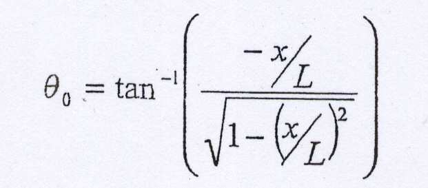
제 2구동용 모터(3222)에는, In the

제 3구동용 모터(3223)에는, In the

의 회전 구동을 시키면 좋다.It is good to drive the rotation of.
또한, θ〉0인 경우는, 제 1구동용 모터(3221)에는, In addition, when (theta)> 0, in the

제 2구동용 모터(3222)에는, In the

제 3구동용 모터(3223)에는, In the

의 회전 구동을 시키면 좋다.It is good to drive the rotation of.
또한, θ〈0인 경우는, 제 1구동용 모터(3221)에는, In addition, when (theta) <0, the
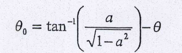
제 2구동용 모터(3222)에는, In the

제 3구동용 모터(3223)에는, In the

의 회전 구동을 시키면 좋다. 단, 상기의 식 중에서 a, b, c, n은, It is good to drive the rotation of. However, in said formula, a, b, c, n are
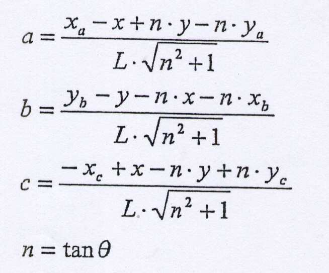
이다. to be.
또한, 예컨대, 도 15에서, 3개의 구동용 모터(3221),(3222),(3223)의 구동축의 중심을, (xa, ya)=(0, 50), (xb, yb)=(-10, 0), (xc, yc)=(0, -50)으로 한 경우는, 가동 평면(3224)의 회전(θ) 중심을, 제 2편심축의 중심 (x1, y1)=(0, 0)으로부터 (10, 10)으로 이동시키기 위해서는, (xa, ya)=(-10, 40), (xb, yb)=(-20, -10), (xc, yc)=(-10, -60)로서 상술한 식에 대입하는 것으로, 가동 평면(3224)의 회전 중심을 (10, 10)으로 한 경우의 X-Y-θ 운동이 가능하게 된다. For example, in FIG. 15, the centers of the drive shafts of the three driving
이상과 같은 얼라이먼트 장치(320)의 구동부(322)를 사용함으로써, 이미지 센서(DUT)를 홀딩하는 파지측 암(317)의 위치를 이동시키는 것이 가능하게 되고, 이미지 센서(DUT)의 위치 얼라이먼트가 달성된다. By using the
이 얼라이먼트 장치(320)의 구동부(322)의 3개 구동용 모터(3221),(3222),(3223)를 지지하는 기반(3226)은, 핸들러(10)의 기대(12)측에 대하여 고정되어 있다. 또한, 가동 평면(3224)은, 스테이지 지지 부재(321b)를 통하 여 가동 스테이지(321)에 접속되어 있고, 도 15에 도시한 바와 같은 초기 상태에서 제 2구동축(2222)의 중심축의 중심과 제 1카메라(326)의 광축(OLC)이 일치되도록 설치되어 있다. The base 3326 supporting the three
한편, 청구의 범위에서 언급된 제 1구동부, 제 2구동부, 제 3구동부는, 각각 상술한 가동 평면(3224)의 X축 방향 동작, Y축 방향 동작, Z축을 중심으로 한 θ 회전 동작에 상당하는 기능적인 표현으로서, 제 1구동용 모터(3221), 제 2구동용 모터(3222), 제 3구동용 모터(3223)에 상당하는 것은 아니다. In addition, the 1st drive part, the 2nd drive part, and the 3rd drive part which were mentioned in the Claim are corresponded to the X-axis direction operation, the Y-axis direction operation, and the (theta) rotation operation centering on the Z axis of the
도 18은 본 발명의 제 1실시 형태에 따른 이미지 센서용 시험 장치의 제어계의 전체 구성을 도시한 플로우 차트이다. It is a flowchart which shows the whole structure of the control system of the test apparatus for image sensors which concerns on 1st Embodiment of this invention.
다음에, 본 실시 형태에 따른 이미지 센서용 시험 장치(1)에서의 제어계의 전체 구성에 대하여 설명하면, 도 18에 도시한 바와 같이, 이 시스템은, 상술한 제 1 및 제 2카메라(326),(312b)와, 테스터(20)와, 어긋남량 산출부(71)(산출 수단) 및 화상 처리부(72)(화상 처리부)를 갖는 집중 제어 장치(70)와, YZ 이동 장치(310)의 제어를 수행하는 YZ 이동 장치용 제어 장치(80)와, 얼라이먼트 장치(320)의 제어를 수행하는 얼라이먼트 장치용 제어 장치(90)로 구성되어 있다. Next, the overall configuration of the control system in the image
제 1 및 제 2카메라(326)(312b)는, 촬상된 화상 정보를 집중 제어 장치(70)로 송신 가능하도록, 집중 제어 장치(70)에 접속되어 있다. 또한, 집중 제어 장치(70)는, 이미지 센서용 시험 장치(1) 전체를 총괄하여 제어를 수행하는 것이 가능하도록, 테스터(20), YZ 이동 장치용 제어 장치(80) 및 얼라이먼트 장치용 제어 장치(90)에 각각 접속되어 있고, 특히 시험 시에 이미지 센서(DUT)로부터 취득된 출력 신호를 테스터(20)로부터 수신 가능하도록 되어 있다. The first and
상술한 바와 같이, 이미지 센서를 대상으로 한 시험에서는, 이미지 센서의 품종이 변경된 경우에는, 예비 테스트를 실행하여, 광원(340)의 위쪽에 위치하고 있는 상태의 품종 변경 후의 이미지 센서(DUT)의 광축(OLD)에 대하여, 광원(340)의 광축(OLL)을 동일축 위에 일치되도록, 이미지 센서(DUT)의 광축(OLD)을 광원(340)의 광축(OLL)의 축 맞춤을 미리 수행할 필요가 있다. As described above, in the test for the image sensor, when the type of the image sensor is changed, a preliminary test is executed to perform an optical axis of the image sensor DUT after the type change in the state located above the
이에 대하여, 본 실시 형태에서의 집중 제어 장치(70)의 어긋남량 산출부(71)는, 이미지 센서(DUT)의 품종 교환 직후의 예비 테스트에서, 테스터(30)가 이미지 센서(DUT)로부터 취득한 출력 신호를 수신하여, 이 수신 신호로부터 이미지 센서(DUT)에 입광된 광의 분포를 도출하고, 이 분포로부터 광원(340)의 광축(OLL)을 추출함으로써, 도 19에 도시한 바와 같은, 광원(340)의 광축(OLL)에 대하는, 이미지 센서(DUT)가 갖는 광축(OLD)의 어긋남량(D)을 산출하는 것이 가능하게 되어 있다. In contrast, the deviation
이와 같이 산출된 어긋남량(D)은, 이 예비 테스트에 이어서 본 테스트로 피드백된다. 구체적으로는, 본 테스트에서는, 상술한 얼라이먼트 장치(320)에 의해 이미지 센서(DUT)의 위치 얼라이먼트의 때에, 이 어긋남량(D)이 상쇄되도록, 상기 어긋남량(D)이 가미된 이미지 센서(DUT)의 위치 얼라이먼트가 수행되어, 도 20에 도시한 바와 같이, 테스트 시에 광축(340)의 광축(OLL)과 이미지 센서(DUT)의 광 축(OLD)이 실질적으로 일치하여, 이미지 센서(DUT)의 고정도의 시험을 수행할 수 있다. The shift amount D calculated as described above is fed back to this test following this preliminary test. Specifically, in the present test, the image sensor with the shift amount D added so that the shift amount D is canceled at the time of the position alignment of the image sensor DUT by the above-described
본 실시 형태에서의 집중 제어 장치(70)의 화상 처리부(72)는, 예컨대 화상 처리용 프로세서 등을 갖고 있고, 제 1카메라(326) 및 제 2카메라(312b)에 의해 촬상된 화상 정보에 대하여 화상 처리를 수행하여, 화상 위에서의 콘택트부(301) 및 이미지 센서(DUT)의 위치 및 자세를 인식하고, 이미지 센서(DUT)의 얼라이먼트량을 산출하는 것이 가능하게 되어 있다. The
그리고, 이미지 센서(DUT)의 품종 변경한 때에는, 화상 처리부(72)가 제 2카메라(312b)에 의해 촬상된 화상 정보에, 각 콘택트부(301)의 복수의 콘택트 핀(302)의 위치를 추출하는 화상 처리를 수행하고, 상기 추출된 위치로부터 콘택트부(301)의 중심 위치 및 상기 콘택트부(301)에서의 XY 좌표축을 산출함으로써, 상기 CCD 카메라(312b)에 의해 촬상된 화상 위에서의 콘택트부(301)의 위치 및 자세를 산출한다. 이에 의해 테스트 헤드(300)의 변경 등에 의해 발생된 콘택트부(301)의 위치 변화를 인식하는 것이 가능하게 된다.And when the kind of image sensor DUT is changed, the position of the some
또한, 본 테스트 시에서는, 이 화상 처리부(72)가 제 1카메라(326)가 촬상된 화상 정보에 대하여 화상 처리를 수행하고, 상기 화상 위에서의 이미지 센서(DUT)의 위치 및 자세를 인식한다. 그리고 상기 화상 위에서의 이미지 센서(DUT)의 위치 및 자세를, 인식된 콘택트부(301)의 위치 및 자세에 일치시키도록, 이미지 센서(DUT)의 필요한 X축, Y축 방향 및 Z축을 중심으로 한 θ 회전의 얼라이먼트량을 산출한다. 한편, 제 1카메라(326) 및 제 2카메라(312b)에 의해 촬상되는 화상 위의 좌표계는, 상술한 바와 같이 상기 카메라(326),(312b)끼리의 캘리브레이션에 의해 대응되어 있다. In this test, the
이와 같이 산출된 얼라이먼트량은, 집중 제어 장치(70)에 의해 YZ 이동 장치용 제어 장치(80) 및 얼라이먼트 장치용 제어 장치(90)로 송신된다. 얼라이먼트 장치용 제어 장치(90)는, 이 송신된 얼라이먼트량에 기초하여, 얼라이먼트 장치(320)의 구동부(322)의 각 액츄에이터의 제어를 수행하고, 이미지 센서(DUT)의 위치 얼라이먼트가 수행된다. 이 때, 상술한 바와 같이 예비 테스트에서 어긋남량(D)이 파악되어 있는 경우에는, 집중 제어 장치(70)로부터 얼라이먼트 장치용 제어 장치(90)로 송신되는 얼라이먼트량에 이 어긋남량(D)이 가미된다. The alignment amount calculated in this manner is transmitted to the YZ moving
언 frozen 로더부Loader (60)(60)
언 로더부(60)는, 테스트부(30)로부터 시험 종료된 이미지 센서(DUT)를 센서 저장부(40)로 반출하기 위한 수단으로서, 제 2 XYZ 이동 장치(601)와, 2개의 언 로더용 버퍼부(602)로 구성되어 있다. The
언 로더용 버퍼부(602)는, YZ 이동 장치(310)의 동작 범위와 제 2 XYZ 이동 장치(601)의 동작 범위의 사이를 왕복 이동 가능한 수단으로서, 가동부(602a)와, X축 방향 액츄에이터(602b)로 구성되어 있다. 핸들러(10)의 기대(12) 위에 고정된 X축 방향 액츄에이터(602b)의 선단부에 가동부(602a)가 지지되어 있고, 상기 가동부(602a)의 상부 표면에는, 이미지 센서(DUT)를 낙하시켜 넣을 수 있는 4개의 오목부(602c)가 형성되어 있다. The unloading
그리고, YZ 이동 장치(310)가, 상기 YZ 이동 장치(310)의 동작 범위 내에 위치하는 언 로더용 버퍼부(602)의 가동부(602a)의 오목부(602c)에, 시험 종료된 이미지 센서(DUT)를 낙하시켜 넣으면, 언 로더용 버퍼부(602)가, X축 방향 액츄에이터(602b)를 줄어들게 함으로써, 가동부(602a)를 제 2 XYZ 이동 장치(601)의 동작 범위 내로 이동시키는 것이 가능하게 되어 있다. Then, the
한편, 가동부(602a) 위에 오목부(602c)를 설치하지 않고, 예컨대 상기 가동부(602a)의 표면을, 흡착면이 연직 위쪽을 향한 흡착 패드를 구비한 평면으로 하여도 좋다. 이 경우, YZ 이동 장치(310)가 이 흡착 패드 위에 이미지 센서(DUT)를 재치하고, 상기 흡착 패드가 이미지 센서(DUT)를 흡착하여, X축 방향 액츄에이터(602b)를 줄어들게 하여, 제 2 XYZ 이동 장치(601)의 동작 범위 내로의 이동이 완료되면 상기 흡착 패드의 흡착을 해방하고, 제 2 XYZ 이동 장치(601)가 이 시험 종료된 이미지 센서(DUT)를 홀딩한다. On the other hand, without providing the recessed
이상과 같이 언 로더용 버퍼부(602)를 설치함으로써, 제 2 XYZ 이동 장치(601)와 YZ 이동 장치(310)가 상호간에 간섭하지 않고 동시에 동작하는 것이 가능하게 된다. 또한, 2개의 언 로더용 버퍼부(602)를 구비함으로써, 테스트 헤드(300)로부터 효율 좋게 이미지 센서(DUT)를 반출하여, 이미지 센서용 시험 장치(1)의 가동률을 높이는 것이 가능하게 된다. 한편, 본 발명에서는 언 로더용 버퍼부의 수는 특별히 2개에 한정되지 않고, 이미지 센서의 얼라이먼트에 요하는 시간이나 이미지 센서(DUT)의 테스트에 요하는 시간 등으로부터 적절히 설정하는 것이 가능하다. By providing the unloading
제 2 XYZ 이동 장치(601)는, 언 로더용 버퍼(602) 위의 이미지 센서(DUT)를 분류 트레이용 스토커(402)의 분류 트레이로 이동시켜 탑재하는 수단으로서, Y축 방향 레일(601a)과, X축 방향 레일(601b)과, 가동 헤드부(601c)와, 흡착 패드(601d)로 구성되어 있고, 2개의 언 로더용 버퍼부(602)와, 분류 트레이용 스토커(402)를 포함하는 동작 범위를 갖고 있다. The second
도 2에 도시한 바와 같이, 이 제 2 XYZ 이동 장치(601)의 2개의 Y축 방향 레일(601a)은, 핸들러(10)의 기대(12) 위에 고정되어 있고, 그 사이에 X축 방향 레일(601b)이 Y축 방향으로 슬라이딩 가능하게 지지되어 있다. 또한, 이 X축 방향 레일(601b)은, Z축 방향 액츄에이터(미도시)를 구비한 가동 헤드부(601c)를 X축 방향으로 슬라이딩 가능하게 지지하고 있다. 또한, 이 가동 헤드부(601c)는, 하단부에 4개의 흡착 패드를 갖고 있고, 구비된 Z축 방향 액츄에이터를 구동시킴으로써, 상기 4개의 흡착 패드(601d)를 Z축 방향으로 승강시키는 것이 가능하게 되어 있다. As shown in FIG. 2, the two Y-
제 2 XYZ 이동 장치(601)는, 상기 4개의 흡착 패드(601d)를 언 로더용 버퍼부(602) 위의 이미지 센서(DUT) 위에 위치시켜, 한번에 4개의 이미지 센서(DUT)를 흡착하여, 분류 트레이용 스토커(402)의 분류 트레이 위로 이동시켜, 위치 결정 후에 분류 트레이 위에 이미지 센서(DUT)를 해방시키는 것이 가능하게 되어 있다.The second
이하에, 도 21~도 33B를 참조하여, 본 실시 형태에 따른 이미지 센서용 시험장치(1)에 의한 이미지 센서(DUT)의 테스트 방법에 대하여 설명한다.Hereinafter, with reference to FIGS. 21-33B, the test method of the image sensor DUT by the image
한편, 본 실시 형태에 따른 이미지 센서용 시험 장치(1)에 의한 테스트에는, 이미지 센서(DUT)를 실제로 테스트하는 본 테스트 이외에, 상술한 바와 같이 이미 지 센서의 품종 교환 후에 광원(340)의 광축(OLL)과 이미지 센서(DUT)의 광축(OLD)을 일치시킬 목적의 예비 테스트도 있지만, 이하의 설명에서는 예비 테스트의 경우와 본 테스트의 경우를 공통하여 설명하고, 처리가 다른 부분만을 구별하여 설명한다. On the other hand, in the test by the image
도 21은 본 발명의 제 1실시 형태에서 품종 변경 시에 제 2카메라에 의해 콘택트부를 촬상하고 있는 상태를 도시한 도면, 도 22는 본 발명의 제 1실시 형태에 따른 이미지 센서용 시험 장치에 의한 얼라이먼트 동작에서, 2행 1열 및 2행 2열의 2개 이미지 센서를 얼라이먼트 장치의 위쪽으로 위치 결정한 상태를 도시한 도면, 도 23은 도 22의 상태로부터 이미지 센서를 얼라이먼트 장치에 삽입한 상태를 도시한 도면, 도 24는 본 발명의 제 1실시 형태에서의 이미지 센서의 위치 얼라이먼트 처리를 도시한 플로우 차트, 도 25A는 본 발명의 제 1실시 형태에서 얼라이먼트 전 상태의 화상예를 도시한 도면, 도 25B는 본 발명의 제 1실시 형태에서 얼라이먼트 후 상태의 화상예를 도시한 도면, 도 26은 도 23의 상태로부터 2행 1열 및 2행 2열의 2개 이미지 센서의 얼라이먼트가 완료된 상태를 도시한 도면, 도 27은 도 26의 상태로부터 4개의 이미지 센서를 상승시킨 상태를 도시한 도면, 도 28은 도 27의 상태로부터 1행 1열 및 1행 2열의 2개 이미지 센서를 얼라이먼트 장치의 위쪽으로 위치 결정한 상태를 도시한 도면, 도 29는 도 28의 상태로부터 이미지 센서를 얼라이먼트 장치에 삽입한 상태를 도시한 도면, 도 30은 도 29의 상태로부터 1행 1열 및 1행 2열의 2개 이미지 센서의 얼라이먼트가 완료된 상태를 도시한 도면, 도 31 은 도 30의 상태로부터 4개의 이미지 센서를 상승시킨 상태를 도시한 도면, 도 32는 도 31의 상태로부터 4개의 이미지 센서의 테스트를 수행하고 있는 상태를 도시한 도면, 도 33A 및 33B는 본 발명의 제 1실시 형태에서의 로크 앤드 프리 기구에 의한 콘택트 암의 센터링 동작을 도시한 도면이다. FIG. 21 is a view showing a state where a contact portion is picked up by a second camera when a variety is changed in the first embodiment of the present invention, and FIG. 22 is a view of the test apparatus for an image sensor according to the first embodiment of the present invention. In the alignment operation, a diagram showing a state in which two image sensors of two rows, one column and two rows and two columns are positioned above the alignment device, and FIG. 23 illustrates a state in which the image sensor is inserted into the alignment device from the state of FIG. 22. 24 is a flowchart showing the position alignment processing of the image sensor in the first embodiment of the present invention, and FIG. 25A is a view showing an example of the image before the alignment in the first embodiment of the present invention. 25B is a diagram showing an example of the image in the post-alignment state in the first embodiment of the present invention, and FIG. 26 is an alignment of two image sensors of two rows, one column and two rows and two columns from the state of FIG. Is a state in which four image sensors are raised from the state of FIG. 26, and FIG. 28 shows two image sensors of one row, one column, and one row and two columns from the state of FIG. Is a view showing a state where the positioning is above the alignment device, FIG. 29 shows a state where the image sensor is inserted into the alignment device from the state of FIG. 28, and FIG. 30 shows one row, one column, and one column from the state of FIG. FIG. 31 shows a state where alignment of two image sensors in a row 2 column is completed, FIG. 31 shows a state in which four image sensors are raised from the state of FIG. 30, and FIG. 32 shows four image sensors from the state of FIG. 31. 33A and 33B are diagrams showing the centering operation of the contact arm by the lock and free mechanism in the first embodiment of the present invention.
한편, 도 21~도 23 및 도 26~도 32는, 도 2에서 테스트부(30)를 X축 부방향을 향해서 본 개략 단면도로서, 가동 헤드부(312)는 도 2중의 Y축 정방향의 가동 헤드부(312)를 도시하고, 얼라이먼트 장치(320)는 도 2중의 Y축 정방향의 1조 2개의 얼라이먼트 장치(320)를 도시하고 있다. 또한, 도 21~도 23 및 도 25~도 32에서 도면 중우측에 도시된 이미지 센서(DUT)가 1행 1열 및 1행 2열의 이미지 센서(DUT)를 도시하고, 도면 중좌측에 도시된 이미지 센서(DUT)가 2행 1열 및 2행 2열의 이미지 센서(DUT)를 도시한다(콘택트 암(315)도 마찬가지임). 단, 1행 1열 및 2행 1열의 이미지 센서(DUT)는, 1행 2열 및 2행 2열로 겹쳐 있기 때문에 도시되어 있지 않다. 마찬가지로 도시된 얼라이먼트 장치(320)의 맞은편 측에도 또 하나의 얼라이먼트 장치(320)가 설치되어 있지만 겹쳐 있기 때문에 도시되어 있지 않다.21-23 and 26-32 are schematic sectional drawing which looked at the
우선, 제 1 XYZ 이동 장치(501)가, 4개의 흡착 패드(501d)에 의해, 센서 저장부(40)의 공급 트레이용 스토커(401)의 최상단에 위치하는 공급 트레이 위의 4개의 이미지 센서(DUT)를 흡착하여 홀딩한다. First, the first
다음에, 제 1 XYZ 이동 장치(501)는, 4개의 이미지 센서(DUT)를 홀딩한 상태로, 가동 헤드부(501c)에 구비된 Z축 방향 액츄에이터에 의해 상기 4개의 이미지 센서(DUT)를 상승시키고, Y축 방향 레일(501a) 위에서 X축 방향 레일(501b)을 슬라 이딩시켜, X축 방향 레일(501b) 위에서 가동 헤드부(501c)를 슬라이딩시켜 로더부(50)로 이동한다. 그리고, 제 1 XYZ 이동 장치(501)는 히트 플레이트(503)의 오목부(503a)의 위쪽에서 위치 결정을 하고, 가동 헤드부(501c)의 Z축 방향 액츄에이터를 신장시켜, 흡착 패드(501d)를 해방하여 오목부(503a)로 이미지 센서(DUT)를 낙하시켜 넣는다. 히트 플레이트(503)가 이미지 센서(DUT)를 소정의 온도까지 가열하면, 재차 제 1 XYZ 이동 장치(501)가 가열된 4개의 이미지 센서(DUT)를 홀딩하여, 대기하고 있는 한쪽의 로더용 버퍼(502)의 위쪽으로 이동한다. 그리고, 제 1 XYZ 이동 장치(501)는, 대기하고 있는 한쪽의 로더용 버퍼부(502)의 가동부(502a)의 위쪽에서 위치 결정하면, 가동 헤드부(501c)의 Z축 방향 액츄에이터를 신장시켜, 흡착 패드(501d)를 해방함으로써 상기 가동부(502a)의 상부 표면에 형성된 오목부(502c)로 4개의 이미지 센서(DUT)를 낙하시켜 넣는다. Next, the first
다음에, 로더용 버퍼부(502)는, 4개의 이미지 센서(DUT)를 홀딩한 상태로 X축 방향 액츄에이터(502b)를 신장시켜, 로더부(50)의 제 1 XYZ 장치(501)의 동작 범위로부터 테스트부(30)의 YZ 이동장치(310)의 동작 범위로 4개의 이미지 센서(DUT)를 이동시킨다. Next, the
한편, 시험 대상인 이미지 센서(DUT)의 품종이 변경된 경우에는, 이상까지의 동작 전 또는 그와 동시에, 도 21에 도시한 바와 같이, 테스트부(30)에서, YZ 이동 장치(310)의 가동 헤드부(312)를, 콘택트부(301) 위로 이동시켜, 제 2카메라(312b)에 의해 상기 콘택트부(301)를 촬상한다. 이 제 2카메라(312b)에 의해 촬상된 화상 정보는, 집중 제어 장치(70)의 화상 처리부(72)에서 화상 처리되어, 이 화상 정보 로부터 화상 위에서의 콘택트부(301)의 위치 및 자세가 인식된다. On the other hand, when the variety of the image sensor DUT to be tested is changed, before or at the same time as the above operation, as shown in FIG. 21, in the
다음에, 로더용 버퍼부(502)의 위쪽에 위치하는 YZ 이동 장치(310)의 한쪽의 가동 헤드부(312)에 구비된 Z축 방향 액츄에이터(313)가 신장하여, 상기 가동 헤드부(312)에 구비된 4개의 흡착 패드(317c)에 의해, 로더용 버퍼부(502)의 가동부(502a)의 오목부(502c)에 위치하는 4개의 이미지 센서(DUT)를 흡착하여 홀딩한다. 이 때, 이미지 센서(DUT)는, 그 수광면(RL)과는 반대면을, YZ 이동 장치(310)의 흡착 패드(317c)에 의해 흡착되어 있다. Next, the Z-axis direction actuator 313 provided in one
다음에, 가동 헤드부(312)는, 상기 가동 헤드부(312)에 구비된 Z축 방향 액츄에이터(313)에 의해 4개의 이미지 센서(DUT)를 홀딩한 상태로 상승한다. Next, the
다음에, 도 22에 도시한 바와 같이, YZ 이동 장치(310)는, Y축 방향 레일(311) 위로 가동 헤드(312)를 지지하는 X축 방향 지지 부재(311a)를 슬라이딩시켜, 2행 1열 및 2행 2열의 2개의 파지측 암(317)을 얼라이먼트 장치(320)의 위쪽에서 위치 결정한다.Next, as shown in FIG. 22, the
다음에, 도 23에 도시한 바와 같이, 가동 헤드부(312)는, Z축 방향 액츄에이터(313)를 신장시킴으로써, 얼라이먼트 장치(320)의 가동 스테이지(321)에 형성된제 1개구(321a)에, 각 파지측 암(317)에 각각 홀딩된 이미지 센서(DUT)를 삽입하고 파지측 암(317)의 당접 부재(317d)를, 얼라이먼트 장치(320)의 가동 스테이지(321)에 맞닿게 하고, 소정의 압력으로 누른다.Next, as shown in FIG. 23, the
다음에, 도 24의 스텝 S100에서, Z축 방향 액츄에이터(313)에 의한 소정의 압력이 유지된 상태에서, 얼라이먼트 장치(320)의 제 1카메라(326)에 의해, 2행 1 열 및 2행 2열의 2개의 이미지 센서(DUT)를 촬상한다. 제 1카메라(326)로 촬상된 화상 정보는, 집중 제어 장치(70)의 화상 처리부(72)로 송신된다. Next, in step S100 of FIG. 24, the
다음에, 도 24의 스텝 S110에서, 집중 제어 장치(70)의 화상 처리부(72)는, 상기 화상 정보로부터 화상 처리에 의해 이미지 센서(DUT)의 각 입출력 단자(HB)의 위치를 추출한다.Next, in step S110 of FIG. 24, the
다음에, 도 24의 스텝 S120에서, 화상 처리부(72)는, 추출된 각 입출력 단자(HB)의 위치로부터, 이미지 센서(DUT)의 센서 중심 위치(DC) 및 이미지 센서(DUT)에서의 XY 좌표축 중 한쪽 좌표축(DA)을 산출하여, 제 1카메라(326)에 의해 촬상된 화상 위에서의 이미지 센서(DUT)의 위치 및 자세를 산출한다. 한편, 본 발명에서는, 입출력 단자(HB)에 기초하여 이미지 센서(DUT)의 위치 및 자세를 산출하는 방법에만 한정되지 않고, 이미지 센서(DUT)가 갖는 칩(CH)에 기초하여 산출하여도 좋다. Next, in step S120 of FIG. 24, the
이와 같이, 화상 처리부(72)가, 제 1카메라(326)에 의해 촬상된 화상 정보 위에서의, 이미지 센서(DUT)가 갖는 칩(CH)이나 입출력 단자(HB)에 기초하여, 콘택트부(301)에 대한 이미지 센서(DUT)의 상대 위치를 인식함으로써, 이미지 센서(DUT)에서 칩(CH)이나 입출력 단자(HB)에 대하여 패키지가 어긋나 있는 경우에도, 콘택트 불량을 방지하는 것이 가능하게 된다. In this way, the
이미지 센서(DUT)의 한쪽 좌표축(DA)의 산출 방법으로서는, 예컨대 스텝 S110에서 추출된 입출력 단자(HB) 중에서 긴 열을 형성하는 입출력 단자(HB)의 중심을 통과하는 근사 직선을 각 열마다 산출하여, 상기 복수의 근사 직선의 평균 직 선을 산출함으로써 수행된다. 한편, 이미지 센서(DUT)의 제조 상 발생되는 입출력 단자(HB)의 위치 흐트러짐 등에 대하여 이미지 센서(DUT)의 위치 및 자세 정보를 향상시키기 위하여, 상기의 한쪽 좌표축(DA) 산출 방법과 유사한 방법에 의해, 다른쪽 좌표축의 산출 등을 하여도 좋다. As a calculation method of one coordinate axis DA of the image sensor DUT, for example, an approximate straight line passing through the center of the input / output terminal HB forming a long column among the input / output terminals HB extracted in step S110 is calculated for each column. By calculating an average straight line of the plurality of approximated straight lines. On the other hand, in order to improve the position and attitude information of the image sensor DUT with respect to the positional disturbance of the input / output terminal HB generated in the manufacturing of the image sensor DUT, and the like, the method similar to the above-described method of calculating the coordinate axis DA is described. By this means, the calculation of the other coordinate axis may be performed.
여기서, 상기 시험이 본 테스트인 경우에는, 이 스텝 S120에서, 광원(340)의 광축(OLL)에 대한 이미지 센서(DUT)의 광축(OLD)의 어긋남량(D)이 상쇄되도록, 상기 어긋남량(D)을 가미하여 이미지 센서(DUT)의 위치 및 자세가 산출된다. In the case where the test is the present test, the deviation amount D of the optical axis OL D of the image sensor DUT with respect to the optical axis OL L of the
이에 대하여, 상기 시험이 예비 테스트인 경우에는, 이미지 센서(DUT)의 품종 교환 후의 어긋남량(D)은 아직 산출되어 있지 않기 때문에, 상기 어긋남량(D)을 가미하지 않고 이미지 센서(DUT)의 위치 및 자세가 산출된다.On the other hand, when the said test is a preliminary test, since the shift | offset | difference amount D after the varieties exchange | exchange of the image sensor DUT is not yet calculated, the shift | offset | difference amount D of the image sensor DUT is not added. Position and posture are calculated.
이와 같이, 이미지 센서(DUT)의 위치 얼라이먼트에서, 광원(340)의 광축(OLL)에 대한 이미지 센서(DUT)의 광축(OLD)의 상대적인 어긋남량(D)을 가미함으로써, 콘택트부(301)에 대한 이미지 센서(DUT)의 상대 위치에 기초하여 콘택트 암(315)의 위치를 얼라이먼트하는 얼라이먼트 장치(320)에, 광원(340)의 광축(OLL)과 이미지 센서(DUT)의 광원(OLD)의 축 맞춤 기능을 부여할 수 있고, 광원(340)에 전용의 미세조정 기능을 설치할 필요가 없게 되기 때문에, 이미지 센서(DUT)용 시험 장치(1)의 소형화를 도모할 수 있는 동시에, 이미지 센서(DUT)용 시험 장치(1)의 코스트를 저감할 수 있다. In this way, in the position alignment of the image sensor DUT, by adding the relative shift amount D of the optical axis OL D of the image sensor DUT to the optical axis OL L of the
특히 본 실시 형태에서는, 4개의 이미지 센서(DUT)를 동시에 시험하기 때문 에, 광원(340)끼리를 근접하여 배치할 수 있고, 이에 따라 콘택트부(301)끼리의 간격을 좁힐 수 있고, 더 나아가서는 이 콘택트부(301)에 대응한 콘택트 암(315)의 간격을 좁힐 수 있기 때문에, 이미지 센서(DUT)용 시험 장치(1)의 소형화를 한층 도모할 수 있다. In particular, in the present embodiment, since the four image sensors (DUT) are tested at the same time, the
또한, 상기와 같은 콘택트 암(315)의 간격이 좁아짐에 따라, 콘택트 암(315) 자체의 중량이 경감하여, YZ 이동 장치(310)의 고속 이동이 가능하게 되는 동시에, 콘택트부(301)와 이미지 센서(DUT)의 입출력 단자(HB)의 콘택트 불량의 방지를 도모할 수 있다. In addition, as the distance between the
다음에, 도 24의 스텝 S130에서, 화상 처리부(72)는, 화상 위에서의 콘택트부(301)의 위치 및 자세와, 이미지 센서(DUT)의 위치 및 자세를 비교한다. 이 스텝S130의 비교에서, 위치 및 자세가 일치되어 있는 경우(스텝 S130에서 YES)는, 이미지 센서(DUT)의 위치 얼라이먼트는 종료된다.Next, in step S130 of FIG. 24, the
한편, 이 스텝 S130에서 비교 대상이 되는, 화상 위의 콘택트부(301)의 위치 및 자세는, 상술한 바와 같이 이미지 센서(DUT)의 품종 변경 시에 미리 제 2 CCD 카메라(312b)로 촬상되어, 촬상 처리부(72)의 화상 처리에 의해 인식된 화상 위의 콘택트부(301)의 위치 및 자세를, 제 1카메라(326)의 화상 위의 위치 및 자세에 대응시킨 것이다. 도 25A에 얼라이먼트 전의 이미지 센서(DUT)의 추출된 각 입출력 단자(HB)와, 산출된 센서 중심 위치(DC)와, 이미지 센서(DUT)의 한쪽 좌표축(DA)을 편의상 표시된 화상 예를 도시한다(도 25B에서 동일함). 한편, 화상 위에서의 콘택트부(301)의 중심 위치 및 XY 좌표축은, 설명의 편의를 위하여, 화상 위의 원점, 즉 제 1카메라(326)의 광축(OLC) 및 XY 좌표축에 일치되어 있다. On the other hand, the position and attitude of the
화상 위에서의 콘택트부(301)의 위치 및 자세와, 이미지 센서(DUT)의 위치 및 자세가 일치되어 있지 않는 경우(도 24의 스텝 S130에서 NO)는, 도 24의 스텝S140에서, 화상 처리부(72)는, 이미지 센서(DUT)의 위치 및 자세를, 콘택트부(301)의 위치 및 자세에 일치시키도록, X축, Y축 방향 및 Z축을 중심으로 한 회전에서의 필요한 얼라이먼트량을 산출한다. When the position and attitude of the
예컨대, 도 25A에서의 필요한 얼라이먼트량은, X축 방향으로 +x분, Y축 방향으로 -y분의 이동과, Z축을 중심으로 한 θ 회전 방향으로 - γ분의 회전이다. For example, the necessary alignment amount in FIG. 25A is a movement of + x in the X-axis direction, -y in the Y-axis direction, and rotation of -γ in the θ rotation direction around the Z axis.
다음에, 도 24의 스텝 S150에서, 집중 제어 장치(70)는, YZ 이동 장치용 제어 장치(80)에 대하여, 2행 1열 및 2행 2열의 이미지 센서(DUT)를 홀딩하고 있는 로크 앤드 프리 기구(318)를 비구속 상태로 하는 지령을 송신한다. YZ 이동 장치용 제어 장치(80)는, 이 지령에 기초하여 로크 앤드 프리 기구(318)의 구속용 피스톤(3183)으로의 에어 공급을 멈추는 제어를 수행하고, 로크 앤드 프리 기구(318)가 비구속 상태로 되면, 그 완료 신호를 집중 제어 장치(70)로 송신한다. Next, in step S150 of FIG. 24, the
한편, 예컨대 본 발명 이외의 실시 형태에서의 당접 부재(317d)에 오목부(317e)가 형성되고, 가동 스테이지(321)에 볼록부(321c)가 형성되어 있는 경우에는, 상기 오목부(317e)와 볼록부(321c)의 걸어 맞춤을 용이하게 하기 위하여, 걸어 맞춤 전에 로크 앤드 프리 기구(318)를 비구속한 상태로 하여도 좋다. On the other hand, when the recessed
다음에, 도 24의 스텝 S160에서, 집중 제어 장치(70)가 YZ 이동 장치용 제어 장치(80)로부터 완료 신호를 수신하면, 스텝 S140에서 산출된 얼라이먼트량을 얼라이먼트 장치용 제어 장치(90)로 송신한다. 그리고, 얼라이먼트 장치용 제어 장치(90)는, 도 26에 도시한 바와 같이, 상기 얼라이먼트량에 기초하여 얼라이먼트 장치(320)의 구동부(322)의 제 1구동용 모터(3221)와, 제 2구동용 모터(3222), 제 3구동용 모터(3223)를 구동시켜, 이미지 센서(DUT)의 위치 얼라이먼트를 수행한다. 얼라이먼트 장치용 제어 장치(90)는, 상기 구동이 완료되면, 그 완료 신호를 집중 제어 장치(70)로 송신한다. Next, when the
얼라이먼트 장치(320)에 의한 얼라이먼트가 완료되면, 도 24의 스텝 S170에서, 집중 제어 장치(70)는, 재차 이미지 센서(DUT)의 위치 및 자세와, 콘택트부(301)의 위치 및 자세의 비교를 수행하여, 일치하고 있지 않다고 판단된 경우(스텝 S170에서 NO)는, 스텝 S140으로 돌아가고, 필요한 얼라이먼트량의 산출을 수행한다. 한편, 이 스텝 S170에서의 비교를 수행하지 않고, 스텝 S160으로부터 스텝 S180으로 진행해도 좋고, 이에 의해, 도 24에 도시한 플로우 차트의 처리 속도를 향상시킬 수 있다. When the alignment by the
도 24의 스텝 S170의 비교에서, 이미지 센서(DUT)의 위치 및 자세와, 콘택트부(301)의 위치 및 자세가 일치하고 있다고 판단된 경우(스텝 S170에서 YES)는, 도 24의 스텝 S180에서, 집중 제어 장치(70)는 YZ 이동 장치용 제어 장치(80)에 대하여, 2행 1열 및 2행 2열의 이미지 센서(DUT)를 홀딩하고 있는 로크 앤드 프리 기구(318)를 구속 상태로 하는 지령을 송신한다. YZ 이동 장치용 제어 장치(80)는, 이 지령에 기초하여, 로크 앤드 프리 기구(318)의 구속용 피스톤(3183)으로 에어를 공급하는 제어를 수행하고, 이미지 센서(DUT)의 위치 얼라이먼트가 종료된다. 한편, 이상의 얼라이먼트 작업은, 2행 1열 및 2행 2열의 2개 이미지 센서(DUT)에 대하여, 2개의 얼라이먼트 장치(320)가 실질적으로 동시에 수행된다. In the comparison of step S170 in FIG. 24, when it is determined that the position and attitude of the image sensor DUT and the position and attitude of the
얼라이먼트 장치(320)에 의한 2행 1열 및 2행 2열의 2개 이미지 센서(DUT)의 위치 얼라이먼트가 완료되면, 도 27에 도시한 바와 같이, 가동 헤드부(312)의 Z축 방향 액츄에이터(312)에 의해, 4개의 이미지 센서(DUT)를 홀딩한 상태로 상승시킨다. Z축 방향 액츄에이터(313)의 구동에 의해 이미지 센서(DUT)가 얼라이먼트 장치(320)로부터 분리되어 멀어지면, 구동부(3322)에 의해, 가동 스테이지(321)가 초기 상태로 되돌아간다. When the alignment of the two image sensors (DUT) of the 2
다음에, 도 28에 도시한 바와 같이, YZ 이동 장치(310)는, 가동 헤드부(312)를, 1행 1열의 기저측 암(316)과 2행 1열의 기저측 암(316)의 사이의 피치분만큼 Y축 부방향으로 이동시켜, 얼라이먼트가 미완료된 1행 1열 및 1행 2열의 2개 이미지 센서(DUT)를 홀딩한 파지측 암(317)을 얼라이먼트 장치(320)의 위쪽에서 위치 결정한다.Next, as shown in FIG. 28, the
다음에, 도 29에 도시한 바와 같이, 가동 헤드부(312)는, Z축 방향 액츄에이터(313)를 신장시킴으로써, 얼라이먼트 장치(320)의 가동 스테이지(321)에 형성된 제 1개구(321a)에, 각 파지측 암(317)에 각각 홀딩된 이미지 센서(DUT)를 삽입하여 파지측 암(317)의 당접 부재(317d)를 얼라이먼트 장치(320)의 가동 스테이지(321)에 맞닿게 하여, 소정의 압력으로 누른다.Next, as shown in FIG. 29, the
다음에, 도 30에 도시한 바와 같이, Z축 액츄에이터(313)에 의해 소정의 압 력이 유지된 상태로, 집중 제어 장치(70), YZ 이동 장치용 제어 장치(80) 및 얼라이먼트 장치용 제어 장치(90)에 의해, 상술한 도 24의 플로우 차트의 스텝 S100~스텝 S180의 처리가 수행되어, 얼라이먼트 장치(320)에 의한 1행 1열 및 1행 2열의 2개 이미지 센서(DUT)의 위치 얼라이먼트가 수행된다. 한편, 이 얼라이먼트 작업은, 1행 1열 및 1행 2열의 2개 이미지 센서(DUT)에 대하여, 2개의 얼라이먼트 장치(320)가 실질적으로 동시에 수행된다.Next, as shown in FIG. 30, with the predetermined pressure maintained by the Z-
여기에서도, 상기 시험이 본 테스트인 경우에는, 도 24의 스텝 S120에서, 광원(340)의 광축(OLL)에 대한 이미지 센서(DUT)의 광축의 어긋남량(D)이 상쇄되도록, 상기 어긋남량(D)을 가미하여 이미지 센서(DUT)의 위치 및 자세가 산출된다.Also, when the test is the present test, the shift so that the shift amount D of the optical axis of the image sensor DUT with respect to the optical axis OL L of the
이에 대하여, 상기 시험이 예비 테스트인 경우에는, 이미지 센서(DUT)의 품종 교환 후의 어긋남량(D)은 아직 산출되어 있지 않기 때문에, 상기 어긋남량(D)을 가미하지 않고, 이미지 센서(DUT)의 위치 및 자세가 산출된다.On the other hand, when the said test is a preliminary test, since the shift | offset | difference amount D after the varieties exchange | exchange of the image sensor DUT is not yet calculated, it does not add the said shift | offset amount D, and does not add the image sensor DUT. The position and posture of are calculated.
얼라이먼트 장치(320)에 의한 1행 1열 및 1행 2열의 2개 이미지 센서(DUT)의 위치 얼라이먼트가 완료되면, 도 31에 도시한 바와 같이, 가동 헤드부(312)의 Z축 방향 액츄에이터(313)에 의해, 4개의 이미지 센서(DUT)를 홀딩한 상태로 상승시킨다. Z축 방향 액츄에이터(313)의 구동에 의해 이미지 센서(DUT)가 얼라이먼트 장치(320)로부터 분리되어 멀어지면, 구동부(322)에 의해 가동 스테이지(321)가 초기 상태로 되돌아간다. When the alignment of the two image sensors (DUT) of the first row, the first column, and the first row, the second column by the
이상과 같이, 2개 1조의 얼라이먼트 장치(320)에 의해 4개의 이미지 센 서(DUT)에 대하여 합계 2회의 얼라이먼트가 수행된다.As described above, two sets of alignment are performed on the four image sensors DUT by the two sets of
한편, 본 테스트에서는, YZ 이동 장치(310)의 한쪽 가동 헤드부(312)가 4개의 이미지 센서(DUT)의 얼라이먼트의 사이에, 다른쪽 가동 헤드부(312)가 테스트 헤드(300)에서 시험을 수행하여, 이미지 센서용 시험 장치(1)의 가동률의 향상이 도모되고 있다.On the other hand, in this test, the one
다음에, YZ 이동 장치(310)는, 가동 헤드부(312)를 지지하는 X축 방향 지지 부재(311a)를 Y축 방향 레일(311) 위로 슬라이딩시켜, 가동 헤드부(312)의 선단의 흡착 패드(317c)에 홀딩된 4개의 이미지 센서(DUT)를, 테스트 헤드(300)의 4개 콘택트부(301)의 위쪽에 위치 결정한다. Next, the
다음에, 도 32에 도시한 바와 같이, 가동 헤드부(312)는, Z축 방향 액츄에이터(313)를 신장시켜, 4개의 이미지 센서(DUT)의 각 입출력 단자(HB)를, 4개의 콘택트부(301)의 각 콘택트 핀(302)에 접촉시킨다.32, the
그리고, 각 이미지 센서(DUT)의 입출력 단자(HB)를 콘택트부(301)에 접촉시켜, 이와 동시에 광원(340)으로부터 이미지 센서(DUT)의 수광면(RL)에 대하여 광을 조사하면서, 콘택트부(301)로부터 이미지 센서(DUT)의 입출력 단자(HB)로 테스터(20)로부터 전기 신호를 입출력함으로써, 4개의 이미지 센서(DUT)가 동시에 시험된다. Then, the input / output terminal HB of each image sensor DUT is brought into contact with the
여기서, 상기 시험이 예비 테스트인 경우에는, 상기 시험 시에 테스터(30)가 이미지 센서(DUT)로부터 취득한 출력 신호를 집중 제어 장치(70)의 어긋남량 산출부(71)가 수신하고, 이 출력 신호로부터 이미지 센서(DUT)로 입광된 광의 분포를 도출하여, 상기 입광된 광의 분포로부터 광원(340)의 광축(OLL)을 도출함으로써, 도 19에 도시한 바와 같은, 광원(340)의 광축(OLL)에 대한 이미지 센서(DUT)의 광축(OLD)의 어긋남량(D)을 산출한다. 이와 같이, 실제로 광원(340)으로부터 광이 조사된 이미지 센서(DUT)로부터 출력된 전기 신호에 기초하여 이미지 센서(DUT)의 광축(OLD)의 상대적인 어긋남량(D)을 산출함으로써, 이 어긋남량(D)을 정확하게 파악할 수 있다. Here, when the test is a preliminary test, the shift
이에 대하여, 상기 시험이 본 테스트인 경우에는, 상술한 바와 같이, 이미지 센서(DUT)의 위치 얼라이먼트에서 어긋남량(D)이 가미되어 있기 때문에, 도 20에 도시한 바와 같이, 광원(340)의 광축(OLL)과, 이미지 센서(DUT)의 광축(OLD)이 실질적으로 일치되어 있고, 이미지 센서(DUT)의 고정도의 시험을 수행할 수 있다. On the other hand, in the case where the test is the present test, as described above, since the shift amount D is added to the position alignment of the image sensor DUT, as shown in FIG. The optical axis OL L and the optical axis OL D of the image sensor DUT substantially coincide with each other, and a test of the accuracy of the image sensor DUT can be performed.
4개의 이미지 센서(DUT)의 테스트가 완료되면, YZ 이동 장치(310)는, 가동 헤드부(312)에 구비된 Z축 방향 액츄에이터(313)에 의해, 시험 종료된 4개의 이미지 센서(DUT)를 홀딩한 상태로 상승시키고, 가동 헤드부(312)를 지지하는 X축 방향 지지 부재(311a)를 Y축 방향 레일(311) 위로 슬라이딩시켜, 홀딩된 4개의 이미지 센서(DUT)를 상기 YZ 이동 장치(310)의 동작 범위 내에서 대기하고 있는 한쪽 언 로더용 버퍼부(602)의 가동부(602a)의 위쪽에 위치 결정한다. When the test of the four image sensors DUT is completed, the
다음에, 가동 헤드부(312)는, Z축 액츄에이터(313)를 신장시켜, 흡착 패드(317c)를 해방함으로써 상기 가동부(602a)의 상부 표면에 형성된 오목부(602c)로 4개의 이미지 센서(DUT)를 낙하시켜 넣는다.Next, the
한편, 도 33A 및 도 33B에 도시한 바와 같이, 시험 종료된 이미지 센서(DUT)를 반출한 후, YZ 이동 장치(310)의 가동 헤드부(312)는, 각 홀딩측 암(317)의 중심선(CLH)을, 기저측 암(316)의 중심선(CLR)에 일치시키도록, 로크 앤드 프리 기구(318)의 구속용 피스톤(3183)으로의 에어 공급을 멈추고, 센터링용 피스톤(3184)으로 에어를 공급함으로써 파지측 콘택트 암(317)의 센터링을 수행한다. 33A and 33B, after carrying out the tested image sensor DUT, the
다음에, 언 로더용 버퍼부(602)는, 시험 종료된 4개의 이미지 센서(DUT)를 홀딩한 상태로, X축 액츄에이터(602b)를 구동시켜, 테스트부(30)의 YZ 이동 장치(310)의 동작 범위로부터, 언 로더부(60)의 제 2 XYZ 이동 장치(601)의 동작 범위로 상기 이미지 센서(DUT)를 이동시킨다. Next, the unloading
다음에, 언 로더용 버터부(602)의 위쪽에 위치하는 제 2 XYZ 이동 장치(601)의 가동부(602c)에 구비된 Z축 방향 액츄에이터를 신장시켜, 상기 가동부(602c)에 구비된 4개의 흡착 패드(601d)에 의해, 언 로더용 버퍼부(602)의 가동부(602a)의 오목부(602c)에 위치하는 시험 종료된 4개의 이미지 센서(DUT)를 흡착하여 홀딩한다. Next, the Z-axis direction actuator provided in the
다음에, 제 2 XYZ 이동 장치(601)는, 시험 종료된 4개의 이미지 센서(DUT)를 홀딩한 상태로, 가동 헤드부(601c)에 구비된 Z축 방향 액츄에이터에 의해 상승시켜, Y축 방향 레일(601a) 위로 X축 방향 레일(601b)을 슬라이딩시켜, X축 방향 레일(601b) 위로 가동 헤드부(601c)를 슬라이딩시켜, 상기 4개의 이미지 센서(DUT)를 센서 저장부(40)의 분류 트레이용 스토커(402) 위로 이동시킨다. 여기서, 각 이미지 센서(DUT)의 시험 결과에 따라, 각 분류 트레이용 스토커(402)의 최상단에 위치하는 분류 트레이 위로 각 이미지 센서(DUT)가 탑재된다.Next, the 2nd
[제 2실시 형태]Second Embodiment
도 34A는 본 발명의 제 2실시 형태에 따른 이미지 센서용 시험 장치의 시험이 대상이 되는 이미지 센서를 도시한 상부 평면도, 도 34B는 도 34A에 도시한 이미지 센서의 하부 평면도, 도 34C는 도 34A의 Ⅶ-Ⅶ선에 따른 이미지 센서의 단면도, 도 35는 본 발명의 제 2실시 형태에 따른 이미지 센서용 시험 장치의 콘택트 암 및 테스트 헤드를 도시한 개략 단면도, 도 36은 본 발명의 제 2실시 형태에 따른 이미지 센서용 시험 장치의 콘택트 암 및 얼라이먼트 장치를 도시한 개략 단면도, 도 37은 도 35 및 도 36에 도시한 콘택트 암의 상부 콘택트를 확대한 개략 단면도, 도 38은 도 37에 도시한 상부 콘택트의 평면도이다.Fig. 34A is a top plan view showing an image sensor subjected to a test of the image sensor test apparatus according to the second embodiment of the present invention, Fig. 34B is a bottom plan view of the image sensor shown in Fig. 34A, and Fig. 34C is Fig. 34A. Fig. 35 is a schematic cross-sectional view showing a contact arm and a test head of a test apparatus for an image sensor according to a second embodiment of the present invention, and Fig. 36 is a second embodiment of the present invention. Fig. 37 is a schematic cross-sectional view showing a contact arm and an alignment device of the test apparatus for an image sensor according to the form, Fig. 37 is a schematic cross-sectional view showing an enlarged upper contact of the contact arm shown in Figs. 35 and 36, and Fig. 38 is shown in Fig. 37. Top view of the top contact.
우선, 본 발명의 제 2실시 형태에서 시험 대상이 되는 이미지 센서에 대하여 설명하면, 이 이미지 센서(DUT')는 도 34A~도 34C에 도시한 바와 같이, 대략 중앙부에 칩(CH)이 배치되고, 외주부에 입출력 단자(HB)가 배치된 CCD 센서나 CMOS 센서 등으로서, 제 1실시 형태에서의 이미지 센서(DUT')와 유사하지만, 입출력 단자(HB)가, 칩(CH)에서 마이크로 렌즈가 형성되어 있는 수광면과는 반대면으로 도출되어 있는 점에서 제 1실시 형태에서의 이미지 센서(DUT)와 다르다.First, the image sensor to be tested in the second embodiment of the present invention will be described. In this image sensor DUT ', as shown in Figs. 34A to 34C, the chip CH is disposed at a substantially center portion. A CCD sensor or a CMOS sensor in which an input / output terminal HB is disposed at an outer circumference thereof is similar to the image sensor DUT 'in the first embodiment. However, the input / output terminal HB is a microlens on a chip CH. It differs from the image sensor DUT in 1st Embodiment in that it is led to the opposite surface to the formed light receiving surface.
이에 따라, 본 발명의 제 2실시 형태에 따른 이미지 센서용 시험 장치는, 도 35 및 도 36에 도시한 바와 같이, 콘택트 암(315')의 구조와, 얼라이먼트 장 치(320')의 가동 스테이지(321')의 구조가, 상술한 제 1실시 형태에 따른 이미지 센서용 시험 장치(1)와 다르지만, 그 이외의 구성은 제 1실시 형태에 따른 이미지 센서용 시험 장치(1)의 구성과 동일하다. 이하에, 제 2실시 형태에 따른 이미지 센서용 시험 장치에 대하여, 제 1실시 형태에 따른 이미지 센서용 시험 장치(10)와의 다른점만 설명한다.Accordingly, in the image sensor test apparatus according to the second embodiment of the present invention, as shown in Figs. 35 and 36, the structure of the contact arm 315 'and the movable stage of the alignment device 320' are shown. Although the structure of 321 'is different from the image
본 실시 형태에 따른 이미지 센서용 시험 장치의 콘택트 암(315')은, 상기와 같은 타입의 이미지 센서(DUT')의 입출력 단자(HB)를 콘택트(301')에 전기적으로 접속하기 위한 상부 콘택트(317f)를 구비하고 있는 점에서, 제 1실시 형태에서의 콘택 암(315)과 다르다. The contact arm 315 'of the image sensor test apparatus according to the present embodiment is an upper contact for electrically connecting the input / output terminal HB of the image sensor DUT' of the above type to the
이 상부 콘택트(317f)는, 도 37 및 도 38에 도시한 바와 같이, 흡착 패드(317c)의 주위에 설치되어, 이미지 센서(DUT')의 입출력 단자(HB)에 대응되도록 배열된 센서측 접속선(317f1)과, 이 센서측 접속선(317f2)에 전기적으로 접속되어, 콘택트 암(315')의 외주측을 향하여 그 간격을 확대하도록 배치된 확장용 접속선(317f2)과, 또한 이 확장용 접속선(317f2)에 전기적으로 접속되어, 콘택트부(301')의 콘택트 핀(302)에 대응되도록 배열된 콘택트측 접속선(317f3)을 갖고 있다. 어떤 접속선(317f1~317f3)도, 예컨대 금속 재료 등과 같이 도전성이 우수한 재료로 구성되어 있다. 37 and 38, the
상기와 같은 수광면(RL)의 반대면에 입출력 단자(HB)가 도출되어 있는 타입의 이미지 센서(DUT')는, 그 구조상, 시험 시에 콘택트부(301')에 직접 접촉시킬 수 없다. 이에 대하여, 본 실시 형태에 따른 이미지 센서용 시험 장치에서는, 콘택 트 암(315')에 이와 같은 상부 콘택트(317f)를 설치함으로써, 콘택트 암(315')의 흡착 패드(317c)에 의해 흡착된 이미지 센서(DUT')의 입출력 단자(HB)가, 상부 콘택트(317f)의 센서측 접속선(317f1)의 선단에 접촉하는 동시에, 도 37에 도시한 바와 같이, 콘택트부(301')의 콘택트 핀(302)에, 상부 콘택트(317f)의 콘택트측 접속선(317f3)의 선단이 접촉하면, 센서측 접속선(317f1), 확장용 접속선(317f2) 및 콘택트측 접속선(317f3)을 통하여, 이미지 센서(DUT')의 입출력 단자(HB)와, 콘택트부(301')의 콘택트 핀(302)이 전기적으로 접속되도록 되어 있다. The image sensor DUT 'of the type in which the input / output terminal HB is led to the opposite surface of the light receiving surface RL as described above cannot be brought into direct contact with the
한편, 제 1실시 형태에 따른 이미지 센서용 시험 장치(1)에서는, 콘택트 불량 방지의 관점으로부터, 광원(340)의 광축(OLL)에 대한 이미지 센서(DUT')의 광축(OLD)의 어긋남량(D)은, 콘택트부(301)의 콘택트 핀(302)의 직경 이하로 허용되지만, 본 실시 형태에 따른 이미지 센서용 시험 장치에서는, 도 38에 도시한 바와 같이, 콘택트 핀(302)과 접촉하는 상부 콘택트(317f)의 콘택트측 접속선(317f3)끼리의 간격이, 이미지 센서(DUT')의 입출력 단자(HB)끼리의 간격과 비교하여 현저하게 넓게 되어 있고, 콘택트부(301)의 콘택트 핀(302) 자체의 직경을 크게 할 수 있기 때문에, 큰 어긋남량(D)을 허용하는 것이 가능하게 되어 있다. On the other hand, in the image
본 실시 형태에 따른 이미지 센서용 시험 장치의 얼라이먼트 장치(320')의 가동 스테이지(321')는, 도 36에 도시한 바와 같이, 상술한 상부 콘택트(317f)에 대하여 이미지 센서(DUT')의 입출력 단자(HB)를 위치 결정하기 위하여, 예컨대 글래스나 합성 수지 등으로 구성된 투명한 재치면(321e')이 제 1개구(321a')에 삽입 되어 있고, 이 재치면(321e') 위에 재치된 이미지 센서(DUT')를, 상기 재치면(321e')을 통하여, 제 1카메라(326)에 의해 촬상하는 것이 가능하게 되어 있는 동시에, 상기 재치면(321e') 위에 재치된 이미지 센서(DUT')를, 구동부(322)의 구동에 의해, XY 평면 위로 X축 및 Y축 방향으로 이동시켜, Z축을 중심으로 한 θ 회전시키는 것이 가능하게 되어 있다. 한편, 이 재치면(321e')에 흡착 라인 등을 매립하여, 재치된 이미지 센서(DUT')를 확실하게 홀딩하여도 좋다. As shown in FIG. 36, the
이하에, 도 39 및 도 43을 참조하여, 본 실시 형태에 따른 이미지 센서용 시험 장치에 의한 이미지 센서(DUT)의 테스트의 방법에 대하여 설명한다.Below, with reference to FIG. 39 and FIG. 43, the test method of the image sensor DUT by the image sensor test apparatus which concerns on this embodiment is demonstrated.
도 39는 본 발명의 제 2실시 형태에서 이미지 센서의 위치 얼라이먼트의 처리를 도시한 플로우 차트, 도 40은 본 발명의 제 2실시 형태에서 얼라이먼트 장치의 재치면에 재치된 이미지 센서를 제 1카메라로 촬상하고 있는 상태를 도시한 도면, 도 41은 도 40의 상태로부터 상부 콘택트에 대하여 이미지 센서를 위치 결정하고 있는 상태를 도시한 도면, 도 42는 도 41의 상태로부터 위치 결정된 이미지 센서를 콘택트 암이 홀딩한 상태를 도시한 도면, 도 43은 도 42의 상태에서의 콘택트 암, 이미지 센서 및 얼라이먼트 장치의 위치 관계를 도시한 상세도이다. FIG. 39 is a flowchart showing processing of position alignment of an image sensor in the second embodiment of the present invention, and FIG. 40 shows an image sensor mounted on the mounting surface of the alignment device as the first camera in the second embodiment of the present invention. 41 shows a state in which an image sensor is positioned with respect to the upper contact from the state of FIG. 40, and FIG. 42 shows an image sensor positioned from the state of FIG. FIG. 43 is a detailed view showing the positional relationship of the contact arm, the image sensor, and the alignment device in the state of FIG. 42. FIG.
본 실시 형태에 따른 이미지 센서용 시험 장치에 의한 이미지 센서(DUT')의 테스트 방법은, 이미지 센서(DUT')의 입출력 단자(HB)가 수광면(RL)의 반대면으로 도출되어 있는 것에 따라, 이미지 센서(DUT')를 콘택트 암(315')의 상부 콘택트(317f)에 대하여 위치 결정을 수행하는 스텝(도 39에서의 스텝 S10~S80)을 갖고 있는 점에서, 상술한 제 1실시 형태에 따른 이미지 센서용 시험 장치(1)에 의한 이 미지 센서(DUT)의 테스트 방법과 다르지만, 상기 테스트 방법에서의 그 이외의 스텝(도 24 및 도 39에서의 스텝 S100~S180)은 제 1실시 형태에서의 테스트 방법과 마찬가지다. 이하에, 제 2실시 형태에서의 이미지 센서(DUT')의 테스트 방법에 대하여, 제 1실시 형태에서의 테스트 방법의 다른점만 설명한다.In the test method of the image sensor DUT 'by the image sensor test apparatus according to the present embodiment, the input / output terminal HB of the image sensor DUT' is derived from the surface opposite to the light receiving surface RL. The first embodiment described above has a step (steps S10 to S80 in FIG. 39) for positioning the image sensor DUT 'with respect to the
제 1실시 형태와 마찬가지로, 핸들러(10)의 센서 저장부(40)로부터 히트 플레이트(503)를 경유하여 소정의 열 스트레스가 인가된 이미지 센서(DUT')가, 로더용 버퍼(502)에 의해 테스트부(30)로 공급된다.As in the first embodiment, an image sensor DUT 'to which a predetermined thermal stress is applied from the
이 테스트부(30)로 공급된 이미지 센서(DUT')를, YZ 이동 장치(310)의 가동 헤드부(312)의 콘택트 암(315')이, 흡착 패드(317c)에 의해 흡착하여 홀딩한다.The contact arm 315 'of the
가동 헤드부(412)의 4개의 콘택트 암(315')이, 이미지 센서(DUT')를 각각 홀딩하면, 2행 1열 및 2행 2열의 2개 파지측 암(317)을 얼라이먼트 장치(320')의 위쪽에서 위치 결정한다.When the four contact arms 315 'of the movable head portion 412 hold the image sensor DUT', respectively, the two holding
다음에, 가동 헤드부(312)가, Z축 방향 액츄에이터(313)를 신장시켜, 흡착 패드(317c)를 해방함으로써, 도 40에 도시한 바와 같이, 얼라이먼트 장치(320')의 가동 스테이지(321')의 재치면(321e') 위로 이미지 센서(DUT')가 재치된다.Next, the
다음에, 도 39에서의 스텝 S10에서, 가동 스테이지(321')의 재치면(321e') 위에 재치된 이미지 센서(DUT')를, 제 1카메라(326)에 의해 촬상한다. 제 1카메라(326)로 촬상된 화상 정보는, 집중 제어 장치(70)의 화상 처리부(72)로 송신된다. Next, in step S10 of FIG. 39, the
다음에, 도 39의 스텝 S20에서, 집중 제어 장치(70)의 화상 처리부(72)는, 상기 화상 정보로부터 화상 처리에 의해 이미지 센서(DUT')의 칩(CH)의 위치를 추출하여, 도 39의 스텝 S30에서, 상기 추출된 칩(CH)의 위치에 기초하여, 이미지 센서(DUT')의 위치 및 자세를 산출한다. 한편, 본 발명에서는, 칩(CH)에 기초하여 이미지 센서(DUT')의 위치 및 자세를 산출하는 방법만으로 한정되지 않고, 이미지 센서(DUT')의 외형 형상(패키지)에 기초하여 산출하여도 좋다.Next, in step S20 of FIG. 39, the
다음에, 도 39의 스텝 S40에서, 화상 처리부(72)는, 화상 위에서의 상부 콘택트(317f)의 위치 및 자세와, 이미지 센서(DUT')의 위치 및 자세를 비교한다. 이 스텝 S40의 비교에서, 위치 및 자세가 일치되어 있는 경우(스텝 S40에서 YES)는, 이미지 센서(DUT')의 상부 콘택트(317f)에 대한 위치 결정은 종료하고, 도 39의 S100으로 이동하여, 이미지 센서(DUT')의 위치 얼라이먼트를 수행한다.Next, in step S40 of FIG. 39, the
한편, 이 스텝 S40에서 비교 대상이 되는, 화상 위에서의 상부 콘택트(317f)의 위치 및 자세는, 이미지 센서용 시험 장치에 의한 본 테스트가 개시되기 전에, 가동 헤드부(312)의 각 콘택트 암(315')을 얼라이먼트 장치(320')의 위쪽에 위치시켜, 이미지 센서(DUT')를 홀딩하고 있지 않는 상태에서 상부 콘택트(317f)를 제 1카메라(326)로 촬상하여, 화상 처리부(72)의 화상 처리에 의해 산출되어 있다.On the other hand, the position and attitude of the
화상 위에서의 상부 콘택트(317f)의 위치 및 자세와, 이미지 센서(DUT')의 위치 및 자세가 일치되어 있지 않는 경우(도 39의 스텝 S40에서 NO)는, 도 39의 스텝 S50에서, 화상 처리부(72)는, 이미지 센서(DUT')의 위치 및 자세를, 상부 콘택트(317f)의 위치 및 자세에 일치시키도록, X축, Y축 방향 및 Z축을 중심으로 한 θ 회전에서의 필요한 보정량을 산출한다. When the position and attitude of the
다음에, 도 39의 스텝 S60에서, 집중 제어 장치(70)는, 이 보정량을 얼라이먼트 장치용 제어 장치(90)로 송신한다. 그리고, 얼라이먼트 장치용 제어 장치(90)는, 도 41에 도시한 바와 같이, 상기 보정량에 기초하여 얼라이먼트 장치(320')의 구동부(322)의 제 1구동용 모터(3221)와, 제 2구동용 모터(3222), 제 3구동용 모터(3223)를 구동시킴으로써, 이미지 센서(DUT')를 상부 콘택트(317f)에 대하여 위치 결정한다. 얼라이먼트 장치용 제어 장치(90)는, 상기 구동이 완료되면, 그 완료 신호를 집중 제어 장치(70)로 송신한다. Next, in step S60 of FIG. 39, the
이와 같이, 콘택트 암(315')의 상부 콘택트(317f)에 대한 이미지 센서(DUT')의 상대 위치를 인식하고, 이에 기초하여 이미지 센서(DUT')의 위치를 보정함으로써, 수광면(RL)의 반대면으로 입출력 단자(HB)가 도출되어 있는 타입의 이미지 센서(DUT')를 시험 대상으로 하여도, 콘택트 불량을 방지할 수 있다. As such, the light receiving surface RL is recognized by recognizing the relative position of the image sensor DUT 'relative to the
또한, 이미지 센서(DUT')를 상부 콘택트(317f)에 대하여 위치 결정하기 위하여 재치면(321e')을 얼라이먼트 장치(320)의 구동부(322)로 구동시킴으로써, 재치면(321e')을 구동시키기 위하여 전용 구동부를 설치할 필요가 없게 되어, 이미지 센서용 시험 장치의 소형화를 도모하는 것이 가능하게 되는 동시에, 이미지 센서용 시험 장치의 코스트를 저감하는 것이 가능하게 된다.Also, in order to position the image sensor DUT 'with respect to the
얼라이먼트 장치(320)에 의한 얼라이먼트가 완료되면, 도 39의 스텝 S70에서, 집중 제어 장치(70)는, 재차 이미지 센서(DUT')의 위치 및 자세와, 상부 콘택트(317f)의 위치 및 자세의 비교를 수행하여, 일치하고 있지 않다고 판단된 경우(스텝 S70에서 NO)는, 스텝 S50으로 되돌아가고, 필요한 보정량의 산출을 수행한 다. 한편, 이 스텝 S70에서의 비교를 수행하지 않고, 스텝 S60으로부터 스텝 S80으로 진행해도 좋고, 이에 의해 도 39에 도시한 플로우 차트의 처리 속도를 항상시킬 수 있다. When the alignment by the
도 39의 스텝 S70의 비교에서, 이미지 센서(DUT')의 위치 및 자세와, 상부 콘택트(317f)의 위치 및 자세가 일치되어 있지 판단된 경우(스텝 S70에서 YES)는, 도 39의 스텝 S80에서, 집중 제어 장치(70)는, YZ 이동 장치(310)에 대하여, 위치 결정이 종료된 이미지 센서(DUT')를 가동 헤드부(312)의 콘택트 암(315')으로 홀딩하는 지령을 송신한다. YZ 이동 장치(310)는, 이 지령에 기초하여, 도 42에 도시한 바와 같이, Z축 방향 액츄에이터(313)를 신장시켜 콘택트 암(315')을 이미지 센서(DUT')에 접근시켜서, 흡착 패드(317c)로 이미지 센서(DUT')를 흡착하여 재차 홀딩한다. In the comparison of step S70 of FIG. 39, when it is determined that the position and attitude of the image sensor DUT 'and the position and attitude of the
한편, 상술한 스텝 S10~S70의 처리에 의해, 이미지 센서(DUT')가 상부 콘택트(317f)에 대하여 위치 결정되어 있기 때문에, 이 흡착된 상태에서, 본 실시 형태에 따른 이미지 센서용 시험 장치에서는, 이미지 센서(DUT')의 입출력 단자(HB)가 상부 콘택트(317f)의 각 센서측 접속선(317f1)에 접촉되어 있다. On the other hand, since the image sensor DUT 'is positioned with respect to the
이상과 같이, 이미지 센서(DUT')의 상부 콘택트(317f)에 대한 위치 결정이 종료되면, 다음에 이미지 센서(DUT')의 위치 얼라이먼트가 개시되지만, 도 39의 스텝 S80에서 콘택트 암(315')의 흡착 패드(314c)가 이미지 센서(DUT')를 흡착한 상태에서, 도 43에 도시한 바와 같이, 콘택트 암(315')의 당접 부재(317d)의 선단으로부터 얼라이먼트 장치(320')의 가동 스테이지(321')까지의 거리 L1와, 흡착된 이 미지 센서(DUT')의 수광면(RL)으로부터 상기 가동 스테이지(321')까지의 거리 L2가 실질적으로 동일하게 되어 있고(L1=L2), 이 상태에서 콘택트 암(315')을 거리 L1분 하강시킴으로써 당접 부재(317)를 얼라이먼트 장치(320')에 맞닿게 하는 것이 가능하게 되어 있다. As described above, when the positioning of the
콘택트 암(315')의 당접 부재(317)를 얼라이먼트 장치(320')의 가동 스테이지(321')에 맞닿게 하여, 소정의 압력으로 누르면, 제 1실시 형태에서의 도 24의 스텝 S100~S180과 마찬가지로, 도 39의 스텝 S100~S180의 처리가 수행되어, 이미지 센서(DUT')의 위치 얼라이먼트가 수행된다. Step S100-S180 of FIG. 24 in 1st Embodiment is made to contact the
4개의 이미지 센서(DUT')의 위치의 얼라이먼트가 완료되면, YZ 이동 장치(310)는, 가동 헤드부(312)를 지지하는 X축 방향 지지 부재(311a)를 Y축 방향 레일(311) 위로 슬라이딩시켜, 가동 헤드부(312)의 선단의 흡착 패드(317c)에 홀딩된 4개의 이미지 센서(DUT')를, 테스트 헤드(300)의 4개의 콘택트부(301')의 위쪽에 위치 결정한다. 다음에, 가동 헤드부(312)는, Z축 방향 액츄에이터(313)를 신장시켜, 각 콘택트 암(315')의 콘택트측 접속부(317f3)를, 콘택트부(301')의 콘택트 핀(302)에 각각 접촉시켜서, 접속부(317f1~317f3)를 통하여, 4개의 이미지 센서(DUT')의 각 입출력 단자(HB)가 콘택트 핀(302)에 전기적으로 접속된다. When the alignment of the positions of the four image sensors DUT 'is completed, the
그리고, 광원(340)으로부터 이미지 센서(DUT')의 수광면(RL)에 대하여 광을 조사하면서, 콘택트부(301')로부터 이미지 센서(DUT')의 입출력 단자(HB)에 테스터(20)로부터 전기 신호를 입력함으로써, 4개의 이미지 센서(DUT')가 동시에 시험된다.The
4개의 이미지 센서(DUT')의 테스트가 완료되면, YZ 이동 장치(310)는, 언 로더부(60)로 상기 이미지 센서(DUT')를 반출하여, 센서 저장부(40)에서 시험 결과에 따라 분류된다.When the test of the four image sensors DUT 'is completed, the
한편, 이상 설명한 실시 형태는 본 발명의 이해를 용이하게 하기 위해 기재된 것으로서, 본 발명을 한정하기 위해 기재된 것은 아니다. 따라서, 상기의 실시형태에 개시된 각 요소는 본 발명의 기술적 범위에 속하는 모든 설계 변경이나 균등물을 포함하는 취지이다. In addition, embodiment described above was described in order to make understanding of this invention easy, and was not described in order to limit this invention. Therefore, each element disclosed in the above embodiment is intended to include all design changes and equivalents falling within the technical scope of the present invention.
상술한 실시 형태에 따른 이미지 센서용 시험 장치의 시험 대상을, 마이크로 렌즈를 갖는 이미지 센서로서 설명하였지만, 본 발명에서는 특별히 한정되지 않고, 예컨대 칩으로부터 화상 정보를 받아서 자동 촛점화용의 데이터를 계산하는 관련 회로를 포함하고, 또한 렌즈 등의 광학적 수단과 조합된 렌즈 모듈을 시험 대상으로 하여도 좋다. Although the test object of the test apparatus for image sensors according to the above-described embodiment has been described as an image sensor having a microlens, the present invention is not particularly limited, and relates to, for example, receiving image information from a chip and calculating data for automatic focusing. A lens module including a circuit and combined with optical means such as a lens may be used as a test object.
Claims (23)
Priority Applications (1)
| Application Number | Priority Date | Filing Date | Title |
|---|---|---|---|
| KR1020067020119A KR100841053B1 (en) | 2006-09-28 | 2004-03-31 | Test apparatus for image sensor and test method for image sensor |
Applications Claiming Priority (1)
| Application Number | Priority Date | Filing Date | Title |
|---|---|---|---|
| KR1020067020119A KR100841053B1 (en) | 2006-09-28 | 2004-03-31 | Test apparatus for image sensor and test method for image sensor |
Publications (2)
| Publication Number | Publication Date |
|---|---|
| KR20070010017A true KR20070010017A (en) | 2007-01-19 |
| KR100841053B1 KR100841053B1 (en) | 2008-06-24 |
Family
ID=38011422
Family Applications (1)
| Application Number | Title | Priority Date | Filing Date |
|---|---|---|---|
| KR1020067020119A Expired - Fee Related KR100841053B1 (en) | 2006-09-28 | 2004-03-31 | Test apparatus for image sensor and test method for image sensor |
Country Status (1)
| Country | Link |
|---|---|
| KR (1) | KR100841053B1 (en) |
Cited By (3)
| Publication number | Priority date | Publication date | Assignee | Title |
|---|---|---|---|---|
| KR102136689B1 (en) * | 2020-03-03 | 2020-07-22 | 장용철 | Flying probe tester |
| KR20210021502A (en) * | 2015-02-11 | 2021-02-26 | (주)테크윙 | Apparatus for checking mounting status of electronic component |
| CN112511820A (en) * | 2020-11-30 | 2021-03-16 | 苏州智华汽车电子有限公司 | High-temperature drawing equipment for vehicle-mounted camera |
Family Cites Families (1)
| Publication number | Priority date | Publication date | Assignee | Title |
|---|---|---|---|---|
| JP2002164526A (en) * | 2000-11-29 | 2002-06-07 | Sony Corp | Solid-state imaging device inspection device |
-
2004
- 2004-03-31 KR KR1020067020119A patent/KR100841053B1/en not_active Expired - Fee Related
Cited By (3)
| Publication number | Priority date | Publication date | Assignee | Title |
|---|---|---|---|---|
| KR20210021502A (en) * | 2015-02-11 | 2021-02-26 | (주)테크윙 | Apparatus for checking mounting status of electronic component |
| KR102136689B1 (en) * | 2020-03-03 | 2020-07-22 | 장용철 | Flying probe tester |
| CN112511820A (en) * | 2020-11-30 | 2021-03-16 | 苏州智华汽车电子有限公司 | High-temperature drawing equipment for vehicle-mounted camera |
Also Published As
| Publication number | Publication date |
|---|---|
| KR100841053B1 (en) | 2008-06-24 |
Similar Documents
| Publication | Publication Date | Title |
|---|---|---|
| KR100687498B1 (en) | Electronic Component Testing Equipment | |
| US8941729B2 (en) | Electronic component handling apparatus, electronic component testing apparatus, and electronic component testing method | |
| US6184675B1 (en) | Horizontal transfer test handler | |
| KR100751842B1 (en) | Electronic part test device | |
| KR100815490B1 (en) | Electronic component testing apparatus | |
| KR101464504B1 (en) | Electronic component handling apparatus, electronic component testing apparatus and electronic component testing method | |
| CN105738793B (en) | Electronic component inspection device and electronic unit transport method | |
| JPWO2005100944A1 (en) | Image sensor test equipment | |
| TW201430356A (en) | Electronic component operation unit, operation method and operation apparatus applied thereof | |
| TWI639841B (en) | Sorting machine for electronic component testing and teaching point adjustment method thereof | |
| KR101748248B1 (en) | Handler apparatus and test apparatus | |
| KR100841053B1 (en) | Test apparatus for image sensor and test method for image sensor | |
| JPH10123207A (en) | Lsi handler | |
| KR101621666B1 (en) | one-touch type picker assembly | |
| KR20070086747A (en) | Electronic Component Handling Device and Defective Terminal Determination Method | |
| TW201423120A (en) | Electronic component operation unit, operation method and operation apparatus applied thereof | |
| TWI853486B (en) | Appearance inspection apparatus and processing machine | |
| TWI545329B (en) | An electronic component operating device, a working method, and a working device for its application | |
| JP2007333697A (en) | Method of calibrating electronic component test apparatus | |
| US20100310151A1 (en) | Electronic device handling apparatus and electronic device position detection method | |
| KR101748253B1 (en) | Handler apparatus and test apparatus | |
| CN114967035B (en) | Imaging device and operating equipment thereof | |
| KR20250172339A (en) | Method of loading a semiconductor device with fine bumps into an insert | |
| JP2025181643A (en) | Method for loading semiconductor devices having fine bumps onto an insert | |
| JPH05152417A (en) | Ic conveyance apparatus and suction movable body for ic conveyance |
Legal Events
| Date | Code | Title | Description |
|---|---|---|---|
| A201 | Request for examination | ||
| PA0105 | International application |
St.27 status event code: A-0-1-A10-A15-nap-PA0105 |
|
| PA0201 | Request for examination |
St.27 status event code: A-1-2-D10-D11-exm-PA0201 |
|
| P11-X000 | Amendment of application requested |
St.27 status event code: A-2-2-P10-P11-nap-X000 |
|
| P13-X000 | Application amended |
St.27 status event code: A-2-2-P10-P13-nap-X000 |
|
| PG1501 | Laying open of application |
St.27 status event code: A-1-1-Q10-Q12-nap-PG1501 |
|
| E902 | Notification of reason for refusal | ||
| PE0902 | Notice of grounds for rejection |
St.27 status event code: A-1-2-D10-D21-exm-PE0902 |
|
| E13-X000 | Pre-grant limitation requested |
St.27 status event code: A-2-3-E10-E13-lim-X000 |
|
| P11-X000 | Amendment of application requested |
St.27 status event code: A-2-2-P10-P11-nap-X000 |
|
| P13-X000 | Application amended |
St.27 status event code: A-2-2-P10-P13-nap-X000 |
|
| E902 | Notification of reason for refusal | ||
| PE0902 | Notice of grounds for rejection |
St.27 status event code: A-1-2-D10-D21-exm-PE0902 |
|
| P11-X000 | Amendment of application requested |
St.27 status event code: A-2-2-P10-P11-nap-X000 |
|
| P13-X000 | Application amended |
St.27 status event code: A-2-2-P10-P13-nap-X000 |
|
| E701 | Decision to grant or registration of patent right | ||
| PE0701 | Decision of registration |
St.27 status event code: A-1-2-D10-D22-exm-PE0701 |
|
| GRNT | Written decision to grant | ||
| PR0701 | Registration of establishment |
St.27 status event code: A-2-4-F10-F11-exm-PR0701 |
|
| PR1002 | Payment of registration fee |
St.27 status event code: A-2-2-U10-U12-oth-PR1002 Fee payment year number: 1 |
|
| PG1601 | Publication of registration |
St.27 status event code: A-4-4-Q10-Q13-nap-PG1601 |
|
| LAPS | Lapse due to unpaid annual fee | ||
| PC1903 | Unpaid annual fee |
St.27 status event code: A-4-4-U10-U13-oth-PC1903 Not in force date: 20110619 Payment event data comment text: Termination Category : DEFAULT_OF_REGISTRATION_FEE |
|
| PC1903 | Unpaid annual fee |
St.27 status event code: N-4-6-H10-H13-oth-PC1903 Ip right cessation event data comment text: Termination Category : DEFAULT_OF_REGISTRATION_FEE Not in force date: 20110619 |
|
| P22-X000 | Classification modified |
St.27 status event code: A-4-4-P10-P22-nap-X000 |
|
| R18-X000 | Changes to party contact information recorded |
St.27 status event code: A-5-5-R10-R18-oth-X000 |
|
| R18-X000 | Changes to party contact information recorded |
St.27 status event code: A-5-5-R10-R18-oth-X000 |