KR102803284B1 - Cylindrical secondary battery, and battery pack and vehicle including the same - Google Patents
Cylindrical secondary battery, and battery pack and vehicle including the same Download PDFInfo
- Publication number
- KR102803284B1 KR102803284B1 KR1020220136807A KR20220136807A KR102803284B1 KR 102803284 B1 KR102803284 B1 KR 102803284B1 KR 1020220136807 A KR1020220136807 A KR 1020220136807A KR 20220136807 A KR20220136807 A KR 20220136807A KR 102803284 B1 KR102803284 B1 KR 102803284B1
- Authority
- KR
- South Korea
- Prior art keywords
- active material
- electrode
- battery
- positive electrode
- battery housing
- Prior art date
- Legal status (The legal status is an assumption and is not a legal conclusion. Google has not performed a legal analysis and makes no representation as to the accuracy of the status listed.)
- Active
Links
Images


Classifications
-
- H—ELECTRICITY
- H01—ELECTRIC ELEMENTS
- H01M—PROCESSES OR MEANS, e.g. BATTERIES, FOR THE DIRECT CONVERSION OF CHEMICAL ENERGY INTO ELECTRICAL ENERGY
- H01M50/00—Constructional details or processes of manufacture of the non-active parts of electrochemical cells other than fuel cells, e.g. hybrid cells
- H01M50/10—Primary casings; Jackets or wrappings
- H01M50/14—Primary casings; Jackets or wrappings for protecting against damage caused by external factors
-
- B—PERFORMING OPERATIONS; TRANSPORTING
- B60—VEHICLES IN GENERAL
- B60L—PROPULSION OF ELECTRICALLY-PROPELLED VEHICLES; SUPPLYING ELECTRIC POWER FOR AUXILIARY EQUIPMENT OF ELECTRICALLY-PROPELLED VEHICLES; ELECTRODYNAMIC BRAKE SYSTEMS FOR VEHICLES IN GENERAL; MAGNETIC SUSPENSION OR LEVITATION FOR VEHICLES; MONITORING OPERATING VARIABLES OF ELECTRICALLY-PROPELLED VEHICLES; ELECTRIC SAFETY DEVICES FOR ELECTRICALLY-PROPELLED VEHICLES
- B60L50/00—Electric propulsion with power supplied within the vehicle
- B60L50/50—Electric propulsion with power supplied within the vehicle using propulsion power supplied by batteries or fuel cells
- B60L50/60—Electric propulsion with power supplied within the vehicle using propulsion power supplied by batteries or fuel cells using power supplied by batteries
- B60L50/64—Constructional details of batteries specially adapted for electric vehicles
-
- H—ELECTRICITY
- H01—ELECTRIC ELEMENTS
- H01M—PROCESSES OR MEANS, e.g. BATTERIES, FOR THE DIRECT CONVERSION OF CHEMICAL ENERGY INTO ELECTRICAL ENERGY
- H01M10/00—Secondary cells; Manufacture thereof
- H01M10/04—Construction or manufacture in general
- H01M10/0422—Cells or battery with cylindrical casing
-
- H—ELECTRICITY
- H01—ELECTRIC ELEMENTS
- H01M—PROCESSES OR MEANS, e.g. BATTERIES, FOR THE DIRECT CONVERSION OF CHEMICAL ENERGY INTO ELECTRICAL ENERGY
- H01M10/00—Secondary cells; Manufacture thereof
- H01M10/04—Construction or manufacture in general
- H01M10/0431—Cells with wound or folded electrodes
-
- H—ELECTRICITY
- H01—ELECTRIC ELEMENTS
- H01M—PROCESSES OR MEANS, e.g. BATTERIES, FOR THE DIRECT CONVERSION OF CHEMICAL ENERGY INTO ELECTRICAL ENERGY
- H01M10/00—Secondary cells; Manufacture thereof
- H01M10/05—Accumulators with non-aqueous electrolyte
- H01M10/058—Construction or manufacture
- H01M10/0587—Construction or manufacture of accumulators having only wound construction elements, i.e. wound positive electrodes, wound negative electrodes and wound separators
-
- H—ELECTRICITY
- H01—ELECTRIC ELEMENTS
- H01M—PROCESSES OR MEANS, e.g. BATTERIES, FOR THE DIRECT CONVERSION OF CHEMICAL ENERGY INTO ELECTRICAL ENERGY
- H01M4/00—Electrodes
- H01M4/02—Electrodes composed of, or comprising, active material
- H01M4/36—Selection of substances as active materials, active masses, active liquids
- H01M4/38—Selection of substances as active materials, active masses, active liquids of elements or alloys
- H01M4/386—Silicon or alloys based on silicon
-
- H—ELECTRICITY
- H01—ELECTRIC ELEMENTS
- H01M—PROCESSES OR MEANS, e.g. BATTERIES, FOR THE DIRECT CONVERSION OF CHEMICAL ENERGY INTO ELECTRICAL ENERGY
- H01M4/00—Electrodes
- H01M4/02—Electrodes composed of, or comprising, active material
- H01M4/36—Selection of substances as active materials, active masses, active liquids
- H01M4/48—Selection of substances as active materials, active masses, active liquids of inorganic oxides or hydroxides
- H01M4/52—Selection of substances as active materials, active masses, active liquids of inorganic oxides or hydroxides of nickel, cobalt or iron
- H01M4/525—Selection of substances as active materials, active masses, active liquids of inorganic oxides or hydroxides of nickel, cobalt or iron of mixed oxides or hydroxides containing iron, cobalt or nickel for inserting or intercalating light metals, e.g. LiNiO2, LiCoO2 or LiCoOxFy
-
- H—ELECTRICITY
- H01—ELECTRIC ELEMENTS
- H01M—PROCESSES OR MEANS, e.g. BATTERIES, FOR THE DIRECT CONVERSION OF CHEMICAL ENERGY INTO ELECTRICAL ENERGY
- H01M4/00—Electrodes
- H01M4/02—Electrodes composed of, or comprising, active material
- H01M4/36—Selection of substances as active materials, active masses, active liquids
- H01M4/58—Selection of substances as active materials, active masses, active liquids of inorganic compounds other than oxides or hydroxides, e.g. sulfides, selenides, tellurides, halogenides or LiCoFy; of polyanionic structures, e.g. phosphates, silicates or borates
- H01M4/583—Carbonaceous material, e.g. graphite-intercalation compounds or CFx
- H01M4/587—Carbonaceous material, e.g. graphite-intercalation compounds or CFx for inserting or intercalating light metals
-
- H—ELECTRICITY
- H01—ELECTRIC ELEMENTS
- H01M—PROCESSES OR MEANS, e.g. BATTERIES, FOR THE DIRECT CONVERSION OF CHEMICAL ENERGY INTO ELECTRICAL ENERGY
- H01M50/00—Constructional details or processes of manufacture of the non-active parts of electrochemical cells other than fuel cells, e.g. hybrid cells
- H01M50/10—Primary casings; Jackets or wrappings
- H01M50/102—Primary casings; Jackets or wrappings characterised by their shape or physical structure
- H01M50/107—Primary casings; Jackets or wrappings characterised by their shape or physical structure having curved cross-section, e.g. round or elliptic
-
- H—ELECTRICITY
- H01—ELECTRIC ELEMENTS
- H01M—PROCESSES OR MEANS, e.g. BATTERIES, FOR THE DIRECT CONVERSION OF CHEMICAL ENERGY INTO ELECTRICAL ENERGY
- H01M50/00—Constructional details or processes of manufacture of the non-active parts of electrochemical cells other than fuel cells, e.g. hybrid cells
- H01M50/10—Primary casings; Jackets or wrappings
- H01M50/172—Arrangements of electric connectors penetrating the casing
- H01M50/174—Arrangements of electric connectors penetrating the casing adapted for the shape of the cells
- H01M50/179—Arrangements of electric connectors penetrating the casing adapted for the shape of the cells for cells having curved cross-section, e.g. round or elliptic
-
- H—ELECTRICITY
- H01—ELECTRIC ELEMENTS
- H01M—PROCESSES OR MEANS, e.g. BATTERIES, FOR THE DIRECT CONVERSION OF CHEMICAL ENERGY INTO ELECTRICAL ENERGY
- H01M50/00—Constructional details or processes of manufacture of the non-active parts of electrochemical cells other than fuel cells, e.g. hybrid cells
- H01M50/10—Primary casings; Jackets or wrappings
- H01M50/183—Sealing members
- H01M50/184—Sealing members characterised by their shape or structure
-
- H—ELECTRICITY
- H01—ELECTRIC ELEMENTS
- H01M—PROCESSES OR MEANS, e.g. BATTERIES, FOR THE DIRECT CONVERSION OF CHEMICAL ENERGY INTO ELECTRICAL ENERGY
- H01M50/00—Constructional details or processes of manufacture of the non-active parts of electrochemical cells other than fuel cells, e.g. hybrid cells
- H01M50/10—Primary casings; Jackets or wrappings
- H01M50/183—Sealing members
- H01M50/186—Sealing members characterised by the disposition of the sealing members
-
- H—ELECTRICITY
- H01—ELECTRIC ELEMENTS
- H01M—PROCESSES OR MEANS, e.g. BATTERIES, FOR THE DIRECT CONVERSION OF CHEMICAL ENERGY INTO ELECTRICAL ENERGY
- H01M50/00—Constructional details or processes of manufacture of the non-active parts of electrochemical cells other than fuel cells, e.g. hybrid cells
- H01M50/50—Current conducting connections for cells or batteries
- H01M50/531—Electrode connections inside a battery casing
- H01M50/533—Electrode connections inside a battery casing characterised by the shape of the leads or tabs
-
- H—ELECTRICITY
- H01—ELECTRIC ELEMENTS
- H01M—PROCESSES OR MEANS, e.g. BATTERIES, FOR THE DIRECT CONVERSION OF CHEMICAL ENERGY INTO ELECTRICAL ENERGY
- H01M50/00—Constructional details or processes of manufacture of the non-active parts of electrochemical cells other than fuel cells, e.g. hybrid cells
- H01M50/50—Current conducting connections for cells or batteries
- H01M50/531—Electrode connections inside a battery casing
- H01M50/538—Connection of several leads or tabs of wound or folded electrode stacks
-
- H—ELECTRICITY
- H01—ELECTRIC ELEMENTS
- H01M—PROCESSES OR MEANS, e.g. BATTERIES, FOR THE DIRECT CONVERSION OF CHEMICAL ENERGY INTO ELECTRICAL ENERGY
- H01M50/00—Constructional details or processes of manufacture of the non-active parts of electrochemical cells other than fuel cells, e.g. hybrid cells
- H01M50/50—Current conducting connections for cells or batteries
- H01M50/543—Terminals
- H01M50/552—Terminals characterised by their shape
- H01M50/559—Terminals adapted for cells having curved cross-section, e.g. round, elliptic or button cells
-
- H—ELECTRICITY
- H01—ELECTRIC ELEMENTS
- H01M—PROCESSES OR MEANS, e.g. BATTERIES, FOR THE DIRECT CONVERSION OF CHEMICAL ENERGY INTO ELECTRICAL ENERGY
- H01M50/00—Constructional details or processes of manufacture of the non-active parts of electrochemical cells other than fuel cells, e.g. hybrid cells
- H01M50/50—Current conducting connections for cells or batteries
- H01M50/543—Terminals
- H01M50/564—Terminals characterised by their manufacturing process
- H01M50/567—Terminals characterised by their manufacturing process by fixing means, e.g. screws, rivets or bolts
-
- H—ELECTRICITY
- H01—ELECTRIC ELEMENTS
- H01M—PROCESSES OR MEANS, e.g. BATTERIES, FOR THE DIRECT CONVERSION OF CHEMICAL ENERGY INTO ELECTRICAL ENERGY
- H01M50/00—Constructional details or processes of manufacture of the non-active parts of electrochemical cells other than fuel cells, e.g. hybrid cells
- H01M50/50—Current conducting connections for cells or batteries
- H01M50/572—Means for preventing undesired use or discharge
- H01M50/584—Means for preventing undesired use or discharge for preventing incorrect connections inside or outside the batteries
- H01M50/586—Means for preventing undesired use or discharge for preventing incorrect connections inside or outside the batteries inside the batteries, e.g. incorrect connections of electrodes
-
- H—ELECTRICITY
- H01—ELECTRIC ELEMENTS
- H01M—PROCESSES OR MEANS, e.g. BATTERIES, FOR THE DIRECT CONVERSION OF CHEMICAL ENERGY INTO ELECTRICAL ENERGY
- H01M50/00—Constructional details or processes of manufacture of the non-active parts of electrochemical cells other than fuel cells, e.g. hybrid cells
- H01M50/50—Current conducting connections for cells or batteries
- H01M50/572—Means for preventing undesired use or discharge
- H01M50/584—Means for preventing undesired use or discharge for preventing incorrect connections inside or outside the batteries
- H01M50/588—Means for preventing undesired use or discharge for preventing incorrect connections inside or outside the batteries outside the batteries, e.g. incorrect connections of terminals or busbars
-
- H—ELECTRICITY
- H01—ELECTRIC ELEMENTS
- H01M—PROCESSES OR MEANS, e.g. BATTERIES, FOR THE DIRECT CONVERSION OF CHEMICAL ENERGY INTO ELECTRICAL ENERGY
- H01M50/00—Constructional details or processes of manufacture of the non-active parts of electrochemical cells other than fuel cells, e.g. hybrid cells
- H01M50/50—Current conducting connections for cells or batteries
- H01M50/572—Means for preventing undesired use or discharge
- H01M50/584—Means for preventing undesired use or discharge for preventing incorrect connections inside or outside the batteries
- H01M50/59—Means for preventing undesired use or discharge for preventing incorrect connections inside or outside the batteries characterised by the protection means
- H01M50/593—Spacers; Insulating plates
-
- H—ELECTRICITY
- H01—ELECTRIC ELEMENTS
- H01M—PROCESSES OR MEANS, e.g. BATTERIES, FOR THE DIRECT CONVERSION OF CHEMICAL ENERGY INTO ELECTRICAL ENERGY
- H01M4/00—Electrodes
- H01M4/02—Electrodes composed of, or comprising, active material
- H01M2004/021—Physical characteristics, e.g. porosity, surface area
-
- H—ELECTRICITY
- H01—ELECTRIC ELEMENTS
- H01M—PROCESSES OR MEANS, e.g. BATTERIES, FOR THE DIRECT CONVERSION OF CHEMICAL ENERGY INTO ELECTRICAL ENERGY
- H01M4/00—Electrodes
- H01M4/02—Electrodes composed of, or comprising, active material
- H01M2004/026—Electrodes composed of, or comprising, active material characterised by the polarity
- H01M2004/028—Positive electrodes
-
- H—ELECTRICITY
- H01—ELECTRIC ELEMENTS
- H01M—PROCESSES OR MEANS, e.g. BATTERIES, FOR THE DIRECT CONVERSION OF CHEMICAL ENERGY INTO ELECTRICAL ENERGY
- H01M2220/00—Batteries for particular applications
- H01M2220/20—Batteries in motive systems, e.g. vehicle, ship, plane
-
- Y—GENERAL TAGGING OF NEW TECHNOLOGICAL DEVELOPMENTS; GENERAL TAGGING OF CROSS-SECTIONAL TECHNOLOGIES SPANNING OVER SEVERAL SECTIONS OF THE IPC; TECHNICAL SUBJECTS COVERED BY FORMER USPC CROSS-REFERENCE ART COLLECTIONS [XRACs] AND DIGESTS
- Y02—TECHNOLOGIES OR APPLICATIONS FOR MITIGATION OR ADAPTATION AGAINST CLIMATE CHANGE
- Y02E—REDUCTION OF GREENHOUSE GAS [GHG] EMISSIONS, RELATED TO ENERGY GENERATION, TRANSMISSION OR DISTRIBUTION
- Y02E60/00—Enabling technologies; Technologies with a potential or indirect contribution to GHG emissions mitigation
- Y02E60/10—Energy storage using batteries
-
- Y—GENERAL TAGGING OF NEW TECHNOLOGICAL DEVELOPMENTS; GENERAL TAGGING OF CROSS-SECTIONAL TECHNOLOGIES SPANNING OVER SEVERAL SECTIONS OF THE IPC; TECHNICAL SUBJECTS COVERED BY FORMER USPC CROSS-REFERENCE ART COLLECTIONS [XRACs] AND DIGESTS
- Y02—TECHNOLOGIES OR APPLICATIONS FOR MITIGATION OR ADAPTATION AGAINST CLIMATE CHANGE
- Y02P—CLIMATE CHANGE MITIGATION TECHNOLOGIES IN THE PRODUCTION OR PROCESSING OF GOODS
- Y02P70/00—Climate change mitigation technologies in the production process for final industrial or consumer products
- Y02P70/50—Manufacturing or production processes characterised by the final manufactured product
Landscapes
- Chemical & Material Sciences (AREA)
- Chemical Kinetics & Catalysis (AREA)
- Electrochemistry (AREA)
- General Chemical & Material Sciences (AREA)
- Engineering & Computer Science (AREA)
- Manufacturing & Machinery (AREA)
- Inorganic Chemistry (AREA)
- Sustainable Development (AREA)
- Life Sciences & Earth Sciences (AREA)
- Sustainable Energy (AREA)
- Power Engineering (AREA)
- Transportation (AREA)
- Mechanical Engineering (AREA)
- Secondary Cells (AREA)
- Connection Of Batteries Or Terminals (AREA)
- Battery Electrode And Active Subsutance (AREA)
- Sealing Battery Cases Or Jackets (AREA)
Abstract
본 발명의 일 실시예에 따른 원통형 배터리는, 제1 무지부를 구비하는 제1 전극 및 제2 무지부를 구비하는 제2 전극을 포함하는 전극 조립체; 일측에 형성된 개방부를 통해 상기 전극 조립체를 수용하는 배터리 하우징; 상기 제1 무지부와 결합되며 상기 배터리 하우징 내에 위치하는 제1 집전판; 상기 개방부를 커버하는 캡 플레이트; 상기 전극 조립체의 유동을 방지하고 상기 배터리 하우징의 실링력을 강화하도록 구성되는 실링 스페이서; 상기 배터리 하우징의 개방부의 반대편에 구비되는 폐쇄부에 형성된 관통 홀을 통해 리벳팅되며, 상기 제2 무지부와 전기적으로 연결되는 전극 단자; 및 상기 전극 단자와 상기 관통 홀 사이에 개재된 절연 가스켓; 을 포함하고,
상기 전극 단자는, 상기 관통 홀에 삽입된 몸체부; 상기 폐쇄부의 외부면을 통해 노출된 상기 몸체부의 일측 둘레로부터 상기 외부면을 따라 연장된 외부 플랜지부; 상기 폐쇄부의 내부면을 통해 노출된 상기 몸체부의 타측 둘레로부터 상기 내부면을 향해 연장된 내부 플랜지부; 및 상기 내부 플랜지부의 내측에 구비된 평탄부; 를 포함한다.According to one embodiment of the present invention, a cylindrical battery comprises: an electrode assembly including a first electrode having a first non-coated portion and a second electrode having a second non-coated portion; a battery housing accommodating the electrode assembly through an opening formed on one side; a first current collector plate coupled to the first non-coated portion and positioned within the battery housing; a cap plate covering the opening; a sealing spacer configured to prevent movement of the electrode assembly and to strengthen the sealing force of the battery housing; an electrode terminal riveted through a through hole formed in a closing portion provided on an opposite side of the opening of the battery housing and electrically connected to the second non-coated portion; and an insulating gasket interposed between the electrode terminal and the through hole;
The electrode terminal includes: a body portion inserted into the through hole; an outer flange portion extending along the outer surface from one side of the body portion exposed through the outer surface of the closed portion; an inner flange portion extending toward the inner surface from the other side of the body portion exposed through the inner surface of the closed portion; and a flat portion provided on the inner side of the inner flange portion.
Description
본 발명은, 원통형 배터리, 그리고 이를 포함하는 배터리 팩 및 자동차에 관한 것이다.The present invention relates to a cylindrical battery, a battery pack including the same, and a vehicle.
원통형 배터리에 있어서, 집전 효율의 극대화를 위해 배터리 하우징이 높이 방향을 따라 상하로 각각 양극 탭 및 음극 탭이 연장된 형태를 갖는 젤리롤을 적용할 수 있다. 이러한 구조를 갖는 젤리롤이 적용되는 원통형 배터리에 있어서, 양극 탭 및 음극 탭 각각을 전극 단자 및 배터리 하우징과 각각 연결시키기 위한 중간 매개체로서 집전판이 이용될 수 있다.In a cylindrical battery, in order to maximize the current collection efficiency, a jellyroll having a battery housing in which the positive and negative tabs extend vertically along the height direction can be applied. In a cylindrical battery to which a jellyroll having such a structure is applied, a current collector plate can be used as an intermediate medium to connect each of the positive and negative tabs to the electrode terminal and the battery housing, respectively.
이 경우, 예를 들어, 양극 집전판은 젤리롤의 일 면을 커버하면서 양극 탭과 결합되고, 음극 집전판은 젤리롤의 타 면을 커버하면서 음극 탭과 결합될 수 있다. 또한, 상기 양극 집전판은 전극 단자와 전기적으로 연결되며, 음극 집전판은 배터리 하우징과 전기적으로 연결될 수 있다.In this case, for example, the positive collector plate may be coupled with the positive tab while covering one side of the jelly roll, and the negative collector plate may be coupled with the negative tab while covering the other side of the jelly roll. In addition, the positive collector plate may be electrically connected to the electrode terminal, and the negative collector plate may be electrically connected to the battery housing.
상술한 바와 같은 구조를 갖는 원통형 배터리에서는, 특히 음극 집전판과 캡 플레이트 사이에 비교적 큰 빈 공간이 형성될 수 있다. 또한, 상기 캡 플레이트와 반대편에 위치하는 배터리 하우징의 바닥 면과 양극 집전판 사이에도 빈 공간이 형성될 수 있다.In a cylindrical battery having a structure as described above, a relatively large empty space may be formed particularly between the negative electrode collector plate and the cap plate. In addition, an empty space may also be formed between the bottom surface of the battery housing located opposite the cap plate and the positive electrode collector plate.
이러한 빈 공간들은, 젤리롤이 배터리 하우징의 내부에서 특히 상하 방향, 즉 원통형 배터리의 높이 방향을 따라 움직이게 하는 원인이 될 수 있다. 상기 젤리롤이 이처럼 상하 방향으로 움직이는 경우, 집전판과 전극 탭 사이의 결합 부위에 손상이 발생될 수 있으며, 이에 더하여 집전판과 배터리 하우징 간의 결합 부위, 집전판과 전극 단자 간의 결합 부위 등에도 손상이 발생될 수 있다.These empty spaces may cause the jellyroll to move, particularly in the up-and-down direction, i.e., along the height direction of the cylindrical battery, within the battery housing. Such up-and-down movement of the jellyroll may cause damage to the joint between the collector plate and the electrode tab, and further damage may also occur to the joint between the collector plate and the battery housing, and the joint between the collector plate and the electrode terminal.
따라서, 이러한 젤리롤의 유동 공간을 최대한 축소시킬 필요가 있다. 또한, 젤리롤의 유동 공간 축소를 위해 적용하는 부가적인 부품을 사용하는 경우 공정 상의 번잡성이 증가되고, 제조 단가 또한 상승할 수 있으므로 기존에 이미 적용되던 부품을 활용하여 이러한 문제를 해소할 필요성이 있다.Therefore, it is necessary to minimize the flow space of these jelly rolls. In addition, if additional components are used to reduce the flow space of the jelly roll, the complexity of the process increases and the manufacturing cost may also increase, so it is necessary to solve this problem by utilizing components that have already been applied.
한편, 제품 군에 따른 적용 용이성이 높고, 높은 에너지 밀도 등의 전기적 특성을 가지는 이차 전지는 휴대용 기기뿐만 아니라 전기적 구동원에 의하여 구동하는 전기 자동차(EV, Electric Vehicle), 하이브리드 자동차(HEV, Hybrid Electric Vehicle) 등에 보편적으로 응용되고 있다. Meanwhile, secondary batteries, which have high applicability according to product group and electrical characteristics such as high energy density, are being universally applied not only to portable devices but also to electric vehicles (EVs) and hybrid electric vehicles (HEVs) driven by electrical power sources.
이러한 이차 전지는 화석 연료의 사용을 획기적으로 감소시킬 수 있다는 일차적인 장점뿐만 아니라 에너지의 사용에 따른 부산물이 전혀 발생되지 않는다는 장점 또한 갖기 때문에 친환경 및 에너지 효율성 제고를 위한 새로운 에너지원으로 주목 받고 있다.These secondary batteries are attracting attention as a new energy source for environmental friendliness and energy efficiency because they not only have the primary advantage of being able to drastically reduce the use of fossil fuels, but also have the advantage of not generating any by-products from energy use.
현재 널리 사용되는 이차 전지의 종류에는 리튬 이온 전지, 리튬 폴리머 전지, 니켈 카드뮴 전지, 니켈 수소 전지, 니켈 아연 전지 등이 있다. 이러한 단위 이차 전지 셀의 작동 전압은 약 2.5V ~ 4.5V이다. 따라서, 이보다 더 높은 출력 전압이 요구될 경우, 복수 개의 배터리를 직렬로 연결하여 배터리 팩을 구성한다. 또한, 배터리 팩에 요구되는 충방전 용량에 따라 다수의 배터리를 병렬 연결하여 배터리 팩을 구성하기도 한다. 따라서, 배터리 팩에 포함되는 배터리의 개수 및 전기적 연결 형태는 요구되는 출력 전압 및/또는 충방전 용량에 따라 다양하게 설정될 수 있다.The types of secondary batteries widely used today include lithium ion batteries, lithium polymer batteries, nickel cadmium batteries, nickel hydrogen batteries, and nickel zinc batteries. The operating voltage of these unit secondary battery cells is approximately 2.5 V to 4.5 V. Therefore, when a higher output voltage is required, a battery pack is configured by connecting multiple batteries in series. In addition, a battery pack is configured by connecting multiple batteries in parallel depending on the charge/discharge capacity required for the battery pack. Therefore, the number of batteries included in the battery pack and the electrical connection type can be set in various ways depending on the required output voltage and/or charge/discharge capacity.
한편, 이차 전지 셀의 종류로서, 원통형, 각형 및 파우치형 배터리가 알려져 있다. 원통형 배터리의 경우, 양극과 음극 사이에 절연체인 분리막을 개재하고 이를 권취하여 젤리롤 형태의 전극 조립체를 형성하고, 이를 전해질과 함께 배터리 하우징 내부에 삽입하여 전지를 구성한다. 그리고 양극 및 음극 각각의 무지부에는 스트립 형태의 전극 탭이 연결될 수 있으며, 전극 탭은 전극 조립체와 외부로 노출되는 전극 단자 사이를 전기적으로 연결시킨다. 참고로, 양극 전극 단자는 배터리 하우징의 개방구를 밀봉하는 밀봉체의 캡 플레이트이고, 음극 전극 단자는 배터리 하우징이다. Meanwhile, as types of secondary battery cells, cylindrical, square, and pouch-shaped batteries are known. In the case of a cylindrical battery, an insulator, a separator, is interposed between the positive and negative electrodes, and this is wound to form a jellyroll-shaped electrode assembly, which is then inserted into the battery housing together with an electrolyte to form a battery. In addition, a strip-shaped electrode tab may be connected to each of the non-conductive portions of the positive and negative electrodes, and the electrode tab electrically connects the electrode assembly and the electrode terminal exposed to the outside. For reference, the positive electrode terminal is a cap plate of a sealing body that seals the opening of the battery housing, and the negative electrode terminal is the battery housing.
그런데, 이와 같은 구조를 갖는 종래의 원통형 배터리에 의하면, 양극 무지부 및/또는 음극 무지부와 결합되는 스트립 형태의 전극 탭에 전류가 집중되기 때문에 저항이 크고 열이 많이 발생하며 집전 효율이 좋지 않다는 문제점이 있었다.However, according to conventional cylindrical batteries having such a structure, there was a problem that the resistance was high, a lot of heat was generated, and the current collection efficiency was poor because the current was concentrated on the strip-shaped electrode tabs connected to the positive electrode non-conductive part and/or the negative electrode non-conductive part.
18650이나 21700의 폼 팩터를 가진 소형 원통형 배터리는 저항과 발열이 큰 이슈가 되지 않는다. 하지만, 원통형 배터리를 전기 자동차에 적용하기 위해 폼 팩터를 증가시킬 경우, 급속 충전 과정에서 전극 탭 주변에서 많은 열이 발생하면서 원통형 배터리가 발화하는 문제가 발생할 수 있다.For small cylindrical batteries with form factors of 18650 or 21700, resistance and heat generation are not major issues. However, if the form factor is increased to apply cylindrical batteries to electric vehicles, the problem of cylindrical batteries catching fire may occur as a lot of heat is generated around the electrode tabs during the rapid charging process.
이러한 문제점을 해결하기 위해, 젤리롤 타입의 전극 조립체의 상단 및 하단에 각각 양극 무지부 및 음극 무지부가 위치하도록 설계하고, 이러한 무지부에 집전판을 용접시켜 집전 효율이 개선된 구조를 갖는 원통형 배터리(소위 탭-리스(Tab-less) 원통형 배터리)이 제시되었다.To solve these problems, a cylindrical battery (so-called tab-less cylindrical battery) was proposed that has a structure in which a positive electrode non-conductive part and a negative electrode non-conductive part are respectively positioned at the top and bottom of a jellyroll-type electrode assembly, and a collector plate is welded to these non-conductive parts to improve current collection efficiency.
도 1 내지 도 4는 탭-리스 원통형 배터리의 제조 과정을 보여주는 도면이다. 도 1은 전극의 구조를 나타내고, 도 2는 전극의 권취 공정을 나타내고, 도 3은 무지부의 절곡면에 집전판이 용접되는 공정을 나타낸다. 도 4는 탭-리스 원통형 배터리를 길이 방향(Y)으로 자른 단면도이다.Figures 1 to 4 are drawings showing the manufacturing process of a tab-less cylindrical battery. Figure 1 shows the structure of an electrode, Figure 2 shows the winding process of the electrode, and Figure 3 shows the process of welding a collector plate to the folded surface of a non-conductive portion. Figure 4 is a cross-sectional view of a tab-less cylindrical battery cut in the longitudinal direction (Y).
도 1 내지 도 4를 참조하면, 양극(210)과 음극(211)은 쉬트 모양의 집전체(220)에 활물질(221)이 코팅된 구조를 가지며, 권취 방향(X)을 따라 한쪽 장변 측에 무지부(222)를 포함한다. Referring to FIGS. 1 to 4, the positive electrode (210) and the negative electrode (211) have a structure in which an active material (221) is coated on a sheet-shaped current collector (220), and includes a non-conductive portion (222) on one long side along the winding direction (X).
전극 조립체(A)는 양극(210)과 음극(211)을 도 12에 도시된 것처럼 2장의 분리막(212)과 함께 순차적으로 적층시킨 후 일방향(X)으로 권취시켜 제작한다. 이 때, 양극(210)과 음극(211)의 무지부는 서로 반대 방향으로 배치된다.The electrode assembly (A) is manufactured by sequentially stacking a positive electrode (210) and a negative electrode (211) together with two separators (212) as shown in Fig. 12, and then winding them in one direction (X). At this time, the non-conductive parts of the positive electrode (210) and the negative electrode (211) are arranged in opposite directions.
권취 공정 이후, 양극(210)의 무지부(210a)와 음극(211)의 무지부(211a)는 코어측으로 절곡된다. 그 이후에는, 무지부(10a, 11a)에 집전판(230, 231)를 각각 용접시켜 결합시킨다.After the winding process, the non-coated portion (210a) of the positive electrode (210) and the non-coated portion (211a) of the negative electrode (211) are folded toward the core side. Thereafter, the collector plates (230, 231) are respectively welded to the non-coated portions (10a, 11a) to join them.
양극 무지부(210a)와 음극 무지부(211a)에는 별도의 전극 탭이 결합되어 있지 않으며, 집전판(230, 231)가 외부의 전극 단자와 연결되며, 전류 패스가 전극 조립체(A)의 권취 축 방향(화살표 참조)을 따라 큰 단면적으로 형성되므로 배터리의 저항을 낮출 수 있는 장점이 있다. 저항은 전류가 흐르는 통로의 단면적에 반비례하기 때문이다.The positive electrode uncharged portion (210a) and the negative electrode uncharged portion (211a) are not connected with separate electrode tabs, the current collector plates (230, 231) are connected to external electrode terminals, and the current path is formed with a large cross-sectional area along the winding axis direction of the electrode assembly (A) (see arrow), so there is an advantage in that the resistance of the battery can be reduced. This is because the resistance is inversely proportional to the cross-sectional area of the path through which the current flows.
하지만, 원통형 배터리의 폼 팩터가 증가하고 급속 충전 시 충전 전류의 크기가 커지면 탭-리스 원통형 배터리에서도 발열 문제가 또 다시 발생한다. However, as the form factor of cylindrical batteries increases and the charging current during rapid charging increases, the heating problem occurs again in tab-less cylindrical batteries.
구체적으로, 종래의 탭-리스 원통형 배터리(240)는 도 14에 도시된 바와 같이 배터리 하우징(241)과 밀봉체(242)를 포함한다. 밀봉체(242)는 캡 플레이트(242a), 실링 가스켓(242b) 및 연결 플레이트(242c)를 포함한다. 실링 가스켓(242b)은 캡 플레이트(242a)의 가장자리를 감싸며 클림핑부(243)에 의해 고정된다. 또한, 전극 조립체(A)는 상하 유동을 방지하기 위해 비딩부(244)에 의해 배터리 하우징(241) 내에 고정된다. Specifically, the conventional tab-less cylindrical battery (240) includes a battery housing (241) and a sealing member (242) as illustrated in FIG. 14. The sealing member (242) includes a cap plate (242a), a sealing gasket (242b), and a connecting plate (242c). The sealing gasket (242b) wraps around the edge of the cap plate (242a) and is fixed by a crimping member (243). In addition, the electrode assembly (A) is fixed within the battery housing (241) by a beading member (244) to prevent up-and-down movement.
통상적으로 양극 단자는 밀봉체(242)의 캡 플레이트(242a)이고 음극 단자는 배터리 하우징(241)이다. 따라서, 양극(210)의 무지부(210a)에 결합된 집전판(230)은 스트립 형태의 리드(245)를 통해 캡 플레이트(242a)에 부착된 연결 플레이트(242c)에 전기적으로 연결된다. 또한, 음극(211)의 무지부(211a)에 결합된 집전판(231)은 배터리 하우징(241)의 바닥에 전기적으로 연결된다. 인슐레이터(246)는 집전판(230)을 커버하여 극성이 다른 배터리 하우징(241)과 양극(210)의 무지부(210a)가 서로 접촉하여 단락을 일으키는 것을 방지한다.Typically, the positive terminal is the cap plate (242a) of the sealing body (242), and the negative terminal is the battery housing (241). Accordingly, the current collector (230) coupled to the non-conductive portion (210a) of the positive electrode (210) is electrically connected to the connecting plate (242c) attached to the cap plate (242a) through a strip-shaped lead (245). In addition, the current collector (231) coupled to the non-conductive portion (211a) of the negative electrode (211) is electrically connected to the bottom of the battery housing (241). The insulator (246) covers the current collector (230) to prevent the non-conductive portion (210a) of the positive electrode (210) and the battery housing (241) having different polarities from coming into contact with each other, thereby causing a short circuit.
집전판(230)이 연결 플레이트(242c)에 연결될 때에는 스트립 형태의 리드(245)가 사용된다. 리드(245)는 집전판(230)에 별도로 부착하거나, 집전판(230)과 일체로 제작된다. 그런데, 리드(245)는 두께가 얇은 스트립 형태이므로 단면적이 작아서 급속충전 전류가 흐를 경우 열이 많이 발생한다. 또한, 리드(245)에서 발생한 과도한 열은 전극 조립체(A) 측으로 전달되어 분리막(212)을 수축시킴으로써 열 폭주의 주요 원인인 내부 단락을 일으킬 수 있다. When the collector plate (230) is connected to the connecting plate (242c), a strip-shaped lead (245) is used. The lead (245) is attached separately to the collector plate (230) or is manufactured integrally with the collector plate (230). However, since the lead (245) is in the form of a thin strip, its cross-sectional area is small, and thus a lot of heat is generated when a rapid charging current flows. In addition, excessive heat generated from the lead (245) is transferred to the electrode assembly (A) side, causing the separator (212) to shrink, which may cause an internal short circuit, which is a major cause of thermal runaway.
리드(245)는 또한 배터리 하우징(241) 내에서 상당한 설치 공간을 차지한다. 따라서, 리드(245)가 포함된 원통형 배터리(240)는 공간 효율성이 낮아서 에너지 밀도를 증가시키는데 한계가 있다. The lead (245) also takes up a significant amount of installation space within the battery housing (241). Therefore, the cylindrical battery (240) including the lead (245) has low space efficiency and thus has limitations in increasing energy density.
뿐만 아니라, 종래의 탭-리스 원통형 배터리(240)를 직렬 및/또는 병렬로 연결하기 위해서는 밀봉체(242)의 캡 플레이트(242a)와 배터리 하우징(241)의 바닥 면에 버스 바 부품을 연결해야 하므로 공간 효율성이 떨어진다. 전기 자동차에 탑재되는 배터리 팩은 수 백 개의 원통형 배터리(240)를 포함한다. 따라서, 전기적 배선의 비효율성은 전기 자동차의 조립 과정, 그리고 배터리 팩의 유지 보수 시에도 상당한 번거로움을 초래한다.In addition, in order to connect conventional tab-less cylindrical batteries (240) in series and/or in parallel, a bus bar part must be connected to the cap plate (242a) of the sealing body (242) and the bottom surface of the battery housing (241), which reduces space efficiency. A battery pack mounted on an electric vehicle includes hundreds of cylindrical batteries (240). Therefore, the inefficiency of electrical wiring causes considerable inconvenience during the assembly process of the electric vehicle and also during the maintenance of the battery pack.
다른 한편으로, 종래의 2차 입자를 포함하는 양극 활물질을 적용하여 전극 제조 시 입자 깨짐이 발생하고 충방전 시의 내부 크랙 발생으로 인한 가스 발생량이 증가하여 전지 안정성에 문제가 발생할 수 있다.On the other hand, when applying a cathode active material containing conventional secondary particles, particle breakage may occur during electrode manufacturing, and the amount of gas generated may increase due to internal cracks occurring during charge and discharge, which may cause problems with battery stability.
이를 해결하기 위해 1차 입자의 크기가 비교적 큰 단입자 또는 유사-단입자 형태의 양극 활물질이 개발되었으나, 상기 단입자 또는 유사-단입자 형태의 양극 활물질을 고로딩 전극에 적용하고 압연하는 경우 전극 공극률이 목표한 수준까지 달성되지 않은 상태에서 전극이 깨져버리는 문제점이 있었으며, 리튬 이차 전지의 저항 특성과 충방전 효율이 좋지 않은 문제가 있었다.To solve this problem, single-particle or pseudo-single-particle cathode active materials having relatively large primary particles have been developed. However, when the single-particle or pseudo-single-particle cathode active materials are applied to a high-loading electrode and rolled, there is a problem that the electrode breaks before the electrode porosity reaches the target level, and there is a problem that the resistance characteristics and charge/discharge efficiency of the lithium secondary battery are poor.
본 발명은, 상술한 문제점을 고려하여 창안된 것으로서, 배터리 하우징 내에서 젤리롤이 움직임으로써 전기적 결합 부위에 손상이 발생되는 것을 방지하는 것을 목적으로 한다.The present invention has been created in consideration of the above-described problems, and aims to prevent damage to an electrical joint portion caused by movement of a jelly roll within a battery housing.
또한, 본 발명은, 원통형 배터리의 제조에 있어서, 기존에 적용되던 부품을 활용하여 젤리롤의 움직임을 방지함으로써, 추가 부품의 적용으로 인해 발생되는 제조 공정 복잡화 및 제조 비용 증가 등을 방지하는 것을 또 다른 목적으로 할 수도 있다.In addition, the present invention may also have another purpose of preventing the complexity of the manufacturing process and the increase in manufacturing cost caused by the application of additional components by preventing the movement of jelly rolls by utilizing components previously applied in the manufacture of cylindrical batteries.
한편, 본 발명은 상술한 종래 기술의 배경 하에 창안된 것으로서 원통형 배터리의 전극 단자 구조를 개선하여 배터리 하우징 내의 공간 효율성을 증가시킴으로써 원통형 배터리의 내부 저항을 낮추고 에너지 밀도를 증가시키는데 있다.Meanwhile, the present invention has been created under the background of the above-described prior art, and is intended to improve the electrode terminal structure of a cylindrical battery to increase space efficiency within a battery housing, thereby lowering the internal resistance of the cylindrical battery and increasing the energy density.
본 발명의 다른 기술적 과제는 원통형 배터리의 전극 단자 구조를 개선하여 전류 패스의 단면적을 확대함으로써 급속 충전 시 생기는 내부 발열 문제를 개선하는 것을 목적으로 한다. Another technical problem of the present invention is to improve the electrode terminal structure of a cylindrical battery to expand the cross-sectional area of the current path, thereby improving the problem of internal heat generation during rapid charging.
본 발명의 또 다른 기술적 과제는, 원통형 배터리의 직렬 및/또는 병렬 연결을 위한 전기적 배선 작업을 원통형 배터리의 한 쪽에서 수행할 수 있는 개선된 구조의 원통형 배터리를 제공하는데 있다.Another technical problem of the present invention is to provide a cylindrical battery having an improved structure in which electrical wiring work for series and/or parallel connection of cylindrical batteries can be performed on one side of the cylindrical battery.
본 발명의 또 다른 기술적 과제는, 개선된 구조를 가진 원통형 배터리를 이용하여 제작된 배터리 팩과 이를 포함하는 자동차를 제공하는데 있다.Another technical object of the present invention is to provide a battery pack manufactured using a cylindrical battery having an improved structure and a vehicle including the same.
본 발명의 또 다른 기술적 과제는 양극 활물질로 단입자 또는 유사-단입자를 적용함으로써 우수한 열 안정성을 구현할 수 있고 전기 전도성이 높으며 압연특성이 높은 전극 및 이를 포함하는 전극 조립체를 제공하는데 있다.Another technical task of the present invention is to provide an electrode having excellent thermal stability, high electrical conductivity, and high rolling characteristics by applying single particles or pseudo-single particles as a cathode active material, and an electrode assembly including the same.
본 발명의 또 다른 기술적 과제는 음극에 실리콘계 음극 활물질을 포함시켜 에너지 밀도가 개선된 전극 조립체를 제공하는데 있다.Another technical challenge of the present invention is to provide an electrode assembly having improved energy density by including a silicon-based negative electrode active material in the negative electrode.
본 발명의 또 다른 기술적 과제는 리튬의 석출 우려 없이 양극 활물질부 구간이 증가된 전극 조립체를 제공하는데 있다.Another technical challenge of the present invention is to provide an electrode assembly having an increased positive electrode active material section without concern for lithium precipitation.
본 발명의 또 다른 기술적 과제는 폼 팩터의 증가로 인해 배터리의 부피가 증가하여도 우수한 열 안전성을 나타낼 수 있는 원통형 배터리를 제공하는데 있다.Another technical challenge of the present invention is to provide a cylindrical battery that can exhibit excellent thermal safety even when the volume of the battery increases due to an increase in the form factor.
다만, 본 발명이 해결하고자 하는 기술적 과제는 상술한 과제에 제한되지 않으며, 언급되지 않은 또 다른 과제들은 아래에 기재된 발명의 설명으로부터 당업자에게 명확하게 이해될 수 있을 것이다.However, the technical problems to be solved by the present invention are not limited to the problems described above, and other problems not mentioned can be clearly understood by those skilled in the art from the description of the invention described below.
상술한 과제를 해결하기 위한 본 발명의 일 실시예에 따른 원통형 배터리는, 제1 무지부를 구비하는 제1 전극 및 제2 무지부를 구비하는 제2 전극을 포함하는 전극 조립체; 일측에 형성된 개방부를 통해 상기 전극 조립체를 수용하는 배터리 하우징; 상기 제1 무지부와 결합되며 상기 배터리 하우징 내에 위치하는 제1 집전판; 상기 개방부를 커버하는 캡 플레이트; 상기 전극 조립체의 유동을 방지하고 상기 배터리 하우징의 실링력을 강화하도록 구성되는 실링 스페이서; 상기 배터리 하우징의 개방부의 반대편에 구비되는 폐쇄부에 형성된 관통 홀을 통해 리벳팅되며, 상기 제2 무지부와 전기적으로 연결되는 전극 단자; 및 상기 전극 단자와 상기 관통 홀 사이에 개재된 절연 가스켓; 을 포함하고,According to one embodiment of the present invention for solving the above-described problem, a cylindrical battery comprises: an electrode assembly including a first electrode having a first non-coated portion and a second electrode having a second non-coated portion; a battery housing accommodating the electrode assembly through an opening formed on one side; a first current collector plate coupled to the first non-coated portion and positioned within the battery housing; a cap plate covering the opening; a sealing spacer configured to prevent movement of the electrode assembly and to strengthen the sealing force of the battery housing; an electrode terminal riveted through a through hole formed in a closing portion provided on an opposite side of the opening of the battery housing and electrically connected to the second non-coated portion; and an insulating gasket interposed between the electrode terminal and the through hole;
상기 전극 단자는, 상기 관통 홀에 삽입된 몸체부; 상기 폐쇄부의 외부면을 통해 노출된 상기 몸체부의 일측 둘레로부터 상기 외부면을 따라 연장된 외부 플랜지부; 상기 폐쇄부의 내부면을 통해 노출된 상기 몸체부의 타측 둘레로부터 상기 내부면을 향해 연장된 내부 플랜지부; 및 상기 내부 플랜지부의 내측에 구비된 평탄부; 를 포함한다.The electrode terminal includes: a body portion inserted into the through hole; an outer flange portion extending along the outer surface from one side of the body portion exposed through the outer surface of the closed portion; an inner flange portion extending toward the inner surface from the other side of the body portion exposed through the inner surface of the closed portion; and a flat portion provided on the inner side of the inner flange portion.
상기 실링 스페이서는, 상기 제1 집전판과 상기 캡 플레이트 사이에 개재되는 유동 방지부; 상기 배터리 하우징과 상기 캡 플레이트 사이에 개재되는 실링부; 및 상기 유동 방지부와 상기 실링부 사이를 연결하는 연결부; 를 포함할 수 있다.The sealing spacer may include a flow prevention portion interposed between the first collector plate and the cap plate; a sealing portion interposed between the battery housing and the cap plate; and a connecting portion connecting the flow prevention portion and the sealing portion.
상기 유동 방지부는, 상기 제1 집전판과 상기 캡 플레이트 사이의 거리와 대응되는 높이를 가질 수 있다.The above-mentioned flow prevention member may have a height corresponding to the distance between the first collector plate and the cap plate.
상기 유동 방지부는, 상기 전극 조립체의 일 면 상에서 중심부에 위치할 수 있다.The above-mentioned flow prevention member may be located at the center on one side of the electrode assembly.
상기 유동 방지부는, 상기 전극 조립체의 권취 중심 홀과 대응되는 위치에 형성되는 스페이서 홀을 구비할 수 있다.The above-mentioned flow prevention part may be provided with a spacer hole formed at a position corresponding to the winding center hole of the electrode assembly.
상기 실링부는, 상기 배터리 하우징의 내주면 둘레를 따라 연장된 형태를 가질 수 있다.The above sealing portion may have a shape extending along the inner circumference of the battery housing.
상기 연결부는, 상기 유동 방지부로부터 방사상으로 연장되는 복수의 연장 레그를 포함할 수 있다.The above connecting member may include a plurality of extension legs extending radially from the flow-preventing member.
상기 복수의 연장 레그는, 상기 제1 집전판과 접촉하지 않도록 구성될 수 있다.The above plurality of extension legs may be configured so as not to contact the first collector plate.
상기 복수의 연장 레그는, 상기 캡 플레이트와 접촉하지 않도록 구성될 수 있다.The above plurality of extension legs may be configured so as not to contact the cap plate.
상기 평탄부와 상기 폐쇄부의 내부면은 서로 평행할 수 있다.The inner surfaces of the above flat portion and the above closed portion can be parallel to each other.
상기 내부 플랜지부와 상기 폐쇄부의 내부면 사이의 각도는 0도 내지 60도 이하일 수 있다.The angle between the inner flange portion and the inner surface of the closure portion may be 0 degrees to 60 degrees or less.
상기 내부 플랜지부와 상기 평탄부 사이에 리세스부가 구비될 수 있다.A recessed portion may be provided between the inner flange portion and the flat portion.
상기 리세스부는, 비대칭 홈의 단면 구조를 가질 수 있다.The above recessed portion may have a cross-sectional structure of an asymmetrical groove.
상기 비대칭 홈은 상기 평탄부의 측벽과 상기 측벽의 단부와 연결된 상기 내부 플랜지부의 경사면을 포함할 수 있다.The above asymmetrical groove may include a sloped surface of the inner flange portion connected to a side wall of the above flat portion and an end of the above side wall.
상기 측벽은 상기 폐쇄부의 내부면과 수직일 수 있다.The above side wall may be perpendicular to the inner surface of the closure.
상기 내부 플랜지부의 두께는 상기 몸체부로부터 멀어질수록 감소할 수 있다.The thickness of the inner flange portion may decrease as it moves away from the body portion.
상기 절연 가스켓은, 상기 외부 플랜지부와 상기 폐쇄부의 외부면 사이에 개재된 외부 가스켓; 및 상기 내부 플랜지부와 상기 폐쇄부의 내부면 사이에 개재된 내부 가스켓을 포함할 수 있으며, 상기 내부 가스켓과 상기 외부 가스켓은 위치에 따라 두께가 다를 수 있다.The above insulating gasket may include an outer gasket interposed between the outer flange portion and the outer surface of the closure portion; and an inner gasket interposed between the inner flange portion and the inner surface of the closure portion, and the inner gasket and the outer gasket may have different thicknesses depending on the location.
상기 내부 가스켓의 영역 중 상기 폐쇄부의 내부면과 연결된 상기 관통 홀의 내측 엣지와 상기 내부 플랜지부 사이에 개재된 영역의 두께가 다른 영역보다 상대적으로 작을 수 있다.The thickness of the region interposed between the inner edge of the through hole connected to the inner surface of the closed portion and the inner flange portion among the regions of the inner gasket may be relatively smaller than that of other regions.
상기 관통 홀의 내측 엣지는 상기 내부 플랜지부와 마주보는 대향면을 포함할 수 있다.The inner edge of the above through hole may include an opposing surface facing the inner flange portion.
상기 내부 가스켓은 상기 내부 플랜지부보다 길게 연장될 수 있다.The above inner gasket may extend longer than the above inner flange portion.
상기 폐쇄부의 내부면을 기준으로 상기 평탄부의 높이가 상기 내부 가스켓의 단부 높이보다 같거나 클 수 있다.The height of the flat portion based on the inner surface of the above-mentioned closed portion may be equal to or greater than the height of the end of the inner gasket.
상기 폐쇄부의 내부면을 기준으로 상기 평탄부의 높이가 상기 내부 플랜지부의 단부 높이보다 같거나 클 수 있다.The height of the flat portion based on the inner surface of the closed portion may be equal to or greater than the height of the end of the inner flange portion.
상기 제2 전극의 활물질층은, 단입자, 유사-단입자 또는 이들의 조합을 포함하는 양극 활물질을 포함할 수 있고, 상기 양극 활물질의 체적 누적 분포에서 나타나는 최소 입자 크기인 Dmin은 1.0㎛ 이상일 수 있으며, 상기 양극 활물질의 체적 누적 분포에서 체적 누적량이 50%일 때의 입자 크기인 D50이 5.0㎛ 이하일 수 있고, 상기 양극 활물질의 체적 누적 분포에서 나타나는 최대 입자 크기인 Dmax가 12㎛ 내지 17㎛ 일 수 있다.The active material layer of the second electrode may include a positive electrode active material including single particles, quasi-single particles, or a combination thereof, and a minimum particle size D min appearing in a volume cumulative distribution of the positive electrode active material may be 1.0 ㎛ or more, a particle size D 50 when the volume cumulative amount in the volume cumulative distribution of the positive electrode active material is 50% may be 5.0 ㎛ or less, and a maximum particle size D max appearing in the volume cumulative distribution of the positive electrode active material may be 12 ㎛ to 17 ㎛.
상기 원통형 배터리에 있어서, 상기 양극 활물질은 체적 누적 입도 분포 그래프에서 단일 피크(single peak)를 나타내는 유니모달 입도 분포를 가지며, 하기 식으로 표시되는 입도 분포(PSD, Particle Size Distribution)가 3 이하일 수 있다:In the above cylindrical battery, the positive electrode active material has a unimodal particle size distribution showing a single peak in a volume cumulative particle size distribution graph, and a particle size distribution (PSD) expressed by the following equation may be 3 or less:
입도 분포(PSD) = (Dmax - Dmin)/D50 Particle size distribution (PSD) = (D max - D min )/D 50
상기 단입자, 유사-단입자 또는 이들의 조합은 상기 제2 전극의 활물질층에 포함된 양극 활물질의 전체 중량을 기준으로 95wt% 내지 100wt%의 양으로 포함될 수 있다.The above single particles, quasi-single particles or a combination thereof may be included in an amount of 95 wt% to 100 wt% based on the total weight of the positive active material included in the active material layer of the second electrode.
상기 양극 활물질은 전이금속 전체 몰수를 기준으로 Ni을 80몰% 이상으로 포함하는 리튬 니켈계 산화물을 포함할 수 있다.The above positive electrode active material may include a lithium nickel-based oxide containing Ni at 80 mol% or more based on the total molar number of transition metals.
상기 제2 전극의 활물질층은 공극율이 15% 내지 23%일 수 있고, 상기 제2 전극의 활물질층은 0.05wt% 내지 5wt%의 중량 비율로 인편상 흑연을 포함할 수 있다.The active material layer of the second electrode may have a porosity of 15% to 23%, and the active material layer of the second electrode may include flake graphite in a weight ratio of 0.05 wt% to 5 wt%.
상기 제2 전극의 활물질층은 탄소나노튜브를 더 포함할 수 있다.The active material layer of the second electrode may further include carbon nanotubes.
상기 제1 전극의 활물질층은, 실리콘계 음극 활물질 및 탄소계 음극 활물질을 포함할 수 있고, 상기 실리콘계 음극 활물질 및 탄소계 음극 활물질은 1 : 99 내지 20 : 80의 중량비로 포함될 수 있다.The active material layer of the first electrode may include a silicon-based negative electrode active material and a carbon-based negative electrode active material, and the silicon-based negative electrode active material and the carbon-based negative electrode active material may be included in a weight ratio of 1:99 to 20:80.
한편, 본 발명의 일 실시예에 따른 배터리 팩은, 상술한 바와 같은 본 발명의 일 실시예에 따른 원통형 배터리; 및 복수의 상기 원통형 배터리를 수용하는 팩 하우징; 을 포함한다.Meanwhile, a battery pack according to one embodiment of the present invention includes a cylindrical battery according to one embodiment of the present invention as described above; and a pack housing accommodating a plurality of the cylindrical batteries.
본 발명의 일 실시예에 따른 자동차는, 상술한 바와 같은 본 발명의 일 실시예에 따른 배터리 팩을 포함한다.A vehicle according to one embodiment of the present invention includes a battery pack according to one embodiment of the present invention as described above.
본 발명의 일 측면에 따르면, 배터리 하우징 내에서 젤리롤의 움직임이 최소화 되어 전기적 결합 부위에 손상이 발생되는 것을 방지할 수 있다.According to one aspect of the present invention, movement of a jelly roll within a battery housing can be minimized, thereby preventing damage to an electrical joint.
본 발명의 다른 측면에 따르면, 젤리롤의 유동 방지를 위한 부품을 추가적으로 적용하는 대신 기존에 적용되던 부품을 활용함으로써 제조 공정의 복잡화 및 제조 비용의 증가를 방지할 수 있다.According to another aspect of the present invention, by utilizing existing components instead of additionally applying components for preventing flow of jelly rolls, the complexity of the manufacturing process and increase in manufacturing cost can be prevented.
한편, 본 발명의 일 측면에 따르면, 원통형 배터리의 전극 단자 구조를 개선하여 배터리 하우징 내의 공간 효율성을 증가시킴으로써 원통형 배터리의 내부 저항을 낮추고 에너지 밀도를 증가시킬 수 있다.Meanwhile, according to one aspect of the present invention, by improving the electrode terminal structure of a cylindrical battery and increasing space efficiency within a battery housing, the internal resistance of the cylindrical battery can be lowered and the energy density can be increased.
본 발명의 다른 측면에 따르면, 원통형 배터리의 전극 단자 구조를 개선하여 전류 패스의 단면적을 확대함으로써 급속 충전 시 생기는 내부 발열 문제를 개선할 수 있다.According to another aspect of the present invention, by improving the electrode terminal structure of a cylindrical battery to expand the cross-sectional area of the current path, the problem of internal heat generation during rapid charging can be improved.
본 발명의 또 다른 측면에 따르면, 원통형 배터리의 직렬 및/또는 병렬 연결을 위한 전기적 배선 작업을 원통형 배터리의 한 쪽에서 수행할 수 있다.According to another aspect of the present invention, electrical wiring work for series and/or parallel connection of cylindrical batteries can be performed on one side of the cylindrical battery.
본 발명의 또 다른 측면에 따르면, 개선된 구조를 가진 원통형 배터리를 이용하여 제작된 배터리 팩과 이를 포함하는 자동차를 제공할 수 있다.According to another aspect of the present invention, a battery pack manufactured using a cylindrical battery having an improved structure and a vehicle including the same can be provided.
본 발명의 또 다른 측면에 따르면, 양극이, Dmin이 1.0㎛ 이상인 양극 활물질 분말을 포함함으로써, 전지의 열 안전성을 더욱 개선할 수 있다. 본 발명자들의 연구에 따르면, 양극 활물질로 단입자 및/또는 유사-단입자를 적용하더라도, 양극 활물질 분말의 입도에 따라 압연 후 입자 깨짐 억제 및 열 안전성 개선 효과가 상이한 것으로 나타났다. 특히, 양극 활물질 분말 내에 입경이 1.0㎛ 미만인 입자들이 포함될 경우, 압연 공정에서 선압이 증가하여 입자 깨짐이 증가하고 열 안정성이 저하되어 대형 원통형 전지 적용 시에 열 안전성을 충분히 확보할 수 없었다. 따라서, 본 발명에서는 최소 입자 크기(Dmin)가 1.0㎛ 이상으로 제어된 양극 활물질 분말을 사용함으로써, 열 안전성 개선 효과를 극대화할 수 있도록 하였다. According to another aspect of the present invention, the thermal safety of the battery can be further improved by the positive electrode including a positive electrode active material powder having a D min of 1.0 ㎛ or more. According to the research of the present inventors, even when single particles and/or quasi-single particles are applied as the positive electrode active material, the effects of suppressing particle breakage after rolling and improving thermal safety are different depending on the particle size of the positive electrode active material powder. In particular, when particles having a particle size of less than 1.0 ㎛ are included in the positive electrode active material powder, the linear pressure increases in the rolling process, which increases particle breakage and deteriorates thermal stability, so that thermal safety cannot be sufficiently secured when applied to a large cylindrical battery. Therefore, in the present invention, the effect of improving thermal safety can be maximized by using a positive electrode active material powder whose minimum particle size (D min ) is controlled to 1.0 ㎛ or more.
본 발명의 또 다른 측면에 따르면, 양극이, D50, Dmax, 및 입도 분포(PSD)가 적절하게 조절된 양극 활물질 분말을 포함함으로써, 단입자 적용으로 인한 저항 증가를 최소화할 수 있도록 함으로써, 우수한 용량 특성 및 출력 특성을 구현할 수 있도록 하였다. According to another aspect of the present invention, the positive electrode comprises positive electrode active material powder having appropriately controlled D 50 , D max , and particle size distribution (PSD), thereby minimizing an increase in resistance due to application of a single particle, thereby realizing excellent capacity characteristics and output characteristics.
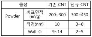
본 발명의 또 다른 측면에 따르면, 양극은 도전성 코팅층이 피복된 단입자계 양극 활물질을 포함하거나 신규 CNT가 도전재로 함유됨으로써 전극의 도전성이 개선될 수 있다. According to another aspect of the present invention, the conductivity of the electrode can be improved by including a single particle type positive electrode active material coated with a conductive coating layer or containing novel CNTs as a conductive material.
본 발명의 또 다른 측면에 따르면, 양극 활물질층에 인편상 흑연이 포함되므로 양극 활물질층을 압연하는 경우, 상기 인편상 흑연이 상기 양극 활물질에 미끄러짐 효과를 제공하여 전극의 압연 특성이 향상되고, 전극 공극률을 목표하는 수준까지 낮출 수 있다. 이에 따라, 원통형 배터리의 안정성, 초기 저항 특성, 및 충방전 효율이 개선된다. According to another aspect of the present invention, since the positive electrode active material layer includes flaky graphite, when the positive electrode active material layer is rolled, the flaky graphite provides a sliding effect to the positive electrode active material, thereby improving the rolling characteristics of the electrode and reducing the electrode porosity to a target level. Accordingly, the stability, initial resistance characteristics, and charge/discharge efficiency of the cylindrical battery are improved.
본 발명의 또 다른 측면에 따르면, 음극에 용량이 큰 실리콘계 음극 활물질이 포함됨으로써 더 높은 에너지 밀도를 구현할 수 있다.According to another aspect of the present invention, a silicon-based negative electrode active material having a large capacity is included in the negative electrode, thereby realizing a higher energy density.
본 발명의 또 다른 측면에 따르면, 양극 활물질의 로딩량이 적은 로딩 감소부가 양극에 포함되므로 리튬의 석출 우려 없이 양극 활물질부의 구간을 늘릴 수 있다.According to another aspect of the present invention, since a loading reduction portion having a small loading amount of positive electrode active material is included in the positive electrode, the section of the positive electrode active material portion can be increased without concern about lithium precipitation.
본 발명의 또 다른 측면에 따르면, 스트립 형태의 전극 탭을 구비한 종래의 배터리와 비교하여 배터리의 내부 발열을 효과적으로 감소시킬 수 있으므로 배터리의 열 안전성이 개선될 수 있다.According to another aspect of the present invention, compared to a conventional battery having a strip-shaped electrode tab, internal heat generation of the battery can be effectively reduced, so that the thermal safety of the battery can be improved.
본 명세서에 첨부되는 다음의 도면들은 본 발명의 바람직한 실시예를 예시하는 것이며, 후술되는 발명의 상세한 설명과 함께 본 발명의 기술사상을 더욱 이해시키는 역할을 하는 것이므로, 본 발명은 그러한 도면에 기재된 사항에만 한정되어 해석되어서는 아니 된다.
도 1은 종래의 탭-리스 원통형 배터리에 사용되는 전극의 구조를 나타낸 평면도이다.
도 2는 종래의 탭-리스 원통형 배터리에 포함되는 전극 조립체의 권취 공정을 나타낸 도면이다.
도 3은 도 2의 전극 조립체에서 무지부의 절곡면에 집전판이 용접되는 공정을 나타낸 도면이다.
도 4는 종래의 탭-리스 원통형 배터리를 길이 방향(Y)으로 자른 단면도이다.
도 5는 본 발명의 일 실시예에 따른 원통형 배터리의 외관을 나타내는 사시도이다.
도 6은 본 발명의 일 실시예에 따른 원통형 배터리의 내부 구조를 나타내는 단면도이다.
도 7은 본 발명에 적용되는 제1 집전판의 예시적 형태를 나타내는 사시도이다.
도 8은 본 발명의 일체형 스페이서가 적용된 영역을 나타내는 부분 단면도이다.
도 9는 본 발명의 일체형 스페이서의 예시적 형태를 나타내는 사시도이다.
도 10은 본 발명의 원통형 배터리의 바닥면을 나타내는 평면도이다.
도 11은 본 발명의 인슐레이터가 적용된 영역을 나타내는 부분 단면도이다.
도 12는 본 발명의 집전판과 전극 탭의 결합 구조를 나타내는 부분 단면도이다.
도 13은 본 발명의 일 실시예에 따른 배터리 팩을 나타내는 개략도이다.
도 14는 본 발명의 일 실시예에 따른 자동차를 나타내는 개념도이다.
도 15는 본 발명의 실시예에 따른 전극 단자의 리벳팅 구조를 나타낸 단면도이다.
도 16은 도 15의 점선 원으로 표시된 부분의 확대 단면도이다.
도 17은 본 발명의 일 실시예에 따른 원통형 배터리를 길이 방향(Y)을 따라 자른 단면도이다.
도 18은 본 발명의 바람직한 실시예에 따른 전극 구조를 예시적으로 나타낸 평면도이다.
도 19는 본 발명의 실시예에 따른 전극의 무지부 분절구조를 제1전극 및 제2전극에 적용한 전극 조립체를 길이 방향(Y)을 따라 자른 단면도이다.
도 20은 본 발명의 실시예에 따라 무지부가 절곡된 전극 조립체를 길이 방향(Y)을 따라 자른 단면도이다.
도 21은 종래에 일반적으로 사용되던 탄소나노튜브(기존 CNT)의 주사현미경 사진이다.
도 22는 본 발명의 실시예에 따른 신규 CNT의 주사현미경 사진이다.
도 23은 기준 CNT와 신규 CNT의 물성을 비교하여 나타낸 표이다.
도 24 내지 도 27은 양극 활물질로 단입자계 활물질 입자가 적용된 경우 도전재 비율별 면저항 및 고온 수명 특성을 보여주는 그래프들이다.
도 28은 BET 비표면적이 300m2/g 내지 500m2/g인 탄소나노튜브(신규 CNT)를 적용한 경우와 BET가 200m2/g 이상 300m2/g 미만인 탄소나노튜브(기존 CNT)를 적용한 경우의 양극 슬러리의 고형분 함량과 점도 및 MP 코팅층과 MP 계면층에서의 저항값을 비교하여 나타낸 표이다.
도 29는 본 발명의 실시예 2-1에서 사용된 양극 활물질의 SEM 사진이다.
도 30는 본 발명의 실시예 2-2에서 사용된 양극 활물질의 SEM 사진이다.
도 31은 본 발명의 비교예 2-2에서 사용된 양극 활물질의 SEM 사진이다.
도 32는 본 발명의 실시예 1에 의해 제조된 4680 셀의 핫 박스 테스트 결과를 보여주는 그래프이다.
도 33은 본 발명의 비교예 1에 의해 제조된 4680 셀의 핫 박스 테스트 결과를 보여주는 그래프이다.
도 34는 본 발명의 실시예 2-1의 샘플 1 및 비교예 2-1에 의해 제조된 4680 셀의 핫 박스 테스트 결과를 보여주는 그래프이다.
도 35는 본 발명의 실시예 2-1의 샘플 2, 3, 실시예 2-2의 샘플 1, 2 및 비교예 2-2에 의해 제조된 4680 셀의 핫 박스 테스트 결과를 보여주는 그래프이다.
도 36은 본 발명의 실시예 2-1에서 제조된 양극의 단면 SEM 사진이다.
도 37은 비교예 2-1에서 제조된 양극의 단면 SEM 사진이다.
도 38은 본 발명의 실시예 3-3, 비교예 3-1, 및 비교예 3-2에 따른 양극을 포함하는 코인 하프 셀을 4.2V까지 충전하면서 SOC에 따른 저항 특성을 측정한 결과를 나타낸 그래프이다.
도 39는 본 발명의 실시예 3-1, 실시예 3-3 및 비교예 3-1에 따른 4680 셀에 대한 충방전 사이클 실험을 통해 얻은 용량 유지율(Capacity Retention) 및 저항 증가율(DCIR increase)의 측정 결과를 나타낸 그래프이다.
도 40은 본 발명의 일 실시예에 따른 전극 조립체를 나타낸 도면이다.
도 41은 도 40의 절단선 A-A'를 따라 자른 단면을 나타낸 단면도이다.
도 42 및 도 43은 본 발명의 일 실시예에 따라 음극을 제조하는 공정을 나타낸 도면들이다.
도 44는 본 발명의 일 실시예에 따른 음극을 나타낸 사시도이다.
도 45 및 도 46은 본 발명의 일 실시예에 따라 양극을 제조하는 공정을 나타낸 도면들이다.
도 47은 본 발명의 일 실시예에 따른 양극을 나타낸 사시도이다.
도 48은 본 발명의 비교예에 따른 전극 조립체를 나타낸 도면이다.
도 49는 도 48의 절단선 B-B'를 따라 자른 단면을 나타낸 단면도이다.
도 50은 본 발명의 비교예에 따라 음극을 제조하는 공정을 나타낸 도면이다.
도 51은 본 발명의 비교예에 따라 양극을 제조하는 공정을 나타낸 도면이다.
도 52는 실리콘계 음극 활물질과 탄소계 음극 활물질의 혼합물을 음극 활물질로 사용한 배터리에서, 실리콘계 음극 활물질의 함량과 실리콘계 음극 활물질의 도핑 유무에 따른 에너지 밀도의 변화를 보여주는 그래프이다.The following drawings attached to this specification illustrate preferred embodiments of the present invention and, together with the detailed description of the invention described below, serve to further understand the technical idea of the present invention; therefore, the present invention should not be interpreted as being limited to matters described in such drawings.
Figure 1 is a plan view showing the structure of an electrode used in a conventional tab-less cylindrical battery.
Figure 2 is a drawing showing a winding process of an electrode assembly included in a conventional tab-less cylindrical battery.
Figure 3 is a drawing showing a process of welding a collector plate to a folded surface of a non-conductive portion in the electrode assembly of Figure 2.
Figure 4 is a cross-sectional view of a conventional tab-less cylindrical battery cut in the longitudinal direction (Y).
FIG. 5 is a perspective view showing the appearance of a cylindrical battery according to one embodiment of the present invention.
FIG. 6 is a cross-sectional view showing the internal structure of a cylindrical battery according to one embodiment of the present invention.
Figure 7 is a perspective view showing an exemplary form of a first collector plate applied to the present invention.
Fig. 8 is a partial cross-sectional view showing an area to which the integral spacer of the present invention is applied.
FIG. 9 is a perspective view showing an exemplary form of an integral spacer of the present invention.
Figure 10 is a plan view showing the bottom surface of the cylindrical battery of the present invention.
Fig. 11 is a partial cross-sectional view showing an area to which the insulator of the present invention is applied.
Fig. 12 is a partial cross-sectional view showing the joint structure of the current collector plate and electrode tab of the present invention.
FIG. 13 is a schematic diagram showing a battery pack according to one embodiment of the present invention.
Figure 14 is a conceptual diagram showing a vehicle according to one embodiment of the present invention.
Fig. 15 is a cross-sectional view showing a riveting structure of an electrode terminal according to an embodiment of the present invention.
Figure 16 is an enlarged cross-sectional view of the portion indicated by the dotted circle in Figure 15.
FIG. 17 is a cross-sectional view taken along the longitudinal direction (Y) of a cylindrical battery according to one embodiment of the present invention.
Fig. 18 is a plan view exemplarily showing an electrode structure according to a preferred embodiment of the present invention.
FIG. 19 is a cross-sectional view taken along the longitudinal direction (Y) of an electrode assembly in which the electrode-less segment structure according to an embodiment of the present invention is applied to the first electrode and the second electrode.
FIG. 20 is a cross-sectional view of an electrode assembly with a folded portion cut along the longitudinal direction (Y) according to an embodiment of the present invention.
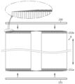
Figure 21 is a scanning electron microscope photograph of a carbon nanotube (existing CNT) that has been commonly used in the past.
Figure 22 is a scanning electron microscope photograph of a novel CNT according to an embodiment of the present invention.
Figure 23 is a table comparing the properties of reference CNTs and novel CNTs.
Figures 24 to 27 are graphs showing surface resistance and high-temperature life characteristics according to the conductive material ratio when single-particle active material particles are applied as the positive electrode active material.
Figure 28 is a table comparing the solid content and viscosity of positive electrode slurry and the resistance value in the MP coating layer and MP interface layer when carbon nanotubes (new CNTs) having a BET surface area of 300 m 2 /g to 500 m 2 /g are applied and when carbon nanotubes (existing CNTs) having a BET surface area of 200 m 2 /g or more and less than 300
Figure 29 is a SEM photograph of the positive electrode active material used in Example 2-1 of the present invention.
Figure 30 is a SEM photograph of the positive electrode active material used in Example 2-2 of the present invention.
Figure 31 is a SEM photograph of the positive electrode active material used in Comparative Example 2-2 of the present invention.
Figure 32 is a graph showing the results of a hot box test of a 4680 cell manufactured by Example 1 of the present invention.
Figure 33 is a graph showing the results of a hot box test of a 4680 cell manufactured by Comparative Example 1 of the present invention.
Figure 34 is a graph showing the results of a hot box test of a 4680 cell manufactured by
FIG. 35 is a graph showing the results of a hot box test of 4680 cells manufactured by
Figure 36 is a cross-sectional SEM photograph of the anode manufactured in Example 2-1 of the present invention.
Figure 37 is a cross-sectional SEM photograph of the anode manufactured in Comparative Example 2-1.
Figure 38 is a graph showing the results of measuring resistance characteristics according to SOC while charging coin half cells including positive electrodes according to Example 3-3, Comparative Example 3-1, and Comparative Example 3-2 of the present invention up to 4.2 V.
Figure 39 is a graph showing the results of measuring capacity retention and resistance increase rate (DCIR increase) obtained through charge/discharge cycle experiments on 4680 cells according to Examples 3-1, 3-3, and Comparative Example 3-1 of the present invention.
FIG. 40 is a drawing showing an electrode assembly according to one embodiment of the present invention.
Figure 41 is a cross-sectional view showing a section taken along the cutting line A-A' of Figure 40.
FIGS. 42 and 43 are drawings showing a process for manufacturing a cathode according to one embodiment of the present invention.
Figure 44 is a perspective view showing a cathode according to one embodiment of the present invention.
FIGS. 45 and 46 are drawings showing a process for manufacturing an anode according to one embodiment of the present invention.
Figure 47 is a perspective view showing an anode according to one embodiment of the present invention.
Figure 48 is a drawing showing an electrode assembly according to a comparative example of the present invention.
Figure 49 is a cross-sectional view showing a section taken along the cutting line B-B' of Figure 48.
Figure 50 is a drawing showing a process for manufacturing a cathode according to a comparative example of the present invention.
Figure 51 is a drawing showing a process for manufacturing an anode according to a comparative example of the present invention.
Figure 52 is a graph showing the change in energy density according to the content of silicon-based negative electrode active material and the presence or absence of doping of the silicon-based negative electrode active material in a battery using a mixture of silicon-based negative electrode active material and carbon-based negative electrode active material as the negative electrode active material.
이하, 첨부된 도면을 참조하여 본 발명의 바람직한 실시예를 상세히 설명하기로 한다. 이에 앞서, 본 명세서 및 청구범위에 사용된 용어나 단어는 통상적이거나 사전적인 의미로 한정해서 해석되어서는 아니 되며, 발명자는 그 자신의 발명을 가장 최선의 방법으로 설명하기 위해 용어의 개념을 적절하게 정의할 수 있다는 원칙에 입각하여 본 발명의 기술적 사상에 부합하는 의미와 개념으로 해석되어야만 한다. 따라서, 본 명세서에 기재된 실시예와 도면에 도시된 구성은 본 발명의 가장 바람직한 일부 실시예에 불과할 뿐이고 본 발명의 기술적 사상을 모두 대변하는 것은 아니므로, 본 출원시점에 있어서 이들을 대체할 수 있는 다양한 균등물과 변형예들이 있을 수 있음을 이해하여야 한다.Hereinafter, preferred embodiments of the present invention will be described in detail with reference to the attached drawings. Prior to this, terms or words used in this specification and claims should not be interpreted as limited to their usual or dictionary meanings, and should be interpreted as meanings and concepts that conform to the technical idea of the present invention based on the principle that the inventor can appropriately define the concept of the term in order to explain his or her own invention in the best way. Therefore, the embodiments described in this specification and the configurations illustrated in the drawings are only some of the most preferred embodiments of the present invention and do not represent all of the technical idea of the present invention, and it should be understood that there may be various equivalents and modified examples that can replace them at the time of filing this application.
또한, 발명의 이해를 돕기 위하여, 첨부된 도면은 실제 축척대로 도시된 것이 아니라 일부 구성요소의 치수가 과장되게 도시될 수 있다. 또한, 서로 다른 실시예에서 동일한 구성요소에 대해서는 동일한 참조번호가 부여될 수 있다. In addition, to facilitate understanding of the invention, the attached drawings are not drawn to scale and some components may have exaggerated dimensions. In addition, the same reference numbers may be given to the same components in different embodiments.
도면에 나타난 각 구성의 크기 및 두께는 설명의 편의를 위해 임의로 나타내었으므로, 본 발명이 반드시 도시된 바에 한정되지 않는다. 도면에서 여러 층 및 영역을 명확하게 표현하기 위하여 두께를 확대하여 나타내었다. 그리고 도면에서, 설명의 편의를 위해, 일부 층 및 영역의 두께를 과장되게 나타내었다.The size and thickness of each component shown in the drawing are arbitrarily shown for the convenience of explanation, so the present invention is not necessarily limited to what is shown. In the drawing, the thickness is shown enlarged to clearly express various layers and regions. In addition, in the drawing, the thickness of some layers and regions is shown exaggeratedly for the convenience of explanation.
또한, 층, 막, 영역, 판 등의 부분이 다른 부분 "위에" 또는 “상에” 있다고 할 때, 이는 다른 부분 "바로 위에" 있는 경우뿐만 아니라 그 중간에 또 다른 부분이 있는 경우도 포함한다. 반대로 어떤 부분이 다른 부분 "바로 위에" 있다고 할 때에는 중간에 다른 부분이 없는 것을 뜻한다. 또한, 기준이 되는 부분 "위에" 또는 “상에” 있다고 하는 것은 기준이 되는 부분의 위 또는 아래에 위치하는 것이고, 반드시 중력 반대 방향을 향하여 “위에” 또는 “상에” 위치하는 것을 의미하는 것은 아니다.Also, when we say that a part such as a layer, film, region, or plate is "over" or "on" another part, this includes not only cases where it is "directly over" the other part, but also cases where there is another part in between. Conversely, when we say that a part is "directly over" another part, it means that there is no other part in between. Also, when we say that a part is "over" or "on" a reference part, it means that it is located above or below the reference part, and does not necessarily mean that it is located "over" or "on" the opposite direction of gravity.
또한, 명세서 전체에서, 어떤 부분이 어떤 구성요소를 "포함" 한다고 할 때, 이는 특별히 반대되는 기재가 없는 한 다른 구성요소를 제외하는 것이 아니라 다른 구성요소를 더 포함할 수 있는 것을 의미한다.Additionally, throughout the specification, whenever a part is said to "include" a component, this does not mean that it excludes other components, but rather that it may include other components, unless otherwise specifically stated.
또한, 명세서 전체에서, "평면상"이라 할 때, 이는 대상 부분을 위에서 보았을 때를 의미하며, "단면상"이라 할 때, 이는 대상 부분을 수직으로 자른 단면을 옆에서 보았을 때를 의미한다.Additionally, throughout the specification, when we say "in plan", we mean when the target portion is viewed from above, and when we say "in cross section", we mean when the target portion is viewed from the side in a cross-section cut vertically.
도 5 및 도 6을 참조하면, 본 발명의 일 실시예에 따른 원통형 배터리(1)는, 전극 조립체(10), 배터리 하우징(20), 제1 집전판(30), 캡 플레이트(40), 실링 스페이서(60) 및 전극 단자(50)를 포함한다. 상기 원통형 배터리(1)는, 상술한 구성요소들 이 외에 절연 가스켓(54) 및/또는 제2 집전판(70) 및/또는 인슐레이터(80)를 더 포함할 수도 있다.Referring to FIGS. 5 and 6, a cylindrical battery (1) according to one embodiment of the present invention includes an electrode assembly (10), a battery housing (20), a first current collector (30), a cap plate (40), a sealing spacer (60), and an electrode terminal (50). In addition to the above-described components, the cylindrical battery (1) may further include an insulating gasket (54) and/or a second current collector (70) and/or an insulator (80).
도 6, 도 8, 도 11 및 도 12를 참조하면, 상기 전극 조립체(10)는, 제1 무지부(제1 전극 탭)(11)를 구비하는 제1 전극 및 제2 무지부(제2 전극 탭)(12)를 구비하는 제2 전극을 포함한다. 이하에서 언급되는 전극 무지부 또는 무지부는 전극 탭을 의미한다. 상기 전극 조립체(10)는, 제1 극성을 갖는 제1 전극, 제2 극성을 갖는 제2 전극 및 제1 전극과 제2 전극 사이에 개재되는 분리막을 포함한다. 상기 제1 전극은 음극 또는 양극이고, 제2 전극은 제1 전극과 반대되는 극성을 갖는 전극에 해당한다. Referring to FIGS. 6, 8, 11, and 12, the electrode assembly (10) includes a first electrode having a first unlined portion (first electrode tab) (11) and a second electrode having a second unlined portion (second electrode tab) (12). The electrode unlined portion or unlined portion mentioned below means an electrode tab. The electrode assembly (10) includes a first electrode having a first polarity, a second electrode having a second polarity, and a separator interposed between the first electrode and the second electrode. The first electrode is a cathode or an anode, and the second electrode corresponds to an electrode having a polarity opposite to that of the first electrode.
상기 전극 조립체(10)는, 예를 들어 젤리-롤(jelly-roll) 형상을 가질 수 있다. 즉, 상기 전극 조립체(10)는, 제1 전극, 분리막, 제2 전극을 순차적으로 적어도 1회 적층하여 형성된 적층체를 권취시킴으로써 제조될 수 있다. 이러한 젤리-롤 타입의 전극 조립체(10)는, 그 중심부에 형성되어 높이 방향(Z축에 나란한 방향)을 따라 연장되는 권취 중심 홀(C)을 구비할 수 있다. 한편, 상기 전극 조립체(10)의 외주면 상에는 배터리 하우징(20)과의 절연을 위해 추가적인 분리막이 구비될 수 있다.The electrode assembly (10) may have, for example, a jelly-roll shape. That is, the electrode assembly (10) may be manufactured by winding a laminate formed by sequentially stacking a first electrode, a separator, and a second electrode at least once. This jelly-roll type electrode assembly (10) may have a winding center hole (C) formed at the center thereof and extending along the height direction (parallel to the Z-axis). Meanwhile, an additional separator may be provided on the outer peripheral surface of the electrode assembly (10) for insulation from the battery housing (20).
상기 제1 전극은, 제1 전극 집전체 및 제1 전극 집전체의 일 면 또는 양 면 상에 도포되어 형성되는 제1 전극 활물질 층을 포함한다. 상기 제1 전극 집전체의 폭 방향(Z축에 나란한 방향) 일 측 단부에는 제1 전극 활물질이 도포되지 않은 제1 무지부(11)가 존재한다. 상기 제1 무지부(11)는, 제1 전극이 펼쳐진 상태를 기준으로 볼 때 제1 전극의 길이 방향을 따라 일 측 단부로부터 타 측 단부까지 연장된 형태를 갖는다. 상기 제1 무지부(11)는, 상술한 바와 같은 제1 전극 탭으로서 기능한다. 상기 제1 무지부(11)는, 전극 조립체(10)의 일 면 상에 구비된다. 좀 더 구체적으로, 상기 제1 무지부(11)는, 배터리 하우징(20) 내에 수용된 전극 조립체(10)의 높이 방향(Z축에 나란한 방향) 하부에 구비된다.The first electrode includes a first electrode current collector and a first electrode active material layer formed by being applied on one or both surfaces of the first electrode current collector. At one end of the first electrode current collector in the width direction (in the direction parallel to the Z-axis), a first uncoated portion (11) on which the first electrode active material is not applied exists. The first uncoated portion (11) has a shape extending from one end to the other end along the length direction of the first electrode when the first electrode is unfolded. The first uncoated portion (11) functions as the first electrode tab as described above. The first uncoated portion (11) is provided on one surface of the electrode assembly (10). More specifically, the first uncoated portion (11) is provided at a lower portion in the height direction (in the direction parallel to the Z-axis) of the electrode assembly (10) accommodated in the battery housing (20).
상기 제2 전극은, 제2 전극 집전체 및 제2 전극 집전체의 일 면 또는 양 면 상에 도포되어 형성되는 제2 전극 활물질 층을 포함한다. 상기 제2 전극 집전체의 폭 방향(Z축에 나란한 방향) 타 측 단부에는 제2 전극 활물질이 도포되지 않은 제2 무지부(12)가 존재한다. 상기 제2 무지부(12)는, 제2 전극이 펼쳐진 상태를 기준으로 볼 때 제2 전극의 길이 방향을 따라 일 측 단부로부터 타 측 단부까지 연장된 형태를 갖는다. 상기 제2 무지부(12)는, 상술한 바와 같은 제2 전극 탭으로서 기능한다. 상기 제2 무지부(12)는, 전극 조립체(10)의 타 면 상에 구비된다. 좀 더 구체적으로, 상기 제2 무지부(12)는, 배터리 하우징(20) 내에 수용된 전극 조립체(10)의 높이 방향(Z축에 나란한 방향) 상부에 구비된다.The second electrode includes a second electrode current collector and a second electrode active material layer formed by being applied on one or both surfaces of the second electrode current collector. A second uncoated portion (12) on which the second electrode active material is not applied exists on the other end of the second electrode current collector in the width direction (in the direction parallel to the Z-axis). The second uncoated portion (12) has a shape extending from one end to the other end along the length direction of the second electrode when the second electrode is unfolded. The second uncoated portion (12) functions as the second electrode tab as described above. The second uncoated portion (12) is provided on the other surface of the electrode assembly (10). More specifically, the second uncoated portion (12) is provided on the upper portion in the height direction (in the direction parallel to the Z-axis) of the electrode assembly (10) accommodated in the battery housing (20).
즉, 상기 제1 무지부(11)와 제2 무지부(12)는, 전극 조립체(10)의 높이 방향(Z축에 나란한 방향), 즉 원통형 배터리(1)의 높이 방향을 따라 서로 반대 방향으로 연장 돌출된다.That is, the first unlined portion (11) and the second unlined portion (12) extend and protrude in opposite directions along the height direction of the electrode assembly (10) (parallel to the Z-axis), i.e., along the height direction of the cylindrical battery (1).
본 발명에 있어서, 양극에 코팅되는 양극 활물질과 음극에 코팅되는 음극 활물질은 당업계에 공지된 활물질이라면 제한없이 사용될 수 있다.In the present invention, the positive electrode active material coated on the positive electrode and the negative electrode active material coated on the negative electrode can be used without limitation as long as they are active materials known in the art.
도 5, 도 6, 도 8 및 도 11을 참조하면, 상기 배터리 하우징(20)은, 그 하단에 형성된 개방부를 통해 전극 조립체(10)를 수용한다. 상기 배터리 하우징(20)은, 그 하단에 개방부가 형성되고 상단에는 폐쇄부가 형성된 대략 원통형의 수용체이다. 상기 배터리 하우징(20)은, 금속과 같은 도전성을 갖는 재질로 이루어질 수 있다. 상기 배터리 하우징(20)의 재질은, 예를 들어 알루미늄일 수 있다. 상기 배터리 하우징(20)의 측면(외주면)과 상면은 일체로 형성될 수 있다. 상기 배터리 하우징(20)의 상면(X-Y 평면에 나란한 면)은 대략 플랫(flat)한 형태를 가질 수 있다. 상기 배터리 하우징(20)은, 하단에 형성된 개방부를 통해 전극 조립체(10)와 함께 전해질도 수용한다.Referring to FIGS. 5, 6, 8, and 11, the battery housing (20) accommodates an electrode assembly (10) through an opening formed at a bottom thereof. The battery housing (20) is a generally cylindrical container having an opening formed at a bottom thereof and a closed portion formed at an upper end thereof. The battery housing (20) may be made of a material having conductivity such as metal. The material of the battery housing (20) may be, for example, aluminum. The side surface (outer surface) and the upper surface of the battery housing (20) may be formed integrally. The upper surface (surface parallel to the X-Y plane) of the battery housing (20) may have a generally flat shape. The battery housing (20) accommodates an electrolyte together with the electrode assembly (10) through the opening formed at the bottom thereof.
상기 배터리 하우징(20)은, 전극 조립체(10)와 전기적으로 연결된다. 상기 배터리 하우징(20)은, 전극 조립체(10)의 제1 무지부(11)와 연결된다. 따라서, 상기 배터리 하우징(20)은, 전기적으로 제1 무지부(11)와 동일한 극성을 갖는다.The above battery housing (20) is electrically connected to the electrode assembly (10). The battery housing (20) is connected to the first non-conductive portion (11) of the electrode assembly (10). Therefore, the battery housing (20) has the same electrical polarity as the first non-conductive portion (11).
도 6 및 도 8을 참조하면, 상기 배터리 하우징(20)은, 그 하단에 형성되는 비딩부(21) 및 클림핑부(22)를 구비할 수 있다. 상기 비딩부(21)는, 배터리 하우징(20)의 내부에 수용된 전극 조립체(10)의 하방에 위치한다. 상기 비딩부(21)는, 배터리 하우징(20)이 외주면 둘레를 압입하여 형성된다. 상기 비딩부(21)는, 배터리 하우징(20)의 내경을 부분적으로 감소시킴으로써, 배터리 하우징(20)의 폭과 대략 대응되는 사이즈를 가질 수 있는 전극 조립체(10)가 배터리 하우징(20)의 하단에 형성된 개방부를 통해 빠져나오지 않도록 한다. 상기 비딩부(21)는, 캡 플레이트(40)가 안착되는 지지부로서도 기능할 수 있다. Referring to FIGS. 6 and 8, the battery housing (20) may have a beading portion (21) and a crimping portion (22) formed at the bottom thereof. The beading portion (21) is located below the electrode assembly (10) accommodated inside the battery housing (20). The beading portion (21) is formed by pressing the outer circumference of the battery housing (20). The beading portion (21) partially reduces the inner diameter of the battery housing (20), thereby preventing the electrode assembly (10), which may have a size roughly corresponding to the width of the battery housing (20), from slipping out through the opening formed at the bottom of the battery housing (20). The beading portion (21) may also function as a support portion on which the cap plate (40) is mounted.
상기 클림핑부(22)는, 비딩부(21)의 하방에 형성된다. 상기 클림핑부(22)는, 실링 스페이서(60)의 가장자리 둘레 부분이 개재된 상태로 캡 플레이트(40)의 가장자리 둘레 부분을 감싸도록 연장 및 절곡된 형태를 갖는다.The above-mentioned crimping portion (22) is formed below the beading portion (21). The above-mentioned crimping portion (22) has an extended and bent shape so as to wrap around the edge of the cap plate (40) with the edge of the sealing spacer (60) interposed therebetween.
도 6 내지 도 8 및 도 12를 참조하면, 상기 제1 집전판(30)은, 전극 조립체(10)의 제1 무지부(11)와 결합되며 배터리 하우징(20) 내에 위치한다. 상기 제1 집전판(30)은, 전극 조립체(10)의 하단 일 면의 적어도 일부를 커버한다. 상기 전극 조립체(10)와 제1 집전판(30)을 포함하는 결합체는 배터리 하우징(20)의 하단에 형성되는 개방부를 통해 배터리 하우징(20) 내에 삽입될 수 있다. 상기 제1 집전판(30)은, 배터리 하우징(20)과 전기적으로 연결된다. 즉, 상기 제1 집전판(30)은, 전극 조립체(10)와 배터리 하우징(20) 간의 전기적 연결을 위한 매개체로서 기능할 수 있다.Referring to FIGS. 6 to 8 and 12, the first current collector (30) is coupled with the first non-conductive portion (11) of the electrode assembly (10) and is positioned within the battery housing (20). The first current collector (30) covers at least a portion of a lower surface of the electrode assembly (10). An assembly including the electrode assembly (10) and the first current collector (30) can be inserted into the battery housing (20) through an opening formed at the lower end of the battery housing (20). The first current collector (30) is electrically connected to the battery housing (20). That is, the first current collector (30) can function as a medium for electrical connection between the electrode assembly (10) and the battery housing (20).
도 7을 참조하면, 상기 제1 집전판(30)은, 예를 들어 중심부(31), 무지부 결합부(32) 및 하우징 접촉부(33)를 포함할 수 있다. 상기 중심부(31)는, 전극 조립체(10)의 하단에 형성되는 일 면 상에서 중심부에 위치한다. 상기 중심부(31)에는 제1 집전판 홀(30a)이 구비될 수 있다. 이 경우, 상기 제1 집전판 홀(30a)은, 전극 조립체(10)의 권취 중심 홀(C)과 대응되는 위치에 형성된다. 상기 제1 집전판 홀(30a)은, 후술할 전극 단자(50)와 제2 집전판(70) 간의 결합을 위한 용접봉의 삽입이나 레이저 조사를 위한 통로로서 기능할 수 있다. 그 밖에도, 상기 제1 집전판 홀(30a)은 전해액의 주액 시에 전극 조립체(10) 내부로 원활한 전해액 함침이 이루어질 수 있도록 하는 통로로서도 기능할 수 있다.Referring to FIG. 7, the first collector plate (30) may include, for example, a center portion (31), a non-conductive coupling portion (32), and a housing contact portion (33). The center portion (31) is located at the center on one side formed at the bottom of the electrode assembly (10). A first collector plate hole (30a) may be provided in the center portion (31). In this case, the first collector plate hole (30a) is formed at a position corresponding to the winding center hole (C) of the electrode assembly (10). The first collector plate hole (30a) may function as a passage for insertion of a welding rod or laser irradiation for joining between an electrode terminal (50) and a second collector plate (70) to be described later. In addition, the first collector plate hole (30a) may also function as a passage for allowing smooth electrolyte impregnation into the inside of the electrode assembly (10) when the electrolyte is injected.
상기 무지부 결합부(32)는, 중심부(31)로부터 연장되며 제1 무지부(11)와 결합한다. 상기 무지부 결합부(32)는, 예를 들어 복수개가 구비될 수 있다. 이 경우, 복수의 무지부 결합부(32)들 각각은, 중심부(31)로부터 방사상으로 연장된 형태를 가질 수 있다. 상기 하우징 접촉부(33)는, 도 7에 도시된 바와 같이 중심부(31)로부터 연장되거나 또는 도 7에 도시된 것과는 달리 무지부 결합부(32)의 단부로부터 연장될 수 있다. 상기 하우징 접촉부(33)의 단부는 후술할 실링 스페이서(60)의 실링부(62)와 배터리 하우징(20) 사이에 개재되어 배터리 하우징(20)과 접촉할 수 있으며, 이로써 배터리 하우징(20)과 제1 집전판(30) 간의 전기적 연결이 이루어질 수 있다.The above-described non-conductive coupling portion (32) extends from the center (31) and is coupled with the first non-conductive portion (11). The non-conductive coupling portion (32) may be provided in multiple numbers, for example. In this case, each of the multiple non-conductive coupling portions (32) may have a shape that extends radially from the center (31). The housing contact portion (33) may extend from the center (31) as illustrated in FIG. 7, or, unlike that illustrated in FIG. 7, may extend from an end of the non-conductive coupling portion (32). The end of the housing contact portion (33) may be interposed between the sealing portion (62) of the sealing spacer (60) described below and the battery housing (20) to come into contact with the battery housing (20), thereby allowing an electrical connection between the battery housing (20) and the first current collector (30).
상기 하우징 접촉부(33)는, 예를 들어 복수개가 구비될 수 있다. 이 경우, 복수의 하우징 접촉부(33)들은, 도 7에 도시된 바와 같이, 중심부(31)로부터 방사상으로 연장된 형태를 가질 수 있고, 서로 이웃하는 무지부 결합부(32) 사이에 적어도 하나의 하우징 접촉부(33)가 위치할 수 있다. 또는, 상기 복수의 하우징 접촉부(33)들은, 도 7에 도시된 것과는 달리, 복수의 무지부 결합부(32) 각각의 단부로부터 연장된 형태를 가질 수도 있다.The above housing contact portions (33) may be provided in multiple numbers, for example. In this case, the multiple housing contact portions (33) may have a shape extending radially from the center (31), as shown in FIG. 7, and at least one housing contact portion (33) may be positioned between adjacent non-coated coupling portions (32). Alternatively, the multiple housing contact portions (33) may have a shape extending from each end of the multiple non-coated coupling portions (32), unlike that shown in FIG. 7.
도 6, 도 8 및 도 10을 참조하면, 상기 캡 플레이트(40)는, 배터리 하우징(20)에 형성된 개방부를 커버한다. 상기 캡 플레이트(40)는, 강성 확보를 위해 예를 들어 금속 재질로 이루어질 수 있다. 상기 캡 플레이트(40)는, 원통형 배터리(1)의 하면을 이룬다. 본 발명의 원통형 배터리(1)에 있어서, 캡 플레이트(40)는, 전도성을 갖는 금속 재질인 경우에도, 극성을 갖지 않을 수 있다. 극성을 갖지 않는다는 것은, 상기 캡 플레이트(40)가 배터리 하우징(20) 및 전극 단자(50)와 전기적으로 절연되어 있음을 의미할 수 있다. 따라서, 상기 캡 플레이트(40)는, 양극 단자 또는 음극 단자로서 기능하지 않는다. 따라서, 상기 캡 플레이트(40)는, 전극 조립체(10) 및 배터리 하우징(20)과 전기적으로 연결될 필요가 없으며, 그 재질이 반드시 전도성 금속이어야 하는 것도 아니다.Referring to FIGS. 6, 8, and 10, the cap plate (40) covers an opening formed in the battery housing (20). The cap plate (40) may be made of, for example, a metal material to secure rigidity. The cap plate (40) forms a lower surface of the cylindrical battery (1). In the cylindrical battery (1) of the present invention, the cap plate (40) may not have polarity even if it is made of a conductive metal material. Not having polarity may mean that the cap plate (40) is electrically insulated from the battery housing (20) and the electrode terminal (50). Therefore, the cap plate (40) does not function as a positive terminal or a negative terminal. Therefore, the cap plate (40) does not need to be electrically connected to the electrode assembly (10) and the battery housing (20), and its material does not necessarily have to be a conductive metal.
본 발명의 배터리 하우징(20)이 비딩부(21)를 구비하는 경우, 상기 캡 플레이트(40)는, 배터리 하우징(20)에 형성된 비딩부(21) 상에 안착될 수 있다. 또한, 본 발명의 배터리 하우징(20)이 클림핑부(22)를 구비하는 경우, 상기 캡 플레이트(40)는, 클림핑부(22)에 의해 고정된다. 상기 캡 플레이트(40)와 배터리 하우징(20)의 클림핑부(22) 사이에는 배터리 하우징(20)의 기밀성 확보를 위해 실링 스페이서(60)의 가장자리 둘레 부분이 개재된다. When the battery housing (20) of the present invention has a beading portion (21), the cap plate (40) can be mounted on the beading portion (21) formed in the battery housing (20). In addition, when the battery housing (20) of the present invention has a crimping portion (22), the cap plate (40) is fixed by the crimping portion (22). Between the cap plate (40) and the crimping portion (22) of the battery housing (20), an edge periphery of a sealing spacer (60) is interposed to ensure airtightness of the battery housing (20).
도 8 및 도 10을 참조하면, 상기 캡 플레이트(40)는, 배터리 하우징(20)의 내부에 발생된 가스로 인해 내압이 기 설정된 수치를 넘어서 증가하는 것을 방지하기 위해 벤팅부(41)를 더 구비할 수 있다. 상기 벤팅부(41)는, 캡 플레이트(40) 중 주변 영역과 비교하여 더 얇은 두께를 갖는 영역에 해당한다. 상기 벤팅부(41)는, 주변 영여과 비교하여 구조적으로 취약하다. 따라서, 상기 원통형 배터리(1)에 이상이 발생하여 배터리 하우징(20)의 내부 압력이 일정 수준 이상으로 증가하게 되면 벤팅부(41)가 파단되어 배터리 하우징(20)의 내부에 생성된 가스가 배출될 수 있다. 상기 벤팅부(41)는, 예를 들어 캡 플레이트(40)의 어느 일 면 상에 또는 양 면 상에 노칭(notching)을 하여 부분적으로 배터리 하우징(20)의 두께를 감소시킴으로써 형성될 수 있다. Referring to FIGS. 8 and 10, the cap plate (40) may further include a venting portion (41) to prevent the internal pressure from increasing beyond a preset value due to gas generated inside the battery housing (20). The venting portion (41) corresponds to a region of the cap plate (40) that has a thinner thickness compared to the surrounding region. The venting portion (41) is structurally weaker compared to the surrounding region. Therefore, when an abnormality occurs in the cylindrical battery (1) and the internal pressure of the battery housing (20) increases above a certain level, the venting portion (41) may be broken and the gas generated inside the battery housing (20) may be discharged. The venting portion (41) may be formed, for example, by notching on one side or both sides of the cap plate (40) to partially reduce the thickness of the battery housing (20).
도 8에 도시된 바와 같이, 상기 캡 플레이트(40)의 하단부는 배터리 하우징(20)의 하단부보다 더 상방에 위치하는 것이 바람직하다. 이 경우, 상기 배터리 하우징(20)의 하단부가 지면에 닿거나 또는 모듈이나 팩 구성을 위한 하우징의 바닥면에 닿더라도, 캡 플레이트(40)는 지면 또는 하우징의 바닥면에 닿지 않게 된다. 따라서, 원통형 배터리(1)의 무게로 인해 벤팅부(41)의 파단에 요구되는 압력이 설계치와 달라지는 현상을 방지할 수 있으며, 이에 따라 벤팅부(41)의 파단 원활성이 확보될 수 있다.As shown in Fig. 8, it is preferable that the lower part of the cap plate (40) is positioned higher than the lower part of the battery housing (20). In this case, even if the lower part of the battery housing (20) touches the ground or the bottom surface of the housing for module or pack configuration, the cap plate (40) does not touch the ground or the bottom surface of the housing. Accordingly, it is possible to prevent the pressure required for the rupture of the venting part (41) from being different from the design value due to the weight of the cylindrical battery (1), and thus the smooth rupture of the venting part (41) can be secured.
한편, 상기 벤팅부(41)가 도 8 및 도 10에 도시된 바와 같이 폐루프 형태를 갖는 경우, 파단의 용이성 측면에서는 캡 플레이트(40)의 중심부로부터 벤팅부(41)에 이르는 거리가 멀수록 유리하다. 이는, 동일한 벤팅 압이 작용했을 때, 상기 캡 플레이트(40)의 중심부로부터 벤팅부(41)에 이르는 거리가 멀어질수록 벤팅부(41)에 작용하는 힘이 커져 파단이 용이해지기 때문이다. 또한, 벤팅 가스 배출의 원활성 측면에서도 캡 플레이트(40)의 중심부로부터 벤팅부(41)에 이르는 거리가 멀수록 유리하다. 이러한 관점에서 볼 때, 상기 벤팅부(41)는, 캡 플레이트(40)의 가장자리 둘레 영역으로부터 하방(도 8을 기준으로 아래를 향하는 방향)으로 돌출된 대략 플랫한 영역의 가장자리 둘레를 따라 형성되는 것이 유리할 수 있다.Meanwhile, when the venting portion (41) has a closed loop shape as illustrated in FIGS. 8 and 10, the longer the distance from the center of the cap plate (40) to the venting portion (41), the more advantageous it is in terms of ease of fracture. This is because, when the same venting pressure is applied, the longer the distance from the center of the cap plate (40) to the venting portion (41), the greater the force applied to the venting portion (41), making fracture easier. In addition, in terms of smooth venting gas discharge, the longer the distance from the center of the cap plate (40) to the venting portion (41) is, the more advantageous it is. From this viewpoint, it may be advantageous for the venting portion (41) to be formed along the edge perimeter of a substantially flat area that protrudes downward (in the downward direction based on FIG. 8) from the edge perimeter area of the cap plate (40).
본 발명의 도 10에서는, 상기 벤팅부(41)가 대략 원을 그리며 연속적으로 형성된 경우를 도시하고 있으나, 이로써 본 발명이 한정되는 것은 아니다. 상기 벤팅부(41)는, 캡 플레이트(40) 상에 대략 원을 그리며 불연속적으로 형성될 수도 있고, 대략 직선 형태 또는 그 밖의 다른 형태로 형성될 수도 있다.In Fig. 10 of the present invention, the case where the venting portion (41) is formed continuously in an approximately circular shape is illustrated, but the present invention is not limited thereto. The venting portion (41) may be formed discontinuously in an approximately circular shape on the cap plate (40), or may be formed in an approximately straight line shape or other shape.
도 6, 도 8 및 도 9를 참조하면, 상기 실링 스페이서(60)는, 전극 조립체(10)의 유동을 방지하고, 배터리 하우징(20)의 실링력을 강화하도록 구성된다. 상기 실링 스페이서(60)는, 예를 들어 유동 방지부(61), 실링부(62) 및 연결부(63)를 포함할 수 있다. 상기 유동 방지부(61)는, 제1 집전판(30)과 캡 플레이트(40) 사이에 개재된다. 상기 유동 방지부(61)는, 제1 집전판(30)과 캡 플레이트(40) 사이의 거리와 대응되는 높이를 가질 수 있다. 이 경우, 상기 유동 방지부(61)는, 제1 집전판(30)과 캡 플레이트(40) 사이에 형성되는 유격으로 인해 전극 조립체(10)가 배터리 하우징(20) 내에서 움직이는 것을 효과적으로 방지할 수 있다. 따라서, 상기 유동 방지부(61)는, 전극 조립체(10)와 제1 집전판(30) 간의 결합 부위 및/또는 제1 집전판(30)과 배터리 하우징(20) 간의 결합 부위에 손상이 발생되는 것을 방지할 수 있다. Referring to FIGS. 6, 8, and 9, the sealing spacer (60) is configured to prevent movement of the electrode assembly (10) and to strengthen the sealing force of the battery housing (20). The sealing spacer (60) may include, for example, a movement prevention portion (61), a sealing portion (62), and a connecting portion (63). The movement prevention portion (61) is interposed between the first current collector plate (30) and the cap plate (40). The movement prevention portion (61) may have a height corresponding to the distance between the first current collector plate (30) and the cap plate (40). In this case, the movement prevention portion (61) can effectively prevent the electrode assembly (10) from moving within the battery housing (20) due to the clearance formed between the first current collector plate (30) and the cap plate (40). Accordingly, the above-mentioned flow prevention part (61) can prevent damage from occurring at the joint portion between the electrode assembly (10) and the first current collector (30) and/or the joint portion between the first current collector (30) and the battery housing (20).
상기 유동 방지부(61)는, 전극 조립체(10) 하단의 일 면 상에서 대략 중심부에 위치할 수 있다. 상기 유동 방지부(61)는, 전극 조립체(10)의 권취 중심 홀(C)과 대응되는 위치에 형성되는 스페이서 홀(60a)을 구비할 수 있다. 상기 스페이서 홀(60a)은, 상술한 제1 집전판 홀(30a)과 마찬가지로 용접봉의 삽입 통로 또는 레이저 조사를 위한 통로로서 기능 할 수 있다. 상기 스페이서 홀(60a)은, 상술한 제1 집전판 홀(30a)과 마찬가지로, 전해액의 주액 시에 전극 조립체(10) 내부로 원활한 전해액 함침이 이루어질 수 있도록 하는 통로로서도 기능할 수 있다. The above-described flow prevention portion (61) may be located approximately at the center on one side of the lower portion of the electrode assembly (10). The above-described flow prevention portion (61) may be provided with a spacer hole (60a) formed at a position corresponding to the winding center hole (C) of the electrode assembly (10). The above-described spacer hole (60a), like the above-described first collector hole (30a), may function as a passage for inserting a welding rod or a passage for laser irradiation. The above-described spacer hole (60a), like the above-described first collector hole (30a), may also function as a passage for allowing smooth electrolyte impregnation into the inside of the electrode assembly (10) when the electrolyte is injected.
상기 실링부(62)는, 배터리 하우징(20)과 캡 플레이트(40)에 개재된다. 상기 실링부(62)는, 배터리 하우징(20)의 내주면 둘레를 따라 연장된 형태를 가질 수 있다. 상기 배터리 하우징(20)이 클림핑부(22)를 구비하는 경우, 상기 실링부(62)는, 클림핑부(22)의 절곡 형상을 따라 함께 절곡되어 캡 플레이트(40)의 가장자리 둘레 영역을 감쌀 수 있다. 이처럼, 상기 실링부(62)는, 캡 플레이트(40)의 고정력 향상 및 배터리 하우징(20)의 실링력 향상을 위한 가스켓으로서 기능할 수 있다.The sealing portion (62) is interposed between the battery housing (20) and the cap plate (40). The sealing portion (62) may have a shape that extends along the inner circumference of the battery housing (20). When the battery housing (20) is provided with the crimping portion (22), the sealing portion (62) may be folded together along the folded shape of the crimping portion (22) to wrap around the edge circumference area of the cap plate (40). In this way, the sealing portion (62) may function as a gasket for improving the fixing force of the cap plate (40) and the sealing force of the battery housing (20).
상기 연결부(63)는, 유동 방지부(61)와 실링부(62) 사이를 연결한다. 상기 연결부(63)는, 예를 들어 유동 방지부(61)로부터 방사상으로 연장되는 복수의 연장 레그(63a)를 포함할 수 있다. 상기 연결부(63)가 이와 같이 구성되는 경우, 서로 인접한 연장 레그(63a) 사이의 공간을 통해 전해액 주입이 원활하게 이루어질 수 있고, 내압 증가에 따른 벤팅 발생 시에 내부 가스가 원활하게 배출될 수 있다. The above-mentioned connecting portion (63) connects between the flow prevention portion (61) and the sealing portion (62). The above-mentioned connecting portion (63) may include, for example, a plurality of extension legs (63a) extending radially from the flow prevention portion (61). When the above-mentioned connecting portion (63) is configured in this manner, the electrolyte can be smoothly injected through the space between the adjacent extension legs (63a), and the internal gas can be smoothly discharged when venting occurs due to an increase in internal pressure.
도 7 내지 도 9를 참조하면, 상기 복수의 연장 레그(63a)들은, 제1 집전판(30)의 하우징 접촉부(33) 중 클림핑부(22)에 삽입된 부분을 제외한 나머지 부분 및/또는 캡 플레이트(40)와 접촉하지 않도록 구성될 수 있다. 예를 들어, 상기 연결부(63)는, 원통형 배터리(1)의 높이 방향(Z축에 나란한 방향)을 따라 하우징 접촉부(33)와 중첩되지 않도록 위치할 수 있다. 특히, 상기 연장 레그(63a)들이 유동 방지부(61)로부터 방사상으로 연장된 형태를 갖고, 복수의 상기 하우징 접촉부(33)들이 중심부(31)로부터 방사상으로 연장된 형태를 갖는 경우, 연장 레그(63a)들과 하우징 접촉부(33)들은 서로 연직 방향을 따라 중첩되지 않도록 서로 엇갈린 위치에 배치될 수 있다. 이 경우, 상기 배터리 하우징(20)에 연직 방향의 압축력이 가해져 부품들의 형태 변형이 발생되더라도 연장 레그(63a)와 하우징 접촉부(33) 간의 간섭 발생 가능성이 현저히 낮아질 수 있고, 이로써 부품들 간의 결합 부위가 파손되는 등의 문제가 발생할 가능성을 현저히 감소시킬 수 있다.Referring to FIGS. 7 to 9, the plurality of extension legs (63a) may be configured so as not to come into contact with the remaining portion of the housing contact portion (33) of the first collector plate (30) except for the portion inserted into the crimping portion (22) and/or the cap plate (40). For example, the connection portion (63) may be positioned so as not to overlap with the housing contact portion (33) along the height direction (parallel to the Z-axis) of the cylindrical battery (1). In particular, when the extension legs (63a) have a form that extends radially from the flow prevention portion (61) and the plurality of housing contact portions (33) have a form that extends radially from the center (31), the extension legs (63a) and the housing contact portions (33) may be arranged at staggered positions so as not to overlap with each other in the vertical direction. In this case, even if a vertical compressive force is applied to the battery housing (20) and the shape of the parts is deformed, the possibility of interference between the extension leg (63a) and the housing contact portion (33) can be significantly reduced, thereby significantly reducing the possibility of problems such as damage to the joint portion between the parts.
이 경우, 상기 원통형 배터리(1)를 높이 방향(Z축에 나라한 방향)을 따라 압축시키는 사이징(sizing) 공정이나 그 밖의 다른 원인으로 인해 실링 스페이서(60)의 형태 변형이 발생되더라도 실링 스페이서(60)의 연결부(63)와 제1 집전판(30)의 하우징 접촉부(33) 간의 간섭이 최소화 될 수 있다. 특히, 상기 연장 레그(63a)가 캡 플레이트(40)와 접촉하지 않도록 구성되는 경우, 사이징 공정이나 외부 충격으로 인해 배터리 하우징(20)에 형태 변형이 발생하더라도 연장 레그(63a)의 형태 변형이 발생될 가능성을 감소시킬 수 있다.In this case, even if the shape of the sealing spacer (60) is deformed due to a sizing process that compresses the cylindrical battery (1) in the height direction (in the direction relative to the Z-axis) or other causes, interference between the connecting portion (63) of the sealing spacer (60) and the housing contact portion (33) of the first current collector (30) can be minimized. In particular, when the extension leg (63a) is configured so as not to contact the cap plate (40), even if the shape of the battery housing (20) is deformed due to the sizing process or external impact, the possibility of the shape of the extension leg (63a) being deformed can be reduced.
한편, 상기 실링 스페이서(60)를 구성하는 각각의 구성요소들은 일체로 형성될 수 있다. 예를 들어, 상기 사출에 의해 유동 방지부(61), 실링부(62) 및 연결부(63)가 일체화된 실링 스페이서(60)를 제조할 수 있다. 즉 본 발명의 원통형 배터리(1)는, 배터리 하우징(20)의 개방부를 실링하기 위해 이용되는 가스켓 부품의 변형 제작을 통해 하나의 부품으로서 배터리 하우징(20)의 개방부에 대한 실링력 강화 및 전극 조립체(10)의 유동 방지 효과를 모두 얻을 수 있다. 따라서, 본 발명에 따르면, 추가 부품의 적용으로 인해 발생되는 제조 공정의 복잡화 및 제조 비용 증가 등을 방지할 수 있다.Meanwhile, each component constituting the sealing spacer (60) may be formed integrally. For example, a sealing spacer (60) in which a flow prevention portion (61), a sealing portion (62), and a connecting portion (63) are integrated may be manufactured by the injection molding. That is, the cylindrical battery (1) of the present invention can obtain both the sealing force reinforcement for the opening of the battery housing (20) and the flow prevention effect of the electrode assembly (10) as a single component by modifying and manufacturing the gasket component used to seal the opening of the battery housing (20). Therefore, according to the present invention, it is possible to prevent the complexity of the manufacturing process and the increase in manufacturing cost caused by the application of additional components.
도 5, 도 6 및 도 11을 참조하면, 상기 전극 단자(50)는 전극 조립체(10)의 제2 무지부(12)와 전기적으로 연결된다. 상기 전극 단자(50)는, 예를 들어 배터리 하우징(20)의 상단에 형성된 폐쇄부의 대략 중심부를 관통할 수 있다. 상기 전극 단자(50)의 일부는 배터리 하우징(20)의 상부로 노출되고 나머지 일부는 배터리 하우징(20)의 내부에 위치할 수 있다. 상기 전극 단자(50)는, 예를 들어 리벳팅(riveting)에 의해 배터리 하우징(20)의 폐쇄부의 내측면 상에 고정될 수 있다. Referring to FIGS. 5, 6, and 11, the electrode terminal (50) is electrically connected to the second non-conductive portion (12) of the electrode assembly (10). The electrode terminal (50) may, for example, penetrate approximately the center of a closed portion formed at the top of the battery housing (20). A portion of the electrode terminal (50) may be exposed to the upper portion of the battery housing (20), and the remaining portion may be located inside the battery housing (20). The electrode terminal (50) may be fixed on the inner surface of the closed portion of the battery housing (20), for example, by riveting.
전술한 바와 같이, 본 발명에 있어서 배터리 하우징(20)은 전극 조립체(10)의 제1 무지부(11)와 전기적으로 연결이 되므로, 배터리 하우징(20)의 상단에 형성된 폐쇄부(20a)는 제1 극성을 갖는 제1 전극 단자로서 기능할 수 있다. 반면, 상기 전극 단자(50)는, 전극 조립체(10)의 제2 무지부(12)와 전기적으로 연결이 되므로, 배터리 하우징(20)의 외측으로 노출된 전극 단자(50)는 제2 전극 단자로서 기능할 수 있다.As described above, in the present invention, since the battery housing (20) is electrically connected to the first non-conductive portion (11) of the electrode assembly (10), the closing portion (20a) formed at the upper end of the battery housing (20) can function as a first electrode terminal having a first polarity. On the other hand, since the electrode terminal (50) is electrically connected to the second non-conductive portion (12) of the electrode assembly (10), the electrode terminal (50) exposed to the outside of the battery housing (20) can function as a second electrode terminal.
즉, 본 발명의 원통형 배터리(1)는, 한 쌍의 전극 단자(60, 20a)가 동일 방향에 위치하는 구조를 갖는다. 따라서, 복수의 원통형 배터리(1)를 전기적으로 연결시키는 경우에 있어서, 버스바 등의 전기적 연결 부품을 원통형 배터리(1)의 일 측에만 배치시키는 것이 가능하다. 이는, 배터리 팩 구조의 단순화 및 에너지 밀도의 향상을 가져올 수 있다. 또한, 상기 원통형 배터리(1)는, 대략 플랫한 형태를 갖는 배터리 하우징(20)의 일 면을 제1 전극 단자로 이용할 수 있는 구조를 가짐으로써 버스바 등의 전기적 연결 부품을 제1 전극 단자에 접합시키는데 있어서 충분한 접합 면적을 확보할 수 있다. 이에 따라, 상기 원통형 배터리(1)는, 전기적 연결 부품과 제1 전극 단자 간의 충분한 접합 강도를 확보할 수 있으며, 접합 부위에서의 저항을 바람직한 수준으로 낮출 수 있다.That is, the cylindrical battery (1) of the present invention has a structure in which a pair of electrode terminals (60, 20a) are positioned in the same direction. Therefore, when electrically connecting a plurality of cylindrical batteries (1), it is possible to place electrical connection components such as a bus bar on only one side of the cylindrical battery (1). This can lead to simplification of the battery pack structure and improvement of energy density. In addition, the cylindrical battery (1) has a structure in which one side of a battery housing (20) having a substantially flat shape can be used as a first electrode terminal, thereby securing a sufficient bonding area when bonding an electrical connection component such as a bus bar to the first electrode terminal. Accordingly, the cylindrical battery (1) can secure sufficient bonding strength between the electrical connection component and the first electrode terminal, and can lower the resistance at the bonding portion to a desirable level.
상술한 바와 같이, 상기 전극 단자(50)가 제2 전극 단자로서 기능하는 경우, 전극 단자(50)는 제1 극성을 갖는 배터리 하우징(20)과는 전기적으로 절연된다. 상기 배터리 하우징(20)과 전극 단자(50) 간의 전기적 절연은 다양한 방식으로 실현될 수 있다. 예를 들어, 상기 전극 단자(50)와 배터리 하우징(20) 사이에 절연 가스켓(54)을 개재시킴으로써 절연을 실현할 수 있다. 이와는 달리, 상기 전극 단자(50)의 일부에 절연성 코팅층을 형성시킴으로써 절연을 실현할 수도 있다. 또는, 상기 전극 단자(50)와 배터리 하우징(20)의 접촉이 불가능하도록 상호 이격된 상태로 배치를 하되, 전극 단자(50)를 구조적으로 단단히 고정시키는 방식을 적용할 수도 있다. 또는, 앞서 설명한 방식들 중 복수의 방식을 함께 적용할 수도 있다.As described above, when the electrode terminal (50) functions as a second electrode terminal, the electrode terminal (50) is electrically insulated from the battery housing (20) having the first polarity. Electrical insulation between the battery housing (20) and the electrode terminal (50) can be realized in various ways. For example, insulation can be realized by interposing an insulating gasket (54) between the electrode terminal (50) and the battery housing (20). Alternatively, insulation can be realized by forming an insulating coating layer on a part of the electrode terminal (50). Alternatively, a method may be applied in which the electrode terminal (50) and the battery housing (20) are arranged in a mutually spaced state so that contact between them is impossible, while the electrode terminal (50) is structurally firmly fixed. Alternatively, a plurality of methods among the methods described above may be applied together.
한편, 전기적 절연을 위해 절연 가스켓(54)을 적용하고 전극 단자(50)의 고정을 위해 리벳팅이 적용되는 경우, 절연 가스켓(54)은 전극 단자(50)의 리벳팅 시에 함께 변형되어 배터리 하우징(20)의 상단 폐쇄부의 내측면을 향해 절곡될 수 있다. 상기 절연 가스켓(54)이 수지 재질로 이루어지는 경우에 있어서, 절연 가스켓(54)은 열 융착에 의해 상기 배터리 하우징(20) 및 전극 단자(50)와 결합될 수 있다. 이 경우, 절연 가스켓(54)과 전극 단자(50)의 결합 계면 및 절연 가스켓(54)과 배터리 하우징(20)의 결합 계면에서의 기밀성이 강화될 수 있다.Meanwhile, when an insulating gasket (54) is applied for electrical insulation and riveting is applied for fixing the electrode terminal (50), the insulating gasket (54) may be deformed together with the electrode terminal (50) when riveting and may be bent toward the inner surface of the upper closing portion of the battery housing (20). When the insulating gasket (54) is made of a resin material, the insulating gasket (54) may be combined with the battery housing (20) and the electrode terminal (50) by heat fusion. In this case, the sealing at the bonding interface between the insulating gasket (54) and the electrode terminal (50) and the bonding interface between the insulating gasket (54) and the battery housing (20) may be strengthened.
도 6, 도 11 및 도 12을 참조하면, 상기 제2 집전판(70)은, 전극 조립체(10)의 상부에 결합된다. 상기 제2 집전판(70)은, 도전성을 갖는 금속 재질로 이루어지며 제2 무지부(12)와 결합된다. 상기 제2 무지부(12)와 제2 집전판(70) 간의 결합은 예를 들어 레이저 용접에 의해 이루어질 수 있다. 도 12를 참조하면, 상기 제2 집전판(70)은, 제2 무지부(12)의 단부가 제2 집전판(70)과 나란한 방향으로 절곡되어 형성된 결합 면 상에 결합될 수 있다. 상기 제2 무지부(12)의 절곡 방향은, 예를 들어 전극 조립체(10)의 권취 중심을 향하는 방향일 수 있다. 상기 제2 무지부(12)가 이처럼 절곡된 형태를 갖는 경우, 제2 무지부(12)가 차지하는 공간이 축소되어 에너지 밀도의 향상을 가져올 수 있다. 또한, 상기 제2 무지부(12)와 제2 집전판(70) 간의 결합 면적의 증가로 인해 결합력 향상 및 저항 감소 효과를 가져올 수 있다. 한편, 상술한 바와 같은 제2 무지부(12)와 제2 집전판(70) 간의 결합 구조 및 결합 방식은 제1 무지부(11)와 제1 집전판(30) 간의 결합에도 동일하게 적용될 수 있다.Referring to FIGS. 6, 11, and 12, the second collector plate (70) is coupled to the upper portion of the electrode assembly (10). The second collector plate (70) is made of a conductive metal material and is coupled to the second non-coated portion (12). The coupling between the second non-coated portion (12) and the second collector plate (70) can be achieved, for example, by laser welding. Referring to FIG. 12, the second collector plate (70) can be coupled to a coupling surface formed by bending an end of the second non-coated portion (12) in a direction parallel to the second collector plate (70). The bending direction of the second non-coated portion (12) can be, for example, a direction toward the winding center of the electrode assembly (10). When the second non-coated portion (12) has such a bent shape, the space occupied by the second non-coated portion (12) can be reduced, which can lead to an improvement in energy density. In addition, the increase in the bonding area between the second non-conductive portion (12) and the second collector plate (70) can result in improved bonding strength and reduced resistance. Meanwhile, the bonding structure and bonding method between the second non-conductive portion (12) and the second collector plate (70) as described above can be equally applied to the bonding between the first non-conductive portion (11) and the first collector plate (30).
도 6 및 도 11을 참조하면, 상기 인슐레이터(80)는, 배터리 하우징(20)의 상단에 형성된 폐쇄부와 전극 조립체(10)의 상단 사이 또는 상기 폐쇄부와 제2 집전판(70) 사이에 개재된다. 상기 인슐레이터(80)는, 예를 들어 절연성을 갖는 수지 재질로 이루어질 수 있다. 상기 인슐레이터(80)는, 전극 조립체(10) 배터리 하우징(20) 간의 접촉 및/또는 전극 조립체(10)와 제2 집전판(70) 간의 접촉을 방지한다.Referring to FIG. 6 and FIG. 11, the insulator (80) is interposed between the closed portion formed at the top of the battery housing (20) and the top of the electrode assembly (10) or between the closed portion and the second current collector (70). The insulator (80) may be made of, for example, a resin material having insulating properties. The insulator (80) prevents contact between the electrode assembly (10) and the battery housing (20) and/or contact between the electrode assembly (10) and the second current collector (70).
상기 인슐레이터(80)는, 그 밖에도 전극 조립체(10)의 외주면의 상단과 배터리 하우징(20)의 내측면 사이에도 개재될 수 있다. 이 경우, 상기 전극 조립체(10)의 제2 무지부(12)가 배터리 하우징(20)의 측벽부의 내측면과 접촉하여 쇼트가 발생되는 것을 방지할 수 있다.The above insulator (80) may also be interposed between the upper end of the outer surface of the electrode assembly (10) and the inner surface of the battery housing (20). In this case, it is possible to prevent a short circuit from occurring due to the second non-conductive portion (12) of the electrode assembly (10) coming into contact with the inner surface of the side wall of the battery housing (20).
상기 인슐레이터(80)는, 배터리 하우징(20)의 상단에 형성된 폐쇄부와 전극 조립체(10) 사이의 거리 또는 상기 폐쇄부와 제2 집전판(70) 사이의 거리와 대응되는 높이를 가질 수 있다. 이 경우, 상기 전극 조립체(10)가 배터리 하우징(20) 내부에서 움직이는 것을 방지할 수 있으며, 이로써 부품 간의 전기적 연결을 위한 결합부위가 파손될 위험성이 현저히 감소할 수 있다. 상기 인슐레이터(80)가, 전술한 실링 스페이서(60)와 함께 적용되는 경우, 전극 조립체(10)의 유동 방지 효과가 극대화 될 수 있다.The above insulator (80) may have a height corresponding to the distance between the closure formed at the top of the battery housing (20) and the electrode assembly (10) or the distance between the closure and the second current collector (70). In this case, the electrode assembly (10) can be prevented from moving inside the battery housing (20), thereby significantly reducing the risk of damage to the joint for electrical connection between components. When the above insulator (80) is applied together with the sealing spacer (60) described above, the movement prevention effect of the electrode assembly (10) can be maximized.
상기 인슐레이터(80)는, 전극 조립체(10)의 권취 중심 홀(C)과 대응되는 위치에 형성되는 인슐레이터 홀(80a)을 구비할 수 있다. 상기 인슐레이터 홀(80a)을 통해 전극 단자(50)는 제2 집전판(70)과 직접 접촉할 수 있다. The above insulator (80) may be provided with an insulator hole (80a) formed at a position corresponding to the winding center hole (C) of the electrode assembly (10). Through the insulator hole (80a), the electrode terminal (50) may be in direct contact with the second collector plate (70).
바람직하게, 원통형 배터리는, 예를 들어 폼 팩터의 비(원통형 배터리의 직경을 높이로 나눈 값, 즉 높이(H) 대비 직경(Φ)의 비로 정의됨)가 대략 0.4 보다 큰 원통형 배터리일 수 있다. Preferably, the cylindrical battery may be a cylindrical battery having, for example, a form factor ratio (defined as the ratio of the diameter (Φ) to the height (H) of the cylindrical battery) of greater than about 0.4.
여기서, 폼 팩터란, 원통형 배터리의 직경 및 높이를 나타내는 값을 의미한다. 본 발명의 일 실시예에 따른 원통형 배터리는, 예를 들어 46110 셀, 48750 셀, 48110 셀, 48800 셀, 46800 셀일 수 있다. 폼 팩터를 나타내는 수치에서, 앞의 숫자 2개는 셀의 직경을 나타내고, 그 다음 숫자 2개는 셀의 높이를 나타내고, 마지막 숫자 0은 셀의 단면이 원형임을 나타낸다. Here, the form factor means a value indicating the diameter and height of a cylindrical battery. The cylindrical battery according to one embodiment of the present invention may be, for example, 46110 cells, 48750 cells, 48110 cells, 48800 cells, and 46800 cells. In the numerical value indicating the form factor, the first two numbers indicate the diameter of the cell, the next two numbers indicate the height of the cell, and the
본 발명의 일 실시예에 따른 배터리는, 대략 원기둥 형태의 셀로서, 그 직경이 대략 46mm이고, 그 높이는 대략 110mm이고, 폼 팩터의 비는 대략 0.418인 원통형 배터리일 수 있다. A battery according to one embodiment of the present invention may be a cylindrical battery having a cell having a generally cylindrical shape, a diameter of approximately 46 mm, a height of approximately 110 mm, and a form factor ratio of approximately 0.418.
다른 실시예에 따른 배터리는, 대략 원기둥 형태의 셀로서, 그 직경이 대략 48mm이고, 그 높이는 대략 75mm이고, 폼 팩터의 비는 대략 0.640인 원통형 배터리일 수 있다. A battery according to another embodiment may be a cylindrical battery having a generally cylindrical cell shape, a diameter of approximately 48 mm, a height of approximately 75 mm, and a form factor ratio of approximately 0.640.
또 다른 실시예에 따른 배터리는, 대략 원기둥 형태의 셀로서, 그 직경이 대략 48mm이고, 그 높이는 대략 110mm이고, 폼 팩터의 비는 대략 0.418인 원통형 배터리일 수 있다. According to another embodiment, a battery may be a cylindrical battery having a generally cylindrical cell, a diameter of approximately 48 mm, a height of approximately 110 mm, and a form factor ratio of approximately 0.418.
또 다른 실시예에 따른 배터리는, 대략 원기둥 형태의 셀로서, 그 직경이 대략 48mm이고, 그 높이는 대략 80mm이고, 폼 팩터의 비는 대략 0.600인 원통형 배터리일 수 있다. According to another embodiment, a battery may be a cylindrical battery having a generally cylindrical cell, a diameter of approximately 48 mm, a height of approximately 80 mm, and a form factor ratio of approximately 0.600.
또 다른 실시예에 따른 배터리는, 대략 원기둥 형태의 셀로서, 그 직경이 대략 46mm이고, 그 높이는 대략 80mm이고, 폼 팩터의 비는 대략 0.575인 원통형 배터리일 수 있다. According to another embodiment, a battery may be a cylindrical battery having a generally cylindrical cell, a diameter of approximately 46 mm, a height of approximately 80 mm, and a form factor ratio of approximately 0.575.
종래에는, 폼 팩터의 비가 대략 0.4 이하인 배터리들이 이용되었다. 즉, 종래에는, 예를 들어 18650 셀, 21700 셀 등이 이용되었다. 18650셀의 경우, 그 직경이 대략 18mm이고, 그 높이는 대략 65mm이고, 폼 팩터의 비는 대략 0.277이다. 21700 셀의 경우, 그 직경이 대략 21mm이고, 그 높이는 대략 70mm이고, 폼 팩터의 비는 대략 0.300이다.Conventionally, batteries having a form factor ratio of approximately 0.4 or less have been used. That is, conventionally, for example, 18650 cells, 21700 cells, etc. have been used. For the 18650 cell, the diameter is approximately 18 mm, the height is approximately 65 mm, and the form factor ratio is approximately 0.277. For the 21700 cell, the diameter is approximately 21 mm, the height is approximately 70 mm, and the form factor ratio is approximately 0.300.
도 13을 참조하면, 본 발명의 일 실시예에 따른 배터리 팩(3)은, 상술한 바와 같은 본 발명의 일 실시예에 따른 복수의 원통형 배터리(1)가 전기적으로 연결된 배터리 집합체 및 이를 수용하는 팩 하우징(2)을 포함한다. 본 발명의 도면에서는, 도면 도시의 편의상 전기적 연결을 위한 버스바, 냉각 유닛, 전력 단자 등의 부품은 생략되었다.Referring to FIG. 13, a battery pack (3) according to one embodiment of the present invention includes a battery assembly in which a plurality of cylindrical batteries (1) according to one embodiment of the present invention are electrically connected, and a pack housing (2) that accommodates the battery assembly. In the drawing of the present invention, for the convenience of illustration, components such as a bus bar, a cooling unit, and a power terminal for electrical connection are omitted.
도 14를 참조하면, 본 발명의 일 실시예에 따른 자동차(5)는, 예를 들어 전기 자동차, 하이브리드 자동차, 플러그인 하이브리드 자동차일 수 있으며, 본 발명의 일 실시예에 따른 배터리 팩(3)을 포함한다. 상기 자동차(5)는, 4륜 자동차 및 2륜 자동차를 포함한다. 상기 자동차(5)는, 본 발명의 일 실시예에 따른 배터리 팩(3)으로부터 전력을 공급 받아 동작한다.Referring to FIG. 14, a vehicle (5) according to one embodiment of the present invention may be, for example, an electric vehicle, a hybrid vehicle, or a plug-in hybrid vehicle, and includes a battery pack (3) according to one embodiment of the present invention. The vehicle (5) includes a four-wheeled vehicle and a two-wheeled vehicle. The vehicle (5) operates by receiving power from the battery pack (3) according to one embodiment of the present invention.
다음은, 도 15 내지 도 20을 참조하여, 상술한 원통형 배터리(1)에 대해서 좀 더 구체적으로 설명하기로 한다. Next, the cylindrical battery (1) described above will be described in more detail with reference to FIGS. 15 to 20.
앞서 설명한 바와 같이, 본 발명의 실시예에 따른 원통형 배터리는 배터리 하우징의 바닥에 리벳팅된 전극 단자를 포함할 수 있다.As described above, the cylindrical battery according to an embodiment of the present invention may include electrode terminals riveted to the bottom of the battery housing.
도 15는 본 발명의 실시예에 따른 전극 단자(50)의 리벳팅 구조를 나타낸 단면도이고, 도 16은 점선 원으로 표시된 부분의 확대 단면도이다.Fig. 15 is a cross-sectional view showing a riveting structure of an electrode terminal (50) according to an embodiment of the present invention, and Fig. 16 is an enlarged cross-sectional view of a portion indicated by a dotted circle.
도 15 및 도 16을 참조하면, 실시예에 따른 전극 단자(50)의 리벳팅 구조는, 일측이 개방된 원통형의 배터리 하우징(20)과, 배터리 하우징(20)의 폐쇄부(20a)에 형성된 관통 홀(23)을 통해 리벳팅된 전극 단자(50)와, 전극 단자(50)와 관통 홀(23) 사이에 개재된 절연 가스켓(54)을 포함할 수 있다.Referring to FIGS. 15 and 16, the riveting structure of the electrode terminal (50) according to the embodiment may include a cylindrical battery housing (20) with one side open, an electrode terminal (50) riveted through a through hole (23) formed in a closed portion (20a) of the battery housing (20), and an insulating gasket (54) interposed between the electrode terminal (50) and the through hole (23).
배터리 하우징(20)은 도전성 금속 재질로 이루어진다. 일 예에서, 배터리 하우징(20)은 스틸 재질로 이루어질 수 있는데, 본 발명이 이에 한정되는 것은 아니다.The battery housing (20) is made of a conductive metal material. In one example, the battery housing (20) may be made of steel material, but the present invention is not limited thereto.
전극 단자(50)는 도전성 금속 재질로 이루어진다. 일 예에서, 전극 단자(50)는 알루미늄으로 이루어질 수 있는데, 본 발명이 이에 한정되는 것은 아니다.The electrode terminal (50) is made of a conductive metal material. In one example, the electrode terminal (50) may be made of aluminum, but the present invention is not limited thereto.
절연 가스켓(54)은 절연성 및 탄성이 있는 고분자 수지로 이루어질 수 있다. 일 예에서, 절연 가스켓(54)은 폴리프로필렌, 폴리부틸렌테레프탈레이드, 폴리플루오르화에틸렌 등으로 이루어질 수 있는데, 본 발명이 이에 한정되는 것은 아니다. The insulating gasket (54) may be made of an insulating and elastic polymer resin. In one example, the insulating gasket (54) may be made of polypropylene, polybutylene terephthalate, polyfluoroethylene, or the like, but the present invention is not limited thereto.
바람직하게, 전극 단자(50)는, 관통 홀(23)에 삽입된 몸체부(50a), 배터리 하우징(20)의 폐쇄부(20a)의 외부면을 통해 노출된 몸체부(50a)의 일측 둘레로부터 외부면을 따라 연장된 외부 플랜지부(50b), 배터리 하우징(20) 폐쇄부(20a)의 내부면을 통해 노출된 몸체부(50a)의 타측 둘레로부터 내부면을 향해 연장된 내부 플랜지부(50c), 및 내부 플랜지부(50c)의 내측에 구비된 평탄부(50d)를 포함할 수 있다. Preferably, the electrode terminal (50) may include a body portion (50a) inserted into the through hole (23), an outer flange portion (50b) extending along the outer surface from one side of the body portion (50a) exposed through the outer surface of the closed portion (20a) of the battery housing (20), an inner flange portion (50c) extending toward the inner surface from the other side of the body portion (50a) exposed through the inner surface of the closed portion (20a) of the battery housing (20), and a flat portion (50d) provided on the inner side of the inner flange portion (50c).
바람직하게, 평탄부(50d)와 배터리 하우징(20) 폐쇄부(20a)의 내부면은 서로 평행할 수 있다. 여기서, '평행'이라 함은 육안으로 관찰했을 때 실질적으로 평행한 것을 의미한다.Preferably, the inner surface of the flat portion (50d) and the closed portion (20a) of the battery housing (20) may be parallel to each other. Here, 'parallel' means substantially parallel when observed with the naked eye.
일 측면에 따르면, 내부 플랜지부(50c)와 배터리 하우징(20) 폐쇄부(20a)의 내부면 사이의 각도(θ)는 0도 내지 60도 이하일 수 있다. 각도의 크기는 콜킹 공법으로 전극 단자(50)가 배터리 하우징(20)의 관통 홀(23)에 설치될 때 콜킹 강도에 의해 결정된다. 일 예에서, 콜킹 강도가 증가할수록 각도(θ)는 0도까지 감소할 수 있다. 각도가 60도를 초과하면 절연 가스켓(54)의 실링 효과가 저하될 수 있다.According to one aspect, the angle (θ) between the inner flange portion (50c) and the inner surface of the closing portion (20a) of the battery housing (20) may be 0 degrees to 60 degrees or less. The size of the angle is determined by the caulking strength when the electrode terminal (50) is installed in the through hole (23) of the battery housing (20) by the caulking method. In one example, as the caulking strength increases, the angle (θ) may decrease to 0 degrees. If the angle exceeds 60 degrees, the sealing effect of the insulating gasket (54) may be reduced.
다른 측면에 따르면, 내부 플랜지부(50c)와 평탄부(50d) 사이에 리세스부(55)가 구비될 수 있다. 리세스부(55)는 비대칭 홈의 단면 구조를 가질 수 있다. 일 예에서, 비대칭 홈은 대략 V자형일 수 있다. 비대칭 홈은 평탄부(50d)의 측벽(55a)과 상기 측벽(55a)의 단부와 연결된 내부 플랜지부(50c)의 경사면(55b)을 포함할 수 있다. 상기 측벽(55a)은 배터리 하우징(20) 폐쇄부(20a)의 내부면과 실질적으로 수직일 수 있다. '수직'이라 함은 육안상으로 관찰했을 때 실질적으로 수직인 경우를 의미한다. 리세스부(55)는 콜킹 공법으로 전극 단자(50)가 배터리 하우징(20)의 관통 홀(23)에 설치될 때 콜킹 지그의 형상에 의해 만들어진 것이다.According to another aspect, a recessed portion (55) may be provided between the inner flange portion (50c) and the flat portion (50d). The recessed portion (55) may have a cross-sectional structure of an asymmetrical groove. In one example, the asymmetrical groove may be approximately V-shaped. The asymmetrical groove may include a side wall (55a) of the flat portion (50d) and an inclined surface (55b) of the inner flange portion (50c) connected to an end of the side wall (55a). The side wall (55a) may be substantially perpendicular to the inner surface of the closed portion (20a) of the battery housing (20). The term “vertical” means a case where it is substantially perpendicular when observed with the naked eye. The recessed portion (55) is created by the shape of a caulking jig when the electrode terminal (50) is installed in the through hole (23) of the battery housing (20) by a caulking method.
바람직하게, 내부 플랜지부(50c)의 두께는 전극 단자(50)의 몸체부(50a)로부터 멀어질수록 감소할 수 있다. Preferably, the thickness of the inner flange portion (50c) may decrease as it gets further away from the body portion (50a) of the electrode terminal (50).
다른 측면에 따르면, 절연 가스켓(54)은, 외부 플랜지부(50b)와 배터리 하우징(20) 폐쇄부(20a)의 외부면 사이에 개재된 외부 가스켓(54a)과, 내부 플랜지부(50c)와 배터리 하우징(20) 폐쇄부(20a)의 내부면 사이에 개재된 내부 가스켓(54b)을 포함할 수 있다. According to another aspect, the insulating gasket (54) may include an outer gasket (54a) interposed between the outer flange portion (50b) and the outer surface of the battery housing (20) closure portion (20a), and an inner gasket (54b) interposed between the inner flange portion (50c) and the inner surface of the battery housing (20) closure portion (20a).
외부 가스켓(54a)과 내부 가스켓(54b)은 두께가 위치에 따라 다를 수 있다. 바람직하게, 내부 가스켓(54b)의 영역 중 배터리 하우징(20) 폐쇄부(20a)의 내부면과 연결된 관통 홀(23)의 내측 엣지(24)와 내부 플랜지부(50c) 사이에 개재된 영역의 두께가 상대적으로 작을 수 있다. 바람직하게, 관통 홀(23)의 내측 엣지(24)와 내부 플랜지부(50c) 사이에 개재된 가스켓 영역에서 최소 두께 지점이 존재할 수 있다. 또한, 관통 홀(23)의 내측 엣지(24)는 내부 플랜지부(50c)와 마주보는 대향면(25)을 포함할 수 있다.The outer gasket (54a) and the inner gasket (54b) may have different thicknesses depending on the location. Preferably, the thickness of the area interposed between the inner edge (24) of the through hole (23) connected to the inner surface of the closing portion (20a) of the battery housing (20) and the inner flange portion (50c) among the areas of the inner gasket (54b) may be relatively small. Preferably, a minimum thickness point may exist in the gasket area interposed between the inner edge (24) of the through hole (23) and the inner flange portion (50c). In addition, the inner edge (24) of the through hole (23) may include an opposing surface (25) facing the inner flange portion (50c).
한편, 배터리 하우징(20)의 폐쇄부(20a)와 수직을 이루는 관통 홀(23) 내벽의 상단과 하단은 전극 단자(50)를 향해 테이퍼진 표면을 형성하도록 모따기(corner cutting) 되어 있다. 하지만, 관통 홀(23) 내벽의 상단 및/또는 하단은 곡률을 가진 부드러운 곡면으로 변형될 수 있다. 이 경우, 관통 홀(23) 내벽의 상단 및/또는 하단 근처에서 가스켓(54)에 가해지는 스트레스를 보다 완화할 수 있다. Meanwhile, the upper and lower ends of the inner wall of the through hole (23) which are perpendicular to the closed portion (20a) of the battery housing (20) are chamfered (corner cut) to form a tapered surface toward the electrode terminal (50). However, the upper and/or lower ends of the inner wall of the through hole (23) may be deformed into a smooth curved surface having a curvature. In this case, the stress applied to the gasket (54) near the upper and/or lower ends of the inner wall of the through hole (23) can be further alleviated.
바람직하게, 내부 가스켓(54b)은 배터리 하우징(20) 폐쇄부(20a)의 내부면과 0도 내지 60도의 각도를 이루며 내부 플랜지부(50c)보다 길게 연장될 수 있다.Preferably, the inner gasket (54b) may form an angle of 0 to 60 degrees with the inner surface of the battery housing (20) closure (20a) and may extend longer than the inner flange portion (50c).
또 다른 측면에서, 배터리 하우징(20) 폐쇄부(20a)의 내부면을 기준으로 평탄부(50d)의 높이(H1)가 내부 가스켓(54b)의 단부 높이(H2)보다 같거나 클 수 있다. 또한, 배터리 하우징(20) 폐쇄부(20a)의 내부면을 기준으로 평탄부(50d)의 높이(H1)가 내부 플랜지부(50c)의 단부 높이(H3)보다 같거나 클 수 있다.In another aspect, the height (H1) of the flat portion (50d) based on the inner surface of the closed portion (20a) of the battery housing (20) may be equal to or greater than the end height (H2) of the inner gasket (54b). In addition, the height (H1) of the flat portion (50d) based on the inner surface of the closed portion (20a) of the battery housing (20) may be equal to or greater than the end height (H3) of the inner flange portion (50c).
높이 파라미터인 H1, H2 및 H3가 상기 조건을 충족하면, 내부 플랜지부(50c)와 내부 가스켓(54b)이 다른 부품과 간섭을 일으키는 것을 방지할 수 있다.When the height parameters H1, H2 and H3 satisfy the above conditions, the inner flange portion (50c) and the inner gasket (54b) can be prevented from interfering with other parts.
또 다른 측면에서, 전극 단자(50)의 몸체부(50a)의 중심으로부터 외부 플랜지부(50b)의 가장자리까지의 반경(R1)은 배터리 하우징(20) 폐쇄부(20a)의 반경(R2)을 기준으로 10 내지 60%일 수 있다. In another aspect, the radius (R1) from the center of the body portion (50a) of the electrode terminal (50) to the edge of the outer flange portion (50b) may be 10 to 60% of the radius (R2) of the closed portion (20a) of the battery housing (20).
R1이 작아지면 전극 단자(50)에 전기 배선 부품(버스 바)을 용접할 때 용접 공간이 부족해 진다. 또한, R1이 커지면 전극 단자(50)를 제외한 배터리 하우징(20) 폐쇄부(20a)의 외부면에 전기 배선 부품(버스바)을 용접할 때 용접 공간이 감소한다.When R1 becomes smaller, the welding space becomes insufficient when welding an electrical wiring component (bus bar) to the electrode terminal (50). In addition, when R1 becomes larger, the welding space decreases when welding an electrical wiring component (bus bar) to the outer surface of the closed portion (20a) of the battery housing (20) excluding the electrode terminal (50).
비율 R1/R2를 10 내지 60% 사이에서 조절하면 전극 단자(50) 및 배터리 하우징(20) 폐쇄부(20a)의 외부면에 대한 용접 공간을 적절하게 확보할 수 있다.By adjusting the ratio R1/R2 between 10 and 60%, an appropriate welding space can be secured for the outer surface of the electrode terminal (50) and the battery housing (20) closure (20a).
또한, 전극 단자(50)의 몸체부(50a)의 중심으로부터 평탄부(50d)의 가장자리까지의 반경(R3)은 배터리 하우징(20) 폐쇄부(20a)의 반경(R2)을 기준으로 4 내지 30%일 수 있다.Additionally, the radius (R3) from the center of the body portion (50a) of the electrode terminal (50) to the edge of the flat portion (50d) may be 4 to 30% of the radius (R2) of the closed portion (20a) of the battery housing (20).
R3이 작아지면 전극 단자(50)의 평탄부(50d)에 집전판(제2 집전판)(도 17의 70 참조)를 용접할 때 용접 공간이 부족해 지고, 전극 단자(50)의 용접 면적이 감소하여 컨택 저항이 증가할 수 있다. 또한, R3은 R1보다는 작아야 하고 R3이 커지면 내부 플랜지부(50c)의 두께가 얇아져서 내부 플랜지부(50c)가 절연 가스켓(54)을 압착하는 힘이 약해져 절연 가스켓(54)의 실링 능력이 저하될 수 있다.If R3 becomes small, when welding the current collector plate (second current collector plate) (see 70 in FIG. 17) to the flat portion (50d) of the electrode terminal (50), the welding space becomes insufficient, and the welding area of the electrode terminal (50) decreases, which may increase the contact resistance. In addition, R3 should be smaller than R1, and if R3 becomes large, the thickness of the inner flange portion (50c) becomes thinner, so that the force with which the inner flange portion (50c) presses the insulating gasket (54) becomes weaker, which may deteriorate the sealing ability of the insulating gasket (54).
R3/R2를 4 내지 30% 사이에서 조절하면 전극 단자(50)의 평탄부(50d)와 집전판(도 17의 70)의 용접 면적을 충분히 확보함으로써 용접 공정을 용이하게 진행할 수 있을 뿐만 아니라 용접 영역의 컨택 저항을 감소시킬 수 있고 절연 가스켓(54)의 실링 능력 저하를 방지할 수 있다.By adjusting R3/R2 between 4 and 30%, the welding process can be easily performed by securing a sufficient welding area between the flat portion (50d) of the electrode terminal (50) and the current collector plate (70 in FIG. 17), and the contact resistance of the welding area can be reduced and the sealing ability of the insulating gasket (54) can be prevented from being deteriorated.
본 발명의 실시예에 따르면, 전극 단자(50)의 리벳팅 구조는 상하 운동을 하는 콜킹 지그를 이용하여 형성할 수 있다. 먼저, 배터리 하우징(20)의 폐쇄부(20a)에 형성된 관통 홀(23)에 절연 가스켓(54)을 개재시켜 전극 단자(50)의 프리폼(미도시)을 삽입한다. 프리폼은 리벳팅 되기 전의 전극 단자를 지칭한다. According to an embodiment of the present invention, the riveting structure of the electrode terminal (50) can be formed using a caulking jig that moves up and down. First, a preform (not shown) of the electrode terminal (50) is inserted into a through hole (23) formed in a closing portion (20a) of the battery housing (20) by interposing an insulating gasket (54). The preform refers to the electrode terminal before riveting.
다음으로, 콜킹 지그를 배터리 하우징(20)의 내측 공간으로 삽입한다. 콜킹 지그는 프리폼을 리벳팅하여 전극 단자(50)를 형성하기 위해 프리폼과 대향하는 면에 전극 단자(50)의 최종 형상에 대응되는 홈과 돌기를 가진다.Next, the caulking jig is inserted into the inner space of the battery housing (20). The caulking jig has grooves and protrusions corresponding to the final shape of the electrode terminal (50) on the surface facing the preform to form the electrode terminal (50) by riveting the preform.
다음으로, 콜킹 지그를 하부로 이동시켜 프리폼의 상부를 가압 포밍하여 프리폼을 리벳팅된 전극 단자(50)로 변형시킨다.Next, the caulking jig is moved downward to pressurize and form the upper part of the preform to transform the preform into a riveted electrode terminal (50).
콜킹 지그에 의해 프리폼이 가압되는 동안, 외부 플랜지부(50b)와 배터리 하우징(20) 폐쇄부(20a)의 외부면 사이에 개재된 외부 가스켓(54a)이 탄성적으로 압축되면서 그 두께가 감소한다. 또한, 관통 홀(23)의 내측 엣지(24)와 프리폼 사이에 개재된 내부 가스켓(54b) 부위가 내부 플랜지부(50c)에 의해 탄성적으로 압축되면서 다른 영역보다 두께가 더욱 감소한다. 특히, 내부 가스켓(54b)의 두께가 집중적으로 감소되는 영역은 도 16의 점선원으로 표시된 부분이다. 이에 따라, 리벳팅된 전극 단자(50)와 배터리 하우징(20) 사이의 실링성 및 밀폐성이 현저하게 향상된다.While the preform is pressurized by the caulking jig, the outer gasket (54a) interposed between the outer flange portion (50b) and the outer surface of the closing portion (20a) of the battery housing (20) is elastically compressed and its thickness is reduced. In addition, the inner gasket (54b) portion interposed between the inner edge (24) of the through hole (23) and the preform is elastically compressed by the inner flange portion (50c) and its thickness is reduced more than other regions. In particular, the region where the thickness of the inner gasket (54b) is intensively reduced is the portion indicated by the dotted line circle in Fig. 16. Accordingly, the sealing and hermeticity between the riveted electrode terminal (50) and the battery housing (20) are remarkably improved.
바람직하게, 절연 가스켓(54)은 프리폼이 리벳팅되는 과정에서 물리적으로 손상되지 않으면서 소망하는 실링 강도를 확보할 수 있도록 충분히 압축되는 것이 바람직하다. Preferably, the insulating gasket (54) is sufficiently compressed to ensure the desired sealing strength without being physically damaged during the riveting process of the preform.
일 예에서, 라벳 가스켓(54)이 폴리부틸렌테레프탈레이드로 이루어진 경우, 절연 가스켓(54)은 그것이 최소 두께로 압축되는 지점에서 압축율이 50% 이상인 것이 바람직하다. 압축율은 압축전 두께에 대한 압축 전후의 두께 변화의 비율이다.In one example, when the rabet gasket (54) is made of polybutylene terephthalate, it is preferable that the insulating gasket (54) have a compression ratio of at least 50% at the point where it is compressed to its minimum thickness. The compression ratio is the ratio of the change in thickness before and after compression to the thickness before compression.
다른 예에서, 절연 가스켓(54)이 폴리플루오르에틸렌으로 이루어진 경우, 절연 가스켓(54)은 그것이 최소 두께로 압축되는 지점에서 압축율이 60% 이상인 것이 바람직하다. In another example, when the insulating gasket (54) is made of polyfluoroethylene, it is preferable that the insulating gasket (54) have a compressibility of at least 60% at the point where it is compressed to its minimum thickness.
또 다른 예에서, 절연 가스켓(54)이 폴리플로필렌으로 이루어진 경우, 절연 가스켓(54)은 그것이 최소 두께로 압축되는 지점에서 압축율이 60% 이상인 것이 바람직하다.In another example, when the insulating gasket (54) is made of polypropylene, it is desirable for the insulating gasket (54) to have a compressibility of at least 60% at the point where it is compressed to its minimum thickness.
바람직하게, 콜킹 지그의 상하 이동을 적어도 12회 이상 실시하여 프리폼 상부의 가압 포밍을 단계적으로 진행할 수 있다. 즉, 프리폼을 단계적으로 가압 포밍하여 여러 번에 걸쳐 변형할 수 있다. 이 때, 콜킹 지그에 가해지는 압력을 단계적으로 증가시킬 수 있다. 이렇게 하면, 프리폼에 가해지는 응력을 여러 번으로 분산시킴으로써 콜킹 공정이 진행되는 동안 절연 가스켓(54)이 손상되는 것을 방지할 수 있다. 특히, 관통 홀(23)의 내측 엣지(24)와 프리폼 사이에 개재된 내부 가스켓(54b) 부위가 내부 플랜지부(50c)에 의해 집중적으로 압축될 때 가스켓의 손상이 최소화된다.Preferably, the pressure forming of the upper part of the preform can be performed stepwise by performing the up-and-down movement of the caulking jig at least 12 times. That is, the preform can be deformed several times by pressure forming stepwise. At this time, the pressure applied to the caulking jig can be increased stepwise. In this way, the stress applied to the preform can be distributed several times, thereby preventing the insulating gasket (54) from being damaged during the caulking process. In particular, when the inner gasket (54b) portion interposed between the inner edge (24) of the through hole (23) and the preform is intensively compressed by the inner flange portion (50c), damage to the gasket is minimized.
콜킹 지그를 이용한 프리폼의 가압 포밍이 완료된 후, 콜킹 지그를 배터리 하우징(20)으로부터 분리시키면, 도 16에 도시된 바와 같이 본 발명의 실시예에 따른 전극 단자(50)의 리벳팅 구조를 얻을 수 있다.After the pressurized forming of the preform using the caulking jig is completed, when the caulking jig is separated from the battery housing (20), a riveting structure of an electrode terminal (50) according to an embodiment of the present invention can be obtained as shown in FIG. 16.
상술한 실시예에 따르면, 코킹 지그는 배터리 하우징(20)의 내부에서 상하 운동을 통해 프리폼의 상부를 가압 포밍한다. 경우에 따라, 프리폼의 가압 포밍을 위해 종래 기술에서 사용되는 로타리(rotary) 회전 지그가 사용될 수 있다.According to the above-described embodiment, the caulking jig pressurizes and forms the upper part of the preform through an up-and-down movement inside the battery housing (20). In some cases, a rotary jig used in the prior art for pressurizing and forming the preform may be used.
다만, 로타리 회전 지그는 배터리 하우징(20)의 중심 축을 기준으로 소정 각도로 기울어진 상태에서 회전 운동을 한다. 따라서, 회전 반경이 큰 로타리 회전 지그는 배터리 하우징(20)의 내벽과 간섭을 일으킬 수 있다. 또한, 배터리 하우징(20)의 깊이가 큰 경우 로타리 회전 지그의 길이도 그만큼 길어진다. 이 경우, 로타리 회전 지그 단부의 회전반경이 커지면서 프리폼의 가압 포밍이 제대로 이루어지지 않을 수 있다. 따라서, 콜킹 지그를 이용한 가압 포밍이 로타리 회전 지그를 이용한 방식보다 더욱 효과적이다.However, the rotary rotation jig rotates while being tilted at a predetermined angle based on the central axis of the battery housing (20). Therefore, a rotary rotation jig with a large rotation radius may interfere with the inner wall of the battery housing (20). In addition, if the depth of the battery housing (20) is large, the length of the rotary rotation jig also becomes longer. In this case, as the rotation radius of the end of the rotary rotation jig increases, the pressurized forming of the preform may not be performed properly. Therefore, pressurized forming using a caulking jig is more effective than a method using a rotary rotation jig.
도 17은 본 발명의 일 실시예에 따른 원통형 배터리(1)를 길이 방향(Y)을 따라 자른 단면도이다. 상기 원통형 배터리(1)의 전체적인 구조에 대해서는 앞서 설명한 바 있으나, 이하에서는 앞서 설명한 바와 또 다른 관점에서 원통형 배터리(1)의 전체적인 구조를 설명하기로 한다.Fig. 17 is a cross-sectional view of a cylindrical battery (1) according to one embodiment of the present invention, taken along the longitudinal direction (Y). The overall structure of the cylindrical battery (1) has been described above, but below, the overall structure of the cylindrical battery (1) will be described from another perspective than that described above.
도 17을 참조하면, 실시예에 따른 원통형 배터리(1)는 쉬트 형상의 제1전극 및 제2전극이 분리막이 개재된 상태로 권취되고, 하부에는 제1전극의 무지부(11)가 노출되고 상부에는 제2전극의 무지부(12)가 노출되어 있는 젤리롤 타입의 전극 조립체(10)를 포함한다.Referring to FIG. 17, a cylindrical battery (1) according to an embodiment includes a jellyroll-type electrode assembly (10) in which sheet-shaped first and second electrodes are wound with a separator interposed therebetween, and the uncoated portion (11) of the first electrode is exposed at the bottom and the uncoated portion (12) of the second electrode is exposed at the top.
실시예에서, 제1전극은 음극이고 제2전극은 양극일 수 있다. 물론, 그 반대의 경우도 가능하다. In an embodiment, the first electrode may be a cathode and the second electrode may be an anode. Of course, the opposite is also possible.
전극 조립체(10)의 권취 방법은 도 1 및 도 2를 참조하여 설명한 종래 기술에 따른 탭-리스 원통형 배터리의 제조 시 사용되는 전극 조립체의 권취 방법과 실질적으로 동일하다.The winding method of the electrode assembly (10) is substantially the same as the winding method of the electrode assembly used in the manufacture of a tab-less cylindrical battery according to the prior art described with reference to FIGS. 1 and 2.
전극 조립체(10)를 도시함에 있어서는 분리막 외측으로 노출되어 연장된 무지부(11, 12)만을 상세히 도시하고 제1전극, 제2전극 및 분리막의 권취 구조에 대한 도시는 생략하였다.In drawing the electrode assembly (10), only the exposed and extended portion (11, 12) outside the separator is drawn in detail, and the drawing of the winding structure of the first electrode, the second electrode, and the separator is omitted.
원통형 배터리(1)는 또한 전극 조립체(10)를 수납하며 제1전극의 무지부(11)와 전기적으로 연결된 원통형의 배터리 하우징(20)을 포함한다.The cylindrical battery (1) also includes a cylindrical battery housing (20) that houses an electrode assembly (10) and is electrically connected to the non-conductive portion (11) of the first electrode.
바람직하게, 배터리 하우징(20)의 일 측(하부)은 개방되어 있다. 또한, 배터리 하우징(20)의 폐쇄부(20a)는 전극 단자(50)가 콜킹 공정을 통해 관통 홀(23)에 리벳팅된 구조를 가진다. Preferably, one side (lower) of the battery housing (20) is open. In addition, the closed portion (20a) of the battery housing (20) has a structure in which the electrode terminal (50) is riveted to the through hole (23) through a caulking process.
구체적으로, 전극 단자(50)는 관통 홀(23)에 삽입된 몸체부(50a)와, 배터리 하우징(20) 폐쇄부(20a)의 외부면을 통해 노출된 몸체부(50a)의 일측 둘레로부터 외부면을 따라 연장된 외부 플랜지부(50b)와, 배터리 하우징(20) 폐쇄부(20a)의 내부면을 통해 노출된 몸체부(50a)의 타측 둘레로부터 내부면을 향해 연장된 내부 플랜지부(50c)와, 내부 플랜지부(50c)의 내측에 구비된 평탄부(50d)를 포함할 수 있다.Specifically, the electrode terminal (50) may include a body portion (50a) inserted into a through hole (23), an outer flange portion (50b) extending along an outer surface from one side of the body portion (50a) exposed through an outer surface of a closed portion (20a) of a battery housing (20), an inner flange portion (50c) extending toward an inner surface from the other side of the body portion (50a) exposed through an inner surface of a closed portion (20a) of a battery housing (20), and a flat portion (50d) provided on the inner side of the inner flange portion (50c).
원통형 배터리(1)는 또한 전극 단자(50)와 관통 홀(23) 사이에 개재된 절연 가스켓(54)을 포함할 수 있다. The cylindrical battery (1) may also include an insulating gasket (54) interposed between the electrode terminal (50) and the through hole (23).
원통형 배터리(1)는 또한 배터리 하우징(20)으로부터 절연 가능하도록 배터리 하우징(20)의 개방 단부를 밀봉하는 밀봉체를 포함할 수 있다. 바람직하게, 밀봉체는 극성이 없는 캡 플레이트(40) 및 캡 플레이트(40)의 가장자리와 배터리 하우징(20)의 개방단부 사이에 개재된 실링부(62)를 포함할 수 있다. 상기 실링부(62)는, 실링을 위해 구비되는 가스켓일 수 있다. The cylindrical battery (1) may also include a sealing member that seals the open end of the battery housing (20) so as to be insulated from the battery housing (20). Preferably, the sealing member may include a non-polar cap plate (40) and a sealing member (62) interposed between an edge of the cap plate (40) and the open end of the battery housing (20). The sealing member (62) may be a gasket provided for sealing.
캡 플레이트(40)는 알루미늄, 스틸, 니켈 등의 도전성 금속 재질로 이루어질 수 있다. 또한, 실링부(62)는 절연성 및 탄성이 있는 폴리프로필렌, 폴리부틸렌테레프탈레이드, 폴리플루오르화에틸렌 등으로 이루어질 수 있다. 하지만, 본 발명이 캡 플레이트(40)와 실링부(62)의 소재에 의해 한정되는 것은 아니다.The cap plate (40) may be made of a conductive metal material such as aluminum, steel, or nickel. In addition, the sealing portion (62) may be made of polypropylene, polybutylene terephthalate, or polyfluoroethylene, which are insulating and elastic. However, the present invention is not limited to the materials of the cap plate (40) and the sealing portion (62).
캡 플레이트(40)는 배터리 하우징(20) 내부의 압력이 임계치를 초과했을 때 파열되는 벤팅부(41)를 포함할 수 있다. 벤팅부(41)는 캡 플레이트(40)의 양면에 형성될 수 있다. 상기 벤팅부(41)는 캡 플레이트(40)의 표면에서 연속적 또는 불연속적인 원형 패턴, 직선 패턴 또는 그 밖의 다른 패턴을 형성할 수 있다.The cap plate (40) may include a venting portion (41) that ruptures when the pressure inside the battery housing (20) exceeds a threshold. The venting portion (41) may be formed on both sides of the cap plate (40). The venting portion (41) may form a continuous or discontinuous circular pattern, a linear pattern, or other patterns on the surface of the cap plate (40).
배터리 하우징(20)은, 밀봉체를 고정하기 위해, 배터리 하우징(20)의 내측으로 연장 및 절곡되어 실링부(62)와 함께 캡 플레이트(40)의 가장자리를 감싸서 고정하는 클림핑부(22)를 포함할 수 있다.The battery housing (20) may include a crimping portion (22) that extends and bends toward the inside of the battery housing (20) to wrap around and secure the edge of the cap plate (40) together with the sealing portion (62) to secure the sealing body.
배터리 하우징(20)은 또한 개방 단부에 인접한 영역에 배터리 하우징(20)의 내측으로 압입된 비딩부(21)를 포함할 수 있다. 비딩부(21)는 밀봉체가 클림핑부(22)에 의해 고정될 때, 밀봉체의 가장자리, 특히 실링부(62)의 외주 표면을 지지한다.The battery housing (20) may also include a beaded portion (21) pressed into the interior of the battery housing (20) in an area adjacent to the open end. The beaded portion (21) supports the edge of the seal, particularly the outer peripheral surface of the sealing portion (62), when the seal is secured by the crimping portion (22).
원통형 배터리(1)는 또한 제1전극의 무지부(11)와 용접되는 제1 집전판(30)을 더 포함할 수 있다. 제1 집전판(30)은 알루미늄, 스틸, 니켈 등의 도전성 금속 재질로 이루어진다. 바람직하게, 제1 집전판(30)은 제1전극의 무지부(11)와 접촉하지 않는 가장자리의 적어도 일부가 비딩부(21)와 실링부(62) 사이에 개재되어 클림핑부(22)에 의해 고정될 수 있다. 선택적으로, 제1 집전판(30)의 가장자리의 적어도 일부는 클림핑부(22)와 인접한 비딩부(21)의 내주면에 용접을 통해 고정될 수 있다. The cylindrical battery (1) may further include a first collector plate (30) welded to the non-conductive portion (11) of the first electrode. The first collector plate (30) is made of a conductive metal material such as aluminum, steel, or nickel. Preferably, the first collector plate (30) may be fixed by the crimping portion (22) while having at least a portion of an edge that does not contact the non-conductive portion (11) of the first electrode interposed between the beading portion (21) and the sealing portion (62). Optionally, at least a portion of an edge of the first collector plate (30) may be fixed by welding to an inner surface of the beading portion (21) adjacent to the crimping portion (22).
원통형 배터리(1)는 또한 제2전극의 무지부(12)와 용접되는 제2 집전판(70)을 포함할 수 있다. 바람직하게, 제2 집전판(70)의 적어도 일부, 예컨대 중앙부는 전극 단자(50)의 평탄부(50d)와 용접될 수 있다. The cylindrical battery (1) may also include a second collector plate (70) welded to the non-conductive portion (12) of the second electrode. Preferably, at least a portion of the second collector plate (70), for example, a central portion, may be welded to the flat portion (50d) of the electrode terminal (50).
바람직하게, 제2 집전판(70)이 용접될 때 용접 도구는 전극 조립체(10)의 코어에 존재하는 권취 중심 홀(C)을 통해 삽입되어 제2 집전판(70)의 용접 지점까지 도달될 수 있다. 또한, 제2 집전판(70)이 전극 단자(50)의 평탄부(50d)에 용접될 때 전극 단자(50)가 제2 집전판(70)의 용접 영역을 지지하므로 용접 영역에 강한 압력을 인가하여 용접 품질을 향상시킬 수 있다. 또한, 전극 단자(50)의 평탄부(50d)는 면적이 넓으므로 용접 영역 또한 넓게 확보할 수 있다. 이로써, 용접 영역의 접촉 저항을 낮춤으로써 원통형 배터리(1)의 내부 저항을 낮출 수 있다. 리벳팅된 전극 단자(50)와 제2 집전판(70)의 면대면 용접 구조는 하이 씨레이트(c-rate) 전류를 이용한 급속 충전에 매우 유용하다. 전류가 흐르는 방향의 단면에서 단위 면적당 전류 밀도를 낮출 수 있으므로 전류 패스에서 발생되는 발열량을 종래보다 낮출 수 있기 때문이다. Preferably, when the second collector plate (70) is welded, the welding tool can be inserted through the winding center hole (C) present in the core of the electrode assembly (10) and reach the welding point of the second collector plate (70). In addition, when the second collector plate (70) is welded to the flat portion (50d) of the electrode terminal (50), since the electrode terminal (50) supports the welding area of the second collector plate (70), a strong pressure can be applied to the welding area to improve the welding quality. In addition, since the flat portion (50d) of the electrode terminal (50) has a large area, the welding area can also be secured widely. Accordingly, the contact resistance of the welding area can be lowered, thereby lowering the internal resistance of the cylindrical battery (1). The face-to-face welding structure of the riveted electrode terminal (50) and the second collector plate (70) is very useful for rapid charging using a high c-rate current. This is because the current density per unit area in the cross-section in the direction of current flow can be lowered, so the amount of heat generated in the current path can be lowered compared to before.
전극 단자(50)의 평탄부(50d)와 제2 집전판(70)의 용접 시에는 레이저 용접, 초음파 용접, 스폿 용접 및 저항 용접 중 어느 하나를 사용할 수 있다. 평탄부(50d)의 면적은 용접 방식에 따라 다르게 조절할 수 있는데, 용접 강도와 용접 공정의 용이성을 위해 2mm 이상인 것이 바람직하다.When welding the flat portion (50d) of the electrode terminal (50) and the second current collector (70), any one of laser welding, ultrasonic welding, spot welding, and resistance welding can be used. The area of the flat portion (50d) can be adjusted differently depending on the welding method, but it is preferably 2 mm or more for welding strength and ease of welding process.
일 예에서, 평탄부(50d)와 제2 집전판(70)이 레이저로 용접되고 원호 패턴의 형태로 연속적 또는 불연속적인 라인으로 용접될 경우 평탄부(50d)의 직경은 4mm 이상인 것이 바람직하다. 평탄부(50d)의 직경이 해당 조건을 충족할 경우 용접 강도 확보가 가능하고, 레이저 용접 도구를 전극 조립체(10)의 권취 중심 홀(C)에 삽입하여 용접 공정을 진행하는데 어려움이 없다.In one example, when the flat portion (50d) and the second collector plate (70) are welded with a laser and welded in a continuous or discontinuous line in the form of an arc pattern, it is preferable that the diameter of the flat portion (50d) be 4 mm or more. When the diameter of the flat portion (50d) satisfies the condition, the welding strength can be secured, and there is no difficulty in inserting the laser welding tool into the winding center hole (C) of the electrode assembly (10) to perform the welding process.
다른 예에서, 평탄부(50d)와 제2 집전판(70)이 초음파로 용접되고 원형 패턴으로 용접될 경우 평탄부(50d)의 직경은 2mm 이상인 것이 바람직하다. 평탄부(50d)의 직경이 해당 조건을 충족할 경우 용접 강도 확보가 가능하고, 초음파 용접 도구를 전극 조립체(10)의 권취 중심 홀(C)에 삽입하여 용접 공정을 진행하는데 어려움이 없다.In another example, when the flat portion (50d) and the second collector plate (70) are welded ultrasonically and in a circular pattern, it is preferable that the diameter of the flat portion (50d) be 2 mm or more. When the diameter of the flat portion (50d) satisfies the condition, it is possible to secure welding strength, and there is no difficulty in inserting the ultrasonic welding tool into the winding center hole (C) of the electrode assembly (10) to perform the welding process.
원통형 배터리(1)는 또한 인슐레이터(80)을 더 포함할 수 있다. 인슐레이터(80)는 제2 집전판(70)와 배터리 하우징(20) 폐쇄부(20a)의 내부면 사이, 그리고 배터리 하우징(20) 측벽의 내주면과 전극 조립체(10) 사이에 개재될 수 있다. 바람직하게, 인슐레이터(80)는 전극 단자(50)의 평탄부(50d)를 제2 집전판(70) 측으로 노출시키는 인슐레이터 홀(80a)을 포함하고, 제2 집전판(70)의 표면과 전극 조립체(10)의 일측(상부) 가장자리를 커버할 수 있다.The cylindrical battery (1) may further include an insulator (80). The insulator (80) may be interposed between the second collector plate (70) and the inner surface of the closure (20a) of the battery housing (20), and between the inner surface of the side wall of the battery housing (20) and the electrode assembly (10). Preferably, the insulator (80) includes an insulator hole (80a) that exposes the flat portion (50d) of the electrode terminal (50) toward the second collector plate (70), and may cover the surface of the second collector plate (70) and one (upper) edge of the electrode assembly (10).
바람직하게, 제1전극 및/또는 제2전극의 무지부(11, 12)는 전극 조립체(10)의 외주측으로부터 코어측으로 절곡됨으로써 전극 조립체(10)의 상부 및 하부에 절곡면을 형성할 수 있다. 또한, 제1 집전판(30)은 제1전극의 무지부(11)가 절곡되면서 형성된 절곡면에 용접되고, 제2 집전판(70)은 제2전극의 무지부(12)가 절곡되면서 형성된 절곡면에 용접될 수 있다.Preferably, the uncoated portions (11, 12) of the first electrode and/or the second electrode may be folded from the outer circumference of the electrode assembly (10) toward the core side to form folded surfaces at the upper and lower portions of the electrode assembly (10). In addition, the first collector plate (30) may be welded to the folded surface formed by folding the uncoated portion (11) of the first electrode, and the second collector plate (70) may be welded to the folded surface formed by folding the uncoated portion (12) of the second electrode.
무지부(11, 12)가 절곡될 때 생기는 응력을 완화하기 위해 제1전극 및/또는 제2전극은 종래의 전극(도 1 참조)과 다른 개선된 구조를 가질 수 있다.To relieve the stress generated when the non-conductive portion (11, 12) is bent, the first electrode and/or the second electrode may have an improved structure different from the conventional electrode (see FIG. 1).
도 18은 본 발명의 바람직한 실시예에 따른 전극(90) 구조를 예시적으로 나타낸 평면도이다.Fig. 18 is a plan view exemplarily showing an electrode (90) structure according to a preferred embodiment of the present invention.
도 18을 참조하면, 전극(90)은 도전성 재질의 포일로 이루어진 쉬트 형상의 집전체(91)와, 집전체(91)의 적어도 일면에 형성된 활물질층(92)과, 집전체(91)의 장변 단부에 활물질이 코팅되지 않은 무지부(93)를 포함한다. Referring to FIG. 18, the electrode (90) includes a sheet-shaped current collector (91) made of a conductive material foil, an active material layer (92) formed on at least one surface of the current collector (91), and a non-coated portion (93) on which the active material is not coated on the long end of the current collector (91).
바람직하게, 무지부(93)는 노칭 가공된 복수의 분절편(93a)을 포함할 수 있다. 복수의 분절편(93a)은 복수의 그룹을 이루며, 각 그룹에 속한 분절편(93a)들은 높이(Y방향 길이) 및/또는 폭(X 방향 길이) 및/또는 이격 피치가 동일할 수 있다. 각 그룹에 속한 분절편(93a)들의 수는 도시된 것보다 증가 또는 감소될 수 있다. 분절편(93a)은 사다리꼴 모양일 수 있는데, 사각형, 평형사변형, 반원형 또는 반타원형으로 변형될 수 있다.Preferably, the non-conductive portion (93) may include a plurality of segments (93a) that have been notched. The plurality of segments (93a) form a plurality of groups, and the segments (93a) belonging to each group may have the same height (length in the Y direction) and/or width (length in the X direction) and/or pitch. The number of segments (93a) belonging to each group may increase or decrease compared to the illustrated shape. The segments (93a) may have a trapezoidal shape, but may be deformed into a square, a parallelogram, a semicircle, or a semi-ellipse.
바람직하게, 분절편(93a)의 높이는 코어측으로부터 외주측으로 가면서 단계적으로 증가할 수 있다. 또한, 코어측과 인접한 코어측 무지부(93')는 분절편(93a)을 포함하지 않을 수 있고, 코어측 무지부(93')의 높이는 다른 무지부 영역보다 작을 수 있다.Preferably, the height of the segment (93a) may increase stepwise from the core side to the outer periphery side. In addition, the core-side plain portion (93') adjacent to the core side may not include the segment (93a), and the height of the core-side plain portion (93') may be smaller than that of other plain portion regions.
선택적으로, 전극(90)은 활물질층(92)과 무지부(93) 사이의 경계를 덮는 절연 코팅층(94)을 포함할 수 있다. 절연 코팅층(94)은 절연성이 있는 고분자 수지를 포함하며, 무기물 필러를 선택적으로 더 포함할 수 있다. 절연 코팅층(94)은 활물질층(92)의 단부가 분리막을 통해 대향하고 있는 반대 극성의 활물질층과 접촉되는 것을 방지하고, 분절편(93a)의 절곡을 구조적으로 지지하는 역할을 한다. 이를 위해, 전극(90)이 전극 조립체로 권취되었을 때, 절연 코팅층(94)은 적어도 일부가 분리막으로부터 외부로 노출되는 것이 바람직하다.Optionally, the electrode (90) may include an insulating coating layer (94) covering the boundary between the active material layer (92) and the non-conductive portion (93). The insulating coating layer (94) includes an insulating polymer resin and may optionally further include an inorganic filler. The insulating coating layer (94) prevents an end of the active material layer (92) from contacting an active material layer of opposite polarity facing through the separator and structurally supports the bending of the segment (93a). To this end, when the electrode (90) is wound into an electrode assembly, it is preferable that at least a portion of the insulating coating layer (94) is exposed to the outside from the separator.
도 19는 본 발명의 실시예에 따른 전극(90)의 무지부 분절구조를 제1전극 및 제2전극에 적용한 전극 조립체(100)를 길이 방향(Y)을 따라 자른 단면도이다.FIG. 19 is a cross-sectional view of an electrode assembly (100) in which the non-conductive segmented structure of an electrode (90) according to an embodiment of the present invention is applied to the first electrode and the second electrode, taken along the longitudinal direction (Y).
도 19를 참조하면, 전극 조립체(100)는 도 1 및 도 2를 통해 설명한 권취 공법으로 제조할 수 있다. 설명의 편의를 위해 분리막 밖으로 연장된 무지부(11, 12)의 돌출 구조를 상세하게 도시하고, 제1전극, 제2전극 및 분리막의 권취 구조에 대한 도시는 생략하였다. 하부로 돌출된 무지부(11)는 제1전극으로부터 연장된 것이고, 상부로 돌출된 무지부(12)는 제2전극으로부터 연장된 것이다. Referring to Fig. 19, the electrode assembly (100) can be manufactured by the winding method described through Figs. 1 and 2. For convenience of explanation, the protruding structure of the non-coated portion (11, 12) extending outside the separator is illustrated in detail, and the drawing of the winding structure of the first electrode, the second electrode, and the separator is omitted. The non-coated portion (11) protruding downward is extended from the first electrode, and the non-coated portion (12) protruding upward is extended from the second electrode.
무지부(11, 12)의 높이가 변화하는 패턴은 개략적으로 도시하였다. 즉, 단면이 잘리는 위치에 따라서 무지부(11, 12)의 높이는 불규칙하게 변화할 수 있다. 일 예로, 사다리꼴 분절편(93a)의 사이드 부분이 잘리면 단면에서의 무지부 높이는 분절편(93a)의 높이보다 낮아진다. 따라서, 전극 조립체(100)의 단면을 나타낸 도면에 도시된 무지부(11, 12)의 높이는 각 권취 턴에 포함된 무지부 높이의 평균에 대응한다고 이해하여야 한다. The pattern of changing height of the plain portion (11, 12) is schematically illustrated. That is, the height of the plain portion (11, 12) may change irregularly depending on the position where the cross-section is cut. For example, when the side part of the trapezoidal segment (93a) is cut, the height of the plain portion in the cross-section becomes lower than the height of the segment (93a). Therefore, it should be understood that the height of the plain portion (11, 12) illustrated in the drawing showing the cross-section of the electrode assembly (100) corresponds to the average of the heights of the plain portions included in each winding turn.
무지부(11, 12)는 도 20에 도시된 것과 같이 전극 조립체(100)의 외주측으로부터 코어측으로 절곡될 수 있다. 도 19에서, 절곡되는 부분(101)은 점선 박스로 표시하였다. 무지부(11, 12)가 절곡될 때, 반경 반향으로 인접하고 있는 분절편들이 여러 겹으로 서로 중첩되면서 전극 조립체(100)의 상부와 하부에 절곡면(102)이 형성된다. 이 때, 코어측 무지부(도 18의 93')는 높이가 낮아서 절곡되지 않으며, 가장 안쪽에서 절곡되는 분절편의 높이(h)는 분절편 구조가 없는 코어측 무지부(93')에 의해 형성된 권취 영역의 반경 방향 길이(r) 보다 같거나 작다. 따라서, 전극 조립체(100)의 코어에 있는 권취 중심 홀(C)이 절곡된 분절편들에 의해 폐쇄되지 않는다. 권취 중심 홀(C)이 폐쇄되지 않으면, 전해질 주액 공정에 어려움이 없고, 전해액 주액 효율이 향상된다. 또한, 권취 중심 홀(C)을 통해 용접 도구를 삽입하여 전극 단자(50)와 제2 집전판(70)의 용접을 용이하게 수행할 수 있다.The plain portion (11, 12) can be folded from the outer circumference of the electrode assembly (100) to the core side as illustrated in FIG. 20. In FIG. 19, the folded portion (101) is indicated by a dotted box. When the plain portion (11, 12) is folded, the segmented pieces that are radially adjacent overlap each other in multiple layers to form folded surfaces (102) at the upper and lower portions of the electrode assembly (100). At this time, the core-side plain portion (93' in FIG. 18) is not folded because its height is low, and the height (h) of the segmented piece folded at the innermost end is equal to or smaller than the radial length (r) of the winding area formed by the core-side plain portion (93') that does not have a segmented piece structure. Therefore, the winding center hole (C) in the core of the electrode assembly (100) is not closed by the folded segmented pieces. If the coil center hole (C) is not closed, there is no difficulty in the electrolyte injection process, and the electrolyte injection efficiency is improved. In addition, welding of the electrode terminal (50) and the second current collector (70) can be easily performed by inserting a welding tool through the coil center hole (C).
본 발명의 실시예에 따른 원통형 배터리(1)는 밀봉체의 캡 플레이트(40)가 극성을 갖지 않는다. 그 대신, 제1 집전판(30)가 배터리 하우징(20)의 측벽에 연결되어 있어서 배터리 하우징(20) 폐쇄부(20a)의 외부면이 전극 단자(50)와는 반대 극성을 가진다. 따라서, 복수의 셀들을 직렬 및/또는 병렬 연결하고자 할 때, 배터리 하우징(20) 폐쇄부(20a)의 외부면과 전극 단자(50)를 이용하여 원통형 배터리(1)의 상부에서 버스 바 연결 등의 배선을 수행할 수 있다. 이를 통해, 동일 공간에 탑재할 수 있는 셀들의 수를 증가시켜 에너지 밀도를 향상시킬 수 있다.In the cylindrical battery (1) according to the embodiment of the present invention, the cap plate (40) of the sealing body does not have polarity. Instead, the first current collector (30) is connected to the side wall of the battery housing (20), so that the outer surface of the closing portion (20a) of the battery housing (20) has the opposite polarity to the electrode terminal (50). Therefore, when a plurality of cells are to be connected in series and/or in parallel, wiring such as bus bar connection can be performed at the upper portion of the cylindrical battery (1) using the outer surface of the closing portion (20a) of the battery housing (20) and the electrode terminal (50). Through this, the number of cells that can be mounted in the same space can be increased, thereby improving the energy density.
이하에서는, 본 발명에 따른 원통형 배터리에 사용되는 양극 활물질의 실시예에 관하여 설명한다.Hereinafter, examples of positive electrode active materials used in cylindrical batteries according to the present invention will be described.
실시예에 있어서, "1차 입자"는 주사전자현미경 또는 후방산란전자 회전패턴 분석기(Electron Back Scatter Diffraction; EBSD)를 이용하여 5000배 내지 20000배의 시야에서 관찰했을 때 외관상 입계가 존재하지 않는 입자 단위를 의미한다. "1차 입자의 평균 입경"은 주사전자현미경 또는 EBSD 이미지에서 관찰되는 1차 입자들의 입경을 측정한 후 계산된 이들의 산술평균 값을 의미한다. In the embodiments, the term "primary particle" refers to a particle unit in which no grain boundary exists in appearance when observed at a magnification of 5,000 to 20,000 times using a scanning electron microscope or an electron backscatter diffraction (EBSD) analyzer. The term "average particle diameter of primary particles" refers to an arithmetic mean value calculated after measuring the particle diameters of primary particles observed in a scanning electron microscope or EBSD image.
"2차 입자"는 복수개의 1차 입자들이 응집되어 형성된 입자이다. 본 발명에서는 1차 입자가 수십 ~ 수백 개 응집되어 형성되는 종래의 2차 입자와 구별하기 위해 1차 입자가 10개 이하로 응집된 2차 입자를 유사-단입자로 지칭하기로 한다."Secondary particles" are particles formed by agglomeration of multiple primary particles. In the present invention, secondary particles formed by agglomeration of tens to hundreds of primary particles are referred to as quasi-single particles, in order to distinguish them from conventional secondary particles formed by agglomeration of tens to hundreds of primary particles.
본 발명에서 "비표면적"은 BET법에 의해 측정한 것으로서, 구체적으로는 BEL Japan사의 BELSORP-mino II를 이용하여 액체 질소 온도 하(77K)에서의 질소 가스 흡착량으로부터 산출될 수 있다. In the present invention, the “specific surface area” is measured by the BET method, and specifically, can be calculated from the nitrogen gas adsorption amount at liquid nitrogen temperature (77K) using BELSORP-mino II of BEL Japan.
본 발명에서 “Dmin”, “D50” 및 “Dmax”는 레이저 회절법(laser diffraction method)를 이용하여 측정된 양극 활물질의 체적 누적 분포의 입도 값이다. 구체적으로는 Dmin은 체적 누적 분포에서 나타나는 최소 입자 크기이며, D50은 체적 누적량이 50%일 때의 입자 크기이고, Dmax는 체적 누적 분포에서 나타나는 최대 입자 크기이다. 양극 활물질이 단입자인 경우 D50은 1차 입자의 평균 입경을 의미한다. 또한, 양극 활물질이 유사-단입자인 경우, D50은 1차 입자들이 응집되어 형성된 입자의 평균 입경을 의미한다.In the present invention, “D min ”, “D 50 ” and “D max ” are particle size values of the volume cumulative distribution of the positive active material measured using the laser diffraction method. Specifically, D min is the minimum particle size appearing in the volume cumulative distribution, D 50 is the particle size when the volume cumulative amount is 50%, and D max is the maximum particle size appearing in the volume cumulative distribution. When the positive active material is a single particle, D 50 means the average particle diameter of the primary particles. In addition, when the positive active material is a quasi-single particle, D 50 means the average particle diameter of the particles formed by agglomeration of primary particles.
상기 체적 누적 분포의 입도 값은, 예를 들면, 양극 활물질을 분산매 중에 분산시킨 후, 시판되는 레이저 회절 입도 측정 장치(예를 들면, Microtrac MT 3000)에 도입하여 약 28kHz의 초음파를 출력 60W로 조사한 후, 체적 누적 입도 분포 그래프를 얻어 측정될 수 있다.The particle size value of the above volume cumulative distribution can be measured, for example, by dispersing the positive active material in a dispersion medium, introducing it into a commercially available laser diffraction particle size measuring device (e.g., Microtrac MT 3000), irradiating it with ultrasonic waves of about 28 kHz at an output of 60 W, and then obtaining a volume cumulative particle size distribution graph.
본 발명에서 “본질적으로 A로 이루어진다(consist essentially of A)”는, A 성분과 본 발명의 기본적이고 신규한 특징에 실질적으로 영향을 미치지 않는 언급되지 않은 임의의 성분들을 포함하는 것을 나타낸다. 본 발명의 기본적이고 신규한 특징은 전지 제조 시 입자 깨짐을 최소화하는 것, 이러한 입자 깨짐에 의해 발생하는 가스를 최소화하는 것 및 내부 크랙의 발생을 최소화하는 것 중 적어도 하나를 포함한다. 당해 기술 분야의 통상의 기술자라면 이러한 특성들의 물질적 영향을 인지할 수 있다. In the present invention, “consisting essentially of A” means including component A and any unmentioned components that do not substantially affect the basic and novel characteristics of the present invention. The basic and novel characteristics of the present invention include at least one of minimizing particle breakage during battery manufacturing, minimizing gases generated by such particle breakage, and minimizing the occurrence of internal cracks. A person skilled in the art will recognize the material effects of these properties.
본 발명자들은 높은 용량을 구현하면서도 안전성이 우수한 전기화학소자용 양극 및 이를 포함하는 전기화학소자를 개발하기 위해 연구를 거듭한 결과, 양극 활물질로 1개의 1차 입자로 이루어진 단입자 또는 10개 이하의 1차 입자들의 응집체인 유사-단입자 형태의 양극 활물질을 단독으로 사용하는 경우, 대형 원통형 배터리의 안전성을 획기적으로 향상시킬 수 있음을 확인하였다.The inventors of the present invention have conducted repeated studies to develop a cathode for an electrochemical device having excellent safety while implementing high capacity and an electrochemical device including the same. As a result, they have confirmed that when a cathode active material in the form of a single particle consisting of one primary particle or a pseudo-single particle which is an aggregate of 10 or fewer primary particles is used alone, the safety of a large cylindrical battery can be dramatically improved.
일 측면에 따르면, 양극은 양극 집전체; 및 상기 양극 집전체의 적어도 일측면 상에 형성된 양극 활물질층;을 포함하고, 상기 양극 활물질층은 양극 활물질을 포함할 수 있고, 선택적으로, 도전재 및/또는 바인더를 포함할 수 있다. According to one aspect, the positive electrode includes a positive electrode current collector; and a positive electrode active material layer formed on at least one side of the positive electrode current collector; wherein the positive electrode active material layer may include a positive electrode active material and, optionally, may include a conductive material and/or a binder.
양극은 긴 시트 형상의 양극 집전체의 적어도 일면 또는 양면에 양극 활물질층이 형성된 구조로 이루어질 수 있으며, 상기 양극 활물질층은 양극 활물질 및 바인더를 포함할 수 있다. The positive electrode may be formed of a structure in which a positive electrode active material layer is formed on at least one side or both sides of a long sheet-shaped positive electrode current collector, and the positive electrode active material layer may include a positive electrode active material and a binder.
구체적으로는 상기 양극은 긴 시트 형상의 양극 집전체의 일면 또는 양면에 양극 활물질, 도전재, 및 바인더를 디메틸셀폭사이드(dimethyl sulfoxide, DMSO), 이소프로필 알코올(isopropyl alcohol), N-메틸피롤리돈(NMP), 아세톤(acetone), 물 등과 같은 용매에 분산시켜 제조된 양극 슬러리를 도포하고, 건조 공정을 통해 양극 슬러리의 용매를 제거한 후, 압연시키는 방법으로 제조될 수 있다. 한편, 상기 양극 슬러리 도포 시에 양극 집전체의 일부 영역, 예를 들면 양극 집전체의 일 단부에 양극 슬러리를 도포하지 않는 방법으로 무지부(미코팅부)를 포함하는 양극을 제조할 수 있다. Specifically, the positive electrode can be manufactured by a method of applying a positive electrode slurry prepared by dispersing a positive electrode active material, a conductive material, and a binder in a solvent such as dimethyl sulfoxide (DMSO), isopropyl alcohol, N-methylpyrrolidone (NMP), acetone, or water on one or both sides of a long sheet-shaped positive electrode collector, removing the solvent of the positive electrode slurry through a drying process, and then rolling. Meanwhile, a positive electrode including an uncoated portion (uncoated portion) can be manufactured by not applying the positive electrode slurry to some area of the positive electrode collector, for example, one end of the positive electrode collector, during the application of the positive electrode slurry.
다른 측면에서, 상기 양극 활물질은 단입자계 활물질 입자를 포함한다. 일 실시양태에 있어서, 상기 단입자계 활물질 입자는 상기 양극 활물질 100wt% 대비 90wt% 이상, 95wt% 이상, 98wt% 이상, 또는 99wt% 이상일 수 있다. 구체적인 일 실시양태에 있어서, 상기 양극 활물질은 상기 단입자계 활물질 입자만으로 구성될 수 있다. In another aspect, the positive electrode active material comprises single-particle active material particles. In one embodiment, the single-particle active material particles may be 90 wt% or more, 95 wt% or more, 98 wt% or more, or 99 wt% or more relative to 100 wt% of the positive electrode active material. In a specific embodiment, the positive electrode active material may be composed solely of the single-particle active material particles.
본 명세서에서 상기 단입자계 활물질 입자는 단입자, 유사 단입자 또는 이 둘 모두를 모두 포함하는 것으로 지칭한다. 상기 단입자는 1개의 1차 입자로 이루어진 입자이며 상기 유사-단입자는 10개 이하의 1차 입자들의 응집체이다. In this specification, the single particle active material particle refers to a single particle, a pseudo-single particle, or both. The single particle is a particle composed of one primary particle, and the pseudo-single particle is an aggregate of 10 or fewer primary particles.
종래에는 리튬 배터리의 양극 활물질로 수십 ~ 수백개의 1차 입자들이 응집된 구형의 2차 입자를 사용하는 것이 일반적이었다. 그러나 이와 같이 많은 1차 입자들이 응집된 2차 입자 형태의 양극 활물질의 경우, 양극 제조 시에 압연 공정에서 1차 입자들이 떨어져나가는 입자 깨짐이 발생하기 쉽고, 충방전 과정에서 입자 내부에 크랙이 발생한다는 문제점이 있다. 양극 활물질의 입자 깨짐이나 입자 내부의 크랙이 발생할 경우, 전해액과의 접촉 면적이 증가하게 되기 때문에 전해액과의 부반응으로 인한 가스 발생이 증가한다는 문제점이 있다. 원통형 배터리 내부에서 가스 발생이 증가하면 전지 내부의 압력이 증가하여 전지 폭발이 발생될 위험이 있다. 특히, 원통형 배터리의 부피를 증가시킬 경우, 부피 증가에 따라 전지 내부의 활물질 양이 증가하고, 이로 인해 가스 발생량도 현저하게 증가하기 때문에 전지의 발화 및/또는 폭발 위험성이 더 커지게 된다. In the past, it was common to use spherical secondary particles in which tens to hundreds of primary particles were aggregated as the cathode active material of lithium batteries. However, in the case of cathode active materials in the form of secondary particles in which many primary particles are aggregated, there is a problem that the primary particles are easily broken during the rolling process during the cathode manufacturing process, and cracks occur inside the particles during the charge and discharge process. If the cathode active material particles break or cracks occur inside the particles, the contact area with the electrolyte increases, which increases the problem of gas generation due to side reactions with the electrolyte. If the gas generation inside a cylindrical battery increases, the pressure inside the battery increases, which may cause a battery explosion. In particular, if the volume of the cylindrical battery is increased, the amount of active material inside the battery increases as the volume increases, and as a result, the amount of gas generation also increases significantly, which increases the risk of ignition and/or explosion of the battery.
이에 비해, 1개의 1차 입자로 이루어진 단입자나 1차 입자가 10개 이하로 응집된 유사-단입자 형태의 단입자계 활물질 입자는 1차 입자가 수십~수백개 응집되어 있는 기존의 2차 입자 형태의 양극 활물질에 비해 입자 강도가 높기 때문에 압연 시의 입자 깨짐이 거의 발생하지 않는다. 또한, 단입자계 활물질 입자의 경우, 입자를 구성하는 1차 입자들의 개수가 적기 때문에 충방전 시에 1차 입자들의 부피 팽창, 수축에 따른 변화가 적고, 이에 따라 입자 내부의 크랙 발생도 현저하게 감소한다. In comparison, single-particle system active material particles in the form of single particles consisting of one primary particle or quasi-single particles in which primary particles are aggregated into tens to hundreds have higher particle strength than conventional secondary particle type positive electrode active materials in which primary particles are aggregated into tens to hundreds, so particle breakage hardly occurs during rolling. In addition, in the case of single-particle system active material particles, since the number of primary particles constituting the particle is small, the change due to volume expansion and contraction of the primary particles during charge and discharge is small, and accordingly, the occurrence of cracks inside the particle is significantly reduced.
따라서, 본 발명과 같이 단입자계 활물질 입자를 사용할 경우, 입자 깨짐 및 내부 크랙 발생으로 인한 가스 발생량을 현저하게 감소시킬 수 있다. 이에 따라, 대형 원통형 배터리에 적용되는 경우 우수한 안전성을 구현할 수 있다. Therefore, when using single-particle active material particles as in the present invention, the amount of gas generated due to particle breakage and internal crack occurrence can be significantly reduced. Accordingly, excellent safety can be realized when applied to large cylindrical batteries.
한편, 상기 단입자 및/또는 유사-단입자는 양극에 포함되는 전체 양극 활물질의 중량을 기준으로 95wt% 내지 100wt%, 바람직하게는 98wt% 내지 100wt%, 더 바람직하게는 99wt% 내지 100wt%, 보다 더 바람직하게는 100wt%의 양으로 포함되는 것이 바람직하다. Meanwhile, it is preferred that the single particles and/or quasi-single particles are included in an amount of 95 wt% to 100 wt%, preferably 98 wt% to 100 wt%, more preferably 99 wt% to 100 wt%, and even more preferably 100 wt%, based on the weight of the total positive electrode active material included in the positive electrode.
단입자 및/또는 유사-단입자의 함량이 상기 범위를 만족할 때, 대형 전지 적용 시에 충분한 안전성을 얻을 수 있다. 2차 입자 형태의 양극 활물질이 전체 양극 활물질 중 5wt%를 초과하는 양으로 포함될 경우, 전극 제조 및 충방전 시에 2차 입자로부터 발생한 미분으로 인해 전해액과의 부반응이 증가하여 가스 발생 억제 효과가 떨어지고, 이로 인해 대형 전지에 적용 시에 안정성 개선 효과가 저하될 수 있기 때문이다. When the content of single particles and/or quasi-single particles satisfies the above range, sufficient safety can be obtained when applied to large batteries. When the positive electrode active material in the form of secondary particles is included in an amount exceeding 5 wt% of the total positive electrode active material, the side reaction with the electrolyte increases due to fine particles generated from the secondary particles during electrode manufacture and charge/discharge, thereby reducing the gas generation suppression effect, and thus the stability improvement effect may be reduced when applied to large batteries.
한편, 본 발명에 따른 단입자 및/또는 유사-단입자를 포함하는 양극 활물질은 Dmin이 1.0㎛ 이상, 1.1㎛ 이상, 1.15㎛ 이상, 1.2㎛ 이상, 1.25㎛ 이상, 1.3㎛ 이상 또는 1.5㎛ 이상일 수 있다. 양극 활물질의 Dmin이 1.0㎛ 미만일 경우, 양극 압연 공정에서 선압이 증가하여 입자 깨짐이 발생하기 쉽고, 열 안정성이 저하되어 대형 원통형 전지 적용 시에 열 안전성을 충분히 확보할 수 없다. Meanwhile, the cathode active material including single particles and/or quasi-single particles according to the present invention may have a D min of 1.0 ㎛ or more, 1.1 ㎛ or more, 1.15 ㎛ or more, 1.2 ㎛ or more, 1.25 ㎛ or more, 1.3 ㎛ or more, or 1.5 ㎛ or more. When the D min of the cathode active material is less than 1.0 ㎛, the line pressure increases in the cathode rolling process, which easily causes particle breakage, and the thermal stability deteriorates, making it difficult to sufficiently secure thermal safety when applied to large cylindrical batteries.
한편, 저항 및 출력 특성을 고려할 때, 상기 양극 활물질의 Dmin은 3㎛ 이하, 2.5㎛ 이하 또는 2㎛ 이하일 수 있다. Dmin이 너무 크면, 입자 내 리튬 이온 확산 거리가 증가하여 저항 및 출력 특성이 저하될 수 있다. Meanwhile, considering the resistance and output characteristics, the D min of the positive electrode active material may be 3 μm or less, 2.5 μm or less, or 2 μm or less. If the D min is too large, the diffusion distance of lithium ions within the particles may increase, which may deteriorate the resistance and output characteristics.
예를 들면, 상기 양극 활물질의 Dmin은 1.0㎛ 내지 3㎛, 1.0㎛ 내지 2.5㎛, 또는 1.3㎛ 내지 2.0㎛일 수 있다. For example, the D min of the positive electrode active material may be 1.0 μm to 3 μm, 1.0 μm to 2.5 μm, or 1.3 μm to 2.0 μm.
한편, 상기 양극 활물질은, D50이 5㎛ 이하, 4㎛ 이하, 또는 3㎛ 이하일 수 있으며, 예를 들면, 0.5㎛ 내지 5㎛, 바람직하게는 1㎛ 내지 5㎛, 더 바람직하게는 2㎛ 내지 5㎛일 수 있다. Meanwhile, the positive electrode active material may have a D50 of 5 ㎛ or less, 4 ㎛ or less, or 3 ㎛ or less, for example, 0.5 ㎛ to 5 ㎛, preferably 1 ㎛ to 5 ㎛, more preferably 2 ㎛ to 5 ㎛.
단입자 및/또는 유사-단입자 형태의 양극 활물질은 입자 내부에서 리튬 이온의 확산 경로가 되는 1차 입자들 사이의 계면이 적기 때문에 2차 입자 형태의 양극 활물질보다 리튬 이동성이 떨어지고, 이로 인해 저항이 증가한다는 문제점이 있다. 이러한 저항 증가는 입자의 크기가 커질수록 더욱 심화되며, 저항이 증가하면 용량 및 출력 특성이 악영향을 미친다. 따라서, 양극 활물질의 D50을 5㎛ 이하로 조절함으로써 양극 활물질 입자 내부에서의 리튬 이온 확산 거리를 최소화함으로써 저항 증가를 억제할 수 있다.Single particle and/or quasi-single particle type cathode active materials have a problem in that lithium mobility is lower than that of secondary particle type cathode active materials because the interface between primary particles, which serves as a diffusion path for lithium ions inside the particles, is small, which increases resistance. This increase in resistance becomes more severe as the particle size increases, and an increase in resistance adversely affects the capacity and output characteristics. Therefore, by controlling the D 50 of the cathode active material to 5 ㎛ or less, the lithium ion diffusion distance inside the cathode active material particles can be minimized, thereby suppressing the increase in resistance.
또한, 상기 양극 활물질은 Dmax가 12㎛ 내지 17㎛, 바람직하게는 12㎛ 내지 16㎛, 더 바람직하게는 12㎛ 내지 15㎛일 수 있다. 양극 활물질의 Dmax가 상기 범위를 만족할 때, 저항 특성 및 용량 특성이 더욱 우수하게 나타난다. 양극 활물질의 Dmax가 너무 큰 경우는 단입자들 간의 응집이 발생한 것으로, 응집된 입자 내부에서의 리튬 이동 경로가 길어져 리튬 이동성이 떨어지고, 이로 인해 저항이 증가할 수 있다. 한편, 양극 활물질의 Dmax가 너무 작은 경우는 과도한 해쇄 공정이 이루어진 경우로, 과도한 해쇄로 인해 Dmin이 1㎛ 미만으로 작아질 수 있어 압연 시 입자 깨짐이 유발되고 열 안정성이 저하될 수 있다. In addition, the positive electrode active material may have a D max of 12 μm to 17 μm, preferably 12 μm to 16 μm, and more preferably 12 μm to 15 μm. When the D max of the positive electrode active material satisfies the above range, the resistance characteristics and capacity characteristics are more excellent. If the D max of the positive electrode active material is too large, agglomeration between single particles occurs, and the lithium movement path inside the agglomerated particles becomes longer, so that the lithium mobility decreases, which may increase the resistance. On the other hand, if the D max of the positive electrode active material is too small, the disintegration process is excessive, and due to the excessive disintegration, D min may decrease to less than 1 μm, which may cause particle breakage during rolling and deteriorate thermal stability.
한편, 상기 양극 활물질은, 하기 식 (1)로 표시되는 입도 분포(PSD, Particle Size Distribution)이 3 이하, 바람직하게는 2 내지 3, 더 바람직하게는 2.3 내지 3일 수 있다. Meanwhile, the positive electrode active material may have a particle size distribution (PSD) represented by the following formula (1) of 3 or less, preferably 2 to 3, and more preferably 2.3 to 3.
식 (1): 입도 분포(PSD) = (Dmax - Dmin)/D50 Equation (1): Particle size distribution (PSD) = (D max - D min )/D 50
양극 활물질이 상기와 같은 입도 분포를 가질 때, 양극의 전극 밀도를 적절하게 유지할 수 있고, 입자 깨짐 및 저항 증가를 효과적으로 억제할 수 있다. When the positive electrode active material has the particle size distribution as described above, the electrode density of the positive electrode can be appropriately maintained, and particle breakage and increase in resistance can be effectively suppressed.
한편, 상기 양극 활물질은 1차 입자의 평균 입경이 5㎛ 이하, 4㎛ 이하, 3㎛ 이하, 또는 2㎛ 이하일 수 있으며, 예를 들면, 0.5㎛ 내지 5㎛, 바람직하게는 1㎛ 내지 5㎛, 더 바람직하게는 2㎛ 내지 5㎛일 수 있다. 1차 입자의 평균 입경이 상기 범위를 만족할 경우, 전기 화학적 특성이 우수한 단입자 및/또는 유사-단입자 형태의 양극 활물질을 형성할 수 있다. 1차 입자의 평균 입경이 너무 작으면, 양극 활물질을 형성하는 1차 입자의 응집 개수가 많아져 압연 시에 입자 깨짐 발생 억제 효과가 떨어지고, 1차 입자의 평균 입경이 너무 크면 1차 입자 내부에서의 리튬 확산 경로가 길어져 저항이 증가하고 출력 특성이 떨어질 수 있다. Meanwhile, the average particle size of the primary particles of the positive electrode active material may be 5 ㎛ or less, 4 ㎛ or less, 3 ㎛ or less, or 2 ㎛ or less, for example, 0.5 ㎛ to 5 ㎛, preferably 1 ㎛ to 5 ㎛, more preferably 2 ㎛ to 5 ㎛. When the average particle size of the primary particles satisfies the above range, a positive electrode active material in the form of a single particle and/or a pseudo-single particle having excellent electrochemical properties can be formed. When the average particle size of the primary particles is too small, the number of agglomerates of the primary particles forming the positive electrode active material increases, which reduces the effect of suppressing particle breakage during rolling, and when the average particle size of the primary particles is too large, the lithium diffusion path inside the primary particles becomes long, which may increase the resistance and reduce the output characteristics.
본 발명에 있어서, 상기 양극 활물질은 유니모달 입도 분포를 갖는 것이 바람직하다. 종래에는 양극 활물질층의 전극 밀도를 향상시키기 위해 평균 입경이 큰 대입경 양극 활물질과 평균 입경이 작은 소입경 양극 활물질을 혼합하여 사용하는 바이모달 양극 활물질이 많이 사용되어 왔다. 그러나, 단입자 또는 유사-단입자 형태의 양극 활물질의 경우, 입경이 증가하면 리튬 이동 경로가 길어져 저항이 현저하게 증가하기 때문에 대입경 입자를 혼합하여 사용할 경우, 용량 및 출력 특성이 저하되는 문제점이 발생할 수 있다. 따라서, 본 발명에서는 유니모달 분포를 갖는 양극 활물질을 사용함으로써, 저항 증가를 최소화할 수 있도록 하였다. In the present invention, it is preferable that the positive electrode active material has a unimodal particle size distribution. In the past, bimodal positive electrode active materials have been widely used in order to improve the electrode density of the positive electrode active material layer, in which a large-particle positive electrode active material having a large average particle size and a small-particle positive electrode active material having a small average particle size are mixed and used. However, in the case of positive electrode active materials in the form of single particles or pseudo-single particles, when the particle size increases, the lithium movement path becomes longer and the resistance increases significantly, so when large-particle particles are mixed and used, there may be a problem in that the capacity and output characteristics are deteriorated. Therefore, in the present invention, by using a positive electrode active material having a unimodal distribution, the increase in resistance can be minimized.
한편, 상기 양극 활물질은 리튬 니켈계 산화물을 포함하는 것일 수 있으며, 구체적으로는, 전이금속 전체 몰수를 기준으로 Ni을 80몰% 이상으로 포함하는 리튬 니켈계 산화물을 포함하는 것일 수 있다. 바람직하게는, 상기 리튬 니켈계 산화물은 Ni을 80몰% 이상 100몰% 미만, 82몰% 이상 100몰% 미만, 또는 83몰% 이상 100몰% 미만으로 포함할 수 있다. 상기와 같이 Ni 함량이 높은 리튬 니켈계 산화물을 사용할 경우, 높은 용량을 구현할 수 있다.Meanwhile, the positive electrode active material may include a lithium nickel-based oxide, and specifically, may include a lithium nickel-based oxide containing Ni in an amount of 80 mol% or more based on the total molar number of transition metals. Preferably, the lithium nickel-based oxide may contain Ni in an amount of 80 mol% or more and less than 100 mol%, 82 mol% or more and less than 100 mol%, or 83 mol% or more and less than 100 mol%. When a lithium nickel-based oxide having a high Ni content as described above is used, a high capacity can be realized.
더 구체적으로는, 상기 양극 활물질은, 하기 [화학식 1]로 표시되는 리튬 니켈계 산화물을 포함하는 것일 수 있다. More specifically, the positive electrode active material may include a lithium nickel-based oxide represented by the following [chemical formula 1].
[화학식 1] [Chemical Formula 1]
LiaNibCocM1 dM2 eO2 Li a Ni b Co c M 1 d M 2 e O 2
상기 화학식 1에서, M1은 Mn, Al 또는 이들의 조합일 수 있으며, 바람직하게는 Mn 또는 Mn 및 Al일 수 있다.In the
상기 M2는 Zr, W, Y, Ba, Ca, Ti, Mg, Ta 및 Nb로 이루어진 군에서 선택되는 1종 이상이며, 바람직하게는 Zr, Y, Mg, 및 Ti로 이루어진 군에서 선택된 1종 이상일 수 있고, 더 바람직하게는 Zr, Y 또는 이들의 조합일 수 있다. M2 원소는 필수적으로 포함되는 것은 아니나, 적절한 양으로 포함될 경우, 소성 시의 입자 성장을 촉진하거나, 결정 구조 안정성을 향상시키는 역할을 수행할 수 있다.The above M 2 is at least one selected from the group consisting of Zr, W, Y, Ba, Ca, Ti, Mg, Ta, and Nb, preferably at least one selected from the group consisting of Zr, Y, Mg, and Ti, and more preferably Zr, Y, or a combination thereof. The M 2 element is not essential, but when included in an appropriate amount, it can promote grain growth during sintering or play a role in improving crystal structure stability.
상기 a는 리튬 니켈계 산화물 내의 리튬 몰비를 나타내는 것으로, 0.8≤a ≤1.2, 0.85≤a ≤1.15, 또는 0.9≤a ≤1.2일 수 있다. 리튬의 몰비가 상기 범위를 만족할 때, 리튬 니켈계 산화물의 결정 구조가 안정적으로 형성될 수 있다. The above a represents the molar ratio of lithium in the lithium nickel-based oxide, and may be 0.8≤a ≤1.2, 0.85≤a ≤1.15, or 0.9≤a ≤1.2. When the molar ratio of lithium satisfies the above range, the crystal structure of the lithium nickel-based oxide can be stably formed.
상기 b는 리튬 니켈계 산화물 내 리튬을 제외한 전체 금속 중 니켈의 몰비를 나타내는 것으로, 0.8≤b<1, 0.82≤b<1, 0.83≤b<1, 0.85≤b<1, 0.88≤b<1 또는 0.90≤b<1일 수 있다. 니켈의 몰비가 상기 범위를 만족할 때, 높은 에너지 밀도를 나타내어 고용량 구현이 가능하다. The above b represents the molar ratio of nickel among the total metal excluding lithium in the lithium nickel-based oxide, and may be 0.8≤b<1, 0.82≤b<1, 0.83≤b<1, 0.85≤b<1, 0.88≤b<1, or 0.90≤b<1. When the molar ratio of nickel satisfies the above range, high energy density is exhibited, enabling high capacity implementation.
상기 c는 리튬 니켈계 산화물 내의 리튬을 제외한 전체 금속 중 코발트 몰비를 나타내는 것으로, 0<c<0.2, 0<c<0.18, 0.01≤c≤0.17, 0.01≤c≤0.15, 0.01≤c≤0.12 또는 0.01≤c≤0.10일 수 있다. 코발트의 몰비가 상기 범위를 만족할 때, 양호한 저항 특성 및 출력 특성을 구현할 수 있다.The above c represents the molar ratio of cobalt among the total metals excluding lithium in the lithium nickel-based oxide, and may be 0<c<0.2, 0<c<0.18, 0.01≤c≤0.17, 0.01≤c≤0.15, 0.01≤c≤0.12, or 0.01≤c≤0.10. When the molar ratio of cobalt satisfies the above range, good resistance characteristics and output characteristics can be implemented.
상기 d는 리튬 니켈계 산화물 내의 리튬을 제외한 전체 금속 중 M1 원소의 몰비를 나타내는 것으로, 0<d<0.2, 0<d<0.18, 0.01≤d≤0.17, 0.01≤d≤0.15, 0.01≤d≤0.12, 또는 0.01≤d≤0.10일 수 있다. M1 원소의 몰비가 상기 범위를 만족할 때, 양극 활물질의 구조 안정성이 우수하게 나타난다. The above d represents the molar ratio of the M 1 element among the total metal excluding lithium in the lithium nickel-based oxide, and may be 0<d<0.2, 0<d<0.18, 0.01≤d≤0.17, 0.01≤d≤0.15, 0.01≤d≤0.12, or 0.01≤d≤0.10. When the molar ratio of the M 1 element satisfies the above range, the structural stability of the positive electrode active material is excellent.
상기 e는 리튬 니켈계 산화물 내의 리튬을 제외한 전체 금속 중 M2 원소의 몰비를 나타내는 것으로, 0≤e≤0.1, 또는 0≤e≤0.05일 수 있다. The above e represents the molar ratio of the M 2 element among the total metals excluding lithium in the lithium nickel-based oxide, and may be 0≤e≤0.1, or 0≤e≤0.05.
한편, 본 발명에 따른 양극 활물질은, 필요에 따라, 상기 리튬 니켈계 산화물 입자 표면에, Al, Ti, W, B, F, P, Mg, Ni, Co, Fe, Cr, V, Cu, Ca, Zn, Zr, Nb. Mo, Sr, Sb, Bi, Si 및 S로 이루어진 군으로부터 선택되는 1종 이상의 코팅 원소를 포함하는 코팅층을 더 포함할 수 있다. 바람직하게는 상기 코팅 원소는 Al, B, Co 또는 이들의 조합일 수 있다. Meanwhile, the cathode active material according to the present invention may further include, if necessary, a coating layer comprising one or more coating elements selected from the group consisting of Al, Ti, W, B, F, P, Mg, Ni, Co, Fe, Cr, V, Cu, Ca, Zn, Zr, Nb. Mo, Sr, Sb, Bi, Si and S, on the surface of the lithium nickel-based oxide particles. Preferably, the coating element may be Al, B, Co or a combination thereof.
리튬 니켈계 산화물 입자 표면에 코팅층이 존재할 경우, 코팅층에 의해 전해질과 리튬 니켈계 산화물의 접촉이 억제되며, 이로 인해 전해질과의 부반응으로 인한 전이금속 용출이나 가스 발생을 감소시키는 효과를 얻을 수 있다. When a coating layer exists on the surface of lithium nickel-based oxide particles, contact between the electrolyte and lithium nickel-based oxide is suppressed by the coating layer, thereby reducing the elution of transition metals or gas generation due to side reactions with the electrolyte.
상기 양극 활물질은 양극 활물질층 총 중량에 대하여 80 wt% 내지 99wt%, 바람직하게는 85wt% 내지 99wt%, 더 바람직하게는 90wt% 내지 99wt%로 포함될 수 있다.The above positive electrode active material may be included in an amount of 80 wt% to 99 wt%, preferably 85 wt% to 99 wt%, and more preferably 90 wt% to 99 wt%, based on the total weight of the positive electrode active material layer.
한편, 상기 양극 집전체로는, 당해 기술 분야에서 사용되는 다양한 양극 집전체들이 사용될 수 있다. 예를 들어, 상기 양극 집전체로는, 스테인리스 스틸, 알루미늄, 니켈, 티탄, 소성 탄소 또는 알루미늄이나 스테인레스 스틸 표면에 탄소, 니켈, 티탄, 은 등으로 표면 처리한 것 등이 사용될 수 있다. 상기 양극 집전체는 통상적으로 3㎛ 내지 500㎛의 두께를 가질 수 있으며, 상기 양극 집전체 표면 상에 미세한 요철을 형성하여 양극 활물질의 접착력을 높일 수도 있다. 상기 양극 집전체는 예를 들어 필름, 시트, 호일, 네트, 다공질체, 발포체, 부직포체 등 다양한 형태로 사용될 수 있다.Meanwhile, as the positive electrode collector, various positive electrode collectors used in the relevant technical field can be used. For example, as the positive electrode collector, stainless steel, aluminum, nickel, titanium, sintered carbon, or aluminum or stainless steel surface-treated with carbon, nickel, titanium, silver, etc. can be used. The positive electrode collector can typically have a thickness of 3 ㎛ to 500 ㎛, and fine unevenness can be formed on the surface of the positive electrode collector to increase the adhesive strength of the positive electrode active material. The positive electrode collector can be used in various forms, such as a film, a sheet, a foil, a net, a porous body, a foam, a non-woven fabric, etc.
한편, 본 발명의 일 실시양태에 있어서, 상기 단입자계 활물질 입자들 전부 또는 일부는 입자 표면이 전도성 코팅층으로 피복된 코어-쉘(Core-shell) 구조를 가질 수 있다. 상기 전도성 코팅층은 입자의 적어도 일부 또는 전부를 피복할 수 있다. 상기 전도성 코팅층은 전도성 나노 물질을 포함하는 것이다.Meanwhile, in one embodiment of the present invention, all or some of the single-particle active material particles may have a core-shell structure in which the particle surface is covered with a conductive coating layer. The conductive coating layer may cover at least a part or all of the particles. The conductive coating layer includes a conductive nanomaterial.
상기 단입자계 활물질 입자의 경우, 종래의 2차 입자 형태의 양극 활물질에 비해 저항이 높고, 도전재와의 접촉 면적이 작기 때문에 전기 전도도가 떨어진다는 문제점이 있다. 전기 전도도를 개선하기 위해 도전재를 과량으로 투입할 경우, 양극 슬러리 내에서 응집이 발생하여 점도가 증가하고, 이로 인해 코팅성이 떨어지는 문제가 발생한다. 따라서, 원활한 코팅성을 구현하기 위해서는 고형분 함량을 감소시켜 양극 슬러리의 점도를 낮춰야 하는데, 양극 슬러리 내 고형분 함량이 감소하면 활물질 함량이 감소하여 용량 특성이 떨어질 수 있다. 본 발명은 이러한 문제점을 해결하기 위해 단입자계 활물질 입자 표면을 전도성 나노 물질로 코팅함으로써, 양극 슬러리에 별도의 도전재를 첨가하지 않더라도 우수한 전기 전도성을 구현할 수 있도록 하였다. In the case of the above single-particle active material particles, there are problems in that the resistance is high compared to the conventional secondary particle type positive electrode active material, and the electrical conductivity is low because the contact area with the conductive material is small. If an excessive amount of conductive material is added to improve the electrical conductivity, coagulation occurs in the positive electrode slurry, which increases the viscosity and causes a problem in that the coatability is low. Therefore, in order to implement smooth coatability, the solid content must be reduced to lower the viscosity of the positive electrode slurry, but if the solid content in the positive electrode slurry is reduced, the active material content may be reduced and the capacity characteristics may be lowered. In order to solve these problems, the present invention coats the surface of the single-particle active material particles with a conductive nanomaterial, thereby enabling excellent electrical conductivity to be implemented even without adding a separate conductive material to the positive electrode slurry.
본 발명의 일 실시양태에 있어서, 상기 단입자계 활물질 입자 표면에 전도성 나노 물질을 코팅한 양극 활물질을 적용할 경우, 상기 양극 활물질층은 도전성 코팅층을 제외한 부분에 도전재를 사용하지 않을 수 있다. 이와 같이 양극 슬러리의 응집을 유발하는 도전재를 추가적으로 사용하지 않아도 되기 때문에 양극 슬러리의 점도가 감소하고 고형분 함량을 증가시킬 수 있으며, 전극 코팅 공정성 및 전극 접착력이 개선되는 효과를 얻을 수 있다. In one embodiment of the present invention, when applying a cathode active material having a conductive nano-material coated on the surface of the single-particle active material particle, the cathode active material layer may not use a conductive material in a portion other than the conductive coating layer. In this way, since there is no need to additionally use a conductive material that causes agglomeration of the cathode slurry, the viscosity of the cathode slurry can be reduced and the solid content can be increased, and the effects of improving the electrode coating processability and electrode adhesiveness can be obtained.
본 발명에서 상기 전도성 나노 물질은, 입자 상에 원활하게 코팅될 수 있도록 나노 사이즈의 크기를 가지고, 전도성이 있는 물질이면 되고, 그 종류가 특별히 한정되는 것은 아니다. 예를 들면, 상기 전도성 나노 물질은 탄소나노튜브, 탄소나노입자 등일 수 있다.In the present invention, the conductive nanomaterial may be a conductive material having a nano-size that can be smoothly coated on particles, and the type thereof is not particularly limited. For example, the conductive nanomaterial may be a carbon nanotube, a carbon nanoparticle, or the like.
상기 전도성 나노 물질은 다양한 형태를 가질 수 있으며, 예를 들면, 구상, 인편상, 또는 섬유상 등일 수 있다. The conductive nanomaterials can have various forms, for example, spherical, spherical, or fibrous.
한편, 상기 전도성 코팅층은 코어부인 단입자계 활물질 입자와 전도성 나노 물질을 혼합한 후, 열처리하는 방법으로 형성될 수 있다. 이때, 상기 혼합은 고상 혼합 또는 액상 혼합으로 이루어질 수 있다. Meanwhile, the conductive coating layer can be formed by mixing core single-particle active material particles and conductive nanomaterials, and then performing heat treatment. At this time, the mixing can be done by solid-phase mixing or liquid-phase mixing.
본 발명의 일 실시양태에 있어서, 상기 양극 활물질층은 인편상 흑연을 포함한다. 양극 활물질로 상기 단입자계 활물질을 사용할 때, 양극 활물질층이 인편상 흑연을 포함하면, 양극 활물질층을 압연하는 경우, 상기 인편상 흑연이 상기 양극 활물질에 미끄러짐 효과를 제공하여 전극의 압연 특성이 향상되고, 전극 공극률을 목표하는 수준까지 낮출 수 있다. 이에 따라, 본 발명에 따른 양극이 적용된 배터리는 안정성, 초기 저항 특성, 및 충방전 효율이 개선될 수 있다.In one embodiment of the present invention, the positive electrode active material layer includes flaky graphite. When the single-particle active material is used as the positive electrode active material, if the positive electrode active material layer includes flaky graphite, when the positive electrode active material layer is rolled, the flaky graphite provides a slipping effect to the positive electrode active material, so that the rolling characteristics of the electrode are improved, and the electrode porosity can be reduced to a target level. Accordingly, a battery to which the positive electrode according to the present invention is applied can have improved stability, initial resistance characteristics, and charge/discharge efficiency.
본 발명의 일 실시양태에 있어서, 상기 인편상 흑연은 상기 양극 활물질층 100wt% 대비 0.1wt% 내지 5wt%로 포함될 수 있으며, 바람직하게는 0.1wt% 내지 3wt%로 포함될 수 있다.In one embodiment of the present invention, the flake graphite may be included in an amount of 0.1 wt% to 5 wt% relative to 100 wt% of the positive electrode active material layer, and preferably, may be included in an amount of 0.1 wt% to 3 wt%.
인편상 흑연의 함량이 상기 범위를 만족할 때, 양극 압연 특성이 개선되어 우수한 전극 밀도를 구현할 수 있다. 인편상 흑연 함량이 너무 적으면 압연 특성 개선 효과가 미미하고, 너무 많으면 슬러리 점도 상승 및 상안정성 저하를 유발할 수 있고, 도전재와의 결합을 통해 전극 균일성 저하로 저항이 증가할 가능성이 있다.When the content of flake graphite satisfies the above range, the anode rolling characteristics are improved, and excellent electrode density can be realized. If the content of flake graphite is too small, the effect of improving the rolling characteristics is minimal, and if it is too large, it may cause an increase in slurry viscosity and a decrease in phase stability, and there is a possibility that the resistance will increase due to a decrease in electrode uniformity through combination with a conductive material.
한편, 본 발명에서 사용되는 인편상 흑연은, 이로써 제한되는 것은 아니나, 평균 입경이 1㎛ 내지 20㎛, 바람직하게는 2㎛ 내지 10㎛, 더 바람직하게는 3㎛ 내지 5㎛일 수 있다. 인편상 흑연의 크기가 너무 작으면, 원하는 공극률을 구현하기 어렵고, 전류 밀도를 낮춰 용량이 낮아질 수 있다. 이때, 상기 인편상 흑연의 평균 입경은 레이저 회절 방법(ISO 13320)으로 측정될 수 있다. Meanwhile, the flake graphite used in the present invention may have, but is not limited to, an average particle size of 1 ㎛ to 20 ㎛, preferably 2 ㎛ to 10 ㎛, and more preferably 3 ㎛ to 5 ㎛. If the size of the flake graphite is too small, it is difficult to implement a desired porosity, and the current density may be lowered, resulting in a lower capacity. At this time, the average particle size of the flake graphite can be measured by a laser diffraction method (ISO 13320).
또한, 상기 인편상 흑연은 종횡비가 0.1 내지 500, 바람직하게는, 1 내지 100, 더 바람직하게는 1 내지 30일 수 있다. 인편상 흑연의 종횡비가 상기 범위를 만족할 경우, 전도성을 개선하여 전극 저항을 낮추는 효과가 발생한다.In addition, the flake graphite may have an aspect ratio of 0.1 to 500, preferably 1 to 100, and more preferably 1 to 30. When the aspect ratio of the flake graphite satisfies the above range, the effect of improving conductivity and lowering electrode resistance occurs.
또한, 상기 인편상 흑연은 밀도가 2.0g/cm3 내지 2.5g/cm3, 바람직하게는 2.1g/cm3 내지 2.4g/cm3, 더 바람직하게는 2.2g/cm3 내지 2.3g/cm3일 수 있다. In addition, the graphite flakes may have a density of 2.0 g/cm 3 to 2.5 g/cm 3 , preferably 2.1 g/cm 3 to 2.4 g/cm 3 , more preferably 2.2 g/cm 3 to 2.3 g/cm 3 .
한편, 본 발명에 있어서, 상기 양극 활물질층의 공극률은 15% 내지 23%, 바람직하게는 17% 내지 23%, 더 바람직하게는 18% 내지 23%일 수 있다. 양극 활물질층의 공극률이 상기 범위를 만족할 때, 전극 밀도가 증가하여 우수한 용량을 구현할 수 있으며, 저항이 감소한다. 공극률이 너무 낮으면 전해액 함침성이 떨어져 전해액 미함침에 의한 리튬 석출이 발생할 수 있고, 너무 높으면 전극간의 접촉이 좋지 않아 저항이 증가되고 에너지 밀도가 감소하여 용량 개선 효과가 미미하다. Meanwhile, in the present invention, the porosity of the positive electrode active material layer may be 15% to 23%, preferably 17% to 23%, and more preferably 18% to 23%. When the porosity of the positive electrode active material layer satisfies the above range, the electrode density increases to realize excellent capacity and the resistance decreases. If the porosity is too low, the electrolyte impregnation property is reduced, and lithium precipitation due to non-impregnation of the electrolyte may occur, and if it is too high, the contact between the electrodes is not good, so the resistance increases and the energy density decreases, and the capacity improvement effect is minimal.
상기 양극 활물질층의 공극률 수치는 i) 상기 양극 활물질이 단입자계 활물질 입자를 포함하는 것과 ii) 상기 양극 활물질에 인편상 흑연을 첨가하는 것으로써 달성될 수 있다. The porosity value of the above positive electrode active material layer can be achieved by i) the positive electrode active material including single-particle active material particles and ii) adding flake graphite to the positive electrode active material.
양극 활물질층의 로딩량이 비교적 높은 고로딩 전극을 구현함에 있어서, 본 발명과 같이 단입자 또는 유사-단입자 형태의 양극 활물질을 사용하는 경우, 종래 2차 입자 형태의 양극 활물질에 비해 압연 시의 활물질의 입자 깨짐이 현저히 감소되고, 양극 집전체(Al Foil)의 손상이 줄어들기 때문에 상대적으로 높은 선압으로 압연이 가능하여 양극 활물질층의 공극률은 상기와 같은 수치범위까지 감소하여 에너지밀도를 높일 수 있다. In implementing a high-loading electrode having a relatively high loading amount of the positive electrode active material layer, when using a positive electrode active material in the form of a single particle or a pseudo-single particle as in the present invention, compared to a positive electrode active material in the form of a secondary particle in the related art, particle breakage of the active material during rolling is significantly reduced, and damage to the positive electrode current collector (Al Foil) is reduced, so rolling is possible at a relatively high preload, and the porosity of the positive electrode active material layer is reduced to the above-mentioned numerical range, thereby increasing the energy density.
또한, 본 발명과 같이 양극 활물질층에 인편상 흑연이 포함되는 경우 압연 시 상기 인편상 흑연이 미끄러짐 효과를 제공하고 상기 양극 활물질층의 공극을 채울 수 있기 때문에 양극 활물질층의 공극률은 상기와 같은 수치범위까지 감소될 수 있다.In addition, when the positive electrode active material layer includes flaky graphite as in the present invention, the flaky graphite provides a sliding effect during rolling and can fill the pores of the positive electrode active material layer, so the porosity of the positive electrode active material layer can be reduced to the numerical range described above.
또한, 상기 양극은, 로딩량이 570mg/25cm2 이상, 바람직하게는 600mg/25cm2 내지 800g/25m2, 더 바람직하게는 600mg/25cm2 내지 750mg/25cm2일 수 있다. 구체적으로, 본 발명에 따른 리튬 이차 전지의 경우 단입자 및/또는 유사-단입자 양극 활물질 및 인편상 흑연을 적용함으로써 전극의 압연 특성이 향상되기 때문에 상기 양극의 로딩량이 비교적 높은 수준으로 확보될 수 있으며, 이를 통해 고용량 특성을 구현할 수 있다.In addition, the positive electrode may have a loading of 570 mg/25 cm 2 or more, preferably 600 mg/25 cm 2 to 800 g/25 m 2 , more preferably 600 mg/25 cm 2 to 750 mg/25 cm 2 . Specifically, in the case of the lithium secondary battery according to the present invention, since the rolling characteristics of the electrode are improved by applying the single-particle and/or quasi-single-particle positive electrode active material and flake graphite, the loading of the positive electrode can be secured at a relatively high level, thereby implementing high-capacity characteristics.
본 발명의 일 실시양태에 있어서, 상기 양극 활물질층은 도전재를 더 포함할 수 있다. 상기 도전재는 전극에 도전성을 부여하기 위해 사용되는 것으로서, 배터리 내부에서 화학변화를 야기하지 않고 전자 전도성을 갖는 것이면 특별한 제한없이 사용가능하다. 구체적인 예로는 천연 흑연이나 인조 흑연 등의 흑연; 카본 블랙, 아세틸렌블랙, 케첸블랙, 채널 블랙, 퍼네이스 블랙, 램프 블랙, 서머 블랙, 탄소섬유, 탄소나노튜브 등의 탄소계 물질; 구리, 니켈, 알루미늄, 은 등의 금속 분말 또는 금속 섬유; 산화아연, 티탄산 칼륨 등의 도전성 휘스커; 산화 티탄 등의 도전성 금속 산화물; 또는 폴리페닐렌 유도체 등의 전도성 고분자 등을 들 수 있으며, 이들 중 1종 단독 또는 2종 이상의 혼합물이 사용될 수 있다. 상기 도전재는 통상적으로 양극 활물질층 총 중량에 대하여 1wt% 내지 30wt%, 바람직하게는 1wt% 내지 20wt%, 더 바람직하게는 1wt% 내지 10wt%로 포함될 수 있다. In one embodiment of the present invention, the positive electrode active material layer may further include a conductive material. The conductive material is used to provide conductivity to the electrode, and can be used without particular limitation as long as it does not cause a chemical change inside the battery and has electronic conductivity. Specific examples thereof include graphite such as natural graphite or artificial graphite; carbon-based materials such as carbon black, acetylene black, Ketjen black, channel black, furnace black, lamp black, summer black, carbon fiber, and carbon nanotube; metal powder or metal fiber such as copper, nickel, aluminum, and silver; conductive whiskers such as zinc oxide and potassium titanate; conductive metal oxides such as titanium oxide; or conductive polymers such as polyphenylene derivatives, and the like. One of these may be used alone or a mixture of two or more may be used. The above-mentioned challenging agent may be typically included in an amount of 1 wt% to 30 wt%, preferably 1 wt% to 20 wt%, and more preferably 1 wt% to 10 wt%, based on the total weight of the positive electrode active material layer.
본 발명의 구체적인 일 실시양태에 있어서, 상기 도전재는 탄소나노튜브를 포함할 수 있다. In a specific embodiment of the present invention, the conductive material may include a carbon nanotube.
본 발명의 일 실시양태에 있어서, 상기 양극 활물질은 도전재로 비표면적이 높고 벽수(Wall number)가 작은 다중벽 탄소나노튜브를 포함할 수 있다. 상기 다중벽 탄소나노튜브는 도전재 100wt% 중 50wt% 이상, 70wt% 이상, 90wt% 이상 또는 99wt% 이상 포함될 수 있다. 본 발명의 구체적인 일 실시예에서 상기 도전재는 상기 다중벽 탄소나노튜브만으로 구성될 수 있다. In one embodiment of the present invention, the positive electrode active material may include multi-walled carbon nanotubes as a conductive material having a high specific surface area and a small wall number. The multi-walled carbon nanotubes may be included in an amount of 50 wt% or more, 70 wt% or more, 90 wt% or more, or 99 wt% or more of 100 wt% of the conductive material. In a specific embodiment of the present invention, the conductive material may be composed solely of the multi-walled carbon nanotubes.
본 발명에 있어서, 상기 다중벽 탄소나노튜브는 BET 비표면적이 300m2/g 내지 500m2/g인 것이다. 이를 종래 기술과 구별하기 위해서 '신규 CNT'라고 지칭한다. In the present invention, the multi-walled carbon nanotube has a BET surface area of 300 m 2 /g to 500 m 2 /g. In order to distinguish it from the prior art, it is referred to as a 'novel CNT'.
종래에 일반적으로 사용되던 탄소나노튜브(기존 CNT)는 BET 비표면적이 300m2/g 미만이었다. 본 발명에서 사용되는 신규 CNT(도 21)와 기존 CNT(도 22)의 주사전자현미경 이미지 및 물성을 비교(도 23)하면 다음과 같다. The carbon nanotubes (existing CNTs) that were commonly used in the past had a BET surface area of less than 300 m 2 /g. The scanning electron microscope images and physical properties of the novel CNTs (Fig. 21) used in the present invention and the existing CNTs (Fig. 22) are compared (Fig. 23) as follows.
상기 SEM 이미지를 통해 알 수 있듯이, 본 발명에 적용되는 신규 CNT는 번들형 타입이며, 다중벽(multiwall) 구조이나, 기존 CNT 대비 BET가 높으며, Wall 수 및 직경이 작다. As can be seen from the above SEM image, the novel CNT applied to the present invention is a bundle type and has a multiwall structure, but has a higher BET and a smaller number of walls and diameter compared to existing CNTs.
2차 입자 형태의 양극 활물질을 사용할 경우, 기존 CNT를 0.4wt% ~ 0.6wt% 수준으로 사용하더라도 충분한 전기 전도성을 구현할 수 있었다. 그러나, 단입자 또는 유사-단입자 양극 활물질의 경우, 종래의 2차 입자 형태의 양극 활물질에 비해 저항이 높고, 도전재와의 접촉 면적이 작아 전기 전도도가 떨어지기 때문에, BET 비표면적이 300m2/g 미만인 기존 CNT를 사용하여 충분한 전기 전도성을 구현하기 위해서는 도전재 함량이 0.9wt% 이상이 되어야 한다. When a secondary particle-shaped cathode active material is used, sufficient electrical conductivity can be achieved even when the existing CNT is used at the level of 0.4 wt% to 0.6 wt%. However, in the case of single-particle or quasi-single-particle cathode active materials, the resistance is high and the contact area with the conductive material is small compared to the conventional secondary particle-shaped cathode active materials, so the electrical conductivity is low. Therefore, in order to achieve sufficient electrical conductivity using existing CNTs having a BET surface area of less than 300 m 2 /g, the conductive material content must be 0.9 wt% or more.
도 24 내지 도 27은 양극 활물질로 단입자 또는 유사-단입자를 적용할 경우, 도전재 비율별 면저항 및 고온 수명 특성을 보여주는 그래프들이다. Figures 24 to 27 are graphs showing surface resistance and high-temperature life characteristics according to the ratio of conductive material when single particles or quasi-single particles are applied as positive electrode active materials.
상기 그래프들을 통해, 양극 활물질로 단입자 또는 유사-단입자를 적용할 경우, 기존의 2차 입자 형태의 양극 활물질을 적용하는 경우에 비해 도전재 사용량이 증가하여야 함을 알 수 있다. Through the above graphs, it can be seen that when single particles or quasi-single particles are applied as the positive electrode active material, the amount of conductive material used must increase compared to when the existing secondary particle type positive electrode active material is applied.
그러나, 탄소나노튜브 함유량이 0.9wt% 이상으로 증가하면 양극 슬러리 내에서 응집이 발생하여 점도가 증가하고, 이로 인해 코팅성이 떨어진다. 따라서, 원활한 코팅성을 구현하기 위해서는 양극 슬러리 내 고형분 함량을 감소시켜 양극 슬러리의 점도를 낮춰야 하는데 양극 슬러리 내 고형분 함량이 감소하면 활물질 함량이 감소하여 용량 특성이 떨어진다는 문제점이 있다. However, when the carbon nanotube content increases to more than 0.9 wt%, agglomeration occurs in the positive electrode slurry, which increases the viscosity and reduces the coatability. Therefore, in order to implement smooth coatability, the solid content in the positive electrode slurry must be reduced to lower the viscosity of the positive electrode slurry. However, there is a problem in that when the solid content in the positive electrode slurry is reduced, the active material content is reduced, which reduces the capacity characteristics.
본 발명자들은 이와 같은 문제점을 해결하기 위해 연구를 거듭한 결과, 단입자계 활물질 입자인 양극 활물질과 함께 도전재로 BET 비표면적이 300m2/g 내지 500m2/g인 탄소나노튜브를 적용할 경우, 상대적으로 적은 양의 탄소나노튜브만으로도 충분한 전기 전도성을 확보할 수 있으며, 이에 따라 양극 슬러리의 고형분 함량을 70wt% ~ 80wt% 정도로 높게 형성하여도 슬러리 점도를 낮게 유지할 수 있음을 확인하였다.The inventors of the present invention have conducted repeated studies to solve such problems and have found that when carbon nanotubes having a BET surface area of 300 m 2 /g to 500 m 2 /g are used as a conductive material together with a cathode active material, which is a single-particle active material particle, sufficient electrical conductivity can be secured even with a relatively small amount of carbon nanotubes, and accordingly, even when the solid content of the cathode slurry is formed high at about 70 wt% to 80 wt%, the viscosity of the slurry can be maintained low.
구체적으로는, 본 발명에서 사용되는 상기 탄소나노튜브는 BET 비표면적이 300m2/g 내지 500m2/g, 바람직하게는 300m2/g 내지 450m2/g인 다중벽 탄소나노튜브일 수 있다. BET 비표면적이 상기 범위를 만족할 때, 적은 양의 탄소나노튜브로도 충분한 전기 전도성을 확보할 수 있다.Specifically, the carbon nanotube used in the present invention may be a multi-walled carbon nanotube having a BET surface area of 300 m 2 /g to 500 m 2 /g, preferably 300 m 2 /g to 450 m 2 /g. When the BET surface area satisfies the above range, sufficient electrical conductivity can be secured even with a small amount of carbon nanotubes.
또한, 상기 탄소나노튜브는 벽수(wall number)가 2 내지 8, 바람직하게는 2 내지 6, 더 바람직하게는 3 ~ 6인 다중벽 탄소나노튜브일 수 있다. Additionally, the carbon nanotube may be a multi-walled carbon nanotube having a wall number of 2 to 8, preferably 2 to 6, more preferably 3 to 6.
또한, 상기 탄소나노튜브는 직경이 1nm ~ 8nm 바람직하게는 3nm ~ 8nm, 더 바람직하게는 3nm ~ 6nm 일 수 있다. Additionally, the carbon nanotube may have a diameter of 1 nm to 8 nm, preferably 3 nm to 8 nm, and more preferably 3 nm to 6 nm.
상기 탄소나노튜브는 양극 활물질층 총 중량에 대하여 0.7wt% 이하, 바람직하게는 0.3wt% 내지 0.7wt%, 더 바람직하게는 0.4wt% 내지 0.6wt%로 포함될 수 있다. 탄소나노튜브의 함량이 상기 범위를 만족할 때, 충분한 전기 전도성을 구현할 수 있으며, 양극 슬러리 내에서의 고형분 함량을 높게 유지할 수 있어 양극 활물질층 내에서 양극 활물질의 함량을 높게 형성할 수 있고, 이로 인해 우수한 용량 특성을 구현할 수 있다. The above carbon nanotubes may be included in an amount of 0.7 wt% or less, preferably 0.3 wt% to 0.7 wt%, and more preferably 0.4 wt% to 0.6 wt%, based on the total weight of the positive electrode active material layer. When the content of the carbon nanotubes satisfies the above range, sufficient electrical conductivity can be implemented, and the solid content in the positive electrode slurry can be maintained high, so that the content of the positive electrode active material can be formed high in the positive electrode active material layer, thereby implementing excellent capacity characteristics.
도 28에 도시된 표는 BET 비표면적이 300m2/g 내지 500m2/g인 탄소나노튜브(신규 CNT)를 적용한 경우와 BET가 200m2/g 이상 300m2/g 미만인 탄소나노튜브(기존 CNT)를 적용한 경우의 양극 슬러리의 고형분 함량과 점도 및 MP 코팅층과 MP 계면층에서의 저항값을 비교한 것이다. 상기 표를 통해, 신규 CNT를 적용할 경우, 기존 CNT에 비해 양극 슬러리의 고형분 함량이 더 높은 경우에도 더 낮은 점도를 나타내며, 전기 전도성도 우수함을 확인할 수 있다. The table illustrated in FIG. 28 compares the solid content and viscosity of the positive electrode slurry and the resistance value in the MP coating layer and the MP interface layer when carbon nanotubes (novel CNTs) having a BET surface area of 300 m 2 /g to 500 m 2 /g are applied and when carbon nanotubes (existing CNTs) having a BET surface area of 200
상기 바인더는 양극 활물질 입자들 간의 부착 및 양극 활물질과 양극 집전체와의 접착력을 향상시키는 역할을 수행하는 것으로, 구체적인 예로는 폴리비닐리덴플로라이드(PVDF), 비닐리덴플루오라이드-헥사플루오로프로필렌 코폴리머(PVDF-co-HFP), 폴리비닐알코올, 폴리아크릴로니트릴(polyacrylonitrile), 카르복시메틸셀룰로우즈(CMC), 전분, 히드록시프로필셀룰로우즈, 재생 셀룰로우즈, 폴리비닐피롤리돈, 폴리테트라플루오로에틸렌, 폴리에틸렌, 폴리프로필렌, 에틸렌-프로필렌-디엔 모노머 고무(EPDM rubber), 술폰화-EPDM, 스티렌 부타디엔 고무(SBR), 불소 고무, 또는 이들의 다양한 공중합체 등을 들 수 있으며, 이들 중 1종 단독 또는 2종 이상의 혼합물이 사용될 수 있다. 상기 바인더는 양극 활물질층 총 중량에 대하여 1 wt% 내지 30 wt%, 바람직하게는 1 wt% 내지 20wt%, 더 바람직하게는 1 wt% 내지 10wt%로 포함될 수 있다. The above binder serves to improve the adhesion between positive electrode active material particles and the adhesiveness between the positive electrode active material and the positive electrode current collector, and specific examples thereof include polyvinylidene fluoride (PVDF), vinylidene fluoride-hexafluoropropylene copolymer (PVDF-co-HFP), polyvinyl alcohol, polyacrylonitrile, carboxymethyl cellulose (CMC), starch, hydroxypropyl cellulose, regenerated cellulose, polyvinyl pyrrolidone, polytetrafluoroethylene, polyethylene, polypropylene, ethylene-propylene-diene monomer rubber (EPDM rubber), sulfonated-EPDM, styrene butadiene rubber (SBR), fluororubber, or various copolymers thereof, and one of these may be used alone or a mixture of two or more thereof may be used. The above binder may be included in an amount of 1 wt% to 30 wt%, preferably 1 wt% to 20 wt%, and more preferably 1 wt% to 10 wt%, based on the total weight of the positive electrode active material layer.
본 발명의 또 다른 측면은 상기 양극을 포함하는 전극 조립체 및 이를 포함하는 배터리에 대한 것이다. 상기 전극 조립체는 음극 및 양극을 포함하며, 상기 양극은 전술한 바와 같은 구성적 특징을 갖는 것이다. Another aspect of the present invention relates to an electrode assembly including the positive electrode and a battery including the same. The electrode assembly includes a negative electrode and a positive electrode, and the positive electrode has the structural characteristics as described above.
상기 전극 조립체는 예를 들어서, 분리막이 음극과 양극 사이에 개재된 상태로 적층되어 스택형 또는 스택/폴딩의 구조체를 형성하거나 권취되어 젤리롤 구조체를 형성할 수 있다. 아울러, 젤리롤 구조체를 형성했을 때, 음극과 양극이 서로 접하는 것을 방지하기 위해 외측에 분리막이 추가 배치될 수 있다.The above electrode assembly may be, for example, laminated to form a stacked or stacked/folded structure with a separator interposed between the negative electrode and the positive electrode, or may be wound to form a jellyroll structure. In addition, when the jellyroll structure is formed, a separator may be additionally arranged on the outside to prevent the negative electrode and the positive electrode from coming into contact with each other.
상기 음극은 음극 집전체; 및 상기 음극 집전체의 적어도 일측면상에 형성된 음극 활물질층;을 포함한다. 상기 음극은 긴 시트 형상의 음극 집전체의 일면 또는 양면에 음극 활물질층이 형성된 구조로 이루어질 수 있으며, 상기 음극 활물질층은 음극 활물질, 도전재 및 바인더를 포함할 수 있다. The above negative electrode includes a negative current collector; and a negative active material layer formed on at least one side of the negative current collector. The negative electrode may have a structure in which a negative active material layer is formed on one side or both sides of a long sheet-shaped negative current collector, and the negative active material layer may include a negative active material, a conductive material, and a binder.
구체적으로는 상기 음극은 긴 시트 형상의 음극 집전체의 일면 또는 양면에 음극 활물질, 도전재, 및 바인더를 디메틸셀폭사이드(dimethyl sulfoxide, DMSO), 이소프로필 알코올(isopropyl alcohol), N-메틸피롤리돈(NMP), 아세톤(acetone), 물 등과 같은 용매에 분산시켜 제조된 음극 슬러리를 도포하고, 건조 공정을 통해 음극 슬러리의 용매를 제거한 후, 압연시키는 방법으로 제조될 수 있다. 상기 음극 슬러리 도포 시에 음극 집전체의 일부 영역, 예를 들면 음극 집전체의 일 단부에 음극 슬러리를 도포하지 않는 방법으로 무지부를 포함하는 음극을 제조할 수 있다. Specifically, the negative electrode can be manufactured by a method of applying a negative electrode slurry prepared by dispersing a negative electrode active material, a conductive material, and a binder in a solvent such as dimethyl sulfoxide (DMSO), isopropyl alcohol, N-methylpyrrolidone (NMP), acetone, or water to one or both sides of a long sheet-shaped negative electrode collector, removing the solvent of the negative electrode slurry through a drying process, and then rolling. An anode including a non-coated region can be manufactured by not applying the negative electrode slurry to some areas of the negative electrode collector, for example, one end of the negative electrode collector, during the application of the negative electrode slurry.
상기 음극 활물질은 리튬의 가역적인 인터칼레이션 및 디인터칼레이션이 가능한 화합물이 사용될 수 있다. 음극 활물질의 구체적인 예로는 인조흑연, 천연흑연, 흑연화 탄소섬유, 비정질 탄소 등의 탄소질 재료; Si, Si-Me 합금(여기서, Me은 Al, Sn, Mg, Cu, Fe, Pb, Zn, Mn, Cr, Ti, 및 Ni로 이루어진 군에서 선택되는 1종 이상), SiOy(여기서, 0<y<2), Si-C 복합체 등과 같은 실리콘계 물질; 리튬 금속 박막; Sn, Al 등과 같이 리튬과 합금화가 가능한 금속 물질; 등을 들 수 있으며, 이들 중 어느 하나 또는 둘 이상의 혼합물이 사용될 수 있다. The negative electrode active material may be a compound capable of reversible intercalation and deintercalation of lithium. Specific examples of the negative electrode active material include carbonaceous materials such as artificial graphite, natural graphite, graphitized carbon fiber, and amorphous carbon; silicon-based materials such as Si, Si-Me alloy (wherein Me is at least one selected from the group consisting of Al, Sn, Mg, Cu, Fe, Pb, Zn, Mn, Cr, Ti, and Ni), SiO y (wherein 0<y<2), and Si-C composites; lithium metal thin film; metal materials capable of alloying with lithium, such as Sn, Al, etc.; and any one or a mixture of two or more of these may be used.
본 발명에 있어서 상기 음극은 실리콘계 음극 활물질을 포함할 수 있다. 상기 실리콘계 음극 활물질은 Si, Si-Me 합금(여기서, Me은 Al, Sn, Mg, Cu, Fe, Pb, Zn, Mn, Cr, Ti, 및 Ni로 이루어진 군에서 선택되는 1종 이상), SiOy(여기서, 0<y<2), Si-C 복합체 또는 이들의 조합일 수 있으며, 바람직하게는 SiOy(여기서, 0<y<2)일 수 있다. 실리콘계 음극 활물질은 높은 이론 용량을 가지기 때문에 실리콘계 음극 활물질을 포함할 경우, 용량 특성을 향상시킬 수 있다. In the present invention, the negative electrode may include a silicon-based negative electrode active material. The silicon-based negative electrode active material may be Si, a Si-Me alloy (wherein Me is at least one selected from the group consisting of Al, Sn, Mg, Cu, Fe, Pb, Zn, Mn, Cr, Ti, and Ni), SiO y (wherein 0<y<2), a Si-C composite, or a combination thereof, and preferably SiO y (wherein 0<y<2). Since the silicon-based negative electrode active material has a high theoretical capacity, when the silicon-based negative electrode active material is included, the capacity characteristics can be improved.
상기 실리콘계 음극 활물질은, Mb 금속으로 도핑된 것일 수 있으며, 이때, 상기 Mb 금속은 1족 금속 원소, 2족 금속 원소일 수 있으며, 구체적으로는, Li, Mg 등일 수 있다. 구체적으로는 상기 실리콘 음극 활물질은 Mb 금속으로 도핑된 Si, SiOy(여기서, 0<y<2), Si-C 복합체 등일 수 있다. 금속 도핑된 실리콘계 음극 활물질의 경우, 도핑 원소로 인해 활물질 용량은 다소 저하되나 높은 효율을 갖기 때문에, 높은 에너지 밀도를 구현할 수 있다. The above silicon-based negative electrode active material may be doped with an M b metal, and at this time, the M b metal may be a
도 52에는 실리콘계 음극 활물질과 탄소계 음극 활물질의 혼합물을 음극 활물질로 사용한 배터리에서, 실리콘계 음극 활물질의 함량과 실리콘계 음극 활물질의 도핑 유무에 따른 에너지 밀도의 변화를 보여주는 그래프가 도시되어 있다.Figure 52 shows a graph showing the change in energy density according to the content of silicon-based negative electrode active material and the presence or absence of doping of the silicon-based negative electrode active material in a battery using a mixture of silicon-based negative electrode active material and carbon-based negative electrode active material as the negative electrode active material.
도 52에서 Low efficiency SiO는 미도핑 SiO이며, Ultra-High efficiency SiO는 Mg/Li 도핑된 SiO를 의미한다. 도 52를 통해, 전체 음극 활물질 중 실리콘계 음극 활물질의 함량이 증가할수록 에너지 밀도가 향상됨을 확인할 수 있다. 또한, 실리콘계 음극 활물질 중에서 도핑된 실리콘계 음극 활물질의 비율이 증가할수록 에너지 밀도의 개선 효과가 더 우수함을 확인할 수 있다. In Fig. 52, low efficiency SiO means undoped SiO, and ultra-high efficiency SiO means Mg/Li doped SiO. Through Fig. 52, it can be confirmed that the energy density is improved as the content of the silicon-based negative electrode active material among the total negative electrode active material increases. In addition, it can be confirmed that the effect of improving the energy density is better as the ratio of the doped silicon-based negative electrode active material among the silicon-based negative electrode active material increases.
상기 실리콘계 음극 활물질은 입자 표면에 탄소 코팅층을 더 포함할 수 있다. 이때, 상기 탄소 코팅량은 실리콘계 음극 활물질 전체 중량을 기준으로 20wt% 이하, 바람직하게는 1 ~ 20wt%일 수 있다. 상기 탄소 코팅층은, 건식 코팅, 습식 코팅, 화학기상증착(CVD), 물리기상증착(PVD), 원자층증착(ALD) 등의 방식을 통해 형성할 수 있다.The above silicon-based negative electrode active material may further include a carbon coating layer on the particle surface. At this time, the amount of the carbon coating may be 20 wt% or less, preferably 1 to 20 wt%, based on the total weight of the silicon-based negative electrode active material. The carbon coating layer may be formed by a method such as dry coating, wet coating, chemical vapor deposition (CVD), physical vapor deposition (PVD), or atomic layer deposition (ALD).
본 발명의 일 실시양태에 있어서, 상기 실리콘계 음극 활물질은 1000~4000mAh/g의 용량을 가질 수 있으며, 초기 효율이 60~95% 정도일 수 있다. In one embodiment of the present invention, the silicon-based negative electrode active material may have a capacity of 1000 to 4000 mAh/g and an initial efficiency of about 60 to 95%.
본 발명의 또 다른 실시양태에 있어서, 상기 실리콘계 음극 활물질의 D50은 3um 내지 8um일 수 있고, Dmin ~ Dmax는 0.5um~30um의 범위에 포함될 수 있다.In another embodiment of the present invention, D 50 of the silicon-based negative electrode active material may be 3 um to 8 um, and D min to D max may be in a range of 0.5 um to 30 um.
상기 음극은, 필요에 따라, 음극 활물질로 탄소계 음극 활물질을 더 포함할 수 있다. 상기 탄소계 음극 활물질은, 예를 들면, 인조흑연, 천연흑연, 흑연화 탄소섬유, 비정질탄소, 연화탄소 (soft carbon), 경화탄소 (hard carbon) 등일 수 있으나, 이에 한정되는 것은 아니다.The above negative electrode may further include a carbon-based negative electrode active material as a negative electrode active material, if necessary. The carbon-based negative electrode active material may be, for example, artificial graphite, natural graphite, graphitized carbon fiber, amorphous carbon, soft carbon, hard carbon, etc., but is not limited thereto.
음극 활물질로 실리콘계 음극 활물질과 탄소계 음극 활물질의 혼합물을 사용할 경우, 상기 실리콘계 음극 활물질 및 탄소계 음극 활물질의 혼합비는 중량 비율로 1 : 99 내지 20 : 80, 바람직하게는 1 : 99 내지 15 : 85, 더 바람직하게는 1 : 99 내지 10 : 90일 수 있다. When a mixture of a silicon-based negative electrode active material and a carbon-based negative electrode active material is used as the negative electrode active material, the mixing ratio of the silicon-based negative electrode active material and the carbon-based negative electrode active material may be 1:99 to 20:80 in weight ratio, preferably 1:99 to 15:85, and more preferably 1:99 to 10:90.
상기 음극 활물질은 음극 활물질층 총 중량에 대하여 80wt% 내지 99wt%, 바람직하게는 85wt% 내지 99wt%, 더 바람직하게는 90wt% 내지 99wt%로 포함될 수 있다.The above negative electrode active material may be included in an amount of 80 wt% to 99 wt%, preferably 85 wt% to 99 wt%, and more preferably 90 wt% to 99 wt%, based on the total weight of the negative electrode active material layer.
필요에 따라서, 상기 음극 활물질은 리튬 금속과 Sn, Al 등과 같이 리튬과 합금화가 가능한 금속 물질 중 선택된 1종 이상을 더 포함할 수 있다. If necessary, the negative electrode active material may further include lithium metal and at least one metal material capable of being alloyed with lithium, such as Sn or Al.
상기 음극 집전체로는, 당해 기술 분야에서 일반적으로 사용되는 음극 집전체들이 사용될 수 있으며, 예를 들면, 구리, 스테인레스 스틸, 알루미늄, 니켈, 티탄, 소성 탄소, 구리나 스테인레스 스틸의 표면에 탄소, 니켈, 티탄, 은 등으로 표면처리한 것, 알루미늄-카드뮴 합금 등이 사용될 수 있다. 상기 음극 집전체는 통상적으로 3㎛ 내지 500㎛의 두께를 가질 수 있으며, 양극 집전체와 마찬가지로, 상기 집전체 표면에 미세한 요철을 형성하여 음극 활물질의 결합력을 강화시킬 수도 있다. 예를 들어, 음극 집전체는 필름, 시트, 호일, 네트, 다공질체, 발포체, 부직포체 등 다양한 형태로 사용될 수 있다.As the above negative electrode collector, negative electrode collectors generally used in the relevant technical field can be used, and for example, copper, stainless steel, aluminum, nickel, titanium, sintered carbon, copper or stainless steel surface-treated with carbon, nickel, titanium, silver, etc., aluminum-cadmium alloy, etc. can be used. The negative electrode collector can typically have a thickness of 3 ㎛ to 500 ㎛, and, like the positive electrode collector, fine unevenness can be formed on the surface of the collector to strengthen the bonding strength of the negative electrode active material. For example, the negative electrode collector can be used in various forms such as a film, a sheet, a foil, a net, a porous body, a foam, and a non-woven fabric.
상기 도전재는 음극에 도전성을 부여하기 위해 사용되는 것으로서, 배터리 내부에서 화학변화를 야기하지 않고 전자 전도성을 갖는 것이면 특별한 제한없이 사용 가능하다. 구체적인 도전재의 예로는 천연 흑연이나 인조 흑연 등의 흑연; 카본 블랙, 아세틸렌블랙, 케첸블랙, 채널 블랙, 퍼네이스 블랙, 램프 블랙, 서머 블랙, 탄소섬유, 탄소나노튜브 등의 탄소계 물질; 구리, 니켈, 알루미늄, 은 등의 금속 분말 또는 금속 섬유; 산화아연, 티탄산 칼륨 등의 도전성 휘스커; 산화 티탄 등의 도전성 금속 산화물; 또는 폴리페닐렌 유도체 등의 전도성 고분자 등을 들 수 있으며, 이들 중 1종 단독 또는 2종 이상의 혼합물이 사용될 수 있다. 상기 도전재는 통상적으로 음극 활물질층 총 중량에 대하여 1wt% 내지 30 wt%, 바람직하게는 1wt% 내지 20wt%, 더 바람직하게는 1wt% 내지 10wt%로 포함될 수 있다.The conductive material is used to provide conductivity to the negative electrode, and can be used without special restrictions as long as it does not cause a chemical change inside the battery and has electronic conductivity. Specific examples of the conductive material include graphite such as natural graphite or artificial graphite; carbon-based materials such as carbon black, acetylene black, Ketjen black, channel black, furnace black, lamp black, summer black, carbon fiber, and carbon nanotube; metal powder or metal fiber such as copper, nickel, aluminum, and silver; conductive whiskers such as zinc oxide and potassium titanate; conductive metal oxides such as titanium oxide; or conductive polymers such as polyphenylene derivatives, and the like, and one of these may be used alone or a mixture of two or more may be used. The conductive material may be typically included in an amount of 1 wt% to 30 wt%, preferably 1 wt% to 20 wt%, and more preferably 1 wt% to 10 wt%, based on the total weight of the negative electrode active material layer.
상기 바인더는 음극 활물질 입자들 간의 부착 및 음극 활물질과 음극 집전체와의 접착력을 향상시키는 역할을 한다. 구체적인 바인더의 예로는 폴리비닐리덴플로라이드(PVDF), 비닐리덴플루오라이드-헥사플루오로프로필렌 코폴리머(PVDF-co-HFP), 폴리비닐알코올, 폴리아크릴로니트릴(polyacrylonitrile), 카르복시메틸셀룰로우즈(CMC), 전분, 히드록시프로필셀룰로우즈, 재생 셀룰로우즈, 폴리비닐피롤리돈, 폴리테트라플루오로에틸렌, 폴리에틸렌, 폴리프로필렌, 에틸렌-프로필렌-디엔 모노머 고무(EPDM rubber), 술폰화-EPDM, 스티렌-부타디엔 고무(SBR), 불소 고무, 또는 이들의 다양한 공중합체 등을 들 수 있으며, 이들 중 1종 단독 또는 2종 이상의 혼합물이 사용될 수 있다. 상기 바인더는 음극 활물질층 총 중량에 대하여 1wt% 내지 30 wt%, 바람직하게는 1wt% 내지 20wt%, 더 바람직하게는 1wt% 내지 10wt%로 포함될 수 있다.The above binder serves to improve adhesion between negative active material particles and adhesion between the negative active material and the negative current collector. Specific examples of the binder include polyvinylidene fluoride (PVDF), vinylidene fluoride-hexafluoropropylene copolymer (PVDF-co-HFP), polyvinyl alcohol, polyacrylonitrile, carboxymethyl cellulose (CMC), starch, hydroxypropyl cellulose, regenerated cellulose, polyvinyl pyrrolidone, polytetrafluoroethylene, polyethylene, polypropylene, ethylene-propylene-diene monomer rubber (EPDM rubber), sulfonated-EPDM, styrene-butadiene rubber (SBR), fluororubber, or various copolymers thereof, and one of these may be used alone or a mixture of two or more thereof may be used. The above binder may be included in an amount of 1 wt% to 30 wt%, preferably 1 wt% to 20 wt%, and more preferably 1 wt% to 10 wt%, based on the total weight of the negative electrode active material layer.
상기 전극 조립체는 분리막을 더 포함하며 상기 분리막은 음극과 양극 사이에 개재되는 방식으로 전극 조립체 내에 배치된다. 상기 분리막은 음극과 양극을 분리하고 리튬 이온의 이동 통로를 제공하는 것으로, 통상 리튬 배터리에서 세퍼레이터로 사용되는 것이라면 특별한 제한 없이 사용가능하다. The above electrode assembly further includes a separator, and the separator is arranged in the electrode assembly in a manner interposed between the negative electrode and the positive electrode. The separator separates the negative electrode and the positive electrode and provides a passage for lithium ions to move, and any separator that is typically used as a separator in a lithium battery may be used without special restrictions.
상기 분리막으로는 다공성 고분자 필름, 예를 들어 에틸렌 단독중합체, 프로필렌 단독중합체, 에틸렌/부텐 공중합체, 에틸렌/헥센 공중합체 및 에틸렌/메타크릴레이트 공중합체 등과 같은 폴리올레핀계 고분자로 제조한 다공성 고분자 필름 또는 이들의 2층 이상의 적층 구조체가 사용될 수 있다. 또 통상적인 다공성 부직포, 예를 들어 고융점의 유리 섬유, 폴리에틸렌테레프탈레이트 섬유 등으로 된 부직포가 사용될 수도 있다. 또, 내열성 또는 기계적 강도 확보를 위해 세라믹 성분 또는 고분자 물질이 포함된 코팅된 분리막이 사용될 수도 있다. As the above-mentioned separator, a porous polymer film, for example, a porous polymer film made of a polyolefin polymer such as an ethylene homopolymer, a propylene homopolymer, an ethylene/butene copolymer, an ethylene/hexene copolymer, and an ethylene/methacrylate copolymer, or a laminated structure of two or more layers thereof can be used. In addition, a conventional porous nonwoven fabric, for example, a nonwoven fabric made of high-melting-point glass fiber, polyethylene terephthalate fiber, etc. can be used. In addition, a coated separator containing a ceramic component or a polymer material to secure heat resistance or mechanical strength can be used.
본 발명의 또 다른 측면은 상기 전극 조립체를 포함하는 배터리에 대한 것이다. 상기 배터리는 전지 케이스에 전극 조립체와 전해액이 함께 수납되어 있는 것으로서 상기 전지 케이스로는 파우치 타입이나 금속 캔 타입 등 본 기술 분야에서 통상적으로 사용되는 것이면 특별한 제한 없이 적절한 것이 선택될 수 있다. Another aspect of the present invention relates to a battery including the electrode assembly. The battery comprises an electrode assembly and an electrolyte housed together in a battery case. As the battery case, any suitable battery type, such as a pouch type or a metal can type, commonly used in the art may be selected without any particular limitation.
본 발명에서 사용되는 전해질로는 리튬 배터리에 사용 가능한 다양한 전해질들, 예를 들면, 유기계 액체 전해질, 무기계 액체 전해질, 고체 고분자 전해질, 겔형 고분자 전해질, 고체 무기 전해질, 용융형 무기 전해질 등이 사용될 수 있으며, 그 종류가 특별히 한정되는 것은 아니다. The electrolyte used in the present invention may include various electrolytes that can be used in lithium batteries, for example, organic liquid electrolytes, inorganic liquid electrolytes, solid polymer electrolytes, gel-type polymer electrolytes, solid inorganic electrolytes, molten inorganic electrolytes, etc., and the type thereof is not particularly limited.
구체적으로는, 상기 전해질은 유기 용매 및 리튬염을 포함할 수 있다. Specifically, the electrolyte may include an organic solvent and a lithium salt.
상기 유기 용매로는 전지의 전기 화학적 반응에 관여하는 이온들이 이동할 수 있는 매질 역할을 할 수 있는 것이라면 특별한 제한없이 사용될 수 있다. 구체적으로 상기 유기 용매로는, 메틸 아세테이트(methyl acetate), 에틸 아세테이트(ethyl acetate), γ-부티로락톤(γ-butyrolactone),ε-카프로락톤(ε-caprolactone) 등의 에스테르계 용매; 디부틸 에테르(dibutyl ether) 또는 테트라히드로퓨란(tetrahydrofuran) 등의 에테르계 용매; 시클로헥사논(cyclohexanone) 등의 케톤계 용매; 벤젠(benzene), 플루오로벤젠(fluorobenzene) 등의 방향족 탄화수소계 용매; 디메틸카보네이트(dimethylcarbonate, DMC), 디에틸카보네이트(diethylcarbonate, DEC), 메틸에틸카보네이트(methylethylcarbonate, MEC), 에틸메틸카보네이트(ethylmethylcarbonate, EMC), 에틸렌카보네이트(ethylene carbonate, EC), 프로필렌카보네이트(propylene carbonate, PC) 등의 카보네이트계 용매; 에틸알코올, 이소프로필 알코올 등의 알코올계 용매; R-CN(R은 C2 내지 C20의 직쇄상, 분지상 또는 환 구조의 탄화수소기이며, 이중결합 방향 환 또는 에테르 결합을 포함할 수 있다) 등의 니트릴류; 디메틸포름아미드 등의 아미드류; 1,3-디옥솔란 등의 디옥솔란류; 또는 설포란(sulfolane)류 등이 사용될 수 있다. 이중에서도 카보네이트계 용매가 바람직하고, 전지의 충방전 성능을 높일 수 있는 높은 이온전도도 및 고유전율을 갖는 환형 카보네이트(예를 들면, 에틸렌카보네이트 또는 프로필렌카보네이트 등)와, 저점도의 선형 카보네이트계 화합물(예를 들면, 에틸메틸카보네이트, 디메틸카보네이트 또는 디에틸카보네이트 등)의 혼합물이 보다 바람직하다. As the organic solvent, any solvent that can act as a medium through which ions involved in the electrochemical reaction of the battery can move may be used without particular limitation. Specifically, the organic solvent may include ester solvents such as methyl acetate, ethyl acetate, γ-butyrolactone, and ε-caprolactone; ether solvents such as dibutyl ether or tetrahydrofuran; ketone solvents such as cyclohexanone; aromatic hydrocarbon solvents such as benzene and fluorobenzene; Examples of solvents that can be used include carbonate solvents, such as dimethylcarbonate (DMC), diethylcarbonate (DEC), methylethylcarbonate (MEC), ethylmethylcarbonate (EMC), ethylene carbonate (EC), and propylene carbonate (PC); alcohol solvents, such as ethyl alcohol and isopropyl alcohol; nitriles, such as R-CN (wherein R represents a C2 to C20 linear, branched, or cyclic hydrocarbon group, which may include a double-bonded aromatic ring or an ether bond); amides, such as dimethylformamide; dioxolanes, such as 1,3-dioxolane; and sulfolanes. Among these, a carbonate solvent is preferable, and a mixture of a cyclic carbonate (e.g., ethylene carbonate or propylene carbonate, etc.) having high ionic conductivity and high dielectric constant that can improve the charge/discharge performance of the battery and a low-viscosity linear carbonate compound (e.g., ethyl methyl carbonate, dimethyl carbonate, or diethyl carbonate, etc.) is more preferable.
상기 리튬염은 리튬 배터리에서 사용되는 리튬 이온을 제공할 수 있는 화합물이라면 특별한 제한 없이 사용될 수 있다. 구체적으로 상기 리튬염은, LiPF6, LiClO4, LiAsF6, LiBF4, LiSbF6, LiAl04, LiAlCl4, LiCF3SO3, LiC4F9SO3, LiN(C2F5SO3)2, LiN(C2F5SO2)2, LiN(CF3SO2)2, LiCl, LiI, 또는 LiB(C2O4)2 등이 사용될 수 있다. 상기 리튬염의 농도는 0.1M 내지 5.0M, 바람직하게는 0.1M 내지 3,0M 범위 내에서 사용하는 것이 좋다. 리튬염의 농도가 상기 범위에 포함되면, 전해질이 적절한 전도도 및 점도를 가지므로 우수한 전해질 성능을 나타낼 수 있고, 리튬 이온이 효과적으로 이동할 수 있다.The lithium salt above can be used without any particular limitation as long as it is a compound capable of providing lithium ions used in a lithium battery. Specifically, the lithium salt may be LiPF 6 , LiClO 4 , LiAsF 6 , LiBF 4 , LiSbF 6 , LiAl0 4 , LiAlCl 4 , LiCF 3 SO 3 , LiC 4 F 9 SO 3 , LiN(C 2 F 5 SO 3 ) 2 , LiN(C 2 F 5 SO 2 ) 2 , LiN(CF 3 SO 2 ) 2 , LiCl, LiI, or LiB(C 2 O 4 ) 2 . It is preferable to use the concentration of the lithium salt in the range of 0.1 M to 5.0 M, preferably 0.1 M to 3.0 M. When the concentration of the lithium salt is within the above range, the electrolyte has appropriate conductivity and viscosity, so that it can exhibit excellent electrolyte performance and lithium ions can move effectively.
상기 전해질에는 상기 전해질 구성 성분들 외에도 전지의 수명 특성 향상, 전지 용량 감소 억제, 전지의 방전 용량 향상 등을 목적으로 첨가제를 추가로 포함할 수 있다. 예를 들어, 상기 첨가제로는 디플루오로 에틸렌카보네이트 등과 같은 할로알킬렌카보네이트계 화합물, 피리딘, 트리에틸포스파이트, 트리에탄올아민, 환상 에테르, 에틸렌 디아민, n-글라임(glyme), 헥사메틸인산 트리아미드, 니트로벤젠 유도체, 유황, 퀴논 이민 염료, N-치환 옥사졸리디논, N,N-치환 이미다졸리딘, 에틸렌 글리콜 디알킬 에테르, 암모늄염, 피롤, 2-메톡시 에탄올 또는 삼염화 알루미늄 등을 단독 또는 혼합하여 사용할 수 있으나, 이에 한정되는 것은 아니다. 상기 첨가제는 전해질 총 중량에 대하여 0.1wt% 내지 10wt%, 바람직하게는 0.1wt% 내지 5 wt%로 포함될 수 있다. In addition to the electrolyte components, the electrolyte may further contain additives for the purposes of improving the life characteristics of the battery, suppressing battery capacity decrease, and improving the discharge capacity of the battery. For example, the additives may include, but are not limited to, haloalkylene carbonate compounds such as difluoroethylene carbonate, pyridine, triethylphosphite, triethanolamine, cyclic ethers, ethylene diamine, n-glyme, hexamethylphosphoric acid triamide, nitrobenzene derivatives, sulfur, quinone imine dyes, N-substituted oxazolidinones, N,N-substituted imidazolidines, ethylene glycol dialkyl ethers, ammonium salts, pyrrole, 2-methoxy ethanol, or aluminum trichloride. The additives may be contained in an amount of 0.1 wt% to 10 wt%, preferably 0.1 wt% to 5 wt%, based on the total weight of the electrolyte.
본 발명의 또 다른 실시양태에 있어서, 상기 양극은 인접 영역보다 양극 활물질의 로딩량이 적은 로딩 감소부를 포함할 수 있다. 양극이 이와 같은 구조를 가지면 리튬의 석출 우려 없이 양극 활물질부의 구간을 늘릴 수 있다. 이에 따라, 전극 조립체의 에너지 밀도를 향상시킬 수 있다. In another embodiment of the present invention, the positive electrode may include a loading reduction portion having a lower loading amount of the positive electrode active material than the adjacent region. If the positive electrode has such a structure, the section of the positive electrode active material portion can be increased without worrying about lithium precipitation. Accordingly, the energy density of the electrode assembly can be improved.
최근 높은 에너지 밀도의 구현과 비용 절감을 위해, 배터리의 사이즈를 증가시키는 방향으로 개발이 진행되고 있다. 배터리의 사이즈에 따라 에너지가 증가할수록 배터리 당 저항이 감소되어야 한다. 저항의 감소를 위해 전극에 전극 탭을 부착시키는 방식이 아닌 전극의 집전체를 전극 탭으로 활용하는 방식이 사용될 수 있다. 이 때, 전극 집전체 상에 전극 슬러리를 도포하는 전극 제조 공정의 특성 상, 음극 슬러리가 도포된 음극 활물질부와 음극 집전체의 경계 부분에 로딩량이 감소되는 부분이 발생한다. N/P ratio를 고려했을 때, 상기 로딩량이 감소되는 부분과 대면하는 양극 활물질부에 금속 리튬이 석출될 우려가 있다. 여기서, N/P ratio는 음극의 면적 및 질량당 용량을 감안하여 산출한 음극의 용량을, 양극의 면적 및 질량당 용량을 감안하여 얻은 양극의 용량으로 나눈 값인데, 일반적으로 1이상의 값을 갖는다. 즉, 음극의 용량을 많게 제작한다. 참고로 N/P ratio가 1이 되지 않으면, 충방전 시 금속 리튬이 석출되기 쉽고, 이는 고율 충방전 시에 전지의 안전성을 급격히 열화시키는 원인으로 작용한다. 다시 말해, N/P ratio는 전지의 안전성 및 용량에 중대한 영향을 미친다. 상기와 같이 금속 리튬의 석출 우려로, 음극의 로딩량이 감소되는 부분과 대면하는 양극 부분에 양극 활물질부를 위치시킬 수 없다. 이는 배터리의 에너지 밀도를 높이지 못하는 원인이 된다. 이에 본 발명은 양극 활물질부의 구간을 늘려 에너지 밀도를 개선하였다.Recently, in order to realize high energy density and reduce cost, development is being conducted in the direction of increasing the size of the battery. As the energy increases according to the size of the battery, the resistance per battery should decrease. In order to reduce the resistance, a method of utilizing the current collector of the electrode as an electrode tab can be used instead of a method of attaching an electrode tab to the electrode. At this time, due to the characteristics of the electrode manufacturing process of applying electrode slurry on the electrode current collector, a portion where the loading amount is reduced occurs at the boundary between the negative electrode active material portion where the negative electrode slurry is applied and the negative electrode current collector. Considering the N/P ratio, there is a concern that metallic lithium may be precipitated in the positive electrode active material portion facing the portion where the loading amount is reduced. Here, the N/P ratio is a value obtained by dividing the negative electrode capacity calculated by considering the area and mass of the negative electrode by the positive electrode capacity obtained by considering the area and mass of the positive electrode, and generally has a value greater than 1. In other words, the negative electrode capacity is manufactured to be large. For reference, if the N/P ratio is not 1, metallic lithium is likely to precipitate during charge and discharge, which causes rapid deterioration of the safety of the battery during high-rate charge and discharge. In other words, the N/P ratio has a significant impact on the safety and capacity of the battery. As described above, due to concerns about metallic lithium precipitation, the cathode active material portion cannot be positioned in the cathode portion facing the portion where the loading amount of the anode is reduced. This causes the energy density of the battery to fail to increase. Therefore, the present invention improves the energy density by increasing the section of the cathode active material portion.
도 48은 본 발명의 일 실시예에 따른 전극 조립체를 나타낸 도면이고, 도 49는 도 48의 절단선 A-A'를 따라 자른 단면을 나타낸 단면도이다. FIG. 48 is a drawing showing an electrode assembly according to one embodiment of the present invention, and FIG. 49 is a cross-sectional view showing a cross-section taken along the cutting line A-A' of FIG. 48.
도 40 및 도 41을 참고하면, 본 발명의 일 실시예에 따른 전극 조립체(300)는, 음극(400), 양극(500) 및 분리막(600)을 포함한다. 분리막(600)은, 음극(400)과 양극(500) 사이에 위치한다. 음극(400), 양극(500) 및 분리막(600)이 함께 권취되어 젤리롤 구조체(300S)를 형성한다. 여기서, 젤리롤 구조체(300S)는, 음극(400), 양극(500) 및 분리막(600)이 권취되어 형성된 구조물을 지칭한다. 아울러, 젤리롤 구조체(300S)를 형성했을 때, 음극(400)과 양극(500)이 서로 접하는 것을 방지하기 위해 외측에 분리막(600)이 추가 배치되는 것이 바람직하다.Referring to FIGS. 40 and 41, an electrode assembly (300) according to one embodiment of the present invention includes a cathode (400), a cathode (500), and a separator (600). The separator (600) is positioned between the cathode (400) and the anode (500). The cathode (400), the anode (500), and the separator (600) are rolled together to form a jellyroll structure (300S). Here, the jellyroll structure (300S) refers to a structure formed by rolling the cathode (400), the anode (500), and the separator (600). In addition, when the jellyroll structure (300S) is formed, it is preferable that a separator (600) is additionally arranged on the outside to prevent the cathode (400) and the anode (500) from coming into contact with each other.
음극(400)은, 음극 집전체(410) 및 음극 집전체(410) 상에 음극 활물질이 도포되어 형성된 음극 활물질부(420)를 포함한다. 특히, 도시된 바와 같이 음극 집전체(410)의 양면 모두에 음극 활물질이 도포되어 음극 활물질부(420)가 형성될 수 있다. 또한, 음극 집전체(410) 중 음극 활물질이 도포되지 않은 음극 무지부(430)가 제1방향(d1)으로 연장된다. 음극 무지부(430)는 권취되는 음극(400)의 일 단부를 따라 이어진다. 또한, 음극 무지부(430)는 제1방향(d1)으로 분리막(600)보다 연장된다. 이에 따라, 젤리롤 구조체(300S)의 제1방향의 일 단부에는 음극 무지부(430)가 노출될 수 있다. The negative electrode (400) includes a negative electrode current collector (410) and a negative electrode active material portion (420) formed by applying a negative electrode active material on the negative electrode current collector (410). In particular, as illustrated, the negative electrode active material may be applied to both sides of the negative electrode current collector (410) to form the negative electrode active material portion (420). In addition, among the negative electrode current collectors (410), a negative electrode non-coated portion (430) on which the negative electrode active material is not applied extends in the first direction (d1). The negative electrode non-coated portion (430) extends along one end of the negative electrode (400) to be wound. In addition, the negative electrode non-coated portion (430) extends further than the separator (600) in the first direction (d1). Accordingly, the negative electrode non-coated portion (430) may be exposed at one end of the jellyroll structure (300S) in the first direction.
양극(500)은, 양극 집전체(510) 및 양극 집전체(510) 상에 양극 활물질이 도포되어 형성된 양극 활물질부(520)를 포함한다. 특히, 도시된 바와 같이 양극 집전체(510)의 양면 모두에 양극 활물질이 도포되어 양극 활물질부(520)가 형성될 수 있다. 또한, 양극 집전체(510) 중 양극 활물질이 도포되지 않은 양극 무지부(530)가 제2방향(d2)으로 연장된다. 양극 무지부(530)는 권취되는 양극(500)의 일 단부를 따라 이어진다. 또한 양극 무지부(530)는 제2방향(d2)으로 분리막(600)보다 연장된다. 이에 따라, 젤리롤 구조체(300S)의 제2방향의 일 단부에는 양극 무지부(530)가 노출될 수 있다. The positive electrode (500) includes a positive electrode current collector (510) and a positive electrode active material portion (520) formed by applying a positive electrode active material on the positive electrode current collector (510). In particular, as illustrated, the positive electrode active material may be applied to both surfaces of the positive electrode current collector (510) to form the positive electrode active material portion (520). In addition, among the positive electrode current collectors (510), a positive electrode non-coated portion (530) on which the positive electrode active material is not applied extends in the second direction (d2). The positive electrode non-coated portion (530) extends along one end of the positive electrode (500) to be wound. In addition, the positive electrode non-coated portion (530) extends further than the separator (600) in the second direction (d2). Accordingly, the positive electrode non-coated portion (530) may be exposed at one end of the jellyroll structure (300S) in the second direction.
여기서 제1방향(d1)과 제2방향(d2)은 서로 대향하는 방향이다. 또한, 제1방향(d1)과 제2방향(d2)은 젤리롤 구조체(300S)의 높이 방향과 평행한 방향일 수 있다.Here, the first direction (d1) and the second direction (d2) are directions that are opposite to each other. In addition, the first direction (d1) and the second direction (d2) may be directions parallel to the height direction of the jelly roll structure (300S).
본 실시예에 따른 전극 조립체(300)는, 별도의 전극 탭을 부착하는 형태가 아니라, 저항 감소를 위해 음극 집전체(410)의 음극 무지부(430)와 양극 집전체(510)의 양극 무지부(530) 자체를 전극 탭으로 활용하는 형태이다. The electrode assembly (300) according to the present embodiment is not of a type that attaches a separate electrode tab, but of a type that utilizes the negative electrode uncoated portion (430) of the negative electrode current collector (410) and the positive electrode uncoated portion (530) of the positive electrode current collector (510) themselves as electrode tabs to reduce resistance.
도면에 도시하지 않았지만, 음극 무지부(430) 및/또는 양극 무지부(530)는 앞서 설명한 전극의 무지부 구조를 실질적으로 동일하게 구비할 수 있다.Although not shown in the drawing, the cathode uncoated portion (430) and/or the anode uncoated portion (530) may have substantially the same structure as the uncoated portion of the electrode described above.
일 실시 양태에서, 양극 활물질부(520)는, 인접 구역보다 양극 활물질의 로딩량이 적은 로딩 감소부(500D)를 포함하고, 로딩 감소부(500D)는, 양극(500)의 제1방향(d1)의 일 단부에 위치한다. 또한, 보다 구체적으로, 로딩 감소부(500D)는 제1방향(d1)으로 갈수록 상기 양극 활물질의 로딩량이 점차 감소할 수 있다. In one embodiment, the positive electrode active material portion (520) includes a loading reduction portion (500D) having a lower loading amount of the positive electrode active material than an adjacent region, and the loading reduction portion (500D) is located at one end of the positive electrode (500) in the first direction (d1). In addition, more specifically, the loading reduction portion (500D) may gradually decrease the loading amount of the positive electrode active material as it goes in the first direction (d1).
여기서, 로딩량은 단위면적당 활물질의 도포량을 의미한다. 로딩량이 많은 부분은, 단위 면적에 많은 음극 활물질 또는 양극 활물질이 도포되어 음극 활물질부 또는 양극 활물질부의 두께가 상대적으로 두꺼울 수 있다. 로딩량이 적은 부분은, 단위 면적에 적은 음극 활물질 또는 양극 활물질이 도포되어 음극 활물질부 또는 양극 활물질부의 두께가 상대적으로 얇을 수 있다. Here, the loading amount refers to the amount of active material applied per unit area. In a part with a large loading amount, a large amount of negative active material or positive active material is applied per unit area, so that the thickness of the negative active material portion or positive active material portion may be relatively thick. In a part with a small loading amount, a small amount of negative active material or positive active material is applied per unit area, so that the thickness of the negative active material portion or positive active material portion may be relatively thin.
활물질을 포함하는 슬러리를 도포하여 활물질부를 형성할 수 있는데, 이러한 공정에서 무지부와 활물질부 사이에는 점차 로딩량이 감소하는 경계부가 형성될 수 있다. An active material portion can be formed by applying a slurry containing an active material, and in this process, a boundary portion with a gradually decreasing loading amount can be formed between the non-conductive portion and the active material portion.
구체적으로, 음극 활물질부(420)는, 음극 활물질부(420)와 음극 무지부(430)간의 경계를 형성하는 음극 경계부(420B)를 포함할 수 있다. 음극 경계부(420B)는 음극 무지부(430)가 위치한 방향으로 갈수록 로딩량이 감소할 수 있다. Specifically, the negative active material portion (420) may include a negative boundary portion (420B) that forms a boundary between the negative active material portion (420) and the negative electrode non-conductive portion (430). The negative boundary portion (420B) may have a loading amount that decreases as it moves in the direction in which the negative electrode non-conductive portion (430) is located.
마찬가지로, 양극 활물질부(520)는, 양극 활물질부(520)와 양극 무지부(530) 간의 경계를 형성하는 양극 경계부(520B)를 포함할 수 있다. 양극 경계부(520B)는 양극 무지부(530)가 위치한 방향으로 갈수록 로딩량이 감소할 수 있다.Likewise, the positive electrode active material portion (520) may include a positive electrode boundary portion (520B) that forms a boundary between the positive electrode active material portion (520) and the positive electrode non-conductive portion (530). The positive electrode boundary portion (520B) may have a loading amount that decreases as it moves in the direction in which the positive electrode non-conductive portion (530) is located.
위와 같이 로딩량이 점차 감소하는 음극 경계부(420B)나 양극 경계부(520B)는 활물질을 포함하는 슬러리를 음극 집전체(410)나 양극 집전체(510)에 도포하는 과정에서 자연히 발생한다. As described above, the negative electrode boundary (420B) or positive electrode boundary (520B) in which the loading amount gradually decreases occurs naturally during the process of applying the slurry containing the active material to the negative electrode current collector (410) or positive electrode current collector (510).
이때, 제2방향(d2)과 수직한 방향을 기준으로, 양극 경계부(520B)와 대응하는 영역에서는, 양극 활물질의 양이 음극 활물질의 양보다 적을 수 있다. 이는 N/P ratio가 1보다 큰 값을 갖는 것이기 때문에 금속 리튬이 석출되는 문제 등이 발생하지 않는다. At this time, based on the direction perpendicular to the second direction (d2), in the region corresponding to the positive electrode boundary (520B), the amount of positive electrode active material may be less than the amount of negative electrode active material. This is because the N/P ratio has a value greater than 1, so problems such as precipitation of metallic lithium do not occur.
문제는, 음극 경계부(420B)와 대응하는 영역이다. 제1방향(d1)과 수직한 방향을 기준으로, 음극 경계부(420B)와 대응하는 영역에서는, 음극 활물질의 양이 양극 활물질의 양보다 적을 수 있다. 이는 N/P ratio가 1보다 작은 값을 갖는 것으로 금속 리튬이 석출되는 문제가 발생할 수 있다.The problem is the area corresponding to the negative electrode boundary (420B). In the area corresponding to the negative electrode boundary (420B) based on the direction perpendicular to the first direction (d1), the amount of the negative electrode active material may be less than the amount of the positive electrode active material. This means that the N/P ratio has a value less than 1, which may cause a problem in which metallic lithium is precipitated.
이에 본 실시예에서는 양극(500)에 로딩 감소부(500D)를 마련하였고, 제1방향(d1)과 수직한 방향을 기준으로, 로딩 감소부(500D)와 대응하는 부분에 음극 활물질부(420)가 위치할 수 있다. 보다 구체적으로, 제1방향(d1)과 수직한 방향을 기준으로, 로딩 감소부(500D)와 대응하는 부분에 음극 경계부(420B)가 위치할 수 있다. Accordingly, in this embodiment, a loading reduction portion (500D) is provided on the positive electrode (500), and a negative electrode active material portion (420) may be positioned at a portion corresponding to the loading reduction portion (500D) based on a direction perpendicular to the first direction (d1). More specifically, a negative electrode boundary portion (420B) may be positioned at a portion corresponding to the loading reduction portion (500D) based on a direction perpendicular to the first direction (d1).
로딩량이 점차 감소하는 음극 경계부(420B)와 대응하는 위치에 인접 구역보다 양극 활물질의 로딩량이 적은 로딩 감소부(500D)를 마련하여, 리튬의 석출 우려 없이 양극 활물질이 도포된 구간을 늘릴 수 있다. 특히, 음극 무지부(430)가 위치한 방향으로 갈수록 로딩량이 점차 감소하는 음극 경계부(420B)의 형상과 대응하도록, 로딩 감소부(500D)가 제1방향(d1)으로 갈수록 상기 양극 활물질의 로딩량이 점차 감소하는 형태를 가질 수 있다. 따라서, 음극 경계부(420B)가 형성된 영역에서의 음극(400)과 양극(500)에 대한 N/P ratio를 높게 유지할 수 있어, 리튬의 석출을 방지할 수 있다. By providing a loading reduction section (500D) having a lower loading amount of positive active material than an adjacent area at a position corresponding to a negative electrode boundary section (420B) where the loading amount gradually decreases, the area where the positive active material is applied can be increased without concern about lithium precipitation. In particular, in order to correspond to the shape of the negative electrode boundary section (420B) where the loading amount gradually decreases as it goes in the direction where the negative electrode non-conductive section (430) is located, the loading reduction section (500D) can have a shape in which the loading amount of the positive active material gradually decreases as it goes in the first direction (d1). Therefore, the N/P ratio for the negative electrode (400) and the positive electrode (500) in the area where the negative electrode boundary section (420B) is formed can be maintained high, thereby preventing lithium precipitation.
이하에서는, 도 42 내지 도 47을 참고하여 본 발명의 일 실시예에 따른 전극 조립체의 제조 방법에 대해 자세히 설명하도록 한다.Hereinafter, a method for manufacturing an electrode assembly according to one embodiment of the present invention will be described in detail with reference to FIGS. 42 to 47.
도 42 및 도 43은 본 발명의 일 실시예에 따라 음극을 제조하는 과정을 나타낸 도면들이다. 구체적으로, 도 42은 음극 시트를 위에서 바라본 평면도이고, 도 43은 도 42의 음극 시트를 정면에서 바라본 정면도이다. FIGS. 42 and 43 are drawings showing a process for manufacturing a cathode according to one embodiment of the present invention. Specifically, FIG. 42 is a plan view of the cathode sheet as viewed from above, and FIG. 43 is a front view of the cathode sheet of FIG. 42 as viewed from the front.
도 42 및 도 43을 참고하면, 본 발명의 일 실시예에 따른 전극 조립체의 제조 방법은, 음극 집전체(410) 상에 음극 활물질이 도포된 음극 활물질부(420)와 음극 활물질이 도포되지 않은 음극 무지부(430)가 번갈아 위치하도록 음극 시트(400S)를 제조하는 단계를 포함한다. Referring to FIGS. 42 and 43, a method for manufacturing an electrode assembly according to one embodiment of the present invention includes a step of manufacturing a negative electrode sheet (400S) such that a negative electrode active material portion (420) on which a negative electrode active material is applied and a negative electrode non-conductive portion (430) on which a negative electrode active material is not applied are alternately positioned on a negative electrode current collector (410).
구체적으로, 음극 활물질을 제3 방향(d3)을 따라 이어지도록 도포하여 음극 활물질부(420)를 형성할 수 있다. 또한, 제3 방향(d3)과 수직한 제4 방향(d4)을 따라 도포 영역을 이격시켜 다수의 음극 활물질부(420)가 제4 방향(d4)을 따라 이격되게 위치시킬 수 있다. 즉, 다수의 음극 활물질부(420) 사이에 음극 무지부(430)가 위치하도록 도포 공정을 진행할 수 있다. Specifically, the negative active material may be applied along the third direction (d3) to form the negative active material portion (420). In addition, the application areas may be spaced apart along the fourth direction (d4) perpendicular to the third direction (d3) so that a plurality of negative active material portions (420) may be positioned spaced apart along the fourth direction (d4). That is, the application process may be performed so that the negative non-conductive portion (430) is positioned between a plurality of negative active material portions (420).
여기서 제3 방향(d3)과 제4 방향(d4)은 음극 시트(400S)를 기준으로 설명하기 위한 방향들로써, 앞서 설명한 젤리롤 구조체(300S)에서의 제1방향(d1) 및 제2방향(d2)과는 무관한 방향들이다.Here, the third direction (d3) and the fourth direction (d4) are directions for explanation based on the negative electrode sheet (400S), and are directions unrelated to the first direction (d1) and the second direction (d2) in the jelly roll structure (300S) described above.
이후, 음극 무지부(430)와 음극 활물질부(420)를 슬릿팅(Slitting)하여 음극(400)을 제조하는 단계가 이어질 수 있다. 도 44는 본 발명의 일 실시예에 따른 음극을 나타낸 사시도이다. Thereafter, a step of manufacturing a negative electrode (400) by slitting the negative electrode non-conductive portion (430) and the negative electrode active material portion (420) may follow. Fig. 44 is a perspective view showing a negative electrode according to one embodiment of the present invention.
도 42 내지 도 44를 참고하면, 도 42 및 도 43에서 점선으로 표시한 부분과 같이, 음극 무지부(430)와 음극 활물질부(420) 각각에 대해 제3 방향(d3)과 나란한 방향으로 슬릿팅을 실시할 수 있다. 이에 따라 음극 시트(400S)로부터 도 44에 도시된 바와 같은 음극(400)을 여러 개 제조할 수 있다. 즉, 도 44의 음극(400)은 도 42 및 도 43의 음극 시트(400S)를 슬릿팅하여 제조된 여러 음극 중 하나에 해당한다. 음극 시트(400S) 중 음극 무지부(430)와 음극 활물질부(420)를 각각 슬릿팅함으로써, 일 측으로 음극 무지부(430)가 연장된 음극(400)이 제조될 수 있다.Referring to FIGS. 42 to 44, as indicated by dotted lines in FIGS. 42 and 43, slitting can be performed in a direction parallel to the third direction (d3) for each of the negative electrode non-coated portion (430) and the negative electrode active material portion (420). Accordingly, multiple negative electrodes (400) as illustrated in FIG. 44 can be manufactured from the negative electrode sheet (400S). That is, the negative electrode (400) of FIG. 44 corresponds to one of multiple negative electrodes manufactured by slitting the negative electrode sheet (400S) of FIGS. 42 and 43. By slitting the negative electrode non-coated portion (430) and the negative electrode active material portion (420) of the negative electrode sheet (400S), respectively, a negative electrode (400) in which the negative electrode non-coated portion (430) extends to one side can be manufactured.
음극 활물질부(420) 형성 시, 음극 활물질을 포함하는 슬러리를 음극 집전체(410) 상에 도포할 수 있는데, 이러한 슬러리 도포 과정에서, 음극 활물질부(420)와 음극 무지부(430) 사이의 경계에는 음극 무지부(430)가 위치한 방향으로 갈수록 로딩량이 감소하는 음극 경계부(420B)가 형성될 수 있다. When forming the negative active material portion (420), a slurry containing the negative active material can be applied onto the negative current collector (410). During this slurry application process, a negative electrode boundary portion (420B) can be formed at the boundary between the negative active material portion (420) and the negative electrode non-conductive portion (430), where the loading amount decreases as it goes in the direction in which the negative electrode non-conductive portion (430) is located.
도 45 및 도 46은 본 발명의 일 실시예에 따라 양극을 제조하는 공정을 나타낸 도면들이다. 구체적으로, 도 45는 양극 시트를 위에서 바라본 평면도이고, 도 46은 도 45의 양극 시트를 정면에서 바라본 정면도이다. FIGS. 45 and 46 are drawings showing a process for manufacturing an anode according to one embodiment of the present invention. Specifically, FIG. 45 is a plan view of the anode sheet as viewed from above, and FIG. 46 is a front view of the anode sheet of FIG. 45 as viewed from the front.
도 45 및 도 46를 참고하면, 본 발명의 일 실시예에 따른 전극 조립체의 제조 방법은, 양극 집전체(510) 상에 양극 활물질이 도포된 양극 활물질부(520)와 양극 활물질이 도포되지 않은 양극 무지부(530)가 번갈아 위치하도록 양극 시트(500S)를 제조하는 단계를 포함한다.Referring to FIGS. 45 and 46, a method for manufacturing an electrode assembly according to one embodiment of the present invention includes a step of manufacturing a cathode sheet (500S) such that a cathode active material portion (520) on which a cathode active material is applied and a cathode non-coated portion (530) on which a cathode active material is not applied are alternately positioned on a cathode current collector (510).
구체적으로, 양극 활물질을 제3 방향(d3)을 따라 이어지도록 도포하여 양극 활물질부(520)를 형성할 수 있다. 또한, 제3 방향(d3)과 수직한 제4 방향(d4)을 따라 도포 간격을 조절하여 다수의 양극 활물질부(520)가 이격되게 위치시킬 수 있다. 즉, 다수의 양극 활물질부(520) 사이에 양극 무지부(530)가 위치하도록 도포 공정을 진행할 수 있다. Specifically, the positive electrode active material may be applied along the third direction (d3) to form a positive electrode active material portion (520). In addition, the application interval may be adjusted along the fourth direction (d4) perpendicular to the third direction (d3) to position a plurality of positive electrode active material portions (520) spaced apart from each other. That is, the application process may be performed so that the positive electrode non-conductive portion (530) is positioned between a plurality of positive electrode active material portions (520).
여기서 제3 방향(d3)과 제4 방향(d4)은 양극 시트(500S)를 기준으로 설명하기 위한 방향들로써, 앞서 설명한 젤리롤 구조체(300S)에서의 제1방향(d1) 및 제2방향(d2)과는 무관한 방향들이다.Here, the third direction (d3) and the fourth direction (d4) are directions for explanation based on the positive electrode sheet (500S), and are directions unrelated to the first direction (d1) and the second direction (d2) in the jelly roll structure (300S) described above.
이후, 양극 무지부(530)와 양극 활물질부(520)를 슬릿팅하여 양극(500)을 제조하는 단계가 이어질 수 있다. 도 47은 본 발명의 일 실시예에 따른 양극(500)을 나타낸 사시도이다. Thereafter, a step of manufacturing a positive electrode (500) by slitting the positive electrode non-conductive portion (530) and the positive electrode active material portion (520) may follow. Fig. 47 is a perspective view showing a positive electrode (500) according to one embodiment of the present invention.
도 45 내지 도 47을 참고하면, 도 45 및 도 46에서 점선으로 표시한 부분과 같이, 양극 무지부(530)와 양극 활물질부(520) 각각에 대해 제3 방향(d3)과 나란한 방향으로 슬릿팅을 실시할 수 있다. 이에 따라 양극 시트(500S)로부터 도 47에 도시된 바와 같은 양극(500)을 여러 개 제조 할 수 있다. 즉, 도 47의 양극(500)은 도 45 및 도 46의 양극 시트(500S)를 슬릿팅하여 제조된 여러 양극 중 하나에 해당한다. 양극 시트(500S) 중 양극 무지부(530)와 양극 활물질부(520)를 각각 슬릿팅함으로써, 일 측으로 양극 무지부(530)가 연장된 양극(500)이 제조될 수 있다.Referring to FIGS. 45 to 47, as indicated by dotted lines in FIGS. 45 and 46, slitting can be performed in a direction parallel to the third direction (d3) for each of the positive electrode non-coated portion (530) and the positive electrode active material portion (520). Accordingly, a plurality of positive electrodes (500) as illustrated in FIG. 47 can be manufactured from the positive electrode sheet (500S). That is, the positive electrode (500) of FIG. 47 corresponds to one of the plurality of positive electrodes manufactured by slitting the positive electrode sheet (500S) of FIGS. 45 and 46. By slitting the positive electrode non-coated portion (530) and the positive electrode active material portion (520) of the positive electrode sheet (500S), a positive electrode (500) in which the positive electrode non-coated portion (530) extends to one side can be manufactured.
양극 활물질부(520) 형성 시, 양극 활물질을 포함하는 슬러리를 양극 집전체(510) 상에 도포할 수 있는데, 이러한 슬러리 도포 과정에서, 양극 활물질부(520)와 양극 무지부(530) 사이의 경계에는 양극 무지부(530)가 위치한 방향으로 갈수록 로딩량이 감소하는 양극 경계부(520B)가 형성될 수 있다.When forming the positive electrode active material portion (520), a slurry containing the positive electrode active material can be applied onto the positive electrode current collector (510). During this slurry application process, an anode boundary portion (520B) can be formed at the boundary between the positive electrode active material portion (520) and the positive electrode non-coated portion (530), where the loading amount decreases as it goes in the direction in which the positive electrode non-coated portion (530) is located.
도 40, 도 44 및 도 47을 함께 참고하면, 제조된 음극(400) 및 양극(500)을 분리막(600)과 함께 권취하여 젤리롤 구조체(300S)를 형성하는 단계가 이어질 수 있다. 이때, 젤리롤 구조체(300S)에서 음극 무지부(430)는 제1방향(d1)으로 분리막(600)보다 연장되고, 양극 무지부(530)는 제1방향(d1)과 대향하는 제2방향(d2)으로 분리막(600)보다 연장될 수 있다.Referring to FIG. 40, FIG. 44 and FIG. 47 together, a step of forming a jellyroll structure (300S) by winding the manufactured negative electrode (400) and positive electrode (500) together with a separator (600) may follow. At this time, in the jellyroll structure (300S), the negative electrode non-coated portion (430) may extend longer than the separator (600) in the first direction (d1), and the positive electrode non-coated portion (530) may extend longer than the separator (600) in the second direction (d2) opposite to the first direction (d1).
도 45 내지 도 47을 다시 참고하면, 본 발명의 일 실시예에 따른 전극 조립체의 제조 방법에 있어서, 양극 시트(500S)는, 인접 구역보다 상기 양극 활물질의 로딩량이 적은 로딩 감소 영역(500DA)을 포함한다. 로딩 감소 영역(500DA)을 형성하는 방법에 특별한 제한은 없고, 일례로 슬러리의 도포 정도를 조절하여 형성할 수 있다.Referring again to FIGS. 45 to 47, in a method for manufacturing an electrode assembly according to one embodiment of the present invention, a positive electrode sheet (500S) includes a loading reduction area (500DA) having a lower loading amount of the positive electrode active material than an adjacent area. There is no particular limitation on a method for forming the loading reduction area (500DA), and for example, it may be formed by controlling the degree of application of slurry.
상기 양극(500)을 제조하는 단계에서, 양극 활물질부(520) 중 로딩 감소 영역(500DA)을 슬릿팅한다. 슬릿팅된 로딩 감소 영역(500DA)이, 도 40 및 도 41에 나타난 젤리롤 구조체(300S)에서 인접 구역보다 양극 활물질의 로딩량이 적은 로딩 감소부(500D)를 형성한다.In the step of manufacturing the above positive electrode (500), the loading reduction area (500DA) among the positive electrode active material portion (520) is slit. The slit loading reduction area (500DA) forms a loading reduction portion (500D) in which the loading amount of the positive electrode active material is lower than that of the adjacent area in the jelly roll structure (300S) shown in FIGS. 40 and 41.
구체적으로, 양극 시트(500S)에 형성된 양극 활물질부(520)에 인접 구역보다 상기 양극 활물질의 로딩량이 적은 로딩 감소 영역(500DA)이 형성된다. 도 46에 나타난 바와 같이, 로딩 감소 영역(500DA)은 양극 활물질부(520)의 중앙에 형성될 수 있다. 한편, 로딩 감소 영역(500DA)은 로딩 감소 영역(500DA)의 중앙부(500C)로 갈수록 상기 양극 활물질의 로딩량이 점차 감소하도록 구성될 수 있고, 상기 양극(500)을 제조하는 단계에서, 로딩 감소 영역(500DA)의 중앙부(500C)를 슬릿팅함에 따라, 본 실시예에 따른 로딩 감소부(500D)가 마련될 수 있다. Specifically, a loading reduction area (500DA) is formed in a positive electrode active material portion (520) formed on a positive electrode sheet (500S) in which the loading amount of the positive electrode active material is lower than that of an adjacent area. As shown in FIG. 46, the loading reduction area (500DA) may be formed in the center of the positive electrode active material portion (520). Meanwhile, the loading reduction area (500DA) may be configured so that the loading amount of the positive electrode active material gradually decreases as it goes toward the center (500C) of the loading reduction area (500DA), and in the step of manufacturing the positive electrode (500), the loading reduction area (500D) according to the present embodiment may be provided by slitting the center (500C) of the loading reduction area (500DA).
즉, 양극 활물질을 포함하는 슬러리를 도포함에 있어 로딩 감소 영역(500DA)을 형성하고, 로딩 감소 영역(500DA)의 중앙부(500C)를 슬릿팅함으로써, 로딩 감소부(500D)가 형성된 양극(500)을 여러 개 제조할 수 있다. That is, when applying a slurry containing a positive electrode active material, a loading reduction area (500DA) is formed, and by slitting the central portion (500C) of the loading reduction area (500DA), multiple positive electrodes (500) having a loading reduction portion (500D) formed can be manufactured.
도 47을 참고하면, 제조된 양극(500)의 일 단부에는 로딩 감소부(500D)가 마련될 수 있고, 상기 일 단부와 대향하는 상기 양극(500)의 타 단부에는 양극 무지부(530)가 마련될 수 있다. Referring to Fig. 47, a loading reduction portion (500D) may be provided at one end of the manufactured anode (500), and an anode non-loading portion (530) may be provided at the other end of the anode (500) opposite to the one end.
도 40 및 도 41을 참고하면, 이러한 양극(500)이 권취되어 젤리롤 구조체(300S)를 형성할 때, 로딩 감소부(500D)는, 양극(500)의 제1방향(d1)의 일 단부에 위치하고, 양극 무지부(530)는 양극(500)의 제2방향(d2)의 일 단부에 위치할 수 있다.Referring to FIGS. 40 and 41, when the positive electrode (500) is wound to form a jellyroll structure (300S), the loading reduction portion (500D) may be located at one end of the positive electrode (500) in the first direction (d1), and the positive electrode non-loading portion (530) may be located at one end of the positive electrode (500) in the second direction (d2).
또한, 로딩 감소 영역(500DA)의 중앙부(500C)를 슬릿팅함에 따라, 로딩 감소부(500D)는, 제1방향(d1)으로 갈수록 양극 활물질의 로딩량이 점차 감소할 수 있다. In addition, by slitting the central portion (500C) of the loading reduction area (500DA), the loading amount of the positive electrode active material can gradually decrease as it goes in the first direction (d1).
또한, 젤리롤 구조체(300S)에서, 제1방향(d1)과 수직한 방향을 기준으로, 로딩 감소부(500D)와 대응하는 부분에 음극 활물질부(420)가 위치할 수 있다. 보다 구체적으로, 젤리롤 구조체(300S)에서, 제1방향(d1)과 수직한 방향을 기준으로, 로딩 감소부(500D)와 대응하는 부분에 음극 경계부(420B)가 위치할 수 있다.In addition, in the jellyroll structure (300S), the negative active material portion (420) may be positioned at a portion corresponding to the loading reduction portion (500D) based on a direction perpendicular to the first direction (d1). More specifically, in the jellyroll structure (300S), the negative electrode boundary portion (420B) may be positioned at a portion corresponding to the loading reduction portion (500D) based on a direction perpendicular to the first direction (d1).
로딩 감소부(500D)와 음극 경계부(420B) 간의 대응하는 위치 관계에 대해서는 앞서 설명한 내용과 중복이므로 생략하도록 한다.The corresponding positional relationship between the loading reduction section (500D) and the cathode boundary section (420B) is omitted as it overlaps with the previously described content.
이하에서는, 도 48내지 도 51을 참고하여, 본 발명의 비교예에 따른 전극 조립체에 대해 설명하고, 본 실시예에 따른 전극 조립체가 비교예에 따른 전극 조립체에 비해 갖는 장점을 설명하도록 한다.Hereinafter, with reference to FIGS. 48 to 51, an electrode assembly according to a comparative example of the present invention will be described, and the advantages of the electrode assembly according to the present embodiment compared to the electrode assembly according to the comparative example will be described.
도 48은 본 발명의 비교예에 따른 전극 조립체를 나타낸 도면이다. 도 49는 도 48의 절단선 B-B'를 따라 자른 단면을 나타낸 단면도이다.Fig. 48 is a drawing showing an electrode assembly according to a comparative example of the present invention. Fig. 49 is a cross-sectional view showing a cross-section taken along the cutting line B-B' of Fig. 48.
도 48 및 도 49을 참고하면, 본 발명의 비교예에 따른 전극 조립체(600)는, 음극(700), 양극(800) 및 분리막(900)을 포함하고, 음극(700), 양극(800) 및 분리막(900)이 권취되어 젤리롤 구조체(600S)를 형성한다.Referring to FIGS. 48 and 49, an electrode assembly (600) according to a comparative example of the present invention includes a cathode (700), an anode (800), and a separator (900), and the cathode (700), the anode (800), and the separator (900) are rolled to form a jellyroll structure (600S).
음극(700)은, 음극 집전체(710), 음극 활물질부(720) 및 음극 무지부(730)를 포함할 수 있다. 또한, 음극 무지부(730)가 제1방향(d1)으로 연장될 수 있고, 음극 활물질부(720)는, 음극 활물질부(720)와 음극 무지부(730)의 경계를 형성하고 로딩량이 점차 감소하는 음극 경계부(720B)를 포함할 수 있다.The negative electrode (700) may include a negative current collector (710), a negative active material portion (720), and a negative electrode non-coated portion (730). In addition, the negative electrode non-coated portion (730) may extend in the first direction (d1), and the negative electrode active material portion (720) may include a negative electrode boundary portion (720B) that forms a boundary between the negative electrode active material portion (720) and the negative electrode non-coated portion (730) and in which the loading amount gradually decreases.
도 50은 본 발명의 비교예에 따라 음극(700)을 제조하는 공정을 나타낸 도면이다.Figure 50 is a drawing showing a process for manufacturing a cathode (700) according to a comparative example of the present invention.
도 50을 참고하면, 음극 활물질부(720)와 음극 무지부(730)가 제4 방향(d4)을 따라 번갈아 위치하도록 음극 시트(700S)가 제조된 후, 음극 무지부(730)와 음극 활물질부(720)를 슬릿팅(Slitting)하여 다수의 음극(700)을 제조할 수 있다. Referring to FIG. 50, after a negative electrode sheet (700S) is manufactured so that the negative electrode active material portion (720) and the negative electrode non-conductive portion (730) are alternately positioned along the fourth direction (d4), a plurality of negative electrodes (700) can be manufactured by slitting the negative electrode non-conductive portion (730) and the negative electrode active material portion (720).
한편, 도 48 및 도 49를 다시 참고하면, 양극(800)은, 양극 집전체(810), 양극 활물질부(820) 및 양극 무지부(880)를 포함할 수 있다. 또한, 양극 무지부(830)가 제1방향(d1)과 대향하는 제2방향(d2)으로 연장될 수 있고, 양극 활물질부(820)는, 양극 활물질부(820)와 양극 무지부(830)의 경계를 형성하고 로딩량이 점차 감소하는 양극 경계부(820B)를 포함할 수 있다. Meanwhile, referring again to FIG. 48 and FIG. 49, the positive electrode (800) may include a positive electrode current collector (810), a positive electrode active material portion (820), and a positive electrode non-coated portion (880). In addition, the positive electrode non-coated portion (830) may extend in a second direction (d2) opposite to the first direction (d1), and the positive electrode active material portion (820) may include a positive electrode boundary portion (820B) that forms a boundary between the positive electrode active material portion (820) and the positive electrode non-coated portion (830) and in which the loading amount gradually decreases.
도 51은 본 발명의 비교예에 따라 양극(800)을 제조하는 공정을 나타낸 도면이다.Figure 51 is a drawing showing a process for manufacturing an anode (800) according to a comparative example of the present invention.
도 51을 참고하면, 양극 활물질부(820)와 양극 무지부(830)가 제4 방향(d4)을 따라 번갈아 위치하도록 양극 시트(800S)가 제조된 후, 양극 무지부(830)와 양극 활물질부(820)를 슬릿팅(Slitting)하여 다수의 양극(800)을 제조할 수 있다.Referring to FIG. 51, after a positive electrode sheet (800S) is manufactured so that the positive electrode active material portion (820) and the positive electrode non-conductive portion (830) are alternately positioned along the fourth direction (d4), a plurality of positive electrodes (800) can be manufactured by slitting the positive electrode non-conductive portion (830) and the positive electrode active material portion (820).
이후, 제조된 음극(700)과 양극(800)을 분리막(900)과 함께 권취하여 본 발명의 비교예에 따른 전극 조립체(600)를 제조할 수 있다. Thereafter, the manufactured negative electrode (700) and positive electrode (800) can be wound together with a separator (900) to manufacture an electrode assembly (600) according to a comparative example of the present invention.
즉, 본 발명의 비교예에 따른 전극 조립체(600)는 로딩 감소부(500D, 도 49 참고)를 제외하고 본 실시예에 따른 전극 조립체(300)와 유사한 구조를 가질 수 있다. That is, the electrode assembly (600) according to the comparative example of the present invention may have a structure similar to the electrode assembly (300) according to the present embodiment, except for the loading reduction portion (500D, see FIG. 49).
도 48 및 도 49를 참고하면, 본 비교예에 따른 전극 조립체(600)의 경우, 제1방향(d1)과 수직한 방향을 기준으로, 음극 경계부(720B)와 대응하는 부분에 양극 활물질부(820)가 위치할 수 없다. 만일 양극 활물질부(820)가 음극 경계부(720B)와 대응하는 부분에까지 연장된다면 해당 부분은 낮은 N/P ratio 값을 보이는 부분이고, 금속 리튬이 석출될 가능성이 높다. 따라서, 리튬 석출을 방지하기 위해 양극 활물질부(820)의 길이를 제한할 수밖에 없다. 즉, 도시된 B1의 영역에만 양극 활물질부(820)를 형성할 수 있고, B2의 영역에는 양극 활물질부(820)를 형성할 수 없다. 이는, 음극 경계부(720B)로 인해 양극 활물질부(820)의 길이를 축소하는 결과가 된다.Referring to FIGS. 48 and 49, in the case of the electrode assembly (600) according to the comparative example, the positive active material portion (820) cannot be positioned at a portion corresponding to the negative electrode boundary portion (720B) based on the direction perpendicular to the first direction (d1). If the positive active material portion (820) extends to a portion corresponding to the negative electrode boundary portion (720B), the portion has a low N/P ratio value, and there is a high possibility that metallic lithium will be precipitated. Therefore, in order to prevent lithium precipitation, the length of the positive active material portion (820) must be limited. That is, the positive active material portion (820) can be formed only in the region B1 illustrated, and the positive active material portion (820) cannot be formed in the region B2. This results in the length of the positive active material portion (820) being reduced due to the negative electrode boundary portion (720B).
반면, 도 40 및 도 41을 참고하면, 본 실시예에 따른 전극 조립체(300)의 경우, 제1방향(d1)과 수직한 방향을 기준으로, 음극 경계부(420B)와 대응하는 부분에 양극 활물질부(520), 특히 로딩 감소부(500D)가 위치할 수 있다. 음극 경계부(420B)와 대응하는 위치에 인접 구역보다 양극 활물질의 로딩량이 적은 로딩 감소부(500D)가 마련되기 때문에 해당 부분에서의 N/P ratio를 높게 유지할 수 있고, 리튬의 석출을 방지할 수 있다. 이에 따라, A1의 영역만큼 양극 활물질부(520)를 형성할 수 있고, 양극 활물질부(520)가 형성될 수 없는 A2의 영역을 줄일 수 있다. 일례로, 음극(400)의 높이 방향 폭 대비 양극(500)의 높이 방향 폭을 98% 이상으로 높일 수 있다. On the other hand, referring to FIGS. 40 and 41, in the case of the electrode assembly (300) according to the present embodiment, the positive electrode active material portion (520), particularly the loading reduction portion (500D), may be positioned at a portion corresponding to the negative electrode boundary portion (420B) with respect to the direction perpendicular to the first direction (d1). Since the loading reduction portion (500D) having a lower loading amount of the positive electrode active material than the adjacent area is provided at a position corresponding to the negative electrode boundary portion (420B), the N/P ratio in the relevant portion can be maintained high, and lithium precipitation can be prevented. Accordingly, the positive electrode active material portion (520) can be formed as much as the area of A1, and the area of A2 where the positive electrode active material portion (520) cannot be formed can be reduced. For example, the height direction width of the positive electrode (500) can be increased to 98% or more compared to the height direction width of the negative electrode (400).
도 40 및 도 41의 A1의 영역과 도 48 및 도 49의 B1의 영역을 비교하면, 본 실시예에 따른 전극 조립체(300)는 양극 활물질부의 길이를 로딩 감소부(500D)만큼 늘일 수 있기 때문에 비교예에 따른 전극 조립체(600)보다 한정된 공간에서 더 높은 에너지 밀도를 가질 수 있다.Comparing the area of A1 in FIGS. 40 and 41 with the area of B1 in FIGS. 48 and 49, the electrode assembly (300) according to the present embodiment can have a higher energy density in a limited space than the electrode assembly (600) according to the comparative example because the length of the positive electrode active material portion can be increased by the loading reduction portion (500D).
본 발명의 또 다른 측면은 양극, 음극, 상기 양극과 음극 사이에 개재된 분리막이 일 방향으로 권취된 구조를 가지는 젤리롤 타입의 전극 조립체와, 상기 전극 조립체가 수납되는 원통형 배터리 하우징; 및 상기 배터리 하우징의 상부에 배치되어 상기 배터리 하우징을 밀봉하는 밀봉체인 전지 캡을 포함하는 원통형 배터리에 대한 것이다. 여기에서 상기 양극은 본 발명에 따른 것으로서 양극 활물질로 평균 입경 D50이 5㎛ 이하인 단입자계 활물질 입자를 포함하는 것이다. 상기 원통형 배터리는 전해액을 더 포함할 수 있으며 전해액에 대해서는 전술한 내용을 참조할 수 있다. Another aspect of the present invention relates to a cylindrical battery including a jellyroll type electrode assembly having a structure in which a cathode, an anode, and a separator interposed between the cathode and the anode are wound in one direction; a cylindrical battery housing in which the electrode assembly is accommodated; and a battery cap which is a sealing body disposed on an upper portion of the battery housing to seal the battery housing. Here, the cathode is according to the present invention and includes single-particle active material particles having an average particle diameter D 50 of 5 ㎛ or less as a cathode active material. The cylindrical battery may further include an electrolyte, and with respect to the electrolyte, reference may be made to the foregoing.
상기 전극 조립체는 전술한 바와 같은 스택 타입, 스택/폴딩 타입 또는 젤리롤 타입의 구조를 가질 수 있다. 본 발명의 구체적인 일 실시양태에 있어서, 상기 전극 조립체는 전술한 바와 같이 양극이 로딩 감소부를 갖는 것일 수 있다.The above electrode assembly may have a structure of a stack type, a stack/folding type or a jellyroll type as described above. In a specific embodiment of the present invention, the electrode assembly may have a positive electrode having a loading reducing portion as described above.
종래의 원통형 배터리의 경우, 스트립 형태의 전극 탭에 전류가 집중되어 저항이 크고, 열이 많이 발생하며, 집전 효율이 좋지 않다는 문제점이 있다. In the case of conventional cylindrical batteries, there is a problem that the current is concentrated on the strip-shaped electrode tabs, resulting in high resistance, a lot of heat generation, and poor current collection efficiency.
최근 전기 자동차 기술의 발전에 따라 고용량 전지에 대한 요구가 증가함에 따라 부피가 큰 대형 원통형 배터리 개발이 요구되고 있다. 종래에 일반적으로 사용되던 소형 원통형 배터리, 즉, 1865이나 2170의 폼 팩터를 갖는 원통형 배터리의 경우, 용량이 작기 때문에 저항이나 발열이 전지 성능에 심각한 영향을 미치지 않았다. 그러나, 종래의 소형 원통형 배터리의 사양을 대형 원통형 배터리에 그대로 적용할 경우, 전지 안전성에 심각한 문제가 발생할 수 있다. Recently, with the development of electric vehicle technology, the demand for high-capacity batteries has increased, and thus the development of large-volume, large-sized cylindrical batteries is required. In the case of small-sized cylindrical batteries that were commonly used in the past, that is, cylindrical batteries with form factors of 1865 or 2170, resistance or heat generation did not have a serious effect on battery performance because the capacity was small. However, if the specifications of conventional small-sized cylindrical batteries are directly applied to large-sized cylindrical batteries, serious problems may occur in battery safety.
전지의 크기가 커지면 전지 내부에서 발생하는 열과 가스의 양도 함께 증가하게 되는데, 이러한 열과 가스로 인해 전지 내부의 온도 및 압력이 상승하여 전지가 발화하거나 폭발할 수 있기 때문이다. 이를 방지하기 위해서는 전지 내부의 열과 가스가 외부로 적절하게 배출되어야 하며, 이를 위해서는 전지 외부로 열을 배출하는 통로가 되는 전지의 단면적이 부피 증가에 맞게 증가하여야 한다. 그러나 통상 단면적의 증가분은 부피 증가분에 미치지 못하기 때문에 전지가 대형화될수록 전지 내부의 발열량이 증가하고 이로 인해 폭발 위험성이 커지고, 출력이 저하되는 등의 문제가 발생하게 된다. 또한, 고전압에서 급속 충전을 수행할 경우, 짧은 시간 동안 전극 탭 주변에서 많은 열이 발생하면서 전지가 발화되는 문제도 발생할 수 있다. 이에 본 발명은 고용량을 구현할 수 있도록 큰 부피를 가지면서도 높은 안전성을 갖는 원통형 배터리를 제안하였다.As the size of the battery increases, the amount of heat and gas generated inside the battery also increases. This heat and gas may cause the temperature and pressure inside the battery to rise, which may cause the battery to ignite or explode. To prevent this, the heat and gas inside the battery must be properly discharged to the outside. To this end, the cross-sectional area of the battery, which acts as a passage for dissipating heat outside the battery, must increase in proportion to the increase in volume. However, since the increase in the cross-sectional area is usually less than the increase in volume, as the battery becomes larger, the amount of heat generated inside the battery increases, which increases the risk of explosion and causes problems such as reduced output. In addition, when rapid charging is performed at high voltage, a problem may occur in which the battery ignites as a large amount of heat is generated around the electrode tabs in a short period of time. Accordingly, the present invention proposes a cylindrical battery that has a large volume to implement high capacity while also having high safety.
또한, 상기 단입자 또는 유사-단입자 형태의 양극 활물질이 적용된 고로딩 전극이 원통형 배터리에 적용될 수 있으므로 원통형 배터리의 초기 저항 특성과 충방전 효율을 개선할 수 있다. In addition, since the high-loading electrode to which the above-mentioned single-particle or quasi-single-particle type cathode active material is applied can be applied to a cylindrical battery, the initial resistance characteristics and charge/discharge efficiency of the cylindrical battery can be improved.
본 발명에 따른 원통형 배터리는, 단입자 또는 유사-단입자 형태의 양극 활물질을 적용하여 종래에 비해 가스 발생량을 현저하게 감소시켰으며, 이에 따라 폼 팩터의 비가 0.4 이상인 대형 원통형 배터리에서도 우수한 안전성을 구현할 수 있다. The cylindrical battery according to the present invention significantly reduces the amount of gas generated compared to conventional batteries by applying a cathode active material in the form of a single particle or pseudo-single particle, and thus can realize excellent safety even in a large cylindrical battery having a form factor ratio of 0.4 or more.
본 발명에 따른 원통형 배터리는, 바람직하게는, 전극 탭을 포함하지 않는 탭-리스(Tab-less) 구조의 배터리일 수 있으나, 이에 한정되는 것은 아니다. The cylindrical battery according to the present invention may preferably be a battery having a tab-less structure that does not include electrode tabs, but is not limited thereto.
상기 탭-리스 구조의 배터리는, 예를 들면, 양극 및 음극이 각각 활물질층이 형성되지 않은 무지부를 포함하고, 전극 조립체의 상단 및 하단에 각각 양극 무지부 및 음극 무지부가 위치하고, 상기 양극 무지부 및 음극 무지부에 집전판이 결합되어 있고, 상기 집전판이 전극 단자와 연결되는 있는 구조일 수 있다. The battery of the above tab-less structure may have, for example, a structure in which the positive and negative electrodes each include a non-conductive portion on which an active material layer is not formed, the positive electrode non-conductive portion and the negative electrode non-conductive portion are respectively positioned at the top and bottom of the electrode assembly, a collector plate is bonded to the positive electrode non-conductive portion and the negative electrode non-conductive portion, and the collector plate is connected to the electrode terminal.
원통형 배터리를 상기와 같이 탭-리스 구조로 형성할 경우, 전극 탭을 구비한 종래의 전지에 비해 전류 집중이 덜하기 때문에 전지 내부의 발열을 효과적으로 감소시킬 수 있고, 이에 따라 전지의 열 안전성이 개선되는 효과를 얻을 수 있다. When a cylindrical battery is formed with a tab-less structure as described above, the current concentration is less than that of a conventional battery equipped with electrode tabs, so the heat generation inside the battery can be effectively reduced, and thus the thermal safety of the battery can be improved.
이하, 구체적인 실시예를 통해 본 발명을 보다 자세히 설명한다. Hereinafter, the present invention will be described in more detail through specific examples.
실시예 1Example 1
평균 입경 D50이 3 ㎛인 유니모달 입도 분포를 가지며, 단입자 형태인 양극 활물질 Li[Ni(0.9Co0.06Mn0.03Al0.01]O2 : 탄소나노튜브 : PVDF 바인더를 97.8 : 0.6 : 1.6의 중량비로 N-메틸피롤리돈 중에서 혼합하여 양극 슬러리를 제조하였다. 상기 양극 슬러리를 알루미늄 집전체 시트의 일면에 도포한 후, 120℃에서 건조 후, 압연하여 양극을 제조하였다.A cathode slurry was prepared by mixing a cathode active material, Li[Ni (0.9Co0.06Mn0.03Al0.01 ] O2: carbon nanotube:PVDF binder, in a weight ratio of 97.8:0.6:1.6 in N- methylpyrrolidone , which has a unimodal particle size distribution with an average particle diameter D50 of 3 ㎛ and is in the form of a single particle. The cathode slurry was applied to one surface of an aluminum current collector sheet, dried at 120°C, and then rolled to prepare a cathode.
음극 활물질 (graphite : SiO = 95 : 5 중량비 혼합물) : 도전재( super C), : 스티렌-부타디엔 고무(SBR) : 카르복시메틸 셀룰로오스(CMC)를 96 : 2 : 1.5 : 0.5의 중량비로 물 중에서 혼합하여 음극 슬러리를 제조하였다. 상기 음극 슬러리를 구리 집전체 시트의 일면에 도포한 후 150℃에서 건조 후 압연하여 음극을 제조하였다.A negative electrode slurry was prepared by mixing negative electrode active material (graphite: SiO = 95:5 weight ratio mixture): conductive material (super C): styrene-butadiene rubber (SBR): carboxymethyl cellulose (CMC) in a weight ratio of 96:2:1.5:0.5 in water. The negative electrode slurry was applied to one surface of a copper current collector sheet, dried at 150°C, and then rolled to prepare a negative electrode.
상기와 같이 제조된 양극과 음극 사이에 분리막을 개재하여 분리막/양극/분리막/음극 순서로 적층한 후 권취하여 젤리-롤 타입의 전극 조립체를 제조하였다. 상기와 같이 제조된 전극 조립체를 원통형 배터리 하우징에 삽입한 후 전해액을 주입하여 4680 셀을 제조하였다.A jelly-roll type electrode assembly was manufactured by interposing a separator between the positive and negative electrodes manufactured as described above, stacking them in the order of separator/positive electrode/separator/negative electrode, and then winding them. The electrode assembly manufactured as described above was inserted into a cylindrical battery housing, and an electrolyte was injected to manufacture a 4680 cell.
비교예 1Comparative Example 1
양극 활물질로 대입경 평균 입경 D50이 9㎛이고, 소입경 평균 입경 D50이 4㎛인 바이모달 입도 분포를 가지며, 2차 입자 형태인 Li[Ni0.9Co0.05Mn0.04Al0.01]O2을 사용한 점을 제외하고는 실시예 1과 동일한 방법으로 4680 셀을 제조하였다. A 4680 cell was manufactured in the same manner as in Example 1, except that Li[Ni 0.9 Co 0.05 Mn 0.04 Al 0.01 ]O 2 in the form of secondary particles and having a bimodal particle size distribution with an average particle diameter D 50 of 9 ㎛ for large particles and an average
실험예 1Experimental Example 1
실시예 1 및 비교예 1에 의해 제조된 4680 셀에 대하여 핫 박스 테스트(hot box test)를 실시하였다.A hot box test was performed on the 4680 cells manufactured in Example 1 and Comparative Example 1.
구체적으로는, 실시예 1 및 비교예 1에 의해 제조된 4680 셀 각각을 상온에서 핫 박스 챔버(hot box chamber)에 넣고, 5℃/min의 승온 속도로 130℃까지 승온시킨 후 30분 동안 유지시키는 핫 박스 평가를 진행하고, 시간에 따른 전지의 온도 변화를 측정하였다. 정확한 평가를 위해 실시예 1의 셀에 대해서는 2회의 핫 박스 평가를 실시하였다. 측정 결과는 도 32 및 도 33에 도시하였다.Specifically, each of the 4680 cells manufactured by Example 1 and Comparative Example 1 was placed in a hot box chamber at room temperature, heated to 130°C at a heating rate of 5°C/min, and maintained for 30 minutes to conduct a hot box evaluation, and the temperature change of the battery over time was measured. For an accurate evaluation, the hot box evaluation was performed twice on the cell of Example 1. The measurement results are shown in FIGS. 32 and 33.
도 32는 실시예 1에 의해 제조된 4680 셀의 핫 박스 테스트 결과를 보여주는 그래프이며, 도 33은 비교예 1에 의해 제조된 4680 셀의 핫 박스 테스트 결과를 보여주는 그래프이다.FIG. 32 is a graph showing the results of a hot box test of a 4680 cell manufactured by Example 1, and FIG. 33 is a graph showing the results of a hot box test of a 4680 cell manufactured by Comparative Example 1.
도 32 및 도 33을 통해, 단입자 양극 활물질을 사용한 실시예 1의 리튬 이차 전지의 경우, 65분 경과 시까지 전지의 전압 및 온도가 안정적으로 유지되는데 반해, 비교예 1의 리튬 이차 전지는 35분 경과 후에 전지 온도가 급격하게 상승하였음을 확인할 수 있다. Through FIG. 32 and FIG. 33, it can be confirmed that in the case of the lithium secondary battery of Example 1 using a single-particle positive electrode active material, the voltage and temperature of the battery were maintained stably until 65 minutes had elapsed, whereas in the case of the lithium secondary battery of Comparative Example 1, the battery temperature rapidly increased after 35 minutes had elapsed.
실시예 2-1 Example 2-1
유니모달 입도 분포를 가지며, Dmin = 1.78㎛, D50 = 4.23㎛, Dmax=13.1㎛이고, 단입자 및 유사-단입자가 혼합되어 있는 양극 활물질(조성: Li[Ni0.9Co0.06Mn0.03Al0.01]O2)을 준비하였다. 도 29에는 실시예 2-1에서 사용된 양극 활물질의 SEM 사진이 도시되어 있다. A cathode active material (composition: Li[Ni 0.9 Co 0.06 Mn 0.03 Al 0.01 ]O 2 ) having a unimodal particle size distribution, D min = 1.78 μm, D 50 = 4.23 μm, D max = 13.1 μm, and a mixture of single particles and quasi- single particles was prepared. Fig. 29 shows an SEM image of the cathode active material used in Example 2-1.
양극 활물질 : 탄소나노튜브 : PVDF 바인더를 97.8 : 0.6 : 1.6의 중량비로 N-메틸피롤리돈 중에서 혼합하여 양극 슬러리를 제조하였다. 상기 양극 슬러리를 알루미늄 집전체 시트의 일면에 도포한 후, 120℃에서 건조 후, 압연하여 양극을 제조하였다.A cathode slurry was prepared by mixing cathode active material: carbon nanotube: PVDF binder in a weight ratio of 97.8: 0.6: 1.6 in N-methylpyrrolidone. The cathode slurry was applied to one surface of an aluminum current collector sheet, dried at 120°C, and then rolled to prepare a cathode.
음극 활물질 (graphite : SiO = 95 : 5 중량비 혼합물) : 도전재(Super C), : 스티렌-부타디엔 고무(SBR) : 카르복시메틸 셀룰로오스(CMC)를 96 : 2 : 1.5 : 0.5의 중량비로 물 중에서 혼합하여 음극 슬러리를 제조하였다. 상기 음극 슬러리를 구리 집전체 시트의 일면에 도포한 후 150℃에서 건조 후 압연하여 음극을 제조하였다.A negative electrode slurry was prepared by mixing negative electrode active material (graphite: SiO = 95:5 weight ratio mixture): conductive material (Super C): styrene-butadiene rubber (SBR): carboxymethyl cellulose (CMC) in a weight ratio of 96:2:1.5:0.5 in water. The negative electrode slurry was applied to one surface of a copper current collector sheet, dried at 150°C, and then rolled to prepare a negative electrode.
상기와 같이 제조된 양극과 음극 사이에 분리막을 개재하여 분리막/양극/분리막/음극 순서로 적층한 후 권취하여 젤리-롤 타입의 전극 조립체를 제조하였다. 상기와 같이 제조된 전극 조립체를 배터리 하우징에 삽입한 후 전해액을 주입하여 4680 셀을 제조하였다.A jelly-roll type electrode assembly was manufactured by interposing a separator between the positive and negative electrodes manufactured as described above, stacking them in the order of separator/positive electrode/separator/negative electrode, and then winding them. The electrode assembly manufactured as described above was inserted into a battery housing, and an electrolyte was injected to manufacture a 4680 cell.
실시예 2-2Example 2-2
양극 활물질로 유니모달 입도 분포를 가지며, Dmin = 1.38㎛, D50 = 4.69㎛, Dmax=18.5㎛이고, 단입자 및 유사-단입자가 혼합되어 있는 양극 활물질(조성: Li[Ni0.9Co0.06Mn0.03Al0.01]O2)을 사용한 점을 제외하고는, 실시예 2-1과 동일한 방법으로 4680 셀을 제조하였다. 도 30에는 실시예 2-2에서 사용된 양극 활물질의 SEM 사진이 도시되어 있다.A 4680 cell was manufactured in the same manner as in Example 2-1, except that the cathode active material (composition: Li[Ni 0.9 Co 0.06 Mn 0.03 Al 0.01 ]O 2 ) having a unimodal particle size distribution with D min = 1.38 μm,
비교예 2-1Comparative Example 2-1
양극 활물질로 대입경 평균 입경 D50이 9㎛이고, 소입경 평균 입경 D50이 4㎛인 바이모달 입도 분포를 가지며, 2차 입자 형태인 양극 활물질(조성: Li[Ni0.9Co0.05Mn0.04Al0.01]O2)을 사용한 점을 제외하고는, 실시예 2-1과 동일한 방법으로 4680 셀을 제조하였다. A 4680 cell was manufactured in the same manner as in Example 2-1 , except that a cathode active material (composition: Li[Ni 0.9 Co 0.05 Mn 0.04 Al 0.01 ]O 2 ) in the form of secondary particles was used, having a bimodal particle size distribution with an average
비교예 2-2Comparative Example 2-2
양극 활물질로 유니모달 입도 분포를 가지며, Dmin = 0.892㎛, D50 = 3.02㎛, Dmax=11㎛이고, 단입자 및 유사-단입자가 혼합되어 있는 양극 활물질(조성: Li[Ni0.9Co0.06Mn0.03Al0.01]O2)을 사용한 점을 제외하고는, 실시예 2-1과 동일한 방법으로 4680 셀을 제조하였다. A 4680 cell was manufactured in the same manner as in Example 2-1 , except that a cathode active material (composition: Li[Ni 0.9 Co 0.06 Mn 0.03 Al 0.01 ]O 2 ) having a unimodal particle size distribution, D min = 0.892 μm,
도 31에는 비교예 2-2에서 사용된 양극 활물질의 SEM 사진이 도시되어 있다. Figure 31 shows an SEM image of the positive electrode active material used in Comparative Example 2-2.
실험예 2-1Experimental Example 2-1
실시예 2-1 ~ 2-2 및 비교예 2-1 ~ 2-2에 의해 제조된 4680 셀에 대하여 핫 박스 테스트(hot box test)를 실시하였다.A hot box test was performed on the 4680 cells manufactured by Examples 2-1 to 2-2 and Comparative Examples 2-1 to 2-2.
구체적으로는, 실시예 2-1 및 비교예 2-1에 의해 제조된 4680 셀 각각을 상온에서 핫 박스 챔버(hot box chamber)에 넣고, 5℃/min의 승온 속도로 130℃까지 승온시킨 후 30분 동안 유지시킨 후 전지의 온도 변화를 측정하였다. 테스트 중에 열 폭주 및 발화가 발생하지 않는 경우를 Pass, 열 폭주 및/또는 발화가 발생한 경우를 Fail로 표시하였다. 또한 테스트의 정확도를 위해, 실시예 2-1 ~ 2-2의 셀에 대해서는 테스트를 2회 이상 실시하였다.Specifically, each of the 4680 cells manufactured by Example 2-1 and Comparative Example 2-1 was placed in a hot box chamber at room temperature, heated to 130°C at a heating rate of 5°C/min, maintained for 30 minutes, and then the temperature change of the cell was measured. If no thermal runaway or ignition occurred during the test, it was marked as Pass, and if thermal runaway and/or ignition occurred, it was marked as Fail. In addition, for the accuracy of the test, the test was performed at least twice for the cells of Examples 2-1 to 2-2.
측정 결과는 하기 표 1 및 도 34, 도 35에 도시하였다. 도 34는 실시예 2-1의 샘플 1 및 비교예 2-1에 의해 제조된 4680 셀의 핫 박스 테스트 결과를 보여주는 그래프이며, 도 35는 실시예 2-1의 샘플 2, 3, 실시예 2-2의 샘플 1, 2 및 비교예 2-2에 의해 제조된 4680 셀의 핫 박스 테스트 결과를 보여주는 그래프이다.The measurement results are shown in Table 1 below and FIGS. 34 and 35. FIG. 34 is a graph showing the results of a hot box test of a 4680 cell manufactured by
상기 표 1, 도 34 및 도 35를 참조하면, Dmin이 1.0㎛ 이상인 단입자/유사-단입자 형태의 양극 활물질을 적용한 실시예 2-1의 4680 셀의 경우, 65분 경과 시까지 전지의 전압 및 온도가 안정적으로 유지되는데 반해, 양극 활물질로 2차 입자를 적용한 비교예 2-1 및 Dmin이 1.0㎛ 미만인 단입자/유사-단입자 형태의 양극 활물질을 적용한 비교예 2-2의 4680 셀은 전지 온도가 급격하게 상승하였음을 확인할 수 있다.Referring to Table 1 above, FIGS. 34 and 35, in the case of the 4680 cell of Example 2-1 that applied the single particle/quasi-single particle type positive electrode active material having a D min of 1.0 ㎛ or more, the voltage and temperature of the battery were stably maintained for up to 65 minutes, whereas in the case of the 4680 cell of Comparative Example 2-1 that applied secondary particles as the positive electrode active material and the 4680 cell of Comparative Example 2-2 that applied the single particle/quasi-single particle type positive electrode active material having a D min of less than 1.0 ㎛, the battery temperature rose rapidly.
실험예 2-2Experimental Example 2-2
실시예 2-1 및 비교예 2-1에서 제조된 양극의 압연 후 양극 활물질 입자 깨짐 정도를 확인하기 위해, 이온 밀링 장치로 양극을 절단한 후 단면을 SEM으로 촬영하였다. 도 36에는 실시예 2-1에서 제조된 양극의 단면 SEM 사진이 도시되어 있으며, 도 37에는 비교예 2-1에서 제조된 양극의 단면 SEM 사진이 도시되어 있다. In order to check the degree of breakage of the positive electrode active material particles after rolling of the positive electrodes manufactured in Example 2-1 and Comparative Example 2-1, the positive electrodes were cut using an ion milling device and the cross-sections were photographed using SEM. Fig. 36 shows a cross-sectional SEM photograph of the positive electrode manufactured in Example 2-1, and Fig. 37 shows a cross-sectional SEM photograph of the positive electrode manufactured in Comparative Example 2-1.
도 36 및 도 37을 통해, 실시예 2-1의 양극은 압연 후에도 양극 활물질의 입자 깨짐이 거의 없는데 반해, 2차 입자를 사용한 비교예 2-2의 양극은 압연 후 양극 활물질 입자 깨짐이 다수 관찰되었다.Through Figures 36 and 37, the positive electrode of Example 2-1 showed almost no breakage of the positive electrode active material particles even after rolling, whereas the positive electrode of Comparative Example 2-2 using secondary particles showed many breakages of the positive electrode active material particles after rolling.
실시예 3-1Example 3-1
유니모달 입도 분포를 가지며, Dmin = 1.78㎛, D50 = 4.23㎛, Dmax=13.1㎛이고, 단입자 및 유사-단입자가 혼합되어 있는 양극 활물질 분말(조성: Li[Ni0.9Co0.06Mn0.03Al0.01]O2), 인편상 흑연(SFG6L), 도전재(다중벽 탄소나노튜브), 및 PVDF 바인더를 96.3 : 1.5 : 0.4 : 1.8의 중량비로 N-메틸피롤리돈 중에서 혼합하여 양극 슬러리를 제조하였다. 상기 양극 슬러리를 알루미늄 집전체 시트의 일면에 도포한 후 건조하고 3.0ton/cm의 선압으로 압연하여 양극을 제조하였다. 상기와 같이 제조된 양극의 양극 활물질층 공극률을 측정하였고, 공극률은 17.5%로 측정되었다.A cathode active material powder (composition: Li[Ni 0.9 Co 0.06 Mn 0.03 Al 0.01 ] O 2 ) having a unimodal particle size distribution (D min = 1.78 μm, D 50 = 4.23 μm, D max = 13.1 μm) and containing single particles and quasi- single particles, flake graphite (SFG6L), a conductive material (multi-walled carbon nanotubes), and a PVDF binder were mixed in a weight ratio of 96.3 : 1.5 : 0.4 : 1.8 in N-methylpyrrolidone to prepare a cathode slurry. The cathode slurry was applied to one surface of an aluminum current collector sheet, dried, and rolled at a linear pressure of 3.0 ton/cm to prepare a cathode. The porosity of the cathode active material layer of the cathode thus prepared was measured, and was measured to be 17.5%.
실시예 3-2Example 3-2
양극 활물질, 인편상 흑연, 도전재, 및 바인더를 97.2 : 0.6 : 0.4 : 1.8의 중량비로 혼합한 점을 제외하고는 실시예 3-1과 동일하게 양극을 제조하고, 양극 활물질층의 공극률을 측정하였다. 상기 양극 활물질층의 공극률은 19%로 측정되었다.A positive electrode was manufactured in the same manner as in Example 3-1, except that the positive electrode active material, graphite flakes, conductive agent, and binder were mixed in a weight ratio of 97.2:0.6:0.4:1.8, and the porosity of the positive electrode active material layer was measured. The porosity of the positive electrode active material layer was measured to be 19%.
실시예 3-3Example 3-3
양극 활물질, 인편상 흑연, 도전재, 및 바인더를 97.4 : 0.4 : 0.4 : 1.8의 중량비로 혼합한 점을 제외하고는 실시예 3-1과 동일하게 양극을 제조하고, 양극 활물질층의 공극률을 측정하였다. 상기 양극 활물질층의 공극률은 20%로 측정되었다.A positive electrode was manufactured in the same manner as in Example 3-1, except that the positive electrode active material, graphite flakes, conductive agent, and binder were mixed in a weight ratio of 97.4:0.4:0.4:1.8, and the porosity of the positive electrode active material layer was measured. The porosity of the positive electrode active material layer was measured to be 20%.
실시예 3-4Example 3-4
양극 활물질, 인편상 흑연, 도전재, 및 바인더를 97.6 : 0.2 : 0.4 : 1.8의 중량비로 혼합한 점을 제외하고는 실시예 3-1과 동일하게 양극을 제조하고, 양극 활물질층의 공극률을 측정하였다. 상기 양극 활물질층의 공극률은 21%로 측정되었다.A positive electrode was manufactured in the same manner as in Example 3-1, except that the positive electrode active material, graphite flakes, conductive agent, and binder were mixed in a weight ratio of 97.6:0.2:0.4:1.8, and the porosity of the positive electrode active material layer was measured. The porosity of the positive electrode active material layer was measured to be 21%.
비교예 3-1Comparative Example 3-1
인편상 흑연을 첨가하지 않고, 양극 활물질, 도전재, 및 바인더를 97.8 : 0.4 : 1.8의 중량비로 N-메틸피롤리돈 중에서 혼합하여 양극 슬러리를 제조한 점을 제외하고는 실시예 3-1과 동일하게 양극을 제조하고, 양극 활물질층의 공극률을 측정하였다. 상기 양극 활물질층의 공극률은 24%로 측정되었다.A positive electrode was manufactured in the same manner as in Example 3-1, except that the positive electrode active material, conductive agent, and binder were mixed in a weight ratio of 97.8:0.4:1.8 in N-methylpyrrolidone without adding graphite, and the porosity of the positive electrode active material layer was measured. The porosity of the positive electrode active material layer was measured to be 24%.
비교예 3-2Comparative Example 3-2
인편상 흑연을 첨가하지 않고, 양극 활물질, 도전재, 및 바인더를 97.8 : 0.4 : 1.8의 중량비로 N-메틸피롤리돈 중에서 혼합하여 양극 슬러리를 제조하고, 2.0ton/cm의 선압으로 압연한 점을 제외하고는 실시예 3-1과 동일하게 양극을 제조하고, 양극 활물질층의 공극률을 측정하였다. 상기 양극 활물질층의 공극률은 30%로 측정되었다.A positive electrode was manufactured in the same manner as in Example 3-1, except that a positive electrode slurry was manufactured by mixing a positive electrode active material, a conductive agent, and a binder in a weight ratio of 97.8:0.4:1.8 in N-methylpyrrolidone without adding graphite, and rolling was performed at a linear pressure of 2.0 ton/cm. The porosity of the positive electrode active material layer was measured. The porosity of the positive electrode active material layer was measured to be 30%.
실험예 3-1 - 충방전 용량 및 충방전 효율 측정Experimental Example 3-1 - Measurement of charge/discharge capacity and charge/discharge efficiency
실시예 3-1 내지 3-4 및 비교예 3-1 및 3-2에 따른 양극을 포함하는 코인 하프 셀을 제조하였고, 0.2C 전류 조건으로 4.25V까지 충전한 후, 0.2C 전류조건으로 2.5V까지 방전하여 각 코인 하프 셀의 충전 용량(mAh/g) 및 방전 용량(mAh/g)측정하였다. 측정 결과는 아래 표 2에 나타내었다.Coin half cells including the positive electrodes according to Examples 3-1 to 3-4 and Comparative Examples 3-1 and 3-2 were manufactured, and after being charged to 4.25 V under 0.2 C current conditions, they were discharged to 2.5 V under 0.2 C current conditions, and the charge capacity (mAh/g) and discharge capacity (mAh/g) of each coin half cell were measured. The measurement results are shown in Table 2 below.
(mAh/g)Charging capacity
(mAh/g)
(mAh/g)Discharge capacity
(mAh/g)
[표 2]를 통해, 인편상 흑연을 첨가한 양극을 사용한 실시예 3-1 ~ 3-4의 경우, 비교예 3-1 ~ 3-2에 비해 낮은 공극률을 나타냈으며, 우수한 용량 특성을 나타냄을 확인할 수 있다. Through [Table 2], it can be confirmed that Examples 3-1 to 3-4 using a cathode with added graphite showed a lower porosity and superior capacity characteristics compared to Comparative Examples 3-1 to 3-2.
실험예 3-2 - 저항 특성 확인Experimental Example 3-2 - Resistance Characteristics Verification
실시예 3-3, 비교예 3-1, 및 비교예 3-2에 따른 양극을 포함하는 코인 하프 셀을 4.2V까지 충전하면서, SOC에 따른 저항 특성을 측정하였다. 실험 결과를 도 38에 나타내었다.The resistance characteristics according to SOC were measured while charging the coin half-cells including the positive electrodes according to Example 3-3, Comparative Example 3-1, and Comparative Example 3-2 up to 4.2 V. The experimental results are shown in Fig. 38.
도 38을 참조하면, SOC10% 기준으로 양극 활물질층에 인편상 흑연을 첨가한 실시예 3-3의 저항 값이 인편상 흑연을 포함하지 않은 비교예 3-1 및 비교예 3-2보다 낮음을 확인할 수 있다. 이는 양극 활물질층에 인편상 흑연을 첨가할 경우, 낮은 SOC 에서의 저항 특성이 개선되는 효과가 있음을 보여준다. Referring to Fig. 38, it can be confirmed that the resistance value of Example 3-3, in which flake graphite was added to the positive electrode active material layer based on
실험예 3-3 - 고온 수명 특성 및 저항 증가율 측정 Experimental Example 3-3 - Measurement of high temperature life characteristics and resistance increase rate
실시예 3-1, 실시예 3-3, 및 비교예 3-1에 따른 양극과 음극 사이에 분리막을 개재하여 분리막/양극/분리막/음극 순서로 적층한 후 권취하여 젤리-롤 타입의 전극 조립체를 제조하였다. 상기와 같이 제조된 전극 조립체를 원통형 배터리 하우징에 삽입한 후 전해액을 주입하여 4680 셀을 제조하였다.A jelly-roll type electrode assembly was manufactured by interposing a separator between the positive and negative electrodes according to Example 3-1, Example 3-3, and Comparative Example 3-1, laminating them in the order of separator/positive electrode/separator/negative electrode, and then winding them. The electrode assembly manufactured as described above was inserted into a cylindrical battery housing, and then an electrolyte was injected to manufacture a 4680 cell.
이때, 상기 음극은, 음극 활물질 (graphite : SiO = 95 : 5 중량비 혼합물) : 도전재( super C), : 스티렌-부타디엔 고무(SBR) : 카르복시메틸 셀룰로오스(CMC)를 96 : 2 : 1.5 : 0.5의 중량비로 물 중에서 혼합하여 음극 슬러리를 제조한 후. 상기 음극 슬러리를 구리 집전체 시트의 일면에 도포한 후 150℃에서 건조 후 압연하여 제조하였다.At this time, the negative electrode was manufactured by mixing negative electrode active material (graphite: SiO = 95:5 weight ratio mixture): conductive material (super C): styrene-butadiene rubber (SBR): carboxymethyl cellulose (CMC) in a weight ratio of 96:2:1.5:0.5 in water to manufacture negative electrode slurry. The negative electrode slurry was then applied to one surface of a copper current collector sheet, dried at 150°C, and then rolled.
상기와 같이 제조된 4680 셀을 40℃에서 0.5C으로 4.2V까지 충전한 후, 0.5C으로 2.5V까지 방전하는 것을 1 사이클로 하여 50 사이클을 충방전을 수행한 후 용량 유지율(Capacity Retention) 및 저항 증가율(DCIR increase)을 측정하였다. 측정 결과는 도 39에 나타내었다.The 4680 cell manufactured as described above was charged to 4.2 V at 0.5 C at 40°C, and then discharged to 2.5 V at 0.5 C for 50 cycles, which constituted one cycle. Then, the capacity retention rate and the DCIR increase rate were measured. The measurement results are shown in Fig. 39.
도 39를 참조하면, 실시예 3-1 및 3-3의 이차 전지의 경우, 비교예 3-1의 이차 전지에 비하여 사이클 수에 따른 용량 유지율의 변화가 작고, 사이클 수에 따른 저항 증가율의 변화도 작게 나타났다.Referring to Figure 39, in the case of the secondary batteries of Examples 3-1 and 3-3, the change in the capacity retention rate according to the number of cycles was smaller than that of the secondary battery of Comparative Example 3-1, and the change in the resistance increase rate according to the number of cycles was also smaller.
본 발명의 원통형 배터리에 있어서, 상술한 바와 같은 양극은 제1 전극일 수 있으며, 음극은 제2 전극일 수 있다. 또한, 이와 반대로 양극은 제2 전극일 수 있으며, 음극은 제1 전극일 수 있다.In the cylindrical battery of the present invention, the positive electrode as described above may be the first electrode, and the negative electrode may be the second electrode. Also, conversely, the positive electrode may be the second electrode, and the negative electrode may be the first electrode.
이상에서 본 발명은 비록 한정된 실시예와 도면에 의해 설명되었으나, 본 발명은 이것에 의해 한정되지 않으며 본 발명이 속하는 기술분야에서 통상의 지식을 가진 자에 의해 본 발명의 기술사상과 아래에 기재될 특허청구범위의 균등범위 내에서 다양한 수정 및 변형이 가능함은 물론이다.Although the present invention has been described above by means of limited embodiments and drawings, the present invention is not limited thereto, and various modifications and variations are possible by those skilled in the art within the scope of the technical idea of the present invention and the equivalent scope of the patent claims to be described below.
Claims (31)
일측에 형성된 개방부를 통해 상기 전극 조립체를 수용하는 배터리 하우징;
상기 제1 무지부와 결합되며 상기 배터리 하우징 내에 위치하는 제1 집전판;
상기 개방부를 커버하는 캡 플레이트;
상기 전극 조립체의 유동을 방지하고 상기 배터리 하우징의 실링력을 강화하도록 구성되는 실링 스페이서;
상기 배터리 하우징의 개방부의 반대편에 구비되는 폐쇄부에 형성된 관통 홀을 통해 리벳팅되며, 상기 제2 무지부와 전기적으로 연결되는 전극 단자; 및
상기 전극 단자와 상기 관통 홀 사이에 개재된 절연 가스켓;
을 포함하고,
상기 전극 단자는,
상기 관통 홀에 삽입된 몸체부;
상기 폐쇄부의 외부면을 통해 노출된 상기 몸체부의 일측 둘레로부터 상기 외부면을 따라 연장된 외부 플랜지부;
상기 폐쇄부의 내부면을 통해 노출된 상기 몸체부의 타측 둘레로부터 상기 내부면을 향해 연장된 내부 플랜지부; 및
상기 내부 플랜지부의 내측에 구비된 평탄부;
를 포함하고,
상기 실링 스페이서는,
상기 제1 집전판과 상기 캡 플레이트 사이에 개재되는 유동 방지부;
상기 배터리 하우징과 상기 캡 플레이트 사이에 개재되는 실링부; 및
상기 유동 방지부와 상기 실링부 사이를 연결하는 연결부;
를 포함하는 원통형 배터리.An electrode assembly comprising a first electrode having a first non-conductive portion and a second electrode having a second non-conductive portion;
A battery housing accommodating the electrode assembly through an opening formed on one side;
A first collector plate coupled to the first non-conductive portion and positioned within the battery housing;
A cap plate covering the above opening;
A sealing spacer configured to prevent movement of the electrode assembly and to strengthen the sealing force of the battery housing;
An electrode terminal riveted through a through hole formed in a closed portion provided on the opposite side of the opening of the battery housing and electrically connected to the second non-conductive portion; and
An insulating gasket interposed between the electrode terminal and the through hole;
Including,
The above electrode terminals are,
A body part inserted into the above through hole;
An external flange portion extending along the outer surface from one side of the body portion exposed through the outer surface of the closed portion;
An inner flange portion extending from the other side of the body portion exposed through the inner surface of the closed portion toward the inner surface; and
A flat portion provided on the inner side of the inner flange portion;
Including,
The above sealing spacer,
A flow prevention member interposed between the first collector plate and the cap plate;
A sealing portion interposed between the battery housing and the cap plate; and
A connecting portion connecting the above-mentioned flow prevention portion and the above-mentioned sealing portion;
A cylindrical battery comprising:
상기 유동 방지부는,
상기 제1 집전판과 상기 캡 플레이트 사이의 거리와 대응되는 높이를 갖는 것을 특징으로 하는 원통형 배터리.In the first paragraph,
The above flow prevention part is,
A cylindrical battery characterized by having a height corresponding to the distance between the first collector plate and the cap plate.
상기 유동 방지부는,
상기 전극 조립체의 일 면 상에서 중심부에 위치하는 것을 특징으로 하는 원통형 배터리.In the first paragraph,
The above flow prevention part is,
A cylindrical battery characterized in that the electrode assembly is located at the center on one side of the electrode assembly.
상기 유동 방지부는,
상기 전극 조립체의 권취 중심 홀과 대응되는 위치에 형성되는 스페이서 홀을 구비하는 것을 특징으로 하는 원통형 배터리.In the first paragraph,
The above flow prevention part is,
A cylindrical battery characterized by having a spacer hole formed at a position corresponding to the winding center hole of the electrode assembly.
상기 실링부는,
상기 배터리 하우징의 내주면 둘레를 따라 연장된 형태를 갖는 것을 특징으로 하는 원통형 배터리.In the first paragraph,
The above sealing part,
A cylindrical battery characterized by having an extended shape along the inner circumference of the battery housing.
상기 연결부는,
상기 유동 방지부로부터 방사상으로 연장되는 복수의 연장 레그를 포함하는 것을 특징으로 하는 원통형 배터리.In the first paragraph,
The above connecting part,
A cylindrical battery characterized by comprising a plurality of extension legs extending radially from the above-described flow-preventing member.
상기 복수의 연장 레그는,
상기 제1 집전판과 접촉하지 않도록 구성되는 것을 특징으로 하는 원통형 배터리.In Article 7,
The above multiple extension legs are,
A cylindrical battery characterized in that it is configured so as not to come into contact with the first collector plate.
상기 복수의 연장 레그는,
상기 캡 플레이트와 접촉하지 않도록 구성되는 것을 특징으로 하는 원통형 배터리.In Article 7,
The above multiple extension legs are,
A cylindrical battery characterized in that it is configured so as not to come into contact with the cap plate.
상기 평탄부와 상기 폐쇄부의 내부면은 서로 평행한 것을 특징으로 하는 원통형 배터리.In the first paragraph,
A cylindrical battery, characterized in that the inner surfaces of the flat portion and the closed portion are parallel to each other.
상기 내부 플랜지부와 상기 폐쇄부의 내부면 사이의 각도는 0도 내지 60도 이하 임을 특징으로 하는 원통형 배터리.In the first paragraph,
A cylindrical battery, characterized in that the angle between the inner flange portion and the inner surface of the closing portion is 0 degrees to 60 degrees or less.
일측에 형성된 개방부를 통해 상기 전극 조립체를 수용하는 배터리 하우징;
상기 제1 무지부와 결합되며 상기 배터리 하우징 내에 위치하는 제1 집전판;
상기 개방부를 커버하는 캡 플레이트;
상기 전극 조립체의 유동을 방지하고 상기 배터리 하우징의 실링력을 강화하도록 구성되는 실링 스페이서;
상기 배터리 하우징의 개방부의 반대편에 구비되는 폐쇄부에 형성된 관통 홀을 통해 리벳팅되며, 상기 제2 무지부와 전기적으로 연결되는 전극 단자; 및
상기 전극 단자와 상기 관통 홀 사이에 개재된 절연 가스켓;
을 포함하고,
상기 전극 단자는,
상기 관통 홀에 삽입된 몸체부;
상기 폐쇄부의 외부면을 통해 노출된 상기 몸체부의 일측 둘레로부터 상기 외부면을 따라 연장된 외부 플랜지부;
상기 폐쇄부의 내부면을 통해 노출된 상기 몸체부의 타측 둘레로부터 상기 내부면을 향해 연장된 내부 플랜지부; 및
상기 내부 플랜지부의 내측에 구비된 평탄부;
를 포함하고,
상기 내부 플랜지부와 상기 평탄부 사이에 리세스부가 구비되는 것을 특징으로 하는 원통형 배터리.An electrode assembly comprising a first electrode having a first non-conductive portion and a second electrode having a second non-conductive portion;
A battery housing accommodating the electrode assembly through an opening formed on one side;
A first collector plate coupled to the first non-conductive portion and positioned within the battery housing;
A cap plate covering the above opening;
A sealing spacer configured to prevent movement of the electrode assembly and to strengthen the sealing force of the battery housing;
An electrode terminal riveted through a through hole formed in a closed portion provided on the opposite side of the opening of the battery housing and electrically connected to the second non-conductive portion; and
An insulating gasket interposed between the electrode terminal and the through hole;
Including,
The above electrode terminals are,
A body part inserted into the above through hole;
An external flange portion extending along the outer surface from one side of the body portion exposed through the outer surface of the closed portion;
An inner flange portion extending from the other side of the body portion exposed through the inner surface of the closed portion toward the inner surface; and
A flat portion provided on the inner side of the inner flange portion;
Including,
A cylindrical battery characterized in that a recessed portion is provided between the inner flange portion and the flat portion.
상기 리세스부는, 비대칭 홈의 단면 구조를 가지는 것을 특징으로 하는 원통형 배터리.In Article 12,
A cylindrical battery, characterized in that the above recessed portion has a cross-sectional structure of an asymmetrical groove.
상기 비대칭 홈은 상기 평탄부의 측벽과 상기 측벽의 단부와 연결된 상기 내부 플랜지부의 경사면을 포함하는 것을 특징으로 하는 원통형 배터리.In Article 13,
A cylindrical battery characterized in that the asymmetrical groove includes a sloped surface of the inner flange portion connected to the side wall of the flat portion and the end of the side wall.
상기 측벽은 상기 폐쇄부의 내부면과 수직임을 특징으로 하는 원통형 배터리.In Article 14,
A cylindrical battery characterized in that the side wall is perpendicular to the inner surface of the closure.
일측에 형성된 개방부를 통해 상기 전극 조립체를 수용하는 배터리 하우징;
상기 제1 무지부와 결합되며 상기 배터리 하우징 내에 위치하는 제1 집전판;
상기 개방부를 커버하는 캡 플레이트;
상기 전극 조립체의 유동을 방지하고 상기 배터리 하우징의 실링력을 강화하도록 구성되는 실링 스페이서;
상기 배터리 하우징의 개방부의 반대편에 구비되는 폐쇄부에 형성된 관통 홀을 통해 리벳팅되며, 상기 제2 무지부와 전기적으로 연결되는 전극 단자; 및
상기 전극 단자와 상기 관통 홀 사이에 개재된 절연 가스켓;
을 포함하고,
상기 전극 단자는,
상기 관통 홀에 삽입된 몸체부;
상기 폐쇄부의 외부면을 통해 노출된 상기 몸체부의 일측 둘레로부터 상기 외부면을 따라 연장된 외부 플랜지부;
상기 폐쇄부의 내부면을 통해 노출된 상기 몸체부의 타측 둘레로부터 상기 내부면을 향해 연장된 내부 플랜지부; 및
상기 내부 플랜지부의 내측에 구비된 평탄부;
를 포함하고,
상기 내부 플랜지부의 두께는 상기 몸체부로부터 멀어질수록 감소하는 것을 특징으로 하는 원통형 배터리.An electrode assembly comprising a first electrode having a first non-conductive portion and a second electrode having a second non-conductive portion;
A battery housing accommodating the electrode assembly through an opening formed on one side;
A first collector plate coupled to the first non-conductive portion and positioned within the battery housing;
A cap plate covering the above opening;
A sealing spacer configured to prevent movement of the electrode assembly and to strengthen the sealing force of the battery housing;
An electrode terminal riveted through a through hole formed in a closed portion provided on the opposite side of the opening of the battery housing and electrically connected to the second non-conductive portion; and
An insulating gasket interposed between the electrode terminal and the through hole;
Including,
The above electrode terminals are,
A body part inserted into the above through hole;
An external flange portion extending along the outer surface from one side of the body portion exposed through the outer surface of the closed portion;
An inner flange portion extending from the other side of the body portion exposed through the inner surface of the closed portion toward the inner surface; and
A flat portion provided on the inner side of the inner flange portion;
Including,
A cylindrical battery, characterized in that the thickness of the inner flange portion decreases as it moves away from the body portion.
상기 절연 가스켓은,
상기 외부 플랜지부와 상기 폐쇄부의 외부면 사이에 개재된 외부 가스켓; 및
상기 내부 플랜지부와 상기 폐쇄부의 내부면 사이에 개재된 내부 가스켓을 포함하고,
상기 내부 가스켓과 상기 외부 가스켓은 위치에 따라 두께가 다른 것을 특징으로 하는 원통형 배터리.In the first paragraph,
The above insulating gasket,
An external gasket interposed between the external flange portion and the external surface of the closure portion; and
Including an internal gasket interposed between the inner flange portion and the inner surface of the closing portion,
A cylindrical battery, characterized in that the inner gasket and the outer gasket have different thicknesses depending on the location.
일측에 형성된 개방부를 통해 상기 전극 조립체를 수용하는 배터리 하우징;
상기 제1 무지부와 결합되며 상기 배터리 하우징 내에 위치하는 제1 집전판;
상기 개방부를 커버하는 캡 플레이트;
상기 전극 조립체의 유동을 방지하고 상기 배터리 하우징의 실링력을 강화하도록 구성되는 실링 스페이서;
상기 배터리 하우징의 개방부의 반대편에 구비되는 폐쇄부에 형성된 관통 홀을 통해 리벳팅되며, 상기 제2 무지부와 전기적으로 연결되는 전극 단자; 및
상기 전극 단자와 상기 관통 홀 사이에 개재된 절연 가스켓;
을 포함하고,
상기 전극 단자는,
상기 관통 홀에 삽입된 몸체부;
상기 폐쇄부의 외부면을 통해 노출된 상기 몸체부의 일측 둘레로부터 상기 외부면을 따라 연장된 외부 플랜지부;
상기 폐쇄부의 내부면을 통해 노출된 상기 몸체부의 타측 둘레로부터 상기 내부면을 향해 연장된 내부 플랜지부; 및
상기 내부 플랜지부의 내측에 구비된 평탄부;
를 포함하고,
상기 절연 가스켓은,
상기 외부 플랜지부와 상기 폐쇄부의 외부면 사이에 개재된 외부 가스켓; 및
상기 내부 플랜지부와 상기 폐쇄부의 내부면 사이에 개재된 내부 가스켓을 포함하고,
상기 내부 가스켓과 상기 외부 가스켓은 위치에 따라 두께가 다르며,
상기 내부 가스켓의 영역 중 상기 폐쇄부의 내부면과 연결된 상기 관통 홀의 내측 엣지와 상기 내부 플랜지부 사이에 개재된 영역의 두께가 다른 영역보다 상대적으로 작은 것을 특징으로 하는 원통형 배터리.An electrode assembly comprising a first electrode having a first non-conductive portion and a second electrode having a second non-conductive portion;
A battery housing accommodating the electrode assembly through an opening formed on one side;
A first collector plate coupled to the first non-conductive portion and positioned within the battery housing;
A cap plate covering the above opening;
A sealing spacer configured to prevent movement of the electrode assembly and to strengthen the sealing force of the battery housing;
An electrode terminal riveted through a through hole formed in a closed portion provided on the opposite side of the opening of the battery housing and electrically connected to the second non-conductive portion; and
An insulating gasket interposed between the electrode terminal and the through hole;
Including,
The above electrode terminals are,
A body part inserted into the above through hole;
An external flange portion extending along the outer surface from one side of the body portion exposed through the outer surface of the closed portion;
An inner flange portion extending from the other side of the body portion exposed through the inner surface of the closed portion toward the inner surface; and
A flat portion provided on the inner side of the inner flange portion;
Including,
The above insulating gasket,
An external gasket interposed between the external flange portion and the external surface of the closure portion; and
Including an internal gasket interposed between the inner flange portion and the inner surface of the closing portion,
The above inner gasket and the above outer gasket have different thicknesses depending on the location.
A cylindrical battery, characterized in that the thickness of the region interposed between the inner edge of the through hole connected to the inner surface of the closing portion and the inner flange portion among the regions of the inner gasket is relatively smaller than that of other regions.
상기 관통 홀의 내측 엣지는 상기 내부 플랜지부와 마주보는 대향면을 포함하는 것을 특징으로 하는 원통형 배터리.In Article 18,
A cylindrical battery, characterized in that the inner edge of the above through hole includes an opposing surface facing the inner flange portion.
상기 내부 가스켓은 상기 내부 플랜지부보다 길게 연장된 것을 특징으로 하는 원통형 배터리.In Article 17,
A cylindrical battery, characterized in that the inner gasket extends longer than the inner flange portion.
상기 폐쇄부의 내부면을 기준으로 상기 평탄부의 높이가 상기 내부 가스켓의 단부 높이보다 같거나 큰 것을 특징으로 하는 원통형 배터리.In Article 17,
A cylindrical battery, characterized in that the height of the flat portion based on the inner surface of the closed portion is equal to or greater than the height of the end of the inner gasket.
상기 폐쇄부의 내부면을 기준으로 상기 평탄부의 높이가 상기 내부 플랜지부의 단부 높이보다 같거나 큰 것을 특징으로 하는 원통형 배터리.In the first paragraph,
A cylindrical battery, characterized in that the height of the flat portion based on the inner surface of the closed portion is equal to or greater than the height of the end of the inner flange portion.
상기 제2 전극의 활물질층은, 단입자, 유사-단입자 또는 이들의 조합을 포함하는 양극 활물질을 포함하고,
상기 양극 활물질의 체적 누적 분포에서 나타나는 최소 입자 크기인 Dmin은 1.0㎛ 이상이고,
상기 양극 활물질의 체적 누적 분포에서 체적 누적량이 50%일 때의 입자 크기인 D50이 5.0㎛ 이하이고
상기 양극 활물질의 체적 누적 분포에서 나타나는 최대 입자 크기인 Dmax가 12㎛ 내지 17㎛인, 원통형 배터리.In the first paragraph,
The active material layer of the second electrode comprises a cathode active material comprising single particles, quasi-single particles or a combination thereof,
The minimum particle size D min appearing in the volume cumulative distribution of the above positive electrode active material is 1.0㎛ or more,
In the volume cumulative distribution of the above positive electrode active material, the particle size D50 when the volume cumulative amount is 50% is 5.0㎛ or less.
A cylindrical battery, wherein D max , which is the maximum particle size appearing in the volume cumulative distribution of the positive electrode active material, is 12 μm to 17 μm.
상기 양극 활물질은 체적 누적 입도 분포 그래프에서 단일 피크(single peak)를 나타내는 유니모달 입도 분포를 가지며, 하기 식으로 표시되는 입도 분포(PSD, Particle Size Distribution)가 3 이하인,
입도 분포(PSD) = (Dmax - Dmin)/D50
원통형 배터리.In Article 23,
The above cathode active material has a unimodal particle size distribution showing a single peak in the volume cumulative particle size distribution graph, and has a particle size distribution (PSD, Particle Size Distribution) expressed by the following formula of 3 or less.
Particle size distribution (PSD) = (D max - D min )/D 50
Cylindrical battery.
상기 단입자, 유사-단입자 또는 이들의 조합은 상기 제2 전극의 활물질층에 포함된 양극 활물질의 전체 중량을 기준으로 95wt% 내지 100wt%의 양으로 포함된, 원통형 배터리.In Article 23,
A cylindrical battery, wherein the single particles, quasi-single particles or a combination thereof are included in an amount of 95 wt% to 100 wt% based on the total weight of the positive electrode active material included in the active material layer of the second electrode.
상기 양극 활물질은 전이금속 전체 몰수를 기준으로 Ni을 80몰% 이상으로 포함하는 리튬 니켈계 산화물을 포함하는, 원통형 배터리.In Article 23,
A cylindrical battery, wherein the positive electrode active material comprises a lithium nickel-based oxide containing Ni at 80 mol% or more based on the total molar number of transition metals.
상기 제2 전극의 활물질층은 공극율이 15% 내지 23%이고,
상기 제2 전극의 활물질층은 0.05wt% 내지 5wt%의 중량 비율로 인편상 흑연을 포함하는, 원통형 배터리.In Article 23,
The active material layer of the second electrode has a porosity of 15% to 23%,
A cylindrical battery, wherein the active material layer of the second electrode contains flake graphite in a weight ratio of 0.05 wt% to 5 wt%.
상기 제2 전극의 활물질층은 탄소나노튜브를 더 포함하는, 원통형 배터리.In Article 23,
A cylindrical battery, wherein the active material layer of the second electrode further includes carbon nanotubes.
상기 제1 전극의 활물질층은, 실리콘계 음극 활물질 및 탄소계 음극 활물질을 포함하고,
상기 실리콘계 음극 활물질 및 탄소계 음극 활물질은 1 : 99 내지 20 : 80의 중량비로 포함되는, 원통형 배터리.In Article 23,
The active material layer of the first electrode includes a silicon-based negative electrode active material and a carbon-based negative electrode active material,
A cylindrical battery, wherein the silicon-based negative electrode active material and the carbon-based negative electrode active material are included in a weight ratio of 1:99 to 20:80.
복수의 상기 원통형 배터리를 수용하는 팩 하우징;
을 포함하는 배터리 팩.A cylindrical battery according to any one of claims 1 and 3 to 29; and
A pack housing accommodating a plurality of said cylindrical batteries;
A battery pack comprising:
Applications Claiming Priority (2)
| Application Number | Priority Date | Filing Date | Title |
|---|---|---|---|
| KR20210142183 | 2021-10-22 | ||
| KR1020210142183 | 2021-10-22 |
Publications (2)
| Publication Number | Publication Date |
|---|---|
| KR20230057990A KR20230057990A (en) | 2023-05-02 |
| KR102803284B1 true KR102803284B1 (en) | 2025-05-07 |
Family
ID=86025620
Family Applications (1)
| Application Number | Title | Priority Date | Filing Date |
|---|---|---|---|
| KR1020220136807A Active KR102803284B1 (en) | 2021-10-22 | 2022-10-21 | Cylindrical secondary battery, and battery pack and vehicle including the same |
Country Status (7)
| Country | Link |
|---|---|
| US (1) | US20250038316A1 (en) |
| EP (1) | EP4293802A4 (en) |
| JP (1) | JP7650989B2 (en) |
| KR (1) | KR102803284B1 (en) |
| CN (2) | CN116014307A (en) |
| CA (1) | CA3235198A1 (en) |
| WO (1) | WO2023068886A1 (en) |
Families Citing this family (10)
| Publication number | Priority date | Publication date | Assignee | Title |
|---|---|---|---|---|
| US12199247B2 (en) | 2021-02-19 | 2025-01-14 | Lg Energy Solution, Ltd. | Battery and current collector applied thereto, and battery pack and vehicle including the same |
| US20240234958A9 (en) * | 2021-02-19 | 2024-07-11 | Lg Energy Solution, Ltd. | Battery, and battery pack and vehicle comprising the same |
| US20230117276A1 (en) * | 2021-10-14 | 2023-04-20 | Lg Energy Solution, Ltd. | Lithium secondary battery |
| CN116014307A (en) * | 2021-10-22 | 2023-04-25 | 株式会社Lg新能源 | Cylindrical battery, battery pack including the cylindrical battery, and automobile |
| WO2024176638A1 (en) * | 2023-02-22 | 2024-08-29 | 株式会社村田製作所 | Positive electrode for secondary battery and secondary battery with same |
| FR3150350B1 (en) * | 2023-06-21 | 2025-10-10 | Verkor | Cell for electric battery and its manufacturing process |
| CN117013159B (en) * | 2023-07-03 | 2025-01-21 | 蜂巢能源科技股份有限公司 | Battery and assembly method thereof |
| WO2025065498A1 (en) * | 2023-09-28 | 2025-04-03 | 宁德时代新能源科技股份有限公司 | Battery cell, battery and electric device |
| WO2025236188A1 (en) * | 2024-05-14 | 2025-11-20 | 宁德时代新能源科技股份有限公司 | Cylindrical battery cell, battery, and electric device |
| DE102024120055A1 (en) * | 2024-07-15 | 2026-01-15 | Bayerische Motoren Werke Aktiengesellschaft | METHOD FOR PRODUCING A BATTERY CELL |
Citations (4)
| Publication number | Priority date | Publication date | Assignee | Title |
|---|---|---|---|---|
| JP4501361B2 (en) * | 2003-06-05 | 2010-07-14 | パナソニック株式会社 | Secondary battery |
| JP2016081927A (en) * | 2014-10-14 | 2016-05-16 | 東莞新能源科技有限公司 | Quickly chargeable lithium ion battery |
| JP2016195036A (en) * | 2015-03-31 | 2016-11-17 | 株式会社Gsユアサ | Power storage element and manufacturing method for the same |
| CN113346201A (en) * | 2021-05-21 | 2021-09-03 | 湖北亿纬动力有限公司 | Cylindrical battery, battery module and battery pack |
Family Cites Families (18)
| Publication number | Priority date | Publication date | Assignee | Title |
|---|---|---|---|---|
| JPH11135151A (en) * | 1997-10-30 | 1999-05-21 | Sanyo Electric Co Ltd | Battery from which a plurality of output voltages can be taken out |
| KR100646512B1 (en) * | 2005-03-25 | 2006-11-14 | 삼성에스디아이 주식회사 | Cylindrical secondary battery |
| JP5051410B2 (en) | 2005-05-30 | 2012-10-17 | 株式会社Gsユアサ | Sealed battery lead, sealed battery using the lead, and method of manufacturing the battery |
| JP2009076394A (en) * | 2007-09-21 | 2009-04-09 | Toshiba Corp | battery |
| KR101023865B1 (en) | 2009-02-25 | 2011-03-22 | 에스비리모티브 주식회사 | Secondary battery |
| KR101679413B1 (en) * | 2015-04-03 | 2016-11-25 | (주)오렌지파워 | Hollow-shaped rechargeable battery |
| CN204651376U (en) | 2015-05-29 | 2015-09-16 | 四川长虹新能源科技有限公司 | Anti-reverse battery |
| KR102788589B1 (en) * | 2016-07-01 | 2025-04-01 | 주식회사 엘 앤 에프 | Positive active material for rechargeable lithium battery and rechargeable lithium battery including the same |
| KR101953837B1 (en) * | 2016-12-09 | 2019-03-05 | 주식회사 엘 앤 에프 | Positive active material for rechargeable lithium battery, method of preparing the same, and rechargeable lithium battery including the same |
| KR102691440B1 (en) * | 2018-09-03 | 2024-08-01 | 주식회사 엘지에너지솔루션 | Positive electrode active material powder, method for manufacturing the same, lithium rechargeable battery including the same |
| KR102434070B1 (en) * | 2018-11-09 | 2022-08-22 | 주식회사 엘지에너지솔루션 | Non-aqueous electrolyte for lithium secondary battery and lithium secondary battery comprising the same |
| WO2020205795A1 (en) | 2019-03-29 | 2020-10-08 | Robin Peng | Modular multiple-use tool |
| JP6734491B1 (en) * | 2020-01-17 | 2020-08-05 | 住友化学株式会社 | Positive electrode active material for all-solid-state lithium-ion battery, electrode and all-solid-state lithium-ion battery |
| CN112429782B (en) | 2020-12-02 | 2023-05-12 | 金川集团股份有限公司 | Method for controlling particle size of small-particle-size cobaltosic oxide kettle |
| CN112909445A (en) * | 2021-01-26 | 2021-06-04 | 苏州宇量电池有限公司 | Single-head bipolar multi-tab cylindrical lithium ion battery |
| US20240234958A9 (en) * | 2021-02-19 | 2024-07-11 | Lg Energy Solution, Ltd. | Battery, and battery pack and vehicle comprising the same |
| US12308429B2 (en) * | 2021-10-14 | 2025-05-20 | Lg Energy Solution, Ltd. | Lithium secondary battery |
| CN116014307A (en) * | 2021-10-22 | 2023-04-25 | 株式会社Lg新能源 | Cylindrical battery, battery pack including the cylindrical battery, and automobile |
-
2022
- 2022-10-18 CN CN202211271825.8A patent/CN116014307A/en active Pending
- 2022-10-18 CN CN202222745337.8U patent/CN219123348U/en active Active
- 2022-10-21 KR KR1020220136807A patent/KR102803284B1/en active Active
- 2022-10-21 EP EP22884107.8A patent/EP4293802A4/en active Pending
- 2022-10-21 WO PCT/KR2022/016196 patent/WO2023068886A1/en not_active Ceased
- 2022-10-21 CA CA3235198A patent/CA3235198A1/en active Pending
- 2022-10-21 JP JP2023544574A patent/JP7650989B2/en active Active
- 2022-10-21 US US18/565,211 patent/US20250038316A1/en active Pending
Patent Citations (4)
| Publication number | Priority date | Publication date | Assignee | Title |
|---|---|---|---|---|
| JP4501361B2 (en) * | 2003-06-05 | 2010-07-14 | パナソニック株式会社 | Secondary battery |
| JP2016081927A (en) * | 2014-10-14 | 2016-05-16 | 東莞新能源科技有限公司 | Quickly chargeable lithium ion battery |
| JP2016195036A (en) * | 2015-03-31 | 2016-11-17 | 株式会社Gsユアサ | Power storage element and manufacturing method for the same |
| CN113346201A (en) * | 2021-05-21 | 2021-09-03 | 湖北亿纬动力有限公司 | Cylindrical battery, battery module and battery pack |
Also Published As
| Publication number | Publication date |
|---|---|
| CN219123348U (en) | 2023-06-02 |
| CA3235198A1 (en) | 2023-04-27 |
| EP4293802A4 (en) | 2025-08-20 |
| JP2024505868A (en) | 2024-02-08 |
| JP7650989B2 (en) | 2025-03-25 |
| WO2023068886A1 (en) | 2023-04-27 |
| US20250038316A1 (en) | 2025-01-30 |
| CN116014307A (en) | 2023-04-25 |
| KR20230057990A (en) | 2023-05-02 |
| EP4293802A1 (en) | 2023-12-20 |
Similar Documents
| Publication | Publication Date | Title |
|---|---|---|
| KR102867671B1 (en) | Cylindrical battery, and battery pack and vehicle including the same | |
| KR102803284B1 (en) | Cylindrical secondary battery, and battery pack and vehicle including the same | |
| KR102825231B1 (en) | Electrode assembly, cylindrical battery, and battery pack and vehicle including the same | |
| KR102761587B1 (en) | Cylindrical secondary battery, and battery pack and vehicle including the same | |
| KR102800929B1 (en) | Cylindrical secondary battery, and battery pack and vehicle including the same | |
| JP7807538B2 (en) | Cylindrical battery, battery pack including the same, and automobile | |
| JP7566168B2 (en) | Cylindrical battery, battery pack including the same, and automobile | |
| KR102861143B1 (en) | Cylindrical secondary battery, and battery pack and vehicle including the same | |
| KR102787830B1 (en) | Cylindrical secondary battery cell, and battery pack and vehicle including the same | |
| KR102833894B1 (en) | Cylindrical battery, and battery pack and vehicle including the same | |
| KR102702209B1 (en) | Cylindrical secondary battery, and battery pack and vehicle including the cylindrical secondary battery | |
| KR102755124B1 (en) | Cylindrical secondary battery, and battery pack and vehicle including the cylindrical secondary battery | |
| KR102861777B1 (en) | Cylindrical secondary battery, and battery pack and vehicle including the cylindrical secondary battery | |
| CN116014262B (en) | Cylindrical battery, battery pack including the cylindrical battery, and automobile |
Legal Events
| Date | Code | Title | Description |
|---|---|---|---|
| PA0109 | Patent application |
Patent event code: PA01091R01D Comment text: Patent Application Patent event date: 20221021 |
|
| A201 | Request for examination | ||
| PA0201 | Request for examination |
Patent event code: PA02012R01D Patent event date: 20230328 Comment text: Request for Examination of Application Patent event code: PA02011R01I Patent event date: 20221021 Comment text: Patent Application |
|
| PG1501 | Laying open of application | ||
| E902 | Notification of reason for refusal | ||
| PE0902 | Notice of grounds for rejection |
Comment text: Notification of reason for refusal Patent event date: 20250121 Patent event code: PE09021S01D |
|
| E701 | Decision to grant or registration of patent right | ||
| PE0701 | Decision of registration |
Patent event code: PE07011S01D Comment text: Decision to Grant Registration Patent event date: 20250416 |
|
| GRNT | Written decision to grant | ||
| PR0701 | Registration of establishment |
Comment text: Registration of Establishment Patent event date: 20250428 Patent event code: PR07011E01D |
|
| PR1002 | Payment of registration fee |
Payment date: 20250428 End annual number: 3 Start annual number: 1 |
|
| PG1601 | Publication of registration |