KR102617407B1 - Endoscope with variable profile tip - Google Patents
Endoscope with variable profile tip Download PDFInfo
- Publication number
- KR102617407B1 KR102617407B1 KR1020187006567A KR20187006567A KR102617407B1 KR 102617407 B1 KR102617407 B1 KR 102617407B1 KR 1020187006567 A KR1020187006567 A KR 1020187006567A KR 20187006567 A KR20187006567 A KR 20187006567A KR 102617407 B1 KR102617407 B1 KR 102617407B1
- Authority
- KR
- South Korea
- Prior art keywords
- endoscope
- distal tip
- working channel
- hub
- expandable
- Prior art date
- Legal status (The legal status is an assumption and is not a legal conclusion. Google has not performed a legal analysis and makes no representation as to the accuracy of the status listed.)
- Active
Links
- 238000011010 flushing procedure Methods 0.000 claims description 41
- 239000004642 Polyimide Substances 0.000 claims description 29
- 229920001721 polyimide Polymers 0.000 claims description 29
- 238000003780 insertion Methods 0.000 claims description 28
- 230000037431 insertion Effects 0.000 claims description 28
- 239000012530 fluid Substances 0.000 claims description 11
- 230000008859 change Effects 0.000 claims description 7
- 229920002379 silicone rubber Polymers 0.000 claims description 7
- 239000004945 silicone rubber Substances 0.000 claims description 7
- 230000005540 biological transmission Effects 0.000 claims description 6
- 230000003287 optical effect Effects 0.000 claims description 6
- 230000033001 locomotion Effects 0.000 claims description 4
- 238000005286 illumination Methods 0.000 abstract description 24
- 239000000463 material Substances 0.000 description 33
- 239000000835 fiber Substances 0.000 description 28
- 230000008878 coupling Effects 0.000 description 26
- 238000010168 coupling process Methods 0.000 description 26
- 238000005859 coupling reaction Methods 0.000 description 26
- 238000005516 engineering process Methods 0.000 description 23
- 238000000034 method Methods 0.000 description 23
- 229920002725 thermoplastic elastomer Polymers 0.000 description 12
- 238000001356 surgical procedure Methods 0.000 description 11
- 239000010935 stainless steel Substances 0.000 description 10
- 229910001220 stainless steel Inorganic materials 0.000 description 10
- -1 HYfREL® from DuPont) Polymers 0.000 description 9
- 239000000853 adhesive Substances 0.000 description 8
- 230000001070 adhesive effect Effects 0.000 description 8
- 239000004020 conductor Substances 0.000 description 8
- JHIVVAPYMSGYDF-UHFFFAOYSA-N cyclohexanone Chemical compound O=C1CCCCC1 JHIVVAPYMSGYDF-UHFFFAOYSA-N 0.000 description 8
- 239000004593 Epoxy Substances 0.000 description 7
- 239000002904 solvent Substances 0.000 description 7
- 210000001519 tissue Anatomy 0.000 description 7
- 229920003023 plastic Polymers 0.000 description 6
- 239000004033 plastic Substances 0.000 description 6
- 229920002614 Polyether block amide Polymers 0.000 description 5
- 239000004676 acrylonitrile butadiene styrene Substances 0.000 description 5
- 230000008901 benefit Effects 0.000 description 5
- 239000002861 polymer material Substances 0.000 description 5
- 229920002633 Kraton (polymer) Polymers 0.000 description 4
- NIXOWILDQLNWCW-UHFFFAOYSA-N acrylic acid group Chemical group C(C=C)(=O)O NIXOWILDQLNWCW-UHFFFAOYSA-N 0.000 description 4
- 150000001875 compounds Chemical class 0.000 description 4
- 238000001839 endoscopy Methods 0.000 description 4
- 238000003384 imaging method Methods 0.000 description 4
- 238000004519 manufacturing process Methods 0.000 description 4
- 239000013307 optical fiber Substances 0.000 description 4
- BASFCYQUMIYNBI-UHFFFAOYSA-N platinum Chemical compound [Pt] BASFCYQUMIYNBI-UHFFFAOYSA-N 0.000 description 4
- 239000004810 polytetrafluoroethylene Substances 0.000 description 4
- 229920001343 polytetrafluoroethylene Polymers 0.000 description 4
- 238000004382 potting Methods 0.000 description 4
- 230000001954 sterilising effect Effects 0.000 description 4
- 239000000126 substance Substances 0.000 description 4
- 238000003466 welding Methods 0.000 description 4
- ZWEHNKRNPOVVGH-UHFFFAOYSA-N 2-Butanone Chemical compound CCC(C)=O ZWEHNKRNPOVVGH-UHFFFAOYSA-N 0.000 description 3
- RYGMFSIKBFXOCR-UHFFFAOYSA-N Copper Chemical compound [Cu] RYGMFSIKBFXOCR-UHFFFAOYSA-N 0.000 description 3
- XECAHXYUAAWDEL-UHFFFAOYSA-N acrylonitrile butadiene styrene Chemical compound C=CC=C.C=CC#N.C=CC1=CC=CC=C1 XECAHXYUAAWDEL-UHFFFAOYSA-N 0.000 description 3
- 238000004026 adhesive bonding Methods 0.000 description 3
- 239000000560 biocompatible material Substances 0.000 description 3
- 238000000576 coating method Methods 0.000 description 3
- 238000004891 communication Methods 0.000 description 3
- 238000010586 diagram Methods 0.000 description 3
- 229940079593 drug Drugs 0.000 description 3
- 239000003814 drug Substances 0.000 description 3
- 229920001971 elastomer Polymers 0.000 description 3
- 239000005038 ethylene vinyl acetate Substances 0.000 description 3
- 230000006870 function Effects 0.000 description 3
- 238000002347 injection Methods 0.000 description 3
- 239000007924 injection Substances 0.000 description 3
- 238000005304 joining Methods 0.000 description 3
- 210000003127 knee Anatomy 0.000 description 3
- 229910052751 metal Inorganic materials 0.000 description 3
- 239000002184 metal Substances 0.000 description 3
- 239000004417 polycarbonate Substances 0.000 description 3
- 229920000642 polymer Polymers 0.000 description 3
- 229920002635 polyurethane Polymers 0.000 description 3
- 239000004814 polyurethane Substances 0.000 description 3
- 239000004800 polyvinyl chloride Substances 0.000 description 3
- 238000004659 sterilization and disinfection Methods 0.000 description 3
- 238000005406 washing Methods 0.000 description 3
- XLYOFNOQVPJJNP-UHFFFAOYSA-N water Substances O XLYOFNOQVPJJNP-UHFFFAOYSA-N 0.000 description 3
- 229910000881 Cu alloy Inorganic materials 0.000 description 2
- IAYPIBMASNFSPL-UHFFFAOYSA-N Ethylene oxide Chemical compound C1CO1 IAYPIBMASNFSPL-UHFFFAOYSA-N 0.000 description 2
- 206010050031 Muscle strain Diseases 0.000 description 2
- 229920001774 Perfluoroether Polymers 0.000 description 2
- 239000004952 Polyamide Substances 0.000 description 2
- 229920000122 acrylonitrile butadiene styrene Polymers 0.000 description 2
- 210000003484 anatomy Anatomy 0.000 description 2
- 230000000844 anti-bacterial effect Effects 0.000 description 2
- 229910052802 copper Inorganic materials 0.000 description 2
- 239000010949 copper Substances 0.000 description 2
- 238000002405 diagnostic procedure Methods 0.000 description 2
- 239000000806 elastomer Substances 0.000 description 2
- 239000013536 elastomeric material Substances 0.000 description 2
- 239000011521 glass Substances 0.000 description 2
- 229920000126 latex Polymers 0.000 description 2
- 239000007788 liquid Substances 0.000 description 2
- 230000013011 mating Effects 0.000 description 2
- 229910052697 platinum Inorganic materials 0.000 description 2
- 229920002647 polyamide Polymers 0.000 description 2
- 229920000515 polycarbonate Polymers 0.000 description 2
- 229920000728 polyester Polymers 0.000 description 2
- 230000008569 process Effects 0.000 description 2
- 230000002787 reinforcement Effects 0.000 description 2
- 239000000523 sample Substances 0.000 description 2
- 230000008054 signal transmission Effects 0.000 description 2
- 229920006132 styrene block copolymer Polymers 0.000 description 2
- 229920003048 styrene butadiene rubber Polymers 0.000 description 2
- 230000001225 therapeutic effect Effects 0.000 description 2
- 229920001187 thermosetting polymer Polymers 0.000 description 2
- 241000894006 Bacteria Species 0.000 description 1
- JPVYNHNXODAKFH-UHFFFAOYSA-N Cu2+ Chemical compound [Cu+2] JPVYNHNXODAKFH-UHFFFAOYSA-N 0.000 description 1
- RYECOJGRJDOGPP-UHFFFAOYSA-N Ethylurea Chemical compound CCNC(N)=O RYECOJGRJDOGPP-UHFFFAOYSA-N 0.000 description 1
- 239000004812 Fluorinated ethylene propylene Substances 0.000 description 1
- SXRSQZLOMIGNAQ-UHFFFAOYSA-N Glutaraldehyde Chemical compound O=CCCCC=O SXRSQZLOMIGNAQ-UHFFFAOYSA-N 0.000 description 1
- 208000000913 Kidney Calculi Diseases 0.000 description 1
- 241001082241 Lythrum hyssopifolia Species 0.000 description 1
- RJQXTJLFIWVMTO-TYNCELHUSA-N Methicillin Chemical compound COC1=CC=CC(OC)=C1C(=O)N[C@@H]1C(=O)N2[C@@H](C(O)=O)C(C)(C)S[C@@H]21 RJQXTJLFIWVMTO-TYNCELHUSA-N 0.000 description 1
- 206010029148 Nephrolithiasis Diseases 0.000 description 1
- 229910000990 Ni alloy Inorganic materials 0.000 description 1
- 239000004696 Poly ether ether ketone Substances 0.000 description 1
- 239000004721 Polyphenylene oxide Substances 0.000 description 1
- FAPWRFPIFSIZLT-UHFFFAOYSA-M Sodium chloride Chemical compound [Na+].[Cl-] FAPWRFPIFSIZLT-UHFFFAOYSA-M 0.000 description 1
- 241000191967 Staphylococcus aureus Species 0.000 description 1
- 208000002847 Surgical Wound Diseases 0.000 description 1
- RTAQQCXQSZGOHL-UHFFFAOYSA-N Titanium Chemical compound [Ti] RTAQQCXQSZGOHL-UHFFFAOYSA-N 0.000 description 1
- 238000002679 ablation Methods 0.000 description 1
- 238000002266 amputation Methods 0.000 description 1
- 229940035676 analgesics Drugs 0.000 description 1
- 229940035674 anesthetics Drugs 0.000 description 1
- 210000003423 ankle Anatomy 0.000 description 1
- 239000000730 antalgic agent Substances 0.000 description 1
- 238000003491 array Methods 0.000 description 1
- 210000001188 articular cartilage Anatomy 0.000 description 1
- 230000000712 assembly Effects 0.000 description 1
- 238000000429 assembly Methods 0.000 description 1
- 230000001580 bacterial effect Effects 0.000 description 1
- 238000005452 bending Methods 0.000 description 1
- 229920000249 biocompatible polymer Polymers 0.000 description 1
- 239000000090 biomarker Substances 0.000 description 1
- 229920001400 block copolymer Polymers 0.000 description 1
- 210000000481 breast Anatomy 0.000 description 1
- 238000006243 chemical reaction Methods 0.000 description 1
- 238000005253 cladding Methods 0.000 description 1
- 239000011248 coating agent Substances 0.000 description 1
- 230000000295 complement effect Effects 0.000 description 1
- 238000011109 contamination Methods 0.000 description 1
- 229920006236 copolyester elastomer Polymers 0.000 description 1
- 229910001431 copper ion Inorganic materials 0.000 description 1
- 238000005520 cutting process Methods 0.000 description 1
- 230000001934 delay Effects 0.000 description 1
- 238000013461 design Methods 0.000 description 1
- 238000002224 dissection Methods 0.000 description 1
- 238000009826 distribution Methods 0.000 description 1
- 230000000694 effects Effects 0.000 description 1
- 210000001513 elbow Anatomy 0.000 description 1
- 125000003700 epoxy group Chemical group 0.000 description 1
- HQQADJVZYDDRJT-UHFFFAOYSA-N ethene;prop-1-ene Chemical group C=C.CC=C HQQADJVZYDDRJT-UHFFFAOYSA-N 0.000 description 1
- 238000009472 formulation Methods 0.000 description 1
- 208000001130 gallstones Diseases 0.000 description 1
- 238000002695 general anesthesia Methods 0.000 description 1
- 239000003193 general anesthetic agent Substances 0.000 description 1
- PCHJSUWPFVWCPO-UHFFFAOYSA-N gold Chemical compound [Au] PCHJSUWPFVWCPO-UHFFFAOYSA-N 0.000 description 1
- 229910052737 gold Inorganic materials 0.000 description 1
- 239000010931 gold Substances 0.000 description 1
- 230000003760 hair shine Effects 0.000 description 1
- 229910052736 halogen Inorganic materials 0.000 description 1
- 150000002367 halogens Chemical class 0.000 description 1
- 230000036541 health Effects 0.000 description 1
- 210000001624 hip Anatomy 0.000 description 1
- 208000015181 infectious disease Diseases 0.000 description 1
- 239000011810 insulating material Substances 0.000 description 1
- 229910052741 iridium Inorganic materials 0.000 description 1
- GKOZUEZYRPOHIO-UHFFFAOYSA-N iridium atom Chemical compound [Ir] GKOZUEZYRPOHIO-UHFFFAOYSA-N 0.000 description 1
- 230000002262 irrigation Effects 0.000 description 1
- 238000003973 irrigation Methods 0.000 description 1
- 210000003041 ligament Anatomy 0.000 description 1
- 239000003589 local anesthetic agent Substances 0.000 description 1
- 230000007246 mechanism Effects 0.000 description 1
- 230000005499 meniscus Effects 0.000 description 1
- 229910044991 metal oxide Inorganic materials 0.000 description 1
- 150000004706 metal oxides Chemical class 0.000 description 1
- 229940032007 methylethyl ketone Drugs 0.000 description 1
- 229960003085 meticillin Drugs 0.000 description 1
- 239000000203 mixture Substances 0.000 description 1
- 238000012986 modification Methods 0.000 description 1
- 230000004048 modification Effects 0.000 description 1
- 239000004081 narcotic agent Substances 0.000 description 1
- 229910001000 nickel titanium Inorganic materials 0.000 description 1
- HLXZNVUGXRDIFK-UHFFFAOYSA-N nickel titanium Chemical compound [Ti].[Ti].[Ti].[Ti].[Ti].[Ti].[Ti].[Ti].[Ti].[Ti].[Ti].[Ni].[Ni].[Ni].[Ni].[Ni].[Ni].[Ni].[Ni].[Ni].[Ni].[Ni].[Ni].[Ni].[Ni] HLXZNVUGXRDIFK-UHFFFAOYSA-N 0.000 description 1
- 230000005693 optoelectronics Effects 0.000 description 1
- 230000000399 orthopedic effect Effects 0.000 description 1
- 230000036407 pain Effects 0.000 description 1
- 239000002245 particle Substances 0.000 description 1
- 229920009441 perflouroethylene propylene Polymers 0.000 description 1
- 229920001200 poly(ethylene-vinyl acetate) Polymers 0.000 description 1
- 229920003229 poly(methyl methacrylate) Polymers 0.000 description 1
- 229920000647 polyepoxide Polymers 0.000 description 1
- 229920000570 polyether Polymers 0.000 description 1
- 229920002530 polyetherether ketone Polymers 0.000 description 1
- 239000004926 polymethyl methacrylate Substances 0.000 description 1
- 229920006124 polyolefin elastomer Polymers 0.000 description 1
- 229920001296 polysiloxane Polymers 0.000 description 1
- 229920003225 polyurethane elastomer Polymers 0.000 description 1
- 229920000915 polyvinyl chloride Polymers 0.000 description 1
- 239000011148 porous material Substances 0.000 description 1
- 102000004196 processed proteins & peptides Human genes 0.000 description 1
- 108090000765 processed proteins & peptides Proteins 0.000 description 1
- 238000012545 processing Methods 0.000 description 1
- 239000012779 reinforcing material Substances 0.000 description 1
- 230000008439 repair process Effects 0.000 description 1
- 239000005060 rubber Substances 0.000 description 1
- 150000003839 salts Chemical class 0.000 description 1
- 229920003031 santoprene Polymers 0.000 description 1
- 238000007789 sealing Methods 0.000 description 1
- 239000004065 semiconductor Substances 0.000 description 1
- 210000002832 shoulder Anatomy 0.000 description 1
- 230000019491 signal transduction Effects 0.000 description 1
- 229910052709 silver Inorganic materials 0.000 description 1
- 239000004332 silver Substances 0.000 description 1
- 239000011780 sodium chloride Substances 0.000 description 1
- 238000012414 sterilization procedure Methods 0.000 description 1
- 238000006467 substitution reaction Methods 0.000 description 1
- 210000002435 tendon Anatomy 0.000 description 1
- 238000002560 therapeutic procedure Methods 0.000 description 1
- 229920001169 thermoplastic Polymers 0.000 description 1
- 229920006342 thermoplastic vulcanizate Polymers 0.000 description 1
- 239000004416 thermosoftening plastic Substances 0.000 description 1
- 239000010936 titanium Substances 0.000 description 1
- 229910052719 titanium Inorganic materials 0.000 description 1
- 238000012546 transfer Methods 0.000 description 1
- WFKWXMTUELFFGS-UHFFFAOYSA-N tungsten Chemical compound [W] WFKWXMTUELFFGS-UHFFFAOYSA-N 0.000 description 1
- 229910052721 tungsten Inorganic materials 0.000 description 1
- 239000010937 tungsten Substances 0.000 description 1
- 230000002792 vascular Effects 0.000 description 1
- 210000001835 viscera Anatomy 0.000 description 1
- 238000012800 visualization Methods 0.000 description 1
- 210000000707 wrist Anatomy 0.000 description 1
- 229910052724 xenon Inorganic materials 0.000 description 1
- FHNFHKCVQCLJFQ-UHFFFAOYSA-N xenon atom Chemical compound [Xe] FHNFHKCVQCLJFQ-UHFFFAOYSA-N 0.000 description 1
Images


Classifications
-
- A—HUMAN NECESSITIES
- A61—MEDICAL OR VETERINARY SCIENCE; HYGIENE
- A61B—DIAGNOSIS; SURGERY; IDENTIFICATION
- A61B1/00—Instruments for performing medical examinations of the interior of cavities or tubes of the body by visual or photographical inspection, e.g. endoscopes; Illuminating arrangements therefor
- A61B1/00064—Constructional details of the endoscope body
- A61B1/00071—Insertion part of the endoscope body
- A61B1/0008—Insertion part of the endoscope body characterised by distal tip features
- A61B1/00082—Balloons
-
- A—HUMAN NECESSITIES
- A61—MEDICAL OR VETERINARY SCIENCE; HYGIENE
- A61B—DIAGNOSIS; SURGERY; IDENTIFICATION
- A61B1/00—Instruments for performing medical examinations of the interior of cavities or tubes of the body by visual or photographical inspection, e.g. endoscopes; Illuminating arrangements therefor
- A61B1/00064—Constructional details of the endoscope body
- A61B1/00071—Insertion part of the endoscope body
- A61B1/0008—Insertion part of the endoscope body characterised by distal tip features
-
- A—HUMAN NECESSITIES
- A61—MEDICAL OR VETERINARY SCIENCE; HYGIENE
- A61B—DIAGNOSIS; SURGERY; IDENTIFICATION
- A61B1/00—Instruments for performing medical examinations of the interior of cavities or tubes of the body by visual or photographical inspection, e.g. endoscopes; Illuminating arrangements therefor
- A61B1/00064—Constructional details of the endoscope body
- A61B1/00071—Insertion part of the endoscope body
- A61B1/00078—Insertion part of the endoscope body with stiffening means
-
- A—HUMAN NECESSITIES
- A61—MEDICAL OR VETERINARY SCIENCE; HYGIENE
- A61B—DIAGNOSIS; SURGERY; IDENTIFICATION
- A61B1/00—Instruments for performing medical examinations of the interior of cavities or tubes of the body by visual or photographical inspection, e.g. endoscopes; Illuminating arrangements therefor
- A61B1/00064—Constructional details of the endoscope body
- A61B1/00103—Constructional details of the endoscope body designed for single use
-
- A—HUMAN NECESSITIES
- A61—MEDICAL OR VETERINARY SCIENCE; HYGIENE
- A61B—DIAGNOSIS; SURGERY; IDENTIFICATION
- A61B1/00—Instruments for performing medical examinations of the interior of cavities or tubes of the body by visual or photographical inspection, e.g. endoscopes; Illuminating arrangements therefor
- A61B1/00112—Connection or coupling means
- A61B1/00114—Electrical cables in or with an endoscope
-
- A—HUMAN NECESSITIES
- A61—MEDICAL OR VETERINARY SCIENCE; HYGIENE
- A61B—DIAGNOSIS; SURGERY; IDENTIFICATION
- A61B1/00—Instruments for performing medical examinations of the interior of cavities or tubes of the body by visual or photographical inspection, e.g. endoscopes; Illuminating arrangements therefor
- A61B1/00112—Connection or coupling means
- A61B1/00121—Connectors, fasteners and adapters, e.g. on the endoscope handle
-
- A—HUMAN NECESSITIES
- A61—MEDICAL OR VETERINARY SCIENCE; HYGIENE
- A61B—DIAGNOSIS; SURGERY; IDENTIFICATION
- A61B1/00—Instruments for performing medical examinations of the interior of cavities or tubes of the body by visual or photographical inspection, e.g. endoscopes; Illuminating arrangements therefor
- A61B1/00131—Accessories for endoscopes
- A61B1/00135—Oversleeves mounted on the endoscope prior to insertion
-
- A—HUMAN NECESSITIES
- A61—MEDICAL OR VETERINARY SCIENCE; HYGIENE
- A61B—DIAGNOSIS; SURGERY; IDENTIFICATION
- A61B1/00—Instruments for performing medical examinations of the interior of cavities or tubes of the body by visual or photographical inspection, e.g. endoscopes; Illuminating arrangements therefor
- A61B1/005—Flexible endoscopes
-
- A—HUMAN NECESSITIES
- A61—MEDICAL OR VETERINARY SCIENCE; HYGIENE
- A61B—DIAGNOSIS; SURGERY; IDENTIFICATION
- A61B1/00—Instruments for performing medical examinations of the interior of cavities or tubes of the body by visual or photographical inspection, e.g. endoscopes; Illuminating arrangements therefor
- A61B1/012—Instruments for performing medical examinations of the interior of cavities or tubes of the body by visual or photographical inspection, e.g. endoscopes; Illuminating arrangements therefor characterised by internal passages or accessories therefor
- A61B1/015—Control of fluid supply or evacuation
-
- A—HUMAN NECESSITIES
- A61—MEDICAL OR VETERINARY SCIENCE; HYGIENE
- A61B—DIAGNOSIS; SURGERY; IDENTIFICATION
- A61B1/00—Instruments for performing medical examinations of the interior of cavities or tubes of the body by visual or photographical inspection, e.g. endoscopes; Illuminating arrangements therefor
- A61B1/012—Instruments for performing medical examinations of the interior of cavities or tubes of the body by visual or photographical inspection, e.g. endoscopes; Illuminating arrangements therefor characterised by internal passages or accessories therefor
- A61B1/018—Instruments for performing medical examinations of the interior of cavities or tubes of the body by visual or photographical inspection, e.g. endoscopes; Illuminating arrangements therefor characterised by internal passages or accessories therefor for receiving instruments
-
- A—HUMAN NECESSITIES
- A61—MEDICAL OR VETERINARY SCIENCE; HYGIENE
- A61B—DIAGNOSIS; SURGERY; IDENTIFICATION
- A61B1/00—Instruments for performing medical examinations of the interior of cavities or tubes of the body by visual or photographical inspection, e.g. endoscopes; Illuminating arrangements therefor
- A61B1/04—Instruments for performing medical examinations of the interior of cavities or tubes of the body by visual or photographical inspection, e.g. endoscopes; Illuminating arrangements therefor combined with photographic or television appliances
- A61B1/05—Instruments for performing medical examinations of the interior of cavities or tubes of the body by visual or photographical inspection, e.g. endoscopes; Illuminating arrangements therefor combined with photographic or television appliances characterised by the image sensor, e.g. camera, being in the distal end portion
-
- A—HUMAN NECESSITIES
- A61—MEDICAL OR VETERINARY SCIENCE; HYGIENE
- A61B—DIAGNOSIS; SURGERY; IDENTIFICATION
- A61B1/00—Instruments for performing medical examinations of the interior of cavities or tubes of the body by visual or photographical inspection, e.g. endoscopes; Illuminating arrangements therefor
- A61B1/06—Instruments for performing medical examinations of the interior of cavities or tubes of the body by visual or photographical inspection, e.g. endoscopes; Illuminating arrangements therefor with illuminating arrangements
Landscapes
- Health & Medical Sciences (AREA)
- Life Sciences & Earth Sciences (AREA)
- Surgery (AREA)
- Biomedical Technology (AREA)
- Medical Informatics (AREA)
- Optics & Photonics (AREA)
- Pathology (AREA)
- Radiology & Medical Imaging (AREA)
- Biophysics (AREA)
- Engineering & Computer Science (AREA)
- Physics & Mathematics (AREA)
- Heart & Thoracic Surgery (AREA)
- Nuclear Medicine, Radiotherapy & Molecular Imaging (AREA)
- Molecular Biology (AREA)
- Animal Behavior & Ethology (AREA)
- General Health & Medical Sciences (AREA)
- Public Health (AREA)
- Veterinary Medicine (AREA)
- Endoscopes (AREA)
- Instruments For Viewing The Inside Of Hollow Bodies (AREA)
Abstract
일회용 전자 내시경(electronic endoscope)은 허브(hub), 상기 허브로부터 연장되며 소망에 따라 유연하거나 또는 단단한 샤프트, 상기 샤프트로부터 연장된 확장 가능한 말단 팁(expandable distal tip)을 가진다. 상기 말단 팁 내부에서, 이미지 센서는 상기 내시경으로부터 외부의 시야(field of view)를 제공한다. 상기 말단 팁 내부의 조명 요소들 또는 광 가이드들은 상기 시야를 조명하기 위해 광을 방출한다. 또한, 상기 말단 팁은, 도구들이 상기 허브로부터 시야 내부로 통과하도록 허용하는 가변성 프로파일 작업 채널(variable profile working channel)을 가진다. 상기 확장 가능한 작업 채널은, 전체적으로 비원형의 형상으로부터 확장된 때 공구의 단면 형상을 수용하기 위한 형상으로 단면 형상을 변화시킨다. A disposable electronic endoscope has a hub, a shaft extending from the hub, flexible or rigid as desired, and an expandable distal tip extending from the shaft. Inside the distal tip, an image sensor provides a field of view outside the endoscope. Illumination elements or light guides within the distal tip emit light to illuminate the field of view. Additionally, the distal tip has a variable profile working channel that allows tools to pass from the hub into the field of view. The expandable working channel changes its cross-sectional shape from a generally non-circular shape to a shape to accommodate the cross-sectional shape of the tool when expanded.
Description
서술된 기술은 일반적으로 신체 내강(body lumen), 공동(cavity) 또는 다른 밀폐 공간 내부의 촬상(imaging)을 위한 장치와 방법에 관한 것이며, 보다 상세하게는, 다양한 용도를 위한(예를 들어, 관절경 무릎 수술을 위한) 일회용(single-use) 전자 내시경에 관한 것이다.The described technology relates generally to devices and methods for imaging inside body lumen, cavities or other enclosed spaces, and more specifically to devices and methods for a variety of uses (e.g. It relates to a single-use electronic endoscope (for arthroscopic knee surgery).
환자를 진단하고 치료하는 것은 종종 내부 장기와 구조의 검사를 수반한다. "열린 외과(open surgery)"에서, 큰 외과적 절단부나 절개부(incision)가 환자의 피부와 살에 만들어진다. 그렇게 하는 것이 의사가 치료될 영역을 직접 볼 수 있도록 하고 치료될 영역에 접근할 수 있도록 한다. 그러나, 큰 수술의 상처는 상당한 환자의 통증을 초래하며, 수술 중과 후에 환자를 편안하게 유지하기 위해 마약과 같은 강력한 마취제와 진통제의 사용을 수반하며, 종종 (특히, 치료 영역에 접근하기 위해 근육이 절단된 경우에) 수술 후 환자의 활동을 치유하고 제한하기 위해 상당한 시간이 걸린다. Diagnosing and treating patients often involves examination of internal organs and structures. In "open surgery," large surgical cuts or incisions are made into the patient's skin and flesh. Doing so allows the doctor to directly see and access the area to be treated. However, major surgical wounds result in significant patient pain, involve the use of powerful anesthetics and analgesics, such as narcotics, to keep the patient comfortable during and after surgery, and often involve muscle strain (especially muscle strain) to access the treatment area. In the case of amputation) it takes a considerable amount of time to heal and limit the patient's activities after surgery.
근접 조직을 건드리지 않기 위해, 의사는 프로브 덕트(probe duct), 오리피스(orifice), 신체의 개구(bodily opening), 또는 다른 공간들에 다양한 촬상 기술들을 사용한다. 이러한 장치들은 접근이 어려운 공간들을 큰 절개부 없이 멀리서 관찰할 수 있도록 하며, 혈관 현미경, 관절경, 보어스코프(borescope), 방광경, 내시경 및 파이버스코프(fiberscope)를 포함하는 각각 다른 명칭들로 지칭되고 있다.To avoid disturbing nearby tissue, doctors use various imaging techniques to probe ducts, orifices, bodily openings, or other spaces. These devices allow difficult-to-access spaces to be observed from a distance without large incisions, and are referred to by different names, including vascular microscope, arthroscope, borescope, cystoscope, endoscope, and fiberscope. there is.
관절경 검사는 점점 대중화되고 있다. 보통의 관절경 절차는, 예를 들어, 반월판(meniscus)의 찢어진 연결 부분의 제거 또는 보수, 인대(ligament) 및 힘줄의 재구성, 유리된 부스러기의 제거, 손상된 관절 연골을 잘라내거나 깎는 것에 의해, 다양한 신체 관절들 내부의 손상된 조직을 검사하고 치료한다. 스포츠 의학을 위한 미국 정형외과학회에 따르면, 세계적으로 매년 4백만 회 이상의 무릎 관절경 검사와 1.4백만 회 이상의 어깨 관절경 검사가 수행된다. 어깨, 팔꿈치, 발목, 엉덩이, 및 손목과 같은 다른 관절들도 관절경 검사를 통해 관찰될 수 있다. Arthroscopy is becoming increasingly popular. Common arthroscopic procedures can be performed in a variety of ways, for example, by removing or repairing torn attachments of the meniscus, reconstructing ligaments and tendons, removing loose debris, and cutting or shaving damaged articular cartilage. Examines and treats damaged tissue within the body's joints. According to the American Academy of Orthopedic Surgeons for Sports Medicine, more than 4 million knee arthroscopies and 1.4 million shoulder arthroscopies are performed each year worldwide. Other joints such as the shoulder, elbow, ankle, hip, and wrist can also be examined through arthroscopy.
내시경은 광원과 카메라를 가진다. 파이버 스코프는(또는 광섬유 내시경)는, 관찰 영역을 조명하는 광을 안내하기 위한 조명 섬유(illumination fiber) 또는 광 가이드(light guide)와, 조명된 영역의 이미지를 카메라로 전송하기 위한 촬상 섬유 다발(imaging fiber bundles)을 포함한다. 진단용 관절경 검사에서, 장치를 환자의 관절 내로 도입한 후, 의사는 그 관절에 내부에 광을 비춘다. 카메라는 관절의 이미지를 제공하며, 이는 그 다음에 비디오 모니터상에 보여진다. 장치를 통해 관심 있는 관절을 관찰함으로써, 의사는 큰 절개부를 만들 필요가 없다. 관절을 확장하기 위해 살균 유체가 사용될 수 있으며, 이는 관절 영역 내의 가시성(visibility)을 증가시키고 의사의 작업을 더 쉽게 만든다. 이러한 단일-포트(single-port) 진단 절차는 의사의 진료실과 "워크인(walk in)" 또는 이동식 수술 센터 내에서, 예를 들어, 2.0 mm 광섬유 관절경을 사용하여 수행되었다. 일상적으로 이러한 진단 절차는 검사될 영역을 마비시키기 위한 국부 마취제 하에서 수행되며 환자는 절차 전체에 걸쳐 깨어 있는 상태로 유지된다. The endoscope has a light source and a camera. A fiber scope (or fiber optic endoscope) consists of an illumination fiber or light guide to guide light that illuminates the observation area, and a bundle of imaging fibers to transmit an image of the illuminated area to a camera. imaging fiber bundles). In diagnostic arthroscopy, after introducing a device into a patient's joint, the doctor shines a light inside the joint. The camera provides an image of the joint, which is then displayed on a video monitor. By viewing the joint of interest through the device, doctors do not need to make large incisions. Sterile fluids may be used to expand the joint, which increases visibility within the joint area and makes the doctor's job easier. This single-port diagnostic procedure has been performed within physician's offices and "walk in" or mobile surgery centers, for example, using a 2.0 mm fiberoptic arthroscope. Routinely, these diagnostic procedures are performed under local anesthetic to numb the area to be examined, and the patient remains awake throughout the procedure.
다른 내시경들은 환자의 관절을 적극적으로 치료하거나 수술하기 위해 사용된다. 의사는 내시경을 관절 내로 삽입한다. 수술 중에 절단하고, 깎고, 관절 내의 입자들을 제거하거나, 또는 조직을 보수하기 위해 다른 도구들이 사용될 수 있도록 추가적 구멍들 또는 절개부들이 제공될 수 있다. 대안으로서, 내시경은 수술 도구들이 관절 내부로 미끄러져 들어가고 나올 수 있도록 허용하는 작업 채널을 포함할 수 있다. Other endoscopes are used to actively treat or operate on a patient's joints. The doctor inserts an endoscope into the joint. Additional holes or incisions may be provided so that other tools may be used to cut, shave, remove particles within the joint, or repair tissue during surgery. Alternatively, the endoscope may include a working channel that allows surgical tools to be slid into and out of the joint.
이러한 수술 또는 치료상의 관절경 수술은 제한을 가진다. 관절경 검사를 위한 작업 채널들을 가진 수술용 관절경은 일반적으로 3 ~ 4 mm의 직경이다. 이는 더 작은 진단용 내시경이 사용될 때 보다 전체 절차를 더욱 침습적으로 만들고 환자에게 더 부담을 준다. These surgical or therapeutic arthroscopic procedures have limitations. Surgical arthroscopes with working channels for arthroscopy are typically 3 to 4 mm in diameter. This makes the entire procedure more invasive and more burdensome to the patient than when smaller diagnostic endoscopes are used.
관절경 수술 절차는 생명을 위협하는 위험을 가질 수 있다. 수반되는 위험을 가진 일반적 마취는, 특히 더욱 중재적인 수술적인 관절경 검사에 사용될 수 있다. 돌발적인 환자의 감염을 방지하기 위해, 의사는 살균 기술과 장비를 사용한다. Arthroscopic surgical procedures can have life-threatening risks. General anesthesia, with its attendant risks, may be used, especially for more interventional surgical arthroscopy. To prevent unexpected patient infections, doctors use sterile techniques and equipment.
이러한 위험은 사소하지 않다. 로날드 레이건 UCLA 의료 센터는 최근의 최소 침습 내시경 절차를 수행하는 리더(leader)이다. 2015년 2월에, 그 병원에서 179명이나 되는 사람들이 내시경 절차를 받는 중에 약물-내성 박테리아에 노출되었다. 언론 보도에 따르면, 그 사람들 중 7명이 메티실린-내성 황색포도상구균(MRSA)에 감염되었으며, 그 환자들 중 2명이 사망하였다. These risks are not trivial. Ronald Reagan UCLA Medical Center is a leader in performing modern minimally invasive endoscopic procedures. In February 2015, as many as 179 people at the hospital were exposed to drug-resistant bacteria while undergoing endoscopic procedures. According to media reports, seven of those people were infected with methicillin-resistant Staphylococcus aureus (MRSA), and two of the patients died.
미국 식품의약국은 모든 의료서비스 제공자들에게 복잡한 내시경 절차를 위한 의료적 내시경의 사용에 관한 일반적인 경고를 제기하였다. 일부 내시경의 복잡한 설계는 재사용 가능한 장치의 세정, 소독, 및 살균 능력을 방해한다. The U.S. Food and Drug Administration has issued a general warning to all health care providers regarding the use of medical endoscopes for complex endoscopic procedures. The complex design of some endoscopes hinders the ability of the reusable device to clean, disinfect, and sterilize.
이전에 알려진 내시경들은 상당한 초기 비용과 각각의 사용 후에 살균의 필요성을 포함하는 많은 단점들을 가진다. 이러한 살균 절차들은 시간을 소비하고 추가적인 비용으로 이어진다. Previously known endoscopes have many disadvantages, including significant initial cost and the need for sterilization after each use. These sterilization procedures are time consuming and lead to additional costs.
Gatto의 미국 특허 번호 6,840,909호는 유방 유관(breasr duct)으로부터 조직과 세포들을 제거하기 위한 장치를 서술한다. 이 장치는 그 말단부에 강성 또는 반강성의 캐뉼라 튜브(cannula tube)를 가진다. 이 캐뉼라는 0.5 mm 내지 대략 1.2 mm 범위의 외경을 가지며, 내시경을 위한 안내 튜브로서 작용한다. 생체 검사 세포들과 조직을 얻기 위해, 의사는 캐뉼라 튜브 자체를 조작하여 조직에서 세포들을 긁어낸다. 식염수를 영역 내부로 주입한 후에 진공을 적용하여 환자로부터 물과 긁어낸 세포들을 빼낸다. U.S. Patent No. 6,840,909 to Gatto describes a device for removing tissue and cells from the breast ducts. The device has a rigid or semi-rigid cannula tube at its distal end. This cannula has an outer diameter ranging from 0.5 mm to approximately 1.2 mm and acts as a guide tube for the endoscope. To obtain biopsied cells and tissue, the doctor manipulates the cannula tube itself to scrape the cells from the tissue. After saline is injected into the area, a vacuum is applied to remove the water and scraped cells from the patient.
Mukherjee의 미국 특허 번호 8,323,181호는 대략 1 내지 2 mm의 외경을 가진 삽입단부를 가진 내시경을 서술한다. 도 5는 내시경의 삽입 단부의 팁을 보여주며, 이는 유연한 폴리아미드 피복을 가진다. 피복 내부에 이미지 포커스 렌즈 다발, 두 개의 레이저-포커스 렌즈들, 및 조명을 위해 사용되는 광섬유 다발들이 봉입된다.U.S. Patent No. 8,323,181 to Mukherjee describes an endoscope with an insertion tip having an outer diameter of approximately 1 to 2 mm. Figure 5 shows the tip of the insertion end of the endoscope, which has a flexible polyamide sheath. Enclosed inside the sheath are an image focus lens bundle, two laser-focus lenses, and an optical fiber bundle used for illumination.
Farr의 미국 특허 번호 8,858,425호는 제거 가능하고, 끼워 넣을 수 있으며, 일회용의 광전자 모듈을 가진 내시경을 서술한다. 도 7b는 말단부(702)가 신체 내부로 삽입된 후에 일회용 캐뉼라(700)를 통해 삽입될 수 있는 수술 도구(750)를 보여준다. 말단부(702)는 유연하게 만들어짐으로써, 환자에게 삽입된 후에, 캐뉼라의 전체 말단 팁(702)은 반경 방향으로 확장될 수 있다. Farr's U.S. Patent No. 8,858,425 describes an endoscope with a removable, removable, disposable optoelectronic module. FIG. 7B shows a surgical tool 750 that can be inserted through a disposable cannula 700 after the distal end 702 has been inserted into the body. The distal portion 702 is made flexible so that, after insertion into the patient, the entire distal tip 702 of the cannula can be expanded radially.
본 기술은 이전에 알려진 수술 내시경들의 단점들을 극복하며, 단일-사용 또는 일회용의, 저비용의, 가변성 프로파일 말단 팁을 가진 전자 내시경을 제공한다. The present technology overcomes the shortcomings of previously known surgical endoscopes and provides a single-use or disposable, low-cost, electronic endoscope with a variable profile distal tip.
이 기술은 이하에서 서술되는 본 발명을 시행하기 위한 특정한 모드들과 유사하고 상이한 다양한 형태들(또한 "실시예들"로 불린다)을 포함한다. 이러한 서술된 내시경들은 기술의 몇몇의 가능한 형태들의 간략한 요약으로서 의도된 것이며, 서술된 기술의 전체 범위 또는 모든 특징들의 포괄적인 개시로서 의도된 것은 아니고, 첨부된 청구항들의 범위를 제한하지 않는다. This technology includes various similar and different forms (also referred to as “embodiments”) and specific modes for practicing the invention described below. These described endoscopes are intended as a brief summary of some possible forms of the technology, and are not intended as a comprehensive disclosure of the entire scope or all features of the described technology, and do not limit the scope of the appended claims.
하나의 양태에 있어서, 전자 내시경(electronic endoscope)은 허브(hub)를 가진다. 상기 허브로부터 샤프트가 연장된다. 확장 가능한 말단 팁(expandable distal tip)이 상기 샤프트로부터 연장된다. 상기 말단 팁 내부의 이미지 센서는 상기 내시경으로부터 외부의 시야(field of view)를 가진다. 상기 말단 팁 내부의 광원은 상기 이미지 센서의 시야 내부에 광을 방출한다. In one aspect, an electronic endoscope has a hub. A shaft extends from the hub. An expandable distal tip extends from the shaft. An image sensor inside the distal tip has a field of view external to the endoscope. A light source within the distal tip emits light within the field of view of the image sensor.
도구들은 상기 허브로부터, 작업 채널 내부에서 상기 샤프트를 따라서, 상기 말단 팁까지 통과할 수 있다. 상기 말단 팁 내부에서 가변성 프로파일 작업 채널(variable profile working channel)은, 근위 샤프트에서 상기 내시경의 전체 크기를 증가시키지 않고, 하나 이상의 도구들이 상기 이미지 센서를 지나서 그것의 시야 내부로 들어가도록 허용한다. 상기 작업 채널은 비교적 콤팩트하고, 전체적으로 비원형의 단면 형상으로부터 상이하고 확대된 단면 형상으로 변한다. 이 형상 변화는 상기 작업 채널을 통과하는 도구들을 수용하지만, 상기 내시경이 환자의 내부로 처음 삽입될 때 비교적 낮은 프로파일(low profile)을 가질 수 있도록 한다. Tools may pass from the hub, along the shaft within a working channel, and up to the distal tip. A variable profile working channel within the distal tip allows one or more tools to pass past the image sensor and into its field of view without increasing the overall size of the endoscope at the proximal shaft. The working channel is relatively compact and varies from an overall non-circular cross-sectional shape to a different, enlarged cross-sectional shape. This shape change accommodates tools passing through the working channel, but allows the endoscope to have a relatively low profile when first inserted inside the patient.
다른 양태에 있어서, 말단 팁(distal tip)을 가진 일회용 내시경(single-use endoscope)은 광원을 봉입한 허브 부분(hub portion)과 상기 허브 부분으로부터 연장된 삽입 부분(환자의 신체 내부로 삽입될 수 있는 부분)을 가진다. 상기 삽입 부분은 상기 내시경의 말단 팁에서 확장 가능한 외부 피복(outer sheath)을 포함한다. 상기 삽입 부분 내부의 광 전송 시스템은 상기 광원으로부터의 광을 전달하며 상기 말단 팁으로부터 조명될 대상까지 그 광을 투사한다. 상기 말단 팁의 대략 중심에 배치된 이미지 센서는 조명된 대상의 이미지를 획득한다. In another aspect, a single-use endoscope with a distal tip includes a hub portion enclosing a light source and an insertion portion extending from the hub portion (which can be inserted into the patient's body). has a part). The insertion portion includes an outer sheath that is expandable at the distal tip of the endoscope. An optical transmission system within the insertion portion transmits light from the light source and projects the light from the distal tip to the object to be illuminated. An image sensor disposed approximately at the center of the distal tip acquires an image of the illuminated object.
가변성 프로파일 작업 채널이 상기 내시경의 허브 부분으로부터 말단 팁까지 연장된다. 상기 작업 채널의 낮은-프로파일(low-profile) 또는 감소된-프로파일(reduced profile) 형태는 상기 이미지 센서와 상기 확장 가능한 외부 피복 사이에 형성된 공간의 적어도 부분 내부에 맞다. 확대된-프로파일 형태(enlarged-profile configuration)는 도구들이 상기 이미지 센서를 지날 수 있도록 하며 상기 내시경의 말단 팁으로부터 밖으로 연장되기에 충분한 단면 형상을 가진다. 상기 작업 채널이 확대된-프로파일 형태로 있을 때, 상기 확장 가능한 외부 피복은 상기 말단 팁에서 전체적으로 비원형의 형상을 가진다. A variable profile working channel extends from the hub portion of the endoscope to the distal tip. The low-profile or reduced profile configuration of the working channel fits within at least a portion of the space defined between the image sensor and the expandable outer sheath. The enlarged-profile configuration has a cross-sectional shape sufficient to allow tools to pass over the image sensor and extend outward from the distal tip of the endoscope. When the working channel is in an expanded-profile configuration, the expandable outer sheath has an overall non-circular shape at the distal tip.
추가적인 양태에 있어서, 내시경(endoscope)은 근위 단부(proximal end), 말단부(distal end), 및 말단부에서 시야(field of view)를 가진다. 허브(hub)는 상기 근위 단부에 또는 상기 근위 단부 가까이에 있다. 삽입 부분은 상기 허브로부터 상기 말단부를 향해 연장된다. 확장 가능한 말단 팁(distal tip)이 상기 삽입 부분으로부터 상기 말단부까지 연장되며, 센서를 가진다. 상기 센서는 상기 시야 내부의 이미지를 획득한다. 작업 채널, 수세용 루멘(flushing lumen), 광-가이드가 상기 삽입 부분 내부에서 상기 허브로부터 상기 말단부까지 연장된다. 상기 삽입 부분을 따르는 지점에서, 상기 내시경은 상기 수세용 루멘, 광-가이드, 전체적으로 원형의 단면의 작업 채널, 및 상기 센서로부터 상기 허브까지 연장된 케이블을 포함하는 단면을 가진다. In a further aspect, the endoscope has a field of view at a proximal end, a distal end, and a distal end. A hub is at or near the proximal end. An insertion portion extends from the hub toward the distal end. An expandable distal tip extends from the insertion portion to the distal end and has a sensor. The sensor acquires an image within the field of view. A working channel, a flushing lumen and a light-guide extend within the insertion portion from the hub to the distal end. At a point along the insertion portion, the endoscope has a cross-section comprising the flushing lumen, a light-guide, a working channel of generally circular cross-section, and a cable extending from the sensor to the hub.
상기 단면은 상기 말단 팁을 따르는 또 다른 지점에서 달라진다. 이러한 제2 단면은 상기 센서, 작업 채널, 수세용 루멘, 및 광-가이드를 포함한다. 상기 제2 단면 내의 상기 작업 채널과 수세용 루멘은 둘 다 독립적인 가변성 프로파일들을 가진다. 각각은 전체적으로 비원형의 낮은-프로파일 형태(low-profile configuration)로부터 확대된-프로파일 형태(enlarged-profile configuration)로 변형된다. 상기 확대된-프로파일 형태는 하나 이상의 도구들이 상기 작업 채널을 통과할 수 있도록 하며 액체가 상기 수세용 루멘을 통과하도록 허용한다. The cross-section varies at another point along the distal tip. This second cross-section includes the sensor, working channel, flush lumen, and light-guide. The working channel and the flushing lumen within the second cross-section both have independent variable profiles. Each is transformed from an overall non-circular low-profile configuration to an enlarged-profile configuration. The expanded-profile configuration allows one or more tools to pass through the working channel and allows liquid to pass through the flushing lumen.
이러한 내시경들은 많은 변형들을 가질 수 있다. 예를 들어, 상기 확장 가능한 또는 탄성중합체의 작업 채널을 가진 내시경 부분의 길이의 상기 삽입 부분의 외경(D)에 대한 비율은 대략 5:1로부터 대략 1:1까지의 범위이며, 바람직하게는 대략 4:1보다 작고, 가장 바람직하게는 대략 2:1보다 작다. These endoscopes can have many variations. For example, the ratio of the length of the endoscopic portion with the expandable or elastomeric working channel to the outer diameter (D) of the insertion portion ranges from approximately 5:1 to approximately 1:1, preferably approximately Less than 4:1, most preferably less than approximately 2:1.
개시된 내시경들 중 적어도 일부에 있어서, 상기 확장 가능한 작업 채널은 상기 광 전송 시스템에 대한 상기 이미지 센서의 이동 없이 확대된-프로파일을 위한다. 예를 들어, 상기 확장 가능한 말단 팁은 탄성중합체 피복(elastomeric sheath)을 가질 수 있으며, 이는 상기 작업 채널 또는 상기 수세용 루멘이 확대될 때 전체적으로 비원형의 단면 형상을 취한다. 다른 개시된 내시경에 있어서, 도구가 통과할 수 있도록 상기 팁이 확장되는 동안, 상기 카메라는 일 방향으로 약간 이동한다. 상기 도구가 나오고 확장이 이루어진 때, 상기 카메라는 재배치될 수 있다. 상기 카메라를 통과한 도구는 상기 카메라의 추가적인 이동을 초래하지 않는 움직임의 범위로 전방으로 또는 뒤로 밀릴 수 있다. In at least some of the disclosed endoscopes, the expandable working channel is for expanded-profile without movement of the image sensor relative to the optical transmission system. For example, the expandable distal tip may have an elastomeric sheath, which assumes an overall non-circular cross-sectional shape when the working channel or flushing lumen is enlarged. In another disclosed endoscope, the camera moves slightly in one direction while the tip expands to allow passage of a tool. When the tool is released and expanded, the camera can be repositioned. A tool passing the camera can be pushed forward or backward with a range of motion that does not result in further movement of the camera.
상기 확장 가능한 외부 피복, 상기 수세용 루멘 및 상기 가변성 프로파일 작업 채널은 다양한 살균 가능한, 생체적합성 폴리머 재료로 만들어질 수 있다. 각각은 생체적합성 탄성중합체 튜브를 가지는 재료들로 만들어질 수 있으며, 이는 동일한 재료들 또는 상이한 재료들일 수 있다. 덧붙여, 상기 수세용 루멘과 상기 가변성 프로파일 작업 채널은 생체적합선 비탄성중합체 재료들로 만들어질 수도 있다. 상기 확대된 작업 채널은 상기 삽입 부분의 외경(D)의 적어도 50%와 동일한 직경을 가진, 바람직하게는 상기 외경(D)의 적어도 60%와 동일한 직경을 가진, 가장 바람직하게는 상기 외경(D)의 적어도 95%와 동일한 직경을 가진 원형의 단면 형상을 가지는 도구의 통과를 수용할 수 있다. 상기 수세용 루멘 또는 상기 작업 채널이 확대된 때, 상기 외부 피복은 전체적으로 비원형의 단면 형상을 취한다. The expandable outer sheath, the flush lumen and the variable profile working channel may be made from a variety of sterilizable, biocompatible polymer materials. Each may be made of materials with a biocompatible elastomer tube, which may be the same materials or different materials. Additionally, the flushing lumen and the variable profile working channel may be made of biocompatible non-elastomeric materials. The enlarged working channel has a diameter equal to at least 50% of the outer diameter D of the insertion portion, preferably has a diameter equal to at least 60% of the outer diameter D, and most preferably has a diameter equal to at least 60% of the outer diameter D. ) can accommodate the passage of tools having a circular cross-sectional shape with a diameter equal to at least 95% of the When the flushing lumen or the working channel is enlarged, the outer sheath takes on an overall non-circular cross-sectional shape.
서술된 전자 내시경들은 다양한 수술 또는 치료 절차들(예를 들어, 관절경 검사, 담석 시술, 부인과 내시경술, 신장결석 시술, 이비인후과 내시경술, 및 비뇨기과 내시경술)을 위해 유용하다. 이러한 일회용 내시경들은 재살균을 필요로 하지 않으며, 환자의 내부로 삽입된 내시경의 부분이 대략 2mm 이하의 외경을 가지기 때문에, 비교적 작은 패키지 내에 양호한 가시화를 제공한다. 이는 일반 진료 의사에 의해 그들의 진료실에서 외래 환자 기반으로 치료적 내시경의 사용을 용이하게 하며, 일정계획 절차에 관련된 지연과 비용이 병원의 수술실 내에서 발생하는 것을 방지한다. The electronic endoscopes described are useful for a variety of surgical or therapeutic procedures (e.g., arthroscopy, gallstone surgery, gynecological endoscopy, kidney stone surgery, ENT endoscopy, and urological endoscopy). These disposable endoscopes do not require resterilization and provide good visualization in a relatively small package because the portion of the endoscope inserted inside the patient has an outer diameter of approximately 2 mm or less. This facilitates the use of therapeutic endoscopy by general practitioners on an outpatient basis in their offices and avoids delays and costs associated with scheduling procedures within hospital operating rooms.
또한, 이러한 내시경을 조립하고 사용하는 방법들이 제공된다. Additionally, methods of assembling and using such an endoscope are provided.
지금까지 상기 기술이 간단하게 서술되었다. 이 요약은 선택된 개념들을 간단한 형태로 소개하며, 이는 바람직한 실시예들의 상세한 설명을 포함하는 이 출원 전체에 걸쳐 더 설명된다. 이 요약은 청구된 주제의 핵심적이거나 본질적인 특징을 확정하기 위한 것이 아니며, 여기에 첨부된 청구항들의 범위를 한정하기 위한 것도 아니다. 위에서 설명된 특징들과 아래에서 설명될 특징들은 서술된 조합으로 바로 사용될 수도 있으며, 본 출원의 범위를 벗어남이 없이 다른 조합들로도 사용될 수 있다. 도시된 양태들, 실시예들, 및 위에서 설명된 특징들에 추가하여, 이하의 설명과 동반된 도식적인 도면들을 고려함으로써, 서술된 기술의 대상들, 특징들 및 이점들과 다른 대상들, 특징들 및 이점들의 구현뿐만 아니라, 더욱 완전한 이해가 본 기술 분야의 기술자에게 제공될 것이다. So far the technology has been briefly described. This summary introduces selected concepts in a simple form, which are further explained throughout this application, including detailed descriptions of preferred embodiments. This summary is not intended to identify key or essential features of the claimed subject matter, nor is it intended to limit the scope of the claims appended hereto. The features described above and the features to be described below may be used directly in the combination described, or may be used in other combinations without departing from the scope of the present application. In addition to the illustrated aspects, embodiments, and features described above, by considering the following description and accompanying schematic drawings, other objects, features and advantages of the described technology are apparent. A more complete understanding, as well as implementation of the features and advantages will be provided to those skilled in the art.
서술되는 기술을 도시하기 위해 그리고 이 기술의 상기한 특징들과 이점들 및 다른 특징들과 이점들을 명확하게 하기 위해, 첨부된 도식적인 도면들에 도시된 특정한 실시예들을 참조하면서 더욱 구체적인 설명이 이하에서 제공된다. 이 도면들은 서술된 기술의 선택된 모드들을 묘사하며, 그 범위를 제한하는 것으로 고려되어서는 안된다. 이 기술은 이 도면들의 사용을 통해 구체적이고 상세하게 서술되고 설명될 것이며, 도면들에서 유사한 참조번호들은 유사한 부분들을 가리킨다.
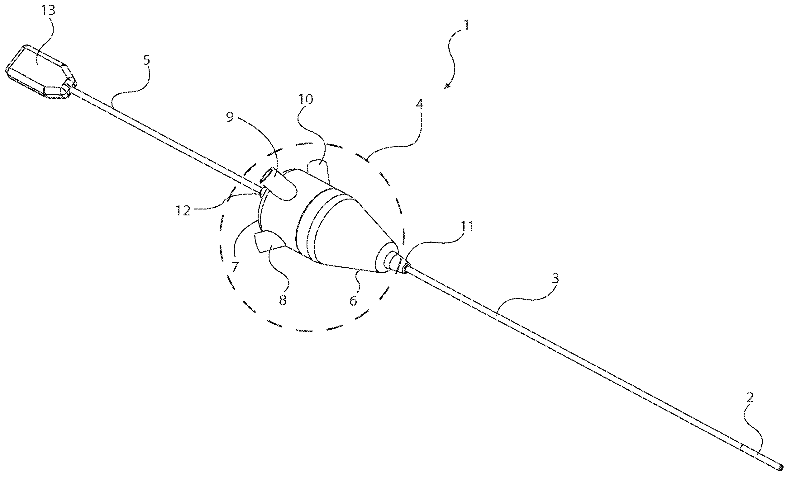
도 1은 이 출원에서 개요가 설명되는 원리에 따라 구성된 예시적인 내시경의 개략도이며;
도 2a는 도 1의 내시경의 확장되지 않은 구성에서 확장 가능한 팁의 사시도이며;
도 2b는 도 2a의 단면을 따라서 취해진 도 1의 확장 가능한 팁의 단면도이며;
도 2c는 비원형 카메라를 가진 내시경의 확장되지 않은 구성에서 확장 가능한 팁의 사시도이며;
도 3은 도 2a와 2b의 내시경의 외부 커버 피복 아래의 확장되지 않은 팁 구성요소들의 도면이며;
도 4는 도 1의 내시경의 확장된 구성에서 확장 가능한 팁의 도면이며;
도 5는 말단 허브 인클로저가 제거된 도 1의 결합 허브의 확대도이며;
도 6은 전체 인클로저가 제거된 도 1의 결합 허브 내부의 구성요소들의 도면이며,
도 7은 도 1의 결합 허브 내부의 인쇄회로 조립체(PCA: Printed Circuit Assembly) 기판의 도면이며,
도 8은 내시경 조명 시스템의 개략도이다.
제공된 도면들은 보여주기 위한 것이며, 이 기술은 도시된 특정한 구성에 제한되지 않는다. 서술된 기술은 도면들에 묘사되지 않은 것을 포함하는 다양한 다른 방식으로 수행될 수 있다. 본 발명의 도면들과 각도들은 기술의 속성을 명확하게 묘사하기 위해 항상 축척에 맞지는 않으며, 본 발명의 일반적인 양태들을 묘사하도록 의도되고, 서술된 기술의 폭, 범위 또는 적용 가능성을 제한하는 것으로서 고려되어는 안된다. 서술된 기술의 추가적인 특징들과 이점들은 아래의 바람직한 실시예들의 상세한 설명에서 제시되고 명확하게 될 것이다. To illustrate the technology being described and to clarify the above and other features and advantages of the technology, a more detailed description is set forth below with reference to specific embodiments shown in the accompanying schematic drawings. provided in . These drawings depict selected modes of the described technology and should not be considered limiting their scope. This technology will be described and explained in detail through the use of the drawings, in which like reference numbers indicate like parts.
1 is a schematic diagram of an exemplary endoscope constructed according to the principles outlined in this application;
Figure 2A is a perspective view of the expandable tip in an unexpanded configuration of the endoscope of Figure 1;
Figure 2b is a cross-sectional view of the expandable tip of Figure 1 taken along the cross-section of Figure 2a;
Figure 2C is a perspective view of the expandable tip in an unexpanded configuration of an endoscope with a non-circular camera;
Figure 3 is a view of the unexpanded tip components beneath the outer cover sheath of the endoscope of Figures 2A and 2B;
Figure 4 is a view of the expandable tip in an expanded configuration of the endoscope of Figure 1;
Figure 5 is an enlarged view of the mating hub of Figure 1 with the end hub enclosure removed;
Figure 6 is a view of the components inside the coupling hub of Figure 1 with the entire enclosure removed;
FIG. 7 is a diagram of a printed circuit assembly (PCA) board inside the coupling hub of FIG. 1;
Figure 8 is a schematic diagram of an endoscopic illumination system.
The drawings provided are for illustrative purposes only and the technology is not limited to the specific configuration shown. The described technique may be performed in a variety of different ways, including those not depicted in the drawings. The drawings and angles of the invention are not always to scale to clearly depict the nature of the technology and are intended to depict general aspects of the invention and should not be considered limiting the breadth, scope or applicability of the technology described. It shouldn't be. Additional features and advantages of the described technology will be presented and become apparent in the detailed description of the preferred embodiments below.
서술된 기술의 다양한 예시적인 양태들이 도면들에 도시되고 아래에서 논의되며, 이는 그 기술의 다양한 양태들과 예들의 제조와 사용을 가능하게 하기 위해 제공된다. 특정한 재료들, 기술들, 및 적용예들의 설명이 예로서 제공된다. 본 기술과 뒤따르는 청구항들의 범위는 도면들, 예들, 또는 아래의 논의들에 의해 제한되지 않는다. Various illustrative aspects of the described technology are shown in the drawings and discussed below, which are provided to enable the manufacture and use of various aspects and examples of the technology. Descriptions of specific materials, techniques, and applications are provided by way of example. The scope of the present technology and the claims that follow is not limited by the drawings, examples, or discussions below.
이 출원은 가변성 프로파일 팁을 가진 전자 내시경, 특히 단일-사용 또는 일회용의, 저비용의, 가변성 프로파일 작업 채널을 가진 전자 내시경을 제공한다. This application provides an electronic endoscope with a variable profile tip, in particular a single-use or disposable, low cost, electronic endoscope with a variable profile working channel.
하나의 내시경에서, 상기 전자 내시경은 환자의 신체 외부에 남아 있는 허브를 가진다. 상기 허브는 의사에 의해 상기 내시경을 조작하기 위해 사용된다. 신장된, 유연한 샤프트는 허브로부터 연장된다. 이것은 상기 내시경의 부분이며, 환자의 신체 내부로 삽입될 수 있다. 확장 가능한 팁(expandable tip)은 상기 허브로부터 가장 멀리 떨어진 상기 샤프트의 단부로부터 연장된다. 이것은 말단 팁(distal tip)이다. 확장 가능한 말단 팁은 센서들과 작업 채널(working channel)을 가지며, 상기 센서들은 의사가 환자의 신체 내부를 볼 수 있도록 허용하고, 상기 작업 채널은 의사가 인접 조직을 치료 또는 수술할 수 있도록 허용한다. 특히, 다른 센서들도 사용될 수 있지만, 상호 보완적인 금속 산화물 반도체(CMOS) 이미지 센서가 상기 말단 팁 내부에 배치되며, 내시경으로부터 외부의 시야(field of view)를 가진다. 상기 말단 팁 내부의 하나 이상의 조명 섬유들(illuminating fibers)은 상기 이미지 센서의 시야 내에 광을 방출한다. In one endoscope, the electronic endoscope has a hub that remains outside the patient's body. The hub is used by the doctor to manipulate the endoscope. An elongated, flexible shaft extends from the hub. This is part of the endoscope and can be inserted inside the patient's body. An expandable tip extends from the end of the shaft furthest from the hub. This is the distal tip. The expandable distal tip has sensors and a working channel that allows the doctor to see inside the patient's body, and the working channel allows the doctor to treat or operate on adjacent tissue. . In particular, a complementary metal oxide semiconductor (CMOS) image sensor is placed within the distal tip and has a field of view external to the endoscope, although other sensors may also be used. One or more illuminating fibers within the distal tip emit light within the field of view of the image sensor.
상기 말단 팁은 가변성 프로파일 작업 채널(variable profile working channel)을 가진다. 상기 작업 채널은 하나 이상의 도구들(예컨대, 삭마(ablation) 장치, 캐뉼라, 해부 기구, 전극, 겸자, 그라스퍼(grasper), 마디 푸셔(knot pusher), 레이저 섬유, 니들 홀더, 흡입 및 세척 기구, 투관침, 및 다른 도구들) 이 상기 허브로부터 이미지 센서들의 전방 시야까지 상기 내시경 내부를 통과할 수 있도록 한다. 상기 가변성 프로파일 작업 채널은, 상기 도구들이 이미지 센서의 옆으로 통과할 수 있도록 형상을 변경할 수 있다. 예를 들어, 상기 확장 가능한 작업 채널은 일반적인 비원형 단면 형상으로부터 도구들이 통과할 수 있는 상이하고 확대된 단면 형상으로 변할 수 있다. The distal tip has a variable profile working channel. The working channel may be equipped with one or more tools (e.g., ablation devices, cannulae, dissection instruments, electrodes, forceps, graspers, knot pushers, laser fibers, needle holders, suction and irrigation instruments, trocars, and other tools) can pass inside the endoscope from the hub to the front view of the image sensors. The variable profile working channel can change shape to allow the tools to pass next to the image sensor. For example, the expandable working channel may change from a general non-circular cross-sectional shape to a different, enlarged cross-sectional shape through which tools may pass.
다른 내시경은 광원을 동봉한 허브를 가진다. 의사는 내시경을 조작하기 위해 상기 허브를 사용한다. 삽입부는 허브로부터 연장된다. 상기 내시경의 (허브로부터 가장 먼) 말단 팁에서, 상기 삽입부는 확장 가능한 외부 피복(outer sheath)을 가진다. 광 전송(light transmission) 시스템은 광을 허브로부터 말단 팁을 넘어서 조명될 대상까지 전달한다. 이미지 센서는 상기 내시경의 말단 팁의 대략 중심에 배치된다. 상기 센서는 조명된 대상의 이미지를 획득한다. Other endoscopes have a hub that contains a light source. Doctors use the herb to manipulate the endoscope. The insertion portion extends from the hub. At the distal tip of the endoscope (farthest from the hub), the insertion portion has an expandable outer sheath. A light transmission system transmits light from the hub over the distal tip to the object to be illuminated. The image sensor is positioned approximately at the center of the distal tip of the endoscope. The sensor acquires an image of the illuminated object.
가변성 프로파일 작업 채널은 상기 허브로부터 내시경의 말단 팁까지 연장된다. 상기 작업 채널은 확장 가능한 외부 피복의 내부에 배치된다. 상기 작업 채널의 낮은-프로파일 형태(low-profile configuration)는 이미지 센서와 확장 가능한 외부 피복 사이에 형성된 공간 내부에 적합하다. 상기 작업 채널의 확대된-프로파일 형태는 도구들이 이미지 센서를 지나서 말단 팁의 밖으로 이동할 수 있게 한다. 상기 작업 채널이 확대된-프로파일의 형태일 때, 상기 확장 가능한 외부 피복은 말단부에서 전체적으로 비원형의 형상을 가진다. A variable profile working channel extends from the hub to the distal tip of the endoscope. The working channel is disposed inside an expandable outer sheath. The low-profile configuration of the working channel fits within the space formed between the image sensor and the expandable outer sheath. The extended-profile shape of the working channel allows tools to move past the image sensor and out of the distal tip. When the working channel is in the form of an expanded-profile, the expandable outer sheath has a generally non-circular shape at the distal end.
또 다른 내시경은 의사와 가장 가까운 근위 단부와, 반대쪽 단부에 말단부와, 상기 말단부에 시야를 가진다. 상기 허브는 근위 단부에 있다. 상기 내시경의 허브로부터 말단부를 향해 연장된 부분은 "삽입부"로 불릴 수 있다. 의사의 필요에 따라, 삽입부의 일부 또는 전체가 환자 내부로 삽입될 수 있다. 상기 허브는 환자의 외부에 남는다. Another endoscope has a proximal end closest to the surgeon, a distal end at the opposite end, and a field of view at the distal end. The hub is at the proximal end. The portion extending from the hub of the endoscope toward the distal end may be referred to as the “insertion portion.” Depending on the doctor's needs, part or all of the insertion portion may be inserted into the patient. The hub remains external to the patient.
확장 가능한 말단 팁은 상기 삽입부로부터 말단부까지 연장되며, 시야 내부의 이미지를 획득하도록 구성된 센서를 가진다. 작업 채널, 수세용 루멘(flushing lumen), 및 광 가이드(예컨대, 하나 이상의 광섬유)는 상기 삽입부 내부에서 허브로부터 말단부까지 연장된다. 상기 삽입부를 따른 일 지점에서, 상기 내시경은 단면을 가지며, 이 단면은 수세용 루멘, 광 가이드, 전체적으로 원형 단면의 작업 채널, 및 센서로부터 허브까지 연장된 케이블을 포함한다. An expandable distal tip extends from the insertion portion to the distal end and has a sensor configured to acquire an image within the field of view. A working channel, flushing lumen, and light guide (eg, one or more optical fibers) extend within the insert from the hub to the distal end. At a point along the insertion section, the endoscope has a cross-section comprising a flushing lumen, a light guide, a working channel of generally circular cross-section, and a cable extending from the sensor to the hub.
상기 말단부를 따른 다른 지점에서, 상기 내시경은 상이한 단면을 가진다. 그 상이한 단면은 이미지 센서, 작업 채널, 수세용 루멘, 및 광 가이드를 가진다. 상기 작업 채널과 수세용 루멘 둘 다 그들의 프로파일을 변경할 수 있으며, 서로 독립적으로 그렇게 할 수 있다. 각각은 전체적으로 비원형의, 낮은-프로파일의 형태를 취할 수 있다. 또한, 각각은 상기 작업 채널을 통과하는 도구를 수용하거나 또는 상기 수세용 루멘을 통과하는 액체를 수용하도록 확대된-프로파일을 취할 수 있다. At different points along the distal end, the endoscope has a different cross-section. The different cross-sections have an image sensor, a working channel, a flush lumen, and a light guide. Both the working channel and the flush lumen can change their profiles and do so independently of each other. Each may take a generally non-circular, low-profile shape. Additionally, each can have an enlarged-profile to accommodate tools passing through the working channel or liquid passing through the flushing lumen.
위에서 간략하게 서술된 내시경들 각각은 확장 가능한 말단 팁, 가변성 프로파일 작업 채널 및, 선택적으로, 확장 가능한 수세용 루멘을 가진다. 이 세 개의 구조물들을 만드는 재료들은 동일하거나 또는 상이할 수 있다. 생체적합성 탄성중합체 재료(biocompatible elastomeric material)(예컨대, 실리콘 고무, 열가소성 엘라스토머(TPE))가 세 개의 구조물들 모두를 만드는데 사용될 수 있다. TPEs는, 코폴리에스테르 엘라스토머(예컨대, DSM의 ARN1TEL®), 폴리에테르 블록 아미드(예컨대, Arkema의 PEBAX®), 폴리에테르 폴리에스테르 블록 공중합체(예컨대. 듀퐁사의 HYfREL®), 폴리올레핀 엘라스토머(예컨대, Dow Chemical의 ENGAGE®), 폴리우레탄 엘라스토머(예컨대, Dow Chemical의 PELLETHANE®), 스티렌 블록 공중합체(예컨대, AlphaGary의 EVOPRENE®), 스티렌-부타디엔 블록 공중합체(예컨대, BASF의 STYROFLEX®), 스티렌-에틸렌-부틸렌-스티렌 블록 공중합체(예컨대, Kraton Polymers의 KRATON®), 및 열가소성 가황물(예컨대, ExxonMobil의 SANTOPRENE®와 GEOLAST®)을 포함한다. Each of the endoscopes briefly described above has an expandable distal tip, a variable profile working channel, and, optionally, an expandable flush lumen. The materials that make these three structures may be the same or different. Biocompatible elastomeric materials (e.g., silicone rubber, thermoplastic elastomers (TPE)) can be used to make all three structures. TPEs include copolyester elastomers (e.g., ARN1TEL® from DSM), polyether block amides (e.g., PEBAX® from Arkema), polyether polyester block copolymers (e.g., HYfREL® from DuPont), and polyolefin elastomers (e.g., ENGAGE® from Dow Chemical), polyurethane elastomers (e.g. PELLETHANE® from Dow Chemical), styrene block copolymers (e.g. EVOPRENE® from AlphaGary), styrene-butadiene block copolymers (e.g. STYROFLEX® from BASF), styrene-butadiene block copolymers (e.g. STYROFLEX® from BASF) ethylene-butylene-styrene block copolymers (e.g., KRATON® from Kraton Polymers), and thermoplastic vulcanizates (e.g., SANTOPRENE® and GEOLAST® from ExxonMobil).
상기 작업 채널과 선택적인 수세용 루멘은 또한 낮은-프로파일의 형태로부터 확대된-프로파일의 형태로 변할 수 있는 비탄성중합체 재료(non-elastomeric material)(예컨대, 폴리(에틸렌-비닐 아세테이트)(PEVA), 폴리이미드, 폴리테트라플루오르에틸렌(PTPE), 또는 폴리비닐 클로라이드(PVC))로 만들어질 수도 있다. 비교적 단단한 도구들이 상기 작업 채널을 통과하며, 이는 더욱 내구성 있으며 강인한 폴리머 재료로부터 이득을 볼 수 있으나, 상기 말단 팁은 확대된 작업 채널 및/또는 확대된 수세용 루멘을 수용할 필요가 있다. The working channel and optional flush lumen can also be made of a non-elastomeric material (e.g., poly(ethylene-vinyl acetate) (PEVA), which can vary from a low-profile configuration to an extended-profile configuration. It may be made of polyimide, polytetrafluoroethylene (PTPE), or polyvinyl chloride (PVC). Relatively rigid tools pass through the working channel, which could benefit from more durable and tough polymer materials, but the distal tip needs to accommodate an enlarged working channel and/or an enlarged flushing lumen.
이제, 도 1을 참조하면, 내시경(1)은 확장 가능한 팁(2), 샤프트(3), 결합 허브(coupling hub)(4), 커넥터 조립체(5), 및 USB 커넥터(13)를 가진다. 도시된 상기 내시경(1)은 5cm 내지 200cm 사이의, 바람직하게는 10cm 내지 100cm 사이의, 가장 바람직하게는 12cm 내지 60cm 사이의 전체 작업 길이(샤프트(3)와 말단 팁(2)이 결합된 길이)를 가진다. 상기 작업 길이(working length)는, 상기 결합 허브(4)는 환자의 신체 외부에 유지하면서, 관련된 해부구조(anatomy)가 보일 수 있도록 상기 내시경(1)의 팁이 환자의 신체 내부에 위치할 수 있게 충분하여야 한다. Now, referring to Figure 1,
상기 샤프트(3)는 상기 말단 팁(2)으로부터 결합 허브(4)까지 연장된다. 상기 샤프트(3)는 상기 샤프트(3)의 길이 방향 축 둘레에 적용되는 토크(회전)를 전달한다. 상기 샤프트의 근위 단부에 적용된 토크는 샤프트(3)의 길이를 따라서 말단 팁(2)까지 전달된다. 일부 내시경에서, 상기 샤프트(3)는 유연하며 샤프트의 횡방향 축에 대해 비교적 작은 굽힘 반경(bend radius)으로 굽혀질 수 있다. 이는 의 료 절차 중에 상기 내시경이 해부학적 구조의 둘레로 조작될 수 있도록 한다. 그러나, 다른 적용예에서, 일부 또는 전체 샤프트(3)는 강성이거나 또는 반강성(semi-rigid)이다. The shaft (3) extends from the distal tip (2) to the coupling hub (4). The
상기 샤프트(3)는 적절한 강도 특성들을 가진 (예를 들어, 유연성과 인장 강도 및 압축 강도뿐만 아니라 근위 단부로부터 말단부로 적절한 토크 전달을 제공하는) 임의의 생체적합성 재료로 만들어질 수 있다. 상기 샤프트(3)를 만들 수 있는 재료는 생체적합성 폴리아미드, 폴리에스테르, 폴리에테르에테르케톤, 폴리에테르우레탄, 폴리이미드, 폴리테트라플로오르에틸렌, 및 폴리우레탄 에폭시를 포함한다. 추가적인 강도 또는 강성을 제공하기 위해, 보강 재료가 샤프트(3) 내에 통합될 수 있다. 이러한 보강 재료들은 구리 합금, 니켈 합금(예컨대, 니티놀(Nitinol)), 스테인리스 강, 및 폴리이미드와 같은 고탄성률(high modulus) 플라스틱을 포함한다. The
상기 결합 허브(4)는, 도구들, 수세용 유체, 스타일릿(stylet), 및 선택적인 전자 장치를 위한 하나 이상의 커넥터들(8, 9, 10)을 포함한다. 상기 결합 허브(4)는 이러한 부품들을 수용하는 크기와 형상을 가진다. 상기 결합 허브(4) 내부의 전자 장치는 내시경을 작동하기 위한 회로를 가진 PCA와 카메라 신호 전송 시스템을 포함하며, 이들은 이하에서 논의된다. The
대안으로서, 상기 PCA는 상기 내시경 외부의 외부 제어 회로에의 상호연결부로서 기능할 수 있다. 만약 상기 허브(4) 내부에 전자 장치가 없거나 바람직하지 않다면, 상기 허브(4)는 상당히 작아질 수 있으며 다른 튜브들, 와이어들, 및 광섬유들 사이의 연결 조인트로서 역할을 할 수 있다. Alternatively, the PCA may function as an interconnect to external control circuitry external to the endoscope. If electronics are not present or desirable inside the
상기 허브(4)는 생체적합성 재료, 예를 들어 폴리카보네이트, 아크릴, 아크릴로니트릴 부타디엔 스티렌(ABS), 캐스트 에폭시, 및 열경화성 플라스틱으로 만들어진다. 일부 등급의 스테인리스 강 또는 티타늄과 같은 생체적합성 재료를 사용하는 성형 금속 하우징도 가능하다. The
상기 결합 허브(4)는 말단 부분(18)과 근위 부분(19)을 가진다. 상기 결합 허브(4)는 하나 이상의 포트들(ports) 또는 커넥터들(8, 9, 10)과 변형 완화 피처들(strain relief features)(11, 12)을 포함한다. 이 커넥터들(8, 9, 10)은, 결합 허브(4)와 커넥터들(8, 9, 10) 사이에 유밀 밀봉(fluid tight seal)을 제공하는 밀봉재들(seals)(예컨대, LUER-LOK® lock component)을 포함한다. The
상기 커넥터들(8, 9, 10)은 결합 허브(4)에 단단하게 부착되고, 의사가 상기 내시경의 말단 팁(2)에서 사용될 수 있는 도구들과 유체들을 허브(4)에 도입할 수 있도록 한다. 이는 접착, 가열-용접, 열경화성 플라스틱 또는 에폭시로 포팅(potting), RF 용접, 나사 체결로 나사 결합, 용제 본딩(solvent bonding), 초음파 용접, 또는 이 공정들의 조합에 의해 성취될 수 있다. 세 개의 커넥터들(8, 9, 10) 중 어느 하나 또는 모두 상기 허브(4)로 들어가는 유연한 튜브에 부착될 수 있다. The connectors (8, 9, 10) are rigidly attached to the coupling hub (4) and allow the surgeon to introduce instruments and fluids that can be used at the distal tip (2) of the endoscope into the hub (4). do. This can be accomplished by gluing, heat-welding, potting with thermoset plastic or epoxy, RF welding, screwing together with screw fastening, solvent bonding, ultrasonic welding, or a combination of these processes. Any or all of the three connectors (8, 9, 10) can be attached to a flexible tube that enters the hub (4).
수세용 채널 커넥터(flushing channel connector)(8)는 유체가 허브(4)에 도입될 수 있도록 하며, 유체는 상기 수세용 루멘(24)을 통해 이동할 수 있다. 스타일릿 채널 커넥터(stylet channel connector)(9)는 스타일릿(미도시)이 허브(4)에 삽입될 수 있도록 하고 스타일릿 채널(27) 내부로 삽입될 수 있도록 한다. 상기 스타일릿은 내시경의 유연한 샤프트(3)의 형상에 영향을 주기 위한 것이다. 예를 들어, 300-계열의 스테인리스 강과 같은 재료로 만들어지며 연성이고(malleable) 탄력이 있는(resilient) 와이어는 원하는 곡률 또는 각도로 굽혀질 수 있으며, 유연한 내시경이 이러한 곡률 또는 각도에 맞춰지도록 하는 상기 스타일릿 채널을 통해 삽입될 수 있다. 상기 작업 채널 커넥터(10)는, 도구들이 허브(4)로부터 샤프트(3) 내부의 작업 채널(28)을 통해 말단 팁(2) 내부의 작업 채널 부분(23)에 이르기까지 통과할 수 있도록 한다. A flushing channel connector (8) allows fluid to be introduced into the hub (4), and fluid can travel through the flushing lumen (24). A stylet channel connector (9) allows a stylet (not shown) to be inserted into the hub (4) and into the stylet channel (27). The stylet is intended to influence the shape of the
도시된 내시경이 단일의 가변성 프로파일 작업 채널을 가진다 할지라도, 하나보다 많은 작업 채널이 포함될 수 있다는 것이 고려될 수 있다. 다수의 작업 채널들이 채용된 때, 그들은 동일한 크기 또는 상이한 크기들일 수 있다. 상기 작업 채널들의 일부 또는 모두는 가변성 프로파일 특징을 가질 수 있다. 예를 들어, 5mm 내시경은 두 개의 1.2mm 작업 채널들을 가질 수 있으며, 이들 둘 다 가변성 프로파일 특징을 가진다. Although the endoscope shown has a single variable profile working channel, it is contemplated that more than one working channel may be included. When multiple working channels are employed, they may be the same size or different sizes. Some or all of the working channels may have variable profile characteristics. For example, a 5 mm endoscope may have two 1.2 mm working channels, both of which have variable profile characteristics.
유사하게, 도 1은 각각 수세용 루멘, 스타일릿(stylet), 및 작업 채널을 위한 세 개의 커넥터들(8, 9, 10)을 보여준다. 하나의 커넥터만 사용하는 것이 고려될 수 있으며, 또는 특정한 내시경의 수세용 루멘, 스타일릿, 및 작업 채널 특징들 위해 필요한 만큼 많은 커넥터들이 사용될 수 있다. 예를 들어, 두 개의 작업 채널들, 스타일릿, 수세용 루멘을 가진 내시경은 네 개의 별개의 커넥터들을 가질 수 있다.Similarly, Figure 1 shows three
전기 케이블(5)과 USB 커넥터(13)은 결합 허브(4) 내부의 회로와 외부 장치들 사이의 인터페이스를 제공한다. 도 1에서, 단일의 케이블(5)이 결합 허브(4)로부터 USB 커넥터(13)까지 연장된다. 이 케이블(5)은 결합 허브(4) 내부의 광원에 전력을 공급하기 위한 전도체들(conductors)를 가지며, 카메라(22)에 의해 출력된 신호들을 USB 커넥터(13)로 전송하기 위한 접점들(contacts)을 가진다. 다수의 케이블들이, 예를 들어, 결합 허브(4) 내의 발광 다이오드(LED) 광원에 전력을 전도하는 제1 케이블(5)과, 카메라(22)로부터 수신한 신호들을 전송하는 별개의 제2 케이블(미도시)과 함께 사용될 수 있다. The electrical cable (5) and USB connector (13) provide an interface between the circuitry inside the coupling hub (4) and external devices. In Figure 1, a
상기 USB 커넥터(13)는 외부의 제어/디스플레이 장치들에 연결되거나 또는 USB 신호들을 외부의 제어 또는 디스플레이 장치들에 의해 사용되는 신호들로 변환하는 전자 인터페이스 박스 내로 연결된다. 상기 USB 커넥터(13)도 상기 전자 내시경을 위해 전력을 제공한다. 비록 USB 커넥터가 도 1에 도시되어 있더라도, 다른 유선 연결들(예컨대, HDMI)과 무선 연결들(예컨대, 블루투스, 와이파이)도 아래에서 논의되는 바와 같이 가능하다. The
상기 결합 허브(4)는 사용 중에 굽힘력(bending force)을 포함하는 다양한 힘들을 받는다. 변형 완화 피처들(11, 12)은 이러한 힘들로부터 허브(4)와 그 구성요소들을 보호한다. 예를 들어, 도 1은 말단 변형 완화 피처(11)와 근위 변형 완화 피처(12)를 보여준다. 변형 완화 피처들(11, 12)은 다양한 재료로 만들어질 수 있다. 이 재료들은 비교적 단단한 사출 성형 열가소성 수지(예컨대, 아크릴로니트릴 부타디엔 스티렌(ABS)), 또는 이전에 정의된 TPEs와 같은 더 유연한 재료들을 포함한다. TPE가 사용될 때, 확장 가능한 팁 성분보다 더 높은 경도값을 가지는 것이 바람직하다. The
도 2a와 2b는 내시경(1)의 말단부를 사시도와 단면도로 보여준다. 도 2a에서, 상기 확장 가능한 팁(2)은 확장 가능한 외부 커버(21)를 가진다. 말단부에서, 상기 확장 가능한 팁(2) 내부의 구성이 도시되며, 가변성 프로파일 작업 채널(23), 확장 가능한 수세용 채널(24), 세 개의 조명 섬유들(25), 및 카메라(22)를 포함한다. 상기 말단 팁(2)은 상기 카메라(22)를 수용하기에 충분한 길이를 가진다. 예를 들어, 상기 말단 팁(2)은 샤프트(3)의 단부로부터 내시경의 가장 말단까지 3mm 내지 50mm 사이의, 바람직하게는 7mm 내지 15mm 사이의, 가장 바람직하게는 8mm 내지 10mm 사이의 길이를 가진다. Figures 2a and 2b show the distal end of the
상기 말단 팁(2)은 확대 및 수축될 수 있다. 낮은-프로파일(low-profile) 상태에서, 상기 말단 팁(2)은, 대략 1.5mm 내지 20mm 사이의, 바람직하게는 1.5mm 내지 5mm 사이의, 가장 바람직하게는 대략 1.5mm 내지 대략 2.0mm 사이의 외경을 가진 감소된 단면적을 가진다. 확대된-프로파일(enlarged-profile) 또는 확장된 상태에서, 상기 말단 팁(2)은 상기 작업 채널을 통한 하나 이상의 도구들의 통과를 수용하게 될 확대된 단면적을 가진다. 예를 들어, 확대된-프로파일은, 1.8mm 내지 20mm 사이의, 바람직하게는 2mm 내지 5mm 사이의, 가장 바람직하게는 1mm 내지 2mm 사이의 직경을 가진 원형의 단면 형상을 가진 도구의 통과를 수용한다. 상기 프로파일의 변화는 도구들이 카메라(22)를 지나서 최종적으로 내시경의 말단 팁을 빠져나갈 수 있도록 한다. The distal tip 2 can be enlarged and retracted. In the low-profile condition, the distal tip 2 has a length of between approximately 1.5 mm and 20 mm, preferably between approximately 1.5 mm and 5 mm, most preferably between approximately 1.5 mm and approximately 2.0 mm. It has a reduced cross-sectional area with an outer diameter. In the enlarged-profile or extended state, the distal tip 2 has an enlarged cross-sectional area that will accommodate the passage of one or more tools through the working channel. For example, the enlarged-profile accommodates the passage of a tool with a circular cross-sectional shape with a diameter between 1.8 mm and 20 mm, preferably between 2 mm and 5 mm, and most preferably between 1 mm and 2 mm. . The change in profile allows the tools to pass through the
상기 조명 섬유들(25)은 세 개의 유연한 섬유-광-가이드들로서 묘사된다. 이 섬유들(25)은 시야(field of view)를 조명하기 위한 광을 결합 허브(4) 내의 광원으로부터 내시경의 말단 팁(2)까지 나른다. 비록, 도 2a에 세 개의 섬유들(25)이 도시되어 있지만, 하나의 섬유만 사용될 수 있으며, 또는 카메라(22)를 위해 충분한 광을 제공하기 위해 허용되는 공간 내부에 맞는 만큼의 많은 섬유들이 사용될 수 있다. 조명 섬유들(25)은 유리, PMMA 또는 다른 광 전송 재료들(light transmitting materials)로 만들어질 수 있다. 낮은-프로파일 형태에서 말단 팁(2)의 단면적 내에 맞고 충분한 조명 강도를 제공하는 한, 상이한 크기의 섬유들(25)의 조합이 사용될 수 있다. The
상기 카메라(22)와 조명 섬유들(25)은 촬상될 영역이 충분히 조명되도록 배치된다. 도시된 형태에서, 상기 카메라(22)는 말단 팁(2)의 대략 중심에 있을 수 있으며, 작업 채널(23), 수세용 루멘(24) 및 조명 섬유들(25)은 원주 둘레에 각을 이루어 분포된다(예를 들어, 작업 채널(23)은 수세용 루멘으로부터 대략 120°로 그리고 조명 섬유들(25)로부터 동일한 정도로 떨어져 있다). 그러나, 작업 채널(23)과 수세용 채널(24)은 서로에 대하여 그리고 카메라(22) 또는 조명 섬유들(25)에 대하여 다양한 배치들이 가능하다. The
상기 외부 커버(21), 작업 채널(23), 및 수세용 채널(24)은 살균 가능한 폴리머 재료로 만들어진다. 적어도 확장 가능한 팁 부분 내부에서, 이러한 구조물들은 형상이 변하거나 또는 확장될 수 있도록 구성된다. 이러한 구조물들 각각은 동일한 재료로 만들어지거나, 또는 상이한 재료들로 만들어질 수 있다. 예를 들어, 각각은 생체적합성 탄성중합체 튜브(biocompatible elastomeric tubing)(예컨대, 라텍스 고무, 실리콘 고무, 또는 다양한 USP 클래스 6 호환 TPEs)로 구성될 수 있다. 예시적인 TPEs는 위에서 언급되었다. The
일회용 내시경에서, 원래 제조자에 의한 살균은 (예를 들어, 에틸렌 옥사이드 가스, 감마선, 증기를 사용하여) 대규모로 수행될 수 있다. 일회용 장치는 서로에 대해 접하는 배관 연결(tubing connection)을 사용할 수 있지만, 접합부(joint)에 작은 크랙, 갭(gap), 또는 보이드(void)를 허용한다. 대규모 살균을 위해 적합한 재료는, 예컨대 에틸렌 옥사이드 가스는, 재료가 글루타르알데히드와 같은 살균 화학물질에 대한 다중 노출에 양립 가능하여야 한다는 염려 없이, 내시경을 제조하는 데에도 사용될 수 있다. In disposable endoscopes, sterilization by the original manufacturer can be performed on a large scale (e.g., using ethylene oxide gas, gamma rays, steam). Disposable devices may use tubing connections that are abutting to each other, but allow for small cracks, gaps, or voids in the joints. Materials suitable for large-scale sterilization, such as ethylene oxide gas, can also be used to manufacture endoscopes without concern that the materials must be compatible with multiple exposures to sterilizing chemicals such as glutaraldehyde.
상기 내시경의 외측에 코팅(미도시)이 적용될 수 있다. 예를 들어, 이러한 코팅(예컨대, 구리 이온들, 은 이온들)은 항박테리아 또는 항균 성질을 제공할 수 있다. 코팅은 또한 의사가 특정한 상태를 검출할 수 있도록 하기 위해 사용될 수 있다. 예를 들어, 박테리아 오염 또는 다른 종류의 생물지표의 존재를 검출하는 특별한 펩타이드(peptide)와 다른 제제(formulations)가 적용될 수 있다. A coating (not shown) may be applied to the outside of the endoscope. For example, such coatings (eg, copper ions, silver ions) may provide antibacterial or antibacterial properties. Coatings can also be used to help doctors detect specific conditions. For example, special peptides and other formulations may be applied to detect the presence of bacterial contamination or other types of biomarkers.
내시경의 말단 팁을 밀봉하기 위해, UV-경화형 접착제 포팅 화합물(potting compound) 화합물이 말단 팁에 적용되어 점성이 있는 동안 구성요소들 사이에서 흐른다. 과잉의 포팅 화합물은 제거되며 UV 광이 적용되어 재료를 양생 또는 경화한다. 2액형 에폭시와 같은 다른 재료들도 사용될 수 있다. 포팅 화합물의 적용은 (예를 들어, 화합물의 분포 영역을 제한하는 기구에 의해) 확장 가능한 말단 팁 부분과 간섭되지 않는 영역으로 제한될 수 있으며, 및/또는 확장 가능한 부분들에 접합되지 않는 재료들을 사용한다. To seal the distal tip of the endoscope, a UV-curable adhesive potting compound is applied to the distal tip and becomes viscous while flowing between the components. Excess potting compound is removed and UV light is applied to cure or harden the material. Other materials such as two-part epoxies may also be used. Application of the potting compound may be limited to an area that does not interfere with the expandable distal tip portion (e.g., by a mechanism that limits the distribution area of the compound), and/or may contain materials that do not bond to the expandable portions. use.
상기 작업 채널(23)은 낮은-프로파일형태를 가진다. 예를 들어, 2mm 내시경의 낮은-프로파일 작업 채널(23)은 샤프트(3) 내부에서 0.5mm 직경을 가질 수 있으며, 그 다음에 말단 팁(2) 내부에서 확장 가능한 외부 커버(21)와 카메라(22) 사이의 공간에 맞도록 더욱 콤팩트한 형태를 취한다. 도 2a에서, 낮은-프로파일 작업 채널(23)은 전체적으로 초승달 모양의 단면 형상을 가진다. 초승달 모양의 단면 형상의 단부는 (도 2a에서와 같이) 둥글거나, 또는 보다 뾰족하게 굽혀질 수 있다. 원형, 콩팥 모양, 장타원형, 타원형, 등을 포함하는 다른 형상들도 가능하다. The working
상기 작업 채널(23)은 또한 도구들이 카메라(22)를 지나갈 수 있도록 확대된-프로파일 형태를 가진다. 예를 들어, 2mm 내시경의 확대된-프로파일 작업 채널(23)은 대략 1.2mm의 외경을 가진 도구들이 통과할 수 있도록 충분히 크다. The working
상기 카메라(22)는 CMOS 컬러 카메라이며, 이는 생체적합성이고 방수된다. 바람직하게는, 상기 카메라는 내시경으로부터 외부의 시야를 제공한다. 전방 시야는 내시경의 말단 팁을 넘어서 보인다. 그러나, 시야는 내시경으로부터 외부에서 비스듬할 수도 있다(예를 들어, 예를 들어 30°의 취출각(off-angle)으로 보는 내시경). 상기 CMOS 이미지 센서는 다중-요소 렌즈 조립체 또는 30~180°, 바람직하게는 50~130°, 가장 바람직하게는 60~120°의 시야를 제공하는 경사 굴절률(GRIN: gradient refractive index) 렌즈를 포함한다. The
효과적인 이미지 해상도는 바람직하게는 적어도 10,000 픽셀, 보다 바람직하게는 적어도 40,000 픽셀, 가장 바람직하게는 적어도 60,000 픽셀이며, 1메가 픽셀 또는 그 이상도 가능하다. 다른 센서들도 충분한 이미지 해상도를 제공하는 한, CMOS 소자 대신에 또는 CMOS 소와 함께 사용될 수 있다. 예를 들어, 전하-결합 소자(CCD: charge-coupled device)가 사용될 수 있다. The effective image resolution is preferably at least 10,000 pixels, more preferably at least 40,000 pixels, and most preferably at least 60,000 pixels, although 1 megapixel or more is also possible. Other sensors can be used instead of or in conjunction with CMOS devices as long as they provide sufficient image resolution. For example, a charge-coupled device (CCD) may be used.
선택적으로, 광 프리즘이 추가될 수 있다. 이미지 센서의 특정한 각도의 뷰를 수정하기 위해 추가될 수 있다. 상기 프리즘은 이미지 센서의 뷰잉 콘(viewing cone)을 미리 결정된 양, 예컨대 30°, 70°, 등으로 기울어지게 하는 반사 표면을 가진다. 상기 프리즘은 유리 또는 임의의 투명한 폴리머, 예컨대 아크릴 또는 폴리카보네이트로 만들어질 수 있다. 상기 프리즘은 광학적으로 투명한 에폭시를 사용하여 카메라의 편평한 말단 표면에 접합될 수 있다. 보다 바람직하게는, 상기 장치의 원래 제조에서 상기 프리즘은 최종 카메라 렌즈를 대체할 수 있다. Optionally, an optical prism may be added. It can be added to modify the view from a specific angle of the image sensor. The prism has a reflective surface that tilts the viewing cone of the image sensor by a predetermined amount, such as 30°, 70°, etc. The prism may be made of glass or any transparent polymer, such as acrylic or polycarbonate. The prism can be bonded to the flat end surface of the camera using optically clear epoxy. More preferably, the prism may replace the final camera lens in the original manufacture of the device.
카메라 센서는 내시경의 구조물에 더 부착될 수 있다. 상기 카메라 센서는 추가적인 지지를 제공하기 위해 광 가이드에 직접 부착될 수 있다. 카메라 케이블은 피복 커버, 작업 채널, 또는 둘 다에 부착될 수 있다. 예를 들어, 상기 카메라 케이블은 확장 가능한 말단 팁 부분에 근접하여 피복 커버의 내측에 접합될 수 있다. 이러한 추가적인 연결은 추가적인 단단함을 제공한다. The camera sensor may be further attached to the structure of the endoscope. The camera sensor can be attached directly to the light guide to provide additional support. The camera cable may be attached to the sheath cover, the working channel, or both. For example, the camera cable may be bonded to the inside of the sheath cover proximate the extendable distal tip portion. This additional connection provides additional rigidity.
도 2b의 단면도는 도 2a의 A-A 단면을 따른 것이며, 신장된 샤프트(3)를 관통한다. 유연하고, 편조된(braided) 피복 커버(26)는 스테인리스 강 보강 폴리이미드 재료로 만들어지지만, 다른 재료들도 사용될 수 있다. The cross-section in Figure 2b is along the line A-A in Figure 2a and passes through the
상기 편조된 피복 커버(26)는 다섯 개의 구조물들을 포함한다. 이 단면 내의 상기 작업 채널은 전체적으로 원형의 단면 형상을 가진 유연한 튜브이다. 상기 작업 채널(28)은 도 1과 2a에 도시된 가변성 프로파일 작업 채널(23)에 부착될 수 있는 살균 가능한 폴리머 재료로 구성될 수 있거나, 또는 작업 채널(28)과 가변성 프로파일 작업 채널(23)은 동일한 튜브로 만들어질 수 있다. 상기 작업 채널(28)의 재료는 가변성 프로파일 작업 채널 부분(23)과 동일한 재료이거나, 또는 상이한 재료로 만들어질 수 있다. 예를 들어, 상기 샤프트(3) 내부의 작업 채널은 비탄성중합체 폴리머 재료(예를 들어, 폴리(에틸렌-비닐 아세테이트)(PEVA), 폴리이미드, 폴리테트라플로오르에틸렌(PTPE), 폴리비닐 클로라이드(PVC)) 또는 생체적합성 탄성중합체 튜브(예를 들어, 라텍스 고무, 실리콘 고무, 또는 다양한 USP 클래스 6 호환 TPEs)로 만들어질 수 있다. The
수세용 유체(flushing fluid)는 상기 수세용 채널(24)을 통과한다. 상기 수세용 채널(24)은 충분한 유체가 통과할 수 있는 한 샤프트(3) 내부에서 임의의 단면 형상을 가질 수 있다. 도 3에 도시된 상기 수세용 채널(24)은 단일 길이의 탄성중합체 튜브로 만들어진다. 대안으로서, 샤프트(3) 내부의 수세용 채널(24)의 근위 부분은 비탄성중합체 재료(예컨대, 폴리이미드 튜브)로 만들어질 수 있으며, 탄성중합체 팁 부분에 결합된다. 상기 수세용 채널(24)을 위해 적합한 탄성중합체 재료는 위에서 확인되었다. Flushing fluid passes through the flushing
스타일릿 채널(stylet channel)(27)은 스타일릿(미도시)을 내시경 내부로 도입할 수 있도록 하며, 상기 스타일릿은 일반적으로 금속으로 만들어진 가느다란 프로브(probe)이다. 상기 스타일릿이 도입된 때, 추가적인 강성을 제공한다. 이는 환자의 내부에 내시경의 말단 팁의 적절한 위치 설정을 용이하게 할 수 있다. 추가적으로, 상기 스타일릿은 내시경에 특정한 형상(예를 들어, 특정한 만곡 또는 굽힘)을 줄 수 있다. 상기 스타일릿 채널(27)은 스타일릿의 팁에 의한 구멍 뚫림에 저항하여야 한다. 보강은 선택적이다. 이 스타일릿 채널(27)은 PEVA, 폴리이미드, PTPE, 또는 PVC와 같은 다양한 폴리머 튜브 재료로 만들어진다. 상기 스타일릿 채널(27)이 원형의 프로파일을 가진 것으로 도시되어 있지만, 스타일릿의 통과를 허용하는 임의의 프로파일을 가질 수 있다. A
또한, 카메라 케이블(29)은 (도 2a에 도시된) 카메라(22)로부터 (도 1에 도시된) 결합 허브(4)까지 연장된다. 상기 카메라 케이블은 단순한 신호 전송 와이어(예컨대, 대략 0.52 mm의 직경을 가진 24 AWG 구리 와이어)이거나, 또는 몇몇의 절연된 도체들을 가진 리본 케이블일 수 있다. 예시적인 도체 성분은, 구리, 구리 합금, MP35N, DFT, 백금, 백금/이리듐, 텅스텐, 금, 및 스테인리스 강을 포함한다. 상기 도체는 베어(bare), 주석 도금, 은-도금, 또는 금-도금될 수 있다. 플루오르화 에틸렌 프로필렌(PEP), 과불화알콕시(PFA), 및 폴리테트라플루오르에틸렌(PTPE)를 포함하는 다양한 절연 재료들이 사용될 수 있다. 예를 들어, 상기 리본 케이블은 네 개의 도체들로 구성될 수 있으며, 이들은 (1) 접지(ground), (2) 시리얼 데이터 라인, (3) 시리얼 클락 라인, 및 (4) 전력 라인이다(예를 들어, 41 AWG 은도금 구리 도체를 사용).Additionally, the
도 2c는 비원형 카메라(22)를 가진 또 다른 내시경의 말단부를 보여주며, 카메라는 내시경의 중심으로부터 반경 방향으로 오프셋 되어 있다. 상기 말단 팁(2) 내부의 작업 채널(23)과 수세용 루멘(24)은 카메라(22)와 탄성중합체 팁 커버(21)에 인접하다. Figure 2c shows the distal end of another endoscope with a
도 3은 내부 구조물들이 보일 수 있도록 하기 위해, 도 2a의 내시경을 외부 커버들(21, 26) 없이 보여준다. 결합 슬리브(coupling sleeve)(31)는 탄성중합체 팁 커버(21)와 유연한 편조된 피복(26)을 결합하는 얇은 벽의 원통형 재료이다. 도 3에 묘사된 결합 슬리브(31)는 폴리이미드, 스테인리스 강, 폴리우레탄 또는 다른 얇은 벽의 튜브로 만들어질 수 있다. 이 결합 슬리브(31)는 편조된 유연한 피복(26)과 탄성중합체의 확장 가능한 팁 커버(21)의 내측 표면들에 접합된다. 결합은 접착제 접합, 가열 용접, 기계적 링-클램핑 또는 용제 접합, 또는 이 구성요소들을 튼튼하게 접합하기 위한 다른 방법들에 의해 수행될 수 있다. Figure 3 shows the endoscope of Figure 2a without the outer covers 21, 26 so that the internal structures can be seen. The coupling sleeve (31) is a thin-walled cylindrical material that joins the elastomeric tip cover (21) and the flexible braided sheath (26). The
상기 스타일릿 채널(27)은, 다른 작업 채널들을 위해 미리 설명된 것과 유사하게, 폴리이미드, PTPE, 또는 다른 튜브와 같은 얇은-벽의 튜브이며, 그것의 말단 팁에 내구성 있는 스탑(stop)(33)을 가지며, 상기 스탑(33)은, 예를 들어, 아크릴, ABS, 또는 스타일릿 채널에 접합될 수 있거나 또는 기계적으로 고정될 수 있는 자른 재료와 같은 단단한 플라스틱의 플러그(plug)이며, 스타일릿이 다른 구성요소들을 구멍 뚫거나 손상시키는 것을 방지하기 위한 것이다. 만약 스타일릿의 팁이 둥글면, 상기 튜브는 스탑을 생성하기 위해 단부에 걸쳐서 주름지거나 접힐 수 있다. 이는 단단한 플라스틱 플러그에 추가되거나 단단한 플라스틱 플러그를 대체할 수 있다. The
선택적인 전향 램프(deflector ramp)(34)가 도 3에 도시되어 있다. 상기 전향 램프는, 카메라의 근위 가장자리 둘레로 그리고 작업 채널의 말단 팁의 확장 영역 내부로 도구의 말단 팁을 안내하기 위해, 각이 진 비교적 단단한 표면을 제공한다. 전향 램프는 아크릴 또는 ABS와 같은 단단한 플라스틱 또는 스탬핑된 얇은 스테인리스 강의 금속 조각으로 만들어질 수 있으며, 작업 채널 샤프트의 외경에 맞추기 위해 만곡될 수 있다. 도 2a와 2b에 관련하여 위에서 서술된 바와 같이, 상기 작업 채널은, 상기 샤프트(3) 내부에서 전체적으로 원형의 단면(28)을 가지며, 말단 팁(2) 내부에서 가변성 프로파일 부분(23)을 가진다. 도구가 상기 작업 채널 샤프트(28)의 원형 단면을 통과하여 가변성 프로파일 작업 채널(23)로 들어갈 때, 카메라(22)의 둘레로 이동하며 내시경의 말단 팁을 빠져나간다. 상기 램프(34)는 내시경에 고정된다. 예를 들어, 상기 램프는, 카메라(22)의 근위 표면에, 확장 가능한 작업 채널(23)에, 피복 커버(26)에, 또는 이 구조물들의 조합들에 부착될 수 있다. 이를 위해, UV-경화형 에폭시 또는 다른 접착제가 사용될 수 있다. 상기 램프(34)는 내시경의 길이 방향 축에 대해 각도를 형성하며, 상기 각도는 대략 30°에서 대략 60°의 범위, 바람직하게는, 40° 내지 50° 사이의 범위, 가장 바람직하게는 대략 45°일 수 있다. 말단 팁에서 내시경의 전체 외경에 대한 램프(34)의 길이의 비율은 대략 1:2보다 작으며, 바람직하게는 대략 1:3보다 작고, 가장 바람직하게는 대략 1:5보다 작다. An
원형 단면의 작업 채널 샤프트(28)와 확장 가능한 작업 채널(23)이 상이한 재료들로 만들어지거나 또는 함께 부착되는 튜브의 상이한 부분들로 만들어질 때, 결합 슬리브(35)가 사용될 수 있다. 단일의 튜브를 사용하여 만들어지는 경우, 결합 슬리브(35)는 제외될 수 있다. 외부 피복 결합 슬리브(31)(이는 확장 가능한 팁 커버(21)의 외부 커버의 내부에 맞춰진다) 및 유연하고 편조된 피복 커버(26)(이는 내시경이 균일한 외경을 유지할 수 있도록 한다)와 달리, 작업 채널 결합 슬리브(35)는, 도구의 삽입과 제거를 위한 일정한 내경을 보존하기 위해, 원형 단면의 작업 채널 샤프트(28)와 확장 가능한 작업 채널(23) 사이의 결합부의 외측에 맞춰진다. 상기 결합 슬리브(35)는 얇은-벽의 폴리머 튜브의 짧은 조각(예를 들어, Putnam Plastics 또는 Vention Medical로부터 얻을 수 있는, 0.0254mm 벽 두께의 폴리이미드 튜브의 4~5mm)일 수 있다. When the working
상기 가변성 프로파일 말단 팁은, 낮은-프로파일 형태에 있는 동안 의사가 최소의 침습 또는 구멍 크기(예를 들어, 12 gauge 바늘)를 통해 내시경을 삽입할 수 있도록 한다. 내시경이 치료될 영역에 있을 때, 팁 부분은 확대된다. 도 4는 확대된-프로파일 형태의 말단 팁(2)을 도시한다. The variable profile distal tip allows the physician to insert the endoscope through minimal invasiveness or pore size (eg, a 12 gauge needle) while in a low-profile configuration. When the endoscope is in the area to be treated, the tip portion is enlarged. Figure 4 shows the distal tip 2 in enlarged-profile form.
이러한 형태는, 예를 들어, 완전한 Lo mm 직경의 공구를 작업 채널 팁(23)을 통과시킴으로써 및/또는 말단 팁(2) 에서 수세용 채널(24)을 확장시키기에 충분한 속도로 수세용 유체(살균한 물 내에 0.9% 염분)를 수세용 채널(24)을 통과시킴으로써 성취된다. This configuration can be achieved, for example, by passing a tool of full Lo mm diameter through the working
도 5와 6은 결합 허브(4)의 상세도를 보여준다. 도 5에서, 말단 인클로저 부분(6)이 제거되어 있다. 수세용 채널 튜브(51)는 수세용 채널 커넥터(8)에 부착된다. 스타일릿 채널 튜브(52)는 스타일릿 채널 커넥터(9)에 부착된다. 작업 채널 샤프트(53)는 작업 채널 커넥터(10)에 부착된다. 튜브들(51, 52, 53)은 근위 단부들에서 커넥터들(예를 들어, 루어(Luer) 또는 루어 록(Luer lock) 커넥터들)에 부착된다. 이러한 연결을 위해 용제 접합(solventing bonding), 접착제 접합, 또는 압입 끼워맞춤(press fit)이 사용될 수 있다. Figures 5 and 6 show details of the
도 6에서, PCA(61), 카메라 케이블(29)의 근위 단부, 및 조명 섬유들(25)의 근위 단부를 드러내기 위해 근위 허브 인클로저(proximal hub enclosure)(7)가 제거되었다. In Figure 6, the proximal hub enclosure (7) has been removed to expose the PCA (61), the proximal end of the camera cable (29), and the proximal end of the lighting fibers (25).
도 7은 PCA(61)의 확대도이다. 카메라 케이블(29)은 커넥터(72)를 통해 PCA(61)에 연결된다. LED(71)는, 조명 섬유들(25)의 근위 단부들이 LED(71)의 발광 표면 영역에 맞닿게 놓이도록 LED가 표면-실장된 칩이다. 그러나, 선택된 특정한 조명이 카메라 또는 센서에 의해 픽업될 수 있는 한, 비-LED 조명 광원(예를 들어, 할로겐 백열광, 크세논 광, 다이오드 레이저)이 사용될 수 있다. 에폭시는 확실한 부착을 제공하지만, 다른 방법들도 적절할 수 있다. Figure 7 is an enlarged view of the
장착 나사들(73)은 PCA(61)를 근위 허브 인클로저(7) 내부로 몰딩된 스터들(stud)에 부착시킨다. 근위 허브 인클로저 부분(7)과 말단 허브 인클로저 부분(6) 사이에 PCA(61)를 캡처하는 것을 포함하는 다른 PCA 장착 기술들이 사용될 수 있다. 두 개의 허브 인클로저 부분들(6, 7)의 부착, 변형 완화 피처들(11, 12)의 부착, 그리고, 차례로, 그들의 전기 케이블(5), 결합 허브(4), 및 내시경 샤프트(3)에의 부착은 수밀성이다. 이러한 수밀성 연결은, 유연성 접착제, 용제 본드, 가열 밀봉재(heat seal), 고무 그로밋(rubber grommet) 및 다른 밀봉재를 포함하는 많은 수단에 의해 성취될 수 있다. Mounting screws (73) attach the PCA (61) to studs molded into the proximal hub enclosure (7). Other PCA mounting techniques may be used, including capturing the
상기 PCA(61) 회로망은 광원(71)의 조도(illumination intensity)를 제어하고 카메라(22)를 작동시킨다. 상기 PCA(61) 회로들은 외부 제어장치/디스플레이(미도시)로 그리고 이들로부터 신호들을 변환한다. 이 회로들은 신호들을 카메라(22)에 의해 요구되거나 또는 카메라(22)로부터 전송된 그리고 조명 광원(71)을 위해 사용되는 패턴, 전압, 타이밍, 등으로 변환한다. 이러한 변환은 신호들을 범용 직렬 버스(USB) 표준으로 변환하는 것을 포함할 수 있다. 소프트웨어(예컨대, 펌웨어)와 필드 프로그램 가능 논리 배열(FPGAs: Field Programmable Logic Arrays)이 내장된 다층 또는 적층된 다층 회로들은 신호들을 변환하고 신호들을 전달한다. The
(RF, 적외선 또는 다른 통신 방법에 관계없이) 무선 통신이 요구되는 경우, 상기 PCA(61)는 무선 송수신기와 전원(예컨대, 배터리)을 포함한다. 상기 배터리는 PCA(61)와 이미지 센서(7)에 전력을 공급한다. 상기 무선 송수신기는 외부 제어장치와 디스플레이 장치에 접속된다. 예를 들어, 상기 PCA(61)는 이미지 센서(7)로부터 외부 디스플레이로 이미지 신호들을 무선 전송한다. If wireless communication (whether RF, infrared, or other communication method) is desired, the
대안으로서, 신호 변환은 내시경의 외부에서 완수될 수 있다. 이 경우에, 상기 PCA(61)는 상호연결장치로서 기능하며, 신호들을 케이블(5)로 전달하고, 그 다음에 케이블은 외부 제어/디스플레이 유닛(미도시)에 연결된다. Alternatively, signal transduction can be accomplished outside of the endoscope. In this case, the
도 8은 전자 내시경을 위한 조명 구조를 도시한다. 상기 허브(4) 내부에, 바람직한 시야와 피사계 심도(depth of field)를 달성하기 위해 충분한 조도를 보장하도록 다수의 LED들과 조명 섬유들 또는 섬유 다발들이 배치된다. LED(82)는, 충분히 작다면, 확장 가능한 팁 부분(2) 내부의 카메라(22)에 인접하여 장착될 수 있다. 조명 섬유들(81)은 LED(82)로부터 말단 팁(2)에서 카메라(22)의 외측까지 도달하도록 배열된다. 이러한 조명 서브조립체는 단단할 수 있다. Figure 8 shows an illumination structure for an electronic endoscope. Inside the
상기 조명 서브조립체는, 충분한 조도가 바람직한 시야와 피사계 심도를 달성하는 한, 변할 수 있다. 예를 들어, 광 가이드로부터 방출된 광의 개구수(numerical aperture)와 조명 영역 패턴이 카메라(22)의 시야와 호환적인 한, 형상화된 광 가이드가 광 조명 섬유들을 대신하여 사용될 수 있다. 상기 LED는 샤프트 부분(3) 내부에 장착되거나 또는 허브 인클로저(4) 내부 대신에 내시경의 외부에 있을 수 있다. The lighting subassembly can be varied as long as sufficient illumination intensity achieves the desired field of view and depth of field. For example, shaped light guides may be used in place of optical illumination fibers, as long as the numerical aperture of light emitted from the light guide and the illumination area pattern are compatible with the field of view of the
이하의 예들은 서술된 기술을 보여주기 위해 제시되며, 첨부된 청구항들을 제한하기 위해 의도된 것은 아니다. The following examples are presented to illustrate the described technology and are not intended to limit the appended claims.
<예 1><Example 1>
도 1에 도시된 것과 유사한 허브 내에 확장 가능한 작업 채널과 LED 광원을 가진 2mm 내시경이 아래에서 설명되는 바와 같이 형성된다. 두 개의 사출-성형된 (Dow Chemical로부터 구할 수 있는) ABS 부품들(6, 7)이 허브 인클로저를 형성한다. A 2 mm endoscope with an expandable working channel and LED light source within a hub similar to that shown in Figure 1 is formed as described below. Two injection-molded ABS parts (available from Dow Chemical) (6, 7) form the hub enclosure.
(Molex Connector Corp.로부터 구할 수 있는) USB 커넥터(13)를 가진 케이블 조립체(5)를 변형 완화 튜브(strain relief tube)(12) 내부로 삽입하고, 그 다음에 근위 허브 인클로저(7)의 근위 개구(proximal opening) 내부로 삽입한다. 상기 변형 완화 튜브(12)는 쇼어(Shore) A 60 TPE로 만들어진 사출 성형 부품이다. 상기 케이블 조립체(5)는 인쇄 회로 조립체(PCA)(61)에 전기적으로 연결된다. Insert the cable assembly (5) with USB connector (13) (available from Molex Connector Corp.) into the strain relief tube (12) and then proximal of the proximal hub enclosure (7). Insert it into the proximal opening. The
PCA(61)는, USB 신호들과 카메라로/카메라로부터의 통신을 카메라 사양에 의해 요구되는 신호 수준과 타이밍으로 변환하기 위해, 표면 실장된 집적 회로들을 가진 작은 다층 인쇄 회로 기판이다. 상기 PCA(61)는 상기 근위 허브 인클로저(7)에 네 개의 나사들(73)을 사용하여 고정된다(도 7 참조).
상기 근위 허브 인클로저는 상기 작업 채널을 위한 개구를 가진다. 작업 채널 커넥터(10)는 상기 근위 허브 인클로저(7)와 작업 채널 사이에 유밀 밀봉을 제공한다. 상기 커넥터(10)(상업적으로 구할 수 있는 LUER-LOK® 록 부품)는 상기 근위 허브 인클로저(7) 내부로 삽입된다. The proximal hub enclosure has an opening for the working channel. Working
상기 피복 커버(26)는 29.2cm 길이의 편조된 스테인리스 강 보강 폴리이미드 튜브(Putnam Plastics 카탈로그 번호 142-0045; 1.88mm OD, I.689mm ID)이다.The
말단 변형 완화 튜브(11)는 쇼어(Shore) A 60 TPE로 만들어진 사출 성형 부품이다. 이 튜브는 허브 인클로저(6) 내의 개구를 통해 삽입된다. 상기 피복 커버(26)는 허브 인클로저(6)의 내부로 접근하기 위해 상기 말단 변형 완화 튜브(11)를 통해 슬라이딩 된다. 시클로헥사논을 가진 용제 본드(solvent bond)가 피복 커버(26)를 말단 변형 완화 튜브(11)에 부착한다. The end
상기 외부 피복(21/26)은 제조 만드렐(mandrel)을 사용하여 폴리이미드와 실리콘 튜브로 형성된다. 대략 1.689mm의 외경(OD)을 가진 얇은-벽의 폴리이미드 결합 튜브(31)를 적절한 크기의 만드렐 상으로 슬라이딩시킨다. 그 다음에, 대략 1.689mm의 내경(ID)을 가진 8mm 길이의 실리콘 고무 튜브(이는 확장 가능한 말단 팁 커버(21)를 형성할 것이다)와 피복/커버 조립체(11, 26)를 반대쪽 단부로부터 상기 폴리이미드 결합 튜브(31) 위에서 서로 치받을 때까지 만드렐 위로 슬라이딩시킨다. 내구성 있는 조인트를 형성하기 위해, 상기 실리콘 고무 튜브(21), 상기 폴리이미드 결합 튜브(31) 및 상기 스테인리스 강 보강 폴리이미드 튜브(26)를 시클로헥사논으로 접합한다. The outer sheath (21/26) is formed from polyimide and silicone tubing using a manufactured mandrel. A thin-walled polyimide bonded
상기 작업 채널도 만드렐을 사용하여 형성된다. 29.2cm 길이의 폴리이미드 튜브(28)(Vention Medical 카탈로그 번호 141-0083; 0.0505in OD x 0.048in ID)를 적합한 직경의 만드렐 상으로 슬라이딩시킨다. 8mm 길이의 USP 클래스 6 TPE 튜브(Kraton Polymers의 KRATON)를 만드렐 상으로 슬라이딩시켜 상기 폴리이미드 튜브(28)에 대하여 치받도록 한다. 결과적인 조인트를 얇은-벽의 폴리이미드 결합 슬리브(35)(Venton Medical로부터)로 덮는다. 이 부품들을 낮은-점도의 자외선 경화형 접착제(Dymax Corp.로부터 구할 수 있는 208-CTH-F 유연성, 수밀성 카데터 접합 접착제)로 함께 결합한다. 함께 붙은 작업 채널 조립체(23/28/35)의 길이는 30cm이다. The working channel is also formed using a mandrel. A 29.2 cm long polyimide tube (28) (Vention Medical catalog number 141-0083; 0.0505 in OD x 0.048 in ID) is slid onto a mandrel of suitable diameter. An 8 mm long USP Class 6 TPE tube (KRATON from Kraton Polymers) is slid onto the mandrel so that it rests against the polyimide tube (28). The resulting joint is covered with a thin-walled polyimide bonding sleeve 35 (from Venton Medical). These parts are bonded together with a low-viscosity, UV-curable adhesive (208-CTH-F flexible, watertight catheter bonding adhesive, available from Dymax Corp.). The length of the working channel assembly (23/28/35) glued together is 30 cm.
상기 작업 채널 조립체(23/28/35)를 외부 피복과 미리 제조된 커버 조립체 내부로 슬라이딩시킨다. 상기 작업 채널 조립체(23/28/35)의 근위 단부를 작업 채널 커넥터(10)에 연결한다. 시클로헥사논 용제가 상기 작업 채널의 근위 단부를 상기 커넥터(10)에 접합한다. The working channel assembly (23/28/35) is slid inside the outer sheath and prefabricated cover assembly. Connect the proximal end of the working channel assembly (23/28/35) to the working channel connector (10). A cyclohexanone solvent bonds the proximal end of the working channel to the
아크릴로니트릴 부타디엔 스티렌(ABS) 램프(34)를 상기 작업 채널 확장 가능한 팁의 외측에 시클로헥사논으로 접합한다. 상기 램프(34)의 대략 중간-지점은 카메라(22)의 후방 에지에 있으며, 램프는 도구가 확장 가능한 말단 팁 영역 내부로 횡단하도록 스무스한 각을 제공한다. 상기 램프(34)는 내시경의 길이 방향 축에 대해 45°의 각도를 형성하며, 길이 방향 축을 따라서 대략 2~3mm의 길이를 가진다. An acrylonitrile butadiene styrene (ABS)
그 다음에, 카메라(22)를 PCA(61)에 부착한다. 상기 카메라는 마이크로 ScoutCamTM 1.2(이스라엘 오메르의 Medigus, Ltd.)이다. 이 카메라(22)는 원통 형상이며 1.2mm 직경과 5mm의 길이이며, 대략 44,880 픽셀의 효과적인 이미지 해상도를 제공한다. 카메라 케이블(29)은 카메라(22)로부터 연장되며, 커버 조립체 내부에서 진행되지만 조립된 작업 채널의 외측을 따라서 진행되며, 카메라 커넥터(72)에서 PCA(61)에 연결된다(도 7 참조). PCA(61)는 카메라(22)를 제어하고 이것으로부터 이미지를 수신한다. Next, the
세 개의 광 조명 섬유들(25)(외경 0.25mm, LightHouse LEDs 카탈로그 번호 0.25MMFIBERENDGLOW)도 커버 조립체 내부에서 작업 채널 조립체의 외측을 따라서 카메라(22)에 인접할 때까지 진행된다. 조명 섬유들(25)의 근위 단부들을 광원(71),Luxeon® C power LED(Philips Lumileds Lighting Company로부터 구할 수 있음)에 UV-경화형 접착제(Dymak Corp.로부터 구할 수 있는 208-CTH-F 접착제)로 부착시킨다. Three light illumination fibers 25 (0.25 mm outer diameter, LightHouse LEDs catalog number 0.25MMFIBERENDGLOW) also run inside the cover assembly along the outside of the working channel assembly until adjacent to the
그 다음에, 팁을 밀봉하고 부품들을 Dymax 접착제로 함께 접합한다.Next, the tip is sealed and the parts are bonded together with Dymax adhesive.
말단 허브 인클로저(6)를 커버/작업 채널 조립체 위로 슬라이딩시킨다. 말단 및 근위 허브 인클로저들(6, 7)은 함께 스냅-핏 연결된다. 액밀 밀봉(liquid-tight seal)을 얻기 위해 이들을 함께 가열 밀봉한다. Slide the end hub enclosure (6) onto the cover/working channel assembly. The distal and
이는 30cm의 작업 길이, 2mm의 외경(OD), 및 가변성 프로파일 말단 팁과 작업 채널을 가진 내시경을 제공한다. 이러한 내시경은 손, 어깨, 무릎, 등을 위한 관절경 검사 및 수술을 포함하는 다양한 내시경의 적용예들을 위해 사용될 수 있다. It provides an endoscope with a working length of 30 cm, an outer diameter (OD) of 2 mm, and a variable profile distal tip and working channel. This endoscope can be used for a variety of endoscopic applications, including arthroscopy and surgery for the hand, shoulder, knee, and back.
<예 2><Example 2>
도 2a에 도시된 바와 같이, 예 1에서 설명된 것과 유사한 내시경이 가변성 프로파일 작업 채널에 추가하여 가변성 프로파일 수세용 루멘(24)을 가지도록 형성된다. 30cm 길이의 TPE 튜브(Vention Medical PEBAX® 튜브 카탈로그 번호 115-1289; 0.279mm ID, 0.1143mm 벽 두께, 0.51mm OD, 쇼어 A 63)가 상기 수세용 루멘(24)을 형성한다. 상기 내시경의 제조를 위한 공정은 예 1과 유사하다. 차이점들은 아래에서 논의된다. As shown in Figure 2A, an endoscope similar to that described in Example 1 is formed having a variable
PEBAX® 튜브를 작업 채널 조립체(23/28/35)에 인접하게 배치하고, 튜브의 근위 단부를 LUER-LOK® 록 커넥터(8)를 결합하는 바브(barb) 위로 민다. 이는 수세용 루멘(24)을 근위 허브 인클로저(7)에 고정시킨다. 팁을 밀봉하기 전에 확장 가능한 팁 내부의 카메라(22)에 인접하게 수세용 루멘 튜브(24)의 말단부를 배치한다. Place the PEBAX® tube adjacent to the working channel assembly (23/28/35) and slide the proximal end of the tube over the barb engaging the LUER-LOK® lock connector (8). This secures the flushing lumen (24) to the proximal hub enclosure (7). Place the distal end of the flushing lumen tube (24) adjacent to the camera (22) inside the expandable tip prior to sealing the tip.
<예 3><Example 3>
내시경은 수세용 루멘(24)이 비확장성(non-expandable) 재료로 만들어진다는 것을 제외하고는 예 2에서 설명된 것과 유사하다. PEBAX® 튜브 대신에, 수세용 루멘(24)은 폴리이미드 튜브(Vention Medical 카탈로그 번호 141-0023; 0.508mm OD, 0.457mm ID)로 만들어진다. The endoscope is similar to that described in Example 2 except that the
재료들 자체는 비확장성일지라도, 수세용 루멘은 그 특징을 제공하도록 제조된다. 말단부에서, 8mm 길이의 폴리이미드 튜브를 가열 가압하여 주름지고 평탄화된 단부를 형성한다. 이는 폴리이미드 튜브가 확장 가능한 외부 커버(21) 내부의 카메라(22) 둘레로 휘어지도록 할 수 있다. 폴리이미드 튜브의 근위 단부를 상업적으로 구할 수 있는 커넥터(8)(LUER-LOK® 부품)의 바브 커넥터(barbed connector) 위에 배치하고, 그것을 메틸-에틸-케톤 용제로 고정한다.Although the materials themselves are non-scalable, the flush lumen is manufactured to provide that feature. At the distal end, an 8 mm long polyimide tube is heated and pressed to form a corrugated and flattened end. This allows the polyimide tube to bend around the
사용에 있어서, 상기 수세용 루멘(24)의 주름지고 평탄화된 말단 팁은 유체가 수세용 루멘(24) 내부를 통과함에 따라 확장된다. 이는, 결국 외부 커버(21)를 확장시킨다(도 3과 4 참조).In use, the crimped and flattened distal tip of the
<예 4><Example 4>
예 1에서 설명된 것과 유사한 내시경은 외부 디스플레이와 제어 장치(예를 들어, PC 또는 태블릿 컴퓨터)와 무선 통신하도록 구성된다. 상기 PCA(61)는 무선 전송 및 수신 부품들을 가진다. PCA(61)에 전력을 공급하기 위해 보통 이용 가능한 버턴-형태의 배터리들이 허브 조립체 내부에 포함된다. 안테나 와이어가 포함되고 PCA(61)에 부착된다. 스위치를 배터리와 직렬로 연결한다. 상기 배터리는 상기 내시경 시스템이 몇 시간동안 기능할 수 있도록 충분한 전력을 제공한다. An endoscope similar to that described in Example 1 is configured to communicate wirelessly with an external display and control device (e.g., a PC or tablet computer). The
<예 5><Example 5>
내시경은 확장 가능한 작업 채널이 30cm 길이의 보강되지 않은 폴리이미드 튜브(Vention Medical 카탈로그 번호 141-0083, 1.283mm OD x 1.219mm ID)라는 점을 제외하고는 예 1에 설명된 것과 유사하다. 위의 예 3에서 설명된 바와 같이, 8mm 길이의 폴리이미드 튜브의 말단부를 가열 가압하여 주름지고 평탄화된 단부를 형성한다. 이는 폴리이미드 튜브가 확장 가능한 외부 커버(21) 내부의 카메라(22) 둘레로 휘어지도록 할 수 있다. 도구 또는 다른 아이템이 작업 채널을 통과할 때, 주름지고 평탄화된 단부는 확장될 것이며, 결국 외부 커버(21)를 도구 또는 다른 아이템이 통과할 수 있는 정도로 확장시킨다. The endoscope is similar to that described in Example 1, except that the expandable working channel is a 30 cm long unreinforced polyimide tube (Vention Medical catalog number 141-0083, 1.283 mm OD x 1.219 mm ID). As described in Example 3 above, the distal end of an 8 mm long polyimide tube was heated and pressed to form a corrugated and flattened end. This allows the polyimide tube to bend around the
추가적으로, 이 예에서 카메라(22)는 (AWAIBA Lda로부터 구할 수 있는) Awaiba NanEye 카메라이다. 이 카메라(22)는 1.1mm x 1.1mm x 1.7mm 길이를 가지며, 대각선 길이는 1.41mm이고, 효과적인 이미지 해상도는 대략 62,500 픽셀이다. 도 2c는 이 내시경의 말단 팁에서의 단면도를 보여준다. Additionally,
<예 6><Example 6>
내시경은 1.7mm의 외경을 가진다는 점을 제외하고 예 1에서 설명된 것과 유사하다. The endoscope is similar to that described in Example 1 except that it has an outer diameter of 1.7 mm.
외부 피복(21/26)은 29.2cm 길이의 편조된 스테인리스 강 보강 폴리이미드 튜브(1.72mm OD, 1.57mm ID, Vention Medical 카탈로그 142-0042로부터 구할 수 있음), 대략 1.689mm의 내경(ID)을 가진 8mm 길이의 실리콘 고무 튜브, 및 대략 1.689mm의 외경(OD)을 가진 얇은-벽의 폴리이미드 결합 튜브(31)로 형성된다.The outer sheath (21/26) was made of 29.2 cm long braided stainless steel reinforced polyimide tubing (1.72 mm OD, 1.57 mm ID, available from Vention Medical catalog 142-0042), with an internal diameter (ID) of approximately 1.689 mm. It is formed of an 8 mm long silicone rubber tube, and a thin-walled polyimide bonded
상기 작업 채널은 얇은-벽의 폴리우레탄 튜브(Vention Medical 카탈로그 번호 115-0565; 1.346mm OD, 0.089mm 벽, 1,168mm ID)로 형성된다. The working channel is formed from thin-walled polyurethane tubing (Vention Medical catalog number 115-0565; 1.346 mm OD, 0.089 mm wall, 1,168 mm ID).
상기 카메라는 위의 예 5에서 설명된 NanEye 카메라이다. 조명 광 가이드들(광섬유들)은 0.125mm 외경(OD)(0.1mm 코어 직경, Edmund Optics stock #57-061)이며, 전체 8개의 섬유들이 조명을 위해 사용된다. NanEye 카메라로부터 4 개의 도체 케이블이 PCA(61)에 연결되며, 도체 케이블들은 외부 사용을 위해 적합한 케이블과, 신호들을 USB 표준 또는 다른 바람직한 형태로 변환하기 위해 PCA(61)에 포함된 가능한 신호 처리 회로에 신호 연결을 위한 것이다. PCA(61)는 사용될 특정한 NanEye 카메라를 위한 교정 정보가 담겨 있는 메모리를 가진다. The camera is the NanEye camera described in Example 5 above. Illumination light guides (optical fibers) are 0.125 mm outer diameter (OD) (0.1 mm core diameter, Edmund Optics stock #57-061), and a total of 8 fibers are used for illumination. Four conductor cables from the NanEye camera are connected to the
상기한 상세한 설명은 이 기술을 실행하는 여러 가지 형태의 논의를 포함하며, 도시의 목적을 위한 많은 구체적인 사항들을 포함한다. 이 기술은 청구항들의 사상과 범위를 벗어나지 않으면서 이 출원 내에 서술된 개시 내용과 제안을 기반으로 많은 변형, 수정, 교체, 및 대안적인 형태들을 허용한다. 특정한 실시예들을 도시하기 위해 예들이 사용된다; 그러나, 청구항들은 이 예들로 제한되도록 의도된 것은 아니며, 청구항들의 전체 범위를 포함한다. 따라서, 선택된 실시예들과 뒤따른 예들의 상기한 설명은 서술된 기술에 대한 범용성의 손실 없이 제한을 부과하지 않도록 제시된다. The above detailed description includes a discussion of various forms of implementing this technology and includes many specific details for urban purposes. This technique allows many variations, modifications, substitutions, and alternative forms based on the disclosure and suggestions set forth in this application without departing from the spirit and scope of the claims. Examples are used to illustrate specific embodiments; However, the claims are not intended to be limited to these examples, but encompass their full scope. Accordingly, the foregoing description of selected embodiments and examples that follow are presented so as not to impose limitations without loss of versatility to the described technology.
또한, 선택된 실시예들의 상기한 상세한 설명에서, 수반된 도면들을 참조하며, 도면들은 상세한 설명의 부분을 형성하고, 서술된 기술이 실행될 수 있는 구체적인 실시예들을 도시한다. 서술된 기술의 범위를 벗어남이 없이, 다른 실시예들이 사용될 수 있으며 구조적 변경도 만들어질 수 있다. 예를 들어, 실시예의 부분으로서 도시되거나 또는 설명된 일반 원리와 특징들은 서술된 기술의 사상과 범위를 벗어남이 없이 다른 실시예에 사용되어 또 다른 실시예를 얻을 수 있다. 따라서, 청구항들의 범위는 상기한 설명에 의해 제한되지 않는다. 청구항들과 등가의 의미와 범위 내에 들어오는 모든 변경들은 청구항들의 범위 내에 포함된다. Additionally, in the foregoing detailed description of selected embodiments, reference is made to the accompanying drawings, which form a part of the detailed description and illustrate specific embodiments in which the described techniques may be practiced. Other embodiments may be used and structural changes may be made without departing from the scope of the described technology. For example, general principles and features shown or described as part of an embodiment may be used in other embodiments to obtain still other embodiments without departing from the spirit and scope of the described technology. Accordingly, the scope of the claims is not limited by the foregoing description. All changes that come within the meaning and scope of equivalency with the claims are included within their scope.
Claims (20)
상기 내시경의 근위 단부에 있는 허브(hub);
상기 허브로부터 원위로 연장된 비-확장(non-expanding) 샤프트;
상기 샤프트로부터 연장된 확장 가능한 말단 팁(expandable distal tip);
상기 내시경으로부터 외부의 시야(field of view)를 가지는, 상기 말단 팁 내부의 이미지 센서;
상기 이미지 센서의 시야 내부에 광을 방출하도록 구성된, 상기 말단 팁 내부의 조명 요소(illuminating element); 및
상기 허브로부터 상기 말단 팁까지 상기 샤프트 내부에서 연장되며, 상기 말단 팁에서 확장 가능한 외부 피복 내부에 위치하는 적어도 하나의 가변성 프로파일 작업 채널 튜브(variable profile working channel tube);를 포함하며,
상기 작업 채널 튜브는 상기 이미지 센서와 상기 확장 가능한 외부 피복 사이에 형성된 공간 내부에 맞는 낮은-프로파일 형태(low-profile configuration)를 가지며, 상기 말단 팁 내부에서 도구의 통과를 수용하기 위해 확대된-프로파일 형태(enlarged-profile configuration)로 변하도록 구성되고, 상기 확장 가능한 외부 피복이 상기 말단 팁에서 전체적으로 비원형의(noncircular) 단면 형상을 가지도록 하는, 전자 내시경.As an electronic endoscope,
a hub at the proximal end of the endoscope;
a non-expanding shaft extending distally from the hub;
an expandable distal tip extending from the shaft;
an image sensor within the distal tip having a field of view external to the endoscope;
an illuminating element within the distal tip configured to emit light within the field of view of the image sensor; and
at least one variable profile working channel tube extending within the shaft from the hub to the distal tip and positioned within an expandable outer sheath at the distal tip,
The working channel tube has a low-profile configuration that fits within a space defined between the image sensor and the expandable outer sheath, and has an enlarged-profile configuration to accommodate passage of a tool within the distal tip. An electronic endoscope configured to vary in an enlarged-profile configuration, wherein the expandable outer sheath has an overall noncircular cross-sectional shape at the distal tip.
수세용 채널(flushing channel)을 더 포함하며, 상기 가변성 프로파일 작업 채널과 상기 수세용 채널은 둘 다 상기 확장 가능한 말단 팁 내부에 독립적인 가변성 프로파일들을 가지는, 전자 내시경.According to clause 1,
An electronic endoscope, further comprising a flushing channel, wherein both the variable profile working channel and the flushing channel have independent variable profiles within the expandable distal tip.
상기 작업 채널과 상기 확장 가능한 외부 피복은 생체적합성 탄성중합체 튜브(biocompatible elastomeric tubing)를 포함하는, 전자 내시경.According to clause 2,
The electronic endoscope of claim 1, wherein the working channel and the expandable outer sheath comprise biocompatible elastomeric tubing.
상기 작업 채널은 폴리이미드 튜브를 포함하며, 상기 확장 가능한 외부 피복은 실리콘 고무를 포함하는, 전자 내시경. According to clause 2,
An electronic endoscope, wherein the working channel comprises a polyimide tube and the expandable outer sheath comprises silicone rubber.
상기 수세용 채널은 상기 말단 팁 내부에서 전체적으로 비원형의 단면 형상을 가지고 상기 허브로부터 상기 말단 팁까지 유체를 전달하도록 구성되며, 상기 수세용 채널은 상기 수세용 채널을 통한 유체 흐름에 응답하여 형상이 변하도록 구성되는, 전자 내시경.According to clause 2,
The rinsing channel has an overall non-circular cross-sectional shape inside the distal tip and is configured to transmit fluid from the hub to the distal tip, and the rinsing channel has a shape in response to fluid flow through the rinsing channel. Electronic endoscope configured to change.
상기 확장 가능한 외부 피복은, 상기 수세용 채널의 형상이 변할 때, 상기 말단 팁에서 전체적으로 비원형의 단면 형상으로 확장되도록 구성되는, 전자 내시경.According to clause 5,
wherein the expandable outer sheath is configured to expand from the distal tip to a generally non-circular cross-sectional shape when the shape of the flushing channel changes.
상기 샤프트의 외경(D)은 대략 2.0mm 이하인, 전자 내시경.According to clause 1,
An electronic endoscope in which the outer diameter (D) of the shaft is approximately 2.0 mm or less.
상기 작업 채널은 상기 샤프트의 외경(D)의 적어도 50%와 동일한 직경을 가진 원형의 단면 형상을 구비한 도구의 통과를 수용하기 위해 상이한 단면 형상을 취할 수 있는, 전자 내시경.According to clause 1,
The electronic endoscope, wherein the working channel can have different cross-sectional shapes to accommodate the passage of a tool having a circular cross-sectional shape with a diameter equal to at least 50% of the outer diameter (D) of the shaft.
상기 작업 채널은 상기 샤프트의 외경(D)의 적어도 60%와 동일한 직경을 가진 원형의 단면 형상을 가진 도구의 통과를 수용하기 위해 상이한 단면 형상을 취할 수 있는, 전자 내시경.According to clause 8,
The electronic endoscope of claim 1 , wherein the working channel can take on different cross-sectional shapes to accommodate the passage of a tool having a circular cross-sectional shape with a diameter equal to at least 60% of the outer diameter (D) of the shaft.
상기 작업 채널은 상기 샤프트의 외경(D)의 적어도 95%와 동일한 직경을 가진 원형의 단면 형상을 가진 도구의 통과를 수용하기 위해 상이한 단면 형상을 취할 수 있는, 전자 내시경.According to clause 9,
The electronic endoscope of claim 1 , wherein the working channel can take on different cross-sectional shapes to accommodate the passage of a tool with a circular cross-sectional shape having a diameter equal to at least 95% of the outer diameter (D) of the shaft.
근위의 허브 부분(hub portion);
상기 허브 부분으로부터 상기 말단 팁을 향해 연장된 삽입 부분;
상기 말단 팁에 있는 확장 가능한 외부 피복(outer sheath);
상기 말단 팁으로부터 조명될 대상까지 광을 투사하는 광 전송 시스템;
상기 말단 팁 내에 배치되며 조명된 대상의 이미지를 획득하도록 구성된 이미지 센서; 및
상기 내시경의 내부에서 상기 허브 부분으로부터 말단 팁까지 연장된 적어도 하나의 연속적인 작업 채널 튜브(working channel tube);를 포함하며,
상기 작업 채널 튜브는 상기 말단 팁 내에서 상기 이미지 센서와 상기 확장 가능한 외부 피복 사이에 형성된 공간의 적어도 부분 내부에 맞도록 구성된 낮은-프로파일 형태(low-profile configuration)와, 도구들의 통과를 수용하기에 충분하며 도구들이 상기 말단 팁으로부터 밖으로 연장될 수 있도록 하는 단면 형상을 가진 확대된-프로파일 형태(enlarged-profile configuration)를 가지는 가변성 프로파일 부분을 가지며,
상기 가변성 프로파일 부분이 도구의 통과를 수용하기 위해 상기 말단 팁 내에서 확대된-프로파일 형태를 취할 때, 상기 확장 가능한 외부 피복은 상기 말단 팁에서 확대된, 전체적으로 비원형의 형상을 가지는, 일회용 내시경.A single-use endoscope with a distal tip, said endoscope having:
a proximal hub portion;
an insertion portion extending from the hub portion toward the distal tip;
an expandable outer sheath at the distal tip;
an optical transmission system that projects light from the distal tip to an object to be illuminated;
an image sensor disposed within the distal tip and configured to acquire an image of an illuminated object; and
At least one continuous working channel tube extending from the hub portion to the distal tip within the endoscope,
The working channel tube has a low-profile configuration configured to fit within at least a portion of a space defined within the distal tip between the image sensor and the expandable outer sheath to receive passage of tools. having a variable profile portion having an enlarged-profile configuration that is sufficient and has a cross-sectional shape that allows tools to extend outwardly from the distal tip;
When the variable profile portion assumes an enlarged-profile configuration within the distal tip to accommodate passage of an instrument, the expandable outer sheath has an enlarged, generally non-circular shape at the distal tip.
상기 작업 채널의 가변성 프로파일 부분은 상기 광 전송 시스템에 대한 상기 이미지 센서의 이동 없이 확대된 형태를 취하도록 구성되는, 일회용 내시경.According to clause 11,
and the variable profile portion of the working channel is configured to assume an enlarged shape without movement of the image sensor relative to the optical transmission system.
상기 말단 팁에서 상기 삽입 부분의 외경(D)은 대략 2.0mm 이하인, 일회용 내시경.According to clause 11,
A disposable endoscope, wherein the outer diameter (D) of the insertion portion at the distal tip is approximately 2.0 mm or less.
상기 작업 채널의 가변성 프로파일 부분은, 상기 말단 팁에서 상기 삽입 부분의 외경(D)의 적어도 50%와 동일한 직경을 가진 원형의 단면 형상을 가진 도구의 통과를 수용하기 위해 확대된 형태를 취할 수 있는, 일회용 내시경.According to clause 11,
The variable profile portion of the working channel may take an enlarged form to accommodate the passage of a tool having a circular cross-sectional shape with a diameter equal to at least 50% of the outer diameter (D) of the insertion portion at the distal tip. , disposable endoscope.
상기 작업 채널의 가변성 프로파일 부분은, 상기 외경(D)의 적어도 60%와 동일한 직경을 가진 원형의 단면 형상을 가진 도구의 통과를 수용하기 위해 확대된 형태를 취할 수 있는, 일회용 내시경.According to clause 14,
Disposable endoscope, wherein the variable profile portion of the working channel can take an enlarged form to accommodate the passage of an instrument with a circular cross-sectional shape having a diameter equal to at least 60% of the outer diameter (D).
상기 근위 단부에 있는 또는 상기 근위 단부 가까이에 있는 허브(hub);
상기 허브로부터 상기 말단부를 향해 연장된 비-확장(non-extending) 삽입 부분; 및
상기 삽입 부분으로부터 상기 말단부까지 연장되며 상기 시야 내부의 이미지를 획득(pick up)하도록 구성된 센서를 가지는 확장 가능한 말단 팁(distal tip);을 포함하며,
연속적인 작업 채널, 수세용 루멘(flushing lumen), 광-가이드가 상기 삽입 부분 내부에서 상기 허브로부터 상기 말단부까지 연장되고,
상기 삽입 부분을 따르는 지점에서 상기 내시경의 제1 단면은 상기 수세용 루멘, 광-가이드, 전체적으로 원형의 단면의 작업 채널, 및 상기 센서로부터 상기 허브까지 연장된 케이블을 포함하며,
상기 말단 팁을 따르는 지점에서 상기 내시경의 제2 단면은 상기 센서, 작업 채널, 수세용 루멘, 및 광-가이드를 포함하고,
상기 제2 단면 내의 상기 작업 채널과 수세용 루멘은 둘 다, 상기 말단 팁도 확장되도록, 전체적으로 비원형의 낮은-프로파일 형태(low-profile configuration)로부터 확대된-프로파일 형태(enlarged-profile configuration)로 서로 독립적으로 변형되도록 구성되는, 내시경.An endoscope having a proximal end, a distal end, and a field of view at the distal end, the endoscope comprising:
a hub at or near the proximal end;
a non-extending insertion portion extending from the hub toward the distal end; and
an expandable distal tip extending from the insertion portion to the distal portion and having a sensor configured to pick up an image within the field of view;
A continuous working channel, a flushing lumen, and a light-guide extend within the insertion portion from the hub to the distal end,
A first cross-section of the endoscope at a point along the insertion portion includes the flushing lumen, a light-guide, a working channel of generally circular cross-section, and a cable extending from the sensor to the hub,
A second cross-section of the endoscope at a point along the distal tip includes the sensor, a working channel, a flush lumen, and a light-guide,
Both the working channel and the flushing lumen in the second cross-section are shifted from a generally non-circular low-profile configuration to an enlarged-profile configuration such that the distal tip is also expanded. An endoscope configured to be deformed independently of one another.
상기 확장 가능한 말단 팁은, 상기 작업 채널 또는 상기 수세용 루멘이 확대된-프로파일 형태일 때, 전체적으로 비원형의 단면 형상을 취하도록 구성된 탄성중합체 외부 피복을 포함하는, 내시경.According to clause 16,
The expandable distal tip includes an elastomeric outer sheath configured to assume an overall non-circular cross-sectional shape when the working channel or flushing lumen is in an enlarged-profile configuration.
상기 제1 단면에서 상기 내시경의 외경(D)은 대략 2.0mm 이하인, 내시경. According to clause 16,
An endoscope in which the outer diameter (D) of the endoscope in the first cross section is approximately 2.0 mm or less.
상기 삽입 부분의 외경(D)에 대한 상기 확장 가능한 말단 팁을 가진 내시경 부분의 길이(L)의 비율은 대략 4:1보다 작은, 내시경.According to clause 18,
An endoscope, wherein the ratio of the length (L) of the endoscopic portion with the expandable distal tip to the outer diameter (D) of the insertion portion is less than approximately 4:1.
상기 제2 단면에서 상기 작업 채널은 상기 삽입 부분의 외경(D)의 적어도 60%와 동일한 직경을 가진 원형의 단면 형상을 가진 도구의 통과를 수용하기 위해 확대된 형태를 취할 수 있는, 내시경. According to clause 16,
The endoscope according to claim 1 , wherein the working channel in the second cross-section can take an enlarged form to accommodate the passage of an instrument with a circular cross-sectional shape having a diameter equal to at least 60% of the outer diameter (D) of the insertion portion.
Applications Claiming Priority (3)
| Application Number | Priority Date | Filing Date | Title |
|---|---|---|---|
| US14/821,579 US9913570B2 (en) | 2015-08-07 | 2015-08-07 | Endoscope with variable profile tip |
| US14/821,579 | 2015-08-07 | ||
| PCT/US2016/045417 WO2017027299A1 (en) | 2015-08-07 | 2016-08-03 | Endoscope with variable profile tip |
Publications (2)
| Publication Number | Publication Date |
|---|---|
| KR20180029263A KR20180029263A (en) | 2018-03-20 |
| KR102617407B1 true KR102617407B1 (en) | 2023-12-26 |
Family
ID=57984180
Family Applications (1)
| Application Number | Title | Priority Date | Filing Date |
|---|---|---|---|
| KR1020187006567A Active KR102617407B1 (en) | 2015-08-07 | 2016-08-03 | Endoscope with variable profile tip |
Country Status (7)
| Country | Link |
|---|---|
| US (4) | US9913570B2 (en) |
| EP (1) | EP3331419B1 (en) |
| JP (1) | JP7043075B2 (en) |
| KR (1) | KR102617407B1 (en) |
| CN (2) | CN108135445B (en) |
| AU (2) | AU2016304752A1 (en) |
| WO (1) | WO2017027299A1 (en) |
Families Citing this family (80)
| Publication number | Priority date | Publication date | Assignee | Title |
|---|---|---|---|---|
| US20070167681A1 (en) | 2001-10-19 | 2007-07-19 | Gill Thomas J | Portable imaging system employing a miniature endoscope |
| US9913570B2 (en) | 2015-08-07 | 2018-03-13 | Enlightenvue Llc | Endoscope with variable profile tip |
| JP7082052B2 (en) | 2015-09-03 | 2022-06-07 | ネプチューン メディカル インク. | A device for advancing the endoscope in the small intestine |
| US20170100016A1 (en) * | 2015-10-12 | 2017-04-13 | Covidien Lp | Continuous flow scope configuration with optional tool usage |
| US20170224956A1 (en) * | 2016-02-10 | 2017-08-10 | Cook Medical Technologies Llc | Steerable catheter |
| WO2019232354A1 (en) | 2018-05-31 | 2019-12-05 | Neptune Medical Inc. | Device and method for enhanced visualization of the small intestine |
| CN110191667B (en) | 2016-08-18 | 2022-06-03 | 海王星医疗公司 | Device and method for enhancing the visual effects of the small intestine |
| US11096560B2 (en) | 2016-09-23 | 2021-08-24 | Meditrina, Inc. | Endoscope with multiple image sensors |
| US20180160893A1 (en) * | 2016-12-12 | 2018-06-14 | Meditrina, Inc. | Endoscope and method of use |
| CN106943114B (en) * | 2017-04-27 | 2019-01-08 | 泗洪县正心医疗技术有限公司 | A kind of expandable endoscope in end |
| US10568521B2 (en) * | 2017-05-19 | 2020-02-25 | Santa Clara University | Fluidic pressure actuated optical probes for improved field of view in tissue imaging |
| US20180338673A1 (en) * | 2017-05-26 | 2018-11-29 | Covidien Lp | Surgical sheath and surgical apparatus including the same |
| JP6450892B1 (en) * | 2017-06-01 | 2019-01-09 | Hoya株式会社 | Endoscope |
| AU2018290908A1 (en) * | 2017-06-30 | 2020-02-20 | Enlightenvue Llc | Endoscopy systems and methods of use thereof |
| WO2019018682A1 (en) | 2017-07-20 | 2019-01-24 | Neptune Medical Inc. | Dynamically rigidizing overtube |
| US11051682B2 (en) * | 2017-08-31 | 2021-07-06 | Wm & Dg, Inc. | Medical devices with camera and methods of placement |
| US12156640B2 (en) | 2017-10-11 | 2024-12-03 | Meditrina, Inc. | Endoscope and method of use |
| CN111787842B (en) * | 2017-10-11 | 2023-11-14 | 梅迪特瑞纳公司 | Endoscope and method of use |
| WO2019087254A1 (en) * | 2017-10-30 | 2019-05-09 | オリンパス株式会社 | Endoscope system |
| WO2019118484A2 (en) | 2017-12-12 | 2019-06-20 | Convergascent Llc | Multi-use endoscopes and associated systems and methods |
| US11730928B2 (en) | 2018-01-16 | 2023-08-22 | Aspero Medical, Inc. | Split overtube assembly |
| US11577056B2 (en) | 2018-01-16 | 2023-02-14 | Aspero Medical, Inc. | Medical devices including textured inflatable balloons |
| JP7194459B2 (en) | 2018-01-16 | 2022-12-22 | ザ リージェンツ オブ ザ ユニバーシティ オブ コロラド,ア ボディー コーポレイト | A medical device containing a textured inflatable balloon |
| US20220240762A1 (en) * | 2018-01-16 | 2022-08-04 | The Regents Of The University Of Colorado, A Body Corporate | Split overtube assembly |
| US12109081B2 (en) * | 2018-03-16 | 2024-10-08 | Clarus Medical, Llc | Medical device inspection scope |
| US12357164B2 (en) | 2018-01-23 | 2025-07-15 | Clarus Medical, Llc | Medical device inspection scope |
| EP3745973A4 (en) | 2018-01-30 | 2021-10-20 | Corinth Medtech, Inc. | SURGICAL PROCEDURES AND DEVICE |
| CN111683579B (en) * | 2018-02-27 | 2023-09-01 | 富士胶片株式会社 | Adhesive for endoscope, cured product, endoscope, and method for producing endoscope |
| US11589736B2 (en) * | 2018-03-13 | 2023-02-28 | Meditrina, Inc. | Deflectable endoscope and method of use |
| KR102085537B1 (en) * | 2018-03-26 | 2020-03-06 | 서울대학교병원 | Endoscope and endoscope for paranasal sinuses |
| WO2019246266A1 (en) * | 2018-06-19 | 2019-12-26 | Boston Scientific Scimed, Inc. | Endoscopic handle attachment for use with suture based closure device |
| CA3106275A1 (en) | 2018-07-19 | 2020-01-23 | Neptune Medical Inc. | Dynamically rigidizing composite medical structures |
| US11596298B2 (en) * | 2018-08-27 | 2023-03-07 | Meditrina, Inc. | Endoscope and method of use |
| US10687698B2 (en) * | 2018-09-12 | 2020-06-23 | Enlightenvue Llc | Direct endoluminal- and/or endovascular-illumination systems and methods of use thereof |
| TWI691320B (en) * | 2018-10-03 | 2020-04-21 | 新視電科技有限公司 | Non-power steering equipment |
| US20210386441A1 (en) * | 2018-11-07 | 2021-12-16 | Richard Wolf Gmbh | Endoscopic instrument |
| US11998172B2 (en) * | 2018-11-07 | 2024-06-04 | Meditrina, Inc. | Endoscope and method of use |
| WO2020105158A1 (en) * | 2018-11-22 | 2020-05-28 | オリンパス株式会社 | Guide tube, treatment system, and guide tube attachment method |
| DE102018133368A1 (en) * | 2018-12-21 | 2020-06-25 | Konstantin Bob | Endoscope with an expandable working channel |
| US20220079419A1 (en) * | 2019-01-11 | 2022-03-17 | Dragonfly Endoscopy Llc | Endoscopic device and methods of use thereof |
| US12082783B2 (en) * | 2019-03-29 | 2024-09-10 | Coopersurgical, Inc. | Endoscopic devices and related methods |
| CN121465488A (en) | 2019-04-17 | 2026-02-06 | 海王星医疗公司 | Dynamic rigidized composite medical structure |
| US11793392B2 (en) * | 2019-04-17 | 2023-10-24 | Neptune Medical Inc. | External working channels |
| US11369253B2 (en) | 2019-04-18 | 2022-06-28 | Meditrina, Inc. | Endoscope and method of use |
| US11903557B2 (en) | 2019-04-30 | 2024-02-20 | Psip2 Llc | Endoscope for imaging in nonvisible light |
| CN114126470A (en) * | 2019-05-17 | 2022-03-01 | 波士顿科学国际有限公司 | System and apparatus for a tubeless working channel for an endoscope |
| DE102019114763A1 (en) * | 2019-06-03 | 2020-12-03 | Olympus Winter & Ibe Gmbh | Endoscope with glued light guide |
| CN110251053B (en) * | 2019-07-24 | 2021-05-28 | 文曼科技(深圳)有限公司 | Endoscope special for breast duct |
| US12336751B2 (en) | 2019-08-26 | 2025-06-24 | Aulea Medical, Inc. | Surgical device and methods |
| US11957310B2 (en) * | 2019-11-19 | 2024-04-16 | Boston Scientific Scimed, Inc. | Medical systems, devices, and related methods |
| FR3106268B1 (en) * | 2020-01-17 | 2022-04-22 | Axess Vision Tech | Distal endoscope head with enlarged working channel |
| US20230165452A1 (en) * | 2020-03-12 | 2023-06-01 | Covidien Lp | Methods and systems for realtime monitoring and cleaning of a laparoscopic lens |
| US11590358B2 (en) * | 2020-03-26 | 2023-02-28 | Osypka Technologies Llc | System and method of using endobronchial ultraviolet light therapy to treat patients infected with COVID-19 coronavirus, SARS, CoV-2 |
| US11744443B2 (en) | 2020-03-30 | 2023-09-05 | Neptune Medical Inc. | Layered walls for rigidizing devices |
| JP2023529307A (en) * | 2020-05-26 | 2023-07-10 | ネプチューン メディカル インク. | stiffening device |
| CN111803011A (en) * | 2020-06-23 | 2020-10-23 | 珠海普生医疗科技有限公司 | Variable multi-channel tube, variable endoscope and use method of variable endoscope |
| WO2021263174A1 (en) * | 2020-06-25 | 2021-12-30 | Kaliber Labs Inc. | Probes, systems, and methods for computer-assisted landmark or fiducial placement in medical images |
| US11259695B2 (en) | 2020-07-21 | 2022-03-01 | Meditrina, Inc. | Endoscope and method of use |
| EP4213717A1 (en) * | 2020-09-15 | 2023-07-26 | Boston Scientific Scimed Inc. | Devices and systems for an endoscopic procedure |
| CN114533211B (en) * | 2020-11-26 | 2025-07-08 | 微创优通医疗科技(上海)有限公司 | Medical catheters and medical devices |
| CN112842523B (en) * | 2021-01-27 | 2022-05-17 | 北京航空航天大学 | An eccentric endoscopic laser catheter |
| CN112842525B (en) * | 2021-01-27 | 2022-06-10 | 北京航空航天大学 | An endoscopic laser ablation catheter |
| JP2024505529A (en) | 2021-01-29 | 2024-02-06 | ネプチューン メディカル インク. | Device and method for preventing unintended movement of dynamically rigidifying devices |
| EP4304441A4 (en) | 2021-03-10 | 2025-01-22 | Neptune Medical Inc. | CONTROL OF ROBOTIC DYNAMICAL STIFFENING MEDICAL COMPOSITE STRUCTURES |
| WO2022221342A1 (en) * | 2021-04-12 | 2022-10-20 | Mark Ruiz | Systems and methods for ai-assisted medical image annotation |
| WO2022221341A1 (en) | 2021-04-12 | 2022-10-20 | Chandra Jonelagadda | Systems and methods for using image analysis in superior capsule reconstruction |
| WO2022221580A1 (en) * | 2021-04-15 | 2022-10-20 | The Regents Of The University Of Colorado, A Body Corporate | Split overtube assembly |
| CN113116517A (en) * | 2021-04-20 | 2021-07-16 | 广州迪光医学科技有限公司 | Ablation aspiration laser catheter |
| EP4329584A1 (en) * | 2021-04-26 | 2024-03-06 | Stryker Corporation | Systems and methods for arthroscopic visualization |
| CN113520284A (en) * | 2021-06-24 | 2021-10-22 | 江苏华圣伦医疗器械有限公司 | Endoscope |
| CN114343544B (en) * | 2021-12-17 | 2024-10-22 | 北京大学 | Endoscope with movable front end |
| US20230301494A1 (en) * | 2022-03-25 | 2023-09-28 | Olympus Medical Systems Corp. | Medical apparatus and positioning method for treatment instrument |
| CN119233783A (en) | 2022-04-27 | 2024-12-31 | 海王星医疗公司 | Sanitary sheath for endoscopy |
| EP4321858A1 (en) * | 2022-08-08 | 2024-02-14 | viZaar Industrial imaging AG | Probe for optical inspection, maintenance and repair of machines, electric generators, turbines and steam generators |
| WO2024226665A2 (en) * | 2023-04-25 | 2024-10-31 | Enlightenvue, Inc. | Tip structure and methods for endoscopic procedures |
| WO2025032385A1 (en) * | 2023-08-09 | 2025-02-13 | Pawan Kumar Gupta | Flexible endoscope |
| US12458210B2 (en) | 2023-09-07 | 2025-11-04 | Neptune Medical Inc. | Pressure rigidization apparatuses and methods |
| US12330292B2 (en) | 2023-09-28 | 2025-06-17 | Neptune Medical Inc. | Telescoping robot |
| TWI888986B (en) * | 2023-11-03 | 2025-07-01 | 筑波醫電股份有限公司 | Detecting device |
| CN120477682A (en) * | 2025-07-21 | 2025-08-15 | 湖南省华芯医疗器械有限公司 | Insertion part, endoscope and suction system |
Citations (4)
| Publication number | Priority date | Publication date | Assignee | Title |
|---|---|---|---|---|
| US5025778A (en) | 1990-03-26 | 1991-06-25 | Opielab, Inc. | Endoscope with potential channels and method of using the same |
| US20100063358A1 (en) | 2006-07-07 | 2010-03-11 | Fred Kessler | Channeled flexible sleeve for medical articles |
| US20110092766A1 (en) | 2007-01-25 | 2011-04-21 | Niti Surgical Solutions Ltd. | Tapered lumens for multi-lumen sleeves used in endoscopic procedures |
| US20110184233A1 (en) | 2008-09-01 | 2011-07-28 | Axess Vision Technology | Instrument for an endoscope |
Family Cites Families (125)
| Publication number | Priority date | Publication date | Assignee | Title |
|---|---|---|---|---|
| US4470407A (en) | 1982-03-11 | 1984-09-11 | Laserscope, Inc. | Endoscopic device |
| JPS59111109A (en) * | 1982-12-15 | 1984-06-27 | Sumitomo Electric Ind Ltd | Manufacture of optical fiber sensor |
| JPS59155231A (en) | 1983-02-22 | 1984-09-04 | 住友電気工業株式会社 | Fiberscope |
| US4961738A (en) | 1987-01-28 | 1990-10-09 | Mackin Robert A | Angioplasty catheter with illumination and visualization within angioplasty balloon |
| US5090959A (en) | 1987-04-30 | 1992-02-25 | Advanced Cardiovascular Systems, Inc. | Imaging balloon dilatation catheter |
| JPH0221292A (en) | 1987-07-11 | 1990-01-24 | Tatsuo Hikage | Pull on-off carrying device for timepiece |
| WO1989000829A1 (en) | 1987-07-23 | 1989-02-09 | Terumo Kabushiki Kaisha | Catheter tube |
| JPH01104238A (en) | 1987-10-16 | 1989-04-21 | Terumo Corp | Catheter tube |
| WO1989011889A1 (en) | 1988-06-06 | 1989-12-14 | Sumitomo Electric Industries, Ltd. | Catheter |
| US5116317A (en) | 1988-06-16 | 1992-05-26 | Optimed Technologies, Inc. | Angioplasty catheter with integral fiber optic assembly |
| JPH0813305B2 (en) | 1989-10-24 | 1996-02-14 | アロカ株式会社 | Ultrasonic surgical instrument |
| US5263931A (en) | 1990-02-14 | 1993-11-23 | Advanced Cardiovascular Systems, Inc. | Balloon catheter for dilating a prostatic urethra |
| US5106368A (en) * | 1990-04-20 | 1992-04-21 | Cook Incorporated | Collapsible lumen catheter for extracorporeal treatment |
| US5503616A (en) * | 1991-06-10 | 1996-04-02 | Endomedical Technologies, Inc. | Collapsible access channel system |
| US5263928A (en) | 1991-06-14 | 1993-11-23 | Baxter International Inc. | Catheter and endoscope assembly and method of use |
| US5323765A (en) | 1991-12-03 | 1994-06-28 | Brown Michael G | Apparatus and method for endoscopic surgery |
| US5217001A (en) * | 1991-12-09 | 1993-06-08 | Nakao Naomi L | Endoscope sheath and related method |
| US6808520B1 (en) * | 1991-12-13 | 2004-10-26 | Endovascular Technologies, Inc. | Dual valve, flexible expandable sheath and method |
| US5879288A (en) | 1992-11-25 | 1999-03-09 | Olympus Optical Co., Ltd. | Endoscope system including both reusable-type and cover-type endoscopes |
| JPH06181879A (en) | 1992-12-17 | 1994-07-05 | Olympus Optical Co Ltd | Endoscope |
| US5464394A (en) | 1993-06-08 | 1995-11-07 | American Biomed, Inc. | Multilumen percutaneous angioscopy catheter |
| US5478309A (en) | 1994-05-27 | 1995-12-26 | William P. Sweezer, Jr. | Catheter system and method for providing cardiopulmonary bypass pump support during heart surgery |
| US5810776A (en) | 1996-02-13 | 1998-09-22 | Imagyn Medical, Inc. | Method and apparatus for performing laparoscopy |
| US5772628A (en) * | 1996-02-13 | 1998-06-30 | Imagyn Medical, Inc. | Surgical access device and method of constructing same |
| US5749889A (en) * | 1996-02-13 | 1998-05-12 | Imagyn Medical, Inc. | Method and apparatus for performing biopsy |
| US6827710B1 (en) * | 1996-11-26 | 2004-12-07 | Edwards Lifesciences Corporation | Multiple lumen access device |
| JP3935550B2 (en) | 1997-03-21 | 2007-06-27 | オリンパス株式会社 | Tubular observation device |
| WO2000060995A2 (en) | 1999-04-09 | 2000-10-19 | Evalve, Inc. | Methods and apparatus for cardiac valve repair |
| JP3574590B2 (en) * | 1999-04-14 | 2004-10-06 | ペンタックス株式会社 | Endoscope flexible tube |
| US20030088210A1 (en) | 1999-12-09 | 2003-05-08 | Laszlo Miskolczi | Regulated gas delivery apparatus for gas-column angioscopy |
| US20020028986A1 (en) | 2000-09-07 | 2002-03-07 | Thompson Robert Lee | Light source for use with scopes |
| US6585639B1 (en) | 2000-10-27 | 2003-07-01 | Pulmonx | Sheath and method for reconfiguring lung viewing scope |
| US6733439B2 (en) | 2001-03-12 | 2004-05-11 | Apti Inc. | Centering mechanism for probe |
| US20030065318A1 (en) | 2001-09-28 | 2003-04-03 | Rajesh Pendekanti | Method and tool for epicardial ablation around pulmonary vein |
| US6740030B2 (en) * | 2002-01-04 | 2004-05-25 | Vision Sciences, Inc. | Endoscope assemblies having working channels with reduced bending and stretching resistance |
| DE10209986B4 (en) * | 2002-03-07 | 2004-07-29 | Stm Medizintechnik Starnberg Gmbh | Endoscope shaft with a movable end section |
| US6840909B2 (en) | 2002-03-25 | 2005-01-11 | Acueity, Inc. | Apparatus and method for intraductal cytology |
| EP1870018A3 (en) | 2002-05-30 | 2008-08-06 | The Board of Trustees of The Leland Stanford Junior University | Apparatus and methods for coronary sinus access |
| US7166120B2 (en) | 2002-07-12 | 2007-01-23 | Ev3 Inc. | Catheter with occluding cuff |
| JP4074169B2 (en) | 2002-09-25 | 2008-04-09 | オリンパス株式会社 | Ultrasonic transceiver unit |
| US6958035B2 (en) | 2002-10-15 | 2005-10-25 | Dusa Pharmaceuticals, Inc | Medical device sheath apparatus and method of making and using same |
| CN1719997A (en) * | 2002-10-15 | 2006-01-11 | Dusa医药品公司 | Medical instrument sheath device and method of making and using same |
| US7625337B2 (en) * | 2003-01-17 | 2009-12-01 | Gore Enterprise Holdings, Inc. | Catheter assembly |
| US8016752B2 (en) * | 2003-01-17 | 2011-09-13 | Gore Enterprise Holdings, Inc. | Puncturable catheter |
| JP4477382B2 (en) | 2003-03-04 | 2010-06-09 | オリンパス株式会社 | Endoscopic intraperitoneal treatment system |
| EP2865320A1 (en) * | 2003-08-04 | 2015-04-29 | Vision-Sciences, Inc. | Sheath with channel for endoscope |
| JP3999715B2 (en) | 2003-08-28 | 2007-10-31 | オリンパス株式会社 | Ultrasonic treatment device |
| US20050075711A1 (en) | 2003-10-03 | 2005-04-07 | Neary Anthony J. | Balloon catheter with selectable diameter and expandable length |
| JP4262631B2 (en) | 2004-01-13 | 2009-05-13 | オリンパス株式会社 | Ultrasonic treatment device |
| DE102004005709A1 (en) | 2004-02-05 | 2005-08-25 | Polydiagnost Gmbh | Endoscope with a flexible probe |
| CA2558796C (en) | 2004-03-23 | 2016-10-04 | Boston Scientific Limited | In-vivo visualization system |
| US20060064059A1 (en) | 2004-09-21 | 2006-03-23 | Mark Gelfand | Treatment of infarct expansion by partially occluding vena cava |
| US9033870B2 (en) * | 2004-09-24 | 2015-05-19 | Vivid Medical, Inc. | Pluggable vision module and portable display for endoscopy |
| US8858425B2 (en) | 2004-09-24 | 2014-10-14 | Vivid Medical, Inc. | Disposable endoscope and portable display |
| US7918787B2 (en) | 2005-02-02 | 2011-04-05 | Voyage Medical, Inc. | Tissue visualization and manipulation systems |
| US7860555B2 (en) | 2005-02-02 | 2010-12-28 | Voyage Medical, Inc. | Tissue visualization and manipulation system |
| US20080091062A1 (en) | 2005-02-07 | 2008-04-17 | Smart Medical Systems, Ltd. | Endoscope assembly |
| US20060235457A1 (en) * | 2005-04-15 | 2006-10-19 | Amir Belson | Instruments having a rigidizable external working channel |
| US20060258906A1 (en) * | 2005-05-16 | 2006-11-16 | Binmoeller Kenneth F | Systems and methods to facilitate endoscopic |
| JP5144515B2 (en) | 2005-08-08 | 2013-02-13 | スマート・メディカル・システムズ・リミテッド | Endoscope assembly |
| US8221310B2 (en) | 2005-10-25 | 2012-07-17 | Voyage Medical, Inc. | Tissue visualization device and method variations |
| US9962066B2 (en) | 2005-12-30 | 2018-05-08 | Intuitive Surgical Operations, Inc. | Methods and apparatus to shape flexible entry guides for minimally invasive surgery |
| WO2007136591A1 (en) | 2006-05-15 | 2007-11-29 | Baystate Health, Inc. | Balloon endoscope device |
| US9220402B2 (en) | 2006-06-07 | 2015-12-29 | Intuitive Surgical Operations, Inc. | Visualization and treatment via percutaneous methods and devices |
| EP2046227A2 (en) | 2006-08-03 | 2009-04-15 | Hansen Medical, Inc. | Systems for performing minimally invasive procedures |
| US9392935B2 (en) * | 2006-11-07 | 2016-07-19 | Hologic, Inc. | Methods for performing a medical procedure |
| US9421071B2 (en) * | 2006-12-01 | 2016-08-23 | Boston Scientific Scimed, Inc. | Direct drive methods |
| US20080194999A1 (en) | 2007-02-09 | 2008-08-14 | Norihiro Yamaha | Ultrasonic treatment apparatus and treatment method |
| US20100261962A1 (en) * | 2007-03-21 | 2010-10-14 | Friedberg Joseph S | Natural orifice transluminal endoscopic surgery overtube and method of introducing multiple endoscopes |
| AU2008291763A1 (en) | 2007-05-23 | 2009-03-05 | Oscillon Ltd. | Apparatus and method for guided chronic total occlusion penetration |
| EP2033571B1 (en) | 2007-09-05 | 2017-02-08 | Vision-Sciences Inc. | Compact endoscope tip and method for assemblying the same |
| US20100030031A1 (en) | 2008-07-30 | 2010-02-04 | Acclarent, Inc. | Swing prism endoscope |
| US20100081873A1 (en) | 2008-09-30 | 2010-04-01 | AiHeart Medical Technologies, Inc. | Systems and methods for optical viewing and therapeutic intervention in blood vessels |
| US8425406B2 (en) * | 2008-12-19 | 2013-04-23 | Boston Scientific Scimed, Inc. | Systems and methods for directing instruments to varying positions at the distal end of a guide tube |
| US8361041B2 (en) | 2009-04-09 | 2013-01-29 | University Of Utah Research Foundation | Optically guided feeding tube, catheters and associated methods |
| US20100298642A1 (en) * | 2009-05-19 | 2010-11-25 | Ethicon Endo-Surgery, Inc. | Manipulatable guide system and methods for natural orifice translumenal endoscopic surgery |
| WO2010148400A1 (en) | 2009-06-19 | 2010-12-23 | Vanderbilt University | Direct visualization catheter |
| JP2011067399A (en) * | 2009-09-25 | 2011-04-07 | Hoya Corp | Endoscope cover |
| WO2011044217A1 (en) | 2009-10-07 | 2011-04-14 | Boston Scientific Scimed, Inc. | Devices for introducing multiple instruments and methods of use |
| US10149601B2 (en) | 2009-12-15 | 2018-12-11 | Lumendi Ltd. | Method and apparatus for manipulating the side wall of a body lumen or body cavity so as to provide increased visualization of the same and/or increased access to the same, and/or for stabilizing instruments relative to the same |
| WO2011082026A1 (en) * | 2009-12-31 | 2011-07-07 | Boston Scientific Scimed, Inc. | Collapsible irrigation channel for procedures involving fluid circulation |
| CN105125158B (en) | 2010-03-09 | 2019-12-03 | 智能医疗系统有限公司 | Balloon endoscope and methods of making and using the same |
| WO2011159834A1 (en) | 2010-06-15 | 2011-12-22 | Superdimension, Ltd. | Locatable expandable working channel and method |
| US20120095292A1 (en) | 2010-10-18 | 2012-04-19 | Gunday Erhan H | Anchored Guidewire |
| US8323181B2 (en) | 2011-02-17 | 2012-12-04 | Apurba Mukherjee | Endoscope with variable incident light and laser source platform |
| CA3133536A1 (en) | 2011-03-07 | 2012-09-13 | Smart Medical Systems Ltd | Balloon-equipped endoscopic devices and methods thereof |
| JP5437300B2 (en) | 2011-03-17 | 2014-03-12 | 富士フイルム株式会社 | Endoscope insertion aid |
| JP5663373B2 (en) | 2011-03-31 | 2015-02-04 | 富士フイルム株式会社 | Endoscope insertion aid |
| US9788706B2 (en) | 2011-08-31 | 2017-10-17 | Boston Scientific Scimed, Inc. | Extendible flexible sheath |
| US9427138B2 (en) * | 2011-09-20 | 2016-08-30 | Boston Scientific Scimed, Inc. | Access devices and related methods of use |
| US10463259B2 (en) | 2011-10-28 | 2019-11-05 | Three Rivers Cardiovascular Systems Inc. | System and apparatus comprising a multi-sensor catheter for right heart and pulmonary artery catheterization |
| WO2013064060A1 (en) | 2011-11-01 | 2013-05-10 | Long Gang | Soft tube for use in medical endoscope |
| WO2013078402A2 (en) * | 2011-11-23 | 2013-05-30 | Boston Scientific Scimed, Inc. | Tissue and stone removal device and related methods of use |
| US9307893B2 (en) * | 2011-12-29 | 2016-04-12 | Cook Medical Technologies Llc | Space-optimized visualization catheter with camera train holder in a catheter with off-centered lumens |
| GB2502767B (en) * | 2012-03-21 | 2017-12-06 | Knight Martin | Cannula |
| US20150150442A1 (en) | 2012-06-05 | 2015-06-04 | The Regents Of The University Of California | Endovascular probe |
| WO2014064698A2 (en) | 2012-10-25 | 2014-05-01 | Laryngoport Ltd. | A pre-shaped rigid port |
| JP6071621B2 (en) | 2013-02-21 | 2017-02-01 | オリンパス株式会社 | Liquid sustained release means, endoscope provided with the same, and endoscopic surgical instrument |
| EP3431196B1 (en) | 2013-05-21 | 2021-11-17 | Smart Medical Systems Ltd. | Endoscope leak testing device and method |
| JP2014226338A (en) * | 2013-05-23 | 2014-12-08 | コニカミノルタ株式会社 | Endoscope |
| JP6185294B2 (en) | 2013-06-11 | 2017-08-23 | オリンパス株式会社 | Endoscope |
| EP3016601A4 (en) | 2013-07-01 | 2017-03-15 | Avinger, Inc. | Occlusion sheath for imaging catheter |
| US9949618B2 (en) * | 2013-11-21 | 2018-04-24 | Motus Gi Medical Technologies Ltd. | Apparatus and method for coupling between a colonoscope and add-on tubes |
| US9370295B2 (en) | 2014-01-13 | 2016-06-21 | Trice Medical, Inc. | Fully integrated, disposable tissue visualization device |
| US20150314110A1 (en) | 2014-05-05 | 2015-11-05 | Hansen Medical, Inc. | Balloon visualization for traversing a vessel |
| US20150351611A1 (en) | 2014-06-10 | 2015-12-10 | Edward A. HLOZEK | Direct view optical cardiac catheter |
| WO2016100072A1 (en) * | 2014-12-19 | 2016-06-23 | University Hospitals Health System, Inc. | Accessory medical device introduction apparatus for endoscopes |
| JP2016182302A (en) | 2015-03-26 | 2016-10-20 | 大正医科器械株式会社 | Balloon catheter having a hollow structure |
| US9498108B1 (en) * | 2015-04-28 | 2016-11-22 | Opportunity/Discovery Llc | Disposable sheath device |
| US20160367120A1 (en) | 2015-06-19 | 2016-12-22 | Children's Medical Center Corporation | Optically Guided Surgical Devices |
| WO2017003514A1 (en) * | 2015-06-29 | 2017-01-05 | Gyrus Acmi, Inc., D.B.A. Olympus Surgical Technologies America | Sheath for an endoscope |
| US9913570B2 (en) | 2015-08-07 | 2018-03-13 | Enlightenvue Llc | Endoscope with variable profile tip |
| US11089951B2 (en) | 2016-02-26 | 2021-08-17 | Meditrina, Inc. | Endoscopic imaging and display system |
| EP3422923A1 (en) | 2016-03-01 | 2019-01-09 | Cook Medical Technologies LLC | Flexible endoscopic support system |
| US11266387B2 (en) | 2016-06-15 | 2022-03-08 | Intuitive Surgical Operations, Inc. | Systems and methods of integrated real-time visualization |
| US11096560B2 (en) | 2016-09-23 | 2021-08-24 | Meditrina, Inc. | Endoscope with multiple image sensors |
| EP3547894A4 (en) | 2016-12-05 | 2019-11-13 | Shaare Zedek Scientific Ltd. | Endoscopic cuffs |
| US20180160893A1 (en) | 2016-12-12 | 2018-06-14 | Meditrina, Inc. | Endoscope and method of use |
| US20180184892A1 (en) | 2017-01-04 | 2018-07-05 | Meditrina, Inc. | Endoscope and method of use |
| US20180326144A1 (en) | 2017-05-12 | 2018-11-15 | Meditrina, Inc. | Endoscope system and method of use |
| US20180338673A1 (en) | 2017-05-26 | 2018-11-29 | Covidien Lp | Surgical sheath and surgical apparatus including the same |
| AU2018290908A1 (en) | 2017-06-30 | 2020-02-20 | Enlightenvue Llc | Endoscopy systems and methods of use thereof |
| IL273352B2 (en) | 2017-09-18 | 2024-10-01 | Veena MOKTALI | A digital device facilitating body cavity screening and diagnosis |
| CN111787842B (en) | 2017-10-11 | 2023-11-14 | 梅迪特瑞纳公司 | Endoscope and method of use |
| US10687698B2 (en) | 2018-09-12 | 2020-06-23 | Enlightenvue Llc | Direct endoluminal- and/or endovascular-illumination systems and methods of use thereof |
-
2015
- 2015-08-07 US US14/821,579 patent/US9913570B2/en active Active
-
2016
- 2016-08-03 CN CN201680058679.7A patent/CN108135445B/en active Active
- 2016-08-03 EP EP16835655.8A patent/EP3331419B1/en active Active
- 2016-08-03 CN CN202111172641.1A patent/CN114129119A/en active Pending
- 2016-08-03 WO PCT/US2016/045417 patent/WO2017027299A1/en not_active Ceased
- 2016-08-03 JP JP2018526491A patent/JP7043075B2/en active Active
- 2016-08-03 AU AU2016304752A patent/AU2016304752A1/en not_active Abandoned
- 2016-08-03 KR KR1020187006567A patent/KR102617407B1/en active Active
-
2018
- 2018-01-31 US US15/885,527 patent/US11141045B2/en active Active
-
2021
- 2021-05-11 AU AU2021202993A patent/AU2021202993A1/en not_active Abandoned
- 2021-09-17 US US17/448,030 patent/US12226075B2/en active Active
-
2025
- 2025-02-14 US US19/053,870 patent/US20250255464A1/en active Pending
Patent Citations (4)
| Publication number | Priority date | Publication date | Assignee | Title |
|---|---|---|---|---|
| US5025778A (en) | 1990-03-26 | 1991-06-25 | Opielab, Inc. | Endoscope with potential channels and method of using the same |
| US20100063358A1 (en) | 2006-07-07 | 2010-03-11 | Fred Kessler | Channeled flexible sleeve for medical articles |
| US20110092766A1 (en) | 2007-01-25 | 2011-04-21 | Niti Surgical Solutions Ltd. | Tapered lumens for multi-lumen sleeves used in endoscopic procedures |
| US20110184233A1 (en) | 2008-09-01 | 2011-07-28 | Axess Vision Technology | Instrument for an endoscope |
Also Published As
| Publication number | Publication date |
|---|---|
| WO2017027299A1 (en) | 2017-02-16 |
| CN108135445A (en) | 2018-06-08 |
| KR20180029263A (en) | 2018-03-20 |
| CN114129119A (en) | 2022-03-04 |
| EP3331419B1 (en) | 2021-02-24 |
| US11141045B2 (en) | 2021-10-12 |
| US12226075B2 (en) | 2025-02-18 |
| JP7043075B2 (en) | 2022-03-29 |
| US20180249888A1 (en) | 2018-09-06 |
| CA2994946A1 (en) | 2017-02-16 |
| US9913570B2 (en) | 2018-03-13 |
| US20250255464A1 (en) | 2025-08-14 |
| JP2018525197A (en) | 2018-09-06 |
| AU2016304752A1 (en) | 2018-03-08 |
| EP3331419A4 (en) | 2019-10-16 |
| AU2021202993A1 (en) | 2021-06-10 |
| CN108135445B (en) | 2021-10-26 |
| US20220211249A1 (en) | 2022-07-07 |
| EP3331419A1 (en) | 2018-06-13 |
| US20170035277A1 (en) | 2017-02-09 |
Similar Documents
| Publication | Publication Date | Title |
|---|---|---|
| US12226075B2 (en) | Endoscope with variable profile tip | |
| CN115348831B (en) | Modular endoscopy systems and methods | |
| JP5702737B2 (en) | Disposable sheath for use in imaging systems | |
| CN113795187A (en) | Single-use endoscopes, cannulas and obturators with integrated vision and illumination | |
| US11503989B2 (en) | Multi-channel system | |
| US20250213099A1 (en) | Systems and methods for robotic endoscope bending section | |
| KR101881226B1 (en) | Catheter Assembly for Endoscope | |
| CA2994946C (en) | Endoscope with variable profile tip | |
| EP4456778A1 (en) | Systems and methods for robotic endoscope shaft | |
| WO2024226665A2 (en) | Tip structure and methods for endoscopic procedures | |
| US11980342B2 (en) | Minimally invasive endoscope | |
| CN118510437A (en) | System and method for robotic endoscope shaft | |
| HK40080155A (en) | Systems and methods for modular endoscope | |
| CN118401161A (en) | System and method for deploying a curved section of an endoscope | |
| CN114391791A (en) | Minimally invasive endoscope | |
| HK40080155B (en) | Systems and methods for modular endoscope |
Legal Events
| Date | Code | Title | Description |
|---|---|---|---|
| PA0105 | International application |
Patent event date: 20180306 Patent event code: PA01051R01D Comment text: International Patent Application |
|
| PG1501 | Laying open of application | ||
| PA0201 | Request for examination |
Patent event code: PA02012R01D Patent event date: 20210802 Comment text: Request for Examination of Application |
|
| E902 | Notification of reason for refusal | ||
| PE0902 | Notice of grounds for rejection |
Comment text: Notification of reason for refusal Patent event date: 20230424 Patent event code: PE09021S01D |
|
| E701 | Decision to grant or registration of patent right | ||
| PE0701 | Decision of registration |
Patent event code: PE07011S01D Comment text: Decision to Grant Registration Patent event date: 20230920 |
|
| GRNT | Written decision to grant | ||
| PR0701 | Registration of establishment |
Comment text: Registration of Establishment Patent event date: 20231219 Patent event code: PR07011E01D |
|
| PR1002 | Payment of registration fee |
Payment date: 20231220 End annual number: 3 Start annual number: 1 |
|
| PG1601 | Publication of registration |