KR102602621B1 - Display device - Google Patents
Display device Download PDFInfo
- Publication number
- KR102602621B1 KR102602621B1 KR1020180123414A KR20180123414A KR102602621B1 KR 102602621 B1 KR102602621 B1 KR 102602621B1 KR 1020180123414 A KR1020180123414 A KR 1020180123414A KR 20180123414 A KR20180123414 A KR 20180123414A KR 102602621 B1 KR102602621 B1 KR 102602621B1
- Authority
- KR
- South Korea
- Prior art keywords
- area
- electrode
- sub
- pixel
- layer
- Prior art date
- Legal status (The legal status is an assumption and is not a legal conclusion. Google has not performed a legal analysis and makes no representation as to the accuracy of the status listed.)
- Active
Links
Images


Classifications
-
- H01L27/1214—
-
- H—ELECTRICITY
- H10—SEMICONDUCTOR DEVICES; ELECTRIC SOLID-STATE DEVICES NOT OTHERWISE PROVIDED FOR
- H10D—INORGANIC ELECTRIC SEMICONDUCTOR DEVICES
- H10D86/00—Integrated devices formed in or on insulating or conducting substrates, e.g. formed in silicon-on-insulator [SOI] substrates or on stainless steel or glass substrates
- H10D86/40—Integrated devices formed in or on insulating or conducting substrates, e.g. formed in silicon-on-insulator [SOI] substrates or on stainless steel or glass substrates characterised by multiple TFTs
-
- H10W90/00—
-
- H01L27/156—
-
- H01L33/38—
-
- H01L33/62—
-
- H—ELECTRICITY
- H10—SEMICONDUCTOR DEVICES; ELECTRIC SOLID-STATE DEVICES NOT OTHERWISE PROVIDED FOR
- H10D—INORGANIC ELECTRIC SEMICONDUCTOR DEVICES
- H10D30/00—Field-effect transistors [FET]
- H10D30/60—Insulated-gate field-effect transistors [IGFET]
- H10D30/67—Thin-film transistors [TFT]
- H10D30/6704—Thin-film transistors [TFT] having supplementary regions or layers in the thin films or in the insulated bulk substrates for controlling properties of the device
- H10D30/6723—Thin-film transistors [TFT] having supplementary regions or layers in the thin films or in the insulated bulk substrates for controlling properties of the device having light shields
-
- H—ELECTRICITY
- H10—SEMICONDUCTOR DEVICES; ELECTRIC SOLID-STATE DEVICES NOT OTHERWISE PROVIDED FOR
- H10D—INORGANIC ELECTRIC SEMICONDUCTOR DEVICES
- H10D86/00—Integrated devices formed in or on insulating or conducting substrates, e.g. formed in silicon-on-insulator [SOI] substrates or on stainless steel or glass substrates
- H10D86/40—Integrated devices formed in or on insulating or conducting substrates, e.g. formed in silicon-on-insulator [SOI] substrates or on stainless steel or glass substrates characterised by multiple TFTs
- H10D86/60—Integrated devices formed in or on insulating or conducting substrates, e.g. formed in silicon-on-insulator [SOI] substrates or on stainless steel or glass substrates characterised by multiple TFTs wherein the TFTs are in active matrices
-
- H—ELECTRICITY
- H10—SEMICONDUCTOR DEVICES; ELECTRIC SOLID-STATE DEVICES NOT OTHERWISE PROVIDED FOR
- H10H—INORGANIC LIGHT-EMITTING SEMICONDUCTOR DEVICES HAVING POTENTIAL BARRIERS
- H10H20/00—Individual inorganic light-emitting semiconductor devices having potential barriers, e.g. light-emitting diodes [LED]
- H10H20/80—Constructional details
- H10H20/81—Bodies
- H10H20/819—Bodies characterised by their shape, e.g. curved or truncated substrates
- H10H20/821—Bodies characterised by their shape, e.g. curved or truncated substrates of the light-emitting regions, e.g. non-planar junctions
-
- H—ELECTRICITY
- H10—SEMICONDUCTOR DEVICES; ELECTRIC SOLID-STATE DEVICES NOT OTHERWISE PROVIDED FOR
- H10H—INORGANIC LIGHT-EMITTING SEMICONDUCTOR DEVICES HAVING POTENTIAL BARRIERS
- H10H20/00—Individual inorganic light-emitting semiconductor devices having potential barriers, e.g. light-emitting diodes [LED]
- H10H20/80—Constructional details
- H10H20/83—Electrodes
- H10H20/831—Electrodes characterised by their shape
-
- H—ELECTRICITY
- H10—SEMICONDUCTOR DEVICES; ELECTRIC SOLID-STATE DEVICES NOT OTHERWISE PROVIDED FOR
- H10H—INORGANIC LIGHT-EMITTING SEMICONDUCTOR DEVICES HAVING POTENTIAL BARRIERS
- H10H20/00—Individual inorganic light-emitting semiconductor devices having potential barriers, e.g. light-emitting diodes [LED]
- H10H20/80—Constructional details
- H10H20/85—Packages
- H10H20/857—Interconnections, e.g. lead-frames, bond wires or solder balls
-
- H—ELECTRICITY
- H10—SEMICONDUCTOR DEVICES; ELECTRIC SOLID-STATE DEVICES NOT OTHERWISE PROVIDED FOR
- H10H—INORGANIC LIGHT-EMITTING SEMICONDUCTOR DEVICES HAVING POTENTIAL BARRIERS
- H10H29/00—Integrated devices, or assemblies of multiple devices, comprising at least one light-emitting semiconductor element covered by group H10H20/00
- H10H29/10—Integrated devices comprising at least one light-emitting semiconductor component covered by group H10H20/00
- H10H29/14—Integrated devices comprising at least one light-emitting semiconductor component covered by group H10H20/00 comprising multiple light-emitting semiconductor components
- H10H29/142—Two-dimensional arrangements, e.g. asymmetric LED layout
Landscapes
- Electroluminescent Light Sources (AREA)
- Devices For Indicating Variable Information By Combining Individual Elements (AREA)
Abstract
표시 장치는, 표시 영역 및 비표시 영역을 포함한 기판; 및 상기 표시 영역에 제공되며, 복수의 서브 화소들을 각각 구비한 복수의 화소들을 포함할 수 있다. 여기서, 각 서브 화소는, 화소 회로부 및 광을 방출하는 적어도 하나의 발광 소자를 구비한 표시 소자층을 포함할 수 있다. 상기 표시 소자층은, 동일한 면 상에 제공되며 서로 이격된 제1 및 제2 전극; 상기 제1 및 제2 전극 사이에 제공된 상기 발광 소자; 상기 발광 소자의 양 단부 중 하나의 단부와 상기 제1 전극을 연결하는 제1 컨택 전극; 및 상기 발광 소자의 양 단부 중 나머지 단부와 상기 제2 전극을 연결하는 제2 컨택 전극을 포함할 수 있다. 본 발명의 일 실시예에 있어서, 각 서브 화소는 상기 화소 회로부가 배치되는 제1 영역 및 상기 제1 영역에 인접한 제2 영역을 포함할 수 있다. 여기서, 상기 제2 영역은 상기 광이 투과되는 투과 영역을 포함할 수 있다. A display device includes a substrate including a display area and a non-display area; and a plurality of pixels provided in the display area, each having a plurality of sub-pixels. Here, each sub-pixel may include a display element layer including a pixel circuit portion and at least one light-emitting element that emits light. The display element layer includes first and second electrodes provided on the same surface and spaced apart from each other; The light emitting element provided between the first and second electrodes; a first contact electrode connecting one of both ends of the light emitting device and the first electrode; And it may include a second contact electrode connecting the remaining end of both ends of the light emitting device and the second electrode. In one embodiment of the present invention, each sub-pixel may include a first area where the pixel circuit unit is disposed and a second area adjacent to the first area. Here, the second area may include a transmission area through which the light transmits.
Description
본 발명은 표시 장치에 관한 것으로, 더욱 상세하게는 초소형의 발광 소자를 포함하는 표시 장치에 관한 것이다. The present invention relates to a display device, and more particularly, to a display device including an ultra-small light emitting element.
발광 다이오드(Light Emitting Diode)는 열악한 환경 조건에서도 비교적 양호한 내구성을 나타내며, 수명 및 휘도 측면에서도 우수한 성능을 보유한다. 최근, 이러한 발광 다이오드를 다양한 표시 장치에 적용하기 위한 연구가 활발히 진행되고 있다. Light emitting diodes exhibit relatively good durability even under harsh environmental conditions and have excellent performance in terms of lifespan and brightness. Recently, research has been actively conducted to apply these light emitting diodes to various display devices.
이러한 연구의 일환으로서, 무기 결정 구조, 일 예로 질화물계 반도체를 성장시킨 구조를 이용하여 마이크로 스케일이나 나노 스케일 정도로 작은 초소형의 발광 다이오드를 제작하는 기술이 개발되고 있다. As part of this research, technology is being developed to manufacture ultra-small light emitting diodes as small as micro or nano scale using an inorganic crystal structure, for example, a structure grown from a nitride-based semiconductor.
발광 다이오드를 조명 장치나 표시 장치 등에 적용하기 위해서는, 상기 발광 다이오드에 전원을 인가할 수 있는 전극의 연결이 필요하며, 활용 목적, 상기 전극이 차지하는 공간의 감소 또는 제조 방법과 연관되어 상기 발광 다이오드와 상기 전극의 배치 관계는 다양하게 연구되고 있다. In order to apply a light emitting diode to a lighting device or display device, it is necessary to connect an electrode that can apply power to the light emitting diode, and in relation to the purpose of use, reduction of the space occupied by the electrode, or manufacturing method, the light emitting diode and the light emitting diode are connected to each other. The arrangement relationship of the electrodes is being studied in various ways.
본 발명이 해결하고자 하는 과제는, 광 투과율을 향상시킬 수 있는 표시 장치를 제공하는 것이다. The problem to be solved by the present invention is to provide a display device capable of improving light transmittance.
본 발명의 일 실시예에 따른 표시 장치는, 표시 영역 및 비표시 영역을 포함한 기판; 및 상기 표시 영역에 제공되며, 복수의 서브 화소들을 각각 구비한 복수의 화소들을 포함할 수 있다. 여기서, 각 서브 화소는, 화소 회로부 및 광을 방출하는 적어도 하나의 발광 소자를 구비한 표시 소자층을 포함할 수 있다. A display device according to an embodiment of the present invention includes a substrate including a display area and a non-display area; and a plurality of pixels provided in the display area, each having a plurality of sub-pixels. Here, each sub-pixel may include a display element layer including a pixel circuit portion and at least one light-emitting element that emits light.
본 발명의 일 실시예에 있어서, 상기 표시 소자층은, 동일한 면 상에 제공되며 서로 이격된 제1 및 제2 전극; 상기 제1 및 제2 전극 사이에 제공된 상기 발광 소자; 상기 발광 소자의 양 단부 중 하나의 단부와 상기 제1 전극을 연결하는 제1 컨택 전극; 및 상기 발광 소자의 양 단부 중 나머지 단부와 상기 제2 전극을 연결하는 제2 컨택 전극을 포함할 수 있다. In one embodiment of the present invention, the display element layer includes first and second electrodes provided on the same surface and spaced apart from each other; The light emitting element provided between the first and second electrodes; a first contact electrode connecting one of both ends of the light emitting device and the first electrode; And it may include a second contact electrode connecting the remaining end of both ends of the light emitting device and the second electrode.
본 발명의 일 실시예에 있어서, 각 서브 화소는 상기 화소 회로부가 배치되는 제1 영역 및 상기 제1 영역에 인접한 제2 영역을 포함할 수 있다. 여기서, 상기 제2 영역은 상기 광이 투과되는 투과 영역을 포함할 수 있다. In one embodiment of the present invention, each sub-pixel may include a first area where the pixel circuit unit is disposed and a second area adjacent to the first area. Here, the second area may include a transmission area through which the light transmits.
본 발명의 일 실시예에 있어서, 상기 제2 영역의 광 투과도는 상기 제1 영역의 광 투과도보다 높을 수 있다. In one embodiment of the present invention, the light transmittance of the second area may be higher than the light transmittance of the first area.
본 발명의 일 실시예에 있어서, 상기 표시 소자층은 상기 제1 영역과 상기 제2 영역 중 적어도 하나 이상의 영역에 제공될 수 있다. In one embodiment of the present invention, the display element layer may be provided in at least one of the first area and the second area.
본 발명의 일 실시예에 있어서, 상기 표시 소자층은, 상기 제1 전극 상에 제공되어 상기 제1 전극과 전기적으로 연결된 제1 캡핑층; 및 상기 제2 전극 상에 제공되어 상기 제2 전극과 전기적으로 연결된 제2 캡핑층을 더 포함할 수 있다. 여기서, 상기 제1 캡핑층과 상기 제2 캡핑층은 투명한 도전성 물질로 이루어질 수 있다. In one embodiment of the present invention, the display device layer includes: a first capping layer provided on the first electrode and electrically connected to the first electrode; and a second capping layer provided on the second electrode and electrically connected to the second electrode. Here, the first capping layer and the second capping layer may be made of a transparent conductive material.
본 발명의 일 실시예에 있어서, 상기 화소 회로부는, 상기 기판 상에 제공되며, 상기 발광 소자에 전기적으로 연결된 하나의 트랜지스터; 상기 기판 상에 제공되며, 상기 제1 영역에서 상기 제2 영역으로 연장된 구동 전압 배선; 및 상기 트랜지스터와 상기 구동 전압 배선 상에 제공된 보호층을 포함할 수 있다. In one embodiment of the present invention, the pixel circuit unit includes one transistor provided on the substrate and electrically connected to the light emitting device; a driving voltage wire provided on the substrate and extending from the first area to the second area; and a protective layer provided on the transistor and the driving voltage wiring.
본 발명의 일 실시예에 있어서, 상기 표시 소자층은 상기 제1 영역과 상기 제2 영역에 각각 제공될 수 있다. In one embodiment of the present invention, the display element layer may be provided in the first area and the second area, respectively.
본 발명의 일 실시예에 있어서, 상기 제1 및 제2 전극은 상기 제1 영역으로부터 상기 제2 영역까지 연장될 수 있다. In one embodiment of the present invention, the first and second electrodes may extend from the first area to the second area.
본 발명의 일 실시예에 있어서, 상기 제1 및 제2 전극은 상기 제1 영역과 상기 제2 영역에 각각 제공될 수 있다. 여기서, 상기 제1 영역에 제공된 상기 제1 전극과 상기 제2 영역에 제공된 상기 제1 전극은 서로 이격될 수 있다. 또한, 상기 제1 영역에 제공된 상기 제2 전극과 상기 제2 영역에 제공된 상기 제2 전극은 서로 이격될 수 있다. In one embodiment of the present invention, the first and second electrodes may be provided in the first area and the second area, respectively. Here, the first electrode provided in the first area and the first electrode provided in the second area may be spaced apart from each other. Additionally, the second electrode provided in the first area and the second electrode provided in the second area may be spaced apart from each other.
본 발명의 일 실시예에 있어서, 상기 각 서브 화소에서, 상기 제1 캡핑층은 상기 제1 영역으로부터 상기 제2 영역까지 연장되며, 상기 제1 영역의 상기 제1 전극과 상기 제2 영역의 상기 제1 전극을 전기적으로 연결할 수 있다. 또한, 상기 각 서브 화소에서, 상기 제2 캡핑층은 상기 제1 영역으로부터 상기 제2 영역까지 연장되며, 상기 제1 영역의 상기 제2 전극과 상기 제2 영역의 상기 제2 전극을 전기적으로 연결할 수 있다. In one embodiment of the present invention, in each sub-pixel, the first capping layer extends from the first area to the second area, the first electrode in the first area and the first capping layer in the second area. The first electrode may be electrically connected. Additionally, in each sub-pixel, the second capping layer extends from the first area to the second area and electrically connects the second electrode in the first area and the second electrode in the second area. You can.
본 발명의 일 실시예에 있어서, 상기 표시 소자층은 상기 제1 영역에 제공되며, 상기 화소 회로부와 중첩할 수 있다. In one embodiment of the present invention, the display element layer is provided in the first area and may overlap the pixel circuit portion.
본 발명의 일 실시예에 있어서, 상기 표시 소자층은 상기 구동 전압 배선과 상기 제2 전극을 연결하는 연결 배선을 더 포함할 수 있다. 여기서, 상기 연결 배선은 상기 제2 캡핑층과 일체로 제공되거나 또는 상기 제2 전극과 일체로 제공될 수 있다. In one embodiment of the present invention, the display element layer may further include a connection wire connecting the driving voltage wire and the second electrode. Here, the connection wire may be provided integrally with the second capping layer or may be provided integrally with the second electrode.
본 발명의 일 실시예에 있어서, 상기 제2 영역은 상기 표시 소자층이 제공된 제2-1 영역과 상기 제2-1 영역에 인접한 제2-2 영역을 포함할 수 있다. 상기 제2-2 영역에는 상기 표시 소자층이 제공되지 않을 수 있다. In one embodiment of the present invention, the second area may include a 2-1 area provided with the display element layer and a 2-2 area adjacent to the 2-1 area. The display element layer may not be provided in the 2-2 region.
본 발명의 일 실시예에 있어서, 상기 제2 영역에는 상기 구동 전압 배선과 상기 제2 전극을 전기적으로 연결하는 추가 도전 패턴이 배치될 수 있다. 상기 추가 도전 패턴은 상기 구동 전압 배선과 일체로 제공되며, 상기 보호층을 관통하는 컨택 홀을 통해 상기 제2 전극에 전기적으로 연결될 수 있다. In one embodiment of the present invention, an additional conductive pattern may be disposed in the second region to electrically connect the driving voltage line and the second electrode. The additional conductive pattern is provided integrally with the driving voltage wiring and may be electrically connected to the second electrode through a contact hole penetrating the protective layer.
본 발명의 일 실시예에 있어서, 상기 각 서브 화소의 상기 제1 영역에는 차단층이 제공될 수 있다. 또한, 상기 차단층은 상기 기판과 상기 트랜지스터 사이에 배치될 수 있다. 추가적으로, 상기 차단층은 상기 기판의 배면으로 유입되는 광을 차단할 수 있다. In one embodiment of the present invention, a blocking layer may be provided in the first area of each sub-pixel. Additionally, the blocking layer may be disposed between the substrate and the transistor. Additionally, the blocking layer may block light flowing into the back of the substrate.
본 발명의 일 실시예에 있어서, 상기 발광 소자는 마이크로 스케일 혹은 나노 스케일을 갖는 원 기둥 형상 혹은 다각 기둥 형상의 초소형의 발광 다이오드를 포함할 수 있다. In one embodiment of the present invention, the light emitting device may include an ultra-small light emitting diode in the shape of a cylindrical or polygonal pillar having a micro or nano scale.
본 발명의 다른 실시예에 따른 표시 장치는, 표시 영역 및 비표시 영역을 포함한 기판; 및 상기 표시 영역에 제공되며, 서로 인접한 제1 및 제2 영역을 포함한 복수의 서브 화소들을 각각 구비한 복수의 화소들을 포함할 수 있다. 여기서, 각 서브 화소는 상기 제1 영역에 제공된 화소 회로부 및 광을 방출하는 적어도 하나의 발광 소자를 구비한 표시 소자층을 포함할 수 있다. A display device according to another embodiment of the present invention includes a substrate including a display area and a non-display area; and a plurality of pixels provided in the display area, each having a plurality of sub-pixels including first and second regions adjacent to each other. Here, each sub-pixel may include a display element layer having a pixel circuit portion provided in the first area and at least one light-emitting element that emits light.
본 발명의 다른 실시예에 있어서, 상기 표시 소자층은, 상기 제1 및 제2 영역 각각에 제공되며, 해당 영역에서 서로 이격된 제1 및 제2 전극; 상기 제1 및 제2 영역 각각에서, 상기 제1 및 제2 전극 사이에 제공되며 상기 광을 방출하는 상기 발광 소자; 상기 제1 및 제2 전극 상에 각각 제공되고 상기 제1 영역으로부터 상기 제2 영역까지 연장된 캡핑층; 상기 제1 및 제2 영역 각각에서, 상기 발광 소자의 양 단부 중 하나의 단부와 상기 제1 전극을 연결하는 제1 컨택 전극; 및 상기 제1 및 제2 영역 각각에서, 상기 발광 소자의 양 단부 중 나머지 단부와 상기 제2 전극을 연결하는 제2 컨택 전극을 포함할 수 있다. 여기서, 상기 제2 영역은 상기 광이 투과되는 투과 영역을 포함할 수 있다. In another embodiment of the present invention, the display element layer includes first and second electrodes provided in each of the first and second regions and spaced apart from each other in the corresponding regions; In each of the first and second regions, the light emitting element is provided between the first and second electrodes and emits the light; a capping layer provided on each of the first and second electrodes and extending from the first area to the second area; a first contact electrode connecting one of both ends of the light emitting device and the first electrode in each of the first and second regions; and a second contact electrode connecting the remaining end of both ends of the light emitting device and the second electrode in each of the first and second regions. Here, the second area may include a transmission area through which the light transmits.
본 발명의 일 실시예에 따르면, 광 투과율을 향상시킬 수 있는 표시 장치가 제공될 수 있다. According to an embodiment of the present invention, a display device capable of improving light transmittance can be provided.
본 발명의 실시예들에 따른 효과는 이상에서 예시된 내용에 의해 제한되지 않으며, 더욱 다양한 효과들이 본 명세서 내에 포함되어 있다. Effects according to embodiments of the present invention are not limited to the contents exemplified above, and further various effects are included in the present specification.
도 1a는 본 발명의 일 실시예에 따른 발광 소자를 개략적으로 도시한 사시도이다.
도 1b는 도 1a의 발광 소자의 단면도이다.
도 1c는 도 1a의 발광 소자의 변형된 실시예를 개략적으로 도시한 사시도이다.
도 1d는 도 1c의 발광 소자의 단면도이다.
도 2는 본 발명의 일 실시예에 따른 표시 장치를 도시한 것으로, 특히, 도 1a에 도시된 발광 소자를 발광원으로 사용한 표시 장치의 개략적인 평면도이다.
도 3a 내지 도 3c는 도 2의 표시 장치의 단위 발광 영역을 다양한 실시예에 따라 나타낸 회로도들이다.
도 4는 도 2에 도시된 화소들 중 하나의 화소에 포함된 제1 내지 제3 서브 화소를 개략적으로 도시한 평면도이다.
도 5는 도 4의 Ⅰ ~ Ⅰ'선에 따른 단면도이다.
도 6은 도 5에 도시된 격벽을 다른 형태에 따라 구현한 것으로, 도 4의 Ⅰ ~ Ⅰ'선에 대응되는 단면도이다.
도 7은 본 발명의 일 실시예에 따른 표시 장치를 나타낸 것으로, 도 4의 Ⅰ ~ Ⅰ'선에 대응되는 단면도이다.
도 8은 본 발명의 일 실시예에 따른 표시 장치의 하나의 화소를 개략적으로 도시한 평면도이다.
도 9는 도 8의 Ⅱ ~ Ⅱ'선에 따른 단면도이다.
도 10은 본 발명의 일 실시예에 따른 표시 장치의 하나의 화소를 개략적으로 도시한 평면도이다.
도 11은 도 10의 Ⅲ ~ Ⅲ'선에 따른 단면도이다.
도 12는 본 발명의 일 실시예에 따른 표시 장치의 하나의 화소를 개략적으로 도시한 평면도이다.
도 13은 도 12의 Ⅳ ~ Ⅳ'선에 따른 단면도이다.
도 14 및 도 15는 도 4의 제1 서브 화소를 다른 실시예에 따라 나타낸 것으로, 표시 소자층의 일부 구성만을 포함한 제1 서브 화소의 개략적인 평면도들이다.
도 16은 도 14의 제1 서브 화소를 다른 실시예에 따라 나타낸 것으로, 표시 소자층의 일부 구성만을 포함한 제1 서브 화소의 개략적인 평면도이다.
도 17은 도 8의 제1 서브 화소를 다른 실시예에 따라 나타낸 것으로, 표시 소자층의 일부 구성만을 포함한 제1 서브 화소의 개략적인 평면도이다.
도 18은 도 4의 제1 서브 화소를 다른 실시예에 따라 나타낸 것으로, 표시 소자층의 일부 구성만을 포함한 제1 서브 화소의 개략적인 평면도이다.
도 19는 도 18의 제1 서브 화소를 다른 실시예에 따라 나타낸 것으로, 표시 소자층의 일부 구성만을 포함한 제1 서브 화소의 개략적인 평면도이다.
도 20은 도 10의 제1 서브 화소를 다른 실시예에 따라 나타낸 것으로, 표시 소자층의 일부 구성만을 포함한 제1 서브 화소의 개략적인 평면도이다. Figure 1A is a perspective view schematically showing a light-emitting device according to an embodiment of the present invention.
FIG. 1B is a cross-sectional view of the light emitting device of FIG. 1A.
FIG. 1C is a perspective view schematically showing a modified embodiment of the light emitting device of FIG. 1A.
FIG. 1D is a cross-sectional view of the light emitting device of FIG. 1C.
FIG. 2 illustrates a display device according to an embodiment of the present invention, and in particular, is a schematic plan view of the display device using the light emitting element shown in FIG. 1A as a light emitting source.
FIGS. 3A to 3C are circuit diagrams showing a unit light emitting area of the display device of FIG. 2 according to various embodiments.
FIG. 4 is a plan view schematically showing first to third sub-pixels included in one of the pixels shown in FIG. 2 .
Figure 5 is a cross-sectional view taken along lines Ⅰ to Ⅰ' in Figure 4.
Figure 6 is a cross-sectional view corresponding to lines Ⅰ to Ⅰ' in Figure 4, which implements the partition wall shown in Figure 5 in a different form.
FIG. 7 shows a display device according to an embodiment of the present invention, and is a cross-sectional view corresponding to lines Ⅰ to Ⅰ' in FIG. 4.
Figure 8 is a plan view schematically showing one pixel of a display device according to an embodiment of the present invention.
Figure 9 is a cross-sectional view taken along line II to II' of Figure 8.
Figure 10 is a plan view schematically showing one pixel of a display device according to an embodiment of the present invention.
FIG. 11 is a cross-sectional view taken along line III to III' of FIG. 10.
Figure 12 is a plan view schematically showing one pixel of a display device according to an embodiment of the present invention.
FIG. 13 is a cross-sectional view taken along lines IV to IV' of FIG. 12.
FIGS. 14 and 15 illustrate the first sub-pixel of FIG. 4 according to another embodiment, and are schematic plan views of the first sub-pixel including only a partial configuration of the display element layer.
FIG. 16 shows the first sub-pixel of FIG. 14 according to another embodiment, and is a schematic plan view of the first sub-pixel including only a portion of the display element layer.
FIG. 17 shows the first sub-pixel of FIG. 8 according to another embodiment, and is a schematic plan view of the first sub-pixel including only a portion of the display element layer.
FIG. 18 shows the first sub-pixel of FIG. 4 according to another embodiment, and is a schematic plan view of the first sub-pixel including only a portion of the display element layer.
FIG. 19 shows the first sub-pixel of FIG. 18 according to another embodiment, and is a schematic plan view of the first sub-pixel including only a portion of the display element layer.
FIG. 20 shows the first sub-pixel of FIG. 10 according to another embodiment, and is a schematic plan view of the first sub-pixel including only a portion of the display element layer.
본 발명은 다양한 변경을 가할 수 있고 여러 가지 형태를 가질 수 있는 바, 특정 실시예들을 도면에 예시하고 본문에 상세하게 설명하고자 한다. 그러나, 이는 본 발명을 특정한 개시 형태에 대해 한정하려는 것이 아니며, 본 발명의 사상 및 기술 범위에 포함되는 모든 변경, 균등물 내지 대체물을 포함하는 것으로 이해되어야 한다.Since the present invention can be subject to various changes and have various forms, specific embodiments will be illustrated in the drawings and described in detail in the text. However, this is not intended to limit the present invention to a specific disclosed form, and should be understood to include all changes, equivalents, and substitutes included in the spirit and technical scope of the present invention.
각 도면을 설명하면서 유사한 참조부호를 유사한 구성요소에 대해 사용하였다. 첨부된 도면에 있어서, 구조물들의 치수는 본 발명의 명확성을 위하여 실제보다 확대하여 도시한 것이다. 제1, 제2 등의 용어는 다양한 구성요소들을 설명하는데 사용될 수 있지만, 상기 구성요소들은 상기 용어들에 의해 한정되어서는 안 된다. 상기 용어들은 하나의 구성요소를 다른 구성요소로부터 구별하는 목적으로만 사용된다. 예를 들어, 본 발명의 권리 범위를 벗어나지 않으면서 제1 구성요소는 제2 구성요소로 명명될 수 있고, 유사하게 제2 구성요소도 제1 구성요소로 명명될 수 있다. 단수의 표현은 문맥상 명백하게 다르게 뜻하지 않는 한, 복수의 표현을 포함한다.While describing each drawing, similar reference numerals are used for similar components. In the attached drawings, the dimensions of the structures are enlarged from the actual size for clarity of the present invention. Terms such as first, second, etc. may be used to describe various components, but the components should not be limited by the terms. The above terms are used only for the purpose of distinguishing one component from another. For example, a first component may be named a second component, and similarly, the second component may also be named a first component without departing from the scope of the present invention. Singular expressions include plural expressions unless the context clearly dictates otherwise.
본 출원에서, "포함하다" 또는 "가지다" 등의 용어는 명세서 상에 기재된 특징, 숫자, 단계, 동작, 구성요소, 부품 또는 이들을 조합한 것이 존재함을 지정하려는 것이지, 하나 또는 그 이상의 다른 특징들이나 숫자, 단계, 동작, 구성요소, 부분품 또는 이들을 조합한 것들의 존재 또는 부가 가능성을 미리 배제하지 않는 것으로 이해되어야 한다. 또한, 층, 막, 영역, 판 등의 부분이 다른 부분 "상에" 있다고 할 경우, 이는 다른 부분 "바로 위에" 있는 경우뿐만 아니라 그 중간에 또 다른 부분이 있는 경우도 포함한다. 또한, 본 명세서에 있어서, 어느 층, 막, 영역, 판 등의 부분이 다른 부분 상(on)에 형성되었다고 할 경우, 상기 형성된 방향은 상부 방향만 한정되지 않으며 측면이나 하부 방향으로 형성된 것을 포함한다. 반대로 층, 막, 영역, 판 등의 부분이 다른 부분 "아래에" 있다고 할 경우, 이는 다른 부분 "바로 아래에" 있는 경우뿐만 아니라 그 중간에 또 다른 부분이 있는 경우도 포함한다.In this application, terms such as “comprise” or “have” are intended to designate the presence of features, numbers, steps, operations, components, parts, or combinations thereof described in the specification, but are not intended to indicate the presence of one or more other features. It should be understood that this does not exclude in advance the possibility of the existence or addition of elements, numbers, steps, operations, components, parts, or combinations thereof. Additionally, when a part of a layer, membrane, region, plate, etc. is said to be “on” another part, this includes not only being “directly above” the other part, but also cases where there is another part in between. In addition, in the present specification, when it is said that a part of a layer, film, region, plate, etc. is formed on another part, the direction of formation is not limited to the upward direction and includes formation in the side or downward direction. . Conversely, when a part of a layer, membrane, region, plate, etc. is said to be “beneath” another part, this includes not only cases where it is “immediately below” another part, but also cases where there is another part in between.
이하, 첨부한 도면들을 참조하여 본 발명의 바람직한 실시예 및 그 밖에 당업자가 본 발명의 내용을 쉽게 이해하기 위하여 필요한 사항에 대하여 상세히 설명하기로 한다. 아래의 설명에서, 단수의 표현은 문맥상 명백하게 단수만을 포함하지 않는 한, 복수의 표현도 포함한다.Hereinafter, with reference to the accompanying drawings, preferred embodiments of the present invention and other matters necessary for those skilled in the art to easily understand the contents of the present invention will be described in detail. In the description below, singular expressions also include plural expressions, unless the context clearly dictates only the singular.
도 1a는 본 발명의 일 실시예에 따른 발광 소자를 개략적으로 도시한 사시도이고, 도 1b는 도 1a의 발광 소자의 단면도이고, 도 1c는 도 1a의 발광 소자의 변형된 실시예를 개략적으로 도시한 사시도이며, 도 1d는 도 1c의 발광 소자의 단면도이다. FIG. 1A is a perspective view schematically showing a light-emitting device according to an embodiment of the present invention, FIG. 1B is a cross-sectional view of the light-emitting device of FIG. 1A, and FIG. 1C schematically shows a modified embodiment of the light-emitting device of FIG. 1A. It is a perspective view, and FIG. 1D is a cross-sectional view of the light emitting device of FIG. 1C.
도 1a 내지 도 1d에 있어서, 원 기둥 형상의 발광 소자를 도시하였으나, 본 발명이 이에 한정되지는 않는다. 1A to 1D, a cylindrical light emitting device is shown, but the present invention is not limited thereto.
도 1a 내지 도 1d를 참조하면, 본 발명의 일 실시예에 따른 발광 소자(LD)는, 제1 도전성 반도체층(11), 제2 도전성 반도체층(13), 상기 제1 및 제2 도전성 반도체층(11, 13) 사이에 개재된 활성층(12)을 포함할 수 있다. 일 예로, 발광 소자(LD)는 제1 도전성 반도체층(11), 활성층(12), 및 제2 도전성 반도체층(13)이 순차적으로 적층된 적층체로 구현될 수 있다. 1A to 1D, a light emitting device (LD) according to an embodiment of the present invention includes a first
본 발명의 일 실시예에 따르면, 발광 소자(LD)는 일 방향으로 연장된 막대 형상으로 제공될 수 있다. 발광 소자(LD)의 연장 방향을 길이 방향이라고 하면, 상기 발광 소자(LD)는 상기 연장 방향을 따라 일측 단부와 타측 단부를 가질 수 있다. 일측 단부에는 제1 및 제2 도전성 반도체층(11, 13) 중 어느 하나, 타측 단부에는 상기 제1 및 제2 도전성 반도체층(11, 13) 중 나머지 하나가 배치될 수 있다. According to one embodiment of the present invention, the light emitting device LD may be provided in a rod shape extending in one direction. If the extension direction of the light emitting device LD is a longitudinal direction, the light emitting device LD may have one end and the other end along the extension direction. One of the first and second conductive semiconductor layers 11 and 13 may be disposed at one end, and the other one of the first and second conductive semiconductor layers 11 and 13 may be disposed at the other end.
발광 소자(LD)는 원 기둥 형상으로 제공될 수 있으나, 이에 한정되는 것은 아니다. 발광 소자(LD)는 길이 방향으로 긴(즉, 종횡비가 1보다 큰) 로드 형상(rod-like shape), 혹은 바 형상(bar-like shape)을 포함할 수 있다. 예컨대, 길이 방향으로의 발광 소자(LD)의 길이(L)는 그 직경(D, 또는 횡단면의 폭)보다 클 수 있다. 이러한 발광 소자(LD)는 일 예로 마이크로 스케일 혹은 나노 스케일 정도의 직경(D) 및/또는 길이(L)를 가질 정도로 초소형으로 제작된 발광 다이오드를 포함할 수 있다.The light emitting device LD may be provided in a cylindrical shape, but is not limited thereto. The light emitting device LD may have a rod-like shape or a bar-like shape that is long in the longitudinal direction (i.e., the aspect ratio is greater than 1). For example, the length (L) of the light emitting device (LD) in the longitudinal direction may be larger than its diameter (D, or width of the cross section). For example, such a light emitting device (LD) may include a light emitting diode manufactured to be ultra-small enough to have a diameter (D) and/or length (L) of the micro-scale or nano-scale.
다만, 발광 소자(LD)의 크기가 이에 한정되는 것은 아니며, 발광 소자(LD)가 적용되는 조명 장치 또는 자발광 표시 장치의 요구 조건에 부합되도록 상기 발광 소자(LD)의 크기가 변경될 수도 있다. However, the size of the light-emitting device LD is not limited to this, and the size of the light-emitting device LD may be changed to meet the requirements of the lighting device or self-luminous display device to which the light-emitting device LD is applied. .
제1 도전성 반도체층(11)은 일 예로 적어도 하나의 n형 반도체층을 포함할 수 있다. 예컨대, 제1 도전성 반도체층(11)은 InAlGaN, GaN, AlGaN, InGaN, AlN, InN 중 어느 하나의 반도체 재료를 포함하며, Si, Ge, Sn 등과 같은 제1 도전성 도펀트가 도핑된 반도체층을 포함할 수 있다. 제1 도전성 반도체층(11)을 구성하는 물질이 이에 한정되는 것은 아니며, 이 외에도 다양한 물질로 제1 도전성 반도체층(11)을 구성할 수 있다.For example, the first
활성층(12)은 제1 도전성 반도체층(11) 상에 형성되며, 단일 또는 다중 양자 우물 구조로 형성될 수 있다. 본 발명의 일 실시예에 따르면, 활성층(12)의 상부 및/또는 하부에는 도전성 도펀트가 도핑된 클래드층(미도시)이 형성될 수도 있다. 일 예로, 클래드층은 AlGaN층 또는 InAlGaN층으로 구현될 수 있다. 그 외에 AlGaN, AlInGaN 등의 물질도 활성층(12)으로 이용될 수 있음을 물론이다. The
발광 소자(LD)의 양 단부에 소정 전압 이상의 전계를 인가하게 되면, 활성층(12)에서 전자-정공 쌍이 결합하면서 발광 소자(LD)가 발광하게 된다.When an electric field of a predetermined voltage or higher is applied to both ends of the light emitting device LD, electron-hole pairs combine in the
제2 도전성 반도체층(13)은 활성층(12) 상에 제공되며, 제1 도전성 반도체층(11)과 상이한 타입의 반도체층을 포함할 수 있다. 일 예로, 제2 도전성 반도체층(13)은 적어도 하나의 p형 반도체층을 포함할 수 있다. 예컨대, 제2 도전성 반도체층(13)은 InAlGaN, GaN, AlGaN, InGaN, AlN, InN 중 적어도 하나의 반도체 재료를 포함하며, Mg 등과 같은 제2 도전성 도펀트가 도핑된 반도체층을 포함할 수 있다. 제2 도전성 반도체층(13)을 구성하는 물질이 이에 한정되는 것은 아니며, 이 외에도 다양한 물질이 제2 도전성 반도체층(13)을 구성할 수 있다.The second
본 발명의 일 실시예에 따르면, 발광 소자(LD)는 상술한 제1 도전성 반도체층(11), 활성층(12), 및 제2 도전성 반도체층(13) 외에도 도 1a 및 도 1b에 도시된 바와 같이 제2 도전성 반도체층(13) 상부에 배치되는 하나의 전극층(15)을 더 포함할 수 있다. 또한, 실시예에 따라 발광 소자(LD)는 전극층(15) 외에도 도 1c 및 도 1d에 도시된 바와 같이 제1 도전성 반도체층(11)의 일단에 배치되는 하나의 다른 전극층(16)을 더 포함할 수 있다. According to one embodiment of the present invention, the light emitting device (LD) includes the first
전극층들(15, 16)은 오믹(Ohmic) 컨택 전극일 수 있으나, 이에 한정되는 것은 아니다. 전극층들(15, 16)은 금속 또는 금속 산화물을 포함할 수 있으며, 예를 들어, 크롬(Cr), 티타늄(Ti), 알루미늄(Al), 금(Au), 니켈(Ni), ITO 및 이들의 산화물 또는 합금 등을 단독 또는 혼합하여 사용할 수 있으나, 이에 한정되지 않는다.The electrode layers 15 and 16 may be ohmic contact electrodes, but are not limited thereto. The electrode layers 15 and 16 may include metal or metal oxide, for example, chromium (Cr), titanium (Ti), aluminum (Al), gold (Au), nickel (Ni), ITO and these. Oxides or alloys of can be used alone or in combination, but are not limited thereto.
전극층들(15, 16) 각각에 포함된 물질은 서로 동일하거나 상이할 수 있다. 전극층들(15, 16)은 실질적으로 투명 또는 반투명할 수 있다. 이에 따라, 발광 소자(LD)에서 생성된 광은 전극층들(15, 16)을 투과하여 발광 소자(LD)의 외부로 방출될 수 있다. Materials included in each of the electrode layers 15 and 16 may be the same or different from each other. The electrode layers 15, 16 may be substantially transparent or translucent. Accordingly, light generated in the light emitting device LD may pass through the electrode layers 15 and 16 and be emitted to the outside of the light emitting device LD.
본 발명의 일 실시예에 있어서, 발광 소자(LD)는 절연성 피막(14)을 더 포함할 수 있다. 다만, 실시예에 따라, 절연성 피막(14)은 생략될 수도 있으며, 제1 도전성 반도체층(11), 활성층(12), 및 제2 도전성 반도체층(13) 중 일부만을 덮도록 제공될 수도 있다.In one embodiment of the present invention, the light emitting device LD may further include an insulating
절연성 피막(14)은 도 1a 및 도 1b에 도시된 바와 같이 발광 소자(LD)의 양 단부 중 하나의 단부를 제외한 부분에 제공될 수 있다. 이러한 경우, 절연성 피막(14)은 발광 소자(LD)의 제2 도전성 반도체층(13)의 일단 측에 배치된 하나의 전극층(15)만을 노출하고, 상기 하나의 전극층(15)을 제외한 나머지 구성들의 측면을 전체적으로 둘러쌀 수 있다. 다만, 절연성 피막(14)은 적어도 발광 소자(LD)의 양 단부를 노출하며, 일 예로 제2 도전성 반도체층(13)의 일단 측에 배치된 하나의 전극층(15)과 더불어, 제1 도전성 반도체층(11)의 일 단부를 노출할 수 있다. As shown in FIGS. 1A and 1B, the insulating
또한, 실시예에 따라, 도 1c 및 도 1d에 도시된 바와 같이 발광 소자(LD)의 양 단부에 전극층들(15, 16)이 배치될 경우, 절연성 피막(14)은 전극층들(15, 16) 각각의 적어도 일 영역을 노출할 수 있다. 또는, 또 다른 실시예에서는, 절연성 피막(14)이 제공되지 않을 수도 있다. In addition, depending on the embodiment, when the electrode layers 15 and 16 are disposed at both ends of the light emitting device LD as shown in FIGS. 1C and 1D, the insulating
본 발명의 일 실시예에 따르면, 절연성 피막(14)은 투명한 절연 물질을 포함할 수 있다. 예를 들어, 절연성 피막(14)은 SiO2, Si3N4, Al2O3 및 TiO2로 이루어지는 군으로부터 선택된 하나 이상의 절연물질을 포함할 수 있으나, 이에 한정되지는 않으며, 절연성을 갖는 다양한 재료가 사용될 수 있다.According to one embodiment of the present invention, the insulating
절연성 피막(14)이 발광 소자(LD)에 제공되면, 활성층(12)이 도시되지 않은 제1 전극 및/또는 제2 전극과 단락되는 것을 방지할 수 있다. 또한, 절연성 피막(14)을 형성함에 의해 발광 소자(LD)의 표면 결함을 최소화하여 수명과 효율을 향상시킬 수 있다. 또한, 복수의 발광 소자들(LD)이 밀접하게 배치되는 경우, 절연성 피막(14)은 발광 소자들(LD)의 사이에서 발생할 수 있는 원치 않은 단락을 방지할 수 있다. When the insulating
상술한 발광 소자(LD)는, 다양한 표시 장치의 발광원으로 이용될 수 있다. 발광 소자(LD)는 표면 처리 과정을 거쳐 제조될 수 있다. The above-described light-emitting device LD can be used as a light-emitting source for various display devices. A light emitting device (LD) can be manufactured through a surface treatment process.
도 2는 본 발명의 일 실시예에 따른 표시 장치를 도시한 것으로, 특히, 도 1a에 도시된 발광 소자를 발광원으로 사용한 표시 장치의 개략적인 평면도이다.FIG. 2 illustrates a display device according to an embodiment of the present invention, and in particular, is a schematic plan view of the display device using the light emitting element shown in FIG. 1A as a light emitting source.
도 2에 있어서, 편의를 위하여 영상이 표시되는 표시 영역을 중심으로 표시 장치의 구조를 간략하게 도시하였다. 다만, 실시예에 따라서 도시되지 않은 적어도 하나의 구동 회로부(일 예로, 주사 구동부 및 데이터 구동부) 및/또는 복수의 신호 배선들이 상기 표시 장치에 더 배치될 수도 있다.In Figure 2, for convenience, the structure of the display device is briefly shown focusing on the display area where the image is displayed. However, depending on the embodiment, at least one driving circuit unit (eg, a scan driver and a data driver) and/or a plurality of signal wires not shown may be further disposed in the display device.
도 1a 및 도 2를 참조하면, 본 발명의 일 실시예에 따른 표시 장치는 기판(SUB), 상기 기판(SUB) 상에 제공되며 적어도 하나의 발광 소자(LD)를 포함하는 복수의 화소들(PXL), 상기 기판(SUB) 상에 제공되며 화소들(PXL)을 구동하는 구동부(미도시), 및 화소들(PXL)과 구동부를 연결하는 배선부(미도시)를 포함할 수 있다.1A and 2, a display device according to an embodiment of the present invention includes a substrate SUB, a plurality of pixels provided on the substrate SUB and including at least one light emitting element LD. PXL), a driver (not shown) provided on the substrate (SUB) and driving the pixels (PXL), and a wiring portion (not shown) connecting the pixels (PXL) and the driver.
표시 장치는 발광 소자(LD)를 구동하는 방식에 따라 패시브 매트릭스형 표시 장치와 액티브 매트릭스형 표시 장치로 분류될 수 있다. 일 예로, 표시 장치가 액티브 매트릭스형으로 구현되는 경우, 화소들(PXL) 각각은 발광 소자(LD)에 공급되는 전류량을 제어하는 구동 트랜지스터와 상기 구동 트랜지스터로 데이터 신호를 전달하는 스위칭 트랜지스터 등을 포함할 수 있다. Display devices can be classified into passive matrix display devices and active matrix display devices depending on the method of driving the light emitting element (LD). For example, when the display device is implemented as an active matrix type, each of the pixels (PXL) includes a driving transistor that controls the amount of current supplied to the light emitting element (LD) and a switching transistor that transmits a data signal to the driving transistor. can do.
최근 해상도, 콘트라스트, 동작 속도의 관점에서 각 화소(PXL)마다 선택하여 점등하는 액티브 매트릭스형 표시 장치가 주류가 되고 있으나 본 발명이 이에 한정되는 것은 아니며 화소(PXL) 그룹별로 점등이 수행되는 패시브 매트릭스형 표시 장치 또한 발광 소자(LD)를 구동하기 위한 구성 요소들(일 예로, 제1 및 제2 전극 등)을 사용할 수 있다. Recently, in terms of resolution, contrast, and operating speed, active matrix display devices that are selectively lit for each pixel (PXL) have become mainstream. However, the present invention is not limited to this and a passive matrix display device in which lighting is performed for each pixel (PXL) group. A type display device may also use components (eg, first and second electrodes, etc.) for driving the light emitting device (LD).
기판(SUB)은 표시 영역(DA) 및 비표시 영역(NDA)을 포함할 수 있다.The substrate SUB may include a display area DA and a non-display area NDA.
실시예에 따라, 표시 영역(DA)은 표시 장치의 중앙 영역에 배치되고, 비표시 영역(NDA)은 표시 영역(DA)을 둘러싸도록 표시 장치의 가장 자리 영역에 배치될 수 있다. 다만, 표시 영역(DA) 및 비표시 영역(NDA)의 위치가 이에 한정되지는 않으며, 이들의 위치는 변경될 수 있다. Depending on the embodiment, the display area DA may be placed in the center area of the display device, and the non-display area NDA may be placed at the edge area of the display device to surround the display area DA. However, the positions of the display area DA and the non-display area NDA are not limited to this, and their positions may be changed.
표시 영역(DA)은 영상을 표시하는 화소들(PXL)이 제공되는 영역일 수 있다. 비표시 영역(NDA)은 화소들(PXL)을 구동하기 위한 구동부, 및 화소들(PXL)과 구동부를 연결하는 배선부의 일부가 제공되는 영역일 수 있다. The display area DA may be an area where pixels PXL that display images are provided. The non-display area NDA may be an area where a driver for driving the pixels PXL and a portion of a wiring unit connecting the pixels PXL and the driver are provided.
표시 영역(DA)은 다양한 형상을 가질 수 있다. 예를 들어, 표시 영역(DA)은 직선으로 이루어진 변을 포함하는 닫힌 형태의 다각형, 곡선으로 이루어진 변을 포함하는 원, 타원 등, 직선과 곡선으로 이루어진 변을 포함하는 반원, 반타원 등 다양한 형상으로 제공될 수 있다. The display area DA may have various shapes. For example, the display area (DA) can be of various shapes, such as a closed polygon with straight sides, a circle with curved sides, an ellipse, a semicircle with straight and curved sides, and a semi-ellipse. can be provided.
비표시 영역(NDA)은 표시 영역(DA)의 적어도 일측에 제공될 수 있다. 본 발명의 일 실시예에 있어서, 비표시 영역(NDA)은 표시 영역(DA)의 둘레를 둘러쌀 수 있다. The non-display area NDA may be provided on at least one side of the display area DA. In one embodiment of the present invention, the non-display area NDA may surround the display area DA.
기판(SUB)은 투명 절연 물질을 포함하여 광의 투과가 가능할 수 있다. 기판(SUB)은 경성(rigid) 기판일 수 있다. 예를 들면, 기판(SUB)은 유리 기판, 석영 기판, 유리 세라믹 기판, 및 결정질 유리 기판 중 하나일 수 있다.The substrate (SUB) may include a transparent insulating material to allow light to pass through. The substrate (SUB) may be a rigid substrate. For example, the substrate SUB may be one of a glass substrate, a quartz substrate, a glass ceramic substrate, and a crystalline glass substrate.
또한, 기판(SUB)은 가요성(flexible) 기판일 수도 있다. 여기서, 기판(SUB)은 고분자 유기물을 포함하는 필름 기판 및 플라스틱 기판 중 하나일 수 있다. 예를 들면, 기판(SUB)은 폴리스티렌(polystyrene), 폴리비닐알코올(polyvinyl alcohol), 폴리메틸메타크릴레이트(Polymethyl methacrylate), 폴리에테르술폰(polyethersulfone), 폴리아크릴레이트(polyacrylate), 폴리에테르이미드(polyetherimide), 폴리에틸렌 나프탈레이트(polyethylene naphthalate), 폴리에틸렌 테레프탈레이트(polyethylene terephthalate), 폴리페닐렌 설파이드(polyphenylene sulfide), 폴리아릴레이트(polyarylate), 폴리이미드(polyimide), 폴리카보네이트(polycarbonate), 트리아세테이트 셀룰로오스(triacetate cellulose), 셀룰로오스아세테이트 프로피오네이트(cellulose acetate propionate) 중 적어도 어느 하나를 포함할 수 있다. 다만, 기판(SUB)을 구성하는 재료는 다양하게 변화될 수 있으며, 섬유 강화플라스틱(FRP, Fiber reinforced plastic) 등을 포함할 수도 있다. Additionally, the substrate SUB may be a flexible substrate. Here, the substrate (SUB) may be one of a film substrate containing a polymer organic material and a plastic substrate. For example, the substrate (SUB) is polystyrene, polyvinyl alcohol, polymethyl methacrylate, polyethersulfone, polyacrylate, polyetherimide ( polyetherimide, polyethylene naphthalate, polyethylene terephthalate, polyphenylene sulfide, polyarylate, polyimide, polycarbonate, triacetate cellulose It may include at least one of (triacetate cellulose) and cellulose acetate propionate (cellulose acetate propionate). However, the materials that make up the substrate (SUB) may vary and may include fiber reinforced plastic (FRP), etc.
화소들(PXL) 각각은 기판(SUB) 상의 표시 영역(DA) 내에 제공될 수 있다. 화소들(PXL) 각각은 영상을 표시하며 복수 개로 제공될 수 있다. Each of the pixels PXL may be provided in the display area DA on the substrate SUB. Each of the pixels (PXL) displays an image and may be provided in plural numbers.
각 화소(PXL)는 대응되는 스캔 신호 및 데이터 신호에 의해 구동되는 발광 소자(LD)를 포함할 수 있다. 발광 소자(LD)는 마이크로 스케일 혹은 나노 스케일 정도로 작은 크기를 가지며 인접하게 배치된 발광 소자들과 서로 병렬로 연결될 수 있다. 발광 소자(LD)는 각 화소(PXL)의 광원을 구성할 수 있다. Each pixel (PXL) may include a light emitting element (LD) driven by a corresponding scan signal and data signal. The light emitting device (LD) has a size as small as micro or nano scale and can be connected in parallel with adjacent light emitting devices. The light emitting device LD may constitute a light source for each pixel PXL.
또한, 화소들(PXL) 각각은 복수의 서브 화소들을 포함할 수 있다. 일 예로, 각 화소(PXL)는 제1 서브 화소(SP1), 제2 서브 화소(SP2) 및 제3 서브 화소(SP3)를 포함할 수 있다. 실시예에 따라, 제1 서브 화소(SP1), 제2 서브 화소(SP2), 및 제3 서브 화소(SP3) 각각은 서로 다른 색상의 광을 방출할 수 있다. 일 예로, 제1 서브 화소(SP1)는 적색의 광을 방출하는 적색 서브 화소일 수 있고, 제2 서브 화소(SP2)는 녹색의 광을 방출하는 녹색 서브 화소일 수 있으며, 제3 서브 화소(SP3)는 청색의 광을 방출하는 청색 서브 화소일 수 있다. 다만, 각 화소(PXL)를 구성하는 서브 화소들의 색상, 종류 및/또는 개수 등이 특별히 한정되지는 않으며, 일 예로 각 서브 화소가 방출하는 광의 색상은 다양하게 변경될 수 있다. 또한, 도 2에서는 표시 영역(DA)에서 화소들(PXL)이 스트라이프 형태로 배열되는 실시예를 도시하였으나, 본 발명이 이에 한정되지는 않는다. 예를 들어, 표시 영역(DA)은 현재 공지된 다양한 화소 배열 형태를 가질 수 있다.Additionally, each pixel PXL may include a plurality of sub-pixels. As an example, each pixel (PXL) may include a first sub-pixel (SP1), a second sub-pixel (SP2), and a third sub-pixel (SP3). Depending on the embodiment, each of the first sub-pixel (SP1), the second sub-pixel (SP2), and the third sub-pixel (SP3) may emit light of different colors. For example, the first sub-pixel (SP1) may be a red sub-pixel that emits red light, the second sub-pixel (SP2) may be a green sub-pixel that emits green light, and the third sub-pixel ( SP3) may be a blue sub-pixel that emits blue light. However, the color, type, and/or number of sub-pixels constituting each pixel (PXL) are not particularly limited, and for example, the color of light emitted by each sub-pixel may vary. In addition, FIG. 2 illustrates an embodiment in which the pixels PXL are arranged in a stripe shape in the display area DA, but the present invention is not limited thereto. For example, the display area DA may have various currently known pixel arrangement forms.
구동부는 배선부를 통해 각 화소(PXL)에 신호를 제공하며, 이에 따라 각 화소(PXL)의 구동을 제어할 수 있다. 도 2에서는 설명의 편의를 위해 배선부가 생략되었다. The driving unit provides a signal to each pixel (PXL) through the wiring unit, and can control the driving of each pixel (PXL) accordingly. In Figure 2, the wiring portion is omitted for convenience of explanation.
구동부는 스캔 라인을 통해 화소들(PXL)에 스캔 신호를 제공하는 스캔 구동부, 발광 제어 라인을 통해 화소들(PXL)에 발광 제어 신호를 제공하는 발광 구동부, 및 데이터 라인을 통해 화소들(PXL)에 데이터 신호를 제공하는 데이터 구동부, 및 타이밍 제어부를 포함할 수 있다. 타이밍 제어부는 스캔 구동부, 발광 구동부, 및 데이터 구동부를 제어할 수 있다. The driver includes a scan driver that provides a scan signal to the pixels (PXL) through a scan line, a light emission driver that provides a light emission control signal to the pixels (PXL) through a light emission control line, and a light emission driver that provides a light emission control signal to the pixels (PXL) through a data line. It may include a data driver that provides a data signal, and a timing control unit. The timing control unit can control the scan driver, the light emission driver, and the data driver.
도 3a 내지 도 3c는 도 2의 표시 장치의 단위 발광 영역을 다양한 실시예에 따라 나타낸 회로도들이다.FIGS. 3A to 3C are circuit diagrams showing a unit light emitting area of the display device of FIG. 2 according to various embodiments.
도 3a 내지 도 3c에 있어서, 제1 내지 제3 서브 화소 각각은 능동형 화소로 구성될 수 있다. 다만, 제1 내지 제3 서브 화소 각각의 종류, 구조 및/또는 구동 방식이 특별히 한정되지는 않는다. 예를 들어, 제1 내지 제3 서브 화소 각각은 현재 공지된 다양한 구조의 수동형 또는 능동형 표시 장치의 화소로 구성될 수도 있다.3A to 3C, each of the first to third sub-pixels may be configured as an active pixel. However, the type, structure, and/or driving method of each of the first to third sub-pixels is not particularly limited. For example, each of the first to third sub-pixels may be composed of a pixel of a passive or active display device of various currently known structures.
또한, 도 3a 내지 도 3c에 있어서, 제1 내지 제3 서브 화소는 실질적으로 동일 또는 유사한 구조를 가질 수 있다. 이하에서는, 편의를 위하여 제1 내지 제3 서브 화소 중 제1 서브 화소를 대표하여 설명하기로 한다.Additionally, in FIGS. 3A to 3C, the first to third sub-pixels may have substantially the same or similar structures. Hereinafter, for convenience, the first sub-pixel among the first to third sub-pixels will be described as a representative example.
우선, 도 1a, 도 2, 및 도 3a를 참조하면, 제1 서브 화소(SP1)는 데이터 신호에 대응하는 휘도의 광을 생성하는 발광부(EMA)와 상기 발광부(EMA)를 구동하기 위한 화소 구동 회로(144)를 포함할 수 있다. First, referring to FIGS. 1A, 2, and 3A, the first sub-pixel SP1 includes a light emitting unit (EMA) that generates light with a brightness corresponding to a data signal and a light emitting unit (EMA) for driving the light emitting unit (EMA). It may include a
실시예에 따라, 발광부(EAM)는 제1 구동 전원(VDD)과 제2 구동 전원(VSS) 사이에 병렬로 연결된 복수의 발광 소자들(LD)을 포함할 수 있다. 여기서, 제1 구동 전원(VDD)과 제2 구동 전원(VSS)은 서로 다른 전위를 가질 수 있다. 일 예로, 제1 구동 전원(VDD)은 고전위 전원으로 설정되고, 제2 구동 전원(VSS)은 저전위 전원으로 설정될 수 있다. 이때, 제1 및 제2 구동 전원들(VDD, VSS)의 전위 차는 제1 서브 화소(SP1)의 발광 기간 동안 발광 소자들(LD)의 문턱 전압 이상으로 설정될 수 있다. 발광 소자들(LD) 각각의 제1 전극(예컨대, 애노드 전극)은 화소 구동 회로(144)를 경유하여 제1 구동 전원(VDD)에 접속되고, 발광 소자들(LD) 각각의 제2 전극(예컨대, 캐소드 전극)은 제2 구동 전원(VSS)에 접속된다. Depending on the embodiment, the light emitting unit EAM may include a plurality of light emitting elements LD connected in parallel between the first driving power source VDD and the second driving power source VSS. Here, the first driving power source (VDD) and the second driving power source (VSS) may have different potentials. For example, the first driving power source (VDD) may be set as a high-potential power source, and the second driving power source (VSS) may be set as a low-potential power source. At this time, the potential difference between the first and second driving power sources VDD and VSS may be set to be higher than the threshold voltage of the light emitting elements LD during the light emission period of the first sub-pixel SP1. The first electrode (e.g., anode electrode) of each of the light-emitting elements LD is connected to the first driving power source VDD via the
발광 소자들(LD) 각각은 화소 구동 회로(144)에 의해 제어되는 구동 전류에 상응하는 휘도로 발광할 수 있다. Each of the light emitting elements LD may emit light with a luminance corresponding to the driving current controlled by the
한편, 도 3a 내지 도 3c에 있어서, 발광 소자들(LD)이 제1 및 제2 구동 전원(VDD, VSS)의 사이에 서로 동일한 방향(일 예로, 순방향)으로 병렬 연결된 실시예를 도시하였으나, 본 발명이 이에 한정되지는 않는다. 예컨대, 다른 실시예에서는 발광 소자들(LD) 중 일부는 제1 및 제2 구동 전원(VDD, VSS)의 사이에 순방향으로 연결되고, 다른 일부는 역방향으로 연결될 수 있다. 제1 및 제2 구동 전원(VDD, VSS) 중 하나는 교류 전압의 형태로 공급될 수 있다. 이 경우, 발광 소자들(LD)은 연결 방향이 동일한 그룹 별로 교번적으로 발광할 수 있다. 혹은, 또 다른 실시예에서는, 제1 서브 화소(SP1)가 단일의 발광 소자(LD)만을 포함할 수도 있다.Meanwhile, in FIGS. 3A to 3C, an embodiment is shown in which the light emitting elements LD are connected in parallel in the same direction (eg, forward direction) between the first and second driving power sources VDD and VSS. The present invention is not limited to this. For example, in another embodiment, some of the light emitting elements LD may be connected in the forward direction between the first and second driving power sources VDD and VSS, and other parts may be connected in the reverse direction. One of the first and second driving powers (VDD, VSS) may be supplied in the form of an alternating current voltage. In this case, the light emitting elements LD may emit light alternately for each group with the same connection direction. Alternatively, in another embodiment, the first sub-pixel SP1 may include only a single light-emitting device LD.
본 발명의 일 실시예에 따르면, 화소 구동 회로(144)는 제1 및 제2 트랜지스터(T1, T2)와 스토리지 커패시터(Cst)를 포함할 수 있다. 다만, 화소 구동 회로(144)의 구조가 도 3a에 도시된 실시예에 한정되지는 않는다. According to one embodiment of the present invention, the
제1 트랜지스터(T1; 스위칭 트랜지스터)의 제1 전극은 데이터 라인(Dj)에 접속되고, 제2 전극은 제1 노드(N1)에 접속된다. 여기서, 제1 트랜지스터(T1)의 제1 전극과 제2 전극은 서로 다른 전극으로, 예컨대 제1 전극이 소스 전극이면 제2 전극은 드레인 전극일 수 있다. 그리고, 제1 트랜지스터(T1)의 게이트 전극은 스캔 라인(Si)에 접속된다. The first electrode of the first transistor (T1; switching transistor) is connected to the data line (Dj), and the second electrode is connected to the first node (N1). Here, the first electrode and the second electrode of the first transistor T1 may be different electrodes. For example, if the first electrode is a source electrode, the second electrode may be a drain electrode. And, the gate electrode of the first transistor (T1) is connected to the scan line (Si).
이와 같은 제1 트랜지스터(T1)는, 스캔 라인(Si)으로부터 제1 트랜지스터(T1)가 턴-온될 수 있는 전압(예컨대, 로우 전압)의 스캔신호가 공급될 때 턴-온되어, 데이터 라인(Dj)과 제1 노드(N1)를 전기적으로 연결한다. 이때, 데이터 라인(Dj)으로는 해당 프레임의 데이터 신호가 공급되고, 이에 따라 제1 노드(N1)로 데이터 신호가 전달된다. 제1 노드(N1)로 전달된 데이터 신호는 스토리지 커패시터(Cst)에 충전된다. This first transistor (T1) is turned on when a scan signal of a voltage (e.g., low voltage) that can turn on the first transistor (T1) is supplied from the scan line (Si), and the data line ( Dj) and the first node (N1) are electrically connected. At this time, the data signal of the frame is supplied to the data line Dj, and the data signal is transmitted to the first node N1 accordingly. The data signal transmitted to the first node (N1) is charged in the storage capacitor (Cst).
제2 트랜지스터(T2; 구동 트랜지스터)의 제1 전극은 제1 구동 전원(VDD)에 접속되고, 제2 전극은 발광 소자(LD)들 각각의 제1 전극에 전기적으로 연결된다. 제2 트랜지스터(T2)의 게이트 전극은 제1 노드(N1)에 접속된다. 이와 같은 제2 트랜지스터(T2)는 제1 노드(N1)의 전압에 대응하여 발광 소자(LD)들로 공급되는 구동 전류의 양을 제어한다. The first electrode of the second transistor (T2) (driving transistor) is connected to the first driving power source (VDD), and the second electrode is electrically connected to the first electrode of each of the light emitting elements (LD). The gate electrode of the second transistor T2 is connected to the first node N1. The second transistor T2 controls the amount of driving current supplied to the light emitting elements LD in response to the voltage of the first node N1.
스토리지 커패시터(Cst)의 일 전극은 제1 구동 전원(VDD)에 접속되고, 다른 전극은 제1 노드(N1)에 접속된다. 이와 같은 스토리지 커패시터(Cst)는 제1 노드(N1)로 공급되는 데이터 신호에 대응하는 전압을 충전하고, 다음 프레임의 데이터 신호가 공급될 때까지 충전된 전압을 유지한다. One electrode of the storage capacitor Cst is connected to the first driving power source VDD, and the other electrode is connected to the first node N1. Such a storage capacitor Cst charges a voltage corresponding to the data signal supplied to the first node N1 and maintains the charged voltage until the data signal of the next frame is supplied.
편의상, 도 3a에서는 데이터 신호를 제1 서브 화소(SP1) 내부로 전달하기 위한 제1 트랜지스터(T1)와, 데이터 신호의 저장을 위한 스토리지 커패시터(Cst)와, 상기 데이터 신호에 대응하는 구동 전류를 발광 소자(LD)들로 공급하기 위한 제2 트랜지스터(T2)를 포함한 비교적 단순한 구조의 화소 구동 회로(144)를 도시하였다. For convenience, in FIG. 3A, a first transistor (T1) for transmitting a data signal into the first sub-pixel (SP1), a storage capacitor (Cst) for storing the data signal, and a driving current corresponding to the data signal are used. A
하지만, 본 발명이 이에 한정되는 것은 아니며 화소 구동 회로(144)의 구조는 다양하게 변경 실시될 수 있다. 일 예로, 화소 구동 회로(144)는 제2 트랜지스터(T2)의 문턱전압을 보상하기 위한 트랜지스터 소자, 제1 노드(N1)를 초기화하기 위한 트랜지스터 소자, 및/또는 발광 소자(LD)들의 발광 시간을 제어하기 위한 트랜지스터 소자 등과 같은 적어도 하나의 트랜지스터 소자나, 제1 노드(N1)의 전압을 부스팅하기 위한 부스팅 커패시터 등과 같은 다른 회로소자들을 추가적으로 더 포함할 수 있음을 물론이다. However, the present invention is not limited to this, and the structure of the
또한, 도 3a에서는 화소 구동 회로(144)에 포함되는 트랜지스터들, 예컨대 제1 및 제2 트랜지스터들(T1, T2)을 모두 P타입의 트랜지스터들로 도시하였으나, 본 발명이 이에 한정되지는 않는다. 즉, 화소 구동 회로(144)에 포함되는 제1 및 제2 트랜지스터들(T1, T2) 중 적어도 하나는 N타입의 트랜지스터로 변경될 수도 있다. In addition, in FIG. 3A, the transistors included in the
다음으로, 도 1a, 도 2, 및 도 3b를 참조하면, 본 발명의 일 실시예에 따르면 제1 및 제2 트랜지스터들(T1, T2)은 N타입의 트랜지스터로 구현될 수 있다. 도 3b에 도시된 화소 구동 회로(144)는 트랜지스터 타입 변경으로 인한 일부 구성요소들의 접속 위치 변경을 제외하고는 그 구성이나 동작이 도 3a의 화소 구동 회로(144)와 유사하다. 따라서, 이에 대한 상세한 설명은 생략하기로 한다. Next, referring to FIGS. 1A, 2, and 3B, according to an embodiment of the present invention, the first and second transistors T1 and T2 may be implemented as N-type transistors. The
본 발명의 일 실시예에 있어서, 화소 구동 회로(144)의 구성은 도 3a 및 도 3b에 도시된 실시예에 한정되지 않는다. 일 예로, 화소 구동 회로(144)는 도 3c에 도시된 실시예와 같이 구성될 수 있다. In one embodiment of the present invention, the configuration of the
도 1a, 도 2, 및 도 3c를 참조하면, 화소 구동 회로(144)는 제1 서브 화소(SP1)의 스캔 라인(Si) 및 데이터 라인(Dj)에 연결될 수 있다. 일 예로, 제1 서브 화소(SP1)가 표시 영역(DA)의 i번째 행 및 j번째 열에 배치된 경우, 제1 서브 화소(SP1)의 화소 구동 회로(144)는 표시 영역(DA)의 i번째 스캔 라인(Si) 및 j번째 데이터 라인(Dj)에 연결될 수 있다. Referring to FIGS. 1A, 2, and 3C, the
또한, 실시예에 따라, 화소 구동 회로(144)는 적어도 하나의 다른 스캔 라인에 더 연결될 수도 있다. 예를 들어, 표시 영역(DA)의 i번째 행에 배치된 제1 서브 화소(SP1)는 i-1번째 스캔 라인(Si-1) 및/또는 i+1번째 스캔 라인(Si+1)에 더 연결될 수 있다. Additionally, depending on the embodiment, the
또한, 실시예에 따라, 화소 구동 회로(144)는 제1 및 제2 구동 전원(VDD, VSS) 외에도 제3의 전원에 더 연결될 수 있다. 예를 들어, 화소 구동 회로(144)는 초기화 전원(Vint)에도 연결될 수 있다.Additionally, depending on the embodiment, the
화소 구동 회로(144)는 제1 내지 제7 트랜지스터(T1 ~ T7)와 스토리지 커패시터(Cst)를 포함할 수 있다. The
제1 트랜지스터(T1; 구동 트랜지스터)의 일 전극, 일 예로, 소스 전극은 제5 트랜지스터(T5)를 경유하여 제1 구동 전원(VDD)에 접속되고, 다른 일 전극, 일 예로, 드레인 전극은 제6 트랜지스터(T6)를 경유하여 발광 소자(LD)들의 일측 단부에 접속될 수 있다. 그리고, 제1 트랜지스터(T1)의 게이트 전극은 제1 노드(N1)에 접속될 수 있다. 이러한 제1 트랜지스터(T1)는, 제1 노드(N1)의 전압에 대응하여, 발광 소자(LD)들을 경유하여 제1 구동 전원(VDD)과 제2 구동 전원(VSS)의 사이에 흐르는 구동 전류를 제어한다.One electrode, for example, the source electrode, of the first transistor (T1; driving transistor) is connected to the first driving power source (VDD) via the fifth transistor (T5), and the other electrode, for example, the drain electrode, is connected to the first driving power source (VDD) via the fifth transistor (T5). 6 It can be connected to one end of the light emitting elements (LD) via the transistor (T6). Also, the gate electrode of the first transistor T1 may be connected to the first node N1. This first transistor T1 has a driving current flowing between the first driving power source VDD and the second driving power source VSS via the light emitting elements LD in response to the voltage of the first node N1. control.
제2 트랜지스터(T2; 스위칭 트랜지스터)는 제1 서브 화소(SP1)에 연결된 j번째 데이터 라인(Dj)과 제1 트랜지스터(T1)의 소스 전극 사이에 접속된다. 그리고, 기 제2 트랜지스터(T2)의 게이트 전극은 제1 서브 화소(SP1)에 연결된 i번째 스캔 라인(Si)에 접속된다. 이와 같은 제2 트랜지스터(T2)는 i번째 스캔 라인(Si)으로부터 게이트-온 전압(일 예로, 로우 전압)의 주사 신호가 공급될 때 턴-온되어 j번째 데이터 라인(Dj)을 제1 트랜지스터(T1)의 소스 전극에 전기적으로 연결한다. 따라서, 제2 트랜지스터(T2)가 턴-온되면, j번째 데이터 라인(Dj)으로부터 공급되는 데이터 신호가 제1 트랜지스터(T1)로 전달된다.The second transistor (T2; switching transistor) is connected between the j-th data line (Dj) connected to the first sub-pixel (SP1) and the source electrode of the first transistor (T1). And, the gate electrode of the second transistor T2 is connected to the i-th scan line Si connected to the first sub-pixel SP1. This second transistor (T2) is turned on when a scan signal of the gate-on voltage (for example, low voltage) is supplied from the i-th scan line (Si) and connects the j-th data line (Dj) to the first transistor. Connect electrically to the source electrode of (T1). Accordingly, when the second transistor T2 is turned on, the data signal supplied from the j-th data line Dj is transmitted to the first transistor T1.
제3 트랜지스터(T3)는 제1 트랜지스터(T1)의 드레인 전극과 제1 노드(N1) 사이에 접속된다. 그리고, 제3 트랜지스터(T3)의 게이트 전극은 i번째 스캔 라인(Si)에 접속된다. 이와 같은 제3 트랜지스터(T3)는 i번째 스캔 라인(Si)으로부터 게이트-온 전압의 주사 신호가 공급될 때 턴-온되어 제1 트랜지스터(T1)의 드레인 전극과 제1 노드(N1)를 전기적으로 연결한다. 따라서, 제3 트랜지스터(T3)가 턴-온될 때 제1 트랜지스터(T1)는 다이오드 형태로 접속된다.The third transistor T3 is connected between the drain electrode of the first transistor T1 and the first node N1. And, the gate electrode of the third transistor (T3) is connected to the i-th scan line (Si). This third transistor (T3) is turned on when a scan signal of the gate-on voltage is supplied from the ith scan line (Si) and electrically connects the drain electrode of the first transistor (T1) and the first node (N1). Connect to Accordingly, when the third transistor T3 is turned on, the first transistor T1 is connected in the form of a diode.
제4 트랜지스터(T4)는 제1 노드(N1)와 초기화 전원(Vint) 사이에 접속된다. 그리고, 제4 트랜지스터(T4)의 게이트 전극은 이전 주사선, 일 예로 i-1번째 스캔 라인(Si-1)에 접속된다. 이와 같은 제4 트랜지스터(T4)는 i-1번째 스캔 라인(Si-1)으로 게이트-온 전압의 주사 신호가 공급될 때 턴-온되어 초기화 전원(Vint)의 전압을 제1 노드(N1)로 전달한다. 여기서, 초기화 전원(Vint)은 데이터 신호의 최저 전압 이하의 전압을 가질 수 있다.The fourth transistor T4 is connected between the first node N1 and the initialization power supply Vint. And, the gate electrode of the fourth transistor T4 is connected to the previous scan line, for example, the i-1th scan line Si-1. This fourth transistor (T4) is turned on when the scan signal of the gate-on voltage is supplied to the i-1th scan line (Si-1) and increases the voltage of the initialization power supply (Vint) to the first node (N1). Pass it to Here, the initialization power source Vint may have a voltage lower than the lowest voltage of the data signal.
제5 트랜지스터(T5)는 제1 구동 전원(VDD)과 제1 트랜지스터(T1) 사이에 접속된다. 그리고, 제5 트랜지스터(T5)의 게이트 전극은 대응하는 발광 제어 라인, 일 예로 i번째 발광 제어 라인(Ei)에 접속된다. 이와 같은 제5 트랜지스터(T5)는 i번째 발광 제어 라인(Ei)으로 게이트-오프 전압의 발광 제어신호가 공급될 때 턴-오프되고, 그 외의 경우에 턴-온된다.The fifth transistor T5 is connected between the first driving power source VDD and the first transistor T1. And, the gate electrode of the fifth transistor T5 is connected to a corresponding emission control line, for example, the i-th emission control line Ei. The fifth transistor T5 is turned off when the light emission control signal of the gate-off voltage is supplied to the ith light emission control line Ei, and is turned on in other cases.
제6 트랜지스터(T6)는 제1 트랜지스터(T1)와 발광 소자(LD)들의 일 단부 사이에 접속된다. 그리고, 제6 트랜지스터(T6)의 게이트 전극은 i번째 발광 제어 라인(Ei)에 접속된다. 이와 같은 제6 트랜지스터(T6)는 i번째 발광 제어 라인(Ei)으로 게이트-오프 전압의 발광 제어신호가 공급될 때 턴-오프되고, 그 외의 경우에 턴-온된다.The sixth transistor T6 is connected between the first transistor T1 and one end of the light emitting elements LD. And, the gate electrode of the sixth transistor T6 is connected to the ith emission control line Ei. The sixth transistor T6 is turned off when the light emission control signal of the gate-off voltage is supplied to the ith light emission control line Ei, and is turned on in other cases.
제7 트랜지스터(T7)는 발광 소자(LD)들의 일 단부와 초기화 전원(Vint) 사이에 접속된다. 그리고, 제7 트랜지스터(T7)의 게이트 전극은 다음 단의 스캔 라인들 중 어느 하나, 일 예로 i+1번째 스캔 라인(Si+1)에 접속된다. 이와 같은 제7 트랜지스터(T7)는 i+1번째 스캔 라인(Si+1)으로 게이트-온 전압의 주사 신호가 공급될 때 턴-온되어 초기화 전원(Vint)의 전압을 발광 소자(LD)들의 일 단부로 공급한다.The seventh transistor T7 is connected between one end of the light emitting elements LD and the initialization power source Vint. Also, the gate electrode of the seventh transistor T7 is connected to one of the next scan lines, for example, the i+1th scan
스토리지 커패시터(Cst)는 제1 구동 전원(VDD)과 제1 노드(N1) 사이에 접속된다. 이와 같은 스토리지 커패시터(Cst)는 각 프레임 기간에 제1 노드(N1)로 공급되는 데이터 신호 및 제1 트랜지스터(T1)의 문턱전압에 대응하는 전압을 저장한다.The storage capacitor Cst is connected between the first driving power source VDD and the first node N1. This storage capacitor Cst stores the data signal supplied to the first node N1 and the voltage corresponding to the threshold voltage of the first transistor T1 during each frame period.
편의를 위하여, 도 3c에서는 제1 내지 제7 트랜지스터(T1 ~ T7) 모두를 P타입의 트랜지스터로 도시하였으나, 본 발명이 이에 한정되지는 않는다. 예를 들어, 화소 구동 회로(144)에 포함되는 제1 내지 제7 트랜지스터들(T1 ~ T7) 중 적어도 하나가 N타입의 트랜지스터로 변경되거나 상기 제1 내지 제7 트랜지스터(T1 ~ T7) 전부가 N타입의 트랜지스터로 변경될 수도 있다.For convenience, in FIG. 3C, all of the first to seventh transistors T1 to T7 are shown as P-type transistors, but the present invention is not limited thereto. For example, at least one of the first to seventh transistors T1 to T7 included in the
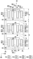
도 4는 도 2에 도시된 화소들 중 하나의 화소에 포함된 제1 내지 제3 서브 화소를 개략적으로 도시한 평면도이고, 도 5는 도 4의 Ⅰ ~ Ⅰ'선에 따른 단면도이며, 도 6은 도 5에 도시된 격벽을 다른 형태에 따라 구현한 것으로, 도 4의 Ⅰ ~ Ⅰ'선에 대응되는 단면도이다. Figure 4 is a plan view schematically showing the first to third sub-pixels included in one of the pixels shown in Figure 2, Figure 5 is a cross-sectional view taken along lines Ⅰ to Ⅰ' of Figure 4, and Figure 6 is a cross-sectional view corresponding to lines Ⅰ to Ⅰ' in FIG. 4, which implements the partition wall shown in FIG. 5 in a different form.
도 4에 있어서, 편의를 위하여 각각의 서브 화소 내에 제공된 복수의 발광 소자들이 수평 방향으로 정렬된 것으로 도시하였으나, 상기 발광 소자들의 배열이 이에 한정되지는 않는다. 예를 들어, 상기 발광 소자들 중 적어도 일부는 상기 수평 방향과 교차하는 방향으로 정렬될 수도 있다.In FIG. 4 , for convenience, a plurality of light-emitting elements provided in each sub-pixel are shown as aligned in the horizontal direction, but the arrangement of the light-emitting elements is not limited to this. For example, at least some of the light emitting elements may be aligned in a direction intersecting the horizontal direction.
또한, 도 4에 있어서, 편의를 위하여 발광 소자들에 연결되는 트랜지스터 및 상기 트랜지스터에 연결된 신호 배선들의 도시를 생략하였다.Additionally, in Figure 4, for convenience, transistors connected to the light emitting elements and signal wires connected to the transistors are omitted.
이에 더하여, 도 4 내지 도 6에서는 각각의 전극을 단일의 전극층으로만 도시하는 등 상기 하나의 화소의 구조를 단순화하여 도시하였으나, 본 발명이 이에 한정되는 것은 아니다. In addition, in Figures 4 to 6, the structure of one pixel is shown in a simplified manner, with each electrode shown as only a single electrode layer, but the present invention is not limited thereto.
도 1a, 도 2, 도 4 내지 도 6을 참조하면, 본 발명의 일 실시예에 따른 표시 장치는 복수의 화소들(PXL)이 제공된 기판(SUB)을 포함할 수 있다. Referring to FIGS. 1A, 2, and 4 to 6, a display device according to an embodiment of the present invention may include a substrate (SUB) provided with a plurality of pixels (PXL).
화소들(PXL) 각각은 기판(SUB) 상에 제공된 제1 서브 화소(SP1), 제2 서브 화소(SP2), 및 제3 서브 화소(SP3)를 포함할 수 있다. 본 발명의 일 실시예에 있어서, 제1 서브 화소(SP1)는 적색 서브 화소이고, 제2 서브 화소(SP2)는 녹색 서브 화소이며, 제3 서브 화소(SP3)는 청색 서브 화소일 수 있다. 그러나, 본 발명이 이에 한정되는 것은 아니며, 실시예에 따라 제1 서브 화소(SP1)가 녹색 서브 화소 또는 청색 서브 화소일 수 있으며, 제2 서브 화소(SP2)가 청색 서브 화소 또는 적색 서브 화소일 수 있으며, 제3 서브 화소(SP3)가 적색 서브 화소 또는 녹색 서브 화소일 수 있다. Each of the pixels PXL may include a first sub-pixel SP1, a second sub-pixel SP2, and a third sub-pixel SP3 provided on the substrate SUB. In one embodiment of the present invention, the first sub-pixel SP1 may be a red sub-pixel, the second sub-pixel SP2 may be a green sub-pixel, and the third sub-pixel SP3 may be a blue sub-pixel. However, the present invention is not limited to this, and depending on the embodiment, the first sub-pixel SP1 may be a green sub-pixel or a blue sub-pixel, and the second sub-pixel SP2 may be a blue sub-pixel or a red sub-pixel. The third sub-pixel SP3 may be a red sub-pixel or a green sub-pixel.
제1 내지 제3 서브 화소들(SP1, SP2, SP3) 각각은 광을 방출하는 발광 영역(EMA)과 상기 발광 영역(EMA)의 주변에 위치하는 주변 영역(PPA)을 포함할 수 있다. 발광 영역(EMA)은 광이 방출되는 영역을 의미하고, 주변 영역(PPA)은 상기 광이 방출되지 않는 영역을 의미할 수 있다. 본 발명의 일 실시예에 있어서, 제1 내지 제3 서브 화소들(SP1, SP2, SP3) 각각의 화소 영역은 해당 서브 화소의 발광 영역(EMA)과 주변 영역(PPA)을 포함할 수 있다. Each of the first to third sub-pixels SP1, SP2, and SP3 may include an emission area (EMA) that emits light and a peripheral area (PPA) located around the emission area (EMA). The emission area (EMA) may refer to an area where light is emitted, and the peripheral area (PPA) may refer to an area where the light is not emitted. In one embodiment of the present invention, the pixel area of each of the first to third sub-pixels SP1, SP2, and SP3 may include an emission area (EMA) and a peripheral area (PPA) of the corresponding sub-pixel.
제1 내지 제3 서브 화소들(SP1, SP2, SP3) 각각의 화소 영역에는 기판(SUB), 화소 회로부(PCL), 및 표시 소자층(DPL)이 제공될 수 있다. A substrate (SUB), a pixel circuit unit (PCL), and a display element layer (DPL) may be provided in the pixel areas of each of the first to third sub-pixels SP1, SP2, and SP3.
본 발명의 일 실시예에 있어서, 제1 내지 제3 서브 화소들(SP1, SP2, SP3) 각각은 제1 영역(FA)과 제2 영역(SA)을 포함할 수 있다. 제1 영역(FA)은 화소 회로부(PCL)가 배치되는 영역이고, 제2 영역(SA)은 상기 제1 영역(FA)에 인접한 영역일 수 있다. 즉, 제2 영역(SA)은 각 서브 화소에서 제1 영역(FA)을 제외한 나머지 영역으로, 화소 회로부(PCL)가 배치되지 않는 영역일 수 있다. In one embodiment of the present invention, each of the first to third sub-pixels SP1, SP2, and SP3 may include a first area FA and a second area SA. The first area FA may be an area where the pixel circuit unit PCL is disposed, and the second area SA may be an area adjacent to the first area FA. That is, the second area SA is the remaining area excluding the first area FA in each sub-pixel, and may be an area in which the pixel circuit unit PCL is not disposed.
제1 내지 제3 서브 화소들(SP1, SP2, SP3) 각각의 화소 회로부(PCL)는, 해당 서브 화소의 특정 영역, 일 예로, 제1 영역(FA)에만 배치될 수 있다. 제1 내지 제3 서브 화소들(SP1, SP2, SP3) 각각의 화소 회로부(PCL)가 해당 서브 화소의 제1 영역(FA)에만 집중적으로 배치되고, 제2 영역(SA)에는 배치되지 않을 경우, 상기 해당 서브 화소의 개구율이 향상될 수 있으며 광 투과율도 증가할 수 있다. The pixel circuit unit (PCL) of each of the first to third sub-pixels SP1, SP2, and SP3 may be disposed only in a specific area of the corresponding sub-pixel, for example, in the first area FA. When the pixel circuit unit (PCL) of each of the first to third sub-pixels (SP1, SP2, SP3) is concentrated only in the first area (FA) of the corresponding sub-pixel and is not placed in the second area (SA) , the aperture ratio of the corresponding sub-pixel can be improved and the light transmittance can also be increased.
본 발명의 일 실시예에 있어서, 제1 내지 제3 서브 화소들(SP1, SP2, SP3) 각각의 제1 영역(FA)은 해당 서브 화소의 화소 회로부(PCL)에 포함된 구성 요소들(일 예로, 트랜지스터 및 상기 트랜지스터에 연결된 배선 등을 포함함)의 집적도 및 인접한 구성 요소들과의 전기적 절연이 확보되는 범위 내에서 그 면적(또는 크기)이 결정될 수 있다. In one embodiment of the present invention, the first area FA of each of the first to third sub-pixels SP1, SP2, and SP3 includes components (one For example, the area (or size) may be determined within a range that ensures the degree of integration of the transistor (including the transistor and wiring connected to the transistor, etc.) and electrical insulation from adjacent components.
본 발명의 일 실시예에 있어서, 제1 내지 제3 서브 화소들(SP1, SP2, SP3) 각각의 제1 영역(FA)은 해당 서브 화소의 발광 영역(EAM)에 제공될 수 있으나, 본 발명이 이에 한정되는 것은 아니다. 실시예에 따라, 제1 내지 제3 서브 화소들(SP1, SP2, SP3) 각각의 제1 영역(FA)은 해당 서브 화소의 주변 영역(PPA)에 제공될 수도 있다. 이러한 경우, 제1 내지 제3 서브 화소들(SP1, SP2, SP3) 각각의 제1 영역(FA)에는 해당 서브 화소의 표시 소자층(DPL)이 제공되지 않는다. In one embodiment of the present invention, the first area (FA) of each of the first to third sub-pixels (SP1, SP2, SP3) may be provided in the emission area (EAM) of the corresponding sub-pixel. This is not limited to this. Depending on the embodiment, the first area FA of each of the first to third sub-pixels SP1, SP2, and SP3 may be provided in the peripheral area PPA of the corresponding sub-pixel. In this case, the display element layer (DPL) of the first to third sub-pixels (SP1, SP2, SP3) is not provided in the first area (FA) of each of the sub-pixels (SP1, SP2, SP3).
설명의 편의를 위해 제1 내지 제3 서브 화소들(SP1, SP2, SP3) 각각의 화소 회로부(PCL)를 우선 설명한 후, 표시 소자층(DPL)을 설명한다. For convenience of explanation, the pixel circuit part (PCL) of each of the first to third sub-pixels (SP1, SP2, and SP3) will be described first, and then the display element layer (DPL) will be described.
제1 내지 제3 서브 화소들(SP1, SP2, SP3) 각각의 화소 회로부(PCL)는 해당 서브 화소의 제1 영역(FA)에 제공될 수 있다. The pixel circuit part (PCL) of each of the first to third sub-pixels SP1, SP2, and SP3 may be provided in the first area FA of the corresponding sub-pixel.
제1 내지 제3 서브 화소들(SP1, SP2, SP3) 각각의 화소 회로부(PCL)는 기판(SUB) 상에 배치된 버퍼층(BFL)과, 상기 버퍼층(BFL) 상에 배치된 제1 및 제2 트랜지스터(T1, T2)와, 구동 전압 배선(DVL)을 포함할 수 있다. 또한, 제1 내지 제3 서브 화소들(SP1, SP2, SP3) 각각의 화소 회로부(PCL)는 제1 및 제2 트랜지스터(T1, T2)와 구동 전압 배선(DVL) 상에 제공된 보호층(PSV)을 더 포함할 수 있다.The pixel circuit portion (PCL) of each of the first to third sub-pixels (SP1, SP2, and SP3) includes a buffer layer (BFL) disposed on the substrate SUB, and first and third sub-pixels disposed on the buffer layer (BFL). It may include two transistors (T1, T2) and a driving voltage line (DVL). In addition, the pixel circuit portion (PCL) of each of the first to third sub-pixels (SP1, SP2, and SP3) has a protective layer (PSV) provided on the first and second transistors (T1, T2) and the driving voltage line (DVL). ) may further be included.
기판(SUB)은 유리, 유기 고분자, 수정 등과 같은 광이 투과될 수 있는 투명한 절연성 재료로 이루어질 수 있다. 또한, 기판(SUB)은 휘거나 접힘이 가능하도록 가요성(flexibility)을 갖는 재료로 이루어질 수 있고, 단층 구조나 다층 구조를 가질 수 있다.The substrate (SUB) may be made of a transparent insulating material that allows light to pass through, such as glass, organic polymer, crystal, etc. Additionally, the substrate SUB may be made of a material that has flexibility so that it can be bent or folded, and may have a single-layer structure or a multi-layer structure.
버퍼층(BFL)은 기판(SUB) 상에 제공되며, 제1 트랜지스터(T1)와 제2 트랜지스터(T2)에 불순물이 확산되는 것을 방지할 수 있다. 버퍼층(BFL)은 기판(SUB)의 재료 및 공정 조건에 따라 생략될 수도 있다.The buffer layer BFL is provided on the substrate SUB and can prevent impurities from diffusing into the first transistor T1 and the second transistor T2. The buffer layer BFL may be omitted depending on the material and process conditions of the substrate SUB.
제1 트랜지스터(T1)는 대응하는 서브 화소의 표시 소자층(DPL)에 구비된 발광 소자들(LD) 중 일부에 전기적으로 연결되어 발광 소자들(LD)을 구동하는 구동 트랜지스터이고, 제2 트랜지스터(T2)는 제1 트랜지스터(T1)를 스위칭하는 스위칭 트랜지스터일 수 있다. 이러한 제1 및 제2 트랜지스터(T1, T2)는 제1 내지 제3 서브 화소들(SP1, SP2, SP3) 각각의 제1 영역(FA)에만 제공될 수 있다. The first transistor T1 is a driving transistor that is electrically connected to some of the light-emitting elements LD provided in the display element layer DPL of the corresponding sub-pixel and drives the light-emitting elements LD, and the second transistor (T2) may be a switching transistor that switches the first transistor (T1). These first and second transistors T1 and T2 may be provided only in the first area FA of each of the first to third sub-pixels SP1, SP2, and SP3.
제1 및 제2 트랜지스터(T1, T2) 각각은 반도체층(SCL), 게이트 전극(GE), 소스 전극(SE) 및 드레인 전극(DE)을 포함할 수 있다. Each of the first and second transistors T1 and T2 may include a semiconductor layer (SCL), a gate electrode (GE), a source electrode (SE), and a drain electrode (DE).
반도체층(SCL)은 버퍼층(BFL) 상에 배치될 수 있다. 반도체층(SCL)은 소스 전극(SE)에 접촉되는 소스 영역과 드레인 전극(DE)에 접촉되는 드레인 영역을 포함할 수 있다. 소스 영역과 상기 드레인 영역 사이의 영역은 채널 영역일 수 있다. The semiconductor layer (SCL) may be disposed on the buffer layer (BFL). The semiconductor layer SCL may include a source region in contact with the source electrode SE and a drain region in contact with the drain electrode DE. The area between the source area and the drain area may be a channel area.
반도체층(SCL)은 폴리 실리콘, 아몰퍼스 실리콘, 산화물 반도체 등으로 이루어진 반도체 패턴일 수 있다. 채널 영역은 불순물이 도핑되지 않는 반도체 패턴으로서, 진성 반도체일 수 있다. 소스 영역 및 드레인 영역은 불순물이 도핑된 반도체 패턴일 수 있다.The semiconductor layer (SCL) may be a semiconductor pattern made of polysilicon, amorphous silicon, or oxide semiconductor. The channel region is a semiconductor pattern that is not doped with impurities and may be an intrinsic semiconductor. The source region and drain region may be a semiconductor pattern doped with impurities.
게이트 전극(GE)은 게이트 절연층(GI)을 사이에 두고 반도체층(SCL) 상에 제공될 수 있다. 게이트 전극(GE)은 금속으로 이루어질 수 있다. 게이트 전극(GE)은 니켈, 크롬, 몰리브덴, 알루미늄, 티타늄, 구리, 텅스텐, 및 이들을 포함하는 합금으로 이루어질 수 있다. 게이트 전극(GE)은 금속을 이용한 단일층 또는 다중층으로 형성될 수 있다. 예를 들어, 게이트 전극(GE)은 몰리브덴, 알루미늄, 및 몰리브덴이 순차적으로 적층된 삼중층이거나, 티타늄과 구리가 순차적으로 적층된 이중층일 수 있다. 또는, 게이트 전극(GE)은 티타늄과 구리의 합금으로 된 단일층일 수도 있다. The gate electrode GE may be provided on the semiconductor layer SCL with the gate insulating layer GI interposed therebetween. The gate electrode (GE) may be made of metal. The gate electrode GE may be made of nickel, chromium, molybdenum, aluminum, titanium, copper, tungsten, and alloys containing these. The gate electrode (GE) may be formed as a single layer or multiple layers using metal. For example, the gate electrode GE may be a triple layer of molybdenum, aluminum, and molybdenum sequentially stacked, or a double layer of titanium and copper sequentially stacked. Alternatively, the gate electrode GE may be a single layer made of an alloy of titanium and copper.
소스 전극(SE)과 드레인 전극(DE) 각각은 층간 절연층(ILD)과 게이트 절연층(GI)을 관통하는 컨택 홀을 통해 반도체층(SCL)의 소스 영역 및 드레인 영역에 접촉될 수 있다. 소스 전극(SE)과 드레인 전극(DE) 각각은 니켈, 크롬, 몰리브덴, 알루미늄, 티타늄, 구리, 텅스텐, 및 이들을 포함하는 합금으로 이루어질 수 있다. 소스 전극(SE)과 드레인 전극(DE)은 금속을 이용한 단일층 또는 다중층으로 형성될 수 있다. 예를 들어, 소스 전극(SE)과 드레인 전극(DE)은 티타늄과 구리가 순차적으로 적층된 이중층이거나, 티타늄과 구리의 합금으로 이루어진 단일층일 수 있다. Each of the source electrode SE and the drain electrode DE may be in contact with the source region and drain region of the semiconductor layer SCL through a contact hole penetrating the interlayer insulating layer ILD and the gate insulating layer GI. Each of the source electrode (SE) and drain electrode (DE) may be made of nickel, chromium, molybdenum, aluminum, titanium, copper, tungsten, and alloys containing these. The source electrode (SE) and drain electrode (DE) may be formed as a single layer or multiple layers using metal. For example, the source electrode SE and the drain electrode DE may be a double layer of titanium and copper sequentially stacked, or a single layer of an alloy of titanium and copper.
본 발명의 일 실시예에 있어서, 제1 내지 제3 서브 화소들(SP1, SP2, SP3) 각각에 제공된 화소 회로부(PCL)에 포함된 제1 및 제2 트랜지스터(T1, T2)는 LTPS 박막 트랜지스터로 구성될 수 있으나, 이에 한정되는 것은 아니며, 실시예에 따라 산화물 반도체 박막 트랜지스터로 구성될 수도 있다. 추가적으로, 본 발명의 일 실시예에 있어서, 제1 및 제2 트랜지스터(T1, T2)가 탑 게이트(top gate) 구조의 박막 트랜지스터인 경우를 예로서 설명하였으나, 이에 한정되는 것은 아니다. 실시예에 따라, 제1 및 제2 트랜지스터(T1, T2)는 바텀 게이트(bottom gate)구조의 박막 트랜지스터일 수도 있다. In one embodiment of the present invention, the first and second transistors (T1, T2) included in the pixel circuit portion (PCL) provided in each of the first to third sub-pixels (SP1, SP2, and SP3) are LTPS thin film transistors. It may be composed of, but is not limited to, and depending on the embodiment, it may be composed of an oxide semiconductor thin film transistor. Additionally, in one embodiment of the present invention, the case where the first and second transistors T1 and T2 are thin film transistors with a top gate structure has been described as an example, but the present invention is not limited thereto. Depending on the embodiment, the first and second transistors T1 and T2 may be thin film transistors with a bottom gate structure.
구동 전압 배선(DVL)은 층간 절연층(ILD) 상에 제공될 수 있으나, 본 발명이 이에 한정되는 것은 아니며, 실시예에 따라 화소 회로부(PCL) 내에 포함된 절연층 중 어느 하나의 절연층 상에 제공될 수 있다. 구동 전압 배선(DVL)에는 제2 구동 전원(도 3a의 VSS 참고)이 인가될 수 있다. The driving voltage line (DVL) may be provided on the interlayer insulating layer (ILD), but the present invention is not limited thereto, and depending on the embodiment, the driving voltage line (DVL) may be provided on any one of the insulating layers included in the pixel circuit unit (PCL). can be provided. A second driving power source (see VSS in FIG. 3A) may be applied to the driving voltage line DVL.
보호층(PSV)은 제1 트랜지스터(T1)의 드레인 전극(DE)의 일부를 노출하는 제1 컨택 홀(CH1)과 구동 전압 배선(DVL)의 일부를 노출하는 제2 컨택 홀(CH2)을 포함할 수 있다. 보호층(PSV)은 무기 재료로 이루어진 무기 절연막 및/또는 유기 재료로 이루어진 유기 절연막 중 적어도 하나를 포함할 수 있다. 실시예에 따라, 보호층(PSV)은 제1 및 제2 트랜지스터(T1, T2)를 커버하는 무기 절연막 및 상기 무기 절연막 상에 배치된 유기 절연막을 포함하는 형태로 제공될 수 있다. 여기서, 무기 절연막은 실리콘 산화물(SiOx), 실리콘 질화물(SiNx) 중 적어도 하나를 포함할 수 있다. 유기 절연막은 광을 투과시킬 수 있는 유기 절연 물질을 포함할 수 있다. 유기 절연막은 예를 들어, 아크릴계 수지(polyacrylates resin), 에폭시계 수지(epoxy resin), 페놀 수지(phenolic resin), 폴리아미드계 수지(polyamides resin), 폴리이미드계 수지(polyimides rein), 불포화 폴리에스테르계 수지(unsaturated polyesters resin), 폴리페닐렌 에테르계 수지(poly-phenylen ethers resin), 폴리페닐렌 설파이드계 수지(poly-phenylene sulfides resin), 및 벤조사이클로부텐 수지enzocyclobutene resin) 중 적어도 하나를 포함할 수 있다.The protective layer (PSV) includes a first contact hole (CH1) exposing a portion of the drain electrode (DE) of the first transistor (T1) and a second contact hole (CH2) exposing a portion of the driving voltage line (DVL). It can be included. The protective layer PSV may include at least one of an inorganic insulating film made of an inorganic material and/or an organic insulating film made of an organic material. Depending on the embodiment, the protective layer PSV may be provided in a form including an inorganic insulating film covering the first and second transistors T1 and T2 and an organic insulating film disposed on the inorganic insulating film. Here, the inorganic insulating film may include at least one of silicon oxide (SiOx) and silicon nitride (SiNx). The organic insulating film may include an organic insulating material capable of transmitting light. Organic insulating films include, for example, polyacrylates resin, epoxy resin, phenolic resin, polyamides resin, polyimides resin, and unsaturated polyester. It may contain at least one of unsaturated polyesters resin, poly-phenylene ethers resin, polyphenylene sulfides resin, and benzocyclobutene resin. You can.
한편, 제1 내지 제3 서브 화소들(SP1, SP2, SP3) 각각의 화소 회로부(PCL)는 기판(SUB)과 반도체층(SCL) 사이에 제공된 차광 패턴(SDL)을 더 포함할 수 있다. Meanwhile, the pixel circuit unit (PCL) of each of the first to third sub-pixels (SP1, SP2, and SP3) may further include a light blocking pattern (SDL) provided between the substrate (SUB) and the semiconductor layer (SCL).
차광 패턴(SDL)은 기판(SUB)의 배면을 통해 유입된 광이 제1 내지 제3 서브 화소들(SP1, SP2, SP3) 각각의 화소 회로부(PCL)로 진행되는 것을 차단하는 광 차단막일 수 있다. 특히, 차광 패턴(SDL)은 기판(SUB)의 배면을 통해 유입된 광이 제1 내지 제3 서브 화소들(SP1, SP2, SP3) 각각의 화소 회로부(PCL)에 포함된 제1 및 제2 트랜지스터(T1, T2) 각각의 반도체층(SCL)으로 진행되는 것을 차단하여 상기 제1 및 제2 트랜지스터(T1, T2) 오동작을 방지할 수 있다. The light blocking pattern (SDL) may be a light blocking film that blocks light introduced through the back of the substrate (SUB) from proceeding to the pixel circuit portion (PCL) of each of the first to third sub-pixels (SP1, SP2, and SP3). there is. In particular, the light blocking pattern (SDL) allows light introduced through the back of the substrate (SUB) to be transmitted to the first and second sub-pixels (SP1, SP2, SP3) included in the pixel circuit portion (PCL) of each of the first to third sub-pixels (SP1, SP2, SP3). Malfunction of the first and second transistors T1 and T2 can be prevented by blocking the transistors T1 and T2 from advancing to the semiconductor layer SCL.
차광 패턴(SDL)은 도전성 물질, 절연 물질 등으로 이루어질 수 있다. 일 예로, 차광 패턴(SDL)은 블랙 매트릭스를 포함할 수 있다. The light blocking pattern (SDL) may be made of a conductive material, an insulating material, etc. As an example, the light blocking pattern (SDL) may include a black matrix.
차광 패턴(SDL)은 제1 및 제2 트랜지스터(T1, T2) 각각의 반도체층(SCL)의 하부에 대응되도록 기판(SUB) 상에 제공될 수 있다. 본 발명의 일 실시예에 있어서, 차광 패턴(SDL)은 도전성 물질인 금속으로 이루어질 수 있다. 이러한 경우, 차광 패턴(SDL)은 제1 및 제2 트랜지스터(T1, T2) 각각의 일부 구성에 전기적으로 연결될 수 있으나, 반드시 이에 한정되는 것은 아니며, 실시예에 따라 전기적으로 연결되지 않을 수도 있다. The light blocking pattern SDL may be provided on the substrate SUB to correspond to the lower portion of the semiconductor layer SCL of each of the first and second transistors T1 and T2. In one embodiment of the present invention, the light blocking pattern (SDL) may be made of metal, which is a conductive material. In this case, the light blocking pattern SDL may be electrically connected to some components of each of the first and second transistors T1 and T2, but is not limited to this and may not be electrically connected depending on the embodiment.
본 발명의 일 실시예에 있어서, 차광 패턴(SDL)은 화소 회로부(PCL)에 포함된 제1 및 제2 트랜지스터(T1, T2) 각각의 반도체층(SCL)과 중첩되도록 제1 내지 제3 서브 화소들(SP1, SP2, SP3) 각각의 제1 영역(FA)의 일부에 제공될 수 있으나, 이에 한정되는 것은 아니다. 실시예에 따라, 차광 패턴(SDL)은 제1 내지 제3 서브 화소들(SP1, SP2, SP3) 각각의 제1 영역(FA)에 전체적으로 제공될 수도 있다. In one embodiment of the present invention, the light blocking pattern (SDL) is formed on the first to third sub-layers so as to overlap the semiconductor layer (SCL) of each of the first and second transistors (T1, T2) included in the pixel circuit unit (PCL). Each of the pixels SP1, SP2, and SP3 may be provided in a portion of the first area FA, but is not limited thereto. Depending on the embodiment, the light blocking pattern SDL may be provided entirely in the first area FA of each of the first to third sub-pixels SP1, SP2, and SP3.
다음으로, 제1 내지 제3 서브 화소들(SP1, SP2, SP3) 각각의 표시 소자층(DPL)에 대해 설명한다. Next, the display element layer DPL of each of the first to third sub-pixels SP1, SP2, and SP3 will be described.
제1 내지 제3 서브 화소들(SP1, SP2, SP3) 각각의 표시 소자층(DPL)은 제1 영역(FA)과 제2 영역(SA)에 모두 제공될 수 있으나, 이에 한정되는 것은 아니다. 실시예에 따라, 제1 내지 제3 서브 화소들(SP1, SP2, SP3) 각각의 표시 소자층(DPL)은 선택적으로 제1 영역(FA)에만 제공되거나 제2 영역(SA)에만 제공될 수도 있다. The display element layer DPL of each of the first to third sub-pixels SP1, SP2, and SP3 may be provided in both the first area FA and the second area SA, but is not limited thereto. Depending on the embodiment, the display element layer (DPL) of each of the first to third sub-pixels (SP1, SP2, SP3) may be selectively provided only in the first area (FA) or only in the second area (SA). there is.
본 발명의 일 실시예에 있어서, 제1 내지 제3 서브 화소들(SP1, SP2, SP3) 각각의 표시 소자층(DPL)은 보호층(PSV) 상에 제공된 격벽(PW)과, 제1 및 제2 전극(REL1, REL2)과, 제1 및 제2 캡핑층(CPL1, CPL2)과, 연결 배선(CNL)과, 복수의 발광 소자들(LD)과, 제1 및 제2 컨택 전극(CNE1, CNE2)을 포함할 수 있다. In one embodiment of the present invention, the display element layer (DPL) of each of the first to third sub-pixels (SP1, SP2, and SP3) includes a partition (PW) provided on the protective layer (PSV), and the first and third sub-pixels (SP1, SP2, SP3). Second electrodes (REL1, REL2), first and second capping layers (CPL1, CPL2), connection wiring (CNL), a plurality of light emitting elements (LD), and first and second contact electrodes (CNE1) , CNE2) may be included.
격벽(PW)은 제1 내지 제3 서브 화소(SP1, SP2, SP3) 각각의 발광 영역(EMA) 내의 보호층(PSV) 상에 제공될 수 있다. 도면에 직접적으로 도시하지 않았으나, 격벽(PW)과 동일한 물질로 구성된 댐부(또는 뱅크)는 인접한 서브 화소들 사이의 주변 영역(PPA)에 형성 및/또는 제공되어 제1 내지 제3 서브 화소들(SP1, SP2, SP3) 각각의 발광 영역(EMA)을 정의할 수 있다. The partition PW may be provided on the protective layer PSV within the emission area EMA of each of the first to third sub-pixels SP1, SP2, and SP3. Although not directly shown in the drawing, a dam portion (or bank) made of the same material as the partition wall PW is formed and/or provided in the peripheral area PPA between adjacent sub-pixels to form the first to third sub-pixels ( SP1, SP2, SP3) Each emission area (EMA) can be defined.
격벽(PW)은 보호층(PSV) 상에서 인접하게 배치된 격벽(PW)과 일정 간격 이격될 수 있다. 인접한 두 개의 격벽들(PW)은 하나의 발광 소자(LD)의 길이(L) 이상으로 보호층(PSV) 상에서 이격될 수 있다. 격벽(PW)은, 도 5에 도시된 바와 같이 보호층(PSV)의 일면으로부터 상부로 향할수록 폭이 좁아지는 반원, 반타원 등의 단면을 가지는 곡면을 포함할 수 있으나, 본 발명이 이에 한정되는 것은 아니다. The partition wall (PW) may be spaced apart from the partition wall (PW) disposed adjacently on the protective layer (PSV) at a certain distance. Two adjacent partition walls (PW) may be spaced apart on the protective layer (PSV) by more than the length (L) of one light emitting device (LD). As shown in FIG. 5, the partition PW may include a curved surface having a cross-section such as a semicircle or semiellipse whose width becomes narrower from one side of the protective layer PSV toward the top, but the present invention is limited to this. It doesn't work.
실시예에 따라, 격벽(PW)은, 도 6에 도시된 바와 같이 보호층(PSV)의 일면으로부터 상부로 향할수록 폭이 좁아지는 사다리꼴의 단면을 가질 수도 있다. 단면 상에서 볼 때, 격벽(PW)의 형상은 상술한 실시예들에 한정되는 것은 아니며 발광 소자들(LD) 각각에서 출사된 광의 효율을 향상시킬 수 있는 범위 내에서 다양하게 변경될 수 있다. 인접한 두 개의 격벽들(PW)은 보호층(PSV) 상의 동일한 평면 상에 배치될 수 있으며, 동일한 높이를 가질 수 있다. Depending on the embodiment, the partition PW may have a trapezoidal cross-section whose width becomes narrower from one side of the protective layer PSV toward the top, as shown in FIG. 6 . When viewed in cross section, the shape of the partition PW is not limited to the above-described embodiments and may be changed in various ways within a range that can improve the efficiency of light emitted from each of the light emitting elements LD. Two adjacent partition walls (PW) may be disposed on the same plane on the protective layer (PSV) and may have the same height.
제1 및 제2 전극(REL1, REL2) 각각은 제1 내지 제3 서브 화소들(SP1, SP2, SP3) 각각의 발광 영역(EMA)에 제공되며, 제2 방향(DR2, 일 예로 '수직 방향')을 따라 연장될 수 있다. 본 발명의 일 실시예에 있어서, 제1 전극(REL1)과 제2 전극(REL2)은 해당 서브 화소의 제1 영역(FA)과 제2 영역(SA)에 각각 위치할 수 있다. 제1 전극(REL1)과 제2 전극(REL2)은 동일한 면 상에 제공되며 서로 이격될 수 있다. 구체적으로, 제1 영역(FA)에 위치한 제1 전극(REL1)과 제2 전극(REL2)은 서로 이격되며, 제2 영역(SA)에 위치한 제1 전극(REL1)과 제2 전극(REL2)도 서로 이격될 수 있다. Each of the first and second electrodes (REL1, REL2) is provided in the emission area (EMA) of each of the first to third sub-pixels (SP1, SP2, SP3), and is provided in the second direction (DR2), for example, the 'vertical direction'. ') can be extended along. In one embodiment of the present invention, the first electrode (REL1) and the second electrode (REL2) may be located in the first area (FA) and the second area (SA) of the corresponding sub-pixel, respectively. The first electrode (REL1) and the second electrode (REL2) may be provided on the same surface and spaced apart from each other. Specifically, the first electrode (REL1) and the second electrode (REL2) located in the first area (FA) are spaced apart from each other, and the first electrode (REL1) and the second electrode (REL2) located in the second area (SA) may also be spaced apart from each other.
제1 내지 제3 서브 화소들(SP1, SP2, SP3) 각각의 제1 영역(FA)에 위치한 제1 전극(REL1)과 해당 서브 화소의 제2 영역(SA)에 위치한 제1 전극(REL1)은 서로 이격되어 전기적으로 분리될 수 있다. 제1 내지 제3 서브 화소들(SP1, SP2, SP3) 각각의 제1 및 제2 영역(FA, SA) 각각에 위치한 제1 전극들(REL1)은 동일한 열에 위치할 수 있으나, 이에 한정되는 것은 아니다. 실시예에 따라, 제1 영역(FA)과 제2 영역(SA) 각각에 위치한 제1 전극들(REL1)은 상이한 열에 위치할 수도 있다. A first electrode (REL1) located in the first area (FA) of each of the first to third sub-pixels (SP1, SP2, SP3) and a first electrode (REL1) located in the second area (SA) of the corresponding sub-pixel can be spaced apart and electrically separated from each other. The first electrodes (REL1) located in the first and second areas (FA, SA) of each of the first to third sub-pixels (SP1, SP2, SP3) may be located in the same column, but are not limited to this. no. Depending on the embodiment, the first electrodes REL1 located in each of the first area FA and the second area SA may be located in different rows.
제1 내지 제3 서브 화소들(SP1, SP2, SP3) 각각의 제1 영역(FA)에 위치한 제1 전극(REL1)은 보호층(PSV)을 관통하는 제1 컨택 홀(CH1)을 통해 해당 서브 화소의 제1 트랜지스터(T1)의 드레인 전극(DE)에 연결될 수 있다. 이로 인하여, 제1 트랜지스터(T1)에 인가된 신호가 제1 내지 제3 서브 화소들(SP1, SP2, SP3) 각각의 제1 영역(FA)에 위치한 제1 전극(REL1)으로 전달될 수 있다. The first electrode (REL1) located in the first area (FA) of each of the first to third sub-pixels (SP1, SP2, SP3) is connected to the corresponding electrode through the first contact hole (CH1) penetrating the protective layer (PSV). It may be connected to the drain electrode (DE) of the first transistor (T1) of the sub-pixel. Due to this, the signal applied to the first transistor T1 may be transmitted to the first electrode REL1 located in the first area FA of each of the first to third sub-pixels SP1, SP2, and SP3. .
제1 캡핑층(CPL1)은 제1 내지 제3 서브 화소들(SP1, SP2, SP3) 각각의 제1 전극(REL1) 상에 제공되어 상기 제1 전극(REL1)과 전기적 및/또는 물리적으로 연결될 수 있다. 제1 캡핑층(CPL1)은 표시 장치의 제조 공정 시 발생하는 불량 등으로 인해 대응하는 제1 전극(REL1)의 손상을 방지하며, 상기 대응하는 제1 전극(REL1)과 보호층(PSV)의 접착력을 강화시킬 수 있다. 제1 캡핑층(CPL1)은 발광 소자들(LD) 각각에서 출사되어 표시 장치의 표시 방향으로 진행되는 광의 손실을 최소화하기 위해 투명한 도전성 물질로 이루어질 수 있다. 투명한 도전성 물질은, 예를 들어, ITO, IZO, ITZO 등을 포함할 수 있으나, 이에 한정되는 것은 아니며, 광의 손실을 최소화하며 도전성을 갖는 재료를 모두 포함할 수도 있다. The first capping layer (CPL1) is provided on the first electrode (REL1) of each of the first to third sub-pixels (SP1, SP2, SP3) and is electrically and/or physically connected to the first electrode (REL1). You can. The first capping layer (CPL1) prevents damage to the corresponding first electrode (REL1) due to defects occurring during the manufacturing process of the display device, and protects the corresponding first electrode (REL1) and the protective layer (PSV) from damage. Adhesion can be strengthened. The first capping layer CPL1 may be made of a transparent conductive material to minimize loss of light emitted from each of the light emitting elements LD and traveling in the display direction of the display device. Transparent conductive materials may include, for example, ITO, IZO, ITZO, etc., but are not limited thereto, and may include any material that minimizes light loss and has conductivity.
본 발명의 일 실시예에 있어서, 제1 캡핑층(CPL1)은 제1 내지 제3 서브 화소들(SP1, SP2, SP3) 각각의 제1 영역(FA)으로부터 제2 영역(SA)까지 연장된 바(Bar) 형상을 가질 수 있으나, 상기 제1 캡핑층(CPL1)의 형상이 이에 한정되는 것은 아니다. In one embodiment of the present invention, the first capping layer CPL1 extends from the first area FA to the second area SA of each of the first to third sub-pixels SP1, SP2, and SP3. It may have a bar shape, but the shape of the first capping layer CPL1 is not limited to this.
제1 캡핑층(CPL1)이 제1 내지 제3 서브 화소들(SP1, SP2, SP3) 각각의 제1 영역(FA)으로부터 제2 영역(SA)까지 연장되는 형태로 제공됨에 따라, 상기 제1 영역(FA)의 제1 전극(REL1)과 상기 제2 영역(SA)의 제1 전극(REL1)은 상기 제1 캡핑층(CPL1)에 의해 전기적으로 서로 연결될 수 있다. 이로 인하여, 제1 내지 제3 서브 화소들(SP1, SP2, SP3) 각각의 제1 영역(FA)에서, 제1 전극(REL1)으로 전달된 신호는 제1 캡핑층(CPL1)을 통해 제2 영역(SA)에 위치한 제1 전극(REL1)으로 인가될 수 있다. As the first capping layer CPL1 is provided in a form extending from the first area FA to the second area SA of each of the first to third sub-pixels SP1, SP2, and SP3, the first capping layer CPL1 The first electrode REL1 of the area FA and the first electrode REL1 of the second area SA may be electrically connected to each other by the first capping layer CPL1. Due to this, the signal transmitted to the first electrode (REL1) in the first area (FA) of each of the first to third sub-pixels (SP1, SP2, SP3) is transmitted to the second electrode (REL1) through the first capping layer (CPL1). It may be applied to the first electrode REL1 located in the area SA.
제1 내지 제3 서브 화소들(SP1, SP2, SP3) 각각의 제1 영역(FA)의 제2 전극(REL2)과 해당 서브 화소의 제2 영역(SA)의 제2 전극(REL2)은 서로 이격되어 전기적으로 분리될 수 있다. 제1 내지 제3 서브 화소들(SP1, SP2, SP3) 각각의 제1 영역(FA)의 제2 전극(REL2)과 해당 서브 화소의 제2 영역(SA)의 제2 전극(REL2)은 동일한 열에 위치할 수 있으나, 이에 한정되는 것은 아니다. 실시예에 따라, 제1 내지 제3 서브 화소들(SP1, SP2, SP3) 각각의 제1 영역(FA)의 제2 전극(REL2)과 해당 서브 화소의 제2 영역(SA)의 제2 전극(REL2)은 상이한 열에 위치할 수도 있다. The second electrode (REL2) of the first area (FA) of each of the first to third sub-pixels (SP1, SP2, SP3) and the second electrode (REL2) of the second area (SA) of the corresponding sub-pixel are connected to each other. They can be spaced apart and electrically isolated. The second electrode (REL2) of the first area (FA) of each of the first to third sub-pixels (SP1, SP2, SP3) and the second electrode (REL2) of the second area (SA) of the corresponding sub-pixel are the same. It may be located in a column, but is not limited to this. Depending on the embodiment, the second electrode (REL2) in the first area (FA) of each of the first to third sub-pixels (SP1, SP2, SP3) and the second electrode in the second area (SA) of the corresponding sub-pixel (REL2) may be located in a different column.
제2 캡핑층(CPL2)은 제1 내지 제3 서브 화소들(SP1, SP2, SP3) 각각의 제2 전극(REL2) 상에 제공되어 상기 제2 전극(REL2)과 전기적 및/또는 물리적으로 연결될 수 있다. 본 발명의 일 실시예에 있어서, 제2 캡핑층(CPL2)은 제1 내지 제3 서브 화소들(SP1, SP2, SP3) 각각의 제1 영역(FA)으로부터 제2 영역(SA)까지 연장되는 바(Bar) 형상을 가질 수 있으나, 상기 제2 캡핑층(CPL2)의 형상이 이에 한정되는 것은 아니다. The second capping layer (CPL2) is provided on the second electrode (REL2) of each of the first to third sub-pixels (SP1, SP2, SP3) and is electrically and/or physically connected to the second electrode (REL2). You can. In one embodiment of the present invention, the second capping layer CPL2 extends from the first area FA to the second area SA of each of the first to third sub-pixels SP1, SP2, and SP3. It may have a bar shape, but the shape of the second capping layer CPL2 is not limited to this.
제2 캡핑층(CPL2)은 제1 캡핑층(CPL1)과 동일한 층에 제공될 수 있다. 또한, 제2 캡핑층(CPL2)은 제1 캡핑층(CPL1)과 동일한 물질, 예를 들어, 투명한 도전성 물질을 포함할 수 있다. The second capping layer CPL2 may be provided on the same layer as the first capping layer CPL1. Additionally, the second capping layer CPL2 may include the same material as the first capping layer CPL1, for example, a transparent conductive material.
제2 캡핑층(CPL2)이 제1 내지 제3 서브 화소들(SP1, SP2, SP3) 각각의 제1 영역(FA)으로부터 제2 영역(SA)까지 연장되는 형태로 제공됨에 따라, 상기 제1 영역(FA)에 위치한 제2 전극(REL2)과 상기 제2 영역(SA)에 위치한 제2 전극(REL2)은 상기 제2 캡핑층(CPL2)에 의해 전기적으로 연결될 수 있다. As the second capping layer (CPL2) is provided in a form extending from the first area (FA) to the second area (SA) of each of the first to third sub-pixels (SP1, SP2, SP3), the first to third sub-pixels (SP1, SP2, SP3) The second electrode REL2 located in the area FA and the second electrode REL2 located in the second area SA may be electrically connected to the second capping layer CPL2.
연결 배선(CNL)은 제2 방향(DR2)과 교차하는 제1 방향(DR1, 일 예로 '수평 방향')으로 연장될 수 있다. 연결 배선(CNL)은 제1 내지 제3 서브 화소들(SP1, SP2, SP3) 각각의 제2 영역(SA)에 위치할 수 있으나, 이에 한정되는 것은 아니다. 실시예에 따라, 연결 배선(CNL)은 해당 서브 화소의 제1 영역(FA)에 위치할 수도 있다. 연결 배선(CNL)은 제1 내지 제3 서브 화소들(SP1, SP2, SP3)에 공통으로 제공될 수 있다. 이에 따라, 제1 내지 제3 서브 화소들(SP1, SP2, SP3)은 연결 배선(CNL)에 공통으로 연결될 수 있다. The connection wire CNL may extend in the first direction DR1 (eg, 'horizontal direction') crossing the second direction DR2. The connection wire CNL may be located in the second area SA of each of the first to third sub-pixels SP1, SP2, and SP3, but is not limited thereto. Depending on the embodiment, the connection line CNL may be located in the first area FA of the corresponding sub-pixel. The connection wire CNL may be commonly provided to the first to third sub-pixels SP1, SP2, and SP3. Accordingly, the first to third sub-pixels SP1, SP2, and SP3 may be commonly connected to the connection wire CNL.
본 발명의 일 실시예에 있어서, 연결 배선(CNL)은 제2 캡핑층(CPL2)과 동일한 층에 제공되며, 동일한 물질을 포함할 수 있다. 구체적으로, 연결 배선(CNL)과 제2 캡핑층(CPL2)은 일체로 제공되어, 전기적 및/또는 물리적으로 서로 연결될 수 있다. 제2 캡핑층(CPL2)과 연결 배선(CNL)이 일체로 형성 및/또는 제공되는 경우, 상기 연결 배선(CNL)을 상기 제2 캡핑층(CPL2)의 일 영역으로 간주할 수 있다. In one embodiment of the present invention, the connection line CNL is provided on the same layer as the second capping layer CPL2 and may include the same material. Specifically, the connection wire (CNL) and the second capping layer (CPL2) may be provided as one body and electrically and/or physically connected to each other. When the second capping layer (CPL2) and the connection line (CNL) are formed and/or provided integrally, the connection line (CNL) may be regarded as one area of the second capping layer (CPL2).
연결 배선(CNL)은 보호층(PSV)을 관통하는 제2 컨택 홀(CH2)을 통해 제1 내지 제3 서브 화소들(SP1, SP2, SP3) 각각의 주변 영역(PPA)에 위치한 구동 전압 배선(DVL)에 연결될 수 있다. 이로 인하여, 구동 전압 배선(DVL)에 인가된 제2 구동 전원(VSS)은 연결 배선(CNL)으로 전달될 수 있다. The connection wire (CNL) is a driving voltage wire located in the peripheral area (PPA) of each of the first to third sub-pixels (SP1, SP2, SP3) through the second contact hole (CH2) penetrating the protective layer (PSV). (DVL). Due to this, the second driving power source VSS applied to the driving voltage line DVL may be transmitted to the connection line CNL.
상술한 바와 같이, 연결 배선(CNL)이 제2 캡핑층(CPL2)과 일체로 제공되는 경우, 상기 연결 배선(CNL)으로 인가된 제2 구동 전원(VSS)은 상기 제2 캡핑층(CPL2)으로 전달될 수 있다. 또한, 제2 캡핑층(CPL2)이 각 서브 화소의 제1 영역(FA)으로부터 제2 영역(SA)까지 연장된 형태로 제공되어 각 영역에 위치한 제2 전극(REL2)과 전기적 및/또는 물리적으로 연결되므로, 상기 제2 캡핑층(CPL2)으로 인가된 제2 구동 전원(VSS)은 각 서브 화소의 제1 및 제2 영역(FA, SA) 각각의 제2 전극(REL2)으로 전달될 수 있다.As described above, when the connection wire (CNL) is provided integrally with the second capping layer (CPL2), the second driving power source (VSS) applied to the connection wire (CNL) is connected to the second capping layer (CPL2). can be passed on. In addition, the second capping layer (CPL2) is provided in a form extending from the first area (FA) to the second area (SA) of each sub-pixel, and is electrically and/or physically connected to the second electrode (REL2) located in each area. Therefore, the second driving power (VSS) applied to the second capping layer (CPL2) can be transmitted to the second electrode (REL2) of each of the first and second areas (FA, SA) of each sub-pixel. there is.
본 발명의 일 실시예에 있어서, 제1 전극(REL1)과 제2 전극(REL2) 각각은 제1 내지 제3 서브 화소들(SP1, SP2, SP3) 각각의 발광 영역(EMA) 내에 발광 소자들(LD)을 정렬하기 위한 정렬 전극으로 기능할 수 있다. In one embodiment of the present invention, each of the first electrode (REL1) and the second electrode (REL2) is a light emitting element within the light emitting area (EMA) of each of the first to third sub-pixels (SP1, SP2, and SP3). It can function as an alignment electrode to align (LD).
제1 내지 제3 서브 화소들(SP1, SP2, SP3) 각각의 발광 영역(EMA)에 발광 소자들(LD)이 정렬되기 전, 제1 전극(REL)에는 정렬 배선(미도시)을 통해 제1 정렬 전압이 인가되고, 제2 전극(REL2)에는 연결 배선(CNL)을 통해 제2 정렬 전압이 인가될 수 있다. 제1 정렬 전압과 제2 정렬 전압은 서로 상이한 전압 레벨을 가질 수 있다. Before the light-emitting elements LD are aligned in the light-emitting area EMA of each of the first to third sub-pixels SP1, SP2, and SP3, an alignment wire (not shown) is applied to the first electrode REL. 1 alignment voltage may be applied, and a second alignment voltage may be applied to the second electrode (REL2) through the connection wire (CNL). The first alignment voltage and the second alignment voltage may have different voltage levels.
제1 전극(REL1)과 제2 전극(REL2) 각각에 서로 상이한 전압 레벨을 갖는 소정의 정렬 전압이 인가됨에 따라 제1 전극(REL1)과 제2 전극(REL2) 사이에 전계가 형성될 수 있다. 전계에 의해 제1 전극(REL1)과 제2 전극(REL2) 사이에 발광 소자들(LD)이 정렬될 수 있다. 즉, 제1 내지 제3 서브 화소들(SP1, SP2, SP3) 각각의 제1 영역(FA)에서 제1 전극(REL1)과 제2 전극(REL2) 사이에 발광 소자들(LD)이 정렬되고, 해당 서브 화소의 제2 영역(SA)에서 제1 전극(REL1)과 제2 전극(REL2) 사이에 발광 소자들(LD)이 정렬될 수 있다. As a predetermined alignment voltage having a different voltage level is applied to each of the first electrode (REL1) and the second electrode (REL2), an electric field may be formed between the first electrode (REL1) and the second electrode (REL2). . The light emitting elements LD may be aligned between the first electrode REL1 and the second electrode REL2 by the electric field. That is, the light emitting elements LD are aligned between the first electrode REL1 and the second electrode REL2 in the first area FA of each of the first to third sub-pixels SP1, SP2, and SP3. , the light emitting elements LD may be aligned between the first electrode REL1 and the second electrode REL2 in the second area SA of the corresponding sub-pixel.
제1 내지 제3 서브 화소들(SP1, SP2, SP3) 각각의 발광 영역(EMA) 내에 발광 소자들(LD)이 정렬된 후, 제1 전극(REL1)과 제2 전극(REL2)은 발광 소자들(LD)을 구동하기 위한 구동 전극으로 기능할 수 있다. After the light-emitting elements LD are aligned within the light-emitting area EMA of each of the first to third sub-pixels SP1, SP2, and SP3, the first electrode REL1 and the second electrode REL2 are the light-emitting elements. It can function as a driving electrode for driving LD.
제1 전극(REL1)과 제2 전극(REL2)은 발광 소자들(LD) 각각의 양 단부(EP1, EP2)에서 출사되는 광을 표시 장치의 표시 방향으로 반사시키기 위해(혹은 진행되도록 하기 위해) 일정한 반사율을 갖는 재료로 이루어질 수 있다. 제1 전극(REL1)과 제2 전극(REL2)은 일정한 반사율을 갖는 도전성 재료로 이루어질 수 있다. 도전성 재료로는 Ag, Mg, Al, Pt, Pd, Au, Ni, Nd, Ir, Cr, Ti, 이들의 합금과 같은 금속, ITO(indium tin oxide), IZO(indium zinc oxide), ZnO(zinc oxide), ITZO(indium tin zinc oxide)와 같은 도전성 산화물, PEDOT와 같은 도전성 고분자 등이 포함될 수 있다. 제1 전극(REL1)과 제2 전극(REL2)의 재료는 상술한 재료들에 한정되는 것은 아니다. The first electrode (REL1) and the second electrode (REL2) are used to reflect (or allow the light to propagate) emitted from both ends (EP1, EP2) of the light emitting elements (LD) in the display direction of the display device. It may be made of a material with a certain reflectance. The first electrode (REL1) and the second electrode (REL2) may be made of a conductive material having a constant reflectance. Conductive materials include metals such as Ag, Mg, Al, Pt, Pd, Au, Ni, Nd, Ir, Cr, Ti, and their alloys, ITO (indium tin oxide), IZO (indium zinc oxide), and ZnO (zinc). oxide), conductive oxides such as indium tin zinc oxide (ITZO), and conductive polymers such as PEDOT. The materials of the first electrode (REL1) and the second electrode (REL2) are not limited to the materials described above.
또한, 제1 전극(REL1)과 제2 전극(REL2)은 단일층으로 형성될 수 있으나, 본 발명이 이에 한정되는 것은 아니며, 금속들, 합금들, 도전성 산화물들, 도전성 고분자들 중 2이상 물질이 적층된 다중층으로 형성될 수도 있다. 제1 전극(REL1)과 제2 전극(REL2)은 발광 소자들(LD) 각각의 양 단부(EP1, EP2)로 신호를 전달할 때 신호 지연에 의한 전압 강하를 최소화하기 위해 적어도 이중층 이상의 다중층으로 형성될 수 있다. In addition, the first electrode (REL1) and the second electrode (REL2) may be formed as a single layer, but the present invention is not limited thereto, and may be formed of two or more materials among metals, alloys, conductive oxides, and conductive polymers. It may also be formed of laminated multiple layers. The first electrode (REL1) and the second electrode (REL2) are made of at least a double layer or more to minimize voltage drop due to signal delay when transmitting signals to both ends (EP1, EP2) of each light emitting element (LD). can be formed.
제1 전극(REL1)과 제2 전극(REL2)은 격벽(PW)의 형상에 대응되는 형상을 갖기 때문에, 발광 소자들(LD) 각각의 양 단부(EP1, EP2)에서 출사된 광은 제1 전극(REL1)과 제2 전극(REL2)에 의해 반사되어 표시 장치의 표시 방향으로 더욱 진행될 수 있다. 따라서, 발광 소자들(LD) 각각에서 출사된 광의 효율이 향상될 수 있다. Since the first electrode (REL1) and the second electrode (REL2) have a shape corresponding to the shape of the partition (PW), the light emitted from both ends (EP1, EP2) of each of the light emitting elements (LD) is It may be reflected by the electrode REL1 and the second electrode REL2 and proceed further in the display direction of the display device. Accordingly, the efficiency of light emitted from each light emitting device LD can be improved.
본 발명의 일 실시예에 있어서, 격벽(PW), 제1 전극(REL1), 및 제2 전극(REL2)은 발광 소자들(LD) 각각에서 출사된 광을 표시 장치의 표시 방향으로 진행되게 하여 발광 소자들(LD)의 출광 효율을 향상시키는 반사 부재로 기능할 수 있다. In one embodiment of the present invention, the partition PW, the first electrode REL1, and the second electrode REL2 direct the light emitted from each of the light emitting elements LD in the display direction of the display device. It can function as a reflective member that improves the light emission efficiency of the light emitting elements LD.
제1 전극(REL1)과 제2 전극(REL2) 중 어느 하나의 전극은 애노드 전극일 수 있으며, 나머지 하나의 전극은 캐소드 전극일 수 있다. 본 발명의 일 실시예에 있어서, 제1 전극(REL1)이 애노드 전극이고, 제2 전극(REL2)이 캐소드 전극일 수 있다. One of the first electrode (REL1) and the second electrode (REL2) may be an anode electrode, and the other electrode may be a cathode electrode. In one embodiment of the present invention, the first electrode (REL1) may be an anode electrode, and the second electrode (REL2) may be a cathode electrode.
발광 소자들(LD) 각각은 무기 결정 구조의 재료를 이용한 초소형의, 예를 들면 나노 또는 마이크로 스케일 정도로 작은 크기의, 발광 다이오드일 수 있다. 발광 소자들(LD)은 제1 내지 제3 서브 화소들(SP1, SP2, SP3) 각각에서 제1 전극(REL1)과 제2 전극(REL2) 사이에 정렬될 수 있다. 구체적으로, 발광 소자들(LD)은 제1 내지 제3 서브 화소들(SP1, SP2, SP3) 각각의 제1 영역(FA)과 제2 영역(SA)에 제공될 수 있다. Each of the light emitting elements LD may be an ultra-small light emitting diode using an inorganic crystal structure material, for example, having a size as small as nano or micro scale. The light emitting elements LD may be aligned between the first electrode REL1 and the second electrode REL2 in each of the first to third sub-pixels SP1, SP2, and SP3. Specifically, the light emitting elements LD may be provided in the first area FA and the second area SA of each of the first to third sub-pixels SP1, SP2, and SP3.
제1 내지 제3 서브 화소들(SP1, SP2, SP3) 각각의 발광 영역(EMA)에는 적어도 2개 내지 수십 개의 발광 소자들(LD)이 제공될 수 있으나, 본 발명이 이에 한정되는 것은 아니다. 실시예에 따라, 각 서브 화소에 제공되는 발광 소자들(LD)의 개수는 다양하게 변경될 수 있음은 물론이다. At least two to dozens of light emitting elements LD may be provided in the light emitting area EMA of each of the first to third sub-pixels SP1, SP2, and SP3, but the present invention is not limited thereto. Of course, depending on the embodiment, the number of light emitting elements LD provided to each sub-pixel may vary.
발광 소자들(LD) 각각은 각 발광 소자(LD)의 길이(L) 방향을 따라 제1 도전성 반도체층(11), 활성층(12), 제2 도전성 반도체층(13), 및 전극층(15)이 순차적으로 적층된 적층체(혹은 적층 패턴)를 포함할 수 있다. 또한, 발광 소자들(LD) 각각은 적층체의 외주면을 둘러싸는 절연 피막(14)을 더 포함할 수 있다. Each of the light emitting elements LD includes a first
본 발명의 일 실시예에 있어서, 발광 소자들(LD) 각각은 원 기둥 형상을 가질 수 있다. 이러한 경우, 각 발광 소자(LD)는 원 기둥의 하부 및 원 기둥의 상부 중 어느 하나에 대응되는 제1 단부(EP1)와 상기 원 기둥의 하부 및 상기 원 기둥의 상부 중 나머지에 대응되는 제2 단부(EP2)를 포함할 수 있다. 각 발광 소자(LD)의 제1 단부(EP1)에는 제1 도전성 반도체층(11) 및 제2 도전성 반도체층(13) 중 어느 하나가 배치될 수 있고, 그의 제2 단부(EP2)에는 제1 도전성 반도체층(11) 및 제2 도전성 반도체층(13) 중 나머지 하나가 배치될 수 있다. In one embodiment of the present invention, each of the light emitting elements LD may have a cylindrical shape. In this case, each light emitting device LD has a first end EP1 corresponding to one of the lower part of the circular pillar and the upper part of the circular pillar, and a second end corresponding to the remainder of the lower part of the circular pillar and the upper part of the circular pillar. It may include an end (EP2). One of the first
본 발명의 일 실시예에 있어서 발광 소자들(LD) 각각은 컬러 및/또는 백색 광 중 어느 하나의 광을 출사할 수 있다. In one embodiment of the present invention, each of the light emitting elements LD may emit either color light and/or white light.
발광 소자들(LD) 상에는 각각 발광 소자들(LD) 각각의 상면 일부를 커버하는 제2 절연층(INS2)이 제공될 수 있다. 이로 인해, 발광 소자들(LD) 각각의 양 단부(EP1, EP2)는 외부로 노출될 수 있다. 제2 절연층(INS2)은 무기 재료로 이루어진 무기 절연막을 포함할 수 있으며, 제1 내지 제3 서브 화소들(SP1, SP2, SP3) 각각의 발광 영역(EMA)에 정렬된 발광 소자들(LD) 각각을 고정시킬 수 있다. A second insulating layer INS2 may be provided on the light emitting devices LD to cover a portion of the upper surface of each light emitting device LD. Because of this, both ends EP1 and EP2 of each light emitting device LD may be exposed to the outside. The second insulating layer INS2 may include an inorganic insulating film made of an inorganic material, and light emitting elements LD aligned in the light emitting area EMA of each of the first to third sub-pixels SP1, SP2, and SP3. ) Each can be fixed.
제2 절연층(INS2) 상에는 제3 절연층(INS3)이 제공될 수 있다. 제3 절연층(INS3)은 제2 절연층(INS2) 상에 제공되어 상기 제2 절연층(INS2)을 커버하면서 발광 소자들(LD) 각각의 양 단부(EP1, EP2)를 외부로 노출할 수 있다. 본 발명의 일 실시예에 있어서, 제3 절연층(INS3)은 유기 재료로 이루어진 유기 절연막을 포함할 수 있으며, 발광 소자들(LD)의 형상을 유지할 수 있다. A third insulating layer (INS3) may be provided on the second insulating layer (INS2). The third insulating layer (INS3) is provided on the second insulating layer (INS2) to cover the second insulating layer (INS2) and expose both ends (EP1, EP2) of each of the light emitting elements (LD) to the outside. You can. In one embodiment of the present invention, the third insulating layer INS3 may include an organic insulating film made of an organic material and may maintain the shape of the light emitting elements LD.
발광 소자들(LD) 각각의 하부에는 제1 절연층(INS1)이 제공될 수 있다. 제1 절연층(INS1)은 발광 소자들(LD) 각각과 보호층(PSV) 사이의 공간을 메워 발광 소자들(LD)을 안정적으로 지지하고, 보호층(PSV)으로부터 발광 소자들(LD)의 이탈을 방지할 수 있다. 제1 절연층(INS1)은 무기 재료로 이루어진 무기 절연막 또는 유기 재료로 이루어진 유기 절연막을 포함할 수 있다. 본 발명의 일 실시예에 있어서, 제1 절연층(INS1)은 화소 회로부(PCL)로부터 발광 소자들(LD)을 보호하는 데에 유리한 무기 절연막으로 이루어질 수 있으나, 본 발명이 이에 한정되는 것은 아니다. 실시예에 따라, 제1 절연층(INS1)은 발광 소자들(LD)의 지지면을 평탄화시키는 데 유리한 유기 절연막으로 이루어질 수 있다.A first insulating layer INS1 may be provided under each light emitting element LD. The first insulating layer (INS1) fills the space between each of the light-emitting devices (LD) and the protective layer (PSV) to stably support the light-emitting devices (LD), and separates the light-emitting devices (LD) from the protective layer (PSV). It is possible to prevent the departure of . The first insulating layer INS1 may include an inorganic insulating film made of an inorganic material or an organic insulating film made of an organic material. In one embodiment of the present invention, the first insulating layer INS1 may be made of an inorganic insulating film that is advantageous for protecting the light emitting elements LD from the pixel circuit unit PCL, but the present invention is not limited thereto. . Depending on the embodiment, the first insulating layer INS1 may be made of an organic insulating film that is advantageous for flattening the support surfaces of the light emitting elements LD.
제1 내지 제3 서브 화소들(SP1, SP2, SP3) 각각의 제1 영역(FA)에 위치한 제1 전극(REL1)과 해당 서브 화소의 제2 영역(SA)에 위치한 제1 전극(REL1)은 발광 소자들(LD) 각각의 양 단부(EP1, EP2) 중 하나의 단부에 인접하게 배치되고, 제1 컨택 전극(CNE1)을 통해 발광 소자들(LD) 각각에 전기적으로 연결될 수 있다. A first electrode (REL1) located in the first area (FA) of each of the first to third sub-pixels (SP1, SP2, SP3) and a first electrode (REL1) located in the second area (SA) of the corresponding sub-pixel is disposed adjacent to one of both ends EP1 and EP2 of each of the light emitting elements LD, and may be electrically connected to each of the light emitting elements LD through the first contact electrode CNE1.
상술한 바와 같이, 제1 내지 제3 서브 화소들(SP1, SP2, SP3) 각각의 제1 영역(FA)에 위치한 제1 전극(REL1)과 제2 영역(SA)에 위치한 제1 전극(REL1)은 제1 캡핑층(CPL1)을 통해 전기적 및/또는 물리적으로 서로 연결될 수 있다. 이에 따라, 제1 내지 제3 서브 화소들(SP1, SP2, SP3) 각각의 제1 영역(FA)에 위치한 제1 전극(REL1)으로 인가된 제1 트랜지스터(T1)의 신호는 제1 캡핑층(CPL1)과 제1 컨택 전극(CNE1)을 통해 해당 서브 화소의 제1 및 제2 영역(FA, SA)에 위치한 발광 소자들(LD) 각각으로 전달될 수 있다.As described above, the first electrode REL1 located in the first area FA of each of the first to third sub-pixels SP1, SP2, and SP3 and the first electrode REL1 located in the second area SA ) may be electrically and/or physically connected to each other through the first capping layer (CPL1). Accordingly, the signal of the first transistor T1 applied to the first electrode (REL1) located in the first area (FA) of each of the first to third sub-pixels (SP1, SP2, SP3) is transmitted to the first capping layer. It may be transmitted to each of the light emitting elements LD located in the first and second areas FA and SA of the corresponding sub-pixel through (CPL1) and the first contact electrode (CNE1).
제1 내지 제3 서브 화소들(SP1, SP2, SP3) 각각의 제1 영역(FA)과 제2 영역(SA)에 위치한 제2 전극(REL2)은 발광 소자들(LD) 각각의 양 단부(EP1, EP2) 중 나머지 단부에 인접하게 배치되고, 제2 컨택 전극(CNE2)을 통해 발광 소자들(LD) 각각에 전기적으로 연결될 수 있다. The second electrode (REL2) located in the first area (FA) and the second area (SA) of each of the first to third sub-pixels (SP1, SP2, SP3) is formed at both ends ( EP1, EP2) and may be electrically connected to each of the light emitting elements LD through the second contact electrode CNE2.
상술한 바와 같이, 제1 내지 제3 서브 화소들(SP1, SP2, SP3) 각각의 제1 영역(FA)과 제2 영역(SA)에 위치한 제2 전극들(REL2)은 제2 캡핑층(CPL2)을 통해 전기적 및/또는 물리적으로 연결될 수 있다. 이에 따라, 제1 내지 제3 서브 화소들(SP1, SP2, SP3) 각각의 제2 캡핑층(CPL2)으로 인가된 제2 구동 전원(VSS)은 제2 전극(REL2)과 제2 컨택 전극(CNE2)을 통해 해당 서브 화소의 제1 및 제2 영역(FA, SA)에 위치한 발광 소자들(LD) 각각으로 전달될 수 있다.As described above, the second electrodes REL2 located in the first area FA and the second area SA of each of the first to third sub-pixels SP1, SP2, and SP3 are formed by a second capping layer ( It can be connected electrically and/or physically via CPL2). Accordingly, the second driving power source VSS applied to the second capping layer CPL2 of each of the first to third sub-pixels SP1, SP2, and SP3 is connected to the second electrode REL2 and the second contact electrode ( It can be transmitted to each of the light emitting elements (LD) located in the first and second areas (FA, SA) of the corresponding sub-pixel through CNE2).
제1 전극(REL1) 상에는, 제1 전극(REL1)과 발광 소자들(LD) 각각의 양 단부(EP1, EP2) 중 하나의 단부를 전기적 및/또는 물리적으로 안정되게 연결하는 제1 컨택 전극(CNE1)이 제공될 수 있다. A first contact electrode ( CNE1) may be provided.
제1 컨택 전극(CNE1)은, 발광 소자들(LD) 각각으로부터 방출되어 제1 전극(REL1)에 의해 표시 장치의 표시 방향으로 반사된 광이 손실 없이 상기 표시 방향으로 진행되도록 투명한 도전성 물질로 구성될 수 있다. 제1 컨택 전극(CNE1)은, 제1 전극(REL1)을 커버하며 상기 제1 전극(REL1)에 중첩될 수 있다. 또한, 제1 컨택 전극(CNE1)은 발광 소자들(LD) 각각의 양 단부(EP1, EP2) 중 하나의 단부를 커버하며, 상기 하나의 단부에 중첩될 수 있다. The first contact electrode CNE1 is made of a transparent conductive material so that the light emitted from each of the light emitting elements LD and reflected in the display direction of the display device by the first electrode REL1 proceeds in the display direction without loss. It can be. The first contact electrode CNE1 covers the first electrode REL1 and may overlap the first electrode REL1. Additionally, the first contact electrode CNE1 covers one of both ends EP1 and EP2 of each of the light emitting elements LD, and may overlap one end.
본 발명의 일 실시예에 있어서, 제1 컨택 전극(CNE1)은 각 서브 화소의 제1 영역(FA)으로부터 제2 영역(SA)까지 연장된 바(Bar) 형상으로 제공될 수 있으나, 본 발명이 이에 한정되는 것은 아니다. 실시예에 따라, 제1 컨택 전극(CNE1)은 제1 내지 제3 서브 화소들(SP1, SP2, SP3) 각각의 제1 영역(FA)과 제2 영역(SA)으로 분리되어 대응하는 제1 전극(REL1)을 커버하는 형태로 제공될 수 있다. In one embodiment of the present invention, the first contact electrode CNE1 may be provided in a bar shape extending from the first area FA to the second area SA of each sub-pixel. This is not limited to this. Depending on the embodiment, the first contact electrode CNE1 is divided into a first area FA and a second area SA of each of the first to third sub-pixels SP1, SP2, and SP3, and the first contact electrode CNE1 is divided into a first area FA and a second area SA of each of the first to third sub-pixels SP1, SP2, and SP3. It may be provided in a form that covers the electrode (REL1).
제1 컨택 전극(CNE1)이 제1 내지 제3 서브 화소들(SP1, SP2, SP3) 각각의 제1 영역(FA)으로부터 제2 영역(SA)까지 연장되는 형태로 제공될 경우, 상기 제1 컨택 전극(CNE1)은 제1 캡핑층(CPL1)과 중첩될 수 있다. When the first contact electrode CNE1 is provided in a form extending from the first area FA to the second area SA of each of the first to third sub-pixels SP1, SP2, and SP3, the first contact electrode CNE1 The contact electrode CNE1 may overlap the first capping layer CPL1.
제1 컨택 전극(CNE1) 상에는 상기 제1 컨택 전극(CNE1)을 커버하는 제4 절연층(INS4)이 제공될 수 있다. 제4 절연층(INS4)은 제1 컨택 전극(CNE1)을 외부로 노출되지 않게 하여 상기 제1 컨택 전극(CNE1)의 부식을 방지할 수 있다. A fourth insulating layer INS4 may be provided on the first contact electrode CNE1 to cover the first contact electrode CNE1. The fourth insulating layer INS4 may prevent corrosion of the first contact electrode CNE1 by preventing the first contact electrode CNE1 from being exposed to the outside.
제4 절연층(INS4)은 무기 재료로 이루어진 무기 절연막 또는 유기 재료로 이루어진 유기 절연막을 포함할 수 있다. 제4 절연층(INS4)은 도면에 도시된 바와 같이 단일층으로 이루어질 수 있으나, 본 발명이 이에 한정되는 것은 아니다. 실시예에 따라, 제4 절연층(INS4)은 다중층으로 이루어질 수도 있다. 제4 절연층(INS4)이 다중층으로 이루어진 경우, 상기 제4 절연층(INS4)은 복수의 절연막 또는 복수의 유기 절연막이 교번하여 적층된 구조를 가질 수 있다. 예를 들어, 제4 절연층(INS4)은 제1 무기 절연막, 유기 절연막, 및 제2 무기 절연막이 순차적으로 적층된 구조를 가질 수 있다. The fourth insulating layer INS4 may include an inorganic insulating film made of an inorganic material or an organic insulating film made of an organic material. The fourth insulating layer (INS4) may be made of a single layer as shown in the drawing, but the present invention is not limited thereto. Depending on the embodiment, the fourth insulating layer INS4 may be made of multiple layers. When the fourth insulating layer INS4 is made of multiple layers, the fourth insulating layer INS4 may have a structure in which a plurality of insulating films or a plurality of organic insulating films are alternately stacked. For example, the fourth insulating layer INS4 may have a structure in which a first inorganic insulating film, an organic insulating film, and a second inorganic insulating film are sequentially stacked.
제2 전극(REL2) 상에는, 제2 전극(REL2)과 발광 소자들(LD) 각각의 양 단부(EP1, EP2) 중 나머지 단부를 전기적 및/또는 물리적으로 안정되게 연결하는 제2 컨택 전극(CNE2)이 제공될 수 있다. On the second electrode (REL2), a second contact electrode (CNE2) is electrically and/or physically stably connected to the second electrode (REL2) and the remaining ends of both ends (EP1, EP2) of each of the light emitting elements (LD). ) can be provided.
제2 컨택 전극(CNE2)은, 제1 컨택 전극(CNE1)과 동일한 물질을 포함할 수 있다. 제2 컨택 전극(CNE2)은, 제2 전극(REL2)을 커버하며 상기 제2 전극(REL2)에 중첩될 수 있다. 또한, 제2 컨택 전극(CNE2)은 발광 소자들(LD) 각각의 양 단부(EP1, EP2) 중 나머지 단부를 커버하여, 상기 나머지 단부에 중첩될 수 있다. The second contact electrode CNE2 may include the same material as the first contact electrode CNE1. The second contact electrode CNE2 covers the second electrode REL2 and may overlap the second electrode REL2. Additionally, the second contact electrode CNE2 covers the remaining ends of both ends EP1 and EP2 of each of the light emitting elements LD, and may overlap the remaining ends.
본 발명의 일 실시예에 있어서, 제2 컨택 전극(CNE2)은 제1 내지 제3 서브 화소들(SP1, SP2, SP3) 각각의 제1 영역(FA)으로부터 제2 영역(SA)까지 연자된 바(Bar) 형상으로 제공될 수 있으나, 본 발명이 이에 한정되는 것은 아니다. 실시예에 따라, 제2 컨택 전극(CNE2)은 제1 내지 제3 서브 화소들(SP1, SP2, SP3) 각각의 제1 영역(FA)에 위치한 제2 전극(REL2)과 중첩되고, 해당 서브 화소의 제2 영역(SA)에 위치한 제2 전극(REL2)과 중첩되도록 각 서브 화소의 영역별로 이격된 형태로 제공될 수도 있다. In one embodiment of the present invention, the second contact electrode CNE2 is stretched from the first area FA to the second area SA of each of the first to third sub-pixels SP1, SP2, and SP3. It may be provided in a bar shape, but the present invention is not limited thereto. Depending on the embodiment, the second contact electrode CNE2 overlaps the second electrode REL2 located in the first area FA of each of the first to third sub-pixels SP1, SP2, and SP3, and the corresponding sub-pixels SP1, SP2, and SP3. It may be provided in a form that is spaced apart for each area of each sub-pixel so as to overlap the second electrode (REL2) located in the second area (SA) of the pixel.
제2 컨택 전극(CNE2)이 제1 내지 제3 서브 화소들(SP1, SP2, SP3) 각각의 제1 영역(FA)으로부터 제2 영역(SA)까지 연장되는 형태로 제공될 경우, 상기 제2 컨택 전극(CNE2)은 제2 캡핑층(CPL2)과 중첩될 수 있다. When the second contact electrode CNE2 is provided in a form extending from the first area FA of each of the first to third sub-pixels SP1, SP2, and SP3 to the second area SA, the second contact electrode CNE2 The contact electrode CNE2 may overlap the second capping layer CPL2.
제2 컨택 전극(CNE2) 상에는 상기 제2 컨택 전극(CNE2)을 커버하는 제5 절연층(INS5)이 제공될 수 있다. 제5 절연층(INS5)은 제2 컨택 전극(CNE2)을 외부로 노출되지 않도록 하여 제2 컨택 전극(CNE2)의 부식을 방지할 수 있다. 제5 절연층(INS5)은 무기 절연막 또는 유기 절연막 중 어느 하나의 절연막으로 구성될 수 있다.A fifth insulating layer INS5 may be provided on the second contact electrode CNE2 to cover the second contact electrode CNE2. The fifth insulating layer INS5 may prevent corrosion of the second contact electrode CNE2 by preventing the second contact electrode CNE2 from being exposed to the outside. The fifth insulating layer (INS5) may be composed of either an inorganic insulating film or an organic insulating film.
제5 절연층(INS5) 상에는 오버 코트층(OC)이 제공될 수 있다. 오버 코트층(OC)은 그 하부에 배치된 격벽(PW), 제1 및 제2 전극들(REL1, REL), 제1 및 제2 컨택 전극들(CNE1, CNE2) 등에 의해 발생된 단차를 완화시키는 평탄화층일 수 있다. 오버 코트층(OC)은 발광 소자들(LD)로 산소 및 수분 등이 침투하는 것을 방지하는 봉지층일 수 있다. 실시예에 따라, 오버 코트층(OC)이 생략될 수 있다. An overcoat layer (OC) may be provided on the fifth insulating layer (INS5). The overcoat layer (OC) alleviates the level difference caused by the partition wall (PW), the first and second electrodes (REL1, REL), and the first and second contact electrodes (CNE1, CNE2) disposed below. Shiki may be a flattening layer. The overcoat layer (OC) may be an encapsulation layer that prevents oxygen and moisture from penetrating into the light emitting devices (LD). Depending on the embodiment, the overcoat layer (OC) may be omitted.
상술한 바와 같이, 제1 내지 제3 서브 화소들(SP1, SP2, SP3) 각각의 제1 영역(FA)과 제2 영역(SA)에 정렬된 발광 소자들(LD) 각각의 양 단부(EP1, EP2)에는 제1 전극(REL1)과 제2 전극(REL2)을 통해 소정의 전압이 인가될 수 있다. 이에 따라, 발광 소자들(LD) 각각의 활성층(12)에서 전자-정공 쌍이 결합하면서 발광 소자들(LD) 각각은 광을 방출할 수 있다. 여기서, 활성층(12)은 400nm 내지 900nm 파장대의 광을 방출 할 수 있다. As described above, both ends EP1 of the light emitting elements LD aligned in the first area FA and the second area SA of each of the first to third sub-pixels SP1, SP2, and SP3. , EP2), a predetermined voltage may be applied through the first electrode (REL1) and the second electrode (REL2). Accordingly, as electron-hole pairs combine in the
한편, 제1 내지 제3 서브 화소들(SP1, SP2, SP3) 각각의 제2 영역(SA)은 광이 투과되는 투과 영역(TA)을 포함할 수 있다. 본 발명의 일 실시예에 있어서, 투과 영역(TA)으로 투과하는 광은 제1 내지 제3 서브 화소들(SP1, SP2, SP3) 각각의 제1 영역(FA)과 제2 영역(SA)에서 방출되는 광 및/또는 기판(SUB)으로 유입되는 광을 모두 포함할 수 있다. Meanwhile, the second area SA of each of the first to third sub-pixels SP1, SP2, and SP3 may include a transmission area TA through which light is transmitted. In one embodiment of the present invention, light passing through the transmission area TA is transmitted from the first area FA and the second area SA of each of the first to third sub-pixels SP1, SP2, and SP3. It may include both emitted light and/or light flowing into the substrate (SUB).
투과 영역(TA)은 각 서브 화소의 표시 소자층(DPL)의 일부 구성(일 예로, 불투명한 도전성 금속을 포함하는 구성)이 배치되지 않는 영역일 수 있다. 여기서, 표시 소자층(DPL)의 일부 구성은 일정한 반사율을 갖는 불투명한 도전성 재료를 포함한 제1 전극(REL1)과 제2 전극(REL2)을 포함할 수 있다. 즉, 투과 영역(TA)은 제1 내지 제3 서브 화소들(SP1, SP2, SP3) 각각의 제2 영역(SA)에서 제1 전극(REL1)과 제2 전극(REL2)이 배치되지 않는 영역일 수 있다. 다시 말해, 투과 영역(TA)은 제1 내지 제3 서브 화소들(SP1, SP2, SP3) 각각의 제2 영역(SA)에서 표시 소자층(DPL)의 일부 구성 요소들을 배치하지 않는 방식으로 제공될 수 있다. The transmission area TA may be an area in which some components of the display element layer DPL of each sub-pixel (for example, a component including an opaque conductive metal) are not disposed. Here, a portion of the display device layer DPL may include a first electrode REL1 and a second electrode REL2 including an opaque conductive material having a certain reflectance. That is, the transmission area TA is an area where the first electrode REL1 and the second electrode REL2 are not disposed in the second area SA of each of the first to third sub-pixels SP1, SP2, and SP3. It can be. In other words, the transmission area TA is provided in a way that some components of the display element layer DPL are not disposed in the second area SA of each of the first to third sub-pixels SP1, SP2, and SP3. It can be.
실시예에 따라, 제2 영역(SA)에서 투과 영역(TA)은 상기 투과 영역(TA)을 지나는 광을 손실없이 관통되게 하기 위한 개구부(미도시)를 포함할 수 있다. 본 발명의 일 실시예에 있어서, 개구부는 제1 내지 제3 서브 화소들(SP1, SP2, SP3) 각각의 제2 영역(SA)에 대응되는 절연층의 적어도 일부와 발광을 위한 구성 요소의 적어도 일부가 제거되는 방식으로 형성될 수 있다. 예를 들어, 개구부는 버퍼층(BFL), 게이트 절연층(GI), 층간 절연층(ILD), 및 보호층(PSV) 등이 제공됨으로써 형성될 수 있다. 개구부를 형성하기 위해 제거되는 절연층은 상술한 예들에 한정되는 것은 아니며, 예를 들어, 표시 소자층(DPL)에 포함된 절연층들의 일부도 제거될 수도 있다. 상술한 개구부를 포함한 투과 영역(TA)에 대해서는 도 10 및 도 11을 참조하여 후술한다. Depending on the embodiment, the transmission area TA in the second area SA may include an opening (not shown) to allow light passing through the transmission area TA to pass through without loss. In one embodiment of the present invention, the opening includes at least a portion of the insulating layer corresponding to the second area SA of each of the first to third sub-pixels SP1, SP2, and SP3 and at least a component for light emission. It can be formed in such a way that some parts are removed. For example, the opening may be formed by providing a buffer layer (BFL), a gate insulating layer (GI), an interlayer insulating layer (ILD), and a protective layer (PSV). The insulating layer removed to form the opening is not limited to the examples described above, and for example, some of the insulating layers included in the display element layer DPL may also be removed. The transmission area TA including the above-described opening will be described later with reference to FIGS. 10 and 11.
상술한 바와 같이, 제1 내지 제3 서브 화소들(SP1, SP2, SP3) 각각의 특정 영역, 예를 들어, 제1 영역(FA)에 해당 서브 화소의 화소 회로부(PCL)가 집중적으로 배치되고, 제2 영역(SA)에 상기 해당 서브 화소의 표시 소자층(DPL)의 일부 구성들이 제공되지 않음에 따라, 상기 해당 서브 화소의 개구율이 확보될 수 있다. 특히, 본 발명의 일 실시예에 따른 표시 장치가 투명 표시 장치인 경우, 각 서브 화소의 개구율이 확보됨에 따라 기판(SUB)의 배면 및/또는 전면으로부터 유입되는 광의 투과율이 증가되어 상기 투명 표시 장치의 화질이 향상될 수 있다. As described above, the pixel circuit unit (PCL) of the first to third sub-pixels (SP1, SP2, SP3) is intensively disposed in a specific area, for example, the first area (FA), of each of the first to third sub-pixels (SP1, SP2, SP3). , As some components of the display element layer (DPL) of the corresponding sub-pixel are not provided in the second area (SA), the aperture ratio of the corresponding sub-pixel can be secured. In particular, when the display device according to an embodiment of the present invention is a transparent display device, as the aperture ratio of each sub-pixel is secured, the transmittance of light flowing in from the back and/or front of the substrate SUB increases, thereby increasing the transparent display device. Image quality can be improved.
본 발명의 일 실시예에 있어서, 화소 회로부(PCL)가 배치되지 않는 제1 내지 제3 서브 화소들(SP1, SP2, SP3) 각각의 제2 영역(SA)의 광 투과도가 상기 화소 회로부(PCL)가 제공되는 해당 서브 화소의 제1 영역(FA)의 광 투과도보다 상대적으로 높을 수 있다. 또한, 제1 내지 제3 서브 화소들(SP1, SP2, SP3) 각각의 제2 영역(SA)에서 표시 소자층(DPL)의 적어도 일부 구성이 배치되지 않는 영역, 일 예로, 투과 영역(TA)의 광 투과도가 상기 제2 영역(SA)에서 상기 투과 영역(TA)을 제외한 나머지 영역의 광 투과도보다 상대적으로 높을 수 있다. In one embodiment of the present invention, the light transmittance of the second area SA of each of the first to third sub-pixels SP1, SP2, and SP3 in which the pixel circuit unit PCL is not disposed is the pixel circuit unit PCL. ) may be relatively higher than the light transmittance of the first area (FA) of the corresponding sub-pixel. In addition, in the second area SA of each of the first to third sub-pixels SP1, SP2, and SP3, an area in which at least a portion of the display element layer DPL is not disposed, for example, a transparent area TA The light transmittance of may be relatively higher than the light transmittance of the remaining areas of the second area (SA) excluding the transmission area (TA).
도 7은 본 발명의 일 실시예에 따른 표시 장치를 나타낸 것으로, 도 4의 Ⅰ ~ Ⅰ'선에 대응되는 단면도이다. FIG. 7 shows a display device according to an embodiment of the present invention, and is a cross-sectional view corresponding to lines Ⅰ to Ⅰ' in FIG. 4.
도 7에 도시된 표시 장치는, 제1 컨택 전극과 제2 컨택 전극이 동일한 층에 제공되는 점을 제외하고는 도 5의 표시 장치와 실질적으로 동일하거나 유사한 구성을 가질 수 있다. The display device shown in FIG. 7 may have a configuration substantially the same as or similar to the display device in FIG. 5 except that the first contact electrode and the second contact electrode are provided on the same layer.
이에, 도 7의 표시 장치와 관련하여, 중복된 설명을 피하기 위하여 상술한 일 실시예와 상이한 점을 위주로 설명한다. 본 실시예에서 특별히 설명하지 않은 부분은 상술한 일 실시예에 따르며, 동일한 번호는 동일한 구성 요소를, 유사한 번호는 유사한 구성 요소를 나타낸다. Accordingly, in relation to the display device of FIG. 7, differences from the above-described embodiment will be mainly described in order to avoid duplicate description. Parts that are not specifically described in this embodiment follow the above-described embodiment, and the same numbers indicate the same components and similar numbers indicate similar components.
도 1a, 도 2, 도 4, 및 도 7를 참조하면, 본 발명의 일 실시예에 따른 표시 장치는 복수의 화소들(PXL)이 제공된 기판(SUB)을 포함할 수 있다. 화소들(PXL) 각각은 제1 내지 제3 서브 화소들(SP1, SP2, SP3)을 포함할 수 있다. Referring to FIGS. 1A, 2, 4, and 7, a display device according to an embodiment of the present invention may include a substrate (SUB) provided with a plurality of pixels (PXL). Each of the pixels PXL may include first to third sub-pixels SP1, SP2, and SP3.
제1 내지 제3 서브 화소들(SP1, SP2, SP3) 각각은 광을 방출하는 발광 영역(EMA) 및 상기 발광 영역(EMA)의 주변에 위치한 주변 영역(PPA)을 포함할 수 있다. 또한, 제1 내지 제3 서브 화소들(SP1, SP2, SP3) 각각은 화소 회로부(PCL)가 배치되는 제1 영역(FA) 및 상기 제1 영역(FA)에 인접한 제2 영역(SA)을 포함할 수 있다. Each of the first to third sub-pixels SP1, SP2, and SP3 may include an emission area (EMA) that emits light and a peripheral area (PPA) located around the emission area (EMA). In addition, each of the first to third sub-pixels SP1, SP2, and SP3 has a first area FA where the pixel circuit unit PCL is disposed and a second area SA adjacent to the first area FA. It can be included.
제1 내지 제3 서브 화소들(SP1, SP2, SP3) 각각은 기판(SUB), 화소 회로부(PCL), 및 표시 소자층(DPL)을 포함할 수 있다. Each of the first to third sub-pixels SP1, SP2, and SP3 may include a substrate SUB, a pixel circuit unit PCL, and a display element layer DPL.
제1 내지 제3 서브 화소들(SP1, SP2, SP3) 각각의 화소 회로부(PCL)는 기판(SUB) 상에 제공된 제1 및 제2 트랜지스터(T1, T2)와, 구동 전압 배선(DVL)과, 제1 및 제2 컨택 홀(CH1, CH2)을 구비한 보호층(PSV)을 포함할 수 있다. The pixel circuit unit (PCL) of each of the first to third sub-pixels (SP1, SP2, and SP3) includes first and second transistors (T1, T2) provided on the substrate (SUB), a driving voltage line (DVL), and , may include a protective layer (PSV) having first and second contact holes (CH1 and CH2).
제1 내지 제3 서브 화소들(SP1, SP2, SP3) 각각의 표시 소자층(DPL)은 해당 서브 화소의 제1 영역(FA)과 제2 영역(SA)에 제공될 수 있다. 제1 내지 제3 서브 화소들(SP1, SP2, SP3) 각각의 표시 소자층(DPL)은 격벽(PW), 제1 및 제2 전극(REL1, REL1), 제1 및 제2 캡핑층(CPL1, CPL2), 복수의 발광 소자들(LD), 제1 및 제2 컨택 전극(CNE1, CNE2)을 포함할 수 있다. The display element layer (DPL) of each of the first to third sub-pixels (SP1, SP2, and SP3) may be provided in the first area (FA) and the second area (SA) of the corresponding sub-pixel. The display element layer (DPL) of each of the first to third sub-pixels (SP1, SP2, and SP3) includes a partition (PW), first and second electrodes (REL1, REL1), and first and second capping layers (CPL1). , CPL2), a plurality of light emitting elements LD, and first and second contact electrodes CNE1 and CNE2.
제1 및 제2 전극(REL1, REL2)은 동일한 면 상에 제공되며 서로 이격될 수 있다. 제1 전극(REL1)과 제2 전극(REL2) 중 하나의 전극은 애노드 전극일 수 있으며 나머지 하나의 전극은 캐소드 전극일 수 있다. 제1 전극(REL1)과 제2 전극(REL2)은 발광 소자들(LD) 각각에서 방출된 광을 표시 장치의 표시 방향으로 진행되도록 일정한 반사율을 갖는 도전성 재료를 포함하여 구성될 수 있다. The first and second electrodes REL1 and REL2 may be provided on the same surface and spaced apart from each other. One of the first electrode (REL1) and the second electrode (REL2) may be an anode electrode, and the other electrode may be a cathode electrode. The first electrode REL1 and the second electrode REL2 may include a conductive material having a constant reflectivity so that the light emitted from each of the light emitting elements LD travels in the display direction of the display device.
제1 및 제2 캡핑층(CPL1, CPL2) 각각은 대응되는 전극 상에 제공될 수 있다. 구체적으로, 제1 캡핑층(CPL1)은 제1 전극(REL1) 상에 제공되며, 제2 캡핑층(CPL2)은 제2 전극(REL2) 상에 제공될 수 있다. 제1 캡핑층(CPL1)과 제2 캡핑층(CPL2)은 동일한 면 상에 제공되며 서로 이격될 수 있다. Each of the first and second capping layers CPL1 and CPL2 may be provided on a corresponding electrode. Specifically, the first capping layer (CPL1) may be provided on the first electrode (REL1), and the second capping layer (CPL2) may be provided on the second electrode (REL2). The first capping layer (CPL1) and the second capping layer (CPL2) are provided on the same surface and may be spaced apart from each other.
제1 캡핑층(CPL1)과 제2 캡핑층(CPL2)은 제1 내지 제3 서브 화소들(SP1, SP2, SP3) 각각의 제1 영역(FA)으로부터 제2 영역(SA)까지 연장된 형태로 제공될 수 있다. 이에 따라, 제1 영역(FA)의 제1 전극(REL1)과 제2 영역(SA)의 제1 전극(REL1)은 제1 캡핑층(CPL1)을 통해 전기적 및/또는 물리적으로 서로 연결될 수 있다. 마찬가지로, 제1 영역(FA)의 제2 전극(REL2)과 제2 영역(SA)의 제2 전극(REL2)은 제2 캡핑층(CPL2)을 통해 전기적 및/또는 물리적으로 서로 연결될 수 있다. The first capping layer (CPL1) and the second capping layer (CPL2) extend from the first area (FA) to the second area (SA) of each of the first to third sub-pixels (SP1, SP2, and SP3). It can be provided as . Accordingly, the first electrode REL1 of the first area FA and the first electrode REL1 of the second area SA may be electrically and/or physically connected to each other through the first capping layer CPL1. . Likewise, the second electrode REL2 of the first area FA and the second electrode REL2 of the second area SA may be electrically and/or physically connected to each other through the second capping layer CPL2.
본 발명의 일 실시예에 있어서, 제1 캡핑층(CPL1)과 제2 캡핑층(CPL2)은 발광 소자들(LD) 각각에서 출사된 광의 손실을 최소화하며 제1 내지 제3 서브 화소들(SP1, SP2, SP3) 각각의 제2 영역(SA)을 관통하는 광의 투과율을 향상시키기 위해 투명한 도전성 물질로 이루어질 수 있다. In one embodiment of the present invention, the first capping layer (CPL1) and the second capping layer (CPL2) minimize the loss of light emitted from each of the light emitting elements (LD) and the first to third sub-pixels (SP1) , SP2, SP3) may be made of a transparent conductive material to improve the transmittance of light penetrating each second area SA.
제1 컨택 전극(CNE1)과 제2 컨택 전극(CNE2)은 대응하는 전극 상에 제공되어, 상기 대응하는 전극과 전기적 및/또는 물리적으로 연결될 수 있다. 일 예로, 제1 컨택 전극(CNE1)은 제1 전극(REL1) 상에 제공되어 상기 제1 전극(REL1)과 전기적 및/또는 물리적으로 연결될 수 있다. 제2 컨택 전극(CNE2)은 제2 전극(REL2) 상에 제공되어 상기 제2 전극(REL2)과 전기적 및/또는 물리적으로 연결될 수 있다. 구체적으로, 제1 컨택 전극(CNE1)은 제1 캡핑층(CPL1) 상에 직접 제공되어 상기 제1 캡핑층(CPL1)의 하부에 배치된 제1 전극(REL1)과 전기적 및/또는 물리적으로 연결될 수 있다. 제2 컨택 전극(CNE2)은 제2 캡핑층(CPL2) 상에 직접 제공되어 상기 제2 캡핑층(CPL2)의 하부에 배치된 제2 전극(REL2)과 전기적 및/또는 물리적으로 연결될 수 있다. The first contact electrode CNE1 and the second contact electrode CNE2 may be provided on corresponding electrodes and electrically and/or physically connected to the corresponding electrodes. As an example, the first contact electrode CNE1 may be provided on the first electrode REL1 and electrically and/or physically connected to the first electrode REL1. The second contact electrode CNE2 may be provided on the second electrode REL2 and electrically and/or physically connected to the second electrode REL2. Specifically, the first contact electrode CNE1 is provided directly on the first capping layer CPL1 and is electrically and/or physically connected to the first electrode REL1 disposed below the first capping layer CPL1. You can. The second contact electrode CNE2 may be directly provided on the second capping layer CPL2 and electrically and/or physically connected to the second electrode REL2 disposed below the second capping layer CPL2.
본 발명의 일 실시예에 있어서, 제1 컨택 전극(CNE1)과 제2 컨택 전극(CNE2)은 동일한 면 상에 제공되며 제3 절연층(INS3) 상에서 일정 간격 이격되어 전기적 및/또는 물리적으로 분리될 수 있다. 즉, 제1 컨택 전극(CNE1)과 제2 컨택 전극(CNE2)은 동일한 층에 제공되며 동일한 제조 공정을 통해 형성될 수 있다. In one embodiment of the present invention, the first contact electrode (CNE1) and the second contact electrode (CNE2) are provided on the same surface and are electrically and/or physically separated by being spaced apart at a certain interval on the third insulating layer (INS3). It can be. That is, the first contact electrode (CNE1) and the second contact electrode (CNE2) are provided on the same layer and may be formed through the same manufacturing process.
제1 컨택 전극(CNE1)과 제2 컨택 전극(CNE2) 상에는 상기 제1 및 제2 컨택 전극(CNE1, CNE2)을 커버하는 제4 절연층(INS4)이 제공될 수 있다. 제4 절연층(INS4)은 도 5에 도시된 제5 절연층(INS5)에 대응될 수 있다. 제4 절연층(INS4)은 제1 컨택 전극(CNE1)과 제2 컨택 전극(CNE2)을 외부로 노출되지 않게 하여 상기 제1 및 제2 컨택 전극(CNE1, CNE2)의 부식을 방지할 수 있다. A fourth insulating layer INS4 may be provided on the first and second contact electrodes CNE1 and CNE2 to cover the first and second contact electrodes CNE1 and CNE2. The fourth insulating layer INS4 may correspond to the fifth insulating layer INS5 shown in FIG. 5 . The fourth insulating layer INS4 prevents the first and second contact electrodes CNE1 and CNE2 from being exposed to the outside, thereby preventing corrosion of the first and second contact electrodes CNE1 and CNE2. .
도 8은 본 발명의 일 실시예에 따른 표시 장치의 하나의 화소를 개략적으로 도시한 평면도이며, 도 9는 도 8의 Ⅱ ~ Ⅱ'선에 따른 단면도이다.FIG. 8 is a plan view schematically showing one pixel of a display device according to an embodiment of the present invention, and FIG. 9 is a cross-sectional view taken along lines II to II' of FIG. 8 .
도 8 및 도 9의 표시 장치는 각 서브 화소의 제2 영역에 표시 소자층이 배치되지 않는 점을 제외하고는 도 4 및 도 5의 표시 장치와 실질적으로 동일하거나 유사한 구성을 가질 수 있다. The display devices of FIGS. 8 and 9 may have substantially the same or similar configuration as the display devices of FIGS. 4 and 5 except that the display element layer is not disposed in the second region of each sub-pixel.
이에, 도 8 및 도 9의 표시 장치와 관련하여, 중복된 설명을 피하기 위하여 상술한 일 실시예와 상이한 점을 위주로 설명한다. 본 실시예에서 특별히 설명하지 않은 부분은 상술한 일 실시예에 따르며, 동일한 번호는 동일한 구성 요소를, 유사한 번호는 유사한 구성 요소를 나타낸다. Accordingly, in relation to the display devices of FIGS. 8 and 9, differences from the above-described embodiment will be mainly described in order to avoid duplicate explanation. Parts that are not specifically described in this embodiment follow the above-described embodiment, and the same numbers indicate the same components and similar numbers indicate similar components.
도 1a, 도 2, 도 8, 및 도 9를 참조하면, 본 발명의 일 실시예에 따른 표시 장치는 복수의 화소들(PXL)이 제공된 기판(SUB)을 포함할 수 있다. 화소들(PXL) 각각은 제1 내지 제3 서브 화소들(SP1, SP, SP3)을 포함할 수 있다. Referring to FIGS. 1A, 2, 8, and 9, a display device according to an embodiment of the present invention may include a substrate (SUB) provided with a plurality of pixels (PXL). Each of the pixels PXL may include first to third sub-pixels SP1, SP, and SP3.
제1 내지 제3 서브 화소들(SP1, SP2, SP3) 각각은 광을 방출하는 발광 영역(EMA)과 상기 발광 영역(EMA)의 주변에 위치한 주변 영역(PPA)을 포함할 수 있다. 또한, 제1 내지 제3 서브 화소들(SP1, SP2, SP3) 각각은 화소 회로부(PCL)가 배치되는 제1 영역(FA) 및 상기 제1 영역(FA)에 인접한 제2 영역(SA)을 포함할 수 있다. Each of the first to third sub-pixels SP1, SP2, and SP3 may include an emission area (EMA) that emits light and a peripheral area (PPA) located around the emission area (EMA). In addition, each of the first to third sub-pixels SP1, SP2, and SP3 has a first area FA where the pixel circuit unit PCL is disposed and a second area SA adjacent to the first area FA. It can be included.
제1 내지 제3 서브 화소들(SP1, SP2, SP3) 각각은 기판(SUB), 화소 회로부(PCL), 및 표시 소자층(DPL)을 포함할 수 있다. Each of the first to third sub-pixels SP1, SP2, and SP3 may include a substrate SUB, a pixel circuit unit PCL, and a display element layer DPL.
제1 내지 제3 서브 화소들(SP1, SP2, SP3) 각각의 화소 회로부(PCL)는 해당 서브 화소의 제1 영역(FA)에 배치되며, 기판(SUB) 상에 제공된 제1 및 제2 트랜지스터(T1, T2)와, 구동 전압 배선(DVL)과, 제1 및 제2 컨택 홀(CH1, CH2)을 구비한 보호층(PSV)을 포함할 수 있다. 또한, 각 서브 화소의 화소 회로부(PCL)는 제1 및 제2 트랜지스터(T1, T2) 각각과 기판(SUB) 사이에 제공된 차광 패턴(SDL)을 더 포함할 수 있다. The pixel circuit unit (PCL) of each of the first to third sub-pixels (SP1, SP2, SP3) is disposed in the first area (FA) of the corresponding sub-pixel, and the first and second transistors provided on the substrate (SUB) It may include a protective layer (PSV) having (T1, T2), a driving voltage line (DVL), and first and second contact holes (CH1, CH2). Additionally, the pixel circuit unit (PCL) of each sub-pixel may further include a light blocking pattern (SDL) provided between each of the first and second transistors (T1 and T2) and the substrate (SUB).
본 발명의 일 실시예에 있어서, 제1 내지 제3 서브 화소들(SP1, SP2, SP3) 각각의 표시 소자층(DPL)은 해당 서브 화소의 제1 영역(FA)에 배치될 수 있다. 구체적으로, 제1 내지 제3 서브 화소들(SP1, SP2, SP3) 각각의 표시 소자층(DPL)은 해당 서브 화소의 제1 영역(FA)의 화소 회로부(PCL) 상에 배치될 수 있다. 즉, 제1 내지 제3 서브 화소들(SP1, SP2, SP3) 각각의 표시 소자층(DPL)은 해당 서브 화소의 화소 회로부(PCL)와 중첩될 수 있다. 제1 내지 제3 서브 화소들(SP1, SP2, SP3) 각각의 표시 소자층(DPL)이 해당 서브 화소의 제1 영역(FA)에만 배치될 경우, 상기 해당 서브 화소의 발광 영역(EMA)은 상기 제1 영역(FA)에 대응될 수 있다. In one embodiment of the present invention, the display element layer DPL of each of the first to third sub-pixels SP1, SP2, and SP3 may be disposed in the first area FA of the corresponding sub-pixel. Specifically, the display element layer (DPL) of each of the first to third sub-pixels (SP1, SP2, and SP3) may be disposed on the pixel circuit portion (PCL) of the first area (FA) of the corresponding sub-pixel. That is, the display element layer (DPL) of each of the first to third sub-pixels (SP1, SP2, and SP3) may overlap the pixel circuit portion (PCL) of the corresponding sub-pixel. When the display element layer (DPL) of each of the first to third sub-pixels (SP1, SP2, SP3) is disposed only in the first area (FA) of the corresponding sub-pixel, the emission area (EMA) of the corresponding sub-pixel is It may correspond to the first area (FA).
편의를 위하여, 제1 내지 제3 서브 화소들(SP1, SP2, SP3) 각각의 제1 영역(FA)을 우선 설명한 후, 해당 서브 화소의 제2 영역(SA)을 설명한다. For convenience, the first area FA of each of the first to third sub-pixels SP1, SP2, and SP3 will first be described, and then the second area SA of the corresponding sub-pixel will be described.
제1 내지 제3 서브 화소들(SP1, SP2, SP3) 각각의 제1 영역(FA)에서, 표시 소자층(DPL)은 격벽(PW)과, 연결 배선(CNL)과, 제1 및 제2 전극(REL1, REL2)과, 제1 및 제2 캡핑층(CPL1, CPL2)과, 제1 및 제2 컨택 전극(CNE1, CNE2)을 포함할 수 있다. In the first area FA of each of the first to third sub-pixels SP1, SP2, and SP3, the display element layer DPL includes a partition PW, a connection line CNL, and first and second sub-pixels SP1, SP2, and SP3. It may include electrodes REL1 and REL2, first and second capping layers CPL1 and CPL2, and first and second contact electrodes CNE1 and CNE2.
연결 배선(CNL)은 제1 방향(DR1, 일 예로 '수평 방향')으로 연장될 수 있다. 연결 배선(CNL)은 제1 내지 제3 서브 화소들(SP1, SP2, SP3)에 공통으로 제공될 수 있다. 이에 따라, 제1 내지 제3 서브 화소들(SP1, SP2, SP3)은 연결 배선(CNL)에 공통으로 연결될 수 있다. 연결 배선(CNL)은 제2 전극(REL2)과 동일한 층에 제공되며, 동일한 물질을 포함할 수 있다. 구체적으로, 연결 배선(CNL)과 제2 전극(REL2)은 일체로 제공되어, 전기적 및/또는 물리적으로 서로 연결될 수 있다. 제2 전극(REL2)과 연결 배선(CNL)이 일체로 형성 및/또는 제공되는 경우, 연결 배선(CNL)을 제2 전극(REL2)의 일 영역으로 간주할 수도 있다. The connection wire CNL may extend in the first direction DR1 (eg, 'horizontal direction'). The connection wire CNL may be commonly provided to the first to third sub-pixels SP1, SP2, and SP3. Accordingly, the first to third sub-pixels SP1, SP2, and SP3 may be commonly connected to the connection wire CNL. The connection wire (CNL) is provided on the same layer as the second electrode (REL2) and may include the same material. Specifically, the connection wire (CNL) and the second electrode (REL2) are provided as one body and may be electrically and/or physically connected to each other. When the second electrode (REL2) and the connection line (CNL) are formed and/or provided integrally, the connection line (CNL) may be regarded as one area of the second electrode (REL2).
연결 배선(CNL)은 보호층(PSV)의 제2 컨택 홀(CH2)을 통해 제1 내지 제3 서브 화소들(SP1, SP2, SP3) 각각의 주변 영역(PPA)에 위치한 구동 전압 배선(DVL)에 연결될 수 있다. 이로 인하여, 구동 전압 배선(DVL)에 인가된 제2 구동 전원(도 3a의 VSS 참고)은 연결 배선(CNL)으로 전달될 수 있다. The connection line (CNL) is a driving voltage line (DVL) located in the peripheral area (PPA) of each of the first to third sub-pixels (SP1, SP2, and SP3) through the second contact hole (CH2) of the protective layer (PSV). ) can be connected to. Because of this, the second driving power (see VSS in FIG. 3A) applied to the driving voltage line DVL may be transmitted to the connection line CNL.
제1 전극(REL1)과 제2 전극(REL2)은 격벽(PW) 상에 제공되며, 서로 이격될 수 있다. 제1 전극(REL1)은 보호층(PSV)의 제1 컨택 홀(CH1)을 통해 화소 회로부(PCL)의 제1 트랜지스터(T1)에 전기적으로 연결될 수 있다. 이에 따라, 제1 트랜지스터(T1)에 인가된 신호는 제1 전극(REL1)으로 전달될 수 있다. 제2 전극(REL2)은 연결 배선(CNL)과 일체로 제공되어 상기 연결 배선(CNL)과 전기적 및/또는 물리적으로 연결될 수 있다. 이에 따라, 연결 배선(CNL)에 인가된 제2 구동 전원(VSS)이 제2 전극(REL2)으로 전달될 수 있다. The first electrode (REL1) and the second electrode (REL2) are provided on the partition PW and may be spaced apart from each other. The first electrode REL1 may be electrically connected to the first transistor T1 of the pixel circuit unit PCL through the first contact hole CH1 of the protective layer PSV. Accordingly, the signal applied to the first transistor T1 may be transmitted to the first electrode REL1. The second electrode REL2 may be provided integrally with the connection wire CNL and may be electrically and/or physically connected to the connection wire CNL. Accordingly, the second driving power source VSS applied to the connection line CNL may be transmitted to the second electrode REL2.
제1 전극(REL1)과 제2 전극(REL2)은 제1 내지 제3 서브 화소들(SP1, SP2, SP3) 각각의 발광 영역(EMA)에 발광 소자들(LD)을 정렬하기 위한 정렬 전극으로 기능할 수 있다. 또한, 제1 전극(REL1)과 제2 전극(REL2)은 발광 소자들(LD)의 정렬 이후 상기 발광 소자들(LD)을 구동하는 구동 전극으로 기능할 수 있다. The first electrode (REL1) and the second electrode (REL2) are alignment electrodes for aligning the light emitting elements (LD) in the light emitting area (EMA) of each of the first to third sub-pixels (SP1, SP2, and SP3). It can function. Additionally, the first electrode REL1 and the second electrode REL2 may function as driving electrodes that drive the light emitting devices LD after the light emitting devices LD are aligned.
제1 캡핑층(CPL1)은 제1 전극(REL1) 상에 제공되며, 상기 제1 전극(REL1)과 전기적 및/또는 물리적으로 연결될 수 있다. 제2 캡핑층(CPL2)은 제2 전극(REL2) 상에 제공되며, 상기 제2 전극(REL2)과 전기적 및/또는 물리적으로 연결될 수 있다. 본 발명의 일 실시예에 있어서, 제1 캡핑층(CPL1)과 제2 캡핑층(CPL2)은 제1 내지 제3 서브 화소들(SP1, SP2, SP3) 각각의 제1 영역(FA)에만 제공될 수 있으나, 이에 한정되는 것은 아니다. 실시예에 따라, 제1 캡핑층(CPL1)과 제2 캡핑층(CPL2)은 제1 내지 제3 서브 화소들(SP1, SP2, SP3) 각각의 제1 영역(FA)으로부터 해당 서브 화소의 제2 영역(SA)으로 연장된 형태로 제공될 수 있다. The first capping layer (CPL1) is provided on the first electrode (REL1) and may be electrically and/or physically connected to the first electrode (REL1). The second capping layer CPL2 is provided on the second electrode REL2 and may be electrically and/or physically connected to the second electrode REL2. In one embodiment of the present invention, the first capping layer CPL1 and the second capping layer CPL2 are provided only in the first area FA of each of the first to third sub-pixels SP1, SP2, and SP3. It may be possible, but it is not limited to this. Depending on the embodiment, the first capping layer CPL1 and the second capping layer CPL2 are formed from the first area FA of each of the first to third sub-pixels SP1, SP2, and SP3. It may be provided in an extended form with 2 areas (SA).
제1 컨택 전극(CNE1)은 발광 소자들(LD) 각각의 양 단부(EP1, EP2) 중 하나의 단부 및 제1 전극(REL1) 상에 제공되어 상기 발광 소자들(LD) 각각의 하나의 단부와 상기 제1 전극(REL1)을 전기적 및/또는 물리적으로 연결할 수 있다. 제2 컨택 전극(CNE2)은 발광 소자들(LD) 각각의 양 단부(EP1, EP2) 중 나머지 단부 및 제2 전극(REL2) 상에 제공되어 상기 발광 소자들(LD) 각각의 나머지 단부와 상기 제2 전극(REL2)을 전기적 및/또는 물리적으로 연결할 수 있다. The first contact electrode CNE1 is provided on one of both ends EP1 and EP2 of each of the light emitting elements LD and the first electrode REL1, and is provided on one end of each of the light emitting elements LD. and the first electrode (REL1) may be electrically and/or physically connected. The second contact electrode CNE2 is provided on the remaining ends of both ends EP1 and EP2 of each of the light emitting elements LD and the second electrode REL2, and is provided on the remaining ends of each of the light emitting elements LD and the second electrode REL2. The second electrode (REL2) may be electrically and/or physically connected.
본 발명의 일 실시예에 있어서, 제1 컨택 전극(CNE1)과 제2 컨택 전극(CNE2)은 제1 내지 제3 서브 화소들(SP1, SP2, SP3) 각각의 제1 영역(FA)에만 제공될 수 있으나, 본 발명이 이에 한정되는 것은 아니다. 실시예에 따라, 제1 컨택 전극(CNE1)과 제2 컨택 전극(CNE2)은 제1 내지 제3 서브 화소들(SP1, SP2, SP3) 각각의 제1 영역(FA)으로부터 해당 서브 화소의 제2 영역(SA)까지 연장된 형태로 제공될 수도 있다. In one embodiment of the present invention, the first contact electrode CNE1 and the second contact electrode CNE2 are provided only in the first area FA of each of the first to third sub-pixels SP1, SP2, and SP3. However, the present invention is not limited thereto. Depending on the embodiment, the first contact electrode (CNE1) and the second contact electrode (CNE2) are formed from the first area (FA) of each of the first to third sub-pixels (SP1, SP2, SP3). It may also be provided in a form extended to area 2 (SA).
상술한 표시 소자층(DPL)을 포함한 제1 내지 제3 서브 화소들(SP1, SP2, SP3) 각각의 제1 영역(FA)은 광이 방출되는 발광 영역(EMA)에 포함될 수 있다. The first area FA of each of the first to third sub-pixels SP1, SP2, and SP3 including the display element layer DPL described above may be included in the emission area EMA where light is emitted.
다음으로, 제1 내지 제3 서브 화소들(SP1, SP2, SP3) 각각의 제2 영역(SA)에 대해 설명한다. Next, the second area SA of each of the first to third sub-pixels SP1, SP2, and SP3 will be described.
제1 내지 제3 서브 화소들(SP1, SP2, SP3) 각각의 제2 영역(SA)에는 기판(SUB), 화소 회로부(PCL)에 포함된 절연층들, 표시 소자층(DPL)에 포함된 절연층들이 배치될 수 있다. 구체적으로, 제1 내지 제3 서브 화소들(SP1, SP2, SP3) 각각의 제2 영역(SA)에는 기판(SUB), 버퍼층(BFL), 게이트 절연층(GI), 층간 절연층(ILD), 보호층(PSV), 제5 절연층(INS), 및 오버 코트층(OC)이 제공될 수 있다. 다만, 제1 내지 제3 서브 화소들(SP1, SP2, SP3) 각각의 제2 영역(SA)에 포함된 층들은 도면에 도시된 것에 한정되는 것은 아니며, 상기 제2 영역(SA)에 포함된 층들 중 일부는 생략될 수 있으며, 다른 층들이 더 추가될 수도 있다. The second area SA of each of the first to third sub-pixels SP1, SP2, and SP3 includes a substrate SUB, insulating layers included in the pixel circuit unit PCL, and display element layer DPL. Insulating layers may be disposed. Specifically, the second area SA of each of the first to third sub-pixels SP1, SP2, and SP3 includes a substrate SUB, a buffer layer BFL, a gate insulating layer GI, and an interlayer insulating layer ILD. , a protective layer (PSV), a fifth insulating layer (INS), and an overcoat layer (OC) may be provided. However, the layers included in the second area SA of each of the first to third sub-pixels SP1, SP2, and SP3 are not limited to those shown in the drawing, and the layers included in the second area SA Some of the layers may be omitted, and other layers may be added.
제1 내지 제3 서브 화소들(SP1, SP2, SP3) 각각의 제2 영역(SA)은 광이 투과되는 투과 영역(TA)을 포함할 수 있다. 투과 영역(TA)은 제1 내지 제3 서브 화소들(SP1, SP2, SP3) 각각의 표시 소자층(DPL)에 포함된 제1 및 제2 전극(REL1, REL2)이 배치되지 않는 영역으로, 광이 방출되지 않는 영역일 수 있다. The second area SA of each of the first to third sub-pixels SP1, SP2, and SP3 may include a transmission area TA through which light is transmitted. The transmission area TA is an area where the first and second electrodes REL1 and REL2 included in the display element layer DPL of each of the first to third sub-pixels SP1, SP2, and SP3 are not disposed, It may be an area where light is not emitted.
본 발명의 일 실시예에 있어서, 제1 내지 제3 서브 화소들(SP1, SP2, SP3) 각각의 투과 영역(TA)은 해당 서브 화소의 제2 영역(SA)에 대응될 수 있다. 즉, 제1 내지 제3 서브 화소들(SP1, SP2, SP3) 각각의 투과 영역(TA)은 해당 서브 화소의 제2 영역(SA)과 동일한 면적(또는 크기)을 가질 수 있다. In one embodiment of the present invention, the transmission area TA of each of the first to third sub-pixels SP1, SP2, and SP3 may correspond to the second area SA of the corresponding sub-pixel. That is, the transmission area TA of each of the first to third sub-pixels SP1, SP2, and SP3 may have the same area (or size) as the second area SA of the corresponding sub-pixel.
상술한 바와 같이, 제1 내지 제3 서브 화소들(SP1, SP2, SP3) 각각의 특정 영역, 즉, 제1 영역(FA)에 해당 서브 화소의 화소 회로부(PCL)와 표시 소자층(DPL)을 배치하고, 제2 영역(SA)에 발광을 위한 구성 요소들, 일 예로, 표시 소자층(DPL)을 배치하지 않음에 따라, 상기 해당 서브 화소의 투과 영역(TA)이 더욱 확보될 수 있다. 이로 인하여, 제1 내지 제3 서브 화소들(SP1, SP2, SP3) 각각의 개구율이 향상되고 해당 서브 화소의 광 투과율이 증가할 수 있다. As described above, the pixel circuit part (PCL) and the display element layer (DPL) of the corresponding sub-pixels are located in a specific area of each of the first to third sub-pixels (SP1, SP2, SP3), that is, the first area (FA). By disposing components for light emission, for example, the display element layer (DPL), in the second area (SA), the transmission area (TA) of the corresponding sub-pixel can be further secured. . As a result, the aperture ratio of each of the first to third sub-pixels SP1, SP2, and SP3 may be improved and the light transmittance of the corresponding sub-pixel may increase.
도 10은 본 발명의 일 실시예에 따른 표시 장치의 하나의 화소를 개략적으로 도시한 평면도이며, 도 11은 도 10의 Ⅲ ~ Ⅲ'선에 따른 단면도이다. FIG. 10 is a plan view schematically showing one pixel of a display device according to an embodiment of the present invention, and FIG. 11 is a cross-sectional view taken along lines III to III' of FIG. 10.
도 10 및 도 11의 표시 장치는 연결 배선이 제2 캡핑층과 일체로 제공되는 점과 제2 영역에 포함된 투과 영역이 개구부를 포함한다는 점을 제외하고는 도 8 및 도 9의 표시 장치와 실질적으로 동일하거나 유사한 구성을 가질 수 있다. The display devices of FIGS. 10 and 11 are similar to the display devices of FIGS. 8 and 9 except that the connection wiring is provided integrally with the second capping layer and the transparent area included in the second area includes an opening. It may have substantially the same or similar configuration.
이에, 도 10 및 도 11의 표시 장치와 관련하여, 중복된 설명을 피하기 위하여 상술한 일 실시예와 상이한 점을 위주로 설명한다. 본 실시예에서 특별히 설명하지 않는 부분은 상술한 일 실시예에 따르며, 동일한 번호는 동일한 구성 요소를, 유사한 번호는 유사한 구성 요소를 나타낸다. Accordingly, in relation to the display devices of FIGS. 10 and 11, differences from the above-described embodiment will be mainly described in order to avoid duplicate explanation. Parts that are not specifically described in this embodiment follow the above-described embodiment, and the same numbers indicate the same components and similar numbers indicate similar components.
도 1a, 도 2, 도 10, 및 도 11을 참조하면, 본 발명의 일 실시예에 따른 표시 장치는 복수의 화소들(PXL)이 제공된 기판(SUB)을 포함할 수 있다. 각 화소(PXL)는 제1 내지 제3 서브 화소들(SP1, SP2, SP3)을 포함할 수 있다. Referring to FIGS. 1A, 2, 10, and 11, a display device according to an embodiment of the present invention may include a substrate (SUB) provided with a plurality of pixels (PXL). Each pixel PXL may include first to third sub-pixels SP1, SP2, and SP3.
제1 내지 제3 서브 화소들(SP1, SP2, SP3) 각각은 화소 회로부(PCL) 및 표시 소자층(DPL)이 배치되는 제1 영역(FA) 및 상기 제1 영역(FA)에 인접한 제2 영역(SA)을 포함할 수 있다. 본 발명의 일 실시예에 있어서, 제1 내지 제3 서브 화소들(SP1, SP2, SP3) 각각의 표시 소자층(DPL)은 해당 서브 화소의 제1 영역(FA)에서 화소 회로부(PCL) 상에 배치될 수 있다. 즉, 제1 내지 제3 서브 화소들(SP1, SP2, SP3) 각각의 표시 소자층(DPL)은 해당 서브 화소의 화소 회로부(PCL)와 중첩될 수 있다. Each of the first to third sub-pixels SP1, SP2, and SP3 has a first area FA where the pixel circuit unit PCL and the display element layer DPL are disposed, and a second area adjacent to the first area FA. It may include an area (SA). In one embodiment of the present invention, the display element layer (DPL) of each of the first to third sub-pixels (SP1, SP2, SP3) is located on the pixel circuit unit (PCL) in the first area (FA) of the corresponding sub-pixel. can be placed in That is, the display element layer (DPL) of each of the first to third sub-pixels (SP1, SP2, and SP3) may overlap the pixel circuit portion (PCL) of the corresponding sub-pixel.
제1 내지 제3 서브 화소들(SP1, SP2, SP3) 각각의 제1 영역(FA)에서, 표시 소자층(DPL)은 격벽(PW)과, 제1 및 제2 전극(REL1, REL2)과, 제1 및 제2 캡핑층(CPL1, CPL2)과, 연결 배선(CNL)과, 제1 및 제2 컨택 전극(CNE1, CNE2)을 포함할 수 있다. In the first area FA of each of the first to third sub-pixels SP1, SP2, and SP3, the display element layer DPL includes a partition PW, first and second electrodes REL1, REL2, and , may include first and second capping layers (CPL1 and CPL2), a connection wire (CNL), and first and second contact electrodes (CNE1 and CNE2).
연결 배선(CNL)은 제1 방향(DR1, 일 예로 '수평 방향')으로 연장될 수 있다. 연결 배선(CNL)은 제1 내지 제3 서브 화소들(SP1, SP2, SP3)에 공통으로 제공될 수 있다. 이에 따라, 제1 내지 제3 서브 화소들(SP1, SP2, SP3)은 연결 배선(CNL)에 공통으로 연결될 수 있다. The connection wire CNL may extend in the first direction DR1 (eg, 'horizontal direction'). The connection wire CNL may be commonly provided to the first to third sub-pixels SP1, SP2, and SP3. Accordingly, the first to third sub-pixels SP1, SP2, and SP3 may be commonly connected to the connection wire CNL.
본 발명의 일 실시예에 있어서, 연결 배선(CNL)은 제2 캡핑층(CPL2)과 동일한 층에 제공되며, 동일한 물질을 포함할 수 있다. 구체적으로, 연결 배선(CNL)과 제2 캡핑층(CPL2)은 일체로 제공되어, 전기적 및/또는 물리적으로 서로 연결될 수 있다. 제2 캡핑층(CPL2)과 연결 배선(CNL)이 일체로 형성 및/또는 제공되는 경우, 연결 배선(CNL)을 제2 캡핑층(CPL2)의 일 영역으로 간주할 수도 있다. In one embodiment of the present invention, the connection line CNL is provided on the same layer as the second capping layer CPL2 and may include the same material. Specifically, the connection wire (CNL) and the second capping layer (CPL2) may be provided as one body and electrically and/or physically connected to each other. When the second capping layer CPL2 and the connection line CNL are formed and/or provided integrally, the connection line CNL may be regarded as one area of the second capping layer CPL2.
연결 배선(CNL)은 보호층(PSV)의 제2 컨택 홀(CH2)을 통해 각 서브 화소의 주변 영역(PPA)에 위치한 구동 전압 배선(DVL)에 연결될 수 있다. 이로 인하여, 구동 전압 배선(DVL)에 인가된 제2 구동 전원(도 3a의 VSS 참고)은 연결 배선(CNL)으로 전달될 수 있다. 상술한 바와 같이, 연결 배선(CNL)이 제2 캡핑층(CPL2)과 일체로 제공됨에 따라, 상기 연결 배선(CNL)으로 인가된 제2 구동 전원(VSS)은 상기 제2 캡핑층(CPL2)으로 전달될 수 있다. The connection line (CNL) may be connected to the driving voltage line (DVL) located in the peripheral area (PPA) of each sub-pixel through the second contact hole (CH2) of the protection layer (PSV). Because of this, the second driving power (see VSS in FIG. 3A) applied to the driving voltage line DVL may be transmitted to the connection line CNL. As described above, as the connection wire (CNL) is provided integrally with the second capping layer (CPL2), the second driving power source (VSS) applied to the connection wire (CNL) is connected to the second capping layer (CPL2). can be passed on.
제1 캡핑층(CPL1)은 제1 전극(REL1) 상에 제공되며, 상기 제1 전극(REL1)과 전기적 및/또는 물리적으로 연결될 수 있다. 본 발명의 일 실시예에 있어서, 제1 캡핑층(CPL1)은 제1 내지 제3 서브 화소들(SP1, SP2, SP3) 각각의 제1 영역(FA)에만 제공될 수 있으나, 본 발명이 이에 한정되는 것은 아니다. 실시예에 따라, 제1 캡핑층(CPL1)은 제1 내지 제3 서브 화소들(SP1, SP2, SP3) 각각의 제1 영역(FA)으로부터 해당 서브 화소의 제2 영역(SA)까지 연장된 형태로 제공될 수도 있다. The first capping layer (CPL1) is provided on the first electrode (REL1) and may be electrically and/or physically connected to the first electrode (REL1). In one embodiment of the present invention, the first capping layer CPL1 may be provided only in the first area FA of each of the first to third sub-pixels SP1, SP2, and SP3, but the present invention does not provide this. It is not limited. Depending on the embodiment, the first capping layer CPL1 extends from the first area FA of each of the first to third sub-pixels SP1, SP2, and SP3 to the second area SA of the corresponding sub-pixel. It may also be provided in the form
제2 캡핑층(CPL2)은 제2 전극(REL2) 상에 제공되며, 상기 제2 전극(REL2)과 전기적 및/또는 물리적으로 연결될 수 있다. 본 발명의 일 실시예에 있어서, 제2 캡핑층(CPL2)은 제1 내지 제3 서브 화소들(SP1, SP2, SP3) 각각의 제1 영역(FA)에만 제공될 수 있으나, 본 발명이 이에 한정되는 것은 아니다. 실시예에 따라, 제2 캡핑층(CPL2)은 제1 내지 제3 서브 화소들(SP1, SP2, SP3) 각각의 제1 영역(FA)으로부터 해당 서브 화소의 제2 영역(SA)까지 연장된 형태로 제공될 수도 있다. 본 발명의 일 실시예에 있어서, 제2 캡핑층(CPL2)이 제2 전극(REL2)과 전기적 및/또는 물리적으로 연결되므로, 상기 제2 캡핑층(CPL2)으로 인가된 제2 구동 전원(VSS)은 상기 제2 전극(REL2)으로 전달될 수 있다. The second capping layer CPL2 is provided on the second electrode REL2 and may be electrically and/or physically connected to the second electrode REL2. In one embodiment of the present invention, the second capping layer (CPL2) may be provided only in the first area (FA) of each of the first to third sub-pixels (SP1, SP2, SP3), but the present invention does not provide this. It is not limited. Depending on the embodiment, the second capping layer CPL2 extends from the first area FA of each of the first to third sub-pixels SP1, SP2, and SP3 to the second area SA of the corresponding sub-pixel. It may also be provided in the form In one embodiment of the present invention, since the second capping layer (CPL2) is electrically and/or physically connected to the second electrode (REL2), the second driving power (VSS) applied to the second capping layer (CPL2) ) may be transmitted to the second electrode (REL2).
본 발명의 일 실시예에 있어서, 제1 캡핑층(CPL1)과 제2 캡핑층(CPL2)은 발광 소자들(LD) 각각에서 출사된 광의 손실을 최소화하며 제1 내지 제3 서브 화소들(SP1, SP2, SP3) 각각의 제2 영역(SA)을 관통하는 광의 투과율을 향상시키기 위해 투명한 도전성 물질로 이루어질 수 있다. 제2 캡핑층(CPL2)은 연결 배선(CNL)과 일체로 제공되므로, 연결 배선(CNL)도 투명한 도전성 물질로 이루어질 수 있다. In one embodiment of the present invention, the first capping layer (CPL1) and the second capping layer (CPL2) minimize the loss of light emitted from each of the light emitting elements (LD) and the first to third sub-pixels (SP1) , SP2, SP3) may be made of a transparent conductive material to improve the transmittance of light penetrating each second area SA. Since the second capping layer CPL2 is provided integrally with the connection line CNL, the connection line CNL may also be made of a transparent conductive material.
제1 내지 제3 서브 화소들(SP1, SP2, SP3) 각각의 제2 영역(SA)은 광이 투과되는 투과 영역(TA)을 포함할 수 있다. 본 발명의 일 실시예에 있어서, 투과 영역(TA)은 제1 내지 제3 서브 화소들(SP1, SP2, SP3) 각각의 표시 소자층(DPL)의 일부 구성, 일 예로, 제1 전극(REL1)과 제2 전극(REL2)이 배치되지 않는 영역으로, 광이 방출되지 않는 영역일 수 있다. 제1 내지 제3 서브 화소들(SP1, SP2, SP3) 각각의 투과 영역(TA)은 해당 서브 화소의 제2 영역(SA)과 동일한 면적(또는 크기)를 가질 수 있다. The second area SA of each of the first to third sub-pixels SP1, SP2, and SP3 may include a transmission area TA through which light is transmitted. In one embodiment of the present invention, the transmission area TA is a part of the display element layer DPL of each of the first to third sub-pixels SP1, SP2, and SP3, for example, the first electrode REL1. ) and the second electrode (REL2) are not disposed, and may be an area in which light is not emitted. The transmission area TA of each of the first to third sub-pixels SP1, SP2, and SP3 may have the same area (or size) as the second area SA of the corresponding sub-pixel.
제1 내지 제3 서브 화소들(SP1, SP2, SP3) 각각의 제2 영역(SA)에 포함된 투과 영역(TA)에는 개구부(OPN)가 제공될 수 있다. 개구부(OPN)는 제1 내지 제3 서브 화소들(SP1, SP2, SP3) 각각의 제2 영역(SA)에 위치한 절연층의 적어도 일부와 발광을 위한 표시 소자층(DPL)의 구성 요소가 제거되는 방식으로 형성될 수 있다. 예를 들어, 개구부(OPN)는 제1 내지 제3 서브 화소들(SP1, SP2, SP3) 각각의 제2 영역(SA)에서 층간 절연층(ILD) 및 보호층(PSV)이 제거됨으로써 형성될 수 있다. 그러나, 개구부(OPN)를 형성하기 위해 제거되는 구성 요소는 상술한 예들에 한정되는 것은 아니다. 예를 들어, 게이트 절연층(GI)이나 버퍼층(BFL)도 제거될 수 있다. An opening OPN may be provided in the transparent area TA included in the second area SA of each of the first to third sub-pixels SP1, SP2, and SP3. In the opening OPN, at least a portion of the insulating layer located in the second area SA of each of the first to third sub-pixels SP1, SP2, and SP3 and components of the display element layer DPL for light emission are removed. It can be formed in such a way that For example, the opening OPN may be formed by removing the interlayer insulating layer ILD and the protective layer PSV in the second area SA of each of the first to third sub-pixels SP1, SP2, and SP3. You can. However, the components removed to form the opening OPN are not limited to the examples described above. For example, the gate insulating layer (GI) or buffer layer (BFL) may also be removed.
투과 영역(TA)에 개구부(OPN)가 형성될 경우, 오버 코트층(OC)은 상기 개구부(OPN) 내부를 채우는 형태로 제공될 수 있다. 이러한 경우, 오버 코트층(OC)은 개구부(OPN)를 관통하는 광의 손실을 최소화하기 위해 투명한 재료로 이루어질 수 있다. When an opening OPN is formed in the transmission area TA, the overcoat layer OC may be provided to fill the inside of the opening OPN. In this case, the overcoat layer OC may be made of a transparent material to minimize loss of light passing through the opening OPN.
제1 내지 제3 서브 화소들(SP1, SP2, SP3) 각각의 제2 영역(SA)에 포함된 투과 영역(TA)에 개구부(OPN)가 형성됨으로써, 기판(SUB)의 배면 및/또는 전면으로 유입된 광은 간섭 등에 의한 광 손실없이 상기 개구부(OPN)를 관통할 수 있다. 이에 따라, 제1 내지 제3 서브 화소들(SP1, SP2, SP3) 각각의 제2 영역(SA)에서 광 투과율이 더욱 증가할 수 있다. An opening OPN is formed in the transmission area TA included in the second area SA of each of the first to third sub-pixels SP1, SP2, and SP3, thereby opening the back and/or front surface of the substrate SUB. The light flowing in may pass through the opening (OPN) without loss of light due to interference or the like. Accordingly, light transmittance may further increase in the second area SA of each of the first to third sub-pixels SP1, SP2, and SP3.
상술한 바와 같이, 제1 내지 제3 서브 화소들(SP1, SP2, SP3) 각각의 특정 영역, 즉, 제1 영역(FA)에 해당 서브 화소의 화소 회로부(PCL)와 표시 소자층(DPL)을 배치하고, 제2 영역(SA)에 상기 표시 소자층(DPL)을 배치하지 않음에 따라, 상기 해당 서브 화소의 투과 영역(TA)이 더욱 확보될 수 있다. 이로 인하여, 제1 내지 제3 서브 화소들(SP1, SP2, SP3) 각각의 개구율이 향상되고 해당 서브 화소의 광 투과율이 증가할 수 있다. As described above, the pixel circuit part (PCL) and the display element layer (DPL) of the corresponding sub-pixels are located in a specific area of each of the first to third sub-pixels (SP1, SP2, SP3), that is, the first area (FA). By disposing the display element layer (DPL) in the second area (SA), the transmission area (TA) of the corresponding sub-pixel can be further secured. As a result, the aperture ratio of each of the first to third sub-pixels SP1, SP2, and SP3 may be improved and the light transmittance of the corresponding sub-pixel may increase.
또한, 제1 내지 제3 서브 화소들(SP1, SP2, SP3) 각각의 제2 영역(SA)에 개구부(OPN)가 배치됨에 따라, 상기 제2 영역(SA) 상의 기판(SUB)의 배면 및/또는 전면으로 유입된 광이 손실 없이 상기 개구부(OPN)를 관통하여 해당 서브 화소의 광 투과율이 더욱 증가할 수 있다. In addition, as the opening OPN is disposed in the second area SA of each of the first to third sub-pixels SP1, SP2, and SP3, the rear surface of the substrate SUB on the second area SA and /Or, the light flowing into the front may pass through the opening OPN without loss, thereby further increasing the light transmittance of the corresponding sub-pixel.
도 12는 본 발명의 일 실시예에 따른 표시 장치의 하나의 화소를 개략적으로 도시한 평면도이며, 도 13은 도 12의 Ⅳ ~ Ⅳ'선에 따른 단면도이다. FIG. 12 is a plan view schematically showing one pixel of a display device according to an embodiment of the present invention, and FIG. 13 is a cross-sectional view taken along lines IV to IV' of FIG. 12 .
도 12 및 도 13의 표시 장치는 각 서브 화소의 표시 소자층이 제2 영역의 적어도 일부에만 제공되는 점을 제외하고는 도 4 및 도 5의 표시 장치와 실질적으로 동일하거나 유사한 구성을 가질 수 있다. The display devices of FIGS. 12 and 13 may have substantially the same or similar configuration as the display devices of FIGS. 4 and 5 except that the display element layer of each sub-pixel is provided only in at least a portion of the second area. .
이에, 도 12 및 도 13의 표시 장치와 관련하여, 중복된 설명을 피하기 위하여 상술한 일 실시예와 상이한 점을 위주로 설명한다. 본 발명의 실시예에서 특별히 설명하지 않는 부분은 상술한 일 실시예에 따르며, 동일한 번호는 동일한 구성 요소를, 유사한 번호는 유사한 구성 요소를 나타낸다. Accordingly, in relation to the display devices of FIGS. 12 and 13, differences from the above-described embodiment will be mainly described in order to avoid duplicate explanation. Parts that are not specifically described in the embodiment of the present invention follow the above-described embodiment, and the same numbers indicate the same components and similar numbers indicate similar components.
도 1a, 도 2, 도 12, 및 도 13을 참조하면, 본 발명의 일 실시예에 따른 표시 장치는 복수의 화소들(PXL)이 제공된 기판(SUB)을 포함할 수 있다. 각 화소(PXL)는 제1 내지 제3 서브 화소들(SP1, SP2, SP3)을 포함할 수 있다. Referring to FIGS. 1A, 2, 12, and 13, a display device according to an embodiment of the present invention may include a substrate (SUB) provided with a plurality of pixels (PXL). Each pixel PXL may include first to third sub-pixels SP1, SP2, and SP3.
제1 내지 제3 서브 화소들(SP1, SP2, SP3) 각각은 제1 영역(FA) 및 상기 제1 영역(FA)에 인접한 제2 영역(SA)을 포함할 수 있다. Each of the first to third sub-pixels SP1, SP2, and SP3 may include a first area FA and a second area SA adjacent to the first area FA.
본 발명의 일 실시예에 있어서, 제1 내지 제3 서브 화소들(SP1, SP2, SP3) 각각의 제1 영역(FA)에는 해당 서브 화소의 화소 회로부(PCL)가 배치될 수 있고, 상기 해당 서브 화소의 제2 영역(SA)에는 표시 소자층(DPL)이 배치될 수 있다. In one embodiment of the present invention, a pixel circuit unit (PCL) of the corresponding sub-pixel may be disposed in the first area (FA) of each of the first to third sub-pixels (SP1, SP2, and SP3), A display element layer (DPL) may be disposed in the second area (SA) of the sub-pixel.
편의를 위하여, 제1 내지 제3 서브 화소들(SP1, SP2, SP3) 각각의 제1 영역(FA)을 우선 설명한 후, 해당 서브 화소의 제2 영역(SA)을 설명한다. For convenience, the first area FA of each of the first to third sub-pixels SP1, SP2, and SP3 will first be described, and then the second area SA of the corresponding sub-pixel will be described.
제1 내지 제3 서브 화소들(SP1, SP2, SP3) 각각의 제1 영역(FA)에서, 화소 회로부(PCL)는 기판(SUB) 상에 제공된 제1 및 제2 트랜지스터(T1, T2)와, 더미 패턴(DMP)과, 구동 전압 배선(DVL)과, 보호층(PSV)을 포함할 수 있다. 또한, 화소 회로부(PCL)는 제1 및 제2 트랜지스터(T1, T2) 각각과 기판(SUB) 사이에 제공된 차광 패턴(SDL)을 더 포함할 수 있다. In the first area FA of each of the first to third sub-pixels SP1, SP2, and SP3, the pixel circuit unit PCL includes first and second transistors T1, T2 provided on the substrate SUB, and , it may include a dummy pattern (DMP), a driving voltage line (DVL), and a protection layer (PSV). Additionally, the pixel circuit unit (PCL) may further include a light blocking pattern (SDL) provided between each of the first and second transistors (T1, T2) and the substrate (SUB).
제1 트랜지스터(T1)와 제2 트랜지스터(T2) 각각은 반도체층(SCL), 게이트 전극(GE), 소스 전극(SE), 및 드레인 전극(DE)을 포함할 수 있다. Each of the first transistor T1 and the second transistor T2 may include a semiconductor layer (SCL), a gate electrode (GE), a source electrode (SE), and a drain electrode (DE).
더미 패턴(DMP)은 제1 트랜지스터(T1)의 드레인 전극(DE)과 동일한 층에 제공되며 동일한 물질을 포함할 수 있다. 구체적으로, 더미 패턴(DMP)은 제1 트랜지스터(T1)의 드레인 전극(DE)과 일체로 제공되어, 상기 제1 트랜지스터(T1)의 드레인 전극(DE)과 전기적 및/또는 물리적으로 연결될 수 있다. 제1 트랜지스터(T1)의 드레인 전극(DE)과 더미 패턴(DMP)이 일체로 형성 및/또는 제공되는 경우, 상기 더미 패턴(DMP)을 제1 트랜지스터(T1)의 드레인 전극(DE)의 일 영역으로 간주할 수도 있다. The dummy pattern DMP is provided on the same layer as the drain electrode DE of the first transistor T1 and may include the same material. Specifically, the dummy pattern (DMP) is provided integrally with the drain electrode (DE) of the first transistor (T1) and may be electrically and/or physically connected to the drain electrode (DE) of the first transistor (T1). . When the drain electrode (DE) of the first transistor (T1) and the dummy pattern (DMP) are formed and/or provided integrally, the dummy pattern (DMP) is one part of the drain electrode (DE) of the first transistor (T1). It can also be considered an area.
더미 패턴(DMP)은 제1 트랜지스터(T1)의 드레인 전극(DE)으로부터 제1 내지 제3 서브 화소들(SP1, SP2, SP3) 각각의 제2 영역(SA)으로 확장될 수 있다. 특히, 본 발명의 일 실시예에 있어서, 더미 패턴(DMP)은 제1 내지 제3 서브 화소들(SP1, SP2, SP3) 각각의 제2 영역(SA)으로 확장되어 보호층(PSV)의 제1 컨택 홀(CH1)을 통해 해당 서브 화소의 제2 영역(SA)에 배치된 표시 소자층(DPL)과 전기적으로 연결될 수 있다. The dummy pattern DMP may extend from the drain electrode DE of the first transistor T1 to the second area SA of each of the first to third sub-pixels SP1, SP2, and SP3. In particular, in one embodiment of the present invention, the dummy pattern DMP is extended to the second area SA of each of the first to third sub-pixels SP1, SP2, and SP3 to form the second area SA of the protective layer PSV. 1 It may be electrically connected to the display element layer (DPL) disposed in the second area (SA) of the corresponding sub-pixel through the contact hole (CH1).
구동 전압 배선(DVL)은 제1 내지 제3 서브 화소들(SP1, SP2, SP3) 각각의 주변 영역(PPA)에서 제2 방향(DR2, 일 예로 '수직 방향')으로 연장될 수 있다. 본 발명의 일 실시예에 있어서, 구동 전압 배선(DVL)은 상기 구동 전압 배선(DVL)으로부터 제2 방향(DR2)과 교차하는 제1 방향(DR1, 일 예로 '수평 방향')으로 연장된 추가 도전 패턴(ACP)을 포함할 수 있다. The driving voltage line DVL may extend from the peripheral area PPA of each of the first to third sub-pixels SP1, SP2, and SP3 in the second direction DR2 (for example, the 'vertical direction'). In one embodiment of the present invention, the driving voltage line (DVL) is an additional line extending from the driving voltage line (DVL) in a first direction (DR1, for example, 'horizontal direction') crossing the second direction (DR2). May include a challenge pattern (ACP).
구동 전압 배선(DVL)과 추가 도전 패턴(ACP)은 동일한 층에 제공되며, 동일한 물질을 포함할 수 있다. 구체적으로, 구동 전압 배선(DVL)과 추가 도전 패턴(ACP)은 일체로 제공되어, 전기적 및/또는 물리적으로 서로 연결될 수 있다. 구동 전압 배선(DVL)과 추가 도전 패턴(ACP)이 일체로 형성 및/또는 제공되는 경우, 추가 도전 패턴(ACP)을 구동 전압 배선(DVL)의 일 영역으로 간주할 수도 있다. 다만, 본 발명이 이에 한정되는 것은 아니며, 실시예에 따라 구동 전압 배선(DVL)과 추가 도전 패턴(ACP)이 서로 개별적으로 형성되어, 도시되지 않은 컨택 홀 또는 비아 홀 등을 통해 전기적으로 연결될 수도 있다. The driving voltage line (DVL) and the additional conductive pattern (ACP) are provided on the same layer and may include the same material. Specifically, the driving voltage line (DVL) and the additional conductive pattern (ACP) may be provided integrally and electrically and/or physically connected to each other. When the driving voltage line (DVL) and the additional conductive pattern (ACP) are formed and/or provided integrally, the additional conductive pattern (ACP) may be regarded as one area of the driving voltage line (DVL). However, the present invention is not limited to this, and depending on the embodiment, the driving voltage line (DVL) and the additional conductive pattern (ACP) may be formed separately from each other and electrically connected through a contact hole or via hole (not shown). there is.
본 발명의 일 실시예에 있어서, 추가 도전 패턴(ACP)은 제1 내지 제3 서브 화소들(SP1, SP2, SP3) 각각의 제2 영역(SA)에 제공될 수 있다. 추가 도전 패턴(ACP)은 보호층(PSV)의 제2 컨택 홀(CH2)을 통해 제1 내지 제3 서브 화소들(SP1, SP2, SP3) 각각의 제2 영역(SA)에 배치된 표시 소자층(DPL)의 제2 전극(REL2)과 전기적으로 연결될 수 있다. 상술한 바와 같이, 추가 도전 패턴(ACP)이 구동 전압 배선(DVL)과 일체로 제공됨에 따라, 상기 구동 전압 배선(DVL)에 인가된 제2 구동 전원(도 3a의 VSS 참고)은 추가 도전 패턴(ACP)을 통해 제2 전극(REL2)으로 전달될 수 있다. In one embodiment of the present invention, the additional conductive pattern ACP may be provided in the second area SA of each of the first to third sub-pixels SP1, SP2, and SP3. The additional conductive pattern (ACP) is a display element disposed in the second area (SA) of each of the first to third sub-pixels (SP1, SP2, and SP3) through the second contact hole (CH2) of the protective layer (PSV). It may be electrically connected to the second electrode REL2 of the layer DPL. As described above, as the additional conductive pattern (ACP) is provided integrally with the driving voltage line (DVL), the second driving power (see VSS in FIG. 3A) applied to the driving voltage line (DVL) is provided as an additional conductive pattern. It can be delivered to the second electrode (REL2) through (ACP).
보호층(PSV)은 제1 및 제2 트랜지스터(T1, T2), 더미 패턴(DMP), 구동 전압 배선(DVL), 및 추가 도전 패턴(ACP)을 커버하며, 제1 내지 제3 서브 화소들(SP1, SP2, SP3) 각각의 제1 및 제2 영역(FA, SA)의 기판(SUB) 상에 제공될 수 있다. 본 발명의 일 실시예에 있어서, 보호층(PSV)의 제1 및 제2 컨택 홀(CH1, CH2) 각각은 제1 내지 제3 서브 화소들(SP1, SP2, SP3) 각각의 제2 영역(SA)에 위치할 수 있으나, 본 발명이 이에 한정되는 것은 아니다. 실시예에 따라, 보호층(PSV)의 제1 컨택 홀(CH1)과 제2 컨택 홀(CH2)은 제1 내지 제3 서브 화소들(SP1, SP2, SP3) 각각의 제1 영역(FA)에 위치할 수도 있다. The protective layer (PSV) covers the first and second transistors (T1, T2), the dummy pattern (DMP), the driving voltage line (DVL), and the additional conductive pattern (ACP), and the first to third sub-pixels (SP1, SP2, SP3) may be provided on the substrate SUB in each of the first and second areas FA and SA. In one embodiment of the present invention, each of the first and second contact holes (CH1, CH2) of the protective layer (PSV) is a second region ( SA), but the present invention is not limited thereto. Depending on the embodiment, the first contact hole (CH1) and the second contact hole (CH2) of the protective layer (PSV) are formed in the first area (FA) of each of the first to third sub-pixels (SP1, SP2, and SP3). It may be located in .
다음으로, 제1 내지 제3 서브 화소들(SP1, SP2, SP3) 각각의 제2 영역(SA)에 대해 설명한다. Next, the second area SA of each of the first to third sub-pixels SP1, SP2, and SP3 will be described.
제1 내지 제3 서브 화소들(SP1, SP2, SP3) 각각의 제2 영역(SA)에서, 표시 소자층(DPL)은 격벽(PW)과, 제1 및 제2 전극(REL1, REL2)과, 제1 및 제2 캡핑층(CPL1, CPL2)과, 복수의 발광 소자들(LD)과, 제1 및 제2 컨택 전극(CNE1, CNE2)을 포함할 수 있다. In the second area SA of each of the first to third sub-pixels SP1, SP2, and SP3, the display element layer DPL includes a partition PW, first and second electrodes REL1, REL2, and , may include first and second capping layers (CPL1, CPL2), a plurality of light emitting elements (LD), and first and second contact electrodes (CNE1, CNE2).
제1 전극(REL1)과 제2 전극(REL2)은 동일한 면 상에 제공되며, 서로 이격될 수 있다. 제1 전극(REL1)은 보호층(PSV)의 제1 컨택 홀(CH1)과 더미 패턴(DMP)을 통해 제1 영역(FA)의 화소 회로부(PCL)에 포함된 제1 트랜지스터(T1)의 드레인 전극(DE)에 전기적으로 연결될 수 있다. 이에 따라, 제1 트랜지스터(T1)에 인가된 신호가 제1 전극(REL1)으로 전달되어 각 발광 소자(LD)의 양 단부(EP1, EP2) 중 하나의 단부로 최종적으로 공급될 수 있다. 제2 전극(REL2)은 보호층(PSV)의 제2 컨택 홀(CH2)과 추가 도전 패턴(ACP)을 통해 구동 전압 배선(DVL)에 전기적으로 연결될 수 있다. 이에 따라, 구동 전압 배선(DVL)에 인가된 제2 구동 전원(VSS)이 제2 전극(REL2)으로 전달되어 각 발광 소자(LD)의 양 단부(EP1, EP2) 중 나머지 단부로 최종적으로 공급될 수 있다. The first electrode (REL1) and the second electrode (REL2) are provided on the same surface and may be spaced apart from each other. The first electrode (REL1) is connected to the first transistor (T1) included in the pixel circuit part (PCL) of the first area (FA) through the first contact hole (CH1) of the protective layer (PSV) and the dummy pattern (DMP). It may be electrically connected to the drain electrode (DE). Accordingly, the signal applied to the first transistor T1 may be transmitted to the first electrode REL1 and finally supplied to one of the two ends EP1 and EP2 of each light emitting device LD. The second electrode REL2 may be electrically connected to the driving voltage line DVL through the second contact hole CH2 of the protective layer PSV and the additional conductive pattern ACP. Accordingly, the second driving power source (VSS) applied to the driving voltage line (DVL) is transmitted to the second electrode (REL2) and is finally supplied to the remaining end of both ends (EP1 and EP2) of each light emitting element (LD). It can be.
제1 캡핑층(CPL1)은 제1 전극(REL1) 상에 제공되며, 상기 제1 전극(REL1)과 전기적 및/또는 물리적으로 연결될 수 있다. 제2 캡핑층(CPL2)은 제2 전극(REL2) 상에 제공되며, 상기 제2 전극(REL2)과 전기적 및/또는 물리적으로 연결될 수 있다. 본 발명의 일 실시예에 있어서, 제1 캡핑층(CPL1)과 제2 캡핑층(CPL2)은 제1 내지 제3 서브 화소들(SP1, SP2, SP3) 각각의 제1 영역(FA)에만 제공될 수 있으나, 이에 한정되는 것은 아니다. 실시예에 따라, 제1 캡핑층(CPL1)과 제2 캡핑층(CPL2)은 제1 내지 제3 서브 화소들(SP1, SP2, SP3) 각각의 제1 영역(FA)으로부터 해당 서브 화소의 제2 영역(SA)까지 연장된 형태로 제공될 수도 있다. The first capping layer (CPL1) is provided on the first electrode (REL1) and may be electrically and/or physically connected to the first electrode (REL1). The second capping layer CPL2 is provided on the second electrode REL2 and may be electrically and/or physically connected to the second electrode REL2. In one embodiment of the present invention, the first capping layer CPL1 and the second capping layer CPL2 are provided only in the first area FA of each of the first to third sub-pixels SP1, SP2, and SP3. It may be possible, but it is not limited to this. Depending on the embodiment, the first capping layer CPL1 and the second capping layer CPL2 are formed from the first area FA of each of the first to third sub-pixels SP1, SP2, and SP3. It may also be provided in a form extended to area 2 (SA).
제1 컨택 전극(CNE1)은 발광 소자들(LD) 각각의 양 단부(EP1, EP2) 중 하나의 단부 및 제1 전극(REL1) 상에 제공되어 상기 발광 소자들(LD) 각각의 하나의 단부와 상기 제1 전극(REL1)을 전기적 및/또는 물리적으로 연결할 수 있다. 제2 컨택 전극(CNE2)은 발광 소자들(LD) 각각의 양 단부(EP1, EP2) 중 나머지 단부 및 제2 전극(REL2) 상에 제공되어 상기 발광 소자들(LD) 각각의 나머지 단부와 상기 제2 전극(REL2)을 전기적 및/또는 물리적으로 연결할 수 있다.The first contact electrode CNE1 is provided on one of both ends EP1 and EP2 of each of the light emitting elements LD and the first electrode REL1, and is provided on one end of each of the light emitting elements LD. and the first electrode (REL1) may be electrically and/or physically connected. The second contact electrode CNE2 is provided on the remaining ends of both ends EP1 and EP2 of each of the light emitting elements LD and the second electrode REL2, and is provided on the remaining ends of each of the light emitting elements LD and the second electrode REL2. The second electrode (REL2) may be electrically and/or physically connected.
본 발명의 일 실시예에 있어서, 제1 내지 제3 서브 화소들(SP1, SP2, SP3) 각각의 제2 영역(SA)은 제2-1 영역(SA_1)과 제2-2 영역(SA_2)으로 구분될 수 있다. 제2-1 영역(SA_1)은 발광을 위한 구성 요소들을 포함하는 표시 소자층(DPL)이 제공되는 영역이며, 제2-2 영역(SA_2)은 상기 표시 소자층(DPL)이 제공되지 않는 영역일 수 있다. 제2-1 영역(SA_1)과 제2-2 영역(SA_2) 각각은 광이 투과되는 투과 영역(TA)을 포함할 수 있다. In one embodiment of the present invention, the second area SA of each of the first to third sub-pixels SP1, SP2, and SP3 is divided into a 2-1 area SA_1 and a 2-2 area SA_2. It can be divided into: The 2-1 area (SA_1) is an area where a display element layer (DPL) including components for light emission is provided, and the 2-2 area (SA_2) is an area where the display element layer (DPL) is not provided. It can be. Each of the 2-1st area SA_1 and the 2-2nd area SA_2 may include a transmission area TA through which light is transmitted.
투과 영역(TA)은 제1 내지 제3 서브 화소들(SP1, SP2, SP3) 각각의 제2 영역(SA)에서 표시 소자층(DPL)의 제1 및 제2 전극(REL1, REL2)이 배치되지 않는 영역으로, 광이 방출되지 않는 영역일 수 있다. 투과 영역(TA)은 제1 내지 제3 서브 화소들(SP1, SP2, SP3) 각각의 제2 영역(SA)에 표시 소자층(DPL)의 일부 구성 요소들을 배치하지 않는 방식으로 제공되거나 상기 표시 소자층(DPL)의 모든 구성 요소들을 배치하지 않는 방식으로 제공될 수 있다. In the transmission area TA, the first and second electrodes REL1 and REL2 of the display element layer DPL are disposed in the second area SA of each of the first to third sub-pixels SP1, SP2, and SP3. This may be an area where no light is emitted. The transmission area TA is provided in a way that does not dispose some components of the display element layer DPL in the second area SA of each of the first to third sub-pixels SP1, SP2, and SP3, or the display It can be provided in a way that does not dispose all the components of the device layer (DPL).
상술한 바와 같이, 제1 내지 제3 서브 화소들(SP1, SP2, SP3) 각각의 제1 영역(FA)에 해당 서브 화소의 화소 회로부(PCL)가 배치되고, 제2 영역(SA)의 일부 영역, 예를 들어, 제2-2 영역(SA_2)에 상기 해당 서브 화소의 표시 소자층(DPL)이 배치되지 않음에 따라, 상기 해당 서브 화소의 개구율이 확보될 수 있다. 특히, 본 발명의 일 실시예에 따른 표시 장치가 투명 표시 장치인 경우, 각 서브 화소의 개구율이 확보됨에 따라 기판(SUB)의 배면으로 유입되는 광의 투과율이 증가되어 상기 투명 표시 장치의 화질이 향상될 수 있다. As described above, the pixel circuit unit (PCL) of the first to third sub-pixels (SP1, SP2, SP3) is disposed in the first area (FA) of each of the corresponding sub-pixels, and a portion of the second area (SA) As the display element layer (DPL) of the corresponding sub-pixel is not disposed in the area, for example, the 2-2 area (SA_2), the aperture ratio of the corresponding sub-pixel can be secured. In particular, when the display device according to an embodiment of the present invention is a transparent display device, as the aperture ratio of each sub-pixel is secured, the transmittance of light flowing into the back of the substrate SUB increases, thereby improving the image quality of the transparent display device. It can be.
도 14 및 도 15는 도 4의 제1 서브 화소를 다른 실시예에 따라 나타낸 것으로, 표시 소자층의 일부 구성만을 포함한 제1 서브 화소의 개략적인 평면도들이다.FIGS. 14 and 15 illustrate the first sub-pixel of FIG. 4 according to another embodiment, and are schematic plan views of the first sub-pixel including only a partial configuration of the display element layer.
도 14 및 도 15의 제1 서브 화소와 관련하여, 중복된 설명을 피하기 위하여 상술한 일 실시예와 상이한 점을 위주로 설명한다. 본 실시에에서 특별히 설명하지 않은 부분은 상술한 일 실시예에 따르며, 동일한 번호는 동일한 구성 요소를, 유사한 번호는 유사한 구성 요소를 나타낸다. In relation to the first sub-pixel of FIGS. 14 and 15 , differences from the above-described embodiment will be mainly explained in order to avoid duplicate explanation. Parts that are not specifically described in this embodiment follow the above-described embodiment, and the same numbers indicate the same components and similar numbers indicate similar components.
도 14 및 도 15에서는, 도시의 편의를 위하여 구동 전압 배선과, 격벽과, 제1 및 제2 전극과, 제1 및 제2 캡핑층과, 연결 배선만을 도시하였다. In FIGS. 14 and 15 , for convenience of illustration, only the driving voltage wiring, partition wall, first and second electrodes, first and second capping layers, and connection wiring are shown.
또한, 도 14 및 도 15에 있어서, 편의를 위하여 제1 전극에 연결되는 트랜지스터 및 상기 트랜지스터에 연결된 신호 배선들의 도시를 생략하였다. Additionally, in FIGS. 14 and 15 , the transistor connected to the first electrode and the signal wires connected to the transistor are omitted for convenience.
도 1a, 도 2, 도 4, 도 14, 및 도 15를 참조하면, 제1 서브 화소(SP1)는 화소 회로부(도 5의 PCL 참고)가 배치되는 제1 영역(FA)과 상기 제1 영역(FA)에 인접한 제2 영역(SA)을 포함할 수 있다. 본 발명의 일 실시예에 있어서, 제2 영역(SA)은 제2-1 영역(SA_1)과 제2-2 영역(SA_2)을 포함할 수 있다. Referring to FIGS. 1A, 2, 4, 14, and 15, the first sub-pixel SP1 includes a first area FA where a pixel circuit unit (see PCL in FIG. 5) is disposed, and the first area It may include a second area (SA) adjacent to (FA). In one embodiment of the present invention, the second area SA may include a 2-1 area SA_1 and a 2-2 area SA_2.
제1 서브 화소(SP1)는 기판(SUB), 화소 회로부(PCL), 및 표시 소자층(DPL)을 포함할 수 있다. The first sub-pixel SP1 may include a substrate SUB, a pixel circuit unit PCL, and a display element layer DPL.
화소 회로부(PCL)는 제1 서브 화소(SP1)의 제1 영역(FA)에 배치될 수 있다. 표시 소자층(DPL)은 제1 서브 화소(SP1)의 제1 영역(FA)과 제2 영역(SA)에 각각 제공될 수 있다. The pixel circuit unit PCL may be disposed in the first area FA of the first sub-pixel SP1. The display element layer DPL may be provided in the first area FA and the second area SA of the first sub-pixel SP1, respectively.
제1 영역(FA)에서, 표시 소자층(DPL)은 화소 회로부(PCL) 상에 제공되어, 상기 화소 회로부(PCL)와 중첩될 수 있다. 제1 영역(FA)에 위치한 표시 소자층(DPL)은 격벽(PW)과, 제1 및 제2 전극(REL1, REL2)과, 제1 및 제2 캡핑층(CPL1, CPL2)과, 연결 배선(CNL)과, 제1 및 제2 브릿지 패턴(BRP1, BRP2) 등을 포함할 수 있다. 또한, 제1 영역(FA)에서, 표시 소자층(DPL)은 도면에 직접적으로 도시하지 않았으나, 제1 전극(REL1)과 제2 전극(REL2) 사이에 제공된 복수의 발광 소자들(LD), 상기 제1 전극(REL1) 상에 제공된 제1 컨택 전극(도 5의 CNE1 참고), 및 상기 제2 전극(REL2) 상에 제공된 제2 컨택 전극(도 5의 CNE2 참고)을 더 포함할 수 있다. In the first area FA, the display element layer DPL may be provided on the pixel circuit part PCL and overlap the pixel circuit part PCL. The display element layer DPL located in the first area FA includes a partition PW, first and second electrodes REL1 and REL2, first and second capping layers CPL1 and CPL2, and connection wiring. (CNL), and first and second bridge patterns (BRP1, BRP2), etc. In addition, in the first area FA, the display element layer DPL is not directly shown in the drawing, but includes a plurality of light emitting elements LD provided between the first electrode REL1 and the second electrode REL2, It may further include a first contact electrode (see CNE1 in FIG. 5) provided on the first electrode (REL1), and a second contact electrode (see CNE2 in FIG. 5) provided on the second electrode (REL2). .
제1 전극(REL1)과 제2 전극(REL2) 각각은 격벽(PW) 상에 제공되며, 서로 이격될 수 있다. Each of the first electrode (REL1) and the second electrode (REL2) is provided on the partition wall (PW) and may be spaced apart from each other.
제1 전극(REL1)은 제1 브릿지 패턴(BRP1)에 연결될 수 있다. 일 예로, 제1 전극(REL1)은 제1 브릿지 패턴(BPR1)과 일체로 제공되어 상기 제1 브릿지 패턴(BRP1)과 전기적 및/또는 물리적으로 연결될 수 있다. 제1 전극(REL1)은 제1 브릿지 패턴(BRP1)으로부터 제2 방향(DR2, 일 예로 '수직 방향')을 따라 분기된 제1-1 전극(REL1_1)과 제1-2 전극(REL1_2)을 포함할 수 있다. 제1 전극(REL1)과 제1 브릿지 패턴(BPR1)이 일체로 형성 및/또는 제공되는 경우, 제1 브릿지 패턴(BPR1)을 제1 전극(REL1)의 일 영역으로 간주할 수도 있다. 다만, 본 발명이 이에 한정되지는 않는다. 예를 들어, 실시예에 따라, 제1 전극(REL1)과 제1 브릿지 패턴(BRP1)이 서로 개별적으로 형성되어 도시되지 않은 컨택 홀 또는 비아 홀 등을 통해 서로 전기적으로 연결될 수도 있다. The first electrode (REL1) may be connected to the first bridge pattern (BRP1). For example, the first electrode REL1 may be provided integrally with the first bridge pattern BPR1 and may be electrically and/or physically connected to the first bridge pattern BRP1. The first electrode (REL1) includes a 1-1 electrode (REL1_1) and a 1-2 electrode (REL1_2) branched from the first bridge pattern (BRP1) along the second direction (DR2, for example, 'vertical direction'). It can be included. When the first electrode (REL1) and the first bridge pattern (BPR1) are formed and/or provided integrally, the first bridge pattern (BPR1) may be regarded as one area of the first electrode (REL1). However, the present invention is not limited to this. For example, depending on the embodiment, the first electrode (REL1) and the first bridge pattern (BRP1) may be formed individually and electrically connected to each other through a contact hole or via hole (not shown).
본 발명의 일 실시예에 있어서, 제1 브릿지 패턴(BRP1)은 제1 서브 화소(SP1)에서 제2 방향(DR2)에 교차한 제1 방향(DR1)을 따라 연장될 수 있다. 제1 브릿지 패턴(BRP1)은 제1 서브 화소(SP1)를 인접한 서브 화소들로부터 독립적으로 구동하기 위해 상기 제1 서브 화소(SP1) 내에만 제공될 수 있다. 제1 브릿지 패턴(BRP1)은 보호층(PSV)의 제1 컨택 홀(CH1)을 통해 제1 영역(FA)의 화소 회로부(PCL)에 포함된 제1 트랜지스터(도 5의 T1 참고)에 전기적으로 연결될 수 있다. 제1 브릿지 패턴(BRP1)은 제1 전극(REL1)과 일체로 제공되므로, 제1 트랜지스터(T1)에 인가된 신호는 상기 제1 브릿지 패턴(BRP1)을 통해 제1 전극(REL1)으로 전달될 수 있다. In one embodiment of the present invention, the first bridge pattern BRP1 may extend from the first sub-pixel SP1 along the first direction DR1 that intersects the second direction DR2. The first bridge pattern BRP1 may be provided only within the first sub-pixel SP1 to drive the first sub-pixel SP1 independently from adjacent sub-pixels. The first bridge pattern (BRP1) is electrically connected to the first transistor (see T1 in FIG. 5) included in the pixel circuit portion (PCL) of the first area (FA) through the first contact hole (CH1) of the protective layer (PSV). It can be connected to . Since the first bridge pattern (BRP1) is provided integrally with the first electrode (REL1), the signal applied to the first transistor (T1) is transmitted to the first electrode (REL1) through the first bridge pattern (BRP1). You can.
제2 전극(REL2)은 제1-2 전극(REL1_2)을 사이에 두고 서로 이격된 제2-1 전극(REL2_1)과 제2-2 전극(REL2_2)을 포함할 수 있다. 제2-1 전극(REL2_1)과 제2-2 전극(REL2_2)은 제1 서브 화소(SP1)의 제1 영역(FA)에서 제2 방향(DR2)으로 연장될 수 있다. 제2 전극(REL2)은 제2 캡핑층(CPL2)과 일체로 제공되는 연결 배선(CNL)에 전기적 및/또는 물리적으로 연결될 수 있다. The second electrode (REL2) may include the 2-1 electrode (REL2_1) and the 2-2 electrode (REL2_2) spaced apart from each other with the 1-2 electrode (REL1_2) interposed therebetween. The 2-1 electrode REL2_1 and the 2-2 electrode REL2_2 may extend from the first area FA of the first sub-pixel SP1 in the second direction DR2. The second electrode REL2 may be electrically and/or physically connected to the connection wire CNL provided integrally with the second capping layer CPL2.
제1 캡핑층(CPL1)은 제2 브릿지 패턴(BRP2)에 연결될 수 있다. 일 예로, 제1 캡핑층(CPL1)은 제2 브릿지 패턴(BRP2)과 일체로 제공되어 상기 제1 브릿지 패턴(BPR1)과 전기적 및/또는 물리적으로 연결될 수 있다. 제1 캡핑층(CPL1)과 제2 브릿지 패턴(BRP2)이 일체로 형성 및/또는 제공되는 경우, 제2 브릿지 패턴(BRP2)을 제1 캡핑층(CPL1)의 일 영역으로 간주할 수도 있다. 다만, 본 발명이 이에 한정되지는 않는다. 예를 들어, 실시예에 따라, 제1 캡핑층(CPL1)과 제2 브릿지 패턴(BRP2)이 서로 개별적으로 형성되어 도시되지 않은 컨택 홀 및 비아 홀 등을 통해 서로 전기적으로 연결될 수도 있다. The first capping layer (CPL1) may be connected to the second bridge pattern (BRP2). As an example, the first capping layer (CPL1) may be provided integrally with the second bridge pattern (BRP2) and may be electrically and/or physically connected to the first bridge pattern (BPR1). When the first capping layer (CPL1) and the second bridge pattern (BRP2) are formed and/or provided integrally, the second bridge pattern (BRP2) may be regarded as one area of the first capping layer (CPL1). However, the present invention is not limited to this. For example, depending on the embodiment, the first capping layer (CPL1) and the second bridge pattern (BRP2) may be formed separately from each other and electrically connected to each other through contact holes and via holes (not shown).
제1 캡핑층(CPL1)은 제2 브릿지 패턴(BRP2)으로부터 제2 방향(DR2)을 따라 분기된 제1-1 캡핑층(CPL1_1)과 제1-2 캡핑층(CPL1_2)을 포함할 수 있다. 제1-1 캡핑층(CPL1_1)은 제1-1 전극(REL1_1) 상에 제공되고, 제1-2 캡핑층(CPL1_2)은 제1-2 전극(REL1_2) 상에 제공될 수 있다.The first capping layer (CPL1) may include a 1-1 capping layer (CPL1_1) and a 1-2 capping layer (CPL1_2) branched from the second bridge pattern (BRP2) along the second direction (DR2). . The 1-1 capping layer (CPL1_1) may be provided on the 1-1 electrode (REL1_1), and the 1-2 capping layer (CPL1_2) may be provided on the 1-2 electrode (REL1_2).
제2 브릿지 패턴(BRP2)은 제1 서브 화소(SP1)에서 제1 방향(DR1)을 따라 연장될 수 있다. 제2 브릿지 패턴(BRP2)은 제1 브릿지 패턴(BRP1) 상에 제공되어, 상기 제1 브릿지 패턴(BRP1)과 전기적 및/또는 물리적으로 연결될 수 있다. 평면 상에서 볼 때, 제2 브릿지 패턴(BRP2)은 제1 브릿지 패턴(BRP1)과 중첩할 수 있다. 실시예에 따라, 제2 브릿지 패턴(BPR2)은 생략될 수 있다. 제2 브릿지 패턴(BRP2)이 생략된 경우, 제1-1 캡핑층(CPL1_1)과 제1-2 캡핑층(CPL1_2)은 서로 이격되어 전기적 및/또는 물리적으로 분리될 수 있다.The second bridge pattern BRP2 may extend from the first sub-pixel SP1 along the first direction DR1. The second bridge pattern (BRP2) may be provided on the first bridge pattern (BRP1) and electrically and/or physically connected to the first bridge pattern (BRP1). When viewed on a plane, the second bridge pattern BRP2 may overlap the first bridge pattern BRP1. Depending on the embodiment, the second bridge pattern BPR2 may be omitted. When the second bridge pattern BRP2 is omitted, the 1-1 capping layer CPL1_1 and the 1-2 capping layer CPL1_2 may be separated from each other electrically and/or physically.
제2 캡핑층(CPL2)은 연결 배선(CNL)에 연결될 수 있다. 일 예로, 제2 캡핑층(CPL2)은 연결 배선(CNL)과 일체로 제공되어 상기 연결 배선(CNL)과 전기적 및/또는 물리적으로 연결될 수 있다. 제2 캡핑층(CPL2)과 연결 배선(CNL)이 일체로 형성 및/또는 제공되는 경우, 연결 배선(CNL)을 제2 캡핑층(CPL2)의 일 영역으로 간주할 수도 있다. 다만, 본 발명이 이에 한정되지는 않는다. 예를 들어, 실시예에 따라, 제2 캡핑층(CPL2)과 연결 배선(CNL)이 서로 개별적으로 형성되어 도시되지 않은 컨택 홀 및 비아 홀 등을 통해 서로 전기적으로 연결될 수 있다. The second capping layer CPL2 may be connected to the connection line CNL. For example, the second capping layer CPL2 may be provided integrally with the connection line CNL and may be electrically and/or physically connected to the connection line CNL. When the second capping layer CPL2 and the connection line CNL are formed and/or provided integrally, the connection line CNL may be regarded as one area of the second capping layer CPL2. However, the present invention is not limited to this. For example, depending on the embodiment, the second capping layer CPL2 and the connection line CNL may be formed separately from each other and electrically connected to each other through a contact hole or via hole, not shown.
제2 캡핑층(CPL2)은 연결 배선(CNL)으로부터 제2 방향(DRL2)을 따라 분기된 제2-1 캡핑층(CPL2_1)과 제2-2 캡핑층(CPL2_2)을 포함할 수 있다. 제2-1 캡핑층(CPL2_1)은 제2-1 전극(REL2_1) 상에 제공되고, 제2-2 캡핑층(CPL2_2)은 제2-2 전극(REL2_2) 상에 제공될 수 있다. The second capping layer CPL2 may include a 2-1 capping layer CPL2_1 and a 2-2 capping layer CPL2_2 branched from the connection line CNL in the second direction DRL2. The 2-1 capping layer (CPL2_1) may be provided on the 2-1 electrode (REL2_1), and the 2-2 capping layer (CPL2_2) may be provided on the 2-2 electrode (REL2_2).
연결 배선(CNL)은 제1 및 제2 브릿지 패턴(BRP1, BRP2)의 연장 방향과 평행하게 연장될 수 있다. 연결 배선(CNL)은 제2 캡핑층(CPL2)과 동일한 층에 제공되며, 동일한 물질을 포함할 수 있다. 연결 배선(CNL)은 보호층(PSV)의 제2 컨택 홀(CH2)을 통해 제1 서브 화소(SP1)의 구동 전압 배선(DVL)에 연결될 수 있다. 이로 인하여, 구동 전압 배선(DVL)에 인가된 제2 구동 전원(도 3a의 VSS 참고)은 연결 배선(CNL)으로 전달될 수 있다. The connection wire CNL may extend parallel to the extension direction of the first and second bridge patterns BRP1 and BRP2. The connection line CNL is provided on the same layer as the second capping layer CPL2 and may include the same material. The connection line (CNL) may be connected to the driving voltage line (DVL) of the first sub-pixel (SP1) through the second contact hole (CH2) of the protection layer (PSV). Because of this, the second driving power (see VSS in FIG. 3A) applied to the driving voltage line DVL may be transmitted to the connection line CNL.
제2 영역(SA)에서, 표시 소자층(DPL)은 일부 영역에만 제공될 수 있다. 예를 들어, 표시 소자층(DPL)은 제2 영역(SA)의 제2-1 영역(SA_1)에만 제공될 수 있으며, 제2 영역(SA)의 제2-2 영역(SA_2)에는 제공되지 않을 수 있다. 본 발명의 일 실시예에 있어서, 제2-2 영역(SA_2)은 표시 소자층(DPL)이 배치되지 않는 영역으로, 도 14에 도시된 바와 같이, 제1 영역(FA)과 제2-1 영역(SA_1) 사이에 위치할 수 있으나, 이에 한정되는 것은 아니다. 실시예에 따라, 제2-2 영역(SA_2)은 도 15에 도시된 바와 같이, 제2-1 영역(SA_1)을 사이에 두고 제1 영역(FA)과 이격되게 위치할 수도 있다. In the second area SA, the display element layer DPL may be provided only in a partial area. For example, the display element layer DPL may be provided only in the 2-1 area SA_1 of the second area SA, and may not be provided in the 2-2 area SA_2 of the second area SA. It may not be possible. In one embodiment of the present invention, the 2-2 area SA_2 is an area in which the display element layer DPL is not disposed, and as shown in FIG. 14, the first area FA and the 2-1 It may be located between areas (SA_1), but is not limited to this. Depending on the embodiment, the 2-2 area SA_2 may be positioned to be spaced apart from the first area FA with the 2-1 area SA_1 in between, as shown in FIG. 15 .
제2-1 영역(SA_1)에 제공된 표시 소자층(DPL)은 제1 영역(FA)에 제공된 표시 소자층(DPL)과 동일한 구성을 가지므로, 제2-1 영역(SA_1)에 제공된 표시 소자층(DPL)에 대한 설명은 상기 제1 영역(FA)에 제공된 표시 소자층(DPL)에 대한 설명으로 대신한다. Since the display element layer DPL provided in the 2-1 area SA_1 has the same configuration as the display element layer DPL provided in the first area FA, the display element layer DPL provided in the 2-1 area SA_1 The description of the layer DPL is replaced with a description of the display element layer DPL provided in the first area FA.
본 발명의 일 실시예에 있어서, 제1 영역(FA)에 위치한 제1 전극(REL1)과 제2-1 영역(SA_1)에 위치한 제1 전극(REL1)은 동일한 트랜지스터, 예를 들면, 상기 제1 영역(FA)에 제공된 화소 회로부(PCL)의 제1 트랜지스터(T1)에 전기적으로 연결될 수 있다. In one embodiment of the present invention, the first electrode (REL1) located in the first area (FA) and the first electrode (REL1) located in the 2-1 area (SA_1) are the same transistor, for example, the first electrode (REL1) located in the first area (FA) It may be electrically connected to the first transistor T1 of the pixel circuit unit (PCL) provided in area 1 (FA).
제2-2 영역(SA_2)은 표시 소자층(DPL)이 제공되지 않는 영역이며, 광이 투과되는 투과 영역(TA)을 포함할 수 있다. 투과 영역(TA)은 표시 소자층(DPL)의 일부 구성, 예를 들면, 제1 및 제2 전극(REL1, REL2)이 배치되지 않는 영역으로, 광이 방출되지 않는 영역일 수 있다. 투과 영역(TA)은, 도 14에 도시된 바와 같이, 제1 서브 화소(SP1)의 가운데 영역에 대응되도록 위치할 수 있으나, 이에 한정되는 것은 아니다. 실시예에 따라, 투과 영역(TA)은, 도 15에 도시된 바와 같이, 제1 서브 화소(SP1)의 하부 영역에 대응되도록 위치할 수 있다. 본 발명의 일 실시예에 있어서, 투과 영역(TA)의 위치는 제1 서브 화소(SP1)의 제2-2 영역(SA_2)에 따라 결정될 수 있다. The 2-2 area (SA_2) is an area where the display element layer (DPL) is not provided, and may include a transmission area (TA) through which light is transmitted. The transmission area TA is an area in which some components of the display element layer DPL, for example, the first and second electrodes REL1 and REL2, are not disposed, and may be an area in which light is not emitted. The transmission area TA may be located to correspond to the center area of the first sub-pixel SP1, as shown in FIG. 14, but is not limited thereto. Depending on the embodiment, the transmission area TA may be located to correspond to the lower area of the first sub-pixel SP1, as shown in FIG. 15. In one embodiment of the present invention, the location of the transparent area TA may be determined according to the 2-2 area SA_2 of the first sub-pixel SP1.
본 발명의 일 실시예에 있어서, 투과 영역(TA)은 제2-2 영역(SA_2)과 동일한 면적(또는 크기)을 갖거나 상기 제2-2 영역(SA_2)보다 큰 면적을 가질 수 있다. 투과 영역(TA)은 제2-2 영역(SA_2)에서 표시 소자층(DPL)의 모든 구성 요소들을 배치하지 않는 방식으로 제공될 수 있다. 그러나, 본 발명이 이에 한정되는 것은 아니며, 실시예에 따라, 투과 영역(TA)은 제2-2 영역(SA_2)에서 표시 소자층(DPL)의 일부 구성 요소들을 배치하지 않는 방식으로 제공될 수도 있다. In one embodiment of the present invention, the transmission area TA may have the same area (or size) as the 2-2 area SA_2 or may have an area larger than the 2-2 area SA_2. The transmission area TA may be provided in a manner that does not dispose all the components of the display element layer DPL in the 2-2 area SA_2. However, the present invention is not limited thereto, and depending on the embodiment, the transmission area TA may be provided in a manner that does not dispose some components of the display element layer DPL in the 2-2 area SA_2. there is.
상술한 바와 같이, 제1 서브 화소(SP1)의 제1 영역(FA)에 해당 서브 화소의 화소 회로부(PCL) 및 표시 소자층(DPL)을 배치하고, 상기 제1 서브 화소(SP1)의 제2-2 영역(SA_2)에 상기 표시 소자층(DPL)을 배치하지 않음에 따라, 상기 제1 서브 화소(SP1)의 개구율이 더욱 확보될 수 있다. As described above, the pixel circuit part (PCL) and the display element layer (DPL) of the corresponding sub-pixel are disposed in the first area (FA) of the first sub-pixel (SP1), and the first sub-pixel (SP1) By not disposing the display element layer (DPL) in the 2-2 area (SA_2), the aperture ratio of the first sub-pixel (SP1) can be further secured.
도 16은 도 14의 제1 서브 화소를 다른 실시예에 따라 나타낸 것으로, 표시 소자층의 일부 구성만을 포함한 제1 서브 화소의 개략적인 평면도이다. FIG. 16 shows the first sub-pixel of FIG. 14 according to another embodiment, and is a schematic plan view of the first sub-pixel including only a portion of the display element layer.
도 16의 제1 서브 화소와 관련하여, 중복된 설명을 피하기 위하여 상술한 일 실시예와 상이한 점을 위주로 설명한다. 본 실시에에서 특별히 설명하지 않은 부분은 상술한 일 실시예에 따르며, 동일한 번호는 동일한 구성 요소를, 유사한 번호는 유사한 구성 요소를 나타낸다.Regarding the first sub-pixel of FIG. 16, the description will focus on differences from the above-described embodiment to avoid duplicate explanation. Parts that are not specifically described in this embodiment follow the above-described embodiment, and the same numbers indicate the same components and similar numbers indicate similar components.
도 16에서는, 도시의 편의를 위하여 구동 전압 배선과, 격벽과, 제1 및 제2 전극과, 제1 및 제2 캡핑층과, 연결 배선만을 도시하였다. In FIG. 16 , for convenience of illustration, only the driving voltage wiring, partition wall, first and second electrodes, first and second capping layers, and connection wiring are shown.
또한, 도 16에 있어서, 편의를 위하여 제1 전극에 연결되는 트랜지스터 및 상기 트랜지스터에 연결된 신호 배선들의 도시를 생략하였다. Additionally, in Figure 16, for convenience, the transistor connected to the first electrode and the signal wires connected to the transistor are omitted.
도 1a, 도 2, 도 14, 및 도 16을 참조하면, 제1 서브 화소(SP1)는 제1 영역(FA) 및 상기 제1 영역(FA)에 인접한 제2 영역(SA)을 포함할 수 있다. 또한, 제1 서브 화소(SP1)는 기판(SUB), 화소 회로부(도 5의 PCL 참고), 및 표시 소자층(도 5의 DPL 참고)을 포함할 수 있다. 1A, 2, 14, and 16, the first sub-pixel SP1 may include a first area FA and a second area SA adjacent to the first area FA. there is. Additionally, the first sub-pixel SP1 may include a substrate SUB, a pixel circuit unit (see PCL in FIG. 5), and a display element layer (see DPL in FIG. 5).
제1 서브 화소(SP1)의 제1 영역(FA)에는 화소 회로부(PCL) 및 표시 소자층(DPL)이 제공될 수 있다. 제1 영역(FA)에 표시 소자층(DPL)이 제공될 경우, 상기 표시 소자층(DPL)은 해당 서브 화소(SP1)의 화소 회로부(PCL) 상에 제공되어 상기 화소 회로부(PCL)와 중첩될 수 있다. 제1 서브 화소(SP1)의 제2 영역(SA)에는 표시 소자층(DPL)만이 제공될 수 있다. A pixel circuit unit (PCL) and a display element layer (DPL) may be provided in the first area FA of the first sub-pixel SP1. When the display element layer DPL is provided in the first area FA, the display element layer DPL is provided on the pixel circuit part PCL of the corresponding sub-pixel SP1 and overlaps the pixel circuit part PCL. It can be. Only the display element layer DPL may be provided in the second area SA of the first sub-pixel SP1.
제1 영역(FA)과 제2 영역(SA) 각각에 제공된 표시 소자층(DPL)은 동일한 구성을 가질 수 있다. 본 발명의 일 실시예에 있어서, 표시 소자층(DPL)은 격벽(PW)과, 제1 및 제2 전극(REL1, REL2)과, 제1 및 제2 캡핑층(CPL1, CPL2)과, 연결 배선(CNL)과, 제1 및 제2 브릿지 패턴(BRP1, BPR2) 등을 포함할 수 있다. The display element layer DPL provided in each of the first area FA and the second area SA may have the same configuration. In one embodiment of the present invention, the display device layer (DPL) is connected to the partition PW, the first and second electrodes (REL1 and REL2), and the first and second capping layers (CPL1 and CPL2). It may include a wiring (CNL), first and second bridge patterns (BRP1, BPR2), etc.
본 발명의 일 실시예에 있어서, 제1 영역(FA)에 위치한 제1 전극(REL1)과 제2 영역(SA)에 위치한 제1 전극(REL2)은 동일한 트랜지스터, 예를 들면, 상기 제1 영역(FA)에 제공된 화소 회로부(PCL)의 제1 트랜지스터(도 5의 T1 참고)에 전기적으로 연결될 수 있다. In one embodiment of the present invention, the first electrode (REL1) located in the first area (FA) and the first electrode (REL2) located in the second area (SA) are the same transistor, for example, the first electrode (REL2) located in the first area (FA) It may be electrically connected to the first transistor (see T1 in FIG. 5) of the pixel circuit unit (PCL) provided in (FA).
제2 영역(SA)은 광이 투과되는 투과 영역(TA)을 포함할 수 있다. 투과 영역(TA)은 표시 소자층(DPL)의 일부 구성, 예를 들면, 일정한 반사율을 갖는 도전성 재료로 이루어진 제1 전극(REL1)과 제2 전극(REL2)이 배치되지 않는 영역으로, 광이 방출되지 않는 영역일 수 있다. 본 발명의 일 실시예에 있어서, 투과 영역(TA)은 제2 영역(SA)에서 표시 소자층(DPL)의 일부 구성 요소들을 배치하지 않는 방식으로 제공될 수 있다. The second area SA may include a transmission area TA through which light is transmitted. The transmission area TA is an area in which a part of the display element layer DPL, for example, the first electrode REL1 and the second electrode REL2 made of a conductive material with a certain reflectance, are not disposed, and light is transmitted. It may be a non-emitting area. In one embodiment of the present invention, the transmission area TA may be provided in a way that some components of the display element layer DPL are not disposed in the second area SA.
상술한 바와 같이, 제1 서브 화소(SP1)의 제2 영역(SA)이 투과 영역(TA)을 포함할 경우, 상기 제1 서브 화소(SP1)의 개구율이 향상될 수 있으며, 광 투과율도 증가할 수 있다. As described above, when the second area SA of the first sub-pixel SP1 includes the transmission area TA, the aperture ratio of the first sub-pixel SP1 can be improved and the light transmittance also increases. can do.
도 17은 도 8의 제1 서브 화소를 다른 실시예에 따라 나타낸 것으로, 표시 소자층의 일부 구성만을 포함한 제1 서브 화소의 개략적인 평면도이다. FIG. 17 shows the first sub-pixel of FIG. 8 according to another embodiment, and is a schematic plan view of the first sub-pixel including only a portion of the display element layer.
도 17의 제1 서브 화소와 관련하여, 중복된 설명을 피하기 위하여 상술한 일 실시예와 상이한 점을 위주로 설명한다. 본 실시에에서 특별히 설명하지 않은 부분은 상술한 일 실시예에 따르며, 동일한 번호는 동일한 구성 요소를, 유사한 번호는 유사한 구성 요소를 나타낸다.Regarding the first sub-pixel of FIG. 17, the description will focus on differences from the above-described embodiment to avoid duplicate explanation. Parts that are not specifically described in this embodiment follow the above-described embodiment, and the same numbers indicate the same components and similar numbers indicate similar components.
도 17에서는, 도시의 편의를 위하여 구동 전압 배선과, 격벽과, 제1 및 제2 전극과, 제1 및 제2 캡핑층과, 연결 배선만을 도시하였다. In FIG. 17 , for convenience of illustration, only the driving voltage wiring, partition wall, first and second electrodes, first and second capping layers, and connection wiring are shown.
또한, 도 17에 있어서, 편의를 위하여 제1 전극에 연결되는 트랜지스터 및 상기 트랜지스터에 연결된 신호 배선들의 도시를 생략하였다. Additionally, in Figure 17, for convenience, the transistor connected to the first electrode and the signal wires connected to the transistor are omitted.
도 1a, 도 2, 도 8, 및 도 17을 참조하면, 제1 서브 화소(SP1)는 화소 회로부(도 5의 PCL 참고)가 배치되는 제1 영역(FA)과 상기 제1 영역(FA)에 인접한 제2 영역(SA)을 포함할 수 있다. 제1 영역(FA)과 제2 영역(SA) 각각에는 제1 서브 화소(SP1)의 표시 소자층(도 5의 DPL 참고)이 제공될 수 있다. Referring to FIGS. 1A, 2, 8, and 17, the first sub-pixel SP1 includes a first area FA where a pixel circuit unit (see PCL in FIG. 5) is placed, and the first area FA. It may include a second area (SA) adjacent to . A display element layer (see DPL in FIG. 5 ) of the first sub-pixel SP1 may be provided in each of the first area FA and the second area SA.
제1 영역(FA)에서, 표시 소자층(DPL)은 격벽(PW)과, 제1 및 제2 전극(REL1, REL2)과, 제1 및 제2 캡핑층(CPL1, CPL2)과, 연결 배선(CNL)을 포함할 수 있다. 제2 영역(FA)에서, 표시 소자층(DPL)도 격벽(PW)과, 제1 및 제2 전극(REL1, REL2)과, 제1 및 제2 캡핑층(CPL1, CPL2)과, 연결 배선(CNL)을 포함할 수 있다.In the first area FA, the display element layer DPL includes a partition PW, first and second electrodes REL1 and REL2, first and second capping layers CPL1 and CPL2, and a connection wire. (CNL) may be included. In the second area FA, the display element layer DPL also has a partition wall PW, first and second electrodes REL1 and REL2, first and second capping layers CPL1 and CPL2, and a connection wire. (CNL) may be included.
제1 및 제2 영역(FA, SA) 각각에 제공된 표시 소자층(DPL)은, 평면 상에서 볼 때, 제1 서브 화소(SP1)의 일측, 예를 들어, 우측으로 편중되어 배치될 수 있으나, 이에 한정되는 것은 아니다. 실시예에 따라, 제1 및 제2 영역(FA, SA) 각각에 제공된 표시 소자층(DPL)은, 평면 상에서 볼 때, 제1 서브 화소(SP1)의 좌측 또는 가운데 영역으로 편중되어 배치될 수도 있다. The display element layer DPL provided in each of the first and second areas FA and SA may be disposed biased toward one side, for example, the right side, of the first sub-pixel SP1 when viewed from a plan view. It is not limited to this. Depending on the embodiment, the display element layer DPL provided in each of the first and second areas FA and SA may be disposed in a biased manner toward the left or center area of the first sub-pixel SP1 when viewed from a plan view. there is.
상술한 바와 같이, 제1 서브 화소(SP1)의 제2 영역(SA)에서 표시 소자층(DPL)이 일부 영역에 편중되어 배치되는 경우, 상기 제2 영역(SA)의 나머지 영역(일 예로, 표시 소자층(DPL)이 배치되지 않는 영역)에서 광이 투과되는 투과 영역(TA)이 더욱 확보될 수 있다. 이에 따라, 제1 서브 화소(SP1)의 개구율이 향상될 수 있으며, 상기 제1 서브 화소(SP1)의 광 투과율도 증가할 수 있다. As described above, when the display element layer DPL is disposed in a partial area in the second area SA of the first sub-pixel SP1, the remaining area of the second area SA (for example, The transmission area (TA) through which light passes through (the area where the display element layer (DPL) is not disposed) can be further secured. Accordingly, the aperture ratio of the first sub-pixel SP1 may be improved, and the light transmittance of the first sub-pixel SP1 may also be increased.
도 18은 도 4의 제1 서브 화소를 다른 실시예에 따라 나타낸 것으로, 표시 소자층의 일부 구성만을 포함한 제1 서브 화소의 개략적인 평면도이다. FIG. 18 shows the first sub-pixel of FIG. 4 according to another embodiment, and is a schematic plan view of the first sub-pixel including only a portion of the display element layer.
도 18에서는, 도시의 편의를 위하여 구동 전압 배선과, 격벽과, 제1 및 제2 전극과, 제1 및 제2 캡핑층과, 연결 배선만을 도시하였다. In FIG. 18 , for convenience of illustration, only the driving voltage wiring, partition wall, first and second electrodes, first and second capping layers, and connection wiring are shown.
또한, 도 18에 있어서, 편의를 위하여 제1 전극에 연결되는 트랜지스터 및 상기 트랜지스터에 연결된 신호 배선들의 도시를 생략하였다. Additionally, in Figure 18, for convenience, the transistor connected to the first electrode and the signal wires connected to the transistor are omitted.
도 1a, 도 2, 도 4, 및 도 18을 참조하면, 제1 서브 화소(SP1)는 기판(SUB), 화소 회로부(도 5의 PCL 참고), 및 표시 소자층(도 5의 DPL 참고)을 포함할 수 있다. 또한, 제1 서브 화소(SP1)는 제1 영역(FA)과 제2 영역(SA)을 포함할 수 있다. 본 발명의 일 실시예에 있어서, 제1 영역(FA)은 화소 회로부(PCL)가 배치되는 영역이고, 제2 영역(SA)은 상기 제1 영역(FA)에 인접한 영역일 수 있다. 1A, 2, 4, and 18, the first sub-pixel SP1 includes a substrate SUB, a pixel circuit unit (see PCL in FIG. 5), and a display element layer (see DPL in FIG. 5). may include. Additionally, the first sub-pixel SP1 may include a first area FA and a second area SA. In one embodiment of the present invention, the first area FA may be an area where the pixel circuit unit PCL is disposed, and the second area SA may be an area adjacent to the first area FA.
제1 영역(FA)에는 화소 회로부(PCL) 및 표시 소자층(DPL)이 제공될 수 있다. A pixel circuit unit (PCL) and a display element layer (DPL) may be provided in the first area FA.
화소 회로부(PCL)는 기판(SUB) 상에 제공된 제1 및 제2 트랜지스터(도 5의 T1 및 T2 참고)와, 구동 전압 배선(DVL)과, 제1 및 제2 컨택 홀(CH1, CH2)을 구비한 보호층(도 5의 PSV 참고)을 포함할 수 있다.The pixel circuit unit (PCL) includes first and second transistors (see T1 and T2 in FIG. 5) provided on the substrate (SUB), a driving voltage line (DVL), and first and second contact holes (CH1, CH2). It may include a protective layer (see PSV in FIG. 5).
표시 소자층(DPL)은 격벽(PW)과, 제1 및 제2 전극(REL1, REL2)과, 제1 및 제2 캡핑층(CPL1, CPL2)과, 연결 배선(CNL) 등을 포함할 수 있다. 또한, 표시 소자층(DPL)은, 도면에 직접적으로 도시하지 않았으나, 제1 전극(REL1)과 제2 전극(REL2) 사이에 정렬된 복수의 발광 소자들(LD)과, 상기 제1 전극(REL1) 상에 제공된 제1 컨택 전극(CNE1), 및 상기 제2 전극(REL2) 상에 제공된 제2 컨택 전극(CNE2)을 더 포함할 수 있다. The display element layer (DPL) may include a partition (PW), first and second electrodes (REL1, REL2), first and second capping layers (CPL1, CPL2), and connection wiring (CNL). there is. In addition, the display element layer DPL, although not directly shown in the drawing, includes a plurality of light emitting elements LD aligned between the first electrode REL1 and the second electrode REL2, and the first electrode It may further include a first contact electrode (CNE1) provided on the REL1) and a second contact electrode (CNE2) provided on the second electrode (REL2).
격벽(PW)은 보호층(PSV) 상에 제공되며, 평면 상에서 볼 때, 제2 방향(DR2, 일 예로 '수직 방향')을 따라 제1 서브 화소(SP1)의 제1 영역(FA)으로부터 제2 영역(SA)까지 연장될 수 있다. The partition PW is provided on the protective layer PSV and, when viewed from a plane, extends from the first area FA of the first sub-pixel SP1 along the second direction DR2 (eg, 'vertical direction'). It may extend to the second area (SA).
제1 전극(REL1)과 제2 전극(REL2) 각각은 격벽(PW) 상에 제공되며, 서로 이격될 수 있다. 본 발명의 일 실시예에 있어서, 제1 전극(REL1)과 제2 전극(REL2)은 격벽(PW)에 대응하는 형태로 제공될 수 있다. 구체적으로, 제1 전극(REL1)과 제2 전극(REL2) 각각은 제2 방향(DR2)을 따라 제1 서브 화소(SP1)의 제1 영역(FA)으로부터 제2 영역(SA)까지 연장된 바(Bar) 형상을 가질 수 있다. Each of the first electrode (REL1) and the second electrode (REL2) is provided on the partition wall (PW) and may be spaced apart from each other. In one embodiment of the present invention, the first electrode (REL1) and the second electrode (REL2) may be provided in a shape corresponding to the partition wall (PW). Specifically, the first electrode (REL1) and the second electrode (REL2) each extend from the first area (FA) to the second area (SA) of the first sub-pixel (SP1) along the second direction (DR2). It may have a bar shape.
제1 전극(REL1)은 보호층(PSV)의 제1 컨택 홀(CH1)을 통해 화소 회로부(PCL)의 제1 트랜지스터(T1)에 전기적으로 연결될 수 있다. 제2 전극(REL2)은 연결 배선(CNL)을 통해 구동 전압 배선(DVL)에 전기적으로 연결될 수 있다. The first electrode REL1 may be electrically connected to the first transistor T1 of the pixel circuit unit PCL through the first contact hole CH1 of the protective layer PSV. The second electrode REL2 may be electrically connected to the driving voltage line DVL through the connection line CNL.
제1 캡핑층(CPL1)은 제1 전극(REL1) 상에 제공되며, 상기 제1 전극(REL1)에 대응하는 형태로 제공될 수 있다. 즉, 제1 캡핑층(CPL1)은 제2 방향(DR2)을 따라 제1 서브 화소(SP1)의 제1 영역(FA)으로부터 제2 영역(SA)까지 연장된 바(Bar) 형상을 가질 수 있다. 제2 캡핑층(CPL2)은 제2 전극(REL2) 상에 제공되며, 상기 제2 전극(REL2)에 대응하는 형태로 제공될 수 있다. 즉, 제2 캡핑층(CPL2)도 제2 방향(DR2)을 따라 제1 서브 화소(SP1)의 제1 영역(FA)으로부터 제2 영역(SA)까지 연장된 바(Bar) 형상을 가질 수 있다. The first capping layer (CPL1) is provided on the first electrode (REL1) and may be provided in a shape corresponding to the first electrode (REL1). That is, the first capping layer CPL1 may have a bar shape extending from the first area FA to the second area SA of the first sub-pixel SP1 along the second direction DR2. there is. The second capping layer CPL2 is provided on the second electrode REL2 and may be provided in a shape corresponding to the second electrode REL2. That is, the second capping layer CPL2 may also have a bar shape extending from the first area FA to the second area SA of the first sub-pixel SP1 along the second direction DR2. there is.
연결 배선(CNL)은 제2 방향(DR2)과 교차하는 제1 방향(DR1, 일 예로 '수평 방향')으로 연장될 수 있다. 연결 배선(CNL)은 제2 캡핑층(CPL2)과 동일한 층에 제공되며, 동일한 물질을 포함할 수 있다. 구체적으로, 연결 배선(CNL)과 제2 캡핑층(CPL2)은 일체로 제공되어, 전기적 및/또는 물리적으로 서로 연결될 수 있다. 제2 캡핑층(CPL2)과 연결 배선(CNL)이 일체로 형성 및/또는 제공되는 경우, 연결 배선(CNL)을 제2 캡핑층(CPL2)의 일 영역으로 간주할 수도 있다. The connection wire CNL may extend in the first direction DR1 (eg, 'horizontal direction') crossing the second direction DR2. The connection line CNL is provided on the same layer as the second capping layer CPL2 and may include the same material. Specifically, the connection wire (CNL) and the second capping layer (CPL2) may be provided as one body and electrically and/or physically connected to each other. When the second capping layer CPL2 and the connection line CNL are formed and/or provided integrally, the connection line CNL may be regarded as one area of the second capping layer CPL2.
연결 배선(CNL)은 보호층(PSV)의 제2 컨택 홀(CH2)을 통해 구동 전압 배선(DVL)에 연결되며, 상기 구동 전압 배선(DVL)에 인가된 제2 구동 전원(도 3a의 VSS 참고)을 제2 캡핑층(CPL2)을 통해 제2 전극(REL2)으로 전달할 수 있다. The connection wire (CNL) is connected to the driving voltage wire (DVL) through the second contact hole (CH2) of the protective layer (PSV), and the second driving power (VSS in Figure 3a) applied to the driving voltage wire (DVL) Reference) can be delivered to the second electrode (REL2) through the second capping layer (CPL2).
본 발명의 일 실시예에 있어서, 제1 서브 화소(SP1)에 제공된 표시 소자층(DPL)은, 평면 상에서 볼 때, 상기 제1 서브 화소(SP1)의 가운데 영역으로 편중되어 배치될 수 있으나, 본 발명이 이에 한정되는 것은 아니다. 실시예에 따라, 제1 서브 화소(SP1)에 제공된 표시 소자층(DPL)은, 평면 상에서 볼 때, 상기 제1 서브 화소(SP1)의 우측 또는 좌측 영역으로 편중되어 배치될 수도 있다. In one embodiment of the present invention, the display element layer (DPL) provided in the first sub-pixel (SP1) may be disposed biased toward the center area of the first sub-pixel (SP1) when viewed from a plan view. The present invention is not limited to this. Depending on the embodiment, the display element layer (DPL) provided in the first sub-pixel (SP1) may be disposed to be biased toward the right or left area of the first sub-pixel (SP1) when viewed from a plan view.
상술한 바와 같이, 제1 서브 화소(SP1)의 제1 영역(FA)과 제2 영역(SA)에서 표시 소자층(DPL)이 일부 영역으로 편중되어 배치되는 경우, 상기 제2 영역(SA)의 나머지 영역(일 예로, 표시 소자층(DPL)이 배치되지 않는 영역)에서 광이 투과되는 투과 영역(TA)이 더욱 확보될 수 있다. 이에 따라, 제1 서브 화소(SP1)의 개구율이 향상될 수 있으며, 상기 제1 서브 화소(SP1)의 광 투과율도 증가할 수 있다. As described above, when the display element layer (DPL) is disposed in a partial area in the first area (FA) and the second area (SA) of the first sub-pixel (SP1), the second area (SA) In the remaining area (for example, an area where the display element layer DPL is not disposed), the transmission area TA through which light passes can be further secured. Accordingly, the aperture ratio of the first sub-pixel SP1 may be improved, and the light transmittance of the first sub-pixel SP1 may also be increased.
본 발명의 일 실시예에 있어서, 투과 영역(TA)은 제1 서브 화소(SP1)의 제2 영역(SA)에서 표시 소자층(DPL)이 배치된 가운데 영역을 사이에 둔 좌측 영역 및 우측 영역을 포함할 수 있다. 그러나, 본 발명이 이에 한정되는 것은 아니며, 투과 영역(TA)은 제1 서브 화소(SP1)의 제2 영역(SA)에서 표시 소자층(DPL)의 제1 및 제2 전극(REL1, REL2)이 배치된 영역을 제외한 나머지 영역을 모두 포함할 수 있다. In one embodiment of the present invention, the transmission area TA is a left area and a right area in the second area SA of the first sub-pixel SP1 with the center area where the display element layer DPL is disposed. may include. However, the present invention is not limited to this, and the transmission area TA includes the first and second electrodes REL1 and REL2 of the display element layer DPL in the second area SA of the first sub-pixel SP1. All areas other than this placed area can be included.
도 19는 도 18의 제1 서브 화소를 다른 실시예에 따라 나타낸 것으로, 표시 소자층의 일부 구성만을 포함한 제1 서브 화소의 개략적인 평면도이다. FIG. 19 shows the first sub-pixel of FIG. 18 according to another embodiment, and is a schematic plan view of the first sub-pixel including only a portion of the display element layer.
도 19의 제1 서브 화소는 제1 전극이 제1-1 전극과 제1-2 전극을 포함하고 상기 제1-1 전극과 상기 제1-2 전극이 제1 브릿지 패턴과 일체로 제공되는 점을 제외하고는 도 18의 제1 서브 화소와 실질적으로 동일하거나 유사한 구성을 가질 수 있다. In the first sub-pixel of FIG. 19, the first electrode includes a 1-1 electrode and a 1-2 electrode, and the 1-1 electrode and the 1-2 electrode are provided integrally with the first bridge pattern. It may have a substantially same or similar configuration as the first sub-pixel of FIG. 18 except for.
이에, 도 19의 제1 서브 화소와 관련하여, 중복된 설명을 피하기 위하여 상술한 일 실시예와 상이한 점을 위주로 설명한다. 본 발명의 일 실시예에 있어서 특별히 설명하지 않는 부분은 상술한 일 실시예에 따르며, 동일한 번호는 동일한 구성 요소를, 유사한 번호는 유사한 구성 요소를 나타낸다. Accordingly, in relation to the first sub-pixel of FIG. 19, the description will focus on differences from the above-described embodiment to avoid duplicate explanation. In an embodiment of the present invention, parts that are not specifically described follow the above-described embodiment, and the same numbers indicate the same components, and similar numbers indicate similar components.
도 19에서는, 도시의 편의를 위하여 구동 전압 배선과, 격벽과, 제1 및 제2 전극과, 제1 및 제2 캡핑층과, 연결 배선과, 제1 및 제2 브릿지 패턴만을 도시하였다. In FIG. 19 , for convenience of illustration, only the driving voltage wiring, partition wall, first and second electrodes, first and second capping layers, connection wiring, and first and second bridge patterns are shown.
또한, 도 19에 있어서, 편의를 위하여 제1 전극에 연결되는 트랜지스터 및 상기 트랜지스터에 연결된 신호 배선들의 도시를 생략하였다. Additionally, in Figure 19, for convenience, the transistor connected to the first electrode and the signal wires connected to the transistor are omitted.
도 1a, 도 2, 및 도 19를 참조하면, 제1 서브 화소(SP1)는 기판(SUB), 화소 회로부(도 5의 PCL 참고), 및 표시 소자층(도 5의 DPL 참고)을 포함할 수 있다. 또한, 제1 서브 화소(SP1)는 제1 영역(FA)과 제2 영역(SA)을 포함할 수 있다. 본 발명의 일 실시예에 있어서, 제1 영역(FA)은 화소 회로부(PCL)가 배치되는 영역이고, 제2 영역(SA)은 상기 제1 영역(FA)에 인접한 영역일 수 있다. 1A, 2, and 19, the first sub-pixel SP1 may include a substrate SUB, a pixel circuit unit (see PCL in FIG. 5), and a display element layer (see DPL in FIG. 5). You can. Additionally, the first sub-pixel SP1 may include a first area FA and a second area SA. In one embodiment of the present invention, the first area FA may be an area where the pixel circuit unit PCL is disposed, and the second area SA may be an area adjacent to the first area FA.
제1 영역(FA)에는 화소 회로부(PCL) 및 표시 소자층(DPL)이 제공될 수 있다. A pixel circuit unit (PCL) and a display element layer (DPL) may be provided in the first area FA.
제1 영역(FA)에서, 표시 소자층(DPL)은 격벽(PW)과, 제1 및 제2 전극(REL1, REL2)과, 제1 및 제2 캡핑층(CPL1, CPL2)과, 제1 및 제2 브릿지 패턴(BRP1, BRP2)과, 연결 배선(CNL) 등을 포함할 수 있다. 또한, 표시 소자층(DPL)은 도면에 직접적으로 도시하지 않았으나, 복수의 발광 소자들(LD)과, 제1 컨택 전극(도 5의 CNE1 참고), 및 제2 컨택 전극(도 5의 CNE2 참고)을 더 포함할 수 있다. In the first area FA, the display element layer DPL includes a partition PW, first and second electrodes REL1 and REL2, first and second capping layers CPL1 and CPL2, and a first electrode layer DPL. and second bridge patterns (BRP1, BRP2) and connection wires (CNL). In addition, the display element layer DPL is not directly shown in the drawing, but includes a plurality of light emitting elements LD, a first contact electrode (see CNE1 in FIG. 5), and a second contact electrode (see CNE2 in FIG. 5). ) may further be included.
제1 전극(REL1)은 제1 방향(DR1, 일 예로 '수평 방향')으로 연장된 제1 브릿지 패턴(BRP1)에 연결될 수 있다. 제1 전극(REL1)은 제1 브릿지 패턴(BRP1)으로부터 제1 방향(DR1)과 교차하는 제2 방향(DR2)을 따라 분기된 제1-1 전극(REL1_1)과 제1-2 전극(REL1_2)을 포함할 수 있다. 제1-1 전극(REL1_1)과 제1-2 전극(REL1_2)은 제1 서브 화소(SP1)의 제1 영역(FA)으로부터 제2 영역(SA)까지 연장된 바(Bar) 형상을 가질 수 있다. 제1-1 전극(REL1_1)과 제1-2 전극(REL1_2)은 제1 브릿지 패턴(BRP1)과 일체로 제공되어, 상기 제1 브릿지 패턴(BRP1)에 전기적 및/또는 물리적으로 연결될 수 있다. The first electrode REL1 may be connected to the first bridge pattern BRP1 extending in the first direction DR1 (eg, 'horizontal direction'). The first electrode (REL1) includes a 1-1 electrode (REL1_1) and a 1-2 electrode (REL1_2) branched from the first bridge pattern (BRP1) along a second direction (DR2) crossing the first direction (DR1). ) may include. The 1-1 electrode (REL1_1) and the 1-2 electrode (REL1_2) may have a bar shape extending from the first area (FA) to the second area (SA) of the first sub-pixel (SP1). there is. The 1-1 electrode (REL1_1) and the 1-2 electrode (REL1_2) are provided integrally with the first bridge pattern (BRP1) and may be electrically and/or physically connected to the first bridge pattern (BRP1).
제2 전극(REL2)은 제2 방향(DR2)을 따라 제1 서브 화소(SP1)의 제1 영역(FA)으로부터 제2 영역(SA)까지 연장된 바(Bar) 형상을 가질 수 있다. 제2 전극(REL2)은 제1-1 전극(REL1_1)과 제1-2 전극(REL1_2) 사이에 제공되며 상기 제1-1 및 제1-2 전극(REL1_1, REL1_2)에 각각 이격될 수 있다. The second electrode REL2 may have a bar shape extending from the first area FA to the second area SA of the first sub-pixel SP1 along the second direction DR2. The second electrode (REL2) is provided between the 1-1 electrode (REL1_1) and the 1-2 electrode (REL1_2) and may be spaced apart from the 1-1 and 1-2 electrodes (REL1_1 and REL1_2), respectively. .
제1 전극(REL1)과 제2 전극(REL2)이 상술한 바와 같은 구성을 갖는 경우, 제1 서브 화소(SP1)에 발광 소자들(LD)을 정렬할 때, 상기 발광 소자들(LD)은 제1-1 전극(REL1_1)과 제2 전극(REL2) 사이 및 상기 제2 전극(REL2)과 제1-2 전극(REL1_2) 사이에 정렬될 수 있다. 또한, 제1 전극(REL1)과 제2 전극(REL2)이 제1 서브 화소(SP1)의 제1 영역(FA)으로부터 제2 영역(SA)까지 연장된 형상으로 제공됨에 따라, 발광 소자들(LD)은 상기 제1 서브 화소(SP1)의 제1 및 제2 영역(FA, SA)에 걸쳐 고르게 정렬될 수 있다. 이러한 경우, 제1 서브 화소(SP1)에 정렬된 발광 소자들(LD)의 수가 증가하여 상기 제1 서브 화소(SP)에서 방출되는 광의 세기가 향상될 수 있다. When the first electrode (REL1) and the second electrode (REL2) have the configuration described above, when aligning the light emitting elements (LD) in the first sub-pixel (SP1), the light emitting elements (LD) It may be aligned between the 1-1 electrode (REL1_1) and the second electrode (REL2) and between the second electrode (REL2) and the 1-2 electrode (REL1_2). In addition, as the first electrode (REL1) and the second electrode (REL2) are provided in a shape extending from the first area (FA) to the second area (SA) of the first sub-pixel (SP1), the light emitting elements ( LD) may be evenly aligned across the first and second areas FA and SA of the first sub-pixel SP1. In this case, the number of light emitting elements LD aligned in the first sub-pixel SP1 may increase, thereby improving the intensity of light emitted from the first sub-pixel SP1.
본 발명의 일 실시예에 있어서, 제1 서브 화소(SP1)의 제2 영역(SA)은 광이 투과되는 투과 영역(TA)을 포함할 수 있다. 투과 영역(TA)은 기판(SUB)의 배면 및/또는 전면을 통해 유입된 광의 투과를 방해하는 구성 요소, 일 예로, 화소 회로부(PCL) 및 표시 소자층(DPL)를 배치하지 않는 방식으로 제공될 수 있다. In one embodiment of the present invention, the second area SA of the first sub-pixel SP1 may include a transmission area TA through which light is transmitted. The transmission area (TA) is provided in a way that does not dispose of components that impede the transmission of light introduced through the back and/or front of the substrate (SUB), such as the pixel circuit part (PCL) and the display element layer (DPL). It can be.
본 발명의 일 실시예에 있어서, 표시 소자층(DPL)은, 평면 상에서 볼 때, 제1 서브 화소(SP1)의 일측, 예를 들어, 우측 영역으로 편중되게 배치될 수 있다. 제1 서브 화소(SP1)에서 표시 소자층(DPL)이 특정 영역으로 편중되게 배치될 경우, 제1 서브 화소(SP1)의 나머지 영역, 일 예로, 표시 소자층(DPL)이 배치되지 않는 영역에서 투과 영역(TA)이 더욱 확보될 수 있다. 이에 따라, 제1 서브 화소(SP1)의 개구율이 향상되고 상기 제1 서브 화소(SP1)의 광 투과율이 증가할 수 있다. In one embodiment of the present invention, the display element layer DPL may be disposed on one side of the first sub-pixel SP1, for example, on the right side, when viewed from a plan view. When the display element layer (DPL) is skewed to a specific area in the first sub-pixel (SP1), the remaining area of the first sub-pixel (SP1), for example, an area in which the display element layer (DPL) is not disposed, The transmission area (TA) can be further secured. Accordingly, the aperture ratio of the first sub-pixel SP1 may be improved and the light transmittance of the first sub-pixel SP1 may increase.
도 20은 도 10의 제1 서브 화소를 다른 실시예에 따라 나타낸 것으로, 표시 소자층의 일부 구성만을 포함한 제1 서브 화소의 개략적인 평면도이다. FIG. 20 shows the first sub-pixel of FIG. 10 according to another embodiment, and is a schematic plan view of the first sub-pixel including only a portion of the display element layer.
도 20의 제1 서브 화소는 제1 전극이 제1-1 전극과 제1-2 전극을 포함하는 점을 제외하고는 도 10의 제1 서브 화소와 실질적으로 동일하거나 유사한 구성을 가질 수 있다. The first sub-pixel of FIG. 20 may have a substantially same or similar configuration as the first sub-pixel of FIG. 10 except that the first electrode includes a 1-1 electrode and a 1-2 electrode.
이에, 도 20의 제1 서브 화소와 관련하여, 중복된 설명을 피하기 위하여 상술한 일 실시예와 상이한 점을 위주로 설명한다. 본 발명의 일 실시예에 있어서 특별히 설명하지 않는 부분은 상술한 일 실시예에 따르며, 동일한 번호는 동일한 구성 요소를, 유사한 번호는 유사한 구성 요소를 나타낸다. Accordingly, in relation to the first sub-pixel of FIG. 20, differences from the above-described embodiment will be mainly described in order to avoid duplicate explanation. In an embodiment of the present invention, parts that are not specifically described follow the above-described embodiment, and the same numbers indicate the same components, and similar numbers indicate similar components.
도 20에서는, 도시의 편의를 위하여 구동 전압 배선과, 격벽과, 제1 및 제2 전극과, 제1 및 제2 캡핑층과, 연결 배선과, 제1 및 제2 브릿지 패턴만을 도시하였다. In FIG. 20, for convenience of illustration, only the driving voltage wiring, partition wall, first and second electrodes, first and second capping layers, connection wiring, and first and second bridge patterns are shown.
또한, 도 20에 있어서, 편의를 위하여 제1 전극에 연결되는 트랜지스터 및 상기 트랜지스터에 연결된 신호 배선들의 도시를 생략하였다. Additionally, in Figure 20, for convenience, the transistor connected to the first electrode and the signal wires connected to the transistor are omitted.
도 1a, 도 2, 도 10, 및 도 20을 참조하면, 제1 서브 화소(SP1)는 화소 회로부(도 5의 PCL 참고), 및 표시 소자층(도 5의 DPL 참고)을 포함할 수 있다. 또한, 제1 서브 화소(SP1)는 제1 영역(FA)과 제2 영역(SA)을 포함할 수 있다. 본 발명의 일 실시예에 있어서, 제1 영역(FA)은 화소 회로부(PCL)가 배치되는 영역이고, 제2 영역(SA)은 상기 제1 영역(FA)에 인접한 영역일 수 있다.Referring to FIGS. 1A, 2, 10, and 20, the first sub-pixel SP1 may include a pixel circuit unit (see PCL in FIG. 5) and a display element layer (see DPL in FIG. 5). . Additionally, the first sub-pixel SP1 may include a first area FA and a second area SA. In one embodiment of the present invention, the first area FA may be an area where the pixel circuit unit PCL is disposed, and the second area SA may be an area adjacent to the first area FA.
제1 영역(FA)에는 화소 회로부(PCL) 및 표시 소자층(DPL)이 제공될 수 있고, 제2 영역(SA)에는 상기 화소 회로부(PCL) 및 상기 표시 소자층(DPL)이 제공되지 않을 수 있다. 제1 영역(FA)에서 표시 소자층(DPL)은 화소 회로부(PCL) 상에 제공되어, 상기 화소 회로부(PCL)에 중첩될 수 있다. The pixel circuit part (PCL) and the display element layer (DPL) may be provided in the first area (FA), and the pixel circuit part (PCL) and the display element layer (DPL) may not be provided in the second area (SA). You can. In the first area FA, the display element layer DPL may be provided on the pixel circuit part PCL and overlap the pixel circuit part PCL.
표시 소자층(DPL)은 격벽(PW)과, 제1 및 제2 전극(REL1, REL2)과, 제1 및 제2 캡핑층(CPL1, CPL2)과, 제1 및 제2 브릿지 패턴(BRP1, BRP2)과, 연결 배선(CNL) 등을 포함할 수 있다. 또한, 표시 소자층(DPL)은 도면에 직접적으로 도시하지 않았으나, 복수의 발광 소자들(LD)과, 제1 컨택 전극(CNE1), 및 제2 컨택 전극(CNE2)을 더 포함할 수 있다.The display element layer (DPL) includes a partition (PW), first and second electrodes (REL1, REL2), first and second capping layers (CPL1, CPL2), and first and second bridge patterns (BRP1, BRP2), connection wiring (CNL), etc. may be included. In addition, although not directly shown in the drawing, the display element layer DPL may further include a plurality of light emitting elements LD, a first contact electrode CNE1, and a second contact electrode CNE2.
제1 전극(REL1)은 제1 브릿지 패턴(BRP1)에 연결되며, 상기 제1 브릿지 패턴(BRP1)으로부터 제2 방향(DR2, 일 예로 '수직 방향')을 따라 분기된 제1-1 전극(REL1_1)과 제1-2 전극(REL1_2)을 포함할 수 있다. 제1-1 전극(REL1_1)과 제1-2 전극(REL1_2)은 제1 서브 화소(SP1)의 제1 영역(FA)에서 제2 전극(REL2)을 사이에 두고 이격될 수 있다. The first electrode (REL1) is connected to the first bridge pattern (BRP1), and a 1-1 electrode branched from the first bridge pattern (BRP1) along a second direction (DR2, for example, 'vertical direction') It may include (REL1_1) and the 1-2 electrode (REL1_2). The 1-1 electrode REL1_1 and the 1-2 electrode REL1_2 may be spaced apart from each other in the first area FA of the first sub-pixel SP1 with the second electrode REL2 therebetween.
제1-1 전극(REL1_1), 제1-2 전극(REL1_2), 및 제1 브릿지 패턴(BRP1)은 일체로 제공되어 전기적 및/또는 물리적으로 서로 연결될 수 있다. The 1-1 electrode (REL1_1), the 1-2 electrode (REL1_2), and the first bridge pattern (BRP1) may be provided as one body and electrically and/or physically connected to each other.
제2 전극(REL2)은 제2 방향(DR2)을 따라 제1 서브 화소(SP1)의 제1 영역(FA)에 제공될 수 있다. 제2 전극(REL2)은 제1-1 전극(REL1_1)과 제1-2 전극(REL1_2) 사이에 제공되며 상기 제1-1 및 제1-2 전극(REL1_1, REL1_2)에 각각 이격될 수 있다.The second electrode REL2 may be provided in the first area FA of the first sub-pixel SP1 along the second direction DR2. The second electrode (REL2) is provided between the 1-1 electrode (REL1_1) and the 1-2 electrode (REL1_2) and may be spaced apart from the 1-1 and 1-2 electrodes (REL1_1 and REL1_2), respectively. .
제1 전극(REL1)과 제2 전극(REL2)이 제1 서브 화소(SP1)의 제1 영역(FA)에만 제공되는 경우, 상기 제1 서브 화소(SP1)에 발광 소자들(LD)을 정렬할 때, 상기 발광 소자들(LD)은 제1-1 전극(REL1_1)과 제2 전극(REL2) 사이 및 제2 전극(REL2)과 제1-2 전극(REL1_2) 사이에 정렬될 수 있다. 즉, 발광 소자들(LD)은 제1 서브 화소(SP1)의 제1 영역(FA)에만 정렬될 수 있다. 이러한 경우, 표시 소자층(DPL)이 배치되지 않는 방식으로 제공되는 투과 영역(TA)이 제1 서브 화소(SP1)의 제2 영역(SA)의 면적(또는 크기)과 동일한 면적을 가질 수 있다. 즉, 제1 서브 화소(SP1)의 투과 영역(TA)은 제2 영역(SA)이 될 수 있다. When the first electrode (REL1) and the second electrode (REL2) are provided only in the first area (FA) of the first sub-pixel (SP1), the light emitting elements (LD) are aligned to the first sub-pixel (SP1) When doing so, the light emitting elements LD may be aligned between the 1-1 electrode (REL1_1) and the second electrode (REL2) and between the second electrode (REL2) and the 1-2 electrode (REL1_2). That is, the light emitting elements LD may be aligned only in the first area FA of the first sub-pixel SP1. In this case, the transmission area TA provided in such a way that the display element layer DPL is not disposed may have the same area (or size) as the area (or size) of the second area SA of the first sub-pixel SP1. . That is, the transmission area TA of the first sub-pixel SP1 may become the second area SA.
상술한 바와 같이, 제1 서브 화소(SP1)의 특정 영역, 즉, 제1 영역(FA)에 해당 서브 화소(SP1)의 화소 회로부(PCL)와 표시 소자층(DPL)을 배치하고, 제2 영역(SA)에 상기 표시 소자층(DPL)을 배치하지 않음에 따라, 상기 해당 서브 화소(SP1)의 투과 영역(TA)이 더욱 확보될 수 있다. 이로 인하여, 제1 서브 화소(SP1)의 개구율이 향상되고 해당 서브 화소(SP1)의 광 투과율이 증가할 수 있다. As described above, the pixel circuit part (PCL) and the display element layer (DPL) of the corresponding sub-pixel (SP1) are disposed in a specific area of the first sub-pixel (SP1), that is, the first area (FA), and the second By not disposing the display element layer DPL in the area SA, the transmission area TA of the corresponding sub-pixel SP1 can be further secured. Due to this, the aperture ratio of the first sub-pixel SP1 may be improved and the light transmittance of the corresponding sub-pixel SP1 may increase.
이상에서는 본 발명의 바람직한 실시예를 참조하여 설명하였지만, 해당 기술 분야의 숙련된 당업자 또는 해당 기술 분야에 통상의 지식을 갖는 자라면, 후술될 특허청구범위에 기재된 본 발명의 사상 및 기술 영역으로부터 벗어나지 않는 범위 내에서 본 발명을 다양하게 수정 및 변경시킬 수 있음을 이해할 수 있을 것이다. Although the present invention has been described above with reference to preferred embodiments, those skilled in the art or have ordinary knowledge in the relevant technical field should not deviate from the spirit and technical scope of the present invention as set forth in the claims to be described later. It will be understood that the present invention can be modified and changed in various ways within the scope of the present invention.
따라서, 본 발명의 기술적 범위는 명세서의 상세한 설명에 기재된 내용으로 한정되는 것이 아니라 특허청구범위에 의해 정하여져야만 할 것이다. Therefore, the technical scope of the present invention should not be limited to what is described in the detailed description of the specification, but should be defined by the scope of the patent claims.
LD: 발광 소자 SUB: 기판
REL1, REL2: 제1 및 제2 전극 PW: 격벽
FA, SA: 제1 및 제2 영역 TA: 투과 영역
PCL: 화소 회로부 DPL: 표시 소자층
CPL1, CPL2: 제1 및 제2 캡핑층 OPN: 개구부
CNE1, CNE2: 제1 및 제2 컨택 전극 SDL: 차광 패턴
INS1 ~ INS5: 제1 내지 제5 절연층LD: Light emitting element SUB: Substrate
REL1, REL2: first and second electrodes PW: partition
FA, SA: first and second areas TA: transmission area
PCL: Pixel circuit part DPL: Display element layer
CPL1, CPL2: first and second capping layers OPN: opening
CNE1, CNE2: first and second contact electrodes SDL: light blocking pattern
INS1 to INS5: first to fifth insulating layers
Claims (20)
상기 표시 영역에 제공되며, 복수의 서브 화소들을 각각 구비한 복수의 화소들을 포함하고,
각 서브 화소는, 화소 회로부 및 광을 방출하는 적어도 하나의 발광 소자를 구비한 표시 소자층을 포함하고,
상기 표시 소자층은,
동일한 면 상에 제공되며 서로 이격된 제1 및 제2 전극;
상기 제1 및 제2 전극 사이에 제공된 상기 발광 소자;
상기 발광 소자의 양 단부 중 하나의 단부와 상기 제1 전극을 연결하는 제1 컨택 전극;
상기 발광 소자의 양 단부 중 나머지 단부와 상기 제2 전극을 연결하는 제2 컨택 전극; 및
상기 제1 전극과 상기 제1 컨택 전극 사이에 배치된 제1 캡핑층을 포함하고,
각 서브 화소는 상기 화소 회로부가 배치되는 제1 영역 및 상기 제1 영역에 인접한 제2 영역을 포함하며,
상기 제2 영역은 상기 광이 투과되는 투과 영역을 포함하고,
상기 제1 전극과 상기 제2 전극은 상기 투과 영역에 배치되지 않고, 상기 투과 영역을 제외한 상기 제2 영역 및 상기 제1 영역에 각각 배치되고,
상기 제1 영역의 상기 제1 전극과 상기 제2 영역의 상기 제1 전극은 서로 이격되고,
상기 제1 캡핑층은 상기 제1 영역으로부터 상기 제2 영역으로 연장되어 상기 제1 영역의 상기 제1 전극과 상기 제2 영역의 상기 제1 전극을 전기적으로 연결하는 표시 장치. A substrate including a display area and a non-display area; and
Provided in the display area, it includes a plurality of pixels each having a plurality of sub-pixels,
Each sub-pixel includes a display element layer having a pixel circuit portion and at least one light-emitting element that emits light,
The display element layer is,
first and second electrodes provided on the same surface and spaced apart from each other;
The light emitting element provided between the first and second electrodes;
a first contact electrode connecting one of both ends of the light emitting device and the first electrode;
a second contact electrode connecting the remaining end of both ends of the light emitting device and the second electrode; and
Comprising a first capping layer disposed between the first electrode and the first contact electrode,
Each sub-pixel includes a first area where the pixel circuit unit is disposed and a second area adjacent to the first area,
The second area includes a transmission area through which the light is transmitted,
The first electrode and the second electrode are not disposed in the transparent area, but are disposed in the second area and the first area, respectively, excluding the transparent area,
The first electrode in the first area and the first electrode in the second area are spaced apart from each other,
The first capping layer extends from the first area to the second area to electrically connect the first electrode in the first area to the first electrode in the second area.
상기 제2 영역의 광 투과도는 상기 제1 영역의 광 투과도보다 높은 표시 장치. According to claim 1,
The light transmittance of the second area is higher than the light transmittance of the first area.
상기 표시 소자층은 상기 제1 영역과 상기 제2 영역 중 적어도 하나 이상의 영역에 제공되는 표시 장치. According to clause 2,
The display device layer is provided in at least one of the first area and the second area.
상기 표시 소자층은,
상기 제2 전극과 상기 제2 컨택 전극 사이에 제공되어 상기 제2 전극과 전기적으로 연결된 제2 캡핑층을 더 포함하고,
상기 제1 캡핑층과 상기 제2 캡핑층은 투명한 도전성 물질로 이루어진 표시 장치. According to clause 3,
The display element layer is,
Further comprising a second capping layer provided between the second electrode and the second contact electrode and electrically connected to the second electrode,
The first capping layer and the second capping layer are made of a transparent conductive material.
상기 화소 회로부는,
상기 기판 상에 제공되며, 상기 발광 소자에 전기적으로 연결된 적어도 하나의 트랜지스터;
상기 기판 상에 제공되며, 상기 제1 영역에서 상기 제2 영역으로 연장된 구동 전압 배선; 및
상기 트랜지스터와 상기 구동 전압 배선 상에 제공된 보호층을 포함하는 표시 장치. According to clause 4,
The pixel circuit unit,
at least one transistor provided on the substrate and electrically connected to the light emitting device;
a driving voltage wire provided on the substrate and extending from the first area to the second area; and
A display device including a protective layer provided on the transistor and the driving voltage wiring.
상기 표시 소자층은 상기 제1 영역과 상기 제2 영역에 각각 제공되는 표시 장치. According to clause 5,
The display device layer is provided in each of the first area and the second area.
상기 제1 영역의 상기 제2 전극과 상기 제2 영역의 상기 제2 전극은 서로 이격된 표시 장치. According to clause 6,
The display device wherein the second electrode in the first area and the second electrode in the second area are spaced apart from each other.
상기 각 서브 화소에서, 상기 제2 캡핑층은 상기 제1 영역으로부터 상기 제2 영역까지 연장되며, 상기 제1 영역의 상기 제2 전극과 상기 제2 영역의 상기 제2 전극을 전기적으로 연결하는 표시 장치. According to clause 8,
In each sub-pixel, the second capping layer extends from the first area to the second area, and electrically connects the second electrode in the first area to the second electrode in the second area. Device.
상기 표시 소자층은 상기 제1 영역에 제공되며, 상기 화소 회로부와 중첩하는 표시 장치. According to clause 5,
The display device layer is provided in the first area and overlaps the pixel circuit portion.
상기 표시 소자층은 상기 구동 전압 배선과 상기 제2 전극을 연결하는 연결 배선을 더 포함하는 표시 장치. According to claim 10,
The display device layer further includes a connection wire connecting the driving voltage wire and the second electrode.
상기 연결 배선은 상기 제2 캡핑층과 일체로 제공되는 표시 장치. According to claim 11,
The display device wherein the connection wire is provided integrally with the second capping layer.
상기 발광 소자는 상기 제1 영역과 상기 제2 영역 각각에서 상기 제1 전극과 상기 제2 전극 사이에 배치되는 표시 장치. According to clause 5,
The display device is disposed between the first electrode and the second electrode in each of the first and second regions.
상기 제1 및 제2 캡핑층들 각각은 상기 제1 영역에 배치된 상기 발광 소자와 상기 제2 영역에 배치된 상기 발광 소자에 전기적으로 연결되는 표시 장치. According to claim 14,
Each of the first and second capping layers is electrically connected to the light emitting device disposed in the first region and the light emitting device disposed in the second region.
상기 제1 컨택 전극과 상기 제2 컨택 전극 각각은 투명한 도전성 물질을 포함하는 표시 장치. According to claim 1,
Each of the first contact electrode and the second contact electrode includes a transparent conductive material.
상기 각 서브 화소의 상기 제1 영역에는 차단층이 제공되며,
상기 차단층은 상기 기판과 상기 트랜지스터 사이에 배치되는 표시 장치. According to clause 5,
A blocking layer is provided in the first area of each sub-pixel,
The blocking layer is disposed between the substrate and the transistor.
상기 차단층은 상기 기판의 배면으로부터 유입되는 광을 차단하는 표시 장치. According to claim 17,
The blocking layer blocks light flowing from the back of the substrate.
상기 발광 소자는 마이크로 스케일 혹은 나노 스케일을 갖는 원 기둥 형상 혹은 다각 기둥 형상의 초소형의 발광 다이오드를 포함하는 표시 장치. According to claim 1,
The light emitting element is a display device including an ultra-small light emitting diode in the shape of a cylindrical or polygonal pillar having a micro or nano scale.
상기 표시 영역에 제공되며, 서로 인접한 제1 및 제2 영역을 포함한 복수의 서브 화소들을 각각 구비한 복수의 화소들을 포함하고,
각 서브 화소는, 상기 제1 영역에 제공된 화소 회로부 및 광을 방출하는 적어도 하나의 발광 소자를 구비한 표시 소자층을 포함하고,
상기 표시 소자층은,
상기 제1 및 제2 영역 각각에 제공되며, 해당 영역에서 서로 이격된 제1 및 제2 전극;
상기 제1 및 제2 영역 각각에서, 상기 제1 및 제2 전극 사이에 제공되며 상기 광을 방출하는 상기 발광 소자;
상기 제1 전극 상에 제공되고 상기 제1 영역으로부터 상기 제2 영역까지 연장된 제1 캡핑층;
상기 제2 전극 상에 제공되고 상기 제1 영역으로부터 상기 제2 영역까지 연장된 제2 캡핑층;
상기 제1 및 제2 영역 각각에서, 상기 발광 소자의 양 단부 중 하나의 단부와 상기 제1 전극을 연결하는 제1 컨택 전극; 및
상기 제1 및 제2 영역 각각에서, 상기 발광 소자의 양 단부 중 나머지 단부와 상기 제2 전극을 연결하는 제2 컨택 전극을 포함하고,
상기 제2 영역은 상기 광이 투과되는 투과 영역을 포함하고,
상기 제1 전극과 상기 제2 전극은 상기 투과 영역에 배치되지 않고,
상기 제1 영역의 상기 제1 전극은 상기 제2 영역의 상기 제1 전극과 서로 이격되고, 상기 제1 영역의 상기 제2 전극은 상기 제2 영역의 상기 제2 전극과 서로 이격되고,
상기 제1 캡핑층은 상기 제1 영역의 상기 제1 전극과 상기 제2 영역의 상기 제1 전극을 전기적으로 연결하고,
상기 제2 캡핑층은 상기 제1 영역의 상기 제2 전극과 상기 제2 영역의 상기 제2 전극을 전기적으로 연결하는 표시 장치. A substrate including a display area and a non-display area; and
Provided in the display area, it includes a plurality of pixels each having a plurality of sub-pixels including first and second regions adjacent to each other,
Each sub-pixel includes a display element layer having a pixel circuit portion provided in the first area and at least one light-emitting element that emits light,
The display element layer is,
first and second electrodes provided in each of the first and second regions and spaced apart from each other in the corresponding regions;
In each of the first and second regions, the light emitting element is provided between the first and second electrodes and emits the light;
a first capping layer provided on the first electrode and extending from the first area to the second area;
a second capping layer provided on the second electrode and extending from the first area to the second area;
a first contact electrode connecting one of both ends of the light emitting device and the first electrode in each of the first and second regions; and
In each of the first and second regions, it includes a second contact electrode connecting the remaining end of both ends of the light emitting device and the second electrode,
The second area includes a transmission area through which the light is transmitted,
The first electrode and the second electrode are not disposed in the transparent area,
The first electrode in the first area is spaced apart from the first electrode in the second area, and the second electrode in the first area is spaced apart from the second electrode in the second area,
The first capping layer electrically connects the first electrode in the first region and the first electrode in the second region,
The second capping layer electrically connects the second electrode in the first area to the second electrode in the second area.
Priority Applications (5)
| Application Number | Priority Date | Filing Date | Title |
|---|---|---|---|
| KR1020180123414A KR102602621B1 (en) | 2018-10-16 | 2018-10-16 | Display device |
| US17/285,689 US12100728B2 (en) | 2018-10-16 | 2019-04-15 | Display device |
| EP19872645.7A EP3869559A4 (en) | 2018-10-16 | 2019-04-15 | DISPLAY DEVICE |
| CN201980067479.1A CN112913021B (en) | 2018-10-16 | 2019-04-15 | Display Devices |
| PCT/KR2019/004526 WO2020080624A1 (en) | 2018-10-16 | 2019-04-15 | Display device |
Applications Claiming Priority (1)
| Application Number | Priority Date | Filing Date | Title |
|---|---|---|---|
| KR1020180123414A KR102602621B1 (en) | 2018-10-16 | 2018-10-16 | Display device |
Publications (2)
| Publication Number | Publication Date |
|---|---|
| KR20200042997A KR20200042997A (en) | 2020-04-27 |
| KR102602621B1 true KR102602621B1 (en) | 2023-11-17 |
Family
ID=70283476
Family Applications (1)
| Application Number | Title | Priority Date | Filing Date |
|---|---|---|---|
| KR1020180123414A Active KR102602621B1 (en) | 2018-10-16 | 2018-10-16 | Display device |
Country Status (5)
| Country | Link |
|---|---|
| US (1) | US12100728B2 (en) |
| EP (1) | EP3869559A4 (en) |
| KR (1) | KR102602621B1 (en) |
| CN (1) | CN112913021B (en) |
| WO (1) | WO2020080624A1 (en) |
Cited By (2)
| Publication number | Priority date | Publication date | Assignee | Title |
|---|---|---|---|---|
| KR20210143350A (en) * | 2020-05-19 | 2021-11-29 | 삼성디스플레이 주식회사 | Display device |
| KR20220021949A (en) * | 2020-08-13 | 2022-02-23 | 삼성디스플레이 주식회사 | Display device |
Families Citing this family (14)
| Publication number | Priority date | Publication date | Assignee | Title |
|---|---|---|---|---|
| KR102831080B1 (en) * | 2019-11-13 | 2025-07-09 | 삼성디스플레이 주식회사 | Display device |
| KR102763305B1 (en) * | 2019-11-26 | 2025-02-05 | 삼성디스플레이 주식회사 | Display device |
| KR102825756B1 (en) * | 2020-02-13 | 2025-06-27 | 엘지전자 주식회사 | Display device using semi-conductor light emitting devices |
| KR102864218B1 (en) * | 2020-04-03 | 2025-09-26 | 삼성디스플레이 주식회사 | Display device |
| KR102847836B1 (en) * | 2020-05-13 | 2025-08-20 | 삼성디스플레이 주식회사 | Display device |
| WO2021261807A1 (en) * | 2020-06-25 | 2021-12-30 | 삼성전자주식회사 | Thin film transistor substrate and display module comprising same |
| CN111708230B (en) * | 2020-06-30 | 2022-09-30 | 厦门天马微电子有限公司 | Display panel and display device |
| KR102837101B1 (en) * | 2020-07-09 | 2025-07-24 | 삼성디스플레이 주식회사 | Display device and method of fabricating the display device |
| KR102867323B1 (en) * | 2020-08-19 | 2025-10-02 | 삼성디스플레이 주식회사 | Tiled display device |
| KR20220053765A (en) | 2020-10-22 | 2022-05-02 | 삼성디스플레이 주식회사 | Display device |
| KR20230013728A (en) * | 2021-07-19 | 2023-01-27 | 삼성디스플레이 주식회사 | Display device and method of fabricating display device |
| KR20230048215A (en) | 2021-10-01 | 2023-04-11 | 삼성디스플레이 주식회사 | Pixel and display device including the same |
| KR20230056859A (en) * | 2021-10-20 | 2023-04-28 | 삼성디스플레이 주식회사 | Display device and manufacturing method thereof |
| CN115390307B (en) * | 2022-08-31 | 2023-09-19 | 厦门天马微电子有限公司 | Display panel and display device |
Family Cites Families (18)
| Publication number | Priority date | Publication date | Assignee | Title |
|---|---|---|---|---|
| KR20050041659A (en) | 2003-10-31 | 2005-05-04 | (주)미래아이앤디 | Face emitting light display apparatus using light emitting diode and manufacturing method the same |
| KR100742092B1 (en) | 2005-05-03 | 2007-07-24 | 엘이디라이텍(주) | Lighting and display device with light emitting element |
| TWI299239B (en) * | 2005-11-10 | 2008-07-21 | Au Optronics Corp | Organic light emitting display |
| KR101163646B1 (en) | 2010-05-06 | 2012-07-09 | 순천대학교 산학협력단 | Address electrode line for LED module and manufacturing method thereof |
| KR102064240B1 (en) | 2012-11-16 | 2020-01-10 | 엘지디스플레이 주식회사 | Transparent display device |
| KR102142481B1 (en) | 2013-12-30 | 2020-08-07 | 엘지디스플레이 주식회사 | Organic electro-luminescent Device |
| KR102160157B1 (en) * | 2014-01-13 | 2020-09-28 | 삼성디스플레이 주식회사 | Organic light-emitting display apparatus and method for manufacturing the same |
| KR102253445B1 (en) | 2014-08-28 | 2021-05-20 | 삼성디스플레이 주식회사 | Thin film transistor substrate and display apparatus comprising the substrate |
| KR102327085B1 (en) * | 2014-10-20 | 2021-11-17 | 삼성디스플레이 주식회사 | Organic light-emitting display apparatus |
| KR102435391B1 (en) * | 2015-09-25 | 2022-08-23 | 삼성디스플레이 주식회사 | Display device |
| KR102572763B1 (en) * | 2016-06-29 | 2023-08-29 | 엘지디스플레이 주식회사 | Transparent display device and method for manufacturing the same |
| KR102699567B1 (en) * | 2016-07-11 | 2024-08-29 | 삼성디스플레이 주식회사 | Pixel structure, display apparatus including the pixel structure and method of manufacturing the same |
| KR102608419B1 (en) | 2016-07-12 | 2023-12-01 | 삼성디스플레이 주식회사 | Display Apparatus and Method for manufacturing the same |
| KR102825974B1 (en) | 2016-09-13 | 2025-06-30 | 삼성디스플레이 주식회사 | Display device |
| KR102633079B1 (en) | 2016-10-28 | 2024-02-01 | 엘지디스플레이 주식회사 | Light emitting diode display apparatus |
| KR102670056B1 (en) * | 2016-11-18 | 2024-05-30 | 삼성디스플레이 주식회사 | Display apparatus and method of manufacturing the same |
| KR102587215B1 (en) * | 2016-12-21 | 2023-10-12 | 삼성디스플레이 주식회사 | Light emitting device and display device having the same |
| KR102667721B1 (en) | 2016-12-26 | 2024-05-23 | 삼성디스플레이 주식회사 | Display device |
-
2018
- 2018-10-16 KR KR1020180123414A patent/KR102602621B1/en active Active
-
2019
- 2019-04-15 US US17/285,689 patent/US12100728B2/en active Active
- 2019-04-15 CN CN201980067479.1A patent/CN112913021B/en active Active
- 2019-04-15 EP EP19872645.7A patent/EP3869559A4/en active Pending
- 2019-04-15 WO PCT/KR2019/004526 patent/WO2020080624A1/en not_active Ceased
Cited By (5)
| Publication number | Priority date | Publication date | Assignee | Title |
|---|---|---|---|---|
| KR20210143350A (en) * | 2020-05-19 | 2021-11-29 | 삼성디스플레이 주식회사 | Display device |
| KR102787637B1 (en) | 2020-05-19 | 2025-03-27 | 삼성디스플레이 주식회사 | Display device |
| US12489096B2 (en) | 2020-05-19 | 2025-12-02 | Samsung Display Co., Ltd. | Display device |
| KR20220021949A (en) * | 2020-08-13 | 2022-02-23 | 삼성디스플레이 주식회사 | Display device |
| KR102751801B1 (en) | 2020-08-13 | 2025-01-08 | 삼성디스플레이 주식회사 | Display device |
Also Published As
| Publication number | Publication date |
|---|---|
| EP3869559A1 (en) | 2021-08-25 |
| EP3869559A4 (en) | 2022-07-20 |
| KR20200042997A (en) | 2020-04-27 |
| US12100728B2 (en) | 2024-09-24 |
| CN112913021A (en) | 2021-06-04 |
| US20210343784A1 (en) | 2021-11-04 |
| WO2020080624A1 (en) | 2020-04-23 |
| CN112913021B (en) | 2024-08-27 |
Similar Documents
| Publication | Publication Date | Title |
|---|---|---|
| KR102602621B1 (en) | Display device | |
| US20250294878A1 (en) | Display device and manufacturing method thereof | |
| KR102600602B1 (en) | Light emitting device, fabricating method thereof, and display device having the same | |
| KR102787185B1 (en) | Display device and method of fabricating the display device | |
| KR102662908B1 (en) | Display device and fabricating method thereof | |
| KR102657126B1 (en) | Light emitting device and display device having the same | |
| KR102574913B1 (en) | Display device and fabricating method thereof | |
| KR102652769B1 (en) | Display device and fabricating method thereof | |
| KR102717688B1 (en) | Pixel and display device including the same | |
| KR102768389B1 (en) | Display device | |
| KR102553231B1 (en) | Display device and fabricating method thereof | |
| KR102830378B1 (en) | Display device and method of fabricating the display device | |
| KR20250110187A (en) | Display device and fabricating method thereof | |
| KR102730958B1 (en) | Display device and fabricating method thereof | |
| KR102801927B1 (en) | Pixel and display device including the same | |
| KR102734577B1 (en) | Display device and method of fabricating the display device | |
| KR102717695B1 (en) | Display device and method of fabricating the display device | |
| KR20240046385A (en) | Display device |
Legal Events
| Date | Code | Title | Description |
|---|---|---|---|
| PA0109 | Patent application |
St.27 status event code: A-0-1-A10-A12-nap-PA0109 |
|
| R18-X000 | Changes to party contact information recorded |
St.27 status event code: A-3-3-R10-R18-oth-X000 |
|
| R17-X000 | Change to representative recorded |
St.27 status event code: A-3-3-R10-R17-oth-X000 |
|
| PG1501 | Laying open of application |
St.27 status event code: A-1-1-Q10-Q12-nap-PG1501 |
|
| R17-X000 | Change to representative recorded |
St.27 status event code: A-3-3-R10-R17-oth-X000 |
|
| A201 | Request for examination | ||
| PA0201 | Request for examination |
St.27 status event code: A-1-2-D10-D11-exm-PA0201 |
|
| E902 | Notification of reason for refusal | ||
| PE0902 | Notice of grounds for rejection |
St.27 status event code: A-1-2-D10-D21-exm-PE0902 |
|
| P11-X000 | Amendment of application requested |
St.27 status event code: A-2-2-P10-P11-nap-X000 |
|
| P13-X000 | Application amended |
St.27 status event code: A-2-2-P10-P13-nap-X000 |
|
| E90F | Notification of reason for final refusal | ||
| PE0902 | Notice of grounds for rejection |
St.27 status event code: A-1-2-D10-D21-exm-PE0902 |
|
| E13-X000 | Pre-grant limitation requested |
St.27 status event code: A-2-3-E10-E13-lim-X000 |
|
| P11-X000 | Amendment of application requested |
St.27 status event code: A-2-2-P10-P11-nap-X000 |
|
| P13-X000 | Application amended |
St.27 status event code: A-2-2-P10-P13-nap-X000 |
|
| E701 | Decision to grant or registration of patent right | ||
| PE0701 | Decision of registration |
St.27 status event code: A-1-2-D10-D22-exm-PE0701 |
|
| PR0701 | Registration of establishment |
St.27 status event code: A-2-4-F10-F11-exm-PR0701 |
|
| PR1002 | Payment of registration fee |
St.27 status event code: A-2-2-U10-U11-oth-PR1002 Fee payment year number: 1 |
|
| PG1601 | Publication of registration |
St.27 status event code: A-4-4-Q10-Q13-nap-PG1601 |
|
| P22-X000 | Classification modified |
St.27 status event code: A-4-4-P10-P22-nap-X000 |