KR102567007B1 - Medical monitoring data display system - Google Patents
Medical monitoring data display system Download PDFInfo
- Publication number
- KR102567007B1 KR102567007B1 KR1020197027620A KR20197027620A KR102567007B1 KR 102567007 B1 KR102567007 B1 KR 102567007B1 KR 1020197027620 A KR1020197027620 A KR 1020197027620A KR 20197027620 A KR20197027620 A KR 20197027620A KR 102567007 B1 KR102567007 B1 KR 102567007B1
- Authority
- KR
- South Korea
- Prior art keywords
- hub
- patient
- display
- data
- delete delete
- Prior art date
- Legal status (The legal status is an assumption and is not a legal conclusion. Google has not performed a legal analysis and makes no representation as to the accuracy of the status listed.)
- Active
Links
Images


Classifications
-
- G—PHYSICS
- G16—INFORMATION AND COMMUNICATION TECHNOLOGY [ICT] SPECIALLY ADAPTED FOR SPECIFIC APPLICATION FIELDS
- G16H—HEALTHCARE INFORMATICS, i.e. INFORMATION AND COMMUNICATION TECHNOLOGY [ICT] SPECIALLY ADAPTED FOR THE HANDLING OR PROCESSING OF MEDICAL OR HEALTHCARE DATA
- G16H40/00—ICT specially adapted for the management or administration of healthcare resources or facilities; ICT specially adapted for the management or operation of medical equipment or devices
- G16H40/60—ICT specially adapted for the management or administration of healthcare resources or facilities; ICT specially adapted for the management or operation of medical equipment or devices for the operation of medical equipment or devices
- G16H40/63—ICT specially adapted for the management or administration of healthcare resources or facilities; ICT specially adapted for the management or operation of medical equipment or devices for the operation of medical equipment or devices for local operation
-
- A—HUMAN NECESSITIES
- A61—MEDICAL OR VETERINARY SCIENCE; HYGIENE
- A61B—DIAGNOSIS; SURGERY; IDENTIFICATION
- A61B5/00—Measuring for diagnostic purposes; Identification of persons
- A61B5/0002—Remote monitoring of patients using telemetry, e.g. transmission of vital signals via a communication network
- A61B5/0015—Remote monitoring of patients using telemetry, e.g. transmission of vital signals via a communication network characterised by features of the telemetry system
- A61B5/002—Monitoring the patient using a local or closed circuit, e.g. in a room or building
-
- A—HUMAN NECESSITIES
- A61—MEDICAL OR VETERINARY SCIENCE; HYGIENE
- A61B—DIAGNOSIS; SURGERY; IDENTIFICATION
- A61B5/00—Measuring for diagnostic purposes; Identification of persons
- A61B5/02—Detecting, measuring or recording for evaluating the cardiovascular system, e.g. pulse, heart rate, blood pressure or blood flow
- A61B5/0205—Simultaneously evaluating both cardiovascular conditions and different types of body conditions, e.g. heart and respiratory condition
-
- A—HUMAN NECESSITIES
- A61—MEDICAL OR VETERINARY SCIENCE; HYGIENE
- A61B—DIAGNOSIS; SURGERY; IDENTIFICATION
- A61B5/00—Measuring for diagnostic purposes; Identification of persons
- A61B5/74—Details of notification to user or communication with user or patient; User input means
- A61B5/742—Details of notification to user or communication with user or patient; User input means using visual displays
- A61B5/743—Displaying an image simultaneously with additional graphical information, e.g. symbols, charts, function plots
-
- A—HUMAN NECESSITIES
- A61—MEDICAL OR VETERINARY SCIENCE; HYGIENE
- A61B—DIAGNOSIS; SURGERY; IDENTIFICATION
- A61B5/00—Measuring for diagnostic purposes; Identification of persons
- A61B5/74—Details of notification to user or communication with user or patient; User input means
- A61B5/742—Details of notification to user or communication with user or patient; User input means using visual displays
- A61B5/7435—Displaying user selection data, e.g. icons in a graphical user interface
-
- A—HUMAN NECESSITIES
- A61—MEDICAL OR VETERINARY SCIENCE; HYGIENE
- A61B—DIAGNOSIS; SURGERY; IDENTIFICATION
- A61B5/00—Measuring for diagnostic purposes; Identification of persons
- A61B5/74—Details of notification to user or communication with user or patient; User input means
- A61B5/742—Details of notification to user or communication with user or patient; User input means using visual displays
- A61B5/744—Displaying an avatar, e.g. an animated cartoon character
-
- A—HUMAN NECESSITIES
- A61—MEDICAL OR VETERINARY SCIENCE; HYGIENE
- A61B—DIAGNOSIS; SURGERY; IDENTIFICATION
- A61B5/00—Measuring for diagnostic purposes; Identification of persons
- A61B5/74—Details of notification to user or communication with user or patient; User input means
- A61B5/742—Details of notification to user or communication with user or patient; User input means using visual displays
- A61B5/7445—Display arrangements, e.g. multiple display units
-
- A—HUMAN NECESSITIES
- A61—MEDICAL OR VETERINARY SCIENCE; HYGIENE
- A61B—DIAGNOSIS; SURGERY; IDENTIFICATION
- A61B5/00—Measuring for diagnostic purposes; Identification of persons
- A61B5/74—Details of notification to user or communication with user or patient; User input means
- A61B5/746—Alarms related to a physiological condition, e.g. details of setting alarm thresholds or avoiding false alarms
-
- G—PHYSICS
- G06—COMPUTING OR CALCULATING; COUNTING
- G06F—ELECTRIC DIGITAL DATA PROCESSING
- G06F21/00—Security arrangements for protecting computers, components thereof, programs or data against unauthorised activity
- G06F21/70—Protecting specific internal or peripheral components, in which the protection of a component leads to protection of the entire computer
- G06F21/82—Protecting input, output or interconnection devices
- G06F21/84—Protecting input, output or interconnection devices output devices, e.g. displays or monitors
-
- G—PHYSICS
- G08—SIGNALLING
- G08B—SIGNALLING OR CALLING SYSTEMS; ORDER TELEGRAPHS; ALARM SYSTEMS
- G08B21/00—Alarms responsive to a single specified undesired or abnormal condition and not otherwise provided for
- G08B21/02—Alarms for ensuring the safety of persons
-
- G—PHYSICS
- G08—SIGNALLING
- G08B—SIGNALLING OR CALLING SYSTEMS; ORDER TELEGRAPHS; ALARM SYSTEMS
- G08B29/00—Checking or monitoring of signalling or alarm systems; Prevention or correction of operating errors, e.g. preventing unauthorised operation
- G08B29/02—Monitoring continuously signalling or alarm systems
- G08B29/06—Monitoring of the line circuits, e.g. signalling of line faults
-
- G—PHYSICS
- G16—INFORMATION AND COMMUNICATION TECHNOLOGY [ICT] SPECIALLY ADAPTED FOR SPECIFIC APPLICATION FIELDS
- G16H—HEALTHCARE INFORMATICS, i.e. INFORMATION AND COMMUNICATION TECHNOLOGY [ICT] SPECIALLY ADAPTED FOR THE HANDLING OR PROCESSING OF MEDICAL OR HEALTHCARE DATA
- G16H40/00—ICT specially adapted for the management or administration of healthcare resources or facilities; ICT specially adapted for the management or operation of medical equipment or devices
- G16H40/40—ICT specially adapted for the management or administration of healthcare resources or facilities; ICT specially adapted for the management or operation of medical equipment or devices for the management of medical equipment or devices, e.g. scheduling maintenance or upgrades
-
- G—PHYSICS
- G16—INFORMATION AND COMMUNICATION TECHNOLOGY [ICT] SPECIALLY ADAPTED FOR SPECIFIC APPLICATION FIELDS
- G16H—HEALTHCARE INFORMATICS, i.e. INFORMATION AND COMMUNICATION TECHNOLOGY [ICT] SPECIALLY ADAPTED FOR THE HANDLING OR PROCESSING OF MEDICAL OR HEALTHCARE DATA
- G16H40/00—ICT specially adapted for the management or administration of healthcare resources or facilities; ICT specially adapted for the management or operation of medical equipment or devices
- G16H40/60—ICT specially adapted for the management or administration of healthcare resources or facilities; ICT specially adapted for the management or operation of medical equipment or devices for the operation of medical equipment or devices
- G16H40/67—ICT specially adapted for the management or administration of healthcare resources or facilities; ICT specially adapted for the management or operation of medical equipment or devices for the operation of medical equipment or devices for remote operation
-
- G—PHYSICS
- G16—INFORMATION AND COMMUNICATION TECHNOLOGY [ICT] SPECIALLY ADAPTED FOR SPECIFIC APPLICATION FIELDS
- G16H—HEALTHCARE INFORMATICS, i.e. INFORMATION AND COMMUNICATION TECHNOLOGY [ICT] SPECIALLY ADAPTED FOR THE HANDLING OR PROCESSING OF MEDICAL OR HEALTHCARE DATA
- G16H50/00—ICT specially adapted for medical diagnosis, medical simulation or medical data mining; ICT specially adapted for detecting, monitoring or modelling epidemics or pandemics
- G16H50/30—ICT specially adapted for medical diagnosis, medical simulation or medical data mining; ICT specially adapted for detecting, monitoring or modelling epidemics or pandemics for calculating health indices; for individual health risk assessment
-
- H—ELECTRICITY
- H01—ELECTRIC ELEMENTS
- H01B—CABLES; CONDUCTORS; INSULATORS; SELECTION OF MATERIALS FOR THEIR CONDUCTIVE, INSULATING OR DIELECTRIC PROPERTIES
- H01B11/00—Communication cables or conductors
-
- A—HUMAN NECESSITIES
- A61—MEDICAL OR VETERINARY SCIENCE; HYGIENE
- A61B—DIAGNOSIS; SURGERY; IDENTIFICATION
- A61B2560/00—Constructional details of operational features of apparatus; Accessories for medical measuring apparatus
- A61B2560/04—Constructional details of apparatus
- A61B2560/0443—Modular apparatus
- A61B2560/045—Modular apparatus with a separable interface unit, e.g. for communication
-
- A—HUMAN NECESSITIES
- A61—MEDICAL OR VETERINARY SCIENCE; HYGIENE
- A61B—DIAGNOSIS; SURGERY; IDENTIFICATION
- A61B2562/00—Details of sensors; Constructional details of sensor housings or probes; Accessories for sensors
- A61B2562/22—Arrangements of medical sensors with cables or leads; Connectors or couplings specifically adapted for medical sensors
- A61B2562/221—Arrangements of sensors with cables or leads, e.g. cable harnesses
- A61B2562/222—Electrical cables or leads therefor, e.g. coaxial cables or ribbon cables
-
- A—HUMAN NECESSITIES
- A61—MEDICAL OR VETERINARY SCIENCE; HYGIENE
- A61B—DIAGNOSIS; SURGERY; IDENTIFICATION
- A61B2562/00—Details of sensors; Constructional details of sensor housings or probes; Accessories for sensors
- A61B2562/22—Arrangements of medical sensors with cables or leads; Connectors or couplings specifically adapted for medical sensors
- A61B2562/225—Connectors or couplings
-
- A—HUMAN NECESSITIES
- A61—MEDICAL OR VETERINARY SCIENCE; HYGIENE
- A61M—DEVICES FOR INTRODUCING MEDIA INTO, OR ONTO, THE BODY; DEVICES FOR TRANSDUCING BODY MEDIA OR FOR TAKING MEDIA FROM THE BODY; DEVICES FOR PRODUCING OR ENDING SLEEP OR STUPOR
- A61M2205/00—General characteristics of the apparatus
- A61M2205/18—General characteristics of the apparatus with alarm
-
- A—HUMAN NECESSITIES
- A61—MEDICAL OR VETERINARY SCIENCE; HYGIENE
- A61M—DEVICES FOR INTRODUCING MEDIA INTO, OR ONTO, THE BODY; DEVICES FOR TRANSDUCING BODY MEDIA OR FOR TAKING MEDIA FROM THE BODY; DEVICES FOR PRODUCING OR ENDING SLEEP OR STUPOR
- A61M2205/00—General characteristics of the apparatus
- A61M2205/35—Communication
- A61M2205/3546—Range
- A61M2205/3561—Range local, e.g. within room or hospital
-
- A—HUMAN NECESSITIES
- A61—MEDICAL OR VETERINARY SCIENCE; HYGIENE
- A61M—DEVICES FOR INTRODUCING MEDIA INTO, OR ONTO, THE BODY; DEVICES FOR TRANSDUCING BODY MEDIA OR FOR TAKING MEDIA FROM THE BODY; DEVICES FOR PRODUCING OR ENDING SLEEP OR STUPOR
- A61M2205/00—General characteristics of the apparatus
- A61M2205/50—General characteristics of the apparatus with microprocessors or computers
- A61M2205/502—User interfaces, e.g. screens or keyboards
- A61M2205/505—Touch-screens; Virtual keyboard or keypads; Virtual buttons; Soft keys; Mouse touches
-
- A—HUMAN NECESSITIES
- A61—MEDICAL OR VETERINARY SCIENCE; HYGIENE
- A61M—DEVICES FOR INTRODUCING MEDIA INTO, OR ONTO, THE BODY; DEVICES FOR TRANSDUCING BODY MEDIA OR FOR TAKING MEDIA FROM THE BODY; DEVICES FOR PRODUCING OR ENDING SLEEP OR STUPOR
- A61M2205/00—General characteristics of the apparatus
- A61M2205/50—General characteristics of the apparatus with microprocessors or computers
- A61M2205/52—General characteristics of the apparatus with microprocessors or computers with memories providing a history of measured variating parameters of apparatus or patient
-
- A—HUMAN NECESSITIES
- A61—MEDICAL OR VETERINARY SCIENCE; HYGIENE
- A61M—DEVICES FOR INTRODUCING MEDIA INTO, OR ONTO, THE BODY; DEVICES FOR TRANSDUCING BODY MEDIA OR FOR TAKING MEDIA FROM THE BODY; DEVICES FOR PRODUCING OR ENDING SLEEP OR STUPOR
- A61M5/00—Devices for bringing media into the body in a subcutaneous, intra-vascular or intramuscular way; Accessories therefor, e.g. filling or cleaning devices, arm-rests
- A61M5/14—Infusion devices, e.g. infusing by gravity; Blood infusion; Accessories therefor
-
- G—PHYSICS
- G16—INFORMATION AND COMMUNICATION TECHNOLOGY [ICT] SPECIALLY ADAPTED FOR SPECIFIC APPLICATION FIELDS
- G16H—HEALTHCARE INFORMATICS, i.e. INFORMATION AND COMMUNICATION TECHNOLOGY [ICT] SPECIALLY ADAPTED FOR THE HANDLING OR PROCESSING OF MEDICAL OR HEALTHCARE DATA
- G16H10/00—ICT specially adapted for the handling or processing of patient-related medical or healthcare data
- G16H10/60—ICT specially adapted for the handling or processing of patient-related medical or healthcare data for patient-specific data, e.g. for electronic patient records
Landscapes
- Health & Medical Sciences (AREA)
- Engineering & Computer Science (AREA)
- Life Sciences & Earth Sciences (AREA)
- Biomedical Technology (AREA)
- Public Health (AREA)
- Medical Informatics (AREA)
- General Health & Medical Sciences (AREA)
- Physics & Mathematics (AREA)
- Pathology (AREA)
- Veterinary Medicine (AREA)
- Heart & Thoracic Surgery (AREA)
- Animal Behavior & Ethology (AREA)
- Molecular Biology (AREA)
- Surgery (AREA)
- Biophysics (AREA)
- Epidemiology (AREA)
- Business, Economics & Management (AREA)
- Primary Health Care (AREA)
- General Business, Economics & Management (AREA)
- Physiology (AREA)
- Cardiology (AREA)
- General Physics & Mathematics (AREA)
- Computer Hardware Design (AREA)
- Theoretical Computer Science (AREA)
- Computer Networks & Wireless Communication (AREA)
- Data Mining & Analysis (AREA)
- Human Computer Interaction (AREA)
- Databases & Information Systems (AREA)
- Computer Security & Cryptography (AREA)
- Pulmonology (AREA)
- General Engineering & Computer Science (AREA)
- Software Systems (AREA)
- Emergency Management (AREA)
- Radiology & Medical Imaging (AREA)
- Nuclear Medicine, Radiotherapy & Molecular Imaging (AREA)
- Vascular Medicine (AREA)
- Anesthesiology (AREA)
- Hematology (AREA)
- Measuring And Recording Apparatus For Diagnosis (AREA)
Abstract
환자 모니터링 허브는 보드-인-케이블 또는 동글과 같은 외부 장치와 양방향으로 통신할 수 있다. 의료 데이터는 환자 모니터링 허브에서 외부 장치로 전달되어 외부 장치가 동작을 시작할 수 있게 한다. 예를 들어, 외부 장치는 환자 모니터링 허브에서 수신한 데이터를 기반으로 계산을 수행하거나 다른 동작 (예를 들어,새 환자 프로파일 작성, 알고리즘의 기준값 재설정, 알고리즘 교정 등)를 수행할 수 있다. 외부 장치는 데이터와 관련된 디스플레이 특성을 모니터링 허브에 통신 할 수도 있다. 모니터링 허브는 다른 외부 장치 또는 파라미터에 해당하는 결합된 레이아웃에 대한 옵션 세트를 계산할 수 있다. 모니터링 허브에 디스플레이 화면 영역을 배치하기 위해 디스플레이 옵션을 선택할 수 있다.The patient monitoring hub can communicate bi-directionally with external devices such as board-in-cables or dongles. Medical data is passed from the patient monitoring hub to the external device, enabling the external device to initiate action. For example, the external device may perform calculations based on data received from the patient monitoring hub or perform other actions (eg, create a new patient profile, reset an algorithm's baseline, calibrate an algorithm, etc.). External devices can also communicate data related display characteristics to the monitoring hub. The monitoring hub can compute a set of options for the combined layout corresponding to other external devices or parameters. Display options can be selected to arrange the display screen area on the monitoring hub.
Description
우선권 출원을 참조하여 결합Combining with reference to priority applications
본 출원의 출원 데이터 시트에서 외국 또는 국내 우선권 주장이 식별되는 임의의 출원 및 모든 출원들이 존재한다면, 37 CFR 1.57하에서 본원에 참조로 언급된다.Any and all applications for which foreign or national priority claims are identified in the filing data sheet of this application, if any, are incorporated herein by reference under 37 CFR 1.57.
오늘날의 환자 모니터링 환경은 임의의 환자에 대한 광범위한 모니터링 및 치료 서비스를 제공하는 정교하면서 전자적이기도 한 의료 장치로 넘쳐난다. 일반적으로, 모든 장치는 아니더라도 많은 장치가 여러 제조사 제품이고, 대부분 휴대용 장치일 수 있다. 장치들은 서로 통신하지 않을 수 있고 각각은 자신만의 제어, 디스플레이, 경보, 구성 등을 포함할 수 있다. 설상가상 간병인은 종종 모든 유형의 측정을 연관시키고 이러한 장치의 데이터를 특정 환자에게 사용하기를 원한다. 따라서, 환자 정보 입력은 종종 각 장치에서 발생한다. 장치가 불일치하기 때문에 간병인의 검토를 위해서 각 장치의 파일을 환자의 파일에 인쇄 및 보관해야 할 필요가 있다.Today's patient monitoring environment is overflowing with sophisticated and electronic medical devices that provide a wide range of monitoring and treatment services for any patient. In general, many, if not all, devices are from multiple manufacturers, and most may be portable devices. The devices may not communicate with each other and each may contain its own controls, displays, alarms, configurations, etc. To make matters worse, caregivers often want to correlate all types of measurements and use the data from these devices for a specific patient. Thus, patient information input often occurs in each device. Because the devices are inconsistent, it is necessary to print and archive each device's file in the patient's file for review by the caregiver.
이러한 장치의 불일치의 결과, 종종 다수의 디스플레이 및 경보로 분산된 간병인 환경이 혼란스러운 경험을 초래할 가능성이 있다. 이러한 혼란은 간병인의 분산을 원치 않는 수술 환경 및 환자의 분산 또는 혼란을 원치 않는 회복 또는 모니터링 환경을 포함하여 많은 상황에서 환자에게 해로울 수 있다.As a result of these device inconsistencies, a distributed caregiver environment, often with multiple displays and alerts, is likely to result in a confusing experience. This disruption can be detrimental to the patient in many situations, including surgical environments where caregiver dispersal is not desired, and recovery or monitoring environments where patient dispersal or confusion is not desired.
다양한 제조 업체는 다중 모니터 장치 또는 특정 시스템이 달성할 수 있는 다양한 모니터링 또는 치료 서비스를 증가시키기 위해 모듈식으로 확장되는 장치를 생산한다. 그러나 의료 장치 기술이 확장됨에 따라 이러한 다중 모니터 장치는 설치되는 순간부터 더 이상 쓸모가 없다.Various manufacturers produce multi-monitor devices or devices that are modularly expandable to increase the variety of monitoring or treatment services a particular system can achieve. However, as medical device technology expands, these multi-monitor devices are no longer obsolete the moment they are installed.
일부 형태에서, 의료 장치 케이블은 환자 모니터링 허브에 연결 가능하게 구성될 수 있다. 의료 장치 케이블은: 메인 케이블부; 디스플레이가 없는 보드-인-케이블(board-in-cable) 장치, - 상기 보드-인-케이블 장치는 상기 메인 케이블부에 연결되고 환자로부터 생리학적 정보를 획득하도록 구성된 센서와 연결되도록 구성됨 - ; 및 상기 메인 케이블부에 연결되고 환자 모니터링 허브에 연결되도록 구성된 커넥터를 포함하고, 상기 보드-인-케이블 장치는: 상기 생리학적 정보에 기초하여 제1 생리학적 파라미터를 계산하고; 상기 환자 모니터링 허브로부터 제2 생리학적 파라미터를 수신하고, - 상기 제2 생리학적 파라미터는 또한 상기 환자 모니터링 허브에 연결된 제2 의료 장치 케이블의 제2 보드-인-케이블에 의해 제공됨 -; 상기 제1 및 제2 생리학적 파라미터를 처리하여 제3 생리학적 파라미터를 생성하고; 및 상기 환자 모니터링 허브가 상기 환자 모니터링 허브의 디스플레이 상에 상기 제3 생리학적 파라미터를 출력하게 구성되도록 상기 제3 생리학적 파라미터를 상기 환자 모니터링 허브와 통신하도록 구성되는 하드웨어 프로세서를 포함한다.In some forms, a medical device cable may be configured to be connectable to a patient monitoring hub. The medical device cable includes: a main cable section; a board-in-cable device without a display, wherein the board-in-cable device is connected to the main cable part and configured to be connected to a sensor configured to obtain physiological information from a patient; and a connector coupled to the main cable portion and configured to be coupled to a patient monitoring hub, wherein the board-in-cable device: calculates a first physiological parameter based on the physiological information; receive a second physiological parameter from the patient monitoring hub, wherein the second physiological parameter is also provided by a second board-in-cable of a second medical device cable coupled to the patient monitoring hub; processing the first and second physiological parameters to generate a third physiological parameter; and a hardware processor configured to communicate the third physiological parameter with the patient monitoring hub such that the patient monitoring hub is configured to output the third physiological parameter on a display of the patient monitoring hub.
이전 단락의 의료 장치 케이블은 또한 다음 특성들 중 하나 이상을 포함할 수 있다. 제3 생리학적 파라미터는 건강 지수를 나타낼 수 있다. 하드웨어 프로세서는 또한, 제3 생리학적 파라미터와 관련된 디스플레이 특성을 결정하도록 구성될 수 있으며, 여기서 디스플레이 특성은 제3 생리학적 파라미터와 관련된 디스플레이 레이아웃을 포함하고; 디스플레이 특성을 환자 모니터링 허브와 통신하도록 구성된다. 의료 모니터링 허브로의 디스플레이 특성의 통신은 환자 모니터링 허브로 하여금 상기 디스플레이 특성으로 기본 디스플레이 특성보다 우선하게 할 수 있다. 하드웨어 프로세서는 환자 모니터링 허브가 설정 사용자 인터페이스를 출력하도록 환자 모니터링 허브와 관련된 애플리케이션 프로그래밍 인터페이스에 액세스하도록 추가로 구성될 수 있다. 보드-인-케이블 장치가 설정 사용자 인터페이스에서 업데이트된 설정을 수신하게 하도록 설정 사용자 인터페이스를 사용자가 선택할 수 있다. 업데이트된 설정은 알람의 한계를 조정하는 것을 포함할 수 있다. 업데이트된 설정은 보드-인-케이블 장치의 기능을 가능하게 하는 것을 포함할 수 있다. 하드웨어 프로세서는 환자 모니터링 허브로부터 새로운 환자가 환자 모니터링 허브와 연결되었다는 표시를 수신하도록 추가로 구성될 수 있다. 하드웨어 프로세서는 또한 표시를 수신하는 것에 응답하여 파라미터 계산 알고리즘의 재설정 및 베이스라인 계산의 재설정 중 하나 이상을 수행하도록 구성될 수 있다.The medical device cable of the previous paragraph may also include one or more of the following characteristics. The third physiological parameter may represent a health index. The hardware processor may also be configured to determine display characteristics associated with the third physiological parameter, where the display characteristics include a display layout associated with the third physiological parameter; configured to communicate display characteristics with the patient monitoring hub. Communication of the display characteristics to the medical monitoring hub may cause the patient monitoring hub to override the default display characteristics with the display characteristics. The hardware processor may be further configured to access an application programming interface associated with the patient monitoring hub such that the patient monitoring hub outputs a settings user interface. The user can select the settings user interface to cause the board-in-cable device to receive updated settings from the settings user interface. Updated settings may include adjusting the limits of the alarm. The updated settings may include enabling functionality of the board-in-cable device. The hardware processor may be further configured to receive an indication from the patient monitoring hub that a new patient is associated with the patient monitoring hub. The hardware processor may also be configured to perform one or more of resetting a parameter calculation algorithm and resetting a baseline calculation in response to receiving the indication.
일부 양상에서, 연결된 의료 장치 간의 데이터 공유 방법이 개시된다. 이 방법은 제1 의료 기기 케이블의 하드웨어 프로세서의 제어하에 수행될 수 있다. 이 방법은 상기 의료 장치 케이블과 결합된 센서로부터 수신된 생리학적 정보에 기초하여 제1 생리학적 파라미터를 계산하는 단계; 상기 제1 의료 장치 케이블에 연결된 환자 모니터링 허브로부터 제2 생리학적 파라미터를 수신하는 단계 - 상기 제2 생리학적 파라미터는 상기 환자 모니터 또는 상기 환자 모니터링 허브에 연결된 제2 의료 장치 케이블에 의해 계산됨 - ; 상기 제1 및 제2 생리학적 파라미터를 처리하여 제3 생리학적 파라미터를 생성하는 단계; 및 상기 의료 모니터링 허브가 상기 제3 생리 파라미터를 디스플레이 상에 출력할 수 있도록 상기 제3 생리학적 파라미터를 상기 환자 모니터링 허브에 통신하는 단계를 포함한다.In some aspects, a method for sharing data between connected medical devices is disclosed. The method may be performed under the control of a hardware processor of the first medical device cable. The method includes calculating a first physiological parameter based on physiological information received from a sensor associated with the medical device cable; receiving a second physiological parameter from a patient monitoring hub connected to the first medical device cable, the second physiological parameter calculated by the patient monitor or a second medical device cable connected to the patient monitoring hub; processing the first and second physiological parameters to generate a third physiological parameter; and communicating the third physiological parameter to the patient monitoring hub such that the medical monitoring hub can output the third physiological parameter on a display.
상기 이전 단락의 방법은 또한 다음 특성들 중 하나 이상을 포함한다. 제3 생리학적 파라미터는 건강 지수를 나타낼 수 있다. 이 방법은 환자 모니터링 허브로 하여금 설정 사용자 인터페이스를 출력하도록 기능 호출을 환자 모니터링 허브로 전송하는 단계를 더 포함할 수 있다. 상기 방법은 설정 사용자 인터페이스로부터 설정을 수신하는 단계를 더 포함할 수 있다. 상기 설정은 의료 장치 케이블의 기능을 가능하게 하는 조정된 알람 한계 또는 토글을 포함할 수 있다. 상기 방법은 환자 모니터링 허브로부터 새로운 환자가 환자 모니터링 허브와 연결되었다는 표시를 수신하는 단계를 더 포함할 수 있다. 상기 방법은 표시에 기초하여 파라미터 계산 알고리즘을 조정하는 단계를 더 포함할 수 있다.The method of the previous paragraph also includes one or more of the following features. The third physiological parameter may represent a health index. The method may further include sending a function call to the patient monitoring hub to cause the patient monitoring hub to output the settings user interface. The method may further include receiving settings from a settings user interface. The settings may include adjusted alarm limits or toggles to enable functionality of the medical device cable. The method may further include receiving an indication from the patient monitoring hub that a new patient is associated with the patient monitoring hub. The method may further include adjusting the parameter calculation algorithm based on the indication.
일부 양상에서, 환자 모니터링 허브에 연결된 외부 장치의 동작을 제어하는 방법이 설명된다. 이 방법은 복수의 외부 장치에 환자 모니터링 허브에 연결될 수 있는 환자 모니터링 허브의 하드웨어 프로세서의 제어하에서 수행될 수 있으며, 외부 장치는 무선 동글, 보드 내 케이블 또는 둘 다를 포함한다. 상기 방법은 상기 환자 모니터링 허브에서 상기 외부 장치들 중 제1 장치의 장치 정보를 수신하는 단계 - 상기 장치 정보는 상기 제1 외부 장치에 의해 모니터링되는 환자 파라미터와 연관된 디스플레이 특성을 포함함-; 상기 환자 모니터링 허브와 상기 제1 외부 장치 사이의 연결을 설정하는 단계; 상기 디스플레이 특성에 적어도 부분적으로 기초하여, 상기 환자 모니터링 허브에서 상기 환자 파라미터를 관리하기 위한 사용자 인터페이스 요소를 생성하는 단계; 상기 환자 모니터링 허브의 디스플레이상에서 상기 사용자 인터페이스 요소의 작동을 검출하는 단계; 상기 사용자 인터페이스 요소의 상기 작동에 응답하여 상기 환자 파라미터와 연관된 하나 이상의 조정을 결정하는 단계; 및 상기 환자 파라미터에 대한 상기 하나 이상의 조정을 상기 제1 외부 장치에 통신하여, 상기 제1 외부 장치가 상기 하나 이상의 조정에 기초하여 그 동작을 자동으로 업데이트하게 하는 단계를 포함한다.In some aspects, a method of controlling operation of an external device connected to a patient monitoring hub is described. The method may be performed under the control of a hardware processor of the patient monitoring hub, which may be coupled to a plurality of external devices, including wireless dongles, on-board cables, or both. The method includes receiving device information of a first one of the external devices at the patient monitoring hub, the device information including display characteristics associated with a patient parameter monitored by the first external device; establishing a connection between the patient monitoring hub and the first external device; based at least in part on the display characteristics, creating user interface elements for managing the patient parameters at the patient monitoring hub; detecting actuation of the user interface element on the display of the patient monitoring hub; determining one or more adjustments associated with the patient parameter in response to the actuation of the user interface element; and communicating the one or more adjustments to the patient parameter to the first external device, causing the first external device to automatically update its operation based on the one or more adjustments.
상기 이전 단락의 방법은 또한 다음 특성들 중 하나 이상을 포함한다. 디스플레이 특성은 사용자 인터페이스 요소를 끌어내기 위해 환자 모니터링 허브에서 그래픽 라이브러리를 호출하는 명령을 포함할 수 있다. 장치 정보는 제1 외부 장치에 의해 지원되는 측정 채널, 측정된 파라미터, 또는 측정된 파라미터에 대한 디스플레이 레이아웃 중 적어도 하나를 포함할 수 있다. 환자 파라미터와 관련된 하나 이상의 조정은 환자 파라미터와 관련된 알람을 트리거할 수 있는 값의 조정을 포함할 수 있다. 환자 파라미터에 대한 하나 이상의 조정은 제1 외부 장치가 환자 파라미터와 관련된 기능을 가능하게 하거나 불가능하게 할 수 있다. 상기 방법은 외부 장치의 설정을 업데이트하기 위한 트리거링 이벤트를 검출하고 트리거링 이벤트의 정보를 제1 외부 장치에 전달하여 외부 장치가 그에 응답하여 설정을 자동으로 변경하게 하는 단계를 더 포함할 수 있다. 상기 방법은 다른 파라미터의 데이터를 제1 외부 장치로 전송하는 단계를 포함할 수 있고, 다른 파라미터는 외부 장치들 중 제2의 것에 의해 획득되고, 다른 파라미터의 데이터는 제2 외부 장치가 제2 동작을 수행하도록 자동 트리거할 수 있다. 수행된 제2 동작은 제2 외부 장치에서 환자 파라미터를 계산하기 위한 알고리즘을 교정하는 단계를 포함할 수 있다.The method of the previous paragraph also includes one or more of the following features. The display properties may include commands to call a graphics library in the patient monitoring hub to derive user interface elements. The device information may include at least one of a measurement channel supported by the first external device, a measured parameter, or a display layout for the measured parameter. Adjustment of one or more associated with the patient parameter may include adjustment of a value that may trigger an alarm associated with the patient parameter. One or more adjustments to the patient parameter may cause the first external device to enable or disable functions related to the patient parameter. The method may further include detecting a triggering event for updating settings of the external device and transmitting information of the triggering event to the first external device so that the external device automatically changes settings in response thereto. The method may include transmitting data of another parameter to a first external device, wherein the other parameter is acquired by a second one of the external devices, and the data of the other parameter is transmitted by the second external device to a second operation. can be automatically triggered to do The second operation performed may include calibrating an algorithm for calculating patient parameters in the second external device.
일부 양상에서, 환자 모니터링 허브는 복수의 센서에 연결 가능하고, 상기 환자 모니터링 허브는: 복수의 센서와 통신하게 동작 가능한 복수의 포트; 디스플레이; 및 상기 환자 모니터링 허브에 연결된 상기 센서에 적어도 부분적으로 기초하여 상기 환자 모니터링 허브에 의해 디스플레이될 복수의 파라미터를 식별하고; 상기 복수의 파라미터에 대응하는 디스플레이 특성을 결정하고; 상기 복수의 파라미터에 대응하는 상기 디스플레이 특성에 기초하여 디스플레이 레이아웃 옵션 세트를 생성하고; 상기 디스플레이 레이아웃 옵션 세트로 디스플레이 레이아웃 관리자를 자동으로 채우고; 상기 디스플레이 레이아웃 옵션 중 하나의 사용자 선택을 수신하고; 및 상기 선택된 디스플레이 레이아웃 옵션에 따라 상기 디스플레이 상에 상기 복수의 파라미터를 출력하도록 구성되는 하드웨어 프로세서를 포함한다.In some aspects, a patient monitoring hub is connectable to a plurality of sensors, the patient monitoring hub comprising: a plurality of ports operable to communicate with the plurality of sensors; display; and identify a plurality of parameters to be displayed by the patient monitoring hub based at least in part on the sensors coupled to the patient monitoring hub; determine display characteristics corresponding to the plurality of parameters; generate a set of display layout options based on the display characteristics corresponding to the plurality of parameters; automatically populate a display layout manager with the set of display layout options; receive a user selection of one of the display layout options; and a hardware processor configured to output the plurality of parameters on the display according to the selected display layout option.
이전 단락의 환자 모니터링 허브는 또한 다음 특성들 중 하나 이상을 포함한다. 하드웨어 프로세서는 또한 복수의 의료 장치 또는 복수의 파라미터에 대한 변화를 검출하고; 이 변화에 적어도 부분적으로 기초하여 디스플레이 레이아웃 옵션 및 디스플레이 레이아웃 관리자를 자동으로 업데이트한다. 변화는 센서 또는 파라미터의 추가 또는 제거를 포함할 수 있다. 센서와 환자 모니터링 허브가 연결을 설정하는 동안 디스플레이 특성은 센서에 의해 환자 모니터링 허브에 자동으로 제공 될 수 있다. 디스플레이 특성은 사용자 인터페이스 요소를 끌어내기 위해 환자 모니터링 허브에서 그래픽 라이브러리를 호출하는 명령; 파라미터에 대한 사전 구성된 디스플레이 레이아웃 세트; 파라미터의 정보를 표시하기 위한 레이아웃 제한; 또는 매개 변수 표시와 관련된 이미지 또는 텍스트 중 적어도 하나를 포함할 수 있다. 복수의 파라미터는 환자 모니터링 허브에 의해 계산된 파라미터를 포함할 수 있다. 디스플레이는 복수의 구획으로 분할될 수 있으며, 각 구획은 하나 이상의 파라미터를 포함한다. 하드웨어 프로세서는 또한 구획의 크기 또는 위치를 조정하기 위한 사용자 입력을 수신하고; 사용자 입력에 응답하여 복수의 구획의 파라미터의 디스플레이를 자동으로 업데이트하도록 구성된다. 하드웨어 프로세서는 디스플레이 레이아웃 옵션 세트 중 디스플레이 레이아웃 옵션을 자동으로 선택하고 선택된 디스플레이 레이아웃 옵션에 따라 복수의 파라미터의 정보를 자동으로 렌더링하도록 추가로 구성될 수 있다.The patient monitoring hub of the previous paragraph also includes one or more of the following features. The hardware processor also detects changes to a plurality of medical devices or a plurality of parameters; Automatically update display layout options and display layout managers based at least in part on this change. Changes may include the addition or removal of sensors or parameters. While the sensor and patient monitoring hub establish a connection, display characteristics can be automatically provided by the sensor to the patient monitoring hub. Display characteristics include commands that call graphics libraries in the patient monitoring hub to derive user interface elements; A set of pre-configured display layouts for parameters; Layout restrictions for displaying parameter information; Alternatively, at least one of an image or text related to parameter display may be included. The plurality of parameters may include parameters calculated by the patient monitoring hub. The display may be divided into multiple sections, each section containing one or more parameters. The hardware processor also receives user input to resize or reposition the partition; and automatically update a display of parameters of the plurality of panes in response to user input. The hardware processor may be further configured to automatically select a display layout option from among the set of display layout options and automatically render information of a plurality of parameters according to the selected display layout option.
일부 양상에서, 환자 모니터링 허브의 디스플레이를 관리하는 방법이 개시된다. 이 방법은 디스플레이를 포함하는 환자 모니터링 허브의 하드웨어 프로세서의 제어하에서 실행된다. 이 방법은 환자 모니터링 허브에 연결된 복수의 의료 장치를 식별하는 단계; 상기 복수의 의료 장치의 정보에 적어도 부분적으로 기초하여 상기 환자 모니터링 허브에 의해 디스플레이될 복수의 파라미터를 식별하는 단계; 상기 복수의 파라미터에 대응하는 디스플레이 특성을 결정하는 단계; 상기 복수의 파라미터에 대응하는 상기 디스플레이 특성에 기초하여 디스플레이 레이아웃 옵션 세트를 생성하는 단계; 상기 디스플레이 레이아웃 옵션 세트로 디스플레이 레이아웃 관리자를 자동으로 채우는 단계; 및 상기 의료 모니터링 허브의 상기 디스플레이에서 상기 디스플레이 레이아웃 옵션 세트로 상기 디스플레이 레이아웃 관리자를 렌더링하는 단계를 포함한다.In some aspects, a method for managing a display of a patient monitoring hub is disclosed. The method is executed under the control of a hardware processor of a patient monitoring hub that includes a display. The method includes identifying a plurality of medical devices connected to a patient monitoring hub; identifying a plurality of parameters to be displayed by the patient monitoring hub based at least in part on information of the plurality of medical devices; determining display characteristics corresponding to the plurality of parameters; generating a set of display layout options based on the display characteristics corresponding to the plurality of parameters; automatically populating a display layout manager with the set of display layout options; and rendering the display layout manager with the display layout option set on the display of the medical monitoring hub.
이전 단락의 환자 모니터링 허브는 또한 다음 특성들 중 하나 이상을 포함한다. 이 방법은 복수의 의료 장치 또는 복수의 파라미터의 변화를 검출하는 단계; 및 상기 변화에 적어도 부분적으로 기초하여 상기 디스플레이 레이아웃 옵션 세트 및 상기 디스플레이 레이아웃 관리자를 자동으로 업데이트하는 단계를 더 포함한다. 상기 변화는 의료 장치 또는 파라미터의 추가 또는 제거를 포함한다. 상기 디스플레이 특성은 상기 의료 장치와 상기 환자 모니터링 허브가 연결을 설정하는 동안 상기 의료 장치에 의해 상기 환자 모니터링 허브에 자동으로 제공된다. 상기 디스플레이 특성은: 상기 사용자 인터페이스 요소를 끌어내기 위해 상기 환자 모니터링 허브에서 그래픽 라이브러리를 호출하는 명령; 파라미터에 대한 사전 구성된 디스플레이 레이아웃 세트; 상기 파라미터의 정보를 표시하기 위한 레이아웃 제한; 또는 상기 파라미터를 표시하는 것과 관련된 이미지 또는 텍스트 중 적어도 하나를 포함한다. 상기 복수의 파라미터는 상기 환자 모니터링 허브에 의해 계산된 파라미터를 포함한다. 상기 디스플레이는 복수의 구획으로 나뉘며, 각 구획은 하나 이상의 파라미터를 포함한다. 상기 방법은 구획의 크기 또는 위치를 조정하기 위한 사용자 입력을 수신하는 단계; 및 상기 사용자 입력에 응답하여 상기 복수의 구획에서의 파라미터의 디스플레이를 자동으로 업데이트하는 단계를 더 포함한다. 상기 방법은 디스플레이 레이아웃 옵션 세트 중 디스플레이 레이아웃 옵션을 자동으로 선택하는 단계; 및 선택된 디스플레이 레이아웃 옵션에 따라 상기 복수의 파라미터의 정보를 자동으로 렌더링하는 단계를 더 포함한다. 파라미터는 상기 파라미터의 데이터를 상기 모니터링 허브에 제공하는 의료 장치에 대한 특성을 관리하기 위해 사용자 인터페이스 요소와 함께 표시되고, 상기 방법은 상기 의료 장치에 대한 상기 특성을 관리하도록 상기 사용자 인터페이스 요소에 대한 사용자 입력 및 상기 사용자 입력의 상기 의료 장치에 대한 통신을 수신하는 단계를 더 포함한다.The patient monitoring hub of the previous paragraph also includes one or more of the following features. The method includes detecting changes in a plurality of medical devices or a plurality of parameters; and automatically updating the set of display layout options and the display layout manager based at least in part on the change. The changes include the addition or removal of medical devices or parameters. The display characteristics are automatically provided by the medical device to the patient monitoring hub while establishing a connection between the medical device and the patient monitoring hub. The display characteristics include: instructions to invoke a graphics library in the patient monitoring hub to derive the user interface elements; A set of pre-configured display layouts for parameters; layout restrictions for displaying information of the parameters; or at least one of an image or text related to displaying the parameter. The plurality of parameters include parameters calculated by the patient monitoring hub. The display is divided into a plurality of sections, each section including one or more parameters. The method includes receiving a user input for adjusting the size or position of a partition; and automatically updating the display of parameters in the plurality of panes in response to the user input. The method includes automatically selecting a display layout option from a set of display layout options; and automatically rendering information of the plurality of parameters according to the selected display layout option. A parameter is displayed with a user interface element for managing a property for a medical device that provides data of the parameter to the monitoring hub, and the method provides a user interface element with the user interface element for managing the property for the medical device. and receiving an input and communication of the user input to the medical device.
본 개시를 요약하기 위해, 특정 양상들, 장점들 및 신규한 특징들이 본 명세서에서 논의된다. 모든 양상, 장점 또는 특징이 반드시 본 발명의 임의의 특정 예에서 구현될 필요는 없으며, 당업자는 본 명세서의 개시로부터 그러한 양상, 장점 또는 특징의 무수한 조합을 인식할 것이라는 것이 이해되어야 한다.For purposes of summarizing the present disclosure, certain aspects, advantages and novel features are discussed herein. It should be understood that not necessarily every aspect, advantage or feature will be implemented in any particular example of the invention, and that those skilled in the art will recognize myriad combinations of such aspects, advantages or features from the disclosure herein.
하기 도면 및 관련 설명은 본 개시의 예를 예시하기 위해 제공되며 청구 범위의 범위를 제한하지 않는다.
도 1a-1c는 예시적인 의료 모니터링 허브의 사시도를 도시한다. 예를 들어, 도 1a는 예시적인 도킹된 휴대용 환자 모니터를 갖는 허브를 도시하고, 도 1b는 의료 포트의 세트 및 비관혈적 혈압 입력을 갖는 허브를 도시하고, 도 1c는 다양한 예시적인 온도 센서가 부착된 허브를 도시한다.
도 2는 도 1의 허브를 포함하는 예시적인 모니터링 환경의 단순화된 블록도를 도시한다.
도 3은 도 1의 허브의 단순화된 예시의 하드웨어 블록도를 도시한다.
도 4는 도 1의 허브의 예시적인 착탈 가능한 도킹 스테이션의 사시도를 도시한다.
도 5는 도 1의 허브로부터 도킹 해제된 예시의 휴대용 환자 모니터의 사시도를 도시한다. 더욱, 도 5는 대안적인 예시의 도킹 스테이션을 도시한다.
도 6은 통상적인 환자 장치 전기 절연 원리의 단순화된 블록도를 도시한다.
도 7a는 본 개시의 예시적인 선택적 환자 장치 절연 시스템의 단순화된 블록도를 도시한 반면; 도 7b는 도 7a의 시스템에 대한 예시적인 선택적 비절연 전력 레벨을 추가한다.
도 8은 범용 의료 커넥터 구성 프로세스의 단순화된 예를 도시한다.
도 9a-9b, 10, 11a-11f, 11g1-11g2, 및 11h-11k는 통상적인 절연 요구 조건보다 단면적이 더 작은 크기 및 형상을 갖는 예시적인 범용 의료 커넥터의 단순화된 블록도를 도시한다.
도 10은 도 1의 허브 측면의 사시도로, 예시적인 범용 의료 커넥터와 같은 장치 측 채널 입력의 예를 도시한다.
도 11a-11f, 11g1-11g2, 및 11h-11k는 예시적인 암수 결합 범용 의료 커넥터의 다양한 도면을 도시한다.
도 12는 도 1의 허브에 대한 채널 시스템의 단순화된 블록도를 도시한다.
도 13은 예시적인 논리 채널 구성을 도시한다.
도 14는 케이블을 구성하고 채널을 구성하기 위한 단순화된 예시의 프로세스를 도시한다.
도 15는 도 1의 허브의 사시도로, 입력 채널을 형성하기 위해 부착된 예시의 보드-인-케이블를 포함한다.
도 16은 도 1의 허브의 후면의 사시도로, 예시의 계측기 측 직렬 데이터 입력을 보여준다.
도 17a는 도 16의 직렬 데이터 연결을 통해 통신이 이루어지는 예시적인 모니터링 환경을 도시한다.
도 17b는 도 1의 허브의 예시적인 연결성 디스플레이를 도시한다.
도 18은 환자 데이터 흐름 프로세스의 단순화된 예를 도시한다.
도 19a 내지 19j는 도 1의 허브와 도킹된 도 1의 휴대용 환자 모니터를 위한 해부학적 그래픽의 예시적인 디스플레이를 도시한다.
도 20a 내지 도 20c는 도 1의 허브의 디스플레이에서 데이터 분리 및 데이터 중첩을 각각 나타내는 측정 데이터의 예시적인 디스플레이를 도시한다.
도 21a 및 21b는 도 1의 휴대용 환자 모니터의 디스플레이에서 데이터 분리 및 데이터 중첩을 나타내는 측정 데이터의 예시적인 디스플레이를 도시한다.
도 22a 및 22b는 예시적인 아날로그 디스플레이 표시를 도시한다.
도 23a 내지 도 23f는 예를 들어, 도 23a 내지 23d에서는 의식 깊이 심도 모니터가 도 1의 허브의 채널 포트에 연결될 때의 데이터 표시, 도 23e에서는 온도와 혈압 센서가 도 1의 허브와 통신할 때의 데이터 표시, 및 도 23f에서는 음향 센서가 도 1의 허브와 또한 통신하고 있을 때의 데이터 표시를 나타내는 측정 데이터의 디스플레이의 예시를 도시한다.
도 24는 도 1의 허브를 포함하는 모니터링 환경의 다른 예를 도시한다.
도 25는 변환 메시지 처리 프로세스를 도시한다.
도 26 내지 39 및 46 내지 71은 측정 데이터의 디스플레이를 포함하는 추가적인 예시의 허브 디스플레이를 도시한다.
도 40a는 변환 모듈을 통해 서로 통신하는 예시의 제1 의료 장치 및 예시의 제2 의료 장치를 도시한다.
도 40b는 변환 모듈 및 통신 버스를 통해 서로 통신하는 예시적인 제1 의료 장치 및 예시적인 제2 의료 장치를 도시한다.
도 41a는 변환 모듈에 의해 수신된 예시적인 입력 메시지를 도시한다.
도 41b는 필드로 파싱된 입력 메시지의 예시적인 메시지 헤더 세그먼트를 도시한다.
도 41C는 도 41b의 파싱된 메시지 헤더 세그먼트의 예시적인 인코딩된 버전을 도시한다.
도 41d는 도 41a의 입력 메시지에 기초한 변환 모듈의 예시적인 출력 메시지를 도시한다.
도 42는 입력 메시지 및 변환 모듈과 연관된 변환 규칙과의 비교에 기초하여 출력 메시지를 생성하는 예시적인 변환 프로세스를 도시한다.
도 43a는 변환 모듈이 제1 HL7 포맷을 갖는 병원 정보 시스템("HIS")으로부터 HL7 메시지를 제2 HL7 포맷을 갖는 의도된 수신자 의료 장치로 통신하게 하는 예시적인 변환 프로세스를 도시한다.
도 43b는 변환 모듈이 제1 HL7 포맷을 갖는 의료 장치로부터 HL7 메시지를 제2 HL7 포맷을 갖는 HIS로 통신하게 하는 예시적인 변환 프로세스를 도시한다.
도 44는 변환 모듈에 의해 사용될 변환 규칙을 수동으로 구성하기 위한 메시징 구현 툴의 예시적인 스크린 샷을 도시한다.
도 45a 및 45b는 변환 모듈에 의해 수행될 수 있는 예시적인 자동 규칙 구성 프로세스를 도시한다.
도 45c 및 45d는 HL7 프로토콜을 이용하는 메시지를 위해 변환 모듈에 의해 수행될 수 있는 예시적인 자동 규칙 구성 프로세스를 도시한다.
도 46-71은 측정 데이터의 디스플레이를 포함하는 추가적인 허브 디스플레이의 예시를 도시한다.
도 72a는 보드-인-케이블을 사용하여 허브와 인터페이스하는 예시를 도시한다.
도 72b는 동글을 사용하여 허브를 외부 센서와 인터페이스하는 예시를 도시한다.
도 73a는 센서와 모니터링 허브 사이의 통신의 컴퓨팅 환경의 예를 도시한다.
도 73b, 73c, 및 73d는 허브와 외부 장치 사이의 다양한 통신 양상에 대한 예시적인 프로세스를 도시한다.
도 73e는 외부 장치의 하나 이상의 동작을 원격으로 제어하기 위한 모니터링 허브의 예시적인 사용자 인터페이스 요소를 도시한다.
도 74는 소프트웨어 개발 키트의 일부 예시적인 특징을 도시한다.
도 75a 및 75b는 디스플레이 레이아웃 관리자의 예시적인 사용자 인터페이스를 도시한다.
도 76a, 76b, 및 76c는 모니터링 허브의 구성 가능한 디스플레이 스크린의 예를 도시한다.
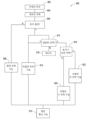
도 77은 모니터링 허브의 디스플레이를 구성하는 예시적인 프로세스를 도시한다.
전술한 "도면의 간단한 설명"은 일반적으로 본 개시의 다양한 예를 참조하지만, 당업자는 본 개시로부터 이러한 예가 상호 배타적이지 않다는 것을 인식할 것이다. 오히려, 당업자는 그러한 예의 일부 또는 전부의 무수한 조합을 인식할 수 있을 것이다.The following figures and related description are provided to illustrate examples of the present disclosure and do not limit the scope of the claims.
1A-1C show perspective views of an exemplary medical monitoring hub. For example, FIG. 1A shows a hub with an example docked portable patient monitor, FIG. 1B shows a hub with a set of medical ports and a non-invasive blood pressure input, and FIG. 1C shows various example temperature sensors attached. shows the hub.
FIG. 2 shows a simplified block diagram of an exemplary monitoring environment including the hub of FIG. 1 .
FIG. 3 shows a simplified example hardware block diagram of the hub of FIG. 1 .
FIG. 4 shows a perspective view of an exemplary detachable docking station of the hub of FIG. 1 .
FIG. 5 shows a perspective view of the exemplary portable patient monitor undocked from the hub of FIG. 1 . Moreover, FIG. 5 shows an alternative example docking station.
6 shows a simplified block diagram of a typical patient device electrical isolation principle.
7A depicts a simplified block diagram of an exemplary selective patient device isolation system of the present disclosure; FIG. 7B adds an exemplary optional non-isolated power level for the system of FIG. 7A.
8 shows a simplified example of a universal medical connector configuration process.
9A-9B, 10, 11A-11F, 11G1-11G2, and 11H-11K show simplified block diagrams of exemplary universal medical connectors having sizes and shapes with smaller cross-sectional areas than typical insulation requirements.
FIG. 10 is a perspective view of the side of the hub of FIG. 1, showing an example of a device-side channel input, such as an exemplary universal medical connector.
11a-11f, 11g1-11g2, and 11h-11k show various views of exemplary male and female mating universal medical connectors.
FIG. 12 shows a simplified block diagram of the channel system for the hub of FIG. 1;
13 shows an exemplary logical channel configuration.
14 shows a simplified example process for configuring a cable and configuring a channel.
15 is a perspective view of the hub of FIG. 1 with an exemplary board-in-cable attached to form an input channel.
FIG. 16 is a perspective view of the back of the hub of FIG. 1, showing an exemplary instrument side serial data input.
FIG. 17A depicts an exemplary monitoring environment in which communication occurs over the serial data connection of FIG. 16 .
17B shows an example connectivity display of the hub of FIG. 1 .
18 shows a simplified example of a patient data flow process.
19A-19J show exemplary displays of anatomical graphics for the portable patient monitor of FIG. 1 docked with the FIG. 1 hub.
20A-20C show exemplary displays of measurement data showing data separation and data overlap, respectively, in the display of the hub of FIG. 1 .
21A and 21B show exemplary displays of measurement data showing data separation and data overlap in the display of the portable patient monitor of FIG. 1 .
22A and 22B show exemplary analog display representations.
23A to 23F show, for example, data when the depth of consciousness monitor is connected to the channel port of the hub of FIG. 1 in FIGS. 23A to 23D, and when a temperature and blood pressure sensor communicates with the hub of FIG. 1 in FIG. 23E. , and in FIG. 23F shows an example of a display of measurement data showing the data display when the acoustic sensor is also in communication with the hub of FIG. 1 .
24 illustrates another example of a monitoring environment including the hub of FIG. 1 .
25 shows the conversion message handling process.
26-39 and 46-71 show additional example hub displays including display of measurement data.
40A shows an example first medical device and an example second medical device communicating with each other via a conversion module.
40B illustrates an exemplary first medical device and an exemplary second medical device communicating with each other via a conversion module and a communication bus.
41A shows an exemplary input message received by the conversion module.
41B shows an example message header segment of an incoming message parsed into fields.
Figure 41C shows an exemplary encoded version of the parsed message header segment of Figure 41B.
41D shows an example output message of the transformation module based on the input message of FIG. 41A.
42 depicts an exemplary transformation process for generating an output message based on a comparison of an input message with a transformation rule associated with a transformation module.
43A depicts an exemplary conversion process by which a conversion module communicates an HL7 message from a Hospital Information System ("HIS") having a first HL7 format to an intended recipient medical device having a second HL7 format.
43B shows an exemplary conversion process by which a conversion module communicates an HL7 message from a medical device having a first HL7 format to an HIS having a second HL7 format.
44 shows an example screen shot of a messaging implementation tool for manually configuring the transformation rules to be used by the transformation module.
45A and 45B show an exemplary automatic rule construction process that may be performed by a transformation module.
45C and 45D illustrate an exemplary automatic rule construction process that may be performed by a transformation module for messages using the HL7 protocol.
46-71 show examples of additional hub displays including display of measurement data.
72A shows an example of interfacing with a hub using a board-in-cable.
72B shows an example of interfacing a hub with an external sensor using a dongle.
73A illustrates an example computing environment of communication between a sensor and a monitoring hub.
73B, 73C, and 73D show exemplary processes for various aspects of communication between a hub and an external device.
73E depicts example user interface elements of a monitoring hub for remotely controlling one or more operations of an external device.
74 shows some exemplary features of a software development kit.
75A and 75B show an example user interface of a display layout manager.
76A, 76B, and 76C show examples of configurable display screens of a monitoring hub.
77 shows an example process for configuring the display of a monitoring hub.
While the foregoing "Brief Description of the Figures" generally refers to various examples of this disclosure, those skilled in the art will recognize from this disclosure that these examples are not mutually exclusive. Rather, one skilled in the art will recognize countless combinations of some or all of such examples.
I. 도입 I. Introduction
적어도 상기에 기초하여, 환자를 치료 또는 모니터링하는 다양한 의료 장치를 조직화하는 해결책이 필요하다. 이러한 해결책은 장치 공간에 걸쳐 환자 식별을 완벽하게 제공할 수 있고, 그러한 해결책은 반드시 반복되는 소프트웨어 업그레이드를 필요로 하지 않고 미래 기술을 위해 확장될 수 있다. 또한, 그러한 솔루션은 원하는 경우 환자의 전기적 절연을 포함할 수 있다.Based at least on the foregoing, a solution is needed to organize the various medical devices that treat or monitor patients. Such a solution can provide seamless patient identification across the device space, and such a solution is extensible for future technologies without necessarily requiring repeated software upgrades. Additionally, such a solution may include electrical isolation of the patient, if desired.
따라서, 본 발명은 임의의 환자에 대한 환자 모니터링 및 치료 활동의 중심 이 되는 환자 모니터링 허브에 관한 것이다. 환자 모니터링 허브는 레거시 재프로그래밍없이 레거시 장치와 인터페이스할 수 있으며, 소프트웨어 업그레이드 없이도 미래 장치와 인터페이스할 수 있는 유연성을 제공하며, 환자의 전기적 절연 옵션을 제공한다. 허브는 광범위한 측정이나 아니면 결정된 파라미터에 관한 정보를 간병인에게 동적으로 제공하는 대형 디스플레이를 포함할 수 있다. 추가적으로 또는 선택적으로, 허브는 휴대용 환자 모니터를 위한 도킹 스테이션을 포함할 수 있다. 휴대용 환자 모니터는 도킹 스테이션을 통해 또는 WiFi, 블루투스, 지그비 등을 포함하여 본 명세서의 개시로부터 당업자에게 알려진 다양한 무선 패러다임을 통해 허브와 통신할 수 있다.Accordingly, the present invention relates to a patient monitoring hub that is central to patient monitoring and treatment activities for any patient. The patient monitoring hub can interface with legacy devices without legacy reprogramming, provides the flexibility to interface with future devices without software upgrades, and provides options for galvanic isolation of the patient. The hub may include a large display that dynamically provides the caregiver with information regarding a wide range of measurements or otherwise determined parameters. Additionally or alternatively, the hub may include a docking station for a portable patient monitor. The portable patient monitor may communicate with the hub via a docking station or via various wireless paradigms known to those skilled in the art from the disclosure herein including WiFi, Bluetooth, ZigBee, and the like.
휴대용 환자 모니터는 도킹될 때 스크린을 수정할 수 있다. 도킹되지 않은 디스플레이 표시는 부분적으로 또는 전체적으로 허브의 큰 동적 디스플레이로 전송되고 도킹된 디스플레이는 모니터링된 신체 부위에 대한 하나 이상의 해부학적 그래픽을 제공한다. 예를 들어, 디스플레이는 도킹될 때 심장, 폐, 뇌, 신장, 내장, 위, 기타 장기, 숫자, 위장계 또는 기타 신체 부위를 제시할 수 있다. 해부학적 그래픽은 바람직하게 애니메이션일 수 있다. 애니메이션은 일반적으로 측정된 파라미터의 행동, 예를 들어 폐가 측정된 호흡률 및/또는 호흡 사이클의 결정된 들숨 부분과 대략 상관 관계로 팽창할 수 있고, 마찬가지로 흡기 사이클의 날숨 부분에 따라 수축할 수 있다. 심장은 심장 박동수에 따라 박동할 수 있고, 이해된 실제 심장 수축 패턴 등에 따라 일반적으로 박동할 수 있다. 또한, 측정된 파라미터가 간병인에게 경고할 필요가 있음을 나타내는 경우, 색상으로 나타낸 심각도의 변화가 심장, 폐, 뇌 등과 같은 하나 이상의 디스플레이된 그래픽과 관련될 수 있다. 신체 부분은 환자의 측정 부위에 측정 장치를 부착하는 위치, 시기 또는 방법에 관한 애니메이션을 포함할 수 있다. 예를 들어, 모니터는 CCHD 스크리닝 절차 또는 포도당 스트립 판독 프로토콜, 이마 센서, 손가락 또는 발가락 센서, 하나 이상의 전극, 음향 센서, 귀 센서, 캐뉼라 센서 등의 적용에 대한 애니메이션 지시를 제공할 수 있다.Portable patient monitors can modify their screens when docked. The undocked display representation is transferred, in part or entirely, to a large dynamic display in the hub, and the docked display presents one or more anatomical graphics for the monitored body part. For example, the display, when docked, may present the heart, lungs, brain, kidneys, intestines, stomach, other organs, numbers, gastrointestinal system, or other body parts. The anatomical graphic may preferably be animated. The animation may generally expand in approximately correlation with the behavior of the measured parameter, eg the lungs may expand in approximately correlation with the measured respiratory rate and/or the determined inspiratory portion of the respiratory cycle, and may likewise contract in accordance with the exhalatory portion of the inspiratory cycle. The heart may beat at a heart rate, may beat generally according to an understood actual heart contraction pattern, and the like. Additionally, changes in severity, indicated by color, may be associated with one or more displayed graphics, such as heart, lungs, brain, etc., if the measured parameter indicates a need to alert the caregiver. The body part may include an animation of a location, time, or method of attaching the measurement device to the patient's measurement site. For example, the monitor may provide animated instructions for application of a CCHD screening procedure or glucose strip reading protocol, forehead sensor, finger or toe sensor, one or more electrodes, acoustic sensor, ear sensor, cannula sensor, and the like.
본 개시는 임의의 환자에 대한 모니터링 활동의 중심이 되도록 구성된 의료 모니터링 허브에 관한 것이다. 허브는 허브의 전면의 대부분을 차지하는 약 10 인치 정도의 디스플레이와 같은, 쉽게 읽을 수 있는 대형 디스플레이를 포함할 수 있다. 디자인 규약에 따라 디스플레이가 훨씬 더 크거나 더 작을 수 있다. 그러나 휴대성과 현재의 설계 목표를 위해, 바람직한 디스플레이는 도킹 가능한 휴대용 환자 모니터들 중 하나의 수직적인 공간에 비례하여 크기가 조정된다. 다른 고려 사항은 당업자에 의해 본 명세서의 개시로부터 인식될 수 있다.The present disclosure relates to a medical monitoring hub configured to be the center of monitoring activities for any patient. The hub may include a large easily readable display, such as a display on the order of 10 inches that takes up most of the front of the hub. Depending on design conventions, displays can be much larger or smaller. However, for portability and current design goals, a preferred display is sized proportionally to the vertical space of one of the dockable portable patient monitors. Other considerations may be recognized from the disclosure herein by those skilled in the art.
디스플레이는 수치 또는 그래픽 형태로 관찰중인 환자에 대해 다양한 모니터링된 파라미터에 대한 측정 데이터를 제공할 수 있고, 허브에서 수신되는 데이터의 유형 및 정보에 기초하여 자동으로 구성될 수 있다. 허브는 간병인 환경 내 편리한 장소에 배치할 수 있도록 이동, 휴대 및 장착이 가능한다. 예를 들어, 허브는 단일 하우징 내에 수집될 수 있다.The display may provide measurement data for various monitored parameters for the patient under observation in numerical or graphical form and may be automatically configured based on the information and type of data received from the hub. The hub is mobile, portable, and mountable for placement in a convenient location within the caregiver's environment. For example, hubs can be collected within a single housing.
허브는 유리하게 허브로부터 도킹 또는 도킹 해제되는 동안 휴대용 환자 모니터로부터 데이터를 수신할 수 있다. 산소 계측기 또는 코-산소 계측기 같은 전형적인 휴대용 환자 모니터는 광학 및/또는 음향 센서, 전극 등으로부터 출력된 신호로부터 유도된 다수의 생리학적 파라미터에 대한 측정 데이터를 제공할 수 있다. 생리학적 파라미터는 산소 포화도, 카르복시 헤모글로빈, 메트헤모글로빈, 총 헤모글로빈, 글루코스, pH, 빌리루빈, 분획 포화도, 맥박수, 호흡률, 호흡주기 성분, 관류 지수를 포함한 관류 지표, 신호 품질 및/또는 신뢰도, plethysmograph 데이터, 건강 또는 건강 지수의 지표 또는 다른 측정 데이터 조합, 호흡에 대한 오디오 정보, 질병 식별 또는 진단, 혈압, 환자 및/또는 측정 부위 온도, 진정 심도, 장기 또는 뇌 산화도, 수화도, 대사에 반응하는 측정, 이들의 조합 등을 포함하지만, 이들에만 제한되지는 않는다. 허브는 주입 펌프 등과 조합하여 폐루프 약물 투여를 달성하기에 충분한 데이터를 출력할 수 있다.The hub may advantageously receive data from the portable patient monitor while being docked or undocked from the hub. A typical portable patient monitor, such as an oximeter or nose-oximeter, can provide measurement data for a number of physiological parameters derived from signals output from optical and/or acoustic sensors, electrodes, and the like. Physiological parameters include oxygen saturation, carboxyhemoglobin, methemoglobin, total hemoglobin, glucose, pH, bilirubin, fractional saturation, pulse rate, respiratory rate, respiratory cycle components, perfusion parameters including perfusion index, signal quality and/or reliability, plethysmograph data, Indices of health or wellness indices or combinations of other measurement data, audio information on respiration, disease identification or diagnosis, blood pressure, patient and/or site temperature, depth of sedation, organ or brain oxidation, hydration, metabolism-responsive measurements , combinations thereof, and the like, but are not limited thereto. The hub may output sufficient data to achieve closed loop drug administration in combination with an infusion pump or the like.
허브는 다수의 방식으로 환자와 상호 작용하는 모니터링 환경에서 다른 장치와 통신할 수 있다. 예를 들어, 허브는 유리하게는 다른 장치로부터 직렬 데이터를 수신하는데, 이들 장치 나 허브의 리프로그래밍을 필요로 하지 않고 수신한다. 이러한 다른 장치는 펌프, 인공 호흡기, 전술한 파라미터의 조합을 모니터링하는 모든 방식의 모니터, ECG/EEG/EKG 장치, 전자식 환자 침대 등을 포함한다. 더욱이, 허브는 유리하게는 다른 의료 장치로부터 채널 데이터를 수신하는데, 이들 장치 나 허브의 리프로그래밍을 필요로 하지 않고 수신한다. 장치가 채널 데이터를 통해 통신할 때, 허브는 유리하게 그 장치로부터의 측정 정보를 포함하는 대형 디스플레이로 교체할 수 있다. 또한 허브는 간호사 호출 시스템에 액세스하여 장치로부터의 간호사 호출 상황이 적절한 간호사 호출 시스템으로 전달되는 것을 확실하게 해준다.The hub may communicate with other devices in the monitoring environment that interact with the patient in a number of ways. For example, a hub advantageously receives serial data from other devices without requiring reprogramming of these devices or hubs. These other devices include pumps, ventilators, monitors of any type that monitor any combination of the aforementioned parameters, ECG/EEG/EKG devices, electronic patient beds, and the like. Moreover, the hub advantageously receives channel data from other medical devices without requiring reprogramming of these devices or the hub. When a device communicates via channel data, the hub can advantageously switch to a large display containing measurement information from that device. The hub also has access to the nurse call system to ensure that nurse call conditions from the device are forwarded to the appropriate nurse call system.
허브는 또한 입원 환자 측정 및 치료 데이터를 모니터링되는 환자와 바람직하게 연관시키도록 병원 시스템과 통신한다. 예를 들어, 허브는 서버 또는 서버 컬렉션과 같은 다중 환자 모니터링 시스템과 무선으로 또는 다른 방식으로 통신할 수 있으며, 다음에 이 시스템은 예를 들어 Admit, Discharge, Transfer ("ADT") 시스템 및/또는 전자 의료 기록("EMR") 시스템과 같은 간병인 데이터 관리 시스템과 통신한다. 허브는 유리하게는 허브를 통해 흐르는 데이터를 모니터링되고 있는 환자와 연관시키므로, 간병인이 환경 내의 각 장치를 환자와 연관시키지 않고도 간병인의 데이터 관리 시스템에 전달될 전자 측정 및 치료 정보를 제공할 수 있다.The hub also communicates with hospital systems to preferably associate inpatient measurement and treatment data with monitored patients. For example, the hub may communicate wirelessly or otherwise with a multi-patient monitoring system, such as a server or collection of servers, which in turn may communicate with, for example, an Admit, Discharge, Transfer ("ADT") system and/or Communicates with caregiver data management systems, such as electronic medical record ("EMR") systems. The hub advantageously associates the data flowing through the hub with the patient being monitored so that the caregiver can provide electronic measurement and treatment information to be passed to the caregiver's data management system without associating each device in the environment with the patient.
허브는 유리하게 재구성 및 제거 가능한 도킹 스테이션을 포함할 수 있다. 도킹 스테이션은 다른 환자 모니터링 장치에 적응하기 위해 추가적인 계층의 도킹 스테이션에 도킹할 수 있다. 또한, 도킹 스테이션 자체는 모듈화되어 기본 도킹 가능한 휴대용 환자 모니터가 그 구성 인자들을 변경하는 경우 제거될 수 있다. 따라서 허브는 도킹 스테이션의 구성 방식에 있어서 유연한다.The hub may advantageously include a reconfigurable and removable docking station. The docking station may dock with additional tiers of docking stations to accommodate other patient monitoring devices. Additionally, the docking station itself is modular and can be eliminated if the basic dockable portable patient monitor changes its components. Hubs are therefore flexible in how the docking station is configured.
허브는 허브가 수신, 처리 및/또는 환자와 연관시키는 데이터의 일부나 전부 및 허브가 다른 장치 및 시스템과 갖는 통신을 저장하기 위한 대형 메모리를 포함한다. 메모리의 일부 또는 전부는 유리하게 착탈 가능한 SD 메모리를 포함할 수 있다.The hub includes a large memory for storing some or all of the data that the hub receives, processes, and/or associates with the patient, and communications the hub has with other devices and systems. Some or all of the memory may advantageously include a removable SD memory.
허브는 적어도 (1) 휴대용 모니터로부터 데이터를 획득하기 위한 도킹 스테이션, (2) 채널 데이터를 획득하기 위한 혁신적인 범용 의료 커넥터, (3) 출력 데이터를 획득하도록 RJ 포트와 같은 직렬 데이터 커넥터, (4) 이더넷, USB 및 간호사 호출 포트, (5) 휴대용 모니터에서 데이터를 수집하는 무선 장치, 및 (6) 당업자에게 알려진 다른 유무선 통신 메커니즘을 통해 다른 장치와 통신한다. 범용 의료 커넥터는 유리하게 전기적으로 절연된 전력 및 통신을 옵션으로 제공하며, 절연 요구 조건보다 단면적이 더 작도록 설계된다. 커넥터와 허브는 허브에 대해 사용 가능하고 디스플레이 가능하도록 다른 장치로부터의 데이터를 유리하게 변환 또는 구성하도록 통신한다. 장치 제조업체에 소프트웨어 개발 키트("SDK")를 제공하여 장치에서 출력되는 데이터의 동작과 의미를 설정하거나 정의할 수 있다. 출력이 정의되면 이 정의는 범용 의료 커넥터의 케이블 쪽에 있는 메모리에 프로그래밍되고 장치 공급 업체에 생산자 주문 제작 방식(OEM)으로 공급된다. 케이블이 장치와 허브 사이에 연결되면 허브는 데이터를 이해하고 이를 장치나 허브로 소프트웨어를 업그레이드하지 않고도 표시 및 처리 목적으로 사용할 수 있다. 허브는 스키마를 협상하고 추가 압축 및/또는 암호화를 추가할 수도 있다. 허브는 범용 의료 커넥터를 사용하여 측정 및 치료 데이터를 단일 디스플레이 및 경보 시스템으로 구성하여 모니터링 환경에 효과적이고 효율적이 되게 한다.The hub has at least (1) a docking station to acquire data from a portable monitor, (2) an innovative universal medical connector to acquire channel data, (3) a serial data connector such as an RJ port to acquire output data, (4) It communicates with other devices via Ethernet, USB and nurse call ports, (5) a wireless device that collects data from a portable monitor, and (6) other wired and wireless communication mechanisms known to those skilled in the art. Universal medical connectors advantageously provide electrically isolated power and communication options and are designed to have a smaller cross-section than the isolation requirements. The connector and hub communicate to advantageously transform or organize data from other devices so that it is usable and displayable to the hub. A software development kit ("SDK") may be provided to the device manufacturer to set up or define the behavior and meaning of data output from the device. Once the outputs are defined, these definitions are programmed into memory on the cable side of the universal medical connector and supplied to the device supplier as an original equipment manufacturer (OEM). When a cable is connected between a device and a hub, the hub can understand the data and use it for display and processing without requiring software upgrades to either the device or the hub. A hub may negotiate a scheme and add additional compression and/or encryption. The hub uses a universal medical connector to organize measurement and treatment data into a single display and alarm system, making the monitoring environment effective and efficient.
허브가 채널 패러다임에 따라 다른 장치로부터 데이터를 수신하고 추적함에 따라, 허브는 환자 측정 또는 치료 데이터의 가상 채널을 생성하기 위한 처리를 유리하게 제공할 수 있다. 가상 채널은 예를 들어, 다양한 측정 또는 다른 파라미터로부터 데이터를 처리한 결과인, 측정되지 않은 파라미터를 포함할 수 있다. 이러한 파라미터의 예는 모니터링된 환자의 전반적인 건강의 표시를 제공하는 다양한 측정 파라미터로부터 도출된 건강 표시자를 포함한다. 건강 파라미터의 예는 미국 특허 출원 번호 13/269,296, 13/371,767, 및 12/904,925에 개시되며, 본원에 참조로 포함된다. 데이터를 채널 및 가상 채널로 구성함으로써, 허브는 유리하게는 수신 데이터 및 가상 채널 데이터를 시간적으로 동기화할 수 있다.As the hub receives and tracks data from other devices according to the channel paradigm, the hub may advantageously provide processing to create virtual channels of patient measurement or treatment data. A virtual channel may include unmeasured parameters, for example, as a result of processing data from various measurements or other parameters. Examples of such parameters include health indicators derived from various measurement parameters that provide an indication of the monitored patient's overall health. Examples of health parameters are disclosed in US Patent Application Serial Nos. 13/269,296, 13/371,767, and 12/904,925, incorporated herein by reference. By organizing data into channels and virtual channels, the hub can advantageously synchronize received data and virtual channel data in time.
허브는 또한 RJ 커넥터와 같은 직렬 통신 포트를 통해 직렬 데이터를 수신한다. 직렬 데이터는 모니터링된 환자와 관련되어 있으며 위에서 논의된 다중 환자 서버 시스템 및/또는 간병인 백엔드 시스템으로 전달된다. 직렬 데이터를 수신함으로써, 간병인은 환자와 관련되며 병원 시스템과도 통신하는 각각의 개별 장치를 가질 필요가 없이, 간병인 환경에서 다양한 제조사로부터의 장치를 특정 환자와 연관시킬 수 있다. 이러한 연관성은 환자에 대해 간병인이 인적 사항 정보를 각 장치에 입력하는 데 소요되는 시간을 줄이므로 매우 중요하다. 더욱이, SDK를 통해, 장치 제조자는 유리하게 장치의 임의의 측정 지연과 관련된 정보를 제공할 수 있어, 허브가 직렬 수신 데이터 및 환자와 관련된 다른 데이터를 유리하게 시간적으로 동기화하는 것을 가능하게 한다.The hub also receives serial data through a serial communication port such as an RJ connector. Serial data is associated with the monitored patient and passed to the multi-patient server system and/or caregiver backend system discussed above. By receiving the serial data, the caregiver can associate devices from various manufacturers with a particular patient in the caregiver environment, without having to have each individual device associated with the patient and also communicating with the hospital system. This association is very important as it reduces the time required for caregivers to enter demographic information about the patient into each device. Moreover, through the SDK, the device manufacturer can advantageously provide information related to any measurement delay of the device, enabling the hub to advantageously synchronize the serially received data and other data related to the patient in time.
휴대용 환자 모니터가 도킹되고 자체 디스플레이를 포함할 때, 허브는 효과적으로 디스플레이 영역을 증가시킨다. 예를 들어, 휴대용 환자 모니터는 단순히 측정 및/또는 치료 데이터를 계속 디스플레이할 수 있으며, 이제 허브 디스플레이 상에 복제될 수 있거나, 도킹된 디스플레이는 그 디스플레이를 변경하여 추가 정보를 제공할 수 있다. 도킹된 디스플레이는 도킹될 때, 예를 들어 심장, 폐, 기관, 뇌 또는 측정되고/되거나 치료되는 다른 신체 부위의 해부학적 그래픽 데이터를 제공할 수 있다. 그래픽 데이터는 유리하게는 측정 데이터와 유사하게 이와 관련하여 애니메이션으로 표시될 수 있다. 예를 들어, 폐는 측정된 호흡률 및/또는 호흡 주기의 결정된 들숨/날숨 부분과 대략 상관 관계로 팽창하고, 심장은 맥박수에 따라 뛰거나, 일반적으로 이해되는 실제 심장 수축 패턴을 따라 뛰고, 뇌는 다양한 진정 심도 등에 기초하여 색 또는 활동을 변화시키는 것으로 표시될 수 있다. 측정된 파라미터가 간병인에게 경고할 필요가 있음을 나타내는 경우, 중증도의 색의 변화는 심장, 폐, 뇌, 기관, 순환계 또는 이의 일부, 호흡기 또는 이의 일부와 다른 신체 부위 등과 같은, 하나 이상의 디스플레이된 그래픽과 관련될 수 있다. 신체 부위는 측정 장치를 부착하는 장소, 시기 또는 방법에 관한 애니메이션을 포함할 수 있다.When a portable patient monitor is docked and contains its own display, the hub effectively increases the display area. For example, a portable patient monitor may simply continue to display measurement and/or treatment data, which may now be duplicated on a hub display, or a docked display may change its display to provide additional information. When docked, the docked display may provide anatomical graphical data of, for example, the heart, lungs, organs, brain, or other body part being measured and/or treated. Graphical data can advantageously be displayed in animation in this regard, similar to measurement data. For example, the lungs expand approximately in correlation with the measured respiratory rate and/or the determined inhalation/exhalation portion of the respiratory cycle, the heart beats according to the pulse rate or according to the commonly understood actual heart contraction pattern, and the brain It can be displayed as changing color or activity based on different depths of sedation and the like. If the measured parameter indicates that a caregiver needs to be alerted, a change in color of severity may be indicated by one or more displayed graphics, such as the heart, lungs, brain, trachea, circulatory system or parts thereof, respiratory system or parts thereof and other body parts, etc. may be related to The body part may include an animation of where, when, or how to attach the measuring device.
허브는 유리하게는 부가적인 시각적 정보를 간병인에게 제공하기 위해 파라미터 디스플레이를 중첩할 수 있다. 이러한 중첩은 사용자가 정의하고 구성할 수 있다. 디스플레이에는 아날로그 표시 아이콘 또는 그래픽 표시가 포함될 수도 있다.The hub may advantageously overlay the parameter display to provide additional visual information to the caregiver. This nesting is user-defined and configurable. The display may also include analog representation icons or graphical representations.
본 개시의 허브는 고도로 구성 가능하고 이전에 알려지지 않은 의료 시스템과 통신할 수 있다. 연결 가능한 의료 시스템은 허브의 기능을 확장할 수 있는 특수한 소프트웨어 처리 기능을 제공하는 내장 프로세서가 있는 동글일 수 있다. 선택적으로, 연결된 의료 시스템은 허브와 통신 케이블을 통해 통신하는 의료 장치일 수 있다. 케이블은 내부에 처리 보드를 포함할 수 있다. 선택적으로 의료 장치 자체의 프로세서가 허브와 직접 통신할 수 있다.The hubs of this disclosure are highly configurable and capable of communicating with previously unknown medical systems. A connectable medical system could be a dongle with an embedded processor providing special software processing capabilities that would extend the capabilities of the hub. Optionally, the connected medical system may be a medical device that communicates with the hub via a communication cable. The cable may contain a processing board therein. Optionally, the processor of the medical device itself may communicate directly with the hub.
의료 시스템이 예를 들어 케이블 또는 동글 장치와 같은 유선 연결을 사용하여 초기에 연결될 때, 케이블 또는 동글 장치 상의 EPROM은 초기에 의료 시스템의 프로세서와 통신하기 위해 필요한 물리적 통신 파라미터를 기술한다. 예를 들어 EPROM은 ISO/비ISO 통신 요구 조건, 보드 속도 등을 포함한 파라미터를 제공할 수 있다.When the medical system is initially connected using a wired connection, for example a cable or dongle device, the EPROM on the cable or dongle device initially describes the physical communication parameters needed to communicate with the medical system's processor. For example, the EPROM can provide parameters including ISO/non-ISO communication requirements, baud rate, etc.
초기 통신 파라미터가 설정되면, 허브는 의료 시스템의 프로세서와 통신을 시작할 수 있다. 그런 다음 의료 시스템은 자체 설명 및 그 기능 설명을 허브에 제공한다. 예를 들어, 자체 설명은 장치에 의해 지원되는 측정 채널; 이름, 표준 기구에 의해 정의된 메트릭 및 코딩 시스템과의 관계, 유효 범위 및 측정 단위, 관련된 신체 부위, 파라미터 예외, 시각적 표현 요구 사항 및 특성을 포함하지만 이에 제한되지 않는 각 채널에 의해 지원되는 측정 파라미터(메트릭); 알람 한계 및 기타 파라미터 설정; 경보, 경보 및 기타 이벤트 조건; 장치가 수행할 수 있는 동작(예: 측정 시작 요청); 장치가 계산을 수행하는 데 필요한 환자 인적 사항 및 외부 측정 메트릭; 제조업체 브랜딩 정보; 또는 환자 모니터링에 필요한 기타 정보를 포함한다.Once the initial communication parameters are set, the hub can start communicating with the medical system's processor. The health system then provides a self-description and a description of its function to the hub. For example, a self-describing may include measurement channels supported by the device; Measurement parameters supported by each channel, including but not limited to name, relationship to metrics and coding systems defined by standards bodies, valid ranges and units of measurement, relevant body parts, parameter exceptions, visual presentation requirements and characteristics. (metric); setting alarm limits and other parameters; alerts, alerts and other event conditions; Actions the device may perform (eg request to start a measurement); patient demographics and external measurement metrics required for the device to perform calculations; manufacturer branding information; or other information necessary for patient monitoring.
플랫폼의 "자체 설명" 특성은 높은 수준의 유연성을 허용하여, 프로토콜 및 소프트웨어 버전에 대한 호환성을 유지하면서 프로토콜 및 그 기능이 진화할 수 있게 한다. 예를 들어, 플랫폼은 타사 장치 (외부 장치 또는 의료 장치일 수 있음)와 통신하여 타사 장치로부터 환자 데이터를 수신하고 환자 데이터를 허브의 스크린에 표시하는 환자 허브 장치(또는 "허브")일 수 있다. 타사 장치는 허브 또는 허브에 연결된 동글 또는 케이블에 저장될 수 있는 응용 프로그래밍 인터페이스("API")로 표시되는 코드 라이브러리에 액세스하여 허브와 통신할 수 있다. 코드 라이브러리는 허브에서 타사 장치의 형태를 제어하는 데 사용할 수 있는 사용자 인터페이스 컨트롤을 형성할 수 있게 하는 기능을 제공할 수 있다.The "self-describing" nature of the platform allows for a high degree of flexibility, allowing protocols and their functions to evolve while maintaining compatibility across protocols and software versions. For example, a platform may be a patient hub device (or "hub") that communicates with a third party device (which may be an external device or medical device) to receive patient data from the third party device and display the patient data on the hub's screen. . Third-party devices may communicate with the Hub by accessing a library of code represented as an application programming interface ("API") that may be stored on the Hub or on a dongle or cable connected to the Hub. Code libraries may provide functionality that allows the hub to form user interface controls that can be used to control the appearance of third-party devices.
예를 들어, 슬라이더는 허브상의 사용자 인터페이스 컨트롤로 제공될 수 있으며, 이는 사용자가 타사 장치의 알람 한계 또는 다른 설정을 조정할 수 있게 한다. 업데이트된 설정을 수신하면 허브는 이 설정 업데이트를 타사 장치(예를 들어, 케이블, 네트워크 등)로 통신할 수 있다. 타사 장치는 허브에서 설정 업데이트를 해석할 수 있는 코드를 포함할 수 있기 때문에 설정 업데이트를 읽는 방법을 알 수 있다(예를 들어, 허브는 타사 장치가 이해할 수 있는 방식으로 설정 업데이트를 포맷할 수 있음) 마찬가지로 허브는 허브에 연결된 모든 센서(예를 들어, SpO2 또는 맥박수 센서)에서 얻은 환자 데이터를 전송하고 해당 환자 데이터(예를 들어, SpO2% 또는 맥박수)를 타사 장치로 전송할 수 있고, 이 장치는 이 데이터를 알고리즘을 업데이트하기 위해서 또는 다른 목적으로 사용한다.For example, a slider could be provided as a user interface control on the hub, allowing users to adjust alarm limits or other settings on third-party devices. Upon receiving updated settings, the hub can communicate this settings update to third-party devices (eg, cable, network, etc.). Third-party devices can know how to read settings updates because they can include code that allows hubs to interpret settings updates (for example, hubs can format settings updates in a way that third-party devices can understand). ) Similarly, a hub may transmit patient data obtained from any sensor connected to the hub (eg SpO2 or pulse rate sensor) and transmit that patient data (eg SpO2% or pulse rate) to a third-party device, which device Use this data to update algorithms or for other purposes.
또한, 새로운 환자가 허브에 연결될 때, 허브는 새로운 환자가 타사 장치에 연결되었음을 보고할 수 있다. 이렇게 하면 타사 장치는 예를 들어 새 환자의 기준을 재설정하여 측정 또는 치료 알고리즘을 다시 시작하는 것을 알 수 있다. 이 기능이 없으면 새 환자가 허브에 연결될 때 타사 장치는 환자에 대한 오래된 기준 데이터(사실 이전 환자를 참조했을 것)를 사용하여 환자를 계속 측정하거나 치료했을 수 있다.Additionally, when a new patient connects to the hub, the hub may report that the new patient has connected to a third-party device. This lets the third-party device know to restart the measurement or treatment algorithm, for example by resetting the criteria for a new patient. Without this capability, when a new patient is connected to the hub, third-party devices may continue to measure or treat the patient using old baseline data about the patient (which, in fact, would have referenced the previous patient).
의료 시스템은 일단 허브에 연결되면, 임의의 정보를 허브로부터 입력하거나 허브로 출력할 수 있다. 예를 들어, 연결된 의료 시스템 A는 연결된 의료 시스템 B에서 측정된 파라미터를 가져올 수 있다. 의료 시스템 A는 이 정보를 사용하여 새로 측정된 파라미터를 생성하고 다음에 이것은 다른 연결된 의료 시스템에 의해 표시하거나 사용하기 위해 플랫폼으로 출력될 수 있다.Once connected to the hub, the medical system can input any information from or output to the hub. For example, connected medical system A may retrieve parameters measured in connected medical system B. Medical system A uses this information to create a new measured parameter, which can then be output to the platform for display or use by other connected medical systems.
다양한 연결된 의료 시스템으로부터 획득된 데이터는 허브의 시스템 시계를 사용하여 타임 스탬프될 수 있다. 타임 스탬프를 사용하면 다양한 측정 값을 다른 측정 값과 동기화되게 할 수 있다. 동기화는 데이터의 표시 및 데이터를 사용한 추가 계산을 지원할 수 있다.Data obtained from the various connected medical systems can be time stamped using the hub's system clock. Timestamps allow various measurements to be synchronized with other measurements. Synchronization can support the display of data and further calculations using the data.
타사 장치는 환자 데이터에 기초하여 계산을 수행하고 계산 결과를 허브에 전달할 수 있다. 예를 들어, 타사 장치는 허브 또는 다른 타사 장치에서 수신한 환자 파라미터 데이터를 기반으로 건강 지수를 계산할 수 있다. 타사 장치는 계산을 수행하도록 구성된 보드-인-케이블(일 수 있다. 예를 들어, 타사 장치는 알고리즘을 실행하여 보드-인-케이블에 연결된 센서에서 획득한 데이터를 기반으로 환자의 파라미터를 계산할 수 있다.Third-party devices may perform calculations based on patient data and communicate calculation results to the hub. For example, a third party device may calculate a health index based on patient parameter data received from a hub or other third party device. The third-party device may be a board-in-cable configured to perform the calculations. For example, the third-party device may run algorithms to calculate parameters of the patient based on data obtained from sensors connected to the board-in-cable. there is.
플랫폼은 의료 시스템의 디스플레이 특성에 따라 표준화된 그래픽 인터페이스를 제공할 수 있다. 예를 들어, 의료 시스템은 수치 판독, 그래프 또는 자체 정의할 수 있는 기타 지정된 디스플레이 옵션으로 자체 정의할 수 있다. 선택적으로, 부착된 의료 장치는 허브에 의해 사용되는 이미지 데이터를 제공하여 디스플레이 그래픽을 제공할 수 있다.The platform may provide a standardized graphic interface according to display characteristics of the medical system. For example, a medical system can be self-defining with numerical readouts, graphs, or other designated display options that can be self-definable. Optionally, an attached medical device may provide image data used by the hub to provide display graphics.
타사 장치는 또한 허브상에서 디스플레이 설정의 적어도 일부를 제어할 수 있다. 예를 들어, 타사 장치는 의료 시스템의 디스플레이 특성 또는 자체 정의된 디스플레이 옵션을 허브에 전달할 수 있으며, 이는 의료 시스템에서 제공하는 데이터와 관련된 허브의 디스플레이 보다 우선하거나 이를 보완할 수 있다. 본 명세서에 설명된 타사 장치의 자체 설명 기능 및 기타 기능 및 통신은 소프트웨어 개발 키트(SDK)로 프로그래밍할 수 있다. SDK는 허브 공급 업체가 타사 장치의 공급 업체에 제공할 수 있으며, 이를 통해 타사 장치의 공급 업체가 사용자 정의 기능을 생성하고 허브와 인터페이스할 수 있다.Third-party devices may also control at least some of the display settings on the hub. For example, a third-party device may pass the medical system's display characteristics or self-defined display options to the hub, which may override or supplement the hub's display related to data provided by the medical system. The self-describing features and other functions and communications of third-party devices described herein can be programmed with software development kits (SDKs). SDKs can be provided by hub vendors to vendors of third-party devices, which allow vendors of third-party devices to create custom functionality and interface with the hub.
명확성을 위해, 실제 구현의 모든 특징들이 본 명세서에서 설명되는 것은 아니다. 물론, 당업자라면 (모든 개발 프로젝트에서와 같이) 실제 구현을 개발할 때 시스템 및 비즈니스 관련 제한 사항들에 준수하는 것과 같이, 개발자의 특정 목표와 하위 목표를 달성하기 위해 저마다 다를 수 있는 수많은 구현마다 특정한 결정을 내려야 한다는 점이 이해될 것이다. 더욱이, 그러한 개발 노력은 복잡하고 시간 소모적일 수 있지만, 그럼에도 본 개시의 이점을 갖는 당업자라면 장치 엔지니어링을 수행하는 루틴이 될 것이다.In the interest of clarity, not all features of an actual implementation are described herein. Of course, those skilled in the art (as in any development project) make specific decisions for each of the many implementations, which may differ in order to achieve the developer's specific goals and sub-goals, such as adhering to system and business-related limitations when developing an actual implementation. It will be understood that the Moreover, such a development effort can be complex and time consuming, but will nonetheless become routine for those skilled in the art having the benefit of this disclosure to perform device engineering.
본 개시의 완전한 이해를 용이하게 하기 위해, 상세한 설명의 나머지 부분은 도면을 참조하여 설명하며, 동일한 참조 번호는 전체에 걸쳐 동일한 참조 번호가 참조된다.To facilitate a thorough understanding of the present disclosure, the remainder of the detailed description is set forth with reference to the drawings, in which like reference numerals are referenced throughout.
II. 의료 모니터링 허브의 예 II. Examples of medical monitoring hubs
도 1a는 예시적으로 도킹된 휴대용 환자 모니터(102)를 갖는 예시적인 의료 모니터링 허브(100)의 사시도를 포함하는 모니터링 환경을 도시한다. 허브(100)는 디스플레이(104) 및 도킹 스테이션(106)을 포함할 수 있고, 기계적으로 그리고 전기적으로 휴대용 환자 모니터(102)와 결합하도록 구성될 수 있으며, 각각은 이동 가능, 장착 가능 및 휴대 가능한 하우징(108)에 내장된다. 하우징(108)은 다양한 위치와 장착법으로 고정되고 다양한 형상과 크기로 구성될 수 있지만, 수평 방향으로 평평한 표면 상에 놓이도록 구성된 일반적으로 직립형 경사진 형상을 포함한다. 1A depicts a monitoring environment comprising a perspective view of an exemplary
디스플레이(104)는 수치, 그래픽, 파형 또는 다른 디스플레이 표시(110)로 광범위한 측정 및/또는 처리 데이터를 제공할 수 있다. 디스플레이(104)는 하우징(108)의 전면의 대부분을 차지할 수 있지만, 당업자라면 디스플레이(104)는 태블릿 또는 테이블탑 구성, 랩탑 구성 등을 포함할 수 있음을 이해할 것이다. 디스플레이(104)는 디스플레이 정보 및 데이터를 테이블 컴퓨터, 스마트 폰, 텔레비전, 또는 당업자에게 인식 가능한 임의의 디스플레이 시스템으로 통신하는 것을 포함할 수 있다. 도 1a의 직립형 경사진 구성은 쉽게 볼 수 있는 방식으로 간병인에게 정보를 제시할 수 있다.The
도 1b는 하우징(108), 디스플레이(104), 및 도킹 스테이션(106)을 포함하는 허브(100)의 측면 사시도로, 휴대용 모니터가 도킹되어 있지 않다. 또한, 비관혈적 혈압 용 커넥터가 도시된다.1B is a side perspective view of
하우징(108)은 또한, 예를 들어, 도 1c에 도시된 것과 같은 혈압 모니터 또는 온도 센서(112)와 같은 추가적인 의료 장치를 보유하기 위한 포켓 또는 만입부를 포함할 수 있다.
도 1a의 휴대용 환자 모니터(102)는 유리하게는 산소 계측기, 코-산소 계측기, 호흡 모니터, 진정 심도 모니터, 비관혈적 혈압 모니터, 바이탈 싸인 모니터 등을 포함할 수 있으며, 예컨대 캘리포니아주 얼바인의 Masimo Corporation으로부터 시판되고/되거나 미국 특허 번호 2002/0140675, 2010/0274099, 2011/0213273, 2012/0226117, 2010/0030040; 미국 특허 출원 번호 61/242792, 61/387457, 61/645570, 13/554908, 및 미국 특허 번호 6,157,850, 6,334,065 등에 기재된 것이 있다. 모니터(102)는 발광 및 검출 회로를 갖는 광학 센서, 음향 센서, 채혈, 혈액, 호흡기 등으로부터 혈액 파라미터를 측정하는 장치와 같은 다양한 비관혈적 및/또는 최소 관혈적 장치와 통신할 수 있다. 모니터(102)는 도 19a-19j를 참조하여 아래에서 논의되는 자체 디스플레이 표시(116)를 나타내는 자체 디스플레이(114)를 포함할 수 있다. 디스플레이 표시는 모니터(102)의 도킹 상태에 기초하여 유리하게 변경될 수 있다. 도킹 해제될 때, 디스플레이 표시자는 파라미터 정보를 포함할 수 있고, 예를 들어 중력 센서 또는 가속도계에 기초하여 방향을 변경할 수 있다.The portable patient monitor 102 of FIG. 1A may advantageously include an oximeter, a nose-oximeter, a respiration monitor, a depth of sedation monitor, a non-invasive blood pressure monitor, a vital sign monitor, and the like, such as Masimo Corporation of Irvine, Calif. and/or US Patent Nos. 2002/0140675, 2010/0274099, 2011/0213273, 2012/0226117, 2010/0030040; US Patent Application Nos. 61/242792, 61/387457, 61/645570, 13/554908, and US Patent Nos. 6,157,850, 6,334,065 and the like. The
허브(100)의 도킹 스테이션(106)은 기계식 래치(118)를 포함하거나, 허브(100)의 움직임이 모니터(102)가 손상되게 모니터(102)를 기계적으로 분리하지 않도록 하기 위해 기계적으로 해제 가능한 캐치를 포함한다.The
특정 휴대용 환자 모니터(102)를 참조하여 개시되었지만, 당업자라면 본 명세서의 개시로부터 허브(100)와 유리하게 도킹될 수 있는 다수의 다양한 의료 장치가 있다는 것을 인식할 것이다. 또한, 도킹 스테이션(106)은 모니터(102)와 기계적이 아니고 전기적으로 연결되어 무선으로 통신하는 것이 바람직할 수 있다.Although disclosed with reference to a particular portable
도 2는 도 1의 허브(100)를 포함하는 예시적인 모니터링 환경(200)의 단순화된 블록도를 도시한다. 도 2에 도시된 바와 같이, 환경은 예를 들어 산소 계측 광학 센서, 음향 센서, 혈압 센서, 호흡 센서 등과 같은 하나 이상의 환자 센서(202)와 통신하는 휴대용 환자 모니터(102)를 포함할 수 있다. 예를 들어, NIBP 센서 또는 시스템(211) 및 온도 센서 또는 센서 시스템(213)과 같은 추가 센서는 허브(100)와 직접 통신할 수 있다. 사용 중에 있는 센서(202, 211 및 213)는 측정 장소에서 환자에게 실재 부착되지 않은 경우라면 일반적으로 모니터링되고 있는 환자와 근접해 있다. FIG. 2 shows a simplified block diagram of an
개시된 바와 같이, 휴대용 환자 모니터(102)는 도킹될 때 및 도킹 해제될 때 무선으로 도킹 스테이션(106)을 통해 허브(100)와 통신할 수 있지만, 그러한 도킹 해제된 통신은 필요하지 않다. 허브(100)는 하나 이상의 다중 환자 모니터링 서버(204) 또는 예를 들어 미국 특허 번호 2011/0105854, 2011/0169644, 및 2007/0180140에 개시된 것과 같은 서버 시스템과 통신한다. 일반적으로, 서버(204)는 EMR 및/또는 ADT 시스템과 같은 간병인 백엔드 시스템(206)과 통신한다. 서버(204)는 유리하게는 인적사항 정보, 청구 정보 등과 같이 환자 입원시에 입력된 환자 정보를 입력, 출력 또는 조합 기술을 통해 얻을 수 있다. 허브(100)는 이 정보에 액세스하여 모니터링된 환자를 간병인 백엔드 시스템(206)과 매끄럽게 연관시킨다. 서버(204)와 모니터링 허브(100) 사이의 통신은 무선, 유선, 모바일 또는 기타 컴퓨팅 네트워크를 포함하여 본 명세서의 개시로부터 당업자에게는 인식 가능하게 될 것이다.As disclosed, the portable patient monitor 102 can communicate with the
도 2는 또한 직렬 데이터 포트(210) 및 채널 데이터 포트(212)를 통해 통신하는 허브(100)를 도시한다. 앞서 언급한 바와 같이, 직렬 데이터 포트(210)는 전자 환자 베드 시스템(214), 폐쇄 루프 제어 시스템을 포함하는 주입 펌프 시스템(216), 산소 호흡기 시스템(218), 혈압 또는 그 외 바이탈 싸인 측정 시스템(220) 등을 포함하는 다양한 환자 의료 장치로부터 데이터를 제공할 수 있다. 유사하게, 채널 데이터 포트(212)는 전술한 것중 임의의 것을 포함하는 다양한 환자 의료 장치 및 다른 의료 장치로부터 데이터를 제공할 수 있다. 예를 들어, 채널 데이터 포트(212)는 SEDLine로부터 상용 가능한 것과 같은 의식 상태 심도 모니터(222), 뇌 또는 다른 기관 산소 측정 장치(224), 비관혈적 혈압 또는 음향 호흡기(226) 등으로부터 데이터를 수신할 수 있다. 채널 장치에는 처리 알고리즘 및 이러한 알고리즘을 수행하는 신호 처리 장치가 추가 디스플레이 기술을 갖지 않는 케이블 또는 케이블 커넥터에 내장된 보드에 장착되는 보드-인-케이블(board-in-cable; "BIC") 솔루션이 포함할 수 있다. BIC 솔루션은 측정된 파라미터 데이터를 채널 포트(212)에 출력하여 허브(100)의 디스플레이(104) 상에 디스플레이한다. 허브(100)는 유리하게는 예를 들어, 태블릿, 스마트 폰, 또는 기타 컴퓨팅 시스템과 같은 다른 시스템과 통신하는 BIC 솔루션으로서 전체적으로 또는 부분적으로 형성될 수 있다.2 also shows
단일 도킹 스테이션(106)과 관련하여 개시되었지만, 환경(200)은 도 5를 참조하여 도시된 바와 같이 후속의 도킹 스테이션이 기계적 및 전기적으로 제1 도킹 스테이션에 도킹되어 다른 휴대용 특허 모니터에 대한 형태 인자를 변경하는 스택형 도킹 스테이션을 포함할 수 있다. 이러한 스태킹은 2개 이상의 도킹 스테이션을 포함할 수 있고, 휴대용 장치에서 기계 구조와 기계적으로 맞물려 형태 인자를 감소 또는 증가시킬 수 있다.Although disclosed with reference to a
도 3은 도 1의 허브(100)의 단순화된 예시적인 하드웨어 블록도를 도시한다. 도 3에 도시된 바와 같이, 허브(100)의 하우징(108)은 계측기 보드(302), 디스플레이(104), 메모리(304) 및 직렬 포트(210), 채널 포트(212), 이더넷 포트(305), 간호사 호출 포트(306), 및 표준 USB 등을 포함하는 통신 포트(308), 및 도킹 스테이션 인터페이스(310)를 포함하는 다양한 통신 연결을 위치 지정 및/또는 포함한다. 계측기 보드(302)는 통신 인터커넥트, 배선, 포트 등을 포함하는 하나 이상의 기판을 포함함으로써, 인터보드 통신을 포함하여 본 명세서에 기술된 통신 및 기능을 가능하게 한다. 코어 보드(312)는 메인 파라미터, 신호 및 다른 프로세서(들) 및 메모리를 포함하고, 휴대용 모니터 보드("RIB")(314)는 모니터(102) 및 하나 이상의 프로세서용 환자의 전기적 절연을 포함하고, 채널 보드("MID")(316)는 선택적인 환자의 전기 절연 및 전원(318)을 포함하는 채널 포트(212)와의 통신을 제어하고, 무선 보드(320)는 무선 통신을 위해 구성된 구성 요소를 포함한다. 부가적으로, 계측기 보드(302)는 유리하게는 하나 이상의 프로세서 및 제어기, 버스, 모든 방식의 통신 연결 및 전자 장치, 메모리, EPROM 리더를 포함하는 메모리 리더, 및 본 명세서의 개시로부터 당업자에게 인식 가능한 다른 전자 장치를 포함할 수 있다. 각각의 보드는 포지셔닝 및 지지를 위한 기판, 통신을 위한 인터커넥트, 제어기를 포함하는 전자 부품, 로직 장치, 하드웨어/소프트웨어 조합 등을 포함하여 위에서 지정된 작업을 수행한다.FIG. 3 shows a simplified exemplary hardware block diagram of
당업자는 본 명세서의 개시로부터 계측기 보드(302)가 다수의 방식으로 구성된 다수의 전자 부품을 포함할 수 있음을 인식할 것이다. 상기 개시된 것과 같은 상이한 보드를 사용하는 것은 복잡한 시스템에 조직화 및 구획화를 제공하는 데에 바람직하다.One skilled in the art will recognize from the disclosure herein that the instrument board 302 can include a number of electronic components configured in a number of ways. Using different boards, such as those described above, is desirable to provide organization and compartmentalization to complex systems.
도 4는 도 1의 허브(100)의 제거 가능한 도킹 스테이션(400)의 사시도를 도시한다. 도 4에 도시된 바와 같이, 도킹 스테이션(400)은 모니터(102)가 도킹될 때 안전한 기계적 지지를 제공하기 위해 휴대용 환자 모니터(102)에 기계적 결합을 제공한다. 도킹 스테이션(400)은 휴대용 모니터(102)의 하우징의 주변부와 유사한 형상의 공동(402)을 포함한다. 스테이션(400)은 또한 허브(100)와의 통신을 제공하는 하나 이상의 전기 커넥터(404)를 포함한다. 볼트로 장착된 것으로 도시되어 있지만, 도킹 스테이션(400)은 스냅 핏(snap fit), 이동 가능한 탭 또는 캐치를 사용할 수 있거나, 자기적으로 부착될 수 있거나, 또는 본 명세서의 개시로부터 당업자에게 알려진 다양한 메커니즘 또는 이들의 조합을 이용할 수 있다. 도킹 스테이션(400)의 부착은 예를 들어 허브(100)가 우연히 충돌하는 등의 경우 모니터(102)와 도킹 스테이션(400)이 온전하게 유지될 수 있는 것과 같이, 도킹시, 장비를 손상시킬 정도로 모니터(102)와 도킹 스테이션이 사고로 분리될 수 없는 것을 확실하게 한다. FIG. 4 shows a perspective view of the
허브(100)의 하우징(108)은 또한 도킹 스테이션(400)을 하우징하기 위한 공동(406)을 포함한다. 휴대용 환자 모니터(102)의 형태 인자의 변경이 발생하게 되면, 도킹 스테이션(400)은 유리하게 제거 가능하고 교체 가능하다. 도킹 스테이션(400)과 유사하게, 허브(100)는 하우징(108)의 공동(406) 내에 도킹 스테이션(400)과의 전기적 통신을 제공하는 전기 커넥터(408)를 포함한다. 도킹 스테이션(400)은 미국 특허 번호 2002/0140675에 개시된 것들과 같이, 자체 마이크로 제어기 및 처리 능력을 포함할 수 있다. 도킹 스테이션(400)은 전기 커넥터(408)와 통신할 수 있다.The
도 4는 또한 아래에서 상세히 논의되는 범용 의료 커넥터로서 채널 포트(212)를 위한 개구부를 포함하는 하우징(108)을 도시한다.4 also shows a
도 5는 도 1의 허브(100)로부터 도킹 해제된 예시의 휴대용 환자 모니터(502 및 504)의 사시도를 도시한다. 도 5에 도시된 바와 같이, 모니터(502)는 제거될 수 있고 모니터(504)와 같은 다른 모니터가 제공될 수 있다. 도킹 스테이션(106)은 원래 도킹 스테이션(106)과 기계적으로 결합하고 모니터(504)와 기계적으로 결합 가능한 형태 인자를 제공하는 추가 도킹 스테이션(506)을 포함한다. 모니터(504)는 허브(100)의 적층된 도킹 스테이션(506 및 106)과 기계적으로 그리고 전기적으로 결합할 수 있다. 본 명세서의 개시 내용에서 쉽게 이해할 수 있는 바와 같이, 도킹 스테이션의 적층 기능은 허브(100)에 광범위한 환자 모니터링 장치를 충전, 통신 및 인터페이스하기 위한 매우 유연한 메커니즘을 제공한다. 전술한 바와 같이, 도킹 스테이션은 적층되거나 제거 및 교체될 수 있다.FIG. 5 shows a perspective view of example portable patient monitors 502 and 504 undocked from
도 6은 통상적인 환자의 전기 절연 원리의 단순화된 블록도를 도시한다. 도 6에 도시된 바와 같이, 호스트 장치(602)는 일반적으로 통신 및 전력을 통해 환자 장치(604)와 관련된다. 환자 장치(604)는 종종 센서 등과 같이, 환자에 근접하거나 연결된 전자 장치를 포함하기 때문에, 특정 안전 필수 조건은 예를 들어 호스트 장치에 연결된 전력 그리드로부터의 전기 서지가 환자로 향한 전기 경로를 찾지 못해야 한다고 지시한다. 이것은 일반적으로 당 업계에 공지된 용어인 "환자 절연"으로 지칭되며, 여기서 호스트 장치(602)와 환자 장치(604) 사이의 직접적인 비차단 전기 경로의 제거를 포함한다. 이러한 절연은 예를 들어 전력 도체(608)와 통신 도체에 대한 절연 장치(606)를 통해 달성된다. 특히 전력 도체에 대한 절연 장치를 사용하면 구성 요소가 값비싸고 크기가 크고 드레인 전원이 소모될 수 있다. 전통적으로, 절연 장치는 환자 장치(604)에 통합되었지만, 환자 장치(604)는 점점 작아지고 있어 모든 장치가 절연 장치를 포함하는 것은 아니다.6 shows a simplified block diagram of a typical patient electrical isolation principle. As shown in FIG. 6 ,
도 7a는 예시적인 선택적 환자 절연 시스템의 간략화된 블록도를 도시한다. 도 7a에 도시된 바와 같이, 호스트 장치(602)는 절연 장치(606)를 통해 절연된 환자 장치(604)와 통신한다. 그러나, 특정 환자 장치와 관련된 메모리(702)는 그 장치가 절연 전력을 필요로 하는지 여부를 호스트(602)에 통지한다. 환자 장치(708)가 일부 유형의 커프스, 주입 펌프, 인공 호흡기 등과 같은 절연된 전력을 필요로하지 않으면, 호스트(602)는 신호 경로(710)를 통해 비절연 전력을 제공할 수 있다. 비절연 환자 장치(708)는 이러한 통신이 일반적으로 더 낮은 전압에 있고 비경제적이기 때문에 절연 통신을 수신할 수 있다. 당업자는 본 명세서의 개시로부터 통신이 또한 비절연일 수 있음을 인식할 것이다. 따라서, 도 7a는 호스트(602)와 다양한 잠재적인 환자 장치(604, 708) 사이에 선택적 환자 절연을 제공하는 환자 절연 시스템(700)을 도시한다. 허브(100)는 유사한 선택적 환자 절연 원리를 통합하는 채널 포트(212)를 포함할 수 있다.7A shows a simplified block diagram of an exemplary selective patient isolation system. As shown in FIG. 7A , the
도 7b는 도 7a의 시스템에 대한 예시적인 선택적 비절연 전력 레벨을 추가한다. 도 7b에 도시된 바와 같이, 일단 호스트(602)가 환자 장치(604)가 자체 절연 환자 장치(708)를 포함하고, 따라서 절연 전력이 필요하지 않다는 것을 이해하면, 호스트(602)는 별도의 도체(710)를 통해 전력을 제공한다. 전력이 절연되지 않기 때문에, 메모리(702) 또한, 2개 이상의 전압 또는 전력 레벨로부터 선택할 수 있는 전력 요건을 호스트(602)에 제공할 수 있다. 도 7b에 도시된 바와 같이, 호스트(602)는 약 12 볼트와 같은 고출력을 환자 장치(708)에 제공하지만, 약 24 볼트 이상과 같은 광범위한 전압 또는 매우 높은 전력을 가질 수 있다. 당업자는 공급 전압이 사실상 임의의 장치(708)의 특정 요구를 충족시키기 위해 변경될 수 있고/있거나 메모리가 환자 장치(708)에 광범위한 비절연 전력을 제공하는 정보를 호스트(602)에 공급할 수 있음을 인식할 것이다.FIG. 7B adds an exemplary optional non-isolated power level for the system of FIG. 7A. As shown in FIG. 7B , once the
더욱이, 메모리(702)를 사용하여, 호스트(602)는 분리된 전력이든 또는 하나 이상의 고전압 비절연형 전원 공급 장치이든, 사용되지 않은 전원 공급 장치를 단순히 활성화하지 않기로 결정할 수 있으며, 이에 따라 호스트의 효율을 증가시킬 수 있다.Moreover, using
도 8은 범용 의료 커넥터 구성 프로세스(800)의 단순화된 예를 도시한다. 도 8에 도시된 바와 같이, 프로세스는 케이블을 전술한 바와 같이 선택적 환자 절연을 통합하는 범용 의료 커넥터에 부착하는 단계(802)를 포함한다. 단계(804)에서, 호스트 장치(602) 또는 허브(100), 보다 구체적으로, 계측기 보드의 채널 데이터 보드(316) 또는 EPROM 리더는 메모리(702)에 저장된 데이터를 판독하고, 단계(806)에서 연결 장치가 절연 전력을 필요로 하는지 여부를 결정한다. 단계(808)에서, 절연 전력이 필요할 때, 허브(100)는 유리하게 절연 전력을 가능하게 할 수 있고, 단계(810)에서 절연 통신을 가능하게 할 수 있다. 단계(806)에서, 절연 전력이 필요하지 않을 때, 허브(100)는 단순히 선택적인 단계(812)에서 비절연된 전력을 가능하게 하고 통신이 절연된 상태로 있는 경우, 단계(810)는 절연 통신을 가능하게 할 수 있다. 단계(806)에서, 절연 전력이 필요하지 않은 경우, 단계(814)의 허브(100)는 환자 장치(708)에 필요한 전력량을 결정하기 위해 메모리(702)로부터의 정보를 사용할 수 있다. 충분한 전력이 이용 가능하지 않은 경우, 예를 들어 다른 연결된 장치로 인해 단계(816)에서, 전력이 제공되지 않는 것을 나타내는 메시지가 디스플레이될 수 있다. 충분한 전력이 이용 가능할 때, 선택적 단계(812)는 비절연 전력을 가능하게 할 수 있다. 선택적으로, 선택적인 단계(818)는 메모리(702)가 더 높은 전력이 요구되는지 또는 더 낮은 전력이 요구되는지를 결정할 수 있다. 더 높은 전력이 요구될 때, 허브(100)는 단계(820)에서 더 높은 전력을 가능하게 할 수 있고, 그렇지 않으면, 단계(822)에서 더 낮은 전력을 가능하게 할 수 있다. 단계(810)에서 허브(100)는 절연 통신을 가능하게 한다. 단계 818에서 허브(100)는 필요한 전력의 양을 간단히 결정하고 자체 절연 장치(708)에 적어도 충분한 전력을 제공할 수 있다.8 shows a simplified example of a universal medical
당업자라면 본 명세서의 개시로부터 허브(100)가 충분한 전력이 이용 가능한지 여부를 확인하지 못하거나 메모리(702)로부터의 정보에 기초하여 하나, 둘 또는 많은 레벨의 비절연 전압을 제공할 수 있는지를 확인할 수 없다는 것을 인식할 것이다.One of ordinary skill in the art will, from the disclosure herein, be able to ascertain whether
도 9a 및 9b는 종래의 절연 필수 조건보다 단면적이 더 작은 크기 및 형상을 갖는 예시적인 범용 의료 커넥터(900)의 단순화된 블록도를 도시한다. 커넥터(900)는 한 측면(910) 상의 비절연 신호를 다른 측면(920) 상의 절연 신호와 물리적으로 분리하고, 이 측면들은 뒤바뀔 수 있다. 이러한 분리된 사이의 간격은 환자 절연을 통제하는 안전 규정에 의해 적어도 부분적으로 지시될 수 있다. 측면들(910 및 920) 사이의 거리가 너무 작은 것으로 보일 수 있다.9A and 9B show a simplified block diagram of an exemplary universal
도 9b의 다른 관점에서 도시된 바와 같이, 커넥터들 간 거리 "x" 는 작게 보인다. 그러나 이 간격으로 인해 거리가 도체 사이의 비직접적인 경로를 포함하게 된다. 예를 들어, 임의의 단거리는 경로(904)를 이동해야 하고, 그러한 경로의 거리는 거리가 "x"보다 크다는 점에서 그러한 안전 규정 내에 있거나 그 규정을 벗어난다. 비직선 경로(904)는 솔더가 다양한 핀을 PCB 보드에 연결하는 보드 커넥터 쪽에서와 같이, 커넥터 전체에 걸쳐서 발생하게 된다.As shown in another view of Fig. 9B, the distance "x" between the connectors appears small. However, this spacing causes the distance to include non-direct paths between the conductors. For example, any short distance must travel
도 10은 예시의 범용 의료용 커넥터로서 계측기측 채널 입력(1000)을 도시하는, 도 1의 허브(100) 측면의 사시도를 도시한다. 도 10에 도시된 바와 같이, 입력은 비절연측(910), 절연측(920), 및 갭을 포함한다. 메모리(710)는 비절연측의 핀을 통해 통신할 수 있다.FIG. 10 shows a side perspective view of the
도 11a-11k는 예시적인 암수 결합 범용 의료 커넥터의 다양한 도면을 도시한다. 예를 들어, 도 11g1 및 11g2는 다양한 바람직하지만 필수적이지 않은 크기를 도시한다. 도 11h는 메모리(702)와 같은 전자 부품이 커넥터에 통합되는 것을 도시한다. 도 11i-11k는 범용 의료 커넥터에 연결될 때 케이블 자체의 배선도 및 케이블 특성을 도시한다.11A-11K show various views of an exemplary male and female universal medical connector. For example, FIGS. 11g1 and 11g2 show various preferred but not essential sizes. 11H shows that electronic components such as
도 12는 도 1의 허브에 대한 채널 시스템의 단순화된 블록도를 도시한다. 도 12를 참조하면, 도 11에 도시된 것과 같은 수 케이블 커넥터는 EPROM과 같은 메모리를 포함한다. 메모리는 허브(100)가 수신할 수 있는 데이터의 유형 및 이의 수신 방법을 기술하는 정보를 유리하게 저장한다. 허브(100)의 제어기는 EPROM과 통신하여 데이터를 수신하는 방법, 및 가능하다면 디스플레이(104)에 데이터를 디스플레이하는 방법, 필요할 때 알람 등을 협상한다. 예를 들어, 의료 장치 공급 업체는 허브 공급 업체에 연락하여 해당 장치에서 출력되는 데이터 유형을 설명하는 방법을 통해 공급 업체를 안내하는 소프트웨어 개발 키트("SDK")를 받을 수 있다. SDK로 작업한 후, 맵, 이미지 또는 다른 변환 파일, 뿐만 아니라 위에서 논의된 전력 요구 조건 및 절연 요구 조건이 EPROM에 로드되는 것이 바람직하다. 채널 케이블이 채널 포트(212)를 통해 허브(100)에 연결될 때, 허브(100)는 EPROM을 판독하고 허브(100)의 제어기는 들어오는 데이터를 처리하는 방법을 협상한다.FIG. 12 shows a simplified block diagram of the channel system for the hub of FIG. 1; Referring to Fig. 12, a male cable connector such as that shown in Fig. 11 includes a memory such as an EPROM. The memory advantageously stores information describing the types of data that
도 13은 도 12의 EPROM에 저장될 수 있는 예시적인 논리 채널 구성을 도시한다. 도 13에 도시된 바와 같이, 각각의 인입 채널은 하나 이상의 파라미터를 기술한다. 각각의 파라미터는 허브(100)가 수신 데이터에 대해 알아야하는 것을 설명한다. 예를 들어, 허브(100)는 데이터가 스트리밍 데이터, 파형 데이터, 이미 결정된 파라미터 측정 데이터, 데이터 범위, 데이터 전달 속도, 데이터 단위, 단위 단계, 디스플레이 색상, 알람 계산을 위한 복잡한 알고리즘, 파라미터 값 중심의 다른 이벤트, 동일한 것의 조합 등을 포함하는 알람 파라미터 및 임계 값인지를 알고 싶어한다. 또한, 파라미터 정보는 허브(100)에 의해 수신된 파라미터 또는 다른 데이터에 대한 데이터 동기화 또는 데이터 동기화의 근사를 돕는 장치의 지연 시간을 포함할 수 있다. SDK는 인입 데이터의 유형과 순서를 자체 설명하는 장치 공급자에게 개요를 제시할 수 있다. 정보는 수신 데이터 스트림에 압축 및/또는 암호화를 적용할지를 결정하기 위해 허브(100)와 유리하게 협상할 수 있다.FIG. 13 shows an exemplary logical channel configuration that may be stored in the EPROM of FIG. 12 . As shown in Figure 13, each incoming channel describes one or more parameters. Each parameter describes what the
이러한 개방형 아키텍처는 유리하게는 장치 제조 업체에게 전술한 바와 같이 디스플레이, 처리 및 데이터 관리를 위해 장치의 출력을 허브(100)로 포팅하는 능력을 제공한다. 케이블 커넥터를 통한 구현으로 장치 제조업체는 원래 장치를 다시 프로그래밍하지 않아도 된다. 오히려 허브(100)가 기존의 출력이 포맷되는 방법을 케이블 커넥터를 통해 알게 해준다. 더욱이, 허브(100)에 의해 이미 이해된 언어로 데이터를 기술함으로써, 허브(100)는 또한 "새로운 허브" 의료 장치로부터의 데이터를 수용하기 위해 소프트웨어 업그레이드를 하지 않아도 된다.This open architecture advantageously provides device manufacturers with the ability to port the device's output to the
도 14는 채널을 구성하기 위한 단순화된 예시적인 프로세스를 도시한다. 도 14에 도시된 바와 같이, 허브 제공자는 단계(1402)에서 장치 제조 업체에게 SDK를 제공하고, 이어서 SDK는 단계(1404)에서 장치로부터 출력 데이터 채널을 자체적으로 기술하기 위해 SDK를 사용한다. SDK는 개발을 안내하는 일련의 질문을 포함할 수 있다. SDK는 데이터의 동작을 설명하는 언어 및 개요를 제공한다.14 shows a simplified example process for configuring a channel. As shown in FIG. 14 , the hub provider provides the SDK to the device manufacturer in
장치 제공 업체가 데이터를 기술하면, 허브 제공자는 단계(1405)에서 케이블 커넥터 내의 메모리에 저장하기 위해 이진 이미지 또는 다른 파일을 생성하고; 그러나 SDK는 이미지를 생성하여 이를 간단히 허브 제공자에게 전달할 수 있다. 케이블 커넥터는 단계(1410)에서 제공자에게 OEM 부품으로 제공되며, 단계(1412)에서 제공자는 장치의 출력 포트와 기계적 및 전기적으로 결합하기 위해 케이블을 구성하고 제조한다. Once the device provider describes the data, the hub provider creates a binary image or other file for storage in memory within the cable connector at step 1405; However, the SDK can create an image and simply pass it to the hub provider. The cable connector is provided as an OEM part to the supplier at
일단 간병인은 일 단이 장치 제조 업체의 시스템과 일치하고 다른 단은 채널 포트(212)에서 허브(100)와 일치하도록 OEM되어, 적절하게 제조된 케이블을 가지고 있으면, 단계(1452)서 간병인은 장치 간의 허브를 연결할 수 있다. 단계(1454)에서, 허브(100)는 메모리를 판독하여 절연 또는 비절연 전력을 제공하며, 케이블 제어기 및 허브(100)는 데이터 전달을 위한 프로토콜 또는 개요를 협상한다. 케이블의 제어기가 프로토콜을 협상할 수 있다. 허브(100)의 제어기는 허브상의 다른 프로세서와 특정 프로토콜을 협상할 수 있다. 프로토콜이 설정되면, 허브(100)는 지능적인 방식으로 들어오는 데이터 스트림을 사용, 표시 및 처리할 수 있다.Once the caregiver has a properly manufactured cable with one end matching the device manufacturer's system and the other end matching the
본 명세서에 기술된 범용 의료 커넥터의 사용을 통해, 허브(100)와 무수한 장치의 연결은 각 장치에 대한 소프트웨어 업그레이드를 필요로 하는 것과 달리 케이블 커넥터의 간단한 프로그래밍을 통해 달성된다.Through the use of the universal medical connector described herein, connection of the
도 15는 입력 채널을 형성하기 위해 부착된 보드-인-케이블("BIC")의 예를 포함하는, 도 1의 허브의 사시도를 도시한다. 도 15에 도시된 바와 같이, SEDLine 의식 상태 심도 보드는 디스플레이 및 간병인 검토를 위해 적절한 환자 센서로부터 허브(100)로 데이터를 통신한다. 설명된 바와 같이, 보드의 제공자는 그들의 데이터 채널을 설명하기 위해 SDK를 사용할 필요가 있고, 허브(100)는 데이터를 간병인에게 제시하는 방법을 이해한다.FIG. 15 shows a perspective view of the hub of FIG. 1, including an example of a board-in-cable ("BIC") attached to form an input channel; As shown in FIG. 15 , the SEDLine Consciousness Depth Board communicates data from appropriate patient sensors to the
도 16은 직렬 데이터 입력의 예를 보여주는, 도 1의 허브(100)의 후면 사시도이다. 입력은 RJ 45 포트 등을 포함할 수 있다. 당 업계에서 이해되는 바와 같이, 이들 포트는 컴퓨터, 네트워크 라우터, 스위치, 및 허브에서 발견되는 것과 유사한 데이터 포트를 포함한다. 복수의 이들 포트는 다양한 장치로부터의 데이터를 허브(100)에서 식별된 특정 환자와 연관시키기 위해 사용될 수 있다. 도 16은 또한 스피커, 간호사 호출 커넥터, 이더넷 커넥터, USB, 전원 커넥터, 및 의료용 접지 러그를 도시한다.16 is a rear perspective view of the
도 17a는 도 1의 허브(100)의 직렬 데이터 연결을 통한 통신을 갖는 예시적인 모니터링 환경을 도시한다. 전술한 바와 같이, 허브(100)는 직렬 데이터 포트(210)를 사용하여 전자 베드, 주입 펌프, 인공 호흡기, 바이탈 싸인 모니터 등을 포함하는 모니터링 환경 내의 다양한 장치로부터 데이터를 수집할 수 있다. 이들 장치로부터 수신된 데이터와 채널 포트(212)를 통해 수신된 데이터의 차이점은 허브(100)가 이 데이터의 포맷 또는 구조를 알 수 없다는 것이다. 허브(100)는 이 데이터로부터의 정보를 표시하지 않거나 이 데이터를 계산 또는 처리에 사용하지 않을 수 있다. 그러나, 허브(100)를 통해 데이터를 포팅하는 것은 전술한 서버(214) 및 백엔드 시스템(206)을 포함하는, 전체 간병인 시스템의 체인에서 데이터를 구체적으로 모니터링된 환자와 편리하게 연관시킨다. 허브(100)는 수신 데이터에 대해 충분한 정보를 결정하여 이를 허브(100)로부터의 데이터와 동기화 시도할 수 있다.FIG. 17A depicts an exemplary monitoring environment with communications over the serial data connection of
도 17b에 도시된 바와 같이, 제어 화면은 수신되는 데이터의 유형에 관한 정보를 제공할 수 있다. 데이터 옆의 녹색 표시등은 장치에 대한 연결 및 연결이 발생한 직렬 입력을 나타낸다.As shown in FIG. 17B, the control screen may provide information about the type of data being received. The green light next to Data indicates the connection to the device and the serial input where the connection occurred.
도 18은 환자 데이터 흐름 프로세스의 단순화된 예를 도시한다. 도시된 바와 같이, 단계 1802에서 환자가 간병인 환경에 들어오면, 환자에 관한 데이터는 간병인 백엔드 시스템(206)에 채워진다. 서버(214)는 유리하게는 단계 1804에서 이 정보를 획득 또는 수신한 다음, 허브(100)에 접근 가능하게 된다. 단계 1806에서 간병인이 허브(100)를 환자에게 할당하면, 간병인은 단순히 현재 이용 가능한 환자 데이터를 보고 현재 모니터링중인 특정 환자를 선택한다. 단계 1808에서 허브(100)는 허브가 수신하고 판정한 측정, 모니터링 및 치료 데이터를 그 환자와 연관시킨다. 간병인은 장치가 (1) 도킹 스테이션, (2) 범용 의료 커넥터, (3) 직렬 데이터 커넥터, 또는 (4) 그 외 당업자에게 알려진 통신 메커니즘을 통해 허브(100)를 통해 통신하는 한, 다른 장치를 환자와 다시 연결할 필요가 없다. 단계 1810에서, 수신, 처리 및/또는 결정된 데이터의 일부 또는 전부가 위에서 논의된 서버 시스템으로 전달된다.18 shows a simplified example of a patient data flow process. As shown, when a patient enters the caregiver environment at
도 19a 내지 19j는 도 1의 허브(100)와 도킹된 휴대용 환자 모니터를 위한 해부학적 그래픽의 예시적인 디스플레이를 도시한다. 도 19a에서, 뇌가 하이라이트되지 않는 동안 심장, 폐 및 호흡계가 도시된다. 따라서, 간병인은 의식 상태 심도 모니터링 또는 뇌 산소 측정 시스템이 현재 휴대용 환자 모니터 연결 또는 채널 데이터 포트를 통해 허브(100)와 통신하고 있지 않다는 것을 쉽게 결정할 수 있다. 그러나, 음향 또는 다른 호흡기 데이터 및 심장 데이터가 허브(100)에 의해 통신되거나 허브(100)에 의해 측정되고 있을 가능성이 있다. 또한, 간병인은 허브(100)가 강조된 신체 부분과 관련하여 경보 데이터를 수신하고 있지 않다는 것을 쉽게 결정할 수 있다. 강조된 부분은 현재 측정된 행동을 나타내도록 애니메이션화되거나, 또는 선택적으로 미리 결정된 방식으로 애니메이션화될 수 있다.19A-19J show exemplary displays of anatomical graphics for a portable patient monitor docked with
도 19b는 건강의 표시를 나타내는 가상 채널의 추가를 도시한다. 도 19b에서, 표시는 "100"까지 심각도 스케일이 증가할 때 "34"이므로 긍정적이다. 건강 표시는 또한 문제를 나타내기 위해 음영 처리될 수 있다. 도 19b와 대조적으로, 도 19c는 문제가 되고 있거나 걱정스러운 심장 그래픽을 도시한다. 따라서, 허브(100) 또는 다른 장치 또는 환자를 모니터링 또는 치료하는 시스템상의 환자 경보에 응답하는 간병인은 심장 기능과 관련된 바이탈 싸인 및 다른 파라미터의 검토가 환자를 진단 및/또는 치료하는 데에 필요하다는 것을 신속하게 결정할 수 있다.19B shows the addition of a virtual channel representing an indication of health. In Fig. 19B, the indication is positive because it is "34" when the severity scale increases to "100". Health indicators can also be shaded to indicate problems. In contrast to FIG. 19B, FIG. 19C depicts a problematic or disturbing heart graphic. Thus, a caregiver responding to a patient alert on the
도 19d 및 19e는 강조된 신체 부분에 포함된 뇌를 나타내며, 이는 허브(100)가 예를 들어 진정 심도 데이터 또는 뇌 산소 측정 데이터와 같은 뇌 기능과 관련된 데이터를 수신하고 있음을 의미한다. 도 19e는 도 19c와 유사한 걱정스러운 심장 기능을 추가로 도시한다.19D and 19E show the brain included in the highlighted body part, which means that the
도 19f에서, 신장과 같은 추가 기관이 모니터링되고 있지만 호흡기는 그렇지 않다. 도 19g에서, 걱정스러운 심장 기능이 도시되어 있으며, 도 19h에는 걱정스러운 순환계가 도시되어 있다. 도 19i는 폐, 심장, 뇌 및 신장에 따른 건강 표시를 나타낸다. 도 19j는 걱정스러운 폐, 심장 및 순환계 뿐만 아니라, 건강 지수를 보여준다. 또한, 도 19j는 예를 들어, 심장이 긴급한 경우 적색으로 경고하고 순환계는 주의를 위해 황색으로 경고하는 것과 같이 심각도 대비를 도시한다. 당업자는 본원의 개시 내용에서 적절한 다른 색 구성표를 인식할 것이다.In FIG. 19F , additional organs such as the kidneys are being monitored but the respiratory tract is not. In Figure 19g, the disturbing cardiac function is shown, and in Figure 19h the disturbing circulatory system is shown. 19I shows health indicators according to lung, heart, brain and kidney. 19J shows health indices, as well as the lungs, heart and circulatory system of concern. 19J also shows severity contrasts, for example, a red warning for cardiac urgency and a yellow warning for circulatory system attention. Those skilled in the art will recognize other color schemes suitable from the present disclosure.
도 20a 내지 20c는 각각 데이터 분리 및 데이터 중첩을 나타내는 측정 데이터의 예시적인 디스플레이를 도시한다. 도 21a 및 21b는 각각 데이터 분리 및 데이터 중첩을 나타내는 측정 데이터의 예시적인 디스플레이를 도시한다.20A-20C show example displays of measurement data showing data separation and data overlap, respectively. 21A and 21B show example displays of measurement data showing data separation and data overlap, respectively.
예를 들어, 음향 센서로부터의 음향 데이터는 유리하게는 호흡 음향 데이터를 제공할 수 있는 반면, 맥파계와 ECG 또는 다른 신호는 또한 별도의 파형으로 제시될 수 있다(도 20a, 스크린 캡처의 상단). 모니터는 호흡률, 날숨 유량, 일 호흡량, 일분 호흡 용량, 무호흡 지속 시간, 호흡 소리, 라일(riles), 라셀음(rhonchi), 천명을 포함하는 환자의 다양한 호흡기관 변수 및 호흡량 감소 또는 기류의 변화와 같은 호흡 소리의 변화를 결정할 수 있다. 또한 일부 시스템은 프로브 오프 감지를 돕는 심박동수, 심장 음(S1, S2, S3, S4 및 잡음)과 같은 다른 생리학적 소리, 및 유체 과부하를 나타내는 정상 내지 잡음 또는 파열음의 심장 소리의 변화를 모니터한다.For example, acoustic data from an acoustic sensor can advantageously provide breath acoustic data, while pulse wave and ECG or other signals can also be presented as separate waveforms (Fig. 20A, top of screen capture). . The monitor monitors the patient's various respiratory parameters including respiratory rate, expiratory flow, tidal volume, tidal tidal volume, apnea duration, breath sound, riles, rhonchi, wheezing, and changes in respiratory volume or airflow. Changes in the sound of the same breath can be determined. Some systems also monitor heart rate, other physiological sounds such as heart sounds (S1, S2, S3, S4 and murmur) to help detect probe off, and changes in heart sounds from normal to murmur or plosive sounds indicating fluid overload. .
다수의 생리학적 신호 사이의 시각적 상관 관계를 제공하는 것은 신호가 관찰 가능한 생리학적 상관 관계를 갖는 다수의 유용한 이점을 제공할 수 있다. 이러한 상관 관계의 일례로서, 맥파계 신호의 형태 (예를 들어, 엔벨로프 및/또는 베이스라인)의 변화는 환자의 혈액 또는 다른 체액 수준을 나타낼 수 있다. 또한, 이러한 변화를 모니터링하여 저 혈량증 또는 기타 유체 수준 관련 상태를 감지할 수 있다. 맥파 변동 지수 (pleth variability index)는 예를 들어 유체 레벨의 표시를 제공할 수 있다. 그리고 맥파계 신호의 형태 변화는 호흡과 관련이 있다. 예를 들어, 맥파계 신호의 엔벨로프 및/또는 베이스라인의 변화는 호흡과 관련이 있다. 이것은 적어도 부분적으로, 호흡 동안 심장과 폐 사이의 기계적 관계 및 상호 작용과 같은 인간의 해부학적 구조의 측면으로 인한 것이다.Providing visual correlations between multiple physiological signals can provide a number of useful advantages in which signals have observable physiological correlations. As an example of such a correlation, a change in the shape (eg, envelope and/or baseline) of a pulse wave signal may indicate a patient's blood or other bodily fluid level. In addition, these changes can be monitored to detect hypovolemia or other fluid level related conditions. A pleth variability index can provide an indication of fluid level, for example. And the change in the shape of the pulse wave signal is related to respiration. For example, changes in the envelope and/or baseline of the pulse wave signal are related to respiration. This is due, at least in part, to aspects of human anatomy such as the mechanical relationship and interaction between the heart and lungs during respiration.
따라서, 맥파계 신호 및 호흡기 신호를 중첩 시키면(도 20b), 맥파 변동 지수와 같은 맥파계 신호 또는 그로부터 유도된 신호의 유효성을 조작자에게 표시할 수 있다. 예를 들어, 들숨과 날숨을 나타내는 호흡 신호의 파열이 맥파계 엔벨로프의 최고점과 최저점의 변화와 상관 관계가 있는 경우, 맥파계 변화가 실제로 호흡으로 인한 것이며 다른 외부 요인이 아니라는 시각적인 표시를 모니터링 담당자에게 제공한다. 마찬가지로 호흡 신호의 파열이 맥파계 엔벨로프의 최고점과 최저점과 일치하는 경우 모니터링 담당자에게 호흡 신호의 파열이 환자의 호흡 소리로 인한 것이며 다른 비타겟의 소리(예를 들어, 환자의 비호흡음 또는 비환자음)가 아니라는 표시를 모티터링 담당자에게 제공한다.Accordingly, by superimposing the pulse wave signal and the respiratory signal (FIG. 20B), the validity of the pulse wave signal or a signal derived therefrom, such as a pulse wave fluctuation index, can be displayed to the operator. For example, if bursts in the respiratory signal representing inhalation and exhalation are correlated with changes in the peaks and valleys of the pulse wave envelope, this is a visual indication that the pulse wave changes are actually due to breathing and not some other external factor. provide to Similarly, if the bursts in the breathing signal coincide with the peaks and troughs of the pulse wave envelope, the monitor can tell the monitor that the bursts in the breathing signal are due to the patient's breathing sounds and other non-target sounds (e.g., non-patient or non-patient sounds). An indication that it is not is provided to the person in charge of monitoring.
모니터는 또한 신호를 처리하고 두 신호 사이에 임계 레벨의 상관이 있는지 여부를 결정하거나, 그렇지 않으면 상관을 평가하도록 구성될 수 있다. 그러나, 서로 중첩된 신호를 표시하는 것과 같이 시각적인 상관의 표시를 추가로 제공함으로써, 디스플레이는 조작자에게 특정 생리학적 상관의 연속적이고 직관적이며 쉽게 관찰 가능한 게이지를 제공한다. 예를 들어, 중첩된 신호를 보고, 사용자는 시간이 지남에 따라 상관 관계의 추세를 관찰할 수 있으며, 그렇지 않으면 확인할 수 없다.The monitor may also be configured to process the signals and determine whether there is a threshold level of correlation between the two signals, or otherwise evaluate the correlation. However, by additionally providing a visual indication of correlation, such as displaying signals superimposed on each other, the display provides the operator with a continuous, intuitive and easily observable gauge of a specific physiological correlation. For example, by looking at overlapping signals, users can observe trends in correlations over time, which would otherwise not be ascertainable.
모니터는 맥파 및 호흡기 신호에 부가하여 또는 추가로 다양한 다른 유형의 신호를 시각적으로 상관시킬 수 있다. 예를 들어, 도 20c는 다른 예시적인 모니터링 디스플레이의 스크린 샷을 도시한다. 도 20c의 우측 상단에 도시된 바와 같이. 디스플레이는 맥파 신호, ECG 신호, 및 호흡 신호를 중첩시킨다. 다른 구성에서, 3개 이상의 상이한 유형의 신호가 서로 겹쳐 질 수 있다.The monitor can visually correlate various other types of signals in addition to or in addition to pulse wave and respiratory signals. For example, FIG. 20C shows a screen shot of another exemplary monitoring display. As shown in the top right of Fig. 20c. The display superimposes the pulse wave signal, ECG signal, and respiration signal. In other configurations, three or more different types of signals may be superimposed on each other.
허브(100)는 사용자가 신호를 서로 중첩하도록 이동시킬 수 있는 인터페이스를 제공할 수 있다. 예를 들어, 사용자는 터치 스크린 인터페이스를 사용하여 호흡 신호를 맥파 신호 위로 드래그할 수 있다. 반대로, 사용자는 터치 스크린 인터페이스를 사용하여 신호를 분리할 수도 있다. 모니터는 사용자가 누를 수 있는 버튼 또는 사용자가 원하는 대로 신호를 중첩 및 분리할 수 있는 다른 사용자 인터페이스를 포함할 수 있다. 도 21a 및 21b는 신호의 유사한 분리 및 결합을 도시한다.The
특정 구성에서, 맥파 신호와 호흡 신호 사이의 시각적 상관을 제공하는 것 외에도, 모니터는 두 신호 사이의 상관을 결정하기 위해 호흡 신호와 맥파 신호를 처리하도록 추가로 구성된다. 예를 들어, 모니터는 맥파계 신호의 엔벨로프 및/또는 베이스라인 변화의 최고점과 최저점이 호흡기 신호의 버스트에 대응하는지 여부를 결정하기 위해 신호를 처리할 수 있다. 그리고, 임계 레벨의 상관이 존재하는지의 여부의 결정에 응답하여, 모니터는 사용자에게 어떤 표시를 제공할 수 있다. 예를 들어, 모니터는 그래픽 표시(예를 들어, 맥파 변동 지수 표시기의 색상 변화), 가청 경보, 또는 다른 표시를 제공할 수 있다. 모니터는 하나 이상의 엔벨로프 검출기 또는 다른 적절한 신호 처리 구성 요소를 이용하여 결정할 수 있다.In certain configurations, in addition to providing a visual correlation between the pulse wave signal and the breathing signal, the monitor is further configured to process the breathing signal and the pulse wave signal to determine a correlation between the two signals. For example, the monitor may process the signal to determine whether peaks and valleys in envelope and/or baseline changes of the pulse wave signal correspond to bursts in the respiratory signal. And, in response to determining whether a threshold level of correlation exists, the monitor may provide some indication to the user. For example, the monitor may provide a graphical display (eg, a color change of a pulse wave variance index indicator), an audible alarm, or other display. The monitor may be determined using one or more envelope detectors or other suitable signal processing components.
시스템은 그래픽 표시 대신에 또는 그래픽 표시에 추가하여 환자의 호흡 음의 가청 표시를 추가로 제공할 수 있다. 예를 들어, 모니터는 스피커를 포함할 수 있거나, 이어피스(예를 들어, 무선 이어 피스)가 환자 사운드의 가청 출력을 제공하는 모니터링 담당자에게 제공될 수 있다. 그러한 능력을 갖는 센서 및 모니터의 예는 미국 특허 번호 2011/0172561에 기재되어 있고 본원에 참고로 포함된다.The system may additionally provide an audible representation of the patient's breath sounds instead of or in addition to the graphical display. For example, the monitor may include a speaker, or an earpiece (eg, wireless earpiece) may be provided to the monitoring personnel providing an audible output of the patient sound. Examples of sensors and monitors with such capabilities are described in US Patent No. 2011/0172561, incorporated herein by reference.
전술한 이점에 더하여, 설명된 방식으로 동일한 디스플레이 상에 음향 및 맥파 신호를 제공하게 되면 모니터링 요원이 호흡 부재, 음향 신호를 저하할 수 있는 높은 주변 소음, 부적절한 센서 배치 등을 더욱 용이하게 검술할 수 있게 된다.In addition to the benefits described above, presenting acoustic and pulse wave signals on the same display in the manner described makes it easier for monitoring personnel to detect respiratory failure, high ambient noise that can degrade the acoustic signal, and improper sensor placement. there will be
도 22a 내지 22b는 예시적인 아날로그 디스플레이 표시를 도시한다. 도 22a 및 22b에 도시된 바와 같이, 스크린 샷은 다른 데이터 외에도, 다양한 생리학적 파라미터의 건강 지표를 표시한다. 각 건강 지표는 아날로그 표시기 및/또는 디지털 표시기를 포함할 수 있다. 건강 지표가 아날로그 및 디지털 표시기를 포함하는 경우, 아날로그 및 디지털 표시기는 나란히, 위, 아래, 전위 등과 같이 임의의 구성으로 배치될 수 있다. 아날로그 표시기는 위와 디지털 표시기의 측면에 배치된다. 도 22b에 도시된 바와 같이, 아날로그 디스플레이는 컬러 경고 섹션, 그래프상의 위치를 나타내는 대시, 및 그래프로부터 양자화 정보를 지정하는 디지털 정보를 포함할 수 있다. 예를 들어, 도 22b에서, 맥박수 PR 그래프는 분당 약 50 내지 약 140 비트에서 그래프가 중립이거나 주의 초기 상태인 반면, 그 숫자 이외의 경우에는 그래프가 채색되어 심각한 상태를 나타낸다. 따라서 대시가 호를 따라 이동함에 따라 간병인은 수용 가능, 주의 및 극한의 범위에서 전류 측정 값이 떨어지는 위치를 쉽게 확인할 수 있다.22A-22B show exemplary analog display representations. As shown in Figures 22a and 22b, the screen shot displays health indicators of various physiological parameters, in addition to other data. Each health indicator may include an analog indicator and/or a digital indicator. When the health indicator includes analog and digital indicators, the analog and digital indicators may be arranged in any configuration, such as side by side, above, below, potential, and the like. The analog indicator is placed above and to the side of the digital indicator. As shown in FIG. 22B, the analog display may include a color warning section, dashes indicating locations on the graph, and digital information designating quantization information from the graph. For example, in FIG. 22B , the pulse rate PR graph is at about 50 to about 140 beats per minute where the graph is neutral or in the initial state of the week, while at other times the graph is colored to indicate a severe state. So, as the dash moves along the arc, caregivers can easily see where current readings fall in the acceptable, caution, and extreme ranges.
건강 지표의 각각의 아날로그 표시기는 측정된 수준의 모니터링된 생리학적 파라미터에 기초한 아크를 중심으로 이동하는 다이얼을 포함할 수 있다. 측정된 생리학적 파라미터 수준이 증가함에 따라 다이얼은 시계 방향으로 움직일 수 있고, 측정된 생리학적 파라미터 수준이 감소함에 따라 다이얼은 시계 반대 방향으로 돌거나, 또는 그 반대로 움직일 수 있다. 이러한 방식으로 사용자는 아날로그 표시기를 보고 환자의 상태를 신속하게 확인할 수 있다. 예를 들어, 다이얼이 호의 중심에 있는 경우, 관찰자는 현재 생리학적 파라미터 측정이 정상임을 확신할 수 있으며, 다이얼이 왼쪽이나 오른쪽으로 너무 돌아가면 관찰자는 생리학적 파라미터의 심각도를 신속히 평가하여 적절한 조치를 취할 수 있다. 다이얼이 오른쪽 또는 왼쪽 등에 있을 때 일반 파라미터 측정이 표시될 수 있다.Each analog indicator of the health indicator may include a dial that moves around an arc based on the measured level of the monitored physiological parameter. As the level of the measured physiological parameter increases, the dial may move clockwise, and as the level of the measured physiological parameter decreases, the dial may move counterclockwise, or vice versa. In this way, the user can quickly check the patient's condition by looking at the analog indicator. For example, if the dial is at the center of the arc, the observer can be confident that the current physiological parameter measurement is normal, and if the dial is turned too far left or right, the observer can quickly assess the severity of the physiological parameter and take appropriate action. can take General parameter measurements can be displayed when the dial is on the right or left, etc.
다이얼은 도트, 대시, 화살표 등으로 구현될 수 있고, 원호는 원하는대로 원, 나선, 피라미드 또는 다른 형상으로 구현될 수 있다. 더욱이, 전체 아크가 점등될 수 있거나 아크의 일부만이 현재 생리학적 파라미터 측정 레벨에 기초하여 점등될 수 있다. 또한, 아크는 현재 생리학적 파라미터 수준에 기초하여 색상을 바꾸거나 하이라이트될 수 있다. 예를 들어, 다이얼이 임계 값 레벨에 접근함에 따라, 아크 및/또는 다이얼은 녹색에서 황색으로, 적색으로 바뀌거나, 더 밝아지거나, 플래시하거나, 확대되거나, 디스플레이의 중심으로 이동할 수 있다.Dials may be implemented as dots, dashes, arrows, etc., and arcs may be implemented as circles, spirals, pyramids, or other shapes as desired. Moreover, the entire arc may be ignited or only a portion of the arc may be ignited based on the current physiological parameter measurement level. Also, the arc may change color or be highlighted based on the current physiological parameter level. For example, as the dial approaches a threshold level, the arc and/or dial may change from green to yellow to red, become brighter, flash, enlarge, or move to the center of the display.
상이한 생리학적 파라미터는 비정상 상태를 나타내는 상이한 임계 값을 가질 수 있다. 예를 들어, 일부 생리학적 파라미터는 하위 임계 값 수준을 상회하는 반면, 다른 생리학적 파라미터는 상위 임계 값 또는 하위 임계 값만 가질 수 있다. 따라서, 각 건강 지표는 모니터링되는 생리학적 파라미터에 기초하여 조정될 수 있다. 예를 들어, SpO2 건강 지표는 충족되면 경보를 활성화하는 하위 임계 값을 가질 수 있는 반면, 호흡수 건강 지표는 하위 및 상위 임계 값을 모두 가질 수 있으며 둘 중 하나가 충족되면 경보가 활성화된다. 각각의 생리학적 파라미터에 대한 임계 값은 전형적인 예상 임계 값 및/또는 사용자 지정 임계 값에 기초할 수 있다.Different physiological parameters may have different threshold values indicating an abnormal state. For example, some physiological parameters may be above a lower threshold level, while other physiological parameters may have an upper threshold or only a lower threshold. Thus, each health indicator can be adjusted based on the physiological parameter being monitored. For example, an SpO2 health indicator can have a lower threshold that activates an alarm when met, whereas a respiratory rate health indicator can have both lower and upper thresholds, with an alarm activated when either is met. Thresholds for each physiological parameter may be based on typical expected thresholds and/or user-specified thresholds.
디지털 지표는 생리학적 파라미터의 현재 수준의 수치적인 표현을 제공할 수 있으며, 디지털 지표는 실제 수준 또는 정규화된 수준을 나타낼 수 있고 또한 환자 상태의 심각성을 신속하게 평가하는데 사용될 수 있다. 디스플레이는 각각의 모니터링된 생리학적 파라미터에 대한 다수의 건강 지표를 포함할 수 있다. 디스플레이는 모니터링된 생리학적 파라미터의 수보다 적은 건강 지표를 포함할 수 있다. 건강 지표는 서로 다른 모니터링된 생리학적 파라미터 사이를 순환할 수 있다.The digital indicator can provide a numerical representation of the current level of a physiological parameter, and the digital indicator can indicate an actual level or a normalized level and can also be used to quickly assess the severity of a patient's condition. The display may include multiple health indicators for each monitored physiological parameter. The display may include fewer health indicators than the number of physiological parameters monitored. The health indicator may cycle between different monitored physiological parameters.
도 23a 내지 도 23f는 도 1의 허브의 채널 포트에 의식 상태 심도 모니터가 연결될 때 도 23a-23d에서 데이터 표현을 보여주는 측정 데이터의 예시적인 디스플레이를 도시한다. 도 23a 내지 도 23c에 도시된 바와 같이, 허브(100)는 유리하게는 디스플레이(104)를 대략 두 개로 분기하여 캘리포니아주 어바인 소재 Masimo Corp.로부터 시판되는 SEDLine 장치로부터의 다양한 정보를 보여준다. 도 23d에 도시된 바와 같이, 허브(100)는 예를 들어 환자의 호흡에 관한 정보를 제공하는, 스웨덴의 PHASEIN AB에 의해 시판되는, PhaseIn 장치를 포함한다. 허브(100)는 또한 SEDLine 정보를 포함하므로, 허브(100)는 디스플레이(104)를 적절히 분할한다. 도 23e에서, 온도 및 혈압 센서는 도 1의 허브와 통신하고 허브(100)는 그에 적합한 디스플레이 영역을 생성한다. 도 23f에서, 음향 센서 뿐만 아니라 상기한 혈압 및 온도 센서도 도 1의 허브와 통신하고 있다. 따라서, 허브(100)는 부착된 각각의 장치로부터의 데이터를 수용하도록 디스플레이 영역을 조정한다.23A-23F depict example displays of measurement data showing the data representations in FIGS. 23A-23D when a depth of consciousness monitor is connected to a channel port of the hub of FIG. 1 . As shown in FIGS. 23A-23C , the
본 명세서에서 용어 "및/또는"은 가장 넓은 최소한의 제한적인 의미를 가지며, 그 기재는 A 단독, B 단독, A 및 B를 함께 포함하거나, 또는 A 또는 B를 선택적으로 포함하지만, A 및 B 둘다 요구하거나 A 중 하나나 B 중 하나만을 요구하는 것은 아니다. 기재된 바와 같이, 어구 "A, B 및 C 중 적어도 하나"는 비배타적인 논리를 사용하여 논리 A 또는 B 또는 C를 의미하는 것으로 해석되어야한다.As used herein, the term "and/or" has the broadest and least restrictive meaning, and the description includes A alone, B alone, A and B together, or optionally including A or B, but A and B It does not require both, or only one of A or only one of B. As noted, the phrase “at least one of A, B, and C” should be interpreted to mean logic A or B or C, using non-exclusive logic.
용어 "혈압계"는 (일반적으로 그것이 함유하는 혈액 또는 공기의 양의 변동으로 인한) 기관 또는 전신 내의 체적의 변화에 반응하는 데이터를 포함하는 당 업계에 공지된 통상적인 넓은 의미를 포함한다.The term "sphygmomanometer" includes its usual broad meaning known in the art to include data responding to changes in volume within an organ or body (usually due to fluctuations in the amount of blood or air it contains).
III. 추가 모니터링 환경 III. Additional monitoring environment
도 24는 도 1의 허브(100)를 포함하는 모니터링 환경(2000)의 다른 예를 도시한다. 모니터링 환경(2000)은 도 2의 모니터링 환경(200)의 모든 특징 뿐만 아니라, 위에서 설명한 다른 기능 중 하나를 포함한다. 또한, 모니터링 환경(2000)은 다중 환자 모니터링 시스템(204)의 다른 예, 즉 다중 환자 모니터링 시스템(MMS) (2004)를 도시한다. MMS(2004)는 직렬 데이터를 수신하고 직렬 데이터를 모니터링 허브(100)에 의해 인식 가능한 포맷으로 변환하고, 이 직렬 회로를 모니터링 허브(100)에 제공할 수 있는 변환 모듈(2005)을 포함한다. 유선 또는 무선으로 MMS(2004), 모니터링 허브(100), 또는 PPM(102)과 통신할 수 있는 보조 장치(2040)가 또한 도시되어 있다.FIG. 24 shows another example of a
전술한 바와 같이, 허브(100)는 환자의 침대(214), 주입 펌프(216), 인공 호흡기(218) 및 기타 바이탈 싸인 모니터(220)를 포함하는, 다양한 의료 장비로부터 직렬 데이터를 수신할 수 있다. 허브(100)는 이들 소스로부터의 직렬 데이터를 MMS(2004)로 보낼 수 있다. MMS(2004)에 전술한 바와 같이, MMS(2004)는 EMR 시스템 또는 ADT 시스템과 같은 간병인 백엔드 시스템(206)에 직렬 데이터를 저장할 수 있다.As noted above,
이 직렬 데이터를 제공하는 의료 장치는 허브(100)에 의해 고유하게 인식될 수 없는 다양한 상이한 독점 프로토콜, 메시징 인프라 등을 사용할 수 있다. 따라서, 허브(100)는 이 의료 장비로부터 파라미터 값 또는 그 외 데이터를 판독할 고유 능력을 갖지 않을 수 있고, 그 결과 이 의료 장비로부터 파라미터 값 또는 다른 데이터를 표시할 능력을 갖지 않을 수 있다. 그러나, 유리하게는, MMS(2004)의 변환 모듈(2005)은 이들 장치로부터 직렬 데이터를 수신하고, 직렬 데이터를 모니터링 허브(100)에 의해 인식 가능한 포맷으로 변환하고, 직렬 데이터를 모니터링 허브(100)에 제공할 수 있다. 그 후 변환된 정보로부터 파라미터 값 및 다른 데이터를 판독하고 이들 값 또는 데이터를 상기 한 임의의 디스플레이와 같은 디스플레이로 출력한다.Medical devices providing this serial data may use a variety of different proprietary protocols, messaging infrastructures, etc. that cannot be uniquely recognized by
변환 모듈(2005)은 직렬 데이터를 하나의 형식에서 다른 형식으로 변환 또는 변환하기 위해 하나 이상의 변환 규칙을 직렬 데이터에 적용할 수 있다. 직렬 데이터는 Health Level Seven("HL7") 프로토콜에 따라 포맷될 수 있다. HL7 프로토콜은 의료 컴퓨터 시스템과 장치 간의 임상 메시지 통신을 위한 메시징 프레임 워크를 제공하기 위해 개발되었다. 그러나 HL7 표준은 매우 유연하며 지침의 틀을 제공한다. 결과적으로, 모든 HL7 호환 의료 장치 또는 임상 컴퓨터 시스템은 여전히 서로 통신하지 못할 수 있다. 예를 들어, 의료 장비(214-220)는 각각 HL7 프로토콜의 버전을 구현할 수 있지만, 이러한 구현은 모니터링 허브(100)에 의해 구현된 HL7 프로토콜과 상이할 수 있다. 따라서, 모니터링 허브(100)는 의료 장비(214-220)로부터 메시지를 파싱 또는 판독할 수 없는데, 둘 다 HL7 표준을 사용하더라도 마찬가지다. 또한, 변환 모듈(2005)은 허브(100)에 의해 구현된 HL7 프로토콜 및 의료 장비(214-220) 이외의 공통 표준의 상이한 구현들 사이에서 변환할 수 있다.The
공통 전자 의료 통신 프로토콜의 상이한 구현들 (예를 들어, HL7 메시지의 상이한 포맷팅) 사이의 변환에 부가하여, 변환 모듈(2005)은 또한 상이한 통신 프로토콜에 부착된 입력 및 출력 메시지 사이에서 변환할 수 있다. 변환 모듈(2005)은 예를 들어 하나의 의료 통신 프로토콜에 응답하여 이를 별도의 의료 통신 프로토콜로 메시지를 변환할 수 있다. 예를 들어, 변환 모듈(2005)은 HL7 프로토콜, ISO 11073 프로토콜, 다른 개방형 프로토콜, 또는 독점 프로토콜에 따라 전송된 메시지 간의 통신을 용이하게 할 수 있다. 따라서, 변환 모듈(2005)은 HL7 프로토콜에 따라 전송된 입력 메시지를 다른 프로토콜에 따라 출력 메시지로 또는 그 반대로 변환할 수 있다. 변환 모듈(2005)은 "의료 모니터링 시스템"이라는 제목의 2013년 9월 19일자로 출원된 미국 출원 번호 14/032,132 뿐만 아니라 "변환 모듈 실시예" 섹션에서 더 상세히 설명된 변환 특성을 구현하며, 이의 개시는 그 전문이 본원에 참조로 포함된다.In addition to converting between different implementations of a common electronic medical communication protocol (eg, different formatting of HL7 messages), the
유리하게는, 변환 모듈(2005)은 변환된 직렬 데이터를 허브(100) 또는 PPM(102)으로 다시 전달할 수 있다. 변환된 데이터는 허브(100) 또는 PPM(102)에 의해 판독 가능한 형식이므로, 허브(100) 또는 PPM(102)은 허브(100) 또는 PPM(102)의 디스플레이 상에 의료 장비(214-220)로부터 데이터를 출력할 수 있다. 또한, 변환 모듈(2005)은 임상의 장치 (예를 들어, 휴대폰, 태블릿 또는 호출기) 및 후술되는 보조 장치(2040)를 포함하여, 허브(100) 이외의 장치에 변환된 데이터를 제공할 수 있다. 의료 장비(214-220)에 의해 제공되는 직렬 데이터는 알람 통지를 포함할 수 있기 때문에, 변환 모듈(2005)은 이러한 알람 통지를 허브(100) 또는 PPM(102)에 전달할 수 있다. 따라서 허브(100) 또는 PPM(102)은 이들 알람 통지에 대해 응답하는 시각적 또는 청각적 알람을 생성할 수 있다. 또한, 변환 모듈(2005)은 예를 들어 병원 네트워크 또는 광역 네트워크(예를 들어 인터넷)를 통해 알람 통지를 임상의 장치에 제공한다. 또한, 변환 모듈(2005)은 알람 통지를 보조 장치(2040)에 제공할 수 있다.Advantageously,
변환 모듈(2005)은 단일 위치에서 변환 모듈(2005)의 변환 규칙을 유지 및 업데이트하는 것이 유리할 수 있기 때문에 MMS(2004)에서 구현된 것으로 도시되어있다. 그러나, 변환 모듈(2005)은 또한 허브(100) 또는 PPM(102)에서 구현될 수 있다 (또는 대신에 구현될 수 있다). 따라서, 허브(100) 또는 PPM(102)은 내부 변환 모듈(2005)에 액세스하여 출력을 위해 직렬 데이터를 허브(100) 또는 PPM(102)의 디스플레이로 변환할 수 있다.
보조 장치(2040)는 물리적 컴퓨터 하드웨어, 디스플레이 등을 갖는 컴퓨팅 장치일 수 있다. 예를 들어, 보조 장치(2040)는 태블릿, 랩탑, 핸드폰 또는 스마트 폰, PDA(personal digital assistant), 웨어러블 컴퓨터 (예를 들어, 스마트 워치 또는 안경) 등과 같은 임상의에 의해 사용되는 핸드 헬드 컴퓨팅 장치일 수 있다. 보조 장치(2040)는 또한 단순히 컴퓨터 모니터 또는 디지털 텔레비전과 같은 디스플레이 장치일 수 있다. 보조 장치(2040)는 허브(100), PPM(102), 또는 MMS(2004)에 대한 제2 스크린 기능을 제공할 수 있다. 이와 같이, 보조 장치(2040)는 무선으로 또는 유선 연결로, 허브(100), MMS(2004), 또는 PPM(102)과 통신할 수 있다.
제2 스크린 장치로서, 보조 장치(2040)는 허브(100) (또는 PPM(102))의 디스플레이의 적어도 일부 또는 다른 버전의 허브(100)(또는 PPM(102)) 디스플레이의 사본을 도시할 수 있다. 예를 들어, 보조 장치(2040)는 허브(100), PPM(102), 또는 MMS(2040)로부터 생리학적 파라미터 데이터, 트렌드 데이터, 또는 파형을 수신하고 파라미터 데이터, 트렌드 데이터, 또는 파형을 표시할 수 있다. 보조 장치(2040)는 허브(100), PPM(102) 또는 MMS(2004)에 이용 가능한 임의의 정보를 출력할 수 있다. 보조 장치(2040)의 한 가지 용도는 임상의가 환자의 방을 떠나있는 동안 (또는 심지어 환자의 방에 있는 동안). 허브(100), PPM(102) 또는 MMS로부터의 데이터를 보기 위해 사용할 수 있는 임상의 장치로서 사용된다. 임상의는 보조 장치(2040)를 사용하여 허브(100) 또는 PPM(102) 상에 표시된 것 보다 생리학적 파라미터에 대한 보다 상세한 정보를 볼 수 있다(예를 들어, 도 39 참조). 예를 들어, 보조 장치(2040)는 임상의가 파라미터 활동을 보다 면밀히 검사하기 위해 트렌드 또는 파형을 확대할 수 있는 줌 기능 등을 포함할 수 있다.As a secondary screen device,
허브(100) 또는 PPM(102)의 디스플레이의 적어도 일부를 복사하는 하나의 예시적인 이유는 여러 임상의가 수술 절차 동안 동일한 뷰의 데이터를 가질 수 있게 하기 위해서이다. 예를 들어, 일부 수술 과정에서, 두 명의 마취 전문의가 환자를 모니터링하고, 한 마취 전문의가 환자의 뇌 기능 및 뇌 산소 공급을 모니터링하고, 다른 마취 전문의가 환자의 말초 산소포화도를 모니터링한다. 전술한 바와 같은 뇌 센서가 환자에게 부착될 수 있고, 처음 마취 전문의에게 제시하기 위해 허브(100) 또는 PPM(102)으로 출력되는 뇌 모니터링 및 산소화 데이터를 제공할 수 있다. 손가락 또는 발가락/발 광학 센서는 또한 환자에게 부착될 수 있고 데이터를 허브(100) 또는 PPM(102)으로 출력할 수 있다. 허브(100) 또는 PPM(102)은 이 데이터를 보조 장치(2040)로 전송할 수 있고, 이 보조 데이터를 두 번째 마취과 의사가 모니터링하여 환자의 말초 산소포화도를 관찰한다. 이 두 번째 마취 전문의는 또한 말초 산소포화도의 열악 또는 심각도를 해석하기 위해 뇌의 산소포화도를 알아야 한다. 그러나, 많은 수술 절차에서, 커튼 또는 스크린은 절차의 일부로서 환자 위에 배치되어, 허브(100) 또는 PPM(102)의 두번째 마취 전문의의 견해를 차단한다. 따라서, 허브(100) 또는 PPM(102)은 적어도 그 디스플레이의 일부에 대한 사본을 보조 장치(2040)에 출력하므로 두번째 마취 전문의가 뇌 기능 또는 산소포화도를 모니터링할 수 있다.One exemplary reason for duplicating at least a portion of the display of
보조 장치는 허브(100)의 디스플레이보다 더 큰 디스플레이 영역을 갖는다. 예를 들어, 허브(100)는 약 10 인치 정도로, 비교적 작은 디스플레이를 가질 수 있는 반면, 보조 장치(2040)는 (보조 장치(2040)에 임의의 크기 디스플레이가 사용될 수 있지만) 40 인치 이상의 디스플레이를 갖는 텔레비전 모니터 등일 수 있다. 텔레비전으로서의 보조 장치(2040)는 프로세서, 메모리, 및 무선 또는 유선 네트워킹 인터페이스 등을 포함하는 하드웨어 모듈을 포함할 수 있다. 프로세서는 텔레비전의 디스플레이 상에 생리학적 파라미터, 트렌드 및 파형을 디스플레이하기 위한 프로그램을 포함하여, 메모리로부터 프로그램을 실행할 수 있다. 텔레비전 모니터는 허브(100)보다 클 수 있기 때문에, 보조 장치(2040)의 텔레비전 모니터 버전은 환자의 파형 및 경향에 대한 보다 세밀한 세부 사항을 표시할 수 있다 (예를 들어, 도 39 참조).The auxiliary device has a larger display area than the display of the
보조 장치(2040)는 본 명세서에 기술된 임의의 디스플레이 중 일부를 디스플레이할 수 있는 반면, 허브(100)는 다른 일부를 디스플레이할 수 있다. 예를 들어, 보조 장치(2040)는 도 19a 내지 도 19j과 관련하여 위에서 설명된 해부학적 그래픽 중 임의의 것을 표시하는 반면, 허브(100)는 도 20a-23f와 관련하여 상술한 파라미터 디스플레이를 표시한다 (또는 그 반대). 마찬가지로, 보조 장치(2040)는 변환 모듈(2005)로부터 수신된 변환된 데이터를 표시할 수 있는 반면 허브(100)는 채널 데이터를 표시할 수 있다(또는 그 반대). 보조 장치(2040)는 변환된 데이터 및 채널 데이터 모두를 표시할 수 있다(예를 들어, 도 38 참조).
보조 장치(2040)는 모니터링 허브(100)의 임의의 기능을 포함하여 생리학적 파라미터의 적어도 일부 처리를 수행할 수 있다. 예를 들어, 보조 장치(2040)는 변환 모듈(2005)을 포함하고 그 특징을 수행할 수 있다.
도 25는 변환 메시지 처리 프로세스(2100)를 도시한다. 프로세스(2100)는 전술한 변환 모듈(2005) 또는 임의의 다른 컴퓨팅 시스템에 의해 구현될 수 있다. 블록(2502)에서, 변환 모듈(2005)은 허브(100)(또는 PPM(102))와 본질적으로 호환되지 않는 의료 장치로부터의 메시지를 포함하는 허브(100)(또는 PPM(102))로부터 메시지를 수신한다. 블록 2504에서, 변환 모듈(2005)은 허브(100)(또는 PPM(102))에 의해 처리될 수 있는 변환된 출력 메시지를 생성하기 위해 하나 이상의 변환 규칙에 기초하여 메시지를 변환할 수 있다. 블록 2506에서, 변환 모듈은 허브(100)(또는 PPM(102)) 또는 보조 장치(2040)에 디스플레이하기 위해 변환된 출력 메시지를 허브(100)에 제공할 수 있다. 허브(100)(또는 PPM(102))는 변환된 데이터를 보조 장치(2040)에 보낼 수 있거나, 보조 장치(2040)는 변환 모듈(2005)로부터 직접 변환된 데이터를 수신할 수 있다.25 shows a conversion
예를 들어, 디지털 논리 회로를 갖는 제1 의료 장치는 생리학적 센서로부터 환자와 관련된 생리학적 신호를 수신하고, 생리학적 신호에 기초하여 제1 생리학적 파라미터 값을 획득하고, 디스플레이를 위해 제1 생리학적 파라미터 값을 출력할 수 있다. 제1 의료 장치는 또한 제1 의료 장치 이외의 제2 의료 장치로부터 제2 생리 파라미터 값을 수신할 수 있고, 여기서 제2 생리학적 파라미터 값은 제1 의료 장치에 의해 사용되지 않는 프로토콜에 따라 포맷되어, 제1 의료 장치는 디스플레이 가능한 출력 값을 생성하기 위해 제2 생리학적 파라미터 값을 처리할 수 없다. 제1 의료 장치는 제1 의료 장치의 생리학적 파라미터 데이터를 별도의 변환 모듈로 전달하고, 제1 의료 장치에서 변환 모듈로부터 변환된 파라미터 데이터를 수신할 수 있으며, 여기서 변환된 파라미터 데이터는 제1 의료 장치에 의해 디스플레이되도록 처리될 수 있으며, 변환된 파라미터 데이터로부터 제2 값을 출력한다. 제1 의료 장치는 예를 들어 허브(100), PPM(102), 또는 MMS(2004)일 수 있고, 제2 의료 장치는 주입 펌프(216) 또는 산소 호흡기(218) 등일 수 있다.For example, a first medical device having a digital logic circuit may receive a physiological signal associated with a patient from a physiological sensor, obtain a first physiological parameter value based on the physiological signal, and for display a first physiological signal. Logical parameter values can be output. The first medical device may also receive a second physiological parameter value from a second medical device other than the first medical device, wherein the second physiological parameter value is formatted according to a protocol not used by the first medical device , the first medical device cannot process the second physiological parameter value to generate a displayable output value. The first medical device may transfer the physiological parameter data of the first medical device to a separate conversion module, and receive the converted parameter data from the conversion module in the first medical device, wherein the converted parameter data is the first medical device. It can be processed to be displayed by the device, and outputs the second value from the converted parameter data. The first medical device can be, for example, the
도 26-38 및 46-71은 측정 데이터의 디스플레이를 포함하는 추가의 예시적인 허브 디스플레이를 도시한다. 이들 디스플레이 각각은 보조 장치(2040)에 의해 구현될 수 있지만, 유사한 디스플레이가 허브(100)(또는 PPM(102)) 상에 직접 출력될 수도 있다. 도시된 예시적인 도면은 터치 스크린 기능을 포함하는 태블릿 컴퓨터에 대해 구현된 것으로 도시되어 있다. 터치 스크린 기능은 선택 사항이며 키보드, 마우스, 트랙 휠 등과 같은 다른 적합한 입력 장치로 대체된다.26-38 and 46-71 show additional exemplary hub displays including display of measurement data. Each of these displays may be implemented by
도 26로 돌아가면, 도시된 사용자 인터페이스는 보조 장치(2040)에 연결된 장치를 도시한다. 도시된 장치는 모니터링 허브(100)일 수 있는 "오마르스 호크(Omar's Hawk)"이다. 보조 장치(2040)는 허브(100)에 무선으로 연결되어 허브(100)로부터 데이터를 수신한다. 보조 장치는 또한 MMS(2004) 또는 PPM(102)에 무선으로 연결될 수 있다.Returning to FIG. 26 , the illustrated user interface depicts a device connected to
도 27은 보조 장치(2040)에 대한 기본 파라미터 뷰를 도시한다. 파라미터 값은 디스플레이의 상부에서 파형과 함께 나타나고, 다른 파라미터(SpHb, SpMet, PVI 등)는 해당 파형 없이 디스플레이의 하단에 나타난다. 디스플레이 하단에 있는 이러한 파라미터는 파형을 표시하기 위해 디스플레이 상단으로 끌어다 놓을 수 있다. 예를 들어, 도 28은 SpHb 파라미터를 디스플레이의 화면 상단에 끌어 놓은 경우를 제외하고 도 27에서와 유사한 디스플레이를 도시하며, SpHb 파형과 경보 한계(18 및 7)에 대한 추가 정보가 표시된다. 유사하게, 도 29는 SpMet 파라미터를 디스플레이의 화면 상단에 끌어 놓은 것을 제외하고 도 28와 동일한 디스플레이를 도시하고, 그 파형 및 경보 한계(3)가 표시된다.27 shows a basic parameter view for
도 27 내지 도 29의 각각의 디스플레이에서, 시간 윈도우 버튼이 우측 상단 코너에 도시되어 있다. 이 시간 윈도우 버튼은 도 27 및 도 29에서 "1 시간"이라고 씌여있지만, 시간 윈도우를 변경하기 위해 사용자가 선택할 수 있으며, 이는 디스플레이에 표시된 트렌드 창 또는 파형 데이터에 영향을 줄 수 있다. 이 시간 윈도우 버튼의 사용자 선택으로 10분 윈도우로의 변경이 도 30에 도시되어 있다. 알 수 있는 바와 같이, 도 30의 파형은 이전 도면에서보다 더 작은 시간 윈도우에 도시되어 있다.In each display of FIGS. 27-29 , a time window button is shown in the upper right corner. This time window button is labeled “1 hour” in FIGS. 27 and 29, but can be selected by the user to change the time window, which may affect the trend window or waveform data displayed on the display. User selection of this time window button to change to a 10 minute window is shown in FIG. 30 . As can be seen, the waveforms in FIG. 30 are shown in a smaller time window than in the previous figures.
도 31은 본 명세서의 다른 곳에서 설명된 다른 적층된 파형과 유사한, 적층된 SpO2 및 호흡 파형을 포함하는, 적층 파형을 갖는 도 29의 디스플레이의 다른 버전을 도시한다. 도 32는 맥박수(PR) 및 SpMet(메트헤모글로빈) 파라미터가 경보 상태에 있는 것으로 하이라이트되어 있는 도 29와 유사한 디스플레이를 도시한다. 경보 조건은 파라미터 값과 파형 주위에 빨간색 상자로 표시되거나 상자의 적어도 일부를 빨간색 슬라이드로 나타낼 수 있다. 빨간색 상자나 슬라이드가 또한 깜박일 수 있으며, 경보 음이 울릴 수 있다. 알람 조건을 나타내는 다른 방법도 사용될 수 있다.FIG. 31 shows another version of the display of FIG. 29 with stacked waveforms, including stacked SpO2 and respiration waveforms, similar to other stacked waveforms described elsewhere herein. FIG. 32 shows a display similar to FIG. 29 with the Pulse Rate (PR) and SpMet (Methemoglobin) parameters highlighted as being in an alert state. An alarm condition can be displayed as a red box around the parameter value and waveform, or as a red slide over at least part of the box. A red box or slide may also flash, and an alarm may sound. Other methods of indicating an alarm condition may also be used.
도 33은 사용자가 파라미터(예를 들어, SpHb 또는 총 헤모글로빈)에 대한 경보 한계를 조정할 수 있게 하는 팝업 인터페이스를 도시한다. 팝업 인터페이스는 사용자가 가능한 파라미터 한계 값을 빠르게 스크롤하고 선택할 수 있게 하는 스크롤 휠을 포함한다.33 depicts a pop-up interface allowing the user to adjust alert limits for parameters (eg SpHb or total hemoglobin). The pop-up interface includes a scroll wheel that allows the user to quickly scroll through and select possible parameter limits.
도 34 내지 도 38은 도 26 내지 도 33의 세로 방향 디스플레이와 대조적으로 가로 디스플레이 보기를 도시한다. 가로 디스플레이 보기는 보조 장치(2040)(예를 들어 태블릿 등)를 가로 방향으로 회전시킴으로써 액세스될 수 있다. 도 34는 제1 파라미터 세트를 도시한 반면, 도 35 및 도 36은 도 27 내지 도 29와 관련하여 전술한 것과 유사하게, 파형 및 추가 경보 한계 세부 사항을 갖는 추가 드래그 앤 드롭 파라미터를 추가한다. 도 37은 누적 파라미터 파형, 적층된 SpO2 및 호흡 파형을 도시한다. 도 38은 펌프 및 벤트로부터의 파라미터를 포함하여, 변환된 직렬 데이터 파라미터(2210)를 도시하면서 채널 파라미터(예를 들어, SpO2, PR(펄스 속도) 및 RRa(음향 측정 호흡률))를 도시한다. 이러한 변환된 직렬 데이터 파라미터(2210)는 허브(100)를 통해 또는 MMS(2004)로부터 직접 변환 모듈(2005)로부터 수신되었을 수 있다.34-38 show a landscape display view as opposed to the portrait orientation display of FIGS. 26-33. Landscape display view can be accessed by rotating the secondary device 2040 (eg tablet, etc.) to a landscape orientation. 34 shows the first set of parameters, while FIGS. 35 and 36 add additional drag and drop parameters with waveforms and additional alert limit details, similar to those described above with respect to FIGS. 27-29 . 37 shows cumulative parameter waveforms, stacked SpO2 and respiration waveforms. 38 shows channel parameters (e.g., SpO2, PR (pulse rate), and RRa (acoustic measurement respiratory rate)) while showing transformed
다시 도 24을 참조하면, 상술한 바와 같이, 허브(100) 또는 PPM(102)은 디스플레이의 적어도 일부의 사본을 보조 장치(2040)에 출력할 수 있다. 허브(100) 또는 PPM(102)은 예를 들어, 허브(100) 또는 PPM(102)에 나타난 풀 파라미터의 서브세트에 관련한 데이터를 보조 장치 상에 표시할 수 있다. 예를 들어, 허브(100) 또는 PPM(102)는 임상의가 보조 장치(204)에 표시된 하나 이상의 파라미터를 보기 위해 그 위에 표시된 하나 이상의 파라미터를 선택하는 기능을 제공할 수 있다. 그렇게 하면 보조 장치(2040)가 허브(100) 또는 PPM(102) 보다 보조 장치(2040)의 디스플레이에 더 적은 수의 파라미터가 표시될 수 있기 때문에, 선택된 하나 이상의 파라미터에 대해 더 상세하게 표시할 수 있다.Referring back to FIG. 24 , as discussed above,
도 39는 하나의 파라미터, 호흡률에 관한 데이터를 도시하는 보조 장치(2040)의 하나의 예시적인 디스플레이를 도시한다. 허브(100) 또는 PPM(102)의 메인 디스플레이와는 달리, 도 39에 도시된 디스플레이는 단지 현재 값(2215), 최근 경향(2230), 및 호흡률의 작은 파형을 포함한다. 또한, 디스플레이는 모니터링되는 환자의 과거 최고 및 최저(예를 들어, 지난 며칠 동안)의 히스토그램(2220)을 도시한다. 또한, 허브(100) 또는 PPM(102)의 메인 디스플레이 상에 도시된 파형보다 더 클 수 있는 상세한 파형(2240)이 도시되며, 이는 사용자에게 환자의 호흡 상태에 대한 보다 상세한 통찰을 제공할 수 있다. 사용자는 파형(2240)(또는 디스플레이의 다른 측면들) 확대를 선택하여, 디스플레이의 다른 요소들 등 대신에 파형(2242)이 디스플레이를 채우도록 확대되게 할 수 있다. 보조 장치 디스플레이(2040)상의 호흡 파라미터에 대한 다른 그래프, 표, 파형 및 데이터가 도시될 수 있다. 물론, 보조 장치(2040)상의 상세한 디스플레이를 위해 호흡률 이외의 파라미터가 또한 선택될 수 있다.39 shows one example display of an
IV. 변환 모듈 IV. conversion module
도 40a 내지 도 45d과 관련하여 설명된 다음 특징들 중 임의의 특징은 도 24의 변환 모듈(2005)에 의해 또는 도 24와 관련하여 상술된 임의의 장치와 함께 구현될 수 있다. Any of the following features described with respect to FIGS. 40A-45D may be implemented by the
건강 관리 비용이 증가하고 있고 합리적인 가격의 고품질 환자 관리에 대한 요구 또한 증가하고 있다. 병원 정보 시스템의 효율성을 높여 건강 관리 비용을 줄일 수 있다. 보건 기관의 효능에 영향을 줄 수 있는 한 가지 요인은 보건 기관에서 사용되는 다양한 임상 컴퓨터 시스템이 서로 상호 작용하여 정보를 교환할 수 있는 정도이다.Health care costs are increasing and the demand for affordable, high-quality patient care is also increasing. Health care costs can be reduced by increasing the efficiency of hospital information systems. One factor that can affect a health institution's effectiveness is the degree to which the various clinical computer systems used in a health institution can interact with each other and exchange information.
병원, 환자 관리 시설, 및 건강 관리 제공자 조직은 전형적으로 전자 건강 관리 정보의 관리를 위한 매우 다양한 임상 컴퓨터 시스템을 포함한다. 전체 IT 또는 관리 인프라의 각 임상 컴퓨터 시스템은 환자 치료 프로세스의 특정 범주 또는 측면을 이행하는 데 도움이 될 수 있다. 예를 들어, 병원에는 환자 모니터링 시스템, 의료 문서, 및/또는 이미징 시스템, 환자 관리 시스템, 전자 의료 기록 시스템, 전자 업무 관리 시스템, 비즈니스 및 재무 시스템(약국 및 청구) 및/또는 통신 시스템이 포함될 수 있다.Hospitals, patient care facilities, and health care provider organizations typically include a wide variety of clinical computer systems for the management of electronic health care information. Each clinical computer system in the overall IT or management infrastructure can help fulfill a specific category or aspect of the patient care process. For example, a hospital may include a patient monitoring system, medical documentation, and/or imaging system, patient management system, electronic medical record system, electronic business management system, business and financial systems (pharmacy and billing), and/or telecommunications system. there is.
IT 인프라에 걸쳐 (또는 심지어 동일한 병실 내에서; 예를 들어, 도 1 및 24참조) 상이한 임상 컴퓨터 시스템 각각의 경우 서로 효율적으로 통신할 수 있으면, 병원 또는 다른 환자 치료 시설에서의 치료 품질이 개선될 수 있다. 이것은 하나의 임상 컴퓨터 시스템에 의해 수집된 환자 데이터를 이 환자 데이터로부터 이익을 얻을 수 있는 다른 임상 컴퓨터 시스템과 교환하는 것을 가능하게 한다. 예를 들어, 이로 인해 이용 가능한 모든 정보의 완전한 분석에 기초하여 환자 치료에 관한 결정이 내려지고 조치가 취해질 수 있다.The quality of care in a hospital or other patient care facility could be improved if each of the different clinical computer systems could communicate efficiently with each other across the IT infrastructure (or even within the same hospital room; see, for example, FIGS. 1 and 24 ). can This makes it possible to exchange patient data collected by one clinical computer system with other clinical computer systems that can benefit from this patient data. For example, this may allow decisions to be made and actions taken regarding patient care based on a complete analysis of all available information.
현재의 실시에서, 개별 임상 컴퓨터 시스템은 종종 다른 벤더에 의해 제공될 수 있고 종종 제공된다. 결과적으로, 개별 임상 컴퓨터 시스템은 독점 네트워크 또는 통신 인프라, 독점 통신 프로토콜 등을 사용하여 구현될 수 있으며; 병원에서 사용되는 다양한 임상 컴퓨터 시스템은 항상 서로 효과적으로 통신할 수 있는 것은 아니다.In current practice, individual clinical computer systems can and often are provided by different vendors. Consequently, individual clinical computer systems may be implemented using proprietary networks or communication infrastructures, proprietary communication protocols, and the like; The various clinical computer systems used in hospitals are not always able to communicate effectively with each other.
의료 장치 및 의료 시스템 벤더는 때때로 시장 점유율을 높이고 추가 제품, 시스템 및/또는 업그레이드를 의료 서비스 제공자에게 판매하기 위해 다른 벤더의 의료 장치 및 시스템과 효과적으로 통신할 수 없는 독점 시스템을 개발한다. 따라서 의료 서비스 제공 업체는 사용중인 각 유형의 개별 임상 컴퓨터 시스템에 사용할 수 있는 최상의 기술을 선택하는 것 보다는, 기업 또는 시스템 전체의 구매 결정을 내려야 한다.Medical device and medical system vendors sometimes develop proprietary systems that cannot effectively communicate with other vendors' medical devices and systems in order to increase market share and sell additional products, systems, and/or upgrades to healthcare providers. Therefore, healthcare providers must make enterprise or system-wide purchasing decisions, rather than selecting the best technology available for each type of individual clinical computer system in use.
이것이 일어나는 하나의 예는 환자 모니터링을 위해 이용 가능한 인명 구조 기술 분야에 있다. 예를 들어, 다양한 생리학적 파라미터를 모니터링하기 위한 많은 여러 병상 장치가 다른 공급 업체 또는 공급자로부터 제공된다. 하나의 제공자는 특정 생리학적 파라미터를 모니터링하기 위한 동급 최고의 장치를 제공할 수 있는 반면, 다른 제공자는 다른 생리학적 파라미터를 위한 동급 최고의 장치를 제공할 수 있다. 따라서, 어떤 상황에서는 병원이 여러 제조업체의 모니터링 장치를 자유롭게 사용할 수 있지만 다른 제조업체의 장치가 환자 정보를 인터페이스하고 교환할 수 없는 경우에는 불가능할 수 있다. 따라서, 합리적인 가격의 고품질 환자 치료를 제공하는 능력이 손상될 수 있다. 또한, 각 병원 또는 환자 관리 시설은 임상 컴퓨터 네트워크 환경에 대한 고유의 독점 통신 프로토콜을 구현할 수 있기 때문에 정보 교환은 더 방해될 수 있다.One example where this occurs is in the field of lifesaving technology available for patient monitoring. For example, many different bedside devices for monitoring various physiological parameters are available from different vendors or suppliers. One provider may offer best-in-class devices for monitoring specific physiological parameters, while another provider may offer best-in-class devices for other physiological parameters. Thus, in some situations, hospitals may be free to use monitoring devices from multiple manufacturers, but may not be able to when devices from different manufacturers are unable to interface and exchange patient information. Thus, the ability to provide affordable, high-quality patient care may be compromised. Additionally, information exchange may be further impeded as each hospital or patient care facility may implement its own proprietary communications protocol for the clinical computer network environment.
전술한 바와 같이, "HL7"(Health Level Seven) 프로토콜은 의료 컴퓨터 시스템과 장치 사이에서 임상 메시지의 통신을 위한 메시징 프레임 워크를 제공하기 위해 개발되었다. HL7 통신 프로토콜은 다양한 HL7 호환 임상 컴퓨터 시스템이 서로 통신하는 데 사용할 수 있는 많은 표준, 지침 및 방법을 지정한다.As mentioned above, the "HL7" (Health Level Seven) protocol was developed to provide a messaging framework for the communication of clinical messages between medical computer systems and devices. The HL7 Communications Protocol specifies a number of standards, guidelines, and methods that various HL7-compatible clinical computer systems can use to communicate with each other.
HL7 통신 프로토콜은 많은 의료 장치 제조업체에 의해 채택되었다. 그러나 HL7 표준은 매우 유연하며 지침의 프레임 워크(예를 들어, 메시지의 높은 수준의 논리적 구조)만 제공한다. 결과적으로, 각 의료 장치 또는 의료 시스템 제조업체 또는 공급 업체는 HL7 호환을 유지하면서 HL7 프로토콜을 약간 다르게 구현할 수 있다. 예를 들어, HL7 메시지의 포맷은 본 명세서에 보다 상세히 설명된 바와 같이, 구현마다 다를 수 있다. 어떤 경우에는, 한 구현의 HL7 메시지는 다른 HL7 구현에 따른 메시지에 포함되지 않은 정보 내용을 포함할 수도 있다. 따라서, 모든 HL7 호환 의료 장치 또는 임상 컴퓨터 시스템은 여전히 서로 통신할 수 없다.The HL7 communication protocol has been adopted by many medical device manufacturers. However, the HL7 standard is very flexible and only provides a framework of instructions (eg the high-level logical structure of messages). As a result, each medical device or medical system manufacturer or vendor may implement the HL7 protocol slightly differently while remaining HL7 compatible. For example, the format of an HL7 message may vary from implementation to implementation, as described in more detail herein. In some cases, an HL7 message of one implementation may contain information content that is not included in a message according to another HL7 implementation. Thus, all HL7 compatible medical devices or clinical computer systems are still unable to communicate with each other.
결과적으로, 확립된 통신 프로토콜(예를 들어, HL7)의 상이한 허용된 구현을 사용하는 의료 장치 또는 시스템 사이에서 의료 메시지의 통신을 개선할 수 있는 변환 모듈이 제공될 수 있으며, 이에 의해 여러 임상 컴퓨터 시스템의 통합을 통해 환자 치료의 질을 높일 수 있다.As a result, a conversion module can be provided that can improve the communication of medical messages between medical devices or systems that use different accepted implementations of established communication protocols (e.g., HL7), whereby multiple clinical computers Integrating systems can improve the quality of patient care.
도 40a는 변환 모듈(2415)을 통해 서로 통신하는 제1 의료 장치(2405) 및 제2 의료 장치(2410)를 도시한다. 제1 의료 장치(2405)는 허용된 전자 의료 통신의 제1 허용된 포맷 또는 구현에 따라 메시지를 송수신하도록 구성되는 반면, 제2 의료 장치(2410)는 전자 의료 통신 프로토콜의 제2 허용 포맷 또는 구현에 따라 메시지를 송신 및 수신하도록 구성된다. 제1 및 제2 프로토콜 포맷은 HL7 통신 프로토콜의 상이한 구현이다. HL7 이외의 다른 전자 의료 통신 프로토콜도 사용될 수 있다.40A shows a first medical device 2405 and a second medical device 2410 communicating with each other via a conversion module 2415 . A first medical device 2405 is configured to send and receive messages according to a first allowed format or implementation of an allowed electronic medical communication, while a second medical device 2410 is configured to send and receive messages according to a second allowed format or implementation of an electronic medical communication protocol. It is configured to send and receive messages according to. The first and second protocol formats are different implementations of the HL7 communication protocol. Other electronic medical communication protocols than HL7 may also be used.
변환 모듈(2415)은 제1 의료 장치(2405)로부터 제1 프로토콜 형식의 입력 메시지를 수신하고 제2 프로토콜 형식의 제2 의료 장치(2410)에 출력 메시지를 생성한다. 변환 모듈(2415)은 또한 제2 의료 장치(2410)로부터 제2 프로토콜 형식의 입력 메시지를 수신하고 제1 프로토콜 형식의 제1 의료 장치(2405)에 출력 메시지를 생성한다. 따라서, 변환 모듈(2415)은 제1 및 제2 의료 장치(2405, 2410)가 각각의 장치에 의해 구현된 통신 장비 또는 프로토콜에 대한 수정을 반드시 필요로 하지 않고 서로 효과적으로 효과적으로 원활하게 통신할 수 있게 한다.The conversion module 2415 receives an input message of a first protocol format from the first medical device 2405 and generates an output message to the second medical device 2410 of a second protocol format. The conversion module 2415 also receives an input message in a second protocol format from the second medical device 2410 and generates an output message to the first medical device 2405 in the first protocol format. Accordingly, the conversion module 2415 enables the first and second medical devices 2405 and 2410 to communicate effectively and seamlessly with each other without necessarily requiring modifications to communication equipment or protocols implemented by the respective devices. do.
변환 모듈(2415)은, 예를 들어, 입력 메시지의 정보에 기초하여 또는 다양한 장치에 의해 사용된 프로토콜 형식을 저장한 다음에, 의도된 수신자 장치 또는 시스템이 사용하는 프로토콜 형식에 따라 출력 메시지를 생성하는 데이터베이스를 참조함으로써 입력 메시지의 의도된 수신자에 의해 예상되는 프로토콜 형식을 결정할 수 있다. 출력 메시지는 변환 모듈(2415)에 의해 액세스 가능한 한 세트의 변환 규칙(2420)과의 비교 및 이의 적용에 기초하여 생성될 수 있다.Transformation module 2415 may, for example, store protocol formats used by various devices or based on information in input messages, and then generate output messages according to protocol formats used by intended recipient devices or systems. It is possible to determine the protocol format expected by the intended recipient of an incoming message by consulting a database of An output message may be generated based on comparison with and application of a set of transformation rules 2420 accessible by transformation module 2415 .
변환 규칙들(2420)은 공통 프로토콜 내의 포맷팅 구현들 사이의 가능한 변형들을 처리하는 방법을 제어하는 규칙들을 포함할 수 있다. 전자 의료 통신 프로토콜의 포맷팅 구현에서의 변형의 예는, 예를 들어, 데이터 필드를 분리하는데 사용되는 구분 기호 또는 구분 문자, 특정 필드가 필수적인지 또는 선택적인지, 메시지의 일부의 반복성(예를 들어, 세그먼트, 필드, 구성 요소, 하위 구성 요소), 메시지의 일부 순서(예를 들어, 필드 또는 구성 요소 순서), 메시지의 특정 부분 포함 여부, 메시지 길이 또는 메시지 부분 및 메시지의 다양한 부분에 사용되는 데이터 유형을 포함한다..Transformation rules 2420 can include rules that control how to handle possible variations between formatting implementations within a common protocol. Examples of variations in formatting implementations of electronic medical communication protocols include, for example, delimiters or delimiters used to separate data fields, whether certain fields are mandatory or optional, repeatability of parts of messages (e.g., Segments, fields, components, subcomponents), the order of parts of a message (for example, the order of fields or components), whether certain parts of a message are included, message length or message parts, and the data types used in the various parts of a message. includes..
변환 규칙(2420)은 제1 HL7 구현을 따르는 입력 메시지를 제2 HL7 구현을 따르는 출력 메시지로 "변환"하기 위해 수행될 수 있는 추가, 삭제, 교환 및/또는 수정을 정의할 수 있다. 출력 메시지는 예를 들어 입력 메시지의 속성이나 내용의 전부 또는 일부를 유지하면서 입력 메시지와 다른 포맷을 가질 수 있다.Transformation rules 2420 may define additions, deletions, exchanges, and/or modifications that may be performed to “convert” an input message conforming to a first HL7 implementation to an output message conforming to a second HL7 implementation. The output message may have a different format than the input message, for example while retaining all or some of the properties or content of the input message.
변환 모듈(2415)은, 공통 전자 의료 통신 프로토콜의 상이한 구현들(예를 들어, HL7 메시지의 상이한 포맷팅) 사이의 변환에 부가하여, 상이한 통신 프로토콜에 부착된 입력 및 출력 메시지들 사이에서도 변환할 수 있다. 변환 모듈(2415)은 예를 들어 하나의 의료 통신 프로토콜로부터의 메시지에 응답하고 이를 별도의 의료 통신 프로토콜로 변환할 수 있다. 예를 들어, 변환 모듈(2415)은 HL7 프로토콜, ISO 11073 프로토콜, 다른 개방형 프로토콜, 및/또는 독점 프로토콜에 따라 전송된 메시지 간의 통신을 용이하게 할 수 있다. 따라서, HL7 프로토콜에 따라 전송된 입력 메시지는 다른 프로토콜에 따라 출력 메시지로 변환될 수 있으며, 그 반대도 가능하다.In addition to converting between different implementations of a common electronic medical communication protocol (eg, different formatting of HL7 messages), the conversion module 2415 may also convert between input and output messages attached to different communication protocols. there is. The transformation module 2415 may respond to messages from one medical communication protocol and convert them to a separate medical communication protocol, for example. For example, the conversion module 2415 may facilitate communication between messages transmitted according to the HL7 protocol, ISO 11073 protocol, other open protocols, and/or proprietary protocols. Thus, an input message sent according to the HL7 protocol can be converted to an output message according to another protocol and vice versa.
변환 모듈(2415) 및 변환 규칙(2420)의 동작은 아래에서 더 상세히 설명될 것이다. 변환 모듈(2415)을 포함하는 시스템 아키텍처의 다양한 예가 이제 설명될 것이다.The operation of transform module 2415 and transform rule 2420 will be described in more detail below. Various examples of system architectures that include the transformation module 2415 will now be described.
제1 의료 장치(2405), 제2 의료 장치(2410), 및 변환 모듈(2415)은 공통 통신 네트워크에의 연결을 통해 또는 예를 들어, 허브(100), PPM(102), 및/또는 MMS(2004)을 통해 (케이블 또는 무선을 통해) 직접 연결될 수 있다. 변환 모듈(2415)은 제1 의료 장치(2405)와 제2 의료 장치(2405) 사이의 모든 메시지가 변환 모듈(2415)을 통해 라우팅되도록 (통신 네트워크가 있거나 없거나) 제1 의료 장치(2405)와 제2 의료 장치(2410) 사이에 통신 가능하게 연결될 수 있다. 다른 아키텍처도 또한 가능하다.The first medical device 2405, the second medical device 2410, and the conversion module 2415 may be connected via connection to a common communication network or, for example, to the
제1 및 제2 의료 장치(2405, 2410) 및 변환 모듈(2415)은 예를 들어, 상술된 도 1 또는 24의 모니터링 환경의 일부에 포함될 수 있다. 제1 의료 장치(2405)는 예를 들어, 주입 펌프(들)(216) 또는 산소 호흡기(218)일 수 있는 한편, 제2 의료 장치(2410)는 예를 들어, 모니터링 허브(100), PPM(102), MMS(2004), 또는 보조 장치(2040)일 수 있다. 변환 모듈(2415)은 변환 모듈(2005)의 예시적인 구현이다.The first and second medical devices 2405 and 2410 and the transformation module 2415 may be included as part of the monitoring environment of FIG. 1 or 24 described above, for example. The first medical device 2405 may be, for example, the infusion pump(s) 216 or
변환 모듈(2415)은 병원 환경 내의 다수의 네트워크를 통한 통신을 용이하게 할 수 있다. 추가로 또는 선택적으로, 변환 모듈(2415)은 병원 또는 임상 네트워크 환경 외부로 연장되는 하나 이상의 네트워크를 통한 메시지의 통신을 용이하게 할 수 있다. 예를 들어, 변환 모듈(2415)은 은행 기관, 보험 제공자, 정부 기관, 외부 약국, 다른 병원, 요양원 또는 환자 관리 시설, 의사 사무실 등과의 통신 인터페이스를 제공할 수 있다.Transformation module 2415 may facilitate communication over multiple networks within a hospital environment. Additionally or alternatively, the transformation module 2415 may facilitate communication of messages over one or more networks extending outside the hospital or clinical network environment. For example, the conversion module 2415 may provide a communication interface with a banking institution, insurance provider, government agency, external pharmacy, other hospital, nursing home or patient care facility, doctor's office, and the like.
도 40의 변환 모듈(2415)은 예를 들어, 도 24와 관련하여 위에서 설명된 환경(2000)의 구성 요소일 수 있다. 예를 들어, 변환 모듈(2415)은 병원 네트워크 또는 다른 네트워크 또는 상술한 모니터링 환경과 통신 가능하게 연결될 수 있다. 변환 모듈(2415)은 예를 들어, 병상 의료 모니터 장치, 간호사의 모니터링 스테이션, 병원 또는 임상 정보 시스템(전자 의료 기록) 및/또는 다른 의료 장치 및 시스템 간에, 생리학적 파라미터 측정, 생리학적 파라미터 경향 정보, 및 생리학적 파라미터 알람 상태를 포함하는 환자 모니터링 정보의 교환을 용이하게 할 수 있다. 변환 모듈(2415)은 상이한 의료 장치와 시스템 사이의 원활한 통신을 가능하게 할 수 있으며, 이들 각각은 임상 또는 병원 네트워크 환경 내에서, 예를 들어 HL7 통신 프로토콜과 같은 전자 의료 통신 프로토콜의 상이한 구현을 사용할 수 있다.Transformation module 2415 of FIG. 40 can be, for example, a component of
변환 모듈(2415)은 또한 환자 모니터링 서브 시스템의 일부인 제1 의료 장치와 환자 모니터링 시스템(200)의 일부가 아니거나 외부에 있는 제2 의료 장치 간의 통신을 용이하게 할 수 있다. 이와 같이, 변환 모듈(2415)은 외부에서 생성된 의료 메시지(예를 들어, HIS 또는 CIS로부터의 환자 정보 업데이트 메시지, 상태 쿼리 메시지 등)에 응답하고 외부 보고 메시지(예를 들어, 환자 모니터 또는 간호사의 모니터링 스테이션으로부터의 이벤트 보고 메시지, 경보 통지 메시지 등)를 생성할 수 있다.The conversion module 2415 can also facilitate communication between a first medical device that is part of the patient monitoring subsystem and a second medical device that is not part of or external to the
제1 및 제2 의료 장치(2405, 2410)는 통신 버스(2421)를 통해 서로 통신할 수 있다. 통신 버스(2421)는 인터넷, 병원 WLAN, LAN, 개인 영역 네트워크 등을 포함하여, 상술한 통신 네트워크, 시스템, 및 방법 중 어느 하나 이상을 포함할 수 있다. 예를 들어, 전술한 임의의 네트워크는 위에서 논의된 제1 및 제2 의료 장치(2405, 2410)를 포함하는 복수의 의료 장치 사이의 통신을 용이하게 하기 위해 사용될 수 있다. 그러한 일 예가 도 40b에 도시되어 있다.The first and second medical devices 2405 and 2410 may communicate with each other through a communication bus 2421 . The communication bus 2421 may include any one or more of the communication networks, systems, and methods described above, including the Internet, hospital WLANs, LANs, personal area networks, and the like. For example, any of the networks described above may be used to facilitate communication between a plurality of medical devices, including the first and second medical devices 2405 and 2410 discussed above. One such example is shown in FIG. 40B.
도 40b에서, 제1 의료 장치(2405)는 통신 버스(2421)에 메시지를 제공한다. 메시지는 제2 의료 장치(2410)에 의해 수신되도록 의도된다; 그러나, 제1 및 제2 의료 장치(2405, 2410)는 상이한 통신 프로토콜 포맷에 따라 통신하기 때문에, 제2 의료 장치(2410)는 메시지를 처리할 수 없다.In FIG. 40B , a first medical device 2405 provides a message to a communication bus 2421 . The message is intended to be received by the second medical device 2410; However, since the first and second medical devices 2405 and 2410 communicate according to different communication protocol formats, the second medical device 2410 cannot process the message.
변환 모듈(2415)은 이러한 메시지에 대한 통신 버스(2421)를 모니터링한다. 변환 모듈은 메시지를 수신하고 제1 의료 장치(2405)가 제2 의료 장치(2410)와 통신을 시도하고 있다고 결정한다. 변환 모듈(2415)은 메시지 변환이 제1 및 제2 의료 장치(2405, 2410) 사이의 통신을 용이하게 할 것이라고 결정한다. 따라서 변환 모듈(2415)은 변역 모듈(2420)에 저장된 적절한 변환을 이용한다. 변환 모듈(2420)은 메모리, EPROM, RAM, ROM 등을 포함할 수 있다.The conversion module 2415 monitors the communication bus 2421 for these messages. The conversion module receives the message and determines that the first medical device 2405 is attempting to communicate with the second medical device 2410 . The transformation module 2415 determines that the message transformation will facilitate communication between the first and second medical devices 2405 and 2410 . Accordingly, transform module 2415 uses the appropriate transform stored in transform module 2420. The conversion module 2420 may include memory, EPROM, RAM, ROM, and the like.
변환 모듈(2415)은 본 명세서에 설명된 임의의 방법에 따라 제1 의료 장치(2405)로부터의 메시지를 변환한다. 일단 변환되면, 변환 모듈(2415)은 변환된 메시지를 통신 버스(2421)로 전달한다. 제2 의료 장치(2410)는 변환된 메시지를 수신하고 적절하게 응답한다. 예를 들어, 제2 의료 장치는 제1 의료 장치(2405)와 통신하기 위한 기능 및/또는 시도를 행할 수 있다. 변환 모듈(2415)은 유사한 방식으로 제2 의료 장치(2410)로부터 제1 의료 장치(2405) 로의 통신을 용이하게 한다.The transformation module 2415 transforms the message from the first medical device 2405 according to any method described herein. Once converted, the conversion module 2415 passes the converted message to the communication bus 2421. The second medical device 2410 receives the transformed message and responds appropriately. For example, the second medical device may function and/or attempt to communicate with the first medical device 2405 . The conversion module 2415 facilitates communication from the second medical device 2410 to the first medical device 2405 in a similar manner.
제1 의료 장치(2405) 및 제2 의료 장치(2410)는 예를 들어 병원 네트워크 또는 허브(100), PPM(102) 및/또는 MMS(2004)에 통신 가능하게 연결된 의료 장치 또는 시스템 중 임의의 것일 수 있다. 이들 의료 장치 또는 시스템은 예를 들어, 진료실 장치(예를 들어, 병상 환자 모니터), 데이터 저장 장치 또는 환자 기록 데이터베이스, 병원 또는 임상 정보 시스템, 중앙 모니터링 스테이션(예를 들어, 간호사 모니터링 스테이션) 및/또는 임상의 장치(예를 들어, 호출기, 휴대 전화, 스마트 폰, 개인 휴대 정보 단말기(PDA), 랩탑, 태블릿 PC, 개인용 컴퓨터, 포드 등)을 포함할 수 있다..The first medical device 2405 and the second medical device 2410 may be, for example, any of the medical devices or systems communicatively coupled to the hospital network or
제1 의료 장치(2405)는 생리학적 파라미터(예를 들어, 산소 포화도, 맥박수, 혈압 등)를 추적하기 위해 환자와 통신 가능하게 연결하기 위한 환자 모니터 일 수 있고, 제2 의료 장치(2410)는 병원 정보 시스템( "HIS") 또는 임상 정보 시스템( "CIS")이다. 환자 모니터는 HIS 또는 CIS에 의해 유지되는 환자의 전자 의료 기록에 포함시키기 위해 환자를 모니터링하는 동안 생성된 생리학적 파라미터 측정, 생리학적 파라미터 경보, 또는 다른 생리학적 파라미터 측정 정보를 HIS 또는 CIS에 통신할 수 있다.The first medical device 2405 can be a patient monitor for communicatively connecting to a patient to track physiological parameters (eg, oxygen saturation, pulse rate, blood pressure, etc.), and the second medical device 2410 can be Hospital Information System (“HIS”) or Clinical Information System (“CIS”). The patient monitor may communicate physiological parameter measurements, physiological parameter alerts, or other physiological parameter measurement information generated while monitoring the patient to the HIS or CIS for inclusion in the patient's electronic medical record maintained by the HIS or CIS. can
제1 의료 장치(2405)는 본 명세서에 기술된 바와 같이 HIS 또는 CIS일 수 있고 제2 의료 장치(2410)는 간호사의 모니터링 스테이션일 수 있다. 그러나, 변환 모듈(2415)은 병원 또는 다른 환자 치료 시설에서 사용되는 다양한 의료 장치 및 시스템 간의 통신을 용이하게 할 수 있다. 예를 들어, 변환 모듈(2415)은 환자의 생리학적 파라미터 모니터링 장치 사이, 모니터링 장치와 간호사의 모니터링 스테이션 사이 등의 통신을 용이하게 할 수 있다.The first medical device 2405 may be a HIS or CIS as described herein and the second medical device 2410 may be a nurse's monitoring station. However, the conversion module 2415 may facilitate communication between various medical devices and systems used in a hospital or other patient care facility. For example, the conversion module 2415 may facilitate communication between a patient's physiological parameter monitoring device, between a monitoring device and a nurse's monitoring station, and the like.
변환 모듈(2415)을 사용하여, 본 명세서에 설명된 것과 같은 환자 모니터링 서브 시스템(예를 들어, 생리학적 모니터링 시스템(200))은 HIS가 HL7 프로토콜 또는 그 외 전자 의료 통신 프로토콜의 다른 구현을 사용하더라도 데이터를 HIS로 내보내거나 데이터를 HIS로부터 가져올 수 있다. Using conversion module 2415, a patient monitoring subsystem as described herein (e.g., physiological monitoring system 200) can enable HIS to use the HL7 protocol or other implementations of electronic medical communication protocols. However, data can be exported to HIS or data can be imported from HIS.
환자 모니터링 서브 시스템은 미리 결정된 간격으로 데이터를 푸시/풀링하도록 구성될 수 있다. 예를 들어, 환자 모니터 또는 임상의 모니터링 스테이션은 환자가 환자 모니터에 연결되어 있을 때 환자 데이터를 이미 사용할 수 있도록 주기적으로 HIS에서 환자 데이터를 자동으로 다운로드할 수 있다. HIS로부터 전송된 환자 데이터는 환자 등록시 수신된 입원/퇴원/이전 "ADT") 정보를 포함할 수 있다. ADT 메시지는 병원 정보 시스템에 의해 시작되어 예를 들어 환자가 입원, 퇴원, 이전 또는 등록되었거나, 환자 정보가 업데이트 또는 병합되었거나, 이전 또는 퇴원이 취소되었음을 보조 시스템에 알릴 수 있다.The patient monitoring subsystem may be configured to push/pull data at predetermined intervals. For example, a patient monitor or clinician monitoring station may automatically download patient data from the HIS periodically so that the patient data is already available when the patient is connected to the patient monitor. Patient data transmitted from HIS may include admission/discharge/previous "ADT") information received upon patient registration. An ADT message may be initiated by the hospital information system to inform ancillary systems that, for example, a patient has been admitted, discharged, transferred or registered, patient information has been updated or merged, or a transfer or discharge has been cancelled.
환자 모니터링 서브 시스템은 HIS가 질의에 의해 요청될 때만 HIS로/로부터 데이터를 푸시/풀링하도록 구성될 수 있다. 예를 들어, 임상의는 환자의 전자 의료 기록에 저장된 정보를 HIS에 요청할 수 있다.The patient monitoring subsystem may be configured to push/pull data to/from the HIS only when the HIS is requested by a query. For example, a clinician may request information stored in a patient's electronic medical record from HIS.
환자 모니터링 서브 시스템은 요청되지 않은 이벤트에 응답하여 HIS로/로부터 데이터를 푸시/풀링하도록 구성될 수 있다. 예를 들어, 모니터링중인 환자의 생리학적 파라미터는 경보 상태로 전환될 수 있으며, 이는 환자의 전자 의료 기록에 저장하기 위해 HIS로 자동 전송될 수 있다. HIS와 메시지를 통신할 시기를 결정하기 위한 상기 방법 또는 대안적인 방법의 임의의 조합이 이용될 수 있다.The patient monitoring subsystem may be configured to push/pull data to/from the HIS in response to unsolicited events. For example, a physiological parameter of a patient being monitored may be put into an alarm state, which may be automatically transmitted to the HIS for storage in the patient's electronic medical record. Any combination of the above methods or alternative methods for determining when to communicate messages with HIS may be used.
변환 모듈(2415)을 포함하는 메시지의 통신을 위한 예시적인 시스템 아키텍처 및 예시적인 트리거가 설명되었다. 이제 변환 모듈의 동작으로 돌아가서, 도 25a 내지 25d는 변환 프로세스의 상이한 국면 또는 단계에서 예시적인 의료 메시지를 도시한다. 변환 프로세스는 도 26, 27a, 및 27b와 관련하여 아래에서 더 상세히 설명될 것이다.An example system architecture and example triggers for communication of messages including transformation module 2415 have been described. Turning now to the operation of the conversion module, FIGS. 25A to 25D illustrate exemplary medical messages at different phases or stages of the conversion process. The conversion process will be described in more detail below with respect to FIGS. 26, 27a, and 27b.
도 41a는 HIS로부터 변환 모듈(2415)에 의해 수신된 예시적인 ADT 입력 메시지(2505)를 도시한다. ADT 입력 메시지(2505)는 HL7 통신 프로토콜에 따라 구현되며 환자의 병원 입원과 관련된 정보를 포함한다. ADT 메시지(2505)는 메시지 헤더 세그먼트(2506), 이벤트 세그먼트, 환자 식별 세그먼트, 환자 방문 세그먼트, 역할 세그먼트, 진단 세그먼트 및 다수의 맞춤형 세그먼트를 포함하는 다수의 세그먼트를 포함한다.41A shows an exemplary ADT input message 2505 received by conversion module 2415 from HIS. ADT input message 2505 is implemented according to the HL7 communication protocol and contains information related to the patient's admission to the hospital. The ADT message 2505 includes a number of segments including a
메시지 헤더("MSH") 세그먼트(2506)는 메시지가 전송되는 방법, 필드 구분 기호 및 인코딩 문자, 메시지 유형, 발신자 및 수신자 등을 정의할 수 있다. MSH 문자열 뒤의 첫 번째 기호 또는 문자는 필드 구분 기호 또는 구분자 (이 메시지에서는 "캐럿" 기호)를 정의할 수 있다. 다음 4 개의 기호 또는 문자는 인코딩 문자를 정의할 수 있다. 첫 번째 기호는 구성 요소 구분 기호("~")를 정의하고, 제2 기호는 반복 가능한 구분 기호("|")를 정의하고, 세 번째 기호는 이스케이프 구분 기호("\")를 정의하고, 네 번째 기호는 하위 구성 요소 구분 기호("&")를 정의한다. 이러한 구분 기호는 모두 HL7 구현마다 다를 수 있다.A message header ("MSH")
예시적인 헤더 세그먼트(2506)는 송신 애플리케이션("VAFC PIMS"), 수신 애플리케이션("NPTF-508"), 메시지의 날짜/시간("20091120104609-0600"), 메시지 유형("ADT ~ A01"), 메시지 제어 ID("58103"), 처리 ID("P"), 및 국가 코드("USA")를 더 포함할 수 있다. 연속 캐럿 기호로 표시되는 것처럼, 헤더 세그먼트에는 또한 여러 개의 빈 필드도 포함된다.
도 41b는 식별된 필드 구분 기호(캐럿 기호)에 기초하여 메시지 헤더 세그먼트(2506)가 필드 또는 요소로 파싱된 후의 메시지 헤더 세그먼트(2506)를 도시한다. 구문 분석된 입력 메시지는 확장 가능한 스타일시트 언어 변환 XSLT 규칙에 따라 변환되도록 구성된 XML 메시지를 포함한다.41B shows the
파싱된 입력 메시지는 인코딩될 수 있다. 도 41c는 인코딩된 후(예를 들어, 유니 코드 변환 포맷-8("UTF-8") 인코딩 방식을 사용하여) 입력 메시지의 파싱된 메시지 헤더 세그먼트를 도시한다.The parsed input message may be encoded. 41C shows the parsed message header segment of an incoming message after it has been encoded (eg, using the Unicode Transformation Format-8 ("UTF-8") encoding scheme).
인코딩된 메시지 헤더 세그먼트는 메시지에 사용될 수 있는 다양한 데이터 유형 중 일부를 도시한다. 예를 들어, 제3 파싱된 필드의 송신 애플리케이션( "VAFC PIMS") 및 제 5 파싱된 필드의 수신 애플리케이션("NPTF-508")은 계층 지정자("HD") 이름 데이터 유형을 사용하여 표현된다. 날짜/시간 필드(제7 구문 분석된 필드)는 타임 스탬프("TS") 데이터 유형을 사용하여 표현된다. 프로세싱 ID 필드(제11 파싱 필드)는 프로세싱 타입("PT")의 데이터 타입을 사용하여 표현된다. 데이터 타입 식별자를 포함하지 않는 필드는 문자열("ST") 데이터 타입을 사용하여 표현된다. 다른 가능한 데이터 타입은 예를 들어, 코딩된 요소, 구조화된 숫자, 타이밍 수량, 텍스트 데이터, 날짜, 엔트리 식별자, 코딩된 값, 숫자 및 시퀀스 식별을 포함한다. 세그먼트의 다양한 필드 또는 속성에 사용되는 데이터 유형은 포맷팅 구현마다 다를 수 있다.An encoded message header segment depicts some of the various data types that can be used in a message. For example, the sending application of the third parsed field ("VAFC PIMS") and the receiving application of the fifth parsed field ("NPTF-508") are expressed using the layer designator ("HD") name data type. . The date/time field (seventh parsed field) is represented using the timestamp ("TS") data type. The processing ID field (eleventh parsing field) is expressed using a data type of processing type ("PT"). Fields that do not contain a data type identifier are represented using the string ("ST") data type. Other possible data types include, for example, coded elements, structured numbers, timing quantities, textual data, dates, entry identifiers, coded values, numbers, and sequence identifications. The data types used for the various fields or attributes of a segment may differ between formatting implementations.
도 41d는 도 41a의 예시적인 입력 메시지(2505)에 기초하여 변환 모듈(2415)로부터의 예시적인 출력 메시지(2510)를 도시한다. 출력 메시지(2510)는 메시지 확인 세그먼트(2512)를 포함한다.FIG. 41D shows an example output message 2510 from the conversion module 2415 based on the example input message 2505 of FIG. 41A. Output message 2510 includes message acknowledge segment 2512 .
변환 모듈의 동작으로 돌아가서, 변환 모듈(2415)은 예를 들어 변환 규칙 세트(2420)의 응용에 기초하여 입력 메시지를 반영하는 출력 메시지를 생성, 형성 또는 생성할 수 있다. 변환 모듈(2415)은, 예를 들어, 변환 규칙들(2420) 세트와의 비교 및 적용에 기초하여 입력 메시지를 변환, 변형, 전환, 재구성, 구성, 변경, 재 배열, 수정, 적응, 개조 또는 조정하여 출력 메시지를 작성할 수 있다. 변환 모듈(2415)은 예를 들어 입력 메시지를 입력 메시지의 내용을 유지하지만 변환 규칙 세트(2420)의 세트와의 비교 및 적용에 기초하여 새로운 포맷팅 구현을 갖는 출력 메시지로 대체하거나 대체할 수 있다.Returning to the operation of the transformation module, the transformation module 2415 can generate, shape or generate an output message that reflects the input message based on application of the transformation rule set 2420, for example. The transformation module 2415 transforms, transforms, transforms, reorganizes, composes, alters, rearranges, modifies, adapts, adapts, or transforms the input message based on, for example, comparison with and application of a set of transformation rules 2420. You can tailor the output message. Transformation module 2415 may, for example, replace or replace an input message with an output message that retains the content of the input message but has a new formatting implementation based on comparison and application of the set of transformation rule sets 2420.
도 42는 입력 메시지에 기초하여 출력 메시지를 생성하기 위한 변환 프로세스(2600) 및 변환 모듈(2415)과 연관된 변환 규칙 세트(2420)와의 비교를 도시한다. 변환 프로세스(2600)는 변환 모듈(2415)이 첫 번째 의료 장치로부터 입력 메시지를 수신하는 블록 2602에서 시작한다. 42 illustrates a
블록 2604에서, 변환 모듈(2415)은 입력 메시지의 포맷팅 구현 및 출력 메시지에 사용될 포맷팅 구현을 결정한다. 입력 메시지는 포맷팅 구현을 나타내는 하나 이상의 식별자를 포함할 수 있다. 포맷팅 구현의 결정은 예를 들어, 사용된 분리 문자 또는 인코딩 문자, 필드 순서, 세그먼트, 필드 또는 컴포넌트의 반복성, 필드의 데이터 유형 또는 기타를 식별함으로써 메시지 자체를 분석함으로써 이루어질 수 있다. 변환 모듈(2415)은 포맷팅 구현의 결정을 돕기 위해(도 41b에 도시된 바와 같이) 메시지의 콘텐츠로부터 포맷을 분리 또는 분석할 수 있다. 변환 모듈(2415)은 변환 모듈(2415)과 인터페이스하도록 구성된 각 장치에 의해 사용된 구현을 저장하는 데이터베이스를 참조함으로써 입력 메시지의 포맷팅 구현을 결정할 수 있다.At
출력 메시지에 의해 사용되는 포맷팅 구현의 결정은 또한 입력 메시지로부터 결정될 수 있다. 예를 들어, 입력 메시지는 의도된 수신자 애플리케이션, 시설, 시스템, 장치 및/또는 목적지를 식별하는 필드를 포함할 수 있다. 입력 메시지는 선택적으로 전송되는 메시지의 유형(예를 들어, ADT 메시지)을 식별하는 필드를 포함할 수 있고, 변환 모듈(2415)은 전송되는 메시지의 유형 및/또는 전송 애플리케이션, 장치, 또는 체계로부터 적당한 수신자를 결정할 수 있다. 다음에 변환 모듈(2415)은 입력 메시지의 의도된 수신자에 의해 요구되는 포맷팅 구현을 결정할 수 있다.Determination of the formatting implementation used by an output message can also be determined from an input message. For example, the incoming message may include fields identifying the intended recipient application, facility, system, device, and/or destination. The input message may optionally include a field identifying the type of message being sent (eg, an ADT message), and conversion module 2415 may determine the type of message being sent and/or from the sending application, device, or scheme. A suitable recipient can be determined. The transformation module 2415 can then determine the formatting implementation required by the intended recipient of the incoming message.
결정 블록(2605)에서, 변환 모듈(2415)은 규칙 세트가 입력 메시지의 식별된 포맷팅 구현으로부터 출력 메시지에 사용될 식별된 포맷팅 구현으로의 변환을 위해 구성되었는지를 결정한다. 규칙 세트는 변환 모듈 소프트웨어를 설치하기 전에 수동으로 구성되었거나 입력 메시지를 수신하기 전에 자동으로 구성되었을 수 있다. 규칙 세트가 이미 구성된 경우, 변환 프로세스(2600)는 블록 2606으로 계속된다. 규칙 세트가 구성되지 않은 경우, 규칙 세트는 블록 2607에서 구성된다. 규칙 세트의 구성은 아래 설명된 바와 같이 수행될 수 있다. 규칙 세트의 구성은 도 44 및 45a-45d와 관련하여 후술되는 바와 같이 실행될 수 있다. 변환 프로세스(2600)는 계속해서 블럭 2608으로 이어진다.At
블록 2606에서, 변환 모듈(2415)은 입력 메시지의 결정된 포맷팅 구현과 출력 메시지의 포맷팅 구현 사이의 변환을 지배하는 변환 규칙 세트(2420)로부터 사전 구성된 규칙을 식별한다. 사전 구성된 규칙의 식별은 수동으로 이루어질 수 있다.At
블록 2608에서, 변환 모듈(2415)은 변환 규칙(2420)의 구성된 규칙 세트(들)에 기초하여 출력 메시지를 생성한다. 출력 메시지는 입력 메시지의 내용의 전부 또는 적어도 일부를 보유하지만, 입력 메시지의 의도된 수신자가 예상하고 지원하는 형식을 갖는다.At
변환 규칙(2420)은 예를 들어 단방향 규칙 및/또는 양방향 규칙을 포함할 수 있다. 단방향 규칙은 예를 들어, 제1 의료 장치(예를 들어, 2405)로부터 제2 의료 장치(예를 들어, 2410)로의 메시지의 경우에 적용될 수 있지만, 제2 의료 장치로부터 제1 의료 장치로의 메시지의 경우에는 적용되지 않는다. 예를 들어, 단방향 규칙은 예를 들어 HL7 통신 프로토콜의 서로 다른 두 가지 포맷팅 구현을 위해 필드간에 사용되는 구분 기호의 차이를 처리할 수 있다. 변환 모듈(2415)은 필드 분리 문자 규칙을 적용하여 필드 구분 기호가 입력 메시지의 의도된 수신자에 의해 지원되는지를 결정할 수 있다. 입력 메시지의 필드 구분 기호가 의도한 수신자에 의해 지원되지 않으면, 필드 구분 기호 규칙은 입력 메시지의 필드 구분 기호를 의도된 수신자가 지원하는 필드 구분 기호로 대체할 수 있다.Transformation rules 2420 may include, for example, one-way rules and/or two-way rules. A one-way rule may apply, for example, in the case of a message from a first medical device (eg, 2405) to a second medical device (eg, 2410), but from the second medical device to the first medical device. It does not apply in the case of messages. For example, one-way rules can handle differences in delimiters used between fields, for example for two different formatting implementations of the HL7 communication protocol. The transformation module 2415 can apply field delimiter rules to determine whether field delimiters are supported by the intended recipient of the incoming message. If a field delimiter in the input message is not supported by the intended recipient, a field delimiter rule MAY substitute a field delimiter in the input message with a field delimiter supported by the intended recipient.
예를 들어, 입력 의료 장치로부터의 입력 메시지는 "캐럿" 기호("^")를 필드 구분 기호 또는 분리자로 사용하는 포맷팅 구현을 포함할 수 있다. 그러나, 의도된 수용자 의료 장치에 의해 인식되는 포맷팅 구현은 "파이프" 기호("|")를 필드 구분 기호로 사용할 수 있다. 변환 모듈(2415)은 변환 규칙 세트(2420)로부터 의도된 수신자 의료 장치에 의해 인식된 포맷팅 구현에 사용된 필드 구분 기호를 식별하고 입력 메시지에 사용되는 캐럿 필드 구분 기호 대신에 파이프 필드 구분 기호를 사용하는 입력 메시지에 기초하여 출력 메시지를 생성할 수 있다. 이 경우 캐럿 기호를 파이프 기호로 대체하는 규칙은 파이프 기호를 필드 구분 기호로 인식하는 수신 장치에 전송되는 메시지에만 적용된다. 이 규칙에는 캐럿 기호를 필드 구분 기호로 인식하는 것으로 알려진 수신 장치를 대상으로 하는 메시지의 경우 캐럿 기호가 파이프 기호 대신에 대체되어야 하는 것을 나타내는 보완 규칙이 수반될 수 있다.For example, an input message from an input medical device may include a formatting implementation that uses the "caret" symbol ("^") as a field delimiter or separator. However, formatting implementations recognized by the intended recipient medical device may use the "pipe" symbol ("|") as a field delimiter. Transformation module 2415 identifies field delimiters used in the formatting implementation recognized by the intended recipient medical device from transformation rule set 2420 and uses pipe field delimiters instead of caret field delimiters used in input messages. An output message can be generated based on an input message to be sent. In this case, the rule for replacing the caret symbol with a pipe symbol applies only to messages sent to receiving devices that recognize the pipe symbol as a field delimiter. This rule may be accompanied by a supplementary rule indicating that the caret symbol should be substituted for the pipe symbol for messages destined for receiving devices known to recognize the caret symbol as a field delimiter.
다른 단방향 규칙은 상이한 포맷팅 구현들 사이에서 특정 필드의 존재 또는 부재를 처리할 수 있다. 예를 들어, 입력 의료 장치로부터의 입력 메시지는 의도된 수신자 의료 장치에 의해 인식되지 않는 필드를 포함할 수 있다. 변환 모듈(2415)은 인식되지 않거나 지원되지 않는 필드를 포함하지 않는 출력 메시지를 생성할 수 있다. 입력 메시지가 의도된 수신자 의료 장치에 의해 예상되는 필드를 포함하지 않는 상황에서, 변환 규칙 세트(2420)는 의도된 수신자 의료 장치에 의해 예상되는 필드에 널 엔트리나 빈 필드 " "를 삽입하고/하거나 수신자 장치에 예상 필드가 없음을 경고하는 규칙을 포함할 수 있다. 발신자 장치는 또한 수신자 장치가 메시지의 특정 부분을 지원하지 않는다는 것을 변환 모듈(2415)에 의해 통지받을 수 있다.Other one-way rules may handle the presence or absence of certain fields between different formatting implementations. For example, an incoming message from an input medical device may contain fields that are not recognized by the intended recipient medical device. The transformation module 2415 can generate output messages that do not contain unrecognized or unsupported fields. In situations where the input message does not contain a field expected by the intended recipient medical device, the translation rule set 2420 inserts a null entry or an empty field " " into the field expected by the intended recipient medical device and/or You can include a rule to warn the recipient device that the expected field is missing. The sender device may also be notified by the conversion module 2415 that the recipient device does not support certain parts of the message.
다른 단방향 규칙은 예를 들어, 하나의 데이터 타입을 다른 데이터 타입으로 변환(예를 들어, 문자열("ST")을 텍스트 데이터("TX")로 또는 구조화된 숫자("SN")를 숫자("NM")로 변환하는 것을 용이하게 할 수 있다. 메시지의 다양한 부분의 길이가 증가 또는 감소한다. 단방향 규칙을 사용하여 메시지 부분의 반복성 변동을 처리할 수도 있다. 예를 들어, 변환 모듈(2415)은 메시지의 세그먼트, 필드, 컴포넌트 또는 서브 컴포넌트의 반복된 인스턴스에 필드 반복성 규칙을 적용하여 만약 있다면 수신자 장치에 의해 얼마나 많은 반복된 인스턴트사 지원되느지를 결정하고, 필요하면 반복 인스턴스를 삭제하거나 추가할 수 있다. 예를 들어, 환자 식별 세그먼트의 전화 번호 필드는 집, 직장 및 휴대 전화 번호의 입력을 허용하는 반복 가능한 필드일 수 있다.Other one-way rules, for example, convert one data type to another data type (e.g., character string ("ST") to text data ("TX") or structured number ("SN") to number ( "NM") Increase or decrease the length of various parts of a message. One-way rules may also be used to handle variations in repeatability of message parts. For example, conversion module 2415 ) applies field repeatability rules to repeated instances of a segment, field, component, or subcomponent in a message to determine how many repeated instances, if any, are supported by the recipient device, and to delete or add repeat instances, if necessary. For example, the phone number field of the patient identification segment can be a repeatable field that allows entry of home, work, and mobile phone numbers.
양방향 규칙이 또한 사용될 수 있다. 이러한 규칙은 어느 장치가 발신자이고 어느 것이 수신자인지에 관계없이 제1 및 제2 의료 장치(예를 들어, 2405, 2410) 사이의 메시지에 동일하게 적용될 수 있다. 예를 들어 양방향 규칙을 사용하여 순서의 변경을 처리할 수 있다. 입력 의료 장치로부터의 입력 메시지는 환자 이름 필드, 또는 이름 구성 요소가 성 구성 요소 앞에 나타나는 필드를 포함할 수 있다. 그러나, 의도된 수령자 의료 장치는 성 구성 요소가 이름 구성 요소 앞에 나타나는 구현을 기대할 수 있다. 따라서, 변환 규칙 세트(2420)는 2개의 의료 장치들 사이에서 또는 2개의 포맷팅 구현들 사이에서 통신할 때 이름 및 성 구성 요소들의 순서를 교환하기 위한 양방향 규칙을 포함할 수 있다. 일반적으로 필드 순서 규칙을 적용하여 필드, 구성 요소 또는 하위 구성 요소가 의도한 수신자에게 올바른 순서인지 확인하고 필요한 경우 이들을 다시 정렬할 수 있다. 다른 양방향 규칙들이 포맷팅 구현들 또는 다른 유형의 변형들 사이의 다른 순차적 변형들을 처리하도록 포함될 수 있다.Bi-directional rules can also be used. These rules apply equally to messages between the first and second medical devices (eg, 2405 and 2410) regardless of which device is the sender and which is the receiver. For example, you can use a bi-directional rule to handle changes in order. An input message from an input medical device may include a patient name field, or a field in which a first name component appears before a last name component. However, intended recipient medical devices may expect implementations where the last name component appears before the first name component. Thus, conversion rule set 2420 may include bi-directional rules for exchanging the order of first and last name components when communicating between two medical devices or between two formatting implementations. In general, field order rules can be applied to ensure fields, components, or subcomponents are in the correct order for their intended recipients, and they can be rearranged if necessary. Other bidirectional rules may be included to handle other sequential transformations between formatting implementations or other types of transformations.
변환 규칙(2420)은 또한 복합 규칙을 포함할 수 있다. 예를 들어, 복합 규칙은 if-then 규칙 시퀀스를 포함할 수 있으며, 여기서 규칙은 다른 규칙의 결과에 의존할 수 있다. 일부 변환 규칙들(2420)은 계산 및 논리 (예를 들어, 불 논리 (Boolean logic) 또는 퍼지 논리) 등을 이용할 수 있다.Transformation rules 2420 can also include compound rules. For example, a compound rule can contain a sequence of if-then rules, where a rule can depend on the outcome of another rule. Some transformation rules 2420 may use computation and logic (eg, Boolean logic or fuzzy logic), and the like.
위에서 논의된 바와 같이, 병원 기반 통신 네트워크를 통해 통신된 메시지는 HL7 프로토콜을 이용할 수 있다. 도 43a 및 43b는 HL7 메시지가 병원 기반 통신 네트워크 또는 임상 네트워크를 통해 HIS와 의료 장치 사이에서 통신되는 변환 프로세스(2700A, 2700B)를 도시한다. 변환 프로세스(2700A, 2700B)는 제1 및 제2 HL7 포맷 사이의 "변환"을 지배하는 규칙이 이미 구성되었다는 가정하에 설명될 것이다.As discussed above, messages communicated over the hospital-based communication network may use the HL7 protocol. 43A and 43B show the
도 43a는 변환 모듈(2415)이 제1 HL7 포맷을 갖는 HIS로부터 제2 HL7 포맷을 갖는 환자 모니터 또는 임상 모니터링 스테이션과 같은 의도된 수용자 의료 장치로의, 도 41a의 ADT 메시지와 같은 HL7 메시지의 통신을 용이하게 하는 변환 프로세스(2700A)를 도시한다. FIG. 43A shows the communication of HL7 messages, such as the ADT messages of FIG. 41A , by conversion module 2415 from an HIS having a first HL7 format to an intended recipient medical device, such as a patient monitor or clinical monitoring station, having a second HL7 format. shows a
변환 프로세스(2700A)는 블록(2701)에서 시작하고, 여기서 변환 모듈(2415)은 HIS로부터 제1 HL7 포맷을 갖는 입력 메시지를 수신한다. 입력 메시지는 예를 들어 전자 의료 기록 데이터베이스로부터의 환자 및/또는 환자 식별 및 환자 병력 정보의 승인에 관한 정보를 포함한다.The
블록 2703에서, 변환 모듈(2415)은 입력 메시지의 포맷팅 구현 및 출력 메시지에 사용될 포맷팅 구현을 결정한다. 이러한 결정은 도 42의 블록 2604와 관련하여 위에서 논의된 결정과 유사한 방식으로 이루어질 수 있다. At
블록 2705에서, 변환 모듈(2415)은 결정된 입력 메시지의 HL7 형식과 출력 메시지의 HL7 형식 사이의 변환을 제어하는 규칙을 식별하고, 식별된 규칙에 기초하여 제2 HL7 형식을 갖는 출력 메시지를 생성한다. 출력 메시지는 HIS에 의해 전송된 입력 메시지의 내용을 유지하지만 입력 메시지의 의도된 수신자가 예상하고 지원하는 형식을 가질 수 있다.At
블록 2707에서, 변환 모듈(2415)은 병원 기반 통신 네트워크를 통해 의도된 수신자에게 출력 메시지를 출력할 수 있다. 의도된 수신자는 성공적인 수신을 확인하거나 오류가 발생했음을 알리는 확인 메시지를 병원 정보 시스템으로 다시 전송할 수 있다.At
도 43b는 변환 모듈(2415)이 제1 HL7 포맷을 갖는 환자 모니터와 같은 의료 장치로부터 제2 HL7 포맷을 갖는 HIS로 HL7 메시지의 통신을 용이하게 하는 변환 프로세스(2700B)를 도시한다. 예를 들어, 환자 모니터는 환자의 전자 의료 기록에 저장하기 위해 환자 경보 데이터와 같은 보고 이벤트 데이터를 HIS에 전송할 수 있다.43B illustrates a
변환 프로세스(2700B)는 블록(2702)에서 시작하고, 여기서 변환 모듈(2415)은 의료 장치로부터 제1 HL7 포맷을 갖는 입력 메시지를 수신한다. 입력 메시지는 HIS와 관련된 전자 의료 기록 데이터베이스에 저장하기 위해 모니터링되는 환자의 하나 이상의 생리학적 파라미터에 관한 환자 모니터링 데이터 또는 경보 데이터를 포함할 수 있다.The
블록 2704에서, 변환 모듈(2415)은 입력 메시지의 포맷팅 구현 및 출력 메시지에 사용될 포맷팅 구현을 결정한다. 이러한 결정은 도 42의 블록 2604와 관련하여 위에서 논의된 결정과 유사한 방식으로 이루어질 수 있다. At
블록 2706에서, 변환 모듈(2415)은 결정된 입력 메시지의 HL7 형식과 출력 메시지의 HL7 형식 사이의 변환을 지배하는 규칙을 식별하고, 식별된 규칙에 기초하여 제2 HL7 형식을 갖는 출력 메시지를 생성한다. 출력 메시지는 의료 장치에 의해 전송된 입력 메시지의 내용을 보유할 수 있지만 HIS에 의해 예상되고 지원되는 형식을 가질 수 있다.At
블록 2708에서, 변환 모듈(2415)은 병원 기반 통신 네트워크를 통해 병원 정보 시스템으로 출력 메시지를 출력할 수 있다. HIS는 성공적인 수신을 확인하거나 오류가 발생했음을 알리는 확인 메시지를 의료 장치로 다시 전송할 수 있다.At
도 42, 도 43a, 및 도 43b는 변환기 모듈(2415)의 동작을 설명한다. 도 44 및 45a-45d는 변환 규칙(2420)의 구성을 설명하기 위해 사용될 것이다.42, 43A, and 43B illustrate the operation of converter module 2415. 44 and 45a-45d will be used to explain the construction of the conversion rule 2420.
변환 규칙(2420)은 하나 이상의 스타일 시트, 계층적 관계 데이터 구조, 테이블, 리스트, 다른 데이터 구조, 및 이들의 조합 등으로 구현될 수 있다. 변환 규칙(2420)은 변환 모듈(2415) 내의 로컬 메모리에 저장될 수 있다. 변환 규칙(2420)은 외부 메모리 또는 변환 모듈(2415)과 통신 가능하게 연결된 데이터 저장 장치에 저장될 수 있다.Transformation rules 2420 may be implemented in one or more style sheets, hierarchical relational data structures, tables, lists, other data structures, and combinations thereof. Transformation rules 2420 may be stored in local memory within transformation module 2415 . The conversion rule 2420 may be stored in an external memory or a data storage device communicatively connected to the conversion module 2415 .
변환 모듈(2415)은 단일 규칙 세트 또는 다중 규칙 세트를 포함할 수 있다. 예를 들어, 변환 모듈(2415)은 각각의 의료 장치/시스템 및/또는 네트워크에 연결되거나 네트워크에 연결될 수 있는 각각의 가능한 통신 쌍의 의료 장치/시스템에 대한 개별 규칙 세트를 포함할 수 있다. 변환 모듈(2415)은 예를 들어 HL7 프로토콜과 같은 의료 통신 프로토콜 하에서 허용되는 각각의 가능한 포맷팅 구현 쌍마다 별도의 규칙 세트를 포함할 수 있다.Transformation module 2415 can include a single rule set or multiple rule sets. For example, the transformation module 2415 may include separate rule sets for each medical device/system and/or each possible communication pair of medical devices/systems connected to or capable of being connected to a network. Transformation module 2415 may include a separate set of rules for each possible pair of formatting implementations allowed under a medical communication protocol, such as, for example, the HL7 protocol.
변환 규칙(2420)은 예를 들어, 도 44에 도시된 메시징 구현 소프트웨어 툴(2800)을 사용하여 수동으로 입력될 수 있다. 예를 들어, 특정 병원 네트워크에 대한 소프트웨어 개발자는 병원 네트워크에 연결되거나 연결될 수 있는 장치 및/또는 시스템에 의해 사용되는 프로토콜 메시지 형식을 결정한 다음에 장치 및/또는 시스템에서 지원하거나 인식하는 다양한 프로토콜 메시지 포맷 간의 "변환"을 용이하게 하기 위해 규칙을 수동으로 입력할 수 있다. Transformation rules 2420 can be manually entered using, for example, the messaging
도 44는 변환 모듈(2415)에 의해 사용될 변환 규칙들(2420)을 수동으로 구성하기 위한 메시징 구현 소프트웨어 툴(2800)로부터의 예시적인 스크린 샷을 도시한다. 메시징 구현 소프트웨어 툴(2800)로부터의 스크린 샷은 HL7과 같은 전자 의료 통신 프로토콜의 포맷팅 구현들간에 상이할 수 있는 다양한 파라미터들을 도시한다. 스크린 샷에는 사용자가 다른 HL7 구현간에 변환하기 위한 변환 규칙을 정의하거나 정의하는 데 사용되는 정보를 입력할 수 있는 영역도 포함되어 있다. 메시징 구현 소프트웨어 툴(2800)은 예를 들어, 다양한 의료 장치의 알려진 통신 프로토콜 구현에 기초하여 다양한 사전 구성된 규칙 세트를 저장할 수 있다. 사용자는 장치 제조자, 모델 번호 등과 같은 식별 정보를 입력함으로써 그러한 장치를 포함하는 통신에 사용되는 하나 이상의 변환 규칙(2420)을 구성할 수 있다. 이 식별 정보에 기초하여, 메시징 구현 툴(2800)은 해당 장치와의 통신을 위해 미리 구성된 변환 규칙 세트를 식별할 수 있다.44 shows an example screen shot from the messaging
변환 규칙들(2420)은 자동으로 생성될 수 있다. 예를 들어, 네트워크상에서 새로 인식된 "통신" 의료 장치 또는 시스템의 검출에 의해 새로운 세트 또는 다수의 규칙 세트의 자동 생성이 트리거될 수 있다. 새로운 세트 또는 다수의 규칙 세트의 자동 생성은 네트워크에 연결된 새로운 "통신" 의료 장치 또는 시스템으로부터 제1 메시지가 수신되거나 전송될 때 발생할 수 있다. 규칙 세트의 자동 생성에는 기존 규칙 세트를 업데이트하거나 동적으로 수정하는 것이 포함될 수 있다.Transformation rules 2420 can be automatically generated. Automatic creation of a new set or multiple rule sets may be triggered, for example, by the detection of a newly recognized “communicating” medical device or system on the network. Automatic creation of a new set or multiple rule sets may occur when a first message is received or transmitted from a new “communicating” medical device or system connected to the network. Automatic creation of rule sets can include updating or dynamically modifying existing rule sets.
변환 규칙 세트의 자동 생성은 다양한 방식으로 수행될 수 있다. 예를 들어, 변환 모듈(2415)은 예를 들어 네트워크상에서 인식되는 새로운 장치의 제조사 및 모델에 기초하여 사전 구성된 변환 규칙 세트(2420)의 사용을 자동으로 개시할 수 있다. 변환 모듈(2415)은 도 45a의 자동 규칙 구성 프로세스(2900A)에 의해 도시된 바와 같이, 새로운 장치 또는 시스템으로부터 하나 이상의 메시지를 요청한 다음, 메시지를 분석하여 구현되고 있는 포맷의 유형을 결정할 수 있다. 자동 규칙 구성 프로세스(2900A)는 블록 2901에서 시작하고, 여기서 변환 모듈(2415)은 네트워크상에서 검출된 의료 장치 또는 시스템으로부터 하나 이상의 메시지를 수신한다. 메시지는 의도된 수신자 의료 장치 또는 시스템으로 전송될 때 또는 변환 모듈(2415) 또는 네트워크에 연결된 다른 의료 장치 또는 시스템에 의해 전송된 질의에 응답하여 수신될 수 있다.Automatic creation of a set of transformation rules can be done in a variety of ways. For example, the transformation module 2415 can automatically initiate use of the pre-configured transformation rule set 2420 based, for example, on the make and model of a new device being recognized on the network. The conversion module 2415 can request one or more messages from a new device or system and then analyze the messages to determine the type of format being implemented, as shown by the automatic
블록 2903에서, 변환 모듈(2415)은 예를 들어, 메시지를 분석하거나 각각의 의료 장치 또는 시스템에 의해 네트워크 상에서 어떤 통신 프로토콜/포맷이 구현되는지를 나타내는 데이터베이스를 컨설팅함으로써 하나 이상의 수신된 메시지의 프로토콜을 결정한다. 변환 모듈(2415)은 HL7과 같은 단일 공통 프로토콜을 사용하여 구현된 의료 메시지를 처리하도록 구성될 수 있다. 따라서, 수신된 메시지가 지원되지 않거나 인식되지 않는 프로토콜을 사용하여 구현된 것으로 결정되면, 변환 모듈은 검출된 의료 장치 또는 시스템으로부터 수신된 메시지를 무시하고, 경고 또는 주의를 출력하거나, 메시지가 변환되지 않고 보내지도록 할 수 있다.In
블록 2905에서, 변환 모듈(2415)은 수신된 메시지(들)의 포맷팅 구현을 결정한다. 수신된 메시지는 포맷팅 구현을 나타내는 하나 이상의 식별자를 포함할 수 있다. 추가적으로 또는 선택적으로, 포맷팅 구현의 결정은 예를 들어, 필드 순서, 사용된 분리 문자 또는 인코딩 문자, 또는 다른 구현 변형을 검사함으로써 메시지 자체를 분석함으로써 이루어질 수 있다. 변환 모듈(2415)은 포맷팅 구현의 결정을 돕기 위해 메시지의 내용으로부터 포맷을 분리 또는 파싱할 수 있다.At
블록 2907에서, 변환 모듈(2415)은 검출된 의료 장치 또는 시스템으로부터 수신 및/또는 전송된 메시지를 처리하기 위해 하나 이상의 규칙 또는 규칙 세트를 구성한다. 규칙 구성에는 새 규칙의 작성 또는 생성이 포함될 수 있다. 추가로 또는 선택적으로, 규칙 구성에는 기존 규칙의 변경 또는 업데이트가 포함될 수 있다. 구성된 규칙 또는 규칙 세트는 변환 규칙(2420)에 포함될 수 있다. 새로운 장치 또는 시스템에 의해 사용되는 포맷팅 구현을 위한 규칙 세트가 이미 존재하는 경우, 새로운 변환 규칙의 구성이 요구되지 않을 수 있다. 대신, 기존 변환 규칙을 새 장치 또는 시스템과 연결하여 해당 장치 또는 시스템과 관련된 통신에 사용할 수 있다. 변환 모듈(2415)은 새로운 장치 또는 시스템에 특화된 새로운 규칙 세트를 생성하거나 식별된 미묘한 포맷팅 변형에 기초하여 기존 규칙 세트를 수정할 수 있다.At
변환 모듈(2415)은 장치 또는 시스템에 의해 사용되는 통신 프로토콜 및 구현을 식별하는데 유용한 테스트 메시지(들)를 생성할 수 있다. 예를 들어, 변환 모듈은 새로 검출된 장치 또는 시스템이 특정 동작(예를 들어, 정보 저장)을 수행하도록 테스트 메시지를 생성한 다음, 테스트 메시지가 이해되었는지의 여부나 방법을 결정하도록 새로 검출된 장치에 의해 취해진 동작에 관한 정보를 질의한다. 이것은 도 45b의 자동 규칙 구성 프로세스(2900B)에 의해 예시된다.Transformation module 2415 may generate test message(s) useful for identifying the communication protocol and implementation used by a device or system. For example, the conversion module may generate a test message to cause the newly detected device or system to perform a specific action (eg, store information), and then determine whether or how the test message was understood by the newly detected device. Query information about actions taken by This is illustrated by the automatic
자동 규칙 구성 프로세스(2900B)는 블록(2902)에서 시작하고, 여기서 변환 모듈(2415)은 하나 이상의 테스트 또는 초기화 메시지를 네트워크 상에서 검출되는 원격 장치 또는 시스템에 전송한다. 테스트 메시지는 예를 들어, 원격 장치 또는 시스템이 특정 조치를 취하도록 지시할 수 있다(예를 들어, 환자 정보 저장). 테스트 메시지는 원격 장치 또는 시스템이 인식하거나 지원하는 포맷팅 유형을 나타내는 응답을 생성하도록 구성할 수 있다. 테스트 메시지는 특정 포맷팅 구현을 지원하는 장치 또는 시스템만이 테스트 메시지를 이해하고 올바르게 작동하도록 구성될 수 있다.Automatic
블록(2904)에서, 변환 모듈(2415)은 원격 장치 또는 시스템에 보내진 테스트 메시지에 기초하여 취해진 질문 메시지가 이해되었는지를 결정하기 위해 원격 장치 또는 시스템에 전송된 테스트 메시지에 기초하여 취해진 액션에 관한 정보를 수신하도록 원격 장치 또는 시스템에 질의한다. 예를 들어, 테스트 메시지가 원격 장치 또는 시스템에 환자 정보를 특정 위치에 저장하도록 지시한 경우, 변환 모듈(2415)은 테스트 메시지가 이해되었는지를 결정하기 위해 그 위치로부터 정보를 질의할 수 있다. 테스트 메시지가 이해되지 않은 경우, 변환 모듈(2415)은 예를 들어 테스트 메시지가 이해되었다는 결정이 내려질 때까지 알려진 포맷팅 구현의 테스트 메시지를 계속 전송할 수 있다.At
블록(2906)에서, 변환 모듈(2415)은 수신된 정보에 기초하여 프로토콜 및 포맷팅 구현을 결정한다. 예로서, 테스트 메시지는 환자 이름 정보를 저장하기 위한 명령을 포함할 수 있다. 테스트 메시지는 이름 구성 요소 및 성 구성 요소를 갖는 환자 이름 필드를 포함할 수 있다. 이어서 변환 모듈(2415)은 환자 성을 보낼지 원격 장치 또는 시스템에 쿼리할 수 있다. 환자 성이나 이름이 보내는지의 여부에 따라, 이 쿼리는 원격 장치 또는 시스템에서 사용하는 포맷팅 구현의 필드 순서에 대한 정보를 결정하는 데 유용할 수 있다. 다른 예로서, 테스트 메시지는 검출된 장치 또는 시스템에 구성 요소의 반복된 인스턴스를 저장하도록 지시할 수 있다. 이어서, 변환 모듈(2415)은 장치 또는 시스템에 쿼리하여, 반복된 인스턴스를 보내어어느 것이 저장되어 있는지를 확인할 수 있다. 이 반복성 정보는 또한 시스템을 위해 원격 장치에 의해 사용되는 포맷팅 구현에서 특정 필드가 반복될 수 있는지의 여부, 그리고 만약 그렇다면, 얼마나 많은 반복 인스턴스가 허용되는지를 결정하는데 유용할 수 있다.At
블록(2908)에서, 변환 모듈(2415)은 검출된 의료 장치 또는 시스템으로부터 수신 및/또는 전송된 메시지를 처리하기 위한 하나 이상의 규칙을 구성한다. 예를 들어, 규칙은 본 명세서에 기술된 바와 같이, 제1 의료 장치에 의해 사용되는 메시지 포맷으로부터 제2 의료 장치에 의해 사용되는 메시지 포맷으로 메시지를 변환할 수 있다. 규칙의 구성에는 새 규칙의 생성 또는 형성이 포함될 수 있다. 추가로 또는 선택적으로, 규칙 구성에는 기존 규칙의 변경 또는 업데이트가 포함될 수 있다. 새 장치 또는 시스템에서 사용하는 포맷팅 구현에 규칙 세트가 이미 존재하는 경우 새 변환 규칙의 구성은 필요하지 않다. 대신 기존 변환 규칙을 새 장치 또는 시스템과 연결하여 해당 장치 또는 시스템과 관련된 통신에 사용할 수 있다.At
도 29c 및 29d는 HL7 프로토콜을 이용하는 메시지에 대해 변환 모듈(2415)에 의해 수행되는 자동 규칙 구성 프로세스를 도시한다. HL7 프로토콜은 예를 들어, 관리, 물류, 재무, 및 임상 프로세스를 지원하기 위해 전자 메시지를 전달하는 데 사용될 수 있다. 예를 들어, HL7 메시지는 ADT 메시지와 같은 환자 관리 메시지를 포함하여 환자 인구 통계를 교환하고 다양한 의료 시스템 간의 정보를 방문하는 데 사용된다.29C and 29D illustrate the automatic rule construction process performed by transformation module 2415 for messages using the HL7 protocol. The HL7 protocol can be used to convey electronic messages to support administrative, logistical, financial, and clinical processes, for example. For example, HL7 messages include patient management messages such as ADT messages, which are used to exchange patient demographics and visit information between various healthcare systems.
도 45c에 도시된 자동 규칙 구성 프로세스(2900C)는 도 45a에 도시된 프로세스(2900A)와 유사하다. 블록 2911에서, 변환 모듈(2415)은 HL7 의료 장치로부터 하나 이상의 메시지를 수신한다. 블록(2915)에서, 변환 모듈(2415)은 수신된 하나 이상의 메시지로부터 HL7 의료 장치의 포맷팅 구현을 결정한다. 위에서 논의된 바와 같이, 포맷팅 구현의 결정은 예를 들어 필드 순서 또는 시퀀스, 필드 분리 문자, 반복성, 카디널리티(cardinality), 및 다른 HL7 구현 변형을 점검함으로써 이루어질 수 있다.The automatic
블록 2917에서, 변환 모듈(2415)은 HL7 의료 장치로부터 수신 및/또는 HL7 의료 장치로 전송된 메시지를 처리하기 위한 하나 이상의 규칙을 구성한다. 규칙 구성에는 감지된 포맷팅 구현을 위한 새 규칙 작성 또는 생성이 포함될 수 있다. 추가로 또는 선택적으로, 규칙 구성에는 기존 규칙의 동적 변경 또는 업데이트가 포함된다. 새로운 HL7 의료 장치가 사용하는 포맷팅 구현에 대한 규칙 세트가 이미 존재하는 경우 새 변환 규칙을 구성하지 않아도 된다. 대신 기존 변환 규칙을 새 HL7 의료 장치와 연결하여 해당 장치와 관련된 통신에 사용할 수 있다.At
도 45d에 도시된 자동 규칙 구성 프로세스(2900D)는 도 45b에 도시된 프로세스(2900B)와 유사하다. 블록(2912)에서, 변환 모듈(2415)은 하나 이상의 테스트, 더미 또는 초기화 메시지를 HL7 의료 장치로 전송할 수 있다. 추가로 또는 선택적으로, 변환 모듈(2415)은 하나 이상의 테스트 메시지가 다른 HL7 의료 장치로부터 새로운 HL7 의료 장치로 전송되게 할 수 있다. 전술한 바와 같이, 테스트 메시지는 HL7 장치가 테스트 메시지를 이해하는지 여부를 결정하도록 구성된 알려진 HL7 포맷을 갖는 메시지를 포함할 수 있다. 테스트 메시지는 예를 들어 테스트 ADT 메시지를 포함할 수 있다.Automatic
블록(2914)에서, 변환 모듈(2415)은 테스트 메시지에 응답하여 취해진 조치 또는 저장된 정보에 대한 정보를 수신하기 위해 HL7 의료 장치를 조회한다. 블록(2916)에서, 변환 모듈(2415)은 수신된 정보에 기초하여 HL7 장치의 포맷팅 구현을 결정한다. 변환 모듈(2415)은 수신된 정보를 분석하여 테스트 메시지 또는 메시지들이 올바르게 이해되었는지를 결정할 수 있다. 테스트 메시지가 제대로 이해되지 않으면, 변환 모듈(2415)은 다른 알려진 HL7 포맷을 갖는 추가 테스트 메시지를 송신하고 블록(2914 및 2916)을 반복할 수 있다.At
블록(2918)에서, 변환 모듈(2415)은 검출된 HL7 의료 장치로부터 수신 및/또는 전송된 메시지를 처리하기 위해 하나 이상의 변환 규칙을 구성한다. 변환 규칙 구성에는 새 변환 규칙의 작성 또는 생성이 포함될 수 있다. 추가로 또는 선택적으로, 규칙 구성에는 기존 규칙의 변경 또는 업데이트가 포함될 수 있다. 새로운 HL7 의료 장치가 사용하는 포맷팅 구현에 대해 일련의 변환 규칙이 이미 존재하는 경우 새로운 변환 규칙 구성이 필요하지 않을 수 있다. 대신 기존 변환 규칙을 해당 HL7 의료 장치와 관련된 통신에 사용하기 위해 새로운 HL7 의료 장치와 연결할 수 있다.At
전술한 자동 규칙 구성 프로세스는 변환 모듈(2415)에 의해 네트워크 장치 또는 시스템의 검출에 의해 트리거될 수 있다. 도 45a 내지 45d는 도 1 내지 도 3에 도시된 임의의 장치 또는 시스템을 포함할 수 있다.The automatic rule configuration process described above may be triggered by the detection of a network device or system by the conversion module 2415. 45A-45D may include any device or system shown in FIGS. 1-3.
변환 규칙의 자동 생성은 변환 모듈(2415)을 포함하는 메시징 서브 시스템 소프트웨어의 설치 후 및 컴파일 후 발생하는 것이 유리하다. 변환 규칙(2420)의 자동 생성 또는 동적 수정은 변환 모듈 소프트웨어를 다시 컴파일하거나 다시 구축할 필요 없이 발생할 수 있다. 이 기능은 의료 환경에서 사용되는 소프트웨어의 유효성 검사와 관련된 미국 식품 의약국(FDA) 요구 사항을 효율적으로 준수한다는 점에서 유리할 수 있다.Automatic generation of transformation rules advantageously occurs after installation and compilation of the messaging subsystem software that includes the transformation module 2415. Automatic generation or dynamic modification of transformation rules 2420 can occur without the need to recompile or rebuild the transformation module software. This capability can be advantageous in terms of efficiently complying with US Food and Drug Administration (FDA) requirements regarding validation of software used in the healthcare environment.
예를 들어, 의료 장치 제조업체가 병원에 설치될 특정 의료 장치 또는 시스템(예를 들어, 본 명세서에서에 설명한, 환자 모니터링 시스템) 또는 다른 환자 치료 설비와, 병원에 이미 설비된 다른 장치나 시스템 (예를 들어, HIS 또는 CIS) 간의 통신을 용이하게 하도록 변환 모듈(2415)를 사용할 계획인 경우를 생각해 본다. 설비될 새로운 의료 장치의 설치에 필요한 모든 소프트웨어는, 예를 들어, 병원에 있던 기존의 장치나 시스템의 HL7 구현이 여전히 알려져 있지 않았단 사실에도 불구하고 병원에 설치하기 전에 FDA 준수 여부에 대해 적어도 부분적으로 검증될 수 있다. 예를 들어, 다른 병원 장치로부터의 메시지 수신에 의존하는 새로운 의료 장치용 소프트웨어의 모든 측면은 예상 메시지 포맷이 수신될 때 완전하고 정확하게 작동할 수 있는 것으로 사전 설치시 검증될 수 있다. 그 후, 의료 장치가 병원에 설치되면, 변환 모듈(2415)이 예상된 포맷의 메시지를 새로 설치된 장치에 제공할 수 있음을 보여줌으로써 소프트웨어의 검증이 완료될 수 있다. 이러한 방식으로, FDA 검증 작업은 현장보다는 통제된 방식으로보다 쉽게 수행될 수 있는 설치 전 기간에 보다 크게 할당될 수 있다.For example, a medical device manufacturer may choose a particular medical device or system to be installed in a hospital (eg, a patient monitoring system, as described herein) or other patient care facility, and another device or system already installed in a hospital (eg, a patient monitoring system). For example, consider the case where you plan to use the conversion module 2415 to facilitate communication between HIS or CIS. Any software required for the installation of a new medical device to be installed must be at least partially tested for FDA compliance prior to installation in a hospital, despite the fact that, for example, the HL7 implementation of an existing device or system in a hospital is still unknown. can be verified with For example, any aspect of software for a new medical device that relies on receiving messages from other hospital devices can be verified upon pre-installation that it can operate completely and correctly when the expected message format is received. Then, when the medical device is installed in the hospital, verification of the software can be completed by showing that the conversion module 2415 can provide messages in the expected format to the newly installed device. In this way, FDA validation work can be allocated to a larger pre-installation period that can more easily be performed in a controlled manner rather than on-site.
또한, 변환 모듈(2415)은, 예를 들어, 의료 장치 또는 시스템이 기존 장치가 예를 들어 상이한 구현의 HL7 프로토콜을 사용하는 여러 병원에 설치될 것으로 예상될 때, FDA 검증을 간소화하는데 도움을 줄 수 있다. 일반적으로 이러한 유형의 상황은 각 병원에서 새 의료 장치용 소프트웨어의 전체 기능을 완전히 검증해야 한다는 요구 사항을 부과할 수 있다. 그러나, 변환 모듈(2415)이 새로운 의료 장치와 병원의 기존 장치 사이의 인터페이스에 사용된다면, 설명된 바와 같이, 설치 전에 한 번에 많은 소프트웨어 기능이 검증될 수 있을 것이다. 그런 다음 각 병원에 설치되면, 변환 모듈 (현장에서 사용자 정의할 수 있는 변환 규칙)에서 올바른 메시지 형식이 수신된 것을 확인하여 의료 장치의 소프트웨어 유효성 검사를 완료할 수 있다. 이로 인해 현장 검증 절차가 훨씬 더 효율적으로 이루어질 수 있으며, 이는 현장 맞춤형 변환 규칙을 사용하여 환자에게 생명을 구하는 의료 기술을 보다 신속하게 제공하기 위해 보다 효율적인 FDA 준수를 가능하게 하는 것이 바람직하다.Additionally, the conversion module 2415 may help simplify FDA validation, for example, when a medical device or system is expected to be installed in multiple hospitals where existing devices are using, for example, different implementations of the HL7 protocol. can Typically, this type of situation may impose a requirement that each hospital fully verify the full functionality of the software for the new medical device. However, if the transformation module 2415 is used to interface between the new medical device and the hospital's existing device, as described, many software functions can be verified at one time prior to installation. Then, once installed in each hospital, the transformation module (transformation rules that can be customized in the field) can verify that the correct message format has been received, completing software validation of the medical device. This makes the field validation process much more efficient, which is desirable to enable more efficient FDA compliance to more quickly deliver life-saving medical technology to patients using field-specific transformation rules.
V. 보드-인-케이블를 통한 허브와의 연결 예시 V. Example of connection to hub via board-in-cable
도 2 및 12를 참조하여 설명된 바와 같이, 모니터링 허브(100)는 의료 시스템에 연결될 수 있고, 예를 들어 센서(202, 222, 224, 226)와 같은 다양한 센서에 의해 획득된 데이터를 수신할 수 있다. 도 12에 도시된 바와 같이, 다양한 센서들이 BIC(Board-in-Cable) 장치를 통해 모니터링 허브(100)에 연결될 수 있다. 도 12의 BIC 장치는 모니터링 허브(100)의 공급자 이외의 타사 제조자에 의해 적어도 부분적으로 구축된 하드웨어 및 소프트웨어를 갖는 맞춤형 장치일 수 있다. 예를 들어, 타사 제조자는 모니터링 허브(100)와 호환되도록 BIC 장치를 설계 및 구축할 수 있다. 이러한 맞춤형 BIC는 예를 들어 새로운 생리학적 파라미터 모니터링 능력을 추가함으로써 모니터링 허브(100)의 능력을 유리하게 확장할 수 있다. 그러나 각 파라미터에 대한 사용자 정의 BIC를 설계하는 것은 노동 집약적 프로세스일 수 있다.As described with reference to FIGS. 2 and 12 ,
도 12의 BIC는 또한 상용 장치일 수 있다. 모니터링 허브(100)의 공급자는 타사 센서에 연결될 때 새로운 파라미터를 모니터링하기 위해 타사에 의해 프로그래밍될 수 있는 BIC를 제공할 수 있다. BIC는, 예를 들어, 프로세서, 메모리, 및 BIC를 설계하기 위해 휠을 재발명할 필요없이 파라미터 계산 알고리즘의 신속한 개발을 가능하게 하는 프로그래밍 환경을 포함할 수 있다. 상용 BIC로 간주될 수 있는 이런 유형의 BIC는 타사가 이들의 자체 하드웨어(센서 및 케이블 제외) 및 디자인 펌웨어를 제조할 필요성을 유리하게 줄이거나 없앨 수 있다.The BIC of FIG. 12 may also be a commercial device. The supplier of the
예로서, 타사는 비관혈적 혈압(NIBP) 모니터링 능력을 추가함으로써 모니터링 허브의 기능성을 확장하고자 할 수 있다. 타사는 모니터링 허브(100)와 인터페이스하는 고유의 BIC를 설계하지 않고 모니터링 허브(100)의 공급자로부터(선택적으로 허브(100)에 부착하기 위한 관련 케이블과 함께) 상용 BIC를 얻을 수 있다. 그런 타사는 모니터링 허브의 제공 업체에서 SDK(위에서 자세히 설명)에 액세스하고 이 SDK를 사용하여 NIBP 모니터링 애플리케이션으로 BIC를 프로그래밍할 수 있다. 그런 다음 타사는 센서와 함께 BIC (및 선택적으로 케이블)를 병원 또는 기타 환자 치료 제공자에게 판매할 수 있으며, 이들은 BIC를 모니터링 허브(100)에 연결하여 NIBP 기능을 모니터링 허브(100)에 추가할 수 있다.As an example, a third party may wish to extend the functionality of the monitoring hub by adding non-invasive blood pressure (NIBP) monitoring capabilities. A third party may obtain a commercially available BIC from the supplier of monitoring hub 100 (optionally along with associated cables to attach to hub 100) without designing their own BIC to interface with
상용 BIC는 허브(100)와의 상호 작용을 허용하는 API를 포함하는, 운영 체제 및 애플리케이션을 포함할 수 있다. 예를 들어, API는 BIC에서 실행되는 애플리케이션이 모니터링 허브(100)에의 애플리케이션의 설정을 노출하게 할 수 있다. 따라서, 상용 BIC는 허브 상에 디스플레이될 데이터를 출력할 뿐만 아니라 허브가 BIC의 양태를 제어하게 할 수도 있다. 예를 들어, BIC의 타사 애플리케이션은 경고 제한 사용자 인터페이스 제어 (예를 들어, 슬라이더)와 같이, BIC에 영향을 줄 수 있는 설정으로 허브가 사용자 인터페이스를 노출시키게 하는 API에 접속할 수 있다. 임상의는 허브의 설정에 액세스하여 설정을 변경하고, 이로 인해 허브가 API 호출을 사용하여 설정 업데이트를 BIC에 전송할 수 있다.A commercially available BIC may include an operating system and applications, including APIs that allow interaction with the
상술한 특징들은 이제 도 72a부터 시작하여 보다 상세하게 설명된다. 도 72a는 전술한 임의의 특징뿐만 아니라 선택적으로 부가적인 특징을 포함할 수 있는 BIC 및 다른 관련 구성 요소를 도시한다. 도 72a는 상용 BIC(7210)을 사용하여 허브와 인터페이싱하는 예를 도시한다. 컴퓨팅 환경(7200a)은 센서(들)(7202) 및 모니터링 허브(100)를 포함할 수 있다. 센서(7202)는 환자의 파라미터 중 하나 이상을 측정하기 위한 생리학적 센서일 수 있다. 센서(들)(7202)는 센서 케이블(7204)(도 15에 도시됨) 및 케이블 커넥터(7220)를 통해 모니터링 허브(100)에 연결될 수 있다. 센서 케이블(7204)은 제1 단부가 센서에 연결되는 한편 제2 단부가 BIS(7210)에 연결되어 있는 두 개의 단부를 포함할 수 있다. BIC(7210)는 모니터링 허브(100)에 연결할 수 있는 케이블 커넥터(7220)에 연결될 수 있다.The aforementioned features are now described in more detail, starting with FIG. 72A. 72A illustrates a BIC and other related components that may include any of the features described above, as well as optionally additional features. 72A shows an example of interfacing with a hub using a commercially available BIC 7210. Computing environment 7200a may include sensor(s) 7202 and
센서 케이블(7204)은 파라미터 계산 및 모니터링 허브(100)와의 인터페이스를 위한 알고리즘으로 프로그래밍될 수 있는 상용 BIC(7210)을 포함할 수 있다. BIC(7210)는 파라미터 계산 애플리케이션(들)(7212)(선택적으로 허브(100) 제공자 이외의 타사에 의해 제공됨), 애플리케이션 프로그래밍 인터페이스(API)(7214)(예를 들어, 허브(100) 제공자에 의해 제공됨), 및 운영 체제(7216)(예를 들어, 허브(100) 제공자에 의해 제공됨)을 포함하고, BIC(7210)의 세 구성 요소중 하나 이상은 선택적일 수 있다. 또한, 도 72a에는 도시하지 않았지만, BIC(7210)는 또한 파라미터 계산 애플리케이션(7212), API(7414), 및 운영 체제(7816)를 지원하기 위해 하드웨어 프로세서 및 비일시적 메모리를 포함할 수 있다.The sensor cable 7204 may include a commercially available BIC 7210 that may be programmed with algorithms for calculating parameters and interfacing with the
파라미터 계산 애플리케이션은 센서(7202)로부터 수신된 파라미터 데이터를 처리하기 위한 알고리즘을 구현하는 실행 코드를 포함할 수 있다. 실행 코드(예를 들어, 파라미터 계산 애플리케이션(들)(7212), API(7214) 등)는 전술한 SDK에 의해 보다 상세히 프로그램될 수 있으며 도 74를 참조하여 이하 상세히 tfj명된다.The parameter calculation application can include executable code that implements algorithms for processing parameter data received from sensors 7202. Executable code (e.g., parameter calculation application(s) 7212, API 7214, etc.) may be programmed in more detail by the aforementioned SDK and is named tfj in detail below with reference to FIG.
BIC(7210)에 의한 데이터 처리의 예로서, BIC(7210)은 센서(7202)에 연결될 수 있으며, 이는 환자의 혈압을 측정할 수 있다. BIC(7210)은 센서(7202)로부터 획득된 환자의 혈압 데이터를 수신하고 시간 변화에 따른 혈압 변화를 갖는 데이터 패킷을 생성할 수 있다. 다른 예로서, BIC(7210)은 모니터링 허브(100) 또는 다른 의료 시스템과 관련된 다른 BIC로부터 환자의 심박동수 데이터를 추가로 수신할 수 있다. 파라미터 계산 애플리케이션(7212)은 (다른 데이터 중에서) 혈압 데이터 및 심박동수 데이터를 사용하여 환자의 건강 지수를 계산할 수 있다. 건강 지수는 디스플레이 또는 추가 처리를 위해 모니터링 허브(100)에 전달될 수 있다.As an example of data processing by BIC 7210, BIC 7210 may be coupled to sensor 7202, which may measure a patient's blood pressure. The BIC 7210 may receive the patient's blood pressure data acquired from the sensor 7202 and generate a data packet having a change in blood pressure over time. As another example, BIC 7210 may further receive heart rate data of a patient from
부가적으로 또는 선택적으로, BIC(7210)는 센서(7202)와 관련된 디스플레이 구성을 모니터링 허브(100)에 전달할 수 있다. 예시적인 디스플레이 구성은 디스플레이의 크기, 허브(100) 상에 보여질 정보의 양, 디스플레이 업데이트의 빈도, 디스플레이의 컬러 또는 폰트, 디스플레이될 파라미터, 및 디스플레이의 포맷(예를 들어, 그래픽 또는 숫자 포맷), 정보의 레이아웃 등을 포함할 수 있다. BIC(7210)를 통해 모니터링 허브(100)의 디스플레이 설정을 제어하는 예로서, BIC(7210)은 예를 들어, 대형, 중형 및 소형과 같은 2개, 3개 또는 그 이상의 상이한 크기의 디스플레이를 제공할 수 있으며, 여기서 대형 디스플레이는 환자 파라미터와 관련된 더 많은 정보를 포함할 수 있다. 예를 들어, 큰 크기는 시간에 따른 심박동수 변화를 나타내는 그래프를 제공할 수 있고 작은 크기는 현재의 심박동수를 나타내는 숫자를 포함할 수 있다. BIC(7210)은 모니터링 허브 디스플레이의 세분을 제어하도록 구성될 수 있다. 도 23f을 참조하면, BIC(7210)는 혈압 데이터를 모니터링 허브와 통신하는 경우, BIC(7210)는 디스플레이의 좌측 하단 영역(혈압이 도시된 곳)에 대한 설정을 관리할 수 있다. 온도 센서와 관련된 다른 BIC는 도 23f의 디스플레이의 우측 하단 영역상에서 디스플레이 설정을 관리하도록 구성될 수 있다.Additionally or alternatively, BIC 7210 may communicate display configuration associated with sensor 7202 to
API(7214)는 BIC(7210)과 허브(100) 사이의 인터페이스를 제공하도록 구성될 수 있다. 이 예에서, API(7214)는 파라미터 계산 애플리케이션(7212)와 별도로 도시되어 있다. 그러나, API(7214)는 파라미터 계산 애플리케이션(7212)의 일부일 수 있다. 허브(100)의 사용자 (예를 들어, 간호사 또는 의사)는 허브(100)에서 BIC(7210)(예를 들어, 파라미터 계산 애플리케이션(7212))을 관리할 수 있다. API(7414)에 대한 호출이 BIC(7210)가 사용자 입력을 구현하도록 이루어질 수 있다. 예를 들어, BIC(7210)(예를 들어, 파라미터 계산 애플리케이션(7212))은 환자의 심박동수가 특정 임계 값 이상(또는 이하) 일 때 모니터링 허브(100)에 경고를 제공할 수 있다. 모니터링 허브(100)는 사용자가 임계 값을 구성하기 위한 사용자 인터페이스 요소(예를 들어, 슬라이더)를 제공할 수 있다. 모니터링 허브(100)의 사용자는 임계 값을 설정 또는 업데이트하기 위해 사용자 인터페이스 요소를 작동시킬 수 있다. 임계 값에 대한 변경은 모니터링 허브(100)에 의해 BIC(7210)에 전달되어 BIC(7210)가 임계 값을 새로운 수로 갱신하고 새로운 임계 값이 충족될 때 경보를 생성할 수 있다. 모니터링 허브(100)는 API(7214)에서 하나 이상의 기능을 호출하여 임계 값을 BIC(7210)에 전달할 수 있다.API 7214 may be configured to provide an interface between BIC 7210 and
허브(100) 또는 센서(7202)가 새로운 환자에게 부착될 때, 허브(100)는 BIC(7210)가 파라미터 데이터가 어떻게 해석되는지와 관련된 알고리즘 또는 파라미터 계산 애플리케이션(7212)을 자동으로 업데이트할 수 있도록 BIC(7210)에 자동으로 통지할 수 있다. 예를 들어, 새로운 환자가 모니터링 허브(100) 및 센서(7202)에 부착되면, 모니터링 허브(100)는 API(7214)를 호출하여 센서(7202)와 관련된 파라미터를 계산하기 위해 환자의 베이스라인 데이터를 재설정할 수 있다. 이들 예시가 허브(100)에 의해 BIC(7210)의 설정을 변경하는 것과 관련하여 기술되었지만, 유사한 기술이 다른 의료 장치 또는 의료 시스템의 구성 요소를 업데이트하는데 사용될 수 있다.When
운영 체제(OS)(7216)은 파라미터 계산 애플리케이션(들)(7212), API(7214),도 72a에 도시되지 않은 BIC(7210)의 다른 컴포넌트들을, 개별적으로 또는 조합하여, 지원하도록 구성될 수 있다. OS(7216)은 실시간 운영 체제(RTOS), 비-RTOS 또는 기타 유형의 독점 또는 비독점 OS(예를 들어, Linux 형식) 일 수 있다.Operating system (OS) 7216 may be configured to support parameter calculation application(s) 7212, API 7214, and other components of BIC 7210 not shown in FIG. 72A, individually or in combination. there is. The OS 7216 may be a real-time operating system (RTOS), a non-RTOS, or other type of proprietary or non-proprietary OS (eg, Linux format).
도 72a에 도시된 바와 같이, 센서 케이블(7204)은 케이블 커넥터(7220)에 연결될 수 있다. 케이블 커넥터(7220)는 센서 케이블(7104)과의 연결을 달성하기 위해 BIC(7210)과 연결되는 케이블을 포함할 수 있다. 케이블 커넥터(7220)는 채널 포트(212)를 통해 (예를 들어, 모니터링 허브의 채널 포트에 꽂아서) 모니터링 허브(100)에 연결될 수 있다. 다양한 다른 구현에서, 케이블 커넥터는 또한 다른 유형의 포트를 통해 모니터링 허브(100)에 연결될 수 있다. 예를 들어, 센서 케이블(7204)은 또한 직렬 포트(210)를 통해 모니터링 허브(100)에 연결될 수 있다. 도시되지 않았지만, 케이블 커넥터(7220)는 또한 프로세서를 포함할 수 있다. 선택적으로, BIC는 케이블 내의 다른 별도의 보드 대신 케이블 커넥터(7220)에 완전히 위치할 수 있다.As shown in FIG. 72A , sensor cable 7204 can be connected to cable connector 7220 . Cable connector 7220 may include a cable that connects with BIC 7210 to achieve connection with sensor cable 7104. Cable connector 7220 may be connected to
케이블 커넥터(7220)는 도 11a 내지 11k에 도시된 예시적인 케이블 커넥터를 포함할 수 있다. 케이블 커넥터(7220)는 허브(100)가 수신할 것으로 예상되는 데이터의 유형 및 이들의 수신 방법을 기술하는 정보를 저장하기 위한 메모리(7220)를 포함할 수 있다. 메모리(7220)는 도 12에 도시된 EPROM일 수 있다. 케이블 커넥터(7220)는 메모리(7220)에 저장된 소프트웨어 또는 펌웨어를 포함할 수 있다. 예를 들어, 소프트웨어 또는 펌웨어는 케이블 커넥터(7220)가 논의된 바와 같이, 자체 설명 언어를 사용하여 들어오는 데이터의 유형 및 순서를 자체 설명하게 할 수 있다. 케이블 커넥터(7220)는 또한 파라미터 계산 애플리케이션(7212) 또는 API(7414)를 위한 기능의 적어도 일부를 구현할 수 있다.Cable connector 7220 may include the exemplary cable connectors shown in FIGS. 11A-11K. The cable connector 7220 may include a memory 7220 for storing information describing types of data that the
센서 케이블(7204) 및/또는 케이블 커넥터(7220)는 모니터링 허브의 제조사 또는 공급자에 의해 제공될 수 있다. 타사 제공자는 본 명세서에 설명된 SDK를 사용하여 다양한 기능으로 BIC(7210)을 프로그래밍할 수 있다. 예를 들어, 타사 제공자는 모니터링 허브(100)의 기능을 확장하기 위해 파라미터 계산 애플리케이션(들)(7212) 및 API(7414)의 다양한 기능을 제공할 수 있다. SDK에 의해 가능하게 될 수 있는 기능에 관한 상세한 설명은 도 74를 참조로 하여 추가로 설명된다.Sensor cable 7204 and/or cable connector 7220 may be provided by the manufacturer or supplier of the monitoring hub. Third party providers can program the BIC 7210 with various functions using the SDKs described herein. For example, third-party providers may provide various functions of parameter calculation application(s) 7212 and API 7414 to extend the functionality of
VI. 동글을 통한 센서 및 허브의 인터페이스의 예 VI. Example of interface of sensor and hub via dongle
모니터링 허브(100)는 무선 연결을 통해 BIC 또는 다른 센서 또는 장치에 연결될 수 있다. 무선 연결에는 Bluetooth, Wi-Fi, ZigBee 또는 기타 유형의 무선 연결이 포함될 수 있다. 도 72b는 모니터링 허브에 대한 무선 연결의 예를 도시한다. 예시적인 컴퓨팅 환경(7200b)에서, 모니터링 허브(100)에 대한 무선 연결은 동글(7250)을 통해 달성된다. 동글(7250)은 전술한 BIC(7210)의 무선 버전일 수 있다. 동글(7250)은 연결 포트(예를 들어, 모니터링 허브에 대한 USB 포트 또는 다른 유형의 포트)를 통해 모니터링 허브에 연결될 수 있다. 동글은 모니터링 허브(100) 및 센서(7628)(또는 센서(7628)와 관련된 장치)와 쌍을 이룰 수 있다. 동글은 센서(들)(7622)로부터 무선으로 환자 데이터를 수신하고 데이터를 모니터링 허브(100)에 전달할 수 있다.
동글(7250)은 하드웨어 프로세서(7262), 비일시적 메모리(7264), 및 네트워크 인터페이스(7266)를 포함할 수 있는 처리 장치를 포함할 수 있다. 처리 장치는 예를 들어 페어링, 데이터 수신 및 전송, 파라미터 계산과 같은 기능, 및 그 외 동글(7250)에 대한 여러 기능을 수행할 수 있다. 동글(7250)은 BIC(7210)의 기능과 유사한 특정 기능을 구현하도록 구성될 수 있다. 예를 들어, 동글(7250)은 파라미터 계산 애플리케이션(들)(7212), API(7214), 및 OS(7216)을 실행하도록 구성될 수 있다.Dongle 7250 may include a processing unit that may include hardware processor 7262 , non-transitory memory 7264 , and network interface 7266 . The processing unit may perform functions such as pairing, receiving and sending data, calculating parameters, and other functions for the dongle 7250, for example. Dongle 7250 may be configured to implement specific functions similar to those of BIC 7210. For example, dongle 7250 may be configured to run parameter calculation application(s) 7212 , API 7214 , and OS 7216 .
동글(7250)에 의한 데이터 처리의 예로서, 동글(7250)은 센서(7228)로부터 환자 파라미터에 대한 데이터를 수신할 수 있다. 동글(7250)은 파라미터 계산 애플리케이션(7212)에서 알고리즘을 실행하여 환자 파라미터를 설명하는 수치를 생성하고 이 수치를 추가 처리 또는 디스플레이를 위해 모니터링 허브(100)에 전달한다. 다른 예로서, 동글(7250)은 환자 파라미터와 관련된 디스플레이 설정을 모니터링 허브(100)에 전달할 수 있으며, 이는 모니터링 허브(100)의 디스플레이의 기본 설정 보다 우선하거나 보완할 수 있다.As an example of data processing by dongle 7250 , dongle 7250 may receive data for patient parameters from sensor 7228 . Dongle 7250 runs algorithms in parameter calculation application 7212 to generate values describing patient parameters and passes these values to
VII. 센서와 허브 간의 통신 예 VII. Communication example between sensor and hub
도 73a는 BIC와 모니터링 허브(100) 사이의 통신을 위한 예시적인 컴퓨팅 환경을 도시한다. 도 73a에서 나타낸 컴퓨팅 환경(7300)은 센서 A(7310a) 및 그 해당 BIC A(7320a) 뿐만 아니라, 센서 B(7310b) 및 그 해당 BIC B(7320b)를 포함한다. 센서 A(7310a 및 B 7310b)는 각각의 BIC(7320a 및 7320b)를 통해 모니터링 허브(100)에 연결될 수 있다. 도시되지는 않았지만, 센서 A 및 B는 하나 이상의 환자 파라미터를 모니터링하기 위한 의료 시스템 또는 환자 장치의 일부일 수 있다. BIC(7320)는 전술한 BIC의 기능 중 임의의 것을 포함할 수 있다.73A depicts an exemplary computing environment for communication between a BIC and
BIC들(7320a 및 7320b)은 센서들(7310a, 7310b)에 의해 획득된 데이터를 각각 모니터링 허브(100)로 전달할 수 있고, 모니터링 허브(100)는 환자 파라미터 데이터, 파형, 경보 및 다른 결과를 도출하기 위해 데이터 처리를 수행할 수 있다. 허브(100)는 임의의 BIC로부터 데이터를 수신하고 하나 이상의 파라미터의 계산에 데이터를 통합할 수 있다. 예로서, 모니터링 허브(100)는 모니터링 허브(100)에 고유한 알고리즘을 사용하여 음향 센서로부터 호흡률을 계산할 수 있고 또한 호흡률 데이터로부터 심박동수를 계산할 수 있다. 외부 ECG 장치가 모니터링 허브(100)에 연결된 경우(예를 들어, ECG 센서에 연결된 BIC 등), 모니터링 허브는 ECG 데이터(음향 데이터보다 정확할 수 있음)를 사용하여 음향 심박동수 알고리즘을 교정하거나 음향 데이터에 기초하여 생성된 출력에 대한 신뢰 값을 갱신한다 (예를 들어, 음향 HR이 ECG HR에 가까울수록, 사용자에게 출력되는 신뢰 값이 더 높음).
대응하는 센서에 의해 획득된 데이터를 통신하는 것에 추가하여 또는 대안 적으로, BIC는 또한 모니터링 허브(100)에 디스플레이 설정을 통신하여 모니터링 허브(100)의 그래픽 구성에 영향을 주거나 제어할 수 있다. 모니터링 허브(100)는 다양한 환자 파라미터 또는 다른 지수에 대한 디스플레이 프레임 워크를 제공할 수 있다. 예를 들어, 허브(100)는 의료 시스템의 디스플레이 특성에 따라 표준화된 그래픽 인터페이스를 제공할 수 있다. 프레임 워크는 다양한 파라미터에 대한 디스플레이와 관련된 디폴트 위치, 레이아웃, 크기, 포맷을 포함할 수 있다. BIC는 프레임 워크를 채우기 위해 허브(100)에 데이터를 제공할 수 있다.In addition or alternatively to communicating data obtained by the corresponding sensors, the BIC may also communicate display settings to the
BIC는 수치 판독, 그래프 또는 다른 특정 디스플레이 특성을 자체 정의할 수 있다. 자체 정의된 디스플레이 특성은(예를 들어,도 75에 설명된 SDK를 통해) 각각의 의료 시스템과 관련된 BIC에 프로그래밍될 수 있다. BIC는 이러한 디스플레이 특성을 모니터링 허브에 제공할 수 있으며, 이는 모니터링 허브(100)의 하나 이상의 디스플레이 구성보다 우선하거나 이를 보완할 수 있다. 예를 들어, 모니터링 허브(100)는 초기에 BIC(7320a)에 연결될 수 있다. BIC(7320b)는 모니터링 허브(100)에 추가되어 새로운 파라미터에 대한 데이터를 제공할 수 있다. 디스플레이에 추가될 새로운 파라미터가 있을 때, BIC(7320b)는 예를 들어 허브(100)에 표시될 라벨, 값이 버스(100)의 스크린 상에 색상으로 (예를 들어, 청색 대 녹색) 디스플레이되는 방식의 형태(예를 들어, 수치, 그래프, 문자 등급 등), 이 파라미터에 대한 정보의 레이아웃 등의 파라미터에 대한 디스플레이 특성을 제공한다. 디스플레이 특성은 모니터링 허브(100)의 버스에 게시되고, 모니터링 허브(100)는 BIC(7320b)로부터 수신된 값을 디스플레이하기 위한 디스플레이 특성을 구현할 수 있다.BICs can self-define numeric readings, graphs, or other specific display characteristics. Self-defined display characteristics can be programmed into the BIC associated with each medical system (eg, via the SDK described in FIG. 75 ). The BIC may provide these display characteristics to the monitoring hub, which may override or supplement one or more display configurations of the
BIC는 또한 모니터링 허브의 그래픽 대신에 사용하기 위해 이미지 또는 디스플레이 그래픽을 전송할 수 있다. 예를 들어, BIC는 심장이 뛰는 것의 이미지 또는 애니메이션을 BIC로부터의 심박동수 측정치를 디스플레이하기 위해 허브(100)에 제공할 수 있다. (예를 들어, 심박동수가 너무 빠르거나 너무 느린 경우에) 심박동수와 관련된 경보에 따라 심장은 색이 변하거나 크기가 커질 수 있다. 다른 예로서, BIC로부터 수신된 디스플레이 특성은 그래픽 라이브러리(예를 들어 OpenGL)에 액세스하는 그래픽 명령을 포함할 수 있다. 이전 예를 참조하면, 명령은 허브(100)가 그래픽 라이브러리에서 하나 이상의 기능을 호출하여 하트 모양을 끌어내도록 할 수 있다.The BIC can also transmit images or display graphics for use in place of the monitoring hub's graphics. For example, the BIC may provide an image or animation of the heart beating to the
유리하게, 일단 BIC는 일단 허브(100)에 연결되면 임의의 정보를 허브로부터 가져오거나 허브로 들여보낼 수 있다. 예를 들어, 연결된 BIC A는 연결된 BIC B의 측정된 파라미터를 허브(100)로부터 가져올 수 있다. 예를 들어, 연결된 BIC A는 허브(100)에게 x로 표시된 파라미터와 관련된 데이터를 전송하도록 알릴 수 있다. 허브(100)는 따라서 허브(100)가 그러한 데이터를 획득함에 따라 레이블 x를 갖는 데이터를 연결된 BIC A에 통신할 수 있다. 그런 다음 BIC A는 이 정보를 사용하여 새로운 측정 파라미터를 생성한 후 허브로 보내어 다른 연결된 의료 시스템에 의해 표시하거나 사용할 수 있다. 예로서, BIC(또는 모니터링 허브)는 임의의 다른 BIC(들) 및/또는 모니터링 허브로부터의 임의의 파라미터 데이터에 기초하여 건강 지수(상기 설명됨)를 계산할 수 있다.Advantageously, once the BIC is connected to the
BIC는 대응하는 센서(또는 의료 시스템), 다른 센서(또는 의료 시스템), 또는 허브(100)로부터 단독으로 또는 조합하여 획득된 데이터에 기초하여 데이터 처리를 수행할 수 있다. 계속해서 도 73a을 참조하면, BIC(7320a)는 데이터 처리를 수행하기 위해 센서(7310a), 센서(7310b), BIC B(7320b) 또는 모니터링 허브(100)으로부터의 데이터를 개별적으로 또는 조합하여 사용할 수 있다. 예를 들어, 센서 A(7310a)는 환자의 호흡 정보를 측정할 수 있고, BIC A(7320a)는 센서 A(7310a)에서 획득한 데이터에서 호흡률을 계산할 수 있다. BIC A(7320a)는 심박동수 데이터(예를 들어, 심박동수가 호흡 수를 조절하는 위치)에서 호흡률을 계산할 수도 있다. BIC B(7320b)는 센서 B(7310b)에서 ECG 데이터를 수신할 수 있다. BIC B(7320b)는 ECG 데이터에 기초하여 심박동수를 계산하고 호흡율의 결정을 위해 심박동수를 BIC A(7320a)로 전달할 수 있다. BIC B는 ECG 데이터를 BIC A로 전달할 수 있으며 BIC A는 심박동수 계산을 수행할 수 있다. 결과적인 호흡률 및 심박동수는 추가 처리 또는 디스플레이를 위해 허브(100)에 전달될 수 있다.The BIC may perform data processing based on data obtained from the corresponding sensor (or medical system), other sensors (or medical system), or
모니터링 허브(100)는 BIC에 의해 획득될 수 있는 데이터 유형과 관련된 제한 메커니즘을 구현할 수 있다. 또는, 모니터링 허브(100)는 허브(100)로부터 BIC가 얻을 수 있는 것에 대한 제한이 없도록 개방 포트 정책을 채택할 수 있다. 일례의 정책에서, BIC는 모니터링 허브(100)로부터 SpO2, 맥박수와 관련된 것과 같은 모든 파형을 얻을 수 있다. 이 예에서 BIC가 허브로부터 메시지를 수신할 때마다 BIC는 이러한 파형을 수신된 메시지로부터 모든 파형을 출력할 수 있다.The
BIC로부터 수신된 데이터에 기초하여 계산을 수행하는 것에 추가하여 또는 대안으로, BIC는 다른 유형의 동작을 위해 허브 또는 다른 BIC로부터 수신된 정보를 사용할 수 있다. 예를 들어, 수신된 데이터는 BIC에 연결된 센서로부터 수신된 데이터를 처리하기 위해 사용되는 알고리즘을 교정하는데 사용될 수 있다. 다른 예로서, BIC는 프로세싱 알고리즘을 재시작하거나 허브 또는 다른 장치로부터 수신된 정보에 기초하여 새로운 기준을 확립할 수 있다. 이 예에서, BIC는 허브(100)로부터 허브(100) 또는 BIC에 대응하는 센서가 새로운 환자에게 부착되었다는 표시를 포함하는 메시지를 수신할 수 있다. 따라서, BIC는 이 메시지에 응답하여 상이한 생리학적 파라미터에 대한 처리 알고리즘 또는 계산된 기준값을 재설정할 수 있다. 추가로 또는 선택적으로, BIC는 새로운 환자에 대한 새로운 프로파일을 생성할 수 있고, 환자 파라미터의 모니터링 또는 환자 파라미터와 관련된 계산을 맨 처음부터 시작할 수 있다.In addition or as an alternative to performing calculations based on data received from the BIC, the BIC may use information received from the hub or other BICs for other types of operations. For example, the received data may be used to calibrate algorithms used to process data received from sensors coupled to the BIC. As another example, the BIC may restart processing algorithms or establish new criteria based on information received from a hub or other device. In this example, the BIC may receive a message from
다른 예로서, BIC는 환자에 대한 경보를 계산하고 경보를 허브(100)에 출력할 수 있다. 허브(100)는 경보의 설정을 조정하기 위한 그래픽 사용자 인터페이스 요소를 디스플레이할 수 있다. 예를 들어, 허브(100)의 사용자는 그래픽 사용자 인터페이스 요소를 작동시켜 경보를 트리거하기 위한 임계 조건을 변경할 수 있다. 허브(100)는 계산에 통합하기 위해 업데이트된 알람 설정을 BIC에 전달할 수 있다. 예를 들어, 사용자는 BIC에 의해 알람을 트리거하기 위해 심박동수의 값을 증가시킬 수 있다. 이러한 증가는 BIC으로 전송될 수 있으며, 이로 인해 심박동수가 이 업데이트된 값 미만인 경우 더 이상 알람이 생성되지 않을 수 있다. 허브(100)는 또한 도 73d을 참조하여 더 설명되는 바와 같이, 알람 설정에 부가하거나 이를 선택적으로 변경하여 BIC의 다른 동작을 원격으로 제어할 수 있다.As another example, the BIC may compute an alert for the patient and output the alert to
도 73a의 예시가 BIC와 모니터링 허브(100) 사이의 양방향 통신을 참조하여 설명되었지만, 다양한 다른 상황에서, 유사한 데이터 또는 통신 기술이 또한 모니터링 허브(100)와 다른 유형의 의료 장치 사이의 통신에 적용될 수 있다. 또한, 센서(또는 BIC)가 동글을 통해 허브(100)에 연결될 때 유사한 기술 및 기능이 적용될 수 있다. 예를 들어, 동글은 예를 들어 환자의 경보 정보, 파형, 환자 파라미터 데이터, 의료 이벤트 정보 등과 같은 모니터링 허브(100)로부터 정보를 가져올 수 있다. 이러한 정보는 예를 들어, 모니터링 허브(100) 자체를 통해, 또는 그 외 모니터링 허브(100)에 연결된 외부 의료 장치를 통해 여러 채널로부터 획득될 수 있다. 동글은 또한 디스플레이 설정을 전달하고,이 정보에 대한 계산을 수행하고, 계산 결과를 모니터링 허브(100)에 전달할 수 있다.Although the example of FIG. 73A is described with reference to bi-directional communication between a BIC and
도 73b, 73c, 및 73d는 허브와 외부 장치 사이의 다양한 통신 양상에 대한 예시적인 프로세스를 도시한다. 외부 장치는 BIC(7210), 동글(7250), 또는 본 명세서에서 설명된 다른 환자 장치일 수 있다.73B, 73C, and 73D show exemplary processes for various aspects of communication between a hub and an external device. The external device may be a BIC 7210, dongle 7250, or other patient device described herein.
도 73b는 외부 장치가 모니터링 허브 또는 다른 외부 장치로부터 획득한 데이터에 기초하여 데이터 처리를 수행할 수 있는 예시적인 프로세스를 도시한다. 도 73b의 예시적인 프로세스(7330)는 외부 장치에 의해 수행될 수 있다.73B illustrates an example process by which an external device may perform data processing based on data acquired from a monitoring hub or other external device. The
블록(7332)에서, 제1 외부 장치와 모니터링 허브 사이에 연결이 설정될 수 있다. 외부 장치는 도 72a를 참조하여 설명된 파라미터 계산 애플리케이션(7212)을 구현하여, 외부 장치에서 수신된 데이터에 대한 계산을 수행하고, 여기서 데이터는 센서, 모니터링 허브 또는 다른 외부 장치로부터 올 수 있다. 외부 장치와 모니터링 허브 간의 연결은 유선 또는 무선 연결일 수 있다. 예를 들어 외부 장치는 모니터링 허브에 무선으로 연결하거나 BIC를 통해 유선 연결로 연결할 수 있다.At
블록(7334)에서, 외부 장치는 모니터링 허브로부터 환자 데이터를 획득할 수 있다. 제1 환자 데이터는 모니터링 허브 또는 다른 외부 장치에 고유한 하나 이상의 센서로부터 획득된 데이터를 포함할 수 있다. 추가적으로 또는 선택적으로, 제1 환자 데이터는 모니터링 허브 또는 다른 외부 장치에 의해 도출된 하나 이상의 알고리즘에 의해 출력된 결과를 포함할 수 있다. 예를 들어, 제1 환자 데이터는 예를 들어 환자의 혈압 또는 심박동수와 관련된 값과 같은 하나 이상의 환자 파라미터와 관련된 값을 포함할 수 있다. 이 예에서, 외부 장치는 모니터링 허브를 통해 다른 외부 장치에 의해 획득된 제1 환자 데이터를 획득할 수 있지만, 외부 장치는 또한 다른 외부 장치로부터 직접 제1 환자 데이터를 획득할 수 있다.At
블록(7336)에서, 외부 장치는 제2 외부 장치에 대응하는 센서로부터 제2 환자 데이터를 수신할 수 있다. 두 번째 외부 장치는 BIC, 동글 또는 기타 환자 장치 일 수 있다. 센서는 환자 데이터를 모니터링 및 획득하고 추가 처리를 위해 환자 데이터를 제2 외부 장치와 통신할 수 있다.At
블록(7338)에서, 제1 외부 장치는 제1 환자 데이터 및 제2 환자 데이터에 적어도 부분적으로 기초하여 계산을 수행할 수 있다. 예를 들어, 제1 외부 장치는 심박동수 및 혈압에 기초하여 건강 지수를 계산할 수 있다.At
블록(7440)에서, 제1 외부 장치는 계산 결과를 모니터링 허브에 출력할 수 있다. 모니터링 허브는 제1 외부 장치로부터의 데이터를 추가로 처리하거나 그 결과를 모니터링 허브의 사용자 인터페이스에 표시할 수 있다. 첫 번째 외부 장치는 결과를 다른 외부 장치와 통신할 수도 있다.At
도 73c는 외부 장치가 모니터링 허브로부터 수신된 데이터에 기초하여 동작을 개시할 수 있는 예시적인 프로세스를 도시한다. 예시적인 프로세스(7350)는 외부 장치에 의해 수행될 수 있다.73C depicts an example process by which an external device may initiate an action based on data received from a monitoring hub.
블록(7351)에서, 외부 장치와 모니터링 허브 사이에 연결이 설정된다. 블록(7352)에서, 외부 장치는 모니터링 허브로부터 의료 데이터를 수신할 수 있다. 의료 데이터는 동작을 수행하기 위한 외부 장치로의 명령 (예를 들어, 알고리즘에서 베이스라인을 재설정하거나 알람에 대한 임계 값을 설정하기 위한 명령) 또는 트리거링 이벤트를 설명하는 데이터 (예를 들어, 새 환자가 연결되었음을 알리는 메시지)를 포함한다. 추가로 또는 선택적으로, 의료 데이터는 또한 도 73b을 참조하여 설명된 바와 같이 환자 파라미터와 관련된 값을 포함할 수 있다.At
블록(7354)에서, 타사 장치는 모니터링 허브로부터 수신된 의료 데이터가 외부 장치의 설정을 변경하기 위한 명령을 포함하는지 여부를 검출할 수 있다.At
설정 변경 명령이 의료 데이터에 존재하면, 블록(7356)에서, 외부 장치는 수신된 의료 데이터에 기초하여 설정을 자동으로 업데이트할 수 있다. 예를 들어, 새 환자가 모니터링 허브에 연결되면 모니터링 허브는 외부 장치에 명령을 보내 외부 장치의 알고리즘 계산 또는 기준을 재설정할 수 있다. 다른 예로서, 명령은 알람을 트리거하기 위한 임계 조건에 대한 조정을 포함할 수 있다.If the setting change command is present in the medical data, at
추가적으로 또는 선택적으로, 외부 장치는 의료 데이터를 분석하고 의료 데이터에 기초한 동작에 대한 하나 이상의 명령을 생성할 수 있다. 예를 들어 모니터링 허브는 새 환자가 연결된 외부 장치에 정보를 보낼 수 있다. 이 정보를 수신하면, 외부 장치는 새로 추가된 환자로 인해 수행될 하나 이상의 동작을 결정할 수 있다. 예를 들어 외부 장치는 환자의 기준 데이터를 재설정하거나 환자에 대한 새 프로필을 만들 수 있다.Additionally or alternatively, the external device may analyze the medical data and generate one or more commands for actions based on the medical data. For example, a monitoring hub could send information to an external device that a new patient is connected to. Upon receiving this information, the external device can determine one or more actions to be performed with the newly added patient. For example, the external device can reset the patient's baseline data or create a new profile for the patient.
도 73d는 외부 장치에 의해 모니터링 허브의 디스플레이 설정을 조정하는 예시적인 프로세스를 도시한다. 예시적인 프로세스(7370)는 본 명세서에서 설명된 모니터링 허브에 의해 수행될 수 있다.73D shows an example process for adjusting the display settings of a monitoring hub by an external device.
블록(7372)에서, 모니터링 허브는 외부 장치, 예컨대 동글 또는 BIC로부터 디스플레이 설정을 수신할 수 있다. 디스플레이 설정은 모니터링 허브에 대한 디스플레이의 적어도 일부의 디스플레이 특성을 관리하도록 구성될 수 있다. 예를 들어, 디스플레이 설정은 외부 장치로부터 통신하는 값 및 파라미터에 대한 레이블, 색상, 이미지, 레이아웃, 데이터 표시 형식 등을 제공할 수 있다. 디스플레이 설정은 도 73a을 참조하여 설명된 바와 같이 모니터링 허브에 대한 기존 사용자 인터페이스 구성 보다 우선하거나, 이를 설정 또는 보완할 수 있다.At
블록(7374)에서, 모니터링 허브는 디스플레이 설정에 적어도 부분적으로 기초하여 적용 가능한 디스플레이 구성을 자동으로 결정할 수 있다. 예를 들어, 모니터링 허브는 두 개의 외부 장치에 연결될 수 있다. 제1 외부 장치는 제1 환자 파라미터에 대한 값을 제공할 수 있는 반면, 제2 외부 장치는 제2 환자 파라미터에 대한 값을 제공할 수 있다. 제1 외부 장치로부터 수신된 디스플레이 설정은 제1 환자 파라미터의 정보를 디스플레이하기 위한 여러 옵션을 포함할 수 있다. 모니터링 허브는 제2 환자 파라미터의 디스플레이 특성을 고려하여 제1 환자 파라미터에 대한 디스플레이 옵션을 선택할 수 있다. 예를 들어, 제2 환자 파라미터가 사용자 인터페이스상에서 큰 디스플레이 영역을 필요로 하는 경우, 모니터링 허브는 제1 환자 파라미터에 대해 작은 사용자 인터페이스 공간을 차지하는 디스플레이 설정을 선택할 수 있다.At
블록(7376)에서, 모니터링 허브는 디스플레이 구성에 따라 환자 데이터를 자동으로 렌더링할 수 있다. 모니터링 허브는 환자 파라미터와 관련된 값을 지속적으로 수신하므로, 모니터링 허브는 디스플레이 구성에 따라 사용자 인터페이스의 값을 업데이트할 수 있다.At
도 73e는 BIC 또는 그 외 외부 장치의 동작을 원격으로 제어하기 위한 일부 예시적인 사용자 인터페이스 요소를 도시한다. 세개의 사용자 인터페이스 요소들(7380, 7386 및 7390)이 도 73e에 도시되어 있다. 이들 사용자 인터페이스 요소는 허브(100)에서 출력될 수 있고 허브(100)에 연결된 하나 이상의 의료 장치의 동작을 제어하기 위해 사용자 입력을 수신할 수 있다.73E illustrates some example user interface elements for remotely controlling the operation of a BIC or other external device. Three
사용자 인터페이스(7930)는 두 상태 (예를 들어, 온 및 오프 상태) 사이에서 안전 특성을 변경하기 위한 예시적인 슬라이더 바(7302)를 도시한다. 도 73e에 도시된 바와 같이, 슬라이더 바의 사용자 인터페이스 요소(7638)는 슬라이더 바의 왼쪽으로 가 있고 이는 안전 특성이 현재 꺼져 있다는 것을 나타낸다. 사용자는 안전 특성을 가능하게 하기 위해 사용자 인터페이스 요소(7403)를 슬라이더 바의 오른쪽으로 이동시킬 수 있다.User interface 7930 shows an exemplary slider bar 7302 for changing the safety feature between two states (eg, on and off states). As shown in FIG. 73E, the slider bar's user interface element 7638 goes to the left of the slider bar, indicating that the safety feature is currently turned off. The user can move the user interface element 7403 to the right of the slider bar to enable the safety feature.
사용자 인터페이스 요소(7638)는 파라미터와 관련된 정보에 대한 깜박임 속도를 제어한다. 깜박임 속도 기능에는 켜짐 상태와 꺼짐 상태, 두 가지 상태가 있을 수도 있다. 추가적으로 또는 선택적으로, 깜박임 속도 특징은 수치에 기초하여 조정될 수 있다. 예를 들어, 사용자는 사용자 인터페이스 요소(7388)의 슬라이더 바에서 사용자 인터페이스 요소(7388)를 슬라이드하여 깜박임 속도를 조정할 수 있다.User interface element 7638 controls the blink rate for information associated with the parameter. The blink rate function may have two states, an on state and an off state. Additionally or alternatively, the blink rate feature may be adjusted on a numerical basis. For example, the user can slide the
도 73e는 또한 사용자가 알람의 한계를 조정할 수 있는 사용자 인터페이스 요소(7390)를 도시한다. 사용자 인터페이스 요소(7390)는 두개의 슬라이더 바(7396a, 7396b)를 포함한다. 슬라이더 바(7396a)는 알람의 상한을 조정하도록 구성될 수 있는 반면, 슬라이더 바(7396b)는 알람을 트리거하기 위한 하한을 조정하도록 구성될 수 있다. 사용자는 사용자 인터페이스 요소(7398a 및 7398b)를 이동시켜 각각 상한 및 하한을 조정할 수 있다. 슬라이더 바(7396a, 7396b)는 각각 한 줄의 사용자 인터페이스 표시자(7392a, 7392b)와 관련될 수 있다. 사용자 인터페이스 표시자(7392a, 7392b)는 가능한 값의 스펙트럼에서 경보 한계 값에 대한 시각적 신호를 제공할 수 있다. 예를 들어, 슬라이더 바(7396a)상의 사용자 인터페이스 요소(7398a)의 현재 위치는 사용자 인터페이스 표시자 열(7392a)의 두 조명된 원에 대응한다. 행에 아홉개의 원이 있고 그 중 두개의 원이 켜져 있기 때문에, 경보의 상한이 상대적으로 낮은 값으로 설정되어 있다는 신호를 줄 수 있다. 슬라이더 바(7396a 및 7396b)는 또한 현재 알람 한계의 수치를 나타낼 수 있는 사용자 인터페이스 요소(7394a 및 7394b)에 대응할 수 있다. 슬라이더 바(7396a, 7396b)를 각각 조정하기 위해 사용자 인터페이스 요소(7398a, 7398b)를 이동시키는 것에 부가하여 또는 대안적으로, 사용자는 알람 한계의 값을 사용자 인터페이스 요소(7394a, 7394b)에 입력하여 알람 한계를 조정할 수 있다. 슬라이더 바(7396a, 7396b)상의 사용자 인터페이스 요소(7398a, 7398b)의 위치는 입력된 값에 응답하여 자동으로 업데이트될 수 있다.73E also shows a
도 74을 참조하여 추가로 설명되는 바와 같이, 사용자 인터페이스 요소(7388, 7390)에 대한 조정 또는 사용자 인터페이스 요소(7380)에서 이루어진 상태 변경은 의료 장치와 관련된 인터페이스 코드(7630)를 호출함으로써 의료 장치에 전달될 수 있다. 또한, 허브(100)는 이 조정을 사용자 인터페이스 요소에 대한 조정이 더 많은 의료 장치들에 더 영향을 미치는 복수의 접속 의료 장치에 전달할 수 있다.As further described with reference to FIG. 74 , adjustments to
VIII. 허브 및 타사 장치의 기능을 활성화하기 위한 SDK 아키텍처 예시 VIII. Example SDK architecture to enable features of hubs and third-party devices
전술한 바와 같이, 허브 제공자는 SDK를 장치 공급 업체에게 제공할 수 있다. SDK는 허브(100)와 외부 장치 간의 다양한 측면의 통신을 정의할 수 있다. 장치 공급 업체는 SDK를 사용하여 BIC, 케이블 커넥터 또는 기타 의료 장치와 같은 다양한 외부 장치를 프로그래밍할 수 있다.As mentioned above, hub providers may provide SDKs to device vendors. The SDK may define various aspects of communication between the
일례로서, SDK는 장치로부터 출력된 데이터의 거동 및 의미를 확립하거나 정의할 수 있다. SDK는 통신 프로토콜 또는 장치로부터 허브(100)에 통신될 수 있는 환자의 파라미터 데이터(예를 들어, 형식, 식별자 등), 디스플레이 특성, 파형 및 알람의 해석을 정의할 수 있다. SDK는 또한 장치 공급 업체가 장치의 데이터와 관련된 디스플레이 설정을 지정할 수 있게 한다. 예를 들어, 장치 공급 업체는 SDK를 사용하여 장치로부터 모니터링 허브(100)와 통신되는 데이터에 대한 이용 가능한 디스플레이 포맷, 레이아웃을 지정할 수 있다. 장치에 의해 출력된 데이터는 모니터링 허브(100)에 대한 입력으로서 사용될 수 있고, 모니터링 허브(100)는 장치에 의해 출력된 데이터에 기초한 하나 이상의 알고리즘을 적용할 수 있다.As an example, the SDK may establish or define the behavior and meaning of data output from a device. The SDK may define the interpretation of the patient's parametric data (eg, format, identifier, etc.), display characteristics, waveforms, and alarms that may be communicated to the
장치로부터 모니터링 허브로의 통신을 위한 데이터 출력을 정의하는 것에 추가하여 또는 대안적으로, SDK는 또한 모니터링 허브(100)로부터 외부 장치에 의한 데이터 획득을 지원할 수 있다. 예를 들어, SDK는 허브로부터 메시지를 수신하고 장치가 메시지의 정보에 기초하여 하나 이상의 동작을 수행하게 하는 API(7214)를정의하는 데에 사용될 수 있다. 예를 들어, 모니터링 허브는 모니터링 허브에 연결된 새 환자 또는 다른 환자가 있음을 장치에 알릴 수 있다. 이 정보를 기반으로 장치는 처리 알고리즘을 다시 시작하거나 새 사용자에 대한 새 프로필을 만들고 처음부터 모니터링을 시작하거나 이 새 정보를 기반으로 적합한 다른 작업을 수행할 수 있다.In addition or alternatively to defining data outputs for communication from the device to the monitoring hub, the SDK may also support data acquisition by external devices from the
SDK는 또한 장치와 관련된 데이터에 대해 계산을 수행하기 위한 알고리즘을 정의하는데 사용될 수 있다. 예를 들어, SDK는 장치 또는 모니터링 허브(100)로부터 수신된 데이터에 기초하여 값(예를 들어, 건강 지수)을 계산하는 알고리즘을 구현하는 데 사용될 수 있다.SDKs can also be used to define algorithms for performing calculations on device-related data. For example, the SDK may be used to implement an algorithm that calculates a value (eg, health index) based on data received from a device or
도 74는 SDK 소프트웨어 아키텍처의 일부 예시적인 특징을 도시한다. 컴퓨팅 환경(7400)은 (상기 기술된 바와 같이 BIC, 동글 또는 다른 환자 장치일 수 있는) 외부 장치에서 구현될 수 있는 모니터링 허브(100) 및 계측기 소프트웨어(7410)를 포함한다. 이 계측기 소프트웨어(7410)는 계측기 선언적 설명 언어 소스(7440)를 사용하여 프로그램될 수 있으며, 이는 계측기 소프트웨어(7410)를 생성하기 위한 툴 및 기능을 제공할 수 있다.74 shows some example features of the SDK software architecture.
SDK는 (도 74에서 객체 데이터베이스(7420)로 도시된) 원격 액세스 가능한 객체 데이터베이스로서 외부 장치를 모델링할 수 있다. 이 객체 데이터베이스는 도 72a 및 72b에 도시된 파라미터 계산 애플리케이션(7212)의 일부일 수 있다. 객체는 ID, (계측기 선언적 설명 언어(7460)을 사용하여 정의될 수 있는) 객체 클래스, 일련의 속성, 원격으로 호출할 수 있는 일련의 가능한 동작 또는 방법, 객체가 다른 장치에 통지하도록 신호 보낼 수 있는 일련의 가능한 이벤트 등과 연관될 수 있다. 객체 데이터베이스(7420)는 일련의 사전 정의된 객체 및/또는 새로운 객체를 포함할 수 있다.The SDK can model the external device as a remotely accessible object database (shown as object database 7420 in FIG. 74 ). This object database may be part of the parameter calculation application 7212 shown in FIGS. 72A and 72B. An object has an ID, an object class (which can be defined using Instrument Declarative Description Language 7460), a set of attributes, a set of possible actions or methods that can be invoked remotely, and the ability of an object to signal other devices to be notified. It can be associated with a series of possible events, etc. Object database 7420 may include a set of predefined objects and/or new objects.
객체 데이터베이스(7420)는 의료 장치(예를 들어, 외부 장치)의 객체 표현으로서 도시될 수 있는 의료 장치 시스템(MDS) 객체(7422)를 갖는 것으로 도시되어 있다. MDS 개체에는 시스템 유형, 시스템 제조업체 및 모델 이름, 고유 식별자(예를 들어,일련 번호), 시스템 소프트웨어 및 하드웨어 버전 번호, 시스템 상태 및 작동 모드, 배터리 또는 전원 공급 장치 상태, 시간, 시간대 및 시계 동기화 정보 등과 같은 속성을 포함할 수 있다.Object database 7420 is shown having medical device system (MDS) objects 7422, which can be viewed as object representations of medical devices (eg, external devices). MDS objects include system type, system manufacturer and model name, unique identifier (e.g., serial number), system software and hardware version number, system status and operating mode, battery or power supply status, time, time zone, and clock synchronization information. properties such as, etc.
때때로 단일 외부 장치는 하드웨어 또는 소프트웨어인, 비교적 독립적인 다수의 서브 시스템을 포함할 수 있다. 가상 의료 장치(VMD) 객체(7622)는 이러한 서브 시스템을 모델링할 수 있다. VMD 개체의 속성에는 장치 상태, 장치 제조업체 및 모델 이름, 소프트웨어 및 하드웨어 버전 번호, 측정을 수행하는 데 사용되는 원리 또는 기술 등이 포함될 수 있다.Sometimes a single external device may include multiple relatively independent subsystems, either hardware or software. A Virtual Medical Device (VMD) object 7622 can model these subsystems. Attributes of a VMD object can include device status, device manufacturer and model name, software and hardware version numbers, and the principle or technology used to make the measurement.
환자 파라미터(예를 들어, 바이탈 싸인)에 대한 측정은 메트릭 클래스(7426a 내지 7426n)로 모델링될 수 있다. 측정은 직접 측정 값 뿐만 아니라, 하나 이상의 바이탈 싸인 측정에 의존할 수 있는 유도된 값을 포함할 수 있다. 메트릭스 클래스에는 업데이트 속도, 관련성, 직접 측정 또는 파생 여부, 측정 유효성 상태, 명명 시스템의 메트릭 식별자, 사용된 측정 단위, 측정시의 신체 부위 또는 관련 부위 본문 또는 유도된 메트릭을 연산하는 데에 사용되는 다른 메트릭, 교정 상태, 측정 시간과 주기, 관련 설정 등과 같은 여러 메트릭 특성을 포함한다. 메트릭 클래스는 사용하는 데이터 표현의 종류에 따라 세분화될 수 있다. 측정 값은 일반적인 스칼라 측정 값을 나타내는 숫자 메트릭 또는 일련의 측정 (예를 들어, 파형과 같은 시계열 또는 히스토그램이나 스펙트럼 분포 측정과 같은 다른 유형)을 나타낼 수 있는 배열 메트릭으로 나태낼 수 있다.Measurements for patient parameters (eg, vital signs) may be modeled into
도 74에는 도시되어 있지 않지만, SDK는 의료 장치에 의해 경고를 트리거하는 조건을 구성할 수도 있다. 경고는 환자에게 기록된 일부 비정상 상태를 나타내는 환자 상태 경고이거나 장치 자체의 작동에 영향을 줄 수 있는 일부 비정상 상태를 나타내는 기술적인 경고일 수 있다.Although not shown in FIG. 74, the SDK may configure conditions that trigger an alert by the medical device. Alerts can be patient condition alerts indicating some abnormal condition recorded by the patient, or technical alerts indicating some abnormal condition that may affect the operation of the device itself.
외부 장치의 특정 양상들은 예를 들어 허브(100) 또는 다른 외부 장치와 같은 다른 장치에 의해 원격으로 변경될 수 있다. 예를 들어, SDK는 알람의 트리거 조건을 제어할 수 있는 한계 경고 동작을 구성할 수 있다. 예를 들어 SDK는 경고를 트리거하는 상한, 하한을 지원하기 위한 속성을 구성할 수 있다. 또한 SDK는 다른 장치가 외부 장치의 숫자 값(예를 들어, 환자 파라미터 값 또는 경고를 트리거할 시간)을 제어할 수 있는 설정 값 동작을 구성할 수 있다. 다른 예로서, 예를 들어, (예를 들어, 표시기의) 깜박임 속도, 안전 모드 등과 같은 의료 장치의 다른 유형의 동작이 또한 (예를 들어, 허브에서) 원격으로 제어될 수 있다. 다른 장치는 의료 장치 내의 객체 데이터베이스(7420)에 직접 액세스할 수 없다. 원격 동작은 동작을 포함하는 서비스 및 제어 객체를 통해 동작의 인스턴스 번호를 참조함으로써 달성될 수 있다.Certain aspects of an external device may be changed remotely by another device, such as, for example,
추가로 또는 선택적으로, SDK는 또한 모니터링 허브에서 의료 장치 데이터의 디스플레이 특성을 구성하기 위해 의료 장치에 대한 제어 동작을 정의할 수 있다. SDK는 디스플레이 설정의 일부로 의료 장치에서 모니터링 허브로 통신할 수 있는 몇 가지 속성을 정의할 수 있다. 일례로, SDK는 제어가 어떤 오브젝트와 연관되어 있는지를 나타내는 제어 조작의 Vmo-Reference 속성(예를 들어, 디바이스 레벨 제어를 위한 VMD 오브젝트 또는 특정 제어 파라미터에 특정적인 제어 메트릭 오브젝트)을 구성하는 데 사용될 수 있다. 이 연결을 통해 허브 메뉴의 레이아웃을 제어할 수 있으므로, VMD 관련 컨트롤은 장치의 최상위 메뉴의 하위 메뉴에 배치할 수 있고 메트릭 수준 컨트롤은 개인적인 메트릭과 관련된 하위 메뉴에 배치할 수 있다 다른 예로서, 메뉴 내에 컨트롤의 배치는 SDK에 의해 구성될 수도 있다. 예를 들어, 동일한 작업 그룹에 대한 컨트롤을 동일한 하위 메뉴에 배치할 수 있다.Additionally or alternatively, the SDK may also define control actions for the medical device to configure display characteristics of medical device data in the monitoring hub. As part of the display settings, the SDK can define several properties that can be communicated from the medical device to the monitoring hub. In one example, the SDK will be used to construct the Vmo-Reference property of a control operation indicating which object the control is associated with (e.g. a VMD object for device level control or a control metric object specific to a specific control parameter). can This connection allows control over the layout of the hub menu, so that VMD-related controls can be placed in sub-menus of the device's top-level menu, and metric-level controls can be placed in sub-menus related to individual metrics. As another example, the menu The placement of controls within may be configured by the SDK. For example, you can place controls for the same action group in the same submenu.
의료 장치(예를 들어, 허브(100))에 원격인 장치는 인터페이스 코드(7630)를 통해 다양한 설정 및 옵션을 제어할 수 있다. 인터페이스 코드(7630)는 의료 장치의 장치 레벨, 채널 레벨 및 메트릭 레벨 기능을 제어하도록 구성될 수 있으며 해당 설정 및 옵션 수정 요청에 응답하도록 구성할 수 있다. 인터페이스 코드(7430)는 설정 및 옵션을 제어하기 위한 소프트웨어 실행 가능 코드일 수 있는 코드 스터브(8432)를 포함할 수 있다. 예를 들어, 코드 스터브(7632)는 기능(예를 들어, 깜박임 속도 또는 안전 작동 모드 등)을 인에이블, 디스에이블, 또는 조절할 수 있는 토글 플래그 동작을 위한 소프트웨어 루틴을 포함할 수 있다.A device remote to the medical device (eg, hub 100) may control various settings and options via
허브의 사용자는 의료 장치의 특징을 제어하기 위해 사용자 인터페이스 요소(예를 들어, 도 73e의 사용자 인터페이스 요소(7380, 7386 또는 7390))를 조정할 수 있다. 소프트웨어 루틴은 허브(100)상의 하나 이상의 사용자 인터페이스 요소에 대한 사용자 입력에 응답하여 호출될 수 있다. 일례로서, 경고 동작은 의료 장치에서 알람을 발생시킬 수 있는 상한 및 하한을 포함할 수 있다(예를 들어, 도 73e에 도시된 바와 같이). 상한은 제1 사용자 인터페이스 요소(예를 들어, 슬라이더 바 또는 한계 값을 입력하기 위한 상자)에 대응할 수 있는 반면, 하한은 다른 사용자 인터페이스 요소에 대응할 수 있다. 사용자 인터페이스 요소의 작동은 허브(100)로 하여금 인터페이스 코드(7630)에 대한 호출을 행하여 상한 또는 하한에 대한 변경을 구현하게 할 수 있다.A user of the hub can adjust user interface elements (eg,
계측기 소프트웨어(7410)는 메모리 객체 데이터베이스(7420) 및 허브(100) 및 의료 장치의 인터페이스와 관련된 기능들을 지원하기 위해 하나 이상의 라이브러리를 포함할 수 있다. 일부 예시적인 라이브러리는 다른 장치(예를 들어, 허브(100))와 관련된 기능을 처리하기 위한 MOAR 라이브러리(7444), 의료 장치의 서브 시스템내에서 또는 다른 장치와 메시지를 전송하기 위한 MOAT 라이브러리(4444), 및 MOAF 라이브러리(7444)와 관련하여 사용될 수 있으며 메시지 전송을 위해 데이터 패킷을 프레임화할 수 있는 MOAF 라이브러리(7446)를 포함할 수 있다.Instrumentation software 7410 may include memory object database 7420 and one or more libraries to support functions related to interfaces of
의료 장치는 다른 유형의 인터페이스도 사용될 수 있지만 USB 직렬 인터페이스(7450)를 통해 모니터링 허브(100)에 연결될 수 있다. 직렬 인터페이스(7450)는 (USB 인터페이스를 지원하는 하나 이상의 핀을 가질 수 있는) 케이블 커넥터(7220)의 일부일 수 있다.A medical device may be connected to the
IX. 모니터링 허브의 디스플레이 관리 예시 IX. Example of display management in Monitoring Hub
이전 섹션에서 설명된 바와 같이, 모니터링 허브(100)는 허브(100)에 고유 한 다양한 접속 의료 시스템 또는 센서로부터 수신된 데이터에 기초하여 환자 데이터 및 알람을 표시할 수 있다. 연결된 의료 시스템은 허브(100) 외부의 BIC, 동글, 의료 장치, 또는 센서 등을 단독으로 또는 조합하여 사용할 수 있다. 허브(100) 외부의 센서는 본 명세서에서 설명된 다양한 연결을 사용하여 허브(100)에 연결될 수 있으며, 전술한 섹션에서 설명된 BIC 또는 동글을 통해 허브(100)에 연결될 필요는 없다.As described in the previous section,
모니터링 허브(100)는 접속된 의료 시스템의 디스플레이 특성에 따라 표준화된 그래픽 인터페이스를 제공할 수 있다. 모니터링 허브(100)는 또한 의료 시스템으로부터 디스플레이 설정을 수신할 수 있으며, 여기서 디스플레이 설정은 기본 그래픽 인터페이스에 통합될 수 있다. 예를 들어, 의료 시스템은 수치 판독, 그래프, 또는 자체 정의할 수 있는 기타 지정된 디스플레이 옵션으로 자체 정의할 수 있다. 의료 시스템은 또한 의료 시스템의 디스플레이 특성 또는 의료 시스템에 의해 제공되는 파라미터를 자체 정의할 수 있다. 예를 들어, 의료 시스템은 레이아웃의 크기, 레이아웃의 색상, 허브에 의해 제시될 파라미터, 또는 그래픽 포맷 등을 제공할 수 있다. 부착된 의료 시스템은 또한 허브가 디스플레이를 제공하기 위해 사용하는 이미지 데이터를 제공할 수 있다. 그래픽을 작성하거나 허브에서 하나 이상의 그래픽 라이브러리를 호출하여 특정 모양을 끌어내는 지침을 제공한다. 허브는 장치 정보, 파라미터 정보, 연결된 장치 또는 의료 시스템이 제공하는 디스플레이 특성에 따라 기본 그래픽 인터페이스 옵션을 식별할 수 있다. 허브는 또한 의료 시스템에서 수신한 디스플레이 설정에 따라 기본 그래픽 인터페이스를 수정하거나 보완할 수도 있다.The
허브(100)는 자체 구성 가능한 디스플레이 옵션을 제공하는 디스플레이 레이아웃 관리자를 포함할 수 있다. 허브(100)는 허브(100)에 연결된 시스템 및 시스템에 의해 제공될 파라미터 또는 데이터를 결정할 수 있다. 이러한 정보는 이전 섹션에서 설명한 자체 설명 기능을 통해 얻을 수 있다. 허브(100)는 이에 따라, 예를 들어, 연결된 시스템으로부터 데이터를 제시하는데 필요한 디스플레이의 행 또는 열 또는 분할의 수와 같은 자체 구성 가능한 디스플레이 옵션을 결정할 수 있다. 허브(100)가 각각의 연결된 의료 시스템에 대한 디스플레이 구성 정보를 획득하면, 허브(100)는 각 의료 시스템 파라미터에 대한 디스플레이 표시를 자동으로 결정할 수 있다. 부동산 표시 옵션은 디스플레이 레이아웃 관리자에 표시될 수 있다. 새로운 시스템이 연결되거나 오래된 시스템이 제거될 때, 허브(100)는 디스플레이 면적을 자동으로 재결정할 수 있다. 예를 들어, 센서가 허브(100)로부터 제거되거나 허브(100)에 연결될 때, 허브(100)는 센서의 제거 또는 추가의 결과로서 디스플레이되는 파라미터의 변경 또는 추가에 기초하여 이용 가능한 디스플레이 레이아웃을 자동으로 결정할 수 있다.
허브(100)에 연결된 접속 의료 시스템은 다양한 크기의 허용 가능한 디스플레이 레이아웃 세트로 사전 구성될 수 있다(예를 들어, 전술한 SDK를 통해). 예를 들어, 의료 장치는 하나 이상의 환자 파라미터에 대한 값을 계산하고 제공하도록 구성될 수 있고, 의료 장치는 하나 이상의 파라미터의 값을 표시하기 위한 디스플레이 레이아웃 세트로 사전 프로그램될 수 있다. 예를 들어, 의료 장치는 파라미터의 라벨 및 파라미터의 값이 직사각형의 상반부에 표시되는 반면에, 파라미터의 파형은 직사각형의 하반부에 표시되는 대략 직사각형의 디스플레이 레이아웃을 포함할 수 있다. 모니터링 허브(100)는 접속 의료 시스템에 대한 디스플레이 레이아웃의 상이한 조합을 결정하기 위해 디스플레이 레이아웃 알고리즘을 실행할 수 있다. 디스플레이 레이아웃 알고리즘은 허브 표시를 알려진 크기(예를 들어, 2열x10행의 그리드)로 나눌 수 있다. 연결된 각 시스템에는 알려진 레이아웃 세트가 있으므로 디스플레이 레이아웃 알고리즘의 검색 엔진은 연결된 각 시스템에 대해 알려진 레이아웃을 사용하여 각 시스템에 해당하는 가능한 모든 레이아웃 조합을 찾을 수 있다. 허브(100)는 이에 따라 가능한 레이아웃을 출력하고 사용자에게 결합된 레이아웃 중 임의의 것을 선택할 수 있는 옵션을 제공할 수 있다. 결합된 레이아웃들 중 적어도 일부는 전체 디스플레이 또는 실질적으로 전체 디스플레이가 연결된 시스템으로부터의 데이터를 점유하게 할 수 있다.A connected medical system coupled to
전체 디스플레이를 사용하는 디스플레이 레이아웃은 데이터를 디스플레이하기 위해 디스플레이의 모든 픽셀을 사용할 수 있지만 꼭 그런 것은 아니다. 오히려, 디스플레이 레이아웃은 전체 디스플레이를 이용 가능한 파라미터에 할당할 수 있다. 예를 들어, 2개의 파라미터가 디스플레이되면, 각각의 파라미터는 디스플레이 면적의 절반에 할당될 수 있다(각 파라미터는 할당된 면적의 실질적인 부분을 차지하는 파형 및/또는 숫자를 포함할 수 있음). 열개의 파라미터가 디스플레이되는 경우, 각각의 파라미터는 유사하게 이용 가능한 디스플레이 표시 부분의 1/10에 할당될 수 있다. 따라서, 더 적은 수의 다른 파라미터가 디스플레이되는 경우 파라미터에 대한 동일한 파형 및/또는 숫자는 더 클 수 있고, 더 많은 다른 파라미터가 디스플레이되는 경우 더 작아 질 수 있다. 선택적으로, 단지 파라미터 숫자 또는 파형을 확대하는 대신에, 추가의 면적이 이용 가능할 때 디스플레이는 추가 데이터를 제공할 수 있다. 예를 들어, 보다 상세한 파형 또는 추가적인 과거 트렌드 값이 도시될 수 있다. 물론, 다른 상황에서, 결합된 레이아웃 중 적어도 일부는 디스플레이 상에서 사용되지 않거나 할당되지 않은 공간을 가질 수 있다.A display layout that uses the entire display can, but does not have to, use every pixel on the display to display data. Rather, the display layout may allocate the entire display to available parameters. For example, if two parameters are displayed, each parameter may be allocated half of the display area (each parameter may include a waveform and/or number occupying a substantial portion of the allocated area). If ten parameters are displayed, each parameter may similarly be assigned to 1/10 of the available display representation portion. Thus, the same waveform and/or number for a parameter can be larger when fewer different parameters are displayed, and smaller when more different parameters are displayed. Optionally, instead of just enlarging the parameter numbers or waveforms, the display can provide additional data when additional area is available. For example, more detailed waveforms or additional historical trend values may be shown. Of course, in other situations, at least some of the combined layouts may have unused or unallocated space on the display.
도 76a 내지 76c를 참조하여 추가로 설명된 바와 같이, 사용자는 결합된 레이아웃 내에서 레이아웃을 재배열하는 옵션을 가질 수 있다. 모니터링 허브(100)는 기본 레이아웃 조합을 자동으로 선택할 수 있으며 사용자는 디스플레이 레이아웃 관리자를 사용하여 기본값을 변경할 수 있다.As further described with reference to FIGS. 76A-76C , the user may have the option of rearranging the layouts within the combined layout. The
추가로 또는 선택적으로, 디스플레이 레이아웃 관리는 또한 파라미터 레벨에서 디스플레이 옵션을 관리할 수 있다. 예를 들어, 각 파라미터에는 사전 구성된 간격 요구 사항 또는 표시 요구 사항 (예를 들어, 파라미터의 표시 옵션 크기, 파라미터에 제공된 정보의 양 등)이 있을 수 있다. 예를 들어 파라미터에는 두 개의 표시가 있을 수 있는데, 하나의 디스플레이 옵션에는 두 열과 두 행의 디스플레이가 필요하고 다른 디스플레이 옵션에는 두 열과 네 행이 표시된다. 다른 예로서, 파라미터의 디스플레이 설정은 행의 수를 지정하지 않고 두 열의 공간을 요구할 수 있다.Additionally or alternatively, display layout management may also manage display options at a parameter level. For example, each parameter may have pre-configured interval requirements or display requirements (eg, size of the parameter's display options, amount of information provided to the parameter, etc.). For example, a parameter may have two representations, one display option requiring a display of two columns and two rows, and another display option requiring two columns and four rows. As another example, the display setting of the parameter may require two columns of space without specifying the number of rows.
파라미터 레벨에서 디스플레이 레이아웃을 관리하는 예로서, 혈압 센서가 허브(100)에 연결될 수 있다. 혈압 센서는 예를 들어, 혈압을 표시하는 특정 공간에 대한 요구 조건과 같은 특정 제약을 가질 수 있다. 모니터링 허브는 표시해야 하는 다른 모든 파라미터를 보고 혈압 데이터에 맞는 다른 구성을 결정할 수 있다. 모니터링 허브(100)는 파라미터 레벨에서 디스플레이 레이아웃을 결정하기 위해 시스템 레벨 디스플레이 레이아웃을 결정하는 것과 관련하여 설명된 것과 유사한 디스플레이 레이아웃 알고리즘을 사용할 수 있다. 모니터링 허브(100)는 파라미터에 대한 수용 가능한 디스플레이 레이아웃의 모든 변형을 디스플레이할 수 있으며, 사용자는 레이아웃을 자동으로 선택할 수 있다. 모니터링 허브(100)는 기본 레이아웃을 자동으로 선택할 수 있고 사용자는 디스플레이 레이아웃 관리자를 사용하여 기본 레이아웃을 변경할 수 있다.As an example of managing the display layout at the parameter level, a blood pressure sensor may be connected to the
허브(100)는 시스템 레벨 레이아웃 및 파라미터 레벨 레이아웃 모두를 고려할 수 있다. 예를 들어, 허브(100)는 조합된 레이아웃의 세트를 결정할 수 있다. 조합된 레이아웃의 세트에서 하나의 옵션은 제1 의료 장치로부터의 2개의 파라미터의 조합된 레이아웃을 포함하는 제1 구획을 포함하고, 제2 의료 장치로부터의 파라미터에 대한 제2 구획을 포함한다. 다른 예로서, 조합된 레이아웃의 세트는 3개의 구획을 갖는 옵션을 포함할 수 있으며, 여기서 제1 구획은 제1 장치로부터의 제1 파라미터에 대한 것이고, 제2 구획은 제1 장치로부터의 제2 파라미터에 대한 것이고, 제3 구획은 제2 장치로부터의 파라미터에 대한 것이다.
허브(100)는 또한 현재 디스플레이의 스크린 캡처를 지원할 수 있다. 예를 들어, 사용자는 손 제스처(예를 들어, 세 손가락 휘두름)를 사용하여 현재 화면을 캡처할 수 있다. 허브(100)는 또한 스크린 캡처의 표시를 제공할 수 있다. 예를 들어, 화면이 일시적으로 정지되고 배경색이 순간적으로 밝아져서 화면 캡처에 성공했음을 나타낸다. 스크린 캡처는 타임 스탬프되고 허브(100)로부터 나중에 액세스 또는 다운로드되도록 저장될 수 있다.
도 75a 및 75b는 디스플레이 레이아웃 관리자의 예시적인 사용자 인터페이스를 도시한다. 도 75a에 허브의 디스플레이(7500)는 복수의 잠재적 디스플레이 구성(7512, 7514, 7516 및 7518)을 그래픽으로 나타내는 디스플레이 옵션 메뉴(7510)를 제공할 수 있다(각 디스플레이 구성 옵션에 대한 결합된 디스플레이 레이아웃을 개략적으로 도시함). 전술한 바와 같이, 이들 레이아웃 옵션은 연결된 시스템 또는 파라미터의 유형 및 개수에 기초하여 최적화되고 변경될 수 있다.75A and 75B show an exemplary user interface of a display layout manager. In FIG. 75A , the hub's
도 75b는 예를 들어, 추가 의료 시스템이 허브에 연결될 때 추가 레이아웃 옵션을 갖는 대체 디스플레이 레이아웃 관리자 화면을 도시한다. 예를 들어, 허브의 디스플레이(7500)는 추가 장치가 연결될 때 레이아웃 옵션(7522, 7524, 7526 및 7528)을 추가로 보여준다. 더 많거나 다른 장치(또는 파라미터)가 허브에 연결되면 허브는 레이아웃 옵션을 자동으로 결정하고 레이아웃 옵션 메뉴를 업데이트한다. 다양한 장치 또는 파라미터의 디스플레이 제약으로 인해, 추가 시스템 또는 파라미터가 허브에 추가되면 레이아웃 옵션의 수가 줄어들 수 있다.75B shows an alternative display layout manager screen with additional layout options, for example when additional medical systems are connected to the hub. For example, the hub's
허브(100)는 사용자가 디스플레이 레이아웃을 수정할 수 있도록 사용자에게 자체 구성 옵션을 제공할 수 있다. 예를 들어, 하나의 의료 시스템만이 연결될 때, 디스플레이 구성 옵션은 사용자에게 제1 복수의 디스플레이 면적 할당 옵션을 포함할 수 있다. 추가 의료 시스템이 연결될 때, 제1 복수의 디스플레이 면적 할당 옵션과 다르거나, 그에 부가하여 제2 복수의 디스플레이 면적 할당 옵션이 사용자에게 제공될 수 있다. 사용자는 옵션을 선택하거나 선택한 옵션 내에서 세분화된 레이아웃을 수정할 수 있다.The
도 76a는 모니터링 허브의 구성 가능한 디스플레이 스크린의 예를 도시한다. 허브(100)의 스크린(7600)은 상이한 개별 파라미터 또는 파라미터 그룹에 대한 복수의 상이한 구성 가능한 디스플레이 공간(또한 구획으로 지칭 됨)을 포함한다. 스크린(7600)은 각각의 디스플레이 공간이 파라미터 또는 파라미터 그룹의 정보를 제시할 수 있는 디스플레이 공간(7630, 7650)을 포함할 수 있다. 예로서, 파라미터 디스플레이 그룹화 1(7630)는 도 23f에 도시된 파라미터 SpO2, PR, SpHb, PVI, SpMet, SpCO에 대응하는 반면 파라미터 디스플레이 그룹화 2(7650)는 도 23f에 도시된 혈압 및 온도의 디스플레이에 대응한다. 예로서, 파라미터 디스플레이 그룹화 1(7630)은 SpO2, PR, SPHb에 대한 데이터를 제시하는데 사용될 수 있는 반면, 파라미터 디스플레이 그룹화 2(7650)는 도 23d에 도시된 SEDLine의 디스플레이와 관련된다.76A shows an example of a configurable display screen of a monitoring hub.
도 76b에 도시된 바와 같이, 메뉴 공간에 들어 가지 않고도 사용자가 표시 공간을 동적으로 조절할 수 있다. 예를 들어, 사용자는 디스플레이 공간을 드래그하여 크기를 조정하여 터치 스크린 모니터를 사용하여 디스플레이 영역의 크기를 간단하게 조정하거나 모양을 바꿀 수 있다. 도 76b에 도시된 바와 같이, 파라미터 디스플레이 그룹화 1(7630)은 더 큰 공간을 차지하도록 조정될 수 있고, 파라미터 디스플레이 그룹화 2(7650)는 동시에 더 적은 공간을 갖도록 조정될 수 있다. 이것은 손가락 터치(7651)를 사용하여 손가락을 스크린을 가로 질러 원하는 크기의 영역까지 슬라이딩하고 손가락 터치(7653)를 제거함으로써 디스플레이의 코너를 "잡아서" 크기를 조정할 수 있다.As shown in FIG. 76B, the user can dynamically adjust the display space without entering the menu space. For example, a user can simply resize or reshape a display area using a touch screen monitor by dragging and resizing the display space. As shown in FIG. 76B ,
허브(100)는 디스플레이 특징들을 크기 조정 및/또는 추가 또는 제거함으로써 디스플레이를 최적화할 수 있다. 예를 들어, 화면 공간 재할당을 통해 텍스트 크기를 자동으로 변경하는 것 외에도 충분한 공간이 제공되면 트렌드 표시를 추가할 수 있다. 추가적으로 또는 선택적으로, 디스플레이 영역들(7630, 7650)은 스냅 그리드 동작에 따라 재조정될 수 있다. 따라서, 사용자는 디스플레이가 다음 스냅 그리드에 도달할 때까지 디스플레이 크기를 조정해야 한다. 도 76c는 다이나믹 핑거 조정을 이용한 추가 디스플레이 변경을 도시한다. 이 도면에서, 파라미터 디스플레이 그룹화 1(7630)의 영역은 손가락 움직임을 통해 추가로 확대되고, 허브(100)는 스크린(7600)상의 두 디스플레이 그룹화에 맞도록 파라미터 디스플레이 그룹화 2 (7650)의 크기를 자동으로 감소시킬 수 있다.
전술한 바와 같이, 의료 시스템(예를 들어, BIC, 동글 또는 의료 장치 등)은 허브(100)의 API를 통한 기능 호출을 사용하여 의료 시스템의 사용자 설정을 허브(100)의 디스플레이에 노출시킬 수 있다. 이것은 임의의 설정일 수 있는데, 즉 경보 설정, 환자 인구 통계 입력을 위한 설정, 모니터링 기능의 활성화 또는 비활성화 또는 특정 파라미터 계산, 또는 기타 설정 등 모든 설정이 가능하다. 일례로서, 허브(100)가 혈압 장치에 연결되면, 신생아, 어린이 또는 성인 커프에 연결될 수 있다. 혈압 장치는 모니터링 허브에 (예를 들어, BIC를 통해) 어느 유형의 커프(cuff)가 허브(100)에 연결되는지를 사용자가 지정하게 하는 출력 인터페이스 컨트롤을 출력하도록 알리어 혈압 장치(또는 BIC)가 적절한 알고리즘을 적용할 수 있도록 한다.As described above, the medical system (eg, BIC, dongle, medical device, etc.) may expose user settings of the medical system to the display of the
도 77은 모니터링 허브의 디스플레이를 구성하는 예시적인 프로세스를 도시한다. 예시(7700)은 본 명세서에 설명된 모니터링 허브(100)에 의해 수행될 수 있다.77 shows an example process for configuring the display of a monitoring hub. Example 7700 may be performed by the
블록(7710)에서, 모니터링 허브는 허브에 연결된 의료 시스템 및 허브에 의해 디스플레이될 파라미터를 식별할 수 있다. 모니터링 허브는 의료 시스템이 접속시 모니터링 허브에 그들의 기능을 자체 설명할 때 이러한 정보를 얻을 수 있다. 자체 설명 기능은 도 74를 참조하여 설명된 SDK의 기능을 사용하여 프로그래밍될 수 있다. 의료 시스템은 또한 의료 시스템과 관련된 모니터링 허브 디스플레이 특성을 제공할 수 있다. 예를 들어, 의료 시스템은 의료 시스템에서 모니터링 허브로 전달될 파라미터에 대해 사전 구성된 디스플레이 레이아웃 옵션을 제공할 수 있다.At
블록(7720)에서, 모니터링 허브는 의료 시스템과 관련된 디스플레이 특성 및/또는 파라미터에 기초하여 디스플레이 레이아웃 옵션을 자동으로 결정할 수 있다. 예를 들어, 모니터링 허브는 의료 시스템의 디스플레이 제약 또는 디스플레이될 파라미터와 관련된 정보를 결정하는 알고리즘을 실행할 수 있다. 알고리즘의 출력은 다양한 파라미터를 디스플레이하기 위한 잠재적 디스플레이 레이아웃 옵션 세트를 포함할 수 있다. 디스플레이 특성은 의료 시스템에 의해 직접 공급되거나 모니터링 허브(100)에 의해 결정될 수 있다(예를 들어, 의료 시스템의 정보 및 파라미터에 기초하여).At
블록(7730)에서, 모니터링 허브는 새로운 시스템이 모니터링 허브에 연결되어 있는지 또는 새로운 파라미터가 허브의 디스플레이에 추가되는지를 결정할 수 있다. 예를 들어, 모니터링 허브는 장치의 자체 설명 기능을 통해 새 장치가 허브에 연결되어 있는지 여부를 감지할 수 있다. 모니터링 허브는 새로 연결된 장치가 제공한 정보를 기반으로 새로운 환자 파라미터가 있는지 여부를 감지할 수 있다. 모니터링 허브의 사용자는 일부 환자 파라미터의 모니터링을 활성화 또는 비활성화할 수 있다. 예를 들어, 사용자는 모니터링 허브에서 사용자 인터페이스 요소를 작동시켜 연결된 의료 장치가 환자의 파라미터 모니터링을 시작하도록 할 수 있다. 결과적으로 모니터링 허브는 새로 추가된 파라미터 또는 장치를 수용하도록 디스플레이 레이아웃 옵션을 자동으로 조정할 수 있다.At
허브에 추가된 새로운 시스템 또는 파라미터가 없는 경우, 블록(7740)에서, 모니터링 허브(100)는 사용자 입력이 모니터링 허브에서 수신되는지 여부를 결정할 수 있다. 사용자는 디스플레이 레이아웃 옵션 중에서 디스플레이 레이아웃을 선택할 수 있다. 사용자는 또한 예를 들어 디스플레이 레이아웃의 위치 또는 크기 세분화를 변경하거나 세분된 한 구역의 파라미터의 디스플레이 특성(예를 들어, 크기, 형상, 위치)을 조정함으로써 디스플레이 레이아웃을 수정할 수 있다.If there are no new systems or parameters added to the hub, at
사용자 입력이 수신되지 않으면, 블록(7754)에서, 모니터링 허브는 디폴트 옵션을 자동으로 선택하고 디폴트 옵션에 기초하여 모니터링 허브의 디스플레이 스크린을 렌더링할 수 있다. 사용자 입력이 수신되면, 블록(7752)에서, 모니터링 허브는 디스플레이 스크린을 자동으로 조정하고 사용자 입력에 기초하여 디스플레이 스크린을 렌더링할 수 있다. 사용자가 의료 시스템의 설정을 변경하는 경우(예를 들어, 알람 설정을 조정하거나 의료 시스템의 기능을 활성화/비활성화하는 등), 모니터링 허브(100)는 또한 의료 시스템에 사용자의 변경을 통지할 수 있고 의료 시스템은 사용자의 변경에 따라 적절한 조치를 취할 수 있다.If no user input is received, at
비록 도 72a 내지 77의 예시들이 모니터링 허브(100)를 참조하여 설명되고 있지만, 이들 도면을 참조하여 설명된 유사한 기능 및 기술은 예를 들어 도 24에 도시된 보조 장치(2040)와 같은 보조 장치에도 적용될 수 있다.Although the examples of FIGS. 72A-77 are described with reference to
X. 추가 예시 X. Additional Examples
특정 양상에서, 의료 모니터링 허브에서 출력하기 위한 의료 데이터 변환을 제공하기 위한 시스템은: 생리학적 센서로부터 환자와 관련된 생리학적 신호를 수신하고, 생리학적 신호에 기초하여 생리학적 파라미터를 계산하고, 이 생리학적 파라미터의 제1 값을 디스플레이를 위해 모니터링 허브에 제공할 수 있는 프로세서를 포함하는 휴대용 생리학적 모니터를 포함할 수 있다. 모니터링 허브는 휴대용 생리학적 모니터로부터 생리학적 파라미터의 제1 값을 수신하고; 생리학적 파라미터의 제1 값을 디스플레이를 위해 출력하고; 휴대용 생리학적 모니터 이외의 의료 장치로부터 생리학적 파라미터 데이터를 수신하고, - 생리학적 파라미터 데이터는 모니터링 허브에 의해 고유하게 판독 가능하거나 디스플레이 가능한 프로토콜 이외의 프로토콜에 따라 포맷팅됨 -; 생리학적 파라미터 데이터를 변환 모듈로 전달하고; 변환 모듈로부터 변환된 파라미터 데이터를 수신하고, - 변환된 파라미터는 모니터링 허브에 의해 판독 가능하고 표시 가능하게 됨 -; 변환된 파라미터 데이터로부터 제2 값을 출력하여 디스플레이할 수 있다.In certain aspects, a system for providing medical data conversion for output at a medical monitoring hub: receives physiological signals associated with a patient from physiological sensors, calculates physiological parameters based on the physiological signals, and calculates physiological parameters based on the physiological signals. A portable physiological monitor comprising a processor capable of providing a first value of a physiological parameter to a monitoring hub for display. The monitoring hub receives the first value of the physiological parameter from the portable physiological monitor; output a first value of the physiological parameter for display; receive physiological parameter data from a medical device other than a portable physiological monitor, wherein the physiological parameter data is formatted according to a protocol other than a protocol uniquely readable or displayable by the monitoring hub; pass the physiological parameter data to the conversion module; receiving converted parameter data from the conversion module, the converted parameter being readable and displayable by the monitoring hub; The second value may be output and displayed from the converted parameter data.
이전 단락의 시스템은 다음 특징의 임의의 하위 조합과 결합될 수 있다: 모니터링 허브는 추가로 생리학적 파라미터의 제1 값 및 변환된 파라미터 데이터로부터 제2 값을 별도의 디스플레이에 출력하도록 구성되고; 모니터링 허브는 변환된 파라미터 데이터로부터 제2 값을 모니터링 허브의 디스플레이와는 별도의 디스플레이를 갖는 보조 장치로 출력하도록 추가로 구성되며; 보조 장치는 텔레비전, 태블릿, 전화, 웨어러블 컴퓨터 및 랩탑으로 이루어진 그룹으로부터 선택되고; 생리학적 파라미터 데이터는 주입 펌프로부터의 데이터를 포함하고; 생리학적 파라미터 데이터는 인공 호흡기로부터의 데이터를 포함하고; 변환 모듈은 생리학적 파라미터 데이터를 제1 건강 레벨 7(HL7) 형식에서 제2 HL7 형식으로 변환하도록 구성된다.The system of the previous paragraph may be combined with any sub-combination of the following features: the monitoring hub is further configured to output the first value of the physiological parameter and the second value from the transformed parameter data to a separate display; the monitoring hub is further configured to output the second value from the converted parameter data to an auxiliary device having a display separate from that of the monitoring hub; the auxiliary device is selected from the group consisting of a television, tablet, phone, wearable computer and laptop; Physiological parameter data includes data from infusion pumps; Physiological parameter data includes data from a ventilator; The conversion module is configured to convert the physiological parameter data from a first health level 7 (HL7) format to a second HL7 format.
특정 양상에서, 의료 모니터링 허브에 출력하기 위한 의료 데이터 변환을 제공하는 방법은: 디지털 논리 회로를 포함하는 제1 의료 장치의 제어 하에서, 생리학적 센서로부터 환자와 관련된 생리학적 신호를 수신하는 단계; 생리학적 신호에 기초하여 제1 생리학적 파라미터 값을 획득하는 단계; 디스플레이를 위해 제1 생리학적 파라미터 값을 출력하는 단계; 제1 의료 장치 이외의 제2 의료 장치로부터 제2 생리학적 파라미터 값을 수신하는 단계로서, 제2 생리학적 파라미터 값은 제1 의료 장치에 의해 사용되지 않는 프로토콜에 따라 포맷되어, 제1 의료 장치가 디스플레이 가능한 출력 값을 생성하기 위해 제2 생리학적 파라미터 값을 출력할 수 없고; 생리학적 파라미터 데이터를 제1 의료 장치로부터 별도의 변환 모듈로 전달하는 단계; 상기 제1 의료 장치에서 상기 변환 모듈로부터 상기 변환된 파라미터 데이터를 수신하는 단계, - 상기 변환된 파라미터 데이터는 상기 제1 의료 장치에 의해 디스플레이되도록 처리될 수 있음 -; 및 변환된 파라미터 데이터로부터 제2 값을 출력하여 디스플레이하는 단계를 포함한다.In a particular aspect, a method of providing medical data conversion for output to a medical monitoring hub includes: receiving, under control of a first medical device comprising a digital logic circuit, a physiological signal associated with a patient from a physiological sensor; obtaining a first physiological parameter value based on the physiological signal; outputting the first physiological parameter value for display; receiving a second physiological parameter value from a second medical device other than the first medical device, the second physiological parameter value being formatted according to a protocol not used by the first medical device, so that the first medical device unable to output the second physiological parameter value to generate a displayable output value; passing the physiological parameter data from the first medical device to a separate transformation module; receiving the transformed parameter data from the transformation module at the first medical device, wherein the transformed parameter data may be processed to be displayed by the first medical device; and outputting and displaying the second value from the converted parameter data.
이전 단락의 방법은 다음 특징의 임의의 하위 조합과 결합될 수 있다: 메시지를 적어도 제1 건강 레벨 7(HL7) 형식으로부터 제2 HL7 형식으로 변환함으로써 메시지를 변환하는 단계를 더 포함하고; 메시지는 생리학적 모니터로부터의 데이터를 포함할 수 있고; 메시지는 주입 펌프 또는 인공 호흡기의 데이터를 포함할 수 있고; 메시지에는 병상으로부터의 데이터가 포함될 수 있다.The method of the previous paragraph may be combined with any subcombination of the following features: further comprising converting the message by converting the message from at least a first Health Level 7 (HL7) format to a second HL7 format; Messages can include data from physiological monitors; The message may include data from an infusion pump or ventilator; The message may contain data from the bedside.
특정 양상에서, 의료 모니터링 허브에서 출력하기 위한 의료 데이터 변환을 제공하기 위한 시스템은 환자와 연관된 제1 생리학적 파라미터 값을 획득하고; 디스플레이를 위해 제1 생리학적 파라미터 값을 출력하고; 제1 의료 장치 이외의 제2 의료 장치로부터 제2 생리학적 파라미터 값을 수신하고, - 제2 생리학적 파라미터 값은 제1 의료 장치가 사용하지 않는 프로토콜에 따라 포맷되어 디스플레이 가능한 출력 값을 생성하도록 제1 의료 장치가 제2 생리학적 파라미터 값을 생성할 수 없음 -; 생리학적 파라미터 데이터를 제1 의료 장치로부터 변환 모듈로 전달하고; 제1 의료 장치에서 변환 모듈로부터 변환된 파라미터 데이터를 수신하고, - 변환된 파라미터 데이터는 제1 의료 장치에 의해 디스플레이되도록 처리될 수 있음 -; 디스플레이를 위해 변환된 파라미터 데이터로부터 제2 값을 출력할 수 있는, 전자 하드웨어를 포함하는 제1 의료 장치를 포함할 수 있다.In a particular aspect, a system for providing medical data conversion for output at a medical monitoring hub obtains a first physiological parameter value associated with a patient; output the first physiological parameter value for display; Receive a second physiological parameter value from a second medical device other than the first medical device; 1 medical device cannot generate a second physiological parameter value -; pass the physiological parameter data from the first medical device to the conversion module; receiving the transformed parameter data from the transformation module in the first medical device, wherein the transformed parameter data may be processed to be displayed by the first medical device; and a first medical device including electronic hardware capable of outputting a second value from the converted parameter data for display.
이전 단락의 시스템은 다음 특징의 임의의 하위 조합과 결합될 수 있다: 제1 의료 장치는 또한 동일한 디스플레이상에서 생리학적 파라미터의 제1 값 및 변환된 파라미터 데이터의 제2 값을 출력할 수 있고; 제1 의료 장치는 또한 생리학적 파라미터의 제1 값 및 변환된 파라미터 데이터로부터 제2 값을 별도의 디스플레이 상에 출력할 수 있고; 제1 의료 장치는 또한 변환된 파라미터 데이터로부터 보조 장치로 제2 값을 출력할 수 있고; 보조 장치는 텔레비전 모니터일 수 있으며; 보조 장치는 태블릿, 전화, 웨어러블 컴퓨터, 및 랩탑으로 이루어진 그룹으로부터 선택될 수 있으며; 제1 의료 장치는 변환 모듈을 포함할 수 있고; 제1 의료 장치는 또한 네트워크를 통해 생리학적 파라미터 데이터를 변환 모듈로 전달할 수 있고; 생리학적 파라미터 데이터는 주입 펌프 또는 인공 호흡기로부터의 데이터를 포함할 수 있다.The system of the previous paragraph may be combined with any sub-combination of the following features: the first medical device may also output the first value of the physiological parameter and the second value of the transformed parameter data on the same display; The first medical device may also output the first value of the physiological parameter and the second value from the converted parameter data on a separate display; The first medical device may also output a second value to the auxiliary device from the converted parameter data; The auxiliary device may be a television monitor; the assistive device may be selected from the group consisting of a tablet, phone, wearable computer, and laptop; The first medical device may include a conversion module; The first medical device may also transmit the physiological parameter data to the conversion module via the network; Physiological parameter data may include data from an infusion pump or ventilator.
XI. 술어 XI. term
본 명세서에 기술된 것 이외의 많은 다른 변형이 본 개시로부터 명백할 것이다. 예를 들어, 본 명세서에 기술된 임의의 알고리즘의 특정 행위, 이벤트 또는 기능은 상이한 순서로 수행될 수 있고, 추가, 병합 또는 생략될 수 있다 (예를 들어, 모든 기술된 행위 또는 이벤트는 알고리즘의 실행에 필요수적인 것은 아니다). 또한, 동작 또는 이벤트는 예를 들어, 다중 드레드 처리, 인터럽트 처리, 또는 다중 프로세서 또는 프로세서 코어를 통해 또는 다른 병렬 아키텍처를 통해 순차적으로 수행하지 않고 동시에 수행될 수 있다. 또한, 서로 다른 작업 또는 프로세스는 함께 작동할 수 있는 다른 시스템 및/또는 컴퓨팅 시스템에 의해 수행될 수 있다.Many other variations other than those described herein will be apparent from this disclosure. For example, certain acts, events, or functions of any algorithm described herein may be performed in a different order, and may be added, merged, or omitted (e.g., all described acts or events of the algorithm). not necessary for implementation). Also, actions or events may be performed concurrently rather than sequentially, for example, through multiple threads of processing, interrupt processing, or across multiple processors or processor cores or through other parallel architectures. Also, different tasks or processes may be performed by different systems and/or computing systems that may work together.
본 명세서에 개시된 예의 임의의 특정 예에 따라 이러한 모든 이점이 반드시 달성될 필요는 없다는 것이 이해되어야 한다. 따라서, 본 명세서에 개시된 예는 본 명세서에서 교시 또는 제안될 수 있는 다른 이점을 반드시 달성하지 않으면서 본 명세서에서 개시된 바와 같은 하나의 장점 또는 이점 그룹을 달성하거나 최적화하는 방식으로 구현되거나 수행될 수 있다.It should be understood that not necessarily all of these advantages may be achieved in accordance with any particular example of the examples disclosed herein. Thus, examples disclosed herein may be implemented or carried out in a manner that achieves or optimizes one advantage or group of advantages as disclosed herein without necessarily achieving other advantages that may be taught or suggested herein. .
본 명세서에 개시된 예와 관련하여 설명된 다양한 예시적인 논리 블록, 모듈 및 알고리즘 단계는 전자 하드웨어, 컴퓨터 소프트웨어 또는 이들의 조합으로 구현될 수 있다. 하드웨어 및 소프트웨어의 이러한 상호 교환성을 명확하게 설명하기 위해, 다양한 예시적인 컴포넌트, 블록, 모듈 및 단계가 일반적으로 그 기능의 관점에서 설명되었다. 이러한 기능이 하드웨어 또는 소프트웨어로 구현되는지 여부는 전체 시스템에 부과된 특정 응용 프로그램 및 설계 제약 조건에 따라 다르다. 설명된 기능은 각각의 특정 애플리케이션에 대해 다양한 방식으로 구현될 수 있지만, 그러한 구현 결정은 본 개시의 범위를 벗어나는 것으로 해석되어서는 안된다.The various illustrative logical blocks, modules, and algorithm steps described in connection with the examples disclosed herein may be implemented as electronic hardware, computer software, or combinations of both. To clearly illustrate this interchangeability of hardware and software, various illustrative components, blocks, modules, and steps have been described generally in terms of their functionality. Whether these functions are implemented in hardware or software depends on the specific application and design constraints imposed on the overall system. The described functionality may be implemented in varying ways for each particular application, but such implementation decisions should not be interpreted as causing a departure from the scope of the present disclosure.
본 명세서에 개시된 예와 관련하여 설명된 다양한 예시적인 논리 블록 및 모듈은 범용 프로세서, DSP(digital signal processor), ASIC(application specific integrated circuit)과 같은 기계에 의해 구현되거나 수행될 수 있다. FPGA(Field Programmable Gate Array) 또는 다른 프로그래머블 로직 장치, 이산 게이트 또는 트랜지스터 로직, 이산 하드웨어 구성 요소, 또는 본 명세서에 기술된 기능을 수행하도록 설계된 이들의 임의 조합. 범용 프로세서는 마이크로 프로세서일 수 있지만, 대안적으로, 프로세서는 제어기, 마이크로 제어기, 또는 상태 머신, 동일의 조합 등일 수 있다. 프로세서는 컴퓨터 실행 가능 명령어를 처리하도록 구성된 전기 회로 또는 디지털 논리 회로를 포함할 수 있다. 다른 예에서, 프로세서는 컴퓨터 실행 가능 명령어를 처리하지 않고 로직 동작을 수행하는 FPGA 또는 다른 프로그램 가능 디바이스를 포함할 수 있다. 프로세서는 또한 컴퓨팅 장치의 조합, 예를 들어 DSP와 마이크로 프로세서의 조합, 복수의 마이크로 프로세서, DSP 코어와 관련된 하나 이상의 마이크로 프로세서, 또는 임의의 다른 그러한 구성으로서 구현될 수 있다. 컴퓨팅 환경은 마이크로 프로세서, 메인 프레임 컴퓨터, 디지털 신호 프로세서, 휴대용 컴퓨팅 장치, 장치 제어기 또는 컴퓨터 엔진을 기반으로 하는 컴퓨터 시스템을 포함하지만 이에 제한되지 않는 임의의 유형의 컴퓨터 시스템을 포함할 수 있다.The various illustrative logical blocks and modules described in connection with the examples disclosed herein may be implemented or performed by a machine such as a general purpose processor, digital signal processor (DSP), or application specific integrated circuit (ASIC). A Field Programmable Gate Array (FPGA) or other programmable logic device, discrete gate or transistor logic, discrete hardware component, or any combination thereof designed to perform the functions described herein. A general purpose processor may be a microprocessor, but in the alternative, the processor may be a controller, microcontroller, or state machine, a combination of the same, or the like. A processor may include electrical circuitry or digital logic circuitry configured to process computer executable instructions. In another example, a processor may include an FPGA or other programmable device that performs logic operations without processing computer executable instructions. A processor may also be implemented as a combination of computing devices, eg, a combination of a DSP and a microprocessor, a plurality of microprocessors, one or more microprocessors in conjunction with a DSP core, or any other such configuration. The computing environment may include any type of computer system, including but not limited to computer systems based on microprocessors, mainframe computers, digital signal processors, portable computing devices, device controllers, or computer engines.
본 명세서에 개시된 예와 관련하여 설명된 방법, 프로세스 또는 알고리즘의 단계는 하드웨어, 하나 이상의 메모리 장치에 저장되고 하나 이상의 프로세서에 의해 실행될 수 있는 소프트웨어 모듈, 또는 이둘의 조합으로 직접 구현될 수 있다. 소프트웨어 모듈은 RAM 메모리, 플래시 메모리, ROM 메모리, EPROM 메모리, EEPROM 메모리, 레지스터, 하드 디스크, 이동식 디스크, CD-ROM 또는 기타 비일시적 컴퓨터 판독 가능 저장 매체, 매체들, 또는 당 업계에 공지된 물리적 컴퓨터 스토리지에 상주할 수 있다. 예시적인 저장 매체는 프로세서가 저장 매체로부터 정보를 판독하고 저장 매체에 정보를 기록할 수 있도록 프로세서에 연결될 수 있다. 대안적으로, 저장 매체는 프로세서와 일체형일 수 있다. 저장 매체는 휘발성 또는 비휘발성일 수 있다. 프로세서 및 저장 매체는 ASIC에 상주할 수 있다.The steps of a method, process, or algorithm described in connection with the examples disclosed herein may be embodied directly in hardware, in a software module that can be stored in one or more memory devices and executed by one or more processors, or in a combination of the two. A software module may be stored in RAM memory, flash memory, ROM memory, EPROM memory, EEPROM memory, registers, hard disk, removable disk, CD-ROM or other non-transitory computer readable storage medium or media, or a physical computer known in the art. It can reside in storage. An exemplary storage medium can be coupled to the processor such that the processor can read information from, and write information to, the storage medium. Alternatively, the storage medium may be integral with the processor. A storage medium may be volatile or non-volatile. A processor and storage medium may reside in an ASIC.
달리 특정하여 언급되지 않거나 사용된 문맥 내에서 달리 이해되지 않는 한, "할 수 있는", "예를 들어" 등과 같이, 본 명세서에서 조건부 언어는, 일반적으로 특정 예가 특정 특징, 요소 및/또는 상태를 포함하지만, 다른 예는 이들을 포함하지 않음을 전달하도록 의도된다. 따라서, 이러한 조건부 언어는 일반적으로 특징, 요소 및/또는 상태가 하나 이상의 예에 필요한 방식이거나 하나 이상의 예에 필자가 저자의 입력 또는 프롬프트 여부를 결정하는 논리를 반드시 포함한다는 것을 의미하지는 않는다. 이들 특징, 요소 및/또는 상태는 임의의 특정 예에 포함되거나 수행되어야 한다. "포함하는", "갖는" 등의 용어는 동의어이며, 개방형 방식으로 포괄적으로 사용되며 추가 요소, 특징, 행위, 작동 등을 배제하지 않는다. 또한, "또는"이라는 용어는 포괄적인 의미로 (그리고 배타적인 의미로) 사용되지 않으므로, 예를 들어, 요소 목록을 연결하기 위해 사용될 때 "또는"이라는 용어는 하나, 일부 또는 전부를 의미한다. 목록의 요소. 또한, 본 명세서에서 사용된 용어 "각"은 그것의 일반적인 의미 외에 "각"이라는 용어가 적용되는 한 세트의 요소의 임의의 부분 집합을 의미할 수 있다.Unless specifically stated otherwise or understood otherwise within the context in which it is used, conditional language in this specification, such as “may,” “for example,” etc., generally refers to a particular example being a particular feature, element, and/or condition. but is intended to convey that other examples do not include them. Thus, such conditional language generally does not imply that the feature, element, and/or state is in the manner required for one or more examples, or that one or more examples necessarily contain logic to determine whether the writer inputs or prompts the author. These features, elements and/or states are to be included or performed in any particular example. The terms "comprising", "having" and the like are synonymous and are used in an open-ended, inclusive manner and do not exclude additional elements, features, acts, operations, etc. Also, the term "or" is not used in an inclusive (and exclusive) sense, so, for example, when used to link a list of elements, the term "or" means one, some, or all. element of the list. Also, the term "each" as used herein may refer to any subset of elements of a set to which the term "each" applies in addition to its general meaning.
달리 구체적으로 언급되지 않는 한, "X, Y 또는 Z 중 적어도 하나"라는 어구와 같은 해석적 언어는 용어 등이 X, Y 또는 Z 또는 이들의 임의의 조합 (예를 들어, X, Y 및/또는 Z)일 수 있다는 것을 제시하기 위해 일반적으로 사용되는 문맥으로 이해된다. 따라서, 이러한 결정적 언어는 일반적으로 특정 예가 X, Y 중 적어도 하나 또는 Z 중 적어도 하나를 필요로 한다는 것을 의미하지 않으며, 암시해서도 안된다.Unless specifically stated otherwise, interpretive language such as the phrase "at least one of X, Y, or Z" means that the term, etc., is X, Y, or Z or any combination thereof (e.g., X, Y and/ or Z). Accordingly, such deterministic language does not generally imply, nor should it imply, that a particular instance requires at least one of X, Y, or at least one of Z.
달리 명시적으로 언급되지 않는 한, "a" 또는 "an"과 같은 관사는 일반적으로 하나 이상의 설명된 항목을 포함하는 것으로 해석되어야 한다. 따라서, "구성된 장치"와 같은 문구는 하나 이상의 언급된 장치를 포함하도록 의도된다. 이러한 하나 이상의 인용된 장치는 또한 언급된 암송을 수행하도록 집합적으로 구성될 수 있다. 예를 들어, "열거 A, B 및 C를 수행하도록 구성된 프로세서"는 열거 B 및 C를 수행하도록 구성된 제2 프로세서와 함께 작동하는 열거 A를 수행하도록 구성된 제1 프로세서를 포함할 수 있다.Unless explicitly stated otherwise, articles such as "a" or "an" should generally be interpreted to include one or more of the described items. Thus, a phrase such as “configured device” is intended to include one or more of the referenced devices. One or more of these recited devices may also be collectively configured to perform the recitation mentioned. For example, “a processor configured to perform enumerations A, B, and C” may include a first processor configured to perform enumeration A in conjunction with a second processor configured to perform enumerations B and C.
상기의 상세한 설명은 다양한 예에 적용되는 바와 같은 신규한 특징을 도시, 설명 및 지적 하였지만, 도시된 장치 또는 알고리즘의 형태 및 세부 사항의 다양한 생략, 대체 및 변경이 이루어질 수 있음이 이해될 것이다. 본 개시의 정신을 벗어나지 않고. 인식될 바와 같이, 본 명세서에 기술된 발명은 일부 특징이 다른 것과 별도로 사용되거나 실행될 수 있기 때문에 본 명세서에 설명된 모든 특징 및 이점을 제공하지 않는 형태로 구현될 수 있다.While the foregoing detailed description has shown, described, and pointed out novel features as applied to various examples, it will be understood that various omissions, substitutions, and changes in form and detail of the devices or algorithms shown may be made. without departing from the spirit of this disclosure. As will be appreciated, the inventions described herein may be implemented in a form that does not provide all of the features and advantages described herein as some features may be used or practiced independently of others.
또한, 본 명세서에 언급된 모든 간행물, 특허 및 특허 출원은 각각의 개별 간행물, 특허 또는 특허 출원이 구체적이고 개별적으로 참조로 포함된 것으로 표시되는 것과 동일한 정도로 본원에 참조로 포함된다.Further, all publications, patents and patent applications mentioned in this specification are herein incorporated by reference to the same extent as if each individual publication, patent or patent application was specifically and individually indicated to be incorporated by reference.
Claims (44)
메인 케이블부;
디스플레이가 없는 보드-인-케이블 장치, - 상기 보드-인-케이블 장치는 상기 메인 케이블부에 연결되고 환자로부터 생리학적 정보를 획득하도록 구성된 센서와 연결되도록 구성됨 - ; 및
상기 메인 케이블부에 연결되고 환자 모니터링 허브에 연결되도록 구성된 커넥터
를 포함하고,
상기 보드-인-케이블 장치는:
상기 생리학적 정보에 기초하여 제1 생리학적 파라미터를 계산하고;
상기 환자 모니터링 허브로부터 제2 생리학적 파라미터를 수신하고, - 상기 제2 생리학적 파라미터는 또한 상기 환자 모니터링 허브에 연결된 제2 의료 장치 케이블의 제2 보드-인-케이블에 의해 제공됨 -;
상기 제1 및 제2 생리학적 파라미터를 처리하여 제3 생리학적 파라미터를 생성하고; 및
상기 환자 모니터링 허브가 상기 환자 모니터링 허브의 디스플레이 상에 상기 제3 생리학적 파라미터를 출력하게 구성되도록 상기 제3 생리학적 파라미터를 상기 환자 모니터링 허브와 통신하도록
구성되는 하드웨어 프로세서를 포함하는 의료 장치 케이블.A medical device cable configured to be connectable to a patient monitoring hub, the medical device cable comprising:
main cable section;
a board-in-cable device without a display, wherein the board-in-cable device is connected to the main cable part and configured to be connected to a sensor configured to obtain physiological information from a patient; and
A connector connected to the main cable portion and configured to connect to the patient monitoring hub
including,
The board-in-cable device comprises:
calculate a first physiological parameter based on the physiological information;
receive a second physiological parameter from the patient monitoring hub, wherein the second physiological parameter is also provided by a second board-in-cable of a second medical device cable connected to the patient monitoring hub;
processing the first and second physiological parameters to generate a third physiological parameter; and
communicate the third physiological parameter to the patient monitoring hub such that the patient monitoring hub is configured to output the third physiological parameter on a display of the patient monitoring hub.
A medical device cable that includes a hardware processor to which it is configured.
상기 제3 생리학적 파라미터와 관련된 디스플레이 특성을 결정하고, - 상기 디스플레이 특성은 상기 제3 생리학적 파라미터와 관련된 디스플레이 레이아웃을 포함함 -; 및
상기 디스플레이 특성을 상기 환자 모니터링 허브로 통신하도록 더욱 구성된의료 장치 케이블.3. The method of claim 1 or 2, wherein the hardware processor:
determine a display characteristic associated with the third physiological parameter, the display characteristic comprising a display layout associated with the third physiological parameter; and
A medical device cable further configured to communicate the display characteristics to the patient monitoring hub.
Applications Claiming Priority (9)
| Application Number | Priority Date | Filing Date | Title |
|---|---|---|---|
| US201762463452P | 2017-02-24 | 2017-02-24 | |
| US62/463,452 | 2017-02-24 | ||
| US201762463614P | 2017-02-25 | 2017-02-25 | |
| US62/463,614 | 2017-02-25 | ||
| US201762594504P | 2017-12-04 | 2017-12-04 | |
| US201762594398P | 2017-12-04 | 2017-12-04 | |
| US62/594,398 | 2017-12-04 | ||
| US62/594,504 | 2017-12-04 | ||
| PCT/US2018/019283 WO2018156804A1 (en) | 2017-02-24 | 2018-02-22 | System for displaying medical monitoring data |
Publications (2)
| Publication Number | Publication Date |
|---|---|
| KR20190118190A KR20190118190A (en) | 2019-10-17 |
| KR102567007B1 true KR102567007B1 (en) | 2023-08-16 |
Family
ID=61691560
Family Applications (1)
| Application Number | Title | Priority Date | Filing Date |
|---|---|---|---|
| KR1020197027620A Active KR102567007B1 (en) | 2017-02-24 | 2018-02-22 | Medical monitoring data display system |
Country Status (6)
| Country | Link |
|---|---|
| US (5) | US11417426B2 (en) |
| EP (2) | EP3585254B1 (en) |
| JP (2) | JP7166264B2 (en) |
| KR (1) | KR102567007B1 (en) |
| CN (1) | CN111010865B (en) |
| WO (1) | WO2018156804A1 (en) |
Families Citing this family (306)
| Publication number | Priority date | Publication date | Assignee | Title |
|---|---|---|---|---|
| US6334065B1 (en) | 1998-06-03 | 2001-12-25 | Masimo Corporation | Stereo pulse oximeter |
| US6697658B2 (en) | 2001-07-02 | 2004-02-24 | Masimo Corporation | Low power pulse oximeter |
| US7355512B1 (en) | 2002-01-24 | 2008-04-08 | Masimo Corporation | Parallel alarm processor |
| US6850788B2 (en) | 2002-03-25 | 2005-02-01 | Masimo Corporation | Physiological measurement communications adapter |
| US6920345B2 (en) | 2003-01-24 | 2005-07-19 | Masimo Corporation | Optical sensor including disposable and reusable elements |
| US7500950B2 (en) | 2003-07-25 | 2009-03-10 | Masimo Corporation | Multipurpose sensor port |
| US7483729B2 (en) | 2003-11-05 | 2009-01-27 | Masimo Corporation | Pulse oximeter access apparatus and method |
| EP1722676B1 (en) | 2004-03-08 | 2012-12-19 | Masimo Corporation | Physiological parameter system |
| US7957780B2 (en) | 2005-03-01 | 2011-06-07 | Masimo Laboratories, Inc. | Physiological parameter confidence measure |
| JP2008537903A (en) | 2005-04-13 | 2008-10-02 | グルコライト・コーポレーシヨン | Data processing and calibration method for blood glucose monitor based on OCT |
| US12014328B2 (en) | 2005-07-13 | 2024-06-18 | Vccb Holdings, Inc. | Medicine bottle cap with electronic embedded curved display |
| US7962188B2 (en) | 2005-10-14 | 2011-06-14 | Masimo Corporation | Robust alarm system |
| US8182443B1 (en) | 2006-01-17 | 2012-05-22 | Masimo Corporation | Drug administration controller |
| US8219172B2 (en) | 2006-03-17 | 2012-07-10 | Glt Acquisition Corp. | System and method for creating a stable optical interface |
| US10188348B2 (en) | 2006-06-05 | 2019-01-29 | Masimo Corporation | Parameter upgrade system |
| US8457707B2 (en) | 2006-09-20 | 2013-06-04 | Masimo Corporation | Congenital heart disease monitor |
| US8840549B2 (en) | 2006-09-22 | 2014-09-23 | Masimo Corporation | Modular patient monitor |
| US7880626B2 (en) | 2006-10-12 | 2011-02-01 | Masimo Corporation | System and method for monitoring the life of a physiological sensor |
| US8255026B1 (en) | 2006-10-12 | 2012-08-28 | Masimo Corporation, Inc. | Patient monitor capable of monitoring the quality of attached probes and accessories |
| US9861305B1 (en) | 2006-10-12 | 2018-01-09 | Masimo Corporation | Method and apparatus for calibration to reduce coupling between signals in a measurement system |
| WO2008045538A2 (en) | 2006-10-12 | 2008-04-17 | Masimo Corporation | Perfusion index smoother |
| US8265723B1 (en) | 2006-10-12 | 2012-09-11 | Cercacor Laboratories, Inc. | Oximeter probe off indicator defining probe off space |
| EP2092470A2 (en) | 2006-10-16 | 2009-08-26 | Hospira, Inc. | System and method for comparing and utilizing activity information and configuration information from mulitple device management systems |
| US8600467B2 (en) | 2006-11-29 | 2013-12-03 | Cercacor Laboratories, Inc. | Optical sensor including disposable and reusable elements |
| WO2008073855A2 (en) | 2006-12-09 | 2008-06-19 | Masimo Corporation | Plethysmograph variability processor |
| US8852094B2 (en) | 2006-12-22 | 2014-10-07 | Masimo Corporation | Physiological parameter system |
| US8652060B2 (en) | 2007-01-20 | 2014-02-18 | Masimo Corporation | Perfusion trend indicator |
| US8374665B2 (en) | 2007-04-21 | 2013-02-12 | Cercacor Laboratories, Inc. | Tissue profile wellness monitor |
| US8571617B2 (en) | 2008-03-04 | 2013-10-29 | Glt Acquisition Corp. | Flowometry in optical coherence tomography for analyte level estimation |
| JP5575752B2 (en) | 2008-05-02 | 2014-08-20 | マシモ コーポレイション | Monitor configuration system |
| JP2011519684A (en) | 2008-05-05 | 2011-07-14 | マシモ コーポレイション | Pulse oximeter system with electrical disconnect circuit |
| JP5756752B2 (en) | 2008-07-03 | 2015-07-29 | セルカコール・ラボラトリーズ・インコーポレイテッドCercacor Laboratories, Inc. | Sensor |
| US8515509B2 (en) | 2008-08-04 | 2013-08-20 | Cercacor Laboratories, Inc. | Multi-stream emitter for noninvasive measurement of blood constituents |
| SE532941C2 (en) | 2008-09-15 | 2010-05-18 | Phasein Ab | Gas sampling line for breathing gases |
| US8771204B2 (en) | 2008-12-30 | 2014-07-08 | Masimo Corporation | Acoustic sensor assembly |
| US8588880B2 (en) | 2009-02-16 | 2013-11-19 | Masimo Corporation | Ear sensor |
| US10007758B2 (en) | 2009-03-04 | 2018-06-26 | Masimo Corporation | Medical monitoring system |
| US9323894B2 (en) | 2011-08-19 | 2016-04-26 | Masimo Corporation | Health care sanitation monitoring system |
| US10032002B2 (en) | 2009-03-04 | 2018-07-24 | Masimo Corporation | Medical monitoring system |
| US9218454B2 (en) | 2009-03-04 | 2015-12-22 | Masimo Corporation | Medical monitoring system |
| US8388353B2 (en) | 2009-03-11 | 2013-03-05 | Cercacor Laboratories, Inc. | Magnetic connector |
| US8271106B2 (en) | 2009-04-17 | 2012-09-18 | Hospira, Inc. | System and method for configuring a rule set for medical event management and responses |
| US8989831B2 (en) | 2009-05-19 | 2015-03-24 | Masimo Corporation | Disposable components for reusable physiological sensor |
| US8571619B2 (en) | 2009-05-20 | 2013-10-29 | Masimo Corporation | Hemoglobin display and patient treatment |
| US20110208015A1 (en) | 2009-07-20 | 2011-08-25 | Masimo Corporation | Wireless patient monitoring system |
| US8473020B2 (en) | 2009-07-29 | 2013-06-25 | Cercacor Laboratories, Inc. | Non-invasive physiological sensor cover |
| US9579039B2 (en) | 2011-01-10 | 2017-02-28 | Masimo Corporation | Non-invasive intravascular volume index monitor |
| US20110137297A1 (en) | 2009-09-17 | 2011-06-09 | Kiani Massi Joe E | Pharmacological management system |
| US20110082711A1 (en) | 2009-10-06 | 2011-04-07 | Masimo Laboratories, Inc. | Personal digital assistant or organizer for monitoring glucose levels |
| US8690799B2 (en) | 2009-10-15 | 2014-04-08 | Masimo Corporation | Acoustic respiratory monitoring sensor having multiple sensing elements |
| US8523781B2 (en) | 2009-10-15 | 2013-09-03 | Masimo Corporation | Bidirectional physiological information display |
| US8430817B1 (en) | 2009-10-15 | 2013-04-30 | Masimo Corporation | System for determining confidence in respiratory rate measurements |
| US9848800B1 (en) | 2009-10-16 | 2017-12-26 | Masimo Corporation | Respiratory pause detector |
| US9839381B1 (en) | 2009-11-24 | 2017-12-12 | Cercacor Laboratories, Inc. | Physiological measurement system with automatic wavelength adjustment |
| DE112010004682T5 (en) | 2009-12-04 | 2013-03-28 | Masimo Corporation | Calibration for multi-level physiological monitors |
| US9153112B1 (en) | 2009-12-21 | 2015-10-06 | Masimo Corporation | Modular patient monitor |
| GB2490817A (en) | 2010-01-19 | 2012-11-14 | Masimo Corp | Wellness analysis system |
| GB2490832B (en) | 2010-03-01 | 2016-09-21 | Masimo Corp | Adaptive alarm system |
| WO2011112524A1 (en) | 2010-03-08 | 2011-09-15 | Masimo Corporation | Reprocessing of a physiological sensor |
| US9307928B1 (en) | 2010-03-30 | 2016-04-12 | Masimo Corporation | Plethysmographic respiration processor |
| US10852069B2 (en) | 2010-05-04 | 2020-12-01 | Fractal Heatsink Technologies, LLC | System and method for maintaining efficiency of a fractal heat sink |
| US8666468B1 (en) | 2010-05-06 | 2014-03-04 | Masimo Corporation | Patient monitor for determining microcirculation state |
| US9408542B1 (en) | 2010-07-22 | 2016-08-09 | Masimo Corporation | Non-invasive blood pressure measurement system |
| EP2621333B1 (en) | 2010-09-28 | 2015-07-29 | Masimo Corporation | Depth of consciousness monitor including oximeter |
| US12198790B1 (en) | 2010-10-07 | 2025-01-14 | Masimo Corporation | Physiological monitor sensor systems and methods |
| US9211095B1 (en) | 2010-10-13 | 2015-12-15 | Masimo Corporation | Physiological measurement logic engine |
| US20120226117A1 (en) | 2010-12-01 | 2012-09-06 | Lamego Marcelo M | Handheld processing device including medical applications for minimally and non invasive glucose measurements |
| EP3567603A1 (en) | 2011-02-13 | 2019-11-13 | Masimo Corporation | Medical risk characterization system |
| US9066666B2 (en) | 2011-02-25 | 2015-06-30 | Cercacor Laboratories, Inc. | Patient monitor for monitoring microcirculation |
| US9532722B2 (en) | 2011-06-21 | 2017-01-03 | Masimo Corporation | Patient monitoring system |
| US9986919B2 (en) | 2011-06-21 | 2018-06-05 | Masimo Corporation | Patient monitoring system |
| US11439329B2 (en) | 2011-07-13 | 2022-09-13 | Masimo Corporation | Multiple measurement mode in a physiological sensor |
| US9782077B2 (en) | 2011-08-17 | 2017-10-10 | Masimo Corporation | Modulated physiological sensor |
| US9808188B1 (en) | 2011-10-13 | 2017-11-07 | Masimo Corporation | Robust fractional saturation determination |
| JP6104920B2 (en) | 2011-10-13 | 2017-03-29 | マシモ・コーポレイション | Medical surveillance hub |
| EP2765909B1 (en) | 2011-10-13 | 2019-06-26 | Masimo Corporation | Physiological acoustic monitoring system |
| US9943269B2 (en) | 2011-10-13 | 2018-04-17 | Masimo Corporation | System for displaying medical monitoring data |
| AU2012325937B2 (en) | 2011-10-21 | 2018-03-01 | Icu Medical, Inc. | Medical device update system |
| US9778079B1 (en) | 2011-10-27 | 2017-10-03 | Masimo Corporation | Physiological monitor gauge panel |
| US9392945B2 (en) | 2012-01-04 | 2016-07-19 | Masimo Corporation | Automated CCHD screening and detection |
| US11172890B2 (en) | 2012-01-04 | 2021-11-16 | Masimo Corporation | Automated condition screening and detection |
| US12004881B2 (en) | 2012-01-04 | 2024-06-11 | Masimo Corporation | Automated condition screening and detection |
| US9267572B2 (en) | 2012-02-08 | 2016-02-23 | Masimo Corporation | Cable tether system |
| US10149616B2 (en) | 2012-02-09 | 2018-12-11 | Masimo Corporation | Wireless patient monitoring device |
| US9195385B2 (en) | 2012-03-25 | 2015-11-24 | Masimo Corporation | Physiological monitor touchscreen interface |
| EP2838428B1 (en) | 2012-04-17 | 2023-09-06 | Masimo Corporation | Hypersaturation index |
| WO2013184965A1 (en) | 2012-06-07 | 2013-12-12 | Masimo Corporation | Depth of consciousness monitor |
| US9697928B2 (en) | 2012-08-01 | 2017-07-04 | Masimo Corporation | Automated assembly sensor cable |
| US10827961B1 (en) | 2012-08-29 | 2020-11-10 | Masimo Corporation | Physiological measurement calibration |
| US9749232B2 (en) | 2012-09-20 | 2017-08-29 | Masimo Corporation | Intelligent medical network edge router |
| US9877650B2 (en) | 2012-09-20 | 2018-01-30 | Masimo Corporation | Physiological monitor with mobile computing device connectivity |
| US9955937B2 (en) | 2012-09-20 | 2018-05-01 | Masimo Corporation | Acoustic patient sensor coupler |
| US9560996B2 (en) | 2012-10-30 | 2017-02-07 | Masimo Corporation | Universal medical system |
| US9787568B2 (en) | 2012-11-05 | 2017-10-10 | Cercacor Laboratories, Inc. | Physiological test credit method |
| US9750461B1 (en) | 2013-01-02 | 2017-09-05 | Masimo Corporation | Acoustic respiratory monitoring sensor with probe-off detection |
| US9724025B1 (en) | 2013-01-16 | 2017-08-08 | Masimo Corporation | Active-pulse blood analysis system |
| ES2908320T3 (en) | 2013-03-06 | 2022-04-28 | Icu Medical Inc | Medical device communication method |
| US10441181B1 (en) | 2013-03-13 | 2019-10-15 | Masimo Corporation | Acoustic pulse and respiration monitoring system |
| US9965946B2 (en) | 2013-03-13 | 2018-05-08 | Masimo Corporation | Systems and methods for monitoring a patient health network |
| US9936917B2 (en) | 2013-03-14 | 2018-04-10 | Masimo Laboratories, Inc. | Patient monitor placement indicator |
| US10456038B2 (en) | 2013-03-15 | 2019-10-29 | Cercacor Laboratories, Inc. | Cloud-based physiological monitoring system |
| US12178572B1 (en) | 2013-06-11 | 2024-12-31 | Masimo Corporation | Blood glucose sensing system |
| US9891079B2 (en) | 2013-07-17 | 2018-02-13 | Masimo Corporation | Pulser with double-bearing position encoder for non-invasive physiological monitoring |
| US10555678B2 (en) | 2013-08-05 | 2020-02-11 | Masimo Corporation | Blood pressure monitor with valve-chamber assembly |
| AU2014312122A1 (en) | 2013-08-30 | 2016-04-07 | Icu Medical, Inc. | System and method of monitoring and managing a remote infusion regimen |
| WO2015038683A2 (en) | 2013-09-12 | 2015-03-19 | Cercacor Laboratories, Inc. | Medical device management system |
| US12367973B2 (en) | 2013-09-12 | 2025-07-22 | Willow Laboratories, Inc. | Medical device calibration |
| US9662436B2 (en) | 2013-09-20 | 2017-05-30 | Icu Medical, Inc. | Fail-safe drug infusion therapy system |
| EP3054848B1 (en) | 2013-10-07 | 2019-09-25 | Masimo Corporation | Regional oximetry pod |
| US11147518B1 (en) | 2013-10-07 | 2021-10-19 | Masimo Corporation | Regional oximetry signal processor |
| US10832818B2 (en) | 2013-10-11 | 2020-11-10 | Masimo Corporation | Alarm notification system |
| US10828007B1 (en) | 2013-10-11 | 2020-11-10 | Masimo Corporation | Acoustic sensor with attachment portion |
| US10311972B2 (en) | 2013-11-11 | 2019-06-04 | Icu Medical, Inc. | Medical device system performance index |
| TR201908852T4 (en) | 2013-11-19 | 2019-07-22 | Icu Medical Inc | Infusion pump automation system and method. |
| US10279247B2 (en) | 2013-12-13 | 2019-05-07 | Masimo Corporation | Avatar-incentive healthcare therapy |
| US11259745B2 (en) | 2014-01-28 | 2022-03-01 | Masimo Corporation | Autonomous drug delivery system |
| CA2945647C (en) | 2014-04-30 | 2023-08-08 | Hospira, Inc. | Patient care system with conditional alarm forwarding |
| US10123729B2 (en) | 2014-06-13 | 2018-11-13 | Nanthealth, Inc. | Alarm fatigue management systems and methods |
| US9724470B2 (en) | 2014-06-16 | 2017-08-08 | Icu Medical, Inc. | System for monitoring and delivering medication to a patient and method of using the same to minimize the risks associated with automated therapy |
| US10231670B2 (en) | 2014-06-19 | 2019-03-19 | Masimo Corporation | Proximity sensor in pulse oximeter |
| US10111591B2 (en) | 2014-08-26 | 2018-10-30 | Nanthealth, Inc. | Real-time monitoring systems and methods in a healthcare environment |
| WO2016036985A1 (en) | 2014-09-04 | 2016-03-10 | Masimo Corportion | Total hemoglobin index system |
| US9539383B2 (en) | 2014-09-15 | 2017-01-10 | Hospira, Inc. | System and method that matches delayed infusion auto-programs with manually entered infusion programs and analyzes differences therein |
| US10383520B2 (en) | 2014-09-18 | 2019-08-20 | Masimo Semiconductor, Inc. | Enhanced visible near-infrared photodiode and non-invasive physiological sensor |
| WO2016057553A1 (en) | 2014-10-07 | 2016-04-14 | Masimo Corporation | Modular physiological sensors |
| JP6721611B2 (en) | 2015-01-23 | 2020-07-15 | マシモ スウェーデン アーベーMasimo Sweden Ab | Nasal/oral cannula system and manufacturing |
| CN107405075B (en) | 2015-02-06 | 2021-03-05 | 迈心诺公司 | Folded flexible circuit for optical probe |
| CN113054464B (en) | 2015-02-06 | 2023-04-07 | 迈心诺公司 | Connector and sensor assembly |
| US10568553B2 (en) | 2015-02-06 | 2020-02-25 | Masimo Corporation | Soft boot pulse oximetry sensor |
| US10524738B2 (en) | 2015-05-04 | 2020-01-07 | Cercacor Laboratories, Inc. | Noninvasive sensor system with visual infographic display |
| WO2016191307A1 (en) | 2015-05-22 | 2016-12-01 | Cercacor Laboratories, Inc. | Non-invasive optical physiological differential pathlength sensor |
| US10448871B2 (en) | 2015-07-02 | 2019-10-22 | Masimo Corporation | Advanced pulse oximetry sensor |
| KR102677391B1 (en) | 2015-08-11 | 2024-06-24 | 마시모 코오퍼레이션 | Medical monitoring analysis and replays, including signs of response to light attenuated by body tissue |
| US10448844B2 (en) | 2015-08-31 | 2019-10-22 | Masimo Corporation | Systems and methods for patient fall detection |
| US11504066B1 (en) | 2015-09-04 | 2022-11-22 | Cercacor Laboratories, Inc. | Low-noise sensor system |
| US11679579B2 (en) | 2015-12-17 | 2023-06-20 | Masimo Corporation | Varnish-coated release liner |
| US10471159B1 (en) | 2016-02-12 | 2019-11-12 | Masimo Corporation | Diagnosis, removal, or mechanical damaging of tumor using plasmonic nanobubbles |
| US10537285B2 (en) | 2016-03-04 | 2020-01-21 | Masimo Corporation | Nose sensor |
| US10993662B2 (en) | 2016-03-04 | 2021-05-04 | Masimo Corporation | Nose sensor |
| US11191484B2 (en) | 2016-04-29 | 2021-12-07 | Masimo Corporation | Optical sensor tape |
| WO2018009612A1 (en) | 2016-07-06 | 2018-01-11 | Patient Doctor Technologies, Inc. | Secure and zero knowledge data sharing for cloud applications |
| US10617302B2 (en) | 2016-07-07 | 2020-04-14 | Masimo Corporation | Wearable pulse oximeter and respiration monitor |
| WO2018013842A1 (en) | 2016-07-14 | 2018-01-18 | Icu Medical, Inc. | Multi-communication path selection and security system for a medical device |
| EP3525661B1 (en) | 2016-10-13 | 2025-07-23 | Masimo Corporation | Systems and methods for patient fall detection |
| GB2557199B (en) | 2016-11-30 | 2020-11-04 | Lidco Group Plc | Haemodynamic monitor with improved filtering |
| US11504058B1 (en) | 2016-12-02 | 2022-11-22 | Masimo Corporation | Multi-site noninvasive measurement of a physiological parameter |
| US10750984B2 (en) | 2016-12-22 | 2020-08-25 | Cercacor Laboratories, Inc. | Methods and devices for detecting intensity of light with translucent detector |
| US10721785B2 (en) | 2017-01-18 | 2020-07-21 | Masimo Corporation | Patient-worn wireless physiological sensor with pairing functionality |
| US10327713B2 (en) | 2017-02-24 | 2019-06-25 | Masimo Corporation | Modular multi-parameter patient monitoring device |
| WO2018156648A1 (en) | 2017-02-24 | 2018-08-30 | Masimo Corporation | Managing dynamic licenses for physiological parameters in a patient monitoring environment |
| US11024064B2 (en) | 2017-02-24 | 2021-06-01 | Masimo Corporation | Augmented reality system for displaying patient data |
| US10388120B2 (en) | 2017-02-24 | 2019-08-20 | Masimo Corporation | Localized projection of audible noises in medical settings |
| KR102567007B1 (en) | 2017-02-24 | 2023-08-16 | 마시모 코오퍼레이션 | Medical monitoring data display system |
| US11086609B2 (en) | 2017-02-24 | 2021-08-10 | Masimo Corporation | Medical monitoring hub |
| US11185262B2 (en) | 2017-03-10 | 2021-11-30 | Masimo Corporation | Pneumonia screener |
| WO2018194992A1 (en) | 2017-04-18 | 2018-10-25 | Masimo Corporation | Nose sensor |
| US10918281B2 (en) | 2017-04-26 | 2021-02-16 | Masimo Corporation | Medical monitoring device having multiple configurations |
| EP3614909B1 (en) | 2017-04-28 | 2024-04-03 | Masimo Corporation | Spot check measurement system |
| WO2018208616A1 (en) | 2017-05-08 | 2018-11-15 | Masimo Corporation | System for pairing a medical system to a network controller by use of a dongle |
| US11026604B2 (en) | 2017-07-13 | 2021-06-08 | Cercacor Laboratories, Inc. | Medical monitoring device for harmonizing physiological measurements |
| CN111031908B (en) | 2017-08-15 | 2023-07-14 | 梅西莫股份有限公司 | Waterproof Connectors for Noninvasive Patient Monitors |
| USD906970S1 (en) | 2017-08-15 | 2021-01-05 | Masimo Corporation | Connector |
| USD880477S1 (en) | 2017-08-15 | 2020-04-07 | Masimo Corporation | Connector |
| USD890708S1 (en) | 2017-08-15 | 2020-07-21 | Masimo Corporation | Connector |
| EP3691532A2 (en) | 2017-10-04 | 2020-08-12 | Ausculsciences, Inc. | Auscultatory sound-or-vibration sensor |
| JP7747439B2 (en) | 2017-10-19 | 2025-10-01 | マシモ・コーポレイション | Display configuration of medical monitoring system |
| US11284827B2 (en) | 2017-10-21 | 2022-03-29 | Ausculsciences, Inc. | Medical decision support system |
| CN111372517B (en) | 2017-10-31 | 2023-02-17 | 梅西莫股份有限公司 | System for displaying oxygen status indication |
| USD925597S1 (en) | 2017-10-31 | 2021-07-20 | Masimo Corporation | Display screen or portion thereof with graphical user interface |
| CN111479495B (en) * | 2017-11-28 | 2024-01-09 | 深圳迈瑞生物医疗电子股份有限公司 | A monitor and its display screen switching method |
| KR102718205B1 (en) | 2017-12-08 | 2024-10-16 | 피셔 앤 페이켈 핼스케어 리미티드 | Graphical user interface for a flow therapy apparatus |
| USD858551S1 (en) * | 2017-12-14 | 2019-09-03 | Atlas Biomed Group Limited | Display screen with graphical user interface |
| US11766198B2 (en) | 2018-02-02 | 2023-09-26 | Cercacor Laboratories, Inc. | Limb-worn patient monitoring device |
| EP3782165A1 (en) | 2018-04-19 | 2021-02-24 | Masimo Corporation | Mobile patient alarm display |
| WO2019209915A1 (en) | 2018-04-24 | 2019-10-31 | Cercacor Laboratories, Inc. | Easy insert finger sensor for transmission based spectroscopy sensor |
| EP3801207B1 (en) | 2018-06-06 | 2024-12-04 | Masimo Corporation | Opioid overdose monitoring |
| US12097043B2 (en) | 2018-06-06 | 2024-09-24 | Masimo Corporation | Locating a locally stored medication |
| US10779098B2 (en) | 2018-07-10 | 2020-09-15 | Masimo Corporation | Patient monitor alarm speaker analyzer |
| EP3824386B1 (en) | 2018-07-17 | 2024-02-21 | ICU Medical, Inc. | Updating infusion pump drug libraries and operational software in a networked environment |
| US10741280B2 (en) | 2018-07-17 | 2020-08-11 | Icu Medical, Inc. | Tagging pump messages with identifiers that facilitate restructuring |
| US10861592B2 (en) | 2018-07-17 | 2020-12-08 | Icu Medical, Inc. | Reducing infusion pump network congestion by staggering updates |
| EP4297379A3 (en) | 2018-07-17 | 2024-01-10 | ICU Medical, Inc. | Systems and methods for facilitating clinical messaging in a network environment |
| US10692595B2 (en) | 2018-07-26 | 2020-06-23 | Icu Medical, Inc. | Drug library dynamic version management |
| AU2019309766B2 (en) | 2018-07-26 | 2024-06-13 | Icu Medical, Inc. | Drug library management system |
| US11872156B2 (en) | 2018-08-22 | 2024-01-16 | Masimo Corporation | Core body temperature measurement |
| CA3282683A1 (en) * | 2018-09-05 | 2025-11-29 | Baxter Healthcare Sa | Medical fluid delivery system including a mobile platform for patient engagement and treatment compliance |
| US11389093B2 (en) | 2018-10-11 | 2022-07-19 | Masimo Corporation | Low noise oximetry cable |
| US11406286B2 (en) | 2018-10-11 | 2022-08-09 | Masimo Corporation | Patient monitoring device with improved user interface |
| USD1041511S1 (en) * | 2018-10-11 | 2024-09-10 | Masimo Corporation | Display screen or portion thereof with a graphical user interface |
| USD917550S1 (en) | 2018-10-11 | 2021-04-27 | Masimo Corporation | Display screen or portion thereof with a graphical user interface |
| JP7128960B2 (en) | 2018-10-11 | 2022-08-31 | マシモ・コーポレイション | Patient connector assembly with vertical detent |
| USD916135S1 (en) | 2018-10-11 | 2021-04-13 | Masimo Corporation | Display screen or portion thereof with a graphical user interface |
| USD999246S1 (en) | 2018-10-11 | 2023-09-19 | Masimo Corporation | Display screen or portion thereof with a graphical user interface |
| USD998630S1 (en) | 2018-10-11 | 2023-09-12 | Masimo Corporation | Display screen or portion thereof with a graphical user interface |
| USD917564S1 (en) | 2018-10-11 | 2021-04-27 | Masimo Corporation | Display screen or portion thereof with graphical user interface |
| USD998631S1 (en) | 2018-10-11 | 2023-09-12 | Masimo Corporation | Display screen or portion thereof with a graphical user interface |
| USD897098S1 (en) | 2018-10-12 | 2020-09-29 | Masimo Corporation | Card holder set |
| US11464410B2 (en) | 2018-10-12 | 2022-10-11 | Masimo Corporation | Medical systems and methods |
| AU2019357721B2 (en) | 2018-10-12 | 2025-05-08 | Masimo Corporation | System for transmission of sensor data using dual communication protocol |
| US12495968B2 (en) | 2018-10-12 | 2025-12-16 | Masimo Corporation | System for transmission of sensor data using dual communication protocol |
| US12004869B2 (en) | 2018-11-05 | 2024-06-11 | Masimo Corporation | System to monitor and manage patient hydration via plethysmograph variablity index in response to the passive leg raising |
| US11986289B2 (en) | 2018-11-27 | 2024-05-21 | Willow Laboratories, Inc. | Assembly for medical monitoring device with multiple physiological sensors |
| CN111326248B (en) * | 2018-12-17 | 2024-06-11 | 深圳迈瑞生物医疗电子股份有限公司 | Synchronous display compatibility method, device and equipment for display terminal and medical equipment |
| US20200253474A1 (en) | 2018-12-18 | 2020-08-13 | Masimo Corporation | Modular wireless physiological parameter system |
| WO2020126007A1 (en) * | 2018-12-20 | 2020-06-25 | Livanova Deutschland Gmbh | Heart-lung machine with simplified setup based on role-profile mapping |
| US11684296B2 (en) | 2018-12-21 | 2023-06-27 | Cercacor Laboratories, Inc. | Noninvasive physiological sensor |
| EP3903385B1 (en) * | 2018-12-28 | 2024-12-25 | Drägerwerk AG & Co. KGaA | Systems, monitor mounts and monitors |
| US12066426B1 (en) | 2019-01-16 | 2024-08-20 | Masimo Corporation | Pulsed micro-chip laser for malaria detection |
| US12076159B2 (en) | 2019-02-07 | 2024-09-03 | Masimo Corporation | Combining multiple QEEG features to estimate drug-independent sedation level using machine learning |
| US12220207B2 (en) | 2019-02-26 | 2025-02-11 | Masimo Corporation | Non-contact core body temperature measurement systems and methods |
| PL3960232T3 (en) | 2019-04-17 | 2023-05-15 | Novocure Gmbh | LOADING DATA FROM AN ISOLATED SYSTEM WITHOUT BREAKING THE INSULATION |
| BR112021020780A2 (en) | 2019-04-17 | 2021-12-14 | Masimo Corp | Electrocardiogram (ECG) device, blood pressure monitoring device, blood pressure monitor, blood pressure cuff, mounting for enabling a caregiver to attach a physiological monitoring device to a user's arm, charging station for providing power to a physiological monitoring device, non-invasive blood pressure monitor and method for a non-invasive blood pressure monitor |
| AU2020267477B2 (en) | 2019-05-08 | 2025-09-18 | Icu Medical, Inc. | Threshold signature based medical device management |
| EP4005615A4 (en) * | 2019-07-26 | 2022-12-21 | Shenzhen Mindray Scientific Co., Ltd. | INJECTION PUMP AND INFUSION PUMP |
| USD938961S1 (en) * | 2019-08-14 | 2021-12-21 | GE Precision Healthcare LLC | Display screen with graphical user interface |
| USD985498S1 (en) * | 2019-08-16 | 2023-05-09 | Masimo Corporation | Connector |
| USD921202S1 (en) | 2019-08-16 | 2021-06-01 | Masimo Corporation | Holder for a blood pressure device |
| USD917704S1 (en) | 2019-08-16 | 2021-04-27 | Masimo Corporation | Patient monitor |
| USD919100S1 (en) | 2019-08-16 | 2021-05-11 | Masimo Corporation | Holder for a patient monitor |
| EP4013297A4 (en) | 2019-08-16 | 2023-12-13 | Poltorak Technologies, LLC | DEVICE AND METHOD FOR MEDICAL DIAGNOSIS |
| USD919094S1 (en) | 2019-08-16 | 2021-05-11 | Masimo Corporation | Blood pressure device |
| US12207901B1 (en) | 2019-08-16 | 2025-01-28 | Masimo Corporation | Optical detection of transient vapor nanobubbles in a microfluidic device |
| US11832940B2 (en) | 2019-08-27 | 2023-12-05 | Cercacor Laboratories, Inc. | Non-invasive medical monitoring device for blood analyte measurements |
| US20210065889A1 (en) * | 2019-08-30 | 2021-03-04 | GE Precision Healthcare LLC | Systems and methods for graphical user interfaces for a supervisory application |
| US12131661B2 (en) | 2019-10-03 | 2024-10-29 | Willow Laboratories, Inc. | Personalized health coaching system |
| JP7778689B2 (en) | 2019-10-18 | 2025-12-02 | マシモ・コーポレイション | Display layouts and interactive objects for patient monitoring |
| USD927699S1 (en) | 2019-10-18 | 2021-08-10 | Masimo Corporation | Electrode pad |
| KR20220115927A (en) | 2019-10-25 | 2022-08-19 | 세르카코르 래버러토리즈, 인크. | Indicator compounds, devices comprising indicator compounds, and methods of making and using the same |
| WO2021102912A1 (en) * | 2019-11-29 | 2021-06-03 | 深圳市汇顶科技股份有限公司 | Biometric data sampling method and sampling management apparatus therefor |
| US12272445B1 (en) | 2019-12-05 | 2025-04-08 | Masimo Corporation | Automated medical coding |
| EP4070329A4 (en) * | 2019-12-08 | 2024-04-03 | Modo Medical Design LLC | Wireless sensor connectivity |
| US12033753B2 (en) * | 2019-12-20 | 2024-07-09 | Micron Technology, Inc. | Medical device data analysis |
| WO2021134638A1 (en) * | 2019-12-31 | 2021-07-08 | 深圳迈瑞生物医疗电子股份有限公司 | Signal transmitting circuit, signal receiving circuit, and portable monitoring device |
| CN115066203A (en) | 2020-01-13 | 2022-09-16 | 梅西莫股份有限公司 | Wearable device with physiological parameter monitoring |
| CA3165737C (en) * | 2020-01-23 | 2024-01-02 | Carefusion 303, Inc. | Automated conversion of drug libraries |
| CN115361981A (en) | 2020-01-30 | 2022-11-18 | 塞卡科实验室有限公司 | Redundant interleaved glucose sensor disease management system |
| GB2593435A (en) * | 2020-02-11 | 2021-09-29 | Breatheox Ltd | Respiratory monitoring device |
| US11879960B2 (en) | 2020-02-13 | 2024-01-23 | Masimo Corporation | System and method for monitoring clinical activities |
| WO2021163447A1 (en) | 2020-02-13 | 2021-08-19 | Masimo Corporation | System and method for monitoring clinical activities |
| KR102364440B1 (en) * | 2020-02-18 | 2022-02-18 | 스마트사운드주식회사 | Pet Surgery Monitoring System and Method in Operating Room |
| US12048534B2 (en) | 2020-03-04 | 2024-07-30 | Willow Laboratories, Inc. | Systems and methods for securing a tissue site to a sensor |
| WO2021189007A1 (en) | 2020-03-20 | 2021-09-23 | Masimo Corporation | Remote patient management and monitoring systems and methods |
| CN120459536A (en) | 2020-03-30 | 2025-08-12 | Zoll医疗公司 | Patient Monitoring and Management Systems |
| US11590057B2 (en) | 2020-04-03 | 2023-02-28 | Icu Medical, Inc. | Systems, methods, and components for transferring medical fluids |
| WO2021211653A1 (en) * | 2020-04-14 | 2021-10-21 | Blate Alex | Doctor-patient video interface device |
| USD933232S1 (en) | 2020-05-11 | 2021-10-12 | Masimo Corporation | Blood pressure monitor |
| CN111584059B (en) * | 2020-04-21 | 2024-01-23 | 武汉联影医疗科技有限公司 | System monitoring methods, devices and computer equipment |
| US12127838B2 (en) | 2020-04-22 | 2024-10-29 | Willow Laboratories, Inc. | Self-contained minimal action invasive blood constituent system |
| US20200323436A1 (en) * | 2020-05-04 | 2020-10-15 | Stacey Knapp | Heart Rate Display System |
| USD979516S1 (en) | 2020-05-11 | 2023-02-28 | Masimo Corporation | Connector |
| CN111625453B (en) * | 2020-05-22 | 2023-07-14 | 泰康保险集团股份有限公司 | Automatic testing method and platform for pension mechanism, storage medium and electronic equipment |
| EP3919105B1 (en) * | 2020-06-06 | 2024-03-13 | Löwenstein Medical Technology S.A. | Interface for ventilator |
| US12029844B2 (en) | 2020-06-25 | 2024-07-09 | Willow Laboratories, Inc. | Combination spirometer-inhaler |
| USD980091S1 (en) | 2020-07-27 | 2023-03-07 | Masimo Corporation | Wearable temperature measurement device |
| USD974193S1 (en) | 2020-07-27 | 2023-01-03 | Masimo Corporation | Wearable temperature measurement device |
| US12082926B2 (en) | 2020-08-04 | 2024-09-10 | Masimo Corporation | Optical sensor with multiple detectors or multiple emitters |
| JP2023538378A (en) | 2020-08-19 | 2023-09-07 | マシモ・コーポレイション | Straps for wearable devices |
| EP4208798A4 (en) | 2020-09-05 | 2024-10-09 | ICU Medical, Inc. | Identity-based secure medical device communications |
| USD946596S1 (en) | 2020-09-30 | 2022-03-22 | Masimo Corporation | Display screen or portion thereof with graphical user interface |
| US12178852B2 (en) | 2020-09-30 | 2024-12-31 | Willow Laboratories, Inc. | Insulin formulations and uses in infusion devices |
| USD946598S1 (en) | 2020-09-30 | 2022-03-22 | Masimo Corporation | Display screen or portion thereof with graphical user interface |
| USD946597S1 (en) | 2020-09-30 | 2022-03-22 | Masimo Corporation | Display screen or portion thereof with graphical user interface |
| US12478293B1 (en) | 2020-10-14 | 2025-11-25 | Masimo Corporation | Systems and methods for assessment of placement of a detector of a physiological monitoring device |
| USD1072836S1 (en) | 2020-10-16 | 2025-04-29 | Masimo Corporation | Display screen or portion thereof with graphical user interface |
| USD1061585S1 (en) | 2020-10-16 | 2025-02-11 | Masimo Corporation | Display screen or portion thereof with graphical user interface |
| USD1072837S1 (en) | 2020-10-27 | 2025-04-29 | Masimo Corporation | Display screen or portion thereof with graphical user interface |
| US12478272B2 (en) | 2020-12-23 | 2025-11-25 | Masimo Corporation | Patient monitoring systems, devices, and methods |
| WO2022144380A1 (en) | 2020-12-30 | 2022-07-07 | Drägerwerk AG & Co. KGaA | Mounting and locking mechanisms for a patient monitoring system |
| USD1085102S1 (en) | 2021-03-19 | 2025-07-22 | Masimo Corporation | Display screen or portion thereof with graphical user interface |
| TWI774286B (en) * | 2021-03-24 | 2022-08-11 | 陳韋翰 | Universal gateway device and universal gateway processing method |
| WO2022240765A1 (en) | 2021-05-11 | 2022-11-17 | Masimo Corporation | Optical physiological nose sensor |
| US12521506B2 (en) | 2021-05-26 | 2026-01-13 | Masimo Corporation | Low deadspace airway adapter |
| USD997365S1 (en) | 2021-06-24 | 2023-08-29 | Masimo Corporation | Physiological nose sensor |
| KR20240032835A (en) | 2021-07-13 | 2024-03-12 | 마시모 코오퍼레이션 | Wearable device that monitors physiological indicators |
| WO2023003980A1 (en) | 2021-07-21 | 2023-01-26 | Masimo Corporation | Wearable band for health monitoring device |
| USD1036293S1 (en) | 2021-08-17 | 2024-07-23 | Masimo Corporation | Straps for a wearable device |
| US12362596B2 (en) | 2021-08-19 | 2025-07-15 | Masimo Corporation | Wearable physiological monitoring devices |
| US12308108B2 (en) * | 2021-08-20 | 2025-05-20 | GE Precision Healthcare LLC | Automatically detecting characteristics of a medical image series |
| US12126683B2 (en) | 2021-08-31 | 2024-10-22 | Masimo Corporation | Privacy switch for mobile communications device |
| USD1000975S1 (en) | 2021-09-22 | 2023-10-10 | Masimo Corporation | Wearable temperature measurement device |
| CN118510440A (en) | 2021-09-22 | 2024-08-16 | 迈心诺公司 | Wearable device for noninvasive body temperature measurement |
| USD1048571S1 (en) | 2021-10-07 | 2024-10-22 | Masimo Corporation | Bite block |
| WO2023132952A1 (en) | 2022-01-05 | 2023-07-13 | Masimo Corporation | Wrist and finger worn pulse oximetry system |
| US12236767B2 (en) | 2022-01-11 | 2025-02-25 | Masimo Corporation | Machine learning based monitoring system |
| USD1063893S1 (en) | 2022-03-11 | 2025-02-25 | Masimo Corporation | Electronic device |
| WO2023180157A1 (en) * | 2022-03-22 | 2023-09-28 | Koninklijke Philips N.V. | Systems and methods for stress detection |
| USD1057159S1 (en) | 2022-03-29 | 2025-01-07 | Masimo Corporation | Electronic measurement device |
| USD1057160S1 (en) | 2022-03-29 | 2025-01-07 | Masimo Corporation | Electronic measurement device |
| USD1095288S1 (en) | 2022-07-20 | 2025-09-30 | Masimo Corporation | Set of straps for a wearable device |
| USD1092244S1 (en) | 2023-07-03 | 2025-09-09 | Masimo Corporation | Band for an electronic device |
| USD1083653S1 (en) | 2022-09-09 | 2025-07-15 | Masimo Corporation | Band |
| USD1095483S1 (en) | 2022-09-23 | 2025-09-30 | Masimo Corporation | Caregiver notification device |
| USD1048908S1 (en) | 2022-10-04 | 2024-10-29 | Masimo Corporation | Wearable sensor |
| USD1071195S1 (en) | 2022-10-06 | 2025-04-15 | Masimo Corporation | Mounting device for a medical transducer |
| US12539046B2 (en) | 2022-10-17 | 2026-02-03 | Masimo Corporation | Physiological monitoring soundbar |
| USD1078689S1 (en) | 2022-12-12 | 2025-06-10 | Masimo Corporation | Electronic device |
| USD1042596S1 (en) | 2022-12-12 | 2024-09-17 | Masimo Corporation | Monitoring camera |
| US12538084B1 (en) | 2023-02-06 | 2026-01-27 | Masimo Corporation | Systems and methods for generating an equal-loudness contour response using an auricular device |
| KR20240127602A (en) * | 2023-02-16 | 2024-08-23 | 삼성전자주식회사 | Computing system and method of controlling operation of the same |
| USD1066244S1 (en) | 2023-05-11 | 2025-03-11 | Masimo Corporation | Charger |
| USD1068656S1 (en) | 2023-05-11 | 2025-04-01 | Masimo Corporation | Charger |
| USD1094735S1 (en) | 2023-05-25 | 2025-09-23 | Masimo Corporation | Wearable device for physiological monitoring |
| USD1102622S1 (en) | 2023-08-03 | 2025-11-18 | Masimo Corporation | Holder |
| USD1093406S1 (en) | 2023-08-07 | 2025-09-16 | Masimo Corporation | Display screen or portion thereof with graphical user interface |
| USD1099937S1 (en) * | 2024-01-18 | 2025-10-28 | Walmart Apollo, Llc | Display screen or portion thereof with graphical user interface |
| USD1106466S1 (en) | 2024-08-30 | 2025-12-16 | Masimo Corporation | Electrical stimulation device |
Citations (2)
| Publication number | Priority date | Publication date | Assignee | Title |
|---|---|---|---|---|
| US20140323825A1 (en) * | 1999-01-25 | 2014-10-30 | Masimo Corporation | Systems and methods for acquiring calibration data usable in a pulse oximeter |
| US20150099951A1 (en) * | 2013-10-07 | 2015-04-09 | Masimo Corporation | Regional oximetry pod |
Family Cites Families (936)
| Publication number | Priority date | Publication date | Assignee | Title |
|---|---|---|---|---|
| US5041187A (en) | 1988-04-29 | 1991-08-20 | Thor Technology Corporation | Oximeter sensor assembly with integral cable and method of forming the same |
| US4964408A (en) | 1988-04-29 | 1990-10-23 | Thor Technology Corporation | Oximeter sensor assembly with integral cable |
| US5069213A (en) | 1988-04-29 | 1991-12-03 | Thor Technology Corporation | Oximeter sensor assembly with integral cable and encoder |
| US5163438A (en) | 1988-11-14 | 1992-11-17 | Paramed Technology Incorporated | Method and apparatus for continuously and noninvasively measuring the blood pressure of a patient |
| US4960128A (en) | 1988-11-14 | 1990-10-02 | Paramed Technology Incorporated | Method and apparatus for continuously and non-invasively measuring the blood pressure of a patient |
| GB9011887D0 (en) | 1990-05-26 | 1990-07-18 | Le Fit Ltd | Pulse responsive device |
| JPH04266739A (en) * | 1991-02-21 | 1992-09-22 | Nec San-Ei Instr Co Ltd | Patient monitoring device |
| US5319355A (en) | 1991-03-06 | 1994-06-07 | Russek Linda G | Alarm for patient monitor and life support equipment system |
| MX9702434A (en) | 1991-03-07 | 1998-05-31 | Masimo Corp | Signal processing apparatus. |
| US5490505A (en) | 1991-03-07 | 1996-02-13 | Masimo Corporation | Signal processing apparatus |
| AU658177B2 (en) | 1991-03-07 | 1995-04-06 | Masimo Corporation | Signal processing apparatus and method |
| US5632272A (en) | 1991-03-07 | 1997-05-27 | Masimo Corporation | Signal processing apparatus |
| US5638818A (en) | 1991-03-21 | 1997-06-17 | Masimo Corporation | Low noise optical probe |
| US6580086B1 (en) | 1999-08-26 | 2003-06-17 | Masimo Corporation | Shielded optical probe and method |
| US6541756B2 (en) | 1991-03-21 | 2003-04-01 | Masimo Corporation | Shielded optical probe having an electrical connector |
| US5645440A (en) | 1995-10-16 | 1997-07-08 | Masimo Corporation | Patient cable connector |
| US5995855A (en) | 1998-02-11 | 1999-11-30 | Masimo Corporation | Pulse oximetry sensor adapter |
| US5377676A (en) | 1991-04-03 | 1995-01-03 | Cedars-Sinai Medical Center | Method for determining the biodistribution of substances using fluorescence spectroscopy |
| AU667199B2 (en) | 1991-11-08 | 1996-03-14 | Physiometrix, Inc. | EEG headpiece with disposable electrodes and apparatus and system and method for use therewith |
| KR950703891A (en) | 1992-12-07 | 1995-11-17 | 안드레드 빌러스 | Electronic Stethoscope |
| US5341805A (en) | 1993-04-06 | 1994-08-30 | Cedars-Sinai Medical Center | Glucose fluorescence monitor and method |
| US5494043A (en) | 1993-05-04 | 1996-02-27 | Vital Insite, Inc. | Arterial sensor |
| USD353195S (en) | 1993-05-28 | 1994-12-06 | Gary Savage | Electronic stethoscope housing |
| USD353196S (en) | 1993-05-28 | 1994-12-06 | Gary Savage | Stethoscope head |
| US5337744A (en) | 1993-07-14 | 1994-08-16 | Masimo Corporation | Low noise finger cot probe |
| US5452717A (en) | 1993-07-14 | 1995-09-26 | Masimo Corporation | Finger-cot probe |
| US5456252A (en) | 1993-09-30 | 1995-10-10 | Cedars-Sinai Medical Center | Induced fluorescence spectroscopy blood perfusion and pH monitor and method |
| US7376453B1 (en) | 1993-10-06 | 2008-05-20 | Masimo Corporation | Signal processing apparatus |
| US6206829B1 (en) | 1996-07-12 | 2001-03-27 | First Opinion Corporation | Computerized medical diagnostic and treatment advice system including network access |
| US5533511A (en) | 1994-01-05 | 1996-07-09 | Vital Insite, Incorporated | Apparatus and method for noninvasive blood pressure measurement |
| USD359546S (en) | 1994-01-27 | 1995-06-20 | The Ratechnologies Inc. | Housing for a dental unit disinfecting device |
| US5436499A (en) | 1994-03-11 | 1995-07-25 | Spire Corporation | High performance GaAs devices and method |
| US5785659A (en) | 1994-04-15 | 1998-07-28 | Vital Insite, Inc. | Automatically activated blood pressure measurement device |
| US5590649A (en) | 1994-04-15 | 1997-01-07 | Vital Insite, Inc. | Apparatus and method for measuring an induced perturbation to determine blood pressure |
| US6371921B1 (en) | 1994-04-15 | 2002-04-16 | Masimo Corporation | System and method of determining whether to recalibrate a blood pressure monitor |
| US5810734A (en) | 1994-04-15 | 1998-09-22 | Vital Insite, Inc. | Apparatus and method for measuring an induced perturbation to determine a physiological parameter |
| US5791347A (en) | 1994-04-15 | 1998-08-11 | Vital Insite, Inc. | Motion insensitive pulse detector |
| US5904654A (en) | 1995-10-20 | 1999-05-18 | Vital Insite, Inc. | Exciter-detector unit for measuring physiological parameters |
| USD362063S (en) | 1994-04-21 | 1995-09-05 | Gary Savage | Stethoscope headset |
| USD361840S (en) | 1994-04-21 | 1995-08-29 | Gary Savage | Stethoscope head |
| USD363120S (en) | 1994-04-21 | 1995-10-10 | Gary Savage | Stethoscope ear tip |
| US5561275A (en) | 1994-04-28 | 1996-10-01 | Delstar Services Informatiques (1993) Inc. | Headset for electronic stethoscope |
| EP1905352B1 (en) | 1994-10-07 | 2014-07-16 | Masimo Corporation | Signal processing method |
| US8019400B2 (en) | 1994-10-07 | 2011-09-13 | Masimo Corporation | Signal processing apparatus |
| US5562002A (en) | 1995-02-03 | 1996-10-08 | Sensidyne Inc. | Positive displacement piston flow meter with damping assembly |
| US5760910A (en) | 1995-06-07 | 1998-06-02 | Masimo Corporation | Optical filter for spectroscopic measurement and method of producing the optical filter |
| US5758644A (en) | 1995-06-07 | 1998-06-02 | Masimo Corporation | Manual and automatic probe calibration |
| US6517283B2 (en) | 2001-01-16 | 2003-02-11 | Donald Edward Coffey | Cascading chute drainage system |
| US6931268B1 (en) | 1995-06-07 | 2005-08-16 | Masimo Laboratories, Inc. | Active pulse blood constituent monitoring |
| US5638816A (en) | 1995-06-07 | 1997-06-17 | Masimo Corporation | Active pulse blood constituent monitoring |
| US5743262A (en) | 1995-06-07 | 1998-04-28 | Masimo Corporation | Blood glucose monitoring system |
| SG38866A1 (en) | 1995-07-31 | 1997-04-17 | Instrumentation Metrics Inc | Liquid correlation spectrometry |
| US6010937A (en) | 1995-09-05 | 2000-01-04 | Spire Corporation | Reduction of dislocations in a heteroepitaxial semiconductor structure |
| USD393830S (en) | 1995-10-16 | 1998-04-28 | Masimo Corporation | Patient cable connector |
| US5671914A (en) | 1995-11-06 | 1997-09-30 | Spire Corporation | Multi-band spectroscopic photodetector array |
| US5726440A (en) | 1995-11-06 | 1998-03-10 | Spire Corporation | Wavelength selective photodetector |
| US6232609B1 (en) | 1995-12-01 | 2001-05-15 | Cedars-Sinai Medical Center | Glucose monitoring apparatus and method using laser-induced emission spectroscopy |
| US5747806A (en) | 1996-02-02 | 1998-05-05 | Instrumentation Metrics, Inc | Method and apparatus for multi-spectral analysis in noninvasive nir spectroscopy |
| US6040578A (en) | 1996-02-02 | 2000-03-21 | Instrumentation Metrics, Inc. | Method and apparatus for multi-spectral analysis of organic blood analytes in noninvasive infrared spectroscopy |
| US6253097B1 (en) | 1996-03-06 | 2001-06-26 | Datex-Ohmeda, Inc. | Noninvasive medical monitoring instrument using surface emitting laser devices |
| US5890929A (en) | 1996-06-19 | 1999-04-06 | Masimo Corporation | Shielded medical connector |
| US6027452A (en) | 1996-06-26 | 2000-02-22 | Vital Insite, Inc. | Rapid non-invasive blood pressure measuring device |
| US6847336B1 (en) | 1996-10-02 | 2005-01-25 | Jerome H. Lemelson | Selectively controllable heads-up display system |
| US6066204A (en) | 1997-01-08 | 2000-05-23 | Bandwidth Semiconductor, Llc | High pressure MOCVD reactor system |
| US5919134A (en) | 1997-04-14 | 1999-07-06 | Masimo Corp. | Method and apparatus for demodulating signals in a pulse oximetry system |
| US6229856B1 (en) | 1997-04-14 | 2001-05-08 | Masimo Corporation | Method and apparatus for demodulating signals in a pulse oximetry system |
| US6002952A (en) | 1997-04-14 | 1999-12-14 | Masimo Corporation | Signal processing apparatus and method |
| US6124597A (en) | 1997-07-07 | 2000-09-26 | Cedars-Sinai Medical Center | Method and devices for laser induced fluorescence attenuation spectroscopy |
| US6115673A (en) | 1997-08-14 | 2000-09-05 | Instrumentation Metrics, Inc. | Method and apparatus for generating basis sets for use in spectroscopic analysis |
| US6415167B1 (en) | 2000-05-02 | 2002-07-02 | Instrumentation Metrics, Inc. | Fiber optic probe placement guide |
| US6255708B1 (en) | 1997-10-10 | 2001-07-03 | Rengarajan Sudharsanan | Semiconductor P-I-N detector |
| US5987343A (en) | 1997-11-07 | 1999-11-16 | Datascope Investment Corp. | Method for storing pulse oximetry sensor characteristics |
| US6184521B1 (en) | 1998-01-06 | 2001-02-06 | Masimo Corporation | Photodiode detector with integrated noise shielding |
| US6241683B1 (en) | 1998-02-20 | 2001-06-05 | INSTITUT DE RECHERCHES CLINIQUES DE MONTRéAL (IRCM) | Phonospirometry for non-invasive monitoring of respiration |
| US6525386B1 (en) | 1998-03-10 | 2003-02-25 | Masimo Corporation | Non-protruding optoelectronic lens |
| US5997343A (en) | 1998-03-19 | 1999-12-07 | Masimo Corporation | Patient cable sensor switch |
| US6165005A (en) | 1998-03-19 | 2000-12-26 | Masimo Corporation | Patient cable sensor switch |
| US6721582B2 (en) | 1999-04-06 | 2004-04-13 | Argose, Inc. | Non-invasive tissue glucose level monitoring |
| US7899518B2 (en) | 1998-04-06 | 2011-03-01 | Masimo Laboratories, Inc. | Non-invasive tissue glucose level monitoring |
| US6505059B1 (en) | 1998-04-06 | 2003-01-07 | The General Hospital Corporation | Non-invasive tissue glucose level monitoring |
| US6728560B2 (en) | 1998-04-06 | 2004-04-27 | The General Hospital Corporation | Non-invasive tissue glucose level monitoring |
| US7647237B2 (en) | 1998-04-29 | 2010-01-12 | Minimed, Inc. | Communication station and software for interfacing with an infusion pump, analyte monitor, analyte meter, or the like |
| US6334065B1 (en) | 1998-06-03 | 2001-12-25 | Masimo Corporation | Stereo pulse oximeter |
| US6128521A (en) | 1998-07-10 | 2000-10-03 | Physiometrix, Inc. | Self adjusting headgear appliance using reservoir electrodes |
| US6285896B1 (en) | 1998-07-13 | 2001-09-04 | Masimo Corporation | Fetal pulse oximetry sensor |
| US6129675A (en) | 1998-09-11 | 2000-10-10 | Jay; Gregory D. | Device and method for measuring pulsus paradoxus |
| US6519487B1 (en) | 1998-10-15 | 2003-02-11 | Sensidyne, Inc. | Reusable pulse oximeter probe and disposable bandage apparatus |
| US6684091B2 (en) | 1998-10-15 | 2004-01-27 | Sensidyne, Inc. | Reusable pulse oximeter probe and disposable bandage method |
| US6721585B1 (en) | 1998-10-15 | 2004-04-13 | Sensidyne, Inc. | Universal modular pulse oximeter probe for use with reusable and disposable patient attachment devices |
| US6144868A (en) | 1998-10-15 | 2000-11-07 | Sensidyne, Inc. | Reusable pulse oximeter probe and disposable bandage apparatus |
| US7245953B1 (en) | 1999-04-12 | 2007-07-17 | Masimo Corporation | Reusable pulse oximeter probe and disposable bandage apparatii |
| USRE41912E1 (en) | 1998-10-15 | 2010-11-02 | Masimo Corporation | Reusable pulse oximeter probe and disposable bandage apparatus |
| US6321100B1 (en) | 1999-07-13 | 2001-11-20 | Sensidyne, Inc. | Reusable pulse oximeter probe with disposable liner |
| US6343224B1 (en) | 1998-10-15 | 2002-01-29 | Sensidyne, Inc. | Reusable pulse oximeter probe and disposable bandage apparatus |
| US6463311B1 (en) | 1998-12-30 | 2002-10-08 | Masimo Corporation | Plethysmograph pulse recognition processor |
| US6684090B2 (en) | 1999-01-07 | 2004-01-27 | Masimo Corporation | Pulse oximetry data confidence indicator |
| US6606511B1 (en) | 1999-01-07 | 2003-08-12 | Masimo Corporation | Pulse oximetry pulse indicator |
| US6280381B1 (en) | 1999-07-22 | 2001-08-28 | Instrumentation Metrics, Inc. | Intelligent system for noninvasive blood analyte prediction |
| US6770028B1 (en) * | 1999-01-25 | 2004-08-03 | Masimo Corporation | Dual-mode pulse oximeter |
| US6658276B2 (en) | 1999-01-25 | 2003-12-02 | Masimo Corporation | Pulse oximeter user interface |
| EP1992278B1 (en) * | 1999-01-25 | 2014-05-07 | Masimo Corporation | Universal/upgrading pulse oximeter |
| US6360114B1 (en) | 1999-03-25 | 2002-03-19 | Masimo Corporation | Pulse oximeter probe-off detector |
| US6308089B1 (en) | 1999-04-14 | 2001-10-23 | O.B. Scientific, Inc. | Limited use medical probe |
| US6526300B1 (en) | 1999-06-18 | 2003-02-25 | Masimo Corporation | Pulse oximeter probe-off detection system |
| US20030018243A1 (en) | 1999-07-07 | 2003-01-23 | Gerhardt Thomas J. | Selectively plated sensor |
| US6301493B1 (en) | 1999-07-10 | 2001-10-09 | Physiometrix, Inc. | Reservoir electrodes for electroencephalograph headgear appliance |
| USRE41333E1 (en) | 1999-07-22 | 2010-05-11 | Sensys Medical, Inc. | Multi-tier method of developing localized calibration models for non-invasive blood analyte prediction |
| US6515273B2 (en) | 1999-08-26 | 2003-02-04 | Masimo Corporation | System for indicating the expiration of the useful operating life of a pulse oximetry sensor |
| US6411373B1 (en) | 1999-10-08 | 2002-06-25 | Instrumentation Metrics, Inc. | Fiber optic illumination and detection patterns, shapes, and locations for use in spectroscopic analysis |
| US7133710B2 (en) | 2002-03-08 | 2006-11-07 | Sensys Medical, Inc. | Compact apparatus for noninvasive measurement of glucose through near-infrared spectroscopy |
| US6943348B1 (en) | 1999-10-19 | 2005-09-13 | Masimo Corporation | System for detecting injection holding material |
| EP1229830B1 (en) | 1999-10-27 | 2006-05-24 | Hospira Sedation, Inc. | Module for acquiring electroencephalograph signals from a patient |
| US6317627B1 (en) | 1999-11-02 | 2001-11-13 | Physiometrix, Inc. | Anesthesia monitoring system based on electroencephalographic signals |
| AU1459001A (en) | 1999-11-03 | 2001-05-14 | Argose, Inc. | Asynchronous fluorescence scan |
| US6542764B1 (en) | 1999-12-01 | 2003-04-01 | Masimo Corporation | Pulse oximeter monitor for expressing the urgency of the patient's condition |
| US6377829B1 (en) | 1999-12-09 | 2002-04-23 | Masimo Corporation | Resposable pulse oximetry sensor |
| US6671531B2 (en) | 1999-12-09 | 2003-12-30 | Masimo Corporation | Sensor wrap including foldable applicator |
| US6950687B2 (en) | 1999-12-09 | 2005-09-27 | Masimo Corporation | Isolation and communication element for a resposable pulse oximetry sensor |
| US6152754A (en) | 1999-12-21 | 2000-11-28 | Masimo Corporation | Circuit board based cable connector |
| US6587196B1 (en) | 2000-01-26 | 2003-07-01 | Sensys Medical, Inc. | Oscillating mechanism driven monochromator |
| WO2001060246A2 (en) | 2000-02-18 | 2001-08-23 | Argose, Inc. | Multivariate analysis of green to ultraviolet spectra of cell and tissue samples |
| US20010039483A1 (en) | 2000-02-18 | 2001-11-08 | Derek Brand | Reduction of inter-subject variation via transfer standardization |
| EP1257192A1 (en) | 2000-02-18 | 2002-11-20 | Argose, Inc. | Generation of spatially-averaged excitation-emission map in heterogeneous tissue |
| US6587199B1 (en) | 2000-02-25 | 2003-07-01 | Sensys Medical, Inc. | Embedded data acquisition and control system for non-invasive glucose prediction instrument |
| US7519406B2 (en) | 2004-04-28 | 2009-04-14 | Sensys Medical, Inc. | Noninvasive analyzer sample probe interface method and apparatus |
| US7606608B2 (en) | 2000-05-02 | 2009-10-20 | Sensys Medical, Inc. | Optical sampling interface system for in-vivo measurement of tissue |
| US6534012B1 (en) | 2000-08-02 | 2003-03-18 | Sensys Medical, Inc. | Apparatus and method for reproducibly modifying localized absorption and scattering coefficients at a tissue measurement site during optical sampling |
| US20020010401A1 (en) | 2000-05-18 | 2002-01-24 | Andrew Bushmakin | Pre- and post-processing of spectral data for calibration using mutivariate analysis techniques |
| US6487429B2 (en) | 2000-05-30 | 2002-11-26 | Sensys Medical, Inc. | Use of targeted glycemic profiles in the calibration of a noninvasive blood glucose monitor |
| US7395158B2 (en) | 2000-05-30 | 2008-07-01 | Sensys Medical, Inc. | Method of screening for disorders of glucose metabolism |
| US6430525B1 (en) | 2000-06-05 | 2002-08-06 | Masimo Corporation | Variable mode averager |
| AU2001275366A1 (en) | 2000-06-15 | 2001-12-24 | Instrumentation Metrics, Inc. | Classification and screening of test subjects according to optical thickness of skin |
| US6470199B1 (en) | 2000-06-21 | 2002-10-22 | Masimo Corporation | Elastic sock for positioning an optical probe |
| US6697656B1 (en) | 2000-06-27 | 2004-02-24 | Masimo Corporation | Pulse oximetry sensor compatible with multiple pulse oximetry systems |
| US6707476B1 (en) | 2000-07-05 | 2004-03-16 | Ge Medical Systems Information Technologies, Inc. | Automatic layout selection for information monitoring system |
| DE60139128D1 (en) | 2000-08-18 | 2009-08-13 | Masimo Corp | PULSE OXIMETER WITH TWO OPERATING MODES |
| US6640116B2 (en) | 2000-08-18 | 2003-10-28 | Masimo Corporation | Optical spectroscopy pathlength measurement system |
| JP2004507935A (en) | 2000-08-22 | 2004-03-11 | メドトロニック・インコーポレーテッド | Remote patient management network system implemented by medical device system |
| US6368283B1 (en) | 2000-09-08 | 2002-04-09 | Institut De Recherches Cliniques De Montreal | Method and apparatus for estimating systolic and mean pulmonary artery pressures of a patient |
| US6816241B2 (en) | 2000-09-26 | 2004-11-09 | Sensys Medical, Inc. | LED light source-based instrument for non-invasive blood analyte determination |
| US6640117B2 (en) | 2000-09-26 | 2003-10-28 | Sensys Medical, Inc. | Method and apparatus for minimizing spectral effects attributable to tissue state variations during NIR-based non-invasive blood analyte determination |
| AU2002230429A1 (en) | 2000-11-13 | 2002-05-21 | Argose, Inc. | Reduction of spectral site to site variation |
| US6760607B2 (en) | 2000-12-29 | 2004-07-06 | Masimo Corporation | Ribbon cable substrate pulse oximetry sensor |
| NZ527164A (en) | 2001-01-26 | 2005-07-29 | Sensys Medical Inc | Noninvasive measurement of glucose through the optical properties of tissue |
| AU2002251877A1 (en) | 2001-02-06 | 2002-08-19 | Argose, Inc. | Layered calibration standard for tissue sampling |
| WO2002089664A2 (en) | 2001-05-03 | 2002-11-14 | Masimo Corporation | Flex circuit shielded optical sensor and method of fabricating the same |
| US6850787B2 (en) | 2001-06-29 | 2005-02-01 | Masimo Laboratories, Inc. | Signal component processor |
| US6697658B2 (en) | 2001-07-02 | 2004-02-24 | Masimo Corporation | Low power pulse oximeter |
| US20030013975A1 (en) | 2001-07-12 | 2003-01-16 | Kiani Massi E. | Method of selling a continuous mode blood pressure monitor |
| US6595316B2 (en) | 2001-07-18 | 2003-07-22 | Andromed, Inc. | Tension-adjustable mechanism for stethoscope earpieces |
| US6788965B2 (en) | 2001-08-03 | 2004-09-07 | Sensys Medical, Inc. | Intelligent system for detecting errors and determining failure modes in noninvasive measurement of blood and tissue analytes |
| US6876931B2 (en) | 2001-08-03 | 2005-04-05 | Sensys Medical Inc. | Automatic process for sample selection during multivariate calibration |
| US6635559B2 (en) | 2001-09-06 | 2003-10-21 | Spire Corporation | Formation of insulating aluminum oxide in semiconductor substrates |
| AU2002332915A1 (en) | 2001-09-07 | 2003-03-24 | Argose, Inc. | Portable non-invasive glucose monitor |
| US7174515B1 (en) * | 2001-11-21 | 2007-02-06 | R2 Technology, Inc. | Method and apparatus for independent display in a computer-aided detection system |
| US20030212312A1 (en) | 2002-01-07 | 2003-11-13 | Coffin James P. | Low noise patient cable |
| US6934570B2 (en) | 2002-01-08 | 2005-08-23 | Masimo Corporation | Physiological sensor combination |
| US6822564B2 (en) | 2002-01-24 | 2004-11-23 | Masimo Corporation | Parallel measurement alarm processor |
| US7355512B1 (en) | 2002-01-24 | 2008-04-08 | Masimo Corporation | Parallel alarm processor |
| WO2003065557A2 (en) | 2002-01-25 | 2003-08-07 | Masimo Corporation | Power supply rail controller |
| US20030156288A1 (en) | 2002-02-20 | 2003-08-21 | Barnum P. T. | Sensor band for aligning an emitter and a detector |
| WO2003071939A1 (en) | 2002-02-22 | 2003-09-04 | Masimo Corporation | Active pulse spectraphotometry |
| US7509494B2 (en) | 2002-03-01 | 2009-03-24 | Masimo Corporation | Interface cable |
| US7697966B2 (en) | 2002-03-08 | 2010-04-13 | Sensys Medical, Inc. | Noninvasive targeting system method and apparatus |
| US8504128B2 (en) | 2002-03-08 | 2013-08-06 | Glt Acquisition Corp. | Method and apparatus for coupling a channeled sample probe to tissue |
| US6998247B2 (en) | 2002-03-08 | 2006-02-14 | Sensys Medical, Inc. | Method and apparatus using alternative site glucose determinations to calibrate and maintain noninvasive and implantable analyzers |
| US8718738B2 (en) | 2002-03-08 | 2014-05-06 | Glt Acquisition Corp. | Method and apparatus for coupling a sample probe with a sample site |
| US6850788B2 (en) | 2002-03-25 | 2005-02-01 | Masimo Corporation | Physiological measurement communications adapter |
| US7448996B2 (en) | 2002-04-16 | 2008-11-11 | Carematix, Inc. | Method and apparatus for remotely monitoring the condition of a patient |
| DE10225316A1 (en) | 2002-06-06 | 2003-12-18 | Philips Intellectual Property | User interface display optimization method in which display window sizes or objects are optimized according to the their content, available space and selected preference rules |
| US6661161B1 (en) | 2002-06-27 | 2003-12-09 | Andromed Inc. | Piezoelectric biological sound monitor with printed circuit board |
| JP2006512795A (en) | 2002-07-15 | 2006-04-13 | コーニンクレッカ フィリップス エレクトロニクス エヌ ヴィ | Method and system for wireless communication between devices |
| US7096054B2 (en) | 2002-08-01 | 2006-08-22 | Masimo Corporation | Low noise optical housing |
| WO2004017120A1 (en) | 2002-08-12 | 2004-02-26 | Scalar Corporation | Image display device |
| US7341559B2 (en) | 2002-09-14 | 2008-03-11 | Masimo Corporation | Pulse oximetry ear sensor |
| US7274955B2 (en) | 2002-09-25 | 2007-09-25 | Masimo Corporation | Parameter compensated pulse oximeter |
| US7142901B2 (en) | 2002-09-25 | 2006-11-28 | Masimo Corporation | Parameter compensated physiological monitor |
| US7096052B2 (en) | 2002-10-04 | 2006-08-22 | Masimo Corporation | Optical probe including predetermined emission wavelength based on patient type |
| EP1551282B1 (en) * | 2002-10-09 | 2015-11-18 | BodyMedia, Inc. | Apparatus for detecting, receiving, deriving and displaying human physiological and contextual information |
| WO2004044557A2 (en) | 2002-11-12 | 2004-05-27 | Argose, Inc. | Non-invasive measurement of analytes |
| US20040106163A1 (en) | 2002-11-12 | 2004-06-03 | Workman Jerome James | Non-invasive measurement of analytes |
| US7027849B2 (en) | 2002-11-22 | 2006-04-11 | Masimo Laboratories, Inc. | Blood parameter measurement system |
| US6956649B2 (en) | 2002-11-26 | 2005-10-18 | Sensys Medical, Inc. | Spectroscopic system and method using a ceramic optical reference |
| US6970792B1 (en) | 2002-12-04 | 2005-11-29 | Masimo Laboratories, Inc. | Systems and methods for determining blood oxygen saturation values using complex number encoding |
| US7919713B2 (en) | 2007-04-16 | 2011-04-05 | Masimo Corporation | Low noise oximetry cable including conductive cords |
| US7225006B2 (en) | 2003-01-23 | 2007-05-29 | Masimo Corporation | Attachment and optical probe |
| US6920345B2 (en) | 2003-01-24 | 2005-07-19 | Masimo Corporation | Optical sensor including disposable and reusable elements |
| US7620674B2 (en) | 2003-03-07 | 2009-11-17 | Sensys Medical, Inc. | Method and apparatus for enhanced estimation of an analyte property through multiple region transformation |
| US7640140B2 (en) | 2003-03-07 | 2009-12-29 | Sensys Medical, Inc. | Method of processing noninvasive spectra |
| US6858012B2 (en) | 2003-03-28 | 2005-02-22 | Applied Cardiac Systems, Inc. | System and method for generating external counterpulsation reports |
| SE525095C2 (en) | 2003-04-25 | 2004-11-30 | Phasein Ab | Window for IR gas analyzer and method for making such window |
| US20050055276A1 (en) | 2003-06-26 | 2005-03-10 | Kiani Massi E. | Sensor incentive method |
| US7003338B2 (en) | 2003-07-08 | 2006-02-21 | Masimo Corporation | Method and apparatus for reducing coupling between signals |
| US7356365B2 (en) | 2003-07-09 | 2008-04-08 | Glucolight Corporation | Method and apparatus for tissue oximetry |
| US7500950B2 (en) | 2003-07-25 | 2009-03-10 | Masimo Corporation | Multipurpose sensor port |
| US7254431B2 (en) | 2003-08-28 | 2007-08-07 | Masimo Corporation | Physiological parameter tracking system |
| US7254434B2 (en) | 2003-10-14 | 2007-08-07 | Masimo Corporation | Variable pressure reusable sensor |
| US20050086389A1 (en) | 2003-10-17 | 2005-04-21 | Phillip Chang | Wireless network adapter |
| US7483729B2 (en) | 2003-11-05 | 2009-01-27 | Masimo Corporation | Pulse oximeter access apparatus and method |
| US7373193B2 (en) | 2003-11-07 | 2008-05-13 | Masimo Corporation | Pulse oximetry data capture system |
| US8029765B2 (en) | 2003-12-24 | 2011-10-04 | Masimo Laboratories, Inc. | SMMR (small molecule metabolite reporters) for use as in vivo glucose biosensors |
| US7280858B2 (en) | 2004-01-05 | 2007-10-09 | Masimo Corporation | Pulse oximetry sensor |
| US7510849B2 (en) | 2004-01-29 | 2009-03-31 | Glucolight Corporation | OCT based method for diagnosis and therapy |
| US7371981B2 (en) | 2004-02-20 | 2008-05-13 | Masimo Corporation | Connector switch |
| US7438683B2 (en) | 2004-03-04 | 2008-10-21 | Masimo Corporation | Application identification sensor |
| EP1722676B1 (en) | 2004-03-08 | 2012-12-19 | Masimo Corporation | Physiological parameter system |
| WO2005089640A2 (en) | 2004-03-19 | 2005-09-29 | Masimo Corporation | Low power and personal pulse oximetry systems |
| US7292883B2 (en) | 2004-03-31 | 2007-11-06 | Masimo Corporation | Physiological assessment system |
| CA2464029A1 (en) | 2004-04-08 | 2005-10-08 | Valery Telfort | Non-invasive ventilation monitor |
| CA2464634A1 (en) | 2004-04-16 | 2005-10-16 | Andromed Inc. | Pap estimator |
| US8868147B2 (en) | 2004-04-28 | 2014-10-21 | Glt Acquisition Corp. | Method and apparatus for controlling positioning of a noninvasive analyzer sample probe |
| US7343186B2 (en) | 2004-07-07 | 2008-03-11 | Masimo Laboratories, Inc. | Multi-wavelength physiological monitor |
| US9341565B2 (en) | 2004-07-07 | 2016-05-17 | Masimo Corporation | Multiple-wavelength physiological monitor |
| US7937128B2 (en) | 2004-07-09 | 2011-05-03 | Masimo Corporation | Cyanotic infant sensor |
| US8036727B2 (en) | 2004-08-11 | 2011-10-11 | Glt Acquisition Corp. | Methods for noninvasively measuring analyte levels in a subject |
| US7254429B2 (en) | 2004-08-11 | 2007-08-07 | Glucolight Corporation | Method and apparatus for monitoring glucose levels in a biological tissue |
| US7976472B2 (en) | 2004-09-07 | 2011-07-12 | Masimo Corporation | Noninvasive hypovolemia monitor |
| US20060073719A1 (en) | 2004-09-29 | 2006-04-06 | Kiani Massi E | Multiple key position plug |
| US20060085398A1 (en) | 2004-10-19 | 2006-04-20 | Meyers Susan A | System and method for augmenting presentation of patient-related medical information |
| USD529616S1 (en) | 2004-11-19 | 2006-10-03 | Sensys Medical, Inc. | Noninvasive glucose analyzer |
| USD526719S1 (en) | 2004-11-19 | 2006-08-15 | Sensys Medical, Inc. | Noninvasive glucose analyzer |
| US7514725B2 (en) | 2004-11-30 | 2009-04-07 | Spire Corporation | Nanophotovoltaic devices |
| DE102005061211B4 (en) | 2004-12-22 | 2023-04-06 | Abb Schweiz Ag | Method for creating a human-machine user interface |
| US20060189871A1 (en) | 2005-02-18 | 2006-08-24 | Ammar Al-Ali | Portable patient monitor |
| USD554263S1 (en) | 2005-02-18 | 2007-10-30 | Masimo Corporation | Portable patient monitor |
| USD566282S1 (en) | 2005-02-18 | 2008-04-08 | Masimo Corporation | Stand for a portable patient monitor |
| US7957780B2 (en) | 2005-03-01 | 2011-06-07 | Masimo Laboratories, Inc. | Physiological parameter confidence measure |
| US7937129B2 (en) | 2005-03-21 | 2011-05-03 | Masimo Corporation | Variable aperture sensor |
| JP2008537903A (en) | 2005-04-13 | 2008-10-02 | グルコライト・コーポレーシヨン | Data processing and calibration method for blood glucose monitor based on OCT |
| US7593230B2 (en) | 2005-05-05 | 2009-09-22 | Sensys Medical, Inc. | Apparatus for absorbing and dissipating excess heat generated by a system |
| US7698105B2 (en) | 2005-05-23 | 2010-04-13 | Sensys Medical, Inc. | Method and apparatus for improving performance of noninvasive analyte property estimation |
| US12014328B2 (en) | 2005-07-13 | 2024-06-18 | Vccb Holdings, Inc. | Medicine bottle cap with electronic embedded curved display |
| US20070073116A1 (en) | 2005-08-17 | 2007-03-29 | Kiani Massi E | Patient identification using physiological sensor |
| US7962188B2 (en) | 2005-10-14 | 2011-06-14 | Masimo Corporation | Robust alarm system |
| US7530942B1 (en) | 2005-10-18 | 2009-05-12 | Masimo Corporation | Remote sensing infant warmer |
| WO2007064984A2 (en) | 2005-11-29 | 2007-06-07 | Masimo Corporation | Optical sensor including disposable and reusable elements |
| US20070180140A1 (en) | 2005-12-03 | 2007-08-02 | Welch James P | Physiological alarm notification system |
| US7990382B2 (en) | 2006-01-03 | 2011-08-02 | Masimo Corporation | Virtual display |
| US8182443B1 (en) | 2006-01-17 | 2012-05-22 | Masimo Corporation | Drug administration controller |
| US20070244377A1 (en) | 2006-03-14 | 2007-10-18 | Cozad Jenny L | Pulse oximeter sleeve |
| US8219172B2 (en) | 2006-03-17 | 2012-07-10 | Glt Acquisition Corp. | System and method for creating a stable optical interface |
| US9176141B2 (en) | 2006-05-15 | 2015-11-03 | Cercacor Laboratories, Inc. | Physiological monitor calibration system |
| US8998809B2 (en) | 2006-05-15 | 2015-04-07 | Cercacor Laboratories, Inc. | Systems and methods for calibrating minimally invasive and non-invasive physiological sensor devices |
| US7941199B2 (en) | 2006-05-15 | 2011-05-10 | Masimo Laboratories, Inc. | Sepsis monitor |
| WO2007140478A2 (en) | 2006-05-31 | 2007-12-06 | Masimo Corporation | Respiratory monitoring |
| US10188348B2 (en) | 2006-06-05 | 2019-01-29 | Masimo Corporation | Parameter upgrade system |
| USD592507S1 (en) | 2006-07-06 | 2009-05-19 | Vitality, Inc. | Top for medicine container |
| US20080015015A1 (en) | 2006-07-12 | 2008-01-17 | Walker Jay S | Systems and methods for gaming dongles |
| US20080064965A1 (en) | 2006-09-08 | 2008-03-13 | Jay Gregory D | Devices and methods for measuring pulsus paradoxus |
| USD587657S1 (en) | 2007-10-12 | 2009-03-03 | Masimo Corporation | Connector assembly |
| US8315683B2 (en) | 2006-09-20 | 2012-11-20 | Masimo Corporation | Duo connector patient cable |
| USD614305S1 (en) | 2008-02-29 | 2010-04-20 | Masimo Corporation | Connector assembly |
| USD609193S1 (en) | 2007-10-12 | 2010-02-02 | Masimo Corporation | Connector assembly |
| US8457707B2 (en) | 2006-09-20 | 2013-06-04 | Masimo Corporation | Congenital heart disease monitor |
| US9161696B2 (en) | 2006-09-22 | 2015-10-20 | Masimo Corporation | Modular patient monitor |
| US8840549B2 (en) | 2006-09-22 | 2014-09-23 | Masimo Corporation | Modular patient monitor |
| US20080103375A1 (en) | 2006-09-22 | 2008-05-01 | Kiani Massi E | Patient monitor user interface |
| US8660635B2 (en) | 2006-09-29 | 2014-02-25 | Medtronic, Inc. | Method and apparatus for optimizing a computer assisted surgical procedure |
| US9192329B2 (en) | 2006-10-12 | 2015-11-24 | Masimo Corporation | Variable mode pulse indicator |
| US20080094228A1 (en) | 2006-10-12 | 2008-04-24 | Welch James P | Patient monitor using radio frequency identification tags |
| US7880626B2 (en) | 2006-10-12 | 2011-02-01 | Masimo Corporation | System and method for monitoring the life of a physiological sensor |
| US9861305B1 (en) | 2006-10-12 | 2018-01-09 | Masimo Corporation | Method and apparatus for calibration to reduce coupling between signals in a measurement system |
| US8255026B1 (en) | 2006-10-12 | 2012-08-28 | Masimo Corporation, Inc. | Patient monitor capable of monitoring the quality of attached probes and accessories |
| US8265723B1 (en) | 2006-10-12 | 2012-09-11 | Cercacor Laboratories, Inc. | Oximeter probe off indicator defining probe off space |
| WO2008045538A2 (en) | 2006-10-12 | 2008-04-17 | Masimo Corporation | Perfusion index smoother |
| US8600467B2 (en) | 2006-11-29 | 2013-12-03 | Cercacor Laboratories, Inc. | Optical sensor including disposable and reusable elements |
| WO2008073855A2 (en) | 2006-12-09 | 2008-06-19 | Masimo Corporation | Plethysmograph variability processor |
| US8852094B2 (en) | 2006-12-22 | 2014-10-07 | Masimo Corporation | Physiological parameter system |
| US7791155B2 (en) | 2006-12-22 | 2010-09-07 | Masimo Laboratories, Inc. | Detector shield |
| US8652060B2 (en) | 2007-01-20 | 2014-02-18 | Masimo Corporation | Perfusion trend indicator |
| US20080183074A1 (en) | 2007-01-25 | 2008-07-31 | Warsaw Orthopedic, Inc. | Method and apparatus for coordinated display of anatomical and neuromonitoring information |
| US8374673B2 (en) | 2007-01-25 | 2013-02-12 | Warsaw Orthopedic, Inc. | Integrated surgical navigational and neuromonitoring system having automated surgical assistance and control |
| US20090093687A1 (en) | 2007-03-08 | 2009-04-09 | Telfort Valery G | Systems and methods for determining a physiological condition using an acoustic monitor |
| US20080221418A1 (en) | 2007-03-09 | 2008-09-11 | Masimo Corporation | Noninvasive multi-parameter patient monitor |
| US8781544B2 (en) | 2007-03-27 | 2014-07-15 | Cercacor Laboratories, Inc. | Multiple wavelength optical sensor |
| US8374665B2 (en) | 2007-04-21 | 2013-02-12 | Cercacor Laboratories, Inc. | Tissue profile wellness monitor |
| US20080270188A1 (en) | 2007-04-25 | 2008-10-30 | Medtronic, Inc. | Graphical display of patient data |
| US8764671B2 (en) | 2007-06-28 | 2014-07-01 | Masimo Corporation | Disposable active pulse sensor |
| US8004396B2 (en) * | 2007-06-28 | 2011-08-23 | Industrial Technology Research Institute | System and method for information integration |
| US20090036759A1 (en) | 2007-08-01 | 2009-02-05 | Ault Timothy E | Collapsible noninvasive analyzer method and apparatus |
| US8048040B2 (en) | 2007-09-13 | 2011-11-01 | Masimo Corporation | Fluid titration system |
| JP5296793B2 (en) | 2007-10-12 | 2013-09-25 | マシモ コーポレイション | Connector assembly |
| US20090095926A1 (en) | 2007-10-12 | 2009-04-16 | Macneish Iii William Jack | Physiological parameter detector |
| EP2208158A2 (en) | 2007-10-12 | 2010-07-21 | Masimo Corporation | Systems and methods for storing, analyzing, and retrieving medical data |
| US8355766B2 (en) | 2007-10-12 | 2013-01-15 | Masimo Corporation | Ceramic emitter substrate |
| US8310336B2 (en) | 2008-10-10 | 2012-11-13 | Masimo Corporation | Systems and methods for storing, analyzing, retrieving and displaying streaming medical data |
| EP2207483B1 (en) | 2007-10-19 | 2016-06-01 | Metritrack, Inc. | Three dimensional mapping display system for diagnostic ultrasound machines and method |
| US20090247984A1 (en) | 2007-10-24 | 2009-10-01 | Masimo Laboratories, Inc. | Use of microneedles for small molecule metabolite reporter delivery |
| US8571617B2 (en) | 2008-03-04 | 2013-10-29 | Glt Acquisition Corp. | Flowometry in optical coherence tomography for analyte level estimation |
| US8719454B2 (en) | 2008-03-19 | 2014-05-06 | Intel Corporation | Enabling peripheral communication in a local area network |
| JP5575752B2 (en) | 2008-05-02 | 2014-08-20 | マシモ コーポレイション | Monitor configuration system |
| WO2009135185A1 (en) | 2008-05-02 | 2009-11-05 | The Regents Of The University Of California | External ear-placed non-invasive physiological sensor |
| JP2011519684A (en) | 2008-05-05 | 2011-07-14 | マシモ コーポレイション | Pulse oximeter system with electrical disconnect circuit |
| US9396669B2 (en) | 2008-06-16 | 2016-07-19 | Microsoft Technology Licensing, Llc | Surgical procedure capture, modelling, and editing interactive playback |
| US20090312660A1 (en) | 2008-06-17 | 2009-12-17 | Biorics Nv | Recognition and localisation of pathologic animal and human sounds |
| USD621516S1 (en) | 2008-08-25 | 2010-08-10 | Masimo Laboratories, Inc. | Patient monitoring sensor |
| JP5756752B2 (en) | 2008-07-03 | 2015-07-29 | セルカコール・ラボラトリーズ・インコーポレイテッドCercacor Laboratories, Inc. | Sensor |
| USD606659S1 (en) | 2008-08-25 | 2009-12-22 | Masimo Laboratories, Inc. | Patient monitor |
| US8203438B2 (en) | 2008-07-29 | 2012-06-19 | Masimo Corporation | Alarm suspend system |
| US8515509B2 (en) | 2008-08-04 | 2013-08-20 | Cercacor Laboratories, Inc. | Multi-stream emitter for noninvasive measurement of blood constituents |
| US20100048134A1 (en) | 2008-08-19 | 2010-02-25 | Mccarthy Randall T | Wireless communication system and communication method with wireless headset |
| US20100099964A1 (en) | 2008-09-15 | 2010-04-22 | Masimo Corporation | Hemoglobin monitor |
| WO2010031070A2 (en) | 2008-09-15 | 2010-03-18 | Masimo Corporation | Patient monitor including multi-parameter graphical display |
| SE532941C2 (en) | 2008-09-15 | 2010-05-18 | Phasein Ab | Gas sampling line for breathing gases |
| US8687554B2 (en) | 2008-09-26 | 2014-04-01 | Koninklijke Philips N.V. | System and method for simple pairing of wired and wireless healthcare devices to a gateway |
| US8401602B2 (en) | 2008-10-13 | 2013-03-19 | Masimo Corporation | Secondary-emitter sensor position indicator |
| US8346330B2 (en) | 2008-10-13 | 2013-01-01 | Masimo Corporation | Reflection-detector sensor position indicator |
| US8823490B2 (en) | 2008-12-15 | 2014-09-02 | Corventis, Inc. | Patient monitoring systems and methods |
| US8771204B2 (en) | 2008-12-30 | 2014-07-08 | Masimo Corporation | Acoustic sensor assembly |
| US9569001B2 (en) | 2009-02-03 | 2017-02-14 | Massachusetts Institute Of Technology | Wearable gestural interface |
| US8588880B2 (en) | 2009-02-16 | 2013-11-19 | Masimo Corporation | Ear sensor |
| US10032002B2 (en) | 2009-03-04 | 2018-07-24 | Masimo Corporation | Medical monitoring system |
| US10007758B2 (en) | 2009-03-04 | 2018-06-26 | Masimo Corporation | Medical monitoring system |
| US9218454B2 (en) | 2009-03-04 | 2015-12-22 | Masimo Corporation | Medical monitoring system |
| US9323894B2 (en) | 2011-08-19 | 2016-04-26 | Masimo Corporation | Health care sanitation monitoring system |
| US8388353B2 (en) | 2009-03-11 | 2013-03-05 | Cercacor Laboratories, Inc. | Magnetic connector |
| US20100234718A1 (en) | 2009-03-12 | 2010-09-16 | Anand Sampath | Open architecture medical communication system |
| US8897847B2 (en) | 2009-03-23 | 2014-11-25 | Masimo Corporation | Digit gauge for noninvasive optical sensor |
| WO2010117578A1 (en) | 2009-03-31 | 2010-10-14 | Nellcor Puritan Bennett Llc | Medical monitoring system with open device architecture |
| US8989831B2 (en) | 2009-05-19 | 2015-03-24 | Masimo Corporation | Disposable components for reusable physiological sensor |
| US8571619B2 (en) | 2009-05-20 | 2013-10-29 | Masimo Corporation | Hemoglobin display and patient treatment |
| US10555676B2 (en) | 2009-05-20 | 2020-02-11 | Sotera Wireless, Inc. | Method for generating alarms/alerts based on a patient's posture and vital signs |
| US8418524B2 (en) | 2009-06-12 | 2013-04-16 | Masimo Corporation | Non-invasive sensor calibration device |
| US8670811B2 (en) | 2009-06-30 | 2014-03-11 | Masimo Corporation | Pulse oximetry system for adjusting medical ventilation |
| US9728006B2 (en) | 2009-07-20 | 2017-08-08 | Real Time Companies, LLC | Computer-aided system for 360° heads up display of safety/mission critical data |
| US20110040197A1 (en) | 2009-07-20 | 2011-02-17 | Masimo Corporation | Wireless patient monitoring system |
| US20110208015A1 (en) | 2009-07-20 | 2011-08-25 | Masimo Corporation | Wireless patient monitoring system |
| US20110021140A1 (en) | 2009-07-22 | 2011-01-27 | Boston Life Labs | Method and apparatus for providing home healthcare services using a sensor network |
| US20110022981A1 (en) * | 2009-07-23 | 2011-01-27 | Deepa Mahajan | Presentation of device utilization and outcome from a patient management system |
| US8471713B2 (en) | 2009-07-24 | 2013-06-25 | Cercacor Laboratories, Inc. | Interference detector for patient monitor |
| US8473020B2 (en) | 2009-07-29 | 2013-06-25 | Cercacor Laboratories, Inc. | Non-invasive physiological sensor cover |
| US20110028806A1 (en) | 2009-07-29 | 2011-02-03 | Sean Merritt | Reflectance calibration of fluorescence-based glucose measurements |
| US20110028809A1 (en) | 2009-07-29 | 2011-02-03 | Masimo Corporation | Patient monitor ambient display device |
| US20110087081A1 (en) | 2009-08-03 | 2011-04-14 | Kiani Massi Joe E | Personalized physiological monitor |
| US8688183B2 (en) | 2009-09-03 | 2014-04-01 | Ceracor Laboratories, Inc. | Emitter driver for noninvasive patient monitor |
| US20110172498A1 (en) | 2009-09-14 | 2011-07-14 | Olsen Gregory A | Spot check monitor credit system |
| US8622922B2 (en) | 2009-09-14 | 2014-01-07 | Sotera Wireless, Inc. | Body-worn monitor for measuring respiration rate |
| US9579039B2 (en) | 2011-01-10 | 2017-02-28 | Masimo Corporation | Non-invasive intravascular volume index monitor |
| US9510779B2 (en) | 2009-09-17 | 2016-12-06 | Masimo Corporation | Analyte monitoring using one or more accelerometers |
| US20110137297A1 (en) | 2009-09-17 | 2011-06-09 | Kiani Massi Joe E | Pharmacological management system |
| US8571618B1 (en) | 2009-09-28 | 2013-10-29 | Cercacor Laboratories, Inc. | Adaptive calibration system for spectrophotometric measurements |
| US20110082711A1 (en) | 2009-10-06 | 2011-04-07 | Masimo Laboratories, Inc. | Personal digital assistant or organizer for monitoring glucose levels |
| CN102612695B (en) | 2009-10-15 | 2016-05-25 | 埃斯奥特欧洲有限公司 | In preparation process and operating procedure, user adopts guiding device to carry out equipment and method that diagnosing image checks |
| US9106038B2 (en) | 2009-10-15 | 2015-08-11 | Masimo Corporation | Pulse oximetry system with low noise cable hub |
| US8523781B2 (en) | 2009-10-15 | 2013-09-03 | Masimo Corporation | Bidirectional physiological information display |
| US8430817B1 (en) | 2009-10-15 | 2013-04-30 | Masimo Corporation | System for determining confidence in respiratory rate measurements |
| US8821415B2 (en) | 2009-10-15 | 2014-09-02 | Masimo Corporation | Physiological acoustic monitoring system |
| WO2011047216A2 (en) | 2009-10-15 | 2011-04-21 | Masimo Corporation | Physiological acoustic monitoring system |
| US8690799B2 (en) | 2009-10-15 | 2014-04-08 | Masimo Corporation | Acoustic respiratory monitoring sensor having multiple sensing elements |
| US9848800B1 (en) | 2009-10-16 | 2017-12-26 | Masimo Corporation | Respiratory pause detector |
| US20110118561A1 (en) | 2009-11-13 | 2011-05-19 | Masimo Corporation | Remote control for a medical monitoring device |
| US20110124996A1 (en) | 2009-11-20 | 2011-05-26 | Roche Diagnostics Operations, Inc. | Diabetes health management systems and methods |
| US9839381B1 (en) | 2009-11-24 | 2017-12-12 | Cercacor Laboratories, Inc. | Physiological measurement system with automatic wavelength adjustment |
| DE112010004682T5 (en) | 2009-12-04 | 2013-03-28 | Masimo Corporation | Calibration for multi-level physiological monitors |
| US9153112B1 (en) | 2009-12-21 | 2015-10-06 | Masimo Corporation | Modular patient monitor |
| GB2490817A (en) | 2010-01-19 | 2012-11-14 | Masimo Corp | Wellness analysis system |
| US10911515B2 (en) | 2012-05-24 | 2021-02-02 | Deka Products Limited Partnership | System, method, and apparatus for electronic patient care |
| PT2359891E (en) | 2010-02-16 | 2013-04-02 | Miracor Medical Systems Gmbh | Control and inflation device for a balloon catheter |
| GB2490832B (en) | 2010-03-01 | 2016-09-21 | Masimo Corp | Adaptive alarm system |
| WO2011112524A1 (en) | 2010-03-08 | 2011-09-15 | Masimo Corporation | Reprocessing of a physiological sensor |
| US9307928B1 (en) | 2010-03-30 | 2016-04-12 | Masimo Corporation | Plethysmographic respiration processor |
| CN102823293B (en) | 2010-04-06 | 2015-12-09 | 皇家飞利浦电子股份有限公司 | Dynamic channel for medical body area network is selected |
| JP5815671B2 (en) | 2010-04-13 | 2015-11-17 | コーニンクレッカ フィリップス エヌ ヴェKoninklijke Philips N.V. | Medical Body Area Network (MBAN) with spectrum-based key-based control |
| BR112012025985A2 (en) | 2010-04-13 | 2016-08-02 | Koninkl Philips Electronics Nv | method, medical system and apparatus |
| US9339209B2 (en) | 2010-04-19 | 2016-05-17 | Sotera Wireless, Inc. | Body-worn monitor for measuring respiratory rate |
| US9138180B1 (en) | 2010-05-03 | 2015-09-22 | Masimo Corporation | Sensor adapter cable |
| US8712494B1 (en) | 2010-05-03 | 2014-04-29 | Masimo Corporation | Reflective non-invasive sensor |
| US8666468B1 (en) | 2010-05-06 | 2014-03-04 | Masimo Corporation | Patient monitor for determining microcirculation state |
| US8852994B2 (en) | 2010-05-24 | 2014-10-07 | Masimo Semiconductor, Inc. | Method of fabricating bifacial tandem solar cells |
| US11337707B2 (en) | 2010-05-25 | 2022-05-24 | Miracor Medical Sa | Treating heart tissue |
| US10743780B2 (en) | 2010-05-25 | 2020-08-18 | Miracor Medical Sa | Catheter system and method for occluding a body vessel |
| US9326712B1 (en) | 2010-06-02 | 2016-05-03 | Masimo Corporation | Opticoustic sensor |
| US9336353B2 (en) | 2010-06-25 | 2016-05-10 | Dexcom, Inc. | Systems and methods for communicating sensor data between communication devices of a glucose monitoring system |
| US8907782B2 (en) | 2010-06-30 | 2014-12-09 | Welch Allyn, Inc. | Medical devices with proximity detection |
| US20120005624A1 (en) | 2010-07-02 | 2012-01-05 | Vesely Michael A | User Interface Elements for Use within a Three Dimensional Scene |
| US8740792B1 (en) | 2010-07-12 | 2014-06-03 | Masimo Corporation | Patient monitor capable of accounting for environmental conditions |
| US9408542B1 (en) | 2010-07-22 | 2016-08-09 | Masimo Corporation | Non-invasive blood pressure measurement system |
| WO2012027613A1 (en) | 2010-08-26 | 2012-03-01 | Masimo Corporation | Blood pressure measurement system |
| US9111255B2 (en) | 2010-08-31 | 2015-08-18 | Nokia Technologies Oy | Methods, apparatuses and computer program products for determining shared friends of individuals |
| US20130310422A1 (en) | 2010-09-01 | 2013-11-21 | The General Hospital Corporation | Reversal of general anesthesia by administration of methylphenidate, amphetamine, modafinil, amantadine, and/or caffeine |
| US8455290B2 (en) | 2010-09-04 | 2013-06-04 | Masimo Semiconductor, Inc. | Method of fabricating epitaxial structures |
| EP2621333B1 (en) | 2010-09-28 | 2015-07-29 | Masimo Corporation | Depth of consciousness monitor including oximeter |
| US9775545B2 (en) | 2010-09-28 | 2017-10-03 | Masimo Corporation | Magnetic electrical connector for patient monitors |
| US20120165629A1 (en) | 2010-09-30 | 2012-06-28 | Sean Merritt | Systems and methods of monitoring a patient through frequency-domain photo migration spectroscopy |
| US9211095B1 (en) | 2010-10-13 | 2015-12-15 | Masimo Corporation | Physiological measurement logic engine |
| US8723677B1 (en) | 2010-10-20 | 2014-05-13 | Masimo Corporation | Patient safety system with automatically adjusting bed |
| WO2012058227A2 (en) | 2010-10-29 | 2012-05-03 | Polymap Wireless Llc | Multiuser health monitoring using biometric identification |
| US9529424B2 (en) | 2010-11-05 | 2016-12-27 | Microsoft Technology Licensing, Llc | Augmented reality with direct user interaction |
| US20120123231A1 (en) | 2010-11-11 | 2012-05-17 | O'reilly Michael | Monitoring cardiac output and vessel fluid volume |
| US9015615B2 (en) | 2010-11-16 | 2015-04-21 | General Electric Company | User interface for medical imaging system applications |
| US20120226117A1 (en) | 2010-12-01 | 2012-09-06 | Lamego Marcelo M | Handheld processing device including medical applications for minimally and non invasive glucose measurements |
| US9262586B2 (en) | 2010-12-20 | 2016-02-16 | Roche Diabetes Care, Inc. | Representation of large, variable size data sets on small displays |
| JP5961627B2 (en) * | 2010-12-22 | 2016-08-02 | コーニンクレッカ フィリップス エヌ ヴェKoninklijke Philips N.V. | System and method for providing replacement of intelligence parameters for clinical applications |
| US9595127B2 (en) | 2010-12-22 | 2017-03-14 | Zspace, Inc. | Three-dimensional collaboration |
| SG191380A1 (en) | 2010-12-28 | 2013-07-31 | Sotera Wireless Inc | Body-worn system for continous, noninvasive measurement of cardiac output, stroke volume, cardiac power, and blood pressure |
| US8903308B2 (en) | 2011-01-14 | 2014-12-02 | Covidien Lp | System and method for patient identification in a remote monitoring system |
| US8694600B2 (en) | 2011-03-01 | 2014-04-08 | Covidien Lp | Remote monitoring systems for monitoring medical devices via wireless communication networks |
| US20150099458A1 (en) | 2011-01-14 | 2015-04-09 | Covidien Lp | Network-Capable Medical Device for Remote Monitoring Systems |
| US20120209084A1 (en) | 2011-01-21 | 2012-08-16 | Masimo Corporation | Respiratory event alert system |
| WO2012107866A1 (en) | 2011-02-09 | 2012-08-16 | Koninklijke Philips Electronics N.V. | Method to use auxiliary channel to achieve fast and power-efficient association in wireless networks |
| EP3567603A1 (en) | 2011-02-13 | 2019-11-13 | Masimo Corporation | Medical risk characterization system |
| US9066666B2 (en) | 2011-02-25 | 2015-06-30 | Cercacor Laboratories, Inc. | Patient monitor for monitoring microcirculation |
| RU2596875C2 (en) | 2011-03-01 | 2016-09-10 | Конинклейке Филипс Н.В. | Backhaul link assisted indoor spectrum use enforcement solution for mban services |
| WO2012135546A1 (en) | 2011-03-29 | 2012-10-04 | Qualcomm Incorporated | Anchoring virtual images to real world surfaces in augmented reality systems |
| WO2012145430A1 (en) | 2011-04-18 | 2012-10-26 | Cercacor Laboratories, Inc. | Pediatric monitor sensor steady game |
| US8830449B1 (en) | 2011-04-18 | 2014-09-09 | Cercacor Laboratories, Inc. | Blood analysis system |
| US9095316B2 (en) | 2011-04-20 | 2015-08-04 | Masimo Corporation | System for generating alarms based on alarm patterns |
| RU2597368C2 (en) | 2011-05-02 | 2016-09-10 | Конинклейке Филипс Н.В. | Mban channel use regulation scheme and adaptive channelization for ieee 802.15. 04j standardization |
| JP6109155B2 (en) | 2011-05-06 | 2017-04-05 | ザ ジェネラル ホスピタル コーポレイション | System and method for tracking the state of the brain during anesthesia administration |
| US9622692B2 (en) | 2011-05-16 | 2017-04-18 | Masimo Corporation | Personal health device |
| US20120316932A1 (en) | 2011-06-10 | 2012-12-13 | Aliphcom | Wellness application for data-capable band |
| US8620682B2 (en) | 2011-06-20 | 2013-12-31 | Cerner Innovation, Inc. | Smart clinical care room |
| US20130127620A1 (en) | 2011-06-20 | 2013-05-23 | Cerner Innovation, Inc. | Management of patient fall risk |
| US9532722B2 (en) | 2011-06-21 | 2017-01-03 | Masimo Corporation | Patient monitoring system |
| US9986919B2 (en) | 2011-06-21 | 2018-06-05 | Masimo Corporation | Patient monitoring system |
| JP2014523573A (en) | 2011-06-22 | 2014-09-11 | コーニンクレッカ フィリップス エヌ ヴェ | Health data mapping |
| US9245668B1 (en) | 2011-06-29 | 2016-01-26 | Cercacor Laboratories, Inc. | Low noise cable providing communication between electronic sensor components and patient monitor |
| US9256711B2 (en) | 2011-07-05 | 2016-02-09 | Saudi Arabian Oil Company | Systems, computer medium and computer-implemented methods for providing health information to employees via augmented reality display |
| US11439329B2 (en) | 2011-07-13 | 2022-09-13 | Masimo Corporation | Multiple measurement mode in a physiological sensor |
| US20130023775A1 (en) | 2011-07-20 | 2013-01-24 | Cercacor Laboratories, Inc. | Magnetic Reusable Sensor |
| US9192351B1 (en) | 2011-07-22 | 2015-11-24 | Masimo Corporation | Acoustic respiratory monitoring sensor with probe-off detection |
| US8755872B1 (en) | 2011-07-28 | 2014-06-17 | Masimo Corporation | Patient monitoring system for indicating an abnormal condition |
| DE102011080260B4 (en) | 2011-08-02 | 2021-07-15 | Siemens Healthcare Gmbh | Method and arrangement for the computer-aided display and evaluation of medical examination data |
| US20130060147A1 (en) | 2011-08-04 | 2013-03-07 | Masimo Corporation | Occlusive non-inflatable blood pressure device |
| US20130096405A1 (en) | 2011-08-12 | 2013-04-18 | Masimo Corporation | Fingertip pulse oximeter |
| US9782077B2 (en) | 2011-08-17 | 2017-10-10 | Masimo Corporation | Modulated physiological sensor |
| US9342610B2 (en) | 2011-08-25 | 2016-05-17 | Microsoft Technology Licensing, Llc | Portals: registered objects as virtualized, personalized displays |
| US9323325B2 (en) | 2011-08-30 | 2016-04-26 | Microsoft Technology Licensing, Llc | Enhancing an object of interest in a see-through, mixed reality display device |
| WO2013038359A1 (en) | 2011-09-13 | 2013-03-21 | Koninklijke Philips Electronics N.V. | Wireless lan connection handover by docking system and generic network device driver |
| US8452323B2 (en) | 2011-09-22 | 2013-05-28 | Qualcomm Incorporated | Method and system for selecting a thermally optimal uplink for a portable computing device |
| US9974018B2 (en) | 2011-09-23 | 2018-05-15 | Dexcom, Inc. | Systems and methods for processing and transmitting sensor data |
| US9943269B2 (en) | 2011-10-13 | 2018-04-17 | Masimo Corporation | System for displaying medical monitoring data |
| EP2765909B1 (en) | 2011-10-13 | 2019-06-26 | Masimo Corporation | Physiological acoustic monitoring system |
| US9808188B1 (en) | 2011-10-13 | 2017-11-07 | Masimo Corporation | Robust fractional saturation determination |
| JP6104920B2 (en) * | 2011-10-13 | 2017-03-29 | マシモ・コーポレイション | Medical surveillance hub |
| US9778079B1 (en) | 2011-10-27 | 2017-10-03 | Masimo Corporation | Physiological monitor gauge panel |
| US9125630B2 (en) * | 2011-10-28 | 2015-09-08 | Shenzhen Mindray Bio-Medical Electronics Co. Ltd. | Dynamically reconfiguring a user interface of a patient monitor responsive to an orientation input |
| JP6130853B2 (en) | 2011-12-05 | 2017-05-17 | コーニンクレッカ フィリップス エヌ ヴェKoninklijke Philips N.V. | Electronic key transmission solution for hospital medical body area network (MBAN) system |
| US9654739B1 (en) | 2011-12-07 | 2017-05-16 | Image Stream Medical, Inc. | System and method for creating a medical virtual presence in a room on a network |
| US9229231B2 (en) | 2011-12-07 | 2016-01-05 | Microsoft Technology Licensing, Llc | Updating printed content with personalized virtual data |
| US20130149684A1 (en) | 2011-12-09 | 2013-06-13 | University Of Florida Research Foundation, Incorporated | Physiological simulator toolkit and viewer |
| US8177704B1 (en) | 2011-12-22 | 2012-05-15 | Miracor Medical Systems Gmbh | System and method for treating heart tissue |
| US9445759B1 (en) | 2011-12-22 | 2016-09-20 | Cercacor Laboratories, Inc. | Blood glucose calibration system |
| US9392945B2 (en) | 2012-01-04 | 2016-07-19 | Masimo Corporation | Automated CCHD screening and detection |
| US9267572B2 (en) | 2012-02-08 | 2016-02-23 | Masimo Corporation | Cable tether system |
| US9480435B2 (en) | 2012-02-09 | 2016-11-01 | Masimo Corporation | Configurable patient monitoring system |
| US10307111B2 (en) | 2012-02-09 | 2019-06-04 | Masimo Corporation | Patient position detection system |
| US10149616B2 (en) | 2012-02-09 | 2018-12-11 | Masimo Corporation | Wireless patient monitoring device |
| US8682049B2 (en) | 2012-02-14 | 2014-03-25 | Terarecon, Inc. | Cloud-based medical image processing system with access control |
| US9195385B2 (en) | 2012-03-25 | 2015-11-24 | Masimo Corporation | Physiological monitor touchscreen interface |
| US8874379B2 (en) | 2012-04-05 | 2014-10-28 | Welch Allyn, Inc. | Central station integration of patient data |
| EP2838428B1 (en) | 2012-04-17 | 2023-09-06 | Masimo Corporation | Hypersaturation index |
| US9501613B1 (en) | 2012-04-24 | 2016-11-22 | Alarm.Com Incorporated | Health and wellness management technology |
| US20130294969A1 (en) | 2012-05-02 | 2013-11-07 | Nellcor Puritan Bennett Llc | Wireless, Reusable, Rechargeable Medical Sensors and System for Recharging and Disinfecting the Same |
| US20130296672A1 (en) | 2012-05-02 | 2013-11-07 | Masimo Corporation | Noninvasive physiological sensor cover |
| US20130293530A1 (en) | 2012-05-04 | 2013-11-07 | Kathryn Stone Perez | Product augmentation and advertising in see through displays |
| WO2013173747A1 (en) | 2012-05-18 | 2013-11-21 | Robert Matthew Pipke | System and method for priority-based management of patient health for a patient population |
| WO2013184965A1 (en) | 2012-06-07 | 2013-12-12 | Masimo Corporation | Depth of consciousness monitor |
| ES2397768B1 (en) | 2012-06-18 | 2014-01-21 | Tecatel, S.L. | Multimedia terminal with measurement of vital parameters |
| US20130345921A1 (en) | 2012-06-22 | 2013-12-26 | Masimo Corporation | Physiological monitoring of moving vehicle operators |
| US20140012509A1 (en) | 2012-07-06 | 2014-01-09 | Daniel Barber | Methods and systems for synchronization and distribution of multiple physiological and performance measures |
| US9978165B2 (en) | 2012-07-31 | 2018-05-22 | Cerner Innovation, Inc. | Dynamic presentation of waveform tracings in a central monitor perspective |
| US9697928B2 (en) | 2012-08-01 | 2017-07-04 | Masimo Corporation | Automated assembly sensor cable |
| EP2884883A1 (en) | 2012-08-16 | 2015-06-24 | Koninklijke Philips N.V. | Connected patient monitoring system and method to provide patient-centric intelligent monitoring services |
| CN104582561B (en) | 2012-08-16 | 2017-06-09 | 皇家飞利浦有限公司 | For the telegon changing method of medical science body area network |
| US10265028B2 (en) | 2012-08-16 | 2019-04-23 | Ginger.io, Inc. | Method and system for modeling behavior and heart disease state |
| US10827961B1 (en) | 2012-08-29 | 2020-11-10 | Masimo Corporation | Physiological measurement calibration |
| US20140081659A1 (en) | 2012-09-17 | 2014-03-20 | Depuy Orthopaedics, Inc. | Systems and methods for surgical and interventional planning, support, post-operative follow-up, and functional recovery tracking |
| US9877650B2 (en) | 2012-09-20 | 2018-01-30 | Masimo Corporation | Physiological monitor with mobile computing device connectivity |
| US9955937B2 (en) | 2012-09-20 | 2018-05-01 | Masimo Corporation | Acoustic patient sensor coupler |
| USD692145S1 (en) | 2012-09-20 | 2013-10-22 | Masimo Corporation | Medical proximity detection token |
| US9749232B2 (en) | 2012-09-20 | 2017-08-29 | Masimo Corporation | Intelligent medical network edge router |
| WO2014051563A1 (en) | 2012-09-26 | 2014-04-03 | Draeger Medical Systems, Inc. | Medical sensor cradle |
| US20190272029A1 (en) | 2012-10-05 | 2019-09-05 | Elwha Llc | Correlating user reaction with at least an aspect associated with an augmentation of an augmented view |
| US20140129493A1 (en) | 2012-10-11 | 2014-05-08 | Orboros, Inc. | Method and System for Visualizing Complex Data via a Multi-Agent Query Engine |
| US20140180160A1 (en) | 2012-10-12 | 2014-06-26 | Emery N. Brown | System and method for monitoring and controlling a state of a patient during and after administration of anesthetic compound |
| US9717458B2 (en) | 2012-10-20 | 2017-08-01 | Masimo Corporation | Magnetic-flap optical sensor |
| US9560996B2 (en) | 2012-10-30 | 2017-02-07 | Masimo Corporation | Universal medical system |
| US9787568B2 (en) | 2012-11-05 | 2017-10-10 | Cercacor Laboratories, Inc. | Physiological test credit method |
| US9865176B2 (en) | 2012-12-07 | 2018-01-09 | Koninklijke Philips N.V. | Health monitoring system |
| US20140166076A1 (en) | 2012-12-17 | 2014-06-19 | Masimo Semiconductor, Inc | Pool solar power generator |
| US9585563B2 (en) | 2012-12-31 | 2017-03-07 | Dexcom, Inc. | Remote monitoring of analyte measurements |
| US9730620B2 (en) | 2012-12-31 | 2017-08-15 | Dexcom, Inc. | Remote monitoring of analyte measurements |
| US9750461B1 (en) | 2013-01-02 | 2017-09-05 | Masimo Corporation | Acoustic respiratory monitoring sensor with probe-off detection |
| US9724025B1 (en) | 2013-01-16 | 2017-08-08 | Masimo Corporation | Active-pulse blood analysis system |
| US10856796B1 (en) | 2013-01-19 | 2020-12-08 | Bertec Corporation | Force measurement system |
| US9770203B1 (en) | 2013-01-19 | 2017-09-26 | Bertec Corporation | Force measurement system and a method of testing a subject |
| US20140222462A1 (en) | 2013-02-07 | 2014-08-07 | Ian Shakil | System and Method for Augmenting Healthcare Provider Performance |
| US10133342B2 (en) | 2013-02-14 | 2018-11-20 | Qualcomm Incorporated | Human-body-gesture-based region and volume selection for HMD |
| JP5696908B2 (en) | 2013-02-15 | 2015-04-08 | コニカミノルタ株式会社 | Operation display system |
| US9026053B2 (en) | 2013-02-17 | 2015-05-05 | Fitbit, Inc. | System and method for wireless device pairing |
| US10642046B2 (en) | 2018-03-28 | 2020-05-05 | Cloud Dx, Inc. | Augmented reality systems for time critical biomedical applications |
| US9750442B2 (en) | 2013-03-09 | 2017-09-05 | Masimo Corporation | Physiological status monitor |
| US20150005600A1 (en) | 2013-03-13 | 2015-01-01 | Cercacor Laboratories, Inc. | Finger-placement sensor tape |
| US10441181B1 (en) | 2013-03-13 | 2019-10-15 | Masimo Corporation | Acoustic pulse and respiration monitoring system |
| US9965946B2 (en) | 2013-03-13 | 2018-05-08 | Masimo Corporation | Systems and methods for monitoring a patient health network |
| US9986952B2 (en) | 2013-03-14 | 2018-06-05 | Masimo Corporation | Heart sound simulator |
| US9936917B2 (en) | 2013-03-14 | 2018-04-10 | Masimo Laboratories, Inc. | Patient monitor placement indicator |
| US10288881B2 (en) | 2013-03-14 | 2019-05-14 | Fresenius Medical Care Holdings, Inc. | Wearable interface for remote monitoring and control of a medical device |
| US20140267003A1 (en) | 2013-03-14 | 2014-09-18 | Fresenius Medical Care Holdings, Inc. | Wireless controller to navigate and activate screens on a medical device |
| US20140275871A1 (en) | 2013-03-14 | 2014-09-18 | Cercacor Laboratories, Inc. | Wireless optical communication between noninvasive physiological sensors and patient monitors |
| WO2014158820A1 (en) | 2013-03-14 | 2014-10-02 | Cercacor Laboratories, Inc. | Patient monitor as a minimally invasive glucometer |
| WO2014159132A1 (en) | 2013-03-14 | 2014-10-02 | Cercacor Laboratories, Inc. | Systems and methods for testing patient monitors |
| WO2014144035A1 (en) | 2013-03-15 | 2014-09-18 | Brian Adams Ballard | Method and system for representing and interacting with augmented reality content |
| US10456038B2 (en) | 2013-03-15 | 2019-10-29 | Cercacor Laboratories, Inc. | Cloud-based physiological monitoring system |
| JP6160154B2 (en) | 2013-03-22 | 2017-07-12 | セイコーエプソン株式会社 | Information display system using head-mounted display device, information display method using head-mounted display device, and head-mounted display device |
| US20150277699A1 (en) | 2013-04-02 | 2015-10-01 | Cherif Atia Algreatly | Interaction method for optical head-mounted display |
| WO2014176356A1 (en) | 2013-04-23 | 2014-10-30 | The General Hospital Corporation | System and method for monitoring anesthesia and sedation using measures of brain coherence and synchrony |
| WO2014176349A1 (en) | 2013-04-23 | 2014-10-30 | The General Hospital Corporation | Monitoring brain metabolism and activity using electroencephalogram and optical imaging |
| US20140323897A1 (en) | 2013-04-24 | 2014-10-30 | Emery N. Brown | System and method for estimating high time-frequency resolution eeg spectrograms to monitor patient state |
| US20140323898A1 (en) | 2013-04-24 | 2014-10-30 | Patrick L. Purdon | System and Method for Monitoring Level of Dexmedatomidine-Induced Sedation |
| US20140323818A1 (en) | 2013-04-25 | 2014-10-30 | Melanie Axelgaard | Wireless Physiological Monitoring Device |
| TW201447375A (en) | 2013-06-13 | 2014-12-16 | Hsiu-Chi Yeh | Head wearable electronic device and method for augmented reality |
| US10139623B2 (en) | 2013-06-18 | 2018-11-27 | Microsoft Technology Licensing, Llc | Virtual object orientation and visualization |
| US10383574B2 (en) | 2013-06-28 | 2019-08-20 | The General Hospital Corporation | Systems and methods to infer brain state during burst suppression |
| US9891079B2 (en) | 2013-07-17 | 2018-02-13 | Masimo Corporation | Pulser with double-bearing position encoder for non-invasive physiological monitoring |
| US10555678B2 (en) | 2013-08-05 | 2020-02-11 | Masimo Corporation | Blood pressure monitor with valve-chamber assembly |
| KR20150026336A (en) | 2013-09-02 | 2015-03-11 | 엘지전자 주식회사 | Wearable display device and method of outputting content thereof |
| KR102083596B1 (en) | 2013-09-05 | 2020-03-02 | 엘지전자 주식회사 | Display device and operation method thereof |
| WO2015038683A2 (en) | 2013-09-12 | 2015-03-19 | Cercacor Laboratories, Inc. | Medical device management system |
| EP4166072A1 (en) | 2013-09-13 | 2023-04-19 | The General Hospital Corporation | Systems and methods for improved brain monitoring during general anesthesia and sedation |
| US9673957B2 (en) | 2013-09-19 | 2017-06-06 | Telefonaktiebolaget Lm Ericsson (Publ) | System and method for providing interference characteristics for interference mitigation |
| US10095833B2 (en) | 2013-09-22 | 2018-10-09 | Ricoh Co., Ltd. | Mobile information gateway for use by medical personnel |
| EP3048955A2 (en) | 2013-09-25 | 2016-08-03 | MindMaze SA | Physiological parameter measurement and feedback system |
| KR20150037254A (en) | 2013-09-30 | 2015-04-08 | 엘지전자 주식회사 | Wearable display device and method of controlling layer |
| US10740979B2 (en) | 2013-10-02 | 2020-08-11 | Atheer, Inc. | Method and apparatus for multiple mode interface |
| US11147518B1 (en) | 2013-10-07 | 2021-10-19 | Masimo Corporation | Regional oximetry signal processor |
| EP3799780B1 (en) | 2013-10-11 | 2023-03-08 | Masimo Corporation | System and method for displaying medical monitoring data |
| US10828007B1 (en) | 2013-10-11 | 2020-11-10 | Masimo Corporation | Acoustic sensor with attachment portion |
| US10832818B2 (en) | 2013-10-11 | 2020-11-10 | Masimo Corporation | Alarm notification system |
| US9958681B2 (en) | 2013-10-28 | 2018-05-01 | Lg Electronics Inc. | Electronic device and control method thereof |
| US9443059B2 (en) | 2013-10-29 | 2016-09-13 | General Electric Company | System and method of evaluating an association between a wireless sensor and a monitored patient |
| CN105745602B (en) | 2013-11-05 | 2020-07-14 | 索尼公司 | Information processing apparatus, information processing method, and program |
| US9629570B2 (en) | 2013-11-21 | 2017-04-25 | Biosense Webster (Israel) Ltd. | Tracking of catheter from insertion point to heart using impedance measurements |
| WO2015081334A1 (en) | 2013-12-01 | 2015-06-04 | Athey James Leighton | Systems and methods for providing a virtual menu |
| US9855049B2 (en) | 2013-12-11 | 2018-01-02 | Miracor Medical Systems Gmbh | System and method for treating heart tissue |
| US10279247B2 (en) | 2013-12-13 | 2019-05-07 | Masimo Corporation | Avatar-incentive healthcare therapy |
| US10037821B2 (en) | 2013-12-27 | 2018-07-31 | General Electric Company | System for integrated protocol and decision support |
| US9836122B2 (en) | 2014-01-21 | 2017-12-05 | Osterhout Group, Inc. | Eye glint imaging in see-through computer display systems |
| US9552060B2 (en) | 2014-01-28 | 2017-01-24 | Microsoft Technology Licensing, Llc | Radial selection by vestibulo-ocular reflex fixation |
| US10086138B1 (en) | 2014-01-28 | 2018-10-02 | Masimo Corporation | Autonomous drug delivery system |
| US11259745B2 (en) | 2014-01-28 | 2022-03-01 | Masimo Corporation | Autonomous drug delivery system |
| US20160335403A1 (en) | 2014-01-30 | 2016-11-17 | Koninklijke Philips N.V. | A context sensitive medical data entry system |
| US10166091B2 (en) | 2014-02-21 | 2019-01-01 | Trispera Dental Inc. | Augmented reality dental design method and system |
| US10532174B2 (en) | 2014-02-21 | 2020-01-14 | Masimo Corporation | Assistive capnography device |
| US20150253860A1 (en) | 2014-03-07 | 2015-09-10 | Fresenius Medical Care Holdings, Inc. | E-field sensing of non-contact gesture input for controlling a medical device |
| WO2015139005A1 (en) | 2014-03-14 | 2015-09-17 | Sony Computer Entertainment Inc. | Methods and systems tracking head mounted display (hmd) and calibrations for hmd headband adjustments |
| WO2015145283A1 (en) | 2014-03-25 | 2015-10-01 | Koninklijke Philips N.V. | Multi-channel communication scheme for medical body area network (mban) to meet duty cycle regulation |
| US9495236B2 (en) | 2014-04-07 | 2016-11-15 | Cubic Corporation | Intuitive visual assessment of device operational health |
| US20150301597A1 (en) | 2014-04-16 | 2015-10-22 | 2020 Ip, Llc | Calculation of an analytical trail in behavioral research |
| US20220027629A1 (en) | 2014-05-15 | 2022-01-27 | Fenwal, Inc. | Determining characteristic of blood component with handheld camera |
| US10235567B2 (en) | 2014-05-15 | 2019-03-19 | Fenwal, Inc. | Head mounted display device for use in a medical facility |
| US20150356263A1 (en) | 2014-06-09 | 2015-12-10 | Samir Chatterjee | Intelligent Health Home Monitoring System Supporting Congestive Heart Failure Self-Care |
| US9924897B1 (en) | 2014-06-12 | 2018-03-27 | Masimo Corporation | Heated reprocessing of physiological sensors |
| US10123729B2 (en) | 2014-06-13 | 2018-11-13 | Nanthealth, Inc. | Alarm fatigue management systems and methods |
| US10231670B2 (en) | 2014-06-19 | 2019-03-19 | Masimo Corporation | Proximity sensor in pulse oximeter |
| US9633431B2 (en) | 2014-07-02 | 2017-04-25 | Covidien Lp | Fluoroscopic pose estimation |
| CA2955194A1 (en) | 2014-07-15 | 2016-01-21 | T6 Health Systems Llc | Healthcare information analysis and graphical display presentation system |
| US9858720B2 (en) | 2014-07-25 | 2018-01-02 | Microsoft Technology Licensing, Llc | Three-dimensional mixed-reality viewport |
| EP3179907A4 (en) | 2014-07-30 | 2018-03-28 | Hmicro, Inc. | Ecg patch and methods of use |
| US10252002B2 (en) | 2014-08-01 | 2019-04-09 | Becton, Dickinson And Company | Continuous glucose monitoring injection device |
| US10111591B2 (en) | 2014-08-26 | 2018-10-30 | Nanthealth, Inc. | Real-time monitoring systems and methods in a healthcare environment |
| WO2016036985A1 (en) | 2014-09-04 | 2016-03-10 | Masimo Corportion | Total hemoglobin index system |
| US10383520B2 (en) | 2014-09-18 | 2019-08-20 | Masimo Semiconductor, Inc. | Enhanced visible near-infrared photodiode and non-invasive physiological sensor |
| US10129506B2 (en) | 2014-09-25 | 2018-11-13 | Steve H. McNelley | Advanced transparent projection communication terminals |
| US10841535B2 (en) | 2014-09-25 | 2020-11-17 | Steve H. McNelley | Configured transparent communication terminals |
| US9700218B2 (en) | 2014-09-29 | 2017-07-11 | Covidien Lp | Systems and methods for reducing nuisance alarms in medical devices |
| EP3204837B1 (en) | 2014-10-06 | 2018-11-28 | Koninklijke Philips N.V. | Docking system |
| WO2016057553A1 (en) | 2014-10-07 | 2016-04-14 | Masimo Corporation | Modular physiological sensors |
| US11488086B2 (en) | 2014-10-13 | 2022-11-01 | ServiceSource International, Inc. | User interface and underlying data analytics for customer success management |
| JP2016082462A (en) | 2014-10-20 | 2016-05-16 | セイコーエプソン株式会社 | Head-mounted display device, control method therefor, and computer program |
| US9746913B2 (en) | 2014-10-31 | 2017-08-29 | The United States Of America As Represented By The Secretary Of The Navy | Secured mobile maintenance and operator system including wearable augmented reality interface, voice command interface, and visual recognition systems and related methods |
| WO2016071244A2 (en) | 2014-11-06 | 2016-05-12 | Koninklijke Philips N.V. | Method and system of communication for use in hospitals |
| CN107111683B (en) | 2014-11-19 | 2021-07-23 | 耐克创新有限合伙公司 | Sports belt with removable modules |
| JP2016110319A (en) | 2014-12-04 | 2016-06-20 | ソニー株式会社 | Display control device, display control method, and program |
| EP3234731B1 (en) | 2014-12-16 | 2020-07-01 | Somatix Inc. | Methods and systems for monitoring and influencing gesture-based behaviors |
| WO2016097982A1 (en) | 2014-12-17 | 2016-06-23 | Koninklijke Philips N.V. | Mobile healthcare hub |
| US10881314B2 (en) | 2014-12-30 | 2021-01-05 | General Electric Company | Common display unit for a plurality of cableless medical sensors |
| US10154239B2 (en) | 2014-12-30 | 2018-12-11 | Onpoint Medical, Inc. | Image-guided surgery with surface reconstruction and augmented reality visualization |
| US20160206800A1 (en) | 2015-01-20 | 2016-07-21 | Fresenius Medical Care Holdings, Inc. | Remote monitoring interface device and mobile application for medical devices |
| JP6721611B2 (en) | 2015-01-23 | 2020-07-15 | マシモ スウェーデン アーベーMasimo Sweden Ab | Nasal/oral cannula system and manufacturing |
| US10013808B2 (en) | 2015-02-03 | 2018-07-03 | Globus Medical, Inc. | Surgeon head-mounted display apparatuses |
| EP3253282A4 (en) | 2015-02-05 | 2018-09-26 | Mc10, Inc. | Method and system for interacting with an environment |
| CN107405075B (en) | 2015-02-06 | 2021-03-05 | 迈心诺公司 | Folded flexible circuit for optical probe |
| CN113054464B (en) | 2015-02-06 | 2023-04-07 | 迈心诺公司 | Connector and sensor assembly |
| US10568553B2 (en) | 2015-02-06 | 2020-02-25 | Masimo Corporation | Soft boot pulse oximetry sensor |
| USD755392S1 (en) | 2015-02-06 | 2016-05-03 | Masimo Corporation | Pulse oximetry sensor |
| JP6336930B2 (en) | 2015-02-16 | 2018-06-06 | 富士フイルム株式会社 | Virtual object display device, method, program, and system |
| JP7055586B2 (en) | 2015-02-27 | 2022-04-18 | フクダ電子株式会社 | Biometric information monitor |
| CN112130329B (en) | 2015-03-17 | 2022-08-23 | 精工爱普生株式会社 | Head-mounted display device and method for controlling head-mounted display device |
| WO2016154256A1 (en) | 2015-03-25 | 2016-09-29 | Quanttus, Inc. | Contact-less blood pressure measurement |
| US10835449B2 (en) | 2015-03-30 | 2020-11-17 | Zoll Medical Corporation | Modular components for medical devices |
| JP6622478B2 (en) | 2015-03-31 | 2019-12-18 | 日本光電工業株式会社 | Medical device and medical system |
| US20160287207A1 (en) | 2015-04-02 | 2016-10-06 | Yan Xue | Smart medical examination and communication apparatus |
| EP3280344B1 (en) | 2015-04-07 | 2025-01-29 | King Abdullah University Of Science And Technology | System for utilizing augmented reality to improve surgery |
| US9999375B2 (en) | 2015-04-09 | 2018-06-19 | Stryker Corporation | Location detection systems and methods |
| GB2537688B (en) | 2015-04-24 | 2019-11-06 | Gen Electric | System and method for monitoring patient physiological data |
| US20160314624A1 (en) | 2015-04-24 | 2016-10-27 | Eon Reality, Inc. | Systems and methods for transition between augmented reality and virtual reality |
| GB2537687A (en) | 2015-04-24 | 2016-10-26 | Gen Electric | System and method for monitoring patient physiological data and a wireless patient monitoring device |
| US10175492B2 (en) | 2015-04-24 | 2019-01-08 | Eon Reality, Inc. | Systems and methods for transition between augmented reality and virtual reality |
| US9602648B2 (en) | 2015-04-30 | 2017-03-21 | Keyssa Systems, Inc. | Adapter devices for enhancing the functionality of other devices |
| US10524738B2 (en) | 2015-05-04 | 2020-01-07 | Cercacor Laboratories, Inc. | Noninvasive sensor system with visual infographic display |
| EP3091459B1 (en) | 2015-05-07 | 2020-06-24 | Sorin CRM SAS | Systems and methods for wireless communication with implantable and body-worn devices |
| WO2016181387A1 (en) | 2015-05-10 | 2016-11-17 | Abraham Berger | Neuroprotection apparatus |
| US9589390B2 (en) | 2015-05-13 | 2017-03-07 | The Boeing Company | Wire harness assembly |
| JP6723798B2 (en) | 2015-05-20 | 2020-07-15 | キヤノン株式会社 | Information processing device, method, and program |
| WO2016191307A1 (en) | 2015-05-22 | 2016-12-01 | Cercacor Laboratories, Inc. | Non-invasive optical physiological differential pathlength sensor |
| WO2016191590A1 (en) | 2015-05-28 | 2016-12-01 | Nike, Inc. | Athletic activity monitoring device with energy capture |
| JP6585929B2 (en) | 2015-06-02 | 2019-10-02 | キヤノン株式会社 | System, control method of system |
| US10417326B2 (en) | 2015-06-11 | 2019-09-17 | Fujifilm Medical Systems U.S.A., Inc. | Methods and apparatus for obtaining a snapshot of a medical imaging display |
| US9898865B2 (en) | 2015-06-22 | 2018-02-20 | Microsoft Technology Licensing, Llc | System and method for spawning drawing surfaces |
| JP6482103B2 (en) | 2015-06-26 | 2019-03-13 | Necソリューションイノベータ株式会社 | Measuring apparatus and measuring method |
| US10095649B2 (en) | 2015-07-01 | 2018-10-09 | Covidien Lp | Medical device connectivity interface system and method |
| US10448871B2 (en) | 2015-07-02 | 2019-10-22 | Masimo Corporation | Advanced pulse oximetry sensor |
| JP6693060B2 (en) | 2015-07-06 | 2020-05-13 | セイコーエプソン株式会社 | Display system, display device, display device control method, and program |
| US20170024748A1 (en) | 2015-07-22 | 2017-01-26 | Patient Doctor Technologies, Inc. | Guided discussion platform for multiple parties |
| US20170024771A1 (en) | 2015-07-24 | 2017-01-26 | Johnson & Johnson Vision Care, Inc. | Title of Invention: BIOMEDICAL DEVICES FOR BIOMETRIC BASED INFORMATION COMMUNICATION |
| KR102677391B1 (en) | 2015-08-11 | 2024-06-24 | 마시모 코오퍼레이션 | Medical monitoring analysis and replays, including signs of response to light attenuated by body tissue |
| US10290147B2 (en) | 2015-08-11 | 2019-05-14 | Microsoft Technology Licensing, Llc | Using perspective to visualize data |
| WO2017038241A1 (en) | 2015-08-28 | 2017-03-09 | 富士フイルム株式会社 | Instrument operation device, instrument operation method, and electronic instrument system |
| US10448844B2 (en) | 2015-08-31 | 2019-10-22 | Masimo Corporation | Systems and methods for patient fall detection |
| DE102015216917A1 (en) | 2015-09-03 | 2017-03-09 | Siemens Healthcare Gmbh | System for presenting an augmented reality about an operator |
| US11504066B1 (en) | 2015-09-04 | 2022-11-22 | Cercacor Laboratories, Inc. | Low-noise sensor system |
| JP6598617B2 (en) | 2015-09-17 | 2019-10-30 | キヤノン株式会社 | Information processing apparatus, information processing method, and program |
| US20170140101A1 (en) | 2015-09-19 | 2017-05-18 | Kyle L. Anderson | Portable health record system and method |
| WO2017055953A2 (en) | 2015-09-28 | 2017-04-06 | Koninklijke Philips N.V. | Portable medical apparatus for individualized treatment guidance based on an online storage profile with body measurements and method |
| US20170092002A1 (en) | 2015-09-30 | 2017-03-30 | Daqri, Llc | User interface for augmented reality system |
| CA2997965C (en) | 2015-10-14 | 2021-04-27 | Surgical Theater LLC | Augmented reality surgical navigation |
| EP3384413B1 (en) | 2015-12-03 | 2024-10-16 | HeartFlow, Inc. | Systems and methods for associating medical images with a patient |
| US10395769B2 (en) | 2015-12-16 | 2019-08-27 | Hill-Rom Services, Inc. | Patient care devices with local indication of correspondence and power line interconnectivity |
| US10929510B2 (en) | 2015-12-17 | 2021-02-23 | Preventice Technologies, Inc. | Patient care systems employing control devices to identify and configure sensor devices for patients |
| US9770171B2 (en) | 2015-12-17 | 2017-09-26 | General Electric Company | Systems and methods for transfer of on-body medical devices between networks |
| US11679579B2 (en) | 2015-12-17 | 2023-06-20 | Masimo Corporation | Varnish-coated release liner |
| US11357453B2 (en) | 2015-12-18 | 2022-06-14 | Baxter International Inc. | Neck-worn physiological monitor |
| US10052170B2 (en) | 2015-12-18 | 2018-08-21 | MediLux Capitol Holdings, S.A.R.L. | Mixed reality imaging system, apparatus and surgical suite |
| AU2015275252A1 (en) | 2015-12-22 | 2017-07-06 | Canon Kabushiki Kaisha | Systems and method to modify display of augmented reality content |
| DE102015226669B4 (en) | 2015-12-23 | 2022-07-28 | Siemens Healthcare Gmbh | Method and system for outputting augmented reality information |
| CA3200794A1 (en) | 2015-12-28 | 2017-07-06 | Dexcom, Inc. | Systems and methods for remote and host monitoring communications |
| US9892310B2 (en) | 2015-12-31 | 2018-02-13 | Cerner Innovation, Inc. | Methods and systems for detecting prohibited objects in a patient room |
| CA3193007A1 (en) | 2016-01-12 | 2017-07-20 | Esight Corp. | Language element vision augmentation methods and devices |
| WO2017126036A1 (en) | 2016-01-19 | 2017-07-27 | オリンパス株式会社 | Image processing apparatus, image processing method, and image processing program |
| JP6688088B2 (en) | 2016-01-19 | 2020-04-28 | キヤノン株式会社 | Information processing apparatus and control method thereof |
| US11000449B2 (en) | 2016-01-22 | 2021-05-11 | Hayward Industries, Inc. | Systems and methods for providing network connectivity and remote monitoring, optimization, and control of pool/spa equipment |
| US20170215388A1 (en) | 2016-01-31 | 2017-08-03 | Mathieu Delecroix | System and method for monitoring and analyzing animal physiological and performance signals |
| US11221750B2 (en) | 2016-02-12 | 2022-01-11 | Purdue Research Foundation | Manipulating 3D virtual objects using hand-held controllers |
| US10471159B1 (en) | 2016-02-12 | 2019-11-12 | Masimo Corporation | Diagnosis, removal, or mechanical damaging of tumor using plasmonic nanobubbles |
| US10148776B2 (en) | 2016-02-18 | 2018-12-04 | Adobe Systems Incorporated | Clickstream visual analytics based on maximal sequential patterns |
| US10080530B2 (en) | 2016-02-19 | 2018-09-25 | Fitbit, Inc. | Periodic inactivity alerts and achievement messages |
| US20170251974A1 (en) | 2016-03-04 | 2017-09-07 | Masimo Corporation | Nose sensor |
| US10993662B2 (en) | 2016-03-04 | 2021-05-04 | Masimo Corporation | Nose sensor |
| US10537285B2 (en) | 2016-03-04 | 2020-01-21 | Masimo Corporation | Nose sensor |
| JP6256497B2 (en) | 2016-03-04 | 2018-01-10 | 日本電気株式会社 | Information processing system, information processing apparatus, control method, and program |
| WO2017165301A1 (en) | 2016-03-21 | 2017-09-28 | Washington University | Virtual reality or augmented reality visualization of 3d medical images |
| US11322261B2 (en) | 2016-04-08 | 2022-05-03 | 19Labs Inc. | System and method for implementing augmented reality during telehealth sessions in a telehealth device |
| US10599670B2 (en) | 2016-04-13 | 2020-03-24 | Hartford Fire Insurance Company | Performance estimation system utilizing a data analytics predictive model |
| US10191615B2 (en) | 2016-04-28 | 2019-01-29 | Medtronic Navigation, Inc. | Method and apparatus for image-based navigation |
| US11191484B2 (en) | 2016-04-29 | 2021-12-07 | Masimo Corporation | Optical sensor tape |
| US10463253B2 (en) | 2016-05-13 | 2019-11-05 | General Electric Company | Interface for two-part wearable patient monitoring device |
| US9681799B1 (en) | 2016-05-26 | 2017-06-20 | Dental Smartmirror, Inc. | Controlling an intraoral mirror with an integrated camera, and applications thereof |
| AU2017273737B2 (en) | 2016-06-03 | 2022-05-05 | Magic Leap, Inc. | Augmented reality identity verification |
| US9998606B2 (en) | 2016-06-10 | 2018-06-12 | Glen A. Norris | Methods and apparatus to assist listeners in distinguishing between electronically generated binaural sound and physical environment sound |
| JP6801263B2 (en) | 2016-06-30 | 2020-12-16 | 富士通株式会社 | Display control program, display control method and display control device |
| US10758184B2 (en) | 2016-06-30 | 2020-09-01 | Washington State University | Self-operable, non-invasive, non-contact bio-signal monitoring |
| WO2018009612A1 (en) | 2016-07-06 | 2018-01-11 | Patient Doctor Technologies, Inc. | Secure and zero knowledge data sharing for cloud applications |
| US10617302B2 (en) | 2016-07-07 | 2020-04-14 | Masimo Corporation | Wearable pulse oximeter and respiration monitor |
| WO2018013580A1 (en) | 2016-07-11 | 2018-01-18 | Strive Tech Inc. | Analytics system for detecting athletic fatigue, and associated methods |
| WO2018012206A1 (en) | 2016-07-12 | 2018-01-18 | 富士フイルム株式会社 | Image display system, control device for head-mounted display, and operating method and operating program for operating same |
| CN109564749B (en) | 2016-07-19 | 2021-12-31 | 富士胶片株式会社 | Image display system, head-mounted display control device, method of operating head-mounted display control device, and non-transitory computer-readable medium |
| WO2018017990A1 (en) | 2016-07-21 | 2018-01-25 | Google Llc | Editing cuts in virtual reality |
| US20180025116A1 (en) | 2016-07-22 | 2018-01-25 | Arizona Board Of Regents On Behalf Of University Of Arizona | Clinical Event Management and Communication System |
| CA3034314C (en) | 2016-08-17 | 2021-04-20 | Synaptive Medical (Barbados) Inc. | Methods and systems for registration of virtual space with real space in an augmented reality system |
| US20180059812A1 (en) | 2016-08-22 | 2018-03-01 | Colopl, Inc. | Method for providing virtual space, method for providing virtual experience, program and recording medium therefor |
| US10325407B2 (en) | 2016-09-15 | 2019-06-18 | Microsoft Technology Licensing, Llc | Attribute detection tools for mixed reality |
| US12444141B2 (en) | 2016-09-16 | 2025-10-14 | Zimmer, Inc. | Augmented reality surgical technique guidance |
| US10429191B2 (en) | 2016-09-22 | 2019-10-01 | Amadeus S.A.S. | Systems and methods for improved data integration in augmented reality architectures |
| US11839433B2 (en) | 2016-09-22 | 2023-12-12 | Medtronic Navigation, Inc. | System for guided procedures |
| US10168798B2 (en) | 2016-09-29 | 2019-01-01 | Tower Spring Global Limited | Head mounted display |
| WO2018060304A1 (en) | 2016-09-30 | 2018-04-05 | Koninklijke Philips N.V. | Anatomical model for position planning and tool guidance of a medical tool |
| KR101865701B1 (en) | 2016-10-06 | 2018-06-11 | 주식회사 메가젠임플란트 | Mobile iinked implant diagnosis system |
| EP3525661B1 (en) | 2016-10-13 | 2025-07-23 | Masimo Corporation | Systems and methods for patient fall detection |
| US10212157B2 (en) | 2016-11-16 | 2019-02-19 | Bank Of America Corporation | Facilitating digital data transfers using augmented reality display devices |
| US11076932B2 (en) | 2016-11-30 | 2021-08-03 | General Electric Company | Wireless sensor and monitored patient association system and method |
| GB2557199B (en) | 2016-11-30 | 2020-11-04 | Lidco Group Plc | Haemodynamic monitor with improved filtering |
| US9905105B1 (en) | 2016-12-01 | 2018-02-27 | General Electric Company | Method of increasing sensing device noticeability upon low battery level |
| US11504058B1 (en) | 2016-12-02 | 2022-11-22 | Masimo Corporation | Multi-site noninvasive measurement of a physiological parameter |
| US10055028B2 (en) | 2016-12-05 | 2018-08-21 | Google Llc | End of session detection in an augmented and/or virtual reality environment |
| US11551441B2 (en) | 2016-12-06 | 2023-01-10 | Enviropedia, Inc. | Systems and methods for a chronological-based search engine |
| EP3559786B1 (en) | 2016-12-21 | 2023-07-26 | InterDigital VC Holdings, Inc. | System and method for placement of augmented reality information for users based on their activity |
| US10750984B2 (en) | 2016-12-22 | 2020-08-25 | Cercacor Laboratories, Inc. | Methods and devices for detecting intensity of light with translucent detector |
| US10936872B2 (en) | 2016-12-23 | 2021-03-02 | Realwear, Inc. | Hands-free contextually aware object interaction for wearable display |
| US11507216B2 (en) | 2016-12-23 | 2022-11-22 | Realwear, Inc. | Customizing user interfaces of binary applications |
| US10564720B2 (en) | 2016-12-31 | 2020-02-18 | Daqri, Llc | User input validation and verification for augmented and mixed reality experiences |
| US10228773B2 (en) | 2017-01-02 | 2019-03-12 | Merge Labs, Inc. | Three-dimensional augmented reality object user interface functions |
| US10354129B2 (en) | 2017-01-03 | 2019-07-16 | Intel Corporation | Hand gesture recognition for virtual reality and augmented reality devices |
| US10332292B1 (en) | 2017-01-17 | 2019-06-25 | Zoox, Inc. | Vision augmentation for supplementing a person's view |
| US10721785B2 (en) | 2017-01-18 | 2020-07-21 | Masimo Corporation | Patient-worn wireless physiological sensor with pairing functionality |
| US20210327304A1 (en) | 2017-01-24 | 2021-10-21 | Tienovix, Llc | System and method for augmented reality guidance for use of equpment systems |
| EP3574504A1 (en) | 2017-01-24 | 2019-12-04 | Tietronix Software, Inc. | System and method for three-dimensional augmented reality guidance for use of medical equipment |
| US20210295048A1 (en) | 2017-01-24 | 2021-09-23 | Tienovix, Llc | System and method for augmented reality guidance for use of equipment systems |
| JP6762242B2 (en) | 2017-01-30 | 2020-09-30 | ジーコム コーポレイションGecom Corporation | Vehicle door latch device |
| US11842030B2 (en) | 2017-01-31 | 2023-12-12 | Medtronic Navigation, Inc. | Method and apparatus for image-based navigation |
| EP3582707B1 (en) | 2017-02-17 | 2025-08-06 | NZ Technologies Inc. | Methods and systems for touchless control of surgical environment |
| US20180235478A1 (en) | 2017-02-18 | 2018-08-23 | VVV IP Holdings Limited | Multi-Vital Sign Detector in an Electronic Medical Records System |
| US20180261329A1 (en) | 2017-02-21 | 2018-09-13 | Segterra, Inc. | Personalized Health-Information Based on Genetic Data |
| US10010379B1 (en) | 2017-02-21 | 2018-07-03 | Novarad Corporation | Augmented reality viewing and tagging for medical procedures |
| US10969583B2 (en) | 2017-02-24 | 2021-04-06 | Zoll Medical Corporation | Augmented reality information system for use with a medical device |
| US11024064B2 (en) | 2017-02-24 | 2021-06-01 | Masimo Corporation | Augmented reality system for displaying patient data |
| US10327713B2 (en) | 2017-02-24 | 2019-06-25 | Masimo Corporation | Modular multi-parameter patient monitoring device |
| US10388120B2 (en) | 2017-02-24 | 2019-08-20 | Masimo Corporation | Localized projection of audible noises in medical settings |
| US11086609B2 (en) | 2017-02-24 | 2021-08-10 | Masimo Corporation | Medical monitoring hub |
| US11250947B2 (en) | 2017-02-24 | 2022-02-15 | General Electric Company | Providing auxiliary information regarding healthcare procedure and system performance using augmented reality |
| WO2018156648A1 (en) | 2017-02-24 | 2018-08-30 | Masimo Corporation | Managing dynamic licenses for physiological parameters in a patient monitoring environment |
| KR102567007B1 (en) | 2017-02-24 | 2023-08-16 | 마시모 코오퍼레이션 | Medical monitoring data display system |
| US20180250510A1 (en) | 2017-03-06 | 2018-09-06 | Ziv Healthcare Ltd. | Monitoring and stimulation module |
| US10822108B2 (en) | 2017-03-06 | 2020-11-03 | Textron Innovations Inc. | Augmented reality system for pilot and passengers |
| US11185262B2 (en) | 2017-03-10 | 2021-11-30 | Masimo Corporation | Pneumonia screener |
| JP6655036B2 (en) | 2017-03-15 | 2020-02-26 | 株式会社Subaru | VEHICLE DISPLAY SYSTEM AND VEHICLE DISPLAY SYSTEM CONTROL METHOD |
| US11830614B2 (en) | 2017-03-20 | 2023-11-28 | Opticsurg, Inc. | Method and system for optimizing healthcare delivery |
| EP3602492B1 (en) | 2017-03-22 | 2022-11-16 | Brainlab AG | Augmented reality patient positioning using an atlas |
| US20180275837A1 (en) | 2017-03-23 | 2018-09-27 | RideOn Ltd. | Graphical user interface (gui) controls |
| US9892564B1 (en) | 2017-03-30 | 2018-02-13 | Novarad Corporation | Augmenting real-time views of a patient with three-dimensional data |
| US20180279947A1 (en) | 2017-03-30 | 2018-10-04 | Sunil Kumar Ummat | Wearable device with integrated sensors |
| US10438415B2 (en) | 2017-04-07 | 2019-10-08 | Unveil, LLC | Systems and methods for mixed reality medical training |
| WO2018194992A1 (en) | 2017-04-18 | 2018-10-25 | Masimo Corporation | Nose sensor |
| US20180315490A1 (en) | 2017-04-26 | 2018-11-01 | The Live Network, Inc. | Method for assessing response validity when using dichotomous items with high granularity |
| USD822215S1 (en) | 2017-04-26 | 2018-07-03 | Masimo Corporation | Medical monitoring device |
| US10918281B2 (en) | 2017-04-26 | 2021-02-16 | Masimo Corporation | Medical monitoring device having multiple configurations |
| USD835283S1 (en) | 2017-04-28 | 2018-12-04 | Masimo Corporation | Medical monitoring device |
| USD835282S1 (en) | 2017-04-28 | 2018-12-04 | Masimo Corporation | Medical monitoring device |
| USD822216S1 (en) | 2017-04-28 | 2018-07-03 | Masimo Corporation | Medical monitoring device |
| USD835285S1 (en) | 2017-04-28 | 2018-12-04 | Masimo Corporation | Medical monitoring device |
| USD835284S1 (en) | 2017-04-28 | 2018-12-04 | Masimo Corporation | Medical monitoring device |
| EP3614909B1 (en) | 2017-04-28 | 2024-04-03 | Masimo Corporation | Spot check measurement system |
| AU2018262533B2 (en) | 2017-05-05 | 2024-01-18 | Stryker European Operations Limited | Surgical navigation system |
| WO2018208616A1 (en) | 2017-05-08 | 2018-11-15 | Masimo Corporation | System for pairing a medical system to a network controller by use of a dongle |
| USD833624S1 (en) | 2017-05-09 | 2018-11-13 | Masimo Corporation | Medical device |
| US10543425B2 (en) | 2017-05-16 | 2020-01-28 | Sony Interactive Entertainment America Llc | Systems and methods for detecting and displaying a boundary associated with player movement |
| US10304251B2 (en) | 2017-06-15 | 2019-05-28 | Microsoft Technology Licensing, Llc | Virtually representing spaces and objects while maintaining physical properties |
| US12141927B2 (en) | 2017-06-30 | 2024-11-12 | Microsoft Technology Licensing, Llc | Presenting augmented reality display data in physical presentation environments |
| US11026604B2 (en) | 2017-07-13 | 2021-06-08 | Cercacor Laboratories, Inc. | Medical monitoring device for harmonizing physiological measurements |
| US20190033989A1 (en) | 2017-07-31 | 2019-01-31 | Google Inc. | Virtual reality environment boundaries using depth sensors |
| US10803663B2 (en) | 2017-08-02 | 2020-10-13 | Google Llc | Depth sensor aided estimation of virtual reality environment boundaries |
| USD906970S1 (en) | 2017-08-15 | 2021-01-05 | Masimo Corporation | Connector |
| USD864120S1 (en) | 2017-08-15 | 2019-10-22 | Masimo Corporation | Connector |
| USD890708S1 (en) | 2017-08-15 | 2020-07-21 | Masimo Corporation | Connector |
| EP3445048B8 (en) | 2017-08-15 | 2026-01-14 | Augmedics, Inc. | A graphical user interface for a surgical navigation system for providing an augmented reality image during operation |
| CN111031908B (en) | 2017-08-15 | 2023-07-14 | 梅西莫股份有限公司 | Waterproof Connectors for Noninvasive Patient Monitors |
| USD880477S1 (en) | 2017-08-15 | 2020-04-07 | Masimo Corporation | Connector |
| WO2019040493A1 (en) | 2017-08-21 | 2019-02-28 | The Trustees Of Columbia University In The City Of New York | Systems and methods for augmented reality guidance |
| US10987016B2 (en) | 2017-08-23 | 2021-04-27 | The Boeing Company | Visualization system for deep brain stimulation |
| US11682472B2 (en) | 2017-08-25 | 2023-06-20 | Xiang-qun XIE | Augmented and virtual mixed reality methods and systems for pharmaceutical and medical research, development, and education |
| US20200187901A1 (en) | 2017-08-31 | 2020-06-18 | The Regents Of The University Of California | Enhanced ultrasound systems and methods |
| US10861236B2 (en) | 2017-09-08 | 2020-12-08 | Surgical Theater, Inc. | Dual mode augmented reality surgical system and method |
| DE102017216051A1 (en) | 2017-09-12 | 2019-03-14 | Siemens Healthcare Gmbh | Method for operating a magnetic resonance system, data carrier, computer program product and magnetic resonance system |
| US20190089691A1 (en) | 2017-09-15 | 2019-03-21 | Pearson Education, Inc. | Generating digital credentials based on actions in a sensor-monitored environment |
| US10265138B2 (en) | 2017-09-18 | 2019-04-23 | MediVis, Inc. | Methods and systems for generating and using 3D images in surgical settings |
| US20190087544A1 (en) | 2017-09-21 | 2019-03-21 | General Electric Company | Surgery Digital Twin |
| US11342073B2 (en) | 2017-09-29 | 2022-05-24 | Fresenius Medical Care Holdings, Inc. | Transmitted display casting for medical devices |
| JP7747439B2 (en) | 2017-10-19 | 2025-10-01 | マシモ・コーポレイション | Display configuration of medical monitoring system |
| US11314399B2 (en) | 2017-10-21 | 2022-04-26 | Eyecam, Inc. | Adaptive graphic user interfacing system |
| CN111372517B (en) | 2017-10-31 | 2023-02-17 | 梅西莫股份有限公司 | System for displaying oxygen status indication |
| USD925597S1 (en) | 2017-10-31 | 2021-07-20 | Masimo Corporation | Display screen or portion thereof with graphical user interface |
| US10430019B2 (en) | 2017-11-08 | 2019-10-01 | Disney Enterprises, Inc. | Cylindrical interface for augmented reality / virtual reality devices |
| US10413363B2 (en) | 2017-12-15 | 2019-09-17 | Medtronic, Inc. | Augmented reality solution to optimize the directional approach and therapy delivery of interventional cardiology tools |
| US11179200B2 (en) | 2017-12-15 | 2021-11-23 | Medtronic, Inc. | Augmented reality solution to disrupt, transform and enhance cardiovascular surgical and/or procedural mapping navigation and diagnostics |
| US10842967B2 (en) | 2017-12-18 | 2020-11-24 | Ifgcure Holdings, Llc | Augmented reality therapy for treating mental health and developmental disorders |
| US10892995B2 (en) | 2017-12-28 | 2021-01-12 | Ethicon Llc | Surgical network determination of prioritization of communication, interaction, or processing based on system or device needs |
| US10438064B2 (en) | 2018-01-02 | 2019-10-08 | Microsoft Technology Licensing, Llc | Live pictures in mixed reality |
| US11766198B2 (en) | 2018-02-02 | 2023-09-26 | Cercacor Laboratories, Inc. | Limb-worn patient monitoring device |
| US11024084B2 (en) | 2018-02-08 | 2021-06-01 | Varian Medical Systems International Ag | Systems and methods for providing medical information and for performing a medically-related process using augmented reality technology |
| US10825251B2 (en) | 2018-02-08 | 2020-11-03 | Varian Medical Systems International Ag | Systems and methods for providing medical information and for performing a medically-related process using augmented reality technology |
| WO2019160955A1 (en) | 2018-02-13 | 2019-08-22 | SentiAR, Inc. | Augmented reality display sharing |
| US20190254753A1 (en) | 2018-02-19 | 2019-08-22 | Globus Medical, Inc. | Augmented reality navigation systems for use with robotic surgical systems and methods of their use |
| US10403047B1 (en) | 2018-03-01 | 2019-09-03 | Dell Products L.P. | Information handling system augmented reality through a virtual object anchor |
| US11819369B2 (en) | 2018-03-15 | 2023-11-21 | Zoll Medical Corporation | Augmented reality device for providing feedback to an acute care provider |
| EP3782165A1 (en) | 2018-04-19 | 2021-02-24 | Masimo Corporation | Mobile patient alarm display |
| US10318811B1 (en) | 2018-04-22 | 2019-06-11 | Bubbler International Llc | Methods and systems for detecting objects by non-visible radio frequencies and displaying associated augmented reality effects |
| WO2019209915A1 (en) | 2018-04-24 | 2019-10-31 | Cercacor Laboratories, Inc. | Easy insert finger sensor for transmission based spectroscopy sensor |
| US20190333274A1 (en) | 2018-04-27 | 2019-10-31 | International Business Machines Corporation | Augmented Reality Presentation Associated with a Patient's Medical Condition and/or Treatment |
| CN112106127A (en) | 2018-04-27 | 2020-12-18 | 克里赛利克斯有限公司 | Medical platform |
| US10861603B2 (en) | 2018-05-07 | 2020-12-08 | Medtronic Minimed, Inc. | Proactive image-based infusion device delivery adjustments |
| US10825563B2 (en) | 2018-05-14 | 2020-11-03 | Novarad Corporation | Aligning image data of a patient with actual views of the patient using an optical code affixed to the patient |
| JP6917340B2 (en) | 2018-05-17 | 2021-08-11 | グリー株式会社 | Data processing programs, data processing methods, and data processing equipment |
| US20210161465A1 (en) | 2018-06-06 | 2021-06-03 | Masimo Corporation | Kit for opioid overdose monitoring |
| EP3801207B1 (en) | 2018-06-06 | 2024-12-04 | Masimo Corporation | Opioid overdose monitoring |
| US20220296161A1 (en) | 2018-06-06 | 2022-09-22 | Masimo Corporation | Time-based critical opioid blood oxygen monitoring |
| WO2019245854A2 (en) | 2018-06-19 | 2019-12-26 | Tornier, Inc. | Extended reality visualization of range of motion |
| JP7213899B2 (en) | 2018-06-27 | 2023-01-27 | センティエーアール インコーポレイテッド | Gaze-Based Interface for Augmented Reality Environments |
| US10810758B2 (en) | 2018-06-27 | 2020-10-20 | General Electric Company | Method and system using augmentated reality for positioning of ECG electrodes |
| US11527044B2 (en) | 2018-06-27 | 2022-12-13 | Samsung Electronics Co., Ltd. | System and method for augmented reality |
| US10779098B2 (en) | 2018-07-10 | 2020-09-15 | Masimo Corporation | Patient monitor alarm speaker analyzer |
| US10803761B2 (en) | 2018-08-13 | 2020-10-13 | University Of Central Florida Research Foundation, Inc. | Multisensory wound simulation |
| US11872156B2 (en) | 2018-08-22 | 2024-01-16 | Masimo Corporation | Core body temperature measurement |
| USD887548S1 (en) | 2018-09-10 | 2020-06-16 | Masimo Corporation | Flow alarm device housing |
| USD887549S1 (en) | 2018-09-10 | 2020-06-16 | Masino Corporation | Cap for a flow alarm device |
| US20200111552A1 (en) | 2018-10-08 | 2020-04-09 | Masimo Corporation | Patient database analytics |
| USD998630S1 (en) | 2018-10-11 | 2023-09-12 | Masimo Corporation | Display screen or portion thereof with a graphical user interface |
| US11389093B2 (en) | 2018-10-11 | 2022-07-19 | Masimo Corporation | Low noise oximetry cable |
| USD916135S1 (en) | 2018-10-11 | 2021-04-13 | Masimo Corporation | Display screen or portion thereof with a graphical user interface |
| US11406286B2 (en) | 2018-10-11 | 2022-08-09 | Masimo Corporation | Patient monitoring device with improved user interface |
| USD999246S1 (en) | 2018-10-11 | 2023-09-19 | Masimo Corporation | Display screen or portion thereof with a graphical user interface |
| USD917550S1 (en) | 2018-10-11 | 2021-04-27 | Masimo Corporation | Display screen or portion thereof with a graphical user interface |
| JP7128960B2 (en) | 2018-10-11 | 2022-08-31 | マシモ・コーポレイション | Patient connector assembly with vertical detent |
| USD998631S1 (en) | 2018-10-11 | 2023-09-12 | Masimo Corporation | Display screen or portion thereof with a graphical user interface |
| USD917564S1 (en) | 2018-10-11 | 2021-04-27 | Masimo Corporation | Display screen or portion thereof with graphical user interface |
| AU2019357721B2 (en) | 2018-10-12 | 2025-05-08 | Masimo Corporation | System for transmission of sensor data using dual communication protocol |
| USD897098S1 (en) | 2018-10-12 | 2020-09-29 | Masimo Corporation | Card holder set |
| USD1013179S1 (en) | 2018-10-12 | 2024-01-30 | Masimo Corporation | Sensor device |
| USD957648S1 (en) | 2018-10-12 | 2022-07-12 | Masimo Corporation | Dongle |
| US11464410B2 (en) | 2018-10-12 | 2022-10-11 | Masimo Corporation | Medical systems and methods |
| US20200113520A1 (en) | 2018-10-16 | 2020-04-16 | Masimo Corporation | Stretch band with indicators or limiters |
| US20200125322A1 (en) | 2018-10-22 | 2020-04-23 | Navitaire Llc | Systems and methods for customization of augmented reality user interface |
| US10898151B2 (en) | 2018-10-31 | 2021-01-26 | Medtronic Inc. | Real-time rendering and referencing for medical procedures |
| US12004869B2 (en) | 2018-11-05 | 2024-06-11 | Masimo Corporation | System to monitor and manage patient hydration via plethysmograph variablity index in response to the passive leg raising |
| US11766296B2 (en) | 2018-11-26 | 2023-09-26 | Augmedics Ltd. | Tracking system for image-guided surgery |
| US11986289B2 (en) | 2018-11-27 | 2024-05-21 | Willow Laboratories, Inc. | Assembly for medical monitoring device with multiple physiological sensors |
| US20200175609A1 (en) | 2018-11-30 | 2020-06-04 | International Business Machines Corporation | Augmented reality badges |
| US20200253474A1 (en) | 2018-12-18 | 2020-08-13 | Masimo Corporation | Modular wireless physiological parameter system |
| US11684296B2 (en) | 2018-12-21 | 2023-06-27 | Cercacor Laboratories, Inc. | Noninvasive physiological sensor |
| US11139071B2 (en) | 2018-12-31 | 2021-10-05 | Cerner Innovation, Inc. | Virtual augmentation of clinical care environments |
| US12076159B2 (en) | 2019-02-07 | 2024-09-03 | Masimo Corporation | Combining multiple QEEG features to estimate drug-independent sedation level using machine learning |
| US20200288983A1 (en) | 2019-02-26 | 2020-09-17 | Masimo Corporation | Respiratory core body temperature measurement systems and methods |
| US12220207B2 (en) | 2019-02-26 | 2025-02-11 | Masimo Corporation | Non-contact core body temperature measurement systems and methods |
| US11599238B2 (en) | 2019-04-02 | 2023-03-07 | Vyaire Medical, Inc. | System and method for generating a virtual reality interface for displaying patient health data |
| US11538574B2 (en) | 2019-04-04 | 2022-12-27 | Centerline Biomedical, Inc. | Registration of spatial tracking system with augmented reality display |
| US11176669B2 (en) | 2019-04-14 | 2021-11-16 | Holovisions LLC | System for remote medical imaging using two conventional smart mobile devices and/or augmented reality (AR) |
| BR112021020780A2 (en) | 2019-04-17 | 2021-12-14 | Masimo Corp | Electrocardiogram (ECG) device, blood pressure monitoring device, blood pressure monitor, blood pressure cuff, mounting for enabling a caregiver to attach a physiological monitoring device to a user's arm, charging station for providing power to a physiological monitoring device, non-invasive blood pressure monitor and method for a non-invasive blood pressure monitor |
| US11205306B2 (en) | 2019-05-21 | 2021-12-21 | At&T Intellectual Property I, L.P. | Augmented reality medical diagnostic projection |
| US10832486B1 (en) | 2019-07-17 | 2020-11-10 | Gustav Lo | Systems and methods for displaying augmented anatomical features |
| US11288802B2 (en) | 2019-07-17 | 2022-03-29 | Gustav Lo | Systems and methods for displaying augmented anatomical features |
| USD921202S1 (en) | 2019-08-16 | 2021-06-01 | Masimo Corporation | Holder for a blood pressure device |
| USD985498S1 (en) | 2019-08-16 | 2023-05-09 | Masimo Corporation | Connector |
| USD919094S1 (en) | 2019-08-16 | 2021-05-11 | Masimo Corporation | Blood pressure device |
| USD917704S1 (en) | 2019-08-16 | 2021-04-27 | Masimo Corporation | Patient monitor |
| USD919100S1 (en) | 2019-08-16 | 2021-05-11 | Masimo Corporation | Holder for a patient monitor |
| US11832940B2 (en) | 2019-08-27 | 2023-12-05 | Cercacor Laboratories, Inc. | Non-invasive medical monitoring device for blood analyte measurements |
| EP4027869A4 (en) | 2019-08-27 | 2023-12-06 | Teixido, Michael | System and method for augmented reality visualization of benign paroxysmal position vertigo (bppv) disorder |
| US12131661B2 (en) | 2019-10-03 | 2024-10-29 | Willow Laboratories, Inc. | Personalized health coaching system |
| JP7778689B2 (en) | 2019-10-18 | 2025-12-02 | マシモ・コーポレイション | Display layouts and interactive objects for patient monitoring |
| USD927699S1 (en) | 2019-10-18 | 2021-08-10 | Masimo Corporation | Electrode pad |
| KR20220115927A (en) | 2019-10-25 | 2022-08-19 | 세르카코르 래버러토리즈, 인크. | Indicator compounds, devices comprising indicator compounds, and methods of making and using the same |
| KR20210051141A (en) | 2019-10-30 | 2021-05-10 | 주식회사 스키아 | Method, apparatus and computer program for providing augmented reality based medical information of patient |
| EP4070329A4 (en) | 2019-12-08 | 2024-04-03 | Modo Medical Design LLC | Wireless sensor connectivity |
| US11992373B2 (en) | 2019-12-10 | 2024-05-28 | Globus Medical, Inc | Augmented reality headset with varied opacity for navigated robotic surgery |
| CN115066203A (en) | 2020-01-13 | 2022-09-16 | 梅西莫股份有限公司 | Wearable device with physiological parameter monitoring |
| US11237627B2 (en) | 2020-01-16 | 2022-02-01 | Novarad Corporation | Alignment of medical images in augmented reality displays |
| CN115361981A (en) | 2020-01-30 | 2022-11-18 | 塞卡科实验室有限公司 | Redundant interleaved glucose sensor disease management system |
| US11879960B2 (en) | 2020-02-13 | 2024-01-23 | Masimo Corporation | System and method for monitoring clinical activities |
| WO2021163447A1 (en) | 2020-02-13 | 2021-08-19 | Masimo Corporation | System and method for monitoring clinical activities |
| US11678152B2 (en) | 2020-02-19 | 2023-06-13 | Pleiotek | Wearable data storage and transmission device for processing sensor data |
| US12048534B2 (en) | 2020-03-04 | 2024-07-30 | Willow Laboratories, Inc. | Systems and methods for securing a tissue site to a sensor |
| US12416967B2 (en) | 2020-03-16 | 2025-09-16 | Arkh, Inc. | Spatially aware computing hub and environment |
| WO2021189007A1 (en) | 2020-03-20 | 2021-09-23 | Masimo Corporation | Remote patient management and monitoring systems and methods |
| US11813121B2 (en) | 2020-03-25 | 2023-11-14 | Optum, Inc. | Systems and methods for generating an instrument positioning map for positioning one or more instruments on a patient body |
| US11297285B2 (en) | 2020-03-27 | 2022-04-05 | Sean Solon Pierce | Dental and medical loupe system for lighting control, streaming, and augmented reality assisted procedures |
| USD933232S1 (en) | 2020-05-11 | 2021-10-12 | Masimo Corporation | Blood pressure monitor |
| US12127838B2 (en) | 2020-04-22 | 2024-10-29 | Willow Laboratories, Inc. | Self-contained minimal action invasive blood constituent system |
| USD979516S1 (en) | 2020-05-11 | 2023-02-28 | Masimo Corporation | Connector |
| US20210386382A1 (en) | 2020-06-11 | 2021-12-16 | Cercacor Laboratories, Inc. | Blood glucose disease management system |
| US12029844B2 (en) | 2020-06-25 | 2024-07-09 | Willow Laboratories, Inc. | Combination spirometer-inhaler |
| US11692934B2 (en) | 2020-07-23 | 2023-07-04 | Masimo Corporation | Solid-state spectrometer |
| USD980091S1 (en) | 2020-07-27 | 2023-03-07 | Masimo Corporation | Wearable temperature measurement device |
| USD974193S1 (en) | 2020-07-27 | 2023-01-03 | Masimo Corporation | Wearable temperature measurement device |
| US12082926B2 (en) | 2020-08-04 | 2024-09-10 | Masimo Corporation | Optical sensor with multiple detectors or multiple emitters |
| US20220039873A1 (en) | 2020-08-06 | 2022-02-10 | Melvyn Harris | Ultrasound guidance system and method |
| JP2023538378A (en) | 2020-08-19 | 2023-09-07 | マシモ・コーポレイション | Straps for wearable devices |
| US12109041B2 (en) | 2020-09-02 | 2024-10-08 | Gonzalo De La Torre | Biometric awareness training platform and method of monitoring physiological responses |
| US20220071562A1 (en) | 2020-09-08 | 2022-03-10 | Masimo Corporation | Face mask with integrated physiological sensors |
| USD946597S1 (en) | 2020-09-30 | 2022-03-22 | Masimo Corporation | Display screen or portion thereof with graphical user interface |
| USD950599S1 (en) | 2020-09-30 | 2022-05-03 | Masimo Corporation | Display screen or portion thereof with graphical user interface |
| USD971933S1 (en) | 2020-09-30 | 2022-12-06 | Masimo Corporation | Display screen or portion thereof with graphical user interface |
| USD950580S1 (en) | 2020-09-30 | 2022-05-03 | Masimo Corporation | Display screen or portion thereof with graphical user interface |
| US12178852B2 (en) | 2020-09-30 | 2024-12-31 | Willow Laboratories, Inc. | Insulin formulations and uses in infusion devices |
| USD946617S1 (en) | 2020-09-30 | 2022-03-22 | Masimo Corporation | Display screen or portion thereof with graphical user interface |
| USD946598S1 (en) | 2020-09-30 | 2022-03-22 | Masimo Corporation | Display screen or portion thereof with graphical user interface |
| USD946596S1 (en) | 2020-09-30 | 2022-03-22 | Masimo Corporation | Display screen or portion thereof with graphical user interface |
| US11992372B2 (en) | 2020-10-02 | 2024-05-28 | Cilag Gmbh International | Cooperative surgical displays |
| US12108931B2 (en) | 2020-10-14 | 2024-10-08 | Covidien Lp | Medical device imaging systems and methods |
| US20220151521A1 (en) | 2020-11-18 | 2022-05-19 | Cercacor Laboratories, Inc. | Glucose sensors and methods of manufacturing |
| US12478272B2 (en) | 2020-12-23 | 2025-11-25 | Masimo Corporation | Patient monitoring systems, devices, and methods |
| US11954242B2 (en) | 2021-01-04 | 2024-04-09 | Apple Inc. | Devices, methods, and graphical user interfaces for interacting with three-dimensional environments |
| US20220218244A1 (en) | 2021-01-11 | 2022-07-14 | Masimo Corporation | Wearable pulse oximeter for tennis players |
| US11307653B1 (en) | 2021-03-05 | 2022-04-19 | MediVis, Inc. | User input and interface design in augmented reality for use in surgical settings |
| US11656690B2 (en) | 2021-03-05 | 2023-05-23 | MediVis, Inc. | User input and virtual touch pad in augmented reality for use in surgical settings |
| US11689688B2 (en) | 2021-03-03 | 2023-06-27 | Cicero Now Llc | Digital overlay |
| EP4304490A4 (en) | 2021-03-10 | 2025-04-09 | Onpoint Medical, Inc. | Augmented reality guidance for imaging systems and robotic surgery |
| CN116964680A (en) | 2021-03-11 | 2023-10-27 | Zoll医疗公司 | Resuscitation care system for context-sensitive guidance |
| WO2022240765A1 (en) | 2021-05-11 | 2022-11-17 | Masimo Corporation | Optical physiological nose sensor |
| US20220367043A1 (en) | 2021-05-14 | 2022-11-17 | Hill-Rom Services, Inc. | Enhanced electronic whiteboards for clinical environments |
| US12521506B2 (en) | 2021-05-26 | 2026-01-13 | Masimo Corporation | Low deadspace airway adapter |
| US20220392610A1 (en) | 2021-06-03 | 2022-12-08 | Cercacor Laboratories, Inc. | Individualized meal kit with real-time feedback and continuous adjustments based on lifestyle tracking |
| USD997365S1 (en) | 2021-06-24 | 2023-08-29 | Masimo Corporation | Physiological nose sensor |
| KR20240032835A (en) | 2021-07-13 | 2024-03-12 | 마시모 코오퍼레이션 | Wearable device that monitors physiological indicators |
| WO2023003980A1 (en) | 2021-07-21 | 2023-01-26 | Masimo Corporation | Wearable band for health monitoring device |
| WO2023000085A1 (en) | 2021-07-22 | 2023-01-26 | The University Of British Columbia | System and apparatus for remote interaction with an object |
| US20230031071A1 (en) | 2021-07-28 | 2023-02-02 | Kevin Carr | Handsfree Communication System and Method |
| US20230038389A1 (en) | 2021-08-04 | 2023-02-09 | Cercacor Laboratories, Inc. | Systems and methods for kink detection in a cannula |
| JP2024528287A (en) | 2021-08-04 | 2024-07-26 | ウィロー・ラボラトリーズ・インコーポレイテッド | Drug delivery pump for a redundant staggered glucose sensor insulin dosing system |
| US20230045647A1 (en) | 2021-08-04 | 2023-02-09 | Cercacor Laboratories, Inc. | Applicator for disease management system |
| USD1036293S1 (en) | 2021-08-17 | 2024-07-23 | Masimo Corporation | Straps for a wearable device |
| US12362596B2 (en) | 2021-08-19 | 2025-07-15 | Masimo Corporation | Wearable physiological monitoring devices |
| US20230058342A1 (en) | 2021-08-20 | 2023-02-23 | Masimo Corporation | Physiological monitoring chair |
| US12191020B2 (en) | 2021-08-31 | 2025-01-07 | International Business Machines Corporation | Patient monitoring and treatment using electronic textiles |
| US12126683B2 (en) | 2021-08-31 | 2024-10-22 | Masimo Corporation | Privacy switch for mobile communications device |
| USD1000975S1 (en) | 2021-09-22 | 2023-10-10 | Masimo Corporation | Wearable temperature measurement device |
| CN118510440A (en) | 2021-09-22 | 2024-08-16 | 迈心诺公司 | Wearable device for noninvasive body temperature measurement |
| US20230116371A1 (en) | 2021-10-07 | 2023-04-13 | Masimo Corporation | System and methods for monitoring and display of a hemodynamic status of a patient |
| US20230111198A1 (en) | 2021-10-07 | 2023-04-13 | Masimo Corporation | Bite block and assemblies including same |
| US20230138098A1 (en) | 2021-10-07 | 2023-05-04 | Masimo Corporation | Opioid overdose detection using pattern recognition |
| JP2024539334A (en) | 2021-10-29 | 2024-10-28 | ウィロー・ラボラトリーズ・インコーポレイテッド | Electrode systems for electrochemical sensors. |
| US20230145155A1 (en) | 2021-10-29 | 2023-05-11 | Cercacor Laboratories, Inc. | Implantable micro-electrochemical cell |
| WO2023132952A1 (en) | 2022-01-05 | 2023-07-13 | Masimo Corporation | Wrist and finger worn pulse oximetry system |
| US12236767B2 (en) | 2022-01-11 | 2025-02-25 | Masimo Corporation | Machine learning based monitoring system |
| US20230226331A1 (en) | 2022-01-18 | 2023-07-20 | Cercacor Laboratories, Inc. | Modular wearable device for patient monitoring and drug administration |
| WO2023164594A1 (en) | 2022-02-26 | 2023-08-31 | Advanced Neuromodulation Systems, Inc. | Digital health architecture including a virtual clinic for facilitating remote programming |
| US12333659B2 (en) | 2022-03-07 | 2025-06-17 | Gustav Lo | Systems and methods for displaying layered augmented anatomical features |
| CA3242591A1 (en) | 2022-03-10 | 2023-09-14 | Stephen SCRUGGS | Foot worn physiological sensor and systems including same |
| EP4489659A1 (en) | 2022-03-11 | 2025-01-15 | Masimo Corporation | Continuous noninvasive blood pressure measurement |
| US20230346993A1 (en) | 2022-04-27 | 2023-11-02 | Cercacor Laboratories, Inc. | Ultraviolet sterilization for minimally invasive systems |
| WO2023215836A2 (en) | 2022-05-05 | 2023-11-09 | Cercacor Laboratories, Inc. | An analyte sensor for measuring at varying depths within a user |
| US20230371893A1 (en) | 2022-05-17 | 2023-11-23 | Masimo Corporation | Hydration measurement using optical sensors |
| US20240016419A1 (en) | 2022-07-18 | 2024-01-18 | Cercacor Laboratories, Inc. | Electrochemical glucose sensing by equilibrium glucose binding to genetically engineered glucose binding proteins |
| JP2025524863A (en) | 2022-07-18 | 2025-08-01 | ウィロー・ラボラトリーズ・インコーポレイテッド | Electrochemical devices and methods for accurate determination of analytes - Patent Application 20070122999 |
| CN119790469A (en) | 2022-08-05 | 2025-04-08 | 迈心诺公司 | Wireless monitoring with reduced data loss transfer |
| US20240046555A1 (en) | 2022-08-08 | 2024-02-08 | Gustav Lo | Arcuate Imaging for Altered Reality Visualization |
| WO2024036327A1 (en) | 2022-08-12 | 2024-02-15 | Masimo Corporation | Wearable physiological monitoring device |
| US20240071605A1 (en) | 2022-08-26 | 2024-02-29 | At&T Intellectual Property I, L.P. | Intelligent assistant for the communication of medical information |
| USD1083653S1 (en) | 2022-09-09 | 2025-07-15 | Masimo Corporation | Band |
| US12165238B2 (en) | 2022-09-16 | 2024-12-10 | At&T Intellectual Property I, L.P. | Emergency ad hoc device communication monitoring |
| US20240135601A1 (en) | 2022-10-06 | 2024-04-25 | Seoul National University R&Db Foundation | Method, device, and system for providing medical augmented reality image using artificial intelligence |
| US12539046B2 (en) | 2022-10-17 | 2026-02-03 | Masimo Corporation | Physiological monitoring soundbar |
| US20240180456A1 (en) | 2022-12-05 | 2024-06-06 | Masimo Corporation | Clip-on optical or ecg light based physiological measurement device |
| JP2026500207A (en) | 2022-12-07 | 2026-01-06 | マシモ・コーポレイション | Wearable Device with Physiological Parameter Monitoring |
| US20240245855A1 (en) | 2023-01-24 | 2024-07-25 | Willow Laboratories, Inc. | Medication bladder for medication storage |
| US20240260894A1 (en) | 2023-02-03 | 2024-08-08 | Willow Laboratories, Inc. | Allergen reaction biofeedback systems and methods |
| US20240267698A1 (en) | 2023-02-06 | 2024-08-08 | Masimo Corporation | Systems for using an auricular device configured with an indicator and beamformer filter unit |
-
2018
- 2018-02-22 KR KR1020197027620A patent/KR102567007B1/en active Active
- 2018-02-22 US US15/902,382 patent/US11417426B2/en active Active
- 2018-02-22 WO PCT/US2018/019283 patent/WO2018156804A1/en not_active Ceased
- 2018-02-22 EP EP18712036.5A patent/EP3585254B1/en active Active
- 2018-02-22 CN CN201880019510.XA patent/CN111010865B/en active Active
- 2018-02-22 JP JP2019546221A patent/JP7166264B2/en active Active
- 2018-02-22 US US15/902,193 patent/US20180247712A1/en not_active Abandoned
- 2018-02-22 EP EP24163762.8A patent/EP4365911B1/en active Active
-
2022
- 2022-07-12 US US17/811,994 patent/US11901070B2/en active Active
- 2022-10-25 JP JP2022170579A patent/JP7420898B2/en active Active
-
2024
- 2024-01-02 US US18/402,037 patent/US12211617B2/en active Active
- 2024-12-19 US US18/987,619 patent/US20250125043A1/en active Pending
Patent Citations (2)
| Publication number | Priority date | Publication date | Assignee | Title |
|---|---|---|---|---|
| US20140323825A1 (en) * | 1999-01-25 | 2014-10-30 | Masimo Corporation | Systems and methods for acquiring calibration data usable in a pulse oximeter |
| US20150099951A1 (en) * | 2013-10-07 | 2015-04-09 | Masimo Corporation | Regional oximetry pod |
Also Published As
| Publication number | Publication date |
|---|---|
| US12211617B2 (en) | 2025-01-28 |
| EP4365911A3 (en) | 2024-05-29 |
| US20240136060A1 (en) | 2024-04-25 |
| JP2020508757A (en) | 2020-03-26 |
| JP7420898B2 (en) | 2024-01-23 |
| CN111010865A (en) | 2020-04-14 |
| US20230033122A1 (en) | 2023-02-02 |
| US20250125043A1 (en) | 2025-04-17 |
| US11901070B2 (en) | 2024-02-13 |
| US20180247712A1 (en) | 2018-08-30 |
| EP3585254A1 (en) | 2020-01-01 |
| JP7166264B2 (en) | 2022-11-07 |
| EP4365911B1 (en) | 2025-10-29 |
| JP2023002739A (en) | 2023-01-10 |
| US11417426B2 (en) | 2022-08-16 |
| EP4365911A2 (en) | 2024-05-08 |
| CN111010865B (en) | 2023-07-25 |
| WO2018156804A1 (en) | 2018-08-30 |
| US20180242926A1 (en) | 2018-08-30 |
| EP3585254B1 (en) | 2024-03-20 |
| KR20190118190A (en) | 2019-10-17 |
Similar Documents
| Publication | Publication Date | Title |
|---|---|---|
| KR102567007B1 (en) | Medical monitoring data display system | |
| JP7443422B2 (en) | System for displaying medical surveillance data | |
| US12402843B2 (en) | System for displaying medical monitoring data | |
| US12205208B2 (en) | Augmented reality system for displaying patient data | |
| KR102559598B1 (en) | A system for pairing a medical system to a network controller using a dongle |
Legal Events
| Date | Code | Title | Description |
|---|---|---|---|
| PA0105 | International application |
Patent event date: 20190920 Patent event code: PA01051R01D Comment text: International Patent Application |
|
| PG1501 | Laying open of application | ||
| A201 | Request for examination | ||
| PA0201 | Request for examination |
Patent event code: PA02012R01D Patent event date: 20210202 Comment text: Request for Examination of Application |
|
| E902 | Notification of reason for refusal | ||
| PE0902 | Notice of grounds for rejection |
Comment text: Notification of reason for refusal Patent event date: 20220822 Patent event code: PE09021S01D |
|
| E701 | Decision to grant or registration of patent right | ||
| PE0701 | Decision of registration |
Patent event code: PE07011S01D Comment text: Decision to Grant Registration Patent event date: 20230621 |
|
| GRNT | Written decision to grant | ||
| PR0701 | Registration of establishment |
Comment text: Registration of Establishment Patent event date: 20230809 Patent event code: PR07011E01D |
|
| PR1002 | Payment of registration fee |
Payment date: 20230810 End annual number: 3 Start annual number: 1 |
|
| PG1601 | Publication of registration |