KR102488305B1 - Input device and electronic device with the same - Google Patents
Input device and electronic device with the same Download PDFInfo
- Publication number
- KR102488305B1 KR102488305B1 KR1020180066789A KR20180066789A KR102488305B1 KR 102488305 B1 KR102488305 B1 KR 102488305B1 KR 1020180066789 A KR1020180066789 A KR 1020180066789A KR 20180066789 A KR20180066789 A KR 20180066789A KR 102488305 B1 KR102488305 B1 KR 102488305B1
- Authority
- KR
- South Korea
- Prior art keywords
- cam member
- guide
- input device
- cam
- shaft
- Prior art date
- Legal status (The legal status is an assumption and is not a legal conclusion. Google has not performed a legal analysis and makes no representation as to the accuracy of the status listed.)
- Active
Links
Images


Classifications
-
- G—PHYSICS
- G06—COMPUTING OR CALCULATING; COUNTING
- G06F—ELECTRIC DIGITAL DATA PROCESSING
- G06F3/00—Input arrangements for transferring data to be processed into a form capable of being handled by the computer; Output arrangements for transferring data from processing unit to output unit, e.g. interface arrangements
- G06F3/01—Input arrangements or combined input and output arrangements for interaction between user and computer
- G06F3/03—Arrangements for converting the position or the displacement of a member into a coded form
- G06F3/033—Pointing devices displaced or positioned by the user, e.g. mice, trackballs, pens or joysticks; Accessories therefor
- G06F3/0354—Pointing devices displaced or positioned by the user, e.g. mice, trackballs, pens or joysticks; Accessories therefor with detection of 2D relative movements between the device, or an operating part thereof, and a plane or surface, e.g. 2D mice, trackballs, pens or pucks
- G06F3/03545—Pens or stylus
-
- G—PHYSICS
- G06—COMPUTING OR CALCULATING; COUNTING
- G06F—ELECTRIC DIGITAL DATA PROCESSING
- G06F3/00—Input arrangements for transferring data to be processed into a form capable of being handled by the computer; Output arrangements for transferring data from processing unit to output unit, e.g. interface arrangements
- G06F3/01—Input arrangements or combined input and output arrangements for interaction between user and computer
- G06F3/02—Input arrangements using manually operated switches, e.g. using keyboards or dials
-
- G—PHYSICS
- G06—COMPUTING OR CALCULATING; COUNTING
- G06F—ELECTRIC DIGITAL DATA PROCESSING
- G06F3/00—Input arrangements for transferring data to be processed into a form capable of being handled by the computer; Output arrangements for transferring data from processing unit to output unit, e.g. interface arrangements
- G06F3/01—Input arrangements or combined input and output arrangements for interaction between user and computer
- G06F3/03—Arrangements for converting the position or the displacement of a member into a coded form
- G06F3/033—Pointing devices displaced or positioned by the user, e.g. mice, trackballs, pens or joysticks; Accessories therefor
- G06F3/0338—Pointing devices displaced or positioned by the user, e.g. mice, trackballs, pens or joysticks; Accessories therefor with detection of limited linear or angular displacement of an operating part of the device from a neutral position, e.g. isotonic or isometric joysticks
-
- G—PHYSICS
- G06—COMPUTING OR CALCULATING; COUNTING
- G06F—ELECTRIC DIGITAL DATA PROCESSING
- G06F3/00—Input arrangements for transferring data to be processed into a form capable of being handled by the computer; Output arrangements for transferring data from processing unit to output unit, e.g. interface arrangements
- G06F3/01—Input arrangements or combined input and output arrangements for interaction between user and computer
- G06F3/03—Arrangements for converting the position or the displacement of a member into a coded form
- G06F3/033—Pointing devices displaced or positioned by the user, e.g. mice, trackballs, pens or joysticks; Accessories therefor
- G06F3/038—Control and interface arrangements therefor, e.g. drivers or device-embedded control circuitry
- G06F3/0383—Signal control means within the pointing device
-
- G—PHYSICS
- G06—COMPUTING OR CALCULATING; COUNTING
- G06F—ELECTRIC DIGITAL DATA PROCESSING
- G06F3/00—Input arrangements for transferring data to be processed into a form capable of being handled by the computer; Output arrangements for transferring data from processing unit to output unit, e.g. interface arrangements
- G06F3/01—Input arrangements or combined input and output arrangements for interaction between user and computer
- G06F3/03—Arrangements for converting the position or the displacement of a member into a coded form
- G06F3/041—Digitisers, e.g. for touch screens or touch pads, characterised by the transducing means
- G06F3/0416—Control or interface arrangements specially adapted for digitisers
- G06F3/04162—Control or interface arrangements specially adapted for digitisers for exchanging data with external devices, e.g. smart pens, via the digitiser sensing hardware
-
- G—PHYSICS
- G06—COMPUTING OR CALCULATING; COUNTING
- G06F—ELECTRIC DIGITAL DATA PROCESSING
- G06F3/00—Input arrangements for transferring data to be processed into a form capable of being handled by the computer; Output arrangements for transferring data from processing unit to output unit, e.g. interface arrangements
- G06F3/01—Input arrangements or combined input and output arrangements for interaction between user and computer
- G06F3/03—Arrangements for converting the position or the displacement of a member into a coded form
- G06F3/041—Digitisers, e.g. for touch screens or touch pads, characterised by the transducing means
- G06F3/046—Digitisers, e.g. for touch screens or touch pads, characterised by the transducing means by electromagnetic means
-
- H—ELECTRICITY
- H02—GENERATION; CONVERSION OR DISTRIBUTION OF ELECTRIC POWER
- H02J—CIRCUIT ARRANGEMENTS OR SYSTEMS FOR SUPPLYING OR DISTRIBUTING ELECTRIC POWER; SYSTEMS FOR STORING ELECTRIC ENERGY
- H02J50/00—Circuit arrangements or systems for wireless supply or distribution of electric power
-
- H—ELECTRICITY
- H02—GENERATION; CONVERSION OR DISTRIBUTION OF ELECTRIC POWER
- H02J—CIRCUIT ARRANGEMENTS OR SYSTEMS FOR SUPPLYING OR DISTRIBUTING ELECTRIC POWER; SYSTEMS FOR STORING ELECTRIC ENERGY
- H02J7/00—Circuit arrangements for charging or depolarising batteries or for supplying loads from batteries
-
- G—PHYSICS
- G06—COMPUTING OR CALCULATING; COUNTING
- G06F—ELECTRIC DIGITAL DATA PROCESSING
- G06F2203/00—Indexing scheme relating to G06F3/00 - G06F3/048
- G06F2203/038—Indexing scheme relating to G06F3/038
- G06F2203/0384—Wireless input, i.e. hardware and software details of wireless interface arrangements for pointing devices
Landscapes
- Engineering & Computer Science (AREA)
- General Engineering & Computer Science (AREA)
- Theoretical Computer Science (AREA)
- Physics & Mathematics (AREA)
- Human Computer Interaction (AREA)
- General Physics & Mathematics (AREA)
- Electromagnetism (AREA)
- Power Engineering (AREA)
- Computer Networks & Wireless Communication (AREA)
- Telephone Set Structure (AREA)
- Position Input By Displaying (AREA)
Abstract
본 발명의 다양한 실시예에 따르면, 전자 장치의 입력 장치는, 일 방향으로 연장된 가이드 튜브; 상기 가이드 튜브 내에서 상기 가이드 튜브가 연장된 방향으로 직선 왕복 운동 가능하게 장착된 샤프트; 상기 가이드 튜브 내에서 상기 샤프트에 회전 가능하게 장착되며, 제1 구간에서 상기 가이드 튜브의 안내를 받아 상기 샤프트와 함께 직선 왕복 운동할 수 있고, 상기 제1 구간을 벗어난 위치(이하, '제1 위치')에서 상기 샤프트에 대하여 회전 또는 직선 운동하여 적어도 부분적으로 상기 제1 구간에 재진입하는 제1 캠 부재; 상기 가이드 튜브 내에서 상기 샤프트에 회전 가능하게 장착되며, 상기 제1 구간과, 상기 제1 구간과 연결된 제2 구간으로서 상기 제1 구간과는 다른 상기 제2 구간 각각에서 직선 이동할 수 있고, 상기 제1 위치에서 상기 샤프트에 대하여 회전 또는 직선 운동하는 제2 캠 부재; 상기 가이드 튜브 내에서 상기 제2 캠 부재를 사이에 두고 상기 제1 캠 부재와 마주보는 상태로 상기 샤프트에 장착되며, 상기 샤프트와 함께 직선 왕복 운동하는 제3 캠 부재; 및 센서 모듈을 포함하고, 상기 제3 캠 부재의 직선 왕복 운동함에 따라 상기 제1 캠 부재와 상기 제2 캠 부재가 각각 직선 운동하고, 상기 센서 모듈은 적어도 상기 제1 캠 부재가 상기 제1 위치에 이르렀음을 감지하여 제1 입력 신호를 발생시킬 수 있다. 상기와 같은 입력 장치는 실시예에 따라 다양할 수 있다. According to various embodiments of the present disclosure, an input device of an electronic device may include a guide tube extending in one direction; a shaft mounted within the guide tube to be capable of linear reciprocating motion in a direction in which the guide tube extends; It is rotatably mounted on the shaft within the guide tube, can perform linear reciprocating motion along with the shaft under the guidance of the guide tube in the first section, and is positioned outside the first section (hereinafter referred to as 'first position'). a first cam member re-entering the first section at least partially by rotation or linear motion with respect to the shaft at '); It is rotatably mounted on the shaft in the guide tube, and can move linearly in each of the first section and the second section, which is different from the first section, as a second section connected to the first section. a second cam member rotating or linearly moving with respect to the shaft at one position; a third cam member mounted on the shaft while facing the first cam member with the second cam member interposed therebetween in the guide tube, and linearly reciprocating along with the shaft; and a sensor module, wherein the first cam member and the second cam member each linearly move as the third cam member linearly reciprocates, and the sensor module determines that at least the first cam member moves to the first position. A first input signal may be generated by detecting that the first input signal has been reached. The above input device may vary according to embodiments.
Description
본 발명의 다양한 실시예는 전자 장치의 입력 장치에 관한 것으로서, 예를 들면, 스타일러스 펜과 같이 필기 입력이 가능한 입력 장치에 관한 것이다. Various embodiments of the present disclosure relate to an input device of an electronic device, for example, to an input device capable of inputting writing, such as a stylus pen.
스마트폰 또는 태블릿 PC 등과 같은 휴대용 전자 장치의 사용이 보편화되면서, 전자 장치의 사용성을 향상시킬 수 있는 다양한 부가 장치들이 제안되고 있다. 예를 들어, 블루투스(Bluetooth) 헤드셋은 전자 장치의 간단한 조작(예: 음향 재생 / 정지 등)을 가능하게 하면서, 전자 장치로부터 출력되는 음향을 편리하게 청취할 수 있는 환경을 제공할 수 있다. 블루투스 스피커는 전자 장치와 연동되어 전자 장치로부터 재생되는 멀티미디어 파일 등의 음향을 출력할 수 있으며, 블루투스 헤드셋과 유사하게 전자 장치의 간단한 조작을 가능하게 할 수 있다. 블루투스와 같은 무선 통신에 기반하여 전자 장치와 연동되는 키보드와 마우스 등의 입력 장치는 전자 장치의 제한된 입력 환경을 개선할 수 있다. 스타일러스 펜(stylus pen)은 일반적인 터치 입력뿐만 아니라, 전자 장치의 터치 스크린 또는 디스플레이에 통합된 디지타이저(digitizer)와 연동되어 필기 입력 환경을 제공할 수 있다. As the use of portable electronic devices such as smart phones or tablet PCs has become more common, various additional devices capable of improving usability of electronic devices have been proposed. For example, a Bluetooth headset can provide an environment in which sound output from an electronic device can be conveniently listened to while enabling simple manipulation of the electronic device (eg, play/pause of sound). The Bluetooth speaker interworks with an electronic device to output sound such as a multimedia file reproduced from the electronic device, and enables simple manipulation of the electronic device similarly to a Bluetooth headset. An input device such as a keyboard and a mouse that interoperates with an electronic device based on wireless communication such as Bluetooth can improve a limited input environment of the electronic device. A stylus pen may provide a writing input environment by interlocking with a digitizer integrated in a touch screen or display of an electronic device as well as general touch input.
이러한 부가 장치들을 휴대하고 다니면서 필요에 따라 전자 장치를 좀더 편리하게 사용할 수 있지만, 사용자로서는 별도의 부가 장치를 휴대하는 것이 번거로울 수 있다. Although it is possible to more conveniently use the electronic device as needed while carrying these additional devices, it may be cumbersome for a user to carry a separate additional device.
스타일러스 펜 등의 입력 장치는 필기 입력을 가능하게 함으로써, 전자 장치의 사용성을 향상시킬 수는 있지만, 더 이상의 전자 장치의 기능 확장이나 사용성 향상에 기여하는데 한계가 있을 수 있다. 예컨대, 별도로 휴대하는 번거로움 또는, 수납 공간 확보에 따른 크기나 두께의 증가 등을 고려할 때, 부가적인 입력 장치가 전자 장치의 기능 확장이나 사용성 등에 기여하는 정도는 낮을 수 있다. An input device such as a stylus pen may improve usability of an electronic device by enabling handwriting input, but may have limitations in contributing to further function expansion or usability improvement of the electronic device. For example, when considering the inconvenience of carrying separately or the increase in size or thickness due to securing storage space, the degree of contribution of the additional input device to function expansion or usability of the electronic device may be low.
본 발명의 다양한 실시예는 휴대가 용이하면서 다양한 입력 기능을 제공할 수 있는 입력 장치 및 그를 포함하는 전자 장치를 제공할 수 있다. Various embodiments of the present disclosure may provide an input device capable of providing various input functions while being easy to carry, and an electronic device including the same.
본 발명의 다양한 실시예는 기능 확장 또는 사용성이 향상된 입력 장치 및 그를 포함하는 전자 장치를 제공할 수 있다. Various embodiments of the present disclosure may provide an input device with function expansion or improved usability and an electronic device including the same.
본 발명의 다양한 실시예에 따르면, 전자 장치의 입력 장치는, 일 방향으로 연장된 가이드 튜브; 상기 가이드 튜브 내에서 상기 가이드 튜브가 연장된 방향으로 직선 왕복 운동 가능하게 장착된 샤프트; 상기 가이드 튜브 내에서 상기 샤프트에 회전 가능하게 장착되며, 제1 구간에서 상기 가이드 튜브의 안내를 받아 상기 샤프트와 함께 직선 왕복 운동할 수 있고, 상기 제1 구간을 벗어난 위치(이하, '제1 위치')에서 상기 샤프트에 대하여 회전 또는 직선 운동하여 적어도 부분적으로 상기 제1 구간에 재진입하는 제1 캠 부재; 상기 가이드 튜브 내에서 상기 샤프트에 회전 가능하게 장착되며, 상기 제1 구간과, 상기 제1 구간과 연결된 제2 구간으로서 상기 제1 구간과는 다른 상기 제2 구간 각각에서 직선 이동할 수 있고, 상기 제1 위치에서 상기 샤프트에 대하여 회전 또는 직선 운동하는 제2 캠 부재; 상기 가이드 튜브 내에서 상기 제2 캠 부재를 사이에 두고 상기 제1 캠 부재와 마주보는 상태로 상기 샤프트에 장착되며, 상기 샤프트와 함께 직선 왕복 운동하는 제3 캠 부재; 및 센서 모듈을 포함하고, 상기 제3 캠 부재의 직선 왕복 운동함에 따라 상기 제1 캠 부재와 상기 제2 캠 부재가 각각 직선 운동하고, 상기 센서 모듈은 적어도 상기 제1 캠 부재가 상기 제1 위치에 이르렀음을 감지하여 제1 입력 신호를 발생시킬 수 있다.According to various embodiments of the present disclosure, an input device of an electronic device may include a guide tube extending in one direction; a shaft mounted within the guide tube to be capable of linear reciprocating motion in a direction in which the guide tube extends; It is rotatably mounted on the shaft within the guide tube, can perform linear reciprocating motion along with the shaft under the guidance of the guide tube in the first section, and is positioned outside the first section (hereinafter referred to as 'first position'). a first cam member re-entering the first section at least partially by rotation or linear motion with respect to the shaft at '); It is rotatably mounted on the shaft in the guide tube, and can move linearly in each of the first section and the second section, which is different from the first section, as a second section connected to the first section. a second cam member rotating or linearly moving with respect to the shaft at one position; a third cam member mounted on the shaft while facing the first cam member with the second cam member interposed therebetween in the guide tube, and linearly reciprocating along with the shaft; and a sensor module, wherein the first cam member and the second cam member each linearly move as the third cam member linearly reciprocates, and the sensor module determines that at least the first cam member moves to the first position. A first input signal may be generated by detecting that the first input signal has been reached.
본 발명의 다양한 실시예에 따른 입력 장치는, 복수의 캠 부재를 이용한 푸시-풀(push-pull) 방식의 버튼 구조를 포함함으로써, 하나의 버튼을 통해 다양한 입력 동작을 구현할 수 있다. 예컨대, 전자 장치의 멀티미디어 재생 모드 또는 촬영 모드에서 다양한 입력 신호를 발생시킴으로써 전자 장치의 사용성을 향상시킬 수 있다. 한 실시예에 따르면, 푸시-풀(push-pull) 방식의 버튼 구조는 한 방향으로 연장된 형태의 입력 장치, 예를 들면, 스타일러스 펜 등의 펜 입력 장치에 탑재하기 용이하며, 펜 입력 장치가 원격 조종기(remote controller)로 활용될 수 있다. 예컨대, 입력 장치의 기능이 부가되어 전자 장치의 기능 확장 또는 사용성 향상에 기여할 수 있다. 다른 실시예에서, 푸시-풀 구조는 실질적으로 펜 입력 장치에 탑재되어, 전자 장치에 수납하는 것이 용이할 수 있다. An input device according to various embodiments of the present invention includes a push-pull button structure using a plurality of cam members, so that various input operations can be implemented through one button. For example, usability of the electronic device may be improved by generating various input signals in a multimedia playback mode or a photographing mode of the electronic device. According to one embodiment, the push-pull button structure is easy to mount on an input device extending in one direction, for example, a pen input device such as a stylus pen. It can be used as a remote controller. For example, functions of an input device may be added to contribute to function expansion or usability improvement of an electronic device. In another embodiment, the push-pull structure may be substantially mounted on a pen input device so that it may be easily accommodated in an electronic device.
도 1은 본 발명의 다양한 실시예에 따른 전자 장치의 전면의 사시도이다.
도 2는 도 1의 전자 장치를 나타내는 후면의 사시도이다.
도 3은 도 1의 전자 장치를 나타내는 분리 사시도이다.
도 4는 본 발명의 다양한 실시예에 따른 전자 장치의 입력 장치를 나타내는 분리 사시도이다.
도 5는 본 발명의 다양한 실시예에 따른 입력 장치의 센서 모듈의 구성을 나타내는 분리 사시도이다.
도 6은 본 발명의 다양한 실시예에 따른 입력 장치의 일부분을 투영하여 나타내는 도면이다.
도 7은 본 발명의 다양한 실시예에 따른 입력 장치를 나타내는 회로도이다.
도 8은 본 발명의 다양한 실시예에 따른 입력 장치에서 클릭 메카니즘을 투영하여 나타내는 도면이다.
도 9는 본 발명의 다양한 실시예에 따른 입력 장치에서 클릭 메카니즘의 가이드 구조를 투영하여 나타내는 도면이다.
도 10은 도 9의 가이드 구조를 나타내는 전개도이다.
도 11a와 도 11b는 도 9의 가이드 구조의 변형 예를 나타내는 전개도이다.
도 12는 본 발명의 다양한 실시예에 따른 입력 장치의 클릭 메카니즘에서 제1 캠 부재를 나타내는 사시도이다.
도 13은 본 발명의 다양한 실시예에 따른 입력 장치의 클릭 메카니즘에서 제1 캠 부재를 나타내는 평면도이다.
도 14는 본 발명의 다양한 실시예에 따른 입력 장치의 클릭 메카니즘에서 제2 캠 부재를 나타내는 사시도이다.
도 15은 본 발명의 다양한 실시예에 따른 입력 장치의 클릭 메카니즘에서 제2 캠 부재를 나타내는 평면도이다.
도 16은 본 발명의 다양한 실시예에 따른 입력 장치의 클릭 메카니즘에서 제3 캠 부재를 나타내는 사시도이다.
도 17은 본 발명의 다양한 실시예에 따른 입력 장치의 클릭 메카니즘에서 제3 캠 부재를 나타내는 평면도이다.
도 18은 본 발명의 다양한 실시예에 따른 입력 장치의 클릭 메카니즘에서 제3 캠 부재의 작동을 설명하기 위한 도면이다.
도 19는 도 18에 도시된 상태에서 버튼 부재의 위치를 나타내는 도면이다.
도 20과 도 21은 도 18에 도시된 상태에서 캠 부재들과 가이드 구조물 간의 작동 관계를 설명하기 위한 구성도이다.
도 22는 도 18에 도시된 상태에서 캠 부재들의 위치 관계를 나타내는 도면이다.
도 23과 도 24는 본 발명의 다양한 실시예에 따른 입력 장치의 버튼 부재가 일부 구간에서 눌러진 상태를 나타내는 도면이다.
도 25는 도 24에 도시된 상태에서 버튼 부재의 위치를 나타내는 도면이다.
도 26과 도 27은 도 24에 도시된 상태에서 캠 부재들과 가이드 구조물 간의 작동 관계를 설명하기 위한 구성도이다.
도 28과 도 29는 본 발명의 다양한 실시예에 따른 입력 장치의 버튼 부재가 다른 일부 구간에서 눌러진 상태를 나타내는 도면이다.
도 30은 도 29에 도시된 상태에서 버튼 부재의 위치를 나타내는 도면이다.
도 31과 도 32는 도 29에 도시된 상태에서 캠 부재들과 가이드 구조물 간의 작동 관계를 설명하기 위한 구성도이다.
도 33 내지 도 35는 본 발명의 다양한 실시예에 따른 입력 장치에서 캠 부재들의 변형 예를 각각 나타내는 도면이다.
도 36과 도 37은 본 발명의 다양한 실시예에 따른 입력 장치에서 버튼 부재의 변형 예를 설명하기 위한 도면이다.
도 38은 본 발명의 다양한 실시예에 따른 입력 장치를 포함하는 전자 장치의 구성을 나타내는 블록도이다. 1 is a perspective view of the front of an electronic device according to various embodiments of the present disclosure;
FIG. 2 is a perspective view of the rear side of the electronic device of FIG. 1 .
FIG. 3 is an exploded perspective view illustrating the electronic device of FIG. 1 .
4 is an exploded perspective view illustrating an input device of an electronic device according to various embodiments of the present disclosure.
5 is an exploded perspective view illustrating a configuration of a sensor module of an input device according to various embodiments of the present disclosure.
6 is a view showing a projected portion of an input device according to various embodiments of the present disclosure.
7 is a circuit diagram illustrating an input device according to various embodiments of the present disclosure.
8 is a view illustrating a projected click mechanism in an input device according to various embodiments of the present disclosure.
9 is a view illustrating a projected guide structure of a click mechanism in an input device according to various embodiments of the present disclosure.
FIG. 10 is a development view showing the guide structure of FIG. 9 .
11A and 11B are development views illustrating modified examples of the guide structure of FIG. 9 .
12 is a perspective view illustrating a first cam member in a click mechanism of an input device according to various embodiments of the present disclosure;
13 is a plan view illustrating a first cam member in a click mechanism of an input device according to various embodiments of the present disclosure;
14 is a perspective view illustrating a second cam member in a click mechanism of an input device according to various embodiments of the present disclosure;
15 is a plan view illustrating a second cam member in a click mechanism of an input device according to various embodiments of the present disclosure;
16 is a perspective view illustrating a third cam member in a click mechanism of an input device according to various embodiments of the present disclosure;
17 is a plan view illustrating a third cam member in a click mechanism of an input device according to various embodiments of the present disclosure;
18 is a view for explaining the operation of the third cam member in the click mechanism of the input device according to various embodiments of the present disclosure.
FIG. 19 is a view showing positions of button members in the state shown in FIG. 18;
20 and 21 are configuration diagrams for explaining the operational relationship between the cam members and the guide structure in the state shown in FIG. 18 .
FIG. 22 is a diagram showing the positional relationship of cam members in the state shown in FIG. 18;
23 and 24 are diagrams illustrating a state in which a button member of an input device according to various embodiments of the present disclosure is pressed in a partial section.
FIG. 25 is a view showing positions of button members in the state shown in FIG. 24;
26 and 27 are configuration diagrams for explaining the operational relationship between the cam members and the guide structure in the state shown in FIG. 24 .
28 and 29 are diagrams illustrating a state in which a button member of an input device according to various embodiments of the present disclosure is pressed in another partial section.
FIG. 30 is a view showing the position of the button member in the state shown in FIG. 29;
31 and 32 are configuration diagrams for explaining the operational relationship between the cam members and the guide structure in the state shown in FIG. 29 .
33 to 35 are diagrams each showing modified examples of cam members in the input device according to various embodiments of the present disclosure.
36 and 37 are diagrams for explaining a modified example of a button member in an input device according to various embodiments of the present disclosure.
38 is a block diagram illustrating the configuration of an electronic device including an input device according to various embodiments of the present disclosure.
본 발명은 다양한 변경을 가할 수 있고 여러 가지 실시 예를 가질 수 있는 바, 일부 실시 예들을 도면을 참조하여 상세하게 설명한다. 그러나, 이는 본 발명을 특정한 실시 형태에 대해 한정하려는 것이 아니며, 본 발명의 사상 및 기술 범위에 포함되는 모든 변경, 균등물 내지 대체물을 포함하는 것으로 이해되어야 한다.Since the present invention can apply various changes and have various embodiments, some embodiments will be described in detail with reference to the drawings. However, this is not intended to limit the present invention to specific embodiments, and should be understood to include all modifications, equivalents, and substitutes included in the spirit and scope of the present invention.
도면의 설명과 관련하여, 유사한 또는 관련된 구성요소에 대해서는 유사한 참조 부호가 사용될 수 있다. 아이템에 대응하는 명사의 단수 형은 관련된 문맥상 명백하게 다르게 지시하지 않는 한, 상기 아이템 한 개 또는 복수 개를 포함할 수 있다. 본 문서에서, "A 또는 B", "A 및 B 중 적어도 하나", "A 또는 B 중 적어도 하나", "A, B 또는 C", "A, B 및 C 중 적어도 하나" 및 "A, B, 또는 C 중 적어도 하나"와 같은 문구들 각각은 그 문구들 중 해당하는 문구에 함께 나열된 항목들의 모든 가능한 조합을 포함할 수 있다. '제1', '제2' 등과 같이 서수를 포함하는 용어는 다양한 구성요소들을 설명하는데 사용될 수 있지만, 상기 구성요소들은 상기 용어들에 의해 한정되지는 않는다. 상기 용어들은 하나의 구성요소를 다른 구성요소로부터 구별하는 목적으로만 사용된다. 예를 들어, 본 발명의 권리 범위를 벗어나지 않으면서 제1 구성요소는 제2 구성요소로 명명될 수 있고, 유사하게 제2 구성요소도 제1 구성요소로 명명될 수 있다. '및/또는' 이라는 용어는 복수의 관련된 기재된 항목들의 조합 또는 복수의 관련된 기재된 항목들 중의 어느 항목을 포함한다. 어떤(예: 제1) 구성요소가 다른(예: 제2) 구성요소에, "기능적으로" 또는 "통신적으로"라는 용어와 함께 또는 이런 용어 없이, "커플드" 또는 "커넥티드"라고 언급된 경우, 그것은 상기 어떤 구성요소가 상기 다른 구성요소에 직접적으로(예: 유선으로), 무선으로, 또는 제3 구성요소를 통하여 연결될 수 있다는 것을 의미한다.In connection with the description of the drawings, like reference numerals may be used for like or related elements. The singular form of a noun corresponding to an item may include one item or a plurality of items, unless the relevant context clearly dictates otherwise. In this document, "A or B", "at least one of A and B", "at least one of A or B", "A, B or C", "at least one of A, B and C" and "A, Each of the phrases such as "at least one of B or C" may include all possible combinations of the items listed together in the corresponding one of the phrases. Terms including ordinal numbers such as 'first' and 'second' may be used to describe various components, but the components are not limited by the terms. These terms are only used for the purpose of distinguishing one component from another. For example, a first element may be termed a second element, and similarly, a second element may be termed a first element, without departing from the scope of the present invention. The term 'and/or' includes a combination of a plurality of related recited items or any one of a plurality of related recited items. A (eg, first) component is said to be "coupled" or "connected" to another (eg, second) component, with or without the terms "functionally" or "communicatively." When mentioned, it means that the certain component may be connected to the other component directly (eg by wire), wirelessly, or through a third component.
또한, '전면', '후면', '상면', '하면' 등과 같은 도면에 보이는 것을 기준으로 기술된 상대적인 용어들은 '제1', '제2' 등과 같은 서수들로 대체될 수 있다. '제1', '제2' 등의 서수들에 있어서 그 순서는 언급된 순서나 임의로 정해진 것으로서, 필요에 따라 임의로 변경될 수 있다. In addition, relative terms described based on what is shown in the drawings, such as 'front', 'rear', 'top', and 'bottom' may be replaced with ordinal numbers such as 'first' and 'second'. For ordinal numbers such as 'first' and 'second', the order is the stated order or arbitrarily determined, and may be arbitrarily changed as needed.
본 발명에서 사용한 용어는 단지 특정한 실시 예를 설명하기 위해 사용된 것으로, 본 발명을 한정하려는 의도가 아니다. 단수의 표현은 문맥상 명백하게 다르게 뜻하지 않는 한, 복수의 표현을 포함한다. 본 발명에서, "포함하다" 또는 "가지다" 등의 용어는 명세서상에 기재된 특징, 숫자, 단계, 동작, 구성요소, 부품 또는 이들을 조합한 것이 존재함을 지정하려는 것이지, 하나 또는 그 이상의 다른 특징들이나 숫자, 단계, 동작, 구성요소, 부품 또는 이들을 조합한 것들의 존재 또는 부가 가능성을 미리 배제하지 않는 것으로 이해되어야 한다.Terms used in the present invention are only used to describe specific embodiments, and are not intended to limit the present invention. Singular expressions include plural expressions unless the context clearly dictates otherwise. In the present invention, terms such as "comprise" or "having" are intended to designate that there is a feature, number, step, operation, component, part, or combination thereof described in the specification, but one or more other features It should be understood that it does not preclude the possibility of the presence or addition of numbers, steps, operations, components, parts, or combinations thereof.
다르게 정의되지 않는 한, 기술적이거나 과학적인 용어를 포함해서 여기서 사용되는 모든 용어들은 본 발명이 속하는 기술 분야에서 통상의 지식을 가진 자에 의해 일반적으로 이해되는 것과 동일한 의미를 가지고 있다. 일반적으로 사용되는 사전에 정의되어 있는 것과 같은 용어들은 관련 기술의 문맥 상 가지는 의미와 일치하는 의미를 가지는 것으로 해석되어야 하며, 본 발명에서 명백하게 정의하지 않는 한, 이상적이거나 과도하게 형식적인 의미로 해석되지 않는다.Unless defined otherwise, all terms used herein, including technical or scientific terms, have the same meaning as commonly understood by one of ordinary skill in the art to which the present invention belongs. Terms such as those defined in commonly used dictionaries should be interpreted as having a meaning consistent with the meaning in the context of the related art, and unless explicitly defined in the present invention, they should not be interpreted in an ideal or excessively formal meaning. don't
본 발명에서 전자 장치는 터치 패널을 구비하는 임의의 장치일 수 있으며, 전자 장치는 단말, 휴대 단말, 이동 단말, 통신 단말, 휴대용 통신 단말, 휴대용 이동 단말, 디스플레이 장치 등으로 칭할 수 있다.In the present invention, an electronic device may be any device having a touch panel, and the electronic device may be referred to as a terminal, a portable terminal, a mobile terminal, a communication terminal, a portable communication terminal, a portable mobile terminal, and a display device.
예를 들어, 전자 장치는 스마트폰, 휴대폰, 내비게이션 장치, 게임기, TV, 차량용 헤드 유닛, 노트북 컴퓨터, 랩탑 컴퓨터, 태블릿(Tablet) 컴퓨터, PMP(Personal Media Player), PDA(Personal Digital Assistants) 등일 수 있다. 전자 장치는 무선 통신 기능을 갖는 포켓 사이즈의 휴대용 통신 단말로서 구현될 수도 있다. 또한, 전자 장치는 플렉서블 장치 또는 플렉서블 디스플레이 장치일 수 있다. For example, the electronic device may be a smart phone, a mobile phone, a navigation device, a game console, a TV, a vehicle head unit, a notebook computer, a laptop computer, a tablet computer, a personal media player (PMP), and personal digital assistants (PDAs). there is. The electronic device may be implemented as a pocket-sized portable communication terminal having a wireless communication function. Also, the electronic device may be a flexible device or a flexible display device.
전자 장치는 서버 등의 외부 전자 장치와 통신하거나, 외부 전자 장치와의 연동을 통해 작업을 수행할 수 있다. 예를 들어, 전자 장치는 카메라에 의해 촬영된 영상 및/또는 센서부에 의해 검출된 위치 정보를 네트워크를 통해 서버로 전송할 수 있다. 네트워크는, 이에 한정되지 않지만, 이동 또는 셀룰러 통신망, 근거리 통신망(Local Area Network: LAN), 무선 근거리 통신망(Wireless Local Area Network: WLAN), 광역 통신망(Wide Area Network: WAN), 인터넷, 소지역 통신망(Small Area Network: SAN) 등일 수 있다. The electronic device may communicate with an external electronic device, such as a server, or perform work through interworking with the external electronic device. For example, the electronic device may transmit an image captured by a camera and/or location information detected by a sensor unit to a server through a network. Networks include, but are not limited to, mobile or cellular networks, local area networks (LANs), wireless local area networks (WLANs), wide area networks (WANs), the Internet, small area networks. (Small Area Network: SAN) and the like.
도 1은 본 발명의 다양한 실시예에 따른 전자 장치(100)의 전면의 사시도이다. 도 2는 도 1의 전자 장치(100)를 나타내는 후면의 사시도이다.1 is a perspective view of the front of an
도 1 및 2를 참조하면, 일 실시예에 따른 전자 장치(100)는, 제1 면(또는 전면)(110A), 제2 면(또는 후면)(110B), 및 제1 면(110A) 및 제2 면(110B) 사이의 공간을 둘러싸는 측면(110C)을 포함하는 하우징(110)을 포함할 수 있다. 다른 실시예(미도시)에서, 하우징은, 도 1의 제1 면(110A), 제2 면(110B) 및 측면(110C)들 중 일부를 형성하는 구조를 지칭할 수도 있다. 일 실시예에 따르면, 제1 면(110A)은 적어도 일부분이 실질적으로 투명한 전면 플레이트(102)(예: 다양한 코팅 레이어들을 포함하는 글라스 플레이트 또는 폴리머 플레이트)에 의하여 형성될 수 있다. 제2 면(110B)은 실질적으로 불투명한 후면 플레이트(111)에 의하여 형성될 수 있다. 상기 후면 플레이트(111)는, 예를 들어, 코팅 또는 착색된 유리, 세라믹, 폴리머, 금속(예: 알루미늄, 스테인레스 스틸(STS) 또는 마그네슘) 또는 상기 물질들 중 적어도 둘의 조합에 의하여 형성될 수 있다. 상기 측면(110C)은, 전면 플레이트(102) 및 후면 플레이트(111)와 결합하며, 금속 및/또는 폴리머를 포함하는 측면 베젤 구조 (또는 "측면 부재")(118)에 의하여 형성될 수 있다. 어떤 실시예에서는, 후면 플레이트(111) 및 측면 베젤 구조(118)는 일체로 형성되고 동일한 물질(예: 알루미늄과 같은 금속 물질)을 포함할 수 있다.1 and 2, the
도시된 실시예에서, 상기 전면 플레이트(102)는, 상기 제1 면(110A)으로부터 상기 후면 플레이트(111) 쪽으로 휘어져 심리스하게(seamless) 연장된 2개의 제1 영역(110D)들을, 상기 전면 플레이트(102)의 긴 엣지(long edge) 양단에 포함할 수 있다. 도시된 실시예(도 2 참조)에서, 상기 후면 플레이트(111)는, 상기 제2 면(110B)으로부터 상기 전면 플레이트(102) 쪽으로 휘어져 심리스하게 연장된 2개의 제2 영역(110E)들을 긴 엣지 양단에 포함할 수 있다. 어떤 실시예에서, 상기 전면 플레이트(102)(또는 상기 후면 플레이트(111))가 상기 제1 영역(110D)들(또는 상기 제2 영역(110E)들) 중 하나만을 포함할 수 있다. 다른 실시예에서, 상기 제1 영역(110D)들 또는 제2 영역(110E)들 중 일부가 포함되지 않을 수 있다. 상기 실시예들에서, 상기 전자 장치(100)의 측면에서 볼 때, 측면 베젤 구조(118)는, 상기와 같은 제1 영역(110D)들 또는 제2 영역(110E)들이 포함되지 않는 측면 쪽에서 제1 두께(또는 폭)을 가지고, 상기 제1 영역(110D)들 또는 제2 영역(110E)들을 포함한 측면 쪽에서는 상기 제1 두께보다 얇은 제2 두께를 가질 수 있다.In the illustrated embodiment, the
일 실시예에 따르면, 전자 장치(100)는, 디스플레이(101), 오디오 모듈(103, 107, 114), 센서 모듈(104, 116, 119), 카메라 모듈(105, 112, 113), 키 입력 장치(117), 발광 소자(106), 펜 입력 장치(120) 및 커넥터 홀(108, 109) 중 적어도 하나를 포함할 수 있다. 어떤 실시예에서, 전자 장치(100)는, 구성요소들 중 적어도 하나(예: 키 입력 장치(117), 또는 발광 소자(106))를 생략하거나 다른 구성요소를 추가적으로 포함할 수 있다.According to an embodiment, the
디스플레이(101)는, 예를 들어, 전면 플레이트(102)의 상당 부분을 통하여 노출될 수 있다. 어떤 실시예에서, 상기 제1 면(110A) 및 상기 측면(110C)의 제1 영역(110D)들을 형성하는 전면 플레이트(102)를 통하여 상기 디스플레이(101)의 적어도 일부가 노출될 수 있다. 어떤 실시예에서, 디스플레이(101)의 모서리를 상기 전면 플레이트(102)의 인접한 외곽 형상과 대체로 동일하게 형성할 수 있다. 다른 실시예(미도시)에서, 디스플레이(101)가 노출되는 면적을 확장하기 위하여, 디스플레이(101)의 외곽과 전면 플레이트(102)의 외곽간의 간격이 대체로 동일하게 형성될 수 있다.The
다른 실시예(미도시)에서, 디스플레이(101)의 화면 표시 영역의 일부에 리세스 또는 개구부(415)(opening)을 형성하고, 상기 리세스 또는 상기 개구부(415)(opening)와 정렬되는 오디오 모듈(114), 센서 모듈(104), 카메라 모듈(105) 및 발광 소자(106) 중 적어도 하나 이상을 포함할 수 있다. 다른 실시예(미도시)에서, 디스플레이(101)의 화면 표시 영역의 배면에, 오디오 모듈(114), 센서 모듈(104), 카메라 모듈(105), 지문 센서(116), 및 발광 소자(106) 중 적어도 하나 이상을 포함할 수 있다. 다른 실시예(미도시)에서, 디스플레이(101)는, 터치 감지 회로, 터치의 세기(압력)를 측정할 수 있는 압력 센서 및/또는 자기장 방식의 스타일러스 펜을 검출하는 디지타이저와 결합되거나 인접하여 배치될 수 있다. 어떤 실시예에서는, 상기 센서 모듈(104, 119)의 적어도 일부 및/또는 키 입력 장치(117)의 적어도 일부가, 상기 제1 영역(110D)들 및/또는 상기 제2 영역(110E)들에 배치될 수 있다.In another embodiment (not shown), a recess or opening 415 (opening) is formed in a part of the screen display area of the
오디오 모듈(103, 107, 114)은 마이크 홀(103) 및 스피커 홀(107, 114)을 포함할 수 있다. 마이크 홀(103)은 외부의 소리를 획득하기 위한 마이크가 내부에 배치될 수 있고, 어떤 실시예에서는 소리의 방향을 감지할 수 있도록 복수개의 마이크가 배치될 수 있다. 스피커 홀(107, 114)은 외부 스피커 홀(107) 및 통화용 리시버 홀(114)을 포함할 수 있다. 어떤 실시예에서 스피커 홀(107, 114)과 마이크 홀(103)이 하나의 홀로 구현되거나, 스피커 홀(107, 114) 없이 스피커가 포함될 수 있다(예: 피에조 스피커). The
센서 모듈(104, 116, 119)은 전자 장치(100)의 내부의 작동 상태 또는 외부의 환경 상태에 대응하는 전기 신호 또는 데이터 값을 생성할 수 있다. 센서 모듈(104, 116, 119)은 예를 들어, 하우징(110)의 제1 면(110A)에 배치된 제1 센서 모듈(104)(예: 근접 센서) 및/또는 제2 센서 모듈(미도시)(예: 지문 센서) 및/또는 상기 하우징(110)의 제2 면(110B)에 배치된 제3 센서 모듈(119)(예: HRM 센서) 및/또는 제4 센서 모듈(116)(예: 지문 센서)을 포함할 수 있다. 상기 지문 센서는 하우징(110)의 제1 면(110A)(예: 디스플레이(101)뿐만 아니라 제2 면(110B)에 배치될 수 있다. 전자 장치(100)는, 도시되지 않은 센서 모듈, 예를 들어, 제스처 센서, 자이로 센서, 기압 센서, 마그네틱 센서, 가속도 센서, 그립 센서, 컬러 센서, IR(infrared) 센서, 생체 센서, 온도 센서, 습도 센서 또는 조도 센서(104) 중 적어도 하나를 더 포함할 수 있다.The
카메라 모듈(105, 112, 113)은 전자 장치(100)의 제1 면(110A)에 배치된 제1 카메라 장치(105) 및 제2 면(110B)에 배치된 제2 카메라 장치(112) 및/또는 플래시(113)를 포함할 수 있다. 상기 카메라 장치들(105, 112)은 하나 또는 복수의 렌즈들, 이미지 센서 및/또는 이미지 시그널 프로세서를 포함할 수 있다. 플래시(113)는 예를 들어, 발광 다이오드 또는 제논 램프(xenon lamp)를 포함할 수 있다. 어떤 실시예에서, 2개 이상의 렌즈들(적외선 카메라, 광각 및 망원 렌즈) 및 이미지 센서들이 전자 장치(100)의 한 면에 배치될 수 있다.The
키 입력 장치(117)는 하우징(110)의 측면(110C)에 배치될 수 있다. 다른 실시예에서, 전자 장치(100)는 상기 언급된 키 입력 장치(117) 중 일부 또는 전부를 포함하지 않을 수 있고 포함되지 않은 키 입력 장치(117)는 디스플레이(101) 상에 소프트 키 등 다른 형태로 구현될 수 있다. 어떤 실시예에서, 키 입력 장치는 하우징(110)의 제2 면(110B)에 배치된 센서 모듈(116)을 포함할 수 있다.The
발광 소자(106)는 예를 들어, 하우징(110)의 제1 면(110A)에 배치될 수 있다. 발광 소자(106)는 예를 들어, 전자 장치(100)의 상태 정보를 광 형태로 제공할 수 있다. 다른 실시예에서는, 발광 소자(106)는 예를 들어, 카메라 모듈(105)의 동작과 연동되는 광원을 제공할 수 있다. 발광 소자(106)는 예를 들어, LED, IR LED 및 제논 램프를 포함할 수 있다.The
커넥터 홀(108, 109)은 외부 전자 장치와 전력 및/또는 데이터를 송수신하기 위한 커넥터(예를 들어, USB 커넥터)를 수용할 수 있는 제1 커넥터 홀(108), 및/또는 외부 전자 장치와 오디오 신호를 송수신하기 위한 커넥터를 수용할 수 있는 제2 커넥터 홀(예를 들어, 이어폰 잭)(109)을 포함할 수 있다.The connector holes 108 and 109 include a
펜 입력 장치(120)(예: 스타일러스(stylus) 펜)는 하우징(110)의 측면에 형성된 홀(121)을 통해 하우징(110)의 내부로 안내되어 삽입되거나 탈착될 수 있고, 탈착을 용이하게 하기 위한 버튼(예: 도 8의 버튼 부재(453))을 포함할 수 있다. 펜 입력 장치(120)에는 별도의 공진 회로(예: 도 7의 전자기 공진 회로(702))가 내장되어 상기 전자 장치(100)에 포함된 전자기 유도 패널(예: 도 3의 전자기 유도 패널(390))(예: 디지타이저(digitizer))과 연동될 수 있다. 펜 입력 장치(120)는 EMR(electro-magnetic resonance)방식, AES(active electrical stylus) 및 ECR(electric coupled resonance) 방식을 포함할 수 있다. The pen input device 120 (eg, a stylus pen) is guided into the
도 3은 도 1의 전자 장치를 나타내는 분리 사시도이다. FIG. 3 is an exploded perspective view illustrating the electronic device of FIG. 1 .
도 3을 참조하면, 전자 장치(300)(예: 도 1의 전자 장치(100))는, 측면 베젤 구조(310), 제1 지지 부재(311)(예: 브라켓), 전면 플레이트(320), 디스플레이(330), 전자기 유도 패널(390), 인쇄 회로 기판(340), 배터리(350), 제2 지지 부재(360)(예: 리어 케이스), 안테나(370), 펜 입력 장치(120) 및 후면 플레이트(380)를 포함할 수 있다. 어떤 실시예에서는, 전자 장치(300)는, 구성요소들 중 적어도 하나(예: 제1 지지 부재(311), 또는 제2 지지 부재(360))를 생략하거나 다른 구성요소를 추가적으로 포함할 수 있다. 전자 장치(300)의 구성요소들 중 적어도 하나는, 도 1 또는 도 2의 전자 장치(100)의 구성요소들 중 적어도 하나와 동일, 또는 유사할 수 있으며, 중복되는 설명은 이하 생략한다.Referring to FIG. 3 , an electronic device 300 (eg, the
전자기 유도 패널(390)(예: 디지타이저(digitizer))은 펜 입력 장치(120)의 입력을 감지하기 위한 패널일 수 있다. 예를 들어, 전자기 유도 패널(390)은 인쇄회로기판(PCB)(예: 연성 인쇄회로기판(FPCB, flexible printed circuit board))과 차폐시트를 포함할 수 있다. 차폐시트는 전자 장치(300) 내에 포함된 컴포넌트들(예: 디스플레이 모듈, 인쇄회로기판, 전자기 유도 패널 등)로부터 발생된 전자기장에 의한 상기 컴포넌트들 상호 간의 간섭을 방지할 수 있다. 차폐시트는 컴포넌트들로부터 발생된 전자기장을 차단함으로써, 펜 입력 장치(120)로부터의 입력이 전자기 유도 패널(390)에 포함된 코일에 정확하게 전달되도록 할 수 있다. 다양한 실시예에 따른 전자기 유도 패널(390)은 전자 장치(300)에 실장된 생체 센서에 대응하는 적어도 일부 영역에 형성된 개구부(415)를 포함할 수 있다.The electromagnetic induction panel 390 (eg, a digitizer) may be a panel for sensing an input of the
제1 지지 부재(311)는, 전자 장치(300) 내부에 배치되어 측면 베젤 구조(310)와 연결될 수 있거나, 측면 베젤 구조(310)와 일체로 형성될 수 있다. 제1 지지 부재(311)는 예를 들어, 금속 재질 및/또는 비금속(예: 폴리머) 재질로 형성될 수 있다. 제1 지지 부재(311)의 일면에 디스플레이(330)가 결합되고 타면에 인쇄 회로 기판(340)이 결합될 수 있다. 인쇄 회로 기판(340)에는, 프로세서, 메모리 및/또는 인터페이스가 장착될 수 있다. 프로세서는, 예를 들어, 중앙처리장치, 어플리케이션 프로세서, 그래픽 처리 장치, 이미지 시그널 프로세서, 센서 허브 프로세서 또는 커뮤니케이션 프로세서 중 하나 또는 그 이상을 포함할 수 있다.The
메모리는, 예를 들어, 휘발성 메모리 또는 비휘발성 메모리를 포함할 수 있다. Memory may include, for example, volatile memory or non-volatile memory.
인터페이스는, 예를 들어, HDMI(high definition multimedia interface), USB(universal serial bus) 인터페이스, SD카드 인터페이스 및/또는 오디오 인터페이스를 포함할 수 있다. 인터페이스는, 예를 들어, 전자 장치(300)를 외부 전자 장치와 전기적 또는 물리적으로 연결시킬 수 있으며, USB 커넥터, SD 카드/MMC 커넥터 또는 오디오 커넥터를 포함할 수 있다.The interface may include, for example, a high definition multimedia interface (HDMI), a universal serial bus (USB) interface, an SD card interface, and/or an audio interface. The interface may electrically or physically connect the
배터리(350)는 전자 장치(300)의 적어도 하나의 구성 요소에 전력을 공급하기 위한 장치로서, 예를 들면, 재충전 불가능한 1차 전지, 또는 재충전 가능한 2차 전지 또는 연료 전지를 포함할 수 있다. 배터리(350)의 적어도 일부는, 예를 들어, 인쇄 회로 기판(340)과 실질적으로 동일 평면 상에 배치될 수 있다. 배터리(350)는 전자 장치(300) 내부에 일체로 배치될 수 있고, 전자 장치(300)와 탈부착 가능하게 배치될 수도 있다.The
안테나(370)는 후면 플레이트(380)와 배터리(350) 사이에 배치될 수 있다. 안테나(370)는, 예를 들어, NFC(near field communication) 안테나, 무선 충전 안테나 및/또는 MST(magnetic secure transmission) 안테나를 포함할 수 있다. 안테나(370)는, 예를 들어, 외부 장치와 근거리 통신을 하거나, 충전에 필요한 전력을 무선으로 송수신할 수 있다. 다른 실시예에서는, 측면 베젤 구조(310) 및/또는 상기 제1 지지 부재(311)의 일부 또는 그 조합에 의하여 안테나 구조가 형성될 수 있다.The
도 4는 본 발명의 다양한 실시예에 따른 전자 장치의 입력 장치(400)를 나타내는 분리 사시도이다. 4 is an exploded perspective view illustrating an
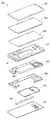
도 4를 참조하면, 본 발명의 다양한 실시예에 따른 입력 장치(400)(예: 도 2 또는 도 3의 펜 입력 장치(120))는 제1 몸체부(401)와 제2 몸체부(402)를 포함할 수 있으며, 도 1 내지 도 3을 통해 살펴본 전자 장치(100, 300)의 입력 장치 중 일부일 수 있다. 예를 들어, 상기 입력 장치(400)은 도 3의 펜 입력 장치(120)일 수 있다. 한 실시예에 따르면, 상기 제1 몸체부(401)는 각종 전기회로들(예: 코일부(403) 또는 회로 기판부(404))을 수용하며, 상기 제2 몸체부(402)는 기계적인 부품들(예: 클릭 메카니즘(405))을 수용할 수 있다. 한 실시예에서, 상기 제2 몸체부(402)의 일단은 상기 제1 몸체부(401)의 일단에 결합할 수 있으며, 상기 입력 장치(400)는 실질적으로 일방향으로 연장된 봉(rod) 형상을 가질 수 있다. 예컨대, 상기 입력 장치(400)는 도 2의 홀(121)과 유사한 또는 동일한 구조(예: 수납 홀)를 통해 전자 장치의 내부로 수납될 수 있다. 다른 실시예에서, 상기 제1 몸체부(401)에 수용된 전기회로들은 전자기 공진 회로(예: 도 7의 공진 회로부(702))를 포함함으로써, 디지타이저, 예를 들면, 도 3의 전자기 유도 패널(390)과 연동될 수 있다. 또 다른 실시예에서, 상기 제2 몸체부(402)에 수용된 기계적인 부품들은 푸시-풀 방식의 버튼 구조를 제공할 수 있으며, 상기 입력 장치(400)는 상기와 같은 버튼 구조의 작동에 기반하여 입력 신호를 발생시킬 수 있다. Referring to FIG. 4 , an input device 400 (eg, the
다양한 실시예에 따르면, 상기 제1 몸체부(401)는 튜브 몸체(411), 코일부(403), 회로 기판부(404)를 포함할 수 있다. 상기 튜브 몸체(411)는 실질적으로 상기 제1 몸체부(401) 또는 상기 입력 장치(400)의 외형의 적어도 일부를 형성하며, 중공형 튜브(hollow tube)로 제작되어 상기 코일부(403) 또는 상기 회로 기판부(404)를 수용하는 공간을 제공할 수 있다. 한 실시예에 따르면, 상기 튜브 몸체(411)는 잠금 홀(413) 또는 개구부(415)를 포함할 수 있다. 상기 잠금 홀(413)은 예를 들면, 상기 코일부(403)를 상기 튜브 몸체(411)의 내부에서 고정하는 수단을 제공할 수 있다. 예컨대, 상기 코일부(403)는 상기 잠금 홀(413)에 상응하는 돌기를 포함할 수 있으며, 상기 코일부(403)가 상기 튜브 몸체(411)의 내부로 수용되었을 때, 상기 잠금 홀(413)과 도시되지 않은 돌기가 맞물려 상기 코일부(403)를 상기 튜브 몸체(411)의 내부에 고정될 수 있다. 상기 개구부(415)는 후술할 작동 키(447)가 배치되는 공간을 제공할 수 있다. 예컨대, 상기 작동 키(447)는 상기 개구부(415)에 배치되어 사용자에 의해 조작될 수 있으며, 상기 작동 키(447)의 조작에 따라 상기 입력 장치(400)가 입력 신호 또는 전자기장을 발생시킬 수 있다. According to various embodiments, the
다양한 실시예에 따르면, 상기 코일부(403)는 펜 팁(pen tip)(431), 밀봉 부재(433), 전자기 코일(435) 및/또는 필압 감지부(pen pressure sensing unit)(437)를 포함할 수 있으며 상기 튜브 몸체(411) 내에서 상기 회로 기판부(404)와 전기적으로 연결될 수 있다. 상기 펜 팁(431)은 상기 밀봉 부재(433)와 상기 전자기 코일(435)을 순차적으로 관통하여 상기 필압 감지부(437)와 전기적으로 또는 기계적으로 연결될 수 있다. 상기 코일부(403)가 상기 튜브 몸체(411)에 결합하면 상기 펜 팁(431)은 상기 튜브 몸체(411)의 단부로 돌출될 수 있으며, 상기 밀봉 부재(433)가 상기 튜브 몸체(411)의 단부 내벽에 밀착하여 밀봉 구조를 형성할 수 있다. 예를 들어, 상기 밀봉 부재(433)는 방수, 방진 구조를 형성하여 상기 튜브 몸체(411)의 내부로 이물질이 유입되는 것을 차단할 수 있다. According to various embodiments, the
한 실시예에서, 상기 전자기 코일(435)은 설계된 또는 설정된 주파수 대역(예: 500kHz의 주파수 대역)에서 공진 주파수를 형성할 수 있으며, 적어도 하나의 집중 소자(예: 용량성 소자(capacitor))가 상기 전자기 코일(435)과 조합되어 일정 정도의 범위에서 상기 전자기 코일(435)이 형성하는 공진 주파수를 조절할 수 있다. 복수의 용량성 소자가 조합된다면 상기 전자기 코일(435)은 복수의 공진 주파수(예: 530kHz, 560kHz의 공진 주파수)를 형성할 수 있다. 예컨대, 상기 전자기 코일(435)과 적어도 하나의 용량성 소자가 조합되어 전자기 공진회로(예: 도 7의 공진 회로부(702))를 형성할 수 있으며, 어떤 실시예에서 상기 전자기 코일(435)는 연결된 용량성 소자의 수에 상응하는 복수의 공진 주파수를 형성할 수 있다. 상기 전자기 코일(435)이 형성하는 복수의 공진 주파수 중 하나는 드래그(drag) 또는 드로잉(drawing) 동작을 검출하는데 이용될 수 있고, 다른 하나는 터치(touch) 또는 클릭(click) 동작을 검출하는데 이용될 수 있다. 예컨대, 상기 입력 장치(400)를 사용하는 사용자의 입력 동작 등이 상기 코일부(403)(또는 상기 코일부(403)가 생성하는 전자기장)를 통해 모사될 수 있으며, 전자 장치(100, 300)의 디지타이저(예: 도 3의 전자기 유도 패널(390))은 상기 코일부(403)가 생성하는 전자기장 또는 전자기장의 이동을 검출하여 입력 신호를 발생시킬 수 있다. 공진 주파수와 그를 통해 검출되는 동작의 종류는 상기 입력 장치(400) 또는 상기 입력 장치(400)를 포함하는 전자 장치(예: 도 3의 전자 장치(300))의 설정에 따라 다양할 수 있다. In one embodiment, the
다른 실시예에서, 상기 필압 감지부(437)는 가변용량 캐패시터(variable capacitor)를 포함할 수 있다. 상기 펜 팁(431)에 외력이 가해지면, 예를 들어, 상기 펜 팁(431)이 도 3의 전면 플레이트(320)에 접촉하면, 상기 필압 감지부(437)의 정전용량(capacitance)이 달라질 수 있으며, 이는 상기 전자기 코일(435)이 생성하는 공진 주파수를 변화(shift)시킬 수 있다. 예컨대, 상기 필압 감지부(437)의 정전용량이 달라지면서 상기 전자기 코일(435)에 의해 형성된 560kHz의 공진 주파수는 대략 30kHz 이내의 범위에서 커질 수 있다. In another embodiment, the
다양한 실시예에 따르면, 상기 회로 기판부(404)는 회로 기판(443), 방사 도체(443b), 상기 작동 키(447) 및/또는 상기 회로 기판(443) 등을 장착 / 고정하는 각종 구조물 등을 포함할 수 있다. 상기 회로 기판(443)은 상부면과 하부면을 포함하는 평판 형상이면서 일 방향으로 연장된 형상으로서 상기 튜브 몸체(411)에 수용될 수 있다. 상기 회로 기판(443)의 상부면에는 상기 전자기 코일(435)과 연결되는 가변용량 캐패시터(미도시) 또는 스위치 부재(443a)(예: 돔 스위치(dome switch)) 등이 배치될 수 있으며, 하부면에는 배터리, 충전 회로, 신호 발생 회로 및/또는 통신 회로(예: 도 7의 배터리(750) 등) 등이 배치될 수 있다. 통신 회로는 상기 방사 도체(443b)를 통해 무선 통신을 수행할 수 있다. 상기 방사 도체(443b)를 통해 무선 통신을 수행하게 된다면, 상기 입력 장치(400) 내에서 상기 방사 도체(443b)는 상기 코일부(403)로부터 충분히 멀리(예: 상기 입력 장치(400) 또는 상기 튜브 몸체(411))의 내부 공간이 허용하는 범위에서 최대한 멀리) 배치될 수 있다. 배터리, 충전 회로 등 각종 회로 장치의 구성에 관해서는 도 7을 통해 더 상세하게 살펴보게 될 것이다.According to various embodiments, the
한 실시예에서, 장착 / 고정을 위한 구조물로는, 기판 홀더(441a), 커버부(445), 키 홀더(441b) 등을 포함할 수 있다. 상기 회로 기판(443)은 상기 기판 홀더(441a)에 적어도 부분적으로 수용된 상태로 상기 튜브 몸체(411)의 내부로 장착될 수 있으며, 상기 방사 도체(443b)가 상기 기판 홀더(441a)에 장착되어 상기 회로 기판(443)에 전기적으로 연결될 수 있다. 상기 기판 홀더(441a)는 길이 방향을 따라 상기 튜브 몸체(411)로 삽입되어 상기 회로 기판(443)을 상기 튜브 몸체(411)의 내부에 고정할 수 있다. 한 실시예에서, 상기 튜브 몸체(411) 내에서 상기 코일부(403)가 상기 회로 기판(443)에 전기적으로 연결될 수 있다. 상기 커버부(445)는 상기 회로 기판(443)을 상기 기판 홀더(441a)에 고정 또는 밀봉할 수 있다. 예컨대, 상기 기판 홀더(441a)의 일부 공간을 상기 커버부(445)가 폐쇄하면서 상기 회로 기판(443)을 상기 기판 홀더(441a)에 고정할 수 있다. 어떤 실시예에서, 상기 방사 도체(443b)는 상기 커버부(445)에 의해 상기 회로 기판(443)에 전기적으로 연결된 또는 기계적으로 접촉한 상태로 유지될 수 있다. 상기 키 홀더(441b)는 상기 커버부(445)와 상기 튜브 몸체(411)의 내벽 사이에 고정되며, 상기 작동 키(447)를 지지할 수 있다. 어떤 실시예에서, 상기 작동 키(447)는 상기 키 홀더(441b)에 의해 지지되면서 상기 개구부(415)를 통해 노출되며, 상기 작동 키(447)가 조작되면 상기 키 홀더(441b) 또는 상기 커버부(445)가 변형되면서 상기 스위치 부재(443a)가 조작될 수 있다. 예컨대, 상기 작동 키(447)는 상기 스위치 부재(443a)와 상응하게 위치될 수 있다. 상기 작동 키(447)에 작용하는 외력이 없으면, 상기 커버부(445) 또는 상기 키 홀더(441b)가 탄성 복원력을 제공하여 상기 작동 키(447)를 일정 위치에 배치된 상태로 복원 또는 유지할 수 있다. In one embodiment, structures for mounting/fixing may include a
어떤 실시예에, 상기 회로 기판부(404)는 오-링(O-ring)과 같은 다른 밀봉 부재(433)를 포함할 수 있다. 예를 들어, 참조번호를 부여하지 않았으나, 상기 기판 홀더(441a)의 양단에 탄성체로 제작된 오-링이 배치되어 상기 기판 홀더(441a)와 상기 튜브 몸체(411) 사이에 밀봉 구조를 형성할 수 있다. 어떤 실시예에서, 상기 키 홀더(441b) 또는 상기 커버부(445)는 부분적으로 상기 개구부(415)의 주위에서 상기 튜브 몸체(411)의 내벽에 밀착하여 밀봉 구조를 형성할 수 있다. 예컨대, 상기 회로 기판부(404)도 상기 코일부(403)의 밀봉 부재(433)와 유사한 방수, 방진 구조를 형성할 수 있다. In some embodiments, the
다양한 실시예에 따르면, 상기 제2 몸체부(402)는 가이드 튜브(421, 451)와 클릭 메카니즘(405)을 포함할 수 있다. 상기 가이드 튜브(421, 451)는 상기 튜브 몸체(411)와 결합하는 제1 가이드 튜브(421)와, 복수의 캠 부재들을 수용한 제2 가이드 튜브(451)의 조합으로 이루질 수 있다. 한 실시예에 따르면, 상기 제1 가이드 튜브(421)와 상기 제2 가이드 튜브(451)는 각각이 일 방향으로 연장되며 상기 제2 가이드 튜브(451)가 상기 제1 가이드 튜브(421)의 내부로 삽입 또는 장착되어 상기 가이드 튜브(421, 451)를 완성할 수 있다. 하지만, 본 발명이 이에 한정되지 않음에 유의한다. 예를 들어, 상기 제1 가이드 튜브(421)와 상기 제2 가이드 튜브(451)는 실질적으로 하나의 몸체로 성형 또는 제작될 수 있다. 이하의 상세한 설명에서는 대체로 '제1 가이드 튜브'와 '제2 가이드 튜브'를 구분하여 기재되지만, 설명의 간결함을 위해 단지 '가이드 튜브'라고 기재하면서, 상기 제1 가이드 튜브 또는 상기 제2 가이드 튜브의 참조번호 '421', '451'가 선택적으로 병기될 수 있다. According to various embodiments, the
한 실시예에서, 상기 제1 가이드 튜브(421)는 실질적으로 상기 제2 몸체부(402) 또는 상기 입력 장치(400) 외형의 일부를 형성할 수 있으며, 일단에 삽입부(423)를 포함함으로써 상기 제1 몸체부(401)와 결합할 수 있다. 예를 들어, 상기 삽입부(423)는 상기 튜브 몸체(411)의 한 단부에 삽입되며, 상기 삽입부(423)를 제외한 상기 제1 가이드 튜브(421)의 외주면은 실질적으로 상기 튜브 몸체(411)의 외주면과 동일한 평면 또는 곡면을 이루게 배치될 수 있다. 어떤 실시예에서, 상기 삽입부(423)는 상기 튜브 몸체(411)의 내부에서 상기 기판 홀더(441a)의 일부분을 감싸게 결합할 수 있다. 예를 들어, 상기 삽입부(423)는 부분적으로 상기 튜브 몸체(411)의 내벽과 상기 기판 홀더(441a)의 외주면 일부 사이에 개재될 수 있다. 다른 실시예에서, 상기 기판 홀더(441a)의 일부에 상기 삽입부(423)에 상응하는 홈이 형성될 수 있다. 예를 들어, 상기 튜브 몸체(411) 내에서 상기 삽입부(423)는 부분적으로 상기 기판 홀더(441a)에 삽입될 수 있다. In one embodiment, the
다른 실시예에서, 상기 클릭 메카니즘(405)은 상기 제2 가이드 튜브(451)와 버튼 부재(453) 또는 샤프트(455)를 포함할 수 있다. 상기 샤프트(455)는 일부분이 상기 제2 가이드 튜브(451)의 한 단부로 돌출된 상태로 상기 제2 가이드 튜브(451) 내에서 가이드 튜브가 연장된 방향을 따라 직선 왕복 운동 가능하게 설치될 수 있다. 상기 제2 가이드 튜브(451) 내에는 도시되지 않은 복수의 기계적인 부품들, 예를 들면, 캠 부재들(예: 도 8의 캠 부재들(801, 802, 803)) 또는 탄성 부재들(예: 도 8의 탄성 부재들(551a, 851a))이 배치되어 푸시-풀 구조를 형성할 수 있다. 상기와 같은 푸시-풀 구조에 관해서는 도 8 등을 통해 더 상세하게 살펴보게 될 것이다. 어떤 실시예에서, 상기 버튼 부재(453)는 상기 제2 가이드 튜브(451)의 다른 단부에 돌출된 상태로 상기 제2 가이드 튜브(451) 내에서 상기 샤프트(455)와 결합할 수 있다. 예컨대, 상기 샤프트(455)와 상기 버튼 부재(453)는 상기 제2 가이드 튜브(451) 내에서 결합하며, 상기 샤프트(455)의 일부는 상기 제2 가이드 튜브(451)의 한 단부에서, 상기 버튼 부재(453)는 상기 제2 가이드 튜브(451)의 다른 단부에서 각각 돌출될 수 있다. 한 실시예에서, 상기 버튼 부재(453)는 실질적으로 상기 샤프트(455)와 함께 상기 제2 가이드 튜브(451)에 대하여 직선 왕복 운동할 수 있다. 한 실시예에서, 상기 제2 가이드 튜브(451)는 상기 제1 가이드 튜브(421)의 내부로 삽입되며, 상기 버튼 부재(453)는 상기 제1 가이드 튜브(421)의 한 단부에서 노출 또는 돌출될 수 있다. 예컨대, 상기 버튼 부재(453)는 부분적으로 상기 입력 장치(400) 외형의 일부를 형성할 수 있다. In another embodiment, the
다양한 실시예에 따르면, 상기 제2 몸체부(402), 예를 들어, 상기 제1 가이드 튜브(421)가 상기 제1 몸체부(401)와 결합하면 상기 샤프트(455)의 한 단부가 상기 제1 몸체부(401)의 내부에 배치될 수 있다. 예를 들어, 상기 샤프트(455)의 한 단부는 상기 기판 홀더(441a)와 인접하게 배치될 수 있다. 상기 입력 장치(400)는 상기 샤프트(455)의 직선 왕복 운동을 검출하는 센서 모듈을 포함함으로써, 입력 신호를 발생시킬 수 있다. 예컨대, 상기 입력 장치(400)는 상기 코일부(403) 등을 이용한 입력 방식과는 독립된 또 다른 입력 방식을 제공할 수 있다. According to various embodiments, when the
상기 입력 장치(400)의 센서 모듈에 관해서는 도 5와 도 6을 더 참조하여 살펴보기로 한다. 이하의 상세한 설명에서는, 선행 실시예와 유사하거나 선행 실시예를 통해 용이하게 이해할 수 있는 구성에 대해서는 도면의 참조번호를 동일하게 부여하거나 생략하고 그 상세한 설명 또한 생략할 수 있다. The sensor module of the
도 5는 본 발명의 다양한 실시예에 따른 입력 장치의 센서 모듈(501)의 구성을 나타내는 분리 사시도이다. 도 6은 본 발명의 다양한 실시예에 따른 입력 장치의 일부분을 투영하여 나타내는 평면도이다. 5 is an exploded perspective view illustrating a configuration of a
도 5와 도 6을 참조하면, 상기 입력 장치(400)는 홀 센서(Hall sensor)(543)와 자성체(magnet)(555a)의 조합으로 이루어진 센서 모듈(501)을 포함할 수 있다. 예컨대, 상기 홀 센서(543)는 상기 기판 홀더(441a)의 한 단부에 배치되고, 상기 자성체(555a)는 상기 샤프트(455)의 단부에 장착될 수 있다. 상기 제2 몸체부(402)가 상기 제1 몸체부(401)와 결합하면, 상기 샤프트(455)의 단부가 실질적으로 상기 기판 홀더(441a)와 인접하게 또는 부분적으로 중첩하게 위치할 수 있다. 예컨대, 상기 자성체(555a)가 상기 홀 센서(543)와 인접하게 배치될 수 있으며, 상기 샤프트(455)의 직선 왕복 운동에 따른 자기장(예: 상기 자성체(555a)에 의해 생성된 자기장)의 변화 또는 이동을 상기 홀 센서(543)가 감지하여 입력 신호를 발생시킬 수 있다. 한 실시예에서, 상기 입력 장치(400)는 제1 탄성 부재(551a)를 포함할 수 있으며, 상기 샤프트(455)는 상기 제1 탄성 부재(551a)의 복원력을 제공받을 수 있다. 예컨대, 상기 샤프트(455)는 외력에 의해 상기 자성체(555a)를 상기 홀 센서(543)에 접근시키는 방향으로 이동할 수 있고, 외력이 사라지면 상기 제1 탄성 부재(551a)의 탄성력(예: 복원력)에 의해 상기 자성체(555a)를 상기 홀 센서(543)로부터 멀어지는 방향으로 이동할 수 있다. 어떤 실시예에서, 상기 튜브 몸체(411)의 내부에는 적어도 하나의 제1 지지 구조물(611a)이 형성되어 상기 제1 탄성 부재(551a)의 한 단부를 지지할 수 있다. 다른 실시예에서, 상기 제1 탄성 부재(551a)를 지지하기 위한 구조물은 상기 제2 몸체부(402) 내부, 예를 들면, 상기 제2 가이드 튜브(451)의 내부에 제공될 수도 있다. Referring to FIGS. 5 and 6 , the
도 7은 본 발명의 다양한 실시예에 따른 입력 장치(700)를 나타내는 회로도이다. 7 is a circuit diagram illustrating an
도 7을 참조하면, 입력 장치(700)(예: 도 4의 입력 장치(400))는 회로 기판부(404)(예: 도 4의 회로 기판부(404))의 적어도 일부를 이루는 충전 회로부(701), 공진 회로부(702), 신호 발생 회로부(703), 통신 회로부(704) 또는 배터리(750)를 포함할 수 있다. 도시되지는 않지만, 컨트롤러 또는 메모리 등을 포함함으로써 상기 입력 장치(700)를 작동하기 위한 명령 등이 저장되거나 실행될 수 있다. Referring to FIG. 7 , an input device 700 (eg, the
다양한 실시예에 따르면, 상기 충전 회로부(701)는 외부로부터 수신된 전력을 이용하여 상기 배터리(750)를 충전할 수 있으며, 상기 배터리(750)의 충전 상태를 검출하여 충전을 선택적으로 중단시킬 수 있다. 한 실시예에서, 전력은 코일부(예: 도 4의 코일부(403))의 전자기 코일(예: 도 4의 전자기 코일(435))을 통해 수신될 수 있다. 예컨대, 상기 충전 회로부(701)는 상기 전자기 코일(435)과 상기 배터리(750) 사이에 위치하며, 전압 검출 회로(voltage detector circuitry) 및 정류기(rectifier)를 포함할 수 있다. 어떤 실시예에서, 상기 입력 장치(700)가 전자 장치(예: 도 3의 전자 장치(300))에 수납된 상태에서 전자 장치는 전자기 결합 또는 전자기 공진 방식으로 상기 입력 장치(700), 예를 들면, 상기 코일부(403)로 전력을 송신할 수 있다. According to various embodiments, the charging
다양한 실시예에 따르면, 상기 공진 회로부(702)는 적어도 하나의 유도성 소자 또는 용량성 소자의 조합을 포함할 수 있다. 예를 들어, 상기 공진 회로부(702)는 전자기 코일(예: 도 4의 전자기 코일(435))과 회로 기판(예: 도 4의 회로 기판(443))에 배치된 적어도 하나의 캐패시터의 조합으로 이루어질 수 있다. 상기 공진 회로부(702)는 스위치(443a)(예: 도 4의 스위치 부재(443a))를 포함할 수 있으며, 상기 스위치(443a)의 동작 여부에 따라 각기 다른 공진 주파수를 형성할 수 있다. According to various embodiments, the
다양한 실시예에 따르면, 상기 신호 발생 회로부(703)는 홀 센서(Hall IC)(예: 도 5의 홀 센서(543)) 등을 포함함으로써 전자기장의 변화 또는 이동에 기반하여 입력 신호를 발생시킬 수 있다. 예컨대, 상기 입력 장치(700)는 클릭 메카니즘(예: 도 4의 클릭 메카니즘(405))에 배치된 자성체(예: 도 5의 자성체(555a))와 상기 홀 센서(543)의 조합으로 이루어진 센서 모듈(예: 도 5의 센서 모듈(501))을 포함할 수 있으며, 상기 홀 센서(543)는 상기 자성체(555a)에 의한 자기장의 변화 또는 이동을 검출할 수 있다. 상기 신호 발생 회로부(703)는 상기 홀 센서(543)를 통해 검출된 정보에 기반하여 입력 신호를 발생시킬 수 있다. According to various embodiments, the signal
다양한 실시예에 따르면, 상기 통신 회로부(704)는, 예를 들어, BLE 회로(Bluetooth Lower Energy circuitry)를 포함할 수 있으며, 도 4의 방사 도체(443b)와 전기적으로 연결되어 무선 통신을 수행할 수 있다. 예를 들어, 상기 신호 발생 회로부(703)에서 발생된 입력 신호는 상기 통신 회로부(704), 상기 방사 도체(443b) 등을 통해 전자 장치(예: 도 3의 전자 장치(300))로 전송될 수 있다. 전자 장치는 상기 통신 회로부(704)에서 송신된 신호에 기반하여, 작동 모드에 따라 다양한 기능을 실행할 수 있다. According to various embodiments, the
어떤 실시예에서, 상기 센서 모듈(501)은 기계적인 스위치 부재, 예를 들면, 돔 스위치(dome switch) 또는 택트 스위치(tact switch)로 대체될 수 있다. 예컨대, 상기 센서 모듈(501)에서, 샤프트(예: 도 4 내지 도 6의 샤프트(455))의 직선 왕복 운동에 따라 기계적인 스위치 부재가 작동될 수 있으며, 기계적인 스위치 부재의 온/오프(on/off) 동작에 따라 통신 회로부(예: 도 7의 통신 회로부(704))가 방사 도체(예: 도 4의 방사 도체(443b)) 등을 통해 전자 장치(예: 도 3의 전자 장치(300))로 입력 신호 등을 송신할 수 있다. In some embodiments, the
다양한 실시예에 따르면, 상기 배터리(750)는 EDLC(electric double layered capacitor)로 구성될 수 있다. 일 실시 예에 따르면, 상기 충전 회로부(701)가 상기 통신 회로부(704)(예: BLE circuitry)와 전기적으로 연결될 수 있으며, 상기 통신 회로부(704)를 통해 상기 배터리(750)의 전압을 모니터링할 수 있다. According to various embodiments, the
도 8은 본 발명의 다양한 실시예에 따른 입력 장치에서 클릭 메카니즘(800)을 투영하여 나타내는 도면이다. 8 is a view illustrating a projected
도 8을 참조하면, 상기 클릭 메카니즘(800)(예: 도 4의 클릭 메카니즘(405))는 상술한 가이드 튜브(예: 도 4의 제1 가이드 튜브(421)와 제2 가이드 튜브(451)), 샤프트(455), 탄성 부재들(551a, 851a) 등을 포함할 수 있으며, 상기 가이드 튜브의 내부에는 복수, 예를 들면, 3개의 캠 부재들(801, 802, 803)이 배치될 수 있다. 상기 가이드 튜브는 상술한 바와 같이, 입력 장치(예: 도 4의 입력 장치(400))의 제1 가이드 튜브(421)와 제2 가이드 튜브(451)의 조합으로 이루어질 수 있다. 본 발명의 다양한 실시예에 따른 클릭 메카니즘(800)에 관한 상세한 설명에서는 필요에 따라 도 4가 더 참조될 수 있다. Referring to FIG. 8 , the click mechanism 800 (eg, the
다양한 실시예에 따르면, 상기 샤프트(455)와 상기 버튼 부재(453)는 가이드 튜브, 예를 들면, 상기 제1 가이드 튜브(421) 내에서 직선 왕복 운동 가능하게 배치되며, 상기 버튼 부재(453)를 상기 제1 가이드 튜브(421)의 한 단부로 돌출시키는 방향(이하, '팝 업(pop up) 방향(PU)')으로 탄성력(예: 복원력)을 제공받을 수 있다. 예를 들어, 상기 클릭 메카니즘(800)은 제1 탄성 부재(예: 도 5 또는 도 6의 제1 탄성 부재(551a))를 포함함으로써 상기 샤프트(455) 또는 상기 버튼 부재(453)를 상기 팝 업 방향(PU)으로 이동시키는 복원력을 제공할 수 있다. 한 실시예에서, 상기 제1 가이드 튜브(421)의 내부에는 연결 부재(841)가 제공되어 상기 샤프트(455)와 상기 버튼 부재(453)를 연결할 수 있다. 예컨대, 상기 샤프트(455)와 상기 버튼 부재(453)는 상기 연결 부재(841)와 결합하여 실질적으로 동일한 방향, 동일한 구간에서 직선 왕복 운동할 수 있다. 어떤 실시예에서, 상기 연결 부재(841)는 상기 버튼 부재(453)로부터 일체형으로 연장될 수 있다. 다른 실시예에서, 상기 연결 부재(841)는 상기 샤프트(455)로부터 일체형으로 연장될 수 있다. According to various embodiments, the
다양한 실시예에 따르면, 상기 입력 장치(400)는 제2 탄성 부재(851a)를 더 포함함으로써 상기 버튼 부재(453)를 상기 제1 가이드 튜브(421)의 내부로 삽입 또는 진입시키는 방향(이하, '팝 다운(pop down) 방향(PD)')으로 탄성력을 제공할 수 있다. 예를 들어, 상기 제1 가이드 튜브(421)(또는 도 4의 제2 가이드 튜브(451))의 내부에는 제2 지지 구조물(811b)이 형성될 수 있으며, 상기 제2 탄성 부재(851a)가 상기 제2 지지 구조물(811b)에 지지되어 상기 버튼 부재(453)를 상기 제1 가이드 튜브(421)의 내부로 삽입 또는 진입시키는 방향으로 탄성력을 제공할 수 있다. 한 실시예에 따르면, 상기 버튼 부재(453)가 상기 제1 가이드 튜브(421)에 완전히 삽입 또는 진입된 상태에서도, 상기 버튼 부재(453)의 일부분은 상기 제1 가이드 튜브(421)의 외부로 노출 또는 돌출될 수 있다. 예컨대, 상기 제1 가이드 튜브(421)에 완전히 삽입 또는 진입된 상태에서, 상기 버튼 부재(453)는 상기 입력 장치(400) 외형의 일부를 형성할 수 있다. According to various embodiments, the
다양한 실시예에 따르면, 상기 입력 장치(400) 또는 상기 클릭 메카니즘(800)은 3개의 상기 캠 부재들(801, 802, 803)을 포함할 수 있다. 예를 들어, 상기 클릭 메카니즘(800)은, 상기 샤프트(455) 상에 배치되며 상기 샤프트(455)에 대하여 회전 또는 직선 왕복 운동하는 제1 캠 부재(801), 상기 샤프트(455) 상에 배치되며 상기 샤프트(455)에 대하여 회전 또는 직선 왕복 운동하는 제2 캠 부재(802), 및/또는 상기 샤프트(455)에 장착되어 상기 샤프트(455)(또는 상기 버튼 부재(453))와 함께 직선 왕복 운동하는 제3 캠 부재(803)를 포함할 수 있다. 한 실시예에 따르면, 상기 제3 캠 부재(803)는 상기 제2 캠 부재(802)를 사이에 두고 상기 제1 캠 부재(801)와 마주보게 배치될 수 있다. 예를 들어, 상기 제1 캠 부재(801), 상기 제2 캠 부재(802), 상기 제3 캠 부재(803)가 상기 샤프트(455) 상에 순차적으로 배치되며, 상기 제1 캠 부재(801)와 상기 제2 캠 부재(802)는 상기 샤프트(455)에 대하여 회전 또는 직선 운동할 수 있다. According to various embodiments, the
다양한 실시예에 따르면, 상기 제1 탄성 부재(551a)는 상기 제1 캠 부재(801)에 지지되어 상기 제1 캠 부재(801)에 탄성력을 제공하며, 상기 제2 탄성 부재(851a)는 상기 제3 캠 부재(803)에 지지되어 상기 제3 캠 부재(803)에 탄성력을 제공할 수 있다. 예를 들어, 상기 제1 탄성 부재(551a)가 상기 제2 탄성 부재(851a)보다 더 내측에서, 예를 들면, 제1 몸체부(예: 도 4의 제1 몸체부(401))에 더 인접한 위치에서 상기 팝 업 방향(PU)으로 상기 제1 캠 부재(801)에 탄성력을 제공하며, 상기 제2 탄성 부재(851a)는 외측에서, 예를 들면, 상기 버튼 부재(453)와 인접한 위치에서 상기 팝 다운 방향(PD)으로 상기 제3 캠 부재(803)에 탄성력을 제공할 수 있다. 상기 제1 캠 부재(801), 상기 제2 캠 부재(802) 및/또는 상기 제3 캠 부재(803)는 상기 제1 탄성 부재(551a)와 상기 제2 탄성 부재(851a)의 탄성력에 의해 서로 밀착한 상태를 유지할 수 있다. 어떤 실시예에서, 상기 제1 탄성 부재(551a)의 탄성력이 상기 제2 탄성 부재(851a)의 탄성력보다 더 클 수 있다. 예를 들어, 외력이 작용하지 않는다면, 상기 제1 탄성 부재(551a)와 상기 제2 탄성 부재(851a)의 합력은 상기 팝 업 방향(PU)으로 작용할 수 있다. According to various embodiments, the first
다양한 실시예에 따르면, 상기 캠 부재들(801, 802, 803) 각각은 가이드 튜브, 예를 들면, 상기 제2 가이드 튜브(451)의 내부로 제공된 가이드 구조물(예: 도 9의 가이드 구조물(905))의 안내를 받아 일정 구간에서 직선 왕복 운동할 수 있다. 한 실시예에서, 상기 제1 캠 부재(801)와 상기 제2 캠 부재(802)는 각각에 허용된 구간에서 가이드 구조물(905)의 안내를 받아 상기 샤프트(455)와 함께 직선 왕복 운동할 수 있으며, 직선 왕복 운동 구간을 벗어나면 상기 샤프트(455)에 대하여 회전하면서 적어도 부분적으로 직선 왕복 운동 구간으로 재진입할 수 있다. 다른 실시예에서, 가이드 튜브의 가이드 구조물(905)은 상기 제3 캠 부재(803)에 대하여 직선 운동 왕복만 허용할 수 있다. 예컨대, 상기 제3 캠 부재(803)는 실질적으로 상기 제2 가이드 튜브(451) 내에서 직선 왕복 운동만 가능하게 설치될 수 있다. According to various embodiments, each of the
상기와 같은 가이드 구조물(905) 및/또는 상기 캠 부재들(801, 802, 803)의 구성에 관해서는 도 9 내지 도 17을 더 참조하여 살펴보기로 한다. The configuration of the
도 9는 본 발명의 다양한 실시예에 따른 입력 장치에서 클릭 메카니즘(800)의 가이드 구조를 투영하여 나타내는 사시도이다. 도 10은 도 9의 가이드 구조를 나타내는 전개도이다. 9 is a perspective view illustrating a projected guide structure of a
도 9와 도 10을 참조하면, 가이드 튜브, 예를 들어, 상기 제2 가이드 튜브(451)는 상기 샤프트(455) 및/또는 상기 캠 부재들(801, 802, 803)을 수용하는 작동 홀(959)을 포함하며, 상기 가이드 튜브의 내주면, 예를 들어, 상기 작동 홀(959)의 내벽에는 상기 캠 부재들(801, 802, 803)의 직선 왕복 운동 또는 회전을 안내하는 가이드 구조물(905)이 형성될 수 있다. 상기 가이드 구조물(905)은 대체로 상기 작동 홀(959)의 내벽에서 돌출되며 내측, 예를 들어, 상술한 제1 몸체부(401)에 인접하는 측에서 개방된 가이드 홈들(951, 953)을 포함할 수 있다. 예컨대, 상기 가이드 홈들(951, 953)은 상기 제1 캠 부재(801)가 배치되는 측의 단부가 개방되며, 상기 제3 캠 부재(803)가 배치되는 측의 단부는 폐쇄된 형태를 가질 수 있고, 상기 가이드 홈들(951, 953)의 개방된 상단은 상기 제1 몸체부(401)를 향하게 배치될 수 있다. 상기 가이드 홈들(951, 953)은 상기 캠 부재들(801, 802, 803)의 직선 왕복 운동 방향과 실질적으로 평행하게 연장될 수 있다. 후술하겠지만, 상기 캠 부재들(801, 802, 803) 각각에는 상기 가이드 홈들(951, 953)과 상응하는 가이드 돌기(들)가 형성되어 있으며, 상기 가이드 홈들(951, 953)과 가이드 돌기(들)가 상기 캠 부재들(801, 802, 803)의 직선 왕복 운동을 안내할 수 있다.9 and 10, the guide tube, for example, the
다양한 실시예에 따르면, 상기 가이드 홈들(951, 953)은, 복수의 제1 가이드 홈(951)과 복수의 제2 가이드 홈(953)의 조합으로 이루어질 수 있다. 예를 들어, 3개의 상기 제1 가이드 홈(951)과 3개의 상기 제2 가이드 홈(953)이 상기 가이드 구조물(905) 또는 상기 제2 가이드 튜브(451)의 원주 방향을 따라 번갈아가며 배열될 수 있다. 한 실시예에 따르면, 상기 제1 가이드 홈(951)은 개방된 단부로부터 제1 길이(d1)만큼 연장되며, 제1 폭(w1)을 가질 수 있다. 다른 실시예에서, 상기 제2 가이드 홈(953)은 개방된 단부로부터 제2 길이(d2)만큼 연장되며, 제2 폭(w2)을 가질 수 있다. 어떤 실시예에서, 상기 제1 길이(d1)는 상기 제2 길이(d2)보다 작을 수 있으며, 상기 제1 폭(w1)은 상기 제2 폭(w2)보다 작을 수 있다. According to various embodiments, the
다양한 실시예에 따르면, 상기 가이드 구조물(905)은 인접하는 2개의 상기 가이드 홈들(951, 953), 예를 들어, 서로 인접하는 상기 제1 가이드 홈(951)과 상기 제2 가이드 홈(953) 사이에 각각 형성된 경사면(955)을 포함할 수 있다. 예를 들어, 상기 경사면(955)은 상기 제2 가이드 홈(953)의 개방된 단부에서 상기 제1 가이드 홈(951)의 개방된 단부를 향해 연장되면서 상기 제1 가이드 홈(951) 또는 상기 제2 가이드 홈(953)에 대하여 경사지게 형성될 수 있다. 한 실시예에서, 상기 제2 가이드 홈(953)의 개방된 단부에서 볼 때, 상기 경사면(955)은 상기 제1 가이드 홈(951)의 폐쇄된 단부를 향하게 연장될 수 있다. According to various embodiments, the
도 11a와 도 11b는 도 9의 가이드 구조의 변형 예를 나타내는 전개도이다. 11A and 11B are development views illustrating modified examples of the guide structure of FIG. 9 .
도 11a를 참조하면, 가이드 구조물(1105a)은 복수, 예를 들면, 3개의 가이드 홈(1151), 인접하는 2개의 상기 가이드 홈(1151)들 사이에서 연장된 경사면(1155)을 포함할 수 있으며, 상기 경사면(1155)에는 걸림턱(1153)이 형성될 수 있다. 상기 가이드 홈(1151)은 도 10의 제2 가이드 홈(953)과 유사한 길이와 폭으로 형성될 수 있다. 상기 경사면(1155)은 상기 가이드 홈(1151)들 중 하나의 개방된 단부로부터 다른 하나의 가이드 홈을 향해 연장되며, 상기 가이드 홈(1151)에 대하여 경사지게 형성될 수 있다. 예를 들어, 상기 경사면(1155)은 상기 가이드 홈(1151)들 중 하나의 개방된 단부로부터 인접하는 다른 가이드 홈(1151)의 폐쇄된 단부를 향하게 연장될 수 있다. 상기 걸림턱(1153)은 상기 경사면(1155)의 양 단부 중 하나, 예를 들면, 상기 가이드 홈(1151)의 폐쇄된 단부에 더 가까운 상기 경사면(1155)의 단부에서 연장되며, 상기 걸림턱(1153)의 일부는 상기 가이드 홈(1151)의 일부를 감싸게 형성될 수 있다. Referring to Figure 11a, the guide structure (1105a) may include a plurality, for example, three guide grooves (1151), an inclined surface (1155) extending between the two adjacent guide grooves (1151), , A locking
후술하겠지만, 상기 제1 캠 부재(801) 또는 상기 제2 캠 부재(802)의 가이드 돌기가 상기 경사면(1155) 상에 위치될 수 있다. 상기 제2 캠 부재(802)의 가이드 돌기가 상기 경사면(1155) 상에 위치된 상태에서, 상기 제1 탄성 부재(851a)의 탄성력은 상기 제2 캠 부재(802)의 가이드 돌기를 상기 졍사면(1155)에 또는 상기 걸림턱(1153)에 밀착된 상태로 유지할 수 있다. 예컨대, 상기 제2 캠 부재(802)의 가이드 돌기가 상기 걸림턱(1153)에 간섭되어 또는 지지되어 상기 제2 캠 부재의 회전이 제한될 수 있다. 한 실시예에서, 상기 제1 캠 부재(801) 또는 상기 제2 캠 부재(802)의 가이드 돌기가 상기 경사면(1155) 상에 고정된 상태에서도, 상기 제1 탄성 부재(551a)의 탄성력은 부분적으로 상기 제3 캠 부재(803)또는 상기 샤프트(455)에 작용할 수 없다. 다른 실시예에서, 상기 제1 캠 부재(801) 또는 상기 제2 캠 부재(802)의 가이드 돌기가 상기 경사면(1155) 상에 고정된 상태에서, 상기 제3 캠 부재(803) 또는 상기 샤프트(455)는 상기 제2 탄성 부재(851a)의 탄성력만 제공받을 수 있다. As will be described later, guide protrusions of the
도 11b를 참조하면, 상기 가이드 구조물(1105b)은 복수, 예를 들면, 6개의 가이드 홈(1157), 인접하는 2개의 상기 가이드 홈(1157)들 사이에서 연장된 가이드 리브(1159)들을 포함할 수 있다. 예컨대, 상기 가이드 리브(1159)들은 가이드 튜브(예: 도 4의 가이드 튜브(421, 451)의 내벽에서 버튼 부재(예: 도 4의 버튼 부재(453))의 직선 왕복 운동 방향을 따라 연장되면서 원주 방향을 따라 일정 각도 간격으로 배열되어, 상기 가이드 홈(1157)들을 형성할 수 있다. Referring to FIG. 11B, the
한 실시예에 따르면, 캠 부재들(예: 도 8의 캠 부재들(801, 802, 803))의 가이드 돌기는 실질적으로 상기 가이드 홈(1157)의 내부로 자유롭게 삽입 또는 진입할 수 있다. 예컨대, 사용자가 상기 버튼 부재(453)를 눌러 직선 이동시키면, 상기 캠 부재들(801, 802, 803) 중 제1 캠 부재(801)의 가이드 돌기가 상기 가이드 홈(1157)으로부터 이탈하는 시점에서 입력 장치(예: 도 4의 입력 장치(400))가 제1 입력 신호를 발생시킬 수 있다. 다른 실시예에서, 상기 제1 캠 부재(801)의 가이드 돌기가 상기 가이드 홈(1157)으로부터 이탈한 시점에서 사용자가 상기 버튼 부재(453)를 누르면, 상기 캠 부재들(801, 802, 803) 중 제2 캠 부재(802)의 가이드 돌기가 상기 가이드 홈(1157)으로부터 이탈하는 시점에서 상기 입력 장치(400)가 제1 입력 신호를 발생시킬 수 있다. According to one embodiment, the guide protrusions of the cam members (eg, the
이와 같이, 상기 버튼 부재(453)가 직선 이동하는 거리에 따라 상기 입력 장치(400)는 서로 다른 입력 신호를 발생시킬 수 있으며, 전자 장치(예: 도 1 또는 도 3의 전자 장치(100, 300))는 이러한 입력 신호에 기반하여 다양한 동작을 실행시킬 수 있다. 한 실시예에서, 촬영 모드라면, 상기 전자 장치(100, 300)는 상기 제1 입력 신호에 기반하여 반셔터 동작을 실행하며, 상기 제2 입력 신호에 기반하여 피사체 이미지를 획득(예: 촬영)할 수 있다. As such, the
도 12는 본 발명의 다양한 실시예에 따른 입력 장치의 클릭 메카니즘에서 제1 캠 부재(1201)를 나타내는 사시도이다. 도 13은 본 발명의 다양한 실시예에 따른 입력 장치의 클릭 메카니즘에서 제1 캠 부재(1201)를 나타내는 평면도이다. 12 is a perspective view illustrating a
도 12와 도 13을 참조하면, 제1 캠 부재(1201)(예: 도 8의 제1 캠 부재(801))는, 일단에 형성된 제1 캠 면(1211)과, 외주면에 형성된 제1 가이드 돌기(1213)와, 양단을 관통하게 형성된 제1 관통홀(1219)을 포함할 수 있다. 한 실시예에서, 도 8의 샤프트(455)가 상기 제1 관통홀(1219)을 관통하게 결합함으로써, 상기 제1 캠 부재(1201)가 상기 샤프트(455) 상에 회전 운동 또는 직선 왕복 운동할 수 있다. 상기 제1 캠 면(1211)은 경사면들 또는 곡면들이 조합되어 형성된 복수의 산형부(mounting portion)(1211a)와 골형부(valley portion)(1211b)를 포함할 수 있다. 상기 산형부(1211a)와 골형부(1211b)의 형상, 크기, 수 등은 상기 입력 장치(400)(예: 도 8의 클릭 메카니즘(800))의 설계 사양에 따라 다양할 수 있다. 상기 산형부(1211a)들과 상기 골형부(1211b)들은 상기 제1 캠 부재(1201)의 일단에서 원주 방향을 따라 번갈아 배열될 수 있다. 12 and 13, the first cam member 1201 (eg, the
다양한 실시예에 따르면, 복수의 상기 제1 가이드 돌기(1213)가 상기 제1 캠 부재(1201)의 외주면에 형성될 수 있다. 예를 들어, 복수의 상기 제1 가이드 돌기(1231)가 상기 제1 캠 부재(1201)의 외주면에서 원주 방향을 따라 등각도 간격으로 배열되며, 상기 제1 캠 부재(1201) 또는 상기 샤프트(455)의 직선 왕복 운동 방향을 따라 연장될 수 있다. 한 실시예에 따르면, 상기 제1 가이드 돌기(1213)는 원주 방향을 따라 측정되는 제3 폭(w3)을 가질 수 있다. 상기 제3 폭(w3)은 도 10의 제1 폭(w1)과 실질적으로 동일하면서, 상기 제1 가이드 돌기(1213)가 상기 제1 가이드 홈(951)에 삽입될 수 있는 폭을 의미할 수 있다. 예컨대, 상기 제1 가이드 돌기(1213)가 상기 제1 가이드 홈(951) 또는 상기 제2 가이드 홈(953)으로 진입할 수 있으며, 실질적으로, 상기 제1 캠 부재(1201)는 상기 제1 가이드 홈(951)의 안내를 받으면서 상기 제2 가이드 튜브(451) 내에서 직선 왕복 운동할 수 있다. 한 실시예에 따르면, 도 10의 제2 폭(w2)은 상기 제1 폭(w1)보다 크기 때문에 상기 제1 가이드 돌기(1213)는 가이드 구조물(905)의 제2 가이드 홈(예: 도 10의 제2 가이드 홈(953)) 내에서도 직선 왕복 운동할 수 있다. 이하의 상세한 설명에서는 상기한 '제1 폭(w1)'은 상기 제1 가이드 돌기(1213)의 폭(예: 상기 제3 폭(w3))을 포함하는 의미로서 사용될 수 있다. According to various embodiments, a plurality of
상기한 실시예에서, 상기 제1 가이드 돌기(1213)가 실질적으로 도 10의 가이드 구조물(905)에 상응하는 형상과 수로 형성된 예를 개시하고 있다. 다른 실시예에서, 가이드 구조물이 도 11a의 형상을 가진다면, 상기 제1 가이드 돌기(1213)는 3개만 형성될 수 있다. 어떤 실시예에서, 상기 제1 가이드 돌기(1213)는 실질적으로 등각도 간격으로 배열될 수 있으며, 하나의 상기 제1 가이드 돌기(1213)가 도 10의 제1 가이드 홈(951) 내에 위치되어 있다면, 나머지의 상기 제1 가이드 돌기(1213)는 다른 제1 가이드 홈(951) 또는 제2 가이드 홈(953) 내에 위치할 수 있다. 다른 실시예에서, 상기 제1 캠 부재(1201)가 도 11a의 가이드 구조물(1105a)과 상응하는 구조라면, 하나의 제1 가이드 돌기(1213)가 가이드 홈(1151) 내에 위치할 때 나머지 2개의 제1 가이드 돌기(1213)는 다른 가이드 홈(1151) 내에 위치할 수 있다. In the above embodiment, an example in which the
다양한 실시예에 따르면, 도 11a의 가이드 구조물(1105a)에서, 상기 제1 캠 부재(1201)의 가이드 돌기(예: 도 12의 제1 가이드 돌기(1213))가 상기 가이드 홈(1151)을 벗어난 상태에서, 상기 제1 캠 부재(1201)는 상기 제1 탄성 부재(예: 도 8의 제1 탄성 부재(551a))의 탄성력을 제공받아 상기 제1 가이드 돌기(1213)를 상기 경사면(1155)에 밀착시킬 수 있다. 예컨대, 도 11a의 가이드 구조물(1105a)에서, 상기 제1 가이드 돌기(1213)가 상기 가이드 홈(1151)으로부터 이탈하여 상기 경사면(1155) 상에 위치한다면, 상기 제1 캠 부재(1201)가 팝 업 방향(PU)으로 이동할 수 있는 거리 또는 범위가 제한될 수 있다. 상기 제1 캠 부재(1201)가 상기 팝 업 방향(PU)으로 이동할 수 없다면, 상기 제1 탄성 부재(551a)의 탄성력은 실질적으로 제2 캠 부재 또는 제3 캠 부재(예: 도 8의 제2 캠 부재(802) 또는 제3 캠 부재(803))로 전달되지 않을 수 있다. 예컨대, 상기 제2 캠 부재(802) 또는 상기 제3 캠 부재(803)는 상기 제2 탄성 부재(예: 도 8의 제2 탄성 부재((851a))의 탄성력을 제공받아 팝 다운 방향(PD)으로 이동하려는 성향을 가질 수 있다. 어떤 실시예에서, 상기 제1 탄성 부재(551a)의 탄성력(예: 복원력)이 작용하지 않고, 상기 제2 탄성 부재(851a)의 탄성력을 제공받는 상태에서 상기 제2 캠 부재(802)는 상기 제1 캠 부재(801)와 접촉하는 위치에 정지된 상태를 유지할 수 있다. According to various embodiments, in the
본 실시예에서, 상기 제1 가이드 돌기(1213)는 '제1 캠 부재 또는 샤프트의 직선 왕복 운동 방향을 따라 연장된 형상'으로 예시되고 있지만, 본 발명이 이에 한정되지 않음에 유의한다. 예를 들어, 상기 제1 가이드 돌기(1213)는 상기 제1 가이드 홈(951)과 조합되어 상기 제1 캠 부재(1201)의 직선 왕복 운동을 안내하기 위한 구조물로서, 상기 제1 가이드 돌기(1213)의 형상은 본 문서의 상세한 설명이나 도면에 한정될 필요는 없다.In this embodiment, the
도 14는 본 발명의 다양한 실시예에 따른 입력 장치의 클릭 메카니즘에서 제2 캠 부재(1402)를 나타내는 사시도이다. 도 15은 본 발명의 다양한 실시예에 따른 입력 장치의 클릭 메카니즘에서 제2 캠 부재(1402)를 나타내는 평면도이다. 14 is a perspective view illustrating a
도 14와 도 15를 참조하면, 제2 캠 부재(1402)(예: 도 8의 제2 캠 부재(802))는, 양단에 각각 형성된 제2 캠 면(1421, 1425)과, 외주면에 형성된 제2 가이드 돌기(1423)와, 양단을 관통하게 형성된 제2 관통홀(1429)을 포함할 수 있다. 상기 제2 캠 면(1421, 1425) 또는 상기 제2 관통홀(1429)의 구성은 상술한 제1 캠 부재(1201)의 제1 캠 면(1211) 또는 제1 관통홀(1219)과 유사하여 그 상세한 설명은 생략하기로 한다. 다만, 상기 제2 캠 면(1421, 1425)은 상기 제2 캠 부재(1402)의 양단에 각각 형성될 수 있으며, 샤프트(예: 도 8의 샤프트(455)) 또는 상기 제2 캠 부재(1402)의 직선 왕복 운동 방향에서 볼 때, '1421'로 지시된 제2 캠 면의 산형부(1421a)(또는 골형부(1421b))는 '1425'로 지시된 제2 캠 면의 산형부(1421a)(또는 골형부(1421b))와 어긋나게 배치될 수 있다. 한 실시예에서, 상기 제2 캠 부재(1402)는 '1421'로 지시된 상기 제2 캠 면이 제1 캠 면(1211)(예: 도 12의 제1 캠 면(1211))과 마주보는 상태로 배치될 수 있다. Referring to FIGS. 14 and 15, the second cam member 1402 (eg, the
다양한 실시예에 따르면, 복수, 예를 들면, 3개의 상기 제2 가이드 돌기(1423)가 상기 제2 캠 부재(1402)의 외주면에 형성될 수 있다. 예를 들어, 복수의 상기 제2 가이드 돌기(1423)가 상기 제2 캠 부재(1402)의 외주면에서 원주 방향을 따라 등각도 간격으로 배열되며, 상기 제2 캠 부재(1402) 또는 상기 샤프트(455)의 직선 왕복 운동 방향을 따라 연장될 수 있다. 한 실시예에 따르면, 상기 제2 가이드 돌기(1423)는 원주 방향을 따라 측정되는 제4 폭(w4)을 가질 수 있다. 상기 제4 폭(w4)은 도 10의 제2 폭(w2)과 실질적으로 동일하면서, 상기 제2 가이드 돌기(1423)가 상기 제2 가이드 홈(953)에 삽입될 수 있는 폭을 의미할 수 있다. 예컨대, 상기 제2 가이드 돌기(1423)가 상기 제2 가이드 홈(953)의 안내를 받아 직선 왕복 운동할 수 있으며, 실질적으로, 상기 제2 캠 부재(1402)는 상기 제2 가이드 홈(953)의 안내를 받으면서 상기 제2 가이드 튜브(451) 내에서 직선 왕복 운동할 수 있다. 한 실시예에 따르면, 상기 제2 폭(w2)은 상기 제1 폭(w1)보다 크기 때문에 상기 제2 가이드 돌기(1423)가 도 10의 제1 가이드 홈(951)으로 진입하는 것은 제한될 수 있다. 예컨대, 도 10의 가이드 구조물(905)에 상응하는 형상의 상기 제2 캠 부재(1402)는 도 10의 제2 가이드 홈(953)에 상응하는 3개의 상기 제2 가이드 돌기(1423)를 포함할 수 있으며, 상기 제2 가이드 돌기(1423)가 상기 제1 가이드 홈(951)과 정렬된 상태라 하더라도 상기 제1 가이드 홈(951)으로 진입하는 것은 제한될 수 있다. 다른 실시예에서, 상기 제1 캠 부재(1201)와 상기 제2 캠 부재(1402)의 배치 위치를 고려하면, 상기 제2 가이드 돌기(1423)가 상기 제2 가이드 홈(953) 내에 위치된 상태에만 상기 제1 가이드 돌기(1213)가 상기 제2 가이드 홈(953)으로 진입할 수 있다. 이하의 상세한 설명에서는 상기한 '제2 폭(w2)'은 상기 제2 가이드 돌기(1423)의 폭(예: 상기 제4 폭(w4))을 포함하는 의미로서 사용될 수 있다. According to various embodiments, a plurality, for example, three
본 실시예에서, 상기 제2 가이드 돌기(1423)는 '제2 캠 부재 또는 샤프트의 직선 왕복 운동 방향을 따라 연장된 형상'으로 예시되고 있지만, 본 발명이 이에 한정되지 않음에 유의한다. 예를 들어, 상기 제2 가이드 돌기(1423)는 상기 제2 가이드 홈(953)과 조합되어 상기 제2 캠 부재(1402)의 직선 왕복 운동을 안내하기 위한 구조물로서, 상기 제2 가이드 돌기(1423)의 형상은 본 문서의 상세한 설명이나 도면에 한정될 필요는 없다.In this embodiment, the
도 16은 본 발명의 다양한 실시예에 따른 입력 장치의 클릭 메카니즘에서 제3 캠 부재(1603)를 나타내는 사시도이다. 도 17은 본 발명의 다양한 실시예에 따른 입력 장치의 클릭 메카니즘에서 제3 캠 부재(1603)를 나타내는 평면도이다. 16 is a perspective view illustrating a
도 16과 도 17을 참조하면, 제3 캠 부재(1603)(예: 도 8의 제3 캠 부재(803))는, 일단에 형성된 제3 캠 면(1631)과, 외주면에 형성된 제3 가이드 돌기(1633)와, 양단을 관통하게 형성된 제3 관통홀(1639)을 포함할 수 있다. 상기 제3 캠 면(1631)은 산형부(1631a)와 골형부(1631b)를 포함할 수 있으며, 상술한 제1 캠 부재(1201)의 제1 캠 면(1211)과 유사하므로 그 상세한 설명은 생략하기로 한다. 한 실시예에서, 상기 제3 캠 부재(1603)는 상기 제3 캠 면(1631)이 '1425'로 지시된 상기 제2 캠 면과 마주보는 상태로 배치될 수 있다. 한 실시예에서, 상기 샤프트(455)는 상기 제3 관통홀(1639)을 관통하게 배치될 수 있으며, 별도의 구조물 등을 도시하지는 않았으나, 상기 제3 캠 부재(1603)는 실질적으로 상기 샤프트(455)와 함께 직선 왕복 운동할 수 있다. 예컨대, 상기 샤프트(455)가 연장된 방향에서 상기 제3 캠 부재(1603)는 상기 샤프트(455)에 구속될 수 있다. 16 and 17, the third cam member 1603 (eg, the
다양한 실시예에 따르면, 복수, 예를 들면, 3개의 상기 제3 가이드 돌기(1633)가 상기 제3 캠 부재(1603)의 외주면에 형성될 수 있다. 예를 들어, 복수의 상기 제3 가이드 돌기(1633)가 상기 제3 캠 부재(1603)의 외주면에서 원주 방향을 따라 등각도 간격으로 배열되며, 상기 제3 캠 부재(1603) 또는 상기 샤프트(455)의 직선 왕복 운동 방향을 따라 연장될 수 있다. 상기 제3 가이드 돌기(1633)는 실질적으로 도 10의 제2 가이드 홈(953) 또는 도 11a의 가이드 홈(1151) 내에 위치되어 상기 제3 캠 부재(1603)의 직선 운동 왕복 운동을 안내할 수 있다. 상기 제3 가이드 돌기(1633)의 폭은 상기 제2 가이드 돌기(1423)의 폭과 동일할 수 있으며 이하의 상세한 설명에서는 상기한 '제2 폭(w2)'은 상기 제3 가이드 돌기(1633)의 폭을 포함하는 의미로서 사용될 수 있다. According to various embodiments, a plurality, for example, three
이하의 상세한 설명에서는 상기와 같은 클릭 메카니즘의 작동에 관해 살펴보게 될 것이다. 클릭 메카니즘의 작동에 관한 상세한 설명에서는 도 8이 더 참조될 수 있으며, 작동 상태에 따라 캠 부재들의 위치 관계는 도 8에 도시된 정렬 상태와 다소 일치되지 않을 수 있다. 예를 들어, 도 8에 도시된 캠 부재들(801, 802, 803)의 위치 관계는 후술할 도 24 내지 도 27의 작동 상태에 상응하는 것이며, 도 18 등의 실시예는 도 8에 도시된 캠 부재들(801, 802, 803)의 정렬 상태와 다소 다를 수 있다. In the following detailed description, the operation of the above click mechanism will be examined. In a detailed description of the operation of the click mechanism, FIG. 8 may be further referred to, and the positional relationship of the cam members may not match the alignment shown in FIG. 8 to some extent depending on the operating state. For example, the positional relationship of the
도 18은 본 발명의 다양한 실시예에 따른 입력 장치의 클릭 메카니즘에서 제3 캠 부재(1603)의 작동을 설명하기 위한 도면이다. 도 19는 도 18에 도시된 상태에서 버튼 부재(453)의 위치를 나타내는 도면이다. 18 is a diagram for explaining the operation of the
도 18과 도 19는 상기 클릭 메카니즘(800)이 허용하는 범위에서, 상기 버튼 부재(453)가 제1 가이드 튜브(421)의 단부로부터 최대한 돌출된 팝 업 상태를 예시하고 있다. 도 8과 함께, 도 18, 도 19를 참조하면, 상기 제3 가이드 돌기(1633)가 제2 가이드 홈(953)의 폐쇄된 단부에 밀착하게 위치할 수 있다. 도시하지는 않았으나, 팝 업 상태에서, 제2 캠 부재(예: 도 14의 제2 캠 부재(1402))의 제2 가이드 돌기(예: 도 14의 제2 가이드 돌기(1423))는 상기 제2 가이드 홈(953)에, 제1 캠 부재(예: 도 12의 제1 캠 부재(1201))의 제1 가이드 돌기(예: 도 12의 제1 가이드 돌기(1213))는 제1 가이드 홈(951) 또는 상기 제2 가이드 홈(953) 중 어느 하나에 각각 수용될 수 있다. 팝 업 상태에서, 상기 버튼 부재(453) 또는 연결 부재(841)는 적어도 부분적으로 상기 제1 가이드 튜브(421)의 외부에 노출될 수 있으며, 상기 버튼 부재(453)는 상기 제1 가이드 튜브(421)의 단부로부터 제1 높이(h1)만큼 돌출될 수 있다. 팝 업 상태에서, 상기 제3 캠 부재(1603) 또는 상기 샤프트(455)는 실질적으로 상기 제1 탄성 부재(551a)와 상기 제2 탄성 부재(851a)의 탄성력을 제공받을 수 있으며, 상기 제1 탄성 부재(551a)의 탄성력이 더 크기 때문에 상기 버튼 부재(453)는 팝 업 상태로 유지될 수 있다. 18 and 19 illustrate a pop-up state in which the
팝 업 상태에서 상기 캠 부재들(예: 도 8의 캠 부재들(801, 802, 803))의 상대적인 위치 관계에 관해 도 20과 도 21을 더 참조하여 살펴보기로 한다. The relative positional relationship of the cam members (eg, the
도 20과 도 21은 도 18에 도시된 상태에서 캠 부재들(2001, 2002, 2003)과 가이드 구조물(905) 간의 작동 관계를 설명하기 위한 구성도이다. 20 and 21 are configuration diagrams for explaining the operating relationship between the
도 20과 도 21은 각각 캠 부재들(2001, 2002, 2003)(예: 도 8의 캠 부재들(801, 802, 803))의 위치 관계와, 가이드 구조물(905) 상에서 가이드 돌기들(1213, 1423, 1633)의 위치 관계를 전개도로 나타내고 있다. 도 20을 참조하면, 팝 업 상태에서, 상기 캠 부재들(2001, 2002, 2003)의 산형부가 다른 캠 부재의 골형부와 완전히 맞물리지 못한 상태로 상기 캠 부재들(2001, 2002, 2003)이 정렬될 수 있다. 제1 탄성 부재(예: 도 8의 제1 탄성 부재(551a))는 팝 업 방향(PU)으로 작용하는 탄성력을 제1 캠 부재(2001)에 제공하며, 제2 탄성 부재(예: 도 8의 제2 탄성 부재(851a))는 팝 다운 방향(PD)으로 작용하는 탄성력을 제3 캠 부재(2003)에 제공할 수 있다. 예컨대, 상기 캠 부재들(2001, 2002, 2003)을 서로 밀착시키는 방향으로 작용하는 탄성력이 제공될 수 있다. 20 and 21 respectively show the positional relationship of the
다양한 실시예에 따르면, 상기 제3 캠 부재(2003)(예: 도 18의 제3 캠 부재(1603))를 기준으로 할 때, 도 20에 도시된 배열 상태에서, 제2 캠 부재(2002)와 상기 제3 캠 부재(2003)는 캠 면들(2011, 2021, 2025, 2031)의 배치 관계와 상기 탄성 부재들(551a, 851a)의 탄성력에 의해 일 방향(이하, 'R 방향')으로 회전하려는 성향을 가질 수 있다. 하지만, 도 21에 도시된 바와 같이, 가이드 돌기들(1213, 1423, 1633)이 제1 가이드 홈(951) 또는 제2 가이드 홈(953)에 맞물려 있으므로, 캠 부재들(2001, 2002, 2003)의 회전은 제한될 수 있다. 예컨대, 팝 업 상태에서 상기 캠 부재들(2001, 2002, 2003)은 상기 가이드 구조물(905)의 안내 또는 제한을 받으면서 상기 탄성 부재들(551a, 851a)의 탄성력을 샤프트(455)로 전달할 수 있다. 상기 제1 탄성 부재(551a)가 상기 제2 탄성 부재(851a)보다 더 큰 탄성력을 제공한다면, 상기 버튼 부재(453)는 실질적으로 상기 제1 높이(h1)(도 19 참조)만큼 돌출된 상태로 유지될 수 있다. 어떤 실시예에서, 상기 제2 가이드 홈(953)은 적어도 상기 제1 구간과 상기 제2 구간을 포함하는 길이로 형성될 수 있으며, 상기 제1 가이드 홈(951)은 적어도 상기 제1 구간을 포함하되, 상기 제2 가이드 홈들보다 더 작은 길이로 연장될 수 있다. According to various embodiments, when the third cam member 2003 (eg, the
한 실시예에 따르면, 상기 제1 캠 부재(2001)는 제1 구간(I1)에서, 상기 제2 캠 부재(2002)는 제2 구간(I2)과 상기 제1 구간(I1)에서 각각 직선 왕복 운동할 수 있다. 상기 제2 구간(I2)은 실질적으로 상기 제1 구간(I1)과 연결되면서 상기 제1 구간(I1)과는 다른 구간을 의미할 수 있다. 예를 들어, 상기 제2 구간(I2)은 상기 제3 가이드 돌기(1633)가 상기 제2 가이드 홈(953)의 폐쇄된 단부에 접촉된 상태에서 상기 제2 캠 부재(2002)와 상기 제3 캠 부재(2003)가 접촉한 지점과, 상기 제1 가이드 돌기(1213)가 상기 제1 가이드 홈(951) 또는 상기 제2 가이드 홈(953)을 벗어나 회전 가능한 상태로 전환되는 위치 사이의 구간을 의미할 수 있다. 어떤 실시예에서, 상기 제1 구간(I1)과 상기 제2 구간(I2)은 상기 제1 캠 부재(2001)와 상기 제2 캠 부재(2002) 각각의 한 부분이 직선 왕복 운동하는 범위를 의미할 수 있다. 다른 실시예에서, 도 20 또는 도 21에 도시된 상태에서 상기 제2 캠 부재(2002)에 접촉한 상기 제1 캠 부재(2001)의 표면을 제1 표면이라 하면, 상기 제1 표면의 위치는 상기 제1 구간(I1)의 한 단(one end)일 수 있다. 예컨대, 상기 제1 구간(I1)은 도 20 또는 도 21에 도시된 상태에서 상기 제1 표면의 위치로부터 상기 제1 가이드 돌기(1213)가 상기 제2 가이드 홈(953)(또는 상기 제1 가이드 홈(951))으로부터 벗어나는 시점까지 상기 제1 캠 부재(2001)가 이동하는 구간으로 정의될 수 있다. 도 20 또는 도 21에 도시된 상태에서 상기 제1 표면에 접촉하는 상기 제2 캠 부재(2002)의 표면을 제2 표면이라 하면, 상기 제2 표면의 위치는 상기 제2 구간(I2)의 한 단(one end)일 수 있으며, 상기 제2 구간(I2)은 상기 제2 표면의 위치로부터 상기 제1 가이드 돌기(1213)가 상기 제2 가이드 홈(953)(또는 상기 제1 가이드 홈(951))으로부터 벗어나는 시점까지 상기 제2 캠 부재(2002)가 이동하는 구간으로 정의될 수 있다. According to one embodiment, the
다양한 실시예에 따르면, 상기 제1 캠 부재(2001)는 상기 제1 탄성 부재(551a)의 탄성력을 제공받으면서 상기 제1 구간(I1)에서 직선 왕복 운동할 수 있으며, 상기 제1 가이드 돌기(1213)가 상기 제1 가이드 홈(951) 또는 상기 제2 가이드 홈(953)을 벗어난 위치(이하, '제1 위치')는 상기 제1 구간(I1)의 양 단(both ends) 중 하나일 수 있다. 한 실시예에 따르면, 상기 제1 위치는, 상기 제1 가이드 돌기(1213)으로부터 완전히 이탈하는 위치를 의미하는 것으로서, 도 22에 도시된 위치와 도 23에 도시된 위치 사이에 형성될 수 있다. 어떤 실시예에서, 팝 다운 방향으로 외력(예: 사용자 조작)이 작용하여 상기 제1 가이드 돌기(1213)가 상기 제1 위치에 이르면, 상기 제1 캠 부재(2001)의 회전은 자유로울 수 있다. 예컨대, 상기 제1 가이드 돌기(1213)가 상기 제1 위치에 이르러 상기 제1 가이드 홈(951) 또는 상기 제2 가이드 홈(953)으로부터 이탈하며, 상기 탄성 부재들(551a, 851a)의 탄성력과 제1 캠 면(2011), 제2 캠 면(2021)의 안내에 의해 상기 제1 캠 부재(2001)가 R 방향으로 회전할 수 있다. According to various embodiments, the
상기 제1 캠 부재(2001)의 회전 동작에 관해서는 도 22 등을 더 참조하여 살펴보기로 한다. The rotational operation of the
도 22는 도 18에 도시된 상태에서 캠 부재들(1201, 1402, 1603)의 위치 관계를 나타내는 도면이다. 도 23과 도 24는 본 발명의 다양한 실시예에 따른 입력 장치의 버튼 부재(453)가 일부 구간에서 눌러진 상태를 나타내는 도면이다. 도 25는 도 24에 도시된 상태에서 버튼 부재(453)의 위치를 나타내는 도면이다. Fig. 22 is a diagram showing the positional relationship of
먼저, 도 22와 도 23을 참조하면, 외력에 의해 상기 버튼 부재(453)가 눌러지면, 상기 제3 캠 부재(1603)는 상기 제2 가이드 홈(953)의 개방된 단부를 향해, 예를 들어, 상기 팝 다운 방향(PD)으로 직선 이동할 수 있다. 상기 제3 캠 부재(1603)가 상기 팝 다운 방향(PD)으로 점차 이동함에 따라, 앞서 언급한 바와 같이, 상기 제1 캠 부재(1201)와 상기 제2 캠 부재(1402)도 점차 상기 팝 다운 방향(PD)으로 점차 이동할 수 있다. 상기 제1 캠 부재(1201)는 상기 팝 다운 방향(PD)을 따라 상기 제2 가이드 홈(953), 예를 들면, 제1 구간(예: 도 21의 제1 구간(I1))의 외측으로 점차 이동할 수 있다. 도 23은 상기 제1 가이드 돌기(1213)가 상기 제1 구간(I1) 또는 상기 제2 가이드 홈(953)을 완전히 벗어난 상태를 도시하고 있다. 상기 제1 캠 부재(1201)와 상기 제2 캠 부재(1402)의 캠 면들 사이의 위치 관계가 좀더 명확하게 드러날 수 있도록, 도 23은 상기 제1 가이드 돌기(1213)의 단부가 상기 제2 가이드 홈(953)의 개방된 단부로부터 일정 정도 거리만큼 더 벗어난 상태로 도시하고 있다. 하지만 상기 클릭 메카니즘(예: 도 8의 클릭 메카니즘(800))의 실제 동작에서는 상기 제1 가이드 돌기(1213)의 단부가 상기 제2 가이드 홈(953)의 개방된 단부로부터 벗어나는 순간 탄성력과 상술한 캠 면들의 안내를 받아 상기 제1 캠 부재(1201)가 일 방향(예: 도 20의 R 방향 또는 후술할 도 24의 R1 방향)으로 회전할 수 있다. First, referring to FIGS. 22 and 23, when the
도 24는 상기 제1 가이드 돌기(1213)가 상기 제2 가이드 홈(953)으로부터 벗어난 후, 상기 제1 캠 부재(1201)가 회전한 모습을 도시하고 있다. 예컨대, 상기 제1 가이드 돌기(1213)의 단부가 상기 제2 가이드 홈(953)의 개방된 단부로부터 벗어나는 순간 상기 탄성 부재들(551a, 851a)의 탄성력에 의해, 아울러 상기 제1 캠 부재(1201)와 상기 제2 캠 부재(1402) 각각의 캠 면의 안내를 받아 상기 제1 캠 부재(1201)는 R1 방향으로 회전하면서 팝 업 방향(PU)으로 직선 이동할 수 있다. 예컨대, 상기 제1 캠 부재(1201)의 산형부(1211a)가 상기 제2 캠 부재(1402)의 골형부(1421b)와 맞물리는 방향으로 회전하면서 상기 제1 캠 부재(1201)가 상기 제2 캠 부재(1402)에 더 밀착할 수 있다. 상기 제1 캠 부재(1201)의 산형부(1211a)가 상기 제2 캠 부재(1402)의 골형부(1421b)와 맞물리는 순간에는, 상기 제1 캠 부재(1201)의 캠 면(예: 도 12의 제1 캠 면(1211))이 상기 제2 캠 부재(1402)의 캠면(예: 도 14의 제1 캠 면(1421))과 충돌하면서 제1 클릭감(a first click feeling)을 발생시킬 수 있다. 24 illustrates a state in which the
도 25는 상기 제1 클릭감이 발생한 시점에서, 상기 버튼 부재(453)의 위치를 도시하고 있다. 상기 제1 캠 부재(1201)가 회전할 때, 또는 상기 제1 클릭감이 발생할 때, 상기 버튼 부재(453)는 중간 높이(hm)만큼 상기 제1 가이드 튜브(421)의 단부로부터 돌출된 상태일 수 있다. 여기서, '중간 높이'라 함은, 상기 버튼 부재(453)가 상기 제1 가이드 튜브(421)에 완전히 또는 최대한 삽입 또는 진입된 상태보다는 높지만 상술한 제1 높이(예: 도 19의 제1 높이(h1))보다는 낮은 높이를 의미할 수 있다. 25 illustrates the position of the
다양한 실시예에 따르면, 상기 제1 클릭감이 발생하는 순간, 입력 장치(예: 도 4의 입력 장치(400)) 또는 센서 모듈(예: 도 5의 센서 모듈(501))은 제1 입력 신호를 발생시킬 수 있다. 도 5를 더 참조하면, 상기 제3 캠 부재(1603) 또는 샤프트(455)가 상기 팝 다운 방향(PD)으로 이동함에 따라 상기 센서 모듈(501)의 자성체(555a)가 상기 센서 모듈(501)의 홀 센서(543)에 점차 접근하게 되며, 상기 홀 센서(543)는 상기 자성체(555a)의 이동에 따른 자기장의 변화를 감지할 수 있다. 도 7의 신호 발생 회로부(703)는 상기 홀 센서(543)를 통해 감지된 자기장의 변화에 기반하여 제1 입력 신호를 발생시킬 수 있다. 상기 입력 장치(400), 예를 들어, 도 7의 입력 장치(700)는 발생된 제1 입력 신호를 전자 장치(예: 도 3의 전자 장치(300))로 송신할 수 있다. 상기 전자 장치(300)는 상기 제1 입력 신호를 수신하여 다양한 기능을 실행할 수 있다. 예를 들어, 상기 전자 장치(300)는 상기 제1 입력 신호를 수신하여, 멀티미디어 모드에서 음향 또는 동영상 파일의 재생 / 정지 등의 기능을 실행하거나, 촬영 모드에서는 반초점 또는 촬영 명령을 실행할 수 있다. 음성 또는 영화 통화 요청이 있을 경우, 상기 전자 장치(300)가 상기 제1 입력 신호를 수신하면 요청된 통화를 연결할 수 있다. According to various embodiments, the moment the first click feeling occurs, an input device (eg, the
도 24에 도시된 상태에서, 상기 팝 다운 방향(PD)으로 작용하는 외력(예: 사용자의 상기 버튼 부재(453) 조작 또는 누름)이 제거되면, 상기 제1 캠 부재(1201)는 상기 제1 탄성 부재(551a)의 탄성력에 의해 상기 팝 업 방향(PU)으로 이동할 수 있다. 상기 팝 업 방향(PU)으로 이동하는 동안, 상기 제1 가이드 돌기(1213)가 상기 경사면(예: 도 9의 경사면(955))에 간섭되어 상기 제1 캠 부재(1201)는 R1 방향으로 더 회전하면서 상기 팝 업 방향(PU) 방향으로 이동하여 상기 제1 가이드 홈(951) 또는 상기 제2 가이드 홈(953) 중 어느 하나로 다시 진입할 수 있다. 도 24에 도시된 상태에서 상기 팝 업 방향(PU)으로 이동하는 동안, 상기 제2 가이드 돌기(1423) 또는 상기 제3 가이드 돌기(1633)는 실질적으로 상기 제2 가이드 홈(953) 내에 위치되어 있으므로, 상기 제2 캠 부재(1402)와 상기 제3 캠 부재(1603)는 상기 팝 업 방향(PU)으로 직선 이동할 수 있다. 예컨대, 외력이 작용하지 않으면, 상기 버튼 부재(453)는 상기 중간 높이(hm)로 돌출된 상태를 유지하지 못하고 다시 제1 높이(예: 도 19의 제1 높이(h1))까지 돌출될 수 있다. In the state shown in FIG. 24 , when an external force acting in the pop-down direction PD (eg, a user's manipulation or pressing of the button member 453) is removed, the
도 26과 도 27은 도 24에 도시된 상태에서 캠 부재들(2001, 2002, 2003)과 가이드 구조물(905) 간의 작동 관계를 설명하기 위한 구성도이다. 26 and 27 are configuration diagrams for explaining the operational relationship between the
도 26과 도 27을 참조하면, 상기 버튼 부재(453)가 중간 높이(예: 도 25의 중간 높이(hm))만큼 돌출된 상태에서 상기 제1 가이드 돌기(1213)가 상기 제2 가이드 홈(953)으로부터 이탈함으로써, 상기 제1 캠 부재(2001)가 R 방향으로 회전할 수 있다. 상기 버튼 부재(453)가 중간 높이(hm)만큼 돌출된 상태에서, 상기 제2 가이드 돌기(1423)와 상기 제3 가이드 돌기(1633)는 여전히 상기 제2 가이드 홈(953) 내에 있으므로, 상기 제2 캠 부재(2002)와 상기 제3 캠 부재(2003)는 직선 운동만 가능할 수 있다. 상기 제1 탄성 부재(551a)의 탄성력과 캠 면들의 안내에 의해 상기 제1 캠 부재(2001)는 상기 팝 업 방향(PU)으로 직선 이동하면서 R 방향으로 회전할 수 있다. 예컨대, 상기 제1 캠 부재(2001)는 도 12의 산형부(1211a)가 도 14의 골형부(1421b)와 맞물리는 방향으로 회전할 수 있다. 26 and 27, in a state in which the
다양한 실시예에 따르면, 상기 제1 캠 부재(2001)가 회전 운동과 동시에 직선 운동하면서, 상기 캠 면(2011, 2021)들이 실질적으로 서로 충돌하면서 밀착할 수 있으며, 상기 캠 면(2011, 2021)들의 충돌에 따른 충격 또는 소음은 사용자에게 촉각적으로 또는 청각적으로 전달될 수 있다. 상기 제1 가이드 돌기(1213)가 상기 제2 가이드 홈(953)으로부터 이탈하는 위치 또는 상기 캠 면(2011, 2021)들이 서로 충돌하는 위치는 도 5의 센서 모듈(501)을 통해 감지되어 제1 입력 신호를 발생시킬 수 있음을 앞서 살펴본 바 있다. 예컨대, 상기 입력 장치(예: 도 4의 입력 장치(400)) 또는 상기 클릭 메카니즘(예: 도 8의 클릭 메카니즘(800))은 자성체와 홀 센서(예: 도 5의 자성체(555a)와 홀 센서(543))를 통해 샤프트(455)의 직선 이동을 검출하여 제1 입력 신호를 발생시키며, 상기 제1 입력 신호가 발생되는 시점과 실질적으로 동시에 사용자는 촉각적인 또는 청각적인 제1 클릭감을 인지할 수 있다. According to various embodiments, while the
도 26 또는 도 27에 도시된 상태에서 버튼 부재(예: 도 25의 버튼 부재(453))에 가해지는 외력이 제거되면, 상기 제1 캠 부재(2001)는 상기 제1 탄성 부재(551a)의 탄성력에 의해 상기 팝 업 방향(PU)으로 이동할 수 있다. 상기 팝 업 방향(PU)으로 이동하는 동안, 상기 제1 가이드 돌기(1213)가 상기 경사면(955)에 간섭되어 상기 제1 캠 부재(2001)는 R 방향으로 더 회전하면서 상기 제1 가이드 홈(951) 또는 상기 제2 가이드 홈(953) 중 어느 하나로 다시 진입할 수 있다. 상기 제1 탄성 부재(551a)의 탄성력에 의해 상기 제1 캠 부재(2001)가 상기 팝 업 방향(PU)으로 이동함에 따라 상기 제2 캠 부재(2002) 및/또는 상기 제3 캠 부재(2003)가 상기 팝 업 방향(PU)으로 이동할 수 있다. 예컨대, 도 26 또는 도 27에 도시된 상태에서 상기 버튼 부재(453)에 가해지는 외력이 제거되면 상기 버튼 부재(453)는 도 19에 도시된 팝 업 상태로 복귀할 수 있다. In the state shown in FIG. 26 or 27, when an external force applied to the button member (eg, the
다양한 실시예에 따르면, 가이드 구조물이 도 11a에 도시된 구조를 가질 때, 상기 제1 캠 부재(2001)의 제1 가이드 돌기(1213)는 실질적으로 가이드 구조물(1105a)의 경사면(1155) 또는 걸림턱(1153)에 지지되어 가이드 홈(1151)으로 진입하지 못할 수 있다. 예컨대, 상기 버튼 부재(453)는 제2 탄성 부재(851a)에 의해 중간 높이(예: 도 25의 중간 높이(hm))만큼 돌출된 상태로 유지될 수 있다. 상기 제1 가이드 돌기(1213)가 상기 경사면(1155) 또는 걸림턱(1153)에 지지된 상태에서 다시 도 11a의 가이드 홈(1151)으로 진입하기 위해, 외력이 작용할 수 있다. 예컨대, 상기 제1 가이드 돌기(1213)가 상기 걸림턱(1153)을 벗어나는(또는 넘어서는) 위치까지 팝 다운 방향(PD)으로 이동할 수 있다. 상기 제1 가이드 돌기(1213)가 상기 걸림턱(1153)을 벗어나면, 상기 제1 탄성 부재(551a)의 탄성력과 캠 면들의 안내를 받으면서 상기 제1 캠 부재(2001)가 회전하면서 상기 가이드 홈(1151)에 진입할 수 있는 위치로 상기 제1 가이드 돌기(1213)를 이동시킬 수 있다. 상기 가이드 홈(1151)에 진입할 수 있는 위치에 이르러, 상기 제1 캠 부재(2001)는 상기 제1 탄성 부재(551a)의 탄성력에 의해 팝 업 방향(PU)으로 이동할 수 있다. According to various embodiments, when the guide structure has the structure shown in FIG. 11A, the
도 28과 도 29는 본 발명의 다양한 실시예에 따른 입력 장치의 버튼 부재가 다른 일부 구간에서 눌러진 상태를 나타내는 도면이다. 도 30은 도 29에 도시된 상태에서 버튼 부재의 위치를 나타내는 도면이다. 28 and 29 are diagrams illustrating a state in which a button member of an input device according to various embodiments of the present disclosure is pressed in another partial section. FIG. 30 is a view showing the position of the button member in the state shown in FIG. 29;
도 28과 도 29를 참조하면, 상기 제1 캠 부재(1201)가 상기 제1 구간(I1)으로부터 이탈한 위치를 지나, 상기 팝 다운 방향(PD)으로 더 이동할 수 있다. 예컨대, 상기 버튼 부재(453)에 외력이 지속적으로 작용하면, 상기 제1 캠 부재(1201)가 상기 제1 구간(I1)을 벗어나더라도, 상기 제2 캠 부재(1402)와 상기 제3 캠 부재(1603)가 상기 팝 다운 방향(PD)으로 더 이동할 수 있다. 상기 팝 다운 방향(PD)으로 이동함에 따라 상기 제2 캠 부재(1402)는 상기 제2 구간(I2)으로부터 상기 제1 구간(I1)을 지나 직선 이동할 수 있으며, 상기 제2 가이드 돌기(1423)가 상기 제2 가이드 홈(953)으로부터 이탈하는 위치(이하, '제2 위치')에서 회전 가능한 상태로 전환될 수 있다. 예컨대, 상기 제1 가이드 돌기(1213)가 상기 제1 위치에 이르렀을 때와 마찬가지로, 상기 제2 캠 부재(1402) 또는 상기 제2 가이드 돌기(1423)가 상기 제2 위치에 이르면, 상기 제2 캠 부재(1402)는 상기 제1 탄성 부재(551a)와 캠 면들(예: 도 14의 '1425'로 지시된 제2 캠 면과 도 16의 제3 캠면(1631))의 안내를 받아 R2 방향으로 회전하면서 팝 업 방향(PU)으로 직선 이동할 수 있다. 본 실시예에서, 상기 제1 가이드 돌기(1213)와 상기 제2 가이드 돌기(1423)가 각각 상기 제2 가이드 홈(953)으로부터 이탈하는 위치를 제1 위치와 제2 위치로 구분하여 설명하지만, 상기 가이드 구조물(905) 또는 상기 제2 가이드 홈(953)을 기준으로 볼 때, 상기 제1 위치와 상기 제2 위치는 실질적으로 동일할 수 있다.Referring to FIGS. 28 and 29 , the
다양한 실시예에 따르면, 상기 제1 위치에 이르러 상기 제1 캠 부재(1201)와 상기 제2 캠 부재(1402)의 캠 면들이 서로 맞물린 상태이므로, 상기 제2 위치에 이르렀을 때 상기 제2 캠 부재(1402)가 회전하면 상기 제1 캠 부재(1201)도 R2 방향으로 회전할 수 있다. 상기 제2 캠 부재(1402)가 회전하면서 직선 이동함에 따라 상기 제2 캠 부재(1402)의 캠 면(예: 도 14의 '1425'로 지시된 제2 캠 면)이 상기 제3 캠 부재(1603)의 캠 면(예: 도 16의 제3 캠 면(1631))과 충돌, 밀착하면서 제2 클릭감을 발생시킬 수 있다. 상기 제2 클릭감이 발생되는 구성은 상술한 제1 클릭감의 발생과 유사하므로 그 상세한 설명은 생략하기로 한다. 상기 제2 위치에 이르는 시점 또는 상기 제2 클릭감이 발생되는 시점에, 센서 모듈(예: 도 5의 센서 모듈(501))은 제2 입력 신호를 발생시켜 전자 장치(예: 도 3의 전자 장치(300))로 전송할 수 있다. 상기 제2 입력 신호를 생성하거나 전자 장치로 송신하는 구성은 상술한 제1 입력 신호의 생성 또는 송신과 유사할 수 있으며, 그 상세한 설명은 생략하기로 한다. According to various embodiments, since the cam faces of the
다양한 실시예에 따르면, 상기 제2 캠 부재(1402)가 상기 제2 위치에 이르러 회전하면, 상기 제2 가이드 돌기(1423)의 적어도 일부분이 샤프트(예: 도 8의 샤프트(455)) 또는 상기 제2 캠 부재(1402)의 직선 이동 방향에서 적어도 부분적으로 상기 경사면(955)과 마주보게 위치할 수 있다. 예컨대, 상기 버튼 부재(453)에 가해지는 외력이 제거되면, 상기 제1 탄성 부재(551a)에 의해 상기 캠 부재들(1201, 1402, 1603)이 팝 업 방향(PU)으로 이동하는데, 상기 제2 가이드 돌기(1423)가 상기 경사면(955)에 간섭되어 상기 제2 가이드 홈(953)으로 진입하지 못하고 상기 경사면(955)의 안내를 받아 이동할 수 있다. 예컨대, 상기 제1 탄성 부재(551a)의 탄성력에 의해 팝 업 방향(PU)으로 이동할 때, 상기 제2 가이드 돌기(1423)와 상기 경사면(955)의 안내를 받아 상기 제2 캠 부재(1402)가 일정 각도만큼 R2 방향으로 회전할 수 있다. According to various embodiments, when the
다양한 실시예에 따르면, 상기 제2 가이드 돌기(1423)가 상기 제1 가이드 홈(951)에 상응하게 정렬된 위치까지 상기 제2 캠 부재(1402)가 회전하면서 팝 업 방향(PU)으로 이동할 수 있다. 상기 제2 가이드 돌기(1423)가 상기 제1 가이드 홈(951)과 상응하는 위치에 정렬되더라도, 상기 제1 가이드 홈(951)은 상기 제2 가이드 돌기(1423)의 진입을 제한할 수 있다. 예컨대, 상기 제1 가이드 홈(951)은 제1 폭(예: 도 10의 제1 폭(w1))을 가지며, 상기 제2 가이드 돌기(1423)는 상기 제1 폭(w1)보다 더 큰 제2 폭(예: 도 10의 제2 폭(w2))을 가지기 때문에, 상기 제2 가이드 돌기(1423)가 상기 제1 가이드 홈(951)으로 진입하는 것이 제한될 수 있다. 예컨대, 상기 가이드 구조물(905)의 경사면(955)과 제1 탄성 부재(예: 도 8의 제1 탄성 부재(551a)) 사이에 상기 제1 캠 부재(1201)와 상기 제2 캠 부재(1402)가 위치하며, 실질적으로 상기 제3 캠 부재(1603)에는 상기 제1 탄성 부재(551a)의 탄성력이 제공되지 않을 수 있다. According to various embodiments, the
상기 가이드 구조물(905)의 경사면(955)과 제1 탄성 부재(예: 도 8의 제1 탄성 부재(551a)) 사이에 상기 제1 캠 부재(1201)와 상기 제2 캠 부재(1402)가 위치한 상태에 관해서는 도 31과 도 32를 더 참조하여 살펴보기로 한다. The
도 31과 도 32는 도 29에 도시된 상태에서 캠 부재들과 가이드 구조물(905) 간의 작동 관계를 설명하기 위한 구성도이다. 31 and 32 are configuration diagrams for explaining the operational relationship between the cam members and the
도 31과 도 32를 더 참조하면, 제1 캠 부재(2001)와 제2 캠 부재(2002)(예: 도 29의 제1 캠 부재(1201)와 제2 캠 부재(1402))가 모두 제2 가이드 홈(953) 또는 제1 구간(I1)으로부터 이탈한 상태에서, 가이드 구조물(905) 또는 제3 캠 부재(2003)(예: 도 29의 가이드 구조물(905) 또는 제3 캠 부재(1603))에 대하여 R 방향으로 회전할 수 있다. 상기 제1 캠 부재(2001)는 상기 제1 구간(I1)을 벗어난 시점에서 상기 제2 캠 부재(2002)에 대하여 회전하여 캠 면(2011, 2021)들이 서로 밀착한 상태이므로, 상기 제1 캠 부재(2001)와 제2 캠 부재(2002)가 모두 상기 제1 구간(I1)으로부터 이탈한 상태에서도 상기 제1 캠 부재(2001)와 제2 캠 부재(2002)의 캠 면(2011, 2021)들은 서로 밀착할 수 있다. 31 and 32, the
다양한 실시예에 따르면, 상기 제1 캠 부재(2001)와 제2 캠 부재(2002)가 모두 상기 제1 구간(I1)으로부터 이탈한 상태에서, 상기 제2 캠 부재(2002)는 상기 제1 캠 부재(2001)와 함께 경사면(955)의 안내를 받으면서 R 방향으로 회전하여 제2 가이드 돌기(1423)가 상기 제1 가이드 홈(951)에 정렬된 위치까지 회전할 수 있다. 제1 탄성 부재(551a)의 탄성력이 팝 업 방향(PU)으로 작용하고 있으므로, 상기 경사면(955)이 연장된 방향에 따라 상기 제2 캠 부재(2002)는 일정 정도 R 방향으로 회전하면서 팝 업 방향(PU)으로 이동할 수 있다. 상기 제2 가이드 돌기(1423)는 상기 제1 가이드 홈(951)보다 더 큰 폭을 가지기 때문에, 상기 제1 가이드 홈(951)과 정렬되더라도 상기 제1 가이드 홈(951)에 진입하는 것은 제한될 수 있다. 이로써, 상기 제1 가이드 홈(951)과 정렬된 상태에서 상기 제2 가이드 돌기(1423)는 더 이상 팝 업 방향(PU)으로 이동하지 못하고, 상기 경사면(955)과 상기 제1 탄성 부재(551a)에 의해 정지된 상태를 유지할 수 있다. According to various embodiments, in a state in which both the
다양한 실시예에 따르면, 상기 제1 캠 부재(2001)와 제2 캠 부재(2002)가 모두 상기 제1 구간(I1)으로부터 이탈한 상태에서, 상기 제2 캠 부재(2002)가 회전하면서 팝 업 방향으로 이동함으로써 상기 제2 캠 부재(2002)의 캠 면(2025)(예: 도 14의 '1425'로 지시된 제2 캠 면)을 상기 제3 캠 부재(2003)의 캠 면(2031)(예: 도 16의 제3 캠 면(1631))에 충돌, 밀착시킬 수 있다. 상기 제2 캠 부재(2002)가 상기 제2 가이드 홈(953)으로부터 이탈하는 시점 또는 상기 제2 캠 부재(2002)의 캠 면(2025)이 상기 제3 캠 부재(2003)의 캠 면(2031)과 충돌하는 시점에, 입력 장치(예: 도 4의 입력 장치(400))의 센서 모듈(예: 도 7의 신호 발생 회로부(703))가 제2 입력 신호를 발생시키고, 클릭 메카니즘(예: 도 4 또는 도 8의 클릭 메카니즘(405, 800))은 사용자에게 제2 클릭감을 제공할 수 있다. According to various embodiments, in a state where both the
다양한 실시예에 따르면, 상기 제2 캠 부재(2002)가 상기 제2 가이드 홈(953)으로부터 이탈한 상태에서, 상기 제2 가이드 돌기(1423)가 상기 경사면(955)과 간섭되기 때문에, 상기 제2 캠 부재(2002)가 상기 팝 업 방향(PU)으로 제한된 거리만큼 이동하더라도 상기 제1 탄성 부재(551a)의 탄성력은 실질적으로 상기 제3 캠 부재(2003)에 작용하지 않을 수 있다. 예컨대, 상기 제2 캠 부재(2002)가 상기 제2 가이드 홈(953)으로부터 이탈한 상태에서, 상기 제3 캠 부재(2003)는 제2 탄성 부재(예: 도 8의 제2 탄성 부재(851a))의 탄성력을 제공받아 팝 다운 방향(PD)으로 이동하려는 성향을 가질 수 있다. 상기 제3 캠 부재(2003)는 클릭 메카니즘(예: 도 8의 클릭 메카니즘(800))의 샤프트(455) 및/또는 버튼 부재(453)와 함께 직선 이동하게 장착되므로, 상기 버튼 부재(453)는 실질적으로 팝 다운 상태(예: 도 30에 도시된 상태)로 유지될 수 있다. According to various embodiments, since the
다양한 실시예에 따르면, 팝 다운 상태에서, 상기 버튼 부재(453)는 상기 제1 가이드 튜브(421)로부터 제2 높이(h2)만큼 돌출될 수 있다. 어떤 실시예에서, 상기 제2 높이(h2)는 상술한 제1 높이 또는 중간 높이(예: 도 19의 제1 높이(h1) 또는 도 25의 중간 높이(hm))보다 작을 수 있다. 어떤 실시예에서, 팝 다운 상태라 하더라도 상기 제1 가이드 튜브(421)와 상기 버튼 부재(453) 사이에 일정 정도의 간격이 형성될 수 있으며, 팝 다운 상태에서도 상기 버튼 부재(453)가 팝 다운 방향으로 더 직선 이동할 수 있다. 한 실시예에 따르면, 팝 다운 상태에서 상기 버튼 부재(453)가 팝 다운 방향(PD)으로 더 직선 이동하면, 상기 제2 캠 부재(2002)가 다시 제2 위치, 예를 들어, 상기 제2 가이드 홈(953)으로부터 이탈하는 위치까지 이동할 수 있다. 상기 제2 캠 부재(2002)가 상기 제2 가이드 홈(953)으로부터 이탈하는 위치는 실질적으로 상기 제1 가이드 홈(951)을 형성하는 구조물들과의 간섭에서 이탈하는 위치일 수 있다. According to various embodiments, in a pop-down state, the
한 실시예에서, 상기 제2 캠 부재(2002)가 상기 제1 가이드 홈(951)을 형성하는 구조물들과의 간섭에서 벗어나면, 상기 제1 탄성 부재(551a)의 탄성력을 제공받으면서 아울러, 상기 캠 면들(2025, 2031)의 안내를 받으면서 상기 제2 캠 부재(2002)가 R 방향으로 회전하면서 팝 업 방향(PU)으로 이동할 수 있다. 상기 제2 캠 부재(2002)가 회전함에 따라 상기 제2 가이드 돌기(1423)가 상기 제2 가이드 홈(953)과 정렬될 수 있다. 상기 제2 가이드 돌기(1423)가 상기 제2 가이드 홈(953)과 정렬되면, 상기 제1 탄성 부재(551a)의 탄성력은 상기 제3 캠 부재(2003)에까지 전달될 수 있다. 예컨대, 상기 캠 부재들(2001, 2002, 2003), 샤프트(455) 또는 상기 버튼 부재(453)에는 실질적으로 팝 업 방향(PU)으로 작용하는 탄성력이 제공되고, 상기 버튼 부재(453)는 팝 업 위치(예: 도 19에 도시된 위치)로 복귀할 수 있다. In one embodiment, when the
다양한 실시예에 따르면, 입력 장치(예: 도 3의 펜 입력 장치(120) 또는 도 4의 입력 장치(400))가 전자 장치(예: 도 1 또는 도 3의 전자 장치(100, 300))에 수납된 상태에서, 상기 버튼 부재(453)는 팝 다운 상태일 수 있으며, 상기 버튼 부재(453)의 노츨된 부분은 실질적으로 상기 전자 장치(300)의 측면(예: 도 1 또는 도 2의 측면(110c)의 일부를 형성할 수 있다. 예컨대, 본 발명의 다양한 실시예에 따른 입력 장치(예: 도 4의 입력 장치(400))는 전자 장치(300)로 다양한 형태의 입력 신호 등을 제공할 수 있으며, 전자 장치(300)에 수납 가능하여 휴대가 용이할 수 있다. 한 실시예에서, 사용자가 상기 버튼 부재(453)를 누르면, 앞서 살펴본 바와 같이, 상기 버튼 부재(453)가 팝 업 위치로 복귀할 수 있다. 예컨대, 상기 버튼 부재(453)가 팝 업 위치로 복귀한 상태에서, 사용자는 상기 버튼 부재(453)를 이용하여 상기 입력 장치(400)를 상기 전자 장치(100, 300)로부터 용이하게 분리할 수 있다. According to various embodiments, an input device (eg, the
도 33 내지 도 35는 본 발명의 다양한 실시예에 따른 입력 장치에서 캠 부재들의 변형 예를 각각 나타내는 도면이다. 33 to 35 are diagrams each showing modified examples of cam members in the input device according to various embodiments of the present disclosure.
도 33 내지 도 35를 참조하면, 캠 부재들(3301, 3302, 3401, 3402, 3501, 3502)(예: 도 8의 캠 부재(801, 802, 803))의 캠 면들(3311, 3321, 3411, 3421, 3511, 3521) 형상은 다양할 수 있다. 예를 들어, 도 33과 도 34에 도시된 바와 같이, 캠 면을 서로 마주보게 배치한 두 캠 부재(3301, 3302, 3401, 3402)의 산형부나 골형부의 형상은 실질적으로 알파벳 'V'자 형상 또는 버튼 부재의 팝 업 / 팝 다운 방향에 수직인 평면(3311a, 3321a, 3411a, 3411b, 3421a, 3421b) 형상을 가질 수 있으며, 곡면 형태로 이루어질 수도 있다. 어떤 실시예에서, 도 35에 도시된 바와 같이, 캠 면(3511, 3521)을 이루는 경사면(또는 곡면)에는 다수의 홈들(3513, 3523)이 형성될 수 있다. 상기와 같은 캠 면들의 형상은 클릭감 또는 충돌음을 다양화할 수 있다. 예를 들어, 도 8에서 제1 캠 부재(801)와 제2 캠 부재(802)의 서로 마주보는 캠 면들 형상과, 제2 캠 부재(802)와 제3 캠 부재(803)의 서로 마주보는 캠 면들의 형상을 다르게 하면, 제1 입력 신호를 발생할 때와 제2 입력 신호를 발생할 때, 서로 다른 충격력 또는 충격음의 클릭감을 제공할 수 있다. 33 to 35, cam faces 3311, 3321, and 3411 of
도 36과 도 37은 본 발명의 다양한 실시예에 따른 입력 장치에서 버튼 부재(453)의 변형 예를 설명하기 위한 도면이다. 36 and 37 are views for explaining modifications of the
도 36과 도 37을 참조하면, 클릭 메카니즘(예: 도 8의 클릭 메카니즘(800))의 연결 부재(3641)(예: 도 8의 연결 부재(841))는 원 형상의 단면을 가진 회전부(3641a)와, 타원 형상의 단면을 가진 간섭부(3641b)를 포함하며, 상기 버튼 부재(453)는 상기 간섭부(3641b)에 조립되거나 상기 간섭부(3641b)와 일체형으로 형성될 수 있다. 한 실시예에 따르면, 상기 간섭부(3641b)의 단면에서 단지름은 실질적으로 상기 회전부(3641a)의 단면 지름과 동일할 수 있으며, 상기 간섭부(3641b)의 단면에서 장지름은 상기 회전부(3641a)의 단면 지름보다 클 수 있다. 도 36에 도시된 방향으로 정렬된 상태에서, 상기 버튼 부재(453)는 제1 가이드 튜브(421)로 삽입 또는 진입하여 상기 간섭부(3641b)가 적어도 부분적으로 상기 제1 가이드 튜브(421) 내에 삽입될 수 있다. Referring to FIGS. 36 and 37, the connecting member 3641 (eg, the connecting
다양한 실시예에 따르면, 도 37에 도시된 바와 같이, 팝 업 상태에서, 상기 버튼 부재(453) 등은 팝 업 방향(PU)과 평행한 회전축을 중심으로 상기 제1 가이드 튜브(421)에 대하여 회전할 수 있으며, 상기 회전부(3641a)의 일부는 상기 제1 가이드 튜브(421)의 내부에 위치되어 상기 버튼 부재(453) 등의 회전을 지지할 수 있다. 회전에 의해 도 36에 도시된 정렬된 위치와 다르게 위치되면, 예를 들어, 도 37에 도시된 위치로 정렬되면, 상기 간섭부(3641b)가 상기 제1 가이드 튜브(421)에 진입하는 것이 제한될 수 있다. 팝 업 상태에서 상기 제1 가이드 튜브(421)의 단부와 상기 간섭부(3641b) 사이에는 일정 정도의 간격(I3)이 형성되며, 상기 간격(I3)은 실질적으로 상술한 제1 구간(예: 도 21의 제1 간격(I1))의 길이와 동일할 수 있다. 한 실시예에 따르면, 도 37에 도시된 정렬 상태에서, 상기 간섭부(3641b)는 상기 제1 가이드 튜브(421)의 단부에 간섭되어 상기 제1 가이드 튜브(421)의 내부로 진입하지 못할 수 있다. 예컨대, 외력과 상술한 제1 탄성 부재(551a)의 탄성력에 의해 상기 버튼 부재(453)는 상기 간격(I3)만큼 직선 왕복 운동할 수 있으며, 입력 장치(예: 도 4의 입력 장치(400))는 제1 입력 신호를 반복적으로 발생시킬 수 있다. According to various embodiments, as shown in FIG. 37 , in the pop-up state, the
도 38은 본 발명의 다양한 실시예에 따른 입력 장치(700)를 포함하는 전자 장치(10)의 구성을 나타내는 블록도이다. 38 is a block diagram illustrating a configuration of an
다양한 실시예에 따르면, 상기 전자 장치(10)는, 도 1 내지 도 3에 도시된 전자 장치(100, 300)의 일부 또는 전체를 포함할 수 있으며, 입력 장치(예: 도 7의 입력 장치(700))를 포함할 수 있다. 상기 전자 장치(10)의 통신 모듈(13) 또는 전자기 유도 패널(15)(예: 도 3의 전자기 유도 패널(390) 또는 디지타이저)은 상기 입력 장치(700)와 통신을 수행하거나 상기 입력 장치(700)에 의한 입력 동작을 검출할 수 있다. 한 실시예에서, 상기 전자 장치(10)의 수납 홀(예: 도 2의 홀(121))로부터 분리된 상태에서, 상기 입력 장치(700)의 신호 발생 회로부(703), 예를 들면, 센서 모듈(예: 도 5의 센서 모듈(501))은 클릭 메카니즘(예: 도 8의 클릭 메카니즘(800))의 동작에 따라 제1 입력 신호 또는 제2 입력 신호를 발생시킬 수 있다. 발생된 입력 신호는 통신 회로부(704)를 통해 송신되며, 상기 전자 장치(10)의 통신 모듈(13)이 이러한 입력 신호를 수신할 수 있다. 상기 전자 장치(10)의 프로세서(11)는 수신된 입력 신호에 기반하여 적어도 하나의 명령 또는 기능을 실행할 수 있다. 수신된 입력 신호에 대응하는 명령 또는 기능은 도시되지 않은 메모리에 저장되어 있을 수 있다. 상기 전자 장치(10)의 통신 모듈(13)과 상기 입력 장치(700)의 통신 회로부(704) 사이의 통신은 블루투스 프로토콜에 기반할 수 있다. According to various embodiments, the
다양한 실시예에 따르면, 상기 입력 장치(700)가 상기 전자 장치(10)의 수납 홀(예: 도 2의 홀(121))로부터 분리된 상태에서, 상기 전자기 유도 패널(15)은 상기 입력 장치(700)의 공진 회로부(702)에서 생성하는 공진 주파수 신호 또는 전자기장을 검출하여 사용자에 의한 입력 동작을 검출할 수 있다. 예컨대, 상기 전자기 유도 패널(15)은 상기 공진 회로부(702)가 생성하는 신호 또는 전자기장을 검출하는 검출 코일(미도시)을 포함할 수 있다. According to various embodiments, in a state in which the
다양한 실시예에 따르면, 상기 입력 장치(700)가 상기 전자 장치(10)의 수납 홀에 수납된 상태에서, 상기 전자 장치(10)는 이를 감지할 수 있다. 예를 들어, 수납 상태에서 상기 입력 장치(700)의 공진 회로부(702)가 일정 위치에 고정되므로, 상기 전자기 유도 패널(15) 또는 상기 프로세서(11)가 상기 공진 회로부(702)의 위치에 기반하여 상기 입력 장치(70)의 수납 상태로 판단할 수 있다. 수납 상태에서, 상기 프로세서(11)는, 상기 입력 장치(700)에 의해 발생된 입력 신호 또는 상기 전자기 유도 패널(15)이 검출하는 사용자의 입력 동작에 관련된 신호 등을 처리하지 않을 수 있다. 예컨대, 수납 상태에서 상기 입력 장치(700)에 관련된 신호가 발생하더라도 상기 전자 장치(10) 또는 상기 프로세서(11)는 어떠한 기능도 실행하지 않을 수 있으며, 상기 입력 장치(700)가 수납 홀에서 분리된 상태에서 발생된 신호만 처리할 수 있다. According to various embodiments, while the
한 실시예에 따르면, 수납 상태에서 상기 전자기 유도 패널(15)은 무선으로 전력을 송신하기 위한 1차 코일로 기능할 수 있으며, 상기 공진 회로부(702)는 무선으로 전력을 수신하는 2차 코일로 기능할 수 있다. 예를 들어, 수납 상태로 인지되면, 상기 프로세서(11)는 상기 전자기 유도 패널(15)(예: 검출 코일)을 이용하여 전자기장을 발생시킬 수 있으며, 이러한 전자기장에 의해 상기 공진 회로부(702)에서 생성되는 유도 전류 등을 이용하여 상기 충전 회로부(701)가 배터리(예: 도 7의 배터리(750))를 충전할 수 있다. According to one embodiment, in the stored state, the
상술한 바와 같이 본 발명의 다양한 실시예에 따르면, 전자 장치의 입력 장치(예: 도 4의 입력 장치(400))는, As described above, according to various embodiments of the present disclosure, an input device (eg, the
일 방향으로 연장된 가이드 튜브(예: 도 4의 제1 가이드 튜브(421) 및/또는 제2 가이드 튜브(451));a guide tube extending in one direction (eg, the
상기 가이드 튜브 내에서 상기 가이드 튜브가 연장된 방향으로 직선 왕복 운동 가능하게 장착된 샤프트(예: 도 4 또는 도 8의 샤프트(455)) ;a shaft (for example, the
상기 가이드 튜브 내에서 상기 샤프트에 회전 가능하게 장착되며, 제1 구간에서 상기 가이드 튜브의 안내를 받아 상기 샤프트와 함께 직선 왕복 운동할 수 있고, 상기 제1 구간을 벗어난 위치(이하, '제1 위치')에서 상기 샤프트에 대하여 회전 또는 직선 운동하여 적어도 부분적으로 상기 제1 구간에 재진입하는 제1 캠 부재(예: 도 8의 제1 캠 부재(801));It is rotatably mounted on the shaft within the guide tube, can perform linear reciprocating motion along with the shaft under the guidance of the guide tube in the first section, and is positioned outside the first section (hereinafter referred to as 'first position'). a first cam member (eg,
상기 가이드 튜브 내에서 상기 샤프트에 회전 가능하게 장착되며, 상기 제1 구간과, 상기 제1 구간과 연결된 제2 구간으로서 상기 제1 구간과는 다른 상기 제2 구간 각각에서 직선 이동할 수 있고, 상기 제1 위치에서 상기 샤프트에 대하여 회전 또는 직선 운동하는 제2 캠 부재(예: 도 8의 제2 캠 부재(802)); It is rotatably mounted on the shaft in the guide tube, and can move linearly in each of the first section and the second section, which is different from the first section, as a second section connected to the first section. a second cam member (e.g., the
상기 가이드 튜브 내에서 상기 제2 캠 부재를 사이에 두고 상기 제1 캠 부재와 마주보는 상태로 상기 샤프트에 장착되며, 상기 샤프트와 함께 직선 왕복 운동하는 제3 캠 부재(예: 도 8의 제3 캠 부재(803)); 및A third cam member (e.g., the third cam member in FIG. cam member 803); and
센서 모듈(예: 도 5의 센서 모듈(501))을 포함하고,A sensor module (eg, the
상기 제3 캠 부재의 직선 왕복 운동함에 따라 상기 제1 캠 부재와 상기 제2 캠 부재가 각각 직선 운동하고, 상기 센서 모듈은 적어도 상기 제1 캠 부재가 상기 제1 위치에 이르렀음을 감지하여 제1 입력 신호를 발생시킬 수 있다.As the third cam member linearly reciprocates, the first cam member and the second cam member each linearly move, and the sensor module senses that at least the first cam member has reached the first position, 1 input signal can be generated.
다양한 실시예에 따르면, 상기 제2 캠 부재는 상기 제1 위치에서 상기 샤프트에 대하여 회전 또는 직선 운동하여 적어도 부분적으로 상기 제1 구간을 벗어나게 위치할 수 있다.According to various embodiments, the second cam member may rotate or linearly move with respect to the shaft at the first position to be positioned at least partially out of the first section.
다양한 실시예에 따르면, 상기 제1 구간으로부터 이탈한 상기 제1 캠 부재가 회전하여 상기 제1 캠 부재의 캠 면(cam surface)을 상기 제2 캠 부재의 캠 면에 충돌시킴으로써 제1 클릭감(click feeling)을 발생시킬 수 있다.According to various embodiments of the present disclosure, the first cam member departing from the first section rotates to collide the cam surface of the first cam member with the cam surface of the second cam member, thereby providing a first click feeling ( click feeling).
다양한 실시예에 따르면, 상기 제3 캠 부재의 직선 이동에 의해 상기 제2 캠 부재가 상기 제2 구간으로부터 상기 제1 구간을 지나 상기 제1 위치에 이르러 상기 샤프트에 대하여 회전 또는 직선 운동할 수 있다. According to various embodiments, the second cam member may rotate or linearly move with respect to the shaft by linear movement of the third cam member from the second section to the first position after passing through the first section. .
다양한 실시예에 따르면, 상기 센서 모듈은 상기 제2 캠 부재가 상기 제1 위치에 이르렀음을 감지하여 제2 입력 신호를 발생시킬 수 있다. According to various embodiments, the sensor module may generate a second input signal by detecting that the second cam member has reached the first position.
다양한 실시예에 따르면, 상기 제1 구간으로부터 이탈한 상기 제2 캠 부재가 회전하여 상기 제2 캠 부재의 캠 면(cam surface)을 상기 제3 캠 부재의 캠 면에 충돌시킴으로써 제2 클릭감(click feeling)을 발생시킬 수 있다.According to various embodiments of the present disclosure, the second cam member separated from the first section rotates to collide the cam surface of the second cam member with the cam surface of the third cam member, thereby providing a second click feeling ( click feeling).
다양한 실시예에 따르면, 상기와 같은 입력 장치는, 상기 가이드 튜브의 일단에 결합하는 튜브 몸체(tube body)(예: 도 4의 튜브 몸체(411))를 더 포함하고,According to various embodiments, the input device as described above further includes a tube body (eg, the
상기 센서 모듈은, 상기 튜브 몸체에 장착된 홀 센서(Hall sensor)(예: 도 5의 홀 센서(543))와, 상기 샤프트의 일단에 장착된 자성체(magnet)(예: 도 5의 자성체(555a))를 포함하며, The sensor module includes a Hall sensor (eg, the
상기 샤프트가 직선 왕복 운동함에 따라, 상기 홀 센서가 상기 자성체의 자기력 또는 자기장을 감지하여 적어도 상기 제1 입력 신호를 발생시킬 수 있다.As the shaft reciprocates in a straight line, the hall sensor may detect a magnetic force or a magnetic field of the magnetic body to generate at least the first input signal.
다양한 실시예에 따르면, 상기 자성체는 적어도 부분적으로 상기 튜브 몸체의 내부로 수용될 수 있다. According to various embodiments, the magnetic material may be at least partially accommodated inside the tube body.
다양한 실시예에 따르면, 상기 튜브 몸체에 수용된 전자기 공진회로(예: 도 7의 공진 회로부(702))를 더 포함할 수 있다.According to various embodiments, an electromagnetic resonance circuit accommodated in the tube body (eg, the
다양한 실시예에 따르면, 상기와 같은 입력 장치는, 상기 샤프트의 타단에 장착된 버튼 부재(button member)(예: 도 8의 버튼 부재(453))를 더 포함하고,According to various embodiments, the input device as described above further includes a button member (eg, the
상기 제1 캠 부재가 상기 제1 구간에, 상기 제2 캠 부재가 상기 제2 구간에 각각 위치되었을 때, 상기 버튼 부재가 상기 가이드 튜브의 타단으로부터 제1 높이(a first hight)만큼 돌출되고, When the first cam member is positioned in the first section and the second cam member is positioned in the second section, the button member protrudes from the other end of the guide tube by a first height,
상기 제1 캠 부재와 상기 제2 캠 부재가 상기 제1 구간으로부터 이탈했을 때, 상기 버튼 부재는 상기 제1 높이보다 낮은 제2 높이만큼 상기 가이드 튜브의 타단으로부터 돌출될 수 있다.When the first cam member and the second cam member are separated from the first section, the button member may protrude from the other end of the guide tube by a second height lower than the first height.
다양한 실시예에 따르면, 상기와 같은 입력 장치는, According to various embodiments, the input device as described above,
상기 제1 캠 부재에 지지되어 상기 제1 캠 부재를 상기 제2 캠 부재에 밀착시키는 방향으로 탄성력을 제공하는 제1 탄성 부재(예: 도 8의 제1 탄성 부재(551a)); 및a first elastic member (eg, the first
상기 제3 캠 부재에 지지되어 상기 제3 캠 부재를 상기 제2 캠 부재에 밀착시키는 방향으로 탄성력을 제공하는 제2 탄성 부재(예: 도 8의 제2 탄성 부재(851a))를 더 포함하고, A second elastic member (for example, the second
상기 제1 탄성 부재가 상기 제2 탄성 부재보다 더 큰 탄성력을 제공할 수 있다.The first elastic member may provide greater elastic force than the second elastic member.
다양한 실시예에 따르면, 상기와 같은 입력 장치는, According to various embodiments, the input device as described above,
상기 가이드 튜브는, 내주면에서 원주 방향을 따라 배열되며 상기 가이드 튜브가 연장된 방향을 따라 연장된 제1 가이드 홈(예: 도 10의 제1 가이드 홈(951))들과, 상기 제1 가이드 홈들 사이에서 상기 가이드 튜브가 연장된 방향을 따라 연장된 제2 가이드 홈(예: 도 10의 제2 가이드 홈(953))들을 포함하고, The guide tube includes first guide grooves (eg,
상기 제2 가이드 홈들은 적어도 상기 제1 구간과 상기 제2 구간을 포함하는 길이로 연장되며,The second guide grooves extend to a length including at least the first section and the second section,
상기 제1 가이드 홈들은 적어도 상기 제1 구간을 포함하면서 상기 제2 가이드 홈들보다 더 작은 길이로 연장될 수 있다. The first guide grooves may extend to a smaller length than the second guide grooves while including at least the first section.
다양한 실시예에 따르면, 상기와 같은 입력 장치는, According to various embodiments, the input device as described above,
상기 제1 캠 부재의 외주면에 형성되며 제1 폭을 가지는 적어도 하나의 제1 가이드 돌기(예: 도 12의 제1 가이드 돌기(1213)); 및at least one first guide protrusion (eg,
상기 제2 캠 부재의 외주면에 형성되며 상기 제1 폭보다 더 큰 제2 폭을 가지는 적어도 하나의 제2 가이드 돌기(예: 도 14의 제2 가이드 돌기(1423))를 더 포함하고,It is formed on the outer circumferential surface of the second cam member and further includes at least one second guide protrusion (eg, the
상기 제1 가이드 홈들은 상기 제1 가이드 돌기의 진입을 허용하며 상기 제2 가이드 돌기의 진입을 제한하는 폭으로 형성될 수 있다.The first guide grooves may have a width that allows entry of the first guide protrusion and restricts entry of the second guide protrusion.
다양한 실시예에 따르면, 상기 가이드 튜브는 내주면에서 상기 제2 가이드 홈의 한 단부와 상기 제1 가이드 홈의 한 단부를 각각 연결하는 경사면(예: 도 10의 경사면(955))들을 더 포함하고, According to various embodiments, the guide tube further includes inclined surfaces (eg, inclined
상기 제1 위치에서 상기 제1 캠 부재 또는 상기 제2 캠 부재는 상기 경사면의 안내를 받아 상기 샤프트에 대하여 회전 또는 직선 이동할 수 있다. In the first position, the first cam member or the second cam member may rotate or linearly move with respect to the shaft by being guided by the inclined surface.
다양한 실시예에 따르면, 상기와 같은 입력 장치는, According to various embodiments, the input device as described above,
통신 회로부(예: 도 7의 통신 회로부(704)); 및communication circuitry (eg,
상기 통신 회로부에 전기적으로 연결된 방사 도체(예: 도 4의 방사 도체(443b))를 더 포함하고,Further comprising a radiation conductor (eg,
상기 통신 회로부는 상기 방사 도체를 통해 상기 센서 모듈이 발생시키는 신호에 기반한 입력 신호를 송신할 수 있다.The communication circuit unit may transmit an input signal based on a signal generated by the sensor module through the radiation conductor.
본 발명의 다양한 실시예에 따르면, 전자 장치(예: 도 1 또는 도 3의 전자 장치(100, 300))는, According to various embodiments of the present disclosure, an electronic device (eg, the
수납 홀(예: 도 2의 홀(121))을 포함하는 하우징(예: 도 1의 하우징(110)); 및a housing including a receiving hole (eg,
상술한 입력 장치(예: 도 4의 입력 장치(400))를 포함하고,Including the above-described input device (eg, the
상기 입력 장치는 길이 방향을 따라 상기 수납 홀에 삽입되거나 상기 수납 홀로부터 이탈될 수 있다.The input device may be inserted into or detached from the storage hole along the longitudinal direction.
다양한 실시예에 따르면, 상기 전자 장치는,According to various embodiments, the electronic device,
상기 하우징 내에 배치된 통신 모듈 또는 전자기 유도 패널(예: 도 38의 통신 모듈(13) 또는 전자기 유도 패널(15))을 더 포함하며, Further comprising a communication module or electromagnetic induction panel (eg,
상기 통신 모듈 또는 전자기 유도 패널을 통해 상기 입력 장치로부터 입력 신호를 수신할 수 있다. An input signal may be received from the input device through the communication module or the electromagnetic induction panel.
다양한 실시예에 따르면, 상기 통신 모듈은 블루투스 통신을 수행할 수 있다.According to various embodiments, the communication module may perform Bluetooth communication.
다양한 실시예에 따르면, 상기 전자 장치는,According to various embodiments, the electronic device,
상기 하우징 내에 배치된 프로세서(예: 도 38의 프로세서(11)), 통신 모듈 또는 전자기 유도 패널을 더 포함하며, Further comprising a processor (eg, the
상기 통신 모듈 또는 전자기 유도 패널을 통해 상기 입력 장치로부터 입력 신호를 수신하고,Receiving an input signal from the input device through the communication module or electromagnetic induction panel;
상기 프로세서는, 상기 입력 장치가 상기 수납 홀에 수납된 상태에서 수신된 입력 신호를 처리하지 않고, 상기 입력 장치가 상기 수납 홀로부터 분리된 상태에서 수신된 입력 신호만 처리할 수 있다.The processor may not process an input signal received while the input device is accommodated in the accommodation hole, but may process only an input signal received while the input device is separated from the accommodation hole.
다양한 실시예에 따르면, 상기 입력 장치는,According to various embodiments, the input device,
충전 회로(예: 도 7 또는 도 38의 충전 회로부(701)), 배터리(예: 도 7의 배터리(750))를 더 포함하고, Further comprising a charging circuit (eg, the charging
상기 수납 홀에 수납된 상태에서 상기 전자 장치로부터 수신된 전력으로 상기 배터리를 충전할 수 있다. The battery may be charged with power received from the electronic device while stored in the storage hole.
이상, 본 발명의 상세한 설명에서는 구체적인 실시 예에 관해서 설명하였으나, 본 발명의 범위에서 벗어나지 않는 한도 내에서 여러 가지 변형이 가능함은 당해 분야에서 통상의 지식을 가진 자에게 있어서 자명하다 할 것이다. In the above detailed description of the present invention, specific embodiments have been described, but it will be apparent to those skilled in the art that various modifications are possible without departing from the scope of the present invention.
100, 300: 전자 장치 120: 펜 입력 장치
400: 입력 장치 401: 제1 몸체부
402: 제2 몸체부 403: 코일부
404: 회로 기판부 405: 클릭 메카니즘
501: 센서 모듈 801: 제1 캠 부재
802: 제2 캠 부재 803: 제3 캠 부재100, 300: electronic device 120: pen input device
400: input device 401: first body
402: second body part 403: coil part
404: circuit board portion 405: click mechanism
501: sensor module 801: first cam member
802: second cam member 803: third cam member
Claims (20)
일 방향으로 연장된 가이드 튜브로서, 내주면에서 원주 방향을 따라 배열되며 상기 가이드 튜브가 연장된 방향을 따라 연장된 제1 가이드 홈들과, 상기 제1 가이드 홈들 사이에서 상기 가이드 튜브가 연장된 방향을 따라 연장된 제2 가이드 홈들을 포함하는 상기 가이드 튜브;
상기 가이드 튜브 내에서 상기 제1 가이드 홈들 또는 상기 제2 가이드 홈들이 연장된 방향으로 직선 왕복 운동 가능하게 장착된 샤프트;
상기 가이드 튜브 내에서 상기 샤프트에 회전 가능하게 장착되며, 제1 구간에서 상기 제1 가이드 홈들 또는 상기 제2 가이드 홈들 중 적어도 하나의 안내를 받아 상기 샤프트와 함께 직선 왕복 운동할 수 있고, 상기 제1 가이드 홈들 또는 상기 제2 가이드 홈들 중 적어도 하나의 안내로부터 벗어난 위치에서 상기 샤프트에 대하여 회전 또는 직선 운동하여 적어도 부분적으로 상기 제1 구간에 재진입하는 제1 캠 부재;
상기 가이드 튜브 내에서 상기 샤프트에 회전 가능하게 장착되며, 상기 제1 구간과, 상기 제1 구간과 연결된 제2 구간으로서 상기 제1 구간과는 다른 상기 제2 구간 각각에서 상기 제2 가이드 홈들 중 적어도 하나의 안내를 받아 직선 이동할 수 있고, 상기 제2 가이드 홈들 중 적어도 하나의 안내로부터 벗어난 위치에서 상기 샤프트에 대하여 회전 또는 직선 운동하는 제2 캠 부재;
상기 가이드 튜브 내에서 상기 제2 캠 부재를 사이에 두고 상기 제1 캠 부재와 마주보는 상태로 상기 샤프트에 장착되며, 상기 샤프트와 함께 직선 왕복 운동하는 제3 캠 부재; 및
센서 모듈을 포함하고,
상기 제3 캠 부재의 직선 왕복 운동함에 따라 상기 제1 캠 부재와 상기 제2 캠 부재가 각각 직선 운동하고, 상기 센서 모듈은 적어도 상기 제1 캠 부재가 상기 제1 가이드 홈들 또는 상기 제2 가이드 홈들 중 적어도 하나의 안내로부터 벗어난 위치에 이르렀음을 감지하여 제1 입력 신호를 발생시키는 입력 장치.
In the input device of the electronic device,
A guide tube extending in one direction, with first guide grooves arranged along the circumferential direction from an inner circumferential surface and extending along the direction in which the guide tube extends, and along the direction in which the guide tube extends between the first guide grooves. The guide tube including extended second guide grooves;
a shaft mounted so as to be capable of linear reciprocating motion in the direction in which the first guide grooves or the second guide grooves extend within the guide tube;
It is rotatably mounted on the shaft in the guide tube, and can perform linear reciprocating motion along with the shaft by receiving guidance from at least one of the first guide grooves and the second guide grooves in a first section. a first cam member rotating or linearly moving with respect to the shaft at a position out of guidance of at least one of the guide grooves or the second guide grooves to at least partially re-enter the first section;
It is rotatably mounted on the shaft in the guide tube, and is connected to the first section and at least one of the second guide grooves in each of the second sections different from the first section as a second section connected to the first section. a second cam member capable of rectilinear movement under one guide and rotating or rectilinearly moving with respect to the shaft at a position deviated from at least one of the second guide grooves;
a third cam member mounted on the shaft while facing the first cam member with the second cam member interposed therebetween in the guide tube, and linearly reciprocating along with the shaft; and
Including a sensor module,
As the third cam member rectilinearly reciprocates, the first cam member and the second cam member each linearly move, and the sensor module is configured so that at least the first cam member extends through the first guide grooves or the second guide grooves. An input device for generating a first input signal by detecting that a position deviating from at least one of the guides has been reached.
The input device according to claim 1, wherein the second cam member rotates or moves linearly with respect to the shaft at a position out of the guidance of at least one of the second guide grooves, and is positioned at least partially out of the first section.
The method according to claim 1, wherein the first cam member that is deviating from the guide of at least one of the first guide grooves and the second guide grooves is rotated to cover a cam surface of the first cam member with the second cam member. An input device generating a first click feeling by colliding with a cam face of a member.
The method according to claim 1, wherein the second cam member passes from the second section through the first section to a position out of guidance of at least one of the second guide grooves by linear movement of the third cam member, An input device that rotates or moves linearly with respect to a shaft.
5 . The input device of claim 4 , wherein the sensor module detects that the second cam member has reached a position deviating from at least one of the second guide grooves and generates a second input signal.
5. The method of claim 4 , wherein the second cam member that is deviating from at least one of the second guide grooves rotates so that the cam surface of the second cam member collides with the cam surface of the third cam member. An input device generating a second click feeling by doing so.
상기 가이드 튜브의 일단에 결합하는 튜브 몸체(tube body)를 더 포함하고,
상기 센서 모듈은, 상기 튜브 몸체에 장착된 홀 센서(Hall sensor)와, 상기 샤프트의 일단에 장착된 자성체(magnet)를 포함하며,
상기 샤프트가 직선 왕복 운동함에 따라, 상기 홀 센서가 상기 자성체의 자기력 또는 자기장을 감지하여 적어도 상기 제1 입력 신호를 발생시키는 입력 장치.
According to claim 1,
Further comprising a tube body coupled to one end of the guide tube,
The sensor module includes a Hall sensor mounted on the tube body and a magnet mounted on one end of the shaft,
As the shaft reciprocates linearly, the hall sensor detects a magnetic force or a magnetic field of the magnetic body to generate at least the first input signal.
The input device according to claim 7, wherein the magnetic body is at least partially accommodated inside the tube body.
The input device according to claim 7, further comprising an electromagnetic resonant circuit accommodated in the tube body.
상기 샤프트의 타단에 장착된 버튼 부재(button member)를 더 포함하고,
상기 제1 캠 부재가 상기 제1 구간에, 상기 제2 캠 부재가 상기 제2 구간에 각각 위치되었을 때, 상기 버튼 부재가 상기 가이드 튜브의 타단으로부터 제1 높이(a first hight)만큼 돌출되고,
상기 제1 캠 부재와 상기 제2 캠 부재가 상기 제1 가이드 홈들 또는 상기 제2 가이드 홈들 중 적어도 하나의 안내로부터 이탈했을 때, 상기 버튼 부재는 상기 제1 높이보다 낮은 제2 높이만큼 상기 가이드 튜브의 타단으로부터 돌출된 입력 장치.
According to claim 1,
Further comprising a button member mounted on the other end of the shaft,
When the first cam member is positioned in the first section and the second cam member is positioned in the second section, the button member protrudes from the other end of the guide tube by a first height,
When the first cam member and the second cam member deviate from the guidance of at least one of the first guide grooves and the second guide grooves, the button member extends the guide tube by a second height lower than the first height. An input device protruding from the other end of
상기 제1 캠 부재에 지지되어 상기 제1 캠 부재를 상기 제2 캠 부재에 밀착시키는 방향으로 탄성력을 제공하는 제1 탄성 부재; 및
상기 제3 캠 부재에 지지되어 상기 제3 캠 부재를 상기 제2 캠 부재에 밀착시키는 방향으로 탄성력을 제공하는 제2 탄성 부재를 더 포함하고,
상기 제1 탄성 부재가 상기 제2 탄성 부재보다 더 큰 탄성력을 제공하는 입력 장치.
According to claim 1,
a first elastic member that is supported by the first cam member and provides elastic force in a direction to bring the first cam member into close contact with the second cam member; and
A second elastic member supported by the third cam member and providing an elastic force in a direction of bringing the third cam member into close contact with the second cam member;
The input device wherein the first elastic member provides a greater elastic force than the second elastic member.
상기 제2 가이드 홈들은 적어도 상기 제1 구간과 상기 제2 구간을 포함하는 길이로 연장되며,
상기 제1 가이드 홈들은 적어도 상기 제1 구간을 포함하면서 상기 제2 가이드 홈들보다 더 작은 길이로 연장된 입력 장치.
According to claim 1,
The second guide grooves extend to a length including at least the first section and the second section,
The first guide grooves include at least the first section and extend to a smaller length than the second guide grooves.
상기 제1 캠 부재의 외주면에 형성되며 제1 폭을 가지는 적어도 하나의 제1 가이드 돌기; 및
상기 제2 캠 부재의 외주면에 형성되며 상기 제1 폭보다 더 큰 제2 폭을 가지는 적어도 하나의 제2 가이드 돌기를 더 포함하고,
상기 제1 가이드 홈들은 상기 제1 가이드 돌기의 진입을 허용하며 상기 제2 가이드 돌기의 진입을 제한하는 폭으로 형성된 입력 장치.
According to claim 12,
at least one first guide protrusion formed on an outer circumferential surface of the first cam member and having a first width; and
It is formed on the outer circumferential surface of the second cam member and further includes at least one second guide protrusion having a second width greater than the first width,
The first guide grooves have a width that allows entry of the first guide protrusion and restricts entry of the second guide protrusion.
상기 제1 가이드 홈들 또는 상기 제2 가이드 홈들 중 적어도 하나의 안내로부터 벗어난 위치에서 상기 제1 캠 부재 또는 상기 제2 캠 부재는 상기 경사면의 안내를 받아 상기 샤프트에 대하여 회전 또는 직선 이동하는 입력 장치.
The method of claim 12, wherein the guide tube further comprises inclined surfaces connecting one end of the second guide groove and one end of the first guide groove, respectively, on an inner circumferential surface,
The first cam member or the second cam member rotates or moves linearly with respect to the shaft by being guided by the inclined surface at a position out of guidance of at least one of the first guide grooves and the second guide grooves.
통신 회로부; 및
상기 통신 회로부에 전기적으로 연결된 방사 도체를 더 포함하고,
상기 통신 회로부는 상기 방사 도체를 통해 상기 센서 모듈이 발생시키는 신호에 기반한 입력 신호를 송신하는 입력 장치.
According to claim 1,
communication circuitry; and
Further comprising a radiation conductor electrically connected to the communication circuitry;
The input device of claim 1 , wherein the communication circuit unit transmits an input signal based on a signal generated by the sensor module through the radiation conductor.
수납 홀을 포함하는 하우징; 및
제1 항 내지 제15 항 중 어느 한 항에 따른 입력 장치를 포함하고,
상기 입력 장치는 길이 방향을 따라 상기 수납 홀에 삽입되거나 상기 수납 홀로부터 이탈되는 전자 장치.
In electronic devices,
a housing including a receiving hole; and
comprising an input device according to any one of claims 1 to 15;
The electronic device of claim 1 , wherein the input device is inserted into or detached from the storage hole along a longitudinal direction.
상기 하우징 내에 배치된 통신 모듈 또는 전자기 유도 패널을 더 포함하며,
상기 통신 모듈 또는 전자기 유도 패널을 통해 상기 입력 장치로부터 입력 신호를 수신하는 전자 장치.
The method of claim 16, wherein the electronic device,
Further comprising a communication module or electromagnetic induction panel disposed within the housing,
An electronic device receiving an input signal from the input device through the communication module or the electromagnetic induction panel.
The electronic device of claim 17, wherein the communication module performs Bluetooth communication.
상기 하우징 내에 배치된 프로세서, 통신 모듈 또는 전자기 유도 패널을 더 포함하며,
상기 통신 모듈 또는 전자기 유도 패널을 통해 상기 입력 장치로부터 입력 신호를 수신하고,
상기 프로세서는, 상기 입력 장치가 상기 수납 홀에 수납된 상태에서 수신된 입력 신호를 처리하지 않고, 상기 입력 장치가 상기 수납 홀로부터 분리된 상태에서 수신된 입력 신호만 처리하는 전자 장치.
The method of claim 16, wherein the electronic device,
Further comprising a processor, communication module or electromagnetic induction panel disposed within the housing;
Receiving an input signal from the input device through the communication module or electromagnetic induction panel;
The processor does not process an input signal received while the input device is stored in the storage hole, but processes only an input signal received while the input device is separated from the storage hole.
충전 회로, 배터리를 더 포함하고,
상기 수납 홀에 수납된 상태에서 상기 전자 장치로부터 수신된 전력으로 상기 배터리를 충전하는 전자 장치. The method of claim 16, wherein the input device,
A charging circuit, further including a battery,
An electronic device that charges the battery with power received from the electronic device while being stored in the storage hole.
Priority Applications (5)
| Application Number | Priority Date | Filing Date | Title |
|---|---|---|---|
| KR1020180066789A KR102488305B1 (en) | 2018-06-11 | 2018-06-11 | Input device and electronic device with the same |
| PCT/KR2019/006061 WO2019240392A1 (en) | 2018-06-11 | 2019-05-21 | Input device and electronic device including the same |
| CN201980033686.5A CN112166401B (en) | 2018-06-11 | 2019-05-21 | Input device and electronic device including the same |
| EP19177432.2A EP3582086B1 (en) | 2018-06-11 | 2019-05-29 | Input device and electronic device including the same |
| US16/426,194 US10775904B2 (en) | 2018-06-11 | 2019-05-30 | Input device and electronic device including the same |
Applications Claiming Priority (1)
| Application Number | Priority Date | Filing Date | Title |
|---|---|---|---|
| KR1020180066789A KR102488305B1 (en) | 2018-06-11 | 2018-06-11 | Input device and electronic device with the same |
Publications (2)
| Publication Number | Publication Date |
|---|---|
| KR20190140245A KR20190140245A (en) | 2019-12-19 |
| KR102488305B1 true KR102488305B1 (en) | 2023-01-13 |
Family
ID=66677023
Family Applications (1)
| Application Number | Title | Priority Date | Filing Date |
|---|---|---|---|
| KR1020180066789A Active KR102488305B1 (en) | 2018-06-11 | 2018-06-11 | Input device and electronic device with the same |
Country Status (5)
| Country | Link |
|---|---|
| US (1) | US10775904B2 (en) |
| EP (1) | EP3582086B1 (en) |
| KR (1) | KR102488305B1 (en) |
| CN (1) | CN112166401B (en) |
| WO (1) | WO2019240392A1 (en) |
Families Citing this family (2)
| Publication number | Priority date | Publication date | Assignee | Title |
|---|---|---|---|---|
| KR102227274B1 (en) | 2018-08-09 | 2021-03-15 | 삼성전자주식회사 | Electronic pen device including a button, method for operation in the electronic pen device and system |
| CN113178900B (en) * | 2021-03-15 | 2023-02-17 | 荣耀终端有限公司 | Wireless charging system, chip and wireless charging circuit |
Family Cites Families (12)
| Publication number | Priority date | Publication date | Assignee | Title |
|---|---|---|---|---|
| US5889512A (en) * | 1994-03-02 | 1999-03-30 | Apple Computer, Inc. | Extendible stylus |
| US6290349B1 (en) * | 1999-05-25 | 2001-09-18 | Silverbrook Research Pty Ltd | Printer consumable cartridge |
| US7077594B1 (en) * | 2003-02-25 | 2006-07-18 | Palm, Incorporated | Expandable and contractible stylus |
| EP1707400B1 (en) * | 2005-03-29 | 2013-03-13 | The Pilot Ink Co., Ltd. | Retractable writing bodies of a multi-refill writing instrument |
| US7518598B2 (en) * | 2005-09-20 | 2009-04-14 | Hwa Ying Industrial Co., Ltd. | Retraction mechanism of light pen |
| KR101453632B1 (en) * | 2009-12-23 | 2014-10-22 | 콜게이트-파아므올리브캄파니 | Oral care system |
| KR20140104539A (en) * | 2013-02-18 | 2014-08-29 | 주식회사 시스플라워 | The infrared sensor is equipped with a 3-dimensional motion recognition input devices |
| KR20150016684A (en) | 2013-08-05 | 2015-02-13 | 삼성전자주식회사 | Electronic pen detachable apparatus and a mobile device comprising the electronic pen detachable apparatus |
| US20150053746A1 (en) * | 2013-08-23 | 2015-02-26 | Ethicon Endo-Surgery, Inc. | Torque optimization for surgical instruments |
| WO2015116074A1 (en) * | 2014-01-30 | 2015-08-06 | Hewlett-Packard Development Company, L.P. | Adjustable stylus pen |
| KR102355459B1 (en) | 2015-08-11 | 2022-01-26 | 삼성전자주식회사 | Stylus pen and electronics apparatus having the same |
| JP6756525B2 (en) * | 2016-06-16 | 2020-09-16 | 株式会社ワコム | Writing implements and electronic pen body |
-
2018
- 2018-06-11 KR KR1020180066789A patent/KR102488305B1/en active Active
-
2019
- 2019-05-21 WO PCT/KR2019/006061 patent/WO2019240392A1/en not_active Ceased
- 2019-05-21 CN CN201980033686.5A patent/CN112166401B/en active Active
- 2019-05-29 EP EP19177432.2A patent/EP3582086B1/en active Active
- 2019-05-30 US US16/426,194 patent/US10775904B2/en active Active
Also Published As
| Publication number | Publication date |
|---|---|
| US10775904B2 (en) | 2020-09-15 |
| EP3582086B1 (en) | 2020-12-23 |
| KR20190140245A (en) | 2019-12-19 |
| CN112166401B (en) | 2024-04-26 |
| WO2019240392A1 (en) | 2019-12-19 |
| CN112166401A (en) | 2021-01-01 |
| EP3582086A1 (en) | 2019-12-18 |
| US20190377430A1 (en) | 2019-12-12 |
Similar Documents
| Publication | Publication Date | Title |
|---|---|---|
| US11191195B2 (en) | Electronic device including magnet and magnetic shield | |
| CN114787748B (en) | Rollable electronic devices including gap compensation structures | |
| KR102258022B1 (en) | Sensor for determination relative position, electronic device including the same and method for determination relative position | |
| KR102681717B1 (en) | Electronic device for performing communication with pen input device having a pluarlity of input buttons and method for controlling thereof | |
| US11366532B2 (en) | Electronic device including antenna structure | |
| US11481564B2 (en) | Tray device and electronic device having i he same | |
| EP3788774B1 (en) | Electronic device including rotating optical module | |
| US11799996B2 (en) | Electronic device including camera pop-up structure | |
| CN117837136A (en) | Hinge assembly and electronic device including the hinge assembly | |
| KR102488305B1 (en) | Input device and electronic device with the same | |
| KR102631112B1 (en) | Electric device including rotating camera | |
| KR102899783B1 (en) | Electronic device including noise detection module | |
| KR102843874B1 (en) | Flexible printed circuit board and electronic device including the flexible printed circuit board | |
| EP4191985A1 (en) | Electronic device comprising noise sensing module | |
| KR102860669B1 (en) | Electronic device comprising flexible display and method of operating the same | |
| US20230384836A1 (en) | Electronic device comprising microphone module | |
| KR102926456B1 (en) | Electronic device including microphone module | |
| US20250351282A1 (en) | Socket for mounting storage medium tray and electronic device comprising same | |
| KR20200059660A (en) | Housing comprising conductive portion and electronic device including the same | |
| KR20240023362A (en) | Metal sheet layer and electronic device with the same | |
| KR20250050665A (en) | An electronic device comprising a cover | |
| KR20240029473A (en) | Electronic device comprising touch pad | |
| CN117957597A (en) | Flexible display and electronic device including the same | |
| CN118541964A (en) | Hinge assembly and electronic device including the same | |
| KR20210145395A (en) | Electronic device including pressure sensor module |
Legal Events
| Date | Code | Title | Description |
|---|---|---|---|
| PA0109 | Patent application |
St.27 status event code: A-0-1-A10-A12-nap-PA0109 |
|
| PG1501 | Laying open of application |
St.27 status event code: A-1-1-Q10-Q12-nap-PG1501 |
|
| P22-X000 | Classification modified |
St.27 status event code: A-2-2-P10-P22-nap-X000 |
|
| A201 | Request for examination | ||
| PA0201 | Request for examination |
St.27 status event code: A-1-2-D10-D11-exm-PA0201 |
|
| D13-X000 | Search requested |
St.27 status event code: A-1-2-D10-D13-srh-X000 |
|
| D14-X000 | Search report completed |
St.27 status event code: A-1-2-D10-D14-srh-X000 |
|
| E902 | Notification of reason for refusal | ||
| PE0902 | Notice of grounds for rejection |
St.27 status event code: A-1-2-D10-D21-exm-PE0902 |
|
| P11-X000 | Amendment of application requested |
St.27 status event code: A-2-2-P10-P11-nap-X000 |
|
| P13-X000 | Application amended |
St.27 status event code: A-2-2-P10-P13-nap-X000 |
|
| E701 | Decision to grant or registration of patent right | ||
| PE0701 | Decision of registration |
St.27 status event code: A-1-2-D10-D22-exm-PE0701 |
|
| GRNT | Written decision to grant | ||
| PR0701 | Registration of establishment |
St.27 status event code: A-2-4-F10-F11-exm-PR0701 |
|
| PR1002 | Payment of registration fee |
St.27 status event code: A-2-2-U10-U11-oth-PR1002 Fee payment year number: 1 |
|
| PG1601 | Publication of registration |
St.27 status event code: A-4-4-Q10-Q13-nap-PG1601 |
|
| PR1001 | Payment of annual fee |
St.27 status event code: A-4-4-U10-U11-oth-PR1001 Fee payment year number: 4 |
|
| U11 | Full renewal or maintenance fee paid |
Free format text: ST27 STATUS EVENT CODE: A-4-4-U10-U11-OTH-PR1001 (AS PROVIDED BY THE NATIONAL OFFICE) Year of fee payment: 4 |