KR102289171B1 - Apparatus and method for light eradication of microorganisms using pulsed purple or blue light - Google Patents
Apparatus and method for light eradication of microorganisms using pulsed purple or blue light Download PDFInfo
- Publication number
- KR102289171B1 KR102289171B1 KR1020187037568A KR20187037568A KR102289171B1 KR 102289171 B1 KR102289171 B1 KR 102289171B1 KR 1020187037568 A KR1020187037568 A KR 1020187037568A KR 20187037568 A KR20187037568 A KR 20187037568A KR 102289171 B1 KR102289171 B1 KR 102289171B1
- Authority
- KR
- South Korea
- Prior art keywords
- delete delete
- light
- irradiation
- light source
- genus
- Prior art date
- Legal status (The legal status is an assumption and is not a legal conclusion. Google has not performed a legal analysis and makes no representation as to the accuracy of the status listed.)
- Active
Links
Images


Classifications
-
- A—HUMAN NECESSITIES
- A61—MEDICAL OR VETERINARY SCIENCE; HYGIENE
- A61N—ELECTROTHERAPY; MAGNETOTHERAPY; RADIATION THERAPY; ULTRASOUND THERAPY
- A61N5/00—Radiation therapy
- A61N5/06—Radiation therapy using light
- A61N5/0613—Apparatus adapted for a specific treatment
- A61N5/0624—Apparatus adapted for a specific treatment for eliminating microbes, germs, bacteria on or in the body
-
- A—HUMAN NECESSITIES
- A23—FOODS OR FOODSTUFFS; TREATMENT THEREOF, NOT COVERED BY OTHER CLASSES
- A23B—PRESERVATION OF FOODS, FOODSTUFFS OR NON-ALCOHOLIC BEVERAGES; CHEMICAL RIPENING OF FRUIT OR VEGETABLES
- A23B2/00—Preservation of foods or foodstuffs, in general
- A23B2/50—Preservation of foods or foodstuffs, in general by irradiation without heating
-
- A23L3/26—
-
- A—HUMAN NECESSITIES
- A61—MEDICAL OR VETERINARY SCIENCE; HYGIENE
- A61L—METHODS OR APPARATUS FOR STERILISING MATERIALS OR OBJECTS IN GENERAL; DISINFECTION, STERILISATION OR DEODORISATION OF AIR; CHEMICAL ASPECTS OF BANDAGES, DRESSINGS, ABSORBENT PADS OR SURGICAL ARTICLES; MATERIALS FOR BANDAGES, DRESSINGS, ABSORBENT PADS OR SURGICAL ARTICLES
- A61L2/00—Methods or apparatus for disinfecting or sterilising materials or objects other than foodstuffs or contact lenses; Accessories therefor
- A61L2/02—Methods or apparatus for disinfecting or sterilising materials or objects other than foodstuffs or contact lenses; Accessories therefor using physical phenomena
- A61L2/08—Radiation
- A61L2/084—Visible light
-
- A—HUMAN NECESSITIES
- A61—MEDICAL OR VETERINARY SCIENCE; HYGIENE
- A61L—METHODS OR APPARATUS FOR STERILISING MATERIALS OR OBJECTS IN GENERAL; DISINFECTION, STERILISATION OR DEODORISATION OF AIR; CHEMICAL ASPECTS OF BANDAGES, DRESSINGS, ABSORBENT PADS OR SURGICAL ARTICLES; MATERIALS FOR BANDAGES, DRESSINGS, ABSORBENT PADS OR SURGICAL ARTICLES
- A61L2/00—Methods or apparatus for disinfecting or sterilising materials or objects other than foodstuffs or contact lenses; Accessories therefor
- A61L2/16—Methods or apparatus for disinfecting or sterilising materials or objects other than foodstuffs or contact lenses; Accessories therefor using chemical substances
-
- A—HUMAN NECESSITIES
- A61—MEDICAL OR VETERINARY SCIENCE; HYGIENE
- A61N—ELECTROTHERAPY; MAGNETOTHERAPY; RADIATION THERAPY; ULTRASOUND THERAPY
- A61N5/00—Radiation therapy
- A61N5/06—Radiation therapy using light
- A61N5/0613—Apparatus adapted for a specific treatment
- A61N5/0616—Skin treatment other than tanning
-
- A—HUMAN NECESSITIES
- A61—MEDICAL OR VETERINARY SCIENCE; HYGIENE
- A61B—DIAGNOSIS; SURGERY; IDENTIFICATION
- A61B17/00—Surgical instruments, devices or methods
- A61B2017/00017—Electrical control of surgical instruments
- A61B2017/00022—Sensing or detecting at the treatment site
- A61B2017/00057—Light
-
- A—HUMAN NECESSITIES
- A61—MEDICAL OR VETERINARY SCIENCE; HYGIENE
- A61L—METHODS OR APPARATUS FOR STERILISING MATERIALS OR OBJECTS IN GENERAL; DISINFECTION, STERILISATION OR DEODORISATION OF AIR; CHEMICAL ASPECTS OF BANDAGES, DRESSINGS, ABSORBENT PADS OR SURGICAL ARTICLES; MATERIALS FOR BANDAGES, DRESSINGS, ABSORBENT PADS OR SURGICAL ARTICLES
- A61L2202/00—Aspects relating to methods or apparatus for disinfecting or sterilising materials or objects
- A61L2202/10—Apparatus features
- A61L2202/11—Apparatus for generating biocidal substances, e.g. vaporisers, UV lamps
-
- A—HUMAN NECESSITIES
- A61—MEDICAL OR VETERINARY SCIENCE; HYGIENE
- A61N—ELECTROTHERAPY; MAGNETOTHERAPY; RADIATION THERAPY; ULTRASOUND THERAPY
- A61N5/00—Radiation therapy
- A61N5/06—Radiation therapy using light
- A61N2005/0626—Monitoring, verifying, controlling systems and methods
- A61N2005/0627—Dose monitoring systems and methods
- A61N2005/0628—Dose monitoring systems and methods including a radiation sensor
-
- A—HUMAN NECESSITIES
- A61—MEDICAL OR VETERINARY SCIENCE; HYGIENE
- A61N—ELECTROTHERAPY; MAGNETOTHERAPY; RADIATION THERAPY; ULTRASOUND THERAPY
- A61N5/00—Radiation therapy
- A61N5/06—Radiation therapy using light
- A61N2005/0632—Constructional aspects of the apparatus
-
- A—HUMAN NECESSITIES
- A61—MEDICAL OR VETERINARY SCIENCE; HYGIENE
- A61N—ELECTROTHERAPY; MAGNETOTHERAPY; RADIATION THERAPY; ULTRASOUND THERAPY
- A61N5/00—Radiation therapy
- A61N5/06—Radiation therapy using light
- A61N2005/065—Light sources therefor
- A61N2005/0651—Diodes
-
- A—HUMAN NECESSITIES
- A61—MEDICAL OR VETERINARY SCIENCE; HYGIENE
- A61N—ELECTROTHERAPY; MAGNETOTHERAPY; RADIATION THERAPY; ULTRASOUND THERAPY
- A61N5/00—Radiation therapy
- A61N5/06—Radiation therapy using light
- A61N2005/065—Light sources therefor
- A61N2005/0651—Diodes
- A61N2005/0653—Organic light emitting diodes
-
- A—HUMAN NECESSITIES
- A61—MEDICAL OR VETERINARY SCIENCE; HYGIENE
- A61N—ELECTROTHERAPY; MAGNETOTHERAPY; RADIATION THERAPY; ULTRASOUND THERAPY
- A61N5/00—Radiation therapy
- A61N5/06—Radiation therapy using light
- A61N2005/0658—Radiation therapy using light characterised by the wavelength of light used
- A61N2005/0662—Visible light
- A61N2005/0663—Coloured light
Landscapes
- Health & Medical Sciences (AREA)
- Life Sciences & Earth Sciences (AREA)
- Engineering & Computer Science (AREA)
- Biomedical Technology (AREA)
- Animal Behavior & Ethology (AREA)
- General Health & Medical Sciences (AREA)
- Public Health (AREA)
- Veterinary Medicine (AREA)
- Pathology (AREA)
- Nuclear Medicine, Radiotherapy & Molecular Imaging (AREA)
- Radiology & Medical Imaging (AREA)
- Epidemiology (AREA)
- Chemical & Material Sciences (AREA)
- Biophysics (AREA)
- Wood Science & Technology (AREA)
- Zoology (AREA)
- Food Science & Technology (AREA)
- Polymers & Plastics (AREA)
- Chemical Kinetics & Catalysis (AREA)
- General Chemical & Material Sciences (AREA)
- Radiation-Therapy Devices (AREA)
- Apparatus For Disinfection Or Sterilisation (AREA)
- Measuring Or Testing Involving Enzymes Or Micro-Organisms (AREA)
- Apparatus Associated With Microorganisms And Enzymes (AREA)
Abstract
본 발명은 타켓으로부터 미생물 광박멸을 위한 시스템 및 방법에 관한 것이다. 광원은 바람직하게는 0.1 mW/cm2 내지 20 mW/cm2 범위의 평균 조사(irradiance)로 펄스화된 조사 모드에서 상기 타겟을 보라색 또는 청색 광으로 조사하도록 구성되어 있다. 전자 회로는 복수의 조사 세션을 포함하는 조사 스케줄에 따라 상기 광원을 제어하도록 구성되어 있다. 상기 광원은 각각의 상기 조사 세션 동안에 바람직하게는 0.5 J/cm2 내지 60 J/cm2의 범위에서 복사 노출로 상기 보라색 또는 청색 광을 제공하도록 제어된다. 상기 조사 세션은 상기 미생물의 전부 또는 일부의 광분을 일으키기 위하여 복수의 시간 간격으로 제공된다. The present invention relates to a system and method for photo eradication of microorganisms from a target. The light source is preferably configured to irradiate the target with purple or blue light in a pulsed irradiation mode with an average irradiance in the range of 0.1 mW/cm 2 to 20 mW/cm 2 . The electronic circuitry is configured to control the light source according to an irradiation schedule comprising a plurality of irradiation sessions. The light source is controlled to provide the purple or blue light with a radiation exposure, preferably in the range of 0.5 J/cm 2 to 60 J/cm 2 , during each said irradiation session. The irradiation sessions are provided at a plurality of time intervals to cause all or a portion of the microbes to flare.
Description
본 발명은 타겟으로부터의 미생물의 광박멸(photoeradication)을 위한 시스템 및 방법을 지향한다.The present invention is directed towards systems and methods for photoeradication of microorganisms from a target.
치료 또는 미용 목적을 위해 피부 영역에 광(light)을 전달하기 위한 다양한 장치가 당 업계에 공지되어있다. 특히 Enwemeka 등이 405 nm와 470 nm의 광이 메티실린 내성 황색 포도상 구균(methicillin -resistant Staphylococcus aureus: MRSA)을 불활성화시킨다고 2007년에 처음 보고한 이래로, 항균 작용을 위한 의료품로서 광선 요법(phototherapy) 특히 청색광의 사용이 큰 관심을 끌었다. 박테리아. 현재의 연구는 박테리아 살균율(bacteria kill rate)이 조사 에너지(irradiation energy)의 총량 및 강도와 관련이 있음을 나타낸다. 즉, 사용된 강도가 높을수록 조사 총 에너지가 높을수록 박테리아 살균율이 높다. 예를 들어, 조사의 연속파(continuous wave, CW) 모드로 작동하는 종래의 발광 다이오드들(LEDs)은 박테리아 살균율을 증가시키기 위해 높은 조사량(irradiance) 및 복사 노출로 광을 전달하도록 사용되어왔다. 그러나, 이러한 높은 조사량 및 복사 노출은 열 또는 광화학적 효과를 통해 치료중인 영역의 다른 조직에 손상을 줄 수 있거나 치료를 받는 피험자(subject)에게 중대한 시각적인 위험을 제공할 리스크가 있다.A variety of devices are known in the art for delivering light to an area of skin for therapeutic or cosmetic purposes. In particular Enwemeka including the 405 nm and 470 nm light is methicillin resistant Staphylococcus aureus syringe of: sikindago enable (methicillin -resistant Staphylococcus aureus MRSA) fire Since first reported in 2007, phototherapy as medical supplies for antibacterial action (phototherapy) In particular, the use of blue light attracted great attention. bacteria. Current studies indicate that the bacteria kill rate is related to the total amount and intensity of irradiation energy. That is, the higher the intensity used, the higher the total irradiation energy, the higher the bacterial sterilization rate. For example, conventional light emitting diodes (LEDs) operating in a continuous wave (CW) mode of irradiation have been used to deliver light at high irradiance and radiation exposure to increase bacterial sterilization rates. However, there is a risk that such high doses and radiation exposure may damage other tissues in the area being treated through thermal or photochemical effects or present a significant visual hazard to the subject being treated.
본 발명은 타겟으로부터의 미생물의 광박멸(photoeradication)을 위한 시스템 및 방법을 지향한다. 광원은 바람직하게 0.1 mW/cm2 내지 약 20 mW/cm2의 범위의 평균 조사량에서 조사의 펄스 모드로 보라색 또는 청색 광을 사용하여 타겟을 조사하도록 구성된다. 전자 회로는 복수의 조사 세션을 포함하는 조사 스케줄에 따라 광원을 제어하도록 구성된다. 광원은 각 조사 세션 동안 바람직하게 0.5 J/cm2 내지 60 J/cm2 범위의 복사 노출에서 펄스화된 보라색 또는 청색 광을 제공하도록 제어된다. 조사 세션은 미생물의 전부 또는 일부의 광박멸을 야기하기 위해 복수의 시간 간격으로 제공된다. The present invention is directed towards systems and methods for photoeradication of microorganisms from a target. The light source is preferably configured to irradiate the target using purple or blue light in a pulsed mode of irradiation at an average dosage in the range of 0.1 mW/cm 2 to about 20 mW/cm 2 . The electronic circuitry is configured to control the light source according to an irradiation schedule comprising a plurality of irradiation sessions. The light source is controlled to provide pulsed purple or blue light during each irradiation session, preferably at a radiation exposure in the range of 0.5 J/cm 2 to 60 J/cm 2 . Irradiation sessions are provided at a plurality of time intervals to cause light eradication of all or part of the microorganisms.
제1 실시예에서, 타겟은 프로피오니박테리움 아크네스(P. acnes )와 같은 다양한 유형의 박테리아에 의해 감염된 피부, 조직 또는 상처 부위(region)를 포함한다. 박테리아 감염된 피부, 조직 또는 상처는 펄스화된 보라색 또는 청색 광으로 부위를 조사함으로써 치료된다. 바람직하게는, 펄스화된 보라색 또는 청색 광은 연속파(CW) 광원에 비해 낮은 조사량 및 복사 노출에서 박테리아의 전부 또는 일부를 불활성화시키기 위해 특정한 펄스 파라미터, 조사량(dosage) 및 시간 간격으로 제공된다. 결과적으로, 치료중인 다른 조직 영역을 상처주지 않으면서 박테리아가 불활성화될 수 있다고 믿어진다. In a first embodiment, the target propynyl sludge including tumefaciens arc Ness skin, tissue or wound site (region) infected by a variety of types of bacteria, such as (P. acnes). Bacterially infected skin, tissue or wounds are treated by irradiating the area with pulsed violet or blue light. Preferably, pulsed violet or blue light is provided at specific pulse parameters, dosages and time intervals to inactivate all or part of the bacteria at lower doses and radiative exposures compared to continuous wave (CW) light sources. As a result, it is believed that bacteria can be inactivated without injuring other tissue areas being treated.
제2 실시예에서, 타겟은 메티실린 내성 황색 포도상 구균(MRSA)과 같은 다양한 유형의 박테리아로 오염된 환경을 포함할 수 있다. 오염된 환경은 예를 들어 라커룸, 공공 또는 개인 화장실, 비행기, 학교, 해변, 놀이터, 경기장, 병원 또는 임상 환경을 포함할 수 있다. 오염된 환경은 상술한 바와 같이 박테리아를 광박멸하기 위해 펄스화된 보라색 또는 청색 광으로 조사될 수 있고, 이로써 영역을 위생 처리한다. In a second embodiment, the target may include an environment contaminated with various types of bacteria, such as methicillin resistant Staphylococcus aureus (MRSA). Contaminated environments may include, for example, locker rooms, public or private toilets, airplanes, schools, beaches, playgrounds, stadiums, hospitals, or clinical environments. The contaminated environment can be irradiated with pulsed violet or blue light to photoeminate the bacteria as described above, thereby sanitizing the area.
제3 실시예에서, 타겟은 살모넬라 속, 대장균 또는 리스테리아 속과 같은 박테리아로 오염된 저장소나 운송 조건 하의 식품을 포함한다. 식품은 예를 들어 냉동 시스템, 식품 디스플레이 시스템, 식품 저장 영역 또는 식품 가공 시스템 안에 들어있을 수 있다. 식품은 상술한 바와 같이 박테리아를 광박멸하기 위해 펄스화된 보라색 또는 청색 광으로 조사될 수 있고, 이로써 저장 수명을 늘리고 중대한 박테리아 감염이 인간과 동물 집단에 전염될 수 있는 잠재성을 줄인다. In a third embodiment, the target comprises food under storage or transport conditions contaminated with bacteria such as the genus Salmonella , E. coli or Listeria. Food may be contained within, for example, a refrigeration system, a food display system, a food storage area or a food processing system. Foods can be irradiated with pulsed purple or blue light to light-kill bacteria as described above, thereby increasing shelf life and reducing the potential for serious bacterial infections to be transmitted to human and animal populations.
이하, 첨부된 도면을 참조하여 본 발명의 다양한 바람직한 실시예들을 상세히 설명한다.
도 1은 20 및 60 J/cm2의 복사 노출; 4.5 mW/cm2의 조사량; 조사의 연속파(CW) 모드; 및 0 시간에 단일 조사에서의 450 nm의 광을 이용한 P. acnes 조사를 도시하는 그래프이다.
도 2는 20 J/cm2의 복사 노출; 4.5 mW/cm2의 조사량; 조사의 연속파(CW) 모드; 및 0, 24 및 48 시간에 다중 조사에서의 450 nm 광을 이용한 P. acnes 조사를 도시하는 그래프이다.
도 3은 20 J/cm2의 복사 노출; 4.5 mW/cm2의 조사량; 조사의 연속파(CW) 모드; 및 0, 4, 24 및 48 시간에 다중 조사에서의 450 nm 광을 이용한 P. acnes 조사를 도시하는 그래프이다.
도 4는 30, 40, 45 및 60 J/cm2의 복사 노출; 4.5 mW/cm2의 조사량; 조사의 연속파(CW) 모드; 및, 0 및 4 시간에 다중 조사에서의 450 nm 광의 P. acnes 조사를 도시하는 그래프이다.
도 5는 60 J/cm2의 복사 노출; 5 mW/cm2의 평균 조사량; 조사의 연속파(CW) 모드 및 조사의 펄스 모드(pulsed mode)(33% 듀티 팩터(duty factor)); 및, 0 및 4 시간에 다중 조사에서의 450 nm의 광을 이용한 P. acnes 조사를 도시하는 그래프이다.
도 6은 20 J/cm2의 복사 노출; 5 mW/cm2의 평균 조사량; 조사의 연속파(CW) 모드 및 조사의 펄스 모드(33% 및 20% 듀티 팩터); 및, 0 및 4 시간에 다중 조사에서의 450 nm의 광을 이용한 P. acnes 조사를 도시하는 그래프이다.
도 7은 5, 10 및 20 J/cm2의 복사 노출; 2 mW/cm2의 평균 조사량; 조사의 펄스 모드(33% 듀티 팩터); 및, 0, 4, 24 및 48 시간에 다중 조사에서의 450 nm 광을 이용한 P. acnes 조사를 도시하는 그래프이다.
도 8은 5, 10 및 20 J/cm2의 복사 노출; 3.5 mW/cm2의 평균 조사량; 조사의 펄스 모드(33% 듀티 팩터); 및, 0, 4, 24 및 48 시간에 다중 조사에서의 450 nm 광을 이용한 P. acnes 조사를 도시하는 그래프이다.
도 9는 5, 10 및 20 J/cm2의 복사 노출; 5 mW/cm2의 조사량; 조사의 연속파(CW) 모드; 및, 0, 4, 24 및 48 시간에 다중 조사에서의 450 nm 광을 이용한 P. acnes 조사를 도시하는 그래프이다.
도 10은 5, 10 및 20 J/cm2의 복사 노출; 3 mW/cm2의 평균 조사량; 조사의 펄스 모드(33% 듀티 팩터); 및, 0, 4, 24 및 48 시간에 다중 조사에서의 450 nm 광을 이용한 P. acnes 조사를 도시하는 그래프이다.
도 11은 5, 10 및 20 J/cm2의 복사 노출; 3 mW/cm2의 평균 조사량; 조사의 펄스 모드(33% 듀티 팩터); 및, 0, 3, 6 및 24 시간에 다중 조사에서의 450 nm 광을 이용한 P. acnes 조사를 도시하는 그래프이다.
도 12는 5, 10 및 20 J/cm2의 복사 노출; 3 mW/cm2의 평균 조사량; 조사의 펄스 모드(33% 듀티 팩터); 및, 0, 3 및 6 시간에 다중 조사에서의 450 nm 광을 이용한 P. acnes 조사를 나타내는 그래프이다.
도 13은 5 J/cm2의 복사 노출; 3 mW/cm2의 평균 조사량; 조사의 펄스 모드(33% 듀티 팩터); 및, 0, 3, 6, 24, 27, 30, 48, 51 및 54 시간에 다중 조사에서의 450 nm 광을 이용한 P. acnes 조사를 도시하는 그래프이다.
도 14는 5 J/cm2의 복사 노출; 3 mW/cm2의 평균 조사량; 조사의 펄스 모드(33% 듀티 팩터); 및, 0, 3, 6, 24, 27, 30, 48, 51, 54, 72, 75 및 78 시간에 다중 조사에서의 450 nm 광을 이용한 P. acnes 조사를 도시하는 그래프이다.
도 15는 5 J/cm2의 복사 노출; 2 mW/cm2의 평균 조사량; 조사의 펄스 모드(33% 듀티 팩터); 및, 0, 3, 6, 24, 27, 30, 48, 51, 54, 72, 75 및 78 시간에 다중 조사에서의 450 nm 광을 이용한 P. acnes 조사를 도시하는 그래프이다.
도 16은 5 J/cm2의 복사 노출; 2 mW/cm2의 평균 조사량; 조사의 펄스 모드(33% 듀티 팩터); 및, 0, 3, 6, 24, 27, 30, 48, 51 및 54 시간에 다중 조사에서의 450 nm의 광을 이용한 P. acnes 조사를 도시하는 그래프이다.
도 17은 3.6 J/cm2의 복사 노출; 2 mW/cm2의 평균 조사량; 조사의 펄스 모드(33% 듀티 팩터); 및, 0, 3, 24, 27, 48, 51, 72 및 75 시간에 다중 조사에서의 450 nm의 광을 이용한 P. acnes 조사를 도시하는 그래프이다.
도 18은 3.6 J/cm2의 복사 노출; 2 mW/cm2의 평균 조사량; 조사의 펄스 모드(33% 듀티 팩터); 및, 0, 3, 24, 27, 48, 51, 72, 75, 96 및 99 시간에 다중 조사에서의 450 nm의 광을 이용한 P. acnes 조사를 도시하는 그래프이다.
도 19는 3.6 J/cm2의 복사 노출; 2 mW/cm2의 평균 조사량; 조사의 펄스 모드(33% 듀티 팩터); 및, 0, 3, 6, 24, 27, 30, 48, 51, 54, 72, 75 및 78 시간에 다중 조사에서의 450 nm 광을 이용한 P. acnes 조사를 도시하는 그래프이다.
도 20은 5 J/㎠의 복사 노출; 2 mW/cm2의 평균 조사량; 조사의 펄스 모드(33% 듀티 팩터); 및, 0, 3, 6, 24, 27, 30, 48, 51 및 54 시간에 다중 조사에서의 450 nm 광을 이용한 P. acnes 조사를 도시하는 그래프이다.
도 21은 3.6 J/cm2의 복사 노출; 2 mW/cm2의 평균 조사량; 조사의 펄스 모드(33% 듀티 팩터); 및, 0, 3, 6, 24, 27, 30, 48, 51 및 54 시간에 다중 조사에서의 450 nm 광을 이용한 P. acnes 조사를 도시하는 그래프이다.
도 22a는 본 발명에 따른 사용에 적합한 인쇄된 LED 플렉서블 램프의 사진이다.
도 22b는 미조명 상태(unlit state)에서의 도 22a에 인쇄된 LED 플렉서블 램프의 사진이다.
도 23은 458 nm 레이저 광으로 박테리아를 조사하는데 사용된 실험 셋업(set-up)을 도시하는 개략도이다.
도 24a는 458 nm 광으로 여기된(excited) P. acnes으로부터 추출된 포르피린 방출(porphyrin emission)을 나타낸 그래프이다.
도 24b는 3 mW/cm2의 평균 조사량; 조사의 펄스 모드(33% 듀티 팩터); 및, 0, 10, 20 및 30 분에 다중 조사에서의 도 22a에 도시된 인쇄된 LED 플렉서블 램프로부터 450 nm 광으로 여기된 P. acnes로부터 추출된 포르피린 형광 방출(porphyrin fluorescence emission)을 도시하는 그래프이다.
도 24c는 도 22a에 도시된 인쇄된 LED 플렉서블 램프로부터 450 nm 광으로 여기된 프로토포르피린 IX(Protoporphyrin IX)의 샘플로부터 추출된 포르피린 방출을 도시하는 그래프이다.
도 25는 본 발명에 따른 펄스화된 광(pulsed light)을 전달하기에 적합한 매우 얇은 층 구조의 형태의 광원의 일반적인 구조를 도시한다.
도 26은 도 25의 광원에 대한 다양한 예시적인 형상들의 상단 평면도이다.
도 27은 도 25의 광원에 사용하기 위한 예시적인 OLED 구조를 도시한다.
도 28은 도 25의 광원에 사용하기 위한 예시적인 인쇄가능한 LED 구조를 도시한다.
도 29는 본 발명에 따른 펄스화된 광을 전달하기에 적합한 하부 발광 구성을 갖는 광원을 도시한다.
도 30은 본 발명에 따른 펄스화된 광을 전달하기에 적합한 상부 발광 구성을 갖는 광원을 도시한다.
도 31은 본 발명에 따른 광원을 제어하기 위한 전자 회로의 블록도로서, 상기 전자 회로는 구동 회로(drive circuit) 및 광의 고정된 선량을 제공하도록 미리 프로그래밍된 마이크로컨트롤러를 포함한다.
도 32는 본 발명에 따른 광원을 제어하기 위한 전자 회로의 블록도로서, 상기 전자 회로는 광원을 동적으로 제어하기 위해 마이크로컨트롤러에 피드백을 제공하도록 폐 루프(closed loop)로 작동하는 센서들을 포함한다.Hereinafter, various preferred embodiments of the present invention will be described in detail with reference to the accompanying drawings.
1 shows radiation exposures of 20 and 60 J/cm 2 ; an irradiation dose of 4.5 mW/cm 2 ; continuous wave (CW) mode of irradiation; and P. acnes irradiation with 450 nm light in a single irradiation at time zero.
2 shows a radiation exposure of 20 J/cm 2 ; an irradiation dose of 4.5 mW/cm 2 ; continuous wave (CW) mode of irradiation; and P. acnes irradiation with 450 nm light at multiple irradiations at 0, 24 and 48 hours.
3 shows a radiation exposure of 20 J/cm 2 ; an irradiation dose of 4.5 mW/cm 2 ; continuous wave (CW) mode of irradiation; and P. acnes irradiation with 450 nm light at multiple irradiations at 0, 4, 24 and 48 hours.
4 shows radiation exposures of 30, 40, 45 and 60 J/cm 2 ; an irradiation dose of 4.5 mW/cm 2 ; continuous wave (CW) mode of irradiation; and, P. acnes of 450 nm light in multiple irradiation at 0 and 4 hours. It is a graph showing the investigation.
5 shows a radiation exposure of 60 J/cm 2 ; an average dose of 5 mW/cm 2 ; continuous wave (CW) mode of irradiation and pulsed mode of irradiation (33% duty factor); and, a graph depicting P. acnes irradiation with light at 450 nm at multiple irradiations at 0 and 4 hours.
6 shows a radiation exposure of 20 J/cm 2 ; an average dose of 5 mW/cm 2 ; continuous wave (CW) mode of irradiation and pulsed mode of irradiation (33% and 20% duty factors); and, a graph depicting P. acnes irradiation with light at 450 nm at multiple irradiations at 0 and 4 hours.
7 shows radiative exposures of 5, 10 and 20 J/cm 2 ; an average dose of 2 mW/cm 2 ; pulse mode of irradiation (33% duty factor); and graphs depicting P. acnes irradiation with 450 nm light at multiple irradiations at 0, 4, 24 and 48 hours.
8 shows radiative exposures of 5, 10 and 20 J/cm 2 ; average dose of 3.5 mW/cm 2 ; pulse mode of irradiation (33% duty factor); and graphs depicting P. acnes irradiation with 450 nm light at multiple irradiations at 0, 4, 24 and 48 hours.
9 shows radiation exposures of 5, 10 and 20 J/cm 2 ; a dose of 5 mW/cm 2 ; continuous wave (CW) mode of irradiation; and graphs depicting P. acnes irradiation with 450 nm light at multiple irradiations at 0, 4, 24 and 48 hours.
10 shows radiative exposures of 5, 10 and 20 J/cm 2 ; an average dose of 3 mW/cm 2 ; pulse mode of irradiation (33% duty factor); and P. acnes with 450 nm light in multiple irradiation at 0, 4, 24 and 48 hours. It is a graph showing the investigation.
11 shows radiation exposures of 5, 10 and 20 J/cm 2 ; an average dose of 3 mW/cm 2 ; pulse mode of irradiation (33% duty factor); and graphs depicting P. acnes irradiation with 450 nm light at multiple irradiations at 0, 3, 6 and 24 hours.
12 shows radiation exposures of 5, 10 and 20 J/cm 2 ; an average dose of 3 mW/cm 2 ; pulse mode of irradiation (33% duty factor); and, a graph showing P. acnes irradiation with 450 nm light in multiple irradiations at 0, 3 and 6 hours.
13 shows a radiation exposure of 5 J/cm 2 ; an average dose of 3 mW/cm 2 ; pulse mode of irradiation (33% duty factor); and graphs depicting P. acnes irradiation with 450 nm light at multiple irradiations at 0, 3, 6, 24, 27, 30, 48, 51 and 54 hours.
14 shows a radiation exposure of 5 J/cm 2 ; an average dose of 3 mW/cm 2 ; pulse mode of irradiation (33% duty factor); and P. acnes irradiation with 450 nm light in multiple irradiations at 0, 3, 6, 24, 27, 30, 48, 51, 54, 72, 75 and 78 hours.
15 shows a radiation exposure of 5 J/cm 2 ; an average dose of 2 mW/cm 2 ; pulse mode of irradiation (33% duty factor); and P. acnes irradiation with 450 nm light in multiple irradiations at 0, 3, 6, 24, 27, 30, 48, 51, 54, 72, 75 and 78 hours.
16 shows a radiation exposure of 5 J/cm 2 ; an average dose of 2 mW/cm 2 ; pulse mode of irradiation (33% duty factor); and P. acnes irradiation with light at 450 nm in multiple irradiations at 0, 3, 6, 24, 27, 30, 48, 51 and 54 hours.
17 shows a radiation exposure of 3.6 J/cm 2 ; an average dose of 2 mW/cm 2 ; pulse mode of irradiation (33% duty factor); and, graphs depicting P. acnes irradiation with light at 450 nm at multiple irradiations at 0, 3, 24, 27, 48, 51, 72 and 75 hours.
18 shows a radiation exposure of 3.6 J/cm 2 ; an average dose of 2 mW/cm 2 ; pulse mode of irradiation (33% duty factor); and P. acnes irradiation with light at 450 nm in multiple irradiations at 0, 3, 24, 27, 48, 51, 72, 75, 96 and 99 hours.
19 shows a radiation exposure of 3.6 J/cm 2 ; an average dose of 2 mW/cm 2 ; pulse mode of irradiation (33% duty factor); and P. acnes irradiation with 450 nm light in multiple irradiations at 0, 3, 6, 24, 27, 30, 48, 51, 54, 72, 75 and 78 hours.
20 shows a radiation exposure of 5 J/cm 2 ; an average dose of 2 mW/cm 2 ; pulse mode of irradiation (33% duty factor); and graphs depicting P. acnes irradiation with 450 nm light at multiple irradiations at 0, 3, 6, 24, 27, 30, 48, 51 and 54 hours.
21 shows a radiation exposure of 3.6 J/cm 2 ; an average dose of 2 mW/cm 2 ; pulse mode of irradiation (33% duty factor); and graphs depicting P. acnes irradiation with 450 nm light at multiple irradiations at 0, 3, 6, 24, 27, 30, 48, 51 and 54 hours.
22A is a photograph of a printed LED flexible lamp suitable for use in accordance with the present invention.
22B is a photograph of the LED flexible lamp printed in FIG. 22A in an unlit state.
23 is a schematic diagram showing the experimental set-up used to irradiate bacteria with 458 nm laser light.
24A is a graph showing porphyrin emission extracted from P. acnes excited with 458 nm light.
24b shows an average dose of 3 mW/cm 2 ; pulse mode of irradiation (33% duty factor); and graphs showing porphyrin fluorescence emission extracted from P. acnes excited with 450 nm light from the printed LED flexible lamp shown in FIG. 22A at multiple irradiations at 0, 10, 20 and 30 minutes. am.
Figure 24c is a graph showing the release porphyrin extracted from samples of the protoporphyrin IX (Protoporphyrin IX) excited by 450 nm light from the flexible printed LED lamp shown in Figure 22a.
Figure 25 shows the general structure of a light source in the form of a very thin layer structure suitable for transmitting pulsed light according to the present invention.
26 is a top plan view of various exemplary shapes for the light source of FIG. 25 ;
27 shows an exemplary OLED structure for use in the light source of FIG. 25 .
28 shows an exemplary printable LED structure for use in the light source of FIG. 25 .
29 shows a light source having a bottom emitting configuration suitable for delivering pulsed light in accordance with the present invention.
30 shows a light source having a top emitting configuration suitable for delivering pulsed light in accordance with the present invention.
Fig. 31 is a block diagram of an electronic circuit for controlling a light source according to the present invention, said electronic circuit including a drive circuit and a microcontroller pre-programmed to provide a fixed dose of light;
32 is a block diagram of an electronic circuit for controlling a light source according to the present invention, the electronic circuit comprising sensors operating in a closed loop to provide feedback to a microcontroller for dynamically controlling the light source; .
본 발명은 복수의 시간 간격으로 제공되는 복수의 조사 세션을 포함하는 조사 스케줄에 따라 펄스화된 보라색 또는 청색 광을 사용하여 타겟으로부터의 미생물의 광박멸(photoeradication)을 위한 방법 및 시스템을 지향한다. 본 발명은 다양한 예시적인 실시예를 참조하여 이하에서 상세하게 설명되지만, 본 발명은 이러한 실시예의 특정 방법론 또는 장치 구성에 제한되지 않는다는 것을 이해해야 한다. 게다가, 예시적인 실시예가 몇몇 상이한 독창적인 특징들을 구현하는 것으로 기술되었지만, 당업자는 이들 특징들 중 어느 하나가 본 발명에 따라 다른 특징들 없이 구현될 수 있다는 것을 이해할 것이다.The present invention is directed to a method and system for photoeradication of microorganisms from a target using purple or blue light pulsed according to an irradiation schedule comprising a plurality of irradiation sessions provided at a plurality of time intervals. While the present invention is described in detail below with reference to various exemplary embodiments, it should be understood that the invention is not limited to the specific methodologies or apparatus configurations of these embodiments. Moreover, although exemplary embodiments have been described as implementing several different inventive features, one of ordinary skill in the art will understand that any one of these features may be implemented in accordance with the present invention without the other features.
I. 개관I. Overview
본 발명의 방법 및 시스템은 특정 펄스 파라미터, 조사량(dosage) 및 시간 간격으로 제공된 펄스화된 보라색 또는 청색 광으로 많은 상이한 유형의 미생물을 광박멸시키는데 사용될 수 있다.The methods and systems of the present invention can be used to photoeradiate many different types of microorganisms with pulsed purple or blue light provided at specific pulse parameters, dosages and time intervals.
제1 실시예에서, 본 발명은 많은 상이한 유형의 질병, 장애 또는 상태에 대한 치료를 제공하는데 사용된다. 예를 들어, 박테리아에 감염된 피부, 조직 또는 상처 부위는 박테리아 감염의 치료를 위해 펄스화된 보라색 또는 청색 광으로 조사될 수 있다. 치료는 박테리아성 피부, 조직 또는 상처 감염을 경험할 리스크가 높거나 이에 걸리기 쉬운 피험자에게 제공될 수 있다. 피험자는 가족력, 연령, 환경 및/또는 생활 방식으로 인해 박테리아성 감염을 경험할 리스크가 높거나 이에 걸리기 쉬울 수 있다. 본 명세서에 사용된 바와 같이, "걸리기 쉬운(susceptible)" 및 "리스크가 있는(at risk)"은 질병, 장애 또는 상태의 증상을 갖는 및/또는 가족력을 갖는 유전적인 소인이 있는(predisposed) 것을 포함하는 특정 질병, 장애 또는 상태에 거의 저항하지 않는 것을 나타낸다.In a first embodiment, the present invention is used to provide treatment for many different types of diseases, disorders or conditions. For example, a bacterially infected skin, tissue or wound site can be irradiated with pulsed purple or blue light for treatment of a bacterial infection. Treatment may be provided to a subject at high risk of experiencing or susceptible to a bacterial skin, tissue, or wound infection. The subject may be at high risk or predisposed to experiencing a bacterial infection due to family history, age, environment, and/or lifestyle. As used herein, "susceptible" and "at risk" mean having a genetic predisposition to having symptoms and/or a family history of a disease, disorder or condition. indicates little or no resistance to a particular disease, disorder or condition, including
박테리아 감염은 호기성 및 혐기성 박테리아(그람 양성 및 그람 음성(Gram positive and Gram negative))에 의한 감염을 포함할 수 있다. 예시적인 박테리아 감염은 골수염(osteomyelitis)과 같은 상처 및 조직 감염뿐만 아니라 여드름, 건선(psoriasis), 봉와직염(cellulitis), 단독(erysipelas), 홍색음선(erythrasma), 모낭염(folliculitis) 및 피부 종기(skin abscesses), 화농성 한선염(hidradenitis suppurativa), 농가진(impetigo) 및 심상성농창(ecthyma), 임파절염(lymphadenitis), 임파선염(lymphangitis), 괴사성 피부 감염(necrotizing skin infections), 포도상 구균성 열상 피부 증후군(staphylococcal scalded skin syndrome)을 포함한다.Bacterial infections can include infections with aerobic and anaerobic bacteria (Gram positive and Gram negative). Exemplary bacterial infections include acne, psoriasis, cellulitis, erysipelas, erythrasma, folliculitis and skin abscesses, as well as wound and tissue infections such as osteomyelitis. ), hidradenitis suppurativa, impetigo and ecthyma, lymphadenitis, lymphangitis, necrotizing skin infections, staphylococcal lacerated skin syndrome (staphylococcal scaled skin syndrome).
제2 실시예에서, 본 발명은 오염된 환경으로부터 박테리아의 광박멸을 가능하게 하는데 사용된다. 박테리아는 호기성 및 혐기성 박테리아(그람 양성 및 그람 음성)를 포함할 수 있다. 예를 들어, 병원 관련 MRSA가 병원 및 임상 환경에서 접촉되는 반면, 지역 사회 관련 메티실린 내성 황색 포도상 구균(MRSA)은 종종 라커룸, 공공 또는 개인 화장실, 비행기, 학교, 해변, 놀이터, 경기장 등과 같이 사람들이 모이는 곳으로부터 획득된다. 이러한 오염된 환경은 이러한 장소들을 위생 처리하는(sanitize) 보다 효과적인 방법을 제공하기 위해 펄스화된 보라색 또는 청색 광으로 조사될 수 있다. 펄스화된 보라색 또는 청색 광은, 하나는 조명 그리고 하나는 살균 효과를 위한 이중 광원으로 작용하도록 백색 광과 함께 배치될 수 있다. 펄스 처리 시퀀스는 환경에 매일 또는 임의의 다른 주기적이거나 예정된 기준으로 적용될 수 있다(예를 들어, 펄스 처리 시퀀스는 다양한 연속적인 비행 사이에서 비행기의 내부 표면에 적용될 수 있다).In a second embodiment, the present invention is used to enable photo eradication of bacteria from a polluted environment. Bacteria can include aerobic and anaerobic bacteria (gram-positive and gram-negative). For example, while hospital-associated MRSA is contacted in hospitals and clinical settings, community-associated methicillin-resistant Staphylococcus aureus (MRSA) is often transmitted to people in locker rooms, public or private bathrooms, airplanes, schools, beaches, playgrounds, stadiums, etc. It is obtained from this gathering place. This polluted environment can be irradiated with pulsed violet or blue light to provide a more effective way to sanitize these places. Pulsed purple or blue light may be placed with white light to act as a dual light source, one for illumination and one for sterilization effect. The pulse processing sequence may be applied to the environment on a daily basis or on any other periodic or scheduled basis (eg, the pulse processing sequence may be applied to the interior surface of an airplane between various successive flights).
제3 실시예에서, 본 발명은 식품으로부터 박테리아의 광박멸을 가능하게 하도록 사용된다. 박테리아는 호기성 및 혐기성 박테리아(그람 양성 및 그람 음성)를 포함할 수 있다. 예를 들어, 식품은 살모넬라 속(Salmonella spp.), 대장균(E.Coli) 또는 리스테리아 속(Listeria spp.)으로 오염되었을 수 있다. 살모넬라 속은 50°C에서 박테리아를 보호하는 저온 충격 단백질(cold shock protein)인 CspH를 함유한다. 이와 같이, 이 온도에서의 냉동은 박테리아를 죽이기에 충분하지 않을 수 있다. 소매점에서의 냉동은 박테리아 성장 문제를 더욱 악화시키는 더 높은 온도일 수 있다. 전 세계적으로, 115,000명 이상의 사망자와 함께 연간 8억 3천만 건 이상의 살모넬라 속이 발생한다. 유통 기한을 연장하고 그러한 식품에 노출된 사람과 동물에게 박테리아 전염을 예방하는 보다 효과적인 방법을 제공하기 위해 오염된 식품은 펄스화된 보라색 또는 청색 광으로 조사될 수 있다. 펄스화된 광은 상업, 거주 또는 휴대용 냉동 시스템, 식품 디스플레이 시스템, 식품 저장 영역 및 식품 가공을 위한 시스템에 내장될 수 있다. 예를 들어, 펄스화된 보라색 또는 청색 광은 냉동 시스템의 문이 열리고 닫힐 때마다 활성화될 수 있다. 문이 열리면 광은 백색이 될 것이고 닫히면 펄스화된 보라색 또는 청색 광이 정확한 선량과 처리 시퀀스로 적용될 것이다. 처리 시퀀스는 매일 적용되거나 및/또는 새로운 식품 품목이 식품 저장소나 가공 시스템에 추가될 때 적용될 것이다.In a third embodiment, the present invention is used to enable photo eradication of bacteria from food. Bacteria can include aerobic and anaerobic bacteria (gram-positive and gram-negative). For example, food may be contaminated with Salmonella genus (Salmonella spp.), Escherichia coli (E.Coli) or in Listeria (Listeria spp.). The genus Salmonella contains CspH, a cold shock protein that protects bacteria at 50 °C. As such, freezing at this temperature may not be sufficient to kill the bacteria. Refrigeration in retail stores may be at higher temperatures, exacerbating the problem of bacterial growth. Worldwide, there are more than 83 million cases of Salmonella annually, with more than 115,000 deaths. Contaminated food can be irradiated with pulsed purple or blue light to extend shelf life and provide a more effective way to prevent bacterial transmission to humans and animals exposed to such food. Pulsed light can be embedded in commercial, residential or portable refrigeration systems, food display systems, food storage areas, and systems for food processing. For example, pulsed purple or blue light can be activated whenever a door of a refrigeration system is opened and closed. When the door is open, the light will be white and when closed, pulsed purple or blue light will be applied with the correct dose and treatment sequence. The processing sequence may be applied daily and/or as new food items are added to the food store or processing system.
상기 논의된 세가지 실시예 모두에 대하여, 예시적인 박테리아는 프로피오니박테리움 아크네(Propionibacterium acnes ), 프로피오니박테리움 속(Propionibacterium spp.), (메티실린 내성 균주를 포함하는) 포도상구균 속(Staphylococcus spp.),), 클로스트리듐 속(Clostridium spp.), 대장균 속(Escherichia spp.), 슈도모나스균 속(Pseudomonas spp.), 캄필로박터 속(Campylocbacter spp.), 리스테리아 속(Listeria spp.), 루코노스톡 속(Leuconostoc spp.), 바실루스 속(Bacillus spp.), 아시네토박터 속(Acinetobacter spp.), 연쇄상구균 속(Streptococcus spp.), 브루셀라 속(Brucella spp.), 프로테우스 속(Proteus spp.), 클레브시엘라 속(Klebsiella spp.), 시겔라 속(Shigella spp.), 헬리코박터 속(Helicobacter spp.), 마이코박테리움 속(Mycobacterium spp.), 장구균 속(Enterococcus spp.), 살모넬라균 속(Salmonella spp.), 클라미디아 속(Chlamydia spp.), 포르피노모나스 속(Porphynomonas spp.), 스테노트로포모나스 속(Stenotrophomonas spp.), 및 엘리자베스킨지아 속(Elizabethkingia spp.)을 포함한다.With respect to all three kinds of the above discussed embodiments, the exemplary bacteria Propionibacterium sludge tumefaciens acne (Propionibacterium acnes), propynyl sludge tumefaciens in (Propionibacterium spp.), (including the methicillin-resistant strains) in Staphylococcus aureus (Staphylococcus spp.),), Clostridium genus (Clostridium spp.), Escherichia coli in (Escherichia spp. ), Pseudomonas bacterium genus (Pseudomonas spp.), Campylobacter in (Campylocbacter spp.), Listeria genus (Listeria spp.), Lou Kono Stock in (Leuconostoc spp.), Bacillus genus (Bacillus spp.), Acinetobacter in (Acinetobacter spp.), genus Streptococcus (Streptococcus spp.), Brucella genus (Brucella spp.), Proteus genus (Proteus spp.), Klebsiella genus (Klebsiella spp.), Shigella genus (Shigella spp. ), Helicobacter genus (Helicobacter spp.), Mycobacterium genus (Mycobacterium spp.), Enterococcus genus (Enterococcus spp.), Salmonella in (Salmonella spp.), Chlamydia genus (Chlamydia spp.), formate pinot Pseudomonas genus (Porphynomonas spp.), Pomona's in a stereo notes (Stenotrophomonas spp.), and Elizabeth include Kindle in Georgia (Elizabethkingia spp.).
본 발명에 따르면, 박테리아 또는 다른 미생물은 조사의 펄스 모드에서 보라색 또는 청색 광의 적용을 통해 불활성화된다. 본 명세서에 사용된 바와 같이, "보라색 또는 청색 광"은 약 380 nm 내지 약 500 nm 범위(예를 들어, 380, 390, 400, 410, 420, 430, 440, 450, 460, 470, 480, 490, 500 nm 또는 그 사이의 어떤 값)의 파장을 갖는 광을 나타낸다. 특히 적합한 파장은 약 450nm이다. 펄스화된 보라색 또는 청색 광은 약 3.6 J/cm2 내지 약 20 J/cm2의 바람직한 범위, 및 약 3.6 J/cm2 내지 약 5 J/cm2의 더욱 바람직한 범위를 갖는 약 0.5 J/cm2 내지 약 60 J/cm2의 범위일 수 있는 복사 노출에서 제공된다. 평균 조사량(average irradiance)은 약 0.1 mW/cm2 내지 약 20 mW/cm2의 범위일 수 있고, 약 2 mW/cm2 내지 약 3 mW/cm2의 평균 조사량은 조직 표면, 오염된 환경 또는 식품 표면에서 바람직하다. 펄스 모드에서의 피크 조사량(peak irradiance)은 평균 조사량의 약 3 배, 즉 약 0.3 mW/cm2 내지 약 60 mW/cm2 이거나 또는 33%의 듀티 팩터에서 약 6 mW/cm2 내지 약 15 mW/cm2의 바람직한 범위이다. 다른 듀티 팩터에서, 피크 조사량은 평균 조사량이 본 명세서에 기술된 조사량의 바람직한 범위 내에서 유지되도록 더 높거나 낮을 수 있다. 듀티 팩터는 전형적으로 약 20% 내지 약 33% 범위이다.According to the present invention, bacteria or other microorganisms are inactivated through application of violet or blue light in a pulsed mode of irradiation. As used herein, "violet or blue light" refers to a range from about 380 nm to about 500 nm (e.g., 380, 390, 400, 410, 420, 430, 440, 450, 460, 470, 480, 490, 500 nm, or any value in between). A particularly suitable wavelength is about 450 nm. Pulsed violet or blue light is about 0.5 J/cm with a preferred range of about 3.6 J/cm 2 to about 20 J/cm 2 , and a more preferred range of about 3.6 J/cm 2 to about 5 J/cm 2 . provided at radiation exposures which may range from 2 to about 60 J/cm 2 . The average irradiance may range from about 0.1 mW/cm 2 to about 20 mW/cm 2 , and an average irradiance of from about 2 mW/cm 2 to about 3 mW/cm 2 may be applied to a tissue surface, a contaminated environment, or It is preferred on food surfaces. The peak irradiance in pulsed mode is about 3 times the average irradiance, that is, about 0.3 mW/cm 2 to about 60 mW/cm 2 or about 6 mW/cm 2 to about 15 mW at a duty factor of 33%. /cm 2 is a preferred range. At other duty factors, the peak dosage may be higher or lower such that the average dosage remains within the preferred range of dosages described herein. The duty factor typically ranges from about 20% to about 33%.
본 발명과 관련하여 사용되는 저 레벨(low level) 광(예를 들어, 약 2 mW/cm2 내지 약 3 mW/cm2의 평균 조사량 및 약 3.6 J/cm2 내지 약 5 J/cm2의 복사 노출)이 IEC TR 62778:2014(광원 및 조명 장치에 대한 청색 광 위험의 평가를 위한 IEC 62471의 적용), IEC 62471:2006(램프 및 램프 시스템의 광생물학적 안전성), IEC 60601-2-57:2011(의료 전기 장비 - 파트 2-57: 치료, 진단, 모니터링 및 미용/미적 용도를 목적으로 하는 비-레이저 광원 장비의 기본적인 안전 및 필수 성능에 대한 특정 요구사항)을 포함하면서, 눈에 매우 안전하고 국제 청색 광 안전 요구사항을 충족시킨다는 것을 이해해야 한다. 이는 높은 조사량 및 복사 노출에서 광을 제공하는 연속파(CW) 광원에 비해 상당한 이점을 제공한다. 이러한 고출력 광원은 또한 상당한 냉각 및 방열을 필요로 하므로, 냉동 적용에 이상적이지 않다.Low level light used in connection with the present invention (eg, an average dose of about 2 mW/cm 2 to about 3 mW/cm 2 and an average dose of about 3.6 J/cm 2 to about 5 J/cm 2 ) Radiation exposure) to IEC TR 62778:2014 (Application of IEC 62471 for the assessment of blue light hazards for light sources and lighting devices), IEC 62471:2006 (Photobiological safety of lamps and lamp systems), IEC 60601-2-57 :2011 (Medical Electrical Equipment - Part 2-57: Specific Requirements for Basic Safety and Essential Performance of Non-Laser Light Source Equipment for Therapeutic, Diagnostic, Monitoring and Cosmetic/Aesthetic Uses) It should be understood that it is safe and meets international blue light safety requirements. This offers significant advantages over continuous wave (CW) light sources that provide light at high doses and radiative exposures. These high power light sources also require significant cooling and heat dissipation, making them not ideal for refrigeration applications.
보라색 또는 청색 광은 바람직하게는 조사의 연속파(CW) 모드와는 반대로 조사의 펄스 모드로 제공된다. 펄스 지속시간(pulse duration)은 약 5 마이크로초 내지 약 1,000 마이크로초 범위일 수 있고, 펄스 간의 오프 타임(off time)은 약 10 마이크로초 내지 약 1 초 범위일 수 있다. 적합한 조합은 약 10 마이크로초 내지 약 100 마이크로초 범위의 오프 타임과 함께 약 5 마이크로초 내지 약 30 마이크로초 범위의 펄스 지속시간일 수 있다. 특히 적절한 조합은 약 10 마이크로초의 펄스 지속시간 및 약 20 마이크로초의 오프 타임을 제공한다. 제공된 펄스는 구형파(square wave), 정류된 정현파 파형 또는 이들의 임의의 조합일 수 있지만, 다른 펄스 형상도 본 발명에 따라 사용될 수 있다. 상승 시간이 1 마이크로초 미만인 구형파가 바람직하다. 특히 적절한 펄스 반복율은 약 33 kHz 내지 약 40 kHz 범위일 수 있다.The purple or blue light is preferably provided in a pulsed mode of irradiation as opposed to a continuous wave (CW) mode of irradiation. The pulse duration may range from about 5 microseconds to about 1,000 microseconds, and the off time between pulses may range from about 10 microseconds to about 1 second. A suitable combination may be a pulse duration ranging from about 5 microseconds to about 30 microseconds with an off time ranging from about 10 microseconds to about 100 microseconds. A particularly suitable combination provides a pulse duration of about 10 microseconds and an off time of about 20 microseconds. The pulse provided may be a square wave, a rectified sinusoidal waveform, or any combination thereof, although other pulse shapes may be used in accordance with the present invention. A square wave with a rise time of less than 1 microsecond is preferred. A particularly suitable pulse repetition rate may range from about 33 kHz to about 40 kHz.
펄스화된 보라색 또는 청색 광은 한번(즉, 단일 조사 세션) 적용될 수 있고, 바람직하게는 소망하는 복사 노출(플루엔스(fluence)) 및 전력 밀도(조사량)에서 여러번(즉, 다중 조사 세션) 제공된다. 당업자는 각각의 조사 세션에 대한 조사 시간이 선량에 의존하고, 본 발명과 관련하여 사용되는 조사 및 복사 노출에 대해 전형적으로 약 20 분 내지 약 45 분의 범위에 있음을 이해할 것이다. 노출 지속시간은 박테리아의 형광 감쇠(decay)에 의해 제어될 수도 있다. 그러한 구성에서, 형광이 박테리아 살균(kill)을 유지하기에 불충분한 광-활성이 있음을 나타내는 미리 설정된 레벨로 고갈되면, 상기 노출은 중지된다.Pulsed purple or blue light may be applied once (i.e., a single irradiation session), preferably providing multiple (i.e., multiple irradiation sessions) at the desired radiation exposure (fluence) and power density (dose) do. Those skilled in the art will appreciate that the irradiation time for each irradiation session is dose dependent and typically ranges from about 20 minutes to about 45 minutes for irradiation and radiation exposure used in connection with the present invention. Exposure duration may be controlled by bacterial fluorescence decay. In such a configuration, when the fluorescence is depleted to a preset level indicating that there is insufficient photo-activity to maintain bacterial kill, the exposure is stopped.
바람직하게는, 펄스화된 보라색 또는 청색 광은 후술하는 바와 같이 조사 스케줄에 따라 미리 정의된 시간 간격으로 복수의 조사 세션 중에 인가된다. 조사 세션 사이의 시간 간격은 하루에 2 또는 3 회(또는 그 이상)의 조사 세션으로 약 1 시간 내지 약 4 시간(예를 들어, 1, 2, 3, 4 시간 또는 그 사이의 값) 범위일 수 있다. 이러한 시기가 맞춰진(timed) 조사 세션은 특정 실시예에서 2 일, 3 일, 4 일 또는 그 이상의 날마다 반복될 수 있고, 또는 환경이나 식품 조사의 경우에는 매일마다 반복될 수 있다. 조사 스케줄이 적용 사이에 세시간 간격으로 하루 세 번의 펄스의 적용을 포함하는 경우 펄싱이 최적화되는 것으로 밝혀졌고, (예를 들어, 펄스가 0, 3, 6, 24, 27, 30, 48, 51 및 54 시간에 적용되는 때) 이는 2 일 또는 그 이상 반복될 수 있다. 대안적으로, 펄스의 적용은 미생물 복제 주기(후술함) 또는 박테리아 광박멸에 관여하는 포르피린 또는 다른 광활성 분자의 고갈 및 복원에 시기가 맞추어질(timed) 수 있다. 물론, 특정 적용에 적합한 다른 조사 스케줄이 또한 본 발명의 범위 내에서 사용될 수 있다. 조사 스케줄은 50% 미만의 및 바람직하게는 0%(즉, 50%, 40%, 30%, 20%, 10%, 5%, 0% 또는 그 사이의 어떤 값의 생존율)의 미생물에 대한 생존율을 제공하도록 바람직하게 선택된다.Preferably, pulsed purple or blue light is applied during a plurality of irradiation sessions at predefined time intervals according to an irradiation schedule as described below. The time interval between irradiation sessions should range from about 1 hour to about 4 hours (e.g., 1, 2, 3, 4 hours or a value in between) with 2 or 3 (or more) irradiation sessions per day. can This timed irradiation session may be repeated every 2, 3, 4 or more days in certain embodiments, or daily in the case of environmental or food investigations. It has been found that pulsing is optimized when the irradiation schedule includes the application of three pulses per day with three hour intervals between applications (e.g.,
상술한 바와 같은 보라색 또는 청색 광의 기본 펄싱뿐만 아니라, 인간 또는 동물 조직의 조사를 위해 사용되는 경우 펄스 모드는 즉, 심박수와 일치하거나 심박수와 유사한 속도(즉, 0.5 내지 2 Hz 또는 그 배수 또는 이들의 고조파(harmonic))로 시기가 맞춰진 저주파 신호로 온 및 오프 게이트될 때 더 변조될 수 있다. 이 신호는 활성 산소, 포르피린 또는 광자극의 휴식 기간 동안 세포 살생 메커니즘의 광화학적 활성화를 담당하는 다른 분자의 재충전을 허용한다. 이 변조에는 5% 내지 95% 범위의 듀티 팩터가 사용될 수 있다.In addition to the basic pulsing of purple or blue light as described above, when used for irradiation of human or animal tissue, the pulsed mode is, i.e., at a rate that matches or resembles the heart rate (i.e. 0.5 to 2 Hz or multiples thereof or their It can be further modulated when on and off gated with low frequency signals that are timed to harmonics. This signal allows the recharge of free radicals, porphyrins, or other molecules responsible for the photochemical activation of cell killing mechanisms during the resting period of photostimulation. A duty factor ranging from 5% to 95% may be used for this modulation.
임의의 적절한 광원이 본 발명에 따라 펄스화된 보라색 또는 청색 광을 생성하는데 사용될 수 있다. 예시적인 광원은 다양한 유형의 레이저, 발광 다이오드(light emitting diodes: LEDs), 유기 발광 다이오드(organic light emitting diodes: OLEDs), 인쇄된 발광 다이오드(printed light emitting diodes: 인쇄된 LED), 발광 폴리머(light emitting polymers: LEPs)로도 알려진 폴리머 발광 다이오드(polymer light emitting diodes: PLEDs), 양자점 발광 다이오드(quantum dot light emitting diodes: QDLEDs), 및 보라색 또는 청색 스펙트럼 영역에서 광을 방출하는 형광 튜브를 포함한다. 예시적인 광원은 이하에서보다 상세히 설명된다.Any suitable light source may be used to generate pulsed violet or blue light in accordance with the present invention. Exemplary light sources include various types of lasers, light emitting diodes (LEDs), organic light emitting diodes (OLEDs), printed light emitting diodes (LEDs), light emitting polymers (light polymer light emitting diodes (PLEDs), also known as emitting polymers (LEPs), quantum dot light emitting diodes (QDLEDs), and fluorescent tubes that emit light in the violet or blue spectral region. Exemplary light sources are described in more detail below.
다양한 질병, 장애 또는 상태의 치료를 지향하는 제1 실시예에 대해, 플렉서블 기재(flexible substrate) 상의 인쇄된 LED 또는 OLED로 구성된 장치는, 광원이 피험자의 피부 또는 조직과 접촉하거나 이를 조명할 때 실질적으로 균일한 광 방출을 제공하기 위해 광원의 표면을 가로질러 실질적으로 일정한 강도를 갖는 광을 생성하는 그것들의 능력 때문에 선호된다. 또한 장치는 광학 결합을 최대화하도록 피부 또는 조직 표면에 순응(conform)할 수 있다. 게다가, 하이드로겔 층은 피부 또는 조직 표면에 플렉서블 기재를 접촉시키기 위한 접착제로서 사용될 수 있어서 광학적인 광 파이핑(piping) 및 결합을 제공할 수 있다. 하이드로겔 층은 또한 박테리아 억제 또는 살균을 강화시키는 데 사용되는 치료 물질들을 함유할 수도 있다. For a first embodiment directed towards the treatment of various diseases, disorders or conditions, a device comprising printed LEDs or OLEDs on a flexible substrate can be substantially It is preferred because of their ability to produce light with a substantially constant intensity across the surface of the light source to provide uniform light emission. The device may also conform to the skin or tissue surface to maximize optical coupling. In addition, the hydrogel layer can be used as an adhesive for contacting the flexible substrate to a skin or tissue surface to provide optical optical piping and bonding. The hydrogel layer may also contain therapeutic substances used to enhance bacterial inhibition or sterilization.
오염된 환경 및 식품으로부터의 박테리아의 광박멸을 지향하는 제2 및 제3 실시예에 대하여, 각각, 인쇄된 LED 또는 OLED, 고출력 LED 또는 청색 스펙트럼 범위를 통해 UVA에서 변조된 광을 방출하는 튜브 램프의 스트립(strip) 또는 시트(sheet)를 사용하는 것이 가능하다. 이러한 스트립 또는 시트의 일부는 백색광을 생성하기 위해 백색 램프 또는 인광체 코팅(phosphor coated) 또는 스토크 변환 양자점(Stokes conversion quantum dots) 등이 병렬 또는 산재된 청색 램프 열(row)을 가질 수 있다. 본 발명에 사용된 "백색 광"은 약 1700 켈빈(K) 내지 약 9500 켈빈(K) 범위의 색 온도를 갖는 광을 의미한다.For a second and third embodiment directed at photo eradication of bacteria from contaminated environments and food, respectively, a printed LED or OLED, a high power LED or a tube lamp emitting modulated light in UVA through the blue spectral range. It is possible to use a strip or sheet of Some of these strips or sheets may have rows of blue lamps juxtaposed or interspersed with white lamps or phosphor coated or Stokes conversion quantum dots or the like to produce white light. As used herein, "white light" means light having a color temperature ranging from about 1700 Kelvin (K) to about 9500 Kelvin (K).
일부 실시예에서, 각 조사 세션 동안 고정된 선량으로 미리 프로그래밍된 광 펄스의 시퀀스를 제공하는 마이크로컨트롤러 및 구동 회로를 갖는 전자 회로에 의해 광원이 제어된다. 다른 실시예에서, 광원은 치료 세션(treatment session) 동안 선량을 동적으로 제어하기 위해 폐쇄 루프(closed loop)에서 작동하여 마이크로컨트롤러에 피드백을 제공하는 하나 이상의 센서를 갖는 전자 회로에 의해 제어된다. 광원의 미리 프로그래밍된 제어 및 동적 제어 모두를 위한 예시적인 전자 회로가 아래에서 보다 상세히 설명된다. 일부 실시예에서, 제어기는 조명 시스템으로부터의 입력 또는 냉동 또는 저장 유닛 내의 도어의 개방 또는 폐쇄를 수신하여 펄스화된 보라색 또는 청색 광을 활성화시키고, 적절한 일일 조사 시퀀스를 제공한다.In some embodiments, the light source is controlled by electronic circuitry having a microcontroller and drive circuitry that provides a sequence of pre-programmed light pulses at a fixed dose during each irradiation session. In another embodiment, the light source is controlled by electronic circuitry having one or more sensors that operate in a closed loop to provide feedback to the microcontroller to dynamically control the dose during a treatment session. Exemplary electronic circuits for both pre-programmed and dynamic control of the light source are described in greater detail below. In some embodiments, the controller receives input from the lighting system or the opening or closing of a door in the refrigeration or storage unit to activate the pulsed purple or blue light and provide the appropriate daily irradiation sequence.
II. 광 조사로 불활성화의 타당성과 재현성을 결정하기 위한 II. To determine the feasibility and reproducibility of inactivation with light irradiation. P. P. AcnesAcnes 배양물(Cultures)의 of Cultures 시험관(In Vitro)In Vitro 시험 test
연속파(CW) 조사 모드, 33% 듀티 팩터를 갖는 펄스 조사 모드(pulsed irradiation mode) 및 20% 듀티 팩터를 갖는 펄스 조사 모드(이하, CW 모드, 33% DF 펄스 모드(DF pulsed mode), 및 20% DF 펄스 모드라고 함)로 작동하는 플렉서블 인쇄된 LED 조명 기재(flexible printed LED lighted substrates)을 사용하여 P. acnes를 불활성화시키기 위한 450 nm 광의 타당성(feasibility) 및 재현성(reproducibility)을 결정하기 위해 시험(testing)이 수행되었다. 조명 기재(lighted substrate)의 예는 도 22a(점등 상태) 및 도 22b(비점등 상태)에 도시된다.Continuous wave (CW) irradiation mode, pulsed irradiation mode with 33% duty factor and pulsed irradiation mode with 20% duty factor (hereinafter CW mode, 33% DF pulsed mode), and 20 To determine the feasibility and reproducibility of 450 nm light to inactivate P. acnes using flexible printed LED lighted substrates operating in % DF pulse mode). Testing was performed. Examples of a lighted substrate are shown in Figs. 22A (lit state) and Fig. 22B (unlit state).
P. P. AcnesAcnes 배양 culture
P. acnes(ATCC 6919)의 바이알(vial)은 ATCC(American Type Culture Collection)로부터 획득되었고, ATCC의 권고에 따라 배양을 시작했다. 간단히 말하면, 혐기성 조건 하에서, 동결 건조된 펠릿(pellet)을 (예비 환원된(pre-reduced)) 500μl의 수정 보강된 클로스트리디움(clostridial) 배지에서 재수화(rehydrated) 하였고, 5ml의 클로스트리디움 배지를 함유하는 다른 튜브로 옮겼다. 시험관을 "StartCulture"(SC)로 표시하였고, 200μl를 보강된 클로스트리디움 한천 플레이트(agar plate)에 옮겼다. 박테리아는 콜로니 모폴로지(colony morphology)와 순도(purity)를 확인하도록 "클럭 플레이트 기술(clock plate technique)"에 의해 단일 콜로니의 분리를 위해 플레이트 상에서 줄무늬가 그어졌다(streaked). 이 플레이트들을 "시작 플레이트(start plates)"이라고 불렀다. 튜브/플레이트 모두를 BD Gas-Pak EZ 혐기성 컨테이너 시스템 사세(sachet)가 있는 혐기성 챔버에 넣었다. 그 다음 혐기성 챔버를 72 시간 동안 37°C 배양기(incubator)에 넣었다. 72 시간의 성장 기간 후, 배양 튜브를 37 ℃의 배양기에서 제거하고, 450 nm의 청색 광으로 조사에 대한 그것들의 민감성을 시험하였다.A vial of P. acnes (ATCC 6919) was obtained from the American Type Culture Collection (ATCC), and culture was started according to the recommendations of the ATCC. Briefly, under anaerobic conditions, lyophilized pellets were rehydrated in 500 μl (pre-reduced) fertilized supplemented clostridial medium and 5 ml of Clostridium. Transfer to another tube containing medium. Test tubes were marked "StartCulture" (SC) and 200 μl was transferred to a reinforced Clostridium agar plate. Bacteria were streaked on plates for isolation of single colonies by the "clock plate technique" to confirm colony morphology and purity. These plates were called "start plates". Both tubes/plates were placed in an anaerobic chamber with a BD Gas-Pak EZ Anaerobic Container System sachet. The anaerobic chamber was then placed in a 37 °C incubator for 72 h. After a growth period of 72 hours, the culture tubes were removed from the incubator at 37° C. and their sensitivity to irradiation was tested with blue light at 450 nm.
박테리아의 조명light of bacteria
5ml의 액체 배양물(liquid culture)을 3 일 동안 성장시키고, 1ml를 멸균 미세원심분리 튜브(sterile microcentrifuge tube)에 피펫팅하고(pipetted) 13,300 rpm에서 5 분간 원심분리하였다. 상청액(supernatant)은 제거되고 폐기됐다. 108 FcU/ml의 농도로 625 nm에서 0.8 내지 1.0 McFarland 표준을 사용하여 조정된 광학 밀도 및 1ml 식염수에서 펠릿이 재현가(re-suspended)되었다. 박테리아는 1 x 10⁶ CFU/ml의 농도로 희석되고, 감소된 클로스트리디움 한천 플레이트(12 개의 플레이트를 사용하여 3 개의 패치로 동시에 삼중 조사를 가능하게 함) 상에 2 μl의 줄무늬가 그어지고, 다양한 프로토콜로 혐기성 챔버에서 조사되었다. 조사되지 않은 플레이트 세트가 대조군(controls)으로 사용되었다. 조사 후, 플레이트를 Gas-pak 사세(sachet)와 함께 혐기성 챔버에 거꾸로 놓고 37°C에서 72 시간 동안 배양했다. 그 후 콜로니를 카운트하고, 퍼센트 생존(percentage survival)을 계산하고 모폴로지를 확인하였다. 조명 시간과 간격은 어느 선량과 시퀀스가 가장 효과적인 살균율을 제공하는지에 관한 실험을 기초로 최적화되었다.5 ml of liquid culture was grown for 3 days, 1 ml was pipetted into a sterile microcentrifuge tube and centrifuged at 13,300 rpm for 5 minutes. The supernatant was removed and discarded. The pellet was re-suspended in 1 ml saline and optical density adjusted using 0.8-1.0 McFarland standards at 625 nm at a concentration of 10 8 FcU/ml. Bacteria were diluted to a concentration of 1 x 10 6 CFU/ml, streaked in 2 μl on reduced Clostridium agar plates (12 plates were used to enable simultaneous triple irradiation with 3 patches) and , were investigated in an anaerobic chamber with various protocols. Unirradiated plate sets were used as controls. After irradiation, the plates were placed upside down in an anaerobic chamber with a Gas-pak sachet and incubated at 37 °C for 72 h. Then colonies were counted, percent survival was calculated and morphology was determined. Illumination times and intervals were optimized based on experiments as to which dose and sequence provided the most effective sterilization rate.
박테리아성 bacterial 콜로니의colony 정량화 quantification
P. acnes 콜로니의 표준화된 디지털 이미지는 배양 후 72 시간 동안 촬영되었으며, 카메라는 콜로니 배율의 일관성을 보장하기 위해 각 플레이트 위에 10cm 수직으로 위치되었다. 조사 군과 비-조사 대조군을 비교하면서 콜로니를 카운트하고 퍼센트 생존(percent survival)을 계산하였다. Normalized digital images of P. acnes colonies were taken 72 hours after incubation, and the camera was positioned 10 cm vertically above each plate to ensure consistency of colony magnification. Colonies were counted and percent survival was calculated while comparing irradiated and non-irradiated control groups.
테스트 프로토콜 및 테스트 Test Protocols and Tests 결과에 대한 설명Description of the results
예제 1Example 1
첫번째 일련의 실험에는 P. acnes를 배양하는 것 및 PET(polyethylene terephthalate, 폴리에틸렌 테레프탈레이트) - 인쇄된 LEDs가 있는 ITO 코팅 필름을 사용한 450 nm 조명 기재(lighted substrate)로 박테리아를 비추는 것(illuminating)이 포함됐다. 조명 기재는 CW 모드에서 작동하도록 설정되었고, 정전류 소스(constant current source)로 구동되었다. 피크 및 평균 조사량은 연속 출력으로 인해 즉 4.5 mW/cm2로 동일했다. 박테리아는 아래에 설명된 것처럼 상이한 복사 노출로 1, 3 또는 4 번 조사되었다. 실험을 위해 3 개의 기재가 제공되었으며, 모두가 시험되고 교정되었다(calibrated).The first series of experiments involved culturing P. acnes and illuminating the bacteria with a 450 nm illuminated substrate using an ITO coated film with PET (polyethylene terephthalate)-printed LEDs. included The lighting substrate was set to operate in CW mode and driven with a constant current source. The peak and average dose were the same due to the continuous power ie 4.5 mW/cm 2 . Bacteria were irradiated 1, 3 or 4 times with different radiation exposures as described below. Three substrates were provided for the experiment, all tested and calibrated.
데이터를 도 1 내지 도 4에 나타내었다. 도 1에 도시된 바와 같이, 20 J/cm2 및 60 J/cm2의 복사 노출을 갖는 박테리아의 단일 조사는, 60 J/cm2에서 관찰된 31%의 최대 감소와 함께, 대조군에 비해 퍼센트 생존에 있어서 통계적으로 유의미한(significant) 감소를 나타냈다. 도 2에 도시된 바와 같이, 0, 24 및 48 시간에 20 J/cm2의 복사 노출을 갖는 박테리아의 삼중(triple) 조사는 퍼센트 생존을 62%로 감소시키며, 이는 대조군과 상당히 다르다. 도 3에 도시된 바와 같이, 박테리아가 0, 4, 24 및 48 시간에 20 J/cm2의 조사량으로 4 회 조사된 경우, 대조군과 비교했을 때 퍼센트 생존에 있어서 31%의 유의미한 감소가 관찰되었다. 이 퍼센트 생존은 0, 24 및 48 시간에서 삼중 조사로 관찰된 62%의 퍼센트 생존(도 2)보다 훨씬 낮았다. 0, 4, 24 및 48 시간에 적용된 20 J/cm2에서의 4 회 노출은 단일, 이중 또는 삼중 노출과 비교하여 가장 높은 살균율을 나타냄을 발견했다.Data are shown in FIGS. 1 to 4 . As shown in FIG. 1 , a single irradiation of bacteria with radiative exposure of 20 J/cm 2 and 60 J/cm 2 , with a maximum reduction of 31% observed at 60 J/cm 2 , was percent compared to the control. There was a statistically significant decrease in survival. As shown in Figure 2, triple irradiation of bacteria with a radiation exposure of 20 J/cm 2 at 0, 24 and 48 hours reduced the percent survival to 62%, which is significantly different from the control. As shown in FIG. 3 , when bacteria were irradiated 4 times with a dose of 20 J/cm 2 at 0, 4, 24 and 48 hours, a significant reduction of 31% in percent survival was observed when compared to the control group. . This percent survival was significantly lower than the 62% percent survival observed with triplicate irradiation at 0, 24 and 48 hours (Figure 2). It was found that 4 exposures at 20 J/cm 2 applied at 0, 4, 24 and 48 hours resulted in the highest sterilization rate compared to single, double or triple exposure.
도 4는 0 및 4 시간에 일어나는 이중 노출에 대한 상이한 복사 노출들 간의 관계를 도시한다. 0 및 4 시간에서 30, 40, 45 및 60 J/cm2의 복사 노출을 갖는 박테리아의 이중 조사는, 60 J/cm2에서 관찰된 완전한 불활성화와 함께, 선량이 증가함에 따라 퍼센트 생존에 있어서 유의미한 선량 의존적 감소(significant dose dependent decrease)를 생산했다.Figure 4 shows the relationship between different radiation exposures for double exposure occurring at 0 and 4 hours. Double irradiation of bacteria with radiative exposures of 30, 40, 45 and 60 J/cm 2 at 0 and 4 hours, with complete inactivation observed at 60 J/cm 2 , in percent survival with increasing dose It produced a significant dose dependent decrease.
예제 2Example 2
두번째 일련의 실험에는 P. acnes를 배양하는 것 및 인쇄된 LEDs가 있는 PET(polyethylene terephthalate) 실버 필름을 사용한 450 nm 조명 기재로 박테리아를 비추는 것이 포함됐다. 조명 기재(lighted substrate)는 CW 모드, 33% DF 펄스 모드 또는 20% DF 펄스 모드로 작동하도록 설정되었고, 아래에 설명된 대로 정전류 소스로 구동되었다. 평균 조사량은 모든 모드에 대해, 즉 5 mW/cm2로 동일했다. 최대 조사량은 33% DF 펄스 모드에서 15 mW/cm2(즉, CW 모드보다 3 배 더 높음) 및 20% DF 펄스 모드에서 25 mW/cm2(즉, CW 모드보다 5 배 높음)였다. 33% DF 펄스 모드에서, 펄스 지속시간(pulse duration)은 20 마이크로초의 오프 타임이 있는 10 마이크로초였고, 펄스 반복률(pulse repetition rate)는 33 kHz였다. 20% DF 펄스 모드에서, 펄스 지속시간은 20 마이크로초의 오프 타임이 있는 5 마이크로초였고, 펄스 반복률은 40 kHz였다. 아래에 설명된 바와 같이 박테리아는 상이한 복사 노출로 0 시간과 4 시간에 두 번 조사되었다. 실험을 위해 3 개의 기질이 제공되었으며, 모두가 시험되고 교정되었다.A second series of experiments involved culturing P. acnes and illuminating the bacteria with a 450 nm illumination substrate using a PET (polyethylene terephthalate) silver film with printed LEDs. The lighted substrate was set to operate in CW mode, 33% DF pulsed mode or 20% DF pulsed mode and driven with a constant current source as described below. The average dose was the same for all modes, ie 5 mW/cm 2 . The maximum dose was 15 mW/cm 2 in the 33% DF pulsed mode (ie, 3 times higher than the CW mode) and 25 mW/cm 2 in the 20% DF pulsed mode (ie, 5 times higher than the CW mode). In the 33% DF pulse mode, the pulse duration was 10 microseconds with an off time of 20 microseconds, and the pulse repetition rate was 33 kHz. In the 20% DF pulse mode, the pulse duration was 5 microseconds with an off time of 20 microseconds, and the pulse repetition rate was 40 kHz. Bacteria were irradiated twice at 0 h and 4 h with different radiation exposures as described below. Three substrates were provided for the experiment, all tested and calibrated.
데이터를 도 5 및 도 6에 나타내었다. 도 5 및 도 6에 도시된 바와 같이, CW 모드 및 DF 펄스 모드에서 60 J/cm2의 복사 노출을 사용한 0 및 4 시간에서의 박테리아의 이중 조사는, 33% DF 펄스 모드에서 관찰된 2.2%의 퍼센트 생존으로의 최대 감소와 함께, 대조군과 비교했을 때 퍼센트 생존에서 현저한 감소를 드러냈다. 도 6에 도시된 바와 같이, CW 모드, 33% DF 펄스 모드 및 20% DF 펄스 모드에서 20 J/cm2의 복사 노출을 갖는 0 및 4 시간에서의 박테리아의 이중 조사는, CW 모드와 20% DF 펄스 모드 각각에서의 87%와 80%의 퍼센트 생존과 비교하여 33% DF 펄스 모드에서 16%의 퍼센트 생존과 함께, 33% DF 펄스 모드가 CW 모드와 20% DF 펄스 모드보다 박테리아 성장을 억제하는 데에 더 효과적이었음을 다시 드러냈다.The data are shown in FIGS. 5 and 6 . As shown in FIGS. 5 and 6 , double irradiation of bacteria at 0 and 4 hours using a radiation exposure of 60 J/cm 2 in CW mode and DF pulse mode resulted in 2.2% observed in 33% DF pulse mode. showed a significant decrease in percent survival when compared to controls, with a maximal decrease in percent survival of As shown in Figure 6, double irradiation of bacteria at 0 and 4 hours with a radiation exposure of 20 J/cm 2 in CW mode, 33% DF pulse mode and 20% DF pulse mode, CW mode and 20% 33% DF pulsed mode inhibited bacterial growth than CW mode and 20% DF pulsed mode, with 16% percent survival in 33% DF pulsed mode compared to 87% and 80% percent survival in DF pulsed mode respectively It was again shown that it was more effective in
예제 3Example 3
세번째 일련의 실험에는 도 3에 기술된 발견 - 즉 20 J/cm2의 복사 노출에서 최고의 살균율을 제공한 4 회의 조사 노출(0, 4, 24 및 48 시간) - 에 기초한 노출 스케줄의 변화에 대한 추가 시험을 포함됐다. 이 실험들에는 P. acnes를 배양하는 것 및 인쇄된 LEDs가 있는 PET(polyethylene terephthalate) 실버 필름을 사용한 450 nm 조명 기재로 박테리아를 비추는 것이 포함됐다. 조명 기재는 아래에 설명된 것처럼 CW 모드 또는 33% DF 펄스 모드에서 작동하도록 설정되었으며, 정전류 소스로 구동되었다. 평균 조사량은, CW 모드에서의 5mW/cm2의 평균 조사량과 비교하여, 33% DF 펄스 모드에서 2 및 3.5 mW/cm2에서 선택할 수 있었다. 33% DF 펄스 모드에서, 펄스 지속시간은 20 마이크로초의 오프 타임이 있는 10 마이크로초였고, 펄스 반복률은 33 kHz였다. 박테리아는 5, 10 및 20 J/cm2의 상이한 복사 노출로 0, 4, 24 및 48 시간에 4 번 조사되었다. 실험을 위해 3 개의 기질이 제공되었으며, 모두가 시험되고 교정되었다.A third series of experiments included changes in the exposure schedule based on the findings described in FIG. 3 - namely, 4 irradiation exposures (0, 4, 24 and 48 hours) that gave the highest sterilization rate at a radiation exposure of 20 J/cm 2 . additional tests were included. These experiments included culturing P. acnes and illuminating the bacteria with a 450 nm illumination substrate using a PET (polyethylene terephthalate) silver film with printed LEDs. The illumination substrate was set to operate in either CW mode or 33% DF pulse mode, as described below, and was driven by a constant current source. The average dose was selectable from 2 and 3.5 mW/cm 2 in the 33% DF pulse mode, compared to the average dose of 5 mW/cm 2 in the CW mode. In the 33% DF pulse mode, the pulse duration was 10 microseconds with an off time of 20 microseconds, and the pulse repetition rate was 33 kHz. Bacteria were irradiated 4 times at 0, 4, 24 and 48 hours with different radiation exposures of 5, 10 and 20 J/cm 2 . Three substrates were provided for the experiment, all tested and calibrated.
데이터를 도 7 내지 도 9에 나타내었다. 도 7에 도시된 바와 같이, 33% DF 펄스 모드에서 5, 10 및 20 J/cm2의 복사 노출 및 2 mW/cm2의 평균 조사량을 사용한 4 회(0, 4, 24 및 48 시간) 배양물(cultures)의 조사는, 대조군과 비교했을 때 퍼센트 생존에 있어서 유의미한 감소를 나타냈다. 그러나, 선량 간에 유의미한 차이는 관찰되지 않았다. 이 결과는 2 mW/cm2의 평균 조사량에서 5 J/cm2로부터 20 J/cm2로 복사 노출이 증가함에 따라 퍼센트 생존에 유의미한 차이가 없음을 나타냈다.Data are shown in FIGS. 7 to 9 . As shown in FIG. 7 , 4 times (0, 4, 24 and 48 h) incubation with radiative exposures of 5, 10 and 20 J/cm 2 and an average dose of 2 mW/cm 2 in 33% DF pulse mode. Irradiation of the cultures showed a significant decrease in percent survival when compared to controls. However, no significant difference between doses was observed. These results indicated that there was no significant difference in percent survival with increasing radiation exposure from 5 J/cm 2 to 20 J/cm 2 at an average dose of 2 mW/cm 2 .
도 8에 도시된 바와 같이, 33% DF 펄스 모드에서 5, 10 및 20 J/cm2의 복사 노출 및 3.5 mW/cm2의 평균 조사량을 사용한 4 회(0, 4, 24 및 48 시간) 배양물의 조사는, 대조군과 비교했을 때 퍼센트 생존에 있어서 유의미한 감소를 나타냈다. 그러나, 선량 간에 유의미한 차이는 관찰되지 않았다. 이 결과는 3.5 mW/cm2의 평균 조사량에서 5 J/cm2로부터 20 J/cm2로 복사 노출이 증가함에 따라 퍼센트 생존에 유의미한 차이가 없음을 나타냈다.As shown in FIG. 8 , 4 times (0, 4, 24 and 48 h) incubation with radiative exposures of 5, 10 and 20 J/cm 2 and an average dose of 3.5 mW/cm 2 in 33% DF pulse mode. Irradiation of water showed a significant decrease in percent survival when compared to the control group. However, no significant difference between doses was observed. These results indicated that there was no significant difference in percent survival with increasing radiation exposure from 5 J/cm 2 to 20 J/cm 2 at an average dose of 3.5 mW/cm 2 .
도 9에 도시된 바와 같이, CW 모드에서 5, 10 및 20 J/cm2의 복사 노출 및 5 mW/cm2의 조사량을 사용한 4 회(0, 4, 24 및 48 시간) 배양물의 조사는, 대조군과 비교하여 퍼센트 생존에 있어서 유의미한 감소를 나타냈다. 그러나, 도 7 및 도 8에 도시된 것과 달리, 박테리아 퍼센트 생존(percent bacterial survival)의 감소는, 5 mW/cm2의 조사량에서 5 J/cm2 및 10 J/cm2의 복사 노출 사이에서 그리고 10 J/cm2 및 20 J/cm2 사이에서 관찰된 유의미한(significant) 감소와 함께 선량 의존적이었다.As shown in Figure 9, irradiation of 4 (0, 4, 24 and 48 hours) cultures using radiation exposures of 5, 10 and 20 J/cm 2 and doses of 5 mW/cm 2 in CW mode, There was a significant decrease in percent survival compared to the control group. However, in contrast to that shown in FIGS. 7 and 8 , the decrease in percent bacterial survival was observed between radiation exposures of 5 J/cm 2 and 10 J/cm 2 at a dose of 5 mW/cm 2 and It was dose dependent with significant reductions observed between 10 J/cm 2 and 20 J/cm 2 .
따라서, CW 모드가 선형 선량 의존적 방식으로 행동했다는 것을 알 수 있다. 그러나, 33% DF 펄스 모드와 관련하여 유의미하고 예기치 않은 결과가 획득됐다. 즉, 2 및 3.5 mW/cm2의 상이한 평균 조사량에 대한 살균율에 대해 유의미한 복사 노출 의존성이 없었다. 결과적으로, 5 J/cm2의 복사 노출에서 33% DF 펄스 모드로 순차적으로 2에서 4 선량을 사용하는 새로운 치료법이 발견되었다.Therefore, it can be seen that the CW mode behaved in a linear dose-dependent manner. However, significant and unexpected results were obtained with respect to the 33% DF pulse mode. That is, there was no significant radiation exposure dependence on the sterilization rate for different average doses of 2 and 3.5 mW/cm 2 . As a result, a novel treatment using sequentially 2 to 4 doses in 33% DF pulse mode at a radiation exposure of 5 J/cm 2 was found.
III. 광 조사로 불활성화의 최적 파라미터를 결정하기 위한 III. To determine the optimal parameters of inactivation by light irradiation P. P. AcnesAcnes 배양물의 시험관 시험 In vitro testing of cultures
상술한 예비 결과는 펄스화된 청색 광이 연속파보다 박테리아 성장을 억제하는데 더 효과적이었음을 드러낸다. 따라서, 33% 듀티 팩터를 갖는 펄스 조사 모드로 작동하는 플렉서블 인쇄된 LED 조명 기재를 사용하여 P. acnes를 불활성화시키기 위한 450 nm 광의 최적 파라미터를 결정하기 위한 추가 시험이 수행되었다. 조명 기재의 예는 도 22a(점등 상태) 및 도 22b(비점등 상태)에 도시된다.The preliminary results described above reveal that pulsed blue light was more effective in inhibiting bacterial growth than continuous waves. Therefore, further tests were performed to determine the optimal parameters of 450 nm light for inactivating P. acnes using a flexible printed LED lighting substrate operating in pulsed irradiation mode with a 33% duty factor. Examples of the lighting substrate are shown in Figs. 22A (lit state) and Fig. 22B (non-illuminated state).
상기 섹션 II에서 논의된 바와 같이, 1 x 10⁶ CFU/ml의 농도로 희석된 P. acnes 박테리아의 현탁액은 혐기성 챔버에서 조사되거나 그렇지 않은(대조군) 감소된 클로스트리디움 한천 플레이트 위에 줄무늬가 그어졌다. 시험은 12 웰 플레이트 상의 2 개의 웰의 상단에 각각 배치된 (동일한 전력 출력을 갖는) 3 개의 상이한 조사 기재을 사용하여 수행되었다. 이는 결과를 세 번(각 실험에 대해 6 세트의 데이터) 얻을 수 있게 한다. 조사 프로토콜이 완료된 후, 플레이트를 Gas-Pak 사세와 함께 혐기성 챔버에 거꾸로 놓고 37°C에서 72 시간 동안 배양했다. 그 후 콜로니를 카운트하고, 퍼센트 생존을 계산하고 모폴로지를 확인하였다.As discussed in Section II above, a suspension of P. acnes bacteria diluted to a concentration of 1 x 10 6 CFU/ml was streaked on a reduced Clostridium agar plate that was not irradiated or not (control) in an anaerobic chamber. . The test was performed using three different irradiation substrates (with the same power output) each placed on top of the two wells on a 12 well plate. This allows the results to be obtained three times (6 sets of data for each experiment). After the irradiation protocol was complete, the plates were placed upside down in an anaerobic chamber with a Gas-Pak sieve and incubated at 37 °C for 72 h. Colonies were then counted, percent survival was calculated and morphology confirmed.
테스트 프로토콜 및 테스트 Test Protocols and Tests 결과에 대한 설명Description of the results
예제1Example 1
첫번째 실험에는 P. acnes를 배양하는 것 및 인쇄된 LEDs가 있는 PET(polyethylene terephthalate) 실버 필름을 사용한 450 nm 조명 기재로 박테리아를 비추는 것이 포함됐다. 조명 기재는 아래에 설명된 바와 같이 33% DF 펄스 모드에서 작동하도록 설정되었으며, 정전류 소스로 구동되었다. 평균 조사량은 3 mW/cm2였다. 펄스 지속시간은 20 마이크로초의 오프타임이 있는 10 마이크로초였고, 펄스 반복률은 33 kHz였다. 박테리아는 5, 10 및 20 J/cm2의 상이한 복사 노출로 0, 4, 24 및 48 시간에 4 회 조사되었다.The first experiment involved culturing P. acnes and illuminating the bacteria with a 450 nm illumination substrate using a PET (polyethylene terephthalate) silver film with printed LEDs. The illuminating substrate was set to operate in 33% DF pulse mode as described below, and was driven by a constant current source. The average dose was 3 mW/cm 2 . The pulse duration was 10 microseconds with an off-time of 20 microseconds, and the pulse repetition rate was 33 kHz. Bacteria were irradiated 4 times at 0, 4, 24 and 48 hours with different radiation exposures of 5, 10 and 20 J/cm 2 .
도 10에 도시된 바와 같이, 33% DF 펄스 모드에서 5, 10 및 20 J/cm2의 복사 노출 및 3 mW/cm2의 평균 조사량을 사용한 4 회(0, 4, 24 및 48 시간) 배양물의 조사는, 대조군에 비교했을 때 퍼센트 생존이 즉 89.1%, 34.3%, 0.5%로 각각 감소한 것을 나타냈다. 박테리아 퍼센트 생존의 감소는, 5 및 10 J/cm2의 복사 노출 사이에서, 5 및 20 J/cm2 사이에서, 그리고 10 및 20 J/cm2 사이에서 관찰된 유의미한 감소와 함께 선량 의존적이었다. As shown in FIG. 10 , 4 times (0, 4, 24 and 48 h) incubation with radiative exposures of 5, 10 and 20 J/cm 2 and an average dose of 3 mW/cm 2 in 33% DF pulse mode. Irradiation of water showed a decrease in percent survival when compared to the control group, namely 89.1%, 34.3% and 0.5%, respectively. The decrease in bacterial percent survival was between 5 and 10 J/cm 2 radiation exposure, between 5 and 20 J/cm 2 , and 10 and 20 J/cm 2 . It was dose dependent with a significant decrease observed between
예제 2Example 2
두번째 실험에는 P. acnes를 배양하는 것 및 인쇄된 LEDs가 있는 PET(polyethylene terephthalate) 실버 필름을 사용한 450 nm 조명 기재로 박테리아를 비추는 것이 포함됐다. 조명 기재는 아래에 설명된 바와 같이 33% DF 펄스 모드에서 작동하도록 설정되었으며, 정전류 소스로 구동되었다. 평균 조사량은 3 mW/cm2였다. 펄스 지속시간은 20 마이크로초의 오프 타임이 있는 10 마이크로초였고, 펄스 반복률은 33 kHz였다. 박테리아는 5, 10 및 20 J/cm2의 상이한 복사 노출로 0, 3, 6 및 24 시간에 4 회 조사되었다.The second experiment involved culturing P. acnes and illuminating the bacteria with a 450 nm illumination substrate using a PET (polyethylene terephthalate) silver film with printed LEDs. The illuminating substrate was set to operate in 33% DF pulse mode as described below, and was driven by a constant current source. The average dose was 3 mW/cm 2 . The pulse duration was 10 microseconds with an off time of 20 microseconds, and the pulse repetition rate was 33 kHz. Bacteria were irradiated 4 times at 0, 3, 6 and 24 hours with different radiation exposures of 5, 10 and 20 J/cm 2 .
도 11에 도시된 바와 같이, 33% DF 펄스 모드에서 5, 10 및 20 J/cm2의 복사 노출 및 3 mW/cm2의 평균 조사량을 사용한 4 회(0, 3, 6 및 24 시간) 배양물의 조사는, 대조군과 비교했을 때 퍼센트 생존에서 즉 각각 85.7%, 16.3% 및 0.0%의 감소를 나타냈다. 생존 퍼센트에서의 전체적인 감소는 첫번째 예제에서 보인 것보다 높았다. 다시 잘하자면, 박테리아 생존 퍼센트에서의 감소는, 5 내지 10 J/cm2의 복사 노출 사이에서, 5 내지 20 J/cm2 사이에서, 그리고 10 내지 20 J/cm2 사이에서 관찰된 유의미한 감소와 함께, 선량 의존적이었다.As shown in FIG. 11 , 4 times (0, 3, 6 and 24 h) incubation with radiative exposures of 5, 10 and 20 J/cm 2 and an average dose of 3 mW/cm 2 in 33% DF pulse mode. Irradiation of water resulted in reductions in percent survival ie 85.7%, 16.3% and 0.0%, respectively, when compared to the control group. The overall decrease in percent survival was higher than that seen in the first example. Again, the decrease in the percent bacterial viability was compared with the significant decrease observed between radiation exposures of 5 to 10 J/cm 2 , between 5 and 20 J/cm 2 , and between 10 and 20 J/cm 2 . Together, they were dose dependent.
예제 3Example 3
세번째 실험에는 P. acnes를 배양하는 것 및 인쇄된 LEDs가 있는 PET(polyethylene terephthalate) 실버 필름을 사용한 450 nm 조명 기재로 박테리아를 비추는 것이 포함됐다. 조명 기재는 아래에 설명된 바와 같이 33% DF 펄스 모드에서 작동하도록 설정되었으며, 정전류 소스로 구동되었다. 평균 조사량은 3mW/cm2였다. 펄스 지속시간은 20 마이크로초의 오프 타임이 있는 10 마이크로초였고, 펄스 반복률은 33 kHz였다. 박테리아는 5, 10 및 20 J/cm2의 상이한 복사 노출로 0, 3 및 6 시간에 3 회 조사되었다.The third experiment involved culturing P. acnes and illuminating the bacteria with a 450 nm illumination substrate using a PET (polyethylene terephthalate) silver film with printed LEDs. The illuminating substrate was set to operate in 33% DF pulse mode as described below, and was driven by a constant current source. The average dose was 3mW/cm 2 . The pulse duration was 10 microseconds with an off time of 20 microseconds, and the pulse repetition rate was 33 kHz. Bacteria were irradiated three times at 0, 3 and 6 hours with different radiation exposures of 5, 10 and 20 J/cm 2 .
도 12에 도시된 바와 같이, 33% DF 펄스 모드에서 5, 10 및 20 J/cm2의 복사 노출 및 3 mW/cm2의 평균 조사량으로 더 짧은 시간 간격(0, 3 및 6 시간)을 사용하는 3 회 배양물의 조사는, 대조군과 비교했을 때 퍼센트 생존에서 즉 각각 60.9%, 11.7% 및 0.2% 의 감소를 나타냈다. 박테리아 생존율의 감소는, 5 및 10 J/cm2의 복사 노출 사이에서, 5 및 20 J/cm2 사이에서, 그리고 10 및 20 J/cm2 사이에서 관찰된 유의미한 감소와 함께 선량 의존적이었다.As shown in Fig. 12, shorter time intervals (0, 3 and 6 h) were used with radiative exposures of 5, 10 and 20 J/cm 2 and average doses of 3 mW/cm 2 in 33% DF pulse mode. Irradiation of three cultures of the two groups showed reductions in percent survival, i.e., 60.9%, 11.7% and 0.2%, respectively, when compared to the control group. The decrease in bacterial viability was dose dependent with significant decreases observed between radiation exposures of 5 and 10 J/cm 2 , between 5 and 20 J/cm 2 , and between 10 and 20 J/cm 2 .
예제 4Example 4
네번째 실험에는 P. acnes를 배양하는 것 및 인쇄된 LEDs가 있는 PET(polyethylene terephthalate) 실버 필름을 사용한 450 nm의 조명 기재로 박테리아를 비추는 것이 포함됐다. 조명 기재는 아래에 설명된 바와 같이 33% DF 펄스 모드에서 작동하도록 설정되었으며, 정전류 소스로 구동되었다. 평균 조사량은 3 mW/cm2 였다. 펄스 지속시간은 20 마이크로초의 오프 타임이 있는 10 마이크로초였고, 펄스 반복 속도는 33 kHz였다. 박테리아는 0, 3, 6, 24, 27, 30, 48, 51 및 54 시간에 5 J/cm2의 복사 노출로 9 회 조사되었다.The fourth experiment involved culturing P. acnes and illuminating the bacteria with a 450 nm illumination substrate using a PET (polyethylene terephthalate) silver film with printed LEDs. The illuminating substrate was set to operate in 33% DF pulse mode as described below, and was driven by a constant current source. The average dose was 3 mW/cm 2 . The pulse duration was 10 microseconds with an off time of 20 microseconds, and the pulse repetition rate was 33 kHz. Bacteria were irradiated 9 times with a radiation exposure of 5 J/cm 2 at 0, 3, 6, 24, 27, 30, 48, 51 and 54 hours.
도 13에 도시된 바와 같이, 33% DF 펄스 모드에서 5 J/cm2의 복사 노출 및 3 mW/cm2의 평균 조사량을 사용하는 하루 3 회 - 3 일의 코스에 걸쳐 3 시간마다 총 9 회(0, 3, 6, 24, 27, 30, 48, 51 및 54 시간) - 로의 조사 스케줄의 변경은, 대조군과 비교했을 때 퍼센트 생존에 있어서 즉 2.57%의 유의미한 감소를 나타냈다.As shown in FIG. 13 , 3 times a day using a radiative exposure of 5 J/cm 2 and an average dose of 3 mW/cm 2 in 33% DF pulse mode - a total of 9 times every 3 hours over a course of 3 days (0, 3, 6, 24, 27, 30, 48, 51 and 54 hours) - Changed the study schedule to − showed a significant decrease in percent survival, ie 2.57%, when compared to the control group.
예제 5Example 5
다섯번째 실험에는 P. acnes를 배양하는 것 및 인쇄된 LEDs가 있는 PET(polyethylene terephthalate) 실버 필름을 사용한 450 nm의 조명 기재로 박테리아를 비추는 것이 포함됐다. 조명 기재는 아래에 설명된 바와 같이 33% DF 펄스 모드에서 작동하도록 설정되었으며, 정전류 소스로 구동되었다. 평균 조사량은 3 mW/cm2였다. 펄스 지속시간은 20 마이크로초의 오프 타임이 있는 10 마이크로초였고, 펄스 반복룰은 33 kHz였다. 박테리아는 5 J/cm2의 복사 노출로 0, 3, 6, 24, 27, 30, 48, 51, 54, 72, 75 및 78 시간에 12 회 조사되었다.A fifth experiment involved culturing P. acnes and illuminating the bacteria with a 450 nm illumination substrate using a PET (polyethylene terephthalate) silver film with printed LEDs. The illuminating substrate was set to operate in 33% DF pulse mode as described below, and was driven by a constant current source. The average dose was 3 mW/cm 2 . The pulse duration was 10 microseconds with an off time of 20 microseconds, and the pulse repetition rule was 33 kHz. Bacteria were irradiated 12 times at 0, 3, 6, 24, 27, 30, 48, 51, 54, 72, 75 and 78 hours with a radiation exposure of 5 J/cm 2 .
도 14에 도시된 바와 같이, 33% DF 펄스 모드에서 5 J/cm2의 복사 노출 및 3 mW/cm2의 평균 조사량을 사용하는 하루 3 회 - 4 일의 코스에 걸쳐 3 시간마다 총 12 번(0, 3, 6, 24, 27, 30, 48, 51, 54, 72, 72, 75 및 78 시간) - 으로의 조사 스케줄의 변경은, 대조군과 비교했을 때 퍼센트 생존에서 즉 1.13%의 유의미한 감소를 나타냈다. 퍼센트 생존의 전반적인 감소는 박테리아가 (다른 모든 파라미터는 동일한 상태로) 3 일의 코스 동안 조사된 경우인 네번째 예제에서 보인 것보다 높았다.14 , a total of 12 times every 3 hours over a course of 3 - 4 days using a radiative exposure of 5 J/cm 2 and an average dose of 3 mW/cm 2 in 33% DF pulse mode, as shown in FIG. 14 . (0, 3, 6, 24, 27, 30, 48, 51, 54, 72, 72, 75 and 78 hours) was a significant change in percent survival, i.e. 1.13%, when compared to control. showed a decrease. The overall decrease in percent survival was higher than that seen in the fourth example, when the bacteria were irradiated over a course of 3 days (all other parameters being the same).
예제 6Example 6
여섯번째 실험에는 P. acnes를 배양하는 것 및 인쇄된 LEDs가 있는 PET(polyethylene terephthalate) 실버 필름을 사용한 450 nm의 조명 기재로 박테리아를 비추는 것이 포함됐다. 조명 기재는 아래에 설명된 바와 같이 33% DF 펄스 모드에서 작동하도록 설정되었으며, 정전류 소스로 구동되었다. 평균 조사량은 2 mW/cm2 였다. 펄스 지속시간은 20 마이크로초의 오프 타임이 있는 10 마이크로초였고, 펄스 반복률은 33 kHz 였다. 박테리아는 5 J/cm2의 복사 노출로 0, 3, 6, 24, 27, 30, 48, 51, 54, 72, 75 및 78 시간에 12 회 조사되었다.The sixth experiment involved culturing P. acnes and illuminating the bacteria with a 450 nm illumination substrate using a PET (polyethylene terephthalate) silver film with printed LEDs. The illuminating substrate was set to operate in 33% DF pulse mode as described below, and was driven by a constant current source. The average dose was 2 mW/cm 2 . The pulse duration was 10 microseconds with an off-time of 20 microseconds, and the pulse repetition rate was 33 kHz. Bacteria were irradiated 12 times at 0, 3, 6, 24, 27, 30, 48, 51, 54, 72, 75 and 78 hours with a radiation exposure of 5 J/cm 2 .
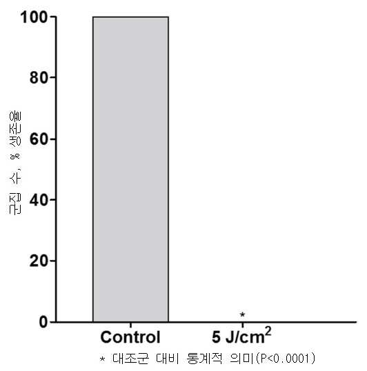
도 15에 도시된 바와 같이, 33% DF 펄스 모드에서 5 J/cm2의 복사 노출 및 2 mW/cm2의 평균 조사량을 사용한 하루 3 회 - 4 일의 코스에 걸쳐 3시간 마다 총 12 회(0, 3, 6, 24, 27, 30, 48, 51, 54, 72, 75 및 78 시간) - 의 박테리아의 조사는, 대조군과 비교했을 때 즉 0.0%로 완전한 박테리아 박멸을 나타냈다. 퍼센트 생존의 전반적인 감소는, 평균 조사량이 (다른 모든 파라미터는 동일한 상태로) 3 mW/cm2 였던 경우인 다섯번째 예제에서 보인 것보다 약간 더 높았다.As shown in Figure 15, 3 times a day using a radiative exposure of 5 J/cm 2 and an average dose of 2 mW/cm 2 in 33% DF pulse mode - 12 times every 3 hours over a course of 4 days ( 0, 3, 6, 24, 27, 30, 48, 51, 54, 72, 75 and 78 hours) of bacteria showed complete bacterial eradication, i.e. 0.0%, when compared to the control group. The overall decrease in percent survival was slightly higher than that shown in the fifth example, when the mean dose (all other parameters remained the same) was 3 mW/cm 2 .
예제 7Example 7
일곱번째 실험에는 P. acnes를 배양하는 것 및 인쇄된 LEDs가 있는 PET(polyethylene terephthalate) 은 필름을 사용하여 450 nm의 조명 기재로 박테리아를 비추는 것이 포함됐다. 조명 기재는 아래에 설명된 바와 같이 33% DF 펄스 모드에서 작동하도록 설정되었으며, 정전류 소스로 구동되었다. 평균 조사량은 2 mW/cm2 였다. 펄스 지속시간은 20 마이크로초의 오프 타임이 있는 10 마이크로초였고, 펄스 반복룰은 33 kHz였다. 박테리아는 5 J/cm2의 복사 노출로 0, 3, 6, 24, 27, 30, 48, 51 및 54 시간에 9 회 조사되었다.A seventh experiment involved culturing P. acnes and illuminating the bacteria with a 450 nm illumination substrate using a PET (polyethylene terephthalate) silver film with printed LEDs. The illuminating substrate was set to operate in 33% DF pulse mode as described below, and was driven by a constant current source. The average dose was 2 mW/cm 2 . The pulse duration was 10 microseconds with an off time of 20 microseconds, and the pulse repetition rule was 33 kHz. Bacteria were irradiated 9 times at 0, 3, 6, 24, 27, 30, 48, 51 and 54 hours with a radiation exposure of 5 J/cm 2 .
도 16에 도시된 바와 같이, 33% DF 펄스 모드에서 5 J/cm2의 복사 노출 및 2mW/cm2의 평균 조사량을 사용한 하루 3 회 - 3 일의 코스에 걸쳐 3 시간마다 총 9 회(0, 3, 6, 24, 27, 30, 48, 51 및 54 시간) - 의 박테리아의 조사는, 대조군과 비교했을 때 즉 0.0%로 완전한 박테리아 박멸을 나타냈다. 퍼센트 생존의 전반적인 감소는, 조사가 (다른 모든 파라미터는 동일한 상태로) 4 일의 코스에 걸쳐 총 12 번 적용되었던 경우인 여섯번째 예제에서 보인 것과 동일했다.As shown in Figure 16, 3 times a day with a radiative exposure of 5 J/cm 2 and an average dose of 2 mW/cm 2 in 33% DF pulse mode - a total of 9 times every 3 hours over a course of 3 days (0 , 3, 6, 24, 27, 30, 48, 51 and 54 hours) - irradiated with bacteria, compared with the control group, i.e. 0.0%, showed complete bacterial eradication. The overall decrease in percent survival was identical to that seen in the sixth example, where the irradiation was applied a total of 12 times over a course of 4 days (all other parameters being the same).
예제 8Example 8
여덟번째 실험에는 P. acnes를 배양하는 것 및 인쇄된 LEDs가 있는 PET(polyethylene terephthalate)은 필름을 사용한 450 nm의 조명 기재로 박테리아를 비추는 것이 포함됐다. 조명 기재는 아래에 설명된 바와 같이 33% DF 펄스 모드에서 작동하도록 설정되었으며, 정전류 소스로 구동되었다. 평균 조사량은 2 mW/cm2 였다. 펄스 지속시간은 20 마이크로초의 오프 타임이 있는 10 마이크로초였고, 펄스 반복률은 33 kHz 였다. 박테리아는 0, 3, 24, 27, 48, 51, 72 및 75 시간에 3.6 J/cm2의 복사 노출로 8 회 조사되었다.The eighth experiment involved culturing P. acnes and illuminating the bacteria with a 450 nm illumination substrate using a PET (polyethylene terephthalate) film with printed LEDs. The illuminating substrate was set to operate in 33% DF pulse mode as described below, and was driven by a constant current source. The average dose is 2 mW/cm 2 it was The pulse duration was 10 microseconds with an off-time of 20 microseconds, and the pulse repetition rate was 33 kHz. Bacteria were irradiated 8 times with a radiation exposure of 3.6 J/cm 2 at 0, 3, 24, 27, 48, 51, 72 and 75 hours.
도 17에 도시된 바와 같이, 33% DF 펄스 모드에서 3.6 J/cm2의 복사 노출 및 2mW/cm2의 평균 조사량을 사용한 하루 2 회 - 4 일의 코스에 걸쳐 3 시간마다 총 8 회(0, 3, 24, 27, 48, 51, 72 및 75 시간) - 의 박테리아의 조사는, 대조군과 비교했을 때 퍼센트 생존에서 즉 86.9%의 약간의 감소를 나타냈다. 이는 (다른 모든 파라미터는 동일한 상태로) 복사 노출은 5 J/cm2였고 조사가 하루 3 회 적용되었던 경우인 일곱번째 예제에서 보인 것보다 현저히 높았다.As shown in Figure 17, twice a day with a radiative exposure of 3.6 J/cm 2 and an average dose of 2 mW/cm 2 in 33% DF pulse mode - a total of 8 times every 3 hours over a course of 4 days (0 , 3, 24, 27, 48, 51, 72 and 75 hours) of bacteria showed a slight decrease in percent survival, ie 86.9%, when compared to the control group. This was significantly higher than that seen in the seventh example where the radiation exposure was 5 J/cm 2 (all other parameters being the same) and the irradiation was applied 3 times a day.
예제 9Example 9
아홉번째 실험에는 P. acnes를 배양하는 것 및 인쇄된 LEDs가 있는 PET(polyethylene terephthalate) 실버 필름을 사용하여 450 nm의 조명 기재로 박테리아를 비추는 것이 포함됐다. 조명 기재는 아래에 설명된 바와 같이 33% DF 펄스 모드에서 작동하도록 설정되었으며, 정전류 소스로 구동되었다. 평균 조사량은 2 mW/cm2 였다. 펄스 지속시간은 20 마이크로초의 오프 타임이 있는 10 마이크로초였고, 펄스 반복룰은 33 kHz였다. 박테리아는 3.6 J/cm2의 복사 노출로 0, 3, 24, 27, 48, 51, 72, 75, 96 및 99 시간에 10 회 조사되었다.A ninth experiment involved culturing P. acnes and illuminating the bacteria with a 450 nm illumination substrate using a PET (polyethylene terephthalate) silver film with printed LEDs. The illuminating substrate was set to operate in 33% DF pulse mode as described below, and was driven by a constant current source. The average dose was 2 mW/cm 2 . The pulse duration was 10 microseconds with an off time of 20 microseconds, and the pulse repetition rule was 33 kHz. Bacteria were irradiated 10 times at 0, 3, 24, 27, 48, 51, 72, 75, 96 and 99 hours with a radiation exposure of 3.6 J/cm 2 .
도 18에 도시된 바와 같이, 33% DF 펄스 모드에서 3.6 J/cm2의 복사 노출과 2mW/cm2의 평균 조사량을 사용한 하루 2 회 - 5 일의 코스에 걸쳐 3 시간마다 총 10 회(0, 3, 24, 27, 48, 51, 72, 75, 96 및 99 시간) - 의 박테리아의 조사는, 대조군과 비교했을 때 퍼센트 생존에서 즉 78.9%의 감소를 나타냈다. 이는 조사가 (다른 모든 파라미터는 동일한 상태로) 4 일의 코스에 걸쳐 적용되었던 경우인 여덟번째 예제에서 보인 것보다 약간 더 낮았다.As shown in Figure 18, twice a day using a radiative exposure of 3.6 J/cm 2 and an average dose of 2 mW/cm 2 in 33% DF pulse mode - a total of 10 times every 3 hours over a course of 5 days (0 , 3, 24, 27, 48, 51, 72, 75, 96 and 99 hours) of bacteria showed a decrease in percent survival, ie 78.9%, when compared to the control group. This was slightly lower than that shown in the eighth example where the investigation was applied over a course of 4 days (with all other parameters being equal).
예제 10Example 10
열번째 실험에는 P. acnes를 배양하는 것 및 인쇄된 LEDs가 있는 PET(polyethylene terephthalate) 실버 필름을 사용한 450 nm 조명 기재로 박테리아를 비추는 것이 포함됐다. 조명 기재는 아래에 설명된 바와 같이 33% DF 펄스 모드에서 작동하도록 설정되었으며, 정전류 소스로 구동되었다. 평균 조사량은 2 mW/cm2 였다. 펄스 지속시간은 20 마이크로초의 오프 타임이 있는 10 마이크로초였고, 펄스 반복률은 33 kHz였다. 박테리아는 3.6 J/cm2의 복사 노출로 0, 3, 6, 24, 27, 30, 48, 51, 54, 72, 75 및 78 시간에 12 회 조사되었다.The tenth experiment involved culturing P. acnes and illuminating the bacteria with a 450 nm illumination substrate using a PET (polyethylene terephthalate) silver film with printed LEDs. The illuminating substrate was set to operate in 33% DF pulse mode as described below, and was driven by a constant current source. The average dose was 2 mW/cm 2 . The pulse duration was 10 microseconds with an off time of 20 microseconds, and the pulse repetition rate was 33 kHz. Bacteria were irradiated 12 times at 0, 3, 6, 24, 27, 30, 48, 51, 54, 72, 75 and 78 hours with a radiation exposure of 3.6 J/cm 2 .
도 19에 도시된 바와 같이, 33% DF 펄스 모드에서 3.6 J/cm2의 복사 노출과 2 mW/cm2의 평균 조사량을 사용한 하루 3 회 - 3 시간마다 4 일의 코스에 걸쳐 총 12 번(0, 3, 6, 24, 27, 30, 48, 51, 54, 72, 75 및 78 시간) - 의 박테리아의 조사는, 대조군과 비교했을 때 퍼센트 생존이 즉 32.6%로 감소한 것으로 나타났다. 이는 여덟번째 및 아홉번째 예제에서 보인 것보다 낮다.As shown in Figure 19, 3 times a day with a radiation exposure of 3.6 J/cm 2 and an average dose of 2 mW/cm 2 in 33% DF pulse mode - every 3 hours for a total of 12 times over a course of 4 days ( 0, 3, 6, 24, 27, 30, 48, 51, 54, 72, 75 and 78 hours) of bacteria showed a decrease in percent survival, ie 32.6%, when compared to the control group. This is lower than shown in the eighth and ninth examples.
예제 11Example 11
열한번째 실험에는 P. acnes를 배양하는 것 및 인쇄된 LEDs가 있는 PET(polyethylene terephthalate) 실버 필름을 사용한 450 nm의 조명 기재로 박테리아를 비추는 것이 포함됐다. 조명 기재는 아래에 설명된 바와 같이 33% DF 펄스 모드에서 작동하도록 설정되었으며, 정전류 소스로 구동되었다. 평균 조사량은 2 mW/cm2였다. 펄스 지속시간은 20 마이크로초의 오프 타임이 있는 10 마이크로초였고, 펄스 반복률은 33 kHz 였다. 박테리아는 5 J/cm2의 복사 노출로 0, 3, 6, 24, 27, 30, 48, 51 및 54 시간에 9 회 조사되었다.The eleventh experiment involved culturing P. acnes and illuminating the bacteria with a 450 nm illumination substrate using a PET (polyethylene terephthalate) silver film with printed LEDs. The illuminating substrate was set to operate in 33% DF pulse mode as described below, and was driven by a constant current source. The average dose was 2 mW/cm 2 . The pulse duration was 10 microseconds with an off-time of 20 microseconds, and the pulse repetition rate was 33 kHz. Bacteria were irradiated 9 times at 0, 3, 6, 24, 27, 30, 48, 51 and 54 hours with a radiation exposure of 5 J/cm 2 .
도 20에 도시된 바와 같이, 33% DF 펄스 모드에서 5 J/cm2의 복사 노출 및 2mW/cm2의 평균 조사량을 사용한 하루 3 회 - 3 일의 코스에 걸쳐 3 시간마다 총 9 회 (0, 3, 6, 24, 27, 30, 48, 51 및 54 시간) - 의 박테리아의 조사는, 대조군과 비교했을 때 퍼센트 생존에서 즉 0.0%로 완전한 박테리아 박멸을 나타냈다. 이 실험은 일곱번째 실험(예제 7 참조)으로부터의 데이터를 확인하였다.As shown in Figure 20, 3 times a day using a radiative exposure of 5 J/cm 2 and an average dose of 2 mW/cm 2 in 33% DF pulse mode - a total of 9 times every 3 hours over a course of 3 days (0 , 3, 6, 24, 27, 30, 48, 51 and 54 hours) showed complete bacterial eradication in percent survival, i.e. 0.0%, when compared to the control group. This experiment confirmed the data from the seventh experiment (see Example 7).
예제 12Example 12
열두번째 실험에는 P. acnes를 배양하는 것 및 인쇄된 LEDs가 있는 PET(polyethylene terephthalate) 실버 필름을 사용한 450 nm의 조명 기재로 박테리아를 비추는 것이 포함됐다. 조명 기재는 아래에 설명된 바와 같이 33% DF 펄스 모드에서 작동하도록 설정되었으며, 정전류 소스로 구동되었다. 평균 조사량은 2 mW/cm2 였다. 펄스 지속시간은 20 마이크로초의 오프 타임이 있는 10 마이크로초였고, 펄스 반복률은 33 kHz 였다. 박테리아는 3.6 J/cm2의 복사 노출로 0, 3, 6, 24, 27, 30, 48, 51 및 54 시간에 9 시간 동안 조사되었다.The twelfth experiment involved culturing P. acnes and illuminating the bacteria with a 450 nm illumination substrate using a PET (polyethylene terephthalate) silver film with printed LEDs. The illuminating substrate was set to operate in 33% DF pulse mode as described below, and was driven by a constant current source. The average dose was 2 mW/cm 2 . The pulse duration was 10 microseconds with an off-time of 20 microseconds, and the pulse repetition rate was 33 kHz. Bacteria were irradiated for 9 hours at 0, 3, 6, 24, 27, 30, 48, 51 and 54 hours with a radiation exposure of 3.6 J/cm 2 .
도 21에 도시된 바와 같이, 33% DF 펄스 모드에서 3.6 J/cm2의 복사 노출 및 2 mW/cm2의 평균 조사량을 사용한 하루 3 회 - 3 일의 코스에 걸쳐 3 시간 동안 총 9 회(0, 3, 6, 24, 27, 30, 48, 51 및 54 시간) - 의 박테리아 조사는, 대조군과 비교했을 때 퍼센트 생존에서 즉 11.7%로 유의미하게 감소한 것으로 나타냈다. 비록 퍼센트 생존은 낮지만, (다른 모든 파라미터는 동일한 상태로) 복사 노출이 5 J/cm2 였던 경우인 열한번째 예제에서 보인 것보다 여전히 높았다.As shown in FIG. 21 , 3 times a day using a radiative exposure of 3.6 J/cm 2 and an average dose of 2 mW/cm 2 in 33% DF pulse mode - a total of 9 times for 3 hours over a course of 3 days ( 0, 3, 6, 24, 27, 30, 48, 51 and 54 hours) showed a significant decrease in percent survival, i.e. 11.7%, when compared to the control group. Although the percent survival is low (all other parameters being the same), it is still higher than that shown in the eleventh example where the radiation exposure was 5 J/cm 2 .
개요outline
추가 시험은 33% 듀티 사이클에서 펄스 광을 방출하는 라이트 패치를 사용하여 수행되었다. 테스트된 다양한 프로토콜은 박테리아 성장에서의 효과적인 감소를 나타냈다. 3 시간의 조사 간격을 사용한 시험은 4 시간의 조사 간격보다 더 효율적이라는 것을 입증했다. 그러한 관찰된 효율은 부분적으로는 복제 사이클 동안 적절한 시간에 박테리아를 타겟팅하는 것 또는 박테리아 내의 포르피린 고갈/보충 기작(replenishing mechanisms)으로 인한 것일 수 있다고 믿어진다. Further testing was performed using a light patch emitting pulsed light at 33% duty cycle. The various protocols tested showed effective reductions in bacterial growth. Trials using a 3 hour irradiation interval proved to be more efficient than a 4 hour irradiation interval. It is believed that such observed efficiencies may be due in part to targeting the bacteria at appropriate times during the replication cycle or porphyrin depletion/replenishing mechanisms within the bacteria.
조사 프로토콜은 1 x 10⁶ CFU/ml P. acnes 배양물의 100% 박테리아 억제를 산출하도록 최적화되었다. 100%의 최적 박테리아 억제는, (i) 20 J/cm2의 복사 노출 및 3mW/cm2의 평균 조사량으로 0, 3, 6 및 24 시간에 배양물이 조사된 경우(예제 2 참조), (ii) 5 J/cm2의 복사 노출 및 2 mW/cm2의 평균 조사량을 사용한 하루 3 회 - 4 일의 코스에 걸쳐 3시간 마다 총 12 회(0, 3, 6, 24, 27, 30, 48, 51, 54, 72, 75 및 78 시간) - 로 배양물이 조사된 경우(예제 6 참조), 및 (iii) 5 J/cm2의 복사 노출 및 2mW/cm2의 평균 조사량을 사용한 하루 3 회 - 3 일의 코스에 걸쳐 3 시간마다 총 9 회(0, 3, 6, 24, 27, 30, 48, 51 및 54 시간) - 로 배양물이 조사된 경우(예제 11 참조)에 달성되었다.The irradiation protocol was optimized to yield 100% bacterial inhibition of 1×10 6 CFU/ml P. acnes cultures. Optimal bacterial inhibition of 100% is achieved when (i) cultures are irradiated at 0, 3, 6 and 24 hours with a radiation exposure of 20 J/cm 2 and an average dose of 3 mW/cm 2 (see Example 2), ( ii) 3 times a day with a radiation exposure of 5 J/cm 2 and an average dose of 2 mW/cm 2 - 12 times every 3 hours over a course of 4 days (0, 3, 6, 24, 27, 30, 48, 51, 54, 72, 75 and 78 hours) when the culture was irradiated (see Example 6), and (iii) a day with a radiation exposure of 5 J/cm 2 and an average dose of 2 mW/cm 2 . Achieved when the culture was irradiated (see Example 11) 3 times - a total of 9 times (0, 3, 6, 24, 27, 30, 48, 51 and 54 hours) every 3 hours over a course of 3 days became
당업자는 본 발명이 감소된 배터리 요구사항, 치료 시간의 상당한 감소, 및, 열과 광학 위험의 유의미한 감소로 인한 개선된 환자 안전성을 갖는 개선된 장치 성능을 허용함을 이해할 것이다.Those skilled in the art will appreciate that the present invention allows for improved device performance with reduced battery requirements, significant reduction in treatment time, and improved patient safety due to significant reduction in thermal and optical risks.
IV. IV. P. P. AcnesAcnes 에서at 흡광absorbance 안료 "포르피린( Pigment "porphyrin ( PorphyrinsPorphyrins )"의 방출 스펙트럼 검출)" emission spectrum detection
P. acnes는 펄스화된 보라색 또는 청색 광으로 비춰지는 경우 600-700 nm(일반적으로 620 nm 내지 640 nm)의 적색 스펙트럼에서 형광(fluorescence)을 발한다. 어떤 이론에도 얽매이지 않고, 포르피린은 펄스의 순서로 광학적으로 펌핑되고, 기저 상태로 되돌아 가면 미토콘드리아 막, DNA 또는 다른 세포 구조를 이어서 파괴하는 자유 라디칼을 생성하는 산화 반응을 일으킨다고 믿어진다. 따라서, 조사를 받는 중인 세포에 의해 조사 도중에 발해지는 적색 또는 다른 파장을 검출하기 위해 광 센서가 사용된다면, 피드백은 광의 선량을 제어하는데 사용될 수 있는데, 예를 들어, 펄스화된 보라색 또는 청색 광의 조사는 포르피린 레벨이 최소 지점에 도달할 때까지 일어날 것이고, 치료는 포르피린 회복이 일어날 때까지 재개되지 않을 것이다. 이것은 미생물의 복제주기의 일부로서 일어날 수 있다. P. acnes fluoresces in the red spectrum of 600-700 nm (typically 620 nm to 640 nm) when illuminated with pulsed violet or blue light. Without wishing to be bound by any theory, it is believed that porphyrins are optically pumped in a sequence of pulses, which, when returned to a ground state, triggers an oxidative reaction that produces free radicals that subsequently destroy mitochondrial membranes, DNA, or other cellular structures. Thus, if a light sensor is used to detect a red or other wavelength emitted during irradiation by a cell being irradiated, the feedback can be used to control the dose of light, for example, irradiation of pulsed purple or blue light. will occur until the porphyrin level reaches a minimum point, and treatment will not resume until porphyrin recovery has occurred. This can happen as part of the microbial replication cycle.
시험은 P. acnes에서 흡광 안료 포르피린의 방출 스펙트럼을 검출하기 위해 수행되었다.The test was performed to detect the emission spectrum of the light-absorbing pigment porphyrin in P. acnes.
P. acnes의 72 시간 배양물을 13,300 rpm에서 5 분간 원심분리하고, 상청액을 폐기하고 1 ml의 셀라인(saline)에서 재현가했다. 그런 다음 1ml의 셀라인으로 13,300 rpm에서 5 분간 원심분리하여 다시 세척하였다(세척은 - P. acnes 세포에서 발견되는 타고난 포르피린을 제외하고 - 다른 모든 요소가 검출에 기여하지 않도록 한다). 광학 밀도는 108CFU/ml의 농도에 대해 625 nm에서 McFarland 표준을 사용하여 0.8 내지 1.0으로 조정되었다. 이 용액의 용량 10 μl가 콘카나발린 A(Concanavalin A) 코팅된 접시에 넣고 아래에 설명된 대로 여기됐다(excited). A 72 hour culture of P. acnes was centrifuged at 13,300 rpm for 5 minutes, the supernatant was discarded and regenerated in 1 ml of saline. It was then washed again by centrifugation at 13,300 rpm for 5 min with 1 ml of cell line (washing - except for the innate porphyrins found in P. acnes cells - such that all other factors do not contribute to detection). The optical density was adjusted from 0.8 to 1.0 using McFarland standards at 625 nm for a concentration of 108 CFU/ml. A volume of 10 μl of this solution was placed in a Concanavalin A coated dish and excited as described below.
도 23에 도시된 바와 같이, 박테리아를 조사하는 데 사용된 셋업은 1 nm 미만의 스펙트럼 대역폭과 및 150 mW의 총 전력을 갖는 연속파(CW) 광을 전달하는 458 nm Ar-Ion 레이저 어셈블리(Edmund optics, USA)를 채용한다. 원래의 발산형(divergent) 레이저 빔은 레이저 조리개로부터 약 22mm 떨어진 렌즈(초점 거리 35mm)를 사용하여 시준됐다(collimated). 최종 빔 직경은 콘카나발린 A로 코팅된 접시의 면적과 대략 일치하는 3 cm2의 단면적을 갖는 15 mm이었다. 샘플은 시준 렌즈로부터 약 25 cm에 위치된 병진 스테이지(translation stage) 상에 위치되었다.As shown in Figure 23, the setup used to irradiate bacteria was a 458 nm Ar-Ion laser assembly (Edmund optics) delivering continuous wave (CW) light with a spectral bandwidth of less than 1 nm and a total power of 150 mW. , USA). The original divergent laser beam was collimated using a lens (focal length 35mm) approximately 22mm away from the laser aperture. The final beam diameter was 15 mm with a cross-sectional area of 3 cm 2 approximately matching the area of the dish coated with concanavalin A. The sample was placed on a translation stage located about 25 cm from the collimating lens.
샘플을 도립 현미경(Axio Observer-Z1, Carl Zeiss, Oberkochen, Germany)에 놓고, 458 nm 파장을 갖는 연속파 Ar-Ion 레이저(Edmund Optics)를 사용하여 현미경의 뒤쪽 포트를 통해 비추었다. 여기 광(excitation light)(0.5 mW)은 1.2의 개구수(NA)를 갖는 63x 침수 대물렌즈(water immersion objective)에 의해 집중되었다. 현미경 스캐닝 헤드는 컴퓨터-제어 OptiMiS TruLine(Aurora Spectral Technologies, Milwaukee, WI, USA)으로 구성된다. 검출은 수정된 OptiMiS 검출 모듈(OptiMiS d-Lux의 상용 프로토타입)을 사용하여 수행되었으며, 여기에는 전하 증강 충전 결합 장치(electron multiplying charged coupled device)(iXon3, Andor, Belfast, UK) 상에 떨어지는 형광 빔을 디스캔(descan)하도록 사용된 갈바노매트릭 스캐너가 포함됐다. 이 디스캐닝 개념은 OptiMiS를 (2 광자가 아닌) 공초점 현미경으로 사용할 수 있게 했다. 이것은 검출된 신호의 강도가 낮은 이 실험들에서 중요했던 세포 형광의 레이저-유도 광-표백을 차례로 감소시켰다. 전체 스펙트럼 이미지를 캡처하기 위해 샘플이 한 줄씩 스캔됐다. 라인 이미지들은 각 파장 채널(총 300 채널)에 대한 이미지를 초래하면서 추가로 재구성되었다.The sample was placed on an inverted microscope (Axio Observer-Z1, Carl Zeiss, Oberkochen, Germany) and illuminated through the rear port of the microscope using a continuous wave Ar-Ion laser (Edmund Optics) with a wavelength of 458 nm. The excitation light (0.5 mW) was focused by a 63x water immersion objective with a numerical aperture (NA) of 1.2. The microscope scanning head consists of a computer-controlled OptiMiS TruLine (Aurora Spectral Technologies, Milwaukee, WI, USA). Detection was performed using a modified OptiMiS detection module (a commercial prototype of the OptiMiS d-Lux), which included fluorescence falling on an electron multiplying charged coupled device (iXon3, Andor, Belfast, UK). A galvanometric scanner used to descan the beam was included. This scanning concept made it possible to use the OptiMiS as a confocal microscope (rather than two photons). This in turn reduced the laser-induced photo-bleaching of cell fluorescence, which was important in these experiments where the intensity of the detected signal was low. Samples were scanned line by line to capture full spectrum images. The line images were further reconstructed resulting in an image for each wavelength channel (300 channels in total).
포르피린 스펙트럼의 추출은 박테리아로부터의 방출 스펙트럼 및 박테리아 외부의 매질(media)의 스펙트럼을 먼저 측정함으로써 수행되었다. 다음으로, 박테리아와 외부 매질 사이의 방출 비율을 고려하면서 매질의 스펙트럼을 박테리아 방출 스펙트럼에서 뺀다. 마지막으로, 방출 스펙트럼은 2 개의 혹(hump)을 가지고 있기 때문에 결과 스펙트럼은 2 개의 가우시안으로 맞추어 졌다(fitted with).Extraction of the porphyrin spectrum was performed by first measuring the emission spectrum from the bacteria and the spectrum of the medium outside the bacteria. Next, the spectrum of the medium is subtracted from the bacterial emission spectrum, taking into account the emission ratio between the bacteria and the external medium. Finally, since the emission spectrum has two humps, the resulting spectrum was fitted with two Gaussians.
도 24a는 458 nm의 광으로 여기되고 P. OptiM TruLine(Aurora Spectral Technologies, Milwaukee, WI)을 사용하여 검출된 P. acnes로부터 추출된 포르피린 방출 스펙트럼을 도시한다. 결과로 초래된 방출의 피크 파장은 2 개의 명백한 혹(humps)에 대한 619 nm 및 670 nm였다. 이 방출은 여드름 박테리아에 존재할 가능성이 큰 시토크롬 C(cytochrome C)의 특징이다. 그러나, 그것은 박테리아 박멸 메카니즘에 참여할 수 있는 코포로포르피린(coproporphyrin)과 같은 다른 포르피린들(porphyrins)으로부터의 몇몇 방출을 여전히 포함할 수 있다. 펄스화된 보라색 또는 청색 광에 노출된 포르피린으로부터 생성된 퍼 옥사이드에 의한 자유 라디칼 생성이 DNA 구조를 변화시키고 그 복제 단계 동안 박테리아의 파괴를 초래할 수 있다고 제안되었다. 따라서, 복제 단계 동안의 광 노출 시기는 살균율에 상당한 영향을 미칠 수 있다.24A depicts porphyrin emission spectra extracted from P. acnes excited with light at 458 nm and detected using P. OptiM TruLine (Aurora Spectral Technologies, Milwaukee, Wis.). The peak wavelengths of the resulting emission were 619 nm and 670 nm for the two distinct humps. This release is characteristic of cytochrome C, which is most likely present in acne bacteria. However, it may still involve some release from other porphyrins, such as coproporphyrin, which may participate in the bacterial eradication mechanism. It has been suggested that free radical generation by peroxides generated from porphyrins exposed to pulsed violet or blue light may change the DNA structure and lead to the destruction of bacteria during its replication phase. Thus, the timing of light exposure during the replication step can significantly affect the sterilization rate.
도 24b는 조사 동안 제로(zero) 내지 30 분의 다양한 시간(T = 1, 10, 20 및 30 분에서 측정됨)에서 P. acnes의 형광 스펙트럼을 입증한다. 형광이 점차적으로 시간이 지남에 따라 고갈되어 세포 수준에서 포르피린 고갈의 지표로 작용할 수 있음을 쉽게 알 수 있다. 포르피린 고갈은 박테리아의 광박멸에 대해 최적인 것으로 밝혀진 선량 파라미터(3 mW/cm2에서 약 30 분의 조사량)를 따른다. 이러한 실험들은 플렉서블 기재 상에 450 nm 인쇄된 LEDs로 조명한 시험관(in vitro), 한천 내 페트리 접시, 에서 수행되었다. 출력은 3 mW/cm2의 조사량에서 33%의 듀티 팩터(10 마이크로초 온(on) 및 20 마이크로초 오프(off))로 펄스되었다. 교정된 해양 광학 OCEAN-FX-VIS-NIR-ES 분광계가 형광을 기록하는 데 사용됐다. 접시는 가볍고 타이트한 하우징에 고정됐다(held). 청색 450 nm 여기 광이 420 및 480 nm를 초과하는 모든 파장을 제거하기 위해 필터링됐다. 510nm 이하의 파장을 제거하기 위해 접시 아래에 필터가 사용됐다. 포르피린 스펙트럼의 추출은 박테리아로부터의 방출 스펙트럼 및 박테리아 외부의 매질 스펙트럼을 먼저 측정함으로써 수행되었다. 다음으로, 박테리아와 외부 매질 간의 방출 비율을 고려하면서 매질의 스펙트럼을 박테리아 방출 스펙트럼에서 뺀다. 스펙트럼은 그 다음 표시되었다(plotted).24B demonstrates the fluorescence spectra of P. acnes at various times (measured at T = 1, 10, 20 and 30 minutes) from zero to 30 minutes during irradiation. It is readily seen that the fluorescence is gradually depleted over time, which can serve as an indicator of porphyrin depletion at the cellular level. Porphyrin depletion follows a dose parameter (dose of about 30 min at 3 mW/cm 2 ) that has been found to be optimal for photoeradication of bacteria. These experiments were performed in vitro, in Petri dishes in agar, illuminated with 450 nm printed LEDs on flexible substrates. The output was pulsed with a duty factor of 33% (10 microseconds on and 20 microseconds off) at a dose of 3 mW/cm 2 . A calibrated ocean optics OCEAN-FX-VIS-NIR-ES spectrometer was used to record the fluorescence. The dish was held in a light and tight housing. Blue 450 nm excitation light was filtered to remove all wavelengths above 420 and 480 nm. A filter is used under the dish to remove wavelengths below 510 nm. Extraction of the porphyrin spectrum was performed by first measuring the emission spectrum from the bacteria and the spectrum of the medium outside the bacteria. Next, the spectrum of the medium is subtracted from the bacterial emission spectrum, taking into account the emission ratio between the bacteria and the external medium. Spectra were then plotted.
도 24c는 PET 기재 상에 450 nm의 인쇄된 LEDs로 여기된 Protoporphyrin IX 샘플로부터 추출되고 도 24b와 동일한 테스트 셋업으로 해양 광학 OCEAN-FX-VIS-NIR-ES 분광계를 사용하여 검출된 포르피린 방출 스펙트럼을 도시한다. 결과로 생성된 방출의 피크 파장은 세 개의 명백한 혹(humps)에 대해 620 nm 및 670 nm 및 750 nm이었다. 이 방출은 458 nm 광으로 여기된 P. acnes로부터 추출된 초기 포르피린 방출 스펙트럼과 유사하다(도 24a). 그러나, 그것은 근적외선 범위에서보다 넓은 방출을 갖는다.Figure 24c shows porphyrin emission spectra extracted from Protoporphyrin IX samples excited with 450 nm printed LEDs on PET substrate and detected using a marine optics OCEAN-FX-VIS-NIR-ES spectrometer with the same test setup as Figure 24b. show The peak wavelengths of the resulting emission were 620 nm and 670 nm and 750 nm for the three distinct humps. This emission is similar to the initial porphyrin emission spectrum extracted from P. acnes excited with 458 nm light ( FIG. 24A ). However, it has a broader emission in the near-infrared range.
포르피린의 방출 스펙트럼 또는 타겟 박테리아로부터의 다른 방출을 검출함으로써, 형광 고갈 또는 회복을 측정함으로써, 치료 세션 사이의 최적의 여기 기간 및 회복을 결정함으로써, 그리고 투약량, 조사량, 플루언스(fluence) 및 치료 스케쥴을 포함하는 이상적인 조사 파라미터를 계산함으로써 조사량(dosage)이 최적화될 수 있다. 또한 이 방법을 사용하여 상이한 균주의 박테리아 죽이는 것을 최적화할 수 있다. 포르피린 고갈을 측정하기 위한 이상적인 파장은 제시된 데이터로부터 620-640 nm 범위 및 670 nm 범위에 있는 것으로 나타났으며, 이는 도 24a, 24b 및 24c에 도시된 데이터와 잘 일치한다. 다른 형태의 방출을 측정하기 위한 이상적인 파장은 당업자에 의해 결정될 수 있다.By detecting the emission spectrum of the porphyrin or other release from the target bacteria, by measuring fluorescence depletion or recovery, by determining the optimal excitation period and recovery between treatment sessions, and by determining the dose, dose, fluence and treatment schedule. Dosage can be optimized by calculating ideal irradiation parameters including This method can also be used to optimize the killing of bacteria of different strains. Ideal wavelengths for measuring porphyrin depletion were shown to be in the range of 620-640 nm and 670 nm from the presented data, which is in good agreement with the data shown in Figures 24a, 24b and 24c. The ideal wavelength for measuring other forms of emission can be determined by one of ordinary skill in the art.
V. 광원 V. Light source 실시예Example
다양한 형태의 광원이 본 발명에 따라 광 에너지를 제공하는데 사용될 수 있다. 예를 들어, 광원은 다양한 유형의 레이저, LEDs, PLEDs/LEPs), QDLEDs, 또는 보라색 또는 청색 스펙트럼 영역에서 광을 방출하는 형광 튜브를 포함할 수 있다. 광원은, 예를 들어 오염된 환경 또는 펄스 광에 노출되는 식품처럼, 조사(irradiated)될 피부, 조직 또는 기타 표면을 직접 조명할 수 있다. 광원은 또한 광섬유에 의해 결합되거나 또는 조사될 표면으로 광을 재지향시키는(redirect) 렌즈-디퓨저의 모서리에 직접 장착될 수 있다. 이러한 디퓨저(diffuser)는 조사될 표면 전체에 걸쳐 광을 균일하게 확산 및 분배하도록 설계된 다수의 광학 소자(optical elements)들을 포함할 수 있다. 여기에는 프레넬 렌즈, 다양한 광 파이프, 광원을 파이프(pipe)하고 렌즈-디퓨저 어셈블리의 표면에 고르게 분배하도록 설계된 불규칙면(irregularities) 및 추가 렌즈와 같은 구조물이 포함될 수 있다. 광의 추출 또는 외부 결합(out-coupling)을 향상시키기 위해, 상기 장치는 투명 포토레지스트 또는 마이크로-렌즈 어레이(MLA) 층에 TiOx와 같은 고굴절 입자(high index particle)의 내부 산란 층을 포함할 수 있다. 광원은 조사될 표면에 적용될 실질적으로 균일한 빔의 생성을 허용하는 충분한 거리에서 디퓨저 또는 프레넬 렌즈 바로 뒤에 배치될 수도 있다. 광원은 백색광과 보라색 또는 청색광의 조합일 수 있으며,그 결과 보라색 또는 청색광은 펄스화되며, 백색광은 연속파(CW)이다. 이러한 서로 다른 파장을 동시에 또는 순차적으로 적용하여 감염된 환경이나 식품을 조사할 수 있다.Various types of light sources may be used to provide light energy in accordance with the present invention. For example, the light source may include various types of lasers, LEDs, PLEDs/LEPs), QDLEDs, or fluorescent tubes that emit light in the violet or blue spectral region. The light source may directly illuminate the skin, tissue or other surface to be irradiated, such as, for example, a contaminated environment or food exposed to pulsed light. The light source may also be coupled by an optical fiber or mounted directly to the edge of a lens-diffuser which redirects the light to the surface to be irradiated. Such a diffuser may include a number of optical elements designed to uniformly spread and distribute light over the entire surface to be irradiated. This may include structures such as Fresnel lenses, various light pipes, irregularities designed to pipe the light source and distribute it evenly over the surface of the lens-diffuser assembly, and additional lenses. To enhance light extraction or out-coupling, the device may include an internal scattering layer of high index particles, such as TiOx, in a transparent photoresist or micro-lens array (MLA) layer. . The light source may be placed directly behind the diffuser or Fresnel lens at a sufficient distance to permit the creation of a substantially uniform beam to be applied to the surface to be irradiated. The light source may be a combination of white light and purple or blue light, so that the purple or blue light is pulsed and the white light is a continuous wave (CW). These different wavelengths can be applied simultaneously or sequentially to irradiate the infected environment or food.
바람직한 광원은 매우 얇은 층 구조물의 형태로 제공된다. 이러한 유형의 광원의 하나의 예는 도 25에 참고번호 10으로 도시되어 있다. 광원(10)은 애노드(anode)(50)와 캐소드(cathode)(60) 사이에 위치한 플렉서블 발광기(40)를 포함하는 복수의 층(12)으로 구성된다. 적절한 전원이 광원(10)에 연결된다. 바람직하게는 직류(DC) 또는 펄스화된 DC가 광원(10)에 전원을 공급한다. 광원(10)은 그 형태가 실질적으로 평면(planar)이며, 플렉서블한 것이 바람직하지만 몸체(Body)의 윤곽, 오염된 환경 내의 표면, 또는 냉장 또는 식품 디스플레이 시스템 내부의 표면에 부합할 수 있도록 순응적인 것(conformable)이 더 바람직하다. 광원(10)의 전체 두께는 전형적으로 약 10 mm 또는 이하(예를 들어, 약 10, 9, 8, 7, 6, 5, 4, 3, 2, 1, 0.5, 0.4, 0.3, 0.2, 0.1, 0.05 mm, 또는 이하) 이다.A preferred light source is provided in the form of a very thin layer structure. One example of a light source of this type is shown by
광원(10)은 실질적으로 균일한 광 방출을 제공하도록 장치의 표면 전체에 걸쳐 실질적으로 일정한 강도를 갖는 광을 생성한다. 이하에서 보다 상세히 설명되는 바와 같이, 광원은 일반적으로 LED 잉크로 언급되는 유기 발광 다이오드(OLEDs) 또는 인쇄된 발광 다이오드(인쇄된 LEDs)(유기 또는 무기)를 포함할 수 있다. 광원은 피사체(subject)로 광을 안전하게 전달하기 위하여 피사체의 피부 또는 조직의 표면 상의 핫 스폿을 감소시킬 수 있음을 이해할 수 있다. 또한, 장치의 표면 전체에 걸쳐 실질적으로 균일한 양의 광선은 피부, 조직, 표면 또는 식품 모두가 동일한 양의 광으로 효과적으로 처리되도록 보장한다.The
광원은 예를 들어 어레이, 패치, 패드, 마스크, 랩, 섬유, 붕대 또는 실린더의 형태 일 수 있다. 광원은 다양한 모양 및 크기를 가질 수 있다. 예를 들어, 광원은 도 26에 일반적으로 도시된 광원(10a-10f)들처럼 정사각형, 직사각형, 원형, 타원형, 클로버형, 타원형 또는 초승달/달 형상일 수 있다. 광원의 한 면의 전체 표면적은, 예를 들어, 1㎠ 내지 1㎡의 범위일 수 있고 또는 더 넓은 면적을 커버하기 위해 함께 배치된 패널에서는, 일반적으로 표면적이 약 1 내지 2000㎠일 수 있다 (예를 들어, 약 1, 4, 9, 16, 25, 36, 49, 64, 81,100,121,144,169,196,225,289,324,361,400,441,484,429,576, 1269, 1156, 122, 1296, 1369, 1444, 1521, 1600, 1681, 1764, 1849, 1936 또는 2000cm2 또는 이들 사이의 일부 범위).The light source may be, for example, in the form of an array, patch, pad, mask, wrap, fiber, bandage or cylinder. The light source may have various shapes and sizes. For example, the light source may be square, rectangular, circular, oval, clover-shaped, oval, or crescent/moon-shaped, such as
따라서, 광원은 피사체의 몸체의 다양한 영역, 예를 들어 얼굴, 이마, 등에 적용하는데 적합하다. 광원은 또한 오염된 환경 내의 표면 또는 냉장 또는 식품 디스플레이 시스템 내부의 표면과 같은 다른 유형의 표면에 적용될 수 있다. 광원의 다양한 소자들/층들이 이제더 상세히 설명될 것이다.Accordingly, the light source is suitable for application to various areas of the subject's body, for example, the face, forehead, and the like. The light source may also be applied to other types of surfaces, such as surfaces within a contaminated environment or surfaces inside a refrigeration or food display system. The various elements/layers of the light source will now be described in greater detail.
기재(substrate)substrate
일부 실시예에서, 광원은 기재를 포함한다. 기재는 광원의 다양한 층을 지지할 수 있는 임의의 물질일 수 있다. 기재는 바람직하게는 플렉서블하고 및/또는 피사체(subject)의 윤곽, 오염된 환경 내의 표면 또는 냉장고, 식품 디스플레이 또는 처리 시스템 내부의 표면과 같이 광원이 사용될 표면에 순응할 수 있다. 기재는 예를 들어, 무기 물질, 유기 물질, 또는 무기 및 유기 물질의 조합을 포함할 수 있다. 기재는 예를 들어 금속, 플라스틱 또는 유리로 제조될 수 있다. 기재는 광원의 다른 구성 요소를 지지하는 임의의 형상일 수 있으며, 예를 들어, 기재는 실질적으로 평평하거나 또는 평면(planar)이거나, 만곡되거나, 또는 실질적으로 평탄한 부분 및 만곡된 부분을 가질 수 있다. 가장 바람직하게는, 기재는 투명하고 플렉서블하며 본질상 순응적이다. 이상적으로는, 상기 재료는 라텍스-프리이며, 비독성이며, 비알레르기성 물질로 자외선, 일광 및 대부분의 감염 컨트롤 제품에 내성이 있다.In some embodiments, the light source comprises a substrate. The substrate can be any material capable of supporting the various layers of the light source. The substrate is preferably flexible and/or capable of conforming to the surface on which the light source will be used, such as the contour of a subject, a surface in a contaminated environment or a surface inside a refrigerator, food display or processing system. The substrate may comprise, for example, an inorganic material, an organic material, or a combination of inorganic and organic materials. The substrate may be made of, for example, metal, plastic or glass. The substrate may be of any shape that supports the other components of the light source, for example, the substrate may be substantially flat or planar, curved, or may have a substantially flat portion and a curved portion . Most preferably, the substrate is transparent, flexible and conformable in nature. Ideally, the material is latex-free, non-toxic, non-allergenic and resistant to UV light, sunlight and most infection control products.
본 명세서에 사용된 용어 "투명"은 일반적으로 광에 대한 투명성을 의미하며 반투명(translucency)뿐만 아니라 완전한 투명(clear transparency) 모두를 포함한다. 일반적으로, 재료를 조명하는 광의 적어도 약 50%, 바람직하게는 약 60%, 보다 바람직하게는 약 70%, 보다 바람직하게는 약 80% 및 더욱 더 바람직하게는 약 90%가 재료를 통과할 수 있는 경우, 재료는 투명하다고 간주된다. 대조적으로, "불투명"이라는 용어는 광이 실질적으로 흡수되거나 반사되는 물질, 예를 들어 광의 적어도 90%가 흡수되거나 반사되는 물질을 의미하며, 전형적으로 광의 적어도 95 %가 흡수되거나 반사된다.As used herein, the term “transparent” generally refers to transparency to light and includes both translucency as well as clear transparency. Generally, at least about 50%, preferably about 60%, more preferably about 70%, more preferably about 80% and even more preferably about 90% of the light illuminating the material can pass through the material. If present, the material is considered transparent. In contrast, the term "opaque" means a material from which light is substantially absorbed or reflected, eg, a material from which at least 90% of the light is absorbed or reflected, typically at least 95% of the light is absorbed or reflected.
일부 실시예에서, 기재는 실리콘-기반 물질, 고무, 열가소성 엘라스토머(TTP),또는 폴리에스테르, 폴리에틸렌 테레프탈레이트(PET), 폴리에틸렌 나프탈레이트(PEN), 폴리카보네이트, 폴리스티렌, 폴리아크릴, 폴리에테르 술폰(PES) 등과 같은 다른 중합체 재료로 구성될 수 있다. 투명 기재는 예를 들어, 폴리에틸렌, 에틸렌 - 비닐 아세테이트 공중합체, 폴리이미드(PI), 폴리에테르이미드(PEI), 에틸렌-비닐 알코올 공중합체, 폴리프로필렌, 폴리스티렌, 폴리메틸 메타크릴레이트, PVC, 폴리비닐 알콜, 폴리비닐부티랄, 폴리에테르 에테르 케톤, 폴리술폰, 폴리에테르 술폰 뿐만 아니라 및 예를 들어 플루오르화 에틸렌-프로필렌(FEP), 테트라플루오로에틸렌-퍼플루오로알킬 비닐 에테르 공중합체, 폴리비닐 플루오라이드, 테트라플루오로에틸렌-에틸렌 공중합체, 테트라플루오로에틸렌- 헥사플루오로프로필렌 공중합체, 폴리클로로트리플루오로에틸렌, 폴리비닐리덴 플루오라이드, 폴리에스테르, 폴리카보네이트, 폴리우레탄, 폴리이미드 또는 폴리에테르 이미드 와 같은 플루오로 중합체를 포함할 수 있다.In some embodiments, the substrate is a silicone-based material, rubber, thermoplastic elastomer (TTP), or polyester, polyethylene terephthalate (PET), polyethylene naphthalate (PEN), polycarbonate, polystyrene, polyacrylic, polyether sulfone ( PES) and the like). The transparent substrate may be, for example, polyethylene, ethylene-vinyl acetate copolymer, polyimide (PI), polyetherimide (PEI), ethylene-vinyl alcohol copolymer, polypropylene, polystyrene, polymethyl methacrylate, PVC, poly Vinyl alcohol, polyvinylbutyral, polyether ether ketones, polysulfones, polyether sulfones as well as for example fluorinated ethylene-propylene (FEP), tetrafluoroethylene-perfluoroalkyl vinyl ether copolymers, polyvinyl Fluoride, tetrafluoroethylene-ethylene copolymer, tetrafluoroethylene-hexafluoropropylene copolymer, polychlorotrifluoroethylene, polyvinylidene fluoride, polyester, polycarbonate, polyurethane, polyimide or poly fluoropolymers such as ether imides.
다른 실시예에서, 투명 기재는 마일라(Mylar)와 같은 폴리에스테르 필름이다. 다른 일 측면에서, 기재는 빅트 렉스(Victrex)로부터 상표명 APTIV로 판매되는 상업적으로 입수 가능한 폴리에테르에테르케톤 필름을 포함한다. 또 다른 실시예에서, 기재는 코니카 미놀타(Konica Minolta)에 의해 플렉시트(Flexent) 이름 하에 판매되는 박막 또는 다우 코닝(Dow Corning)에 의한 윌로우 글래스와 같은 플렉서블 유리이다. 이상적으로는, 유기층과 직접 또는 간접적으로 접촉하는 기재는 열을 견디고 유연성을 제공하며 지속적인 안정성을 가지고 및 대량 생산될 수 있는 탁월한 장벽 기능을 가질 것이다.In another embodiment, the transparent substrate is a polyester film such as Mylar. In another aspect, the substrate comprises a commercially available polyetheretherketone film sold under the trade designation APTIV from Victrex. In another embodiment, the substrate is a thin film sold under the name Flexent by Konica Minolta or a flexible glass such as Willow Glass by Dow Corning. Ideally, a substrate that is in direct or indirect contact with the organic layer will withstand heat, provide flexibility, have lasting stability, and have excellent barrier functions that can be mass-produced.
도전 층(전극)conductive layer (electrode)
광원은 복수의 도전 층(즉, 전극), 즉 캐소드 및 애노드를 포함한다. 애노드는 예를 들어, ITO(Indium Tin Oxide), ZnO(zinc oxide) 등과 같은 투명 전도성 산화물(TCO)을 포함할 수 있으나, 그에 국한되지는 않는다. 캐소드는 또한 예를 들어 금속 박막 또는 알루미늄, 구리, 금, 몰리브덴, 이리듐, 마그네슘, 은, 불화 리튬 및 이들의 합금, 또는 비금속 도전 층과 같은 섬유를 포함할 수 있다.The light source includes a plurality of conductive layers (ie electrodes), ie, a cathode and an anode. The anode may include, but is not limited to, a transparent conductive oxide (TCO) such as, for example, indium tin oxide (ITO), zinc oxide (ZnO), or the like. The cathode may also comprise, for example, a thin metal film or fiber such as aluminum, copper, gold, molybdenum, iridium, magnesium, silver, lithium fluoride and alloys thereof, or a non-metallic conductive layer.
광원은 한쪽 또는 양쪽 전극을 통해 광을 방출해야 하기 때문에 적어도 하나의 전극은 투명해야 한다. 투명 전극은 조사될 표면을 향하도록 설계된 광원의 측면 상에 위치된다. 하부 전극(즉, 표면-대향 전극)을 통해서만 광을 방출하도록 의도된 광원에 대해, 상부 전극(즉, 표면으로부터 멀리 향하는 전극)은 투명할 필요는 없다. 따라서, 상부 전극은 높은 전기 전도도를 갖는 불투명한 또는 광-반사 금속층을 포함할 수 있다. 상부 전극이 투명할 필요가 없는 경우, 보다 두꺼운 층을 사용하면 더 우수한 전도성을 제공할 수 있고, 반사 전극을 사용하면 광을 투명 전극을 향해 반사시킴으로써 투명 전극을 통해 방출되는 광량을 증가시킬 수 있다. 두 전극이 모두 투명한 완전 투명 광원을 제작할 수도 있다.At least one electrode must be transparent because the light source must emit light through one or both electrodes. A transparent electrode is placed on the side of the light source designed to face the surface to be irradiated. For a light source intended to emit light only through the bottom electrode (ie, the surface-facing electrode), the top electrode (ie, the electrode facing away from the surface) need not be transparent. Accordingly, the top electrode may include an opaque or light-reflective metal layer with high electrical conductivity. If the top electrode does not need to be transparent, using a thicker layer can provide better conductivity, and using a reflective electrode can increase the amount of light emitted through the transparent electrode by reflecting it towards the transparent electrode. . It is also possible to fabricate a fully transparent light source in which both electrodes are transparent.
각 전극의 두께는 전형적으로 약 200 nm 또는 이하(예를 들어, 약 200, 180, 160, 140, 120, 100, 90, 80, 70, 60, 50, 40, 30 nm 또는 이하)이다. 바람직하게는, 각 전극의 두께는 10 nm 미만(예를 들어, 약 10, 9, 8, 7, 6, 5, 4, 3, 2, 1, 0.8, 0.6, 0.4, 0.2 nm 또는 이하 또는 그들 사이 일부 범위)이다.The thickness of each electrode is typically about 200 nm or less (eg, about 200, 180, 160, 140, 120, 100, 90, 80, 70, 60, 50, 40, 30 nm or less). Preferably, the thickness of each electrode is less than 10 nm (eg, about 10, 9, 8, 7, 6, 5, 4, 3, 2, 1, 0.8, 0.6, 0.4, 0.2 nm or less or their some range between).
전극은 본질적으로 바람직하게는 플렉서블하다. 일부 실시예에서, 전극들 중 하나 또는 둘 모두의 도전성 물질들은 인듐 주석 산화물(ITO), 불소-도핑 산화 주석(FTO), ZnO-Ga2O3, ZnO-Al2O3, SnO2-Sb2O3 및 폴리티오펜 같은 투명 도전성 폴리머 물질을 포함할 수 있으나 그에 국한되지는 않는다. 또한, 전극은 투명 기재 상에 도금된 은 또는 구리 그리드 또는 부쉬바(bushbars)또는 폴리(3,4-에틸렌디옥시티오펜) 폴리(스티렌설포네이트)(PEDOT:PSS) 코팅으로 기재 상에 증착된 은 나노와이어 또는 나노입자를 포함할 수 있다. 도전성을 향상시키기 위해 추가적인 도전성 중합체 층이 첨가될 수 있다.The electrode is preferably flexible in nature. In some embodiments, the conductive materials of one or both electrodes are indium tin oxide (ITO), fluorine-doped tin oxide (FTO), ZnO-Ga 2 O 3 , ZnO-Al 2 O 3 , SnO 2 -Sb 2 O 3 and transparent conductive polymer materials such as polythiophene. In addition, the electrodes were deposited on the substrate with a silver or copper grid or bushbars or poly(3,4-ethylenedioxythiophene) poly(styrenesulfonate) (PEDOT:PSS) coating plated on the transparent substrate. silver nanowires or nanoparticles. Additional conductive polymer layers may be added to enhance conductivity.
일 측면에서, 투명 도전성 전극은 카본-기반의, 예를 들어, 카본 나노튜브, 카본 나노와이어 또는 그래핀 등일 수 있다. 하나의 바람직한 전극(전형적으로 적외선 용)은 그래핀을 포함한다. 1 개 또는 2 개의 그래핀 층이 바람직하지만, 전극은 약 1 내지 20 개의 그래핀 층(예를 들어, 1, 2, 3, 4, 5, 6, 7, 8, 9, 10, 11, 12, 13, 14, 15, 16, 17, 18, 19, 20 층 또는 그 사이의 일부 범위)을 포함할 수 있다. 그래핀 전극(들)은 또한 그들 사이에 샌드위치된 광활성층을 산화로부터 보호하는 효과를 갖는다. 따라서, 광원의 환경 안정성이 개선될 수 있다. 그래핀 전극은 선택적으로 다양한 형태(구형, 막대, 디스크, 프리즘 등)를 가질 수 있는 복수의 플라즈몬 나노 구조물을 광학적으로 가질 수 있다. 예시적인 나노 구조물은 금, 은, 구리, 니켈 및 다른 전이 금속, 예를 들어 금 나노 입자,은 나노 입자, 구리 나노 입자, 니켈 나노 입자 및 다른 전이 금속 나노 입자로 제조된 나노 구조물을 포함한다. 일반적으로, 가시 스펙트럼에서 표면 플라즈몬 공진 주파수의 산화물 및 질화물과 같은 전기 도전성 물질은 동일한 목적을 위해 플라즈몬 나노 구조물로 제조될 수 있다. 일부 실시예에서, 플라즈몬 입자는 약 1 nm 내지 약 300 nm(예를 들어, 약 10, 50, 100, 150, 200, 250, 300 nm 또는 그 사이의 일부 범위)의 크기를 갖는다.In one aspect, the transparent conductive electrode may be carbon-based, for example, carbon nanotubes, carbon nanowires, or graphene. One preferred electrode (typically for infrared) comprises graphene. Although one or two graphene layers are preferred, the electrode may contain about 1 to 20 graphene layers (eg, 1, 2, 3, 4, 5, 6, 7, 8, 9, 10, 11, 12). , 13, 14, 15, 16, 17, 18, 19, 20 layers or some range in between). The graphene electrode(s) also have the effect of protecting the photoactive layer sandwiched therebetween from oxidation. Accordingly, the environmental stability of the light source can be improved. The graphene electrode may optically have a plurality of plasmonic nanostructures that may optionally have various shapes (spherical, rod, disk, prism, etc.). Exemplary nanostructures include nanostructures made of gold, silver, copper, nickel and other transition metals, such as gold nanoparticles, silver nanoparticles, copper nanoparticles, nickel nanoparticles, and other transition metal nanoparticles. In general, electrically conductive materials such as oxides and nitrides of surface plasmon resonance frequencies in the visible spectrum can be made into plasmonic nanostructures for the same purpose. In some embodiments, the plasmonic particles have a size from about 1 nm to about 300 nm (eg, about 10, 50, 100, 150, 200, 250, 300 nm, or some range in between).
발광체 층illuminant layer
광원은 예를 들어 OLED 또는 인쇄된 LED(유기 또는 무기)를 포함할 수 있는 얇은 발광체를 포함한다. 발광체의 두께는 바람직하게는 약 2mm 이하(예를 들어, 약 2, 1.8, 1.6, 1.4, 1.2, 1, 0.9, 0.8, 0.7, 0.6, 0.5, 0.4, 0.3, 0.2, 0.1, 0.09, 0.08, 0.07, 0.06, 0.05, 0.04, 0.03, 0.02, 0.01mm 또는 이하)이다. 가장 바람직하게는, 플렉서블 발광체는 약 10 내지 200 nm 두께이다(예를 들어, 약 200, 180, 160, 140, 120, 100, 90, 80, 70, 60, 50, 40, 30, 20, 또는 그 사이의 소정 범위). 발광체는 바람직하게는 플렉서블하고 애노드 및 캐소드에 인가된 전류에 반응하여 광을 방출한다.The light source comprises a thin emitter, which may include, for example, an OLED or a printed LED (organic or inorganic). The thickness of the emitter is preferably about 2 mm or less (e.g., about 2, 1.8, 1.6, 1.4, 1.2, 1, 0.9, 0.8, 0.7, 0.6, 0.5, 0.4, 0.3, 0.2, 0.1, 0.09, 0.08, 0.07, 0.06, 0.05, 0.04, 0.03, 0.02, 0.01 mm or less). Most preferably, the flexible emitter is about 10-200 nm thick (eg, about 200, 180, 160, 140, 120, 100, 90, 80, 70, 60, 50, 40, 30, 20, or some range in between). The emitter is preferably flexible and emits light in response to a current applied to the anode and cathode.
OLEDsOLEDs
일부 실시예에서, 광원은 플렉서블 발광체가 얇은 유기 필름인 OLEDs를 포함할 수 있다. 본 명세서에서 사용된 바와 같이, OLEDs에 관련하여 용어 "유기"는 유기-광전자 장치를 제조하는데 사용될 수 있는 저분자 유기 물질 뿐만 아니라 중합체 물질을 포함한다. 이러한 물질은 당 업계에 잘 알려져 있다. "저분자"는 중합체가 아닌 임의의 유기 물질을 의미하며, "저분자"는 실제로 상당히 클 수 있음을 이해하게 될 것이다. "저분자"는 일부 환경에서 반복 단위를 포함할 수 있다. 예를 들어, 치환체로서 긴 체인 알킬기를 사용하면 "저분자" 클래스로부터 분자를 제거하지 못한다. "저 분자"는 또한 폴리머에 포함될 수 있으며, 예를 들어 폴리머 백본의 펜던트 그룹 또는 백본의 일부로 포함될 수 있다. "저분자"는 코어 모이어티(core moiety)에 구축된 일련의 화학 셸(shell)로 구성된 덴드리머의 코어 부분으로 제공할 수도 있다. 덴드리머의 코어 모이어티(core moiety)는 형광 또는 인광성 저분자 발광체일 수 있다. 덴드리머는 "저분자"일 수 있으며, 현재 OLEDs 분야에서 사용되는 모든 덴드리머는 저분자라고 여겨진다. 일반적으로 "저분자"는 단일 분자량을 가진 잘 정의된 화학식을 가지고 있는 반면, 중합체는 분자에서 분자로 변할 수 있는 화학식과 분자량을 가진다. In some embodiments, the light source may include OLEDs in which the flexible emitter is a thin organic film. As used herein, the term "organic" with respect to OLEDs includes polymeric materials as well as low molecular weight organic materials that can be used to fabricate organic-optoelectronic devices. Such materials are well known in the art. It will be understood that "low molecular weight" means any organic material that is not a polymer, and that "low molecular weight" can actually be quite large. A “small molecule” may in some circumstances include repeat units. For example, the use of a long chain alkyl group as a substituent does not remove the molecule from the "small molecule" class. "Low molecule" may also be included in a polymer, for example as a pendant group of the polymer backbone or as part of the backbone. "Small molecule" may also serve as the core portion of a dendrimer consisting of a series of chemical shells built into a core moiety. The core moiety of the dendrimer may be a fluorescent or phosphorescent small molecule emitter. A dendrimer can be "low molecular weight", and all dendrimers currently used in the field of OLEDs are considered to be low molecular weight. In general, a "low molecule" has a well-defined chemical formula with a single molecular weight, whereas a polymer has a chemical formula and molecular weight that can vary from molecule to molecule.
일반적으로 말해서, 플렉서블 발광체에서, 전자와 정공(holes)이 재결합하여 광자를 방출한다. 플렉서블한 발광체로부터 방출된 복사 광 에너지(radiative photonenergy)는 유기물의 최저 비-점유 분자 궤도(LUMO) 레벨과 최고 점유 분자 궤도(HOMO) 레벨 사이의 에너지 차이에 해당한다. 더 낮은 에너지/더 긴 파장의 광자는 형광 또는 인광 처리를 통해 고-에너지 광자에 의해 생성될 수 있다.Generally speaking, in a flexible light emitter, electrons and holes recombine to emit a photon. The radiative photoenergy emitted from the flexible illuminator corresponds to the energy difference between the lowest unoccupied molecular orbital (LUMO) level and the highest occupied molecular orbital (HOMO) level of an organic material. Lower energy/longer wavelength photons can be generated by high-energy photons through fluorescence or phosphorescence processing.
후술하는 바와 같이, 플렉서블 발광체는 선택적으로 하나 이상의 정공 주입 재료(HIM), 정공 수송 재료(HTM), 정공 차단 재료(HBM), 전자 주입 재료(EIM), 전자 수송 물질(ETM), 전자 차단 재료(EBM), 및/또는 엑시톤 차단 재료(ExBM)를 포함할 수 있다.As will be described below, the flexible emitter may optionally include one or more of a hole injection material (HIM), a hole transport material (HTM), a hole blocking material (HBM), an electron injection material (EIM), an electron transport material (ETM), an electron blocking material (EBM), and/or an exciton blocking material (ExBM).
일 측면에서, 방출형 전계 발광층은 정공 주입 재료(HIM)를 포함할 수 있다. HIM은 애노드로부터 유기층으로 주입된 정공들(즉, 양 전하)을 촉진시킬 수 있는 물질 또는 단위를 의미한다. 전형적으로, HIM은 애노드의 일 함수(work function), 즉 -5.3 eV 또는 그 이상과 비슷하거나 또는 더 높은 HOMO 레벨을 갖는다.In one aspect, the emissive electroluminescent layer may include a hole injection material (HIM). HIM refers to a material or unit capable of promoting holes (ie, positive charge) injected from the anode to the organic layer. Typically, the HIM has a HOMO level comparable to or higher than the work function of the anode, ie -5.3 eV or more.
다른 측면에서, 방출형 전계 발광층은 정공 수송 물질(HTM)을 포함할 수 있다. HTM은 정공 주입 물질 또는 애노드로부터 주입된 정공(즉, 양 전하)을 수송할 수 있는 물질 또는 단위인 것을 특징으로 한다. HTM은 전형적으로 -5.4 eV 보다 높은, 일반적으로 높은 HOMO를 가진다. 많은 경우에 있어서, HIM은 또한 인접 층에 따라, 또한 HTM으로 기능할 수 있다.In another aspect, the emissive electroluminescent layer may include a hole transport material (HTM). HTM is characterized as a hole injection material or a material or unit capable of transporting holes injected from the anode (ie positive charge). HTMs typically have a higher, generally higher HOMO than -5.4 eV. In many cases, the HIM may also function as an HTM, depending on the adjacent layer.
다른 측면에서, 방출형 전계 발광층은 정공 차단 재료(HBM)를 포함할 수 있다. HBM은 일반적으로, 다층 구조물에서 발광층 또는 정공 수송 층에 인접하여 증착되는 경우, 정공이 통과하는 것을 방지하는 물질을 의미한다. 일반적으로 그것은 인접층에서의 HTM의 HOMO 레벨과 비교할 때 낮은 HOMO를 갖는다. 정공 차단 층은 종종 발광층과 전자-수송 층 사이에 삽입된다.In another aspect, the emissive electroluminescent layer may include a hole blocking material (HBM). HBM generally refers to a material that prevents the passage of holes when deposited adjacent to a light emitting layer or a hole transport layer in a multilayer structure. In general, it has a low HOMO compared to the HOMO level of the HTM in the adjacent layer. A hole blocking layer is often interposed between the light emitting layer and the electron-transporting layer.
다른 측면에서, 방출형 전계 발광층은 전자 주입 재료(EIM)를 포함 할 수 있다. EIM은 일반적으로 캐소드로부터 유기층으로 주입된 전자(즉, 음전하)를 촉진시킬 수 있는 물질을 지칭한다. EIM은 일반적으로 캐소드의 일 함수(work function)와 비슷하거나 더 낮은 LUMO 레벨을 갖는다. 전형적으로, EIM은 -2.6 eV보다 낮은 LUMO를 갖는다.In another aspect, the emissive electroluminescent layer may include an electron injection material (EIM). EIM generally refers to a material capable of promoting electrons (ie negative charge) injected from the cathode into the organic layer. EIMs generally have a LUMO level that is close to or lower than the work function of the cathode. Typically, the EIM has a LUMO lower than -2.6 eV.
다른 측면에서, 방출형 전계 발광층은 전자 수송 물질(ETM)을 포함 할 수 있다. ETM은 일반적으로 EIM 또는 캐소드로부터 주입된 전자(즉, 음전하)를 수송할 수 있는 물질을 지칭한다. ETM은 일반적으로, 전형적으로 -2.7eV보다 낮은 저 LUMO 를 갖는다. 많은 경우 EIM은 인접 층에 따라 또한 ETM 역할을 제공할 수 있다.In another aspect, the emissive electroluminescent layer may include an electron transport material (ETM). ETM generally refers to a material capable of transporting electrons (ie negative charge) injected from the EIM or cathode. ETMs generally have a low LUMO, typically lower than -2.7 eV. In many cases the EIM can also serve as an ETM depending on the adjacent layer.
다른 측면에서, 방출형 전계 발광층은 전자 차단 재료(EBM)를 포함 할 수 있다. EBM은 일반적으로 다층 구조물에서 발광 또는 전자 수송 층에 인접하여 증착되는 경우 전자가 통과하는 것을 방지하는 물질을 지칭한다. 일반적으로, 그것은 인접 층의 ETM의 LUMO와 비교할 때 더 높은 LUMO를 갖는다.In another aspect, the emissive electroluminescent layer may include an electron blocking material (EBM). EBM generally refers to a material that prevents electrons from passing when deposited adjacent to a light emitting or electron transport layer in a multilayer structure. In general, it has a higher LUMO when compared to the LUMO of the ETM of the adjacent layer.
다른 측면에서, 방출형 전계 발광층은 엑시톤 차단 물질(exBM)을 포함할 수 있다. ExBM은 일반적으로 다층 구조물에서의 발광층에 인접하여 증착되는 경우 엑시톤이 확산되는 것을 방지하는 물질을 지칭한다. ExBM은 발광층 또는 다른 인접 층에 비해 더 높은 삼중항(triplet) 레벨 또는 단일항(singlet) 레벨을 가져야 한다.In another aspect, the emissive electroluminescent layer may include an exciton blocking material (exBM). ExBM generally refers to a material that prevents excitons from diffusing when deposited adjacent to a light emitting layer in a multilayer structure. ExBM should have a higher triplet level or singlet level compared to the light emitting layer or other adjacent layers.
예시적인 OLED 물질은 하몬드 등의 미국 공개 특허 출원 제2010/0179469 호; 팬 등의, 미국 공개 특허 출원 제2013/0006119호; 부츠홀즈 등의, PCT 공개 특허 출원 WO 2010/010238호; 및 아다모비츠 등의 미국 공개 특허 출원 제2007/0247061 호에 개시되어 있다.Exemplary OLED materials are disclosed in US Published Patent Application Nos. 2010/0179469 to Hammond et al; Pan et al., U.S. Published Patent Application No. 2013/0006119; Bootholz et al., PCT Published Patent Application WO 2010/010238; and US Published Patent Application No. 2007/0247061 to Adamovitz et al.
도 27을 참조하면, OLED의 애노드와 캐소드 사이의 플렉서블 발광체에서 발견되는 물질의 전형적인 시퀀스는 HIM, HTM, 방출 층, HBM 및 ETM이다. 물질의 다른 전형적인 시퀀스는 HTM, 방출 층 및 ETM이다. 물론 물질의 다른 시퀀스도 가능하다. 또한, OLED는 하나 이상의 중간층을 포함할 수 있다.Referring to Figure 27, typical sequences of materials found in flexible emitters between the anode and cathode of an OLED are HIM, HTM, Emissive Layer, HBM and ETM. Other typical sequences of materials are HTM, emissive layer and ETM. Of course, other sequences of matter are possible. The OLED may also include one or more interlayers.
일 측면에서, 플랙서블 발광체는 단일 층을 포함한다. 플렉서블 발광체는 예를 들어 발광인 공액 중합체, 전자 수송 분자로 도핑된 정공 수송성 중합체 및 발광성 물질, 또는 정공 수송성 분자 및 발광성 물질로 도핑된 복합 중합체(conjugated polymer)를 포함할 수 있다. 플렉서블 발광기는 또한 다른 발광 분자로 도핑될 수 있는 발광 소 유기 분자의 비정질 막을 포함할 수 있다.In one aspect, the flexible light emitter comprises a single layer. The flexible light-emitting body may include, for example, a light-emitting conjugated polymer, a hole-transporting polymer doped with an electron-transporting molecule and a light-emitting material, or a conjugated polymer doped with a hole-transporting molecule and a light-emitting material. The flexible light emitter may also include an amorphous film of light emitting small organic molecules that may be doped with other light emitting molecules.
다른 측면에서, 플렉서블 발광체는 동일한 방출층이나 또는 상이한 방출층에서 하나 이상의 상이한 방출 물질을 포함할 수 있다. 예를 들어, 플렉서블 발광체는 5, 4, 3, 2 또는 1 개의 방사선 방출 물질을 포함 할 수 있다.In other aspects, the flexible emitter may include one or more different emissive materials in the same emissive layer or in different emissive layers. For example, the flexible emitter may include 5, 4, 3, 2 or 1 radiation emitting material.
다양한 상이한 방출 재료는 상기 언급된 문헌에 기재된 방출 재료 중에서 선택될 수 있지만, 임의의 다른 적절한 방출 재료가 사용될 수 있다. 2 개의 방출 재료가 하나의 방출 층에 사용되는 경우, 2 개의 방출 재료 중 하나의 흡수 스펙트럼은 다른 방출 재료의 방출 스펙트럼과 중첩되는 것이 바람직하다. 발광 재료는 적층된 층으로 또는 나란한 구성으로 배치될 수 있다. 발광 층은 단일 발광체 또는 복수의 발광체를 형성하는 연속 영역을 포함할 수 있다. 복수의 발광체는 실질적으로 상이한 파장을 갖는 광을 방출할 수 있다. 복수의 발광체는 발광층 내에 수직으로 적층되거나 또는 혼합물을 형성할 수 있다. 일부 실시예에서, 도판트(dopant)가 유기 호스트 매트릭스 내에 분산되어 있다. 일 실시예에서, 양자 도트 층은 2 개의 유기 박막 사이에 샌드위치 된다.A variety of different emissive materials may be selected from among the emissive materials described in the aforementioned documents, although any other suitable emissive material may be used. When two emitting materials are used in one emitting layer, it is preferred that the absorption spectrum of one of the two emitting materials overlaps the emission spectrum of the other emitting material. The luminescent materials may be disposed in stacked layers or in a side-by-side configuration. The light emitting layer may include a continuous region forming a single emitter or a plurality of emitters. The plurality of emitters may emit light having substantially different wavelengths. The plurality of light emitting bodies may be vertically stacked in the light emitting layer or may form a mixture. In some embodiments, a dopant is dispersed within an organic host matrix. In one embodiment, the quantum dot layer is sandwiched between two organic thin films.
다른 측면에서, 플렉서블한 발광체는 공통의 애노드 및/또는 캐소드를 공유하는 복수의 층을 포함할 수 있다. 이 경우에 개별 층들은 다른 층의 상부에 적층된다. 적층 구성은 일반적으로 연속적인 층이 중간 전극을 공유하도록, 즉 하나의 층의 상부 전극이 적층 내의 다른 층의 하부 전극이 되도록 인접층 사이에 배치된 중간 전극을 포함할 수 있다. 적층된 층은 상이한 재료로 형성될 수 있으며, 따라서 상이한 방출 스펙트럼으로 형성될 수 있다.In another aspect, a flexible light emitter may include a plurality of layers that share a common anode and/or cathode. In this case the individual layers are stacked on top of another layer. Stack configurations may generally include intermediate electrodes disposed between adjacent layers such that successive layers share an intermediate electrode, ie, the top electrode of one layer is the bottom electrode of another layer in the stack. The stacked layers can be formed of different materials and thus can be formed with different emission spectra.
플렉서블한 발광체는 실질적으로 투명할 수 있다. 대부분 투명 층이 사용되는 경우, 개별 층으로부터의 광 방출을 실질적으로 차단시키지 않고 복수의 방출 층이 수직으로 적층될 수 있다. 플렉서블한 발광체는 단일 층 또는 다수의 층, 예를 들어 p 형 및 n 형 재료의 조합을 포함할 수 있다. p 형 및 n 형 재료는 층 내에서 서로 결합될 수 있다. 결합은 예를 들어, 이온 결합 또는 공유 결합일 수 있다. 플렉서블 발광체의 다수의 층은 그 사이에 이질 구조물을 형성할 수 있다.The flexible light emitting body may be substantially transparent. When a mostly transparent layer is used, a plurality of emissive layers can be stacked vertically without substantially blocking light emission from the individual layers. Flexible emitters may comprise a single layer or multiple layers, for example a combination of p-type and n-type materials. The p-type and n-type materials may be bonded to each other within the layer. The bond may be, for example, an ionic bond or a covalent bond. Multiple layers of flexible light emitters may form heterogeneous structures therebetween.
인쇄된 printed LEDsLEDs
일부 실시예에서, 광원은 인쇄된 LEDs(유기 또는 무기물), 즉 LED 잉크를 포함 할 수 있다. LED 잉크를 사용하면, 각 광원이 매우 작아서 LED들을 서로 매우 근접하게 배치할 수 있다. 제조 중에, LED는 균일한 방식으로 인쇄될 수 있으며, 그로써 각 LED는 개별 LED로부터 빔이 서로 실질적으로 평행한 점 광원으로서 동작하여 장치의 표면 전체에 걸쳐 실질적으로 균일한 광을 제공할 수 있다. 종래의 LEDs와 달리, 인쇄된 LEDs는 실질적으로 균일한 광량을 전달하기 위해 조사될 표면으로부터 충분한 거리에 위치될 필요가 없다. 후술하는 바와 같이, 이러한 LEDs를 인쇄하기 위한 몇 가지 공지된 방법이 있다.In some embodiments, the light source may include printed LEDs (organic or inorganic), ie, LED ink. With LED inks, each light source is so small that the LEDs can be placed very close to each other. During manufacture, the LEDs may be printed in a uniform manner, such that each LED may operate as a point light source in which the beams from the individual LEDs are substantially parallel to each other, providing substantially uniform light across the surface of the device. Unlike conventional LEDs, printed LEDs do not need to be located at a sufficient distance from the surface to be irradiated to deliver a substantially uniform amount of light. As discussed below, there are several known methods for printing such LEDs.
하나의 방법에서, 복수의 개별 LED들이 플렉서블 기재 상에 인쇄될 수 있는 다이오드 잉크를 형성하도록 하기 위해 하나 이상의 용매 및 점도 조절제를 포함하는 액체 또는 겔에 현탁되고 분산된다(예를 들어, 스크린 인쇄, 플렉소그래픽 프린팅 (flexographic printing) 등을 통해). 일 측면에서, LED의 평균 표면적 농도는 평방 센티미터 당 약 25 내지 50,000 개의 LED이다. 일반적으로, 각각의 LED는 발광 영역, 발광 영역의 제1 측면 상에 위치한 제1 금속 단자, 및 발광 영역의 제2 측면 상에 위치된 제2 금속 단자를 포함한다. 각 LED의 제1 및 제2 금속 단자는 도전층(즉, 전극)에 전기적으로 연결되어, 활성화되면 발광 영역이 광을 방출하게 한다.In one method, a plurality of individual LEDs are suspended and dispersed in a liquid or gel comprising one or more solvents and a viscosity modifier (e.g., screen printing, via flexographic printing, etc.). In one aspect, the average surface area concentration of the LEDs is about 25 to 50,000 LEDs per square centimeter. Generally, each LED includes a light-emitting area, a first metal terminal located on a first side of the light-emitting area, and a second metal terminal located on a second side of the light-emitting area. The first and second metal terminals of each LED are electrically connected to a conductive layer (ie, an electrode), causing the light emitting region to emit light when activated.
예시적인 광원이 도28에 일반적으로 도시되어 있으며, 여기서는 설명을 단순화하기 위해 5 개의 LEDs 만이 제공된다. 도시된 바와 같이,이 장치는 플렉서블 기재(82) 상에 증착된 복수의 도체(80a-80e)를 포함한다. 복수의LEDs(84a-84e)는 도체(80a-80e) 상에 증착되어LEDs(84a-84e)의 제1 금속 단자가 상기 도체(80a-80e) (80a-80e)에 전기적으로 결합된다. 통상의 기술자는 LEDs(84a-84e)가 다양한 형상으로 형성될 수 있다는 것을 이해할 것이다. 바람직하게는, LEDs(84a-84e)는 도체(80a-80e) 위의 위치로 정착되어 LEDs의 형상에 기초하여 그들의 극성을 유지한다. 다음에, 복수의 유전체층(86a-86e)이 도시된 바와 같이 LEDs(84a-84e) 및 도체(80a-80e) 위에 증착된다. 그리고 나서, LEDs(84a-84e)의 제2 금속 단자가 도체(88)에 연결되도록 LEDs(84a-84e) 및 유전체층(86a-86e) 위에 다른 도체(88)가 증착된다. 통상의 기술자는 기재(82)와 도체( 80a-80e)는 투명할 수 있어서, 장치의 하부로부터 빛이 방출되며, 및/또는 도체(82)가 투명하여 장치의 상부로부터 빛이 방출됨을 이해할 것이다. 상기 방법에 따라 제조될 수 있는 인쇄된 LEDs의 다양한 구성은 Lowenthal 등의 미국 특허 제8,415,879 호에 기재되어 있다.An exemplary light source is shown generally in Figure 28, where only five LEDs are provided to simplify the description. As shown, the device includes a plurality of conductors 80a - 80e deposited on a
다른 방법에서, 광원은 인쇄 공정을 통해 생성된 LEDs를 포함한다. 이 방법에서, 복수의 이격된 채널을 포함하는 기재가 제공된다. 기재 상에 복수의 제1 도체가 형성되어 각각의 제1 도체가 채널들 중 하나에 위치된다. 다음으로, 다수의 실질적으로 구형인(spherical) 기재 입자가 제1 도체에 결합되고, 그리고 나서 실질적으로 구형인 기재 입자는 복수의 실질적으로 구형인 다이오드로 변환된다. 실질적으로 구형인 다이오드는 예를 들어, 반도체 LEDs, 유기 LEDs 캡슐화된 유기 LEDs 또는 폴리머 LEDs를 포함 할 수 있다. 이어서, 실질적으로 구형인 다이오드 상에 복수의 제2 도체가 형성된다. 마지막으로, 폴리머로 현탁된 복수의 실질적으로 구형인 렌즈는(여기서 렌즈 및 현탁 폴리머가 상이한 굴절률을 가짐)실질적으로 구형인 다이오드 및 제2 도체 상에 증착된다. 따라서, 이 방법에서, LED는 기재 상에 탑재되는 것과는 대조적으로 기재 상에 형성된다. 상기 방법에 따라 제조될 수 있는 인쇄 가능한 LEDs의 다양한 구성이 Ray 등의 미국 특허 제8,384,630 호에 개시되어 있다. 예시적인 실시예에서, 상기 광원은 12㎛의 두께를 갖는 인쇄된 LEDs, 0.05㎛ 내지 5㎛의 두께를 갖는 투명한 은 섬유로 각각 5-10㎛의 두께를 갖는 은 전극, 및 125㎛ 의 두께를 갖는 PET 기재로 구성된다.In another method, the light source includes LEDs produced through a printing process. In this method, a substrate comprising a plurality of spaced apart channels is provided. A plurality of first conductors are formed on the substrate such that each first conductor is positioned in one of the channels. Next, a plurality of substantially spherical substrate particles are coupled to the first conductor, and then the substantially spherical substrate particles are converted into a plurality of substantially spherical diodes. Substantially spherical diodes may include, for example, semiconductor LEDs, organic LEDs, encapsulated organic LEDs or polymer LEDs. A plurality of second conductors are then formed on the substantially spherical diode. Finally, a plurality of substantially spherical lenses suspended in a polymer (wherein the lenses and the suspending polymer have different refractive indices) are deposited on the substantially spherical diode and the second conductor. Thus, in this method, the LEDs are formed on a substrate as opposed to being mounted on the substrate. Various configurations of printable LEDs that can be fabricated according to this method are disclosed in US Pat. No. 8,384,630 to Ray et al. In an exemplary embodiment, the light source comprises printed LEDs having a thickness of 12 μm, a transparent silver fiber having a thickness of 0.05 μm to 5 μm, a silver electrode each having a thickness of 5-10 μm, and a thickness of 125 μm. It is composed of a PET substrate with
마이크로 렌즈 어레이micro lens array
광원은 선택적으로 마이크로 렌즈 어레이와 같은 광 분산 층을 포함 할 수 있다. OLED 장치의 효율을 제한하는 핵심 요소 중 하나는 OLED 장치에서 전자-정공 재결합에 의해 생성된 광자를 추출하는 것이 비효율적이라는 것이 밝혀졌다. 사용된 유기 물질의 광학 지수가 높기 때문에, 재결합 과정에 의해 생성된 대부분의 광자는 내부 전반사로 인해 장치에 실제로 갇힌다. 이러한 갇힌 광자는 결코 OLED 장치를 떠나지 않으며 이들 장치의 광 출력에 아무런 기여도 하지 않는다. OLED로부터 빛의 추출 또는 아웃-커플링(dut-coupling)을 향상시키기 위해, 상기 장치는 투명 포토레지스트 또는 마이크로-렌즈 어레이(MLA) 층에TiOx와 같은 고 굴절률 입자의 내부 산란 층을 포함 할 수 있다. 예시적인 MLA 및 이를 형성하는 방법은 Gardner 등의 미국 공개 특허 출원 제2004/01217702 호; Chari 등의 미국 특허 제7,777,416 호; Xu 등의 미국 특허 제8,373,341 호; Yamae 등의 내장형 아웃-커플링 기재를 갖춘 고효율 백색 OLED, SID 심포지움 Digest of Technical Papers, 43694(2012); 및 Komoda 등의 조명용 고효율 라이트 OLED, J. Photopolymer Science and Technology, Vol. 25, No. 3 321-326 (2012)에 기재되어 있다.The light source may optionally include a light dispersing layer such as a micro lens array. It has been found that one of the key factors limiting the efficiency of OLED devices is the inefficiency of extracting photons generated by electron-hole recombination in OLED devices. Because of the high optical index of the organic material used, most of the photons generated by the recombination process are actually trapped in the device due to total internal reflection. These trapped photons never leave the OLED device and contribute nothing to the light output of these devices. To enhance the extraction or dut-coupling of light from the OLED, the device may include an internal scattering layer of high refractive index particles, such as TiOx, in a transparent photoresist or micro-lens array (MLA) layer. there is. Exemplary MLAs and methods of forming them are described in US Published Patent Applications 2004/01217702 to Gardner et al.; US Pat. No. 7,777,416 to Chari et al.; US Pat. No. 8,373,341 to Xu et al.; High-efficiency white OLED with built-in out-coupling substrate, SID Symposium Digest of Technical Papers, 43694 (2012); and Komoda et al., high-efficiency light OLED for lighting, J. Photopolymer Science and Technology, Vol. 25, No. 3 321-326 (2012).
장벽 층(barrier layer)barrier layer
광원은 발광체(또는 다른 층들)를 주변 환경으로부터 격리시키는 하나 이상의 캡슐화 또는 장벽 층을 선택적으로 포함할 수 있다. 캡슐화 또는 장벽 층은 바람직하게는 실질적으로 수분 및 산소에 대해 불투과성이다. 일반적으로, 수분 및 산소에 민감한 구성요소들은 가스 투과성을 갖는 재료에 의해 둘러싸여야 한다. 장벽은 바람직하게 10-4 g/m2/일 이하, 10-5 g/m2/일 이하, 더욱 바람직하게는 약 10-6 g/m2/일 이하의 낮은 수증기 투과 속도를 달성한다.The light source may optionally include one or more encapsulating or barrier layers that isolate the emitter (or other layers) from the surrounding environment. The encapsulation or barrier layer is preferably substantially impermeable to moisture and oxygen. In general, moisture and oxygen sensitive components must be surrounded by a gas permeable material. The barrier preferably achieves a low water vapor transmission rate of 10 -4 g/m 2 /day or less, 10 -5 g/m 2 /day or less, more preferably about 10 -6 g/m 2 /day or less.
캡슐화 또는 장벽 층은 예를 들어 유리 또는 플라스틱일 수 있다. 예시적인 물질은 Victrex로부터 APTIV라는 이름으로 상업적으로 입수 가능한 폴리에테르에테르케톤 필름을 포함한다. 또 다른 측면에서, 상기 기재는 코니카 미놀타(Konica Minolta)에 의해 플렉슨트(Flexent)라는 이름으로 판매되는 박막 또는 다우 코닝(Dow Corning)에 의한 윌로우 글래스와 같은 플렉서블 유리이다. 이상적으로는, 유기층과 직접 접촉하는 기재는 열을 견디고, 유연성을 제공하고, 지속적인 신뢰성을 가지며 대량 생산될 수 있는 탁월한 장벽 기능을 갖는다.The encapsulation or barrier layer may be, for example, glass or plastic. Exemplary materials include polyetheretherketone films commercially available from Victrex under the name APTIV. In another aspect, the substrate is a flexible glass, such as a thin film sold under the name Flexent by Konica Minolta or Willow Glass by Dow Corning. Ideally, the substrate in direct contact with the organic layer has excellent barrier properties that withstand heat, provide flexibility, have lasting reliability and can be mass-produced.
광원은 투명 또는 반투명 커버링으로 또한 커버될 수 있다. 상기 커버링은 광원을 사용하는 피사체에게 안락함을 제공 할 수 있다. 상기 커버링은 광원에 대한 보호를 제공하고, 장치에 오물 및 유체가 들어오지 못하게 막아내며, 장치를 충격으로부터 보호하기 위한 쿠션을 제공 할 수 있다. The light source may also be covered with a transparent or translucent covering. The covering may provide comfort to the subject using the light source. The covering may provide protection against the light source, prevent dirt and fluids from entering the device, and provide a cushion to protect the device from impact.
양자 quantum 도트dot 층(Quantum Dot Layer) Quantum Dot Layer
일부 실시예에서, 발광의 전부 또는 일부를 상이한 파장으로 변환하기 위해 발광 표면과 조사될 표면 사이에 양자 도트 층이 사용된다. 파장은 일반적으로 더 긴 파장으로 다운 컨버팅된다(스토크스 변환). 예를 들어, 보라색 또는 청색 광은 630 nm에서 적색 광으로 변환 될 수 있다. 양자 도트는 카드뮴을 포함하거나 유기 및 카드뮴 프리일 수 있다. 파장 변환은 많은 파장에서 발생할 수 있고 따라서 고정된 파장 소스로부터 추가적인 또는 다수의 파장을 제공한다. 양자 도트는 또한 피부 또는 조직 표면과 같이 조사될 표면에 광원을 연결시키는데 사용되는 하이드로 겔에 삽입될 수 있다. 이것은 하이드로 겔의 표면 또는 램프의 발광 표면 상에 적층된 필름 또는 캡슐화된 양자 도트로 구성될 수 있다. 다양한 밀도의 양자 도트를 사용하여 한 파장에서 다른 파장으로 변환된 광의 퍼센티지를 제어할 수 있다. 예를 들어, 시험은 박테리아 박멸 실험에서 50 % 및 75 % 청색 광 및 50 % 및 25 % 적색 광을 사용하여 수행되었다. 이 조합은 P. acnes의 살생에 영향을 미쳤으며 적색 광의 첨가로 인한 빛의항 염증 효과를 향상시키기 위해 첨가될 수 있을 것이다. 양자 도트는 입사광을 받을 때 빛을 변환시켜 빛의 연속 또는 펄스 특성을 유지한다.In some embodiments, a quantum dot layer is used between the light emitting surface and the surface to be irradiated to convert all or part of the light emission to a different wavelength. The wavelength is usually down-converted to a longer wavelength (Stokes transform). For example, purple or blue light can be converted to red light at 630 nm. The quantum dots may contain cadmium or be organic and cadmium free. Wavelength conversion can occur at many wavelengths and thus provide additional or multiple wavelengths from a fixed wavelength source. Quantum dots can also be embedded in a hydrogel used to connect a light source to a surface to be irradiated, such as a skin or tissue surface. It can consist of a film or encapsulated quantum dots laminated on the surface of a hydrogel or the light emitting surface of a lamp. Quantum dots of varying densities can be used to control the percentage of light converted from one wavelength to another. For example, tests were performed using 50% and 75% blue light and 50% and 25% red light in a bacterial eradication experiment. This combination affected the killing of P. acnes and could be added to enhance the anti-inflammatory effect of light due to the addition of red light. Quantum dots convert light when it receives incident light to maintain continuous or pulsed characteristics of light.
하부 및 상부 발광 구성Bottom and top luminous configurations
일부 실시예에서, 광원은 "하부" 발광 구성 또는 "상부" 발광 구성을 갖는다. 도 29는 "하부" 발광 구성을 갖는 광원(110)의 예시적인 실시예를 도시한다. 광원(110)은 애노드(150)와 캐소드(160) 사이에 위치한 플렉서블 발광체(140)를 포함하며, 이들 모두는 투명 기재(120) 상에 형성된다. 광원(미도시)이 제공되며 그리하여 DC 또는 펄스 형 DC가 광원에 전력을 제공하는데 사용된다. 또한, 투명 장벽 층(180)은 수분 및 산소로부터 플렉서블 발광체(140)를 보호한다.In some embodiments, the light source has a “bottom” light-emitting configuration or a “top” light-emitting configuration. 29 shows an exemplary embodiment of a
이 실시예에서, 플렉서블 발광체(140)는 OLED 또는 인쇄된 LEDs를 포함한다. 기재(120)과 애노드(150)는 모두 투명하다. 상기 기재는 투명한 실리콘 고무로 구성된다. 애노드(150)는 ITO로 구성된다. 플렉서블 발광체(140)로부터 생성된 광은 투명 애노드(150) 및 기재(120)를 통해 방출되며, 그리하여 장치는 "하부" 발광 구성을 갖는다. 캐소드(160)는 은과 같은 도전성 금속으로 구성된다. 장벽 층은 플렉슨트 필림(Konica Minolta)으로 구성된다.In this embodiment, the
도 30은 "상부" 발광 구성을 갖는 광원(210)의 예시적인 실시예를 도시한다. 광원(210)은 애노드(250)와 캐소드(260) 사이에 위치된 플렉서블 발광체(240)를 포함하며, 이들 모두는 기재(220)의 하부 표면(즉, 조사될 표면 쪽을 향하는 표면) 상에 형성된다. 광원(미도시)이 제공되며 그리하여 DC 또는 펄스화된 DC가 광원에 전력을 공급하는데 사용된다. 또한, 투명 장벽 층(280)은 수분 및 산소로부터 플렉서블 발광체(240)를 보호한다.30 shows an exemplary embodiment of a
이 실시예에서, 플렉서블 발광체(240)는 OLED 또는 인쇄된 LEDs를 포함한다. 기재(220)는 마일 라 필름(Mylar film)을 포함하고 실버 나노 층이 그것의 하부면에 코팅되어 광원의 캐소드(260)를 형성한다. 은 나노층은 플렉서블 발광체(240)에 의해 생성된 광에 대해 매우 반사적이어서 광은 조사 될 표면을 향한다. 장벽 층(280)과 애노드(250)는 모두 투명하다. 장벽 층(280)은 윌로우 투명한 플렉서블 유리(Dow Corning)로 구성된다. 애노드(250)는 ITO로 구성된다. 플렉서블 발광체(240)로부터 생성된 광은 투명한 애노드(250) 및 장벽 층(280)을 통해 방출되고 그리하여 장치는 "상부" 발광 구성을 갖는다. In this embodiment, the
하이드로hydro 겔 또는 gel or 접착제층adhesive layer
일부 실시예에서, 투명한 하이드로 겔 또는 양면 접착 테이프 층이 램프의 발광 표면 사이에 적용되어 피부 또는 조직 표면과 같은 조사될 표면에 그것을 부착시킨다. 이 층은 특정 미생물이 하이드로 겔 또는 접착제층을 관통할 수 있는 경우에 일회용일 수 있다. 이와 같이, 하이드로 겔 또는 접착제층은 감염 제어 요구 조건으로 인해 재사용에 적합하지 않으며 및 사용자 또는 장치의 후속 사용자에 대한 감염의 비-전송에 적합하지 않다. 대안으로, 이 층은 미생물 침투가 없는 경우에는 여러 번 사용할 수 있다. 예를 들어 연구에 따르면 특정 박테리아가 하이드로 겔 층 표면에서 자라지 않는다는 사실이 밝혀졌다. 하이드로 겔 또는 접착제층은 상처 치유에 사용하기 위한 조직 재생을 향상시키는데 적합한 추가적인항-박테리아 및 물질을 또한 함유할 수 있다. 양면 투명 접착 테이프는 예를 들어, 3M 9964 투명 폴리에스테르 진단용 미세유체 의료용 테이프(3M.com) 일 수 있다. 다양한 피부 타입 및 상처 드레싱에 대한 접착 요구 사항에 기초하여 다양한 하이드로 겔이 이용 가능하다.In some embodiments, a layer of transparent hydrogel or double-sided adhesive tape is applied between the light emitting surfaces of the lamp to adhere it to the surface to be irradiated, such as a skin or tissue surface. This layer may be disposable if certain microorganisms are able to penetrate the hydrogel or adhesive layer. As such, hydrogels or adhesive layers are not suitable for reuse due to infection control requirements and non-transmission of infection to a user or subsequent users of the device. Alternatively, this layer can be used multiple times in the absence of microbial infiltration. For example, studies have shown that certain bacteria do not grow on the surface of a hydrogel layer. The hydrogel or adhesive layer may also contain additional anti-bacteria and substances suitable for enhancing tissue regeneration for use in wound healing. The double-sided transparent adhesive tape may be, for example, 3M 9964 transparent polyester diagnostic microfluidic medical tape (3M.com). Different hydrogels are available based on the adhesion requirements for different skin types and wound dressings.
VI. 광원 제어VI. light source control
광원은 예를 들어 전원, 구동 회로 및 제어 모듈을 포함하는 전자 회로에 의해 구동 및 제어된다. 플렉서블 광원의 경우, 전자 회로는 광원에 전기적으로 연결된 별도의 하우징에 제공되거나 광원을 장착하는 플렉서블 재료에 내장될 수 있다. 전원은 광원을 작동시키기에 충분한 전력을 공급할 수 있는 임의의 전원일 수 있다. 전원은 일회용 또는 재충전 가능한 배터리, 태양 전지, 연료 전지, 어댑터를 포함할 수 있고 또는 전력 망(power grid)에 의해 전력이 공급될 수 있다. 배터리는 인쇄된 배터리일 수 있고 또는 인쇄된 LED 또는 OLED 기재로 휘어질 수 있는 플렉서블 인쇄된 1 차 또는 2 차 전지일 수 있다. 광원은 바람직하게는DC 또는 펄스화된 DC에 의해 구동된다. 통상의 기술자는 DC 또는 펄스화된 DC의 출력 전압 및 전류 레벨이 장치의 각 층의 피크 출력을 제어하며, 그것이 치료 시간과 함께 선량(dose)을 제어함을 이해할 것이다.The light source is driven and controlled by electronic circuitry including, for example, a power source, a drive circuit and a control module. In the case of a flexible light source, the electronic circuitry may be provided in a separate housing electrically connected to the light source or may be embedded in the flexible material that mounts the light source. The power source may be any power source capable of supplying sufficient power to operate the light source. Power sources may include disposable or rechargeable batteries, solar cells, fuel cells, adapters, or may be powered by a power grid. The battery may be a printed battery or it may be a flexible printed primary or secondary cell that can be bent with a printed LED or OLED substrate. The light source is preferably driven by DC or pulsed DC. The skilled person will understand that the output voltage and current level of DC or pulsed DC controls the peak output of each layer of the device, which controls the dose along with the treatment time.
도 31은 패치 구성을 기초로 고정된 선량 또는 파장으로 일련의 광을 제공하는 사전 프로그래밍된 치료에 따라 마이크로제어기(후술되는)에 의해 광원 및 광원 구동 회로가 제공되는 예시적인 시스템의 블록도이다. 예를 들어, 마이크로제어기는 여드름과 같은 특정 질병의 치료를 위해 사전 프로그래밍될 수 있다. 마이크로제어기는 광원, 전압, 전류, 광 파장, 펄스 폭, 듀티 팩터(duty factor) 및 광 처리 시간의 활성화 및 비활성화를 조정함으로써 광원을 제어할 수 있다. 통상의 기술자는 다른 동작 파라미터들이 본 발명에 따라 마이크로제어기에 의해 또한 제어될 수 있다는 것을 이해할 것이다.31 is a block diagram of an exemplary system in which a light source and light source drive circuitry are provided by a microcontroller (discussed below) in accordance with a pre-programmed treatment that provides a series of light at a fixed dose or wavelength based on a patch configuration. For example, the microcontroller may be pre-programmed for the treatment of certain conditions, such as acne. The microcontroller may control the light source by adjusting the activation and deactivation of the light source, voltage, current, light wavelength, pulse width, duty factor, and light processing time. A person skilled in the art will understand that other operating parameters may also be controlled by the microcontroller according to the present invention.
마이크로 컨트롤러는 또한 광원이 켜져 있는지/꺼져 있는지에 대한 표시를 제공하는 LED 또는 특정 치료가 완료되는 즉시 사용자에게 경보하는 오디오 부저와 같은 하나 이상의 I/O 장치에도 연결된다. 온/오프 스위치는 또한 광원에 전력을 공급하도록 제공될 수 있다.The microcontroller is also connected to one or more I/O devices, such as an LED that provides an indication of whether the light source is on/off, or an audio buzzer that alerts the user as soon as a particular treatment is complete. An on/off switch may also be provided to power the light source.
이 시스템은 결과적으로 합쳐 전체 치료 시간이 되는 다수의 치료(방사선 조사) 세션에 사용될 수 있다. 이러한 경우, 마이크로컨트롤러는 세션 시간 및 전체 치료 시간 또는 둘 다를 측정하도록 구성된 적어도 하나의 타이머를 포함할 수 있다. 타이머는 단순히 세션 시간 또는 전체 치료 시간을 모니터링하기 위해 사용될 수 있거나 세션 또는 전체 치료의 완료 후에 광원을 비활성화시키는데 사용될 수 있다. 타이머는 또한 예를 들어, 상처 치료 드레싱에서 자동적인 선량 투여(dosing)를 위해 순차적인 치료를 제공하는데 사용될 수 있다. 상기 시스템과 관련된 리얼 타임 클록은 치료 과정을 모니터링하고 치료 순서 및 선량(dosing)을 추적/관리할 수 있다. The system can be used for multiple treatment (irradiation) sessions, which in turn result in a total treatment time. In this case, the microcontroller may include at least one timer configured to measure session time and total treatment time or both. The timer may simply be used to monitor the session time or overall treatment time, or it may be used to deactivate the light source after completion of the session or overall treatment. A timer may also be used to provide sequential treatment, for example, for automatic dosing in a wound care dressing. A real-time clock associated with the system may monitor the course of treatment and track/manage treatment sequence and dosing.
도 32는 광원이 치료(방사선 조사) 세션 동안 광원을 동적으로 제어하기 위해 마이크로제어기에 피드백을 제공하기 위해 폐쇄 루프(closed loop)에서 작동하는 하나 이상의 센서를 갖는 전자 회로에 의해 제어되는 예시적인 시스템의 블록도이다. 도시된 바와 같이, 상기 전자 회로는, 마이크로 컨트롤러에 피드백을 제공하기 위해 폐쇄 루프에서 작동하는 하나 이상의 센서가 추가된, 도 31과 관련하여 도시되고 설명된 그것과 유사하다. 예를 들어, P.acnes 및 다른 미생물의 광분(photoeradication)을 포함하는 응용에서, 포토 센서는 전술한 바와 같이 형광 스펙트럼의 적색 또는 다른 파장 부분 내에서 빛을 방출하는 박테리아의 불활성화에 관련된 포르피린 또는 다른 스펙트럼을 검출하는데 사용될 수 있다. 예시적인 센서는 박테리아의 불활성화와 관련된 펄스화된 보라색 또는 청색광 또는 다른 스펙트럼과 함께 P.acnes의 광분에 관계하는 응용에서 형광 스펙트럼의 적색 또는 다른 부분 내에서 빛을 방출하는 포르피린을 검출하는데 사용되는 광 센서이다. 광 센서는, 예를 들어, 선명한 퍼플 또는 블루 노치 필터를 갖는 광 검출기 및 형광 스펙트럼의 적색 또는 다른 파장 부분을 검출하는데 사용되는 대역 통과 필터를 포함 할 수 있다. 이것은 치료 중에 모니터링되며 사전 설정된 임계 값으로 감쇠될 때 펄스화된 보라색 또는 파란색 광 자극이 꺼지게 된다. 때때로 시스템이 켜져서 포르피린 레벨이 펄스화된 보라색 또는 청색광에 노출되는 즉시 미생물을 죽일 수 있을 만큼 높은 수준으로 되돌아가는지 확인한다. 물론, 다른 유형의 센서가 또한 본 발명에 따라 사용될 수 있다. 특정 센서는 장치의 층에 내장될 수 있는 반면에 다른 센서는 조사될 피부 또는 다른 표면에 적용되거나 조명기구에 내장될 수 있다.32 is an exemplary system in which a light source is controlled by electronic circuitry having one or more sensors operating in a closed loop to provide feedback to a microcontroller to dynamically control the light source during a treatment (irradiation) session. is a block diagram of As shown, the electronic circuit is similar to that shown and described with respect to FIG. 31 with the addition of one or more sensors operating in a closed loop to provide feedback to the microcontroller. For example, in applications involving the photoeradication of P. acnes and other microorganisms, the photosensor can be used as a porphyrin or other porphyrin, which is involved in the inactivation of bacteria that emit light within the red or other wavelength portion of the fluorescence spectrum, as described above. It can be used to detect other spectra. Exemplary sensors are used to detect porphyrins emitting light within the red or other portion of the fluorescence spectrum in applications relating to the luminescence of P. acnes with pulsed purple or blue light or other spectra associated with bacterial inactivation. It is a light sensor. The optical sensor may include, for example, a photodetector with a bright purple or blue notch filter and a bandpass filter used to detect the red or other wavelength portion of the fluorescence spectrum. This is monitored during treatment and the pulsed purple or blue light stimulus is turned off when attenuated to a preset threshold. Occasionally the system is turned on to ensure that the porphyrin levels return to high enough to kill microorganisms upon exposure to pulsed violet or blue light. Of course, other types of sensors may also be used in accordance with the present invention. Certain sensors may be embedded in a layer of the device while other sensors may be applied to the skin or other surface to be irradiated or embedded in the luminaire.
달리 정의되지 않는 한, 본원에서 사용되는 모든 기술 및 과학 용어는 본 개시 내용과 관련된 통상의 기술자에 의해 일반적으로 이해되는 것과 동일한 의미를 갖는다. 또한, 통상의 기술자에 의해 이해되는 바와 같이, 임의의 목적 및 모든 목적을 위해, 본원에 개시된 모든 범위는 또한 그 하위 범위의 임의 및 모든 가능한 부분 범위 및 조합을 포함한다. 나열된 임의의 범위는 동일한 범위가 적어도 동등한 1/2, 3 분의 1, 4 분의 1, 5 분의 1, 10 분의 1 등으로 분해되는 것을 충분히 설명하고 가능하게 하는 것으로 쉽게 인식될 수 있다. 통상의 기술자에 의해 또한 이해할 수 있는 바와 같이, 범위는 각 개별 부재를 포함한다. Unless defined otherwise, all technical and scientific terms used herein have the same meaning as commonly understood by one of ordinary skill in the art to which this disclosure relates. Also, as will be understood by one of ordinary skill in the art, for any and all purposes, all ranges disclosed herein also include any and all possible subranges and combinations of subranges thereof. Any range listed can be readily recognized as sufficiently descriptive and enabling that the same range is at least decomposed into equal halves, thirds, quarters, fifths, tenths, etc. . As will also be understood by one of ordinary skill in the art, ranges include each individual member.
본 발명은 몇몇 예시적인 실시예를 참조하여 상기 설명되고 도시되었지만, 본 발명의 범위를 벗어남이 없이 이들 실시예에 대한 다양한 변형이 이루어질 수 있음을 이해해야 한다. 따라서, 본 발명은, 이러한 제한이 다음의 청구 범위에 포함되는 것을 제외하고는, 예시적인 실시예의 특정 방법론 또는 장치 구성에 제한되지 않는다.While the invention has been described and illustrated above with reference to several exemplary embodiments, it should be understood that various modifications may be made to these embodiments without departing from the scope of the invention. Accordingly, the present invention is not limited to the particular methodologies or apparatus configurations of the exemplary embodiments, except that such limitations are included in the scope of the following claims.
본 출원은 2016년 5월 26일자로 출원된 미국 가출원 제62/341,691호에 기초하여 우선권을 주장하며, 이는 본원에 참조로서 통합된다.This application claims priority to U.S. Provisional Application No. 62/341,691, filed on May 26, 2016, which is incorporated herein by reference.
Claims (210)
보라색 또는 청색 광을 생성하도록 구성된 광원; 및
조사(irradiate) 스케줄에 따라 복수의 펄스 파라미터들을 갖는 광 펄스들의 시퀀스로 타겟을 조사하기 위해 광원을 제어하도록 구성된 전자 회로를 포함하고,
상기 펄스 파라미터들은 (a) 미생물을 광박멸시킬 수 있는 광활성 분자를 여기(excite)시키도록 선택된 상기 광 펄스들 각각에 대한 피크 조사량 및 펄스 지속시간 및 (b) 상기 광활성 분자의 기저 상태로의 복귀를 가능하게 하여 상기 미생물의 세포 구조를 파괴하는 자유 라디칼을 생산하는 산화 반응을 생성하도록 선택된 각각의 두 개의 인접한 광 펄스들 사이의 오프 타임을 포함하며, 상기 펄스 파라미터들 및 상기 조사 스케줄은 상기 광 펄스들을 이용한 조사 이후 0% 와 30% 사이의 상기 미생물에 대한 생존율을 초래하도록 선택되는, 미생물 광박멸을 위한 장치.A device for photoeradication of microorganisms from a target, the device comprising:
a light source configured to produce purple or blue light; and
an electronic circuit configured to control the light source to irradiate the target with a sequence of light pulses having a plurality of pulse parameters according to an irradiate schedule;
The pulse parameters include (a) a peak dose and pulse duration for each of the light pulses selected to excite a photoactive molecule capable of photo eradicating a microorganism, and (b) a return of the photoactive molecule to a ground state. an off-time between each two adjacent light pulses selected to generate an oxidation reaction that produces free radicals that destroy the cellular structure of the microorganism by enabling A device for photo eradication of microorganisms, selected to result in a viability for said microorganism between 0% and 30% after irradiation with pulses.
상기 광은 380 nm 내지 500 nm 범위의 파장을 갖는, 미생물 광박멸을 위한 장치.According to claim 1,
The light has a wavelength in the range of 380 nm to 500 nm, the device for light eradication of microorganisms.
상기 피크 조사량은 0.3 mW/cm2 내지 60 mW/cm2 범위이고 상기 펄스 지속시간은 5 마이크로초 내지 1000 마이크로초 범위이며, 상기 오프 타임은 10 마이크로초 내지 1 초의 범위인, 미생물 광박멸을 위한 장치.According to claim 1,
The peak irradiation dose is in the range of 0.3 mW/cm 2 to 60 mW/cm 2 , the pulse duration is in the range of 5 microseconds to 1000 microseconds, and the off-time is in the range of 10 microseconds to 1 second. Device.
상기 전자 회로는 20 % 내지 33 % 범위의 듀티 팩터(duty factor) 및 33 kHz 내지 40 kHz 범위의 펄스 반복률에서 상기 광 펄스들을 제공하기 위해 상기 광원을 제어하도록 구성되는, 미생물 광박멸을 위한 장치.4. The method of claim 3,
and the electronic circuit is configured to control the light source to provide the light pulses at a duty factor in the range of 20% to 33% and a pulse repetition rate in the range of 33 kHz to 40 kHz.
상기 조사 스케줄은 복수의 조사 세션을 포함하는, 미생물 광박멸을 위한 장치.According to claim 1,
wherein the irradiation schedule comprises a plurality of irradiation sessions.
상기 조사 세션은 (a) 상기 미생물의 복제 주기 및 (b) 상기 광활성 분자의 고갈 및 회복 주기 중 하나 또는 양쪽 모두와 시기가 맞춰지는, 미생물 광박멸을 위한 장치.6. The method of claim 5,
wherein the irradiation session is timed with one or both of (a) a replication cycle of the microorganism and (b) a depletion and recovery cycle of the photoactive molecule.
상기 펄스 파라미터들과 조사 스케줄은 상기 광 펄스들을 이용한 조사 이후 10 % 미만의 상기 미생물에 대한 생존율을 초래하도록 선택되는, 미생물 광박멸을 위한 장치.6. The method of claim 5,
wherein the pulse parameters and irradiation schedule are selected to result in a survival rate for the microorganism of less than 10% after irradiation with the light pulses.
상기 펄스 파라미터들과 조사 스케줄은 상기 광 펄스들을 이용한 조사 이후 0 %의 상기 미생물에 대한 생존율을 초래하도록 선택되는, 미생물 광박멸을 위한 장치.6. The method of claim 5,
wherein the pulse parameters and the irradiation schedule are selected to result in a viability for the microorganism of 0% after irradiation with the light pulses.
상기 전자 회로는 0.1 mW/cm2 내지 20 mW/cm2 범위의 평균 조사량 및 각각의 상기 조사 세션 동안 0.5 J/cm2 내지 60 J/cm2 범위의 복사 노출로 상기 광 펄스들을 제공하기 위해 상기 광원을 제어하도록 구성되는, 미생물 광박멸을 위한 장치.6. The method of claim 5,
The electronic circuit is configured to provide the light pulses with an average dosage in the range of 0.1 mW/cm 2 to 20 mW/cm 2 and a radiation exposure in the range of 0.5 J/cm 2 to 60 J/cm 2 during each said irradiation session. A device for microbial light eradication, configured to control a light source.
상기 전자 회로는 각각의 상기 조사 세션 동안 고정된 선량(fixed dose)으로 상기 광 펄스들을 제공하기 위해 상기 광원을 제어하도록 구성되는, 미생물 광박멸을 위한 장치.6. The method of claim 5,
and the electronic circuitry is configured to control the light source to provide the light pulses at a fixed dose during each said irradiation session.
상기 전자 회로는 각각의 상기 조사 세션 동안 광 센서로부터의 피드백에 의해 제어되는 선량(dose)으로 상기 광 펄스들을 제공하기 위해 상기 광원을 제어하도록 구성되고, 상기 광 센서는 상기 미생물의 조사 동안 상기 광활성 분자에 의해 발광된 광을 검출하는, 미생물 광박멸을 위한 장치.6. The method of claim 5,
the electronic circuitry is configured to control the light source to provide the light pulses at a dose controlled by feedback from a light sensor during each of the irradiation sessions, the light sensor is configured to control the light source during irradiation of the microorganism A device for light eradication of microorganisms, detecting light emitted by molecules.
상기 미생물은 프로피오니박테리움 아크네를 포함하고, 상기 광활성 분자는 포르피린을 포함하는, 미생물 광박멸을 위한 장치.According to claim 1,
The microorganism comprises Propionibacterium acnes , and the photoactive molecule comprises a porphyrin.
상기 광원은 레이저, 발광 다이오드(LEDs), 유기 발광 다이오드(OLEDs), 인쇄된 발광 다이오드(인쇄된 LEDs), 폴리머 발광 다이오드(PLEDs), 양자 도트 발광 다이오드(QDLEDs), 형광 튜브 중 하나를 포함함을 특징으로 하는, 미생물 광박멸을 위한 장치.According to claim 1,
The light source comprises one of a laser, light emitting diodes (LEDs), organic light emitting diodes (OLEDs), printed light emitting diodes (printed LEDs), polymer light emitting diodes (PLEDs), quantum dot light emitting diodes (QDLEDs), fluorescent tubes. A device for light eradication of microorganisms, characterized in that.
상기 광원은 유기 발광 다이오드(OLEDs) 및 인쇄된 발광 다이오드(인쇄된 LEDs) 중 하나를 포함하는 플렉서블 발광 층을 포함하며, 여기서 상기 플렉서블 발광 층은 제1 플렉서블 도전층 및 제2 플렉서블 도전층에 전기적으로 결합되며, 상기 제1 및 제2 플렉서블 도전층 중 적어도 하나는 투명하고, 상기 플렉서블 발광 층 및 상기 제1 및 제2 플렉서블 도전층은 플렉서블 기재에 의해 지지되는 것을 특징으로 하는, 미생물 광박멸을 위한 장치.According to claim 1,
The light source comprises a flexible light emitting layer comprising one of organic light emitting diodes (OLEDs) and printed light emitting diodes (printed LEDs), wherein the flexible light emitting layer is electrically connected to a first flexible conductive layer and a second flexible conductive layer. , wherein at least one of the first and second flexible conductive layers is transparent, and the flexible light emitting layer and the first and second flexible conductive layers are supported by a flexible substrate, characterized in that the microbial light eradication device for.
상기 광원은 인쇄된 발광 다이오드(인쇄된 LEDs)를 포함하는 플렉서블 발광 층을 포함하며, 여기서 상기 플렉서블 발광 층은 제1 플렉서블 도전층 및 제2 플렉서블 도전층에 전기적으로 결합되며, 상기 제1 및 제2 플렉서블 도전층 중 적어도 하나는 투명하고, 상기 플렉서블 발광 층 및 상기 제1 및 제2 플렉서블 도전층은 플렉서블 기재에 의해 지지되는 것을 특징으로 하는, 미생물 광박멸을 위한 장치.According to claim 1,
The light source comprises a flexible light emitting layer comprising printed light emitting diodes (printed LEDs), wherein the flexible light emitting layer is electrically coupled to a first flexible conductive layer and a second flexible conductive layer, the first and second At least one of the two flexible conductive layers is transparent, and the flexible light emitting layer and the first and second flexible conductive layers are supported by a flexible substrate, characterized in that the device for eradicating microbial light.
상기 광원은 하이드로겔 층을 포함하는 것을 특징으로 하는, 미생물 광박멸을 위한 장치.19. The method of claim 18,
The light source is characterized in that it comprises a hydrogel layer, microbial light eradication device.
상기 전자회로는 각각의 조사 세션 동안 0.5 J/cm2 내지 60 J/cm2 범위의 복사 노출로 상기 광 펄스들을 제공하기 위해 상기 광원을 제어하도록 구성되는 것을 특징으로 하는, 미생물 광박멸을 위한 장치.6. The method of claim 5,
wherein the electronic circuitry is configured to control the light source to provide the light pulses with a radiation exposure in the range of 0.5 J/cm 2 to 60 J/cm 2 during each irradiation session. .
상기 전자 회로는 각각의 조사 세션 동안 3.6 J/cm2 내지 20 J/cm2 범위의 복사 노출로 상기 광 펄스들을 제공하기 위해 상기 광원을 제어하도록 구성되는 것을 특징으로 하는, 미생물 광박멸을 위한 장치.6. The method of claim 5,
wherein the electronic circuit is configured to control the light source to provide the light pulses with a radiation exposure in the range of 3.6 J/cm 2 to 20 J/cm 2 during each irradiation session. .
상기 전자 회로는 상기 조사 세션 각각 동안 3.6 J/cm2 내지 5 J/cm2 범위의 복사 노출로 상기 광 펄스들을 제공하기 위해 상기 광원을 제어하도록 구성되는 것을 특징으로 하는, 미생물 광박멸을 위한 장치.6. The method of claim 5,
wherein the electronic circuitry is configured to control the light source to provide the light pulses with a radiation exposure in the range of 3.6 J/cm 2 to 5 J/cm 2 during each of the irradiation sessions. .
상기 전자 회로는 0.1 mW/cm2 내지 20 mW/cm2 범위의 평균 조사량으로 상기 광 펄스들을 제공하기 위해 상기 광원을 제어하도록 구성되는 것을 특징으로 하는, 미생물 광박멸을 위한 장치.6. The method of claim 5,
wherein the electronic circuit is configured to control the light source to provide the light pulses with an average dosage in the range of 0.1 mW/cm 2 to 20 mW/cm 2 .
상기 전자 회로는 2 mW/cm2 내지 3 mW/cm2 범위의 평균 조사량으로 상기 광 펄스들을 제공하기 위해 상기 광원을 제어하도록 구성되는 것을 특징으로 하는, 미생물 광박멸을 위한 장치.6. The method of claim 5,
and the electronic circuit is configured to control the light source to provide the light pulses with an average dosage in the range of 2 mW/cm 2 to 3 mW/cm 2 .
상기 전자 회로는 20 % 내지 33 % 범위의 듀티 팩터(duty factor)로 상기 광 펄스들을 제공하기 위해 상기 광원을 제어하도록 구성되는, 미생물 광박멸을 위한 장치.6. The method of claim 5,
and the electronic circuitry is configured to control the light source to provide the light pulses with a duty factor in the range of 20% to 33%.
상기 장치는 상기 전자 회로에 전기적으로 결합된 센서를 더 포함하며, 여기서 상기 전자 회로는 각각의 상기 조사 세션 동안 상기 센서로부터의 피드백에 의해 제어된 선량(dose)으로 상기 광 펄스들을 제공하기 위해 상기 광원을 제어하도록 구성되는, 미생물 광박멸을 위한 장치.6. The method of claim 5,
The apparatus further comprises a sensor electrically coupled to the electronic circuit, wherein the electronic circuit is configured to provide the light pulses at a dose controlled by feedback from the sensor during each said irradiation session. A device for microbial light eradication, configured to control a light source.
상기 광 센서는 상기 미생물의 조사 동안 상기 광활성 분자에 의해 방출된 적색 광을 검출하는, 미생물 광박멸을 위한 장치.32. The method of claim 31,
wherein the optical sensor detects red light emitted by the photoactive molecule during irradiation of the microorganism.
상기 전자 회로는 상기 형광 스펙트럼의 검출된 부분이 미리 결정된 저 레벨(lower level)에 도달할 때 각각의 상기 조사 세션을 종료시키도록 구성되는, 미생물 광박멸을 위한 장치.32. The method of claim 31,
and the electronic circuitry is configured to terminate each said irradiation session when the detected portion of the fluorescence spectrum reaches a predetermined lower level.
상기 전자 회로는 상기 검출된 광이 다음 조사 세션이 시작되는 미리 결정된 고 레벨(higher level)로 언제 복귀하는지를 결정하기 위해 미생물을 간헐적으로 조사하도록 구성되는, 미생물 광박멸을 위한 장치.34. The method of claim 33,
and the electronic circuit is configured to intermittently irradiate the microorganism to determine when the detected light returns to a predetermined higher level at which a next irradiation session begins.
상기 미생물은 호기성 또는 혐기성 박테리아(그람 양성 및 그람 음성)를 포함하는, 미생물 광박멸을 위한 장치.According to claim 1,
The microorganisms include aerobic or anaerobic bacteria (gram-positive and gram-negative), the device for light eradication of microorganisms.
상기 미생물은 프로피오니박테리움 아크네, 프로피온산균 속, 포도상구균 속, 클로스트리듐 속, 대장균 속, 슈도모나스균 속, 캄필로박터 속, 리스테리아균 속, 루코노스톡 속, 바실루스 속, 아시네토박터 속, 연쇄상구균 속, 브루셀라균 속, 프로테우스 속, 클레브시엘라 속, 이질균 속, 헬리코박터 속, 마이코박테리움 속, 장구균 속, 살모넬라균 속, 클라미디아 속, 포르피노모나스 속, 스테노트로포모나스 속 및 엘리자베스킨지아 속 중 하나를 포함하는, 미생물 광박멸을 위한 장치.According to claim 1,
The microorganism Propionibacterium sludge tumefaciens acne, propionic acid bacteria genus Staphylococcus genus, Clostridium genus, Escherichia genus Pseudomonas bacterium genus Campylobacter genus Listeria genus, Lou Kono Stock genus, Bacillus genus, Acinetobacter in , Streptococcus genus, Brucella genus, Proteus genus, Klebsiella genus, Shigella genus, Helicobacter genus, Mycobacterium genus, Enterococci genus, Salmonella genus, Chlamydia genus, Porfinomonas genus, Stenotrophomonas A device for photo eradication of microorganisms, comprising one of the genus and the genus Elizabethkinzia.
상기 타겟은 박테리아 감염을 일으키기 위해 상기 미생물에 의해 감염된 상처, 조직 또는 피부 부위 중 하나를 포함하는, 미생물 광박멸을 위한 장치.According to claim 1,
wherein the target comprises one of a wound, tissue or skin area infected by the microorganism to cause a bacterial infection.
상기 박테리아 감염은 여드름, 건선, 봉소염(cellulitis), 단독(erysipelas), 에리스타스마, 모낭염 및 피부 농양, 화농성한선염, 농가진(impetigo) 및 농창(ecthyma), 림프절염(lymphadenitis), 림프관염(lymphangitis), 괴사 성 피부 감염, 포도상 구균 점액 피부 증후군, 상처 감염, 조직 감염 및 골수염 중 하나를 포함하는, 미생물 광박멸을 위한 장치.39. The method of claim 38,
The bacterial infections include acne, psoriasis, cellulitis, erysipelas, erythma, folliculitis and skin abscesses, ichthyosis pyorrhea, impetigo and ecthyma, lymphadenitis, lymphangitis. ), necrotic skin infection, staphylococcal mucinous skin syndrome, wound infection, tissue infection and one of osteomyelitis.
상기 타겟은 상기 미생물로 오염된 환경을 포함함을 특징으로 하는, 미생물 광박멸을 위한 장치.According to claim 1,
The target is an apparatus for light eradication of microorganisms, characterized in that it includes an environment contaminated with the microorganism.
상기 미생물은 지역사회 관련 메티실린 내성 황색 포도상 구균(MRSA)을 포함함을 특징으로 하는, 미생물 광박멸을 위한 장치.41. The method of claim 40,
The device for photo eradication of microorganisms, characterized in that the microorganism comprises community-associated methicillin-resistant Staphylococcus aureus (MRSA).
상기 오염된 환경은 라커 룸, 공중 또는 사유 화장실, 비행기, 학교, 해변, 놀이터 및 경기장 중 하나를 포함하는 것을 특징으로 하는, 미생물 광박멸을 위한 장치.41. The method of claim 40,
wherein the contaminated environment comprises one of a locker room, a public or private toilet, an airplane, a school, a beach, a playground, and a stadium.
상기 미생물은 병원 관련 메티실린 내성 황색 포도상 구균(MRSA)을 포함하는, 미생물 광박멸을 위한 장치.41. The method of claim 40,
Wherein the microorganism comprises hospital-associated methicillin-resistant Staphylococcus aureus (MRSA).
상기 오염된 환경은 병원 및 임상 환경 중 하나를 포함하는, 미생물 광박멸을 위한 장치.41. The method of claim 40,
wherein the contaminated environment includes one of a hospital and a clinical environment.
상기 타겟은 미생물로 오염된 식품을 포함하는, 미생물 광박멸을 위한 장치.According to claim 1,
The target is a device for light eradication of microorganisms, including food contaminated with microorganisms.
상기 미생물은 살모넬라 속, 대장균, 및 리스테리아 속 중 하나를 포함하는, 미생물 광박멸을 위한 장치.46. The method of claim 45,
The microorganism comprises one of the genus Salmonella , Escherichia coli , and Listeria genus, an apparatus for light eradication of microorganisms.
상기 광원은 냉장 시스템, 식품 디스플레이 시스템, 식품 저장 영역 및 식품 처리 시스템 중 하나 내(within)에 위치됨을 특징으로 하는, 미생물 광박멸을 위한 장치.46. The method of claim 45,
wherein the light source is located within one of a refrigeration system, a food display system, a food storage area and a food processing system.
상기 광원은 펄스화된 상기 보라색 또는 청색 광과 동시에 또는 순차적으로 인가되는 백색광으로 상기 타겟을 조사하도록 더 구성됨을 특징으로 하는, 미생물 광박멸을 위한 장치.48. The method of claim 47,
wherein the light source is further configured to irradiate the target with white light applied simultaneously or sequentially with the pulsed purple or blue light.
상기 전자 회로는 상기 냉장 시스템, 상기 식품 디스플레이 시스템, 상기 식품 저장 영역, 또는 상기 식품 처리 시스템의 도어가 닫힌 후 또는 백색광이 비활성화되었을 때만 펄스화된 상기 보라색 또는 청색 광을 활성화시키기 위해 상기 광원을 제어하도록 구성되는 것을 특징으로 하는, 미생물 광박멸을 위한 장치.49. The method of claim 48,
The electronic circuitry controls the light source to activate the pulsed purple or blue light only after a door of the refrigeration system, the food display system, the food storage area, or the food processing system is closed or when the white light is deactivated. A device for light eradication of microorganisms, characterized in that configured to do so.
Applications Claiming Priority (3)
| Application Number | Priority Date | Filing Date | Title |
|---|---|---|---|
| US201662341691P | 2016-05-26 | 2016-05-26 | |
| US62/341,691 | 2016-05-26 | ||
| PCT/US2017/034396 WO2017205578A1 (en) | 2016-05-26 | 2017-05-25 | Photoeradication of microorganisms with pulsed purple or blue light |
Publications (2)
| Publication Number | Publication Date |
|---|---|
| KR20190006023A KR20190006023A (en) | 2019-01-16 |
| KR102289171B1 true KR102289171B1 (en) | 2021-08-12 |
Family
ID=60412585
Family Applications (1)
| Application Number | Title | Priority Date | Filing Date |
|---|---|---|---|
| KR1020187037568A Active KR102289171B1 (en) | 2016-05-26 | 2017-05-25 | Apparatus and method for light eradication of microorganisms using pulsed purple or blue light |
Country Status (7)
| Country | Link |
|---|---|
| US (1) | US10639498B2 (en) |
| EP (1) | EP3463569B1 (en) |
| JP (1) | JP3223608U (en) |
| KR (1) | KR102289171B1 (en) |
| AU (1) | AU2017271535B2 (en) |
| CA (1) | CA3025009C (en) |
| WO (1) | WO2017205578A1 (en) |
Families Citing this family (51)
| Publication number | Priority date | Publication date | Assignee | Title |
|---|---|---|---|---|
| US10363325B2 (en) | 2015-06-26 | 2019-07-30 | Kenall Manufacturing Company | Lighting device that deactivates dangerous pathogens while providing visually appealing light |
| HK1251495A1 (en) | 2015-06-26 | 2019-02-01 | 科耐立制造公司 | Method of providing doses of light sufficient to deactivate dangerous pathogens throughout a volumetric space over a period of time |
| CN111701144B (en) | 2015-07-28 | 2023-03-21 | 诺欧生物有限责任公司 | Systems and methods for phototherapy modulation of nitric oxide |
| US12109429B2 (en) | 2015-07-28 | 2024-10-08 | Know Bio, Llc | Phototherapeutic light for treatment of pathogens |
| US10918747B2 (en) | 2015-07-30 | 2021-02-16 | Vital Vio, Inc. | Disinfecting lighting device |
| JP2018525848A (en) | 2015-07-30 | 2018-09-06 | バイタル バイオ、 インコーポレイテッド | Single diode sterilization |
| KR102444284B1 (en) * | 2015-11-17 | 2022-09-16 | 삼성전자주식회사 | Raman signal measuring method and apparatus, and biometric information analyzing apparatus including the Raman signal measuring apparatus |
| CN109073357B (en) * | 2016-02-26 | 2021-11-12 | 加利福尼亚大学董事会 | Filter array reconstruction spectrometry |
| US11266855B2 (en) * | 2016-05-26 | 2022-03-08 | Carewear Corp. | Photoeradication of microorganisms with pulsed purple or blue light |
| US10981017B2 (en) * | 2016-05-26 | 2021-04-20 | San Diego State University Research Foundation | Photoeradication of microorganisms with pulsed purple or blue light |
| CN109890426A (en) | 2016-10-24 | 2019-06-14 | 锋翔科技公司 | Systems and methods for biological inactivation |
| US20180185533A1 (en) * | 2016-12-29 | 2018-07-05 | Vital Vio, Inc. | Control systems for disinfecting light systems and methods of regulating operations of disinfecting light systems |
| DE102017108120A1 (en) * | 2017-04-13 | 2018-10-18 | Laser-Laboratorium Göttingen e.V. | analyzer |
| US10835627B2 (en) | 2017-12-01 | 2020-11-17 | Vital Vio, Inc. | Devices using flexible light emitting layer for creating disinfecting illuminated surface, and related method |
| US10309614B1 (en) | 2017-12-05 | 2019-06-04 | Vital Vivo, Inc. | Light directing element |
| WO2019212374A1 (en) * | 2017-12-22 | 2019-11-07 | Bucuresteanu Razvan Catalin | Multifunctional bodies for controlled illumination and disinfection of premises at high risk of infection and their uses |
| KR20200110673A (en) | 2018-01-16 | 2020-09-24 | 코닝 인코포레이티드 | Light diffusion optical fiber illumination, blue-violet light transmission system illumination, blue-violet light transmission system, and blue-violet light induced disinfection method |
| EP3517138B1 (en) * | 2018-01-26 | 2022-04-27 | Urgo Recherche Innovation Et Developpement | Photobiomodulation device |
| CN108070545A (en) * | 2018-02-01 | 2018-05-25 | 湖南农业大学 | Inhibit the method and its application of bacillus |
| CN108130322A (en) * | 2018-02-01 | 2018-06-08 | 湖南农业大学 | Inhibit the method and its application of Escherichia coli |
| CN108118048A (en) * | 2018-02-01 | 2018-06-05 | 湖南农业大学 | Regulate and control the method and its application of Salmonella growth |
| US10413626B1 (en) | 2018-03-29 | 2019-09-17 | Vital Vio, Inc. | Multiple light emitter for inactivating microorganisms |
| US11020605B2 (en) * | 2018-05-29 | 2021-06-01 | Carewear Corp. | Method and system for irradiating tissue with pulsed blue and red light to reduce muscle fatigue, enhance wound healing and tissue repair, and reduce pain |
| US20200033265A1 (en) * | 2018-07-30 | 2020-01-30 | Diversey, Inc. | Digital fingerprinting |
| US20210402206A1 (en) * | 2018-10-26 | 2021-12-30 | Nippon Shokubai Co., Ltd. | Organic electric field light-emitting sheet for use in light cosmetology or light therapy |
| EP3877734B1 (en) * | 2018-11-08 | 2023-08-16 | Seti Institute | Method and system for polarimetry using static geometric polarization manipulation |
| US12194168B2 (en) | 2018-12-19 | 2025-01-14 | Vyv, Inc. | Lighting and dissipation device |
| US11639897B2 (en) | 2019-03-29 | 2023-05-02 | Vyv, Inc. | Contamination load sensing device |
| EP3976109A4 (en) | 2019-05-24 | 2023-01-25 | KNOW Bio, LLC | Photoactivated blood products and methods and apparatus for fabrication and use of same |
| US11022488B1 (en) * | 2019-06-19 | 2021-06-01 | Malvern Panalytical Inc. | Spectrometer for VNIR spectrometry |
| US10537534B1 (en) * | 2019-06-25 | 2020-01-21 | Johnson & Johnson Consumer Inc. | Compositions and methods for treating skin conditions using visible light and resorcinols |
| US11541135B2 (en) | 2019-06-28 | 2023-01-03 | Vyv, Inc. | Multiple band visible light disinfection |
| US11369704B2 (en) | 2019-08-15 | 2022-06-28 | Vyv, Inc. | Devices configured to disinfect interiors |
| US10845239B1 (en) * | 2019-09-05 | 2020-11-24 | Schenck Process Llc | Laser-induced spectroscopy system and process |
| US11878084B2 (en) | 2019-09-20 | 2024-01-23 | Vyv, Inc. | Disinfecting light emitting subcomponent |
| FI20205218A1 (en) * | 2020-03-02 | 2021-09-03 | Flexbright Oy | Lighting device and procedure |
| US12011611B2 (en) | 2020-03-19 | 2024-06-18 | Know Bio, Llc | Illumination devices for inducing biological effects |
| US11986666B2 (en) | 2020-03-19 | 2024-05-21 | Know Bio, Llc | Illumination devices for inducing biological effects |
| US11147984B2 (en) | 2020-03-19 | 2021-10-19 | Know Bio, Llc | Illumination devices for inducing biological effects |
| US12447354B2 (en) | 2020-03-19 | 2025-10-21 | Know Bio, Llc | Illumination devices for inducing biological effects |
| JP7440661B2 (en) * | 2020-04-08 | 2024-02-28 | コリアテック カンパニー リミテッド | LED irradiator and facial recovery method using it |
| EP4112121A4 (en) * | 2020-04-08 | 2023-08-23 | Koreatechnics Co., Ltd. | LED ILLUMINATOR AND COMPLEXION REVITALIZING METHOD USING THE SAME |
| US11938235B2 (en) | 2020-09-02 | 2024-03-26 | Dupont Electronics, Inc. | Self-sanitizing structure for automatically neutralizing infectious agents on the structure's commonly touched surfaces |
| US12347337B2 (en) | 2020-12-10 | 2025-07-01 | Know Bio, Llc | Enhanced testing and characterization techniques for phototherapeutic light treatments |
| US11654294B2 (en) | 2021-03-15 | 2023-05-23 | Know Bio, Llc | Intranasal illumination devices |
| US12115384B2 (en) | 2021-03-15 | 2024-10-15 | Know Bio, Llc | Devices and methods for illuminating tissue to induce biological effects |
| US11980774B2 (en) | 2021-08-05 | 2024-05-14 | Know Bio, Llc | Illumination devices and related methods for phototherapeutic light treatments in the presence of vitamins |
| CN114028725A (en) * | 2021-09-28 | 2022-02-11 | 杭州领挚科技有限公司 | QLED (quantum light emitting diode) light-emitting module and beauty instrument |
| DE102022126875A1 (en) * | 2021-10-22 | 2023-04-27 | Gyrus Acmi, Inc. D/B/A Olympus Surgical Technologies America | CHARACTERIZATION OF TISSUE USING FLUORESCENCE EMISSION |
| DE102022126810A1 (en) | 2021-10-22 | 2023-04-27 | Gyrus Acmi, Inc. D/B/A Olympus Surgical Technologies America | LASER COMBINATION WITH IN VIVO TARGET FEEDBACK ANALYSIS |
| EP4205807B1 (en) * | 2021-12-30 | 2025-10-29 | Paul Hartmann AG | Wound dressing for antimicrobial wound treatment |
Citations (6)
| Publication number | Priority date | Publication date | Assignee | Title |
|---|---|---|---|---|
| US20020074559A1 (en) | 1997-08-26 | 2002-06-20 | Dowling Kevin J. | Ultraviolet light emitting diode systems and methods |
| US20060293727A1 (en) * | 2002-05-09 | 2006-12-28 | Greg Spooner | System and method for treating exposed tissue with light emitting diodes |
| JP2012502696A (en) * | 2008-09-16 | 2012-02-02 | トリア ビューティ インコーポレイテッド | Method, system and apparatus for treating acne |
| JP2013146528A (en) | 2012-01-19 | 2013-08-01 | Forward Electronics Co Ltd | Photo-stimulation method and device |
| JP2014507230A (en) | 2011-02-14 | 2014-03-27 | メルク パテント ゲーエムベーハー | Devices and methods for treatment of cells and cellular tissues |
| JP2016506625A (en) * | 2012-12-18 | 2016-03-03 | メルク パテント ゲーエムベーハー | Luminescent body having a condensed ring system |
Family Cites Families (79)
| Publication number | Priority date | Publication date | Assignee | Title |
|---|---|---|---|---|
| US4780212A (en) | 1987-07-31 | 1988-10-25 | Massachusetts Institute Of Technology | Ultrasound enchancement of membrane permeability |
| WO1995003744A1 (en) | 1993-07-30 | 1995-02-09 | Sonex International Corporation | Ultrasonic bone healing device |
| GB9408668D0 (en) | 1994-04-30 | 1994-06-22 | Orthosonics Ltd | Untrasonic therapeutic system |
| JP2002515786A (en) | 1996-06-28 | 2002-05-28 | ソントラ メディカル,エル.ピー. | Ultrasound enhancement of transdermal delivery |
| US20040171980A1 (en) | 1998-12-18 | 2004-09-02 | Sontra Medical, Inc. | Method and apparatus for enhancement of transdermal transport |
| AU5496700A (en) | 1999-06-17 | 2001-01-09 | Transurgical, Inc. | Sonic transducer arrays and methods |
| JP2003518394A (en) | 1999-07-02 | 2003-06-10 | プロソニック カンパニー リミテッド | Linear or curved ultrasonic transducer and its connection technology |
| US7133710B2 (en) | 2002-03-08 | 2006-11-07 | Sensys Medical, Inc. | Compact apparatus for noninvasive measurement of glucose through near-infrared spectroscopy |
| WO2001032114A1 (en) | 1999-11-02 | 2001-05-10 | Wizcare Ltd. | Skin-gripper |
| US6719694B2 (en) | 1999-12-23 | 2004-04-13 | Therus Corporation | Ultrasound transducers for imaging and therapy |
| EP1263465B9 (en) * | 2000-02-26 | 2012-12-05 | Advanced Photodynamic Technologies, Inc. | Photodynamic cellular organism eradication using a photosensitive material and surfactant |
| US6622049B2 (en) | 2000-10-16 | 2003-09-16 | Remon Medical Technologies Ltd. | Miniature implantable illuminator for photodynamic therapy |
| NO315547B1 (en) | 2000-10-16 | 2003-09-22 | Meditron Asa | Medical patch |
| US7273457B2 (en) | 2000-10-16 | 2007-09-25 | Remon Medical Technologies, Ltd. | Barometric pressure correction based on remote sources of information |
| DE10136402C2 (en) | 2001-07-26 | 2003-07-31 | Fraunhofer Ges Forschung | Physically active patch and method of manufacture |
| WO2003039325A2 (en) | 2001-11-07 | 2003-05-15 | Andrew David Gardner | Medical apparatus for relief of pain |
| GB0127581D0 (en) | 2001-11-17 | 2002-01-09 | Univ St Andrews | Therapeutic Light-emitting device |
| US20050177093A1 (en) | 2002-03-04 | 2005-08-11 | Barry Hart M. | Joint / tissue inflammation therapy and monitoring device |
| US20070149868A1 (en) | 2002-03-08 | 2007-06-28 | Blank Thomas B | Method and Apparatus for Photostimulation Enhanced Analyte Property Estimation |
| CA2478567A1 (en) | 2002-03-15 | 2003-09-25 | Brian Zelickson | A device and method for treatment of external surfaces of a body utilizing a light-emitting container |
| US8328420B2 (en) | 2003-04-22 | 2012-12-11 | Marcio Marc Abreu | Apparatus and method for measuring biologic parameters |
| US20070213696A1 (en) * | 2006-03-10 | 2007-09-13 | Palomar Medical Technologies, Inc. | Photocosmetic device |
| WO2004016311A2 (en) | 2002-07-22 | 2004-02-26 | Hans-Werner Bender | Ultrasonic applicator device with a flat, flexible ultrasonic applicator and cavitation medium |
| WO2004052238A2 (en) | 2002-12-10 | 2004-06-24 | University Of Florida | Phototherapy bandage |
| CA2515695A1 (en) * | 2003-02-10 | 2004-10-07 | Palomar Medical Technologies, Inc. | Light emitting oral appliance and method of use |
| US20050137656A1 (en) | 2003-12-23 | 2005-06-23 | American Environmental Systems, Inc. | Acoustic-optical therapeutical devices and methods |
| CA2561344A1 (en) | 2004-04-09 | 2005-10-27 | Palomar Medical Technologies, Inc. | Methods and products for producing lattices of emr-treated islets in tissues, and uses therefor |
| US7828754B2 (en) | 2004-06-21 | 2010-11-09 | Hiroshi Furuhata | Ultrasonic cerebral infarction therapeutic apparatus |
| GB0422525D0 (en) | 2004-10-11 | 2004-11-10 | Luebcke Peter | Dermatological compositions and methods |
| US8109981B2 (en) | 2005-01-25 | 2012-02-07 | Valam Corporation | Optical therapies and devices |
| US20060173514A1 (en) | 2005-02-02 | 2006-08-03 | Advanced Photodynamic Technologies, Inc. | Wound treatment device for photodynamic therapy and method of using same |
| JP2006289098A (en) | 2005-04-12 | 2006-10-26 | Inolase 2002 Ltd | Apparatus for vacuum-assisted light-based treatment of skin |
| US20060253078A1 (en) | 2005-04-25 | 2006-11-09 | Wu Jeffrey M | Method of treating skin disorders with stratum corneum piercing device |
| JP2009505376A (en) | 2005-08-22 | 2009-02-05 | コーニンクレッカ フィリップス エレクトロニクス エヌ ヴィ | Acoustic light emitting device |
| US20070208395A1 (en) | 2005-10-05 | 2007-09-06 | Leclerc Norbert H | Phototherapy Device and Method of Providing Phototherapy to a Body Surface |
| WO2007054855A1 (en) | 2005-11-11 | 2007-05-18 | Koninklijke Philips Electronics N.V. | Device for use in phototherapy |
| US20110224598A1 (en) * | 2010-03-12 | 2011-09-15 | Daniel Barolet | Radiant near infrared light emitting diode exposure as skin preparation |
| US20070247061A1 (en) | 2006-04-20 | 2007-10-25 | Vadim Adamovich | Multiple dopant emissive layer OLEDs |
| DE102006019293A1 (en) | 2006-04-21 | 2007-10-25 | LABTEC Gesellschaft für technologische Forschung und Entwicklung mbH | Transdermal therapeutic system, useful for pain treatment, comprises a carrier layer, an adhesive layer comprising a pressure sensitive copolymer with a content of fentanyl and analogs and a removable protection layer |
| WO2007141720A1 (en) | 2006-06-07 | 2007-12-13 | Koninklijke Philips Electronics N.V. | Light device and method of manufacturing a light device |
| US20080097557A1 (en) | 2006-10-19 | 2008-04-24 | Apsara Medical Corporation | Method and apparatus for carrying out the controlled heating of tissue in the region of dermis |
| US8652040B2 (en) | 2006-12-19 | 2014-02-18 | Valencell, Inc. | Telemetric apparatus for health and environmental monitoring |
| US8622991B2 (en) | 2007-03-19 | 2014-01-07 | Insuline Medical Ltd. | Method and device for drug delivery |
| US8456392B2 (en) | 2007-05-31 | 2013-06-04 | Nthdegree Technologies Worldwide Inc | Method of manufacturing a light emitting, photovoltaic or other electronic apparatus and system |
| US8415879B2 (en) | 2007-05-31 | 2013-04-09 | Nthdegree Technologies Worldwide Inc | Diode for a printable composition |
| US20080312581A1 (en) | 2007-06-06 | 2008-12-18 | Biovaluation & Analysis, Inc. | Peptosomes for Use in Acoustically Mediated Intracellular Drug Delivery in vivo |
| US7777416B2 (en) | 2007-06-14 | 2010-08-17 | Global Oled Technology Llc | Light emitting device with microlens array |
| US8373341B2 (en) | 2007-07-10 | 2013-02-12 | University Of Florida Research Foundation, Inc. | Top-emission organic light-emitting devices with microlens arrays |
| US20100256489A1 (en) | 2007-09-28 | 2010-10-07 | Nivasonix, Llc | Handheld Transducer Scanning Speed Guides and Position Detectors |
| WO2009102944A2 (en) | 2008-02-15 | 2009-08-20 | Piezo Resonance Innovations, Inc. | Transdermal micro-patch |
| US20090259176A1 (en) | 2008-04-09 | 2009-10-15 | Los Gatos Research, Inc. | Transdermal patch system |
| US8129266B2 (en) * | 2008-07-09 | 2012-03-06 | Semiconductor Componenets Industries, LLC | Method of forming a shielded semiconductor device and structure therefor |
| ES2736276T3 (en) | 2008-07-14 | 2019-12-27 | Arizona Board Of Regents For And On Behalf Of Arizona State Univ | Cellular activity modulation devices using ultrasound |
| US20100100160A1 (en) | 2008-10-16 | 2010-04-22 | Philometron, Inc. | Methods and devices for self adjusting phototherapeutic intervention |
| JP2012514498A (en) | 2009-01-05 | 2012-06-28 | プレクストロニクス インコーポレイテッド | Organic light-emitting diode phototherapy lighting system |
| US20110071482A1 (en) | 2009-01-28 | 2011-03-24 | Selevan James R | Devices and methods for signaling when action is due in relation to a medical device |
| US20100204617A1 (en) | 2009-02-12 | 2010-08-12 | Shmuel Ben-Ezra | Ultrasonic probe with acoustic output sensing |
| US20100217100A1 (en) | 2009-02-25 | 2010-08-26 | Leboeuf Steven Francis | Methods and Apparatus for Measuring Physiological Conditions |
| JP5789199B2 (en) | 2009-02-25 | 2015-10-07 | ヴァレンセル,インコーポレイテッド | Headset and earbud |
| US8317737B2 (en) | 2009-02-25 | 2012-11-27 | The Invention Science Fund I, Llc | Device for actively removing a target component from blood or lymph of a vertebrate subject |
| DK2263808T3 (en) | 2009-06-19 | 2014-06-10 | Sonovia Holdings Llc | Dual-Frequency ultrasonic transducer |
| US8523791B2 (en) | 2009-08-11 | 2013-09-03 | Laboratoire Naturel Paris, Llc | Multi-modal drug delivery system |
| GB2473265A (en) | 2009-09-07 | 2011-03-09 | Sonovia Ltd | Flexible PCB mounting for ultrasonic transducers |
| US10441185B2 (en) | 2009-12-16 | 2019-10-15 | The Board Of Trustees Of The University Of Illinois | Flexible and stretchable electronic systems for epidermal electronics |
| US10918298B2 (en) | 2009-12-16 | 2021-02-16 | The Board Of Trustees Of The University Of Illinois | High-speed, high-resolution electrophysiology in-vivo using conformal electronics |
| WO2011110277A1 (en) | 2010-03-11 | 2011-09-15 | Merck Patent Gmbh | Fibers in therapy and cosmetics |
| GB201007256D0 (en) | 2010-04-30 | 2010-06-16 | Polyphotonix Ltd | Radiation treatment apparatus |
| JP6158082B2 (en) | 2010-07-17 | 2017-07-05 | メルク パテント ゲーエムベーハー | Enhanced penetration and action |
| EP2422844A1 (en) | 2010-08-24 | 2012-02-29 | Polyphotonix Limited | Wearable phototherapy device |
| KR101074882B1 (en) | 2010-10-29 | 2011-10-19 | (주) 로우티에스 | Skin care light mask device |
| FR2968569B1 (en) * | 2010-12-13 | 2013-01-04 | Oreal | PROCESS FOR TREATING NON-ACNEIC FATTY SKIN |
| US10441808B2 (en) | 2010-12-29 | 2019-10-15 | Ethicon Endo-Surgery, Inc. | Methods and devices for activating brown adipose tissue with light |
| EP2691114A1 (en) | 2011-03-29 | 2014-02-05 | Principium Europe S.r.l. | Delivery of large molecular weight biologically active substances |
| US10357661B2 (en) | 2011-09-30 | 2019-07-23 | Percuvision, Llc | Medical device and method for internal healing and antimicrobial purposes |
| US8658444B2 (en) | 2012-05-16 | 2014-02-25 | International Business Machines Corporation | Semiconductor active matrix on buried insulator |
| US20140135874A1 (en) | 2012-11-12 | 2014-05-15 | Monica Dean | Device for wound treatment through photobiomodulation |
| GB201301958D0 (en) | 2013-02-04 | 2013-03-20 | Polyphotonix Ltd | Medical apparatus,system and method |
| US20140303547A1 (en) * | 2013-03-01 | 2014-10-09 | Klox Technologies Inc. | Phototherapeutic device, method and use |
| DK3446742T3 (en) * | 2013-03-15 | 2023-09-04 | Carewear Corp | Light therapy unit |
-
2017
- 2017-05-25 WO PCT/US2017/034396 patent/WO2017205578A1/en not_active Ceased
- 2017-05-25 AU AU2017271535A patent/AU2017271535B2/en active Active
- 2017-05-25 EP EP17803555.6A patent/EP3463569B1/en active Active
- 2017-05-25 CA CA3025009A patent/CA3025009C/en active Active
- 2017-05-25 KR KR1020187037568A patent/KR102289171B1/en active Active
- 2017-05-25 JP JP2019600040U patent/JP3223608U/en active Active
-
2018
- 2018-04-18 US US15/955,773 patent/US10639498B2/en active Active
Patent Citations (6)
| Publication number | Priority date | Publication date | Assignee | Title |
|---|---|---|---|---|
| US20020074559A1 (en) | 1997-08-26 | 2002-06-20 | Dowling Kevin J. | Ultraviolet light emitting diode systems and methods |
| US20060293727A1 (en) * | 2002-05-09 | 2006-12-28 | Greg Spooner | System and method for treating exposed tissue with light emitting diodes |
| JP2012502696A (en) * | 2008-09-16 | 2012-02-02 | トリア ビューティ インコーポレイテッド | Method, system and apparatus for treating acne |
| JP2014507230A (en) | 2011-02-14 | 2014-03-27 | メルク パテント ゲーエムベーハー | Devices and methods for treatment of cells and cellular tissues |
| JP2013146528A (en) | 2012-01-19 | 2013-08-01 | Forward Electronics Co Ltd | Photo-stimulation method and device |
| JP2016506625A (en) * | 2012-12-18 | 2016-03-03 | メルク パテント ゲーエムベーハー | Luminescent body having a condensed ring system |
Also Published As
| Publication number | Publication date |
|---|---|
| CA3025009A1 (en) | 2017-11-30 |
| WO2017205578A1 (en) | 2017-11-30 |
| EP3463569A4 (en) | 2020-01-29 |
| AU2017271535A2 (en) | 2019-01-24 |
| EP3463569C0 (en) | 2025-11-05 |
| EP3463569A1 (en) | 2019-04-10 |
| CA3025009C (en) | 2022-07-26 |
| AU2017271535B2 (en) | 2022-09-08 |
| EP3463569B1 (en) | 2025-11-05 |
| JP3223608U (en) | 2019-10-24 |
| US10639498B2 (en) | 2020-05-05 |
| KR20190006023A (en) | 2019-01-16 |
| US20180280723A1 (en) | 2018-10-04 |
| AU2017271535A1 (en) | 2019-01-17 |
Similar Documents
| Publication | Publication Date | Title |
|---|---|---|
| KR102289171B1 (en) | Apparatus and method for light eradication of microorganisms using pulsed purple or blue light | |
| US10981017B2 (en) | Photoeradication of microorganisms with pulsed purple or blue light | |
| US11266855B2 (en) | Photoeradication of microorganisms with pulsed purple or blue light | |
| US11020605B2 (en) | Method and system for irradiating tissue with pulsed blue and red light to reduce muscle fatigue, enhance wound healing and tissue repair, and reduce pain | |
| Triana et al. | Quantum dot light-emitting diodes as light sources in photomedicine: photodynamic therapy and photobiomodulation | |
| JP4651281B2 (en) | Portable device for use in therapeutic and / or cosmetic procedures | |
| JP5296705B2 (en) | Electrochromic device and photodynamic processing device having such an electrochromic device | |
| CN104138608B (en) | Convenient and effective LED (light-emitting diode) disinfection and sterilization device | |
| JP2012514498A (en) | Organic light-emitting diode phototherapy lighting system | |
| JP6799860B2 (en) | Biologically applicable light irradiation device, how to use bioapplied light irradiation device, encapsulant of bioapplied light irradiation device, method of manufacturing encapsulant of bioapplied light irradiation device, method of using encapsulant of bioapplied light irradiation device , Set, skin disease treatment device and beauty treatment device | |
| WO2004080494A1 (en) | Optical sterilizing method and device using flash pulses | |
| JP2017006348A (en) | Optical treatment apparatus | |
| JP2017006347A (en) | Optical treatment apparatus | |
| CN109331343A (en) | A new type of surface luminous light source treatment patch | |
| CN116585622B (en) | Photodynamic tablets and preparation methods thereof, anti-tumor model construction methods and systems | |
| SE2250041A1 (en) | A portable system comprising an ultraviolet lighting arrangement | |
| CN212969075U (en) | Charging device capable of being disinfected | |
| CN214511975U (en) | Intelligent ultraviolet chip sterilizing device | |
| US20230270896A1 (en) | System and method of eliminating microorganisms | |
| CN206924251U (en) | OLED instrument for treating acne | |
| CN111193307A (en) | Charging device capable of being disinfected |
Legal Events
| Date | Code | Title | Description |
|---|---|---|---|
| A201 | Request for examination | ||
| E13-X000 | Pre-grant limitation requested |
St.27 status event code: A-2-3-E10-E13-lim-X000 |
|
| P11-X000 | Amendment of application requested |
St.27 status event code: A-2-2-P10-P11-nap-X000 |
|
| P13-X000 | Application amended |
St.27 status event code: A-2-2-P10-P13-nap-X000 |
|
| PA0105 | International application |
St.27 status event code: A-0-1-A10-A15-nap-PA0105 |
|
| PA0201 | Request for examination |
St.27 status event code: A-1-2-D10-D11-exm-PA0201 |
|
| P11-X000 | Amendment of application requested |
St.27 status event code: A-2-2-P10-P11-nap-X000 |
|
| P13-X000 | Application amended |
St.27 status event code: A-2-2-P10-P13-nap-X000 |
|
| PG1501 | Laying open of application |
St.27 status event code: A-1-1-Q10-Q12-nap-PG1501 |
|
| D13-X000 | Search requested |
St.27 status event code: A-1-2-D10-D13-srh-X000 |
|
| R17-X000 | Change to representative recorded |
St.27 status event code: A-3-3-R10-R17-oth-X000 |
|
| D14-X000 | Search report completed |
St.27 status event code: A-1-2-D10-D14-srh-X000 |
|
| E902 | Notification of reason for refusal | ||
| PE0902 | Notice of grounds for rejection |
St.27 status event code: A-1-2-D10-D21-exm-PE0902 |
|
| T11-X000 | Administrative time limit extension requested |
St.27 status event code: U-3-3-T10-T11-oth-X000 |
|
| E13-X000 | Pre-grant limitation requested |
St.27 status event code: A-2-3-E10-E13-lim-X000 |
|
| P11-X000 | Amendment of application requested |
St.27 status event code: A-2-2-P10-P11-nap-X000 |
|
| P13-X000 | Application amended |
St.27 status event code: A-2-2-P10-P13-nap-X000 |
|
| P11-X000 | Amendment of application requested |
St.27 status event code: A-2-2-P10-P11-nap-X000 |
|
| P13-X000 | Application amended |
St.27 status event code: A-2-2-P10-P13-nap-X000 |
|
| E902 | Notification of reason for refusal | ||
| PE0902 | Notice of grounds for rejection |
St.27 status event code: A-1-2-D10-D21-exm-PE0902 |
|
| P11-X000 | Amendment of application requested |
St.27 status event code: A-2-2-P10-P11-nap-X000 |
|
| P13-X000 | Application amended |
St.27 status event code: A-2-2-P10-P13-nap-X000 |
|
| E701 | Decision to grant or registration of patent right | ||
| PE0701 | Decision of registration |
St.27 status event code: A-1-2-D10-D22-exm-PE0701 |
|
| GRNT | Written decision to grant | ||
| PR0701 | Registration of establishment |
St.27 status event code: A-2-4-F10-F11-exm-PR0701 |
|
| PR1002 | Payment of registration fee |
St.27 status event code: A-2-2-U10-U12-oth-PR1002 Fee payment year number: 1 |
|
| PG1601 | Publication of registration |
St.27 status event code: A-4-4-Q10-Q13-nap-PG1601 |
|
| R18-X000 | Changes to party contact information recorded |
St.27 status event code: A-5-5-R10-R18-oth-X000 |
|
| PC1903 | Unpaid annual fee |
St.27 status event code: A-4-4-U10-U13-oth-PC1903 Not in force date: 20240807 Payment event data comment text: Termination Category : DEFAULT_OF_REGISTRATION_FEE |
|
| P22-X000 | Classification modified |
St.27 status event code: A-4-4-P10-P22-nap-X000 |
|
| K11-X000 | Ip right revival requested |
St.27 status event code: A-6-4-K10-K11-oth-X000 |
|
| PC1903 | Unpaid annual fee |
St.27 status event code: N-4-6-H10-H13-oth-PC1903 Ip right cessation event data comment text: Termination Category : DEFAULT_OF_REGISTRATION_FEE Not in force date: 20240807 |
|
| PR0401 | Registration of restoration |
St.27 status event code: A-6-4-K10-K13-oth-PR0401 |
|
| PR1001 | Payment of annual fee |
St.27 status event code: A-4-4-U10-U11-oth-PR1001 Fee payment year number: 4 |
|
| PR1001 | Payment of annual fee |
St.27 status event code: A-4-4-U10-U11-oth-PR1001 Fee payment year number: 5 |
|
| U11 | Full renewal or maintenance fee paid |
Free format text: ST27 STATUS EVENT CODE: A-4-4-U10-U11-OTH-PR1001 (AS PROVIDED BY THE NATIONAL OFFICE) Year of fee payment: 5 |