KR102143861B1 - Fuel cell system with improved CO2 capture - Google Patents
Fuel cell system with improved CO2 capture Download PDFInfo
- Publication number
- KR102143861B1 KR102143861B1 KR1020187015877A KR20187015877A KR102143861B1 KR 102143861 B1 KR102143861 B1 KR 102143861B1 KR 1020187015877 A KR1020187015877 A KR 1020187015877A KR 20187015877 A KR20187015877 A KR 20187015877A KR 102143861 B1 KR102143861 B1 KR 102143861B1
- Authority
- KR
- South Korea
- Prior art keywords
- exhaust gas
- gas stream
- carbon dioxide
- fuel cell
- connection line
- Prior art date
- Legal status (The legal status is an assumption and is not a legal conclusion. Google has not performed a legal analysis and makes no representation as to the accuracy of the status listed.)
- Active
Links
Images


Classifications
-
- H—ELECTRICITY
- H01—ELECTRIC ELEMENTS
- H01M—PROCESSES OR MEANS, e.g. BATTERIES, FOR THE DIRECT CONVERSION OF CHEMICAL ENERGY INTO ELECTRICAL ENERGY
- H01M8/00—Fuel cells; Manufacture thereof
- H01M8/06—Combination of fuel cells with means for production of reactants or for treatment of residues
- H01M8/0662—Treatment of gaseous reactants or gaseous residues, e.g. cleaning
- H01M8/0668—Removal of carbon monoxide or carbon dioxide
-
- B—PERFORMING OPERATIONS; TRANSPORTING
- B01—PHYSICAL OR CHEMICAL PROCESSES OR APPARATUS IN GENERAL
- B01D—SEPARATION
- B01D53/00—Separation of gases or vapours; Recovering vapours of volatile solvents from gases; Chemical or biological purification of waste gases, e.g. engine exhaust gases, smoke, fumes, flue gases, aerosols
- B01D53/32—Separation of gases or vapours; Recovering vapours of volatile solvents from gases; Chemical or biological purification of waste gases, e.g. engine exhaust gases, smoke, fumes, flue gases, aerosols by electrical effects other than those provided for in group B01D61/00
- B01D53/326—Separation of gases or vapours; Recovering vapours of volatile solvents from gases; Chemical or biological purification of waste gases, e.g. engine exhaust gases, smoke, fumes, flue gases, aerosols by electrical effects other than those provided for in group B01D61/00 in electrochemical cells
-
- B—PERFORMING OPERATIONS; TRANSPORTING
- B01—PHYSICAL OR CHEMICAL PROCESSES OR APPARATUS IN GENERAL
- B01D—SEPARATION
- B01D53/00—Separation of gases or vapours; Recovering vapours of volatile solvents from gases; Chemical or biological purification of waste gases, e.g. engine exhaust gases, smoke, fumes, flue gases, aerosols
- B01D53/34—Chemical or biological purification of waste gases
- B01D53/46—Removing components of defined structure
- B01D53/62—Carbon oxides
-
- C—CHEMISTRY; METALLURGY
- C01—INORGANIC CHEMISTRY
- C01B—NON-METALLIC ELEMENTS; COMPOUNDS THEREOF; METALLOIDS OR COMPOUNDS THEREOF NOT COVERED BY SUBCLASS C01C
- C01B3/00—Hydrogen; Gaseous mixtures containing hydrogen; Separation of hydrogen from mixtures containing it; Purification of hydrogen
- C01B3/02—Production of hydrogen or of gaseous mixtures containing a substantial proportion of hydrogen
- C01B3/06—Production of hydrogen or of gaseous mixtures containing a substantial proportion of hydrogen by reaction of inorganic compounds containing electro-positively bound hydrogen, e.g. water, acids, bases, ammonia, with inorganic reducing agents
- C01B3/12—Production of hydrogen or of gaseous mixtures containing a substantial proportion of hydrogen by reaction of inorganic compounds containing electro-positively bound hydrogen, e.g. water, acids, bases, ammonia, with inorganic reducing agents by reaction of water vapour with carbon monoxide
- C01B3/16—Production of hydrogen or of gaseous mixtures containing a substantial proportion of hydrogen by reaction of inorganic compounds containing electro-positively bound hydrogen, e.g. water, acids, bases, ammonia, with inorganic reducing agents by reaction of water vapour with carbon monoxide using catalysts
-
- C—CHEMISTRY; METALLURGY
- C25—ELECTROLYTIC OR ELECTROPHORETIC PROCESSES; APPARATUS THEREFOR
- C25B—ELECTROLYTIC OR ELECTROPHORETIC PROCESSES FOR THE PRODUCTION OF COMPOUNDS OR NON-METALS; APPARATUS THEREFOR
- C25B1/00—Electrolytic production of inorganic compounds or non-metals
-
- C—CHEMISTRY; METALLURGY
- C25—ELECTROLYTIC OR ELECTROPHORETIC PROCESSES; APPARATUS THEREFOR
- C25B—ELECTROLYTIC OR ELECTROPHORETIC PROCESSES FOR THE PRODUCTION OF COMPOUNDS OR NON-METALS; APPARATUS THEREFOR
- C25B1/00—Electrolytic production of inorganic compounds or non-metals
- C25B1/01—Products
- C25B1/02—Hydrogen or oxygen
- C25B1/04—Hydrogen or oxygen by electrolysis of water
-
- C—CHEMISTRY; METALLURGY
- C25—ELECTROLYTIC OR ELECTROPHORETIC PROCESSES; APPARATUS THEREFOR
- C25B—ELECTROLYTIC OR ELECTROPHORETIC PROCESSES FOR THE PRODUCTION OF COMPOUNDS OR NON-METALS; APPARATUS THEREFOR
- C25B15/00—Operating or servicing cells
- C25B15/08—Supplying or removing reactants or electrolytes; Regeneration of electrolytes
-
- H—ELECTRICITY
- H01—ELECTRIC ELEMENTS
- H01M—PROCESSES OR MEANS, e.g. BATTERIES, FOR THE DIRECT CONVERSION OF CHEMICAL ENERGY INTO ELECTRICAL ENERGY
- H01M8/00—Fuel cells; Manufacture thereof
- H01M8/06—Combination of fuel cells with means for production of reactants or for treatment of residues
- H01M8/0606—Combination of fuel cells with means for production of reactants or for treatment of residues with means for production of gaseous reactants
- H01M8/0612—Combination of fuel cells with means for production of reactants or for treatment of residues with means for production of gaseous reactants from carbon-containing material
- H01M8/0618—Reforming processes, e.g. autothermal, partial oxidation or steam reforming
-
- H—ELECTRICITY
- H01—ELECTRIC ELEMENTS
- H01M—PROCESSES OR MEANS, e.g. BATTERIES, FOR THE DIRECT CONVERSION OF CHEMICAL ENERGY INTO ELECTRICAL ENERGY
- H01M8/00—Fuel cells; Manufacture thereof
- H01M8/06—Combination of fuel cells with means for production of reactants or for treatment of residues
- H01M8/0606—Combination of fuel cells with means for production of reactants or for treatment of residues with means for production of gaseous reactants
- H01M8/0656—Combination of fuel cells with means for production of reactants or for treatment of residues with means for production of gaseous reactants by electrochemical means
-
- H—ELECTRICITY
- H01—ELECTRIC ELEMENTS
- H01M—PROCESSES OR MEANS, e.g. BATTERIES, FOR THE DIRECT CONVERSION OF CHEMICAL ENERGY INTO ELECTRICAL ENERGY
- H01M8/00—Fuel cells; Manufacture thereof
- H01M8/18—Regenerative fuel cells, e.g. redox flow batteries or secondary fuel cells
- H01M8/184—Regeneration by electrochemical means
- H01M8/186—Regeneration by electrochemical means by electrolytic decomposition of the electrolytic solution or the formed water product
-
- B—PERFORMING OPERATIONS; TRANSPORTING
- B01—PHYSICAL OR CHEMICAL PROCESSES OR APPARATUS IN GENERAL
- B01D—SEPARATION
- B01D2257/00—Components to be removed
- B01D2257/50—Carbon oxides
- B01D2257/504—Carbon dioxide
-
- C—CHEMISTRY; METALLURGY
- C01—INORGANIC CHEMISTRY
- C01B—NON-METALLIC ELEMENTS; COMPOUNDS THEREOF; METALLOIDS OR COMPOUNDS THEREOF NOT COVERED BY SUBCLASS C01C
- C01B2203/00—Integrated processes for the production of hydrogen or synthesis gas
- C01B2203/02—Processes for making hydrogen or synthesis gas
- C01B2203/0205—Processes for making hydrogen or synthesis gas containing a reforming step
- C01B2203/0227—Processes for making hydrogen or synthesis gas containing a reforming step containing a catalytic reforming step
- C01B2203/0233—Processes for making hydrogen or synthesis gas containing a reforming step containing a catalytic reforming step the reforming step being a steam reforming step
-
- C—CHEMISTRY; METALLURGY
- C01—INORGANIC CHEMISTRY
- C01B—NON-METALLIC ELEMENTS; COMPOUNDS THEREOF; METALLOIDS OR COMPOUNDS THEREOF NOT COVERED BY SUBCLASS C01C
- C01B2203/00—Integrated processes for the production of hydrogen or synthesis gas
- C01B2203/02—Processes for making hydrogen or synthesis gas
- C01B2203/0283—Processes for making hydrogen or synthesis gas containing a CO-shift step, i.e. a water gas shift step
-
- C—CHEMISTRY; METALLURGY
- C01—INORGANIC CHEMISTRY
- C01B—NON-METALLIC ELEMENTS; COMPOUNDS THEREOF; METALLOIDS OR COMPOUNDS THEREOF NOT COVERED BY SUBCLASS C01C
- C01B2203/00—Integrated processes for the production of hydrogen or synthesis gas
- C01B2203/06—Integration with other chemical processes
- C01B2203/066—Integration with other chemical processes with fuel cells
- C01B2203/067—Integration with other chemical processes with fuel cells the reforming process taking place in the fuel cell
-
- H—ELECTRICITY
- H01—ELECTRIC ELEMENTS
- H01M—PROCESSES OR MEANS, e.g. BATTERIES, FOR THE DIRECT CONVERSION OF CHEMICAL ENERGY INTO ELECTRICAL ENERGY
- H01M8/00—Fuel cells; Manufacture thereof
- H01M8/14—Fuel cells with fused electrolytes
- H01M2008/147—Fuel cells with molten carbonates
-
- H—ELECTRICITY
- H01—ELECTRIC ELEMENTS
- H01M—PROCESSES OR MEANS, e.g. BATTERIES, FOR THE DIRECT CONVERSION OF CHEMICAL ENERGY INTO ELECTRICAL ENERGY
- H01M2250/00—Fuel cells for particular applications; Specific features of fuel cell system
- H01M2250/10—Fuel cells in stationary systems, e.g. emergency power source in plant
-
- Y—GENERAL TAGGING OF NEW TECHNOLOGICAL DEVELOPMENTS; GENERAL TAGGING OF CROSS-SECTIONAL TECHNOLOGIES SPANNING OVER SEVERAL SECTIONS OF THE IPC; TECHNICAL SUBJECTS COVERED BY FORMER USPC CROSS-REFERENCE ART COLLECTIONS [XRACs] AND DIGESTS
- Y02—TECHNOLOGIES OR APPLICATIONS FOR MITIGATION OR ADAPTATION AGAINST CLIMATE CHANGE
- Y02B—CLIMATE CHANGE MITIGATION TECHNOLOGIES RELATED TO BUILDINGS, e.g. HOUSING, HOUSE APPLIANCES OR RELATED END-USER APPLICATIONS
- Y02B90/00—Enabling technologies or technologies with a potential or indirect contribution to GHG emissions mitigation
- Y02B90/10—Applications of fuel cells in buildings
-
- Y—GENERAL TAGGING OF NEW TECHNOLOGICAL DEVELOPMENTS; GENERAL TAGGING OF CROSS-SECTIONAL TECHNOLOGIES SPANNING OVER SEVERAL SECTIONS OF THE IPC; TECHNICAL SUBJECTS COVERED BY FORMER USPC CROSS-REFERENCE ART COLLECTIONS [XRACs] AND DIGESTS
- Y02—TECHNOLOGIES OR APPLICATIONS FOR MITIGATION OR ADAPTATION AGAINST CLIMATE CHANGE
- Y02C—CAPTURE, STORAGE, SEQUESTRATION OR DISPOSAL OF GREENHOUSE GASES [GHG]
- Y02C20/00—Capture or disposal of greenhouse gases
- Y02C20/40—Capture or disposal of greenhouse gases of CO2
-
- Y—GENERAL TAGGING OF NEW TECHNOLOGICAL DEVELOPMENTS; GENERAL TAGGING OF CROSS-SECTIONAL TECHNOLOGIES SPANNING OVER SEVERAL SECTIONS OF THE IPC; TECHNICAL SUBJECTS COVERED BY FORMER USPC CROSS-REFERENCE ART COLLECTIONS [XRACs] AND DIGESTS
- Y02—TECHNOLOGIES OR APPLICATIONS FOR MITIGATION OR ADAPTATION AGAINST CLIMATE CHANGE
- Y02E—REDUCTION OF GREENHOUSE GAS [GHG] EMISSIONS, RELATED TO ENERGY GENERATION, TRANSMISSION OR DISTRIBUTION
- Y02E60/00—Enabling technologies; Technologies with a potential or indirect contribution to GHG emissions mitigation
- Y02E60/30—Hydrogen technology
- Y02E60/36—Hydrogen production from non-carbon containing sources, e.g. by water electrolysis
-
- Y—GENERAL TAGGING OF NEW TECHNOLOGICAL DEVELOPMENTS; GENERAL TAGGING OF CROSS-SECTIONAL TECHNOLOGIES SPANNING OVER SEVERAL SECTIONS OF THE IPC; TECHNICAL SUBJECTS COVERED BY FORMER USPC CROSS-REFERENCE ART COLLECTIONS [XRACs] AND DIGESTS
- Y02—TECHNOLOGIES OR APPLICATIONS FOR MITIGATION OR ADAPTATION AGAINST CLIMATE CHANGE
- Y02E—REDUCTION OF GREENHOUSE GAS [GHG] EMISSIONS, RELATED TO ENERGY GENERATION, TRANSMISSION OR DISTRIBUTION
- Y02E60/00—Enabling technologies; Technologies with a potential or indirect contribution to GHG emissions mitigation
- Y02E60/30—Hydrogen technology
- Y02E60/50—Fuel cells
-
- Y—GENERAL TAGGING OF NEW TECHNOLOGICAL DEVELOPMENTS; GENERAL TAGGING OF CROSS-SECTIONAL TECHNOLOGIES SPANNING OVER SEVERAL SECTIONS OF THE IPC; TECHNICAL SUBJECTS COVERED BY FORMER USPC CROSS-REFERENCE ART COLLECTIONS [XRACs] AND DIGESTS
- Y02—TECHNOLOGIES OR APPLICATIONS FOR MITIGATION OR ADAPTATION AGAINST CLIMATE CHANGE
- Y02P—CLIMATE CHANGE MITIGATION TECHNOLOGIES IN THE PRODUCTION OR PROCESSING OF GOODS
- Y02P20/00—Technologies relating to chemical industry
- Y02P20/151—Reduction of greenhouse gas [GHG] emissions, e.g. CO2
Landscapes
- Chemical & Material Sciences (AREA)
- Chemical Kinetics & Catalysis (AREA)
- Engineering & Computer Science (AREA)
- Electrochemistry (AREA)
- General Chemical & Material Sciences (AREA)
- Sustainable Development (AREA)
- Sustainable Energy (AREA)
- Manufacturing & Machinery (AREA)
- Life Sciences & Earth Sciences (AREA)
- Organic Chemistry (AREA)
- Oil, Petroleum & Natural Gas (AREA)
- Analytical Chemistry (AREA)
- Health & Medical Sciences (AREA)
- Inorganic Chemistry (AREA)
- Materials Engineering (AREA)
- Metallurgy (AREA)
- Biomedical Technology (AREA)
- Environmental & Geological Engineering (AREA)
- Combustion & Propulsion (AREA)
- General Health & Medical Sciences (AREA)
- Fuel Cell (AREA)
- Treating Waste Gases (AREA)
- Carbon And Carbon Compounds (AREA)
- Electrolytic Production Of Non-Metals, Compounds, Apparatuses Therefor (AREA)
Abstract
본 발명은 연소 발전소에 의해 생성된 연도 가스로부터 이산화탄소를 제거하기 위한 이산화탄소 포집 시스템에 관한 것이다. 본 시스템은 이산화탄소를 포함하는 연도 가스를 수용하고 이산화탄소를 포함하는 농축된 연도 가스를 포함하는 제1 배기가스 스트림을 배출하도록 구성된 전해조 전지를 포함한다. 본 시스템은 제1 배기가스 스트림을 수용하고 이산화탄소를 포함하는 제2 배기가스 스트림을 배출하도록 구성된 연료 전지를 추가로 포함한다. 제2 배기가스 스트림은 제1 배기가스 스트림보다 더 높은 농도의 이산화탄소를 함유한다.The present invention relates to a carbon dioxide capture system for removing carbon dioxide from flue gas produced by a combustion power plant. The system includes an electrolyzer cell configured to receive a flue gas comprising carbon dioxide and discharge a first exhaust gas stream comprising a concentrated flue gas comprising carbon dioxide. The system further includes a fuel cell configured to receive the first exhaust gas stream and discharge a second exhaust gas stream comprising carbon dioxide. The second exhaust gas stream contains a higher concentration of carbon dioxide than the first exhaust gas stream.
Description
관련 출원에 대한 상호 참고문헌Cross-references to related applications
본 출원은 2015년 11월 17일에 출원된 미국특허출원번호 제62/256,484호에 대한 우선권의 이점을 청구하며, 이러한 문헌의 전체 내용은 전문이 본원에 참고로 포함된다.This application claims the advantage of priority to U.S. Patent Application No. 62/256,484 filed on November 17, 2015, the entire contents of which are incorporated herein by reference in their entirety.
본 개시내용은 전기의 생산을 위한 연료 전지 시스템에 관한 것이다. 특히, 본 개시내용은 향상된 CO2 포집을 가능하게 하는 연료 전지 시스템에 관한 것이다.
정부 권리에 관한 진술
본 발명은 미국 에너지부에 의해 부여된 협약 협정 DE-EE0006669에 따른 정부 지원에 의해 이루어졌다. 정부는 본 발명에 특정 권리를 갖는다.The present disclosure relates to a fuel cell system for the production of electricity. In particular, the present disclosure relates to fuel cell systems that enable improved CO 2 capture.
Statement of Government Rights
The present invention was made with government support in accordance with Convention Agreement DE-EE0006669 granted by the US Department of Energy. The government has certain rights in the invention.
연소 발전소(combustion power plant)는 석탄, 석유 또는 천연 가스와 같은 화석 연료의 연소를 통해 에너지를 생산한다. 연소 공정 동안, 연도 가스(flue gas) 형태의 배기가스가 생성되고 종종 대기로 배출된다. 그러나, 연소 공정 동안 생성된 연도 가스는 이산화탄소와 같은 많은 오염물을 함유한다. 이러한 오염물은 전반적인 기후 변화에 기여함으로써 환경에 악영향을 미치는 것으로 알려져 있다. 이와 같이, 최근 몇 년 동안, 많은 정부 규제 기관들은 대기에 이러한 오염물, 특히 이산화탄소의 배출을 감소시킬 것을 요구하고 있다.Combustion power plants produce energy through the combustion of fossil fuels such as coal, oil or natural gas. During the combustion process, exhaust gas in the form of flue gas is produced and is often released to the atmosphere. However, the flue gas produced during the combustion process contains many contaminants such as carbon dioxide. These pollutants are known to adversely affect the environment by contributing to overall climate change. As such, in recent years, many government regulatory agencies have been calling on the atmosphere to reduce the emissions of these pollutants, especially carbon dioxide.
유해한 이산화탄소 방출 효과의 인식과 최근의 이러한 배출에 대한 규제를 고려할 때, 연소 발전소에 의해 생성된 연도 가스로부터 정제된 형태의 이산화탄소를 효율적으로 제거하려는 노력이 있어 왔다. 연도 가스로부터 이산화탄소를 제거함으로써, 이산화탄소는 대안적으로, 지하 저장소 또는 석유 생산 요구와 같은 다른, 보다 안전한 목적을 위해 사용될 수 있다.In view of the recognition of the harmful carbon dioxide emission effect and the recent regulations on such emission, efforts have been made to efficiently remove carbon dioxide in purified form from flue gases produced by combustion power plants. By removing carbon dioxide from the flue gas, carbon dioxide can alternatively be used for other, safer purposes, such as underground storage or oil production needs.
그러나, 현재의 연도 가스로부터의 CO2 포집 방법은 매우 비효율적이다. 이는 일부, 연도 가스에 존재하는 이산화탄소의 희석된 농도에 기인한 것이며, 이는 농도가 5% 정도로 낮을 수 있다. 이와 같이, CO2를 제거하도록 설계된 통상적인 시스템은 매우 고가이고, CO2를 충분히 제거하고 감소시키기 위해 높은 에너지 투입을 필요로 하여 발전소 자체의 생산 능력을 현저하게 감소시킬 수 있다.However, current methods of capturing CO 2 from flue gases are very inefficient. This is partly due to the diluted concentration of carbon dioxide present in the flue gas, which can be as low as 5%. As such, conventional systems designed to remove CO 2 are very expensive and require high energy inputs to sufficiently remove and reduce CO 2, which can significantly reduce the production capacity of the power plant itself.
연도 가스로부터 이산화탄소를 제거하기 위한 투입 에너지가 상쇄될 수 있는 하나의 공지된 방법은 연료 전지의 사용을 통한 것이다. 연료 전지는 탄화수소 연료와 같은 연료에 저장된 화학적 에너지를 전기화학적 반응을 통해 전기 에너지로 변환시킬 수 있는 디바이스이다. 특히, 연료 전지, 예를 들어, 용융 카르보네이트 연료 전지(MCFC)는 연도 가스의 투입 공급물로부터 전기 에너지를 생산할 수 있고, 부산물로서 연도 가스에 함유된 이산화탄소를 선택적으로 제거할 수 있다. 이에 따라, 배기가스는 더욱 농축된 형태의 이산화탄소를 함유한 연료 전지로부터 생성되며, 이는 약 70% 정도일 수 있다. 이러한 농축된 배기가스 스트림은 이산화탄소를 통상적인 방법과 같이 높은 투입 에너지를 필요로 하지 않으면서 용이하게 제거할 수 있게 한다. 또한, 연료 전지가 이의 내부 전기화학적 반응의 부산물로서 전기를 생산하기 때문에, 농축된 이산화탄소 스트림을 생성시키는 공정은 연소 발전소의 전체 에너지 생산을 증가시킨다.One known method by which the input energy to remove carbon dioxide from the flue gas can be offset is through the use of a fuel cell. A fuel cell is a device capable of converting chemical energy stored in a fuel such as a hydrocarbon fuel into electrical energy through an electrochemical reaction. In particular, fuel cells, such as molten carbonate fuel cells (MCFCs), can produce electrical energy from an input feed of flue gas and selectively remove carbon dioxide contained in the flue gas as a by-product. Accordingly, exhaust gas is generated from a fuel cell containing carbon dioxide in a more concentrated form, which may be about 70%. This concentrated exhaust gas stream makes it possible to easily remove carbon dioxide without requiring high input energy as in conventional methods. In addition, since the fuel cell produces electricity as a by-product of its internal electrochemical reaction, the process of producing a concentrated carbon dioxide stream increases the overall energy production of the combustion power plant.
그러나, 연도 가스가 희석된 형태의 이산화탄소를 함유하기 때문에, 연료 전지에 투입 공급물로서 연도 가스를 제공하는 것은 보다 낮은 전기 출력을 야기시킨다.However, since the flue gas contains carbon dioxide in a diluted form, providing the flue gas as an input feed to the fuel cell results in a lower electrical output.
본 발명의 특정 구현예는 보다 높은 출력값(output value)이 실현될 수 있고, 연도 가스로부터 CO2를 포집하는 비용을 추가로 상쇄하고 발전소의 전체 효율을 증가시킬 수 있도록, 연료 전지에 투입 전에 O2가 풍부한 연도 가스를 발생시키는 CO2 회수 시스템을 제공한다.Certain embodiments of the present invention allow higher output values to be realized, and to further offset the cost of capturing CO 2 from flue gas and increase the overall efficiency of the power plant. It provides a CO 2 recovery system that generates 2 rich flue gases.
특정 구현예에서, CO2 포집 시스템은 농축된 CO2 스트림을 압축시키고 냉각시켜, 액체 CO2를 생성하는 것을 포함한다. CO2가 비-응축 가능한 가스(예를 들어, H2, CO)를 함유하기 때문에, H2, CO, 및 CO2의 오프 가스(off gas)(또는 배기가스) 스트림이 생성되는데, 이는 연료 전지로 연료로서 재순환되거나 H2 또는 H2 및 CO로 정제될 수 있다.In certain embodiments, the C0 2 capture system includes compressing and cooling the concentrated C0 2 stream to produce liquid C0 2 . Because CO 2 contains non-condensable gases (e.g. H 2 , CO), off gas (or exhaust) streams of H 2 , CO, and CO 2 are produced, which are fuel It can be recycled as fuel to the cell or purified with H 2 or H 2 and CO.
특정 구현예에서, 연소 발전소에 의해 생성된 연도 가스로부터 이산화탄소를 제거하기 위한 이산화탄소 포집 시스템은 이산화탄소, 수소, 일산화탄소, 및 물을 포함하는 오프 가스를 수용하고 산소 및 이산화탄소를 포함하는 연도 가스를 포함하는 제1 배기가스 스트림 및 가치가 있는 부산물로서 내보내어질 수 있는, 고농도의 수소(예를 들어, 95% 초과)를 함유한 제2 배기가스 스트림을 배출하도록 구성된 전해조 전지를 포함한다.In certain embodiments, a carbon dioxide capture system for removing carbon dioxide from a flue gas produced by a combustion power plant contains an off-gas comprising carbon dioxide, hydrogen, carbon monoxide, and water and comprises a flue gas comprising oxygen and carbon dioxide. And an electrolyzer cell configured to discharge a first exhaust gas stream and a second exhaust gas stream containing a high concentration of hydrogen (eg, greater than 95%), which can be exported as a valuable by-product.
특정 구현예에서, 연소 발전소에 의해 생성된 연도 가스로부터 이산화탄소를 제거하기 위한 이산화탄소 포집 시스템은 이산화탄소를 포함하는 연도 가스를 수용하고 이산화탄소를 포함하는 농축된 연도 가스를 포함하는 제1 배기가스 스트림을 배출하도록 구성된 전해조 전지를 포함한다. 이산화탄소 포집 시스템은 제1 배기가스 스트림을 수용하고 제2 배기가스 스트림을 배출하도록 구성된 연료 전지를 추가로 포함한다. 제2 배기가스 스트림은 제1 배기가스 스트림보다 더 높은 농도의 이산화탄소를 함유한다.In certain embodiments, a carbon dioxide capture system for removing carbon dioxide from flue gases produced by a combustion power plant receives a flue gas comprising carbon dioxide and discharges a first exhaust gas stream comprising a concentrated flue gas comprising carbon dioxide. It includes an electrolytic cell battery configured to be. The carbon dioxide capture system further includes a fuel cell configured to receive the first exhaust gas stream and discharge the second exhaust gas stream. The second exhaust gas stream contains a higher concentration of carbon dioxide than the first exhaust gas stream.
상기 구현예 및 양태와 조합 가능한 일 양태에서, 농축된 연도 가스는 연도 가스보다 더 높은 농도의 산소를 추가로 포함한다.In one aspect combinable with the above embodiments and aspects, the concentrated flue gas further comprises a higher concentration of oxygen than the flue gas.
상기 구현예와 조합 가능한 일 양태에서, 농축된 연도 가스는 연도 가스보다 더 높은 농도의 이산화탄소를 포함한다.In one aspect combinable with the above embodiment, the concentrated flue gas comprises a higher concentration of carbon dioxide than the flue gas.
상기 구현예 및 양태와 조합 가능한 일 양태에서, 전해조 전지는 용융 카르보네이트 전해 셀이다.In one aspect combinable with the above embodiments and aspects, the electrolytic cell is a molten carbonate electrolysis cell.
상기 구현예 및 양태와 조합 가능한 일 양태에서, 연료 전지는 용융 카르보네이트 연료 전지이다.In one aspect combinable with the above embodiments and aspects, the fuel cell is a molten carbonate fuel cell.
상기 구현예 및 양태와 조합 가능한 일 양태에서, 전해조 전지는 수소를 포함하는 제3 배기가스 스트림을 생성하도록 구성된다.In one aspect combinable with the above embodiments and aspects, the electrolyzer cell is configured to produce a third exhaust gas stream comprising hydrogen.
상기 구현예 및 양태와 조합 가능한 일 양태에서, 이산화탄소 포집 시스템은 액체 이산화탄소가 생성되게 제2 배기가스 스트림을 냉각시키고 응축하도록 구성된 격리 시스템을 추가로 포함한다.In one aspect combinable with the above embodiments and aspects, the carbon dioxide capture system further comprises an isolation system configured to cool and condense the second exhaust gas stream to produce liquid carbon dioxide.
상기 구현예 및 양태와 조합 가능한 일 양태에서, 제2 배기가스 스트림은 약 70%의 이산화탄소를 포함한다.In one aspect combinable with the above embodiments and aspects, the second exhaust gas stream comprises about 70% carbon dioxide.
상기 구현예 및 양태와 조합 가능한 일 양태에서, 연료 전지는 이산화탄소가 실질적으로 고갈된 제4 배기가스 스트림을 배출하도록 구성된다.In one aspect combinable with the above embodiments and aspects, the fuel cell is configured to discharge a fourth exhaust gas stream substantially depleted of carbon dioxide.
특정 구현예에서, 연소 발전소에 의해 생성된 연도 가스로부터 이산화탄소를 제거하기 위한 이산화탄소 포집 시스템은 제1 애노드 및 제1 캐소드를 갖는 연료 전지를 포함한다. 제1 캐소드는 이산화탄소 및 산소를 포함하는 연도 가스를 수용하고 주로 질소 및 일부 이산화탄소 및 산소를 포함하는 CO2-고갈된 연도 가스를 배출하도록 구성된다. 이산화탄소 포집 시스템은 제2 애노드 및 제2 캐소드를 갖는 전해 셀을 추가로 포함한다. 제2 애노드는 CO2 액화로부터 오프 가스를 수용하고 수소의 배기 가스(vent gas)를 배출하도록 구성된다. 제2 캐소드는 CO2 및 O2를 배출하는데, 이는 연료 전지에 연도 가스를 풍부하게 한다.In certain embodiments, a carbon dioxide capture system for removing carbon dioxide from flue gases produced by a combustion power plant includes a fuel cell having a first anode and a first cathode. The first cathode is configured to receive a flue gas comprising carbon dioxide and oxygen and to discharge a CO 2 -depleted flue gas mainly comprising nitrogen and some carbon dioxide and oxygen. The carbon dioxide capture system further includes an electrolysis cell having a second anode and a second cathode. The second anode is configured to receive off-gas from the CO 2 liquefaction and discharge a vent gas of hydrogen. The second cathode emits CO 2 and O 2 , which enriches the fuel cell with flue gases.
상기 구현예와 조합 가능한 일 양태에서, 전해조 전지는 용융 카르보네이트 전해 셀이며, 연료 전지는 용융 카르보네이트 연료 전지이다.In one aspect combinable with the above embodiment, the electrolyzer cell is a molten carbonate electrolysis cell, and the fuel cell is a molten carbonate fuel cell.
상기 구현예 및 양태와 조합 가능한 일 양태에서, 농축된 연도 가스는 연도 가스보다 더 높은 농도의 산소 및 이산화탄소를 포함한다.In one aspect combinable with the above embodiments and aspects, the concentrated flue gas comprises a higher concentration of oxygen and carbon dioxide than the flue gas.
상기 구현예 및 양태와 조합 가능한 일 양태에서, 제2 애노드는 소량의 이산화탄소 및 일산화탄소와 함께 주로 수소를 포함하는 배기 가스(exhaust gas)를 배출하도록 구성된다.In one aspect combinable with the above embodiments and aspects, the second anode is configured to discharge an exhaust gas containing primarily hydrogen along with a small amount of carbon dioxide and carbon monoxide.
상기 구현예 및 양태와 조합 가능한 일 양태에서, 제2 애노드는 오프 가스를 수용하고 수소 가스를 배출하도록 구성된다.In one aspect combinable with the above embodiments and aspects, the second anode is configured to receive off-gas and to discharge hydrogen gas.
상기 구현예 및 양태와 조합 가능한 일 양태에서, 제2 애노드는 고순도를 갖는 수소 가스를 배출하도록 구성된다.In an aspect combinable with the above embodiments and aspects, the second anode is configured to discharge hydrogen gas having high purity.
임의의 상기 구현예 및 양태와 조합 가능한 일 양태에서, 제2 애노드는 탄화수소 연료 및 물을 포함하는 연료 공급 스트림을 수용하도록 구성된다.In one aspect combinable with any of the above embodiments and aspects, the second anode is configured to receive a fuel feed stream comprising hydrocarbon fuel and water.
임의의 상기 구현예 및 양태와 조합 가능한 일 양태에서, 제2 애노드는 연료 공급 스트림을 내부적으로 개질시키도록 구성된다.In one aspect combinable with any of the above embodiments and aspects, the second anode is configured to internally reform the fuel feed stream.
특정 구현예에서, 연소 발전소에 의해 생성된 연도 가스로부터 이산화탄소를 제거하기 위한 이산화탄소 포집 시스템은 제1 애노드 및 제1 캐소드를 갖는 전해조 전지를 포함한다. 제1 캐소드는 이산화탄소 및 산소를 포함하는 연도 가스를 수용하고 이산화탄소 및 산소를 포함하는 농축된 연도 가스를 배출하도록 구성된다. 이산화탄소 포집 시스템은 제2 애노드 및 제2 캐소드를 갖는 연료 전지를 추가로 포함한다. 제2 캐소드는 농축된 연도 가스를 수용하고 이산화탄소가 고갈된 배기 가스를 배출하도록 구성된다.In certain embodiments, a carbon dioxide capture system for removing carbon dioxide from flue gases produced by a combustion power plant includes an electrolyzer cell having a first anode and a first cathode. The first cathode is configured to receive a flue gas comprising carbon dioxide and oxygen and to discharge a concentrated flue gas comprising carbon dioxide and oxygen. The carbon dioxide capture system further includes a fuel cell having a second anode and a second cathode. The second cathode is configured to receive the concentrated flue gas and to discharge carbon dioxide-depleted exhaust gas.
특정 구현예에서, 연소 발전소에 의해 생성된 연도 가스로부터 이산화탄소를 포집하는 방법은 전해조 전지에 이산화탄소를 포함하는 연도 가스를 공급하고, 이산화탄소를 갖는 농축된 연도 가스를 포함하는 제1 배기가스 스트림을 배출하는 것을 포함한다. 본 방법은 연료 전지에 제1 배기가스 스트림을 공급하고, 이산화탄소, 물, 수소, 및 일산화탄소를 포함하는 제2 배기가스 스트림을 배출하는 것을 추가로 포함한다. 제2 배기가스 스트림은 제1 배기가스 스트림보다 더 높은 농도의 이산화탄소를 포함한다.In a specific embodiment, the method of capturing carbon dioxide from flue gas generated by a combustion power plant comprises supplying flue gas including carbon dioxide to an electrolyzer cell, and discharging a first exhaust gas stream including concentrated flue gas having carbon dioxide. Includes doing. The method further includes supplying a first exhaust gas stream to the fuel cell and discharging a second exhaust gas stream comprising carbon dioxide, water, hydrogen, and carbon monoxide. The second exhaust gas stream contains a higher concentration of carbon dioxide than the first exhaust gas stream.
상기 구현예와 조합 가능한 일 양태에서, 이산화탄소를 포집하는 방법은 제2 배기가스 스트림으로부터 실질적으로 모든 이산화탄소를 격리하는 것을 추가로 포함한다.In one aspect combinable with the above embodiments, the method of capturing carbon dioxide further comprises sequestering substantially all of the carbon dioxide from the second exhaust gas stream.
상기 구현예 및 양태와 조합 가능한 일 양태에서, 이산화탄소를 포집하는 방법은 연료 전지에 탄화수소 연료 및 물을 공급하는 것을 추가로 포함한다.In one aspect combinable with the above embodiments and aspects, the method of capturing carbon dioxide further comprises supplying a hydrocarbon fuel and water to the fuel cell.
상기 구현예 및 양태와 조합 가능한 일 양태에서, 이산화탄소를 포집하는 방법은 전해조 전지로부터 수소 가스 스트림을 배출하는 것을 추가로 포함한다.In one aspect combinable with the above embodiments and aspects, the method of capturing carbon dioxide further comprises discharging the hydrogen gas stream from the electrolyzer cell.
상기 구현예 및 양태와 조합 가능한 일 양태에서, 이산화탄소를 포집하는 방법은 연료 전지로부터 제3 배기가스 스트림을 배출하는 것을 추가로 포함하며, 제3 배기가스 스트림에는 이산화탄소가 실질적으로 고갈되어 있다.In one aspect combinable with the above embodiments and aspects, the method of capturing carbon dioxide further comprises discharging a third exhaust gas stream from the fuel cell, wherein the third exhaust gas stream is substantially depleted of carbon dioxide.
이러한 및 다른 유리한 특징은 본 개시내용 및 도면을 검토하는 사람에게 명백하게 될 것이다.These and other advantageous features will become apparent to persons reviewing the present disclosure and drawings.
도 1은 연료 전지를 사용하는 탄소 포집 시스템의 개략도를 도시한 것이다.
도 2는 본 발명의 일 구현예에 따른, 개질기-전해조-정제기를 도입하는 탄소 포집 시스템의 개략도를 도시한 것이다.1 shows a schematic diagram of a carbon capture system using a fuel cell.
2 is a schematic diagram of a carbon capture system introducing a reformer-electrolyzer-purifier according to an embodiment of the present invention.
일반적으로 도면을 참조하면, 본원에는 CO2 포집 공정으로부터 보다 높은 에너지 출력이 실현될 수 있도록, 연료 전지에 도입하기 전에 연도 가스를 이산화탄소로 풍부하게 하기 위한 개질기-전해조-정제기를 사용하는 향상된 CO2 포집 시스템이 개시된다.In general, referring to the drawings, here is an improved CO 2 using a reformer-electrolyzer-purifier to enrich the flue gas with carbon dioxide prior to introduction into the fuel cell, so that a higher energy output from the CO 2 capture process can be realized. A collection system is disclosed.
도 1은 연소 발전소에 의해 생성된 연도 가스 스트림 내에 함유된 이산화탄소를 포집하기 위해 연료 전지를 사용하는 CO2 포집 시스템(10)을 도시한 것이다. 이러한 시스템은 예를 들어, 미국특허번호 제7,396,603호에 기술되어 있으며, 이러한 문헌은 전문이 본원에 참고로 포함된다. 연소 발전소에서, 화석 연료 라인(11)은 연소 챔버(50), 예를 들어, 보일러 또는 가스 터빈으로, 화석 연료 스트림, 예를 들어, 석탄, 석유, 천연 가스, 또는 다른 타입의 탄화수소 연료를 공급한다. 또한, 공기 공급 라인(13)은 연소 챔버(50)로 공기 스트림을 공급한다. 연소 챔버(50) 내에서 화석 연료 및 공기의 연소 반응은 에너지 출력 및 배기가스로서 연도 가스 스트림을 생성한다. 연도 가스 스트림은 물, 산소, 및 이산화탄소를 포함하는 유해한 배출물의 혼합물을 함유한다. 특히, 연도 가스 스트림은 사용되는 화석 연료의 타입 및 연소 공정에 따라, 약 3% 내지 약 15% 범위일 수 있는 묽은 농도의 이산화탄소를 포함할 수 있다.1 shows a CO 2 capture system 10 using a fuel cell to capture carbon dioxide contained in a flue gas stream produced by a combustion power plant. Such systems are described, for example, in US Pat. No. 7,396,603, which is incorporated herein by reference in its entirety. In a combustion power plant, the
연도 가스 스트림은 연도 가스 라인(52)을 통해 연소 챔버(50)로부터 배출되는데, 여기서, 연도 가스 스트림은 제1 가스 정화 스테이션(24)으로 공급된다. 제1 가스 정화 스테이션(24)은 연료 전지 시스템에 유해할 수 있는 연도 가스에 함유된 불순물을 제거하도록 구성된다. 제1 송풍기(26)는 이후에, 제1 열교환기(25)를 통해 정화된 연도 가스 스트림을 유도하며, 여기서, 연도 가스는 연료 전지(30)의 캐소드(32)로 도입되기 전에 폐열에 의해 가열된다. 도면에 도시된 구현예에서, 연료 전지(30)는 용융 카르보네이트 연료 전지(MCFC)를 포함한다. 일부 구현예에서, 연료 전지(30)는 공급 가스(12)를 내부적으로 개질시킬 수 있도록 구성될 수 있다. 대안적으로, 연료 전지(30)는 외부 개질기로부터 개질된 연료를 수용할 수 있다. 또한, 연료 전지(30)는 연료 전지 스택을 형성하기 위해 연결된 복수의 개별 전지들을 추가로 포함할 수 있다.The flue gas stream exits the
도 1에 추가로 도시된 바와 같이, 연료 공급 라인(12)은 연료 전지(30)를 위한 연료 스트림을 공급한다. 연료 스트림은 탄화수소, 예를 들어, 천연 가스 또는 바이오가스를 포함할 수 있다. 연료 스트림은 제2 가스 정화 스테이션(22)에 공급되며, 여기서, 연료 스트림에서 연료 전지 시스템에 유해할 수 있는 불순물이 제거된다. 정화된 연료 스트림은 이후에, 물 공급 라인(14)에 의해 공급되는 물 스트림, 및 하기에서 더욱 상세히 기술되는 회수 라인(44)에 의해 운반되는 연료 전지(30)의 애노드(34)로부터 수소 가스, 일산화탄소, 및 이산화탄소의 재순환 스트림과 혼합된다. 혼합된 가스 스트림(천연 가스, 물, 수소 가스, 일산화탄소, 및 이산화탄소를 함유함)은 혼합된 연료 라인(16)을 통해 제2 열교환기(23)를 통과하여 공급되는데, 여기서, 이는 연료 전지(30)의 애노드(34)에 도입되기 전에 폐열에 의해 가열된다.As further shown in FIG. 1, the
MCFC 유닛으로서 연료 전지(30)의 작동 동안에, 혼합된 연료 라인(16)에 의해 애노드(34)로 공급되는 메탄 및 물은 수소 및 이산화탄소를 생성시키기 위해, 촉매에 의해 구동된, 내부 개질 반응을 겪을 수 있다. 추가적인 수소 및 이산화탄소는 가스-이동 반응에서 생성될 수 있으며, 여기서, 물은 일산화탄소와 반응한다. 수소는 이후에, 카르보네이트 이온(CO3 =)과 반응하며, 이는 캐소드(32)에서 일어나는 전기화학적 반응에 의해 생성되고, 캐소드(32)와 애노드(34) 사이에 배치된 전해질 층(미도시됨)을 가로질러 전달된다. 반응은 애노드 배기가스 스트림을 형성하는 물 및 이산화탄소, 및 전기의 생산을 유도하는 전자의 생성을 야기시킨다.During operation of the
MCFC 시스템의 통상적인 사용에서, 애노드 배기가스 스트림은 캐소드(32)로 다시 재순환되며, 여기서, 애노드 배기가스 스트림에 함유된 이산화탄소는 캐소드(32)에서 일어나는 전기화학적 반응을 지지하기 위해 사용된다. 그러나, 도 1에 도시된 바와 같이, 연도 가스 스트림은 요구되는 이산화탄소를 공급하기 위해 대신에 사용된다. 특히, 연도 가스 스트림에 함유된 산소 및 이산화탄소는 전자와 반응하여 애노드(34)로 이동하는 카르보네이트 이온을 생성하여, 전기 회로를 완성하고 전기의 생산을 위해 애노드(34)에서 일어나는 반응을 촉진시킨다. 이산화탄소가 실질적으로 고갈된 연도 가스는 캐소드 배기가스 라인(38)을 통해 캐소드 배기가스 스트림으로서 시스템(10)으로부터 배기된다. 유리하게, 연도 가스 스트림에 존재하는 질소 산화물은, 연도 가스 스트림이 연료 전지(30)를 통과하고 캐소드 배기가스 스트림에서 질소 가스로서 방출됨에 따라 거의 파괴된다. 도 1에 도시된 바와 같이, 캐소드 배기가스 스트림에 함유된 폐열은 상술된 바와 같이, 연료 전지(30)에 공급된 유입 가스 스트림을 가열하기 위해 제1 교환기(25) 및 제2 열교환기(23)에 의해 사용된다.In typical use of the MCFC system, the anode exhaust gas stream is recycled back to the
도 1에서 추가로 도시된 바와 같이, 잔류 양의 미반응된 수소 및 일산화탄소와 함께 실질적으로 물 및 이산화탄소를 함유한, 애노드 배기가스 스트림은 제2 송풍기(28)에 의해 연료 전지(30)로부터 애노드 배기가스 라인(36)을 통해 격리 시스템(40)으로 제거된다. 이러한 포인트에서, 연료 전지(30)의 전기화학적 반응으로 인하여, 애노드 배기가스 스트림은 연도 가스 스트림보다 더 높은 농도의 이산화탄소를 함유한다. 특히, 애노드 배기가스 스트림은 약 70%의 이산화탄소를 포함할 수 있다. 이러한 더 높은 농도의 CO2는 이산화탄소의 더욱 효율적인 제거 공정을 야기시킨다. CO2를 제거하기 위하여, 격리 시스템(40)에서, 애노드 배기가스 스트림이 냉각되며, 스트림에 존재하는 물은 응축된다. 가스는 이후에, 대량의 CO2가 응축되도록 추가로 냉각된다. 응축된 이산화탄소는 이후에, 잔류하는 가스들로부터 분리되고 제거 라인(42)을 통해 시스템(10)으로부터 제거되며, 여기서, 액체 CO2는 다른 목적을 위해 저장될 수 있다. 그 동안에, 잔류하는 수소, 일산화탄소, 및 애노드 배기가스 스트림에 함유된 잔류 이산화탄소는 회수 공급 라인(44)을 통해 오프 가스로서 시스템으로 회수되며, 여기서, 이는 천연 가스 및 물 스트림과 혼합되고, 예열되고, 이후에, 애노드(34)로 다시 도입된다.As further shown in FIG. 1, the anode exhaust gas stream, which contains substantially water and carbon dioxide along with residual amounts of unreacted hydrogen and carbon monoxide, is from the
상기에 언급된 바와 같이, 연소 발전소에 의해 생성된 연도 가스는 3% 정도 내지 15% 정도 범위의 낮은 농도의 이산화탄소를 함유한다. 더 낮은 농도의 산소 및 이산화탄소를 연료 전지(30)의 캐소드(32)에 공급함으로써, 연료 전지(30)의 더 낮은 전체 에너지 출력이 생성된다. 도 2를 참조로 하여 하기에서 보다 상세히 기술되는 바와 같이, 개질기-전해조-정제기(REP) 셀을 이용함으로써, 연도 가스 스트림으로부터 보다 높은 CO2 포집 및 연료 전지(30)에 대한 더 큰 에너지 생산이 실현될 수 있다.As mentioned above, the flue gas produced by the combustion power plant contains a low concentration of carbon dioxide in the range of about 3% to about 15%. By supplying lower concentrations of oxygen and carbon dioxide to the
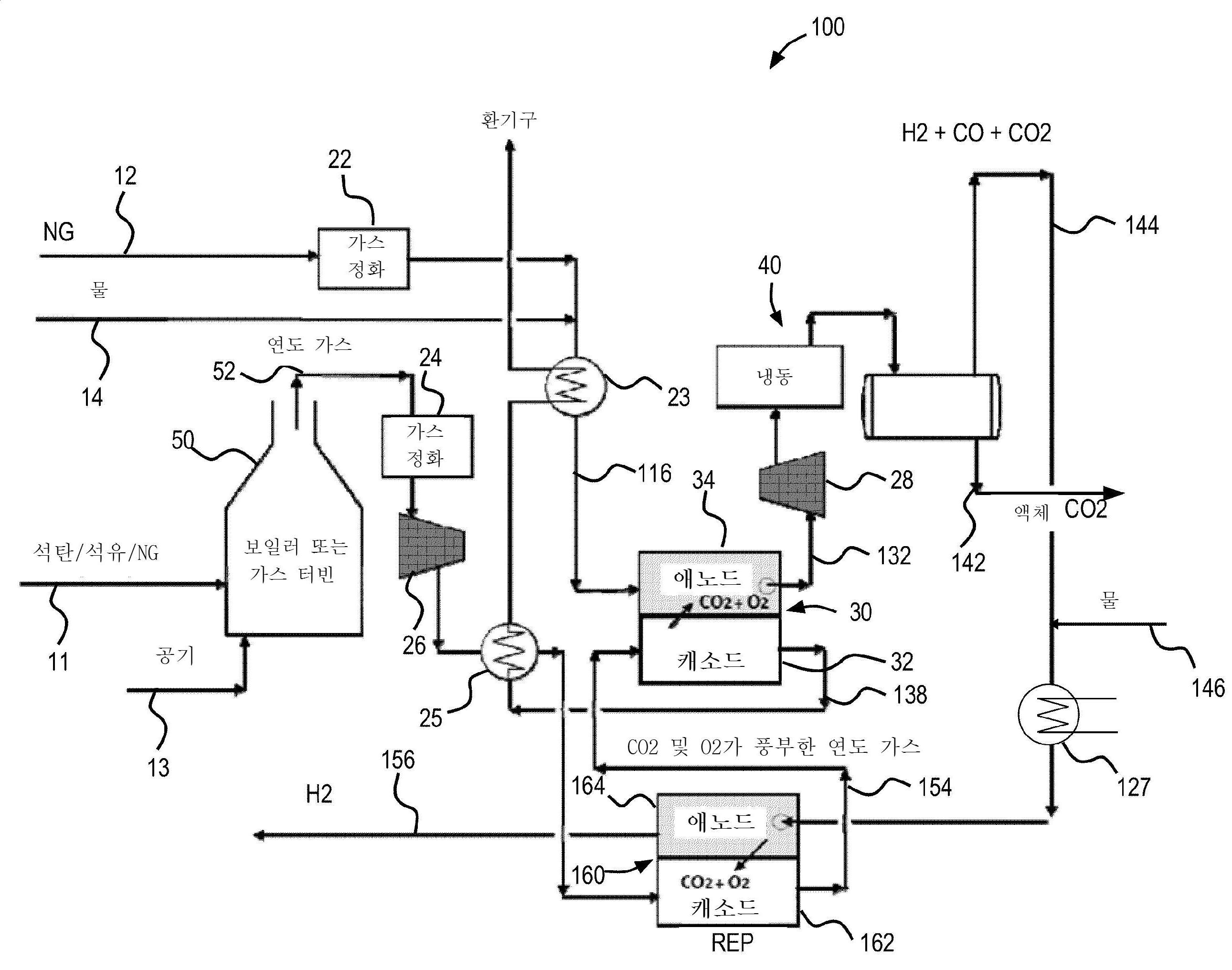
도 2는 본 발명에 따른 증가된 CO2 포집을 위해 REP 셀을 도입한 향상된 CO2 포집 시스템(100)의 일 구현예를 도시한 것이다. REP 시스템의 일 예는 국제특허출원번호 제PCT/US2015/013837호에 더욱 상세히 기술되며, 이러한 문헌은 전문이 본원에 참고로 포함된다. 도 1에 도시된 CO2 포집 시스템과 유사하게, 화석 연료 라인(11)에 의해 공급된, 화석 연료 스트림, 예를 들어, 석탄, 석유, 천연 가스, 또는 다른 타입의 탄화수소 연료, 및 공기 공급 라인(13)에 의해 공급된 공기 스트림은 연소 챔버(50), 예를 들어, 보일러 또는 가스 터빈에 도입된다. 연소 챔버(50) 내에서 화석 연료 및 공기의 연소 반응은 에너지 출력 및 연도 가스 스트림을 생산한다. 연도 가스 스트림은 연도 가스 라인(52)을 통해 연소 챔버(50)에서 배출되며, 여기서, 스트림은 불순물의 연도 가스 스트림을 제거하기 위해 제1 가스 정화 스테이션(24)에 공급된다. 정화된 연도 가스는 전해조 전지일 수 있는 REP 셀(160)의 캐소드(162)에 도입되기 전에 폐열에 의해 가열되도록, 제1 송풍기(26)에 의해 제1 열교환기(25)를 통해 유도된다. 도면에 도시된 구현예에서, REP 셀(160)은 하기에서 보다 상세히 기술되는, 용융 카르보네이트 전해 셀(MCEC)로서 구성된다. REP 셀(160)은 내부적으로 개질될 수 있고, REP 스택을 형성하기 위해 복수의 개별 셀들을 추가로 포함할 수 있다.2 shows an embodiment of an improved CO 2 capture system 100 incorporating a REP cell for increased CO 2 capture according to the present invention. An example of the REP system is described in more detail in International Patent Application No. PCT/US2015/013837, the entirety of which is incorporated herein by reference. Similar to the CO 2 capture system shown in FIG. 1, fossil fuel streams, such as coal, petroleum, natural gas, or other types of hydrocarbon fuel, and air supply lines, supplied by
도 2에 추가로 도시된 바와 같이, 연료 공급 라인(12)은 탄화수소 연료, 예를 들어, 천연 가스 또는 바이오가스 형태의, 연료 전지(30)용 연료 스트림을 공급한다. 연료 스트림은 먼저, 제2 가스 정화 스테이션(22)으로 유도되며, 여기서, 연료 스트림에서 연료 전지 시스템에 유해할 수 있는 불순물이 제거된다. 정화된 연료 스트림은 이후에, 물 공급 라인(14)에 의해 공급된 물 스트림과 혼합되며, 연료 및 물을 함유한 혼합된 가스 스트림은 혼합된 연료 라인(116)을 경유하여 제2 열교환기(23)를 통해 공급되며, 여기서, 이는 연료 전지(30)의 애노드(34)에 도입되기 전에 폐열에 의해 가열된다.As further shown in FIG. 2, the
상기에서 상세히 기술된 바와 같이, 연료 전지(30)에서 생성되는 전기화학적 반응으로 인하여, 고농도의 CO2(예를 들어, 약 70% 이상)를 포함하는 애노드 배기가스 스트림(제2 배기가스 스트림)은 애노드(34)로부터 배출된다. 애노드 배기가스 스트림은 애노드 배기가스 라인(132)을 통해 제2 송풍기(28)로 공급되며, 이는 격리 시스템(40)에 애노드 배기가스 스트림을 공급한다. 도 1과 관련하여 상술된 탄소 포집 시스템과 유사하게, 격리 시스템(40)은 스트림으로부터 액체 CO2를 격리시키기 위해 애노드 배기가스 스트림을 냉각시키고 응축시킨다. 액체 CO2는 제거 라인(142)을 통해 시스템(100)으로부터 제거되며, 여기서, 이는 저장되거나 다른 목적을 위하여 사용된다. 도 2에 도시된 바와 같이, 수소 가스, 일산화탄소, 및 잔류 이산화탄소는 회수 라인(144)을 통해 시스템(100)으로 회수되고, REP 셀(160)의 애노드(164)에 도입된다.As described in detail above, due to the electrochemical reaction generated in the
REP 셀(160)은 일반적으로, 촉매 층을 갖는 애노드(164), 촉매 층을 갖는 캐소드(162), 및 애노드(164)와 캐소드(162) 사이에서 이온의 전달을 위한 전해질 층(미도시됨)을 함유한다. 또한, REP 셀(160)은 전력 공급 장치(미도시됨)에 연결되며, 이는 내부 전기화학적 반응을 유도하기 위해 REP 셀(160)에 전압을 인가하도록 구성된다. MCEC 유닛으로서 REP 셀(160)의 작동 동안에, 회수 라인(144)으로부터의 수소, 일산화탄소, 및 잔류 이산화탄소를 함유한 가스 스트림은 애노드(164)에 도입된다. 물은 또한, 물 공급 라인(146)을 통해 회수 라인(144)에서의 가스 스트림에 첨가되며, 스트림은 이후에, 가스 스트림이 애노드(164)에 진입하기 전에, 제3 열교환기(127)에 의해 가열된다. 후속하여, 전해/CO2 펌프 반응은 이산화탄소 및 물, 및 전력 공급 장치에 의해 인가된 전압으로 인해 애노드(164)로 흐르는 전자 간에 일어나서, 수소 및 카르보네이트 이온의 생성을 야기시킨다. 애노드(164)에서 생성된 카르보네이트 이온 가스(CO3 =)는 전해질 층을 통해 REP 셀(160)로부터 펌핑된다. 주로, 공급 가스로부터 그리고 전해 반응로부터의 고순도의 H2는 수소 라인(156)을 통해 배출되며(제3 배기가스 스트림), 여기서, 이는 연료 전지(30)의 에너지 요구를 상쇄하기 위해 사용되거나 다른 목적을 위해 내보내어진다. 특정 구현예에서, REP 셀(160)으로부터 배출된 H2의 순도는 95% 이상의 수준이다. 한편, 카르보네이트 이온은 전해질 층을 가로질러 캐소드(162)로 전달되며, 여기서, 이온은 산소, 이산화탄소 및 전자로 변환한다. 전자는 캐소드로부터 전력 공급 장치로 흐르고, 전기 회로를 완성한다. 이에 따라, 캐소드(162)에서 후속 반응과 함께 카르보네이트 이온(CO3 =)의 전달은 회수 라인 가스 스트림으로부터 산소 및 이산화탄소를 펌핑하는 효과를 갖는다. 연도 가스 스트림이 캐소드(162)를 통해 흐르기 때문에, 전해 반응에 의해 펌핑된 이산화탄소 및 산소는 연도 가스 스트림에 도입되어, 보다 큰 농도의 산소 및 이산화탄소가 농축된 연도 가스 스트림을 야기시킨다.The
도 2에 도시된 바와 같이, 농축된 연도 가스 스트림(제1 배기가스 스트림)은 연료 전지(30)의 캐소드(32)를 위한 필요한 이산화탄소 및 산소를 공급하기 위해 연료 전지 공급 라인(154)을 통해 REP 셀(160)으로부터 운반되며, 여기서, 농축된 스트림에 존재하는 산소 및 이산화탄소는 상기에서 상세히 기술된 바와 같이, 전기 생산을 위한 내부 반응을 유도하기 위해 사용된다. 그러나, 농축된 연도 가스 스트림이 더 높은 농도의 O2 및 CO2를 함유하기 때문에, 더 높은 에너지 출력이 연료 전지(30)로부터 실현될 수 있다. 도 2에서 추가로 도시된 바와 같이, 연료 전지(30)의 캐소드(32)는 시스템으로부터 배기되기 전에 연료 전지(30)에 공급된 연료 스트림 및 연도 가스를 가열하기 위해 제1 열교환기(25) 및 제2 열교환기(23)를 통과하는 배기 가스(138)(제4 배기가스 스트림)를 배출한다. 이러한 배기 가스에는, 연소 챔버(50)로부터 배출된 연도 가스와 비교하여, 이산화탄소가 실질적으로 고갈된다.As shown in Figure 2, the concentrated flue gas stream (first exhaust gas stream) is through the fuel
또한, 추가적인 에너지 출력은 고순도 수소 가스의 생성을 통해 REP 셀(160)을 통해 실현되며, 이는 연료 전지(30)에 연료로서 사용되고/거나 다른 에너지 사용을 위한 시스템으로부터 내보내어질 수 있다. 또한, 격리 시스템으로부터 회수된 잔류 이산화탄소는 REP 셀(160)에 도입되어 연도 가스 스트림으로 다시 재순환되고 후속하여 연료 전지에 의해 제거된다. 이에 따라, CO2 포집이 증가되고 제거 공정으로부터의 에너지 출력(수소)이 실현되어, 유해한 CO2 배출물을 감소시키면서 발전소의 생산 능력을 개신시킬 수 있는, 향상되고 효율적인 CO2 포집 시스템은 실현될 수 있다.Further, additional energy output is realized through the
본원에서 사용되는 용어 "대략," "약," "실질적으로," 및 유사한 용어들은 본 개시내용의 대상과 관련된 당업자에 의해 일반적으로 허용되는 사용법과 조화하여 넓은 의미를 갖는 것으로 의도된다. 이러한 개시내용을 검토하는 당업자에 의해, 이러한 용어들이 제공된 정확한 수치 범위로 이러한 특징의 범위를 제한하지 않으면서 기술되고 청구된 특정 특징들의 설명을 가능하게 하도록 의도된 것으로 이해되어야 한다. 이에 따라, 이러한 용어들은 기술되고 청구된 대상의 비실질적이거나 중요하지 않은 변형 또는 변경이 첨부된 청구범위에서 나열된 바와 같은 본 발명의 범위 내에 있는 것으로 여겨진다는 것을 나타내는 것으로 해석되어야 한다.As used herein, the terms “approximately,” “about,” “substantially,” and similar terms are intended to have a broad meaning in accord with the usage generally accepted by those skilled in the art with regard to the subject of the present disclosure. It is to be understood that by one of ordinary skill in the art upon reviewing this disclosure, these terms are intended to enable a description of the specific features described and claimed without limiting the scope of such features to the precise numerical ranges provided. Accordingly, these terms are to be construed as indicating that non-substantial or insignificant modifications or alterations of the described and claimed subject matter are deemed to be within the scope of the invention as recited in the appended claims.
본원에서 사용되는 용어 "결합된(coupled)," "연결된(connected)," 등은 두 개의 부재를 서로 직접적으로 또는 간접적으로 연결(joining)시키는 것을 의미한다. 이러한 연결은 정지(예를 들어, 영구적)되거나 이동 가능(예를 들어, 제거 가능 또는 배출 가능)할 수 있다. 이러한 연결은 두 개의 부재로 달성될 수 있으며, 두 개의 부재 및 임의의 추가적인 중간 부재는 서로 또는 두 개의 부재와 함께 단일의 통합된 바디로서 일체형으로 형성되며, 두 개의 부재 및 임의의 추가적인 중간 부재는 서로 부착된다.The terms “coupled,” “connected,” and the like, as used herein, mean directly or indirectly joining two members to each other. This connection can be stationary (eg, permanent) or moveable (eg, removable or retractable). This connection can be achieved with two members, the two members and any additional intermediate members are integrally formed with each other or together with the two members as a single integrated body, the two members and any additional intermediate members Are attached to each other.
본원에서 구성요소의 위치에 대한 언급(예를 들어, "상부," "하부," "위," "아래," 등)은 단지 도면에서 다양한 구성요소의 방향을 기술하기 위해 사용된다. 다양한 구성요소의 방향이 다른 예시적인 구현예에 따라 다를 수 있으며, 이러한 변화가 본 개시내용에 의해 포함되는 것으로 의도된다는 것이 주지되어야 한다.References to the location of components herein (eg, “top,” “bottom,” “top,” “bottom,” etc.) are used only to describe the orientation of the various components in the drawings. It should be noted that the orientation of the various components may differ for other exemplary implementations, and that such changes are intended to be covered by the present disclosure.
다양한 예시적인 구현예의 구성 및 배열이 단지 예시적인 것이라는 것을 주목하는 것이 중요하다. 단지 몇몇 구현예가 본 개시내용에서 상세히 기술되었지만, 본 개시내용을 검토하는 당업자는, 본원에 기술된 대상의 신규한 교시 및 장점으로부터 실질적으로 벗어나지 않으면서, 다수의 변형(예를 들어, 다양한 구성요소의 크기, 치수, 구조, 형상 및 비율의 변화, 파라미터의 값, 마운팅 배열, 물질의 사용, 칼라, 배향(orientation), 등)이 가능하다는 것을 용이하게 이해할 것이다. 예를 들어, 일체적으로 형성된 것으로 나타낸 구성요소는 다수의 부품 또는 구성요소로 구성될 수 있으며, 구성요소의 위치는 반전되거나 달리 변화될 수 있으며, 별개의 구성요소 또는 위치의 성질 또는 수는 변경되거나 달라질 수 있다. 임의의 공정 또는 방법 단계의 순서 또는 시퀀스(sequence)는 대안적인 구현예에 따라 변경되거나 재배열될 수 있다. 다른 치환, 수정, 변경 및 생략이 또한, 본 발명의 범위를 벗어나지 않으면서 다양한 예시적 구현예의 설계, 작동 조건 및 배열에서 이루어질 수 있다. 예를 들어, 열 회수 열교환기는 더욱 최적화될 수 있다.It is important to note that the configurations and arrangements of the various exemplary embodiments are exemplary only. While only a few embodiments have been described in detail in this disclosure, those skilled in the art reviewing the disclosure will have a number of variations (e.g., various components) without substantially departing from the novel teachings and advantages of the subject matter described herein. It will be readily understood that variations in size, dimensions, structure, shape and proportions, values of parameters, mounting arrangements, use of materials, color, orientation, etc.) are possible. For example, a component shown as integrally formed may be composed of a number of parts or components, the position of the component may be reversed or otherwise changed, and the nature or number of separate components or positions may be changed. May be or may be different. The order or sequence of any process or method steps may be altered or rearranged according to alternative implementations. Other substitutions, modifications, changes and omissions may also be made in the design, operating conditions, and arrangements of various exemplary embodiments without departing from the scope of the present invention. For example, heat recovery heat exchangers can be further optimized.
Claims (21)
전해 셀 애노드 및 전해 셀 캐소드를 포함하는 용융 카르보네이트 전해 셀;
연료 전지 애노드 및 연료 전지 캐소드를 포함하는 용융 카르보네이트 연료 전지;
상기 전해 셀 캐소드와 연결되고 상기 연소 발전소로부터 수용된 연도 가스를 공급하도록 구성되는 연도 가스 공급 라인;
상기 전해 셀 캐소드 및 상기 연료 전지 캐소드에 연결되는 제1 배기가스 스트림 연결 라인; 및
상기 연료 전지 애노드에 연결되는 제2 배기가스 스트림 연결 라인을 포함하고,
상기 전해 셀 캐소드는 (i) 상기 연도 가스 공급 라인으로부터의 상기 연도 가스를 수용하고, (ii) 상기 연도 가스보다 더 높은 제1 농도의 이산화탄소를 포함하는 제1 배기가스 스트림을 상기 제1 배기가스 스트림 연결 라인으로 배출하도록 구성되고,
상기 연료 전지 캐소드는 상기 제1 배기가스 스트림 연결 라인으로부터 상기 제1 배기가스 스트림을 수용하도록 구성되고,
상기 연료 전지 애노드는 상기 제1 농도의 이산화탄소보다 더 높은 제2 농도의 이산화탄소를 포함하는 제2 배기가스 스트림을 상기 제2 배기가스 스트림 연결 라인으로 배출하도록 구성되는,
시스템.As a carbon dioxide capture system for removing carbon dioxide from flue gas produced by a combustion power plant,
A molten carbonate electrolysis cell comprising an electrolysis cell anode and an electrolysis cell cathode;
A molten carbonate fuel cell comprising a fuel cell anode and a fuel cell cathode;
A flue gas supply line connected to the electrolytic cell cathode and configured to supply flue gas received from the combustion power plant;
A first exhaust gas stream connection line connected to the electrolytic cell cathode and the fuel cell cathode; And
A second exhaust gas stream connection line connected to the fuel cell anode,
The electrolytic cell cathode (i) receives the flue gas from the flue gas supply line, and (ii) generates a first exhaust gas stream comprising carbon dioxide at a first concentration higher than that of the flue gas. Configured to discharge to the stream connection line,
The fuel cell cathode is configured to receive the first exhaust gas stream from the first exhaust gas stream connection line,
The fuel cell anode is configured to discharge a second exhaust gas stream comprising carbon dioxide of a second concentration higher than the first concentration of carbon dioxide to the second exhaust gas stream connection line,
system.
이산화탄소 포집 시스템을 제공하되, 상기 이산화탄소 포집 시스템은,
전해 셀 애노드 및 전해 셀 캐소드를 포함하는 용융 카르보네이트 전해 셀;
연료 전지 애노드 및 연료 전지 캐소드를 포함하는 용융 카르보네이트 연료 전지;
상기 전해 셀 캐소드와 연결되고 상기 연소 발전소로부터 수용된 연도 가스를 공급하도록 구성되는 연도 가스 공급 라인;
상기 전해 셀 캐소드 및 상기 연료 전지 캐소드에 연결되는 제1 배기가스 스트림 연결 라인; 및
상기 연료 전지 애노드에 연결되는 제2 배기가스 스트림 연결 라인을 포함하고,
상기 전해 셀 캐소드에서 상기 연도 가스 공급 라인으로부터 상기 연도 가스를 수용하고,
상기 전해 셀 캐소드로부터 상기 연도 가스의 이산화탄소 농도보다 더 높은 제1 농도의 이산화탄소를 포함하는 제1 배기가스 스트림을 상기 제1 배기가스 스트림 연결 라인으로 배출하고,
상기 연료 전지 캐소드에서 상기 제1 배기가스 스트림 연결 라인으로부터 상기 제1 배기가스 스트림을 수용하고,
상기 연료 전지 애노드로부터 상기 제1 농도의 이산화탄소보다 더 높은 제2 농도의 이산화탄소를 포함하는 제2 배기가스 스트림을 상기 제2 배기가스 스트림 연결 라인으로 배출하는,
방법.A method of removing carbon dioxide from flue gas produced by a combustion power plant, comprising:
Provides a carbon dioxide capture system, wherein the carbon dioxide capture system,
A molten carbonate electrolysis cell comprising an electrolysis cell anode and an electrolysis cell cathode;
A molten carbonate fuel cell comprising a fuel cell anode and a fuel cell cathode;
A flue gas supply line connected to the electrolytic cell cathode and configured to supply flue gas received from the combustion power plant;
A first exhaust gas stream connection line connected to the electrolytic cell cathode and the fuel cell cathode; And
A second exhaust gas stream connection line connected to the fuel cell anode,
Receiving the flue gas from the flue gas supply line in the electrolysis cell cathode,
Discharging a first exhaust gas stream containing carbon dioxide of a first concentration higher than the carbon dioxide concentration of the flue gas from the electrolytic cell cathode to the first exhaust gas stream connection line,
Receiving the first exhaust gas stream from the first exhaust gas stream connection line at the fuel cell cathode,
Discharging a second exhaust gas stream including carbon dioxide of a second concentration higher than the first concentration of carbon dioxide from the fuel cell anode to the second exhaust gas stream connection line,
Way.
Applications Claiming Priority (3)
| Application Number | Priority Date | Filing Date | Title |
|---|---|---|---|
| US201562256484P | 2015-11-17 | 2015-11-17 | |
| US62/256,484 | 2015-11-17 | ||
| PCT/US2016/061981 WO2017087360A1 (en) | 2015-11-17 | 2016-11-15 | Fuel cell system having enhanced co 2 capture |
Publications (2)
| Publication Number | Publication Date |
|---|---|
| KR20180078319A KR20180078319A (en) | 2018-07-09 |
| KR102143861B1 true KR102143861B1 (en) | 2020-08-12 |
Family
ID=58719237
Family Applications (1)
| Application Number | Title | Priority Date | Filing Date |
|---|---|---|---|
| KR1020187015877A Active KR102143861B1 (en) | 2015-11-17 | 2016-11-15 | Fuel cell system with improved CO2 capture |
Country Status (7)
| Country | Link |
|---|---|
| US (1) | US11043684B2 (en) |
| EP (1) | EP3403290A4 (en) |
| JP (1) | JP6650035B2 (en) |
| KR (1) | KR102143861B1 (en) |
| CN (1) | CN108604696B (en) |
| CA (1) | CA3005628C (en) |
| WO (1) | WO2017087360A1 (en) |
Families Citing this family (10)
| Publication number | Priority date | Publication date | Assignee | Title |
|---|---|---|---|---|
| US10975477B2 (en) | 2017-10-02 | 2021-04-13 | Battelle Energy Alliance, Llc | Methods and systems for the electrochemical reduction of carbon dioxide using switchable polarity materials |
| GB2568564B (en) | 2018-07-17 | 2020-01-01 | Omnagen Ltd | Carbon dioxide conversion using combined fuel cell and electrolysis cell |
| CN117623221A (en) * | 2019-02-18 | 2024-03-01 | 燃料电池能有限公司 | Energy storage using combustion turbines using molten carbonate electrolytic cells |
| KR102620207B1 (en) * | 2019-07-19 | 2024-01-02 | 블룸 에너지 코퍼레이션 | Integrated power generation, carbon dioxide separation and downstream treatment systems and methods |
| DE102019217114A1 (en) * | 2019-11-06 | 2021-05-06 | Siemens Energy Global GmbH & Co. KG | Power-to-X system with optimized hydrogen drying and cleaning |
| US11555446B2 (en) * | 2021-06-11 | 2023-01-17 | Mitsubishi Power Americas, Inc. | Hybrid power plant with C02 capture |
| CN114883616A (en) * | 2022-05-20 | 2022-08-09 | 湖南博忆源机电设备有限公司 | Carbon dioxide capture system based on fuel cell and capture method thereof |
| JP2024027957A (en) * | 2022-08-19 | 2024-03-01 | 株式会社東芝 | Carbon monoxide production equipment |
| US11955674B1 (en) | 2023-03-07 | 2024-04-09 | Chevron Phillips Chemical Company Lp | Use of a fuel cell to decarbonize a hydrocarbon cracking system |
| CN118855590A (en) | 2023-04-26 | 2024-10-29 | 通用电气技术有限公司 | Combustion system with fuel cell and carbon capture system |
Citations (3)
| Publication number | Priority date | Publication date | Assignee | Title |
|---|---|---|---|---|
| JP2004099927A (en) * | 2002-09-05 | 2004-04-02 | Ishikawajima Harima Heavy Ind Co Ltd | Oxygen and carbon dioxide purification and high concentration treatment method |
| JP2010129286A (en) * | 2008-11-26 | 2010-06-10 | Chugoku Electric Power Co Inc:The | Power generation system |
| WO2015116964A1 (en) * | 2014-01-31 | 2015-08-06 | Fuelcell Energy, Inc. | Reformer-electrolyzer-purifier (rep) assembly for hydrogen production, systems incorporating same and method of producing hydrogen |
Family Cites Families (93)
| Publication number | Priority date | Publication date | Assignee | Title |
|---|---|---|---|---|
| US3094390A (en) | 1958-07-09 | 1963-06-18 | Air Prod & Chem | Production and storage of converted hydrogen |
| US3180813A (en) * | 1961-05-31 | 1965-04-27 | Consolidation Coal Co | Electrolytic process for producing hydrogen from hydrocarbonaceous gases |
| IT1020634B (en) | 1974-06-11 | 1977-12-30 | Shell Bv | INTERNAL COMBUSTION ENGINE WITH EXHAUST GAS RECYCLING |
| CA1242985A (en) | 1984-02-08 | 1988-10-11 | William P. Hegarty | Method for controlling fluidized catalytic cracker regenerator temperature and velocity with carbon dioxide |
| JPS60235893A (en) | 1984-05-09 | 1985-11-22 | Osaka Gas Co Ltd | Method for methanizing gas containing co and h2 |
| US4849091A (en) | 1986-09-17 | 1989-07-18 | Uop | Partial CO combustion with staged regeneration of catalyst |
| DK162961C (en) | 1989-11-20 | 1992-05-25 | Haldor Topsoe As | FUEL CELL POWER PLANT |
| EP0564796B1 (en) * | 1992-03-13 | 2000-01-19 | Binsmaier, Hannelore, geb. Gallin-Ast | Process for generating electrical energy from biomass |
| JP3407747B2 (en) | 1992-06-19 | 2003-05-19 | 石川島播磨重工業株式会社 | Fuel cell power generator with moisture separator |
| US5346778A (en) | 1992-08-13 | 1994-09-13 | Energy Partners, Inc. | Electrochemical load management system for transportation applications |
| US5346613A (en) | 1993-09-24 | 1994-09-13 | Uop | FCC process with total catalyst blending |
| US5413878A (en) | 1993-10-28 | 1995-05-09 | The United States Of America As Represented By The Department Of Energy | System and method for networking electrochemical devices |
| US5711770A (en) | 1996-01-04 | 1998-01-27 | Malina; Mylan | Energy conversion system |
| US5928806A (en) * | 1997-05-07 | 1999-07-27 | Olah; George A. | Recycling of carbon dioxide into methyl alcohol and related oxygenates for hydrocarbons |
| US6187465B1 (en) | 1997-11-07 | 2001-02-13 | Terry R. Galloway | Process and system for converting carbonaceous feedstocks into energy without greenhouse gas emissions |
| JPH11169661A (en) | 1997-12-12 | 1999-06-29 | Ishikawajima Harima Heavy Ind Co Ltd | Carbon dioxide capture device |
| JP4100479B2 (en) | 1998-02-04 | 2008-06-11 | 信行 神谷 | Carbon dioxide decomposition method |
| KR20020020931A (en) | 1999-07-09 | 2002-03-16 | 마에다 시게루 | Process and apparatus for production of hydrogen by gasification of combustible material and method for electric power generation using fuel cell and electric power generation system using fuel cell |
| WO2002005363A2 (en) | 2000-07-10 | 2002-01-17 | Global Thermoelectric Inc. | Integrated module for solid oxide fuel cell systems |
| JP2002319428A (en) * | 2001-04-19 | 2002-10-31 | Ishikawajima Harima Heavy Ind Co Ltd | Molten carbonate fuel cell power generation equipment |
| AU2003268522A1 (en) | 2002-09-05 | 2004-03-29 | Miglin, Maria, Therese | Apparatus and process for production of high purity hydrogen |
| US7070874B2 (en) | 2002-12-24 | 2006-07-04 | Fuelcell Energy, Inc. | Fuel cell end unit with integrated heat exchanger |
| US7276306B2 (en) | 2003-03-12 | 2007-10-02 | The Regents Of The University Of California | System for the co-production of electricity and hydrogen |
| US7014932B2 (en) | 2003-03-19 | 2006-03-21 | Proton Energy Systems, Inc. | Drainage system and process for operating a regenerative electrochemical cell system |
| US7045238B2 (en) | 2003-03-24 | 2006-05-16 | Ion America Corporation | SORFC power and oxygen generation method and system |
| JP2004311159A (en) | 2003-04-04 | 2004-11-04 | Central Res Inst Of Electric Power Ind | High pressure hydrogen production method and apparatus and fuel cell vehicle |
| US7364810B2 (en) | 2003-09-03 | 2008-04-29 | Bloom Energy Corporation | Combined energy storage and fuel generation with reversible fuel cells |
| US7482078B2 (en) | 2003-04-09 | 2009-01-27 | Bloom Energy Corporation | Co-production of hydrogen and electricity in a high temperature electrochemical system |
| US7575822B2 (en) | 2003-04-09 | 2009-08-18 | Bloom Energy Corporation | Method of optimizing operating efficiency of fuel cells |
| US7878280B2 (en) | 2003-04-09 | 2011-02-01 | Bloom Energy Corporation | Low pressure hydrogen fueled vehicle and method of operating same |
| US7150927B2 (en) | 2003-09-10 | 2006-12-19 | Bloom Energy Corporation | SORFC system with non-noble metal electrode compositions |
| US6896988B2 (en) | 2003-09-11 | 2005-05-24 | Fuelcell Energy, Inc. | Enhanced high efficiency fuel cell/turbine power plant |
| US7353085B2 (en) | 2003-09-22 | 2008-04-01 | Hydrogenics Corporation | Electrolyzer cell stack system |
| US20050112425A1 (en) | 2003-10-07 | 2005-05-26 | Ztek Corporation | Fuel cell for hydrogen production, electricity generation and co-production |
| US20050123810A1 (en) | 2003-12-09 | 2005-06-09 | Chellappa Balan | System and method for co-production of hydrogen and electrical energy |
| US7422810B2 (en) | 2004-01-22 | 2008-09-09 | Bloom Energy Corporation | High temperature fuel cell system and method of operating same |
| JP4751580B2 (en) | 2004-03-31 | 2011-08-17 | 東京瓦斯株式会社 | Power generator |
| US7396603B2 (en) | 2004-06-03 | 2008-07-08 | Fuelcell Energy, Inc. | Integrated high efficiency fossil fuel power plant/fuel cell system with CO2 emissions abatement |
| US7323270B2 (en) | 2004-08-11 | 2008-01-29 | Fuelcell Energy, Inc. | Modular fuel-cell stack assembly |
| US7381487B2 (en) | 2004-12-27 | 2008-06-03 | Fuelcell Energy, Inc. | In-situ removal of electrolyte from gas oxidizer |
| US8691462B2 (en) | 2005-05-09 | 2014-04-08 | Modine Manufacturing Company | High temperature fuel cell system with integrated heat exchanger network |
| JP5542332B2 (en) | 2005-07-25 | 2014-07-09 | ブルーム エナジー コーポレーション | Fuel cell system that partially recycles anode exhaust |
| GB0524486D0 (en) | 2005-12-01 | 2006-01-11 | Rolls Royce Fuel Cell Systems | An electrolysis apparatus |
| JP4813887B2 (en) | 2005-12-12 | 2011-11-09 | 三菱重工業株式会社 | Gas turbine plant |
| EP1982364A4 (en) | 2006-01-23 | 2010-07-07 | Bloom Energy Corp | Modular fuel cell system |
| WO2008033452A2 (en) | 2006-09-13 | 2008-03-20 | Ceramatec, Inc. | High purity hydrogen and electric power co-generation apparatus and method |
| JP2008084698A (en) | 2006-09-27 | 2008-04-10 | Toshiba Corp | Fuel reformer and fuel cell system |
| CA2569006C (en) * | 2006-11-20 | 2013-12-24 | Jose Lourenco | Method to condense and recover carbon dioxide from fuel cells |
| US8435689B2 (en) | 2006-10-23 | 2013-05-07 | Bloom Energy Corporation | Dual function heat exchanger for start-up humidification and facility heating in SOFC system |
| US20080155984A1 (en) | 2007-01-03 | 2008-07-03 | Ke Liu | Reforming system for combined cycle plant with partial CO2 capture |
| US7862938B2 (en) | 2007-02-05 | 2011-01-04 | Fuelcell Energy, Inc. | Integrated fuel cell and heat engine hybrid system for high efficiency power generation |
| US9557057B2 (en) | 2007-02-09 | 2017-01-31 | Dale Robert Lutz | Reliable carbon-neutral power generation system |
| US7833668B2 (en) | 2007-03-30 | 2010-11-16 | Bloom Energy Corporation | Fuel cell system with greater than 95% fuel utilization |
| WO2008150524A2 (en) | 2007-06-04 | 2008-12-11 | Bloom Energy Corporation | Structure for high temperature fuel cell system start up and shutdown |
| US8852820B2 (en) | 2007-08-15 | 2014-10-07 | Bloom Energy Corporation | Fuel cell stack module shell with integrated heat exchanger |
| EP2074290A4 (en) | 2007-09-06 | 2017-06-21 | Korea Institute Of Machinery & Materials | Power plant having pure oxygen combustor |
| US8062804B2 (en) | 2007-10-31 | 2011-11-22 | Fuelcell Energy, Inc. | Flow control assembly for use with fuel cell systems operating on fuels with varying fuel composition |
| US7935245B2 (en) | 2007-12-21 | 2011-05-03 | Uop Llc | System and method of increasing synthesis gas yield in a fluid catalytic cracking unit |
| US8652694B2 (en) | 2008-03-04 | 2014-02-18 | Fuelcell Energy, Inc. | Water recovery assembly for transferring water from fuel cell cathode exhaust |
| US8366902B2 (en) | 2008-03-24 | 2013-02-05 | Battelle Energy Alliance, Llc | Methods and systems for producing syngas |
| JP5137199B2 (en) | 2008-07-07 | 2013-02-06 | 東京瓦斯株式会社 | Separation and recovery system for atmospheric carbon dioxide |
| WO2010004425A2 (en) | 2008-07-07 | 2010-01-14 | Osum Oil Sands Corp. | Carbon removal from an integrated thermal recovery process |
| US8062799B2 (en) * | 2008-08-19 | 2011-11-22 | Fuelcell Energy, Inc. | High-efficiency dual-stack molten carbonate fuel cell system |
| AU2009332961A1 (en) | 2008-12-31 | 2011-07-14 | Shell Internationale Research Maatschappij B.V. | Process for producing a methane-rich gas |
| JP2010212141A (en) | 2009-03-11 | 2010-09-24 | Fuji Electric Systems Co Ltd | Fuel cell generator |
| JP5106461B2 (en) * | 2009-03-27 | 2012-12-26 | 中国電力株式会社 | Carbon dioxide recovery device |
| US20100266923A1 (en) | 2009-04-15 | 2010-10-21 | Bloom Energy Corporation | Fuel cell system with electrochemical hydrogen pump and method of operating same |
| IT1394308B1 (en) * | 2009-05-21 | 2012-06-06 | Genport S R L | GROUP OF ELECTRIC GENERATION OF TRANSPORTABLE / DRIVE TYPE AND METHOD USING THIS GROUP OF ELECTRIC GENERATION. |
| US8153309B2 (en) | 2009-05-27 | 2012-04-10 | GM Global Technology Operations LLC | Apparatus and method using hydrogen pressure in fuel cell electric vehicle |
| US8563186B2 (en) | 2009-06-16 | 2013-10-22 | Shell Oil Company | Systems and processes of operating fuel cell systems |
| US8632922B2 (en) | 2009-06-16 | 2014-01-21 | Shell Oil Company | Systems and processes for operating fuel cell systems |
| KR20110114816A (en) | 2010-04-14 | 2011-10-20 | 삼성중공업 주식회사 | CO2 capture device and method using fuel cell power generation system |
| JP5738983B2 (en) | 2010-05-05 | 2015-06-24 | ハルドール・トプサー・アクチエゼルスカベット | How to operate a high temperature fuel cell stack |
| US9819038B2 (en) | 2011-03-31 | 2017-11-14 | General Electric Company | Fuel cell reforming system with carbon dioxide removal |
| CN103890236B (en) | 2011-08-29 | 2016-09-14 | 卡尔-赫尔曼·布塞 | Especially suitable for energy supply devices in the field of residential engineering |
| US9190685B2 (en) | 2011-10-27 | 2015-11-17 | Bloom Energy Corporation | SOFC system with selective CO2 removal |
| FR2982422B1 (en) | 2011-11-09 | 2013-11-15 | Saint Gobain | CONDUCTIVE SUBSTRATE FOR PHOTOVOLTAIC CELL |
| CA2855780C (en) | 2011-11-21 | 2018-05-08 | Saudi Arabian Oil Company | Method and a system for combined hydrogen and electricity production using petroleum fuels |
| DE102012206541A1 (en) | 2012-04-20 | 2013-10-24 | Siemens Aktiengesellschaft | Method and arrangement for high-temperature electrolysis |
| US9664385B2 (en) | 2012-09-17 | 2017-05-30 | Phillips 66 Company | Process for enabling carbon-capture from existing combustion processes |
| US9190676B2 (en) | 2012-09-28 | 2015-11-17 | Fuelcell Energy, Inc. | Flame stabilized mixer-eductor-oxidizer for high temperature fuel cells |
| WO2014151184A1 (en) | 2013-03-15 | 2014-09-25 | Exxonmobil Research And Engineering Company | Integrated power generation and carbon capture using fuel cells |
| EP2784187A1 (en) | 2013-03-25 | 2014-10-01 | Helmut-Schmidt-Universität/ Universität der Bundeswehr Hamburg | High efficiency fuel cell |
| JP2014198789A (en) | 2013-03-29 | 2014-10-23 | 大阪瓦斯株式会社 | Methane-rich gas production system |
| US20150280265A1 (en) * | 2014-04-01 | 2015-10-01 | Dustin Fogle McLarty | Poly-generating fuel cell with thermally balancing fuel processing |
| US10096840B1 (en) | 2014-12-15 | 2018-10-09 | Bloom Energy Corporation | High temperature air purge of solid oxide fuel cell anode electrodes |
| US9478819B2 (en) | 2014-12-19 | 2016-10-25 | Fuelcell Energy, Inc. | High-efficiency molten carbonate fuel cell system and method |
| EP3054519B1 (en) | 2015-02-03 | 2017-11-08 | Technische Universität München | Reversible fuel cell system and method for operating a fuel cell system |
| CN104847424B (en) | 2015-05-05 | 2016-05-18 | 华北电力大学 | Catch the CO of coal-burning power plant with molten carbonate fuel cell2System and method |
| JP6534116B2 (en) | 2015-05-22 | 2019-06-26 | パナソニックIpマネジメント株式会社 | Solid oxide fuel cell system |
| CN108604697B (en) | 2015-11-16 | 2021-06-04 | 燃料电池能有限公司 | CO capture from fuel cells2Of (2) a |
| US10361442B2 (en) | 2016-11-08 | 2019-07-23 | Bloom Energy Corporation | SOFC system and method which maintain a reducing anode environment |
| US10581090B2 (en) | 2017-11-03 | 2020-03-03 | Bloom Energy Corporation | Fuel cell system containing humidity sensor and method of operating thereof |
-
2016
- 2016-11-15 WO PCT/US2016/061981 patent/WO2017087360A1/en not_active Ceased
- 2016-11-15 EP EP16866931.5A patent/EP3403290A4/en active Pending
- 2016-11-15 JP JP2018525557A patent/JP6650035B2/en active Active
- 2016-11-15 CN CN201680073568.3A patent/CN108604696B/en active Active
- 2016-11-15 CA CA3005628A patent/CA3005628C/en active Active
- 2016-11-15 KR KR1020187015877A patent/KR102143861B1/en active Active
-
2018
- 2018-05-15 US US15/980,291 patent/US11043684B2/en active Active
Patent Citations (3)
| Publication number | Priority date | Publication date | Assignee | Title |
|---|---|---|---|---|
| JP2004099927A (en) * | 2002-09-05 | 2004-04-02 | Ishikawajima Harima Heavy Ind Co Ltd | Oxygen and carbon dioxide purification and high concentration treatment method |
| JP2010129286A (en) * | 2008-11-26 | 2010-06-10 | Chugoku Electric Power Co Inc:The | Power generation system |
| WO2015116964A1 (en) * | 2014-01-31 | 2015-08-06 | Fuelcell Energy, Inc. | Reformer-electrolyzer-purifier (rep) assembly for hydrogen production, systems incorporating same and method of producing hydrogen |
Also Published As
| Publication number | Publication date |
|---|---|
| CN108604696A (en) | 2018-09-28 |
| EP3403290A4 (en) | 2019-05-29 |
| US11043684B2 (en) | 2021-06-22 |
| JP6650035B2 (en) | 2020-02-19 |
| JP2019501486A (en) | 2019-01-17 |
| US20180261864A1 (en) | 2018-09-13 |
| CN108604696B (en) | 2021-10-19 |
| KR20180078319A (en) | 2018-07-09 |
| EP3403290A1 (en) | 2018-11-21 |
| CA3005628C (en) | 2021-05-25 |
| CA3005628A1 (en) | 2017-05-26 |
| WO2017087360A1 (en) | 2017-05-26 |
Similar Documents
| Publication | Publication Date | Title |
|---|---|---|
| KR102143861B1 (en) | Fuel cell system with improved CO2 capture | |
| KR102143864B1 (en) | System to capture CO2 from fuel cells | |
| CN107251297B (en) | Power Generation Gas Separation System and Method | |
| KR102372516B1 (en) | Methanation of anode exhaust to enhance carbon dioxide capture | |
| KR20110114816A (en) | CO2 capture device and method using fuel cell power generation system | |
| KR20150020463A (en) | Fuel cell apparatus | |
| US20220093950A1 (en) | Solid oxide fuel cell arrangement generating ammonia as byproduct and utilizing ammonia as secondary fuel |
Legal Events
| Date | Code | Title | Description |
|---|---|---|---|
| PA0105 | International application |
St.27 status event code: A-0-1-A10-A15-nap-PA0105 |
|
| A201 | Request for examination | ||
| P11-X000 | Amendment of application requested |
St.27 status event code: A-2-2-P10-P11-nap-X000 |
|
| P13-X000 | Application amended |
St.27 status event code: A-2-2-P10-P13-nap-X000 |
|
| PA0201 | Request for examination |
St.27 status event code: A-1-2-D10-D11-exm-PA0201 |
|
| PG1501 | Laying open of application |
St.27 status event code: A-1-1-Q10-Q12-nap-PG1501 |
|
| D13-X000 | Search requested |
St.27 status event code: A-1-2-D10-D13-srh-X000 |
|
| D14-X000 | Search report completed |
St.27 status event code: A-1-2-D10-D14-srh-X000 |
|
| E902 | Notification of reason for refusal | ||
| PE0902 | Notice of grounds for rejection |
St.27 status event code: A-1-2-D10-D21-exm-PE0902 |
|
| R17-X000 | Change to representative recorded |
St.27 status event code: A-3-3-R10-R17-oth-X000 |
|
| E13-X000 | Pre-grant limitation requested |
St.27 status event code: A-2-3-E10-E13-lim-X000 |
|
| P11-X000 | Amendment of application requested |
St.27 status event code: A-2-2-P10-P11-nap-X000 |
|
| P13-X000 | Application amended |
St.27 status event code: A-2-2-P10-P13-nap-X000 |
|
| E701 | Decision to grant or registration of patent right | ||
| PE0701 | Decision of registration |
St.27 status event code: A-1-2-D10-D22-exm-PE0701 |
|
| GRNT | Written decision to grant | ||
| PR0701 | Registration of establishment |
St.27 status event code: A-2-4-F10-F11-exm-PR0701 |
|
| PR1002 | Payment of registration fee |
St.27 status event code: A-2-2-U10-U12-oth-PR1002 Fee payment year number: 1 |
|
| PG1601 | Publication of registration |
St.27 status event code: A-4-4-Q10-Q13-nap-PG1601 |
|
| R18-X000 | Changes to party contact information recorded |
St.27 status event code: A-5-5-R10-R18-oth-X000 |
|
| P22-X000 | Classification modified |
St.27 status event code: A-4-4-P10-P22-nap-X000 |
|
| PR1001 | Payment of annual fee |
St.27 status event code: A-4-4-U10-U11-oth-PR1001 Fee payment year number: 4 |
|
| PR1001 | Payment of annual fee |
St.27 status event code: A-4-4-U10-U11-oth-PR1001 Fee payment year number: 5 |
|
| PR1001 | Payment of annual fee |
St.27 status event code: A-4-4-U10-U11-oth-PR1001 Fee payment year number: 6 |
|
| U11 | Full renewal or maintenance fee paid |
Free format text: ST27 STATUS EVENT CODE: A-4-4-U10-U11-OTH-PR1001 (AS PROVIDED BY THE NATIONAL OFFICE) Year of fee payment: 6 |