KR102124380B1 - Ceramics laminate, ceramics insulating substrate, and method for manufacturing ceramics laminate - Google Patents
Ceramics laminate, ceramics insulating substrate, and method for manufacturing ceramics laminate Download PDFInfo
- Publication number
- KR102124380B1 KR102124380B1 KR1020187023122A KR20187023122A KR102124380B1 KR 102124380 B1 KR102124380 B1 KR 102124380B1 KR 1020187023122 A KR1020187023122 A KR 1020187023122A KR 20187023122 A KR20187023122 A KR 20187023122A KR 102124380 B1 KR102124380 B1 KR 102124380B1
- Authority
- KR
- South Korea
- Prior art keywords
- phase
- zirconia
- particles
- ceramics
- alumina
- Prior art date
- Legal status (The legal status is an assumption and is not a legal conclusion. Google has not performed a legal analysis and makes no representation as to the accuracy of the status listed.)
- Active
Links
Images


Classifications
-
- C—CHEMISTRY; METALLURGY
- C23—COATING METALLIC MATERIAL; COATING MATERIAL WITH METALLIC MATERIAL; CHEMICAL SURFACE TREATMENT; DIFFUSION TREATMENT OF METALLIC MATERIAL; COATING BY VACUUM EVAPORATION, BY SPUTTERING, BY ION IMPLANTATION OR BY CHEMICAL VAPOUR DEPOSITION, IN GENERAL; INHIBITING CORROSION OF METALLIC MATERIAL OR INCRUSTATION IN GENERAL
- C23C—COATING METALLIC MATERIAL; COATING MATERIAL WITH METALLIC MATERIAL; SURFACE TREATMENT OF METALLIC MATERIAL BY DIFFUSION INTO THE SURFACE, BY CHEMICAL CONVERSION OR SUBSTITUTION; COATING BY VACUUM EVAPORATION, BY SPUTTERING, BY ION IMPLANTATION OR BY CHEMICAL VAPOUR DEPOSITION, IN GENERAL
- C23C24/00—Coating starting from inorganic powder
- C23C24/02—Coating starting from inorganic powder by application of pressure only
- C23C24/04—Impact or kinetic deposition of particles
-
- H—ELECTRICITY
- H01—ELECTRIC ELEMENTS
- H01L—SEMICONDUCTOR DEVICES NOT COVERED BY CLASS H10
- H01L23/00—Details of semiconductor or other solid state devices
- H01L23/12—Mountings, e.g. non-detachable insulating substrates
- H01L23/14—Mountings, e.g. non-detachable insulating substrates characterised by the material or its electrical properties
- H01L23/15—Ceramic or glass substrates
-
- H10W70/692—
Landscapes
- Chemical & Material Sciences (AREA)
- Engineering & Computer Science (AREA)
- Chemical Kinetics & Catalysis (AREA)
- Materials Engineering (AREA)
- Mechanical Engineering (AREA)
- Metallurgy (AREA)
- Organic Chemistry (AREA)
- Laminated Bodies (AREA)
- Ceramic Engineering (AREA)
- Physics & Mathematics (AREA)
- Condensed Matter Physics & Semiconductors (AREA)
- General Physics & Mathematics (AREA)
- Computer Hardware Design (AREA)
- Microelectronics & Electronic Packaging (AREA)
- Power Engineering (AREA)
- Other Surface Treatments For Metallic Materials (AREA)
Abstract
우수한 내열 피로성이나, 열전도성, 절연성을 갖는 복합 세라믹스층의 기계적 특성을 높여, 우수한 내구성 및 방열성, 절연성을 가진 세라믹스 적층체, 세라믹스 절연 기판 및 세라믹 적층체의 제조 방법을 제공한다. 접합면과 직교하는 단면에 있어서, 제2 상 입자(3)의 평균 직경이 0.02㎛ 이상 0.3㎛ 이하이며, 또한 제2 상 입자(3)를 타원으로 보고 판단하였을 때의 상당 타원의 긴 직경, 짧은 직경의 비의 평균값을 2 이상 10 이하로 한다. 또한, 60% 이상의 수의 제2 상 입자(3)가 30°이하의 배향각을 갖고, 평균 배향각이 5°이상 35°이하인 것을 특징으로 한다.Provides a method for manufacturing a ceramics laminate, ceramics insulating substrate, and ceramics laminate having excellent durability, heat dissipation, and insulation by increasing the mechanical properties of a composite ceramics layer having excellent heat fatigue resistance, thermal conductivity, and insulation. In the cross section orthogonal to the bonding surface, the average diameter of the second phase particles 3 is 0.02 µm or more and 0.3 µm or less, and the long diameter of a significant ellipse when judged by looking at the second phase particle 3 as an ellipse, The average value of the ratios of the short diameters is 2 or more and 10 or less. In addition, it is characterized in that the second phase particles 3 having a number of 60% or more have an orientation angle of 30° or less, and an average orientation angle of 5° or more and 35° or less.
Description
본 발명은 우수한 강도, 파괴 인성, 내마모성, 열전도성, 방열성, 절연성을 갖는 알루미나-지르코니아(Al2O3-ZrO2)로 이루어지는 복합 세라믹스층이 기재층과 접합된 세라믹스 적층체 및 그 제조 방법에 관한 것이다. 특히 비교적 높은 전류, 전압을 취급하는 파워 반도체 디바이스에 사용되는 세라믹스 절연 기판, 표면에 내마모성 등의 높은 기계 특성이 필요한 반송 롤에 관한 것이다.The present invention relates to a ceramics laminate in which a composite ceramic layer made of alumina-zirconia (Al 2 O 3 -ZrO 2 ) having excellent strength, fracture toughness, abrasion resistance, thermal conductivity, heat dissipation, and insulation properties is bonded to a base layer and a method for manufacturing the same It is about. In particular, it relates to a ceramic insulating substrate used in a power semiconductor device that handles relatively high current and voltage, and a conveying roll requiring high mechanical properties such as wear resistance on a surface.
우수한 강도, 파괴 인성, 내마모성, 열전도성, 방열성, 절연성을 구비시키기 위해 기재에 세라믹스를 피복, 혹은 접합한 세라믹스 적층체는, 압연, 반송 롤, 노벽 등의 구조재나 세라믹스 절연 회로 기판 등의 기능재로서 여러 분야에서 이용되고 있다. 사용되는 세라믹스는 용도에 따라 다양하지만, 각각의 용도에서 높은 특성을 얻기 위해, 특히 순도, 성분 관리 기준을 높인 알루미나(Al2O3), 질화알루미늄(AlN), 질화규소(Si3N4), 지르코니아(ZrO2) 등의 파인 세라믹스가 사용된다.Ceramic laminates in which ceramics are coated or bonded to a substrate to provide excellent strength, fracture toughness, abrasion resistance, heat conductivity, heat dissipation, and insulation properties include structural materials such as rolling, conveying rolls, furnace walls, and functional materials such as ceramic insulating circuit boards. As used in many fields. The ceramics used vary depending on the application, but in order to obtain high properties in each application, in particular, alumina (Al 2 O 3 ), aluminum nitride (AlN), silicon nitride (Si 3 N 4 ) with increased purity and component management standards, Fine ceramics such as zirconia (ZrO 2 ) are used.
이 중에서 알루미나나 지르코니아 등의 산화물은 비교적 저렴하여 자주 사용되지만, 알루미나는 강도의 면에서 질화규소에 떨어지고, 지르코니아는 상기 4종의 세라믹스 중에서 가장 열전도율이 떨어진다. 이들 결점을 보충하기 위해, 알루미나와 지르코니아를 혼합하여 2상 구조로 한 세라믹스가 있다. 이 세라믹스는 알루미나상과 지르코니아상 중 체적률이 높은 제1 상 내에 체적률이 낮은 제2 상 입자가 분산되어 있는 조직 구조를 취하며, 알루미나 분산 지르코니아, 지르코니아 분산 알루미나, 지르코니아 강화 알루미나, 알루미나 강화 지르코니아라고 불린다. 본 발명은 이들 재료를 총칭하여 알루미나-지르코니아 세라믹스, 혹은 간단히 복합 세라믹스라고 호칭하고, 복합 세라믹스(알루미나-지르코니아 세라믹스)로 형성된 층을 복합 세라믹스층이라고 호칭한다.Of these, oxides such as alumina and zirconia are relatively inexpensive and frequently used, but alumina falls on silicon nitride in terms of strength, and zirconia has the lowest thermal conductivity among the four types of ceramics. To compensate for these drawbacks, there are ceramics in which alumina and zirconia are mixed to form a two-phase structure. The ceramics have a structure in which a second phase particle having a low volume fraction is dispersed in a first phase having a high volume ratio among alumina phase and zirconia phase, and alumina dispersion zirconia, zirconia dispersion alumina, zirconia reinforced alumina, alumina reinforced zirconia It is called. In the present invention, these materials are collectively referred to as alumina-zirconia ceramics or simple composite ceramics, and a layer formed of composite ceramics (alumina-zirconia ceramics) is referred to as a composite ceramics layer.
알루미나-지르코니아 세라믹스의 강인화 기구 중 하나는 두 상이 혼재함에 따른 응력장에 의해 크랙의 진전이 방해되는 기구가 있다. 결정 구조를 제어한 지르코니아상은, 강도나 파괴 인성이 알루미나상보다 높고, 지르코니아상이 응력 유기 변태됨으로써 크랙 선단의 에너지를 흡수하는 기구를 실현할 수 있다. 또한, 지르코니아상을 제2 상 입자로 한 경우에는, 제2 상 입자에 발생한 미소한 크랙이, 응력에 의해 진전되어 온 큰 크랙 선단부에 있어서 크랙 진전 방향을 분산시킬 수 있다. 이들 기구에 의해 알루미나-지르코니아 세라믹스의 기계적인 성질은 알루미나, 지르코니아 단상의 세라믹스보다 우수한 기계적 특성이 얻어진다고 되어 있다. 따라서, 알루미나-지르코니아 세라믹스에 있어서는, 공극률이나 공극의 크기, 잔류 응력장, 제1 상의 조직 상태에 추가하여, 특히 제2 상 입자의 입경, 형태, 분산 상태에 크게 영향을 받아, 이들 제어는 중요하게 된다.One of the toughening mechanisms of alumina-zirconia ceramics is a mechanism in which crack growth is impeded by a stress field due to the mixing of two phases. The zirconia phase in which the crystal structure is controlled has a higher strength and fracture toughness than the alumina phase, and the zirconia phase can undergo a stress induced transformation, thereby realizing a mechanism for absorbing energy at the crack tip. In addition, when the zirconia phase is used as the second phase particles, the micro cracks generated in the second phase particles can disperse the crack propagation direction at the tip of the large crack that has been propagated by stress. It is said that the mechanical properties of the alumina-zirconia ceramics are superior to those of the alumina-zirconia ceramics by these mechanisms. Therefore, in alumina-zirconia ceramics, in addition to the porosity or the size of the pores, the residual stress field, and the tissue state of the first phase, they are greatly affected by the particle size, shape, and dispersion state of the second phase particles, and these controls are important. do.
알루미나-지르코니아 세라믹스의 일반적인 제조 방법은 각각의 분말을 혼합하여 소결하는 방법이 취해진다. 소결법은 원료 입자가 결합, 성장함으로써 치밀화되는 프로세스이기 때문에, 소결 후의 세라믹스의 결정립경이나 형태는 원료 입자 사이즈의 제약을 받아, 그보다 미세하게 되는 일은 없다. 알루미나-지르코니아 세라믹스에서는 소결에 의한 치밀화를 촉진하기 위해 실리카(SiO2), 마그네시아(MgO) 등의 소결 보조제를 첨가하는 경우가 있다. 이들은 소결체 중에서 알루미나상, 지르코니아상 이외의 상을 형성해 버려, 기계적 특성이나 내식성을 손상시키는 경우가 있다.As a general method of manufacturing alumina-zirconia ceramics, a method of mixing each powder and sintering it is taken. Since the sintering method is a process in which the raw material particles are densified by bonding and growing, the grain size and shape of the ceramics after sintering are limited by the raw material particle size, and are never made smaller. In alumina-zirconia ceramics, sintering aids such as silica (SiO 2 ) and magnesia (MgO) are sometimes added to promote densification by sintering. These may form phases other than the alumina phase and the zirconia phase in the sintered body, thereby impairing mechanical properties and corrosion resistance.
소결법 이외의 일정한 두께를 갖는 세라믹스의 형성 방법으로는, 용사법이나 에어로졸 디포지션법을 들 수 있다. 용사법은 세라믹스가 용융 상태로 되기 때문에, 미세한 조직을 얻기는 어렵다.As a method for forming ceramics having a constant thickness other than the sintering method, a spraying method or an aerosol deposition method can be cited. In the thermal spraying method, since the ceramics are in a molten state, it is difficult to obtain a fine structure.
한편, 에어로졸 디포지션법은 고체 미분말 원료를 기체와 혼합하여 에어로졸화하여, 감압 챔버 내에서 기재를 향하여 분사, 퇴적하는 방법이며, 상온에서 세라믹스층을 형성할 수 있는 것이 특징이다(특허문헌 1, 2). 원료 분말로서 상이한 물질로 이루어지는 혼합 분말을 사용함으로써 복합막이 얻어질 것이 기대되지만, 각각의 분말에서 성막에 적합한 조건이 상이하다는 등의 이유에 의해, 치밀하고 두꺼운 복합막의 형성은 용이하지 않으며, 알루미나-지르코니아 세라믹스의 성막 성공예는 알려져 있지 않아, 복합 세라믹스로서의 조직 구조, 및 그것에 반영되는 기계적 특성, 전기적 특성은 알고 있지 못하다.On the other hand, the aerosol deposition method is a method in which a solid fine powder raw material is aerosolized by mixing with a gas, sprayed and deposited toward a substrate in a reduced pressure chamber, and is characterized by being capable of forming a ceramic layer at room temperature (Patent Document 1, 2). Although it is expected that a composite film is obtained by using a mixed powder made of a different material as the raw material powder, it is not easy to form a dense and thick composite film due to different conditions suitable for film formation in each powder, and alumina- The success of film formation of zirconia ceramics is not known, and the structure structure as composite ceramics, and the mechanical and electrical properties reflected therein, are not known.
알루미나-지르코니아 세라믹스의 응용 중 하나로 금속층과 접합하여 사용하는 세라믹스 절연 기판이 있다. 여기서 세라믹스 절연 기판이란, 세라믹스에 의해 전기적인 절연을 갖게 하는 기판이며, 세라믹스 절연 회로 기판, 히트 싱크, 히트 스프레더 등의 여러 가지 기능, 형태를 갖게 한 것이 있다.One of the applications of alumina-zirconia ceramics is a ceramic insulating substrate used in combination with a metal layer. Here, the ceramic insulating substrate is a substrate that has electrical insulation by ceramics, and has various functions and forms such as a ceramic insulating circuit board, a heat sink, and a heat spreader.
세라믹스 절연 기판 중, 실리콘, 탄화규소, 질화갈륨 등의 반도체를 탑재하거나 하여, 전기적인 회로를 형성하기 위한 기판은 세라믹스 절연 회로 기판 혹은 간단히 세라믹스 기판이라고 불린다. 세라믹스 절연 회로 기판은, 절연체인 박판상의 세라믹스층의 편측, 혹은 양측에 전기나 열을 잘 전달하는 구리나 알루미늄이 접합된 형태를 갖는다. 양측에 금속을 접합하는 경우, 편측이 반도체 칩을 실장하는 회로면으로 되고, 반대측은 열을 방산하기 위한 히트 싱크와의 접합면으로 되는 경우가 많다.Among the ceramic insulating substrates, a substrate for forming an electrical circuit by mounting a semiconductor such as silicon, silicon carbide, or gallium nitride, or called a ceramics insulating circuit substrate or simply a ceramic substrate. The ceramic insulated circuit board has a form in which copper or aluminum, which transfers electricity or heat, is bonded to one side or both sides of a thin ceramic layer as an insulator. When the metal is bonded to both sides, one side is a circuit surface for mounting a semiconductor chip, and the other side is often a bonding surface with a heat sink for dissipating heat.
세라믹스 절연 기판에 사용되는 세라믹스의 전형적인 두께는 0.2mm 내지 0.6mm이며, 닥터 블레이드법이나 롤 콤팩션법에 의해 시트형으로 형성된 세라믹스 소지(素地)를 1300℃ 이상에서 소성하여 얻어지는 소결체가 사용된다.The typical thickness of the ceramics used for the ceramic insulating substrate is 0.2 mm to 0.6 mm, and a sintered body obtained by firing a ceramics substrate formed in a sheet form by a doctor blade method or a roll compaction method at 1300° C. or higher is used.
세라믹스 재료로서는, 절연성이 우수하고, 강도가 강하고, 열전도율도 우수한 알루미나나, 알루미나에 대하여 더 열전도율이 우수한 질화알루미늄, 알루미나에 대하여 더 강도가 강한 질화규소 등의 소결체 기판이 통상 사용되고 있다. 알루미나-지르코니아 세라믹스도 고강도, 고인성 세라믹스로서 일부 이용되고 있다.As a ceramic material, alumina having excellent insulation, strong strength, and excellent thermal conductivity, sintered substrates such as aluminum nitride, which has higher thermal conductivity than alumina, and silicon nitride, which is stronger than alumina, are commonly used. Alumina-zirconia ceramics are also partially used as high strength and high toughness ceramics.
세라믹스층과 금속층의 접합은, Ag-Cu-Ti 합금 등의 활성 브레이징 금속이나 Mo-Mn 메탈라이즈층을 개재시켜 접합하는 브레이징법이나, 세라믹스층과 구리층의 계면에 Cu-Cu2O 공정체를 생성하게 하고, 그 후 냉각함으로써 직접 구리층과 접합하는 직접 접합법(DCB법)이 주류이다.The bonding between the ceramic layer and the metal layer is a brazing method in which an active brazing metal such as an Ag-Cu-Ti alloy or a Mo-Mn metallization layer is bonded, or a Cu-Cu 2 O process body at the interface between the ceramic layer and the copper layer. The direct bonding method (DCB method), in which the copper layer is directly bonded to the copper layer by cooling, is then mainstream.
이들 접합 방법은, 800℃ 내지 1080℃의 사이의 온도에서 접합하기 때문에, 세라믹스층과 금속층의 열팽창률차에 기인하는 열응력이 발생하고, 이 잔류 응력에 세라믹스 절연 기판에 대하여 반도체나 주변 기기를 내장하는 공정이나, 사용 시의 반복적인 열 사이클에 기인하는 열응력이 가해져, 세라믹스층이 파괴에 이르는 문제가 있다. 특히 금속층과 세라믹스층의 접합면 근방에서 금속 회로 단부 세라믹스측에, 접합 시에 발생하는 잔류 인장 응력과 사용 시에 받는 열적, 기계적 응력이 중첩하여 파괴에 이르는 경우가 많다(비특허문헌 1, 2). 비특허문헌 1에 따르면 DCB법으로 제작한 세라믹스 절연 기판(Cu/Al2O3)의 접합면 구리층 단부에 발생하는 인장 잔류 응력은 최대 105MPa이며, 이것에 열 사이클이 가해지면 최대 360MPa의 인장 응력에 도달한다고 산출되어 있다.Since these bonding methods are performed at a temperature between 800°C and 1080°C, thermal stress caused by a difference in thermal expansion coefficient between the ceramic layer and the metal layer occurs, and a semiconductor or peripheral device is embedded in the residual stress against the ceramic insulating substrate. There is a problem that a process to be performed or thermal stress due to repeated thermal cycles in use is applied, leading to destruction of the ceramic layer. In particular, in the vicinity of the bonding surface of the metal layer and the ceramic layer, the residual tensile stress generated during bonding and the thermal and mechanical stress received during use often overlap with the ceramic circuit end ceramics (non-patent documents 1 and 2). ). According to the non-patent document 1, the tensile residual stress generated at the end of the copper layer on the joint surface of the ceramic insulating substrate (Cu/Al 2 O 3 ) produced by the DCB method is up to 105 MPa, and when a thermal cycle is applied thereto, the tensile strength is up to 360 MPa. It is calculated that the stress is reached.
한편, 용사법도 세라믹스가 용융되는 온도까지 가열한다는 점에서, 열응력의 문제는 피할 수 없다.On the other hand, since the thermal spraying method also heats to the temperature at which the ceramics melt, the problem of thermal stress is inevitable.
금후, 차량 탑재 용도나 탄화규소 반도체의 사용이 증가하고, 사용 온도도 높아지며, 또한 사용 온도 범위도 커질 것이 예상된다. 파워 반도체에서는 투입 전력량도 커져, 방열성을 상승시킬 필요성으로부터, 구리층의 두께는 두껍게, 세라믹스층의 두께는 얇게 할 것이 요구되고 있지만, 열팽창 계수의 차에 기인하는 열응력에 의한 휨의 문제에 의해, 세라믹스층에 대한 구리층의 두께는 세라믹스층과 동일 정도로 할 수 밖에 없는 것이 현실이다.In the future, it is expected that the use of in-vehicle applications and the use of silicon carbide semiconductors will increase, the use temperature will increase, and the use temperature range will also increase. In power semiconductors, the amount of input power is also increased, and from the need to increase heat dissipation, the thickness of the copper layer is required to be thick and the thickness of the ceramics layer is reduced. However, due to the problem of warpage due to thermal stress due to the difference in the coefficient of thermal expansion, , It is a reality that the thickness of the copper layer with respect to the ceramics layer is equal to that of the ceramics layer.
이상과 같이, 금후 커지는 열응력에 견딜 수 있는 고강도이며 강인한 세라믹스층이 요구된다. 그래서 질화규소와 나란히 기대되는 것이 알루미나-지르코니아 세라믹스이지만, 상술한 바와 같이 소결법에 의한 알루미나-지르코니아 세라믹스의 입경, 형태, 분산 상태, 결정 구조의 제어는 제약이 있어, 강인화에는 한계가 있다. 한편, 에어로졸 디포지션법에 의한 제작 방법은 확립되어 있지 않고, 특성에 대해서는 전혀 알고 있지 못하다. 에어로졸 디포지션법에 의한 일반적인 세라믹스층은 소결 세라믹스판과 비교하여 두껍게 하기가 곤란하며, 방열성의 점에서는 유리하지만, 기계적인 특성의 점에서는, 한층 더 특성 향상이 필요하다.As described above, there is a need for a high-strength and robust ceramic layer capable of withstanding the thermal stresses that grow in the future. Therefore, alumina-zirconia ceramics are expected to be parallel with silicon nitride, but as described above, the alumina-zirconia ceramics controlled by the sintering method has limitations in controlling the particle size, shape, dispersion state, and crystal structure, and thus there is a limitation in toughening. On the other hand, the production method by the aerosol deposition method is not established, and the characteristics are not known at all. The general ceramics layer by the aerosol deposition method is difficult to thicken compared to the sintered ceramics plate, and is advantageous in terms of heat dissipation, but in terms of mechanical properties, further improvement in properties is required.
본 발명은 우수한 내열 피로성이나, 열전도성, 절연성을 갖는 복합 세라믹스층의 기계적 특성을 높여, 우수한 내구성 및 방열성을 가진 세라믹스 적층체, 세라믹스 절연 기판, 및 세라믹 적층체의 제조 방법을 제공하는 것을 목적으로 한다.The present invention aims to provide a method of manufacturing a ceramics laminate, a ceramics insulating substrate, and a ceramics laminate having excellent durability and heat dissipation by raising the mechanical properties of a composite ceramics layer having excellent heat resistance, thermal conductivity, and insulation. do.
본 발명은 하기의 수단을 취하는 것이다.The present invention takes the following means.
(1) 기재층의 일부 혹은 전체면에, 알루미나상과 지르코니아상을 포함하여 이루어지는 복합 세라믹스층이 피복된 세라믹스 적층체이며, 상기 복합 세라믹스층과 상기 기재층의 접합면에 대하여 직교하는 임의의 단면에 있어서, 상기 알루미나상 또는 상기 지르코니아상 중 어느 것으로 이루어지는 제1 상 내에, 해당 제1 상보다 총 면적률이 작은 다른 쪽의 상기 지르코니아상 또는 상기 알루미나상으로 이루어지는 제2 상 입자가 분산된 조직을 갖고, 상기 단면 내에 있어서 원 상당 직경이 0.01㎛ 이상인 상기 제2 상 입자와 공극을 계측하였을 때, 상기 제2 상 입자의 원 상당 직경의 최댓값이 5㎛ 이하이고, 상기 제2 상 입자의 원 상당 직경의 평균값이 0.02㎛ 이상 0.3㎛ 이하로 이루어지고, 또한, 상기 제2 상 입자를 타원으로 보고 판단하였을 때의 상당 타원의 긴 직경을 짧은 직경으로 나눈 값의 평균값이 2 이상 10 이하이고, 공극의 면적률이 5% 이하인 것을 특징으로 하는 세라믹스 적층체.(1) A ceramics laminate in which a composite ceramic layer comprising an alumina phase and a zirconia phase is coated on a part or the entire surface of the substrate layer, and any cross section orthogonal to the bonding surface between the composite ceramic layer and the substrate layer The method according to claim 1, wherein in the first phase consisting of either the alumina phase or the zirconia phase, a tissue in which the second phase particles composed of the other zirconia phase or the alumina phase having a smaller total area ratio than the first phase is dispersed When the second phase particles and the pores having a circle equivalent diameter of 0.01 µm or more in the cross section are measured, the maximum value of the circle equivalent diameter of the second phase particles is 5 µm or less, and the circle equivalent of the second phase particles The average value of the diameters is 0.02 µm or more and 0.3 µm or less, and the average value of the value obtained by dividing the long diameter of a significant oval by a short diameter when judging the second phase particles as an ellipse is 2 or more and 10 or less, The ceramic laminate, characterized in that the area ratio of 5% or less.
(2) 상기 제2 상 입자의 무게 중심에 가장 거리가 가까운 상기 접합면의 면 방향과, 상기 제2 상 입자의 상당 타원 긴 직경의 방향이 이루는 각이 -90°내지 90°의 각도로 표현되고, 그 각도의 절댓값을 상기 제2 상 입자의 배향각이라고 하였을 때, 임의의 상기 단면에서는, 60% 이상의 수의 상기 제2 상 입자가 30°이하의 상기 배향각을 갖고 있으며, 또한, 상기 배향각의 총합을 상기 제2 상 입자의 총 입자수로 나눈 평균 배향각이 5°이상 35°이하인 것을 특징으로 하는 (1)에 기재된 세라믹스 적층체.(2) The direction of the surface of the joint surface closest to the center of gravity of the second phase particle and the direction of the large elliptical long diameter of the second phase particle are formed.” The angle is expressed as an angle of -90° to 90°. When the absolute value of the angle is referred to as the orientation angle of the second phase particles, in any of the cross-sections, the number of the second phase particles having a number of 60% or more has the orientation angle of 30° or less. The ceramic laminate according to (1), wherein the average alignment angle obtained by dividing the sum of the alignment angles by the total number of particles of the second phase particles is 5° or more and 35° or less.
(3) 상기 기재층은 구리 또는 알루미늄을 주체로 하고, 상기 복합 세라믹스층은, 상기 기재층과 수직 방향의 두께가 5㎛ 이상 200㎛ 이하인 것을 특징으로 하는 (1) 또는 (2)에 기재된 세라믹스 적층체.(3) The ceramic layer according to (1) or (2), characterized in that the base layer is mainly made of copper or aluminum, and the composite ceramic layer has a thickness in a direction perpendicular to the base layer of 5 µm or more and 200 µm or less. Laminate.
(4) 상기 제1 상이 알루미나상이고, 상기 제2 상이 지르코니아상인 것을 특징으로 하는 (1) 내지 (3) 중 어느 한 항에 기재된 세라믹스 적층체.(4) The ceramic laminate according to any one of (1) to (3), wherein the first phase is an alumina phase and the second phase is a zirconia phase.
(5) 상기 지르코니아상이 적어도 정방정을 함유하고, 이트륨의 함유량이 0.1질량% 이하인 것을 특징으로 하는 (1) 내지 (4) 중 어느 한 항에 기재된 세라믹스 적층체.(5) The ceramic laminate according to any one of (1) to (4), wherein the zirconia phase contains at least a tetragonal crystal, and the yttrium content is 0.1% by mass or less.
(6) (1) 내지 (5) 중 어느 것에 기재된 세라믹스 적층체로 이루어지는 것을 특징으로 하는 세라믹스 절연 기판.(6) A ceramic insulating substrate comprising the ceramic laminate according to any one of (1) to (5).
(7) 해당 기재층이 구리 또는 알루미늄이며, 해당 복합 세라믹스층을 사이에 두고 반대면에 구리 또는 알루미늄 회로가 형성되어 있는 (6)에 기재된 세라믹스 절연 기판.(7) The ceramic insulating substrate according to (6), wherein the base layer is copper or aluminum, and a copper or aluminum circuit is formed on the opposite side with the composite ceramic layer interposed therebetween.
(8) 해당 기재층의 두께가 0.5mm 초과이며, 해당 회로의 두께의 2배 이상인 (7)에 기재된 절연 기판.(8) The insulating substrate according to (7), wherein the thickness of the substrate layer is greater than 0.5 mm and is at least twice the thickness of the circuit.
(9) 알루미나 원료 입자와 지르코니아 원료 입자를 기체와 혼합하고, 상기 알루미나 원료 입자와 상기 지르코니아 원료 입자를 상기 기체와 함께 기재층의 표면을 향하여 분사하여 충돌시킴으로써, 상기 기재층의 표면에 복합 세라믹스층을 적층하는 것을 특징으로 하는 세라믹스 적층체의 제조 방법.(9) Alumina raw material particles and zirconia raw material particles are mixed with a gas, and the alumina raw material particles and the zirconia raw material particles are jetted together with the gas to the surface of the base material layer to collide, thereby colliding the surface of the base material layer with a composite ceramics layer Method for producing a ceramic laminate, characterized in that the lamination.
(10) 상기 알루미나 원료 입자와 상기 기체를 혼합하여 하나의 에어로졸을 생성하고, 상기 지르코니아 원료 입자와 상기 기체를 혼합하여 다른 에어로졸을 생성하고, 상기 하나의 에어로졸과 상기 다른 에어로졸을 상기 기재층의 표면을 향하여 분사하는 것을 특징으로 하는 (9)에 기재된 세라믹스 적층체의 제조 방법.(10) Mixing the alumina raw particles and the gas to produce one aerosol, mixing the zirconia raw particles and the gas to produce another aerosol, and the one aerosol and the other aerosol to the surface of the base layer The manufacturing method of the ceramics laminated body as described in (9) characterized by spraying toward.
(11) 상기 알루미나 원료 입자 및 상기 지르코니아 원료 입자를 혼합한 혼합 원료 분말에, 상기 기체를 혼합시켜 에어로졸을 생성하고, 상기 에어로졸을 상기 기재층의 표면을 향하여 분사하는 것을 특징으로 하는 (9)에 기재된 세라믹스 적층체의 제조 방법.(11) In (9), the alumina raw material particles and the zirconia raw material particles are mixed, and the gas is mixed to generate an aerosol, and the aerosol is sprayed toward the surface of the base layer. A method for manufacturing the described ceramics laminate.
(12) 상기 지르코니아 원료가 전융 분말인 (9) 내지 (11) 중 어느 한 항에 기재된 세라믹스 적층체의 제조 방법.(12) The method for producing a ceramic laminate according to any one of (9) to (11), wherein the zirconia raw material is an electrolytic powder.
본 발명의 조직 형태를 취하게 함으로써, 우수한 내열 피로성이나, 열전도성, 절연성을 갖는 복합 세라믹스층의 파괴 인성값, 절연 파괴 전계값이 증대되고, 기계적, 열적, 전기적 내구성이 높고, 기재층과 일체로 된 세라믹스 적층체를 실현할 수 있다.By taking the tissue form of the present invention, the fracture toughness value and the dielectric breakdown electric field value of the composite ceramic layer having excellent heat fatigue resistance, heat conductivity, and insulation are increased, mechanical, thermal, and electrical durability are high, and integral with the base layer A ceramic laminate can be realized.
복합 세라믹스층과 열팽창 계수가 크게 상이한 구리나 알루미늄으로 이루어지는 기재층과 일체화시키는 경우가 많은 세라믹스 절연 기판에서는, 복합 세라믹스층의 기계적 특성의 향상에 의해, 반복적인 열 사이클에 의한 열응력에 대한 내구성을 높이는 효과가 얻어진다.In ceramics insulating substrates, which are often integrated with a composite ceramics layer and a base layer made of copper or aluminum with significantly different coefficients of thermal expansion, by improving the mechanical properties of the composite ceramics layer, durability against thermal stress due to repeated thermal cycles is improved. A heightening effect is obtained.
또한, 본 발명과 같은 복합 세라믹스층의 조직 형태에 의해, 우수한 기계적 특성, 절연 파괴 전계값이 얻어진다는 점에서, 복합 세라믹스층의 두께를 얇게 해도 필요한 절연 파괴 전압, 기계적 파괴 저항이 얻어지고, 방열성이 향상되는 효과가 있다.In addition, according to the structure shape of the composite ceramic layer as in the present invention, excellent mechanical properties and dielectric breakdown electric field values are obtained, so that even if the thickness of the composite ceramic layer is thin, necessary breakdown voltage and mechanical breakdown resistance are obtained, and heat dissipation properties are obtained. This has the effect of improving.
또한, 에어로졸 디포지션법으로 기재층에 상온에서 복합 세라믹스층을 접합함으로써, 복합 세라믹스층과 열팽창 계수가 큰 기재층이라도, 종래의 복합 세라믹스층과 기재층을 높은 열을 사용하여 접합하는 방법보다, 복합 세라믹층과 기재층의 접합면에서의 잔류 열응력은 작아진다. 또한, 복합 세라믹스층 내에 발생하는 압축 응력장은, 종래의 세라믹스 절연 회로 기판에서 문제가 되고 있는 접합 시에 발생하는 잔류 인장 응력과, 사용 시에 받는 열적, 기계적 응력이 중첩하여, 기재층과 복합 세라믹스층의 접합면 근방에서 금속 회로 단부 세라믹스측에 발생하는 파괴를 억제하는 효과가 있다.In addition, by bonding the composite ceramic layer to the substrate layer at room temperature by an aerosol deposition method, even if the composite ceramic layer and the substrate layer having a high thermal expansion coefficient are used, the conventional composite ceramic layer and the substrate layer are bonded using high heat. The residual thermal stress at the bonding surface between the composite ceramic layer and the base layer becomes small. In addition, the compressive stress field generated in the composite ceramic layer overlaps the residual tensile stress generated at the time of bonding, which is a problem in the conventional ceramic insulated circuit board, and the thermal and mechanical stress received during use, so that the base layer and the composite ceramics There is an effect of suppressing the breakdown occurring on the ceramics end of the metal circuit near the bonding surface of the layer.
또한, 접합 열응력이 작음으로써, 열응력에 의한 기재층의 두께의 제한이 없어, 기재층을 두껍게 함으로써, 기재층 자체에 히트 싱크, 히트 스프레더의 기능을 갖게 하는 것도 가능하다. 예를 들어, 본 발명의 세라믹스 적층체를 절연 회로 기판에 사용하였을 때, 기재층을 히트 싱크, 히트 스프레더로서, 기재층과 복합 세라믹스층을 사이에 두고 반대면에 설치하는 도전 회로의 두께를 자유롭게 설정할 수 있다.In addition, since the bonding thermal stress is small, there is no limitation in the thickness of the base layer due to the thermal stress, and it is also possible to make the base layer itself function as a heat sink and a heat spreader by making the base layer thick. For example, when the ceramic laminate of the present invention is used for an insulating circuit board, the thickness of the conductive circuit provided on the opposite side with the substrate layer as a heat sink and a heat spreader, with the substrate layer and the composite ceramic layer interposed therebetween, is free. Can be set.
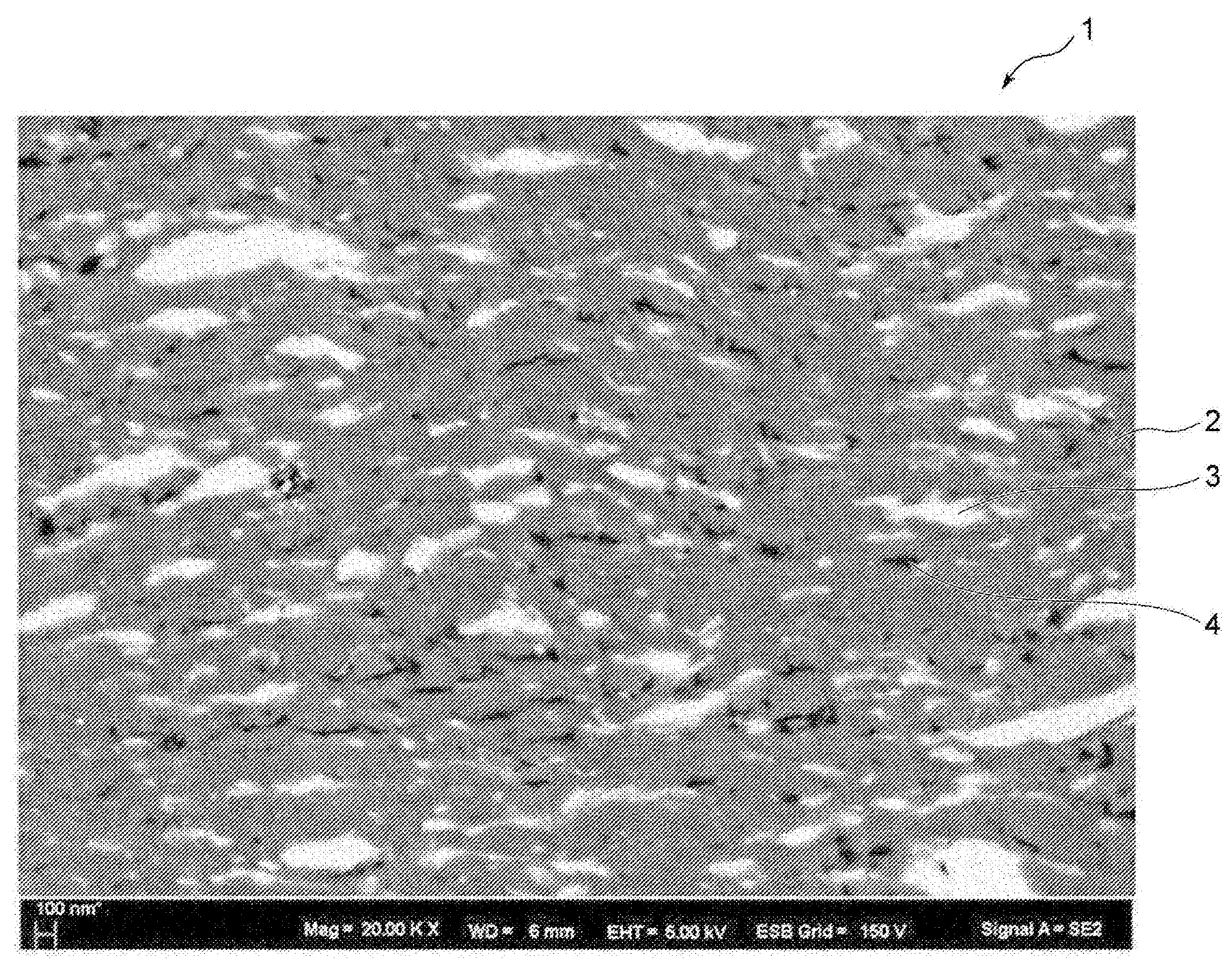
도 1은, 전계 방사형 주사 전자 현미경으로 관찰된 제2 상 입자를 도시하는 반사 전자상이다.
도 2는, 제2 상 입자를 타원으로 보고 판단하여 상당 타원을 도시하는 개략도이다.
도 3은, 배향각의 설명에 제공되는 개략도이다.
도 4는, 실시예 1에서 제작한 본 발명의 세라믹스 적층체에 있어서, 복합 세라믹스층과 기재의 접합면에 대하여 직교하는 임의의 단면을, 전계 방사형 주사 전자 현미경으로 관찰하였을 때의 반사 전자상이다.
도 5는, 실시예 3에서 제작한 본 발명의 세라믹스 적층체에 있어서, 복합 세라믹스층과 기재의 접합면에 대하여 직교하는 임의의 단면을, 전계 방사형 주사 전자 현미경으로 관찰하였을 때의 2차 전자상이다.1 is a reflected electron image showing second phase particles observed by an electric field emission scanning electron microscope.
Fig. 2 is a schematic diagram showing an equivalent ellipse by judging and judging the second phase particle as an ellipse.
3 is a schematic diagram provided to explain the orientation angle.
Fig. 4 is a reflection electron image when an arbitrary cross section orthogonal to the bonding surface of the composite ceramics layer and the substrate is observed with an electric field emission scanning electron microscope in the ceramics laminate of the present invention prepared in Example 1. .
Fig. 5 is a secondary electron image obtained by observing an arbitrary cross section orthogonal to the bonding surface of the composite ceramics layer and the substrate in the ceramics laminate of the present invention prepared in Example 3 with a field emission scanning electron microscope. to be.
(용어의 정의)(Definition of Terms)
본 발명에 있어서의 알루미나-지르코니아 세라믹스로 이루어지는 복합 세라믹스층의 조직을 평가, 규정하는 관찰면은, 기재층과 복합 세라믹스층의 접합면에 수직인 단면으로 한다. 반송, 압연 롤 등의 원기둥, 원통 형상의 구조체로 이루어지는 기재층의 둘레면에, 복합 세라믹스층이 형성된 세라믹스 적층체의 경우, 복합 세라믹스층의 조직을 평가, 규정하는, 기재층과 복합 세라믹스층의 접합면에 수직인 단면은, 원기둥, 원통의 중심축을 통과하는 평면 상에 있는 임의의 단면이다. 이 경우, 원기둥, 원통의 중심축을 통과하는 평면 상에 있는 본 발명의 관찰면인 단면에 있어서, 단면과 접합면이 교차하는 선은 직선으로 된다.The observation surface for evaluating and defining the structure of the composite ceramic layer made of alumina-zirconia ceramics in the present invention is a cross section perpendicular to the bonding surface between the base layer and the composite ceramic layer. In the case of a ceramics laminate in which a composite ceramics layer is formed on a circumferential surface of a base layer made of a cylindrical or cylindrical structure such as a conveying or rolling roll, the structure of the base layer and the composite ceramics layer is evaluated and defined. The cross section perpendicular to the joining surface is an arbitrary cross section on a plane passing through the cylinder, the central axis of the cylinder. In this case, in the cross section which is the observation surface of the present invention on the plane passing through the cylinder, the central axis of the cylinder, the line where the cross section and the joining surface intersect becomes a straight line.
본 발명에 있어서, 복합 세라믹스층 내에 있는 제2 상 입자의 크기는, 제2 상 입자와 동일한 면적을 갖는 원의 직경, 즉 원 상당 직경으로 나타낸다. 제2 상 입자가 다수 분산된 조직에 대하여, 본 발명의 제2 상 입자의 평균 직경으로서 정의되는 평균 입경은, 분리된 제2 상 입자의 각각의 면적으로부터 산출한 각각의 제2 상 입자의 직경의 총합을 제2 상 입자의 총 입자수(합계 입자수)로 나눈 평균값이다.In the present invention, the size of the second phase particles in the composite ceramic layer is represented by the diameter of the circle having the same area as the second phase particles, that is, the equivalent diameter of the circle. For a tissue in which a large number of second phase particles are dispersed, the average particle diameter defined as the average diameter of the second phase particles of the present invention is the diameter of each second phase particle calculated from each area of the separated second phase particles. It is an average value divided by the total number of particles of the second phase particles (total number of particles).
도 1은, 제1 상(2) 내에, 이 제1 상(2)보다 총 면적률이 작은 입자상의 제2 상 입자(3)가 분산된 조직을 가진 복합 세라믹스층(1)에 대하여, 전계 방사형 주사 전자 현미경으로 관찰하였을 때의 2차 전자상이다. 본 발명의 세라믹스 적층체는, 도시하지 않은 기재층의 일부 혹은 전체면에, 알루미나상과 지르코니아상으로 구성되는 복합 세라믹스층(1)이 피복된 구성을 갖는다.FIG. 1 shows the electric field of the composite ceramic layer 1 having a structure in which the
본 발명이 규정하는 제2 상 입자(3)는, 기재층 및 복합 세라믹스층간의 접합면과 직교하는 단면(수직인 단면)에서는 편평한 형태를 하고 있으므로, 하나의 제2 상 입자(3)의 형태를 상당 타원으로 치환하여 해석한다. 여기서 상당 타원이란, 대상으로 하는 제2 상 입자 단면과 0차, 1차, 2차 모멘트가 일치하는 타원을 말한다. 즉, 상당 타원이란, 대상으로 한 제2 상 입자의 단면과 동일한 면적, 무게 중심을 갖고, 장축, 단축의 방향, 애스펙트비를 정량화하는 근사 형태이다.Since the
예를 들어, 도 1 중의 영역(ER1) 내에 있는 제2 상 입자(3)에 착안한 경우, 도 2에 도시하는 바와 같이, 제2 상 입자(3)는, 표면에 대소의 요철이 있고, 불규칙한 외형을 가진 입자상으로 형성되어 있다. 이러한 제2 상 입자(3)를 타원으로 보고 판단한 상당 타원(E1)은, 제2 상 입자(3)와 동일한 면적 및 무게 중심을 갖고, 상당 타원(E1)의 장축의 방향이, 제2 상 입자(3)의 장축의 방향으로 정의되며, 또한 상당 타원(E1)의 단축의 방향이, 제2 상 입자(3)의 단축의 방향으로 정의되는 것이며, 또한 상당 타원(E1)의 애스펙트비를 제2 상 입자(3)의 애스펙트비로서 정의한다.For example, when focusing on the
본 발명의 제2 상 입자(3)의 애스펙트비를 나타내는 제2 상 입자(3)의 긴 직경, 짧은 직경의 비의 평균이란, 각각의 제2 상 입자(3)의 상당 타원(E1)의 긴 직경(이하, 상당 타원 긴 직경이라고도 칭함)과 짧은 직경(이하, 상당 타원 짧은 직경이라고도 칭함)의 비를 총합한 값을, 제2 상 입자(3)의 총 입자수로 나눈 평균값이다.The average of the ratios of the long diameter and the short diameter of the
본 발명에서는, 복합 세라믹스층과 기재층의 접합면에 대한 상당 타원(E1)의 방향을 나타내기 위해 배향각을 사용한다. 배향각이란, 도 3에 도시하는 바와 같이, 제2 상 입자(3)의 무게 중심(C1)에 가장 거리가 가까운 접합면(7)의 점(b)에 있어서의 당해 접합면(7)의 면 방향(x1)과, 제2 상 입자(3)의 상당 타원 긴 직경의 방향(이하, 상당 타원 긴 직경 방향이라고도 칭함)(a1)이 이루는 각 θ가, -90°내지 90°의 각도로 표현되었을 때, 그 각도의 절댓값을 제2 상 입자(3)의 배향각으로 한다. 보다 구체적으로, 면 방향(x1)이란, 제2 상 입자(3)의 무게 중심(C1)에 가장 거리가 가까운 접합면(7) 상의 점(b)과, 제2 상 입자(3)의 무게 중심(C1)을 연결하는 직선(y1)에 대하여, 접합면(7)의 점(b)에 있어서 직교하는 접합면(7)의 면 방향을 말한다. 또한, 도 3 중의 a2는, 상당 타원 긴 직경 방향(a1)과 직교하는 상당 타원 짧은 직경의 방향(이하, 상당 타원 짧은 직경 방향이라고도 칭함)을 나타낸다.In the present invention, an orientation angle is used to indicate the direction of the corresponding ellipse E1 with respect to the bonding surface of the composite ceramic layer and the base layer. As shown in Fig. 3, the orientation angle of the
제2 상 입자(3)의 무게 중심(C1)과 가장 거리가 가까운 접합면(7)의 점(b)으로부터 연장되는 면 방향(x1)과, 상당 타원 긴 직경 방향(a1)이 이루는 각 θ는, 360°표기가 아니라, 0°를 중심으로 하여 ±180°표기로 하고, 상당 타원(E1)의 대칭성으로부터 ±90°의 값을 취한다. 본 발명에서는, 이 각도의 절댓값을 제2 상 입자의 배향각이라고 정의한다. 즉, 본 발명이 정의하는 단면에 있어서, 복합 세라믹스층과 기재층의 접합면에 있는 직선에 대하여, 제2 상 입자를 나타내는 상당 타원이 누워 있으면 평균 배향각은 0°이상 45°미만으로 되고, 제2 상 입자가 서 있으면 45°초과 90°이하의 값을 취한다.The angle θ between the plane direction (x1) extending from the point (b) of the bonding surface (7) closest to the center of gravity (C1) of the second phase particle (3) and the elliptical long radial direction (a1) Is not a 360° notation, but is assumed to be a ±180° centered around 0°, and a value of ±90° is taken from the symmetry of the significant ellipse E1. In the present invention, the absolute value of this angle is defined as the orientation angle of the second phase particles. That is, in the cross section defined by the present invention, when a significant ellipse representing the second phase particle is laid with respect to a straight line on the bonding surface of the composite ceramic layer and the base layer, the average orientation angle becomes 0° or more and less than 45°, If the
평균 배향각은, 임의의 단면 내에 있는 개개의 제2 상 입자(3)의 배향각의 총합을, 당해 단면 내에 있는 제2 상 입자(3)의 총 입자수로 나눈 평균값이다. 애스펙트비가 1보다 큰 제2 상 입자(3)가 완전히 랜덤한 방향을 향하고 있는 경우에는, 평균 배향각은 45°의 값을 취한다.The average alignment angle is an average value obtained by dividing the sum of the alignment angles of the individual
(본 발명의 세라믹스 적층체에 관하여)(About the ceramics laminate of the present invention)
본 발명은 기재층의 일부 혹은 전체면에, 알루미나상과 지르코니아상으로 구성되는, 특정 조직을 갖는 복합 세라믹스층이 피복된 세라믹 적층체이다. 알루미나상 중에 지르코니아상, 혹은 지르코니아상 중에 알루미나상이 분산된 조직이며, 양자의 비율은 불문한다. 본 발명에서는, 임의의 단면에 있어서, 총 면적률이 큰 상을 제1 상이라고 하고, 제1 상보다 총 면적률이 작고, 입자상으로 형성된 상을 제2 상 입자라고 한다. 알루미나-지르코니아 세라믹스(복합 세라믹스)로 이루어지는 복합 세라믹스층의 주된 강인화 기구는 두 상(제1 상 및 제2 상 입자)이 혼재됨에 따른 응력장의 공간 분포에 의해 크랙의 진전을 방해하는 기구이다. 이 응력장은 두 입자의 탄성률이나 열팽창 계수의 차이에 의해, 복합 세라믹스층을 형성할 때의 내부 응력, 열응력에 의해 발생한다.The present invention is a ceramic laminate in which a composite ceramic layer having a specific structure composed of an alumina phase and a zirconia phase is coated on a part or the entire surface of a base layer. A zirconia phase in the alumina phase or a structure in which the alumina phase is dispersed in the zirconia phase, and the ratio of both is irrespective. In the present invention, in an arbitrary cross-section, a phase having a large total area ratio is referred to as a first phase, and a phase having a smaller total area ratio than the first phase and formed in a particulate form is referred to as a second phase particle. The main toughening mechanism of the composite ceramic layer made of alumina-zirconia ceramics (composite ceramics) is a mechanism that prevents crack growth by spatial distribution of stress fields due to the mixing of the two phases (first phase and second phase particles). This stress field is generated by internal stress and thermal stress when forming a composite ceramic layer due to differences in elastic modulus or coefficient of thermal expansion between two particles.
제2 상 입자의 필요한 비율은 그 입경이나 분포 정도에 따라 상이하지만, 임의의 단면에서의 면적비로 1% 이상 있으면 된다. 또한, 복합 세라믹층에 있어서의 제1 상 및 제2 상 입자의 면적비로서는, 3% 이상이면 크랙의 진전 억제 효과가 커지고, 10% 이상이면 더욱 바람직하다. 이론적으로는 매트릭스 내에 분산되는 입자의 면적이 매트릭스의 면적보다 커지는 경우는 있을 수 있지만, 실제는 분산되는 입자의 면적은 매트릭스의 면적보다 작으며, 복합 세라믹층에 있어서의 제1 상 및 제2 상 입자의 면적비는, 상한이 40% 이하인 것이 바람직하고, 33% 이하인 것이 더욱 바람직하다.The required proportion of the second phase particles varies depending on the particle diameter and the degree of distribution, but may be 1% or more in an area ratio in an arbitrary cross section. Moreover, as an area ratio of the 1st phase and 2nd phase particle|grains in a composite ceramic layer, if it is 3% or more, the crack growth suppression effect will become large, and if it is 10% or more, it is more preferable. Theoretically, the area of the particles dispersed in the matrix may be larger than the area of the matrix, but in reality, the area of the dispersed particles is smaller than the area of the matrix, and the first phase and the second phase in the composite ceramic layer The area ratio of the particles is preferably 40% or less, and more preferably 33% or less.
또한, 알루미나상이란, 주로 알루미나로 구성된 상을 가리키며, 본 명세서에 있어서는, 알루미나 함유율이 90질량% 이상, 또는 92질량% 이상, 또는 94질량% 이상, 또는 96질량% 이상, 또는 98질량% 이상의 것이어도 된다. 지르코니아상이란, 주로 지르코니아로 구성된 상을 가리키며, 본 명세서에 있어서는, 지르코니아 함유율이 90질량% 이상, 또는 92질량% 이상, 또는 94질량% 이상, 또는 96질량% 이상, 또는 98질량% 이상의 것이어도 된다.In addition, an alumina phase mainly refers to the phase which consists of alumina, and in this specification, an alumina content is 90 mass% or more, or 92 mass% or more, or 94 mass% or more, or 96 mass% or more, or 98 mass% or more May be. The zirconia phase mainly refers to a phase composed of zirconia, and in this specification, the zirconia content is 90% by mass or more, or 92% by mass or more, or 94% by mass or more, or 96% by mass or more, or 98% by mass or more do.
본 발명은 알루미나-지르코니아 세라믹스에 우수한 기계적 특성을 갖게 하기 위해, 일반적으로 제조되는 알루미나-지르코니아 세라믹스 소결체에 비하여, 제2 상 입자의 입경이 작고, 제2 상 입자의 형태도 크게 상이하다. 본 발명의 복합 세라믹스층에서는, 기재층과 직교하는 임의의 단면에 있어서, 알루미나상과 지르코니아상 중, 제1 상보다 총 면적률이 작을 쪽을 제2 상 입자라고 하며, 제2 상 입자의 원 상당 직경이 0.01㎛ 이상 1㎛ 이하인 입자가 제2 상 입자의 면적률의 대부분을 차지하고, 원 상당 직경이 0.01㎛ 이상인 제2 상 입자를 계측하였을 때, 제2 상 입자의 평균 직경이 0.02㎛ 이상 0.3㎛ 이하이며, 또한 제2 상 입자의 상당 타원의 긴 직경을 짧은 직경으로 나눈 장단축비의 평균값이 2 이상 10 이하인 것을 요건으로 한다(이하, 특별히 언급하지 않는 한, 제2 상 입자의 원 상당 직경이란, 원 상당 직경이 0.01㎛ 이상인 제2 상 입자를 계측한 것임). 이 조직 형태를 취함으로써, 강도와 파괴 인성값을 향상시켜, 절연 파괴 전계값을 향상시킬 수 있다. 특히 기재층과 복합 세라믹스층의 접합면과 수직 방향, 즉 복합 세라믹스층의 막 두께 방향으로 진행하는 크랙의 진전을 저해하여, 절연 파괴 전계값을 향상시키는 효과가 커진다. 이에 의해, 예를 들어 반송, 압연 롤 등의 원기둥, 원통 형상의 구조체로 이루어지는 기재층의 둘레면에, 복합 세라믹스층이 형성된 세라믹스 적층체로 한 경우에는, 내마모성이 우수한 반송 롤을 구축할 수 있다. 세라믹스 절연 기판에 응용하는 경우에는, 내열 사이클성을 향상시킬 수 있고, 또한 절연막 두께를 작게 할 수 있다는 점에서, 방열성이 우수한 세라믹스 절연 기판을 구축할 수 있다.In order to have excellent mechanical properties of the alumina-zirconia ceramics, the present invention has a smaller particle size of the second phase particle and a significantly different shape of the second phase particle than the sintered alumina-zirconia ceramics. In the composite ceramic layer of the present invention, in an arbitrary cross section orthogonal to the base layer, the one having a smaller total area ratio than the first phase among the alumina phase and the zirconia phase is referred to as the second phase particle, and the source of the second phase particle When the particles having a corresponding diameter of 0.01 μm or more and 1 μm or less occupy most of the area ratio of the second phase particles, and when the second phase particles having a circle equivalent diameter of 0.01 μm or more are measured, the average diameter of the second phase particles is 0.02 μm or more It is required that the average value of the long and short axis ratios of 0.3 µm or less and the long diameter of the significant ellipse of the second phase particle divided by the short diameter is 2 or more and 10 or less (hereinafter, unless otherwise specified, the circle of the second phase particle) The equivalent diameter is a measurement of the second phase particles having a circle equivalent diameter of 0.01 µm or more). By taking this structure form, the strength and fracture toughness values can be improved, and the dielectric breakdown electric field value can be improved. In particular, the effect of improving the dielectric breakdown electric field value is increased by inhibiting the progress of cracks that progress in the direction perpendicular to the bonding surface of the base layer and the composite ceramic layer, that is, in the film thickness direction of the composite ceramic layer. Thereby, for example, in the case of a ceramic laminate having a composite ceramic layer formed on a circumferential surface of a base layer made of a cylindrical or cylindrical structure such as a conveying roll or a rolling roll, a conveying roll excellent in abrasion resistance can be constructed. When applied to a ceramic insulating substrate, it is possible to construct a ceramic insulating substrate excellent in heat dissipation from the viewpoint of improving the heat cycle resistance and reducing the thickness of the insulating film.
알루미나-지르코니아 세라믹스로 이루어지는 본 발명의 복합 세라믹스층은, 제2 상 입자의 입경이, 일반적인 알루미나-지르코니아 세라믹스 소결체와 비교하여 한 자릿수 정도 작고, 평균 입경을 0.3㎛ 이하로 함으로써, 제2 상 입자의 주위에 발생하는 응력장 발생 영역의 수가 증가하여, 크랙이 진전되었을 때 당해 크랙이 제2 상 입자를 우회할 기회가 증가하여, 크랙 진전을 저해할 수 있다. 제2 상 입자의 크기는, 수㎛까지 크랙의 진전을 억제하는 작용이 있지만, 최대 직경이 5㎛를 초과하면 그 주위의 제1 상에 비교적 큰 크랙, 또는 공극이 발생하는 경우가 커져, 기계적 특성은 열화되어 버린다. 그 때문에, 제2 상 입자의 최대 직경은 5㎛ 이하가 바람직하며, 나아가 1.5㎛ 이하인 것이 바람직하고, 1㎛ 미만이면 더욱 바람직하다. 한편, 본 발명의 세라믹스 적층체에 있어서의 복합 세라믹스층에 있어서, 원 상당 직경으로 0.01㎛ 이하의 입자를 함유하고 있어도 상관없지만, 제2 상 입자의 평균 직경이 0.02㎛보다 작은 경우에는, 크랙의 진전을 저해하는 작용이 작아진다. 특히, 제2 상 입자의 평균 직경은 0.02㎛ 이상 0.2㎛ 이하가 바람직하며, 이 경우, 복합 세라믹스층의 기계적인 특성이 한층 더 높아진다.In the composite ceramics layer of the present invention made of alumina-zirconia ceramics, the particle size of the second phase particles is about one digit smaller than that of a typical sintered alumina-zirconia ceramics, and the average particle size is 0.3 µm or less, thereby reducing the The number of stress-field-generating regions generated around the periphery increases, and when the crack propagates, the chance of the crack bypassing the second phase particles increases, thereby inhibiting crack propagation. The size of the second phase particles has an effect of suppressing the growth of cracks up to several µm, but when the maximum diameter exceeds 5 µm, the relatively large cracks or voids in the surrounding first phase become large and mechanical. The characteristic is deteriorated. Therefore, the maximum diameter of the second phase particles is preferably 5 μm or less, more preferably 1.5 μm or less, and more preferably 1 μm or less. On the other hand, in the composite ceramics layer in the ceramics laminate of the present invention, it may be a particle having a circle equivalent diameter of 0.01 µm or less, but if the average diameter of the second phase particles is smaller than 0.02 µm, cracks The action of inhibiting progress decreases. In particular, the average diameter of the second phase particles is preferably 0.02 μm or more and 0.2 μm or less, and in this case, the mechanical properties of the composite ceramic layer are further increased.
제1 상의 결정립경은 불문하지만, 제2 상 입자와 동등하거나 그 이상으로 미세화하면, 기계적 특성은 더 향상되고, 전체로서의 절연 파괴 전계값도 높아진다. 따라서, 제1 상의 결정립경은, 제2 상 입자 내의 결정 입자와 동등하거나 그 이상으로 미세화되어 있는 것이 바람직하다.Regardless of the crystal grain diameter of the first phase, if the particle size is equal to or greater than that of the second phase particle, the mechanical properties are further improved, and the dielectric breakdown electric field value as a whole is also increased. Therefore, it is preferable that the crystal grain diameter of the first phase is equal to or more than the crystal grain in the second phase particles.
본 발명의 복합 세라믹스층은, 제2 상 입자가 편평하게 형성되어 있고, 제2 상 입자의 상당 타원의 짧은 직경을 기준으로 하였을 때의 긴 직경, 짧은 직경의 비의 평균값이 2 이상 10 이하임으로써, 결정립계를 진전하는 크랙에 대해서는, 제2 층의 짧은 직경 방향에 대한 크랙의 진전을 저해한다. 본 발명의 복합 세라믹스 입자는 대략 막 두께 방향이 짧은 직경 방향으로 된다는 점에서, 막 두께 방향으로 높은 강도와 파괴 인성을 얻을 수 있다. 또한, 본 발명의 복합 세라믹스상의 제2 상은, 막의 면 내 방향으로 완전히 긴 직경 방향이 평행으로 되어 있지 않기 때문에, 면 내 방향으로도 결정립계를 따라 진전하는 크랙의 진행을 방해하는 효과가 있다. 따라서, 복합 세라믹스층의 모든 방향으로 강도나 파괴 인성값을 향상시킬 수 있다.In the composite ceramics layer of the present invention, the second phase particles are formed flat, and the average value of the ratio of the long diameter and the short diameter is 2 or more and 10 or less based on the short diameter of the significant ellipse of the second phase particles. Thus, for cracks advancing grain boundaries, crack propagation in the short diameter direction of the second layer is inhibited. The composite ceramics particles of the present invention can obtain high strength and fracture toughness in the film thickness direction in that the film thickness direction is in the short diameter direction. In addition, the second phase of the composite ceramic phase of the present invention has an effect of preventing the progress of cracks advancing along grain boundaries even in the in-plane direction because the long-diameter directions in the in-plane direction of the film are not parallel. Therefore, the strength and the fracture toughness value can be improved in all directions of the composite ceramic layer.
또한, 제2 상 입자 자체가 정방정 지르코니아인 경우, 특히 상당 타원 긴 직경 방향으로는 크랙 선단이 진전하는 에너지를 흡수하는 작용이 크게 작용하기 때문에, 강도나 파괴 인성값을 향상시킬 수 있다.In addition, when the second phase particles themselves are tetragonal zirconia, the effect of absorbing the energy of the crack tip advancing in the direction of the elongation in a substantially elliptical elongated direction is large, so it is possible to improve the strength or fracture toughness value.
또한, 결정립이 막 두께 방향으로 편평해 있는 경우에는, 세라믹스 적층체의 절연 특성을 결정하는, 복합 세라믹스층의 막 두께 방향의 절연 파괴 전계값을 향상시킬 수 있다.In addition, when the crystal grains are flat in the film thickness direction, it is possible to improve the dielectric breakdown electric field value in the film thickness direction of the composite ceramic layer, which determines the insulating properties of the ceramic laminate.
본 발명의 세라믹스 적층체에 있어서의 복합 세라믹스층에 있어서, 공극도 기계적인 특성이나 전기적인 특성에 영향을 준다. 공극은, 파괴 인성의 점에서는 적절하게 있는 편이 바람직한 경우도 있지만, 강도나 절연성의 점에서는 적은 편이 바람직하다. 본 발명에서는, 본 발명이 규정하는 단면에 있어서, 공극의 면적률은 5% 이하인 것을 요건으로 하며, 바람직하게는 3% 이하, 더욱 바람직하게는 0.7% 이하인 것이 바람직하다.In the composite ceramics layer in the ceramics laminate of the present invention, the voids also affect mechanical and electrical properties. In some cases, the voids may be appropriately appropriate in terms of fracture toughness, but less preferably in terms of strength and insulation. In the present invention, in the cross-section defined by the present invention, the area ratio of the void is required to be 5% or less, preferably 3% or less, more preferably 0.7% or less.
(조직의 계측 방법)(Measurement method of organization)
본 발명의 세라믹스 적층체는, 기재층에, 알루미나상과 지르코니아상으로 구성된 특정 조직을 갖는 복합 세라믹스층이 피복된 구성을 갖고 있으며, 상술한 바와 같이 기재층과 복합 세라믹스층의 접합면에 대하여 알루미나-지르코니아 세라믹스(복합 세라믹스)의 조직이 이방성을 갖는다. 이 때문에, 본 발명의 알루미나-지르코니아 세라믹스로 이루어지는 복합 세라믹스층의 조직을 평가, 규정하는 관찰면은, 기재층과 복합 세라믹스층의 접합면에 수직인 단면으로 한다. 즉, 반송, 압연 롤 등의 원기둥, 원통 형상의 구조체로 이루어지는 기재층의 둘레면에, 복합 세라믹스층이 형성된 세라믹스 적층체인 경우, 복합 세라믹스층의 조직을 평가, 규정하는 관찰면(기재층과 복합 세라믹스층의 접합면에 수직인 단면)은, 원기둥, 원통의 중심축을 통과하는 평면 상에 있는 임의의 단면이다. 이 경우, 접합면에 수직인 본 발명의 관찰면인 단면에 있어서, 접합면은 곡선이 아니라 직선으로 된다.The ceramics laminate of the present invention has a structure in which a composite ceramics layer having a specific structure composed of an alumina phase and a zirconia phase is coated on a substrate layer, and as described above, the alumina is bonded to the bonding surface between the substrate layer and the composite ceramics layer. -The structure of zirconia ceramics (composite ceramics) has anisotropy. For this reason, the observation surface for evaluating and defining the structure of the composite ceramic layer made of alumina-zirconia ceramics of the present invention is a cross section perpendicular to the bonding surface between the base layer and the composite ceramic layer. That is, in the case of a ceramics laminate in which a composite ceramic layer is formed on a circumferential surface of a base layer made of a cylindrical or cylindrical structure such as a conveying roll or a rolling roll, an observation surface (composite with a base layer and a composite that evaluates and defines the structure of the composite ceramic layer) The cross section perpendicular to the bonding surface of the ceramic layer) is an arbitrary cross section on a plane passing through the cylinder, the central axis of the cylinder. In this case, in the cross section which is the observation surface of the present invention perpendicular to the joining surface, the joining surface is straight, not curved.
본 발명의 복합 세라믹스층의 제2 상 입자의 형태의 평가 방법은 불문하지만, 본 발명의 조직을 구성하는 제2 상 입자는 종래의 소결체 내의 입자와 비교하여 작기 때문에, 원 상당 직경으로 0.01㎛ 이상의 입자를 검지할 수 있는 평가 방법일 필요가 있다. 또한, 본 발명의 세라믹스 적층체에 있어서의 복합 세라믹스층의 기계적, 전기적 특성은 0.01㎛ 이상의 입자에 의해 향상된다는 점에서, 원 상당 직경으로 0.01㎛ 이상의 입자를 검지할 수 있는 평가 방법이면 된다. 이것을 만족하는 방법 중 하나는, 점점 보급되고 있는 전계 방사형 주사 전자 현미경(FE-SEM)의 반사 전자상이나 2차 전자상을 화상 해석하는 방법이 있으며, 본 발명의 조직의 표준적인 평가 방법으로 된다.Although the method for evaluating the shape of the second phase particles in the composite ceramic layer of the present invention is not limited, the second phase particles constituting the structure of the present invention are smaller than the particles in the conventional sintered body, and therefore have a circle equivalent diameter of 0.01 µm or more. It needs to be an evaluation method capable of detecting particles. In addition, since the mechanical and electrical properties of the composite ceramic layer in the ceramic laminate of the present invention are improved by particles of 0.01 µm or more, an evaluation method capable of detecting particles of 0.01 µm or more in a circle equivalent diameter may be used. One of the methods satisfying this is a method of image analysis of a reflected electron image or a secondary electron image of an increasingly popular field emission scanning electron microscope (FE-SEM), which is a standard evaluation method of the tissue of the present invention.
알루미나와 지르코니아는 질량수가 크게 상이하기 때문에, 이들 상은 주사 전자 현미경의 반사 전자상이나 2차 전자상의 콘트라스트의 차로서, 비교적 용이하게 분리할 수 있다. FE-SEM을 사용하여, 가속 전압을 5kV, 배율을 20000배 정도까지 올리면, 0.01㎛ 정도의 분해능은 용이하게 얻어진다. 가속 전압이 큰 경우, 표면에 노출된 것뿐만 아니라, 내부의 상도 콘트라스트로서 습득될 가능성이 있다. 따라서, 본 발명의 복합 세라믹스층의 평가는 가속 전압 5kV 이하에서 취득한 화상을 사용하는 것이 바람직하다.Since the mass number of alumina and zirconia differ greatly, these phases can be separated relatively easily as the difference in contrast between the reflected electron phase and the secondary electron phase of a scanning electron microscope. When FE-SEM is used to increase the acceleration voltage to 5 kV and the magnification to about 20000 times, a resolution of about 0.01 µm is easily obtained. When the acceleration voltage is large, it is possible that not only the surface is exposed, but also the internal phase is acquired as contrast. Therefore, it is preferable to use an image acquired at an acceleration voltage of 5 kV or less for the evaluation of the composite ceramic layer of the present invention.
이상과 같은 조건에서 얻어진 화상을 2치화하여 형태 해석을 행하면 된다. 단, 본 발명의 복합 세라믹스층의 관찰면에서는 긴 직경이 1㎛를 초과하는 입자도 포함되는 경우가 있으므로, 20000배의 시야에서는 재료의 평균적인 정보를 얻는 데 1시야로는 지나치게 좁은 경우가 있다. 기준으로서 제2 상 입자가 1000개 이상으로 되도록 겹치지 않는 시야에서 복수의 상을 취득하여 형태 해석을 행할 필요가 있다.The image obtained under the above conditions may be binarized to perform shape analysis. However, in the observation surface of the composite ceramic layer of the present invention, particles having a long diameter exceeding 1 µm may also be included, and therefore, in the field of view of 20000 times, the average information of the material may be too narrow in one field of view. . As a criterion, it is necessary to acquire a plurality of images in a non-overlapping field of view so that the second phase particles become 1000 or more, and perform shape analysis.
제2 상 입자의 면적은, 상술한 전계 방사형 주사 전자 현미경(FE-SEM)의 반사 전자상이나 2차 전자상에 의해, 복합 세라믹스층의 단면 화상을 얻고, 이 단면 화상을 기초로 제2 상 입자의 단면 영역을 눈으로 봐서 추출하고, 추출한 영역 내의 면적을, 화상 해석 소프트웨어를 사용하여 산출함으로써 특정할 수 있다. 본 발명에서는, 관찰면으로 한 복합 세라믹스층의 단면 화상으로부터 제2 상 입자의 각각의 면적과 형태를 특정하고, 이것을 사용하여 제2 상 입자의 평균 직경이나, 제2 상 입자의 상당 타원 긴 직경, 상당 타원 짧은 직경, 애스펙트비 등을 특정할 수 있다.The area of the second phase particle is obtained by a cross-sectional image of the composite ceramic layer by the reflected electron image or secondary electron image of the above-described field emission scanning electron microscope (FE-SEM), and based on this cross-sectional image, the second phase particle It can be specified by visually extracting the cross-sectional area of and extracting the area within the extracted area using image analysis software. In the present invention, the area and shape of each of the second phase particles are specified from the cross-sectional image of the composite ceramic layer serving as the observation surface, and the average diameter of the second phase particles or the equivalent elliptical long diameter of the second phase particles is used using this. , Equivalent ellipse short diameter, aspect ratio and the like can be specified.
또한, 본 발명의 복합 세라믹스의 경우, 공극도 주사형 전자 현미경으로 용이하게 콘트라스트로서 식별할 수 있으므로, 제2 상 입자의 평가에 사용한 화상을 사용하여, 공극만을 2치화하여 면적률이나 크기를 평가할 수 있다.Further, in the case of the composite ceramics of the present invention, the voids can also be easily identified as contrast with a scanning electron microscope, so that only the voids are binarized using the image used for the evaluation of the second phase particles to evaluate the area ratio or size. Can be.
(제2 상 입자의 배향각에 대하여)(About the orientation angle of the second phase particles)
본 발명에서는 「평균으로 2 이상의 애스펙트비를 갖는 제2 상 입자」의 기재층에 대한 분포에 특징이 있으며, 이에 의해 세라믹스 적층체의 절연 저항값이나, 파괴 인성값이 향상될 수 있다. 본 발명의 세라믹스 적층체에서는, 기재층과 복합 세라믹스층의 접합면이, 반송 롤의 둘레면에 피복시키는 경우와 같이, 평판형일 필요는 없지만, 본 발명의 제2 상 입자의 방향은 하기와 같은 특징을 갖는 것이 바람직하다. 본 발명의 세라믹스 적층체는, 기재층과 복합 세라믹스층의 접합면에 대하여 수직인 단면에 있어서, 제2 상 입자의 개개의 무게 중심에 가장 거리가 가까운 당해 접합면의 점(b)에서의 면 방향(x1)에 대하여, 제2 상 입자의 상당 타원 긴 직경의 방향(a1)이 이루는 각도 θ와, 제2 상 입자의 상당 타원 짧은 직경의 방향(a2)이 이루는 각도 θ의 여각인 각도를 비교하면, 상당 타원 긴 직경의 방향(a1)이 이루는 각도 θ 쪽이, 상당 타원 짧은 직경의 방향(a2)이 이루는 각도보다 작다.In the present invention, the distribution of the "second phase particles having an aspect ratio of 2 or more on average" is characteristic of the distribution to the base layer, whereby the insulation resistance value and fracture toughness value of the ceramic laminate can be improved. In the ceramic laminate of the present invention, the bonding surface between the base layer and the composite ceramic layer does not need to be flat, as in the case where the peripheral surface of the conveying roll is coated, but the direction of the second phase particles of the present invention is as follows. It is desirable to have features. The ceramics laminate of the present invention is a plane at a point (b) of the bonding surface closest to the individual center of gravity of the second phase particle in a cross section perpendicular to the bonding surface between the base layer and the composite ceramics layer. With respect to the direction (x1), the angle θ formed by the direction (a1) of the equivalent ellipse long diameter of the second phase particle and the angle θ formed by the direction (a2) of the equivalent ellipse short diameter of the second phase particle In comparison, the angle θ formed by the direction (a1) of the corresponding ellipse long diameter is smaller than the angle formed by the direction (a2) of the equivalent ellipse short diameter.
즉, 세라믹스 적층체가 평판인 경우에는, 기재층과 복합 세라믹스층의 접합면에 대하여 수직 방향에 있어서 제2 상 입자의 입경이 작고, 당해 접합면에 대하여 평행 방향에 있어서 입경이 큰 편평화된 제2 상 입자가 형성되어 있다. 구체적으로는, 제2 상 입자의 무게 중심에 가장 거리가 가까운 접합면의 점(b)에서의 면 방향(x1)과, 개개의 제2 상 입자의 상당 타원 긴 직경의 방향(a1)이 이루는 각 θ가, -90°내지 90°의 각도로 표현되고, 그 각도의 절댓값을 제2 상 입자의 배향각으로 하였을 때, 60% 이상의 수의 제2 상 입자가 30°이하의 배향각을 갖고 있는 것이 바람직하다. 본 발명의 세라믹스 적층체는, 이러한 특징적인 조직을 갖고 있음으로써, 기재층과 복합 세라믹스층의 접합면에 대하여 수직 방향의 절연 저항값이 향상되고, 강도, 파괴 인성값이 향상된다. 이러한 배향각의 물성값은, 세라믹스 절연 기판의 열적, 기계적, 전기적 특성에 강하게 영향을 미쳐, 우수한 내열 사이클 특성, 파괴 전압을 얻기 위해 효과가 있다.That is, when the ceramic laminate is flat, the particle size of the second phase particles is small in the direction perpendicular to the bonding surface of the base layer and the composite ceramic layer, and the flattened agent has a large particle diameter in the parallel direction to the bonding surface. Two-phase particles are formed. Specifically, the plane direction (x1) at the point (b) of the bonding surface closest to the center of gravity of the second phase particle and the direction (a1) of the elliptical long diameter corresponding to the individual second phase particle are formed. When each θ is expressed by an angle of -90° to 90°, and the absolute value of the angle is the orientation angle of the second phase particles, the number of second phase particles of 60% or more has an orientation angle of 30° or less It is desirable. The ceramics laminate of the present invention has such a characteristic structure, thereby improving the insulation resistance value in the vertical direction with respect to the bonding surface between the base layer and the composite ceramic layer, and improving the strength and fracture toughness values. The physical property value of such an orientation angle strongly influences the thermal, mechanical, and electrical properties of the ceramic insulating substrate, and is effective in obtaining excellent heat cycle characteristics and breakdown voltage.
한편, 기재층과 복합 세라믹스층의 접합면에 평행인 면에 대해서는, 본 발명의 경우, 제2 상 입자가 편평하며, 제2 상 입자 그 자체에 의해 크랙의 진전을 저해하는 작용이 있기 때문에, 제1 상 단독의 경우보다 기계적 특성은 향상된다. 한편, 제2 상 입자의 상당 타원 긴 직경 방향(a1)과 접합면이 정렬되어, 극단적으로는 상당 타원 긴 직경 방향(a1)과 접합면이 이루는 각 θ가 0°인 경우, 세라믹스 적층체의 접합면과 평행 방향의 결정립계의 연속성이 높아져, 특히 결정립계에 전달되는 크랙에 대해서는, 진전에 대한 억제 효과는 작아진다.On the other hand, with respect to the surface parallel to the bonding surface of the base layer and the composite ceramic layer, in the case of the present invention, the second phase particles are flat, and the second phase particles themselves have an effect of inhibiting crack growth. The mechanical properties are improved than in the case of the first phase alone. On the other hand, if the bonding surface is aligned with the significant elliptical long radial direction (a1) of the second phase particle, and the angle θ between the extremely large elliptical long radial direction (a1) and the bonding surface is 0°, the ceramic laminate The continuity of the grain boundaries in the direction parallel to the bonding surface is increased, and particularly, for cracks transmitted to the grain boundaries, the effect of suppressing the progress is small.
본 발명의 제2 상 입자는, 기재층과 복합 세라믹스층의 접합면에 수직인 단면에 있어서, 상당 타원 긴 직경 방향(a1)과, 상당 타원 짧은 직경 방향(a2)이, 접합면과 평행 방향 및 수직 방향에 대하여 일정 정도 어긋나 있는 것이 바람직하며, 배향각의 총합을 제2 상 입자의 총 입자수로 나눈 평균 배향각이 5°이상 35°이하인 것이 바람직하고, 나아가 여러 가지 각도로 분포하고, 요동하고 있는 것이 바람직하다.In the second phase particle of the present invention, in the cross section perpendicular to the bonding surface between the base layer and the composite ceramic layer, the significant elliptical long diameter direction (a1) and the significant elliptical short diameter direction (a2) are parallel to the bonding surface. And it is preferable to deviate to a certain degree with respect to the vertical direction, it is preferable that the average orientation angle divided by the total number of particles of the second phase particles by the sum of the orientation angle is 5 ° or more and 35 ° or less, furthermore distributed at various angles, It is desirable to shake.
FE-SEM에 의한 2차 전자상이나 반사 전자상과 화상 처리에 의해 추출된 개개의 제2 상 입자는, 0°내지 90°의 사이의 상이한 배향각으로 분포하고, 요동하고 있으며, 또한 배향각의 총합을, 제2 상 입자의 총 입자수로 나눔으로써 얻어지는, 제2 상 입자의 접합면과의 평균 배향각이 5°이상 35°이하임으로써, 접합면과 대략 평행인 면을 진전하는 결정립계를 따른 크랙의 진전이, 제2 상 입자에 의해 방향이 구부러져 억제된다. 동일한 논리로부터, 제1 상의 결정립도 제2 상 입자와 마찬가지의 형태로 분포되어 있는 것이 바람직하다.Secondary or reflective electron images by FE-SEM and individual second phase particles extracted by image processing are distributed at different orientation angles between 0° and 90°, fluctuating, and also A grain boundary for advancing a plane substantially parallel to the bonding surface by an average orientation angle of 5° or more and 35° or less with the bonding surface of the second phase particles obtained by dividing the total by the total number of particles of the second phase particles The progress of cracks along is suppressed by bending the direction by the second phase particles. From the same logic, it is preferable that the crystal grains of the first phase are distributed in the same form as the particles of the second phase.
(세라믹스 절연 기판에 관하여)(About ceramic insulating substrate)
본 발명의 세라믹스 적층체는, 편평하고 미세한 제2 상 입자의 작용에 의해 기계적인 특성이 우수하며, 예를 들어 평판형 기재층의 판면에, 본 발명에서 규정하는 복합 세라믹스층을 성막하고, 기재층에 복합 세라믹스층이 접합된 구성으로 됨으로써, 특히 기재층에 대하여 수직 방향으로 진전하는 크랙을 억제하는 효과가 강해지고, 접합면과 평행인 면 내 방향의 인장 응력에 대하여 매우 강한 내성을 갖는다. 또한, 제1 상의 결정립 및 제2 상 입자가 미세하다는 점에서, 절연 파괴 전계도 높다. 따라서, 본 발명에서는, 복합 세라믹스층의 두께를 얇게 할 수 있고, 기재층과 수직 방향의 열전도율을 높게 설계할 수 있다.The ceramics laminate of the present invention is excellent in mechanical properties by the action of flat and fine second phase particles, for example, a composite ceramic layer defined in the present invention is deposited on a plate surface of a flat substrate layer, and the substrate is The structure in which the composite ceramic layer is bonded to the layer has a strong effect of suppressing cracks advancing in the direction perpendicular to the base layer, and has a very strong resistance to tensile stress in the in-plane direction parallel to the bonding surface. In addition, since the crystal grains of the first phase and the particles of the second phase are fine, the dielectric breakdown electric field is also high. Therefore, in the present invention, the thickness of the composite ceramic layer can be reduced, and the thermal conductivity in the vertical direction with the base layer can be designed high.
이러한 특성은 세라믹스 절연 기판으로서 유용하다는 점에서, 본 발명의 세라믹스 적층체는 세라믹스 절연 기판으로서 특히 적합하다. 특히 이제까지 -40℃ 내지 125℃의 열 사이클 시험 온도 범위보다 저온측, 혹은 고온측으로 넓은 열 사이클에 대한 내열 사이클 특성은, 종래의 세라믹스 절연 기판으로는 달성 곤란한 레벨이었지만, 본 발명에 따른 세라믹스 적층체는, 당해 열 사이클에 대하여 내열 사이클 특성을 갖는다. 따라서, 본 발명의 세라믹스 적층체는, 엄격한 온도 환경 하에서 사용되는 차세대 차량 탑재용 세라믹스 절연 기판으로서도 사용할 수 있다.In view of this property being useful as a ceramic insulating substrate, the ceramic laminate of the present invention is particularly suitable as a ceramic insulating substrate. In particular, the heat cycle characteristics for heat cycles which are wider to the lower temperature side or the higher temperature side than the thermal cycle test temperature range of -40°C to 125°C have been difficult to achieve with conventional ceramic insulating substrates, but the ceramics laminate according to the present invention Has heat-resistant cycle characteristics with respect to the heat cycle. Therefore, the ceramics laminate of the present invention can also be used as a ceramics insulating substrate for next-generation vehicle mounting used under severe temperature environments.
세라믹스 절연 기판이란, 세라믹스층에 의해 전기적인 절연을 갖게 하는 기판이다. 본 발명의 세라믹스 절연 기판은, 절연층이, 상술한 특징적인 조직으로 이루어지는 알루미나-지르코니아 세라믹스로 이루어지는 복합 세라믹스층이며, 기재층으로서는 열이나 전기를 전달하는 구리, 또는 알루미늄을 주체로 하는 것이 바람직하다. 또한, 여기서 주체란, 기재층을 구성하는 조성물 전체의 질량을 기준으로 하여, 구리 또는 알루미늄을 50질량% 이상 함유하는 것을 말한다. 즉, 열전도나 전기 전도의 점에서, 구리 또는 알루미늄은 불순물이 적은 순구리나 순알루미늄이 바람직하지만, 강도면, 또는 그 밖의 이유로부터 기재층은, 구리나 알루미늄을 주체로 하고, 열전도나 전기 전도가 현저하게 손상되지 않는 범위에서, 잔부에 구리 및 알루미늄 이외의 다른 금속이 함유되어 있어도 된다. 단, 다이아몬드는 세라믹스층과의 접합력이 작으므로, 세라믹스층을 형성시키는 면에는 노출되어 있지 않는 편이 바람직하다.The ceramics insulating substrate is a substrate that provides electrical insulation by the ceramics layer. The ceramic insulating substrate of the present invention is a composite ceramic layer in which the insulating layer is composed of alumina-zirconia ceramics having the above-described characteristic structure, and it is preferable that the base layer is mainly made of copper or aluminum that transfers heat or electricity. . In addition, a main body here means that it contains 50 mass% or more of copper or aluminum based on the mass of the whole composition which comprises a base material layer. That is, from the viewpoint of heat conduction or electrical conduction, copper or aluminum is preferably pure copper or pure aluminum with few impurities, but for strength or other reasons, the base layer mainly consists of copper or aluminum, and conducts heat conduction or electrical conduction. To the extent that is not significantly damaged, other metals other than copper and aluminum may be contained in the remainder. However, since diamond has a small bonding strength with the ceramic layer, it is preferable that it is not exposed on the surface forming the ceramic layer.
본 발명의 세라믹스 절연 기판은, 복합 세라믹스층의 두께가 얇고, 기재층의 두께에 제한이 없기 때문에, 회로 기판이나, 히트 싱크, 히트 스프레더로서 우수한 방열 기능을 갖는다. 종래의 세라믹스 절연 회로 기판은, 닥터 블레이드법이나 롤 콤팩션법에 의해 시트형으로 형성된 세라믹스 소지를 1300℃ 이상에서 소성하여 얻어지는 두께 0.2mm 내지 0.6mm의 소결체가 사용되지만, 본 발명의 세라믹스 절연 기판에서는, 복합 세라믹스층의 두께를, 소결체의 두께보다 얇게 할 수 있다. 여기서, 종래의 소결체(세라믹스 절연 회로 기판)보다 우수한 열전도성을 갖게 하기 위해, 본 발명의 우수한 기계 특성, 절연 특성을 갖는 복합 세라믹스층은, 기재층과 수직 방향의 두께가 200㎛ 이하, 바람직하게는 100㎛ 이하인 것이 바람직하다. 또한, 복합 세라믹스층은, 절연성을 확보한다는 점이나, 또한 본 발명의 제2 상 입자의 최대 직경의 값으로부터, 기재층과 수직 방향의 두께가 5㎛ 이상인 것이 바람직하다.The ceramic insulating substrate of the present invention has excellent heat dissipation function as a circuit board, heat sink, or heat spreader because the thickness of the composite ceramic layer is thin and there is no limitation on the thickness of the base layer. In the conventional ceramic insulated circuit board, a sintered body having a thickness of 0.2 mm to 0.6 mm obtained by firing a ceramic substrate formed in a sheet form at a temperature of 1300° C. or higher by using a doctor blade method or a roll compaction method is used, but in the ceramics insulating substrate of the present invention, , The thickness of the composite ceramic layer can be made thinner than the thickness of the sintered body. Here, in order to have superior thermal conductivity than conventional sintered bodies (ceramic insulated circuit boards), the composite ceramics layer having excellent mechanical and insulating properties of the present invention has a thickness in the vertical direction with the base layer of 200 μm or less, preferably Is preferably 100 μm or less. Moreover, it is preferable that the composite ceramic layer has an insulating property, and from the value of the maximum diameter of the second phase particles of the present invention, the thickness in the direction perpendicular to the base layer is 5 µm or more.
본 발명의 세라믹스 절연 기판에 있어서, 한쪽 편측에 반도체 칩을 탑재하는 전기 회로를 설치하고, 다른 쪽 반대측에 방열을 목적으로 하는 히트 싱크나, 히트 스프레더를 설치하는 경우, 본 발명의 기재층은, 종래의 방법과 비교하여 두께나, 형태의 제한이 없기 때문에, 히트 싱크나, 히트 스프레더가 배치되는 측으로 하는 것이 바람직하며, 또한 후술하는 바와 같이 기재층을 그대로 히트 싱크나 히트 스프레더로 할 수도 있다. 또한, 전기 회로는, 복합 세라믹스층을 형성한 후에 구리 또는 알루미늄층을 형성한 것인 쪽이 본 발명의 효과가 발휘되기 쉽다.In the ceramic insulated substrate of the present invention, when an electric circuit for mounting a semiconductor chip on one side and a heat sink or a heat spreader for heat dissipation on the other side are provided, the substrate layer of the present invention comprises: Since there is no limitation in thickness and shape compared to the conventional method, it is preferable to set the heat sink or the side where the heat spreader is disposed, and the substrate layer may be used as a heat sink or heat spreader as described later. In addition, the effect of the present invention is likely to be exhibited in the case where the copper or aluminum layer is formed after the composite ceramic layer is formed in the electric circuit.
본 발명의 세라믹스 적층체를 형성한 후, 상기 회로와 같이 다른 면에 막을 형성하는 방법은 불문하지만, 후술하는 「에어로졸 디포지션법(AD법)이나 콜 스프레이법」과 같은 카이네틱 디포지션법, 충격 고화법으로 분류되는 방법 외에, 도금법, 용사법, 또는 이들을 조합한 방법을 들 수 있다.After forming the ceramics laminate of the present invention, a method of forming a film on the other side as in the above-mentioned circuit is irrespective of the method of kinetic deposition such as the "aerosol deposition method (AD method) or the call spray method" described later. , In addition to the method classified as the impact solidification method, a plating method, a thermal spraying method, or a combination of these methods.
종래의 세라믹스 절연 회로 기판에서는, 기재층과 세라믹스층의 접합 시에 발생하는 구리와 세라믹스의 열팽창차로부터 발생하는 열응력이 매우 커진다. 그 때문에, 종래에는, 구리로 이루어지는 기재층의 두께에는 제한이 있으며, 예를 들어 세라믹스층의 판 두께가 0.2mm 내지 0.6mm인 경우, 0.5mm 이상의 기재층에 대하여 세라믹스층을 접합시키기가 곤란하였다. 따라서, 기재층의 구리면측을 히트 싱크나 히트 스프레더로서 큰 열량을 발산시키는 경우, 저융점 브레이징 금속 등으로 더 고열전도, 고방열성을 갖는 구조체를 복합 세라믹스 적층체의 기재층에 더 접합할 필요가 있다. 이에 비해, 본 발명의 세라믹스 절연 기판에서는, 구리를 비롯한 금속판을 기재층으로서 사용한 경우, 당해 기재층의 두께를, 예를 들어 10mm와 같이 두껍게 하는 것이 가능하다. 또한, 이 경우에도, 방열성을 높이기 위해, 기재층의 표면을 다른 물질로 수식해도 되며, 또한 기재층의 표면에 요철을 두어도 되고, 기재층의 표면을 핀 형상으로 해도 된다.In a conventional ceramic insulated circuit board, the thermal stress generated from a difference in thermal expansion between copper and ceramics generated at the time of bonding the base layer and the ceramics layer becomes very large. Therefore, conventionally, the thickness of the base layer made of copper is limited. For example, when the thickness of the ceramic layer is 0.2 mm to 0.6 mm, it is difficult to bond the ceramic layer to the base layer of 0.5 mm or more. . Therefore, in the case of dissipating a large amount of heat as the heat sink or heat spreader on the copper side of the base layer, it is necessary to further bond a structure having higher thermal conductivity and higher heat dissipation with a low-melting brazing metal to the base layer of the composite ceramics laminate. have. In contrast, in the ceramic insulating substrate of the present invention, when a metal plate including copper is used as the base layer, it is possible to increase the thickness of the base layer, for example, 10 mm. Also in this case, in order to improve heat dissipation, the surface of the base material layer may be modified with another material, or may be provided on the surface of the base material layer, or the surface of the base material layer may be formed in a pin shape.
종래의 세라믹스 절연 회로 기판에서는, 기재층과 세라믹스층의 접합 시에 발생하는 구리와 세라믹스의 열팽창차로부터 발생하는 열응력이 매우 커진다. 그 때문에, 종래에는, 절연 세라믹스판의 두께나 밸런스에 제한이 있었다. 예를 들어 절연 세라믹스판의 판 두께가 0.2mm 내지 0.6mm인 경우, 편측에만 금속판을 접합하면 열응력으로 휨이 발생해 버린다. 따라서, 절연 세라믹스판의 양측에 거의 동일한 두께의 금속을 접합하여 균형을 잡을 필요가 있었다. 예를 들어, 절연 방열 회로 기판을 형성하는 경우, 히트 싱크로서 0.3mm의 구리를 접합하는 경우, 회로측에도 0.3mm 정도의 구리 회로를 형성할 필요가 있었다. 이에 비해 본 발명의 세라믹스 적층체를 사용함으로써, 0.5mm를 초과하는 구리를 기재층으로서 사용하여, 절연 세라믹스측에 기재층의 1/2 이하의 구리 회로를 형성하는 것도 가능하며, 예를 들어 히트 싱크측으로 되는 기재층의 두께를 1mm 이상으로 두껍게, 회로측의 두께를 0.5mm 이하로 얇게 하고, 양측의 동판 두께의 차를 0.2mm 이상으로 하는 구성도 가능하다. 물론, 회로에 통전하는 전류량에 따라 회로측의 두께를 두껍게 해도 상관없다. 이 경우, 본 발명의 세라믹스 적층체에 설치하는 금속 회로의 형성 방법은, 큰 열이 가해지지 않는 방법이 바람직하며, 에어로졸 디포지션법이 적합하다. 또한 두께를 늘리기 위해 콜드 스프레이나 도금법을 조합해도 된다.In a conventional ceramic insulated circuit board, the thermal stress generated from a difference in thermal expansion between copper and ceramics generated at the time of bonding the base layer and the ceramics layer becomes very large. Therefore, conventionally, the thickness and balance of the insulating ceramic plate were limited. For example, when the plate thickness of the insulating ceramic plate is 0.2 mm to 0.6 mm, bending is caused by thermal stress when the metal plate is joined to only one side. Therefore, it was necessary to balance by bonding metals of almost the same thickness to both sides of the insulating ceramic plate. For example, when forming an insulating heat dissipation circuit board, when bonding 0.3 mm copper as a heat sink, it was necessary to form a copper circuit of about 0.3 mm on the circuit side as well. On the other hand, by using the ceramics laminate of the present invention, it is also possible to form copper circuits of 1/2 or less of the base layer on the insulating ceramics side by using copper exceeding 0.5 mm as the base layer, for example, heat It is also possible to make the thickness of the base material layer on the sink side thicker than 1 mm, the thickness of the circuit side thinner to 0.5 mm or less, and the difference in thickness of the copper plates on both sides to 0.2 mm or more. Of course, the thickness of the circuit side may be increased depending on the amount of current to be supplied to the circuit. In this case, the method of forming a metal circuit provided on the ceramic laminate of the present invention is preferably a method in which large heat is not applied, and an aerosol deposition method is suitable. In addition, a cold spray or a plating method may be combined to increase the thickness.
열팽창 계수는, 알루미나, 지르코니아, 구리, 알루미늄의 순으로 커진다. 그 때문에, 기재층을 순구리나 순알루미늄으로 형성하여 절연 방열 기판으로 한 경우에는, 복합 세라믹스층을, 알루미나상 중에 지르코니아상이 분산된 형태로 함으로써, 복합 세라믹스층의 거시적인 열팽창률을, 구리나 알루미늄의 열팽창률에 접근시킬 수 있다. 따라서, 이러한 세라믹스 절연 기판(세라믹스 적층체)은, 반복적인 열 사이클에 대하여 열변형, 열응력이 알루미나 단상의 세라믹스보다 작아지며, 또한 기계 특성이 우수하기 때문에, 피로 파괴가 일어나기 어려워진다. 또한, 지르코니아상 중에 알루미나상이 분산된 복합 세라믹스층인 경우, 열전도율은 지르코니아상보다 알루미나상 쪽이 우수하기 때문에, 지르코니아 단상의 세라믹스보다 방열성이 향상된다.The coefficient of thermal expansion increases in the order of alumina, zirconia, copper, and aluminum. Therefore, when the base layer is formed of pure copper or pure aluminum to form an insulating heat dissipation substrate, the composite ceramics layer is formed by dispersing the zirconia phase in the alumina phase, thereby increasing the macroscopic thermal expansion coefficient of the composite ceramics layer to copper or copper. It can approach the thermal expansion coefficient of aluminum. Therefore, such a ceramic insulating substrate (ceramic laminate) undergoes repetitive thermal cycles, so that thermal deformation and thermal stress are smaller than those of alumina single-phase ceramics, and mechanical properties are excellent, so fatigue breakdown is likely to occur. Further, in the case of a composite ceramics layer in which an alumina phase is dispersed in a zirconia phase, the heat conductivity of the alumina phase is superior to that of a zirconia single phase, so that heat dissipation is improved.
(제조 방법)(Manufacturing method)
기재층의 일부 혹은 전체면에, 알루미나상과 지르코니아상으로 구성되는 복합 세라믹스층이 피복된 본 발명의 세라믹스 적층체의 제조 방법은 한정되는 것은 아니지만, 예를 들어 알루미나 원료 입자와 지르코니아 원료 입자를 기체와 혼합하고, 알루미나 원료 입자와 지르코니아 원료 입자를 기체와 함께 기재층의 표면을 향하여 분사하여 충돌시켜, 기재층의 표면에 복합 세라믹스층을 적층하는 에어로졸 디포지션법(AD법)을 사용하는 것이 바람직하다. 그때, 원료 분체(알루미나 원료 입자 및 지르코니아 원료 입자로 이루어지는 분체)와 프로세스 조건을 제어함으로써, 본 발명의 세라믹스 적층체를 얻을 수 있다.The manufacturing method of the ceramic laminate of the present invention in which a composite ceramic layer composed of an alumina phase and a zirconia phase is coated on a part or the entire surface of a base layer is not limited, for example, alumina raw material particles and zirconia raw material gases It is preferred to use an aerosol deposition method (AD method) in which alumina raw material particles and zirconia raw material particles are jetted together with a gas to collide against the surface of the base material layer to collide, thereby stacking a composite ceramic layer on the surface of the base material layer. Do. At this time, the ceramics laminate of the present invention can be obtained by controlling the raw material powder (alumina raw material particles and zirconia raw material particles) and process conditions.
AD법을 사용하는 경우의 프로세스 요건으로서는, 알루미나 원료 입자와 지르코니아 원료 입자로 이루어지는 원료 분체에 있어서의 알루미나 및 지르코니아의 혼합 조성에 가까운 조성으로, 기재층의 표면에 치밀하게 성막하는 것이 필요하다. 이 때문에 특정한 하나의 조건으로 한정시키는 것은 아니지만, 상기 요건을 얻기 위한 조건은 예의 검토할 필요가 있다. 예를 들어, 알루미나 원료 입자로 이루어지는 분체(알루미나 원료 분말이라고도 칭함)와, 지르코니아 원료 입자로 이루어지는 분체(지르코니아 원료 분말이라고도 칭함)의 양쪽이 양호하게 퇴적되어 가지 않으면 치밀하게 분산된 복합 세라믹스층은 얻어지지 않는다. 또한, 성막 조성과 혼합 조성이 크게 상이하면, 복합 세라믹스층의 조성이 바뀌거나, 원료 분말 중의 한쪽 성분만이 없어져 가거나 하여 장시간의 안정된 성막이 불가능하므로, 면적이 크고 막 두께가 큰 복합 세라믹스층이 얻어지지 않는다. 이러한 점에서, AD법으로 단상의 막을 형성할 때보다 현저하게 곤란하며, 양호한 복합 세라믹스층을 얻기 위해서는, 세라믹스 적층체의 구성상이나 그 조합에 따라, 원료 분체의 형태 등을 개별적으로 검토해야 한다.As a process requirement in the case of using the AD method, it is necessary to form a dense film on the surface of the base layer with a composition close to the mixed composition of alumina and zirconia in a raw material powder composed of alumina raw material particles and zirconia raw material particles. For this reason, although it is not limited to a specific one condition, the condition for obtaining the said requirement needs to be examined carefully. For example, a finely dispersed composite ceramic layer can be obtained unless both powder (also called alumina raw material powder) made of alumina raw material particles and powder (also referred to as zirconia raw material powder) made of zirconia raw material particles are not well deposited. Do not lose. In addition, when the film composition and the mixed composition are significantly different, the composition of the composite ceramics layer is changed, or only one component in the raw material powder is lost. Is not obtained. In this regard, the AD method is significantly more difficult than when forming a single-phase film, and in order to obtain a good composite ceramic layer, the shape of the raw material powder and the like must be individually examined depending on the configuration of the ceramic laminate or a combination thereof.
또한, 본 발명의 세라믹 적층체의 제조 방법으로서는, 알루미나 원료 입자가 기체에 혼합된 에어로졸과, 지르코니아 원료 입자가 기체에 혼합된 에어로졸을 개별적으로 형성하고, 두 에어로졸이 각각 다른 노즐로부터 동시에 분사되어 기재층의 표면에 각 에어로졸을 충돌시켜, 기재층의 표면에 복합 세라믹스층을 적층시키는 제조 방법이어도 된다. 또한, 그 밖의 제조 방법으로서는, 알루미나 원료 입자와 지르코니아 원료 입자를 미리 소정의 조성으로 혼합한 혼합 원료 분말에 대하여 기체를 혼합하여 당해 혼합 원료 분말의 에어로졸을 생성하고, 하나의 노즐로부터 혼합 원료 분말의 에어로졸을 기재층의 표면을 향하여 분사하여 충돌시켜, 기재층의 표면에 복합 세라믹스층을 적층하는 제조 방법이어도 된다.In addition, as a method of manufacturing the ceramic laminate of the present invention, the aerosol in which the alumina raw material particles are mixed in the gas and the aerosol in which the zirconia raw material particles are mixed in the gas are separately formed, and the two aerosols are simultaneously sprayed from different nozzles and described. It may be a manufacturing method in which each aerosol is collided on the surface of the layer and the composite ceramic layer is laminated on the surface of the base layer. Further, as another manufacturing method, a gas is mixed with a mixed raw material powder in which alumina raw material particles and zirconia raw material particles are mixed in a predetermined composition in advance to generate an aerosol of the mixed raw material powder, and the mixed raw material powder is An aerosol may be sprayed toward the surface of the substrate layer to collide, and a manufacturing method in which a composite ceramic layer is laminated on the surface of the substrate layer may be used.
후자의 제조 방법의 경우에는, 알루미나보다 지르코니아의 비중이 큼에도 불구하고, 알루미나 원료 입자의 입경보다, 지르코니아 원료 입자의 입경 쪽이 큰 것을 사용하는 것이 바람직하다. 알루미나 원료 입자로서는 메디안 직경으로 1㎛ 이하인 것을 사용하는 것이 바람직하다. 지르코니아 분말은, 가수분해 프로세스를 사용하여 화학적인 방법으로 제조하는 방법과, 전기 용융체를 분쇄하여 제조하는 방법이 있으며, 전자의 쪽이 미세하고 균일한 1차 입자가 얻어지기 쉽지만, 본 발명의 알루미나-지르코니아층을 형성하는 경우, 후자를 원료로 하는 편이, 본 발명의 바람직한 조직을 얻기 쉽고, 치밀도도 우수한 것을 얻기 쉽기 때문에 바람직하다. 이들 알루미나 원료 입자 및 지르코니아 원료 입자를 균일하게 혼합하기 위해 볼 밀 등에서 혼합하는데, 이때의 분쇄도 고려하여, 알루미나 원료 입자 및 지르코니아 원료 입자의 입도나 혼합 조건을 결정할 필요가 있다.In the case of the latter manufacturing method, it is preferable to use a larger particle size of the zirconia raw material particle than the particle size of the alumina raw material particle, although the specific gravity of the zirconia is larger than that of the alumina. It is preferable to use alumina raw material particles having a median diameter of 1 µm or less. Zirconia powder has a method of manufacturing by a chemical method using a hydrolysis process, and a method of manufacturing by pulverizing an electric melt, and it is easy to obtain fine and uniform primary particles of the former, but the alumina of the present invention -In the case of forming a zirconia layer, it is preferable to use the latter as a raw material because it is easy to obtain a desirable structure of the present invention and to obtain an excellent density. In order to uniformly mix these alumina raw material particles and zirconia raw material particles in a ball mill or the like, it is necessary to determine the particle size or mixing conditions of the alumina raw material particles and zirconia raw material particles in consideration of pulverization at this time.
에어로졸을 형성하는 기체로서는 질소 가스나 헬륨, 아르곤 등의 불활성 가스를 들 수 있다. 헬륨 가스는 가볍기 때문에 에어로졸의 분사 속도를 높이기 때문에, 알루미나 원료 입자 및 지르코니아 원료 입자의 성막 가능한 입경의 범위 등의 프로세스 윈도우는 넓어지지만, 비용의 점을 고려하면 질소 가스의 사용이 바람직하다.Examples of the gas forming the aerosol include nitrogen gas, inert gases such as helium and argon. Since helium gas is light, it increases the injection speed of the aerosol, and thus the process window, such as the range of particle diameters capable of forming alumina raw material particles and zirconia raw material particles, is wide, but considering the cost point, the use of nitrogen gas is preferred.
최적의 성막 조건은, 원료의 크기에 의존한다. 특별히 한정되는 것은 아니지만, 원료 입자의 크기가 0.1㎛ 내지 10㎛의 범위인 알루미나-지르코니아 혼합 분말인 경우, 분사 노즐의 입구와 출구의 차압이 20kPa 이상이며, 노즐을 통과하는 가스의 유속이 50 내지 800m/s, 성막실의 압력이 50Pa 내지 500Pa의 범위로 성막 가스 유량을 조정하면, 본 발명의 제2 상 입자의 평균 직경(0.02㎛ 이상 0.3㎛ 이하)의 규정을 만족하는 결과가 얻어진다. 이 알루미나-지르코니아 혼합 분말의 원료 입자의 크기의 범위 내에서는, 에어로졸을 형성하는 가스로서, 질소 가스를 사용하였을 때에는 하한(50m/s)측의 유속으로 하는 것이 바람직하며, 한편, 헬륨 가스를 사용하였을 때에는 상한(800m/s)측의 유속으로 하는 것이 바람직하다. 노즐을 통과하는 가스의 유속이 지나치게 작으면 입자의 운동 에너지가 작아 성막되지 않는다. 한편, 노즐을 통과하는 가스의 유속이 지나치게 크면 원료 입자가 기재층을 파괴해 버려 성막되지 않는다. 또한, 노즐을 통과하는 가스의 유속이 성막 범위에 있어도 막의 밀도나 평균 배향각은 바뀐다. 평균 배향각은, 에어로졸 내의 입자의 속도가 클수록 작아지는 경향이 있으므로, 치밀한 성막이 가능한 범위에서, 성막 가스 유량은 작게 하고, 성막실의 압력은 크게 하는 편이 본 발명의 바람직한 범위(5°이상 35°이하)의 평균 배향각이 얻어진다. 또한, 원료 입자의 애스펙트비가 작으면 평균 배향각은 작아지는 경향이 있다.The optimum film-forming conditions depend on the size of the raw materials. Although not particularly limited, in the case of alumina-zirconia mixed powder having a particle size of 0.1 µm to 10 µm, the differential pressure between the inlet and the outlet of the injection nozzle is 20 kPa or more, and the flow velocity of the gas passing through the nozzle is 50 to When the flow rate of the deposition gas is adjusted to 800 m/s and the pressure in the deposition chamber is in the range of 50 Pa to 500 Pa, results satisfying the provisions of the average diameter (0.02 µm or more and 0.3 µm or less) of the second phase particles of the present invention are obtained. Within the range of the size of the raw material particles of the alumina-zirconia mixed powder, as a gas forming an aerosol, when nitrogen gas is used, it is preferable to set the flow rate at the lower limit (50 m/s) side, while using helium gas. When done, it is desirable to set the flow rate at the upper limit (800m/s) side. If the flow rate of the gas passing through the nozzle is too small, the kinetic energy of the particles is small and film formation does not occur. On the other hand, if the flow rate of the gas passing through the nozzle is too large, the raw material particles will destroy the base layer and will not form. In addition, even if the flow rate of the gas passing through the nozzle is within the film forming range, the film density and the average orientation angle change. Since the average orientation angle tends to decrease as the speed of particles in the aerosol increases, it is preferable to decrease the flow rate of the deposition gas and increase the pressure in the deposition chamber in a range capable of dense deposition (5° or more and 35°). ° or less) is obtained. In addition, when the aspect ratio of the raw material particles is small, the average orientation angle tends to be small.
에어로졸 디포지션법으로 평면으로 복합 세라믹스층을 성막하는 경우, (i) 성막 폭과 동일한 노즐 폭의 노즐을 사용하여, 기재층의 성막면을 따라 노즐 폭과 수직 방향으로, 노즐 또는 기재층(워크)을 성막 길이만큼 단순 왕복시키는 방법과, (ii) 성막 폭보다 작은 노즐 폭의 노즐을 사용하여, 노즐 또는 기재층이 당해 기재층의 성막면을 따라 왕복 운동하는 과정에서, 노즐 또는 워크를 왕복 운동 방향(성막면 길이 방향이라고도 칭함)과 직교하는 횡방향으로 보내면서 성막하는 방법이 있다. 후자의 방법 (ii)의 경우, 워크에 대하여 왕복 운동하는 노즐의 위치가, 성막면 길이 방향의 초기 좌표 위치로 복귀되었을 때의 횡방향에 대한 이송량(피치)은, 작은 편이 균일한 막 두께가 얻어지고, 피치는 2mm 이하인 편이 본 발명의 규정의 평균 배향각을 얻기 쉽다.When a composite ceramics layer is formed in a plane by an aerosol deposition method, (i) a nozzle or a substrate layer (work) in a direction perpendicular to the nozzle width along the deposition surface of the substrate layer, using a nozzle having a nozzle width equal to the deposition width ), and (ii) a nozzle or a substrate layer is reciprocated along the film forming surface of the substrate layer by using a nozzle with a nozzle width smaller than the film formation width, and (ii) a nozzle or a work piece is reciprocated. There is a method of forming a film while sending in a transverse direction orthogonal to a direction of movement (also referred to as a longitudinal direction of the film forming surface). In the case of the latter method (ii), when the position of the nozzle reciprocating with respect to the workpiece is returned to the initial coordinate position in the longitudinal direction of the film formation surface, the amount of conveyance (pitch) with respect to the transverse direction has a smaller uniform film thickness. Obtained, the pitch is 2 mm or less, it is easy to obtain the average orientation angle specified in the present invention.
한편, 원기둥, 원통으로 이루어지는 기재층(워크)의 둘레면에 복합 세라믹스층을 성막하는 경우에는, 워크의 중심축을 축으로 하여 회전시키면서, 복합 세라믹스층을 성막해 간다. 이때, 평면으로 성막하는 경우와 마찬가지로, (i) 성막 폭과 동일한 노즐 폭의 노즐을 사용하여, 노즐을 고정하여 성막하는 방법과, (ii) 성막 폭보다 작은 노즐 폭의 노즐을 사용하여, 노즐을 워크의 중심축에 대하여 평행으로 한 채, 폭 방향(축 방향)으로 보내면서, 성막면 폭 방향 단부에서 이송을 반전시켜서 되돌려, 둘레면에 성막하는 방법이 있다. 후자의 방법 (ii)의 경우, 워크가 1회전하였을 때의 이송량(피치)은 작은 편이 균일한 막 두께가 얻어지며, 피치는 2mm 이하인 편이 본 발명의 규정의 평균 배향각을 얻기 쉽다.On the other hand, when a composite ceramics layer is formed on the circumferential surface of a base layer (work) made of a cylinder or a cylinder, the composite ceramics layer is formed while rotating about the central axis of the work. At this time, as in the case of flat film formation, (i) using a nozzle having a nozzle width equal to the film formation width, and fixing the nozzle to form a film, and (ii) using a nozzle with a nozzle width smaller than the film width, the nozzle There is a method of forming a film on the circumferential surface by reversing the feed at the end in the width direction of the film forming surface while sending in the width direction (axial direction) while being parallel to the central axis of the work. In the latter method (ii), when the workpiece is rotated once, the feed amount (pitch) is small, and a uniform film thickness is obtained, and a pitch of 2 mm or less tends to obtain the average orientation angle of the present invention.
(기타)(Etc)
AD법으로 치밀한 복합 세라믹스층을 형성한 경우, 제1 상만이거나, 또는 제1 상과 제2 상 입자의 양쪽에 압축장이 형성되는 경우가 있다. 이러한 압축장의 크기는, 적어도 면 내 방향으로는 100MPa 이상 수GPa 이하의 압축 응력으로 될 가능성이 있다. 알루미나와 지르코니아의 탄성률은 상이하기 때문에, 응력장이 미시적으로 변화할 것이 예상되며, 그 결과 크랙의 진전을 저해하는 효과가 발생한다.When a dense composite ceramic layer is formed by the AD method, there may be cases in which only the first phase or the compression field is formed on both the first and second phase particles. The size of such a compression field may be a compressive stress of 100 MPa or more and several GPa or less in at least an in-plane direction. Since the elastic modulus of alumina and zirconia are different, the stress field is expected to change microscopically, and as a result, an effect of inhibiting crack growth occurs.
종래의 세라믹스 절연 회로 기판에서는, 세라믹스층과, 구리나 금속으로 이루어지는 기재층을 고온에서 접합하기 때문에, 세라믹스층과 기재층의 열팽창률차에 기인하는 잔류 열응력이 발생해 버려, 세라믹스층이 파괴에 이르는 문제가 있다. 또한, 종래에는, 추가로 세라믹스 절연 회로 기판에 대하여 반도체나 주변 기기를 내장하는 공정이나, 사용 시의 반복적인 열 사이클에 의해 열응력이 가해져, 세라믹스층이 파괴에 이르는 문제가 있다.In a conventional ceramic insulated circuit board, since the ceramic layer and the base layer made of copper or metal are bonded at high temperature, residual thermal stress caused by a difference in thermal expansion coefficient between the ceramic layer and the base layer is generated, and the ceramic layer is subject to destruction. There is a problem to reach. In addition, conventionally, there is a problem in that a thermal stress is applied by a process in which a semiconductor or peripheral device is embedded in a ceramic insulated circuit board, or by repeated thermal cycles during use, leading to destruction of the ceramic layer.
특히 금속 기재층과 세라믹스층의 접합면 근방에서 금속 회로 단부 세라믹스측에, 접합 시에 발생하는 잔류 인장 응력과 사용 시에 받는 열적, 기계적 응력이 중첩하여, 세라믹스층이 파괴에 이르는 경우가 많다. 세라믹스층의 접합면 동판 단부에 발생하는 인장 잔류 응력과 열 사이클에 의한 응력이 가해지면 수백MPa의 인장 응력에 도달한다고 산출되고 있다. 본 발명의 복합 세라믹스층에 잔류하는 면 내 방향에서의 압축 응력은 이러한 복합 세라믹스층을 파괴하는 응력을 완화하여, 사용 시의 반복적인 열 사이클에 기인하는 열응력에 의한 파괴를 억제할 것을 기대할 수 있다.In particular, in the vicinity of the bonding surface between the metal base layer and the ceramic layer, the residual tensile stress generated during bonding and the thermal and mechanical stress received during use overlap the ceramic circuit end, and the ceramic layer often breaks. It has been calculated that tensile stress generated at the end of the copper plate of the bonding surface of the ceramics layer and stress due to thermal cycles reach tensile stress of several hundred MPa. Compressive stress in the in-plane direction remaining in the composite ceramic layer of the present invention can be expected to alleviate the stress that breaks the composite ceramic layer and suppress fracture due to thermal stress caused by repeated thermal cycles in use. have.
지르코니아상은 실온에서는 단사정이 안정되고, 소결 온도 범위가 들어가는 1170℃부터 2200℃에서는 정방정, 또한 고온에서는 입방정이 안정된다. 따라서, 소결 후 실온까지 냉각하면 정방정으로부터 단사정으로 마르텐사이트 변태된다. 상변태에 수반하여 큰 체적 변화가 발생하기 때문에, 지르코니아상 내에 크랙이 발생해 버려, 기계적 강도를 현저하게 저하시키는 경우가 있다. 따라서, 일반적인 소결체에서는, 이것을 방지하기 위해 이트리아나 칼시아를 일정량 넣고, 고온상을 안정화할 필요가 있다.In the zirconia phase, the monoclinic crystal is stable at room temperature, the tetragonal crystal is stable at 1170°C to 2200°C, and the cubic crystal is stable at high temperature. Therefore, after sintering and cooling to room temperature, martensitic transformation occurs from tetragonal to monoclinic. Since a large volume change occurs with phase transformation, cracks may occur in the zirconia phase, and the mechanical strength may be remarkably lowered. Therefore, in a typical sintered body, it is necessary to stabilize the high temperature phase by adding a certain amount of yttria or calcia to prevent this.
본 발명의 세라믹스 적층체의 제조 방법에서는 소결 공정을 거치지 않는다는 점에서, 사용 온도가 1170℃ 이하인 경우, 지르코니아상의 결정형은 불문한다. 단, 지르코니아상이 정방정으로부터 단사상으로 응력 유기 변태됨으로써 크랙 선단의 에너지를 흡수하는 강인화 기구를 활용하기 위해서는, 사용할 온도에서 적어도 일부의 지르코니아상은 정방정으로 되어 있을 필요가 있다.In the method for producing a ceramic laminate of the present invention, the sintering step is not performed. When the use temperature is 1170°C or less, the crystalline form of the zirconia phase is irrespective. However, in order to utilize a toughening mechanism that absorbs the energy of the crack tip by stress induced transformation of the zirconia phase from a tetragonal to a monoclinic phase, it is necessary that at least some of the zirconia phases are tetragonal.
본 발명의 제조 방법으로 제작하는 치밀한 복합 세라믹스층은, 원료로서 단사정 지르코니아를 사용해도 정방상 지르코니아를 포함하는 상이 형성되는 것이 특징이다. 따라서, 고온상을 안정화하기 위한 이트리아, 세리아, 칼시아, 마그네시아 등의 안정화제를 함유시키지 않아도 기계적 특성이 우수한 세라믹스 적층체로 된다. 이 세라믹스층은 안정화제를 함유하고 있지 않아, 안정화제의 함유량은 본래 0%이거나 또는 불가피적 불순물 레벨이다. 단, 함유량을 형광 X선 등의 분석 방법으로 확인하는 경우, 일반적인 검출 한계가 0.05질량%이다. 따라서, 일반적인 안정화제로서 사용되는 세라믹층 중의 이트륨과 세륨을 더한 함유량은 0.1질량% 이하라고 규정해도 된다. 가격이 높은 이트리아, 세리아를 의도적으로 함유시키지 않아도 되는 것은, 비용면에서 유리하다. 물론, 고온에서 사용할 용도가 있는 등의 이유에 의해, 상기 안정화재를 복합 세라믹스층 내에 혼입하여, 정방상이나 기계적인 강도가 우수한 입방정의 지르코니아상과, 알루미나상으로 구성된 복합 세라믹스층으로 해도 상관없다. 이 경우에도 안정화제인 이트리아, 세리아의 양은, 소결법과 비교하여 적어도 되며, 부분 안정화하기 위해서는, 원료 지르코니아에 대하여, 통상의 소결법보다 적은 양, 예를 들어 5질량% 이하로 충분하다.The dense composite ceramics layer produced by the production method of the present invention is characterized in that a phase containing square zirconia is formed even when monoclinic zirconia is used as a raw material. Therefore, a ceramics laminate having excellent mechanical properties is obtained even when stabilizers such as yttria, ceria, calcia, and magnesia for stabilizing the high-temperature phase are not included. This ceramic layer does not contain a stabilizer, so the content of the stabilizer is essentially 0% or an unavoidable impurity level. However, when the content is confirmed by an analytical method such as fluorescent X-rays, the general detection limit is 0.05% by mass. Therefore, the content of yttrium and cerium in the ceramic layer used as a general stabilizer may be defined to be 0.1% by mass or less. It is advantageous from a cost point of view that it is not necessary to intentionally contain high-priced yttria and ceria. Needless to say, the stabilizer may be incorporated into the composite ceramic layer for reasons such as that it is used at a high temperature, and may be a composite ceramic layer composed of a cubic zirconia phase having excellent square or mechanical strength and an alumina phase. Even in this case, the amount of yttria and ceria, which are stabilizers, is at least as compared with the sintering method, and in order to partially stabilize, a smaller amount than the conventional sintering method, for example, 5 mass% or less, is sufficient for the raw material zirconia.
세라믹스막 내에서 정방정 지르코니아의 응력 유기 변태를 이용하는 경우, 지르코니아 입자는 막 두께 방향으로 편평하면 막 두께와 수직 방향의 강도, 인성을 보충하는 것이 가능해져 바람직하다. 입방정 지르코니아는 그 자체가 강도가 높으며, 안정화제를 많이 함유하여 입방정 지르코니아의 비율을 증가시키는 것은, 강인화에 유리하다. 한편, 안정화제를 지나치게 많이 넣으면 이온 전도성을 갖는 입방정 지르코니아의 양이 증가하기 때문에, 세라믹스 절연 기판으로서 입방정 지르코니아를 제1 상으로서 사용하는 경우에는, 절연성에 유의해야 한다.In the case of using the stress-induced transformation of tetragonal zirconia in the ceramic film, it is preferable that the zirconia particles can be supplemented with strength and toughness in the film thickness, vertical direction when flat in the film thickness direction. Cubic zirconia itself has high strength, and contains a large amount of stabilizers to increase the proportion of cubic zirconia, which is advantageous for toughening. On the other hand, if too much stabilizer is added, the amount of cubic zirconia having ionic conductivity increases, so when using cubic zirconia as a ceramic insulating substrate as the first phase, it is necessary to pay attention to insulating properties.
이상의 구성에 있어서, 본 발명의 세라믹스 적층체에서는, 제1 상보다 총 면적률이 작은, 지르코니아상 또는 알루미나상으로 이루어지는 제2 상 입자가 제1 상에 분산된 조직을 갖고, 제2 상 입자의 원 상당 직경의 최댓값을 5㎛ 이하로 하고, 제2 상 입자의 평균 직경을 0.02㎛ 이상 0.3㎛ 이하로 하며, 또한 제2 상 입자를 타원으로 보고 판단하였을 때의 상당 타원의 긴 직경과 짧은 직경의 비의 평균값을 2 이상 10 이하로 하고, 공극의 면적률을 5% 이하로 하였다. 이에 의해 본 발명에서는, 우수한 내열 피로성이나, 열전도성, 절연성을 갖는 복합 세라믹스층의 파괴 인성값이나, 절연 파괴 전계값이 증대되어, 복합 세라믹스층의 기계적 특성이 높고, 우수한 내구성 및 방열성을 가진 세라믹스 적층체 및 세라믹스 절연 기판, 나아가 세라믹스 절연 회로 기판을 실현할 수 있다.In the above structure, in the ceramics laminate of the present invention, the second phase particles composed of a zirconia phase or an alumina phase having a smaller total area ratio than the first phase have a structure in which the first phase is dispersed, and the second phase particles are The maximum diameter of the equivalent circle diameter is 5 µm or less, the average diameter of the second phase particles is 0.02 µm or more and 0.3 µm or less, and the long and short diameters of the significant ellipse when judged by looking at the second phase particle as an ellipse The average value of the ratio was 2 or more and 10 or less, and the area ratio of the void was 5% or less. Accordingly, in the present invention, the fracture toughness value of the composite ceramics layer having excellent heat fatigue resistance, thermal conductivity, and insulation, or the dielectric breakdown electric field value is increased, the mechanical properties of the composite ceramics layer are high, and the ceramics have excellent durability and heat dissipation. It is possible to realize a laminate and a ceramic insulating substrate, and furthermore, a ceramic insulating circuit board.
실시예 1Example 1
이하, 본 실시예에 기초하여 본 발명을 상세하게 설명하지만, 이것은 본 발명의 예를 나타내는 것이며, 본 발명은 실시예에 의해 전혀 한정되는 것은 아니다.Hereinafter, the present invention will be described in detail based on the present embodiment, but this shows an example of the present invention, and the present invention is not limited at all by the examples.
(실시예 1)(Example 1)
여기서는, 실시예 1로서, 에어로졸 디포지션법을 사용하여, 구리 기재층 상에, 알루미나-지르코니아로 이루어지는 복합 세라믹스층을 형성한 세라믹스 적층체를 준비하였다. 또한, 일반적인 소결법으로 제조한 알루미나-지르코니아 소결체를 비교예 1로서 준비하였다. 그리고, 상술한 실시예 1에 대하여, 비교예 1과 비교함으로써, 조직의 특징과 기계적 특성의 특징을 조사하였다.Here, as Example 1, a ceramics laminate was prepared in which a composite ceramic layer made of alumina-zirconia was formed on a copper base layer using an aerosol deposition method. In addition, an alumina-zirconia sintered body prepared by a general sintering method was prepared as Comparative Example 1. Then, with respect to Example 1 described above, by comparing with Comparative Example 1, characteristics of tissues and characteristics of mechanical properties were investigated.
음미 결과, 사용한 알루미나 원료 분말과 지르코니아 원료 분말은, 알루미나 원료 분말이 순도 99.5질량%, 메디안 직경 0.73㎛, 최대 직경 6.7㎛의 α-Al2O3이고, 지르코니아 원료 분말이 순도 98질량%, 메디안 직경 4.7㎛, 최대 직경이 19.1㎛인 단사정 지르코니아 전융(電融) 분말이다. 알루미나 원료 분말 중의 주된 불순물은, 산화나트륨(Na2O)이 0.06질량%, 마그네시아(MgO)가 0.06질량%이며, 지르코니아 원료 분말 중의 주된 불순물은, 실리카(SiO2)가 0.19질량%, 산화철(Fe2O3)이 0.12질량%, 티타니아(TiO2)가 0.1질량%이다. 여기서 메디안 직경이란, 누적 개수 분포도에서 50%의 높이를 제공하는 직경이며 중위 직경(d50)이다.As a result of the savoring, the alumina raw material powder and the zirconia raw material powder are α-Al 2 O 3 having a purity of 99.5 mass%, a median diameter of 0.73 μm, and a maximum diameter of 6.7 μm, and a zirconia raw material powder having a purity of 98 mass% and median. It is a monoclinic zirconia electrolytic powder having a diameter of 4.7 µm and a maximum diameter of 19.1 µm. The main impurity in the alumina raw material powder is 0.06 mass% sodium oxide (Na 2 O), 0.06 mass% magnesia (MgO), and the main impurity in the zirconia raw material powder is silica (SiO 2 ) 0.19 mass%, iron oxide ( Fe 2 O 3 ) is 0.12% by mass, and titania (TiO 2 ) is 0.1% by mass. Here, the median diameter is a diameter that provides a height of 50% in the cumulative number distribution chart and is the median diameter (d50).
이들 원료 분말을 지르코니아의 함유량이 20질량%로 되도록 칭량하여, 동일한 중량이며 직경 10mm, 순도 99.9질량% 이상의 알루미나 볼과 함께 수지제 포트에 넣고, 또한 분체가 가려질 정도의 아세톤을 수지제 포트 내에 넣어, 습식으로 6시간 혼련, 분쇄, 건조시키고, 이것을 φ250㎛의 체로 걸러, 얻어진 분말을 혼합 원료 분말로 하였다. 혼합 원료 분말의 메디안 직경은 0.73㎛, 최대 직경은 8.2㎛였다. 혼합 원료 분말 중의 불순물을 ICP 발광 분석으로 확인한바, 칼슘이 0.01질량%, 이트륨이 0.02질량%, 마그네시아가 0.06질량%, 세륨이 0.01질량% 이하이며, 지르코니아의 안정화 성분은 거의 포함되어 있지 않음을 확인하였다.These raw powders were weighed so that the zirconia content was 20% by mass, placed in a resin pot with an alumina ball having the same weight and a diameter of 10 mm and a purity of 99.9 mass% or more. It was put, and kneaded, pulverized, and dried for 6 hours by wet, and this was sieved through a φ250 μm sieve to obtain the resulting powder as a mixed raw material powder. The median diameter of the mixed raw material powder was 0.73 µm and the maximum diameter was 8.2 µm. When the impurities in the mixed raw material powder were confirmed by ICP emission analysis, calcium was 0.01 mass%, yttrium was 0.02 mass%, magnesia was 0.06 mass%, cerium was 0.01 mass% or less, and almost no zirconia stabilizing component was included. Confirmed.
그리고, 이 혼합 원료 분말을 사용하여 22×22×t2mm의 순동판 상에 복합 세라믹층을 형성하였다. 구체적으로는, 충분히 건조한 혼합 원료 분말을 에어로졸실에 투입하고, 에어로졸실 내를 진동시키면서 12L/min.의 질소 가스를 에어로졸실 내로 보내 에어로졸을 형성하였다. 이어서, 0.1kPa로 감압한 성막실에 압력차를 이용하여 에어로졸을 이송하고, 개구 사이즈가 X 방향 0.3mm, Y 방향 5mm의 노즐로부터, 수평 구동하는 기재층으로 되는 순동판(구리 기재층)에 분사하여, 순동판의 표면에 성막을 행하였다. 노즐을 통과하는 가스의 유속은 133m/s이다.Then, a composite ceramic layer was formed on the 22×22×t2 mm pure copper plate using the mixed raw material powder. Specifically, a sufficiently dry mixed raw material powder was introduced into the aerosol chamber, and 12 L/min. of nitrogen gas was sent into the aerosol chamber while vibrating in the aerosol chamber to form an aerosol. Subsequently, the aerosol was transferred to the film formation chamber decompressed to 0.1 kPa using a pressure difference, and from a nozzle having an opening size of 0.3 mm in the X direction and 5 mm in the Y direction, to a pure copper plate (copper substrate layer) serving as a substrate layer horizontally driven. It sprayed and formed into the surface of a pure copper plate. The gas flow rate through the nozzle is 133 m/s.
기재층의 구동 속도는 X 방향으로 0.5mm/s로 25mm 이동시켜, 1층, 일 방향의 성막마다 구동 방향과 직각 방향(Y 방향)으로 1mm 성막 위치를 어긋나게 하는 것을 반복하여(1mm 피치로), 면의 성막을 행하였다. Y 방향으로 30mm 이동시킨 후, Y 방향의 구동을 반전시켜 성막을 행하고, 노즐이 원래의 위치로 복귀되고, 적층 횟수가 2로 된 시점에서, Y 방향의 구동을 다시 반전시킨다. 즉 성막 영역은 25×30mm로 된다. 구리 기재는 성막 영역의 중앙에 배치하였다. 적층 횟수는 30회로 하였다. 이와 같이 하여 22×22mm 정사각형의 구리 기재의 편측 전체면에 복합 세라믹스층이 적층된 세라믹스 적층체를 제작하고, 이것을 실시예 1이라고 하였다.The driving speed of the base layer is shifted by 25 mm at 0.5 mm/s in the X direction, and the position of the 1 mm film is shifted in a direction perpendicular to the driving direction (Y direction) for each layer and film formation in one direction (at a 1 mm pitch). , The film formation of cotton was performed. After moving 30 mm in the Y direction, the Y-direction driving is reversed to form a film, and the nozzle is returned to the original position, and when the number of laminations is 2, the Y-direction driving is reversed again. That is, the film formation region is 25×30 mm. The copper substrate was placed in the center of the film formation region. The number of stacking was 30. Thus, a ceramics laminate in which a composite ceramics layer was laminated on one entire surface of one side of a 22×22 mm square copper substrate was prepared, and this was referred to as Example 1.
실시예 1의 성막면에 대하여 X선 해석을 행한바, 알루미나상과 지르코니아상으로 구성되어 있음을 알 수 있었다. 알루미나상의 피크는 α-Al2O3과 일치하였다. 한편, 지르코니아상의 피크는, 지르코니아 원료 분말과 동일한 단사정에 추가하여, 소결을 위한 가열이 되어 있지 않으며, 또한 안정화제가 함유되어 있지 않음에도 불구하고, 고온상인 정방정도 존재함을 알 수 있었다. 막면의 성분을 형광 X선으로 확인한바, 지르코니아의 안정화제인 이트륨, 세륨, 칼슘, 마그네슘, 및 이트륨과 세륨을 제외한 희토류 원소는 검출되지 않고, 각각 검출 한계인 0.05질량% 이하임이 확인되었다. 즉, 막 내의 이트륨과 세륨의 총량은 0.1질량% 이하이다.When the X-ray analysis was performed on the film-forming surface of Example 1, it was found that it was composed of an alumina phase and a zirconia phase. The peak on the alumina coincided with α-Al 2 O 3 . On the other hand, the peak of the zirconia phase, in addition to the same monoclinic crystal as the zirconia raw material powder, it was found that even though it is not heated for sintering and does not contain a stabilizer, there is also a high-temperature tetragonal phase. When the components of the film surface were confirmed by fluorescence X-rays, it was confirmed that yttrium, cerium, calcium, magnesium, which are stabilizers of zirconia, and rare earth elements other than yttrium and cerium were not detected, and the detection limit was 0.05 mass% or less, respectively. That is, the total amount of yttrium and cerium in the film is 0.1% by mass or less.
알루미나상과 지르코니아상의 X선 회절 피크는 변형이 없는 분말과 비교하여 약간 저각측으로 시프트되어 있었다. 그 정도는 피크에 따라 달랐지만, 기재층의 구리의 피크와의 비교 등도 고려하여, 적어도 면 내 방향으로 100MPa 내지 2GPa 정도의 압축 응력은 들어 있다고 추측할 수 있었다.The X-ray diffraction peaks of the alumina phase and the zirconia phase were shifted slightly to the lower side compared to the powder without deformation. The degree differed depending on the peak, but it was also considered that the compressive stress of about 100 MPa to 2 GPa was contained in at least the in-plane direction in consideration of the comparison of the base layer with the copper peak.
이어서, 구리 기재층과 복합 세라믹스층의 접합면과 직교하는 단면을 경면 연마하고, 매우 얇은 카본으로 도전 처리를 행하여 단면을 관찰하였다. 관찰은 FE-SEM(ULTRA55, Zeiss사제)을 사용하였다. 그 결과, 구리 기재층의 표면에는, 50㎛ 두께의 막(복합 세라믹스층)이 형성되어 있음을 알 수 있었다. 복합 세라믹층의 조직에 대하여 상세하게 조사하기 위해, 가속 전압을 5kV, 배율을 20000배로 하여, 반사 전자상을 관찰하였다. 그 결과 얻어진 상을 도 4에 도시한다. 도 4에서는, 지면 수평 방향(반사 전자상의 캡션이 배열되어 있는 방향)이 구리 기재층과 복합 세라믹스층의 접합면과 평행 방향을 나타내고, 지면 종방향이 접합면 수직 방향을 나타낸다. 시야의 크기는 5.66×4.25㎛이다.Subsequently, the cross section orthogonal to the joint surface of the copper base layer and the composite ceramic layer was mirror polished, and conducting treatment was performed with very thin carbon to observe the cross section. For observation, FE-SEM (ULTRA55, manufactured by Zeiss) was used. As a result, it was found that a film (composite ceramics layer) having a thickness of 50 µm was formed on the surface of the copper base layer. In order to investigate the structure of the composite ceramic layer in detail, the reflected electron image was observed with an acceleration voltage of 5 kV and a magnification of 20000 times. Fig. 4 shows the resultant phase. In Fig. 4, the horizontal direction of the ground (the direction in which the captions of the reflective electrons are arranged) indicates the direction parallel to the bonding surface of the copper base layer and the composite ceramic layer, and the vertical direction of the ground indicates the vertical direction of the bonding surface. The size of the field of view is 5.66×4.25 μm.
도 4에서 도시한 바와 같이, 복합 세라믹스층(1)은, 중간적인 콘트라스트이며 가장 면적률이 큰 회색의 제1 상(2)과, 입자상에서의 밝은 콘트라스트로 보이는 제2 상 입자(3)와, 검게 찌부러져 보이는 공극(4)으로 구성되어 있음을 알 수 있었다. FE-SEM에 부설되어 있는 에너지 분산형 X선 분석 장치에서, 복합 세라믹스층(1)을 분석한 결과, 제1 상(2)은 알루미나상이고, 입자상의 제2 상 입자(3)는 지르코니아상임을 알 수 있었다.As shown in FIG. 4, the composite ceramics layer 1 has a medium contrast and a gray
제2 상 입자로 되는 지르코니아상은, 대략 접합면과 수직 방향으로 찌부러져 편평해 있음을 확인할 수 있었다. 그 크기는 혼합 원료 분말의 중심 직경보다 작았다. 20000배의 배율에서는 화소의 크기로부터, 이론적으로 직경 0.002㎛ 이상의 입자를 검출할 수 있고, 직경 0.01㎛ 이하의 입자도 관찰되었지만, 0.01㎛ 이상의 입자로 99% 이상, 대부분의 면적률을 차지하였다. 한편, 제1 상의 알루미나상의 결정립도, 지르코니아상의 제2 상 입자와 마찬가지로 편평하고, 결정립의 크기는 제2 상 입자보다 미세하였다.It was confirmed that the zirconia phase used as the second phase particles was flattened in a direction perpendicular to the bonding surface. Its size was smaller than the center diameter of the mixed raw powder. At a magnification of 20000 times, particles having a diameter of 0.002 µm or more can be theoretically detected from the size of a pixel, and particles having a diameter of 0.01 µm or less were observed, but particles having a diameter of 0.01 µm or more occupied 99% or more and most of the area ratio. On the other hand, the crystal grains of the alumina phase of the first phase were also flat like the second phase particles of the zirconia phase, and the size of the crystal grains was finer than that of the second phase particles.
제1 상, 제2 상 입자 모두 종방향과 횡방향의 애스펙트비는 크고, 대략 접합면과 평행인 층상의 조직을 나타내고 있지만, 완전히 평행이 아니라, 굴곡진 것 같이 요동하는 형태를 하고 있었다.Both the first phase and the second phase particles had a large aspect ratio in the longitudinal and transverse directions, and exhibited a layered structure substantially parallel to the bonding surface, but were not completely parallel, but had a form of oscillation.
제2 상 입자인 지르코니아상의 특징을 보기 위해 화상 처리를 행하여 형태 해석을 행하였다. 비교를 위해, 닥터 블레이드법에 의해 그린 시트를 소결하여 제작한 두께 0.3mm의 알루미나-지르코니아 소결체(비교예 1)의 단면 관찰도 행하였다. 이 알루미나-지르코니아 소결체는, 이트리아를 함유시켜 부분 안정화 처리를 행하였다. 비교예 1의 관찰한 단면은 판 두께 방향을 종방향, 판면 방향을 횡방향으로 한 단면이다. 비교예 1의 조정 방법은 실시예 1과 동일하다.To see the characteristics of the zirconia phase, which is the second phase particle, image processing was performed to perform shape analysis. For comparison, cross-sectional observation of an alumina-zirconia sintered body (Comparative Example 1) having a thickness of 0.3 mm produced by sintering the green sheet by the doctor blade method was also performed. This alumina-zirconia sintered body was subjected to partial stabilization treatment by containing yttria. The observed cross section of Comparative Example 1 is a cross section with the plate thickness direction in the longitudinal direction and the plate surface direction in the transverse direction. The adjustment method of Comparative Example 1 is the same as in Example 1.
실시예 1 및 비교예 1의 2종류의 시료의 시료 단면에 대하여, 시야의 위치가 상이한 5시야에 대하여 반사 전자상을 촬상하였다. 가속 전압 등의 관찰 조건은 거의 동일하지만, 비교예 1에 있어서의 제2 상 입자의 크기가, AD법으로 제작한 복합 세라믹스층의 제2 상 입자(지르코니아상)의 크기보다 한 자릿수 정도 컸기 때문에, 촬상 배율은, 실시예 1이 도 4와 동일한 20000배로 한 것에 비해, 비교예 1의 촬상 배율은 1/10배인 2000배로 하였다. 후자의 1시야의 크기는 56.6×42.5㎛이다.With respect to the sample cross-sections of the two types of samples of Example 1 and Comparative Example 1, the reflected electron image was imaged in 5 fields of view with different visual field positions. Although the observation conditions such as the acceleration voltage were almost the same, the size of the second phase particle in Comparative Example 1 was about one digit larger than the size of the second phase particle (zirconia phase) of the composite ceramic layer produced by the AD method. , The imaging magnification was set to 2000 times, which is 1/10 times that of Example 1, while Example 1 was made to be 20000 times the same as in FIG. 4. The size of the latter one field of view is 56.6×42.5 μm.
이와 같이 하여 얻은 반사 전자상에 대하여, 화상 처리 소프트웨어(Image Pro, 닛폰 로퍼사제)를 사용하여 지르코니아상(제2 상 입자)의 형태 해석과 공극의 면적률의 산출을 행하였다. 지르코니아상의 형태 해석 결과를 표 1에 나타내었다.The reflection electron image thus obtained was analyzed by morphology of the zirconia phase (second phase particles) and calculation of the area ratio of the voids using image processing software (Image Pro, manufactured by Nippon Loper). Table 1 shows the morphological analysis results of the zirconia phase.
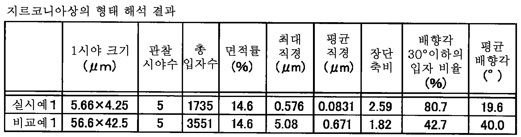
표 1의 지표와, 각 지표를 구한 수순은 하기와 같다.The index of Table 1 and the procedure for obtaining each index are as follows.
우선, 복합 세라믹스층을 찍은 반사 전자상 중에서, 제2 상 입자로 되는 지르코니아상만을 추출하기 위해, 당해 반사 전자상의 2치화를 행하였다. 그리고, 2치화한 화상(2치화 화상) 내에 있고, 대부분의 면적을 차지하는 크기 0.01㎛ 이상의 입자인 제2 상 입자(지르코니아상)의 수(총 입자수)와, 총 면적률을 산출하였다. 여기서, 입자의 크기란, 제2 상 입자의 2치화 화상의 픽셀수를 면적으로 환산하여 원 상당 직경을 산출한 것이다.First, in order to extract only the zirconia phase which is the second phase particle, among the reflection electron images obtained by taking the composite ceramics layer, the reflection electron phase was binarized. Then, the number (total number of particles) of the second phase particles (zirconia phase), which is a particle having a size of 0.01 µm or more and occupies most of the area in the binarized image (binarized image), and the total area ratio were calculated. Here, the size of the particle is calculated by converting the number of pixels of the binarized image of the second phase particle into an area to calculate a circle equivalent diameter.
마찬가지로, 제2 상 입자의 최대 직경과 평균 직경은, 개개의 제2 상 입자의 2치화 화상의 픽셀수를 면적으로 환산하여 원 상당 직경을 산출하여, 그 최댓값을 최대 직경으로 하고, 평균 직경은, 개개의 제2 상 입자의 원 상당 직경의 합계를 제2 상 입자의 총 입자수로 나눈 값으로 하였다.Similarly, the maximum diameter and the average diameter of the second phase particles are calculated by converting the number of pixels of the binarized image of each second phase particle into an area to calculate a circle equivalent diameter, the maximum value being the maximum diameter, and the average diameter , The sum of the circle equivalent diameters of the individual second phase particles was divided by the total number of particles of the second phase particles.
제2 상 입자의 애스펙트비나 배향성의 특징은, 2치화 화상에서 얻어진 개개의 제2 상 입자를 상당 타원으로 치환하여 통계 처리를 행하였다. 여기서 상당 타원이란, 대상으로 한 제2 상 입자의 단면과 0차, 1차, 2차 모멘트가 일치하는 타원을 말한다. 즉, 상당 타원이란 대상으로 한 제2 상 입자의 단면과 동일한 면적, 무게 중심을 갖고, 장축의 방향, 단축의 방향, 애스펙트비를 정량 평가하기 위해 정의한 타원이다.The characteristics of the aspect ratio and orientation of the second phase particles were statistically performed by substituting each second phase particle obtained in the binarized image with a significant ellipse. Here, an equivalent ellipse means an ellipse in which the cross-section of the target second phase particle coincides with the 0th, 1st, and 2nd moments. That is, an equivalent ellipse is an ellipse defined to have the same area and center of gravity as the cross section of the target second phase particle, and to quantitatively evaluate the direction of the long axis, the direction of the minor axis, and the aspect ratio.
본 발명의 제2 상 입자의 애스펙트비를 나타내는 「제2 상 입자의 긴 직경, 짧은 직경의 비의 평균」이란, 각각의 제2 상 입자를 타원으로 보고 판단하였을 때의 상당 타원 긴 직경과 상당 타원 짧은 직경의 비를 총합한 값을, 제2 상 입자의 총 입자수로 나눈 평균값이다. 표 1에서는 「장단축비」라고 표기한다.The "average of ratios of the long diameter and the short diameter of the second phase particle" which represents the aspect ratio of the second phase particle of the present invention is equivalent to the elliptical long diameter equivalent when judged by viewing each second phase particle as an ellipse It is an average value obtained by dividing the sum of the ratios of the oval short diameters by the total number of particles of the second phase particles. In Table 1, it is referred to as "long and shortened ratio".
표 1에서 배향각이란, 개개의 제2 상 입자의 상당 타원 긴 직경의 방향과, 세라믹 적층체의 기재층 및 복합 세라믹층의 접합면의 면 방향(즉 화상 수평 방향)이 이루는 각도를 ±180°표기로 나타냈을 때의 절댓값을 나타낸 것이며, 상당 타원의 대칭성으로부터 개개의 제2 상 입자의 배향각은 ±90°의 값을 취한다. 즉, 배향각의 각도가 작을수록, 상당 타원 긴 직경의 방향과, 접합면의 면 방향이 이루는 각은 작아지고, 편평한 제2 상 입자는 접합면 법선에 가까운 방향으로 찌부러져 있게 된다. 배향각이 45°보다 작을 때에는, 편평한 제2 상 입자가 접합면에 누워 있고, 배향각이 45°보다 클 때에는, 편평한 제2 상 입자가 접합면에 대하여 서 있음을 나타낸다. 표 1에서 「배향각 30°이하의 입자 비율」이란, 배향각 30°이하이며, 상당 타원 긴 직경의 방향이 접합면의 면 방향에 가까운 제2 상 입자의 총 입자수에 대한 비율을 나타낸다. 또한, 평균 배향각이란, 개개의 제2 상 입자의 배향각의 총합을, 제2 상 입자의 총 입자수로 나누었을 때의 평균값이다.In Table 1, the orientation angle is an angle of ±180 degrees between the direction of the corresponding elliptical long diameter of each second phase particle and the plane direction (ie, the horizontal direction of the image) of the bonding surfaces of the base layer and the composite ceramic layer of the ceramic laminate. The absolute value when expressed in ° is indicated, and the orientation angle of each second phase particle is ±90° from the symmetry of the significant ellipse. In other words, the smaller the angle of the alignment angle, the smaller the angle between the direction of the major ellipse and the plane direction of the bonding surface is, and the flat second phase particles are crushed in a direction close to the bonding surface normal. When the orientation angle is less than 45°, the flat second phase particles lie on the bonding surface, and when the orientation angle is larger than 45°, it indicates that the flat second phase particles are standing against the bonding surface. In Table 1, "orientation ratio of particles having an orientation angle of 30 degrees or less" means an orientation angle of 30 degrees or less, and indicates the ratio of the total number of particles of the second phase particle whose direction of a large elliptical long diameter is close to the plane direction of the bonding surface. Note that the average alignment angle is an average value obtained by dividing the sum of the alignment angles of the individual second phase particles by the total number of particles of the second phase particles.
실시예 1과 비교예 1에 있어서의 제1 상에 대한 제2 상 입자의 면적률은 모두 14.6%로 일치하였다. 그러나, 제2 상 입자의 형태는 크게 상이함을 알 수 있었다. 우선, 실시예 1과 비교예 1에서는, 제2 상 입자의 크기가 한 자릿수 가까이 상이하며, 실시예 1의 쪽이 비교예 1보다 평균 직경이 1/7 이하로 미세하였다. 애스펙트비는, 실시예 1의 쪽이 비교예 1보다 컸다.The area ratios of the second phase particles to the first phase in Example 1 and Comparative Example 1 were all 14.6%. However, it was found that the shape of the second phase particles differed greatly. First, in Example 1 and Comparative Example 1, the size of the second phase particles differed by a single digit, and the average diameter of Example 1 was smaller than that of Comparative Example 1 by 1/7 or less. The aspect ratio of Example 1 was larger than that of Comparative Example 1.
본 실시예에서 사용한 소프트웨어에서는, 제2 상 입자와 외접하는 직사각형의 세로(수직 페레(Feret) 직경) 및 가로(가위 직경(수평 페레 직경))의 길이의 최댓값을 해석 가능하지만, 수직 페레 직경 및 수평 페레 직경으로 평가한 장축의 길이, 단축의 길이, 그리고 이들의 비와, 본 발명 규정의 상당 타원의 긴 직경, 짧은 직경, 장단축비와의 차는 10% 이하였다.In the software used in this example, the maximum values of the lengths of the vertical (vertical Ferret diameter) and the horizontal (scissor diameter (horizontal Ferret diameter)) of the rectangle circumscribed with the second phase particle can be analyzed, but the vertical Feret diameter and The difference between the length of the long axis, the length of the short axis, and their ratios evaluated by the horizontal Ferre diameter, and the long diameter, short diameter, and long short axis ratio of the corresponding ellipse specified in the present invention was 10% or less.
비교예 1은, 제2 상 입자의 애스펙트비가 거의 1이었지만, 판 두께와 수직 방향에서 제2 상 입자끼리 연결되어 있었던 점에서 애스펙트비가 크게 나온 것이라고 생각되며, 개개의 제2 상 입자의 애스펙트비는 보다 차가 있다.In Comparative Example 1, the aspect ratio of the second phase particles was almost 1, but the aspect ratio of the second phase particles is considered to be large because the aspect ratios of the second phase particles are connected to each other in the vertical direction with the plate thickness. There are more cars.
배향각 30°이하의 제2 상 입자의 비율은, 실시예 1에서 80%를 초과하고 있어, 실시예 1의 제2 상 입자는 편평하며, 또한 기재층 및 복합 세라믹스층간의 접합면에 대하여, 당해 접합면의 법선 방향으로 찌부러져 배향되어 있음을 알 수 있었다. 또한, 실시예 1에 있어서 평균 배향각이 0°가 아니라, 약 20°로 되어 있는 것은, 제2 상 입자가 접합면과 평행인 층상의 조직을 나타내고 있지만, 완전히 평행이 아니라, 굴곡진 것 같이 요동하는 형태를 하고 있음을 반영하고 있다. 한편, 알루미나-지르코니아 소결체인 비교예 1의 평균 배향각은 40°이며, 완전히 랜덤한 방향을 향하고 있는 경우에 45°에 가까운 값이었다.The proportion of the second phase particles having an orientation angle of 30° or less exceeds 80% in Example 1, and the second phase particles of Example 1 are flat, and also with respect to the bonding surface between the base layer and the composite ceramic layer, It was found that the joint surface was crushed and oriented in the normal direction. In addition, in Example 1, the average orientation angle is not 0° but about 20°. Although the second phase particles show a layered structure parallel to the bonding surface, they are not completely parallel but curved. It reflects the form of fluctuation. On the other hand, the average orientation angle of Comparative Example 1 of an alumina-zirconia sintered chain was 40°, which was a value close to 45° when facing a completely random direction.
비교예 1의 판면에 대하여, 실시예 1과 마찬가지로 X선 광각 회절을 행한 결과, 실시예 1과 마찬가지로 제2 상 입자로 되는 지르코니아상은 정방정과 단사정이 혼재하고 있으며, 또한 모상인 α-Al2O3이 보였다. 실시예 1 및 비교예 1의 각각의 X선 회절 피크는, 변형이 없는 분말의 것과 거의 일치하거나 약간 고각측으로 시프트되어 있으며, 면 내 방향으로는 거의 변형이 없거나 약간 인장 응력이 작용하고 있다고 추정되었다.As a result of performing X-ray wide-angle diffraction on the plate surface of Comparative Example 1 as in Example 1, as in Example 1, the zirconia phase, which is the second phase particle, has a mixture of tetragonal and monoclinic crystals, and α-Al 2 which is a mother phase. O 3 was seen. Each of the X-ray diffraction peaks of Example 1 and Comparative Example 1 was almost identical to or slightly shifted toward the elevation angle of the powder without deformation, and it was estimated that there was little or little tensile stress in the in-plane direction. .
지르코니아상의 화상 해석과 마찬가지의 방법을 사용하여, 공극의 어두운 콘트라스트를 추출하도록 2치화하여 공극의 면적률을 측정하였다. 그 결과, 실시예의 재료에서 1시야의 최댓값이 4.91%, 평균 2.21%, 비교예의 재료에서 1시야의 최댓값이 5.09%, 평균 0.72%였다. 비교예에서 최댓값이 나온 시야는 큰 공극이 우발적으로 관찰 시야에 들어갔기 때문으로, 평균값을 산출할 때에는 제외하였다. 비교예의 시료는, 국소적으로 큰 공극이 있는 장소가 존재한다.Using the method similar to the image analysis on the zirconia, the area ratio of the pores was measured by binarization to extract the dark contrast of the pores. As a result, the maximum value of 1 field of view in the material of the example was 4.91%, the average of 2.21%, and the maximum value of 1 field of view in the material of the comparative example was 5.09% and average of 0.72%. In the comparative example, the field of view where the maximum value appeared was excluded when calculating the average value because the large pores accidentally entered the field of view. In the sample of the comparative example, a place with large pores locally exists.
이들 실시예 1 및 비교예 1의 각 복합 세라믹스층에 대하여, 비커스 경도를 측정하였다. 실시예 1 및 비교예 1의 각 복합 세라믹층의 표면을 약간 연마한 후, 100gf의 하중으로 다이아몬드 압자(이하, 간단히 압자라고도 칭함)를 압입 15초 유지한 후, 압자를 올리는 조작을 충분한 거리를 두고 반복하고, 얇게 카본 증착하여 FE-SEM으로 압흔과 크랙의 관찰을 행하였다.Vickers hardness was measured for each of the composite ceramic layers of Example 1 and Comparative Example 1. After the surface of each composite ceramic layer of Example 1 and Comparative Example 1 was slightly polished, the diamond indenter (hereinafter, also referred to simply as the indenter) was held for 15 seconds under a load of 100 gf, and then the operation of raising the indenter was sufficient distance. After repeating, carbon was deposited thinly to observe indentations and cracks with FE-SEM.
비커스 경도는, 모두 16GPa±2GPa의 범위에 들어 있었다. 한편, 압자의 정상부로부터는 실시예 1 및 비교예 1의 어느 시료에도 압자 대각선의 방향으로 크랙의 진전이 보였지만, 크랙의 길이는 비교예 1보다 실시예 1의 쪽이 작았다. 실시예 1의 파괴 인성이 비교예 1보다 높음을 알 수 있었다.Vickers hardness was all in the range of 16 GPa±2 GPa. On the other hand, from the top of the indenter, cracks were seen in the diagonal direction of the indenter in any of the samples of Example 1 and Comparative Example 1, but the length of the crack was smaller in Example 1 than in Comparative Example 1. It was found that the fracture toughness of Example 1 was higher than that of Comparative Example 1.
한편, 실시예 1의 접합면과 수직인 단면과, 비교예 1의 두께 방향의 단면에 대해서도 경도 측정을 실시하였다. 실시예 1 및 비교예 1의 각각의 시료를 연마용 매립 수지에 매립하여 그 단면을 경면 연마하고, 압자를 판 두께 방향 중앙으로 압입하여, 측정을 행하였다. 판 두께 방향(실시예 1에서는 접합면과 수직 방향)과, 판면에 대하여 평행인 판면 평행 방향(실시예 1에서는 접합면과 평행 방향)으로 하중을 70gf의 하중으로 압자를 압입하여 15초 유지한 후, 압자를 올리는 조작을 충분한 거리를 두고 반복하였다. 압자의 방향은 연마면 상방에서 보았을 때의 대략 정사각형의 형태로 되는 비커스 압흔의 정점을 연결하는 직교하는 대각선이 막 두께 방향과 수직과 평행으로 되도록 하였다. 그 후, 연마면에 얇게 카본 증착하여 FE-SEM으로 압흔과 크랙의 관찰을 행하였다.On the other hand, hardness measurement was also performed on the cross section perpendicular to the bonding surface of Example 1 and the cross section of the thickness direction of Comparative Example 1. Each sample of Example 1 and Comparative Example 1 was embedded in a polishing buried resin, the cross-section thereof was mirror-polished, and the indenter was pressed into the center of the plate thickness direction to measure. In the plate thickness direction (direction perpendicular to the joint surface in Example 1) and parallel to the plate surface in the parallel direction (parallel direction to the joint surface in Example 1), the indenter was pressed with a load of 70 gf and held for 15 seconds. Thereafter, the operation of raising the indenter was repeated with a sufficient distance. The direction of the indenter was such that an orthogonal diagonal line connecting the apex of the Vickers indentation in the form of a substantially square when viewed from above the polishing surface was parallel to the film thickness direction and perpendicular to the direction. Thereafter, carbon was thinly deposited on the polished surface to observe indentations and cracks with FE-SEM.
판면 평행 방향의 크랙은, 실시예 1, 비교예 1 모두 제2 상 입자 계면을 따라 발생하였지만, 실시예 1의 쪽이 비교예 1보다 대체로 폭이 작았다. 실시예 1 및 비교예 1의 어느 시료에서도 제2 상 입자에 의해 크랙의 우회는 보였지만, 비교예 1에서는, 크랙이 제2 상 입자의 계면을 따라 진행하고 있거나, 크랙이 제2 상 입자를 관통하여 진전하는 모습이 보였다. 한편, 실시예 1에 대하여 크랙과 조직의 관계를 조사하면, 제2 상 입자, 또는 그 근방에서 크랙의 방향이 구부러져 우회하고 있는 빈도가 높음이 확인되었다. 또한, 실시예 1에서는, 접합면과 평행인 평행 방향의 크랙을 확인한바, 도 4에 보이는 제2 상 입자가 만곡되어 이어져 있는 굴곡을 따라 크랙이 구부러져 있음이 관찰되었다.Cracks in the parallel direction of the plate surface were generated along the second phase particle interface in both Example 1 and Comparative Example 1, but the width of Example 1 was generally smaller than that of Comparative Example 1. Cracks were bypassed by the second phase particles in any of the samples of Example 1 and Comparative Example 1, but in Comparative Example 1, cracks were progressing along the interface of the second phase particles, or cracks penetrated the second phase particles. And progress was seen. On the other hand, when the relationship between the crack and the tissue was examined for Example 1, it was confirmed that the second phase particles, or the direction of the crack in the vicinity of the crack, were bent and bypassed. In addition, in Example 1, when the crack in the parallel direction parallel to the bonding surface was confirmed, it was observed that the second phase particles shown in FIG. 4 were curved and the cracks were bent along a curved line.
한편, 판 두께 방향에 관해서는, 비교예 1의 시료에서는 압자의 정상부로부터, 압적 대각선 방향, 즉 판 두께 방향으로 수평 방향과 동일 정도의 크랙이 진전되어 있음이 관찰되었지만, 실시예 1에서는 크랙은 전혀 보이지 않았다. 이로부터, 본 발명의 실시예 1에서는, 접합면과 수직 방향에 대한 파괴 인성이 매우 우수함이 확인되었다.On the other hand, with respect to the plate thickness direction, in the sample of Comparative Example 1, it was observed that cracks of the same extent as the horizontal direction were observed from the top of the indenter, in the stacking diagonal direction, that is, in the plate thickness direction. It was not visible at all. From this, in Example 1 of the present invention, it was confirmed that the fracture toughness with respect to the bonding surface and the vertical direction is very excellent.
실시예 1에서 대채로 크랙의 확대가 작았던 것은, 제2 상 입자의 면적률(체적률)이 동일해도, 진전하는 크랙 선단과, 제2 상 입자가 근접할 확률이 높았기 때문이다. 즉, 알루미나상(제1 상)과 지르코니아상(제2 상 입자)이 혼재됨에 따른 응력장에 의해 크랙의 진전 방향이 바뀔 기회가 많았기 때문이다. 또한, 실시예 1은, (i) 지르코니아상의 상변태 온도를 통과하지 않는 프로세스로 제조되며, 또한 단사정 원료를 사용하였음에도 불구하고, 지르코니아상의 상변태에 수반하는 체적 변화에 의한 큰 크랙의 발생을 방지할 수 있었던 것, (ii) 또한 이트리아, 세리아, 칼시아, 마그네시아 등의 안정화제가 없어도 실온에서 정방정의 지르코니아상을 도입할 수 있었기 때문에, 응력 유기 변태됨으로써 크랙 선단의 에너지를 흡수하는 기구를 일으키게 할 수 있었던 것도 파괴 인성의 향상에 기여한 것이라고 생각된다.In Example 1, the crack expansion was largely large because the probability of the advancing crack tip and the second phase particle approaching was high even if the area ratio (volume ratio) of the second phase particles was the same. That is, there were many opportunities for the crack propagation direction to change due to the stress field caused by the mixing of the alumina phase (first phase) and zirconia phase (second phase particles). In addition, Example 1, (i) is prepared by a process that does not pass the phase transformation temperature of the zirconia phase, and despite the use of a monoclinic raw material, to prevent the occurrence of large cracks due to the volume change accompanying the phase transformation of the zirconia phase What could be done, (ii) also, it was possible to introduce a tetragonal zirconia phase at room temperature without stabilizers such as yttria, ceria, calcia, magnesia, etc., resulting in a mechanism that absorbs the energy of the crack tip by stress induced transformation. It is thought that it was possible to contribute to the improvement of fracture toughness.
한편, 접합면과 수직 방향에 있어서의 파괴 인성이 비교적 등방적인 비교예 1(알루미나-지르코니아 소결체)과 비교하여, 실시예 1이 접합면과 수직 방향에 있어서의 파괴 인성이 매우 우수하였던 것은, (i) 지르코니아상의 제2 상 입자뿐만 아니라, 제1 상의 알루미나상의 결정립도 편평하며, 접합면에 대하여 수직 방향에 있어서 결정립계를 진전하는 크랙이 크게 우회하는 효과와, (ii) 면 내 방향으로 특히 강한 압축 응력을 갖고 있기 때문에, 크랙 선단의 인장 응력이 이 압축 응력과 상쇄되어, 균열 선단 개구 에너지가 작아진 효과 때문이다.On the other hand, compared with Comparative Example 1 (alumina-zirconia sintered body) in which the fracture toughness in the perpendicular direction to the bonding surface was relatively isotropic, Example 1 had very good fracture toughness in the vertical direction to the bonding surface, ( i) not only the second phase particles of the zirconia phase, but also the grains of the alumina phase of the first phase are flat, and the effect of largely bypassing cracks advancing grain boundaries in the direction perpendicular to the bonding surface, and (ii) particularly strong compression in the in-plane direction It is because of the effect that the tensile stress at the crack tip is offset from this compressive stress because of the stress, and the opening energy at the crack tip is reduced.
실시예의 시료에 대하여, 막압 방향으로 절연 파괴 전계를 측정하였다. JISC2110(2010)의 도 1의 (c)에 있어서, 상부 전극을 직경 12.5mm의 구(球)전극으로 변경한 조합으로 행하였다. 측정은 직류유 중에서 행하였다. 그 결과, 3점의 평균적인 절연 파괴 전계값은 270×106V/m였다. 일반적인 알루미나계 소결체의 절연 파괴 전계값은 10 내지 18×106V/m라는 점에서, 그 10배 이상의 절연 성능을 가짐을 알 수 있었다.About the sample of the example, the dielectric breakdown electric field was measured in the film pressure direction. In FIG. 1(c) of JISC2110 (2010), the upper electrode was formed by a combination of spherical electrodes having a diameter of 12.5 mm. The measurement was performed in DC oil. As a result, the average dielectric breakdown electric field value of three points was 270×10 6 V/m. Since the breakdown electric field value of a typical alumina-based sintered body is 10 to 18×10 6 V/m, it was found that it has an insulation performance of 10 times or more.
이상과 같이, 제2 상 입자가 미세하며 특정 방향으로 요동을 갖고 배열된 복합 세라믹스층을 기재층에 적층한 본 발명의 세라믹스 적층체는, 우수한 기계 특성을 나타냄이 시사되었다. 이러한 세라믹스 적층체는, 기계적 특성이 필요한 반송 롤 등의 구조체에 활용할 수 있다는 것 외에, 특히 기재층이 구리나 알루미늄 등의 열팽창 계수가 크게 상이한 금속과, 세라믹스층을 일체화시키는 경우가 많은 세라믹스 절연 기판으로서도 사용할 수 있다. 본 발명의 세라믹 적층체를 세라믹 절연 기판으로서 사용한 경우에는, 복합 세라믹스층의 기계적 특성의 향상에 의해, 복합 세라믹스층의 두께를 종래보다 점점 작게 하면서, 방열성이 높은 세라믹스 절연 기판을 실현할 수 있다. 또한, 본 발명의 세라믹스 적층체는, 복합 세라믹스의 특수한 조직 구조에 의한 효과와 적층체 제조 시에 발생하는 세라믹스에 잔류하는 인장 응력이 작아지는 효과에 의해 반복적인 열 사이클에 의한 인장 열응력에 대한 수명을 높여, 우수한 내구성을 갖는 세라믹스 절연 기판을 실현할 수 있다.As described above, it was suggested that the ceramics laminate of the present invention, in which the second phase particles were fine and the composite ceramics layers arranged with fluctuations in a specific direction were stacked on the base layer, exhibited excellent mechanical properties. In addition to being able to be used for structures such as conveyance rolls that require mechanical properties, such ceramics laminates are particularly useful for integrating ceramic layers with metals having significantly different coefficients of thermal expansion, such as copper or aluminum, and ceramic layers. It can also be used as. When the ceramic laminate of the present invention is used as a ceramic insulating substrate, by improving the mechanical properties of the composite ceramic layer, it is possible to realize a ceramic insulating substrate with high heat dissipation, while gradually reducing the thickness of the composite ceramic layer. In addition, the ceramics laminate of the present invention is for the tensile thermal stress caused by repetitive thermal cycles due to the effect of the special structure of the composite ceramics and the effect of reducing the tensile stress remaining in the ceramics generated at the time of manufacturing the laminate. By increasing the life, it is possible to realize a ceramic insulating substrate having excellent durability.
(실시예 2)(Example 2)
2종류의 원료를 사용하여, 지르코니아를 주체로 한 알루미나-지르코니아 세라믹스를 시작하였다. 하나는, 시판 중인 알루미나 분말과 지르코니아 분말을 혼합한 원료를 에어로졸 디포지션법으로 성막한 재료(시료 3)와 시판 중인 알루미나-지르코니아 혼합 분말을 원료로 하여 에어로졸 디포지션법으로 성막한 재료(시료 4)이다.Using two types of raw materials, alumina-zirconia ceramics mainly based on zirconia were started. One is a material formed by mixing a commercially available alumina powder and a zirconia powder with an aerosol deposition method (Sample 3) and a commercially available alumina-zirconia mixed powder as a raw material formed by an aerosol deposition method (Sample 4) )to be.
양쪽 원료 모두 알루미나를 20질량% 포함하는 지르코니아를 주체로 하고, 지르코니아의 안정화를 위해 이트리아를 함유한 것이다.Both raw materials mainly contain zirconia containing 20% by mass of alumina, and contain yttria for stabilization of zirconia.
시료 3의 원료 분말은, 실시예 1에 사용한 알루미나 분말과 부분 안정화한 지르코니아 전융 분말이다. 지르코니아 전융 분말은 부분 안정화된 것이며, 지르코니아에 대하여 5.5질량%의 이트리아를 포함한다. 중심 입자 직경(메디안 직경)은 3.5㎛였다. 이 지르코니아와 알루미나를 지르코니아가 20질량%로 되도록 칭량하여, 테플론제의 볼 밀 포트에 넣고, 직경 10mm 알루미나 볼, 에탄올과 함께 10시간 혼련하였다. 취출한 분말을 충분히 건조하였다. 이 분말을 수분산액에 분산시켜 입도 측정을 행한바, 메디안 직경은 0.9㎛였다. 알루미나-지르코니아 원료 분말 총량에 대한 이트리아의 함유량은 4.4질량%로 계산된다.The raw material powder of
한편, 시료 4의 원료에 사용한 시판 중인 알루미나-지르코니아 분말은, 지르코니아와 알루미나의 비율은 시료 3의 원료 분말과 동일하며, 지르코니아는 3mol%의 이트리아를 함유하고, 마찬가지로 부분 안정화되어 있지만, 지르코니아는 가수분해를 이용한 화학적 방법으로 제조되었으며, 1차 입자 직경은 대략 0.09㎛로 작고, 애스펙트비도 작다.On the other hand, the commercially available alumina-zirconia powder used for the raw material of
이들 분말을 에어로졸 디포지션법으로 동일한 조건에서 성막하였다. 기재는 50×50×5mm의 Cr-Mo강을 사용하였다. 이 기판 상에 충분히 건조한 혼합 원료 분말을 에어로졸실에 투입하고, 에어로졸실 내를 진동시키면서 10L/min.의 질소 가스를 에어로졸실 내로 보내 에어로졸을 형성하였다. 이어서, 0.3kPa로 감압한 성막실에 압력차를 이용하여 에어로졸을 이송하고, 개구 사이즈가 X 방향 0.3mm, Y 방향 5mm의 노즐로부터, 수평 구동하는 기재층으로 되는 Cr-Mo 강판에 분사하여 성막을 행하였다.These powders were formed under the same conditions by aerosol deposition. Cr-Mo steel of 50 x 50 x 5 mm was used as the substrate. On the substrate, a sufficiently dry mixed raw material powder was introduced into the aerosol chamber, and nitrogen gas at 10 L/min. was sent into the aerosol chamber while vibrating in the aerosol chamber to form an aerosol. Subsequently, the aerosol is transferred to the film formation chamber decompressed to 0.3 kPa using a pressure difference, and the film is formed by spraying a Cr-Mo steel sheet serving as a substrate layer to be horizontally driven from nozzles having an opening size of 0.3 mm in the X direction and 5 mm in the Y direction. Was done.
기재의 구동 속도는 X 방향으로 1mm/s로 30mm 구동시킨 후, 구동 방향을 역전시켜 30mm 구동하고, 다시 구동 방향을 역전시키는 것을 반복하여, 5×30mm의 영역에 두께 10㎛의 막을 성막하고, Cr-Mo강을 기재로 하는 알루미나-지르코니아 적층체를 제작하였다.The driving speed of the substrate was driven 30 mm at 1 mm/s in the X direction, and then the driving direction was reversed to drive 30 mm, and the driving direction was reversed again to form a film having a thickness of 10 μm in an area of 5×30 mm, An alumina-zirconia laminate based on Cr-Mo steel was produced.
이와 같이 하여 제작한 적층체, 시료 3과 시료 4의 성막면에 대하여 X선 해석과 라만 분광법에 의해 구성하는 상의 동정을 행한바, 모두 알루미나상과 지르코니아상으로 구성되어 있음을 알 수 있었다. 알루미나상의 피크는 α-Al2O3과 일치하였다. 한편, 지르코니아상의 피크는, 모두 정방정, 입방정이 존재함을 알 수 있었다.When the thus-formed laminate, the film formation surfaces of
이어서, 성막 영역의 중앙 부분을 Y 방향으로 막면과 수직으로 절단하고, 수지에 매립한 후, 경면 연마, 경면 처리를 행하여, 주사형 전자 현미경의 2차 전자상에 의해 조직을 관찰하였다. 가속 전압 5kV로 배율 20000배의 2차 전자상을 장소를 옮겨 10시야 측정하여, 최댓값과 평균값을 산출하였다. 본 실시예의 시료에서는 제2 상은 알루미나이며, 화상 처리에서, 알루미나 입자와 그 이외의 지르코니아 모상, 공극을 분리하여, 알루미나 입자의 형태 해석을 행하였다. 또한, 동일한 화상을 사용하여 공극과 그 이외의 알루미나 입자, 지르코니아 모상을 분리하여 공극의 면적률을 산출하였다. 알루미나 입자는 0.01㎛ 이하의 입자도 보였지만, 0.01㎛ 이상의 입자가 면적률의 대부분을 차지하였다. 10시야의 알루미나 입자의 총수는 5000개 이상으로 된다. 알루미나 입자의 형태의 해석 결과를 표 2에 나타내었다. 사용한 화상 해석 소프트웨어, 입자의 형태를 나타내는 각각의 지표의 정의는 실시예 1과 동일하다.Subsequently, the central portion of the film formation region was cut perpendicular to the film surface in the Y direction, embedded in the resin, and then subjected to mirror polishing and mirror treatment to observe the structure by a secondary electron image of a scanning electron microscope. The secondary electronic image at a magnification of 20000 times at an acceleration voltage of 5 kV was moved to a location and measured at 10 o'clock to calculate the maximum and average values. In the sample of this example, the second phase was alumina, and in image processing, the alumina particles and other zirconia mother phases and voids were separated to analyze the shape of the alumina particles. In addition, the voids, other alumina particles and zirconia mother phases were separated using the same image to calculate the area ratio of the voids. The alumina particles also showed particles smaller than 0.01 µm, but particles larger than 0.01 µm occupied most of the area ratio. The total number of alumina particles at 10 o'clock is 5000 or more. Table 2 shows the analysis results of the alumina particles. The image analysis software used and the definition of each index indicating the shape of the particles are the same as in Example 1.

시료 3에 있어서의 알루미나 입자는 크게 편평하며, 장단축비가 커서 본 발명의 조직 규정을 만족하고 있었다. 한편, 시료 4의 알루미나 입자의 크기는 본 발명의 규정을 만족하고 있었지만, 시료 3의 공극의 면적률은 0.69%였던 것에 비해, 시료 4의 공극의 면적률은 9.8%로 컸다. 또한, 시료 4는, 장단축비가 규정의 범위 밖이었다. 또한, 시료 4의 배향각 30°이하의 제2 상 입자 비율 및 평균 배향각은, 바람직한 범위 밖이었다. 모상인 지르코니아상의 결정립도 시료 3에서는 알루미나 입자와 동등한 크기이며 편평하였지만, 시료 4에서는, 개개의 결정립의 크기는 작았지만, 편평도가 작았다. 또한, 지르코니아 원료 입자의 1차 입자가 미세하였음에도 불구하고 지르코니아 모상은 공극이 많고 다공성이었다.The alumina particles in
시료 4의 알루미나 입자의 최대 직경이 큰 것은, 치밀한 막 상에서는 통상 변형될 수 없어 성막되지 않고 떨어져 버리는 에어로졸 중의 알루미나 원료 입자가, 막이 변형 또는 파괴되기 쉬워짐으로써 물리적으로 매립되는 형태로 막 내에 남겨져 버린 것이라고 생각된다. 그 원인은, 막이 다공성이라는 점, 및 입자의 변형이 작고, 막을 구성하는 입자간의 결합력이 작기 때문이다. 또한, 간단히 혼입된 입자와 그 주위의 입자의 계면에서의 결합력이 약하고, 이러한 입자의 주위에는, 변형이나 파괴 등으로 큰 공극이 형성되기 때문에, 기계적인 특성을 저하시키는 요인이 된다.The maximum diameter of the alumina particles of
실제로, 시료 3과 시료 4의 막을 위에서 핀셋으로 깍아내도록 강하게 문지른바, 시료 3은 막 내, 그리고 막과 기재의 계면에서 전혀 박리되는 일이 없었지만, 시료 4의 막은 막 내에서 파괴되어 깍아내어졌다. 시료 3과 시료 4의 차이는, 상술한 막의 조직 형태의 차에 기인한다.Indeed, when the membranes of
(실시예 3)(Example 3)
조성과 결정 구조가 상이한 지르코니아를 사용하여, 알루미나-지르코니아 세라믹스 적층체를 제작하고, 기계적 특성과 전기적 특성을 평가하였다.Alumina-zirconia ceramics laminates were prepared using zirconia having different compositions and crystal structures, and mechanical and electrical properties were evaluated.
시료 5의 원료 분말은, 지르코니아의 함유량이 12질량%인 알루미나-지르코니아 혼합 분말이다. 원료 혼합 분말의 혼련은 볼 밀을 이용하였다. 원료인 알루미나는, 실시예 1에 사용한 것과 동일하다. 또한, 지르코니아는, 성분, 불순물량은 실시예 1과 동일한 안정화 원소를 함유시키지 않은 전융 분말이지만, 입경은 메디안 직경으로 1.1㎛, 최대 직경으로 11㎛인 미분쇄된 시판품을 이용하였다.The raw material powder of
이들 원료 분말을 지르코니아의 함유량이 12질량%, 알루미나의 함유량이 88질량%로 되도록 칭량하였다. 직경 10mm, 순도 99.9질량% 이상의 알루미나 볼과 함께 수지제 포트에 넣고, 또한 분체가 가려질 정도의 에탄올을 수지제 포트 내에 넣어, 습식으로 20시간 혼련, 분쇄, 건조시키고, 이것을 φ250㎛의 체로 걸러, 얻어진 분말을 혼합 원료 분말로 하였다. 혼합 원료 분말의 메디안 직경은 0.48㎛, 최대 직경은 3.8㎛였다.These raw powders were weighed so that the zirconia content was 12% by mass and the alumina content was 88% by mass. Alumina balls with a diameter of 10 mm and a purity of 99.9 mass% or more were placed in a resin pot, and ethanol of the degree to which the powder was covered was put in a resin pot, and kneaded, pulverized and dried for 20 hours by wet, and filtered through a sieve of φ250 μm. , The obtained powder was used as a mixed raw material powder. The median diameter of the mixed raw material powder was 0.48 µm and the maximum diameter was 3.8 µm.
이들 분말을 에어로졸 디포지션법으로 동일한 조건에서 성막하였다. 기재는 40×40×1mm의 무산소 동판을 사용하였다. 이 기판 상에 충분히 건조한 혼합 원료 분말을 에어로졸실에 투입하고, 에어로졸실 내를 진동시키면서 8L/min.의 질소 가스를 에어로졸실 내로 보내 에어로졸을 형성하였다. 이어서, 0.3kPa로 감압한 성막실에 압력차를 이용하여 에어로졸을 이송하고, 개구 사이즈가 X 방향 0.3mm, Y 방향 5mm의 노즐로부터, 수평 구동하는 기재층으로 되는 Cu판에 분사하여 성막을 행하였다.These powders were formed under the same conditions by aerosol deposition. As the substrate, an oxygen-free copper plate of 40×40×1 mm was used. On the substrate, a sufficiently dry mixed raw material powder was introduced into the aerosol chamber, and 8 L/min. of nitrogen gas was sent into the aerosol chamber while vibrating in the aerosol chamber to form an aerosol. Subsequently, an aerosol is transferred to the film formation chamber decompressed to 0.3 kPa using a pressure difference, and the film is formed by spraying from a nozzle having an opening size of 0.3 mm in the X direction and 5 mm in the Y direction to a Cu plate serving as a base layer to be horizontally driven. Did.
기재의 구동 속도는 X 방향으로 0.5mm/s로 30mm 구동시킨 후, 구동 방향을 역전시켜 30mm 구동하고, 다시 구동 방향을 역전시키는 것을 반복하여, 5×30mm의 영역에 두께 80㎛의 막을 성막하였다.The driving speed of the substrate was driven 30 mm at 0.5 mm/s in the X direction, the driving direction was reversed to drive 30 mm, and the driving direction was reversed again to form a film having a thickness of 80 μm in a 5×30 mm region. .
시료 6의 원료 분말은, 지르코니아의 함유량이 20질량%인 알루미나-지르코니아 혼합 분말이다. 원료 혼합 분말의 혼련은 볼 밀을 이용하였다. 원료인 알루미나는, 실시예 1에 사용한 것과 동일하다. 또한, 지르코니아는, 5.5%의 이트리아를 함유한 시판 중인 부분 안정화 지르코니아이며, 입경은 메디안 직경으로 1.1㎛, 최대 직경으로 13㎛인 미세한 시판품을 이용하였다.The raw material powder of Sample 6 is an alumina-zirconia mixed powder having a zirconia content of 20% by mass. A ball mill was used for kneading the raw material mixed powder. The raw material alumina was the same as that used in Example 1. Further, zirconia is a commercially available partially stabilized zirconia containing 5.5% yttria, and a fine commercial product having a median diameter of 1.1 µm and a maximum diameter of 13 µm was used.
이들 원료 분말을 지르코니아의 함유량이 20질량%, 알루미나의 함유량이 80질량%로 되도록 칭량하였다. 이들 원료 분말을 직경 10mm, 순도 99.9질량% 이상의 알루미나 볼과 함께 수지제 포트에 넣고, 또한 분체가 가려질 정도의 에탄올을 수지제 포트 내에 넣어, 습식으로 20시간 혼련, 분쇄, 건조시키고, 이것을 φ250㎛의 체로 걸러, 얻어진 분말을 혼합 원료 분말로 하였다. 혼합 원료 분말의 메디안 직경은 0.63㎛, 최대 직경은 5.4㎛였다. 알루미나-지르코니아 원료 분말 중의 이트리아의 함유량은 1.1%로 계산된다.These raw powders were weighed so that the zirconia content was 20% by mass and the alumina content was 80% by mass. These raw powders were placed in a resin pot with an alumina ball having a diameter of 10 mm and a purity of 99.9 mass% or more, and ethanol of the degree to which the powder was covered was placed in a resin pot, and kneaded, pulverized and dried for 20 hours wet, and this was φ250. It was sieved through a µm sieve to obtain the resulting powder as a mixed raw material powder. The median diameter of the mixed raw material powder was 0.63 µm and the maximum diameter was 5.4 µm. The yttria content in the alumina-zirconia raw material powder is calculated to be 1.1%.
이 분말을 에어로졸 디포지션법으로 동일한 조건에서 성막하였다. 기재는 시료 5와 동일한 40×40×1mm의 무산소 동판을 사용하였다. 이 기판 상에 충분히 건조한 혼합 원료 분말을 에어로졸실에 투입하고, 에어로졸실 내를 진동시키면서 12L/min.의 질소 가스를 에어로졸실 내로 보내 에어로졸을 형성하였다. 이어서, 0.04kPa로 감압한 성막실에 압력차를 이용하여 에어로졸을 이송하고, 개구 사이즈가 X 방향 0.3mm, Y 방향 5mm의 노즐로부터, 수평 구동하는 기재층으로 되는 Cu판에 분사하여 성막을 행하였다.This powder was formed under the same conditions by an aerosol deposition method. As the substrate, an oxygen-free copper plate of 40×40×1 mm, which was the same as
기재의 구동 속도는 X 방향으로 0.5mm/s로 30mm 구동시킨 후, 구동 방향을 역전시켜 30mm 구동하고, 다시 구동 방향을 역전시키는 것을 반복하여, 5×30mm의 영역에 두께 80㎛의 막을 성막하였다.The driving speed of the substrate was driven 30 mm at 0.5 mm/s in the X direction, the driving direction was reversed to drive 30 mm, and the driving direction was reversed again to form a film having a thickness of 80 μm in a 5×30 mm region. .
시료 7의 원료 분말은, 지르코니아의 함유량이 50질량%인 알루미나-지르코니아 혼합 분말이다. 원료 혼합 분말의 혼련은 볼 밀을 이용하였다. 원료인 알루미나는, 실시예 1에 사용한 것과 동일하다. 또한, 지르코니아는, 8.07%의 이트리아를 함유한 시판 중인 안정화 지르코니아이며, 입경은 메디안 직경으로 1.7㎛, 최대 직경으로 13㎛의 미세한 시판품을 이용하였다.The raw material powder of
이들 원료 분말을 알루미나, 지르코니아 각각의 함유량이 50질량%로 되도록 칭량하여, 동일한 중량이며 직경 10mm, 순도 99.9질량% 이상의 알루미나 볼과 함께 수지제 포트에 넣고, 또한 분체가 가려질 정도의 에탄올을 수지제 포트 내에 넣어, 습식으로 20시간 혼련, 분쇄, 건조시키고, 이것을 φ250㎛의 체로 걸러, 얻어진 분말을 혼합 원료 분말로 하였다. 혼합 원료 분말의 메디안 직경은 0.72㎛, 최대 직경은 5.4㎛였다. 알루미나-지르코니아 원료 분말 중의 이트리아의 함유량은 4.04%로 계산된다.These raw powders were weighed so that the content of each of alumina and zirconia was 50% by mass, placed in a resin pot with alumina balls having a diameter of 10 mm and a purity of 99.9% by mass or more, and further ethanol to the extent that the powder was covered. It was put in a pot and kneaded, pulverized, and dried for 20 hours wet, and this was sieved through a φ250 μm sieve to obtain the resulting powder as a mixed raw material powder. The median diameter of the mixed raw material powder was 0.72 µm and the maximum diameter was 5.4 µm. The yttria content in the alumina-zirconia raw material powder is calculated to be 4.04%.
이 분말을 에어로졸 디포지션법으로 동일한 조건에서 성막하였다. 기재는 시료 5와 동일한 40×40×1mm의 무산소 동판을 사용하였다. 이 기판 상에 충분히 건조한 혼합 원료 분말을 에어로졸실에 투입하고, 에어로졸실 내를 진동시키면서 10L/min.의 질소 가스를 에어로졸실 내로 보내 에어로졸을 형성하였다. 이어서, 0.1kPa로 감압한 성막실에 압력차를 이용하여 에어로졸을 이송하고, 개구 사이즈가 X 방향 0.3mm, Y 방향 5mm의 노즐로부터, 수평 구동하는 기재층으로 되는 Cu판에 분사하여 성막을 행하였다.This powder was formed under the same conditions by an aerosol deposition method. As the substrate, an oxygen-free copper plate of 40×40×1 mm, which was the same as
기재의 구동 속도는 X 방향으로 0.5mm/s로 30mm 구동시킨 후, 구동 방향을 역전시켜 30mm 구동하고, 다시 구동 방향을 역전시키는 것을 반복하여, 5×30mm의 영역에 두께 80㎛의 막을 성막하고, 구리를 기재로 하는 알루미나-지르코니아 적층체를 제작하였다.The driving speed of the substrate was driven 30 mm at 0.5 mm/s in the X direction, followed by reversing the driving direction to drive 30 mm, and then reversing the driving direction again to form a film of 80 µm thick in a 5×30 mm region. , Alumina-zirconia laminate based on copper was produced.
이상과 같이 하여 제작한 시료 5 내지 7의 시료에 대하여, X선 회절과 라만 분광법에 의해 구성하는 상의 동정을 행한바, 모두 알루미나상과 지르코니아상으로 구성되어 있음을 알 수 있었다. 알루미나상의 피크는 α-Al2O3과 일치하였다. 한편, 지르코니아상의 피크는 각각 상이하였다. 시료 5에서는 단사정과 정방정을 함유하였다. 시료 6 및 시료 7에서는 정방정, 입방정을 주체로 하고 약간 단사정을 함유하였다.When the samples of the
또한, 각각의 시료 중의 막면을 형광 X선으로 분석한바, 시료 5에서는 이트륨을 포함한 희토류 원소는 검출되지 않고, 이트륨과 세륨의 총량은 기재의 구리를 제외하고 0.1질량% 이하임이 확인되었다.In addition, when the film surface in each sample was analyzed by fluorescent X-rays, it was confirmed that in
이어서, 성막 영역의 중앙 부분을 Y 방향으로 막면과 수직으로 절단하고, 수지에 매립한 후, 경면 연마, 경면 처리를 행하여, 주사형 전자 현미경의 2차 전자상에 의해 조직을 관찰하였다. 가속 전압 5kV로 배율 20000배의 2차 전자상을 장소를 옮겨 10시야 측정하여, 최댓값과 평균값을 산출하였다. 본 실시예의 시료에서는 제2 상은 지르코니아 입자이며, 화상 처리에서, 지르코니아 입자와 그 이외의 알루미나 모상, 공극을 분리하여 지르코니아 입자의 형태 해석을 행하였다. 또한, 동일한 화상을 사용하여 공극과 그 이외의 지르코니아 입자, 알루미나 모상을 분리하여, 공극의 면적률을 산출하였다. 지르코니아 입자는, 0.01㎛ 이하의 입자도 보였지만, 0.01㎛ 이상의 입자가 면적률의 대부분을 차지하였다. 10시야의 지르코니아 입자의 총수는 3000개 이상으로 된다. 지르코니아 입자의 형태의 해석 결과를 표 3에 나타내었다. 사용한 화상 해석 소프트웨어, 입자의 형태를 나타내는 각각의 지표의 정의는 실시예 1, 실시예 2와 동일하다. 또한, 조직 해석에 사용한 화상의 일례로서 시료 6의 2차 전자상을 도 5에 도시하였다. 도 5에 있어서 상하 방향(반사 전자상의 캡션이 배열되어 있는 방향에 수직인 방향)이 막 두께 방향이다. 시료 4, 6도 지르코니아상의 면적률의 차이는 있지만, 마찬가지로 미세한 조직을 나타내고 있었다.Subsequently, the central portion of the film formation region was cut perpendicular to the film surface in the Y direction, embedded in the resin, and then subjected to mirror polishing and mirror treatment to observe the structure by a secondary electron image of a scanning electron microscope. The secondary electronic image at a magnification of 20000 times at an acceleration voltage of 5 kV was moved to a location and measured at 10 o'clock to calculate the maximum and average values. In the sample of this example, the second phase is zirconia particles, and in image processing, the zirconia particles, other alumina matrix, and pores were separated to analyze the shape of the zirconia particles. In addition, the voids, other zirconia particles and alumina matrix were separated using the same image to calculate the area ratio of the voids. As for the zirconia particles, particles of 0.01 µm or less were also seen, but particles of 0.01 µm or more occupied most of the area ratio. The total number of zirconia particles at 10 o'clock is more than 3000. Table 3 shows the analysis results of the zirconia particles. The image analysis software used and the definition of each index indicating the shape of the particles are the same as in Example 1 and Example 2. 5 is a secondary electron image of Sample 6 as an example of an image used for tissue analysis. In Fig. 5, the vertical direction (the direction perpendicular to the direction in which the captions of the reflective electrons are arranged) is the film thickness direction.
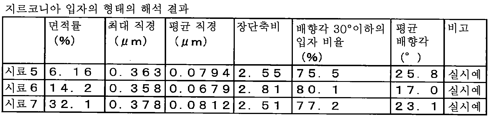
시료 5 내지 시료 7의 막은 모두 알루미나를 모상으로 하고 지르코니아상을 제2 상으로 한 미세한 결정립으로 구성되어 있었다. 또한, 반사 전자상으로 알루미나 모상의 결정립을 판별할 수 있는 바, 지르코니아 입자와 동일 정도의 결정립으로 구성되고, 막 두께 방향으로 강하게 편평한 조직을 나타내고 있었다. 공극은 적고 치밀하며 화상 해석으로부터 산출한 공극의 면적률은, 시료 5에서 0.311%, 시료 6에서 0.0564%, 시료 7에서 0.121%였다. 실시예 1과 비교하여 밀도가 높은 것은, 원료 입자가 미세하였기 때문이라고 생각된다.The films of
시료 5 내지 시료 7에 있어서 제2 상인 지르코니아 입자는 크게 편평하고, 장단축비가 커서 본 발명의 조직 규정을 만족하고 있었다. 특히 시료 6의 지르코니아 입자는 강하게 변형되어 있으며, 장단축비가 컸다. 한편, 배향각은 셋 시료에서 가장 작았다. 이 이유로서, 시료 6의 성막 조건은 가스 유량이 크고, 또한 성막실 압력이 낮았기 때문에, 에어로졸 내의 원료 입자가 구리 기재에 충돌하는 속도가 가장 높았기 때문이다. 셋 시료 중에서 밀도가 가장 높았던 것도 이 때문이라고 생각된다.In
이어서, 이들 셋 시료의 알루미나-지르코니아 연마면에 비커스 압자를 눌러, 크랙을 관찰하고, 인성을 평가하였다. 비커스 압자는 실시예 1과 완전히 동일한 방법으로 행하였다. 즉, 압자를 판 두께 방향 중앙에 70gf의 힘으로 압자를 압입하여 15초 유지한 후, 압자를 올리는 조작을 충분한 간격을 두고 반복하였다. 압자의 방향은 연마면 상방에서 보았을 때의 대략 정사각형의 형태로 되는 비커스 압흔의 정점을 연결하는 직교하는 대각선이 막 두께 방향과 수직과 평행으로 되도록 하였다. 통상 크랙은 그 정점으로부터 정점의 대각선의 방향, 즉 이 경우 막 두께 방향과 기재의 접합면에 평행인 방향으로 진전한다. 이 크랙의 길이에 의해 세라믹스의 인성을 평가하였다.Subsequently, a Vickers indenter was pressed against the alumina-zirconia polished surface of these three samples to observe cracks and evaluate toughness. Vickers indentation was performed in exactly the same manner as in Example 1. That is, after indenting the indenter with a force of 70 gf in the center of the plate thickness direction and holding it for 15 seconds, the operation of raising the indenter was repeated at a sufficient interval. The direction of the indenter was such that an orthogonal diagonal line connecting the apex of the Vickers indentation in the form of a substantially square when viewed from above the polishing surface was parallel to the film thickness direction and perpendicular to the direction. Normally, cracks propagate from the apex to the direction of the diagonal of the apex, in this case in a direction parallel to the film thickness direction and the bonding surface of the substrate. Toughness of the ceramics was evaluated by the length of the crack.
시료 5 내지 7의 시료에 있어서, 막 두께 방향에 대한 크랙의 발생은 없었다. 실시예 1의 세라믹스 적층체 시료와 마찬가지로, 막 두께 방향으로는 매우 높은 파괴 인성을 갖고 있다. 이것은 탄성률이 상이한 2종류의 미세한 결정이 혼재되어 있고, 이들이 막 두께 방향으로 강하게 변형되어 있고, 또한 압축 응력을 갖고 있기 때문이다.In the samples of
시료 5에 있어서 또 하나의 대각선 정점을 기점으로 하는 비커스 압흔으로부터는, 기재와의 접합면에 대체로 평행으로 크랙이 발생하였음이 보였지만, 그 길이는 실시예 1의 알루미나-지르코니아 적층체보다 작았다. 지르코니아의 체적률이 크고, 공극의 밀도가 작고 보다 치밀함에도 불구하고, 파괴 인성이 향상된 것은, 분산되는 지르코니아의 크기가 보다 작고, 균일하게 된 것, 또한 프로세스 조건의 차이에 따라, 장단축비가 큰 지르코니아의 배향각이 커져, 막 두께 방향으로 수직인 면에 평행으로 크랙이 진전하는 것을 방해하는 효과가 커졌기 때문이다. 실제로, 분산되는 지르코니아에 의해 크랙이 멈추어지거나, 우회하는 모습이 관찰되었다.From the Vickers indentation starting from another diagonal apex in
시료 6과 시료 7에서는 또한 막 두께 방향에 수직인 크랙의 길이는 작아졌다. 이것은, 지르코니아의 함유량이 커지고, 시료 6에서는 크랙의 진전을 저해하는 작용이 큰 정방정 지르코니아의 비율이 증가하고, 또한 시료 7에서는 강도가 우수한 입방정 지르코니아의 비율이 증가하였기 때문이다.In
시료 6에 대하여, 절연성의 평가를 행하였다. 평가 방법은 실시예와 동일하지만, 시료가 작기 때문에, 상부 전극에 직경 1.5mm의 전극구를 사용하였다. 그 결과, 절연 파괴 전계값은 510×106V/m로 매우 높음을 알 수 있었다. 그 이유는 프로세스 조건의 차이에 따라, 알루미나-지르코니아막이 보다 치밀해져, 막을 구성하는 결정립이 막 두께 방향에 따라 크게 변형되었기 때문이다.About the sample 6, the insulation property was evaluated. The evaluation method was the same as in the example, but because the sample was small, an electrode sphere having a diameter of 1.5 mm was used for the upper electrode. As a result, it was found that the dielectric breakdown electric field value was very high at 510×10 6 V/m. The reason is that the alumina-zirconia film becomes more dense depending on the difference in process conditions, and the crystal grains constituting the film are greatly deformed along the film thickness direction.
1: 복합 세라믹스층
2: 알루미나상(제1 상)
3: 지르코니아상(제2 상 입자)
4: 공극1: Composite ceramic layer
2: Alumina phase (first phase)
3: Zirconia phase (second phase particle)
4: void
Claims (12)
상기 복합 세라믹스층과 상기 기재층의 접합면에 대하여 직교하는 임의의 단면에 있어서, 상기 알루미나상 또는 상기 지르코니아상 중 어느 것으로 이루어지는 제1 상 내에, 해당 제1 상보다 총 면적률이 작은 다른 쪽의 상기 지르코니아상 또는 상기 알루미나상으로 이루어지는 제2 상 입자가 분산된 조직을 갖고,
상기 단면 내에 있어서 원 상당 직경이 0.01㎛ 이상인 상기 제2 상 입자와 공극을 계측하였을 때,
상기 제2 상 입자의 원 상당 직경의 최댓값이 5㎛ 이하이고,
상기 제2 상 입자의 원 상당 직경의 평균값이 0.02㎛ 이상 0.3㎛ 이하로 이루어지고,
또한, 상기 제2 상 입자를 타원으로 보고 판단하였을 때의 상당 타원의 긴 직경을 짧은 직경으로 나눈 값의 평균값이 2 이상 10 이하이고,
공극의 면적률이 5% 이하인 것을 특징으로 하는 세라믹스 적층체.A ceramics laminate in which a composite ceramic layer comprising an alumina phase and a zirconia phase is coated on a part or the entire surface of the base layer,
In the arbitrary cross section orthogonal to the bonding surface of the composite ceramic layer and the base layer, in the first phase made of either the alumina phase or the zirconia phase, the other having a smaller total area ratio than the first phase The zirconia phase or the alumina phase has a structure in which the second phase particles are dispersed,
When the pores and the second phase particles having a circle equivalent diameter of 0.01 µm or more in the cross section were measured,
The maximum value of the circle equivalent diameter of the second phase particles is 5 μm or less,
The average value of the circle-equivalent diameter of the second phase particles is made from 0.02 μm to 0.3 μm,
In addition, the average value of the value obtained by dividing the long diameter of a significant ellipse by the short diameter when judged by looking at the second phase particles as an ellipse is 2 or more and 10 or less,
A ceramic laminate, characterized in that the area ratio of the voids is 5% or less.
임의의 상기 단면에서는, 60% 이상의 수의 상기 제2 상 입자가 30°이하의 상기 배향각을 갖고 있으며,
또한 상기 배향각의 총합을 상기 제2 상 입자의 총 입자수로 나눈 평균 배향각이 5°이상 35°이하인 것을 특징으로 하는 세라믹스 적층체.The angle between the plane direction of the bonding surface closest to the center of gravity of the second phase particle and the direction of a significant ellipse long diameter of the second phase particle is -90° to 90°. When expressed as an angle, and the absolute value of the angle is the orientation angle of the second phase particles,
In any of the above cross-sections, the number of the second phase particles of 60% or more has the orientation angle of 30° or less,
In addition, the average orientation angle divided by the total number of particles of the second phase particles divided by the total orientation angle is 5 ° or more and 35 ° or less ceramic laminate.
상기 복합 세라믹스층은, 상기 기재층과 수직 방향의 두께가 5㎛ 이상 200㎛ 이하인 것을 특징으로 하는 세라믹스 적층체.The method of claim 1 or 2, wherein the base layer is mainly made of copper or aluminum,
The composite ceramic layer is a ceramic laminate, characterized in that the thickness of the substrate layer and the vertical direction is 5㎛ to 200㎛.
상기 하나의 에어로졸과 상기 다른 에어로졸을 상기 기재층의 표면을 향하여 분사하는 것을 특징으로 하는 세라믹스 적층체의 제조 방법.The method of claim 9, wherein the alumina raw material particles and the gas are mixed to produce one aerosol, and the zirconia raw material particle and the gas are mixed to produce another aerosol,
A method of manufacturing a ceramic laminate, characterized in that the one aerosol and the other aerosol are sprayed toward the surface of the base layer.
Applications Claiming Priority (3)
| Application Number | Priority Date | Filing Date | Title |
|---|---|---|---|
| JPJP-P-2016-030501 | 2016-02-19 | ||
| JP2016030501 | 2016-02-19 | ||
| PCT/JP2017/006004 WO2017142090A1 (en) | 2016-02-19 | 2017-02-17 | Ceramic laminate, ceramic insulating substrate, and method for manufacturing ceramic laminate |
Publications (2)
| Publication Number | Publication Date |
|---|---|
| KR20180100429A KR20180100429A (en) | 2018-09-10 |
| KR102124380B1 true KR102124380B1 (en) | 2020-06-19 |
Family
ID=59625248
Family Applications (1)
| Application Number | Title | Priority Date | Filing Date |
|---|---|---|---|
| KR1020187023122A Active KR102124380B1 (en) | 2016-02-19 | 2017-02-17 | Ceramics laminate, ceramics insulating substrate, and method for manufacturing ceramics laminate |
Country Status (7)
| Country | Link |
|---|---|
| US (1) | US10889899B2 (en) |
| EP (1) | EP3418428B1 (en) |
| JP (1) | JP6477968B2 (en) |
| KR (1) | KR102124380B1 (en) |
| CN (1) | CN108603294B (en) |
| TW (1) | TWI632059B (en) |
| WO (1) | WO2017142090A1 (en) |
Families Citing this family (10)
| Publication number | Priority date | Publication date | Assignee | Title |
|---|---|---|---|---|
| JP2018168035A (en) * | 2017-03-30 | 2018-11-01 | Toto株式会社 | Zirconia structure |
| US20210101840A1 (en) * | 2018-04-03 | 2021-04-08 | Nippon Steel Corporation | Composite ceramic layered body and manufacturing method |
| JP7206716B2 (en) * | 2018-09-07 | 2023-01-18 | トヨタ自動車株式会社 | Evaporator, manufacturing method thereof, and loop heat pipe having evaporator |
| JP7129485B2 (en) * | 2018-09-11 | 2022-09-01 | 京セラ株式会社 | Heater and heating tool with the same |
| EP3648156B1 (en) * | 2018-11-02 | 2025-06-04 | Infineon Technologies AG | Semiconductor substrate |
| JP7376594B2 (en) * | 2019-07-01 | 2023-11-08 | 日本碍子株式会社 | Ceramic heater with shaft |
| CN110473778B (en) * | 2019-08-17 | 2021-10-15 | 哈尔滨工业大学 | A method for directly bonding zirconia and alumina by plasma activation |
| JP7339538B2 (en) * | 2020-01-15 | 2023-09-06 | 日本製鉄株式会社 | Metal-ceramic laminate |
| TWI806482B (en) * | 2022-03-10 | 2023-06-21 | 誠創科技股份有限公司 | Ceramic substrate and method for manufacturing the same |
| CN119776819B (en) * | 2024-12-18 | 2025-10-28 | 北京科技大学 | Method for plating insulating ceramic coating on surface of copper/diamond composite material |
Citations (1)
| Publication number | Priority date | Publication date | Assignee | Title |
|---|---|---|---|---|
| WO2009050251A2 (en) | 2007-10-16 | 2009-04-23 | Hkpb Scientific Limited | Surface coating processes and uses of same |
Family Cites Families (17)
| Publication number | Priority date | Publication date | Assignee | Title |
|---|---|---|---|---|
| JP4331825B2 (en) * | 1999-05-31 | 2009-09-16 | 京セラ株式会社 | Method for producing high strength alumina sintered body |
| JP2002004029A (en) * | 2000-06-16 | 2002-01-09 | Fuji Kihan:Kk | Method for preventing carburization by oxide-dispersed plating film and the same oxide-dispersed plating film |
| JP3784341B2 (en) | 2001-04-03 | 2006-06-07 | 独立行政法人産業技術総合研究所 | Circuit board and manufacturing method thereof |
| EP1414765A2 (en) * | 2001-08-02 | 2004-05-06 | 3M Innovative Properties Company | Method of making amorphous materials and ceramics |
| JP3937952B2 (en) | 2002-07-15 | 2007-06-27 | 東陶機器株式会社 | Heat dissipation circuit board and method for manufacturing the same |
| JP4784150B2 (en) | 2004-11-10 | 2011-10-05 | 富士電機株式会社 | Semiconductor device and manufacturing method of semiconductor device |
| JP2008196012A (en) * | 2007-02-13 | 2008-08-28 | Ntn Corp | Aerosol-producing apparatus |
| JP2009179847A (en) * | 2008-01-30 | 2009-08-13 | Hitachi Cable Ltd | Carbon coating material manufacturing method and carbon coating material |
| JP2010232580A (en) | 2009-03-30 | 2010-10-14 | Brother Ind Ltd | Piezoelectric element |
| JP5842457B2 (en) | 2011-01-24 | 2016-01-13 | 富士通株式会社 | HEAT SPREADER AND MANUFACTURING METHOD THEREOF, SEMICONDUCTOR DEVICE, ELECTRONIC DEVICE |
| JP2013032265A (en) * | 2011-07-01 | 2013-02-14 | Maruwa Co Ltd | Alumina zirconia sintered board for semiconductor device and manufacturing method therefor |
| JP5879141B2 (en) * | 2012-02-03 | 2016-03-08 | スタンレー電気株式会社 | Article having hard coat layer and method for producing the same |
| US9212099B2 (en) | 2012-02-22 | 2015-12-15 | Applied Materials, Inc. | Heat treated ceramic substrate having ceramic coating and heat treatment for coated ceramics |
| US20130288037A1 (en) * | 2012-04-27 | 2013-10-31 | Applied Materials, Inc. | Plasma spray coating process enhancement for critical chamber components |
| US9343289B2 (en) | 2012-07-27 | 2016-05-17 | Applied Materials, Inc. | Chemistry compatible coating material for advanced device on-wafer particle performance |
| US9708713B2 (en) | 2013-05-24 | 2017-07-18 | Applied Materials, Inc. | Aerosol deposition coating for semiconductor chamber components |
| US9947850B2 (en) * | 2014-04-04 | 2018-04-17 | Sharp Kabushiki Kaisha | Substrate for light emitting devices and light emitting device |
-
2017
- 2017-02-17 KR KR1020187023122A patent/KR102124380B1/en active Active
- 2017-02-17 US US15/999,792 patent/US10889899B2/en active Active
- 2017-02-17 EP EP17753344.5A patent/EP3418428B1/en active Active
- 2017-02-17 JP JP2018500239A patent/JP6477968B2/en active Active
- 2017-02-17 CN CN201780011306.9A patent/CN108603294B/en active Active
- 2017-02-17 WO PCT/JP2017/006004 patent/WO2017142090A1/en not_active Ceased
- 2017-02-17 TW TW106105335A patent/TWI632059B/en active
Patent Citations (2)
| Publication number | Priority date | Publication date | Assignee | Title |
|---|---|---|---|---|
| WO2009050251A2 (en) | 2007-10-16 | 2009-04-23 | Hkpb Scientific Limited | Surface coating processes and uses of same |
| US20100211158A1 (en) * | 2007-10-16 | 2010-08-19 | Hkpb Scientific Limited | Surface coating processes and uses of same |
Also Published As
| Publication number | Publication date |
|---|---|
| US20200071836A1 (en) | 2020-03-05 |
| EP3418428B1 (en) | 2023-05-17 |
| CN108603294A (en) | 2018-09-28 |
| US10889899B2 (en) | 2021-01-12 |
| TW201731688A (en) | 2017-09-16 |
| WO2017142090A1 (en) | 2017-08-24 |
| CN108603294B (en) | 2020-05-26 |
| JPWO2017142090A1 (en) | 2019-01-10 |
| EP3418428A4 (en) | 2020-01-15 |
| TWI632059B (en) | 2018-08-11 |
| EP3418428A1 (en) | 2018-12-26 |
| KR20180100429A (en) | 2018-09-10 |
| JP6477968B2 (en) | 2019-03-06 |
Similar Documents
| Publication | Publication Date | Title |
|---|---|---|
| KR102124380B1 (en) | Ceramics laminate, ceramics insulating substrate, and method for manufacturing ceramics laminate | |
| US10308560B2 (en) | High thermal conductive silicon nitride sintered body, and silicon nitride substrate and silicon nitride circuit board and semiconductor apparatus using the same | |
| KR102239069B1 (en) | Ceramics laminated body | |
| US9293384B2 (en) | Silicon nitride substrate, circuit substrate and electronic device using the same | |
| KR20150087334A (en) | Metal-ceramic bonded substrate and method for producing same | |
| JP5440947B2 (en) | Silicon nitride substrate manufacturing method, silicon nitride substrate, and circuit board using the same | |
| CN114787105A (en) | Plate-like silicon nitride sintered body and method for producing same | |
| KR102274971B1 (en) | Copper-ceramic composites | |
| KR102206422B1 (en) | Copper/ceramic composite | |
| KR102222223B1 (en) | Copper-ceramic composite | |
| KR102274969B1 (en) | Copper-ceramic composites | |
| JP6992879B2 (en) | Composite ceramic laminate and manufacturing method | |
| KR20180111938A (en) | Copper-ceramic composite | |
| KR102206421B1 (en) | Copper-ceramic composite | |
| JP2002029850A (en) | Silicon nitride sintered body and method for producing the same | |
| JP3562042B2 (en) | Ceramic substrate and method of manufacturing the same |
Legal Events
| Date | Code | Title | Description |
|---|---|---|---|
| A201 | Request for examination | ||
| PA0105 | International application |
St.27 status event code: A-0-1-A10-A15-nap-PA0105 |
|
| PA0201 | Request for examination |
St.27 status event code: A-1-2-D10-D11-exm-PA0201 |
|
| PG1501 | Laying open of application |
St.27 status event code: A-1-1-Q10-Q12-nap-PG1501 |
|
| PN2301 | Change of applicant |
St.27 status event code: A-3-3-R10-R13-asn-PN2301 St.27 status event code: A-3-3-R10-R11-asn-PN2301 |
|
| E902 | Notification of reason for refusal | ||
| PE0902 | Notice of grounds for rejection |
St.27 status event code: A-1-2-D10-D21-exm-PE0902 |
|
| P11-X000 | Amendment of application requested |
St.27 status event code: A-2-2-P10-P11-nap-X000 |
|
| P13-X000 | Application amended |
St.27 status event code: A-2-2-P10-P13-nap-X000 |
|
| E701 | Decision to grant or registration of patent right | ||
| PE0701 | Decision of registration |
St.27 status event code: A-1-2-D10-D22-exm-PE0701 |
|
| PR0701 | Registration of establishment |
St.27 status event code: A-2-4-F10-F11-exm-PR0701 |
|
| PR1002 | Payment of registration fee |
St.27 status event code: A-2-2-U10-U12-oth-PR1002 Fee payment year number: 1 |
|
| PG1601 | Publication of registration |
St.27 status event code: A-4-4-Q10-Q13-nap-PG1601 |
|
| PR1001 | Payment of annual fee |
St.27 status event code: A-4-4-U10-U11-oth-PR1001 Fee payment year number: 4 |
|
| PR1001 | Payment of annual fee |
St.27 status event code: A-4-4-U10-U11-oth-PR1001 Fee payment year number: 5 |
|
| P22-X000 | Classification modified |
St.27 status event code: A-4-4-P10-P22-nap-X000 |