KR102085228B1 - Imaging processing method and apparatus for calibrating depth of depth sensor - Google Patents
Imaging processing method and apparatus for calibrating depth of depth sensor Download PDFInfo
- Publication number
- KR102085228B1 KR102085228B1 KR1020140036346A KR20140036346A KR102085228B1 KR 102085228 B1 KR102085228 B1 KR 102085228B1 KR 1020140036346 A KR1020140036346 A KR 1020140036346A KR 20140036346 A KR20140036346 A KR 20140036346A KR 102085228 B1 KR102085228 B1 KR 102085228B1
- Authority
- KR
- South Korea
- Prior art keywords
- depth
- feature point
- image plane
- camera
- projector
- Prior art date
- Legal status (The legal status is an assumption and is not a legal conclusion. Google has not performed a legal analysis and makes no representation as to the accuracy of the status listed.)
- Expired - Fee Related
Links
Images


Classifications
-
- H—ELECTRICITY
- H04—ELECTRIC COMMUNICATION TECHNIQUE
- H04N—PICTORIAL COMMUNICATION, e.g. TELEVISION
- H04N13/00—Stereoscopic video systems; Multi-view video systems; Details thereof
- H04N13/10—Processing, recording or transmission of stereoscopic or multi-view image signals
- H04N13/106—Processing image signals
- H04N13/128—Adjusting depth or disparity
-
- G—PHYSICS
- G06—COMPUTING OR CALCULATING; COUNTING
- G06T—IMAGE DATA PROCESSING OR GENERATION, IN GENERAL
- G06T7/00—Image analysis
- G06T7/80—Analysis of captured images to determine intrinsic or extrinsic camera parameters, i.e. camera calibration
- G06T7/85—Stereo camera calibration
-
- G—PHYSICS
- G06—COMPUTING OR CALCULATING; COUNTING
- G06T—IMAGE DATA PROCESSING OR GENERATION, IN GENERAL
- G06T7/00—Image analysis
- G06T7/50—Depth or shape recovery
- G06T7/521—Depth or shape recovery from laser ranging, e.g. using interferometry; from the projection of structured light
-
- G—PHYSICS
- G06—COMPUTING OR CALCULATING; COUNTING
- G06T—IMAGE DATA PROCESSING OR GENERATION, IN GENERAL
- G06T7/00—Image analysis
- G06T7/80—Analysis of captured images to determine intrinsic or extrinsic camera parameters, i.e. camera calibration
-
- H—ELECTRICITY
- H04—ELECTRIC COMMUNICATION TECHNIQUE
- H04N—PICTORIAL COMMUNICATION, e.g. TELEVISION
- H04N13/00—Stereoscopic video systems; Multi-view video systems; Details thereof
- H04N13/10—Processing, recording or transmission of stereoscopic or multi-view image signals
- H04N13/106—Processing image signals
- H04N13/15—Processing image signals for colour aspects of image signals
-
- H—ELECTRICITY
- H04—ELECTRIC COMMUNICATION TECHNIQUE
- H04N—PICTORIAL COMMUNICATION, e.g. TELEVISION
- H04N13/00—Stereoscopic video systems; Multi-view video systems; Details thereof
- H04N13/20—Image signal generators
- H04N13/204—Image signal generators using stereoscopic image cameras
- H04N13/246—Calibration of cameras
-
- H—ELECTRICITY
- H04—ELECTRIC COMMUNICATION TECHNIQUE
- H04N—PICTORIAL COMMUNICATION, e.g. TELEVISION
- H04N13/00—Stereoscopic video systems; Multi-view video systems; Details thereof
- H04N13/20—Image signal generators
- H04N13/204—Image signal generators using stereoscopic image cameras
- H04N13/254—Image signal generators using stereoscopic image cameras in combination with electromagnetic radiation sources for illuminating objects
-
- H—ELECTRICITY
- H04—ELECTRIC COMMUNICATION TECHNIQUE
- H04N—PICTORIAL COMMUNICATION, e.g. TELEVISION
- H04N13/00—Stereoscopic video systems; Multi-view video systems; Details thereof
- H04N13/20—Image signal generators
- H04N13/257—Colour aspects
-
- H—ELECTRICITY
- H04—ELECTRIC COMMUNICATION TECHNIQUE
- H04N—PICTORIAL COMMUNICATION, e.g. TELEVISION
- H04N13/00—Stereoscopic video systems; Multi-view video systems; Details thereof
- H04N13/20—Image signal generators
- H04N13/271—Image signal generators wherein the generated image signals comprise depth maps or disparity maps
-
- G—PHYSICS
- G06—COMPUTING OR CALCULATING; COUNTING
- G06T—IMAGE DATA PROCESSING OR GENERATION, IN GENERAL
- G06T2207/00—Indexing scheme for image analysis or image enhancement
- G06T2207/10—Image acquisition modality
- G06T2207/10024—Color image
-
- G—PHYSICS
- G06—COMPUTING OR CALCULATING; COUNTING
- G06T—IMAGE DATA PROCESSING OR GENERATION, IN GENERAL
- G06T2207/00—Indexing scheme for image analysis or image enhancement
- G06T2207/10—Image acquisition modality
- G06T2207/10028—Range image; Depth image; 3D point clouds
-
- H—ELECTRICITY
- H04—ELECTRIC COMMUNICATION TECHNIQUE
- H04N—PICTORIAL COMMUNICATION, e.g. TELEVISION
- H04N2213/00—Details of stereoscopic systems
- H04N2213/003—Aspects relating to the "2D+depth" image format
Landscapes
- Engineering & Computer Science (AREA)
- Physics & Mathematics (AREA)
- Multimedia (AREA)
- Signal Processing (AREA)
- Computer Vision & Pattern Recognition (AREA)
- General Physics & Mathematics (AREA)
- Theoretical Computer Science (AREA)
- Optics & Photonics (AREA)
- Electromagnetism (AREA)
- Length Measuring Devices By Optical Means (AREA)
Abstract
깊이 센서의 깊이 보정을 위한 이미지 처리방법 및 그 장치가 개시된다. 본 발명의 일 실시 예에 따른 이미지 처리방법은, 대상물체를 대상으로 깊이 센서를 통해 촬영된 깊이 이미지와 컬러 카메라를 통해 촬영된 컬러 이미지를 획득하는 단계와, 획득된 이미지들을 기초로 하여 깊이 센서의 프로젝터 및 깊이 카메라 간의 기하 관계를 보정하고 프로젝터의 이미지 평면의 특징점에 대응하는 깊이 카메라의 이미지 평면의 옳은 특징점을 계산하여 깊이 센서의 깊이를 보정하는 단계를 포함한다.An image processing method and apparatus therefor for depth correction of a depth sensor are disclosed. The image processing method according to an exemplary embodiment of the present disclosure may include obtaining a depth image photographed by a depth sensor and a color image photographed by a color camera, and based on the acquired images. Correcting the geometric relationship between the projector and the depth camera of and correcting the depth of the depth sensor by calculating the correct feature point of the image plane of the depth camera corresponding to the feature point of the projector's image plane.
Description
본 발명은 이미지 처리기술에 관한 것으로, 세부적으로는 카메라 보정기술에 관한 것이다.The present invention relates to an image processing technique, and more particularly to a camera correction technique.
마이크로소프트 사의 키넥트(Kinect)와 같이 구조 광(structured light)을 이용하여 삼각측량(triangulation)하는 깊이 센서(depth sensor)는 생산 시의 조립 공차(tolerances in manufacturing) 및 광학 부분의 오차 등에 의해 최종 사용자가 사용하게 될 때 깊이의 오차를 내포한 결과를 얻게 된다. 또한 이러한 깊이 센서와 이외의 컬러 카메라(color camera)를 같이 사용하여 대상물체의 텍스처(texture)를 동시에 추출할 때, 깊이 센서와 컬러 카메라 사이의 기하학적인 관계를 정밀하게 구해도, 깊이 센서의 깊이의 오차를 보정하지 않으면 3차원 복원되는 대상에 대한 텍스처 정보도 오류가 있게 된다. 깊이 오류를 보정하는 방법으로, 깊이 센서에서 제공되는 스테레오 디스패러티(stereo disparity)나 깊이 값의 선형 변환을 취하여 깊이 값을 보정하는 방식 등이 있다. 그러나 해당 방식들은 사용하는 모델이 근사식에 의한 것이어서 정확도의 한계를 가진다.Depth sensors that triangulate using structured light, such as Microsoft's Kinect, are ultimately subject to tolerances in manufacturing and optical errors. When you use it, you get a result that includes the error of depth. In addition, when the texture of the object is simultaneously extracted using the depth sensor and the other color camera, even if the geometric relationship between the depth sensor and the color camera is precisely determined, the depth of the depth sensor If the error is not corrected, the texture information of the object to be three-dimensionally restored will also be in error. As a method of correcting a depth error, a stereo disparity provided by the depth sensor or a method of correcting the depth value by taking a linear transformation of the depth value may be used. However, these methods have limited accuracy because the model used is approximate.
깊이 카메라와 컬러 카메라를 동시에 이용하는 경우 깊이 이미지에 발생할 수 있는 오차를 정확하게 보정하기 위한 이미지 처리방법 및 그 장치를 제안한다.An image processing method and apparatus for accurately correcting an error that may occur in a depth image when using a depth camera and a color camera are proposed.
일 실시 예에 따른 깊이 센서의 깊이 보정을 위한 이미지 처리방법은, 대상물체를 대상으로 깊이 센서를 통해 촬영된 깊이 이미지와 컬러 카메라를 통해 촬영된 컬러 이미지를 획득하는 단계와, 획득된 이미지들을 기초로 하여 깊이 센서의 프로젝터 및 깊이 카메라 간의 기하 관계를 보정하고 프로젝터의 이미지 평면의 특징점에 대응하는 깊이 카메라의 이미지 평면의 옳은 특징점을 계산하여 깊이 센서의 깊이를 보정하는 단계를 포함한다.An image processing method for depth correction of a depth sensor according to an embodiment may include obtaining a depth image photographed by a depth sensor and a color image photographed by a color camera, and based on the acquired images. And correcting the geometric relationship between the projector of the depth sensor and the depth camera and calculating the correct feature point of the image plane of the depth camera corresponding to the feature point of the image plane of the projector to correct the depth of the depth sensor.
다른 실시 예에 따른 깊이 센서의 깊이 보정을 위한 이미지 처리장치는, 대상물체를 대상으로 깊이 카메라에 의해 촬영된 깊이 이미지와 컬러 카메라를 통해 촬영된 컬러 이미지를 획득하는 수신부와, 수신부를 통해 획득된 이미지들을 기초로 하여 깊이 센서의 프로젝터 및 깊이 카메라 간의 기하 관계를 보정하고 프로젝터의 이미지 평면의 특징점에 대응하는 깊이 카메라의 이미지 평면의 옳은 특징점을 계산하여 깊이 센서의 깊이를 보정하는 프로세서를 포함한다.An image processing apparatus for depth correction of a depth sensor according to another exemplary embodiment may include a receiver configured to acquire a depth image photographed by a depth camera and a color image photographed by a color camera, and acquired through a receiver. And a processor that corrects the geometric relationship between the projector and the depth camera of the depth sensor based on the images and calculates the correct feature points of the image plane of the depth camera corresponding to the feature points of the image plane of the projector to correct the depth of the depth sensor.
일 실시 예에 따르면, 깊이 센서를 컬러 카메라와 동시에 사용하여 대상물체에 대한 이미지를 획득할 때에, 깊이 센서의 생산 시의 조립 공차와 운송 중의 온도 변화와 진동 등에 의하여 최종 사용자가 사용하게 될 때 발생하는 깊이의 오차를 정확하게 보정하여 카메라의 정밀도를 향상시킨다.According to an embodiment of the present disclosure, when an image of an object is acquired by using a depth sensor simultaneously with a color camera, an occurrence occurs when an end user uses the assembly due to the production of the depth sensor and temperature changes and vibrations during transportation. The accuracy of the depth is corrected to improve the accuracy of the camera.
도 1은 본 발명의 일 실시 예에 따른 깊이 센서의 깊이 보정을 위한 이미지 처리방법을 도시한 흐름도,
도 2는 본 발명의 일 실시 예에 따른 대상물체를 도시한 참조도,
도 3은 본 발명의 일 실시 예에 따른 뎁스 센서의 프로젝터와 뎁스 카메라를 이용한 측정 원리를 도시한 참조도,
도 4는 본 발명의 일 실시 예에 따른 옳은 대응점을 찾기 위한 개념을 설명하기 위해 필요한 에피폴라 라인과 점들의 예를 도시한 참조도,
도 5는 본 발명의 일 실시 예에 따른 이미지 처리장치의 구성도이다.1 is a flowchart illustrating an image processing method for depth correction of a depth sensor according to an exemplary embodiment of the present disclosure;
2 is a reference diagram illustrating an object according to an embodiment of the present invention;
3 is a reference diagram illustrating a measurement principle using a projector and a depth camera of a depth sensor according to an embodiment of the present invention;
4 is a reference diagram illustrating an example of an epipolar line and points necessary to explain a concept for finding a right correspondence point according to an embodiment of the present invention;
5 is a block diagram of an image processing apparatus according to an exemplary embodiment.
이하에서는 첨부한 도면을 참조하여 본 발명의 실시 예들을 상세히 설명한다. 본 발명을 설명함에 있어 관련된 공지 기능 또는 구성에 대한 구체적인 설명이 본 발명의 요지를 불필요하게 흐릴 수 있다고 판단되는 경우에는 그 상세한 설명을 생략할 것이다. 또한, 후술되는 용어들은 본 발명에서의 기능을 고려하여 정의된 용어들로서 이는 사용자, 운용자의 의도 또는 관례 등에 따라 달라질 수 있다. 그러므로 그 정의는 본 명세서 전반에 걸친 내용을 토대로 내려져야 할 것이다.Hereinafter, with reference to the accompanying drawings will be described embodiments of the present invention; In the following description of the present invention, detailed descriptions of well-known functions or configurations will be omitted if it is determined that the detailed description of the present invention may unnecessarily obscure the subject matter of the present invention. In addition, terms to be described below are terms defined in consideration of functions in the present invention, which may vary according to intention or custom of a user or an operator. Therefore, the definition should be made based on the contents throughout the specification.
도 1은 본 발명의 일 실시 예에 따른 깊이 센서의 깊이 보정을 위한 이미지 처리방법을 도시한 흐름도이다.1 is a flowchart illustrating an image processing method for depth correction of a depth sensor according to an exemplary embodiment.
도 1을 참조하면, 카메라 보정을 위해 대상물체를 3차원 공간에 배치한다(100). 이어서, 대상물체를 대상으로 깊이 센서(depth sensor)의 깊이 카메라(depth camera)를 통해 촬영한 깊이 이미지와 컬러 카메라(color camera)를 통해 촬영한 컬러 이미지를 획득한다(110). 이때, 깊이 카메라와 컬러 카메라를 통해 동시에 실시간으로 촬영된 깊이 이미지와 컬러 이미지를 획득할 수 있다. 컬러 카메라는 고해상도를 가지며, 깊이 센서는 고해상도의 깊이 맵(depth map)을 획득할 수 있다.Referring to FIG. 1, an object is disposed in a three-dimensional space for camera correction (100). Subsequently, a depth image photographed through a depth camera of a depth sensor and a color image photographed through a color camera are obtained for the object (110). At this time, the depth image and the color image captured in real time through the depth camera and the color camera can be obtained. The color camera has a high resolution, and the depth sensor can obtain a high resolution depth map.
삼각측량 방식을 이용하여 깊이를 측정하는 깊이 센서는 구조 광(structured light)을 투사하는 프로젝터(projector)와 투사된 구조 광을 촬영하는 카메라로 구성되며, 깊이 센서의 좌표계는 이 카메라의 좌표계와 일치한다. 이 카메라를 깊이 카메라(depth camera)로 명한다. 이때, 획득된 깊이 이미지, 컬러 이미지와 측정된 깊이 센서의 깊이 값(depth value)을 저장할 수 있다. 측정된 깊이 센서의 깊이 값은 깊이 카메라로부터 측정된 3차원 좌표까지의 깊이 또는 거리를 의미하는데, 생산 시의 조립 공차와 운송 중의 온도 변화와 진동 등에 의하여 최종 사용자가 사용하게 될 때 발생하는 깊이 오차를 가지며, 실제 깊이 값과 비교하여 깊이 오차만큼의 차이가 발생한다. 이후, 본 발명에 의해 측정된 깊이를 보정한 것이 실제 깊이이다.Depth sensors that measure depth using triangulation methods consist of a projector that projects structured light and a camera that captures projected structured light, and the coordinate system of the depth sensor matches the coordinate system of this camera. do. This camera is called the depth camera. In this case, the acquired depth image, the color image, and the measured depth value of the depth sensor may be stored. The depth value of the measured depth sensor refers to the depth or distance from the depth camera to the measured three-dimensional coordinates. The depth error that occurs when the end user uses it due to assembly tolerances during production and temperature changes and vibrations during transportation The difference is as much as the depth error compared to the actual depth value. The actual depth is then corrected for the depth measured by the present invention.
획득된 이미지들을 기반으로 깊이 센서와 컬러 카메라 사이의 기하관계 및 각 카메라의 내부 파라미터를 계산할 수 있다. 계산 방식은 카메라 보정방법 중 하나를 이용할 수 있으나 이에 한정되지는 않는다. 또한, 카메라 보정방법을 통해 카메라와 대상물체 간의 기하관계도 계산할 수 있다.Based on the acquired images, the geometric relationship between the depth sensor and the color camera and internal parameters of each camera can be calculated. The calculation method may use one of camera calibration methods, but is not limited thereto. In addition, the geometrical relationship between the camera and the object can be calculated through the camera calibration method.
이어서, 프로젝터 및 깊이 카메라 간의 기하 관계를 보정(120)하고, 프로젝터의 이미지 평면의 특징점에 대응하는 깊이 카메라의 이미지 평면의 옳은 특징점을 계산하여 깊이를 보정하며 실제 3차원 좌표를 획득한다(130). 실제 3차원 좌표는 깊이 카메라를 통해 측정된 3차원 좌표를 보정한 실제 좌표이다.Subsequently, the geometric relationship between the projector and the depth camera is corrected (120), the correct feature point of the image plane of the depth camera corresponding to the feature point of the image plane of the projector is calculated to correct the depth, and the actual three-dimensional coordinates are obtained (130). . The actual three-dimensional coordinates are actual coordinates corrected by the three-dimensional coordinates measured by the depth camera.
도 2는 본 발명의 일 실시 예에 따른 대상물체를 도시한 참조도이다.2 is a reference diagram illustrating an object according to an embodiment of the present invention.
도 2를 참조하면, 대상물체는 적어도 하나의 평면이 포함되는 보정용 물체이다. 예를 들어, 대상물체는 도 2의 (c)에 도시된 바와 같이 다수 개의 사각평면과 다수 개의 삼각평면의 조합으로 형성되는 다면체일 수 있다. 대상물체는 동일한 패턴이 반복되는 형태일 수 있다. 이하 대상물체를 보정패턴으로 한정하여 설명한다.2, the object is a correction object including at least one plane. For example, the object may be a polyhedron formed by a combination of a plurality of square planes and a plurality of triangular planes, as shown in FIG. The object may be in the form of repeating the same pattern. Hereinafter, the object is limited to the correction pattern.
도 3은 본 발명의 일 실시 예에 따른 뎁스 센서의 프로젝터와 뎁스 카메라를 이용한 측정 원리를 도시한 참조도이다.3 is a reference diagram illustrating a measurement principle using a projector and a depth camera of a depth sensor according to an embodiment of the present invention.
도 3을 참조하면, 뎁스 센서는 프로젝터와 뎁스 카메라를 포함하며, 프로젝터는 구조 광을 투사하고 뎁스 카메라는 구조 광을 촬영한다. 구조 광은 예를 들어 적외선(IR)일 수 있으나, 이에 한정되지는 않는다.Referring to FIG. 3, the depth sensor includes a projector and a depth camera, the projector projects structured light and the depth camera photographs structured light. The structured light may be, for example, infrared light (IR), but is not limited thereto.
{P}를 프로젝터의 좌표계, {I}를 깊이 카메라의 좌표계, πP를 프로젝터의 이미지 평면, πI를 깊이 카메라의 이미지 평면이라 명한다. 또한, 3차원 공간상의 한점 X에 대해 πP 상의 이미지 포인트를 p, πI 상의 이미지 포인트를 x라 명한다. RPI, tPI를 {P}와 {I} 사이의 회전행렬(rotation matrix)과 병진벡터(translation vector)로 명한다. 뎁스 센서는 πP 상의 p에 대응하는 πI 상의 x를 추출함에 따라 삼각측량을 통하여 3차원 정보인 3차원 좌표 X를 획득한다.{P} denotes the coordinate system of the projector, {I} denotes the coordinate system of the depth camera, π P denotes the image plane of the projector, and π I denotes the image plane of the depth camera. Further, an image point on π P is designated as p and an image point on π I with respect to one point X in the three-dimensional space. R PI , t PI is designated as the rotation matrix and translation vector between {P} and {I}. The depth sensor obtains three-dimensional coordinates X, which are three-dimensional information, through triangulation by extracting x on π I corresponding to p on π P.
RPI, tPI의 정확한 값을 계산하기 위해서, 우선 보정패턴이 투영되는 πI 상의 영역 내의 한 점 x에 대응하는 3차원 상의 한 점 X(=[X,Y,Z])를 식 1을 이용하여 계산한다.In order to calculate the exact values of R PI and t PI , we first calculate one point X (= [X, Y, Z]) on the three-dimensional point corresponding to one point x in the region on π I onto which the correction pattern is projected. Calculate using
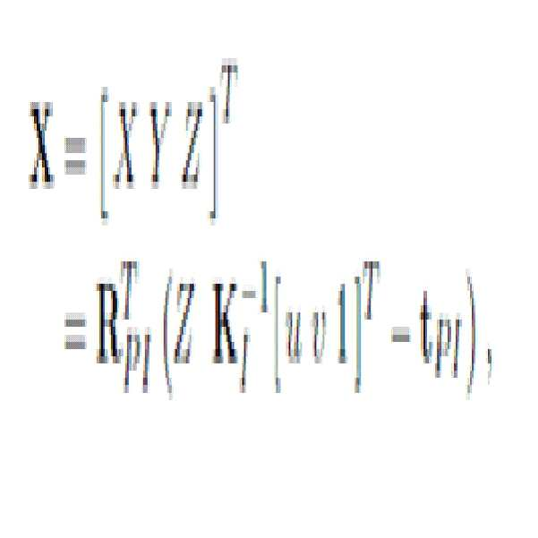
식 1에서, [u,v]는 x의 이미지 좌표를, Z는 이 x에 대해 깊이 센서가 제공하는 깊이를, KI는 깊이 카메라의 내부 파라미터(intrinsic parameter)를 의미한다. [u,v,1]은 행렬 계산을 위해 1이 추가된 확장 벡터(augmented vector)이고, [u,v,1]T는 [u,v,1]의 전치행렬(transposed matrix)이다.In Equation 1, [u, v] denotes an image coordinate of x, Z denotes a depth provided by the depth sensor for x, and K I denotes an intrinsic parameter of the depth camera. [u, v, 1] is an augmented vector with 1 added for matrix calculation, and [u, v, 1] T is the transposed matrix of [u, v, 1].
일 실시 예에 따른 회전행렬 RPI와 병진벡터 tPI는 식 2 및 식 3과 같이 정의할 수 있다.The rotation matrix R PI and the translation vector t PI according to an embodiment may be defined as in Equations 2 and 3.
![]()
![]()
![]()
![]()
식 3에 있어서, 75mm는 프로젝터와 깊이 카메라 간의 거리를 의미하는 것으로, 사용자 설정에 따라 변경 가능하다.In Equation 3, 75 mm means a distance between the projector and the depth camera, and can be changed according to a user setting.
이어서, X가 πP 상에 투영된 점 p를 식 4를 이용해서 계산한다.Next, the point p which X projected on (pi) P is computed using Formula (4).
![]()
![]()
x가 속한 보정패턴이 투영되는 평면 πI는 카메라 보정방식을 통해 구한 카메라와 보정패턴 사이의 기하관계를 통해 계산할 수 있다. 이 평면의 {I}의 원점으로부터의 거리를 d, {I}를 대상으로 한 평면의 수직벡터를 N이라 한다. 그러면 식 5에서와 같이 2차원 호모그래피(homography) HPI를 계산할 수 있다.The plane π I on which the correction pattern to which x belongs is computed through the geometric relationship between the camera and the correction pattern obtained through the camera correction method. The distance from the origin of {I} of this plane is d, and the vertical vector of the plane of {I} is N. Then, as in
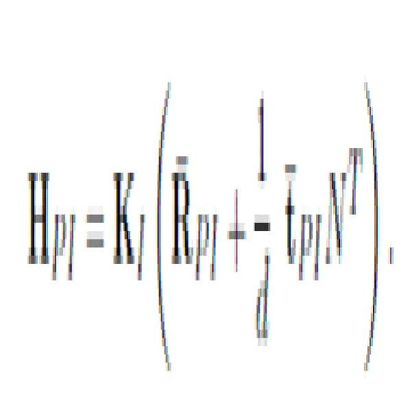
식 5에 있어서, 회전행렬 ![]()
![]()
![]()
![]()
![]()
![]()
![]()
![]()
식 6에 있어서, a, b, c는 식 5의 HPI를 이용하여 계산할 수 있다.In Formula 6, a, b, and c can be calculated using H PI of
![]()
![]()
여기서 계산하게 되는 새로운 대응점 ![]()
![]()
![]()
![]()
![]()
![]()
도 4는 본 발명의 일 실시 예에 따른 옳은 대응점을 찾기 위한 개념을 설명하기 위해 필요한 에피폴라 라인과 점들의 예를 도시한 참조도이다.FIG. 4 is a reference diagram illustrating an example of epipolar lines and points necessary to explain a concept for finding a correct correspondence point according to an embodiment of the present invention.
도 4를 참조하면, 깊이 센서는 pi의 대응점을 πI 상의 에피폴라 라인 lP 상에서 찾고, 찾은 결과가 xi이다. 그러나, 실제로는 보정 오차에 의해 에피폴라 라인이 틀리므로 대응점도 오차가 있게 된다. 옳은 대응점은 옳은 에피폴라 라인 ![]()
![]()
![]()
![]()
![]()
![]()
![]()
![]()
![]()
![]()
![]()
![]()
![]()
![]()
![]()
![]()
![]()
![]()
식 5 및 식 6에서 계산한 ![]()
![]()
![]()
![]()
![]()
![]()
![]()
![]()
![]()
![]()
![]()
![]()
![]()
![]()
![]()
![]()
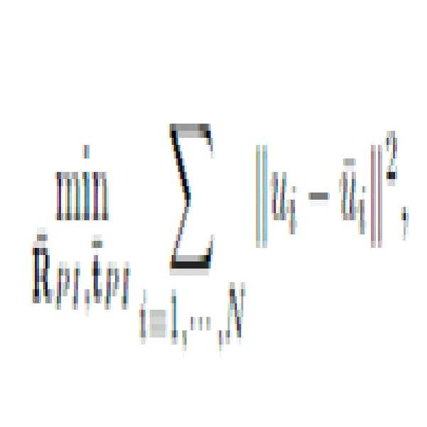
식 8에 있어서, N은 점 x의 개수이다. 이때 비용함수를 최소화는 방식은 최적화 분야에서 개발된 어떠한 비선형 최적화 방식을 써도 상관없다. 예를 들어, Levenberg-Marquardt 알고리즘을 이용하여 비용함수에 최적화를 수행할 수 있다.In Equation 8, N is the number of points x. At this time, the method of minimizing the cost function may be any nonlinear optimization method developed in the optimization field. For example, the Levenberg-Marquardt algorithm can be used to optimize the cost function.
![]()
![]()
![]()
![]()
![]()
![]()
![]()
![]()
![]()
![]()
![]()
![]()
![]()
![]()
![]()
![]()
![]()
![]()
![]()
![]()
![]()
![]()
![]()
![]()
![]()
![]()
![]()
![]()
도 5는 본 발명의 일 실시 예에 따른 이미지 처리장치(5)의 구성도이다.5 is a configuration diagram of an
도 5를 참조하면, 이미지 처리장치(5)는 수신부(52), 프로세서(54) 및 저장부(56)를 포함한다. 수신부(52)는 대상물체를 대상으로 깊이 센서의 깊이 카메라가 촬영한 깊이 이미지와, 컬러 카메라를 통해 촬영한 컬러 이미지를 획득한다.Referring to FIG. 5, the
프로세서(54)는 수신부(52)를 통해 획득된 이미지들을 기초로 하여 깊이 센서의 프로젝터 및 깊이 카메라 간의 기하 관계를 보정하고, 프로젝터의 이미지 평면의 특징점에 대응하는 깊이 카메라의 이미지 평면의 옳은 특징점을 계산하여 깊이 센서의 깊이를 보정한다. 일 실시 예에 따른 프로세서(54)는 제1 계산부(541), 제2 계산부(542) 및 제3 계산부(543)를 포함한다.The
제1 계산부(541)는 깊이 카메라의 이미지 평면에서 소정의 깊이 값을 갖는 특징점에 대응하는 프로젝터의 이미지 평면의 특징점을 계산한다. 일 실시 예에 따른 제1 계산부(541)는 깊이 카메라의 이미지 평면의 특징점에 대응하는 3차원 좌표를 계산한다. 그리고, 계산된 3차원 좌표가 프로젝터의 이미지 평면에 투영되는 특징점을 계산한다. 3차원 좌표를 계산 시에 프로젝터와 깊이 카메라 간의 상대자세를 알 수 있는 회전행렬 및 병진벡터와, 깊이 카메라의 내부 파라미터를 이용하여 3차원 좌표를 계산할 수 있다.The
제2 계산부(542)는 추정된 올바른 프로젝터의 자세에서의 구조 광 투사 시에 제1 계산부(541)를 통해 계산된 프로젝터의 이미지 평면의 특징점에 대응하는 깊이 카메라의 이미지 평면의 옳은 특징점을 계산한다.The
일 실시 예에 따른 제2 계산부(542)는 회전행렬 보정 값 및 병진벡터 보정 값을 계산한다. 그리고, 계산된 회전행렬 보정 값 및 병진벡터 보정 값과 제1 계산부(541)를 통해 계산된 프로젝터의 이미지 평면의 특징점을 이용하여 깊이 카메라의 이미지 평면 상에서 보정된 에피폴라 라인을 계산한다. 그리고, 보정된 에피폴라 라인 내에서 회전행렬 보정 값과 병진벡터 보정 값에 따라 프로젝터의 이미지 평면의 특징점에 대응하는 깊이 카메라의 이미지 평면의 옳은 특징점에 해당하는 새로운 특징점을 검색한다.The
일 실시 예에 따른 제2 계산부(542)는 깊이 카메라의 이미지 평면의 보정된 에피폴라 라인 내에 형성되는 옳은 특징점과 보정 전 에피폴라 라인 내에 형성되는 특징점의 차를 나타내는 비용함수를 최소화하여 최적의 회전행렬 보정 값과 병진벡터 보정 값을 계산한다. 즉, 제2 계산부(542)는 깊이 카메라의 이미지 평면의 보정된 에피폴라 라인 내에서 수평 픽셀 좌표가 보정 전 에피폴라 라인 내에서 계산된 특징점의 수평 픽셀 좌표와 동일한 지점을 검색하여 검색된 지점을 옳은 특징점으로 선택한다. 검색된 지점은 보정 전 에피폴라 라인의 특징점의 수직선이 보정된 에피폴라 라인과 교차하는 지점이다.The
제3 계산부(543)는 제2 계산부(542)를 통해 계산된 깊이 카메라의 이미지 평면의 옳은 특징점에 대한 실제 깊이 값을 계산한다. 일 실시 예에 따른 제3 계산부(543)는 계산된 프로젝터의 이미지 평면의 특징점, 계산된 프로젝터의 이미지 평면의 특징점과 대응하는 깊이 카메라의 이미지 평면의 옳은 특징점, 회전행렬 보정 값, 병진벡터 보정 값 및 깊이 카메라 내부 파라미터를 이용한 삼각측량을 통해 깊이 카메라의 이미지 평면의 옳은 특징점에 대한 실제 깊이 값 및 실제 3차원 좌표를 계산한다.The
저장부(56)에는 깊이 센서를 통해 획득된 깊이 이미지와 컬러 카메라를 통해 획득된 컬러 이미지가 저장되며, 프로세서(54)를 통해 계산된 각종 정보 또는 프로세서(54)의 계산을 위해 필요한 정보들이 저장된다.The
이제까지 본 발명에 대하여 그 실시 예들을 중심으로 살펴보았다. 본 발명이 속하는 기술분야에서 통상의 지식을 가진 자는 본 발명이 본 발명의 본질적인 특성에서 벗어나지 않는 범위에서 변형된 형태로 구현될 수 있음을 이해할 수 있을 것이다. 그러므로 개시된 실시 예들은 한정적인 관점이 아니라 설명적인 관점에서 고려되어야 한다. 본 발명의 범위는 전술한 설명이 아니라 특허청구범위에 나타나 있으며, 그와 동등한 범위 내에 있는 모든 차이점은 본 발명에 포함된 것으로 해석되어야 할 것이다.So far, the present invention has been described with reference to the embodiments. Those skilled in the art will appreciate that the present invention can be implemented in a modified form without departing from the essential features of the present invention. Therefore, the disclosed embodiments should be considered in descriptive sense only and not for purposes of limitation. The scope of the present invention is shown in the claims rather than the foregoing description, and all differences within the scope will be construed as being included in the present invention.
5: 이미지 처리장치 52: 수신부
54: 프로세서 56: 저장부
541: 제1 계산부 542: 제2 계산부
543: 제3 계산부5: image processing apparatus 52: receiver
54: processor 56: storage unit
541: First calculation unit 542: Second calculation unit
543: third calculation unit
Claims (19)
획득된 이미지들을 기초로 하여 깊이 센서의 프로젝터 및 깊이 카메라 간의 기하 관계를 보정하고 프로젝터의 이미지 평면의 특징점에 대응하는 깊이 카메라의 이미지 평면의 옳은 특징점을 계산하여 깊이 센서의 깊이를 보정하는 단계;
를 포함하고,
상기 깊이 센서의 깊이를 보정하는 단계는
깊이 카메라의 이미지 평면에서 소정의 깊이 값을 갖는 특징점에 대응하는 프로젝터의 이미지 평면의 특징점을 계산하는 단계;
추정된 올바른 프로젝터의 자세에서의 구조 광 투사 시에 상기 계산된 프로젝터의 이미지 평면의 특징점에 대응하는 깊이 카메라의 이미지 평면의 옳은 특징점을 계산하는 단계; 및
상기 계산된 깊이 카메라의 이미지 평면의 옳은 특징점에 대한 실제 깊이 값을 계산하는 단계를 포함하고,
상기 깊이 카메라의 이미지 평면의 옳은 특징점을 계산하는 단계는
회전행렬 보정 값 및 병진벡터 보정 값을 계산하는 단계;
계산된 프로젝터의 이미지 평면의 특징점과 회전행렬 보정 값 및 병진벡터 보정 값을 이용하여 깊이 카메라의 이미지 평면 상에서 보정된 에피폴라 라인을 계산하는 단계; 및
보정된 에피폴라 라인 내에서 회전행렬 보정 값과 병진벡터 보정 값에 따라 프로젝터의 이미지 평면의 특징점에 대응하는 깊이 카메라의 이미지 평면의 옳은 특징점에 해당하는 새로운 특징점을 검색하는 단계를 포함하는 것을 특징으로 하는 깊이 센서의 깊이 보정을 위한 이미지 처리방법.Obtaining a depth image photographed by a depth sensor and a color image photographed by a color camera of the object; And
Correcting the geometric relationship between the projector and the depth camera of the depth sensor based on the acquired images and calculating the correct feature point of the image plane of the depth camera corresponding to the feature point of the image plane of the projector to correct the depth of the depth sensor;
Including,
Correcting the depth of the depth sensor
Calculating a feature point of the image plane of the projector corresponding to the feature point having a predetermined depth value in the image plane of the depth camera;
Calculating a correct feature point of the image plane of the depth camera corresponding to the calculated feature point of the image plane of the projector during projected light projection in the estimated correct projector attitude; And
Calculating an actual depth value for the correct feature point of the image plane of the calculated depth camera,
Calculating the correct feature point of the image plane of the depth camera
Calculating a rotation matrix correction value and a translation vector correction value;
Calculating the corrected epipolar line on the image plane of the depth camera using the calculated feature points of the image plane of the projector, the rotation matrix correction value, and the translation vector correction value; And
Retrieving a new feature point corresponding to the correct feature point of the image plane of the depth camera corresponding to the feature point of the image plane of the projector according to the rotation matrix correction value and the translation vector correction value within the corrected epipolar line. Image processing method for depth correction of the depth sensor.
대상물체를 동시에 촬영하는 깊이 센서의 깊이 카메라와 컬러 카메라를 통해 깊이 이미지와 컬러 이미지를 동시에 획득하는 것을 특징으로 하는 깊이 센서의 깊이 보정을 위한 이미지 처리방법.The method of claim 1, wherein the obtaining step
An image processing method for depth correction of a depth sensor, characterized by simultaneously obtaining a depth image and a color image through a depth camera and a color camera of a depth sensor simultaneously photographing an object.
깊이 카메라의 이미지 평면의 특징점에 대응하는 3차원 좌표를 계산하는 단계; 및
계산된 3차원 좌표가 프로젝터의 이미지 평면에 투영되는 특징점을 계산하는 단계;
를 포함하는 것을 특징으로 하는 깊이 센서의 깊이 보정을 위한 이미지 처리방법.The method of claim 1, wherein calculating a feature point of the image plane of the projector
Calculating three-dimensional coordinates corresponding to the feature points of the image plane of the depth camera; And
Calculating a feature point at which the calculated three-dimensional coordinates are projected onto the image plane of the projector;
Image processing method for depth correction of the depth sensor comprising a.
프로젝터와 깊이 카메라 간의 상대자세를 알 수 있는 회전행렬 및 병진벡터와, 깊이 카메라의 내부 파라미터를 이용하여 3차원 좌표를 계산하는 것을 특징으로 하는 깊이 센서의 깊이 보정을 위한 이미지 처리방법.The method of claim 4, wherein calculating the three-dimensional coordinates
An image processing method for depth correction of a depth sensor, comprising: calculating a three-dimensional coordinate by using a rotation matrix and a translation vector for knowing a relative position between a projector and a depth camera, and internal parameters of the depth camera.
호모그래피를 계산하는 단계; 및
비용함수를 최소화하는 회전행렬 보정 값과 병진벡터 보정 값을 계산하는 단계;
를 포함하는 것을 특징으로 하는 깊이 센서의 깊이 보정을 위한 이미지 처리방법.The method of claim 1, wherein the calculating of the rotation matrix correction value and the translation vector correction value comprises:
Calculating homography; And
Calculating a translation matrix correction value and a translation vector correction value that minimize the cost function;
Image processing method for depth correction of the depth sensor comprising a.
상기 호모그래피는 회전행렬 보정 값과 병진벡터 보정 값을 이용하여 계산되는 것으로, 깊이 카메라의 이미지 평면의 옳은 특징점은 계산된 프로젝터의 이미지 평면의 특징점에 호모그래피를 곱 연산한 것인 것을 특징으로 하는 깊이 센서의 깊이 보정을 위한 이미지 처리방법.The method of claim 7, wherein
The homography is calculated using the rotation matrix correction value and the translation vector correction value, and the correct feature point of the image plane of the depth camera is a product of the computed feature point of the image plane of the projector. Image processing method for depth correction of depth sensor.
깊이 카메라의 이미지 평면의 보정된 에피폴라 라인 내에 형성되는 옳은 특징점과 보정 전 에피폴라 라인 내에 형성되는 특징점의 차를 나타내는 비용함수를 최소화하여 최적의 회전행렬 보정 값과 병진벡터 보정 값을 계산하는 것을 특징으로 하는 깊이 센서의 깊이 보정을 위한 이미지 처리방법.The method of claim 7, wherein the calculating of the rotation matrix correction value and the translation vector correction value that minimizes the cost function is performed.
Calculating the optimal rotation matrix correction value and the translation vector correction value by minimizing the cost function representing the difference between the correct feature point formed in the corrected epipolar line of the depth camera image plane and the feature point formed in the epipolar line before correction. An image processing method for depth correction of a depth sensor.
깊이 카메라의 이미지 평면의 보정된 에피폴라 라인 내에서 수평 픽셀 좌표가 보정 전 에피폴라 라인 내의 특징점의 수평 픽셀 좌표와 동일한 지점을 검색하여 검색된 지점을 옳은 특징점으로 선택하고, 검색된 지점은 보정 전 에피폴라 라인의 특징점의 수직선이 보정된 에피폴라 라인과 교차하는 지점인 것을 특징으로 하는 깊이 센서의 깊이 보정을 위한 이미지 처리방법.The method of claim 1, wherein searching for a new feature point corresponding to a correct feature point of the image plane of the depth camera comprises:
Detect the point where the horizontal pixel coordinates within the calibrated epipolar line of the depth camera's image plane is the same as the horizontal pixel coordinates of the feature point within the epipolar line before correction, and select the searched point as the correct feature point, and the retrieved point is the epipolar before correction An image processing method for depth correction of a depth sensor, wherein the vertical line of the feature point of the line intersects the corrected epipolar line.
계산된 프로젝터의 이미지 평면의 특징점, 계산된 프로젝터의 이미지 평면의 특징점과 대응하는 깊이 카메라의 이미지 평면의 옳은 특징점, 회전행렬 보정 값, 병진벡터 보정 값 및 깊이 카메라 내부 파라미터를 이용한 삼각측량을 통해 깊이 카메라의 이미지 평면의 실제 깊이 값을 계산하는 것을 특징으로 하는 깊이 센서의 깊이 보정을 위한 이미지 처리방법.The method of claim 1, wherein calculating the actual depth value for the correct feature point of the image plane of the calculated depth camera
Depth corresponding to the calculated feature point of the image plane of the projector, the corresponding feature point of the calculated image plane of the projector The correct feature point of the image plane of the camera, the rotation matrix correction value, the translation vector correction value and the depth through the triangulation using the camera internal parameters An image processing method for depth correction of a depth sensor, characterized by calculating an actual depth value of an image plane of a camera.
깊이 오차 보정에 기반하여 깊이 카메라에 의해 측정된 3차원 좌표를 보정하여 실제 3차원 좌표를 계산하는 단계;
를 더 포함하는 것을 특징으로 하는 깊이 센서의 깊이 보정을 위한 이미지 처리방법.The image processing method of claim 1, wherein the image processing method for depth correction of the depth sensor comprises:
Calculating actual three-dimensional coordinates by correcting the three-dimensional coordinates measured by the depth camera based on the depth error correction;
Image processing method for depth correction of the depth sensor, characterized in that it further comprises.
상기 수신부를 통해 획득된 이미지들을 기초로 하여 깊이 센서의 프로젝터 및 깊이 카메라 간의 기하 관계를 보정하고 프로젝터의 이미지 평면의 특징점에 대응하는 깊이 카메라의 이미지 평면의 옳은 특징점을 계산하여 깊이 센서의 깊이를 보정하는 프로세서;
를 포함하고,
상기 프로세서는
깊이 카메라의 이미지 평면에서 소정의 깊이 값을 갖는 특징점에 대응하는 프로젝터의 이미지 평면의 특징점을 계산하는 제1 계산부;
추정된 올바른 프로젝터의 자세에서의 구조 광 투사 시에 상기 제1 계산부를 통해 계산된 프로젝터의 이미지 평면의 특징점에 대응하는 깊이 카메라의 이미지 평면의 옳은 특징점을 계산하는 제2 계산부; 및
상기 제2 계산부를 통해 계산된 깊이 카메라의 이미지 평면의 옳은 특징점에 대한 실제 깊이 값 및 실제 3차원 좌표를 계산하는 제3 계산부를 포함하고,
상기 제2 계산부는
회전행렬 보정 값 및 병진벡터 보정 값을 계산하고, 계산된 회전행렬 보정 값 및 병진벡터 보정 값과 상기 제1 계산부를 통해 계산된 프로젝터의 이미지 평면의 특징점을 이용하여 깊이 카메라의 이미지 평면 상에서 보정된 에피폴라 라인을 계산하며, 보정된 에피폴라 라인 내에서 회전행렬 보정 값과 병진벡터 보정 값에 따라 프로젝터의 이미지 평면의 특징점에 대응하는 깊이 카메라의 이미지 평면의 옳은 특징점에 해당하는 새로운 특징점을 검색하는 것을 특징으로 하는 깊이 센서의 깊이 보정을 위한 이미지 처리장치.A receiver configured to acquire a depth image photographed by a depth camera and a color image photographed by a color camera, on a target object; And
Correcting the geometric relationship between the projector and the depth camera of the depth sensor based on the images acquired through the receiver and calculating the correct feature point of the image plane of the depth camera corresponding to the feature point of the image plane of the projector to correct the depth of the depth sensor. A processor;
Including,
The processor is
A first calculator configured to calculate a feature point of the image plane of the projector corresponding to the feature point having a predetermined depth value in the image plane of the depth camera;
A second calculator for calculating the correct feature point of the image plane of the depth camera corresponding to the feature point of the image plane of the projector calculated by the first calculator when projecting the structured light at the estimated correct projector attitude; And
A third calculator configured to calculate an actual depth value and an actual three-dimensional coordinate for the right feature point of the image plane of the depth camera calculated through the second calculator,
The second calculation unit
The rotation matrix correction value and the translation vector correction value are calculated and corrected on the image plane of the depth camera using the calculated rotation matrix correction value and the translation vector correction value and the feature points of the image plane of the projector calculated by the first calculation unit. Calculate the epipolar line and search for a new feature point corresponding to the correct feature point of the depth camera image plane corresponding to the feature point of the image plane of the projector according to the rotation matrix correction value and the translation vector correction value within the corrected epipolar line. Image processing apparatus for the depth correction of the depth sensor, characterized in that.
깊이 카메라의 이미지 평면의 특징점에 대응하는 3차원 좌표를 계산하고, 계산된 3차원 좌표가 프로젝터의 이미지 평면에 투영되는 특징점을 계산하며, 3차원 좌표를 계산 시에 프로젝터와 깊이 카메라 간의 상대자세를 알 수 있는 회전행렬 및 병진벡터와, 깊이 카메라의 내부 파라미터를 이용하여 3차원 좌표를 계산하는 것을 특징으로 하는 깊이 센서의 깊이 보정을 위한 이미지 처리장치.The method of claim 13, wherein the first calculation unit
Calculate the three-dimensional coordinates corresponding to the feature points of the depth camera's image plane, calculate the feature points from which the calculated three-dimensional coordinates are projected on the image plane of the projector, and calculate the relative posture between the projector and the depth camera when calculating the three-dimensional coordinates. An image processing apparatus for depth correction of a depth sensor, comprising calculating a three-dimensional coordinate by using a known rotation matrix and a translation vector and an internal parameter of a depth camera.
깊이 카메라의 이미지 평면의 보정된 에피폴라 라인 내에 형성되는 옳은 특징점과 보정 전 에피폴라 라인 내에 형성되는 특징점의 차를 나타내는 비용함수를 최소화하여 최적의 회전행렬 보정 값과 병진벡터 보정 값을 계산하는 것을 특징으로 하는 깊이 센서의 깊이 보정을 위한 이미지 처리장치.The method of claim 13, wherein the second calculation unit
Calculating the optimal rotation matrix correction value and the translation vector correction value by minimizing the cost function representing the difference between the correct feature point formed in the corrected epipolar line of the depth camera image plane and the feature point formed in the epipolar line before correction. An image processing apparatus for depth correction of a depth sensor.
깊이 카메라의 이미지 평면의 보정된 에피폴라 라인 내에서 수평 픽셀 좌표가 보정 전 에피폴라 라인 내의 특징점의 수평 픽셀 좌표와 동일한 지점을 검색하여 검색된 지점을 옳은 특징점으로 선택하고, 검색된 지점은 보정 전 에피폴라 라인의 특징점의 수직선이 보정된 에피폴라 라인과 교차하는 지점인 것을 특징으로 하는 깊이 센서의 깊이 보정을 위한 이미지 처리장치.The method of claim 17, wherein the second calculation unit
Detect the point where the horizontal pixel coordinates within the calibrated epipolar line of the depth camera's image plane is the same as the horizontal pixel coordinates of the feature point within the epipolar line before correction, and select the searched point as the correct feature point, and the retrieved point is the epipolar before correction An image processing apparatus for depth correction of a depth sensor, wherein the vertical line of the feature points of the line intersects the corrected epipolar line.
계산된 프로젝터의 이미지 평면의 특징점, 계산된 프로젝터의 이미지 평면의 특징점과 대응하는 깊이 카메라의 이미지 평면의 옳은 특징점, 회전행렬 보정 값, 병진벡터 보정 값 및 깊이 카메라 내부 파라미터를 이용한 삼각측량을 통해 깊이 카메라의 이미지 평면의 실제 깊이 값을 계산하는 것을 특징으로 하는 깊이 센서의 깊이 보정을 위한 이미지 처리장치.The method of claim 13, wherein the third calculation unit
Depth corresponding to the calculated feature point of the image plane of the projector, the corresponding feature point of the calculated image plane of the projector The correct feature point of the image plane of the camera, the rotation matrix correction value, the translation vector correction value and the depth through the triangulation using the camera internal parameters An image processing apparatus for depth correction of a depth sensor, characterized in that to calculate the actual depth value of the image plane of the camera.
Priority Applications (2)
| Application Number | Priority Date | Filing Date | Title |
|---|---|---|---|
| KR1020140036346A KR102085228B1 (en) | 2014-03-27 | 2014-03-27 | Imaging processing method and apparatus for calibrating depth of depth sensor |
| US14/444,030 US9858684B2 (en) | 2014-03-27 | 2014-07-28 | Image processing method and apparatus for calibrating depth of depth sensor |
Applications Claiming Priority (1)
| Application Number | Priority Date | Filing Date | Title |
|---|---|---|---|
| KR1020140036346A KR102085228B1 (en) | 2014-03-27 | 2014-03-27 | Imaging processing method and apparatus for calibrating depth of depth sensor |
Publications (2)
| Publication Number | Publication Date |
|---|---|
| KR20150112362A KR20150112362A (en) | 2015-10-07 |
| KR102085228B1 true KR102085228B1 (en) | 2020-03-05 |
Family
ID=54191102
Family Applications (1)
| Application Number | Title | Priority Date | Filing Date |
|---|---|---|---|
| KR1020140036346A Expired - Fee Related KR102085228B1 (en) | 2014-03-27 | 2014-03-27 | Imaging processing method and apparatus for calibrating depth of depth sensor |
Country Status (2)
| Country | Link |
|---|---|
| US (1) | US9858684B2 (en) |
| KR (1) | KR102085228B1 (en) |
Families Citing this family (31)
| Publication number | Priority date | Publication date | Assignee | Title |
|---|---|---|---|---|
| US9554121B2 (en) * | 2015-01-30 | 2017-01-24 | Electronics And Telecommunications Research Institute | 3D scanning apparatus and method using lighting based on smart phone |
| JP6566768B2 (en) * | 2015-07-30 | 2019-08-28 | キヤノン株式会社 | Information processing apparatus, information processing method, and program |
| US10096131B2 (en) * | 2015-09-25 | 2018-10-09 | Logical Turn Services Inc. | Dimensional acquisition of packages |
| US10769806B2 (en) * | 2015-09-25 | 2020-09-08 | Logical Turn Services, Inc. | Dimensional acquisition of packages |
| KR20180094878A (en) * | 2015-12-18 | 2018-08-24 | 소니 주식회사 | Image processing apparatus and method, data, and recording medium |
| CN108603933B (en) * | 2016-01-12 | 2022-07-08 | 三菱电机株式会社 | System and method for fusing sensor outputs with different resolutions |
| CN105976375A (en) * | 2016-05-06 | 2016-09-28 | 苏州中德睿博智能科技有限公司 | RGB-D-type sensor based tray identifying and positioning method |
| JP6702796B2 (en) * | 2016-05-16 | 2020-06-03 | キヤノン株式会社 | Image processing device, imaging device, image processing method, and image processing program |
| GB201702118D0 (en) * | 2017-02-09 | 2017-03-29 | Cathx Ocean Ltd | Method and system for calibrating imaging system |
| US10542245B2 (en) * | 2017-05-24 | 2020-01-21 | Lg Electronics Inc. | Mobile terminal and method for controlling the same |
| CN107730561B (en) * | 2017-10-17 | 2021-07-06 | 奥比中光科技集团股份有限公司 | Depth camera temperature error correction method and system |
| CN109754427A (en) * | 2017-11-01 | 2019-05-14 | 虹软科技股份有限公司 | A method and apparatus for calibration |
| US10706505B2 (en) * | 2018-01-24 | 2020-07-07 | GM Global Technology Operations LLC | Method and system for generating a range image using sparse depth data |
| WO2019175629A1 (en) * | 2018-03-14 | 2019-09-19 | Nokia Technologies Oy | Camera calibration and/or use of a calibrated camera |
| CN108550169B (en) * | 2018-04-24 | 2021-08-10 | 中北大学 | Method for determining positions of chess pieces in three-dimensional space and calculating heights of chess pieces |
| KR102093622B1 (en) * | 2018-07-02 | 2020-03-27 | 경희대학교 산학협력단 | Method and apparatus for real-time correction of projector image using depth camera |
| JP6717887B2 (en) | 2018-07-12 | 2020-07-08 | ファナック株式会社 | Distance measuring device having distance correction function |
| TWI680436B (en) * | 2018-12-07 | 2019-12-21 | 財團法人工業技術研究院 | Depth camera calibration device and method thereof |
| CN110570368B (en) * | 2019-08-21 | 2020-09-25 | 贝壳技术有限公司 | Depth image distortion correction method, depth image distortion correction device, electronic device and storage medium |
| CN111028294B (en) * | 2019-10-20 | 2024-01-16 | 奥比中光科技集团股份有限公司 | Multi-distance calibration method and system based on depth camera |
| CN111127528A (en) * | 2019-12-10 | 2020-05-08 | Oppo广东移动通信有限公司 | Image registration method, terminal and storage medium |
| KR102438853B1 (en) * | 2019-12-10 | 2022-09-06 | 한국전자기술연구원 | Method and system for depth image estimation using flat information |
| US11430142B2 (en) | 2020-04-28 | 2022-08-30 | Snap Inc. | Photometric-based 3D object modeling |
| US20230266314A1 (en) * | 2020-09-04 | 2023-08-24 | 3M Innovative Properties Company | Chromatographic reader devices for biodetection |
| US20230266232A1 (en) * | 2020-09-04 | 2023-08-24 | 3M Innovative Properties Company | Chromatographic reader devices for biodetection |
| US11748936B2 (en) * | 2021-03-02 | 2023-09-05 | GM Global Technology Operations LLC | Using epipolar reprojection for virtual view perspective change |
| US11790606B2 (en) * | 2021-07-06 | 2023-10-17 | Bentley Systems, Incorporated | Determining camera rotations based on known translations |
| US11770495B2 (en) * | 2021-08-13 | 2023-09-26 | GM Global Technology Operations LLC | Generating virtual images based on captured image data |
| CN114708331B (en) * | 2022-02-24 | 2023-03-14 | 合肥的卢深视科技有限公司 | Calibration method and device for depth camera, electronic equipment and storage medium |
| EP4361555B1 (en) * | 2022-09-09 | 2025-02-26 | Contemporary Amperex Technology (Hong Kong) Limited | Size measurement method and apparatus, and computer-readable storage medium |
| CN118781201B (en) * | 2024-06-14 | 2025-10-21 | 点昀技术(深圳)有限公司 | Camera calibration method, electronic device, and computer-readable storage medium |
Family Cites Families (6)
| Publication number | Priority date | Publication date | Assignee | Title |
|---|---|---|---|---|
| US7212663B2 (en) * | 2002-06-19 | 2007-05-01 | Canesta, Inc. | Coded-array technique for obtaining depth and other position information of an observed object |
| US8009930B2 (en) * | 2008-03-26 | 2011-08-30 | City University Of Hong Kong | Auto-calibration method for a projector-camera system |
| CA2666256C (en) * | 2008-05-23 | 2015-12-29 | National Research Council Of Canada | Deconvolution-based structured light system with geometrically plausible regularization |
| KR101221449B1 (en) | 2009-03-27 | 2013-01-11 | 한국전자통신연구원 | Apparatus and method for calibrating image between cameras |
| US9270974B2 (en) * | 2011-07-08 | 2016-02-23 | Microsoft Technology Licensing, Llc | Calibration between depth and color sensors for depth cameras |
| US9142025B2 (en) * | 2011-10-05 | 2015-09-22 | Electronics And Telecommunications Research Institute | Method and apparatus for obtaining depth information using optical pattern |
-
2014
- 2014-03-27 KR KR1020140036346A patent/KR102085228B1/en not_active Expired - Fee Related
- 2014-07-28 US US14/444,030 patent/US9858684B2/en not_active Expired - Fee Related
Non-Patent Citations (2)
| Title |
|---|
| 3D with Kinect, 2011 IEEE International Conference on Computer Vision Workshops (ICCV Workshops), 2011.11.6-13* |
| Geometric Calibration of a Structured Light System using Circular Control Points, Proceedings of 3DPVT'08 - the Fourth International Symposium on 3D Data Processing, Visualization and Transmission, 20* |
Also Published As
| Publication number | Publication date |
|---|---|
| US9858684B2 (en) | 2018-01-02 |
| KR20150112362A (en) | 2015-10-07 |
| US20150279016A1 (en) | 2015-10-01 |
Similar Documents
| Publication | Publication Date | Title |
|---|---|---|
| KR102085228B1 (en) | Imaging processing method and apparatus for calibrating depth of depth sensor | |
| US11243072B2 (en) | Method for the three dimensional measurement of moving objects during a known movement | |
| CN109961468B (en) | Volume measurement method and device based on binocular vision and storage medium | |
| AU2013379669B2 (en) | Apparatus and method for three dimensional surface measurement | |
| US10165262B2 (en) | Image processing device and markers | |
| JP6359259B2 (en) | Depth image correction apparatus and method based on relationship between depth sensor and photographing camera | |
| US11222433B2 (en) | 3 dimensional coordinates calculating apparatus and 3 dimensional coordinates calculating method using photo images | |
| JP6413595B2 (en) | Image processing apparatus, system, image processing method, and program | |
| CN101563709A (en) | Calibrating a camera system | |
| JP2007278845A (en) | Image processing apparatus and processing method thereof | |
| CN108662987A (en) | The scaling method of 2D camera shooting type laser measuring heads | |
| US11295478B2 (en) | Stereo camera calibration method and image processing device for stereo camera | |
| KR102185329B1 (en) | Distortion correction method of 3-d coordinate data using distortion correction device and system therefor | |
| KR20130041440A (en) | Image processing apparatus and method thereof | |
| CN112305524A (en) | Ranging method, ranging system, and computer-readable storage medium | |
| JP7580614B2 (en) | Speed measurement method and speed measurement device using multiple cameras | |
| CN110232715B (en) | Method, device and system for self calibration of multi-depth camera | |
| KR101770866B1 (en) | Apparatus and method for calibrating depth image based on depth sensor-color camera relations | |
| CN115100284B (en) | Binocular feature matching displacement measurement method and device | |
| Bräuer-Burchardt et al. | Calibration of stereo 3D scanners with minimal number of views using plane targets and vanishing points | |
| WO2009143321A2 (en) | Stereoscopic measurement system and method | |
| CN119762597A (en) | Method, equipment and medium for calibrating reference plane and reconstructing three-dimension of camera | |
| OA17428A (en) | Apparatus and method for three dimensional surface measurement. |
Legal Events
| Date | Code | Title | Description |
|---|---|---|---|
| PA0109 | Patent application |
St.27 status event code: A-0-1-A10-A12-nap-PA0109 |
|
| PN2301 | Change of applicant |
St.27 status event code: A-3-3-R10-R13-asn-PN2301 St.27 status event code: A-3-3-R10-R11-asn-PN2301 |
|
| PG1501 | Laying open of application |
St.27 status event code: A-1-1-Q10-Q12-nap-PG1501 |
|
| R17-X000 | Change to representative recorded |
St.27 status event code: A-3-3-R10-R17-oth-X000 |
|
| PA0201 | Request for examination |
St.27 status event code: A-1-2-D10-D11-exm-PA0201 |
|
| D13-X000 | Search requested |
St.27 status event code: A-1-2-D10-D13-srh-X000 |
|
| D14-X000 | Search report completed |
St.27 status event code: A-1-2-D10-D14-srh-X000 |
|
| E902 | Notification of reason for refusal | ||
| PE0902 | Notice of grounds for rejection |
St.27 status event code: A-1-2-D10-D21-exm-PE0902 |
|
| E13-X000 | Pre-grant limitation requested |
St.27 status event code: A-2-3-E10-E13-lim-X000 |
|
| P11-X000 | Amendment of application requested |
St.27 status event code: A-2-2-P10-P11-nap-X000 |
|
| P13-X000 | Application amended |
St.27 status event code: A-2-2-P10-P13-nap-X000 |
|
| E701 | Decision to grant or registration of patent right | ||
| PE0701 | Decision of registration |
St.27 status event code: A-1-2-D10-D22-exm-PE0701 |
|
| PR0701 | Registration of establishment |
St.27 status event code: A-2-4-F10-F11-exm-PR0701 |
|
| PR1002 | Payment of registration fee |
St.27 status event code: A-2-2-U10-U11-oth-PR1002 Fee payment year number: 1 |
|
| PG1601 | Publication of registration |
St.27 status event code: A-4-4-Q10-Q13-nap-PG1601 |
|
| PC1903 | Unpaid annual fee |
St.27 status event code: A-4-4-U10-U13-oth-PC1903 Not in force date: 20230301 Payment event data comment text: Termination Category : DEFAULT_OF_REGISTRATION_FEE |
|
| PC1903 | Unpaid annual fee |
St.27 status event code: N-4-6-H10-H13-oth-PC1903 Ip right cessation event data comment text: Termination Category : DEFAULT_OF_REGISTRATION_FEE Not in force date: 20230301 |
|
| P22-X000 | Classification modified |
St.27 status event code: A-4-4-P10-P22-nap-X000 |