CN112305524A - Ranging method, ranging system, and computer-readable storage medium - Google Patents
Ranging method, ranging system, and computer-readable storage medium Download PDFInfo
- Publication number
- CN112305524A CN112305524A CN202011168892.8A CN202011168892A CN112305524A CN 112305524 A CN112305524 A CN 112305524A CN 202011168892 A CN202011168892 A CN 202011168892A CN 112305524 A CN112305524 A CN 112305524A
- Authority
- CN
- China
- Prior art keywords
- camera
- target image
- target
- parameters
- image
- Prior art date
- Legal status (The legal status is an assumption and is not a legal conclusion. Google has not performed a legal analysis and makes no representation as to the accuracy of the status listed.)
- Pending
Links
Images


Classifications
-
- G—PHYSICS
- G01—MEASURING; TESTING
- G01S—RADIO DIRECTION-FINDING; RADIO NAVIGATION; DETERMINING DISTANCE OR VELOCITY BY USE OF RADIO WAVES; LOCATING OR PRESENCE-DETECTING BY USE OF THE REFLECTION OR RERADIATION OF RADIO WAVES; ANALOGOUS ARRANGEMENTS USING OTHER WAVES
- G01S11/00—Systems for determining distance or velocity not using reflection or reradiation
- G01S11/12—Systems for determining distance or velocity not using reflection or reradiation using electromagnetic waves other than radio waves
-
- G—PHYSICS
- G06—COMPUTING OR CALCULATING; COUNTING
- G06T—IMAGE DATA PROCESSING OR GENERATION, IN GENERAL
- G06T5/00—Image enhancement or restoration
- G06T5/80—Geometric correction
-
- G—PHYSICS
- G06—COMPUTING OR CALCULATING; COUNTING
- G06T—IMAGE DATA PROCESSING OR GENERATION, IN GENERAL
- G06T7/00—Image analysis
- G06T7/50—Depth or shape recovery
-
- G—PHYSICS
- G06—COMPUTING OR CALCULATING; COUNTING
- G06T—IMAGE DATA PROCESSING OR GENERATION, IN GENERAL
- G06T2207/00—Indexing scheme for image analysis or image enhancement
- G06T2207/20—Special algorithmic details
- G06T2207/20112—Image segmentation details
- G06T2207/20164—Salient point detection; Corner detection
-
- G—PHYSICS
- G06—COMPUTING OR CALCULATING; COUNTING
- G06T—IMAGE DATA PROCESSING OR GENERATION, IN GENERAL
- G06T2207/00—Indexing scheme for image analysis or image enhancement
- G06T2207/20—Special algorithmic details
- G06T2207/20228—Disparity calculation for image-based rendering
Landscapes
- Engineering & Computer Science (AREA)
- Physics & Mathematics (AREA)
- General Physics & Mathematics (AREA)
- Theoretical Computer Science (AREA)
- Computer Vision & Pattern Recognition (AREA)
- Electromagnetism (AREA)
- Radar, Positioning & Navigation (AREA)
- Remote Sensing (AREA)
- Measurement Of Optical Distance (AREA)
Abstract
The invention discloses a distance measuring method, a distance measuring system and a computer readable storage medium. The distance measurement method comprises the following steps: acquiring a first target image from a first camera and a second target image from a second camera; correcting the first target image and the second target image; performing matching calculation on the corrected first target image and the second target image to obtain a target parallax value; and calculating to obtain a target distance by using the properties of similar triangles according to the camera parameters of the first camera and the second camera and the target parallax value. According to the distance measuring method, the target distance can be calculated according to the camera parameters of the shot images and the target parallax value only by matching and calculating the two images to obtain the target parallax value, so that accurate distance measuring operation can be simply and conveniently completed.
Description
Technical Field
The present invention relates to the field of ranging technologies, and in particular, to a ranging method, a ranging system, and a computer-readable storage medium.
Background
Ranging is an important step in the field of artificial intelligence for accurately positioning objects, and helps a machine to accurately position objects, i.e., accurately obtain three-dimensional coordinates of the objects. Currently, the most common ranging method is TOF ranging, which uses the time of flight of a data signal back and forth between a pair of transceivers to measure the distance between two points. However, this method requires that the transmitting device and the receiving device must always be synchronized, and the length of the transmission time for which the receiving device provides a signal affects the measurement accuracy.
Disclosure of Invention
The present invention is directed to solving at least one of the problems of the prior art. Therefore, the invention provides a distance measuring method, a distance measuring system and a computer readable storage medium, which can simply and accurately measure the distance.
In a first aspect, an embodiment of the present invention provides a ranging method, including:
acquiring a first target image from a first camera and a second target image from a second camera;
correcting the first target image and the second target image;
performing matching calculation on the corrected first target image and the second target image to obtain a target parallax value;
and calculating to obtain a target distance by using the properties of similar triangles according to the camera parameters of the first camera and the second camera and the target parallax value.
The distance measuring method according to the embodiment of the first aspect of the invention has at least the following beneficial effects:
when the distance measuring method is used, a first target image from a first camera and a second target image from a second camera are obtained, the first target image and the second target image are corrected, the corrected first target image and the corrected second target image are subjected to matching calculation to obtain a target parallax value, and then the target distance can be obtained by calculation according to the camera parameters of the first camera and the second camera and the target parallax value and by using the property of a similar triangle. According to the distance measuring method, the target distance can be calculated according to the camera parameters of the shot images and the target parallax value only by matching and calculating the two images to obtain the target parallax value, so that accurate distance measuring operation can be simply and conveniently completed.
According to some embodiments of the first aspect of the present invention, before the obtaining the first target image from the first camera and the second target image from the second camera, further comprising: and calibrating the first camera and the second camera by using a camera calibration method.
According to some embodiments of the first aspect of the present invention, the calibrating the first camera and the second camera using a camera calibration method comprises: acquiring pixel coordinates and sub-pixel coordinates of grid corner points in the planar black-white chessboard pattern; drawing a chessboard angular point according to the pixel coordinate and the sub-pixel coordinate; and calibrating the first camera and the second camera according to the chessboard angular points.
According to some embodiments of the first aspect of the present invention, the calibrating the first camera and the second camera using a camera calibration method further comprises: and acquiring camera parameters of the first camera and the second camera, wherein the camera parameters comprise a radial distortion parameter and a tangential distortion parameter.
According to some embodiments of the first aspect of the present invention, the obtaining a first target image from a first camera and a second target image from a second camera comprises: when the first camera and the second camera are positioned on the same horizontal plane, the first camera and the second camera are controlled to shoot the same object in the same scene so as to respectively obtain a first target image and a second target image.
According to some embodiments of the first aspect of the present invention, the correcting the first target image and the second target image comprises: obtaining a mapping matrix for image correction according to camera parameters of the first camera and the second camera and image information of the first target image and the second target image, wherein the camera parameters comprise a radial distortion parameter, a tangential distortion parameter and camera parameters, and the image information comprises coordinates of each pixel; and generating the corrected first target image and the second target image according to the mapping matrix.
According to some embodiments of the first aspect of the present invention, the performing a matching calculation on the corrected first target image and the second target image to obtain a target disparity value includes: obtaining a parallax value corresponding to each pixel point in the corrected first target image and the second target image by using a feature matching algorithm; and taking the value of the independent variable corresponding to the minimum value in the parallax values as a target parallax value, wherein the target parallax value is taken as the parallax value corresponding to each pixel point in the corrected first target image and the second target image.
According to some embodiments of the first aspect of the present invention, the camera parameters of the first and second cameras comprise a baseline length and a focal length; the calculating the target distance by using the property of the similar triangle according to the camera parameters of the first camera and the second camera and the target parallax value comprises: and calculating to obtain the target distance by utilizing the proportional property of the corresponding side of the similar triangle according to the base length, the focal length and the target parallax value.
In a second aspect, an embodiment of the present invention provides a ranging system, where the ranging system includes: the camera comprises a first camera, a second camera, a memory and a processor, wherein the first camera and the second camera are respectively connected with the memory, and the memory stores a computer program; the computer program, when executed by the processor, implements a ranging method as in any one of the embodiments of the first aspect.
The distance measuring system according to the embodiment of the second aspect of the invention has at least the following advantages:
when the distance measuring system is used, the first camera and the second camera shoot the same scene from different viewpoints to obtain two images, the two images are stored in the memory, the processor corrects the two images, the target parallax value is obtained through matching calculation, and then the target distance is obtained through calculation according to camera parameters of the shot images and the target parallax value. Through this ranging system, can accomplish the range finding simply, accurately.
In a third aspect, the present invention further provides a computer-readable storage medium, where the computer-readable storage medium stores computer-executable instructions for causing a computer to execute the ranging method according to the first aspect.
Additional aspects and advantages of the invention will be set forth in part in the description which follows and, in part, will be obvious from the description, or may be learned by practice of the invention.
Drawings
Additional aspects and advantages of the present invention will become apparent and readily appreciated from the following description of the embodiments, taken in conjunction with the accompanying drawings of which:
FIG. 1A is a schematic diagram of a first target image of a distance measuring method according to an embodiment of the first aspect of the present invention;
FIG. 1B is a schematic diagram of a second target image of the distance measuring method according to the first aspect of the present invention;
FIG. 2 is a disparity map generated from FIGS. 1A and 1B;
FIG. 3 is a schematic view of the imaging of FIGS. 1A and 1B;
fig. 4 is a flowchart of a ranging method according to another embodiment of the first aspect of the present invention;
fig. 5 is a flowchart of a ranging method according to another embodiment of the first aspect of the present invention;
fig. 6 is a flowchart of a ranging method according to another embodiment of the first aspect of the present invention;
fig. 7 is a flowchart of a ranging method according to another embodiment of the first aspect of the present invention;
fig. 8 is a flowchart of a ranging method according to another embodiment of the first aspect of the present invention;
fig. 9 is a flowchart of a ranging method according to another embodiment of the first aspect of the present invention;
fig. 10 is a flow chart of a ranging method according to another embodiment of the first aspect of the present invention;
fig. 11 is a flowchart of a ranging method according to another embodiment of the first aspect of the present invention.
Reference numerals:
a target object 100; a first camera 200; a second camera 300; an imaging plane 400.
Detailed Description
Reference will now be made in detail to embodiments of the present invention, examples of which are illustrated in the accompanying drawings, wherein like or similar reference numerals refer to the same or similar elements or elements having the same or similar function throughout. The embodiments described below with reference to the accompanying drawings are illustrative only for the purpose of explaining the present invention, and are not to be construed as limiting the present invention.
In the description of the present invention, it should be understood that the orientation or positional relationship referred to in the description of the orientation, such as the upper, lower, front, rear, left, right, etc., is based on the orientation or positional relationship shown in the drawings, and is only for convenience of description and simplification of description, and does not indicate or imply that the device or element referred to must have a specific orientation, be constructed and operated in a specific orientation, and thus, should not be construed as limiting the present invention.
In the description of the present invention, if there are first and second described only for the purpose of distinguishing technical features, it is not understood that relative importance is indicated or implied or that the number of indicated technical features or the precedence of the indicated technical features is implicitly indicated or implied.
In the description of the present invention, unless otherwise explicitly limited, terms such as arrangement, installation, connection and the like should be understood in a broad sense, and those skilled in the art can reasonably determine the specific meanings of the above terms in the present invention in combination with the specific contents of the technical solutions.
The embodiments of the present invention will be further explained with reference to the drawings.
In a first aspect, an embodiment of the present invention provides a ranging method.
Referring to fig. 4, in some embodiments, the ranging method includes, but is not limited to, step S100, step S200, step S300, and step S400.
Step S100: a first target image from a first camera and a second target image from a second camera are obtained.
In this embodiment, a first target image and a second target image are acquired by a first camera and a second camera, respectively. It should be noted that, the apparatus for shooting may further include a third camera, a fourth camera, and the like, and the first target image and the second target image may be from different cameras, which is not limited in this embodiment.
Step S200: the first target image and the second target image are corrected.
In this embodiment, the correction to the first target image and the second target image may include, but is not limited to, geometric correction and gamma correction.
Step S300: and performing matching calculation on the corrected first target image and the second target image to obtain a target parallax value.
In the present embodiment, the corrected first target image and second target image are subjected to matching calculation by the SAD matching algorithm to obtain a target disparity value. It should be noted that, the MAD algorithm and the SSD algorithm may also be used, and the embodiment does not limit the same.
Step S400: and calculating to obtain the target distance by using the properties of the similar triangles according to the camera parameters of the first camera and the second camera and the target parallax value.
In the present embodiment, the target distance may be calculated by constructing a similar triangle and utilizing the properties of the similar triangle.
In some embodiments, through the steps S100, S200, S300, and S400, only the first target image and the second target image need to be matched and calculated to obtain the target parallax value, and then the target distance can be calculated according to the camera parameters of the captured image and the target parallax value, so that the accurate distance measurement operation can be simply and conveniently completed.
Referring to fig. 5, in some embodiments, before the step S100, the ranging method may specifically include, but is not limited to, the following steps:
step S110: and calibrating the first camera and the second camera by using a camera calibration method.
In this embodiment, the first camera and the second camera are calibrated by using a camera calibration method, which may be a conventional camera calibration method, an active vision camera calibration method, a camera self-calibration method, a zero-distortion camera calibration method, and the like, and this embodiment does not limit this.
Referring to fig. 6, in some embodiments, regarding step S110, the ranging method may specifically include, but is not limited to, the following steps:
step S111: and acquiring the pixel coordinates and the sub-pixel coordinates of the grid corner points in the planar black-white chessboard pattern.
Step S112: and drawing the corner points of the chessboard according to the pixel coordinates and the sub-pixel coordinates.
Step S113: and calibrating the first camera and the second camera according to the corner points of the chessboard.
In this embodiment, the first camera and the second camera are calibrated by using the zhang's calibration method, and a planar black-and-white checkerboard pattern is used as a calibration template. Firstly calling a findchessboardcorrers () function to obtain the pixel coordinates of the checkerboard corner point, and then calling a cornerSubpix () function to obtain the sub-pixel coordinates of the checkerboard corner point. Then calling a draw ChessboardCorrers () function to draw the detected chessboard angular points, and then calibrating the first camera and the second camera by using a stereoCalibrate () function.
Referring to fig. 7, in some embodiments, regarding step S110, the ranging method may specifically include, but is not limited to, the following steps:
step S114: and acquiring camera parameters of the first camera and the second camera, wherein the camera parameters comprise a radial distortion parameter and a tangential distortion parameter.
In this embodiment, since the first camera and the second camera are not completely parallel to the imaging plane, the first target image and the second target image may be distorted, and acquiring the camera parameters of the first camera and the second camera is beneficial to image correction.
Wherein, there are 3 radial distortion parameters, which are k1, k2 and k3 respectively, the coordinate relationship before and after correcting the radial distortion can be completed by the following formula, x represents the distance of the horizontal axis, y represents the distance of the vertical axis, and r represents the distortion factor of the physical coordinate of the image:
xcorrected=x(1+k1r2+k2r4+k3r6)
ycorrected=y(1+k1r2+k2r4+k3r6)
the tangential distortion parameters are 2, p1 and p2, and the coordinate relationship before and after correcting the tangential distortion can be completed by the following formula, wherein x represents the distance of a horizontal axis, y represents the distance of a vertical axis, and r represents a distortion factor of the physical coordinates of an image:
xdistorted=x+[2p1xy+p2(r2+2x2)]
ydistorted=y+[p1(r2+2y2)+2p2xy]
in addition, the radial distortion parameters and the tangential distortion parameters are presented in the software OpenCV as a row matrix with 5 columns as follows:
distortio3n_coefficients=(k1k2p1p2k3)
referring to fig. 8, in some embodiments, regarding step S100, the ranging method may specifically include, but is not limited to, the following steps:
step S120: when the first camera and the second camera are positioned on the same horizontal plane, the first camera and the second camera are controlled to shoot the same object in the same scene so as to respectively obtain a first target image and a second target image.
In this embodiment, the first target image and the second target image are obtained by shooting the same object in the same scene with the first camera and the second camera in the same horizontal plane. As shown in fig. 1A and fig. 1B, fig. 1A is a schematic diagram of a first target image of a ranging method according to an embodiment of the first aspect of the present invention, d1 represents a horizontal distance between a target object and an imaging plane in the first target image, fig. 1B is a schematic diagram of a second target image of the ranging method according to the first aspect of the present invention, d2 represents a horizontal distance between a target object and an imaging plane in the second target image, and it can be understood that d1 is not equal to d 2.
Referring to fig. 9, in some embodiments, regarding step S200, the ranging method may specifically include, but is not limited to, the following steps:
step S210: and obtaining a mapping matrix for image correction according to camera parameters of the first camera and the second camera and image information of the first target image and the second target image, wherein the camera parameters comprise a radial distortion parameter, a tangential distortion parameter and camera internal parameters, and the image information comprises coordinates of each pixel.
Step S220: and generating a corrected first target image and a corrected second target image according to the mapping matrix.
In this embodiment, according to the relationship between the camera parameters and the coordinates of each pixel, a camera matrix can be obtained by conversion, and the matrix is as follows:
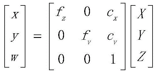
according to the matrix, a correction function is completed in the software OpenCV through a stereoRectify () function, and output parameters are a left projection matrix P, a right projection matrix P and a re-projection matrix Q. Then, a function initunorthortrectifymap () is called to generate a mapping matrix for image correction. And then, clicking the show undersorted in the OpenCV software to obtain the corrected first target image and the corrected second target image.
Referring to fig. 10, in some embodiments, regarding step S300, the ranging method may specifically include, but is not limited to, the following steps:
step S310: and obtaining a corresponding parallax value of each pixel point in the corrected first target image and the second target image by using a feature matching algorithm.
Step S320: and taking the value of the independent variable corresponding to the minimum value in the parallax values as a target parallax value, wherein the target parallax value is taken as the parallax value corresponding to each pixel point in the corrected first target image and the second target image.
In this embodiment, a feature matching algorithm is used to perform matching calculation on the corrected first target image and the second target image, where the corrected first target image is shown in fig. 1A, and the corrected second target image is shown in fig. 1B. In FIG. 1B, a left-right swipe is performed at the same height as in FIG. 1A, and each swipe calculates the degree of match until the best match is found. The corresponding position of the same vegetable leaf in fig. 1A is found in fig. 1B, and the parallax Δ d is obtained by matching search, and the calculation formula is as follows:
Δd=argmindf(x,y,d)
in the matching process, a disparity map of the corrected first target image and the second target image can be obtained, and the disparity map is shown in fig. 2. Meanwhile, the pixel value with the minimum absolute error of the matched position of the two images is continuously searched, so that the target parallax value can be obtained. And then taking the target parallax value as the parallax value corresponding to each pixel point in the corrected first target image and the second target image.
Referring to fig. 11, in some embodiments, regarding step S400, the ranging method may specifically include, but is not limited to, the following steps:
step S410: and calculating to obtain the target distance by utilizing the proportional property of the corresponding side of the similar triangle according to the base length, the focal length and the target parallax value.
In this embodiment, the target distance may be calculated by using the property that the corresponding sides of the similar triangle are proportional according to the base length, the focal length, and the target parallax value. As shown in fig. 3, Δ LMN and Δ LPQ can be formed by connecting the target object 100, the first camera 200, and the second camera 300 through the imaging plane 400, respectively. Since < MLN ═ PLQ and PQ/MN, Δ LMN is similar to Δ LPQ. In addition, B denotes a baseline distance of the first camera from the second camera, F denotes a focal length, and Z denotes a target distance. Since Δ LMN is similar to Δ LPQ, Δ LMN is proportional to the corresponding side of Δ LPQ, and taking the ratio of the height to the base of the two triangles yields equation (1), as follows:

equation (1) is converted into equation (2) through a series of operations, as follows:

in a second aspect, an embodiment of the present invention further provides a distance measuring system, where the distance measuring system includes a first camera, a second camera, a memory and a processor, the first camera and the second camera are respectively connected to the memory, and the memory stores a computer program; the computer program when executed by a processor implements a ranging method as described in any of the embodiments of the first aspect above.
In some embodiments, when the distance measuring system is used, the first camera and the second camera shoot the same scene from different viewpoints to obtain two images, the two images are stored in the memory, the processor corrects the two images again, performs matching calculation to obtain a target parallax value, and then calculates the target distance according to the camera parameters of the shot images and the target parallax value. Through this ranging system, can accomplish the range finding simply, accurately.
In a third aspect, further embodiments of the present invention provide a computer-readable storage medium storing computer-executable instructions for causing a computer to perform a ranging method according to any one of the embodiments of the first aspect.
In some embodiments, the controller or processor performs the above-described method steps S100 to S400 in fig. 4, method step S110 in fig. 5, method steps S111 to S113 in fig. 6, method step S114 in fig. 7, method step S120 in fig. 8, method steps S210 to S220 in fig. 9, method steps S310 to S330 in fig. 10, method step S410 in fig. 11.
One of ordinary skill in the art will appreciate that all or some of the steps, systems, and methods disclosed above may be implemented as software, firmware, hardware, and suitable combinations thereof. Some or all of the physical components may be implemented as software executed by a processor, such as a central processing unit, digital signal processor, or microprocessor, or as hardware, or as an integrated circuit, such as an application specific integrated circuit. Such software may be distributed on computer readable media, which may include computer storage media (or non-transitory media) and communication media (or transitory media). The term computer storage media includes volatile and nonvolatile, removable and non-removable media implemented in any method or technology for storage of information such as computer readable instructions, data structures, program modules or other data, as is well known to those of ordinary skill in the art. Computer storage media includes, but is not limited to, RAM, ROM, EEPROM, flash memory or other memory technology, CD-ROM, Digital Versatile Disks (DVD) or other optical disk storage, magnetic cassettes, magnetic tape, magnetic disk storage or other magnetic storage devices, or any other medium which can be used to store the desired information and which can accessed by a computer. In addition, communication media typically embodies computer readable instructions, data structures, program modules or other data in a modulated data signal such as a carrier wave or other transport mechanism and includes any information delivery media as known to those skilled in the art.
The embodiments of the present invention have been described in detail with reference to the accompanying drawings, but the present invention is not limited to the above embodiments, and various changes can be made within the knowledge of those skilled in the art without departing from the gist of the present invention.
Claims (10)
Priority Applications (1)
| Application Number | Priority Date | Filing Date | Title |
|---|---|---|---|
| CN202011168892.8A CN112305524A (en) | 2020-10-28 | 2020-10-28 | Ranging method, ranging system, and computer-readable storage medium |
Applications Claiming Priority (1)
| Application Number | Priority Date | Filing Date | Title |
|---|---|---|---|
| CN202011168892.8A CN112305524A (en) | 2020-10-28 | 2020-10-28 | Ranging method, ranging system, and computer-readable storage medium |
Publications (1)
| Publication Number | Publication Date |
|---|---|
| CN112305524A true CN112305524A (en) | 2021-02-02 |
Family
ID=74331656
Family Applications (1)
| Application Number | Title | Priority Date | Filing Date |
|---|---|---|---|
| CN202011168892.8A Pending CN112305524A (en) | 2020-10-28 | 2020-10-28 | Ranging method, ranging system, and computer-readable storage medium |
Country Status (1)
| Country | Link |
|---|---|
| CN (1) | CN112305524A (en) |
Cited By (2)
| Publication number | Priority date | Publication date | Assignee | Title |
|---|---|---|---|---|
| CN114565854A (en) * | 2022-04-29 | 2022-05-31 | 河北冀云气象技术服务有限责任公司 | Intelligent image cloud identification system and method |
| WO2025015723A1 (en) * | 2023-07-18 | 2025-01-23 | 中车唐山机车车辆有限公司 | Multi-information-fusion-based binocular ranging method and system for autonomous rail rapid transit |
Citations (5)
| Publication number | Priority date | Publication date | Assignee | Title |
|---|---|---|---|---|
| US20160117820A1 (en) * | 2014-10-23 | 2016-04-28 | Hanwha Techwin Co., Ltd. | Image registration method |
| CN108122259A (en) * | 2017-12-20 | 2018-06-05 | 厦门美图之家科技有限公司 | Binocular camera scaling method, device, electronic equipment and readable storage medium storing program for executing |
| CN109974659A (en) * | 2019-03-31 | 2019-07-05 | 徐州工程学院 | An embedded ranging system based on binocular machine vision |
| CN109990756A (en) * | 2019-04-11 | 2019-07-09 | 武汉纺织大学 | A binocular ranging method and system |
| CN111210468A (en) * | 2018-11-22 | 2020-05-29 | 中移(杭州)信息技术有限公司 | Image depth information acquisition method and device |
-
2020
- 2020-10-28 CN CN202011168892.8A patent/CN112305524A/en active Pending
Patent Citations (5)
| Publication number | Priority date | Publication date | Assignee | Title |
|---|---|---|---|---|
| US20160117820A1 (en) * | 2014-10-23 | 2016-04-28 | Hanwha Techwin Co., Ltd. | Image registration method |
| CN108122259A (en) * | 2017-12-20 | 2018-06-05 | 厦门美图之家科技有限公司 | Binocular camera scaling method, device, electronic equipment and readable storage medium storing program for executing |
| CN111210468A (en) * | 2018-11-22 | 2020-05-29 | 中移(杭州)信息技术有限公司 | Image depth information acquisition method and device |
| CN109974659A (en) * | 2019-03-31 | 2019-07-05 | 徐州工程学院 | An embedded ranging system based on binocular machine vision |
| CN109990756A (en) * | 2019-04-11 | 2019-07-09 | 武汉纺织大学 | A binocular ranging method and system |
Non-Patent Citations (1)
| Title |
|---|
| 席云飞等: "基于双目立体视觉的IC板深度测量", 《制造业自动化》, vol. 42, no. 5, pages 129 - 132 * |
Cited By (2)
| Publication number | Priority date | Publication date | Assignee | Title |
|---|---|---|---|---|
| CN114565854A (en) * | 2022-04-29 | 2022-05-31 | 河北冀云气象技术服务有限责任公司 | Intelligent image cloud identification system and method |
| WO2025015723A1 (en) * | 2023-07-18 | 2025-01-23 | 中车唐山机车车辆有限公司 | Multi-information-fusion-based binocular ranging method and system for autonomous rail rapid transit |
Similar Documents
| Publication | Publication Date | Title |
|---|---|---|
| CN115830103B (en) | Transparent object positioning method and device based on monocular color and storage medium | |
| CN110689581B (en) | Structured light module calibration method, electronic device, and computer-readable storage medium | |
| KR102085228B1 (en) | Imaging processing method and apparatus for calibrating depth of depth sensor | |
| CN109767474B (en) | Multi-view camera calibration method and device and storage medium | |
| US8593524B2 (en) | Calibrating a camera system | |
| CN106548489B (en) | A kind of method for registering, the three-dimensional image acquisition apparatus of depth image and color image | |
| US8306323B2 (en) | Method and apparatus for correcting depth image | |
| CN110009687B (en) | Color three-dimensional imaging system based on three cameras and calibration method thereof | |
| CN111383264B (en) | A positioning method, device, terminal and computer storage medium | |
| WO2021077731A1 (en) | Multi-distance calibration method and system based on depth camera | |
| CN112686961A (en) | Method and device for correcting calibration parameters of depth camera | |
| CN113587895A (en) | Binocular distance measuring method and device | |
| CN112305524A (en) | Ranging method, ranging system, and computer-readable storage medium | |
| JP3666348B2 (en) | Distance recognition device | |
| CN112419427A (en) | Methods for improving the accuracy of time-of-flight cameras | |
| CN112419383B (en) | Method, device and storage medium for generating a depth map | |
| KR20130041440A (en) | Image processing apparatus and method thereof | |
| CN117523009B (en) | Binocular camera calibration method, system, device and storage medium | |
| CN108413941A (en) | A kind of simple and efficient distance measuring method based on cheap binocular camera | |
| CN116894907B (en) | RGBD camera texture mapping optimization method and system | |
| CN115984389B (en) | Calibration method, system calibration method, device and electronic equipment | |
| CN110232715B (en) | Method, device and system for self calibration of multi-depth camera | |
| CN117541659A (en) | Calibration method, device and storage medium of vehicle-mounted camera | |
| CN115311369A (en) | External parameter calibration method of high-precision multi-RGB-D camera with low cost and small amount of overlapped areas | |
| CN117974878A (en) | Hand 3D reconstruction method, device, equipment, storage medium and vehicle |
Legal Events
| Date | Code | Title | Description |
|---|---|---|---|
| PB01 | Publication | ||
| PB01 | Publication | ||
| SE01 | Entry into force of request for substantive examination | ||
| SE01 | Entry into force of request for substantive examination | ||
| RJ01 | Rejection of invention patent application after publication |
Application publication date: 20210202 |
|
| RJ01 | Rejection of invention patent application after publication |