KR101955787B1 - Focusing ultrasonic transducer to applying needle type hydrophone and method for controlling the focusing ultrasonic transducer - Google Patents
Focusing ultrasonic transducer to applying needle type hydrophone and method for controlling the focusing ultrasonic transducer Download PDFInfo
- Publication number
- KR101955787B1 KR101955787B1 KR1020170022371A KR20170022371A KR101955787B1 KR 101955787 B1 KR101955787 B1 KR 101955787B1 KR 1020170022371 A KR1020170022371 A KR 1020170022371A KR 20170022371 A KR20170022371 A KR 20170022371A KR 101955787 B1 KR101955787 B1 KR 101955787B1
- Authority
- KR
- South Korea
- Prior art keywords
- ultrasonic
- concentric
- radius
- regions
- region
- Prior art date
- Legal status (The legal status is an assumption and is not a legal conclusion. Google has not performed a legal analysis and makes no representation as to the accuracy of the status listed.)
- Active
Links
- 238000000034 method Methods 0.000 title claims abstract description 48
- 230000005540 biological transmission Effects 0.000 claims abstract description 50
- 238000002604 ultrasonography Methods 0.000 claims description 32
- 239000000463 material Substances 0.000 claims description 11
- 239000011358 absorbing material Substances 0.000 claims description 10
- 238000009413 insulation Methods 0.000 claims description 9
- 239000002131 composite material Substances 0.000 claims description 3
- 239000011521 glass Substances 0.000 claims description 3
- 239000011810 insulating material Substances 0.000 claims description 3
- 239000011159 matrix material Substances 0.000 claims description 3
- 230000001939 inductive effect Effects 0.000 claims 1
- 239000013078 crystal Substances 0.000 description 4
- 230000000694 effects Effects 0.000 description 4
- 238000000059 patterning Methods 0.000 description 4
- 230000005684 electric field Effects 0.000 description 3
- 238000004519 manufacturing process Methods 0.000 description 3
- 229910002113 barium titanate Inorganic materials 0.000 description 2
- 239000013585 weight reducing agent Substances 0.000 description 2
- 229910003781 PbTiO3 Inorganic materials 0.000 description 1
- 229910020698 PbZrO3 Inorganic materials 0.000 description 1
- JRPBQTZRNDNNOP-UHFFFAOYSA-N barium titanate Chemical compound [Ba+2].[Ba+2].[O-][Ti]([O-])([O-])[O-] JRPBQTZRNDNNOP-UHFFFAOYSA-N 0.000 description 1
- 230000000295 complement effect Effects 0.000 description 1
- 238000001514 detection method Methods 0.000 description 1
- 238000002059 diagnostic imaging Methods 0.000 description 1
- NKZSPGSOXYXWQA-UHFFFAOYSA-N dioxido(oxo)titanium;lead(2+) Chemical compound [Pb+2].[O-][Ti]([O-])=O NKZSPGSOXYXWQA-UHFFFAOYSA-N 0.000 description 1
- 230000014509 gene expression Effects 0.000 description 1
- -1 or the like Substances 0.000 description 1
- 210000000056 organ Anatomy 0.000 description 1
- 230000001151 other effect Effects 0.000 description 1
- LJCNRYVRMXRIQR-OLXYHTOASA-L potassium sodium L-tartrate Chemical compound [Na+].[K+].[O-]C(=O)[C@H](O)[C@@H](O)C([O-])=O LJCNRYVRMXRIQR-OLXYHTOASA-L 0.000 description 1
- 239000010453 quartz Substances 0.000 description 1
- 230000035945 sensitivity Effects 0.000 description 1
- VYPSYNLAJGMNEJ-UHFFFAOYSA-N silicon dioxide Inorganic materials O=[Si]=O VYPSYNLAJGMNEJ-UHFFFAOYSA-N 0.000 description 1
- 235000011006 sodium potassium tartrate Nutrition 0.000 description 1
- 239000000126 substance Substances 0.000 description 1
- 230000000007 visual effect Effects 0.000 description 1
Images


Classifications
-
- A—HUMAN NECESSITIES
- A61—MEDICAL OR VETERINARY SCIENCE; HYGIENE
- A61B—DIAGNOSIS; SURGERY; IDENTIFICATION
- A61B8/00—Diagnosis using ultrasonic, sonic or infrasonic waves
- A61B8/44—Constructional features of the ultrasonic, sonic or infrasonic diagnostic device
- A61B8/4483—Constructional features of the ultrasonic, sonic or infrasonic diagnostic device characterised by features of the ultrasound transducer
- A61B8/4494—Constructional features of the ultrasonic, sonic or infrasonic diagnostic device characterised by features of the ultrasound transducer characterised by the arrangement of the transducer elements
-
- G—PHYSICS
- G01—MEASURING; TESTING
- G01H—MEASUREMENT OF MECHANICAL VIBRATIONS OR ULTRASONIC, SONIC OR INFRASONIC WAVES
- G01H17/00—Measuring mechanical vibrations or ultrasonic, sonic or infrasonic waves, not provided for in the preceding groups
Landscapes
- Health & Medical Sciences (AREA)
- Life Sciences & Earth Sciences (AREA)
- Physics & Mathematics (AREA)
- Biomedical Technology (AREA)
- Medical Informatics (AREA)
- Biophysics (AREA)
- Nuclear Medicine, Radiotherapy & Molecular Imaging (AREA)
- Pathology (AREA)
- Radiology & Medical Imaging (AREA)
- Engineering & Computer Science (AREA)
- General Physics & Mathematics (AREA)
- Heart & Thoracic Surgery (AREA)
- Gynecology & Obstetrics (AREA)
- Molecular Biology (AREA)
- Surgery (AREA)
- Animal Behavior & Ethology (AREA)
- General Health & Medical Sciences (AREA)
- Public Health (AREA)
- Veterinary Medicine (AREA)
- Transducers For Ultrasonic Waves (AREA)
- Ultra Sonic Daignosis Equipment (AREA)
Abstract
본 발명은 바늘형 초음파 수신기가 적용된 집속 초음파 트랜스듀서 및 그 작동방법에 관한 것이다. 보다 상세하게는 초음파 트랜스 듀서에 있어서, 중앙개구부가 형성되며, 초음파를 가진 시키는 초음파 가진기; 상기 초음파 가진기로부터 초음파를 입사받고, 입사되는 초음파를 초점부근에서 집속시키며, 중앙개구부가 형성되며, 중심점을 기준으로 동심원 형상으로 배치되는 복수의 동심원 영역을 갖고, 상기 동심원 영역은 중심점부터 반경방향으로, 입사되는 음파를 차음시키는 차음영역과, 음파를 투과시키는 투과영역이 교차되며 형성되는 음향렌즈; 및 일측 끝단부가 상기 초음파 가진기의 중앙개구부와, 상기 음향렌즈의 중앙개구부에 위치되어, 반사된 초음파 신호를 수신하는 초음파 수신부를 포함하는 것을 특징으로 하는 바늘형 초음파 수신기가 적용된 집속 초음파 트랜스듀서에 관한 것이다. The present invention relates to a focused-type ultrasonic transducer to which a needle-shaped ultrasonic receiver is applied, and a method of operation thereof. More particularly, the present invention relates to an ultrasonic transducer, which comprises: an ultrasonic wave vibrator having a central opening and having an ultrasonic wave; And a plurality of concentric circular regions arranged concentrically with respect to the center point, wherein the concentric circular region has a radius of curvature in the radial direction from the center point An acoustic lens formed so as to intersect a sound-insulating region for shielding incident sound waves and a transmission region for transmitting sound waves; And an ultrasonic receiver for receiving the reflected ultrasonic signal, the ultrasonic receiver being located at a central opening of the ultrasonic wave vibrator and at a central opening of the acoustic lens at one end of the ultrasonic wave vibrator, and a focusing ultrasonic transducer .
Description
본 발명은 바늘형 초음파 수신기가 적용된 집속 초음파 트랜스듀서 및 그 작동방법에 관한 것이다. The present invention relates to a focused-type ultrasonic transducer to which a needle-shaped ultrasonic receiver is applied, and a method of operation thereof.
초음파 트랜스듀서(ultrasonic transducer)(이하, 초음파 변환기)는 전기적 신호를 초음파 신호로 변환하거나, 반대로 초음파 신호를 전기적 신호로 변환할 수 있는 장치이다. An ultrasonic transducer (hereinafter referred to as an ultrasonic transducer) is a device that converts an electric signal into an ultrasonic signal, or conversely, an ultrasonic signal into an electric signal.
초음파는 사람이 들을 수 있는 가청 주파수 대역보다 큰 20 ㎑를 넘는 주파수를 가지는 음파로서, 인간이 청각을 이용하여 들을 수 없다. 이러한 초음파는 다양한 분야에서 널리 활용되며 우리 삶에 많은 영역에서 편의를 제공해주고 있다.Ultrasound is a sound wave with a frequency greater than 20 kHz that is greater than the human audible frequency band and can not be heard by humans using auditory sense. These ultrasound waves are widely used in various fields and provide convenience in many areas of our lives.
예를 들어, 의료 영상 진단 기기에 사용될 수 있는데, 비침습적(non-invasive)으로 신체의 조직이나 기관의 사진이나 영상을 얻을 수 있는 장점이 있다.For example, it can be used in medical imaging diagnostic devices, which is non-invasive and has the advantage of obtaining images or images of the tissues or organs of the body.
또한, 초음파 트랜스듀서는 외부 객체의 검지를 위하여 활용될 수도 있다. 즉, 초음파 변환기를 이용하여 초음파 신호를 출력한 후, 출력된 초음파 신호가 외부 객체에 반사되어 되돌아오는 경우 이를 수신하여 초음파 신호가 되돌아오는 데 걸리는 시간을 측정할 수 있다. 상기 측정된 시간을 이용하여 외부 객체의 존재 및 상기 외부 객체까지의 거리를 계산할 수 있다.Also, the ultrasonic transducer may be utilized for detecting an external object. That is, after outputting the ultrasonic signal by using the ultrasonic transducer, if the outputted ultrasonic signal is reflected by the external object and is returned, it can receive the ultrasonic signal and measure the time taken for the ultrasonic signal to return. The presence of an external object and the distance to the external object can be calculated using the measured time.
현재 일반적으로 많이 사용되고 있는 초음파 트랜스듀서는 자기장(magnetic field)을 이용하는 방식, 전기장을 이용하는 방식, 압전(piezoelectic) 물질을 이용하는 방식 세 가지가 있다.There are three types of ultrasonic transducers that are commonly used today: a magnetic field, an electric field, and a piezoelectric material.
이들 중 압전 물질을 이용하는 방식은 높은 주파수 대역(초음파 대역)에서 소형화에 비교적 유리하고 내구성도 뛰어 나서 많이 사용되어 있다.Among them, a piezoelectric material is widely used because it is relatively advantageous for miniaturization in a high frequency band (ultrasound band) and has excellent durability.
압전 효과란 역학적인 진동이 가해졌을 때에 결정체(crystal)에 전위차가 발생하는 현상을 말한다. 이와 반대로 결정체에 전기장을 걸어주었을 때에 역학적인 진동이 발생하는 현상을 포함한다. Piezoelectric effect refers to a phenomenon in which a potential difference occurs in a crystal when mechanical vibration is applied. On the contrary, it includes the phenomenon that dynamic vibration occurs when an electric field is applied to a crystal body.
따라서, 압전소자를 이용한 초음파 트랜스듀서는 압전소자에 전기장을 인가하여 압전소자에서 발생되는 진동에 의해 초음파를 발생시키게 된다.Therefore, an ultrasonic transducer using a piezoelectric element applies an electric field to the piezoelectric element to generate ultrasonic waves by vibrations generated in the piezoelectric element.
압전소자를 이루는 재료는 로셸염(Rochelle salt)과 수정(quartz)은 단결정(single crystal)이고, 타이타늄산바륨(Barium titanate, BaTiO3)과 Lead titanate(PbTiO3), Lead zirconate system(PbZrO3) 등은 복결정(multi-crystal)이다.Rochelle salt and quartz are single crystals. Barium titanate (BaTiO3), lead titanate (PbTiO3) and lead zirconate system (PbZrO3) It is multi-crystal.
이러한 압전 특성을 이용하면 초음파 발생용 변환기, 수신용 변환기, 발신/수신 겸용 변환기를 만들 수 있다.Using these piezoelectric properties, transducers for generating ultrasonic waves, receiving transducers, and transmitting / receiving transducers can be made.
한편, 초음파 변환기를 외부 객체의 감지나 장애인용 시각 보조장치 등에 사용하는 경우, 일반적으로 출력되는 초음파 신호의 지향성은 크게 상관이 없으나, 초음파 신호의 수신 시에는 높은 지향성을 갖는 것이 요구된다.On the other hand, when the ultrasonic transducer is used for the detection of an external object or a visual aid for a person with a disability, generally, the directivity of the outputted ultrasonic signal is not significantly related, but it is required to have a high directivity when receiving the ultrasonic signal.
또한, 집속 초음파 트랜스듀서는 초음파 가진기에서 가진되는 초음파를 초점부근으로 집속시키기 위하여 음향렌즈를 포함하여 구성되게 된다. The focused ultrasound transducer is configured to include an acoustic lens for converging the ultrasound excited by the ultrasound exciter to the vicinity of the focus.
도 1은 종래 구면형 음향렌즈(2)가 적용된 초음파 트랜스듀서(1)의 단면도를 도시한 것이다. 도 1에 도시된 바와 같이, 초음파 가진기(10)는 초음파를 가진하여 음향렌즈(2) 측으로 초음파를 입사시키게 되고, 입사되는 초음파는 음향렌즈(2)에 의해 초점 부근으로 집속되게 된다. 1 is a cross-sectional view of an
이러한 종래 음향렌즈(2)의 초음파 출사면은 입사면 측으로 오목한 일정 반경곡률을 갖는 오목면으로 구성됨을 알 수 있다. 그러나, 이러한 종래 구면형 음향렌즈(2)의 경우, 음향렌즈를 구성하는 재료의 임피던스가 초음파 가진기(10) 재료의 임피던스보다는 작고, 전달물질의 임피던스보다는 크게 되어야 하므로 선택될 수 있는 재료가 제한적인 문제점이 존재하였다. It can be seen that the ultrasonic emission surface of the conventional
또한, 종래 구면형 음향렌즈(2)는 곡률반경의 영향으로 두께가 두꺼워질 수 밖에 없어 경량화, 소형화에 불리하다는 문제점이 존재하였다. In addition, the conventional spherical
따라서 본 발명은 상기와 같은 종래의 문제점을 해결하기 위하여 안출된 것으로서, 본 발명의 일실시예에 따르면, 초음파 가진기의 중앙부분에 개구부를 형성하고, 이러한 개구부에 초음파 수신을 위한 바늘형(Needle type) 하이드로폰을 집적하여 출력과, 수신효율을 향상시킬 수 있는 바늘형 초음파 수신기가 적용된 집속 초음파 트랜스듀서를 제공하는데 그 목적이 있다. SUMMARY OF THE INVENTION Accordingly, the present invention has been made keeping in mind the above problems occurring in the prior art, and it is an object of the present invention to provide an ultrasound system, type ultrasonic transducer with a needle type ultrasonic receiver capable of integrating hydrophones to improve output and reception efficiency.
또한, 본 발명의 일실시예 따르면, 투과영역과 차음영역이 교차되는 다수의 동심원 영역 각각의 반경 치수를 신속하고 효율적으로 설계할 수 있는 프레넬 존 플레이트(fresnel zone plate, FZP) 원리를 이용한 음향렌즈를 적용하고, 이러한 음향렌즈의 중앙부분은 초음파 에너지 발신과 수신에 사용되지 않기 때문에, 중앙 부분에 개구부를 형성하고, 이러한 개구부에 초음파 수신을 위한 바늘형(Needle type) 하이드로폰을 집적하여 출력과, 수신효율을 향상시킬 수 있는 바늘형 초음파 수신기가 적용된 집속 초음파 트랜스듀서를 제공하는데 그 목적이 있다. According to an embodiment of the present invention, there is provided an acoustic device using a fresnel zone plate (FZP) principle capable of rapidly and efficiently designing a radius dimension of each of a plurality of concentric regions in which a transmission region and a sound insulation region intersect each other Since the center portion of such an acoustic lens is not used for transmission and reception of ultrasonic energy, an opening is formed at the center portion, and a needle-type hydrophone for receiving ultrasonic waves is integrated in such an opening to output And a focusing ultrasonic transducer to which a needle-like ultrasonic receiver capable of improving reception efficiency is applied.
또한, 본 발명의 또 다른 실시예 따르면, 별도의 음향 렌즈없이 전극을 프레넬 존 플레이트 치수로 패터닝하여 선택적으로 초음파를 송수신할 수 있는 동심원 전극을 적용한 집속 초음파 트랜스듀서를 적용하고, 중앙 부분에 개구부를 형성하고, 이러한 개구부에 초음파 수신을 위한 바늘형(Needle type) 하이드로폰을 집적하여 출력과, 수신효율을 향상시킬 수 있는 바늘형 초음파 수신기가 적용된 집속 초음파 트랜스듀서를 제공하는데 그 목적이 있다. According to another aspect of the present invention, there is provided a focusing ultrasonic transducer applying a concentric circular electrode capable of selectively transmitting and receiving ultrasonic waves by patterning an electrode in a Fresnel zone plate dimension without a separate acoustic lens, And an object of the present invention is to provide a focusing ultrasonic transducer to which needle type ultrasonic receivers for integrating needle-type hydrophones for receiving ultrasonic waves and capable of improving the output and receiving efficiency are provided in such openings.
본 발명의 또 다른 실시예에 따른 초음파 트랜스듀서의 동심원 전극을 촘촘하게 제작하여, 전압이 인가되는 유효전극(Effective electrode)의 개수, 면적을 선택, 조절하여 하나의 집속 초음파 트랜스듀서에서 다양한 초점거리, 빔 직경을 자유롭게 구현, 조절할 수 있는 바늘형 초음파 수신기가 적용된 집속 초음파 트랜스듀서의 제어방법을 제공하는데 그 목적이 있다. The concentric electrode of the ultrasonic transducer according to another embodiment of the present invention may be manufactured in a compact manner to select and adjust the number and area of the effective electrode to which voltage is applied so that a single focusing ultrasonic transducer can detect various focal lengths, And an object of the present invention is to provide a control method of a focused ultrasonic transducer to which a needle type ultrasonic receiver capable of freely implementing and adjusting a beam diameter can be applied.
한편, 본 발명에서 이루고자 하는 기술적 과제들은 이상에서 언급한 기술적 과제들로 제한되지 않으며, 언급하지 않은 또 다른 기술적 과제들은 아래의 기재로부터 본 발명이 속하는 기술분야에서 통상의 지식을 가진 자에게 명확하게 이해될 수 있을 것이다.It is to be understood that both the foregoing general description and the following detailed description of the present invention are exemplary and explanatory and are not intended to limit the invention to the precise form disclosed. It can be understood.
본 발명의 제1목적은, 초음파 트랜스 듀서에 있어서, 중앙개구부가 형성되며, 초음파를 가진 시키는 초음파 가진기; 상기 초음파 가진기로부터 초음파를 입사받고, 입사되는 초음파를 초점부근에서 집속시키며, 중앙개구부가 형성되며, 중심점을 기준으로 동심원 형상으로 배치되는 복수의 동심원 영역을 갖고, 상기 동심원 영역은 중심점부터 반경방향으로, 입사되는 음파를 차음시키는 차음영역과, 음파를 투과시키는 투과영역이 교차되며 형성되는 음향렌즈; 및 일측 끝단부가 상기 초음파 가진기의 중앙개구부와, 상기 음향렌즈의 중앙개구부에 위치되어, 반사된 초음파 신호를 수신하는 초음파 수신부를 포함하는 것을 특징으로 하는 바늘형 초음파 수신기가 적용된 집속 초음파 트랜스듀서로서 달성될 수 있다. SUMMARY OF THE INVENTION A first object of the present invention is to provide an ultrasonic transducer comprising: an ultrasonic wave vibrator having a central opening and having an ultrasonic wave; And a plurality of concentric circular regions arranged concentrically with respect to the center point, wherein the concentric circular region has a radius of curvature in the radial direction from the center point An acoustic lens formed so as to intersect a sound-insulating region for shielding incident sound waves and a transmission region for transmitting sound waves; And an ultrasonic receiver for receiving a reflected ultrasonic signal, the ultrasonic receiver being positioned at a central opening of the ultrasonic wave vibrator and at a central opening of the acoustic lens at one end of the ultrasonic wave vibrator, and a focusing ultrasonic transducer to which the ultrasonic wave receiver is applied Can be achieved.
그리고, 상기 초음파 가진기는 압전소자와, 상기 압전소자를 진동시키기 위해 전압을 인가받는 전극층을 포함하여 구성되는 것을 특징으로 할 수 있다. The ultrasonic vibrator may include a piezoelectric element and an electrode layer to which a voltage is applied to vibrate the piezoelectric element.
또한, 상기 음향렌즈는 양면이 평평한 면으로 구성되며 두께가 일정한 판형태이고, 상기 동심원 영역 내 복수의 차음영역과 투과영역 각각의 반경은, 설정된 음향렌즈의 초점거리와, 설정된 음파의 주파수로부터 결정되는 전달매질에서의 파장을 기반으로 연산되는 것을 특징으로 할 수 있다. The radius of each of the plurality of sound insulating regions and the transmissive regions in the concentric circular region is determined from the focal distance of the set acoustic lens and the frequency of the set acoustic wave, Based on the wavelength in the transmission medium.
그리고, 상기 동심원 영역 내 복수의 차음영역과 투과영역 각각의 반경은 이하의 수학식 1, 수학식 2에 의해 연산되는 것을 특징으로 할 수 있다. The radius of each of the plurality of sound insulating regions and the transmitting regions in the concentric circular region may be calculated by the following equations (1) and (2).
[수학식 1][Equation 1]
![]()
![]()
[수학식 2]&Quot; (2) "

수학식 1에서, m은 중심점부터 반경방향으로 순차적인 상기 동심원 영역의 인덱스이고, λ는 전달매질에서의 음파 파장이고, F는 음향렌즈의 초점거리이고, In Equation (1), m is an index of the concentric circular region sequentially from a center point to a radial direction,? Is an acoustic wave wavelength in the transmission medium, F is a focal length of the acoustic lens,
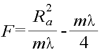
수학식 2에서, Ra는 음향렌즈의 반경이고, λ는 전달매질에서의 음파 파장이고, m은 음향렌즈 내의 동심원 영역의 개수이다. In Equation (2), Ra is the radius of the acoustic lens,? Is the acoustic wave wavelength in the transmission medium, and m is the number of concentric regions in the acoustic lens.
또한, 상기 투과영역을 구성하는 투과물질은 유리 및 고무 중 적어도 어느 하나이고, 상기 차음영역을 구성하는 차음물질은 공기 또는, 음파의 산란과정을 유도하는 복합재와 음파의 산란과정에서 흡음재의 바탕을 메우는 매트릭스 재료(matrix material)갖는 흡음재인 것을 특징으로 할 수 있다. In addition, the permeable material constituting the permeable region is at least one of glass and rubber, and the sound-insulating material constituting the sound-insulating region is a composite material which induces air or a scattering process of sound waves, and a sound- The cover may be a sound absorbing material having a matrix material.
본 발명의 제2목적은, 집속 초음파 트랜스듀서에 있어서, 중앙개구부가 형성되며, 초음파를 가진 시키는 초음파 가진기; 상기 초음파 가진기의 일면에 구비되며, 중앙개구부가 형성된 제1전극층; 중앙개구부가 형성되고, 상기 초음파 가진기의 타면에 구비되며, 중심점을 기준으로 동심원 형상으로 배치되는 복수의 동심원 영역을 갖고, 상기 동심원 영역은 중심점부터 반경방향으로 서로 특정간격 이격된 다수의 동심원 전극과, 상기 동심원 전극 사이 각각의 이격영역이 교차형성되는 제2전극층; 및 상기 일측 끝단부가 상기 초음파 가진기의 중앙개구부와, 상기 제1전극층과 제2전극층의 중앙개구부에 위치되어, 반사된 초음파 신호를 수신하는 초음파 수신부를 포함하는 것을 특징으로 하는 바늘형 초음파 수신기가 적용된 집속 초음파 트랜스듀서로서 달성될 수 있다. A second object of the present invention is to provide a focused ultrasound transducer, comprising: an ultrasonic wave vibrator formed with a central opening and having an ultrasonic wave; A first electrode layer provided on one surface of the ultrasonic vibrator and having a central opening; And a plurality of concentric circular regions disposed on the other surface of the ultrasonic vibrator and arranged concentrically with respect to the center point, wherein the concentric circular regions include a plurality of concentric circular electrodes spaced apart from each other by a predetermined distance in the radial direction from the center point, A second electrode layer in which spacing regions are formed between the concentric circles; And an ultrasonic receiver for receiving the reflected ultrasonic signal, the ultrasonic receiver being located at a central opening of the ultrasonic vibrator and a central opening of the first electrode layer and the second electrode layer, Can be achieved as an applied focused ultrasonic transducer.
본 발명의 제1,2목적에 있어서, 초음파 수신부는 하이드로폰으로 구성되는 것을 특징으로 할 수 있다. In the first or second object of the present invention, the ultrasonic wave receiver may be configured as a hydrophone.
본 발명의 제1,2목적에 있어서, 하이드로폰의 일측 끝단부는 일측으로 점진적으로 직경이 감소되는 바늘형 하이드로폰인 것을 특징으로 할 수 있다. In one or more embodiments of the present invention, one end of the hydrophone may be a needle-like hydrophone whose diameter is gradually reduced toward one side.
본 발명의 제2목적에 있어서, 상기 초음파 가진기는 압전소자로 구성되고, 상기 다수의 동심원 전극 중 적어도 어느 하나에 전압을 인가하는 전압인가부; 및 설정된 초점거리를 갖도록, 선택된 다수의 동심원 전극에 전압을 인가하도록 상기 전압인가부를 제어하는 제어부를 더 포함하는 것을 특징으로 할 수 있다. According to a second aspect of the present invention, the ultrasonic vibrator is composed of a piezoelectric element, and applies a voltage to at least one of the plurality of concentric circles; And a control unit for controlling the voltage applying unit to apply a voltage to the selected plurality of concentric circular electrodes so as to have a predetermined focal distance.
그리고, 제2목적에 있어서, 전압이 인가될 상기 동심원 전극의 선택은, 설정된 초점거리와, 설정된 음파의 주파수로부터 결정되는 전달매질에서의 파장을 기반으로 연산된 동심원 영역의 반경에 기반하는 것을 특징으로 할 수 있다. And, for the second object, the selection of the concentric electrodes to which the voltage is applied is characterized by being based on a set focal distance and a radius of a concentric circle area calculated on the basis of the wavelength in the transmission medium determined from the frequency of the set sound wave .
그리고, 제2목적에 있어서, 상기 동심원 영역 내 복수의 동심원 전극과 이격영역 각각의 반경은 이하의 수학식 1, 2에 의해 연산되며, 제어부는 연산된 상기 동심원 영역 내 복수의 동심원 전극과 이격영역 각각의 반경에 부합되도록 전압이 인가될 동심원 전극을 선택하는 것을 특징으로 할 수 있다. In the second object, the radiuses of the plurality of concentric circular electrodes and the spacing regions in the concentric circle region are calculated by the following equations (1) and (2), and the control unit calculates the radius of each of the concentric circular- And selecting a concentric electrode to which a voltage is applied so as to match each of the radii.
[수학식 1][Equation 1]
![]()
![]()
[수학식 2]&Quot; (2) "

수학식 1에서, m은 중심점부터 반경방향으로 순차적인 상기 동심원 영역의 인덱스이고, λ는 전달매질에서의 음파 파장이고, F는 초점거리이고,In Equation (1), m is an index of the concentric circle region sequentially from a center point to a radial direction,? Is an acoustic wave wavelength in a transmission medium, F is a focal length,
수학식 2에서, Ra는 선택된 동심원 전극 중 최외곽 동심원 전극의 반경이고, λ는 전달매질에서의 음파 파장이고, F는 초점거리이고, m은 선택된 동심원 영역의 개수이다. In Equation (2), Ra is the radius of the outermost concentric circle of the selected concentric electrodes, lambda is the sonic wave wavelength in the transmission medium, F is the focal length, and m is the number of the selected concentric circle regions.
그리고, 제1, 2목적에 있어서, 내부 상단 일측에 상기 초음파 가진기가 장착되는 하우징; 및 상기 하우징 내부에 구비되는 초음파 흡수물질을 더 포함하는 것을 특징으로 할 수 있다. In addition, in the first and second objects, there is provided an ultrasonic diagnostic apparatus comprising: a housing on which an ultrasonic vibrator is mounted; And an ultrasonic absorbing material provided inside the housing.
본 발명의 제3목적은, 앞서 언급한 제 1목적에 따른 집속 초음파 트랜스듀서에 구비되는 음향렌즈를 설계하는 방법에 있어서, 원하는 초음파 주파수와, 원하는 초점거리를 결정하는 단계; 전달매질 내에서의 초음파 파장을 연산하는 단계; 상기 초음파 파장과, 상기 초점거리를 기반으로, 동심원 영역 내 복수의 차음영역과 투과영역 각각의 반경을 연산하는 단계; 제작된 상기 음향렌즈의 반경을 초음파 가진기의 반경 내에서 결정하고, 상기 동심원 영역의 개수가 결정되는 단계; 및 상기 동심원 영역의 개수와, 상기 음향렌즈의 반경과, 동심원 영역 내 복수의 차음영역과 투과영역 각각의 반경에 부합되도록 음향렌즈를 제작하는 단계를 포함하는 것을 특징으로 하는 바늘형 초음파 수신기가 적용된 집속 초음파 트랜스듀서의 음향렌즈 설계방법으로서 달성될 수 있다. A third object of the present invention is to provide a method of designing an acoustic lens included in a focused ultrasound transducer according to the first aspect, comprising: determining a desired ultrasonic frequency and a desired focal distance; Computing an ultrasonic wavelength in the propagation medium; Calculating a radius of each of the plurality of sound insulation regions and the transmission region in the concentric circle region based on the ultrasonic wave wavelength and the focal distance; Determining the radius of the manufactured acoustic lens within the radius of the ultrasonic vibrator and determining the number of the concentric regions; And fabricating the acoustic lens so that the number of the concentric circular regions, the radius of the acoustic lens, and the radius of each of the plurality of sound-insulating regions and the transmissive regions in the concentric circular region are equal to each other. Can be achieved as a method for designing an acoustic lens of a focused ultrasound transducer.
본 발명의 제3목적에 있어서, 상기 반경을 연산하는 단계는, 상기 동심원 영역 내 복수의 차음영역과 투과영역 각각의 반경은 이하의 수학식 1,2에 의해 연산되는 것을 특징으로 할 수 있다. In the third aspect of the present invention, the step of calculating the radius may be characterized in that a radius of each of the plurality of sound insulating regions and the transmitting regions in the concentric circular region is calculated by the following expressions (1) and (2).
[수학식 1][Equation 1]
![]()
![]()
[수학식 2]&Quot; (2) "

수학식 1에서, m은 중심점부터 반경방향으로 순차적인 상기 동심원 영역의 인덱스이고, λ는 전달매질에서의 음파 파장이고, F는 음향렌즈의 초점거리이고, In Equation (1), m is an index of the concentric circular region sequentially from a center point to a radial direction,? Is an acoustic wave wavelength in the transmission medium, F is a focal length of the acoustic lens,
수학식 2에서, Ra는 음향렌즈의 반경이고, λ는 전달매질에서의 음파 파장이고, m은 음향렌즈 내의 동심원 영역의 개수이다. In Equation (2), Ra is the radius of the acoustic lens,? Is the acoustic wave wavelength in the transmission medium, and m is the number of concentric regions in the acoustic lens.
본 발명의 제4목적은 앞서 언급한 제 2목적에 따른 집속 초음파 트랜스듀서의 제어방법에 있어서, 원하는 초음파 주파수와, 원하는 초점거리를 결정하는 단계; 전달매질 내에서의 초음파 파장을 연산하는 단계; 상기 초음파 파장과, 상기 초점거리를 기반으로, 상기 동심원 영역 내 복수의 동심원 전극과 이격영역 각각의 반경을 연산하는 단계; 전압을 인가할 동심원 전극 중 최외곽 동심원 전극의 반경을 결정하고, 상기 전압을 인가할 동심원 전극의 개수가 결정되는 단계; 제어부는 연산된 상기 동심원 영역 내 복수의 동심원 전극과 이격영역 각각의 반경에 부합되도록 전압이 인가될 동심원 전극을 선택하는 단계; 및 전압인가부가 선택된 동심원 전극에 전압을 인가하여 초음파 신호가 출력되는 단계; 및 출력된 초음파 신호가 외부객체에 반사되고, 바늘형 하이드로폰으로 구성된 초음파 수신부가 반사된 초음파 신호를 수신하는 단계;를 포함하는 것을 특징으로 하는 바늘형 초음파 수신기가 적용된 집속 초음파 트랜스듀서의 제어방법으로서 달성될 수 있다. A fourth object of the present invention is to provide a method of controlling a focused ultrasound transducer according to the second object, comprising the steps of: determining a desired ultrasonic frequency and a desired focal distance; Computing an ultrasonic wavelength in the propagation medium; Calculating a radius of each of the plurality of concentric electrodes and the spacing regions in the concentric region based on the ultrasonic wavelength and the focal distance; Determining a radius of an outermost concentric circle electrode of the concentric circles to which a voltage is to be applied and determining the number of concentric circles to which the voltage is to be applied; Selecting a concentric electrode to which a voltage is applied so as to match the radius of each of the plurality of concentric electrodes and the spacing regions in the calculated concentric circle region; And outputting an ultrasonic signal by applying a voltage to the concentric circular electrode selected by the voltage application unit; And a step of receiving the reflected ultrasound signal by the ultrasound receiving unit including the needle-shaped hydrophone, and outputting the reflected ultrasound signal to an external object and receiving the reflected ultrasound signal. . ≪ / RTI >
본 발명의 제4목적에 있어서, 상기 반경을 연산하는 단계에서, 상기 동심원 영역 내 복수의 동심원 전극과 이격영역 각각의 반경은 이하의 수학식 1에 의해 연산되는 것을 특징으로 할 수 있다. In the fourth aspect of the present invention, in the step of calculating the radius, the radii of each of the plurality of concentric circular electrodes and the spacing regions in the concentric circular region may be calculated by the following equation (1).
[수학식 1][Equation 1]
![]()
![]()
[수학식 2]&Quot; (2) "
수학식 1에서, m은 중심점부터 반경방향으로 순차적인 상기 동심원 영역의 인덱스이고, λ는 전달매질에서의 음파 파장이고, F는 초점거리이고,In Equation (1), m is an index of the concentric circle region sequentially from a center point to a radial direction,? Is an acoustic wave wavelength in a transmission medium, F is a focal length,
수학식 2에서, Ra는 선택된 동심원 전극 중 최외곽 동심원 전극의 반경이고, λ는 전달매질에서의 음파 파장이고, F는 초점거리이고, m은 선택된 동심원 영역의 개수이다. In Equation (2), Ra is the radius of the outermost concentric circle of the selected concentric electrodes, lambda is the sonic wave wavelength in the transmission medium, F is the focal length, and m is the number of the selected concentric circle regions.
본 발명의 일실시예에 따르면, 초음파 가진기의 중앙부분에 개구부를 형성하고, 이러한 개구부에 초음파 수신을 위한 바늘형(Needle type) 하이드로폰을 집적하여 출력과, 수신효율을 향상시킬 수 있는 효과를 갖는다. According to an embodiment of the present invention, an opening is formed in a central portion of the ultrasonic vibrator, and an output and a reception efficiency can be improved by integrating a needle type hydrophone for receiving ultrasonic waves into the opening. .
또한, 본 발명의 일실시예 따르면, 투과영역과 차음영역이 교차되는 다수의 동심원 영역 각각의 반경 치수를 신속하고 효율적으로 설계할 수 있는 프레넬 존 플레이트(fresnel zone plate, FZP) 원리를 이용한 음향렌즈를 적용하고, 이러한 음향렌즈의 중앙부분은 초음파 에너지 발신과 수신에 사용되지 않기 때문에, 중앙 부분에 개구부를 형성하고, 이러한 개구부에 초음파 수신을 위한 바늘형(Needle type) 하이드로폰을 집적하여 출력과, 수신효율을 향상시킬 수 있는 효과를 갖는다.According to an embodiment of the present invention, there is provided an acoustic device using a fresnel zone plate (FZP) principle capable of rapidly and efficiently designing a radius dimension of each of a plurality of concentric regions in which a transmission region and a sound insulation region intersect each other Since the center portion of such an acoustic lens is not used for transmission and reception of ultrasonic energy, an opening is formed at the center portion, and a needle-type hydrophone for receiving ultrasonic waves is integrated in such an opening to output And an effect of improving the reception efficiency.
또한, 본 발명의 또 다른 실시예 따르면, 별도의 음향 렌즈없이 전극을 프레넬 존 플레이트 치수로 패터닝하여 선택적으로 초음파를 송수신할 수 있는 동심원 전극을 적용한 집속 초음파 트랜스듀서를 적용하고, 중앙 부분에 개구부를 형성하고, 이러한 개구부에 초음파 수신을 위한 바늘형(Needle type) 하이드로폰을 집적하여 출력과, 수신효율을 향상시킬 수 있는 효과를 갖는다.According to another aspect of the present invention, there is provided a focusing ultrasonic transducer applying a concentric circular electrode capable of selectively transmitting and receiving ultrasonic waves by patterning an electrode in a Fresnel zone plate dimension without a separate acoustic lens, And integrating a needle type hydrophone for receiving ultrasonic waves into the opening, thereby improving the output and receiving efficiency.
본 발명의 또 다른 실시예에 따른 초음파 트랜스듀서의 동심원 전극을 촘촘하게 제작하여, 전압이 인가되는 유효전극(Effective electrode)의 개수, 면적을 선택, 조절하여 하나의 집속 초음파 트랜스듀서에서 다양한 초점거리, 빔 직경을 자유롭게 구현, 조절할 수 있는 효과를 갖는다.The concentric electrode of the ultrasonic transducer according to another embodiment of the present invention may be manufactured in a compact manner to select and adjust the number and area of the effective electrode to which voltage is applied so that a single focusing ultrasonic transducer can detect various focal lengths, The beam diameter can be freely implemented and adjusted.
한편, 본 발명에서 얻을 수 있는 효과는 이상에서 언급한 효과들로 제한되지 않으며, 언급하지 않은 또 다른 효과들은 아래의 기재로부터 본 발명이 속하는 기술분야에서 통상의 지식을 가진 자에게 명확하게 이해될 수 있을 것이다.It should be understood, however, that the effects obtained by the present invention are not limited to the above-mentioned effects, and other effects not mentioned may be clearly understood by those skilled in the art to which the present invention belongs It will be possible.
본 명세서에 첨부되는 다음의 도면들은 본 발명의 바람직한 일실시예를 예시하는 것이며, 발명의 상세한 설명과 함께 본 발명의 기술적 사상을 더욱 이해시키는 역할을 하는 것이므로, 본 발명은 그러한 도면에 기재된 사항에만 한정되어 해석 되어서는 아니 된다.
도 1은 종래 구면형 음향렌즈가 적용된 초음파 트랜스듀서의 단면도,
도 2는 본 발명의 제1실시예에 따른 바늘형 초음파 수신기가 적용된 집속 초음파 트랜스듀서의 단면 사시도,
도 3은 본 발명의 제1실시예에 따른 바늘형 초음파 수신기가 적용된 집속 초음파 트랜스듀서의 음향렌즈의 평면도,
도 4는 본 발명의 제1실시예에 따른 바늘형 초음파 수신기가 적용된 집속 초음파 트랜스듀서의 부분 단면도,
도 5는 본 발명의 제1실시예에 따른 프레넬 존 플레이트 원리를 이용한 음향렌즈의 집속원리를 설명한 모식도,
도 6은 본 발명의 제1실시예인 음향렌즈 설계방법에 따른 주파수별 동심원 영역 개수에 대한 초점거리 그래프,
도 7은 본 발명의 제1실시예인 음향렌즈 설계방법에 따른 주파수별 동심원 영역 개수에 대한 음향렌즈의 반경 그래프,
도 8은 본 발명의 제1실시예에 따른 음향렌즈의 설계방법의 흐름도,
도 9는 본 발명의 제1실시예인 음향렌즈 설계방법에 따른 초점거리가 30mm일 때, 주파수별, 동심원 영역 각각의 반경 수치표,
도 10은 본 발명의 제2실시예에 따른 바늘형 초음파 수신기가 적용된 집속 초음파 트랜스듀서의 단면 사시도,
도 11 및 도 12는 본 발명의 제2실시예에 따른 바늘형 초음파 수신기가 적용된 집속 초음파 트랜스듀서의 부분단면도,
도 13은 본 발명의 제2실시예에 따른 바늘형 초음파 수신기가 적용된 집속 초음파 트랜스듀서의 제어방법의 흐름도를 도시한 것이다. BRIEF DESCRIPTION OF THE DRAWINGS The accompanying drawings, which are incorporated in and constitute a part of the specification, illustrate preferred embodiments of the invention and, together with the description, serve to further the understanding of the technical idea of the invention, It should not be construed as limited.
1 is a sectional view of an ultrasonic transducer to which a conventional spherical acoustic lens is applied,
FIG. 2 is a cross-sectional perspective view of a focused-type ultrasonic transducer to which a needle-shaped ultrasonic receiver according to a first embodiment of the present invention is applied,
FIG. 3 is a plan view of an acoustic lens of a focused ultrasonic transducer to which a needle-like ultrasonic receiver according to the first embodiment of the present invention is applied,
4 is a partial cross-sectional view of a focused-type ultrasonic transducer to which a needle-shaped ultrasonic receiver according to a first embodiment of the present invention is applied,
FIG. 5 is a schematic view illustrating the principle of focusing the acoustic lens using the Fresnel zone plate principle according to the first embodiment of the present invention,
FIG. 6 is a graph showing a focal length of the number of concentric circular areas per frequency according to the acoustic lens designing method of the first embodiment of the present invention,
FIG. 7 is a graph illustrating a radius graph of an acoustic lens with respect to the number of concentric circular areas per frequency according to the acoustic lens designing method of the first embodiment of the present invention,
8 is a flowchart of a method of designing an acoustic lens according to the first embodiment of the present invention,
FIG. 9 is a graph showing the numerical values of the radii of each of the frequency and the concentric regions when the focal length is 30 mm according to the acoustic lens designing method of the first embodiment of the present invention,
FIG. 10 is a cross-sectional perspective view of a focused-type ultrasonic transducer to which a needle-shaped ultrasonic receiver according to a second embodiment of the present invention is applied,
11 and 12 are partial sectional views of a focused ultrasonic transducer to which a needle type ultrasonic receiver according to a second embodiment of the present invention is applied,
13 is a flowchart illustrating a method of controlling a focused ultrasonic transducer to which a needle-like ultrasonic receiver according to a second embodiment of the present invention is applied.
이상의 본 발명의 목적들, 다른 목적들, 특징들 및 이점들은 첨부된 도면과 관련된 이하의 바람직한 실시예들을 통해서 쉽게 이해될 것이다. 그러나 본 발명은 여기서 설명되는 실시예들에 한정되지 않고 다른 형태로 구체화될 수도 있다. 오히려, 여기서 소개되는 실시예들은 개시된 내용이 철저하고 완전해질 수 있도록 그리고 통상의 기술자에게 본 발명의 사상이 충분히 전달될 수 있도록 하기 위해 제공되는 것이다.BRIEF DESCRIPTION OF THE DRAWINGS The above and other objects, features, and advantages of the present invention will become more readily apparent from the following description of preferred embodiments with reference to the accompanying drawings. However, the present invention is not limited to the embodiments described herein but may be embodied in other forms. Rather, the embodiments disclosed herein are provided so that this disclosure will be thorough and complete, and will fully convey the concept of the invention to those skilled in the art.
본 명세서에서, 어떤 구성요소가 다른 구성요소 상에 있다고 언급되는 경우에 그것은 다른 구성요소 상에 직접 형성될 수 있거나 또는 그들 사이에 제 3의 구성요소가 개재될 수도 있다는 것을 의미한다. 또한 도면들에 있어서, 구성요소들의 두께는 기술적 내용의 효과적인 설명을 위해 과장된 것이다.In this specification, when an element is referred to as being on another element, it may be directly formed on another element, or a third element may be interposed therebetween. Also in the figures, the thickness of the components is exaggerated for an effective description of the technical content.
본 명세서에서 기술하는 실시예들은 본 발명의 이상적인 예시도인 단면도 및/또는 평면도들을 참고하여 설명될 것이다. 도면들에 있어서, 막 및 영역들의 두께는 기술적 내용의 효과적인 설명을 위해 과장된 것이다. 따라서 제조 기술 및/또는 허용 오차 등에 의해 예시도의 형태가 변형될 수 있다. 따라서 본 발명의 실시예들은 도시된 특정 형태로 제한되는 것이 아니라 제조 공정에 따라 생성되는 형태의 변화도 포함하는 것이다. 예를 들면, 직각으로 도시된 영역은 라운드지거나 소정 곡률을 가지는 형태일 수 있다. 따라서 도면에서 예시된 영역들은 속성을 가지며, 도면에서 예시된 영역들의 모양은 소자의 영역의 특정 형태를 예시하기 위한 것이며 발명의 범주를 제한하기 위한 것이 아니다. 본 명세서의 다양한 실시예들에서 제1, 제2 등의 용어가 다양한 구성요소들을 기술하기 위해서 사용되었지만, 이들 구성요소들이 이 같은 용어들에 의해서 한정되어서는 안 된다. 이들 용어들은 단지 어느 구성요소를 다른 구성요소와 구별시키기 위해서 사용되었을 뿐이다. 여기에 설명되고 예시되는 실시예들은 그것의 상보적인 실시예들도 포함한다.Embodiments described herein will be described with reference to cross-sectional views and / or plan views that are ideal illustrations of the present invention. In the drawings, the thicknesses of the films and regions are exaggerated for an effective description of the technical content. Thus, the shape of the illustrations may be modified by manufacturing techniques and / or tolerances. Accordingly, the embodiments of the present invention are not limited to the specific forms shown, but also include changes in the shapes that are produced according to the manufacturing process. For example, the area shown at right angles may be rounded or may have a shape with a certain curvature. Thus, the regions illustrated in the figures have attributes, and the shapes of the regions illustrated in the figures are intended to illustrate specific forms of regions of the elements and are not intended to limit the scope of the invention. Although the terms first, second, etc. have been used in various embodiments of the present disclosure to describe various components, these components should not be limited by these terms. These terms have only been used to distinguish one component from another. The embodiments described and exemplified herein also include their complementary embodiments.
본 명세서에서 사용된 용어는 실시예들을 설명하기 위한 것이며 본 발명을 제한하고자 하는 것은 아니다. 본 명세서에서, 단수형은 문구에서 특별히 언급하지 않는 한 복수형도 포함한다. 명세서에서 사용되는 '포함한다(comprises)' 및/또는 '포함하는(comprising)'은 언급된 구성요소는 하나 이상의 다른 구성요소의 존재 또는 추가를 배제하지 않는다.The terminology used herein is for the purpose of illustrating embodiments and is not intended to be limiting of the present invention. In the present specification, the singular form includes plural forms unless otherwise specified in the specification. The terms "comprises" and / or "comprising" used in the specification do not exclude the presence or addition of one or more other elements.
아래의 특정 실시예들을 기술하는데 있어서, 여러 가지의 특정적인 내용들은 발명을 더 구체적으로 설명하고 이해를 돕기 위해 작성되었다. 하지만 본 발명을 이해할 수 있을 정도로 이 분야의 지식을 갖고 있는 독자는 이러한 여러 가지의 특정적인 내용들이 없어도 사용될 수 있다는 것을 인지할 수 있다. 어떤 경우에는, 발명을 기술하는 데 있어서 흔히 알려졌으면서 발명과 크게 관련 없는 부분들은 본 발명을 설명하는데 있어 별 이유 없이 혼돈이 오는 것을 막기 위해 기술하지 않음을 미리 언급해 둔다.In describing the specific embodiments below, various specific details have been set forth in order to explain the invention in greater detail and to assist in understanding it. However, it will be appreciated by those skilled in the art that the present invention may be understood by those skilled in the art without departing from such specific details. In some instances, it should be noted that portions of the invention that are not commonly known in the description of the invention and are not significantly related to the invention do not describe confusing reasons to explain the present invention.
이하에서는 본 발명의 제1실시예에 따른 바늘형 초음파 수신기가 적용된 집속 초음파 트랜스듀서의 구성 및 기능에 대해 설명하도록 한다. 먼저, 도 2는 본 발명의 제1실시예에 따른 바늘형 초음파 수신기가 적용된 집속 초음파 트랜스듀서의 단면 사시도를 도시한 것이다. 그리고, 도 3은 본 발명의 제1실시예에 따른 바늘형 초음파 수신기가 적용된 집속 초음파 트랜스듀서의 음향렌즈(30)의 평면도를 도시한 것이고, 도 4는 본 발명의 제1실시예에 따른 바늘형 초음파 수신기가 적용된 집속 초음파 트랜스듀서의 부분 단면도를 도시한 것이고, 도 5는 본 발명의 제1실시예에 따른 프레넬 존 플레이트 원리를 이용한 음향렌즈(30)의 집속원리를 설명한 모식도를 도시한 것이다. Hereinafter, the configuration and function of a focused ultrasound transducer to which the needle-shaped ultrasound receiver according to the first embodiment of the present invention is applied will be described. 2 is a cross-sectional perspective view of a focused-type ultrasonic transducer to which a needle-shaped ultrasonic receiver according to a first embodiment of the present invention is applied. 3 is a plan view of an
도 2에 도시된 바와 같이, 본 발명의 제1실시예에 따른 바늘형 초음파 수신기가 적용된 집속 초음파 트랜스듀서는 초음파가진기(10)와, 음향렌즈(30), 초음파수신기, 하우징(50) 등을 포함하여 구성됨을 알 수 있다. 2, a focused-type ultrasonic transducer to which a needle-shaped ultrasonic receiver according to the first embodiment of the present invention is applied includes an
초음파 가진기(10)는 도 2 및 도 4에 도시된 바와 같이, 압전소자와 압전소자를 진동시키기 위해 전압을 인가받는 전극층(20)을 포함하여 초음파를 가진시키며, 중앙에 중앙개구부(21)가 형성됨을 알 수 있다. 2 and 4, the
또한, 이러한 초음파 가진기(10)의 일면에는 프레넬 존 플레이트 원리를 이용한 음향렌즈(30)가 구비되게 된다. 이러한 음향렌즈(30)는 도 2 내지 도 4에 도시된 바와 같이, 초음파 가진기(10)로부터 초음파를 입사받고, 입사되는 초음파를 초점부근에서 집속시키며, 중앙개구부(31)가 형성되며, 중심점을 기준으로 동심원 형상으로 배치되는 복수의 동심원 영역을 갖고, 동심원 영역은 중심점부터 반경방향으로, 입사되는 음파를 차음시키는 차음영역(32)과, 음파를 투과시키는 투과영역이 교차되며 형성됨을 알 수 있다. In addition, an
그리고, 초음파수신부(40)는 도 2 및 도 4에 도시된 바와 같이, 일측 끝단부(41)가 초음파 가진기(10)의 중앙개구부(11)와, 음향렌즈(30)의 중앙개구부(31)에 위치되어, 반사된 초음파 신호를 수신하게 된다. 2 and 4, one
이러한 초음파 수신부(40)는 하이드로폰으로 구성되며, 하이드로폰의 일측 끝단부(41)는 일측으로 점진적으로 직경이 감소되는 바늘형 하이드로폰 형태로 구성됨이 바람직하다. The
즉, 프레넬 존 플레이트(FZP) 물질을 사용한 음향렌즈(30)를 적용하면 초음파 에너지가 FZP 물질을 통과하기 때문에 수신감도가 낮아지는 문제가 존재하고, 이러한 문제점을 해결하기 위하여 본 발명에서는 초음파 에너지 발신과 수신에 사용되지 않는 중앙부분에 개구부(11,31)를 형성시키고, 이러한 개구부(11,31)에 초음파 수신을 위한 바늘형 하이드로폰(40)을 집적하여, 출력과, 수신효율을 향상시킬 수 있게 된다. That is, when the
또한, 본 발명의 제1실시예에 따른 집속 초음파 트랜스듀서에 적용되는 프레넬 존 플레이트 원리를 이용한 음향렌즈(30)는, 종래와 구면형 음향렌즈와 달리 두께가 일정하며 입사면과 출사면이 모두 평면으로 구성된 향상을 가지게 되므로, 소형화와 경량화가 가능해 진다. In addition, the
또한, 후에 상세하게 설명되는 바와 같이, 원하는 초점에서 초음파가 효율적으로 집속될 수 있는 동심원 영역 내 복수의 차음영역(32)과 투과영역(33) 각각의 반경 치수는, 설정된 음향렌즈(30)의 초점거리와, 설정된 음파의 주파수로부터 결정되는 전달매질에서의 파장을 기반으로 계산되어 질 수 있다. As will be described later in detail, the radial dimension of each of the plurality of
또한, 투과영역(33)을 구성하는 투과물질은 유리, 고무 등이 될 수 있으며, 초음파를 투과시킬 수 있는 물질이라면 그 재질에 제한은 없다. 또한, 차음영역(32)을 구성하는 차음물질은 공기 등에 해당하며, 음파의 산란과정을 유도하는 복합재와 음파의 산란과정에서 흡음재의 바탕을 메우는 매트릭스 재료(matrix material)갖는 흡음재로 구성될 수도 있다. The transmissive material constituting the
또한, 하우징(50)은 도 2에 도시된 바와 같이, 내부 상단 일측에 초음파 가진기(10)가 장착되게 되고, 이러한 하우징(50) 내부에는 초음파 흡수물질(51)이 구비되게 됨을 알 수 있다. 2, the
이하에서는 본 발명의 제1실시예에 따른 집속 초음파 트랜스듀서에 적용되는 프레넬 존 플레이트 원리를 이용한 음향렌즈(30)의 설계방법에 대해 설명하도록 한다. 도 6은 본 발명의 제1실시예에 따른 음향렌즈(30) 설계방법에 따른 주파수별 동심원 영역 개수에 대한 초점거리 그래프를 도시한 것이다. 그리고, 도 7은 본 발명의 제1실시예인 음향렌즈(30) 설계방법에 따른 주파수별 동심원 영역 개수에 대한 음향렌즈(30)의 반경 그래프를 도시한 것이다. 또한, 도 8은 본 발명의 제1실시예에 따른 음향렌즈(30)의 설계방법의 흐름도를 도시한 것이다. Hereinafter, a method of designing the
이러한 본 발명의 제1실시예에 따른 음향렌즈(30)의 설계방법은, 원하는 초점거리와 초음파 가진기(10)의 주파수에서 최적으로 초점부근에서 초음파를 집속시킬 수 있는 동심원 영역의 개수, 다수의 차음영역(32)과 투과영역(33) 각각의 반경 치수를 설계하게 된다. The method of designing the
먼저, 원하는 초음파 주파수와, 원하는 초점거리를 결정하게 된다(S1). 즉, 원하는 초음파 주파수를 가진시키는 초음파 가진기(10)를 선택하거나 초음파 가진기(10)를 제어하여 원하는 초음파 주파수가 가진되도록 한다. 그리고, 초음파 주파수가 결정되면, 전달매질 내에서의 초음파 파장을 연산하게 된다(S2).First, a desired ultrasonic frequency and a desired focal distance are determined (S1). That is, the
초음파 파장과, 초점거리를 기반으로, 동심원 영역 내 복수의 차음영역(32)과 투과영역(33) 각각의 반경을 연산하게 된다(S3). 동심원 영역 내 복수의 차음영역(32)과 투과영역(33) 각각의 반경은 이하의 수학식 1에 의해 연산되게 된다. The radius of each of the plurality of
[수학식 1][Equation 1]
![]()
![]()
m은 중심점으로부터 반경방향까지의 순차적인 상기 동심원영역 인덱스이고, λ는 전달매질에서의 음파 파장이고, F는 음향렌즈(30)의 초점거리이다.m is the above-mentioned concentric circle area index from the center point to the radial direction,? is the sound wave wavelength in the transmission medium, and F is the focal length of the
또한, 초점거리와, 음향렌즈(30)의 반경, 전달매질에서의 음파 파장과의 관계는 이하의 수학식 2로 정의될 수 있다. Further, the relationship between the focal length, the radius of the
[수학식 2]&Quot; (2) "

Ra는 음향렌즈(30)의 반경이고, λ는 전달매질에서의 음파 파장이고, m은 음향렌즈(30) 내의 동심원 영역의 개수이다. Ra is the radius of the
또한, 본 발명의 제1실시예에서는 데이터베이스를 포함하여, 초점거리 별로, 초음파 주파수에 대한 순차적인 동심원 영역 각각의 반경을 연산하여 데이터베이스화하여 저장하게 되고, 이러한 데이터를 이용하여, 초점거리와, 초음파 주파수를 결정하면, 신속하게 최적의 인덱스 별 동심원 영역 각각의 반경치수(b1, b2, b3...bm)을 선택할 수 있게 된다. In addition, in the first embodiment of the present invention, the radius of each successive concentric region with respect to the ultrasonic frequency is calculated for each focal distance including the database, and the calculated radius is stored in a database. Using this data, When the ultrasonic frequency is determined, it becomes possible to quickly select the radius dimensions (b 1 , b 2 , b 3, ..., b m ) of each of the optimum concentric regions by index.
그리고, 제작된 음향렌즈(30)의 반경을 초음파 가진기(10)의 반경 내에서 결정하면, 동심원 영역의 개수가 결정되게 된다(S4). 이러한 음향렌즈(30)의 반경은 초음파 가진기(10)의 반경 내로 제한되게 된다. When the radius of the manufactured
그리고, 동심원 영역의 개수와, 상기 음향렌즈(30)의 반경과, 동심원 영역 내 복수의 차음영역(32)과 투과영역(33) 각각의 반경에 부합되도록 음향렌즈(30)를 제작하게 된다(S5). The
도 9는 본 발명의 제1실시예인 음향렌즈(30) 설계방법에 따른 초점거리가 30mm일 때, 주파수별, 동심원 영역 각각의 반경 수치표를 도시한 것이다. 이러한 기 연산된 데이터가 데이터베이스에 저장되어, 데이터 값을 읽어들여 신속하게 동심원 영역 각각의 반경치수를 설계할 수 있게 된다. FIG. 9 is a numerical value table showing the radius of each of the frequency and the concentric regions when the focal length according to the method of designing the
즉, 도 9에 도시된 바와 같이, 원하는 초점거리가 30mm이고, 매질 내에서의 속도가 1540m/s일 때, 초음파 주파수가 1.MHz ~ 10MHz 일 때의, 최적의 동심원 영역 각각의 반경치수가 수학식 1에 의해 연산되어 진다. That is, as shown in Fig. 9, when the desired focal distance is 30 mm, the velocity in the medium is 1540 m / s, and the radial dimension of each optimal concentric circle region when the ultrasonic frequency is 1. MHz to 10 MHz (1).
예를 들어, 초점거리가 30mm이고, 초음파 주파수가 1MHz인 경우, 첫번째, 동심원 영역이 차음영역(32)의 반경은 b1 = 6.8mm이고, 순차적으로 투과영역(33)의 반경은 b2= 9.7, b3 = 12.0mm, b4=13.9mm … b15 = 28.7mm이 됨을 알 수 있다. For example, when the focal length is 30 mm and the ultrasonic frequency is 1 MHz, the radius of the first concentric region is b1 = 6.8 mm and the radius of the
그리고, 설계될 음향렌즈(30)의 반경을 예를 들어, 22mm로 할 경우, 1MHz에서 도 9에 도시된 바와 같이, 동심원 영역의 개수는 9개가 되고, 그 9개 각각의 동심원 영역의 반경치수가 결정되게 된다. When the radius of the
따라서, 초점거리가 30mm이고, 초음파 주파수가 1MHz이고, 설계할 음향렌즈(30)의 반경이 22mm일 때, 동심원 영역 9개 각각의 반경이 도 9의 표에서 결정된 반경치수가 되도록 음향렌즈(30)를 제작하게 된다. Therefore, when the focal length is 30 mm, the ultrasonic frequency is 1 MHz, and the radius of the
이하에서는 본 발명의 제2실시예에 따른 바늘형 초음파 수신기가 적용된 집속 초음파 트랜스듀서의 구성 및 기능에 대해 설명하도록 한다. 먼저, 도 10은 본 발명의 제2실시예에 따른 바늘형 초음파 수신기가 적용된 집속 초음파 트랜스듀서의 단면 사시도를 도시한 것이다. 도 11은 본 발명의 제2실시예에 따른 바늘형 초음파 수신기가 적용된 집속 초음파 트랜스듀서의 부분단면도를 도시한 것이다. Hereinafter, the configuration and function of the focused ultrasonic transducer to which the needle-like ultrasonic receiver according to the second embodiment of the present invention is applied will be described. 10 is a cross-sectional perspective view of a focused-type ultrasonic transducer to which a needle-shaped ultrasonic receiver according to a second embodiment of the present invention is applied. 11 is a partial cross-sectional view of a focused-type ultrasonic transducer to which a needle-shaped ultrasonic receiver according to a second embodiment of the present invention is applied.
도 10 및 도 11에 도시된 바와 같이, 본 발명의 제2실시예에 따른 바늘형 초음파 수신기가 적용된 집속 초음파 트랜스듀서는 초음파가진기(10), 제1전극층, 제2전극층, 초음파수신부(40), 하우징(50) 등을 포함하여 구성될 수 있다. 10 and 11, the focused ultrasonic transducer to which the needle-shaped ultrasonic receiver according to the second embodiment of the present invention is applied includes an
초음파 가진기(10)는 압전소자로 구성되어 초음파를 가진 시키며, 중앙에 개구부(11)를 형성하고 있다. 제1전극층은 중앙에 개구부(23)가 구비되며, 평판형태로 초음파 가진기(10)의 하면에 결합된다. The
또한, 제2전극층은 초음파 가진기(10)의 상면에 구비되며, 도 10 내지 도 11에 도시된 바와 같이, 중심점을 기준으로 동심원 형상으로 배치되는 복수의 동심원 영역을 갖고 있음을 알 수 있다. 제2전극층 역시 초음파가진기(10), 제1전극층과 같이 중앙에 개구부(25)가 형성되게 된다. In addition, the second electrode layer is provided on the upper surface of the
이러한 동심원 영역은 중심점부터 반경방향으로 서로 특정간격 이격된 다수의 동심원 전극과, 이러한 동심원 전극 사이 각각의 이격영역이 교차형성되도록 구성된다. 따라서 전압인가부에 의해 전극층에 전압이 인가되면, 초점부근에 초음파를 집속시키게 된다. The concentric circular region is formed such that a plurality of concentric circular electrodes spaced apart from each other by a predetermined distance in the radial direction from the center point, and a spacing region between the concentric circular electrodes are formed in a crossing manner. Therefore, when a voltage is applied to the electrode layer by the voltage applying unit, the ultrasonic waves are focused near the focus.
따라서, 본 발명의 일실시예에 따르면, 별도의 음향 렌즈없이 전극을 프레넬 존 플레이트(fresnel zone plate, FZP) 치수로 패터닝하여 선택적으로 초음파를 송수신할 수 있고, 별도의 음향렌즈가 필요없어 두께가 얇아 경량화, 소형화가 가능하게 된다. Therefore, according to the embodiment of the present invention, it is possible to selectively transmit and receive ultrasonic waves by patterning electrodes with a fresnel zone plate (FZP) dimension without a separate acoustic lens, So that it is possible to reduce weight and size.
또한, 후에 상세하게 설명되는 바와 같이, 원하는 초점에서 초음파가 효율적으로 집속될 수 있는 동심원 영역 내 복수의 동심원 전극과 이격영역 각각의 반경 치수는, 설정된 초점거리와, 설정된 초음파의 주파수로부터 결정되는 전달매질에서의 파장을 기반으로 계산되어 질 수 있다. Further, as will be described later in detail, the radial dimension of each of the plurality of concentric circular electrodes and the spacing regions in the concentric circular region in which the ultrasonic waves can be efficiently focused at the desired focal point is determined by a predetermined focal distance, Can be calculated based on the wavelength in the medium.
그리고, 초음파수신부(40)는 일측 끝단부(41)가 초음파 가진기(10)의 중앙개구부(11)와, 제1전극층과 제2전극층의 중앙개구부(23, 25)에 위치되어, 반사된 초음파 신호를 수신하게 된다. One
이러한 초음파 수신부(40)는 하이드로폰으로 구성되며, 하이드로폰의 일측 끝단부(41)는 일측으로 점진적으로 직경이 감소되는 바늘형 하이드로폰 형태로 구성됨이 바람직하다. The
본 발명의 제2실시예 역시 앞서 언급한 제1실시예에서와 같이, 초음파 에너지 발신과 수신에 사용되지 않는 중앙부분에 개구부(11, 23, 25)를 형성시키고, 이러한 개구부(11, 23, 25)에 초음파 수신을 위한 바늘형 하이드로폰(40)을 집적하여, 출력과, 수신효율을 향상시킬 수 있게 된다. The second embodiment of the present invention is also characterized in that
또한, 하우징(50)은 도 10에 도시된 바와 같이, 내부 상단 일측에 초음파 가진기(10)가 장착되게 되고, 이러한 하우징(50) 내부에는 초음파 흡수물질(51)이 구비되게 됨을 알 수 있다. 10, the
이하에서는 본 발명의 제2실시예에 따른 동심원 전극을 적용한 집속 초음파 트랜스듀서의 제2전극층의 설계, 제작방법에 대해 설명하도록 한다. Hereinafter, a method of designing and manufacturing a second electrode layer of a focusing ultrasonic transducer using the concentric circular electrode according to the second embodiment of the present invention will be described.
이러한 본 발명의 제2실시예에 따른 제2전극층의 설계방법은, 원하는 초점거리와 초음파 가진기(10)의 주파수에서 최적으로 초점부근에서 초음파를 집속시킬 수 있는 동심원 영역의 개수, 즉 다수의 동심원 전극과 이격영역 각각의 반경 치수를 설계하게 된다. The method of designing the second electrode layer according to the second embodiment of the present invention is a method of designing the second electrode layer according to the second embodiment of the present invention. That is, the number of concentric regions, The radial dimension of each of the concentric electrode and the spacing region is designed.
먼저, 원하는 초음파 주파수와, 원하는 초점거리를 결정하게 된다. 즉, 원하는 초음파 주파수를 가진시키는 초음파 가진기(10)를 선택하거나 초음파 가진기(10)를 제어하여 원하는 초음파 주파수가 가진되도록 한다. 그리고, 초음파 주파수가 결정되면, 전달매질 내에서의 초음파 파장을 연산하게 된다.First, the desired ultrasonic frequency and the desired focal length are determined. That is, the
그리고, 초음파 파장과, 초점거리를 기반으로, 제작될 제2전극층의 동심원 영역 내 복수의 동심원 전극과 이격영역 각각의 반경을 연산하게 된다. 동심원 영역 내 복수의 동심원 전극과 이격영역 각각의 반경은 이하의 수학식 1에 의해 연산되게 된다. The radius of each of the plurality of concentric electrodes and the spacing regions in the concentric region of the second electrode layer to be fabricated is calculated based on the ultrasonic wave wavelength and the focal distance. The radii of each of the plurality of concentric circular electrodes and the spacing regions in the concentric circle region are calculated by the following equation (1).
[수학식 1][Equation 1]
![]()
![]()
m은 중심점으로부터 반경방향까지의 순차적인 상기 동심원영역 인덱스이고, λ는 전달매질에서의 초음파 파장이고, F는 초점거리이다.m is the above-mentioned concentric region index sequentially from the center point to the radial direction,? is the ultrasonic wave wavelength in the transmission medium, and F is the focal distance.
또한, 초점거리와, 제2전극층의 반경, 전달매질에서의 음파 파장과의 관계는 이하의 수학식 2로 정의될 수 있다. Further, the relationship between the focal distance, the radius of the second electrode layer, and the wavelength of the sound wave in the transmission medium can be defined by the following equation (2).
[수학식 2]&Quot; (2) "

Ra는 제2전극층의 반경이고, λ는 전달매질에서의 음파 파장이고, m은 제2전극층 내의 동심원 영역의 개수이다. Ra is a radius of the second electrode layer,? Is an acoustic wave wavelength in the transmission medium, and m is the number of concentric regions in the second electrode layer.
또한, 본 발명의 제2실시예에서는 데이터베이스를 포함하여, 초점거리 별로, 초음파 주파수에 대한 순차적인 동심원 영역 각각의 반경을 연산하여 데이터베이스화하여 저장하게 되고, 이러한 데이터를 이용하여, 초점거리와, 초음파 주파수를 결정하면, 신속하게 최적의 인덱스별 동심원 영역 각각의 반경치수(b1, b2, b3...bm)을 선택할 수 있게 된다. In addition, in the second embodiment of the present invention, the radii of each of the sequentially concentric regions with respect to the ultrasonic frequency are calculated for each focal distance including the database and stored in a database, and using the data, When the ultrasonic frequency is determined, it becomes possible to quickly select the radius dimensions (b 1 , b 2 , b 3, ..., b m ) of each of the optimum concentric regions by index.
그리고, 제작될 제2전극층의 반경을 초음파 가진기(10)의 반경 내에서 결정하면, 동심원 영역의 개수가 결정되게 된다. 이러한 제2전극층의 반경은 초음파 가진기(10)의 반경 내로 제한되게 된다. When the radius of the second electrode layer to be fabricated is determined within the radius of the
그리고, 동심원 영역의 개수와, 제2전극층의 반경과, 동심원 영역 내 복수의 동심원 전극과 이격영역 각각의 반경에 부합되도록 제2전극층을 제작하게 된다. 그리고, 일면에 제1전극층이 구비된 압전소자로 구성된 초음파가진기(10) 타면에 제작된 제2전극층을 결합시키게 된다. 또는 압전소자 상면에 평면형 제2전극층을 결합시킨 후, 설계된 동심원 영역의 개수와, 제2전극층의 반경과, 동심원 영역 내 복수의 동심원 전극과 이격영역 각각의 반경에 부합되도록 패터닝기법을 통해 압전소자 상면에 제2전극층을 형성시킬 수도 있다. The second electrode layer is fabricated so as to match the number of the concentric circular regions, the radius of the second electrode layer, and the radii of the plurality of concentric circular electrodes and the spaced regions in the concentric circular region. Then, the second electrode layer formed on the other surface of the
또한, 본 발명의 제2실시예에서, 중앙개구부(25)를 갖는 제2전극층의 동심원 전극을 촘촘하게 제작하여, 전압이 인가되는 유효전극(Effective electrode)의 개수, 면적을 선택, 조절하여 하나의 집속 초음파 트랜스듀서에서 다양한 초점거리, 빔 직경을 자유롭게 구현, 조절할 수 있도록 구성할 수 있다. In the second embodiment of the present invention, the concentric circles of the second electrode layer having the
도 12는 본 발명의 제2실시예에 따른 바늘형 초음파 수신기가 적용된 집속 초음파 트랜스듀서의 부분단면도를 도시한 것이다. 그리고, 도 13은 본 발명의 제2실시예에 따른 바늘형 초음파 수신기가 적용된 집속 초음파 트랜스듀서의 제어방법의 흐름도를 도시한 것이다. 12 is a partial sectional view of a focused-type ultrasonic transducer to which a needle-shaped ultrasonic receiver according to a second embodiment of the present invention is applied. FIG. 13 is a flowchart illustrating a method of controlling a focused ultrasonic transducer to which a needle-shaped ultrasonic receiver according to a second embodiment of the present invention is applied.
본 발명의 제2실시예에 따르면, 중앙개구부(25)를 갖는 제2전극층의 동심원 전극을 촘촘하게 제작하여, 전압이 인가되는 유효전극(Effective electrode)의 개수, 비유효전극의 면적을 선택, 조절하여 하나의 집속 초음파 트랜스듀서에서 다양한 초점거리, 빔 직경을 자유롭게 구현, 조절할 수 있도록 구성할 수 있다. According to the second embodiment of the present invention, the concentric circles of the second electrode layer having the
먼저, 도 12에 도시된 바와 같이, 중앙개구부(11)가 형성되며 압전소자로 구성된 초음파가진기(10)의 하면에 중앙개구부(23)를 갖는 제1전극층을 구비하고, 상면에 최대한 촘촘하게 다수의 동심원 전극와 이격영역이 교차되도록 중앙개구부(25)를 갖는 제2전극층을 제작하게 됨을 알 수 있다. 12, a first electrode layer having a
그리고, 전압인가부는 다수의 동심원 전극 중 적어도 어느 하나에 전압을 인가하게 되고, 제어부는 설정된 초점거리를 갖도록, 선택된 다수의 동심원 전극에 전압을 인가하도록 전압인가부를 제어하게 된다. 전압이 인가될 동심원 전극의 선택은, 설정된 초점거리와, 설정된 음파의 주파수로부터 결정되는 전달매질에서의 파장을 기반으로 연산된 동심원 영역의 반경에 부합되는 동심원 전극이 선택되게 된다. 따라서 전압이 인가되는 유효전극(Effective electrode)의 개수, 비유효전극의 개수, 면적을 선택, 조절하여 하나의 집속 초음파 트랜스듀서에서 다양한 초점거리, 빔 직경을 자유롭게 구현, 조절할 수 있게 된다. The voltage applying unit applies a voltage to at least one of the plurality of concentric circular electrodes, and the control unit controls the voltage applying unit to apply a voltage to the selected plurality of concentric circular electrodes so as to have a predetermined focal distance. The selection of the concentric electrode to which the voltage is to be applied will result in the selection of a concentric electrode matching the radius of the concentric region calculated on the basis of the set focal distance and the wavelength in the transmission medium determined from the frequency of the set sound wave. Accordingly, it is possible to freely implement and adjust various focal lengths and beam diameters in one focusing ultrasonic transducer by selecting and adjusting the number of effective electrodes to which a voltage is applied, the number of inactive electrodes, and the area.
보다 구체적으로, 도 12에 도시된 바와 같이, 집속 초음파 트랜스듀서를 제작한 후에(S10), 원하는 초음파 주파수와, 원하는 초점거리를 결정하게 된다(S20). 그리고, 전달매질 내에서의 초음파 파장을 연산하게 된다(S30). More specifically, as shown in FIG. 12, after a focusing ultrasound transducer is manufactured (S10), a desired ultrasonic frequency and a desired focal distance are determined (S20). Then, the ultrasonic wave in the transmission medium is calculated (S30).
그리고, 이러한 초음파 파장과, 초점거리를 기반으로, 동심원 영역 내 복수의 동심원 전극과 이격영역 각각의 반경을 연산하게 된다(S40). Then, based on the ultrasonic wave wavelength and the focal distance, the radius of each of the plurality of concentric circular electrodes and the spacing regions in the concentric circular region is calculated (S40).
이러한 동심원 영역 내 복수의 동심원 전극과 이격영역 각각의 반경의 연산은 이하의 수학식 1에 의해 연산되게 된다. The calculation of the radius of each of the plurality of concentric circular electrodes and the spacing regions in the concentric circle region is calculated by the following equation (1).
[수학식 1][Equation 1]
![]()
![]()
수학식 1에서, m은 중심점부터 반경방향으로 순차적인 상기 동심원 영역의 인덱스이고, λ는 전달매질에서의 음파 파장이고, F는 초점거리이다.In Equation (1), m is the index of the concentric circle region sequentially from the center point to the radial direction,? Is the wavelength of the sound wave in the transmission medium, and F is the focal distance.
그리고, 초점거리는 이하의 수학식 2로 정의되게 된다. Then, the focal length is defined by the following equation (2).
[수학식 2]&Quot; (2) "

수학식 2에서, Ra는 선택된 동심원 전극 중 최외곽 동심원 전극의 반경이고, λ는 전달매질에서의 음파 파장이고, F는 초점거리이고, m은 선택된 동심원 영역의 개수이다. In Equation (2), Ra is the radius of the outermost concentric circle of the selected concentric electrodes, lambda is the sonic wave wavelength in the transmission medium, F is the focal length, and m is the number of the selected concentric circle regions.
또한, 전압을 인가할 동심원 전극 중 최외곽 동심원 전극의 반경을 결정하면, 전압을 인가할 동심원 전극의 개수가 결정되게 된다(S50)When the radius of the outermost concentric circular electrode among the concentric circular electrodes to which voltage is to be applied is determined, the number of concentric circular electrodes to which the voltage is to be applied is determined (S50)
그리고, 제어부는 연산된 동심원 영역 내 복수의 동심원 전극과 이격영역 각각의 반경에 부합되도록 전압이 인가될 동심원 전극을 선택하게 된다(S60). 전압이 인가될 동심원 전극 즉, 유효전극이 선택된다. Then, the controller selects the concentric circles to which the voltage is applied so as to match the radiuses of the plurality of concentric circles and the spacing regions in the calculated concentric circles (S60). A concentric electrode to be applied with a voltage, that is, a valid electrode is selected.
그리고, 전압인가부가 선택된 동심원 전극에 전압을 인가하여 초음파 신호가 출력되게 된다(S70). Then, a voltage is applied to the selected concentric circular electrode to output an ultrasonic signal (S70).
출력된 초음파 신호는 외부객체에 반사되게 되고, 초음파가진기(10), 제1전극층, 제2전극층의 중앙개구부(11, 23, 25)에 집속된 바늘형 하이드로폰으로 구성된 초음파 수신부(40)가 반사된 초음파 신호를 수신하게 된다(S80). The output ultrasound signal is reflected by an external object and is transmitted to the
또한, 상기와 같이 설명된 장치 및 방법은 상기 설명된 실시예들의 구성과 방법이 한정되게 적용될 수 있는 것이 아니라, 상기 실시예들은 다양한 변형이 이루어질 수 있도록 각 실시예들의 전부 또는 일부가 선택적으로 조합되어 구성될 수도 있다.It should be noted that the above-described apparatus and method are not limited to the configurations and methods of the embodiments described above, but the embodiments may be modified so that all or some of the embodiments are selectively combined .
1:종래 초음파 트랜스듀서
2:종래 구면형 음향렌즈
3:투과물질
10:초음파가진기
11:초음파가진기 중앙개구부
20:전극층
21:전극층 중앙개구부
22:제1전극층
23:제1전극층 중앙개구부
24:제2전극층
25:제2전극층 중앙개구부
26:동심원 전극
26-1:유효전극
26-2:비유효전극
27:이격영역
30:음향렌즈
31:음향렌즈 중앙개구부
32:차음영역
33:투과영역
40:초음파수신부
41:끝단부
50:하우징
51:초음파 흡수물질
100:바늘형 초음파 수신기가 적용된 집속 초음파 트랜스듀서1: Conventional ultrasonic transducer
2: Conventional spherical acoustic lens
3: permeable substance
10: Ultrasonic wave
11: Ultrasonic wave propagation center opening
20: electrode layer
21: central opening of the electrode layer
22: First electrode layer
23: first electrode layer central opening
24: Second electrode layer
25: the center electrode opening of the second electrode layer
26: concentric electrode
26-1: Effective electrode
26-2: Inactive electrode
27:
30: Acoustic lens
31: Acoustic lens center opening
32: Sound insulation area
33: transmission region
40: Ultrasonic receiver
41:
50: Housing
51: Ultrasonic absorbing material
100: Focused ultrasonic transducer with needle type ultrasonic receiver
Claims (16)
중앙개구부가 형성되며, 초음파를 가진 시키는 초음파 가진기;
상기 초음파 가진기로부터 초음파를 입사받고, 입사되는 초음파를 초점부근에서 집속시키며, 중앙개구부가 형성되며, 중심점을 기준으로 동심원 형상으로 배치되는 복수의 동심원 영역을 갖고, 상기 동심원 영역은 중심점부터 반경방향으로, 입사되는 음파를 차음시키는 차음영역과, 음파를 투과시키는 투과영역이 교차되며 형성되는 음향렌즈; 및
일측 끝단부가 상기 초음파 가진기의 중앙개구부와, 상기 음향렌즈의 중앙개구부에 위치되어, 반사된 초음파 신호를 수신하는 초음파 수신부를 포함하는 것을 특징으로 하는 바늘형 초음파 수신기가 적용된 집속 초음파 트랜스듀서.
In the ultrasonic transducer,
An ultrasonic vibrator having a central opening formed therein and having an ultrasonic wave;
And a plurality of concentric circular regions arranged concentrically with respect to the center point, wherein the concentric circular region has a radius of curvature in the radial direction from the center point An acoustic lens formed so as to intersect a sound-insulating region for shielding incident sound waves and a transmission region for transmitting sound waves; And
And an ultrasonic receiver for receiving the reflected ultrasonic signal, the ultrasonic receiver including a central opening at one end of the ultrasonic vibrator and a central opening of the acoustic lens, and receiving the reflected ultrasonic signal.
상기 초음파 가진기는 압전소자와, 상기 압전소자를 진동시키기 위해 전압을 인가받는 전극층을 포함하여 구성되는 것을 특징으로 하는 바늘형 초음파 수신기가 적용된 집속 초음파 트랜스듀서.
The method according to claim 1,
Wherein the ultrasonic vibrator comprises a piezoelectric element and an electrode layer to which a voltage is applied to vibrate the piezoelectric element.
상기 음향렌즈는 양면이 평평한 면으로 구성되며 두께가 일정한 판형태이고, 상기 동심원 영역 내 복수의 차음영역과 투과영역 각각의 반경은, 설정된 음향렌즈의 초점거리와, 설정된 음파의 주파수로부터 결정되는 전달매질에서의 파장을 기반으로 연산되는 것을 특징으로 하는 바늘형 초음파 수신기가 적용된 집속 초음파 트랜스듀서.
The method according to claim 1,
The radius of each of the plurality of sound insulating regions and the transmissive regions in the concentric circular region is set so that the radius of each of the plurality of sound insulating regions and the transmissive regions in the concentric circular region is determined by the focal distance of the set acoustic lens, Wherein the ultrasonic transducer is calculated based on a wavelength in the medium.
상기 동심원 영역 내 복수의 차음영역과 투과영역 각각의 반경은 이하의 수학식 1에 의해 연산되는 것을 특징으로 하는 바늘형 초음파 수신기가 적용된 집속 초음파 트랜스듀서:
[수학식 1]
[수학식 2]

수학식 1에서, m은 중심점부터 반경방향으로 순차적인 상기 동심원 영역의 인덱스이고, λ는 전달매질에서의 음파 파장이고, F는 음향렌즈의 초점거리이고,
Ra는 음향렌즈의 반경이고, λ는 전달매질에서의 음파 파장이고, m은 음향렌즈 내의 동심원 영역의 개수이다.
The method of claim 3,
Wherein a radius of each of a plurality of sound-insulating regions and a plurality of transmitting regions in the concentric circular region is calculated by the following Equation (1): < EMI ID = 1.0 >
[Equation 1]
&Quot; (2) "
In Equation (1), m is an index of the concentric circular region sequentially from a center point to a radial direction,? Is an acoustic wave wavelength in the transmission medium, F is a focal length of the acoustic lens,
Ra is the radius of the acoustic lens,? Is the acoustic wave wavelength in the transmission medium, and m is the number of concentric regions in the acoustic lens.
상기 투과영역을 구성하는 투과물질은 유리 및 고무 중 적어도 어느 하나이고,
상기 차음영역을 구성하는 차음물질은 공기 또는, 음파의 산란과정을 유도하는 복합재와 음파의 산란과정에서 흡음재의 바탕을 메우는 매트릭스 재료(matrix material)갖는 흡음재인 것을 특징으로 하는 바늘형 초음파 수신기가 적용된 집속 초음파 트랜스듀서.
5. The method of claim 4,
Wherein the transmissive material constituting the transmissive region is at least one of glass and rubber,
Wherein the sound insulating material constituting the sound insulating region is a sound absorbing material having a composite material for inducing air or a scattering process of sound waves and a matrix material for covering the background of the sound absorbing material in a process of scattering sound waves. Focused ultrasound transducer.
중앙개구부가 형성되며, 초음파를 가진 시키는 초음파 가진기;
상기 초음파 가진기의 일면에 구비되며, 중앙개구부가 형성된 제1전극층;
중앙개구부가 형성되고, 상기 초음파 가진기의 타면에 구비되며, 중심점을 기준으로 동심원 형상으로 배치되는 복수의 동심원 영역을 갖고, 상기 동심원 영역은 중심점부터 반경방향으로 서로 특정간격 이격된 다수의 동심원 전극과, 상기 동심원 전극 사이 각각의 이격영역이 교차형성되는 제2전극층; 및
일측 끝단부가 상기 초음파 가진기의 중앙개구부와, 상기 제1전극층과 제2전극층의 중앙개구부에 위치되어, 반사된 초음파 신호를 수신하는 초음파 수신부를 포함하는 것을 특징으로 하는 바늘형 초음파 수신기가 적용된 집속 초음파 트랜스듀서.
In a focused ultrasound transducer,
An ultrasonic vibrator having a central opening formed therein and having an ultrasonic wave;
A first electrode layer provided on one surface of the ultrasonic vibrator and having a central opening;
And a plurality of concentric circular regions disposed on the other surface of the ultrasonic vibrator and arranged concentrically with respect to the center point, wherein the concentric circular regions include a plurality of concentric circular electrodes spaced apart from each other by a predetermined distance in the radial direction from the center point, A second electrode layer in which spacing regions are formed between the concentric circles; And
And an ultrasound receiver for receiving the reflected ultrasound signal, the ultrasound receiver including a central opening at one end of the ultrasound exciter and a central opening of the first and second electrode layers, Ultrasonic transducer.
상기 초음파 수신부는 하이드로폰으로 구성되는 것을 특징으로 하는 바늘형 초음파 수신기가 적용된 집속 초음파 트랜스듀서.
7. The method according to claim 1 or 6,
Wherein the ultrasonic receiving unit comprises a hydrophone. ≪ RTI ID = 0.0 > 8. ≪ / RTI >
상기 하이드로폰의 일측 끝단부는 일측으로 점진적으로 직경이 감소되는 바늘형 하이드로폰인 것을 특징으로 하는 바늘형 초음파 수신기가 적용된 집속 초음파 트랜스듀서.
8. The method of claim 7,
Wherein the one end of the hydrophone is a needle-shaped hydrophone whose diameter is gradually reduced to one side. ≪ RTI ID = 0.0 > 8. ≪ / RTI >
상기 초음파 가진기는 압전소자로 구성되고,
상기 다수의 동심원 전극 중 적어도 어느 하나에 전압을 인가하는 전압인가부; 및
설정된 초점거리를 갖도록, 선택된 다수의 동심원 전극에 전압을 인가하도록 상기 전압인가부를 제어하는 제어부를 더 포함하는 것을 특징으로 하는 바늘형 초음파 수신기가 적용된 집속 초음파 트랜스듀서.
The method according to claim 6,
Wherein the ultrasonic vibrator is composed of a piezoelectric element,
A voltage applying unit for applying a voltage to at least one of the plurality of concentric circles; And
Further comprising a controller for controlling the voltage applying unit to apply a voltage to the selected plurality of concentric circular electrodes so as to have a predetermined focal distance.
전압이 인가될 상기 동심원 전극의 선택은,
설정된 초점거리와, 설정된 음파의 주파수로부터 결정되는 전달매질에서의 파장을 기반으로 연산된 동심원 영역의 반경에 기반하는 것을 특징으로 하는 바늘형 초음파 수신기가 적용된 집속 초음파 트랜스듀서.
10. The method of claim 9,
The selection of the concentric electrode to which the voltage is applied,
And a radius of a concentric circle area calculated based on a wavelength in a transmission medium determined from a frequency of a set sound wave.
상기 동심원 영역 내 복수의 동심원 전극과 이격영역 각각의 반경은 이하의 수학식 1에 의해 연산되며, 제어부는 연산된 상기 동심원 영역 내 복수의 동심원 전극과 이격영역 각각의 반경에 부합되도록 전압이 인가될 동심원 전극을 선택하는 것을 특징으로 하는 바늘형 초음파 수신기가 적용된 집속 초음파 트랜스듀서:
[수학식 1]
[수학식 2]

수학식 1에서, m은 중심점부터 반경방향으로 순차적인 상기 동심원 영역의 인덱스이고, λ는 전달매질에서의 음파 파장이고, F는 초점거리이고,
수학식 2에서, Ra는 선택된 동심원 전극 중 최외곽 동심원 전극의 반경이고, λ는 전달매질에서의 음파 파장이고, F는 초점거리이고, m은 선택된 동심원 영역의 개수이다.
11. The method of claim 10,
The radius of each of the plurality of concentric circular electrodes and the spacing regions in the concentric circular region is calculated by the following Equation 1 and the control unit applies a voltage so as to match the radius of each of the plurality of concentric circular electrodes and the spacing regions in the calculated concentric circular region Wherein the concentric electrode is selected from the concentric ultrasonic transducer.
[Equation 1]
&Quot; (2) "
In Equation (1), m is an index of the concentric circle region sequentially from a center point to a radial direction,? Is an acoustic wave wavelength in a transmission medium, F is a focal length,
In Equation (2), Ra is the radius of the outermost concentric circle of the selected concentric electrodes, lambda is the sonic wave wavelength in the transmission medium, F is the focal length, and m is the number of the selected concentric circle regions.
내부 상단 일측에 상기 초음파 가진기가 장착되는 하우징; 및
상기 하우징 내부에 구비되는 초음파 흡수물질을 더 포함하는 것을 특징으로 하는 바늘형 초음파 수신기가 적용된 집속 초음파 트랜스듀서.
7. The method according to claim 1 or 6,
A housing in which the ultrasonic vibrator is mounted on one inner upper side; And
The ultrasonic transducer according to claim 1, further comprising an ultrasonic absorbing material provided inside the housing.
원하는 초음파 주파수와, 원하는 초점거리를 결정하는 단계;
전달매질 내에서의 초음파 파장을 연산하는 단계;
상기 초음파 파장과, 상기 초점거리를 기반으로, 동심원 영역 내 복수의 차음영역과 투과영역 각각의 반경을 연산하는 단계;
제작된 상기 음향렌즈의 반경을 초음파 가진기의 반경 내에서 결정하고, 상기 동심원 영역의 개수가 결정되는 단계; 및
상기 동심원 영역의 개수와, 상기 음향렌즈의 반경과, 동심원 영역 내 복수의 차음영역과 투과영역 각각의 반경에 부합되도록 음향렌즈를 제작하는 단계를 포함하는 것을 특징으로 하는 바늘형 초음파 수신기가 적용된 집속 초음파 트랜스듀서의 음향렌즈 설계방법.
A method of designing an acoustic lens included in a focused acoustic transducer according to claim 1,
Determining a desired ultrasonic frequency and a desired focal distance;
Computing an ultrasonic wavelength in the propagation medium;
Calculating a radius of each of the plurality of sound insulation regions and the transmission region in the concentric circle region based on the ultrasonic wave wavelength and the focal distance;
Determining the radius of the manufactured acoustic lens within the radius of the ultrasonic vibrator and determining the number of the concentric regions; And
And a step of fabricating an acoustic lens such that the number of the concentric circular regions, the radius of the acoustical lens, and the radius of each of the plurality of light-shielding regions and the transmissive regions in the concentric circular region coincide with each other. Method of designing acoustic lens of ultrasonic transducer.
상기 반경을 연산하는 단계는,
상기 동심원 영역 내 복수의 차음영역과 투과영역 각각의 반경은 이하의 수학식 1에 의해 연산되는 것을 특징으로 하는 바늘형 초음파 수신기가 적용된 집속 초음파 트랜스듀서의 음향렌즈 설계방법:
[수학식 1]
[수학식 2]

수학식 1에서, m은 중심점부터 반경방향으로 순차적인 상기 동심원 영역의 인덱스이고, λ는 전달매질에서의 음파 파장이고, F는 음향렌즈의 초점거리이고,
수학식 2에서, Ra는 음향렌즈의 반경이고, λ는 전달매질에서의 음파 파장이고, m은 음향렌즈 내의 동심원 영역의 개수이다. 14. The method of claim 13,
The step of calculating the radius comprises:
Wherein a radius of each of a plurality of sound-insulating regions and a plurality of transmission regions in the concentric circular region is calculated by the following Equation 1. < EMI ID = 1.0 >
[Equation 1]
&Quot; (2) "
In Equation (1), m is an index of the concentric circular region sequentially from a center point to a radial direction,? Is an acoustic wave wavelength in the transmission medium, F is a focal length of the acoustic lens,
In Equation (2), Ra is the radius of the acoustic lens,? Is the acoustic wave wavelength in the transmission medium, and m is the number of concentric regions in the acoustic lens.
원하는 초음파 주파수와, 원하는 초점거리를 결정하는 단계;
전달매질 내에서의 초음파 파장을 연산하는 단계;
상기 초음파 파장과, 상기 초점거리를 기반으로, 상기 동심원 영역 내 복수의 동심원 전극과 이격영역 각각의 반경을 연산하는 단계;
전압을 인가할 동심원 전극 중 최외곽 동심원 전극의 반경을 결정하고, 상기 전압을 인가할 동심원 전극의 개수가 결정되는 단계;
제어부는 연산된 상기 동심원 영역 내 복수의 동심원 전극과 이격영역 각각의 반경에 부합되도록 전압이 인가될 동심원 전극을 선택하는 단계; 및
전압인가부가 선택된 동심원 전극에 전압을 인가하여 초음파 신호가 출력되는 단계; 및
출력된 초음파 신호가 외부객체에 반사되고, 바늘형 하이드로폰으로 구성된 초음파 수신부가 반사된 초음파 신호를 수신하는 단계;를 포함하는 것을 특징으로 하는 바늘형 초음파 수신기가 적용된 집속 초음파 트랜스듀서의 제어방법.
The method of controlling a focused ultrasonic transducer according to claim 6,
Determining a desired ultrasonic frequency and a desired focal distance;
Computing an ultrasonic wavelength in the propagation medium;
Calculating a radius of each of the plurality of concentric electrodes and the spacing regions in the concentric region based on the ultrasonic wavelength and the focal distance;
Determining a radius of an outermost concentric circle electrode of the concentric circles to which a voltage is to be applied and determining the number of concentric circles to which the voltage is to be applied;
Selecting a concentric electrode to which a voltage is applied so as to match the radius of each of the plurality of concentric electrodes and the spacing regions in the calculated concentric circle region; And
Applying a voltage to a selected concentric circular electrode to output an ultrasonic signal; And
The method of controlling a focused ultrasound transducer according to any one of claims 1 to 3, wherein the output of the ultrasound signal is reflected by an external object, and the ultrasound receiving unit including the needle-shaped hydrophone receives the reflected ultrasound signal.
상기 반경을 연산하는 단계에서,
상기 동심원 영역 내 복수의 동심원 전극과 이격영역 각각의 반경은 이하의 수학식 1에 의해 연산되는 것을 특징으로 하는 바늘형 초음파 수신기가 적용된 집속 초음파 트랜스듀서의 제어방법:
[수학식 1]
[수학식 2]

수학식 1에서, m은 중심점부터 반경방향으로 순차적인 상기 동심원 영역의 인덱스이고, λ는 전달매질에서의 음파 파장이고, F는 초점거리이고,
수학식 2에서, Ra는 선택된 동심원 전극 중 최외곽 동심원 전극의 반경이고, λ는 전달매질에서의 음파 파장이고, F는 초점거리이고, m은 선택된 동심원 영역의 개수이다. 16. The method of claim 15,
In calculating the radius,
Wherein a radius of each of the plurality of concentric circular electrodes and the spacing regions in the concentric circular region is calculated by the following Equation 1. < EMI ID = 1.0 >
[Equation 1]
&Quot; (2) "
In Equation (1), m is an index of the concentric circle region sequentially from a center point to a radial direction,? Is an acoustic wave wavelength in a transmission medium, F is a focal length,
In Equation (2), Ra is the radius of the outermost concentric circle of the selected concentric electrodes, lambda is the sonic wave wavelength in the transmission medium, F is the focal length, and m is the number of the selected concentric circle regions.
Priority Applications (1)
| Application Number | Priority Date | Filing Date | Title |
|---|---|---|---|
| KR1020170022371A KR101955787B1 (en) | 2017-02-20 | 2017-02-20 | Focusing ultrasonic transducer to applying needle type hydrophone and method for controlling the focusing ultrasonic transducer |
Applications Claiming Priority (1)
| Application Number | Priority Date | Filing Date | Title |
|---|---|---|---|
| KR1020170022371A KR101955787B1 (en) | 2017-02-20 | 2017-02-20 | Focusing ultrasonic transducer to applying needle type hydrophone and method for controlling the focusing ultrasonic transducer |
Publications (2)
| Publication Number | Publication Date |
|---|---|
| KR20180096849A KR20180096849A (en) | 2018-08-30 |
| KR101955787B1 true KR101955787B1 (en) | 2019-03-11 |
Family
ID=63453569
Family Applications (1)
| Application Number | Title | Priority Date | Filing Date |
|---|---|---|---|
| KR1020170022371A Active KR101955787B1 (en) | 2017-02-20 | 2017-02-20 | Focusing ultrasonic transducer to applying needle type hydrophone and method for controlling the focusing ultrasonic transducer |
Country Status (1)
| Country | Link |
|---|---|
| KR (1) | KR101955787B1 (en) |
Cited By (1)
| Publication number | Priority date | Publication date | Assignee | Title |
|---|---|---|---|---|
| KR20220110377A (en) | 2021-01-29 | 2022-08-08 | 한국표준과학연구원 | Focusing ultrasonic transducer and acoustic lens composed of fresnel zone shape piezoelectric element, manufacturing and designing method threreof |
Families Citing this family (2)
| Publication number | Priority date | Publication date | Assignee | Title |
|---|---|---|---|---|
| KR102241711B1 (en) * | 2019-11-11 | 2021-04-20 | 재단법인 파동에너지 극한제어 연구단 | Cover unit of ultrasonic transducer |
| JP7440188B2 (en) * | 2020-05-15 | 2024-02-28 | 朝日インテック株式会社 | catheter |
Citations (2)
| Publication number | Priority date | Publication date | Assignee | Title |
|---|---|---|---|---|
| US20160107194A1 (en) | 2014-10-15 | 2016-04-21 | Qualcomm Incorporated | Three-port piezoelectric ultrasonic transducer |
| KR101638730B1 (en) | 2015-02-10 | 2016-07-12 | 경북대학교 산학협력단 | Ultrasonic transducer, ultrasonic device including the same and method for manufacturing the same |
Family Cites Families (4)
| Publication number | Priority date | Publication date | Assignee | Title |
|---|---|---|---|---|
| KR20030082303A (en) | 2002-04-17 | 2003-10-22 | 주식회사 프로소닉 | Ultrasonic transducer array |
| KR101117203B1 (en) | 2010-07-07 | 2012-03-16 | 한국전기연구원 | Continuous wave type Doppler ultrasonic transducer and method for manufacturing the same |
| EP2926179A1 (en) | 2012-11-30 | 2015-10-07 | Essilor International (Compagnie Générale d'Optique) | Fresnel lens and optical device |
| CN104838306B (en) | 2012-12-12 | 2016-12-21 | 埃西勒国际通用光学公司 | Method for Optimizing Fresnel Optical Lenses |
-
2017
- 2017-02-20 KR KR1020170022371A patent/KR101955787B1/en active Active
Patent Citations (2)
| Publication number | Priority date | Publication date | Assignee | Title |
|---|---|---|---|---|
| US20160107194A1 (en) | 2014-10-15 | 2016-04-21 | Qualcomm Incorporated | Three-port piezoelectric ultrasonic transducer |
| KR101638730B1 (en) | 2015-02-10 | 2016-07-12 | 경북대학교 산학협력단 | Ultrasonic transducer, ultrasonic device including the same and method for manufacturing the same |
Cited By (2)
| Publication number | Priority date | Publication date | Assignee | Title |
|---|---|---|---|---|
| KR20220110377A (en) | 2021-01-29 | 2022-08-08 | 한국표준과학연구원 | Focusing ultrasonic transducer and acoustic lens composed of fresnel zone shape piezoelectric element, manufacturing and designing method threreof |
| US12208417B2 (en) | 2021-01-29 | 2025-01-28 | Korea Research Institute Of Standards And Science | Flat-plate focusing ultrasonic transducer and acoustic lens which are composed of annular array piezoelectric element, and methods of manufacturing and designing thereof |
Also Published As
| Publication number | Publication date |
|---|---|
| KR20180096849A (en) | 2018-08-30 |
Similar Documents
| Publication | Publication Date | Title |
|---|---|---|
| KR101860198B1 (en) | Focusing ultrasonic transducer to applying acoustic lens using fresnel zone plate and method for manufacturing the focusing ultrasonic transducer | |
| KR101955786B1 (en) | Focusing ultrasonic transducer to applying acoustic lens using concentric circle electrode and method for controlling the focusing ultrasonic transducer | |
| JP3478874B2 (en) | Ultrasonic phased array converter and method of manufacturing the same | |
| US10013969B2 (en) | Acoustic lens for micromachined ultrasound transducers | |
| US6618206B2 (en) | System and method for acoustic imaging at two focal lengths with a single lens | |
| US5415175A (en) | Broadband phased array transducer design with frequency controlled two dimension capability and methods for manufacture thereof | |
| US7678054B2 (en) | Ultrasonic probe and ultrasonic diagnosing device | |
| KR101354603B1 (en) | Ultrasound Probe and Manufacturing Method thereof | |
| Sadeghpour et al. | Novel phased array piezoelectric micromachined ultrasound transducers (pMUTs) for medical imaging | |
| US5976090A (en) | Broadband phased array transducer design with frequency controlled two dimension capability and methods for manufacture thereof | |
| JP5643191B2 (en) | Ultrasonic probe and ultrasonic imaging apparatus | |
| CN105903667B (en) | The hollow focusing ultrasonic detector of double frequency | |
| JP2001258879A (en) | Ultrasonic transducer system and ultrasonic transducer | |
| KR102539113B1 (en) | Focusing ultrasonic transducer and acoustic lens composed of fresnel zone shape piezoelectric element, manufacturing and designing method threreof | |
| Azuma et al. | Dual-frequency ultrasound imaging and therapeutic bilaminar array using frequency selective isolation layer | |
| US20110208059A1 (en) | Ultrasound probe | |
| CN107534815A (en) | Ultrasonic transducer including matching layer with composite structure and manufacturing method thereof | |
| KR101955787B1 (en) | Focusing ultrasonic transducer to applying needle type hydrophone and method for controlling the focusing ultrasonic transducer | |
| JP2002336248A (en) | Ultrasonic probe | |
| CN103069844A (en) | Ultrasound probe and ultrasound diagnostic device using same | |
| KR101927635B1 (en) | Focusing ultrasonic transducer to applying shadow FZP mask and method for controlling the focusing ultrasonic transducer | |
| Fang et al. | Broadband 1–3 piezoelectric composite transducer design using Sierpinski gasket fractal geometry | |
| JP2009112379A (en) | Ultrasonic probe | |
| JPH08289889A (en) | Ultrasonic diagnostic device | |
| JP2024508044A (en) | medical ultrasound transducer |
Legal Events
| Date | Code | Title | Description |
|---|---|---|---|
| A201 | Request for examination | ||
| PA0109 | Patent application |
Patent event code: PA01091R01D Comment text: Patent Application Patent event date: 20170220 |
|
| PA0201 | Request for examination | ||
| PG1501 | Laying open of application | ||
| E902 | Notification of reason for refusal | ||
| PE0902 | Notice of grounds for rejection |
Comment text: Notification of reason for refusal Patent event date: 20180921 Patent event code: PE09021S01D |
|
| E701 | Decision to grant or registration of patent right | ||
| PE0701 | Decision of registration |
Patent event code: PE07011S01D Comment text: Decision to Grant Registration Patent event date: 20190128 |
|
| PR0701 | Registration of establishment |
Comment text: Registration of Establishment Patent event date: 20190228 Patent event code: PR07011E01D |
|
| PR1002 | Payment of registration fee |
Payment date: 20190228 End annual number: 3 Start annual number: 1 |
|
| PG1601 | Publication of registration | ||
| PR1001 | Payment of annual fee |
Payment date: 20220103 Start annual number: 4 End annual number: 4 |
|
| PR1001 | Payment of annual fee |
Payment date: 20221219 Start annual number: 5 End annual number: 5 |
|
| PR1001 | Payment of annual fee |
Payment date: 20231226 Start annual number: 6 End annual number: 6 |
|
| PR1001 | Payment of annual fee |
Payment date: 20241223 Start annual number: 7 End annual number: 7 |