KR101913345B1 - Circuit structure installed in lan cable connector inside and lan cable connector having thereof - Google Patents
Circuit structure installed in lan cable connector inside and lan cable connector having thereof Download PDFInfo
- Publication number
- KR101913345B1 KR101913345B1 KR1020170070798A KR20170070798A KR101913345B1 KR 101913345 B1 KR101913345 B1 KR 101913345B1 KR 1020170070798 A KR1020170070798 A KR 1020170070798A KR 20170070798 A KR20170070798 A KR 20170070798A KR 101913345 B1 KR101913345 B1 KR 101913345B1
- Authority
- KR
- South Korea
- Prior art keywords
- line
- contact
- lan cable
- connector
- main path
- Prior art date
- Legal status (The legal status is an assumption and is not a legal conclusion. Google has not performed a legal analysis and makes no representation as to the accuracy of the status listed.)
- Expired - Fee Related
Links
Images


Classifications
-
- H—ELECTRICITY
- H01—ELECTRIC ELEMENTS
- H01R—ELECTRICALLY-CONDUCTIVE CONNECTIONS; STRUCTURAL ASSOCIATIONS OF A PLURALITY OF MUTUALLY-INSULATED ELECTRICAL CONNECTING ELEMENTS; COUPLING DEVICES; CURRENT COLLECTORS
- H01R24/00—Two-part coupling devices, or either of their cooperating parts, characterised by their overall structure
- H01R24/60—Contacts spaced along planar side wall transverse to longitudinal axis of engagement
- H01R24/62—Sliding engagements with one side only, e.g. modular jack coupling devices
- H01R24/64—Sliding engagements with one side only, e.g. modular jack coupling devices for high frequency, e.g. RJ 45
-
- H—ELECTRICITY
- H01—ELECTRIC ELEMENTS
- H01R—ELECTRICALLY-CONDUCTIVE CONNECTIONS; STRUCTURAL ASSOCIATIONS OF A PLURALITY OF MUTUALLY-INSULATED ELECTRICAL CONNECTING ELEMENTS; COUPLING DEVICES; CURRENT COLLECTORS
- H01R13/00—Details of coupling devices of the kinds covered by groups H01R12/70 or H01R24/00 - H01R33/00
- H01R13/66—Structural association with built-in electrical component
- H01R13/6608—Structural association with built-in electrical component with built-in single component
- H01R13/6641—Structural association with built-in electrical component with built-in single component with diode
-
- H—ELECTRICITY
- H01—ELECTRIC ELEMENTS
- H01R—ELECTRICALLY-CONDUCTIVE CONNECTIONS; STRUCTURAL ASSOCIATIONS OF A PLURALITY OF MUTUALLY-INSULATED ELECTRICAL CONNECTING ELEMENTS; COUPLING DEVICES; CURRENT COLLECTORS
- H01R13/00—Details of coupling devices of the kinds covered by groups H01R12/70 or H01R24/00 - H01R33/00
- H01R13/66—Structural association with built-in electrical component
- H01R13/665—Structural association with built-in electrical component with built-in electronic circuit
Landscapes
- Engineering & Computer Science (AREA)
- Microelectronics & Electronic Packaging (AREA)
- Details Of Connecting Devices For Male And Female Coupling (AREA)
Abstract
본 발명은 랜케이블의 커넥터 내부에 설치되는 회로의 구조에 관한 것으로서, 제1선과 제2선이 포함되는 랜케이블의 커넥터 내부에 설치되는 회로의 구조에 있어서, 송신측 부분 또는 수신측 부분 중 어느 한 부분에서 상호 인접한 상기 제1선과 상기 제2선을 전기적으로 연결하는 메인경로; 상기 제1선과 상기 메인경로가 접하는 접점인 제1접점에 전기적으로 연결되는 양극부; 상기 제2선과 상기 메인경로가 접하는 접점인 제2접점에 전기적으로 연결되는 음극부; 상기 제1접점과 상기 제2접점 사이의 상기 메인경로 상에 배치되며, 상기 양극부와 상기 음극부를 통해 외부전원이 인가되는 경우 상기 메인경로를 따라 흐르는 외부전원에 의해 발광하는 발광부; 및 상기 제1선의 단부와 상기 제1접점 사이의 상기 제1선 상에 배치되며, 상기 양극부와 상기 음극부를 통해 외부전원이 인가되는 경우 상기 외부전원이 상기 제1선의 단부로 유입되는 것을 차단하는 차단부를 포함하되, 상기 제1선과 상기 제2선은, 데이터 통신에 사용되는 선인 것을 특징으로 한다.
본 발명에 따르면, 커넥터로 유입되는 외부전원이 랜케이블 통신선을 따라 네트워크 장치로 유입되는 것이 효과적으로 차단될 수 있다.The present invention relates to a structure of a circuit provided inside a connector of a LAN cable, and more particularly to a structure of a circuit provided inside a connector of a LAN cable including a first line and a second line, A main path electrically connecting the first line and the second line mutually adjacent in a portion; A positive electrode electrically connected to a first contact which is a contact between the first line and the main path; A negative electrode electrically connected to a second contact, which is a contact between the second line and the main path; A light emitting unit disposed on the main path between the first contact and the second contact and emitting light by an external power source flowing along the main path when external power is applied through the anode and the cathode; And an external power source, which is disposed on the first line between the end of the first line and the first contact, when the external power is applied through the anode portion and the cathode portion, Wherein the first line and the second line are lines used for data communication.
According to the present invention, the external power input to the connector can be effectively prevented from flowing into the network device along the LAN cable communication line.
Description
본 발명은 랜케이블의 커넥터 내부에 설치되는 회로의 구조에 관한 것으로서, 보다 상세하게는 커넥터로 유입되는 외부전원이 랜케이블 통신선을 따라 네트워크 장치로 유입되는 것을 효과적으로 차단할 수 있는 랜케이블의 커넥터 내부에 설치되는 회로의 구조 및 이를 포함하는 랜케이블 커넥터에 관한 것이다.BACKGROUND OF THE INVENTION 1. Field of the Invention [0001] The present invention relates to a circuit structure inside a connector of a LAN cable, and more particularly, to a structure of a LAN cable connector capable of effectively preventing external power flowing into a connector from flowing into a network device along a LAN cable communication line And a LAN cable connector including the circuit structure.
랜케이블(Local Area Network Cable)이란, 유선네트워크를 이용하기 위한 케이블로써, 각종 네트워크장치들을 상호 연결하는데 사용된다.LAN cable (Local Area Network Cable) is a cable for using a wired network and is used to interconnect various network devices.
일반 기업, 관공서, 학교, 병원 등 대규모 네트워크 설비가 구비되는 대형시설 뿐만 아니라, 소규모 사무실, 식당, 가정 등 소형 네트워크 장치가 설치되는 곳에서도 상술한 랜케이블은 필수적으로 사용된다.The above-mentioned LAN cable is essentially used not only in a large-sized facility having large-scale network facilities such as a general enterprise, a government office, a school, a hospital, etc., but also in a small-sized office, a restaurant,
이러한 네트워크 장치들에 문제가 발생하는 경우, 작업자는 랜케이블이 어느 장치의 어떤 포트에 삽입되어 있는지를 우선적으로 파악해야 한다.In the event of a problem with such network devices, the operator must first determine which port of the device the LAN cable is inserted into.
대형 기업, 관공서 등의 대규모 시설에 설치되는 대형 네트워크 장치들은 무수히 많은 수의 랜케이블로 상호 연결되어 있다. 따라서, 네트워크 장치들을 연결하는 복수개의 랜케이블의 양단부를 개별적으로 확인하는 종래의 방법으로는 랜케이블이 어떤 장치의 어느 포트에 삽입되어 있는지를 작업자가 파악하기 어렵다.Large-scale network devices installed in large-scale facilities such as large corporations and government offices are interconnected by a large number of LAN cables. Therefore, it is difficult for a worker to grasp which port of a certain device the LAN cable is inserted in a conventional method of individually checking both ends of a plurality of LAN cables connecting network devices.
상술한 랜케이블 확인 작업을 용이하게 하기 위해서, 종래에는 각각의 랜케이블에 태그를 부착하는 방법이 이용되었다. 상술한 방법이 제대로 효과를 가져오기 위해서는 네트워크 장치의 교체 및 변경 등이 발생하는 경우, 태그도 함께 교체 되어야 한다. 그러나, 상술한 교체 작업은 작업자의 변경 및 관리 소홀 등으로 인해 현장에서 완벽하게 실시되지 못하고 있다. 따라서, 교체되지 않은 태그로 인해, 네트워크 유지 및 보수 작업에 많은 시간과 노동력이 소모되고 있다.In order to facilitate the above-described checking of the LAN cable, conventionally, a method of attaching a tag to each LAN cable has been used. In order for the above-described method to be effective, when a network device is replaced or changed, the tag must be replaced. However, the above-described replacement work has not been carried out completely in the field due to the change of the worker and the neglect of management. Therefore, much time and labor are consumed for network maintenance and repair work due to the tags that are not replaced.
상기와 같은 문제점을 해결하기 위해, 랜케이블 연결 확인 작업을 위해 수신측 및 송신측의 각 랜케이블 커넥터에 LED가 설치된 기판을 각각 설치하고, 외부에서 기판으로 전원을 인가하여 양쪽 LED의 점등 시킴으로써, 양측 랜케이블의 연결 여부를 파악하는 기술이 제안되었다.In order to solve the above-described problem, in order to confirm the connection of the LAN cable, a board provided with LEDs is installed on each of the LAN cable connectors on the receiving side and the transmitting side, and power is supplied from the outside to the board, A technique for determining whether or not both LAN cables are connected is proposed.
그러나 상기 기술의 경우, 외부전원이 랜케이블을 따라 양측 네트워크 장치로 유입됨에 따라 네크워크의 오류를 발생시키는 문제를 야기 하였다.However, in the case of the above-described technology, an external power source is introduced into both network devices along a LAN cable, causing a problem of network error.
본 발명의 목적은 상술한 종래의 문제를 해결하기 위한 것으로서, 커넥터로 유입되는 외부전원이 랜케이블 통신선을 따라 네트워크 장치로 유입되는 것을 효과적으로 차단할 수 있는 랜케이블의 커넥터 내부에 설치되는 회로의 구조 및 이를 포함하는 랜케이블 커넥터를 제공함에 있다.SUMMARY OF THE INVENTION It is an object of the present invention to provide a structure of a circuit installed inside a connector of a LAN cable which can effectively prevent external power flowing into a connector from flowing into a network device along a LAN cable communication line, And a LAN cable connector including the same.
상기 목적은, 본 발명에 따라,제1선과 제2선이 포함되는 랜케이블의 커넥터 내부에 설치되는 회로의 구조에 있어서, 송신측 부분 또는 수신측 부분 중 어느 한 부분에서 상호 인접한 상기 제1선과 상기 제2선을 전기적으로 연결하는 메인경로; 상기 제1선과 상기 메인경로가 접하는 접점인 제1접점에 전기적으로 연결되는 양극부; 상기 제2선과 상기 메인경로가 접하는 접점인 제2접점에 전기적으로 연결되는 음극부; 상기 제1접점과 상기 제2접점 사이의 상기 메인경로 상에 배치되며, 상기 양극부와 상기 음극부를 통해 외부전원이 인가되는 경우 상기 메인경로를 따라 흐르는 외부전원에 의해 발광하는 발광부; 및 상기 제1선의 단부와 상기 제1접점 사이의 상기 제1선 상에 배치되며, 상기 양극부와 상기 음극부를 통해 외부전원이 인가되는 경우 상기 외부전원이 상기 제1선의 단부로 유입되는 것을 차단하는 차단부를 포함하되, 상기 제1선과 상기 제2선은, 데이터 통신에 사용되는 선인 것을 특징으로 하는 랜케이블의 커넥터 내부에 설치되는 회로의 구조에 의해 달성된다.According to the present invention, there is provided a structure of a circuit provided inside a connector of a LAN cable including a first line and a second line, wherein the first line and the second line adjoin each other at any one of a transmission- A main path electrically connecting the second line; A positive electrode electrically connected to a first contact which is a contact between the first line and the main path; A negative electrode electrically connected to a second contact, which is a contact between the second line and the main path; A light emitting unit disposed on the main path between the first contact and the second contact and emitting light by an external power source flowing along the main path when external power is applied through the anode and the cathode; And an external power source, which is disposed on the first line between the end of the first line and the first contact, when the external power is applied through the anode portion and the cathode portion, Wherein the first line and the second line are lines used for data communication. The present invention is also achieved by a circuit structure provided inside a connector of a LAN cable.
또한, 상기 발광부는, LED(Light Emitting Diode)로 마련될 수 있다.The light emitting unit may be a light emitting diode (LED).
삭제delete
삭제delete
상기 목적은 본 발명에 따라, 랜케이블의 커넥터 내부에 설치되는 회로의 구조를 포함하는 랜케이블 커넥터에 의해 달성된다.The above object is achieved by a LAN cable connector including a structure of a circuit provided inside a connector of a LAN cable according to the present invention.
본 발명에 따르면, 커넥터로 유입되는 외부전원이 랜케이블 통신선을 따라 네트워크 장치로 유입되는 것이 효과적으로 차단될 수 있다.According to the present invention, the external power input to the connector can be effectively prevented from flowing into the network device along the LAN cable communication line.
도 1은 본 발명의 일실시예에 따른 랜케이블의 커넥터 내부에 설치되는 회로의 구조를 도시한 것이고,
도 2는 본 발명의 일실시예에 따른 랜케이블의 커넥터 내부에 설치되는 회로의 구조를 포함하는 랜케이블의 사시도 이고,
도 3은 본 발명의 일실시예에 따른 랜케이블의 커넥터 내부에 설치되는 회로의 구조를 포함하는 랜케이블의 분해 사시도 이고,
도 4는 본 발명의 일실시예에 따른 랜케이블의 커넥터 내부에 설치되는 회로의 구조를 포함하는 랜케이블 커넥터를 네트워크장치에 설치한 것을 도시한 것이고,
도 5는 본 발명의 일실시예에 따른 랜케이블의 커넥터 내부에 설치되는 회로의 구조에 의해 외부전원이 랜케이블 통신선을 따라 네트워크 장치로 유입되는 것이 차단되는 과정을 도시한 것이다.1 shows a structure of a circuit provided inside a connector of a LAN cable according to an embodiment of the present invention,
2 is a perspective view of a LAN cable including a structure of a circuit installed inside a connector of a LAN cable according to an embodiment of the present invention,
3 is an exploded perspective view of a LAN cable including a structure of a circuit installed inside a connector of a LAN cable according to an embodiment of the present invention,
4 is a view showing a LAN cable connector provided in a network device including a structure of a circuit installed inside a connector of a LAN cable according to an embodiment of the present invention,
FIG. 5 illustrates a process of blocking external power from flowing into a network device along a LAN cable communication line according to the structure of a circuit installed inside a connector of a LAN cable according to an embodiment of the present invention.
이하, 본 발명의 일부 실시 예들을 예시적인 도면을 통해 상세하게 설명한다. 각 도면의 구성요소들에 참조부호를 부가함에 있어서, 동일한 구성요소들에 대해서는 비록 다른 도면상에 표시되더라도 가능한 한 동일한 부호를 가지도록 하고 있음에 유의해야 한다.Hereinafter, some embodiments of the present invention will be described in detail with reference to exemplary drawings. It should be noted that, in adding reference numerals to the constituent elements of the drawings, the same constituent elements are denoted by the same reference symbols as possible even if they are shown in different drawings.
그리고 본 발명의 실시 예를 설명함에 있어, 관련된 공지 구성 또는 기능에 대한 구체적인 설명이 본 발명의 실시예에 대한 이해를 방해한다고 판단되는 경우에는 그 상세한 설명은 생략한다.In the following description of the embodiments of the present invention, a detailed description of known functions and configurations incorporated herein will be omitted when it may make the understanding why the present invention is not intended to be a complete disclosure.
또한, 본 발명의 실시 예의 구성 요소를 설명하는 데 있어서, 제1, 제2, A, B, (a), (b) 등의 용어를 사용할 수 있다. 이러한 용어는 그 구성 요소를 다른 구성 요소와 구별하기 위한 것일 뿐, 그 용어에 의해 해당 구성 요소의 본질이나 차례 또는 순서 등이 한정되지 않는다.In describing the components of the embodiment of the present invention, terms such as first, second, A, B, (a), and (b) may be used. These terms are intended to distinguish the constituent elements from other constituent elements, and the terms do not limit the nature, order or order of the constituent elements.
지금부터, 첨부된 도면을 참조하여 본 발명의 일실시예에 따른 랜케이블의 커넥터 내부에 설치되는 회로의 구조에 대해서 상세히 설명한다.Hereinafter, the structure of a circuit installed inside a connector of a LAN cable according to an embodiment of the present invention will be described in detail with reference to the accompanying drawings.
도 1은 본 발명의 일실시예에 따른 랜케이블의 커넥터 내부에 설치되는 회로의 구조를 도시한 것이고, 도 2는 본 발명의 일실시예에 따른 랜케이블의 커넥터 내부에 설치되는 회로의 구조를 포함하는 랜케이블의 사시도 이고, 도 3은 본 발명의 일실시예에 따른 랜케이블의 커넥터 내부에 설치되는 회로의 구조를 포함하는 랜케이블의 분해 사시도 이고, 도 4는 본 발명의 일실시예에 따른 랜케이블의 커넥터 내부에 설치되는 회로의 구조를 포함하는 랜케이블 커넥터를 네트워크장치에 설치한 것을 도시한 것이고, 도 5는 본 발명의 일실시예에 따른 랜케이블의 커넥터 내부에 설치되는 회로의 구조에 의해 외부전원이 랜케이블 통신선을 따라 네트워크 장치로 유입되는 것이 차단되는 과정을 도시한 것이다.FIG. 1 is a circuit diagram of a circuit installed in a connector of a LAN cable according to an embodiment of the present invention. FIG. 2 is a circuit diagram of a circuit installed inside a connector of a LAN cable according to an embodiment of the present invention. FIG. 3 is an exploded perspective view of a LAN cable including a structure of a circuit installed inside a connector of a LAN cable according to an embodiment of the present invention, and FIG. 4 is a perspective view of a LAN cable according to an embodiment of the present invention. FIG. 5 is a perspective view illustrating a circuit structure of a circuit installed inside a connector of a LAN cable according to an embodiment of the present invention. FIG. The external power source is blocked from flowing into the network device along the LAN cable communication line.
랜케이블은 네트워크 통신용으로 마련되는 것으로써, 내부에 다수개의 통신선(일반적으로 8개)을 포함한다. 한편, 랜케이블의 양단부에는 RJ45 규격의 커넥터가 각각 설치되는데, 상기 각각의 커넥터에는 랜케이블 연결 확인 작업을 위해, LED가 내장되는 소형의 기판이 각각 설치된다.The LAN cable is provided for network communication, and includes a plurality of communication lines (generally eight) inside. On the other hand, RJ45 standard connectors are installed at both ends of the LAN cable, and each of the connectors is provided with a small board having LEDs embedded therein for confirming LAN cable connection.
본 발명의 일실시예에 따른 랜케이블의 커넥터 내부에 설치되는 회로의 구조는 이러한 RJ45 규격의 커넥터에 삽입, 설치되는 기판의 회로 구조에 관한 것이다.A structure of a circuit provided inside a connector of a LAN cable according to an embodiment of the present invention relates to a circuit structure of a board inserted and installed in a connector of the RJ45 standard.
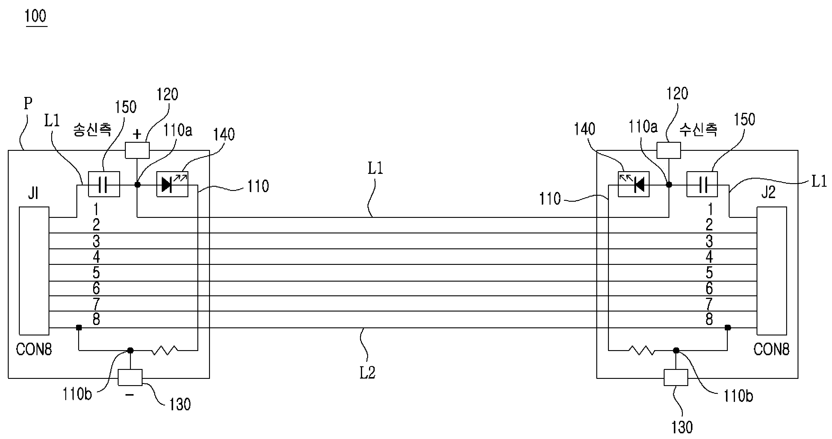
도 1 내지 도 5에 도시된 바와 같이, 본 발명의 일실시예에 따른 랜케이블의 커넥터 내부에 설치되는 회로의 구조(100)는 메인경로(110)와, 양극부(120)와, 음극부(130)와, 발광부(140)와, 차단부(150)를 포함한다.1 to 5, a
메인경로(110)는 제1선(L1)과 제2선(L2)을 전기적으로 연결하는 것으로써, 후술하는 양극부(120)가 접하는 접점인 제1접점(110a)과 후술하는 음극부(130)가 접하는 접점인 제2접점(110b)을 형성한다.The
즉, 메인경로(110)는 기판(P)상에 형성되는 외부전류의 경로이다. 이러한 메인경로(110)의 일단부인 제1접점(110a)에는 후술하는 양극부(120)가 전기적으로 연결되며, 타단부 측의 어느 부분인 제2접점(110b)에는 후술하는 음극부(130)가 전기적으로 연결되고, 제1접점(110a)과 제2접점(110b)의 사이에는 후술하는 발광부(140)가 설치된다.That is, the
도 5에 도시된 바와 같이, 송신측 양극부(120)와 송신측 음극부(130)에 외부전원 입력기로부터 외부전원이 연결되면, 외부전류가 송신측 발광부(140)에 공급되어 송신측 발광부(140)가 발광하게 되며, 이와 동시에 제1선(L1)을 따라 외부전류가 수신측 메인경로(110)로 공급되어 수신측 발광부(140)가 발광하게 된다. 상기와 같은 과정에 따른 케이블의 양단부 커넥터에서 발광 되는 빛에 의하면, 케이블의 연결상태가 용이하게 확인될 수 있다.5, when external power is supplied from the external power input unit to the
양극부(120)는 메인경로(110)에 접하는 접점인 제1접점(110a)에 전기적으로 연결되는 것으로써, 외부전원 발생기의 (+)극이 접할 수 있도록 커넥터의 외부로 노출되게 마련된다.The
한편, 여기서, 제1접점(110a)은 메인경로(110)와 접하는 지점, 즉, 도 1 및 도 5에 도시된 바와 같이, 메인경로(110)의 일단부에 해당되나, 이에 반드시 제한되는 것은 아니며, 메인경로(110)가 아닌 제1선(L1)의 단부 방향에 위치하는 제1선(L1)의 어느 지점에 접하는 접점으로 마련되더라도 무방하다.Here, the
음극부(130)는 제2선(L2)에 접하거나 메인경로(110)에 접하는 접점인 제2접점(110b)에 전기적으로 연결되는 것으로써, 외부전원 발생기의 (-)극이 접할 수 있도록 커넥터의 외부로 노출되게 마련된다.The
한편, 여기서, 제2접점(110b)은 메인경로(110)와 접하는 지점, 즉, 도 1 및 도 5에 도시된 바와 같이, 메인경로(110)의 타단부 측에 위치하는 메인경로(110)의 어느 부분에 해당되나, 이에 반드시 제한되는 것은 아니며, 제2선(L2)과 메인경로(110)의 타단부가 접하는 지점 또는 메인경로(110)가 아닌 제2선(L2)의 단부 방향에 위치하는 제2선(L2)의 어느 지점에 접하는 접점으로 마련되더라도 무방하다.1 and 5, the
상술한 바와 같은, 양극부(120)와 음극부(130)에 외부전원 입력기로부터 외부전원이 연결되면, 제1선(L1) 및 메인경로(110)에 외부전류가 흐르게 된다. 이때, 외부전류는 직류전류로 마련되는 것이 바람직하다.When an external power source is connected to the
발광부(140)는 제1접점(110a)과 제2접점(110b) 사이의 메인경로(110) 상에 배치되어 메인경로(110)를 따라 흐르는 외부전류에 의해 발광하는 것으로써, LED(Light Emitting Diode)로 마련될 수 있다.The
차단부(150)는 제1선(L1)의 단부와 제1접점(110a) 사이의 제1선(L1) 상에 배치되어 외부전류가 제1선(L1)의 단부로 유입되는 것을 차단하는 것으로써, 커패시터, 즉, 콘덴서(Condenser)로 마련될 수 있다.The
도 5에 도시된 바와 같이, 송신측 양극부(120)와 송신측 음극부(130)에 외부전원 입력기로부터 외부전원이 연결되면, 외부전류가 송신측 발광부(140)에 공급되어 송신측 발광부(140)가 발광하게 된다. 이때, 외부전류는 제1선(L1)의 일단부, 즉, 송신측 제1선(L1)의 단부 방향으로 유입될 수 있는데, 상술한 차단부(150)가 송신측 제1접점(110a)과 송신측 제1선(L1)의 단부 사이의 제1선(L1) 상에 배치되어 있으므로, 송신측 제1선(L1)의 단부 방향으로 향하는 외부전류는 차단부(150)에 의해서 차단된다.5, when external power is supplied from the external power input unit to the
한편, 외부전류는 제1선(L1)의 타단부, 즉, 수신측 제1선(L1)의 단부 방향으로 유입된 후, 일부는 수신측 메인경로(110)로 유입되며, 나머지 일부는 수신측 제1선(L1)의 단부로 유입될 수 있는데, 상술한 차단부(150)가 수신측 제1접점(110a)과 수신측 제1선(L1)의 단부 사이의 제1선(L1) 상에 배치되어 있으므로, 수신측 제1선(L1)의 단부 방향으로 향하는 외부전류 역시, 차단부(150)에 의해서 차단된다.On the other hand, the external current flows into the other end of the first line L1, that is, the end direction of the first line L1 on the receiving side, and then flows into the receiving-side
따라서, 상술한 차단부(150)에 의하면, 송신 및 수신측 발광부(140)는 외부전류에 의해 발광 되면서도, 송신측 제1선(L1)의 단부 및 수신측 제1선(L1)의 단부로는 외부전류가 유입되는 것이 원천적으로 차단된다. 이러한 과정에 따르면, 결국, 외부전원이 커넥터에서 네트워크 장치로 유입되는 것이 차단된다.Therefore, the
상술한 바와 같은, 메인경로(110)와, 양극부(120)와, 음극부(130)와, 발광부(140)와, 차단부(150)를 포함하는 본 발명의 일실시예에 따른 랜케이블의 커넥터 내부에 설치되는 회로의 구조(100)에 따르면, 외부전원이 커넥터에서 네트워크 장치로 유입되는 것이 차단되므로, 데이터의 차단 및 데이터 전송 속도의 저하 등의 네크워크의 오류 없이 케이블의 양단부 확인작업이 효율적으로 수행될 수 있다.According to an embodiment of the present invention including the
이상에서, 본 발명의 실시 예를 구성하는 모든 구성 요소들이 하나로 결합하거나 결합하여 동작하는 것으로 설명되었다고 해서, 본 발명이 반드시 이러한 실시 예에 한정되는 것은 아니다. 즉, 본 발명의 목적 범위 안에서라면, 그 모든 구성 요소들이 하나 이상으로 선택적으로 결합하여 동작할 수도 있다.While the present invention has been described in connection with what is presently considered to be the most practical and preferred embodiment, it is to be understood that the invention is not limited to the disclosed embodiments. That is, within the scope of the present invention, all of the components may be selectively coupled to one or more of them.
또한, 이상에서 기재된 "포함하다", "구성하다" 또는 "가지다" 등의 용어는, 특별히 반대되는 기재가 없는 한, 해당 구성 요소가 내재할 수 있음을 의미하는 것이므로, 다른 구성 요소를 제외하는 것이 아니라 다른 구성 요소를 더 포함할 수 있는 것으로 해석되어야 한다. 기술적이거나 과학적인 용어를 포함한 모든 용어들은, 다르게 정의되지 않는 한, 본 발명이 속하는 기술 분야에서 통상의 지식을 가진 자에 의해 일반적으로 이해되는 것과 동일한 의미가 있다. 사전에 정의된 용어와 같이 일반적으로 사용되는 용어들은 관련 기술의 문맥상의 의미와 일치하는 것으로 해석되어야 하며, 본 발명에서 명백하게 정의하지 않는 한, 이상적이거나 과도하게 형식적인 의미로 해석되지 않는다.Furthermore, the terms "comprises", "comprising", or "having" described above mean that a component can be implanted unless otherwise specifically stated, But should be construed as including other elements. All terms, including technical and scientific terms, have the same meaning as commonly understood by one of ordinary skill in the art to which this invention belongs, unless otherwise defined. Commonly used terms, such as predefined terms, should be interpreted to be consistent with the contextual meanings of the related art, and are not to be construed as ideal or overly formal, unless expressly defined to the contrary.
그리고 이상의 설명은 본 발명의 기술 사상을 예시적으로 설명한 것에 불과한 것으로서, 본 발명이 속하는 기술 분야에서 통상의 지식을 가진 자라면 본 발명의 본질적인 특성에서 벗어나지 않는 범위에서 다양한 수정 및 변형이 가능할 것이다.It will be apparent to those skilled in the art that various modifications and variations can be made in the present invention without departing from the spirit or essential characteristics thereof.
따라서, 본 발명에 개시된 실시 예들은 본 발명의 기술 사상을 한정하기 위한것이 아니라 설명하기 위한 것이고, 이러한 실시 예에 의하여 본 발명의 기술 사상의 범위가 한정되는 것은 아니다. 본 발명의 보호 범위는 아래의 청구범위에 의하여 해석되어야 하며, 그와 동등한 범위 내에 있는 모든 기술 사상은 본 발명의 권리범위에 포함되는 것으로 해석되어야 할 것이다.Therefore, the embodiments disclosed in the present invention are intended to illustrate rather than limit the scope of the present invention, and the scope of the technical idea of the present invention is not limited by these embodiments. The scope of protection of the present invention should be construed according to the following claims, and all technical ideas within the scope of equivalents should be construed as falling within the scope of the present invention.
100 : 본 발명의 일실시예에 따른 랜케이블의 커넥터 내부에 설치되는 회로의 구조
110 : 메인경로
110a : 제1접점
110b : 제2접점
120 : 양극부
130 : 음극부
140 : 발광부
150 : 차단부
L1 : 제1선
L2 : 제2선
P : 기판
200 : 본 발명의 일실시예에 따른 랜케이블의 커넥터 내부에 설치되는 회로의 구조를 포함하는 랜케이블 커넥터100: Structure of a circuit installed inside a connector of a LAN cable according to an embodiment of the present invention
110: Main path
110a: first contact
110b: second contact
120: anode part
130: cathode part
140:
150:
L1: First line
L2: second line
P: substrate
200: a LAN cable connector including a structure of a circuit installed inside a connector of a LAN cable according to an embodiment of the present invention;
Claims (5)
송신측 부분 또는 수신측 부분 중 어느 한 부분에서 상호 인접한 상기 제1선과 상기 제2선을 전기적으로 연결하는 메인경로;
상기 제1선과 상기 메인경로가 접하는 접점인 제1접점에 전기적으로 연결되는 양극부;
상기 제2선과 상기 메인경로가 접하는 접점인 제2접점에 전기적으로 연결되는 음극부;
상기 제1접점과 상기 제2접점 사이의 상기 메인경로 상에 배치되며, 상기 양극부와 상기 음극부를 통해 외부전원이 인가되는 경우 상기 메인경로를 따라 흐르는 외부전원에 의해 발광하는 발광부; 및
상기 제1선의 단부와 상기 제1접점 사이의 상기 제1선 상에 배치되며, 상기 양극부와 상기 음극부를 통해 외부전원이 인가되는 경우 상기 외부전원이 상기 제1선의 단부로 유입되는 것을 차단하는 차단부를 포함하되,
상기 제1선과 상기 제2선은,
데이터 통신에 사용되는 선인 것을 특징으로 하는 랜케이블의 커넥터 내부에 설치되는 회로의 구조.In a structure of a circuit provided inside a connector of a LAN cable including a first line and a second line,
A main path electrically connecting the first line and the second line mutually adjacent to each other in any one of a transmitting side portion and a receiving side portion;
A positive electrode electrically connected to a first contact which is a contact between the first line and the main path;
A negative electrode electrically connected to a second contact, which is a contact between the second line and the main path;
A light emitting unit disposed on the main path between the first contact and the second contact and emitting light by an external power source flowing along the main path when external power is applied through the anode and the cathode; And
And an external power source is disposed on the first line between the end of the first line and the first contact and blocks the external power source from being introduced into the end of the first line when the external power is applied through the anode portion and the cathode portion And a blocking portion,
And the first line and the second line are connected to each other,
A structure of a circuit provided inside a connector of a LAN cable, characterized by being a line used for data communication.
상기 발광부는,
LED(Light Emitting Diode)로 마련되는 것을 특징으로 하는 랜케이블의 커넥터 내부에 설치되는 회로의 구조.The method according to claim 1,
The light-
And a light emitting diode (LED). The structure of the circuit is provided inside the connector of the LAN cable.
Priority Applications (1)
| Application Number | Priority Date | Filing Date | Title |
|---|---|---|---|
| KR1020170070798A KR101913345B1 (en) | 2017-06-07 | 2017-06-07 | Circuit structure installed in lan cable connector inside and lan cable connector having thereof |
Applications Claiming Priority (1)
| Application Number | Priority Date | Filing Date | Title |
|---|---|---|---|
| KR1020170070798A KR101913345B1 (en) | 2017-06-07 | 2017-06-07 | Circuit structure installed in lan cable connector inside and lan cable connector having thereof |
Publications (1)
| Publication Number | Publication Date |
|---|---|
| KR101913345B1 true KR101913345B1 (en) | 2018-10-30 |
Family
ID=64100740
Family Applications (1)
| Application Number | Title | Priority Date | Filing Date |
|---|---|---|---|
| KR1020170070798A Expired - Fee Related KR101913345B1 (en) | 2017-06-07 | 2017-06-07 | Circuit structure installed in lan cable connector inside and lan cable connector having thereof |
Country Status (1)
| Country | Link |
|---|---|
| KR (1) | KR101913345B1 (en) |
Citations (1)
| Publication number | Priority date | Publication date | Assignee | Title |
|---|---|---|---|---|
| KR101701708B1 (en) * | 2016-07-25 | 2017-02-03 | 주식회사 체크올 | Led lan cable connecter capable of transmitting high rate data and led lan cable capable of transmitting high rate data and led lan cable capabl system capable of transmitting high rate data |
-
2017
- 2017-06-07 KR KR1020170070798A patent/KR101913345B1/en not_active Expired - Fee Related
Patent Citations (1)
| Publication number | Priority date | Publication date | Assignee | Title |
|---|---|---|---|---|
| KR101701708B1 (en) * | 2016-07-25 | 2017-02-03 | 주식회사 체크올 | Led lan cable connecter capable of transmitting high rate data and led lan cable capable of transmitting high rate data and led lan cable capabl system capable of transmitting high rate data |
Similar Documents
| Publication | Publication Date | Title |
|---|---|---|
| US10541758B2 (en) | Power delivery through an optical system | |
| MX2011008507A (en) | Inter-networking devices for use with physical layer information. | |
| JP2007267372A (en) | Method and apparatus for patch panel patch cord documentation and revision | |
| KR101991342B1 (en) | Patch panel with function of detecting connected port | |
| JP6457509B2 (en) | NETWORK CABLE INCLUDING VISUAL MARKING DEVICE AND VISUAL MARKING DEVICE OF END | |
| US9449206B2 (en) | Network cable tracking system | |
| KR101913348B1 (en) | Led lan cable coupler | |
| CN107005269A (en) | Feed line branch unit and feed line branching method | |
| CN1363189A (en) | Test access system and method for digital cross connect communication networks | |
| US20180278813A1 (en) | Camera system for gas-insulated switchgear systems | |
| KR101913345B1 (en) | Circuit structure installed in lan cable connector inside and lan cable connector having thereof | |
| US10891847B2 (en) | Visible indication of a port as configured to management functionality | |
| KR101701708B1 (en) | Led lan cable connecter capable of transmitting high rate data and led lan cable capable of transmitting high rate data and led lan cable capabl system capable of transmitting high rate data | |
| EP1332570B1 (en) | Network comprising converters between electrical and optical signals | |
| US9236690B2 (en) | Device for a patch panel | |
| EP2448071A1 (en) | Telecommunication connecting device | |
| KR101634125B1 (en) | Patch Panel | |
| KR101701714B1 (en) | Lan cable connecter | |
| CN206818816U (en) | A kind of Portable multi-interface passage self-looped testing box | |
| CN105159417A (en) | Anti-lightning project server with deterioration indication function | |
| KR102098725B1 (en) | Patch panel for connecting communication equipments | |
| KR200484590Y1 (en) | intermediate distribution frame | |
| KR20220110891A (en) | Communication patch cord and patch cord tester |
Legal Events
| Date | Code | Title | Description |
|---|---|---|---|
| PA0109 | Patent application |
St.27 status event code: A-0-1-A10-A12-nap-PA0109 |
|
| PA0201 | Request for examination |
St.27 status event code: A-1-2-D10-D11-exm-PA0201 |
|
| P11-X000 | Amendment of application requested |
St.27 status event code: A-2-2-P10-P11-nap-X000 |
|
| P13-X000 | Application amended |
St.27 status event code: A-2-2-P10-P13-nap-X000 |
|
| D13-X000 | Search requested |
St.27 status event code: A-1-2-D10-D13-srh-X000 |
|
| D14-X000 | Search report completed |
St.27 status event code: A-1-2-D10-D14-srh-X000 |
|
| PE0902 | Notice of grounds for rejection |
St.27 status event code: A-1-2-D10-D21-exm-PE0902 |
|
| E13-X000 | Pre-grant limitation requested |
St.27 status event code: A-2-3-E10-E13-lim-X000 |
|
| P11-X000 | Amendment of application requested |
St.27 status event code: A-2-2-P10-P11-nap-X000 |
|
| P13-X000 | Application amended |
St.27 status event code: A-2-2-P10-P13-nap-X000 |
|
| E701 | Decision to grant or registration of patent right | ||
| PE0701 | Decision of registration |
St.27 status event code: A-1-2-D10-D22-exm-PE0701 |
|
| GRNT | Written decision to grant | ||
| PR0701 | Registration of establishment |
St.27 status event code: A-2-4-F10-F11-exm-PR0701 |
|
| PR1002 | Payment of registration fee |
St.27 status event code: A-2-2-U10-U11-oth-PR1002 Fee payment year number: 1 |
|
| PG1601 | Publication of registration |
St.27 status event code: A-4-4-Q10-Q13-nap-PG1601 |
|
| PN2301 | Change of applicant |
St.27 status event code: A-5-5-R10-R11-asn-PN2301 |
|
| PN2301 | Change of applicant |
St.27 status event code: A-5-5-R10-R14-asn-PN2301 |
|
| PR1001 | Payment of annual fee |
St.27 status event code: A-4-4-U10-U11-oth-PR1001 Fee payment year number: 4 |
|
| PR1001 | Payment of annual fee |
St.27 status event code: A-4-4-U10-U11-oth-PR1001 Fee payment year number: 5 |
|
| PR1001 | Payment of annual fee |
St.27 status event code: A-4-4-U10-U11-oth-PR1001 Fee payment year number: 6 |
|
| PC1903 | Unpaid annual fee |
St.27 status event code: A-4-4-U10-U13-oth-PC1903 Not in force date: 20241025 Payment event data comment text: Termination Category : DEFAULT_OF_REGISTRATION_FEE |
|
| H13 | Ip right lapsed |
Free format text: ST27 STATUS EVENT CODE: N-4-6-H10-H13-OTH-PC1903 (AS PROVIDED BY THE NATIONAL OFFICE); TERMINATION CATEGORY : DEFAULT_OF_REGISTRATION_FEE Effective date: 20241025 |
|
| PC1903 | Unpaid annual fee |
St.27 status event code: N-4-6-H10-H13-oth-PC1903 Ip right cessation event data comment text: Termination Category : DEFAULT_OF_REGISTRATION_FEE Not in force date: 20241025 |