KR101861715B1 - Golf Club Head Having Optimized Ball Speed to CT Relationship - Google Patents
Golf Club Head Having Optimized Ball Speed to CT Relationship Download PDFInfo
- Publication number
- KR101861715B1 KR101861715B1 KR1020170024372A KR20170024372A KR101861715B1 KR 101861715 B1 KR101861715 B1 KR 101861715B1 KR 1020170024372 A KR1020170024372 A KR 1020170024372A KR 20170024372 A KR20170024372 A KR 20170024372A KR 101861715 B1 KR101861715 B1 KR 101861715B1
- Authority
- KR
- South Korea
- Prior art keywords
- golf club
- club head
- reinforcing member
- striking surface
- soul
- Prior art date
- Legal status (The legal status is an assumption and is not a legal conclusion. Google has not performed a legal analysis and makes no representation as to the accuracy of the status listed.)
- Active
Links
- 230000003014 reinforcing effect Effects 0.000 claims abstract description 65
- 238000000034 method Methods 0.000 claims description 20
- 229910052751 metal Inorganic materials 0.000 claims description 11
- 239000002184 metal Substances 0.000 claims description 10
- 239000007787 solid Substances 0.000 claims description 10
- 239000002131 composite material Substances 0.000 claims description 9
- 229910001069 Ti alloy Inorganic materials 0.000 claims description 8
- OKTJSMMVPCPJKN-UHFFFAOYSA-N Carbon Chemical compound [C] OKTJSMMVPCPJKN-UHFFFAOYSA-N 0.000 claims description 7
- 229910052799 carbon Inorganic materials 0.000 claims description 7
- 239000007769 metal material Substances 0.000 claims description 5
- 229910001200 Ferrotitanium Inorganic materials 0.000 claims description 4
- 239000010959 steel Substances 0.000 claims description 4
- 230000002787 reinforcement Effects 0.000 description 12
- 238000012360 testing method Methods 0.000 description 8
- 238000005266 casting Methods 0.000 description 5
- 238000004519 manufacturing process Methods 0.000 description 3
- 239000000463 material Substances 0.000 description 3
- RTAQQCXQSZGOHL-UHFFFAOYSA-N Titanium Chemical compound [Ti] RTAQQCXQSZGOHL-UHFFFAOYSA-N 0.000 description 2
- 230000000694 effects Effects 0.000 description 2
- 230000005484 gravity Effects 0.000 description 2
- 239000000203 mixture Substances 0.000 description 2
- 239000010936 titanium Substances 0.000 description 2
- 229910052719 titanium Inorganic materials 0.000 description 2
- 229910000851 Alloy steel Inorganic materials 0.000 description 1
- 239000000853 adhesive Substances 0.000 description 1
- 230000001070 adhesive effect Effects 0.000 description 1
- 229910045601 alloy Inorganic materials 0.000 description 1
- 239000000956 alloy Substances 0.000 description 1
- 229910021535 alpha-beta titanium Inorganic materials 0.000 description 1
- 238000005219 brazing Methods 0.000 description 1
- 238000009750 centrifugal casting Methods 0.000 description 1
- 238000005242 forging Methods 0.000 description 1
- 238000005495 investment casting Methods 0.000 description 1
- 238000005339 levitation Methods 0.000 description 1
- 238000003801 milling Methods 0.000 description 1
- 238000012986 modification Methods 0.000 description 1
- 230000004048 modification Effects 0.000 description 1
- 238000000465 moulding Methods 0.000 description 1
- 229910000679 solder Inorganic materials 0.000 description 1
- 239000003351 stiffener Substances 0.000 description 1
- 238000006467 substitution reaction Methods 0.000 description 1
- 238000003466 welding Methods 0.000 description 1
- 239000002023 wood Substances 0.000 description 1
Images


Classifications
-
- A—HUMAN NECESSITIES
- A63—SPORTS; GAMES; AMUSEMENTS
- A63B—APPARATUS FOR PHYSICAL TRAINING, GYMNASTICS, SWIMMING, CLIMBING, OR FENCING; BALL GAMES; TRAINING EQUIPMENT
- A63B53/00—Golf clubs
- A63B53/04—Heads
- A63B53/045—Strengthening ribs
-
- A—HUMAN NECESSITIES
- A63—SPORTS; GAMES; AMUSEMENTS
- A63B—APPARATUS FOR PHYSICAL TRAINING, GYMNASTICS, SWIMMING, CLIMBING, OR FENCING; BALL GAMES; TRAINING EQUIPMENT
- A63B53/00—Golf clubs
- A63B53/04—Heads
-
- A—HUMAN NECESSITIES
- A63—SPORTS; GAMES; AMUSEMENTS
- A63B—APPARATUS FOR PHYSICAL TRAINING, GYMNASTICS, SWIMMING, CLIMBING, OR FENCING; BALL GAMES; TRAINING EQUIPMENT
- A63B60/00—Details or accessories of golf clubs, bats, rackets or the like
-
- A—HUMAN NECESSITIES
- A63—SPORTS; GAMES; AMUSEMENTS
- A63B—APPARATUS FOR PHYSICAL TRAINING, GYMNASTICS, SWIMMING, CLIMBING, OR FENCING; BALL GAMES; TRAINING EQUIPMENT
- A63B53/00—Golf clubs
- A63B53/04—Heads
- A63B53/0408—Heads characterised by specific dimensions, e.g. thickness
-
- A—HUMAN NECESSITIES
- A63—SPORTS; GAMES; AMUSEMENTS
- A63B—APPARATUS FOR PHYSICAL TRAINING, GYMNASTICS, SWIMMING, CLIMBING, OR FENCING; BALL GAMES; TRAINING EQUIPMENT
- A63B53/00—Golf clubs
- A63B53/04—Heads
- A63B53/0437—Heads with special crown configurations
-
- A—HUMAN NECESSITIES
- A63—SPORTS; GAMES; AMUSEMENTS
- A63B—APPARATUS FOR PHYSICAL TRAINING, GYMNASTICS, SWIMMING, CLIMBING, OR FENCING; BALL GAMES; TRAINING EQUIPMENT
- A63B53/00—Golf clubs
- A63B53/04—Heads
- A63B53/0466—Heads wood-type
-
- C—CHEMISTRY; METALLURGY
- C22—METALLURGY; FERROUS OR NON-FERROUS ALLOYS; TREATMENT OF ALLOYS OR NON-FERROUS METALS
- C22C—ALLOYS
- C22C14/00—Alloys based on titanium
-
- A63B2053/0437—
-
- A—HUMAN NECESSITIES
- A63—SPORTS; GAMES; AMUSEMENTS
- A63B—APPARATUS FOR PHYSICAL TRAINING, GYMNASTICS, SWIMMING, CLIMBING, OR FENCING; BALL GAMES; TRAINING EQUIPMENT
- A63B2102/00—Application of clubs, bats, rackets or the like to the sporting activity ; particular sports involving the use of balls and clubs, bats, rackets, or the like
- A63B2102/32—Golf
-
- A—HUMAN NECESSITIES
- A63—SPORTS; GAMES; AMUSEMENTS
- A63B—APPARATUS FOR PHYSICAL TRAINING, GYMNASTICS, SWIMMING, CLIMBING, OR FENCING; BALL GAMES; TRAINING EQUIPMENT
- A63B2209/00—Characteristics of used materials
-
- A—HUMAN NECESSITIES
- A63—SPORTS; GAMES; AMUSEMENTS
- A63B—APPARATUS FOR PHYSICAL TRAINING, GYMNASTICS, SWIMMING, CLIMBING, OR FENCING; BALL GAMES; TRAINING EQUIPMENT
- A63B2209/00—Characteristics of used materials
- A63B2209/02—Characteristics of used materials with reinforcing fibres, e.g. carbon, polyamide fibres
Landscapes
- Health & Medical Sciences (AREA)
- General Health & Medical Sciences (AREA)
- Physical Education & Sports Medicine (AREA)
- Chemical & Material Sciences (AREA)
- Engineering & Computer Science (AREA)
- Materials Engineering (AREA)
- Mechanical Engineering (AREA)
- Metallurgy (AREA)
- Organic Chemistry (AREA)
- Life Sciences & Earth Sciences (AREA)
- Wood Science & Technology (AREA)
- Golf Clubs (AREA)
Abstract
본체 및 복수의 보강 부재를 포함하고 방정식 ![]()
![]()
Description
본 발명은 2016년 2월 23일자 출원된 미국특허출원 제15/051,361호의 일부 계속 출원(continuation-in-part)이고, 상기 제15/051,361호는 2016년 1월 15일자 출원된 미국특허출원 제14/997,199호의 일부 계속 출원이고, 상기 제14/997,199호는 2015년 6월 30일자 출원된 미국특허출원 제14/788,326호의 일부 계속 출원이고, 상기 제14/997,199호는 또한 2015년 7월 8일자 출원된 미국특허출원 제14/794,578호의 일부 계속 출원이고, 상기 제14/794,578호는 2015년 6월 30일자 출원된 미국특허출원 제14/755,068호의 일부 계속 출원이고, 상기 제14/755,068호는 2014년 9월 26일자 출원되고 2016년 2월 16일자 미국 특허 제9,259,627호로 등록된 미국특허출원 제14/498,843호의 일부 계속 출원이고, 상기 제9,259,627호는 2014년 2월 5일자 출원되고 2015년 11월 10일자 미국 특허 제9,180,349호로 등록된 미국특허출원 제14/173,615호의 일부 계속 출원이고, 상기 제9,180,349호는 2013년 9월 27일자 출원되고 2014년 9월 16일자 미국 특허 제8,834,294호로 등록된 미국특허출원 제14/039,102호의 일부 계속 출원이고, 상기 제8,834,294호는 2013년 3월 12일자 출원되고 현재 포기된 미국특허출원 제13/797,404호의 계속 출원이고, 상기 제13/797,404호는 2012년 6월 27일자 출원된 미국 임시특허출원 제61/665,203호 및 2012년 8월 16일자 출원된 미국특허출원 제61/684,079호의 우선권주장 출원으로서, 이들 특허의 각각의 개시는 본 명세서에서 그 전체가 참고로서 포함된다. 미국특허출원 제14/997,199호는 또한 2015년 2월 13일자 출원되고 2016년 5월 24일자 미국 특허 제9,345,936호로 등록된 미국특허출원 제14/622,606호의 일부 계속 출원이고, 상기 제9,345,936호는 2013년 5월 31일자 출원되고 2015년 2월 17일자 미국 특허 제8,956,244호로 등록된 미국특허출원 제13/906,572호의 계속 출원으로서, 이들 특허의 각각의 개시는 본 명세서에서 그 전체가 참고로서 포함된다. The present invention is a continuation-in-part of US patent application Ser. No. 15 / 051,361, filed Feb. 23, 2016, and Ser. No. 15 / 051,361, filed on January 15, 2016, 14 / 997,199, which is a continuation-in-part of U.S. Patent Application No. 14 / 788,326, filed June 30, 2015, No. 14 / 794,578, filed on June 30, 2015, which is a continuation-in-part of U.S. Patent Application No. 14 / 794,578 filed on June 30, 2015, Is a continuation-in-part of U.S. Patent Application No. 14 / 498,843, filed September 26, 2014, and U.S. Patent No. 9,259,627, filed February 16, 2016, which is filed February 5, 2014, U.S. Patent Application No. 14 / 173,615, filed November 10, U.S. Patent No. 9,180,349 9,180,349 is a continuation-in-part of U.S. Patent Application No. 14 / 039,102, filed September 27, 2013, and assigned to U.S. Patent No. 8,834,294, issued September 16, 2014, and U.S. Patent No. 8,834,294, No. 13 / 797,404, filed March 12, 2013 and now abandoned, and Ser. No. 13 / 797,404, filed on June 27, 2012, and U.S. Provisional Patent Application No. 61 / 665,203 filed June 27, 2012, U.S. Patent Application No. 61 / 684,079, filed August 16, 2005, the disclosures of each of which are incorporated herein by reference in their entirety. U.S. Patent Application No. 14 / 997,199 is also a continuation-in-part of U.S. Patent Application No. 14 / 622,606, filed February 13, 2015, and U.S. Patent No. 9,345,936, issued May 24, 2016, U.S. Patent Application No. 13 / 906,572, filed May 31, 2015, and U.S. Patent No. 8,956,244, filed February 17, 2015, the disclosure of each of which is incorporated herein by reference in its entirety.
본 발명은 골프 클럽 헤드에 관한 것이다. 보다 구체적으로, 본 발명은 중공 내부(hollow interior)를 통해 크라운(crown) 부분과 소울(sole) 부분을 연결하고 타격면부(striking face section)에 근접하게 배치되는 응력 저감 특성(stress-reducing features)을 구비한 골프 클럽 헤드에 관한 것이다.The present invention relates to a golf club head. More particularly, the present invention relates to stress-reducing features that connect a crown portion and a sole portion through a hollow interior and are disposed proximate the striking face section, To a golf club head.
종래 기술은 내부 구조체를 갖는 다양한 골프 클럽 헤드들을 개시하고 있다. 예를 들어, 내부 타격 플레이트 버팀대(internal striking plate brace)를 구비한 골프 클럽 헤드에 대한 Kosmatka의 미국특허 제6299547호는 타격 플레이트의 휨을 제한하기 위해 버팀대를 구비한 골프 클럽 헤드를 개시하고 있고, 골프 클럽 헤드 및 그 제조 방법에 대한 Yabu의 미국특허 제6852038호는 사운드 바(sound bar)를 구비한 골프 클럽 헤드를 개시하고 있으며, 다중 재료(multiple material) 골프 클럽 헤드에 대한 Callaway의 미국특허 제7118493호는 금속 페이스 구성요소(metal face component)의 소울부(sole section)로부터 위쪽으로 연장된 내부 사운드 구성요소(interior sound component)를 갖는 복합재의 후미체(composite aft body)를 구비한 골프 클럽 헤드를 개시하고 있고, 무게 중심 조정기능(center of gravity adjustability)을 갖는 골프 클럽 헤드에 대한 Seluga 등의 미국특허 제8834294호는 골프 클럽 헤드의 무게 중심(CG)을 조정하기 위한 질량체(mass)를 갖는 튜브를 구비한 골프 클럽 헤드를 개시하고 있고, 그리고 가중 골프 클럽 헤드(Weighted Golf Club Head)에 대한 Dawson 등의 미국특허 제8900070호는 소울로부터 페이스(face)를 향해 연장되는 내부 중량 립(interior weight lip)을 구비한 골프 클럽 헤드를 개시하고 있다. The prior art discloses various golf club heads having internal structures. For example, US Pat. No. 6,299,547 to Kosmatka for a golf club head with an internal striking plate brace discloses a golf club head with a bracing to limit deflection of the striking plate, U.S. Patent No. 6,85,208 to Yabu on a club head and its method of manufacture discloses a golf club head with a sound bar and is described in Callaway, U.S. Patent 7118493 for a multiple material golf club head A golf club head having a composite aft body with an interior sound component extending upwardly from a sole section of a metal face component, US Patent No. 8834294 to Seluga et al. Discloses a golf club head having a center of gravity adjustability, Discloses a golf club head having a tube with a mass for adjusting the center of gravity (CG) of the club head and is disclosed in U.S. Patent No. 8900070 to Dawson et al., For a Weighted Golf Club Head, A golf club head having an interior weight lip extending from a soul toward a face.
그러나, 종래 기술은 골프 클럽 헤드의 질량을 최소한으로 증가시키면서 충돌 시 타격면부의 응력을 줄여 볼 속도(ball speed)를 증가시키는 내부 구조를 개시하고 있지 않다.However, the prior art does not disclose an internal structure that increases the ball speed by reducing the stress of the striking surface during a collision while minimizing the mass of the golf club head.
골프 클럽 헤드는 골프공과 충돌 시 타격면부의 응력을 줄이기 위해 크라운부를 소울부에 연결하는 내부 구조체를 포함한다. 일부 실시형태들에서, 내부 구조체는 티타늄 합금으로 구성된 중공(hollow) 튜브들 또는 중실(solid) 로드들이다.The golf club head includes an inner structure that connects the crown portion to the sole portion to reduce the stress on the striking surface portion when the golf ball collides with the golf ball. In some embodiments, the internal structure is hollow tubes or solid rods made of a titanium alloy.
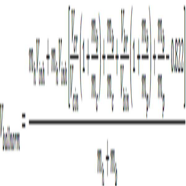
본 발명의 일 태양은 타격면부, 상기 타격면부의 하부 가장자리로부터 연장된 소울부, 및 상기 타격면부의 상부 가장자리로부터 연장된 크라운부 - 상기 타격면부, 소울부, 및 크라운부는 중공의 본체 내부를 정의함 - 을 포함하는 본체, 및 상기 중공의 본체 내부에 배치되고 상기 크라운부로부터 상기 소울부까지 연장된 적어도 하나의 보강 부재를 포함하는 골프 클럽 헤드이며, 상기 타격면부는 중공의 본체 내부와 면하는(facing) 후방 페이스 표면(rear face surface)을 포함하고, 상기 적어도 하나의 보강 부재는 타격면부에 수직인 페이스 센터(face center)를 통해 연장된 수직면을 따라 상기 후방 페이스 표면으로부터 1인치 이하의 위치에 배치되고, 상기 적어도 하나의 보강 부재의 어떤 부분도 타격면부와 접촉하지 않으며, 상기 골프 클럽 헤드는 방정식 ![]()

![]()
![]()
![]()
일부 실시형태들에서, 상기 적어도 하나의 보강 부재는 제1 및 제2 보강 부재를 포함할 수 있으며, 상기 제1 보강 부재는 상기 제2 보강 부재와 대체로 평행하게 연장될 수 있고, 그리고 상기 제1 보강 부재는 상기 제2 보강 부재로부터 0.75 내지 1.50 인치의 거리만큼 이격될 수 있다. 추가의 실시형태에서, 제1 및 제2 보강 부재의 각각은 중실 로드 및 중공 튜브로 이루어진 군으로부터 선택된 구조를 포함할 수 있다. 또 하나의 추가의 실시형태에서, 제1 및 제2 보강 부재의 각각은 티타늄 합금 및 강로 이루어진 군으로부터 선택된 금속 재료로 구성된 중실 로드일 수 있다. 대안적인 실시형태에서, 상기 적어도 하나의 보강 부재는 타격면부와 수직인 페이스 센터(face center)를 통해 연장된 수직면을 따라 후방 페이스 표면으로부터 0.25인치 이하의 위치에 배치될 수 있다. 추가의 실시형태에서, 상기 적어도 하나의 보강 부재는 크라운부에 근접한 상단 및 소울부에 근접한 하단을 포함할 수 있으며, 상기 상단은 후방 페이스 표면으로부터 제1 거리만큼 이격될 수 있고, 상기 하단은 상기 후방 페이스 표면으로부터 제2 거리만큼 이격될 수 있으며, 그리고 상기 제1 거리는 상기 제2 거리 미만일 수 있다. 이 실시형태들 중 어느 하나에서, 골프 클럽 헤드는 커버편(cover piece)을 더 포함할 수 있고, 상기 소울부는 복수의 컷 아웃들(cutouts)을 포함할 수 있으며, 상기 커버편은 상기 소울부에 고정될 수 있고 상기 복수의 컷 아웃들의 각각을 적어도 부분적으로 커버할 수 있다. 또한, 이 실시형태들 중 어느 하나에서, 골프 클럽 헤드는 크라운 인서트(crown insert)를 포함할 수 있고, 상기 크라운부는 상부 개구를 포함할 수 있으며, 그리고 상기 크라운 인서트는 상기 상부 개구를 덮을 수 있다. In some embodiments, the at least one reinforcing member may include first and second reinforcing members, the first reinforcing member may extend substantially parallel to the second reinforcing member, and the first reinforcing member may extend substantially parallel to the first reinforcing member, The reinforcing member may be spaced from the second reinforcing member by a distance of 0.75 to 1.50 inches. In a further embodiment, each of the first and second stiffening members may comprise a structure selected from the group consisting of a solid rod and a hollow tube. In yet another further embodiment, each of the first and second stiffening members may be a solid rod comprised of a metallic material selected from the group consisting of a titanium alloy and steel. In an alternative embodiment, the at least one stiffening member may be disposed at a position less than 0.25 inches from the rear face surface along a vertical plane extending through a face center perpendicular to the striking face portion. In a further embodiment, the at least one reinforcing member may include an upper end proximate to the crown portion and a lower end adjacent to the soul portion, the upper end being spaced a first distance from the rear face surface, The first distance may be less than the second distance, and the first distance may be less than the second distance. In any of these embodiments, the golf club head may further include a cover piece, wherein the soul portion may include a plurality of cutouts, And at least partially cover each of the plurality of cutouts. In addition, in any of the embodiments, the golf club head may include a crown insert, the crown portion may include an upper opening, and the crown insert may cover the upper opening .
본 발명의 또 하나의 태양은 타격면부, 상기 타격면부의 하부 가장자리로부터 연장된 소울부, 및 상기 타격면부의 상부 가장자리로부터 연장된 리턴부(return section) - 상기 리턴부 및 소울부는 상부 개구를 정의하고, 상기 타격면부, 소울부, 및 리턴부는 중공의 본체 내부를 정의함 - 을 포함하는 금속 본체, 및 상기 중공의 본체 내부에 배치되고 상기 리턴부로부터 상기 소울부까지 연장된 제1 및 제2 보강 부재를 포함하는 골프 클럽 헤드이며, 상기 제1 및 제2 보강 부재의 각각은 중실 금속 로드(solid metal rod)이고, 제1 또는 제2 보강 부재의 어느 부분도 타격면부와 접촉하지 않으며, 상기 골프 클럽 헤드는 방정식 ![]()
![]()
![]()
![]()
또 하나의 실시형태에서, 골프 클럽 헤드는 탄소 복합재 커버편을 포함할 수 있으며, 상기 소울부는 적어도 하나의 컷 아웃을 포함할 수 있고, 상기 커버편은 상기 적어도 하나의 컷 아웃을 커버하기 위해 상기 소울부에 영구적으로 부착될 수 있다. 또 하나의 실시형태에서, 제1 및 제2 보강 부재의 각각은 1.00 인치 내지 2.50 인치의 길이를 가질 수 있으며, 제1 보강 부재는 제2 보강 부재와 대체로 평행하게 연장될 수 있고, 그리고 상기 제1 보강 부재는 상기 제2 보강 부재로부터 0.500 내지 2.00 인치의 거리만큼 이격될 수 있다. 또 하나의 실시형태에서, 타격면부는 페이스 센터 및 후방 페이스 표면을 포함할 수 있으며, 제1 및 제2 보강 부재의 각각은 상기 타격면부에 수직인 페이스 센터를 통해 연장되는 수직면을 따라 상기 후방 페이스 표면으로부터 0.500 인치 이하의 위치에 배치될 수 있다. In another embodiment, a golf club head may include a carbon composite cover piece, wherein the soul portion may include at least one cutout, and wherein the cover piece includes at least one cut- And may be permanently attached to the soul portion. In another embodiment, each of the first and second reinforcing members may have a length of 1.00 inch to 2.50 inches, the first reinforcing member may extend substantially parallel to the second reinforcing member, One reinforcing member may be spaced from the second reinforcing member by a distance of 0.500 to 2.00 inches. In another embodiment, the striking surface portion may include a face center and a rear face surface, and each of the first and second stiffening members may include a rear face extending along a vertical plane extending through a face center perpendicular to the striking face portion, And may be disposed at a position of 0.500 inches or less from the surface.
본 발명의 또 하나의 태양은 타격면부, 상기 타격면부의 하부 가장자리로부터 연장된 소울부, 상기 타격면부의 상부 가장자리로부터 연장된 리턴부, 및 상기 타격면부의 반대편의 후단(aft end) - 상기 리턴부 및 소울부는 상부 개구를 정의하고, 그리고 상기 타격면부, 소울부, 및 리턴부는 중공의 본체 내부를 정의함 - 을 포함하는 금속 본체, 상기 중공의 본체 내부에 배치되고 상기 리턴부로부터 상기 소울부까지 연장된 상기 제1 및 제2 보강 부재, 및 상기 상부 개구를 폐쇄하도록 상기 본체에 영구적으로 부착된 탄소 복합재 크라운 인서트를 포함하는 골프 클럽 헤드이고, 상기 제1 및 제2 보강 부재의 각각은 상기 중공의 본체 내부에서 상기 후단보다 상기 타격면부에 더 가깝게 위치되고, 상기 골프 클럽 헤드는 420㎤ 내지 470㎤의 체적을 가지며, 상기 골프 클럽 헤드는 방정식 ![]()
![]()
본 발명을 간략히 기술하였지만, 첨부된 도면과 함께 취해질 경우 본 발명의 이하의 상세한 설명으로부터 당업자는 본 발명의 상기 및 추가의 목적들, 특징들 및 이점들을 인식할 것이다.While the present invention has been described in brief, those skilled in the art will recognize from the following detailed description of the invention, when taken in conjunction with the accompanying drawings, those which are perceived by those skilled in the art, and which further objects, features and advantages of the invention emerge.
도 1은 본 발명의 골프 클럽 헤드의 바람직한 실시형태의 상면 사시도이다.
도 2는 도 1에 도시된 골프 클럽 헤드의 저면 사시도이다.
도 3은 도 2에 도시된 라인 3-3에 따른 골프 클럽 헤드의 단면도이다.
도 4는 도 3 도시된 라인 4-4에 따른 골프 클럽 헤드의 단면도이다.
도 5 내지 6은 도 3에 도시된 라인 5-5 및 6-6의 각각에 따른 골프 클럽 헤드의 단면도이다.
도 7은 도 1에 도시된 골프 클럽 헤드의 크라운 인서트 및 소울 커버편이 제거된 상태의 상면 사시도이다.
도 8은 도 7에 도시된 실시형태의 저면 사시도이다.
도 9는 도 1에 도시된 실시형태를 포함하여 골프 클럽 헤드의 정규화 볼 속도를 계산하는 방법을 설명한 흐름도이다.
도 10은 골프 클럽 헤드의 정규화 볼 속도를 계산하기 위해 사용된 예시적인 교정 플레이트의 평면도이다.
도 11은 도 10에 도시된 라인 11-11에 따른 교정 플레이트의 단면도이다.
도 12는 종래의 골프 클럽 헤드 및 본 명세서에 기술된 본 발명의 골프 클럽 헤드의 정규화 볼 속도(y-축)와 특성 시간(Characteristic Time;μs)(x-축) 사이의 관계를 보여주는 그래프이다.1 is a top perspective view of a preferred embodiment of a golf club head of the present invention.
2 is a bottom perspective view of the golf club head shown in FIG.
3 is a cross-sectional view of the golf club head according to line 3-3 shown in Fig.
4 is a cross-sectional view of the golf club head according to line 4-4 shown in FIG.
5 to 6 are cross-sectional views of the golf club head according to each of the lines 5-5 and 6-6 shown in Fig.
FIG. 7 is a top perspective view of the golf club head shown in FIG. 1 with the crown insert and the sole cover piece removed.
8 is a bottom perspective view of the embodiment shown in Fig.
9 is a flow chart illustrating a method for calculating a normalized ball velocity of a golf club head including the embodiment shown in FIG.
10 is a plan view of an exemplary calibration plate used to calculate a normalized ball speed of a golf club head.
11 is a cross-sectional view of the calibration plate according to line 11-11 shown in Fig.
12 is a graph showing the relationship between the normalized ball speed (y-axis) and the characteristic time (μ-axis) of a conventional golf club head and the inventive golf club head described herein .
도 1 내지 도 8에 도시된 바와 같이, 본 발명의 골프 클럽 헤드(10)의 바람직한 실시형태가 전반적으로 지정된다. 골프 클럽 헤드(10)는 페이스 센터(face center;34)를 구비한 타격면부(striking face section;30), 타격면부(30)의 상부 가장자리(31)로부터 멀어져 후방으로 연장되는 리턴부(return section;32), 타격면부(30)의 하부 가장자리(33)로부터 멀어져 후방으로 연장되는 소울부(sole section;22), 샤프트를 결합하기 위한 호젤(hosel;24), 힐 단(heel end;23), 토우 단(toe end;25), 상부 개구(26), 중공 내부(hollow interior;27) 및 후단(aft end;28)을 갖는 본체(20)를 포함한다. 크라운부(40)는 리턴부(32) 및, 중공 내부(27)를 둘러싸도록 상부 개구(26) 위에 배치되는 크라운 인서트(crown insert;42)를 포함한다. 본체(20)는 또한 소울부(22)의 중앙 영역(21)에 3개의 컷 아웃(70,72,74)들을 포함하고, 상기 컷 아웃들은 본체(20)를 제조하는데 사용된 재료의 밀도보다 낮은 밀도를 갖는 커버편(cover piece;80)에 의해 폐쇄된다. 크라운부(40)와 커버편(80)의 각각은 바람직하게는 탄소 복합 재료로 구성되는 반면, 본체(20)는 티타늄 합금 또는 강과 같은 금속 재료로 구성된다.1 to 8, a preferred embodiment of the
중공 내부(27) 내에, 2개의 보강 부재(50,52)가 소울부(22)으로부터, 타격면부(30)의 후면(36)과 대체로 평행하게 그리고 서로에 대해 대체로 평행하게 리턴부(32)까지 위쪽으로 연장된다. 대안적인 실시형태에서, 보강 부재(50,52)는 대신에 크라운 인서트(42)까지 연장될 수 있으며; 중요한 것은 보강 부재(50,52)들이, 타격면부(30)가 골프공에 충돌할 때조차도 타격면부(30)의 어떠한 부분과도 접촉하지 않고, 크라운부(40)를 타격면부(30)에 근접한 소울부(22)에 연결한다는 점이다. 보강 부재(50,52)들은 어떠한 경우에도 본체(20)의 후단(28)보다 타격면부(30)에 더 가까워야 한다.Two
도 3에 도시된 바와 같이, 바람직한 실시형태는 각각이 티타늄 합금 또는 강과 같은 경량의 강한 금속 재료로 구성된 중실 로드인 2개의 보강 부재(50,52)를 갖지만, 대안적인 실시형태에서는 보강 부재(50, 52)는 강한 경량 금속 또는 복합 재료로 제조된 중공 튜브 또는 다른 중공 구조일 수 있다. 또 하나의 실시형태에서, 골프 클럽 헤드(10)는 중실형 및 중공형 보강 부재(50)를 모두 포함할 수 있다. 보강 부재(50,52)는 바람직하게는 왁스 몰딩 공정(wax molding process)을 사용하여 본체(20)와 함께 주조하지만, 대안적인 실시형태들에서는 본체(20)가 제조된 후에 부가될 수 있으며, 용접, 브레이징(brazing), 솔더(solder), 또는 접착제를 통해 및/또는 기계적으로 본체(20)에 고정될 수 있다.3, the preferred embodiment has two reinforcing
바람직한 실시형태에서, 보강 부재(50,52)의 각각은 0.050 인치 내지 0.200 인치의 직경, 및 1 내지 2.5 인치의 길이를 갖는다. 보강 부재(50,52)는 타격면부(30)에 수직인 페이스 센터(34)를 통해 연장되는 수직면(60)을 따라 측정된, 타격면부(30)의 후면(36)의 1인치 이내에 위치한다. 임의의 보강 부재(50,52)의 어떤 부분도 이 1인치 범위을 벗어나 위치하지 않아야 하며; 실제로는, 각각의 보강 부재(50,52)가 타격면부(30)의 후면(36)에 더 가깝게 위치되는 것이 보다 바람직하다. 바람직한 실시형태에서, 보강 부재들은 후면(30)으로부터 0.136 인치 내지 0.210 인치 이격되며, 각각의 보강 부재(50,52)의 상단(50a,52a)은 하단(50b,52b)의 간격(D2)보다 후면(36)에 약간 더 가까운 거리(D1)만큼 이격된다. 바람직한 실시형태에서, D1은 0.120 인치 내지 0.150 인치의 범위이고, D2는 0.180 인치 내지 0.210 인치의 범위이다. 보강 부재(50,52)는 또한 0.500 내지 2.00 인치,보다 바람직하게는 약 0.75 내지 1.50 인치, 가장 바람직하게는 약 1.00 인치의 거리(D3)만큼 서로 이격된다. 보강 부재(50,52)의 이러한 위치는 미국 골프 협회(USGA) CT 테스트에 의해 μs로 측정된 바와 같이, 특성 시간(Characteristic Time;CT)에 대한 정규화 볼 속도 관계를 최적화한다.In a preferred embodiment, each of the reinforcing
정규화 볼 속도는, 본 발명의 골프 클럽 헤드(10)를 포함하는 임의의 주어진 골프 클럽 헤드와의 충돌(impact) 시의 골프공의 속도를 테스트하는 것을 통해, 골프 클럽 헤드의 질량 및 로프트(loft) 및 특정 골프공의 구성의 가변 효과를 제거하고; 다시 말해, 그것은 골프 클럽 헤드 성능에 대한 동일조건에서의 비교(apples-to-apples comparison)를 가능케 한다. 정규화(normalized) 볼 속도는 또한 도 9의 순서도에 도시된 다음의 단계들을 사용하여 골프 클럽 헤드에 대해 결정될 수 있다.The normalized ball velocity is determined by testing the velocity of the golf ball upon impact with any given golf club head including the
먼저, 도 10 및 도 11에 도시된 바와 같이, 약 190g의 질량, 약 4 인치의 직경(D4), 약 0.100∼0.150 인치의 최소 두께(T1), 및 약 0.200 내지 0.400 인치의 최대 두께(T2)를 갖는 티타늄 6-4 교정 플레이트(90)를 제공하고, 약 109 mph로 이동하는 테스트 골프공으로 교정 플레이트(calibration plate)의 중심(92)을 타격한다(단계 100). 볼의 리턴 속도(return velocity)를 측정한다(단계 110). 그 다음에, 추정된 골프 클럽 헤드(10)의 타격면부(30)의 중심(34)을 통해 약 109 mph로 다시 이동하는 동일한 테스트 골프공을 타격하고(단계 120), 테스트 골프공의 반발 속도(rebound velocity;![]()
![]()
![]()
![]()
![]()
![]()
![]()
![]()
![]()
![]()
![]()
![]()
![]()
![]()
![]()
![]()

이 방정식에서 ![]()
![]()
![]()
![]()
본 발명의 골프 클럽 헤드(10)는 ![]()
![]()
![]()
![]()
골프 클럽 헤드(10)의 정규화 볼 속도를 최적화하는 것에 추가하여, 상기 정의된 골프 클럽 헤드(10)의 영역 내에 보강 부재(50,52)를 위치시키는 것은 골프 클럽 헤드(10)에 가장 큰 응력 저감 효과(stress-reducing effect)를 나타낸다. 보강 부재(50,52) 중 어느 하나가 타격면부(30)의 후면(36)으로부터 1인치 보다 멀리 배치될 경우, 보강 부재들은 골프 클럽 헤드(10)가 사용 중일 때 타격면부(30)에 가해진 응력에 현저한 영향을 받지 않을 것이며, 그리고 유의미한 성능상의 이점이 제공함이 없이 재량으로 사용할 수 있는(discretionary) 질량을 사용할 것이다.In addition to optimizing the normalized ball speed of the
골프 클럽 헤드(10)가 드라이버(driver)로 설계될 경우, 골프 클럽 헤드는 바람직하게는 200㎤ 내지 600㎤의 체적, 보다 바람직하게는 300㎤에서 500㎤의 체적, 그리고 가장 바람직하게는 420㎤에서 470㎤의 체적을 가지며, 가장 바람직한 체적은 460㎤이다. 바람직한 실시형태에서, 골프 클럽 헤드(10)는 약 450cc 내지 460cc의 체적을 갖는다.When the
골프 클럽 헤드(10)의 체적은 또한 드라이버보다 작은 체적을 갖는 페어웨이 우드(fairway woods; 바람직하게는 3번 우드 내지 11번 우드 범위)들 사이에서 변할 것이다. 드라이버로 설계될 경우, 골프 클럽 헤드(10)는 바람직하게는 215g 이하의 질량, 그리고 가장 바람직하게는 180 내지 215g의 질량을 가지며; 페어웨이 우드로 설계될 경우, 골프 클럽 헤드(10)는 바람직하게는 135g 내지 200g의 질량, 그리고 바람직하게는 140g 내지 165g의 질량을 갖는다.The volume of the
본 명세서에 개시된 각각의 실시형태들에서, 타격면부(30)는 바람직하게는 가변 페이스 두께를 갖는 골프 클럽 헤드에 대한 미국특허 제7448960호에 기재된 것과 같은 가변 두께를 가지며, 그의 관련 부분들이 본 명세서에서 참조로서 포함된다. 타격면부(30)의 두께에 관한 다른 대안적인 실시형태는, 가변 두께를 갖는 골프 클럽 타격 플레이트에 대한 미국특허 제6398666호, 윤곽이 잡힌 골프 클럽 페이스에 대한 미국특허 제6471603호, 및 두께의 타원형 영역들을 갖는 골프 클럽 타격 플레이트에 대한 미국특허 제6368234호에 개시되어 있으며, 이들 모두는 Callaway Golf Company가 소유하고, 그의 관련 부분들은 본 명세서에서 참조로서 포함된다. 대안적으로, 타격면부(30)는 균일한 두께를 가질 수 있다.In each of the embodiments disclosed herein, striking
본 명세서에 개시된 각각의 실시형태들에서, 본체(20)는 바람직하게는 공지의 로스트 왁스 주조법(lost-wax casting method)과 같은 방법으로 용융 금속으로 주조된다. 주조용 금속은 바람직하게는 티타늄 또는 6-4 티타늄 합금, 알파-베타(alpha-beta) 티타늄 합금 또는 단조용 베타 티타늄 합금과 같은 티타늄 합금, 및 주조용 6-4 티타늄이다. 대안적으로, 본체(20)는 17-4 강 합금으로 이루어진다. 본체(20)를 제조하기 위한 추가의 방법은, 평평한 금속 시트로부터 본체를 형성하는 단계, 평평한 금속 시트로부터 본체를 초소성 성형(super-plastic forming)하는 단계, 금속의 고체 블록으로부터 본체(20)를 기계 가공하는 단계, 단조된 예비 성형체(pre-form)로부터 본체(20)를 전기화학적으로 밀링하는 단계, 원심 주조법(centrifugal casting)을 이용하여 본체를 주조하는 단계, 부상 주조법(levitation casting)을 이용하여 본체(20)를 주조하는 단계, 및 그와 유사한 제조 방법들을 포함한다.In each of the embodiments disclosed herein, the
다른 실시예들에서, 골프 클럽 헤드(10)는 미국특허 제6244976호, 제6332847호, 제6386990호, 제6406378호, 제6440008호, 제6471604호, 제6491592호, 제6527650호, 제6565452호, 제6575845호, 제6478692호, 제6582323호, 제6508978호, 제6592466, 제6602149호, 제6607452호, 제6612398호, 제6663504호, 제6669578호, 제6739982호, 제6758763호, 제6860824호, 제6994637호, 제7025692호, 제7070517호, 제7112148호, 제7118493호, 제7121957호, 제7125344호, 제7128661호, 제7163470호, 제7226366호, 제7252600호, 제7258631호, 제7314418호, 제7320646호, 제7387577호, 제7396296호, 제7402112호, 제7407448호, 제7413520호, 제7431667호, 제7438647호, 제7455598호, 제7476161호, 제7491134호, 제7497787호, 제7549935호, 제7578751호, 제7717807호, 제7749096호, 및 제7749097호에 개시된 임의의 것과 같은 다중 재료 조성을 가질 수 있으며, 이들 특허의 각각의 개시는 본 명세서에 전체로서 포함된다.In other embodiments, the
전술한 내용으로부터, 당업자는 본 발명의 진보된 발전을 인식할 수 있으며, 본 발명은 그 바람직한 실시형태 및 첨부된 도면에 도시된 다른 실시형태들과 관련하여 설명되었지만, 본 발명의 사상 및 범주를 벗어나지 않으면서 균등물의 많은 변화, 수정 및 대체가 이루어질 수 있음을 쉽게 이해할 것이며, 아래의 첨부된 청구범위에 나타날 수 있는 것을 제외하고는 상술한 내용에 의해 제한되지 않는다. 따라서, 배타적인 특성 또는 특권이 청구되는 본 발명의 실시형태들은 이하의 첨부된 청구범위에서 정의된다. From the foregoing it will be appreciated by those of ordinary skill in the art that those skilled in the art may recognize the advancement of the present invention and that while the invention has been described in conjunction with the preferred embodiment thereof and other embodiments shown in the accompanying drawings, It will be readily understood that many variations, modifications and substitutions of equivalents may be made without departing from the spirit and scope of the present invention, and are not limited by the foregoing description, except as may appear in the appended claims below. Accordingly, embodiments of the present invention, which claim exclusive features or privileges, are defined by the following appended claims.
Claims (20)
중공의 본체 내부에 배치되고 상기 크라운부로부터 상기 소울부까지 연장된 적어도 하나의 보강 부재; 및
크라운 인서트를 포함하는 골프 클럽 헤드로서,
상기 타격면부는 상기 중공의 본체 내부 쪽으로 향하는 후방 페이스 표면을 포함하고,
상기 적어도 하나의 보강 부재는 상기 타격면부에 수직인 페이스 센터를 통해 연장된 수직면을 따라 상기 후방 페이스 표면으로부터 1인치 이하의 위치에 배치되고,
상기 적어도 하나의 보강 부재의 어떤 부분도 타격면부와 접촉하지 않으며,
상기 크라운부는 상부 개구를 포함하고,
상기 크라운 인서트는 상기 상부 개구를 커버하며,
상기 골프 클럽 헤드는 방정식

At least one reinforcing member disposed inside the hollow body and extending from the crown portion to the soul portion; And
A golf club head comprising a crown insert,
Wherein the striking surface portion includes a rear face surface facing toward the interior of the hollow body,
Wherein the at least one reinforcing member is disposed at a position less than one inch from the rear face surface along a vertical plane extending through a face center perpendicular to the striking face portion,
No part of the at least one reinforcing member comes into contact with the striking surface portion,
The crown portion including an upper opening,
Wherein the crown insert covers the upper opening,
Wherein the golf club head comprises:
상기 골프 클럽 헤드는 방정식
Wherein the golf club head comprises:
상기 적어도 하나의 보강 부재는 제1 및 제2 보강 부재를 포함하고, 상기 제1 보강 부재는 상기 제2 보강 부재와 평행하게 연장되고, 그리고 상기 제1 보강 부재는 상기 제2 보강 부재로부터 0.75 내지 1.50 인치의 거리만큼 이격되어 있는 골프 클럽 헤드.The method according to claim 1,
Wherein the at least one reinforcing member includes first and second reinforcing members, the first reinforcing member extends parallel to the second reinforcing member, and the first reinforcing member extends from 0.75 to 0. < RTI ID = 0.0 > A golf club head spaced 1.50 inches apart.
상기 제1 및 제2 보강 부재의 각각은 중실 로드 및 중공 튜브로 이루어진 군으로부터 선택된 구조를 포함하는 골프 클럽 헤드.The method of claim 3,
Wherein each of the first and second stiffening members comprises a structure selected from the group consisting of a solid rod and a hollow tube.
상기 제1 및 제2 보강 부재의 각각은 티타늄 합금 및 강로 이루어진 군으로부터 선택된 금속 재료로 구성된 중실 로드인 골프 클럽 헤드.5. The method of claim 4,
Wherein each of the first and second reinforcing members is a solid rod composed of a metallic material selected from the group consisting of titanium alloy and steel.
상기 적어도 하나의 보강 부재는 상기 크라운부에 근접한 상단 및 상기 소울부에 근접한 하단을 포함하고, 상기 상단은 상기 후방 페이스 표면으로부터 제1 거리만큼 이격되고, 상기 하단은 상기 후방 페이스 표면으로부터 제2 거리만큼 이격되고, 상기 제1 거리는 상기 제2 거리 미만인 골프 클럽 헤드. The method according to claim 6,
Wherein the at least one reinforcing member includes an upper end proximate to the crown portion and a lower end adjacent the soul portion, the upper end is spaced a first distance from the rear face surface, the lower end is spaced a second distance from the rear face surface And the first distance is less than the second distance.
커버편을 더 포함하고, 상기 소울부는 복수의 컷 아웃들을 포함하고, 상기 커버편은 상기 소울부에 고정되고 상기 복수의 컷 아웃들의 각각을 적어도 부분적으로 커버하는 골프 클럽 헤드.The method according to claim 1,
The golf club head further comprising a cover piece, the soul portion including a plurality of cutouts, the cover piece being fixed to the soul portion and at least partially covering each of the plurality of cutouts.
상기 중공의 본체 내부에 배치되고 상기 리턴부로부터 상기 소울부까지 연장된 제1 및 제2 보강 부재; 및
크라운 인서트를 포함하는 골프 클럽 헤드로서,
상기 제1 및 제2 보강 부재의 각각은 중실 금속 로드이고,
제1 또는 제2 보강 부재의 어느 부분도 상기 타격면과 접촉하지 않으며,
상기 크라운 인서트는 상기 상부 개구를 폐쇄하도록 상기 본체에 영구적으로 부착되고,
상기 골프 클럽 헤드는 방정식
First and second reinforcing members disposed in the hollow main body and extending from the return portion to the soul portion; And
A golf club head comprising a crown insert,
Wherein each of the first and second reinforcing members is a solid metal rod,
No part of the first or second reinforcing member is in contact with the striking surface,
The crown insert being permanently attached to the body to close the upper opening,
Wherein the golf club head comprises:
상기 크라운 인서트는 탄소 복합 재료로 구성되는 골프 클럽 헤드.11. The method of claim 10,
Wherein the crown insert is comprised of a carbon composite material.
상기 제1 및 제2 보강 부재의 각각은 상기 본체와 일체로 주조되는 골프 클럽 헤드.11. The method of claim 10,
Wherein each of the first and second reinforcing members is integrally cast with the main body.
탄소 복합재 커버편을 더 포함하고, 상기 소울부는 적어도 하나의 컷 아웃을 포함하고, 상기 커버편은 상기 적어도 하나의 컷 아웃을 커버하기 위해 상기 소울부에 영구적으로 부착되는 골프 클럽 헤드.11. The method of claim 10,
Carbon composite cover piece, the soul portion including at least one cutout, the cover piece being permanently attached to the soul portion to cover the at least one cutout.
상기 제1 및 제2 보강 부재의 각각은 1.00 인치 내지 2.50 인치의 길이를 가지며, 상기 제1 보강 부재는 상기 제2 보강 부재와 평행하게 연장되고, 그리고 상기 제1 보강 부재는 상기 제2 보강 부재로부터 0.500 내지 2.00 인치의 거리만큼 이격된 골프 클럽 헤드.11. The method of claim 10,
Wherein each of the first and second reinforcing members has a length of 1.00 to 2.50 inches, the first reinforcing member extends parallel to the second reinforcing member, and the first reinforcing member is extended from the second reinforcing member, 0.0 > 0.5 < / RTI > to 2.00 inches.
상기 타격면부는 페이스 센터 및 후방 페이스 표면을 포함하고, 상기 제1 및 제2 보강 부재의 각각은 상기 타격면부에 수직인 페이스 센터를 통해 연장되는 수직면을 따라 상기 후방 페이스 표면으로부터 0.500 인치 이하의 위치에 배치되는 골프 클럽 헤드.11. The method of claim 10,
Wherein the striking surface portion includes a face center and a rear face surface, and each of the first and second stiffening members is positioned at a position less than or equal to 0.500 inches from the rear face surface along a vertical plane extending through a face center perpendicular to the striking face portion The golf club head comprising:
제1 및 제2 보강 부재의 각각은 상기 중공의 본체 내부에서 상기 후단보다 상기 타격면부에 더 가깝게 위치되고, 상기 골프 클럽 헤드는 420㎤ 내지 470㎤의 체적을 가지며, 상기 골프 클럽 헤드는 방정식
Wherein each of the first and second stiffening members is positioned closer to the striking surface than the trailing end inside the hollow body, the golf club head having a volume of 420 cm to 470 cm 3,
상기 제1 보강 부재는 상기 리턴부에 근접한 상단 및 상기 소울부에 근접한 하단을 포함하고, 상기 상단은 상기 타격면부로부터 제1 거리만큼 이격되고, 상기 하단은 상기 타격면부로부터 제2 거리 - 상기 제2 거리는 제1 거리보다 큼 - 만큼 이격된 골프 클럽 헤드.18. The method of claim 17,
Wherein the first reinforcing member includes an upper end close to the return portion and a lower end close to the soul portion, the upper end is spaced apart from the striking surface portion by a first distance, and the lower end is distanced from the striking surface portion by a second distance- 2 The distance of the golf club head is greater than the first distance.
상기 제1 거리는 0.120 인치 내지 0.150 인치이고, 상기 제2 거리는 0.180 인치 내지 0.210 인치인 골프 클럽 헤드.19. The method of claim 18,
Wherein the first distance is 0.120 inches to 0.150 inches and the second distance is 0.180 inches to 0.210 inches.
상기 제1 및 제2 보강 부재의 각각은 1.00 인치 내지 2.50 인치의 길이를 가지며, 상기 제1 보강 부재는 상기 제2 보강 부재와 평행하게 연장되고, 상기 제1 보강 부재는 상기 제2 보강 부재로부터 0.75 인치 내지 1.50 인치의 거리만큼 이격된 골프 클럽 헤드.19. The method of claim 18,
Wherein each of the first and second reinforcing members has a length of 1.00 to 2.50 inches, the first reinforcing member extends parallel to the second reinforcing member, and the first reinforcing member extends from the second reinforcing member A golf club head spaced a distance of 0.75 to 1.50 inches.
Applications Claiming Priority (4)
| Application Number | Priority Date | Filing Date | Title |
|---|---|---|---|
| US15/051,361 US9757629B2 (en) | 2012-06-27 | 2016-02-23 | Golf club head having stress-reducing features |
| US15/051,361 | 2016-02-23 | ||
| US15/385,549 US9776058B2 (en) | 2012-06-27 | 2016-12-20 | Golf club head having optimized ball speed to CT relationship |
| US15/385,549 | 2016-12-20 |
Publications (2)
| Publication Number | Publication Date |
|---|---|
| KR20170099388A KR20170099388A (en) | 2017-08-31 |
| KR101861715B1 true KR101861715B1 (en) | 2018-07-05 |
Family
ID=59717939
Family Applications (1)
| Application Number | Title | Priority Date | Filing Date |
|---|---|---|---|
| KR1020170024372A Active KR101861715B1 (en) | 2016-02-23 | 2017-02-23 | Golf Club Head Having Optimized Ball Speed to CT Relationship |
Country Status (3)
| Country | Link |
|---|---|
| JP (1) | JP6533543B2 (en) |
| KR (1) | KR101861715B1 (en) |
| CN (1) | CN107115644B (en) |
Families Citing this family (1)
| Publication number | Priority date | Publication date | Assignee | Title |
|---|---|---|---|---|
| JP7286214B1 (en) | 2023-01-18 | 2023-06-05 | 株式会社 ロア・ジャパン | golf club head |
Citations (1)
| Publication number | Priority date | Publication date | Assignee | Title |
|---|---|---|---|---|
| JP2001346919A (en) | 2000-04-13 | 2001-12-18 | Callaway Golf Co | Internal offset hosel for golf club head |
Family Cites Families (19)
| Publication number | Priority date | Publication date | Assignee | Title |
|---|---|---|---|---|
| JP2710208B2 (en) * | 1994-06-21 | 1998-02-10 | 株式会社遠藤製作所 | Golf club head and method of manufacturing the same |
| US5718641A (en) * | 1997-03-27 | 1998-02-17 | Ae Teh Shen Co., Ltd. | Golf club head that makes a sound when striking the ball |
| JP4001970B2 (en) * | 1997-04-04 | 2007-10-31 | ブリヂストンスポーツ株式会社 | Wood club head |
| CA2365598A1 (en) * | 1998-01-16 | 1999-07-22 | Mizuno Corporation | Metal golf club head |
| JP4009359B2 (en) * | 1998-03-30 | 2007-11-14 | ダイワ精工株式会社 | Manufacturing method of golf club head |
| US6299547B1 (en) * | 1999-12-30 | 2001-10-09 | Callaway Golf Company | Golf club head with an internal striking plate brace |
| JP2001346917A (en) * | 2000-06-07 | 2001-12-18 | Bridgestone Sports Co Ltd | Golf club head |
| JP4057286B2 (en) * | 2001-11-28 | 2008-03-05 | Sriスポーツ株式会社 | Manufacturing method of golf club head |
| CN2661252Y (en) * | 2003-10-21 | 2004-12-08 | 李明贤 | Golf club head |
| US7121957B2 (en) * | 2004-10-08 | 2006-10-17 | Callaway Golf Company | Multiple material golf club head |
| JP2007267777A (en) * | 2006-03-30 | 2007-10-18 | Mizuno Corp | Golf club head and golf club |
| US8025591B2 (en) * | 2006-10-25 | 2011-09-27 | Acushnet Company | Golf club with optimum moments of inertia in the vertical and hosel axes |
| US7914393B2 (en) * | 2008-05-30 | 2011-03-29 | Cobra Golf, Inc. | Golf club head with sound tuning |
| JP5095546B2 (en) * | 2008-07-28 | 2012-12-12 | ダンロップスポーツ株式会社 | Golf club head |
| US8523702B2 (en) * | 2010-03-11 | 2013-09-03 | Nike, Inc. | Golf clubs and golf club heads including structure to selectively control the sound of the club head |
| US9216332B1 (en) * | 2012-06-08 | 2015-12-22 | Callaway Golf Company | Golf club head with adjustable center of gravity |
| US9180349B1 (en) * | 2012-06-08 | 2015-11-10 | Callaway Golf Company | Golf club head with adjustable center of gravity |
| US9636552B2 (en) * | 2012-09-14 | 2017-05-02 | Acushnet Company | Golf club head with flexure |
| US10150016B2 (en) * | 2014-07-22 | 2018-12-11 | Taylor Made Golf Company, Inc. | Golf club with modifiable sole and crown features adjacent to leading edge |
-
2017
- 2017-02-23 JP JP2017032588A patent/JP6533543B2/en active Active
- 2017-02-23 CN CN201710099617.7A patent/CN107115644B/en active Active
- 2017-02-23 KR KR1020170024372A patent/KR101861715B1/en active Active
Patent Citations (1)
| Publication number | Priority date | Publication date | Assignee | Title |
|---|---|---|---|---|
| JP2001346919A (en) | 2000-04-13 | 2001-12-18 | Callaway Golf Co | Internal offset hosel for golf club head |
Also Published As
| Publication number | Publication date |
|---|---|
| CN107115644A (en) | 2017-09-01 |
| JP2017153955A (en) | 2017-09-07 |
| CN107115644B (en) | 2019-09-24 |
| KR20170099388A (en) | 2017-08-31 |
| JP6533543B2 (en) | 2019-06-19 |
Similar Documents
| Publication | Publication Date | Title |
|---|---|---|
| US9908017B2 (en) | Golf club head with structural columns | |
| US10201733B2 (en) | Golf club head with structural columns | |
| US9776058B2 (en) | Golf club head having optimized ball speed to CT relationship | |
| US10213661B2 (en) | Golf club head with tubes connecting crown to elongated protrusion | |
| US9486677B1 (en) | Weighted golf club head having composite tubes | |
| US10213662B2 (en) | Golf club head having stiffening members and variable face thickness | |
| US20030036442A1 (en) | Golf club head having a high coefficient of restitution and method of making it | |
| US10406408B1 (en) | Golf club head having stiffening members and variable face thickness | |
| US20170165539A1 (en) | Golf Club Head With Structural Columns | |
| CN110354467B (en) | Golf club head with structural post | |
| US20170151474A1 (en) | Golf Club Head With Structural Columns | |
| KR101861715B1 (en) | Golf Club Head Having Optimized Ball Speed to CT Relationship | |
| KR101858034B1 (en) | Golf Club Head With Structural Columns | |
| JP2017153955A5 (en) | ||
| AU2017276183B2 (en) | Golf club head having optimized ballspeed to CT relationship | |
| JP2018099494A5 (en) | ||
| AU2017201154B1 (en) | Golf club head with structural columns |
Legal Events
| Date | Code | Title | Description |
|---|---|---|---|
| PA0109 | Patent application |
Patent event code: PA01091R01D Comment text: Patent Application Patent event date: 20170223 |
|
| A201 | Request for examination | ||
| PA0201 | Request for examination |
Patent event code: PA02012R01D Patent event date: 20170228 Comment text: Request for Examination of Application Patent event code: PA02011R01I Patent event date: 20170223 Comment text: Patent Application |
|
| PG1501 | Laying open of application | ||
| E902 | Notification of reason for refusal | ||
| PE0902 | Notice of grounds for rejection |
Comment text: Notification of reason for refusal Patent event date: 20180308 Patent event code: PE09021S01D |
|
| E701 | Decision to grant or registration of patent right | ||
| PE0701 | Decision of registration |
Patent event code: PE07011S01D Comment text: Decision to Grant Registration Patent event date: 20180516 |
|
| GRNT | Written decision to grant | ||
| PR0701 | Registration of establishment |
Comment text: Registration of Establishment Patent event date: 20180521 Patent event code: PR07011E01D |
|
| PR1002 | Payment of registration fee |
Payment date: 20180523 End annual number: 3 Start annual number: 1 |
|
| PG1601 | Publication of registration | ||
| PR1001 | Payment of annual fee |
Payment date: 20210426 Start annual number: 4 End annual number: 4 |
|
| PR1001 | Payment of annual fee |
Payment date: 20240424 Start annual number: 7 End annual number: 7 |
|
| PR1001 | Payment of annual fee |
Payment date: 20250507 Start annual number: 8 End annual number: 8 |