KR101827275B1 - Mobile terminal - Google Patents
Mobile terminal Download PDFInfo
- Publication number
- KR101827275B1 KR101827275B1 KR1020150167904A KR20150167904A KR101827275B1 KR 101827275 B1 KR101827275 B1 KR 101827275B1 KR 1020150167904 A KR1020150167904 A KR 1020150167904A KR 20150167904 A KR20150167904 A KR 20150167904A KR 101827275 B1 KR101827275 B1 KR 101827275B1
- Authority
- KR
- South Korea
- Prior art keywords
- mobile terminal
- ground
- conductive member
- case
- sub
- Prior art date
- Legal status (The legal status is an assumption and is not a legal conclusion. Google has not performed a legal analysis and makes no representation as to the accuracy of the status listed.)
- Active
Links
Images


Classifications
-
- H—ELECTRICITY
- H04—ELECTRIC COMMUNICATION TECHNIQUE
- H04M—TELEPHONIC COMMUNICATION
- H04M1/00—Substation equipment, e.g. for use by subscribers
- H04M1/02—Constructional features of telephone sets
- H04M1/0202—Portable telephone sets, e.g. cordless phones, mobile phones or bar type handsets
- H04M1/026—Details of the structure or mounting of specific components
-
- H—ELECTRICITY
- H01—ELECTRIC ELEMENTS
- H01Q—ANTENNAS, i.e. RADIO AERIALS
- H01Q1/00—Details of, or arrangements associated with, antennas
- H01Q1/12—Supports; Mounting means
- H01Q1/22—Supports; Mounting means by structural association with other equipment or articles
- H01Q1/24—Supports; Mounting means by structural association with other equipment or articles with receiving set
- H01Q1/241—Supports; Mounting means by structural association with other equipment or articles with receiving set used in mobile communications, e.g. GSM
- H01Q1/242—Supports; Mounting means by structural association with other equipment or articles with receiving set used in mobile communications, e.g. GSM specially adapted for hand-held use
- H01Q1/243—Supports; Mounting means by structural association with other equipment or articles with receiving set used in mobile communications, e.g. GSM specially adapted for hand-held use with built-in antennas
-
- H—ELECTRICITY
- H01—ELECTRIC ELEMENTS
- H01Q—ANTENNAS, i.e. RADIO AERIALS
- H01Q1/00—Details of, or arrangements associated with, antennas
- H01Q1/12—Supports; Mounting means
- H01Q1/22—Supports; Mounting means by structural association with other equipment or articles
- H01Q1/24—Supports; Mounting means by structural association with other equipment or articles with receiving set
-
- H—ELECTRICITY
- H01—ELECTRIC ELEMENTS
- H01Q—ANTENNAS, i.e. RADIO AERIALS
- H01Q1/00—Details of, or arrangements associated with, antennas
- H01Q1/48—Earthing means; Earth screens; Counterpoises
-
- H—ELECTRICITY
- H01—ELECTRIC ELEMENTS
- H01Q—ANTENNAS, i.e. RADIO AERIALS
- H01Q13/00—Waveguide horns or mouths; Slot antennas; Leaky-waveguide antennas; Equivalent structures causing radiation along the transmission path of a guided wave
- H01Q13/10—Resonant slot antennas
-
- H—ELECTRICITY
- H01—ELECTRIC ELEMENTS
- H01Q—ANTENNAS, i.e. RADIO AERIALS
- H01Q21/00—Antenna arrays or systems
- H01Q21/28—Combinations of substantially independent non-interacting antenna units or systems
-
- H—ELECTRICITY
- H01—ELECTRIC ELEMENTS
- H01Q—ANTENNAS, i.e. RADIO AERIALS
- H01Q5/00—Arrangements for simultaneous operation of antennas on two or more different wavebands, e.g. dual-band or multi-band arrangements
- H01Q5/30—Arrangements for providing operation on different wavebands
- H01Q5/307—Individual or coupled radiating elements, each element being fed in an unspecified way
- H01Q5/342—Individual or coupled radiating elements, each element being fed in an unspecified way for different propagation modes
- H01Q5/35—Individual or coupled radiating elements, each element being fed in an unspecified way for different propagation modes using two or more simultaneously fed points
-
- H—ELECTRICITY
- H01—ELECTRIC ELEMENTS
- H01Q—ANTENNAS, i.e. RADIO AERIALS
- H01Q9/00—Electrically-short antennas having dimensions not more than twice the operating wavelength and consisting of conductive active radiating elements
- H01Q9/04—Resonant antennas
-
- H—ELECTRICITY
- H01—ELECTRIC ELEMENTS
- H01Q—ANTENNAS, i.e. RADIO AERIALS
- H01Q9/00—Electrically-short antennas having dimensions not more than twice the operating wavelength and consisting of conductive active radiating elements
- H01Q9/04—Resonant antennas
- H01Q9/0407—Substantially flat resonant element parallel to ground plane, e.g. patch antenna
-
- H—ELECTRICITY
- H01—ELECTRIC ELEMENTS
- H01Q—ANTENNAS, i.e. RADIO AERIALS
- H01Q9/00—Electrically-short antennas having dimensions not more than twice the operating wavelength and consisting of conductive active radiating elements
- H01Q9/04—Resonant antennas
- H01Q9/30—Resonant antennas with feed to end of elongated active element, e.g. unipole
- H01Q9/42—Resonant antennas with feed to end of elongated active element, e.g. unipole with folded element, the folded parts being spaced apart a small fraction of the operating wavelength
-
- H—ELECTRICITY
- H04—ELECTRIC COMMUNICATION TECHNIQUE
- H04M—TELEPHONIC COMMUNICATION
- H04M1/00—Substation equipment, e.g. for use by subscribers
- H04M1/02—Constructional features of telephone sets
-
- H—ELECTRICITY
- H04—ELECTRIC COMMUNICATION TECHNIQUE
- H04M—TELEPHONIC COMMUNICATION
- H04M1/00—Substation equipment, e.g. for use by subscribers
- H04M1/02—Constructional features of telephone sets
- H04M1/0202—Portable telephone sets, e.g. cordless phones, mobile phones or bar type handsets
- H04M1/026—Details of the structure or mounting of specific components
- H04M1/0266—Details of the structure or mounting of specific components for a display module assembly
-
- H—ELECTRICITY
- H04—ELECTRIC COMMUNICATION TECHNIQUE
- H04M—TELEPHONIC COMMUNICATION
- H04M1/00—Substation equipment, e.g. for use by subscribers
- H04M1/02—Constructional features of telephone sets
- H04M1/0202—Portable telephone sets, e.g. cordless phones, mobile phones or bar type handsets
- H04M1/026—Details of the structure or mounting of specific components
- H04M1/0274—Details of the structure or mounting of specific components for an electrical connector module
-
- H—ELECTRICITY
- H04—ELECTRIC COMMUNICATION TECHNIQUE
- H04M—TELEPHONIC COMMUNICATION
- H04M1/00—Substation equipment, e.g. for use by subscribers
- H04M1/02—Constructional features of telephone sets
- H04M1/0202—Portable telephone sets, e.g. cordless phones, mobile phones or bar type handsets
- H04M1/026—Details of the structure or mounting of specific components
- H04M1/0277—Details of the structure or mounting of specific components for a printed circuit board assembly
Landscapes
- Engineering & Computer Science (AREA)
- Signal Processing (AREA)
- Computer Networks & Wireless Communication (AREA)
- Telephone Set Structure (AREA)
- Telephone Function (AREA)
Abstract
본 발명은 이동 단말기에 관한 것으로, 단말기 바디; 상기 단말기 바디의 내부에 구비되는 그라운드; 상기 그라운드로부터 이격 형성되고, 제1 급전부로부터 급전되며 상기 그라운드의 일측을 감싸는 제1 도전 멤버; 상기 제1 도전 멤버의 일측에 형성되고, 제2 급전부로부터 급전되며 상기 그라운드의 타측을 감싸는 제2 도전 멤버; 및 상기 제1 도전 멤버의 일 지점에 형성되어 상기 제1 도전 멤버를 상기 그라운드에 접지시키는 접합부(junction portion)를 포함하고, 상기 제1 도전 멤버의 일 단부는 상기 그라운드와 이격되어 제1 개방 슬롯을 형성하고, 상기 제2 도전 멤버의 일 단부는 상기 제1 도전 멤버의 일 단부와 이격되어 제2 개방 슬롯을 형성하고, 타 단부는 상기 그라운드에 연결되며, 상기 제1 및 제2 도전 멤버는 서로 교차되는 방향으로 형성되는 것을 특징으로 하는 이동 단말기가 개시된다.The present invention relates to a mobile terminal, including: a terminal body; A ground provided inside the terminal body; A first conductive member spaced apart from the ground and fed from the first feeding part and surrounding one side of the ground; A second conductive member formed on one side of the first conductive member, the second conductive member being fed from the second feeding part and surrounding the other side of the ground; And a junction portion formed at one point of the first conductive member and grounding the first conductive member to the ground, wherein one end of the first conductive member is spaced apart from the ground, Wherein one end of the second conductive member is spaced apart from one end of the first conductive member to form a second open slot and the other end is connected to the ground, The mobile terminal being formed in a direction crossing each other.
Description
본 발명은 안테나를 구비하는 이동 단말기에 관한 것이다.The present invention relates to a mobile terminal having an antenna.
단말기는 이동 가능 여부에 따라 이동 단말기(mobile/portable terminal) 및 고정 단말기(stationary terminal)으로 나뉠 수 있다. 다시 이동 단말기는 사용자의 직접 휴대 가능 여부에 따라 휴대(형) 단말기(handheld terminal) 및 거치형 단말기(vehicle mounted terminal)로 나뉠 수 있다. A terminal can be divided into a mobile terminal (mobile / portable terminal) and a stationary terminal according to whether the terminal can be moved. The mobile terminal can be divided into a handheld terminal and a vehicle mounted terminal according to whether the user can directly carry the mobile terminal.
이동 단말기의 기능은 다양화 되고 있다. 예를 들면, 데이터와 음성통신, 카메라를 통한 사진촬영 및 비디오 촬영, 음성녹음, 스피커 시스템을 통한 음악파일 재생 그리고 디스플레이부에 이미지나 비디오를 출력하는 기능이 있다. 일부 단말기는 전자게임 플레이 기능이 추가되거나, 멀티미디어 플레이어 기능을 수행한다. 특히 최근의 이동 단말기는 방송과 비디오나 텔레비전 프로그램과 같은 시각적 컨텐츠를 제공하는 멀티캐스트 신호를 수신할 수 있다.The functions of mobile terminals are diversified. For example, there are data and voice communication, photographing and video shooting through a camera, voice recording, music file playback through a speaker system, and outputting an image or video on a display unit. Some terminals are equipped with an electronic game play function or a multimedia player function. In particular, modern mobile terminals can receive multicast signals that provide visual content such as broadcast and video or television programs.
이와 같은 단말기(terminal)는 기능이 다양화됨에 따라 예를 들어, 사진이나 동영상의 촬영, 음악이나 동영상 파일의 재생, 게임, 방송의 수신 등의 복합적인 기능들을 갖춘 멀티미디어 기기(Multimedia player) 형태로 구현되고 있다. Such a terminal has various functions, for example, in the form of a multimedia device having multiple functions such as photographing and photographing of a moving picture, reproduction of a music or video file, reception of a game and broadcasting, etc. .
이동 단말기에는 다수의 안테나들이 구비되는데, PIFA(Planar Inverted F-type Antenna) 또는 슬롯 안테나(slot antenna) 등의 안테나들이 구비된다.A plurality of antennas are provided in a mobile terminal, and antennas such as a Planar Inverted F-type Antenna (PIFA) or a slot antenna are provided.
이때, 다수의 주파수 대역을 확보하기 위해서는 안테나 방사 공간을 충분히 확보해야 하는데, 안테나의 방사 공간을 충분히 확보하기 위해서는 베젤(bezel)이 넓어지거나 별도의 안테나 패턴이 필요한 문제가 있다. In this case, in order to secure a plurality of frequency bands, it is necessary to sufficiently secure the antenna radiation space. However, in order to sufficiently secure the radiation space of the antenna, a bezel is widened or a separate antenna pattern is required.
본 발명은 전술한 문제 및 다른 문제를 해결하는 것을 목적으로 한다. 또 다른 목적은 하나 이상의 슬롯을 이용하여 전기장의 분포가 서로 간섭하지 않도록 안테나가 형성될 수 있도록 하는 이동단말기를 제공하는 것을 그 목적으로 한다.The present invention is directed to solving the above-mentioned problems and other problems. It is another object of the present invention to provide a mobile terminal in which an antenna can be formed using one or more slots so that electric field distributions do not interfere with each other.
상기 또는 다른 목적을 달성하기 위해 본 발명의 일 측면에 따르면, 단말기 바디; 상기 단말기 바디의 내부에 구비되는 그라운드; 상기 그라운드로부터 이격 형성되고, 제1 급전부로부터 급전되며 상기 그라운드의 일측을 감싸는 제1 도전 멤버; 상기 제1 도전 멤버의 일측에 형성되고, 제2 급전부로부터 급전되며 상기 그라운드의 타측을 감싸는 제2 도전 멤버; 및 상기 제1 도전 멤버의 일 지점에 형성되어 상기 제1 도전 멤버를 상기 그라운드에 접지시키는 접합부(junction portion)를 포함하고, 상기 제1 도전 멤버의 일 단부는 상기 그라운드와 이격되어 제1 개방 슬롯을 형성하고, 상기 제2 도전 멤버의 일 단부는 상기 제1 도전 멤버의 일 단부와 이격되어 제2 개방 슬롯을 형성하고, 타 단부는 상기 그라운드에 연결되며, 상기 제1 및 제2 도전 멤버는 서로 교차되는 방향으로 형성되는 것을 특징으로 하는 이동 단말기가 제공한다.According to an aspect of the present invention, there is provided a mobile terminal comprising: a terminal body; A ground provided inside the terminal body; A first conductive member spaced apart from the ground and fed from the first feeding part and surrounding one side of the ground; A second conductive member formed on one side of the first conductive member, the second conductive member being fed from the second feeding part and surrounding the other side of the ground; And a junction portion formed at one point of the first conductive member and grounding the first conductive member to the ground, wherein one end of the first conductive member is spaced apart from the ground, Wherein one end of the second conductive member is spaced apart from one end of the first conductive member to form a second open slot and the other end is connected to the ground, The mobile terminal is formed in a direction crossing each other.
본 발명의 일 측면에 따르면, 상기 제1 및 제2 개방 슬롯 중 적어도 하나는 상기 단말기 바디의 모서리 부근에 형성될 수 있다.According to an aspect of the present invention, at least one of the first and second open slots may be formed in the vicinity of an edge of the terminal body.
본 발명의 일 측면에 따르면, 상기 제1 도전 멤버는, 제1 방향을 따라 형성되는 제1 서브 멤버; 및 상기 제1 방향과 교차되는 제2 방향을 따라 형성되는 제2 서브 멤버를 포함하고, 상기 제1 서브 멤버의 길이가 제2 서브 멤버의 길이보다 길 수 있다.According to an aspect of the present invention, the first conductive member includes: a first sub-member formed along a first direction; And a second sub-member formed along a second direction intersecting the first direction, the length of the first sub-member being longer than the length of the second sub-member.
본 발명의 일 측면에 따르면, 상기 제2 도전 멤버는, 상기 제1 방향을 따라 형성되는 제3 서브 멤버; 및 상기 제2 방향을 따라 형성되는 제4 서브 멤버를 포함하고, 상기 제3 서브 멤버는 제4 서브 멤버의 길이보다 짧을 수 있다.According to an aspect of the present invention, the second conductive member includes: a third sub-member formed along the first direction; And a fourth sub-member formed along the second direction, and the third sub-member may be shorter than the length of the fourth sub-member.
본 발명의 일 측면에 따르면, 상기 제1 도전 멤버 중 상기 접합부를 중심으로 제1 급전부와 반대 위치에 상기 제1 도전 멤버를 급전시키는 제3 급전부를 더 포함할 수 있다. According to an aspect of the present invention, a third power feeder may be further provided for feeding the first conductive member at a position opposite to the first power feeder with respect to the junction among the first conductive members.
본 발명의 일 측면에 따르면, 상기 제1 내지 제3 급전부 중 적어도 하나에는 급전 연장부가 형성될 수 있다. According to an aspect of the present invention, at least one of the first to third feeding parts may be provided with a power supply extending part.
본 발명의 일 측면에 따르면, 상기 제1 및 제2 도전 멤버, 제1 내지 제3 급전부, 접합부는 상기 단말기 바디의 상단 및 하단 중 적어도 하나의 위치에 형성될 수 있다. According to an aspect of the present invention, the first and second conductive members, the first to third feeding parts, and the bonding part may be formed on at least one of the upper and lower ends of the terminal body.
본 발명의 일 측면에 따르면, 상기 제1 및 제2 도전 멤버는 상기 단말기 바디의 측면을 감싸면서 외부에 노출되는 금속부재일 수 있다.According to an aspect of the present invention, the first and second conductive members may be a metal member that is exposed to the outside while covering a side surface of the terminal body.
본 발명의 일 측면에 따르면, 상기 단말기 바디는, 디스플레이부가 구비되는 프론트 케이스; 상기 프론트 케이스의 후면에 형성되고 상기 프론트 케이스에 결합되는 리어 케이스; 상기 프론트 케이스와 리어 케이스 사이에 구비되는 메탈 프레임; 및 상기 메탈 프레임의 일면에 구비되는 인쇄회로기판을 포함하고, 상기 그라운드는 상기 금속 프레임 및 인쇄회로기판 중 적어도 하나일 수 있다.According to an aspect of the present invention, the terminal body includes: a front case having a display unit; A rear case formed on a rear surface of the front case and coupled to the front case; A metal frame provided between the front case and the rear case; And a printed circuit board provided on one side of the metal frame, wherein the ground may be at least one of the metal frame and the printed circuit board.
본 발명의 일 측면에 따르면, 상기 제1 및 제2 도전 멤버 중 적어도 하나에는 상기 인쇄회로기판에 연결되는 스위치가 구비될 수 있다.According to an aspect of the present invention, at least one of the first and second conductive members may be provided with a switch connected to the printed circuit board.
본 발명의 일 측면에 따르면, 상기 급전 연장부는 상기 제1 또는 제2 도전 멤버로부터 연장되어 상기 리어 케이스의 일면에 형성될 수 있다.According to an aspect of the present invention, the power supply extension part may extend from the first or second conductive member and be formed on one surface of the rear case.
본 발명의 일 측면에 따르면, 상기 리어 케이스의 후면을 덮는 금속 재질의 후면 커버를 더 포함하고, 상기 후면 커버는 비금속부재일 수 있다.According to an aspect of the present invention, there is further provided a rear cover of a metal material covering the rear surface of the rear case, and the rear cover may be a non-metallic member.
본 발명의 일 측면에 따르면, 상기 리어 케이스는 상기 인쇄회로기판을 덮는 주면부와 상기 프론트 케이스와의 사이에 내부 공간을 형성하도록 단말기 바디의 두께 방향으로 형성되는 측면부를 포함하고, 상기 측면부와 그라운드를 연결하는 다수의 접촉핀을 더 포함할 수 있다.According to an aspect of the present invention, the rear case includes a main surface portion covering the printed circuit board and a side portion formed in a thickness direction of the terminal body so as to form an internal space between the front case and the side surface portion, And a plurality of contact pins connecting the contact pins.
본 발명의 일 측면에 따르면, 상기 단말기 바디는 디스플레이부를 수용하는 케이스를 포함하고, 상기 케이스와 금속부재의 사이에는 비금속부재가 구비될 수 있다.According to an aspect of the present invention, the terminal body includes a case for accommodating a display unit, and a nonmetal member may be provided between the case and the metal member.
본 발명의 일 측면에 따르면, 상기 접합부 및 급전 연장부는 상기 인쇄회로기판으로부터 상기 디스플레이부의 배면에까지 연장될 수 있다.According to an aspect of the present invention, the junction and the power supply extension may extend from the printed circuit board to a back surface of the display unit.
본 발명의 일 측면에 따르면, 상기 디스플레이부와 케이스의 사이에 구비되는 메탈 프레임; 및 상기 메탈 프레임의 일면에 구비되는 인쇄회로기판을 포함하고, 상기 그라운드는 상기 금속 프레임, 인쇄회로기판 및 케이스 중 적어도 하나일 수 있다.According to an aspect of the present invention, a metal frame is provided between the display unit and the case. And a printed circuit board provided on one side of the metal frame, and the ground may be at least one of the metal frame, the printed circuit board and the case.
본 발명의 일 측면에 따르면, 상기 케이스와 그라운드를 연결하는 다수의 접촉핀을 더 포함할 수 있다.According to an aspect of the present invention, the apparatus may further include a plurality of contact pins connecting the case and the ground.
본 발명의 일 측면에 따르면, 상기 제2 개방 슬롯은 이어잭(earjack)을 위한 슬롯일 수 있다.According to an aspect of the invention, the second open slot may be a slot for an ear jack.
본 발명에 따른 이동 단말기의 효과에 대해 설명하면 다음과 같다.The effect of the mobile terminal according to the present invention will be described below.
본 발명의 실시 예들 중 적어도 하나에 의하면, 그라운드 방사를 향상시킴으로써 안테나의 방사 공간을 확보할 수 있다는 장점이 있다.According to at least one of the embodiments of the present invention, there is an advantage in that the radiation space of the antenna can be ensured by improving the ground radiation.
또한, 본 발명의 실시 예들 중 적어도 하나에 의하면, 이동 단말기의 측면부분을 안테나의 방사체로 활용할 수 있다는 장점이 있다.Also, according to at least one of the embodiments of the present invention, there is an advantage that the side portion of the mobile terminal can be utilized as a radiator of an antenna.
본 발명의 적용 가능성의 추가적인 범위는 이하의 상세한 설명으로부터 명백해질 것이다. 그러나 본 발명의 사상 및 범위 내에서 다양한 변경 및 수정은 당업자에게 명확하게 이해될 수 있으므로, 상세한 설명 및 본 발명의 바람직한 실시 예와 같은 특정 실시 예는 단지 예시로 주어진 것으로 이해되어야 한다.Further scope of applicability of the present invention will become apparent from the following detailed description. It should be understood, however, that the detailed description and specific examples, such as the preferred embodiments of the invention, are given by way of illustration only, since various changes and modifications within the spirit and scope of the invention will become apparent to those skilled in the art.
도 1a는 본 발명과 관련된 이동 단말기를 설명하기 위한 블록도이다.
도 1b 및 1c는 본 발명과 관련된 이동 단말기의 일 예를 서로 다른 방향에서 바라본 개념도들이다.
도 2a는 본 발명의 제1 실시예에 따른 이동 단말기의 분해사시도이고, 도 2b는 본 발명의 제2 실시예에 다른 이동 단말기의 분해사시도이다.
도 3은 본 발명의 일 실시예에 따른 안테나 장치를 설명하기 위한 이동 단말기의 개념도이다.
도 4a는 슬롯 안테나의 비교예의 개념도이고, 도 4b는 본 발명의 일 실시예와 관련된 슬롯 안테나의 개념도이다.
도 5a 및 도 5c는 본 발명의 일 실시예에 따른 하부 안테나를 설명하기 위한 도면이고, 도 5b는 본 발명의 일 실시예에 따른 상부 안테나를 설명하기 위한 도면이다.
도 6a는 본 발명의 일 실시예에 따른 제1 도전 멤버에 의한 방사 패턴을 개략적으로 도시한 것이고, 도 6b는 본 발명의 일 실시예에 따른 제2 도전 멤버에 의한 방사 패턴을 개략적으로 도시한 것이다.
도 7은 본 발명의 일 실시예에 따른 이동 단말기의 안테나에 스위치가 형성된 것을 설명하기 위한 도면이다.
도 8은 본 발명의 제1 실시예에 따른 제1 도전 멤버에 의한 방사 패턴을 이동 단말기 전체에 대하여 개략적으로 도시한 것이다.
도 9a는 도 2a에 대응되는 이동 단말기의 안테나로 작동되는 도전 멤버를 개략적으로 도시한 도면이고, 도 9b는 도 2b에 대응되는 이동 단말기에서의 도전 멤버를 개략적으로 도시한 도면이다.
도 10a는 본 발명의 제2 실시예에 따른 이동 단말기의 후면 사시도이고, 도 10b는 본 발명의 제2 실시예에 따른 이동 단말기의 윈도우를 제거한 상태에서의 전면 사시도이며, 도 10c는 도 10b에서 디스플레이부가 제거된 상태에서의 이동 단말기의 전면 사시도이다.1A is a block diagram illustrating a mobile terminal according to the present invention.
FIGS. 1B and 1C are conceptual diagrams illustrating an example of a mobile terminal according to the present invention in different directions.
FIG. 2A is an exploded perspective view of a mobile terminal according to a first embodiment of the present invention, and FIG. 2B is an exploded perspective view of a mobile terminal according to a second embodiment of the present invention.
3 is a conceptual diagram of a mobile terminal for explaining an antenna apparatus according to an embodiment of the present invention.
FIG. 4A is a conceptual view of a comparative example of a slot antenna, and FIG. 4B is a conceptual view of a slot antenna according to an embodiment of the present invention.
FIGS. 5A and 5C are views for explaining a lower antenna according to an embodiment of the present invention, and FIG. 5B is a view for explaining an upper antenna according to an embodiment of the present invention.
Figure 6a schematically illustrates a radiation pattern by a first conductive member according to one embodiment of the present invention and Figure 6b schematically illustrates a radiation pattern by a second conductive member in accordance with an embodiment of the present invention will be.
7 is a diagram illustrating a switch formed on an antenna of a mobile terminal according to an embodiment of the present invention.
FIG. 8 schematically shows a radiation pattern of the first conductive member according to the first embodiment of the present invention with respect to the entire mobile terminal.
FIG. 9A is a view schematically showing a conductive member operated by an antenna of a mobile terminal corresponding to FIG. 2A, and FIG. 9B is a view schematically showing a conductive member in a mobile terminal corresponding to FIG. 2B.
FIG. 10A is a rear perspective view of a mobile terminal according to a second embodiment of the present invention, FIG. 10B is a front perspective view of a mobile terminal according to a second embodiment of the present invention, And FIG. 6 is a front perspective view of the mobile terminal with the display portion removed.
이하, 첨부된 도면을 참조하여 본 명세서에 개시된 실시 예를 상세히 설명하되, 도면 부호에 관계없이 동일하거나 유사한 구성요소에는 동일한 참조 번호를 부여하고 이에 대한 중복되는 설명은 생략하기로 한다. 이하의 설명에서 사용되는 구성요소에 대한 접미사 "모듈" 및 "부"는 명세서 작성의 용이함만이 고려되어 부여되거나 혼용되는 것으로서, 그 자체로 서로 구별되는 의미 또는 역할을 갖는 것은 아니다. 또한, 본 명세서에 개시된 실시 예를 설명함에 있어서 관련된 공지 기술에 대한 구체적인 설명이 본 명세서에 개시된 실시 예의 요지를 흐릴 수 있다고 판단되는 경우 그 상세한 설명을 생략한다. 또한, 첨부된 도면은 본 명세서에 개시된 실시 예를 쉽게 이해할 수 있도록 하기 위한 것일 뿐, 첨부된 도면에 의해 본 명세서에 개시된 기술적 사상이 제한되지 않으며, 본 발명의 사상 및 기술 범위에 포함되는 모든 변경, 균등물 내지 대체물을 포함하는 것으로 이해되어야 한다. DETAILED DESCRIPTION OF THE PREFERRED EMBODIMENTS Reference will now be made in detail to embodiments of the present invention, examples of which are illustrated in the accompanying drawings, wherein like reference numerals refer to the like elements throughout. The suffix "module" and " part "for the components used in the following description are given or mixed in consideration of ease of specification, and do not have their own meaning or role. In the following description of the embodiments of the present invention, a detailed description of related arts will be omitted when it is determined that the gist of the embodiments disclosed herein may be blurred. It is to be understood that both the foregoing general description and the following detailed description are exemplary and explanatory and are intended to provide further explanation of the invention as claimed. , ≪ / RTI > equivalents, and alternatives.
제1, 제2 등과 같이 서수를 포함하는 용어는 다양한 구성요소들을 설명하는데 사용될 수 있지만, 상기 구성요소들은 상기 용어들에 의해 한정되지는 않는다. 상기 용어들은 하나의 구성요소를 다른 구성요소로부터 구별하는 목적으로만 사용된다.Terms including ordinals, such as first, second, etc., may be used to describe various elements, but the elements are not limited to these terms. The terms are used only for the purpose of distinguishing one component from another.
어떤 구성요소가 다른 구성요소에 "연결되어" 있다거나 "접속되어" 있다고 언급된 때에는, 그 다른 구성요소에 직접적으로 연결되어 있거나 또는 접속되어 있을 수도 있지만, 중간에 다른 구성요소가 존재할 수도 있다고 이해되어야 할 것이다. 반면에, 어떤 구성요소가 다른 구성요소에 "직접 연결되어" 있다거나 "직접 접속되어" 있다고 언급된 때에는, 중간에 다른 구성요소가 존재하지 않는 것으로 이해되어야 할 것이다.It is to be understood that when an element is referred to as being "connected" or "connected" to another element, it may be directly connected or connected to the other element, . On the other hand, when an element is referred to as being "directly connected" or "directly connected" to another element, it should be understood that there are no other elements in between.
단수의 표현은 문맥상 명백하게 다르게 뜻하지 않는 한, 복수의 표현을 포함한다. The singular expressions include plural expressions unless the context clearly dictates otherwise.
본 출원에서, "포함한다" 또는 "가지다" 등의 용어는 명세서상에 기재된 특징, 숫자, 단계, 동작, 구성요소, 부품 또는 이들을 조합한 것이 존재함을 지정하려는 것이지, 하나 또는 그 이상의 다른 특징들이나 숫자, 단계, 동작, 구성요소, 부품 또는 이들을 조합한 것들의 존재 또는 부가 가능성을 미리 배제하지 않는 것으로 이해되어야 한다.In the present application, the terms "comprises", "having", and the like are used to specify that a feature, a number, a step, an operation, an element, a component, But do not preclude the presence or addition of one or more other features, integers, steps, operations, elements, components, or combinations thereof.
본 명세서에서 설명되는 이동 단말기에는 휴대폰, 스마트 폰(smart phone), 노트북 컴퓨터(laptop computer), 디지털방송용 단말기, PDA(personal digital assistants), PMP(portable multimedia player), 네비게이션, 슬레이트 PC(slate PC), 태블릿 PC(tablet PC), 울트라북(ultrabook), 웨어러블 디바이스(wearable device, 예를 들어, 워치형 단말기 (smartwatch), 글래스형 단말기 (smart glass), HMD(head mounted display)) 등이 포함될 수 있다. The mobile terminal described in this specification includes a mobile phone, a smart phone, a laptop computer, a digital broadcasting terminal, a personal digital assistant (PDA), a portable multimedia player (PMP), a navigation device, a slate PC A tablet PC, an ultrabook, a wearable device such as a smartwatch, a smart glass, and a head mounted display (HMD). have.
본 명세서에서 설명되는 이동 단말기에는 휴대폰, 스마트 폰(smart phone), 노트북 컴퓨터(laptop computer), 디지털방송용 단말기, PDA(personal digital assistants), PMP(portable multimedia player), 네비게이션, 슬레이트 PC(slate PC), 태블릿 PC(tablet PC), 울트라북(ultrabook), 웨어러블 디바이스(wearable device, 예를 들어, 워치형 단말기 (smartwatch), 글래스형 단말기 (smart glass), HMD(head mounted display)) 등이 포함될 수 있다. The mobile terminal described in this specification includes a mobile phone, a smart phone, a laptop computer, a digital broadcasting terminal, a personal digital assistant (PDA), a portable multimedia player (PMP), a navigation device, a slate PC A tablet PC, an ultrabook, a wearable device such as a smartwatch, a smart glass, and a head mounted display (HMD). have.
그러나, 본 명세서에 기재된 실시 예에 따른 구성은 이동 단말기에만 적용 가능한 경우를 제외하면, 디지털 TV, 데스크탑 컴퓨터, 디지털 사이니지 등과 같은 고정 단말기에도 적용될 수도 있음을 본 기술분야의 당업자라면 쉽게 알 수 있을 것이다.However, it will be appreciated by those skilled in the art that the configuration according to the embodiments described herein may be applied to fixed terminals such as a digital TV, a desktop computer, a digital signage, and the like, will be.
도 1a 내지 도 1c를 참조하면, 도 1a는 본 발명과 관련된 이동 단말기를 설명하기 위한 블록도이고, 도 1b 및 1c는 본 발명과 관련된 이동 단말기의 일 예를 서로 다른 방향에서 바라본 개념도이다.1A to 1C are block diagrams for explaining a mobile terminal according to the present invention, and FIGS. 1B and 1C are conceptual diagrams showing an example of a mobile terminal according to the present invention in different directions.
상기 이동 단말기(100)는 무선 통신부(110), 입력부(120), 감지부(140), 출력부(150), 인터페이스부(160), 메모리(170), 제어부(180) 및 전원 공급부(190) 등을 포함할 수 있다. 도 1a에 도시된 구성요소들은 이동 단말기를 구현하는데 있어서 필수적인 것은 아니어서, 본 명세서 상에서 설명되는 이동 단말기는 위에서 열거된 구성요소들 보다 많거나, 또는 적은 구성요소들을 가질 수 있다. The
보다 구체적으로, 상기 구성요소들 중 무선 통신부(110)는, 이동 단말기(100)와 무선 통신 시스템 사이, 이동 단말기(100)와 다른 이동 단말기(100) 사이, 또는 이동 단말기(100)와 외부서버 사이의 무선 통신을 가능하게 하는 하나 이상의 모듈을 포함할 수 있다. 또한, 상기 무선 통신부(110)는, 이동 단말기(100)를 하나 이상의 네트워크에 연결하는 하나 이상의 모듈을 포함할 수 있다.The
이러한 무선 통신부(110)는, 방송 수신 모듈(111), 이동통신 모듈(112), 무선 인터넷 모듈(113), 근거리 통신 모듈(114), 위치정보 모듈(115) 중 적어도 하나를 포함할 수 있다.The
입력부(120)는, 영상 신호 입력을 위한 카메라(121) 또는 영상 입력부, 오디오 신호 입력을 위한 마이크로폰(microphone, 122), 또는 오디오 입력부, 사용자로부터 정보를 입력받기 위한 사용자 입력부(123, 예를 들어, 터치키(touch key), 푸시키(mechanical key) 등)를 포함할 수 있다. 입력부(120)에서 수집한 음성 데이터나 이미지 데이터는 분석되어 사용자의 제어명령으로 처리될 수 있다.The
센싱부(140)는 이동 단말기 내 정보, 이동 단말기를 둘러싼 주변 환경 정보 및 사용자 정보 중 적어도 하나를 센싱하기 위한 하나 이상의 센서를 포함할 수 있다. 예를 들어, 센싱부(140)는 근접센서(141, proximity sensor), 조도 센서(142, illumination sensor), 터치 센서(touch sensor), 가속도 센서(acceleration sensor), 자기 센서(magnetic sensor), 중력 센서(G-sensor), 자이로스코프 센서(gyroscope sensor), 모션 센서(motion sensor), RGB 센서, 적외선 센서(IR 센서: infrared sensor), 지문인식 센서(finger scan sensor), 초음파 센서(ultrasonic sensor), 광 센서(optical sensor, 예를 들어, 카메라(121 참조)), 마이크로폰(microphone, 122 참조), 배터리 게이지(battery gauge), 환경 센서(예를 들어, 기압계, 습도계, 온도계, 방사능 감지 센서, 열 감지 센서, 가스 감지 센서 등), 화학 센서(예를 들어, 전자 코, 헬스케어 센서, 생체 인식 센서 등) 중 적어도 하나를 포함할 수 있다. 한편, 본 명세서에 개시된 이동 단말기는, 이러한 센서들 중 적어도 둘 이상의 센서에서 센싱되는 정보들을 조합하여 활용할 수 있다.The
출력부(150)는 시각, 청각 또는 촉각 등과 관련된 출력을 발생시키기 위한 것으로, 디스플레이부(151), 음향 출력부(152), 햅팁 모듈(153), 광 출력부(154) 중 적어도 하나를 포함할 수 있다. 디스플레이부(151)는 터치 센서와 상호 레이어 구조를 이루거나 일체형으로 형성됨으로써, 터치 스크린을 구현할 수 있다. 이러한 터치 스크린은, 이동 단말기(100)와 사용자 사이의 입력 인터페이스를 제공하는 사용자 입력부(123)로써 기능함과 동시에, 이동 단말기(100)와 사용자 사이의 출력 인터페이스를 제공할 수 있다.The
인터페이스부(160)는 이동 단말기(100)에 연결되는 다양한 종류의 외부 기기와의 통로 역할을 수행한다. 이러한 인터페이스부(160)는, 유/무선 헤드셋 포트(port), 외부 충전기 포트(port), 유/무선 데이터 포트(port), 메모리 카드(memory card) 포트, 식별 모듈이 구비된 장치를 연결하는 포트(port), 오디오 I/O(Input/Output) 포트(port), 비디오 I/O(Input/Output) 포트(port), 이어폰 포트(port) 중 적어도 하나를 포함할 수 있다. 이동 단말기(100)에서는, 상기 인터페이스부(160)에 외부 기기가 연결되는 것에 대응하여, 연결된 외부 기기와 관련된 적절할 제어를 수행할 수 있다.The
또한, 메모리(170)는 이동 단말기(100)의 다양한 기능을 지원하는 데이터를 저장한다. 메모리(170)는 이동 단말기(100)에서 구동되는 다수의 응용 프로그램(application program 또는 애플리케이션(application)), 이동 단말기(100)의 동작을 위한 데이터들, 명령어들을 저장할 수 있다. 이러한 응용 프로그램 중 적어도 일부는, 무선 통신을 통해 외부 서버로부터 다운로드 될 수 있다. 또한 이러한 응용 프로그램 중 적어도 일부는, 이동 단말기(100)의 기본적인 기능(예를 들어, 전화 착신, 발신 기능, 메시지 수신, 발신 기능)을 위하여 출고 당시부터 이동 단말기(100)상에 존재할 수 있다. 한편, 응용 프로그램은, 메모리(170)에 저장되고, 이동 단말기(100) 상에 설치되어, 제어부(180)에 의하여 상기 이동 단말기의 동작(또는 기능)을 수행하도록 구동될 수 있다.In addition, the
제어부(180)는 상기 응용 프로그램과 관련된 동작 외에도, 통상적으로 이동 단말기(100)의 전반적인 동작을 제어한다. 제어부(180)는 위에서 살펴본 구성요소들을 통해 입력 또는 출력되는 신호, 데이터, 정보 등을 처리하거나 메모리(170)에 저장된 응용 프로그램을 구동함으로써, 사용자에게 적절한 정보 또는 기능을 제공 또는 처리할 수 있다.In addition to the operations related to the application program, the
또한, 제어부(180)는 메모리(170)에 저장된 응용 프로그램을 구동하기 위하여, 도 1a와 함께 살펴본 구성요소들 중 적어도 일부를 제어할 수 있다. 나아가, 제어부(180)는 상기 응용 프로그램의 구동을 위하여, 이동 단말기(100)에 포함된 구성요소들 중 적어도 둘 이상을 서로 조합하여 동작시킬 수 있다.In addition, the
전원공급부(190)는 제어부(180)의 제어 하에서, 외부의 전원, 내부의 전원을 인가 받아 이동 단말기(100)에 포함된 각 구성요소들에 전원을 공급한다. 이러한 전원공급부(190)는 배터리를 포함하며, 상기 배터리는 내장형 배터리 또는 교체가능한 형태의 배터리가 될 수 있다.The
상기 각 구성요소들 중 적어도 일부는, 이하에서 설명되는 다양한 실시 예들에 따른 이동 단말기의 동작, 제어, 또는 제어방법을 구현하기 위하여 서로 협력하여 동작할 수 있다. 또한, 상기 이동 단말기의 동작, 제어, 또는 제어방법은 상기 메모리(170)에 저장된 적어도 하나의 응용 프로그램의 구동에 의하여 이동 단말기 상에서 구현될 수 있다. At least some of the components may operate in cooperation with one another to implement a method of operation, control, or control of a mobile terminal according to various embodiments described below. In addition, the operation, control, or control method of the mobile terminal may be implemented on the mobile terminal by driving at least one application program stored in the
이하에서는, 위에서 살펴본 이동 단말기(100)를 통하여 구현되는 다양한 실시 예들을 살펴보기에 앞서, 위에서 열거된 구성요소들에 대하여 도 1a를 참조하여 보다 구체적으로 살펴본다.Hereinafter, the various components of the
먼저, 무선 통신부(110)에 대하여 살펴보면, 무선 통신부(110)의 방송 수신 모듈(111)은 방송 채널을 통하여 외부의 방송 관리 서버로부터 방송 신호 및/또는 방송 관련된 정보를 수신한다. 상기 방송 채널은 위성 채널, 지상파 채널을 포함할 수 있다. 적어도 두 개의 방송 채널들에 대한 동시 방송 수신 또는 방송 채널 스위칭을 위해 둘 이상의 상기 방송 수신 모듈이 상기 이동단말기(100)에 제공될 수 있다.First, referring to the
이동통신 모듈(112)은, 이동통신을 위한 기술표준들 또는 통신방식(예를 들어, GSM(Global System for Mobile communication), CDMA(Code Division Multi Access), CDMA2000(Code Division Multi Access 2000), EV-DO(Enhanced Voice-Data Optimized or Enhanced Voice-Data Only), WCDMA(Wideband CDMA), HSDPA(High Speed Downlink Packet Access), HSUPA(High Speed Uplink Packet Access), LTE(Long Term Evolution), LTE-A(Long Term Evolution-Advanced) 등)에 따라 구축된 이동 통신망 상에서 기지국, 외부의 단말, 서버 중 적어도 하나와 무선 신호를 송수신한다. The mobile communication module 112 may be a mobile communication module or a mobile communication module such as a mobile communication module or a mobile communication module that uses technology standards or a communication method (e.g., Global System for Mobile communication (GSM), Code Division Multi Access (CDMA), Code Division Multi Access 2000 (Enhanced Voice-Data Optimized or Enhanced Voice-Data Only), Wideband CDMA (WCDMA), High Speed Downlink Packet Access (HSDPA), High Speed Uplink Packet Access (HSUPA), Long Term Evolution And an external terminal, or a server on a mobile communication network established according to a long term evolution (AR), a long term evolution (AR), or the like.
상기 무선 신호는, 음성 호 신호, 화상 통화 호 신호 또는 문자/멀티미디어 메시지 송수신에 따른 다양한 형태의 데이터를 포함할 수 있다. The wireless signal may include various types of data depending on a voice call signal, a video call signal or a text / multimedia message transmission / reception.
무선 인터넷 모듈(113)은 무선 인터넷 접속을 위한 모듈을 말하는 것으로, 이동 단말기(100)에 내장되거나 외장될 수 있다. 무선 인터넷 모듈(113)은 무선 인터넷 기술들에 따른 통신망에서 무선 신호를 송수신하도록 이루어진다.The
무선 인터넷 기술로는, 예를 들어 WLAN(Wireless LAN), Wi-Fi(Wireless-Fidelity), Wi-Fi(Wireless Fidelity) Direct, DLNA(Digital Living Network Alliance), WiBro(Wireless Broadband), WiMAX(World Interoperability for Microwave Access), HSDPA(High Speed Downlink Packet Access), HSUPA(High Speed Uplink Packet Access), LTE(Long Term Evolution), LTE-A(Long Term Evolution-Advanced) 등이 있으며, 상기 무선 인터넷 모듈(113)은 상기에서 나열되지 않은 인터넷 기술까지 포함한 범위에서 적어도 하나의 무선 인터넷 기술에 따라 데이터를 송수신하게 된다.Wireless Internet technologies include, for example, wireless LAN (WLAN), wireless fidelity (Wi-Fi), wireless fidelity (Wi-Fi) Direct, DLNA (Digital Living Network Alliance), WiBro Interoperability for Microwave Access, High Speed Downlink Packet Access (HSDPA), High Speed Uplink Packet Access (HSUPA), Long Term Evolution (LTE) and Long Term Evolution-Advanced (LTE-A) 113 transmit and receive data according to at least one wireless Internet technology, including Internet technologies not listed above.
WiBro, HSDPA, HSUPA, GSM, CDMA, WCDMA, LTE, LTE-A 등에 의한 무선인터넷 접속은 이동통신망을 통해 이루어진다는 관점에서 본다면, 상기 이동통신망을 통해 무선인터넷 접속을 수행하는 상기 무선 인터넷 모듈(113)은 상기 이동통신 모듈(112)의 일종으로 이해될 수도 있다.The
근거리 통신 모듈(114)은 근거리 통신(Short range communication)을 위한 것으로서, 블루투스(Bluetooth™), RFID(Radio Frequency Identification), 적외선 통신(Infrared Data Association; IrDA), UWB(Ultra Wideband), ZigBee, NFC(Near Field Communication), Wi-Fi(Wireless-Fidelity), Wi-Fi Direct, Wireless USB(Wireless Universal Serial Bus) 기술 중 적어도 하나를 이용하여, 근거리 통신을 지원할 수 있다. 이러한, 근거리 통신 모듈(114)은, 근거리 무선 통신망(Wireless Area Networks)을 통해 이동 단말기(100)와 무선 통신 시스템 사이, 이동 단말기(100)와 다른 이동 단말기(100) 사이, 또는 이동 단말기(100)와 다른 이동 단말기(100, 또는 외부서버)가 위치한 네트워크 사이의 무선 통신을 지원할 수 있다. 상기 근거리 무선 통신망은 근거리 무선 개인 통신망(Wireless Personal Area Networks)일 수 있다.The short-
여기에서, 다른 이동 단말기(100)는 본 발명에 따른 이동 단말기(100)와 데이터를 상호 교환하는 것이 가능한(또는 연동 가능한) 웨어러블 디바이스(wearable device, 예를 들어, 스마트워치(smartwatch), 스마트 글래스(smart glass), HMD(head mounted display))가 될 수 있다. 근거리 통신 모듈(114)은, 이동 단말기(100) 주변에, 상기 이동 단말기(100)와 통신 가능한 웨어러블 디바이스를 감지(또는 인식)할 수 있다. 나아가, 제어부(180)는 상기 감지된 웨어러블 디바이스가 본 발명에 따른 이동 단말기(100)와 통신하도록 인증된 디바이스인 경우, 이동 단말기(100)에서 처리되는 데이터의 적어도 일부를, 상기 근거리 통신 모듈(114)을 통해 웨어러블 디바이스로 전송할 수 있다. 따라서, 웨어러블 디바이스의 사용자는, 이동 단말기(100)에서 처리되는 데이터를, 웨어러블 디바이스를 통해 이용할 수 있다. 예를 들어, 이에 따르면 사용자는, 이동 단말기(100)에 전화가 수신된 경우, 웨어러블 디바이스를 통해 전화 통화를 수행하거나, 이동 단말기(100)에 메시지가 수신된 경우, 웨어러블 디바이스를 통해 상기 수신된 메시지를 확인하는 것이 가능하다.Here, the other
위치정보 모듈(115)은 이동 단말기의 위치(또는 현재 위치)를 획득하기 위한 모듈로서, 그의 대표적인 예로는 GPS(Global Positioning System) 모듈 또는 WiFi(Wireless Fidelity) 모듈이 있다. 예를 들어, 이동 단말기는 GPS모듈을 활용하면, GPS 위성에서 보내는 신호를 이용하여 이동 단말기의 위치를 획득할 수 있다. 다른 예로서, 이동 단말기는 Wi-Fi모듈을 활용하면, Wi-Fi모듈과 무선신호를 송신 또는 수신하는 무선 AP(Wireless Access Point)의 정보에 기반하여, 이동 단말기의 위치를 획득할 수 있다. 필요에 따라서, 위치정보모듈(115)은 치환 또는 부가적으로 이동 단말기의 위치에 관한 데이터를 얻기 위해 무선 통신부(110)의 다른 모듈 중 어느 기능을 수행할 수 있다. 위치정보모듈(115)은 이동 단말기의 위치(또는 현재 위치)를 획득하기 위해 이용되는 모듈로, 이동 단말기의 위치를 직접적으로 계산하거나 획득하는 모듈로 한정되지는 않는다.The
다음으로, 입력부(120)는 영상 정보(또는 신호), 오디오 정보(또는 신호), 데이터, 또는 사용자로부터 입력되는 정보의 입력을 위한 것으로서, 영상 정보의 입력을 위하여, 이동 단말기(100) 는 하나 또는 복수의 카메라(121)를 구비할 수 있다. 카메라(121)는 화상 통화모드 또는 촬영 모드에서 이미지 센서에 의해 얻어지는 정지영상 또는 동영상 등의 화상 프레임을 처리한다. 처리된 화상 프레임은 디스플레이부(151)에 표시되거나 메모리(170)에 저장될 수 있다. 한편, 이동 단말기(100)에 구비되는 복수의 카메라(121)는 매트릭스 구조를 이루도록 배치될 수 있으며, 이와 같이 매트릭스 구조를 이루는 카메라(121)를 통하여, 이동 단말기(100)에는 다양한 각도 또는 초점을 갖는 복수의 영상정보가 입력될 수 있다. 또한, 복수의 카메라(121)는 입체영상을 구현하기 위한 좌 영상 및 우 영상을 획득하도록, 스트레오 구조로 배치될 수 있다.Next, the
마이크로폰(122)은 외부의 음향 신호를 전기적인 음성 데이터로 처리한다. 처리된 음성 데이터는 이동 단말기(100)에서 수행 중인 기능(또는 실행 중인 응용 프로그램)에 따라 다양하게 활용될 수 있다. 한편, 마이크로폰(122)에는 외부의 음향 신호를 입력 받는 과정에서 발생되는 잡음(noise)을 제거하기 위한 다양한 잡음 제거 알고리즘이 구현될 수 있다.The
사용자 입력부(123)는 사용자로부터 정보를 입력받기 위한 것으로서, 사용자 입력부(123)를 통해 정보가 입력되면, 제어부(180)는 입력된 정보에 대응되도록 이동 단말기(100)의 동작을 제어할 수 있다. 이러한, 사용자 입력부(123)는 기계식 (mechanical) 입력수단(또는, 메커니컬 키, 예를 들어, 이동 단말기(100)의 전·후면 또는 측면에 위치하는 버튼, 돔 스위치 (dome switch), 조그 휠, 조그 스위치 등) 및 터치식 입력수단을 포함할 수 있다. 일 예로서, 터치식 입력수단은, 소프트웨어적인 처리를 통해 터치스크린에 표시되는 가상 키(virtual key), 소프트 키(soft key) 또는 비주얼 키(visual key)로 이루어지거나, 상기 터치스크린 이외의 부분에 배치되는 터치 키(touch key)로 이루어질 수 있다. 한편, 상기 가상키 또는 비주얼 키는, 다양한 형태를 가지면서 터치스크린 상에 표시되는 것이 가능하며, 예를 들어, 그래픽(graphic), 텍스트(text), 아이콘(icon), 비디오(video) 또는 이들의 조합으로 이루어질 수 있다. The
한편, 센싱부(140)는 이동 단말기 내 정보, 이동 단말기를 둘러싼 주변 환경 정보 및 사용자 정보 중 적어도 하나를 센싱하고, 이에 대응하는 센싱 신호를 발생시킨다. 제어부(180)는 이러한 센싱 신호에 기초하여, 이동 단말기(100)의 구동 또는 동작을 제어하거나, 이동 단말기(100)에 설치된 응용 프로그램과 관련된 데이터 처리, 기능 또는 동작을 수행 할 수 있다. 센싱부(140)에 포함될 수 있는 다양한 센서 중 대표적인 센서들의 대하여, 보다 구체적으로 살펴본다.Meanwhile, the
먼저, 근접 센서(141)는 소정의 검출면에 접근하는 물체, 혹은 근방에 존재하는 물체의 유무를 전자계의 힘 또는 적외선 등을 이용하여 기계적 접촉이 없이 검출하는 센서를 말한다. 이러한 근접 센서(141)는 위에서 살펴본 터치 스크린에 의해 감싸지는 이동 단말기의 내부 영역 또는 상기 터치 스크린의 근처에 근접 센서(141)가 배치될 수 있다. First, the
근접 센서(141)의 예로는 투과형광전 센서, 직접 반사형광전 센서, 미러반사형광전 센서, 고주파 발진형 근접 센서, 정전 용량형 근접 센서, 자기형 근접 센서, 적외선 근접 센서 등이 있다. 터치 스크린이 정전식인 경우에, 근접 센서(141)는 전도성을 갖는 물체의 근접에 따른 전계의 변화로 상기 물체의 근접을 검출하도록 구성될 수 있다. 이 경우 터치 스크린(또는 터치 센서) 자체가 근접 센서로 분류될 수 있다. Examples of the
한편, 설명의 편의를 위해, 터치 스크린 상에 물체가 접촉되지 않으면서 근접되어 상기 물체가 상기 터치 스크린 상에 위치함이 인식되도록 하는 행위를 "근접 터치(proximity touch)"라고 명명하고, 상기 터치 스크린 상에 물체가 실제로 접촉되는 행위를 "접촉 터치(contact touch)"라고 명명한다. 상기 터치 스크린 상에서 물체가 근접 터치 되는 위치라 함은, 상기 물체가 근접 터치될 때 상기 물체가 상기 터치 스크린에 대해 수직으로 대응되는 위치를 의미한다. 상기 근접 센서(141)는, 근접 터치와, 근접 터치 패턴(예를 들어, 근접 터치 거리, 근접 터치 방향, 근접 터치 속도, 근접 터치 시간, 근접 터치 위치, 근접 터치 이동 상태 등)을 감지할 수 있다. 한편, 제어부(180)는 위와 같이, 근접 센서(141)를 통해 감지된 근접 터치 동작 및 근접 터치 패턴에 상응하는 데이터(또는 정보)를 처리하며, 나아가, 처리된 데이터에 대응하는 시각적인 정보를 터치 스크린상에 출력시킬 수 있다. 나아가, 제어부(180)는, 터치 스크린 상의 동일한 지점에 대한 터치가, 근접 터치인지 또는 접촉 터치인지에 따라, 서로 다른 동작 또는 데이터(또는 정보)가 처리되도록 이동 단말기(100)를 제어할 수 있다.On the other hand, for convenience of explanation, the act of recognizing that the object is located on the touch screen in proximity with no object touching the touch screen is referred to as "proximity touch & The act of actually touching an object on the screen is called a "contact touch. &Quot; The position at which the object is closely touched on the touch screen means a position where the object corresponds to the touch screen vertically when the object is touched. The
터치 센서는 저항막 방식, 정전용량 방식, 적외선 방식, 초음파 방식, 자기장 방식 등 여러가지 터치방식 중 적어도 하나를 이용하여 터치 스크린(또는 디스플레이부(151))에 가해지는 터치(또는 터치입력)을 감지한다.The touch sensor senses a touch (or touch input) applied to the touch screen (or the display unit 151) by using at least one of various touch methods such as a resistance film type, a capacitive type, an infrared type, an ultrasonic type, do.
일 예로서, 터치 센서는, 터치 스크린의 특정 부위에 가해진 압력 또는 특정 부위에 발생하는 정전 용량 등의 변화를 전기적인 입력신호로 변환하도록 구성될 수 있다. 터치 센서는, 터치 스크린 상에 터치를 가하는 터치 대상체가 터치 센서 상에 터치 되는 위치, 면적, 터치 시의 압력, 터치 시의 정전 용량 등을 검출할 수 있도록 구성될 수 있다. 여기에서, 터치 대상체는 상기 터치 센서에 터치를 인가하는 물체로서, 예를 들어, 손가락, 터치펜 또는 스타일러스 펜(Stylus pen), 포인터 등이 될 수 있다. For example, the touch sensor may be configured to convert a change in a pressure applied to a specific portion of the touch screen or a capacitance generated in a specific portion to an electrical input signal. The touch sensor may be configured to detect a position, an area, a pressure at the time of touch, a capacitance at the time of touch, and the like where a touch object touching the touch screen is touched on the touch sensor. Here, the touch object may be a finger, a touch pen, a stylus pen, a pointer, or the like as an object to which a touch is applied to the touch sensor.
이와 같이, 터치 센서에 대한 터치 입력이 있는 경우, 그에 대응하는 신호(들)는 터치 제어기로 보내진다. 터치 제어기는 그 신호(들)를 처리한 다음 대응하는 데이터를 제어부(180)로 전송한다. 이로써, 제어부(180)는 디스플레이부(151)의 어느 영역이 터치 되었는지 여부 등을 알 수 있게 된다. 여기에서, 터치 제어기는, 제어부(180)와 별도의 구성요소일 수 있고, 제어부(180) 자체일 수 있다. Thus, when there is a touch input to the touch sensor, the corresponding signal (s) is sent to the touch controller. The touch controller processes the signal (s) and transmits the corresponding data to the
한편, 제어부(180)는, 터치 스크린(또는 터치 스크린 이외에 구비된 터치키)을 터치하는, 터치 대상체의 종류에 따라 서로 다른 제어를 수행하거나, 동일한 제어를 수행할 수 있다. 터치 대상체의 종류에 따라 서로 다른 제어를 수행할지 또는 동일한 제어를 수행할 지는, 현재 이동 단말기(100)의 동작상태 또는 실행 중인 응용 프로그램에 따라 결정될 수 있다. On the other hand, the
한편, 위에서 살펴본 터치 센서 및 근접 센서는 독립적으로 또는 조합되어, 터치 스크린에 대한 숏(또는 탭) 터치(short touch), 롱 터치(long touch), 멀티 터치(multi touch), 드래그 터치(drag touch), 플리크 터치(flick touch), 핀치-인 터치(pinch-in touch), 핀치-아웃 터치(pinch-out 터치), 스와이프(swype) 터치, 호버링(hovering) 터치 등과 같은, 다양한 방식의 터치를 센싱할 수 있다.On the other hand, the touch sensors and the proximity sensors discussed above can be used independently or in combination to provide a short touch (touch), a long touch, a multi touch, a drag touch ), Flick touch, pinch-in touch, pinch-out touch, swipe touch, hovering touch, and the like. Touch can be sensed.
초음파 센서는 초음파를 이용하여, 감지대상의 위치정보를 인식할 수 있다. 한편 제어부(180)는 광 센서와 복수의 초음파 센서로부터 감지되는 정보를 통해, 파동 발생원의 위치를 산출하는 것이 가능하다. 파동 발생원의 위치는, 광이 초음파보다 매우 빠른 성질, 즉, 광이 광 센서에 도달하는 시간이 초음파가 초음파 센서에 도달하는 시간보다 매우 빠름을 이용하여, 산출될 수 있다. 보다 구체적으로 광을 기준 신호로 초음파가 도달하는 시간과의 시간차를 이용하여 파동 발생원의 위치가 산출될 수 있다.The ultrasonic sensor can recognize the position information of the object to be sensed by using ultrasonic waves. Meanwhile, the
한편, 입력부(120)의 구성으로 살펴본, 카메라(121)는 카메라 센서(예를 들어, CCD, CMOS 등), 포토 센서(또는 이미지 센서) 및 레이저 센서 중 적어도 하나를 포함한다.The
카메라(121)와 레이저 센서는 서로 조합되어, 3차원 입체영상에 대한 감지대상의 터치를 감지할 수 있다. 포토 센서는 디스플레이 소자에 적층될 수 있는데, 이러한 포토 센서는 터치 스크린에 근접한 감지대상의 움직임을 스캐닝하도록 이루어진다. 보다 구체적으로, 포토 센서는 행/열에 Photo Diode와 TR(Transistor)를 실장하여 Photo Diode에 인가되는 빛의 양에 따라 변화되는 전기적 신호를 이용하여 포토 센서 위에 올려지는 내용물을 스캔한다. 즉, 포토 센서는 빛의 변화량에 따른 감지대상의 좌표 계산을 수행하며, 이를 통하여 감지대상의 위치정보가 획득될 수 있다.The
디스플레이부(151)는 이동 단말기(100)에서 처리되는 정보를 표시(출력)한다. 예를 들어, 디스플레이부(151)는 이동 단말기(100)에서 구동되는 응용 프로그램의 실행화면 정보, 또는 이러한 실행화면 정보에 따른 UI(User Interface), GUI(Graphic User Interface) 정보를 표시할 수 있다. The
또한, 상기 디스플레이부(151)는 입체영상을 표시하는 입체 디스플레이부로서 구성될 수 있다.In addition, the
상기 입체 디스플레이부에는스테레오스코픽 방식(안경 방식), 오토 스테레오스코픽 방식(무안경 방식), 프로젝션 방식(홀로그래픽 방식) 등의 3차원 디스플레이 방식이 적용될 수 있다. In the stereoscopic display unit, a three-dimensional display system such as a stereoscopic system (glasses system), an autostereoscopic system (no-glasses system), and a projection system (holographic system) can be applied.
음향 출력부(152)는 호신호 수신, 통화모드 또는 녹음 모드, 음성인식 모드, 방송수신 모드 등에서 무선 통신부(110)로부터 수신되거나 메모리(170)에 저장된 오디오 데이터를 출력할 수 있다. 음향 출력부(152)는 이동 단말기(100)에서 수행되는 기능(예를 들어, 호신호 수신음, 메시지 수신음 등)과 관련된 음향 신호를 출력하기도 한다. 이러한 음향 출력부(152)에는 리시버(receiver), 스피커(speaker), 버저(buzzer) 등이 포함될 수 있다.The
햅틱 모듈(haptic module)(153)은 사용자가 느낄 수 있는 다양한 촉각 효과를 발생시킨다. 햅틱 모듈(153)이 발생시키는 촉각 효과의 대표적인 예로는 진동이 될 수 있다. 햅틱 모듈(153)에서 발생하는 진동의 세기와 패턴 등은 사용자의 선택 또는 제어부의 설정에 의해 제어될 수 있다. 예를 들어, 상기 햅틱 모듈(153)은 서로 다른 진동을 합성하여 출력하거나 순차적으로 출력할 수도 있다.The
햅틱 모듈(153)은, 진동 외에도, 접촉 피부면에 대해 수직 운동하는 핀 배열, 분사구나 흡입구를 통한 공기의 분사력이나 흡입력, 피부 표면에 대한 스침, 전극(electrode)의 접촉, 정전기력 등의 자극에 의한 효과와, 흡열이나 발열 가능한 소자를 이용한 냉온감 재현에 의한 효과 등 다양한 촉각 효과를 발생시킬 수 있다.In addition to vibration, the
햅틱 모듈(153)은 직접적인 접촉을 통해 촉각 효과를 전달할 수 있을 뿐만 아니라, 사용자가 손가락이나 팔 등의 근 감각을 통해 촉각 효과를 느낄 수 있도록 구현할 수도 있다. 햅틱 모듈(153)은 이동 단말기(100)의 구성 태양에 따라 2개 이상이 구비될 수 있다.The
광출력부(154)는 이동 단말기(100)의 광원의 빛을 이용하여 이벤트 발생을 알리기 위한 신호를 출력한다. 이동 단말기(100)에서 발생 되는 이벤트의 예로는 메시지 수신, 호 신호 수신, 부재중 전화, 알람, 일정 알림, 이메일 수신, 애플리케이션을 통한 정보 수신 등이 될 수 있다.The
광출력부(154)가 출력하는 신호는 이동 단말기가 전면이나 후면으로 단색이나 복수색의 빛을 발광함에 따라 구현된다. 상기 신호 출력은 이동 단말기가 사용자의 이벤트 확인을 감지함에 의하여 종료될 수 있다.The signal output from the
인터페이스부(160)는 이동 단말기(100)에 연결되는 모든 외부 기기와의 통로 역할을 한다. 인터페이스부(160)는 외부 기기로부터 데이터를 전송받거나, 전원을 공급받아 이동 단말기(100) 내부의 각 구성요소에 전달하거나, 이동 단말기(100) 내부의 데이터가 외부 기기로 전송되도록 한다. 예를 들어, 유/무선 헤드셋 포트(port), 외부 충전기 포트(port), 유/무선 데이터 포트(port), 메모리 카드(memory card) 포트(port), 식별 모듈이 구비된 장치를 연결하는 포트(port), 오디오 I/O(Input/Output) 포트(port), 비디오 I/O(Input/Output) 포트(port), 이어폰 포트(port) 등이 인터페이스부(160)에 포함될 수 있다.The
한편, 식별 모듈은 이동 단말기(100)의 사용 권한을 인증하기 위한 각종 정보를 저장한 칩으로서, 사용자 인증 모듈(user identify module; UIM), 가입자 인증 모듈(subscriber identity module; SIM), 범용 사용자 인증 모듈(universal subscriber identity module; USIM) 등을 포함할 수 있다. 식별 모듈이 구비된 장치(이하 '식별 장치')는, 스마트 카드(smart card) 형식으로 제작될 수 있다. 따라서 식별 장치는 상기 인터페이스부(160)를 통하여 단말기(100)와 연결될 수 있다.The identification module is a chip for storing various information for authenticating the use right of the
또한, 상기 인터페이스부(160)는 이동 단말기(100)가 외부 크래들(cradle)과 연결될 때 상기 크래들로부터의 전원이 상기 이동 단말기(100)에 공급되는 통로가 되거나, 사용자에 의해 상기 크래들에서 입력되는 각종 명령 신호가 상기 이동 단말기(100)로 전달되는 통로가 될 수 있다. 상기 크래들로부터 입력되는 각종 명령 신호 또는 상기 전원은 상기 이동 단말기(100)가 상기 크래들에 정확히 장착되었음을 인지하기 위한 신호로 동작될 수 있다. 또한, 도 1b 및 도 1c에서와 같이, 단말기의 하단에 형성되는 USB 포트(119)가 형성될 수도 있다.The
메모리(170)는 제어부(180)의 동작을 위한 프로그램을 저장할 수 있고, 입/출력되는 데이터들(예를 들어, 폰북, 메시지, 정지영상, 동영상 등)을 임시 저장할 수도 있다. 상기 메모리(170)는 상기 터치 스크린 상의 터치 입력시 출력되는 다양한 패턴의 진동 및 음향에 관한 데이터를 저장할 수 있다.The
메모리(170)는 플래시 메모리 타입(flash memory type), 하드디스크 타입(hard disk type), SSD 타입(Solid State Disk type), SDD 타입(Silicon Disk Drive type), 멀티미디어 카드 마이크로 타입(multimedia card micro type), 카드 타입의 메모리(예를 들어 SD 또는 XD 메모리 등), 램(random access memory; RAM), SRAM(static random access memory), 롬(read-only memory; ROM), EEPROM(electrically erasable programmable read-only memory), PROM(programmable read-only memory), 자기 메모리, 자기 디스크 및 광디스크 중 적어도 하나의 타입의 저장매체를 포함할 수 있다. 이동 단말기(100)는 인터넷(internet)상에서 상기 메모리(170)의 저장 기능을 수행하는 웹 스토리지(web storage)와 관련되어 동작될 수도 있다.The
한편, 앞서 살펴본 것과 같이, 제어부(180)는 응용 프로그램과 관련된 동작과, 통상적으로 이동 단말기(100)의 전반적인 동작을 제어한다. 예를 들어, 제어부(180)는 상기 이동 단말기의 상태가 설정된 조건을 만족하면, 애플리케이션들에 대한 사용자의 제어 명령의 입력을 제한하는 잠금 상태를 실행하거나, 해제할 수 있다. Meanwhile, as described above, the
또한, 제어부(180)는 음성 통화, 데이터 통신, 화상 통화 등과 관련된 제어 및 처리를 수행하거나, 터치 스크린 상에서 행해지는 필기 입력 또는 그림 그리기 입력을 각각 문자 및 이미지로 인식할 수 있는 패턴 인식 처리를 행할 수 있다. 나아가 제어부(180)는 이하에서 설명되는 다양한 실시 예들을 본 발명에 따른 이동 단말기(100) 상에서 구현하기 위하여, 위에서 살펴본 구성요소들을 중 어느 하나 또는 복수를 조합하여 제어할 수 있다.In addition, the
전원 공급부(190)는 제어부(180)의 제어에 의해 외부의 전원, 내부의 전원을 인가 받아 각 구성요소들의 동작에 필요한 전원을 공급한다. 전원공급부(190)는 배터리를 포함하며, 배터리는 충전 가능하도록 이루어지는 내장형 배터리가 될 수 있으며, 충전 등을 위하여 단말기 바디에 착탈 가능하게 결합될 수 있다.The
또한, 전원공급부(190)는 연결포트를 구비할 수 있으며, 연결포트는 배터리의 충전을 위하여 전원을 공급하는 외부 충전기가 전기적으로 연결되는 인터페이스(160)의 일 예로서 구성될 수 있다.In addition, the
다른 예로서, 전원공급부(190)는 상기 연결포트를 이용하지 않고 무선방식으로 배터리를 충전하도록 이루어질 수 있다. 이 경우에, 전원공급부(190)는 외부의 무선 전력 전송장치로부터 자기 유도 현상에 기초한 유도 결합(Inductive Coupling) 방식이나 전자기적 공진 현상에 기초한 공진 결합(Magnetic Resonance Coupling) 방식 중 하나 이상을 이용하여 전력을 전달받을 수 있다.As another example, the
한편, 이하에서 다양한 실시 예는 예를 들어, 소프트웨어, 하드웨어 또는 이들의 조합된 것을 이용하여 컴퓨터 또는 이와 유사한 장치로 읽을 수 있는 기록매체 내에서 구현될 수 있다. In the following, various embodiments may be embodied in a recording medium readable by a computer or similar device using, for example, software, hardware, or a combination thereof.
도 1 b 및 1c를 참조하면, 개시된 이동 단말기(100)는 바 형태의 단말기 바디를 구비하고 있다. 다만, 본 발명은 여기에 한정되지 않고 와치 타입, 클립 타입, 글래스 타입 또는 2 이상의 바디들이 상대 이동 가능하게 결합되는 폴더 타입, 플립 타입, 슬라이드 타입, 스윙 타입, 스위블 타입 등 다양한 구조에 적용될 수 있다. 이동 단말기의 특정 유형에 관련될 것이나, 이동 단말기의 특정유형에 관한 설명은 다른 타입의 이동 단말기에 일반적으로 적용될 수 있다. Referring to FIGS. 1B and 1C, the disclosed
여기에서, 단말기 바디는 이동 단말기(100)를 적어도 하나의 집합체로 보아 이를 지칭하는 개념으로 이해될 수 있다.Here, the terminal body can be understood as a concept of referring to the
이동 단말기(100)는 외관을 이루는 케이스(예를 들면, 프레임, 하우징, 커버 등)를 포함한다. 도시된 바와 같이, 이동 단말기(100)는 프론트 케이스(101)와 리어 케이스(102)를 포함할 수 있다. 프론트 케이스(101)와 리어 케이스(102)의 결합에 의해 형성되는 내부공간에는 각종 전자부품들이 배치된다. 프론트 케이스(101)와 리어 케이스(102) 사이에는 적어도 하나의 미들 케이스가 추가로 배치될 수 있다.The
단말기 바디의 전면에는 디스플레이부(151)가 배치되어 정보를 출력할 수 있다. 도시된 바와 같이, 디스플레이부(151)의 윈도우(151a)는 프론트 케이스(101)에 장착되어 프론트 케이스(101)와 함께 단말기 바디의 전면을 형성할 수 있다.A
경우에 따라서, 리어 케이스(102)에도 전자부품이 장착될 수 있다. 리어 케이스(102)에 장착 가능한 전자부품은 착탈 가능한 배터리, 식별 모듈, 메모리 카드 등이 있다. 이 경우, 리어 케이스(102)에는 장착된 전자부품을 덮기 위한 후면커버(103)가 착탈 가능하게 결합될 수 있다. 따라서, 후면 커버(103)가 리어 케이스(102)로부터 분리되면, 리어 케이스(102)에 장착된 전자부품은 외부로 노출된다.In some cases, electronic components may also be mounted on the
도시된 바와 같이, 후면커버(103)가 리어 케이스(102)에 결합되면, 리어 케이스(102)의 측면 일부가 노출될 수 있다. 경우에 따라서, 상기 결합시리어 케이스(102)는 후면커버(103)에 의해 완전히 가려질 수도 있다. 한편, 후면커버(103)에는 카메라(121b)나 음향 출력부(152b)를 외부로 노출시키기 위한 개구부가 구비될 수 있다.As shown, when the
이러한 케이스들(101, 102, 103)은 합성수지를 사출하여 형성되거나 금속, 예를 들어 스테인레스스틸(STS), 알루미늄(Al), 티타늄(Ti) 등으로 형성될 수도 있다.These
이동 단말기(100)는, 복수의 케이스가 각종 전자부품들을 수용하는 내부 공간을 마련하는 위의 예와 달리, 하나의 케이스가 상기 내부 공간을 마련하도록 구성될 수도 있다. 이 경우, 합성수지 또는 금속이 측면에서 후면으로 이어지는 유니 바디의 이동 단말기(100)가 구현될 수 있다.The
한편, 이동 단말기(100)는 단말기 바디 내부로 물이 스며들지 않도록 하는 방수부(미도시)를 구비할 수 있다. 예를 들어, 방수부는 윈도우(151a)와 프론트 케이스(101) 사이, 프론트 케이스(101)와 리어 케이스(102) 사이 또는 리어 케이스(102)와 후면 커버(103) 사이에 구비되어, 이들의 결합 시 내부 공간을 밀폐하는 방수부재를 포함할 수 있다.Meanwhile, the
이동 단말기(100)에는 디스플레이부(151), 제1 및 제2 음향 출력부(152a, 152b), 근접 센서(141), 조도 센서(142), 광 출력부(154), 제1 및 제2 카메라(121a, 121b), 제1 및 제2 조작유닛(123a, 123b), 마이크로폰(122), 인터페이스부(160) 등이 구비될 수 있다.The
이하에서는, 도 1b 및 도 1c에 도시된 바와 같이, 단말기 바디의 전면에 디스플레이부(151), 제1 음향 출력부(152a), 근접 센서(141), 조도 센서(142), 광 출력부(154), 제1 카메라(121a) 및 제1 조작유닛(123a)이 배치되고, 단말기 바디의 측면에 제2 조작유닛(123b), 마이크로폰(122) 및 인터페이스부(160)이 배치되며, 단말기 바디의 후면에 제2 음향 출력부(152b) 및 제2 카메라(121b)가 배치된 이동 단말기(100)를 일 예로 들어 설명한다.1B and 1C, a
다만, 이들 구성은 이러한 배치에 한정되는 것은 아니다. 이들 구성은 필요에 따라 제외 또는 대체되거나, 다른 면에 배치될 수 있다. 예를 들어, 단말기 바디의 전면에는 제1 조작유닛(123a)이 구비되지 않을 수 있으며, 제2 음향 출력부(152b)는 단말기 바디의 후면이 아닌 단말기 바디의 측면에 구비될 수 있다.However, these configurations are not limited to this arrangement. These configurations may be excluded or replaced as needed, or placed on different planes. For example, the
디스플레이부(151)는 이동 단말기(100)에서 처리되는 정보를 표시(출력)한다. 예를 들어, 디스플레이부(151)는 이동 단말기(100)에서 구동되는 응용 프로그램의 실행화면 정보, 또는 이러한 실행화면 정보에 따른 UI(User Interface), GUI(Graphic User Interface) 정보를 표시할 수 있다.The
디스플레이부(151)는 액정 디스플레이(liquid crystal display, LCD), 박막 트랜지스터 액정 디스플레이(thin film transistor-liquid crystal display, TFT LCD), 유기 발광 다이오드(organic light-emitting diode, OLED), 플렉서블 디스플레이(flexible display), 3차원 디스플레이(3D display), 전자잉크 디스플레이(e-ink display) 중에서 적어도 하나를 포함할 수 있다.The
또한, 디스플레이부(151)는 이동 단말기(100)의 구현 형태에 따라 2개 이상 존재할 수 있다. 이 경우, 이동 단말기(100)에는 복수의 디스플레이부들이 하나의 면에 이격되거나 일체로 배치될 수 있고, 또한 서로 다른 면에 각각 배치될 수도 있다.In addition, the
디스플레이부(151)는 터치 방식에 의하여 제어 명령을 입력 받을 수 있도록, 디스플레이부(151)에 대한 터치를 감지하는 터치센서를 포함할 수 있다. 이를 이용하여, 디스플레이부(151)에 대하여 터치가 이루어지면, 터치센서는 상기 터치를 감지하고, 제어부(180)는 이에 근거하여 상기 터치에 대응하는 제어명령을 발생시키도록 이루어질 수 있다. 터치 방식에 의하여 입력되는 내용은 문자 또는 숫자이거나, 각종 모드에서의 지시 또는 지정 가능한 메뉴항목 등일 수 있다.The
한편, 터치센서는, 터치패턴을 구비하는 필름 형태로 구성되어 윈도우(151a)와 윈도우(151a)의 배면 상의 디스플레이(미도시) 사이에 배치되거나, 윈도우(151a)의 배면에 직접 패터닝되는 메탈 와이어가 될 수도 있다. 또는, 터치센서는 디스플레이와 일체로 형성될 수 있다. 예를 들어, 터치센서는, 디스플레이의 기판 상에 배치되거나, 디스플레이의 내부에 구비될 수 있다.The touch sensor may be a film having a touch pattern and disposed between the
이처럼, 디스플레이부(151)는 터치센서와 함께 터치 스크린을 형성할 수 있으며, 이 경우에 터치 스크린은 사용자 입력부(123, 도 1a 참조)로 기능할 수 있다. 경우에 따라, 터치 스크린은 제1조작유닛(123a)의 적어도 일부 기능을 대체할 수 있다.In this way, the
제1 음향 출력부(152a)는 통화음을 사용자의 귀에 전달시키는 리시버(receiver)로 구현될 수 있으며, 제2 음향 출력부(152b)는 각종 알람음이나 멀티미디어의 재생음을 출력하는 라우드 스피커(loud speaker)의 형태로 구현될 수 있다.The first
디스플레이부(151)의 윈도우(151a)에는 제1 음향 출력부(152a)로부터 발생되는 사운드의 방출을 위한 음향홀이 형성될 수 있다. 다만, 본 발명은 이에 한정되는 것은 아니고, 상기 사운드는 구조물 간의 조립틈(예를 들어, 윈도우(151a)와 프론트 케이스(101) 간의 틈)을 따라 방출되도록 구성될 수 있다. 이 경우, 외관상 음향 출력을 위하여 독립적으로 형성되는 홀이 보이지 않거나 숨겨져 이동 단말기(100)의 외관이 보다 심플해질 수 있다.The
광 출력부(154)는 이벤트의 발생시 이를 알리기 위한 빛을 출력하도록 이루어진다. 상기 이벤트의 예로는 메시지 수신, 호 신호 수신, 부재중 전화, 알람, 일정 알림, 이메일 수신, 애플리케이션을 통한 정보 수신 등을 들 수 있다. 제어부(180)는 사용자의 이벤트 확인이 감지되면, 빛의 출력이 종료되도록 광 출력부(154)를 제어할 수 있다.The
제1 카메라(121a)는 촬영 모드 또는 화상통화 모드에서 이미지 센서에 의해 얻어지는 정지영상 또는 동영상의 화상 프레임을 처리한다. 처리된 화상 프레임은 디스플레이부(151)에 표시될 수 있으며, 메모리(170)에 저장될 수 있다.The
제1 및 제2 조작유닛(123a, 123b)은 이동 단말기(100)의 동작을 제어하기 위한 명령을 입력 받기 위해 조작되는 사용자 입력부(123)의 일 예로서, 조작부(manipulating portion)로도 통칭될 수 있다. 제1 및 제2 조작유닛(123a, 123b)은 터치, 푸시, 스크롤 등 사용자가 촉각적인 느낌을 받으면서 조작하게 되는 방식(tactile manner)이라면 어떤 방식이든 채용될 수 있다. 또한, 제1 및 제2 조작유닛(123a, 123b)은 근접 터치(proximity touch), 호버링(hovering) 터치 등을 통해서 사용자의 촉각적인 느낌이 없이 조작하게 되는 방식으로도 채용될 수 있다.The first and
본 도면에서는 제1 조작유닛(123a)이 터치키(touch key)인 것으로 예시하나, 본 발명이 이에 한정되는 것은 아니다. 예를 들어, 제1 조작유닛(123a)은 푸시키(mechanical key)가 되거나, 터치키와푸시키의 조합으로 구성될 수 있다.In this figure, the
제1 및 제2 조작유닛(123a, 123b)에 의하여 입력되는 내용은 다양하게 설정될 수 있다. 예를 들어, 제1 조작유닛(123a)은 메뉴, 홈키, 취소, 검색 등의 명령을 입력 받고, 제2 조작유닛(123b)은 제1 또는 제2 음향 출력부(152a, 152b)에서 출력되는 음향의 크기 조절, 디스플레이부(151)의 터치 인식 모드로의 전환 등의 명령을 입력 받을 수 있다.The contents input by the first and
한편, 단말기 바디의 후면에는 사용자 입력부(123)의 다른 일 예로서, 후면 입력부(미도시)가 구비될 수 있다. 이러한 후면 입력부는 이동 단말기(100)의 동작을 제어하기 위한 명령을 입력 받기 위해 조작되는 것으로서, 입력되는 내용은 다양하게 설정될 수 있다. 예를 들어, 전원의 온/오프, 시작, 종료, 스크롤 등과 같은 명령, 제1 및 제2 음향 출력부(152a, 152b)에서 출력되는 음향의 크기 조절, 디스플레이부(151)의 터치 인식 모드로의 전환 등과 같은 명령을 입력 받을 수 있다. 후면 입력부는 터치입력, 푸시입력 또는 이들의 조합에 의한 입력이 가능한 형태로 구현될 수 있다.On the other hand, a rear input unit (not shown) may be provided on the rear surface of the terminal body as another example of the
후면 입력부는 단말기 바디의 두께방향으로 전면의 디스플레이부(151)와 중첩되게 배치될 수 있다. 일 예로, 사용자가 단말기 바디를 한 손으로 쥐었을 때 검지를 이용하여 용이하게 조작 가능하도록, 후면 입력부는 단말기 바디의 후면 상단부에 배치될 수 있다. 다만, 본 발명은 반드시 이에 한정되는 것은 아니며, 후면 입력부의 위치는 변경될 수 있다.The rear input unit may be disposed so as to overlap with the
이처럼 단말기 바디의 후면에 후면 입력부가 구비되는 경우, 이를 이용한 새로운 형태의 유저 인터페이스가 구현될 수 있다. 또한, 앞서 설명한 터치 스크린 또는 후면 입력부가 단말기 바디의 전면에 구비되는 제1 조작유닛(123a)의 적어도 일부 기능을 대체하여, 단말기 바디의 전면에 제1 조작유닛(123a)이 미배치되는 경우, 디스플레이부(151)가 보다 대화면(大畵面)으로 구성될 수 있다.When a rear input unit is provided on the rear surface of the terminal body, a new type of user interface using the rear input unit can be realized. When the
한편, 이동 단말기(100)에는 사용자의 지문을 인식하는 지문인식센서가 구비될 수 있으며, 제어부(180)는 지문인식센서를 통하여 감지되는 지문정보를 인증수단으로 이용할 수 있다. 상기 지문인식센서는 디스플레이부(151) 또는 사용자 입력부(123)에 내장될 수 있다.Meanwhile, the
마이크로폰(122)은 사용자의 음성, 기타 소리 등을 입력 받도록 이루어진다. 마이크로폰(122)은 복수의 개소에 구비되어 스테레오 음향을 입력 받도록 구성될 수 있다.The
인터페이스부(160)는 이동 단말기(100)를 외부기기와 연결시킬 수 있는 통로가 된다. 예를 들어, 인터페이스부(160)는 다른 장치(예를 들어, 이어폰, 외장 스피커)와의 연결을 위한 접속단자, 근거리 통신을 위한 포트[예를 들어, 적외선 포트(IrDA Port), 블루투스 포트(Bluetooth Port), 무선 랜 포트(Wireless LAN Port) 등], 또는 이동 단말기(100)에 전원을 공급하기 위한 전원공급단자 중 적어도 하나일 수 있다. 이러한 인터페이스부(160)는 SIM(Subscriber Identification Module) 또는 UIM(User Identity Module), 정보 저장을 위한 메모리 카드 등의 외장형 카드를 수용하는 소켓의 형태로 구현될 수도 있다.The
단말기 바디의 후면에는 제2카메라(121b)가 배치될 수 있다. 이 경우, 제2카메라(121b)는 제1카메라(121a)와 실질적으로 반대되는 촬영 방향을 가지게 된다.And a
제2카메라(121b)는 적어도 하나의 라인을 따라 배열되는 복수의 렌즈를 포함할 수 있다. 복수의 렌즈는 행렬(matrix) 형식으로 배열될 수도 있다. 이러한 카메라는, '어레이(array) 카메라'로 명명될 수 있다. 제2카메라(121b)가 어레이 카메라로 구성되는 경우, 복수의 렌즈를 이용하여 다양한 방식으로 영상을 촬영할 수 있으며, 보다 나은 품질의 영상을 획득할 수 있다.The
플래시(124)는 제2카메라(121b)에 인접하게 배치될 수 있다. 플래시(124)는 제2카메라(121b)로 피사체를 촬영하는 경우에 피사체를 향하여 빛을 비추게 된다.The
단말기 바디에는 제2 음향 출력부(152b)가 추가로 배치될 수 있다. 제2 음향 출력부(152b)는 제1 음향 출력부(152a)와 함께 스테레오 기능을 구현할 수 있으며, 통화시 스피커폰 모드의 구현을 위하여 사용될 수도 있다.And a second
단말기 바디에는 무선 통신을 위한 적어도 하나의 안테나가 구비될 수 있다. 안테나는 단말기 바디에 내장되거나, 케이스에 형성될 수 있다. 예를 들어, 방송 수신 모듈(111, 도 1a 참조)의 일부를 이루는 안테나는 단말기 바디에서 인출 가능하게 구성될 수 있다. 또는, 안테나는 필름 타입으로 형성되어 후면 커버(103)의 내측면에 부착될 수도 있고, 도전성 재질을 포함하는 케이스가 안테나로서 기능하도록 구성될 수도 있다.The terminal body may be provided with at least one antenna for wireless communication. The antenna may be embedded in the terminal body or formed in the case. For example, an antenna constituting a part of the broadcast receiving module 111 (see FIG. 1A) may be configured to be able to be drawn out from the terminal body. Alternatively, the antenna may be formed in a film type and attached to the inner surface of the
단말기 바디에는 이동 단말기(100)에 전원을 공급하기 위한 전원 공급부(190, 도 1a 참조)가 구비된다. 전원 공급부(190)는 단말기 바디에 내장되거나, 단말기 바디의 외부에서 착탈 가능하게 구성되는 배터리(191)를 포함할 수 있다.The terminal body is provided with a power supply unit 190 (see FIG. 1A) for supplying power to the
배터리(191)는 인터페이스부(160)에 연결되는 전원 케이블을 통하여 전원을 공급받도록 구성될 수 있다. 또한, 배터리(191)는 무선충전기기를 통하여 무선충전 가능하도록 구성될 수도 있다. 상기 무선충전은 자기유도방식 또는 공진방식(자기공명방식)에 의하여 구현될 수 있다.The
한편, 본 도면에서는 후면 커버(103)가 배터리(191)를 덮도록 리어 케이스(102)에 결합되어 배터리(191)의 이탈을 제한하고, 배터리(191)를 외부 충격과 이물질로부터 보호하도록 구성된 것을 예시하고 있다. 배터리(191)가 단말기 바디에 착탈 가능하게 구성되는 경우, 후면 커버(103)는 리어 케이스(102)에 착탈 가능하게 결합될 수 있다.The
이동 단말기(100)에는 외관을 보호하거나, 이동 단말기(100)의 기능을 보조 또는 확장시키는 액세서리가 추가될 수 있다. 이러한 액세서리의 일 예로, 이동 단말기(100)의 적어도 일면을 덮거나 수용하는 커버 또는 파우치를 들 수 있다. 커버 또는 파우치는디스플레이부(151)와 연동되어 이동 단말기(100)의 기능을 확장시키도록 구성될 수 있다. 액세서리의 다른 일 예로, 터치 스크린에 대한 터치입력을 보조 또는 확장하기 위한 터치펜을 들 수 있다.The
도 2a는 본 발명의 제1 실시예에 따른 이동 단말기(100)의 분해사시도이고, 도 2b는 본 발명의 제2 실시예에 다른 이동 단말기(100)의 분해사시도이다. 도 2a는 앞서 설명한 도 1c의 분해사시도로 이해될 수 있고, 도 2b는 디스플레이부(151)와 상기 디스플레이부(151)를 수용하는 하나의 케이스로 이루어진 경우로 이해될 수 있으며, 이를 유니바디(uni-body) 타입의 단말기로 분류할 수 있다.FIG. 2A is an exploded perspective view of a
또한, 도 2a에서는 윈도우(151a)가 수용되는 프론트 케이스(101), 상기 윈도우(151a) 하부에 구비되는 디스플레이 모듈(151b), 상기 디스플레이 모듈(151b)의 하부에 구비되는 인쇄회로기판(181), 상기 프론트 케이스(101)와 결합되고, 상기 프론트 케이스(101)와의 사이에 내부 공간을 형성하며, 상기 내부 공간에 전자부품(182,도 2a 참조)들이 수용되도록 하는 리어 케이스(102), 상기 리어 케이스(102)의 후면을 덮고 이동 단말기(100)의 후면 외관을 형성하는 후면 커버(103)를 포함하는 이동 단말기(100)가 개시되어 있는데, 이때의 리어 케이스(102)는 상기 인쇄회로기판(181)을 덮는 주면부(102b)와 상기 프론트 케이스(101)와의 사이에 내부 공간을 형성하도록 이동 단말기(100)의 두께 방향으로 형성되는 측면부(102a)를 포함하여 이루어진다.2A shows a
이때, 상기 측면부(102a)는 금속 물질로 이루어질 수 있으며, 상기 주면부(102b)는 플라스틱 재질로 이루어질 수 있으나, 반드시 이에 한정되는 것은 아니다.At this time, the
한편, 도 2b에서는 상기 리어 케이스(102)와 후면 커버(103)가 일체로 형성되어 하나의 케이스를 형성하는 유니바디 타입의 이동 단말기(100)를 도시하였다. 도 2b에서는 윈도우(151a)가 프론트 케이스(101)에 형성되는 것을 예시하였으나, 반드시 이에 한정되는 것은 아니고, 프론트 케이스(101)가 없이 윈도우(151a) 및 디스플레이 모듈(151b)이 일체로 형성되어 하이브리드 엘시디(hybrid LCD,미도시)를 형성하고, 상기 하이브리드 엘시디가 상기 유니바디 타입의 케이스에 체결될 수도 있다. 다만, 도 2b에서는 상기 윈도우(151a)가 수용되는 케이스(103)를 도 2a에서의 리어 케이스(102)와 후면 커버(103)가 일체로 형성된 것으로 하여 설명하기로 한다.2B shows a unibody type
이때, 도 2a에서의 주면부(102b)와 측면부(102a)에 대응되는 부분이 모두 금속 재질로 이루어지거나 측면부(102b)는 금속 재질로 이루어지는 반면, 주면부(102b)는 비금속재질로 이루어질 수 있으며, 상기 도 2b에서의 케이스(103)는 금속 재질로 이루어져 있다. 이와 같은 경우, 상기 리어 케이스(102)의 측면부(102a)를 이루는 부분이 안테나로 작동되거나, 도 2b에서의 케이스(103)의 일부가 안테나로 작동되도록 할 수 있다.In this case, the portions corresponding to the
본 발명의 일 실시예에서는 이동 단말기(100)의 바디를 이루는 부분 중 특히 측면부분, 예를 들면 측면부(102a)를 안테나로 활용하는 기술에 대한 것이다. In an embodiment of the present invention, particularly, a side surface portion of the body of the
보다 구체적으로, 상기 이동 단말기(100)의 내부에 그라운드(ground)의 기능을 수행하는 부품으로부터 일정 간격 이격 형성되는 측면부분을 안테나로 활용하는 기술이 개시된다. 이때, 상기 이동 단말기(100)의 측면부분을 형성하는 부분은 단말기 바디의 외관을 형성하므로 데코부재(decoration member)로 명명될 수도 있다. 즉, 본 발명의 일 실시예에서는 안테나가 그라운드에서 방사가 일어날 수 있도록 부스팅(boosting)하는 것으로, 부스팅 슬롯 안테나(boosting slot antenna)에 관한 기술이 개시된다.More specifically, a technique is disclosed in which a side portion formed at a predetermined distance from a component that performs a function of a ground in the
이동 단말기(100)에서 안테나 장치는 대부분 단말기 바디의 상측 또는 하측에 구비되는데, 본 발명의 일 실시예에서 구현되는 안테나는 단말기 바디의 상측 및/또는 하측에 구비되는 것을 도시하였으며, 이하에서는 이를 위주로 설명하기로 한다.Most of the antenna devices in the
도 2a에 도시한 것은 일 예로, 리어 케이스(102)와 회로기판(181) 사이에 프레임(185)이 배치되고, 회로기판(181)의 일면에 디스플레이 모듈(151b)이 결합되는 것을 도시하고 있다. 배터리(191)를 덮도록 후면 커버(103)가 리어 케이스(102)에 결합될 수 있다. 이때, 상기 프레임(185)은 이동 단말기(100)의 강성을 향상시키기 위한 부품이다.2A shows that the
상기 윈도우(151a)에는 터치 센서(미도시)가 장착될 수 있다. 터치 센서는 터치 입력을 감지하도록 형성되고, 광투과성으로 이루어진다. 터치 센서는 상기 윈도우(151a)의 전면에 장착되며, 윈도우(151a)의 특정 부위에 발생하는 전압 등의 변화를 전기적인 입력신호로 변환하도록 구성될 수 있다. A touch sensor (not shown) may be mounted on the
상기 디스플레이 모듈(151b)은 상기 윈도우(151a)의 후면에 장착된다. 본 실시예에서는 상기 디스플레이 모듈(151b)의 예로서 박막 트랜지스터 액정 디스플레이(thin film transistor-liquid crystal display, TFT LCD)가 개시되나, 본 발명은 반드시 이에 한정되는 것은 아니다. The
예를 들어, 디스플레이 모듈(151b)은 액정 디스플레이(liquid crystal display, LCD), 유기 발광 다이오드(organic light-emitting diode, OLED), 플렉시블 디스플레이(flexible display), 3차원 디스플레이(3D display) 등이 될 수 있다. For example, the
상기 회로기판(181)은 상기 디스플레이 모듈(151b)의 하부에 장착될 수도 있다. 그리고, 상기 회로기판(181)의 하면 상에 적어도 하나의 전자소자(182)들이 장착된다. The
상기 프레임(185)에는 상기 배터리(191)가 수용될 수 있도록 리세스된 형태의 수용부가 형성될 수 있다. 상기 리어 케이스(102) 또는 프레임(185)의 일 측면에는 상기 배터리(191)가 단말기 본체에 전원을 공급하도록 상기 회로기판(181)과 연결되는 접촉단자가 형성될 수 있다. The
이동 단말기(100)의 상단 또는 하단에는 안테나 모듈이 형성될 수 있다. An antenna module may be formed on the upper or lower end of the
일반적으로 이동 단말기(100)의 상단에는 LTE/WCDMA Rx Only 안테나, GPS 안테나, BT/WiFi 안테나 등이 사용되고, 이동 단말기(100)의 하단에는 메인 안테나가 형성되될 수 있다.In general, an LTE / WCDMA Rx Only antenna, a GPS antenna, a BT / WiFi antenna and the like may be used at the upper end of the
본 발명의 일 실시예는 주파수 대역에 따라 LTE/WCDMA Rx Only 안테나, GPS 안테나, BT/WiFi 안테나 중 적어도 하나 이상의 주파수 대역을 송수신할 수도 있다.According to an embodiment of the present invention, at least one frequency band among an LTE / WCDMA Rx Only antenna, a GPS antenna, and a BT / WiFi antenna may be transmitted / received according to a frequency band.
또한, 상기의 안테나 모듈들은 복수로 형성되어 단말기의 각 단부에 배치되고, 각 안테나 모듈은 서로 다른 주파수 대역의 무선 신호를 송수신하도록 형성될 수 있다. In addition, the plurality of antenna modules may be disposed at each end of the terminal, and each antenna module may be configured to transmit and receive radio signals of different frequency bands.
프레임(185)은 얇은 두께로 형성되더라도 충분한 강성을 유지할 수 있도록 금속 재질로 형성될 수 있다. 금속 재질의 프레임(185)은 그라운드로 동작할 수 있다. 즉, 회로기판(181) 또는 안테나용 도전 멤버(131,132)가 프레임(185)에 접지 연결될 수 있으며, 프레임(185)은 회로기판(181)이나 안테나의 그라운드로 동작할 수 있다. 이 경우 프레임(185)은 이동 단말기(100)의 그라운드를 확장할 수 있다. 나아가, 본 발명의 제2 실시예에서는 도 2b에 도시된 바와 같이, 후면 커버(103)가 안테나의 그라운드 영역을 보다 확장시킬 수 있다.The
이때, 상기 프레임(185)을 구비하지 않고, 회로기판(181)이 단말기 바디의 대부분의 면적을 차지하도록 형성되는 경우에는 회로기판(181) 자체로써 그라운드를 확장할 수도 있다.At this time, when the
회로기판(181)은 안테나(ANT1 내지 ANT6)와 전기적으로 연결되며, 안테나(ANT1 내지 ANT6)에 의하여 송수신되는 무선 신호(또는 무선 전자기파)를 처리하도록 이루어진다. 무선 신호의 처리를 위해, 복수의 송수신 회로들(182)이 회로기판(181)에 형성되거나 장착될 수 있다. The
송수신 회로들은 하나 이상의 집적 회로 및 관련 전기적 소자들을 포함하여 형성될 수 있다. 일 예로, 송수신 회로는 송신 집적 회로, 수신 집적회로, 스위칭 회로, 증폭기 등을 포함할 수 있다. The transmit / receive circuits may be formed including one or more integrated circuits and associated electrical elements. In one example, the transmit / receive circuit may include a transmit integrated circuit, a receive integrated circuit, a switching circuit, an amplifier, and the like.
복수의 송수신 회로들은 방사체인 도전 멤버들을 동시 급전함으로써, 복수의 안테나(ANT1 내지 ANT6)가 동시에 작동할 수 있다. 예를 들면, 어느 하나가 송신하는 동안, 다른 하나는 수신할 수 있으며, 둘 다 송신하거나 둘 다 수신을 할 수 있다. The plurality of transmitting and receiving circuits simultaneously feed the conductive members which are radiators, so that the plurality of antennas ANT1 to ANT6 can operate simultaneously. For example, while either one is transmitting, the other can receive, both transmit or both receive.
상기 송수신 회로는 복수로 형성될 수 있으며, 각각의 송수신 회로는 CP(Call Processor), Modem chip, RF transiver chip, RF receiver chip 중 적어도 하나를 포함하는 통신 칩 형태로 구현될 수 있다. 이로 인해, 각 통신 칩은 급전부와 매칭 모듈(가변 스위치(135) 포함)을 통해 도전 멤버를 급전함으로써, 무선 신호를 송신하거나, 도전 멤버에 의해 수신된 수신 무선 신호를 매칭 모듈(가변 스위치(135) 포함)과 급전부를 통해서 입력받아 주파수 변환 처리나 복조 처리 등의 소정의 수신 처리를 실행할 수 있다.The transmission / reception circuit may be formed in a plurality of, and each transmission / reception circuit may be implemented as a communication chip including at least one of a call processor (CP), a modem chip, an RF transceiver chip, and an RF receiver chip. As a result, each communication chip transmits a radio signal by feeding the conductive member through the power feeder and the matching module (including the variable switch 135), or transmits the received radio signal received by the conductive member to the matching module 135) and the power feeder, and can perform predetermined reception processing such as frequency conversion processing and demodulation processing.
종래에는 단말기 바디의 내부에 구비되는 도전 패턴에 의해 방사(radiation)가 이루어지도록 하여 방사되는 영역의 확보가 용이하였다. 만약, 도전 멤버의 방사 공간을 극대화하기 위해서는 별도의 추가적인 안테나 패턴이 필요하게 되고, 이는 기본 안테나의 면적이 증가해야 함을 의미한다.Conventionally, it is easy to secure a radiation region by radiating radiation by a conductive pattern provided inside a terminal body. If an additional antenna pattern is required to maximize the radiation space of the conductive member, this means that the area of the basic antenna must be increased.
따라서, 이동 단말기(100)의 외관을 형성하는 금속부재, 일예로 이동 단말기(100)의 측면을 형성하는 측면부(102a)를 안테나의 방사체로 이용하는 경우, 안테나 패턴을 추가하지 않고서는 방사 공간(open space)의 확보에 한계가 있다. 이에 대하여는 도 4a 및 도 4b를 참조하여 설명하기로 한다.Therefore, when the
도 4a는 슬롯 안테나의 비교예의 개념도이고, 도 4b는 본 발명의 일 실시예와 관련된 슬롯 안테나의 개념도이다. 도 4a 및 도 4b에서는 도 4a에서의 제1 방사 영역(A1)의 크기가 도 4b에서의 제1 방사 영역(A1')보다 크고, 도 4a에서의 제2 방사 영역(A2)과 도 4b에서의 제2 방사 영역(A2)의 크기는 동일한 것을 예시하였다. 이때, 상기 제1 방사 영역(A1,A1')은 안테나 패턴(도전 패턴)에 의한 방사 영역을 의미하고, 제2 방사 영역(A2)은 그라운드(GND)에 유기되는 방사 영역을 의미한다.FIG. 4A is a conceptual view of a comparative example of a slot antenna, and FIG. 4B is a conceptual view of a slot antenna according to an embodiment of the present invention. 4A and 4B, the size of the first radiation area A1 in FIG. 4A is larger than the first radiation area A1 'in FIG. 4B, and in the second radiation area A2 in FIG. 4A and FIG. The size of the second radiation region A2 is the same. In this case, the first radiation region A1 and the first radiation region A1 'refer to a radiation region by an antenna pattern (conductive pattern), and the second radiation region A2 refers to a radiation region which is induced to a ground GND.
도 4a에서는 안테나(ANT)에 의한 제1 방사 영역(A1)이 충분히 확보되어 제1 방사 영역(A1)에 의한 방사의 의존도가 높은 반면, 도 4b에서는 제1 방사 영역(A1')이 충분히 확보되지 않아 안테나(ANT)의 방사 성능 저하로 인하여 제2 방사 영역(A2)의 방사를 유도할 필요가 있다. 즉, 본 발명의 일 실시예에서는 그라운드(GND)로 활용되는 부분도 안테나 방사체의 일부로 활용할 수 있는 기술이 제공된다. 다만, 본 발명의 일 실시예에서 항상 그라운드에서 방사가 이루어져야함을 의미하는 것은 아니다.In Fig. 4A, the first radiation area A1 by the antenna ANT is sufficiently secured and the dependency of the radiation by the first radiation area A1 is high, whereas in Fig. 4b, the first radiation area A1 ' It is necessary to induce the radiation of the second radiation region A2 due to a decrease in the radiation performance of the antenna ANT. That is, according to an embodiment of the present invention, a part utilized as a ground (GND) can also be utilized as a part of an antenna radiator. However, in one embodiment of the present invention, it does not mean that radiation must always be performed on the ground.
이와 같이, 그라운드(GND)를 안테나 패턴의 방사 공간으로 확장함으로써 방사 영역을 확장시킬 수 있으며, 주어진 그라운드의 크기에서 방사 성능을 극대화할 수 있다. Thus, by expanding the ground (GND) to the radiation space of the antenna pattern, the radiation area can be expanded and the radiation performance can be maximized at a given ground size.
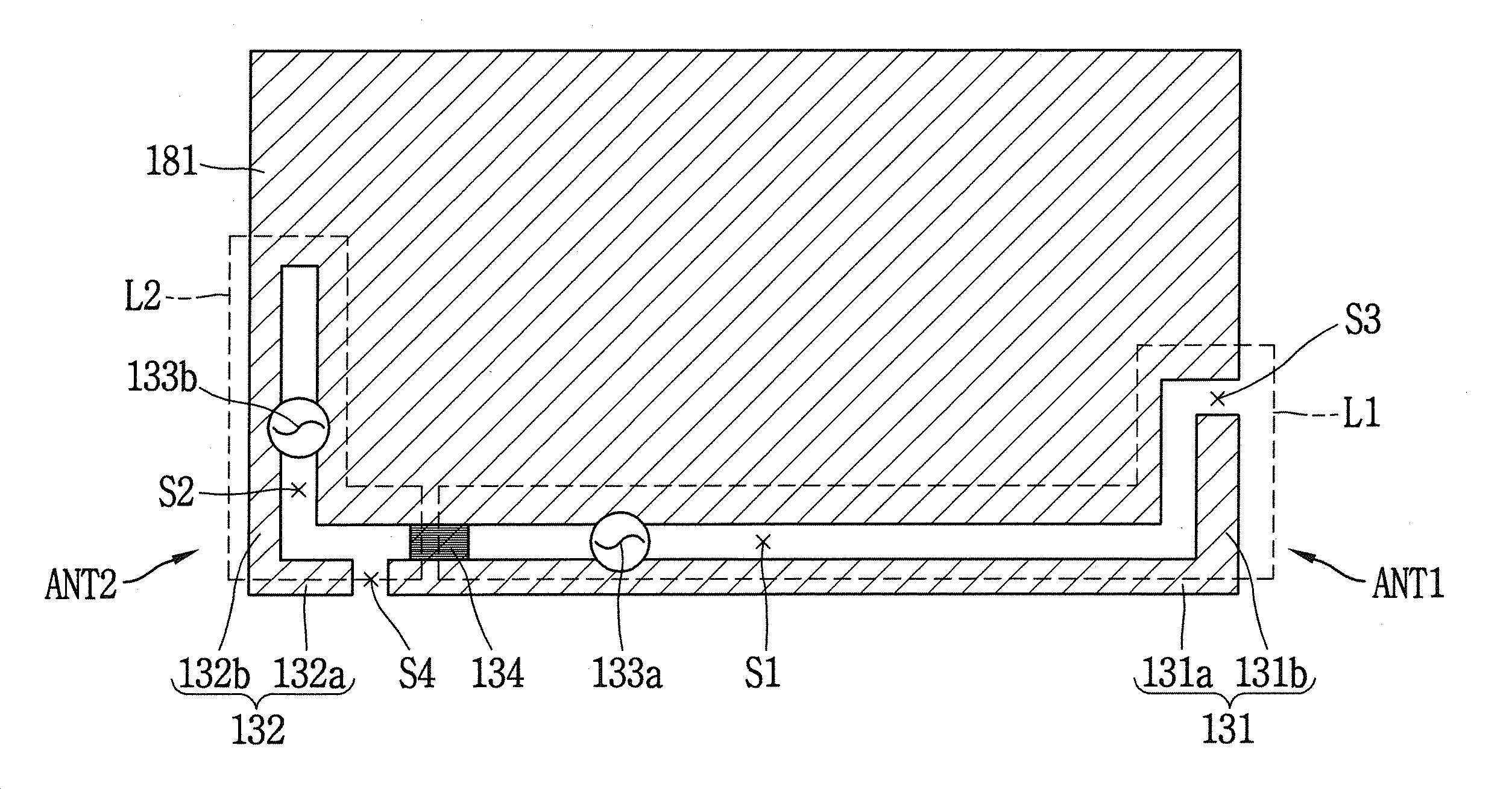
한편, 도 3은 본 발명의 일 실시예에 따른 안테나 장치(ANT1,ANT2)를 설명하기 위한 이동 단말기(100)의 개념도이고, 도 5a는 본 발명의 일 실시예에 따른 안테나 장치의 개념도인데, 도 3을 도 5a와 함께 참조하여 설명하기로 한다. 3 is a conceptual diagram of a
본 발명의 일 실시예에서는 단말기 바디의 내부에 구비되는 그라운드로부터 이격 형성되는 도전 멤버들(131,132)이 슬롯(slot)을 형성하여 슬롯 안테나(slot antenna)를 형성한다. 이때의 그라운드는 단말기 바디의 내부에 구비되는 인쇄회로기판(181), 중간 프레임(185,도 2a 참조) 또는 단말기 바디의 후면을 덮는 후면 커버(103) 중 어느 하나일 수 있으며, 이하에서는 인쇄회로기판(181)이 그라운드의 기능을 수행하는 것을 위주로 설명하기로 한다. In an embodiment of the present invention, the
본 발명의 일 실시예에서의 이동 단말기(100)는 그라운드(181)로부터 이격 형성되어 제1 슬롯(S1)을 형성하는 제1 도전 멤버(131)와, 상기 그라운드(181)로부터 이격 형성되어 제2 슬롯(S2)을 형성하는 제2 도전 멤버(132)를 포함한다. 상기 제1 도전 멤버(131)와 제2 도전 멤버(132)는 대략적으로 서로 교차하는 방향으로 형성되는데, 예를 들면, 상기 제1 도전 멤버(131)가 상기 이동 단말기(100)의 폭 방향으로 형성된다면, 상기 제2 도전 멤버(132)는 이동 단말기(100)의 길이 방향을 따라 형성될 수 있다. 다만, 상기 제1 도전 멤버(131)는 제1 방향으로만 형성되고, 제2 도전 멤버(132)가 제2 방향으로만 형성되는 것을 의미하는 것은 아니고, 상기 제1 도전 멤버(131)에 의해 형성되는 전류의 흐름인 제1 루프(L1)와, 상기 제2 도전 멤버(132)에 의해 형성되는 전류의 흐름인 제2 루프(L2)가 서로 간섭되지 않도록 형성되면 충분하다. 바람직하게는 상기 제1 및 제2 루프(L1,L2)는 교차하는 방향으로 형성되면 된다.The
이하에서는 상기 제1 도전 멤버(131)의 대부분이 향하는 방향을 제1 방향이라고 칭하고, 상기 제2 도전 멤버(132)의 대부분이 향하는 방향을 제2 방향이라고 칭하기로 한다.Hereinafter, a direction in which most of the first
도 3에서는 상기 제1 도전 멤버(131)가 제1 방향을 따라 형성되는 제1 서브 멤버(131a)와 상기 제2 방향을 따라 형성되는 제2 서브 멤버(131b)를 포함하고, 상기 제2 도전 멤버(132)가 제1 방향을 따라 형성되는 제3 서브 멤버(132a)와 상기 제2 방향을 따라 형성되는 제4 서브 멤버(132b)를 포함하는 것을 도시하였다. 이때, 상기 제1 서브 멤버(131a)의 길이가 제2 서브 멤버(131b)의 길이보다 길고, 상기 제3 서브 멤버(132a)는 제4 서브 멤버(132b)의 길이보다 짧은 것을 예시하였으나, 반드시 이에 한정되는 것은 아니다. 즉, 상기 제1 도전 멤버(131)와 그라운드(181)의 사이에는 제1 개방 슬롯(S3)이 형성되고, 제1 및 제2 도전 멤버(131,132)의 사이에는 제2 개방 슬롯(S4)이 형성되는데, 상기 제1 및 제2 개방 슬롯(S3,S4)의 위치는 구현하고자 하는 공진 주파수에 따라 가변될 수 있다.3, the first
상기 제1 및 제2 도전 멤버(131,132)는 각각 서로 다른 공진 주파수 대역을 구현하는 제1 안테나(ANT1) 및 제2 안테나(ANT2)일 수 있으며, 상기 제1 안테나(ANT1)에 의해 제1 공진주파수 대역이 구현되고, 제2 안테나(ANT2)에 의해서는 상기 제1 공진주파수 대역과는 상이한 제2 공진주파수 대역이 구현된다. The first and second
상기 제1 도전 멤버(131)를 급전시키는 제1 급전부(133a)는 인쇄회로기판(181)과 연결되고, 상기 제2 도전 멤버(132)를 급전시키는 제2 급전부(133b) 역시 인쇄회로기판(181)과 연결된다. 상기 제1 도전 멤버(131) 중 일 지점에는 상기 그라운드(181)에 연결되는 접합부(134)(junction portion)가 형성되는데, 상기 접합부(134)는 상기 제1 안테나(ANT1)에서의 접지부의 기능을 수행한다. 상기 접합부(134)는 일정한 면적을 갖는 금속부재 또는 다수의 미세 케이블로 이루어질 수 있으며, 상기 그라운드(181)와 제1 도전 멤버(131)를 전기적으로 연결시켜, 제1 도전 멤버(131)를 접지시킴과 동시에 제1 안테나(ANT1)와 제2 안테나(ANT2)를 구분하는 기능을 수행한다.The
즉, 상기 접합부(134)를 기준으로 제1 안테나(ANT1)와 제2 안테나(ANT2)로 구분된다. That is, the first antenna ANT1 and the second antenna ANT2 are divided based on the
상기 제1 도전 멤버(131)의 일 단부는 상기 그라운드(181)와 이격되어 제1 개방 슬롯(S3)을 형성하고, 상기 제2 도전 멤버(132)의 일 단부는 상기 제1 도전 멤버(131)의 일 단부와 이격되어 제2 개방 슬롯(S4)을 형성하고, 타 단부는 상기 그라운드(181)에 연결된다. 이때, 상기 제2 개방 슬롯(S4)은 음향 출력부(152)인 이어잭(earjacj)을 위한 슬롯일 수 있다.One end of the first
상기 제1 및 제2 도전 멤버(131,132)는 안테나로서 기능하게 된다. 이때, 상기 제2 도전 멤버(132)가 그라운드(181)에 연결되는 지점(G)에는 상기 제2 도전 멤버(132)가 직접 그라운드(181)에 연결될 수도 있다. 또한, 도 9a에 도시된 접촉핀(C1 내지 C4)이 형성되어 제2 도전 멤버(132)를 그라운드(181)에 접지시킬 수 있다. 뿐만 아니라, 이동 단말기(100)의 측면 부분에서 제1 내지 제4 도전 멤버(131,132,131',132')를 제외한 부분 중 하나 이상의 지점에는 상기 그라운드(181)와 접촉하는 하나 이상의 접촉핀(C1 내지 C4)이 형성될 수 있다.The first and second
이는 본 발명의 제2 실시예에서도 마찬가지이다. 즉, 도 9b에 구체적으로 도시하지는 않았으나, 케이스(103)의 측면 부분에는 그라운드와 연결되는 다수의 접촉핀(C1 내지 C4)이 형성될 수 있다. 나아가, 인쇄회로기판(181)을 덮는 케이스(103)의 후면 부분에 접촉핀(C1 내지 C4)이 형성될 수도 있다.This also applies to the second embodiment of the present invention. That is, although not specifically shown in FIG. 9B, a plurality of contact pins C1 to C4, which are connected to the ground, may be formed on a side portion of the
도 6a는 본 발명의 일 실시예에 따른 제1 도전 멤버(131)에 의한 방사 패턴을 개략적으로 도시한 것이고, 도 6b는 본 발명의 일 실시예에 따른 제2 도전 멤버(132)에 의한 방사 패턴을 개략적으로 도시한 것이며, 도 8은 본 발명의 제1 실시예에 따른 제1 도전 멤버(131)에 의한 방사 패턴을 이동 단말기(100) 전체에 대하여 개략적으로 도시한 것이다. 6a schematically illustrates a radiation pattern by a first
도 6a 및 도 6b를 참조하면, 제1 도전 멤버(131)에 의한 방사 영역(R1)은 주로 이동 단말기(100)의 우측 하단에 형성되고, 제2 도전 멤버(132)에 의한 방사 영역(R2)은 주로 이동 단말기(100)의 좌측 하단에 형성되어 서로 간섭이 이루어지지 않음을 알 수 있다. 나아가, 제1 도전 멤버(131)에 의한 방사 패턴은 주로 제1 방향을 따라 형성되고, 제2 도전 멤버(132)에 의한 방사 패턴은 주로 제2 방향을 따라 형성됨을 알 수 있으며, 이에 의해 제1 및 제2 도전 멤버(131,132)에 의한 방사 패턴은 서로에 큰 영향을 미치지 않고 독립적으로 방사 영역을 확보함을 알 수 있다.6A and 6B, the radiation region R1 by the first
또한, 본 발명의 일 실시예에서는 제1 및 제2 도전 멤버(131,132)를 "L" 타입으로 형성하는데, 이에 의해 이동 단말기(100)의 모서리 부근에서의 전기장이 최대가 되도록 유도하였으며, 이로써 방사 영역을 보다 넓게 확보할 수 있게 되었다. 예를 들면, 그라운드 방사를 극대화할 수 있게 하였다. 보다 구체적으로 설명하면, 이동 단말기(100)는 일반적으로 이동 단말기(100)에서 구현되는 주파수 밴드 중 로우 밴드(low band)의 공진 주파수의 구현을 위해, 로우 밴드의 공진 주파수에 대응되는 파장의 크기 이상을 갖도록 형성되는데, 본 발명의 일 실시예에서와 같이, 슬롯 안테나(slot antenna)의 경우에는 이동 단말기(100)의 길이 방향에서의 길이를 로우 밴드의 중심 주파수에 대응되는 파장(λ)의 1/4배보다 크게 형성한다. 이때, 제1 도전 멤버(131)에 의한 방사 영역의 부족으로 인한 방사 성능이 약화되는 것을 보완하기 위하여 본 발명의 일 실시예에서는 그라운드 방사가 보다 활발하게 이루어지도록 하였다. 즉, 본 발명의 일 실시예에서의 제1 및 제2 도전 멤버(131,132)에서의 전기장은 이동 단말기(100)의 모서리 근처에서 최대가 되도록 하였다.Also, in one embodiment of the present invention, the first and second
나아가, 본 발명의 일 실시예에서는 제1 도전 멤버(131)에 의해서는 로우 밴드(low band) 및 하이 밴드(high band) 대역의 주파수를 구현하고, 제2 도전 멤버(132)에 의해서는 미들 밴드(middle band) 대역의 주파수를 구현하도록 할 수 있다. 로우 밴드의 주파수를 구현하기 위하여 상술한 바와 같이, 제1 도전 멤버(131)에 의한 전기장 분포가 코너 부근에서 최대가 되도록 하였으며, 본 발명의 일 실시예에서는 도 8에 도시된 바와 같이, 이동 단말기(100)의 하측(R11)에서 뿐만 아니라 상측(R12)에서도 그라운드 방사가 이루어지도록 하였다. 이를 위하여 본 발명의 일 실시예에서는 상기 제1 및 제2 개방 슬롯(S3,S4)이 이동 단말기(100)의 모서리 부근에 형성되도록 하였다. 이는 개방 슬롯의 근처에 전기장이 집중 분포되는 현상을 이용한 것이다.Further, in one embodiment of the present invention, the first
다만, 제2 도전 멤버(132)는 미들 밴드 대역의 주파수를 구현하므로, 미들 밴드 주파수 대역을 구현하기 위하여는 이동 단말기(100)의 상측에서 그라운드 방사가 반드시 발생하도록 할 필요는 없다. However, since the second
한편, 본 발명의 일 실시예에서는 구현하고자 하는 주파수 대역에 따라 상기 제1 도전 멤버(131)와 접합부(134)가 연결되는 부분의 위치를 조정할 수 있으며, 제1 도전 멤버(131)에 추가적인 급전부를 더 형성하여 구현하고자 하는 주파수 대역을 추가할 수도 있다. 예를 들면, 도 5c는 본 발명의 일 실시예에 따른 제3 안테나(ANT3) 장치를 설명하기 위한 도면으로, 도 5a에 제3 급전부(133c)가 추가된 도면이다. 다만, 이때, 상기 접합부(134)가 제1 도전 멤버(131)에 연결되는 위치가 변동될 수 있다.According to an embodiment of the present invention, the position of the portion where the first
앞서 설명한 바와 같이, 상기 접합부(134)는 제1 및 제2 도전 멤버(131,132)에 의한 안테나를 구분하는 기능을 함과 동시에 제1 도전 멤버(131)에서의 접지부의 기능을 수행하므로, 제1 도전 멤버(131) 중 일부를 제1 안테나(ANT1)로 작동되도록 함과 동시에 제1 도전 멤버(131) 중 나머지를 제3 안테나(ANT3)로 작동되도록 할 수 있다. 이를 위하여, 도 5c에 도시된 바와 같이, 인쇄회로기판(181)에 연결되면서 제1 도전 멤버(131) 중 제1 급전부(133a)가 형성되는 위치와 반대편에 제3 급전부(133c)를 형성할 수 있다. 즉, 상기 제1 급전부(133a)가 제1 도전 멤버(131)에 연결되는 지점(P3)와 제3 급전부(133c)가 제1 도전 멤버(131)에 연결되는 지점(P4)의 사이에 상기 접합부(134)가 형성된다.As described above, the
이때, 상기 제1 도전 멤버(131) 및 제3 급전부(133c)에 의해 형성되는 제3 안테나(ANT3)의 접지부는 상기 접합부(134)가 수행할 수 있다. 즉, 상기 제1 안테나(ANT1)의 방사체는 제1 도전 멤버(131) 중 상기 접합부(134)가 연결되는 지점부터 제1 급전부(133a)가 연결되는 지점을 경유하여 제1 개방 슬롯(S3)에까지 형성되는 부분이고, 제2 안테나(ANT2)의 방사체는 제2 도전 멤버(132)이며, 상기 제3 안테나(ANT3)의 방사체는 상기 제1 도전 멤버(131) 중 상기 접합부(134)가 연결되는 지점에서 상기 제3 급전부(133c)가 연결되는 지점을 경유하여 제2 개방 슬롯(S4)에까지 형성되는 부분으로, 상기 제2 도전 멤버(132)와 마주보는 단부까지이다.At this time, the grounding part of the third antenna ANT3 formed by the first
앞에서는 이동 단말기(100)의 하단부에 형성되는 안테나를 위주로 설명하였는데, 본 발명의 일 실시예에서는 이에 한정되는 것은 아니고, 이동 단말기(100)의 상단에도 동일한 방식으로 다수의 주파수 대역을 구현하는 안테나가 형성될 수도 있다.In the above description, the antenna formed at the lower end of the
즉, 도 5b는 본 발명의 일 실시예에 따른 상부 안테나를 설명하기 위한 도면인데, 이는 도 5c에 도시된 바와 유사하게 형성된 것을 알 수 있다.That is, FIG. 5B is a view for explaining an upper antenna according to an embodiment of the present invention, which is formed similar to that shown in FIG. 5C.
이하에서는 도 5b를 참조하여, 이동 단말기(100)의 상단에 형성되는 안테나들(ANT4 내지 ANT6)에 대하여 설명하기로 한다.Hereinafter, the antennas ANT4 to ANT6 formed at the upper end of the
도 5b를 참조하면, 그라운드 기능을 수행하는 인쇄회로기판(181)으로부터 일정 간격 이격 형성되는 제3 및 제4 도전 멤버(131',132')가 형성되고, 제3 도전 멤버(131')에는 접합부(134')가 연결되어 있으며, 제3 및 제4 도전 멤버(131',132')에는 각각 제4 및 제5 급전부(133a',133b')가 형성되어 제4 및 제5 안테나(ANT4,ANT5)를 형성한다. 뿐만 아니라, 상기 제3 도전 멤버(131') 중 일 지점에는 상기 제4 급전부(133a')와 반대편에 제6 급전부(133c')가 형성되어 제6 안테나(ANT6)를 구현할 수 있다. 이때, 상기 제3 및 제4 도전 멤버(131',132')에 의해 제3 및 제4 루프(L3,L4)가 형성된다.Referring to FIG. 5B, third and fourth conductive members 131 'and 132' are formed at predetermined intervals from the printed
이동 단말기(100)의 상측에 형성되는 제4 내지 제6 안테나(ANT4 내지 ANT6)는 제1 내지 제3 안테나(ANT1 내지 ANT3)와 동일한 방식으로 형성되므로, 구체적인 설명은 생략하기로 한다. The fourth to sixth antennas ANT4 to ANT6 formed on the upper side of the
한편, 본 발명의 일 실시예에서는 인쇄회로기판(181)과 제1 내지 제4 도전 멤버(131,131',132,132')에 이르는 제1 내지 제6 급전부(133a,133a',133b,133b',133c,133c') 중 적어도 하나 이상에는 급전 연장부(133d,133d',133e,133e')가 형성될 수 있다. 상기 급전 연장부(133d,133d',133e,133e')는 임피던스 매칭을 위한 소자이다.In one embodiment of the present invention, the first to
도 7은 본 발명의 일 실시예에 따른 이동 단말기(100)의 안테나에 스위치(135)가 형성된 것을 설명하기 위한 도면이다. 도 7을 참조하면, 상기 그라운드(181)와 제1 도전 멤버(131) 또는 제2 도전 멤버(132)의 일 지점을 연결하는 스위치(135)가 형성될 수 있다. 상기 스위치(135)는 공진 주파수를 가변시키기 위한 소자로, 매칭 모듈(matching module) 또는 임피던스 매칭을 위한 정합부로 명명될 수도 있으며, 상기 제1 슬롯(S1) 또는 제2 슬롯(S2)에 형성된다. 7 is a view for explaining that a
상기 스위치(135)는 커패시터와 인덕터의 다양한 조합으로 이루어질 수 있다. 예를 들면, 서로 다른 크기의 인덕터만을 갖거나, 인덕터와 커패시터를 함께 갖거나, 인덕터 하나만 가질 수도 있다. 또한, 인덕터와 가변 커패시터가 직렬로 연결될 수도 있으며, 가변 커패시터를 가질 수도 있고, 인덕터 및 가변 커패시터가 병렬로 연결될 수도 있다.The
상기 예들은 일 예에 불과하고, 가변 인덕터도 사용될 수 있으며, 2접점 스위치(135)(SPDT,Single Pole Double Throw) 및 3접점 스위치(135)(SP3T,Single Pole Triple Throw)도 가능하다. 이때, 인덕터를 사용하게 되면 공진 주파수를 낮출 수 있고, 커패시터를 사용하게 되면 공진 주파수를 높일 수 있으며, 이들의 적절한 조합에 의해 공진 주파수를 가변시킬 수 있게 된다. 이러한 가변 스위치(135)는 본 발명이 속하는 기술분야에서의 통상의 기술자에게는 자명한 것으로 여기에서는 구체적인 설명은 생략하기로 한다.The above examples are merely examples, and a variable inductor can also be used, and a two-contact switch 135 (SPDT) and a three-contact switch 135 (SP3T, Single Pole Triple Throw) are also possible. At this time, if the inductor is used, the resonance frequency can be lowered. If a capacitor is used, the resonance frequency can be increased. By appropriately combining the resonance frequency and the resonance frequency, the resonance frequency can be varied. The
이하에서는 앞서 설명한 제1 내지 제4 도전 멤버(131,131',132,132')들 또는 제1 내지 제6 안테나(ANT1 내지 ANT6)를 이동 단말기(100)에 어떤 방식으로 구체적으로 구현하는지에 대하여 설명하기로 한다.Hereinafter, how the first to fourth
도 2a는 본 발명의 제1 실시예에 따른 이동 단말기(100)의 분해사시도이고, 도 9a는 도 2a에 대응되는 이동 단말기(100)의 안테나로 작동되는 도전 멤버를 개략적으로 도시한 도면이다. 도 2a 및 도 9a를 참조하면, 제1 내지 제4 도전 멤버(131,131',132,132')는 이동 단말기(100)의 측면부(102a)를 형성하고, 외부에 노출되어 있으며, 제1 및 제2 도전 멤버(131,132)에는 제1 및 제2 개방 슬롯(S3,S4)이 형성되고, 제3 및 제4 도전 멤버(131',132')에는 제3 및 제4 개방 슬롯(S3',S4')이 형성되어 있다. 도 9a에서는 급전부들을 생략하였으며, 이는 도 9b에서도 마찬가지이다. 이때, 앞서 설명한 제1 내지 제3 안테나(ANT1 내지 ANT3)는 하단 안테나(ANTI)이고, 제4 내지 제5 안테나(ANT4 내지 ANT6)은 상단 안테나(ANTII)이다.FIG. 2A is an exploded perspective view of a
본 발명의 제1 실시예에서는 상기 제1 및 제2 도전 멤버(131,132)를 포함하는 측면부(102a)가 금속부재로 형성되고, 상기 측면부(102a) 중 일부가 안테나로 작동되며, 후면 커버(103)는 비금속부재로 이루어진다. 또한, 상기 리어 케이스(102)의 일면에는 구체적으로 도시하지는 않았으나 급전 연장부(133d) 또는 도전 패턴(미도시)이 추가적으로 형성될 수도 있다. In the first embodiment of the present invention, the
본 발명의 제1 실시예는 이동 단말기(100)의 측면을 형성하는 금속부재 중 일부를 안테나로 활용하므로, 메탈 링(metal ring) 구조라 명명할 수 있다.The first embodiment of the present invention uses a part of the metal member forming the side surface of the
반면, 본 발명의 제2 실시예에서도 이동 단말기(100)의 측면을 형성하는 금속부재 중 일부를 안테나로 활용하는 점에서는 동일하나, 디스플레이부(151)가 수용되는 케이스(103)를 단일 구성으로 하여, 케이스(103)의 후면을 덮는 부분을 금속부재로 활용하므로 메탈 커버(metal cover) 구조라고 명명할 수 있다.In the second embodiment of the present invention, a part of the metal member forming the side surface of the
도 2b는 본 발명의 제2 실시예에 따른 이동 단말기(100)의 분해사시도이고, 도 9b는 도 2b에 대응되는 이동 단말기(100)에서의 후면 커버(103), 및 안테나로 작동되는 도전 멤버를 개략적으로 도시한 도면이다.FIG. 2B is an exploded perspective view of the
본 발명의 제2 실시예에 따른 이동 단말기(100)는 유니바디 타입의 단말기로, 디스플레이부(151)는 하나의 케이스(103)에 수용된다. 이때, 상기 케이스(103)의 후면은 금속 재질로 이루어질 수 있는데, 이와 같이 이동 단말기(100)의 후면을 덮는 부분이 금속 재질로 이루어지는 경우에는 제1 내지 제4 도전 멤버(131,131',132,132')들에 의한 방사 성능에 영향을 미치게 된다. 따라서, 본 발명의 제2 실시예에서는 상기 제1 내지 제4 도전 멤버(131,131',132,132')와 이동 단말기(100)의 후면 대부분을 차지하는 후면 부분을 전기적으로 절연시키기 위하여 비금속부재(136,136')가 형성된다. 상기 비금속부재(136,136')는 일예로, 폴리카보네이트(polycarbonate)일 수 있으며, 비금속 재질이면 특별히 제한되지 않는다. 또한, 도 9a에 도시된 바와 같이, 그라운드(181)와 측면부(102a)를 연결하는 다수의 접촉핀(C1,C2,C3,C4)이 형성되어 상기 제1 내지 제4 도전 멤버(131,131',132,132') 이외의 측면부(102a)가 안테나의 방사 성능에 영향을 미치지 않도록 할 수 있다. 즉, 상기 접촉핀(C1,C2,C3,C4)은 상기 측면부(102a) 중 제1 내지 제4 도전 멤버(131,131',132,132') 이외의 부분에 형성될 수 있다.The
도 10a는 본 발명의 제2 실시예에 따른 이동 단말기(100)의 후면 사시도이고, 도 10b는 본 발명의 제2 실시예에 따른 이동 단말기(100)의 윈도우(151a)를 제거한 상태에서의 전면 사시도이며, 도 10c는 도 10b에서 디스플레이부(151)가 제거된 상태에서의 이동 단말기(100)의 전면 사시도이다. 즉, 도 10b는 디스플레이부(151) 중 윈도우(151a)만 제거한 상태이고, 디스플레이 모듈(151b)은 단말기 바디에 구비되어 있는 상태를 도시한 것이다.10A is a rear perspective view of a
도 10a 내지 도 10c에 도시된 바와 같이, 본 발명의 제2 실시예에서의 이동 단말기(100)의 금속부재인 케이스(103)가 안테나 성능에 영향을 미칠 수 있으므로, 도 10a에 도시된 바와 같이, 제1 및 제2 도전 멤버(131,132)와 케이스(103)가 전기적으로 절연되도록 비금속부재(136,136')가 구비된다. 또한, 제1 도전 멤버(131)를 급전시키는 제1 급전부(133a)와 제1 급전부(133a)의 급전 연장부(133d)는 이동 단말기(100)의 전면 근처에까지 형성된다. 보다 구체적으로, 상기 제1 급전부(133a) 및 급전 연장부(133d)는 인쇄회로기판(181)에 형성되어 디스플레이부(151)의 배면에까지 연장될 수 있다. 다만, 반드시 제1 급전부(133a) 및 급전 연장부(133d)를 이동 단말기(100)의 전면 근처에 형성할 필요는 없으나, 케이스(103)의 영향을 최소화하기 위해서는 안테나 성능과 관련된 금속부재들을 케이스(103)로부터 이격 형성하는 것이 바람직하다. As shown in Figs. 10A to 10C, since the
전술한 본 발명은, 프로그램이 기록된 매체에 컴퓨터가 읽을 수 있는 코드로서 구현하는 것이 가능하다. 컴퓨터가 읽을 수 있는 매체는, 컴퓨터 시스템에 의하여 읽혀질 수 있는 데이터가 저장되는 모든 종류의 기록장치를 포함한다. 컴퓨터가 읽을 수 있는 매체의 예로는, HDD(Hard Disk Drive), SSD(Solid State Disk), SDD(Silicon Disk Drive), ROM, RAM, CD-ROM, 자기 테이프, 플로피 디스크, 광 데이터 저장 장치 등이 있으며, 또한 캐리어 웨이브(예를 들어, 인터넷을 통한 전송)의 형태로 구현되는 것도 포함한다. 또한, 상기 컴퓨터는 단말기의 제어부(180)를 포함할 수도 있다. 따라서, 상기의 상세한 설명은 모든 면에서 제한적으로 해석되어서는 아니되고 예시적인 것으로 고려되어야 한다. 본 발명의 범위는 첨부된 청구항의 합리적 해석에 의해 결정되어야 하고, 본 발명의 등가적 범위 내에서의 모든 변경은 본 발명의 범위에 포함된다.The present invention described above can be embodied as computer-readable codes on a medium on which a program is recorded. The computer readable medium includes all kinds of recording devices in which data that can be read by a computer system is stored. Examples of the computer readable medium include a hard disk drive (HDD), a solid state disk (SSD), a silicon disk drive (SDD), a ROM, a RAM, a CD-ROM, a magnetic tape, a floppy disk, , And may also be implemented in the form of a carrier wave (e.g., transmission over the Internet). Also, the computer may include a
Claims (19)
상기 단말기 바디의 내부에 구비되는 그라운드;
상기 그라운드로부터 이격 형성되고, 제1 급전부로부터 급전되며 상기 그라운드의 일측 모서리를 감싸는 L자 형태로 배치된 제1 서브 멤버와 제2 서브 멤버를 포함하는 제1 도전 멤버;
상기 그라운드로부터 이격 형성되고, 제2 급전부로부터 급전되며 상기 그라운드의 타측 모서리를 감싸는 L자 형태로 배치된 제3 서브 멤버와 제4 서브 멤버를 포함하는 제2 도전 멤버; 및
상기 제1 도전 멤버의 일 지점에 형성되어 상기 제1 도전 멤버를 상기 그라운드에 접지시키는 접합부(junction portion)를 포함하고,
상기 제1 도전 멤버의 제1 단부는 상기 그라운드와 이격되어 제1 개방 슬롯을 형성하고,
상기 제2 도전 멤버의 제1 단부는 상기 제1 도전 멤버의 제1 단부와 이격되어 제2 개방 슬롯을 형성하고, 제2 단부는 상기 그라운드에 연결되며,
상기 제1 서브 멤버는 상기 제2 서브 멤버의 길이보다 길고, 상기 제3 서브 멤버는 상기 제4 서브 멤버보다 길이가 짧으며
상기 제1 서브 멤버 및 상기 제4 서브 멤버는 서로 다른 방향으로 형성된 것을 특징으로 하는 이동 단말기.Terminal body;
A ground provided inside the terminal body;
A first conductive member spaced apart from the ground, the first conductive member including a first sub-member and a second sub-member, the first sub-member being disposed in an L-shape and being fed from the first feeding portion and surrounding one side edge of the ground;
A second conductive member spaced apart from the ground, the second conductive member including a third sub-member and a fourth sub-member arranged in an L-shape arranged to feed from the second feeder and to surround the other edge of the ground; And
And a junction portion formed at one point of the first conductive member and grounding the first conductive member to the ground,
The first end of the first conductive member being spaced apart from the ground to form a first open slot,
Wherein a first end of the second conductive member is spaced apart from a first end of the first conductive member to form a second open slot and the second end is connected to the ground,
The first sub-member is longer than the length of the second sub-member, the third sub-member is shorter than the fourth sub-member
Wherein the first sub-member and the fourth sub-member are formed in different directions.
상기 제1 및 제2 개방 슬롯 중 적어도 하나는 상기 단말기 바디의 모서리 부근에 형성되는 것을 특징으로 하는 이동 단말기.The method according to claim 1,
Wherein at least one of the first and second open slots is formed in the vicinity of an edge of the terminal body.
상기 제1 도전 멤버 중 상기 접합부를 중심으로 제1 급전부와 반대 위치에 상기 제1 도전 멤버를 급전시키는 제3 급전부를 더 포함하는 것을 특징으로 하는 이동 단말기.The method according to claim 1,
Further comprising a third feeding part for feeding the first conductive member at a position opposite to the first feeding part about the junction among the first conductive members.
상기 제1 내지 제3 급전부 중 적어도 하나에는 급전 연장부가 형성되는 것을 특징으로 하는 이동 단말기.6. The method of claim 5,
And at least one of the first to third feeding parts is formed with a power supply extension part.
상기 제1 및 제2 도전 멤버, 제1 내지 제3 급전부, 접합부는 상기 단말기 바디의 상단 및 하단 중 적어도 하나의 위치에 형성되는 것을 특징으로 하는 이동 단말기. The method according to claim 6,
Wherein the first and second conductive members, the first to third feeding parts, and the connecting part are formed at at least one of an upper end and a lower end of the terminal body.
상기 제1 및 제2 도전 멤버는 상기 단말기 바디의 측면을 감싸면서 외부에 노출되는 금속부재인 것을 특징으로 하는 이동 단말기.8. The method of claim 7,
Wherein the first and second conductive members are metal members that surround the side of the terminal body and are exposed to the outside.
상기 단말기 바디는,
디스플레이부가 구비되는 프론트 케이스;
상기 프론트 케이스의 후면에 형성되고 상기 프론트 케이스에 결합되는 리어 케이스;
상기 프론트 케이스와 리어 케이스 사이에 구비되는 메탈 프레임; 및
상기 메탈 프레임의 일면에 구비되는 인쇄회로기판을 포함하고,
상기 그라운드는 상기 메탈 프레임 및 인쇄회로기판 중 적어도 하나인 것을 특징으로 하는 이동 단말기.9. The method of claim 8,
The terminal body includes:
A front case having a display unit;
A rear case formed on a rear surface of the front case and coupled to the front case;
A metal frame provided between the front case and the rear case; And
And a printed circuit board provided on one surface of the metal frame,
Wherein the ground is at least one of the metal frame and the printed circuit board.
상기 제1 및 제2 도전 멤버 중 적어도 하나에는 상기 인쇄회로기판에 연결되는 스위치가 구비되는 것을 특징으로 하는 이동 단말기.10. The method of claim 9,
Wherein at least one of the first and second conductive members is provided with a switch connected to the printed circuit board.
상기 급전 연장부는 상기 제1 또는 제2 도전 멤버로부터 연장되어 상기 리어 케이스의 일면에 형성되는 것을 특징으로 하는 이동 단말기.10. The method of claim 9,
Wherein the power supply extension part extends from the first or second conductive member and is formed on one surface of the rear case.
상기 리어 케이스의 후면을 덮는 금속 재질의 후면 커버를 더 포함하고, 상기 후면 커버는 비금속부재인 것을 특징으로 하는 이동 단말기.10. The method of claim 9,
Further comprising a metallic rear cover covering the rear surface of the rear case, wherein the rear cover is a non-metallic member.
상기 리어 케이스는 상기 인쇄회로기판을 덮는 주면부와 상기 프론트 케이스와의 사이에 내부 공간을 형성하도록 단말기 바디의 두께 방향으로 형성되는 측면부를 포함하고,
상기 측면부와 그라운드를 연결하는 다수의 접촉핀을 더 포함하는 것을 특징으로 하는 이동 단말기.13. The method of claim 12,
Wherein the rear case includes a main surface portion covering the printed circuit board and a side portion formed in a thickness direction of the terminal body so as to form an internal space between the main body and the front case,
And a plurality of contact pins connecting the side portion and the ground.
상기 단말기 바디는 디스플레이부를 수용하는 케이스를 포함하고, 상기 케이스와 금속부재의 사이에는 비금속부재가 구비되는 것을 특징으로 하는 이동 단말기.9. The method of claim 8,
Wherein the terminal body includes a case for accommodating a display unit, and a non-metallic member is provided between the case and the metal member.
상기 케이스 내부에 위치하는 인쇄회로기판을 더 포함하고,
상기 접합부 및 급전 연장부는 상기 인쇄회로기판으로부터 상기 디스플레이부의 배면에까지 연장되는 것을 특징으로 하는 이동 단말기.15. The method of claim 14,
Further comprising a printed circuit board positioned within the case,
Wherein the junction and the power supply extension extend from the printed circuit board to the back surface of the display unit.
상기 디스플레이부와 상기 케이스의 사이에 구비되는 메탈 프레임; 및
상기 메탈 프레임의 일면에 구비되는 인쇄회로기판을 포함하고,
상기 그라운드는 상기 메탈 프레임, 상기 인쇄회로기판 및 상기 케이스 중 적어도 하나인 것을 특징으로 하는 이동 단말기.15. The method of claim 14,
A metal frame disposed between the display unit and the case; And
And a printed circuit board provided on one surface of the metal frame,
Wherein the ground is at least one of the metal frame, the printed circuit board, and the case.
상기 제1 및 제2 도전 멤버 중 적어도 하나에는 상기 인쇄회로기판에 연결되는 스위치가 구비되는 것을 특징으로 하는 이동 단말기.17. The method of claim 16,
Wherein at least one of the first and second conductive members is provided with a switch connected to the printed circuit board.
상기 케이스와 그라운드를 연결하는 다수의 접촉핀을 더 포함하는 것을 특징으로 하는 이동 단말기.17. The method of claim 16,
And a plurality of contact pins connecting the case and the ground.
상기 제2 개방 슬롯에 이어잭(earjack)의 입구가 위치하는 것을 특징으로 하는 이동 단말기.The method according to claim 1,
And an inlet of an earjack is located after the second open slot.
Priority Applications (13)
| Application Number | Priority Date | Filing Date | Title |
|---|---|---|---|
| KR1020150167904A KR101827275B1 (en) | 2015-11-27 | 2015-11-27 | Mobile terminal |
| EP16868766.3A EP3383003B1 (en) | 2015-11-27 | 2016-08-08 | Mobile terminal |
| PCT/KR2016/008703 WO2017090865A1 (en) | 2015-11-27 | 2016-08-08 | Mobile terminal |
| EP21195350.0A EP3996204A1 (en) | 2015-11-27 | 2016-08-08 | Mobile terminal |
| US15/779,492 US10205225B2 (en) | 2015-11-27 | 2016-08-08 | Mobile terminal |
| PCT/KR2016/013601 WO2017090997A1 (en) | 2015-11-27 | 2016-11-24 | Mobile terminal |
| EP16868893.5A EP3383004A4 (en) | 2015-11-27 | 2016-11-24 | MOBILE TERMINAL |
| US15/779,479 US10498038B2 (en) | 2015-11-27 | 2016-11-24 | Mobile terminal |
| US16/236,080 US10553931B2 (en) | 2015-11-27 | 2018-12-28 | Mobile terminal |
| US16/676,220 US11189929B2 (en) | 2015-11-27 | 2019-11-06 | Mobile terminal |
| US16/737,839 US11043734B2 (en) | 2015-11-27 | 2020-01-08 | Mobile terminal |
| US17/236,636 US11509040B2 (en) | 2015-11-27 | 2021-04-21 | Mobile terminal |
| US17/522,401 US11600905B2 (en) | 2015-11-27 | 2021-11-09 | Mobile terminal |
Applications Claiming Priority (1)
| Application Number | Priority Date | Filing Date | Title |
|---|---|---|---|
| KR1020150167904A KR101827275B1 (en) | 2015-11-27 | 2015-11-27 | Mobile terminal |
Publications (2)
| Publication Number | Publication Date |
|---|---|
| KR20170062283A KR20170062283A (en) | 2017-06-07 |
| KR101827275B1 true KR101827275B1 (en) | 2018-02-08 |
Family
ID=58763776
Family Applications (1)
| Application Number | Title | Priority Date | Filing Date |
|---|---|---|---|
| KR1020150167904A Active KR101827275B1 (en) | 2015-11-27 | 2015-11-27 | Mobile terminal |
Country Status (4)
| Country | Link |
|---|---|
| US (5) | US10205225B2 (en) |
| EP (3) | EP3383003B1 (en) |
| KR (1) | KR101827275B1 (en) |
| WO (1) | WO2017090865A1 (en) |
Families Citing this family (38)
| Publication number | Priority date | Publication date | Assignee | Title |
|---|---|---|---|---|
| KR101827275B1 (en) | 2015-11-27 | 2018-02-08 | 엘지전자 주식회사 | Mobile terminal |
| KR102518499B1 (en) * | 2016-04-22 | 2023-04-05 | 삼성전자주식회사 | Antenna and electronic device having it |
| WO2018028486A1 (en) | 2016-08-08 | 2018-02-15 | Guangdong Oppo Mobile Telecommunications Corp., Ltd. | Housing, method for manufacturing housing, and mobile terminal having housing |
| KR20190077343A (en) * | 2016-11-22 | 2019-07-03 | 엘지전자 주식회사 | Mobile terminal |
| CN107425258B (en) * | 2017-06-22 | 2020-02-18 | 瑞声科技(新加坡)有限公司 | Antenna system and mobile terminal |
| TWI682586B (en) * | 2017-07-03 | 2020-01-11 | 仁寶電腦工業股份有限公司 | Multi-band antenna |
| KR102266626B1 (en) * | 2017-07-17 | 2021-06-17 | 엘에스엠트론 주식회사 | Wireless Communication Chip Having Internal Antenna, Internal Antenna for Wireless Communication Chip, and Method for Fabricating Wireless Communication Chip Having Internal Antenna |
| KR102364470B1 (en) | 2017-08-23 | 2022-02-18 | 삼성전자주식회사 | Electronic device comprising antenna |
| US10700416B2 (en) | 2017-08-30 | 2020-06-30 | Lg Electronics Inc. | Mobile terminal |
| KR101964651B1 (en) * | 2017-08-30 | 2019-04-02 | 엘지전자 주식회사 | Mobile terminal |
| CN110622492B (en) * | 2017-09-18 | 2020-11-27 | Lg电子株式会社 | mobile terminal |
| CN108232421B (en) * | 2017-12-29 | 2021-04-02 | 瑞声精密制造科技(常州)有限公司 | Antenna system and mobile terminal |
| USD915320S1 (en) * | 2018-03-15 | 2021-04-06 | Huawei Technologies Co., Ltd. | Mobile phone |
| KR102455333B1 (en) * | 2018-05-15 | 2022-10-14 | 후아웨이 테크놀러지 컴퍼니 리미티드 | Antenna systems and terminal equipment |
| CN108832272B (en) * | 2018-05-29 | 2020-08-21 | 北京小米移动软件有限公司 | Electronic equipment and its antenna structure |
| KR102521191B1 (en) | 2018-05-29 | 2023-04-13 | 삼성전자주식회사 | Overlapped printed circuit boards and electronic device including the same |
| WO2019237278A1 (en) * | 2018-06-13 | 2019-12-19 | 深圳市大疆创新科技有限公司 | Photographing device |
| CN108808221B (en) * | 2018-06-19 | 2021-05-04 | 深圳市万普拉斯科技有限公司 | Antenna system and mobile terminal |
| CN109193129B (en) * | 2018-08-31 | 2021-04-27 | 北京小米移动软件有限公司 | Antenna system and terminal |
| CN111146571A (en) * | 2018-11-06 | 2020-05-12 | 华为终端有限公司 | Coupling antenna device and electronic equipment |
| WO2020101881A1 (en) * | 2018-11-14 | 2020-05-22 | Google Llc | Connector interface assembly |
| US12095159B2 (en) | 2019-01-04 | 2024-09-17 | Huawei Technologies Co., Ltd. | Antenna system and electronic apparatus |
| CN111864349B (en) * | 2019-04-26 | 2021-12-28 | 北京小米移动软件有限公司 | Mobile terminal and antenna radiation method for mobile terminal |
| US11171408B2 (en) * | 2019-05-23 | 2021-11-09 | Htc Corporation | Communication device |
| US11128032B2 (en) * | 2019-08-09 | 2021-09-21 | Apple Inc. | Electronic devices having multi-band antennas |
| CN110459872B (en) | 2019-08-19 | 2021-07-16 | Oppo广东移动通信有限公司 | Housing components and electronic equipment |
| KR102597872B1 (en) | 2019-08-21 | 2023-11-03 | 삼성전자주식회사 | Electronic device comprising antenna |
| CN112448725B (en) * | 2019-08-28 | 2022-05-24 | 华为技术有限公司 | Antenna, electronic device and antenna control method |
| CN111029754B (en) * | 2019-12-31 | 2021-10-22 | 联想(北京)有限公司 | Electronic equipment and antenna setting method |
| CN113078444B (en) * | 2020-01-06 | 2024-06-11 | 深圳富泰宏精密工业有限公司 | Antenna structure and wireless communication device with same |
| CN113328233B (en) | 2020-02-29 | 2022-11-08 | 华为技术有限公司 | Electronic device |
| CN113517556B (en) * | 2020-04-10 | 2024-09-17 | 深圳富泰宏精密工业有限公司 | Antenna structure and electronic equipment with same |
| EP4354653A4 (en) | 2021-11-08 | 2024-12-04 | Samsung Electronics Co., Ltd. | ANTENNA STRUCTURE AND ELECTRONIC DEVICE COMPRISING AN ANTENNA STRUCTURE |
| CN114552181A (en) * | 2022-01-30 | 2022-05-27 | Oppo广东移动通信有限公司 | Antenna assembly and electronic equipment |
| EP4459794A4 (en) * | 2022-02-08 | 2025-04-23 | Samsung Electronics Co., Ltd. | Electronic device comprising antenna |
| TWI823424B (en) * | 2022-06-14 | 2023-11-21 | 廣達電腦股份有限公司 | Wearable device |
| US12401116B2 (en) | 2022-09-06 | 2025-08-26 | Apple Inc. | Electronic device with multi-feed antenna structures |
| WO2026023833A1 (en) * | 2024-07-25 | 2026-01-29 | 삼성전자주식회사 | Electronic device comprising connector |
Family Cites Families (24)
| Publication number | Priority date | Publication date | Assignee | Title |
|---|---|---|---|---|
| US6466176B1 (en) * | 2000-07-11 | 2002-10-15 | In4Tel Ltd. | Internal antennas for mobile communication devices |
| US6791500B2 (en) * | 2002-12-12 | 2004-09-14 | Research In Motion Limited | Antenna with near-field radiation control |
| EP1880444A1 (en) * | 2005-05-13 | 2008-01-23 | Fractus, S.A. | Antenna diversity system and slot antenna component |
| US20080062045A1 (en) * | 2006-09-08 | 2008-03-13 | Motorola, Inc. | Communication device with a low profile antenna |
| US7889139B2 (en) * | 2007-06-21 | 2011-02-15 | Apple Inc. | Handheld electronic device with cable grounding |
| KR101801186B1 (en) | 2011-02-25 | 2017-11-24 | 엘지전자 주식회사 | Mobile terminal |
| US8457699B2 (en) * | 2011-05-24 | 2013-06-04 | Research In Motion Limited | Mobile wireless communications device having an antenna assembly with corner coupled rectangular base conductor portions and related methods |
| KR101257093B1 (en) * | 2011-06-10 | 2013-04-19 | 엘지전자 주식회사 | Mobile terminal |
| KR101224089B1 (en) * | 2011-06-23 | 2013-01-21 | 엘지전자 주식회사 | Mobile terminal |
| KR101318877B1 (en) | 2011-10-14 | 2013-10-17 | 삼성전자주식회사 | Portable terminal |
| KR101909604B1 (en) | 2011-11-02 | 2018-10-18 | 엘지전자 주식회사 | Mobile terminal |
| KR101899971B1 (en) | 2011-11-16 | 2018-09-18 | 엘지전자 주식회사 | Mobile terminal |
| US9160058B2 (en) * | 2011-11-28 | 2015-10-13 | Htc Corporation | Portable communication device |
| US9337528B2 (en) * | 2012-01-27 | 2016-05-10 | Blackberry Limited | Mobile wireless communications device including electrically conductive portable housing sections defining an antenna |
| CN202616411U (en) | 2012-04-23 | 2012-12-19 | 中兴通讯股份有限公司 | Mobile terminal |
| KR102013588B1 (en) * | 2012-09-19 | 2019-08-23 | 엘지전자 주식회사 | Mobile terminal |
| US9276319B2 (en) * | 2013-05-08 | 2016-03-01 | Apple Inc. | Electronic device antenna with multiple feeds for covering three communications bands |
| US10020561B2 (en) * | 2013-09-19 | 2018-07-10 | Pulse Finland Oy | Deposited three-dimensional antenna apparatus and methods |
| US9197270B2 (en) * | 2013-11-27 | 2015-11-24 | Sony Corporation | Double ring antenna with integrated non-cellular antennas |
| KR102094754B1 (en) | 2013-12-03 | 2020-03-30 | 엘지전자 주식회사 | Mobile terminal |
| US9484631B1 (en) * | 2014-12-01 | 2016-11-01 | Amazon Technologies, Inc. | Split band antenna design |
| CN104577334B (en) * | 2015-02-11 | 2017-07-21 | 小米科技有限责任公司 | Anneta module and mobile terminal |
| KR101827275B1 (en) | 2015-11-27 | 2018-02-08 | 엘지전자 주식회사 | Mobile terminal |
| KR102465796B1 (en) * | 2016-05-27 | 2022-11-10 | 삼성전자주식회사 | Electronic device with multi-slot antenna |
-
2015
- 2015-11-27 KR KR1020150167904A patent/KR101827275B1/en active Active
-
2016
- 2016-08-08 EP EP16868766.3A patent/EP3383003B1/en active Active
- 2016-08-08 EP EP21195350.0A patent/EP3996204A1/en active Pending
- 2016-08-08 US US15/779,492 patent/US10205225B2/en active Active
- 2016-08-08 WO PCT/KR2016/008703 patent/WO2017090865A1/en not_active Ceased
- 2016-11-24 EP EP16868893.5A patent/EP3383004A4/en not_active Withdrawn
-
2018
- 2018-12-28 US US16/236,080 patent/US10553931B2/en active Active
-
2020
- 2020-01-08 US US16/737,839 patent/US11043734B2/en active Active
-
2021
- 2021-04-21 US US17/236,636 patent/US11509040B2/en active Active
- 2021-11-09 US US17/522,401 patent/US11600905B2/en active Active
Also Published As
| Publication number | Publication date |
|---|---|
| US20180261907A1 (en) | 2018-09-13 |
| KR20170062283A (en) | 2017-06-07 |
| US11600905B2 (en) | 2023-03-07 |
| US10553931B2 (en) | 2020-02-04 |
| US20220069445A1 (en) | 2022-03-03 |
| EP3383003B1 (en) | 2021-09-29 |
| US11043734B2 (en) | 2021-06-22 |
| WO2017090865A1 (en) | 2017-06-01 |
| EP3383004A1 (en) | 2018-10-03 |
| EP3996204A1 (en) | 2022-05-11 |
| US11509040B2 (en) | 2022-11-22 |
| EP3383003A4 (en) | 2019-07-31 |
| US20200153087A1 (en) | 2020-05-14 |
| EP3383003A1 (en) | 2018-10-03 |
| EP3383004A4 (en) | 2019-07-31 |
| US20190157745A1 (en) | 2019-05-23 |
| US10205225B2 (en) | 2019-02-12 |
| US20210242571A1 (en) | 2021-08-05 |
Similar Documents
| Publication | Publication Date | Title |
|---|---|---|
| KR101827275B1 (en) | Mobile terminal | |
| KR101622731B1 (en) | Mobile terminal | |
| KR101958789B1 (en) | Mobile terminal | |
| US10381750B2 (en) | Electronic device | |
| US10879585B2 (en) | Mobile terminal | |
| US10038245B2 (en) | Antenna module and mobile terminal having the same | |
| KR101964651B1 (en) | Mobile terminal | |
| KR20190094454A (en) | Mobile terminal | |
| KR20160084192A (en) | Antenna module and mobile terminal having the same | |
| KR20190005030A (en) | Electronic device | |
| KR20170120438A (en) | Mobile terminal and method for controlling the same | |
| KR20180027881A (en) | Mobile terminal | |
| KR20190041231A (en) | Mobile terminal | |
| KR20190090870A (en) | Mobile terminal | |
| KR20190083446A (en) | Mobile terminal | |
| KR20170084632A (en) | Mobile terminal | |
| KR20190052120A (en) | Mobile terminal | |
| KR20160023438A (en) | Mobile terminal | |
| KR20150107229A (en) | Mobile terminal | |
| KR20190105101A (en) | Mobile terminal | |
| KR20170111484A (en) | Mobile terminal | |
| KR20190019307A (en) | Mobile terminal | |
| KR101861681B1 (en) | Mobile terminal | |
| KR20170083907A (en) | Mobile terminal | |
| KR101818115B1 (en) | Mobile terminal |
Legal Events
| Date | Code | Title | Description |
|---|---|---|---|
| A201 | Request for examination | ||
| PA0109 | Patent application |
St.27 status event code: A-0-1-A10-A12-nap-PA0109 |
|
| PA0201 | Request for examination |
St.27 status event code: A-1-2-D10-D11-exm-PA0201 |
|
| R17-X000 | Change to representative recorded |
St.27 status event code: A-3-3-R10-R17-oth-X000 |
|
| E902 | Notification of reason for refusal | ||
| PE0902 | Notice of grounds for rejection |
St.27 status event code: A-1-2-D10-D21-exm-PE0902 |
|
| E13-X000 | Pre-grant limitation requested |
St.27 status event code: A-2-3-E10-E13-lim-X000 |
|
| P11-X000 | Amendment of application requested |
St.27 status event code: A-2-2-P10-P11-nap-X000 |
|
| P13-X000 | Application amended |
St.27 status event code: A-2-2-P10-P13-nap-X000 |
|
| PG1501 | Laying open of application |
St.27 status event code: A-1-1-Q10-Q12-nap-PG1501 |
|
| E90F | Notification of reason for final refusal | ||
| PE0902 | Notice of grounds for rejection |
St.27 status event code: A-1-2-D10-D21-exm-PE0902 |
|
| P11-X000 | Amendment of application requested |
St.27 status event code: A-2-2-P10-P11-nap-X000 |
|
| P13-X000 | Application amended |
St.27 status event code: A-2-2-P10-P13-nap-X000 |
|
| E701 | Decision to grant or registration of patent right | ||
| PE0701 | Decision of registration |
St.27 status event code: A-1-2-D10-D22-exm-PE0701 |
|
| GRNT | Written decision to grant | ||
| PR0701 | Registration of establishment |
St.27 status event code: A-2-4-F10-F11-exm-PR0701 |
|
| PR1002 | Payment of registration fee |
St.27 status event code: A-2-2-U10-U11-oth-PR1002 Fee payment year number: 1 |
|
| PG1601 | Publication of registration |
St.27 status event code: A-4-4-Q10-Q13-nap-PG1601 |
|
| P22-X000 | Classification modified |
St.27 status event code: A-4-4-P10-P22-nap-X000 |
|
| PN2301 | Change of applicant |
St.27 status event code: A-5-5-R10-R13-asn-PN2301 St.27 status event code: A-5-5-R10-R11-asn-PN2301 |
|
| PR1001 | Payment of annual fee |
St.27 status event code: A-4-4-U10-U11-oth-PR1001 Fee payment year number: 4 |
|
| PR1001 | Payment of annual fee |
St.27 status event code: A-4-4-U10-U11-oth-PR1001 Fee payment year number: 5 |
|
| PR1001 | Payment of annual fee |
St.27 status event code: A-4-4-U10-U11-oth-PR1001 Fee payment year number: 6 |
|
| PR1001 | Payment of annual fee |
St.27 status event code: A-4-4-U10-U11-oth-PR1001 Fee payment year number: 7 |
|
| PR1001 | Payment of annual fee |
St.27 status event code: A-4-4-U10-U11-oth-PR1001 Fee payment year number: 8 |
|
| PR1001 | Payment of annual fee |
St.27 status event code: A-4-4-U10-U11-oth-PR1001 Fee payment year number: 9 |
|
| U11 | Full renewal or maintenance fee paid |
Free format text: ST27 STATUS EVENT CODE: A-4-4-U10-U11-OTH-PR1001 (AS PROVIDED BY THE NATIONAL OFFICE) Year of fee payment: 9 |