KR101818115B1 - Mobile terminal - Google Patents
Mobile terminal Download PDFInfo
- Publication number
- KR101818115B1 KR101818115B1 KR1020160049602A KR20160049602A KR101818115B1 KR 101818115 B1 KR101818115 B1 KR 101818115B1 KR 1020160049602 A KR1020160049602 A KR 1020160049602A KR 20160049602 A KR20160049602 A KR 20160049602A KR 101818115 B1 KR101818115 B1 KR 101818115B1
- Authority
- KR
- South Korea
- Prior art keywords
- conductive member
- mobile terminal
- main
- touch
- main conductive
- Prior art date
- Legal status (The legal status is an assumption and is not a legal conclusion. Google has not performed a legal analysis and makes no representation as to the accuracy of the status listed.)
- Expired - Fee Related
Links
Images


Classifications
-
- H—ELECTRICITY
- H04—ELECTRIC COMMUNICATION TECHNIQUE
- H04M—TELEPHONIC COMMUNICATION
- H04M1/00—Substation equipment, e.g. for use by subscribers
- H04M1/02—Constructional features of telephone sets
- H04M1/0202—Portable telephone sets, e.g. cordless phones, mobile phones or bar type handsets
-
- H—ELECTRICITY
- H01—ELECTRIC ELEMENTS
- H01Q—ANTENNAS, i.e. RADIO AERIALS
- H01Q1/00—Details of, or arrangements associated with, antennas
- H01Q1/12—Supports; Mounting means
- H01Q1/22—Supports; Mounting means by structural association with other equipment or articles
- H01Q1/24—Supports; Mounting means by structural association with other equipment or articles with receiving set
- H01Q1/241—Supports; Mounting means by structural association with other equipment or articles with receiving set used in mobile communications, e.g. GSM
- H01Q1/242—Supports; Mounting means by structural association with other equipment or articles with receiving set used in mobile communications, e.g. GSM specially adapted for hand-held use
- H01Q1/243—Supports; Mounting means by structural association with other equipment or articles with receiving set used in mobile communications, e.g. GSM specially adapted for hand-held use with built-in antennas
-
- H—ELECTRICITY
- H01—ELECTRIC ELEMENTS
- H01Q—ANTENNAS, i.e. RADIO AERIALS
- H01Q1/00—Details of, or arrangements associated with, antennas
- H01Q1/36—Structural form of radiating elements, e.g. cone, spiral, umbrella; Particular materials used therewith
- H01Q1/38—Structural form of radiating elements, e.g. cone, spiral, umbrella; Particular materials used therewith formed by a conductive layer on an insulating support
Landscapes
- Engineering & Computer Science (AREA)
- Computer Networks & Wireless Communication (AREA)
- Signal Processing (AREA)
- Telephone Function (AREA)
- Telephone Set Structure (AREA)
Abstract
본 발명은 이동 단말기에 관한 것으로, 상기 이동 단말기는 단말기 바디; 상기 바디의 내부에 구비되는 메인 회로기판; 상기 메인 회로기판으로부터 이격되어 단부에서 전자기파를 방사하는 메인 도전 멤버; 및 상기 메인 도전 멤버와 메인 회로기판 사이에 구비되어 상기 메인 도전 멤버에 대한 공진주파수를 가변시키는 주파수 가변부를 포함하고, 상기 주파수 가변부는, 상기 메인 회로기판에 연결되는 급전부; 및 상기 메인 도전 멤버와 상기 급전부 사이에 배치되면서 서로 이격 형성되며 상기 급전부에 의해 급전되는 하나 이상의 서브 도전 멤버를 포함하고, 상기 서브 도전 멤버 및 메인 도전 멤버는 기설정된 간격으로 서로 이격 형성되는 것을 특징으로 한다.The present invention relates to a mobile terminal, the mobile terminal including: a terminal body; A main circuit board provided inside the body; A main conductive member spaced from the main circuit board and radiating electromagnetic waves at an end thereof; And a frequency variable part provided between the main conductive member and the main circuit board to vary a resonant frequency with respect to the main conductive member, wherein the frequency variable part includes: a feed part connected to the main circuit board; And at least one sub conductive member disposed between the main conductive member and the feeding member and spaced apart from each other and being fed by the feeding member, wherein the sub conductive member and the main conductive member are spaced apart from each other at predetermined intervals .
Description
본 발명은 안테나를 구비하는 이동 단말기에 관한 것이다.The present invention relates to a mobile terminal having an antenna.
단말기는 이동 가능 여부에 따라 이동 단말기(mobile/portable terminal) 및 고정 단말기(stationary terminal)으로 나뉠 수 있다. 다시 이동 단말기는 사용자의 직접 휴대 가능 여부에 따라 휴대(형) 단말기(handheld terminal) 및 거치형 단말기(vehicle mounted terminal)로 나뉠 수 있다. A terminal can be divided into a mobile terminal (mobile / portable terminal) and a stationary terminal according to whether the terminal can be moved. The mobile terminal can be divided into a handheld terminal and a vehicle mounted terminal according to whether the user can directly carry the mobile terminal.
이동 단말기의 기능은 다양화 되고 있다. 예를 들면, 데이터와 음성통신, 카메라를 통한 사진촬영 및 비디오 촬영, 음성녹음, 스피커 시스템을 통한 음악파일 재생 그리고 디스플레이부에 이미지나 비디오를 출력하는 기능이 있다. 일부 단말기는 전자게임 플레이 기능이 추가되거나, 멀티미디어 플레이어 기능을 수행한다. 특히 최근의 이동 단말기는 방송과 비디오나 텔레비전 프로그램과 같은 시각적 컨텐츠를 제공하는 멀티캐스트 신호를 수신할 수 있다.The functions of mobile terminals are diversified. For example, there are data and voice communication, photographing and video shooting through a camera, voice recording, music file playback through a speaker system, and outputting an image or video on a display unit. Some terminals are equipped with an electronic game play function or a multimedia player function. In particular, modern mobile terminals can receive multicast signals that provide visual content such as broadcast and video or television programs.
이와 같은 단말기(terminal)는 기능이 다양화됨에 따라 예를 들어, 사진이나 동영상의 촬영, 음악이나 동영상 파일의 재생, 게임, 방송의 수신 등의 복합적인 기능들을 갖춘 멀티미디어 기기(Multimedia player) 형태로 구현되고 있다. Such a terminal has various functions, for example, in the form of a multimedia device having multiple functions such as photographing and photographing of a moving picture, reproduction of a music or video file, reception of a game and broadcasting, etc. .
한편, 이동 단말기 내의 좁은 공간에 안테나를 배치할 때 안테나의 방사를 위한 충분한 공간 확보가 쉽지 않다. 예를 들면, 다수의 전자부품들에 의한 전자파가 영향을 미칠 수 있어 이를 회피하면서 안테나를 배치하는 것이 필요하다.On the other hand, when arranging the antenna in a narrow space in the mobile terminal, it is not easy to secure a sufficient space for radiating the antenna. For example, it is necessary to dispose antennas while avoiding the influence of electromagnetic waves due to a large number of electronic components.
본 발명은 전술한 문제 및 다른 문제를 해결하는 것을 목적으로 한다. 또 다른 목적은 안테나의 방사 공간을 변경할 수 있는 안테나를 제공하고자 한다.The present invention is directed to solving the above-mentioned problems and other problems. Another object is to provide an antenna capable of changing the radiation space of an antenna.
상기 또는 다른 목적을 달성하기 위해 본 발명의 일 측면에 따르면, 단말기 바디; 상기 바디의 내부에 구비되는 메인 회로기판; 상기 메인 회로기판으로부터 이격되어 단부에서 전자기파를 방사하는 메인 도전 멤버; 및 상기 메인 도전 멤버와 메인 회로기판 사이에 구비되어 상기 메인 도전 멤버에 대한 공진주파수를 가변시키는 주파수 가변부를 포함하고, 상기 주파수 가변부는, 상기 메인 회로기판에 연결되는 급전부; 및 상기 메인 도전 멤버와 상기 급전부 사이에 배치되면서 서로 이격 형성되며 상기 급전부에 의해 급전되는 하나 이상의 서브 도전 멤버를 포함하고, 상기 서브 도전 멤버 및 메인 도전 멤버는 기설정된 간격으로 서로 이격 형성되는 것을 특징으로 하는 이동 단말기가 제공될 수 있다.According to an aspect of the present invention, there is provided a mobile terminal comprising: a terminal body; A main circuit board provided inside the body; A main conductive member spaced from the main circuit board and radiating electromagnetic waves at an end thereof; And a frequency variable part provided between the main conductive member and the main circuit board to vary a resonant frequency with respect to the main conductive member, wherein the frequency variable part includes: a feed part connected to the main circuit board; And at least one sub conductive member disposed between the main conductive member and the feeding member and spaced apart from each other and being fed by the feeding member, wherein the sub conductive member and the main conductive member are spaced apart from each other at predetermined intervals The mobile terminal can be provided.
본 발명의 일 측면에 따르면, 상기 급전부에는 상기 급전부와 직렬로 연결되는 커패시터를 포함하는 매칭 모듈이 연결될 수 있다.According to an aspect of the present invention, a matching module including a capacitor connected in series with the feeding part may be connected to the feeding part.
본 발명의 일 측면에 따르면, 상기 메인 도전 멤버 및 서브 도전 멤버는 금속부재이고 중첩(overlap)되는 영역의 크기는 1~3mm일 수 있다.According to an aspect of the present invention, the main conductive member and the sub conductive member are metal members, and the size of the overlapping region may be 1 to 3 mm.
본 발명의 일 측면에 따르면, 상기 단말기 바디는 이동 단말기의 대부분을 차지하는 제1 바디와, 상기 제1 바디의 하부에 구비되어 상기 제1 바디에 탈착가능한(detachable) 제2 바디를 포함하고, 상기 제2 바디는 상기 제2 바디의 전면에 노출되는 제1 부재; 상기 제2 바디의 후면에 노출되는 제2 부재; 및 상기 제1 및 제2 부재의 단부를 연결하는 연결부를 포함할 수 있다.According to an aspect of the present invention, the terminal body includes a first body occupying most of the mobile terminal, and a second body provided below the first body and detachable to the first body, A second body exposed to the front surface of the second body; A second member exposed on a rear surface of the second body; And a connection portion connecting ends of the first and second members.
본 발명의 일 측면에 따르면, 상기 연결부는 금속 재질로 이루어지며, 상기 메인 도전 멤버는 상기 연결부의 일부일 수 있다.According to an aspect of the present invention, the connection portion may be made of a metal material, and the main conductive member may be a part of the connection portion.
본 발명의 일 측면에 따르면, 상기 제1 부재는 비금속 물질로 이루어지고, 상기 메인 도전 멤버는 상기 메인 회로기판과 이격되어 형성되는 캐리어에 형성되어 상기 제1 부재를 통하여 상기 메인 도전 멤버에 의해 방사될 수 있다.According to an aspect of the present invention, the first member is made of a non-metallic material, and the main conductive member is formed on a carrier formed so as to be spaced apart from the main circuit board, .
본 발명의 일 측면에 따르면, 상기 서브 도전 멤버들에 의해 구현되는 공진주파수는 4GHz 이상일 수 있다.According to an aspect of the invention, the resonant frequency implemented by the sub-conductive members may be greater than or equal to 4 GHz.
본 발명의 일 측면에 따르면, 상기 주파수 가변부는 복수로 형성되고, 상기 주파수 가변부에 의해 구현되는 공진주파수는 서로 다른 것일 수 있다.According to an aspect of the present invention, the plurality of frequency variable sections may be formed, and the resonance frequencies implemented by the frequency variable section may be different from each other.
본 발명의 일 측면에 따르면, 상기 메인 도전 멤버의 길이가 작아질수록 상기 서브 도전 멤버들의 개수는 증가할 수 있다.According to an aspect of the present invention, the smaller the length of the main conductive member, the greater the number of sub conductive members.
본 발명의 일 측면에 따르면, 상기 매칭 모듈은 상기 커패시터에 직렬 또는 병렬로 연결되는 하나 이상의 집중정수소자(lumped element)를 더 포함할 수 있다.According to an aspect of the present invention, the matching module may further include one or more lumped elements connected in series or parallel to the capacitor.
본 발명에 따른 이동 단말기의 효과에 대해 설명하면 다음과 같다.The effect of the mobile terminal according to the present invention will be described below.
본 발명의 실시예들 중 적어도 하나에 의하면, 낮은 주파수 대역의 길이를 갖는 도전 패턴을 보다 높은 주파수 대역의 공진주파수를 구현할 수 있는 장점이 있다.According to at least one embodiment of the present invention, a conductive pattern having a length of a low frequency band can have a resonance frequency of a higher frequency band.
본 발명의 실시예들 중 적어도 하나에 의하면, 다수의 도전 멤버들을 이격 배치함으로써 구현되는 동일한 도전 멤버에 의해서도 구현되는 공진주파수 대역을 높일 수 가변시킬 수 있는 효과가 있다.According to at least one of the embodiments of the present invention, there is an effect that it is possible to increase the resonance frequency band realized by the same conductive member implemented by disposing a plurality of conductive members.
본 발명의 적용 가능성의 추가적인 범위는 이하의 상세한 설명으로부터 명백해질 것이다. 그러나 본 발명의 사상 및 범위 내에서 다양한 변경 및 수정은 당업자에게 명확하게 이해될 수 있으므로, 상세한 설명 및 본 발명의 바람직한 실시예와 같은 특정 실시예는 단지 예시로 주어진 것으로 이해되어야 한다.Further scope of applicability of the present invention will become apparent from the following detailed description. It should be understood, however, that the detailed description and specific examples, such as the preferred embodiments of the invention, are given by way of illustration only, since various changes and modifications within the spirit and scope of the invention will become apparent to those skilled in the art.
도 1a는 본 발명과 관련된 이동 단말기를 설명하기 위한 블록도이다.
도 1b 및 1c는 본 발명과 관련된 이동 단말기의 일 예를 서로 다른 방향에서 바라본 개념도들이고, 도 1d 및 도 1e는 본 발명과 관련된 이동 단말기의 일 예를 서로 다른 방향에서 바라본 개념도들이다.
도 2는 본 발명의 일 실시예와 관련된 안테나를 설명하기 위한 도면이다.
도 3a 및 도 3b는 본 발명의 비교예에 따른 안테나 방사 패턴의 핸드 이펙트를 설명하기 위한 도면이다.
도 4는 본 발명의 일 실시예에 따른 안테나 장치의 일예를 도시한 것이다.
도 5는 본 발명의 일 실시예에 따른 안테나 장치가 메인 회로기판에 형성된 것을 도시한 것이다.
도 6a는 도 5에 도시된 안테나 장치에서의 주파수에 따른 저항값을 도시한 그래프이고, 도 6b는 도 6a에 대응되는 VSWR (voltage standing wave ratio) 그래프이다.
도 7a는 본 발명의 일 실시예에 따른 안테나 장치를 개략적으로 도시한 도면이고, 도 7b는 도 7a의 개념도이며, 도 7c는 도 7a의 안테나 장치의 VSWR 그래프이다.
도 8은 본 발명의 일 실시예에 따른 안테나 장치의 개념도이다.
도 9는 본 발명의 일 실시예에 따른 안테나 장치의 개념도이다.
도 10 및 도 11은 본 발명의 일 실시예에 따른 안테나 장치의 실시예들의 개념도이다.
도 12는 본 발명의 일 실시에에 따른 이동 단말기의 일부 단면도이다.1A is a block diagram illustrating a mobile terminal according to the present invention.
1B and 1C are conceptual diagrams showing an example of a mobile terminal according to the present invention from different directions, and FIGS. 1D and 1E are conceptual diagrams showing an example of a mobile terminal related to the present invention from different directions.
2 is a view for explaining an antenna according to an embodiment of the present invention.
3A and 3B are diagrams for explaining a hand effect of an antenna radiation pattern according to a comparative example of the present invention.
4 illustrates an example of an antenna device according to an embodiment of the present invention.
5 illustrates an antenna device formed on a main circuit board according to an embodiment of the present invention.
FIG. 6A is a graph showing a resistance value according to frequency in the antenna device shown in FIG. 5, and FIG. 6B is a graph of a voltage standing wave ratio (VSWR) corresponding to FIG. 6A.
FIG. 7A is a schematic view of an antenna device according to an embodiment of the present invention, FIG. 7B is a conceptual view of FIG. 7A, and FIG. 7C is a VSWR graph of the antenna device of FIG. 7A.
8 is a conceptual diagram of an antenna device according to an embodiment of the present invention.
9 is a conceptual diagram of an antenna device according to an embodiment of the present invention.
10 and 11 are conceptual diagrams of embodiments of an antenna device according to an embodiment of the present invention.
12 is a partial cross-sectional view of a mobile terminal according to an embodiment of the present invention.
이하, 첨부된 도면을 참조하여 본 명세서에 개시된 실시 예를 상세히 설명하되, 도면 부호에 관계없이 동일하거나 유사한 구성요소에는 동일한 참조 번호를 부여하고 이에 대한 중복되는 설명은 생략하기로 한다. 이하의 설명에서 사용되는 구성요소에 대한 접미사 "모듈" 및 "부"는 명세서 작성의 용이함만이 고려되어 부여되거나 혼용되는 것으로서, 그 자체로 서로 구별되는 의미 또는 역할을 갖는 것은 아니다. 또한, 본 명세서에 개시된 실시 예를 설명함에있어서 관련된 공지 기술에 대한 구체적인 설명이 본 명세서에 개시된 실시 예의 요지를 흐릴 수 있다고 판단되는 경우 그 상세한 설명을 생략한다. 또한, 첨부된 도면은 본 명세서에 개시된 실시 예를 쉽게 이해할 수 있도록 하기 위한 것일 뿐, 첨부된 도면에 의해 본 명세서에 개시된 기술적 사상이 제한되지 않으며, 본 발명의 사상 및 기술 범위에 포함되는 모든 변경, 균등물 내지 대체물을 포함하는 것으로 이해되어야 한다. Hereinafter, embodiments of the present invention will be described in detail with reference to the accompanying drawings, wherein like or similar components are denoted by the same reference numerals, and redundant explanations thereof will be omitted. The suffix "module" and " part "for the components used in the following description are given or mixed in consideration of ease of specification, and do not have their own meaning or role. In the following description of the embodiments of the present invention, a detailed description of related arts will be omitted when it is determined that the gist of the embodiments disclosed herein may be blurred. It is to be understood that both the foregoing general description and the following detailed description are exemplary and explanatory and are intended to provide further explanation of the invention as claimed. , ≪ / RTI > equivalents, and alternatives.
제1, 제2 등과 같이 서수를 포함하는 용어는 다양한 구성요소들을 설명하는데 사용될 수 있지만, 상기 구성요소들은 상기 용어들에의해 한정되지는 않는다. 상기 용어들은 하나의 구성요소를 다른 구성요소로부터 구별하는 목적으로만 사용된다.Terms including ordinals, such as first, second, etc., may be used to describe various elements, but the elements are not limited to these terms. The terms are used only for the purpose of distinguishing one component from another.
어떤 구성요소가 다른 구성요소에 "연결되어" 있다거나 "접속되어" 있다고 언급된 때에는, 그 다른 구성요소에 직접적으로 연결되어 있거나 또는 접속되어 있을 수도 있지만, 중간에 다른 구성요소가 존재할 수도 있다고 이해되어야 할 것이다. 반면에, 어떤 구성요소가 다른 구성요소에 "직접 연결되어" 있다거나 "직접 접속되어" 있다고 언급된 때에는, 중간에 다른 구성요소가 존재하지 않는 것으로 이해되어야 할 것이다.It is to be understood that when an element is referred to as being "connected" or "connected" to another element, it may be directly connected or connected to the other element, . On the other hand, when an element is referred to as being "directly connected" or "directly connected" to another element, it should be understood that there are no other elements in between.
단수의 표현은 문맥상 명백하게 다르게 뜻하지 않는 한, 복수의 표현을 포함한다. The singular expressions include plural expressions unless the context clearly dictates otherwise.
본 출원에서, "포함한다" 또는 "가지다" 등의 용어는 명세서상에 기재된 특징, 숫자, 단계, 동작, 구성요소, 부품 또는 이들을 조합한 것이 존재함을 지정하려는 것이지, 하나 또는 그 이상의 다른 특징들이나 숫자, 단계, 동작, 구성요소, 부품 또는 이들을 조합한 것들의 존재 또는 부가 가능성을미리 배제하지 않는 것으로 이해되어야 한다.In the present application, the terms "comprises", "having", and the like are used to specify that a feature, a number, a step, an operation, an element, a component, But do not preclude the presence or addition of one or more other features, integers, steps, operations, elements, components, or combinations thereof.
본 명세서에서 설명되는 이동 단말기에는 휴대폰, 스마트 폰(smart phone), 노트북 컴퓨터(laptop computer), 디지털방송용 단말기, PDA(personal digital assistants), PMP(portable multimedia player), 네비게이션, 슬레이트 PC(slate PC), 태블릿 PC(tablet PC), 울트라북(ultrabook), 웨어러블 디바이스(wearable device, 예를 들어, 워치형 단말기 (smartwatch), 글래스형 단말기(smart glass), HMD(head mounted display)) 등이 포함될 수 있다. The mobile terminal described in this specification includes a mobile phone, a smart phone, a laptop computer, a digital broadcasting terminal, a personal digital assistant (PDA), a portable multimedia player (PMP), a navigation device, a slate PC A tablet PC, an ultrabook, a wearable device such as a smartwatch, a smart glass, and a head mounted display (HMD). have.
본 명세서에서 설명되는 이동 단말기에는 휴대폰, 스마트 폰(smart phone), 노트북 컴퓨터(laptop computer), 디지털방송용 단말기, PDA(personal digital assistants), PMP(portable multimedia player), 네비게이션, 슬레이트 PC(slate PC), 태블릿 PC(tablet PC), 울트라북(ultrabook), 웨어러블 디바이스(wearable device, 예를 들어, 워치형 단말기 (smartwatch), 글래스형 단말기 (smart glass), HMD(head mounted display)) 등이 포함될 수 있다. The mobile terminal described in this specification includes a mobile phone, a smart phone, a laptop computer, a digital broadcasting terminal, a personal digital assistant (PDA), a portable multimedia player (PMP), a navigation device, a slate PC A tablet PC, an ultrabook, a wearable device such as a smartwatch, a smart glass, and a head mounted display (HMD). have.
그러나, 본 명세서에 기재된 실시 예에 따른 구성은 이동 단말기에만 적용 가능한 경우를 제외하면, 디지털 TV, 데스크탑 컴퓨터, 디지털 사이니지 등과 같은 고정 단말기에도 적용될 수도 있음을 본 기술분야의 당업자라면 쉽게 알 수 있을 것이다.However, it will be appreciated by those skilled in the art that the configuration according to the embodiments described herein may be applied to fixed terminals such as a digital TV, a desktop computer, a digital signage, and the like, will be.
도 1a 내지 도 1c를 참조하면, 도 1a는 본 발명과 관련된 이동 단말기를 설명하기 위한 블록도이고, 도 1b 및 1c는 본 발명과 관련된 이동 단말기의 일 예를 서로 다른 방향에서 바라본 개념도이다.1A to 1C are block diagrams for explaining a mobile terminal according to the present invention, and FIGS. 1B and 1C are conceptual diagrams showing an example of a mobile terminal according to the present invention in different directions.
상기 이동 단말기(100)는 무선 통신부(110), 입력부(120), 감지부(140), 출력부(150), 인터페이스부(160), 메모리(170), 제어부(180) 및 전원 공급부(190) 등을 포함할 수 있다. 도 1a에 도시된 구성요소들은 이동 단말기를 구현하는데 있어서 필수적인것은 아니어서, 본 명세서 상에서 설명되는 이동 단말기는 위에서 열거된 구성요소들 보다 많거나, 또는 적은 구성요소들을 가질 수 있다. The
보다 구체적으로, 상기 구성요소들 중 무선 통신부(110)는, 이동 단말기(100)와 무선 통신 시스템 사이, 이동 단말기(100)와 다른 이동 단말기(100) 사이, 또는 이동 단말기(100)와 외부서버 사이의 무선 통신을 가능하게 하는 하나 이상의 모듈을 포함할 수 있다. 또한, 상기 무선 통신부(110)는, 이동 단말기(100)를 하나 이상의 네트워크에 연결하는 하나 이상의 모듈을 포함할 수 있다.The
이러한 무선 통신부(110)는, 방송 수신 모듈(111), 이동통신 모듈(112), 무선 인터넷 모듈(113), 근거리 통신 모듈(114), 위치정보 모듈(115) 중 적어도 하나를 포함할 수 있다.The
입력부(120)는, 영상 신호 입력을 위한 카메라(121) 또는 영상 입력부, 오디오 신호 입력을 위한 마이크로폰(microphone, 122), 또는 오디오 입력부, 사용자로부터 정보를 입력받기 위한 사용자 입력부(123, 예를 들어, 터치키(touch key), 푸시키(mechanical key) 등)를 포함할 수 있다. 입력부(120)에서 수집한 음성 데이터나 이미지 데이터는 분석되어 사용자의 제어명령으로 처리될 수 있다.The
센싱부(140)는 이동 단말기 내 정보, 이동 단말기를 둘러싼 주변 환경 정보 및 사용자 정보 중 적어도 하나를 센싱하기 위한 하나 이상의 센서를 포함할 수 있다. 예를 들어, 센싱부(140)는 근접센서(141, proximity sensor), 조도 센서(142, illumination sensor), 터치 센서(touch sensor), 가속도 센서(acceleration sensor), 자기 센서(magnetic sensor), 중력 센서(G-sensor), 자이로스코프 센서(gyroscope sensor), 모션 센서(motion sensor), RGB 센서, 적외선 센서(IR 센서: infrared sensor), 지문인식 센서(finger scan sensor), 초음파 센서(ultrasonic sensor), 광 센서(optical sensor, 예를 들어, 카메라(121 참조)), 마이크로폰(microphone, 122 참조), 배터리 게이지(battery gauge), 환경 센서(예를 들어, 기압계, 습도계, 온도계, 방사능 감지 센서, 열 감지 센서, 가스 감지 센서 등), 화학 센서(예를 들어, 전자 코, 헬스케어 센서, 생체 인식 센서 등) 중 적어도 하나를 포함할 수 있다. 한편, 본 명세서에 개시된 이동 단말기는, 이러한 센서들 중 적어도 둘 이상의 센서에서 센싱되는 정보들을 조합하여 활용할 수 있다.The
출력부(150)는 시각, 청각 또는 촉각 등과 관련된 출력을 발생시키기 위한 것으로, 디스플레이부(151), 음향 출력부(152), 햅팁 모듈(153), 광 출력부(154) 중 적어도 하나를 포함할 수 있다. 디스플레이부(151)는 터치 센서와 상호 레이어 구조를 이루거나 일체형으로 형성됨으로써, 터치 스크린을 구현할 수 있다. 이러한 터치 스크린은, 이동 단말기(100)와 사용자 사이의 입력 인터페이스를 제공하는 사용자 입력부(123)로써 기능함과 동시에, 이동 단말기(100)와 사용자 사이의 출력 인터페이스를 제공할 수 있다.The
인터페이스부(160)는 이동 단말기(100)에 연결되는 다양한 종류의 외부 기기와의 통로 역할을 수행한다. 이러한 인터페이스부(160)는, 유/무선 헤드셋 포트(port), 외부 충전기 포트(port), 유/무선 데이터 포트(port), 메모리 카드(memory card) 포트, 식별 모듈이 구비된 장치를 연결하는 포트(port), 오디오 I/O(Input/Output) 포트(port), 비디오 I/O(Input/Output) 포트(port), 이어폰 포트(port) 중 적어도 하나를 포함할 수 있다. 이동 단말기(100)에서는, 상기 인터페이스부(160)에 외부 기기가 연결되는 것에 대응하여, 연결된 외부 기기와 관련된 적절할 제어를 수행할 수 있다.The
또한, 메모리(170)는 이동 단말기(100)의 다양한 기능을 지원하는 데이터를 저장한다. 메모리(170)는 이동 단말기(100)에서 구동되는 다수의 응용 프로그램(application program 또는 애플리케이션(application)), 이동 단말기(100)의 동작을 위한 데이터들, 명령어들을 저장할 수 있다. 이러한 응용 프로그램중 적어도 일부는, 무선 통신을 통해 외부 서버로부터 다운로드 될 수 있다. 또한 이러한 응용 프로그램 중 적어도 일부는, 이동 단말기(100)의 기본적인 기능(예를 들어, 전화 착신, 발신 기능, 메시지 수신, 발신 기능)을 위하여 출고 당시부터 이동 단말기(100)상에 존재할 수 있다. 한편, 응용 프로그램은, 메모리(170)에 저장되고, 이동 단말기(100) 상에 설치되어, 제어부(180)에 의하여 상기 이동 단말기의 동작(또는 기능)을 수행하도록 구동될 수 있다.In addition, the
제어부(180)는 상기 응용 프로그램과 관련된 동작 외에도, 통상적으로 이동 단말기(100)의 전반적인 동작을 제어한다. 제어부(180)는 위에서 살펴본 구성요소들을 통해 입력 또는 출력되는 신호, 데이터, 정보 등을 처리하거나 메모리(170)에 저장된 응용 프로그램을 구동함으로써, 사용자에게 적절한 정보 또는 기능을 제공 또는 처리할 수 있다.In addition to the operations related to the application program, the
또한, 제어부(180)는 메모리(170)에 저장된 응용 프로그램을 구동하기 위하여, 도 1a와 함께 살펴본 구성요소들 중 적어도 일부를 제어할 수 있다. 나아가, 제어부(180)는 상기 응용 프로그램의 구동을 위하여, 이동 단말기(100)에 포함된 구성요소들 중 적어도 둘 이상을 서로 조합하여 동작시킬 수 있다.In addition, the
전원공급부(190)는 제어부(180)의 제어 하에서, 외부의 전원, 내부의 전원을 인가 받아 이동 단말기(100)에 포함된 각 구성요소들에 전원을 공급한다. 이러한 전원공급부(190)는 배터리를 포함하며, 상기 배터리는 내장형 배터리 또는 교체가능한 형태의 배터리가 될 수 있다.The
상기 각 구성요소들 중 적어도 일부는, 이하에서 설명되는 다양한 실시 예들에 따른 이동 단말기의 동작, 제어, 또는 제어방법을 구현하기 위하여 서로 협력하여 동작할 수 있다. 또한, 상기 이동 단말기의 동작, 제어, 또는 제어방법은 상기 메모리(170)에 저장된 적어도 하나의 응용 프로그램의 구동에 의하여 이동 단말기 상에서 구현될 수 있다. At least some of the components may operate in cooperation with one another to implement a method of operation, control, or control of a mobile terminal according to various embodiments described below. In addition, the operation, control, or control method of the mobile terminal may be implemented on the mobile terminal by driving at least one application program stored in the
이하에서는, 위에서 살펴본 이동 단말기(100)를 통하여 구현되는다양한 실시 예들을 살펴보기에 앞서, 위에서 열거된 구성요소들에 대하여 도 1a를 참조하여 보다 구체적으로 살펴본다.Hereinafter, the various components of the
먼저, 무선 통신부(110)에 대하여 살펴보면, 무선 통신부(110)의 방송 수신 모듈(111)은 방송 채널을 통하여 외부의 방송 관리 서버로부터 방송 신호 및/또는 방송 관련된 정보를 수신한다. 상기 방송 채널은 위성 채널, 지상파 채널을 포함할 수 있다. 적어도 두 개의 방송 채널들에 대한 동시 방송 수신 또는 방송 채널 스위칭을 위해 둘 이상의 상기 방송 수신 모듈이 상기 이동단말기(100)에 제공될 수 있다.First, referring to the
이동통신 모듈(112)은, 이동통신을 위한 기술표준들 또는 통신방식(예를 들어, GSM(Global System for Mobile communication), CDMA(Code Division Multi Access), CDMA2000(Code Division Multi Access 2000), EV-DO(Enhanced Voice-Data Optimized or Enhanced Voice-Data Only), WCDMA(Wideband CDMA), HSDPA(High Speed Downlink Packet Access), HSUPA(High Speed Uplink Packet Access), LTE(Long Term Evolution), LTE-A(Long Term Evolution-Advanced) 등)에 따라 구축된 이동 통신망 상에서 기지국, 외부의 단말, 서버 중 적어도 하나와 무선 신호를 송수신한다. The
상기 무선 신호는, 음성 호 신호, 화상 통화 호 신호 또는 문자/멀티미디어 메시지 송수신에 따른 다양한 형태의 데이터를 포함할 수 있다. The wireless signal may include various types of data depending on a voice call signal, a video call signal or a text / multimedia message transmission / reception.
무선 인터넷 모듈(113)은 무선 인터넷 접속을 위한 모듈을 말하는 것으로, 이동 단말기(100)에 내장되거나 외장될 수 있다. 무선 인터넷 모듈(113)은 무선 인터넷 기술들에 따른 통신망에서 무선 신호를 송수신하도록 이루어진다.The
무선 인터넷 기술로는, 예를 들어 WLAN(Wireless LAN), Wi-Fi(Wireless-Fidelity), Wi-Fi(Wireless Fidelity) Direct, DLNA(Digital Living Network Alliance), WiBro(Wireless Broadband), WiMAX(World Interoperability for Microwave Access), HSDPA(High Speed Downlink Packet Access), HSUPA(High Speed Uplink Packet Access), LTE(Long Term Evolution), LTE-A(Long Term Evolution-Advanced) 등이 있으며, 상기 무선 인터넷 모듈(113)은 상기에서 나열되지 않은 인터넷 기술까지 포함한 범위에서 적어도 하나의 무선 인터넷 기술에 따라 데이터를 송수신하게 된다.Wireless Internet technologies include, for example, wireless LAN (WLAN), wireless fidelity (Wi-Fi), wireless fidelity (Wi-Fi) Direct, DLNA (Digital Living Network Alliance), WiBro Interoperability for Microwave Access, High Speed Downlink Packet Access (HSDPA), High Speed Uplink Packet Access (HSUPA), Long Term Evolution (LTE) and Long Term Evolution-Advanced (LTE-A) 113 transmit and receive data according to at least one wireless Internet technology, including Internet technologies not listed above.
WiBro, HSDPA, HSUPA, GSM, CDMA, WCDMA, LTE, LTE-A 등에 의한 무선인터넷 접속은 이동통신망을 통해 이루어진다는 관점에서 본다면, 상기 이동통신망을 통해 무선인터넷 접속을 수행하는 상기 무선 인터넷 모듈(113)은 상기 이동통신모듈(112)의 일종으로 이해될 수도 있다.The
근거리 통신 모듈(114)은 근거리 통신(Short range communication)을 위한 것으로서, 블루투스(Bluetooth™), RFID(Radio Frequency Identification), 적외선 통신(Infrared Data Association; IrDA), UWB(Ultra Wideband), ZigBee, NFC(Near Field Communication), Wi-Fi(Wireless-Fidelity), Wi-Fi Direct, Wireless USB(Wireless Universal Serial Bus) 기술 중 적어도 하나를 이용하여, 근거리 통신을 지원할 수 있다. 이러한, 근거리 통신 모듈(114)은, 근거리 무선 통신망(Wireless Area Networks)을 통해 이동 단말기(100)와 무선 통신 시스템 사이, 이동 단말기(100)와 다른 이동 단말기(100) 사이, 또는 이동 단말기(100)와 다른 이동 단말기(100, 또는 외부서버)가 위치한 네트워크 사이의 무선 통신을 지원할 수 있다. 상기 근거리 무선 통신망은 근거리 무선 개인 통신망(Wireless Personal Area Networks)일 수 있다.The short-
여기에서, 다른 이동 단말기(100)는 본 발명에 따른 이동 단말기(100)와 데이터를 상호 교환하는 것이 가능한(또는 연동 가능한) 웨어러블 디바이스(wearable device, 예를 들어, 스마트워치(smartwatch), 스마트 글래스(smart glass), HMD(head mounted display))가 될 수 있다. 근거리 통신 모듈(114)은, 이동 단말기(100) 주변에, 상기 이동 단말기(100)와 통신 가능한 웨어러블 디바이스를 감지(또는 인식)할 수 있다. 나아가, 제어부(180)는 상기 감지된 웨어러블 디바이스가 본 발명에 따른 이동 단말기(100)와 통신하도록 인증된 디바이스인 경우, 이동 단말기(100)에서 처리되는 데이터의 적어도 일부를, 상기 근거리 통신 모듈(114)을 통해 웨어러블 디바이스로 전송할 수 있다. 따라서, 웨어러블 디바이스의 사용자는, 이동 단말기(100)에서 처리되는 데이터를, 웨어러블 디바이스를 통해 이용할 수 있다. 예를 들어, 이에 따르면 사용자는, 이동 단말기(100)에 전화가 수신된 경우, 웨어러블 디바이스를 통해 전화 통화를 수행하거나, 이동 단말기(100)에 메시지가 수신된 경우, 웨어러블 디바이스를 통해 상기 수신된 메시지를 확인하는 것이 가능하다.Here, the other
위치정보 모듈(115)은 이동 단말기의 위치(또는 현재 위치)를 획득하기 위한 모듈로서, 그의 대표적인 예로는 GPS(Global Positioning System) 모듈 또는WiFi(Wireless Fidelity) 모듈이 있다. 예를 들어, 이동 단말기는 GPS모듈을 활용하면, GPS 위성에서 보내는 신호를 이용하여 이동 단말기의 위치를 획득할 수 있다. 다른 예로서, 이동 단말기는 Wi-Fi모듈을 활용하면, Wi-Fi모듈과 무선신호를 송신 또는 수신하는 무선 AP(Wireless Access Point)의 정보에 기반하여, 이동 단말기의 위치를 획득할 수 있다. 필요에 따라서, 위치정보모듈(115)은 치환 또는 부가적으로 이동 단말기의 위치에 관한 데이터를 얻기 위해 무선 통신부(110)의 다른 모듈 중 어느 기능을 수행할 수 있다. 위치정보모듈(115)은 이동 단말기의 위치(또는 현재 위치)를 획득하기 위해 이용되는 모듈로, 이동 단말기의 위치를 직접적으로 계산하거나 획득하는 모듈로 한정되지는 않는다.The
다음으로, 입력부(120)는 영상 정보(또는 신호), 오디오 정보(또는 신호), 데이터, 또는 사용자로부터 입력되는 정보의 입력을 위한 것으로서, 영상 정보의 입력을 위하여, 이동 단말기(100) 는 하나 또는 복수의 카메라(121)를 구비할 수 있다. 카메라(121)는 화상 통화모드 또는 촬영 모드에서 이미지 센서에 의해 얻어지는 정지영상 또는 동영상 등의 화상 프레임을 처리한다. 처리된 화상 프레임은 디스플레이부(151)에 표시되거나 메모리(170)에 저장될 수 있다. 한편, 이동 단말기(100)에 구비되는 복수의 카메라(121)는 매트릭스 구조를 이루도록 배치될 수 있으며, 이와 같이 매트릭스 구조를 이루는 카메라(121)를 통하여, 이동 단말기(100)에는 다양한 각도 또는 초점을 갖는 복수의 영상정보가 입력될 수 있다. 또한, 복수의 카메라(121)는 입체영상을 구현하기 위한 좌 영상 및 우 영상을 획득하도록, 스트레오 구조로 배치될 수 있다.Next, the
마이크로폰(122)은 외부의 음향 신호를 전기적인 음성 데이터로 처리한다. 처리된 음성 데이터는 이동 단말기(100)에서 수행 중인 기능(또는 실행 중인 응용 프로그램)에 따라 다양하게 활용될 수 있다. 한편, 마이크로폰(122)에는 외부의 음향 신호를 입력 받는 과정에서 발생되는 잡음(noise)을 제거하기 위한 다양한 잡음 제거 알고리즘이 구현될 수 있다.The
사용자 입력부(123)는 사용자로부터 정보를 입력받기 위한 것으로서, 사용자 입력부(123)를 통해 정보가 입력되면, 제어부(180)는 입력된 정보에 대응되도록 이동 단말기(100)의 동작을 제어할 수 있다. 이러한, 사용자 입력부(123)는 기계식 (mechanical) 입력수단(또는, 메커니컬 키, 예를 들어, 이동 단말기(100)의 전·후면 또는 측면에 위치하는 버튼, 돔 스위치(dome switch), 조그 휠, 조그 스위치 등) 및 터치식 입력수단을 포함할 수 있다. 일 예로서, 터치식 입력수단은, 소프트웨어적인 처리를 통해 터치스크린에 표시되는 가상 키(virtual key), 소프트 키(soft key) 또는 비주얼 키(visual key)로 이루어지거나, 상기 터치스크린 이외의 부분에 배치되는 터치 키(touch key)로 이루어질 수 있다. 한편, 상기 가상키 또는 비주얼 키는, 다양한 형태를 가지면서 터치스크린 상에 표시되는것이 가능하며, 예를 들어, 그래픽(graphic), 텍스트(text), 아이콘(icon), 비디오(video) 또는 이들의 조합으로 이루어질 수 있다. The
한편, 센싱부(140)는 이동 단말기 내 정보, 이동 단말기를 둘러싼 주변 환경 정보 및 사용자 정보 중 적어도 하나를 센싱하고, 이에 대응하는 센싱 신호를 발생시킨다. 제어부(180)는 이러한 센싱 신호에 기초하여, 이동 단말기(100)의 구동 또는 동작을 제어하거나, 이동 단말기(100)에 설치된 응용 프로그램과 관련된 데이터 처리, 기능 또는 동작을 수행 할 수 있다. 센싱부(140)에 포함될 수 있는 다양한 센서 중 대표적인 센서들의 대하여, 보다 구체적으로 살펴본다.Meanwhile, the
먼저, 근접 센서(141)는 소정의 검출면에 접근하는 물체, 혹은 근방에 존재하는 물체의 유무를 전자계의 힘 또는 적외선 등을 이용하여 기계적 접촉이 없이 검출하는 센서를 말한다. 이러한 근접 센서(141)는 위에서 살펴본 터치 스크린에의해 감싸지는 이동 단말기의 내부 영역 또는 상기 터치 스크린의 근처에 근접 센서(141)가 배치될 수 있다. First, the
근접 센서(141)의 예로는 투과형광전 센서, 직접 반사형광전 센서, 미러반사형광전 센서, 고주파 발진형 근접 센서, 정전 용량형 근접 센서, 자기형 근접 센서, 적외선 근접 센서 등이 있다. 터치 스크린이 정전식인 경우에, 근접 센서(141)는 전도성을 갖는 물체의 근접에 따른 전계의 변화로 상기 물체의 근접을 검출하도록 구성될 수 있다. 이 경우 터치 스크린(또는 터치 센서) 자체가 근접 센서로 분류될 수 있다. Examples of the
한편, 설명의 편의를 위해, 터치 스크린 상에 물체가 접촉되지 않으면서 근접되어 상기 물체가 상기 터치 스크린 상에 위치함이 인식되도록 하는 행위를 "근접 터치(proximity touch)"라고 명명하고, 상기 터치 스크린 상에 물체가 실제로 접촉되는 행위를 "접촉 터치(contact touch)"라고 명명한다. 상기 터치 스크린 상에서 물체가 근접 터치 되는 위치라 함은, 상기 물체가 근접 터치될 때 상기 물체가 상기 터치 스크린에 대해 수직으로 대응되는 위치를 의미한다. 상기 근접 센서(141)는, 근접 터치와, 근접 터치 패턴(예를 들어, 근접 터치 거리, 근접 터치 방향, 근접 터치 속도, 근접 터치 시간, 근접 터치 위치, 근접 터치 이동 상태 등)을 감지할 수 있다. 한편, 제어부(180)는 위와 같이, 근접 센서(141)를 통해 감지된 근접 터치 동작 및 근접 터치 패턴에 상응하는 데이터(또는 정보)를 처리하며, 나아가, 처리된 데이터에 대응하는 시각적인 정보를 터치 스크린상에 출력시킬 수 있다. 나아가, 제어부(180)는, 터치 스크린 상의 동일한 지점에 대한 터치가, 근접 터치인지 또는 접촉 터치인지에 따라, 서로 다른 동작 또는 데이터(또는 정보)가 처리되도록 이동 단말기(100)를 제어할 수 있다.On the other hand, for convenience of explanation, the act of recognizing that the object is located on the touch screen in proximity with no object touching the touch screen is referred to as "proximity touch & The act of actually touching an object on the screen is called a "contact touch. &Quot; The position at which the object is closely touched on the touch screen means a position where the object corresponds to the touch screen vertically when the object is touched. The
터치 센서는 저항막 방식, 정전용량 방식, 적외선 방식, 초음파 방식, 자기장 방식 등 여러가지 터치방식 중 적어도 하나를 이용하여 터치 스크린(또는 디스플레이부(151))에 가해지는 터치(또는 터치입력)을 감지한다.The touch sensor senses a touch (or touch input) applied to the touch screen (or the display unit 151) by using at least one of various touch methods such as a resistance film type, a capacitive type, an infrared type, an ultrasonic type, do.
일 예로서, 터치 센서는, 터치 스크린의 특정 부위에 가해진 압력 또는 특정 부위에 발생하는 정전 용량 등의 변화를 전기적인 입력신호로 변환하도록 구성될 수 있다. 터치 센서는, 터치 스크린 상에 터치를 가하는 터치 대상체가 터치 센서 상에 터치 되는 위치, 면적, 터치 시의 압력, 터치 시의 정전 용량 등을 검출할 수 있도록 구성될 수 있다. 여기에서, 터치 대상체는 상기 터치 센서에 터치를 인가하는물체로서, 예를 들어, 손가락, 터치펜 또는 스타일러스 펜(Stylus pen), 포인터 등이 될 수 있다. For example, the touch sensor may be configured to convert a change in a pressure applied to a specific portion of the touch screen or a capacitance generated in a specific portion to an electrical input signal. The touch sensor may be configured to detect a position, an area, a pressure at the time of touch, a capacitance at the time of touch, and the like where a touch object touching the touch screen is touched on the touch sensor. Here, the touch object may be a finger, a touch pen, a stylus pen, a pointer, or the like as an object to which a touch is applied to the touch sensor.
이와 같이, 터치 센서에 대한 터치 입력이 있는 경우, 그에 대응하는 신호(들)는 터치 제어기로 보내진다. 터치 제어기는 그 신호(들)를 처리한 다음 대응하는 데이터를 제어부(180)로 전송한다. 이로써, 제어부(180)는 디스플레이부(151)의 어느 영역이 터치 되었는지 여부 등을 알 수 있게 된다. 여기에서, 터치 제어기는, 제어부(180)와 별도의 구성요소일 수 있고, 제어부(180) 자체일 수 있다. Thus, when there is a touch input to the touch sensor, the corresponding signal (s) is sent to the touch controller. The touch controller processes the signal (s) and transmits the corresponding data to the
한편, 제어부(180)는, 터치 스크린(또는 터치 스크린 이외에 구비된 터치키)을 터치하는, 터치 대상체의 종류에 따라 서로 다른 제어를 수행하거나, 동일한 제어를 수행할 수 있다. 터치 대상체의 종류에 따라 서로 다른 제어를 수행할지 또는 동일한 제어를 수행할 지는, 현재 이동 단말기(100)의 동작상태 또는 실행 중인 응용 프로그램에 따라 결정될 수 있다. On the other hand, the
한편, 위에서 살펴본 터치 센서 및 근접 센서는 독립적으로 또는 조합되어, 터치 스크린에 대한 숏(또는 탭) 터치(short touch), 롱 터치(long touch), 멀티 터치(multi touch), 드래그 터치(drag touch), 플리크 터치(flick touch), 핀치-인 터치(pinch-in touch), 핀치-아웃터치(pinch-out 터치), 스와이프(swype) 터치, 호버링(hovering) 터치 등과 같은, 다양한 방식의 터치를 센싱할 수 있다.On the other hand, the touch sensors and the proximity sensors discussed above can be used independently or in combination to provide a short touch (touch), a long touch, a multi touch, a drag touch ), Flick touch, pinch-in touch, pinch-out touch, swipe touch, hovering touch, and the like. Touch can be sensed.
초음파 센서는 초음파를 이용하여, 감지대상의 위치정보를 인식할 수 있다. 한편 제어부(180)는 광 센서와 복수의 초음파 센서로부터 감지되는 정보를 통해, 파동 발생원의 위치를 산출하는 것이 가능하다. 파동 발생원의 위치는, 광이 초음파보다 매우 빠른 성질, 즉, 광이 광 센서에 도달하는 시간이 초음파가 초음파 센서에 도달하는 시간보다 매우 빠름을 이용하여, 산출될 수 있다. 보다 구체적으로 광을 기준 신호로 초음파가 도달하는 시간과의 시간차를 이용하여 파동 발생원의 위치가 산출될 수 있다.The ultrasonic sensor can recognize the position information of the object to be sensed by using ultrasonic waves. Meanwhile, the
한편, 입력부(120)의 구성으로 살펴본, 카메라(121)는 카메라 센서(예를 들어, CCD, CMOS 등), 포토 센서(또는 이미지 센서) 및 레이저 센서 중 적어도 하나를 포함한다.The
카메라(121)와 레이저 센서는 서로 조합되어, 3차원 입체영상에 대한 감지대상의 터치를 감지할 수 있다. 포토 센서는 디스플레이 소자에 적층될 수 있는데, 이러한 포토 센서는 터치 스크린에 근접한 감지대상의 움직임을 스캐닝하도록 이루어진다. 보다 구체적으로, 포토 센서는 행/열에 Photo Diode와TR(Transistor)를 실장하여 Photo Diode에 인가되는 빛의 양에 따라 변화되는 전기적 신호를 이용하여 포토 센서 위에 올려지는 내용물을 스캔한다. 즉, 포토 센서는 빛의 변화량에 따른 감지대상의 좌표 계산을 수행하며, 이를 통하여 감지대상의 위치정보가 획득될 수 있다.The
디스플레이부(151)는 이동 단말기(100)에서 처리되는 정보를 표시(출력)한다. 예를 들어, 디스플레이부(151)는 이동 단말기(100)에서 구동되는 응용 프로그램의 실행화면 정보, 또는 이러한 실행화면 정보에 따른UI(User Interface), GUI(Graphic User Interface) 정보를 표시할 수 있다. The
또한, 상기 디스플레이부(151)는 입체영상을 표시하는 입체 디스플레이부로서 구성될 수 있다.Also, the
상기 입체 디스플레이부에는 스테레오스코픽 방식(안경 방식), 오토 스테레오스코픽 방식(무안경 방식), 프로젝션 방식(홀로그래픽 방식) 등의 3차원 디스플레이 방식이 적용될 수 있다. In the stereoscopic display unit, a three-dimensional display system such as a stereoscopic system (glasses system), an autostereoscopic system (no-glasses system), and a projection system (holographic system) can be applied.
음향 출력부(152)는 호신호 수신, 통화모드 또는 녹음 모드, 음성인식 모드, 방송수신 모드 등에서 무선 통신부(110)로부터 수신되거나 메모리(170)에 저장된 오디오 데이터를 출력할 수 있다. 음향 출력부(152)는 이동 단말기(100)에서 수행되는 기능(예를 들어, 호신호 수신음, 메시지 수신음 등)과 관련된 음향 신호를 출력하기도 한다. 이러한 음향 출력부(152)에는 리시버(receiver), 스피커(speaker), 버저(buzzer) 등이 포함될 수 있다.The
햅틱 모듈(haptic module)(153)은 사용자가 느낄 수 있는 다양한 촉각 효과를 발생시킨다. 햅틱 모듈(153)이 발생시키는 촉각 효과의 대표적인 예로는 진동이 될 수 있다. 햅틱 모듈(153)에서 발생하는 진동의 세기와 패턴 등은 사용자의선택 또는 제어부의 설정에 의해 제어될 수 있다. 예를 들어, 상기 햅틱 모듈(153)은 서로 다른 진동을 합성하여 출력하거나 순차적으로 출력할 수도 있다.The
햅틱 모듈(153)은, 진동 외에도, 접촉 피부면에 대해 수직 운동하는 핀 배열, 분사구나 흡입구를 통한 공기의 분사력이나 흡입력, 피부 표면에 대한 스침, 전극(electrode)의 접촉, 정전기력 등의 자극에 의한 효과와, 흡열이나 발열 가능한 소자를 이용한 냉온감 재현에 의한 효과 등 다양한 촉각 효과를 발생시킬 수 있다.In addition to vibration, the
햅틱 모듈(153)은 직접적인 접촉을 통해 촉각 효과를 전달할 수 있을 뿐만 아니라, 사용자가 손가락이나 팔 등의 근 감각을 통해 촉각 효과를 느낄 수 있도록 구현할 수도 있다. 햅틱 모듈(153)은 이동 단말기(100)의 구성 태양에 따라 2개 이상이 구비될 수 있다.The
광출력부(154)는 이동 단말기(100)의 광원의 빛을 이용하여 이벤트 발생을 알리기 위한 신호를 출력한다. 이동 단말기(100)에서 발생 되는 이벤트의 예로는 메시지 수신, 호 신호 수신, 부재중 전화, 알람, 일정 알림, 이메일 수신, 애플리케이션을 통한 정보 수신 등이 될 수 있다.The
광출력부(154)가 출력하는 신호는 이동 단말기가 전면이나 후면으로 단색이나 복수색의 빛을 발광함에따라 구현된다. 상기 신호 출력은 이동 단말기가 사용자의 이벤트 확인을 감지함에 의하여 종료될 수 있다.The signal output from the
인터페이스부(160)는 이동 단말기(100)에 연결되는 모든 외부 기기와의 통로 역할을 한다. 인터페이스부(160)는 외부 기기로부터 데이터를 전송받거나, 전원을 공급받아이동 단말기(100) 내부의 각 구성요소에 전달하거나, 이동 단말기(100) 내부의 데이터가 외부 기기로 전송되도록 한다. 예를 들어, 유/무선 헤드셋 포트(port), 외부 충전기 포트(port), 유/무선 데이터 포트(port), 메모리 카드(memory card) 포트(port), 식별 모듈이 구비된 장치를 연결하는 포트(port), 오디오 I/O(Input/Output) 포트(port), 비디오 I/O(Input/Output) 포트(port), 이어폰 포트(port) 등이 인터페이스부(160)에 포함될 수 있다.The
한편, 식별 모듈은 이동 단말기(100)의 사용 권한을 인증하기 위한 각종 정보를 저장한 칩으로서, 사용자 인증 모듈(user identify module; UIM), 가입자 인증 모듈(subscriber identity module; SIM), 범용 사용자 인증 모듈(universal subscriber identity module; USIM) 등을 포함할 수 있다. 식별 모듈이 구비된 장치(이하 '식별 장치')는, 스마트 카드(smart card) 형식으로 제작될 수 있다. 따라서 식별 장치는 상기 인터페이스부(160)를 통하여 단말기(100)와 연결될 수 있다.The identification module is a chip for storing various information for authenticating the use right of the
또한, 상기 인터페이스부(160)는 이동 단말기(100)가 외부 크래들(cradle)과 연결될 때 상기 크래들로부터의 전원이 상기 이동 단말기(100)에 공급되는 통로가 되거나, 사용자에 의해 상기 크래들에서 입력되는 각종 명령 신호가 상기 이동 단말기(100)로 전달되는 통로가 될 수 있다. 상기 크래들로부터 입력되는 각종 명령 신호 또는 상기 전원은 상기 이동 단말기(100)가 상기 크래들에 정확히 장착되었음을 인지하기 위한 신호로 동작될 수 있다.The
메모리(170)는 제어부(180)의 동작을 위한 프로그램을 저장할 수 있고, 입/출력되는 데이터들(예를 들어, 폰북, 메시지, 정지영상, 동영상 등)을 임시 저장할 수도 있다. 상기 메모리(170)는 상기 터치 스크린 상의 터치 입력시 출력되는 다양한 패턴의 진동 및 음향에 관한 데이터를 저장할 수 있다.The
메모리(170)는 플래시 메모리 타입(flash memory type), 하드디스크 타입(hard disk type), SSD 타입(Solid State Disk type), SDD 타입(Silicon Disk Drive type), 멀티미디어 카드 마이크로타입(multimedia card micro type), 카드 타입의 메모리(예를 들어 SD 또는 XD 메모리 등), 램(random access memory; RAM), SRAM(static random access memory), 롬(read-only memory; ROM), EEPROM(electrically erasable programmable read-only memory), PROM(programmable read-only memory), 자기 메모리, 자기 디스크 및 광디스크 중 적어도 하나의 타입의 저장매체를 포함할 수 있다. 이동 단말기(100)는 인터넷(internet)상에서 상기 메모리(170)의 저장 기능을 수행하는 웹 스토리지(web storage)와 관련되어동작될 수도 있다.The
한편, 앞서 살펴본 것과 같이, 제어부(180)는 응용 프로그램과 관련된 동작과, 통상적으로 이동 단말기(100)의 전반적인 동작을 제어한다. 예를 들어, 제어부(180)는 상기 이동 단말기의 상태가 설정된 조건을 만족하면, 애플리케이션들에 대한 사용자의 제어 명령의 입력을 제한하는 잠금 상태를 실행하거나, 해제할 수 있다. Meanwhile, as described above, the
또한, 제어부(180)는 음성 통화, 데이터 통신, 화상 통화 등과 관련된 제어 및 처리를 수행하거나, 터치 스크린 상에서 행해지는 필기 입력 또는 그림 그리기 입력을 각각 문자 및 이미지로 인식할 수 있는 패턴 인식 처리를 행할 수 있다. 나아가 제어부(180)는 이하에서 설명되는 다양한 실시 예들을 본 발명에 따른 이동 단말기(100) 상에서 구현하기 위하여, 위에서 살펴본 구성요소들을 중 어느 하나 또는 복수를 조합하여 제어할 수 있다.In addition, the
전원 공급부(190)는 제어부(180)의 제어에 의해 외부의 전원, 내부의 전원을 인가 받아 각 구성요소들의 동작에 필요한 전원을 공급한다. 전원공급부(190)는 배터리를 포함하며, 배터리는 충전 가능하도록 이루어지는 내장형 배터리가 될 수 있으며, 충전 등을 위하여 단말기 바디에 착탈 가능하게 결합될 수 있다.The
또한, 전원공급부(190)는 연결포트를 구비할 수 있으며, 연결포트는 배터리의 충전을 위하여 전원을 공급하는 외부 충전기가 전기적으로 연결되는 인터페이스(160)의 일 예로서 구성될 수 있다.In addition, the
다른 예로서, 전원공급부(190)는 상기 연결포트를 이용하지 않고 무선방식으로 배터리를 충전하도록 이루어질 수 있다. 이 경우에, 전원공급부(190)는 외부의 무선 전력 전송장치로부터 자기 유도 현상에 기초한 유도 결합(Inductive Coupling) 방식이나 전자기적 공진 현상에 기초한 공진 결합(Magnetic Resonance Coupling) 방식 중 하나 이상을 이용하여 전력을 전달받을 수 있다.As another example, the
한편, 이하에서 다양한 실시 예는 예를 들어, 소프트웨어, 하드웨어 또는 이들의 조합된 것을 이용하여 컴퓨터 또는 이와 유사한 장치로 읽을 수 있는 기록매체 내에서 구현될 수 있다. In the following, various embodiments may be embodied in a recording medium readable by a computer or similar device using, for example, software, hardware, or a combination thereof.
도 1b 및 1c를 참조하면, 개시된 이동 단말기(100)는 바 형태의 단말기 바디를 구비하고 있다. 다만, 본 발명은 여기에 한정되지 않고 와치 타입, 클립 타입, 글래스 타입 또는 2 이상의 바디들이 상대 이동 가능하게 결합되는 폴더 타입, 플립 타입, 슬라이드 타입, 스윙 타입, 스위블 타입 등 다양한 구조에 적용될 수 있다. 이동 단말기의 특정 유형에 관련될 것이나, 이동 단말기의 특정유형에 관한 설명은 다른 타입의 이동 단말기에 일반적으로 적용될 수 있다. Referring to FIGS. 1B and 1C, the disclosed
여기에서, 단말기 바디는 이동 단말기(100)를 적어도 하나의 집합체로 보아 이를 지칭하는 개념으로 이해될 수 있다.Here, the terminal body can be understood as a concept of referring to the
이동 단말기(100)는 외관을 이루는 케이스(예를 들면, 프레임, 하우징, 커버 등)를 포함한다. 도시된 바와 같이, 이동 단말기(100)는 프론트 케이스(101)와 리어 케이스(102)를 포함할 수 있다. 프론트 케이스(101)와 리어 케이스(102)의 결합에 의해 형성되는 내부공간에는 각종 전자부품들이 배치된다. 프론트 케이스(101)와 리어 케이스(102) 사이에는 적어도 하나의 미들 케이스가 추가로 배치될 수 있다.The
단말기 바디의 전면에는 디스플레이부(151)가 배치되어 정보를 출력할 수 있다. 도시된 바와 같이, 디스플레이부(151)의 윈도우(151a)는 프론트 케이스(101)에 장착되어 프론트 케이스(101)와 함께 단말기 바디의 전면을 형성할 수 있다.A
경우에 따라서, 리어 케이스(102)에도 전자부품이 장착될 수 있다. 리어 케이스(102)에 장착 가능한 전자부품은 착탈 가능한 배터리, 식별 모듈, 메모리 카드 등이 있다. 이 경우, 리어 케이스(102)에는 장착된 전자부품을 덮기 위한 후면커버(103)가 착탈 가능하게 결합될 수 있다. 따라서, 후면 커버(103)가 리어 케이스(102)로부터 분리되면, 리어 케이스(102)에 장착된 전자부품은 외부로 노출된다.In some cases, electronic components may also be mounted on the
도시된 바와 같이, 후면커버(103)가 리어 케이스(102)에 결합되면, 리어 케이스(102)의 측면 일부가 노출될 수 있다. 경우에 따라서, 상기 결합시리어 케이스(102)는 후면커버(103)에 의해 완전히 가려질 수도 있다. 한편, 후면커버(103)에는 카메라(121b)나 음향 출력부(152b)를 외부로 노출시키기 위한 개구부가 구비될 수 있다.As shown, when the
이러한 케이스들(101, 102, 103)은 합성수지를 사출하여 형성되거나 금속, 예를 들어 스테인레스스틸(STS), 알루미늄(Al), 티타늄(Ti) 등으로 형성될 수도 있다.These
이동 단말기(100)는, 복수의 케이스가 각종 전자부품들을 수용하는내부 공간을 마련하는 위의 예와 달리, 하나의 케이스가 상기 내부 공간을 마련하도록 구성될 수도 있다. 이 경우, 합성수지 또는 금속이 측면에서 후면으로 이어지는 유니 바디의 이동 단말기(100)가 구현될 수 있다.The
한편, 이동 단말기(100)는 단말기 바디 내부로 물이 스며들지 않도록 하는 방수부(미도시)를 구비할 수 있다. 예를 들어, 방수부는 윈도우(151a)와 프론트 케이스(101) 사이, 프론트 케이스(101)와 리어 케이스(102) 사이 또는 리어 케이스(102)와 후면 커버(103) 사이에 구비되어, 이들의 결합 시 내부 공간을 밀폐하는방수부재를 포함할 수 있다.Meanwhile, the
이동 단말기(100)에는 디스플레이부(151), 제1 및 제2 음향 출력부(152a, 152b), 근접 센서(141), 조도 센서(142), 광 출력부(154), 제1 및 제2 카메라(121a, 121b), 제1 및 제2 조작유닛(123a, 123b), 마이크로폰(122), 인터페이스부(160) 등이 구비될 수 있다.The
이하에서는, 도 1b 및 도 1c에 도시된 바와 같이, 단말기 바디의 전면에 디스플레이부(151), 제1 음향 출력부(152a), 근접 센서(141), 조도 센서(142), 광 출력부(154), 제1 카메라(121a) 및 제1 조작유닛(123a)이 배치되고, 단말기 바디의 측면에 제2 조작유닛(123b), 마이크로폰(122) 및 인터페이스부(160)이 배치되며, 단말기 바디의 후면에 제2 음향 출력부(152b) 및 제2 카메라(121b)가 배치된 이동 단말기(100)를 일 예로 들어 설명한다.1B and 1C, a
다만, 이들 구성은 이러한 배치에 한정되는 것은 아니다. 이들 구성은 필요에 따라 제외 또는 대체되거나, 다른 면에 배치될 수 있다. 예를 들어, 단말기 바디의 전면에는 제1 조작유닛(123a)이 구비되지 않을 수 있으며, 제2 음향 출력부(152b)는 단말기 바디의 후면이 아닌 단말기 바디의 측면에 구비될 수 있다.However, these configurations are not limited to this arrangement. These configurations may be excluded or replaced as needed, or placed on different planes. For example, the
디스플레이부(151)는 이동 단말기(100)에서 처리되는 정보를 표시(출력)한다. 예를 들어, 디스플레이부(151)는 이동 단말기(100)에서 구동되는 응용 프로그램의 실행화면 정보, 또는 이러한 실행화면 정보에 따른UI(User Interface), GUI(Graphic User Interface) 정보를 표시할 수 있다.The
디스플레이부(151)는 액정 디스플레이(liquid crystal display, LCD), 박막 트랜지스터 액정 디스플레이(thin film transistor-liquid crystal display, TFT LCD), 유기 발광 다이오드(organic light-emitting diode, OLED), 플렉서블 디스플레이(flexible display), 3차원 디스플레이(3D display), 전자잉크 디스플레이(e-ink display) 중에서 적어도 하나를 포함할 수 있다.The
또한, 디스플레이부(151)는 이동 단말기(100)의 구현 형태에 따라 2개 이상 존재할 수 있다. 이 경우, 이동 단말기(100)에는 복수의 디스플레이부들이 하나의 면에 이격되거나 일체로 배치될 수 있고, 또한 서로 다른 면에 각각 배치될 수도 있다.In addition, the
디스플레이부(151)는 터치 방식에 의하여 제어 명령을 입력 받을 수 있도록, 디스플레이부(151)에 대한 터치를 감지하는 터치센서를 포함할 수 있다. 이를 이용하여, 디스플레이부(151)에 대하여 터치가 이루어지면, 터치센서는 상기 터치를 감지하고, 제어부(180)는 이에 근거하여 상기 터치에 대응하는 제어명령을 발생시키도록 이루어질 수 있다. 터치 방식에 의하여 입력되는 내용은 문자 또는 숫자이거나, 각종 모드에서의 지시 또는 지정 가능한 메뉴항목 등일 수 있다.The
한편, 터치센서는, 터치패턴을 구비하는 필름 형태로 구성되어 윈도우(151a)와 윈도우(151a)의 배면 상의 디스플레이(미도시) 사이에 배치되거나, 윈도우(151a)의 배면에 직접 패터닝되는 메탈 와이어가 될 수도 있다. 또는, 터치센서는 디스플레이와 일체로 형성될 수 있다. 예를 들어, 터치센서는, 디스플레이의 기판 상에 배치되거나, 디스플레이의 내부에 구비될 수 있다.The touch sensor may be a film having a touch pattern and disposed between the
이처럼, 디스플레이부(151)는 터치센서와 함께 터치 스크린을 형성할 수 있으며, 이 경우에 터치 스크린은 사용자 입력부(123, 도 1a 참조)로 기능할 수 있다. 경우에 따라, 터치 스크린은 제1조작유닛(123a)의 적어도 일부 기능을 대체할 수 있다.In this way, the
제1 음향 출력부(152a)는 통화음을 사용자의 귀에 전달시키는 리시버(receiver)로 구현될 수 있으며, 제2 음향 출력부(152b)는 각종 알람음이나 멀티미디어의 재생음을 출력하는 라우드 스피커(loud speaker)의 형태로 구현될 수 있다.The first
디스플레이부(151)의 윈도우(151a)에는 제1 음향 출력부(152a)로부터 발생되는 사운드의 방출을 위한 음향홀이 형성될 수 있다. 다만, 본 발명은 이에 한정되는 것은 아니고, 상기 사운드는 구조물 간의 조립틈(예를 들어, 윈도우(151a)와 프론트 케이스(101) 간의 틈)을 따라 방출되도록 구성될 수 있다. 이 경우, 외관상 음향 출력을 위하여 독립적으로 형성되는 홀이 보이지 않거나 숨겨져 이동 단말기(100)의 외관이 보다 심플해질 수 있다.The
광 출력부(154)는 이벤트의 발생시 이를 알리기 위한 빛을 출력하도록 이루어진다. 상기 이벤트의 예로는 메시지 수신, 호 신호 수신, 부재중 전화, 알람, 일정 알림, 이메일 수신, 애플리케이션을 통한 정보 수신 등을 들 수 있다. 제어부(180)는 사용자의 이벤트 확인이 감지되면, 빛의 출력이 종료되도록 광 출력부(154)를 제어할 수 있다.The
제1 카메라(121a)는 촬영 모드 또는 화상통화 모드에서 이미지 센서에 의해 얻어지는 정지영상 또는 동영상의 화상 프레임을 처리한다. 처리된 화상 프레임은 디스플레이부(151)에 표시될 수 있으며, 메모리(170)에 저장될 수 있다.The
제1 및 제2 조작유닛(123a, 123b)은 이동 단말기(100)의 동작을 제어하기 위한 명령을 입력 받기 위해 조작되는 사용자 입력부(123)의 일 예로서, 조작부(manipulating portion)로도 통칭될 수 있다. 제1 및 제2 조작유닛(123a, 123b)은 터치, 푸시, 스크롤 등 사용자가 촉각적인 느낌을 받으면서 조작하게 되는 방식(tactile manner)이라면 어떤 방식이든 채용될 수 있다. 또한, 제1 및 제2 조작유닛(123a, 123b)은 근접 터치(proximity touch), 호버링(hovering) 터치 등을 통해서 사용자의 촉각적인 느낌이 없이 조작하게 되는 방식으로도 채용될 수 있다.The first and
본 도면에서는 제1 조작유닛(123a)이 터치키(touch key)인 것으로 예시하나, 본 발명이 이에 한정되는 것은 아니다. 예를 들어, 제1 조작유닛(123a)은 푸시키(mechanical key)가 되거나, 터치키와 푸시키의 조합으로 구성될 수 있다.In this figure, the
제1 및 제2 조작유닛(123a, 123b)에 의하여 입력되는 내용은 다양하게 설정될 수 있다. 예를 들어, 제1 조작유닛(123a)은 메뉴, 홈키, 취소, 검색 등의 명령을 입력 받고, 제2 조작유닛(123b)은 제1 또는 제2 음향 출력부(152a, 152b)에서 출력되는 음향의 크기 조절, 디스플레이부(151)의 터치 인식 모드로의 전환 등의 명령을 입력 받을 수 있다.The contents input by the first and
한편, 단말기 바디의 후면에는 사용자 입력부(123)의 다른 일 예로서, 후면 입력부(미도시)가 구비될 수 있다. 이러한 후면 입력부는 이동 단말기(100)의 동작을 제어하기 위한 명령을 입력 받기 위해 조작되는 것으로서, 입력되는 내용은 다양하게 설정될 수 있다. 예를 들어, 전원의 온/오프, 시작, 종료, 스크롤 등과 같은 명령, 제1 및 제2 음향 출력부(152a, 152b)에서 출력되는 음향의 크기 조절, 디스플레이부(151)의 터치 인식 모드로의 전환 등과 같은 명령을 입력 받을 수 있다. 후면 입력부는 터치입력, 푸시입력 또는 이들의 조합에 의한 입력이 가능한 형태로 구현될 수 있다.On the other hand, a rear input unit (not shown) may be provided on the rear surface of the terminal body as another example of the
후면 입력부는 단말기 바디의 두께방향으로 전면의 디스플레이부(151)와 중첩되게 배치될 수 있다. 일 예로, 사용자가 단말기 바디를 한 손으로 쥐었을 때 검지를 이용하여 용이하게 조작 가능하도록, 후면 입력부는단말기 바디의 후면 상단부에 배치될 수 있다. 다만, 본 발명은 반드시 이에 한정되는 것은 아니며, 후면 입력부의 위치는 변경될 수 있다.The rear input unit may be disposed so as to overlap with the
이처럼 단말기 바디의 후면에 후면 입력부가 구비되는 경우, 이를 이용한 새로운 형태의 유저 인터페이스가 구현될 수 있다. 또한, 앞서 설명한 터치 스크린 또는 후면 입력부가 단말기 바디의 전면에 구비되는 제1 조작유닛(123a)의 적어도 일부 기능을 대체하여, 단말기 바디의 전면에 제1 조작유닛(123a)이 미배치되는 경우, 디스플레이부(151)가 보다 대화면(大畵面)으로 구성될 수 있다.When a rear input unit is provided on the rear surface of the terminal body, a new type of user interface using the rear input unit can be realized. When the
한편, 이동 단말기(100)에는 사용자의 지문을 인식하는 지문인식센서가 구비될 수 있으며, 제어부(180)는 지문인식센서를 통하여 감지되는 지문정보를 인증수단으로 이용할 수 있다. 상기 지문인식센서는 디스플레이부(151) 또는 사용자 입력부(123)에 내장될 수 있다.Meanwhile, the
마이크로폰(122)은 사용자의 음성, 기타 소리 등을 입력 받도록 이루어진다. 마이크로폰(122)은 복수의 개소에 구비되어 스테레오 음향을 입력 받도록 구성될 수 있다.The
인터페이스부(160)는 이동 단말기(100)를 외부기기와 연결시킬 수 있는 통로가 된다. 예를 들어, 인터페이스부(160)는 다른 장치(예를 들어, 이어폰, 외장 스피커)와의 연결을 위한 접속단자, 근거리 통신을 위한 포트[예를 들어, 적외선 포트(IrDA Port), 블루투스 포트(Bluetooth Port), 무선 랜 포트(Wireless LAN Port) 등], 또는 이동 단말기(100)에 전원을 공급하기 위한 전원공급단자 중 적어도 하나일 수 있다. 이러한 인터페이스부(160)는 SIM(Subscriber Identification Module) 또는 UIM(User Identity Module), 정보 저장을 위한 메모리 카드 등의 외장형 카드를 수용하는소켓의 형태로 구현될 수도 있다.The
단말기 바디의 후면에는 제2카메라(121b)가 배치될 수 있다. 이 경우, 제2카메라(121b)는 제1카메라(121a)와 실질적으로 반대되는 촬영 방향을 가지게 된다.And a
제2카메라(121b)는 적어도 하나의 라인을 따라 배열되는 복수의 렌즈를 포함할 수 있다. 복수의 렌즈는 행렬(matrix) 형식으로 배열될 수도 있다. 이러한 카메라는, '어레이(array) 카메라'로 명명될 수 있다. 제2카메라(121b)가 어레이 카메라로 구성되는 경우, 복수의 렌즈를 이용하여 다양한 방식으로 영상을 촬영할 수 있으며, 보다 나은 품질의 영상을 획득할 수 있다.The
플래시(124)는 제2카메라(121b)에 인접하게 배치될 수 있다. 플래시(124)는 제2카메라(121b)로 피사체를 촬영하는 경우에 피사체를 향하여 빛을 비추게 된다.The
단말기 바디에는 제2 음향 출력부(152b)가 추가로 배치될 수 있다. 제2 음향 출력부(152b)는 제1 음향 출력부(152a)와 함께 스테레오 기능을 구현할 수 있으며, 통화시 스피커폰 모드의 구현을 위하여 사용될 수도 있다.And a second
단말기 바디에는 무선 통신을 위한 적어도 하나의 안테나가 구비될 수 있다. 안테나는 단말기 바디에 내장되거나, 케이스에 형성될 수 있다. 예를 들어, 방송 수신 모듈(111, 도 1a 참조)의 일부를 이루는 안테나는 단말기 바디에서 인출 가능하게구성될 수 있다. 또는, 안테나는 필름 타입으로 형성되어 후면 커버(103)의 내측면에 부착될 수도 있고, 도전성 재질을 포함하는 케이스가 안테나로서 기능하도록 구성될 수도 있다.The terminal body may be provided with at least one antenna for wireless communication. The antenna may be embedded in the terminal body or formed in the case. For example, an antenna constituting a part of the broadcast receiving module 111 (see FIG. 1A) may be configured to be able to be drawn out from the terminal body. Alternatively, the antenna may be formed in a film type and attached to the inner surface of the
단말기 바디에는 이동 단말기(100)에 전원을 공급하기 위한 전원 공급부(190, 도 1a 참조)가 구비된다. 전원 공급부(190)는 단말기 바디에 내장되거나, 단말기 바디의 외부에서 착탈 가능하게 구성되는 배터리(191)를 포함할 수 있다.The terminal body is provided with a power supply unit 190 (see FIG. 1A) for supplying power to the
배터리(191)는 인터페이스부(160)에 연결되는 전원 케이블을 통하여 전원을 공급받도록 구성될 수 있다. 또한, 배터리(191)는 무선충전기기를 통하여 무선충전 가능하도록 구성될 수도 있다. 상기 무선충전은 자기유도방식 또는 공진방식(자기공명방식)에 의하여 구현될 수 있다.The
한편, 본 도면에서는 후면 커버(103)가 배터리(191)를 덮도록 리어 케이스(102)에 결합되어 배터리(191)의 이탈을 제한하고, 배터리(191)를 외부 충격과 이물질로부터 보호하도록 구성된 것을 예시하고 있다. 배터리(191)가 단말기 바디에 착탈 가능하게 구성되는 경우, 후면 커버(103)는 리어 케이스(102)에 착탈 가능하게 결합될 수 있다.The
이동 단말기(100)에는 외관을 보호하거나, 이동 단말기(100)의 기능을 보조 또는 확장시키는 액세서리가 추가될 수 있다. 이러한 액세서리의 일 예로, 이동 단말기(100)의 적어도 일면을 덮거나 수용하는 커버 또는 파우치를 들 수 있다. 커버 또는 파우치는 디스플레이부(151)와 연동되어 이동 단말기(100)의 기능을 확장시키도록 구성될 수 있다. 액세서리의 다른 일 예로, 터치 스크린에 대한 터치입력을 보조 또는 확장하기위한 터치펜을 들 수 있다.The
도 1d 및 도 1e는 본 발명과 관련된 이동 단말기의 일 예를 서로 다른 방향에서 바라본 개념도이고, 도 2는 본 발명의 일 실시예와 관련된 안테나를 설명하기 위한 도면이다.FIG. 1D and FIG. 1E are conceptual diagrams illustrating an example of a mobile terminal according to the present invention in different directions, and FIG. 2 is a view for explaining an antenna related to an embodiment of the present invention.
이하에서는 도 1d, 도 1e 및 도 2를 참조하여 본 발명의 일 실시예와 관련된 안테나를 구비하는 이동 단말기에 대하여 설명하기로 한다.Hereinafter, a mobile terminal having an antenna according to an embodiment of the present invention will be described with reference to FIG. 1D, FIG. 1E, and FIG.
도 1d 및 도 1e에 도시된 바와 같이, 본 발명의 일 실시예에서는 케이스를 유니바디(uni-body)로 형성한 것으로 예시하였다. 다만, 본 발명의 일 실시예에서는 이에 한정되는 것은 아니고, 도 1b 및 도 1c에 도시된 바와 같이, 프론트 케이스(101), 리어 케이스(102) 및 후면 커버(103)에 의해 이동 단말기의 외관을 형성할 수도 있다.As shown in FIGS. 1D and 1E, in an embodiment of the present invention, the case is illustrated as a uni-body. However, the present invention is not limited to this. As shown in FIGS. 1B and 1C, the
이하에서는 유니바디 타입의 단말기를 위주로 설명하기로 한다. 다만, 본 발명은 이에 한정되는 것은 아니며, 특별히 저촉되지 않는 한 도 1b 및 도 1c에 도시된 단말기에도 적용될 수 있다.Hereinafter, a unibody type terminal will be mainly described. However, the present invention is not limited to this, and can be applied to the terminal shown in FIG. 1B and FIG.
본 발명의 일 실시예에서는 이동 단말기에 전원을 공급하는 배터리(191)를 교체하기 위하여 제2 바디(106)가 이동 단말기의 제1 바디(105)에 삽입되거나 인출될 수 있다. 즉, 도 2에 도시된 바와 같이, 본 발명의 일 실시예에서의 이동 단말기(100)는 배터리(191)를 수용할 수 있는 제2 바디(106)가 이동 단말기(100)의 하단으로 삽입되거나 단말기(100)의 하단으로부터 인출될 수 있는 구조를 갖는다. In an embodiment of the present invention, a
본 발명의 일 실시예에 따른 이동 단말기는 윈도우(151a)를 구비하는 디스플레이부(151)와, 상기 디스플레이부(151)가 안착되어 상기 디스플레이부(151)와의 사이에 내부 공간을 형성하는 제1 바디(105)와, 상기 배터리(191)가 선택적으로 연결되는 제2 바디(106)를 포함하여 이루어진다. 상기 제2 바디(106)는 상기 제1 바디(105)의 하단으로 삽입 또는 인출되어, 상기 내부 공간으로 삽입되는 제1 상태와, 상기 내부 공간으로부터 인출되는 제2 상태를 구현될 수 있다. 상기 내부 공간에는 각종 전자부품들이 구비될 수 있으며, 강성을 위하여 금속 재질의 중간 프레임이 구비될 수도 있다. The mobile terminal according to an exemplary embodiment of the present invention includes a
또한, 본 발명의 일 실시예에서는 단말기(100)의 전면을 향해 배치되는 디스플레이부(151)와, 상기 디스플레이부(151)의 후면을 덮으면서 내부 공간을 형성하는 제1 바디(105)가 이동 단말기(100)의 외관을 형성하고, 이동 단말기의 하단은 상기 제2 바디(106)에 의해 외관이 형성된다.According to an embodiment of the present invention, a
상기 제2 상태는 상기 배터리(191)가 제1 바디(105)로부터 분리된 상태인데, 상기 배터리(191)가 분리된 경우에는 이동 단말기의 전원이 꺼지게 된다.In the second state, the
한편, 이동 단말기의 상단 또는 하단에는 안테나 장치(130)가 형성될 수 있다. 또한 안테나 장치(130)는 복수로 형성되어 단말기의 각 단부에 배치되고, 각 안테나는 서로 다른 주파수 대역의 무선 신호를 송수신하도록 형성될 수 있다.Meanwhile, the
또한, 본 발명의 일 실시예에 따른 이동 단말기(100)에서는 금속 재질의 중간 프레임(미도시)을 포함할 수 있다. 상기 중간 프레임은 얇은 두께로 형성되더라도 충분한 강성을 유지할 수 있도록 금속 재질로 형성될 수 있다. 상기 중간 프레임은 그라운드로 동작할 수 있다. 즉, 메인 회로기판(181) 또는 안테나 장치(130)가 중간 프레임에 접지 연결될 수 있으며, 상기 중간 프레임은 상기 메인 회로기판(181)이나 안테나 장치(130)의 그라운드로 동작할 수 있다. 이 경우 중간 프레임은 이동 단말기(100)의 그라운드를 확장할 수 있다. 따라서, 이하에서의 그라운드는 상기 중간 프레임 또는 메인 회로기판(181) 중 하나 이상을 의미하는 것으로 한다.In addition, the
상기 메인 회로기판(181)은 안테나 장치(130)와 전기적으로 연결되며, 안테나에 의하여 송수신되는 무선 신호(또는 무선 전자기파)를 처리하도록 이루어진다. 무선 신호의 처리를 위해, 복수의 송수신 회로들이 메인 회로기판(181)에 형성되거나 장착될 수 있다.The
송수신기 회로들은 하나 이상의 집적 회로 및 관련 전기적 소자들을 포함하여 형성될 수 있다. 일 예로, 송수신기 회로는 송신 집적 회로, 수신 집적회로, 스위칭 회로, 증폭기 등을 포함할 수 있다. The transceiver circuits may be formed including one or more integrated circuits and associated electrical components. In one example, the transceiver circuitry may include a transmit integrated circuit, a receive integrated circuit, a switching circuit, an amplifier, and the like.
복수의 송수신기 회로들은 방사체인 도전 멤버들을 동시 급전함으로써, 복수의 안테나 장치(130)가 동시에 작동할 수 있다. 예를 들면, 어느 하나가 송신하는 동안, 다른 하나는 수신할 수 있으며, 둘 다 송신하거나 둘 다 수신할 수 있다.The plurality of transceiver circuits simultaneously power the conductive members, which are radiators, so that the plurality of
도 3a 및 도 3b는 본 발명의 비교예에 따른 안테나 방사 패턴의 핸드 이펙트를 설명하기 위한 도면이다.3A and 3B are diagrams for explaining a hand effect of an antenna radiation pattern according to a comparative example of the present invention.
도 3a 및 도 3b에서는 이동 단말기(100)의 대부분을 차지하는 제1 바디(105)와, 상기 제1 바디(105)의 하부에 구비되어 상기 제1 바디(105)에 탈착가능한(detachable) 제2 바디(106)의 사이에 형성되는 안테나 장치(30)에서 방사되는 방사 패턴(B1,B2)을 도시한 것이다. 즉, 도 3a는 안테나 장치(130)의 도전 멤버(32)가 사용자가 이동 단말기(100)를 쥘 때 사용자의 신체와 중첩되는 영역에 배치되는 경우로, 사용자의 신체에 의한 핸드 이펙트(hand effect)를 설명하기 위한 도면이다. 이때, 상기 제1 바디(105)는 본체로 명명될 수 있고, 상기 제2 바디(106)는 상기 제1 바디(105)에 탈착되며, 제1 바디(105)의 일부에 체결되는 부분으로 하단 캡으로 명명될 수 있다. 도 3a 및 도 3b는 사용자가 이동 단말기(100)를 사용시에 그립(grip) 상태를 도시한 것으로, 도 3a 및 도 3b에서는 이동 단말기(100)의 우측을 쥐는 것으로 예시하였다. 만약, 이동 단말기(100)의 좌측을 쥐는 경우에는 안테나 장치(130)의 방사에 영향을 미치지 않으므로 문제되지 않는다. 상기 핸드 이펙트는 사용자의 손을 포함한 신체 일부에 의해 이동 단말기(100)에 내장되는 안테나 장치(30)의 방사가 제대로 이루어지지 않는 경우를 의미한다.3A and 3B show a
도 3a에서는 상기 안테나 장치(130)의 방사가 제대로 이루어지지 않아 안테나 성능에 영향을 미치는 경우를 도시한 것으로, 도 3a를 참조하면, 상기 제1 바디(105)와 제2 바디(106)에 걸쳐 안테나 장치(30)가 형성되고, 상기 안테나 장치(130)는 급전부(31)와 도전 패턴(32)을 포함한다. 3A shows a case where the
상기 안테나 장치(130)는 상기 제1 바디(105)와 제2 바디(106)의 사이에 형성되는 슬롯(S1)을 통해 방사가 이루어지는데, 상기 안테나 장치(130)의 도전 패턴은 우측 슬롯(S1)에 인접하여 형성되므로, 우측 슬롯(S1)을 통해 방사가 이루어진다. 이때의 방사 패턴(B1)이 도 3a에 도시되어 있다.The
상기 슬롯 중 우측에 형성되는 슬롯(S1)에 인접하여 사용자의 신체가 위치하게 되므로, 안테나의 방사에 영향이 생기게 된다. 일반적으로 안테나에서의 방사체는 전자기파가 외부에 방사되도록 하기 위하여 금속 재질로 이루어진 부분을 피하여 방사되도록 한다. 특히, 이동 단말기(100)의 외관을 형성하는 케이스의 일부가 금속 재질로 이루어진 경우에는 비금속부재로 이루어진 부분을 통하여 외부로 방사된다. 도 3a는 비금속부재, 예를 들면 슬롯 부분을 통해 외부로 방사되는 안테나에 사용자의 신체에 의해 방사 성능을 저해하는 것을 도시한 도면이다.Since the user's body is positioned adjacent to the slot S1 formed on the right side of the slot, the radiation of the antenna is affected. Generally, the radiator in the antenna is made to radiate from a portion made of a metal material in order to radiate the electromagnetic wave to the outside. Particularly, when a part of the case forming the outer appearance of the
도 3a 및 도 3b에서는 상기 제1 바디(105)와 제2 바디(106)가 서로 착탈되는 방식 뿐만 아니라, 상기 제1 바디(105)와 제2 바디(106)의 구분이 없는 이동 단말기(100)에도 적용될 수 있다. 예를 들면, 상기 제1 바디(105)와 제2 바디(106)가 일체형으로 되는 형태(예를 들면, 도 1b 및 도 1c 참조)로 사용자의 신체 일부가 안테나 장치(30)의 방사를 저해하는 영역에 위치되는 이동 단말기(100)에 적용될 수 있다.3A and 3B show not only the manner in which the
도 3b에서는 핸드 이펙트 문제를 해결하기 위한 한 방법으로 방사되는 위치(또는 영역)를 사용자의 신체에 의해 방해받지 않는 영역으로 형성한 것을 도시한 것이다. 보다 구체적으로 설명하면, 도 3b에서의 우측 슬롯(S1)을 통해 방사되던 것을 좌측 슬롯(S2)을 통하여 방사되도록 도전 멤버(32)를 우측에서 좌측으로 길게 연장 형성하였다.In FIG. 3B, a position (or region) to be radiated is formed as a region that is not disturbed by the user's body as a method for solving the hand effect problem. More specifically, the
도 3b에서와 같이, 상기 안테나 장치(130)에서의 방사는 도전 패턴(32)의 종단에서 이루어지므로, 사용자의 신체에 의한 핸드 이펙트(hand effect)는 줄일 수 있다. 이러한 경우에는 안테나 장치(30)의 도전 패턴(32)에 의한 방사 패턴(B2)은 도 3b에 도시된 바와 같다. 도 3b에 도시된 바와 같이, 사용자의 신체는 우측 슬롯(S1)을 감싸고 있으며, 안테나 장치(130)의 방사 패턴(B2)은 좌측 슬롯(S2)을 향하여 형성되어 있으므로, 안테나 장치(30)는 사용자의 신체에 거의 영향을 받지 않으면서 방사할 수 있게 된다.As shown in FIG. 3B, since the radiation in the
이와 같이, 방사 위치(또는 영역)를 변경하기 위해서는 도전 패턴(32)의 길이가 길어져야 하는데, 도전 패턴(32)의 길이가 변하게 되면 공진주파수에 변동이 생기게 된다. 즉, 도 3a에서보다는 도 3b에서의 도전 패턴(32)의 길이가 길기 때문에 도 3b에서의 공진주파수가 도 3a에서의 안테나 장치(30)의 공진주파수에 비하여 낮아지게 되므로, 도 3b에서와 같이 단순히 도전 패턴(32)의 길이만 증가시키는 경우에는 구현하고자 하는 공진주파수를 제대로 구현하지 못하게 되는 문제가 발생된다. As described above, in order to change the radiation position (or area), the length of the
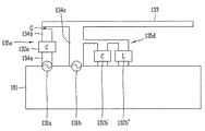
도 4는 본 발명의 일 실시예에 따른 안테나 장치(130)의 일예를 도시한 것이고, 도 5는 본 발명의 일 실시예에 따른 안테나 장치(130)가 메인 회로기판(181)에 형성된 것을 도시한 것이다.FIG. 4 illustrates an example of an
도 4 및 도 5를 참조하면, 본 발명의 일 실시예에 따른 이동 단말기(100)는 제1 바디(105)와, 상기 제1 바디(105)의 내부에 구비되는 메인 회로기판(181)과, 상기 메인 회로기판(181)으로부터 이격되어 단부(또는 종단)에서 전자기파를 방사하는 메인 도전 멤버(133)와, 상기 메인 도전 멤버(133)와 메인 회로기판(181) 사이에 구비되어 상기 메인 도전 멤버(133)에 대한 공진주파수를 가변시키는 주파수 가변부(135)를 포함하여 이루어진다.4 and 5, a
이하에서는 상기 주파수 가변부(135)에 의해 가변되는 상기 메인 도전 멤버(133)에 대한 공진주파수에 대하여 보다 구체적으로 설명하기로 한다. 상기 메인 도전 멤버(133)를 포함하는 안테나 장치(130)에서의 도전 멤버 전체(메인 도전 멤버(133)와 서브 도전 멤버(134a,134b)를 포함)가 일체로 형성된 상태에서의 도전 멤버의 총 길이를 L이라 하고, 상기 도전 멤버 전체가 일체로 형성된 상태에서의 공진주파수가 H1이라고 하고, 상기 주파수 가변부(135)에 의해 가변된 상태에서의 안테나 장치(130)의 공진주파수를 H2라고 하면, H1<H2가 된다. Hereinafter, the resonance frequency of the main
다시 말해, 동일한 도전 멤버를 분할하여 이격 배치하게 되면 도전 멤버가 일체로 형성된 상태에서의 공진주파수보다 높아지게 된다.In other words, if the same conductive member is divided and separated from the conductive member, the conductive member becomes higher than the resonance frequency in a state where the conductive member is integrally formed.
예를 들면, PIFA(planar inverted F antenna)의 경우에는 주파수 대역의 중심 공진주파수가 λ/4에서 λ로 변경되도록 할 수 있다. 다시 말해 동작되는 공진주파수가 높은 물리적으로 작은 안테나(λ/4)를 물리적으로 큰 안테나(λ)로 변환시키는 것이다.For example, in the case of a planar inverted F antenna (PIFA), the center resonance frequency of the frequency band may be changed from? / 4 to?. In other words, a physically small antenna (λ / 4) with a high resonance frequency to be operated is converted into a physically large antenna (λ).
이는 방사체로 동일한 메인 도전 멤버(133)를 사용하고, 상기 메인 도전 멤버(133)에 연결되는 주파수 가변부(135)를 달리 구성하는 경우에도 마찬가지이다. This is also the case when the same main
예를 들면, 상기 메인 도전 멤버(133)에 대한 공진주파수가 700MHz라고 할 때, 상기 주파수 가변부(135)가 추가됨으로써 안테나 장치(130)의 공진주파수가 2.0GHz가 될 수 있다. 이와 같이, 상기 메인 도전 멤버(133)의 본래의 길이에 의해 구현될 수 있는 공진주파수 보다 높은 공진주파수를 메인 도전 멤버(133)의 길이를 변화시키지 않은 상태에서 구현할 수 있다. For example, when the resonance frequency for the main
이때, 상기 공진주파수를 가변시키는 것은 메인 도전 멤버(133)에 대한 공진주파수의 변화 뿐만 아니라 안테나 장치(130) 자체의 공진주파수 변화도 포함한다. 이는 메인 도전 멤버(133)가 안테나 장치(130)의 구성요소이기 때문이다. 따라서, 본 발명의 일 실시예에서의 공진주파수의 변화란 메인 도전 멤버(133)만에 의한 공진주파수의 변화와 안테나 장치(130) 자체의 공진주파수의 변화를 동시에 의미한다.At this time, varying the resonance frequency includes not only a change in the resonance frequency with respect to the main
이와 같이, 상기 메인 도전 멤버(133)는 안테나 장치(130)를 이루는 도전 멤버이고, 상기 주파수 가변부(135)는 상기 메인 도전 멤버(133)에 의해 구현되는 공진주파수를 가변시키는 것으로, 상기 공진주파수를 낮추거나 높이는 기능을 수행하나, 본 발명의 일 실시예에서는 상기 공진주파수를 높이는 것에 한정하여 설명하기로 한다.The main
다만, 이에 한정되는 것은 아니고, 상기 메인 도전 멤버(133)의 길이를 유지한 채 공진주파수를 낮출 수도 있다. 일예로, 상기 주파수 가변부(135)는 집중정수소자(lumped element)를 포함하는데, 상기 집중정수소자의 조합에 의해 상기 공진주파수를 낮추는 기능을 수행할 수 있다.However, the present invention is not limited thereto, and the resonance frequency may be lowered while maintaining the length of the main
한편, 상기 주파수 가변부(135)는 상기 메인 회로기판(181)에 연결되는 급전부(131)와, 상기 메인 도전 멤버(133)와 상기 급전부(131) 사이에 배치되면서 서로 이격 형성되며 상기 급전부(131)에 의해 급전되는 하나 이상의 서브 도전 멤버(134)를 포함한다. 상기 급전부(131)는 상기 메인 회로기판(181)상에 형성될 수 있으며, 씨 클립(C-clip)와 같은 접촉단자 또는 스크류와 같은 체결부재에 의해 형성될 수 있다.The frequency
상기 서브 도전 멤버(134) 및 메인 도전 멤버(133)는 기설정된 간격으로 서로 이격 형성된다. 상기 서브 도전 멤버(134)가 하나인 경우에는 상기 메인 도전 멤버(133)와 이격된다. 이와 같이, 본 발명의 일 실시예에서는 상기 서브 도전 멤버(134)들을 이격 배치함으로써 상기 메인 도전 멤버(133), 나아가 안테나 장치(130)에서 구현되는 공진주파수를 높일 수 있다. 보다 구체적으로 설명하면, 안테나 장치(130)에서의 공진주파수를 낮추기 위해서는 도전 멤버의 길이를 길게 해야 하고, 공진주파수를 높이기 위해서는 도전 멤버의 길이를 짧게 해야 한다. 그러나, 본 발명의 일 실시예에서와 같이, 낮은 공진주파수에 대응되는 길이를 갖는 도전 멤버를 이용하여 높은 공진주파수를 구현하기 위해서 주파수 가변부(135)를 도입하였다. 상기 주파수 가변부(135)에 의해 상기 메인 도전 멤버(133)의 길이를 유지시키면서 공진주파수를 높일 수 있도록 하였다.The sub conductive member 134 and the main
즉, 본 발명의 일 실시예에서는 기설정된 방향을 따라 배치되고 상기 메인 회로기판(181)으로부터 급전되는 다수의 도전 멤버(133,134)를 포함하고,That is, in one embodiment of the present invention, a plurality of
본 발명의 일 실시예에서는 상기 메인 도전 멤버(133)와 서브 도전 멤버(134)에 의해 구현되는 공진주파수를 높이기 위하여 상기 서브 도전 멤버(134)들을 기설정된 간격으로 이격되도록 배치한다. 상기 메인 도전 멤버(133)와 서브 도전 멤버(134)를 합하여 도전 패턴 또는 도전 멤버로 칭하기로 한다. 즉, 상기 도전 패턴에 의해 안테나 장치(130)의 방사가 이루어진다.In one embodiment of the present invention, the sub-conductive members 134 are spaced apart at predetermined intervals to increase the resonance frequency implemented by the main
이때, 상기 급전부(131)에는 상기 급전부(131)와 직렬로 연결되는 커패시터를 포함하는 매칭 모듈(132)(matching circuit, matching module)이 연결될 수 있으며, 상기 매칭 모듈(132)은 상기 도전 패턴에 의한 공진주파수를 높이기 위하여 상기 급전부(131)와 직렬로 연결되는 커패시터를 포함하도록 한다. 상기 매칭 모듈(132)에는 집중정수소자들의 조합에 의해 구성될 수 있어, 하나 이상의 인덕터(inductor)와 하나 이상의 커패시터(capacitor)를 포함하며, 다수의 집중정수소자들의 직렬 또는 병렬의 조합을 포함할 수 있다. 상기 매칭 모듈(132)은 본 발명이 속하는 기술분야에서는 일반적인 사항이므로, 이하에서는 구체적인 설명을 생략하기로 한다. The
다만, 본 발명의 일 실시예에서는 메인 도전 멤버(133)만에 의해 구현될 수 있는 공진주파수(Hm)보다 높은 공진주파수를 구현하기 위한 것이므로, 상기 급전부(131)와 직렬로 연결되는 커패시터를 반드시 포함해야 한다. 이때, 상기 커패시터는 기설정된 유전율을 갖는 전자부품이나, 단순히 상기 서브 도전 멤버(134)들을 이격시킴으로써 상기 매칭 모듈(132)에 의해 달성하고자 하는 목적을 달성할 수도 있다. However, since the resonance frequency is higher than the resonance frequency Hm that can be realized by only the main
본 발명의 일 실시예에서는 상기 다수의 도전 멤버는 금속 재질로 이루어지면 충분하고, 일예로 구리선(copper wire) 또는 구리 스트립(copper strip)일 수 있으며, 연성회로기판(flexible printed circuit board,FPCB)일 수도 있다. 이때, 상기 도전 멤버들의 중첩(overlap)되는 영역(d)은 서로 마주보는 도전 멤버들의 폭의 크기를 의미하는데, 상기 도전 멤버들이 중첩(overlap)되는 영역(d)의 크기는 1~3mm로 한정하기로 한다. In an embodiment of the present invention, the plurality of conductive members may be made of a metal material, for example, a copper wire or a copper strip, and may be a flexible printed circuit board (FPCB) Lt; / RTI > In this case, the overlapping region d of the conductive members means the width of the conductive members facing each other. The size of the overlapping region d of the conductive members is limited to 1 to 3 mm .
본 발명의 일 실시예에서는 다수의 도전 멤버들에 의해 공진주파수를 메인 도전 멤버(133)에 대한 공진주파수(Hm)보다 높이도록 하기 위하여, 도전 멤버들간에 전기적인 단절(electrically disconnected)이 구현되도록 한다. 이때의 전기적인 단절은 이웃한 도전 멤버들(133,134a,134b) 사이에서의 전기적인 흐름이 완전히 단절되는 것이라기보다는 인접한 도전 멤버들(133,134a,134b)간의 전류의 흐름을 약화시키는 것을 의미하는 것이어서, 전기적인 절연(electrically isolated)과는 다른 의미이다.In one embodiment of the present invention, an electrically disconnected is implemented between the conductive members to allow the resonant frequency to be higher than the resonant frequency (Hm) for the main
즉, 본 발명의 일 실시예에서의 도전 멤버들(133,134a,134b)은 물리적으로 단절(disconnected)되어 있어, 도전 멤버들(133,134a,134b) 사이에서는 전류의 흐름이 원활하지는 않으나, 미세하게나마 전류가 흐르게 되어 안테나 장치(130)를 작동시킬 수 있다. 반면, 상기 전기적인 절연은 전류가 거의 차단되어 안테나 장치(130)를 작동시킬 수 없는 정도의 전류 흐름 상태를 의미한다.That is, the
상기 도전 멤버들(133,134a,134b)간의 전기적 단절 상태는 일반적인 커플링 급전(coupling feeding)과는 상이하다. 일반적으로 커플링 급전이라 함은 서로 이격되어 있는 도전 멤버들 간에 발생되는 것으로, 어느 하나의 도전 멤버는 직접 급전되고, 다른 하나의 도전 멤버는 직접 급전되는 도전 멤버에 일정 간격 이격되어 직접 급전되는 도전 멤버의 주위에 형성되는 전기장에 의해 간접적인 방식으로 급전되는 것을 의미한다.The electrical disconnect condition between the
상기 일반적인 형태의 커플링 급전을 협의의 커플링 급전이라고 한다면, 본 발명의 일 실시예에서의 도전 멤버들(133,134a,134b)간의 급전 형태는 협의의 커플링 급전이라고 할 수 있다. 이는 상기 서브 도전 멤버들(134a,134b) 사이 또는 서브 도전 멤버(134b)와 메인 도전 멤버(133)의 사이에서도 이격된 채 전기적인 흐름이 존재하므로, 광의의 커플링 급전이라고 할 수 있다.If the general type of coupling feeding is referred to as a narrow coupling feeding, the feeding form between the
따라서, 이하에서는 본 발명의 일 실시예에서의 도전 멤버들간의 급전 방식을 광의의 커플링 급전 방식이라 칭하고, 일반적인 커플링 급전에 의한 방식을 협의의 커플링 급전 방식이라고 칭하기로 한다.Therefore, in the following description, the feeding method between the conductive members in the embodiment of the present invention will be referred to as the optical coupling feeding method, and the method based on the general coupling feeding will be referred to as the narrow coupling feeding method.
상기 협의의 커플링 급전은 긴 도전 멤버와 짧은 도전 멤버간에 발생되는 경우, 짧은 도전 멤버의 길이는 긴 도전 멤버의 길이의 1/2보다 큰 경우가 일반적이다. 그러나, 본 발명의 일 실시예에서의 도전 멤버들(133,134a,134b)간에는 협의의 커플링 급전이 이루어지는 것이 아니라, 광의의 커플링 급전이 이루어져 로우 밴드(low band) 대역에서는 전기적으로 끊어지도록 하여, 로우 밴드 대역에 해당하는 공진주파수는 발생되지 않도록 하고, 하이 밴드(high band) 또는 미드 밴드(middle band)에 해당하는 공진주파수만 발생되도록 한다. When the coupling feed of the narrowing occurs between a long conductive member and a short conductive member, the length of the short conductive member is generally greater than half the length of the long conductive member. However, instead of supplying the narrow coupling between the
이때, 로우 밴드 대역을 위해서는 주파수 가변부(135)가 불필요하므로, 본 발명과는 무관하다. 즉, 본 발명의 일 실시예는 로우 밴드 대역에 대응되는 길이를 갖는 메인 도전 멤버(133)가 동일한 길이를 유지하면서 하이 밴드 대역의 공진주파수를 구현하는 것에 관한 것이다.At this time, since the frequency
만약, 상기 도전 멤버들(133,134a,134b)간에 중첩되는 영역(d)의 크기가 3mm보다 큰 경우에는 협의의 커플링 급전이 발생될 수 있고, 1mm보다 작은 경우에는 인접한 도전 멤버들(133,134a,134b)간에 전기적으로 절연(electrically insulated)되어 광의의 커플링 급전이 이루어지지 않을 수 있다. 따라서, 본 발명의 일 실시예에서는 상기 도전 멤버들(133,134a,134b)간에 중첩되는 영역의 크기는 1~3mm로 한정한다. 다만, 반드시 이에 한정할 것은 아니고, 협의의 커플링 급전이 발생되지 않으면서, 완전히 절연되지 않을 정도의 크기이면 본 발명의 권리범위에 해당될 수 있다.If the size of the overlapping region d between the
도 6a는 도 5에 도시된 안테나 장치(130)에서의 실수(real) 성분 및 허수(imaginary) 성분의 주파수에 따른 저항값을 도시한 그래프이고, 도 6b는 도 6a에 대응되는 VSWR (voltage standing wave ratio) 그래프이다. 상기 실수 성분은 임피던스의 실수부를 의미하고 허수 성분은 임피던스의 허수부로 리액턴스를 의미한다. 6A is a graph showing a resistance value according to a frequency of a real component and an imaginary component in the
도 6a 및 도 6b를 참조하면, 저주파 대역에서부터 고주파 대역을 따라 허수 성분의 값이 0 보다 작을 때는 공진이 발생되지 않은 것을 알 수 있는데, 이는 저주파수 대역에서의 공진이 차단되었기 때문이다. 즉, 상기 주파수 가변부에 의해 저주파수 대역에서는 공진이 발생하지 않도록 한 것이다. Referring to FIGS. 6A and 6B, when the value of the imaginary component along the high-frequency band from the low-frequency band is less than 0, it can be seen that no resonance occurs because the resonance in the low-frequency band is blocked. That is, the resonance does not occur in the low frequency band by the frequency variable portion.
상기 허수 성분이 0이 되는 주파수인 f1주파수에서 공진이 최초로 발생되며, 실수부가 최대치가 되고 허수부가 최소치가 되는 f2 주파수에서 구현하고자 하는 하이 밴드(high band)의 공진주파수가 발생된다.Resonance is generated for the first time at the frequency f1 which is the frequency at which the imaginary component becomes zero, and a high band resonance frequency to be realized at the frequency f2 where the real part is the maximum value and the imaginary part is the minimum value is generated.
한편, 본 발명의 일 실시예에서는 도 1e에 도시된 바와 같이, 상기 제1 바디(105)는 후면(105a) 및 상기 후면(105a) 의 단부로부터 전면을 향하여 형성되는 측면(105b)을 포함하고, 금속 재질로 이루어지도록 함으로써 상기 메인 도전 멤버(133)가 상기 측면(105a)의 일부가 될 수 있도록 하였다. 예를 들면, 외관을 형성하는 케이스의 일부를 금속 재질로 하고, 이를 안테나 장치(130)의 메인 도전 멤버(133)의 일부가 될 수 있도록 할 수 있다. 이때, 케이스의 일부는 반드시 측면(105a)일 필요는 없으며, 케이스의 전면 또는 후면 일부일 수도 있다. 특히, 이동 단말기(100)의 후면에는 많은 전자부품들이 배치되므로, 이동 단말기(100)의 전면을 금속 재질로 하는 경우에는 전면을 안테나의 방사체로 할 수도 있다. 다만, 상기 케이스가 슬릿을 구비하는 경우에는 도전 멤버는 슬릿에 의해 한정된다. 이때의 케이스는 상기 제1 바디(105) 및 제2 바디(106)를 포함한다. 1E, the
도 12는 본 발명의 일 실시에에 따른 이동 단말기(100)의 일부 단면도인데, 도 12를 참조하면, 상기 제2 바디(106)의 단면은 대략 'ㄷ' 또는 'C'형상이고, 제2 바디(106)의 전면에 노출되는 제1 부재(106a)와, 후면에 노출되는 제2 부재(106b)와, 상기 제1 및 제2 부재(106a,106b)의 단부를 연결하는 연결부((106c)를 포함한다. 이와 같이, 상기 제2 바디(106)는 모자(cap) 형상이며, 적어도 일부가 금속 재질을 포함하므로 상기 안테나 장치(130)의 방사체로 작동할 수 있다. 12 is a partial cross-sectional view of a
본 발명의 일 실시예에서는 상기 제1 부재(106a)를 포함한 제2 바디(106) 전부가 금속 재질로 이루어질 수도 있으나, 상기 제2 부재(106b) 및 연결부(106c)는 금속 재질로 이루어지는 반면, 제1 부재(106a)는 비금속 재질로 이루어질 수도 있다.Although the
상기 제1 부재(106a)가 비금속부재인 경우에는 상기 메인 회로기판(181)과 이격되고 제2 바디(106)에 구비되는 캐리어(108)의 일면에 상기 도전 멤버(133)가 구비될 수도 있다. 이러한 경우에는 상기 도전 멤버(133)를 통한 방사가 제1 부재(106a)를 통하여 이루어진다.When the
한편, 상기 케이스의 측면이 금속부재로 이루어진 경우, 상기 메인 도전 멤버(133)가 측면의 일부를 형성할 수 있으며, 상기 제2 바디(106)의 상기 연결부(106c)를 통하여 방사되도록 할 수도 있다. Meanwhile, in the case where the side surface of the case is made of a metal member, the main
본 발명의 일 실시예에서는 다수의 도전 멤버들(133,134a,134b)에 의해 구현되는 공진주파수를 높이는데, 만약 상기 주파수 가변부(135), 보다 구체적으로는 상기 서브 도전 멤버(134a,134b)들에 의해 구현되는 공진주파수가 구현하고자 하는 공진주파수 대역에 포함되면, 메인 도전 멤버(133)는 불필요할 수 있다. 본 발명의 일 실시예에서는 이를 방지하기 위하여 상기 서브 도전 멤버들(134a,134b)에 의해 구현되는 공진주파수는 4GHz 이상이 되도록 하였다. 이를 위하여 본 발명의 일 실시예에서는 서브 도전 멤버들(134a,134b)의 전체 길이를 7~8mm 정도로 하였다.In one embodiment of the present invention, the resonant frequency implemented by the plurality of conductive members 133,134a, 134b is raised if the frequency
이와 같이, 상기 서브 도전 멤버들(134a,134b)에 의한 공진주파수를 충분히 높게 함으로써, 서브 도전 멤버들(134a,134b)만에 의해서는 구현하고자 하는 공진주파수를 구현할 수 없도록 하였다. 이때, 일반적으로 구현하고자 하는 공진주파수는 700~25,000MHz이다.As described above, by making the resonant frequencies of the sub
도 7a는 본 발명의 일 실시예에 따른 안테나 장치(130)를 개략적으로 도시한 도면이고, 도 7b는 도 7a의 개념도이며, 도 7c는 도 7a의 안테나 장치(130)의 VSWR 그래프이다.FIG. 7A is a schematic view of an
먼저, 도 7a 및 도 7b 참조하면, 안테나 장치(130)의 메인 도전 멤버(133)는 이동 단말기(100)의 외관을 형성하며, 금속 재질로 이루어진 측면 부분을 포함한다. 도 7a 및 도 7b에서는 도 5에서와는 달리, 급전부(131b)가 추가된 것을 알 수 있다. 즉, 주파수 가변부(135 d)가 추가되었다. 7A and 7B, the main
도 7a 및 도 7b에서는 메인 도전 멤버(133)에 제1 주파수 가변부(135a)가 구비됨과 동시에 제2 주파수 가변부(135b)가 상기 제1 주파수 가변부(135a)와 이격되어 연결되는 것을 나타내었다. 상기 제1 주파수 가변부(135a)는 도 5에서의 주파수 가변부(135)와 유사하게 제1 급전부(131a), 하나 이상의 서브 도전 멤버(134a,134b), 제1 매칭 모듈(132a)을 포함한다. 반면, 제2 주파수 가변부(135b)에서는 제2 급전부(131b), 상기 메인 도전 멤버(133)와 일체로 형성되는 제2 서브 도전 멤버(134c)와, 상기 제2 서브 도전 멤버(134c)에 병렬로 연결되는 매칭 모듈들(132b',132b'')을 포함한다. 7A and 7B show that the first
도 7c에 도시된 바와 같이, 도 7a 및 도 7b에 도시된 안테나 장치에서 로우 밴드에서의 공진주파수(f1,f2)가 구현됨과 동시에 하이 밴드에서의 공진주파수(f3,f4)가 구현됨을 알 수 있다. 보다 구체적으로, 상기 제2 주파수 가변부(135b)에 의해서는 로우 밴드의 공진주파수(f1,f2)가 구현되고, 상기 제1 주파수 가변부(135a)에 의해서는 하이 밴드의 공진주파수(f3,f4)가 구현됨을 알 수 있다. 도 7c에서 굵은 실선은 상기 제2 주파수 가변부(135b)에 의한 VSWR 그래프이고, 얇은 실선은 상기 제1 주파수 가변부(135a)에 의한 VSWR 그래프이다.As shown in Fig. 7C, it can be seen that the resonance frequencies f1 and f2 in the low band are realized and the resonance frequencies f3 and f4 in the high band are implemented in the antenna device shown in Figs. 7A and 7B have. More specifically, the resonance frequencies f1 and f2 of the low band are realized by the second frequency
또한, 도 8은 본 발명의 일 실시예에 따른 안테나 장치(130)의 개념도인데, 도 8을 참조하면 본 발명의 일 실시예에서는 다수의 주파수 대역을 구현하기 위하여, 상기 메인 도전 멤버(133)와 상기 메인 회로기판(181) 사이에 구비되는 하나 이상의 주파수 가변부(135a,135b,135c)를 더 포함한다. 즉, 상기 주파수 가변부(135a,135b,135c)는 복수로 형성될 수 있으며, 동일 또는 유사한 구성을 갖는다.8 is a conceptual diagram of an
즉, 상기 제1 주파수 가변부(135a)는 도 5에서 설명한 주파수 가변부(135)와 동일하다. 제2 주파수 가변부(135b)는 상기 메인 회로기판(181)에 연결되는 제2 급전부(131b)와, 상기 제2 급전부(131b)에 의해 급전되고 서로 이격 형성되는 하나 이상의 제2 서브 도전 멤버(134a'',134b'')를 포함하여 이루어진다. 또한, 상기 제2 서브 도전 멤버(134a'',134b'')는 상기 메인 도전 멤버(133)와 이격 배치되도록 한다. 이와 같이, 상기 제2 주파수 가변부(135b)는 상기 제1 주파수 가변부(135a)와 구성 및 기능이 유사하다.That is, the first
이때, 상기 제2 주파수 가변부(135b)는, 상기 제2 급전부(131b)와 메인 회로기판(181) 사이에 구비되고 상기 제2 급전부(131b)와 직렬로 연결되는 커패시터를 포함하는 제2 매칭 모듈(132b)을 더 포함할 수 있다.The second frequency
나아가, 주파수 가변부가 더 구비되는 경우로, 즉, 제3 주파수 가변부(135c)를 포함하는 경우, 상기 제3 주파수 가변부(135c)는, 상기 메인 회로기판(181)에 연결되는 제3 급전부(131c)와, 상기 제3 급전부(131c)에 의해 급전되고 서로 이격 형성되는 하나 이상의 제3 서브 도전 멤버(134a''',134b''')를 포함하여 이루어진다. 또한, 상기 제3 서브 도전 멤버(134a''',134b''')는 상기 메인 도전 멤버(133)와 이격 배치되도록 한다. 이때도, 상기 제3 주파수 가변부(135c)는, 상기 제3 급전부(131c)와 메인 회로기판(181) 사이에 구비되고 상기 제3 급전부(131c)와 직렬로 연결되는 커패시터를 포함하는 제3 매칭 모듈(132c)을 더 포함할 수 있다.The third frequency
한편, 상기 주파수 가변부가 다수 존재하는 경우, 상기 메인 도전 멤버(133)에 형성되는 위치에 따라 구현되는 공진주파수가 달라질 수 있으며, 일예로 보다 높은 공진주파수를 구현하고자 하는 경우에는 도 8에서 상기 메인 도전 멤버(133)의 일 단부에 가까워지면서 상기 제1 주파수 가변부(135a)로부터 멀어지는 위치에 배치하면 된다. 다시 말해, 각각의 급전부(131a,131b,131c)로부터 메인 도전 멤버(133)의 방사 단부까지의 거리에 따라 구현하고자 하는 공진주파수를 조절할 수 있다. In the meantime, when there are a plurality of frequency variable portions, the resonance frequency realized according to the position formed in the main
나아가, 본 발명의 일 실시예에서는 상기 제1 내지 제3 주파수 가변부(135a,135b,135c)의 조합에 따라 공진주파수를 구현할 수 있으므로, 안테나 장치(130)의 공진주파수는 상기 제1 내지 제3 주파수 가변부(135a,135b,135c)가 상기 메인 도전 멤버(133)와 연결되는 위치에 의해서만 결정되는 것은 아니고, 상기 제1 내지 제3 주파수 가변부(135a,135b,135c)의 구성에 의해서도 결정될 수 있다. 다시 말해, 상기 제1 내지 제3 주파수 가변부(135a,135b,135c)를 어떻게 구성하는지에 따라서 상기 메인 도전 멤버(133)와의 연결 위치와는 무관하게 보다 높은 공진주파수를 구현하거나 보다 낮은 공진주파수를 구현할 수도 있다.Further, in one embodiment of the present invention, the resonance frequency can be implemented according to the combination of the first to third frequency
도 9는 본 발명의 일 실시예에 따른 안테나 장치(130)의 개념도인데, 도 9에서의 메인 도전 멤버(133)는 도 5에서의 메인 도전 멤버(133)보다 짧게 형성된 것을 예시한 것이다. 도 5 및 도 9의 안테나 장치(130)에 의해 구현되는 공진주파수는 동일하며, 이를 위하여 도 9에서는 서브 도전 멤버들(134a',134b',134c')의 개수가 증가한 것을 알 수 있다. 즉, 상기 메인 도전 멤버(133)의 길이가 작아질수록 상기 서브 도전 멤버들(134a',134b',134c')의 개수는 증가해야 한다. 이와 같이, 상기 메인 도전 멤버(133)의 길이와 서브 도전 멤버(134a',134b',134c')의 개수는 상호 보완적인 관계에 있다. 다시 말해, 메인 도전 멤버(133)의 길이를 줄이고자 하는 경우에는 서브 도전 멤버들(134a',134b',134c')의 개수를 증가시켜야 한다. 9 is a conceptual view of an
도 10 및 도 11은 본 발명의 일 실시예에 따른 안테나 장치(130)의 실시예들의 개념도이다. 10 and 11 are conceptual diagrams of embodiments of an
먼저, 도 10을 참조하면, 메인 도전 멤버(133)는 일 단부에서 제1 급전부(131a)에 의해 급전되고, 상기 제1 급전부(131a)와 메인 도전 멤버(133)의 사이에는 제1 커패시터(136a)가 구비되어 있다. 상기 제1 커패시터(136a)가 직렬로 형성됨으로써 상기 메인 도전 멤버(133)에 대한 공진주파수를 높일 수 있다. 그리고, 상기 메인 도전 멤버(133)는 제2 급전부(131b)에 의해 급전될 수 있으며, 상기 제2 급전부(131b)와 상기 메인 도전 멤버(133)의 사이에는 되고, 상기 제2 커패시터(136a)가 형성된다. 상기 제2 커패시터(136a)와 메인 도전 멤버(133)의 사이에는 기설정된 간격으로 이격되는 갭(G1)이 구비되어 있다. 10, the main
또한, 상기 메인 도전 멤버(133)는 제3 급전부(131c)에 의해 급전될 수 있으며, 상기 제3 급전부(131c)와 메인 도전 멤버(133)의 사이에는 제3 커패시터(136a)가 형성된다. 상기 제3 커패시터(136a)와 메인 도전 멤버(133)의 사이에는 기설정된 간격으로 이격되는 갭(G2,G3)이 형성된다. 이때, 상기 도전 멤버들 사이의 갭(G1,G2,G3)은 등가 회로(equivalant circuit)에서는 커패시터로 표현될 수 있다.A
본 발명의 일 실시예에서의 상기 메인 도전 멤버(133)와 서브 도전 멤버들(134b) 에 의해 형성되는 갭(G)은 일종의 슬릿(slit)이다.The gap G formed by the main
이때, 상기 제1 내지 제3 급전부(131a,131b,131c)에 의해 구현되는 공진주파수는 서로 상이할 수 있으며, 일예로, 상기 제1 급전부(131a)에 의해 구현되는 공진주파수를 F1, 상기 제2 급전부(131b)에 의해 구현되는 공진주파수를 F2, 상기 제3 급전부(131c)에 의해 구현되는 공진주파수를 F3라 할 때, F1<F2<F3일 수 있다. 이와 같이, 멀티 포트를 이용하여 급전함으로써 서로 다른 주파수 대역의 공진주파수를 구현할 수 있게 된다. 이때, 상기 제1 내지 제3 커패시터(136a)는 매칭 모듈로서 기능하게 된다.Here, the resonance frequencies realized by the first to
예를 들면, 1.7 ~ 2.1GHz 범위의 미드 밴드(mid band)의 공진주파수를 구현하고자 하는 경우에는 상기 제1 매칭 모듈(132a)이 1 ~ 2 pF의 크기를 가지면서 하나의 갭(G1)를 갖도록 하면 된다. 그리고, 2.5 ~ 2.7GHz 범위의 하이 밴드(high band) 대역의 공진주파수를 구현하고자 하는 경우에는 상기 제2 매칭 모듈(132b)이 1 ~ 2 pF의 크기를 가지면서 두 개의 갭(G2,G3)를 갖도록 하면 된다. 나아가, 3.3 ~ 3.5 GHz 범위의 초고주파(very high band) 대역의 공진주파수를 구현하고자 하는 경우에는 제3 매칭 모듈(132c)이 1 ~ 2 pF의 크기를 가지면서 세 개의 갭(G4,G5,G6)를 갖도록 하면 된다.For example, when it is desired to realize the resonance frequency of the mid band in the range of 1.7 to 2.1 GHz, the
이때, 상기 제1 내지 제3 매칭 모듈(132a,132b,132c)의 용량이 서로 상이할 수도 있다. 그러나, 본 발명의 일 실시예에서의 제1 내지 제3 매칭 모듈(132a,132b,132c)의 용량의 크기를 0.1pF 또는 0.05pF 이하로 제작하는 것은 쉽지 않다.Here, the capacities of the first to
한편, 도 11을 참조하면, 하나의 메인 도전 멤버(133)에 하나의 급전부(131)만 연결된 것을 알 수 있다. 상기 급전부(131)에 연결되는 매칭 모듈(132)은 집중정수소자 다수 개를 포함하여 구성될 수 있으며, 도 11에 도시된 바와 같이, 인덕터(137b) 또는 커패시터(136b)가 포함된다. 도 11에서 상기 매칭 모듈(132)은 상기 급전부(131)에 직렬로 연결되는 제1 커패시터(136a)와, 상기 제1 커패시터(136a)에 직렬로 연결되는 제1 인덕터(137a)와, 상기 제1 인덕터(137a)와 병렬 연결되는 제2 커패시터(136b) 및 제2 인덕터(137b)를 포함한다. 이와 같이, 상기 급전부(131)와는 직렬로 연결되는 커패시터(136a)를 적어도 하나 포함한다. Referring to FIG. 11, it can be seen that only one
이때, 상기 급전부(131)와 직렬로 연결되는 커패시터(136a)가 2개 이상일 수 있는데, 이러한 경우에는 서브 도전 멤버들(134a,134b)의 개수를 줄일 수 있게 된다. 도 11에서는 주파수 가변부(135)와 메인 도전 멤버(133)의 사이에 두 개의 갭(G1,G2)이 형성된 것을 예시하였다.At this time, there may be two or
한편, 본 발명의 일 실시예에서의 갭의 크기는 0.1~0.5mm 정도로 하는 것이 바람직하다.In an embodiment of the present invention, the size of the gap is preferably about 0.1 to 0.5 mm.
전술한 본 발명은, 프로그램이 기록된 매체에 컴퓨터가 읽을 수 있는 코드로서 구현하는 것이 가능하다. 컴퓨터가 읽을 수 있는 매체는, 컴퓨터 시스템에 의하여 읽혀질 수 있는 데이터가 저장되는 모든 종류의 기록장치를 포함한다. 컴퓨터가 읽을 수 있는 매체의 예로는, HDD(Hard Disk Drive), SSD(Solid State Disk), SDD(Silicon Disk Drive), ROM, RAM, CD-ROM, 자기 테이프, 플로피 디스크, 광 데이터 저장 장치 등이 있으며, 또한 캐리어 웨이브(예를 들어, 인터넷을 통한 전송)의 형태로 구현되는 것도 포함한다. 또한, 상기 컴퓨터는 단말기의 제어부(180)를 포함할 수도 있다. 따라서, 상기의 상세한 설명은 모든 면에서 제한적으로 해석되어서는 아니되고 예시적인 것으로 고려되어야 한다. 본 발명의 범위는 첨부된 청구항의 합리적 해석에 의해 결정되어야 하고, 본 발명의 등가적 범위 내에서의 모든 변경은 본 발명의 범위에 포함된다.The present invention described above can be embodied as computer-readable codes on a medium on which a program is recorded. The computer readable medium includes all kinds of recording devices in which data that can be read by a computer system is stored. Examples of the computer readable medium include a hard disk drive (HDD), a solid state disk (SSD), a silicon disk drive (SDD), a ROM, a RAM, a CD-ROM, a magnetic tape, a floppy disk, , And may also be implemented in the form of a carrier wave (e.g., transmission over the Internet). Also, the computer may include a
Claims (10)
상기 바디의 내부에 구비되는 메인 회로기판;
상기 메인 회로기판으로부터 이격되어 단부에서 전자기파를 방사하는 메인 도전 멤버; 및
상기 메인 도전 멤버와 메인 회로기판 사이에 구비되어 상기 메인 도전 멤버에 대한 공진주파수를 가변시키는 주파수 가변부를 포함하고,
상기 주파수 가변부는,
상기 메인 회로기판에 연결되는 급전부; 및
상기 메인 도전 멤버와 상기 급전부 사이에 배치되면서 서로 이격 형성되며 상기 급전부에 의해 급전되는 하나 이상의 서브 도전 멤버를 포함하고,
상기 서브 도전 멤버 및 메인 도전 멤버는 기설정된 간격으로 서로 이격 형성되고,
상기 급전부에는 상기 급전부와 직렬로 연결되는 커패시터를 포함하는 매칭 모듈이 연결되며,
상기 주파수 가변부는 복수로 형성되고,
상기 주파수 가변부에 의해 구현되는 공진주파수는 서로 다른 것을 특징으로 하는 이동 단말기.Terminal body;
A main circuit board provided inside the body;
A main conductive member spaced from the main circuit board and radiating electromagnetic waves at an end thereof; And
And a frequency variable portion provided between the main conductive member and the main circuit board to vary a resonant frequency with respect to the main conductive member,
The frequency-
A power feeder connected to the main circuit board; And
And at least one sub conductive member disposed between the main conductive member and the feeding member and spaced from each other and being fed by the feeding member,
The sub conductive member and the main conductive member are spaced apart from each other at predetermined intervals,
A matching module including a capacitor connected in series with the power feeder is connected to the power feeder,
Wherein the frequency variable portion is formed in a plurality of,
Wherein the resonant frequencies implemented by the frequency variable portion are different from each other.
상기 메인 도전 멤버 및 서브 도전 멤버는 금속부재이고 중첩(overlap)되는 영역의 크기는 1~3mm인 것을 특징으로 하는 이동 단말기.The method according to claim 1,
Wherein the main conductive member and the sub conductive member are metal members and the size of the overlapping region is 1 to 3 mm.
상기 단말기 바디는,
이동 단말기의 대부분을 차지하는 제1 바디와, 상기 제1 바디의 하부에 구비되어 상기 제1 바디에 탈착가능한(detachable) 제2 바디를 포함하고,
상기 제2 바디는,
상기 제2 바디의 전면에 노출되는 제1 부재;
상기 제2 바디의 후면에 노출되는 제2 부재; 및
상기 제1 및 제2 부재의 단부를 연결하는 연결부를 포함하는 것을 특징으로 하는 이동 단말기.The method according to claim 1,
The terminal body includes:
A first body that occupies most of the mobile terminal; and a second body provided below the first body and detachable to the first body,
The second body may include:
A first member exposed on a front surface of the second body;
A second member exposed on a rear surface of the second body; And
And a connecting portion connecting ends of the first and second members.
상기 연결부는 금속 재질로 이루어지며,
상기 메인 도전 멤버는 상기 연결부의 일부인 것을 특징으로 하는 이동 단말기.5. The method of claim 4,
The connection part is made of a metal material,
And the main conductive member is a part of the connection portion.
상기 제1 부재는 비금속 물질로 이루어지고,
상기 메인 도전 멤버는 상기 메인 회로기판과 이격되어 형성되는 캐리어에 형성되어 상기 제1 부재를 통하여 상기 메인 도전 멤버에 의해 방사되는 것을 특징으로 하는 이동 단말기.5. The method of claim 4,
Wherein the first member is made of a non-metallic material,
Wherein the main conductive member is formed on a carrier spaced apart from the main circuit board and is radiated by the main conductive member through the first member.
상기 서브 도전 멤버들에 의해 구현되는 공진주파수는 4GHz 이상인 것을 특징으로 하는 이동 단말기.The method according to claim 1,
Wherein the resonant frequency implemented by the sub-conductive members is 4 GHz or more.
상기 메인 도전 멤버의 길이가 작아질수록 상기 서브 도전 멤버들의 개수는 증가하는 것을 특징으로 하는 이동 단말기.The method according to claim 1,
And the number of sub conductive members increases as the length of the main conductive member decreases.
상기 매칭 모듈은 상기 커패시터에 직렬 또는 병렬로 연결되는 하나 이상의 집중정수소자(lumped element)를 더 포함하는 것을 특징으로 하는 이동 단말기.The method according to claim 1,
Wherein the matching module further comprises one or more lumped elements connected in series or parallel to the capacitors.
Priority Applications (3)
| Application Number | Priority Date | Filing Date | Title |
|---|---|---|---|
| KR1020160049602A KR101818115B1 (en) | 2016-04-22 | 2016-04-22 | Mobile terminal |
| PCT/KR2017/000742 WO2017183801A1 (en) | 2016-04-22 | 2017-01-20 | Mobile terminal |
| US16/095,333 US20190131722A1 (en) | 2016-04-22 | 2017-01-20 | Mobile terminal |
Applications Claiming Priority (1)
| Application Number | Priority Date | Filing Date | Title |
|---|---|---|---|
| KR1020160049602A KR101818115B1 (en) | 2016-04-22 | 2016-04-22 | Mobile terminal |
Publications (2)
| Publication Number | Publication Date |
|---|---|
| KR20170120970A KR20170120970A (en) | 2017-11-01 |
| KR101818115B1 true KR101818115B1 (en) | 2018-01-12 |
Family
ID=60382809
Family Applications (1)
| Application Number | Title | Priority Date | Filing Date |
|---|---|---|---|
| KR1020160049602A Expired - Fee Related KR101818115B1 (en) | 2016-04-22 | 2016-04-22 | Mobile terminal |
Country Status (1)
| Country | Link |
|---|---|
| KR (1) | KR101818115B1 (en) |
Families Citing this family (1)
| Publication number | Priority date | Publication date | Assignee | Title |
|---|---|---|---|---|
| CN115249884A (en) * | 2021-04-27 | 2022-10-28 | 北京小米移动软件有限公司 | Antenna structure and electronic device |
Citations (1)
| Publication number | Priority date | Publication date | Assignee | Title |
|---|---|---|---|---|
| JP2009135692A (en) | 2007-11-29 | 2009-06-18 | Kyocera Corp | Mobile communication device |
-
2016
- 2016-04-22 KR KR1020160049602A patent/KR101818115B1/en not_active Expired - Fee Related
Patent Citations (1)
| Publication number | Priority date | Publication date | Assignee | Title |
|---|---|---|---|---|
| JP2009135692A (en) | 2007-11-29 | 2009-06-18 | Kyocera Corp | Mobile communication device |
Also Published As
| Publication number | Publication date |
|---|---|
| KR20170120970A (en) | 2017-11-01 |
Similar Documents
| Publication | Publication Date | Title |
|---|---|---|
| KR101622731B1 (en) | Mobile terminal | |
| KR101958789B1 (en) | Mobile terminal | |
| US10601115B2 (en) | Mobile terminal | |
| KR101827275B1 (en) | Mobile terminal | |
| KR102129799B1 (en) | Mobile terminal | |
| KR101964651B1 (en) | Mobile terminal | |
| KR101921182B1 (en) | Array antenna and mobile terminal | |
| KR20190038264A (en) | Mobile terminal | |
| KR20160084191A (en) | Antenna module and mobile terminal having the same | |
| KR20190094454A (en) | Mobile terminal | |
| US10107952B2 (en) | Mobile terminal and method for controlling the same | |
| KR20160084192A (en) | Antenna module and mobile terminal having the same | |
| KR20180021432A (en) | Mobile terminal | |
| US20190131722A1 (en) | Mobile terminal | |
| KR20170136292A (en) | Mobile terminal | |
| KR20180027881A (en) | Mobile terminal | |
| KR20190005030A (en) | Electronic device | |
| KR20190041231A (en) | Mobile terminal | |
| US10700417B1 (en) | Mobile terminal | |
| KR20190090870A (en) | Mobile terminal | |
| KR20190083446A (en) | Mobile terminal | |
| KR20170084632A (en) | Mobile terminal | |
| KR20190052120A (en) | Mobile terminal | |
| KR20160023438A (en) | Mobile terminal | |
| KR20150107229A (en) | Mobile terminal |
Legal Events
| Date | Code | Title | Description |
|---|---|---|---|
| A201 | Request for examination | ||
| PA0109 | Patent application |
St.27 status event code: A-0-1-A10-A12-nap-PA0109 |
|
| PA0201 | Request for examination |
St.27 status event code: A-1-2-D10-D11-exm-PA0201 |
|
| D13-X000 | Search requested |
St.27 status event code: A-1-2-D10-D13-srh-X000 |
|
| D14-X000 | Search report completed |
St.27 status event code: A-1-2-D10-D14-srh-X000 |
|
| E902 | Notification of reason for refusal | ||
| PE0902 | Notice of grounds for rejection |
St.27 status event code: A-1-2-D10-D21-exm-PE0902 |
|
| E13-X000 | Pre-grant limitation requested |
St.27 status event code: A-2-3-E10-E13-lim-X000 |
|
| P11-X000 | Amendment of application requested |
St.27 status event code: A-2-2-P10-P11-nap-X000 |
|
| E13-X000 | Pre-grant limitation requested |
St.27 status event code: A-2-3-E10-E13-lim-X000 |
|
| P11-X000 | Amendment of application requested |
St.27 status event code: A-2-2-P10-P11-nap-X000 |
|
| P13-X000 | Application amended |
St.27 status event code: A-2-2-P10-P13-nap-X000 |
|
| E701 | Decision to grant or registration of patent right | ||
| PE0701 | Decision of registration |
St.27 status event code: A-1-2-D10-D22-exm-PE0701 |
|
| PG1501 | Laying open of application |
St.27 status event code: A-1-1-Q10-Q12-nap-PG1501 |
|
| GRNT | Written decision to grant | ||
| PR0701 | Registration of establishment |
St.27 status event code: A-2-4-F10-F11-exm-PR0701 |
|
| PR1002 | Payment of registration fee |
St.27 status event code: A-2-2-U10-U11-oth-PR1002 Fee payment year number: 1 |
|
| PG1601 | Publication of registration |
St.27 status event code: A-4-4-Q10-Q13-nap-PG1601 |
|
| PN2301 | Change of applicant |
St.27 status event code: A-5-5-R10-R13-asn-PN2301 St.27 status event code: A-5-5-R10-R11-asn-PN2301 |
|
| PR1001 | Payment of annual fee |
St.27 status event code: A-4-4-U10-U11-oth-PR1001 Fee payment year number: 4 |
|
| PC1903 | Unpaid annual fee |
St.27 status event code: A-4-4-U10-U13-oth-PC1903 Not in force date: 20220109 Payment event data comment text: Termination Category : DEFAULT_OF_REGISTRATION_FEE |
|
| PC1903 | Unpaid annual fee |
St.27 status event code: N-4-6-H10-H13-oth-PC1903 Ip right cessation event data comment text: Termination Category : DEFAULT_OF_REGISTRATION_FEE Not in force date: 20220109 |