KR101792588B1 - Apparatus and method optical coherence tomography using multiple beams - Google Patents
Apparatus and method optical coherence tomography using multiple beams Download PDFInfo
- Publication number
- KR101792588B1 KR101792588B1 KR1020110033773A KR20110033773A KR101792588B1 KR 101792588 B1 KR101792588 B1 KR 101792588B1 KR 1020110033773 A KR1020110033773 A KR 1020110033773A KR 20110033773 A KR20110033773 A KR 20110033773A KR 101792588 B1 KR101792588 B1 KR 101792588B1
- Authority
- KR
- South Korea
- Prior art keywords
- beams
- image
- response
- measurement
- probe
- Prior art date
- Legal status (The legal status is an assumption and is not a legal conclusion. Google has not performed a legal analysis and makes no representation as to the accuracy of the status listed.)
- Expired - Fee Related
Links
Images


Classifications
-
- A—HUMAN NECESSITIES
- A61—MEDICAL OR VETERINARY SCIENCE; HYGIENE
- A61B—DIAGNOSIS; SURGERY; IDENTIFICATION
- A61B5/00—Measuring for diagnostic purposes; Identification of persons
-
- G—PHYSICS
- G01—MEASURING; TESTING
- G01B—MEASURING LENGTH, THICKNESS OR SIMILAR LINEAR DIMENSIONS; MEASURING ANGLES; MEASURING AREAS; MEASURING IRREGULARITIES OF SURFACES OR CONTOURS
- G01B9/00—Measuring instruments characterised by the use of optical techniques
- G01B9/02—Interferometers
- G01B9/02015—Interferometers characterised by the beam path configuration
- G01B9/02027—Two or more interferometric channels or interferometers
-
- G—PHYSICS
- G01—MEASURING; TESTING
- G01B—MEASURING LENGTH, THICKNESS OR SIMILAR LINEAR DIMENSIONS; MEASURING ANGLES; MEASURING AREAS; MEASURING IRREGULARITIES OF SURFACES OR CONTOURS
- G01B9/00—Measuring instruments characterised by the use of optical techniques
- G01B9/02—Interferometers
-
- G—PHYSICS
- G01—MEASURING; TESTING
- G01B—MEASURING LENGTH, THICKNESS OR SIMILAR LINEAR DIMENSIONS; MEASURING ANGLES; MEASURING AREAS; MEASURING IRREGULARITIES OF SURFACES OR CONTOURS
- G01B9/00—Measuring instruments characterised by the use of optical techniques
- G01B9/02—Interferometers
- G01B9/02001—Interferometers characterised by controlling or generating intrinsic radiation properties
- G01B9/02007—Two or more frequencies or sources used for interferometric measurement
-
- G—PHYSICS
- G01—MEASURING; TESTING
- G01B—MEASURING LENGTH, THICKNESS OR SIMILAR LINEAR DIMENSIONS; MEASURING ANGLES; MEASURING AREAS; MEASURING IRREGULARITIES OF SURFACES OR CONTOURS
- G01B9/00—Measuring instruments characterised by the use of optical techniques
- G01B9/02—Interferometers
- G01B9/02015—Interferometers characterised by the beam path configuration
- G01B9/02027—Two or more interferometric channels or interferometers
- G01B9/02028—Two or more reference or object arms in one interferometer
-
- G—PHYSICS
- G01—MEASURING; TESTING
- G01B—MEASURING LENGTH, THICKNESS OR SIMILAR LINEAR DIMENSIONS; MEASURING ANGLES; MEASURING AREAS; MEASURING IRREGULARITIES OF SURFACES OR CONTOURS
- G01B9/00—Measuring instruments characterised by the use of optical techniques
- G01B9/02—Interferometers
- G01B9/0209—Low-coherence interferometers
- G01B9/02091—Tomographic interferometers, e.g. based on optical coherence
-
- G—PHYSICS
- G01—MEASURING; TESTING
- G01N—INVESTIGATING OR ANALYSING MATERIALS BY DETERMINING THEIR CHEMICAL OR PHYSICAL PROPERTIES
- G01N21/00—Investigating or analysing materials by the use of optical means, i.e. using sub-millimetre waves, infrared, visible or ultraviolet light
- G01N21/17—Systems in which incident light is modified in accordance with the properties of the material investigated
Landscapes
- Physics & Mathematics (AREA)
- General Physics & Mathematics (AREA)
- Health & Medical Sciences (AREA)
- General Health & Medical Sciences (AREA)
- Life Sciences & Earth Sciences (AREA)
- Nuclear Medicine, Radiotherapy & Molecular Imaging (AREA)
- Radiology & Medical Imaging (AREA)
- Pathology (AREA)
- Immunology (AREA)
- Heart & Thoracic Surgery (AREA)
- Analytical Chemistry (AREA)
- Chemical & Material Sciences (AREA)
- Biophysics (AREA)
- Engineering & Computer Science (AREA)
- Biomedical Technology (AREA)
- Biochemistry (AREA)
- Medical Informatics (AREA)
- Molecular Biology (AREA)
- Surgery (AREA)
- Animal Behavior & Ethology (AREA)
- Public Health (AREA)
- Veterinary Medicine (AREA)
- Investigating Or Analysing Materials By Optical Means (AREA)
Abstract
광 간섭 단층촬영 장치 및 방법에 따르면, 복수의 광선들을 생성하고, 광선들로부터 측정 광선들과 참조 광선들을 분리하고, 대상체로 조사되기 위한 측정 광선들을 프로브로 전송하고, 프로브로부터 응답 광선들을 수신하고, 응답 광선들과 참조 광선들과의 간섭(interference)으로부터 간섭 신호들을 검출하고, 검출된 간섭 신호들 중 어느 하나의 간섭 신호에 기초하여 제1 영상을 생성하고, 검출된 간섭 신호들 중 다른 간섭 신호에 기초하여 제1 영상과는 다른 영상 특성의 제2 영상을 생성한다. According to the optical coherence tomography apparatus and method, a plurality of light beams are generated, the measurement beams and reference beams are separated from the light beams, the measurement beams to be irradiated to the object are transmitted to the probe, the response beams are received , Detects interference signals from interference between the response beams and reference beams, generates a first image based on any one of the detected interference signals, And generates a second image having an image characteristic different from that of the first image based on the signal.
Description
광 간섭 단층촬영 장치 및 방법에 관한 것으로 복수의 광선들을 이용하여 대상체의 단층 영상을 생성하는 장치 및 방법에 관한 것이다. And more particularly, to an apparatus and method for generating a tomographic image of a target using a plurality of light beams.
생물체 및 재료의 내부 구조를 관찰할 수 있는 X선 장치 (X-ray System), CT (Computerized Tomograghy) 스캐너, MRI (Magnetic Resonance Image) 장치 및 초음파 장치 (Ultrasound system) 등의 다양한 내부 투과영상 및 단층영상 촬영 장비들이 연구되어 왔으며 현재 다양한 분야에서 활용되고 있다. 특히 이러한 장비들은 인체와 생명체의 내부 구조를 직접 절개하지 않고 각종 질병의 원인과 위치 및 진행과정을 파악함으로써 의료분야에 있어서 중요한 위치를 차지하고 있다. 이러한 진단 장비에 있어서, 생명체에 대한 저 유해성, 고 분해능 영상 획득, 합리적인 가격 및 이동 및 사용의 편리성 등은 중요한 요소로 인식되고 있다.
한편, 광 간섭 단층촬영 (Optical Coherence Tomography) 장치는 광을 이용하여 실시간으로 살아있는 조직 및 재료의 내부에 손상을 가하지 않고 그 내부 영상을 얻을 수 있는 촬영 장비이다. A variety of internal transmission images and tomographic images such as an X-ray system, a CT (Computerized Tomography) scanner, an MRI (Magnetic Resonance Image) apparatus and an ultrasound system, Imaging equipment has been studied and is currently being used in various fields. In particular, these devices occupy an important position in the medical field by not directly cutting the internal structure of the human body and organism, but also by understanding the cause, location and progress of various diseases. In such diagnostic equipment, low harmfulness to living organisms, high resolution image acquisition, reasonable price, and convenience of use and movement are recognized as important factors.
On the other hand, optical coherence tomography apparatus is an imaging apparatus that can obtain an internal image of living tissues and materials without damaging it in real time using light.
복수의 광선들을 이용하여 복수의 영상을 생성함으로써, 보다 다양한 생체 영상신호를 생성할 수 있는 장치 및 방법을 제공하는데 있다. 또한, 서로 다른 중심 파장을 갖는 복수의 광선들을 이용하여 복수의 생체 영상신호를 생성하고 이를 합성함으로써, 보다 고 해상도의 생체 영상을 제공할 수 있는 장치 및 방법을 제공하는데 있다. 또한, 상기 방법을 컴퓨터에서 실행시키기 위한 프로그램을 기록한 컴퓨터로 읽을 수 있는 기록 매체를 제공하는데 있다. 본 발명의 일 실시예가 이루고자 하는 기술적 과제는 상기된 바와 같은 기술적 과제들로 한정되지 않으며, 또 다른 기술적 과제들이 존재할 수 있다. And an apparatus and method for generating a plurality of images using a plurality of light beams to generate a variety of biometric image signals. It is another object of the present invention to provide an apparatus and a method for generating a plurality of biometric image signals using a plurality of light beams having different central wavelengths and combining the same to provide higher resolution biometric images. It is still another object of the present invention to provide a computer-readable recording medium on which a program for executing the above method on a computer is recorded. The technical problem to be solved by one embodiment of the present invention is not limited to the above-mentioned technical problems, and other technical problems may exist.
본 발명의 일 측면에 따른 광 간섭 단층촬영 장치는 복수의 광선들을 생성하는 광 생성기, 상기 광선들로부터 측정 광선들과 참조 광선들을 분리하고, 대상체로 조사되기 위한 상기 측정 광선들을 프로브로 전송하고, 상기 프로브로부터 응답 광선들을 수신하는 광 결합기, 상기 응답 광선들과 상기 참조 광선들과의 간섭(interference)으로부터 간섭 신호들을 검출하는 검출기 및 상기 간섭 신호들 중 어느 하나의 간섭 신호에 기초하여 제1 영상을 생성하고, 상기 간섭 신호들 중 다른 간섭 신호에 기초하여 제1 영상과는 다른 영상 특성의 제2 영상을 생성하는 영상 처리기를 포함한다.
본 발명의 다른 측면에 따른 광 간섭 단층촬영 방법은 복수의 광선들을 생성하는 단계, 상기 광선들로부터 측정 광선들과 참조 광선들을 분리하는 단계, 대상체로 조사되기 위한 상기 측정 광선들을 프로브로 전송하는 단계, 상기 조사에 대응하여 상기 프로브로 입력된 응답 광선들을 상기 프로브로부터 수신하는 단계, 상기 응답 광선들과 상기 참조 광선들과의 간섭(interference)으로부터 간섭 신호들을 검출하는 단계 및 상기 간섭 신호들 중 어느 하나의 간섭 신호에 기초하여 제1 영상을 생성하고, 상기 간섭 신호들 중 다른 간섭 신호에 기초하여 제1 영상과는 다른 영상 특성의 제2 영상을 생성하는 단계를 포함한다.
본 발명의 또 다른 측면에 따라 상기 광 간섭 단층촬영 방법을 컴퓨터에서 실행시키기 위한 프로그램을 기록한 컴퓨터로 읽을 수 있는 기록매체가 제공된다. An optical coherent tomography apparatus according to an aspect of the present invention includes a light generator for generating a plurality of light beams, a light source for separating the measurement light beams and reference light rays from the light beams, transmitting the measurement light beams to be irradiated to the object to the probe, A detector for detecting interference signals from interference of said response beams with said reference beams and a detector for detecting interference signals from said interference beams, And an image processor for generating a second image having an image characteristic different from that of the first image based on another interference signal among the interference signals.
A method of optical coherence tomography according to another aspect of the present invention includes the steps of generating a plurality of beams, separating measurement beams and reference beams from the beams, transmitting the measurement beams to the probe for irradiation with the object The method comprising the steps of: receiving response beams input to the probe in response to the probe from the probe; detecting interference signals from interference between the response beams and the reference beams; Generating a first image based on one interference signal and generating a second image having an image characteristic different from that of the first image based on another interference signal among the interference signals.
According to still another aspect of the present invention, there is provided a computer-readable recording medium having recorded thereon a program for causing the computer to execute the optical coherent tomography method.
복수의 광선들을 이용하여 복수의 영상들을 생성함으로써, 보다 다양한 생체 영상신호를 생성할 수 있다. 또한, 서로 다른 중심 파장을 갖는 복수의 광선들을 이용하여 복수의 생체 영상신호를 생성하고 이를 합성함으로써, 보다 고 해상도의 생체 영상을 제공할 수 있다. 또한, 복수의 중심 파장의 광선들로부터 생성된 영상은 생체 조직의 깊이에 따라 일관된 해상도를 보장할 수 있다. By generating a plurality of images using a plurality of light beams, a variety of biological image signals can be generated. In addition, a plurality of biometric image signals are generated using a plurality of light beams having different central wavelengths, and the biometric image signals are synthesized to provide a biometric image having a higher resolution. In addition, an image generated from light beams having a plurality of central wavelengths can ensure a consistent resolution according to the depth of a living tissue.
도 1은 본 발명의 일 실시예에 따른 광 간섭 단층촬영 장치(10)의 구성도이다.
도 2는 본 발명의 일 실시예에 따른 프로브(20)에 의해 조사되는 측정 광선들(211, 212, 213)을 나타낸 도면이다.
도 3은 본 발명의 일 실시예에 따른 프로브(20)에 의해 조사되는 측정 광선들(221, 222, 223)을 나타낸 도면이다.
도 4는 대상체(30)로 조사된 측정 광선(21)과 간섭 신호의 일 예를 나타낸 도면이다.
도 5는 본 발명의 일 실시예에 따른 영상 처리기(14)와 영상 처리기(14)로부터 출력되는 영상들(51, 52, 53)을 나타낸 도면이다.
도 6은 본 발명의 일 실시예에 따른 영상 처리기(14)의 구성도이다.
도 7은 본 발명의 다른 실시예에 따른 광 간섭 단층촬영 장치(10)를 나타낸 도면이다.
도 8은 본 발명의 일 실시예에 따른 광 간섭 단층촬영 방법의 동작 흐름도이다. 1 is a block diagram of an optical
FIG. 2 is a diagram illustrating
FIG. 3 is a diagram illustrating
4 is a diagram showing an example of a
5 is a
6 is a configuration diagram of an
FIG. 7 is a diagram illustrating an optical
8 is a flowchart illustrating an operation of the optical coherence tomography method according to an embodiment of the present invention.
이하에서는 도면을 참조하여 본 발명의 실시예들을 상세히 설명한다. 이하의 실시예들에서는 본 발명의 요지가 흐려지는 것을 방지하기 위하여 대상체의 영상 신호를 생성하기 위한 구성들만을 설명하기로 한다. 다만, 본 발명의 일 실시예가 속하는 기술 분야에서 통상의 지식을 가진 자라면 대상체의 영상 신호를 생성하기 위한 구성들 외에 다른 범용적인 구성들이 부가될 수 있음을 이해할 수 있다. 예를 들어, 의사 등과 같은 의료 전문가가 영상 신호를 인식할 수 있도록 하기 위하여 피검자의 영상 신호를 생성하는 구성들 외에 피검자의 영상 신호를 스크린 또는 종이 위에 디스플레이하는 구성 등이 부가될 수 있다.
도 1은 본 발명의 일 실시예에 따른 광 간섭 단층촬영 장치(10)의 구성도이다. 도 1을 참조하면, 본 발명의 일 실시예에 따른 광 간섭 단층촬영 장치(10)는 프로브(20)로 측정 광선들을 전송한다. 일반적으로 광 간섭 단층촬영 장치(10)는 복수의 광선 들로부터 측정 광선들과 참조 광선들을 분리하고, 분리된 측정 광선들을 프로브(20)로 전송한다. 프로브(20)는 이러한 측정 광선들을 대상체(30)로 조사(illuminate)하고, 이러한 전송에 대응하여 대상체(30)로부터 응답 광선들을 수신한다. 예를 들어, 프로브(20)는 측정 광선들 중 어느 하나의 측정 광선(21)을 대상체(30)로 조사하고, 대상체(30)로부터 응답 광선들 중 어느 하나의 응답 광선을 수신한다. 이와 같은 맥락으로, 프로브(20)는 측정 광선들 중 다른 하나의 측정 광선(22)을 대상체(30)로 조사하고, 대상체(30)로부터 응답 광선들 중 다른 응답 광선을 수신할 수 있다. 이 때, 측정 광선들은 순차적으로 또는 동시에 대상체(30)로 조사될 수 있다.
프로브(20)는 수신된 응답 광선들을 광 간섭 단층촬영 장치(10)로 전송한다. 예를 들어, 프로브(20)는 대상체(30)로부터 수신된 응답 광선들 중 어느 하나의 응답 광선을 광 간섭 단층촬영 장치(10)로 전송한다. 이와 같은 맥락으로, 프로브(20)는 대상체(30)로부터 수신된 응답 광선들 중 다른 응답 광선을 광 간섭 단층촬영 장치(10)로 전송할 수 있다.
광 간섭 단층촬영 장치(10)는 수신된 응답 광선들과 참조 광선들과의 간섭(interference)으로부터 간섭 신호들을 검출한다. 일반적으로, 광 간섭 단층촬영 장치(10)는 수신된 응답 광선들 중 어느 하나의 응답 광선과 참조 광선들 중 어느 하나의 참조 광선 상호간의 간섭에 의해 발생하는 간섭 신호를 검출한다. 예를 들어, 광 간섭 단층촬영 장치(10)는 광선들 중 어느 하나로부터 제1 측정 광선과 제1 참조 광선을 분리하고, 프로브(20)로부터 수신된 제1 응답 광선과 제1 참조 광선간의 간섭으로부터 제1 간섭 신호를 검출한다. 이와 같은 맥락으로, 광 간섭 단층촬영 장치(10)는 광선들 중 다른 하나로부터 제2 측정 광선과 제2 참조 광선을 분리하고, 프로브(20)로부터 수신된 제2 응답 광선과 제2 참조 광선간의 간섭으로부터 제2 간섭 신호를 검출할 수 있다.
일반적으로, 복수의 광선들은 서로 다른 중심 파장의 광선들이다. 예를 들어, 광선들 중 어느 하나의 중심 파장은 300nm이고, 광선들 중 다른 하나의 중심 파장은 500nm이고, 광선들 중 또 다른 하나의 중심 파장은 800nm일 수 있다. 이와 같은 맥락으로, 측정 광선들은 서로 다른 중심 파장의 측정 광선들이고, 참조 광선들은 서로 다른 중심 파장의 참조 광선들이고, 응답 광선들을 서로 다른 중심 파장의 응답 광선들일 수 있다. 또한, 복수의 광선들 중 어느 하나로부터 분리된 측정 광선과 참조 광선, 그리고 이러한 측정 광선에 대응하는 응답 광선은 동일한 파장의 광선들일 수 있다. 예를 들어, 복수의 광선들 중 어느 하나의 광선으로부터 분리된 제1 측정 광선과 제1 참조 광선, 그리고 제1 응답 광선은 모두 제1 중심 파장을 갖는 광선들일 수 있다. 이 때, 중심 파장은 광선의 파장에 따른 상대적인 분포 상에 최대값을 갖는 파장을 의미할 수 있다. 또한, 이러한 중심 파장은 광선의 파장에 따른 상대적인 분포를 확률밀도함수로 놓고 파장을 평균하거나, 또는 상대적인 분포 상에서 최대값의 1/2를 갖는 위치의 파장 값 한 쌍을 산술 평균하여 결정될 수 있다.
본 발명의 일 실시예에 따르면, 측정 광선들은 대상체(30)의 서로 다른 초점 깊이로 조사된다. 예를 들어, 측정 광선들 중 어느 하나의 측정 광선은 프로브(20)에 의해 대상체(30)의 제1 초점 깊이로 조사되고, 측정 광선들 중 다른 측정 광선은 프로브(20)에 의해 대상체(30)의 제2 초점 깊이로 조사된다.
본 발명의 일 실시예에 따른 광 간섭 단층촬영 장치(10)는 간섭 신호를 이용하여 대상체(20)의 영상을 생성한다. 일반적으로 이러한 영상은 단층영상으로 불리어질 수 있다. 또한, 광 간섭 단층촬영 장치(10)는 복수의 간섭 신호들을 이용하여 복수의 영상을 생성한다. 예를 들어, 광 간섭 단층촬영 장치(10)는 제1 측정 광선과 제1 참조 광선의 간섭으로부터 제1 간섭 신호를 검출하고, 검출된 제1 간섭 신호를 이용하여 제1 영상을 생성한다. 이와 같은 맥락으로, 광 간섭 단층촬영 장치(10)는 제2 측정 광선과 제2 참조 광선의 간섭으로부터 제2 간섭 신호를 검출하고, 검출된 제2 간섭 신호를 이용하여 제2 영상을 생성할 수 있다. 또한, 본 발명의 일 실시예에 따른 광 간섭 단층촬영 장치(10)는 이러한 제1 영상 및 제2 영상을 출력 수단을 통해 출력할 수 있다.
본 발명의 일 실시예에 따른 광 간섭 단층촬영 장치(10)는 복수의 기초 영상들을 합성하여 출력되기 위한 영상을 생성할 수 있다. 예를 들어, 광 간섭 단층촬영 장치(10)는 제1 측정 광선과 제1 응답 광선간의 간섭으로부터 검출된 제1 간섭 신호를 이용하여 제1 기초 영상을 생성하고, 제2 측정 광선과 제2 응답 광선간의 간섭으로부터 검출된 제2 간섭 신호를 이용하여 제2 기초 영상을 생성한 후, 이러한 제1 기초 영상과 제2 기초 영상을 합성하여 출력되기 위한 영상을 생성한다. 또한, 본 발명의 일 실시예에 따른 광 간섭 단층촬영 장치(10)는 제1 기초 영상에 제1 가중치를 적용하고, 제2 기초 영상에 제2 가중치를 적용함으로써, 제1 기초 영상과 제2 기초 영상으로부터 출력되기 위한 영상을 생성할 수 있다. 이 때, 제1 가중치는 광선들 중 어느 하나로부터 분리된 제1 측정 광선과 제1 참조 광선 중 적어도 하나 이상의 광선의 중심 파장으로부터 결정되고, 제2 가중치는 광선들 중 다른 하나로부터 분리된 제2 측정 광선과 제2 참조 광선 중 적어도 하나 이상의 광선의 중심 파장으로부터 결정될 수 있다.
이러한 광 간섭 단층촬영 장치(10)와 프로브(20)에 대한 동작은 이하 보다 구체적으로 설명된다.
도 1을 참조하면, 본 발명의 일 실시예에 따른 광 간섭 단층촬영 장치(10)는 광 생성기(light source, 11), 광 결합기(coupler, 12), 검출기(detector, 13) 및 영상 처리기(14)를 포함한다.
광 생성기(11)는 복수의 광선들을 생성한다. 일반적으로 복수의 광선들은 서로 다른 중심 파장의 광선들이다. 예를 들어, 광선들에는 중심 파장이 300nm인 제1 광선, 중심 파장이 500nm인 제2 광선, 중심 파장이 800nm인 제3 광선 및 중심 파장이 1300nm인 제4 파장 등이 포함된다. 또한, 이러한 중심 파장은 생체 조직에서 광선들의 투과가 용이한 파장 범위 내에서 결정될 수 있다.
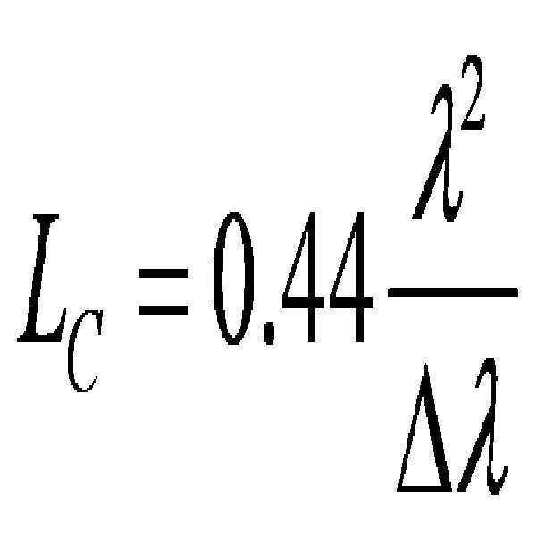
일반적으로 복수의 광선들은 서로 다른 가간섭(coherent) 길이를 갖는다. 예를 들어, 복수의 광원들 중 제1 광선과 제2 광선은 서로 다른 가간섭 길이를 갖는다. 일반적으로 광선의 가간섭 길이는 이러한 광선의 중심 파장과 파장의 단위에서 측정된 광선의 대역폭으로부터 아래 수학식 1과 같이 결정된다. 이 때, Lc는 광선의 가간섭 길이를 의미하고, ![]()
![]()
[수학식 1]
광선의 대표적인 일 예에는 SLD (super Luminescent Diode) 광선과 ELED (Edge-emitting Light-emitting Diodes)광선이 포함된다. 다만, 본 발명의 다양한 실시예에 따르면 이러한 광선 이외에도 다양한 종류의 광선들이 이용될 수 있다. 일반적으로, 광선은 광선의 중심 파장, 광선의 대역폭, 광선의 가간섭 길이, 광선의 세기 및 측정 대상체의 특성 등의 다양한 인자들을 고려하여 결정된다.
광 생성기(11)는 생성된 광선들을 광 결합기(12)로 전송한다. 본 발명의 일 실시예에 따르면, 광선들은 자유공간상으로 광 결합기(12)로 전송될 수 있다. 다만, 본 발명의 다른 실시예에 따르면, 광선들은 전송 매체를 통하여 광 결합기(12)로 전송될 수도 있다. 이러한 전송 매체의 일 예에는 광 섬유가 포함된다. 또한, 본 발명의 일 실시예에 따르면, 광 생성기(11)는 광선들을 순차적으로 광 결합기(12)로 전송한다. 예를 들어, 광 생성기(11)는 광선들 중 제1 광선을 광 결합기(12)로 전송하고, 광선들 중 제2 광선을 광 결합기(12)로 전송할 수 있다. 다만, 본 발명의 다른 실시예에 따르면, 광 생성기(11)는 광선들을 동시에 광 결합기(12)로 전송한다. 예를 들어, 광 생성기(11)는 파장 분할 다중화(Wavelength Division Multiplexing)를 기반으로 광 섬유를 통해 광선들을 동시에 광 결합기(12)로 전송할 수 있다. 이 때, 광선들은 파장 분할 다중화를 통해 광선들 각각의 중심 파장을 기준으로 하나로 묶여 광 섬유를 통해 전송되고, 전송된 광선들은 광 섬유의 말단, 즉 광 결합기(12)에서 파장 분할 역다중화를 통해 분리될 수 있다. 또한, 광 생성기(11)는 자유공간상으로 동시에 광선들을 광 결합기(12)로 전송할 수도 있다.
광 결합기(12)는 광선들로부터 측정 광선들과 참조 광선들을 분리한다. 일반적으로, 광 결합기(12)는 광선들을 측정 광선들과 참조 광선으로 분리하기 위해 두 개 이상의 경로들을 구분하고, 구분된 경로들 중 어느 하나의 경로로 측정 광선들을 전송하고, 구분된 경로들 중 다른 경로로 참조 광선들을 전송한다. 예를 들어, 광 결합기(12)는 자유공간상의 빔 분배기(beam splitter)를 이용하여 빔 분배기로 입사하는 광선이 두 개의 경로로 분리되어 진행되도록 함으로써, 광선으로부터 측정 광선과 참조 광선을 분리할 수 있다. 또한, 다른 일 예에 따르면, 광 결합기(12)는 광선들을 측정 광선들과 참조 광선으로 분리하기 위해 소정의 전달 매체로 구성된 두 개 이상의 경로들을 구성하고, 구성된 경로들 중 어느 하나의 경로로 측정 광선들을 전송하고, 구성된 경로들 중 다른 경로로 참조 광선을 전송할 수도 있다. 이러한 전달 매체의 대표적이 일 예에는 광 섬유가 포함된다. 또한, 본 발명의 다양한 실시예에 따르면, 이 밖에 광선들로부터 측정 광선들과 참조 광선들을 구분하는 다양한 형태의 광 결합기(12)의 구성이 가능하다.
본 발명의 일 실시예에 따르면, 광 결합기(12)는 순차적으로 광선들을 측정 광선들과 참조 광선들로 분리한다. 예를 들어, 광 결합기(12)는 광선들 중 제1 광선으로부터 제1 측정 광선과 제1 참조 광선을 분리한 후, 광선들 중 제2 광선으로부터 제2 측정 광선과 제2 참조 광선을 분리할 수 있다. 다만, 본 발명의 다른 실시예에 따르면, 광 결합기(12)는 동시에 광선들을 분리한다. 예를 들어, 광 결합기(12)는 제1 광선으로부터 제1 측정 광선과 제1 참조 광선을 분리함과 동시에, 제2 광선으로부터 제2 측정 광선과 제2 참조 광선을 분리할 수 있다.
일반적으로, 동일 광선으로부터 분리된 측정 광선과 참조 광선은 이러한 광선과 동일한 중심 파장을 갖는다. 예를 들어, 중심 파장이 300nm인 제1 광선은 중심 파장이 300nm인 제1 측정 광선과 중심 파장이 300nm인 제1 참조 광선으로 분리되고, 중심 파장이 500nm인 제2 광선은 중심 파장이 500nm인 제2 측정 광선과 중심 파장이 500nm인 제2 참조 광선으로 분리될 수 있다.
본 발명의 일 실시예에 따르면, 광 결합기(12)는 나눔 비율로 광선으로부터 측정 광선과 참조 광선을 분리한다. 일반적으로, 나눔 비율은 광선의 출력 세기를 기준으로 측정 광선의 출력 세기와 참조 광선의 출력 세기의 비율을 의미한다. 예를 들어, 광 결합기(12)는 5:5의 비율로 측정 광선과 참조 광선을 광선으로부터 분리할 수 있다. 이와 같은 맥락으로, 광 결합기(12)는 9:1의 비율로 측정 광선과 참조 광선을 광선으로부터 분리할 수도 있다. 또한, 본 발명의 일 실시예에 따르면, 광 결합기(12)는 제1 나눔 비율로 광선들 중 어느 하나의 광선으로부터 제1 참조 광선과 제1 측정 광선을 분리하고, 제2 나눔 비율로 광선들 중 다른 광선으로부터 제2 참조 광선과 제2 측정 광선을 분리할 수 있다. 예를 들어, 광 결합기(12)는 5:5의 비율로 광선들 중 어느 하나의 광선으로부터 제1 참조 광선과 제1 측정 광선을 분리하고, 4:6의 비율로 광선들 중 다른 광선으로부터 제2 참조 광선과 제2 측정 광선을 분리할 수 있다. 또한, 이러한 나눔 비율은 이후 간섭 신호를 검출함에 있어서 고려될 수 있다.
광 결합기(12)는 측정 광선들을 프로브(20)로 전송한다. 앞서 설명된 바와 같이 이러한 측정 광선들은 서로 다른 중심 파장의 측정 광선들일 수 있다. 또한, 광 결합기(12)는 두 개 이상의 경로들 중 어느 하나의 경로로 측정 광선들을 전송한다. 앞서 설명된 바와 같이, 두 개 이상의 경로들은 자유공간상의 빔 분배기를 통하여 구성될 수 있다. 다만, 두 개 이상의 경로들은 서로 다른 광 섬유로 구성될 수도 있다. 또한, 본 발명의 다양한 실시예에 따르면, 광 결합기(12)는 다양한 형태의 수단들을 통해 두 개 이상의 경로들을 구성하고, 이러한 경로들 중 어느 하나의 경로를 이용하여 측정 광선들을 프로브(20)로 전송할 수도 있다.
본 발명의 일 실시예에 따르면, 광 결합기(12)는 측정 광선들을 순차적으로 프로브(20)로 전송한다. 예를 들어, 광 결합기(12)는 측정 광선들 중 제1 측정 광선을 프로브(20)로 전송하고, 측정 광선들 중 제2 측정 광선을 프로브(20)로 전송할 수 있다. 다만, 본 발명의 다른 실시예에 따르면, 광 결합기(12)는 측정 광선들을 동시에 프로브(20)로 전송한다. 예를 들어, 광 결합기(12)는 파장 분할 다중화(Wavelength Division Multiplexing)를 기반으로 광 섬유를 통해 측정 광선들을 동시에 프로브(20)로 전송할 수 있다. 이 때, 측정 광선들은 측정 광선들 각각의 중심 파장을 기준으로 파장 분할 다중화를 통해 하나로 묶여 광 섬유를 통해 전송되고, 전송된 측정 광선들은 광 섬유의 말단, 즉 프로브(20)에서 파장 분할 역다중화를 통해 분리될 수 있다. 다만, 광 결합기(12)는 자유공간상으로 동시에 측정 광선들을 프로브(20)로 전송할 수도 있다.
측정 광선들은 프로브(20)에 의하여 대상체(30)로 조사된다. 또한, 응답 광선들은 이러한 조사에 대응하여 대상체(30)로부터 프로브(20)로 수신된다. 다시 말하면, 프로브(20)는 측정 광선들을 대상체(30)로 조사하고, 이에 대한 응답으로 대상체(30)로부터 응답 광선들을 수신한다. 일반적으로, 응답 광선들에는 측정 광선들에 의한 반사 또는 산란 광선들이 포함된다.
본 발명의 일 실시예에 따르면, 프로브(20)는 측정 광선들을 대상체(30)로 순차적으로 조사하고, 대상체(30)로부터 응답 광선들을 수신한다. 이 때, 응답 광선들은 순차적으로 또는 동시에 수신될 수 있다. 예를 들어, 프로브(20)는 측정 광선들 중 제1 측정 광선을 대상체(30)로 조사한 후, 측정 광선들 중 제2 측정 광선을 대상체(30)로 조사하고, 대상체(30)로부터 순차적으로 또는 동시에 응답 광선들을 수신한다.
도 2는 본 발명의 일 실시예에 따른 프로브(20)에 의해 조사되는 측정 광선들(211, 212, 213)을 나타낸 도면이다. 도 2를 참조하면, 본 발명의 일 실시예에 따른 프로브(20)는 측정 광선들(211, 212, 213)을 순차적으로 대상체(30)로 조사한다. 구체적으로, 프로브(20)는 측정 광선들 중 제1 측정 광선(211)을 대상체(30)로 조사한 후, 측정 광선들 중 제2 측정 광선(212)을 대상체(30)로 조사한 후, 측정 광선들 중 제3 측정 광선(213)을 대상체(30)로 조사한다. 이 때, 프로브(20)는 제1 측정 광선(211), 제2 측정 광선(212), 제3 측정 광선(213) 모두를 동일한 초점 깊이와 함께 대상체(30)로 조사할 수 있다. 다만, 본 발명의 다른 실시예에 따르면, 프로브(20)는 제1 측정 광선(211), 제2 측정 광선(212) 및 제3 측정 광선(213) 각각을 서로 다른 초점 깊이와 함께 대상체(30)로 조사할 수도 있다. 예를 들어, 프로브(20)는 제1 측정 광선(211)을 제1 초점 깊이와 함께 대상체(30)로 조사하고, 제2 측정 광선(212)을 제2 초점 깊이와 함께 대상체(30)로 조사하고, 제3 측정 광선(211)을 제3 초점 깊이와 함께 대상체(30)로 조사할 수도 있다.
본 발명의 일 실시예에 따르면, 프로브(20)는 측정 광선들을 대상체(30)로 동시에 조사하고, 대상체(30)로부터 응답 광선들을 수신한다. 이 때, 응답 광선들은 순차적으로 또는 동시에 수신될 수 있다. 예를 들어, 프로브(20)는 측정 광선들 중 제1 측정 광선과, 측정 광선들 중 제2 측정 광선을 동시에 대상체(30)로 조사하고, 대상체(30)로부터 순차적으로 또는 동시에 응답 광선들을 수신한다.
도 3은 본 발명의 일 실시예에 따른 프로브(20)에 의해 조사되는 측정 광선들(221, 222, 223)을 나타낸 도면이다. 도 3을 참조하면, 본 발명의 일 실시예에 따른 프로브(20)는 측정 광선들(221, 222, 223)을 동시에 대상체(30)로 조사한다. 구체적으로, 프로브(20)는 측정 광선들 중 제1 측정 광선(221), 제2 측정 광선(222), 제3 측정 광선(223)을 동시에 대상체(30)로 조사한다. 이 때, 프로브(20)는 제1 측정 광선(221), 제2 측정 광선(222), 제3 측정 광선(223) 모두를 동일한 초점 깊이와 함께 대상체(30)로 조사할 수 있다. 다만, 본 발명의 다른 실시예에 따르면, 프로브(20)는 제1 측정 광선(221), 제2 측정 광선(222) 및 제3 측정 광선(223) 각각을 서로 다른 초점 깊이와 함께 대상체(30)로 조사할 수도 있다. 예를 들어, 프로브(20)는 제1 측정 광선(221)을 제1 초점 깊이와 함께 대상체(30)로 조사하고, 제2 측정 광선(222)을 제2 초점 깊이와 함께 대상체(30)로 조사하고, 제3 측정 광선(221)을 제3 초점 깊이와 함께 대상체(30)로 조사할 수도 있다.
광 결합기(12)는 프로브(20)로부터 응답 광선들을 수신한다. 이러한 응답 광선들은 서로 다른 중심 파장의 응답 광선들일 수 있다. 프로브(20)는 측정 광선들이 수신된 경로를 통해 응답 광선들을 광 결합기(12)로 전송할 수 있다. 따라서, 응답 광선들은 앞서 측정 광선들의 수신에 대응하여 자유공간을 통하여 광 결합기(12)로 전송될 수도 있고, 광 섬유와 같은 전달 매체를 통하여 광 결합기(12)로 전송될 수도 있다.
본 발명의 일 실시예에 따르면, 광 결합기(12)는 프로브(20)로부터 응답 광선들을 순차적으로 수신한다. 예를 들어, 광 결합기(12)는 응답 광선들 중 제1 응답 광선을 프로브(20)로부터 수신하고, 응답 광선들 중 제2 응답 광선을 프로브(20)로부터 수신할 수 있다. 다만, 본 발명의 다른 실시예에 따르면, 광 결합기(12)는 응답 광선들을 동시에 프로브(20)로부터 수신할 수도 있다. 예를 들어, 광 결합기(12)는 파장 분할 다중화(Wavelength Division Multiplexing)를 기반으로 광 섬유를 통해 응답 광선들을 동시에 프로브(20)로부터 수신할 수 있다. 이 때, 응답 광선들은 파장 분할 다중화를 통하여 응답 광선들 각각의 중심 파장을 기준으로 하나로 묶여 광 섬유를 통해 수신되고, 수신된 응답 광선들은 광 섬유의 말단, 즉 광 결합기(12)에서 파장 분할 역다중화를 통해 분리될 수 있다. 또한, 광 결합기(12)는 자유공간을 통하여 응답 광선들을 동시에 프로브(20)로부터 수신할 수도 있다.
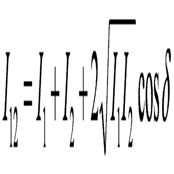
검출기(13)는 응답 광선들 중 어느 하나의 응답 광선과 참조 광선들 중 어느 하나의 참조 광선간의 간섭으로부터 제1 간섭 신호를 검출한다. 일반적으로, 광선의 간섭은 2개 이상의 파동, 즉 광선이 겹칠 때 증가하거나 감소하여 그 강도가 원래의 광선들의 강도의 합과는 다른 현상을 의미한다. 또한, 간섭 신호는 원래의 광선들의 강도의 합과는 다른 크기의 값을 의미한다. 주파수가 동일한 두 개의 광선들 상호간의 간섭은 수학식 2와 같이 설명된다. 이 때, 두 개의 광선들은 소정의 중심 파장의 광선으로부터 분리되어 서로 다른 경로를 통해 한 점에서 합쳐졌다고 가정된다. 또한, I12는 두 광선들의 간섭에 따른 강도를 의미하고, I1은 두 광선들 중 어느 하나의 광선의 강도를 의미하고, I2는 두 광선들 중 다른 하나의 광선의 강도를 의미하고, ![]()
![]()
[수학식 2]
일반적으로 두 개의 광선들 간의 간섭은 두 개의 광선들간의 위상차가 일정하게 유지되는 시간 동안에 또는 위상차가 일정하게 유지되는 공간적 거리 동안에 이루어진다. 일반적으로 위상차가 일정하게 유지되는 시간을 광선의 가간섭(coherent) 시간이라고 하며, 위상차가 일정하게 유지되는 공간적 길이를 가간섭 거리라고 한다. 실제로 대부분의 광선들은 가간섭 거리가 유한하다. 수학식 2에 이러한 광선의 가간섭 거리와 가간섭 시간을 반영하면 수학식 3으로 표현될 수 있다. 이 때, 두 개의 광선들은 소정의 중심 파장의 광선으로부터 분리되어 서로 다른 경로를 통해 한 점에서 합쳐졌다고 가정된다. 또한, ![]()
![]()
![]()
![]()
![]()
![]()
![]()
![]()
![]()
![]()
![]()
[수학식 3]
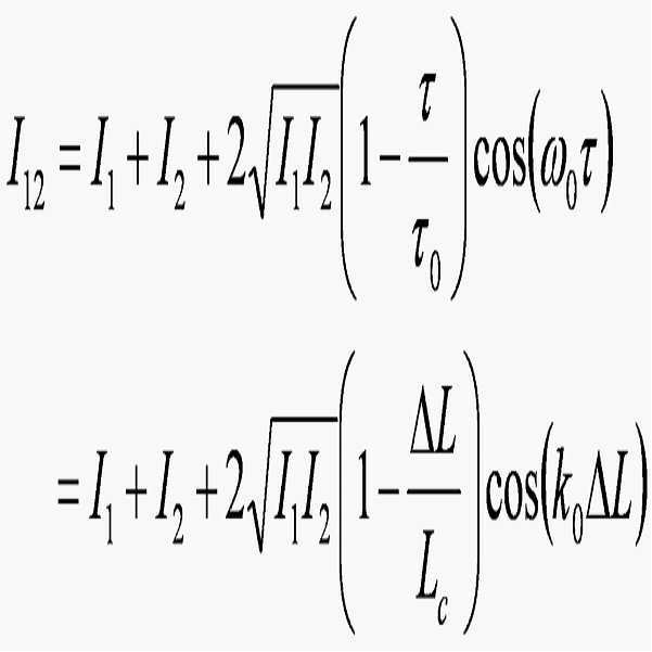
이와 같이, 소정 중심 파장의 광선으로부터 분리된 두 개의 광선들이 서로 다른 경로를 경유하여 한 점에서 합쳐지고, 두 개의 광선들간의 광 경로의 차이가 두 개의 광선들의 가간섭 거리보다 작은 경우, 간섭 신호가 발생하게 된다. 이와 같은 맥락으로, 본 발명의 일 실시예에 따른 검출기(13)는 제1 참조 광선과 제1 응답 광선간의 간섭으로부터 제1 간섭 신호를 검출한다. 구체적으로, 제1 광선으로부터 분리된 제1 참조 광선은 제1 참조 광선의 광 경로를 경유하여 광 결합기(12)에 도착한다. 이와 대조적으로, 제1 광선으로부터 분리되어 대상체(30)로 조사된 제1 측정 광선은 제1 응답 광선으로 변형되어 제1 측정 광선과 제1 응답 광선의 광 경로를 경유하여 광 결합기(12)에 도착한다. 이 때, 제1 참조 광선의 광 경로와 제1 응답 광선의 광 경로가 일치하는 경우, 제1 참조 광선과 제1 응답 광선 상호간에 간섭으로 인한 제1 간섭 신호가 발생된다. 이러한 제1 간섭 신호는 검출기(13)를 통하여 검출된다. 광 경로의 일치는 제1 응답 광선의 광 경로와 제1 참조 광선의 광 경로의 차이가 임계값 이하인 경우를 의미할 수 있다. 또한, 이러한 임계값은 제1 광선, 제1 참조 광선, 제1 측정 광선 및 제1 응답 광선 중 어느 하나의 가간섭 거리에 의해 결정될 수 있다. 예를 들어, 가간섭 거리가 30um인 경우, 임계값은 30um이다.
제1 응답 광선의 광 경로는 광 결합기(12)에서 분리된 제1 측정 광선이 프로브(20)를 통해 대상체(30)로 조사되고 대상체(30)로부터 반사 또는 산란되어 제1 응답 광선으로서 프로브(20)에 의해 수신되어 광 결합기(12)로 도착하는 경우, 제1 측정 광선의 분리된 지점에서부터 제1 응답 광선이 광 결합기(12)로 도착한 지점까지의 경로를 의미할 수 있다. 또한, 제1 참조 광선의 광 경로는 광 결합기(12)에서 분리된 제1 참조 광선이 기준 반사체로 조사되고, 기준 반사체로부터 반사되어 광 결합기(12)로 도착하는 경우, 제1 참조 광선의 분리된 지점에서부터 제1 참조 광선이 광 결합기(12)로 도착한 지점까지의 경로를 의미할 수 있다.
검출기(13)는 제1 간섭 신호를 검출한다. 일반적으로, 검출기(13)는 수광 수단을 이용하여 제1 간섭 신호를 검출한다. 이러한 수광 수단의 대표적인 일 예에는 수광 소자(photo detector)가 포함된다.
검출기(13)는 응답 광선들 중 다른 응답 광선과 참조 광선들 중 다른 참조 광선간의 간섭으로부터 제2 간섭 신호를 검출한다. 즉, 제2 간섭 신호는 대상체(30)로 조사된 측정 광선들 중 제2 측정 광선에 대응하여 프로브(20)로 수신된 제2 응답 광선과 참조 광선들 중 제2 참조 광선 사이의 간섭에 의하여 발생하는 신호를 의미할 수 있다. 일반적으로, 제2 간섭 신호는 제2 응답 광선의 광 경로와 제2 참조 광선의 광 경로가 일치하는 경우, 제2 응답 광선과 제2 참조 광선간의 간섭으로 인한 제2 간섭 신호가 발생된다. 또한, 이러한 제2 간섭 신호는 검출기(13)를 통하여 검출된다.
영상 처리기(14)는 제1 간섭 신호를 이용하여 대상체(30)의 제1 영상을 생성한다. 일반적으로, 영상 처리기(14)는 제1 간섭 신호를 이용하여 대상체(30)의 어느 하나의 측정 지점에 대한 축 방향의 변화를 기록하고, 측정 지점이 횡 방향으로 이동됨에 따라 축 방향의 변화를 누적하여 기록함으로써, 제1 영상을 생성할 수 있다. 이 때, 축 방향의 변화는 제1 참조 광선의 광 경로의 변화에 대응하는 제1 간섭 신호의 세기의 변화일 수 있다.
도 4는 대상체(30)로 조사된 측정 광선(21)과 간섭 신호(44)의 일 예를 나타낸 도면이다. 도 4를 참조하면, 제1 간섭 신호(44)는 대상체(30)의 내부의 종축 방향의 변화에 대응하여 제1 간섭 신호(44)의 신호 세기의 변화를 포함한다. 구체적으로, 대상체(30)로 조사된 제1 측정 광선(21)에 대응하여 프로브(20)는 제1 응답 광선을 수신한다. 이 때, 제1 응답 광선은 대상체(30) 내부에서 반사 및 산란된 반사 광 성분들을 포함한다. 또한, 이러한 반사 광 성분들은 대상체(30) 내부의 각 지점에 따라 반사의 정도를 달리한다. 예를 들어, 대상체(30) 내부의 지점(41), 지점(42) 및 지점(43)에서의 반사 광 성분들은 다른 지점들에 비하여 크다. 따라서, 지점(41), 지점(42) 및 지점(43)에서의 반사 광 성분들과 제1 참조 광선의 광 경로를 일치시키는 경우 간섭이 일어나고 이러한 간섭으로 인한 신호 세기는 다른 지점들로부터의 반사 광 성분들과 제1 참조 광선 사이의 간섭으로 인한 신호의 세기와 비교하여 매우 크다. 또한, 지점(41), 지점(42) 및 지점(43)에서의 반사 광 성분들과 제1 참조 광선의 간섭으로 인한 신호의 포락선 폭은 제1 측정 광선, 제1 응답 광선 및 제1 참조 광선의 가간섭 거리와 일치되고, 제1 간섭 신호(44)의 X 축은 제1 응답 광선과 제1 참조 광선간의 광 경로의 차이로 결정된다.
영상 처리기(14)는 이와 같이 제1 응답 광선과 제1 참조 광선간의 간섭으로 인한 제1 간섭 신호의 신호 세기의 변화를 제1 응답 광선과 제1 참조 광선간의 광 경로의 차이를 기준으로 기록함으로써, 대상체(30)의 내부의 종축의 깊이 방향에 대한 변화를 측정한다. 또한, 앞서 설명된 바와 같이, 영상 처리기(14)는 이러한 중축의 깊이 방향에 대한 변화를 횡축으로 진행하여 누적함으로써, 제1 영상을 생성한다.
영상 처리기(14)는 제2 간섭 신호를 이용하여 대상체(30)의 제2 영상을 생성한다. 일반적으로, 영상 처리기(14)는 제2 간섭 신호를 이용하여 대상체(30)의 어느 하나의 측정 지점에 대한 축 방향의 변화를 기록하고, 측정 지점이 횡 방향으로 이동됨에 따라 축 방향의 변화를 누적하여 기록함으로써, 제2 영상을 생성할 수 있다. 이 때, 축 방향의 변화는 제2 참조 광선의 광 경로의 변화에 대응하는 제2 간섭 신호의 세기의 변화일 수 있다.
도 5는 본 발명의 일 실시예에 따른 영상 처리기(14)와 영상 처리기(14)로부터 출력되는 영상들(51, 52, 53)을 나타낸 도면이다. 도 7을 참조하면, 본 발명의 일 실시예에 따른 영상 처리기(14)는 응답 광선들 중 제1 응답 광선과 참조 광선들 중 제1 참조 광선간의 간섭에 의한 제1 간섭 신호로부터 제1 영상(51)을 생성하고, 응답 광선들 중 제2 응답 광선과 참조 광선들 중 제2 참조 광선간의 간섭에 의한 제2 간섭 신호로부터 제2 영상(52)을 생성하고, 응답 광선들 중 제3 응답 광선과 참조 광선들 중 제3 참조 광선간의 간섭에 의한 제3 간섭 신호로부터 제3 영상(53)을 생성한다. 이 때, 제1 참조 광선, 제2 참조 광선 및 제3 참조 광선간의 중심 파장은 서로 다르고, 제1 응답 광선, 제2 응답 광선 및 제3 응답 광선간의 중심 파장도 서로 다를 수 있다. 예를 들어, 제1 참조 광선과 제1 응답 광선의 중심 파장은 500nm이고, 제2 참조 광선과 제2 응답 광선의 중심 파장은 800nm이고, 제3 참조 광선과 제3 응답 광선의 중심 파장은 1300nm일 수 있다.
제1 영상, 제2 영상 및 제3 영상은 대상체(30)의 동일한 측정 환경 내에서 획득된 영상들로 가정된다. 다시 말하면, 프로브(20)는 동일한 측정 범위 내에서 동일한 초점 깊이로 제1 영상을 위한 제1 측정 광선과, 제2 영상을 위한 제2 측정 광선과 제3 영상을 위한 제3 측정 광선을 조사하고, 영상 처리기(14)는 이를 기초로 제1 영상, 제2 영상 및 제3 영상을 생성한다. 다만, 광 생성기(11)는 제1 영상을 위한 제1 광선과 제2 영상을 위한 제2 광선과 제3 영상을 위한 제3 광선을 상호간에 중심 파장이 다르도록 생성한다. 예를 들어, 제1 광선의 중심 파장은 500nm이고, 제2 광선의 중심 파장은 800nm이고, 제3 광선의 중심 파장은 1300nm이다.
이 경우, 제1 영상, 제2 영상 및 제3 영상은 동일한 측정 환경 내에서 획득된 영상들임에도 불구하고, 상호간에 차이점을 갖는다. 예를 들어, 제1 영상의 영역(511)은 제1 영상의 다른 영역들에 비하여 선명, 즉, 고 주파수 영상 영역이고, 제2 영상의 영역(521)은 제2 영상의 다른 영역들에 비하여 선명, 즉 고 주파수 영상 영역이고, 제3 영상의 영역(531)은 제3 영상의 다른 영역들에 비하여 선명, 즉 고 주파수 영역이며. 이로 인해, 제1 영상, 제2 영상 및 제3 영상은 상호간에 차이점을 갖게 된다. 이러한 영상들간의 차이점은 제1 영상을 위한 제1 광선의 중심 파장과 제2 영상을 위한 제2 광선의 중심 파장과 제3 광선을 위한 제3 광선의 중심 파장 상호간에 차이로부터 기인된다. 구체적으로, 제1 광선, 제2 광선 및 제3 광선의 중심 파장들의 차이는 제1 영상, 제2 영상 및 제3 영상의 종축 해상도의 차이, 횡축(lateral) 해상도의 차이 및 제1 광선, 제2 광선 및 제3 광선의 투과도의 차이 등을 야기하고, 종축 해상도의 차이, 횡축(lateral) 해상도의 차이 및 투과도의 차이 등으로 인하여 제1 영상, 제2 영상 및 제3 영상은 상호간에 차이점을 갖게 된다. 일반적으로, 영상의 종축 해상도는 수학식 1에서와 같이 영상을 위한 광선의 중심 파장으로부터 결정되고, 광선의 투과도 역시 광선의 중심 파장에 따라 서로 다르다.
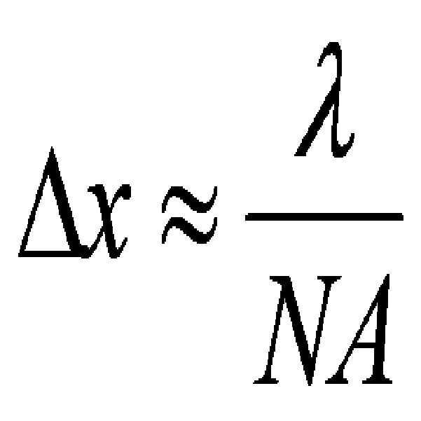
일반적으로, 영상의 횡축 해상도는 이러한 영상을 위한 중심 파장으로부터 결정된다. 구체적으로, 수학식 4와 같이 광 결합 단층촬영 장치(10)로부터 생성된 영상의 횡축 해상도는 측정 광선의 중심 파장과 프로브(20)의 렌즈의 개구수(Numerical Aperture, NA)에 의해 결정된다. 이 때, ![]()
![]()
[수학식 4]
본 발명의 일 실시예에 따른 영상 처리기(14)는 제1 간섭 신호와 제2 간섭 신호를 이용하여 영상을 생성한다. 예를 들어, 영상 처리기(14)는 광 결합기(12)로 동시에 또는 순차적으로 도착하는 응답 광선들과 광 결합기(12)로 동시에 또는 순차적으로 도착하는 참조 광선들의 간섭으로부터 간섭 신호들을 검출하고, 검출된 간섭 신호들을 이용하여 영상을 생성할 수 있다.
도 6은 본 발명의 일 실시예에 따른 영상 처리기(14)의 구성도이다. 도 6을 참조하면, 영상 처리기(14)는 영상 생성부(141) 및 출력 영상 생성부(142)를 포함한다. 다만, 도 6에 도시된 영상 처리기(14)는 본 발명의 하나의 구현 예에 불과하며, 도 6에 도시된 구성 요소들을 기초로 하여 여러 가지 변형이 가능함을 본 발명의 일 실시예가 속하는 기술분야에서 통상의 지식을 가진 자라면 이해할 수 있다.
영상 생성부(141)는 제1 간섭 신호를 이용하여 제1 영상을 생성하고, 제2 간섭 신호를 이용하여 제2 영상을 생성한다. 다만, 본 발명의 다른 실시예에 따르면, 영상 생성부(141)는 제3 간섭 신호를 이용하여 제3 영상을 더 생성한다. 이와 같은 영상 생성부(141)에 대하여 설명되지 아니한 사항은 앞서 영상 처리기(14)에 설명된 내용과 동일 또는 설명된 내용으로부터 당업자에 의해 용이하므로 이하 설명을 생략한다.
본 발명의 일 실시예에 따른 출력 영상 생성부(142)는 제1 영상과 제2 영상으로부터 출력되기 위한 영상을 생성한다. 일반적으로, 출력 영상 생성부(142)는 제1 영상(51)과 제2 영상(52)을 합성함으로써, 출력 되기 위한 영상을 생성한다. 이 때, 본 발명의 일 실시예에 따르면, 출력 영상 생성부(142)는 제1 영상(51)에 제1 가중치를 적용하고, 제2 영상(52)에 제2 가중치를 적용한 후, 출력 영상 생성부(142)는 제1 영상(51)과 제2 영상(52)을 합성함으로써, 출력 되기 위한 영상을 생성할 수 있다. 다만, 본 발명의 일 실시예에 따른 출력 영상 생성부(142)는 제1 영상, 제2 영상 이외에도 제3 영상, 제4 영상 등을 더 합성함으로써 출력 되기 위한 영상을 생성할 수도 있다.
본 발명의 다른 실시예에 따른 출력 영상 생성부(142)는 측정 광선들 중 어느 하나의 측정 광선의 중심 파장 또는 응답 광선들 중 어느 하나의 응답 광선의 중심 파장에 기초하여 제1 영상(51)으로부터 고 주파수 영역(511)을 추출한다. 예를 들어, 출력 영상 생성부(142)는 측정 광선들 중 어느 하나의 측정 광선의 중심 파장 또는 응답 광선들 중 어느 하나의 응답 광선의 중심 파장을 영상 생성부(141)로부터 수신하고, 이러한 중심 파장에 따라 제1 영상(51)으로부터 고 주파수 영역을 결정하고, 이러한 결정에 기초하여 제1 영상(51)으로부터 고 주파수 영역(511)을 추출할 수 있다. 이 때, 출력 영상 생성부(142)는 다양한 파라미터들을 통해 제1 영상(51)으로부터 고 주파수 영역(511)을 추출할 수 있다. 이러한 파라미터들의 일 예에는 앞서 설명된 중심 파장, 종축 해상도, 횡축 해상도, 투과도 및 초점 깊이 등이 포함된다.
이와 같은 맥락으로, 본 발명의 다른 실시예에 따른 출력 영상 생성부(142)는 측정 광선들 중 다른 측정 광선의 중심 파장 또는 응답 광선들 중 다른 응답 광선의 중심 파장에 기초하여 제2 영상(52)으로부터 고 주파수 영역(521)을 추출한다. 다만, 본 발명의 다른 실시예에 따른 출력 영상 생성부(142)는 측정 광선들 중 또 다른 측정 광선의 중심 파장 또는 응답 광선들 중 또 다른 응답 광선의 중심 파장에 기초하여 제3 영상(53)으로부터 제3 영상(53)의 고 주파수 영역(531)을 더 추출할 수도 있다.
본 발명의 다른 실시예에 따른 출력 영상 생성부(142)는 추출된 제1 영상(51)의 고 주파수 영역(511)과 추출된 제2 영상(52)의 고 주파수 영역(521)에 기초하여 제1 영상(51)과 제2 영상(52)으로부터 출력되기 위한 영상을 생성한다. 일반적으로, 본 발명의 다른 실시예에 따른 출력 영상 생성부(142)는 제1 영상(51)의 고 주파수 영역(511)과 제2 영상(52)의 고 주파수 영역(521)의 합성을 통해 출력되기 위한 영상을 생성할 수 있다. 이 때, 본 발명의 다른 실시예에 따른 출력 영상 생성부(142)는 제1 영상(51)의 고 주파수 영역(511)에 제1 가중치를 적용하고, 제2 영상(52)의 고 주파수 영역(521)에 제2 가중치를 적용한 후, 제1 영상(51)의 고 주파수 영역(511)과 제2 영상(52)의 고 주파수 영역(521)을 합성함으로써, 출력되기 위한 영상을 생성할 수도 있다. 다만, 본 발명의 다른 실시예에 따른 출력 영상 생성부(142)는 제1 영상(51)의 고 주파수 영역(511), 제2 영상(52)의 고 주파수 영역(521) 및 제3 영상(53)의 고 주파수 영역(531)을 합성함으로써, 출력되기 위한 영상을 생성할 수도 있다.
본 발명의 또 다른 실시예에 따르면, 본 발명의 또 다른 실시예에 따른 출력 영상 생성부(142)는 제1 영상(51)의 고 주파수 영역(511)에 제1 가중치를 적용하고, 제2 영상(52)의 고 주파수 영역(521)에 제2 가중치를 적용한 후, 제1 영상(51)과 제2 영상(52)을 합성함으로써, 출력되기 위한 영상을 생성할 수도 있다. 다만, 본 발명의 또 다른 실시예에 따른 출력 영상 생성부(142)는 제1 영상(51)의 고 주파수 영역(511)에 제1 가중치를 적용하고, 제2 영상(52)의 고 주파수 영역(521)에 제2 가중치를 적용하고, 제3 영상(53)의 고 주파수 영역(531)에 제3 가중치를 적용한 후, 제1 영상(51), 제2 영상(52) 및 제3 영상(53)을 합성함으로써, 출력되기 위한 영상을 생성할 수도 있다.
도 7은 본 발명의 일 실시예에 따른 광 간섭 단층촬영 장치(10)를 나타낸 도면이다. 도 7을 참조하면, 광 결합기(12)는 반사체(90)로 조사되는 참조 광선들을 참조 프로브(40)로 전송하고, 참조 프로브(40)로부터 반사 광선들을 수신한다. 또한, 검출기(13)는 응답 광선들 중 어느 하나의 응답 광선과 반사 광선들 중 어느 하나의 반사 광선간의 간섭으로부터 제1 간섭 신호를 검출하고, 응답 광선들 중 다른 응답 광선과 반사 광선들 중 다른 반사 광선간의 간섭으로부터 제2 간섭 신호를 검출한다. 일반적으로 반사 광선들은 참조 광선들과 비교하여 강도의 손실이 매우 적음이 바람직하다. 따라서, 본 발명의 일 실시예에 따르면, 반사 광선들은 참조 광선들과 동일한 의미로 사용될 수 있다.
일반적으로, 참조 프로브(40)는 참조 광선들의 광 경로를 제어한다. 예를 들어, 참조 프로브(40)는 광 경로 제어 수단을 이용하여 참조 광선들의 광 경로를 제어할 수 있다. 이러한 광 경로 제어 수단의 대표적인 일 예에는 기준 반사체까지의 거리를 제어하는 수단, 회전체 큐브를 이용하여 광 경로를 제어하는 수단, 광 섬유 인장을 통하여 광 경로 제어하는 수단 및 회절 격자를 이용하여 광 경로를 제어하는 수단 등이 포함된다. 앞서 설명된 바와 같이, 참조 광선들의 광 경로가 변경됨으로써, 간섭 신호는 대상체(30)의 내부의 종축 방향의 변화에 대응하여 신호 세기의 변화를 나타낼 수 있다.
도 8은 본 발명의 일 실시예에 따른 광 간섭 단층촬영 방법의 동작 흐름도이다. 도 8에 도시된 실시예에 따른 광 간섭 단층촬영 방법은 도 1에 도시된 광 간섭 단층촬영 장치(10)에서 시계열적으로 처리되는 단계들로 구성된다. 따라서, 이하 생략된 내용이라고 하더라도 광 간섭 단층촬영 장치(10)에 관하여 이상에서 기술된 내용과 동일하거나 당업자에 의해 용이하게 유추 가능한 내용들은 도 8에 도시된 실시예에 따른 생체 신호 측정 방법에도 적용된다.
단계 81에서 광 생성기(11)는 복수의 광선들을 생성한다. 단계 82에서 광 결합기(12)는 광선들로부터 측정 광선들과 참조 광선들을 분리한다. 단계 83에서 광 결합기(12)는 대상체(30)로 조사되는 측정 광선들을 프로브(20)로 전송한다. 단계 84에서 광 결합기(12)는 프로브(20)로부터 이러한 측정 광선들의 조사에 대응하여 응답 광선들을 수신한다. 단계 85에서 검출기(13)는 응답 광선들과 참조 광선들간의 간섭으로부터 간섭 신호들을 검출한다. 단계 86에서 영상 처리기(14)는 간섭 신호들 중 어느 하나의 간섭 신호에 기초하여 제1 영상을 생성하고, 간섭 신호들 중 다른 간섭 신호에 기초하여 제1 영상과는 다른 영상 특성의 제2 영상을 생성한다.
도 8에 도시된 실시예에 따른 광 간섭 단층촬영 방법은 컴퓨터에서 실행될 수 있는 프로그램으로 작성 가능하고, 컴퓨터로 읽을 수 있는 기록매체를 이용하여 상기 프로그램을 동작시키는 범용 디지털 컴퓨터에서 구현될 수 있다. 상기 컴퓨터로 읽을 수 있는 기록매체는 마그네틱 저장매체(예를 들면, 롬, 플로피 디스크, 하드 디스크 등), 광학적 판독 매체(예를 들면, 시디롬, 디브이디 등)와 같은 저장매체를 포함한다.
이제까지 본 발명에 대하여 그 바람직한 실시예들을 중심으로 살펴보았다. 본 발명이 속하는 기술 분야에서 통상의 지식을 가진 자는 본 발명이 본 발명의 본질적인 특성에서 벗어나지 않는 범위에서 변형된 형태로 구현될 수 있음을 이해할 수 있을 것이다. 그러므로 개시된 실시예들은 한정적인 관점이 아니라 설명적인 관점에서 고려되어야 한다. 본 발명의 범위는 전술한 설명이 아니라 특허청구범위에 나타나 있으며, 그와 동등한 범위 내에 있는 모든 차이점은 본 발명에 포함된 것으로 해석되어야 할 것이다. Hereinafter, embodiments of the present invention will be described in detail with reference to the drawings. In the following embodiments, only configurations for generating a video signal of a target object in order to prevent the gist of the present invention from being blurred will be described. However, those skilled in the art will appreciate that other general configurations other than those for generating a video signal of a target object may be added to the embodiments of the present invention. For example, in order to allow a medical professional such as a doctor to recognize a video signal, configurations of generating a video signal of a subject and displaying a video signal of the subject on a screen or paper may be added.
1 is a block diagram of an optical
The
The optical
Generally, the plurality of rays are rays of different center wavelengths. For example, the center wavelength of one of the rays may be 300 nm, the center wavelength of the other of the rays may be 500 nm, and the center wavelength of the other one of the rays may be 800 nm. In this context, the measurement beams are measurement beams of different center wavelengths, the reference beams are reference beams of different center wavelengths, and the response beams may be response beams of different central wavelengths. Also, the measurement light and reference light separated from any one of the plurality of light beams, and the response light corresponding to this measurement light may be light beams of the same wavelength. For example, the first measurement light and the first reference light, and the first response light, which are separated from any one of the plurality of light beams, may be light rays having a first central wavelength. In this case, the central wavelength may mean a wavelength having a maximum value on a relative distribution along the wavelength of the light ray. The center wavelength can be determined by averaging the wavelengths with a relative distribution along the wavelength of the light as a probability density function, or by arithmetically averaging a pair of wavelengths at positions having a half of the maximum value on the relative distribution.
According to one embodiment of the invention, the measuring beams are illuminated with different focus depths of the
The optical
The optical
The operation of the optical
1, an optical
The
Generally, the plurality of rays have different coherent lengths. For example, the first beam and the second beam of the plurality of light sources have different coherence lengths. Generally, the interference length of a light beam is determined from the center wavelength of such a light beam and the bandwidth of the light beam measured in units of wavelength as shown in Equation 1 below. At this time, L c Is the interference length of the ray, ![]()
![]()
[Equation 1]
A typical example of a light beam includes a super luminescent diode (SLD) light and an edge-emitting light-emitting diode (ELED) light. However, according to various embodiments of the present invention, various types of light beams may be used in addition to these light rays. Generally, the light rays are determined in consideration of various factors such as the central wavelength of the light rays, the bandwidth of the light rays, the interference length of the light rays, the intensity of the light rays, and the characteristics of the measurement object.
The
The
According to one embodiment of the present invention, the
Generally, the measurement beam and the reference beam separated from the same beam have the same central wavelength as this beam. For example, a first ray having a center wavelength of 300 nm is separated into a first measurement ray having a center wavelength of 300 nm and a first reference ray having a center wavelength of 300 nm, and a second ray having a center wavelength of 500 nm has a center wavelength of 500 nm The second measurement light beam and the second reference light beam having a center wavelength of 500 nm.
According to one embodiment of the present invention, the
The
According to one embodiment of the present invention, the
The measurement beams are irradiated to the
According to one embodiment of the present invention, the
FIG. 2 is a diagram illustrating measurement beams 211, 212, and 213 illuminated by a
According to one embodiment of the present invention, the
FIG. 3 is a diagram illustrating measurement beams 221, 222, and 223 illuminated by a
The optical coupler (12) receives the response beams from the probe (20). These response beams may be response beams of different central wavelengths. The
According to one embodiment of the present invention, the
The ![]()
![]()
&Quot; (2) "
Generally, the interference between two beams occurs during the time that the phase difference between the two beams is kept constant or during the spatial distance where the phase difference is kept constant. Generally, the time during which the phase difference remains constant is called the coherent time of the light, and the spatial length where the phase difference remains constant is called the interference distance. In practice, most of the rays have a finite interference distance. If Equation (2) reflects the interference distance and the interference time of such a ray, it can be expressed by Equation (3). At this time, it is assumed that the two rays are separated from the ray of the predetermined center wavelength and combined at one point through different paths. Also, ![]()
![]()
![]()
![]()
![]()
![]()
![]()
![]()
![]()
![]()
![]()
&Quot; (3) "
In this way, when two light beams separated from a light beam of a predetermined center wavelength are combined at one point via different paths, and the difference in optical path between two light beams is smaller than the interference distance of two light beams, . In this regard, the
The optical path of the first response beam is such that the first measurement beam separated by the
The
The
The
Fig. 4 is a diagram showing an example of the
The
The
5 is a
The first image, the second image, and the third image are assumed to be images obtained in the same measurement environment of the
In this case, although the first image, the second image, and the third image are images obtained in the same measurement environment, they have mutual differences. For example, the
Generally, the transverse resolution of an image is determined from the central wavelength for such an image. Specifically, the horizontal axis resolution of the image generated from the optical coupling-![]()
![]()
&Quot; (4) "
The
6 is a configuration diagram of an
The
The output
The output
The output
The output
According to another embodiment of the present invention, an output
7 is a diagram illustrating an optical
Generally, the
8 is a flowchart illustrating an operation of the optical coherence tomography method according to an embodiment of the present invention. The optical coherence tomography method according to the embodiment shown in FIG. 8 is composed of steps that are processed in a time-series manner in the optical
In
The optical coherent tomography method according to the embodiment shown in FIG. 8 can be implemented in a general-purpose digital computer that can be created as a program that can be executed by a computer and operates the program using a computer-readable recording medium. The computer-readable recording medium includes a storage medium such as a magnetic storage medium (e.g., ROM, floppy disk, hard disk, etc.), optical reading medium (e.g., CD ROM,
The present invention has been described with reference to the preferred embodiments. It will be understood by those skilled in the art that various changes in form and details may be made therein without departing from the spirit and scope of the invention as defined by the appended claims. Therefore, the disclosed embodiments should be considered in an illustrative rather than a restrictive sense. The scope of the present invention is defined by the appended claims rather than by the foregoing description, and all differences within the scope of equivalents thereof should be construed as being included in the present invention.
10 ... 광 간섭 단층촬영 장치
11 ... 광 생성기
12 ... 광 결합기
13 ... 검출기
14 ... 영상 처리기
20 ... 프로브
30 ... 대상체10 ... optical coherence tomography apparatus
11 ... light generator
12 ... optical coupler
13 ... detector
14 ... image processor
20 ... probe
30 ... object
Claims (22)
상기 광선들로부터 측정 광선들과 참조 광선들을 분리하고, 대상체로 조사되기 위한 상기 측정 광선들을 프로브로 전송하고, 상기 프로브로부터 응답 광선들을 수신하는 광 결합기;
상기 응답 광선들과 상기 참조 광선들과의 간섭(interference)으로부터 간섭 신호들을 검출하는 검출기; 및
상기 간섭 신호들 중 어느 하나의 간섭 신호에 기초하여 제1 영상을 생성하고, 상기 간섭 신호들 중 다른 간섭 신호에 기초하여 제1 영상과 종축 해상도, 횡축 해상도 및 투과도 중 적어도 하나가 다른 제2 영상을 생성하고, 상기 제1 영상의 고 주파수 영역 및 상기 제2 영상의 고 주파수 영역을 합성함으로써 출력 영상을 생성하는 영상 처리기를 포함하고,
상기 제1 영상의 고 주파수 영역은 상기 제2 영상의 고 주파수 영역과 상이한 광 간섭 단층촬영 장치.
A light generator for generating a plurality of light beams having different central wavelengths;
An optical coupler for separating the measurement beams and reference beams from the beams, for transmitting the measurement beams to be irradiated to the object to the probe, and for receiving the response beams from the probe;
A detector for detecting interference signals from interference between the response beams and the reference beams; And
Generating a first image based on any one of the interference signals, and generating a second image based on another one of the interference signals, the second image having at least one of longitudinal resolution, transverse resolution, And an image processor for generating an output image by combining the high frequency region of the first image and the high frequency region of the second image,
Wherein the high frequency region of the first image is different from the high frequency region of the second image.
상기 응답 광선들 중 어느 하나와 상기 참조 광선들 중 어느 하나는 제1 중심 파장의 광선들이고, 상기 응답 광선들 중 다른 하나와 상기 참조 광선들 중 다른 하나는 제2 중심 파장의 광선들인 광 간섭 단층촬영 장치.
The method according to claim 1,
Wherein one of the response beams and one of the reference beams are light beams of a first center wavelength and the other one of the response beams and the other of the reference beams are light beams of a second center wavelength, Shooting device.
상기 어느 하나의 간섭 신호는 상기 응답 광선들 중 어느 하나의 응답 광선과 상기 참조 광선들 중 어느 하나의 참조 광선간의 간섭(interference)으로부터 검출되고, 상기 다른 간섭 신호는 상기 응답 광선들 중 다른 응답 광선과 상기 참조 광선들 중 다른 참조 광선간의 간섭으로부터 검출되는 광 간섭 단층촬영 장치.The method according to claim 1,
Wherein the one of the interference signals is detected from an interference between any one of the response beams and one of the reference beams and the other interference signal is detected from another response beam of the response beams, And interference from another of the reference beams.
상기 측정 광선들은 상기 프로브에 의해 순차적으로 상기 대상체로 조사되고, 상기 응답 광선들은 상기 대상체로부터 상기 프로브로 순차적으로 수신되는 광 간섭 단층촬영 장치.The method according to claim 1,
Wherein the measurement beams are sequentially irradiated onto the object by the probe and the response beams are sequentially received from the object to the probe.
상기 측정 광선들은 상기 프로브에 의해 동시에 상기 대상체로 조사되고, 상기 응답 광선들은 상기 대상체로부터 상기 프로브로 동시에 수신되는 광 간섭 단층촬영 장치. The method according to claim 1,
Wherein the measurement beams are simultaneously irradiated to the object by the probe and the response beams are simultaneously received from the object to the probe.
상기 응답 광선들 중 어느 하나의 응답 광선과 다른 응답 광선은 상기 응답 광선들로부터 추출되는 광 간섭 단층촬영 장치.6. The method of claim 5,
Wherein one of the response beams and the other response beam are extracted from the response beams.
상기 측정 광선들은 동일한 초점 깊이로 상기 대상체에 조사되는 광 간섭 단층 촬영 장치.The method according to claim 1,
Wherein the measuring beams are irradiated to the object at the same focal depth.
상기 측정 광선들 중 어느 하나의 측정 광선은 상기 대상체의 제1 초점 깊이에 조사되고, 상기 측정 광선들 중 다른 측정 광선은 상기 대상체의 제2 초점 깊이에 조사되는 광 간섭 단층촬영 장치.The method according to claim 1,
Wherein one of the measurement beams is irradiated to a first focus depth of the object and another of the measurement beams is irradiated to a second focus depth of the object.
상기 영상 처리기는,
상기 제1 영상의 제1 가중치와 상기 제2 영상의 제2 가중치에 기초하여 상기 제1 영상과 상기 제2 영상으로부터 상기 출력 영상을 생성하는 광 간섭 단층촬영 장치.
The method according to claim 1,
Wherein the image processor comprises:
And generates the output image from the first image and the second image based on a first weight of the first image and a second weight of the second image.
상기 영상 처리기는,
상기 측정 광선들 중 어느 하나의 측정 광선 또는 상기 응답 광선들 중 어느 하나의 응답 광선의 중심 파장에 기초하여 상기 제1 영상으로부터 상기 제1 영상의 고 주파수 영역을 추출하고, 상기 측정 광선들 중 다른 측정 광선 또는 상기 응답 광선들 중 다른 응답 광선의 중심 파장에 기초하여 상기 제2 영상으로부터 상기 제2 영상의 고 주파수 영역을 추출하고, 추출된 제1 영상의 고 주파수 영역과 추출된 제2 영상의 고 주파수 영역에 기초하여 상기 제1 영상과 상기 제2 영상으로부터 상기 출력 영상을 생성하는 광 간섭 단층촬영 장치.
The method according to claim 1,
Wherein the image processor comprises:
Extracting a high frequency region of the first image from the first image based on a center wavelength of one of the measurement beams or the response beams of the response beams, Extracting a high frequency region of the second image from the second image based on a measurement wavelength or a central wavelength of the other response beam among the response beams, extracting a high frequency region of the extracted first image, And generates the output image from the first image and the second image based on the high frequency region.
상기 광 결합기는, 반사체로 조사되는 상기 참조 광선들을 참조 프로브로 전송하고, 상기 참조 프로브로부터 반사 광선들을 수신하고,
상기 검출기는, 상기 응답 광선들과 상기 반사 광선들간의 간섭으로부터 간섭 신호들을 검출하는 광 간섭 단층촬영 장치.The method according to claim 1,
The optical coupler is configured to transmit the reference beams illuminated by the reflector to a reference probe, receive reflected beams from the reference probe,
Wherein the detector detects interfering signals from interference between the response beams and the reflected beams.
상기 광선들로부터 측정 광선들과 참조 광선들을 분리하는 단계;
대상체로 조사되기 위한 상기 측정 광선들을 프로브로 전송하는 단계;
상기 조사에 대응하여 상기 프로브로 입력된 응답 광선들을 상기 프로브로부터 수신하는 단계;
상기 응답 광선들과 상기 참조 광선들과의 간섭(interference)으로부터 간섭 신호들을 검출하는 단계; 및
상기 간섭 신호들 중 어느 하나의 간섭 신호에 기초하여 제1 영상을 생성하고, 상기 간섭 신호들 중 다른 간섭 신호에 기초하여 제1 영상과 종축 해상도, 횡축 해상도 및 투과도 중 적어도 하나가 다른 제2 영상을 생성하고, 상기 제1 영상의 고 주파수 영역 및 상기 제2 영상의 고 주파수 영역을 합성함으로써 출력 영상을 생성하는 단계를 포함하고,
상기 제1 영상의 고 주파수 영역은 상기 제2 영상의 고 주파수 영역과 상이한 광 간섭 단층촬영 방법.
Generating a plurality of rays having different central wavelengths;
Separating measurement beams and reference beams from the beams;
Transmitting the measurement beams to be probed to the object with a probe;
Receiving response beams input from the probe to the probe corresponding to the probe;
Detecting interference signals from interference between the response beams and the reference beams; And
Generating a first image based on any one of the interference signals, and generating a second image based on another one of the interference signals, the second image having at least one of longitudinal resolution, transverse resolution, Generating an output image by combining the high frequency region of the first image and the high frequency region of the second image,
Wherein the high frequency region of the first image is different from the high frequency region of the second image.
상기 응답 광선들 중 어느 하나와 상기 참조 광선들 중 어느 하나는 제1 중심 파장의 광선들이고, 상기 응답 광선들 중 다른 하나와 상기 참조 광선들 중 다른 하나는 제2 중심 파장의 광선들인 광 간섭 단층촬영 방법.
13. The method of claim 12,
Wherein one of the response beams and one of the reference beams are light beams of a first center wavelength and the other one of the response beams and the other of the reference beams are light beams of a second center wavelength, How to shoot.
상기 어느 하나의 간섭 신호는 상기 응답 광선들 중 어느 하나의 응답 광선과 상기 참조 광선들 중 어느 하나의 참조 광선간의 간섭(interference)으로부터 검출되고, 상기 다른 간섭 신호는 상기 응답 광선들 중 다른 응답 광선과 상기 참조 광선들 중 다른 참조 광선간의 간섭으로부터 검출되는 광 간섭 단층촬영 방법.13. The method of claim 12,
Wherein the one of the interference signals is detected from an interference between any one of the response beams and one of the reference beams and the other interference signal is detected from another response beam of the response beams, And interference from another of the reference beams.
상기 측정 광선들은 상기 프로브에 의해 순차적으로 상기 대상체로 조사되고, 상기 응답 광선들은 상기 대상체로부터 상기 프로브로 순차적으로 수신되는 광 간섭 단층촬영 방법.13. The method of claim 12,
Wherein the measurement beams are sequentially irradiated onto the object by the probe and the response beams are sequentially received from the object to the probe.
상기 측정 광선들은 상기 프로브에 의해 동시에 상기 대상체로 조사되고, 상기 응답 광선들은 상기 대상체로부터 상기 프로브로 동시에 수신되는 광 간섭 단층촬영 방법.13. The method of claim 12,
Wherein the measurement beams are simultaneously irradiated to the object by the probe and the response beams are simultaneously received from the object to the probe.
상기 응답 광선들 중 어느 하나의 응답 광선과 다른 응답 광선은 상기 응답 광선들로부터 추출되는 광 간섭 단층촬영 방법.17. The method of claim 16,
Wherein one of the response beams and the other response beam are extracted from the response beams.
상기 측정 광선들은 동일한 초점 깊이로 상기 대상체에 조사되는 광 간섭 단층 촬영 방법.13. The method of claim 12,
Wherein the measurement beams are irradiated to the object at the same focal depth.
상기 측정 광선들 중 어느 하나의 측정 광선은 상기 대상체의 제1 초점 깊이에 조사되고, 상기 측정 광선들 중 다른 측정 광선은 상기 대상체의 제2 초점 깊이에 조사되는 광 간섭 단층촬영 방법.13. The method of claim 12,
Wherein one of the measurement beams is irradiated to a first focus depth of the object and another of the measurement beams is irradiated to a second focus depth of the object.
상기 제1 영상의 고 주파수 영역 및 상기 제2 영상의 고 주파수 영역을 합성함으로써 출력 영상을 생성하는 상기 단계는, 상기 제1 영상의 제1 가중치와 상기 제2 영상의 제2 가중치에 기초하여 상기 제1 영상과 상기 제2 영상으로부터 상기 출력 영상을 생성하는 광 간섭 단층촬영 방법.
13. The method of claim 12,
Wherein the step of generating an output image by synthesizing a high frequency region of the first image and a high frequency region of the second image comprises the steps of generating an output image by combining the first weight of the first image and the second weight of the second image, And generating the output image from the first image and the second image.
상기 광 간섭 단층촬영 방법은, 반사체로 조사되는 상기 참조 광선들을 참조 프로브로 전송하고, 상기 참조 프로브로부터 반사 광선들을 수신하는 단계를 더 포함하고,
간섭 신호들을 검출하는 상기 단계는, 상기 응답 광선들과 상기 반사 광선들간의 간섭으로부터 간섭 신호들을 검출하는 광 간섭 단층촬영 방법.13. The method of claim 12,
The optical coherence tomography method further comprises transmitting the reference beams illuminated by the reflector to a reference probe and receiving reflected beams from the reference probe,
Wherein the step of detecting interfering signals detects interfering signals from interference between the response beams and the reflected beams.
A computer-readable recording medium on which a program for executing the method of any one of claims 12 to 21 is recorded.
Priority Applications (2)
| Application Number | Priority Date | Filing Date | Title |
|---|---|---|---|
| KR1020110033773A KR101792588B1 (en) | 2011-04-12 | 2011-04-12 | Apparatus and method optical coherence tomography using multiple beams |
| US13/296,960 US9170088B2 (en) | 2011-04-12 | 2011-11-15 | Apparatus and method for optical coherence tomography using multiple beams |
Applications Claiming Priority (1)
| Application Number | Priority Date | Filing Date | Title |
|---|---|---|---|
| KR1020110033773A KR101792588B1 (en) | 2011-04-12 | 2011-04-12 | Apparatus and method optical coherence tomography using multiple beams |
Publications (2)
| Publication Number | Publication Date |
|---|---|
| KR20120116183A KR20120116183A (en) | 2012-10-22 |
| KR101792588B1 true KR101792588B1 (en) | 2017-11-01 |
Family
ID=47006181
Family Applications (1)
| Application Number | Title | Priority Date | Filing Date |
|---|---|---|---|
| KR1020110033773A Expired - Fee Related KR101792588B1 (en) | 2011-04-12 | 2011-04-12 | Apparatus and method optical coherence tomography using multiple beams |
Country Status (2)
| Country | Link |
|---|---|
| US (1) | US9170088B2 (en) |
| KR (1) | KR101792588B1 (en) |
Cited By (3)
| Publication number | Priority date | Publication date | Assignee | Title |
|---|---|---|---|---|
| KR20190080507A (en) * | 2017-12-28 | 2019-07-08 | 울산과학기술원 | Optical Projection Tomography System including Optical Filter and Operation Method of the Same |
| US12320642B2 (en) | 2019-05-24 | 2025-06-03 | Apple Inc. | Wearable skin vibration or silent gesture detector |
| US12366442B2 (en) | 2019-02-28 | 2025-07-22 | Apple Inc. | Self-interferometry based sensor systems capable of generating depth maps or velocity maps |
Families Citing this family (4)
| Publication number | Priority date | Publication date | Assignee | Title |
|---|---|---|---|---|
| US9835436B2 (en) | 2013-11-01 | 2017-12-05 | Tomey Corporation | Wavelength encoded multi-beam optical coherence tomography |
| JP2017173305A (en) * | 2016-02-10 | 2017-09-28 | 株式会社トーメーコーポレーション | Wavelength-encoded multi-beam optical coherence tomography |
| CN107481190B (en) * | 2017-07-04 | 2018-12-07 | 腾讯科技(深圳)有限公司 | A kind of image processing method and device |
| US12209890B2 (en) * | 2022-03-31 | 2025-01-28 | Apple Inc. | Optical sensor module including an interferometric sensor and extended depth of focus optics |
Citations (2)
| Publication number | Priority date | Publication date | Assignee | Title |
|---|---|---|---|---|
| US20080100848A1 (en) * | 2006-10-25 | 2008-05-01 | Koji Kobayashi | Optical tomograph |
| JP2010246654A (en) * | 2009-04-13 | 2010-11-04 | Canon Inc | Optical tomographic imaging apparatus and control method thereof |
Family Cites Families (10)
| Publication number | Priority date | Publication date | Assignee | Title |
|---|---|---|---|---|
| KR20040081964A (en) | 2003-03-17 | 2004-09-23 | 학교법인연세대학교 | A Device Of Low Coherence Source Of Light Using Combined LED |
| JP3796550B2 (en) | 2003-09-26 | 2006-07-12 | 日本電信電話株式会社 | Optical interference tomography device |
| EP1607064B1 (en) * | 2004-06-17 | 2008-09-03 | Cadent Ltd. | Method and apparatus for colour imaging a three-dimensional structure |
| JP2006047264A (en) | 2004-07-09 | 2006-02-16 | Nippon Telegr & Teleph Corp <Ntt> | Optical coherent tomography apparatus, variable wavelength light generating apparatus and variable wavelength light source used therefor |
| GB0425419D0 (en) | 2004-11-18 | 2004-12-22 | Sira Ltd | Interference apparatus and method and probe |
| US7301644B2 (en) * | 2004-12-02 | 2007-11-27 | University Of Miami | Enhanced optical coherence tomography for anatomical mapping |
| US7408649B2 (en) * | 2005-10-26 | 2008-08-05 | Kla-Tencor Technologies Corporation | Method and apparatus for optically analyzing a surface |
| JP4869877B2 (en) * | 2006-11-17 | 2012-02-08 | 富士フイルム株式会社 | Optical tomographic imaging system |
| GB0624361D0 (en) | 2006-12-06 | 2007-01-17 | Michelson Diagnostics Ltd | Multiple beam source for a multi-beam interferometer and multi-beam interferometer |
| JP5181384B2 (en) | 2007-07-20 | 2013-04-10 | 独立行政法人情報通信研究機構 | Optical interference tomography device, optical shape measurement device |
-
2011
- 2011-04-12 KR KR1020110033773A patent/KR101792588B1/en not_active Expired - Fee Related
- 2011-11-15 US US13/296,960 patent/US9170088B2/en not_active Expired - Fee Related
Patent Citations (2)
| Publication number | Priority date | Publication date | Assignee | Title |
|---|---|---|---|---|
| US20080100848A1 (en) * | 2006-10-25 | 2008-05-01 | Koji Kobayashi | Optical tomograph |
| JP2010246654A (en) * | 2009-04-13 | 2010-11-04 | Canon Inc | Optical tomographic imaging apparatus and control method thereof |
Cited By (4)
| Publication number | Priority date | Publication date | Assignee | Title |
|---|---|---|---|---|
| KR20190080507A (en) * | 2017-12-28 | 2019-07-08 | 울산과학기술원 | Optical Projection Tomography System including Optical Filter and Operation Method of the Same |
| KR102044967B1 (en) * | 2017-12-28 | 2019-11-14 | 울산과학기술원 | Optical Projection Tomography System including Optical Filter and Operation Method of the Same |
| US12366442B2 (en) | 2019-02-28 | 2025-07-22 | Apple Inc. | Self-interferometry based sensor systems capable of generating depth maps or velocity maps |
| US12320642B2 (en) | 2019-05-24 | 2025-06-03 | Apple Inc. | Wearable skin vibration or silent gesture detector |
Also Published As
| Publication number | Publication date |
|---|---|
| US9170088B2 (en) | 2015-10-27 |
| US20120262722A1 (en) | 2012-10-18 |
| KR20120116183A (en) | 2012-10-22 |
Similar Documents
| Publication | Publication Date | Title |
|---|---|---|
| KR101792588B1 (en) | Apparatus and method optical coherence tomography using multiple beams | |
| US11779219B2 (en) | Low-coherence interferometry and optical coherence tomography for image-guided surgical treatment of solid tumors | |
| JP5371315B2 (en) | Optical coherence tomography method and optical coherence tomography apparatus | |
| KR101336048B1 (en) | Optical tomographic imaging method and optical tomographic imaging apparatus | |
| JP6366367B2 (en) | SUBJECT INFORMATION ACQUISITION DEVICE, CONTROL METHOD FOR SUBJECT INFORMATION ACQUISITION DEVICE, AND PROGRAM | |
| JP2006313158A (en) | Luminal tomographic image display method and optical coherence tomography apparatus by optical coherence tomography | |
| CN105342568B (en) | The optical coherence angiographic method and system of joint phase and amplitude | |
| KR101442708B1 (en) | Optical coherence tomography for processing three-dimensional oct data using 64 bit based dynamic memory allocation method | |
| US8599386B2 (en) | Optical tomographic imaging apparatus, interference signal processing method, and endoscope apparatus | |
| JP2019518210A (en) | Biological tissue inspection apparatus and method thereof | |
| JP4704519B2 (en) | SUBJECT INFORMATION ANALYSIS DEVICE AND SUBJECT INFORMATION ANALYSIS METHOD | |
| JP5298352B2 (en) | Optical structure image observation device and endoscope device | |
| CN108403079A (en) | A kind of confocal imaging system based on OCT | |
| KR101011575B1 (en) | Non-invasive fine seed selection method and device | |
| JP6358573B2 (en) | Operation method of breast measurement apparatus and breast measurement apparatus | |
| US10229091B2 (en) | Method for reconstructing the optical properties of a medium with computing of a signal corrected as a function of a first modeling function for a reference medium and of a second distribution for a medium to be characterized, and associated reconstruction system | |
| JP4603100B2 (en) | Living body observation apparatus and living body tomographic image generation method | |
| JP2011137717A (en) | Optical tomographic imaging apparatus, interference signal processing method of the same, and endoscopic equipment | |
| KR101862354B1 (en) | Apparatus and method for generating a tomography image | |
| KR101409234B1 (en) | Optical coherence tomography capable of parallel processing of coherence signal | |
| Yu et al. | Design for source-and-detector configuration of a ring-scanning-based near-infrared optical imaging system | |
| RU91517U1 (en) | DEVICE FOR DIFFUSION OPTICAL TOMOGRAPHY | |
| US20140285810A1 (en) | Apparatus and method for facilitating mesoscopic spectrally encoded tomography co-registered with optical frequency domain imaging and/or spectrally encoded confocal microscopy | |
| JPWO2019031537A1 (en) | Imaging device using optical coherence tomography | |
| JP2021037096A (en) | Optical coherence tomography equipment, operation method of optical coherence tomography equipment, and programs |
Legal Events
| Date | Code | Title | Description |
|---|---|---|---|
| PA0109 | Patent application |
St.27 status event code: A-0-1-A10-A12-nap-PA0109 |
|
| P11-X000 | Amendment of application requested |
St.27 status event code: A-2-2-P10-P11-nap-X000 |
|
| P13-X000 | Application amended |
St.27 status event code: A-2-2-P10-P13-nap-X000 |
|
| R18-X000 | Changes to party contact information recorded |
St.27 status event code: A-3-3-R10-R18-oth-X000 |
|
| PG1501 | Laying open of application |
St.27 status event code: A-1-1-Q10-Q12-nap-PG1501 |
|
| A201 | Request for examination | ||
| PA0201 | Request for examination |
St.27 status event code: A-1-2-D10-D11-exm-PA0201 |
|
| D13-X000 | Search requested |
St.27 status event code: A-1-2-D10-D13-srh-X000 |
|
| D14-X000 | Search report completed |
St.27 status event code: A-1-2-D10-D14-srh-X000 |
|
| E902 | Notification of reason for refusal | ||
| PE0902 | Notice of grounds for rejection |
St.27 status event code: A-1-2-D10-D21-exm-PE0902 |
|
| P11-X000 | Amendment of application requested |
St.27 status event code: A-2-2-P10-P11-nap-X000 |
|
| P13-X000 | Application amended |
St.27 status event code: A-2-2-P10-P13-nap-X000 |
|
| E701 | Decision to grant or registration of patent right | ||
| PE0701 | Decision of registration |
St.27 status event code: A-1-2-D10-D22-exm-PE0701 |
|
| GRNT | Written decision to grant | ||
| PR0701 | Registration of establishment |
St.27 status event code: A-2-4-F10-F11-exm-PR0701 |
|
| PR1002 | Payment of registration fee |
St.27 status event code: A-2-2-U10-U11-oth-PR1002 Fee payment year number: 1 |
|
| PG1601 | Publication of registration |
St.27 status event code: A-4-4-Q10-Q13-nap-PG1601 |
|
| PC1903 | Unpaid annual fee |
St.27 status event code: A-4-4-U10-U13-oth-PC1903 Not in force date: 20201027 Payment event data comment text: Termination Category : DEFAULT_OF_REGISTRATION_FEE |
|
| PC1903 | Unpaid annual fee |
St.27 status event code: N-4-6-H10-H13-oth-PC1903 Ip right cessation event data comment text: Termination Category : DEFAULT_OF_REGISTRATION_FEE Not in force date: 20201027 |