RU91517U1 - DEVICE FOR DIFFUSION OPTICAL TOMOGRAPHY - Google Patents
DEVICE FOR DIFFUSION OPTICAL TOMOGRAPHY Download PDFInfo
- Publication number
- RU91517U1 RU91517U1 RU2008144279/22U RU2008144279U RU91517U1 RU 91517 U1 RU91517 U1 RU 91517U1 RU 2008144279/22 U RU2008144279/22 U RU 2008144279/22U RU 2008144279 U RU2008144279 U RU 2008144279U RU 91517 U1 RU91517 U1 RU 91517U1
- Authority
- RU
- Russia
- Prior art keywords
- radiation
- unit
- receiver
- processing
- laser radiation
- Prior art date
Links
- 230000003287 optical effect Effects 0.000 title claims abstract description 24
- 238000003325 tomography Methods 0.000 title claims abstract description 23
- 238000009792 diffusion process Methods 0.000 title claims abstract description 15
- 230000005855 radiation Effects 0.000 claims abstract description 97
- 230000003595 spectral effect Effects 0.000 claims abstract description 23
- 238000012545 processing Methods 0.000 claims abstract description 22
- 238000012800 visualization Methods 0.000 claims abstract description 14
- 238000000926 separation method Methods 0.000 claims abstract description 12
- 238000012360 testing method Methods 0.000 claims abstract description 6
- 230000001360 synchronised effect Effects 0.000 claims abstract description 5
- 239000000835 fiber Substances 0.000 claims abstract 2
- 230000002123 temporal effect Effects 0.000 claims abstract 2
- 239000000523 sample Substances 0.000 description 13
- 210000001519 tissue Anatomy 0.000 description 12
- 238000010521 absorption reaction Methods 0.000 description 7
- 238000000034 method Methods 0.000 description 7
- 239000000203 mixture Substances 0.000 description 5
- 238000001514 detection method Methods 0.000 description 3
- 238000011835 investigation Methods 0.000 description 3
- XLYOFNOQVPJJNP-UHFFFAOYSA-N water Substances O XLYOFNOQVPJJNP-UHFFFAOYSA-N 0.000 description 3
- 239000008280 blood Substances 0.000 description 2
- 210000004369 blood Anatomy 0.000 description 2
- 238000010586 diagram Methods 0.000 description 2
- 239000003814 drug Substances 0.000 description 2
- 230000004907 flux Effects 0.000 description 2
- 150000002632 lipids Chemical class 0.000 description 2
- 230000033001 locomotion Effects 0.000 description 2
- INGWEZCOABYORO-UHFFFAOYSA-N 2-(furan-2-yl)-7-methyl-1h-1,8-naphthyridin-4-one Chemical compound N=1C2=NC(C)=CC=C2C(O)=CC=1C1=CC=CO1 INGWEZCOABYORO-UHFFFAOYSA-N 0.000 description 1
- 208000026310 Breast neoplasm Diseases 0.000 description 1
- 208000007659 Fibroadenoma Diseases 0.000 description 1
- 108010054147 Hemoglobins Proteins 0.000 description 1
- 102000001554 Hemoglobins Human genes 0.000 description 1
- 206010028980 Neoplasm Diseases 0.000 description 1
- 108010064719 Oxyhemoglobins Proteins 0.000 description 1
- 230000005540 biological transmission Effects 0.000 description 1
- 238000010276 construction Methods 0.000 description 1
- 230000007423 decrease Effects 0.000 description 1
- 108010002255 deoxyhemoglobin Proteins 0.000 description 1
- 238000013461 design Methods 0.000 description 1
- 230000001066 destructive effect Effects 0.000 description 1
- 238000011161 development Methods 0.000 description 1
- 238000003745 diagnosis Methods 0.000 description 1
- 238000001914 filtration Methods 0.000 description 1
- 238000003384 imaging method Methods 0.000 description 1
- 238000009434 installation Methods 0.000 description 1
- 210000005075 mammary gland Anatomy 0.000 description 1
- 238000005259 measurement Methods 0.000 description 1
- 239000013307 optical fiber Substances 0.000 description 1
- 238000006213 oxygenation reaction Methods 0.000 description 1
- 230000001991 pathophysiological effect Effects 0.000 description 1
- 230000035945 sensitivity Effects 0.000 description 1
Landscapes
- Investigating Or Analysing Materials By Optical Means (AREA)
Abstract
1. Устройство диффузионной оптической томографии, содержащее набор, по крайней мере, из трех лазерных источников излучения, имеющих единственный оптический выход, приемник излучения, блок определения формы поверхности исследуемого объекта и блок обработки и визуализации полученных данных, отличающееся тем, что упомянутые лазерные источники излучения выполнены с возможностью модуляции по амплитуде, единственный оптический выход выполнен в виде волоконно-оптического выхода, который снабжен электромеханической системой сканирования поверхности исследуемого объекта зондирующим излучением от набора лазерных источников излучения, электрически соединенной с блоком управления сканированием, при этом блок обработки и визуализации полученных данных электрически соединен с блоком управления сканированием, а также с блоком определения формы поверхности исследуемого объекта, выполненным таким образом, что форма поверхности определяется по искривлению линий проецируемого на исследуемый объект простого монохромного изображения эталонной сетки, при этом приемник излучения, блок обработки и визуализации полученных данных и лазерные источники излучения электрически соединены с блоком временного разделения спектральных компонент зондирующего излучения, обеспечивающим последовательное переключение лазерных источников излучения, синхронизированное с периодом считывания данных блоком обработки и визуализации с приемника излучения. ! 2. Устройство по п.1, отличающееся тем, что приемник излучения выполнен в виде CCD-камеры. ! 3. Устройство по п.1, отличающееся тем, что приемник излучения выполнен в виде блока пр1. A diffusion optical tomography device comprising a set of at least three laser radiation sources having a single optical output, a radiation receiver, a unit for determining the surface shape of a test object, and a processing and visualization unit for the obtained data, characterized in that the said laser radiation sources made with the possibility of modulation in amplitude, the only optical output is made in the form of a fiber optic output, which is equipped with an electromechanical scanning system the surface of the test object by probing radiation from a set of laser radiation sources electrically connected to the scanning control unit, while the processing and visualization unit of the obtained data is electrically connected to the scanning control unit, and also to the surface shape determination unit of the studied object, made in such a way that the surface shape is determined by the curvature of the lines of a simple monochrome image of the reference grid projected onto the object under study, while the receiver is radiated The unit for processing and visualizing the obtained data and laser radiation sources are electrically connected to the unit for temporal separation of the spectral components of the probing radiation, which provides sequential switching of the laser radiation sources, synchronized with the data reading period by the processing and visualization unit from the radiation receiver. ! 2. The device according to claim 1, characterized in that the radiation receiver is made in the form of a CCD camera. ! 3. The device according to claim 1, characterized in that the radiation receiver is made in the form of a block pr
Description
Изобретение относится к медицине, в частности к медицинской диагностике, и может быть использовано для получения томографических (трехмерных) изображений большого разрешения в интересующей области исследуемого объекта, в частности, сильно-рассеивающей среды, примером которой являются биологические ткани.The invention relates to medicine, in particular to medical diagnostics, and can be used to obtain high-resolution tomographic (three-dimensional) images in the region of interest of the object under study, in particular, a strongly scattering medium, for example, biological tissues.
Принцип томографии - решение обратной задачи, т.е. восстановление внутренней структуры исследуемого объекта по данным, которые получены в результате серии измерений при различных положениях источника излучения и приемника относительно объекта. Диффузионная оптическая томография (ДОТ) основана на получении информации из сильно рассеянной (диффузной) компоненты зондирующего излучения, которая может проникать в биологическую ткань на глубину порядка нескольких сантиметров. ДОТ определяет поглощающие и рассеивающие неоднородности внутри биоткани при обработке сигнала от прошедшего через ткань лазерного излучения. Как и для любого другого трансмиссионного метода, задача обработки сигнала сводится к реконструкции распределения поглощения и рассеяния по измеренному набору интегралов по траекториям. В отличие от рентгеновской просветной томографии, где можно считать трассы лучей прямыми, здесь этого сделать нельзя из-за сильного рассеяния оптического излучения биологическими тканями. ДОТ целесообразно применять для получения изображения объектов на глубине от одного сантиметра. ДОТ является неразрушающим методом и может использоваться для оперативной медицинской диагностики. Методы ДОТ различаются, прежде всего, по типу зондирующего излучения. Зондирующее излучение может быть импульсным (время-пролетная томография), амплитудно-модулированным (модуляционная томография или волны фотонной плотности) или постоянным (свето-диффузионная томография).The principle of tomography is the solution of the inverse problem, i.e. restoration of the internal structure of the studied object according to the data obtained as a result of a series of measurements at various positions of the radiation source and receiver relative to the object. Diffusion optical tomography (DOT) is based on obtaining information from the highly scattered (diffuse) component of the probe radiation, which can penetrate into biological tissue to a depth of the order of several centimeters. DOT determines the absorbing and scattering inhomogeneities inside the biological tissue when processing the signal from the laser radiation transmitted through the tissue. As for any other transmission method, the signal processing problem is reduced to reconstructing the distribution of absorption and scattering along the measured set of path integrals. Unlike x-ray tomography, where ray paths can be considered straight, this cannot be done here because of the strong scattering of optical radiation by biological tissues. DOT should be used to obtain images of objects at a depth of one centimeter. DOT is a non-destructive method and can be used for operational medical diagnostics. DOT methods differ primarily in the type of probe radiation. The probe radiation can be pulsed (time-of-flight tomography), amplitude-modulated (modulation tomography or photon density waves) or constant (light diffusion tomography).
Во время-пролетной томографии используется, как правило, фемтосекундный лазер, генерирующий мощные короткие импульсы, а изменившийся после прохождения среды импульс детектируется устройствами с высоким временем разрешения, например, специальными камерами. Эффективность такой установки высока, поскольку о показателях рассеяния и поглощения среды можно судить не только по амплитуде, но и по форме прошедшего через ткань импульса. Анализ изменения формы импульса позволяет выделить фотоны, прошедшие через ткань и не испытавшие столкновений и диффузные фотоны.During flight tomography, as a rule, a femtosecond laser is used that generates powerful short pulses, and a pulse that has changed after passing through the medium is detected by devices with high resolution time, for example, special cameras. The efficiency of such a setup is high, since the scattering and absorption indices of the medium can be judged not only by the amplitude, but also by the shape of the pulse transmitted through the tissue. An analysis of the change in the shape of the pulse makes it possible to identify photons that have passed through the tissue and have not experienced collisions and diffuse photons.
Однако помимо ее высокой стоимости она сложна в использовании и необходимо много времени для превращения ее в коммерчески доступную.However, in addition to its high cost, it is difficult to use and it takes a lot of time to turn it into a commercially available one.
В томографии на волнах фотонной плотности лазерное излучение модулируется по амплитуде, и прошедший через ткань сигнал регистрируется и подается на вход синхронного детектора, позволяющего вычислить амплитуду и фазу прошедшего сигнала. По фазе сигнала можно определить среднюю длину траектории фотона и, соответственно оценить параметры рассеяния и поглощения среды. Информации в этих параметрах содержится меньше, чем во время-пролетной томографии, однако данная конфигурация не требует использования дорогостоящих лазеров и специальных камер. С увеличением частоты модуляции зондирующего излучения пространственное разрешение такой системы растет, а чувствительность падает.В зависимости от оптических свойств и толщины объекта, возможности модуляции излучения и приема такого сигнала выбирается оптимальная частота.In tomography using photon-density waves, the laser radiation is modulated in amplitude, and the signal transmitted through the tissue is recorded and fed to the input of a synchronous detector, which makes it possible to calculate the amplitude and phase of the transmitted signal. From the phase of the signal, one can determine the average length of the trajectory of the photon and, accordingly, estimate the parameters of scattering and absorption of the medium. Information in these parameters contains less than during time-of-flight tomography, however, this configuration does not require the use of expensive lasers and special cameras. With an increase in the modulation frequency of the probe radiation, the spatial resolution of such a system increases, and the sensitivity decreases. Depending on the optical properties and thickness of the object, the possibility of modulating the radiation and receiving such a signal, the optimal frequency is chosen.
Важной особенностью при зондировании непрерывным излучением, является отказ от каких-либо методов селекции фотонов, прошедших через диагностируемый объект, а восстановление внутренней структуры исследуемого объекта проводится только за счет решения обратной математической задачи, основанное на анализе изображений прошедшего через исследуемый объект излучения, полученных при различных взаимных расположениях источника излучения и приемника. Пространственное разрешение, полученного трехмерного изображения зависит от числа используемых для восстановления проекций. Достоинством данного метода является то, что используется весь регистрируемый приемником поток фотонов.An important feature when probing with continuous radiation is the rejection of any methods of selection of photons transmitted through the diagnosed object, and the restoration of the internal structure of the studied object is carried out only by solving the inverse mathematical problem, based on the analysis of the images transmitted through the studied object of radiation obtained with various relative positions of the radiation source and receiver. The spatial resolution of the resulting three-dimensional image depends on the number of projections used to restore. The advantage of this method is that the entire photon flux recorded by the receiver is used.
Последние два метода (амплитудно-модулированный и постоянный) являются наиболее перспективными в плане создания коммерчески доступной установки для томографии опухолей молочной железы.The last two methods (amplitude-modulated and constant) are the most promising in terms of creating a commercially available installation for tomography of breast tumors.
По патенту US 5832922 МПК6 А61В 6/00 публ. 10.11.1998 известно устройство диффузионной оптической томографии, включающее в себя лазерный источник непрерывного излучения, приемник излучения, соединенный с блоком обработки сигнала. Сформированный широкий пучок зондирующего излучения от лазерного источника направляется на исследуемый объект. Рассеянное от исследуемого объекта излучение попадает на приемник излучения. Затем в блоке обработки сигнала происходит его оцифровка и последующая математическая обработка с выводом изображения на экран. Основным недостатком данного устройства является невозможность определения компонентного состава неоднородностей в биологических тканях.According to patent US 5832922 IPC 6 A61B 6/00 publ. 11/10/1998 known device diffusion optical tomography, which includes a laser source of continuous radiation, a radiation receiver connected to the signal processing unit. The generated wide beam of probe radiation from a laser source is directed to the object under study. The radiation scattered from the object under investigation falls on the radiation receiver. Then, in the signal processing unit, it is digitized and the subsequent mathematical processing with the output of the image on the screen. The main disadvantage of this device is the inability to determine the component composition of heterogeneities in biological tissues.
Ближайшим аналогом разработанного устройства является устройство диффузионной оптической томографии (патент US 7107116 МПК7 G06F 19/00 публ. 12.09.2006), которое включает в себя набор лазерных источников, излучающих на различных длинах волн, источник оптического излучения (спектральный источник) во всем видимом диапазоне длин волн, приемник излучения со спектральным разрешением (мультиспектральная CCD камера), а также блок обработки и визуализации. Излучение от лазерных источников через систему зеркал с управляемым положением попадает в необходимую область исследуемого объекта. Прошедшее сквозь объект излучение принимается приемником излучения, в качестве которого используется CCD-камера с установленной линейкой полосовых фильтров, и далее поступает в блок обработки и визуализации. Для определения формы поверхности исследуемого объекта используется система, состоящая из спектрального источника и приемника излучения. Излучение от спектрального источника - это оптическое излучение во всем видимом диапазоне длин волн, которые пространственно разнесены в падающем на исследуемый объект световом потоке. Это излучение освещает объект и регистрируется приемником излучения со спектральным разрешением.The closest analogue of the developed device is a diffusion optical tomography device (patent US 7107116 IPC 7 G06F 19/00 publ. 09/12/2006), which includes a set of laser sources emitting at different wavelengths, an optical radiation source (spectral source) in all visible wavelength range, a radiation receiver with spectral resolution (multispectral CCD camera), as well as a processing and visualization unit. Radiation from laser sources through a system of mirrors with a controlled position falls into the necessary region of the object under study. The radiation passing through the object is received by the radiation receiver, which is used as a CCD camera with an installed line of bandpass filters, and then enters the processing and visualization unit. To determine the surface shape of the object under study, a system consisting of a spectral source and a radiation receiver is used. Radiation from a spectral source is optical radiation in the entire visible range of wavelengths that are spatially spaced in the light flux incident on the object under study. This radiation illuminates the object and is recorded by a radiation receiver with spectral resolution.
В отличие от предыдущего устройства в данном устройстве получение спектроскопической информации позволяет не только определять неоднородности в биологической ткани, но и компонентный состав по различной зависимости коэффициента поглощения от длины волны. Однако параллельное использование лазерных источников излучения и разделение спектральных компонент с помощью фильтрации дает низкую селективность разделения спектральных компонент и малое отношение сигнала к шуму по сравнению с последовательным переключением лазерных источников излучения и временным разделением спектральных компонент.Unlike the previous device in this device, obtaining spectroscopic information allows not only to determine the heterogeneity in the biological tissue, but also the component composition by the different dependence of the absorption coefficient on the wavelength. However, the parallel use of laser radiation sources and the separation of spectral components by filtering gives a low selectivity of separation of spectral components and a low signal-to-noise ratio compared to sequential switching of laser radiation sources and temporary separation of spectral components.
Задачей, на решение которой направлено настоящее изобретение, является разработка устройства диффузионной оптической томографии, обеспечивающего повышение селективности разделения спектральных компонент в проходящем через исследуемый объект излучении и улучшение отношения сигнала к шуму, что приводит к повышению точности как определения компонентного состава, так и трехмерного восстановления внутренней структуры исследуемого объекта.The problem to which the present invention is directed, is the development of a diffusion optical tomography device that improves the selectivity of the separation of spectral components in the radiation passing through the studied object and improves the signal-to-noise ratio, which leads to an increase in the accuracy of both determining the composition and three-dimensional reconstruction of the internal structure of the investigated object.
Указанный технический результат достигается благодаря тому, что разработанное устройство диффузионной оптической томографии так же, как и ближайший аналог, содержит набор, по крайней мере, из трех лазерных источников излучения, имеющих единственный оптический выход, приемник излучения, блок определения формы поверхности исследуемого объекта и блок обработки и визуализации полученных данных.The indicated technical result is achieved due to the fact that the developed diffusion optical tomography device, like the closest analogue, contains a set of at least three laser radiation sources having a single optical output, a radiation receiver, a unit for determining the surface shape of the object under study, and a unit processing and visualization of the received data.
Новым в разработанном устройстве является то, что упомянутые лазерные источники излучения выполнены с возможностью модуляции по амплитуде, единственный оптический выход выполнен в виде волоконно-оптического выхода, который снабжен электромеханической системой сканирования поверхности исследуемого объекта зондирующим излучением от набора лазерных источников излучения, электрически соединенной с блоком управления сканированием. При этом блок обработки и визуализации полученных данных электрически соединен с блоком управления сканированием, а также с блоком определения формы поверхности исследуемого объекта, выполненным таким образом, что форма поверхности определяется по искривлению линий проецируемого на исследуемый объект простого монохромного изображения эталонной сетки. При этом приемник излучения, блок обработки и визуализации полученных данных и лазерные источники излучения электрически соединены с блоком временного разделения спектральных компонент зондирующего излучения, обеспечивающим последовательное переключение лазерных источников излучения, синхронизированное с периодом считывания данных блоком обработки и визуализации с приемника излучения.New in the developed device is that the aforementioned laser radiation sources are modulated in amplitude, the only optical output is made in the form of a fiber-optic output, which is equipped with an electromechanical system for scanning the surface of the object under investigation by probing radiation from a set of laser radiation sources, electrically connected to the unit scan management. In this case, the processing and visualization unit of the obtained data is electrically connected to the scanning control unit, as well as to the surface shape determination unit of the object under study, made in such a way that the surface shape is determined by the curvature of the lines of a simple monochrome image of the reference grid projected onto the object under study. In this case, the radiation receiver, the processing and visualization unit of the received data, and the laser radiation sources are electrically connected to the time division block of the spectral components of the probe radiation, providing sequential switching of the laser radiation sources, synchronized with the data reading period by the processing and visualization unit from the radiation receiver.
В первом частном случае реализации устройства диффузионной оптической томографии приемник излучения выполнен в виде CCD-камеры.In the first particular case of the implementation of the diffusion optical tomography device, the radiation detector is made in the form of a CCD camera.
Во втором частном случае реализации устройства диффузионной оптической томографии приемник излучения выполнен в виде блока приема излучения с волоконно-оптическим входом, снабженным собственной электромеханической системой сканирования поверхности исследуемого объекта, электрически соединенной с блоком управления сканированием.In the second particular case of the implementation of the diffusion optical tomography device, the radiation receiver is made in the form of a radiation receiving unit with a fiber-optic input equipped with its own electromechanical scanning system for the surface of the object under study, electrically connected to the scanning control unit.
В третьем частном случае реализации устройства диффузионной оптической томографии блок приема излучения выполнен с возможностью синхронного детектирования принимаемого сигнала.In the third particular case of the implementation of the diffusion optical tomography device, the radiation receiving unit is configured to synchronously detect the received signal.
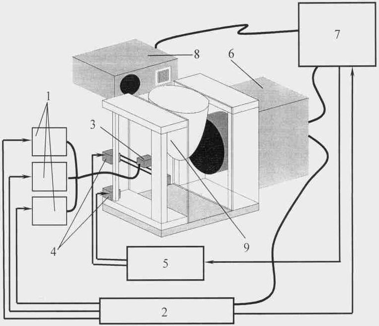
На фиг.1 представлена схема реализации устройства диффузионной оптической томографии, в котором приемник излучения выполнен в виде CCD-камеры.Figure 1 presents the implementation diagram of a diffusion optical tomography device, in which the radiation detector is made in the form of a CCD camera.
На фиг.2 представлена схема реализации устройства диффузионной оптической томографии, в котором приемник излучения выполнен в виде блока приема излучения с волоконно-оптическим входом.Figure 2 presents the implementation diagram of a diffusion optical tomography device in which the radiation receiver is made in the form of a radiation receiving unit with a fiber-optic input.
Разработанное устройство в общем случае реализации по п.1 содержит, как показано на фиг.1, набор лазерных источников 1 излучения, выполненных с возможностью модуляции по амплитуде, блок временного разделения 2 спектральных компонент зондирующего излучения, волоконно-оптический выход 3 от набора лазерных источников 1 излучения, электромеханическую систему сканирования 4 волоконно-оптическим выходом 3, блок управления сканированием 5 электромеханической системы сканирования 4, приемник излучения 6, блок обработки и визуализации 7 полученных данных, блок определения формы поверхности 8 исследуемого объекта 9.The developed device in the general case of implementation according to claim 1, contains, as shown in FIG. 1, a set of laser radiation sources 1 configured for amplitude modulation, a time division unit for 2 spectral components of the probe radiation, a fiber-optic output 3 from a set of laser sources 1 radiation, electromechanical scanning system 4, fiber-optic output 3, scanning control unit 5, electromechanical scanning system 4, radiation receiver 6, processing and visualization unit 7 received data, the unit for determining the shape of the surface 8 of the investigated object 9.
Блок временного разделения 2 спектральных компонент зондирующего излучения последовательно включает на определенный период времени каждый лазерный источник из набора лазерных источников 1 излучения и управляет считыванием данных с приемника излучения 6. Излучение от набора лазерных источников 1 через волоконно-оптический выход 3 попадает на исследуемый объект 9. Прошедшее через исследуемый объект 9 излучение поступает на приемник излучения 6 и далее в блок обработки и визуализации 7 полученных данных. Волоконно-оптический выход 3 набора лазерных источников 1 снабжен электромеханической системой сканирования 4 поверхности исследуемого объекта 9. Блок управления сканированием 5 электромеханической системы сканирования 4 позволяет производить сканирование волоконно-оптическим выходом 3 исследуемого объекта 9 по двум координатам поверхности, образованной данной электромеханической системой сканирования 4, с произвольным шагом сканирования, что необходимо для последующего построения трехмерного изображения внутренней структуры исследуемого объекта 9. Блок определения формы поверхности 8 проецирует на исследуемый объект 9 простое монохромное изображение эталонной сетки, принимает и передает в блок обработки и визуализации 7 данные о кривизне поверхности исследуемого объекта 9.The time division unit 2 of the spectral components of the probe radiation sequentially turns on each laser source from the set of laser radiation sources 1 for a certain period of time and controls the reading of data from the radiation receiver 6. The radiation from the set of laser sources 1 passes through the fiber-optic output 3 to the studied object 9. The radiation transmitted through the studied object 9 is supplied to the radiation receiver 6 and then to the processing and visualization unit 7 of the obtained data. The fiber-optic output 3 of the set of laser sources 1 is equipped with an electromechanical scanning system 4 of the surface of the test object 9. The scan control unit 5 of the electromechanical scanning system 4 allows you to scan the fiber-optic output 3 of the test object 9 at two coordinates of the surface formed by this electromechanical scanning system 4, with an arbitrary scanning step, which is necessary for the subsequent construction of a three-dimensional image of the internal structure 9. under investigation object determination unit 8 forms a surface projected onto the examined object 9 simple monochrome image reference grid, receives and transmits to the processing unit 7 and imaging data on the curvature of the surface of the object 9.
Таким образом, использование набора лазерных источников 1 излучения, в котором каждый лазерный источник выполнен с возможностью модуляции по амплитуде, и блока временного разделения 2 спектральных компонент зондирующего излучения позволяет достигнуть временного разделения спектральных компонент зондирующего излучения и их последовательного детектирования, что значительно повышает селективность разделения спектральных компонент в проходящем через исследуемый объект 9 излучении, и улучшает отношение сигнала к шуму, что в свою очередь, приводит к повышению точности как определения компонентного состава, так и трехмерного восстановления внутренней структуры исследуемого объекта 9, то есть позволяет решить поставленную задачу.Thus, the use of a set of laser radiation sources 1, in which each laser source is capable of amplitude modulation, and a time division block of 2 spectral components of the probe radiation makes it possible to achieve temporary separation of the spectral components of the probe radiation and their sequential detection, which significantly increases the selectivity of spectral separation component in the radiation passing through the studied object 9, and improves the signal-to-noise ratio, which in turn b, leads to an increase in the accuracy of both determining the component composition and three-dimensional restoration of the internal structure of the investigated object 9, that is, it allows to solve the problem.
Кроме того, использование временного разделения спектральных компонент зондирующего излучения позволяет использовать более простой метод определения формы поверхности исследуемого объекта 9, поскольку отпадает необходимость использования приборов со спектральным разрешением, которые использовались в ближайшем аналоге совместно со спектральным источником.In addition, the use of time separation of the spectral components of the probe radiation makes it possible to use a simpler method for determining the surface shape of the investigated object 9, since there is no need to use instruments with spectral resolution, which were used in the closest analogue with a spectral source.
Использование набора лазерных источников 1 с длинами волн 600-1000 нм позволяет определить концентрацию основных четырех компонентов биоткани (липидов, воды, окси- (O2Hb) и деоксигемоглобина (HHb)). В медицине и биологии их концентрация является традиционным клиническим индикатором состояния организма. Концентрацию гемоглобина в крови, степень оксигенации крови, содержание воды и липидов легко связать с патофизиологическими признаками. В частности, в районе опухоли увеличена концентрация оксигемоглобина, в фиброаденомах относительно окружающих тканей содержится больше воды.Using a set of laser sources 1 with wavelengths of 600-1000 nm, it is possible to determine the concentration of the main four components of biological tissue (lipids, water, oxy- (O 2 Hb) and deoxyhemoglobin (HHb)). In medicine and biology, their concentration is a traditional clinical indicator of the state of the body. The concentration of hemoglobin in the blood, the degree of oxygenation of the blood, the content of water and lipids can be easily associated with pathophysiological signs. In particular, the concentration of oxyhemoglobin is increased in the area of the tumor, more water is contained in fibroadenomas relative to surrounding tissues.
В конкретной реализации устройства диффузионной оптической томографии для диагностики молочной железы был использован набор лазерных источников 1 излучения, состоящий из трех лазерных источников производства ООО «Дилаз» г.Москва с длинами волн 684 нм (основной вклад в поглощение вносит HHb), 790 нм (изобестическая точка с равным поглощением HHb и O2Hb) и 850 нм (малое поглощение HHb). В качестве электромеханической системы сканирования 4 были использованы прецизионные линейные направляющие и каретки фирмы «SBG» (Южная Корея), управляемые шаговыми двигателями с контроллерами MDrive Intelligent Motion Systems, Inc. (США).In a specific implementation of the diffusion optical tomography device for the diagnosis of the mammary gland, a set of laser sources of radiation 1 was used, consisting of three laser sources manufactured by Dilaz LLC in Moscow with wavelengths of 684 nm (the main contribution to the absorption was made by HHb), 790 nm (isobestic point with equal absorption of HHb and O 2 Hb) and 850 nm (low absorption of HHb). As an electromechanical scanning system 4, precision linear guides and carriages from SBG (South Korea) were used, controlled by stepper motors with controllers MDrive Intelligent Motion Systems, Inc. (USA).
Особенностью работы предлагаемого устройства, описанного в п.2 формулы и представленного также на фиг.1, является то, что в качестве приемника излучения 6 была использована охлаждаемая высокочувствительная CCD-камера.A feature of the operation of the proposed device, described in claim 2 of the formula and also shown in FIG. 1, is that a cooled highly sensitive CCD camera was used as the radiation detector 6.
Технический результат в этом частном случае реализации устройства заключается в том, что использование CCD-камеры позволяет максимально сократить время сканирования исследуемого объекта 9, так как отпадает необходимость сканирования исследуемого объекта приемником излучения 6, поскольку здесь уже присутствует набор различных пространственных положений точечных приемников излучения, необходимый для трехмерного восстановления внутренней структуры исследуемого объекта 9.The technical result in this particular case of the implementation of the device is that the use of a CCD camera can minimize the scanning time of the studied object 9, since there is no need to scan the studied object by the radiation receiver 6, since there is already a set of different spatial positions of the point radiation receivers necessary for three-dimensional restoration of the internal structure of the investigated object 9.
Особенностью работы предлагаемого устройства по фиг.2, описанного в п.3 формулы, является то, что приемник излучения 6 выполнен в виде блока приема 10 излучения с волоконно-оптическим входом 11, снабженным собственной (дополнительной) электромеханической системой сканирования 12 поверхности исследуемого объекта 9, электрически соединенной с блоком управления сканированием 5. Блок управления сканированием 5 обеспечивает независимое друг от друга перемещение с задаваемым шагом и пространственным сдвигом волоконно-оптического выхода 3 от набора лазерных источников 1 относительно волоконно-оптического входа 11 блока приема 10.A feature of the operation of the proposed device according to figure 2, described in claim 3 of the formula, is that the radiation receiver 6 is made in the form of a radiation receiving unit 10 with a fiber-optic input 11 equipped with its own (additional) electromechanical scanning system 12 of the surface of the investigated object 9 electrically connected to the scanning control unit 5. The scanning control unit 5 provides independent movement from each other with a predetermined step and spatial shift of the optical fiber output 3 from the set ra of laser sources 1 relative to the fiber-optic input 11 of the receiving unit 10.
С использованием подобной конструкции возможно создать бесконечное количество положений волоконно-оптического входа 11 блока приема 10 и волоконно-оптического выхода 3 от набора лазерных источников 1 с помощью электромеханических систем сканирования 4 и 12, что позволит получить лучшее пространственное разрешение по сравнению с ближайшим аналогом.Using this design, it is possible to create an infinite number of positions of the fiber-optic input 11 of the receiving unit 10 and the fiber-optic output 3 from a set of laser sources 1 using electromechanical scanning systems 4 and 12, which will allow to obtain better spatial resolution compared to the closest analogue.
Особенностью работы предлагаемого устройства, описанного в п.4 формулы и представленного на фиг.2, является то, что блок приема 10 выполнен с возможностью синхронного детектирования принимаемого сигнала. Это позволяет еще более повысить отношение сигнала к шуму.A feature of the operation of the proposed device, described in paragraph 4 of the formula and presented in figure 2, is that the receiving unit 10 is configured to synchronously detect the received signal. This allows you to further increase the signal to noise ratio.
Таким образом, использование временного разделения спектральных компонент зондирующего излучения и их последовательного детектирования значительно повышает селективность разделения спектральных компонент в проходящем сквозь исследуемый объект излучении, и улучшает отношение сигнала к шуму, что приводит к повышению точности как определения компонентного состава, так и трехмерного восстановления исследуемого объекта. Применение временного разделения спектральных компонент зондирующего излучения позволяет использовать более простую, а, следовательно, и более надежную систему определения формы поверхности исследуемого объекта. Применение приемника излучения с возможностью синхронного детектирования принимаемого сигнала еще больше повышает отношение сигнала к шуму, а использование приемника излучения с волоконно-оптическим входом, снабженным собственной электромеханической системой сканирования поверхности исследуемого объекта, позволяет получить лучшее пространственное разрешение по сравнению с ближайшим аналогом.Thus, the use of time separation of the spectral components of the probe radiation and their sequential detection significantly increases the selectivity of the separation of spectral components in the radiation passing through the studied object, and improves the signal-to-noise ratio, which leads to an increase in the accuracy of both determining the composition and three-dimensional reconstruction of the studied object . The use of time separation of the spectral components of the probe radiation makes it possible to use a simpler, and, therefore, more reliable system for determining the surface shape of the investigated object. The use of a radiation receiver with the possibility of synchronous detection of the received signal further increases the signal-to-noise ratio, and the use of a radiation receiver with a fiber-optic input equipped with its own electromechanical scanning system for the surface of the object under study allows one to obtain better spatial resolution compared to the closest analogue.
Claims (4)
Priority Applications (1)
| Application Number | Priority Date | Filing Date | Title |
|---|---|---|---|
| RU2008144279/22U RU91517U1 (en) | 2008-11-10 | 2008-11-10 | DEVICE FOR DIFFUSION OPTICAL TOMOGRAPHY |
Applications Claiming Priority (1)
| Application Number | Priority Date | Filing Date | Title |
|---|---|---|---|
| RU2008144279/22U RU91517U1 (en) | 2008-11-10 | 2008-11-10 | DEVICE FOR DIFFUSION OPTICAL TOMOGRAPHY |
Publications (1)
| Publication Number | Publication Date |
|---|---|
| RU91517U1 true RU91517U1 (en) | 2010-02-20 |
Family
ID=42127283
Family Applications (1)
| Application Number | Title | Priority Date | Filing Date |
|---|---|---|---|
| RU2008144279/22U RU91517U1 (en) | 2008-11-10 | 2008-11-10 | DEVICE FOR DIFFUSION OPTICAL TOMOGRAPHY |
Country Status (1)
| Country | Link |
|---|---|
| RU (1) | RU91517U1 (en) |
Cited By (3)
| Publication number | Priority date | Publication date | Assignee | Title |
|---|---|---|---|---|
| RU2467694C2 (en) * | 2010-07-13 | 2012-11-27 | Федеральное государственное бюджетное образовательное учреждение высшего профессионального образования "Воронежский государственный университет" (ФГБОУ ВПО "ВГУ") | X-ray computed tomograph simulator using optical radiation band for test sample operations |
| RU2515203C1 (en) * | 2012-10-12 | 2014-05-10 | Федеральное государственное бюджетное учреждение науки Институт прикладной физики Российской академии наук (ИПФ РАН) | Tomographic fluorescent imaging device |
| RU2817057C1 (en) * | 2019-09-17 | 2024-04-09 | Интеграл Джиометри Сайенс Инк. | Scattered radiation tomography device and scattered radiation tomography method |
-
2008
- 2008-11-10 RU RU2008144279/22U patent/RU91517U1/en active
Cited By (4)
| Publication number | Priority date | Publication date | Assignee | Title |
|---|---|---|---|---|
| RU2467694C2 (en) * | 2010-07-13 | 2012-11-27 | Федеральное государственное бюджетное образовательное учреждение высшего профессионального образования "Воронежский государственный университет" (ФГБОУ ВПО "ВГУ") | X-ray computed tomograph simulator using optical radiation band for test sample operations |
| RU2515203C1 (en) * | 2012-10-12 | 2014-05-10 | Федеральное государственное бюджетное учреждение науки Институт прикладной физики Российской академии наук (ИПФ РАН) | Tomographic fluorescent imaging device |
| RU2817057C1 (en) * | 2019-09-17 | 2024-04-09 | Интеграл Джиометри Сайенс Инк. | Scattered radiation tomography device and scattered radiation tomography method |
| RU2851681C1 (en) * | 2024-12-28 | 2025-11-27 | Федеральное государственное бюджетное образовательное учреждение высшего образования "Московский государственный университет имени М.В. Ломоносова" (МГУ) | Contactless detector of high-intensity x-ray radiation based on the effect of inducted absorption in diamond |
Similar Documents
| Publication | Publication Date | Title |
|---|---|---|
| US9635349B2 (en) | Second generation hand held optical imager | |
| US9709733B2 (en) | Hand-held optical probe based imaging system with 3D tracking facilities | |
| JP5183381B2 (en) | Measuring apparatus and measuring method | |
| US8314406B2 (en) | Systems and methods for optical imaging using early arriving photons | |
| US9750413B2 (en) | Massively parallel diffuse optical tomography | |
| JP2007528500A (en) | Methods and systems for tomographic imaging using fluorescent proteins | |
| EP0834277A1 (en) | Measuring absorption of a scattering medium | |
| JP6544910B2 (en) | INFORMATION PROCESSING APPARATUS, OBJECT INFORMATION ACQUIRING APPARATUS, AND METHOD OF DETERMINING SOUND SPEED | |
| US7692160B2 (en) | Method and system of optical imaging for target detection in a scattering medium | |
| JP6025888B2 (en) | Photoacoustic apparatus, apparatus and method | |
| KR101053222B1 (en) | Optical Coherence Tomography Device Using Multi-line Camera | |
| WO2018043193A1 (en) | Information acquisition device and signal processing method | |
| US20160058295A1 (en) | Photoacoustic wave measurement apparatus and photoacoustic wave measurement method | |
| JP2015223210A (en) | Subject information acquisition device | |
| RU91517U1 (en) | DEVICE FOR DIFFUSION OPTICAL TOMOGRAPHY | |
| JP2016101425A (en) | Photoacoustic wave measurement device | |
| JP2009529948A (en) | Turbid medium image forming apparatus | |
| RU2368306C2 (en) | Device for obtaining fluorescent tomographic images | |
| JP6218908B2 (en) | Method | |
| JPH10246697A (en) | Optical inspection method and optical inspection device | |
| US20230371852A1 (en) | Wide-field system integrating intensity and spatially modulated light for optical tomography and spectroscopy applications | |
| RU2441582C2 (en) | Device for diffuse fluorescent tomography | |
| CN211962001U (en) | Hyperspectral deep three-dimensional scattered light imager | |
| KR101917479B1 (en) | Method of performing oct imaging using a surgical microscope and hybrid beam scanning, and apparatuses for performing the same | |
| JP2017164222A (en) | Processing apparatus and processing method |