KR101740905B1 - A fixation tool for opening wedge high tibial osteotomy - Google Patents
A fixation tool for opening wedge high tibial osteotomy Download PDFInfo
- Publication number
- KR101740905B1 KR101740905B1 KR1020140046872A KR20140046872A KR101740905B1 KR 101740905 B1 KR101740905 B1 KR 101740905B1 KR 1020140046872 A KR1020140046872 A KR 1020140046872A KR 20140046872 A KR20140046872 A KR 20140046872A KR 101740905 B1 KR101740905 B1 KR 101740905B1
- Authority
- KR
- South Korea
- Prior art keywords
- tibia
- head
- nut hole
- head portion
- plate
- Prior art date
- Legal status (The legal status is an assumption and is not a legal conclusion. Google has not performed a legal analysis and makes no representation as to the accuracy of the status listed.)
- Ceased
Links
- 210000002303 tibia Anatomy 0.000 claims abstract description 69
- 238000000034 method Methods 0.000 claims abstract description 20
- 210000004417 patella Anatomy 0.000 claims description 5
- 238000005452 bending Methods 0.000 description 5
- 210000003127 knee Anatomy 0.000 description 4
- 238000001356 surgical procedure Methods 0.000 description 2
- 210000003423 ankle Anatomy 0.000 description 1
- 206010003246 arthritis Diseases 0.000 description 1
- 238000010009 beating Methods 0.000 description 1
- 210000000988 bone and bone Anatomy 0.000 description 1
- 210000000845 cartilage Anatomy 0.000 description 1
- 238000009434 installation Methods 0.000 description 1
- 210000000629 knee joint Anatomy 0.000 description 1
- 210000003041 ligament Anatomy 0.000 description 1
- 210000003141 lower extremity Anatomy 0.000 description 1
- 239000000463 material Substances 0.000 description 1
- 239000002184 metal Substances 0.000 description 1
- 201000008482 osteoarthritis Diseases 0.000 description 1
- 230000002035 prolonged effect Effects 0.000 description 1
- 238000000926 separation method Methods 0.000 description 1
- 210000002435 tendon Anatomy 0.000 description 1
- 210000000707 wrist Anatomy 0.000 description 1
Images


Classifications
-
- A—HUMAN NECESSITIES
- A61—MEDICAL OR VETERINARY SCIENCE; HYGIENE
- A61B—DIAGNOSIS; SURGERY; IDENTIFICATION
- A61B17/00—Surgical instruments, devices or methods
- A61B17/56—Surgical instruments or methods for treatment of bones or joints; Devices specially adapted therefor
- A61B17/58—Surgical instruments or methods for treatment of bones or joints; Devices specially adapted therefor for osteosynthesis, e.g. bone plates, screws or setting implements
- A61B17/68—Internal fixation devices, including fasteners and spinal fixators, even if a part thereof projects from the skin
- A61B17/80—Cortical plates, i.e. bone plates; Instruments for holding or positioning cortical plates, or for compressing bones attached to cortical plates
- A61B17/8095—Wedge osteotomy devices
-
- A—HUMAN NECESSITIES
- A61—MEDICAL OR VETERINARY SCIENCE; HYGIENE
- A61B—DIAGNOSIS; SURGERY; IDENTIFICATION
- A61B17/00—Surgical instruments, devices or methods
- A61B17/56—Surgical instruments or methods for treatment of bones or joints; Devices specially adapted therefor
- A61B17/58—Surgical instruments or methods for treatment of bones or joints; Devices specially adapted therefor for osteosynthesis, e.g. bone plates, screws or setting implements
- A61B17/68—Internal fixation devices, including fasteners and spinal fixators, even if a part thereof projects from the skin
- A61B17/80—Cortical plates, i.e. bone plates; Instruments for holding or positioning cortical plates, or for compressing bones attached to cortical plates
- A61B17/8004—Cortical plates, i.e. bone plates; Instruments for holding or positioning cortical plates, or for compressing bones attached to cortical plates with means for distracting or compressing the bone or bones
- A61B17/8014—Cortical plates, i.e. bone plates; Instruments for holding or positioning cortical plates, or for compressing bones attached to cortical plates with means for distracting or compressing the bone or bones the extension or compression force being caused by interaction of the plate hole and the screws
-
- A—HUMAN NECESSITIES
- A61—MEDICAL OR VETERINARY SCIENCE; HYGIENE
- A61B—DIAGNOSIS; SURGERY; IDENTIFICATION
- A61B17/00—Surgical instruments, devices or methods
- A61B17/56—Surgical instruments or methods for treatment of bones or joints; Devices specially adapted therefor
- A61B17/58—Surgical instruments or methods for treatment of bones or joints; Devices specially adapted therefor for osteosynthesis, e.g. bone plates, screws or setting implements
- A61B17/68—Internal fixation devices, including fasteners and spinal fixators, even if a part thereof projects from the skin
- A61B17/80—Cortical plates, i.e. bone plates; Instruments for holding or positioning cortical plates, or for compressing bones attached to cortical plates
- A61B17/8061—Cortical plates, i.e. bone plates; Instruments for holding or positioning cortical plates, or for compressing bones attached to cortical plates specially adapted for particular bones
-
- A—HUMAN NECESSITIES
- A61—MEDICAL OR VETERINARY SCIENCE; HYGIENE
- A61B—DIAGNOSIS; SURGERY; IDENTIFICATION
- A61B17/00—Surgical instruments, devices or methods
- A61B17/56—Surgical instruments or methods for treatment of bones or joints; Devices specially adapted therefor
- A61B17/58—Surgical instruments or methods for treatment of bones or joints; Devices specially adapted therefor for osteosynthesis, e.g. bone plates, screws or setting implements
- A61B17/68—Internal fixation devices, including fasteners and spinal fixators, even if a part thereof projects from the skin
- A61B17/70—Spinal positioners or stabilisers, e.g. stabilisers comprising fluid filler in an implant
- A61B17/7001—Screws or hooks combined with longitudinal elements which do not contact vertebrae
- A61B17/7002—Longitudinal elements, e.g. rods
- A61B17/7014—Longitudinal elements, e.g. rods with means for adjusting the distance between two screws or hooks
-
- A—HUMAN NECESSITIES
- A61—MEDICAL OR VETERINARY SCIENCE; HYGIENE
- A61B—DIAGNOSIS; SURGERY; IDENTIFICATION
- A61B17/00—Surgical instruments, devices or methods
- A61B17/56—Surgical instruments or methods for treatment of bones or joints; Devices specially adapted therefor
- A61B17/58—Surgical instruments or methods for treatment of bones or joints; Devices specially adapted therefor for osteosynthesis, e.g. bone plates, screws or setting implements
- A61B17/68—Internal fixation devices, including fasteners and spinal fixators, even if a part thereof projects from the skin
- A61B17/70—Spinal positioners or stabilisers, e.g. stabilisers comprising fluid filler in an implant
- A61B17/7058—Plates mounted on top of bone anchor heads or shoulders
-
- A—HUMAN NECESSITIES
- A61—MEDICAL OR VETERINARY SCIENCE; HYGIENE
- A61B—DIAGNOSIS; SURGERY; IDENTIFICATION
- A61B17/00—Surgical instruments, devices or methods
- A61B17/56—Surgical instruments or methods for treatment of bones or joints; Devices specially adapted therefor
- A61B17/58—Surgical instruments or methods for treatment of bones or joints; Devices specially adapted therefor for osteosynthesis, e.g. bone plates, screws or setting implements
- A61B17/68—Internal fixation devices, including fasteners and spinal fixators, even if a part thereof projects from the skin
- A61B17/70—Spinal positioners or stabilisers, e.g. stabilisers comprising fluid filler in an implant
- A61B17/7074—Tools specially adapted for spinal fixation operations other than for bone removal or filler handling
- A61B17/7076—Tools specially adapted for spinal fixation operations other than for bone removal or filler handling for driving, positioning or assembling spinal clamps or bone anchors specially adapted for spinal fixation
-
- A—HUMAN NECESSITIES
- A61—MEDICAL OR VETERINARY SCIENCE; HYGIENE
- A61B—DIAGNOSIS; SURGERY; IDENTIFICATION
- A61B17/00—Surgical instruments, devices or methods
- A61B17/56—Surgical instruments or methods for treatment of bones or joints; Devices specially adapted therefor
- A61B17/58—Surgical instruments or methods for treatment of bones or joints; Devices specially adapted therefor for osteosynthesis, e.g. bone plates, screws or setting implements
- A61B17/68—Internal fixation devices, including fasteners and spinal fixators, even if a part thereof projects from the skin
- A61B17/80—Cortical plates, i.e. bone plates; Instruments for holding or positioning cortical plates, or for compressing bones attached to cortical plates
- A61B17/8004—Cortical plates, i.e. bone plates; Instruments for holding or positioning cortical plates, or for compressing bones attached to cortical plates with means for distracting or compressing the bone or bones
-
- A—HUMAN NECESSITIES
- A61—MEDICAL OR VETERINARY SCIENCE; HYGIENE
- A61B—DIAGNOSIS; SURGERY; IDENTIFICATION
- A61B17/00—Surgical instruments, devices or methods
- A61B17/56—Surgical instruments or methods for treatment of bones or joints; Devices specially adapted therefor
- A61B17/58—Surgical instruments or methods for treatment of bones or joints; Devices specially adapted therefor for osteosynthesis, e.g. bone plates, screws or setting implements
- A61B17/68—Internal fixation devices, including fasteners and spinal fixators, even if a part thereof projects from the skin
- A61B17/82—Internal fixation devices, including fasteners and spinal fixators, even if a part thereof projects from the skin for bone cerclage
-
- A—HUMAN NECESSITIES
- A61—MEDICAL OR VETERINARY SCIENCE; HYGIENE
- A61B—DIAGNOSIS; SURGERY; IDENTIFICATION
- A61B17/00—Surgical instruments, devices or methods
- A61B17/56—Surgical instruments or methods for treatment of bones or joints; Devices specially adapted therefor
- A61B17/58—Surgical instruments or methods for treatment of bones or joints; Devices specially adapted therefor for osteosynthesis, e.g. bone plates, screws or setting implements
- A61B17/68—Internal fixation devices, including fasteners and spinal fixators, even if a part thereof projects from the skin
- A61B17/84—Fasteners therefor or fasteners being internal fixation devices
- A61B17/86—Pins or screws or threaded wires; nuts therefor
Landscapes
- Health & Medical Sciences (AREA)
- Orthopedic Medicine & Surgery (AREA)
- Life Sciences & Earth Sciences (AREA)
- Surgery (AREA)
- Neurology (AREA)
- Heart & Thoracic Surgery (AREA)
- Engineering & Computer Science (AREA)
- Biomedical Technology (AREA)
- Nuclear Medicine, Radiotherapy & Molecular Imaging (AREA)
- Medical Informatics (AREA)
- Molecular Biology (AREA)
- Animal Behavior & Ethology (AREA)
- General Health & Medical Sciences (AREA)
- Public Health (AREA)
- Veterinary Medicine (AREA)
- Surgical Instruments (AREA)
- Prostheses (AREA)
Abstract
본 발명은 개방형 근위 경골 절골술을 위한 고정 기구에 관한 것으로서, 경골 절골술에 의하여 절개된 경골에 설치되는 개방형 근위 경골 절골술을 위한 고정 기구에 있어서, 복수 개의 헤드 너트공이 형성된 헤드부와, 상부 너트공, 하부 너트공 및 상기 상부 너트공과 상기 하부 너트공 사이에 형성되는 장공을 구비하며, 상기 헤드부의 일측으로부터 돌출되게 형성된 세장형 플레이트를 포함하는 고정 플레이트; 상기 헤드 너트공, 상기 상부 너트공, 및 상기 하부 너트공에 결합되어 상기 고정 플레이트를 상기 경골에 고정시키는 스크류; 및 상기 헤드부측에 마련되는 상기 상부 너트공으로부터 기 설정된 간격으로 이격되어 형성된 상기 장공을 따라 이동하여 설치되는 지지 스크류를 포함한다. 이에 따라, 근위 경골 절골술의 시술에 따라 벌어진 경골에 밀착되게 고정되어, 상기 경골이 견고하게 유합될 수 있게 한다.The present invention relates to a fixation mechanism for an open-type proximal tibial osteotomy, and is a fixation mechanism for an open-type proximal tibial osteotomy provided on a tibia cut by a tibial osteotomy. The fixation mechanism includes a head portion having a plurality of head- A stationary plate having a lower nut hole and an elongated hole formed between the upper nut hole and the lower nut hole, the elongated plate protruding from one side of the head part; A screw coupled to the head nut hole, the upper nut hole, and the lower nut hole to fix the fixing plate to the tibia; And a support screw installed to move along the slot formed at a predetermined interval from the upper nut hole provided in the head portion. Accordingly, the proximal tibial osteotomy is firmly fixed to the tibia according to the procedure, so that the tibia can be firmly fused.
Description
본 발명은 개방형 근위 경골 절골술을 위한 고정 기구에 관한 것이다. 더욱 상세하게는 본 발명은 내측 근위 절골술 후에 벌어진 경골에 고정되어, 상기 경골이 견고하게 유합될 수 있게 하는 개방형 근위 경골 절골술을 위한 고정 기구에 관한 것이다.The present invention relates to a fixture for an open proximal tibial osteotomy. More particularly, the present invention relates to a fixture for an open proximal tibial osteotomy, which is secured to the tibia after the medial proximal osteotomy, so that the tibia can be firmly united.
퇴행성관절염은 무릎의 내측 관절의 연골이 닳는 정도가 심해지면서 휜 다리가 되어 동통을 유발하며, 서 있거나 걸을 때 체중이 한쪽으로 집중되어 관절염의 진행과 통증이 더욱 심해지게 된다.Degenerative arthritis is caused by the wrist wear of the medial joint of the knee, resulting in a painful tendon, resulting in pain and pain or aggravation of arthritis when the patient is standing or walking.
이러한 내측 변형다리에 대한 수술은 내측 근위 경골의 무릎 근처에서 절골술 시행 후 금속판을 사용하여 고정하는 방법이 사용되고 있다. The procedure for the internal deformity of the medial proximal tibia is performed by using a metal plate after osteotomy near the knee of the medial proximal tibia.
근위 경골 절골술은 경골의 근위부에 절골술을 가해 무릎 관절의 안쪽에 집중되어 있는 체중 부하를 좀 더 바깥쪽으로 분산시켜 통증을 감소시키는 방법이다.Proximal tibial osteotomy is a method of reducing pain by osteotomizing the proximal tibia and distributing the weight burden concentrated inside the knee joint to the outside.
도 1에 도시된 바와 같이, 고관절 중심에서 발목 중심으로 그은 선을 하지의 축이라 할 때, 상기 선은 보행시 체중부하선을 의미하며, 정상인 경우 상기 선은 무릎의 중앙을 지나게 된다.As shown in FIG. 1, when a line drawn from the center of the hip to the ankle is referred to as an axis of the lower limb, the line refers to a weight load line during walking, and in the normal case, the line passes through the center of the knee.
따라서, 근위 경골 절골술은 상기 선이 무릎의 중앙을 지나도록 하는 시술을 말한다. 그에 따라, 수술 후 쪼그려 앉기와 뛰는 운동 등 비교적 정상적인 관절 운동이 가능하게 된다.Therefore, the proximal tibial osteotomy refers to a procedure in which the line passes through the center of the knee. Thus, relatively normal joint movements such as squatting and beating movements after surgery are possible.
이와 관련된 발명으로는 대한민국특허등록공보 제10-1253915호(2013.04.05)인 '경골 근위부 절골술용 결속구'가 있다.An example of such a related invention is Korean Patent Registration No. 10-1253915 (March 31, 2013) entitled " Bonding Zone for Proximal Osteotomy of Tibia ".
도 2를 참조하여 살펴보면, 상기 경골 근위부 절골술용 결속구는 연골의 상처부위를 꿰매고 남은 의료용 실이 통과할 수 있는 장공 형상의 관통공이 형성되는 것을 특징으로 한다.Referring to FIG. 2, the tibial proximal osteotomy ligament is formed with an elongated through-hole through which a remaining medical sample can pass through a wound of a cartilage.
그러나, 상기 경골 근위부 절골술용 결속구에 기재된 결속 본체(10)의 경우, 평판의 형태로 형성되어 있기 때문에, 근위 경골 절골술의 시술시 경골의 외면에 밀착력이 떨어지는 문제가 있다.However, in the case of the
또한, 결속 본체(10)의 고정시, 결속 본체(10)를 별도의 도구를 이용하여 고정하면서 나사(11)를 결합하거나, 시술자가 결속 본체(10)를 잡고 나사(11)를 결합하여야 하기 때문에, 결속 본체(10)의 위치 선정 및 고정에 어려움이 있다.When fixing the binding
그에 따라, 시술 시간이 연장되는 문제가 있다.Accordingly, there is a problem that the procedure time is prolonged.
이에, 본 발명은 상기한 문제점을 해결하기 위한 것으로, 내측 근위 경골 절골술 후에 벌어진 경골에 고정되어, 상기 경골이 견고하게 유합될 수 있게 하는 개방형 근위 경골 절골술을 위한 고정 기구를 제공하는 것을 그 목적으로 한다.SUMMARY OF THE INVENTION Accordingly, it is an object of the present invention to provide a fixing mechanism for an open-type proximal tibial osteotomy, which is fixed to the tibia after the medial proximal tibial osteotomy, do.
또한, 개방형 근위 경골 절골술에 의하여 절개된 상기 경골에 밀착되게 고정되어 수술 및 경골의 유합을 용이하게 하며, 상기 경골에 인가되는 하중을 지지하는 개방형 근위 경골 절골술을 위한 고정 기구를 제공하는 것을 그 목적으로 한다.It is another object of the present invention to provide a fixation mechanism for an open-type proximal tibial osteotomy for supporting the load applied to the tibia, facilitating the union of the tibia and the surgery, and being firmly fixed to the tibia incised by the open proximal tibial osteotomy. .
상기 목적은 본 발명에 따라, 개방형 경골 절골술에 의하여 절개된 경골에 설치되는 개방형 근위 경골 절골술을 위한 고정 기구에 있어서, 복수 개의 헤드 너트공이 형성된 헤드부와, 상부 너트공, 하부 너트공 및 상기 상부 너트공과 상기 하부 너트공 사이에 형성되는 장공을 구비하며, 상기 헤드부의 일측으로부터 돌출되게 형성된 세장형 플레이트를 포함하는 고정 플레이트; 상기 헤드 너트공, 상기 상부 너트공, 및 상기 하부 너트공에 결합되어 상기 고정 플레이트를 상기 경골에 고정시키는 스크류; 및 상기 헤드부측에 마련되는 상기 상부 너트공으로부터 기 설정된 간격으로 이격되어 형성된 상기 장공을 따라 이동하여 설치되는 지지 스크류를 포함하는 것을 특징으로 하는 개방형 근위 경골 절골술을 위한 고정 기구에 의하여 달성된다.According to the present invention, there is provided a fixation mechanism for an open proximal tibial osteotomy provided on a tibia cut by an open tibial osteotomy according to the present invention, comprising: a head portion having a plurality of head nut holes; A stationary plate having a long hole formed between a nut hole and the lower nut hole, the stationary plate including a long plate protruding from one side of the head portion; A screw coupled to the head nut hole, the upper nut hole, and the lower nut hole to fix the fixing plate to the tibia; And a support screw which is installed to move along the slot formed at a predetermined interval from the upper nut hole provided on the side of the head, and is provided with a fixing screw for the open proximal tibial osteotomy.
여기서, 상기 헤드부는 소정의 곡률로 만곡되게 형성될 수 있다.Here, the head portion may be curved at a predetermined curvature.
그리고, 상기 헤드부가 만곡되게 형성됨에 따라, 상기 헤드부의 중심에 형성되는 상기 헤드 너트공의 양측에 형성되는 상기 너트공에 설치되는 스크류는 상기 곡률의 중심을 향하여 경사지게 설치될 수 있다. In addition, since the head portion is formed to be curved, a screw provided on the nut hole formed at both sides of the head nut hole formed at the center of the head portion may be inclined toward the center of the curvature.
또한, 상기 헤드부의 중심과 상기 곡률의 중심을 잇는 중심선을 향하여 설치되되, 상기 헤드부의 중심을 기준으로 양측에 설치되는 상기 스크류의 선단은 상기 중심선으로부터 이격되게 설치될 수 있다.The tip of the screw provided on both sides of the center of the head may be spaced apart from the center line. The center of the head may be a center line connecting the center of the head and the center of curvature.
또한, 상기 헤드부에 형성된 너트공은 상기 세장형 플레이트 방향으로 8~12도의 기울기로 경사지게 형성될 수 있다.In addition, the nut hole formed in the head portion may be inclined at an inclination of 8 to 12 degrees in the direction of the elongated plate.
또한, 상기 헤드부의 타측은 경사각을 갖도록 경사지게 형성될 수 있다.The other side of the head portion may be inclined so as to have an inclination angle.
여기서, 상기 경사각은 5~7도인 것을 특징으로 한다.Here, the inclination angle is 5 to 7 degrees.
또한, 상기 헤드부와 연설되는 상기 세장형 플레이트의 일 영역은 벤딩각을 구비하도록 절곡되게 형성될 수 있다.In addition, one region of the elongated plate that is adjoined to the head portion may be bent so as to have a bending angle.
여기서, 상기 벤딩각은 13~16도인 것을 특징으로 한다.Here, the bending angle is 13 to 16 degrees.
또한, 상기 세장형 플레이트는 폭은 및 소정의 곡률로 만곡되게 형성될 수 있다.Further, the elongated plate may be formed to be curved in a width and a predetermined curvature.
또한, 복수 개의 상기 하부 너트공은 상기 세장형 플레이트의 길이 방향을 따라, 지그재그 형태가 되도록 배치될 수 있다.The plurality of lower nut holes may be arranged in a zigzag shape along the longitudinal direction of the elongated plate.
한편, 상기 상부 너트공에 설치되는 상기 스크류는 상기 헤드부측으로 경사지게 설치될 수 있다.Meanwhile, the screw provided on the upper nut hole may be inclined toward the head portion.
그리고, 상기 상부 너트공에 설치되는 상기 스크류의 길이는 상기 헤드부에 설치되는 스크류보다 작은 것을 특징으로 한다.The length of the screw installed in the upper nut hole is smaller than the screw provided in the head portion.
또한, 상기 고정 플레이트는 가이드 핀이 설치되게 형성된 적어도 세 개의 가이드공을 포함할 수 있다.In addition, the fixing plate may include at least three guide holes formed with guide pins.
즉, 상기 헤드부에는 두 개의 상기 가이드공이 형성되고, 상기 세장형 플레이트에는 하나의 상기 가이드공이 형성되되, 상기 세장형 플레이트에 형성되는 상기 가이드공은 슬개골측에 형성되는 것을 특징으로 한다. That is, in the head portion, two guide holes are formed, one of the guide holes is formed in the elongated plate, and the guide holes formed in the elongated plate are formed on the patella side.
또한, 기 설정된 상기 간격은 17~21mm일 수 있다.In addition, the predetermined interval may be 17 to 21 mm.
상기와 같은 구성을 갖는 본 발명의 바람직한 일실시예에 따른 개방형 근위 경골 절골술을 위한 고정 기구는 근위 경골 절골술의 시술에 따라 절개된 경골에 밀착되게 고정되어, 상기 경골이 견고하게 유합될 수 있게 한다.According to the preferred embodiment of the present invention, the fixation mechanism for the open-type proximal tibial osteotomy is firmly fixed to the incised tibia according to the procedure of the proximal tibial osteotomy, so that the tibia can be firmly fused .
즉, 상기 고정 플레이트를 소정의 곡률로 만곡되게 형성하고, 상기 고정 플레이트의 일 영역을 절곡하여 경골에 밀착됨으로써, 경골과의 일체성이 향상된다.That is, the fixation plate is curved at a predetermined curvature, and one region of the fixation plate is bent and closely attached to the tibia, thereby improving the integrity with the tibia.
또한, 가이드 핀을 이용하여 상기 개방형 근위 경골 절골술을 위한 고정 기구를 임시 고정함으로써, 개방형 근위 경골 절골술의 시술의 편의성을 도모할 수 있다.In addition, the fixation mechanism for the open-type proximal tibial osteotomy can be temporarily fixed by using the guide pin, thereby facilitating the operation of the open-type proximal tibial osteotomy.
도 1은 근위 경골 절골술의 시술을 요하는 사람의 X선 사진이고,
도 2는 종래의 경골 근위부 절골술용 결속구를 나타내는 도면이고,
도 3은 본 발명의 바람직한 일실시예에 따른 개방형 근위 경골 절골술을 위한 고정 기구의 실시도이고,
도 4는 본 발명의 바람직한 일실시예에 따른 개방형 근위 경골 절골술을 위한 고정 기구를 나타내는 사시도이고,
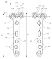
도 5는 본 발명의 바람직한 일실시예에 따른 개방형 근위 경골 절골술을 위한 고정 기구의 좌, 우측 고정 플레이트를 나타내는 도면이고,
도 6은 본 발명의 바람직한 일실시예에 따른 개방형 근위 경골 절골술을 위한 고정 기구의 헤드부 및 세장형 플레이트의 곡률 반경을 나타내는 도면이고,
도 7은 본 발명의 바람직한 일실시예에 따른 개방형 근위 경골 절골술을 위한 고정 기구의 측면도이다.1 is an X-ray picture of a person requiring a procedure of a proximal tibial osteotomy,
2 is a view showing a conventional tie-bar for a tibial proximal osteotomy,
FIG. 3 is an embodiment of a fixation mechanism for an open-type proximal tibial osteotomy according to a preferred embodiment of the present invention,
FIG. 4 is a perspective view showing a fixing mechanism for an open-type proximal tibial osteotomy according to a preferred embodiment of the present invention,
FIG. 5 is a view showing a left and right fixation plate of a fixation mechanism for an open-type proximal tibial osteotomy according to a preferred embodiment of the present invention,
FIG. 6 is a view showing curvature radii of a head portion and a elongated plate of a fixation mechanism for an open-type proximal tibial osteotomy according to a preferred embodiment of the present invention,
7 is a side view of a locking mechanism for an open proximal tibial osteotomy according to a preferred embodiment of the present invention.
이하, 본 발명의 기술적 과제에 관한 해결 방안을 명확화하기 위해 첨부도면을 참조하여 본 발명의 바람직한 실시 예들을 상세하게 설명한다. 다만, 본 발명을 설명함에 있어서 관련 공지기술에 관한 설명이 오히려 본 발명의 요지를 불명료하게 하는 경우 그에 관한 설명은 생략하기로 한다. 또한, 후술하는 용어들은 본 발명에서의 기능을 고려하여 정의된 용어들로서 이는 설계자, 제조자 등의 의도 또는 관례 등에 따라 달라질 수 있을 것이다. 그러므로 그 정의는 본 명세서 전반에 걸친 내용을 토대로 내려져야 할 것이다. 또한, 명세서 전체에 걸쳐서 동일한 도면번호(참조번호)로 표시된 부분은 동일한 요소들을 나타낸다.Hereinafter, preferred embodiments of the present invention will be described in detail with reference to the accompanying drawings in order to clarify the solution to the technical problem of the present invention. In the following description of the present invention, however, the description of related arts will be omitted if the gist of the present invention becomes obscure. In addition, the terms described below are defined in consideration of the functions of the present invention, and may be changed depending on the intention or custom of the designer, the manufacturer, and the like. Therefore, the definition should be based on the contents throughout this specification. In addition, parts denoted by the same reference numerals throughout the specification represent the same elements.
이하, 본 발명의 바람직한 일실시예에 따른 개방형 근위 경골 절골술을 위한 고정 기구에 대하여 설명한다.
Hereinafter, a fixing mechanism for an open-type proximal tibial osteotomy according to a preferred embodiment of the present invention will be described.
도 3을 참조하여 살펴보면, 경골(2)을 절개하는 개방형 근위 경골 절골술의 시술에 따라, 절개부(3)가 형성된다. 그에 따라, 경골(2)은 상부 경골(2a)과 하부 경골(2b)로 구분된다.Referring to FIG. 3, according to the procedure of the open-type proximal tibial osteotomy for cutting the tibia 2, an
본 발명의 바람직한 일실시예에 따른 개방형 근위 경골 절골술을 위한 고정 기구(1)는 경골 절골술에 의하여 절개된 상부 경골(2a)과 하부 경골(2b)에 밀착되게 고정되어 수술 후 상부 경골(2a)과 하부 경골(2b)의 유합을 용이하게 한다.The
또한, 상기 개방형 근위 경골 절골술을 위한 고정 기구(1)는 상부 경골(2a)과 하부 경골(2b)이 유합될 때까지 경골(2)에 인가되는 하중을 지지한다. The
도 4 내지 도 7을 참조하여 살펴보면, 상기 개방형 근위 경골 절골술을 위한 고정 기구(1)는 고정 플레이트(100), 스크류(200), 및 지지 스크류(300)를 포함할 수 있다.4 to 7, the
도 5에 도시된 바와 같이, 고정 플레이트(100)는 좌측(L)과 우측(R)로 구분되어, 수술되는 경골(2)에 따라 선택적으로 사용될 수 있다.5, the
고정 플레이트(100)는 헤드부(110)와 세장형 플레이트(130)를 포함할 수 있다. The
세장형 플레이트(130)는 헤드부(110)의 일측으로부터 돌출되게 형성되며, 그에 따라, 고정 플레이트(100)는, 도 5에 도시된 바와 같이, T자형으로 형성될 수 있다.The
여기서, 고정 플레이트(100)의 두께는 3mm 정도이며, 고정 플레이트(100)의 전체 길이는 100~103mm이고, 헤드부(110)의 길이 방향의 길이는 31mm가 바람직하다.Here, the thickness of the
헤드부(110)와 세장형 플레이트(130) 각각에는 스크류(200)가 결합될 수 있도록 복수 개의 너트공(111a, 111b, 131a, 131b)이 형성된다. 본 발명을 명확하게 설명하기 위하여, 복수 개의 너트공(111a, 111b, 131a, 131b)은 헤드부(110)에 형성된 헤드 너트공(111a, 111b)과, 세장형 플레이트(130)에 형성된 너트공(131a, 131b)로 구분될 수 있다. 또한, 세장형 플레이트(130)에 형성된 너트공(131a, 131b)은 형성 위치에 따라 상부 너트공(131a)과 하부 너트공(131b)으로 구분될 수 있다.A plurality of
여기서, 너트공(111a, 111b, 131a, 131b)은 테이퍼 형상으로 절개된 상광하협의 형태로 형성된다. 그에 따라, 스크류(200)의 머리부는 너트공(111a, 111b, 131a, 131b)에 형합된다. 그리고, 스크류(200)의 머리부는 너트공(111a, 111b, 131a, 131b)에 의하여 지지된다.
Here, the
도 6을 참조하여 살펴보면, 헤드부(110)는 소정의 곡률 반경(R1)으로 만곡되게 형성된다. 바람직하게는 헤드부(110)의 헤드 밀착면(112)이 상부 경골(2a)의 외측면 일측에 밀착될 수 있도록, 헤드 밀착면(112)은 소정의 곡률 반경(R1)으로 만곡되게 형성된다.Referring to FIG. 6, the
그리고, 헤드부(110)의 헤드 밀착면(112)이 만곡되게 형성됨에 따라, 도 6에 도시된 바와 같이, 헤드 너트공(111b)에 설치되는 스크류(200)는 곡률 반경(R1)의 중심을 향하여 경사지게 설치될 수 있다.6, the
물론, 상술 된 바와 같이, 헤드 너트공(111b)에 설치되는 스크류(200)는 곡률 반경(R1)의 중심을 향하여 경사지게 설치될 수 있으나, 반드시 이에 한정되는 것은 아니며, 헤드 너트공(111b)의 형성 각도를 조절하여 헤드 너트공(111b)에 설치되는 스크류(200) 설치 각도를 조절할 수 있음은 물론이다. Of course, as described above, the
그에 따라, 헤드 너트공(111a)에 설치되는 스크류(200)와 헤드 너트공(111b)에 설치되는 스크류(200)의 이격 간격을 고려하여, 도 6에 도시된 바와 같이, 헤드 너트공(111b)에 설치되는 스크류(200)는 헤드 너트공(111a)에 설치되는 스크류(200)의 길이 방향 중심축을 기준으로 2~4도 정도 경사지게 설치될 수 있으며, 3도 정도로 경사지게 설치되는 것이 바람직하다.6, in consideration of the spacing distance between the
즉, 헤드 너트공(111b)에 설치되는 스크류(200)는 헤드부(110)의 중심과 곡률 반경(R1)의 중심을 잇는 중심선을 향하여 설치되되, 헤드 너트공(111b)에 설치되는 스크류(200)의 선단은 상기 중심선으로부터 이격되게 설치된다.That is, the
한편, 도 7에 도시된 바와 같이, 헤드부(110)에 형성된 헤드 너트공(111a, 111b)은 세장형 플레이트(130) 방향으로 8~12도의 기울기로 형성될 수 있다. 바람직하게는 10도의 기울기로 형성될 수 있다.7, the
따라서, 헤드부(110)에 형성된 헤드 너트공(111a, 111b)에 설치되는 스크류(200)는 세장형 플레이트(130) 방향으로 10도의 기울기로 상부 경골(2a)에 설치된다. 그에 따라, 상부 경골(2a)에 설치되는 복수 개의 스크류(200)는 상기 개방형 근위 경골 절골술을 위한 고정 기구(1)에 인가되는 하중에 용이하게 대응할 수 있다. The
또한, 헤드 너트공(111a, 111b)에 설치되는 스크류(200)는 세장형 플레이트(130) 방향으로 10도의 기울기로 상부 경골(2a)에 고정 설치되기 때문에, 외력 및 상기 하중에 의하여 쉽게 상부 경골(2a)로부터 이탈되지 않는다.Since the
헤드부(110)는, 도 5에 도시된 바와 같이, 헤드부(110)의 중심을 가로지르는 가상의 수평선(H)를 기준으로 경사각(θ1)을 갖도록 경사지게 형성될 수 있다. 즉, 헤드부(110)에 있어서, 세장형 플레이트(130)가 연설되는 측의 맞은편 모서리는 경사각(θ1)을 갖도록 경사지게 형성될 수 있다.The
여기서, 경사각(θ1)은 5~7도인 것이 바람직하다.Here, the inclination angle? 1 is preferably 5 to 7 degrees.
그에 따라, 세장형 플레이트(130)의 끝단으로부터 헤드부(110)의 측면 모서리의 일측의 높이(h1)는 타측의 높이(h2)보다 높게 된다. The height h1 of one side of the side edge of the
일측 측면 모서리(h1)가 타측의 높이(h2)보다 높기 때문에, 상기 개방형 근위 경골 절골술을 위한 고정 기구(1)의 측면 모서리(h1) 측이 경골(2)과의 접촉 면적이 크게 된다. 따라서, 측면 모서리(h1) 측을 경골(2)의 전방측(슬개골측)에 위치되게 시술함으로써, 경골(2)의 전방측으로 인가되는 하중에 더욱 용이하게 대응할 수 있다. 또한, 경골(2)의 전방측으로부터 인가되는 외력에 대하여도 용이하게 대응할 수 있다.The side edge edge h1 of the
헤드부(110)는 가이드 핀(미도시)이 설치되게 형성된 적어도 두 개의 가이드공(113)을 더 포함할 수 있다.The
스크류(200) 설치전에, 상기 가이드 핀을 가이드공(113)을 관통하여 상부 경골(2a)에 설치함으로써, 고정 플레이트(100)의 헤드부(110)를 임시적으로 고정한다. The
그에 따라, 고정 플레이트(100)에 스크류(200) 설치시, 상기 가이드 핀은 고정 플레이트(100)가 선형적으로 유동되는 것을 방지한다. 또한, 수술하는 자가 고정 플레이트(100)를 잡고 스크류(200)를 설치하지 않아도 된다.
Accordingly, when the
이하, 도 5 내지 도 7을 참조하여 세장형 플레이트(130)에 관하여 살펴보기로 한다.Hereinafter, the
도 6에 도시된 바와 같이, 세장형 플레이트(130)는 폭 방향으로 만곡되게 형성될 수 있다.As shown in FIG. 6, the
세장형 플레이트(130)는 소정의 곡률 반경(R2)으로 만곡되게 형성된다. 바람직하게는 세장형 플레이트(130)의 플레이트 밀착면(133)이 하부 경골(2b)의 외측면 일측에 밀착될 수 있도록, 플레이트 밀착면(133)은 소정의 곡률 반경(R2)로 만곡되게 형성된다.The
플레이트 밀착면(133)의 곡률 반경(R2)은 헤드 밀착면(112)의 곡률 반경(R1) 과 다르게 형성될 수 있다. 바람직하게는, 플레이트 밀착면(133)의 곡률반경(R2)은 헤드 밀착면(112)의 곡률반경(R1) 보다 크게 형성될 수 있다.The radius of curvature R2 of the
즉, 하부 경골(2b)의 외측면의 경우 상부 경골(2a)과 달리 편평한 외측면을 구비할 수 있기 때문에, 경골 절골술이 시술되는 경골(2)의 위치에 따라, 플레이트 밀착면(133)의 곡률반경(R2)은 헤드 밀착면(112)의 곡률반경(R1) 보다 크게 형성될 수 있다.That is, the outer surface of the
도 7을 참조하여 살펴보면, 헤드부(110)와 연설되는 세장형 플레이트(130)의 일 영역은 벤딩각(θ2)을 구비하도록 절곡되게 형성된다. 여기서, 벤딩각(θ2)은 13~16도일 수 있으며, 15도인 것이 바람직하다.Referring to FIG. 7, one region of the
상부 경골(2a)의 외경은 하부 경골(2b)의 외경보다 크기 때문에, 벤딩각(θ2)을 구비하여 헤드부(110)로부터 절곡되게 형성된 세장형 플레이트(130)는 하부 경골(2b)에 용이하게 밀착된다.Since the outer diameter of the
한편, 세장형 플레이트(130)는 헤드부(110)의 일측으로부터 돌출되게 형성되며, 상부 너트공(131a), 하부 너트공(131b) 및 장공(132)을 구비할 수 있다. The
상부 너트공(131a)은, 도 4 및 도 5에 도시된 바와 같이, 헤드부(110)측의 세장형 플레이트(130)에 형성될 수 있다. 그리고, 상부 너트공(131a)에는 스크류(200)가 관통되게 설치된다. 여기서, 상부 너트공(131a)에 설치되는 스크류(200)는 헤드부(110)측으로 경사지게 상부 경골(2a)에 고정 설치될 수 있다.The
도 7에 도시된 바와 같이, 상부 너트공(131a)에 설치되는 스크류(200)와 헤드 너트공(111a, 111b)와 스크류(200)가 이루는 각은 11~13도가 바람직하다.As shown in FIG. 7, the angle formed between the
그에 따라, 상부 너트공(131a)에 설치되는 스크류(200)는 절개부(3)로 노출되는 것이 방지된다.Accordingly, the
또한, 상부 너트공(131a)에 설치되는 스크류(200)의 길이는 헤드부(110)에 설치되는 스크류(200)의 길이보다 작은 것을 특징으로 한다. 따라서, 스크류(200)의 설치시, 상부 너트공(131a)에 설치되는 스크류(200)와 헤드부(110)에 설치되는 스크류(200)는 상호 간섭하지 않는다.The length of the
상부 너트공(131a)과 하부 너트공(131b) 사이에 형성되는 장공(132)은 세장형 플레이트(130)의 길이 방향으로 길게 형성된다.The
그리고, 장공(132)은 상부 너트공(131a)으로부터 기 설정된 간격(d)으로 이격되어 형성될 수 있다. 여기서, 기 설정된 간격(d)은 절개부(3)의 간격을 고려하여 17~21mm일 수 있으며, 장공(132)에 설치되는 지지 스크류(300)의 지지 및 지지 스크류(300)에 의한 하부 경골(2b)의 파단 가능성을 고려하여 21mm인 것이 바람직하다.The
장공(132)에는 지지 스크류(300)가 설치될 수 있다.A
따라서, 지지 스크류(300)는 장공(132)을 따라 이동한 후 하부 경골(2b)에 고정 설치된다.Accordingly, the
한편, 세장형 플레이트(130)에는, 도 4 및 도 5에 도시된 바와 같이, 복수 개의 하부 너트공(131b)가 형성될 수 있다. 그리고, 하부 너트공(131b)에는 스크류(200)가 설치됨으로써, 세장형 플레이트(130)는 하부 경골(2b)에 밀착되게 설치된다. 4 and 5, a plurality of
여기서, 복수 개의 하부 너트공(131b)은 세장형 플레이트(130)의 길이 방향을 따라 지그재그 형태가 되도록 배치될 수 있다.Here, the plurality of
따라서, 하부 너트공(131b)에 지그재그 형태로 설치되는 스크류(200)는 세장형 플레이트(130)의 길이 방향의 중심축으로 인가되는 하중을 폭 방향으로 분산한다.Therefore, the
또한, 세장형 플레이트(130)의 길이 방향의 중심축을 따라 형성되는 하부 너트공(131b)과 비교해 볼 때, 지그재그 형태로 설치되는 하부 너트공(131b) 간의 이격 거리는 세장형 플레이트(130)의 길이 방향의 중심축을 따라 형성되는 하부 너트공(131b) 보다 멀다. The spacing distance between the
따라서, 하부 너트공(131b)에 설치되는 스크류(200) 간의 거리 또한 멀어지게 된다. 즉, 하부 너트공(131b)에 설치되는 스크류(200)의 이격 거리가 멀어짐에 따라 하부 경골(2b)의 파단 가능성은 감소된다.Accordingly, the distance between the
한편, 세장형 플레이트(130)에는 가이드공(134)이 더 형성될 수 있다.On the other hand, a
가이드공(134)에는 가이드 핀(미도시)이 설치되어 세장형 플레이트(130)를 하부 경골(2b)에 임시 고정한다.A guide pin (not shown) is provided in the
따라서, 고정 플레이트(100)는, 도 4 및 도 5에 도시된 바와 같이, 헤드부(110)에 두 개, 세장형 플레이트(130)에 하나의 가이드공(113, 134)을 구비하게 된다. 4 and 5, the fixing
특히, 세장형 플레이트(130)에 형성되는 가이드공(134)은 슬개골측에 형성될 수 있다. 개방형 근위 경골 절골술을 수술받는 자는 누워서 수술받기 때문에, 슬개골측에 세장형 플레이트(130)에 가이드공(134)을 형성함으로써, 상기 가이드 핀을 용이하게 설치할 수 있다.In particular, a
상술 된 바와 같이, 고정 플레이트(100)는 적어도 세 개의 가이드공(113, 134)을 구비하게 된다. As described above, the fixing
그에 따라, 고정 플레이트(100)는 세 점에서 임시 고정되기 때문에, 선형 방향의 유동뿐만 아니라 회전 방향의 유동 또한 방지할 수 있다. 그리고, 고정 플레이트(100)에는 스크류(200)가 설치되어, 고정 플레이트(100)를 경골(2)에 밀착 고정되게 한다. 그리고나서, 상기 가이드 핀은 제거된다.
Accordingly, since the fixing
종합해보면, 상기 개방형 근위 경골 절골술을 위한 고정 기구(1)는 근위 경골 절골술에 의하여 절개된 경골(2)에 밀착되게 고정되어, 경골(2)에 인가되는 하중을 지지함으로써, 절개부(3)로 뼈가 성장하여 빠르게 붙게 한다.
The
본 발명에 따른 다양한 실시 예들은, 당해 기술 분야는 물론 관련 기술 분야에서 본 명세서에 언급된 내용 이외의 다른 여러 기술적 과제들을 해결할 수 있음은 물론이다.It should be understood that the various embodiments according to the present invention can solve various technical problems other than those mentioned in the specification in the related technical field as well as the related art.
지금까지 본 발명에 대해 실시 예들을 참고하여 설명하였다. 그러나 당업자라면 본 발명의 본질적인 기술적 사상으로부터 벗어나지 않는 범위에서 본 발명이 변형된 형태로 구현될 수 있음을 자명하게 이해할 수 있을 것이다. 그러므로 개시된 실시예들은 한정적인 관점이 아니라 설명적인 관점에서 고려되어야 한다. 즉, 본 발명의 진정한 기술적 범위는 첨부된 특허청구범위에 나타나 있으며, 그와 균등범위 내에 있는 모든 차이점은 본 발명에 포함되는 것으로 해석되어야 할 것이다.The present invention has been described with reference to the embodiments. It will be apparent, however, to one skilled in the art that the present invention may be embodied in various other forms without departing from the spirit or essential characteristics thereof. Therefore, the disclosed embodiments should be considered in an illustrative rather than a restrictive sense. That is, the true technical scope of the present invention is indicated in the appended claims, and all differences within the scope of equivalents thereof should be construed as being included in the present invention.
1 : 개방형 근위 경골 절골술을 위한 고정 기구
100 : 고정 플레이트 110 : 헤드부
130 : 세장형 플레이트 200 : 스크류
300 : 지지 스크류 1: Fixation device for open proximal tibial osteotomy
100: fixed plate 110: head portion
130: elongated plate 200: screw
300: Support Screw
Claims (16)
복수 개의 헤드 너트공이 형성되고, 상기 절개된 경골의 상부 경골에 고정되도록 된 헤드부와,
상부 너트공, 하부 너트공 및 상기 상부 너트공과 상기 하부 너트공 사이에 형성되는 장공을 구비하며, 상기 헤드부의 일측으로부터 돌출되게 형성된 세장형 플레이트를 포함하고, 상기 절개된 경골의 하부 경골에 고정되도록 된 고정 플레이트;
상기 헤드부의 상기 헤드 너트공에 결합되어 상기 헤드부를 상기 절개된 경골의 상기 상부 경골에 고정시키고, 상기 고정 플레이트의 상기 상부 너트공, 및 상기 하부 너트공에 결합되어 상기 고정 플레이트를 상기 절개된 경골의 하부 경골에 고정시키는 고정 스크류; 및
상기 헤드부측에 마련되는 상기 상부 너트공으로부터 기 설정된 간격으로 이격되어 형성된 상기 장공을 따라 이동하여 설치되는 지지 스크류를 포함하고,
상기 고정 플레이트는 상기 고정 스크류의 결합 전에 가이드 핀이 설치되도록 형성된 적어도 세 개의 가이드공을 포함하며,
상기 헤드부가 고정된 상기 절개된 경골의 상기 상부 경골과 상기 고정 플레이트가 고정된 상기 절개된 경골의 상기 하부 경골은 서로 이격되어 그 사이에 절개부가 빈 공간을 이루도록 배치되고, 상기 절개된 경골에 인가되는 하중을 지지하도록 된 것을 특징으로 하는 개방형 근위 경골 절골술을 위한 고정 기구.A fixation device for an open proximal tibial osteotomy provided on a tibia cut by an open tibial osteotomy,
A head portion formed with a plurality of head nut holes and adapted to be fixed to an upper tibia of the incised tibia;
And an elongated plate having an upper nut hole, a lower nut hole, and a slot formed between the upper nut hole and the lower nut hole, the elongated plate protruding from one side of the head portion, Fixed plate;
Wherein the head plate is coupled to the head nut hole of the head unit to fix the head unit to the upper tibia of the incised tibia and is coupled to the upper nut hole and the lower nut hole of the fixation plate, A fixing screw for fixing the tibia to the lower tibia of the tibia; And
And a support screw which is installed to move along the slot formed at a predetermined interval from the upper nut hole provided on the head portion side,
Wherein the fixing plate includes at least three guide holes formed to receive guide pins before the fixing screws are coupled,
Wherein the upper tibia of the incised tibia to which the head part is fixed and the lower tibia of the incised tibia to which the fixation plate is fixed are spaced from each other such that the incision part forms an empty space therebetween, So that the tibial osteotomy can be carried out in a stable manner.
상기 헤드부는 소정의 곡률로 만곡되게 형성되는 것을 특징으로 하는 개방형 근위 경골 절골술을 위한 고정 기구.The method according to claim 1,
Wherein the head portion is formed to be curved at a predetermined curvature.
상기 헤드부가 만곡되게 형성됨에 따라,
상기 헤드부의 중심을 기준으로 양측에 설치되는 상기 고정 스크류는 상기 곡률의 중심을 향하여 경사지게 설치되는 것을 특징으로 하는 개방형 근위 경골 절골술을 위한 고정 기구.3. The method of claim 2,
As the head portion is curved,
Wherein the fixing screws provided on both sides of the center of the head are inclined toward the center of curvature.
상기 헤드부의 중심과 상기 곡률의 중심을 잇는 중심선을 향하여 설치되되, 상기 헤드부의 중심을 기준으로 양측에 설치되는 상기 고정 스크류의 선단은 상기 중심선으로부터 이격되게 설치되는 것을 특징으로 하는 개방형 근위 경골 절골술을 위한 고정 기구.3. The method of claim 2,
Wherein the distal end of the fixation screw is installed on both sides of the center of the head with respect to a center line connecting the center of the head and the center of curvature so that the distal end of the fixation screw is spaced apart from the centerline. Fixing mechanism for.
상기 헤드 너트공은 상기 세장형 플레이트 방향으로 8~12도의 기울기로 경사지게 형성되는 것을 특징으로 하는 개방형 근위 경골 절골술을 위한 고정 기구.The method according to claim 1,
Wherein the head nut hole is inclined at an inclination of 8 to 12 degrees in the direction of the elongated plate.
상기 헤드부의 타측은 경사각을 갖도록 경사지게 형성되는 것을 특징으로 하는 개방형 근위 경골 절골술을 위한 고정 기구.The method according to claim 1,
And the other side of the head portion is inclined to have an inclination angle.
상기 경사각은 5~7도인 것을 특징으로 하는 개방형 근위 경골 절골술을 위한 고정 기구.The method according to claim 6,
Wherein the tilting angle is 5 to 7 degrees.
상기 세장형 플레이트는 폭은 소정의 곡률로 만곡되게 형성되는 것을 특징으로 하는 개방형 근위 경골 절골술을 위한 고정 기구.The method according to claim 1,
Wherein the elongated plate is formed to have a width curved at a predetermined curvature.
복수 개의 상기 하부 너트공은 상기 세장형 플레이트의 길이 방향을 따라, 지그재그 형태가 되도록 배치되는 것을 특징으로 하는 개방형 근위 경골 절골술을 위한 고정 기구.The method according to claim 1,
Wherein the plurality of lower nut holes are arranged in a zigzag shape along the longitudinal direction of the elongated plate.
상기 상부 너트공에 설치되는 상기 고정 스크류는 상기 헤드부측으로 경사지게 설치되는 것을 특징으로 하는 개방형 근위 경골 절골술을 위한 고정 기구.The method according to claim 1,
Wherein the fixing screw provided on the upper nut hole is inclined toward the head portion.
상기 상부 너트공에 설치되는 상기 고정 스크류의 길이는 상기 헤드부에 설치되는 고정 스크류보다 작은 것을 특징으로 하는 개방형 근위 경골 절골술을 위한 고정 기구.13. The method of claim 12,
Wherein the length of the fixing screw provided on the upper nut hole is smaller than the length of the fixing screw provided on the head portion.
상기 헤드부에는 두 개의 상기 가이드공이 형성되고, 상기 세장형 플레이트에는 하나의 상기 가이드공이 형성되되, 상기 세장형 플레이트에 형성되는 상기 가이드공은 슬개골측에 형성되는 것을 특징으로 하는 개방형 근위 경골 절골술을 위한 고정 기구.The method according to claim 1,
Wherein the head portion is formed with two guide holes, one of the guide holes is formed in the elongated plate, and the guide hole formed in the elongated plate is formed on the patella side. Fixing mechanism for.
기 설정된 상기 간격은 17~21mm인 것을 특징으로 하는 개방형 근위 경골 절골술을 위한 고정 기구.The method according to claim 1,
Wherein the predetermined interval is 17 to 21 mm.
Priority Applications (6)
| Application Number | Priority Date | Filing Date | Title |
|---|---|---|---|
| KR1020140046872A KR101740905B1 (en) | 2014-04-18 | 2014-04-18 | A fixation tool for opening wedge high tibial osteotomy |
| US15/303,830 US10441331B2 (en) | 2014-04-18 | 2014-05-07 | Fixing tool for open-wedge high tibial osteotomy |
| EP14889612.9A EP3132762A4 (en) | 2014-04-18 | 2014-05-07 | Fixing tool for open-wedge high tibial osteotomy |
| CN201480077985.6A CN106163434A (en) | 2014-04-18 | 2014-05-07 | Fixing utensil for opening hto art |
| PCT/KR2014/004036 WO2015160022A1 (en) | 2014-04-18 | 2014-05-07 | Fixing tool for open-wedge high tibial osteotomy |
| JP2016561757A JP6250836B2 (en) | 2014-04-18 | 2014-05-07 | Fixing device for open wedge high tibial osteotomy |
Applications Claiming Priority (1)
| Application Number | Priority Date | Filing Date | Title |
|---|---|---|---|
| KR1020140046872A KR101740905B1 (en) | 2014-04-18 | 2014-04-18 | A fixation tool for opening wedge high tibial osteotomy |
Publications (2)
| Publication Number | Publication Date |
|---|---|
| KR20150120778A KR20150120778A (en) | 2015-10-28 |
| KR101740905B1 true KR101740905B1 (en) | 2017-05-29 |
Family
ID=54324216
Family Applications (1)
| Application Number | Title | Priority Date | Filing Date |
|---|---|---|---|
| KR1020140046872A Ceased KR101740905B1 (en) | 2014-04-18 | 2014-04-18 | A fixation tool for opening wedge high tibial osteotomy |
Country Status (6)
| Country | Link |
|---|---|
| US (1) | US10441331B2 (en) |
| EP (1) | EP3132762A4 (en) |
| JP (1) | JP6250836B2 (en) |
| KR (1) | KR101740905B1 (en) |
| CN (1) | CN106163434A (en) |
| WO (1) | WO2015160022A1 (en) |
Cited By (3)
| Publication number | Priority date | Publication date | Assignee | Title |
|---|---|---|---|---|
| EP3476341A1 (en) | 2017-10-24 | 2019-05-01 | Paik, Hae Sun | Checking apparatus for bone conglutination |
| KR20200087002A (en) * | 2019-01-10 | 2020-07-20 | 충남대학교산학협력단 | A animal bone plate for being implanted into the tibia in cruclate ligament rupture surgery |
| KR20200087004A (en) | 2019-01-10 | 2020-07-20 | 충남대학교산학협력단 | A animal bone plate for being implanted into the distolateral surfacief femur in distal femur osteotomy surgray |
Families Citing this family (11)
| Publication number | Priority date | Publication date | Assignee | Title |
|---|---|---|---|---|
| CN109310456B (en) * | 2016-05-11 | 2022-03-08 | 奥林巴斯泰尔茂生物材料株式会社 | Plates and Plate Systems |
| CN110236659A (en) * | 2019-07-09 | 2019-09-17 | 曾忠友 | High Tibial Osteotomy Plate |
| WO2021129547A1 (en) * | 2019-12-26 | 2021-07-01 | 天津市威曼生物材料有限公司 | Special-shaped block |
| CN111166454B (en) * | 2019-12-26 | 2025-01-07 | 天津市威曼生物材料有限公司 | A special-shaped block for the medial side of the proximal tibia |
| KR102399608B1 (en) | 2020-04-03 | 2022-05-19 | 주식회사 모레컴퍼니 | Bone fixing apparatus |
| US11395686B2 (en) | 2020-04-20 | 2022-07-26 | Khay-Yong Saw | Bone fixation plate and method of using thereof |
| WO2021250853A1 (en) | 2020-06-11 | 2021-12-16 | オリンパステルモバイオマテリアル株式会社 | Bone plate |
| CN111904569B (en) * | 2020-07-29 | 2025-02-11 | 北京德尔康尼骨科医院有限公司 | A high lateral tibial closed osteotomy internal fixation device and a preparation method thereof |
| CN114129247A (en) * | 2020-09-04 | 2022-03-04 | 宝楠生技股份有限公司 | Stable fixing bone plate for high-position tibia osteotomy |
| KR102548060B1 (en) * | 2020-12-18 | 2023-06-27 | 김정엽 | Plate body for proximal tibial osteotomy containing window hole and fixation plate apparatus for proximal tibial osteotomy using the same |
| USD1099319S1 (en) | 2024-06-07 | 2025-10-21 | Stryker European Operations Limited | Bone plate |
Citations (3)
| Publication number | Priority date | Publication date | Assignee | Title |
|---|---|---|---|---|
| US20060004362A1 (en) * | 2004-07-02 | 2006-01-05 | Patterson Chad J | Distal radius bone plating system with locking and non-locking screws |
| JP2006312062A (en) * | 2005-05-06 | 2006-11-16 | Inion Oy | Plate for fixing bone fragments to each other, its usage and mounting method |
| KR101253915B1 (en) * | 2011-06-29 | 2013-04-16 | 김진구 | Connector for high tibia osteotomy |
Family Cites Families (31)
| Publication number | Priority date | Publication date | Assignee | Title |
|---|---|---|---|---|
| US6096040A (en) * | 1996-06-14 | 2000-08-01 | Depuy Ace Medical Company | Upper extremity bone plates |
| US6440135B2 (en) | 2000-02-01 | 2002-08-27 | Hand Innovations, Inc. | Volar fixation system with articulating stabilization pegs |
| US7857838B2 (en) * | 2003-03-27 | 2010-12-28 | Depuy Products, Inc. | Anatomical distal radius fracture fixation plate |
| US6358250B1 (en) | 2000-02-01 | 2002-03-19 | Hand Innovations, Inc. | Volar fixation system |
| US20040153073A1 (en) * | 2000-02-01 | 2004-08-05 | Hand Innovations, Inc. | Orthopedic fixation system including plate element with threaded holes having divergent axes |
| US6283969B1 (en) * | 2000-03-10 | 2001-09-04 | Wright Medical Technology, Inc. | Bone plating system |
| US20020156474A1 (en) * | 2001-04-20 | 2002-10-24 | Michael Wack | Polyaxial locking plate |
| AUPR546601A0 (en) * | 2001-06-05 | 2001-06-28 | Australian Surgical Design And Manufacture Pty Limited | High tibial osteotomy device |
| EP1424946A4 (en) * | 2001-06-08 | 2009-12-02 | Mayo Foundation | OSTEOSYNTHESIS PLATES |
| DE10153467B4 (en) * | 2001-10-30 | 2006-05-24 | Königsee Implantate und Instrumente zur Ostheosynthese GmbH | Device for stabilizing the tibia and / or tibial plateau following osteotomy procedures |
| ITBO20020224A1 (en) * | 2002-04-23 | 2003-10-23 | Citieffe Srl | STABILIZER SUPPORT FOR ADDITION AND SUBTRACTION OSTEOTOMIES |
| US7722653B2 (en) * | 2003-03-26 | 2010-05-25 | Greatbatch Medical S.A. | Locking bone plate |
| US7635381B2 (en) * | 2003-03-27 | 2009-12-22 | Depuy Products, Inc. | Anatomical distal radius fracture fixation plate with fixed-angle K-wire holes defining a three-dimensional surface |
| US7951176B2 (en) * | 2003-05-30 | 2011-05-31 | Synthes Usa, Llc | Bone plate |
| WO2005041752A2 (en) * | 2003-10-20 | 2005-05-12 | Blackstone Medical, Inc. | Bone plate and method for using bone plate |
| US20060173458A1 (en) * | 2004-10-07 | 2006-08-03 | Micah Forstein | Bone fracture fixation system |
| WO2006099766A1 (en) * | 2005-03-24 | 2006-09-28 | Medartis Ag | Bone plate |
| ES2523435T3 (en) | 2005-07-25 | 2014-11-25 | Smith And Nephew, Inc. | Polyaxial Plates |
| JP2007151674A (en) * | 2005-12-01 | 2007-06-21 | Hidetoshi Onoe | Bone plate |
| US8523921B2 (en) | 2006-02-24 | 2013-09-03 | DePuy Synthes Products, LLC | Tibial plateau leveling osteotomy plate |
| US8197521B2 (en) * | 2007-11-02 | 2012-06-12 | Depuy Products, Inc. | Fracture fixation plate for the proximal radius |
| US8317842B2 (en) | 2007-11-30 | 2012-11-27 | Biomet C.V. | Distal tibia plating system |
| US20090177203A1 (en) * | 2008-01-04 | 2009-07-09 | Inbone Technologies, Inc. | Devices, systems and methods for re-alignment of bone |
| JP5283956B2 (en) | 2008-04-08 | 2013-09-04 | 瑞穂医科工業株式会社 | Fracture treatment device |
| US9072555B2 (en) * | 2008-07-21 | 2015-07-07 | Arthrex, Inc. | Carbon fiber reinforced peek bone plate with titanium fixation screws |
| US10603090B2 (en) * | 2011-09-06 | 2020-03-31 | Skeletal Dynamics, Inc. | Fracture fixation plate, system and methods of use |
| JP5505767B2 (en) | 2009-03-23 | 2014-05-28 | オリンパステルモバイオマテリアル株式会社 | Bone plate and bone plate system |
| US8998903B2 (en) * | 2010-03-10 | 2015-04-07 | Orthohelix Surgical Designs, Inc. | Wedge opening osteotomy plate |
| CN102551860B (en) * | 2010-12-28 | 2014-06-18 | 北京国人骨科医疗器械有限公司 | Bone fracture plate |
| FR2973218B1 (en) * | 2011-03-29 | 2014-03-28 | Neosteo | OSTEOSYNTHESIS PLATE. |
| KR101632652B1 (en) * | 2014-04-18 | 2016-07-01 | 백혜선 | A fixation tool for opening wedge high tibial osteotomy |
-
2014
- 2014-04-18 KR KR1020140046872A patent/KR101740905B1/en not_active Ceased
- 2014-05-07 US US15/303,830 patent/US10441331B2/en not_active Expired - Fee Related
- 2014-05-07 WO PCT/KR2014/004036 patent/WO2015160022A1/en not_active Ceased
- 2014-05-07 JP JP2016561757A patent/JP6250836B2/en not_active Expired - Fee Related
- 2014-05-07 CN CN201480077985.6A patent/CN106163434A/en active Pending
- 2014-05-07 EP EP14889612.9A patent/EP3132762A4/en not_active Withdrawn
Patent Citations (3)
| Publication number | Priority date | Publication date | Assignee | Title |
|---|---|---|---|---|
| US20060004362A1 (en) * | 2004-07-02 | 2006-01-05 | Patterson Chad J | Distal radius bone plating system with locking and non-locking screws |
| JP2006312062A (en) * | 2005-05-06 | 2006-11-16 | Inion Oy | Plate for fixing bone fragments to each other, its usage and mounting method |
| KR101253915B1 (en) * | 2011-06-29 | 2013-04-16 | 김진구 | Connector for high tibia osteotomy |
Cited By (4)
| Publication number | Priority date | Publication date | Assignee | Title |
|---|---|---|---|---|
| EP3476341A1 (en) | 2017-10-24 | 2019-05-01 | Paik, Hae Sun | Checking apparatus for bone conglutination |
| KR20200087002A (en) * | 2019-01-10 | 2020-07-20 | 충남대학교산학협력단 | A animal bone plate for being implanted into the tibia in cruclate ligament rupture surgery |
| KR20200087004A (en) | 2019-01-10 | 2020-07-20 | 충남대학교산학협력단 | A animal bone plate for being implanted into the distolateral surfacief femur in distal femur osteotomy surgray |
| KR102210953B1 (en) | 2019-01-10 | 2021-02-02 | 충남대학교산학협력단 | A animal bone plate for being implanted into the tibia in cruclate ligament rupture surgery |
Also Published As
| Publication number | Publication date |
|---|---|
| KR20150120778A (en) | 2015-10-28 |
| JP6250836B2 (en) | 2017-12-20 |
| EP3132762A4 (en) | 2017-12-27 |
| WO2015160022A1 (en) | 2015-10-22 |
| CN106163434A (en) | 2016-11-23 |
| US20170027627A1 (en) | 2017-02-02 |
| JP2017511194A (en) | 2017-04-20 |
| US10441331B2 (en) | 2019-10-15 |
| EP3132762A1 (en) | 2017-02-22 |
Similar Documents
| Publication | Publication Date | Title |
|---|---|---|
| KR101740905B1 (en) | A fixation tool for opening wedge high tibial osteotomy | |
| KR101632652B1 (en) | A fixation tool for opening wedge high tibial osteotomy | |
| EP3023068B1 (en) | Bone plates, plate alignment systems, and methods of use | |
| US11395691B2 (en) | Alignment guide apparatus, methods and systems | |
| US9078713B2 (en) | Orthopedic implant in the form of a plate to be fixed between two bone parts | |
| EP3082633B1 (en) | Orthopedic bone plate and locking tab apparatus | |
| US20120123484A1 (en) | Ulna Osteotomy System | |
| TW201601677A (en) | Locking first metacarpal plate | |
| MX2011002560A (en) | Orthopaedic device to be associated with the outside of a bone. | |
| US10499963B2 (en) | Fixing instrument for open-type distal tibial osteotomy | |
| JP7326381B2 (en) | phalanx head plate | |
| US20110054539A1 (en) | Bone anchor, orthopaedic device and orthopaedic system | |
| AU2010306474B2 (en) | Scapholunate stabilization implant | |
| US10499965B2 (en) | Fixing mechanism for closed distal femur osteotomy | |
| KR102158669B1 (en) | Spreader for high tibial osteotomy | |
| KR20200119121A (en) | Connector for high tibia osteotomy | |
| EP4009892B1 (en) | Dynamic bone plate | |
| CN103930060A (en) | Device for fixing a bone fractured in the femoral neck region |
Legal Events
| Date | Code | Title | Description |
|---|---|---|---|
| A201 | Request for examination | ||
| PA0109 | Patent application |
Patent event code: PA01091R01D Comment text: Patent Application Patent event date: 20140418 |
|
| PA0201 | Request for examination | ||
| E902 | Notification of reason for refusal | ||
| PE0902 | Notice of grounds for rejection |
Comment text: Notification of reason for refusal Patent event date: 20151021 Patent event code: PE09021S01D |
|
| PG1501 | Laying open of application | ||
| E90F | Notification of reason for final refusal | ||
| PE0902 | Notice of grounds for rejection |
Comment text: Final Notice of Reason for Refusal Patent event date: 20160718 Patent event code: PE09021S02D |
|
| E902 | Notification of reason for refusal | ||
| PE0902 | Notice of grounds for rejection |
Comment text: Notification of reason for refusal Patent event date: 20170118 Patent event code: PE09021S01D |
|
| E701 | Decision to grant or registration of patent right | ||
| PE0701 | Decision of registration |
Patent event code: PE07011S01D Comment text: Decision to Grant Registration Patent event date: 20170517 |
|
| GRNT | Written decision to grant | ||
| PR0701 | Registration of establishment |
Comment text: Registration of Establishment Patent event date: 20170523 Patent event code: PR07011E01D |
|
| PR1002 | Payment of registration fee |
Payment date: 20170523 End annual number: 3 Start annual number: 1 |
|
| PG1601 | Publication of registration | ||
| FPAY | Annual fee payment |
Payment date: 20200310 Year of fee payment: 4 |
|
| PR1001 | Payment of annual fee |
Payment date: 20200310 Start annual number: 4 End annual number: 4 |
|
| J204 | Request for invalidation trial [patent] | ||
| PJ0204 | Invalidation trial for patent |
Patent event date: 20210112 Comment text: Request for Trial Patent event code: PJ02042R01D Patent event date: 20170523 Comment text: Registration of Establishment Patent event code: PJ02041E01I Appeal kind category: Invalidation Request date: 20210112 Decision date: 20220302 Appeal identifier: 2021100000063 |
|
| PR1001 | Payment of annual fee |
Payment date: 20210322 Start annual number: 5 End annual number: 5 |
|
| J301 | Trial decision |
Free format text: TRIAL NUMBER: 2021100000063; TRIAL DECISION FOR INVALIDATION REQUESTED 20210112 Effective date: 20220302 |
|
| PJ1301 | Trial decision |
Patent event code: PJ13011S05D Patent event date: 20220302 Comment text: Trial Decision on Invalidation (Patent, Utility Model, Industrial Design) Appeal kind category: Invalidation Request date: 20210112 Decision date: 20220302 Appeal identifier: 2021100000063 |
|
| PJ2001 | Appeal |
Patent event date: 20220302 Comment text: Trial Decision on Invalidation (Patent, Utility Model, Industrial Design) Patent event code: PJ20011S05I Appeal kind category: Invalidation Decision date: 20220722 Appeal identifier: 2022200002820 Request date: 20220422 |
|
| PC2102 | Extinguishment |
Termination category: Others Termination date: 20220728 |
|
| J122 | Written withdrawal of action (patent court) | ||
| PJ1202 | Withdrawal of action (patent court) |
Patent event code: PJ12021R01D Patent event date: 20220727 Comment text: Written Withdrawal of Action Decision date: 20220722 Request date: 20220422 Appeal identifier: 2022200002820 Appeal kind category: Invalidation |