EP4009892B1 - Dynamic bone plate - Google Patents
Dynamic bone plate Download PDFInfo
- Publication number
- EP4009892B1 EP4009892B1 EP20850367.2A EP20850367A EP4009892B1 EP 4009892 B1 EP4009892 B1 EP 4009892B1 EP 20850367 A EP20850367 A EP 20850367A EP 4009892 B1 EP4009892 B1 EP 4009892B1
- Authority
- EP
- European Patent Office
- Prior art keywords
- opening
- bone plate
- deformable member
- hole
- top surface
- Prior art date
- Legal status (The legal status is an assumption and is not a legal conclusion. Google has not performed a legal analysis and makes no representation as to the accuracy of the status listed.)
- Active
Links
Images


Classifications
-
- A—HUMAN NECESSITIES
- A61—MEDICAL OR VETERINARY SCIENCE; HYGIENE
- A61B—DIAGNOSIS; SURGERY; IDENTIFICATION
- A61B17/00—Surgical instruments, devices or methods
- A61B17/56—Surgical instruments or methods for treatment of bones or joints; Devices specially adapted therefor
- A61B17/58—Surgical instruments or methods for treatment of bones or joints; Devices specially adapted therefor for osteosynthesis, e.g. bone plates, screws or setting implements
- A61B17/68—Internal fixation devices, including fasteners and spinal fixators, even if a part thereof projects from the skin
- A61B17/70—Spinal positioners or stabilisers, e.g. stabilisers comprising fluid filler in an implant
- A61B17/7059—Cortical plates
-
- A—HUMAN NECESSITIES
- A61—MEDICAL OR VETERINARY SCIENCE; HYGIENE
- A61B—DIAGNOSIS; SURGERY; IDENTIFICATION
- A61B17/00—Surgical instruments, devices or methods
- A61B17/56—Surgical instruments or methods for treatment of bones or joints; Devices specially adapted therefor
- A61B17/58—Surgical instruments or methods for treatment of bones or joints; Devices specially adapted therefor for osteosynthesis, e.g. bone plates, screws or setting implements
- A61B17/68—Internal fixation devices, including fasteners and spinal fixators, even if a part thereof projects from the skin
- A61B17/80—Cortical plates, i.e. bone plates; Instruments for holding or positioning cortical plates, or for compressing bones attached to cortical plates
- A61B17/8004—Cortical plates, i.e. bone plates; Instruments for holding or positioning cortical plates, or for compressing bones attached to cortical plates with means for distracting or compressing the bone or bones
-
- A—HUMAN NECESSITIES
- A61—MEDICAL OR VETERINARY SCIENCE; HYGIENE
- A61B—DIAGNOSIS; SURGERY; IDENTIFICATION
- A61B17/00—Surgical instruments, devices or methods
- A61B17/56—Surgical instruments or methods for treatment of bones or joints; Devices specially adapted therefor
- A61B17/58—Surgical instruments or methods for treatment of bones or joints; Devices specially adapted therefor for osteosynthesis, e.g. bone plates, screws or setting implements
- A61B17/68—Internal fixation devices, including fasteners and spinal fixators, even if a part thereof projects from the skin
- A61B17/80—Cortical plates, i.e. bone plates; Instruments for holding or positioning cortical plates, or for compressing bones attached to cortical plates
- A61B17/8033—Cortical plates, i.e. bone plates; Instruments for holding or positioning cortical plates, or for compressing bones attached to cortical plates having indirect contact with screw heads, or having contact with screw heads maintained with the aid of additional components, e.g. nuts, wedges or head covers
- A61B17/8042—Cortical plates, i.e. bone plates; Instruments for holding or positioning cortical plates, or for compressing bones attached to cortical plates having indirect contact with screw heads, or having contact with screw heads maintained with the aid of additional components, e.g. nuts, wedges or head covers the additional component being a cover over the screw head
-
- A—HUMAN NECESSITIES
- A61—MEDICAL OR VETERINARY SCIENCE; HYGIENE
- A61B—DIAGNOSIS; SURGERY; IDENTIFICATION
- A61B17/00—Surgical instruments, devices or methods
- A61B17/56—Surgical instruments or methods for treatment of bones or joints; Devices specially adapted therefor
- A61B17/58—Surgical instruments or methods for treatment of bones or joints; Devices specially adapted therefor for osteosynthesis, e.g. bone plates, screws or setting implements
- A61B17/68—Internal fixation devices, including fasteners and spinal fixators, even if a part thereof projects from the skin
- A61B17/80—Cortical plates, i.e. bone plates; Instruments for holding or positioning cortical plates, or for compressing bones attached to cortical plates
- A61B17/8052—Cortical plates, i.e. bone plates; Instruments for holding or positioning cortical plates, or for compressing bones attached to cortical plates immobilised relative to screws by interlocking form of the heads and plate holes, e.g. conical or threaded
- A61B17/8057—Cortical plates, i.e. bone plates; Instruments for holding or positioning cortical plates, or for compressing bones attached to cortical plates immobilised relative to screws by interlocking form of the heads and plate holes, e.g. conical or threaded the interlocking form comprising a thread
-
- A—HUMAN NECESSITIES
- A61—MEDICAL OR VETERINARY SCIENCE; HYGIENE
- A61B—DIAGNOSIS; SURGERY; IDENTIFICATION
- A61B17/00—Surgical instruments, devices or methods
- A61B17/56—Surgical instruments or methods for treatment of bones or joints; Devices specially adapted therefor
- A61B17/58—Surgical instruments or methods for treatment of bones or joints; Devices specially adapted therefor for osteosynthesis, e.g. bone plates, screws or setting implements
- A61B17/68—Internal fixation devices, including fasteners and spinal fixators, even if a part thereof projects from the skin
- A61B17/80—Cortical plates, i.e. bone plates; Instruments for holding or positioning cortical plates, or for compressing bones attached to cortical plates
- A61B17/8061—Cortical plates, i.e. bone plates; Instruments for holding or positioning cortical plates, or for compressing bones attached to cortical plates specially adapted for particular bones
Definitions
- the present disclosure relates generally to general surgery and orthopaedic implants used for achieving bone fusion. More specifically, but not exclusively, the present disclosure relates to surgical devices, implants, guides, and systems for fixation of human bones, such as, the foot and ankle bones, and to stabilize the realignment of a fracture, dislocation, fusion or the like of the bones of the foot and ankle.
- the present disclosure is directed towards a bone plate system and related methods (the methods not claimed) for use in securing two bone segments together.
- a bone plate system comprises a bone plate with a top surface and a bottom surface and a first end and a second end, the bone plate comprising; a base portion disposed between the first end and the second end; and at least one opening extending away from the top surface of the bone plate; at least one deformable member received within the at least one opening of the bone plate, wherein the at least one deformable member comprises: a first portion having a first opening; a second portion having a second opening coupled to and extending away from the first portion; and wherein the first opening of one deformable member of the at least one deformable member comprises: two first openings, wherein one first opening is positioned at the first end of the base portion, and wherein a second first opening is positioned at the second end of the base portion; and at least one coupling member engaging the at least one deformable member to couple the at least one coupling member and the at least one deformable member to the
- proximal, distal, anterior or plantar, posterior or dorsal, medial, lateral, superior and inferior are defined by their standard usage for indicating a particular part of a bone, implant, device or guide according to the relative disposition of the natural bone or directional terms of reference.
- proximal means the portion of a device or implant nearest the torso
- distal indicates the portion of the device or implant farthest from the torso.
- anterior is a direction towards the front side of the body
- posterior means a direction towards the back side of the body
- medial means towards the midline of the body
- lateral is a direction towards the sides or away from the midline of the body
- superior means a direction above
- inferior means a direction below another object or structure.
- the term “dorsal” refers to the top of the foot and the term “plantar” refers the bottom of the foot.
- the devices and methods, and the components, features and the like thereof, described and/or illustrated herein may be changed, varied, modified, reconfigured or otherwise altered for use or association with another side of the body for a same or similar purpose without departing from scope of the disclosure.
- the devices and methods, and the components, features and the like thereof, described herein with respect to the right foot and ankle may be mirrored so that they likewise function with the left foot and ankle.
- the devices and methods, and the components, features and the like thereof, disclosed herein are described with respect to the foot and ankle for brevity purposes, but it should be understood that the devices and methods may be used with other bones of the body having similar structures, for example the upper extremity, and more specifically, with the bones of the wrist, hand, and arm.
- the bone plate system 100 includes an implant, plate, or bone plate 110, at least one deformable member, dynamic member, or elastic member 106, 108, for example, a first deformable member 106 and a second deformable member 108 and at least one coupling member or threaded button 102, 104 for example, a first coupling member 102 and a second coupling member 104.
- the deformable members 106, 108 may be received within the bone plate 110 by, for example, engagement with the coupling members 102, 104 which may be coupled to the bone plate 110.
- Each component of the bone plate system 100 may be made from, for example, a biocompatible material, including but not limited to a metal, polymer, composite, etc.
- the implant or plate 110 is shown.
- the plate 110 includes a top surface 112 opposite a bottom surface 114, a first end 116 opposite a second end 118, and a first side 120 generally opposite a second side 122.
- the plate 110 also includes a base portion 124 positioned between the first end 116 and second end 118.
- the plate 110 includes at least one opening 126, 128, for example, a first opening 126 and a second opening 128, which may be, for example, longer than the first opening 126.
- the first opening 126 may be positioned at the first end 116 of the plate 110 and may include a first end 138 opposite a second end 140 and a first side 142 opposite a second side 144.
- the first opening 126 may also include a recessed portion 130 which, may include a first hole 136 extending from the recessed portion 130 and through to the bottom surface 114 of the plate 110.
- the first opening 126 may include a first receiving portion or cut out 146, carved out of the first side 142 of the first opening 126 positioned near the first end 138.
- the first opening 126 may also include a second receiving portion or cut out 148, carved out of the second side 144 of the first opening 126 positioned near the first end 138.
- the first and second receiving portions 146, 148 may extend from the top surface 112 to the recessed portion 130 of the first opening 126. Extending from the first receiving portion 146 vertically to the second end 144, of the first opening 126 around to the second receiving portion 148 may be a groove or lip 150, positioned between the top surface 112 and the recessed portion 130.
- the first opening 126 may also include an engagement hole 152 extending from the recessed portion 130 to the bottom surface 114. Also, the engagement hole 152 may be positioned, centrally, near the second end 140 of the opening 126.
- the first opening 126 may include a slot 156 (not shown) positioned, centrally, in the first end 138 of the opening 126.
- the slot 156 may, for example, extend from the recessed portion 130 towards, but not through, the top surface 112.
- the slot 156 is similar to slot 178 as seen in FIG. 4 .
- the second opening 128 may be positioned at the second end 118 of the plate 110 and may include a first end 160 opposite a second end 162 and a first side 164 opposite a second side 166.
- the second opening 128 may also include a recessed portion 132 which, includes a second hole 158 extending from the recessed portion 132 to and through the bottom surface 114.
- the second opening 128 may include a first receiving portion or cut out 168, carved out of the first side 164 of the second opening 128 positioned near the second end 162 of the second opening 128.
- the second opening 128 may also include a second receiving portion or cut out 170 carved out of the second side 166 of the second opening 128 positioned near the second end 162 of the second opening 128.
- the first and second receiving portions 168, 170 may extend from the top surface 112 to the recessed portion 132 of the second opening 128. Extending from the first receiving portion 168 vertically toward the first end 160 of the second opening 128 to the second receiving portion 170 is a groove or lip 172, positioned between the top surface 112 and the recessed portion 132.
- the second opening 128 may also include an engagement hole 174 (see FIG. 6 ), extending from the recessed 132 portion to the bottom surface 114.
- the engagement hole 174 is positioned centrally, at the first end 160 of the second opening 128.
- the second opening 128 may further include a centrally located slot 178 in the second end 162 of the opening 128.
- the slot 178 may, for example, extend from the recessed portion 132 towards, but not through, the top surface 112.
- the plate may also include at least one alignment hole 154, 176, and a threaded opening 134.
- the threaded opening 134 may be positioned between the first opening 126 and second opening 128 of the plate 110.
- the at least one alignment hole 154, 176 may, for example, include a first alignment hole 154 and a second alignment hole 176.
- the first alignment hole 154 may be located at the first end 116 of the plate 110 such that the alignment hole 154 is positioned above the first slot 156 of the first opening 126.
- the second alignment hole 176 may be located at the second end 118 of the plate 110 such that the alignment hole 176 is located above the second slot 178 of the second opening 128.
- the first and second alignment holes 154, 176 may extend from the top surface 112 to the first and second recessed portions 130, 132.
- the first deformable member or single dynamic member or elastic member 106 includes a first end 190 opposite a second end 192, and a first portion 194 coupled to and extending away from a generally smaller second portion 196.
- the first portion 194 is generally circular in shape, and has a diameter greater than or equal to the width of the first opening 126 of the plate 110.
- the second portion 196 has the same width as the first portion 194 but is shorter than the first portion 194 and is generally oval in shape, for example.
- the first deformable member 106 may also include an engagement protrusion or tab 198 positioned at the first end 190 of the first deformable member 106.
- the protrusion tab 198 may include a hole or alignment opening 200, which may be, for example, equal to the size and shape of the alignment hole 154 of the first opening 126 of the plate 110.
- the protrusion tab 198 may be, for example, coupled to the slot 156 of the first opening 126 of the plate 110.
- the first deformable member 106 may also include a first hole 202 positioned in the first portion 194 and a second hole 204 position in the second portion 196.
- the first hole 202 and second hole 204 may be, for example, similarly shaped as the first and second portions 194, 196 of the first deformable member 106.
- the second deformable member 108 may include a base or first portion 214 having a first end 216 opposite a second end 218, an extension or second portion 220 coupled to the first portion 214.
- the second portion 220 has a first end 222 and second end 224.
- the first portion 214 may be, for example, longer than the second portion 220 and include an engagement tab or protrusion 226 at the second end 218.
- the first portion 214 may include a first opening 228 positioned near the first end 216, and a second opening 230, positioned proximate the second end 218.
- the first portion 214 may have, for example, sides that are concave shaped.
- the second portion 220 may also, include through opening 232 for engagement with the second opening 128 of the plate 110.
- the third opening 232 may be, for example, a non-circular shape and smaller than the first and second openings 228, 230.
- the protrusion tab 226 may be positioned at the second end 218 of the first portion 214 and may include a hole or alignment opening 234.
- the protrusion tab 226 may, for example, couple to the slot 178 of the second opening 128 of the bone plate 110.
- the alignment opening 234 of the protrusion tab 226 may be, for example, the same size and shape as the second alignment hole 176 of the bone plate 110.
- the first coupling member, single coupling member or threaded button 102 may have a top surface 244 opposite a bottom surface 246, a first end 248 opposite a second end 250, and a first side 252 opposite a second side 254.
- the coupling member 102 may have a recessed region 266 extending toward the top surface from the bottom surface 246.
- the first coupling member 102 may also include an extension member 256 coupled to and extending away from the recessed portion 266 to the bottom surface 246.
- the extension member 256 may have, for example, a linear first side 258 and linear second side 260 that are parallel to and shorter than the first side 252 and second side 254 of the coupling member 102.
- the extension member 256 may also have, for example, a curved first end 262 and curved second end 264 that are tangent to the first end 250 and second end 252 of the coupling member 102.
- the coupling member 102 may have a first arm or protrusion 268 positioned at the first side 252 of the coupling member 102 and a second arm or protrusion 274 positioned at the second side 254 of the coupling member 102.
- the first and second arms 268 and 270 may be coupled to the recessed region 266 and extend away from the top surface 244.
- the first arm 268 may have a linear first side 270 and a curved second side 272, where the first side 270 is flush with the first side 252 of the coupling member 102.
- the second side 272 of the first arm 268 may, for example, be the same shape as the first hole 202 of the first deformable member 106.
- the second arm 274 may be of the same shape, size and nature as the first arm 268, with the first side of the second arm 276 flush with the second side 254 of the coupling member 102.
- the coupling member 102 may have a threaded opening 280 extending from the top surface 244 through the extension member 256 to the bottom surface 246.
- the coupling member 102 may also have a first tab 282 positioned on the first side 252 of the coupling member 102 and a second tab 284 opposite the first tab 282 positioned on the second side 254 for engagement with the first and second recessed portions 130, 132 of the first opening 126 on the plate 110.
- the first extension member 308 may be positioned near the first end 302 of the coupling member 104 and may include, for example, a rounded first end 312 opposite a rounded second end 314 and a first linear side 316 opposite a second linear side 318.
- the second extension member 310 may be positioned near the second end 304 of the coupling member 104 and may also include, for example, a rounded first end 320 opposite a rounded second end 322 and a first linear side 324 opposite a linear second side 326.
- the first end 312 of the first extension 308 member may be tangent with the first end 302 of the coupling member 104 and the second end 322 of the second extension member 310 may be tangent with the second end 304 of the coupling member 104.
- first protrusion or arm 328 and a second protrusion or arm 330 may each have an inside surface 332, 334 which may be, for example, shaped in order to receive the second deformable member 108.
- the coupling member 104 may also, include a first threaded opening 336 in the first extension member 308 and a second threaded opening 338 in the second extension member 310. Further, the coupling member 104 may include a first tab 340 and second tab 342 positioned near the first end 302 of the coupling member 104.
- the first and second tabs 340, 342 may be sized, for example, to engage with the first and second receiving portions 168, 170 of the second opening 128 of the plate 110.
- the first tab 340 may be located on the first side 298 of the coupling member 104, and the second tab 342 may be positioned opposite the first tab 340 on the second side 300.
- the bone plate system 100 may also include at least one retaining pin or elastic retaining pin 352 and at least one fastener, pin or removable retaining pin 350.
- the at least one removable retaining pin 350 may, for example, include two retaining pins, both being identical in nature.
- the removable retaining pin 350 may include a head portion 354, with a drive opening 356 coupled to a shaft portion 358 that extends away from the head portion 354.
- the shaft portion 358 may include, a body portion 360 having a smaller diameter than the head portion 354 and a coupling portion 362 having a smaller diameter than the body portion 360.
- the removable retaining pin 350 may, for example, be used to couple the deformable members 106, 108 to the plate 110 in order to, for example, maintain a constant tension on the coupling members 102, 104.
- the elastic retaining pin 352 may include a head portion 366 and a body 364 that extends away from the head portion 366.
- a first elastic retaining pin 352 may, for example, be coupled to the engagement hole 152 of the bone plate 110 and a second elastic retaining pin 352 may, for example, be coupled to the second engagement hole 174 of the bone plate 110.
- the elastic retaining pin 352 may, for example, be used to hold the first and second deformable members 106, 108 in place within the bone plate 110.
- the bone plate system 400 may include an implant, plate or bone plate 410, at least one deformable member or dynamic member 106 and at least one coupling member or single button 408.
- the deformable member 106 may be positioned within the bone plate 410 by, for example, engagement with the coupling member 408 which may be coupled to the bone plate 410.
- the bone plate system 400 may also include at least one removable retaining pin 350 and one elastic retaining pin 352.
- the structural elements of the retaining pin 350 discussed above will not be again described here, as it relates to the bone plate system 400.
- Each component of the bone plate system 400 may be made from, for example, a biocompatible material, including but not limited to a metal, polymer, composite, etc.
- the bone plate 410 may have a top surface 412 opposite a bottom surface 414, a first side 416 opposite a second side 418 and a first end 420 opposite a second end 422.
- the bone plate 410 may include at least one opening, for example a first opening 424, a second opening 426, a third opening 428 and a fourth opening 430.
- the openings 424, 426, 428, 430 are identical in shape, size and nature.
- the first opening 424 may be positioned at the first end 420 of the plate 410, and the fourth opening 430 may be positioned at the second end 412 of the bone plate 410.
- the second opening 426 and third opening 428 may be positioned between and apart from the first opening 424 and fourth opening 430.
- the openings 424, 426, 428, 430 may include a first side 432 opposite a second side 434, a first end 436 opposite a second end 438.
- the openings 424, 426, 428, 430 may also each include a recessed portion 440 which, may surround a hole 442 that extends from the recessed portion 440 to and through the bottom surface 414 of the plate 410.
- the openings 424, 426, 428, 430 may include a first receiving portion or cut out 444, carved out of the first side 432 of the particular opening positioned near the first end 436 of the opening.
- the openings 424, 426, 428, 430 may also include a second receiving portion or cut out 446, carved out of the second side 434 of the opening positioned near the first end 436 of the opening 424, 426, 428, 430 and opposite the first cutout 444.
- the first and second receiving portions 444, 446 may extend from the top surface 412 to the recessed portion 440 of the openings. Extending from the first receiving portion 444 vertically to the second end 438 of the opening around to the second receiving portion 446 may be a groove or lip 448, positioned between the top surface 412 and the recessed portion 440.
- the openings 424, 426, 428, 430 may also include an engagement hole 450 extending from the recessed portion 440 to the bottom surface 414 (see FIG. 16 ).
- the engagement hole 450 may be positioned, centrally, near the second end 438 of the opening 424, 426, 428, 430.
- the openings 424, 426, 428, 430 may include a slot 452 positioned, centrally and proximate to the first end 438 of the opening.
- the slot 458 may, for example, be defined by the recessed portion 440 and top surface 412.
- the slot 458 may be, for example, for engagement with the engagement protrusion 198 of the first deformable member 106.
- the bone plate system 400 includes a single coupling member, or single threaded button 408.
- the single coupling member 408 may include a top surface 462 opposite a bottom surface 464, a first side 466 opposite a second side 468, and a first end 470 opposite a second end 472.
- the coupling member 408 may have a recessed region 474 extending away from the bottom surface 464.
- the recessed region 474 may, for example, be the same shape as the first hole 202 of the first deformable member 106.
- the single coupling member 408 may also include an extension member 476 coupled to and extending away from the recessed 474 to the bottom surface 464.
- the extension member 476 may, for example, be the same shape as the first hole 202 of the first deformable member 106, and may, for example, have a smaller outside diameter then the diameter of the first hole 202 of the first deformable member 106.
- the single coupling member 408 may have a first arm or protrusion 478 positioned at the first side 466 of the single coupling member 408 and a second arm or protrusion positioned 480 at the second side 468 of the single coupling member 408.
- the first and second arms 478 and 480 may be coupled to the recessed region 474 and extend towards the bottom surface 464.
- the first arm 478 may have a linear first side 482 and a curved second side 484, where the first side 482 is tangent to the first side 466 of the single coupling member 408.
- the second arm 480 may be of the same shape, size and nature as the first arm 478, with the first side 486 of the second arm 480 tangent to the second side 468 of the single coupling member 408.
- the single coupling member 408 may have an opening 490 extending from the top surface 462 through the extension member 476 to the bottom surface 464.
- the single coupling member 408 may have a first tab 492 positioned at a corner of the first side 468 and the second end 472 and a second tab 494 opposite the first tab 492, for engagement with the first and second receiving portions 444, 446 of the openings 424, 426, 428 and 430 on the plate 410.
- the bone plate system 400 also include at least one alignment hole, for example, a first alignment hole 454, second alignment hole 456, third alignment hole 458 and fourth alignment hole 460.
- the alignment holes 454, 456, 458, and 460 may be, for example, the same shape and size as the removable pin 350, and may be for coupling the deformable member 106 to the bone plate 410 with the removable pin 350.
- the alignment holes 454, 456, 458, 460 may be positioned at the first end 436 of the openings 424, 426, 428, 430 such that it extends from the top surface 412 through the slot 452 to the recessed portion 440.
- the bone plate system 500 may include an implant, plate, or bone plate 510, a deformable member, dynamic member, or elastic member 512, and a coupling member or threaded button 514.
- the deformable member 512 may be received within the bone plate 510 by, for example, engagement with the coupling member 514 which may, be coupled to the bone plate 510.
- Each component of the bone plate system 500 may be made from, for example, a biocompatible material, including but not limited to a metal, polymer, composite, etc.
- the bone plate 510 may include a top surface 516 opposite a bottom surface 518, a first side 524 opposite a second side 526 and a first end 520 opposite a second end 522.
- the bone plate 510 may include an opening 528 positioned between the first end 520 and second end 522, with the opening having a first end 530 opposite a second end 532 and a first side 534 opposite a second side 536.
- the opening 528 may include a recessed region 538 extending away from the top surface 516 of the plate 510. Further, the recessed region 538 may include a through hole 540 extending from the recessed region 538 through the bottom surface 518.
- the second end 532 of the opening 528 may include a receiving portion 542 which may be configured for engaging the deformable member 512.
- the receiving portion 542 may include, a first carve out 544 in the corner of the first side 534 and the second end 532 and a second carve out 546 in the corner of the second side 536 and the second end 532. Extending from the first carve out 544 to the second carve out 546 may be a lip or groove 548, which may extend away from the recessed region 538. As shown in FIGS. 25 and 27 opposite the groove 548 in the first end 532 of the opening 528 may be a slot 550 extending away from the recessed region 538.
- the deformable member 512 may have a top surface 552 opposite a bottom surface 518, a first end 520 opposite a second end 522 and a first side 524 opposite a second side 526. Also, the deformable member 512 may have, for example, a spheroid shape and it may equal in length to the width of the opening 528 in the plate 510. The second end 558 of the deformable member 512 may, for example, engage with the groove 548 of the plate 510 when assembled. The width of the deformable member 512 may be such that, when assembled, the first end 556 does not come into contact with the through hole 540 of the plate 510. Additionally, the deformable member 512 may have a through hole 584 positioned between the first end 556 and second end 558.
- the coupling member or sliding button 514 may have a top surface 564 opposite a bottom surface 566, a first side 568 opposite a second side 570 and a first end 572 opposite a second end 574.
- the first end 572 of the coupling member 514 may have an engagement protrusion 576 extending from the bottom surface 566 and first end 572. (See FIG. 27 ).
- the engagement protrusion 576 may be, for example, the same shape and smaller than the slot 550 of the plate 510, and may be used to engage the coupling member 514 with the plate 510.
- the coupling member 514 may also have a receiving portion or groove 578 positioned at the second end 574.
- the receiving portion 578 may be of the same shape, and size as the first end 556 of the deformable member 512. Forming the top of the receiving portion 578 may be, for example, an extension portion 580 extending away from the second end 574. Also, the coupling member 514 may include a through hole positioned 582 between the first side 568 and second side 570.
- the system 600 is shown to include an implant or bone plate 610, at least one deformable member, dynamic member, or elastic member 106, for example, the first deformable member 106, and at least one coupling member 102, for example, the first coupling member 102.
- the first deformable member 106 and the first coupling member 102 implemented in conjunction with the system 600 are the same as those shown and described previously (e.g., the system 600 and plate 610 accommodates the first deformable member 106, as well as the first coupling member 102).
- one or more components may be the same as and/or similar to the first deformable member 106, the second deformable member 108, the first coupling member 102, and the second coupling member 102 may be implemented.
- the aspects of the system 600 as shown in FIGS. 31-37 may include one or more of the first coupling member 102 and the first deformable member 106.
- the plate system 600 and the plate 610 may be similar to the plate systems and plates previously discloses herein, for example the system 100 and the plate 110.
- the first deformable member 106 may be received by the bone plate 610 by, for example, engagement with the coupling member 102, which may be coupled with the bone plate 610.
- Each component of the system 600 may be made from, for example, a biocompatible material including but not limited to a metal, polymer, composite, etc. Additionally, in some aspects one or more components of the system 600 (e.g., the at least one coupling member 102; the at least one deformable member 106, etc.) may be made from a material with shape retention properties, for example nitinol or other materials with similar properties.
- the plate 610 includes a top surface 612 opposite a bottom surface 614, a first end 616 opposite a second end 618, and a first side 620 generally opposite a second side 622.
- the plate 610 also includes a base portion 624 positioned between the first end 616 and second end 618. Additionally, the plate 610 includes at least one opening 626, 628, for example, a first opening 626 and a second opening 628, which may be, for example, similar to the first opening 126 as shown and described previously.
- the first and second openings 626, 628 may be positioned at the first end 616 of the plate 610 and may include a first end 638 opposite a second end 640 and a first side 642 opposite a second side 644.
- the first opening 626 may also include a recessed portion 630 which, may include a first hole 636 extending from the recessed portion 630 and through to the bottom surface 614 of the plate 610.
- the first opening 626 may include a first receiving portion or cut out 646, carved out of the first side 642 of the first opening 626 positioned near the first end 638.
- the first opening 626 may also include a second receiving portion or cut out 648, carved out of the second side 644 of the first opening 626 positioned near the first end 638.
- the first and second receiving portions 646, 648 may extend from the top surface 612 to the recessed portion 630 of the first opening 626. Extending from the first receiving portion 646 vertically to the second end 644, of the first opening 626 around to the second receiving portion 648 may be a groove or lip 650, positioned between the top surface 612 and the recessed portion 630.
- the first opening 626 may also include an engagement hole 652 extending from the recessed portion 630 to the bottom surface 614. Also, the engagement hole 652 may be positioned, centrally, near the second end 640 of the opening 626.
- the engagement hole 652 may be sized to receive a portion (e.g., a protrusion, etc.) of the first deformable member 106 and/or the first coupling member 102 so as to retain one or both of said components.
- the first opening 626 may include a first slot 656 positioned, centrally, in the first end 638 of the first opening 626.
- the first slot 656 may, for example, extend from the recessed portion 630 towards, but not through, the top surface 612.
- the first opening 626 may also include a second slot 668, as shown in FIG. 37 , with said second slot 668 arranged opposite from the first slot 656.
- the second slot 668 is shown to receive at least a portion of the first deformable member 106 so as to retain the first deformable at least partially within the second slot 668.
- the second opening 628 may be configured to include similar features and/or have a similar geometry to the first opening 626 as shown and described previously.
- the second opening 626 is shown to include a recessed portion 631 which, may include a second hole 637 extending from the recessed portion 631 and through to the bottom surface 614 of the plate 610.
- the second opening 628 may include a first receiving portion or cut out 647, carved out of the first side 643 of the second opening 628 positioned near a first end 641 of the second opening 628 (and opposite the second opening 628 from a second end 639).
- the second opening 628 may also include a second receiving portion or cut out 649, carved out of the second side 645 of the second opening 628 positioned near the first end 641.
- the first and second receiving portions 647, 649 may extend from the top surface 612 to the recessed portion 631 of the second opening 628. Extending from the first receiving portion 647 vertically to the second end 644, of the second opening 628 around to the second receiving portion 649 may be a groove or lip 651, positioned between the top surface 612 and the recessed portion 630.
- the second opening 628 may also include an engagement hole 653 extending from the recessed portion 631 to the bottom surface 614. Also, the engagement hole 653 may be positioned, centrally, near the second end 639 of the second opening 628.
- the engagement hole 653 may be sized to receive a portion (e.g., a protrusion, etc.) of the first deformable member 106 and/or the first coupling member 102 so as to retain one or both of said components
- the second opening 628 may include a slot 657 positioned, centrally, in the first end 641 of the second opening 628.
- the slot 657 may, for example, extend from the recessed portion 631 towards, but not through, the top surface 612.
- the second opening 628 may also include a second slot 669, as shown in FIG. 37 , with said second slot 669 arranged opposite from the first slot 657.
- the second slot 669 is shown to receive at least a portion of the first deformable member 106 so as to retain the first deformable at least partially within the second slot 668.
- the plate 610 may also include at least one alignment hole 654 disposed in the body 624 of the plate 610, where the at least one alignment hole 654 extends through the plate 610 from the top surface 614 to the bottom surface 614.
- the alignment hole 654 may have a round or oval configuration.
- the at least one alignment hole 654 may, in some aspects, include additional alignment holes arranged variously about the plate 610.
- the at least one alignment hole 654 may be located, for example, at the second end 618 of the plate 610 such that the at least one alignment hole 654 is positioned below the first opening 626 and the second opening 628.
- the body 624 of the plate 610 is further shown to include at least one threaded opening 634, 635, for example shown as a first threaded opening 634 and a second threaded opening 635.
- the first and second threaded openings 634, 635 may be configured to receive a coupling mechanism (e.g., a screw or other bone coupling/fastening member) for example to attach the plate 610 to one or more bone segments of a patient.
- a coupling mechanism e.g., a screw or other bone coupling/fastening member
- the plate 610 is further shown to have a curvature configured to facilitate interfacing and/or coupling with one or more bones. As shown in FIG. 33 , the plate 610 is shown to have a substantially concave geometry on the bottom surface 614, and a substantially convex geometry on the top surface 612. The concave geometry of the bottom surface 614 is configured to interface with one or more bones of a patient, with the convex geometry of the top surface 612 complementary to the concave geometry of the bottom surface 614 (e.g., has a corresponding curvature).
- the curvature of the plate 610 (e.g., the concave geometry of the bottom surface 614 and corresponding convex geometry of the top surface 612) is configured to permit the system 600 to apply a force in at least two directions when used with the components of the system 600.
- the plate 610 as shown is configured to accommodate a pair of the first deformable members 106 in the same or similar manner to the plates shown and described previously herein. (e.g., the plate 110).
- the first deformable members 106 are received within the first and second openings 626, 628 of the plate 610.
- the first and second openings 626, 628 of the plate 610 are configured to have a width less than or equal to the diameter of the first portion 194 of the first deformable members 106.
- the first engagement hole 652 and the second engagement hole 653 may be, for example, equal to the size and shape of the alignment opening 200 of the first deformable members 106.
- the protrusion tabs 198 of the first deformable members 106 may couple with the first slot 656 of the first opening 626 and the first slot 657 of the second opening 628 of the plate 610.
- the plate 610 is shown to receive the first coupling members 102 in a manner the same as or similar to that of the plate 110 as shown and described previously with reference to the system 100.
- the first coupling members 102 may engage with the first and second recessed portions 630, 631 of the first opening 626 and the second opening 628, respectively.
- the system 600 is shown to include at least one removable retaining pin 350, the same as or similar to the removable retaining pin 350 as shown and described previously herein.
- the plate 610 is configured to include one or more coupling features to facilitate coupling with the at least one removable retaining pin 350 in the same as, or similar manner that is shown and described with reference to the system 100.
- a pair of the removable retaining pins 350 may be received by the engagement holes 652 and 653 of the first and second openings 626, 628 respectively, so as to retain the pair of first deformable members 106 within the first and second openings 626, 628 of the bone plate 610.
- the removable retaining pins 350 may retain the first deformable members 106 in a desired orientation prior to implantation, for example as shown with reference to the pin 350 adjacent the second opening 628.
- the removable pin 350 is shown to prevent a portion of the first deformable member 106 from entering the first slot 657.
- the removable pin 350 upon removal of the removable pin 350, at least a portion of the first deformable member 106 may enter/be received by the first slot 657 of the second opening 628. Prior to removal of the removable pin 350, at least a portion of the removable pin 350 may contact at least a portion of the perimeter of the first and/or second openings 626, 628 so as to retain the first deformable member in a desired position/geometry. With reference to the first opening 626, as shown in FIG.
- the removable pin 350 has already been removed, thus allowing the first deformable member 106 to enter (e.g., intraoperatively via shape retention properties of the first deformable member 106, which may be formed of a material such as nitinol or similar) the first slot 656 of the first opening 626.
- first coupling members 102 and the first deformable members 106 implemented in conjunction with the plate 610 of the system 600 may be modified to include features other than those shown.
- first end 190 and the second end 192 of the first deformable members 106 may include additional holes relative to the first hole 202 and the second hole 204 shown and described previously.
- the first deformable member may include three or more holes the same as and/or similar to the first hole 202 and the second hole 204 disposed between the first end 190 and the second end 192 of the first deformable member 106.
- a third, fourth, fifth, etc. hole may be incorporated into the first deformable member 106 so as to increase the force that may be applied by the first deformable member in one or more directions.
Landscapes
- Health & Medical Sciences (AREA)
- Orthopedic Medicine & Surgery (AREA)
- Life Sciences & Earth Sciences (AREA)
- Surgery (AREA)
- Neurology (AREA)
- Heart & Thoracic Surgery (AREA)
- Engineering & Computer Science (AREA)
- Biomedical Technology (AREA)
- Nuclear Medicine, Radiotherapy & Molecular Imaging (AREA)
- Medical Informatics (AREA)
- Molecular Biology (AREA)
- Animal Behavior & Ethology (AREA)
- General Health & Medical Sciences (AREA)
- Public Health (AREA)
- Veterinary Medicine (AREA)
- Surgical Instruments (AREA)
- Prostheses (AREA)
Description
- The present disclosure relates generally to general surgery and orthopaedic implants used for achieving bone fusion. More specifically, but not exclusively, the present disclosure relates to surgical devices, implants, guides, and systems for fixation of human bones, such as, the foot and ankle bones, and to stabilize the realignment of a fracture, dislocation, fusion or the like of the bones of the foot and ankle.
- Currently available methods for securing two bone segments together with a plate do not allow for internal pre-tensioning of the bone plate, which result in compression of the joint or fracture site. Additionally, current methods do not allow for a bone plate to permit fracture site loading resulting in micro motion to entice fracture healing through callus formation.
- Accordingly, it is the object of the present invention to overcome one or more of the above-described drawbacks and/or disadvantages of the currently used techniques. For example, in view of the deficiencies of the current systems and corresponding surgical techniques, it would be desirable to develop devices, instruments, systems and/or methods that allow for dynamic loading within a bone plate. Relevant teaching can be found in, for example,
US 2009/048606 . - The present invention is defined in claim 1 while preferred embodiments are set forth in the dependent claims.
- Associated surgical methods are also described herein to aid understanding the invention. These methods do not form part of the claimed invention.
- The present disclosure is directed towards a bone plate system and related methods (the methods not claimed) for use in securing two bone segments together.
- The aspect of the present disclosure provided herein, is a dynamic bone plate system. According to the present invention, a bone plate system comprises a bone plate with a top surface and a bottom surface and a first end and a second end, the bone plate comprising; a base portion disposed between the first end and the second end; and at least one opening extending away from the top surface of the bone plate; at least one deformable member received within the at least one opening of the bone plate, wherein the at least one deformable member comprises: a first portion having a first opening; a second portion having a second opening coupled to and extending away from the first portion; and wherein the first opening of one deformable member of the at least one deformable member comprises: two first openings, wherein one first opening is positioned at the first end of the base portion, and wherein a second first opening is positioned at the second end of the base portion; and at least one coupling member engaging the at least one deformable member to couple the at least one coupling member and the at least one deformable member to the bone plate.
- These and features and advantages of this disclosure will become apparent from the following detailed description of the various embodiments and examples of the disclosure taken in conjunction with the accompanying drawings.
- The accompanying drawings, which are incorporated in and constitute a part of the specification, illustrate embodiments of the disclosure and together with the detailed description herein, serve to explain the principles of the disclosure. The foregoing and other features and advantages of the disclosure are apparent from the following detailed description taken in conjunction with the accompanying drawings in which:
-
FIG. 1 is a top perspective view of a bone plate system, in accordance with an embodiment of the present disclosure; -
FIG. 2 is a bottom perspective view of the bone plate system ofFIG. 1 , in accordance with an embodiment of the present disclosure; -
FIG. 3 is a top view of the bone plate system ofFIG. 1 , in accordance with an embodiment of the present disclosure; -
FIG. 4 is a top perspective view of the bone plate ofFIG. 1 , in accordance with an embodiment of the present disclosure; -
FIG. 5 is an exploded, top perspective view of the bone plate system ofFIG. 1 , in accordance with an embodiment of the present disclosure; -
FIG. 6 is an exploded, top view of the bone plate system ofFIG. 1 , in accordance with an embodiment of the present disclosure; -
FIG.7 is an exploded, bottom view of the bone plate system ofFIG. 1 , in accordance with an embodiment of the present disclosure; -
FIG. 8 is an exploded, side view of the bone plate system ofFIG. 1 , in accordance with an embodiment of the present disclosure; -
FIG. 9 is an exploded, first end view of the bone plate system ofFIG. 1 , in accordance with an embodiment of the present disclosure; -
FIG. 10 is an exploded, second end view of the bone plate system ofFIG. 1 , in accordance with an embodiment of the present disclosure; -
FIG. 11 is a top, perspective view of a second embodiment of a bone plate system, in accordance with an example of the present disclosure; -
FIG. 12 is a top view of the bone plate system ofFIG. 11 , in accordance with an example of the present disclosure; -
FIG. 13 is a bottom view of the bone plate system ofFIG. 11 , in accordance with an example of the present disclosure; -
FIG. 14 is a top, perspective view of the bone plate system ofFIG. 11 , in accordance with an example of the present disclosure; -
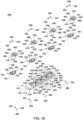
FIG. 15 is an exploded, top perspective view of the bone plate system ofFIG. 11 , in accordance with an example of the present disclosure; -
FIG. 16 is an exploded, top view of the bone plate system ofFIG. 11 , in accordance with an example of the present disclosure; -
FIG. 17 is an exploded, bottom view of the bone plate system ofFIG. 11 , in accordance with an example of the present disclosure; -
FIG. 18 is an exploded, side view of the bone plate system ofFIG. 11 , in accordance with an example of the present disclosure; -
FIG. 19 is an exploded, first end view of the bone plate system ofFIG. 11 , in accordance with an example of the present disclosure; -
FIG. 20 is an exploded, second end view of the bone plate system ofFIG. 11 , in accordance with an example of the present disclosure; -
FIG. 21 is a first perspective view of a third embodiment of a bone plate system, in accordance with an example of the present disclosure; -
FIG. 22 is a second perspective view of the third embodiment of a bone plate system ofFIG. 21 , in accordance with an example of the present disclosure; -
FIG. 23 is a top view of the bone plate system ofFIG. 21 , in accordance with an example of the present disclosure; -
FIG. 24 is a bottom view of the bone plate system ofFIG. 21 , in accordance with an example of the present disclosure; -
FIG. 25 is an exploded, top perspective view of the bone plate system ofFIG. 21 , in accordance with an example of the present disclosure; -
FIG. 26 is an exploded, first end view of the bone plate system ofFIG. 21 , in accordance with an example of the present disclosure; -
FIG. 27 is an exploded, second end view of the bone plate system ofFIG. 21 , in accordance with an example of the present disclosure; -
FIG. 28 is an exploded, side view of the bone plate system ofFIG. 21 , in accordance with an example of the present disclosure; -
FIG. 29 is an exploded, top view of the bone plate system ofFIG. 21 , in accordance with an example of the present disclosure; and -
FIG. 30 is an exploded, bottom view of the bone plate system ofFIG. 21 , in accordance with an example of the present disclosure; -
FIG. 31 is first perspective view of a fourth embodiment of a bone plate system, in accordance with an example of the present disclosure; -
FIG. 32 is a bottom view of the bone plate system ofFIG. 31 , in accordance with an example of the present disclosure; -
FIG. 33 is top, side view of the bone plate system ofFIG. 31 , in accordance with an example of the present disclosure; -
FIG. 34 is a side view of the bone plate system ofFIG. 31 , in accordance with an example of the present disclosure; -
FIG. 35 is a top, perspective view of the bone plate system ofFIG. 31 , in accordance with an example of the present disclosure; -
FIG. 36 is an alternate top, perspective view of the bone plate system ofFIG. 31 , in accordance with an example of the present disclosure; and -
FIG. 37 is a cross-sectional view taken along line 37-37 of the bone plate system ofFIG. 31 , in accordance with an example of the present disclosure. - Generally stated, disclosed herein are embodiments and examples of devices, implants, guides, and systems for fixation of human bones, such as, foot and ankle bones. Further, surgical methods for using the devices, implants, guides, and systems for fixation of human bones to stabilize realignment of a fracture, dislocation, fusion or the like of the foot and ankle bones are discussed, but not claimed.
- In this detailed description and the following claims, the words proximal, distal, anterior or plantar, posterior or dorsal, medial, lateral, superior and inferior are defined by their standard usage for indicating a particular part of a bone, implant, device or guide according to the relative disposition of the natural bone or directional terms of reference. For example, "proximal" means the portion of a device or implant nearest the torso, while "distal" indicates the portion of the device or implant farthest from the torso. As for directional terms, "anterior" is a direction towards the front side of the body, "posterior" means a direction towards the back side of the body, "medial" means towards the midline of the body, "lateral" is a direction towards the sides or away from the midline of the body, "superior" means a direction above and "inferior" means a direction below another object or structure. Further, specifically in regards to the foot, the term "dorsal" refers to the top of the foot and the term "plantar" refers the bottom of the foot.
- Similarly, positions or directions may be used herein with reference to anatomical structures or surfaces. For example, as the current devices and methods are described herein with reference to use with the bones of the foot and ankle, the bones of the foot, ankle and lower leg may be used to describe the surfaces, positions, directions or orientations of the devices, instrumentation and methods. Further, the devices and methods, and the components, features and the like thereof, disclosed herein are described with respect to one side of the body for brevity purposes. However, as the human body is relatively symmetrical or mirrored about a line of symmetry (midline), it is hereby expressly contemplated that the devices and methods, and the components, features and the like thereof, described and/or illustrated herein may be changed, varied, modified, reconfigured or otherwise altered for use or association with another side of the body for a same or similar purpose without departing from scope of the disclosure. For example, the devices and methods, and the components, features and the like thereof, described herein with respect to the right foot and ankle may be mirrored so that they likewise function with the left foot and ankle. Further, the devices and methods, and the components, features and the like thereof, disclosed herein are described with respect to the foot and ankle for brevity purposes, but it should be understood that the devices and methods may be used with other bones of the body having similar structures, for example the upper extremity, and more specifically, with the bones of the wrist, hand, and arm.
- Referring to the drawings, wherein like reference numerals are used to indicate like or analogous components throughout the several views, and with particular reference to
FIGS. 1 - 10 , there is illustrated a bone plate system according to the present invention. Thebone plate system 100 includes an implant, plate, orbone plate 110, at least one deformable member, dynamic member, orelastic member deformable member 106 and a seconddeformable member 108 and at least one coupling member or threadedbutton first coupling member 102 and asecond coupling member 104. Thedeformable members bone plate 110 by, for example, engagement with thecoupling members bone plate 110. Each component of thebone plate system 100 may be made from, for example, a biocompatible material, including but not limited to a metal, polymer, composite, etc. - With continued reference to
FIGS. 1-10 , and with particular reference toFIG. 4 , the implant orplate 110 is shown. Theplate 110 includes atop surface 112 opposite abottom surface 114, afirst end 116 opposite asecond end 118, and afirst side 120 generally opposite asecond side 122. Theplate 110 also includes abase portion 124 positioned between thefirst end 116 andsecond end 118. Additionally, theplate 110 includes at least oneopening first opening 126 and asecond opening 128, which may be, for example, longer than thefirst opening 126. With reference toFIGS. 1-10 , thefirst opening 126 may be positioned at thefirst end 116 of theplate 110 and may include afirst end 138 opposite asecond end 140 and afirst side 142 opposite asecond side 144. Thefirst opening 126 may also include a recessedportion 130 which, may include afirst hole 136 extending from the recessedportion 130 and through to thebottom surface 114 of theplate 110. As depicted inFIG. 4 , thefirst opening 126 may include a first receiving portion or cut out 146, carved out of thefirst side 142 of thefirst opening 126 positioned near thefirst end 138. Thefirst opening 126 may also include a second receiving portion or cut out 148, carved out of thesecond side 144 of thefirst opening 126 positioned near thefirst end 138. The first and second receivingportions top surface 112 to the recessedportion 130 of thefirst opening 126. Extending from the first receivingportion 146 vertically to thesecond end 144, of thefirst opening 126 around to thesecond receiving portion 148 may be a groove orlip 150, positioned between thetop surface 112 and the recessedportion 130. Thefirst opening 126 may also include anengagement hole 152 extending from the recessedportion 130 to thebottom surface 114. Also, theengagement hole 152 may be positioned, centrally, near thesecond end 140 of theopening 126.
Additionally, thefirst opening 126 may include a slot 156 (not shown) positioned, centrally, in thefirst end 138 of theopening 126. The slot 156 may, for example, extend from the recessedportion 130 towards, but not through, thetop surface 112. The slot 156 is similar to slot 178 as seen inFIG. 4 . - With continued reference to
FIGS. 1-10 , thesecond opening 128 may be positioned at thesecond end 118 of theplate 110 and may include afirst end 160 opposite asecond end 162 and afirst side 164 opposite asecond side 166. Thesecond opening 128 may also include a recessedportion 132 which, includes asecond hole 158 extending from the recessedportion 132 to and through thebottom surface 114. As depicted inFIG. 4 , thesecond opening 128 may include a first receiving portion or cut out 168, carved out of thefirst side 164 of thesecond opening 128 positioned near thesecond end 162 of thesecond opening 128. Thesecond opening 128 may also include a second receiving portion or cut out 170 carved out of thesecond side 166 of thesecond opening 128 positioned near thesecond end 162 of thesecond opening 128. The first and second receivingportions top surface 112 to the recessedportion 132 of thesecond opening 128. Extending from the first receivingportion 168 vertically toward thefirst end 160 of thesecond opening 128 to thesecond receiving portion 170 is a groove orlip 172, positioned between thetop surface 112 and the recessedportion 132. Thesecond opening 128 may also include an engagement hole 174 (seeFIG. 6 ), extending from the recessed 132 portion to thebottom surface 114. Theengagement hole 174 is positioned centrally, at thefirst end 160 of thesecond opening 128. Thesecond opening 128 may further include a centrally locatedslot 178 in thesecond end 162 of theopening 128. Theslot 178 may, for example, extend from the recessedportion 132 towards, but not through, thetop surface 112. - With continued reference to
FIGS. 1-10 , the plate may also include at least onealignment hole opening 134. The threadedopening 134 may be positioned between thefirst opening 126 andsecond opening 128 of theplate 110. The at least onealignment hole first alignment hole 154 and asecond alignment hole 176. Thefirst alignment hole 154 may be located at thefirst end 116 of theplate 110 such that thealignment hole 154 is positioned above the first slot 156 of thefirst opening 126. Thesecond alignment hole 176 may be located at thesecond end 118 of theplate 110 such that thealignment hole 176 is located above thesecond slot 178 of thesecond opening 128. The first and second alignment holes 154, 176 may extend from thetop surface 112 to the first and second recessedportions - As shown in
FIGS. 1-3 andFIGS. 5-10 , the first deformable member or single dynamic member orelastic member 106 includes afirst end 190 opposite asecond end 192, and afirst portion 194 coupled to and extending away from a generally smallersecond portion 196. Thefirst portion 194 is generally circular in shape, and has a diameter greater than or equal to the width of thefirst opening 126 of theplate 110. Thesecond portion 196 has the same width as thefirst portion 194 but is shorter than thefirst portion 194 and is generally oval in shape, for example. The firstdeformable member 106 may also include an engagement protrusion ortab 198 positioned at thefirst end 190 of the firstdeformable member 106. Theprotrusion tab 198 may include a hole oralignment opening 200, which may be, for example, equal to the size and shape of thealignment hole 154 of thefirst opening 126 of theplate 110. Theprotrusion tab 198 may be, for example, coupled to the slot 156 of thefirst opening 126 of theplate 110. The firstdeformable member 106 may also include afirst hole 202 positioned in thefirst portion 194 and asecond hole 204 position in thesecond portion 196. Thefirst hole 202 andsecond hole 204 may be, for example, similarly shaped as the first andsecond portions deformable member 106. - With continued reference to
FIGS. 1-3 and5-10 , the seconddeformable member 108 may include a base orfirst portion 214 having afirst end 216 opposite asecond end 218, an extension orsecond portion 220 coupled to thefirst portion 214. Thesecond portion 220 has afirst end 222 andsecond end 224. Thefirst portion 214 may be, for example, longer than thesecond portion 220 and include an engagement tab orprotrusion 226 at thesecond end 218. Also, thefirst portion 214 may include afirst opening 228 positioned near thefirst end 216, and asecond opening 230, positioned proximate thesecond end 218. Thefirst portion 214 may have, for example, sides that are concave shaped. Thesecond portion 220 may also, include throughopening 232 for engagement with thesecond opening 128 of theplate 110. Thethird opening 232 may be, for example, a non-circular shape and smaller than the first andsecond openings FIGS. 1-3 and5-10 , theprotrusion tab 226 may be positioned at thesecond end 218 of thefirst portion 214 and may include a hole oralignment opening 234. Theprotrusion tab 226 may, for example, couple to theslot 178 of thesecond opening 128 of thebone plate 110. Further, thealignment opening 234 of theprotrusion tab 226 may be, for example, the same size and shape as thesecond alignment hole 176 of thebone plate 110. - With continued reference to
FIGS. 1-3 and5-10 , the first coupling member, single coupling member or threadedbutton 102 may have atop surface 244 opposite abottom surface 246, afirst end 248 opposite asecond end 250, and afirst side 252 opposite asecond side 254. Thecoupling member 102 may have a recessedregion 266 extending toward the top surface from thebottom surface 246. Thefirst coupling member 102 may also include anextension member 256 coupled to and extending away from the recessedportion 266 to thebottom surface 246. Theextension member 256 may have, for example, a linearfirst side 258 and linearsecond side 260 that are parallel to and shorter than thefirst side 252 andsecond side 254 of thecoupling member 102. Theextension member 256 may also have, for example, a curvedfirst end 262 and curvedsecond end 264 that are tangent to thefirst end 250 andsecond end 252 of thecoupling member 102. Additionally, thecoupling member 102 may have a first arm orprotrusion 268 positioned at thefirst side 252 of thecoupling member 102 and a second arm orprotrusion 274 positioned at thesecond side 254 of thecoupling member 102. The first andsecond arms region 266 and extend away from thetop surface 244. Thefirst arm 268 may have a linearfirst side 270 and a curvedsecond side 272, where thefirst side 270 is flush with thefirst side 252 of thecoupling member 102. Thesecond side 272 of thefirst arm 268 may, for example, be the same shape as thefirst hole 202 of the firstdeformable member 106. Thesecond arm 274 may be of the same shape, size and nature as thefirst arm 268, with the first side of thesecond arm 276 flush with thesecond side 254 of thecoupling member 102. Further, thecoupling member 102 may have a threadedopening 280 extending from thetop surface 244 through theextension member 256 to thebottom surface 246. Thecoupling member 102 may also have afirst tab 282 positioned on thefirst side 252 of thecoupling member 102 and asecond tab 284 opposite thefirst tab 282 positioned on thesecond side 254 for engagement with the first and second recessedportions first opening 126 on theplate 110. - As illustrated in
FIGS. 1-3 and5-10 , the second coupling member or doubled threadedbutton 104 has atop surface 294 opposite abottom surface 296, afirst side 298 opposite asecond side 300, and afirst end 302 opposite asecond end 304. Thesecond coupling member 104 may include a recessedregion 306 on thebottom surface 296. The recessedregion 306 may be, for example, the same general shape as thebase portion 214 of the seconddeformable member 108. Further, thesecond coupling member 104 may include afirst extension member 308 and asecond extension member 310, both extending from the recessedregion 306 towards thebottom surface 296, which may be, for example the same size and shape. Thefirst extension member 308 may be positioned near thefirst end 302 of thecoupling member 104 and may include, for example, a roundedfirst end 312 opposite a roundedsecond end 314 and a firstlinear side 316 opposite a secondlinear side 318. Thesecond extension member 310 may be positioned near thesecond end 304 of thecoupling member 104 and may also include, for example, a roundedfirst end 320 opposite a roundedsecond end 322 and a firstlinear side 324 opposite a linearsecond side 326. Thefirst end 312 of thefirst extension 308 member may be tangent with thefirst end 302 of thecoupling member 104 and thesecond end 322 of thesecond extension member 310 may be tangent with thesecond end 304 of thecoupling member 104. As shown inFIG. 9 , there may be a first protrusion orarm 328 and a second protrusion orarm 330, extending away from thetop surface 294 towards thebottom surface 296. Thefirst arm 328 andsecond arm 330 may each have aninside surface deformable member 108. Thecoupling member 104 may also, include a first threadedopening 336 in thefirst extension member 308 and a second threadedopening 338 in thesecond extension member 310. Further, thecoupling member 104 may include afirst tab 340 andsecond tab 342 positioned near thefirst end 302 of thecoupling member 104. The first andsecond tabs portions second opening 128 of theplate 110. Thefirst tab 340 may be located on thefirst side 298 of thecoupling member 104, and thesecond tab 342 may be positioned opposite thefirst tab 340 on thesecond side 300. - As further illustrated in
FIGS. 1-3 and5-10 , thebone plate system 100 may also include at least one retaining pin orelastic retaining pin 352 and at least one fastener, pin orremovable retaining pin 350. The at least oneremovable retaining pin 350 may, for example, include two retaining pins, both being identical in nature. Theremovable retaining pin 350 may include ahead portion 354, with adrive opening 356 coupled to ashaft portion 358 that extends away from thehead portion 354. Theshaft portion 358 may include, abody portion 360 having a smaller diameter than thehead portion 354 and acoupling portion 362 having a smaller diameter than thebody portion 360. Theremovable retaining pin 350 may, for example, be used to couple thedeformable members plate 110 in order to, for example, maintain a constant tension on thecoupling members elastic retaining pin 352 may include ahead portion 366 and abody 364 that extends away from thehead portion 366. A firstelastic retaining pin 352 may, for example, be coupled to theengagement hole 152 of thebone plate 110 and a secondelastic retaining pin 352 may, for example, be coupled to thesecond engagement hole 174 of thebone plate 110. Theelastic retaining pin 352 may, for example, be used to hold the first and seconddeformable members bone plate 110. - Now with reference to
FIGS. 11-20 , an example of of abone plate system 400 is shown. Thebone plate system 400 may include an implant, plate orbone plate 410, at least one deformable member ordynamic member 106 and at least one coupling member orsingle button 408. Thedeformable member 106, may be positioned within thebone plate 410 by, for example, engagement with thecoupling member 408 which may be coupled to thebone plate 410. Thebone plate system 400 may also include at least oneremovable retaining pin 350 and oneelastic retaining pin 352. For brevity sake, the structural elements of the retainingpin 350 discussed above will not be again described here, as it relates to thebone plate system 400. Each component of thebone plate system 400 may be made from, for example, a biocompatible material, including but not limited to a metal, polymer, composite, etc. - With continued reference to
FIGS. 11-20 , and with special reference toFIG. 14 , thebone plate 410 is shown. Thebone plate 410 may have atop surface 412 opposite abottom surface 414, afirst side 416 opposite asecond side 418 and afirst end 420 opposite asecond end 422. Thebone plate 410 may include at least one opening, for example afirst opening 424, asecond opening 426, athird opening 428 and afourth opening 430. Theopenings first opening 424 may be positioned at thefirst end 420 of theplate 410, and thefourth opening 430 may be positioned at thesecond end 412 of thebone plate 410. Thesecond opening 426 andthird opening 428 may be positioned between and apart from thefirst opening 424 andfourth opening 430. - Continuing to reference
FIGS. 11-20 , theopenings first side 432 opposite asecond side 434, afirst end 436 opposite asecond end 438. Theopenings portion 440 which, may surround ahole 442 that extends from the recessedportion 440 to and through thebottom surface 414 of theplate 410. As shown, theopenings first side 432 of the particular opening positioned near thefirst end 436 of the opening. Theopenings second side 434 of the opening positioned near thefirst end 436 of theopening first cutout 444. The first and second receivingportions top surface 412 to the recessedportion 440 of the openings. Extending from the first receivingportion 444 vertically to thesecond end 438 of the opening around to thesecond receiving portion 446 may be a groove orlip 448, positioned between thetop surface 412 and the recessedportion 440. Theopenings engagement hole 450 extending from the recessedportion 440 to the bottom surface 414 (seeFIG. 16 ). Theengagement hole 450 may be positioned, centrally, near thesecond end 438 of theopening openings slot 452 positioned, centrally and proximate to thefirst end 438 of the opening. Theslot 458 may, for example, be defined by the recessedportion 440 andtop surface 412. Theslot 458 may be, for example, for engagement with theengagement protrusion 198 of the firstdeformable member 106. - With reference to
FIGS. 11-13 and15-20 , thebone plate system 400 includes a single coupling member, or single threadedbutton 408. Thesingle coupling member 408 may include atop surface 462 opposite abottom surface 464, afirst side 466 opposite asecond side 468, and afirst end 470 opposite asecond end 472. Thecoupling member 408 may have a recessedregion 474 extending away from thebottom surface 464. The recessedregion 474 may, for example, be the same shape as thefirst hole 202 of the firstdeformable member 106. Thesingle coupling member 408 may also include anextension member 476 coupled to and extending away from the recessed 474 to thebottom surface 464. Theextension member 476 may, for example, be the same shape as thefirst hole 202 of the firstdeformable member 106, and may, for example, have a smaller outside diameter then the diameter of thefirst hole 202 of the firstdeformable member 106. Additionally, thesingle coupling member 408 may have a first arm orprotrusion 478 positioned at thefirst side 466 of thesingle coupling member 408 and a second arm or protrusion positioned 480 at thesecond side 468 of thesingle coupling member 408. The first andsecond arms region 474 and extend towards thebottom surface 464. Thefirst arm 478 may have a linearfirst side 482 and a curvedsecond side 484, where thefirst side 482 is tangent to thefirst side 466 of thesingle coupling member 408. Thesecond arm 480 may be of the same shape, size and nature as thefirst arm 478, with thefirst side 486 of thesecond arm 480 tangent to thesecond side 468 of thesingle coupling member 408. Further, thesingle coupling member 408 may have anopening 490 extending from thetop surface 462 through theextension member 476 to thebottom surface 464. Thesingle coupling member 408 may have afirst tab 492 positioned at a corner of thefirst side 468 and thesecond end 472 and asecond tab 494 opposite thefirst tab 492, for engagement with the first and second receivingportions openings plate 410. - As illustrated in
FIGS. 11-20 , thebone plate system 400 also include at least one alignment hole, for example, afirst alignment hole 454,second alignment hole 456,third alignment hole 458 andfourth alignment hole 460. The alignment holes 454, 456, 458, and 460 may be, for example, the same shape and size as theremovable pin 350, and may be for coupling thedeformable member 106 to thebone plate 410 with theremovable pin 350. The alignment holes 454, 456, 458, 460 may be positioned at thefirst end 436 of theopenings top surface 412 through theslot 452 to the recessedportion 440. - Now referencing
FIGS. 21-30 , abone plate system 500 is shown. Thebone plate system 500 may include an implant, plate, orbone plate 510, a deformable member, dynamic member, orelastic member 512, and a coupling member or threadedbutton 514. Thedeformable member 512 may be received within thebone plate 510 by, for example, engagement with thecoupling member 514 which may, be coupled to thebone plate 510. Each component of thebone plate system 500 may be made from, for example, a biocompatible material, including but not limited to a metal, polymer, composite, etc. - Continuing to reference
FIGS. 21-30 thebone plate 510 may include atop surface 516 opposite abottom surface 518, afirst side 524 opposite asecond side 526 and afirst end 520 opposite asecond end 522. Thebone plate 510 may include anopening 528 positioned between thefirst end 520 andsecond end 522, with the opening having afirst end 530 opposite asecond end 532 and afirst side 534 opposite asecond side 536. Theopening 528 may include a recessedregion 538 extending away from thetop surface 516 of theplate 510. Further, the recessedregion 538 may include a throughhole 540 extending from the recessedregion 538 through thebottom surface 518. Thesecond end 532 of theopening 528 may include a receivingportion 542 which may be configured for engaging thedeformable member 512. The receivingportion 542 may include, a first carve out 544 in the corner of thefirst side 534 and thesecond end 532 and a second carve out 546 in the corner of thesecond side 536 and thesecond end 532. Extending from the first carve out 544 to the second carve out 546 may be a lip or groove 548, which may extend away from the recessedregion 538. As shown inFIGS. 25 and27 opposite thegroove 548 in thefirst end 532 of theopening 528 may be aslot 550 extending away from the recessedregion 538. - With further reference to
FIGS. 21-30 , adeformable member 512 is illustrated. Thedeformable member 512 may have atop surface 552 opposite abottom surface 518, afirst end 520 opposite asecond end 522 and afirst side 524 opposite asecond side 526. Also, thedeformable member 512 may have, for example, a spheroid shape and it may equal in length to the width of theopening 528 in theplate 510. Thesecond end 558 of thedeformable member 512 may, for example, engage with thegroove 548 of theplate 510 when assembled. The width of thedeformable member 512 may be such that, when assembled, thefirst end 556 does not come into contact with the throughhole 540 of theplate 510. Additionally, thedeformable member 512 may have a throughhole 584 positioned between thefirst end 556 andsecond end 558. - Continuing to reference
FIGS. 21-30 , the coupling member or slidingbutton 514 is illustrated. Thecoupling member 514 may have atop surface 564 opposite abottom surface 566, afirst side 568 opposite asecond side 570 and afirst end 572 opposite asecond end 574. Thefirst end 572 of thecoupling member 514 may have anengagement protrusion 576 extending from thebottom surface 566 andfirst end 572. (SeeFIG. 27 ). Theengagement protrusion 576 may be, for example, the same shape and smaller than theslot 550 of theplate 510, and may be used to engage thecoupling member 514 with theplate 510. Thecoupling member 514 may also have a receiving portion or groove 578 positioned at thesecond end 574. The receivingportion 578 may be of the same shape, and size as thefirst end 556 of thedeformable member 512. Forming the top of the receivingportion 578 may be, for example, anextension portion 580 extending away from thesecond end 574. Also, thecoupling member 514 may include a through hole positioned 582 between thefirst side 568 andsecond side 570. - Referring now to
FIGS. 31-37 , an alternate example of abone plate system 600 is shown. Thesystem 600 is shown to include an implant orbone plate 610, at least one deformable member, dynamic member, orelastic member 106, for example, the firstdeformable member 106, and at least onecoupling member 102, for example, thefirst coupling member 102. The firstdeformable member 106 and thefirst coupling member 102 implemented in conjunction with thesystem 600 are the same as those shown and described previously (e.g., thesystem 600 andplate 610 accommodates the firstdeformable member 106, as well as the first coupling member 102). However, is should be noted that in some aspects of thesystem 600, one or more components may be the same as and/or similar to the firstdeformable member 106, the seconddeformable member 108, thefirst coupling member 102, and thesecond coupling member 102 may be implemented. The aspects of thesystem 600 as shown inFIGS. 31-37 may include one or more of thefirst coupling member 102 and the firstdeformable member 106. In some aspects, theplate system 600 and theplate 610 may be similar to the plate systems and plates previously discloses herein, for example thesystem 100 and theplate 110. Further, the firstdeformable member 106 may be received by thebone plate 610 by, for example, engagement with thecoupling member 102, which may be coupled with thebone plate 610. Each component of thesystem 600 may be made from, for example, a biocompatible material including but not limited to a metal, polymer, composite, etc. Additionally, in some aspects one or more components of the system 600 (e.g., the at least onecoupling member 102; the at least onedeformable member 106, etc.) may be made from a material with shape retention properties, for example nitinol or other materials with similar properties. - With continued reference to
FIGS. 31-37 , theplate 610 includes atop surface 612 opposite abottom surface 614, afirst end 616 opposite asecond end 618, and afirst side 620 generally opposite asecond side 622. Theplate 610 also includes abase portion 624 positioned between thefirst end 616 andsecond end 618. Additionally, theplate 610 includes at least oneopening first opening 626 and asecond opening 628, which may be, for example, similar to thefirst opening 126 as shown and described previously. The first andsecond openings first end 616 of theplate 610 and may include afirst end 638 opposite asecond end 640 and afirst side 642 opposite asecond side 644. Thefirst opening 626 may also include a recessedportion 630 which, may include afirst hole 636 extending from the recessedportion 630 and through to thebottom surface 614 of theplate 610. Thefirst opening 626 may include a first receiving portion or cut out 646, carved out of thefirst side 642 of thefirst opening 626 positioned near thefirst end 638. Thefirst opening 626 may also include a second receiving portion or cut out 648, carved out of thesecond side 644 of thefirst opening 626 positioned near thefirst end 638. The first and second receivingportions top surface 612 to the recessedportion 630 of thefirst opening 626. Extending from the first receivingportion 646 vertically to thesecond end 644, of thefirst opening 626 around to thesecond receiving portion 648 may be a groove orlip 650, positioned between thetop surface 612 and the recessedportion 630. Thefirst opening 626 may also include anengagement hole 652 extending from the recessedportion 630 to thebottom surface 614. Also, theengagement hole 652 may be positioned, centrally, near thesecond end 640 of theopening 626. Theengagement hole 652 may be sized to receive a portion (e.g., a protrusion, etc.) of the firstdeformable member 106 and/or thefirst coupling member 102 so as to retain one or both of said components. Additionally, thefirst opening 626 may include afirst slot 656 positioned, centrally, in thefirst end 638 of thefirst opening 626. Thefirst slot 656 may, for example, extend from the recessedportion 630 towards, but not through, thetop surface 612. Thefirst opening 626 may also include asecond slot 668, as shown inFIG. 37 , with saidsecond slot 668 arranged opposite from thefirst slot 656. As shown inFIG. 37 , thesecond slot 668 is shown to receive at least a portion of the firstdeformable member 106 so as to retain the first deformable at least partially within thesecond slot 668. - The
second opening 628 may be configured to include similar features and/or have a similar geometry to thefirst opening 626 as shown and described previously. For example, thesecond opening 626 is shown to include a recessedportion 631 which, may include asecond hole 637 extending from the recessedportion 631 and through to thebottom surface 614 of theplate 610. Thesecond opening 628 may include a first receiving portion or cut out 647, carved out of thefirst side 643 of thesecond opening 628 positioned near afirst end 641 of the second opening 628 (and opposite thesecond opening 628 from a second end 639). Thesecond opening 628 may also include a second receiving portion or cut out 649, carved out of thesecond side 645 of thesecond opening 628 positioned near thefirst end 641. The first and second receivingportions top surface 612 to the recessedportion 631 of thesecond opening 628. Extending from the first receivingportion 647 vertically to thesecond end 644, of thesecond opening 628 around to thesecond receiving portion 649 may be a groove orlip 651, positioned between thetop surface 612 and the recessedportion 630. Thesecond opening 628 may also include anengagement hole 653 extending from the recessedportion 631 to thebottom surface 614. Also, theengagement hole 653 may be positioned, centrally, near thesecond end 639 of thesecond opening 628. Theengagement hole 653 may be sized to receive a portion (e.g., a protrusion, etc.) of the firstdeformable member 106 and/or thefirst coupling member 102 so as to retain one or both of said components Additionally, thesecond opening 628 may include aslot 657 positioned, centrally, in thefirst end 641 of thesecond opening 628. Theslot 657 may, for example, extend from the recessedportion 631 towards, but not through, thetop surface 612. Thesecond opening 628 may also include asecond slot 669, as shown inFIG. 37 , with saidsecond slot 669 arranged opposite from thefirst slot 657. As shown inFIG. 37 , thesecond slot 669 is shown to receive at least a portion of the firstdeformable member 106 so as to retain the first deformable at least partially within thesecond slot 668. - With continued reference to
FIGS. 31-37 , theplate 610 may also include at least onealignment hole 654 disposed in thebody 624 of theplate 610, where the at least onealignment hole 654 extends through theplate 610 from thetop surface 614 to thebottom surface 614. In some aspects, thealignment hole 654 may have a round or oval configuration. The at least onealignment hole 654 may, in some aspects, include additional alignment holes arranged variously about theplate 610. The at least onealignment hole 654 may be located, for example, at thesecond end 618 of theplate 610 such that the at least onealignment hole 654 is positioned below thefirst opening 626 and thesecond opening 628. Thebody 624 of theplate 610 is further shown to include at least one threadedopening opening 634 and a second threadedopening 635. The first and second threadedopenings plate 610 to one or more bone segments of a patient. - The
plate 610 is further shown to have a curvature configured to facilitate interfacing and/or coupling with one or more bones. As shown inFIG. 33 , theplate 610 is shown to have a substantially concave geometry on thebottom surface 614, and a substantially convex geometry on thetop surface 612. The concave geometry of thebottom surface 614 is configured to interface with one or more bones of a patient, with the convex geometry of thetop surface 612 complementary to the concave geometry of the bottom surface 614 (e.g., has a corresponding curvature). The curvature of the plate 610 (e.g., the concave geometry of thebottom surface 614 and corresponding convex geometry of the top surface 612) is configured to permit thesystem 600 to apply a force in at least two directions when used with the components of thesystem 600. - The
plate 610 as shown is configured to accommodate a pair of the firstdeformable members 106 in the same or similar manner to the plates shown and described previously herein. (e.g., the plate 110). For example, the firstdeformable members 106 are received within the first andsecond openings plate 610. The first andsecond openings plate 610 are configured to have a width less than or equal to the diameter of thefirst portion 194 of the firstdeformable members 106. Similarly, thefirst engagement hole 652 and thesecond engagement hole 653 may be, for example, equal to the size and shape of thealignment opening 200 of the firstdeformable members 106. Theprotrusion tabs 198 of the firstdeformable members 106 may couple with thefirst slot 656 of thefirst opening 626 and thefirst slot 657 of thesecond opening 628 of theplate 610. - The
plate 610 is shown to receive thefirst coupling members 102 in a manner the same as or similar to that of theplate 110 as shown and described previously with reference to thesystem 100. For example, thefirst coupling members 102 may engage with the first and second recessedportions first opening 626 and thesecond opening 628, respectively. Additionally, thesystem 600 is shown to include at least oneremovable retaining pin 350, the same as or similar to theremovable retaining pin 350 as shown and described previously herein. Similarly, theplate 610 is configured to include one or more coupling features to facilitate coupling with the at least oneremovable retaining pin 350 in the same as, or similar manner that is shown and described with reference to thesystem 100. - As shown in
FIGS. 31-34 , a pair of the removable retaining pins 350 may be received by the engagement holes 652 and 653 of the first andsecond openings deformable members 106 within the first andsecond openings bone plate 610. The removable retaining pins 350, as shown inFIG. 37 , may retain the firstdeformable members 106 in a desired orientation prior to implantation, for example as shown with reference to thepin 350 adjacent thesecond opening 628. Theremovable pin 350 is shown to prevent a portion of the firstdeformable member 106 from entering thefirst slot 657. However, upon removal of theremovable pin 350, at least a portion of the firstdeformable member 106 may enter/be received by thefirst slot 657 of thesecond opening 628. Prior to removal of theremovable pin 350, at least a portion of theremovable pin 350 may contact at least a portion of the perimeter of the first and/orsecond openings first opening 626, as shown inFIG. 37 , theremovable pin 350 has already been removed, thus allowing the firstdeformable member 106 to enter (e.g., intraoperatively via shape retention properties of the firstdeformable member 106, which may be formed of a material such as nitinol or similar) thefirst slot 656 of thefirst opening 626. - It should be noted that in some aspects, the
first coupling members 102 and the firstdeformable members 106 implemented in conjunction with theplate 610 of thesystem 600 may be modified to include features other than those shown. For example, in some aspects thefirst end 190 and thesecond end 192 of the firstdeformable members 106 may include additional holes relative to thefirst hole 202 and thesecond hole 204 shown and described previously. For example, the first deformable member may include three or more holes the same as and/or similar to thefirst hole 202 and thesecond hole 204 disposed between thefirst end 190 and thesecond end 192 of the firstdeformable member 106. Further to the previous example, a third, fourth, fifth, etc. hole may be incorporated into the firstdeformable member 106 so as to increase the force that may be applied by the first deformable member in one or more directions.
Claims (14)
- A bone plate system (100), comprising:a bone plate (110) with a top surface (112) and a bottom surface (114) and a first end (116) and a second end (118), the bone plate (110) comprising;a base portion (124) disposed between the first end (116) and the second end (118); andat least one opening (126, 128) extending away from the top surface (112) of the bone plate (110);at least one deformable member (106, 108) received within the at least one opening (126, 128) of the bone plate (110), wherein the at least one deformable member (106, 108) comprises:a first portion (194, 214) having a first opening (202, 228, 230);a second portion (196, 220) having a second opening (204, 232) coupled to and extending away from the first portion (194, 214); andwherein the first opening (228, 230) of one deformable member (108) of the at least one deformable member (106, 108) comprises:
two first openings (228, 230), wherein one first opening (228) is positioned at the first end (216) of the base portion (214), and wherein a second first opening (230) is positioned at the second end (218) of the base portion (214); andat least one coupling member (102, 104) engaging the at least one deformable member (106, 108) to couple the at least one coupling member (102, 104) and the at least one deformable member (106, 108) to the bone plate (110). - The bone plate system (100) of claim 1, wherein the at least one opening (126, 128) comprises:a first opening (126) having a first side (142) and a second side (144), wherein the first opening (126) is proximate the first end (116) of the bone plate (110); anda second opening (128) having a first side (164) and a second side (166), wherein the second opening (128) is proximate the second end (118) of the bone plate (110).
- The bone plate system (100) of claim 2, wherein the first opening (126) comprises:a first end (138) extending away from the first end (116) of the bone plate (110);a second end (140);a recessed portion (130) inset below the top surface (112) of the bone plate (110) and between the first end (138) and second end (140);a through hole (136) positioned between the first end (138) and second end (140);a slot (156) positioned at the first end (138);at least one receiving portion (146, 148); andat least one engagement hole (152) extending from the recessed portion (130) to the bottom surface (114).
- The bone plate system (100) of claim 3, wherein the at least one receiving portion (146, 148) comprises:a first receiving portion (146) positioned in the first side (142) of the first opening (126); anda second receiving portion (148) positioned in the second side (144) of the first opening (126), wherein the second receiving portion (148) is opposite the first receiving portion (146).
- The bone plate system (100) of claim 2, wherein the second opening (128) comprises:a first end (160);a second end (162) extending away from the second end (118) of the bone plate (110);a recessed portion (132) inset below the top surface (112) of the bone plate (110) and positioned between the first end (160) and second ends (162);a through hole (158) positioned intermediate the first end (160) and the second end (162) and extending from the recessed portion (132) through the bottom surface (114);a slot (178) positioned at the first end (160);at least one receiving portion (168, 170), comprising:a first receiving portion (168) positioned in the first side (164) of the second opening (128); anda second receiving portion (170) positioned in the second side (166) of the second opening (128), wherein the second receiving portion (170) is opposite the first receiving portion (168); andat least one engagement hole (174) extending from the recessed portion (132) to the bottom surface (114).
- The bone plate system (100) of claim 1, wherein the at least one deformable member (106, 108) comprises:a first deformable member (106) having a first end (190) and a second end (192) for engagement with a first opening (126) in the bone plate (110), wherein the first opening (126) has a first side (142) and a second side (144), wherein the first opening (126) is proximate the first end (116) of the bone plate (110), wherein the first deformable member (106) comprises:the first portion (194) having the first opening (202); andthe second portion (196) having the second opening (204) coupled to and extending away from the first portion (194); andan engagement protrusion (198) received within the bone plate (110); anda second deformable member (108) having a first end and a second end for engagement with a second opening (128) in the bone plate (110), wherein the second deformable member (108) comprises:the first portion (214) having a first end (216) and a second end (218);the second portion (220) coupled to and extending away from the base portion (124); andan engagement tab (226) extending away from the second end and received within the bone plate (110).
- The bone plate system (100) of claim 1, wherein the at least one deformable member (106, 108) comprises:a first deformable member (106); anda second deformable member (108); andwherein the at least one coupling member (102, 104) comprises:a first coupling member (102) having a top surface (244) and a bottom surface (246) for engagement with a first deformable member (106); anda second coupling member (104) having a top surface (294) and a bottom surface (296) for engagement with a second deformable member (108).
- The bone plate system (100) of claim 7, wherein the first coupling member (102) comprises:an extension member (256) extending from the top surface (244) to the bottom surface (246);a through hole (280) extending from the top surface (244) through the extension member (256) to the bottom surface (246);at least one tab (282, 284);at least one protrusion (268, 270); anda recessed region (266) extending toward the top surface (244) from the bottom surface (246).
- The bone plate system (100) of claim 8, wherein the at least one protrusion (268, 270) comprises:a first protrusion (268) having a first side (270) opposite a second side (272), wherein the first protrusion (268) extends from the recessed region(266) to the bottom surface (246); anda second protrusion (270) having a first side opposite a second side, wherein the second protrusion (270) is opposite the first protrusion (268).
- The bone plate system (100) of claim 7, wherein the second coupling member (104) comprises:a first end (302) opposite a second end (304);at least one extension member (308, 310) extending from the top surface (294) to the bottom surface (296);at least one through hole extending from the top surface (294) through the at least one extension member (308, 310);at least one tab (340, 342);at least one protrusion (328, 330); anda recessed region (306) extending away from the bottom surface (296).
- The bone plate system (100) of claim 10, wherein the at least one extension member (308, 310) comprises:a first extension member (308) having a first through hole positioned at the first end; anda second extension member (310) having a second through hole positioned at the second end.
- The bone plate system (100) of claim 1, wherein the bone plate (110) further comprises:at least one alignment hole (154, 176), comprising:a first alignment hole (154) extending from the top surface (112) to the bottom surface (124), wherein the first alignment hole (154) is located at the first end (116) of the bone plate (110) and extends through a portion of a first opening (126) of the at least one opening (126, 128); anda second alignment hole (176) extending from the top surface (112) to the bottom surface (114), wherein the second alignment hole (176) is located at the second end (118) of the bone plate (110) and extends through a portion of a second opening (128) of the at least one opening (126, 128); andat least one retaining pin (350, 352) for coupling the at least one deformable member (106, 108) to the bone plate (110), wherein the at least one retaining pin (350, 352) comprises:a first retaining pin (350) received within the first alignment hole (154); anda second retaining pin (352) received within the second alignment hole (176).
- The bone plate system (100) of claim 12, wherein the at least one retaining pin (350, 352) comprises:at least one retaining pin (350) having a head portion (354), a body (360) and a coupling portion (362); andat least one elastic pin (352) having a head portion (366) and a body (364).
- The bone plate system (100) of claim 12, wherein the at least one retaining pin (350, 352) comprises:a first retaining pin (352) for engagement with an alignment hole of the first opening in the bone plate (110); anda second retaining pin (350) for engagement with an alignment hole of the second opening in the bone plate (110).
Priority Applications (1)
| Application Number | Priority Date | Filing Date | Title |
|---|---|---|---|
| EP25173364.8A EP4570201A3 (en) | 2019-08-06 | 2020-08-06 | Dynamic bone plate |
Applications Claiming Priority (2)
| Application Number | Priority Date | Filing Date | Title |
|---|---|---|---|
| US201962883501P | 2019-08-06 | 2019-08-06 | |
| PCT/US2020/045166 WO2021026331A1 (en) | 2019-08-06 | 2020-08-06 | Dynamic bone plate and method of use |
Related Child Applications (1)
| Application Number | Title | Priority Date | Filing Date |
|---|---|---|---|
| EP25173364.8A Division EP4570201A3 (en) | 2019-08-06 | 2020-08-06 | Dynamic bone plate |
Publications (4)
| Publication Number | Publication Date |
|---|---|
| EP4009892A1 EP4009892A1 (en) | 2022-06-15 |
| EP4009892A4 EP4009892A4 (en) | 2023-09-06 |
| EP4009892C0 EP4009892C0 (en) | 2025-04-30 |
| EP4009892B1 true EP4009892B1 (en) | 2025-04-30 |
Family
ID=74504121
Family Applications (2)
| Application Number | Title | Priority Date | Filing Date |
|---|---|---|---|
| EP20850367.2A Active EP4009892B1 (en) | 2019-08-06 | 2020-08-06 | Dynamic bone plate |
| EP25173364.8A Pending EP4570201A3 (en) | 2019-08-06 | 2020-08-06 | Dynamic bone plate |
Family Applications After (1)
| Application Number | Title | Priority Date | Filing Date |
|---|---|---|---|
| EP25173364.8A Pending EP4570201A3 (en) | 2019-08-06 | 2020-08-06 | Dynamic bone plate |
Country Status (6)
| Country | Link |
|---|---|
| US (2) | US12426929B2 (en) |
| EP (2) | EP4009892B1 (en) |
| AU (1) | AU2020326867A1 (en) |
| CA (1) | CA3149638A1 (en) |
| ES (1) | ES3028791T3 (en) |
| WO (1) | WO2021026331A1 (en) |
Family Cites Families (27)
| Publication number | Priority date | Publication date | Assignee | Title |
|---|---|---|---|---|
| US20090048606A1 (en) * | 2001-10-18 | 2009-02-19 | Fxdevices Llc | Guide system and method for the fixation of bone fractures |
| KR100552117B1 (en) * | 2003-07-22 | 2006-02-13 | 유앤아이 주식회사 | Cervical vertebrae device and driver used in it |
| US7699879B2 (en) | 2003-10-21 | 2010-04-20 | Warsaw Orthopedic, Inc. | Apparatus and method for providing dynamizable translations to orthopedic implants |
| US7883531B2 (en) * | 2005-07-06 | 2011-02-08 | Stryker Spine | Multi-axial bone plate system |
| CN101262828B (en) | 2005-07-13 | 2011-06-15 | 精密医疗责任有限公司 | Bone plate with removable locking elements |
| WO2008021656A2 (en) * | 2006-07-21 | 2008-02-21 | Merlot Orthopedix, Inc. | Apparatus and method for body tissue fixation |
| US8066750B2 (en) * | 2006-10-06 | 2011-11-29 | Warsaw Orthopedic, Inc | Port structures for non-rigid bone plates |
| WO2008115981A1 (en) * | 2007-03-19 | 2008-09-25 | Alpinespine Llc | Active compression orthopedic plate system and method for using the same |
| US8623019B2 (en) | 2007-07-03 | 2014-01-07 | Pioneer Surgical Technology, Inc. | Bone plate system |
| US8551144B2 (en) * | 2008-04-22 | 2013-10-08 | Collab Comlo, LLC | Bone plate system configurable as static or dynamic implant |
| US20110106159A1 (en) * | 2008-06-05 | 2011-05-05 | Seaspine, Inc. | Spinal fixation plate assembly |
| US10188438B2 (en) | 2013-04-24 | 2019-01-29 | Skeletal Dynamics, Llc | Bone plate with transversal slots for receiving a fastener |
| US20110029025A1 (en) * | 2009-07-31 | 2011-02-03 | Medoff Robert J | Locking pin plate assembly adapted for fracture fixation |
| US8790379B2 (en) | 2010-06-23 | 2014-07-29 | Zimmer, Inc. | Flexible plate fixation of bone fractures |
| WO2011163387A2 (en) | 2010-06-23 | 2011-12-29 | Apex Biomedical Company, Llc | Flexible plate fixation of bone fractures |
| CN101999927B (en) | 2010-11-28 | 2012-07-25 | 孙德修 | Universal locking pressure device for bone fracture plate |
| WO2013006980A1 (en) * | 2011-07-12 | 2013-01-17 | Montavon Lorraine | Bone plate |
| US20160074082A1 (en) * | 2011-10-20 | 2016-03-17 | Stryker Trauma Sa | Flexible locked plate fixation |
| US9265543B2 (en) * | 2011-12-27 | 2016-02-23 | Pioneer Surgical Technology, Inc. | Bone plate system and method |
| US9295508B2 (en) | 2012-02-03 | 2016-03-29 | Zimmer, Inc. | Bone plate for elastic osteosynthesis |
| US20140148860A1 (en) * | 2012-11-27 | 2014-05-29 | Jim A. Rinner | Expanding Blade Screw Retention System |
| EP2789303A1 (en) * | 2013-04-12 | 2014-10-15 | Zimmer GmbH | Implantable insert sleeve |
| AU2016215127B2 (en) * | 2015-02-05 | 2020-12-03 | Paragon 28, Inc. | Bone plates, systems, and methods of use |
| US11202664B2 (en) * | 2018-12-17 | 2021-12-21 | Nextremity Solutions, Inc. | Compression force magnifier |
| US20200253645A1 (en) | 2019-02-11 | 2020-08-13 | Nexus Spine, LLC | Press-Fit Anterior Cervical Plate |
| CA3170978A1 (en) * | 2020-02-14 | 2021-08-19 | Paragon 28, Inc. | Bone plate hole caps, bone plate systems, and methods using same |
| CN111920504A (en) | 2020-07-20 | 2020-11-13 | 张厚斌 | Rib fracture fixing device for thoracic surgery |
-
2020
- 2020-08-06 EP EP20850367.2A patent/EP4009892B1/en active Active
- 2020-08-06 WO PCT/US2020/045166 patent/WO2021026331A1/en not_active Ceased
- 2020-08-06 CA CA3149638A patent/CA3149638A1/en active Pending
- 2020-08-06 AU AU2020326867A patent/AU2020326867A1/en active Pending
- 2020-08-06 EP EP25173364.8A patent/EP4570201A3/en active Pending
- 2020-08-06 ES ES20850367T patent/ES3028791T3/en active Active
-
2022
- 2022-02-07 US US17/650,160 patent/US12426929B2/en active Active
-
2025
- 2025-09-30 US US19/345,187 patent/US20260020887A1/en active Pending
Also Published As
| Publication number | Publication date |
|---|---|
| EP4009892A1 (en) | 2022-06-15 |
| EP4009892A4 (en) | 2023-09-06 |
| CA3149638A1 (en) | 2021-02-11 |
| AU2020326867A1 (en) | 2022-03-24 |
| WO2021026331A1 (en) | 2021-02-11 |
| EP4009892C0 (en) | 2025-04-30 |
| EP4570201A3 (en) | 2025-08-20 |
| US20220151665A1 (en) | 2022-05-19 |
| US12426929B2 (en) | 2025-09-30 |
| US20260020887A1 (en) | 2026-01-22 |
| EP4570201A2 (en) | 2025-06-18 |
| ES3028791T3 (en) | 2025-06-20 |
Similar Documents
| Publication | Publication Date | Title |
|---|---|---|
| KR101632652B1 (en) | A fixation tool for opening wedge high tibial osteotomy | |
| US9949773B2 (en) | Orthopedic bone plate and locking tab apparatus and method of use | |
| JP4849694B2 (en) | Interprotrusion distance retention implant | |
| EP3600069B1 (en) | Bone fixation systems and insertion guides | |
| CA2643678C (en) | Orthopaedic fixation component and method | |
| JP5449316B2 (en) | Joint fixation system for ankles of human patients | |
| BR112019018933A2 (en) | proximal system of the femur plate | |
| US11457965B1 (en) | Rotational guided growth devices, systems, and methods | |
| KR20120023625A (en) | Nail locking systems | |
| US20250160909A1 (en) | Implants, systems, and methods of use | |
| US8574305B2 (en) | System and method for modifying talocalcaneal relationship in a foot | |
| EP4009892B1 (en) | Dynamic bone plate | |
| JP7749568B2 (en) | Bone plate hole caps, bone plate systems, and methods of using them | |
| EP2938300B1 (en) | Orthopedic bone plate and locking tab apparatus | |
| US12193941B2 (en) | Tibial-tray system |
Legal Events
| Date | Code | Title | Description |
|---|---|---|---|
| STAA | Information on the status of an ep patent application or granted ep patent |
Free format text: STATUS: THE INTERNATIONAL PUBLICATION HAS BEEN MADE |
|
| PUAI | Public reference made under article 153(3) epc to a published international application that has entered the european phase |
Free format text: ORIGINAL CODE: 0009012 |
|
| STAA | Information on the status of an ep patent application or granted ep patent |
Free format text: STATUS: REQUEST FOR EXAMINATION WAS MADE |
|
| 17P | Request for examination filed |
Effective date: 20220224 |
|
| AK | Designated contracting states |
Kind code of ref document: A1 Designated state(s): AL AT BE BG CH CY CZ DE DK EE ES FI FR GB GR HR HU IE IS IT LI LT LU LV MC MK MT NL NO PL PT RO RS SE SI SK SM TR |
|
| DAV | Request for validation of the european patent (deleted) | ||
| DAX | Request for extension of the european patent (deleted) | ||
| A4 | Supplementary search report drawn up and despatched |
Effective date: 20230803 |
|
| RIC1 | Information provided on ipc code assigned before grant |
Ipc: A61B 17/80 20060101AFI20230728BHEP |
|
| GRAP | Despatch of communication of intention to grant a patent |
Free format text: ORIGINAL CODE: EPIDOSNIGR1 |
|
| STAA | Information on the status of an ep patent application or granted ep patent |
Free format text: STATUS: GRANT OF PATENT IS INTENDED |
|
| RIN1 | Information on inventor provided before grant (corrected) |
Inventor name: KARAS, KAITLIN Inventor name: LIPKER, GARRETT JEFFREY Inventor name: ROGGOW, KENNETH ALLAN Inventor name: BRINKER, LAURA ZAGROCKI Inventor name: BARMES, FRANCIS D. Inventor name: HUNT, RICHARD DAVID Inventor name: ALLARD, RANDY Inventor name: DACOSTA, ALBERT |
|
| INTG | Intention to grant announced |
Effective date: 20241002 |
|
| GRAJ | Information related to disapproval of communication of intention to grant by the applicant or resumption of examination proceedings by the epo deleted |
Free format text: ORIGINAL CODE: EPIDOSDIGR1 |
|
| STAA | Information on the status of an ep patent application or granted ep patent |
Free format text: STATUS: REQUEST FOR EXAMINATION WAS MADE |
|
| GRAP | Despatch of communication of intention to grant a patent |
Free format text: ORIGINAL CODE: EPIDOSNIGR1 |
|
| STAA | Information on the status of an ep patent application or granted ep patent |
Free format text: STATUS: GRANT OF PATENT IS INTENDED |
|
| INTC | Intention to grant announced (deleted) | ||
| GRAS | Grant fee paid |
Free format text: ORIGINAL CODE: EPIDOSNIGR3 |
|
| GRAA | (expected) grant |
Free format text: ORIGINAL CODE: 0009210 |
|
| STAA | Information on the status of an ep patent application or granted ep patent |
Free format text: STATUS: THE PATENT HAS BEEN GRANTED |
|
| INTG | Intention to grant announced |
Effective date: 20250226 |
|
| AK | Designated contracting states |
Kind code of ref document: B1 Designated state(s): AL AT BE BG CH CY CZ DE DK EE ES FI FR GB GR HR HU IE IS IT LI LT LU LV MC MK MT NL NO PL PT RO RS SE SI SK SM TR |
|
| REG | Reference to a national code |
Ref country code: CH Ref legal event code: EP Ref country code: GB Ref legal event code: FG4D |
|
| REG | Reference to a national code |
Ref country code: IE Ref legal event code: FG4D |
|
| REG | Reference to a national code |
Ref country code: DE Ref legal event code: R096 Ref document number: 602020050572 Country of ref document: DE |
|
| U01 | Request for unitary effect filed |
Effective date: 20250513 |
|
| U07 | Unitary effect registered |
Designated state(s): AT BE BG DE DK EE FI FR IT LT LU LV MT NL PT RO SE SI Effective date: 20250519 |
|
| REG | Reference to a national code |
Ref country code: ES Ref legal event code: FG2A Ref document number: 3028791 Country of ref document: ES Kind code of ref document: T3 Effective date: 20250620 |
|
| U20 | Renewal fee for the european patent with unitary effect paid |
Year of fee payment: 6 Effective date: 20250723 |
|
| PGFP | Annual fee paid to national office [announced via postgrant information from national office to epo] |
Ref country code: ES Payment date: 20250901 Year of fee payment: 6 |
|
| PG25 | Lapsed in a contracting state [announced via postgrant information from national office to epo] |
Ref country code: NO Free format text: LAPSE BECAUSE OF FAILURE TO SUBMIT A TRANSLATION OF THE DESCRIPTION OR TO PAY THE FEE WITHIN THE PRESCRIBED TIME-LIMIT Effective date: 20250730 Ref country code: GR Free format text: LAPSE BECAUSE OF FAILURE TO SUBMIT A TRANSLATION OF THE DESCRIPTION OR TO PAY THE FEE WITHIN THE PRESCRIBED TIME-LIMIT Effective date: 20250731 |
|
| PG25 | Lapsed in a contracting state [announced via postgrant information from national office to epo] |
Ref country code: PL Free format text: LAPSE BECAUSE OF FAILURE TO SUBMIT A TRANSLATION OF THE DESCRIPTION OR TO PAY THE FEE WITHIN THE PRESCRIBED TIME-LIMIT Effective date: 20250430 |
|
| PGFP | Annual fee paid to national office [announced via postgrant information from national office to epo] |
Ref country code: GB Payment date: 20250724 Year of fee payment: 6 |
|
| PG25 | Lapsed in a contracting state [announced via postgrant information from national office to epo] |
Ref country code: HR Free format text: LAPSE BECAUSE OF FAILURE TO SUBMIT A TRANSLATION OF THE DESCRIPTION OR TO PAY THE FEE WITHIN THE PRESCRIBED TIME-LIMIT Effective date: 20250430 |
|
| PG25 | Lapsed in a contracting state [announced via postgrant information from national office to epo] |
Ref country code: RS Free format text: LAPSE BECAUSE OF FAILURE TO SUBMIT A TRANSLATION OF THE DESCRIPTION OR TO PAY THE FEE WITHIN THE PRESCRIBED TIME-LIMIT Effective date: 20250731 |
|
| PG25 | Lapsed in a contracting state [announced via postgrant information from national office to epo] |
Ref country code: IS Free format text: LAPSE BECAUSE OF FAILURE TO SUBMIT A TRANSLATION OF THE DESCRIPTION OR TO PAY THE FEE WITHIN THE PRESCRIBED TIME-LIMIT Effective date: 20250830 |
|
| PG25 | Lapsed in a contracting state [announced via postgrant information from national office to epo] |
Ref country code: SM Free format text: LAPSE BECAUSE OF FAILURE TO SUBMIT A TRANSLATION OF THE DESCRIPTION OR TO PAY THE FEE WITHIN THE PRESCRIBED TIME-LIMIT Effective date: 20250430 |
|
| PG25 | Lapsed in a contracting state [announced via postgrant information from national office to epo] |
Ref country code: CZ Free format text: LAPSE BECAUSE OF FAILURE TO SUBMIT A TRANSLATION OF THE DESCRIPTION OR TO PAY THE FEE WITHIN THE PRESCRIBED TIME-LIMIT Effective date: 20250430 |
|
| PG25 | Lapsed in a contracting state [announced via postgrant information from national office to epo] |
Ref country code: SK Free format text: LAPSE BECAUSE OF FAILURE TO SUBMIT A TRANSLATION OF THE DESCRIPTION OR TO PAY THE FEE WITHIN THE PRESCRIBED TIME-LIMIT Effective date: 20250430 |