KR101662377B1 - Indoor unit of air conditoiner - Google Patents
Indoor unit of air conditoiner Download PDFInfo
- Publication number
- KR101662377B1 KR101662377B1 KR1020140009419A KR20140009419A KR101662377B1 KR 101662377 B1 KR101662377 B1 KR 101662377B1 KR 1020140009419 A KR1020140009419 A KR 1020140009419A KR 20140009419 A KR20140009419 A KR 20140009419A KR 101662377 B1 KR101662377 B1 KR 101662377B1
- Authority
- KR
- South Korea
- Prior art keywords
- guide plate
- discharge port
- connecting member
- corner cover
- fixing
- Prior art date
- Legal status (The legal status is an assumption and is not a legal conclusion. Google has not performed a legal analysis and makes no representation as to the accuracy of the status listed.)
- Active
Links
- 230000008878 coupling Effects 0.000 claims description 53
- 238000010168 coupling process Methods 0.000 claims description 53
- 238000005859 coupling reaction Methods 0.000 claims description 53
- 238000007664 blowing Methods 0.000 claims description 6
- 238000000034 method Methods 0.000 claims 13
- 239000000463 material Substances 0.000 description 3
- 238000001816 cooling Methods 0.000 description 2
- 238000010438 heat treatment Methods 0.000 description 2
- 230000002452 interceptive effect Effects 0.000 description 2
- 238000000465 moulding Methods 0.000 description 2
- 238000004378 air conditioning Methods 0.000 description 1
- 238000010276 construction Methods 0.000 description 1
- 239000002826 coolant Substances 0.000 description 1
- 238000007599 discharging Methods 0.000 description 1
- 238000002347 injection Methods 0.000 description 1
- 239000007924 injection Substances 0.000 description 1
- 238000001746 injection moulding Methods 0.000 description 1
- 230000037431 insertion Effects 0.000 description 1
- 238000003780 insertion Methods 0.000 description 1
- 238000007689 inspection Methods 0.000 description 1
- 238000009434 installation Methods 0.000 description 1
- 239000007769 metal material Substances 0.000 description 1
- 230000000452 restraining effect Effects 0.000 description 1
- 239000000126 substance Substances 0.000 description 1
Images


Classifications
-
- F—MECHANICAL ENGINEERING; LIGHTING; HEATING; WEAPONS; BLASTING
- F24—HEATING; RANGES; VENTILATING
- F24F—AIR-CONDITIONING; AIR-HUMIDIFICATION; VENTILATION; USE OF AIR CURRENTS FOR SCREENING
- F24F7/00—Ventilation
- F24F7/04—Ventilation with ducting systems, e.g. by double walls; with natural circulation
- F24F7/06—Ventilation with ducting systems, e.g. by double walls; with natural circulation with forced air circulation, e.g. by fan positioning of a ventilator in or against a conduit
- F24F7/10—Ventilation with ducting systems, e.g. by double walls; with natural circulation with forced air circulation, e.g. by fan positioning of a ventilator in or against a conduit with air supply, or exhaust, through perforated wall, floor or ceiling
-
- F—MECHANICAL ENGINEERING; LIGHTING; HEATING; WEAPONS; BLASTING
- F24—HEATING; RANGES; VENTILATING
- F24F—AIR-CONDITIONING; AIR-HUMIDIFICATION; VENTILATION; USE OF AIR CURRENTS FOR SCREENING
- F24F1/00—Room units for air-conditioning, e.g. separate or self-contained units or units receiving primary air from a central station
- F24F1/0003—Room units for air-conditioning, e.g. separate or self-contained units or units receiving primary air from a central station characterised by a split arrangement, wherein parts of the air-conditioning system, e.g. evaporator and condenser, are in separately located units
-
- F—MECHANICAL ENGINEERING; LIGHTING; HEATING; WEAPONS; BLASTING
- F24—HEATING; RANGES; VENTILATING
- F24F—AIR-CONDITIONING; AIR-HUMIDIFICATION; VENTILATION; USE OF AIR CURRENTS FOR SCREENING
- F24F1/00—Room units for air-conditioning, e.g. separate or self-contained units or units receiving primary air from a central station
- F24F1/0007—Indoor units, e.g. fan coil units
- F24F1/0011—Indoor units, e.g. fan coil units characterised by air outlets
- F24F1/0014—Indoor units, e.g. fan coil units characterised by air outlets having two or more outlet openings
-
- F—MECHANICAL ENGINEERING; LIGHTING; HEATING; WEAPONS; BLASTING
- F24—HEATING; RANGES; VENTILATING
- F24F—AIR-CONDITIONING; AIR-HUMIDIFICATION; VENTILATION; USE OF AIR CURRENTS FOR SCREENING
- F24F1/00—Room units for air-conditioning, e.g. separate or self-contained units or units receiving primary air from a central station
- F24F1/0007—Indoor units, e.g. fan coil units
- F24F1/0043—Indoor units, e.g. fan coil units characterised by mounting arrangements
- F24F1/0047—Indoor units, e.g. fan coil units characterised by mounting arrangements mounted in the ceiling or at the ceiling
-
- F—MECHANICAL ENGINEERING; LIGHTING; HEATING; WEAPONS; BLASTING
- F24—HEATING; RANGES; VENTILATING
- F24F—AIR-CONDITIONING; AIR-HUMIDIFICATION; VENTILATION; USE OF AIR CURRENTS FOR SCREENING
- F24F13/00—Details common to, or for air-conditioning, air-humidification, ventilation or use of air currents for screening
- F24F13/02—Ducting arrangements
- F24F13/06—Outlets for directing or distributing air into rooms or spaces, e.g. ceiling air diffuser
-
- F—MECHANICAL ENGINEERING; LIGHTING; HEATING; WEAPONS; BLASTING
- F24—HEATING; RANGES; VENTILATING
- F24F—AIR-CONDITIONING; AIR-HUMIDIFICATION; VENTILATION; USE OF AIR CURRENTS FOR SCREENING
- F24F13/00—Details common to, or for air-conditioning, air-humidification, ventilation or use of air currents for screening
- F24F13/08—Air-flow control members, e.g. louvres, grilles, flaps or guide plates
- F24F13/082—Grilles, registers or guards
-
- F—MECHANICAL ENGINEERING; LIGHTING; HEATING; WEAPONS; BLASTING
- F24—HEATING; RANGES; VENTILATING
- F24F—AIR-CONDITIONING; AIR-HUMIDIFICATION; VENTILATION; USE OF AIR CURRENTS FOR SCREENING
- F24F13/00—Details common to, or for air-conditioning, air-humidification, ventilation or use of air currents for screening
- F24F13/08—Air-flow control members, e.g. louvres, grilles, flaps or guide plates
- F24F13/10—Air-flow control members, e.g. louvres, grilles, flaps or guide plates movable, e.g. dampers
- F24F13/14—Air-flow control members, e.g. louvres, grilles, flaps or guide plates movable, e.g. dampers built up of tilting members, e.g. louvre
-
- F—MECHANICAL ENGINEERING; LIGHTING; HEATING; WEAPONS; BLASTING
- F24—HEATING; RANGES; VENTILATING
- F24F—AIR-CONDITIONING; AIR-HUMIDIFICATION; VENTILATION; USE OF AIR CURRENTS FOR SCREENING
- F24F13/00—Details common to, or for air-conditioning, air-humidification, ventilation or use of air currents for screening
- F24F13/02—Ducting arrangements
- F24F13/06—Outlets for directing or distributing air into rooms or spaces, e.g. ceiling air diffuser
- F24F2013/0616—Outlets that have intake openings
Landscapes
- Engineering & Computer Science (AREA)
- Chemical & Material Sciences (AREA)
- Combustion & Propulsion (AREA)
- Mechanical Engineering (AREA)
- General Engineering & Computer Science (AREA)
- Air-Flow Control Members (AREA)
- Air Filters, Heat-Exchange Apparatuses, And Housings Of Air-Conditioning Units (AREA)
Abstract
본 발명의 실시예에 윈드바이저 및 윈드바이저가 구비된 공기조화기의 실내기는, 토출구의 형상과 대응하는 형상으로 형성되며 실내기의 하면에 직접 회동가능하게 장착되어 토출되는 공기를 안내하는 보다 간결한 구조를 가지는 윈드바이저를 제공하며, 실내기에 윈드바이저가 설치될 수 있는 고정부가 형성되며, 상기 윈드바이저는 상기 고정부에 간결한 구조로 회전 가능하게 결합될 수 있도록 하는 것을 특징으로 한다.In the embodiment of the present invention, the indoor unit of the air conditioner having the wind visor and the wind visor is formed in a shape corresponding to the shape of the discharge port and is installed to be rotatable on the lower surface of the indoor unit, The indoor unit is provided with a fixing part for installing a wind visor, and the wind visor is rotatably coupled to the fixing part in a simple structure.
Description
본 발명은 공기조화기의 실내기에 관한 것이다. The present invention relates to an indoor unit of an air conditioner.
일반적으로 공기조화기는 실내의 공기를 흡입하여 저온 또는 고온의 냉매와 열교환 한 후 이를 실내로 토출하는 것을 반복하는 작용에 의해 시내를 냉방시키거나 또는 난방시키는 냉/난방 시스템으로서, 압축기-응축기-팽창밸브-증발기로 이루어지는 일련의 사이클을 형성하는 기기이다.In general, an air conditioner is a cooling / heating system for cooling or heating a city by an operation of sucking indoor air and exchanging heat with coolant of low or high temperature and discharging it to the room, And a valve-evaporator.
특히 공기조화기는 주로 실외에 설치되는 실외기('실외측' 또는 '방열측'이라 칭하기도 함)와, 주로 건물 내부에 설치되는 실내기('실내측' 또는 '흡열측'이라 칭하기도 함)로 나뉘어 지는데, 상기 실외기에는 응축기(실외열교환기)와 압축기가 설치되고, 상기 실내기(실내열교환기)에는 증발기가 설치된다.Particularly, the air conditioner mainly comprises an outdoor unit (also referred to as an 'outdoor side' or a 'heat radiating side') installed in an outdoor space and an indoor unit (also referred to as an 'indoor side' or ' A condenser (outdoor heat exchanger) and a compressor are installed in the outdoor unit, and an evaporator is installed in the indoor unit (indoor heat exchanger).
그리고, 주지된 바와 같이 공기조화기는 실외기와 실내기가 각각 분리되어 설치되는 분리형 공기조화기와, 실외기와 실내기가 일체로 설치되는 일체형 공기조화기로 크게 나눌 수 있으며, 설치 공간이나 소음 등을 고려하여 분리형 공기조화기가 선호된다.As is well known, the air conditioner can be broadly divided into a separate type air conditioner in which an outdoor unit and an indoor unit are separated from each other, and an integral type air conditioner in which an outdoor unit and an indoor unit are integrally installed. In consideration of installation space and noise, Harmonics are preferred.
이러한 분리형 공기조화기 중 멀티형 공기조화기는 하나의 실외기에 다수의 실내기가 연결되며, 이러한 실내기가 공기 조화를 위한 실내에 각각 설치됨으로써 여러 대의 공기조화기를 설치한 효과를 얻을 수 있게 된다.In the multi-type air conditioner of the separate type air conditioner, a plurality of indoor units are connected to one outdoor unit, and the indoor units are installed in the room for air conditioning, thereby providing a plurality of air conditioners.
이하에서는 일반적인 멀티형 공기조화기 중에서 카세트형 공기조화기의 실내기 구성을 첨부된 도면을 참조하여 설명하기로 한다.Hereinafter, a configuration of an indoor unit of a cassette type air conditioner in a general multi-type air conditioner will be described with reference to the accompanying drawings.
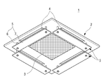
도 1은 종래 기술에 의한 공기조화기의 실내기 외관을 보인 저면 사시도이다.1 is a bottom perspective view showing an appearance of an indoor unit of an air conditioner according to the prior art.
도면에 도시된 바와 같이 카세트형 공기조화기의 실내기(1)(이하 "실내기"라 함)는 천정에 설치되는 본체(2)의 중앙에 흡입구(3)가 형성되고, 상기 흡입구(3)의 외측에 다수의 토출구(4)가 형성된다. 그리고 상기 본체(2)의 내부에는 송풍팬이 구비되어 상기 송풍팬의 구동에 의해 상기 흡입구(3)로 공기를 흡입하여 내부에 구비된 열교환기에서 열교환된 후 상기 토출구(4)로 토출되는 구조를 가진다.As shown in the figure, the indoor unit 1 (hereinafter referred to as "indoor unit") of the cassette type air conditioner has a
그리고, 상기 실내기(1)의 각 토출구(4)의 하방에는 바람막이(5)가 배치된다. 상기 바람막이(5)는 상기 토출구(4)에서 토출되는 공기의 흐름을 가로막아 상기 토출구(4)에서 토출되는 공기가 직접 사용자에게 닿지 않고 실내에 고르게 퍼지도록 한다. 상기 바람막이(5)는 연결부(6)와 바람막이 판(7)으로 이루어지며, 상기 연결부(6)에 의해 상기 실내기(1)의 본체(2) 하면과 상기 바람막이 판(7)은 연결될 수 있게 된다.A windshield (5) is disposed below each of the discharge ports (4) of the indoor unit (1). The
이때, 상기 연결부(6)에는 관절부가 형성되며, 상기 관절부에 의해 상기 연결부(6)는 회전될 수 있으며, 상기 가이드 플레이트(7)은 수평을 기준으로 소정의 각도록 기울어지는 구조를 가질 수 있게 된다.At this time, a joint part is formed in the connection part 6, the joint part 6 can be rotated by the joint part, and the
하지만 이와 같은 구조를 가지는 상기 바람막이(5)는 상기 실내기(1)에 고정된 상태를 유지하게 되므로 바람막이(5)가 필요하지 않은 상황에서는 상기 실내기(1)의 외관을 저해하게 된다.However, since the
그리고, 기존의 실내기 구조에는 상기 바람막이(5)를 설치할 수 없으며, 상기 본체(2)에 구멍을 내어 성형한 후에 장착될 수 있게 된다. 따라서, 상기 바람막이(5)가 불필요한 상황에서 이를 제거하게 될 경우 구멍이 노출되어 외관을 저해하게 되며, 별도의 마감재가 필요하게 되는 문제가 있다.In addition, the windshield (5) can not be installed in the conventional indoor unit structure, and it can be mounted after forming a hole in the main body (2). Therefore, when the
그리고, 기존의 바람막이(5)의 경우 설치를 위해서는 연결부(6) 자체가 관절구조를 가져야 하며, 연결부(6)의 양단은 상기 바람막이(5)와 본체(2)에 각각 고정 가능한 구조를 가져야 하므로 그 구성이 복잡한 단점이 있다.In the case of the existing
그리고, 상기 토출부(4)와 바람막이 판(7)의 사이는 하면을 제외한 모든 면이 개구되어 있으며, 특히 이웃하는 토출구(4)의 사이에는 측방으로 향하는 바람이 서로 부딪힐 수 있게 되어 공기의 흐름이 원할하지 않게 되어 소음이 발생되는 문제가 있다.Between the
그리고, 상기 바람막이(5)를 회동 가능하게 연결하는 연결부(6)의 경우 회동은 가능하지만 별도의 고정을 위한 구조가 없어 일정시간 이상 사용되거나, 바람의 세기가 센 경우 또는 외부에서 부주의로 인해 상기 바람막이(5)와 부딪히게 되는 등 여러 가지 상황에서 회전 각도가 임의 변경될 수 있으며 이러한 경우 원하는 각도로 토출되는 공기를 안내할 수 없는 문제점이 있다.In the case of the connecting portion 6 which rotatably connects the
본 발명의 목적은 토출구의 형상과 대응하는 형상으로 형성되며 실내기의 하면에 직접 회동가능하게 장착되어 토출되는 공기를 안내하는 보다 간결한 구조를 가지는 윈드바이저가 구비되고, 실내기에 상기 윈드바이저가 설치될 수 있는 고정부가 형성되며, 상기 윈드바이저는 상기 고정부에 간결한 구조로 회전 가능하게 결합될 수 있도록 하는 공기조화기의 실내기를 제공하는 것에 있다.An object of the present invention is to provide a wind visor which is formed in a shape corresponding to the shape of a discharge port and which is mounted on a lower surface of an indoor unit so as to be rotatable and which directs discharged air, And the wind visor can be rotatably coupled to the fixed portion with a simple structure.
삭제delete
본 발명의 실시예에 따른 공기조화기의 실내기는, 열교환기와 송풍팬이 수용되는 캐비닛의 하단에 제공되어, 천정면으로 노출되며, 중앙의 흡입구와 상기 흡입구의 외측에 배치되는 다수의 토출구가 형성되는 판넬; 상기 판넬의 모서리에 탈착가능하게 장착되며, 상기 토출구의 양단에 위치되는 코너 커버; 상기 토출구의 하방에서 상기 토출구의 길이와 대응하도록 상기 토출구의 내측단을 따라 연장 형성되며, 상기 토출구에서 토출되는 공기를 측방으로 안내하는 윈드바이저를 포함하되, 상기 윈드바이저는, 토출 공기를 안내하는 면을 형성하는 가이드 플레이트와, 상기 가이드 플레이트의 양단에 구비되는 결합부를 포함하며, 상기 코너 커버 외측에는 상기 결합부와 결합되어 상기 윈드바이저가 고정 장착되는 고정부가 구비되는 것을 특징으로 한다.
상기 토출구와 가이드 플레이트는 좌우 양측단으로 갈수록 폭이 좁아지는 형상을 가지는 것을 특징으로 한다.
상기 가이드 플레이트의 양측단으로 갈수록 상기 판넬의 하면을 향하도록 라운드지게 형성되는 것을 특징으로 한다.
상기 결합부는 상기 가이드 플레이트의 양측단에서 서로 마주보는 방향으로 연장되어, 상기 고정부를 관통하는 나사 형상으로 형성되며, 상기 고정부를 관통한 상기 결합부에는 상기 가이드 플레이트가 설정 각도에서 상기 고정부에서 고정될 수 있도록 하는 캡이 체결되는 것을 특징으로 한다.
상기 결합부는 상기 가이드플레이트의 성형시 일체로 형성되는 것을 특징으로 한다.
상기 결합부는 별도의 부재로 성형되며, 상기 가이드 플레이트에 체결되는 것을 특징으로 한다.
상기 코너 커버에는 상기 결합부와 대응하는 위치에서 절개되어 형성되는 절개부가 형성되고, 상기 고정부는 상기 코너 커버의 장착 위치에 구비되며, 상기 코너 커버의 장착시 상기 절개부를 통과하여 외측으로 노출되는 것을 특징으로 한다.
상기 결합부는, 상기 가이드 플레이트의 양측단에서 내측을 향하여 돌출되며, 상기 고정부에 압입되어 상기 가이드 플레이트의 회전축이 되되, 서로 접하는 상기 결합부의 둘레 및 상기 고정부의 내측면은 서로 대응하는 다수의 평면으로 구성되는 것을 특징으로 한다.
상기 결합부는 중앙부가 길이 방향으로 절개되어 상기 고정부를 관통하거나 상기 가이드 플레이트의 회전시 탄성 변형될 수 있도록 구성되는 것을 특징으로 한다.
상기 결합부와 상기 고정부의 사이에는 상기 가이드 플레이트의 회전축이되는 연결부재가 구비되는 것을 특징으로 한다.
상기 연결부재는, 상기 결합부에 연결되는 제 1 연결부재와, 상기 고정부에 연결되는 제 2 연결부재로 구성되며, 상기 제 1 연결부재와 제 2 연결부재는 서로 회전 가능하게 결합되는 것을 특징으로 한다.
상기 제 1 연결부재에는 제 2 연결부재의 내측으로 삽입되도록 돌출되는 회전부와, 상기 회전부의 둘레에는 치형부가 형성되며, 상기 제 2 연결부재에는 상기 회전부를 관통하는 회전축과, 상기 치형부의 외측면과 접하여 상기 제 1 연결부재 및 제 2 연결부재의 상대 회전을 선택적으로 구속하는 제한부를 포함하여 구성되는 것을 특징으로 한다.
상기 연결부재는, 상기 가이드 플레이트의 단부에 결합되는 장착돌기와; 상기 장착돌기의 하부에 형성되며, 상기 고정부의 내측으로 삽입되도록 돌출되는 회전부와; 상기 회전부의 둘레에 형성되는 치형을 포함하여 구성되는 것을 특징으로 한다.
상기 고정부에는 상기 회전부가 수용 가능하며, 상기 치형과 대응하는 치형부가 형성되는 개구가 형성되며, 상기 개구의 중앙은 절개되어 상기 회전부의 회전시 탄성 변형되는 것을 특징으로 한다.The indoor unit of the air conditioner according to the embodiment of the present invention is provided at the lower end of the cabinet in which the heat exchanger and the blowing fan are housed and is exposed at the ceiling face and has a central suction port and a plurality of discharge ports arranged outside the suction port Panel; A corner cover detachably mounted on an edge of the panel and positioned at both ends of the discharge port; And a wind visor extending along an inner end of the discharge port to correspond to a length of the discharge port below the discharge port and guiding the air discharged from the discharge port in a lateral direction, And a fixing part which is coupled to the coupling part and is fixedly mounted on the wind visor is provided on the outer side of the corner cover.
Wherein the discharge port and the guide plate have a shape that becomes narrower toward both left and right ends.
And the guide plates are formed to be rounded toward the lower side of the panel toward both side ends of the guide plate.
Wherein the engaging portions extend in opposite directions at opposite ends of the guide plate and are formed in a screw shape passing through the fixing portion, and the guide plate, which penetrates the fixing portion, So that the cap can be fixed.
And the engaging portion is integrally formed when the guide plate is formed.
The coupling portion is formed as a separate member, and is fastened to the guide plate.
The corner cover is formed with a cut portion formed at a position corresponding to the engaging portion. The fixing portion is provided at a mounting position of the corner cover, and is exposed to the outside through the cut portion when the corner cover is mounted .
Wherein the engaging portion protrudes inward from both side ends of the guide plate and is press-fitted into the fixing portion to serve as a rotation axis of the guide plate, and the periphery of the engaging portion and the inner surface of the fixing portion, Plane.
And the coupling portion is configured such that a central portion thereof is cut in a longitudinal direction and penetrates through the fixing portion or is elastically deformed when the guide plate rotates.
And a connecting member which is a rotating shaft of the guide plate is provided between the engaging part and the fixing part.
The connection member may include a first connection member connected to the connection portion and a second connection member connected to the fixing portion. The first connection member and the second connection member are rotatably coupled to each other .
The first connection member is formed with a rotation part protruded to be inserted into the second connection member, and a tooth part is formed around the rotation part. The second connection member includes a rotation shaft passing through the rotation part, And a restricting portion for selectively restricting the relative rotation of the first linking member and the second linking member.
The connecting member includes: a mounting protrusion coupled to an end of the guide plate; A rotation part formed at a lower portion of the mounting projection and protruding to be inserted into the fixing part; And a tooth formed around the rotation part.
The fixing part is provided with an opening in which the rotation part is accommodated and in which a toothed part corresponding to the toothed part is formed, and the center of the opening is cut so that the rotation part is elastically deformed upon rotation of the rotation part.
삭제delete
삭제delete
삭제delete
삭제delete
삭제delete
삭제delete
삭제delete
삭제delete
삭제delete
삭제delete
삭제delete
삭제delete
삭제delete
삭제delete
삭제delete
삭제delete
삭제delete
삭제delete
삭제delete
삭제delete
삭제delete
삭제delete
삭제delete
상기한 바와 같은 구성을 가지는 본 발명에 따르면, 토출구에서 토출되는 공기를 측방으로 가이드 하는 가이드 플레이트의 양단이 라운드진 형상으로 형성되어, 이웃하는 토출구에서 토출되는 공기와 간섭되지 않고 각각의 방향으로 토출될 수 있게 되어 공기의 흐름이 개선될 수 있다.According to the present invention having such a construction as described above, both ends of the guide plate for guiding air discharged from the discharge port to the side are formed in a rounded shape, and discharged in the respective directions without interfering with the air discharged from the adjacent discharge port So that the flow of air can be improved.
그리고, 가이드 플레이트와 회전 가능하게 결합되는 고정부는 탈착 가능한 코너커버와 일체로 형성될 수 있으며, 따라서 별도의 체결을 위한 구성이 없이 상기 가이드 플레이트와 고정부의 직접적인 결합에 의한 결합과 분리가 가능하여 조립성 및 생산성이 향상될 수 있다.The fixing part rotatably coupled to the guide plate can be integrally formed with the detachable corner cover, so that the guide plate can be coupled and separated by a direct coupling between the guide plate and the fixing part without a separate fastening structure The assemblability and the productivity can be improved.
또한, 상기 고정부가 코너 커버에 구비되거나, 판넬에 장착되도록 구성됨으로써 윈드바이저의 사용이 불필요한 경우에는 상기 코너 커버의 교체 만으로 완전한 외관의 유지가 가능하게 되므로 윈드바이저 설치 및 분리에 따른 외관의 저해를 방지하게 된다.In addition, since the fixing part is provided on the corner cover or mounted on the panel, when the use of the wind visor is not necessary, it is possible to maintain the complete appearance only by replacing the corner cover, thereby preventing the appearance of the wind visor .
또한, 기존에 설치되어 있는 실내기에 코너 커버만 교체 하는 것으로 상기 윈드바이저의 장착이 가능하게 되므로, 다양한 제품에 적용될 수 있는 이점이 있다.In addition, since the wind visor can be mounted by replacing only the corner cover in the existing indoor unit, there is an advantage that it can be applied to various products.
그리고, 상기 가이드 플레이트는 각도의 조절을 위해서 설정각도에서 캡을 조여 결합시키거나, 둘레면이 다수의 평면으로 이루어지는 결합부를 형성하거나, 연결부재가 치형의 구조를 갖도록 하여 상기 가이드 플레이트가 일정 각도로 회전되며 회전된 상태를 유지할 수 있도록 하여, 임의로 각도가 변경되거나 유동이 발생되는 등의 문제를 해결할 수 있다.In addition, the guide plate may be formed by coupling a cap at a set angle for adjusting the angle, or by forming a coupling portion having a plurality of circumferential planes, or the coupling member may have a tooth-like structure, It is possible to maintain the rotated and rotated state, thereby solving the problem that the angle is arbitrarily changed or the flow is generated.
도 1은 종래 기술에 의한 공기조화기의 실내기 외관을 보인 저면 사시도이다.
도 2는 본 발명의 제 1 실시예에 의한 윈드바이저가 구비된 공기조화기의 실내기의 외관을 보인 저면 사시도이다.
도 3은 상기 공기조화기의 실내기의 분해 사시도이다.
도 4는 본 발명의 제 1 실시예에 의한 윈드바이저의 분해 사시도이다.
도 5 및 도 6은 상기 윈드바이저의 결합 구조를 보인 부분 사시도이다.
도 7은 상기 윈드바이저가 장착된 상기 실내기의 공기 유동 상태를 보인 부분 단면도이다.
도 8은 본 발명의 제 2 실시예에 의한 윈드바이저가 장착된 부분 사시도이다.
도 9은 상기 윈드바이저의 결합구조를 보인 부분 분해 사시도이다.
도 10은 본 발명의 제 3 실시예에 의한 윈드바이저가 장착된 부분 사시도이다.
도 11은 상기 윈드바이저의 결합구조를 보인 부분 분해 사시도이다.
도 12는 본 발명의 제 4 실시예에 의한 윈드바이저가 장착된 부분 사시도이다.
도 13은 상기 윈드바이저의 결합구조를 보인 부분 분해 사시도이다.
도 14 및 도 15 는 상기 윈드바이저의 일구성인 연결부재의 사시도이다.
도 16은 상기 연결부재의 동작 상태를 보인 도면이다.
도 17은 본 발명의 제 5 실시예에 의한 윈드바이저가 장착된 부분 사시도이다.
도 18은 상기 윈드바이저의 결합구조를 보인 부분 분해 사시도이다.
도 19는 본 발명의 제 6 실시예에 의한 윈드바이저가 장착된 부분 사시도이다.
도 20은 상기 윈드바이저의 결합구조를 보인 부분 분해 사시도이다.1 is a bottom perspective view showing an appearance of an indoor unit of an air conditioner according to the prior art.
2 is a bottom perspective view showing an appearance of an indoor unit of an air conditioner having a wind visor according to a first embodiment of the present invention.
3 is an exploded perspective view of the indoor unit of the air conditioner.
4 is an exploded perspective view of a wind visor according to a first embodiment of the present invention.
5 and 6 are partial perspective views showing a coupling structure of the wind visor.
7 is a partial cross-sectional view showing an air flow state of the indoor unit to which the wind visor is attached.
8 is a partial perspective view of a wind visor according to a second embodiment of the present invention.
FIG. 9 is a partially exploded perspective view showing a coupling structure of the wind visor. FIG.
10 is a partial perspective view of a wind visor according to a third embodiment of the present invention.
11 is a partially exploded perspective view showing the coupling structure of the wind visor.
12 is a partial perspective view of a wind visor according to a fourth embodiment of the present invention.
Fig. 13 is a partially exploded perspective view showing a coupling structure of the wind visor. Fig.
14 and 15 are perspective views of a connecting member which is one configuration of the wind visor.
16 is a view showing an operating state of the connecting member.
17 is a partial perspective view of a wind visor according to a fifth embodiment of the present invention.
18 is a partially exploded perspective view showing the coupling structure of the wind visor.
19 is a partial perspective view of a wind visor according to a sixth embodiment of the present invention.
20 is a partially exploded perspective view showing a coupling structure of the wind visor.
이하에서는 본 발명의 구체적인 실시예를 도면과 함께 상세히 설명하도록 한다. 그러나 본 발명은 본 발명의 사상이 제시되는 실시예에 제한된다고 할 수 없으며, 또 다른 구성요소의 추가, 변경, 삭제 등에 의해서 퇴보적인 다른 발명이나 본 발명의 사상범위 내에 포함되는 다른 실시예를 용이하게 제안할 수 있다.Hereinafter, specific embodiments of the present invention will be described in detail with reference to the drawings. However, it should be understood that the present invention is not limited to the embodiment shown in the drawings, and that other embodiments falling within the spirit and scope of the present invention may be easily devised by adding, .
도 2는 본 발명의 제 1 실시예에 의한 윈드바이저가 구비된 공기조화기의 실내기의 외관을 보인 저면 사시도이다. 그리고, 도 3은 상기 공기조화기의 실내기의 분해 사시도이다.2 is a bottom perspective view showing an appearance of an indoor unit of an air conditioner having a wind visor according to a first embodiment of the present invention. 3 is an exploded perspective view of the indoor unit of the air conditioner.
도면에 도시된 바와 같이, 본 발명의 제 1 실시예에 의한 공기조화기의 실내기(10)(이하 "실내기"라 칭함)는 전체적으로 실내 공간의 천장 내부에 삽입되어 매립되는 캐비넷(미도시)과, 상기 캐비넷의 하단에 구비되어 하면의 외관을 형성하며 상기 실내기의 설치시 상기 천장의 하측으로 노출되는 판넬(100) 및 흡입 그릴(110)로 구성될 수 있다.As shown in the drawings, an indoor unit 10 (hereinafter referred to as "indoor unit") of an air conditioner according to a first embodiment of the present invention includes a cabinet (not shown) A
그리고, 상세하게 도시되지는 않았지만, 상기 캐비넷의 내부에는 흡입되는 공기와 열교환되는 열교환기와, 실내공기의 강제 흡입 및 토출을 위한 송풍팬 등이 구비될 수 있다.Although not shown in detail, the cabinet may include a heat exchanger for heat exchange with air to be sucked, and a blower fan for forced suction and discharge of indoor air.
상기 판넬(100)은 상기 캐비넷의 하단에 장착되며, 하방에서 바라볼 때 대략 사각형 형상으로 형성될 수 있다. 그리고, 상기 판넬(100)은 상기 캐비넷의 하단보다 더 외측으로 돌출되도록 형성되어 둘레부가 상기 천장의 하면과 접하도록 구성될 수 있다. The
그리고 상기 판넬(100)에는 상기 캐비넷의 내측을 경유하여 열교환된 공기가 토출되는 토출구(101)가 천공 형성될 수 있다. 상기 토출구(101)는 상기 판넬(100)의 각 변과 대응하는 위치에 형성될 수 있다. 그리고, 상기 토출구(101)는 상기 판넬(100)의 각 변의 길이방향을 따라 길게 형성될 수 있으며, 상기 판넬(100)에 장착되는 베인(120)에 의해 개폐되도록 구성될 수 있다.A
상기 판넬(100)은 대략 사각형 형상의 판상으로 형성되며, 중앙에는 흡입구(102)가 천공되어 형성된다. 상기 흡입구(102)는 실내공기가 흡입되는 것으로, 사각형 형상으로 형성되며, 상기 흡입 그릴(110)의 크기보다는 다소 작게 형성될 수 있다.The
상기 흡입구(102)의 외측에는 상기 토출구(101)가 형성된다. 상기 토출구(101)는 상하좌우 모두 네개가 구비될 수 있으며, 각 변의 방향을 따라서 길게 형성될 수 있다. 이때, 상기 토출구(101)의 양측 단부는 외측으로 갈수록 좁아지는 곡선 형상으로 형성된다. The discharge port (101) is formed outside the suction port (102). The
그리고, 상기 흡입구(102) 외측에는 그릴 안착부(103)가 형성된다. 상기 그릴 안착부(103)는 상기 흡입 그릴(110)이 지지될 수 있도록 단차지게 형성된다. 상기 그릴 안착부(103)의 둘레는 전체적으로 상기 토출구(101)의 외측 라인을 연결하는 폐곡선 형상으로 형성된다. A
그리고, 상기 흡입 그릴(110)이 장착된 상태에서는 상기 그릴 안착부(103)의 둘레는 라운드 홈(104)을 형성하게 된다. 상기 라운드 홈(104)은 네 모서리가 라운드 처리된 사각형 형상으로 형성될 수 있다. 그리고, 상기 라운드 홈(104)의 모서리 부분은 상기 흡입 그릴(110)의 돌출부(112)의 단부와 대응하는 라인을 형성하도록 하여 상기 토출구(101)의 베인(120)과 흡입 그릴(110) 및 상기 판넬(100)이 전체적으로 일체감을 느낄 수 있도록 형성된다.In the state where the
그리고, 상기 라운드 홈(104)은 토출되는 공기가 상기 판넬(100)을 따라 흐르지 않고 실내 공간을 향하도록 단면이 소정의 라운드 또는 경사를 가지도록 형성되어 상기 토출구(101)에서 토출되는 공기에 의해 천장면이 젖거나 오염되지 않도록 한다.The
상기 토출구(101)는 베인(120)에 의해 개폐될 수 있으며, 상기 베인(120)의 좌우 양측 중 적어도 일측의 단부에는 모터 어셈블리(121)가 구비되어 상기 베인(120)이 상기 모터 어셈블리(121)에 의해 회전되어 상기 토출구(101)를 개폐되거나 토출되는 공기의 방향을 조절하도록 구성될 수 있다.The
상기 베인(120)의 형상은 상기 토출구(101)의 형상과 대응하도록 형성되어 상기 토출구(101)를 차폐할 수 있도록 형성될 수 있다. 그리고, 상기 베인(120)은 상기 토출구(101)와 동일하게 양측 단부가 외측으로 갈수록 폭이 좁아지도록 형성될 수 있다. The shape of the
또한, 상기 베인(120)은 닫힌 상태에서, 상기 베인(120)의 외측단은 상기 라운드 홈(104)을 따라 연장되어 상기 판넬(100)과 접하고, 상기 베인(120)의 내측단은 상기 흡입 그릴(110)의 요입부(111)와 접하도록 형성될 수 있다.The outer end of the
한편, 상기 판넬(100)의 네 모서리에는 코너 커버(130)가 장착되는 커버 장착부(105)가 형성된다. 상기 커버 장착부(105)는 하방으로 단차지게 형성되어 상기 코너 커버(130)의 장착시 상기 코너 커버(130)의 상면(도 2에서 볼 때)과 상기 판넬(100) 및 흡입 그릴(110)의 상면이 동일 평면을 형성하여 일체감을 가질 수 있도록 한다.On the other hand, a
그리고, 구체적으로 도시되지는 않았지만 상기 커버 장착부(105)와 상기 코너 커버(130)의 사이에는 커버의 결합을 위한 구조가 더 형성될 수 있다. 즉, 상기 코너 커버(130)가 상기 판넬(100)에 탈착 가능하게 제공될 수 있도록, 상기 코너 커버(130)가 슬라이딩 삽입될 수 있도록 서로 대응하는 형상의 리브와 슬롯 형상의 구조를 가질 수도 있고, 슬라이딩 삽입 후 일측이 후크 형상으로 형합되어 걸림 구속되는 구조를 가질 수도 있다.Further, although not specifically shown, a structure for coupling the cover may be further formed between the
또한, 상기 판넬(100)의 네 모서리에는 점검구가 천공되어 형성될 수 있다. 상기 점검구는 상기 판넬(100)의 고정 및 설치를 위한 공간을 제공함과 동시에 상기 판넬(100) 배면에 장착되는 전장 부품들의 서비스 또는 상기 실내기(10)의 동작 확인을 위한 것으로 코너 커버(130)에 의해 개폐되도록 구성될 수 있다. 이때, 상기 점검구와 코너 커버(130)는 상기 판넬(100)의 네 모서리에 모두 형성될 수도 있고 필요에 따라 적어도 하나의 위치에 형성될 수 있다.In addition, an inspection hole may be formed in the four corners of the
그리고, 상기 코너 커버(130)의 단부는 상기 라운드 홈(104)을 경계로 상기 흡입 그릴(110)의 돌출부(112) 단부와 마주보도록 배치된다. 이때, 상기 코너 커버(130)와 상기 돌출부(112)는 모두 상기 라운드 홈(104)과 대응하는 라인을 가지도록 형성되어 전체적으로 일체감이 있는 외관을 형성할 수 있도록 한다.The end of the
상기 판넬(100)의 그릴 안착부(103)에는 필요에 따라 별도의 판넬 브라켓(140)이 장착될 수도 있으며, 상기 판넬 브라켓(140)은 상기 그릴 안착부(103)의 보강은 물론, 상기 그릴 안착부(103)에 장착되는 흡입 그릴(110)의 장착 및 개폐를 위한 구성들이 안정적으로 지지될 수 있도록 구성될 수 있다. 물론, 필요에 따라 상기 판넬 브라켓(140)이 구비되지 않고, 상기 그릴 안착부(103)와 판넬 브라켓(140)이 일체로 구성되어 상기 그릴 안착부(103)가 판넬 브라켓(140)의 기능을 수행할 수도 있을 것이다.A
상기 흡입 그릴(110)은 상기 그릴 안착부(103)에 장착되며, 상기 흡입 그릴(110)이 장착된 상태에서 상기 판넬(100)의 하면과 상기 흡입 그릴(110)의 하면은 동일 평면상에 위치되어 일체감을 가질 수 있도록 형성될 수 있다.The
그리고, 상기 흡입 그릴(110)의 각 변에는 요입부(111)가 형성된다. 상기 요입부(111)는 각 상기 토출구(101)의 내측의 라인과 동일한 위치에 형성될 수 있다. 그리고, 상기 흡입 그릴(110)이 장착된 상태에서 상기 토출구(101)의 내측 라인과 상기 요입부(111)는 동일한 형상으로 형성된다. 즉, 상기 요입부(111)는 양측단이 라운드형상으로 형성되며, 이때의 곡률은 상기 토출구(101) 및 베인(120)의 형상과 대응하도록 형성될 수 있다.Each of the
따라서, 상기 흡입 그릴(110)이 닫힌 상태에서는 상기 베인(120)의 내측 라인과 상기 흡입 그릴(110)의 단부는 동일 간격으로 인접하게 되며, 상기 흡입 그릴(110)과 판넬(100)은 보다 일체감을 가질 수 있게 된다.Therefore, when the
아울러, 상기 흡입 그릴(110)의 네 모서리에는 돌출부(112)가 형성된다. 상기 돌출부(112)는 상기 각각의 요입부(111) 사이의 영역을 형성하며, 상기 요입부(111) 보다 더 돌출되는 형상으로 형성될 수 있다. 이때, 상기 돌출부(112)는 상기 흡입 그릴(110)의 장착시 각각의 상기 토출구(101) 사이에 위치되며, 상기 돌출부(112)의 단부는 상기 라운드 홈(104)의 곡률과 동일한 곡률로 라운드지게 형성될 수 있다. 따라서, 상기 흡입 그릴(110)이 장착된 상태에서는 상기 흡입 그릴(110) 및 상기 베인(120)이 형성하는 둘레의 형상과 상기 라운드 홈(104)의 형상은 동일하게 형성될 수 있다.In addition,
한편, 상기 돌출부(112)의 폭은 상기 코너 커버(130)의 폭과 동일한 크기로 형성될 수 있으며, 상기 돌출부(112)를 따라 형성되는 사이드 홈(106)은 상기 코너 커버(130)의 양측을 따라 연장되어 상기 판넬(100)의 단부까지 형성될 수 있게 된다. 그리고, 상기 사이드 홈(106)은 상기 흡입 그릴(110)의 요입부(111) 및 상기 베인(120)의 내측 라인과 연결될 수 있도록 형성될 수 있다. The width of the
따라서, 상기 실내기(10)가 설치된 상태에서 상기 실내기(10)의 하면을 바라보게 될 때 상기 라운드 홈(104)이 중앙에 위치되고, 네 방향으로 각각의 상기 사이드 홈(106)이 나타나게 된다. 그리고, 상기 라운드 홈(104) 및 사이드 홈(106)에 의해 상기 흡입 그릴(110)과 토출구(101) 및 베인(120)의 형상이 정의될 수 있게 된다.Therefore, when the lower surface of the
그리고, 상기 흡입 그릴(110)의 일단에는 상기 흡입 그릴이 고정 및 선택적인 구속을 위한 구조가 제공될 수도 있다. 따라서, 상기 흡입 그릴(110)은 상기 실내기(10) 내부의 서비스가 필요하거나 필터의 교환이 필요한 경우 개방될 수 있도록 구성된다.In addition, a structure for fixing and selectively restraining the suction grille may be provided at one end of the
한편, 상기 흡입 그릴(110)의 상면에는 공기를 정화하기 위한 필터 어셈블리(150)가 구비될 수 있으며, 상기 필터 어셈블리(150)의 내부에는 이물질을 걸러내고 물리 화학적으로 흡입되는 공기를 정화가기 위한 상기 에어필터가 구비된다. 상기 에어필터 또는 상기 필터 어셈블리(150)는 설정된 시간 또는 사용 시간의 경과 후에 분리되어 교체될 수 있도록 구성될 수 있다.A
상기 흡입 그릴(110)의 중앙에는 격자형상으로 형성된 흡입부(113)가 형성된다. 상기 흡입부(113)는 상기 판넬(100)의 흡입구(102)의 내측 영역에 위치되며, 흡입되는 공기가 온전히 상기 판넬(100)을 통해 상기 캐비넷 내측으로 유동될 수 있도록 한다.The
한편, 상기 각각의 토출구(101)에는 윈드바이저(200)가 구비된다. 상기 윈드바이저(200)는 상기 토출구(101)에서 토출되는 공기가 상기 실내기(10) 하방의 사용자에게 직접 전해지지 않도록 토출되는 공기를 측방으로 안내하는 것으로, 상기 각각의 토출구(101)의 형상과 대응하는 위치에 위치되며 대응하는 형상으로 형성될 수 있다.On the other hand, each of the
이하에서는 도면을 참조하여 상기 윈드바이저에 관하여 보다 상세하게 살펴보기로 한다.Hereinafter, the wind visor will be described in more detail with reference to the drawings.
도 4는 본 발명의 제 1 실시예에 의한 윈드바이저의 분해 사시도이다. 그리고, 도 5 및 도 6은 상기 윈드바이저의 결합 구조를 보인 부분 사시도이다. 4 is an exploded perspective view of a wind visor according to a first embodiment of the present invention. 5 and 6 are partial perspective views showing the coupling structure of the wind visor.
도면에 도시된 것과 같이, 상기 윈드바이저(200)는 상기 토출구(101)의 가로방향 길이와 대응하는 형상으로 연장 형성되며, 좌우 양측단은 측방으로 갈수록 폭이 좁아지는 형상으로 형성될 수 있다.As shown in the drawing, the
이때, 상기 윈드바이저(200)의 종 단면 형상은 라운드지게 형성되며, 상기 윈드바이저(200)의 좌우 양측단 또한 내측을 향하여 라운드지게 형성된다. 따라서, 상기 토출구(101)에서 토출되는 공기는 상기 윈드바이저(200)의 내측면을 따라서 유동되어 자연스럽게 측방을 향하여 토출되며, 특히 상기 토출구(101) 좌우 양측단측에서 토출되는 공기는 곡률을 따라 윈드바이저(200)의 내측 방향으로 토출될 수 있게 된다.At this time, the vertical cross-sectional shape of the
이와 같은 상기 윈드바이저(200)가 각각 네 방향의 토출구에 구비될 수 있으며, 따라서 각각의 상기 토출구(101)에서 토출되는 공기는 윈드바이저(200)에 의해 서로 간섭되지 않고 측방향으로 토출될 수 있다.Each of the
그리고, 상기 윈드바이저(200)는 장착된 상태에서 상기 윈드바이저(200)의 외측단이 상기 토출구(101)의 내측라인 즉 상기 요입부(111)를 따라서 연장될 수 있도록 형성될 수 있으며, 상기 윈드바이저(200)의 하단은 상기 라운드 홈(104)의 외측단 보다 더 외측에 위치하여 토출되는 공기를 안정적으로 측방향으로 안내할 수 있도록 구성된다.The
한편, 상기 윈드바이저(200)의 구성을 보다 상세하게 살펴보면, 상기 윈드바이저(200)는 공기의 유동을 안내하는 가이드 플레이트(210)와, 상기 가이드 플레이트(210)가 상기 코너 커버(130)에 고정될 수 있도록 하는 고정부(131)를 포함하여 구성된다. The
그리고, 상기 가이드 플레이트(210)는 상기 고정부(131)에 회전 가능하게 장착되어 사용자가 원하는 경우 상기 가이드 플레이트(210)는 상기 고정부(131)를 축으로 하여 회전시켜 상기 윈드바이저(200)에 의해 안내되는 공기의 토출 각을 조절할 수도 있다.The
상기 가이드 플레이트(210)는 플라스틱 소재로 사출 형성될 수 있으며, 판상으로 형성될 수 있다. 그리고, 상기 가이드 플레이트(210)의 양단에는 상기 고정부(131)에 삽입되는 결합부(211)가 더 형성된다.The
상기 결합부(211)는 볼트 형상으로 형성되며, 상기 고정부(131)의 외측에서 상기 고정부(131)를 관통하도록 상기 가이드 플레이트(210)의 양단에서 서로 마주보는 방향으로 연장 형성된다. 이때, 상기 결합부(211)의 외주면에는 나사산이 형성될 수 있으며, 상기 고정부(131)의 내측에서 체결되는 캡(220)과 체결되어 상기 윈드바이저(200)가 고정되도록 할 수 있다.The engaging
상기 결합부(211)는 상기 가이드 플레이트(210)의 성형시 플라스틱 소재로 함께 사출 형성될 수 있으며, 금속소재의 볼트가 상기 가이드 플레이트(210)의 성형시 인서트 사출되어 형성될 수 있다. 물론, 상기 결합부(211)는 별도의 볼트로 구성되어 상기 가이드 플레이트(210)의 외측에서 상기 가이드 플레이트(210)의 단부와 고정부(131)를 관통하도록 체결될 수도 있을 것이다.The
한편, 상기 고정부(131)는 상기 가이드 플레이트(210)의 양단과 대응하는 상기 코너 커버(130)에 형성될 수 있다. 상기 고정부(131)는 상기 코너 커버(130)에서 상방으로 연장 형성되며, 상기 결합부(211)가 관통될 수 있는 결합홀이 형성된다.The fixing
상기 고정부(131)는 상기 코너 커버(130)의 성형시 사출에 의해 일체로 형성될 수 있게 된다. 따라서, 별도의 결합 또는 장착 없이 상기 코너 커버(130)의 성형에 의해 형성될 수 있게 되며, 상기 가이드 플레이트(210)와의 결합에 의해 상기 윈드바이저(200)를 구성하게 된다.The fixing
그리고, 상기 윈드바이저(200)는 상기 결합부(211)를 축으로 하여 회전 될 수 있으며, 사용자가 설정한 각도에서 상기 결합부(211)에 캡(220)을 결합시키는 것으로 상기 윈드바이저(200)의 각도를 조정하게 된다.The
상기 윈드바이저(200)가 불필요한 경우 상기 코너 커버(130)를 분리하고, 상기 결합부(211)가 형성되지 않은 코너 커버(130)를 상기 판넬(100)에 장착할 경우 외관을 저해하지 않게 된다.When the
그리고, 상기 윈드바이저(200)를 분리 및 장착하고자 하는 경우 상기 결합부(211)와 상기 캡(220)을 서로 분리 결합하는 것으로 작업이 완료될 수 있으므로, 보다 간편하고 용이하게 분리 장착 가능하게 된다.In addition, when the
이하에서는 상기와 같은 구조를 가지는 공기조화기의 실내기의 동작 상태를 도면을 참조하여 살펴보기로 한다.Hereinafter, operation of the indoor unit of the air conditioner having the above structure will be described with reference to the drawings.
도 7은 상기 윈드바이저가 장착된 상기 실내기의 공기 유동 상태를 보인 부분 단면도이다.7 is a partial cross-sectional view showing an air flow state of the indoor unit to which the wind visor is attached.
도면에 도시된 것과 같이, 상기 실내기(10)의 구동시 실내의 공기는 상기 흡입 그릴(110)을 통해서 상기 실내기(10)의 내측으로 흡입될 수 있게 된다. 그리고, 상기 실내기(10)의 내측에서 열교환된 후 다수의 토출구(101)를 통해서 외측으로 배출된다.As shown in the drawing, the indoor air can be sucked into the
상기 토출구(101)에 구비되는 베인(120)의 회전시 상기 베인(120)의 방향에 따라 토출되는 공기의 방향이 결정될 수 있으며, 각각의 토출구(101)에서는 외측 방향으로 공기를 토출하게 된다.The direction of the air discharged in accordance with the direction of the
이때, 토출구(101)의 외측 라인은 상기 라운드 홈(104)에 의해 형성되며, 상기 라운드 홈(104)은 단면의 형상이 라운드지게 형성되어 토출되는 공기는 판넬(100)의 외측면을 따라 흐르지 않고 실내공간으로 토출될 수 있게 된다. 따라서, 토출되는 공기는 상기 토출구(101) 외측의 판넬(100) 또는 천장면을 오염시키지 않고 실내측으로 공급될 수 있게 된다.At this time, the outer line of the
한편, 판넬(100)의 상기 토출구(101)의 양측단은 외측으로 갈수록 폭이 좁아질 뿐만 아니라 라운드지게 형성되어 단부의 형상이 뾰족하게 형성될 수 있다. 그리고, 상기 토출구(101)의 내측면을 형성하는 가이드부재가 경사지게 형성되고, 특히 토출구(101)의 양측단의 경우 상기 토출구(101)의 양측단을 향하여 라운드지도록 형성될 수 있다.On the other hand, the both side ends of the
따라서, 토출되는 공기는 상기 토출구(101)의 양측단에서 토출되는 공기의 기류를 중앙측을 향하여 모아 줄 수 있게 되며, 따라서 상기 토출구(101)의 양단 및 상기 베인(120)의 단부에 이슬맺힘이 발생되지 않도록 한다.Accordingly, the air to be discharged can collect the airflow of the air discharged from both side ends of the
한편, 토출구(101)를 통해 배출되는 공기는 상기 윈드바이저(200)에 의해 안내되어 측방으로 토출될 수 있게 된다. 즉, 상기 토출구(101)에서 배출되는 공기는 상기 윈드바이저(200)의 가이드 플레이트(210)의 내측면 곡률을 따라서 유동하게 되며, 결국 개구된 측방을 향하여 배출될 수 있게 된다.On the other hand, the air discharged through the
이때, 상기 가이드 플레이트(210)의 좌우 양측단 또한 상기 토출구(101)의 형상과 마찬가지로 외측으로 갈수록 좁아지는 형상으로 형성되어, 토출되는 공기는 상기 가이드 플레이트(210)의 좌우 양측방 즉 외측이 아닌 상기 가이드 플레이트(210)의 내측 방향으로 토출될 수 있게 된다. 따라서, 네 방향으로 배치되는 상기 각각의 토출구(101)에서 토출되는 공기는 서로 부딪히거나 간섭되지 않고 각각의 방향으로 토출될 수 있게 된다.At this time, the left and right side ends of the
또한, 상기 가이드 플레이트(210)는 상기 토출구(101)의 내측 라인을 따라서 접하도록 형성되므로, 상기 토출구(101)에서 토출되는 공기는 모두 외측으로 토출될 수 있게 되어 상기 흡입 그릴(110)을 통해서 흡입되는 공기의 흐름을 방해하지 않고 상기 흡입 그릴(110)을 통해 재유입되는 것을 방지하게 된다.Since the
한편, 상기 윈드바이저(200)의 조작을 통해서 토출되는 공기의 토출 각도를 조절할 수도 있다. 상기 가이드 플레이트(210)는 상기 결합부(211)를 축으로 하여 회전 할 수 있으며, 상기 가이드 플레이트(210)를 설정된 각도만큼 회전시킨 후 상기 캡(220)을 결합하여 상기 가이드 플레이트(210)를 고정할 수 있게 된다. 이러한 조작을 통해서 실내기(10)의 구동시 실내 공간의 사용자에게 토출되는 공기가 직접 닿는 것을 방지할 수 있게 된다.Meanwhile, the discharge angle of air discharged through the operation of the
그리고, 상기 윈드바이저(200)의 사용이 필요하지 않는 상황에서는 상기 캡(220)의 분리 후 상기 가이드 플레이트(210)를 분리하는 간단한 작업으로 처리 가능하게 된다. 그리고, 장기간 상기 윈드바이저(200)를 사용하지 않거나, 윈드바이저(200)를 전혀 사용하지 않는 경우에는 상기 고정부(131)가 형성되지 않은 상기 코너 커버(130)를 장착하는 것으로, 상기 실내기의 외관이 깔끔한 상태로 유지될 수 있도록 할 수 있다.In a situation where the use of the
한편, 본 발명에 의한 윈드바이저가 구비된 공기조화기의 실내기는 전술한 제 1 실시예외에도 다양한 다른 실시예가 가능할 것이다.Meanwhile, the indoor unit of the air conditioner having the wind visor according to the present invention may have various other embodiments in addition to the first embodiment described above.
본 발명의 제 2 실시예에 의한 윈드바이저가 구비된 공기조화기의 실내기는 윈드바이저가 가이드 플레이트와 상기 판넬에 구비되는 고정부로 구성되는 것을 특징으로 한다.The indoor unit of the air conditioner having the wind visor according to the second embodiment of the present invention is characterized in that the wind visor is composed of a guide plate and a fixing part provided on the panel.
이때, 본 발명의 제 2 실시예에 의한 윈드바이저가 구비된 공기조화기의 실내기는 상기 윈드바이저 및 코너 커버의 구성에만 차이가 있을 뿐 상기 실내기의 다른 구성은 전술한 실시예와 모두 동일하므로, 동일한 구성에 대해서는 동일한 도면부호를 사용하고 그 상세한 설명은 생략하기로 한다.At this time, the indoor unit of the air conditioner having the wind visor according to the second embodiment of the present invention differs only in the configuration of the wind visor and the corner cover. The other components of the indoor unit are the same as those of the above- The same reference numerals are used for the same components and a detailed description thereof will be omitted.
도 8은 본 발명의 제 2 실시예에 의한 윈드바이저가 장착된 부분 사시도이다. 그리고, 도 9은 상기 윈드바이저의 결합구조를 보인 부분 분해 사시도이다.8 is a partial perspective view of a wind visor according to a second embodiment of the present invention. 9 is a partially exploded perspective view showing the coupling structure of the wind visor.
도면에 도시된 것과 같이, 본 발명의 제 2 실시예에 의한 실내기(10)는 실내공간의 천장 내측에 설치되며, 내부에 송풍팬과 열교환기가 수용되는 캐비넷(미도시)과, 상기 캐비넷의 하단에 구비되며, 실내공간의 천장면으로 노출되어 외관을 형성하는 판넬(100)과 상기 판넬(100)과 상기 판넬(100)의 중앙에 배치되는 흡입 그릴(110)로 구성될 수 있다.As shown in the figure, the
상기 판넬(100)에는 상기 흡입 그릴에 의해 차폐되며 상기 송풍팬의 구동시 공기가 흡입되는 흡입구(도 3에서 102)와, 상기 흡입구(102)의 외측을 따라서 네 방향에 서로 교차되는 방향으로 배치되는 토출구(101)가 형성된다.The
상기 토출구(101)는 상기 판넬(100)의 각 변과 대응하는 방향으로 연장 형성되며, 연장되는 길이 방향의 양측은 외측으로 갈수록 폭이 좁아지도록 형성되어 그 단부가 뾰족하게 형성될 수 있다.The
그리고, 상기 판넬(100)에는 상기 라운드 홈(104)이 형성되며, 상기 판넬(100)의 모서리에 장착되는 상기 코너 커버(160)에도 상기 라운드 홈(104)의 일부가 형성되어 상기 코너 커버(160)의 장착시 상기 라운드 홈(104)은 전체적으로 폐곡선을 형성할 수 있게 된다.The
그리고, 상기 흡입 그릴(110)에는 상기 토출구(101)의 내측 라인과 대응하는 형상으로 함몰된 요입부(111)가 각 변에 형성되고, 네 모서리에는 돌출부(112)가 형성된다. 따라서, 상기 흡입 그릴(110)의 장착에 의해 상기 토출구(101)가 정의 될 수 있게 된다.The
한편, 상기 판넬(100)의 네 모서리에는 상기 코너 커버(160)가 장착되는 커버 장착부(107)가 형성된다. 상기 커버 장착부(107)는 하방으로 단차지게 형성되어 상기 코너 커버(160)의 장착시 상기 코너 커버(160)의 상면(도 8에서 볼 때)과 상기 판넬(100) 및 흡입 그릴(110)의 상면이 동일 평면을 형성하여 일체감을 가질 수 있도록 한다.On the other hand, a
그리고, 상기 커버 장착부(107)와 상기 코너 커버(160)의 사이에는 상기 코너 커버(160)가 결합되는 결합 구조가 제공되어 상기 코너 커버(160)가 상기 판넬(100)에 탈착 가능하게 제공될 수 있다. 상기 코너 커버(160)의 결합 구조는 상기 코너 커버(160)가 슬라이딩 삽입될 수 있도록 서로 대응하는 형상의 리브와 슬롯 형상으로 이루어질 수도 있고, 슬라이딩 삽입 후 일측이 후크 형상으로 형합되어 걸림 구속되는 구조로 이루어질 수 있다.A coupling structure in which the
한편, 상기 커버 장착부(107)에는 아래에서 설명할 윈드바이저(300)의 일 구성인 고정부(310)가 장착되며, 상기 코너 커버(160)에는 상기 커버 장착부(107)에 장착된 고정부(310)가 장착될 수 있는 공간이 형성된다.The
따라서, 상기 코너 커버(160)의 장착시 상기 상기 코너 커버(160)의 외측으로 상기 고정부(310)의 적어도 일부가 외측으로 돌출되어 노출될 수 있다. 이때, 상기 절개부(161)와 상기 고정부(310)는 형합되는 구조를 가질 수 있으며, 상기 절개부(161)와 고정부(310)의 사이가 벌어지거나 틈새가 발생하지 않도록 구성될 수 있다. 그리고, 상기 고정부(310)가 장착된 상태에서 상기 윈드바이저(300)의 일 구성인 가이드 플레이트(210)는 상기 고정부(310)에 회전 가능하게 장착될 수 있게 된다. Therefore, at the time of mounting the
상기 윈드바이저(300)는 상기 토출구(101)에서 토출되는 공기를 외측 측방으로 안내하기 위한 것으로, 바람의 방향을 안내하는 가이드 플레이트(210)와 상기 가이드 플레이트(210)가 고정 장착될 수 있도록 하는 고정부(310)를 포함하여 구성될 수 있다.The
이를 보다 상세하게 살펴보면, 상기 가이드 플레이트(210)는 상기 토출구(101)에서 토출되는 공기를 측방으로 안내하는 것으로, 전술한 제 1 실시예의 가이드 플레이트(210)의 구조와 동일하게 형성된다.In more detail, the
즉, 상기 가이드 플레이트(210)는 상기 토출구(101)의 형상과 대응하는 형상으로 형성되며, 좌우 양측단이 뾰족하게 라운드지도록 형성된다. 그리고, 상기 가이드 플레이트(210)의 좌우 양측단은 장착시 상기 판넬(100)을 향하는 방향으로 라운드지게 형성된다. That is, the
따라서, 상기 가이드 플레이트(210)의 좌우 양측단에서 내측을 향하여 돌출되는 결합부(211)가 상기 고정부(310)를 관통하도록 장착될 수 있다. 상기 결합부(211)는 제 1 실시예에서와 동일한 구조와 형상을 가질 수 있으며, 상기 가이드 플레이트(210)와 일체로 성형되거나 별도의 부재가 결합되어 구성될 수 있다.Therefore, the engaging
상기 고정부(310)는 별도의 부재로 성형되며, 상기 가이드 플레이트(210)의 결합부(211)의 위치와 대응하는 상기 판넬(100)의 일측에 장착된다. 즉, 상기 고정부(310)는 상기 커버 장착부(107)에 스크류(320)와 같은 별도의 부재에 의해 장착될 수 있다.The fixing
상세히, 상기 고정부(310)는 상기 단차지게 형성된 상기 커버 장착부(107)의 일측단에 밀착되어 흔들리지 않게 고정될 수 있으며, 상기 커버 장착부(107)와 접하는 체결부(311)와 상방으로 돌출된 결합편(312), 그리고 상기 결합편(312)에 개구되어 상기 결합부(211)가 관통되는 결합구(313)로 구성될 수 있다.In detail, the fixing
상기 체결부(311)에는 체결홀(314)이 더 형성될 수 있으며 상기 체결홀(314)을 관통하는 스크류(320)가 상기 판넬(100)에 체결되어 상기 고정부(310)가 고정된 상태를 유지할 수 있도록 한다. 그리고, 상기 결합부(211)는 상기 결합구(313)를 관통하는 상태로 상기 캡(220)과 결합되어 상기 고정부(310) 상에 상기 가이드 플레이트(210)가 고정되도록 한다.A
한편, 상기 코너 커버(160)는 상기 가이드 플레이트(210)를 상기 고정부(310)에 결합시킨 후에 상기 커버 장착부(107)에 장착된다. 상기 코너 커버(160)는 슬라이딩 삽입될 수 있으며, 상기 커버 장착부(107)의 일측과 형합되어 걸림 구속되는 구조를 가질 수 있다.The
그리고, 상기 코너 커버(160)가 완전히 상기 커버 장착부(107)에 장착된 상태에서는 상기 고정부(310)가 상기 코너 커버(160)의 일측에 절개부(161)가 형성된다. 상기 절개부(161)는 상기 고정부(310)의 결합편(312)이 상방으로 돌출될 수 있도록 하는 것으로, 단부가 내측으로 함몰되는 형상으로 형성될 수 있다.When the
따라서, 상기 코너 커버(160)가 완전히 장착된 상태에서는 상기 절개부(161)를 통해 상기 결합편(312)이 상방으로 돌출되며, 상기 결합부(211)가 체결될 수 있게 된다. 물론, 상기 윈드바이저(300)가 불필요한 경우에는 상기 윈드바이저(300)를 분리하여 보관할 수 있으며, 상기 윈드바이저(300)가 장기간 사용되지 않거나 상기 윈드바이저(300)의 사용이 필요없는 경우에는 상기 고정부(310)를 상기 판넬(100)로부터 제거할 수도 있고, 상기 절개부(161)가 형성되지 않은 일반적인 코너 커버(160)가 장착될 수도 있다.Therefore, when the
한편, 본 발명에 의한 윈드바이저가 구비된 공기조화기의 실내기는 전술한 실시예들 외에도 다양한 다른 실시예가 가능할 것이다.Meanwhile, the indoor unit of the air conditioner having the wind visor according to the present invention may have various other embodiments in addition to the above-described embodiments.
본 발명의 제 3 실시예에 의한 윈드바이저가 구비된 공기조화기의 실내기는 윈드바이저가 가이드 플레이트와 상기 판넬 또는 코너 커버에 구비되는 고정부로 구성되며, 상기 가이드 플레이트의 단부가 상기 고정부에 회전 가능하게 삽입 고정되는 것을 특징으로 한다.The indoor unit of the air conditioner having the wind visor according to the third embodiment of the present invention is constituted of a guide plate and a fixing portion provided on the panel or the corner cover, And is rotatably inserted and fixed.
이때, 본 발명의 제 3 실시예에 의한 윈드바이저가 구비된 공기조화기의 실내기는 상기 윈드바이저의 구성에만 차이가 있을 뿐 상기 실내기의 다른 구성은 전술한 실시예들과 모두 동일하므로, 동일한 구성에 대해서는 동일한 도면부호를 사용하고 그 상세한 설명은 생략하기로 한다.At this time, the indoor unit of the air conditioner having the wind visor according to the third embodiment of the present invention differs only in the configuration of the wind visor, and the other components of the indoor unit are the same as those of the above- The same reference numerals are used and detailed description thereof will be omitted.
도 10은 본 발명의 제 3 실시예에 의한 윈드바이저가 장착된 부분 사시도이다. 그리고, 도 11은 상기 윈드바이저의 결합구조를 보인 부분 분해 사시도이다.10 is a partial perspective view of a wind visor according to a third embodiment of the present invention. 11 is a partially exploded perspective view showing the coupling structure of the wind visor.
도면에 도시된 것과 같이, 본 발명의 제 3 실시예에 의한 실내기(10)에는 윈드바이저(400)가 장착될 수 있다. 상기 윈드바이저(400)는 판상으로 형성되어 공기를 안내하는 가이드 플레이트(410)와 상기 가이드 플레이트(410)의 양단이 회전 가능하게 결합되는 고정부(430)로 구성될 수 있다.As shown in the drawing, a
이를 보다 상세하게 살펴보면, 상기 가이드 플레이트(410)는 상기 토출구(101)의 형상과 대응하는 길이와 형상을 가지도록 형성된다. 즉, 상기 가이드 플레이트(410)는 좌우 양측단으로 갈수록 그 폭이 좁아지며, 좌우측 단부가 뾰족한 형상을 가진다. 그리고, 상기 가이드 플레이트(410)의 좌우측 단부는 상기 토출구(101) 측을 향하여 라운드지게 형성되며, 전체적으로 종단면의 형상이 라운드지게 형성되어 상기 토출구(101)에서 토출되는 공기가 측방으로 배출될 수 있도록 안내하게 된다.In more detail, the
한편, 상기 가이드 플레이트(410)의 좌우 양측 단부에는 결합부(420)가 형성된다. 상기 결합부(420)는 상기 판넬(100) 또는 상기 코너 커버(130)에 형성되는 고정부(430)와 결합되는 것으로, 상기 가이드 플레이트(410)의 좌우양측 단부에는 서로 마주보는 방향으로 돌출되는 돌기와 같은 형상으로 형성된다.On the other hand, the
상세히, 상기 결합부(420)는 상기 가이드 플레이트(410)의 단부에서 연장되는 연장부(421)와, 상기 연장부(421)의 단부에서 외측 방향으로 돌출되는 걸림부(422)로 구성될 수 있다. 상기 연장부(421)의 둘레는 다수의 평면으로 형성된다. 따라서, 상기 결합부(420)가 상기 고정부(430)에 삽입된 상태에서 서로 이웃하는 평면의 각도만큼 상기 가이드 플레이트(410)는 단계적으로 회전될 수 있게 된다.The engaging
그리고, 상기 걸림부(422)는 상기 결합부(420) 보다 더 외측으로 돌출되며, 둘레는 경사지게 형성되어 상기 고정부의 내측으로 삽입이 용이하도록 형성된다. 그리고 상기 결합부(420)가 삽입된 상태에서는 상기 걸림부(422)가 상기 고정부(430)와 걸림 구속되어 상기 가이드 플레이트(410)가 분리되는 것을 방지하게 된다.The engaging
그리고, 상기 결합부(420)는 중앙을 기준으로 양측으로 갈라진 형상으로 형성될 수 있으며, 좌우 양측은 서로 이격되어 상기 결합부(420)가 상기 고정부(430)에 삽입될 때 탄성 변형될 수 있도록 구성된다.The
상기 고정부(430)는 상기 결합부(420)와 대응하는 상기 판넬(100) 또는 상기 코너 커버(130)에서 상방으로 연장되는 판상으로 형성된다. 이때, 상기 고정부(430)는 상기 실내기(10)의 구조에 따라 상기 판넬(100)과 일체 또는 별도의 구성으로 형성될 수 있으며, 상기 코너 커버(130)에 일체로 성형될 수 있다.The fixing
그리고, 상기 고정부(430)에는 상기 결합부(420)가 삽입되는 고정구(431)가 형성된다. 상기 고정구(431)는 상기 결합부(420)의 연장부(421) 둘레와 대응하는 형상을 가지는 다각형 형상으로 개구된다. 또한, 상기 고정구(431)의 개구된 크기는 상기 걸림부(422)의 크기보다 더 작게 형성되어 상기 결합부(420)가 상기 고정구(431)를 관통하여 삽입된 후에는 상기 걸림부(422)가 상기 고정부(430)와 걸림 구속되어 상기 가이드 플레이트(410)가 분리되는 것을 방지하게 된다.The
따라서, 상기 결합부(420)가 상기 고정부(430)를 관통하였을 때 상기 연장부(421) 둘레의 평면과 상기 고정부(430)의 내측면은 접하게 되며, 서로 형합되어 상기 가이드 플레이트(410)가 고정 상태를 유지할 수 있도록 한다. 그리고, 상기 가이드 플레이트(410)의 각도 조절을 위해 상기 가이드 플레이트(410)를 회전 시키는 경우에는 상기 연장부(421)는 상기 고정구(431)의 내측에서 회전될 수 있으며, 이웃 하는 평면의 각도만큼 회전된 상태에서 다시 상기 고정구(431)의 내측에서 고정될 수 있게 된다.When the engaging
상기 결합부(420)가 상기 고정구(431)를 관통하도록 삽입하게 되면, 상기 결합부(420)의 좌우 양측이 탄성 변형되면서 상기 걸림부(422)가 상기 고정구(431)를 통과하게 되며, 상기 걸림부(422)가 상기 고정구(431)를 통과 한 후에는 상기 걸림부(422)가 상기 고정구(431)와 걸림 구속되고 상기 연장부(421)의 외측면은 상기 고정구(431)의 내측면과 접하여 상기 가이드 플레이트(410)가 고정된 상태를 유지할 수 있게 된다.When the engaging
한편, 본 발명에 의한 윈드바이저가 구비된 공기조화기의 실내기는 전술한 실시예들 외에도 다양한 다른 실시예가 가능할 것이다.Meanwhile, the indoor unit of the air conditioner having the wind visor according to the present invention may have various other embodiments in addition to the above-described embodiments.
본 발명의 제 4 실시예에 의한 윈드바이저가 구비된 공기조화기의 실내기는 윈드바이저가 가이드 플레이트와 상기 가이드 플레이트가 상기 판넬 또는 코너 커버에 회전 가능하게 연결되도록 할 수 있는 연결부재로 구성되는 것을 특징으로 한다.The indoor unit of the air conditioner having the wind visor according to the fourth embodiment of the present invention is configured such that the wind visor is composed of a guide plate and a connecting member that allows the guide plate to be rotatably connected to the panel or the corner cover .
이때, 본 발명의 제 4 실시예에 의한 윈드바이저가 구비된 공기조화기의 실내기는 상기 윈드바이저의 구성에만 차이가 있을 뿐 상기 실내기의 다른 구성은 전술한 실시예들과 모두 동일하므로, 동일한 구성에 대해서는 동일한 도면부호를 사용하고 그 상세한 설명은 생략하기로 한다.In this case, the indoor unit of the air conditioner having the wind visor according to the fourth embodiment differs only in the configuration of the wind visor, and the other components of the indoor unit are the same as those of the above- The same reference numerals are used and detailed description thereof will be omitted.
도 12는 본 발명의 제 4 실시예에 의한 윈드바이저가 장착된 부분 사시도이다. 그리고, 도 13은 상기 윈드바이저의 결합구조를 보인 부분 분해 사시도이다.12 is a partial perspective view of a wind visor according to a fourth embodiment of the present invention. 13 is a partially exploded perspective view showing the coupling structure of the wind visor.
도면에 도시된 것과 같이, 본 발명의 제 4 실시예에 의한 실내기(10)에는 윈드바이저(500)가 장착될 수 있다. 상기 윈드바이저(500)는 상기 토출구(101)에서 토출되는 공기를 안내하는 가이드 플레이트(510)와, 상기 가이드 플레이트(510)가 상기 실내기(10)에 회전 가능하게 장착되도록 하는 연결부재(520)와 상기 연결부재(520)가 상기 코너 커버(130)에 고정될 수 있도록 하는 고정부(550)로 구성될 수 있다.As shown in the drawing, a
이를 보다 상세하게 살펴보면, 상기 가이드 플레이트(510)는 상기 토출구(101)의 형상과 대응하는 길이와 형상을 가지도록 형성된다. 즉, 상기 가이드 플레이트(510)는 좌우 양측단으로 갈수록 그 폭이 좁아지며, 좌우측 단부가 뾰족한 형상을 가진다. 그리고, 상기 가이드 플레이트(510)의 좌우측 단부는 상기 토출구(101) 측을 향하여 라운드지게 형성되며, 전체적으로 단면의 형상이 라운드지게 형성되어 상기 토출구(101)에서 토출되는 공기가 측방으로 배출될 수 있도록 안내하게 된다.In more detail, the
그리고, 상기 가이드 플레이트(510)의 좌우 양측단에는 장착부(511)가 형성된다. 상기 장착부(511)는 상기 연결부재(520)의 일단이 삽입될 수 있도록 개구된다.Mounting
상기 연결부재(520)는 서로 축결합되어 회동 가능하게 구성되는 제 1 연결부재(530)와 제 2 연결부재(540)의 결합으로 구성된다. 그리고 상기 제 1 연결부재(530)의 상단에서 연장되는 제 1 장착돌기(532)는 상기 장착부(511)에 삽입되며, 상기 제 2 연결부재(540)의 하단에서 연장되는 제 2 장착돌기(542)는 상기 코너 커버(130)에 형성되는 고정부(550)에 삽입될 수 있도록 구성된다.The connecting
따라서, 상기 연결부재(520)가 조립되고, 상기 가이드 플레이트(510) 및 상기 코너 커버(130)에 장착된 상태에서 상기 가이드 플레이트(510)는 장착된 상태를 유지하며, 상기 연결부재(520)에 의해 회전 가능한 상태로 장착될 수 있게 된다.The
도 14 및 도 15 는 상기 윈드바이저의 일구성인 연결부재의 사시도이다. 그리고, 도 16은 상기 연결부재의 동작 상태를 보인 도면이다.14 and 15 are perspective views of a connecting member which is one configuration of the wind visor. 16 is a view showing an operating state of the connecting member.
도 14 내지 도 16을 참조하여 상기 연결부재(520)의 구조에 관하여 보다 상세하게 살펴보면, 상기 연결부재(520)는 도 14에 도시된 제 1 연결부재(530)와 도 15에 도시된 제 2 연결부재(540)의 결합에 의해 구성될 수 있으며, 상기 제 1 연결부재(530)와 제 2 연결부재(540)는 서로 결합된 상태에서 회전 될 수 있도록 구성된다.Referring to FIGS. 14 to 16, the connecting
상기 제 1 연결부재(530)는 상기 가이드 플레이트(510)에 고정 장착되는 것으로, 상단에는 상기 가이드 플레이트(510)의 장착부(511)에 삽입되는 제 1 장착돌기(532)가 상방으로 연장 형성된다. 그리고, 상기 제 1 장착돌기(532)의 하방에는 제 1 바디(531)가 형성된다. 상기 제 1 바디(531)는 원형으로 형성되며, 상기 제 2 연결부재(540)와 결합된 상태에서 외측 일부의 형상을 형성하게 된다.The first connecting
그리고, 상기 제 1 바디(531)의 중앙에는 회전부(533)가 돌출 형성된다. 상기 회전부(533)는 상기 연결부재(520)의 회전 축이 되는 것으로, 상기 제 1 바디(531)의 일측에서 돌출되어 상기 제 2 연결부재(540)와 결합될 수 있도록 형성된다. 그리고, 상기 회전부(533)의 외주를 따라서 치형부(534)가 형성된다. 상기 치형부(534)는 아래에서 설명할 제한부(545)와 선택적으로 걸림 구속될 수 있도록 형성된다.A
상기 제 1 장착돌기(532)와 상기 제 1 바디(531)의 사이에는 연결부(535)가 형성된다. 상기 연결부(535)의 상면에 상기 제 1 장착돌기(532)가 형성되고, 상기 제 1 바디(531)는 상기 연결부(535)의 일측 단부에 형성된다. 따라서, 상기 제 1 연결부재(530)와 제 2 연결부재(540)가 서로 결합된 상태에서 상기 연결부(535)는 상기 제 2 연결부재(540)의 상방에 위치하게 되며, 이때, 제 1 장착돌기(532)와 제 2 장착돌기(542)는 동일 연장선상에 배치될 수 있게 된다.A
상기 제 2 연결부재(540)는 상기 코너 커버(130)에 고정 장착되는 것으로,하단에는 상기 코너 커버(130)의 고정부(550)에 삽입되는 제 2 장착돌기(542)가 형성된다. 그리고, 상기 제 2 장착돌기(542)의 상단에는 제 2 바디(541)가 형성된다.The second connecting
상기 제 2 바디(541)는 제 1 바디(531)와 대응하는 형상으로 형성되며, 상기 제 1 바디(531)의 회전부(533)가 수용될 수 있는 수용부(543)가 형성된다. 그리고, 상기 제 2 바디(541)의 중앙에는 상기 회전부(533)의 중앙의 개구(536)를 관통하는 회전축(544)이 형성된다. 따라서, 상기 제 1 연결부재(530)는 상기 회전축(544)을 중심으로 회전할 수 있게 된다.The
그리고, 상기 수용부(543)의 외측으로는 다수의 제한부(545)가 형성된다. 상기 제한부(545)는 상기 치형부(534)와 대응하는 형상의 헤드(546)와 상기 헤드(546)에서 연장되는 리브(547)로 구성될 수 있다. 상기 제한부(545)는 상기 수용부(543)의 외측을 따라서 다수개가 연속하여 형성되며, 다수의 상기 제한부(545)는 서로 이격되도록 형성된다. 그리고, 상기 리브(547)의 단부는 고정되어 상기 리브(547)는 소정의 탄성을 가지도록 형성된다.A plurality of restricting
따라서, 상기 제 1 연결부재(530)와 제 2 연결부재(540)가 서로 결합된 상태에서 상기 제 1 연결부재(530) 또는 제 2 연결부재(540)가 회전 되는 경우 상기 치형부(534)가 회전하게 되고, 상기 제한부(545)는 상기 리브(547)의 탄성에 의해 상기 헤드(546)가 상기 치형부(534)에 형성되는 홈에 연속적으로 삽입될 수 있게 된다.When the
즉, 상기 가이드 플레이트(510)의 각도의 조절을 위해 상기 가이드 플레이트(510)를 잡고 회전시키게 되면, 상기 제 1 연결부재(530)와 제 2 연결부재(540)는 상대 회전운동하게 되고, 상기 제한부(545)와 치형부(534)의 결합에 의해 상기 가이드 플레이트(510)는 설정된 각도 만큼씩 회전할 수 있게 된다. 그리고, 회전된 상태의 가이드 플레이트(510)는 상기 치형부(534)와 제한부(545)의 결합에 의해 고정된 상태를 유지할 수 있게 된다.That is, when the
한편, 본 발명에 의한 윈드바이저가 구비된 공기조화기의 실내기는 전술한 실시예들 외에도 다양한 다른 실시예가 가능할 것이다.Meanwhile, the indoor unit of the air conditioner having the wind visor according to the present invention may have various other embodiments in addition to the above-described embodiments.
본 발명의 제 5 실시예에 의한 윈드바이저가 구비된 공기조화기의 실내기는 윈드바이저가 가이드 플레이트와 상기 가이드 플레이트가 상기 판넬 또는 코너 커버에 구비되는 고정부에 회전 가능하게 연결되도록 할 수 있도록 하는 연결부재로 구성되는 것을 특징으로 한다.The indoor unit of the air conditioner having the wind visor according to the fifth embodiment of the present invention is configured such that the wind visor is rotatably connected to the guide plate and the fixed portion provided on the panel or the corner cover And a connecting member.
그리고, 본 발명의 제 5 실시예에 의한 윈드바이저가 구비된 공기조화기의 실내기는 상기 윈드바이저의 구성에만 차이가 있을 뿐 상기 실내기의 다른 구성은 전술한 실시예들과 모두 동일하므로, 동일한 구성에 대해서는 동일한 도면부호를 사용하고 그 상세한 설명은 생략하기로 한다.In the indoor unit of the air conditioner having the wind visor according to the fifth embodiment of the present invention, only the configuration of the wind visor differs from that of the wind visor. Other configurations of the indoor unit are the same as those of the above- The same reference numerals are used and detailed description thereof will be omitted.
도 17은 본 발명의 제 5 실시예에 의한 윈드바이저가 장착된 부분 사시도이다. 그리고, 도 18은 상기 윈드바이저의 결합구조를 보인 부분 분해 사시도이다.17 is a partial perspective view of a wind visor according to a fifth embodiment of the present invention. 18 is a partially exploded perspective view showing the coupling structure of the wind visor.
도면에 도시된 것과 같이, 본 발명의 제 5 실시예에 의한 실내기(10)에는 윈드바이저(600)가 장착될 수 있다. 상기 윈드바이저(600)는 상기 토출구에서 토출되는 공기를 안내하는 가이드 플레이트(610)와, 상기 가이드 플레이트(610)가 상기 실내기(10)에 회전 가능하게 장착되도록 하는 연결부재(620)와 상기 연결부재(620)가 상기 코너 커버(130)에 고정될 수 있도록 하는 고정부(630)로 구성될 수 있다.As shown in the drawing, a
이를 보다 상세하게 살펴보면, 상기 가이드 플레이트(610)는 상기 토출구(101)의 형상과 대응하는 길이와 형상을 가지도록 형성된다. 즉, 상기 가이드 플레이트(610)는 좌우 양측단으로 갈수록 그 폭이 좁아지며, 좌우측 단부가 뾰족한 형상을 가진다. 그리고, 상기 가이드 플레이트(610)의 좌우측 단부는 상기 토출구(101) 측을 향하여 라운드지게 형성되며, 전체적으로 단면의 형상이 라운드지게 형성되어 상기 토출구(101)에서 토출되는 공기가 측방으로 배출될 수 있도록 안내하게 된다.In more detail, the
그리고, 상기 가이드 플레이트(610)의 좌우 양측단에는 장착부(611)가 형성된다. 상기 장착부(611)는 상기 연결부재(620)의 일단이 삽입될 수 있도록 개구되며, 상기 가이드 플레이트(610)의 성형시 상기 가이드 플레이트(610)와 일체로 형성된다.Mounting
상기 연결부재(620)는 일측이 상기 장착부(611)에 삽입되어 고정되며, 타측이 상기 코너 커버(130)에 형성되는 고정부(630)에 회전 가능하게 장착된다. 따라서, 상기 상기 연결부재(620)가 상기 가이드 플레이트(610) 및 상기 코너 커버(130)에 장착된 상태에서 상기 가이드 플레이트(610)는 장착된 상태를 유지하며, 상기 연결부재(620)에 의해 회전 가능한 상태가 될 수 있다.One side of the connecting
상세히, 상기 연결부재(620)는 상기 가이드 플레이트(610)의 장착부에 삽입되는 장착돌기(622)가 상방으로 연장 형성된다. 상기 장착돌기(622)는 상기 연결부재(620)의 상부를 형성하며, 상기 장착부(611)에 압입되어 상기 가이드 플레이트(610)와 상기 연결부재(620)가 함께 회전될 수 있도록 구성된다. In detail, the connecting
그리고, 상기 장착돌기(622) 하부에는 바디(621)가 형성된다. 상기 바디(621)는 원형으로 형성되며, 상기 고정부(630)와 결합될 수 있도록 구성된다. 상기 바디(621)의 상단에는 상기 장착돌기(622)가 형성되며, 상기 바디(621)의 일측면은 상기 고정부(630)와 결합될 수 있도록 대응하는 형상으로 형성된다.A
상세히, 상기 바디(621)의 일측면에는 상기 고정부(630)에 형성되는 회전부(631)가 수용될 수 있는 수용부(623)가 형성된다. 그리고, 상기 바디(621)의 중앙에는 상기 회전부(631)의 중앙의 개구(633)를 관통하는 회전축(627)이 형성된다. 따라서, 상기 연결부재(620)는 상기 회전축(627)을 중심으로 회전할 수 있게 된다.A receiving
그리고, 상기 수용부(623)의 외측으로는 다수의 제한부(624)가 형성된다. 상기 제한부(624)는 상기 고정부(630)에 형성되는 치형부(632)와 대응하는 형상의 헤드(265)와 상기 헤드(265)에서 연장되는 리브(626)로 구성될 수 있다. 상기 제한부(624)는 상기 수용부(623)의 외측을 따라서 다수개가 연속하여 형성되며, 다수의 상기 제한부(624)는 서로 이격되도록 형성된다. 그리고, 상기 리브(626)의 단부는 고정되어 상기 리브는 소정의 탄성을 가지도록 형성된다.A plurality of restricting
따라서, 상기 연결부재(620)와 상기 고정부(630)가 서로 결합된 상태에서 상기 연결부재(620)가 회전 되는 경우, 상기 제한부(624)는 상기 리브(626)의 탄성에 의해 상기 헤드(265)가 상기 치형부(632)에 형성되는 홈을 연속적으로 지나면서 이동하게 된다.When the connecting
즉, 상기 가이드 플레이트(610)의 각도의 조절을 위해 상기 가이드 플레이트(610)를 잡고 회전시키게 되면, 상기 연결부재(620)는 상대 회전운동하게 되고, 상기 제한부(624)와 치형부(632)의 결합에 의해 상기 가이드 플레이트(610)는 설정된 각도 만큼씩 회전할 수 있게 된다. 그리고, 회전된 상태의 가이드 플레이트(610)는 상기 치형부(632)와 제한부(624)의 결합에 의해 고정된 상태를 유지할 수 있게 된다.That is, when the
한편, 상기 고정부(630)는 상기 가이드 플레이트(610)의 양측 단부와 대응하는 상기 코너 커버(130)의 일측에 구비된다. 상기 고정부(630)는 상기 코너 커버(130)와 일체로 형성될 수 있으며, 상기 코너 커버(130)와 별도의 부재로 상기 판넬(100)에 구비될 수도 있다.The fixing
상기 고정부(630)는 상기 코너 커버(130)에서 상방으로 연장 형성되며, 상기 고정부(630)의 일측에는 회전부(631)가 돌출 형성된다. 상기 회전부(631)는 상기 연결부재(620)의 수용부(623)의 내측에 삽입될 수 있도록 형성되며, 상기 회전부(631)의 외주를 따라서 치형부(632)가 형성된다. 상기 치형부(632)는 상기 제한부(624)와 선택적으로 걸림 구속될 수 있도록 상기 회전부(631)의 둘레를 따라서 형성된다.The fixing
따라서, 상기 고정부(630)와 상기 연결부재(620)의 결합시 상기 회전축(627)은 상기 회전부(631) 중앙의 개구(633)를 관통하며, 상기 회전부(631)는 상기 수용부(623)의 내측에 삽입될 수 있다. 이때, 상기 제한부(624)의 헤드(265)는 상기 치형부(632)의 홈에 삽입되어 상기 가이드 플레이트(610)가 설정된 각도 만큼씩 회전 조작될 수 있도록 구성된다.The
본 발명에 의한 윈드바이저가 구비된 공기조화기의 실내기는 전술한 실시예들 외에도 다양한 다른 실시예가 가능할 것이다. The indoor unit of the air conditioner having the wind visor according to the present invention may have various other embodiments in addition to the above-described embodiments.
본 발명의 제 6 실시예에 의한 윈드바이저가 구비된 공기조화기의 실내기는 윈드바이저가 가이드 플레이트와 상기 가이드 플레이트가 상기 판넬 또는 코너 커버에 구비되는 고정부에 회전 가능하게 연결되도록 하는 것을 특징으로 한다.The indoor unit of the air conditioner having the wind visor according to the sixth embodiment of the present invention is characterized in that the wind visor is rotatably connected to the guide plate and the fixed portion provided on the panel or the corner cover do.
그리고, 본 발명의 제 6 실시예에 의한 윈드바이저가 구비된 공기조화기의 실내기는 상기 윈드바이저의 구성에만 차이가 있을 뿐 상기 실내기의 다른 구성은 전술한 실시예들과 모두 동일하므로, 동일한 구성에 대해서는 동일한 도면부호를 사용하고 그 상세한 설명은 생략하기로 한다.In the indoor unit of the air conditioner having the wind visor according to the sixth embodiment of the present invention, only the configuration of the wind visor is different. The other configurations of the indoor units are the same as those of the above- The same reference numerals are used and detailed description thereof will be omitted.
도 19는 본 발명의 제 6 실시예에 의한 윈드바이저가 장착된 부분 사시도이다. 그리고, 도 20은 상기 윈드바이저의 결합구조를 보인 부분 분해 사시도이다.19 is a partial perspective view of a wind visor according to a sixth embodiment of the present invention. 20 is a partially exploded perspective view showing the coupling structure of the wind visor.
도면에 도시된 것과 같이, 본 발명의 제 6 실시예에 의한 실내기(10)에는 윈드바이저(700)가 장착될 수 있다. 상기 윈드바이저(700)는 상기 토출구(101)에서 토출되는 공기를 안내하는 가이드 플레이트(710)와, 상기 가이드 플레이트(710)가 상기 실내기(10)에 회전 가능하게 장착되도록 하는 회전부(720)와 상기 회전부(720)가 상기 코너 커버(130)에 고정될 수 있도록 하는 고정부(730)로 구성될 수 있다.As shown in the figure, a
이를 보다 상세하게 살펴보면, 상기 가이드 플레이트(710)는 상기 토출구(101)의 형상과 대응하는 길이와 형상을 가지도록 형성된다. 즉, 상기 가이드 플레이트(710)는 좌우 양측단으로 갈수록 그 폭이 좁아지며, 좌우측 단부가 뾰족한 형상을 가진다. 그리고, 상기 가이드 플레이트(710)의 좌우측 단부는 상기 토출구(101) 측을 향하여 라운드지게 형성되며, 전체적으로 단면의 형상이 라운드지게 형성되어 상기 토출구(101)에서 토출되는 공기가 측방으로 배출될 수 있도록 안내하게 된다.In more detail, the
그리고, 상기 가이드 플레이트(710)의 좌우 양측단의 내측면에는 서로 마주보는 방향으로 돌출되는 회전부(720)가 형성된다. 상기 회전부(720)는 아래에서 설명할 고정부(730)에 삽입될 수 있도록 형성되며, 상기 회전부(720)의 둘레를 따라서 일정 간격으로 치형(721)이 형성된다.On the inner side surfaces of the left and right ends of the
상기 코너 커버(130)에는 상기 회전부(720)와 결합되는 고정부(730)가 형성된다. 상기 고정부(730)는 상기 가이드 플레이트(710)의 좌우 양측단과 대응하는 위치에 형성될 수 있으며, 상기 코너 커버(130)와 일체로 성형될 수 있다. 물론, 상기 고정부(730)는 상기 판넬(100)에 형성될 수도 있으며, 별도의 부재로 구성될 수도 있다.The
상기 고정부(730)는 상방으로 연장 형성되며, 상기 회전부(720)의 삽입되는 개구(731)가 형성된다. 상기 개구(731)의 상단이 개구되도록 형성되며, 개구된 상단과 대응하는 하단엔는 절개부(732)가 형성되어 상기 회전부(720)의 삽입 및 회전시 상기 고정부(730)가 탄성 변형되어 상기 회전부(720)가 용이하게 삽입 및 회전될 수 있도록 한다.The fixing
한편, 상기 고정부(730)의 개구 둘레에는 치형부(731)가 형성된다. 상기 치형부(731)는 상기 회전부(720) 둘레의 치형(721)과 대응하는 형상으로 형성되며, 상기 회전부(720)가 상기 개구에 삽입되었을 때 상기 회전부(720) 둘레의 치형(721)과 형합될 수 있도록 형성된다.On the other hand, a
따라서, 사용자가 상기 가이드 플레이트(710)를 회전 조작하게 될 경우, 상기 치형부(731)와 상기 회전부(720)의 치형(721)의 형합에 의해서 상기 가이드 플레이트(710)를 일정 각도만큼씩 회전될 수 있으며, 회전 완료된 상태에서는 고정된 각도를 유지할 수 있도록 고정될 수 있다.
Therefore, when the user rotates the
Claims (24)
상기 판넬의 모서리에 탈착가능하게 장착되며, 상기 토출구의 양단에 위치되는 코너 커버;
상기 토출구의 하방에서 상기 토출구의 길이와 대응하도록 상기 토출구의 내측단을 따라 연장 형성되며, 상기 토출구에서 토출되는 공기를 측방으로 안내하는 윈드바이저를 포함하되,
상기 윈드바이저는,
토출 공기를 안내하는 면을 형성하는 가이드 플레이트와,
상기 가이드 플레이트의 양단에 구비되는 결합부를 포함하며,
상기 코너 커버 외측에는 상기 결합부와 결합되어 상기 윈드바이저가 고정 장착되는 고정부가 구비되는 것을 특징으로 하는 공기조화기의 실내기.
A panel provided at a lower end of a cabinet in which a heat exchanger and a blowing fan are accommodated and exposed at a ceiling surface and having a central suction port and a plurality of discharge ports disposed outside the suction port;
A corner cover detachably mounted on an edge of the panel and positioned at both ends of the discharge port;
And a wind visor extending along an inner end of the discharge port so as to correspond to a length of the discharge port below the discharge port and guiding the air discharged from the discharge port in a lateral direction,
The wind visor includes:
A guide plate for forming a surface for guiding discharged air,
And an engaging portion provided at both ends of the guide plate,
Wherein the corner cover has a fixing portion coupled to the coupling portion to fix the wind visor on the outer side of the corner cover.
상기 토출구와 가이드 플레이트는 좌우 양측단으로 갈수록 폭이 좁아지는 형상을 가지는 것을 특징으로 하는 공기조화기의 실내기.
The method according to claim 1,
Wherein the discharge port and the guide plate have a shape that becomes narrower toward both left and right ends thereof.
상기 가이드 플레이트의 양측단으로 갈수록 상기 판넬의 하면을 향하도록 라운드지게 형성되는 것을 특징으로 하는 공기조화기의 실내기.
The method according to claim 1,
Wherein the guide plate is rounded so as to be directed to a lower surface of the panel toward both side ends of the guide plate.
상기 결합부는 상기 가이드 플레이트의 양측단에서 서로 마주보는 방향으로 연장되어, 상기 고정부를 관통하는 나사 형상으로 형성되며,
상기 고정부를 관통한 상기 결합부에는 상기 가이드 플레이트가 설정 각도에서 상기 고정부에서 고정될 수 있도록 하는 캡이 체결되는 것을 특징으로 하는 공기조화기의 실내기.
The method according to claim 1,
Wherein the engaging portions extend in opposite directions at opposite ends of the guide plate and are formed in a screw shape passing through the fixing portion,
And a cap is fastened to the coupling portion passing through the fixing portion so that the guide plate can be fixed at the fixing portion at a predetermined angle.
상기 결합부는 상기 가이드플레이트의 성형시 일체로 형성되는 것을 특징으로 하는 공기조화기의 실내기.
6. The method of claim 5,
Wherein the engaging portion is integrally formed when the guide plate is formed.
상기 결합부는 별도의 부재로 성형되며, 상기 가이드 플레이트에 체결되는 것을 특징으로 하는 공기조화기의 실내기.
6. The method of claim 5,
Wherein the coupling portion is formed as a separate member and is fastened to the guide plate.
상기 코너 커버에는 상기 결합부와 대응하는 위치에서 절개되어 형성되는 절개부가 형성되고,
상기 고정부는 상기 코너 커버의 장착 위치에 구비되며, 상기 코너 커버의 장착시 상기 절개부를 통과하여 외측으로 노출되는 것을 특징으로 하는 공기조화기의 실내기.
6. The method of claim 5,
Wherein the corner cover is formed with a cut portion formed at a position corresponding to the engaging portion,
Wherein the fixing portion is provided at a mounting position of the corner cover and is exposed to the outside through the cutout when the corner cover is mounted.
상기 결합부는,
상기 가이드 플레이트의 양측단에서 내측을 향하여 돌출되며, 상기 고정부에 압입되어 상기 가이드 플레이트의 회전축이 되되,
서로 접하는 상기 결합부의 둘레 및 상기 고정부의 내측면은 서로 대응하는 다수의 평면으로 구성되는 것을 특징으로 하는 공기조화기의 실내기.
The method according to claim 1,
The coupling portion
The guide plate is protruded inward from both side ends of the guide plate and press-fitted into the fixing portion to be a rotation axis of the guide plate,
Wherein a periphery of the engaging portion and an inner surface of the fixing portion which are in contact with each other are formed of a plurality of planes corresponding to each other.
상기 결합부는 중앙부가 길이 방향으로 절개되어 상기 고정부를 관통하거나 상기 가이드 플레이트의 회전시 탄성 변형될 수 있도록 구성되는 것을 특징으로 하는 공기조화기의 실내기.
12. The method of claim 11,
Wherein the coupling portion is configured such that a central portion thereof is cut in a longitudinal direction to pass through the fixing portion or to be elastically deformed when the guide plate rotates.
상기 결합부와 상기 고정부의 사이에는 상기 가이드 플레이트의 회전축이되는 연결부재가 구비되는 것을 특징으로 하는 공기조화기의 실내기.
The method according to claim 1,
Wherein a connecting member is provided between the engaging part and the fixing part to serve as a rotating shaft of the guide plate.
상기 연결부재는,
상기 결합부에 연결되는 제 1 연결부재와,
상기 고정부에 연결되는 제 2 연결부재로 구성되며,
상기 제 1 연결부재와 제 2 연결부재는 서로 회전 가능하게 결합되는 것을 특징으로 하는 공기조화기의 실내기.
14. The method of claim 13,
The connecting member includes:
A first connecting member connected to the coupling portion,
And a second connecting member connected to the fixing portion,
Wherein the first connecting member and the second connecting member are rotatably coupled to each other.
상기 제 1 연결부재에는 제 2 연결부재의 내측으로 삽입되도록 돌출되는 회전부와, 상기 회전부의 둘레에는 치형부가 형성되며,
상기 제 2 연결부재에는 상기 회전부를 관통하는 회전축과, 상기 치형부의 외측면과 접하여 상기 제 1 연결부재 및 제 2 연결부재의 상대 회전을 선택적으로 구속하는 제한부를 포함하여 구성되는 것을 특징으로 하는 공기조화기의 실내기.
15. The method of claim 14,
The first connection member is provided with a rotation part protruded to be inserted into the second connection member, and a toothed part is formed around the rotation part,
Wherein the second connecting member includes a rotation shaft passing through the rotating portion and a restricting portion for restricting relative rotation between the first connecting member and the second connecting member in contact with the outer surface of the toothed portion. The indoor unit of harmonizer.
상기 연결부재는,
상기 가이드 플레이트의 단부에 결합되는 장착돌기와;
상기 장착돌기의 하부에 형성되며, 상기 고정부의 내측으로 삽입되도록 돌출되는 회전부와;
상기 회전부의 둘레에 형성되는 치형을 포함하여 구성되는 것을 특징으로 하는 공기조화기의 실내기.
14. The method of claim 13,
The connecting member includes:
A mounting protrusion coupled to an end of the guide plate;
A rotation part formed at a lower portion of the mounting projection and protruding to be inserted into the fixing part;
And a tooth formed around the rotation part.
상기 고정부에는 상기 회전부가 수용 가능하며, 상기 치형과 대응하는 치형부가 형성되는 개구가 형성되며,
상기 개구의 중앙은 절개되어 상기 회전부의 회전시 탄성 변형되는 것을 특징으로 하는 공기조화기의 실내기.
17. The method of claim 16,
Wherein the fixing portion is formed with an opening in which the rotating portion is accommodated and in which a toothed portion corresponding to the toothed portion is formed,
Wherein the center of the opening is cut and elastically deformed when the rotating part rotates.
Priority Applications (5)
| Application Number | Priority Date | Filing Date | Title |
|---|---|---|---|
| KR1020140009419A KR101662377B1 (en) | 2014-01-27 | 2014-01-27 | Indoor unit of air conditoiner |
| US14/510,340 US10203124B2 (en) | 2014-01-27 | 2014-10-09 | Indoor device for air conditioner having wind visors |
| CN201410538568.9A CN104807081B (en) | 2014-01-27 | 2014-10-13 | The indoor set of air regulator with plate of becalming |
| EP14188794.3A EP2899472B1 (en) | 2014-01-27 | 2014-10-14 | Indoor unit for air conditioner having wind visors |
| ES14188794T ES2755888T3 (en) | 2014-01-27 | 2014-10-14 | Indoor unit for air conditioning that has baffles |
Applications Claiming Priority (1)
| Application Number | Priority Date | Filing Date | Title |
|---|---|---|---|
| KR1020140009419A KR101662377B1 (en) | 2014-01-27 | 2014-01-27 | Indoor unit of air conditoiner |
Publications (2)
| Publication Number | Publication Date |
|---|---|
| KR20150089158A KR20150089158A (en) | 2015-08-05 |
| KR101662377B1 true KR101662377B1 (en) | 2016-10-04 |
Family
ID=51726395
Family Applications (1)
| Application Number | Title | Priority Date | Filing Date |
|---|---|---|---|
| KR1020140009419A Active KR101662377B1 (en) | 2014-01-27 | 2014-01-27 | Indoor unit of air conditoiner |
Country Status (5)
| Country | Link |
|---|---|
| US (1) | US10203124B2 (en) |
| EP (1) | EP2899472B1 (en) |
| KR (1) | KR101662377B1 (en) |
| CN (1) | CN104807081B (en) |
| ES (1) | ES2755888T3 (en) |
Cited By (1)
| Publication number | Priority date | Publication date | Assignee | Title |
|---|---|---|---|---|
| KR20200030865A (en) * | 2018-09-13 | 2020-03-23 | (주)에이피 | Filterassembly and fan coil unit having the same |
Families Citing this family (26)
| Publication number | Priority date | Publication date | Assignee | Title |
|---|---|---|---|---|
| KR101880103B1 (en) * | 2013-11-14 | 2018-07-23 | 삼성전자주식회사 | Front panel of indoor unit and manufacturing method thereof |
| WO2016133261A1 (en) * | 2015-02-18 | 2016-08-25 | 삼성전자주식회사 | Air conditioner |
| JP6498598B2 (en) * | 2015-12-21 | 2019-04-10 | 三菱重工サーマルシステムズ株式会社 | Control device, air conditioning system including the same, and control method |
| JP2017116120A (en) * | 2015-12-21 | 2017-06-29 | 三菱重工業株式会社 | Control device, air conditioning system including the same, and control method |
| JP6344375B2 (en) * | 2015-12-22 | 2018-06-20 | ダイキン工業株式会社 | Indoor unit of air conditioner |
| JP2017215086A (en) * | 2016-05-31 | 2017-12-07 | 三菱重工サーマルシステムズ株式会社 | Air conditioner |
| CN106352471B (en) * | 2016-08-19 | 2019-03-01 | 青岛海尔空调器有限总公司 | A kind of vertical air conditioner and its control method |
| KR102596983B1 (en) * | 2016-09-09 | 2023-11-02 | 삼성전자주식회사 | Outdoor Unit Of Air Conditioner |
| US11384955B2 (en) | 2017-02-01 | 2022-07-12 | Mitsubishi Electric Corporation | Indoor unit for air-conditioning apparatus, and air-conditioning apparatus |
| ES1177662Y (en) * | 2017-02-17 | 2017-05-24 | Saiz Javier Sagastizabal | DEVICE FOR REDUCTION AND REDIRECTION OF AIR FLOW IN AIR CONDITIONING DEVICES |
| KR102101397B1 (en) * | 2017-04-18 | 2020-04-17 | 주식회사노바코리아 | wind visor |
| KR102249321B1 (en) * | 2017-09-05 | 2021-05-07 | 삼성전자주식회사 | Air conditioner |
| AU2018330127B2 (en) * | 2017-09-06 | 2022-03-10 | Lg Electronics Inc. | Ceiling-type indoor unit of air conditioner |
| AU2018337546B2 (en) * | 2017-09-20 | 2022-04-28 | Lg Electronics Inc. | Ceiling type indoor unit of air conditioner |
| KR102167891B1 (en) * | 2018-06-01 | 2020-10-20 | 엘지전자 주식회사 | A ceiling type air conditioner and controlling method thereof |
| US11460200B2 (en) * | 2018-08-21 | 2022-10-04 | Kenneth Horvath | Method and apparatus for air circulation and purification |
| CN109099546B (en) * | 2018-08-22 | 2022-11-25 | 珠海格力电器股份有限公司 | Fresh air device and courtyard machine air conditioner |
| USD987807S1 (en) * | 2019-12-02 | 2023-05-30 | Qingdao Hisense Hitachi Air-conditioning Systems Co., Ltd. | Air conditioner panel |
| KR102802810B1 (en) | 2020-03-02 | 2025-05-07 | 엘지전자 주식회사 | Ceiling type indoor unit of air conditioner |
| US12228149B2 (en) | 2020-07-02 | 2025-02-18 | Broan-Nutone Llc | Flush-mount fan grille |
| CN112710074A (en) * | 2021-01-12 | 2021-04-27 | 南京开实成商贸有限公司 | Extensible wind shield for wall type air conditioner |
| CN113587223A (en) * | 2021-07-13 | 2021-11-02 | 青岛海信日立空调系统有限公司 | Indoor unit of air conditioner |
| US20220357067A1 (en) * | 2021-05-05 | 2022-11-10 | Trane International Inc. | Personal comfort variable air volume diffuser with improved air quality elements |
| CN113566281B (en) * | 2021-07-27 | 2022-08-26 | 珠海格力电器股份有限公司 | Air conditioner indoor unit |
| KR20230061111A (en) | 2021-10-28 | 2023-05-08 | 엘지전자 주식회사 | A method that provide information of accessories for a home appliance, and a medium storing a program to run the same method |
| CN119934671B (en) * | 2023-10-27 | 2025-12-05 | 宁波奥克斯电气有限公司 | A ceiling-mounted unit corner cover mounting structure and air conditioner |
Citations (3)
| Publication number | Priority date | Publication date | Assignee | Title |
|---|---|---|---|---|
| JP2004138363A (en) * | 2002-10-21 | 2004-05-13 | Takara Sangyo Kk | Attachment structure of louver for wind direction control |
| KR100583415B1 (en) * | 2004-12-01 | 2006-05-26 | 위니아만도 주식회사 | Horizontal Blade Fastening Structure of Indoor Air Conditioner for Room |
| KR100794596B1 (en) * | 2006-08-11 | 2008-01-17 | 삼성전자주식회사 | Air conditioner |
Family Cites Families (83)
| Publication number | Priority date | Publication date | Assignee | Title |
|---|---|---|---|---|
| JPS58173320A (en) | 1982-03-31 | 1983-10-12 | Matsushita Seiko Co Ltd | Ceiling embedded type air conditioner |
| JPH03183736A (en) * | 1989-12-12 | 1991-08-09 | Akira Shibata | Silver-oxide electrical contact material |
| KR960004920B1 (en) | 1993-12-29 | 1996-04-17 | 주식회사기아기공 | Cannon's trigger |
| US5775989A (en) | 1995-08-21 | 1998-07-07 | Samsung Electronics Co., Ltd. | Methods of and apparatus for adjusting air flow control louver |
| JP2828432B2 (en) | 1995-10-31 | 1998-11-25 | 三星電子株式会社 | Discharge port opening / closing device for air conditioner |
| US5642608A (en) | 1995-11-01 | 1997-07-01 | Deere & Company | Shaft structure for a cotton harvester doffer column |
| KR0168265B1 (en) | 1996-09-03 | 1999-01-15 | 김광호 | Wind direction control apparatus and method for an airconditioner |
| US5746655A (en) | 1996-12-10 | 1998-05-05 | Samsung Electronics Co., Ltd. | Method and apparatus for opening and closing an air outlet of an air conditioner |
| JP3052862B2 (en) | 1996-12-16 | 2000-06-19 | ダイキン工業株式会社 | Outdoor unit for air conditioner |
| JP3765357B2 (en) | 1997-06-20 | 2006-04-12 | 株式会社富士通ゼネラル | Air conditioner |
| KR200161129Y1 (en) | 1997-08-29 | 1999-11-15 | 윤종용 | Display assembly device of airconditioner |
| JP3791159B2 (en) | 1997-11-20 | 2006-06-28 | 株式会社富士通ゼネラル | Air conditioner |
| DE69724627T2 (en) | 1997-12-24 | 2004-06-24 | Carrier Corp., Farmington | Ceiling-mounted device for heating and cooling |
| JP3885846B2 (en) * | 1998-04-17 | 2007-02-28 | 株式会社富士通ゼネラル | Air conditioner |
| US6250373B1 (en) * | 1998-07-20 | 2001-06-26 | Carrier Corporation | Ceiling mounted apparatus for heating and cooling |
| JP4462389B2 (en) | 1998-11-20 | 2010-05-12 | 株式会社富士通ゼネラル | Air conditioner |
| US6598413B2 (en) * | 1999-01-25 | 2003-07-29 | Mitsubishi Denki Kabushiki Kaisha | Ceiling embedded-type air conditioner |
| JP3282616B2 (en) | 1999-11-05 | 2002-05-20 | ダイキン工業株式会社 | Ceiling-mounted air conditioner |
| JP4378816B2 (en) | 1999-12-20 | 2009-12-09 | 株式会社富士通ゼネラル | Embedded ceiling air conditioner |
| CN2420551Y (en) | 2000-04-19 | 2001-02-21 | 大金工业株式会社 | Air conditioner |
| US6802361B2 (en) | 2000-06-22 | 2004-10-12 | Air Techno Company Limited | Ceiling panel structure for a ceiling-mounted air-conditioning apparatus or the like |
| GB2364771B (en) * | 2000-07-13 | 2002-08-07 | Mitsubishi Electric Corp | Ceiling-embedded air conditioner |
| WO2002029332A1 (en) | 2000-10-04 | 2002-04-11 | Sharp Kabushiki Kaisha | Air conditioner and temperature detector |
| JP3850221B2 (en) | 2001-02-02 | 2006-11-29 | シャープ株式会社 | Air conditioner |
| US6692349B1 (en) | 2001-06-11 | 2004-02-17 | Fusion Design, Inc. | Computer controlled air vent |
| AU2002314572A1 (en) | 2001-06-19 | 2003-01-02 | Lg Electronics Inc. | Air conditioner |
| JP4170676B2 (en) | 2001-07-16 | 2008-10-22 | エルジー エレクトロニクス インコーポレイティド | Vane control device for ceiling type air conditioner and control method therefor |
| KR100371926B1 (en) | 2002-02-19 | 2003-02-12 | 디아이에스테크(주) | Grill Controlling Apparatus for Indoor ventilator |
| ITBS20020067A1 (en) | 2002-07-29 | 2004-01-29 | Elettro Plastica Domestici | UNIVERSAL INSTALLATION AIR CONDITIONER |
| JP3730604B2 (en) | 2002-08-01 | 2006-01-05 | 三菱電機株式会社 | Indoor unit of air conditioner |
| EP1548375B1 (en) | 2002-08-30 | 2011-07-20 | Toshiba Carrier Corporation | Air conditioner |
| AU2003280658A1 (en) | 2002-10-31 | 2004-05-25 | Daikin Industries, Ltd. | Indoor apparatus for air conditioner |
| JP4279564B2 (en) | 2002-11-11 | 2009-06-17 | 三星電子株式会社 | Air conditioner |
| JP2004218963A (en) | 2003-01-16 | 2004-08-05 | Sanyo Electric Co Ltd | Recessed type ceiling air conditioner |
| US20040166797A1 (en) | 2003-02-03 | 2004-08-26 | Steven Thrasher | Electrically isolated systems, methods and devices for controlling ventilation registers |
| KR100628205B1 (en) | 2003-05-28 | 2006-09-26 | 엘지전자 주식회사 | Ventilation combined air conditioning system and control method |
| US20050053465A1 (en) | 2003-09-04 | 2005-03-10 | Atico International Usa, Inc. | Tower fan assembly with telescopic support column |
| KR100626444B1 (en) | 2003-11-24 | 2006-09-20 | 엘지전자 주식회사 | Indoor unit of air conditioner |
| CN100455917C (en) | 2004-06-21 | 2009-01-28 | 乐金电子(天津)电器有限公司 | air conditioner |
| KR100733296B1 (en) | 2004-07-27 | 2007-06-28 | 엘지전자 주식회사 | Air conditioner |
| JP3806881B2 (en) | 2004-11-08 | 2006-08-09 | ダイキン工業株式会社 | Indoor unit of air conditioner |
| KR101035169B1 (en) | 2004-12-03 | 2011-05-17 | 엘지전자 주식회사 | Double drawer in refrigerator |
| JP2006300433A (en) * | 2005-04-21 | 2006-11-02 | Daikin Ind Ltd | Air conditioner |
| WO2007035025A2 (en) | 2005-09-22 | 2007-03-29 | Lg Electronics, Inc. | Air conditioning apparatus |
| JP4923639B2 (en) | 2005-11-11 | 2012-04-25 | ダイキン工業株式会社 | Indoor panel of air conditioner and air conditioner |
| WO2007091766A2 (en) | 2006-02-07 | 2007-08-16 | Lg Electronics Inc. | Indoor unit of air conditioner |
| KR101259805B1 (en) | 2006-02-07 | 2013-04-30 | 엘지전자 주식회사 | Indoor unit of air conditioner |
| WO2007108584A1 (en) | 2006-03-20 | 2007-09-27 | Lg Electronics, Inc. | Indoor unit for air conditioner |
| KR101304608B1 (en) | 2006-03-20 | 2013-09-05 | 엘지전자 주식회사 | Indoor unit for air conditioner |
| JP4107334B2 (en) | 2006-04-21 | 2008-06-25 | ダイキン工業株式会社 | Air conditioner |
| KR20080075632A (en) | 2007-02-13 | 2008-08-19 | 엘지전자 주식회사 | Air Conditioner Indoor Unit |
| KR100972273B1 (en) | 2007-07-25 | 2010-07-23 | 산요덴키가부시키가이샤 | Indoor unit of ceiling flush air conditioner |
| KR101163860B1 (en) | 2007-09-07 | 2012-07-11 | 도시바 캐리어 가부시키가이샤 | Indoor unit for air conditioner |
| WO2009031609A1 (en) | 2007-09-07 | 2009-03-12 | Toshiba Carrier Corporation | Ceiling-buried type air conditioner |
| CN101464041A (en) | 2007-12-19 | 2009-06-24 | 乐金电子(天津)电器有限公司 | Four-air inlet wind-guiding blade structure of ceiling type air conditioner |
| JP2009168347A (en) | 2008-01-16 | 2009-07-30 | Daikin Ind Ltd | Suction grill |
| WO2009096613A2 (en) | 2008-01-30 | 2009-08-06 | Lg Electronics Inc. | Grill unit for air conditioner and manufacturing method for thereof |
| KR101356650B1 (en) | 2008-02-12 | 2014-02-05 | 삼성전자주식회사 | Indoor unit of air conditioner |
| US7992794B2 (en) | 2008-07-10 | 2011-08-09 | Honeywell International Inc. | Backup control for HVAC system |
| JP5193782B2 (en) | 2008-09-30 | 2013-05-08 | 三洋電機株式会社 | Air conditioner and control method of air conditioner |
| KR20100073121A (en) | 2008-12-22 | 2010-07-01 | 엘지전자 주식회사 | Ceiling type air conditioner |
| KR101632884B1 (en) | 2008-12-23 | 2016-06-23 | 엘지전자 주식회사 | Ceiling Type Air Conditioner |
| KR101045380B1 (en) * | 2008-12-23 | 2011-06-30 | 엘지전자 주식회사 | Ceiling air conditioners |
| KR101065830B1 (en) * | 2008-12-29 | 2011-09-20 | 엘지전자 주식회사 | Ceiling air conditioners |
| CN201368569Y (en) | 2009-01-06 | 2009-12-23 | 苏州三星电子有限公司 | Limit device for swinging fan blade in air-conditioner |
| US8393550B2 (en) | 2009-01-30 | 2013-03-12 | Tim Simon, Inc. | Thermostat assembly with removable communication module and method |
| WO2010100462A1 (en) | 2009-03-04 | 2010-09-10 | Dyson Technology Limited | Humidifying apparatus |
| RU2526135C2 (en) | 2009-03-04 | 2014-08-20 | Дайсон Текнолоджи Лимитед | Fan |
| JP4803296B2 (en) | 2009-10-30 | 2011-10-26 | ダイキン工業株式会社 | Indoor unit and air conditioner equipped with the same |
| JP4803297B2 (en) | 2009-10-30 | 2011-10-26 | ダイキン工業株式会社 | Controller and air conditioner |
| US7908879B1 (en) | 2009-11-03 | 2011-03-22 | Chen Yung-Hua | Multifunctional ceiling air-conditioning circulation machine |
| JP4924697B2 (en) | 2009-11-05 | 2012-04-25 | ダイキン工業株式会社 | Air conditioner indoor unit |
| CN102725589B (en) | 2010-01-26 | 2015-03-04 | 大金工业株式会社 | Ceiling-mounted indoor unit for air conditioning device |
| JP5258816B2 (en) | 2010-02-27 | 2013-08-07 | 三菱電機株式会社 | Air conditioner |
| KR20120001065U (en) | 2010-08-05 | 2012-02-15 | 고영신 | The wind guide |
| GB2482547A (en) | 2010-08-06 | 2012-02-08 | Dyson Technology Ltd | A fan assembly with a heater |
| CN102478304A (en) | 2010-11-22 | 2012-05-30 | 大连创达技术交易市场有限公司 | Filter screen taking-out device in air conditioner |
| JP5005826B1 (en) | 2011-04-08 | 2012-08-22 | 午郎 佐伯 | Directional control board that controls the flow direction of the air blown out from the indoor unit of the air conditioner |
| GB2501301B (en) | 2012-04-19 | 2016-02-03 | Dyson Technology Ltd | A fan assembly |
| CN202630252U (en) | 2012-06-04 | 2012-12-26 | 大金工业株式会社 | Air conditioner embedded into ceiling |
| JP5847034B2 (en) | 2012-07-24 | 2016-01-20 | 三菱電機株式会社 | Air conditioner |
| JP3183736U (en) | 2013-03-15 | 2013-05-30 | アイディー・シー株式会社 | Air conditioner for air conditioner |
| JP6369684B2 (en) | 2014-10-10 | 2018-08-08 | 株式会社富士通ゼネラル | Embedded ceiling air conditioner |
-
2014
- 2014-01-27 KR KR1020140009419A patent/KR101662377B1/en active Active
- 2014-10-09 US US14/510,340 patent/US10203124B2/en active Active
- 2014-10-13 CN CN201410538568.9A patent/CN104807081B/en active Active
- 2014-10-14 ES ES14188794T patent/ES2755888T3/en active Active
- 2014-10-14 EP EP14188794.3A patent/EP2899472B1/en active Active
Patent Citations (3)
| Publication number | Priority date | Publication date | Assignee | Title |
|---|---|---|---|---|
| JP2004138363A (en) * | 2002-10-21 | 2004-05-13 | Takara Sangyo Kk | Attachment structure of louver for wind direction control |
| KR100583415B1 (en) * | 2004-12-01 | 2006-05-26 | 위니아만도 주식회사 | Horizontal Blade Fastening Structure of Indoor Air Conditioner for Room |
| KR100794596B1 (en) * | 2006-08-11 | 2008-01-17 | 삼성전자주식회사 | Air conditioner |
Cited By (2)
| Publication number | Priority date | Publication date | Assignee | Title |
|---|---|---|---|---|
| KR20200030865A (en) * | 2018-09-13 | 2020-03-23 | (주)에이피 | Filterassembly and fan coil unit having the same |
| KR102118660B1 (en) | 2018-09-13 | 2020-06-03 | (주)에이피 | Filterassembly and fan coil unit having the same |
Also Published As
| Publication number | Publication date |
|---|---|
| CN104807081B (en) | 2018-03-09 |
| KR20150089158A (en) | 2015-08-05 |
| EP2899472B1 (en) | 2019-09-04 |
| CN104807081A (en) | 2015-07-29 |
| ES2755888T3 (en) | 2020-04-24 |
| US10203124B2 (en) | 2019-02-12 |
| US20180073755A9 (en) | 2018-03-15 |
| US20150211756A1 (en) | 2015-07-30 |
| EP2899472A1 (en) | 2015-07-29 |
Similar Documents
| Publication | Publication Date | Title |
|---|---|---|
| KR101662377B1 (en) | Indoor unit of air conditoiner | |
| KR102480990B1 (en) | Air conditioner | |
| KR101702169B1 (en) | Indoor unit for cassette type air conditoiner | |
| KR20150041340A (en) | Indoor unit for cassette type air conditoiner | |
| KR20150004471A (en) | A wind-visor and an air conditioner comprising the same | |
| KR101833303B1 (en) | Indoor unit for cassette type air conditoiner | |
| KR101706812B1 (en) | Indoor unit for cassette type air conditoiner | |
| KR20170135503A (en) | Fan guard assembly and outdoor unit having the same | |
| KR100596254B1 (en) | Indoor unit of separate air conditioner | |
| US20150338124A1 (en) | Wind direction adjusting device of air-conditioning apparatus and air-conditioning apparatus | |
| JP3821144B2 (en) | Floor-mounted air conditioner | |
| US7685833B2 (en) | Air conditioner | |
| KR101158602B1 (en) | Inlet-panel supprot structure of indoor unit for air conditioner | |
| JP2632108B2 (en) | Air conditioner | |
| KR101101576B1 (en) | Indoor unit of separate air conditioner | |
| KR100925718B1 (en) | Indoor unit of separate air conditioner | |
| KR20070044294A (en) | Front panel structure of air conditioner | |
| KR20060027535A (en) | Main chassis structure of the separate air conditioner | |
| KR20070044295A (en) | Refrigerant pipe cover coupling structure of indoor unit of air conditioner | |
| KR101345040B1 (en) | Indoor unit for air conditioner | |
| KR101409014B1 (en) | Indoor unit for cassette type air conditioner | |
| KR20030032589A (en) | Front grille assembly for airconditioner | |
| HK1199080A1 (en) | Ventilating fan | |
| KR20040076467A (en) | Air leakage prevention structure of Airconditioner | |
| KR20060131414A (en) | Indoor unit of separate air conditioner |
Legal Events
| Date | Code | Title | Description |
|---|---|---|---|
| PA0109 | Patent application |
Patent event code: PA01091R01D Comment text: Patent Application Patent event date: 20140127 |
|
| A201 | Request for examination | ||
| PA0201 | Request for examination |
Patent event code: PA02012R01D Patent event date: 20150202 Comment text: Request for Examination of Application Patent event code: PA02011R01I Patent event date: 20140127 Comment text: Patent Application |
|
| PG1501 | Laying open of application | ||
| E902 | Notification of reason for refusal | ||
| PE0902 | Notice of grounds for rejection |
Comment text: Notification of reason for refusal Patent event date: 20160302 Patent event code: PE09021S01D |
|
| E701 | Decision to grant or registration of patent right | ||
| PE0701 | Decision of registration |
Patent event code: PE07011S01D Comment text: Decision to Grant Registration Patent event date: 20160920 |
|
| GRNT | Written decision to grant | ||
| PR0701 | Registration of establishment |
Comment text: Registration of Establishment Patent event date: 20160927 Patent event code: PR07011E01D |
|
| PR1002 | Payment of registration fee |
Payment date: 20160927 End annual number: 3 Start annual number: 1 |
|
| PG1601 | Publication of registration | ||
| FPAY | Annual fee payment |
Payment date: 20190814 Year of fee payment: 4 |
|
| PR1001 | Payment of annual fee |
Payment date: 20190814 Start annual number: 4 End annual number: 4 |
|
| PR1001 | Payment of annual fee |
Payment date: 20210809 Start annual number: 6 End annual number: 6 |
|
| PR1001 | Payment of annual fee |
Payment date: 20220810 Start annual number: 7 End annual number: 7 |
|
| PR1001 | Payment of annual fee |
Payment date: 20230809 Start annual number: 8 End annual number: 8 |