KR101651691B1 - Floor panel - Google Patents
Floor panel Download PDFInfo
- Publication number
- KR101651691B1 KR101651691B1 KR1020107013325A KR20107013325A KR101651691B1 KR 101651691 B1 KR101651691 B1 KR 101651691B1 KR 1020107013325 A KR1020107013325 A KR 1020107013325A KR 20107013325 A KR20107013325 A KR 20107013325A KR 101651691 B1 KR101651691 B1 KR 101651691B1
- Authority
- KR
- South Korea
- Prior art keywords
- locking
- floor panel
- locking element
- floor
- lock body
- Prior art date
- Legal status (The legal status is an assumption and is not a legal conclusion. Google has not performed a legal analysis and makes no representation as to the accuracy of the status listed.)
- Active
Links
Images


Classifications
-
- E—FIXED CONSTRUCTIONS
- E04—BUILDING
- E04F—FINISHING WORK ON BUILDINGS, e.g. STAIRS, FLOORS
- E04F15/00—Flooring
- E04F15/02—Flooring or floor layers composed of a number of similar elements
- E04F15/02038—Flooring or floor layers composed of a number of similar elements characterised by tongue and groove connections between neighbouring flooring elements
-
- E—FIXED CONSTRUCTIONS
- E04—BUILDING
- E04F—FINISHING WORK ON BUILDINGS, e.g. STAIRS, FLOORS
- E04F15/00—Flooring
- E04F15/02—Flooring or floor layers composed of a number of similar elements
-
- E—FIXED CONSTRUCTIONS
- E04—BUILDING
- E04F—FINISHING WORK ON BUILDINGS, e.g. STAIRS, FLOORS
- E04F15/00—Flooring
- E04F15/02—Flooring or floor layers composed of a number of similar elements
- E04F15/04—Flooring or floor layers composed of a number of similar elements only of wood or with a top layer of wood, e.g. with wooden or metal connecting members
- E04F15/045—Layered panels only of wood
-
- E—FIXED CONSTRUCTIONS
- E04—BUILDING
- E04F—FINISHING WORK ON BUILDINGS, e.g. STAIRS, FLOORS
- E04F15/00—Flooring
- E04F15/02—Flooring or floor layers composed of a number of similar elements
- E04F15/10—Flooring or floor layers composed of a number of similar elements of other materials, e.g. fibrous or chipped materials, organic plastics, magnesite tiles, hardboard, or with a top layer of other materials
- E04F15/107—Flooring or floor layers composed of a number of similar elements of other materials, e.g. fibrous or chipped materials, organic plastics, magnesite tiles, hardboard, or with a top layer of other materials composed of several layers, e.g. sandwich panels
-
- E—FIXED CONSTRUCTIONS
- E04—BUILDING
- E04F—FINISHING WORK ON BUILDINGS, e.g. STAIRS, FLOORS
- E04F15/00—Flooring
- E04F15/02—Flooring or floor layers composed of a number of similar elements
- E04F15/04—Flooring or floor layers composed of a number of similar elements only of wood or with a top layer of wood, e.g. with wooden or metal connecting members
-
- E—FIXED CONSTRUCTIONS
- E04—BUILDING
- E04F—FINISHING WORK ON BUILDINGS, e.g. STAIRS, FLOORS
- E04F2201/00—Joining sheets or plates or panels
- E04F2201/01—Joining sheets, plates or panels with edges in abutting relationship
- E04F2201/0107—Joining sheets, plates or panels with edges in abutting relationship by moving the sheets, plates or panels substantially in their own plane, perpendicular to the abutting edges
- E04F2201/0115—Joining sheets, plates or panels with edges in abutting relationship by moving the sheets, plates or panels substantially in their own plane, perpendicular to the abutting edges with snap action of the edge connectors
-
- E—FIXED CONSTRUCTIONS
- E04—BUILDING
- E04F—FINISHING WORK ON BUILDINGS, e.g. STAIRS, FLOORS
- E04F2201/00—Joining sheets or plates or panels
- E04F2201/01—Joining sheets, plates or panels with edges in abutting relationship
- E04F2201/0138—Joining sheets, plates or panels with edges in abutting relationship by moving the sheets, plates or panels perpendicular to the main plane
- E04F2201/0146—Joining sheets, plates or panels with edges in abutting relationship by moving the sheets, plates or panels perpendicular to the main plane with snap action of the edge connectors
-
- E—FIXED CONSTRUCTIONS
- E04—BUILDING
- E04F—FINISHING WORK ON BUILDINGS, e.g. STAIRS, FLOORS
- E04F2201/00—Joining sheets or plates or panels
- E04F2201/01—Joining sheets, plates or panels with edges in abutting relationship
- E04F2201/0153—Joining sheets, plates or panels with edges in abutting relationship by rotating the sheets, plates or panels around an axis which is parallel to the abutting edges, possibly combined with a sliding movement
-
- E—FIXED CONSTRUCTIONS
- E04—BUILDING
- E04F—FINISHING WORK ON BUILDINGS, e.g. STAIRS, FLOORS
- E04F2201/00—Joining sheets or plates or panels
- E04F2201/01—Joining sheets, plates or panels with edges in abutting relationship
- E04F2201/0169—Joining sheets, plates or panels with edges in abutting relationship by rotating the sheets, plates or panels around an axis which is perpendicular to the abutting edges and parallel to the main plane, possibly combined with a sliding movement
- E04F2201/0176—Joining sheets, plates or panels with edges in abutting relationship by rotating the sheets, plates or panels around an axis which is perpendicular to the abutting edges and parallel to the main plane, possibly combined with a sliding movement with snap action of the edge connectors
-
- E—FIXED CONSTRUCTIONS
- E04—BUILDING
- E04F—FINISHING WORK ON BUILDINGS, e.g. STAIRS, FLOORS
- E04F2201/00—Joining sheets or plates or panels
- E04F2201/02—Non-undercut connections, e.g. tongue and groove connections
- E04F2201/023—Non-undercut connections, e.g. tongue and groove connections with a continuous tongue or groove
-
- E—FIXED CONSTRUCTIONS
- E04—BUILDING
- E04F—FINISHING WORK ON BUILDINGS, e.g. STAIRS, FLOORS
- E04F2201/00—Joining sheets or plates or panels
- E04F2201/04—Other details of tongues or grooves
- E04F2201/043—Other details of tongues or grooves with tongues and grooves being formed by projecting or recessed parts of the panel layers
-
- E—FIXED CONSTRUCTIONS
- E04—BUILDING
- E04F—FINISHING WORK ON BUILDINGS, e.g. STAIRS, FLOORS
- E04F2201/00—Joining sheets or plates or panels
- E04F2201/04—Other details of tongues or grooves
- E04F2201/044—Other details of tongues or grooves with tongues or grooves comprising elements which are not manufactured in one piece with the sheets, plates or panels but which are permanently fixedly connected to the sheets, plates or panels, e.g. at the factory
- E04F2201/049—Other details of tongues or grooves with tongues or grooves comprising elements which are not manufactured in one piece with the sheets, plates or panels but which are permanently fixedly connected to the sheets, plates or panels, e.g. at the factory wherein the elements are made of organic plastics with or without reinforcements or filling materials
-
- E—FIXED CONSTRUCTIONS
- E04—BUILDING
- E04F—FINISHING WORK ON BUILDINGS, e.g. STAIRS, FLOORS
- E04F2201/00—Joining sheets or plates or panels
- E04F2201/05—Separate connectors or inserts, e.g. pegs, pins, keys or strips
- E04F2201/0523—Separate tongues; Interlocking keys, e.g. joining mouldings of circular, square or rectangular shape
- E04F2201/0552—Separate tongues; Interlocking keys, e.g. joining mouldings of circular, square or rectangular shape adapted to be rotated around an axis parallel to the joint edge
-
- E—FIXED CONSTRUCTIONS
- E04—BUILDING
- E04F—FINISHING WORK ON BUILDINGS, e.g. STAIRS, FLOORS
- E04F2201/00—Joining sheets or plates or panels
- E04F2201/05—Separate connectors or inserts, e.g. pegs, pins, keys or strips
- E04F2201/0523—Separate tongues; Interlocking keys, e.g. joining mouldings of circular, square or rectangular shape
- E04F2201/0564—Separate tongues; Interlocking keys, e.g. joining mouldings of circular, square or rectangular shape depending on the use of specific materials
- E04F2201/0588—Separate tongues; Interlocking keys, e.g. joining mouldings of circular, square or rectangular shape depending on the use of specific materials of organic plastics with or without reinforcements or filling materials
Landscapes
- Engineering & Computer Science (AREA)
- Architecture (AREA)
- Civil Engineering (AREA)
- Structural Engineering (AREA)
- Life Sciences & Earth Sciences (AREA)
- Wood Science & Technology (AREA)
- Floor Finish (AREA)
- Road Repair (AREA)
- Glass Compositions (AREA)
Abstract
마루 패널로서, 측면 (2 ~ 3) 에서, 일방의 마루 패널 (1) 을 하방 운동 (M) 에 의해 타방의 마루 패널 (1) 에 제공함으로써, 이러한 마루 패널 (1) 중 2 개를 서로 연결시키도록 하는 수평방향 작용 잠금 수단 (6) 과 수직방향 작용 잠금 시스템 (7) 을 가지고; 상기 수직방향 작용 잠금 시스템 (7) 은 삽입물 형태의 잠금 요소 (12) 를 포함하며; 이 잠금 요소 (12) 적어도 선회가능한 잠금체 (14) 를 포함하고; 상기 선회가능한 잠금체 (14) 는, 관련 마루 패널 (1) 에 부속되는 지지면 (21) 에 접하여, 보다 특히 시트 (22) 내에서 회전가능한 지지부 (20) 를 포함하는 것을 특징으로 한다.By providing one floor panel 1 to the other floor panel 1 by a downward movement M at the side surfaces 2 to 3 as floor panels, (6) and a vertical directional locking system (7), respectively, Said vertical action locking system (7) comprising a locking element (12) in the form of an insert; The locking element (12) comprises at least a pivotable locking element (14); Characterized in that the pivotable locking element (14) comprises a support (20) which is in contact with the supporting surface (21) associated with the associated floor panel (1) and more particularly rotatable within the seat (22).
Description
본 발명은 35 U.S.C 119 (e) 하에서 미국 가특허출원 제 61/071,201 호의 이점을 청구한다.The present invention claims the benefit of U.S. Provisional Patent Application No. 61 / 071,201 under 35 USC 119 (e).
본 발명은 마루 패널에 관한 것이다.The present invention relates to a floor panel.
보다 자세하게는, 본 발명은 적어도 2 개의 대향 측면에 수 결합부와 암 결합부 형태의 결합부를 각각 포함하는 마루 패널에 관한 것으로, 이 수 결합부와 암 결합부는 상기 측면에서, 부속의 수 결합부를 가진 일방의 마루 패널을 하방 운동에 의해 타방의 마루 패널의 암 결합부에 제공함으로써, 이러한 마루 패널 중 2 개를 서로 연결시키도록 하며, 그리하여 적어도 수평방향 잠금이 얻어진다.More particularly, the present invention relates to a floor panel comprising at least two opposite side surfaces, each of which has a male engaging portion and a female engaging portion, wherein the male engaging portion and the female engaging portion are provided with an associated male engaging portion By providing a one-sided floor panel with one of these floor panels to the female coupling portion of the other floor panel by downward motion, it is possible to connect two of these floor panels to each other so that at least a horizontal locking is obtained.
일방의 마루 패널을 하방 운동에 의해 타방의 마루 패널에 연결시킴으로써 2 개의 마루 패널을 서로 결합시키는 결합부는, 실제로 2 종류, 즉 수직방향으로는 어떠한 잠금 없이 수평방향 잠금에 대해서만 결합부가 제공되는 제 1 종류와, 수평방향 잠금뿐만 아니라 수직방향 잠금에 대해 제공되는 제 2 종류로 나누어진다.The coupling portion connecting the two floor panels to each other by connecting one floor panel to the other floor panel by downward motion is actually one of two types, that is, the first one in which the coupling is provided only for the horizontal locking without any locking in the vertical direction Type, and a second type provided for vertical locking as well as horizontal locking.
제 1 종류의 결합을 소위 "드롭-인 (drop-in)" 시스템이라고 개시되어 있다. 2 개의 대향 측면에 결합부를 장착한 마루 패널은, 무엇보다도, CA 991.373 및 JP 07-300979 에 개시되어 있다. 이러한 특허 문서로부터 명백한 바와 같이, 이러한 "드롭-인" 시스템은 종종 마루 패널의 제 1 대향 측면 쌍에서만 사용되고, 그 후 제 2 대향 측면 쌍에서, 2 개의 마루 패널의 결합된 상태에서 수직방향뿐만 아니라 수평방향 잠금을 제공하고 또한 각운동에 의해 2 개의 상기 마루 패널이 서로 결합되도록 하는 결합부가 사용된다. 이러한 결합부를 조합한 마루 패널은, 간단하게 새로운 마루 패널 각각을 각운동에 의해 이전 열의 마루 패널에 설치되도록 결합함으로써 또한 마루 패널이 하방으로 각운동할 때, 상기 마루 패널이 동일한 열의 이미 설치된 이전의 마루 패널과 동시에 결합하도록 제공함으로써, 마루 패널을 일렬로 연속적으로 용이하게 설치할 수 있는 장점을 제공해 준다. 그리하여, 이러한 마루 패널의 설치는 특히 사용자에게 익숙한 설치 기법인 각운동 및 내려놓기 (putting down) 운동만을 필요로 한다.Called "drop-in" system of a first type of coupling. A floor panel having two opposing side engaging portions is described above, among other things, in CA 991.373 and JP 07-300979. As is evident from these patent documents, such "drop-in" systems are often used only in the first opposite side pair of the floor panel, then in the second opposite side pair, not only in the vertical direction in the combined state of the two floor panels A coupling is provided which provides a horizontal locking and which allows the two floor panels to be joined together by angular movement. A floor panel combining these joins can be achieved by simply joining each of the new floor panels to each other by angular movement so as to be mounted on the floor panel of the previous row and also by the fact that when the floor panel is angularly moved downward, By providing for simultaneous engagement with the floor panels, it provides the advantage of being able to easily and continuously install the floor panels in a row. Thus, the installation of such a floor panel requires only a particular installation and putting down movement, which is a user-friendly installation technique.
이러한 결합부를 가진 마루 패널의 단점은, 수직방향으로의 잠금이 없기 때문에, 상부면에서 결합된 마루 패널간의 높이 차이가 발생할 수 있다는 것이다. 그리하여, 예를 들어 마루 패널이 걸레받이 등에 의해 하방으로 유지되지 않으면, 마루 커버링의 제 1 열 또는 마지막 열의 마루 패널은 편평한 위치에서 상방으로 되돌아갈 수 있다. 이러한 마루 패널에서는, 인접한 마루 패널에 대하여 다른 쌍의 측면에서 수평방향뿐만 아니라 수직방향으로 잠기면서, 단지 한 쌍의 측면에 "드롭-인" 시스템이 장착되더라도, 그 중에서, 2 개의 인접한 마루 패널이 상이하게 부하를 받을 때 또는 일방의 마루 패널이 서로에 대하여 다소 비틀림 및 굽힘을 받을 때, "드롭-인" 시스템에 의해 결합되는 측면에서 인접한 마루 패널 사이에는 높이 차이가 발생할 수 있다.The disadvantage of a floor panel with this coupling is that there is no vertical locking, so that a height difference between the floor panels coupled at the top surface can occur. Thus, for example, if the floor panel is not held down by a backboard or the like, the floor panel of the first row or the last row of floor covering can be returned upward in a flat position. In such a floor panel, even if a "drop-in" system is mounted on only a pair of sides while being locked in the horizontal direction as well as the horizontal direction on the side of the other pair with respect to the adjacent floor panel, When different loads are applied, or when one floor panel undergoes some twist and bend with respect to each other, a height difference may occur between adjacent floor panels on the side joined by a "drop-in" system.
상기 제 2 종류의 결합, 즉 "누름-잠금 (push-lock)" 시스템은, 또한 수직방향 잠금을 제공함으로써 전술한 단점을 해결하려고 하였다. 소위 "누름-잠금" 시스템은 2 개의 상이한 카테고리, 즉 실제 마루 패널에 고정 부착되었는지의 유무에 상관없이, 일체의 실시형태 및 삽입물로서 형성되는 별개의 잠금 요소를 포함하는 실시형태로 나눌 수 있다.The second type of coupling, or "push-lock" system, also tries to solve the above-mentioned disadvantages by providing vertical locking. The so-called " push-lock "system can be divided into two different categories, i.e., embodiments that include separate locking elements formed as integral embodiments and inserts, with or without fixed attachment to the actual floor panel.
일체의 실시형태는, 그 중에서, 특허문헌 DE 29924454, DE 20008708, DE 20112474, DE 102004001363, DE 102004055951, EP 1.282.752 및 EP 1.350.904 에 기재되어 있다. 공지된 일체의 실시형태는, 비교적 강성으로 작동하고 또한 2 개의 마루 패널의 양호한 연결이 항상 보장될 수 없는 단점을 가지고 있다.All of the embodiments are described in patent documents DE 29924454, DE 20008708, DE 20112474, DE 102004001363, DE 102004055951, EP 1.282.752 and EP 1.350.904. Any known embodiment has the disadvantage that it works relatively stiffly and also that a good connection of the two floor panels can not always be guaranteed.
2 개의 결합된 마루 패널 사이에 수직방향 잠금 및 가능한 한 수평방향 잠금을 보조하는 별개의 잠금 요소를 포함하는 실시형태는, 그 중에서, DE 202007000310, DE 10200401363, DE 102005002297, EP 1.159.497, EP 1.415.056 B1, EP 1.818.478, WO 2004/079130, WO 2005/054599, WO 2006/043893, WO 2006/104436, WO 2007/008139, WO 2007/079845 및 SE 515324 에 기재되어 있다. 별개의 잠금 요소의 사용은, 잠금 요소의 재료가 실제 마루 패널과는 별개여서 적용에 따라서 최적으로 선택될 수 있는 장점을 제공해 준다. 그리하여, 상기 삽입물은 합성 재료 또는 금속으로 제조될 수 있지만, 그로 인해 비교적 견고하고 여전히 용이하게 이동가능한 잠금부가 구현되고, 최소한의 접촉면으로 비교적 큰 힘을 감당할 수 있다.An embodiment comprising a separate locking element that assists vertical locking and possibly horizontal locking between two joined floor panels is disclosed in DE 202007000310, DE 10200401363, DE 102005002297, EP 1.159.497, EP 1.415 .056 B1, EP 1,818,478, WO 2004/079130, WO 2005/054599, WO 2006/043893, WO 2006/104436, WO 2007/008139, WO 2007/079845 and SE 515324. The use of a separate locking element provides the advantage that the material of the locking element is separate from the actual floor panel and can be optimally selected for application. Thus, the insert can be made of synthetic material or metal, but it is thereby possible to realize a relatively rigid and still easily movable lock, which can withstand a relatively large force with a minimum contact surface.
본 발명은 마지막에 언급한 카테고리의 "누름-잠금" 시스템이 장착된 마루 패널, 즉 고정 부착되었지의 여부는 상관없이 별도로 구현된 삽입물을 포함하는 마루 패널에 관한 것이다. 본원의 목적은 마루 패널에서 이러한 "누름-잠금" 시스템을 더 최적화하는 것이다. 이러한 개선은 실질적으로 7 개의 양태로 구성되며, 이에 대해서는 이하 설명된다.The present invention relates to a floor panel with a "push-lock" system of the last mentioned category, ie a floor panel comprising a separately implemented insert, whether fixed or not. The purpose of this disclosure is to further optimize this " push-lock "system in the floor panel. This improvement is made up of substantially seven aspects, which will be described below.
먼저 5 개의 양태는 하기의 유형의 마루 패널과 특히 관련 있다:The first five aspects are particularly relevant to floor panels of the following type:
- 마루 패널은 적어도 2 개의 대향 측면을 포함하고, 상기 마루 패널 중 2 개가 결합부에 의해 서로 결합될 수 있고;- the floor panel comprises at least two opposed sides, two of the floor panels can be joined to each other by means of a coupling;
- 상기 결합부는 수평방향 작용 잠금 시스템 및 수직방향 작용 잠금 시스템을 포함하며;The engagement portion comprises a horizontal action locking system and a vertical action locking system;
- 상기 수평방향 작용 잠금 시스템은 수부 및 암부를 포함하고, 이 수부와 암부는 상기 측면에서, 부속의 수부를 가진 일방의 마루 패널을 하방 운동에 의해 타방의 마루 패널의 암부에 제공함으로써, 이러한 마루 패널 중 2 개를 서로 연결시키고;The horizontal acting locking system comprises a hand part and an arm part which, on the side, provide one floor panel with an associated hand part to the arm part of the other floor panel by downward motion, Connect two of the panels together;
- 상기 수직방향 작용 잠금 시스템은 잠금 요소를 포함하고, 이 잠금 요소는 관련 측면 중 하나에 삽입물 형태로 제공되며;Said vertical acting locking system comprising a locking element, said locking element being provided in the form of an insert on one of its associated sides;
- 상기 잠금 요소는 적어도 선회가능한 잠금체를 포함하고;The locking element comprising at least a pivotable locking element;
- 상기 잠금체는 일방의 말단에서, 결합된 유사한 마루 패널의 잠금부와 상호작용할 수 있는 정지부 형성 잠금부를 형성한다.The locking body forms, at one end, a stop forming locking portion which can interact with the locking portion of the associated similar floor panel.
이러한 종류의 마루 패널은, 그 중에서, 전술한 EP 1.415.056 B1 의 도 5 ~ 7, 도 8 및 도 9 ~ 도 11 에 기재되어 있다. 이러한 공지된 실시형태에서, 삽입물 형태로 구현되는 잠금물은, 굽힘시, 선회가능한 잠금체로서의 기능을 하는 탄성적으로 굽힘가능한 립을 갖춘 합성 재료 스트립으로 구성된다. 이러한 공지된 실시형태에서는, 비교적 간단한 구성, 소위 "누름-잠금" 연결부로 합성 재료 스트립의 전체 길이에서 걸쳐 작용할 수 있는 장점을 나타낸다. 하지만, 실제로는 이러한 공지된 실시형태에서는 항상 원활하게 기능하지 않으며 또한 구현된 결합부의 공차를 제어하기 어려울 때가 있는 것으로 나타났다.Floating panels of this kind are described in Figures 5 to 7, 8 and 9 to 11 of EP 1.415.056 B1 mentioned above. In this known embodiment, the lock, which is embodied in the form of an insert, is composed of a composite material strip with an elastically bendable lip which, upon bending, serves as a pivotable lock. In this known embodiment, a relatively simple construction, the so-called "push-lock" connection, has the advantage that it can work over the entire length of the composite strip. However, in practice, in this known embodiment, it has always been found that it does not function smoothly and it is sometimes difficult to control the tolerance of the implemented coupling portion.
처음 5 개의 양태에 따르면, 본 발명은 전술한 공지된 실시형태에 대하여 더 개선된 전술한 특정 유형의 미루 패널을 제공하는 것을 목적으로 한다. 그리하여, 이러한 개선은, 별개로 또는 어떠한 상상가능한 조합으로 적용될 수 있는 5 개의 양태로 실질적으로 구성된다.According to the first five aspects, the present invention aims at providing a specific type of sole panel as described above, which is further improved over the known embodiment described above. Thus, these improvements are substantially composed of five aspects that can be applied separately or in any imaginable combination.
이를 위해, 전술한 특정 유형의 마루 패널에 대한 제 1 양태에 따른 본원에 있어서, 상기 선회가능한 잠금체는, 잠금부를 형성하는 말단 반대편에, 관련 마루 패널에 부속되는 지지면에 접하여, 보다 특히 시트 내에서 회전가능한 지지부를 포함하는 것을 특징으로 한다. 잠금체에는 지지면에 접하여 회전가능한, 보다 특히 시트 내에서 회전가능한 지지부가 제공되기 때문에, 잠금체의 회전 운동은 공지된 실시형태에서보다 양호하게 한정되고 또한, 예를 들어 EP 1.415.056 B1 의 도 5 ~ 도 7, 도 8 및 도 9 ~ 도 11 에 따른 실시형태의 경우에서보다 보다 정밀한 결합부가 제공될 수 있다. 상기 공지된 실시형태에 있어서, 선회가능한 잠금체는, 사실 부착부의 연장부로서 구현되고, 그로 인해 삽입물의 재료에서 힌지 기능이 발생하고, 정확한 회전 운동을 예측하기 어려워서, 덜 최적의 기능을 유도할 수 있다.To this end, according to the first aspect of the above-mentioned particular type of floor panel, according to the first aspect, the pivotable locking body is provided on the opposite side of the end forming the locking part, in contact with the supporting surface associated with the associated floor panel, And a support portion rotatable within the housing. Since the lock body is provided with a rotatable support portion which is rotatable in contact with the support surface, more particularly in the seat, the rotational movement of the lock body is preferably better defined than in the known embodiment, and also, for example, in EP 1.415.056 B1 More precise engagement can be provided than in the case of the embodiment according to Figs. 5 to 7, 8 and 9 to 11. In the known embodiment, the pivotable closure is in fact embodied as an extension of the attachment portion, thereby causing a hinge function in the material of the insert and making it difficult to predict an accurate rotational motion, .
제 2 독립적인 양태에 따라서, 전술한 특정 유형의 마루 패널에 관한 본원에 있어서, 상기 선회가능한 잠금체는, 잠금부를 형성하는 말단 반대편에, 지지부를 포함하고, 상기 잠금체는, 잠금부와 지지부 사이에, 본질적으로 힌지부 및 굽힘부가 없는 것을 특징으로 한다. 잠금체는 힌지부 및 굽힘부가 없기 때문에, 잠금체의 형상 및 길이에 대한 영향이 가능한 한 배제되며 또한 그 중에서, 정확한 연결을 가능하게 하면서, 제조 공차를 작게 유지할 수 있도록, 잠금체의 일정한 유용한 길이가 보장될 수 있다. 이와 관련하여, 잠금체를 강성 요소로서 실시하는 것이 바람직하다.According to a second independent aspect there is provided a floor panel as claimed in the above-mentioned specific type of floor panel, wherein said pivotable locking body comprises a support, opposite the end forming the locking portion, , Characterized in that there are essentially no hinge portions and no bent portions. Since the lock body has no hinged portion and no bending portion, the influence on the shape and length of the lock body is excluded as far as possible, and among them, certain useful lengths of the lock body Can be guaranteed. In this regard, it is desirable to implement the locking element as a rigid element.
제 3 독립적인 양태에 따라서, 전술한 특정 유형의 마루 패널에 관한 본원에 있어서, 상기 선회가능한 잠금체는, 잠금부를 형성하는 말단 반대편에, 자유 말단 형태의 지지부를 포함하고, 상기 지지부는, 적어도 수직 방향으로, 마루 패널에 부속되는 지지부에 의해 확실하게 지지되는 것을 특징으로 한다. 지지부를 자유 말단으로서 형성하기 때문에, 지지부에서의 인접한 재료부로부터의 영향을 받지 않아서, 잠금체의 원활한 힌지 운동을 하는데 유익하다. 자유 말단은, 실질적으로, 어떠한 다른 부품을 그에 부착하지 않은, 돌출 레그로서 간단하게 만들어지는 것을 말한다.According to a third independent aspect there is provided a floor panel as claimed in the above-mentioned specific type of floor panel, wherein said pivotable locking body comprises a free end support at the opposite end forming a locking portion, And is reliably supported in the vertical direction by a support portion attached to the floor panel. Since the support portion is formed as a free end, it is not affected by the adjacent material portion in the support portion, and is advantageous for smooth hinge movement of the lock body. The free end is meant to be made substantially as a protruding leg, without actually attaching any other parts thereto.
제 4 독립적인 양태에 따라서, 전술한 특정 유형의 마루 패널에 관한 본원에 있어서, 상기 잠금체는 회전 지점, 지지 지점 각각의 주변에서 회전가능하고, 상기 잠금 요소는 잠금체상의 회전 지점, 지지 지점 각각으로부터 거리를 두고 결합하는 가압부를 포함하는 것을 특징으로 한다. 그리하여, 상기 가압 요소가 매우 약하더라도, 가압 요소로 선회가능한 잠금체에 대하여 적절한 힘을 가할 수 있다.According to a fourth independent aspect, in the context of a particular type of floor panel as described above, the lock body is rotatable about a respective rotation point, a support point, the lock element comprising a rotation point on the lock body, And a pressing portion which is engaged with the pressing portion at a distance from each other. Thus, even if the pressing element is very weak, an appropriate force can be applied to the lockable body with the pressing element.
제 5 독립적인 양태에 따라서, 전술한 특정 유형의 마루 패널에 관한 본원에 있어서, 상기 수직방향 작용 잠금 시스템은 잠금체의 잠금부의 말단에 형성되는 캠면에 의해 형성된 인장 시스템을 포함하고, 상기 캠면은, 결합된 상태에서, 결합된 마루 패널의 맞은편 잠금부에 대하여 쐐기 효과를 제공해주는 것을 특징으로 한다. 이러한 구성으로 인하여, 잠금체는, 결합된 상태에서, 다른 마루 패널의 잠금부 아래에 항상 양호하게 놓이게 된다. 마루 패널 위를 걸을 때 발생하는 작은 운동때문에, 잠금체는, 쐐기 효과로 인해, 다른 마루 패널의 잠금부 아래에 더 멀리 들어가게 되어, 보다 더 견고한 결합이 얻어진다. 이러한 제 5 양태는 회전가능한 잠금체의 모든 형태에 적용될 수 있고, 그리하여 예를 들어 EP 1.415.056 B1 에 공지된 실시형태에도 적용될 수 있음을 알아야 한다.According to a fifth independent aspect, in the context of a particular type of floor panel as described above, the vertical action locking system comprises a tensioning system formed by a cam surface formed at the end of the locking portion of the lock, To provide a wedge effect on the opposite lock of the combined floor panel, in the combined state. Due to this configuration, the locks are always well under the locks of the other floor panels, in the engaged condition. Owing to the small movement that occurs when walking on the floor panel, the lock body is moved farther under the locking portion of the other floor panel due to the wedge effect, resulting in a more rigid coupling. It is to be understood that this fifth aspect may be applied to all forms of rotatable locks and thus also to the embodiment known, for example, from EP 1.415.056 B1.
제 6 독립적인 양태에 따라서, 전술한 특정 유형의 마루 패널에 관한 본원에 있어서, 적어도 2 개의 대향 측면을 포함하고, 상기 마루 패널 중 2 개가 결합부에 의해 서로 결합될 수 있고; 상기 결합부는 수평방향 작용 잠금 시스템 및 수직방향 작용 잠금 시스템을 포함하며; 상기 수평방향 작용 잠금 시스템은 수부 및 암부를 포함하고, 이 수부와 암부는 상기 측면에서, 부속의 수부를 가진 일방의 마루 패널을 하방 운동에 의해 타방의 마루 패널의 암부에 제공함으로써, 이러한 마루 패널 중 2 개를 서로 연결시키고; 상기 수직방향 작용 잠금 시스템은 잠금 요소를 포함하고, 이 잠금 요소는 관련 측면 중 하나에 삽입물 형태로 제공되며; 상기 잠금 요소는, 단면에서 볼 때, 상이한 특징, 보다 특히 상이한 가요성을 가진 합성 재료로 된 영역을 가진 공압출된 합성 재료 스트립으로 구성되는 것을 특징으로 한다. 즉, 상이한 재료 특징을 가진 적어도 2 개의 재료 영역이 있다. 하지만, 어떠한 영역은 동일한 재료 특징을 가지는 것을 배제하지 않는다.According to a sixth independent aspect there is provided herein a specific type of floor panel as described above, comprising at least two opposite sides, two of said floor panels being joined together by a coupling; The engagement portion including a horizontal action lock system and a vertical action lock system; The horizontal action locking system includes a hand part and an arm part which, on the side, provide one of the floor panels with an associated hand part to the arm part of the other floor panel by downward motion, Two of them are connected to each other; Said vertical action locking system comprising a locking element, said locking element being provided in the form of an insert on one of the associated sides; The locking element is characterized in that it consists of a coextruded composite material strip having regions of synthetic material with different characteristics, more particularly different flexibility, as viewed in cross section. That is, there are at least two material regions with different material characteristics. However, some regions do not exclude having the same material characteristics.
상기 공압출된 합성 재료 스트립을 사용하면, 이 스트립으로 된 어떠한 부품이 충족해야 하는 기능에 따라서 특징이 선택될 수 있는 장점을 제공해 준다. 예를 들어, 압력 또는 인장력을 가해야 하는 어떠한 부품은 보다 탄성적인 합성 재료로 구현될 수 있지만, 힘을 일정하게 받아야 하는 부품은 그 후 경질의 합성 재료로 구성되는 것이 낫다. 바람직하게는, 그 후, 또한 가요성, 탄성이 각각 상이한 합성 재료를 사용한다. 또한, 스트립으로 된 상이한 부품 중에서 가동 연결부를 구현하기 위해서 가요적인 합성 재료가 적용될 수 있다. 또 다른 가능성에 따르면, 공압출 영역에 의하여 보다 양호한 밀봉을 제공할 수 있거나 또는 마찰 저항을 증가시키게 된다. 요약하면, 소망하는 운동가능성 및/또는 소망하는 압축성 및/또는 소망하는 밀봉 효과에 따라서 상이한 합성 재료가 적용된다.The use of the coextruded composite material strip provides the advantage that the feature can be selected according to the function that any part of the strip must meet. For example, any part that needs to be subjected to pressure or tensile force can be implemented with a more elastic composite material, but it is better that the part that is to be subjected to constant force is then composed of a hard synthetic material. Preferably, a synthetic material having a different flexibility and elasticity is used thereafter. In addition, a flexible synthetic material may be applied to implement the movable connection among the different parts of the strip. According to yet another possibility, the coextrusion region can provide a better seal or increase the frictional resistance. In summary, different synthetic materials are applied depending on the desired motability and / or the desired compressibility and / or the desired sealing effect.
마루 패널의 가장자리의 리세스내에 제공되거나 제공될 별개의 잠금 요소를 적용하는 모든 "누름 잠금" 시스템까지 확장되면 또한 선회가능한 잠금체를 가진 잠금 요소에만 한정되지 않음이 명확하다.It is clear that the invention is not limited to locking elements with a pivotable locking element if they are extended to all "pushlock" systems applying a separate locking element provided or provided within the recess of the edge of the floor panel.
제 7 독립적인 양태에 따라서, 전술한 특정 유형의 마루 패널에 관한 본원에 있어서, 적어도 2 개의 대향 측면을 포함하고, 상기 마루 패널 중 2 개가 결합부에 의해 서로 결합될 수 있고; 상기 결합부는 수평방향 작용 잠금 시스템 및 수직방향 작용 잠금 시스템을 포함하며; 상기 수평방향 작용 잠금 시스템은 수부 및 암부를 포함하고, 이 수부와 암부는 상기 측면에서, 부속의 수부를 가진 일방의 마루 패널을 하방 운동에 의해 타방의 마루 패널의 암부에 제공함으로써, 이러한 마루 패널 중 2 개를 서로 연결시키고; 상기 수직방향 작용 잠금 시스템은 잠금 요소를 포함하고, 이 잠금 요소는 관련 측면 중 하나에 삽입물 형태로 제공되며; 상기 잠금 요소는 리세스에 제공되는 합성 재료 스트립으로 구성되고, 상기 스트립은, 2 개의 마루 패널이 결합된 상태에서, 2 개의 마루 패널과 접촉하여 밀봉부를 형성하고, 마루 패널의 상부측과 합성 재료 스트립 사이에는 패널 가장자리에서 밀봉부가 존재하는 것을 특징으로 한다. 이러한 양태의 주요점 및 장점은 이하의 상세한 설명으로부터 명백하다.According to a seventh independent aspect there is provided herein a floor panel of a particular type as described above, comprising at least two opposing sides, two of the floor panels being joined together by a coupling; The engagement portion including a horizontal action lock system and a vertical action lock system; The horizontal action locking system includes a hand part and an arm part which, on the side, provide one of the floor panels with an associated hand part to the arm part of the other floor panel by downward motion, Two of them are connected to each other; Said vertical action locking system comprising a locking element, said locking element being provided in the form of an insert on one of the associated sides; Wherein the locking element is comprised of a composite material strip provided to the recess and wherein the strip is in contact with the two floor panels in the combined state of the two floor panels to form a seal, And between the strips, there is a seal at the edge of the panel. The main points and advantages of such an embodiment are apparent from the following detailed description.
전술한 7 개의 양태의 모든 조합 형태가 가능함을 알아야 한다.It should be noted that all combinations of the seven aspects described above are possible.
다양한 유리한 종속 특징이 도면에 도시된 실시형태에 의해 기재된다. 이러한 모든 종속 특징은 반드시 도면에 도시된 바와 같이 상호 조합하여 적용되어야 하는 것은 아니다. 각각의 특징은 독립적인 양태 중 하나와 조합될 수 있고; 그리하여 이러한 종속 특징이 각각의 독립적인 양태 그 자체의 특징과 일치하지 않는 것은 아니다.A variety of advantageous dependent features are described by the embodiments shown in the drawings. All of these dependent features need not necessarily be applied mutually in combination as shown in the figures. Each feature may be combined with one of the independent aspects; Thus, these subordinate features do not necessarily coincide with the characteristics of each independent mode itself.
본 발명은, 삽입물로서 구성되는 잠금 요소가, 실질적으로 또한 여전히 보다 배타적으로, 수직방향 잠금 (수평방향 잠금이 아니라) 시에 보조하는 잠금 요소로서 사용되는 실시형태에도 적용됨을 알아야 한다. 수평방향 잠금은, 바람직하게는 전술한 수부 및 암부 등의 부품에 의해서만 실시되며, 이러한 부품들은 실제 패널 재료로 형성되며, 보다 특히 그로부터 기계적으로 형성된다. 보다 특히, 본원은, 바람직하게는, 삽입물이 별도로 형성된 후, 일정한 방식의 여부에 상관없이, 실제 마루 패널의 가장자리에 장착되는 실시형태에 관한 것이다.It should be noted that the invention applies also to embodiments in which the locking element, which is configured as an insert, is used as a locking element which assists in a vertical locking (not a horizontal locking), substantially and still more exclusively. The horizontal locking is preferably effected only by parts, such as the hand and arm portions described above, and these parts are formed of an actual panel material, more particularly mechanically formed therefrom. More particularly, the present invention relates to an embodiment wherein, preferably, the insert is separately formed and then mounted to the edge of an actual floor panel, whether in a certain manner or not.
보다 특히, 본원은, 바람직하게는, 상기 잠금 요소가 상방 차단만을 제공하는 실시형태에 적용되며, 즉 상기 차단은, 수부가 암 요소로부터 상방으로 손실되는 것을 방지하고, 그리하여, 패널 가장자리 자체의 설계, 즉 패널의 재료에 기계적으로 형성되는 결합부에 의해 다른 방향, 즉 하방 및 수평방향 차단이 얻어진다는 것이다.More particularly, the present application is preferably applied to an embodiment in which the locking element provides only upward blocking, that is to say that the blocking is prevented from being lost upwardly from the male arm elements and thus the design of the panel edges themselves That is to say the blocking in the other direction, that is to say in the downward direction and the horizontal direction, is obtained by the joining part which is mechanically formed in the material of the panel.
바람직하게는, 본원은, 적어도 잠금체 및 보다 양호하게는 삽입물로서 형성되는 전체 잠금 요소가 비교적 국부적으로 구현되며, 즉 보다 자세하게는 제 1 및 제 2 수평방향 높이 사이에만 존재하는 것으로, 제 1 수평방향 높이는 결합된 마루 패널의 상부측 아래에 거리를 두고 위치되고, 제 2 수평방향 높이는 제 1 수평방향 높이보다는 낮지만 수부의 최하부 지점보다 높게 위치된다. 하지만, 그 이외에도, 상기 잠금 요소는 상기 결합된 마루 패널의 상부측과 수부의 최하 지점 사이의 높이차의 적어도 40%, 보다 양호하게는 적어도 50% 의 높이에 걸쳐 연장한다. 상기 제 1 높이 및 제 2 높이 사이의 상기 위치와 조합하여 상기 높이의 적어도 40%, 적어도 50% 를 사용하면 다양한 장점을 제공해 준다. 이를 충족하는 실시형태의 장점으로는, 한편으로는 마루 패널의 가장자리에 원활하게 적용하는 가능성의 관점 및 비용적인 관점에서 충분한 압축성 및 다른 한편으로는 잠금 요소의 구성 및 형상을 최적화하는데 충분한 정도의 압축성 사이의 양호한 중간 정도를 얻을 수 있다는 것이다. 하지만, 잠금체의 높이가 적어도 40% 의 상기 비를 충족하지 않는, 동일한 총 두께를 가진 마루 패널의 공지된 실시형태에 대하여 또 다른 장점은, 적어도 선회가능한 잠금체의 경우에, 이 잠금체의 회전이 더 작으면 자유 말단에서 비교적 큰 편차를 유발하여, 양호한 잠금이 원활하게 얻어질 수 있다. 그 결과, 잠금 요소가 비교적 직립으로 기립하고 또한 45% 보다 상당히 작은 수직방향에 대하여 소정의 각에서 연장하여, 잠금 요소가 특히 단단한 잠금을 제공하는, 대부분 잠금 상태를 구현할 수 있다. 이는, 또한 돌출하는 외부 측면이 비교적 직립으로 기립하는 잠금체로 작동하도록 하여, 이 잠금체는 결합시 다른 패널에 의해 보다 원활하게 옆으로 밀어진다. 잠금 상태의 잠금 요소는 매우 직립으로 기립하기 때문에, 연결된 마루 패널과 잠금체의 접촉 지점이 패널 가장자리에 근접하게 위치되어, 양호한 연결에 유리하게 된다.Preferably, the present application is based on the idea that the entire locking element, which is formed at least as a lock and more preferably as an insert, is relatively localized, that is to say only between the first and second horizontal height, The directional height is located at a distance below the top side of the combined floor panel and the second horizontal height is lower than the first horizontal height but higher than the lowermost point of the handle. However, in addition, the locking element extends over a height of at least 40%, more preferably at least 50% of the height difference between the top side of the combined floor panel and the bottom of the handgrip. Use of at least 40%, at least 50% of the height in combination with the position between the first height and the second height provides various advantages. Advantages of embodiments that meet this need include compressibility sufficient on the one hand in terms of the possibility of smooth application to the edge of the floor panel and in terms of cost and on the other hand compressibility Lt; RTI ID = 0.0 > a < / RTI > Yet another advantage to the known embodiment of the floor panel with the same total thickness, wherein the height of the locking body does not meet the above ratio of at least 40%, is that, in the case of at least a pivotable locking body, If the rotation is smaller, it causes a relatively large deviation at the free end, and good locking can be smoothly obtained. As a result, it is possible to implement most locking conditions, in which the locking elements rise relatively upright and extend at a predetermined angle with respect to a vertical direction considerably smaller than 45%, so that the locking element provides a particularly rigid lock. This also causes the protruding outer side to act as a relatively uprightly rising lock which is pushed more smoothly laterally by the other panel upon engagement. Since the locking element in the locked state stands up very erect, the point of contact between the connected floor panel and the locking element is located close to the edge of the panel, which is advantageous for good connection.
본 발명은, 상기 잠금 요소가 수부에 일체화되는 실시형태와, 상기 잠금 요소가 암부에 일체화되는 실시형태에 관한 것이다. 수부에 일체화되는 경우에, 잠금 요소는, 바람직하게는, 이러한 부품의 원위 측에 위치되며, 다른 측과의 일체화를 배제하는 것은 아니다. 암부에 일체화되는 경우에, 잠금 요소는, 바람직하게는, 근위 측에 위치되며, 다른 측과의 일체화를 배제하는 것은 아니다.The present invention relates to an embodiment in which the locking elements are integrated into a male part and an embodiment in which the locking elements are integrated in the arm part. When integrated into the hand, the locking element is preferably located on the distal side of such a component and does not preclude integration with the other. When integrated into the arm portion, the locking element is preferably located on the proximal side and does not exclude integration with the other side.
바람직하게는, 본원의 마루 패널의 결합부는, 이러한 결합부를 구현하는 전술한 양태와는 별개로, 선회 운동에 의해 분리될 수 있도록 구성된다. 특정 실시형태에 따라서, 결합부는 또한 각운동에 의해 결합될 수도 있도록 구성된다.Preferably, the joining portion of the floor panel of the present invention is configured so that it can be separated by the pivoting movement, separately from the above-described embodiment of implementing such joining portion. According to a particular embodiment, the engaging portion is also configured to be engaged by angular movement.
다른 실시형태에 따라서, 상기 마루 패널의 수부 및 암부는, 이러한 마루 패널이 관련 측면에서 이들을 서로 쪽으로 위치이동시킴으로써 서로 만날 수 있도록 구성되고, 바람직하게는 실질적으로 동일한 평면에서 서로 쪽으로 이동시킴으로써, 예를 들어 밑면에 걸쳐 패널을 서로 쪽으로 위치이동시킴으로써 상기와 같이 할 수 있다. 그 후, 바람직하게는, 스냅 연결에 의해 상기 잠금이 실시되며, 암부의 훅형상부가 연결시 탄성적으로 굽힌다.According to another embodiment, the hand and arm portions of the floor panel are constructed such that the floor panel can meet with each other by positioning them relative to each other at the relevant side, and are preferably moved toward each other in substantially the same plane, So that the panels can be moved toward each other across the bottom surface. Thereafter, preferably, the locking is effected by snap connection, and the hook-shaped portion of the arm portion is elastically bent at the time of connection.
또 다른 변형예에 따라서, 상기 마루 패널은 관련 측면에서, 하방 운동에 의한 잠금 이외에, 또한 마루 패널을 서로 쪽으로 위치이동시킴에 의한 잠금뿐만 아니라 마루 패널을 상호 각운동시킴에 의한 잠금 및/또는 잠금해제가 가능하도록 구현된다.According to yet another variant, the floor panel is, in a related aspect, not only a locking by downward movement but also a locking by displacing the floor panels towards each other, as well as a locking and / or locking Can be released.
동일한 가장자리에서 2 개의 마루 패널이, "누름-잠금" 원리에 따라서 하방 운동에 의해, 뿐만 아니라 "동일한 평면에서의 위치이동에 의한 스냅 작용" 의 원리에 따라서 동일한 평면에서의 상호 위치이동에 의해 연결될 수 있도록 하는 구성은, 또한 보다 일반적으로, 상기 7 개의 양태 중 하나와 반드시 조합되지 않고서도, 특정성을 형성한다. 이로 인해, 제 8 양태에 따른 본원에 있어서, 적어도 2 개의 대향 측면을 포함하는 마루 패널로서, 상기 마루 패널 중 2 개가 결합부에 의해 서로 결합될 수 있고; 상기 결합부는 수평방향 작용 잠금 시스템 및 수직방향 작용 잠금 시스템을 포함하며; 상기 수평방향 작용 잠금 시스템은 수부 및 암부를 포함하고, 이 수부와 암부는 상기 측면에서, 부속의 수부를 가진 일방의 마루 패널을 하방 운동에 의해 타방의 마루 패널의 암부에 제공함으로써, 이러한 마루 패널 중 2 개를 서로 연결시키고; 상기 수직방향 작용 잠금 시스템은 잠금 요소를 포함하고, 이 잠금 요소는 관련 측면 중 하나에 삽입물 형태로 제공되며; 상기 잠금 요소는 립 형상의 잠금체를 포함하고; 상기 잠금체는 일방의 말단에서, 결합된 유사한 마루 패널의 잠금부와 상호작용할 수 있는 정지부 형성 잠금부 (17) 를 형성하는 마루 패널에 있어서; 상기 암부와 수부는, 2 개의 마루 패널이 관련 측면과 함께 동일 평면에서 서로 쪽으로 위치이동됨으로써 관련 측면에서 서로 연결될 수 있도록 구성되는 것을 특징으로 한다. 그로 인해, 하방 운동에 의한 연결은 신속 조립을 가능하게 하기 때문에, 이러한 마루 패널의 설치 편안함이 상당히 증가되는 장점이 생기며, 한편, 마루 패널을 서로 쪽으로 위치이동시킴으로써 함께 결합하는 가능성은, 하방 운동이 가능하지 않고 위치이동에 의한 결합만이 가능한 위치, 예를 들어 도어 프레임 등의 매달린 부재 아래에 마루 패널이 부분적으로 제공되어야 하고 또한 이 위치에서부터 다른 마루 패널에 결합되어야 하는 경우에, 서로 결합될 수 있다.Two floor panels at the same edge are connected by downward movement according to the principle of "push-locking" as well as by mutual position movement in the same plane according to the principle of " The configuration to allow for, and more generally, forms a specificity without necessarily being combined with one of the seven aspects. Thereby, in accordance with the present invention according to the eighth aspect, there is provided a floor panel comprising at least two opposite sides, wherein two of the floor panels can be coupled to each other by a coupling portion; The engagement portion including a horizontal action lock system and a vertical action lock system; The horizontal action locking system includes a hand part and an arm part which, on the side, provide one of the floor panels with an associated hand part to the arm part of the other floor panel by downward motion, Two of them are connected to each other; Said vertical action locking system comprising a locking element, said locking element being provided in the form of an insert on one of the associated sides; Said locking element comprising a lip-shaped lock body; The lock body forming, at one end thereof, a stop forming locking portion (17) capable of interacting with a locking portion of a similar floor panel coupled thereto; And the arm portion and the water receiving portion are configured such that the two floor panels are connected to each other in relation to each other by being moved toward each other in the same plane with the related side. Thereby, the down-movement connection allows for rapid assembly, thus providing the advantage that the installation comfort of such floor panels is considerably increased, while the possibility of joining together by moving the floor panels to each other, It is possible that the floor panel is only partially provided under a hanging member such as a door frame, and where it is to be joined to another floor panel from this position, have.
본원은 또한 제 8 양태를 이전의 양태 중 하나 이상과 조합한 마루 패널에 관한 것임이 명백하다.It is also apparent that the subject matter is also directed to a floor panel that combines the eighth aspect with one or more of the previous aspects.
제 8 양태를 만족하는 마루 패널은 이하의 특징 중 하나 이상을 나타낸다:The floor panel satisfying the eighth aspect exhibits one or more of the following features:
- 관련 결합부는 상기 측면 등에서 마루 패널을 서로 쪽으로, 외부로 상호 각운동 함으로써, 이러한 마루 패널 2 개를 서로에 대하여 잠금 및/또는 잠금해제하도록 구현되고;- the associated engaging portions are adapted to lock and / or unlock these two floor panels relative to each other by mutually angularly muting the floor panels to each other and outwards on the side or the like;
- 자유 상태에서, 립 형상의 잠금체는 경사지게 외부로 돌출하며;In the free state, the lip-shaped lock body projects obliquely outwardly;
- 암부의 근위방향 측면에 잠금체가 제공되고;A lock is provided on the proximal side of the arm;
- 암부와 수부는 그 원위방향 말단에서 접촉면을 포함하고, 이러한 접촉면은 원위방향으로 상방으로 경사져 실시되며;The arm portion and the male portion comprise a contact surface at a distal end thereof, the contact surface being inclined upwardly in a distal direction;
- 립 형상의 잠금체가 선회가능한 본체이다.- Lip lock body is pivotable.
특히 바람직한 실시형태에 따라서, 제 8 양태의 마루 패널은, 사각형, 즉 직사각형이나 정사각형 패널에 관한 것이고, 상기 결합부의 한 쌍의 대향 측면이 제 8 효과에 따라서 제공되며, 한편 다른 두 번째의 대향 측면 쌍은 수직방향뿐만 아니라 수평방향 잠금을 제공해주는 어떠한 종류의 결합부를 포함하지만, 이 결합부는 관련 측면을 가진 마루 패널을 동일한 평면에서 서로 쪽으로 위치이동시킴으로써, 이러한 마루 패널 중 2 개가 마지막에 언급한 측면에서 서로 연결될 수 있도록 해준다. 이러한 가능성의 조합은 어려운 상황에서 설치를 보다 더 편안하게 해준다. 추가의 바람직한 특징에 따라서, 두 번째 쌍의 대향 측면에서의 결합부는 또한 마루 패널을 서로안으로 또한 외부로 각운동시키도록 구성된다. 이러한 결합부의 예는, 종래 기술, 예를 들어 WO 97/47834 의 도 23 으로부터 광범위하게 개시되어 있다.According to a particularly preferred embodiment, the floor panel of the eighth aspect relates to a square, i.e. a rectangular or square panel, a pair of opposed sides of said engaging portion being provided according to an eighth effect, while the other opposed side The pair includes any type of coupling which provides a horizontal locking as well as a vertical direction which can be achieved by locating the floor panel with the associated side towards one another in the same plane so that two of these floor panels To be connected to each other. This combination of possibilities makes the installation more comfortable in difficult situations. According to a further preferred feature, the engagement parts on the opposite sides of the second pair are also configured to angularly move the floor panels inward and outward with respect to each other. Examples of such coupling portions are widely disclosed in the prior art, for example, from FIG. 23 of WO 97/47834.
또 다른 특정 실시형태에 따라서, 제 8 양태의 결합부는 두 상의 측면에서 적용된다.According to another specific embodiment, the coupling portion of the eighth aspect is applied in terms of two phases.
또한, 제 9 양태에 따른 본원에 있어서, 적어도 2 개의 대향 측면을 포함하는 마루 패널로서, 상기 마루 패널 중 2 개가 결합부에 의해 각각의 가장자리에서 서로 결합될 수 있고; 상기 결합부는 수평방향 작용 잠금 시스템 및 수직방향 작용 잠금 시스템을 포함하며; 적어도 하나의 잠금 시스템은 잠금 요소를 포함하고, 이 잠금 요소는 각각의 가장자리 중 하나에 별개의 삽입물 형태로 제공되며; 상기 잠금 요소는 적어도 이동가능한 잠금체를 포함하고; 상기 잠금체는 일방의 말단에서, 결합된 유사한 마루 패널의 잠금부와 상호작용할 수 있는 정지부 형성 잠금부를 형성하는 마루 패널에 있어서; 상기 잠금 요소는 합성 재료 스트립으로 구성되며, 이 스트립은, 단면에서 볼 때, 상이한 재료 특성을 가진 재료의 적어도 2 개의 영역으로 구성되는 것을 특징으로 한다. 상이한 재료로 형성되는 별개의 삽입물을 사용함으로써, 이 삽입물의 상이한 부분이 그 목적에 따라서 최적화될 수 있는 장점이 생긴다. 그리하여, 예를 들어, 발생하는 힘을 적절하게 견딜 수 있도록 잠금체는 비교적 강성으로 구현될 수 있고, 한편 잠금체의 운동가능성을 제공해야 하는 1 개 이상의 다른 부분은 비교적 가요적으로 구현된다.According to a ninth aspect of the present invention, there is also provided a floor panel comprising at least two opposed sides, wherein two of the floor panels can be coupled to each other at respective edges by a coupling portion; The engagement portion including a horizontal action lock system and a vertical action lock system; Wherein the at least one locking system comprises a locking element, the locking element being provided in the form of a separate insert in one of the respective edges; The locking element comprising at least a movable locking element; The lock body forming, at one end thereof, a stop forming locking portion capable of interacting with a lock portion of a similar similar floor panel coupled thereto, The locking element is composed of a composite material strip, characterized in that it consists of at least two areas of material having different material properties when viewed in cross section. By using separate inserts formed of different materials, the advantage is that different parts of the insert can be optimized for that purpose. Thus, for example, the lock body can be implemented relatively rigidly so as to withstand the forces that occur, while one or more other portions that must provide the possibility of movement of the lock body are implemented relatively flexibly.
바람직하게는, 제 9 양태에 따른 마루 패널에 있어서, 상기 잠금체는 잠금 요소에 부속되는 재료부에 직접 또는 간접적으로 부착되거나 그와 일체로 형성되어, 잠금체의 탄성 운동을 가능하게 하고, 상기 재료부는 잠금체가 기본적으로 형성되는 재료보다 더 가요적이고 탄성적인 재료로 구성되는 것을 특징으로 한다.Preferably, in the floor panel according to the ninth aspect, the lock body is directly or indirectly attached to or integrally formed with the material portion attached to the lock element, enabling elastic movement of the lock body, The material portion is characterized by being made of a more flexible and elastic material than the material from which the lock is basically formed.
또 다른 바람직한 특징에 따라서, 전술한 재료부는 매우 정확하게 한정된 선회 운동을 얻게 되는 장점을 가진 국부적인 힌지부로서 구현되는 것을 특징으로 한다.According to another preferred characteristic, the above-mentioned material part is characterized as being implemented as a local hinge part having the advantage of obtaining highly accurate limited swiveling motion.
본원에서, 상기 재료부는 잠금체와 부착부 사이에 연결부를 형성하고, 상기 잠금체 및 부착부는 전술한 재료부보다 덜 가요적인 재료로 구성된다. 이러한 방식으로, 비교적 강성의 잠금체에 의해 적절한 잠금이 형성되며, 한편 비교적 강성의 부착부에 의해, 관련 마루 패널의 가장자리의 리세스내에 잠금 요소를 안정적으로 위치시킬 수 있게 된다.In the present application, the material portion forms a connection between the lock and the attachment portion, and the lock and attachment portion are made of a material that is less flexible than the material portion described above. In this way, a suitable lock is formed by the relatively rigid lock, while the relatively rigid attachment makes it possible to stably position the locking element within the recess of the edge of the associated floor panel.
본원의 제 9 양태의 바람직한 실시형태에 있어서, 상기 부착부는, 단면에서 볼 때, 편평하거나 또는 보다 편평한 방향으로 연장하는, 실질적으로 마루 패널의 평면에서, 리세스에 제공되는 부착 본체로 구성된다. 이러한 부착부는, 본원이 비교적 얇은 마루 패널에 적용될 때 적절하게 부착되도록 한다. 다른 장점은, 부착부가 마루 패널에 사용될 때의 방향을 다소 변경함으로써, 상이한 기능적 특징이 얻어질 수 있고 또한 이러한 방식으로 엔지니어가 최적화시킬 수 있다는 것이다.In a preferred embodiment of the ninth aspect of the present application, the attachment portion comprises an attachment body provided in the recess, substantially in the plane of the floor panel, extending in a flat or more flat direction when viewed in cross section. These attachments allow for proper attachment when applied to relatively thin floor panels. Another advantage is that by varying the orientation of the attachment when used on the floor panel, different functional characteristics can be obtained and also engineers can optimize in this way.
또한, 제 9 양태에 있어서, 상기 잠금체는 말단에 대하여 탄성적으로 외부로 각운동할 수 있고; 상기 잠금체는, 포괄적으로 볼 때, 부착부에 대하여 각을 형성하며; 잠금체는, 외부로 각운동할 수 있는 말단 반대편에 위치되는 말단과 함께, 부착부를 넘어 돌출하고; 상기 재료부는 부착부를 넘어 돌출하는 상기 말단과 실제 부착부의 인접부 사이에 연결부를 형성하며; 잠금체가 부착부를 따라 통과하는 위치에서, 잠금체와 부착부 간의 거리가 잠금체의 돌출 말단에서부터 부착부까지의 거리보다 작은 것을 특징으로 한다. 다른 설명으로부터 명백한 바와 같이, 이이는 다양한 장점을 제공해 준다.Also in the ninth aspect, the lock body is able to angularly move outwardly elastically with respect to the distal end; Said lock body forming an angle relative to the attachment portion, viewed in a broad sense; The lock body protrudes beyond the attachment portion, with the end located at the opposite end to be angularly movable outward; The material portion forming a connection between the end projecting beyond the attachment portion and the adjacent portion of the actual attachment portion; The distance between the lock body and the attachment portion at a position where the lock body passes along the attachment portion is smaller than the distance from the projecting end of the lock body to the attachment portion. As is clear from the other explanations, this provides various advantages.
가장 바람직한 실시형태에 있어서, 본원의 제 9 양태의 잠금 요소는 공압출에 의해 형성된다.In a most preferred embodiment, the locking element of the ninth aspect of the invention is formed by coextrusion.
상기 제 9 양태는 하기를 특징으로 하는 유형의 마루 패널, 즉 소위 누름-잠금 유형의 마루 패널에 특히 유용한데, 상기 수평방향 작용 잠금 시스템은 수부 및 암부를 포함하고, 이 수부와 암부는, 상기 측면에서, 부속의 수부를 가진 일방의 마루 패널을 하방 운동에 의해 타방의 마루 패널의 암부에 제공함으로써, 이러한 마루 패널 중 2 개를 서로 연결시키도록 한다. 하지만, 제 9 양태는 이러한 유형의 마루 패널에만 한정되지 않고, 주로, 수평방향 작용 잠금 시스템과 수직방향 작용 잠금 시스템이 사용되며, 하나의 방식 또는 다른 방식으로 별도의 잠금 시스템이 통합되는, 마루 패널을 위한 각 유형의 결합부에 적용될 수 있다. 그리하여, 예를 들어 상기 제 9 양태를 WO 2006/104436, 보다 자세하게는 도 9c, 도 9e 및 도 9f 로부터 개시되어 있는 유형의 스트립형 잠금 요소에 일체화될 수 있다.The ninth aspect is particularly useful for a floor panel of the type characterized by the following: a so-called push-lock type floor panel, wherein the horizontal action locking system comprises a hand part and an arm part, On the side, by providing the one floor panel with the accessory part to the arm part of the other floor panel by the downward motion, two of these floor panels are connected to each other. However, the ninth aspect is not limited only to this type of floor panel, but mainly consists of a floor panel in which a horizontal acting locking system and a vertical acting locking system are used and a separate locking system is integrated in one manner or another For each type of coupling portion for the < / RTI > Thus, for example, the ninth embodiment can be integrated into a strip-like locking element of the type disclosed in WO 2006/104436, more particularly Figs. 9c, 9e and 9f.
제 9 양태의 특징은 처음 8 개의 양태의 특징과 조합될 수 있음이 명백하다.It is clear that the features of the ninth aspect can be combined with the features of the first eight aspects.
본원의 특징을 보다 잘 나타내는 이하의 여러 개의 바람직한 실시형태를 첨부 도면을 참조하여 예로서 설명하며, 이에 한정하는 것은 아니다.DETAILED DESCRIPTION OF THE PREFERRED EMBODIMENTS Hereinafter, preferred embodiments of the present invention will be described with reference to the accompanying drawings, but the present invention is not limited thereto.
도 1 은 본원에 따른 마루 패널을 개략적으로 나타내는 상부 평면도,
도 2 는 도 1 의 선 Ⅱ-Ⅱ 을 따른 확대 단면도,
도 3 은 도 2 에 따라서 제조되는 2 개의 마루 패널을 결합한 상태를 나타내는 단면도,
도 4 및 도 5 는 도 3 으로부터의 마루 패널을 연결할 시 상이한 2 단계를 나타내는 도면,
도 6 은 도 2 ~ 도 5 의 실시형태에 사용되는 잠금 요소의 확대 도면,
도 7 은 도 2 에서 F7 으로 나타내는 부분의 확대 도면,
도 8 은 도 7 의 잠금 요소를 마루 패널에 장착할 수 있는 방법을 개략적으로 나타내는 도면,
도 9 는 도 6 의 잠금 요소를 크게 확대한 단면도,
도 10 은 접촉하게 되는 잠금부와 함께 도 9 의 잠금 요소의 최상부의 말단을 나타내는 확대 도면,
도 11 및 도 12 는 2 개의 변형예를 나타내는 도면,
도 13 및 도 14 는 2 개의 실제 실시형태를 나타내는 도면,
도 15 및 도 16 은 특정 실시형태를 나타내는 도면,
도 17 은 본원의 또 다른 실시형태를 나타내는 도면,
도 18 및 도 19 는 도 17 에서 F18 및 F19 로 나타내는 부분의 확대 도면,
도 20 은 도 17 에 따라서 제조되는 2 개의 마루 패널을 함께 결합하는 특정 방식을 나타내는 도면,
도 21 ~ 도 24 는 본원의 다른 4 개의 실시형태를 나타내는 도면,
도 25 는 본원에 따라서 구현되는 다수의 마루 패널을 나타내는 도면,
도 26 은 도 25 의 F26 으로 나타내는 부분의 확대 도면,
도 27 은 본원의 다른 2 개의 특정 실시형태를 나타내는 단면도,
도 29 및 도 30 은 본원의 다른 2 개의 실시형태를 나타내는 도면,
도 31 은 도 25 에 따라서 서로 결합되는 마루 패널의 개략적인 평면도,
도 32 는 본원의 또 다른 실시형태를 나타내는 단면도,
도 33 은 본원의 또 다른 실시형태를 나타내는 단면도,
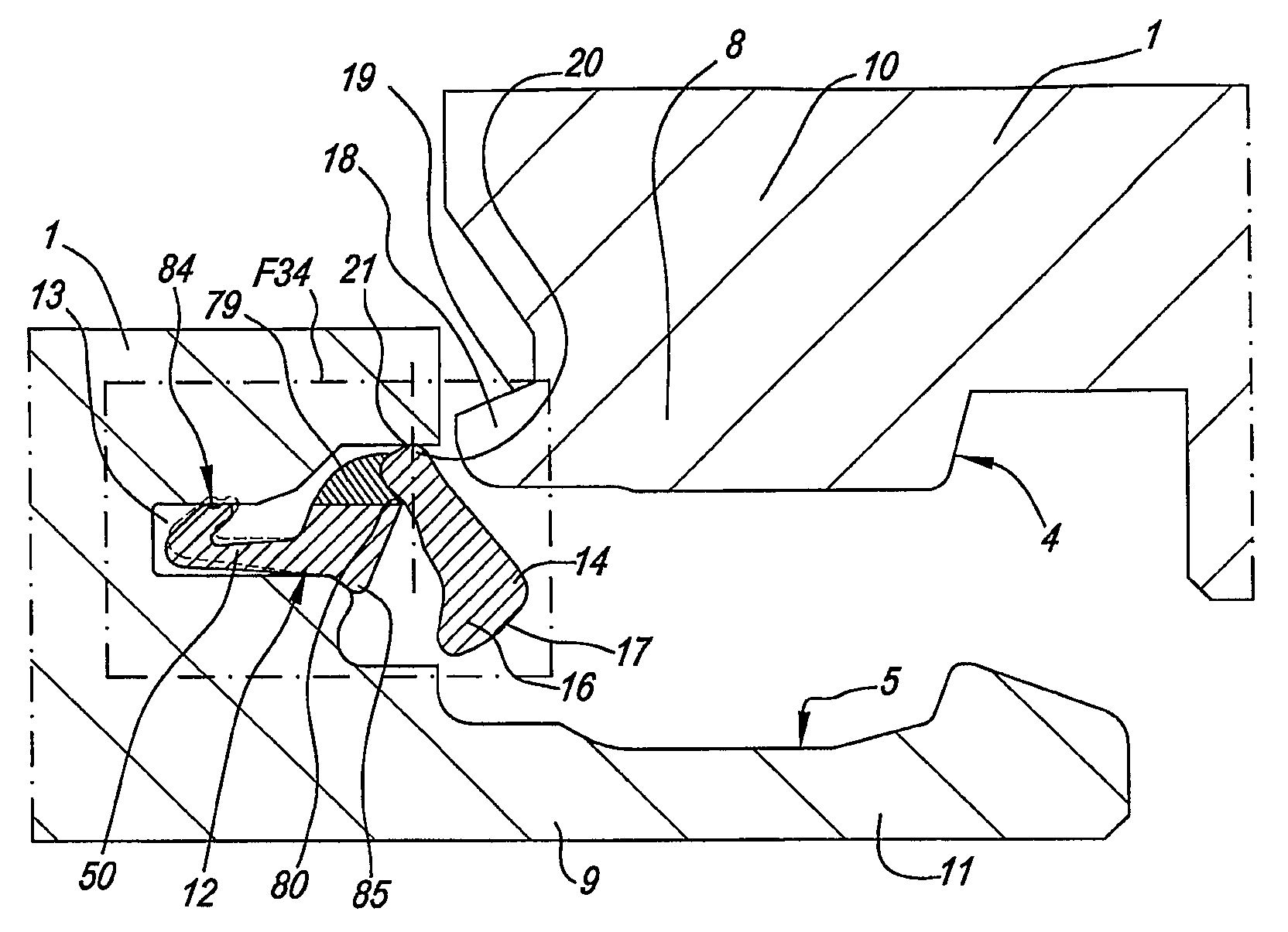
도 34 는 도 33 의 F34 로 나타내는 확대 도면,
도 35 ~ 도 37 은 도 34 로부터의 부분을 2 개의 마루 패널을 결합할 시 다양한 상태에 대하여 나타내는 도면,
도 38 은 본원에 따라서 삽입물로서 제조되는 잠금 요소를 마루 패널의 가장자리에 부착시킬 수 있는 방법을 개략적으로 나타내는 도면,
도 39 ~ 도 41 은 도 38 에서 선 XXXIX-XXXIX, XL-XL 및 XLI-XLI 각각에 따른 확대 단면도,
도 42 는 삽입물로서 제조되는 잠금 요소를 마루 패널의 가장자리에 부착시킬 수 있는, 본원에 따른 기술의 또 다른 실시형태의 단면도, 및
도 43 은 도 42 에서 선 XLIII-XLIII 에 따른 개략화된 단면도.1 is a top plan view schematically illustrating a floor panel according to the present invention,
Fig. 2 is an enlarged cross-sectional view along the line II-II in Fig. 1,
Fig. 3 is a sectional view showing a state in which two floor panels manufactured according to Fig. 2 are combined,
Figs. 4 and 5 are diagrams showing two different steps when connecting the floor panel from Fig. 3, Fig.
Figure 6 is an enlarged view of a locking element used in the embodiment of Figures 2-5,
7 is an enlarged view of a portion indicated by F7 in Fig. 2,
Figure 8 is a schematic representation of a method of mounting the locking element of Figure 7 to a floor panel,
FIG. 9 is a greatly enlarged cross-sectional view of the locking element of FIG. 6,
10 is an enlarged view showing the uppermost end of the locking element of Fig. 9 together with the locking part to be brought into contact, Fig.
Figs. 11 and 12 are views showing two modified examples,
Figures 13 and 14 show two actual embodiments,
15 and 16 are views showing a specific embodiment,
17 is a view showing still another embodiment of the present invention,
Figs. 18 and 19 are enlarged views of portions indicated by F18 and F19 in Fig. 17,
Figure 20 is a view showing a particular way of joining together two floor panels produced according to Figure 17,
Figs. 21 to 24 are views showing another four embodiments of the present invention,
25 illustrates a plurality of floor panels implemented in accordance with the present invention,
26 is an enlarged view of a portion indicated by F26 in Fig. 25,
27 is a cross-sectional view showing another two specific embodiments of the present invention, Fig.
29 and 30 are views showing another two embodiments of the present invention,
Figure 31 is a schematic plan view of a floor panel joined together according to Figure 25;
32 is a cross-sectional view showing still another embodiment of the present invention,
33 is a cross-sectional view showing still another embodiment of the present invention,
34 is an enlarged view indicated by F34 in Fig. 33,
Figs. 35 to 37 are views showing various states when the two floor panels are joined to the portion from Fig. 34; Fig.
Figure 38 is a schematic representation of a method by which a locking element made as an insert according to the present invention may be attached to the edge of a floor panel;
Figures 39 to 41 are enlarged cross-sectional views according to lines XXXIX-XXXIX, XL-XL and XLI-XLI, respectively, in Figure 38,
Figure 42 is a cross-sectional view of another embodiment of the technique according to the present invention, which can attach a locking element made as an insert to the edge of a floor panel; and
Figure 43 is a schematic cross-sectional view according to line XLIII-XLIII in Figure 42;
도 1 ~ 도 5 에 도시된 바와 같이, 본원은 적어도 2 개의 반대편 측면 (2 ~ 3) 을 포함하는 마루 패널 (1) 에 관한 것으로, 이러한 마루 패널 (1) 중 2 개가 결합부 (4 ~ 5) 에 의해 서로 결합될 수 있다.1 to 5, the present invention relates to a
도 3 의 결합 상태로부터 명백한 바와 같이, 이러한 결합부 (4 ~5) 는 수평방향 작용 잠금 시스템 (6) 및 수직방향 작용 잠금 시스템 (7) 을 포함한다. 수평방향 작용 잠금 시스템 (6) 은 수부 (8) 및 암부 (9) 를 포함하고, 이 수부와 암부는 상기 측면 (2 ~ 3) 에서, 부속의 수부 (8) 를 가진 일방의 마루 패널 (1) 을 하방 운동 (M) 에 의해 타방의 마루 패널의 암부 (9) 에 제공함으로써, 이러한 마루 패널 (1) 중 2 개를 서로 연결시키도록 하며, 이러한 운동 (M) 은 도 4 및 도 5 에서 2 개의 상이한 위치로 나타내었다.3, these engaging
수부 (8) 는 훅 형상부 (10) 의 하방으로 배향된 말단에 의해 형성되는 한편, 암부 (9) 는 상방으로 배향된 훅 형상부 (11) 에 의해 형성되는 시트 (seat) 로 이루어진다.The
수직방향 작용 잠금 시스템 (7) 은 잠금 요소 (12) 를 포함하고, 이 잠금 요소는 삽입물 형태이며 관련 측면 중 하나, 이 경우에는 측면 (2) 에, 보다 자세하게는 이러한 목적으로 제공되는 리세스 (13) 내에 제공된다. 명확하게 하기 위해서, 잠금 요소 (12) 또는 즉, 삽입물이 도 6 에서 분리 상태로 도시되어 있다. 이 도면에서 볼 수 있는 바와 같이, 이러한 잠금 요소 (12) 는 스트립으로서 형성되는 것이 바람직하다. 이러한 스트립은 바람직하게는 측면 (2) 의 전체 또는 거의 전체 길이에 걸쳐 연장하는 것이 명백하다.The vertical acting locking system 7 comprises a locking
바람직하게는, 이러한 스트립은 합성 재료로 구성되지만, 이러한 목적을 위해 다른 재료를 사용하는 것을 배제하지 않는다. 더욱이, 스트립은 그 전체 길이에 걸쳐 연속적인 단면을 가지며, 이는 제조를 간단하게 해준다. 합성 재료의 스트립인 경우에, 바람직하게는 PVC 를 사용한다.Preferably, such a strip is composed of synthetic material, but does not preclude the use of other materials for this purpose. Moreover, the strip has a continuous cross-section over its entire length, which simplifies manufacturing. In the case of a strip of synthetic material, preferably PVC is used.
도 7 의 확대도에서는, 상기 스트립이 리세스 (13) 에 부착되는 방법을 자세히 나타내며, 이하 이에 대하여 설명한다.In the enlarged view of FIG. 7, the manner in which the strip is attached to the
도시된 예에서, 잠금 요소 (12) 는 적어도 선회가능한 잠금체 (14) 와 가압부 (15) 로 이루어진다. 도 6 의 실시형태에 있어서, 잠금체 (14) 는 완전 직립부로 구성되는 한편, 가압부 (15) 는 경사지도록 배향된 부분으로 형성된다.In the illustrated example, the locking
회전될 수 있는 잠금체 (14) 의 말단 (16) 은, 결합된 유사한 마루 패널 (1) 의 잠금부 (18) 와 상호 협력할 수 있는 정지부 형성 잠금부 (17) 로서의 역할을 한다. 본원에서, 잠금부 (18) 는 정지부 형성 잠금부 (19) 를 한정하는 부분으로 형성되고, 이 부분은 이러한 목적은 위해 측면 (3) 에 존재하며 또한 마루 패널 (1) 의 코어에 기계식으로 제공된다. 수직방향 작용 잠금 시스템의 기능은, 간단하게 도면으로부터 유추될 수 있고, 또한 도 4 및 도 5 에 도시된 바와 같이, 관련 마루 패널이 하방으로 이동될 때, 잠금체 (14) 가 타방의 마루 패널의 가장자리와 접촉함으로써 내부로 탄성적으로 접히게 되며, 그 후에 마루 패널이 동일한 평면에 도달하자마자, 도 3 의 결합 상태가 되도록 잠금부 (18) 아래에 자가 위치되도록 잠금 요소가 후방 외부로 회전하는 원리에 따른다.The
본원의 제 1 양태에 따라서, 선회가능한 잠금체 (14) 는, 잠금부 (17) 를 형성하는 말단 (16) 반대편에, 관련 마루 패널 (1) 에 부속되는 지지면 (21) 에 접하여, 보다 자세하게는 시트 (22) 내에서 회전가능한 지지부 (20) 를 포함한다. 도 2 ~ 도 10 의 실시형태의 지지부 (20) 에 의해, 잠금체 (14) 의 최하부 말단 (23) 이 수반된다.According to a first aspect of the present application a
더욱이, 본원의 제 2 양태 등에 따라서, 잠금체 (14) 는, 잠금부 (17) 와 지지부 (20) 사이, 즉 그 말단 (16, 23) 사이 등에 힌지부 및 굽힘부가 없다. 이를 위해, 그리하여 잠금체 (14) 는 비교적 두껍게 만들어지고, 바람직하게는 강성체를 형성하는데, 즉 잠금체 (14) 는 압력이 가해지면 말단 사이에서 주목할만한 변형이 일어날 수 없으며, 이는 통상적으로 "누름 잠금" 결합부를 생기게 할 수 있다.Further, according to the second aspect of the present application, the
본원의 제 3 양태에 따라서, 도시된 실시형태의 지지부 (20) 는 자유 말단으로서 형성되고, 이 지지부는 마루 패널 (1) 에 부속되는 지지부 (24), 보다 자세하게는 지지면 (21) 에 의해 적어도 수직방향으로 확실하게 지지된다.According to a third aspect of the present application, the
도 3 및 도 7 에서 명확하게 볼 수 있는 바와 같이, 잠금체 (14) 의 지지부 (20) 는 보다 바람직하게는 2 방향으로, 2 개의 마루 패널 (1) 의 적어도 결합된 상태에서, 즉 수직방향 (V) 으로, 이러한 경우에는 하방으로, 뿐만 아니라 마루 패널 (1) 에 대하여 근위 방향 (P), 즉 시트 (22) 의 측방 벽 (25) 에 의해 지지된다.As can be clearly seen in Figures 3 and 7, the
도 1 ~ 도 10 의 도시된 예에서, 마루 패널 (1) 은 또한 정지부 형성부 (26) 를 포함하고, 이 정지부 형성부는 마루 패널 (1) 에 대하여 원위 방향 (D) 으로 지지부 (20) 또는 잠금체 (14) 의 말단 (23) 에 대한 차단부를 형성한다. 그리하여, 적절한 시트 (22) 가 형성될 수 있고, 그로 인해 지지부 (20) 는 3 개의 측면에서 둘러싸여 착석되어 있다. 이러한 방식으로, 시트는 다소 자세하게는 한정된 힌지점으로서의 기능을 할 수 있다.1 to 10, the
일반적으로, 잠금 요소 (12) 는 마루 패널 (1) 의 리세스내에, 도시된 예에서는 리세스 (13) 내에 부착되는 스트립으로 구성되는 것이 바람직하고 또한 이 리세스내에 스트립을 유지하는 부착 제공물이 존재하는 것을 나타낼 수 있다. 보다 자세하게는, 스트립은 리세스내에 스냅결합되고/스냅결합되거나 그 구성으로 인해 리세스내에 둘러싸여 착석되는 것이 바람직하고, 이러한 원리는 도 1 ~ 도 10 의 실시형태에도 적용된다. 도 7 에 도시된 바와 같이, 리세스의 개구 (A) 는 스트립의 최대 치수 (B) 보다 작고, 그리하여 스트립은 리세스 (13) 내에 자동적으로 유지된다.In general, the locking
이러한 스트립을 리세스에 부착하거나 유지하기 위한 다른 기술, 예를 들어 접착, 클램핑 등도 가능할 수 있음을 알아야 한다. 다수의 장점이 이하 기재되어 있다.It should be appreciated that other techniques for attaching or retaining such strips to the recesses, such as gluing, clamping, etc., may also be possible. A number of advantages are described below.
도 8 에 개략적으로 도시된 바와 같이, 스트립 또는 그로 인한 잠금 요소 (12) 는 마루 패널 (1) 에서, 예를 들어 가압부 또는 슬라이딩 블록 (27) 에 의해 이를 리세스 (13) 안으로 가압함으로써 간단하게 제공될 수 있다. 가해진 압력으로 인해, 스트립은 변형되어 개구 (A) 를 통하여 끼워진 후, 원래 형상으로 복귀되고 또한 리세스내에 둘러싸이게 된다. 보다 자세하게는, 그럼으로써 최종적으로 위치 복원되도록, 가압부 (15) 는 도시된 바와 같은 방식으로 굽혀진다.As shown schematically in Figure 8, the strip or the resulting locking
도 1 ~ 도 10 의 실시형태는 또한 본원의 제 4 실시형태, 즉 잠금체 (14) 가 회전 지점, 지지 지점 각각을 중심으로 회전가능하고 또한 가압부 (15) 가 이 회전 지점으로부터 거리를 두고, 보다 자세하게는 실제 지지 지점으로부터 거리 (D1) 를 두고 잠금체 (14) 와 결합하는 데에도 적용된다. "지점" 또한 "영역" 으로 의도될 수 있음을 알아야 한다. 그리하여, "지지 지점" 은 또한 "영역" 에 걸쳐서 연장할 수 있다.The embodiments of Figures 1 to 10 also illustrate the fourth embodiment of the present invention, that is, the locking
도시된 바와 같이, 가압부 (15) 는 단면에서 볼 때 잠금체 (14) 의 후방측에 인접하는 레그로 적어도 구성되고, 이 레그는 자유 상태에서, 잠금체의 2 개의 말단 사이에 위치한 위치 (P1) 등으로부터 잠금체 (14) 에 대하여 경사지게 연장한다. 바람직하게는, 이러한 레그는 또한 잠금체 (14) 의 일부 (28) 에 대하여 70 도 미만의 각 (A1) 하에서 광범위하게 연장하고, 이 일부는 상기 위치 (P1) 에서부터 잠금부 (17) 쪽으로 연장한다.As shown, the pushing
가압부 (15) 는 바람직하게는 탄성재, 보다 특히 잠금체 (14) 의 재료보다 더 가요적인 재료 등으로 구성된다. 바람직하게는, 가압부는 또한 합성 재료이고, 가장 바람직한 실시형태에 있어서, 가압부 (15) 는 공압출에 의해 잠금체 (14) 와 함께 일체로 제조된다. 도 6 및 도 9 의 확대도에 있어서, 공압출된 재료는 상이한 음영으로 나타내었다.The
일반적으로, 잠금 요소 (12) 는, 실제로 통상 2 ㎝ 미만, 대부분의 경우에 심지어 1 ㎝ 미만의 두께를 가진 마루 패널의 가장자리에 일체화되어야 한다는 사실로 인해, 그 단면이 단지 작은 치수일 수 있다. 그리하여, 그 후 잠금 요소 (12) 를 위해 이용가능한 공간은 5 밀리미터 이하의 크기 정도로만 되어 있다. 이러한 작은 치수로, 상이한 가요성이 잠금 요소에 포함되어야 할 때, 상이한 두께로 작업함으로써 종래의 방법으로 이를 실시하고자 할 때 그 가능성이 또한 제한된다. 본원에 따라서 공압출물을 사용함으로써, 의도하는 효과에 따라서, 상이한 가요성 또한 그로 인한 상이한 탄성을 포함하도록 광범위한 가능성이 제공된다.In general, the locking
공압출된 재료는 동일하거나 유사한 기본 재료로 구성될 수 있고 또한, 예를 들어 어떠한 성분이 일 재료에 첨가되거나 어떠한 성분이 더 많이 존재할 때에만 서로 상이하다. 실제 실시형태에 있어서, 전체 스트립은 PVC 로 구성되지만, 보다 가요적인 부분은 다량의 가소제가 첨가된 PVC 로 형성된다.The co-extruded material may be composed of the same or similar base material and is also different, for example, only when certain components are added to one material or more are present. In an actual embodiment, the entire strip is composed of PVC, but the more flexible part is formed of PVC with a large amount of plasticizer added.
또한, 공압출된 재료 사이의 천이부 (T) 의 위치는 중요하다. 그리하여, 예를 들어, 도 1 ~ 도 10 의 실시형태에서 이러한 천이부 (T) 가 잠금체로부터 거리 (X) 를 두고 위치되는 것이 바람직하다. 그로 인해, 보다 강성의 안내부는 도 8 에 도시된 스냅결합 효과를 향상시키는 가압부 (15) 의 기저에 존재한다.In addition, the position of the transition T between the co-extruded materials is important. Thus, for example, in the embodiment of Figures 1 to 10, it is preferred that such a transition T is located at a distance X from the lock. As a result, the guide portion having a higher rigidity exists at the base of the
도 1 ~ 도 10 의 실시형태에 있어서, 가압부 (15) 는, 단면에서 볼 때, 하나만의 레그로 구성된다.In the embodiment of Figs. 1 to 10, the
도 1 ~ 도 10 의 실시형태에 있어서, 인장 시스템 (29) 은 수직방향 작용 잠금 시스템에 통합되고, 이 인장 시스템은 잠금체 (14) 가 경사질 때 양호한 잠금이 형성되도록 제공된다. 인장 시스템에 의해, 잠금체 (14) 를 경사지게 할 때, 잠금부 (17, 18) 간의 접근에 추가의 효과가 있는 시스템이 의도된다.In the embodiment of Figures 1 to 10, the
도 9 및 도 10 의 확대도에서 명확한 바와 같이, 도 1 ~ 도 10 의 실시형태에 있어서, 이러한 목적을 위해 잠금체 (14) 의 말단 (16) 에 형성되는 캠면 (30) 을 사용하고, 이 캠면은 결합된 상태에서 결합된 마루 패널 (1) 의 맞은편 잠금부 (18) 에 대하여 쐐기 효과를 제공해 준다.As is apparent from the enlarged views of Figs. 9 and 10, in the embodiment of Figs. 1 to 10, the
도 9 에 도시된 바와 같이, 적어도 유효 접촉 영역 (31) 및 가능하게는 유입 영역 (32) 으로 구성되는 캠면 (30) 은, 잠금체 (14) 의 전체 폭 (B2) 의 적어도 60% 의 폭 (B1) 에 걸쳐 연장하는 것이 바람직하고, 이렇게 함으로써 양호한 쐐기 효과를 향상시키는 완만한 천이부를 제공하게 된다. 실제로, 유입 영역 (32) 은, 접촉 영역 (31) 보다 다소 급격한 것이 바람직하고 또한 잠금체 (14) 가 초기에 항상 표면 (19) 아래에서 원활하게 되도록 제공하려는 것이다.9, the
본원에서, 도 9 및 도 10 에 도시된 바와 같이, 가장 외부에 위치한 가장자리 (33) 에서부터 방향 (R) 을 따라 가장 내부에 위치한 가장자리 (34) 쪽으로 캠면 (30) 이 증가하는 높이 (E) 를 나타내도록, 예를 들어 방향 (R) 을 따라 캠면의 연속 지점에 대하여 잠금체 (14) 의 유효 길이가 증가하도록, 캠면 (30) 이 연장하는 것이 바람직하다. 본원에서, 유효 길이는, 잠금체가 상단 및 바닥에서 접촉하게 되는 위치간의 거리이다.9 and 10, the height E at which the
캠면 (30) 및 이에 대향 위치한 면 (19) 은, 공차 차이로 인해 잠금체 (14) 의 변위가 더 작거나 또는 잠금부 (17, 18) 사이의 접촉 영역, 보다 자세하게는 접촉 지점의 변위가 없도록 실시되는 것이 바람직하다. 바람직하게는, 여기에서 접촉 영역 또는 접촉 지점의 변위량이 캠면 (30) 의 변위 크기의 50% 미만이다. 이는 이하 도 10 을 참조하여 설명된다. 본원에서, 위치 C1 에서의 접촉 지점과의 제 1 상태를 실선으로 도시하였다. 장착으로 인해, 면 (19) 이 다소 높게 놓이게 되면, 점선으로 도시한 와 같은 상태가 만들어지고, 여기에서 접촉 지점은 위치 C1 에서 위치 C2 로 변위되며 또한 본원에 따라서 잠금체 (14) 의 변위 (V2) 보다 현저하게 작은 변위 (V1) 로 변위된다. 본원에서의 장점은, 항상 변위 (V2) 가 작다는 것이고, 이는 마루 패널 (1) 의 상가장자리에서의 소정의 거리 (D2) 내에서 접촉이 항상 실시되고 또한 취약한 연결을 유도하는 매우 멀리 외부방향 회전이 배제됨을 보장해준다. 공차 차이로 인해 동일한 효과가 발생한다. 먼저 한 쌍의 마루 패널이, 예를 들어 실선으로 도시한 바와 같이 접촉하게 될 수 있고, 공차 차이로 인해 다른 쌍의 마루 패널이 점선으로 도시한 바와 같이 접촉하게 된다. 본원에 따른 캠 형상으로 인해, 그 후 상기 두번째의 경우에 접촉 지점 (C2) 이 마루 패널의 가장자리로부터 너무 멀리 위치되는 것이 방지된다.The
도면에 도시된 바와 같이, 잠금체 (14) 의 잠금부 (17) 는 이 잠금체 (14) 의 말단이 넓어진 형태로 실시되는 것이 바람직하고, 이로 인해 소망하는 캠면 (30) 을 구현하기 위한 공간을 더 제공해줌을 알아야 한다.As shown in the figure, it is preferable that the
캠면 (30) 및 이와 상호작용하는 면 (19) 의 경사는, 그 접촉 영역, 접촉 지점 (C1 ~ C2) 각각에서 접선 (L1 ~ L2) 을 항상 한정하도록 구현되는 것이 바람직하고, 수평면에 대한 경사각은 도 10 에서 A2 로 하나만 도시되었지만 35 도 미만이다.The inclination of the
도 11 및 도 12 에서는, 잠금체 (14) 가 연결된 상태에서 상호작용하는 면 (19) 의 형상을 선택함으로써 접촉 지점 (C) 이 변위될 수도 있음을 도시하였다. 연결된 상태에서 접촉 지점 (C), 또는 접촉이 일 지점보다 넓을 때의 접촉 영역의 중간, 및 잠금체 (14) 가 지지되는 지점 사이의 연결선 (L3) 은 가능한 한 수직하고, 그 후 이들 중에서 잠금체를 후방으로 힘을 가하는 수평방향 힘성분이 제한됨을 알아야 한다. 이와 관련하여, 접촉 (C), 접촉 영역의 중심 각각이 마루 패널 (1) 이 서로 접촉하여 장착되는 평면으로부터 위치되는 거리 (D3) 가 1 ㎜ 보다 작고 또한 더 바람직하게는 0.8 ㎜ 보다 작은 것이 바람직하다.11 and 12 illustrate that the contact point C may be displaced by selecting the shape of the interacting
도 2 및 도 7 에 도시된 바와 같이, 잠금 요소 (12) 및 리세스 (13) 는, 이잠금 요소 (12) 가 관련 마루 패널 (1) 의 자유로운 미결합 상태에서 리세스 (13) 내에 잠금부 (17) 와 함께 적어도 부분적으로 착석되도록 실시된다. 이렇게 함으로써, 그 중에서, 상기 잠금 요소를 구성하는 스트립이, 하방으로의 운동에 의해 2 개의 마루 패널 (1) 이 서로 연결될 때, 주로 마찰력 또는 어떠한 다른 원인 (이는 양호한 작동을 방해할 수 있음) 에 의해 시트 외부로 절대로 당겨질 수 없는 장점을 얻을 수 있다.2 and 7, the locking
본원에 따른 결합이 어떠한 마루 패널 (1) 과 조합하여 적용될 수 있음이 명확하다.It is clear that the combination according to the invention can be applied in combination with any
도 13 에서는 소위 미리제조된 조각나무 (parquet), 보다 자세하게는 소위 "공학 목재 (engineered wood)" 에 도 1 ~ 도 10 에 도시한 실시형태를 적용한 것을 도시하였다. 이러한 예에서, 이는 스트립 (35, 36, 37) 으로 이루어진 코어 (38), 목재 상부층 (39) 뿐만 아니라 목재 후방층 (40) 으로 구성되는 마루 패널 (1) 에 관한 것이다. 상부층 (39) 은, 양호한 품질의 목재로 구성되며, 가시적인 장식층으로서의 역할을 한다. 후방층 (39) 은 값싼 종류의 목재로 구성될 수 있다. 스트립 (35) 은 또한 값싼, 예를 들어 연질 종류의 목재로 구성되는 것이 바람직하다. 하지만, 마루 패널 (1) 의 말단에는, 비교적 견고하고 또한 소망하는 프로파일 형상을 제공하는데, 예를 들어 이를 밀링하는데 적절한 일 재료로 된 스트립 (37 ~ 38) 이 사용된다. 실제 실시형태에 있어서, 이러한 스트립 (37 ~ 38) 은 MDF (Medium Density Fiberboard) 또는 HDF (High Density Fiberboard) 로 구성된다. 본원은 다른 형태의 "공학 목재" 와 조합하여 사용될 수도 있고, 예를 들어, 코어는 단일의 연속 MDF/HDF 판 또는 합판으로 구성된다.In Fig. 13, the embodiment shown in Figs. 1 to 10 is applied to a so-called pre-manufactured parquet, more specifically, so-called "engineered wood ". In this example it concerns a
도 14 에서는, 적층 마루 패널, 이러한 경우에 소위 DPL (Direct Pressure Laminate) 에 적용한 것을 도시하였고, 상기 DPL 은, 공지된 방식으로, 예를 들어 MDF 또는 HDF 로 된 코어 (41), 1 개 이상의 수지 함침층, 예를 들어 인쇄 장식층 (43) 과 소위 오버레이 (44) 를 기초로 하는 상부층 (42) 뿐만 아니라 1 개 이상의 수지 함침층으로 되는 후방층 (45) 으로 구성되며, 전체적으로 열 및 압력 하에서 압밀되어 있다.14 shows application to a laminated floor panel, in this case a so-called DPL (Direct Pressure Laminate), in which the
다른 마루 패널 (1) 에 적용하는 것을 배제하지 않는다.It does not exclude the application to the
도 15 및 도 16 은, 잠금체 (14) 에 대향 위치된 마루 패널 (1) 의 측면에 리세스 (46) 가 제공되는 특정 실시형태를 도시하였고, 도 16 에서 볼 수 있는 바와 같이, 가장자리의 종방향을 따라서 마루 패널 (1) 사이에 로드 (47) 등이 도입되어, 잠금체 (14) 가 후방으로 밀리고 또한 관련 마루 패널이 상승될 수 있어서 분리될 수 있다.Figures 15 and 16 show a specific embodiment in which a
도 17 에서는 다양한 방식에 있어서 전술한 실시형태와 상이한 본원의 변형예를 도시하였다. 그리하여, 예를 들어, 말단 (23) (이를 따라 선회가능함) 다음의 선회가능한 잠금체 (14) 는 인장 시스템 (48) (본 실시예에서는 도 18 에서 확대 도시하였음) 을 포함하고, 이 인장 시스템은 상기 말단 (23) 에서 구현되는 캠 (49) 으로 실질적으로 구성되며, 이 캠은, 또한 잠금체 (14) 가 외부로 선회될 때, 이 잠금체 (14) 가 잠금부 (17) 의 방향으로 축방향 변위 (V3) 를 받게 한다. 이를 위해 캠 (49) 은 소망하는 효과에 따라 당업자에 의해 결정될 수 있는 적절한 높이로 구현되어야 함이 명확하다. 도 18 에서, 이 높이를 거리 (D4, D5) 로 나타내었고, D5 는 D4 보다 크다. 축방향 변위 (V3) 는, 잠금체 (14) 가 결합시 초기에 원활하게 외부로 선회할 수 있지만, 이 잠금체가 부분적으로 선회하자마자, 매우 멀리 외부로 선회할 수 있기 전에, 보다 신속하게 다른 마루 패널 (1) 과 접촉하려는 것에 기여한다.Fig. 17 shows a modification of the present invention which is different from the above-described embodiment in various ways. Thus, for example, the
도 17 의 실시형태에 있어서, 또한 원위방향 정지부 형성부가 존재하지 않으며, 이로 인해 잠금 부재는 리세스 (13) 안으로 보다 원활하게 가압될 수 있다. 도 18 에서 볼 수 있는 바와 같이, 잠금체 (14) 는, 순수 선회 운동 대신에, 그 후에 가능하다면 롤링 운동을 실시할 수도 있고, 그럼으로써 이 잠금체는 그 자체적으로 근위방향 측방벽 (25) 으로부터 다소 거리를 두지만, 전체를 장착함으로써 마루 위를 걸을 때 또는 다른 힘을 받을 때 다시 상기 벽에 접하게 될 수 있다.In the embodiment of Fig. 17, there is also no distal stop forming portion, which allows the locking member to be pressed more smoothly into the
도 17 의 실시형태에 있어서, 잠금 요소에는 또한 이러한 목적을 위해 특별히 제공된 부착부 (50) 가 장착되며, 이 부착부는 이러한 경우에 클랭핑부로서 실시된다. 도 19 에 명확히 도시된 바와 같이, 본원에서의 클랭핑 작용은 부착부 (50) 의 탄성 굽힘 및/또는 변형에 의해 얻어진다.In the embodiment of Figure 17, the locking element is also equipped with a mounting
도 17 에서, 또한 암부 (9) 가 비교적 낮은 훅형상부 (10) 와 함께 실시될 수 있고 또한 더욱이 훅형상부 (11) 가 가능한 한 탄성적으로 굽힘가능한 사실에 의해 보조될지의 여부에 상관없이, 상기 마루 패널 (1) 중 두 개가 서로 쪽으로 미끄러짐으로써 각각의 가장자리에서 서로 만나게 될 수 있는 형상을 가질 수 있음이 도시되어 있다. 이러한 방식의 연결이 도 20 에 도시되어 있다. 본원에서는 2 개의 가능성이 있을 수 있다. 마루 패널 (1) 이 동일한 평면에 유지되고 또한 화살표 S1 으로 도시된 바와 같은 방식으로 서로 쪽으로 이동되면, 훅형상부 (11) 는 외부로 탄성적으로 굽혀지도록 힘을 받게 된다. 마루 패널 (1) 의 상부 가장자리들이 서로 접하여 미끄러지면, 잠금체 (14) 는 자동적으로 잠금 위치로 오게 되고, 한편 굽혀진 훅형상부 (11) 도 복원되어 수부 (8) 뒤에 착석된다. 가장자리에 잠금체 (14) 를 포함하는 마루 패널 (1) 이 높이방향으로 자유롭게 이동되면, 그 후 연결시 화살표 S2 를 따른 운동이 발생하고, 수부 (8) 는 잠겨질 때까지 최종적으로 내려가도록 훅형상부 (11) 에 걸쳐 활형으로 미끄러진다. 물론, 또한 양 운동을 조합하여 실시할 수 있다.In Fig. 17, it can also be seen that the
도 17 에서 화살표 S3 로 개략적으로 도시한 바와 같이, 도시된 결합부는 또한 상기 패널 중 두 개가 각 운동에 의해, 예를 들어 훅형상부 (11) 의 적절한 높이 및/또는 접촉면 (51 ~ 52) 의 적절한 경사를 사용함으로써, 결합 및/또는 분리될 수 있도록 한다.As shown schematically by arrow S3 in Fig. 17, the illustrated coupling also allows two of the panels to be moved by angular movement, for example at a suitable height of the hook-shaped
도 17 ~ 도 20 에 의해 전술한 모든 특징이 본원의 다른 실시형태에 선택적으로 통합될 수도 있음은 명확하다.It is clear that all of the features described above with reference to Figures 17-20 may be optionally incorporated into other embodiments of the present disclosure.
본원에 따른 잠금 요소 (12) 는 다양한 위치에서 결합되는 측면 (2 ~ 3) 에 장착될 수 있음을 알아야 한다. 예를 들어, 도 21 ~ 도 23 은 상기 잠금 요소가 수부 (8) 대신에 암부 (9) 에 제공되는 3 개의 실시형태를 나타내며, 한편 도 24 는 가장자리 영역에 잠금 요소 (12) 가 제공되어 수부가 암부에 장착되는 실제 시트에는 제공되지 않는 일 실시형태를 나타낸다.It should be noted that the locking
도 22 의 실시형태에서는, 가압부 (15) 가 또한 굽혀지거나 접혀지는 형상을 가질 수 있음을 나타낸다.In the embodiment of Fig. 22, it is shown that the
도 23 에서는, 잠금 요소가 아교 (53) 에 의해, 가능한 한 이러한 목적을 위해 특별하게 제공되는 부분, 예를 들어 가압부 (15) 와 연결되는 부착 립 (54) 에 의해 리세스 (13) 에 부착될 수도 있다.In Figure 23 the locking element is connected to the
잠금 요소 (12) 또는 그리하여 1 개 이상의 탄성 굽힘 영역이 제공될 수 있는 스트립 등이 실제 가압부 (15) 와 잠금체 (14) 간의 연결, 또는 가압부 (15) 의 여러 부분간의 연결, 또는 다른 부분간의 연결을 형성함을 알아야 한다. 이러한 굽힘 영역은 구성부 사이에서 소망하는 상호 운동가능성을 얻도록 해준다. 도 23 의 실시형태는 이러한 예로서, 한편으로는 부착 립 (54) 과 가압부 (15) 사이에 또한 다른 한편으로는 가압부 (15) 와 잠금체 (14) 사이에 2 개의 가요적인 굽힘 영역 (15A) 이 제공된다.A locking
바람직하게는, 이러한 굽힘 영역 (15A) 은 잠금 요소 (12) 의 제조시 공압출에 의해 형성된다.Preferably, this
일반적으로, 본원에 따른 잠금 요소는 수직 방향으로의 안정적인 지지를 위해 제공되는 것이 바람직하고, 한편 수평방향, 그로 인한 선회 방향으로는 가요적인 운동가능성이 유효하다. 여기에서 공압출된 부분을 사용하여 보조된다.In general, the locking elements according to the invention are preferably provided for stable support in the vertical direction, while the flexibility of motion in the horizontal direction and hence in the turning direction is effective. Here it is assisted by coextruded parts.
사각형, 즉 직사각형 또는 정사각형의 마루 패널의 경우에, 두 번째의 마주보는 측면 쌍에 결합부가 제공될 수도 있고, 이 결합부는 결합된 상태에서 수평방향뿐만 아니라 수직방향 잠금을 제공해주는 것이 바람직하다. 이러한 결합부는 본원에 상관없이 두 번째의 측면 쌍에서 "누름-잠금" 결합부로서 실시될 수도 있다. 하지만, 바람직하게는, 두 번째 측면 쌍에서 결합 수단이, 결합될 2 개의 마루 패널간의 선회 운동에 의해 및/또는 스냅 연결을 유발하는 위치변경 운동에 의해 상호 결합시키는데 사용된다. 이러한 결합부는 종래에 광범위하게 공지되어 있고, 예를 들어 WO 97/47834 에 기재되어 있다.In the case of a square, i. E. A rectangular or square floor panel, it may be provided on the second opposing side pair, which preferably provides a horizontal locking as well as a vertical locking in the combined state. This engaging portion may be implemented as a "push-lock" engaging portion in a second side pair irrespective of the present invention. Preferably, however, the coupling means in the second side pair are used to interconnect each other by a pivot motion between the two floor panels to be coupled and / or by a displacement movement causing a snap connection. These coupling parts are conventionally widely known and are described, for example, in WO 97/47834.
가장 바람직한 실시형태에 있어서, 두 번째의 측면 (55 ~ 56) 쌍에서 결합부 (57 ~ 58) 는, 선회 운동에 의해 적어도 연결을 가능하게 사용되며, 그로 인해 도 25 및 도 26 에 도시된 바와 같이, 마루 패널을 간단하게 설치할 수 있도록 해준다. 그 후, 설치할 새로운 마루 패널 (1C) 은 이전 열의 마루 패널 (1A) 에 또한 동일 열의 이전의 마루 패널 (1B) 바로 다음에 그 측면 (55) 이 간단하게 각 운동할 수 있다. 그 후, 각을 내리면, 어떠한 다른 작업이 필요없이, 설치할 새로운 마루 패널 (1C) 의 수부가 이전의 마루 패널 (1B) 의 암부와 자동적으로 결합한다. 그리하여, 직사각형 마루 패널 (1) 의 경우에, 소위 "누름-잠금" 연결부가 단변에 위치되는 것이 바람직하다.In the most preferred embodiment, the engaging portions 57-58 in the second pair of side surfaces 55-56 are used to enable at least connection by pivoting movement, Likewise, it allows the floor panel to be easily installed. The
도 27 은 본원의 제 7 양태의 실시예를 도시한다. 이러한 양태에 따라서, 잠금 요소 (12) 는 리세스 (13) 에 제공되는 합성 재료 스트립으로 구성되고, 이 스트립은, 2 개의 마루 패널 (1) 의 결합된 상태에서, 양 마루 패널 (1) 과 접촉하게 되어 밀봉부를 형성하며, 마루 패널 (1) 의 상부측 (59) 및 합성 재료 스트립 사이에는 또한 패널 가장자리 (62 ~ 63) 에 밀봉부 (60 ~ 61) 가 존재한다. 본원에서, 합성 재료 스트립은 물 침윤에 대한 밀봉부로서 사용되어 결합부 (4 ~ 5) 사이에서 가능한 물의 침윤을 적어도 감소시키고 바람직하게는 완전히 차단하는 적어도 배리어를 제공하며, 밀봉부 (60, 61) 각각은 패널 가장자리에서 대부분 목재로 된 패널 재료 (64) 를 물의 침투 등에 대하여 보호하려는 것이다. 그 후, 2 개의 마루 패널 사이에 침윤할 수 있는 가능한 물이 없을 수 있거나 또는 마루 패널 (1) 바로 아래까지 침윤하기 어렵게 되며, 그로 인해 마루 패널 (1) 바로 아래에 부패물 및 곰팡이가 형성될 위험이 제한되며, 이러한 물은 마루 패널 (1) 자체 안으로 침투할 수도 없으며 그리하여 예를 들어 팽창에 의해 마루 패널 (1) 자체에서의 손상이 배제된다. 합성 재료 스트립 위에 존재하는 수분은 정상 과정 중에 증발될 수 있다.27 shows an embodiment of the seventh aspect of the present application. According to this aspect, the locking
도시된 예에서, 수분 침투에 대한 밀봉부는 일 측면 (3) 에서 접촉부 (65) 에 의해 형성되고 또한 다른 측면 (2) 에서 1 개 이상의 접촉부 (66, 67 또는 68) 에 의해 형성된다. 보다 나은 밀봉을 보장하기 위해서, 잠금 요소에는, 예를 들어 비교적 연성의 합성 재료 또는 고무로 된 1 개 이상의 밀봉 재료부 (69) 가 제공될 수 있고, 이러한 밀봉 재료부는 잠금 요소 (12) 에서 접촉부 (65, 66, 67, 68) 의 위치에 존재한다. 이러한 밀봉 재료부는 합성 재료 스트립에서 어떠한 방식으로 제공될 수 있다. 실시형태에 있어서, 밀봉 재료부는 공압출에 의해 실시될 수 있다.In the example shown, the seal for moisture penetration is formed by the
패널 가장자리 (62, 63) 에 있는 밀봉부 (60, 61) 는 어떠한 형상을 가질 수 있다. 도시된 바와 같이, 밀봉부는, 예를 들어 함침층 또는 커버층, 예를 들어 래커 (lacquer) 또는 바니시 (varnish) 층에 의해 형성된다. 밀봉부는 상부층에서부터 하방으로 연장하고, 매번 적어도 상기 접촉이 구현되는 위치 중 하나까지 연장한다. 도시하지 않은 변형예에 따라서, 상기 밀봉부는 또한, 예를 들어 상부 가장자리에 걸쳐 하방으로 연장하는 상부층을 사용함으로써, 상부층이 접촉부 중 하나가 구현되는 위치까지 연장하도록 구성될 수 있다.
제 7 양태에 따라서, 상부층은 또한 방수성이도록 한다. 더욱이, 그 후 상부층은 어떠한 재료, 예를 들어, 적층체, 필름, 래커층, 내수성 또는 방수성 프린트, 바니시 등으로 구성될 수도 있다.According to a seventh aspect, the top layer is also waterproof. Furthermore, the upper layer may then consist of any material, such as a laminate, a film, a lacquer layer, a water resistant or waterproof print, a varnish, or the like.
이러한 방식으로 패널 가장자리로의 물의 침윤뿐만 아니라 물의 침투 둘 다가 방지됨이 명확하다.It is clear that in this way both the infiltration of water as well as the infiltration of water to the edge of the panel are prevented.
일렬로 설치되는 마루 패널, 특히 직사각형 마루 패널에서는, 이 마루 패널이 열의 종방향으로 정렬되고 또한 대부분 서로에 대하여 그 측면과 잘 인접하는 반면, 제조 공차로 인해, 이러한 마루 패널이 종종 완벽하게 수직하게 정렬된 측면을 갖지 않기 때문에, 열에 수직하게 배향된 측면에 개구부가 보다 용이하게 생성되는 것으로 나타난다. 이러한 개구부의 위치에서, 신속한 침윤이 가능하고, 이 개구부가 너무 커서 메우지 못하기 때문에, 마루 패널의 상부 가장자리에서의 다소 탄성적인 코팅에 의한 밀봉이 대부분 유효하지 않다. 그리하여, 특히 이러한 측면의 위치에서는 본원의 제 7 양태에 따른 밀봉 원리의 이점을 나타낸다. 열의 종방향으로 연장시키려는 마루 패널의 측면 (55, 56) 이 자동 정렬로 인해 서로 보다 잘 인접하게 된다는 사실의 관점에서, 이러한 측면에서의 침윤 문제가 거의 없거나 전혀 존재하지 않으며, 또한 4 개의 모든 측면에 밀봉부를 제공하고 한다면, 이러한 측면에서, 도 26 의 도면부호 71 ~ 72 로 나타낸 바와 같이, 패널의 가장자리에 코팅 또는 함침만이 제공된다.In a row of floor panels, especially rectangular floor panels, such floor panels are often perfectly perfectly vertical due to manufacturing tolerances, while these floor panels are aligned in the longitudinal direction of the rows and also closely adjacent to their sides with respect to each other Since it does not have aligned sides, it appears that openings are more easily created on the sides oriented perpendicular to the column. Sealing by a somewhat elastic coating at the top edge of the floor panel is largely ineffective, because at this location of the opening, rapid infiltration is possible and the opening is too large to cover. Thus, particularly in this aspect of the position, it shows the advantages of the sealing principle according to the seventh aspect of the present application. There is little or no infiltration problem in this respect in terms of the fact that the side surfaces 55,56 of the floor panels intended to extend in the longitudinal direction of the column are more closely adjacent to each other due to automatic alignment, In this regard, only coating or impregnation is provided at the edges of the panel, as indicated by reference numerals 71-72 in Fig.
도 27 에서와 같이, 클램핑되고 또한 공압출로 형성되는 가압부 (15) 를 사용하면, 천이부 (T) 가 도 6 의 실시형태에서보다 잠금체 (15) 에 더 근접하게 위치되는 것이 바람직하다. 자유 상태에서 적절한 치수로, 장착 상태에서 지지면 (21) 과 영구적으로 접촉하는 잠금 요소 (12) 를 유지하는 힘이 생성되도록 가압부가 얻어질 수 있다.27, it is preferable that the transition portion T is positioned closer to the
도 28 은, 소위 "누름-잠금" 시스템에 공압출된 잠금 요소 (12) 를 사용하는 발명의 아이디어가 선회가능한 잠금체를 가진 실시형태에만 한정되지 않음을 명확하게 하는 변형예를 나타낸다. 도 28 에 따라서, 잠금체 (14) 는 변위가능하고 또한 비교적 경질의 합성 재료로 구성되는 반면, 가압부 (15) 는 가요성 및 탄성의 합성 재료로 구성된다. 본원에서, 공압출된 가압부 (15) 는 스프링 형태로 잠금체 (14) 뒤에 위치되는 탄성 덩어리로서의 역할을 한다.28 shows a variant which makes it clear that the idea of the invention using a
도 29 는 도 17 의 실시형태에 필적하는 다른 변형예를 나타낸다. 본원에서, 도 29 의 훅형상부 (11) 는, 접촉면 (51 ~ 52) 이 적어도 부분적으로 잠금체의 지지면 (21) 보다 높게 위치되도록, 도 17 의 실시형태에서보다 상당히 더 크게 구현되는 차이가 있다.Fig. 29 shows another modification example which is comparable to the embodiment of Fig. The hook-shaped
도 30 은 본원에 따른 일 실시형태의 바람직한 변형예를 나타내고, 암부의 근위방향 측면에 잠금 요소 (12) 가 제공된다. 도 29 의 실시형태에 비하여, 이는 중요한 장점을 제공해 준다. 도 29 에서, 가장자리 (73) 는 자유 상태에서 잠금체 (14) 가 이 가장자리 (73) 아래에 착석되도록 비교적 날카롭고 직선으로 형성된다. 도 25 에 도시된 바와 같이 마루 패널 (1) 을 하강시키는 동안, 예를 들어 이전 열의 마루 패널의 뒤틀림 또는 패널의 비정사각형으로 인해, 예를 들어 평면도에서 볼 때 마루 패널 (1B ~ 1C) 이 다소 겹쳐지기 때문에, 서로 결합될 측면 (2 ~ 3) 이 완벽하게 대응하지 못하게 될 때, 도 31 에 도시한 상태가 생성되며, 그 후 가장자리 (73) 는 상부 가장자리 (74) 를 따라서 스크래핑한다. 도 30 의 실시형태에 있어서, 이는, 적절한 챔퍼를 가진 가장자리 (73) 가 실시될 수 있어서, 그럼으로써 가장자리 (73) 와 상부 가장자리 (74) 간의 가능한 접촉은 스크래핑 효과보다는 서로를 따른 미끄러짐 운동을 유발하는 것으로 용이하게 대향될 수 있다.Fig. 30 shows a preferred variant of an embodiment according to the present application, in which the
또한, 도 29 에 따른 일 실시형태에 있어서, 우측 마루 패널을 하방으로 이동시키면, 잠금 요소 (12) 는 좌측 마루 패널의 날카로운 상부 가장자리 (74) 와 접촉하게 되어, 설치를 방해할 수 있는 스크래핑 효과가 또한 생길 수 있다. 반대로, 도 30 의 실시형태에서는, 수부의 둥글게 된 하부측이 잠금 요소를 따라 원활하게 미끄러진다는 사실로 인해, 상기 단점이 나타나지 않는다.29, when the right floor panel is moved downward, the locking
도 30 은 또한 도입부에서 언급한 본원의 제 8 양태를 충족하는 일 실시형태에 관한 것으로, 보다 자세하게는 마루 패널 (1) 의 가장자리가 위치이동 운동 (S1) 에 의해 서로 연결될 수 있다.Fig. 30 also relates to an embodiment which satisfies the eighth aspect of the present invention mentioned in the introduction section, more specifically, the edges of the
더욱이, 도 30 의 실시형태는 다음의 특징을 나타낸다:Further, the embodiment of Fig. 30 shows the following features:
- 관련 결합부 (4 ~ 5) 는 상기 측면 등에서 마루 패널을 서로 안으로, 외부로 상호 각운동 함으로써, 이러한 마루 패널 2 개를 서로에 대하여 잠금 및/또는 잠금해제하도록 구현되고;- the associated engaging portions (4 ~ 5) are embodied to lock and / or unlock these two floor panels relative to each other by mutually angularly muting the floor panels to and from each other on the side or the like;
- 자유 상태에서, 립 형상의 잠금체 (14) 는 경사지게 외부로 돌출하며;In the free state, the lip-shaped
- 암부 (9) 의 근위방향 측면에 잠금체 (14) 가 제공되고;- the lock body (14) is provided on the proximal side of the arm part (9);
- 암부 (9) 와 수부 (8) 는 그 원위방향 말단에 접촉면 (52 ~ 51) 을 포함하고, 이러한 접촉면은 원위방향으로 상방으로 경사져 실시되며;The
- 립 형상의 잠금체 (14) 가 선회가능한 본체이다.- A lip-shaped lock body (14) is a swivelable body.
도 30 에서는, 잠금체 (14), 또한 보다 양호하게는 삽입물로서 구현되는 전체 잠금 요소 (12) 가 비교적 국부적으로 형성되고, 특히 이는 제 1 및 제 2 수평 높이 사이에만 존재한다는 것을 의미하며, 제 1 수평 높이 (N1) 는 결합된 마루 패널의 상부측 아래에 거리를 두고 위치되며, 제 2 수평 높이 (N2) 는 제 1 수평 높이보다 낮지만 수부의 최하부 지점보다 높게 위치됨을 나타낸다. 더욱이, 도 30 에서는, 상기 잠금체 (14) 가 결합된 마루 패널의 상부측과 수부의 최하부 지점 사이의 높이 (D7) 의 적어도 40%, 보다 양호하게는 적어도 50% 인 높이 (H) 에 걸쳐 연장함이 나타나 있다. 이러한 특징은 도 30 의 실시형태에 한정되지 않음은 명확하다.In Figure 30, it is meant that the locking
선회가능한 실시형태의 경우에 있어서, 하나의 마루 패널이 서로 안으로 또는 외부로 각운동할 수 있고, 도 30 에 도시된 바와 같이, 마루 패널의 상부 가장자리에서부터 접촉면 (51 ~ 52) 의 상호작용 지점 (상부 가장자리로부터 가장 멀리 위치됨) 까지 측정되는 수평 거리 (D6) 가, 마루 패널의 상부측 및 수부의 하부측 사이의 거리 (D7) 의 적어도 1.3 배인 것이 바람직하고, 이는 원활한 각운동을 가능하게 한다.In the case of the pivotable embodiment, one floor panel can angularly move inward or outward with respect to each other, and from the upper edge of the floor panel, as shown in Fig. 30, The horizontal distance D6 measured to the farthest from the upper edge) is at least 1.3 times the distance D7 between the upper side of the floor panel and the lower side of the hand, which allows smooth angular movement .
내부 및 외부로의 원활한 각운동 및/또는 위치운동이 함께 가능하도록, 최고 지점 (75) 이 높이 (N3) 에 위치되는 것이 바람직하고, 이 높이는 잠금체 (14) 의 최하부 지점보다 낮다.It is preferable that the
도 30 에서는 가압부 (15) 의 특정 구성을 나타내고, 이러한 구성은 또한 본원에 따른 마루 패널의 다른 실시형태에도 적용될 수 있다. 상기 가압부, 보다 자세하게는 가압부의 구성은 다음의 특징을 나타낸다:30 shows a specific configuration of the
- 가압부 (15) 는, 단면에서 볼 때, 선회 아암으로서 구현되고, 이 선회 아암은 일 말단 다음에 지지되거나 유지되며 또한 다른 말단에서 힌지 및/또는 굽힘 영역 (76) 에 의해 잠금체 (14) 의 후방측에 인접하게 되고;The pushing
- 상기 선회 아암은 재료의 얇은 부분에 의해 형성되는 경우에, 양 말단에서 힌지 및/또는 굽힘 영역 (76 ~ 77) 각각을 구비하며; 더욱이, 영역 (77) 은 하부 지지면에 대하여 하방 선회 운동보다는 상방 선회 운동이 보다 원활하게 가능하도록 위치되는 것이 바람직하고;The swivel arm has hinges and / or bend areas 76-77 at both ends, when formed by a thin portion of material; Moreover, it is preferred that the
- 가압부 (15) 는, 잠금체가 압축될 때, 이 잠금체가 일 말단이 지지면 (21) 에 접하여 위치되도록 제공되는 기구로서 구현되며; 보다 자세하게는, 압축력 (K1) 은 선회 운동 (K2) 을 유발하고, 그로 인해 잠금 요소 (14) 는 지지면 (21) 에 대하여 화살표 K3 를 따라 상방으로 가압되며;The pushing
- 전술한 기구는, 한편으로는 잠금체의 후방측에 연결되는 선회 아암으로 구성되고, 다른 한편으로는 지지 칼라 (78) 등의 지지부에 의해 지지된다.The above-mentioned mechanism is constituted by a swinging arm connected on the one hand to the rear side of the lock body, and on the other hand by a support portion such as a
마지막으로, 본원에 따른 마루 패널은 일반적으로 결합 상태에서 소위 "예비 인장" 이 생기도록 구현될 수 있고, 이는 마루 패널이 그 결합 측면에서 인장력에 의해 서로 쪽으로 가압되는 것을 의미한다. 본원에서, 인장력은 어떠한 방식으로 공급될 수 있다. 예를 들어, 인장력은 암부의 하부측을 경계짓는 립의 탄성 굽힘에 의해 형성될 수 있다. 본원에서, WO97/47834, 보다 자세하게는 상기 WO97/47834 의 도 23 으로부터 공지된 원리를 적용할 수 있다.Finally, the floor panel according to the present invention can be embodied so as to create a so-called "preliminary tension" in the generally engaged state, which means that the floor panel is pressed toward each other by the tensile force at its engagement side. In the present application, the tensile force can be supplied in any manner. For example, the tensile force can be formed by the elastic bending of the rib which bounds the lower side of the arm portion. In this application, it is possible to apply the known principles from WO 97/47834, more particularly from FIG. 23 of WO 97/47834.
또한, 본 발명의 마루 패널에는, 보다 자세하게는 WO 2006/032398 에 기재된 원리를 적용함으로써, 삐걱거림 방지 시스템이 장착될 수 있음이 명확하다.It is also clear that the anti-squealing system can be mounted on the floor panel of the present invention, more particularly by applying the principle described in WO 2006/032398.
도 32 에서는, 다양한 실시형태, 특히 본원의 제 9 양태를 충족하는 다른 실시형태를 도시한다. 본원에서, 잠금체 (14) 및 부착부 (50) 는 비교적 강성의 재료로 구성되고 또한 힌지부로서 형성된 재료부 (79) 에 의해 공압출에 의해 서로 연결되며, 이 재료부는 보다 가요성 및 탄성의 재료로 구성된다.Fig. 32 shows various embodiments, particularly, another embodiment that satisfies the ninth aspect of the present invention. The
잠금체 (14) 는, 포괄적으로 부착부 (50) 에 대하여 각을 형성하고, 또한 잠금체 (14) 가 부착부 (50) 를 따라 통과하는 위치 (80) 에서, 잠금체 (14) 와 부착부 (50) 사이의 거리가 잠금체 (14) 의 말단 (이러한 경우에 상방으로 돌출됨) 에서부터 부착부 (50) 까지의 거리보다 작도록, 지지부 (20) 로서의 역할을 하는 말단과 함께 실제 부착부 (50) 이상까지 도달한다.The locking
재료부 (79) 는 실제 부착부 (50) 및 이를 넘어 돌출하는 잠금체 (14) 의 말단 사이에 위치된다. 이러한 구성은, 위치 (80) 에서의 적은 재료의 양으로 인해, 잠금체 (14) 는 각운동을 제외하고 부착부 (50) 에 대하여 거의 변위될 수 없고, 잠금체 (14) 를 소정의 위치에 유지하고 또한 그의 소망하는 탄성 운동을 가능하게 하도록, 재료부 (79) 의 충분히 가요적인 재료가 상방으로 존재하는 장점을 가진다. 또 다른 장점으로는, 잠금체 (14) 가 각운동할 때, 위치 (80) 상의 재료가 압축되고 또한 잠금체 (14) 가 상방으로 밀려져서, 이 잠금체가 지지면 (21) 과 접촉하게 된다는 것이다.The
장착된 상태에서, 잠금체 (12) 는 적어도 3 곳의 위치, 한편으로는 지지 칼라 (78) 높이의 바닥, 재료부 (79) 의 상부측 (81) 에 의한 상단, 뿐만 아니라 도시된 리브 (82) 의 높이에서 지지된다.The
도 32 에서는, 부착부 (50) 가 리세스 (13) 내에 실질적으로 편평하게 제공되며, 즉 이러한 부착부 (50) 가 연장하는 방향 (83) 이 마루 패널의 평면으로부터 거의 또는 전혀 편향되지 않는 것으로 나타난다. 마루 패널의 제조사가 리세스 (13) 를 다소 상이하게 위치시킴으로써 간단하게 할 수 있는, 상기 방향 (83) 을 변경함으로써, 잠금체를 내부로 및 외부로 각운동시키는 것에 대하여 상이한 기능적 특성이 얻어질 수 있고, 그리하여 최적화가 가능하다.In Figure 32, the
도 33 ~ 도 37 에서는 본원의 다른 변형예를 도시한다. 도 32 에 대한 다수의 차이점이 이하 설명된다.33 to 37 show another modification of the present invention. A number of differences with respect to FIG. 32 are described below.
제 1 차이점은, 수직방향의 잠금 요소 (12) 가 단지 3 개의 지지부에 의해서 또는 적어도 실질적으로 단지 3 개의 지지부에 의해서 리세스 (13) 내에 지지되고, 일 지지부는 잠금체 (14) 의 전술한 지지부 (20) 에 의해 형성된다는 것이다. 다른 2 개의 지지부 (84, 85) 각각은, 실제 부착부 (50) 의 상부측 및 하부 측면에 위치되는 것이 바람직하다. 보다 특히, 상부에 위치된 지지부 (84) 는 하부에 위치된 지지부 (85) 보다 근위방향으로 마루 패널에 대하여 위치된다. 보다 더 특히, 상부측의 지지부 (84) 는 실제 부착부 (50) 의 (마루 패널 (1) 에 대하여 근위방향으로 위치됨) 말단에 위치되는 것이 바람직하고, 지지부 (85) 는 원위방향으로 위치된 말단에 위치된다. 그리하여, 도 32 의 실시형태와의 상당한 차이점은, 재료부 (79) 가 적어도 자유 상태에서 지지 지점을 형성하지 않는다는 것이다. 예를 들어, 리브형 면을 가지면, 이러한 하나의 동일한 지지부가 여러 개의 접촉 지점을 포함하는 것이 명확하다.The first difference is that the locking
상기 실시형태에 있어서, 잠금 요소 (12) 는, 장착되었지만 눌러 찍히지 않은 상태에서, 즉 도 33 에 도시된 바와 같이, 리세스 (13) 내에 소정의 클램핑이 생성되도록 구성된다. 이는, 예를 들어 부착부 (50) 의 실제 본체가 도 33 에의 점선으로 도시한 위치에서부터 실선으로 도시한 위치까지 탄성 변형함으로써 얻어지고, 이러한 변형은 리세스 (13) 내에 잠금 요소 (12) 를 클램핑할 시 달성된다.In this embodiment, the locking
제 2 차이점은, 2 개의 마루 패널 (1) 의 연결시 실제 부착부 (50) 의 소정의 운동가능성이 있도록 실제 부착부 (50) 가 리세스 (13) 내에 형성되고 부착된다는 것이다. 도시된 실시예에서, 이러한 목적을 위한 지지부 (85) 에는 마루 패널에서 경사진 안내면 (87) 과 상호작용할 수 있는 안내면 (86) 이 제공되고, 그로 인해 부착부 (50) 의 적은 변위 (88) 가 가능하고, 이에 대해서는 도 34 ~ 도 37 에 의해 이하 설명된다.The second difference is that the
도 34 ~ 도 37 에서는 2 개의 마루 패널 (1) 의 연결시 잠금 요소 (12) 의 연속 상태를 도시한다. 도 34 에서는 휴지 위치를 도시한다. 실체적으로 인장력으로 인해, 지지부 (85) 는 도시된 위치에 도달할 때까지 안내면 (8) 을 따라 하방으로 미끄러지는 경향이 있다. 도 35 및 도 36 은 연속 상태를 나타내고, 우측 패널은 하방으로 각운동하고 잠금체 (14) 는 옆쪽으로 밀려진다. 위치 (80) 에서, 잠금체 (14) 및 실제 부착부 (50) 사이에는 재료부 (79) 의 매우 적은 재료가 존재하고, 이 부착부는, 소정의 운동으로부터 시작하여, 다소 내부로 힘을 받고, 이는 안내면 (87) 을 따른 부착부의 안내면 (86) 이 도 36 에 도시한 상태에 도달할 때까지 이동한다. 본원에서, 그리하여 부착부 (50) 는 잠금체 (14) 의 운동을 위한 공간을 만들어서, 예를 들어 말단 (89) 이 리세스 (13) 의 가장 깊은 지점과 접촉할 때까지 어느 정도 회전 변위 (88) 를 실시한다. 이에 의해, 그 중에서, 지지부 (20) 가 최고 지점을 따른 장소에서만 실제로 회전하고 마루 패널을 따른 롤링 운동이 거의 없거나 없이 실시된다. 더욱이, 전체적으로 실제 부착부 (50) 는 마루 패널을 잠기게 한 후에 도 37 에 도시한 바와 같이 어느 정도 초기 위치로 되돌아 오도록 구성될 수 있다. 그리하여, 하방으로 돌출하는 지지부 (85) 는 리세스내의 잠금 요소 (12) 의 정상 위치를 결정하는 제한 기능을 제공하지만, 소정의 부하는 실제로 부가적인 운동 (88) 을 가능하게 한다.34 to 37 show the continuous state of the locking
도 36 에 도시된 바와 같이, 본원에 따른 잠금 요소 (12) 는 또한, 가장 눌려 찍힌 상태에서, 지지부 (20) 와 리세스 (13) 의 벽 사이에 자유 공간 (90) 이 생기도록 구성될 수 있다. 이를 위한 적절한 형상은 시험에 의해 결정될 수 있다. 이의 장점은, 잠금체 (14) 의 초기 후방 운동시, 지지부 (20) 와 리세스 (13) 의 벽 사이에 잠금체 (14) 의 원활한 외부로의 선회를 방지할 수 있는 마찰이 존재하지 않는다는 것이다.36, the locking
도 34 에서 점선 (91) 으로 도시한 바와 같이, 변형예에 따라서, 리세스 (13) 의 벽에는 변형이 제공될 수 있고, 이러한 변형은 부착부 (50) 의 변형과 상호작용하며, 그로 인해 잠금 요소 (12) 는 스냅결합된 연결부에 의해 리세스 (13) 에 고정되게 부착될 수 있다.As shown by the dashed
도 32 의 실시형태 및 도 33 ~ 도 37 의 실시형태의 주요 특징은, 잠금 요소 (12) 가, 단면에서 볼 때, 실제 부착부 (50), 적어도 각운동을 실시할 수 있는 잠금체 (14), 및 부착부 (50) 와 잠금체 (14) 사이에 존재하는 재료부 (79) 로 적어도 구성되고, 이 재료부는 잠금체 (14) 의 재료보다 더 가요적이고 탄성적이며 그럼으로써 적어도 힌지부로서의 기능을 하는 재료로 구성된다는 것이다. 전술한 바로부터, 도 33 ~ 도 37 에 의해 기재된 다른 모든 특징은 임의적이며 이러한 모든 임의적인 특징은 무작위로 상호 조합될 수 있음이 명확하다. 본원에서, 가장 중요한 바람직한 특징은, 부착부 (50), 재료부 (79) 및 잠금체 (40) 를 공압출함으로써 일체의 스트립으로서 구현된다는 것이다. 본원에서, 실제 부착부 (50) 및 잠금체 (14) 는 하나의 동일한 재료로 제조되고, 재료부 (79) 는 보다 가요적인 재료로 구성되는 것이 바람직하다. 대체로, 두 개의 재료에 대하여 동일한 기본 물질을 적용할 수 있지만, 가소제 등의 첨가제의 첨가에 의해 서로 다를 수 있다. 재료부 (79) 의 재료는 비교적 연성의 고무처럼 거동하는 것이 바람직하고, 실제 부착부 (50) 의 재료 및 잠금체 (40) 의 재료는, 바람직하게는 통상의 PVC 등의 전형적인 합성 재료처럼 거동하여 작은 치수의 단면적에서 볼 때, 비교적 강성으로 거동한다.The main feature of the embodiment of Figure 32 and the embodiment of Figures 33-37 is that the locking
도 33 ~ 도 37 에 따른 실시형태에서는, 2 개의 상기 마루 패널이 도시된 가장자리에서 하방 운동뿐만 아니라 각운동 또는 서로 쪽으로의 위치이동에 의해 서로 접할 수 있도록 해준다. 예를 들어, 마루 패널을 서로 외부로 각운동시킴으로써 잠금해제가 될 수 있다. 또한, 로드 (47) 에 의해 잠금해제할 수 있는 도 15 및 도 16 의 리세스 (46) 와 유사하게, 상기 실시형태에서 리세스를 제공하는 것을 배제하는 것은 아니다.In the embodiment according to FIGS. 33 to 37, the two floor panels can be brought into contact with each other by not only downward movement from the illustrated edge but also angular movement or positional movement toward each other. For example, the floor panels can be unlocked by angularly moving each other outward. Similar to the
일반적으로, "지지부, 예를 들어 도면부호 20 은 지지면, 예를 들어 도면부호 21 에 접하여 회전가능하다" 는 특징에 의해, 적어도 회전 부분 동안 접촉부가 있으며, 그리하여 도 36 의 예로부터 명확한 바와 같이, 회전 부분에 대하여 접촉부가 없다는 것을 배제하는 것은 아니며, 소정의 위치에서는 실제로 자유 공간 (90) 이 존재한다. 접촉부는 통상적으로 잠금체의 소정의 외부로의 각운동으로부터 존재될 수 있다.In general, by the feature that "the supporting portion, for example 20, is rotatable in contact with the supporting surface, for example 21, there is at least a contact portion during the rotating portion, , It does not exclude that there is no contact portion with respect to the rotating portion, and actually the
상기 지지부 (20) 가 지지면 (21) 에 접하여 회전가능하다는 사실은 광범위하게 해석되어야 한다. 회전 (rotation) 은 지지부 (20) 의 국부적인 회전뿐만 아니라 지지면을 따른 롤링 운동 또한 이들의 조합을 제공할 수 있다. 또한, 회전 (turning) 운동이 위치이동 (shifting) 과 조합되는 것도 배제하지 않는다. 국부적인 회전 또는 "지지 또는 회전 지점에 접한 선회 (pivoting)" 는 지지면 (21) 에 각각 위치되는 일 지점 또는 영역, 뿐만 아니라 지지면으로부터 거리를 둔 회전 지점 또는 회전 영역 주변의 회전을 고려할 수 있다.The fact that the
본원에 따른 마루 패널의 제조시, 리세스 (13) 는 어떠한 방식으로 구현될 수 있다. 바람직한 특성에 따라서, 상기 결합 암부를 구현할 때 실시되는 밀링 처리에 의해 실시된다.In manufacturing the floor panel according to the present invention, the
리세스 (13) 내에 스트립 형상의 잠금 요소 (12) 를 적용하는 것은 또한 어떠한 방식으로 실시될 수 있다. 이하, 이를 위한 방법의 2 개의 비한정적인 실시형태가 기재되어 있고, 이는 본 발명의 범위내에서 적용될 수 있다.The application of the strip-shaped
제 1 기법에 따라서, 스트립 형상의 잠금 요소 (12) 는 리세스 (13) 내에 일정하게 가압되고, 바람직하게는 리세스안으로 롤링된다. 바람직하게는, 도 38 에 도시된 바와 같이, 대부분 상부측이 하방으로 놓인 마루 패널 (1) 을 컨베이어 (92) 에 의해 변위시키고, 스트립 형상의 잠금 요소 (12) 로 절단되어야 하는 스트립 (93) 을 이에 공급하며, 국부적으로 설치된 회전 가압 롤 (94) 에 의해 연속적인 마루 패널 (1) 의 리세스 (13) 내에서 스트립 (93), 즉 이로부터 절단된 잠금 요소 (12) 를 각각 일정하게 가압함으로써 실시된다. 도 39 ~ 도 41 에서는, 가압 롤 (94) 에 의해 리세스 (13) 내에서 스트립이 가압되는 방법을 나타내고, 이를 위해 프로파일링된 면 (95) 이 제공될 수 있다.According to a first technique, the strip-shaped
스트립 (93) 은 스톡, 예를 들어 감겨진 스톡으로부터 공급될 수 있음이 명확하다. 더욱이, 절단 장치 (96) 는 스트립 (93) 으로부터 잠금 요소 (12) 를 적절한 길이로 분리하기 위해 존재하고, 이 장치는 개략적으로만 도시되어 있다. 스트립 (93) 및 잠금 요소 (12) 가 정확한 코스를 따도록 하기 위해서 실제로 필요한 안내 요소가 존재하고, 도 40 및 도 41 에서 안내 요소 (97) 는 일예이다.It is clear that the
도 42 에서는, 본원에 따라서, 전체 길이에 걸쳐 스트립 형상의 잠금 요소 (12) 의 길이로의 절단물이 리세스 (13) 안으로 가압되는 방법이 사용되는 변형예를 도시한다. 도 42 에 도시된 바와 같이, 이는 슬라이더 또는 플런저 (98) 에 의해 실시되는데, 이러한 슬라이더 또는 플런저에 의해, 잠금 요소 (12) 는 한번에 전체 길이에 걸쳐 리세스 (13) 안으로 밀어진다. 도시된 바와 같이, 상기 장치는 공간 (100) 을 한정하는 홀더 (99) 를 포함하는 것이 바람직하고, 이러한 공간에서 사용될 잠금 요소 (12) 가 위로 올려질 수 있고, 플런저 (98) 가 이동될 수 있다. 그 후, 홀더 (99) 는, 그 내부에 존재하는 플런저 (98) 및 그 내부에 존재하는 잠금 요소 (12) 와 함께, 도 42 에 도시된 바와 같이, 관련 마루 패널의 가장자리에 대향하도록 위치되고, 그 후 플런저 (98) 를 우측 앞뒤로 변위시킴으로써, 잠금 요소 (12) 는 실선으로 도시한 위치에서부터 점선으로 도시한 위치로 이동되며, 그 후 이 잠금 요소는 리세스 (13) 내에 있게 된다.In Figure 42, according to the present application, a variant is shown in which a method in which cuts to the length of the strip-shaped
도 43 은 도 42 로부터의 장치가 실제로 사용될 수 있는 방법을 개략적으로 도시한다. 이러한 예에서, 마루 패널 (1) 은 컨베이어 (92) 를 따라 변위된다. 홀더 (99) 는 또한 이하에 기재된 기능적 순서로부터 명백한 바와 같이 다양한 변위를 실시할 수 있다.Figure 43 schematically shows how the device from Figure 42 can be actually used. In this example, the
초기에, 홀더 (99) 는 위치 101 에 위치된다. 우선, 홀더에 스트립 (93) 이 공급되고, 이 스트립은 공간 (100) 에 제공된다. 도시된 바와 같이, 이는 예를 들어, 홀더 (99) 를 가압 롤 (103) 를 따라 변위시킴으로써 실시될 수 있고, 이 홀더에 의해, 도시하지 않은 스톡으로부터 공급되는 스트립 (93) 이 홀더 (99) 의 위치 102 에 대하여 도시한 바와 같이 홀더 (99) 의 공간 (100) 안으로 향하게 된다. 그 후, 개략적으로 도시된 절단 장치 (104) 에 의해 잠금 요소 (12) 를 형성하는데 필요한 길이로 절단된다. 한편, 마루 패널은 위치 105 에 도달하게 된다. 그 후에, 홀더 (99) 는 통과하는 마루 패널 (1) 의 운동을 따를 수 있고, 그로 인해 이들은 위치 106, 107 로 각각 온다. 이러한 운동시, 예를 들어 홀더 (99) 가 위치 108 에 도달할 때까지 측방으로 변위시킴으로써, 홀더 (99) 및 관련 마루 패널은 서로 쪽으로 제공된다. 그리하여, 그 후 도 42 의 상태가 얻어지고, 그 후에 잠금 요소 (12) 를 리세스 (13) 안으로 가져오도록 플런저 (98) 를 작동시키는데 충분하다. 전술한 바와 같이, 이러한 모든 것은 마루 패널의 연속 운반시, 예를 들어 마루 패널이 밀링 장치를 나온 후 이 마루 패널이 포장되기 전에 실시될 수 있다. 홀더 (99) 또는 가능하게는 여러 번 적용되는 홀더 (99) 는, 그 후에 모든 전술한 위치를 통하여 전후로 변위될 수 있다. 또한, 컨베이어 벨트상에 다수의 홀더가 사용될 수 있고, 그 후 홀더는 위치 108 에서부터 위치 101 로 되돌아가며, 이미 1 개 이상의 다른 홀더는 동일한 궤도를 통과한다. 변형예에 따라서, 패널은 또한 잠금 요소 (12) 를 위한 삽입 장치에 연속적이기보다는 단계적으로 공급될 수 있다.Initially, the
선회되거나 굽혀질 수 있는 잠금체 (14) 에 의해, 단면의 평면에서 선회되거나 굽혀질 수 있음도 명확하다.It is also clear that it can be pivoted or bent in the plane of the cross section by the locking
일반적으로, 주변에서 회전가능한 잠금체의 지지부는, 마루 패널이 상방으로 서로 멀어지려고 할 때 힘을 받는 지지부임을 알아야 한다. WO 2007/008139 에 대응하는 US 2007/0006543 으로부터 또한 회전가능한 잠금 요소가 공지되어 있지만, 이러한 잠금 요소는, 본원과는 반대로, 전술한 바와 같이 마루 패널의 잠금해제에 대향하는 잠금 지지 기능을 위해 제공한 지지 지점 주변에서 회전하지 않는다.Generally, it is important to note that the support of the lockable body that is rotatable in the vicinity is the support that receives the force when the floor panel tries to move away from one another. Although a rotatable locking element is also known from US 2007/0065134 corresponding to WO 2007/008139, this locking element is contrary to the present invention, provided for the locking support function against the unlocking of the floor panel as described above It does not rotate around one support point.
"강성" 잠금체는, 단면을 따른 평면에서 적어도 강성이 존재하는 것을 의미한다.A "rigid" lock means that there is at least stiffness in the plane along the cross-section.
본 발명은 예를 들어 기재되고 또한 도면에 도시된 실시형태에한 한정되지 않고, 반대로 이러한 마루 패널은 본원의 범위를 벗어나지 않는 한 다양한 형태 및 치수로 구현될 수 있다.The present invention is not limited to the embodiments described and shown in the drawings by way of example, and conversely, such floor panels can be embodied in various forms and dimensions without departing from the scope of the present invention.
전술한 바와 같이, 본원, 특히 본원에 따른 잠금 요소는 다양한 마루 패널, 그 중에서, 적층 마루 패널, 미리 제조된 마루 패널, 예를 들어 소위 "공학 목재", 중실 나무조각, 판자 나무조각뿐만 아니라 어떠한 상부층, 예를 들어 비닐, 리놀륨, 돌, 금속 등에 제공되는 마루 패널에 사용될 수 있다.As described above, the locking elements herein, particularly the locking elements according to the present invention, may be applied to a variety of floor panels, among them laminated floor panels, prefabricated floor panels, such as so-called "engineered wood" For example, vinyl, linoleum, stone, metal, and the like.
이러한 마루 패널의 코어는 반드시 목재 또는 목재 기재의 제품으로 구성되어야 하는 것은 아니며, 대체로 어떠한 재료, 예를 들어 합성 재료로 구성될 수도 있음을 알아야 한다.It should be noted that the cores of such floor panels do not necessarily have to consist of wood or wood based products, but may in principle be composed of any material, for example of synthetic material.
Claims (36)
상기 결합부 (4 ~ 5) 는 수평방향 작용 잠금 시스템 (6) 및 수직방향 작용 잠금 시스템 (7) 을 포함하며;
상기 수평방향 작용 잠금 시스템 (6) 은 수부 (8) 및 암부 (9) 를 포함하고, 이 수부와 암부는 상기 측면 (2 ~ 3) 에서, 부속의 수부 (8) 를 가진 일방의 마루 패널 (1) 을 하방 운동 (M) 에 의해 타방의 마루 패널 (1) 의 암부 (9) 에 제공함으로써, 이러한 마루 패널 (1) 중 2 개를 서로 연결시키고;
상기 수직방향 작용 잠금 시스템 (7) 은 잠금 요소 (12) 를 포함하고, 이 잠금 요소는 관련 측면 (2 ~ 3) 중 하나에 삽입물 형태로 제공되며;
상기 잠금 요소 (12) 는 적어도 선회가능한 잠금체 (14) 를 포함하고;
상기 잠금체 (14) 는 일방의 말단 (16) 에서, 결합된 유사한 마루 패널 (1) 의 잠금부 (18) 와 상호작용할 수 있는 정지부 형성 잠금부 (17) 를 형성하는 마루 패널에 있어서,
상기 선회가능한 잠금체 (14) 는, 잠금부 (17) 를 형성하는 말단 반대편에, 관련 마루 패널 (1) 에 부속되는 지지면 (21) 에 접하여, 회전가능한 지지부 (20) 를 포함하고,
상기 잠금체 (14) 는 상기 지지부 (20) 둘레를 회전가능한 것을 특징으로 하는 마루 패널.A floor panel comprising at least two opposite sides (2 to 3), wherein two of the floor panels (1) can be joined to each other by engaging portions (4 to 5);
The engaging portions 4 to 5 include a horizontal action locking system 6 and a vertical action locking system 7;
The horizontal operating locking system 6 comprises a hand part 8 and an arm part 9 which are provided on the side surfaces 2 to 3 with one of the floor panels 1 to the arm portions 9 of the other floor panel 1 by the downward movement M, thereby connecting two of the floor panels 1 to each other;
The vertical acting locking system (7) comprises a locking element (12), which is provided in the form of an insert in one of the associated sides (2-3);
Said locking element (12) comprising at least a pivotable locking element (14);
The locking body 14 forms a stop forming locking portion 17 which can interact with the locking portion 18 of the associated similar floor panel 1 at one end 16,
The pivotable locking element 14 comprises a rotatable support 20 on the opposite side of the end forming the locking part 17 in contact with the supporting surface 21 associated with the associated floor panel 1,
Characterized in that the locking element (14) is rotatable about the support (20).
상기 결합부 (4 ~ 5) 는 수평방향 작용 잠금 시스템 (6) 및 수직방향 작용 잠금 시스템 (7) 을 포함하며;
상기 수평방향 작용 잠금 시스템 (6) 은 수부 (8) 및 암부 (9) 를 포함하고, 이 수부와 암부는 상기 측면 (2 ~ 3) 에서, 부속의 수부 (8) 를 가진 일방의 마루 패널 (1) 을 하방 운동 (M) 에 의해 타방의 마루 패널 (1) 의 암부 (9) 에 제공함으로써, 이러한 마루 패널 (1) 중 2 개를 서로 연결시키고;
상기 수직방향 작용 잠금 시스템 (7) 은 잠금 요소 (12) 를 포함하고, 이 잠금 요소는 관련 측면 (2 ~ 3) 중 하나에 삽입물 형태로 제공되며;
상기 잠금 요소 (12) 는 적어도 선회가능한 잠금체 (14) 를 포함하고;
상기 잠금체 (14) 는 일방의 말단 (16) 에서, 결합된 유사한 마루 패널 (1) 의 잠금부 (18) 와 상호작용할 수 있는 정지부 형성 잠금부 (17) 를 형성하는 마루 패널에 있어서,
상기 선회가능한 잠금체 (14) 는, 잠금부 (17) 를 형성하는 말단 반대편에, 지지부 (20) 를 포함하고,
상기 잠금체 (14) 는, 잠금부 (17) 와 지지부 (20) 사이에, 본질적으로 힌지부 및 굽힘부가 없고,
상기 잠금체 (14) 는 상기 지지부 (20) 둘레를 회전가능한 것을 특징으로 하는 마루 패널.A floor panel comprising at least two opposite sides (2 to 3), wherein two of the floor panels (1) can be joined to each other by engaging portions (4 to 5);
The engaging portions 4 to 5 include a horizontal action locking system 6 and a vertical action locking system 7;
The horizontal operating locking system 6 comprises a hand part 8 and an arm part 9 which are provided on the side surfaces 2 to 3 with one of the floor panels 1 to the arm portions 9 of the other floor panel 1 by the downward movement M, thereby connecting two of the floor panels 1 to each other;
The vertical acting locking system (7) comprises a locking element (12), which is provided in the form of an insert in one of the associated sides (2-3);
Said locking element (12) comprising at least a pivotable locking element (14);
The locking body 14 forms a stop forming locking portion 17 which can interact with the locking portion 18 of the associated similar floor panel 1 at one end 16,
The pivotable lock body (14) includes a support portion (20) at the opposite end forming the lock portion (17)
The locking body 14 has essentially no hinge and no bend between the locking portion 17 and the support 20,
Characterized in that the locking element (14) is rotatable about the support (20).
상기 지지부 (20) 는 자유 말단 형태이고, 적어도 수직 방향 (V) 으로, 마루 패널 (1) 에 부속되는 지지부 (24) 에 의해 확실하게 지지되는 것을 특징으로 하는 마루 패널.3. The method according to claim 1 or 2,
Characterized in that the support part (20) is of free end shape and is supported at least in the vertical direction (V) by the support part (24) attached to the floor panel (1).
상기 결합부 (4 ~ 5) 는 수평방향 작용 잠금 시스템 (6) 및 수직방향 작용 잠금 시스템 (7) 을 포함하며;
상기 수평방향 작용 잠금 시스템 (6) 은 수부 (8) 및 암부 (9) 를 포함하고, 이 수부와 암부는 상기 측면 (2 ~ 3) 에서, 부속의 수부 (8) 를 가진 일방의 마루 패널 (1) 을 하방 운동 (M) 에 의해 타방의 마루 패널 (1) 의 암부 (9) 에 제공함으로써, 이러한 마루 패널 (1) 중 2 개를 서로 연결시키고;
상기 수직방향 작용 잠금 시스템 (7) 은 잠금 요소 (12) 를 포함하고, 이 잠금 요소는 관련 측면 (2 ~ 3) 중 하나에 삽입물 형태로 제공되며;
상기 잠금 요소 (12) 는 적어도 선회가능한 잠금체 (14) 를 포함하고;
상기 잠금체 (14) 는 일방의 말단 (16) 에서, 결합된 유사한 마루 패널 (1) 의 잠금부 (18) 와 상호작용할 수 있는 정지부 형성 잠금부 (17) 를 형성하는 마루 패널에 있어서,
상기 잠금체 (14) 는 회전 지점의 주변에서 회전가능하고,
상기 잠금 요소 (12) 는 잠금체 (14) 상에서 회전 지점으로부터 거리를 두고 결합하는 가압부 (15) 를 포함하는 것을 특징으로 하는 마루 패널.A floor panel comprising at least two opposite sides (2 to 3), wherein two of the floor panels (1) can be joined to each other by engaging portions (4 to 5);
The engaging portions 4 to 5 include a horizontal action locking system 6 and a vertical action locking system 7;
The horizontal operating locking system 6 comprises a hand part 8 and an arm part 9 which are provided on the side surfaces 2 to 3 with one of the floor panels 1 to the arm portions 9 of the other floor panel 1 by the downward movement M, thereby connecting two of the floor panels 1 to each other;
The vertical acting locking system (7) comprises a locking element (12), which is provided in the form of an insert in one of the associated sides (2-3);
Said locking element (12) comprising at least a pivotable locking element (14);
The locking body 14 forms a stop forming locking portion 17 which can interact with the locking portion 18 of the associated similar floor panel 1 at one end 16,
The lock (14) is rotatable about the rotation point,
Characterized in that the locking element (12) comprises a pressing part (15) which engages with a distance from the turning point on the locking body (14).
상기 회전 지점은 지지 지점을 형성하는 것을 특징으로 하는 마루 패널.5. The method of claim 4,
Wherein the pivot point forms a support point.
상기 수직방향 작용 잠금 시스템 (7) 은 잠금체 (14) 의 잠금부 (17) 의 말단에 형성되는 캠면 (30) 에 의해 형성된 인장 시스템 (29, 48) 을 포함하고,
상기 캠면은, 결합된 상태에서, 결합된 마루 패널 (1) 의 맞은편 잠금부에 대하여 쐐기 효과를 제공하는 것을 특징으로 하는 마루 패널.3. The method according to claim 1 or 2,
The vertical acting locking system 7 comprises a tensioning system 29, 48 formed by a camming surface 30 formed at the end of the locking portion 17 of the locking body 14,
Characterized in that the cam surface provides, in the engaged condition, a wedging effect on the opposite lock of the combined floor panel (1).
상기 지지부 (20) 는 자유 말단 형태이고, 상기 지지부 (20) 는, 2 개의 마루 패널 (1) 의 결합된 상태에서, 마루 패널 (1) 에 대하여 수직방향뿐만 아니라 근위방향으로 지지되는 것을 특징으로 하는 마루 패널.3. The method according to claim 1 or 2,
Characterized in that the supporting part (20) is in the free end form and the supporting part (20) is supported not only in the vertical direction but also in the proximal direction with respect to the floor panel (1) in the combined state of the two floor panels Floor panel.
마루 패널 (1) 에 대하여 원위방향으로, 지지부 (20) 용 차단부를 형성하는 정지부 형성부 (26) 를 포함하는 것을 특징으로 하는 마루 패널.8. The method of claim 7,
And a stop part forming part (26) for forming a blocking part for the support part (20) in the distal direction with respect to the floor panel (1).
상기 잠금체 (14) 는 강성체로서 실시되는 것을 특징으로 하는 마루 패널.3. The method according to claim 1 or 2,
Characterized in that the locking element (14) is embodied as a rigid body.
상기 선회가능한 잠금체 (14) 는 말단 옆에 인장 시스템 (48) 을 포함하며, 이 말단을 따라 잠금체가 회전가능한 것을 특징으로 하는 마루 패널.3. The method according to claim 1 or 2,
Characterized in that the pivotable locking element (14) comprises a tensioning system (48) next to the distal end, the locking element being rotatable along the distal end.
상기 인장 시스템 (48) 은 상기 말단에서 구현되는 캠으로 구성되고, 이 캠은 잠금체 (14) 의 외부로의 회전시에 잠금체 (14) 를 잠금부 (17) 의 방향으로 축방향 변위시키는 것을 특징으로 하는 마루 패널.11. The method of claim 10,
The tensioning system 48 consists of a cam embodied at the end which axially displaces the locking body 14 in the direction of the locking part 17 upon rotation out of the locking body 14 A floor panel characterized by.
상기 잠금 요소 (12) 는 마루 패널 (1) 의 리세스 (13) 내에 제공되고, 또한 이 잠금 요소는 자유 결합해제 상태에서도 여전히 리세스 (13) 내에 적어도 부분적으로 잠금부 (18) 에 착석되는 것을 특징으로 하는 마루 패널.3. The method according to claim 1 or 2,
The locking element 12 is provided in the recess 13 of the floor panel 1 and the locking element is still seated in the locking part 18 at least partly in the recess 13, A floor panel characterized by.
상기 잠금 요소 (12) 는 잠금체 (14) 에 측방으로 유효한 가압부 (15) 를 포함하는 것을 특징으로 하는 마루 패널.3. The method according to claim 1 or 2,
Characterized in that the locking element (12) comprises a pressurizing part (15) which is laterally effective in the locking body (14).
상기 가압부 (15) 는 1 개 이상의 이하의 특징:
- 가압부는 탄성 재료로 구성되고;
- 가압부는 잠금체 (14) 의 재료보다 더 가요적인 탄성 재료로 구성되고, 공압출에 의해 잠금체 (14) 와 함께 일체로 제조되며;
- 가압부는 접힘가능부 또는 굽힘가능부로 구성되고;
- 가압부에는 부착부 (50) 가 제공되며;
- 가압부에는 클랭핑된 부분 형태의 부착부 (50) 가 제공되고;
- 가압부에는 마루 패널 (1) 에 접착되는 부분이 제공되며;
- 가압부는, 단면에서 볼 때, 탄성적으로 굽힘가능한 레그로 구성되고;
- 가압부에는 1 개 이상의 탄성 굽힘 영역이 제공되며, 이 탄성 굽힘 영역은 실제 가압부 (15) 와 잠금체 (14) 간의 연결 또는 가압부 (15) 의 여러 부분간의 연결을 형성하고;
- 가압부 (15) 는, 단면에서 볼 때, 선회 아암으로서 구현되며, 이 선회 아암은 일방의 말단에서 지지되거나 유지되며 반대편 말단에서 힌지 및/또는 굽힘 영역 (76) 에 의해 잠금체 (14) 에 인접하며;
- 가압부 (15) 는, 단면에서 볼 때, 선회 아암으로서 구현되며, 이 선회 아암은 일방의 말단에서 지지되거나 유지되며 반대편 말단에서 힌지 및/또는 굽힘 영역 (76) 에 의해 잠금체 (14) 에 인접하고, 상기 선회 아암은 양 말단에서 힌지 및/또는 굽힘 영역 (76 ~ 77) 을 포함하고;
- 가압부 (15) 는, 잠금체가 압축되었을 때, 이 잠금체가 일방의 말단이 지지면 (21) 에 접하여 위치되도록 제공하는 기구로서 구현되며;
- 가압부 (15) 는, 잠금체가 압축되었을 때, 이 잠금체가 일방의 말단이 지지면 (21) 에 접하여 위치되도록 제공하는 기구로서 구현되고, 상기 기구는, 한편으로는 잠금체에 연결되고 또한 다른 한편으로는 지지부에 의해 지지되는 선회 아암으로 구성되는 특징을 가지는 것을 특징으로 하는 마루 패널.14. The method of claim 13,
The pressing portion 15 has one or more of the following characteristics:
The pressing portion is made of an elastic material;
The pressing portion is made of a resilient material which is more flexible than the material of the locking body 14 and is made integral with the locking body 14 by coextrusion;
The pressing portion comprises a foldable portion or a bendable portion;
- the pressing portion is provided with an attachment portion (50);
- the pressing part is provided with an attachment part (50) in the form of a clamped part;
- the pressing portion is provided with a portion to be adhered to the floor panel (1);
The pressing portion is constituted by an elastically bendable leg when viewed in cross section;
The pressing portion is provided with at least one elastic bending region which forms a connection between the actual pressing portion 15 and the locking body 14 or between the various portions of the pressing portion 15;
The pushing portion 15 is embodied as a swivel arm, viewed in cross section, which is either supported or held at one end and held at the opposite end by a hinge and / or bend region 76, Lt; / RTI >
The pushing portion 15 is embodied as a swivel arm, viewed in cross section, which is either supported or held at one end and held at the opposite end by a hinge and / or bend region 76, , Said swivel arm including hinges and / or bending regions (76-77) at both ends;
The pushing portion 15 is embodied as a mechanism which, when the lock body is compressed, causes the lock body to be positioned at one end of the lock body in contact with the support face 21;
The pushing portion 15 is embodied as a mechanism which, when the closure element is compressed, provides that the closure element is located at one end of the closure element in contact with the support surface 21, And on the other hand a swivel arm supported by the support.
상기 가압부 (15) 는, 단면에서 볼 때, 잠금체 (14) 의 후방측에 인접하는 적어도 레그로 구성되고, 이 레그는 자유 상태에서, 잠금체 (14) 의 두 말단 사이에 위치된 위치에서부터 시작하여 또한 이 위치에서부터 잠금부 (17) 까지 연장하는 잠금체 (14) 의 일부에 대하여 70 도 미만의 각으로, 잠금체 (14) 에 대하여 경사지게 연장하는 것을 특징으로 하는 마루 패널.14. The method of claim 13,
The pressing portion 15 is constituted by at least legs adjacent to the rear side of the lock body 14 as seen from a cross section and the legs are located at positions located between the two ends of the lock body 14 Extends at an angle of less than 70 degrees with respect to a portion of the locking element (14) starting from and extending from the locking element (17) to the locking element (14).
상기 삽입물은 합성 재료의 스트립으로 구성되는 것을 특징으로 하는 마루 패널.3. The method according to claim 1 or 2,
Wherein the insert comprises a strip of synthetic material.
상기 잠금 요소 (12) 는 마루 패널 (1) 의 리세스 (13) 내에 부착되는 스트립으로 구성되고, 그리하여 리세스 (13) 내에 스트립을 유지하는 부착 형성물이 존재하는 것을 특징으로 하는 마루 패널.3. The method according to claim 1 or 2,
Characterized in that the locking element (12) is constituted by a strip adhered in the recess (13) of the floor panel (1), so that there is an adhering formation which holds the strip in the recess (13).
상기 스트립은 리세스 (13) 내에 스냅장착되는 것을 특징으로 하는 마루 패널.18. The method of claim 17,
Characterized in that the strip is snapped in the recess (13).
상기 잠금 요소 (12) 는, 단면에서 볼 때, 상이한 가요성을 가진 합성 재료로 된 영역을 가진 공압출된 합성 재료 스트립으로 구성되는 것을 특징으로 하는 마루 패널.17. The method of claim 16,
Characterized in that the locking element (12) consists of a coextruded composite material strip having regions of synthetic material of different flexibility when viewed in cross section.
상기 수직방향 작용 잠금 시스템 (7) 은 잠금체 (14) 의 잠금부 (18) 의 말단에 형성되는 캠면 (30) 에 의해 형성되는 인장 시스템 (29) 을 포함하고, 상기 캠면은, 결합된 상태에서, 결합된 마루 패널 (1) 의 맞은편 잠금부 (18) 에 접하여 쐐기 효과를 제공하며,
상기 인장 시스템 (29) 은 1 개 이상의 이하의 특징:
- 캠면 (30) 의 가장 외부에 위치한 가장자리에서부터 가장 내부에 위치한 가장자리 쪽으로의 방향 (R) 을 따라, 캠면 (30) 의 연속 지점에 대한 잠금체 (14) 의 유효 길이가 증가하도록 캠면 (30) 이 증가하는 높이 (E) 를 나타내도록, 캠면 (30) 이 연장하고;
- 캠면 (30) 은 적어도 작용 접촉 영역, 가능하게는 입구 영역으로 구성되고 또한 잠금체 (14) 의 전체 폭의 적어도 60% 에 걸쳐 연장하며;
- 캠면 (30) 및 상기 2 개의 패널이 결합된 상태에서 이 캠면 (30) 과 상호작용하는 면 (19) 은, 캠면 (30) 의 변위가 2 개의 잠금부간의 접촉 영역의 변위가 되도록 형성되고, 상기 접촉 영역의 변위는 캠면 (30) 의 변위보다 작거나 또는 2 개의 잠금부간의 접촉영역의 변위가 없으며;
- 캠면 (30) 및 대응하는 면 (19) 은, 2 개의 마루 패널이 결합된 상태에서, 접촉부를 제공하도록 배향되고, 그로 인해 한정되는 이 접촉부의 접선은 수평에 대하여 35°미만의 각을 형성하며;
- 잠금체는 캠면의 높이에서 넓어진 헤드를 갖는 특징을 나타내는 것을 특징으로 하는 마루 패널.3. The method according to claim 1 or 2,
Said vertical acting locking system 7 comprises a tensioning system 29 formed by a camming surface 30 formed at the end of the locking portion 18 of the locking body 14, Abutting the opposing locking portion 18 of the combined floor panel 1 to provide a wedging effect,
The tensioning system 29 comprises one or more of the following features:
The cam surface 30 is moved so that the effective length of the lock body 14 relative to the continuous point of the cam surface 30 increases along the direction R from the outermost edge to the innermost edge of the cam surface 30, The cam surface 30 extends so as to exhibit this increasing height E;
The cam surface 30 is constituted by at least the working contact area, possibly the entrance area, and extends over at least 60% of the entire width of the locking body 14;
The cam surface 30 and the surface 19 interacting with the cam surface 30 with the two panels engaged are formed so that the displacement of the cam surface 30 is the displacement of the contact area between the two locking parts , The displacement of the contact area is less than the displacement of the cam surface (30) or there is no displacement of the contact area between the two lock parts;
The cam surface 30 and the corresponding surface 19 are oriented so as to provide a contact with the two floor panels engaged and the tangent of this contact defined thereby forms an angle of less than 35 degrees with respect to the horizontal ;
Characterized in that the locking element has a head which is widened from the height of the cam surface.
상기 결합부 (4 ~ 5) 는 수평방향 작용 잠금 시스템 (6) 및 수직방향 작용 잠금 시스템 (7) 을 포함하며;
잠금 시스템 중 적어도 하나는 잠금 요소 (12) 를 포함하고, 이 잠금 요소는 각각의 가장자리 중 하나에 별개의 삽입물 형태로 제공되며;
상기 잠금 요소 (12) 는 적어도 이동가능한 잠금체 (14) 를 포함하고;
상기 잠금체 (14) 는 일방의 말단에서, 결합된 유사한 마루 패널 (1) 의 잠금부 (18) 와 상호작용할 수 있는 정지부 형성 잠금부 (17) 를 형성하는 마루 패널에 있어서,
상기 잠금 요소는 합성 재료 스트립으로 구성되며, 이 스트립은, 단면에서 볼 때, 상이한 재료 특성을 가진 재료의 적어도 2 개의 영역으로 구성되고,
상기 잠금체 (14) 는 잠금 요소 (12) 에 부속되는 재료부 (79) 에 직접 또는 간접적으로 부착되거나 그와 일체로 형성되어, 잠금체 (14) 의 탄성 운동을 가능하게 하고, 상기 재료부는 잠금체 (14) 가 기본적으로 형성되는 재료보다 더 가요적이고 탄성적인 재료로 구성되는 것을 특징으로 하는 마루 패널.A floor panel comprising at least two opposing sides (2 to 3), wherein two of the floor panels (1) can be joined to each other by engaging portions (4 to 5) at their respective edges;
The engaging portions 4 to 5 include a horizontal action locking system 6 and a vertical action locking system 7;
At least one of the locking systems includes a locking element (12), which is provided in the form of a separate insert on one of its respective edges;
The locking element (12) comprises at least a movable locking element (14);
The lock body (14) forms, at one end, a stop forming locking portion (17) which can interact with the locking portion (18) of a similar floor panel (1)
Wherein the locking element comprises a composite material strip, the strip being composed of at least two areas of material having different material properties when viewed in cross section,
The locking body 14 is attached directly or indirectly to the material portion 79 associated with the locking element 12 or integrally formed therewith to enable elastic movement of the locking body 14, Characterized in that the locking body (14) is made of a more flexible and elastic material than the material on which it is basically formed.
상기 재료부는 국부적인 힌지부로서 구현되는 것을 특징으로 하는 마루 패널.29. The method of claim 28,
Wherein the material portion is embodied as a local hinge portion.
상기 잠금 요소 (12) 는 부착부 (50) 를 포함하고,
상기 재료부는 잠금체 (14) 와 상기 부착부 (50) 사이에 연결부를 형성하고, 상기 잠금체 (14) 및 부착부 (50) 는 상기 재료부보다 덜 가요적인 재료로 구성되는 것을 특징으로 하는 마루 패널.31. The method of claim 28 or 30,
The locking element 12 includes an attachment portion 50,
Characterized in that the material part forms a connection between the lock body (14) and the attachment part (50), and the lock body (14) and the attachment part (50) are made of a material less flexible than the material part Floor panel.
상기 부착부 (50) 는, 단면에서 볼 때, 편평하거나 또는 보다 편평한 방향으로 연장하고 또한 마루 패널 (1) 의 리세스 (13) 에 제공되는 부착 본체로 구성되는 것을 특징으로 하는 마루 패널.32. The method of claim 31,
Characterized in that the attachment part (50) consists of an attachment body which extends in a flat or more flat direction when viewed in cross section and which is provided in the recess (13) of the floor panel (1).
상기 잠금체 (14) 는 말단에 대하여 탄성적으로 외부로 각운동할 수 있고;
상기 잠금체 (14) 는, 포괄적으로 볼 때, 부착부 (50) 에 대하여 각을 형성하며;
잠금체 (14) 는, 외부로 각운동할 수 있는 말단 반대편에 위치되는 말단과 함께, 부착부 (50) 를 넘어 돌출하고;
잠금체 (14) 가 부착부 (50) 를 따라 통과하는 위치에서, 잠금체 (14) 와 부착부 (50) 간의 거리가 잠금체 (14) 의 돌출 말단에서부터 부착부 (50) 까지의 거리보다 작은 것을 특징으로 하는 마루 패널.32. The method of claim 31,
The locking body 14 is able to angularly move outward elastically with respect to the distal end;
The locking element 14, when viewed in perspective, forms an angle with respect to the attachment portion 50;
The locking member 14 protrudes beyond the attachment portion 50, with an end located opposite the end capable of angular movement outwardly;
The distance between the lock body 14 and the attachment portion 50 at a position where the lock body 14 passes along the attachment portion 50 is longer than the distance from the projecting end of the lock body 14 to the attachment portion 50 A floor panel featuring small.
상기 잠금 요소 (12) 는 공압출에 의해 형성되는 것을 특징으로 하는 마루 패널.31. The method of claim 28 or 30,
Characterized in that the locking element (12) is formed by coextrusion.
상기 수평방향 작용 잠금 시스템 (6) 은 수부 (8) 및 암부 (9) 를 포함하고, 이 수부와 암부는, 상기 측면 (2 ~ 3) 에서, 부속의 수부 (8) 를 가진 일방의 마루 패널 (1) 을 하방 운동 (M) 에 의해 타방의 마루 패널 (1) 의 암부 (9) 에 제공함으로써, 이러한 마루 패널 (1) 중 2 개를 서로 연결시키는 것을 특징으로 하는 마루 패널.31. The method of claim 28 or 30,
Characterized in that the horizontal operating locking system (6) comprises a hand part (8) and a arm part (9) which are arranged on one of the side panels (2 - 3) (1) is provided to the arm portion (9) of the other floor panel (1) by a downward movement (M), thereby connecting two of the floor panels (1) to each other.
Applications Claiming Priority (6)
| Application Number | Priority Date | Filing Date | Title |
|---|---|---|---|
| BEBE2007/0567 | 2007-11-23 | ||
| BE2007/0567A BE1018600A5 (en) | 2007-11-23 | 2007-11-23 | FLOOR PANEL. |
| US7120108P | 2008-04-17 | 2008-04-17 | |
| US61/071,201 | 2008-04-17 | ||
| DE202008008597U DE202008008597U1 (en) | 2007-11-23 | 2008-06-26 | floor panel |
| DE202008008597 | 2008-06-26 |
Publications (2)
| Publication Number | Publication Date |
|---|---|
| KR20100106393A KR20100106393A (en) | 2010-10-01 |
| KR101651691B1 true KR101651691B1 (en) | 2016-08-26 |
Family
ID=39535710
Family Applications (1)
| Application Number | Title | Priority Date | Filing Date |
|---|---|---|---|
| KR1020107013325A Active KR101651691B1 (en) | 2007-11-23 | 2008-11-19 | Floor panel |
Country Status (23)
| Country | Link |
|---|---|
| US (8) | US8621814B2 (en) |
| EP (4) | EP2217775B1 (en) |
| JP (1) | JP5385911B2 (en) |
| KR (1) | KR101651691B1 (en) |
| CN (3) | CN103452275B (en) |
| AU (1) | AU2008327616B2 (en) |
| BE (1) | BE1018600A5 (en) |
| BR (1) | BRPI0819640B1 (en) |
| CA (2) | CA2702876C (en) |
| DE (1) | DE202008008597U1 (en) |
| DK (2) | DK2217775T3 (en) |
| EA (2) | EA025886B1 (en) |
| ES (2) | ES2581932T3 (en) |
| HR (2) | HRP20160707T1 (en) |
| HU (2) | HUE029352T2 (en) |
| LT (1) | LT2843154T (en) |
| MX (2) | MX2010004973A (en) |
| MY (1) | MY154207A (en) |
| PL (2) | PL2843154T3 (en) |
| PT (2) | PT2217775T (en) |
| UA (1) | UA101813C2 (en) |
| WO (1) | WO2009066153A2 (en) |
| ZA (1) | ZA201001948B (en) |
Families Citing this family (127)
| Publication number | Priority date | Publication date | Assignee | Title |
|---|---|---|---|---|
| US7131242B2 (en) | 1995-03-07 | 2006-11-07 | Pergo (Europe) Ab | Flooring panel or wall panel and use thereof |
| SE9500810D0 (en) | 1995-03-07 | 1995-03-07 | Perstorp Flooring Ab | Floor tile |
| US7992358B2 (en) | 1998-02-04 | 2011-08-09 | Pergo AG | Guiding means at a joint |
| SE514645C2 (en) | 1998-10-06 | 2001-03-26 | Perstorp Flooring Ab | Floor covering material comprising disc-shaped floor elements intended to be joined by separate joint profiles |
| SE518184C2 (en) | 2000-03-31 | 2002-09-03 | Perstorp Flooring Ab | Floor covering material comprising disc-shaped floor elements which are joined together by means of interconnecting means |
| US7841144B2 (en) | 2005-03-30 | 2010-11-30 | Valinge Innovation Ab | Mechanical locking system for panels and method of installing same |
| BE1017157A3 (en) * | 2006-06-02 | 2008-03-04 | Flooring Ind Ltd | FLOOR COVERING, FLOOR ELEMENT AND METHOD FOR MANUFACTURING FLOOR ELEMENTS. |
| SE533410C2 (en) | 2006-07-11 | 2010-09-14 | Vaelinge Innovation Ab | Floor panels with mechanical locking systems with a flexible and slidable tongue as well as heavy therefore |
| SE531111C2 (en) | 2006-12-08 | 2008-12-23 | Vaelinge Innovation Ab | Mechanical locking of floor panels |
| US7726088B2 (en) * | 2007-07-20 | 2010-06-01 | Moritz Andre Muehlebach | Flooring system |
| BE1018600A5 (en) | 2007-11-23 | 2011-04-05 | Flooring Ind Ltd Sarl | FLOOR PANEL. |
| CA2712099C (en) | 2008-01-31 | 2016-07-05 | Darko Pervan | Mechanical locking of floor panels, methods to install and uninstall panels, a method and an equipment to produce the locking system, a method to connect a displaceable tongue to a panel and a tongue blank |
| DE102008047099B4 (en) * | 2008-09-12 | 2010-05-12 | Guido Schulte | flooring |
| EP2163709B1 (en) | 2008-09-12 | 2012-10-10 | Flooring Industries Limited, SARL | Method for installing a floor covering and agent for treating an underlying surface for such method |
| DE102008047098B3 (en) * | 2008-09-12 | 2010-04-08 | Guido Schulte | flooring |
| SE532679C2 (en) * | 2008-10-27 | 2010-03-16 | Micael Johansson | Method of repair and a device for carrying it out |
| EP2376722A1 (en) * | 2008-12-16 | 2011-10-19 | HAMBERGER INDUSTRIEWERKE GmbH | Floor covering |
| BE1018389A3 (en) | 2008-12-17 | 2010-10-05 | Unilin Bvba | COMPOSITE ELEMENT, MULTI-LAYER PLATE AND PANEL-SHAPED ELEMENT FOR FORMING SUCH COMPOSITE ELEMENT. |
| ES3013911T3 (en) | 2008-12-19 | 2025-04-15 | Unilin Bv | Coated panel comprising foamable or foamed synthetic material |
| BE1018680A5 (en) | 2008-12-19 | 2011-06-07 | Flooring Ind Ltd Sarl | METHODS FOR MANUFACTURING PANELS AND PANEL OBTAINED HEREBY |
| EP2202056A1 (en) | 2008-12-23 | 2010-06-30 | Unilin Industries, BVBA | Floor panel and methods for manufacturing floor panels |
| BE1018627A5 (en) * | 2009-01-16 | 2011-05-03 | Flooring Ind Ltd Sarl | FLOOR PANEL. |
| BE1018728A3 (en) * | 2009-04-22 | 2011-07-05 | Flooring Ind Ltd Sarl | FLOOR PANEL. |
| CA2759394A1 (en) | 2009-04-27 | 2010-11-11 | Mohawk Carpet Corporation | Flooring systems and methods of making and using same |
| DE102009022483A1 (en) * | 2009-05-25 | 2010-12-02 | Pergo (Europe) Ab | Set of panels, in particular floor panels |
| DE102009034902B4 (en) * | 2009-07-27 | 2015-10-01 | Guido Schulte | Surface made of mechanically interconnectable panels |
| DE102009041297B4 (en) | 2009-09-15 | 2018-10-11 | Guido Schulte | Coating of mechanically interconnectable elements and a process for the production of elements |
| DE102009048050B3 (en) * | 2009-10-02 | 2011-01-20 | Guido Schulte | Surface made of mechanical interconnectable elements |
| PL2333195T3 (en) | 2009-12-14 | 2014-12-31 | Barlinek Sa | Floor made of floor panels with separate connection components |
| DK2339092T3 (en) | 2009-12-22 | 2019-07-22 | Flooring Ind Ltd Sarl | Method of Manufacturing Coating Panels |
| EP2524093B1 (en) | 2010-01-12 | 2020-02-05 | Välinge Innovation AB | Mechanical locking system for floor panels |
| WO2011085825A1 (en) * | 2010-01-14 | 2011-07-21 | Spanolux N.V.- Div. Balterio | Floor panel assembly and floor panel for use therein |
| DE102010004717A1 (en) | 2010-01-15 | 2011-07-21 | Pergo (Europe) Ab | Set of panels comprising retaining profiles with a separate clip and method for introducing the clip |
| US8402707B2 (en) * | 2010-01-29 | 2013-03-26 | Royal Group Inc. | Interlocking panel system |
| CN102725464B (en) | 2010-02-04 | 2015-01-07 | 瓦林格创新股份有限公司 | Mechanical locking system for floor panels and a tongue therefore |
| DE102010012572B3 (en) * | 2010-03-23 | 2011-07-14 | Fritz Egger Gmbh & Co. Og | System of at least two panels |
| EP2558658B1 (en) | 2010-04-15 | 2018-11-21 | Unilin, BVBA | Floor panel assembly |
| CA2797092C (en) | 2010-05-10 | 2015-11-03 | Pergo (Europe) Ab | Set of panels |
| US8925275B2 (en) | 2010-05-10 | 2015-01-06 | Flooring Industries Limited, Sarl | Floor panel |
| BE1019331A5 (en) | 2010-05-10 | 2012-06-05 | Flooring Ind Ltd Sarl | FLOOR PANEL AND METHODS FOR MANUFACTURING FLOOR PANELS. |
| BE1019747A3 (en) | 2010-07-15 | 2012-12-04 | Flooring Ind Ltd Sarl | UPHOLSTERY AND PANELS AND ACCESSORIES USED THEREIN. |
| BE1019501A5 (en) | 2010-05-10 | 2012-08-07 | Flooring Ind Ltd Sarl | FLOOR PANEL AND METHOD FOR MANUFACTURING FLOOR PANELS. |
| CA2796588C (en) | 2010-06-03 | 2019-03-19 | Unilin, Bvba | Composed element and corner connection applied herewith. |
| BE1019383A3 (en) | 2010-06-23 | 2012-06-05 | Flooring Ind Ltd Sarl | METHOD FOR MANUFACTURING PANELS AND PANEL OBTAINED HEREBY |
| US8806832B2 (en) | 2011-03-18 | 2014-08-19 | Inotec Global Limited | Vertical joint system and associated surface covering system |
| BE1019891A5 (en) | 2011-03-28 | 2013-02-05 | Unilin Bvba | COMPOSITIONED ELEMENT AND BACK WALL CONSTRUCTION APPLIED HEREIN. |
| EP2526819A1 (en) * | 2011-05-25 | 2012-11-28 | Steen Sauer | Assembling of drawer |
| DE102011104718B4 (en) * | 2011-06-06 | 2016-08-04 | Fritz Egger Gmbh & Co. Og | Floor panel with a locking bar afweisenden side edge |
| BE1020044A5 (en) | 2011-06-29 | 2013-04-02 | Unilin Bvba | TRAY, TRAY CONSTRUCTION AND METHOD FOR MANUFACTURING A TRAY. |
| UA114715C2 (en) | 2011-07-05 | 2017-07-25 | Сералок Інновейшн Аб | Mechanical locking of floor panels with a glued tongue |
| US9725912B2 (en) | 2011-07-11 | 2017-08-08 | Ceraloc Innovation Ab | Mechanical locking system for floor panels |
| US8650826B2 (en) | 2011-07-19 | 2014-02-18 | Valinge Flooring Technology Ab | Mechanical locking system for floor panels |
| US8857126B2 (en) | 2011-08-15 | 2014-10-14 | Valinge Flooring Technology Ab | Mechanical locking system for floor panels |
| US8769905B2 (en) * | 2011-08-15 | 2014-07-08 | Valinge Flooring Technology Ab | Mechanical locking system for floor panels |
| CN107869228A (en) | 2011-08-29 | 2018-04-03 | 塞拉洛克创新股份有限公司 | Mechanical locking system for floor panel |
| BE1020305A5 (en) | 2011-12-05 | 2013-07-02 | Unilin Bvba | PACKED SET OF PANELS. |
| DE102011056494A1 (en) * | 2011-12-15 | 2013-06-20 | Pergo (Europe) Ab | Set of panels with clip |
| DE102012013742A1 (en) * | 2011-12-19 | 2013-06-20 | Fritz Egger Gmbh & Co. Og | Panel of a floor covering with foreign element |
| BE1020433A3 (en) * | 2012-01-05 | 2013-10-01 | Flooring Ind Ltd Sarl | PANEL. |
| WO2013102804A2 (en) | 2012-01-05 | 2013-07-11 | Flooring Industries Limited, Sarl | Panel |
| EP2812510B1 (en) * | 2012-02-07 | 2018-03-07 | Flooring Industries Limited, SARL | Floor panel for forming a floor covering, floor covering formed from such floor panels and method for manufacturing such floor panels |
| US9394698B2 (en) | 2012-02-23 | 2016-07-19 | Admiral Composite Technologies, Inc. | Deck system and components |
| US10760283B2 (en) * | 2012-02-23 | 2020-09-01 | Admiral Composite Technologies, Inc. | Deck system and components |
| WO2013151493A1 (en) * | 2012-04-04 | 2013-10-10 | Välinge Innovation AB | Method for producing a mechanical locking system for building panels |
| LT2852722T (en) * | 2012-04-04 | 2017-08-10 | Välinge Innovation AB | Building panel with a mechanical locking system |
| WO2014007738A1 (en) | 2012-07-02 | 2014-01-09 | Välinge Flooring Technology AB | A building panels, a method to produce of floor panels and a wooden based floor panel, with reduced weight and material content |
| US9140010B2 (en) | 2012-07-02 | 2015-09-22 | Valinge Flooring Technology Ab | Panel forming |
| US10035358B2 (en) | 2012-07-17 | 2018-07-31 | Ceraloc Innovation Ab | Panels with digital embossed in register surface |
| US9446602B2 (en) * | 2012-07-26 | 2016-09-20 | Ceraloc Innovation Ab | Digital binder printing |
| WO2014033628A1 (en) | 2012-08-27 | 2014-03-06 | Pergo (Europe) Ab | Panel |
| CA2892212C (en) | 2012-11-22 | 2020-06-30 | Valinge Flooring Technology Ab | Mechanical locking system for floor panels |
| CA2895312C (en) * | 2013-01-11 | 2020-11-17 | Flooring Industries Limited, Sarl | Floor panel for forming a floor covering, floor covering formed of such floor panels, and method for manufacturing such floor panels |
| US9279058B2 (en) | 2013-01-11 | 2016-03-08 | Floor Iptech Ab | Digital embossing |
| GB2538492A (en) | 2015-05-11 | 2016-11-23 | Cook Medical Technologies Llc | Aneurysm treatment assembly |
| US10041212B2 (en) | 2013-02-04 | 2018-08-07 | Ceraloc Innovation Ab | Digital overlay |
| BE1021833B1 (en) | 2013-05-30 | 2016-01-21 | Flooring Industries Limited Sarl | PANEL |
| CA3140669C (en) | 2013-06-27 | 2025-06-10 | Valinge Innovation Ab | Building panel with a mechanical locking system |
| WO2015070890A1 (en) * | 2013-11-12 | 2015-05-21 | Grigorij Wagner | Flooring component |
| PL3092353T3 (en) | 2014-01-09 | 2020-12-28 | Flooring Industries Limited, Sarl | Floor panel for forming a floor covering |
| CN105178549A (en) * | 2014-05-13 | 2015-12-23 | 文森特·弗兰克·卡鲁巴 | Deck system and components |
| CN106460394B (en) * | 2014-05-14 | 2019-09-17 | 瓦林格创新股份有限公司 | Building panel with mechanical locking system |
| US10246883B2 (en) | 2014-05-14 | 2019-04-02 | Valinge Innovation Ab | Building panel with a mechanical locking system |
| BE1021929B1 (en) | 2014-07-04 | 2016-01-27 | Unilin Bvba | FLOOR PANEL |
| EP3868978B1 (en) | 2014-11-27 | 2025-05-21 | Välinge Innovation AB | Set of essentially identical floor panels provided with a mechanical locking system |
| US11022161B2 (en) * | 2014-12-19 | 2021-06-01 | Kinan Khatib | Connection assembly between two components |
| US9650792B2 (en) * | 2014-12-23 | 2017-05-16 | Afi Licensing Llc | Interlocking floor panels and floor system |
| EP3245351B1 (en) | 2015-01-15 | 2019-12-04 | Flooring Industries Limited, SARL | Floor panel for forming a floor covering |
| DE202015101572U1 (en) | 2015-03-27 | 2015-04-21 | Guido Schulte | Coating of composite rectangular or square panels |
| EP3916170A1 (en) | 2015-05-12 | 2021-12-01 | Aladdin Manufacturing Corporation | Floor board |
| DE102015208904A1 (en) * | 2015-05-13 | 2016-11-17 | Falquon Gmbh | Panel and method for laying panels |
| BE1023446B1 (en) | 2015-09-14 | 2017-03-22 | Ivc N.V. | Method for manufacturing floor panels and floor panel for forming a floor covering |
| JP2018534456A (en) * | 2015-10-08 | 2018-11-22 | ベリーアロック エンベーBerryalloc Nv | Panel set for floor, wall, or ceiling covering |
| BE1023545B1 (en) | 2015-10-23 | 2017-04-28 | Flooring Industries Limited, Sarl | Set of floor panels for forming a floor covering |
| CN106639032B (en) * | 2015-10-29 | 2020-05-29 | 北新集团建材股份有限公司 | Screw-in type framework, connecting framework and wall splicing structure and splicing method thereof |
| DE102015121761A1 (en) | 2015-12-14 | 2017-06-14 | Guido Schulte | Mechanical connection for panels |
| BE1023817B1 (en) | 2016-01-15 | 2017-08-01 | Unilin Bvba | Floor panel for forming a floor covering, and substrate for a panel |
| DE102016107650B4 (en) * | 2016-04-25 | 2022-01-20 | Guido Schulte | Method and device for mounting a locking element on a panel |
| WO2017187298A2 (en) | 2016-04-25 | 2017-11-02 | Flooring Industries Limited, Sarl | Set of floor panels and method for installing this set of floor panels |
| BE1024157B1 (en) | 2016-04-25 | 2017-11-24 | Flooring Industries Limited, Sarl | Set of floor panels and method for installing this set of floor panels. |
| CN106049803A (en) * | 2016-05-31 | 2016-10-26 | 安徽森泰木塑集团股份有限公司 | Seamless splicing floor board and splicing sealing strip thereof |
| BE1024723B1 (en) | 2016-11-10 | 2018-06-11 | Ivc Bvba | Floor panel and method for manufacturing a floor panel. |
| SE541420C2 (en) * | 2016-12-16 | 2019-09-24 | Vaelinge Innovation Ab | A set of decking boards provided with a connecting system |
| BE1025875B1 (en) | 2018-01-04 | 2019-08-06 | Unilin Bvba | Methods for manufacturing panels |
| WO2019138365A1 (en) * | 2018-01-11 | 2019-07-18 | Flooring Industries Limited, Sarl | Set of floor panels and method for installing this set of floor panels |
| EP3743267B1 (en) * | 2018-01-22 | 2024-04-24 | Inovame | Method for manufacturing a covering panel made of plastic material |
| SI3908718T1 (en) | 2019-01-10 | 2025-11-28 | Välinge Innovation AB | Set of panels that can be vertically unlocked |
| BE1027032B1 (en) | 2019-02-07 | 2020-09-07 | Flooring Ind Ltd Sarl | Panel and trim formed with such panels |
| KR20250099406A (en) | 2019-03-05 | 2025-07-01 | 세라록 이노베이션 에이비 | Methods for forming grooves in a board element and an associated panel |
| US11377855B2 (en) | 2019-03-25 | 2022-07-05 | Ceraloc Innovation Ab | Mineral-based panel comprising grooves and a method for forming grooves |
| DE102019134858A1 (en) * | 2019-12-18 | 2021-06-24 | Windmöller Gmbh | Floor panel with separate clip for vertical locking |
| US11725398B2 (en) | 2019-12-27 | 2023-08-15 | Ceraloc Innovation Ab | Thermoplastic-based building panel comprising a balancing layer |
| NL2024630B1 (en) * | 2020-01-09 | 2021-09-07 | I4F Licensing Nv | Glue-down decorative floor covering system |
| BE1026833B1 (en) | 2020-04-21 | 2021-07-02 | Flooring Ind Ltd Sarl | Panel |
| EP3971366A1 (en) * | 2020-09-17 | 2022-03-23 | Surface Technologies GmbH & Co. KG | Panel |
| NL2026988B1 (en) * | 2020-11-26 | 2022-07-04 | I4F Licensing Nv | Panel, in particular a floor, ceiling, or wall panel; a covering constructed by a multitude of such panels; and a method for the recycling of such a panel |
| CA3206480A1 (en) * | 2021-02-03 | 2022-08-11 | Valinge Innovation Ab | Building panels comprising a locking device |
| EP4314437A4 (en) * | 2021-04-01 | 2025-03-05 | Välinge Innovation AB | BUILDING PANEL OR ASSEMBLY OF BUILDING PANELS AND LOCKING DEVICES THEREFOR |
| FR3121948B1 (en) | 2021-04-19 | 2025-04-11 | Les 27 Cles De Saint Pierre | Parquet blade including a removable interlocking assembly system |
| BE1030080B1 (en) * | 2021-12-23 | 2023-07-24 | Flooring Ind Ltd Sarl | Panel |
| US20250382802A1 (en) | 2022-06-01 | 2025-12-18 | Unilin, Bv | Wall or ceiling panel, connection member and assembly of a wall or ceiling panel and a connection member |
| DE202023102907U1 (en) | 2022-09-27 | 2023-08-09 | Flooring Industries Limited, Sarl | Device for testing panels |
| CN119895226A (en) | 2022-09-27 | 2025-04-25 | 尤尼林有限公司 | Method for inspecting sheet material and apparatus therefor |
| BE1030916B1 (en) | 2022-09-27 | 2024-04-22 | Flooring Ind Ltd Sarl | Method for inspecting panels, and equipment used for this |
| EP4461902A3 (en) | 2023-05-11 | 2024-11-20 | Unilin, BV | Set of panels |
| EP4494861A1 (en) | 2023-07-19 | 2025-01-22 | Unilin, BV | Panel and method for manufacturing a panel |
| BE1031978B1 (en) | 2023-09-07 | 2025-04-14 | Unilin Bv | Panel for forming a cladding |
| WO2025120491A1 (en) | 2023-12-05 | 2025-06-12 | Unilin, Bv | Connection member for installing panels |
Citations (1)
| Publication number | Priority date | Publication date | Assignee | Title |
|---|---|---|---|---|
| WO2003016654A1 (en) * | 2001-08-10 | 2003-02-27 | Akzenta Paneele + Profile Gmbh | Panel and fastening system for such a panel |
Family Cites Families (68)
| Publication number | Priority date | Publication date | Assignee | Title |
|---|---|---|---|---|
| US4037377A (en) * | 1968-05-28 | 1977-07-26 | H. H. Robertson Company | Foamed-in-place double-skin building panel |
| SE515324C2 (en) | 2000-06-22 | 2001-07-16 | Tarkett Sommer Ab | Floor board with connecting means |
| DE2238660A1 (en) | 1972-08-05 | 1974-02-07 | Heinrich Hebgen | FORMAL JOINT CONNECTION OF PANEL-SHAPED COMPONENTS WITHOUT SEPARATE CONNECTING ELEMENTS |
| US5274979A (en) * | 1992-12-22 | 1994-01-04 | Tsai Jui Hsing | Insulating plate unit |
| US5437934A (en) * | 1993-10-21 | 1995-08-01 | Permagrain Products, Inc. | Coated cement board tiles |
| JP3461569B2 (en) | 1994-05-02 | 2003-10-27 | 大建工業株式会社 | Floor material |
| US7131242B2 (en) * | 1995-03-07 | 2006-11-07 | Pergo (Europe) Ab | Flooring panel or wall panel and use thereof |
| US6421970B1 (en) * | 1995-03-07 | 2002-07-23 | Perstorp Flooring Ab | Flooring panel or wall panel and use thereof |
| SE9500810D0 (en) * | 1995-03-07 | 1995-03-07 | Perstorp Flooring Ab | Floor tile |
| BE1010487A6 (en) | 1996-06-11 | 1998-10-06 | Unilin Beheer Bv | FLOOR COATING CONSISTING OF HARD FLOOR PANELS AND METHOD FOR MANUFACTURING SUCH FLOOR PANELS. |
| BE1012141A6 (en) * | 1998-07-24 | 2000-05-02 | Unilin Beheer Bv | FLOOR COVERING, FLOOR PANEL THEREFOR AND METHOD for the realization of such floor panel. |
| SE515789C2 (en) | 1999-02-10 | 2001-10-08 | Perstorp Flooring Ab | Floor covering material comprising floor elements which are intended to be joined vertically |
| SE517183C2 (en) * | 2000-01-24 | 2002-04-23 | Valinge Aluminium Ab | Locking system for mechanical joining of floorboards, floorboard provided with the locking system and method for making such floorboards |
| DE20008708U1 (en) | 2000-05-16 | 2000-09-14 | Kronospan Technical Co. Ltd., Nikosia | Panels with coupling agents |
| CN2445040Y (en) * | 2000-11-10 | 2001-08-29 | 上海汇丽地板制品有限公司 | Locking groove and tongue floor |
| CN1212462C (en) * | 2001-01-12 | 2005-07-27 | 凡林奇铝业有限公司 | Floor and Locking Systems |
| US8028486B2 (en) * | 2001-07-27 | 2011-10-04 | Valinge Innovation Ab | Floor panel with sealing means |
| DE20112474U1 (en) | 2001-07-28 | 2002-12-19 | M. Kaindl, Wals | Panel, for example for floor, wall and / or ceiling cladding |
| JP2003056168A (en) * | 2001-08-21 | 2003-02-26 | Toppan Printing Co Ltd | Floor material and method of manufacturing the same |
| BRPI0308966B8 (en) * | 2002-04-03 | 2016-05-17 | Vaelinge Innovation Ab | floor board |
| ATE434095T1 (en) | 2002-04-05 | 2009-07-15 | Tilo Gmbh | FLOOR BOARDS |
| US8850769B2 (en) * | 2002-04-15 | 2014-10-07 | Valinge Innovation Ab | Floorboards for floating floors |
| CN2565892Y (en) * | 2002-08-13 | 2003-08-13 | 苏州德尔地板有限公司 | Three-lock catch reinforced floor |
| DE50309830D1 (en) * | 2002-11-15 | 2008-06-26 | Flooring Technologies Ltd | Device consisting of two interconnected construction panels and an insert for locking these building panels |
| DE602004027711D1 (en) | 2003-03-06 | 2010-07-29 | Vaelinge Innovation Ab | FLOOR SYSTEMS AND INSTALLATION PROCEDURES |
| SE0300642D0 (en) * | 2003-03-11 | 2003-03-11 | Pergo Europ Ab | Process for sealing a joint |
| DE20304761U1 (en) | 2003-03-24 | 2004-04-08 | Kronotec Ag | Device for connecting building boards, in particular floor panels |
| DE20313661U1 (en) * | 2003-09-05 | 2003-11-13 | Kronospan Technical Co. Ltd., Nikosia | Panel with protected V-groove |
| SE526688C2 (en) | 2003-11-20 | 2005-10-25 | Pergo Europ Ab | Method of joining panels where a locking rod is inserted into a locking groove or locking cavity |
| SE526179C2 (en) * | 2003-12-02 | 2005-07-19 | Vaelinge Innovation Ab | Flooring and method of laying |
| DE102004001363A1 (en) | 2004-01-07 | 2005-08-04 | Hamberger Industriewerke Gmbh | Floor units interconnection, has panel with interlocking projection having spring blade, which lies in interlocked position with abutting face of active surface of vertical interlocking projection |
| ATE366533T1 (en) * | 2004-01-13 | 2007-08-15 | Berry Finance Nv | CARPET TILES |
| DE102005002297A1 (en) | 2004-01-16 | 2005-08-04 | Hamberger Industriewerke Gmbh | Tile-shaped building parts e.g. laminated floor tiles, joint, has devices for horizontal and vertical interlocking, which is provided along part`s leading edges formed independent of elasticity of materials with which parts are made |
| US7150970B2 (en) | 2004-08-02 | 2006-12-19 | University Of Iowa Research Foundation | Methods of inhibiting VEGF-C |
| BE1016216A5 (en) | 2004-09-24 | 2006-05-02 | Flooring Ind Ltd | FLOOR PANEL AND FLOOR COVERING COMPOSED OF SUCH FLOOR PANELS. |
| US7841144B2 (en) * | 2005-03-30 | 2010-11-30 | Valinge Innovation Ab | Mechanical locking system for panels and method of installing same |
| DK1936068T3 (en) | 2004-10-22 | 2012-03-19 | Vaelinge Innovation Ab | Method of providing floor panels with a mechanical locking system |
| US7365494B2 (en) | 2004-12-03 | 2008-04-29 | Semiconductor Energy Laboratory Co., Ltd. | Display device and manufacturing method thereof |
| CN2804243Y (en) * | 2005-05-19 | 2006-08-09 | 北京克诺森华地板有限公司 | Floor structure with high compact buckle lap |
| US8061104B2 (en) * | 2005-05-20 | 2011-11-22 | Valinge Innovation Ab | Mechanical locking system for floor panels |
| SE529076C2 (en) * | 2005-07-11 | 2007-04-24 | Pergo Europ Ab | A joint for panels |
| CN2866693Y (en) * | 2005-08-05 | 2007-02-07 | 刘共庭 | Construction decorative plate hasping structure |
| BE1016924A5 (en) | 2006-01-12 | 2007-09-04 | Flooring Ind Ltd | FLOOR COVERING, FLOOR PANEL AND METHOD FOR MANUFACTURING FLOOR PANELS. |
| DE102006011887A1 (en) | 2006-01-13 | 2007-07-19 | Akzenta Paneele + Profile Gmbh | Blocking element, panel with separate blocking element, method of installing a panel covering of panels with blocking elements, and method and device for pre-assembling a blocking element on a panel |
| SE529506C2 (en) * | 2006-02-03 | 2007-08-28 | Pergo Europ Ab | A joint cover for panels |
| CN1807812A (en) * | 2006-02-08 | 2006-07-26 | 圣象实业(深圳)有限公司 | Locking floor with oblique tenon |
| DE102006006124A1 (en) | 2006-02-10 | 2007-08-23 | Flooring Technologies Ltd. | Device for locking two building panels |
| BE1017157A3 (en) * | 2006-06-02 | 2008-03-04 | Flooring Ind Ltd | FLOOR COVERING, FLOOR ELEMENT AND METHOD FOR MANUFACTURING FLOOR ELEMENTS. |
| SE533410C2 (en) | 2006-07-11 | 2010-09-14 | Vaelinge Innovation Ab | Floor panels with mechanical locking systems with a flexible and slidable tongue as well as heavy therefore |
| US8323016B2 (en) * | 2006-09-15 | 2012-12-04 | Valinge Innovation Belgium Bvba | Device and method for compressing an edge of a building panel and a building panel with compressed edges |
| DE102006057491A1 (en) * | 2006-12-06 | 2008-06-12 | Akzenta Paneele + Profile Gmbh | Panel and flooring |
| SE531111C2 (en) * | 2006-12-08 | 2008-12-23 | Vaelinge Innovation Ab | Mechanical locking of floor panels |
| DE202007000310U1 (en) * | 2007-01-03 | 2007-04-19 | Akzenta Paneele + Profile Gmbh | Panel for floor covering has vertical locking element with complementary hook elements that are configured so that connected panels can be unlocked from their hooked and vertically locked state |
| DE102007002590A1 (en) | 2007-01-12 | 2008-07-31 | Akzenta Paneele + Profile Gmbh | Panel and flooring |
| US7726088B2 (en) * | 2007-07-20 | 2010-06-01 | Moritz Andre Muehlebach | Flooring system |
| DE102007042250B4 (en) * | 2007-09-06 | 2010-04-22 | Flooring Technologies Ltd. | Device for connecting and locking two building panels, in particular floor panels |
| KR20090002996U (en) * | 2007-09-21 | 2009-03-25 | 오광석 | Prefab flooring |
| BE1018600A5 (en) | 2007-11-23 | 2011-04-05 | Flooring Ind Ltd Sarl | FLOOR PANEL. |
| US8029880B2 (en) * | 2008-04-24 | 2011-10-04 | Liu David C | Water resistant wide flooring boards |
| BE1018627A5 (en) | 2009-01-16 | 2011-05-03 | Flooring Ind Ltd Sarl | FLOOR PANEL. |
| BE1018728A3 (en) * | 2009-04-22 | 2011-07-05 | Flooring Ind Ltd Sarl | FLOOR PANEL. |
| DE102009022483A1 (en) * | 2009-05-25 | 2010-12-02 | Pergo (Europe) Ab | Set of panels, in particular floor panels |
| DE102009034902B4 (en) | 2009-07-27 | 2015-10-01 | Guido Schulte | Surface made of mechanically interconnectable panels |
| EP2513386B1 (en) * | 2009-12-17 | 2019-11-06 | Välinge Innovation AB | Method and arrangements relating to surface forming of building panels |
| EP2524093B1 (en) * | 2010-01-12 | 2020-02-05 | Välinge Innovation AB | Mechanical locking system for floor panels |
| CA2797092C (en) * | 2010-05-10 | 2015-11-03 | Pergo (Europe) Ab | Set of panels |
| BE1019501A5 (en) * | 2010-05-10 | 2012-08-07 | Flooring Ind Ltd Sarl | FLOOR PANEL AND METHOD FOR MANUFACTURING FLOOR PANELS. |
| CN107869228A (en) * | 2011-08-29 | 2018-04-03 | 塞拉洛克创新股份有限公司 | Mechanical locking system for floor panel |
-
2007
- 2007-11-23 BE BE2007/0567A patent/BE1018600A5/en not_active IP Right Cessation
-
2008
- 2008-06-26 DE DE202008008597U patent/DE202008008597U1/en not_active Expired - Lifetime
- 2008-11-19 PL PL14187475T patent/PL2843154T3/en unknown
- 2008-11-19 US US12/744,231 patent/US8621814B2/en active Active
- 2008-11-19 AU AU2008327616A patent/AU2008327616B2/en active Active
- 2008-11-19 CN CN201310311887.1A patent/CN103452275B/en active Active
- 2008-11-19 HU HUE08851947A patent/HUE029352T2/en unknown
- 2008-11-19 MX MX2010004973A patent/MX2010004973A/en active IP Right Grant
- 2008-11-19 WO PCT/IB2008/003133 patent/WO2009066153A2/en not_active Ceased
- 2008-11-19 EA EA201000853A patent/EA025886B1/en not_active IP Right Cessation
- 2008-11-19 CN CN200880117255.9A patent/CN101868583B/en active Active
- 2008-11-19 HU HUE14187475A patent/HUE034262T2/en unknown
- 2008-11-19 KR KR1020107013325A patent/KR101651691B1/en active Active
- 2008-11-19 EA EA201201568A patent/EA028874B9/en not_active IP Right Cessation
- 2008-11-19 EP EP08851947.5A patent/EP2217775B1/en active Active
- 2008-11-19 CA CA2702876A patent/CA2702876C/en active Active
- 2008-11-19 EP EP16161616.4A patent/EP3103938B1/en active Active
- 2008-11-19 LT LTEP14187475.0T patent/LT2843154T/en unknown
- 2008-11-19 ES ES08851947.5T patent/ES2581932T3/en active Active
- 2008-11-19 CA CA2994639A patent/CA2994639C/en active Active
- 2008-11-19 MY MYPI2010001883A patent/MY154207A/en unknown
- 2008-11-19 PL PL08851947.5T patent/PL2217775T3/en unknown
- 2008-11-19 UA UAA201003212A patent/UA101813C2/en unknown
- 2008-11-19 CN CN201310382362.7A patent/CN103437528B/en active Active
- 2008-11-19 PT PT88519475T patent/PT2217775T/en unknown
- 2008-11-19 EP EP21161315.3A patent/EP3859098B8/en active Active
- 2008-11-19 PT PT141874750T patent/PT2843154T/en unknown
- 2008-11-19 EP EP14187475.0A patent/EP2843154B1/en active Active
- 2008-11-19 DK DK08851947.5T patent/DK2217775T3/en active
- 2008-11-19 HR HRP20160707TT patent/HRP20160707T1/en unknown
- 2008-11-19 JP JP2010534559A patent/JP5385911B2/en active Active
- 2008-11-19 BR BRPI0819640A patent/BRPI0819640B1/en active IP Right Grant
- 2008-11-19 DK DK14187475.0T patent/DK2843154T3/en active
- 2008-11-19 ES ES14187475.0T patent/ES2626781T3/en active Active
-
2010
- 2010-03-18 ZA ZA2010/01948A patent/ZA201001948B/en unknown
- 2010-05-04 MX MX2013007029A patent/MX343401B/en unknown
-
2013
- 2013-12-12 US US14/104,685 patent/US8966852B2/en active Active
-
2015
- 2015-02-19 US US14/626,444 patent/US9371654B2/en active Active
-
2016
- 2016-05-20 US US15/160,240 patent/US20160265233A1/en not_active Abandoned
-
2017
- 2017-05-30 HR HRP20170823TT patent/HRP20170823T1/en unknown
-
2018
- 2018-03-30 US US15/941,594 patent/US10815674B2/en active Active
-
2020
- 2020-08-10 US US16/989,464 patent/US10995500B2/en not_active Expired - Fee Related
-
2021
- 2021-04-01 US US17/220,141 patent/US11668101B2/en active Active
-
2023
- 2023-04-17 US US18/301,328 patent/US20230250643A1/en not_active Abandoned
Patent Citations (1)
| Publication number | Priority date | Publication date | Assignee | Title |
|---|---|---|---|---|
| WO2003016654A1 (en) * | 2001-08-10 | 2003-02-27 | Akzenta Paneele + Profile Gmbh | Panel and fastening system for such a panel |
Also Published As
Similar Documents
| Publication | Publication Date | Title |
|---|---|---|
| KR101651691B1 (en) | Floor panel | |
| EP3901392B1 (en) | Panel | |
| HK1146741A (en) | Floor panel | |
| HK1146741B (en) | Floor panel |
Legal Events
| Date | Code | Title | Description |
|---|---|---|---|
| PA0105 | International application |
St.27 status event code: A-0-1-A10-A15-nap-PA0105 |
|
| PG1501 | Laying open of application |
St.27 status event code: A-1-1-Q10-Q12-nap-PG1501 |
|
| A201 | Request for examination | ||
| AMND | Amendment | ||
| E13-X000 | Pre-grant limitation requested |
St.27 status event code: A-2-3-E10-E13-lim-X000 |
|
| P11-X000 | Amendment of application requested |
St.27 status event code: A-2-2-P10-P11-nap-X000 |
|
| P13-X000 | Application amended |
St.27 status event code: A-2-2-P10-P13-nap-X000 |
|
| PA0201 | Request for examination |
St.27 status event code: A-1-2-D10-D11-exm-PA0201 |
|
| R18-X000 | Changes to party contact information recorded |
St.27 status event code: A-3-3-R10-R18-oth-X000 |
|
| E902 | Notification of reason for refusal | ||
| PE0902 | Notice of grounds for rejection |
St.27 status event code: A-1-2-D10-D21-exm-PE0902 |
|
| T11-X000 | Administrative time limit extension requested |
St.27 status event code: U-3-3-T10-T11-oth-X000 |
|
| T11-X000 | Administrative time limit extension requested |
St.27 status event code: U-3-3-T10-T11-oth-X000 |
|
| T11-X000 | Administrative time limit extension requested |
St.27 status event code: U-3-3-T10-T11-oth-X000 |
|
| AMND | Amendment | ||
| P11-X000 | Amendment of application requested |
St.27 status event code: A-2-2-P10-P11-nap-X000 |
|
| P13-X000 | Application amended |
St.27 status event code: A-2-2-P10-P13-nap-X000 |
|
| E902 | Notification of reason for refusal | ||
| PE0902 | Notice of grounds for rejection |
St.27 status event code: A-1-2-D10-D21-exm-PE0902 |
|
| AMND | Amendment | ||
| E13-X000 | Pre-grant limitation requested |
St.27 status event code: A-2-3-E10-E13-lim-X000 |
|
| P11-X000 | Amendment of application requested |
St.27 status event code: A-2-2-P10-P11-nap-X000 |
|
| P13-X000 | Application amended |
St.27 status event code: A-2-2-P10-P13-nap-X000 |
|
| PE0601 | Decision on rejection of patent |
St.27 status event code: N-2-6-B10-B15-exm-PE0601 |
|
| AMND | Amendment | ||
| E13-X000 | Pre-grant limitation requested |
St.27 status event code: A-2-3-E10-E13-lim-X000 |
|
| J201 | Request for trial against refusal decision | ||
| P11-X000 | Amendment of application requested |
St.27 status event code: A-2-2-P10-P11-nap-X000 |
|
| P13-X000 | Application amended |
St.27 status event code: A-2-2-P10-P13-nap-X000 |
|
| PJ0201 | Trial against decision of rejection |
St.27 status event code: A-3-3-V10-V11-apl-PJ0201 |
|
| PB0901 | Examination by re-examination before a trial |
St.27 status event code: A-6-3-E10-E12-rex-PB0901 |
|
| B701 | Decision to grant | ||
| PB0701 | Decision of registration after re-examination before a trial |
St.27 status event code: A-3-4-F10-F13-rex-PB0701 |
|
| GRNT | Written decision to grant | ||
| PR0701 | Registration of establishment |
St.27 status event code: A-2-4-F10-F11-exm-PR0701 |
|
| PR1002 | Payment of registration fee |
St.27 status event code: A-2-2-U10-U12-oth-PR1002 Fee payment year number: 1 |
|
| PG1601 | Publication of registration |
St.27 status event code: A-4-4-Q10-Q13-nap-PG1601 |
|
| FPAY | Annual fee payment |
Payment date: 20190725 Year of fee payment: 4 |
|
| PR1001 | Payment of annual fee |
St.27 status event code: A-4-4-U10-U11-oth-PR1001 Fee payment year number: 4 |
|
| PR1001 | Payment of annual fee |
St.27 status event code: A-4-4-U10-U11-oth-PR1001 Fee payment year number: 5 |
|
| PR1001 | Payment of annual fee |
St.27 status event code: A-4-4-U10-U11-oth-PR1001 Fee payment year number: 6 |
|
| PR1001 | Payment of annual fee |
St.27 status event code: A-4-4-U10-U11-oth-PR1001 Fee payment year number: 7 |
|
| PR1001 | Payment of annual fee |
St.27 status event code: A-4-4-U10-U11-oth-PR1001 Fee payment year number: 8 |
|
| PN2301 | Change of applicant |
St.27 status event code: A-5-5-R10-R11-asn-PN2301 |
|
| PN2301 | Change of applicant |
St.27 status event code: A-5-5-R10-R14-asn-PN2301 |
|
| PR1001 | Payment of annual fee |
St.27 status event code: A-4-4-U10-U11-oth-PR1001 Fee payment year number: 9 |
|
| PR1001 | Payment of annual fee |
St.27 status event code: A-4-4-U10-U11-oth-PR1001 Fee payment year number: 10 |
|
| U11 | Full renewal or maintenance fee paid |
Free format text: ST27 STATUS EVENT CODE: A-4-4-U10-U11-OTH-PR1001 (AS PROVIDED BY THE NATIONAL OFFICE) Year of fee payment: 10 |