KR101646249B1 - Method and apparatus of transmitting information in wireless communication system - Google Patents
Method and apparatus of transmitting information in wireless communication system Download PDFInfo
- Publication number
- KR101646249B1 KR101646249B1 KR1020090062714A KR20090062714A KR101646249B1 KR 101646249 B1 KR101646249 B1 KR 101646249B1 KR 1020090062714 A KR1020090062714 A KR 1020090062714A KR 20090062714 A KR20090062714 A KR 20090062714A KR 101646249 B1 KR101646249 B1 KR 101646249B1
- Authority
- KR
- South Korea
- Prior art keywords
- information
- resource index
- index
- resource
- sequence
- Prior art date
- Legal status (The legal status is an assumption and is not a legal conclusion. Google has not performed a legal analysis and makes no representation as to the accuracy of the status listed.)
- Expired - Fee Related
Links
Images


Classifications
-
- H—ELECTRICITY
- H04—ELECTRIC COMMUNICATION TECHNIQUE
- H04B—TRANSMISSION
- H04B7/00—Radio transmission systems, i.e. using radiation field
- H04B7/02—Diversity systems; Multi-antenna system, i.e. transmission or reception using multiple antennas
- H04B7/04—Diversity systems; Multi-antenna system, i.e. transmission or reception using multiple antennas using two or more spaced independent antennas
- H04B7/06—Diversity systems; Multi-antenna system, i.e. transmission or reception using multiple antennas using two or more spaced independent antennas at the transmitting station
- H04B7/0613—Diversity systems; Multi-antenna system, i.e. transmission or reception using multiple antennas using two or more spaced independent antennas at the transmitting station using simultaneous transmission
- H04B7/068—Diversity systems; Multi-antenna system, i.e. transmission or reception using multiple antennas using two or more spaced independent antennas at the transmitting station using simultaneous transmission using space frequency diversity
-
- H—ELECTRICITY
- H04—ELECTRIC COMMUNICATION TECHNIQUE
- H04L—TRANSMISSION OF DIGITAL INFORMATION, e.g. TELEGRAPHIC COMMUNICATION
- H04L27/00—Modulated-carrier systems
- H04L27/26—Systems using multi-frequency codes
- H04L27/2601—Multicarrier modulation systems
- H04L27/2626—Arrangements specific to the transmitter only
- H04L27/2646—Arrangements specific to the transmitter only using feedback from receiver for adjusting OFDM transmission parameters, e.g. transmission timing or guard interval length
-
- H—ELECTRICITY
- H04—ELECTRIC COMMUNICATION TECHNIQUE
- H04L—TRANSMISSION OF DIGITAL INFORMATION, e.g. TELEGRAPHIC COMMUNICATION
- H04L5/00—Arrangements affording multiple use of the transmission path
- H04L5/0001—Arrangements for dividing the transmission path
- H04L5/0026—Division using four or more dimensions, e.g. beam steering or quasi-co-location [QCL]
-
- H—ELECTRICITY
- H04—ELECTRIC COMMUNICATION TECHNIQUE
- H04L—TRANSMISSION OF DIGITAL INFORMATION, e.g. TELEGRAPHIC COMMUNICATION
- H04L5/00—Arrangements affording multiple use of the transmission path
- H04L5/003—Arrangements for allocating sub-channels of the transmission path
- H04L5/0044—Allocation of payload; Allocation of data channels, e.g. PDSCH or PUSCH
-
- H—ELECTRICITY
- H04—ELECTRIC COMMUNICATION TECHNIQUE
- H04L—TRANSMISSION OF DIGITAL INFORMATION, e.g. TELEGRAPHIC COMMUNICATION
- H04L5/00—Arrangements affording multiple use of the transmission path
- H04L5/003—Arrangements for allocating sub-channels of the transmission path
- H04L5/0053—Allocation of signalling, i.e. of overhead other than pilot signals
- H04L5/0055—Physical resource allocation for ACK/NACK
-
- H—ELECTRICITY
- H04—ELECTRIC COMMUNICATION TECHNIQUE
- H04J—MULTIPLEX COMMUNICATION
- H04J13/00—Code division multiplex systems
- H04J13/0074—Code shifting or hopping
Landscapes
- Engineering & Computer Science (AREA)
- Signal Processing (AREA)
- Computer Networks & Wireless Communication (AREA)
- Mobile Radio Communication Systems (AREA)
Abstract
무선 통신 시스템에서 정보 전송 방법 및 장치를 제공한다. 상기 방법은 제1 자원 인덱스 및 제2 자원 인덱스를 획득하는 단계, 제1 안테나를 통해 제1 정보를 상기 제1 자원 인덱스를 이용하여 전송하는 단계 및 제2 안테나를 통해 제2 정보를 상기 제2 자원 인덱스를 이용하여 전송하는 단계를 포함한다. A method and apparatus for transmitting information in a wireless communication system. The method includes obtaining a first resource index and a second resource index, transmitting first information using a first resource index through a first antenna, and transmitting second information through a second antenna to the second And transmitting using the resource index.
Description
본 발명은 무선 통신에 관한 것으로, 더욱 상세하게는 무선 통신 시스템에서 정보 전송 방법 및 장치에 관한 것이다. BACKGROUND OF THE
최근 활발하게 연구되고 있는 차세대 멀티미디어 무선 통신 시스템은 초기의 음성 위주의 서비스를 벗어나 영상, 무선 데이터 등의 다양한 정보를 처리하여 전송할 수 있는 시스템이 요구되고 있다. 무선 통신 시스템의 목적은 다수의 사용자가 위치와 이동성에 관계없이 신뢰할 수 있는(reliable) 통신을 할 수 있도록 하는 것이다. 그런데, 무선 채널(wireless channel)은 경로 손실(path loss), 잡음(noise), 다중 경로(multipath)에 의한 페이딩(fading) 현상, 심벌 간 간섭(Intersymbol Interference, ISI) 또는 단말의 이동성으로 인한 도플러 효과(Doppler effect) 등의 비이상적인 특성이 있다. 무선 채널의 비이상적 특성을 극복하고, 무선 통신의 신뢰도(reliability)를 높이기 위해 다양한 기술이 개발되고 있다.The next generation multimedia wireless communication system, which has been actively researched recently, requires a system capable of processing various information such as video and wireless data and transmitting the initial voice-oriented service. The purpose of a wireless communication system is to allow multiple users to communicate reliably regardless of location and mobility. However, a wireless channel may be a wireless channel, which is caused by path loss, noise, fading due to multipath, intersymbol interference (ISI) There is a non-ideal characteristic such as a Doppler effect. A variety of techniques have been developed to overcome the non-ideal characteristics of wireless channels and to increase the reliability of wireless communications.
신뢰할 수 있는 고속의 데이터 서비스를 지원하기 위한 기술로 MIMO(multiple input multiple output)가 있다. MIMO 기술은 다중 전송 안테나와 다중 수신 안테나를 사용하여 데이터의 송수신 효율을 향상시킨다. MIMO 기술에는 공간 다중화(spatial multiplexing), 전송 다이버시티(transmit diversity), 빔포밍(beamforming) 등이 있다. 수신 안테나 수와 전송 안테나 수에 따른 MIMO 채널 행렬은 다수의 독립 채널로 분해될 수 있다. 각각의 독립 채널은 공간 계층(spatial layer) 또는 스트림(stream)이라 한다. 스트림의 개수는 랭크(rank)라 한다. There is multiple input multiple output (MIMO) as a technique to support reliable high-speed data service. MIMO technology improves data transmission / reception efficiency by using multiple transmit antennas and multiple receive antennas. MIMO techniques include spatial multiplexing, transmit diversity, beamforming, and the like. The MIMO channel matrix according to the number of reception antennas and the number of transmission antennas can be decomposed into a plurality of independent channels. Each independent channel is referred to as a spatial layer or stream. The number of streams is called a rank.
ITU(International Telecommunication Union)에서는 3세대 이후의 차세대 이동통신 시스템으로 하향링크 1Gbps(Gigabits per second) 및 상향링크 500Mbps(Megabits per second)인 고속의 전송률을 제공하여 IP(internet protocol) 기반의 멀티미디어 심리스(seamless) 서비스를 지원하는 것을 목표로 하는 IMT-A(Advanced) 시스템의 표준화를 진행하고 있다. 3GPP에서는 IMT-A 시스템을 위한 후보 기술로 3GPP LTE-A(Advanced) 시스템이 고려되고 있다. LTE-A 시스템은 LTE 시스템의 완성도를 높이는 방향으로 진행되고, LTE 시스템과 역호환성(backward compatibility)을 유지할 것으로 예상되고 있다. LTE-A 시스템과 LTE 시스템과 호환성을 두는 것이 사용자의 입장에서 편리하고, 사업자의 입장에서도 기존 장비의 재활용을 도모할 수 있기 때문이다. The International Telecommunication Union (ITU) provides next-generation mobile communication systems of the third generation or later with high-speed transmission rates of 1 Gbps (Gigabits per second) and 500 Mbps (Megabits per second) A (Advanced) system aiming to support the IMT-A (seamless) service. In 3GPP, a 3GPP LTE-A (Advanced) system is considered as a candidate technology for the IMT-A system. The LTE-A system is expected to improve the completeness of the LTE system and maintain backward compatibility with the LTE system. Compatibility with the LTE-A system and the LTE system is convenient for the user, and it is possible to recycle the existing equipment from the viewpoint of the operator.
셀 내 복수의 단말은 기지국으로 동시에 상향링크 정보를 전송할 수 있다. 기지국은 동시에 전송된 각 단말마다의 상향링크 정보를 구별할 수 있어야 있다. 각 단말마다의 상향링크 정보가 다른 주파수를 사용하여 전송된 경우, 기지국은 이 를 구별할 수 있다. 서로 다른 주파수를 사용하여 복수의 단말이 다중화(multiplexing)되는 방식을 FDM(frequency division multiplexing)이라 한다. 그런데, 셀 내 복수의 단말은 기지국으로 동일한 시간-주파수 자원을 사용하여 상향링크 정보를 전송할 수 있다. 동일한 시간-주파수 자원을 사용하여 전송되는 각 단말마다의 상향링크 정보를 구별하기 위해, 각 단말마다 상향링크 정보 전송에 서로 직교하는(orthogonal) 시퀀스가 사용될 수 있다. 또는 서로 상관도(correlation)가 낮은 시퀀스가 사용될 수도 있다. 이와 같이, 서로 다른 시퀀스를 사용하여 복수의 단말이 다중화되는 방식을 CDM(code division multiplexing)이라 한다. 즉, CDM 및/또는 FDM 방식으로 복수의 단말마다의 상향링크 정보가 다중화되어 전송될 수 있다. 그런데, CDM 방식의 정보 전송 방법이 MIMO 기술과 결합될 경우, 직교성(orthogonality)이 깨지는 문제가 발생할 수 있다. 직교성이 깨질 경우, 기지국은 각 단말마다의 정보를 구별하는 것이 직교성이 유지될 때보다 어려워진다. 이로 인해, 무선 통신의 신뢰도가 떨어질 수 있고, 전체 시스템 성능이 악화될 수 있다. 따라서, MIMO 기술과 CDM 방식이 결합된 효율적인 정보 전송 방법을 제공할 필요가 있다. A plurality of terminals in a cell can simultaneously transmit uplink information to a base station. The base station must be able to distinguish the uplink information for each terminal transmitted simultaneously. When the uplink information for each terminal is transmitted using a different frequency, the base station can distinguish it. A method in which a plurality of terminals are multiplexed using different frequencies is called frequency division multiplexing (FDM). However, a plurality of terminals in the cell can transmit uplink information using the same time-frequency resource to the base station. In order to distinguish uplink information for each terminal transmitted using the same time-frequency resource, an orthogonal sequence may be used for transmission of UL information for each UE. Or a sequence having a low correlation with each other may be used. The manner in which a plurality of terminals are multiplexed using different sequences is referred to as code division multiplexing (CDM). That is, uplink information for each of a plurality of terminals can be multiplexed and transmitted in CDM and / or FDM manner. However, when the CDM-based information transmission method is combined with the MIMO technique, orthogonality may be broken. When orthogonality is broken, the base station is more difficult to distinguish information from each terminal than when orthogonality is maintained. As a result, the reliability of wireless communication may deteriorate, and the overall system performance may deteriorate. Therefore, there is a need to provide an efficient information transmission method combining the MIMO technique and the CDM method.
본 발명이 이루고자 하는 기술적 과제는 무선 통신 시스템에서 정보 전송 방법 및 장치를 제공하는 데 있다.SUMMARY OF THE INVENTION The present invention provides a method and apparatus for transmitting information in a wireless communication system.
일 양태에서, 무선 통신 시스템에서 전송기에 의해 수행되는 정보 전송 방법을 제공한다. 상기 방법은 제1 자원 인덱스 및 제2 자원 인덱스를 획득하는 단계, 제1 구간 동안 제1 안테나를 통해 제1 정보를 상기 제1 자원 인덱스를 이용하여 전송하는 단계 및 상기 제1 구간 동안 제2 안테나를 통해 제2 정보를 상기 제2 자원 인덱스를 이용하여 전송하는 단계를 포함한다. In one aspect, a method of transmitting information performed by a transmitter in a wireless communication system is provided. The method includes obtaining a first resource index and a second resource index, transmitting first information through a first antenna using the first resource index during a first interval, And transmitting the second information through the second resource index using the second resource index.
다른 양태에서, 무선 신호를 생성 및 전송하는 RF(radio frequency)부 및 상기 RF부와 연결되어, 제1 자원 인덱스 및 제2 자원 인덱스를 획득하고, 제1 안테나를 통해 제1 정보를 상기 제1 자원 인덱스를 이용하여 전송하고, 제2 안테나를 통해 제2 정보를 상기 제2 자원 인덱스를 이용하여 전송하는 프로세서를 포함하는 무선 통신을 위한 장치를 제공한다. In another aspect, there is provided an apparatus comprising: a radio frequency (RF) unit for generating and transmitting a radio signal; and a radio frequency (RF) unit coupled to the RF unit for obtaining a first resource index and a second resource index, And transmitting the second information through the second antenna using the second resource index. The present invention also provides an apparatus for wireless communication comprising:
무선 통신 시스템에서 효율적인 정보 전송 방법 및 장치를 제공한다. 따라서, 전체 시스템 성능을 향상시킬 수 있다. A method and apparatus for efficiently transmitting information in a wireless communication system. Thus, the overall system performance can be improved.
이하의 기술은 CDMA(code division multiple access), FDMA(frequency division multiple access), TDMA(time division multiple access), OFDMA(orthogonal frequency division multiple access), SC-FDMA(single carrier frequency division multiple access) 등과 같은 다양한 다중 접속 방식(multiple access scheme)에 사용될 수 있다. SC-FDMA는 DFT(Discrete Fourier Transform) 확산(spreading)된 복소수 심벌들에 IFFT(Inverse Fast Fourier Transform)가 수행되는 방식으로, DFTS-OFDM(DFT spread-orthogonal frequency division multiplexing)이라고도 한다. 또한, 이하의 기술은 SC-FDMA의 변형인 클러스터된(clustered) SC-FDMA, N×SC-FDMA 등의 다중 접속 방식에 사용될 수도 있다. 클러스터된 SC-FDMA는 DFT 확산된 복소수 심벌들이 복수의 서브블록(subblock)으로 나뉘고, 상기 복수의 서브블록이 주파수 영역에서 분산되어 부반송파에 맵핑되는 방식으로, 클러스터된 DFTS-OFDM이라고도 한다. N×SC-FDMA는 코드블록이 복수의 청크(chunk)로 나뉘고, 청크 단위로 DFT와 IFFT가 수행되는 방식으로, 청크 특정(chunk specific) DFTS-OFDM이라고도 한다. The following description is to be understood as illustrative and non-limiting, such as code division multiple access (CDMA), frequency division multiple access (FDMA), time division multiple access (TDMA), orthogonal frequency division multiple access (OFDMA), single carrier frequency division multiple access And can be used in various multiple access schemes. SC-FDMA is also referred to as DFT spread-orthogonal frequency division multiplexing (DFTS-OFDM) in a manner that an inverse fast Fourier transform (IFFT) is performed on complex symbols that are DFT (Discrete Fourier Transform) spreading. In addition, the following description may be applied to a multiple access scheme such as clustered SC-FDMA or NxSC-FDMA, which is a modification of SC-FDMA. The clustered SC-FDMA is also referred to as a clustered DFTS-OFDM scheme in which DFT spread complex symbols are divided into a plurality of subblocks, and the plurality of subblocks are dispersed in the frequency domain and mapped to subcarriers. N × SC-FDMA is also referred to as chunk specific DFTS-OFDM, in which code blocks are divided into a plurality of chunks and DFT and IFFT are performed in chunk units.
CDMA는 UTRA(Universal Terrestrial Radio Access)나 CDMA2000과 같은 무선 기술(radio technology)로 구현될 수 있다. TDMA는 GSM(Global System for Mobile communications)/GPRS(General Packet Radio Service)/EDGE(Enhanced Data Rates for GSM Evolution)와 같은 무선 기술로 구현될 수 있다. OFDMA는 IEEE(Institute of Electrical and Electronics Engineers) 802.11 (Wi-Fi), IEEE 802.16 (WiMAX), IEEE 802-20, E-UTRA(Evolved UTRA) 등과 같은 무선 기술로 구현될 수 있다. UTRA는 UMTS(Universal Mobile Telecommunications System)의 일부이다. 3GPP(3rd Generation Partnership Project) LTE(long term evolution)는 E-UTRA를 사용하는 E-UMTS(Evolved UMTS)의 일부로써, 하향링크에서 OFDMA를 채용하고 상향링크에서 SC-FDMA를 채용한다. LTE-A(Advanced)는 3GPP LTE의 진화이다. CDMA may be implemented in radio technology such as Universal Terrestrial Radio Access (UTRA) or CDMA2000. The TDMA may be implemented in a wireless technology such as Global System for Mobile communications (GSM) / General Packet Radio Service (GPRS) / Enhanced Data Rates for GSM Evolution (EDGE). OFDMA can be implemented with wireless technologies such as IEEE (Institute of Electrical and Electronics Engineers) 802.11 (Wi-Fi), IEEE 802.16 (WiMAX), IEEE 802-20, and E-UTRA (Evolved UTRA). UTRA is part of the Universal Mobile Telecommunications System (UMTS). 3GPP (3rd Generation Partnership Project) LTE (Long Term Evolution) is a part of E-UMTS (Evolved UMTS) using E-UTRA, adopting OFDMA in downlink and SC-FDMA in uplink. LTE-A (Advanced) is the evolution of 3GPP LTE.
설명을 명확하게 하기 위해, 3GPP LTE/LTE-A를 위주로 기술하지만 본 발명의 기술적 사상이 이에 제한되는 것은 아니다. For clarity of description, 3GPP LTE / LTE-A is mainly described, but the technical idea of the present invention is not limited thereto.
도 1은 무선 통신 시스템을 나타낸다. 1 shows a wireless communication system.
도 1을 참조하면, 무선 통신 시스템(10)는 적어도 하나의 기지국(11; Base Station, BS)을 포함한다. 각 기지국(11)은 특정한 지리적 영역(일반적으로 셀이라고 함)(15a, 15b, 15c)에 대해 통신 서비스를 제공한다. 셀은 다시 다수의 영역(섹터라고 함)으로 나누어질 수 있다. 단말(12; User Equipment, UE)은 고정되거나 이동성을 가질 수 있으며, MS(mobile station), UT(user terminal), SS(subscriber station), 무선기기(wireless device), PDA(personal digital assistant), 무선 모뎀(wireless modem), 휴대기기(handheld device) 등 다른 용어로 불릴 수 있다. 기지국(11)은 일반적으로 단말(12)과 통신하는 고정된 지점(fixed station)을 말하며, eNB(evolved-NodeB), BTS(Base Transceiver System), 액세스 포인트(Access Point) 등 다른 용어로 불릴 수 있다.Referring to FIG. 1, a
이하에서 하향링크(downlink, DL)는 기지국에서 단말로의 통신을 의미하며, 상향링크(uplink, UL)는 단말에서 기지국으로의 통신을 의미한다. 하향링크에서 전송기는 기지국의 일부분일 수 있고, 수신기는 단말의 일부분일 수 있다. 상향링크에서 전송기는 단말의 일부분일 수 있고, 수신기는 기지국의 일부분일 수 있다. Hereinafter, downlink (DL) means communication from a base station to a terminal, and uplink (UL) means communication from a terminal to a base station. In the downlink, the transmitter may be part of the base station, and the receiver may be part of the terminal. In the uplink, the transmitter may be part of the terminal, and the receiver may be part of the base station.
무선 통신 시스템은 MIMO(multiple input multiple output) 시스템, MISO(multiple input single output) 시스템, SISO(single input single output) 시스템 및 SIMO(single input multiple output) 시스템 중 어느 하나일 수 있다. MIMO 시스템은 다수의 전송 안테나(transmit antenna)와 다수의 수신 안테나(receive antenna)를 사용한다. MISO 시스템은 다수의 전송 안테나와 하나의 수신 안테나를 사용한다. SISO 시스템은 하나의 전송 안테나와 하나의 수신 안테나를 사용한다. SIMO 시스템은 하나의 전송 안테나와 다수의 수신 안테나를 사용한다. The wireless communication system may be any of a multiple input multiple output (MIMO) system, a multiple input single output (MISO) system, a single input single output (SISO) system, and a single input multiple output (SIMO) system. A MIMO system uses a plurality of transmit antennas and a plurality of receive antennas. The MISO system uses multiple transmit antennas and one receive antenna. The SISO system uses one transmit antenna and one receive antenna. The SIMO system uses one transmit antenna and multiple receive antennas.
이하에서, 전송 안테나는 하나의 신호 또는 스트림을 전송하는 데 사용되는 물리적 또는 논리적 안테나를 의미하고, 수신 안테나는 하나의 신호 또는 스트림을 수신하는 데 사용되는 물리적 또는 논리적 안테나를 의미한다. Hereinafter, a transmit antenna means a physical or logical antenna used to transmit one signal or stream, and a receive antenna means a physical or logical antenna used to receive one signal or stream.
무선 통신 시스템에서는 상향링크 및/또는 하향링크 HARQ(Hybrid Automatic Repeat Request)가 지원될 수 있다. 또한, 링크 적응(link adaptation)을 위해 CQI(channel quality indicator)가 사용될 수 있다. In a wireless communication system, uplink and / or downlink HARQ (Hybrid Automatic Repeat Request) may be supported. In addition, a channel quality indicator (CQI) may be used for link adaptation.
도 2는 HARQ ACK(acknowledgement)/NACK(not-acknowledgement) 및 CQI 전송을 나타낸다.2 shows HARQ ACK (acknowledgment) / NACK (not-acknowledgment) and CQI transmission.
도 2를 참조하면, 기지국으로부터 하향링크 데이터(DL data)를 수신한 단말은 일정 시간이 경과한 후에 HARQ ACK/NACK을 전송한다. 하향링크 데이터는 PDCCH(physical downlink control channel)에 의해 지시되는 PDSCH(physical downlink shared channel) 상으로 전송될 수 있다. HARQ ACK/NACK은 상기 하향링크 데이터의 디코딩에 성공하면 ACK이 되고, 상기 하향링크 데이터의 디코딩에 실패하 면 NACK이 된다. 기지국은 NACK이 수신되면, ACK이 수신되거나 최대 재전송 횟수까지 상기 하향링크 데이터를 재전송할 수 있다. Referring to FIG. 2, a UE receiving DL data from a BS transmits an HARQ ACK / NACK after a predetermined time elapses. The downlink data may be transmitted on a physical downlink shared channel (PDSCH) indicated by a physical downlink control channel (PDCCH). The HARQ ACK / NACK is ACK when the downlink data is decoded successfully, and becomes NACK if the downlink data is not decoded. When a NACK is received, the base station can receive the ACK or retransmit the downlink data up to the maximum number of retransmissions.
하향링크 데이터에 대한 HARQ ACK/NACK의 전송 시점, HARQ ACK/NACK 전송을 위한 자원 할당 정보 등은 기지국이 시그널링(signaling)을 통해 동적으로 알려줄 수 있다. 또는, HARQ ACK/NACK의 전송 시점, 자원 할당 정보 등은 상기 하향링크 데이터의 전송 시점이나 상기 하향링크 데이터 전송에 사용된 자원에 따라 미리 약속되어 있을 수 있다. 예를 들어, FDD(frequency division duplex) 시스템에서, PDSCH가 n번 서브프레임을 통해 수신되면, 상기 PDSCH에 대한 HARQ ACK/NACK은 n+4번 서브프레임 내 PUCCH(physical uplink control channel)를 통해 전송될 수 있다. A transmission time point of HARQ ACK / NACK for downlink data, resource allocation information for HARQ ACK / NACK transmission, and the like can be dynamically informed through signaling by the base station. Alternatively, the transmission time of the HARQ ACK / NACK, resource allocation information, and the like may be predetermined according to the transmission time of the downlink data or resources used for the downlink data transmission. For example, in a frequency division duplex (FDD) system, when a PDSCH is received through n subframes, the HARQ ACK / NACK for the PDSCH is transmitted through a physical uplink control channel (PUCCH) in the (n + .
단말은 하향링크 채널 상태를 측정하여, 주기적 및/또는 비주기적으로 CQI를 기지국에 보고할 수 있다. 기지국은 CQI를 이용하여 하향링크 스케줄링에 사용할 수 있다. 기지국은 단말로부터 수신되는 CQI를 이용하여 전송에 사용되는 MCS(Modulation and Coding Scheme)를 결정할 수 있다. CQI를 이용하여 채널 상태가 좋다고 판단되면, 기지국은 변조 차수(modulation order)를 높이거나 부호화율(coding rate)을 높여 전송률을 높일 수 있다. CQI를 이용하여 채널 상태가 좋지 않다고 판단되면, 기지국은 변조 차수를 낮추거나 부호화율을 낮춰 전송률을 낮출 수 있다. 전송률을 낮추면, 수신 오류율을 낮출 수 있다. CQI는 전체 대역에 대한 채널 상태 및/또는 전체 대역 중 일부 대역에 대한 채널 상태를 가리킬 수 있다. 기지국은 단말에게 CQI의 전송 시점이나 CQI 전송을 위한 자원 할당 정보를 알려줄 수 있다. The UE can measure the downlink channel state and report the CQI to the BS periodically and / or aperiodically. The base station can use the CQI for downlink scheduling. The base station can determine a Modulation and Coding Scheme (MCS) used for transmission by using the CQI received from the UE. If it is determined that the channel state is good using the CQI, the base station can increase the modulation order or increase the coding rate by increasing the transmission rate. If it is determined that the channel state is not good using the CQI, the base station can lower the transmission rate by lowering the modulation order or lowering the coding rate. If the transmission rate is lowered, the reception error rate can be lowered. The CQI may indicate a channel state for the entire band and / or a channel state for some of the entire band. The base station can inform the UE of the transmission time point of the CQI or the resource allocation information for the CQI transmission.
도 3은 상향링크 전송을 나타낸다.3 shows an uplink transmission.
도 3을 참조하면, 상향링크 전송을 위해 먼저 단말은 기지국으로 SR(Scheduling Request)을 보낸다. SR은 단말이 상향링크 무선 자원 할당을 기지국에 요청하는 것으로, 데이터 교환을 위한 사전 정보 교환의 일종이다. 단말이 기지국으로 상향링크 데이터를 전송하기 위해서는 먼저 SR을 통해 무선 자원 할당을 요청한다. Referring to FIG. 3, for uplink transmission, the MS sends a Scheduling Request (SR) to the BS. SR is a kind of advance information exchange for data exchange in which the UE requests the uplink radio resource allocation to the base station. In order to transmit uplink data to the BS, the MS first requests a radio resource allocation through the SR.
기지국은 SR에 대한 응답으로 상향링크 그랜트(UL grant)를 단말에게 보낸다. 상향링크 그랜트는 PDCCH 상으로 전송될 수 있다. 상향링크 그랜트는 상향링크 무선 자원 할당에 대한 정보를 포함한다. 단말은 할당된 상향링크 무선 자원을 통해 상향링크 데이터를 전송한다. 기지국은 단말에게 SR의 전송 시점이나 SR 전송을 위한 자원 할당 정보를 알려줄 수 있다.The base station sends an uplink grant (UL grant) to the terminal in response to the SR. The uplink grant may be transmitted on the PDCCH. The uplink grant includes information on uplink radio resource allocation. The UE transmits uplink data through the allocated uplink radio resource. The BS can inform the UE of the transmission time of the SR or the resource allocation information for the SR transmission.
도 2 및 3에 나타난 바와 같이, 단말은 HARQ ACK/NACK, CQI 및 SR과 같은 상향링크 제어정보를 주어진 전송 시점에서 전송할 수 있다. 상향링크 제어정보의 종류 및 크기는 시스템에 따라 달라질 수 있으며, 본 발명의 기술적 사상이 이에 제한되는 것은 아니다. As shown in FIGS. 2 and 3, the UE can transmit uplink control information such as HARQ ACK / NACK, CQI, and SR at a given transmission time. The type and size of the uplink control information may vary depending on the system, and the technical idea of the present invention is not limited thereto.
도 4는 3GPP LTE에서 무선 프레임(radio frame)의 구조를 나타낸다. 4 shows a structure of a radio frame in 3GPP LTE.
도 4를 참조하면, 무선 프레임은 10개의 서브프레임(subframe)으로 구성되고, 하나의 서브프레임은 2개의 슬롯(slot)으로 구성된다. 무선 프레임 내 슬롯은 0부터 19까지 슬롯 번호가 매겨진다. 하나의 서브프레임이 전송되는 데 걸리는 시 간을 TTI(transmission time interval)라 한다. TTI는 데이터 전송을 위한 스케줄링 단위라 할 수 있다. 예를 들어, 하나의 무선 프레임의 길이는 10ms이고, 하나의 서브프레임의 길이는 1ms이고, 하나의 슬롯의 길이는 0.5ms 일 수 있다. Referring to FIG. 4, a radio frame is composed of 10 subframes, and one subframe is composed of two slots. The slots in the radio frame are slot numbered from 0 to 19. The time taken for one subframe to be transmitted is called a transmission time interval (TTI). TTI is a scheduling unit for data transmission. For example, the length of one radio frame is 10 ms, the length of one subframe is 1 ms, and the length of one slot may be 0.5 ms.
무선 프레임의 구조는 예시에 불과하고, 무선 프레임에 포함되는 서브프레임의 수 또는 서브프레임에 포함되는 슬롯의 수 등은 다양하게 변경될 수 있다. The structure of the radio frame is merely an example, and the number of subframes included in the radio frame, the number of slots included in the subframe, and the like can be variously changed.
도 5는 3GPP LTE에서 하나의 상향링크 슬롯에 대한 자원 그리드(resource grid)를 나타낸 예시도이다.5 is an exemplary diagram illustrating a resource grid for one uplink slot in 3GPP LTE.
도 5를 참조하면, 상향링크 슬롯은 시간 영역(time domain)에서 복수의 OFDM(orthogonal frequency division multiplexing) 심벌을 포함하고, 주파수 영역(frequency domain)에서 NUL 자원블록(Resource Block, RB)을 포함한다. OFDM 심벌은 하나의 심벌 구간(symbol period)을 표현하기 위한 것이다. OFDM 심벌은 OFDMA, SC-FDMA, 클러스터된 SC-FDMA 또는 N×SC-FDMA 등의 다중 접속 방식이 적용될 수 있으며, 시스템에 따라 SC-FDMA 심벌, OFDMA 심벌 또는 심벌 구간이라고 할 수 있다. Referring to FIG. 5, an uplink slot includes a plurality of orthogonal frequency division multiplexing (OFDM) symbols in a time domain and includes N UL resource blocks (RBs) in a frequency domain. do. An OFDM symbol is used to represent one symbol period. An OFDM symbol may be a multiple access scheme such as OFDMA, SC-FDMA, clustered SC-FDMA, or NxSC-FDMA, and may be referred to as an SC-FDMA symbol, an OFDMA symbol, or a symbol interval.
자원블록은 자원 할당 단위로 주파수 영역에서 복수의 부반송파를 포함한다. 상향링크 슬롯에 포함되는 자원블록의 수 NUL은 셀에서 설정되는 상향링크 전송 대역폭(bandwidth)에 종속한다. The resource block includes a plurality of subcarriers in the frequency domain as a resource allocation unit. The number of resource blocks N UL included in the uplink slot is dependent on the uplink transmission bandwidth set in the cell.
자원 그리드 상의 각 요소(element)를 자원요소(resource element)라 한다. 자원 그리드 상의 자원요소는 슬롯 내 인덱스 쌍(pair) (k, ℓ)에 의해 식별될 수 있다. 여기서, k(k=0,...,NUL×12-1)는 주파수 영역 내 부반송파 인덱스이고, ℓ(ℓ=0,...,6)은 시간 영역 내 심벌 인덱스이다. Each element on the resource grid is called a resource element. The resource element on the resource grid can be identified by an in-slot index pair (k, l). Here, k (k = 0, ..., NLL x 12-1) is a subcarrier index in the frequency domain, and l (l = 0, ..., 6) is a time domain symbol index.
여기서, 하나의 자원블록은 시간 영역에서 7 OFDM 심벌, 주파수 영역에서 12 부반송파로 구성되는 7×12 자원요소를 포함하는 것을 예시적으로 기술하나, 자원블록 내 부반송파의 수와 OFDM 심벌의 수는 이에 제한되는 것은 아니다. 자원블록이 포함하는 OFDM 심벌의 수 또는 부반송파의 수는 다양하게 변경될 수 있다. 이하, 자원블록은 일반적인 주파수 영역의 자원(resource)을 의미한다. OFDM 심벌의 수는 사이클릭 프리픽스(Cyclic Prefix, 이하 CP)의 길이에 따라 변경될 수 있다. 예를 들어, 노멀(normal) CP의 경우 OFDM 심벌의 수는 7이고, 확장된(extended) CP의 경우 OFDM 심벌의 수는 6이다. Here, one resource block exemplarily includes 7 × 12 resource elements including 7 OFDM symbols in the time domain and 12 subcarriers in the frequency domain, but the number of subcarriers and the number of OFDM symbols in the resource block are But is not limited to. The number of OFDM symbols or the number of subcarriers included in the resource block may be variously changed. Hereinafter, a resource block refers to a resource in a general frequency domain. The number of OFDM symbols can be changed according to the length of a cyclic prefix (CP). For example, the number of OFDM symbols in a normal CP is 7, and the number of OFDM symbols is 6 in an extended CP.
도 5의 3GPP LTE에서 하나의 상향링크 슬롯에 대한 자원 그리드는 하향링크 슬롯에 대한 자원 그리드에도 적용될 수 있다. In 3GPP LTE of FIG. 5, a resource grid for one uplink slot can be applied to a resource grid for downlink slots.
도 6은 3GPP LTE에서 하향링크 서브프레임의 구조의 예를 나타낸다. 6 shows an example of the structure of a DL subframe in 3GPP LTE.
도 6을 참조하면, 하향링크 서브프레임은 2개의 연속적인(consecutive) 슬롯을 포함한다. 하향링크 서브프레임 내의 첫 번째 슬롯의 앞선 최대 3 OFDM 심벌들은 제어영역(control region)이고, 나머지 OFDM 심벌들은 데이터 영역(data region)이 된다. Referring to FIG. 6, the downlink subframe includes two consecutive slots. The maximum 3 OFDM symbols preceding the first slot in the DL subframe are control regions and the remaining OFDM symbols are data regions.
데이터 영역에는 PDSCH(physical downlink shared channel)가 할당될 수 있다. PDSCH 상으로는 하향링크 데이터가 전송된다. 하향링크 데이터는 TTI 동안 전 송되는 전송 채널(transport channel)인 DL-SCH(downlink shared channel)를 위한 데이터 블록인 전송블록(transport block)일 수 있다. 기지국은 단말에게 하나의 안테나 또는 다중 안테나를 통해 하향링크 데이터를 전송할 수 있다. 3GPP LTE에서, 기지국은 단말에게 하나의 안테나를 통해 1 코드워드(codeword)를 전송할 수 있고, 다중 안테나를 통해서는 2 코드워드를 전송할 수 있다. 즉, 3GPP LTE에서는 2 코드워드까지 지원된다. 코드워드란 전송블록에 해당하는 정보 비트(information bit)에 채널 코딩이 수행된 부호화된 비트(coded bits)이다. 코드워드마다 변조가 수행된다. A data downlink shared channel (PDSCH) may be allocated to the data area. Downlink data is transmitted on the PDSCH. The downlink data may be a transport block that is a data block for a downlink shared channel (DL-SCH) which is a transport channel transmitted during the TTI. The base station can transmit downlink data to the terminal through one antenna or multiple antennas. In 3GPP LTE, a base station can transmit one codeword through one antenna to a terminal and two codewords through multiple antennas. That is, up to two codewords are supported in 3GPP LTE. A codeword is a coded bit in which channel coding is performed on an information bit corresponding to a transport block. Modulation is performed for each codeword.
제어영역에는 PCFICH(physical control format indicator channel), PHICH(physical HARQ indicator channel), PDCCH(physical downlink control channel) 등의 제어채널이 할당될 수 있다. A control channel such as a physical control format indicator channel (PCFICH), a physical HARQ indicator channel (PHICH), and a physical downlink control channel (PDCCH) may be allocated to the control region.
PCFICH는 단말에게 서브프레임 내에서 PDCCH들의 전송에 사용되는 OFDM 심벌의 개수에 관한 정보를 나른다(carry). 여기서, 제어영역이 3 OFDM 심벌을 포함하는 것은 예시에 불과하다. PHICH는 상향링크 전송에 대한 HARQ ACK/NACK을 나른다. The PCFICH carries information on the number of OFDM symbols used for transmission of the PDCCHs in the subframe to the UE. Here, it is only an example that the control region includes 3 OFDM symbols. The PHICH carries HARQ ACK / NACK for the uplink transmission.
제어영역은 복수의 CCE(control channel elements)들의 집합으로 구성된다. 하향링크 서브프레임에서 CCE의 총 수가 NCCE라면, CCE는 0부터 NCCE-1까지 CCE 인덱스가 매겨진다. CCE는 복수의 자원요소 그룹(resource element group)에 대응된다. 자원요소 그룹은 자원요소로의 제어채널 맵핑을 정의하기 위해 사용된다. 하나의 자원요소 그룹은 복수의 자원요소로 구성된다. PDCCH는 하나 또는 몇몇 연속적인 CCE의 집단(aggregation) 상으로 전송된다. 제어영역 내에서 복수의 PDCCH가 전송될 수 있다. The control area consists of a set of a plurality of control channel elements (CCEs). If the total number of CCEs in the DL subframe is N CCE , the CCE is indexed from 0 to N CCE -1 by CCE. The CCE corresponds to a plurality of resource element groups. A resource element group is used to define a control channel mapping to a resource element. One resource element group is composed of a plurality of resource elements. The PDCCH is transmitted on an aggregation of one or several consecutive CCEs. A plurality of PDCCHs may be transmitted within the control domain.
PDCCH는 하향링크 스케줄링 정보, 상향링크 스케줄링 정보 또는 상향링크 파워 제어 명령 등의 하향링크 제어정보를 나른다. 기지국이 서브프레임 내 PDSCH 상으로 하향링크 데이터를 전송하는 경우, 기지국은 상기 서브프레임 내 PDCCH 상으로 상기 PDSCH의 스케줄링을 위해 사용되는 하향링크 제어정보를 나른다. 단말은 상기 하향링크 제어정보를 디코딩하여 PDSCH 상으로 전송되는 하향링크 데이터를 읽을 수 있다. The PDCCH carries downlink control information such as downlink scheduling information, uplink scheduling information, or uplink power control command. When the BS transmits downlink data on the PDSCH in the subframe, the BS carries downlink control information used for scheduling the PDSCH on the PDCCH in the subframe. The UE can decode the downlink control information and read the downlink data transmitted on the PDSCH.
도 7은 3GPP LTE에서 상향링크 서브프레임의 구조의 예를 나타낸다. 7 shows an example of the structure of a UL subframe in 3GPP LTE.
도 7을 참조하면, 상향링크 서브프레임은 상향링크 제어정보를 나르는 PUCCH가 할당되는 제어영역과 상향링크 데이터를 나르는 PUSCH(physical uplink shared channel)가 할당되는 데이터 영역으로 나눌 수 있다. 3GPP LTE(Release 8)에서는 단일 반송파 특성(single carrier property)을 유지하기 위해, 하나의 단말에게 할당되는 자원블록들은 주파수 영역에서 연속된다. 하나의 단말은 PUCCH와 PUSCH를 동시에 전송할 수 없다. LTE-A(Release 10)에서는 PUCCH와 PUSCH의 동시 전송(concurrent transmission)이 고려 중에 있다. Referring to FIG. 7, the uplink subframe can be divided into a control region to which a PUCCH carrying uplink control information is allocated and a data region to which a physical uplink shared channel (PUSCH) for carrying uplink data is allocated. In 3GPP LTE (Release 8), in order to maintain a single carrier property, resource blocks allocated to one UE are continuous in the frequency domain. One terminal can not simultaneously transmit PUCCH and PUSCH. In LTE-A (Release 10), concurrent transmission of PUCCH and PUSCH is under consideration.
하나의 단말에 대한 PUCCH는 서브프레임에서 자원블록 쌍(RB pair)으로 할당된다. 자원블록 쌍에 속하는 자원블록들은 제1 슬롯과 제2 슬롯 각각에서 서로 다른 부반송파를 차지한다. PUCCH에 할당되는 자원블록 쌍에 속하는 자원블록이 차지하는 주파수는 슬롯 경계(slot boundary)를 기준으로 변경된다. 즉, PUCCH에 할당 된 자원블록은 슬롯 레벨(slot level)로 홉핑(hopping)된다. 이하, 슬롯 레벨의 자원블록 홉핑을 주파수 홉핑(frequency hopping)이라 한다. 단말이 상향링크 제어정보를 시간에 따라 서로 다른 부반송파를 통해 전송함으로써, 주파수 다이버시티 이득이 얻어질 수 있다. m은 서브프레임 내에서 PUCCH에 할당된 자원블록 쌍의 논리적인 주파수 영역 위치를 나타내는 위치 인덱스이다. A PUCCH for one UE is allocated as a resource block pair (RB pair) in a subframe. The resource blocks belonging to the resource block pair occupy different subcarriers in the first slot and the second slot. The frequency occupied by the resource blocks belonging to the resource block pair allocated to the PUCCH is changed based on the slot boundary. That is, the resource block allocated to the PUCCH is hopped at a slot level. Hereinafter, resource block hopping at a slot level is referred to as frequency hopping. A frequency diversity gain can be obtained by the UE transmitting uplink control information on different subcarriers over time. and m is a position index indicating the logical frequency domain position of the resource block pair allocated to the PUCCH in the subframe.
PUSCH는 전송 채널인 UL-SCH(uplink shared channel)에 맵핑된다. PUCCH 상으로 전송되는 상향링크 제어정보에는 HARQ ACK/NACK, 하향링크 채널 상태를 나타내는 CQI, 상향링크 무선 자원 할당 요청인 SR 등이 있다. The PUSCH is mapped to an uplink shared channel (UL-SCH) which is a transport channel. The uplink control information transmitted on the PUCCH includes an HARQ ACK / NACK, a CQI indicating a downlink channel state, and an SR, which is an uplink radio resource allocation request.
PUCCH는 다중 포맷을 지원할 수 있다. 즉, 변조 방식(modulation scheme)에 따라 서브프레임당 서로 다른 비트 수를 갖는 상향링크 제어정보를 전송할 수 있다. 다음 표는 PUCCH 포맷에 따른 변조 방식 및 서브프레임당 비트 수의 예를 나타낸다. PUCCH can support multiple formats. That is, uplink control information having a different number of bits per subframe can be transmitted according to a modulation scheme. The following table shows examples of the modulation scheme according to the PUCCH format and the number of bits per subframe.

PUCCH 포맷 1은 SR의 전송에 사용되고, PUCCH 포맷 1a 또는 포맷 1b는 HARQ ACK/NACK의 전송에 사용되고, PUCCH 포맷 2는 CQI의 전송에 사용되고, PUCCH 포맷 2a/2b는 CQI 및 HARQ ACK/NACK의 전송에 사용된다.
임의의 서브프레임에서 HARQ ACK/NACK이 단독으로 전송되는 경우에는 PUCCH 포맷 1a 또는 포맷 1b을 사용되고, SR이 단독으로 전송되는 경우에는 PUCCH 포맷 1을 사용한다. 단말은 HARQ ACK/NACK 및 SR을 동일 서브프레임에서 전송할 수 있다. 긍정적인(positive) SR 전송을 위해 단말은 SR용으로 할당된 자원을 통해 HARQ ACK/NACK을 전송하고, 부정적인(negative) SR 전송을 위해서는 단말은 ACK/NACK용으로 할당된 자원을 통해 HARQ ACK/NACK을 전송한다.The PUCCH format 1a or the format 1b is used when the HARQ ACK / NACK is transmitted alone in a certain subframe, and the
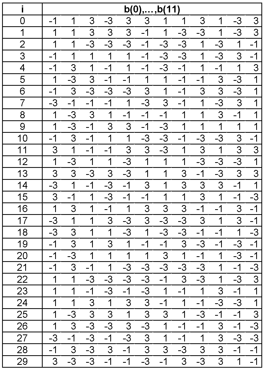
PUCCH 상으로 전송되는 제어정보는 순환 쉬프트된 시퀀스(cyclically shifted sequence)를 이용한다. 순환 쉬프트된 시퀀스는 기본 시퀀스(base sequence)를 특정 CS 양(cyclic shift amount) 만큼 순환 쉬프트시켜 생성할 수 있다. 특정 CS 양은 순환 쉬프트 인덱스(CS index)에 의해 지시된다. 다양한 종류의 시퀀스가 기본 시퀀스로 사용될 수 있다. 예를 들어, PN(pseudo-random) 시퀀스, ZC(Zadoff-Chu) 시퀀스와 같은 잘 알려진 시퀀스를 기본 시퀀스로 사용할 수 있다. 또는, 컴퓨터를 통해 생성되는 CAZAC(Constant Amplitude Zero Auto-Correlation)를 사용할 수 있다. 다음 수학식은 기본 시퀀스의 예이다. The control information transmitted on the PUCCH uses a cyclically shifted sequence. The cyclically shifted sequence can be generated by cyclically shifting the base sequence by a certain amount of CS (cyclic shift amount). The specific CS amount is indicated by a cyclic shift index (CS index). Various kinds of sequences can be used as the basic sequence. For example, well-known sequences such as PN (pseudo-random) sequences and ZC (Zadoff-Chu) sequences can be used as base sequences. Alternatively, a Constant Amplitude Zero Auto-Correlation (CAZAC) generated through a computer can be used. The following equation is an example of a basic sequence.
![]()
![]()
여기서, i ∈ {0,1,...,29}는 원시 인덱스(root index), n은 요소 인덱스로 0≤n≤N-1, N은 기본 시퀀스의 길이이다. i는 셀 ID(identity), 무선 프레임 내 슬롯 번호 등에 의해 정해질 수 있다. 하나의 자원블록이 12 부반송파를 포함한다고 할 때, N은 12로 할 수 있다. 다른 원시 인덱스에 따라 다른 기본 시퀀스가 정의된 다. N=12 일 때, b(n)은 다음 표와 같이 정의될 수 있다.Here, i ∈ {0, 1, ..., 29} is a root index, n is an element index, 0 ≤n ≤N-1, and N is the length of the basic sequence. i may be defined by a cell ID, a slot number in a radio frame, or the like. Assuming that one resource block includes 12 subcarriers, N may be 12. Different base indexes are defined according to different primitive indexes. When N = 12, b (n) can be defined as shown in the following table.
기본 시퀀스 r(n)을 다음 수학식과 같이 순환 쉬프트시켜 순환 쉬프트된 시퀀스 r(n, Ics)을 생성할 수 있다. The cyclic-shifted sequence r (n, Ics) can be generated by cyclically shifting the base sequence r (n) according to the following equation.

여기서, Ics는 CS 양을 나타내는 순환 쉬프트 인덱스이다(0≤Ics≤N-1, Ics는 정수). Here, Ics is a cyclic shift index indicating the amount of CS (0? Ics? N-1, Ics is an integer).
이하에서 기본 시퀀스의 가용(available) 순환 쉬프트 인덱스는 CS 간격(CS interval)에 따라 기본 시퀀스로부터 얻을 수(derive) 있는 순환 쉬프트 인덱스를 말한다. 예를 들어, 기본 시퀀스의 길이가 12이고, CS 간격이 1이라면, 기본 시퀀스의 가용 순환 쉬프트 인덱스의 총 수는 12가 된다. 또는, 기본 시퀀스의 길이가 12이고, CS 간격이 2이라면, 기본 시퀀스의 가용 순환 쉬프트 인덱스의 총 수는 6이 된다. CS 간격은 지연 스프레드(delay spread)를 고려하여 결정될 수 있다. In the following, the available cyclic shift index of the base sequence refers to a cyclic shift index deriving from the base sequence according to the CS interval (CS interval). For example, if the length of the base sequence is 12 and the CS interval is 1, then the total number of available cyclic shift indexes of the base sequence is 12. Or, if the length of the basic sequence is 12 and the CS interval is 2, the total number of available cyclic shift indexes of the basic sequence is 6. The CS interval may be determined in consideration of a delay spread.
도 8은 노멀 CP의 경우, PUCCH 포맷 1/1a/1b 전송의 예를 나타낸다. 이는 하나의 서브프레임 내 제1 슬롯과 제2 슬롯에 할당된 자원블록 쌍을 나타낸 것이다. 여기서는, 자원블록 쌍에 속하는 자원블록들이 제1 슬롯과 제2 슬롯에서 동일한 주파수 대역을 차지하는 것처럼 표현하였으나, 도 7에서 설명한 것과 같이 자원블록은 슬롯 레벨로 홉핑될 수 있다. 8 shows an example of
도 8을 참조하면, 제1 슬롯과 제2 슬롯 각각은 7 OFDM 심벌을 포함한다. 각 슬롯의 7 OFDM 심벌 중 3 OFDM 심벌에는 RS(reference signal)가 실리고, 나머지 4 OFDM 심벌에는 제어정보가 실린다. RS는 각 슬롯 중간의 3개의 인접하는(contiguous) OFDM 심벌에 실린다. 이때 RS에 사용되는 심벌의 개수 및 위치는 달라질 수 있으며, 제어정보에 사용되는 심벌의 개수 및 위치도 그에 따라 변경될 수 있다.Referring to FIG. 8, each of the first slot and the second slot includes 7 OFDM symbols. Among the 7 OFDM symbols of each slot, 3 reference symbols (RS) are put on 3 OFDM symbols, and control information is put on 4 remaining OFDM symbols. The RS is placed in three contiguous OFDM symbols in the middle of each slot. At this time, the number and position of the symbols used in the RS may be changed, and the number and position of the symbols used in the control information may be changed accordingly.
PUCCH 포맷 1, 1a 및 1b 각각은 하나의 복소 심벌(complex-valued symbol) d(0)를 사용한다. 기지국은 SR을 단말로부터의 PUCCH 전송의 존재 또는 부존재만으로 알 수 있다. 즉, SR 전송에는 OOK(on-off keying) 변조 방식이 사용될 수 있다. 따라서, PUCCH 포맷 1을 위한 복소 심벌 d(0)로 특정값, 예를 들어, d(0)=1을 사용할 수 있다. PUCCH 포맷 1a를 위한 복소 심벌 d(0)는 1비트의 HARQ ACK/NACK 정보 가 BPSK(Binary Phase Shift Keying) 변조되어 생성되는 변조 심벌이다. PUCCH 포맷 1b를 위한 복소 심벌 d(0)는 2비트의 HARQ ACK/NACK 정보가 QPSK(Quadrature Phase Shift Keying) 변조되어 생성되는 변조 심벌이다. PUCCH 포맷 1a는 1 코드워드에 대한 HARQ ACK/NACK 정보이고, PUCCH 포맷 1b는 2 코드워드에 대한 HARQ ACK/NACK 정보이다. Each of the PUCCH formats 1, 1a and 1b uses one complex-valued symbol d (0). The base station can know the SR only by the presence or absence of the PUCCH transmission from the terminal. That is, on-off keying (OOK) modulation scheme can be used for SR transmission. Therefore, a specific value, for example, d (0) = 1, can be used as the complex symbol d (0) for
다음 표는 변조 방식에 따라 HARQ ACK/NACK 정보 비트가 맵핑되는 변조 심벌의 예를 나타낸다. The following table shows an example of a modulation symbol to which HARQ ACK / NACK information bits are mapped according to a modulation scheme.

PUCCH 포맷 1/1a/1b을 위한 복소 심벌 d(0) 및 순환 쉬프트된 시퀀스 r(n,Ics)를 이용하여 변조된 시퀀스(modulated sequence) s(n)를 생성한다. 다음 수학식과 같이 순환 쉬프트된 시퀀스 r(n,Ics)에 복소 심벌 d(0)를 곱하여 변조된 시퀀스 s(n)을 생성할 수 있다. A modulated sequence s (n) is generated using the complex symbol d (0) and the cyclically shifted sequence r (n, Ics) for the
![]()
![]()
순환 쉬프트된 시퀀스 r(n,Ics)의 순환 쉬프트 인덱스인 Ics는 할당된 자원으로부터 시작하여 심벌 레벨(symbol level)로 홉핑될 수 있다. 이하, 심벌 레벨의 순환 쉬프트 인덱스의 홉핑을 CS 홉핑(CS hopping)이라 한다. CS 홉핑은 무선 프레임 내 슬롯 번호(ns) 및 슬롯 내 심벌 인덱스(ℓ)에 따라 수행될 수 있다. 따라서, 순환 쉬프트 인덱스 Ics는 Ics(ns,ℓ)로 표현될 수 있다. CS 홉핑은 셀 간 간섭(inter-cell interference)을 랜덤화(randomization)시키기 위해 셀 특정하게 수행될 수 있다. 여기서는, 제1 슬롯의 슬롯 번호는 0이고, 제2 슬롯의 슬롯 번호는 1로 하고, Ics(0,0)=0, Ics(0,1)=1, Ics(0,5)=2, Ics(0,6)=3, Ics(1,0)=4, Ics(1,1)=5, Ics(1,5)=6 및 Ics(1,6)=7로 두고 있으나, 이는 예시에 불과하다. The cyclic shift index Ics of the cyclically shifted sequence r (n, Ics) may be hopped to a symbol level starting from the allocated resource. Hereinafter, the hopping of the symbol-level cyclic shift index is referred to as CS hopping. The CS hopping can be performed according to the slot number n s in the radio frame and the in-slot symbol index l. Therefore, the cyclic shift index Ics can be expressed by Ics (n s , l). CS hopping may be performed cell-specific to randomize inter-cell interference. Here, Ics (0, 0) = 0, Ics (0, 1) = 1, Ics (0, 5) = 2, Ics (1, 6) = 3, Ics (1, 0) = 4, Ics .
단말 다중화 용량(UE multiplexing capacity)을 증가시키기 위해, 변조된 시퀀스 s(n)은 직교 시퀀스를 이용하여 확산될 수 있다. 단말 다중화 용량이란, 동일한 자원블록에 다중화될 수 있는 단말의 개수이다. In order to increase the UE multiplexing capacity, the modulated sequence s (n) may be spread using an orthogonal sequence. The terminal multiplexing capacity is the number of terminals that can be multiplexed in the same resource block.
여기서는, 하나의 슬롯 내의 제어정보가 실리는 4 OFDM 심벌에 대해 확산 계수(spreading factor) K=4인 직교 시퀀스 w(k)를 통해 변조된 시퀀스 s(n)을 확산시키는 것을 보이고 있다. 확산 계수 K=4인 직교 시퀀스 wIos(k) (Ios는 직교 시퀀스 인덱스, k는 직교 시퀀스의 요소 인덱스, 0≤k≤K-1)로 다음 표와 같은 시퀀스를 사용할 수 있다. Here, it is shown that spreading the modulated sequence s (n) through an orthogonal sequence w (k) with a spreading factor K = 4 for four OFDM symbols carrying control information in one slot. The sequence shown in the following table can be used as the orthogonal sequence w Ios (k) (I os is an orthogonal sequence index, k is an element index of an orthogonal sequence, 0 k K-1) having a spreading factor K = 4.

직교 시퀀스를 구성하는 요소들은 차례대로 제어정보가 실리는 OFDM 심벌들에 1:1로 대응된다. 직교 시퀀스를 구성하는 요소들은 각각 대응하는 OFDM 심벌에 실리는 변조된 시퀀스 s(n)에 곱해져 확산된 시퀀스가 생성된다. 확산된 시퀀스는 서브프레임 내 PUCCH에 할당되는 자원블록 쌍에 맵핑된다. 확산된 시퀀스가 자원블록 쌍에 맵핑된 후, 상기 서브프레임의 OFDM 심벌마다 IFFT가 수행되어 제어정보에 대한 시간 영역 신호가 출력된다. 여기서는, IFFT 수행 전에 직교 시퀀스가 곱해지나, 변조된 시퀀스 s(n)에 대한 IFFT 수행 후에 직교 시퀀스가 곱해져도 동일한 결과가 얻어질 수 잇다. The elements constituting the orthogonal sequence correspond one-to-one to OFDM symbols carrying control information in order. The elements constituting the orthogonal sequence are multiplied by a modulated sequence s (n), each of which is contained in a corresponding OFDM symbol, to generate a spread sequence. The spread sequence is mapped to a resource block pair allocated to a PUCCH in a subframe. After the spread sequence is mapped to the resource block pair, IFFT is performed for each OFDM symbol of the subframe, and a time domain signal for the control information is output. Here, the orthogonal sequence is multiplied before the IFFT operation, but the same result can be obtained even if the orthogonal sequence is multiplied after the IFFT operation on the modulated sequence s (n).
또는, 확산 계수 K=3인 직교 시퀀스 wIos(k) (Ios는 직교 시퀀스 인덱스, k는 직교 시퀀스의 요소 인덱스, 0≤k≤K-1)로 다음 표와 같은 시퀀스를 사용할 수 있다.Alternatively, the sequence shown in the following table can be used as the orthogonal sequence w Ios (k) (I os is an orthogonal sequence index, k is an element index of an orthogonal sequence, 0 k K-1) having a spreading factor K = 3.

사운딩 참조신호(sounding reference signal, SRS)와 PUCCH 포맷 1/1a/1b이 하나의 서브프레임에서 동시에 전송되는 경우, 하나의 OFDM 심벌이 천공(puncturing)된다. 예를 들어, 서브프레임의 마지막 OFDM 심벌이 천공될 수 있다. 이 경우, 상기 서브프레임의 제1 슬롯에서는 제어정보가 4 OFDM 심벌에 실리고, 제2 슬롯에서는 제어정보가 3 OFDM 심벌에 실린다. 따라서, 제1 슬롯에 대해서는 확산 계수 K=4인 직교 시퀀스가 이용되고, 제2 슬롯에 대해서는 확산 계수 K=3인 직교 시퀀스가 이용된다. When a sounding reference signal (SRS) and a
직교 시퀀스 인덱스 Ios는 할당된 자원으로부터 시작하여 슬롯 레벨로 홉핑될 수 있다. 이하, 슬롯 레벨의 직교 시퀀스 인덱스의 홉핑을 직교 시퀀스 리맵핑(OS remapping)이라 한다. 직교 시퀀스 리맵핑은 무선 프레임 내 슬롯 번호(ns)에 따라 수행될 수 있다. 따라서, 직교 시퀀스 인덱스 Ios는 Ios(ns)로 표현될 수 있다. 직교 시퀀스 리맵핑은 셀 간 간섭의 랜덤화를 위해 수행될 수 있다. The orthogonal sequence index Ios may be hopped to the slot level starting from the allocated resource. Hereinafter, the hopping of the slot-level orthogonal sequence index is referred to as orthogonal sequence remapping (OS remapping). Orthogonal sequence remapping may be performed according to the slot number n s in the radio frame. Therefore, the orthogonal sequence index Ios can be expressed by (n s) Ios. Orthogonal sequence remapping may be performed for randomization of inter-cell interference.
또한, 변조된 시퀀스 s(n)은 직교 시퀀스를 이용한 확산 외에도 스크램블될 수 있다. 예를 들어, 변조된 시퀀스 s(n)에 특정 파라미터에 따라 1 또는 j가 곱해질 수 있다.Also, the modulated sequence s (n) may be scrambled in addition to spreading using an orthogonal sequence. For example, the modulated sequence s (n) may be multiplied by 1 or j according to certain parameters.
RS는 제어정보와 동일한 기본 시퀀스로부터 생성된 순환 쉬프트된 시퀀스와 직교 시퀀스를 이용하여 생성할 수 있다. 순환 쉬프트된 시퀀스를 확산 계수 K=3인 직교 시퀀스 w(k)를 통해 확산시켜 RS로 사용할 수 있다. 따라서, 단말이 제어정보를 전송하기 위해, 제어정보를 위한 순환 쉬프트 인덱스와 직교 시퀀스 인덱스 외에도, RS를 위한 순환 쉬프트 인덱스와 직교 시퀀스 인덱스도 필요하다. RS may be generated using a cyclically shifted sequence and an orthogonal sequence generated from the same base sequence as the control information. The cyclic-shifted sequence can be spread as an RS through an orthogonal sequence w (k) with a spreading factor K = 3. Therefore, in addition to the cyclic shift index and the orthogonal sequence index for control information, the terminal also needs a cyclic shift index and an orthogonal sequence index for RS to transmit control information.
도 9는 확장된 CP의 경우, PUCCH 포맷 1/1a/1b 전송의 예를 나타낸다. 여기서는, 자원블록 쌍에 속하는 자원블록들이 제1 슬롯과 제2 슬롯에서 동일한 주파수 대역을 차지하는 것처럼 표현하였으나, 도 7에서 설명한 것과 같이 자원블록은 슬롯 레벨로 홉핑될 수 있다. 9 shows an example of
도 9를 참조하면, 제1 슬롯과 제2 슬롯 각각은 6 OFDM 심벌을 포함한다. 각 슬롯의 6 OFDM 심벌 중 2 OFDM 심벌에는 RS가 실리고, 나머지 4 OFDM 심벌에는 제어정보가 실린다. 이를 제외하면, 도 8의 노멀 CP의 경우의 예가 그대로 적용된다. 다만, RS는 순환 쉬프트된 시퀀스를 확산 계수 K=2인 직교 시퀀스 w(k)를 통해 확산시켜 RS로 사용할 수 있다. Referring to FIG. 9, each of the first slot and the second slot includes 6 OFDM symbols. RS is inserted in 2 OFDM symbols of 6 OFDM symbols of each slot, and control information is stored in 4 remaining OFDM symbols. Except for this, the example of the normal CP of FIG. 8 is applied as it is. However, the RS can spread the cyclic-shifted sequence through the orthogonal sequence w (k) with the spreading factor K = 2 and use it as an RS.
확산 계수 K=2인 직교 시퀀스 wIos(k) (Ios는 직교 시퀀스 인덱스, 0≤k≤K-1)로 다음 표와 같은 시퀀스를 사용할 수 있다.The orthogonal sequence w Ios (k) (Ios is an orthogonal sequence index, 0? K? K-1) with a spreading factor K = 2 can be used as the following table.

상술한 바와 같이, 노멀 CP, 확장된 CP의 경우 모두 PUCCH 포맷 1/1/a/1b 전송을 위해, 다음의 정보가 필요하다. 제어정보가 전송되는 부반송파(또는 자원블록), 제어정보를 위한 순환 쉬프트 인덱스 Ics 및 직교 시퀀스 인덱스 Ios, RS를 위한 순환 쉬프트 인덱스 I'cs 및 직교 시퀀스 인덱스 I'os가 필요하다. 예를 들어, 확장된 CP에서 CS 간격이 2인 경우, 단말 다중화 용량은 다음과 같다. 제어정보를 위한 Ics의 개수는 6이고, Ios의 개수는 3이므로, 하나의 자원블록당 18개의 단말이 다중화될 수 있다. 그러나, RS를 위한 I'cs의 개수는 6이고, I'os의 개수는 2이므로, 하나의 자원블록당 12개의 단말이 다중화될 수 있다. 따라서, 단말 다중화 용량은 제어정보 부분보다는 RS 부분에 의해 제한된다. As described above, for the normal CP and the extended CP, the following information is required for
도 10은 노멀 CP의 경우, PUCCH 포맷 2/2a/2b 전송의 예를 나타낸다. 여기서는, 자원블록 쌍에 속하는 자원블록들이 제1 슬롯과 제2 슬롯에서 동일한 주파수 대역을 차지하는 것처럼 표현하였으나, 도 7에서 설명한 것과 같이 자원블록은 슬롯 레벨로 홉핑될 수 있다. 10 shows an example of
도 10을 참조하면, 각 슬롯에 포함되는 7 OFDM 심벌 중 2 OFDM 심벌에는 RS가 실리고, 나머지 5 OFDM 심벌에는 CQI가 실린다. 이때 RS에 사용되는 심벌의 개수 및 위치는 달라질 수 있으며, CQI에 사용되는 심벌의 개수 및 위치도 그에 따라 변경될 수 있다. Referring to FIG. 10, RS is inserted in 2 OFDM symbols of 7 OFDM symbols included in each slot, and CQI is inserted in 5 remaining OFDM symbols. At this time, the number and position of the symbols used in the RS may be changed, and the number and position of the symbols used in the CQI may be changed accordingly.
단말은 CQI 정보 비트에 채널 코딩을 수행하여 부호화된 CQI 비트를 생성한다. 이때, 블록 코드(block code)가 사용될 수 있다. 블록 코드의 예로 리드 뮬러 코드(Reed-Muller code)가 있다. 3GPP LTE에서는 (20, A) 블록 코드가 사용된다. 여기서, A는 CQI 정보 비트의 크기이다. 즉, 3GPP LTE에서는 CQI 정보 비트의 크기에 상관없이 항상 20 비트의 부호화된 CQI 비트가 생성된다. The UE generates channelized CQI bits by performing channel coding on the CQI information bits. At this time, a block code may be used. An example of a block code is a Reed-Muller code. (20, A) block code is used in 3GPP LTE. Where A is the size of the CQI information bits. That is, in 3GPP LTE, 20-bit coded CQI bits are always generated regardless of the size of CQI information bits.
다음 표는 (20, A) 블록 코드를 위한 13 기저 시퀀스(basis sequence)의 예를 나타낸다. The following table shows an example of a 13 basis sequence for a (20, A) block code.

여기서, Mi,n은 기저 시퀀스이다(0≤n≤12, n은 정수). 부호화된 CQI 비트는 13 기저 시퀀스들의 선형 결합(linear combination)으로 생성된다. 다음 수학식은 부호화된 CQI 비트 bi의 예를 나타낸다(0≤i≤19, i는 정수). Here, M i, n is a base sequence (0? N? 12, n is an integer). The encoded CQI bits are generated in a linear combination of 13 basis sequences. The following equation shows an example of an encoded CQI bit b i (0? I? 19, where i is an integer).

여기서, a0,a1,...,aA-1은 CQI 정보 비트이고, A는 CQI 정보 비트의 크기이다(A는 자연수).Where a 0 , a 1 , ..., a A-1 is the CQI information bit and A is the size of the CQI information bit (A is a natural number).
CQI 정보 비트는 하나 이상의 필드를 포함할 수 있다. 예를 들어, MCS를 결정하는 CQI 인덱스를 지시하는 CQI 필드, 코드북 상의 프리코딩 행렬의 인덱스를 지시하는 PMI(precoding matrix indication) 필드, 랭크를 지시하는 RI(rank indication) 필드 등이 CQI 정보 비트에 포함될 수 있다. The CQI information bits may include one or more fields. For example, a CQI field indicating a CQI index for determining an MCS, a precoding matrix indication (PMI) field indicating an index of a precoding matrix on a codebook, a rank indication (RI) field indicating a rank, .
다음 표는 CQI 정보 비트가 포함하는 필드 및 상기 필드의 비트 크기의 일 예를 나타낸다. The following table shows an example of a field included in a CQI information bit and a bit size of the field.

CQI 정보 비트는 4 비트 크기의 광대역(wideband) CQI 필드만을 포함할 수 있다. 이때, CQI 정보 비트의 크기 A는 4이다. 광대역 CQI 필드는 전체 대역에 대한 CQI 인덱스를 지시한다. The CQI information bits may only include a 4-bit wideband CQI field. At this time, the size A of the CQI information bits is 4. The wideband CQI field indicates the CQI index for the entire band.
다음 표는 CQI 정보 비트가 포함하는 필드 및 상기 필드의 비트 크기의 다른 예를 나타낸다. The following table shows another example of a field included in the CQI information bits and a bit size of the field.

CQI 정보 비트는 광대역 CQI 필드, 공간 차이(spatial differential) CQI 필드, PMI 필드를 포함할 수 있다. 공간 차이 CQI 필드는 제1 코드워드를 위한 전체 대역에 대한 CQI 인덱스와 제2 코드워드를 위한 전체 대역에 대한 CQI 인덱스의 차이를 지시한다. 각 필드의 크기는 기지국의 전송 안테나의 개수와 랭크에 따라 달라진다. 예를 들어, 기지국이 4 전송 안테나를 사용하고, 랭크가 1 보다 큰 경우, CQI 정보 비트는 4 비트의 광대역 CQI 필드, 3 비트의 공간 차이 CQI 필드 및 4 비트의 PMI 필드를 포함한다(A=13).The CQI information bits may include a wideband CQI field, a spatial differential CQI field, and a PMI field. The Spatial Differential CQI field indicates the difference between the CQI index for the entire band for the first codeword and the CQI index for the entire band for the second codeword. The size of each field depends on the number and rank of transmit antennas of the base station. For example, if the base station uses 4 transmit antennas and the rank is greater than 1, the CQI information bits include a 4-bit wideband CQI field, a 3-bit spatial difference CQI field, and a 4-bit PMI field (A = 13).
다음 표는 CQI 정보 비트가 포함하는 필드 및 상기 필드의 비트 크기의 또 다른 예를 나타낸다. The following table shows another example of a field included in the CQI information bits and a bit size of the field.

20 비트의 부호화된 CQI 비트는 단말 특정 스크램블링 시퀀스(UE-specific scrambling sequence)에 의해 스크램블되어 20 비트의 스크램블된 비트를 생성할 수 있다. 20 비트의 스크램블된 비트는 QPSK를 통해 10개의 변조 심벌들 d(0),...,d(9)로 맵핑된다. PUCCH 포맷 2a에서는 1비트의 HARQ ACK/NACK 정보가 BPSK 변조를 통해 1개의 변조 심벌 d(10)로 맵핑된다. PUCCH 포맷 2b에서는 2비트의 HARQ ACK/NACK 정보가 QPSK 변조를 통해 1개의 변조 심벌 d(10)로 맵핑된다. The 20-bit coded CQI bits may be scrambled by a UE-specific scrambling sequence to produce 20 bits of scrambled bits. 20 bits of scrambled bits are mapped to 10 modulation symbols d (0), ..., d (9) via QPSK. In the PUCCH format 2a, one bit of HARQ ACK / NACK information is mapped to one modulation symbol d (10) through BPSK modulation. In the
변조 심벌들 d(0),...,d(9)와 기본 시퀀스로부터 생성된 순환 쉬프트된 시퀀스 r(n,Ics)를 이용하여 변조된 시퀀스를 생성한다. 순환 쉬프트된 시퀀스 r(n,Ics)의 순환 쉬프트 인덱스 Ics는 무선 프레임 내 슬롯 번호(ns) 및 슬롯 내 심벌 인덱스(ℓ)에 따라 달라질 수 있다. 따라서, 순환 쉬프트 인덱스 Ics는 Ics(ns,ℓ)로 표현될 수 있다. 여기서는, 제1 슬롯의 슬롯 번호는 0이고, 제2 슬롯의 슬롯 번호는 1로 하고, Ics(0,0)=0, Ics(0,2)=1, Ics(0,3)=2, Ics(0,4)=3, Ics(0,6)=4, Ics(1,0)=5, Ics(1,2)=6, Ics(1,3)=7, Ics(1,4)=8 및 Ics(1,6)=9로 두고 있으나, 이는 예시에 불과하다. RS는 제어정보와 동일한 기본 시퀀스로부터 생성된 순환 쉬프트된 시퀀스를 이용할 수 있다. PUCCH 포맷 2a 및 2b 각각에서, 1개의 변조 심벌 d(10)은 RS 생성에 사용된다. The modulated sequence is generated using the modulation symbols d (0), ..., d (9) and the cyclically shifted sequence r (n, Ics) generated from the base sequence. The cyclic shift index Ics of the cyclically shifted sequence r (n, Ics) may vary according to the slot number n s in the radio frame and the intra-slot symbol index l. Therefore, the cyclic shift index Ics can be expressed by Ics (n s , l). Here, the slot number of the first slot is 0, the slot number of the second slot is 1, Ics (0, 0) = 0, Ics (0, 2) = 1, Ics Ics (0, 4) = 3, Ics (0, 6) = 4, Ics (1, 0) = 5, Ics ) = 8 and Ics (1,6) = 9, but this is merely an example. The RS may use a cyclically shifted sequence generated from the same base sequence as the control information. In each of the PUCCH formats 2a and 2b, one modulation symbol d (10) is used for RS generation.
PUCCH 포맷 2/2a/2b는 PUCCH 포맷 1/1a/1b와 달리 직교 시퀀스는 사용하지 않는다. Unlike
도 11은 확장된 CP의 경우, PUCCH 포맷 2/2a/2b 전송의 예를 나타낸다. 여기서는, 자원블록 쌍에 속하는 자원블록들이 제1 슬롯과 제2 슬롯에서 동일한 주파수 대역을 차지하는 것처럼 표현하였으나, 도 7에서 설명한 것과 같이 자원블록은 슬롯 레벨로 홉핑될 수 있다. 11 shows an example of a
도 11을 참조하면, 제1 슬롯과 제2 슬롯 각각은 6 OFDM 심벌을 포함한다. 각 슬롯의 6 OFDM 심벌 중 1 OFDM 심벌에는 RS가 실리고, 나머지 5 OFDM 심벌에는 제어정보가 실린다. 이를 제외하면, 도 10의 노멀 CP의 경우의 예가 그대로 적용된다. Referring to FIG. 11, each of the first slot and the second slot includes 6 OFDM symbols. RS is inserted in one OFDM symbol among six OFDM symbols of each slot, and control information is placed in the remaining five OFDM symbols. Except for this, the example of the normal CP of FIG. 10 is applied as it is.
상술한 바와 같이, 노멀 CP, 확장된 CP의 경우 모두 PUCCH 포맷 2/2/a/2b 전송을 위해, 다음의 정보가 필요하다. 제어정보가 전송되는 부반송파(또는 자원블록), 제어정보를 위한 순환 쉬프트 인덱스 Ics, RS를 위한 순환 쉬프트 인덱스 I'cs가 필요하다. CS 간격이 1인 경우, 제어정보를 위한 Ics의 개수 및 RS를 위한 I'cs는 12이고, 하나의 자원블록당 12개의 단말이 다중화될 수 있다. CS 간격이 2인 경우, 제어정보를 위한 Ics의 개수 및 RS를 위한 I'cs는 6이고, 하나의 자원블록당 6개의 단말이 다중화될 수 있다. As described above, for the normal CP and the extended CP, the following information is required for
도 12는 제어정보 전송 방법의 일 예를 나타낸 흐름도이다. 12 is a flowchart showing an example of a control information transmission method.
도 12를 참조하면, 단말은 자원 인덱스(resource index)를 획득한다(S11). 단말은 자원 인덱스를 이용하여 제어정보를 처리한다(S12). 단말은 기지국으로 제어정보를 전송한다(S13). Referring to FIG. 12, the terminal obtains a resource index (S11). The terminal processes the control information using the resource index (S12). The terminal transmits control information to the base station (S13).
셀 내 복수의 단말은 기지국으로 동시에 제어정보를 전송할 수 있다. 이때, 각 단말이 서로 다른 자원을 사용한다면, 기지국은 각 단말마다의 제어정보를 구별할 수 있다. A plurality of terminals in a cell can simultaneously transmit control information to a base station. At this time, if each terminal uses different resources, the base station can distinguish control information for each terminal.
이하, 자원(resource)은 자원블록, CS 양, 직교 시퀀스 중 적어도 하나 이상일 수 있다. 자원 인덱스는 제어정보 전송에 사용되는 자원을 식별한다. 자원 인덱스로부터 순환 쉬프트 인덱스 및 자원블록이 결정된다. 예를 들어, 서브프레임 내에서 PUCCH에 할당된 자원블록의 주파수 영역 위치를 나타내는 위치 인덱스 m은 자원 인덱스로부터 결정될 수 있다. 또한, 직교 시퀀스 인덱스 역시 자원 인덱스로부터 결정될 수 있다.Hereinafter, the resource may be at least one of a resource block, a CS amount, and an orthogonal sequence. The resource index identifies the resource used to transmit the control information. A circular shift index and a resource block are determined from the resource index. For example, a position index m indicating a frequency domain position of a resource block allocated to a PUCCH in a subframe can be determined from a resource index. The orthogonal sequence index can also be determined from the resource index.
PUCCH 포맷 1/1a/1b의 경우, 자원은 (1) CS 양, (2) 직교 시퀀스 및 (3) 자원블록의 조합으로 구성된다. 자원 인덱스는 순환 쉬프트 인덱스, 직교 시퀀스 인덱스 및 자원블록을 지시한다. 예를 들어, 순환 쉬프트 인덱스의 개수가 6, 직교 시퀀스 인덱스의 개수가 3, 자원블록의 개수가 3이면, 자원의 총수는 54(=6*3*3)이다. 54개의 자원은 0부터 53까지 자원 인덱스가 매겨질 수 있다. 54개 자원 각각은 서로 다른 단말에게 할당될 수 있다. In the case of the
PUCCH 포맷 2/2a/2b의 경우, 자원은 (1) CS 양, (2) 자원블록의 조합으로 구성된다. 자원 인덱스는 순환 쉬프트 인덱스 및 자원블록을 지시한다. 예를 들어, 순환 쉬프트 인덱스의 개수가 6, 자원블록의 개수가 2이면, 자원의 총수는 12(=6*2)이다. 12개의 자원은 0부터 11까지 자원 인덱스가 매겨질 수 있다. 12개 자원 각각은 서로 다른 단말에게 할당될 수 있다. In the case of
도 13은 제어정보 전송 방법의 다른 예를 나타낸 흐름도이다. 13 is a flowchart showing another example of the control information transmission method.
도 13을 참조하면, 기지국은 단말에게 자원 인덱스를 전송한다(S21). 단말은 자원 인덱스를 이용하여 제어정보를 처리한다(S22). 단말은 기지국으로 제어정보를 전송한다(23). 이와 같이, 기지국은 단말에게 자원 인덱스를 명시적으로(explicitly) 알려줄 수 있다. 자원 인덱스는 물리 계층(physical layer)의 상위 계층(higher layer)에 의해 설정될 수 있다. 예를 들어, 상위 계층은 단말과 네트워크 간에 무선 자원을 제어하는 역할을 수행하는 RRC(Radio Resource Control)일 수 있다. 이 경우, 단말이 전송하는 제어정보는 SR, SPS(semi-persistent scheduling) ACK/NACK, CQI 등일 수 있다. SPS ACK/NACK은 반정적 스케줄링으로 전송된 하향링크 데이터에 대한 ACK/NACK이다. 상기 하향링크 데이터가 PDSCH를 통해 전송될 경우, 상기 PDSCH에 대응하는 PDCCH가 존재하지 않을 수 있다. Referring to FIG. 13, the BS transmits a resource index to the MS (S21). The terminal processes the control information using the resource index (S22). The terminal transmits control information to the base station (23). In this way, the BS can explicitly inform the UE of the resource index. The resource index can be set by a higher layer of the physical layer. For example, the upper layer may be an RRC (Radio Resource Control) that controls radio resources between the UE and the network. In this case, the control information transmitted by the UE may be SR, semi-persistent scheduling (SPS) ACK / NACK, CQI, and the like. The SPS ACK / NACK is an ACK / NACK for downlink data transmitted in semi-static scheduling. When the downlink data is transmitted through the PDSCH, the PDCCH corresponding to the PDSCH may not exist.
도 14는 제어정보 전송 방법의 또 다른 예를 나타낸 흐름도이다. 14 is a flowchart showing another example of the control information transmission method.
도 14를 참조하면, 기지국은 단말에게 하향링크 데이터를 전송한다(S31). 단말은 자원 인덱스를 획득한다(S32). 이때, 자원 인덱스는 하향링크 데이터 수신을 위한 제어채널이 전송되는 무선 자원으로부터 얻을 수 있다. 단말은 자원 인덱스를 이용하여 제어정보를 처리한다(S33). 단말은 기지국으로 제어정보를 전송한다(S34). 이와 같이, 기지국은 단말에게 자원 인덱스를 암시적으로(implicitly) 알려줄 수 있다. 이 경우, 단말이 전송하는 제어정보는 동적(dynamic) ACK/NACK일 수 있다. 동적 ACK/NACK은 동적 스케줄링으로 전송된 하향링크 데이터에 대한 ACK/NACK이다. 동적 스케줄링은 기지국이 PDSCH를 통한 하향링크 데이터를 전송할 때마다 단말에게 PDCCH를 통해 하향링크 그랜트를 매번 전송하는 것이다. Referring to FIG. 14, the base station transmits downlink data to the mobile station (S31). The terminal obtains a resource index (S32). At this time, the resource index can be obtained from the radio resource to which the control channel for downlink data reception is transmitted. The terminal processes the control information using the resource index (S33). The terminal transmits control information to the base station (S34). In this way, the BS can implicitly inform the MS of the resource index. In this case, the control information transmitted by the UE may be a dynamic ACK / NACK. The dynamic ACK / NACK is ACK / NACK for the downlink data transmitted in the dynamic scheduling. Dynamic scheduling is performed every time a base station transmits downlink data through a PDCCH to a mobile station whenever it transmits downlink data through a PDSCH.
다음 수학식은 동적 ACK/NACK 전송을 위한 자원 인덱스(In)를 결정하는 예이다.The following equation is an example of determining a resource index (In) for transmission of dynamic ACK / NACK.
![]()
![]()
여기서, nCCE는 PDSCH에 대한 PDCCH 전송에 사용된 첫번째 CCE 인덱스이고, N(1) PUCCH는 SR과 SPS ACK/NACK을 위해 할당되는 자원 인덱스의 개수이다. N(1) PUCCH는 RRC와 같은 상위 계층에 의해 설정될 수 있다. Here, n CCE is the first CCE index used for PDCCH transmission for the PDSCH, and N (1) PUCCH is the number of resource indices allocated for SR and SPS ACK / NACK. N (1) PUCCH may be set by an upper layer such as RRC.
따라서, 기지국은 PDCCH 전송에 사용되는 첫번째 CCE 인덱스를 조절하여 ACK/NACK 전송을 위한 자원을 조절할 수 있다.Accordingly, the BS may adjust the first CCE index used for the PDCCH transmission to adjust resources for ACK / NACK transmission.
도 15는 자원 인덱스를 이용한 제어정보 처리 방법의 일 예를 나타낸 순서도이다. 15 is a flowchart showing an example of a control information processing method using a resource index.
도 15를 참조하면, 단말은 자원 인덱스를 이용하여 순환 쉬프트 인덱스를 결정한다(S41). 단말은 순환 쉬프트 인덱스를 이용하여 순환 쉬프트된 시퀀스를 생성한다(S42). 순환 쉬프트된 시퀀스는 순환 쉬프트 인덱스로부터 얻은 순환 쉬프트 양만큼 기본 시퀀스를 순환 쉬프트시킴으로써 생성될 수 있다. 단말은 순환 쉬프트된 시퀀스 및 제어정보를 위한 심벌을 이용하여 변조된 시퀀스를 생성한다(S43). 단말은 변조된 시퀀스를 자원블록에 맵핑한다(S44). 단말은 변조된 시퀀스를 전송한다. 이때, 단말이 전송하는 제어정보는 CQI일 수 있다. Referring to FIG. 15, the UE determines a cyclic shift index using a resource index (S41). The terminal generates a cyclically shifted sequence using the cyclic shift index (S42). The cyclically shifted sequence can be generated by cyclically shifting the base sequence by the cyclic shift amount obtained from the cyclic shift index. The terminal generates the modulated sequence using the cyclic-shifted sequence and the symbols for the control information (S43). The terminal maps the modulated sequence to the resource block (S44). The terminal transmits the modulated sequence. At this time, the control information transmitted by the UE may be a CQI.
도 16은 자원 인덱스를 이용한 제어정보 처리 방법의 다른 예를 나타낸 순서도이다. 16 is a flowchart showing another example of a control information processing method using a resource index.
도 16을 참조하면, 단말은 자원 인덱스를 이용하여 직교 시퀀스 인덱스 및 순환 쉬프트 인덱스를 결정한다(S51). 단말은 순환 쉬프트 인덱스를 이용하여 순환 쉬프트된 시퀀스를 생성한다(S52). 단말은 순환 쉬프트된 시퀀스 및 제어정보를 위한 심벌을 이용하여 변조된 시퀀스를 생성한다(S53). 단말은 직교 시퀀스 인덱스를 이용하여 변조된 시퀀스로부터 확산된 시퀀스를 생성한다(S54). 단말은 확산된 시퀀스를 자원블록에 맵핑한다(S55). 단말은 확산된 시퀀스를 전송한다. 이때, 단말이 전송하는 제어정보는 SR, ACK/NACK 등일 수 있다. Referring to FIG. 16, the UE determines an orthogonal sequence index and a cyclic shift index using a resource index (S51). The terminal generates a cyclically shifted sequence using a cyclic shift index (S52). The terminal generates a modulated sequence using symbols for the cyclically shifted sequence and the control information (S53). The terminal generates a spread sequence from the modulated sequence using the orthogonal sequence index (S54). The terminal maps the spread sequence to the resource block (S55). The terminal transmits the spread sequence. At this time, the control information transmitted by the UE may be SR, ACK / NACK, and the like.
지금까지 살펴본 바와 같이, CDM(Code Division Multiplexing) 및/또는 FDM(Frequency Division Multiplexing) 방식으로 셀 내 복수의 단말마다의 상향링크 제어정보가 서브프레임 내에서 다중화되어 전송될 수 있다. 복수의 단말은 각각 서로 다른 자원을 이용하여 기지국으로 동시에 제어정보를 전송할 수 있다. 기지국은 동시에 전송된 각 단말마다의 제어정보를 구별할 수 있다. As described so far, uplink control information for each of a plurality of terminals in a cell can be multiplexed and transmitted in a subframe according to CDM (Code Division Multiplexing) and / or FDM (Frequency Division Multiplexing). A plurality of terminals can simultaneously transmit control information to the base station using different resources. The base station can distinguish control information for each terminal transmitted at the same time.
단말은 다수의 전송 안테나를 통해 제어정보를 전송할 수 있다. MIMO 기술 중 전송 다이버시티(transmit diversity) 기법(scheme)은 다이버시티 이득(diversity gain)이 있고, 무선 통신의 신뢰도(reliability)를 증가시킬 수 있다. 전송 다이버시티 기법의 예로 CDD(cyclic delay diversity), PVS(precoding vector switching), SC-SFBC(single carrier space-frequency block coding), STBC(space-time block coding) 등이 있다. 그러나, 상기 기법들을 이용할 경우, 직교성(orthogonality)이 유지되지 않거나, 전송 다이버시티 이득이 제한되거나, 3GPP LTE와의 역호환성(backward compatibility)이 만족되지 않는 문제가 있다. 따라서, 상기 문제들을 해결할 수 있는 전송 다이버시티 기법을 이용한 제어정보 전송 방법을 제공할 필요가 있다. A terminal may transmit control information through a plurality of transmit antennas. Among the MIMO techniques, the transmit diversity scheme has a diversity gain and can increase the reliability of wireless communication. Examples of transmission diversity techniques include cyclic delay diversity (CDD), precoding vector switching (PVS), single carrier space-frequency block coding (SC-SFBC), and space-time block coding (STBC). However, there is a problem in that orthogonality is not maintained, transmission diversity gain is limited, or backward compatibility with 3GPP LTE is not satisfied when using the above techniques. Therefore, there is a need to provide a control information transmission method using a transmit diversity scheme that can solve the above problems.
또한, 지금까지 설명된 제어정보 전송 방법을 이용할 경우, 2 코드워드 대한 2비트의 HARQ ACK/NACK 정보 또는 20 비트의 부호화된 CQI 비트가 전송될 수 있다. 그런데, 3GPP LTE와의 호환성을 유지하면서, 추가적인 제어정보를 전송할 수 있는 방법이 필요하다. 예를 들어, 코드워드의 개수가 증가되거나, 다중 반송파(multiple carrier) 시스템의 경우, 추가적인 제어정보를 전송해야 한다. 예를 들어, 코드워드의 개수가 4개인 경우, 4비트의 HARQ ACK/NACK 정보를 전송하는 방법이 필요하다. 또 다른 예로, 2 하향링크 및 1 상향링크(2DL-1UL)로 구성된 반송파 집성 시스템(carrier aggregation system)의 경우에도 4비트의 HARQ ACK/NACK 정보를 전송하는 방법이 필요하다. In addition, when the control information transmission method described so far is used, 2 bits of HARQ ACK / NACK information or 20 bits of encoded CQI bits for 2 codewords can be transmitted. However, there is a need for a method capable of transmitting additional control information while maintaining compatibility with 3GPP LTE. For example, the number of codewords may be increased or, in the case of a multiple carrier system, additional control information should be transmitted. For example, if the number of codewords is four, a method of transmitting 4 bits of HARQ ACK / NACK information is needed. As another example, a method of transmitting 4-bit HARQ ACK / NACK information is also required in the case of a carrier aggregation system composed of two downlinks and one uplink (2DL-1UL).
이하, 상향링크 제어정보 전송을 기준으로 설명하나, 이하에서 설명되는 내용은 하향링크 제어정보 전송에도 그대로 적용될 수 있다. 또한, 이하에서 설명되는 내용은 제어정보 전송뿐 아니라, 데이터 정보 전송 등 일반적인 정보 전송에도 적용될 수 있다. Hereinafter, the uplink control information transmission is described with reference to the following description, but the following description can be applied to the downlink control information transmission as it is. In addition, the contents described below can be applied not only to control information transmission but also to general information transmission such as data information transmission.
도 17은 본 발명의 실시예에 따른 정보 전송 방법을 나타낸 흐름도이다. 17 is a flowchart illustrating an information transmission method according to an embodiment of the present invention.
도 17을 참조하면, 단말은 제1 자원 인덱스 및 제2 자원 인덱스를 획득한다(S110). 단말은 제1 구간 동안 제1 안테나를 통해 제1 정보를 제1 자원 인덱스를 이용하여 기지국으로 전송한다(S120). 단말은 제1 구간 동안 제2 안테나를 통해 제2 정보를 제2 자원 인덱스를 이용하여 기지국으로 전송한다(S130). 제1 구간은 정보가 전송되는 시간 구간이다. 예를 들어, 제1 구간은 슬롯, OFDM 심벌 등일 수 있다. 제1 정보와 제2 정보는 동시에 전송된다. 제1 자원 인덱스는 제1 정보 전송을 위해 할당되고, 제2 자원 인덱스는 제2 정보 전송을 위해 할당된다. 제1 자원 인덱스와 제2 자원 인덱스는 서로 다를 수 있다. 제1 자원 인덱스와 제2 자원 인덱스가 서로 다르면, 각 전송 안테나 간에는 직교성이 유지될 수 있다. 제1 안테나 및 제2 안테나별 채널 추정(channel estimation)을 위해 RS 부분에 2개의 자원이 할당될 수 있다. Referring to FIG. 17, the UE acquires a first resource index and a second resource index (S110). The terminal transmits the first information to the base station using the first resource index through the first antenna during the first interval (S120). The terminal transmits the second information to the base station using the second resource index through the second antenna during the first interval (S130). The first section is a time interval during which information is transmitted. For example, the first interval may be a slot, an OFDM symbol, or the like. The first information and the second information are simultaneously transmitted. A first resource index is allocated for the first information transmission and a second resource index is allocated for the second information transmission. The first resource index and the second resource index may be different from each other. If the first resource index and the second resource index are different from each other, orthogonality can be maintained between the respective transmit antennas. Two resources may be allocated to the RS part for channel estimation for each of the first antenna and the second antenna.
도 17의 정보 전송 방법은 3개 이상의 전송 안테나에 대해서도 확장 적용될 수 있다. 단말이 N개의 전송 안테나를 통해 N개의 정보를 전송하려는 경우, N개의 전송 안테나 각각에 대해 서로 다른 N개의 자원 인덱스를 할당받을 수 있다(N은 2 이상의 자연수). 단말은 N개의 정보 각각을 각 자원 인덱스를 이용하여 각 전송 안테나를 통해 기지국으로 전송할 수 있다. RS는 안테나별 채널 추정을 위해 각 전송 안테나별로 전송될 수 있고, RS 전송을 위해 N개의 자원이 할당될 수 있다. 즉, 단말에게 정보 전송을 위해 할당되는 자원의 개수와 RS 전송을 위해 할당되는 자원의 개수는 동일할 수 있다. The information transmission method of FIG. 17 can be extended to three or more transmission antennas. When the UE transmits N information through N transmit antennas, N different resource indexes may be allocated to N transmit antennas (N is a natural number of 2 or more). The UE can transmit each of N pieces of information to each of the base stations via each transmit antenna using each resource index. RS may be transmitted for each transmit antenna for channel estimation of each antenna, and N resources may be allocated for RS transmission. That is, the number of resources allocated for information transmission to the UE and the number of resources allocated for RS transmission may be the same.
도 18은 전송기 구조의 일 예를 나타낸 블록도이다. 여기서, 전송기는 단말 또는 기지국의 일부분일 수 있다. 18 is a block diagram showing an example of a transmitter structure. Here, the transmitter may be a terminal or a part of a base station.
도 18을 참조하면, 전송기(100)는 채널 코딩부(110), 변조기(120), 분할기(splitter, 130), N개의 정보 처리부(140-1,...,140-N, N은 2 이상의 자연수) 및 N개의 전송 안테나(190-1,...,190-N)를 포함한다. 제nr 정보 처리부(140-nr)는 제nr 전송 안테나(190-nr)와 연결된다(nr=1,...,N). 채널 코딩부(110)는 정보 비트에 채널 코딩을 수행하여 부호화된 비트를 생성한다. 부호화된 비트는 코드워드라 할 수 있다. 변조기(120)는 부호화된 비트를 변조하여 변조 심벌을 생성한다. 변조 방식에는 제한이 없으며, m-PSK(m-Phase Shift Keying) 또는 m-QAM(m-Quadrature Amplitude Modulation)일 수 있다. 변조기(120)를 통해 M×N개의 변조 심벌이 생성된다(M은 자연수). 예를 들어, PUCCH 포맷 1/1a/1b에서는 M=1이고, PUCCH 포맷 2/2a/2b에서는 M=10이다. 분할기(130)는 M×N개의 변조 심벌을 이용하여 N개의 정 보(s(1),s(2),...,s(N))로 분리하여, 제nr 정보 s(nr)을 제nr 정보 처리부(140-nr)에 입력한다. 제nr 정보 처리부(140-nr)는 제nr 자원 인덱스를 이용하여 제nr 정보를 처리하여 제nr 제어신호를 생성한다. 즉, N개의 정보마다 자원인덱스가 할당된다. 제nr 제어신호는 제nr 전송 안테나(190-nr)를 통해 전송될 수 있다. Referring to FIG. 18, the
도 19는 변조 과정의 예를 나타낸다. 19 shows an example of a modulation process.
도 19를 참조하면, 변조기에 2비트의 제1 부호화된 비트(b(0),b(1)) 및 2비트의 제2 부호화된 비트(c(0),c(1))가 입력된다. 제1 부호화된 비트는 제1 하향링크 반송파를 통해 전송된 제1 데이터에 대한 제1 ACK/NACK이고, 제2 부호화된 비트는 제2 하향링크 반송파를 통해 전송된 제2 데이터에 대한 제2 ACK/NACK일 수 있다. 변조기는 제1 부호화된 비트를 QPSK 변조하여 제1 변조 심벌(d(0))을 생성하고, 제2 부호화된 비트를 QPSK 변조하여 제2 변조 심벌(e(0))을 생성한다. 또는, 변조기는 제1 부호화된 비트와 제2 부호화된 비트를 치환(permutation)하여, 치환된 후의 비트를 변조할 수 있다. 예를 들어, 변조기는 제1 부호화된 비트 및 제2 부호화된 비트 각각의 첫번째 비트(b(0),c(0))를 교환(swapping)하여 치환할 수 있다. 변조기는 c(0), b(1)을 변조하여 제1 변조 심벌(d(0))을 생성하고, b(0), c(1)을 변조하여 제2 변조 심벌(e(0))을 생성할 수 있다. 19, two bits of the first coded bits b (0), b (1) and two bits of the second coded bits c (0), c (1) are input to the modulator . The first coded bit is the first ACK / NACK for the first data transmitted on the first downlink carrier and the second coded bit is the second ACK / NACK for the second data transmitted on the second downlink carrier. / NACK. The modulator QPSK modulates the first coded bit to generate a first modulated symbol d (0), and QPSK modulates the second coded bit to generate a second modulated symbol e (0). Alternatively, the modulator may perform permutation of the first coded bit and the second coded bit to modulate the bit after being replaced. For example, the modulator may replace the first bit (b (0), c (0)) of each of the first coded bit and the second coded bit by swapping. The modulator generates a first modulation symbol d (0) by modulating c (0), b (1) and modulates b (0), c (1) Can be generated.
분할기는 제1 변조 심벌(d(0))과 제2 변조 심벌(e(0))을 이용하여 제1 정보 s(1), 제2 정보 s(2)로 분리한다. 일 예로, 제1 변조 심벌은 제1 정보에 대응되고, 제2 변조 심벌은 제2 정보에 대응될 수 있다. 다른 예로, 제1 변조 심벌과 제2 변조 심벌은 치환 및/또는 혼합(mixing)되어 제1 정보 및 제2 정보로 분리될 수 있 다. The divider separates the first information s (1) and the second information s (2) by using the first modulation symbol d (0) and the second modulation symbol e (0). In one example, the first modulation symbol may correspond to the first information, and the second modulation symbol may correspond to the second information. As another example, the first modulation symbol and the second modulation symbol may be replaced and / or mixed to separate into the first information and the second information.
다음 수학식은 제1 변조 심벌(d(0))과 제2 변조 심벌(e(0))이 치환 및/또는 혼합되어 제1 정보(s(1)) 및 제2 정보(s(2))로 분리되는 예들을 나타낸다.(1) and the second information s (2) are replaced and / or mixed with the first modulation symbol d (0) and the second modulation symbol e (0) . ≪ / RTI >

또는 다음 수학식과 같이 제1 변조 심벌(d(0)) 또는 제2 변조 심벌(e(0))이 임의의 위상으로 회전된 후 치환 및/또는 혼합되어 제1 정보(s(1)) 및 제2 정보(s(2))로 분리될 수 있다. Alternatively, the first information s (1) and / or the second information s (1) may be replaced and / or mixed after the first modulation symbol d (0) or the second modulation symbol e And the second information s (2).

여기서, a와 b는 동일할 수도 있고, 다를 수도 있다. Here, a and b may be the same or different.
M=10이고 R=2인 경우를 가정하여, 도 20 및 21에서 전송기의 채널 코딩 및 변조 과정을 상술한다. Assuming that M = 10 and R = 2, the channel coding and modulation process of the transmitter will be described in FIGS. 20 and 21. FIG.
도 20은 전송기의 채널 코딩 및 변조 과정의 일 예를 나타낸다. 20 shows an example of a channel coding and modulation process of a transmitter.
도 20을 참조하면, 채널 코딩부에 A비트의 제1 정보 비트(x(0),x(1),...,x(A-1))와 A비트의 제2 정보 비트(y(0),y(1),...,y(A-1))가 입력된다. 제2 정보 비트는 제1 정보 비트의 채널 코딩이 완료된 후에 채널 코딩부에 입력될 수 있다. 채널 코딩부는 제1 정보 비트를 채널 코딩하여 20 비트의 제1 부호화된 비트(b(0),b(1),...,b(19))를 생성하고, 제2 정보 비트를 채널 코딩하여 20 비트의 제2 부호화된 비트(c(0),c(1),...,c(19)를 생성한다. 즉, 제1 정보 비트 및 제2 정보 비트 각각에 채널 코딩이 수행되어, 2개의 코드워드가 생성된다. 부호화율(rate)은 R=A/20이다. Referring to FIG. 20, in the channel coding unit, a first information bit (x (0), x (1), ..., x (A- 0), y (1), ..., y (A-1). The second information bit may be input to the channel coding unit after channel coding of the first information bit is completed. The channel coding unit channel-codes the first information bits to generate 20-bit first coded bits b (0), b (1), ..., b (19) , C (19) of 20 bits, that is, channel coding is performed on each of the first information bit and the second information bit , Two code words are generated. The coding rate is R = A / 20.
변조기에 20비트의 제1 부호화된 비트와 20 비트의 제2 부호화된 비트가 입력된다. 제2 부호화된 비트는 제1 부호화된 비트 입력 이후에 입력될 수 있다. 또는, 제1 부호화된 비트와 제2 부호화된 비트는 치환 가능하다. 변조기는 제1 부호화된 비트를 QPSK 변조하여 제1 변조 심벌(d(0),d(1),..,d(9))을 생성하고, 제2 부호화된 비트를 QPSK 변조하여 제2 변조 심벌(e(0),e(1),...,e(9))을 생성한다. 20 bits of the first encoded bit and 20 bits of the second encoded bit are input to the modulator. The second coded bit may be input after the first coded bit input. Alternatively, the first coded bit and the second coded bit are replaceable. The modulator QPSK modulates the first coded bits to generate first modulation symbols d (0), d (1), .., d (9), QPSK modulates the second coded bits, To generate symbols e (0), e (1), ..., e (9).
분할기는 제1 변조 심벌과 제2 변조 심벌을 이용하여 제1 정보 s(1), 제2 정보 s(2)로 분리한다. 제1 변조 심벌은 제1 정보 s(1)에 대응되고, 제2 변조 심벌은 제2 정보에 대응될 수 있다. 즉, 제1 정보는 제1 정보 비트를 채널 코딩하여 생성된 제1 코드워드에 대응되고, 상기 제2 정보는 제2 정보 비트를 채널 코딩하여 생성된 제2 코드워드에 대응될 수 있다. 또는, 제1 변조 심벌과 제2 변조 심벌은 치환 및/또는 혼합되어 제1 정보 및 제2 정보로 분리될 수도 있다. The divider separates the first information s (1) and the second information s (2) by using the first modulation symbol and the second modulation symbol. The first modulation symbol may correspond to the first information s (1), and the second modulation symbol may correspond to the second information. That is, the first information corresponds to the first code word generated by channel coding the first information bit, and the second information corresponds to the second code word generated by channel coding the second information bit. Alternatively, the first modulation symbol and the second modulation symbol may be replaced and / or mixed to separate the first information and the second information.
도 21은 전송기의 채널 코딩 및 변조 과정의 다른 예를 나타낸다. 21 shows another example of the channel coding and modulation process of the transmitter.
도 21을 참조하면, 채널 코딩부에 A비트의 정보 비트(x(0),x(1),...,x(A-1))가 입력된다. 채널 코딩부는 정보 비트를 채널 코딩하여 40 비트의 부호화된 비트(b(0),b(1),...,b(39))를 생성한다. 즉, 정보 비트에 채널 코딩이 수행되어, 1개 의 코드워드가 생성된다. 부호화율(rate)은 R/2=A/40이다. 변조기는 부호화된 비트를 QPSK 변조하여 20개의 변조 심벌(d(0),d(1),..,d(19))을 생성한다. 분할기는 변조 심벌을 이용하여 제1 정보 s(1), 제2 정보 s(2)로 분리한다. 예를 들어, d(0),d(1),..,d(9)는 제1 정보 s(1)에 대응되고, d(10),d(11),..,d(19)는 제2 정보에 대응될 수 있다. 즉, 제1 정보는 정보 비트를 채널 코딩하여 생성된 하나의 코드워드의 일부 비트에 대응되고, 제2 정보는 상기 코드워드의 나머지 비트에 대응된다. Referring to FIG. 21, A bit information bits (x (0), x (1), ..., x (A-1)) are input to the channel coding unit. The channel coding unit channel-codes the information bits to generate 40-bit encoded bits b (0), b (1), ..., b (39). That is, channel coding is performed on the information bits, and one code word is generated. The coding rate is R / 2 = A / 40. The modulator performs QPSK modulation on the coded bits to generate 20 modulation symbols (d (0), d (1), .., d (19)). The divider separates the first information s (1) and the second information s (2) by using modulation symbols. For example, d (0), d (1), ..., d (9) correspond to the first information s (1) May correspond to the second information. That is, the first information corresponds to some bits of one code word generated by channel coding the information bits, and the second information corresponds to the remaining bits of the code word.
도 21과 같이, 정보 비트가 R/T의 부호화율로 채널 코딩되어 하나의 코드워드가 생성되고, 상기 코드워드의 다른 부분들은 다른 전송 안테나를 통해 전송되는 채널 코딩 방식을 조인트 코딩(joint coding)이라 한다. 이때, R은 전송 안테나가 하나일 때의 부호화율이고, T는 전송 안테나의 개수이다. 도 21과 달리 도 20에서는 전송 안테나의 개수와 동일한 개수의 코드워드가 생성되는 채널 코딩 방식이 사용된다. As shown in FIG. 21, a channel coding scheme in which information bits are channel-coded with a coding rate of R / T to generate one codeword, and other parts of the codeword are transmitted through different transmission antennas is joint- Quot; In this case, R is the coding rate when one transmission antenna is used, and T is the number of transmission antennas. 20, a channel coding scheme is used in which the same number of code words as the number of transmission antennas are generated.
이하, 정보 전송 방법에 대해 구체적으로 설명한다. Hereinafter, the information transmission method will be described in detail.
첫째, PUCCH 포맷 1/1a/1b가 적용된 정보 전송 방법에 대해 설명한다. 정보 전송에 이용되는 자원은 (1) CS 양, (2) 직교 시퀀스 및 (3) 자원블록의 조합으로 구성될 수 있다. 이 경우, 각 자원 인덱스는 순환 쉬프트 인덱스, 직교 시퀀스 인덱스 및 자원블록을 지시할 수 있다. 이 경우, 제1 자원 인덱스는 제1 순환 쉬프트 인덱스, 제1 직교 시퀀스 인덱스 및 제1 자원블록을 지시하고, 제2 자원 인덱스는 제2 순환 쉬프트 인덱스, 제2 직교 시퀀스 인덱스 및 제2 자원블록을 지시한다. First, an information transmission method using the
제1 정보는 단말이 제1 하향링크 반송파를 통해 수신한 제1 데이터에 대한 제1 ACK/NACK이고, 제2 정보는 단말이 제2 하향링크 반송파를 통해 수신한 제2 데이터에 대한 제2 ACK/NACK일 수 있다. 또는, 제1 정보는 2 코드워드에 대한 제1 ACK/NACK이고, 제2 정보는 다른 2 코드워드에 대한 제2 ACK/NACK일 수 있다. 제1 정보 및 제2 정보의 각 변조 심벌은 1비트의 HARQ ACK/NACK 정보가 BPSK 변조된 변조 심벌이거나, 2비트의 HARQ ACK/NACK 정보가 QPSK 변조된 변조 심벌일 수 있다. 단말은 기지국으로부터 각 하향링크 데이터를 수신하는 단계를 더 포함할 수 있다. 제1 자원 인덱스는 제1 하향링크 데이터를 수신하기 위한 물리적 제어채널에 대한 무선 자원으로부터 획득되고, 제1 자원 인덱스는 제1 하향링크 데이터를 수신하기 위한 물리적 제어채널에 대한 무선 자원으로부터 획득될 수 있다. The first information is a first ACK / NACK for the first data received through the first downlink carrier and the second information is a second ACK / NACK for the second data received through the second downlink carrier / NACK. Alternatively, the first information may be a first ACK / NACK for two codewords and the second information may be a second ACK / NACK for another two codewords. Each modulation symbol of the first information and the second information may be a modulation symbol in which 1 bit of HARQ ACK / NACK information is BPSK modulated or a modulation symbol in which 2 bits of HARQ ACK / NACK information is QPSK modulation. The terminal may further include receiving each downlink data from the base station. A first resource index is obtained from a radio resource for a physical control channel for receiving first downlink data and a first resource index is obtained from a radio resource for a physical control channel for receiving first downlink data have.
각 정보는 각 자원 인덱스를 이용하여 PUCCH 포맷 1/1a/1b와 같이 처리될 수 있다. 단말은 제1 순환 쉬프트 인덱스로부터 얻은 제1 CS 양만큼 기본 시퀀스를 순환 쉬프트시킴으로써 제1 순환 쉬프트된 시퀀스를 생성하고, 제1 순환 쉬프트된 시퀀스 및 제1 정보에 대한 제1 변조 심벌을 이용하여 제1 변조된 시퀀스를 생성하고, 제1 직교 시퀀스 인덱스를 이용하여 제1 변조된 시퀀스로부터 제1 확산된 시퀀스를 생성하고, 제1 확산된 시퀀스를 제1 자원블록에 맵핑한 후, 제1 안테나를 통해 제1 확산된 시퀀스를 전송할 수 있다. 또한, 단말은 제2 순환 쉬프트 인덱스로부터 얻은 제2 CS 양만큼 상기 기본 시퀀스를 순환 쉬프트시킴으로써 제2 순환 쉬프트된 시퀀스를 생성하고, 제2 순환 쉬프트된 시퀀스 및 제2 정보에 대한 제2 변조 심벌을 이용하여 제2 변조된 시퀀스를 생성하고, 제2 직교 시퀀스 인덱스를 이 용하여 제2 변조된 시퀀스로부터 제2 확산된 시퀀스를 생성하고, 제2 확산된 시퀀스를 제2 자원블록에 맵핑한 후, 제2 안테나를 통해 제2 확산된 시퀀스를 전송할 수 있다. 이때, 제1 확산된 시퀀스 및 제2 확산된 시퀀스는 동시에 전송될 수 있다. Each piece of information can be processed as
이하, 제nt 전송 안테나를 통해 전송되는 제nr 확산된 시퀀스를 z{nr,nt}로 나타낸다. 제nr 확산된 시퀀스는 제nr 자원 인덱스 및 제nr 정보를 이용하여 생성된 시퀀스이다. z{nr,nt}는 다음 수학식과 같이 나타낼 수 있다. Hereinafter, the nr-spread sequence transmitted through the nth transmission antenna is expressed as z {nr, nt}. The nr-spread sequence is a sequence generated using the nr resource index and the nr information. z {nr, nt} can be expressed by the following equation.
![]()
![]()
여기서, k는 제nr 자원블록 내 OFDM 심벌의 심벌 인덱스이다. RS가 실리는 OFDM 심벌을 제외하면 k=0,1,2,3일 수 있다. Rnr은 제nr 자원블록의 주파수 위치 오프셋이고, n은 제nr 자원블록 내 부반송파 인덱스이다(n=0,1,...,11). wnr(k)는 제nr 직교 시퀀스 인덱스의 k번째 요소이고, dnr(0)는 제nr 정보에 대한 제nr 변조 심벌이고, Icsnr은 제nr 순환 쉬프트 인덱스이고, r(n,Icsnr)은 제nr 순환 쉬프트된 시퀀스이다. Here, k is a symbol index of an OFDM symbol in the nrth resource block. Except for OFDM symbols carrying RS, k = 0,1,2,3. R nr is the frequency position offset of the n th resource block and n is the subcarrier index in the n th resource block (n = 0, 1, ..., 11). w nr (k) is first and the k-th element of the nr orthogonal sequence index, d nr (0) is the nr modulation symbols for the nr information, Ics nr is first and nr cyclic shift index, r (n, Ics nr ) Is the nr cyclic shifted sequence.
도 22는 PUCCH 포맷 1/1a/1b가 적용된 정보 전송의 일 예를 나타낸다.22 shows an example of information transmission in which the
도 22를 참조하면, z{11}은 제1 안테나를 통해 전송되는 제1 확산된 시퀀스이고, z{22}는 제2 안테나를 통해 전송되는 제2 확산된 시퀀스이다. 서브프레임 내 제1 슬롯에서 제1 확산된 시퀀스는 제1 안테나를 통해 전송되고, 제2 확산된 시퀀스는 제2 안테나를 통해 전송된다. 그리고, 서브프레임 내 제2 슬롯에서 제1 확산된 시퀀스는 제1 안테나를 통해 전송되고, 제2 확산된 시퀀스는 제2 안테나를 통해 전송된다. 여기서, 제1 자원 인덱스는 m=1인 자원블록 쌍을 지시하고, 제2 자원 인덱스는 m=2인 자원블록 쌍을 지시하는 것으로 나타내나, 이는 예시에 불과하다. Referring to FIG. 22, z {11} is a first spread sequence transmitted through a first antenna and z {22} is a second spread sequence transmitted via a second antenna. The first spreading sequence in the first slot in the subframe is transmitted via the first antenna and the second spreading sequence is transmitted via the second antenna. The first spreading sequence in the second slot in the subframe is transmitted through the first antenna, and the second spreading sequence is transmitted through the second antenna. Here, the first resource index indicates a resource block pair with m = 1, and the second resource index indicates a resource block pair with m = 2, but this is merely an example.
도 23은 전송기 구조의 다른 예를 나타낸 블록도이다. 여기서, 전송기는 단말 또는 기지국의 일부분일 수 있다. 23 is a block diagram showing another example of the transmitter structure. Here, the transmitter may be a terminal or a part of a base station.
도 23을 참조하면, 전송기(200)는 채널 코딩부(210), 변조기(220), 분할기(230), 2개의 정보 처리부(240-1, 240-2) 및 2개의 전송 안테나(290-1, 290-2)를 포함한다. 제1 정보 처리부(240-1)는 제2 전송 안테나(290-2)와 연결되고, 제2 정보 처리부(240-2)는 제1 전송 안테나(290-1)와 연결된다. 23, the
다이버시티 이득을 극대화시키기 위해, 특정 시간 구간 단위로 정보가 전송되는 전송 안테나를 변경할 수 있다. 특정 시간 구간 단위는 슬롯, OFDM 심벌 등일 수 있다. 예를 들어, 제1 구간 동안에는 제1 정보는 제1 자원 인덱스를 이용하여 제1 전송 안테나로 전송되고, 제2 정보는 제2 자원 인덱스를 이용하여 제2 전송 안테나로 전송된다. 그리고, 제2 구간 동안에는 제1 정보는 제1 자원 인덱스를 이용하여 제2 전송 안테나로 전송되고, 제2 정보는 제2 자원 인덱스를 이용하여 제1 전송 안테나로 전송된다. In order to maximize the diversity gain, it is possible to change the transmission antenna in which information is transmitted in a specific time interval unit. A specific time interval unit may be a slot, an OFDM symbol, or the like. For example, during a first interval, the first information is transmitted to a first transmit antenna using a first resource index, and the second information is transmitted to a second transmit antenna using a second resource index. During the second interval, the first information is transmitted to the second transmission antenna using the first resource index, and the second information is transmitted to the first transmission antenna using the second resource index.
2개의 전송 안테나의 경우, 정보가 전송되는 전송 안테나 변경은 안테나 교환 작용(operation)과 동일하다. N개의 전송 안테나의 경우, 전송기는 N개의 전송 안테나들 중 적어도 하나 이상의 전송 안테나를 변경하여 정보를 전송할 수 있다. 시간 구간이 2개 이상인 경우, N개의 전송 안테나를 순환 형태로 쉬프트시킬 수 있다. 예를 들어, 제1 구간 동안 제1 정보는 제1 전송 안테나, 제2 정보는 제2 전송 안테나,..., 제N 정보는 제N 전송 안테나로 전송된다. 제2 구간 동안에는 제N 정보는 제1 전송 안테나, 제1 정보는 제2 전송 안테나,..., 제N-1 정보는 제N 전송 안테나로 전송될 수 있다. 정보가 전송되는 안테나가 변경될 때, RS를 위해 안테나별로 할당된 자원 역시 변경될 수 있다. In the case of two transmit antennas, the transmit antenna change to which the information is transmitted is the same as the antenna exchange operation. In case of N transmit antennas, the transmitter may transmit information by changing at least one transmit antenna among N transmit antennas. If the time interval is two or more, the N transmit antennas can be shifted in a cyclic manner. For example, during the first interval, the first information is transmitted to the first transmission antenna, the second information is transmitted to the second transmission antenna, ..., and the Nth information is transmitted to the Nth transmission antenna. During the second interval, the Nth information may be transmitted to the Nth transmit antenna, the first information may be transmitted to the Nth transmit antenna, and the (N-1) th information may be transmitted to the Nth transmit antenna. When the antenna through which the information is transmitted is changed, the resources allocated for each antenna for the RS can also be changed.
도 24는 PUCCH 포맷 1/1a/1b가 적용된 정보 전송의 다른 예를 나타낸다.Fig. 24 shows another example of information transmission in which the
도 24를 참조하면, z{11}은 제1 안테나를 통해 전송되는 제1 확산된 시퀀스이고, z{22}는 제2 안테나를 통해 전송되는 제2 확산된 시퀀스이다. z{12}는 제2 안테나를 통해 전송되는 제1 확산된 시퀀스이고, z{21}는 제1 안테나를 통해 전송되는 제2 확산된 시퀀스이다. 서브프레임 내 제1 슬롯에서 제1 확산된 시퀀스는 제1 안테나를 통해 전송되고, 제2 확산된 시퀀스는 제2 안테나를 통해 전송된다. 그리고, 서브프레임 내 제2 슬롯에서 제1 확산된 시퀀스는 제2 안테나를 통해 전송되고, 제2 확산된 시퀀스는 제1 안테나를 통해 전송된다. 따라서, 제2 슬롯에서는 제1 안테나를 통해 제2 정보가 제2 자원 인덱스를 이용하여 전송되고, 제2 안테나를 통해 제1 정보가 제1 자원 인덱스를 이용하여 전송된다. 여기서, 제1 구간은 서브프레임 내 제1 슬롯이고, 제2 구간은 상기 서브프레임 내 제2 슬롯이다. Referring to FIG. 24, z {11} is a first spread sequence transmitted through a first antenna and z {22} is a second spread sequence transmitted via a second antenna. z {12} is a first spread sequence transmitted through a second antenna, and z {21} is a second spread sequence transmitted via a first antenna. The first spreading sequence in the first slot in the subframe is transmitted via the first antenna and the second spreading sequence is transmitted via the second antenna. The first spreading sequence in the second slot in the subframe is transmitted through the second antenna, and the second spreading sequence is transmitted through the first antenna. Therefore, in the second slot, the second information is transmitted using the second resource index through the first antenna, and the first information is transmitted using the first resource index through the second antenna. Here, the first interval is the first slot in the subframe, and the second interval is the second slot in the subframe.
도 25는 PUCCH 포맷 1/1a/1b가 적용된 정보 전송의 또 다른 예를 나타낸다.FIG. 25 shows another example of information transmission in which the
도 25를 참조하면, 제1 구간 및 제2 구간은 각각 OFDM 심벌이다. 이때, 제1 직교 시퀀스 인덱스 및 상기 제2 직교 시퀀스 인덱스는 동일하게 제한할 수 있다. Referring to FIG. 25, the first and second sections are OFDM symbols, respectively. In this case, the first orthogonal sequence index and the second orthogonal sequence index may be limited to the same.
둘째, PUCCH 포맷 2/2a/2b가 적용된 정보 전송 방법에 대해 설명한다. 정보 전송에 이용되는 자원은 (1) CS 양 및 (2) 자원블록의 조합으로 구성될 수 있다. 이 경우, 각 자원 인덱스는 순환 쉬프트 인덱스 및 자원블록을 지시할 수 있다. 이 경우, 제1 자원 인덱스는 제1 순환 쉬프트 인덱스 및 제1 자원블록을 지시하고, 제2 자원 인덱스는 제2 순환 쉬프트 인덱스 및 제2 자원블록을 지시한다. Second, an information transmission method to which the
제1 정보는 제1 하향링크 반송파에 대한 제1 CQI이고, 제2 정보는 제2 하향링크 반송파에 대한 제2 CQI일 수 있다. 또는, 제1 정보는 2 코드워드에 대한 제1 CQI이고, 제2 정보는 다른 2 코드워드에 대한 제2 CQI일 수 있다. 제1 정보 및 제2 정보의 각 변조 심벌은 20비트의 부호화된 CQI 비트가 QPSK 변조된 10 변조 심벌일 수 있다. 또는, 제1 정보 및 제2 정보의 각 변조 심벌은 20×N 비트의 부호화된 CQI 비트가 QPSK 변조된 10×N 변조 심벌일 수 있다. 제1 자원 인덱스 및 제2 자원 인덱스는 각각 기지국으로부터 지시될 수 있다. 또는, 제1 자원 인덱스는 기지국으로부터 지시되고, 제2 자원 인덱스는 단말이 제1 자원 인덱스로부터 획득할 수 있다. The first information may be a first CQI for a first downlink carrier and the second information may be a second CQI for a second downlink carrier. Alternatively, the first information may be a first CQI for two codewords and the second information may be a second CQI for another two codewords. Each modulation symbol of the first information and the second information may be a 10 modulation symbol in which the 20-bit coded CQI bits are QPSK-modulated. Alternatively, each modulation symbol of the first information and the second information may be a 10 x N modulation symbol in which 20 x N bits of the encoded CQI bits are QPSK modulated. The first resource index and the second resource index may be indicated from the base station, respectively. Alternatively, the first resource index may be indicated by the base station, and the second resource index may be obtained from the first resource index by the terminal.
각 정보는 각 자원 인덱스를 이용하여 PUCCH 포맷 2/2a/2b와 같이 처리될 수 있다. 단말은 제1 순환 쉬프트 인덱스로부터 얻은 제1 CS 양만큼 기본 시퀀스를 순환 쉬프트시킴으로써 제1 순환 쉬프트된 시퀀스를 생성하고, 제1 순환 쉬프트된 시퀀스 및 제1 정보에 대한 제1 변조 심벌을 이용하여 제1 변조된 시퀀스를 생성하고, 제1 변조된 시퀀스를 제1 자원블록에 맵핑한 후, 제1 안테나를 통해 제1 변조 된 시퀀스를 전송할 수 있다. 또한, 단말은 제2 순환 쉬프트 인덱스로부터 얻은 제2 CS 양만큼 상기 기본 시퀀스를 순환 쉬프트시킴으로써 제2 순환 쉬프트된 시퀀스를 생성하고, 제2 순환 쉬프트된 시퀀스 및 제2 정보에 대한 제2 변조 심벌을 이용하여 제2 변조된 시퀀스를 생성하고, 제2 변조된 시퀀스를 제2 자원블록에 맵핑한 후, 제2 안테나를 통해 제2 변조된 시퀀스를 전송할 수 있다. 이때, 제1 변조된 시퀀스 및 제2 변조된 시퀀스는 동시에 전송될 수 있다. Each piece of information can be processed as
이하, 제nt 전송 안테나를 통해 전송되는 제nr 변조된 시퀀스를 s{nr,nt}로 나타낸다. 제nr 변조된 시퀀스는 제nr 자원 인덱스 및 제nr 정보를 이용하여 생성된 시퀀스이다. s{nr,nt}는 다음 수학식과 같이 나타낼 수 있다. Hereinafter, the nr modulated sequence transmitted through the nth transmission antenna is denoted by s {nr, nt}. The nr modulated sequence is a sequence generated using the nr resource index and the nr information. s {nr, nt} can be expressed by the following equation.
![]()
![]()
여기서, k는 제nr 자원 인덱스가 지시하는 자원블록 쌍의 OFDM 심벌의 심벌 인덱스이다. RS가 실리는 OFDM 심벌을 제외하면 k=0,1,...,9일 수 있다. Rnr은 제nr 자원블록의 주파수 위치 오프셋이고, n은 제nr 자원블록 내 부반송파 인덱스이다(n=0,1,...,11). dnr(k)는 제nr 정보에 대한 제nr 변조 심벌이고, Icsnr은 제nr 순환 쉬프트 인덱스이고, r(n,Icsnr)은 제nr 순환 쉬프트된 시퀀스이다. Here, k is a symbol index of an OFDM symbol of a resource block pair indicated by the nr resource index. , K = 0, 1, ..., 9, except for the OFDM symbol in which RS is carried. R nr is the frequency position offset of the n th resource block and n is the subcarrier index in the n th resource block (n = 0, 1, ..., 11). d nr (k) is an nr modulation symbol for nr information, Ics nr is an nr cyclic shift index, and r (n, Ics nr ) is an nr cyclic shifted sequence.
도 22는 PUCCH 포맷 2/2a/2b가 적용된 정보 전송에도 적용될 수 있다. 서브프레임 내 제1 슬롯에서 제1 변조된 시퀀스는 제1 안테나를 통해 전송되고, 제2 변 조된 시퀀스는 제2 안테나를 통해 전송된다. 그리고, 서브프레임 내 제2 슬롯에서 제1 변조된 시퀀스는 제1 안테나를 통해 전송되고, 제2 변조된 시퀀스는 제2 안테나를 통해 전송된다. PUCCH 포맷 2/2a/2b가 적용된 정보 전송의 경우에도 도 24와 같은 슬롯 레벨 안테나 변경이 적용될 수 있다. 또한, PUCCH 포맷 2/2a/2b가 적용된 정보 전송의 경우에도 심벌 레벨 안테나 변경이 적용될 수 있다. FIG. 22 can also be applied to information transmission in which
도 26은 PUCCH 포맷 2/2a/2b가 적용된 정보 전송의 예를 나타낸다.26 shows an example of information transmission in which
도 26을 참조하면, s{11}은 제1 안테나를 통해 전송되는 제1 변조된 시퀀스이고, s{22}는 제2 안테나를 통해 전송되는 제2 변조된 시퀀스이다. s{12}는 제2 안테나를 통해 전송되는 제1 변조된 시퀀스이고, s{21}는 제1 안테나를 통해 전송되는 제2 변조된 시퀀스이다. Referring to FIG. 26, s {11} is a first modulated sequence transmitted via a first antenna and s {22} is a second modulated sequence transmitted via a second antenna. s {12} is a first modulated sequence transmitted via a second antenna, and s {21} is a second modulated sequence transmitted via a first antenna.
도 27은 무선 통신을 위한 장치를 나타낸 블록도이다. 무선 통신을 위한 장치(50)는 단말의 일부일 수 있다. 무선 통신을 위한 장치(50)는 프로세서(processor, 51), 메모리(memory, 52), RF부(Radio Frequency unit, 53), 디스플레이부(display unit, 54), 사용자 인터페이스부(user interface unit, 55)를 포함한다. RF부(53)는 프로세서(51)와 연결되어, 무선 신호(radio signal)를 전송 및/또는 수신한다. 메모리(52)는 프로세서(51)와 연결되어, 구동 시스템, 애플리케이션 및 일반적인 파일을 저장한다. 디스플레이부(54)는 단말의 여러 정보를 디스플레이하며, LCD(Liquid Crystal Display), OLED(Organic Light Emitting Diodes) 등 잘 알려진 요소를 사용할 수 있다. 사용자 인터페이스부(55)는 키패드나 터치 스크린 등 잘 알려진 사용자 인터페이스의 조합으로 이루어질 수 있다. 프로세서(51)는 지금까지 상술한 정보 처리 및 전송에 관한 모든 방법들을 수행한다. 27 is a block diagram showing an apparatus for wireless communication. The
도 28은 기지국의 예를 나타낸 블록도이다. 기지국(60)은 프로세서(processor, 61), 메모리(memory, 62), 스케줄러(scheduler, 63) 및 RF부(64)를 포함한다. RF부(64)는 프로세서(61)와 연결되어, 무선 신호를 전송 및/또는 수신한다. 프로세서(61)는 지금까지 상술한 정보 전송과 관련한 모든 방법들을 수행할 수 있다. 메모리(62)는 프로세서(61)와 연결되어, 프로세서(61)에서 처리된 정보들을 저장한다. 스케줄러(63)는 프로세서(61)와 연결되어, 지금까지 상술한 자원 인덱스 할당과 같이 정보 전송을 위한 스케줄링에 관한 모든 방법들을 수행할 수 있다. 28 is a block diagram showing an example of a base station. The
이와 같이, 무선 통신 시스템에서 효율적인 정보 전송 방법을 제공할 수 있다. 복수의 전송 안테나를 이용하여 전송 다이버시티 이득을 얻을 수 있고, 각 전송 안테나 간에는 직교성이 유지될 수 있다. 또한, 복수의 전송 안테나를 통해 추가적인 정보를 전송할 수 있어, 전송률을 높일 수 있다. 또한, 3GPP LTE와의 역호환성이 만족될 수 있다. 이를 통해, 무선 통신의 신뢰도를 높일 수 있고, 전체 시스템 성능을 향상시킬 수 있다. Thus, an efficient information transmission method in the wireless communication system can be provided. A transmission diversity gain can be obtained by using a plurality of transmission antennas, and orthogonality can be maintained between the respective transmission antennas. Further, additional information can be transmitted through a plurality of transmission antennas, and the transmission rate can be increased. In addition, backward compatibility with 3GPP LTE can be satisfied. This can increase the reliability of the wireless communication and improve the overall system performance.
지금까지 상향링크 제어정보 전송을 기준으로 설명하였으나, 지금까지 설명된 내용은 하향링크 제어정보 전송에도 그대로 적용될 수 있다. 또한, 지금까지 설명된 내용은 제어정보 전송뿐 아니라, 데이터 정보 전송 등 일반적인 정보 전송에도 적용될 수 있다. Although the uplink control information transmission has been described based on the above, the contents described so far can be applied to the downlink control information transmission as it is. In addition, the contents described so far can be applied not only to control information transmission but also to general information transmission such as data information transmission.
상술한 모든 기능은 상기 기능을 수행하도록 코딩된 소프트웨어나 프로그램 코드 등에 따른 마이크로프로세서, 제어기, 마이크로제어기, ASIC(Application Specific Integrated Circuit) 등과 같은 프로세서에 의해 수행될 수 있다. 상기 코드의 설계, 개발 및 구현은 본 발명의 설명에 기초하여 당업자에게 자명하다고 할 것이다.All of the functions described above may be performed by a processor such as a microprocessor, a controller, a microcontroller, an application specific integrated circuit (ASIC), etc. according to software or program code or the like coded to perform the function. The design, development and implementation of the above code will be apparent to those skilled in the art based on the description of the present invention.
이상 본 발명에 대하여 실시예를 참조하여 설명하였지만, 해당 기술 분야의 통상의 지식을 가진 자는 본 발명의 기술적 사상 및 영역으로부터 벗어나지 않는 범위 내에서 본 발명을 다양하게 수정 및 변경시켜 실시할 수 있음을 이해할 수 있을 것이다. 따라서 상술한 실시예에 한정되지 않고, 본 발명은 이하의 특허청구범위의 범위 내의 모든 실시예들을 포함한다고 할 것이다.While the present invention has been particularly shown and described with reference to exemplary embodiments thereof, it will be understood by those skilled in the art that various changes and modifications may be made therein without departing from the spirit and scope of the invention. You will understand. Therefore, it is intended that the present invention covers all embodiments falling within the scope of the following claims, rather than being limited to the above-described embodiments.
도 1은 무선 통신 시스템을 나타낸다. 1 shows a wireless communication system.
도 2는 HARQ ACK/NACK 및 CQI 전송을 나타낸다.2 shows HARQ ACK / NACK and CQI transmission.
도 3은 상향링크 전송을 나타낸다.3 shows an uplink transmission.
도 4는 3GPP LTE에서 무선 프레임의 구조를 나타낸다. 4 shows a structure of a radio frame in 3GPP LTE.
도 5는 3GPP LTE에서 하나의 상향링크 슬롯에 대한 자원 그리드를 나타낸 예시도이다. 5 is an exemplary view illustrating a resource grid for one uplink slot in 3GPP LTE.
도 6은 3GPP LTE에서 하향링크 서브프레임의 구조의 예를 나타낸다. 6 shows an example of the structure of a DL subframe in 3GPP LTE.
도 7은 3GPP LTE에서 상향링크 서브프레임의 구조의 예를 나타낸다. 7 shows an example of the structure of a UL subframe in 3GPP LTE.
도 8은 노멀 CP의 경우, PUCCH 포맷 1/1a/1b 전송의 예를 나타낸다. 8 shows an example of
도 9는 확장된 CP의 경우, PUCCH 포맷 1/1a/1b 전송의 예를 나타낸다. 9 shows an example of
도 10은 노멀 CP의 경우, PUCCH 포맷 2/2a/2b 전송의 예를 나타낸다. 10 shows an example of
도 11은 확장된 CP의 경우, PUCCH 포맷 2/2a/2b 전송의 예를 나타낸다. 11 shows an example of a
도 12는 정보 전송 방법의 일 예를 나타낸 흐름도이다. 12 is a flowchart showing an example of an information transmission method.
도 13은 정보 전송 방법의 다른 예를 나타낸 흐름도이다. 13 is a flowchart showing another example of the information transmission method.
도 14는 정보 전송 방법의 또 다른 예를 나타낸 흐름도이다. 14 is a flowchart showing another example of the information transmission method.
도 15는 자원 인덱스를 이용한 정보 처리 방법의 일 예를 나타낸 순서도이다. 15 is a flowchart showing an example of an information processing method using a resource index.
도 16은 자원 인덱스를 이용한 정보 처리 방법의 다른 예를 나타낸 순서도이다. 16 is a flowchart showing another example of the information processing method using the resource index.
도 17은 본 발명의 실시예에 따른 정보 전송 방법을 나타낸 흐름도이다. 17 is a flowchart illustrating an information transmission method according to an embodiment of the present invention.
도 18은 전송기 구조의 예를 나타낸 블록도이다. 18 is a block diagram showing an example of a transmitter structure.
도 19는 변조 과정의 예를 나타낸다. 19 shows an example of a modulation process.
도 20은 전송기의 채널 코딩 및 변조 과정의 일 예를 나타낸다. 20 shows an example of a channel coding and modulation process of a transmitter.
도 21은 전송기의 채널 코딩 및 변조 과정의 다른 예를 나타낸다. 21 shows another example of the channel coding and modulation process of the transmitter.
도 22는 PUCCH 포맷 1/1a/1b가 적용된 정보 전송의 일 예를 나타낸다. 22 shows an example of information transmission in which the
도 23은 전송기 구조의 다른 예를 나타낸 블록도이다. 23 is a block diagram showing another example of the transmitter structure.
도 24는 PUCCH 포맷 1/1a/1b가 적용된 정보 전송의 다른 예를 나타낸다.Fig. 24 shows another example of information transmission in which the
도 25는 PUCCH 포맷 1/1a/1b가 적용된 정보 전송의 또 다른 예를 나타낸다. FIG. 25 shows another example of information transmission in which the
도 25는 PUCCH 포맷 2/2a/2b가 적용된 정보 전송의 예를 나타낸다.25 shows an example of information transmission in which
도 26은 PUCCH 포맷 2/2a/2b가 적용된 정보 전송의 예를 나타낸다.26 shows an example of information transmission in which
도 27은 무선 통신을 위한 장치를 나타낸 블록도이다. 27 is a block diagram showing an apparatus for wireless communication.
도 28은 기지국의 예를 나타낸 블록도이다.28 is a block diagram showing an example of a base station.
Claims (14)
Priority Applications (2)
| Application Number | Priority Date | Filing Date | Title |
|---|---|---|---|
| PCT/KR2009/004478 WO2010018978A2 (en) | 2008-08-11 | 2009-08-11 | Method and apparatus of transmitting information in wireless communication system |
| US13/054,351 US8477868B2 (en) | 2008-08-11 | 2009-08-11 | Method and apparatus of transmitting information in wireless communication system |
Applications Claiming Priority (4)
| Application Number | Priority Date | Filing Date | Title |
|---|---|---|---|
| US8773708P | 2008-08-11 | 2008-08-11 | |
| US61/087,737 | 2008-08-11 | ||
| US11847308P | 2008-11-27 | 2008-11-27 | |
| US61/118,473 | 2008-11-27 |
Publications (2)
| Publication Number | Publication Date |
|---|---|
| KR20100019956A KR20100019956A (en) | 2010-02-19 |
| KR101646249B1 true KR101646249B1 (en) | 2016-08-16 |
Family
ID=42090146
Family Applications (1)
| Application Number | Title | Priority Date | Filing Date |
|---|---|---|---|
| KR1020090062714A Expired - Fee Related KR101646249B1 (en) | 2008-08-11 | 2009-07-09 | Method and apparatus of transmitting information in wireless communication system |
Country Status (2)
| Country | Link |
|---|---|
| US (1) | US8477868B2 (en) |
| KR (1) | KR101646249B1 (en) |
Families Citing this family (157)
| Publication number | Priority date | Publication date | Assignee | Title |
|---|---|---|---|---|
| US8873585B2 (en) | 2006-12-19 | 2014-10-28 | Corning Optical Communications Wireless Ltd | Distributed antenna system for MIMO technologies |
| US9276656B2 (en) | 2007-02-19 | 2016-03-01 | Corning Optical Communications Wireless Ltd | Method and system for improving uplink performance |
| US20100054746A1 (en) | 2007-07-24 | 2010-03-04 | Eric Raymond Logan | Multi-port accumulator for radio-over-fiber (RoF) wireless picocellular systems |
| US8175459B2 (en) | 2007-10-12 | 2012-05-08 | Corning Cable Systems Llc | Hybrid wireless/wired RoF transponder and hybrid RoF communication system using same |
| EP2203799A4 (en) | 2007-10-22 | 2017-05-17 | Mobileaccess Networks Ltd. | Communication system using low bandwidth wires |
| US8175649B2 (en) | 2008-06-20 | 2012-05-08 | Corning Mobileaccess Ltd | Method and system for real time control of an active antenna over a distributed antenna system |
| WO2009081376A2 (en) * | 2007-12-20 | 2009-07-02 | Mobileaccess Networks Ltd. | Extending outdoor location based services and applications into enclosed areas |
| US8472366B2 (en) * | 2008-09-22 | 2013-06-25 | Research In Motion Limited | Network-relay signaling for downlink transparent relay |
| KR101501714B1 (en) * | 2008-10-14 | 2015-03-11 | 삼성전자주식회사 | Apparatus and method for reducing the over-head in a mimo wireless communication system |
| KR101324670B1 (en) | 2008-12-08 | 2013-11-04 | 노키아 지멘스 네트웍스 오와이 | Uplink control signaling in cellular telecommunication system |
| CN102369678B (en) | 2009-02-03 | 2015-08-19 | 康宁光缆系统有限责任公司 | Optical fiber based distributed antenna systems, assemblies and related methods for calibrating optical fiber based distributed antenna systems, assemblies |
| US9673904B2 (en) | 2009-02-03 | 2017-06-06 | Corning Optical Communications LLC | Optical fiber-based distributed antenna systems, components, and related methods for calibration thereof |
| JP2012517190A (en) | 2009-02-03 | 2012-07-26 | コーニング ケーブル システムズ リミテッド ライアビリティ カンパニー | Fiber optic based distributed antenna system, components and related methods for monitoring and configuration thereof |
| WO2010089719A1 (en) | 2009-02-08 | 2010-08-12 | Mobileaccess Networks Ltd. | Communication system using cables carrying ethernet signals |
| KR101472750B1 (en) * | 2009-04-01 | 2014-12-15 | 삼성전자주식회사 | An interference mitigation method in a hierarchical cell structure and a communication system performing the same |
| US9590733B2 (en) | 2009-07-24 | 2017-03-07 | Corning Optical Communications LLC | Location tracking using fiber optic array cables and related systems and methods |
| US8548330B2 (en) | 2009-07-31 | 2013-10-01 | Corning Cable Systems Llc | Sectorization in distributed antenna systems, and related components and methods |
| US8280259B2 (en) | 2009-11-13 | 2012-10-02 | Corning Cable Systems Llc | Radio-over-fiber (RoF) system for protocol-independent wired and/or wireless communication |
| CA3013734C (en) * | 2009-12-03 | 2020-01-14 | Dr. Kenneth Adams Medicine Professional Corporation | Method and composition for treatment and prevention of broad spectrum virus ailments |
| KR101753586B1 (en) * | 2010-02-03 | 2017-07-04 | 엘지전자 주식회사 | Apparatus and method of transmitting control information in wireless communication system |
| US8275265B2 (en) | 2010-02-15 | 2012-09-25 | Corning Cable Systems Llc | Dynamic cell bonding (DCB) for radio-over-fiber (RoF)-based networks and communication systems and related methods |
| KR101754668B1 (en) * | 2010-02-16 | 2017-07-19 | 엘지전자 주식회사 | Relay node apparatus for transmitting and receiving signal according to link operation mode in wireless communication system and method thereof |
| EP2552044A4 (en) * | 2010-03-22 | 2014-12-31 | Lg Electronics Inc | Method and user equipment for transmitting uplink control information |
| DK2378828T3 (en) * | 2010-03-22 | 2013-07-29 | Samsung Electronics Co Ltd | Multi-transfer of control and data information from a user equipment in a physical data channel |
| AU2011232897B2 (en) | 2010-03-31 | 2015-11-05 | Corning Optical Communications LLC | Localization services in optical fiber-based distributed communications components and systems, and related methods |
| US20110268446A1 (en) | 2010-05-02 | 2011-11-03 | Cune William P | Providing digital data services in optical fiber-based distributed radio frequency (rf) communications systems, and related components and methods |
| US9525488B2 (en) | 2010-05-02 | 2016-12-20 | Corning Optical Communications LLC | Digital data services and/or power distribution in optical fiber-based distributed communications systems providing digital data and radio frequency (RF) communications services, and related components and methods |
| EP3709589B1 (en) | 2010-05-04 | 2021-10-27 | LG Electronics Inc. | Method and apparatus for transmitting a reference signal in a wireless communication system |
| US8605669B2 (en) * | 2010-05-06 | 2013-12-10 | Telefonaktiebolaget Lm Ericsson (Publ) | System and method for signaling control information in a mobile communication network |
| TW201210239A (en) * | 2010-05-06 | 2012-03-01 | Htc Corp | Method of multiplexing and transmission of uplink control information and related communication device |
| EP4333321B1 (en) * | 2010-05-11 | 2025-11-12 | Electronics And Telecommunications Research Institute | Method of transmitting downlink channel rank information through physical uplink shared channel |
| US8976851B2 (en) | 2011-05-26 | 2015-03-10 | Cohere Technologies, Inc. | Modulation and equalization in an orthonormal time-frequency shifting communications system |
| US9071286B2 (en) | 2011-05-26 | 2015-06-30 | Cohere Technologies, Inc. | Modulation and equalization in an orthonormal time-frequency shifting communications system |
| US9444514B2 (en) | 2010-05-28 | 2016-09-13 | Cohere Technologies, Inc. | OTFS methods of data channel characterization and uses thereof |
| US9071285B2 (en) | 2011-05-26 | 2015-06-30 | Cohere Technologies, Inc. | Modulation and equalization in an orthonormal time-frequency shifting communications system |
| US10667148B1 (en) | 2010-05-28 | 2020-05-26 | Cohere Technologies, Inc. | Methods of operating and implementing wireless communications systems |
| US9130638B2 (en) | 2011-05-26 | 2015-09-08 | Cohere Technologies, Inc. | Modulation and equalization in an orthonormal time-frequency shifting communications system |
| US11943089B2 (en) | 2010-05-28 | 2024-03-26 | Cohere Technologies, Inc. | Modulation and equalization in an orthonormal time-shifting communications system |
| US10681568B1 (en) | 2010-05-28 | 2020-06-09 | Cohere Technologies, Inc. | Methods of data channel characterization and uses thereof |
| KR101701305B1 (en) * | 2010-06-21 | 2017-02-13 | 주식회사 팬택 | Method and Apparatus for Transmitting and Receiving Uplink Control Information in Carrier Aggregation |
| JP4852166B1 (en) * | 2010-08-04 | 2012-01-11 | シャープ株式会社 | Mobile station apparatus, communication system, communication method, and integrated circuit |
| US8570914B2 (en) | 2010-08-09 | 2013-10-29 | Corning Cable Systems Llc | Apparatuses, systems, and methods for determining location of a mobile device(s) in a distributed antenna system(s) |
| CN103119865A (en) | 2010-08-16 | 2013-05-22 | 康宁光缆系统有限责任公司 | Remote antenna clusters and related systems, components, and methods supporting digital data signal propagation between remote antenna units |
| KR20120016561A (en) * | 2010-08-16 | 2012-02-24 | 주식회사 팬택 | Apparatus and method for transmitting control information in multicarrier system |
| JP4923161B1 (en) | 2010-09-29 | 2012-04-25 | シャープ株式会社 | Mobile communication system, mobile station apparatus, base station apparatus, communication method, and integrated circuit |
| US9160449B2 (en) | 2010-10-13 | 2015-10-13 | Ccs Technology, Inc. | Local power management for remote antenna units in distributed antenna systems |
| US9252874B2 (en) | 2010-10-13 | 2016-02-02 | Ccs Technology, Inc | Power management for remote antenna units in distributed antenna systems |
| US11296504B2 (en) | 2010-11-24 | 2022-04-05 | Corning Optical Communications LLC | Power distribution module(s) capable of hot connection and/or disconnection for wireless communication systems, and related power units, components, and methods |
| EP2643947B1 (en) | 2010-11-24 | 2018-09-19 | Corning Optical Communications LLC | Power distribution module(s) capable of hot connection and/or disconnection for distributed antenna systems, and related power units, components, and methods |
| EP2678972B1 (en) | 2011-02-21 | 2018-09-05 | Corning Optical Communications LLC | Providing digital data services as electrical signals and radio-frequency (rf) communications over optical fiber in distributed communications systems, and related components and methods |
| WO2012138112A2 (en) | 2011-04-04 | 2012-10-11 | 엘지전자 주식회사 | Method for transmitting uplink control information in a wireless communication system and device for same. |
| JP5739521B2 (en) | 2011-04-19 | 2015-06-24 | パナソニック インテレクチュアル プロパティ コーポレーション オブアメリカPanasonic Intellectual Property Corporation of America | Signal generation method and signal generation apparatus |
| EP2702780A4 (en) | 2011-04-29 | 2014-11-12 | Corning Cable Sys Llc | Systems, methods, and devices for increasing radio frequency (rf) power in distributed antenna systems |
| CN103548290B (en) | 2011-04-29 | 2016-08-31 | 康宁光缆系统有限责任公司 | Judge the communication propagation delays in distributing antenna system and associated component, System and method for |
| US9031141B2 (en) | 2011-05-26 | 2015-05-12 | Cohere Technologies, Inc. | Modulation and equalization in an orthonormal time-frequency shifting communications system |
| WO2012177073A2 (en) | 2011-06-24 | 2012-12-27 | 엘지전자 주식회사 | Method for transmitting uplink control information, user equipment, method for receiving uplink control information, and base station |
| WO2013048213A1 (en) | 2011-09-30 | 2013-04-04 | Samsung Electronics Co., Ltd. | Transmission power control for a sounding reference signal |
| WO2013142662A2 (en) * | 2012-03-23 | 2013-09-26 | Corning Mobile Access Ltd. | Radio-frequency integrated circuit (rfic) chip(s) for providing distributed antenna system functionalities, and related components, systems, and methods |
| WO2013148986A1 (en) | 2012-03-30 | 2013-10-03 | Corning Cable Systems Llc | Reducing location-dependent interference in distributed antenna systems operating in multiple-input, multiple-output (mimo) configuration, and related components, systems, and methods |
| US9781553B2 (en) | 2012-04-24 | 2017-10-03 | Corning Optical Communications LLC | Location based services in a distributed communication system, and related components and methods |
| WO2013162988A1 (en) | 2012-04-25 | 2013-10-31 | Corning Cable Systems Llc | Distributed antenna system architectures |
| WO2013181247A1 (en) | 2012-05-29 | 2013-12-05 | Corning Cable Systems Llc | Ultrasound-based localization of client devices with inertial navigation supplement in distributed communication systems and related devices and methods |
| US9967758B2 (en) | 2012-06-25 | 2018-05-08 | Cohere Technologies, Inc. | Multiple access in an orthogonal time frequency space communication system |
| US10003487B2 (en) | 2013-03-15 | 2018-06-19 | Cohere Technologies, Inc. | Symplectic orthogonal time frequency space modulation system |
| US9929783B2 (en) | 2012-06-25 | 2018-03-27 | Cohere Technologies, Inc. | Orthogonal time frequency space modulation system |
| US10469215B2 (en) | 2012-06-25 | 2019-11-05 | Cohere Technologies, Inc. | Orthogonal time frequency space modulation system for the Internet of Things |
| US9912507B2 (en) | 2012-06-25 | 2018-03-06 | Cohere Technologies, Inc. | Orthogonal time frequency space communication system compatible with OFDM |
| US10411843B2 (en) | 2012-06-25 | 2019-09-10 | Cohere Technologies, Inc. | Orthogonal time frequency space communication system compatible with OFDM |
| US10090972B2 (en) | 2012-06-25 | 2018-10-02 | Cohere Technologies, Inc. | System and method for two-dimensional equalization in an orthogonal time frequency space communication system |
| US9154222B2 (en) | 2012-07-31 | 2015-10-06 | Corning Optical Communications LLC | Cooling system control in distributed antenna systems |
| EP2883416A1 (en) | 2012-08-07 | 2015-06-17 | Corning Optical Communications Wireless Ltd. | Distribution of time-division multiplexed (tdm) management services in a distributed antenna system, and related components, systems, and methods |
| US9455784B2 (en) | 2012-10-31 | 2016-09-27 | Corning Optical Communications Wireless Ltd | Deployable wireless infrastructures and methods of deploying wireless infrastructures |
| US10257056B2 (en) | 2012-11-28 | 2019-04-09 | Corning Optical Communications LLC | Power management for distributed communication systems, and related components, systems, and methods |
| CN105308876B (en) | 2012-11-29 | 2018-06-22 | 康宁光电通信有限责任公司 | Remote unit antennas in distributing antenna system combines |
| US9647758B2 (en) | 2012-11-30 | 2017-05-09 | Corning Optical Communications Wireless Ltd | Cabling connectivity monitoring and verification |
| US9158864B2 (en) | 2012-12-21 | 2015-10-13 | Corning Optical Communications Wireless Ltd | Systems, methods, and devices for documenting a location of installed equipment |
| US9497706B2 (en) | 2013-02-20 | 2016-11-15 | Corning Optical Communications Wireless Ltd | Power management in distributed antenna systems (DASs), and related components, systems, and methods |
| EP3008515A1 (en) | 2013-06-12 | 2016-04-20 | Corning Optical Communications Wireless, Ltd | Voltage controlled optical directional coupler |
| EP3008828B1 (en) | 2013-06-12 | 2017-08-09 | Corning Optical Communications Wireless Ltd. | Time-division duplexing (tdd) in distributed communications systems, including distributed antenna systems (dass) |
| US9247543B2 (en) | 2013-07-23 | 2016-01-26 | Corning Optical Communications Wireless Ltd | Monitoring non-supported wireless spectrum within coverage areas of distributed antenna systems (DASs) |
| US9661781B2 (en) | 2013-07-31 | 2017-05-23 | Corning Optical Communications Wireless Ltd | Remote units for distributed communication systems and related installation methods and apparatuses |
| EP3039814B1 (en) | 2013-08-28 | 2018-02-21 | Corning Optical Communications Wireless Ltd. | Power management for distributed communication systems, and related components, systems, and methods |
| US9385810B2 (en) | 2013-09-30 | 2016-07-05 | Corning Optical Communications Wireless Ltd | Connection mapping in distributed communication systems |
| EP3064032A1 (en) | 2013-10-28 | 2016-09-07 | Corning Optical Communications Wireless Ltd | Unified optical fiber-based distributed antenna systems (dass) for supporting small cell communications deployment from multiple small cell service providers, and related devices and methods |
| WO2015079435A1 (en) | 2013-11-26 | 2015-06-04 | Corning Optical Communications Wireless Ltd. | Selective activation of communications services on power-up of a remote unit(s) in a distributed antenna system (das) based on power consumption |
| US9178635B2 (en) | 2014-01-03 | 2015-11-03 | Corning Optical Communications Wireless Ltd | Separation of communication signal sub-bands in distributed antenna systems (DASs) to reduce interference |
| US9775123B2 (en) | 2014-03-28 | 2017-09-26 | Corning Optical Communications Wireless Ltd. | Individualized gain control of uplink paths in remote units in a distributed antenna system (DAS) based on individual remote unit contribution to combined uplink power |
| US9357551B2 (en) | 2014-05-30 | 2016-05-31 | Corning Optical Communications Wireless Ltd | Systems and methods for simultaneous sampling of serial digital data streams from multiple analog-to-digital converters (ADCS), including in distributed antenna systems |
| US9509133B2 (en) | 2014-06-27 | 2016-11-29 | Corning Optical Communications Wireless Ltd | Protection of distributed antenna systems |
| US9525472B2 (en) | 2014-07-30 | 2016-12-20 | Corning Incorporated | Reducing location-dependent destructive interference in distributed antenna systems (DASS) operating in multiple-input, multiple-output (MIMO) configuration, and related components, systems, and methods |
| US9730228B2 (en) | 2014-08-29 | 2017-08-08 | Corning Optical Communications Wireless Ltd | Individualized gain control of remote uplink band paths in a remote unit in a distributed antenna system (DAS), based on combined uplink power level in the remote unit |
| US9653861B2 (en) | 2014-09-17 | 2017-05-16 | Corning Optical Communications Wireless Ltd | Interconnection of hardware components |
| US9602210B2 (en) | 2014-09-24 | 2017-03-21 | Corning Optical Communications Wireless Ltd | Flexible head-end chassis supporting automatic identification and interconnection of radio interface modules and optical interface modules in an optical fiber-based distributed antenna system (DAS) |
| US9184960B1 (en) | 2014-09-25 | 2015-11-10 | Corning Optical Communications Wireless Ltd | Frequency shifting a communications signal(s) in a multi-frequency distributed antenna system (DAS) to avoid or reduce frequency interference |
| US9420542B2 (en) | 2014-09-25 | 2016-08-16 | Corning Optical Communications Wireless Ltd | System-wide uplink band gain control in a distributed antenna system (DAS), based on per band gain control of remote uplink paths in remote units |
| US10659163B2 (en) | 2014-09-25 | 2020-05-19 | Corning Optical Communications LLC | Supporting analog remote antenna units (RAUs) in digital distributed antenna systems (DASs) using analog RAU digital adaptors |
| WO2016071902A1 (en) | 2014-11-03 | 2016-05-12 | Corning Optical Communications Wireless Ltd. | Multi-band monopole planar antennas configured to facilitate improved radio frequency (rf) isolation in multiple-input multiple-output (mimo) antenna arrangement |
| WO2016075696A1 (en) | 2014-11-13 | 2016-05-19 | Corning Optical Communications Wireless Ltd. | Analog distributed antenna systems (dass) supporting distribution of digital communications signals interfaced from a digital signal source and analog radio frequency (rf) communications signals |
| US9729267B2 (en) | 2014-12-11 | 2017-08-08 | Corning Optical Communications Wireless Ltd | Multiplexing two separate optical links with the same wavelength using asymmetric combining and splitting |
| WO2016098111A1 (en) | 2014-12-18 | 2016-06-23 | Corning Optical Communications Wireless Ltd. | Digital- analog interface modules (da!ms) for flexibly.distributing digital and/or analog communications signals in wide-area analog distributed antenna systems (dass) |
| WO2016098109A1 (en) | 2014-12-18 | 2016-06-23 | Corning Optical Communications Wireless Ltd. | Digital interface modules (dims) for flexibly distributing digital and/or analog communications signals in wide-area analog distributed antenna systems (dass) |
| US20160249365A1 (en) | 2015-02-19 | 2016-08-25 | Corning Optical Communications Wireless Ltd. | Offsetting unwanted downlink interference signals in an uplink path in a distributed antenna system (das) |
| US9785175B2 (en) | 2015-03-27 | 2017-10-10 | Corning Optical Communications Wireless, Ltd. | Combining power from electrically isolated power paths for powering remote units in a distributed antenna system(s) (DASs) |
| US9681313B2 (en) | 2015-04-15 | 2017-06-13 | Corning Optical Communications Wireless Ltd | Optimizing remote antenna unit performance using an alternative data channel |
| US10090973B2 (en) | 2015-05-11 | 2018-10-02 | Cohere Technologies, Inc. | Multiple access in an orthogonal time frequency space communication system |
| WO2016183230A1 (en) | 2015-05-11 | 2016-11-17 | Cohere Technologies | Systems and methods for symplectic orthogonal time frequency shifting modulation and transmission of data |
| US10574317B2 (en) | 2015-06-18 | 2020-02-25 | Cohere Technologies, Inc. | System and method for providing wireless communication services using configurable broadband infrastructure shared among multiple network operators |
| US9866363B2 (en) | 2015-06-18 | 2018-01-09 | Cohere Technologies, Inc. | System and method for coordinated management of network access points |
| CN108353052B (en) * | 2015-06-27 | 2021-12-03 | 凝聚技术股份有限公司 | Orthogonal time-frequency space communication system compatible with OFDM |
| US10892547B2 (en) | 2015-07-07 | 2021-01-12 | Cohere Technologies, Inc. | Inconspicuous multi-directional antenna system configured for multiple polarization modes |
| WO2017011455A1 (en) | 2015-07-12 | 2017-01-19 | Cohere Technologies | Orthogonal time frequency space modulation over a plurality of narrow band subcarriers |
| US9948349B2 (en) | 2015-07-17 | 2018-04-17 | Corning Optical Communications Wireless Ltd | IOT automation and data collection system |
| EP3348015B1 (en) | 2015-09-07 | 2022-09-07 | Cohere Technologies, Inc. | Multiple access using orthogonal time frequency space modulation |
| US10560214B2 (en) | 2015-09-28 | 2020-02-11 | Corning Optical Communications LLC | Downlink and uplink communication path switching in a time-division duplex (TDD) distributed antenna system (DAS) |
| CN108781160B (en) | 2015-11-18 | 2022-04-29 | 凝聚技术公司 | Quadrature Time Frequency Spatial Modulation Technology |
| EP3378179B1 (en) * | 2015-12-01 | 2019-05-08 | Telefonaktiebolaget LM Ericsson (PUBL) | Predictive acknowledgment feedback mechanism |
| WO2017100666A1 (en) | 2015-12-09 | 2017-06-15 | Cohere Technologies | Pilot packing using complex orthogonal functions |
| WO2017142378A1 (en) * | 2016-02-18 | 2017-08-24 | 엘지전자 주식회사 | Method for setting frame structure in wireless communication system and device therefor |
| EP3420641B1 (en) | 2016-02-25 | 2025-05-28 | Cohere Technologies, Inc. | Reference signal packing for wireless communications |
| US9648580B1 (en) | 2016-03-23 | 2017-05-09 | Corning Optical Communications Wireless Ltd | Identifying remote units in a wireless distribution system (WDS) based on assigned unique temporal delay patterns |
| WO2017165697A1 (en) | 2016-03-23 | 2017-09-28 | Cohere Technologies | Receiver-side processing of orthogonal time frequency space modulated signals |
| US10236924B2 (en) | 2016-03-31 | 2019-03-19 | Corning Optical Communications Wireless Ltd | Reducing out-of-channel noise in a wireless distribution system (WDS) |
| WO2017173160A1 (en) | 2016-03-31 | 2017-10-05 | Cohere Technologies | Channel acquisition using orthogonal time frequency space modulated pilot signal |
| US9667307B1 (en) | 2016-03-31 | 2017-05-30 | Cohere Technologies | Wireless telecommunications system for high-mobility applications |
| EP3437197B1 (en) | 2016-04-01 | 2022-03-09 | Cohere Technologies, Inc. | Tomlinson-harashima precoding in an otfs communication system |
| WO2017173389A1 (en) | 2016-04-01 | 2017-10-05 | Cohere Technologies | Iterative two dimensional equalization of orthogonal time frequency space modulated signals |
| WO2017201467A1 (en) | 2016-05-20 | 2017-11-23 | Cohere Technologies | Iterative channel estimation and equalization with superimposed reference signals |
| EP3497799A4 (en) | 2016-08-12 | 2020-04-15 | Cohere Technologies, Inc. | MULTILEVEL ITERATIVE EQUALIZATION AND DECODING |
| EP4362590B1 (en) | 2016-08-12 | 2026-01-14 | Cohere Technologies, Inc. | Method for multi-user multiplexing of orthogonal time frequency space signals |
| US10826728B2 (en) | 2016-08-12 | 2020-11-03 | Cohere Technologies, Inc. | Localized equalization for channels with intercarrier interference |
| US11310000B2 (en) | 2016-09-29 | 2022-04-19 | Cohere Technologies, Inc. | Transport block segmentation for multi-level codes |
| EP3520310B1 (en) | 2016-09-30 | 2021-10-27 | Cohere Technologies, Inc. | Uplink user resource allocation for orthogonal time frequency space modulation |
| EP3549200B1 (en) | 2016-12-05 | 2022-06-29 | Cohere Technologies, Inc. | Fixed wireless access using orthogonal time frequency space modulation |
| CN108259312A (en) | 2016-12-29 | 2018-07-06 | 广州市动景计算机科技有限公司 | Information issuing method, device and server |
| EP3566379B1 (en) | 2017-01-09 | 2024-12-11 | Cohere Technologies, Inc. | Pilot scrambling for channel estimation |
| WO2018140837A1 (en) | 2017-01-27 | 2018-08-02 | Cohere Technologies | Variable beamwidth multiband antenna |
| US10568143B2 (en) | 2017-03-28 | 2020-02-18 | Cohere Technologies, Inc. | Windowed sequence for random access method and apparatus |
| WO2018191309A1 (en) | 2017-04-11 | 2018-10-18 | Cohere Technologies | Digital communication using dispersed orthogonal time frequency space modulated signals |
| EP4109983A1 (en) | 2017-04-21 | 2022-12-28 | Cohere Technologies, Inc. | Communication techniques using quasi-static properties of wireless channels |
| EP3616341A4 (en) | 2017-04-24 | 2020-12-30 | Cohere Technologies, Inc. | Digital communication using lattice division multiplexing |
| WO2018200567A1 (en) | 2017-04-24 | 2018-11-01 | Cohere Technologies | Multibeam antenna designs and operation |
| JP6710812B2 (en) * | 2017-06-16 | 2020-06-17 | エルジー エレクトロニクス インコーポレイティド | Method for transmitting and receiving physical uplink control channel between terminal and base station in wireless communication system and apparatus supporting the same |
| WO2019014332A1 (en) | 2017-07-12 | 2019-01-17 | Cohere Technologies | Data modulation schemes based on the zak transform |
| WO2019032605A1 (en) | 2017-08-11 | 2019-02-14 | Cohere Technologies | Ray tracing technique for wireless channel measurements |
| WO2019036492A1 (en) | 2017-08-14 | 2019-02-21 | Cohere Technologies | Transmission resource allocation by splitting physical resource blocks |
| CN111279337B (en) | 2017-09-06 | 2023-09-26 | 凝聚技术公司 | Wireless communication method implemented by wireless communication receiver device |
| WO2019051427A1 (en) | 2017-09-11 | 2019-03-14 | Cohere Technologies, Inc. | Wireless local area networks using orthogonal time frequency space modulation |
| CN111095883B (en) | 2017-09-15 | 2023-04-07 | 凝聚技术公司 | Synchronization in orthogonal time-frequency space signal receivers |
| WO2019060596A2 (en) | 2017-09-20 | 2019-03-28 | Cohere Technologies, Inc. | Low cost electromagnetic feed network |
| WO2019068053A1 (en) | 2017-09-29 | 2019-04-04 | Cohere Technologies, Inc. | Forward error correction using non-binary low density parity check codes |
| EP4362344A3 (en) | 2017-11-01 | 2024-07-31 | Cohere Technologies, Inc. | Precoding in wireless systems using orthogonal time frequency space multiplexing |
| US11184122B2 (en) | 2017-12-04 | 2021-11-23 | Cohere Technologies, Inc. | Implementation of orthogonal time frequency space modulation for wireless communications |
| US11632270B2 (en) | 2018-02-08 | 2023-04-18 | Cohere Technologies, Inc. | Aspects of channel estimation for orthogonal time frequency space modulation for wireless communications |
| EP3763050A4 (en) | 2018-03-08 | 2021-11-24 | Cohere Technologies, Inc. | Scheduling multi-user mimo transmissions in fixed wireless access systems |
| EP4485869A3 (en) | 2018-06-13 | 2025-03-26 | Cohere Technologies, Inc. | Reciprocal calibration for channel estimation based on second-order statistics |
| US11522600B1 (en) | 2018-08-01 | 2022-12-06 | Cohere Technologies, Inc. | Airborne RF-head system |
| US12335081B2 (en) | 2021-04-29 | 2025-06-17 | Cohere Technologies, Inc. | Ultra wide band signals using orthogonal time frequency space modulation |
Family Cites Families (78)
| Publication number | Priority date | Publication date | Assignee | Title |
|---|---|---|---|---|
| US20020110108A1 (en) | 2000-12-07 | 2002-08-15 | Younglok Kim | Simple block space time transmit diversity using multiple spreading codes |
| US20030048753A1 (en) | 2001-08-30 | 2003-03-13 | Ahmad Jalali | Method and apparatus for multi-path elimination in a wireless communication system |
| US7095709B2 (en) | 2002-06-24 | 2006-08-22 | Qualcomm, Incorporated | Diversity transmission modes for MIMO OFDM communication systems |
| KR20050081522A (en) | 2004-02-14 | 2005-08-19 | 김용구 | System and method for automatic control of gas valve |
| US7564814B2 (en) | 2004-05-07 | 2009-07-21 | Qualcomm, Incorporated | Transmission mode and rate selection for a wireless communication system |
| WO2006019250A1 (en) | 2004-08-17 | 2006-02-23 | Samsung Electronics Co., Ltd. | Apparatus and method for space-time-frequency block coding for increasing performance |
| EP1788742B1 (en) | 2004-09-13 | 2013-09-11 | Panasonic Corporation | Automatic retransmission request control system and retransmission method in mimo-ofdm system |
| KR100938091B1 (en) | 2004-10-13 | 2010-01-21 | 삼성전자주식회사 | Base Station Transmission Apparatus and Method Using Block Coding Technique and Cyclic Delay Diversity Technique in Orthogonal Frequency Multiplexing Mobile Communication System |
| KR100719840B1 (en) | 2004-11-04 | 2007-05-18 | 삼성전자주식회사 | Space-time frequency block encoding apparatus and method |
| US8130855B2 (en) | 2004-11-12 | 2012-03-06 | Interdigital Technology Corporation | Method and apparatus for combining space-frequency block coding, spatial multiplexing and beamforming in a MIMO-OFDM system |
| US20070183386A1 (en) | 2005-08-03 | 2007-08-09 | Texas Instruments Incorporated | Reference Signal Sequences and Multi-User Reference Signal Sequence Allocation |
| US8331216B2 (en) | 2005-08-09 | 2012-12-11 | Qualcomm Incorporated | Channel and interference estimation in single-carrier and multi-carrier frequency division multiple access systems |
| US8130857B2 (en) | 2006-01-20 | 2012-03-06 | Qualcomm Incorporated | Method and apparatus for pilot multiplexing in a wireless communication system |
| US7848438B2 (en) | 2006-02-14 | 2010-12-07 | Motorola Mobility, Inc. | Method and apparatus for pilot signal transmission |
| KR20070091889A (en) | 2006-03-08 | 2007-09-12 | 삼성전자주식회사 | Apparatus and method for determining transmission mode in multi-antenna system |
| CN101043311B (en) | 2006-03-20 | 2011-01-26 | 松下电器产业株式会社 | Frequency allocation and detection method for realizing hybrid frequency division multiple access |
| KR101253162B1 (en) | 2006-06-16 | 2013-04-10 | 엘지전자 주식회사 | Method and apparatus for transmitting control information in the wireless communication system, and user equipment for dft-s-ofdm type wireless communication system |
| US8295243B2 (en) * | 2006-08-21 | 2012-10-23 | Qualcomm Incorporated | Method and apparatus for random access in an orthogonal multiple-access communication system |
| US8670777B2 (en) | 2006-09-08 | 2014-03-11 | Qualcomm Incorporated | Method and apparatus for fast other sector interference (OSI) adjustment |
| KR100830614B1 (en) | 2006-10-10 | 2008-05-22 | 한국전자통신연구원 | Signal transmission system using multiple antenna and signal transmission method thereof |
| KR101002247B1 (en) | 2006-12-18 | 2010-12-20 | 삼성전자주식회사 | Method and apparatus for transmitting and receiving data and control information through uplink in wireless communication system |
| CN104065443B (en) | 2007-01-05 | 2017-05-10 | 三星电子株式会社 | Method and apparatus for transmitting and receiving control information to randomize inter-cell interference in a mobile communication system |
| KR101386214B1 (en) | 2007-01-09 | 2014-04-18 | 삼성전자주식회사 | Transmission and reception method for ACK/NAK signaling in wireless communication systems |
| KR101384078B1 (en) * | 2007-01-10 | 2014-04-09 | 삼성전자주식회사 | Method and apparatus for allocating and signalling ack/nack channel resources in wireless communication systems |
| US9065714B2 (en) | 2007-01-10 | 2015-06-23 | Qualcomm Incorporated | Transmission of information using cyclically shifted sequences |
| US8625652B2 (en) * | 2007-01-11 | 2014-01-07 | Qualcomm Incorporated | Collision-free group hopping in a wireless communication system |
| JP2008193414A (en) * | 2007-02-05 | 2008-08-21 | Nec Corp | Wireless communication system, data transmission method for uplink thereof, base station device, and mobile station device |
| KR101345505B1 (en) | 2007-02-06 | 2013-12-27 | 삼성전자주식회사 | Method and apparatus for transmitting and receiving uplink control signalling channels in wireless communication systems |
| CN101247171A (en) * | 2007-02-16 | 2008-08-20 | 北京三星通信技术研究有限公司 | Device and method for sending control channel using agreed resource |
| US8077596B2 (en) | 2007-03-12 | 2011-12-13 | Qualcomm Incorporated | Signaling transmission and reception in wireless communication systems |
| CN101682399A (en) * | 2007-03-12 | 2010-03-24 | 韩国电子通信研究院 | Radio resource allocation and data transmission in packet based mobile communication system |
| KR101049138B1 (en) * | 2007-03-19 | 2011-07-15 | 엘지전자 주식회사 | In a mobile communication system, an acknowledgment signal receiving method |
| US8553594B2 (en) * | 2007-03-20 | 2013-10-08 | Motorola Mobility Llc | Method and apparatus for resource allocation within a multi-carrier communication system |
| US8451915B2 (en) | 2007-03-21 | 2013-05-28 | Samsung Electronics Co., Ltd. | Efficient uplink feedback in a wireless communication system |
| US20080233966A1 (en) | 2007-03-22 | 2008-09-25 | Comsys Communication & Signal Processing Ltd. | Resource allocation apparatus and method in an orthogonal frequency division multiple access communication system |
| CN101272179A (en) | 2007-03-23 | 2008-09-24 | Nxp股份有限公司 | Method for wireless communication, subscriber station and base station |
| KR101381095B1 (en) | 2007-04-26 | 2014-04-02 | 삼성전자주식회사 | Method and apparatus for transmitting and receiving ack/nack signal in wireless telecommunication system |
| KR100968223B1 (en) | 2007-05-01 | 2010-07-06 | 한국전자통신연구원 | Method and apparatus for transmitting / receiving AC / NAC control information in wireless communication system |
| WO2008136615A1 (en) * | 2007-05-02 | 2008-11-13 | Samsung Electronics Co., Ltd. | Apparatus and method for allocating resources in a mobile communication system |
| US9084277B2 (en) * | 2007-05-04 | 2015-07-14 | Qualcomm Incorporated | Method and apparatus for UL ACK allocation |
| GB2463194B (en) | 2007-05-30 | 2011-10-12 | Lg Electronics Inc | Method of transmitting control signal in wireless communication system |
| US8493873B2 (en) | 2007-06-18 | 2013-07-23 | Qualcomm Incorporated | Multiplexing of sounding signals in ACK and CQI channels |
| JP5024533B2 (en) * | 2007-06-19 | 2012-09-12 | 日本電気株式会社 | Method and apparatus for assigning reference signal sequence in mobile communication system |
| US8102809B2 (en) | 2007-06-19 | 2012-01-24 | Texas Instruments Incorporated | Time-sharing of sounding resources |
| US20090028261A1 (en) * | 2007-07-26 | 2009-01-29 | Interdigital Technology Corporation | Method and apparatus for reducing signaling overhead during a dual codeword hybrid automatic repeat request operation |
| BRPI0815232A2 (en) | 2007-08-14 | 2015-03-31 | Ntt Docomo Inc | User device, base station device and transmission control method |
| KR101405974B1 (en) * | 2007-08-16 | 2014-06-27 | 엘지전자 주식회사 | Methods for transmitting codewords in multiple input multiple output system |
| US8077693B2 (en) * | 2007-09-19 | 2011-12-13 | Samsung Electronics Co., Ltd. | Resource remapping and regrouping in a wireless communication system |
| US8023524B2 (en) | 2007-10-09 | 2011-09-20 | Nokia Corporation | Cooperative relay system enabling simultaneous broadcast-unicast operation with efficient automatic repeat request functionality |
| KR101447750B1 (en) * | 2008-01-04 | 2014-10-06 | 엘지전자 주식회사 | How to Perform a Random Access Procedure |
| US8155683B2 (en) * | 2008-02-05 | 2012-04-10 | Motorola Mobility, Inc. | Physical downlink control channel specific scrambling |
| KR100943908B1 (en) * | 2008-02-19 | 2010-02-24 | 엘지전자 주식회사 | Control information transmission and reception method through PDCHC |
| KR101349830B1 (en) * | 2008-03-05 | 2014-01-09 | 엘지전자 주식회사 | Method of measuring interference |
| WO2009116754A2 (en) * | 2008-03-16 | 2009-09-24 | Lg Electronics Inc. | Method of performing hybrid automatic repeat request (harq) in wireless communication system |
| CN101960732B (en) * | 2008-03-17 | 2014-11-05 | Lg电子株式会社 | Method of transmitting uplink data in wireless communication system |
| US8606336B2 (en) | 2008-03-20 | 2013-12-10 | Blackberry Limited | System and method for uplink timing synchronization in conjunction with discontinuous reception |
| US8477734B2 (en) * | 2008-03-25 | 2013-07-02 | Qualcomm Incorporated | Reporting of ACK and CQI information in a wireless communication system |
| US9036564B2 (en) | 2008-03-28 | 2015-05-19 | Qualcomm Incorporated | Dynamic assignment of ACK resource in a wireless communication system |
| US9030948B2 (en) * | 2008-03-30 | 2015-05-12 | Qualcomm Incorporated | Encoding and decoding of control information for wireless communication |
| KR101467512B1 (en) * | 2008-04-30 | 2014-12-02 | 삼성전자주식회사 | P2P Network System And Operating Method thereof |
| US20090276675A1 (en) * | 2008-05-05 | 2009-11-05 | Jussi Ojala | Signaling of redundancy version and new data indication |
| US8626223B2 (en) | 2008-05-07 | 2014-01-07 | At&T Mobility Ii Llc | Femto cell signaling gating |
| CA2723859C (en) * | 2008-05-15 | 2016-03-22 | Telefonaktiebolaget L M Ericsson (Publ) | Increasing reliability of hybrid automatic repeat request protocol |
| JP4511611B2 (en) | 2008-05-29 | 2010-07-28 | 株式会社エヌ・ティ・ティ・ドコモ | Radio resource selection method, radio base station, and mobile station |
| PL2849378T3 (en) * | 2008-06-23 | 2019-04-30 | Beijing Xiaomi Mobile Software Co Ltd | Method and apparatus for providing acknowledgment bundling |
| WO2009156838A1 (en) * | 2008-06-25 | 2009-12-30 | Nokia Corporation | Physical uplink control channel ack/nack indexing |
| US20100150081A1 (en) * | 2008-06-30 | 2010-06-17 | Nokia Corporation | Physical upling control channel compression supporting ack/nack bundling |
| KR101565417B1 (en) * | 2008-08-08 | 2015-11-03 | 엘지전자 주식회사 | Method and apparatus for resource allocation in a multi-frequency band system |
| KR20100019947A (en) | 2008-08-11 | 2010-02-19 | 엘지전자 주식회사 | Method of transmitting information in wireless communication system |
| KR101520708B1 (en) * | 2008-08-12 | 2015-05-15 | 엘지전자 주식회사 | An appratus and method for transceiving downlink control information |
| US9094910B2 (en) * | 2008-09-09 | 2015-07-28 | Htc Corporation | Methods utilized in mobile device for handling situations when time alignment timer expires, and mobile device thereof |
| WO2010044721A1 (en) * | 2008-10-17 | 2010-04-22 | Telefonaktiebolaget L M Ericsson (Publ) | Method for improving battery life and harq retransmissions in wireless communications systems |
| WO2010050766A2 (en) * | 2008-10-31 | 2010-05-06 | 엘지전자주식회사 | Method and apparatus for performing harq process in wireless communication system |
| US8488535B2 (en) * | 2008-11-04 | 2013-07-16 | Nokia Corporation | Apparatus and method to allocate communication resources for an aperiodic data packet in a communication system |
| US8743783B2 (en) * | 2008-11-14 | 2014-06-03 | Lg Electronics Inc. | Method and apparatus for information transmission in wireless communication system |
| US9425620B2 (en) * | 2009-01-12 | 2016-08-23 | Battelle Memorial Institute | Nested, hierarchical resource allocation schema for management and control of an electric power grid |
| KR101731333B1 (en) * | 2009-03-25 | 2017-04-28 | 엘지전자 주식회사 | Method and appratus of transmitting ack/nack |
| US8891480B2 (en) * | 2009-07-01 | 2014-11-18 | Qualcomm Incorporated | Positioning reference signals in a telecommunication system |
-
2009
- 2009-07-09 KR KR1020090062714A patent/KR101646249B1/en not_active Expired - Fee Related
- 2009-08-11 US US13/054,351 patent/US8477868B2/en not_active Expired - Fee Related
Non-Patent Citations (2)
| Title |
|---|
| ETRI; Sequence allocation and hopping for uplink ACK/NAK channels; R1-073413; August 20 - 24, 2007* |
| Mitsubishi Electric; Uplink transmit diversity schemes for LTE Advanced; R1-082522; June 30 - July 4, 2008* |
Also Published As
| Publication number | Publication date |
|---|---|
| US20110126071A1 (en) | 2011-05-26 |
| US8477868B2 (en) | 2013-07-02 |
| KR20100019956A (en) | 2010-02-19 |
Similar Documents
| Publication | Publication Date | Title |
|---|---|---|
| KR101646249B1 (en) | Method and apparatus of transmitting information in wireless communication system | |
| KR101571566B1 (en) | Method of transmitting control signal in wireless communication system | |
| KR101577458B1 (en) | Method of transmitting information in wireless communication system | |
| KR101603338B1 (en) | Method and apparatus of transmitting information in wireless communication system | |
| KR20100019946A (en) | Method of transmitting control information in wireless communication system | |
| DK2313988T3 (en) | Method and device for the transmission of information in a wireless communication system |
Legal Events
| Date | Code | Title | Description |
|---|---|---|---|
| PA0109 | Patent application |
St.27 status event code: A-0-1-A10-A12-nap-PA0109 |
|
| R18-X000 | Changes to party contact information recorded |
St.27 status event code: A-3-3-R10-R18-oth-X000 |
|
| PG1501 | Laying open of application |
St.27 status event code: A-1-1-Q10-Q12-nap-PG1501 |
|
| R17-X000 | Change to representative recorded |
St.27 status event code: A-3-3-R10-R17-oth-X000 |
|
| A201 | Request for examination | ||
| AMND | Amendment | ||
| E13-X000 | Pre-grant limitation requested |
St.27 status event code: A-2-3-E10-E13-lim-X000 |
|
| P11-X000 | Amendment of application requested |
St.27 status event code: A-2-2-P10-P11-nap-X000 |
|
| P13-X000 | Application amended |
St.27 status event code: A-2-2-P10-P13-nap-X000 |
|
| PA0201 | Request for examination |
St.27 status event code: A-1-2-D10-D11-exm-PA0201 |
|
| PN2301 | Change of applicant |
St.27 status event code: A-3-3-R10-R13-asn-PN2301 St.27 status event code: A-3-3-R10-R11-asn-PN2301 |
|
| E902 | Notification of reason for refusal | ||
| PE0902 | Notice of grounds for rejection |
St.27 status event code: A-1-2-D10-D21-exm-PE0902 |
|
| AMND | Amendment | ||
| E13-X000 | Pre-grant limitation requested |
St.27 status event code: A-2-3-E10-E13-lim-X000 |
|
| P11-X000 | Amendment of application requested |
St.27 status event code: A-2-2-P10-P11-nap-X000 |
|
| P13-X000 | Application amended |
St.27 status event code: A-2-2-P10-P13-nap-X000 |
|
| E601 | Decision to refuse application | ||
| PE0601 | Decision on rejection of patent |
St.27 status event code: N-2-6-B10-B15-exm-PE0601 |
|
| AMND | Amendment | ||
| E13-X000 | Pre-grant limitation requested |
St.27 status event code: A-2-3-E10-E13-lim-X000 |
|
| P11-X000 | Amendment of application requested |
St.27 status event code: A-2-2-P10-P11-nap-X000 |
|
| P13-X000 | Application amended |
St.27 status event code: A-2-2-P10-P13-nap-X000 |
|
| PX0901 | Re-examination |
St.27 status event code: A-2-3-E10-E12-rex-PX0901 |
|
| E902 | Notification of reason for refusal | ||
| PE0902 | Notice of grounds for rejection |
St.27 status event code: A-1-2-D10-D21-exm-PE0902 |
|
| AMND | Amendment | ||
| E13-X000 | Pre-grant limitation requested |
St.27 status event code: A-2-3-E10-E13-lim-X000 |
|
| P11-X000 | Amendment of application requested |
St.27 status event code: A-2-2-P10-P11-nap-X000 |
|
| P13-X000 | Application amended |
St.27 status event code: A-2-2-P10-P13-nap-X000 |
|
| PX0701 | Decision of registration after re-examination |
St.27 status event code: A-3-4-F10-F13-rex-PX0701 |
|
| X701 | Decision to grant (after re-examination) | ||
| GRNT | Written decision to grant | ||
| PR0701 | Registration of establishment |
St.27 status event code: A-2-4-F10-F11-exm-PR0701 |
|
| PR1002 | Payment of registration fee |
St.27 status event code: A-2-2-U10-U11-oth-PR1002 Fee payment year number: 1 |
|
| PG1601 | Publication of registration |
St.27 status event code: A-4-4-Q10-Q13-nap-PG1601 |
|
| PR1001 | Payment of annual fee |
St.27 status event code: A-4-4-U10-U11-oth-PR1001 Fee payment year number: 4 |
|
| PN2301 | Change of applicant |
St.27 status event code: A-5-5-R10-R13-asn-PN2301 St.27 status event code: A-5-5-R10-R11-asn-PN2301 |
|
| PC1903 | Unpaid annual fee |
St.27 status event code: A-4-4-U10-U13-oth-PC1903 Not in force date: 20200802 Payment event data comment text: Termination Category : DEFAULT_OF_REGISTRATION_FEE |
|
| PC1903 | Unpaid annual fee |
St.27 status event code: N-4-6-H10-H13-oth-PC1903 Ip right cessation event data comment text: Termination Category : DEFAULT_OF_REGISTRATION_FEE Not in force date: 20200802 |