KR101324670B1 - Uplink control signaling in cellular telecommunication system - Google Patents
Uplink control signaling in cellular telecommunication system Download PDFInfo
- Publication number
- KR101324670B1 KR101324670B1 KR1020117015858A KR20117015858A KR101324670B1 KR 101324670 B1 KR101324670 B1 KR 101324670B1 KR 1020117015858 A KR1020117015858 A KR 1020117015858A KR 20117015858 A KR20117015858 A KR 20117015858A KR 101324670 B1 KR101324670 B1 KR 101324670B1
- Authority
- KR
- South Korea
- Prior art keywords
- control message
- control
- symbols
- transmission scheme
- message field
- Prior art date
- Legal status (The legal status is an assumption and is not a legal conclusion. Google has not performed a legal analysis and makes no representation as to the accuracy of the status listed.)
- Active
Links
Images


Classifications
-
- H—ELECTRICITY
- H04—ELECTRIC COMMUNICATION TECHNIQUE
- H04L—TRANSMISSION OF DIGITAL INFORMATION, e.g. TELEGRAPHIC COMMUNICATION
- H04L1/00—Arrangements for detecting or preventing errors in the information received
- H04L1/0078—Avoidance of errors by organising the transmitted data in a format specifically designed to deal with errors, e.g. location
- H04L1/0079—Formats for control data
-
- H—ELECTRICITY
- H04—ELECTRIC COMMUNICATION TECHNIQUE
- H04L—TRANSMISSION OF DIGITAL INFORMATION, e.g. TELEGRAPHIC COMMUNICATION
- H04L5/00—Arrangements affording multiple use of the transmission path
- H04L5/0001—Arrangements for dividing the transmission path
- H04L5/0003—Two-dimensional division
- H04L5/0005—Time-frequency
- H04L5/0007—Time-frequency the frequencies being orthogonal, e.g. OFDM(A) or DMT
-
- H—ELECTRICITY
- H04—ELECTRIC COMMUNICATION TECHNIQUE
- H04B—TRANSMISSION
- H04B7/00—Radio transmission systems, i.e. using radiation field
- H04B7/02—Diversity systems; Multi-antenna system, i.e. transmission or reception using multiple antennas
- H04B7/028—Spatial transmit diversity using a single antenna at the transmitter
-
- H—ELECTRICITY
- H04—ELECTRIC COMMUNICATION TECHNIQUE
- H04B—TRANSMISSION
- H04B7/00—Radio transmission systems, i.e. using radiation field
- H04B7/02—Diversity systems; Multi-antenna system, i.e. transmission or reception using multiple antennas
- H04B7/04—Diversity systems; Multi-antenna system, i.e. transmission or reception using multiple antennas using two or more spaced independent antennas
- H04B7/0413—MIMO systems
-
- H—ELECTRICITY
- H04—ELECTRIC COMMUNICATION TECHNIQUE
- H04B—TRANSMISSION
- H04B7/00—Radio transmission systems, i.e. using radiation field
- H04B7/02—Diversity systems; Multi-antenna system, i.e. transmission or reception using multiple antennas
- H04B7/04—Diversity systems; Multi-antenna system, i.e. transmission or reception using multiple antennas using two or more spaced independent antennas
- H04B7/06—Diversity systems; Multi-antenna system, i.e. transmission or reception using multiple antennas using two or more spaced independent antennas at the transmitting station
- H04B7/0697—Diversity systems; Multi-antenna system, i.e. transmission or reception using multiple antennas using two or more spaced independent antennas at the transmitting station using spatial multiplexing
-
- H—ELECTRICITY
- H04—ELECTRIC COMMUNICATION TECHNIQUE
- H04L—TRANSMISSION OF DIGITAL INFORMATION, e.g. TELEGRAPHIC COMMUNICATION
- H04L1/00—Arrangements for detecting or preventing errors in the information received
-
- H—ELECTRICITY
- H04—ELECTRIC COMMUNICATION TECHNIQUE
- H04L—TRANSMISSION OF DIGITAL INFORMATION, e.g. TELEGRAPHIC COMMUNICATION
- H04L1/00—Arrangements for detecting or preventing errors in the information received
- H04L1/0078—Avoidance of errors by organising the transmitted data in a format specifically designed to deal with errors, e.g. location
- H04L1/0086—Unequal error protection
- H04L1/0088—Unequal error protection in control part
-
- H—ELECTRICITY
- H04—ELECTRIC COMMUNICATION TECHNIQUE
- H04L—TRANSMISSION OF DIGITAL INFORMATION, e.g. TELEGRAPHIC COMMUNICATION
- H04L1/00—Arrangements for detecting or preventing errors in the information received
- H04L1/0078—Avoidance of errors by organising the transmitted data in a format specifically designed to deal with errors, e.g. location
- H04L1/009—Avoidance of errors by organising the transmitted data in a format specifically designed to deal with errors, e.g. location arrangements specific to transmitters
-
- H—ELECTRICITY
- H04—ELECTRIC COMMUNICATION TECHNIQUE
- H04L—TRANSMISSION OF DIGITAL INFORMATION, e.g. TELEGRAPHIC COMMUNICATION
- H04L1/00—Arrangements for detecting or preventing errors in the information received
- H04L1/08—Arrangements for detecting or preventing errors in the information received by repeating transmission, e.g. Verdan system
-
- H—ELECTRICITY
- H04—ELECTRIC COMMUNICATION TECHNIQUE
- H04L—TRANSMISSION OF DIGITAL INFORMATION, e.g. TELEGRAPHIC COMMUNICATION
- H04L1/00—Arrangements for detecting or preventing errors in the information received
- H04L1/12—Arrangements for detecting or preventing errors in the information received by using return channel
- H04L1/16—Arrangements for detecting or preventing errors in the information received by using return channel in which the return channel carries supervisory signals, e.g. repetition request signals
- H04L1/1607—Details of the supervisory signal
- H04L1/1671—Details of the supervisory signal the supervisory signal being transmitted together with control information
-
- H—ELECTRICITY
- H04—ELECTRIC COMMUNICATION TECHNIQUE
- H04L—TRANSMISSION OF DIGITAL INFORMATION, e.g. TELEGRAPHIC COMMUNICATION
- H04L1/00—Arrangements for detecting or preventing errors in the information received
- H04L1/12—Arrangements for detecting or preventing errors in the information received by using return channel
- H04L1/16—Arrangements for detecting or preventing errors in the information received by using return channel in which the return channel carries supervisory signals, e.g. repetition request signals
- H04L1/18—Automatic repetition systems, e.g. Van Duuren systems
- H04L1/1829—Arrangements specially adapted for the receiver end
- H04L1/1858—Transmission or retransmission of more than one copy of acknowledgement message
-
- H—ELECTRICITY
- H04—ELECTRIC COMMUNICATION TECHNIQUE
- H04L—TRANSMISSION OF DIGITAL INFORMATION, e.g. TELEGRAPHIC COMMUNICATION
- H04L1/00—Arrangements for detecting or preventing errors in the information received
- H04L1/12—Arrangements for detecting or preventing errors in the information received by using return channel
- H04L1/16—Arrangements for detecting or preventing errors in the information received by using return channel in which the return channel carries supervisory signals, e.g. repetition request signals
- H04L1/18—Automatic repetition systems, e.g. Van Duuren systems
- H04L1/1829—Arrangements specially adapted for the receiver end
- H04L1/1861—Physical mapping arrangements
-
- H—ELECTRICITY
- H04—ELECTRIC COMMUNICATION TECHNIQUE
- H04L—TRANSMISSION OF DIGITAL INFORMATION, e.g. TELEGRAPHIC COMMUNICATION
- H04L5/00—Arrangements affording multiple use of the transmission path
- H04L5/003—Arrangements for allocating sub-channels of the transmission path
- H04L5/0042—Intra-user or intra-terminal allocation
-
- H—ELECTRICITY
- H04—ELECTRIC COMMUNICATION TECHNIQUE
- H04L—TRANSMISSION OF DIGITAL INFORMATION, e.g. TELEGRAPHIC COMMUNICATION
- H04L5/00—Arrangements affording multiple use of the transmission path
- H04L5/003—Arrangements for allocating sub-channels of the transmission path
- H04L5/0053—Allocation of signalling, i.e. of overhead other than pilot signals
- H04L5/0055—Physical resource allocation for ACK/NACK
-
- H—ELECTRICITY
- H04—ELECTRIC COMMUNICATION TECHNIQUE
- H04L—TRANSMISSION OF DIGITAL INFORMATION, e.g. TELEGRAPHIC COMMUNICATION
- H04L5/00—Arrangements affording multiple use of the transmission path
- H04L5/003—Arrangements for allocating sub-channels of the transmission path
- H04L5/0058—Allocation criteria
-
- H—ELECTRICITY
- H04—ELECTRIC COMMUNICATION TECHNIQUE
- H04W—WIRELESS COMMUNICATION NETWORKS
- H04W72/00—Local resource management
- H04W72/04—Wireless resource allocation
-
- H—ELECTRICITY
- H04—ELECTRIC COMMUNICATION TECHNIQUE
- H04W—WIRELESS COMMUNICATION NETWORKS
- H04W72/00—Local resource management
- H04W72/04—Wireless resource allocation
- H04W72/044—Wireless resource allocation based on the type of the allocated resource
- H04W72/0473—Wireless resource allocation based on the type of the allocated resource the resource being transmission power
-
- H—ELECTRICITY
- H04—ELECTRIC COMMUNICATION TECHNIQUE
- H04W—WIRELESS COMMUNICATION NETWORKS
- H04W72/00—Local resource management
- H04W72/20—Control channels or signalling for resource management
- H04W72/21—Control channels or signalling for resource management in the uplink direction of a wireless link, i.e. towards the network
-
- H—ELECTRICITY
- H04—ELECTRIC COMMUNICATION TECHNIQUE
- H04L—TRANSMISSION OF DIGITAL INFORMATION, e.g. TELEGRAPHIC COMMUNICATION
- H04L5/00—Arrangements affording multiple use of the transmission path
- H04L5/003—Arrangements for allocating sub-channels of the transmission path
- H04L5/0048—Allocation of pilot signals, i.e. of signals known to the receiver
Landscapes
- Engineering & Computer Science (AREA)
- Signal Processing (AREA)
- Computer Networks & Wireless Communication (AREA)
- Mobile Radio Communication Systems (AREA)
- Radio Transmission System (AREA)
Abstract
셀룰러 통신 시스템에서 업링크 송신에서의 제어 메시지 필드들의 할당(406)을 제어하기 위한 방법, 장치 및 컴퓨터 프로그램이 제시된다. 업링크 제어 메시지 필드들은 사용자 단말에 대해 선택된 업링크 송신 방식(402)에 따라 물리적 업링크 공유 트래픽 채널의 자원들에 할당(406)된다. 제어 메시지 필드들은 제어 메시지들의 송신 성능이 선택된 업링크 송신 방식에 대해 최적화되도록 할당된다.A method, apparatus, and computer program for controlling assignment of control message fields 406 in uplink transmissions in a cellular communication system is presented. The uplink control message fields are allocated 406 to the resources of the physical uplink shared traffic channel according to the uplink transmission scheme 402 selected for the user terminal. Control message fields are allocated such that the transmission performance of control messages is optimized for the selected uplink transmission scheme.
Description
본 발명은 셀룰러 무선 통신 분야에 관한 것이고, 특히 업링크 시그널링에 관한 것이다.TECHNICAL FIELD The present invention relates to the field of cellular wireless communications, and more particularly to uplink signaling.
진화된 UMTS(Universal Mobile Telecommunication System) 지상 무선 액세스 네트워크(E-UTRAN, 또한 그것의 롱-텀 에볼루션에 대해 UTRAN-LTE로서 또는 롱-텀 에볼루션-어드밴스드에 대하여 LTE-A로서 지칭됨)로서 알려진 통신 시스템은 현재 3GPP 내에서 개발 중에 있다. 이러한 시스템에서, 다운링크 무선 액세스 기술은 OFDMA(직교 주파수 분할 다중 액세스)일 것이고, 업링크 무선 액세스 기술은 선형 프리-코딩된 OFDMA의 타입인 단일-캐리어 FDMA(SC-FDMA)일 것이다. 업링크 시스템 대역은 업링크 제어 메시지들을 전달하기 위하여 물리적 업링크 제어 채널(PUCCH)이 사용되고 업링크 사용자 트래픽을 전송하기 위해 물리적 업링크 공유 채널(PUSCH)이 사용되는 구조를 갖는다. 부가적인 제어 메시지들이 처음에 PUSCH에 할당된 자원들에서 전송될 수 있다. PUCCH는 ACK/NACK 메시지들, 채널 품질 표시자들(CQI), 스케줄링 요청 표시자들(SRI), 채널 랭크 표시자들, 다운링크 프리-코딩(pre-coding) 정보 등과 같은 업링크 제어 정보를 운반한다.Communication known as an evolved Universal Mobile Telecommunication System (UMTS) terrestrial radio access network (E-UTRAN, also referred to as UTRAN-LTE for its long-term evolution or LTE-A for long-term evolution-advanced) The system is currently under development within 3GPP. In such a system, the downlink radio access technology will be orthogonal frequency division multiple access (OFDMA) and the uplink radio access technology will be single-carrier FDMA (SC-FDMA), a type of linear pre-coded OFDMA. The uplink system band has a structure in which a physical uplink control channel (PUCCH) is used to carry uplink control messages and a physical uplink shared channel (PUSCH) is used to transmit uplink user traffic. Additional control messages may be sent in the resources initially assigned to the PUSCH. The PUCCH includes uplink control information such as ACK / NACK messages, channel quality indicators (CQI), scheduling request indicators (SRI), channel rank indicators, downlink pre-coding information, and the like. To carry.
본 발명의 일 양상에 따라, 청구항 제1항에서 특정된 바와 같은 방법이 제공된다.According to one aspect of the invention, a method as specified in
본 발명의 또 다른 양상에 따라, 청구항 제14항에서 특정된 바와 같은 장치가 제공된다.According to another aspect of the invention, an apparatus as specified in claim 14 is provided.
본 발명의 또 다른 양상에 따라, 청구항 제26항에서 정의된 바와 같은 셀룰러 통신 시스템의 기지국이 제공된다.According to another aspect of the present invention, a base station of a cellular communication system as defined in claim 26 is provided.
본 발명의 또 다른 양상에 따라, 청구항 제27항에서 정의된 바와 같은 셀룰러 통신 시스템의 사용자 단말이 제공된다.According to another aspect of the invention, a user terminal of a cellular communication system as defined in claim 27 is provided.
본 발명의 또 다른 양상에 따라, 청구항 제28항에서 특정된 바와 같은 장치가 제공된다.According to another aspect of the invention, there is provided an apparatus as specified in claim 28.
본 발명의 또 다른 양상에 따라, 청구항 제29항에서 특정된 바와 같은 컴퓨터 판독가능 배포 매체 상에서 구현된 컴퓨터 프로그램 물건이 제공된다. According to another aspect of the invention, a computer program product embodied on a computer readable distribution medium as specified in claim 29 is provided.
본 발명의 실시예들은 종속항들에서 정의된다.Embodiments of the invention are defined in the dependent claims.
본 발명의 실시예들은 첨부된 도면들을 참조하여, 단지 예의 방식으로 이하에서 설명된다.
도 1a는 셀룰러 통신들의 원리를 예시한다;
도 1b는 최신 UMTS 시스템에서의 업링크 시스템 대역 구조를 예시한다;
도 2는 셀룰러 통신들에서 사용하기 위한 송신기 및 수신기 구조들을 예시한다;
도 3은 최신 UMTS에서의 현재 업링크 신호 구조들을 예시한다;
도 4는 본 발명의 실시예에 따른 제어 메시지 필드 할당을 실행하기 위한 프로세스를 예시하는 흐름도이다;
도 5a 및 도 5b는 본 발명의 실시예에 따른 제어 메시지 필드 할당의 효과들을 예시한다;
도 6a는 본 발명의 일 실시예에 따른 제어 메시지 필드 할당에 대한 상세한 프로세스를 예시한다;
도 6b는 도 6a에 따른 제어 메시지 필드 할당의 효과를 예시한다; 그리고
도 7은 본 발명의 일 실시예에 따른 멀티-스트림 송신을 예시한다.Embodiments of the present invention are described below by way of example only, with reference to the accompanying drawings.
1A illustrates the principle of cellular communications;
1B illustrates the uplink system band structure in a modern UMTS system;
2 illustrates transmitter and receiver structures for use in cellular communications;
3 illustrates current uplink signal structures in the latest UMTS;
4 is a flow chart illustrating a process for performing control message field assignment in accordance with an embodiment of the present invention;
5A and 5B illustrate the effects of control message field assignment in accordance with an embodiment of the present invention;
6A illustrates a detailed process for control message field assignment in accordance with one embodiment of the present invention;
6b illustrates the effect of control message field assignment according to FIG. 6a; And
7 illustrates multi-stream transmission according to an embodiment of the present invention.
이하의 실시예들은 예시적이다. 비록 본 명세서는 여러 곳에서 "일", "하나" 또는 "소정의" 실시예들을 언급할 수 있지만, 이것은 반드시 각각의 그러한 언급이 동일 실시예(들)에 대한 것을 의미하거나 그 특징이 단일의 실시예에만 적용됨을 의미하는 것이 아니다. 상이한 실시예들의 단일 특징들은 또한 다른 실시예들을 제공하기 위해 결합될 수 있다.The following embodiments are illustrative. Although the present specification may refer to “one”, “one” or “predetermined” embodiments in many places, this necessarily means that each such reference refers to the same embodiment (s) or that its features are singular. It is not meant to apply only to the examples. Single features of different embodiments may also be combined to provide other embodiments.
이동 단말들에 음성 및 데이터 전달 서비스들을 제공하는 셀룰러 통신 시스템의 일반적인 구조가 도 1a 및 도 1b에 예시된다. 도 1a는 기지국(100)이 셀(102) 내에서 사용자 단말들(110 내지 122)에게 무선 통신 서비스들을 제공하는 셀룰러 통신들의 일반적인 시나리오를 예시한다. 기지국(100)은 3GPP(3세대 파트너십 프로젝트) 내에서 특정된 UMTS(Universal Mobile Telecommunication System)의 롱-텀 에볼루션(LTE) 또는 LTE-어드밴스드(LTE-A)의 무선 액세스 네트워크에 속할 수 있고, 따라서, 각각 다운링크 및 업링크에 대한 무선 액세스 방식들로서 적어도 OFDMA 및 SC-FDMA를 지원할 수 있다. 기지국은 당업계에 공지된 바와 같이, 사용자 단말들의 이동성을 제어하는 이동성 관리 엔티티(MME), 데이터가 통과하여 라우팅되는 하나 이상의 게이트웨이 노드들, 및 일정한 통신 파라미터들을 제어하도록 구성된 동작 및 유지(maintenance) 서버와 같은 셀룰러 통신 시스템의 다른 부분들에 접속된다.The general structure of a cellular communication system for providing voice and data delivery services to mobile terminals is illustrated in FIGS. 1A and 1B. 1A illustrates a general scenario of cellular communications in which
도 1b는 LTE 릴리스 8 및 9에 다른 업링크 통신 서비스들을 제공하기 위하여 네트워크 운영자에 할당된 업링크 시스템 대역의 일반 구조를 예시한다. 상기 시스템 대역은 트래픽 채널, 즉, 물리적 업링크 공유 채널(PUSCH)이 시스템 대역의 중간에서 할당되고 제어 채널, 즉, 물리적 업링크 제어 채널(PUCCH)이 트래픽 채널 대역의 양쪽 에지들에 할당되도록 구조화된다. PUCCH 대역의 크기는 기지국(100)에 의해 구성가능하고, 특정한 네트워크 전개들에서, 기지국(100)은 시스템 대역의 에지들에 있는 주파수 자원들이 비어 있는 상태로 남아 있도록 대역의 이용을 구성할 수 있다. LTE 시스템의 현재 시나리오들에서, 업링크 L1/L2 제어 시그널링은 LTE 시스템에서 2개의 부류들로 나누어진다: PUCCH 상에서 일어나는 UL 데이터의 부재 시의 제어 시그널링, 및 PUSCH 상에서 일어나는 UL 데이터의 존재 시의 제어 시그널링. PUCCH는 단지 L1/L2 제어 신호들만을 송신하는 사용자 단말들에 대해 배타적으로 확보된 공유 주파수/시간 자원이다. 이러한 설명은 PUSCH 제어 시그널링에 초점이 있고, 여기서, PUSCH는 UE가 데이터 송신을 위해 스케줄링된 경우에 업링크 L1/L2 제어 신호들을 운반한다. FIG. 1B illustrates the general structure of an uplink system band allocated to a network operator to provide other uplink communication services to
도 2는 SC-FDMA 송신기(블록들(200 내지 212)) 및 SC-FDMA 수신기(블록들(214 내지 226))의 매우 기본 구조들을 도시한다. LTE 시스템의 미래의 릴리스들도 마찬가지로 업링크 방향으로 OFDM을 이용함이 예상되었다. 그러한 구조는 현대의 통신 시스템들의 분야의 기술자에게 널리 알려져 있고, 따라서 도 2는 일반적인 레벨로 설명될 것이다. SC-FDMA 송신기에서, 송신될 변조된 심볼들은 먼저 블록(200)에서 직렬에서 병렬 형태로 변형되고, 블록(202)에서 이산 푸리에 변환(DFT)을 통해 주파수 도메인으로 변환된다. 제어 및 트래픽 데이터 심볼들은 결정된 기준에 따라 자원 엘리먼트 맵핑 블록(204)에서 대응하는 주파수 자원 엘리먼트들에 할당된다. 자원 엘리먼트는 서브-캐리어 또는 가상 서브-캐리어일 수 있고, 서브-캐리어 또는 가상 서브-캐리어는 SC-FDMA 송신의 맥락에서 널리 사용되는 용어이다. 그 다음, 역 DFT가 블록(206)에서 계산되고, 신호는 블록(208)에서 병렬에서 직렬 형태로 변환되고, 주기적 프리픽스가 블록(210)에서 부가되며, 신호는 블록(212)에서 아날로그 형태로 변환되어 송신기의 무선 주파수(RF) 부분들을 통해 송신된다. 수신기에서, 무선 신호는 블록(214)에서 안테나 및 RF 부분들을 통해 수신되고, 수신된 신호는 디지털 도메인으로 변환된다. 주기적 프리픽스는 블록(216)에서 제거되고, 직렬-대-병렬 변환은 블록(220)에서의 DFT 이전에 블록(218)에서 수행된다. 제어 및 트래픽 데이터 심볼들은 블록(224)에서의 역 DFT 및 블록(226)에서의 병렬-대-직렬 변환 이전에 블록(222)에서 그들의 자원 엘리먼트들로부터 추출된다. 2 shows the very basic structures of an SC-FDMA transmitter (blocks 200-212) and an SC-FDMA receiver (blocks 214-226). Future releases of the LTE system were likewise expected to use OFDM in the uplink direction. Such a structure is well known to those skilled in the art of modern communication systems, and therefore FIG. 2 will be described at the general level. In an SC-FDMA transmitter, the modulated symbols to be transmitted are first transformed in series to parallel form at
미래의 LTE 버전들이 업링크에서 또한 OFDM을 지원할 것이라는 것이 예상되어 오고 있다. 그러한 경우에, OFDM 송신기 및 수신기를 제공하기 위해 SC-FDMA 송신기 및 수신기 구조를 단순히 송신기에서의 DFT 블록(202) 및 수신기에서의 역 DFT 블록을 단락(short-circuit)시키도록 변형하는 것이 단순하다. 따라서, 송신기는 DFT 블록(202)의 단락을 제어하는 제어기를 포함할 수 있고, 수신기는 역 DFT 블록(224)의 단락을 제어하는 대응하는 제어기를 포함할 수 있다. 부가적으로, 미래의 사용자 단말들은 업링크에서 단일-사용자 다중-입력-다중-출력 송신(SU-MIMO)을 지원할 수 있는 능력을 갖출 것이고, 업링크 송신은 더 높은 데이터 레이트들 및 더 나은 스펙트럼 효율을 달성하기 위해 공간적으로 멀티플렉싱된다. 그러한 목적으로, 도 2의 송신기 및 수신기 구조들은 선택된 멀티-안테나 전송 방식에 따라 신호 프로세싱을 수행하는 각각의 송신/수신 안테나 및 신호 프로세서를 위한 하나의 신호 분기(도 2는 하나의 분기를 도시함)를 포함하도록 변형될 것이다. 신호 프로세서는 실제로 송신/수신 체인의 디지털 도메인 내 임의의 위치에 위치할 수 있고, 이것은 당업계의 통상의 기술자에게 자명하다. SU-MIMO 송신은 OFDM이나 SC-FDMA 송신과 함께 이용될 수 있다.It is anticipated that future LTE versions will also support OFDM in the uplink. In such a case, it is simple to modify the SC-FDMA transmitter and receiver structure to simply short-circuit the
표기를 위하여 그리고 복수 개의 코딩된 심볼들을 운반하는 OFDM 또는 SC-FDMA 심볼들로부터 각각의 자원 엘리먼트로 맵핑된 코딩된 심볼들을 구별하기 위하여, OFDM 및 SC-FDMA 심볼들 양자 모두는 정보 엘리먼트들로서 복수 개의 (변조 및 채널-코딩된) 심볼들을 운반하는 심볼 블록들로서 보일 수 있다.For notation and to distinguish coded symbols mapped to respective resource elements from OFDM or SC-FDMA symbols carrying a plurality of coded symbols, both OFDM and SC-FDMA symbols are provided as information elements. It can be seen as symbol blocks carrying (modulated and channel-coded) symbols.
도 3은 보통 길이를 가진 주기적 프리픽스가 가정되는 경우에 PUSCH 자원들, 즉, 주어진 사용자 단말에 할당된 주파수 자원 블록으로의 제어 메시지 필드들의 할당 및 현재의 업링크 PUSCH 서브-프레임 구조를 도시한다. 시간 슬롯은 7개의 SC-FDMA 심볼들을 포함하고, 서브-프레임은 2개의 시간 슬롯들을 포함한다. 확장된 주기적 프리픽스에 있어서, 시간 슬롯은 6개의 SC-FDMA 심볼들을 포함한다. 상이한 L1/L2 제어 신호들의 실제 혼합 및 그들의 크기는 서브-프레임마다 변화한다. 사용자 단말 및 기지국 양자 모두는 이후에 설명되는 바와 같이, 제어 부분에 의해 비축되는 심볼들의 개수에 관한 지식을 갖는다. 기준 신호(RS)는 시간 슬롯의 한가운데 심볼의 매 서브-캐리어 상에서 송신된다. 다운링크 데이터 패킷의 정확한(ACK) 또는 잘못된(NACK) 수신을 나타내는 확인응답 메시지(ACK/NACK)는 중요한 ACK/NACK 메시지들의 수신 품질을 개선하기 위하여 RS를 운반하는 심볼 다음의 SC-FDMA 심볼들 상에 위치한다. ACK/NACK 메시지에 할당된 자원 엘리먼트들은 SC-FDMA 심볼의 하나의 말단에 위치한다. 다운링크 채널 랭크를 표시하는 랭크 표시자는 ACK/NACK와 동일한 서브-캐리어들에, 그러나 ACK/NACK의 심볼들에 인접한 SC-FDMA 심볼들 상에 할당될 수 있다. (가상) 서브-캐리어 당 ACK/NACK 시그널링에 할당된 슬롯 당 최대 2개의 SC-FDMA 심볼들이 존재한다. 동일한 것이 랭크 표시자에 적용된다. 채널 품질 표시자(CQI) 메시지 필드는 자원 엘리먼트들의 나머지 말단에 할당되고, 그것은 다수의 SC-FDMA 심볼들을 사용하여 송신될 수 있다.FIG. 3 shows the current uplink PUSCH sub-frame structure and allocation of PUSCH resources, ie control message fields, to a frequency resource block assigned to a given user terminal when a periodic prefix with normal length is assumed. The time slot includes seven SC-FDMA symbols and the sub-frame includes two time slots. In the extended periodic prefix, the time slot includes six SC-FDMA symbols. The actual mix of different L1 / L2 control signals and their magnitude vary from sub-frame to sub-frame. Both the user terminal and the base station have knowledge as to the number of symbols reserved by the control portion, as described later. The reference signal RS is transmitted on every sub-carrier of the symbol in the middle of the time slot. An acknowledgment message (ACK / NACK) indicating correct (ACK) or wrong (NACK) reception of a downlink data packet is followed by the SC-FDMA symbols following the symbol carrying the RS to improve the reception quality of important ACK / NACK messages. Located in the phase. Resource elements allocated to the ACK / NACK message are located at one end of the SC-FDMA symbol. The rank indicator indicating the downlink channel rank may be assigned to the same sub-carriers as ACK / NACK, but on SC-FDMA symbols adjacent to the symbols of ACK / NACK. There are a maximum of two SC-FDMA symbols per slot allocated for ACK / NACK signaling per (virtual) sub-carrier. The same applies to rank indicators. The Channel Quality Indicator (CQI) message field is assigned to the remaining end of the resource elements, which can be transmitted using multiple SC-FDMA symbols.
이러한 단계에서, 용어 '서브-캐리어'는 블록(204)에서 동작되는 서브-캐리어들을 지칭하는 반면, 상기 용어는 송신된 무선 신호가 멀티-캐리어 신호의 형태를 갖지 않는다는 견지에서 가장 적절한 것은 아닐 수 있다. 따라서, 용어 "가상 서브-캐리어"는 또한 SC-FDMA 송신의 맥락에서 사용되었다.At this stage, the term 'sub-carrier' refers to the sub-carriers operated at
도 3에 도시된 구조는 SC-FDMA 송신에 적절한데, 그 이유는 DFT 연산은 주파수 도메인에 걸쳐 각각의 서브-캐리어의 콘텐츠를 효과적으로 확산시키기 때문이다. 그러나, OFDM 송신에서는, DFT 연산이 생략되고, 그 결과, 도 3의 구조는 제어 메시지 필드들의 고정된 그리고 로컬화된 위치들로 인해 차선이 된다. 실제로, 이것은 서브-캐리어들이 주파수 자원 블록에 걸쳐 확산되지 않고 주파수-선택적 페이딩(frequency-selective fading)에 취약하게 됨을 의미한다. 만약 ACK/NACK 메시지들을 운반하는 서브-캐리어들의 주파수들이 페이딩 때문에 많이 감쇠된다면, 전체 ACK/NACK 메시지는 손실되기 쉽다. 부가적으로 또는 대안적으로, SU-MIMO 송신 방식은 업링크 송신에서의 필수불가결한 제어 메시지들의 송신 성능을 개선하기 위해 효과적으로 이용되어야 한다. The structure shown in FIG. 3 is suitable for SC-FDMA transmission because the DFT operation effectively spreads the content of each sub-carrier across the frequency domain. However, in OFDM transmission, the DFT operation is omitted, and as a result, the structure of FIG. 3 becomes suboptimal due to the fixed and localized positions of the control message fields. In practice, this means that sub-carriers are not spread across frequency resource blocks and are vulnerable to frequency-selective fading. If the frequencies of the sub-carriers carrying ACK / NACK messages are attenuated much because of fading, then the entire ACK / NACK message is likely to be lost. Additionally or alternatively, the SU-MIMO transmission scheme should be effectively used to improve the transmission performance of indispensable control messages in uplink transmission.
도 4는 본 발명의 실시예에 따라 제어 메시지들을 송신하기 위한 PUSCH 자원들을 이용하기 위한 프로세스를 도시하는 흐름도이다. 상기 프로세스는 이하에서 더 상세히 설명되는 바와 같이, 송신기 또는 수신기에서, 즉, 사용자 단말 또는 기지국에서 수행될 수 있다. 상기 프로세스는 블록(400)에서 시작한다. 블록(402)에서, 업링크 송신 방식은 사용자 단말에 대해 선택된다. 블록(404)에서, PUSCH 자원들은 사용자 단말에 대해 결정된다. 블록 406에서, 제어 메시지 필드들은 블록(402)에서 선택된 송신 방식에 따라 블록(404)에서 결정된 PUSCH 자원들에 할당된다.4 is a flowchart illustrating a process for using PUSCH resources for transmitting control messages in accordance with an embodiment of the present invention. The process may be performed at the transmitter or receiver, ie at the user terminal or base station, as described in more detail below. The process begins at block 400. At block 402, an uplink transmission scheme is selected for the user terminal. At block 404, PUSCH resources are determined for a user terminal. At block 406, control message fields are allocated to the PUSCH resources determined at block 404 according to the transmission scheme selected at block 402.
송신 방식의 선택은 OFDM과 SC-FDMA 송신 사이의, 그리고 단일-스트림과 멀티-스트림 송신 사이의 선택을 포함할 수 있다. 그러한 선택은 멀티-안테나 전송 방법 및 다중 액세스 방식(또는 업링크 파형)을 자동으로 정의할 수 있는 채널 랭크의 선택을 통해 수행될 수 있다. 업링크 송신 방식의 선택은 기지국에 의해 수행될 수 있고, 송신 방식은 다운링크 시그널링에서 사용자 단말에 시그널링될 수 있다. 단일-안테나 및 멀티-안테나 전송 방식 사이의 선택은 사용자 단말로부터 송신된 채널 랭크 표시자에 기초할 수 있다. 채널 랭크는 이용가능한 공간 MIMO 채널들의 개수를 표시한다. 따라서, 블록(402)은 상기 프로세스가 기지국에서 실행될 때 업링크 송신 방식의 선택 및 사용자 단말에 대한 송신 방식의 표시를 포함한다. 유사하게, 블록(404)은 사용자 단말로의 업링크 PUSCH 자원들의 스케줄링, 사용자 단말로 할당된 PUSCH 자원들을 시그널링하는 것, 및 할당된 PUSCH 자원들로부터 사용자 단말의 업링크 송신을 수신하도록 기지국의 수신기를 구성하는 것을 포함한다. 블록(406)은 할당된 PUSCH 자원들에서 데이터 및 제어 메시지 필드들에 대한 패턴을 결정하는 것 및 그에 따라 데이터 및 제어 메시지들을 수신하도록 수신기를 구성하는 것을 포함한다.Selection of the transmission scheme may include the selection between OFDM and SC-FDMA transmissions, and between single-stream and multi-stream transmissions. Such selection may be performed through the selection of a channel rank that may automatically define the multi-antenna transmission method and multiple access scheme (or uplink waveform). The selection of the uplink transmission scheme may be performed by the base station, and the transmission scheme may be signaled to the user terminal in downlink signaling. The choice between single-antenna and multi-antenna transmission scheme may be based on the channel rank indicator transmitted from the user terminal. The channel rank indicates the number of spatial MIMO channels available. Thus, block 402 includes the selection of an uplink transmission scheme and an indication of the transmission scheme for the user terminal when the process is executed at the base station. Similarly, block 404 is a receiver of a base station to schedule uplink PUSCH resources to the user terminal, signal PUSCH resources allocated to the user terminal, and receive uplink transmission of the user terminal from the assigned PUSCH resources. It comprises constructing. Block 406 includes determining a pattern for data and control message fields in the allocated PUSCH resources and configuring the receiver to receive data and control messages accordingly.
사용자 단말에서 실행될 때, 블록(402)은 기지국으로부터 수신된 제어 메시지로부터의 업링크 송신 방식의 추론을 포함하고, 블록(404)은 기지국으로부터 수신된 제어 메시지로부터의 사용자 단말로 할당된 업링크 PUSCH 자원들의 추론을 포함하며, 블록(406)은 할당된 PUSCH 자원들에서 데이터 및 제어 메시지 필드들에 대한 패턴을 결정하는 것 및 그에 따라 데이터 및 제어 메시지들을 송신하도록 송신기를 구성하는 것을 포함한다.When executed at the user terminal, block 402 includes inference of the uplink transmission scheme from the control message received from the base station, and block 404 is assigned an uplink PUSCH to the user terminal from the control message received from the base station. And inference of resources, block 406 includes determining a pattern for data and control message fields in the allocated PUSCH resources and configuring the transmitter to transmit data and control messages accordingly.
선택된 업링크 송신 방식이 SC-FDMA일 때, 제어 메시지 필드들은 도 3에 도시된 바와 같이, 종래의 방식으로 할당될 수 있다. 즉, 제어 메시지 필드들의 서브-캐리어 맵핑은 제어 메시지 필드들이 할당된 PUSCH 자원에 대하여 로컬화되도록 수행될 수 있다. 그 다음 DFT는 할당된 주파수 자원들에 걸쳐 서브-캐리어들을 확산시킨다. 반면, 선택된 업링크 송신 방식이 OFDM일 때, 각각의 제어 메시지 필드의 심볼들은 사용자 단말의 PUSCH 주파수 자원들에 걸쳐 분산된다. 따라서, 각각의 제어 메시지 필드는 사용자 단말에 할당된 주파수 스펙트럼을 따라 분포되게 되고, 그것은 OFDM 송신에 관해 도 3의 구조를 사용하는 것에 비해 주파수-선택적 페이딩에 대한 더 양호한 내성(tolerance)을 야기한다.When the selected uplink transmission scheme is SC-FDMA, control message fields may be assigned in a conventional manner, as shown in FIG. That is, sub-carrier mapping of control message fields may be performed such that control message fields are localized to the assigned PUSCH resource. The DFT then spreads the sub-carriers over the allocated frequency resources. On the other hand, when the selected uplink transmission scheme is OFDM, the symbols of each control message field are distributed over PUSCH frequency resources of the user terminal. Thus, each control message field is distributed along the frequency spectrum assigned to the user terminal, which results in better tolerance to frequency-selective fading compared to using the structure of FIG. 3 for OFDM transmission. .
송신 방식은 전형적으로 기지국에 의해 선택된다. 기지국은 먼저, 적용된 멀티-안테나 전송 방식을 선택할 수 있다: 복수 개의 공간적으로 병렬인 송신 스트림들을 통한 공간 멀티플렉싱 또는 빔포밍(beamforming), 또는 단일 스트림을 통한 송신 다이버시티(diversity) 전송(단일-입력-다중-출력, SIMO). 그러한 선택은 업링크 채널 랭크, 즉, 비상관된 업링크 공간 서브-채널들의 개수에 기초하여 이루어질 수 있다. 기지국이 멀티-안테나 전송 방식으로서 공간 멀티플렉싱을 선택한 때, 기지국은 또한 공간적으로 병렬인 업링크 서브-스트림들의 개수를 선택한다. 그 다음, OFDM 및 SC-FDMA 사이의 선택은 선택된 멀티-안테나 전송 방식에 기초하여 이루어질 수 있다: 공간 멀티플렉싱에 대해 OFDM 및 단일-스트림 빔포밍 또는 SIMO에 대해 SC-FDMA. 그러나, 이하에서 기술된 본 발명의 실시예들은 이러한 송신 방식의 선택 타입에 제한되지 않고, SC-FDMA(또는 OFDM)는 모든 멀티-안테나 전송 방식들에 대해 사용될 수 있다. 송신 방식(멀티-안테나 방식 및 다중-액세스 방식)은 동작 스케줄링 허가들에 의해, 예를 들어, 다운링크 시그널링에서 기지국으로부터 사용자 단말로 시그널링된 다운링크 제어 정보(DCI) 포맷 0에 의해 사용자 단말에서 결정될 수 있다. 시그널링은 공간 멀티플렉싱을 사용할지 말지를 표시하는 적어도 하나의 시그널링 비트를 사용하여 명시적으로 수행될 수 있다. 그 다음 사용자 단말은 OFDM으로의 공간 멀티플렉싱이나 SC-FDMA으로의 빔포밍을 구현한다. 대안적으로, 기지국은 업링크 랭크 표시자를 송신함으로써 암시적으로 송신 방식을 시그널링할 수 있다. 만약 랭크 표시자가 1보다 더 높은 채널 랭크를 표시한다면, 사용자 단말은 OFDM으로의 공간 멀티플렉싱을 구현한다. 그렇지 않으면, 사용자 단말은 SC-FDMA로의 빔포밍을 구현한다. 대안적인 실시예에서, 송신 방식은 사용자-단말 특정 또는 셀-특정 파라미터로서 더 높은 계층(L3) 시그널링을 통해 시그널링될 수 있다. 만약 사용자 단말이 단지 고정된 송신 방식만을 지원한다면, 어떠한 명시적인 시그널링도 필수적이지 않고, 송신 방식은 사용자 단말의 능력(capability)들에 따라 적용된다.The transmission scheme is typically chosen by the base station. The base station may first select the applied multi-antenna transmission scheme: spatial multiplexing or beamforming over a plurality of spatially parallel transmission streams, or transmission diversity transmission (single-input) over a single stream. -Multi-output, SIMO). Such a selection may be made based on the uplink channel rank, ie the number of uncorrelated uplink spatial sub-channels. When the base station selects spatial multiplexing as the multi-antenna transmission scheme, the base station also selects the number of spatially parallel uplink sub-streams. The choice between OFDM and SC-FDMA can then be made based on the selected multi-antenna transmission scheme: OFDM and single-stream beamforming for spatial multiplexing or SC-FDMA for SIMO. However, embodiments of the present invention described below are not limited to the selection type of this transmission scheme, and SC-FDMA (or OFDM) may be used for all multi-antenna transmission schemes. The transmission scheme (multi-antenna scheme and multi-access scheme) may be used at the user terminal by operation scheduling grants, for example by downlink control information (DCI) format 0 signaled from the base station to the user terminal in downlink signaling. Can be determined. The signaling may be performed explicitly using at least one signaling bit indicating whether to use spatial multiplexing. The user terminal then implements spatial multiplexing with OFDM or beamforming with SC-FDMA. Alternatively, the base station may implicitly signal the transmission scheme by transmitting an uplink rank indicator. If the rank indicator indicates a channel rank higher than one, the user terminal implements spatial multiplexing with OFDM. Otherwise, the user terminal implements beamforming to SC-FDMA. In an alternative embodiment, the transmission scheme may be signaled via higher layer (L3) signaling as user-terminal specific or cell-specific parameter. If the user terminal only supports a fixed transmission scheme, no explicit signaling is necessary and the transmission scheme is applied according to the capabilities of the user terminal.
도 5a 및 도 5b는 주파수 자원에 걸친 제어 메시지 필드의 분포에 대한 2가지 예들을 도시한다. 도 5a 및 도 5b 양자 모두에서, 제어 메시지 필드는 서브-캐리어들에 걸쳐 균일하게 분배된다(또는 OFDM 송신의 맥락에서 통상 사용되는 용어로 "인터리빙"됨). 즉, 제어 메시지 필드의 제어 심볼들은 제어 심볼들 간의 주파수-간격을 가진 서브-캐리어들로 맵핑되고, 상기 간격은 제어 메시지 필드의 제어 심볼들 사이에 있는, 제어 메시지 필드의 제어 심볼들이 아닌 심볼들의 개수를 정의하도록 각각의 제어 메시지 필드에 대해 선택된 반복 계수(repetition factor)에 의해 정의된다. 동일한 제어 메시지 필드의 제어 심볼들 간의 주파수-간격은 해당하는 제어 메시지 필드의 모든 제어 심볼들에게 동일할 수 있다. 도 5a는 반복 계수 2를 가진 맵핑을 예시하고, 즉, 제어 메시지 필드의 심볼들은 매 2 번째 서브-캐리어로 맵핑된다. 도 5b는 반복 계수 4를 가진 맵핑을 예시하고, 즉, 제어 메시지 필드의 심볼들은 매 4 번째 서브-캐리어에 맵핑된다. 상이한 반복 계수들이 사용자 단말에 할당된 자원 블록의 크기, 제어 필드들의 크기들 등에 따라 결정될 수 있다. 자연적으로, 제어 메시지 필드의 심볼들은 맵핑될 더 이상의 제어 심볼들이 존재하지 않는 정도까지의 반복 계수로 맵핑된다. 5A and 5B show two examples of the distribution of control message fields over frequency resources. In both FIGS. 5A and 5B, the control message field is distributed evenly across the sub-carriers (or “interleaved” in the term commonly used in the context of OFDM transmission). That is, the control symbols of the control message field are mapped to sub-carriers with frequency-intervals between the control symbols, the interval of which is not the control symbols of the control message field, between the control symbols of the control message field. It is defined by the repetition factor selected for each control message field to define the number. The frequency-interval between control symbols of the same control message field may be the same for all control symbols of the corresponding control message field. 5A illustrates the mapping with
할당된 자원들로의 주어진 제어 메시지 필드의 분배는 먼저 제어 메시지 필드의 크기를 디멘셔닝(dimension)하고, 그 다음 반복 계수 및 시작 위치 서브-캐리어 인덱스를 결정하며, 그 다음 제어 메시지의 심볼들을 대응하는 서브-캐리어들에 맵핑하는 것을 포함할 수 있다. 이것은 블록(404)의 실시예를 도시하는 도 6에 예시된다. 도 6의 흐름도는 할당된 PUSCH 자원으로의 제어 메시지 필드들의 맵핑을 도시한다. 도 6의 프로세스는 2개의 제어 채널 필드들(CQI 및 ACK/NACK)의 맵핑을 기술하나, 그것은 이하의 설명으로부터 자명해지는 바와 같이, 다른 제어 메시지 필드들을 커버하도록 쉽게 확장될 수 있다. 블록(502)에서, 각각의 제어 채널 필드(NX)에 할당된 심볼들의 개수는 이하의 식에 따라 결정된다:The distribution of a given control message field to allocated resources first dimensioned the size of the control message field, then determines the repetition count and starting position sub-carrier index, and then maps the symbols of the control message. Mapping to sub-carriers. This is illustrated in FIG. 6 showing an embodiment of block 404. 6 illustrates the mapping of control message fields to allocated PUSCH resources. The process of FIG. 6 describes the mapping of two control channel fields (CQI and ACK / NACK), but it can be easily extended to cover other control message fields, as will be apparent from the description below. At block 502, the number of symbols assigned to each control channel field N X is determined according to the following equation:
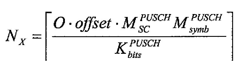
여기서, 


블록(504)에서, 반복 계수 RPF는 이하의 식에 따라 CQI 메시지 필드에 대해 계산된다:In block 504, the repetition coefficient RPF is calculated for the CQI message field according to the following equation:
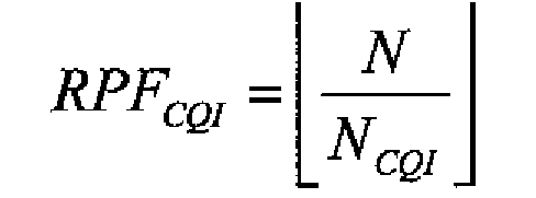
여기서, N은 서브-프레임 내에서 사용자 단말에 할당된 서브-캐리어들의 총 개수이고, NCQI는 서브-프레임에서 송신될 CQI 심볼들의 개수이다. 

여기서, NAN은 서브-프레임에서 송신될 ACK/NACK 심볼들의 개수이다. 송신될 CQI 자원 엘리먼트들(또는 심볼들)의 개수가 자원 엘리먼트들의 총 개수로부터 감소되기 때문에, 반복 계수 RPFAN은 CQI 이후에 논리적으로 이용가능한 자원 엘리먼트들을 고려함으로써 계산된다. 이러한 방식으로, 추가 제어 메시지 필드들(랭크 표시자, 프리-코딩 행렬 표시자, 등)에 대한 반복 계수들은 해당하는 특정 제어 메시지 필드에 대해 사용될 심볼들 또는 자원 엘리먼트들의 개수에 의한 나눗셈 이전에 자원 엘리먼트들의 총 개수 N으로부터 할당된 자원 엘리먼트들의 개수를 감소시킴으로써 계산될 수 있다. 블록(508)에서, 자원 엘리먼트들 맵핑이 할당된 반복 계수를 사용함으로써 상이한 자원 엘리먼트들로부터 시작되도록 상이한 시작 위치 자원 엘리먼트들이 상이한 제어 메시지 필드들에 대해 선택된다. 반복 계수는 0 내지 RPF-1 사이에서 변화할 수 있다. 블록(510)에서, 제어 메시지 필드들의 제어 심볼들은 블록(508)에서 선택된 시작 위치 및 CQI에 대하여 블록(504)에서 그리고 ACK/NACK에 대하여 블록(506)에서 계산된 반복 계수를 사용함으로써 자원 엘리먼트들에 맵핑된다. Here, N AN is the number of ACK / NACK symbols to be transmitted in the sub-frame. Since the number of CQI resource elements (or symbols) to be transmitted is reduced from the total number of resource elements, the iteration coefficient RPF AN is calculated by considering the resource elements that are logically available after CQI. In this way, the iteration coefficients for additional control message fields (rank indicator, pre-coding matrix indicator, etc.) are prior to division by the number of symbols or resource elements to be used for that particular control message field. It can be calculated by reducing the number of allocated resource elements from the total number N of elements. In block 508, different starting position resource elements are selected for different control message fields so that the resource elements mapping starts from different resource elements by using the assigned repetition coefficient. The repetition coefficient can vary between 0 and RPF-1. In block 510, the control symbols of the control message fields are determined by using the repetition coefficient calculated at block 504 for the start position and CQI selected at block 508 and at block 506 for ACK / NACK. Are mapped.
도 6은 N=36, NCQI=7, 및 NAN=4일 때 도 5의 프로세스 결과를 도시한다. 따라서, 반복 계수 RCQI는 식(2)에 따라 5(36/7=5.143~5)가 되고, RAN은 7((36-7)/4=7.25~7)이 된다. CQI의 시작 위치는 0으로 선택되고, ACK/NACK의 시작 위치는 2(서브-캐리어 인덱스들)로 선택된다. 이제, CQI 심볼은 서브-캐리어 0부터 시작하여 매 5 번째 서브-캐리어에 맵핑되고, ACK/NACK 심볼은 서브-캐리어 2부터 시작하여 매 7 번째 비-CQI 서브-캐리어에 맵핑된다. CQI 심볼들의 개수는 식(3)에서 배제되었고, 그리하여 그들은 실제 맵핑을 수행할 때 배제되었다. 결국, 결코 중첩하지 않을 반복 계수들을 발견하는 것은 어렵고, 본 절차는 ACK/NACK가 일차적으로 이전에 맵핑된 CQI 심볼을 펑쳐링하는 것을 회피할 것이라는 것을 보장한다. 펑쳐링될 수 있는 데이터 심볼들의 고갈의 경우에, ACK/NACK는 또한 CQI 심볼들을 펑쳐링할 수 있는데, 그 이유는 ACK/NACK 메시지의 신뢰성 있는 송신이 CQI 메시지의 송신보다 우세하기 때문이다. 일반적으로, 어떠한 후속적으로 맵핑된 제어 메시지 심볼도 이전에 맵핑된 제어 심볼과 동일한 서브-캐리어로 맵핑되지 않을 것인데, 그 이유는 맵핑된 자원 엘리먼트들이 추가 맵핑으로부터 배제되기 때문이다. 그러한 맵핑은 송신기의 자원 엘리먼트 맵핑 블록(204)에서 수행될 수 있고, 유사한 동작이 수신기의 자원 엘리먼트 맵핑 제거 블록(222)에서 수행되고, 그 결과 디맵핑이 정확하게 수행된다.FIG. 6 shows the process results of FIG. 5 when N = 36, N CQI = 7, and N AN = 4. Therefore, the repetition coefficient R CQI is 5 (36/7 = 5.143-5) according to equation (2), and R AN is 7 ((36-7) /4=7.25-7). The starting position of CQI is selected as 0, and the starting position of ACK / NACK is selected as 2 (sub-carrier indices). Now, the CQI symbols are mapped to every fifth sub-carrier starting from sub-carrier 0 and the ACK / NACK symbols are mapped to every seventh non-CQI sub-carrier starting from sub-carrier two. The number of CQI symbols was excluded in equation (3), so they were excluded when performing the actual mapping. After all, it is difficult to find repeating coefficients that will never overlap, and this procedure ensures that ACK / NACK will primarily avoid puncturing previously mapped CQI symbols. In the case of exhaustion of data symbols that can be punctured, the ACK / NACK can also puncture the CQI symbols, because reliable transmission of the ACK / NACK message is superior to transmission of the CQI message. In general, no subsequently mapped control message symbol will be mapped to the same sub-carrier as the previously mapped control symbol because the mapped resource elements are excluded from further mapping. Such mapping may be performed at the resource
실제 맵핑은 여러 방식들로 수행될 수 있다. 동일한 맵핑 패턴은 매 OFDM 심볼에 대해 반복될 수 있고, 즉, 동일한 제어 필드들이 OFDM 심볼마다 동일한 서브-캐리어들을 점유할 수 있다. 주어진 제어 메시지 필드의 크기 및 제어 메시지 필드들의 전체 크기는 심볼마다 변화하도록 구성될 수 있다. 다른 실시예에서, 상이한 시작 위치가 연속적인 OFDM 심볼들에서 제어 메시지 필드들의 스태거링된(staggered) 맵핑을 획득하기 위하여 연속적인 OFDM 심볼들에 대해 선택된다. 이것은 연속적인 OFDM 심볼들 간의 주파수 다이버시티를 개선하는데, 그 이유는 제어 메시지 필드가 상이한 OFDM 심볼들에서 상이한 주파수 위치들을 점유하기 때문이다. 대안적으로, 인터리빙은 모든 서브-캐리어들 및 복수 개의 OFDM 심볼들에 걸쳐, 예를 들어, 시간 슬롯 또는 서브-프레임 내 심볼들에 걸쳐 수행될 수 있다. 이제, 주어진 제어 메시지 필드를 맵핑할 때, 마지막으로 맵핑된 이전의 OFDM 심볼의 서브-캐리어가 후속적인 심볼의 서브-캐리어들을 맵핑하기 시작할 때 고려된다. 예를 들어, 만약 도 6에서와 같이 서브-캐리어들의 개수가 36이라면, 마지막으로 맵핑된 서브-캐리어 인덱스는 34이고, 반복 계수는 6이며, 후속적인 OFDM 심볼에서 맵핑된 첫 번째 서브-캐리어는 인덱스 4를 갖는다. 이제, 서브-캐리어들의 개수 및 반복 계수들에 의존하여, 상이한 제어 메시지 필드들은 연속적인 OFDM 심볼들에서 상이한 서브-캐리어들을 점유할 수 있다.The actual mapping can be done in several ways. The same mapping pattern may be repeated for every OFDM symbol, that is, the same control fields may occupy the same sub-carriers per OFDM symbol. The size of a given control message field and the overall size of the control message fields can be configured to vary from symbol to symbol. In another embodiment, different starting positions are selected for successive OFDM symbols to obtain a staggered mapping of control message fields in successive OFDM symbols. This improves the frequency diversity between consecutive OFDM symbols because the control message field occupies different frequency positions in different OFDM symbols. Alternatively, interleaving may be performed across all sub-carriers and a plurality of OFDM symbols, eg, across symbols within a time slot or sub-frame. Now, when mapping a given control message field, the sub-carrier of the last mapped previous OFDM symbol is taken into account when starting to map the sub-carriers of the subsequent symbol. For example, if the number of sub-carriers is 36 as in FIG. 6, the last mapped sub-carrier index is 34, the repetition coefficient is 6, and the first sub-carrier mapped in the subsequent OFDM symbol is Has
대안적인 실시예에서, 인터리빙은 상이한 공간 스트림들에 걸쳐 수행될 수 있다. 전술한 바와 같이, 사용자 단말들은 SU-MIMO를 지원할 능력을 갖추는 것이 예상되고, 그러한 경우에, 다수의 공간 송신 스트림들이 사용자 단말에 할당될 수 있다. 그러한 경우에, 송신은 다수의 공간적으로 병렬인 신호 스트림들로 멀티플렉싱될 수 있다. 이러한 경우에, 인터리빙은 다수의 스트림들로 확장될 수 있다. 인터리빙은 예를 들어, 먼저 제어 심볼들을 제 1 스트림의 서브-프레임에 맵핑하고, 그 다음 계속하여 제 2 스트림으로 맵핑하는 등에 의해 수행될 수 있다. 맵핑의 계속은 서브-캐리어들의 개수 및 반복 계수들에 따라, 상이한 제어 메시지 필드들이 상이한 공간적으로 병렬인 스트림들에서 상이한 서브-캐리어들을 점유할 수 있도록 연속적인 OFDM 심볼들 간의 맵핑과 유사한 방식으로 수행될 수 있다. 대안적으로, 후속적인 공간 스트림의 맵핑은 제 1 공간 스트림의 맵핑에 대응하도록 초기화될 수 있고, 그 결과 시작 위치는 양쪽 스트림들에서 동일하다. 추가적인 신호 스트림들의 사용으로 인하여 이용가능한 부가적인 심볼들의 개수는 식(1) 및 반복 계수들을 계산할 때 또한 명백히 고려될 수 있다. 식(1)은 이후에 설명되는 바와 같이, 공간 멀티플렉싱의 사용을 수용하도록 수정될 수 있다.In alternative embodiments, interleaving may be performed over different spatial streams. As mentioned above, it is expected that the user terminals have the capability to support SU-MIMO, in which case multiple spatial transmission streams may be assigned to the user terminal. In such case, the transmission may be multiplexed into multiple spatially parallel signal streams. In this case, interleaving can be extended to multiple streams. Interleaving may be performed, for example, by first mapping control symbols to sub-frames of the first stream, then subsequently to the second stream, and the like. The continuation of the mapping is performed in a manner similar to the mapping between successive OFDM symbols so that different control message fields may occupy different sub-carriers in different spatially parallel streams, depending on the number of sub-carriers and the repetition coefficients. Can be. Alternatively, the mapping of subsequent spatial streams can be initialized to correspond to the mapping of the first spatial stream, so that the starting position is the same in both streams. The number of additional symbols available due to the use of additional signal streams can also be explicitly taken into account when calculating Equation (1) and repetition coefficients. Equation (1) can be modified to accommodate the use of spatial multiplexing, as described later.
일 실시예에서, 데이터 심볼들은 ACK/NACK를 맵핑하기 이전에 자원 엘리먼트들로 맵핑될 수 있고, 그 결과 ACK/NACK는 데이터 심볼들을 펑쳐링할 것이다. 이러한 실시예에서, 먼저 인터리빙 패턴은 각각의 제어 메시지 필드에 대한 식(1), 반복 계수, 시작 위치를 계산함으로써 각각의 제어 메시지 필드에 대해 결정된다. 그 다음, CQI 및 랭크 표시자 심볼들은 먼저 도 5의 프로세스에 따라 자원 엘리먼트들로 맵핑된다. 그 후에, 데이터 심볼들은 남아 있는 자원 엘리먼트들에 맵핑될 수 있다. 그 다음, ACK/NACK는 ACK/NACK 심볼이 데이터 심볼을 펑쳐링하도록, 즉, 데이터 심볼을 대신하도록 그들의 결정된 위치들에 할당될 수 있다. ACK/NACK가 데이터를 펑쳐링하는 이유는 사용자 단말이 다운링크 데이터 패킷의 수신을 놓치는 경우에, 업링크 서브-프레임 내 ACK/NACK 메시지 필드의 존재를 인식하지 못하고 따라서 스케줄링된 ACK/NACK 메시지를 송신할 수 없기 때문이다. 대신에 그것은 그러한 자원 엘리먼트들에서의 데이터를 송신한다. In one embodiment, data symbols may be mapped to resource elements prior to mapping ACK / NACK, so that ACK / NACK will puncture the data symbols. In this embodiment, the interleaving pattern is first determined for each control message field by calculating equation (1), repetition coefficient, and start position for each control message field. Then, the CQI and rank indicator symbols are first mapped to resource elements according to the process of FIG. 5. Thereafter, data symbols can be mapped to remaining resource elements. ACK / NACK may then be assigned to their determined locations so that the ACK / NACK symbol punctures the data symbol, ie replaces the data symbol. The reason why the ACK / NACK punctures the data is that when the user terminal misses receiving the downlink data packet, it does not recognize the existence of the ACK / NACK message field in the uplink sub-frame and thus receives the scheduled ACK / NACK message. This is because it cannot be transmitted. Instead it sends data in such resource elements.
추가 실시예에서, 주파수 자원 블록의 에지에서의 결정된 서브-캐리어들의 개수는 제어 심볼들의 맵핑으로부터 배제될 수 있다. 전형적으로, 주파수 자원의 에지에서의 서브-캐리어들은 간섭에 더 취약하고, 따라서, 결정적인 제어 데이터는 바람직하게 주파수 자원의 중심 주파수에 더 근접한 서브-캐리어들에 맵핑될 수 있다. 실제로, 이것은 시작 위치를 충분히 높게 설정하고 결정된 임계치보다 더 높은 인덱스를 갖는 서브-캐리어들의 맵핑을 스킵핑함(맵핑은 다음 심볼로 스킵핑함)으로써 수행될 수 있다. 맵핑이 이전의 OFDM 심볼에서 종료된 서브-캐리어로부터 맵핑이 후속적인 OFDM 심볼에서 계속되는 경우에, 다른 임계치보다 더 낮은 인덱스를 갖는 서브-캐리어들의 맵핑이 또한 스킵될 수 있다.In a further embodiment, the determined number of sub-carriers at the edge of the frequency resource block may be excluded from the mapping of control symbols. Typically, the sub-carriers at the edge of the frequency resource are more susceptible to interference, and thus, deterministic control data can be mapped to sub-carriers, preferably closer to the center frequency of the frequency resource. In practice, this can be done by setting the starting position high enough and skipping the mapping of sub-carriers with indices higher than the determined threshold (mapping skips to the next symbol). If the mapping continues from a sub-carrier where the mapping terminates in the previous OFDM symbol, the mapping of sub-carriers with an index lower than the other threshold may also be skipped.
OFDM의 이용은 상이한 자원 엘리먼트들에 대한 상이한 전송 전력 값들의 할당을 가능하게 하는데, 그 이유는 자원 엘리먼트들이 SC-FDMA에서와 같이 주파수 스펙트럼에 걸쳐 확산되지 않을 것이기 때문이다. 일 실시예에서, 상이한 전송 전력 오프셋 값들은 OFDM 심볼 내에서 제어 메시지 필드들을 운반하는 자원 엘리먼트들 및 데이터 트래픽 필드들을 운반하는 자원 엘리먼트들에 할당된다. 더 높은 전송 전력은 수신기에서의 적어도 일부 제어 메시지 필드들의 정확한 수신을 보장하기 위하여 그러한 적어도 일부 제어 메시지 필드들에 할당될 수 있다. 자연적으로, 상이한 추가 전송 전력 오프셋들은 그들이 얼마나 중요한 시그널링 정보를 운반하는지에 따라 상이한 제어 메시지 필드들에 할당될 수 있다. 더 높은 전송 전력은 더 중요한 제어 메시지들에 할당될 수 있다. 제어 메시지 필드들에 할당된 추가 전송 전력은 또한 PUSCH 상에서 현재 사용 중인 변조 및 코딩 방식에 의존할 수 있다. 변조 차수가 더 낮고 사용 중인 코딩 방식이 더 강할수록, 더 낮은 전송 전력 오프셋이 제어 메시지 필드들에 할당되는데, 그 이유는 간섭-내성 변조 및 코딩 방식이 더 강한 전송 전력에 대한 필요성을 상쇄한다고 간주되기 때문이다.The use of OFDM enables the assignment of different transmit power values for different resource elements because the resource elements will not spread over the frequency spectrum as in SC-FDMA. In one embodiment, different transmit power offset values are assigned to resource elements carrying control message fields and resource elements carrying data traffic fields within an OFDM symbol. Higher transmit power may be allocated to such at least some control message fields to ensure accurate reception of at least some control message fields at the receiver. Naturally, different additional transmit power offsets may be assigned to different control message fields depending on how important signaling information they carry. Higher transmit power may be assigned to more important control messages. The additional transmit power allocated to the control message fields may also depend on the modulation and coding scheme currently in use on the PUSCH. The lower the modulation order and the stronger the coding scheme in use, the lower the transmit power offset is assigned to the control message fields because the interference-resistant modulation and coding scheme assumes that the need for stronger transmit power cancels out. Because it becomes.
송신 방식으로서 공간 멀티플렉싱을 이용할 때, 인터리빙 패턴은 전술한 바와 같이, 추가적인 신호 스트림들에 고려될 수 있다. 제어 메시지 필드들은 상이한 공간 스트림들에 균등하게 분배될 수 있거나, 제어 메시지 필드들의 크기는 각각의 공간 스트림에 대해 별개로 정의될 수 있다. 이것은 사용자 단말로부터 CQI의 표시에 의존할 수 있다. 만약 사용자 단말이 각각의 공간 스트림에 대한 별개의 CQI들을 송신한다면, 기지국은 상이한 공간 스트림들에 대해 상이한 변조 및 코딩 방식들을 정의할 수 있고, 따라서, 상이한 개수의 비트들이 상이한 공간 스트림들에서 송신될 수 있다. 이것은 전형적으로 상이한 SU-MIMO 공간 스트림들이 상이한 스프레딩(또는 스크램블링) 코드들로 코딩될 때 가능해진다. 그렇지 않으면, 동일한 변조 및 코딩 방식이 모든 스트림들에 대해 사용되고, 균등한 양의 제어 데이터가 상이한 공간 스트림들에 할당될 수 있다. 이것은 전형적으로 상이한 SU-MIMO 공간 스트림들이 동일한 스프레딩(또는 스크램블링) 코드로 코딩될 때 가능해진다.When using spatial multiplexing as the transmission scheme, the interleaving pattern can be considered for additional signal streams, as described above. The control message fields can be evenly distributed to different spatial streams, or the size of the control message fields can be defined separately for each spatial stream. This may depend on the indication of the CQI from the user terminal. If the user terminal transmits separate CQIs for each spatial stream, the base station can define different modulation and coding schemes for different spatial streams, so that different numbers of bits will be transmitted in different spatial streams. Can be. This is typically enabled when different SU-MIMO spatial streams are coded with different spreading (or scrambling) codes. Otherwise, the same modulation and coding scheme is used for all streams, and an equal amount of control data can be assigned to different spatial streams. This is typically enabled when different SU-MIMO spatial streams are coded with the same spreading (or scrambling) code.
SU-MIMO 업링크 송신은 공간 멀티플렉싱으로 데이터 레이트들을 개선하기 위해 또는 송신된 신호들이 최고의 신호-대-잡음 속성들을 제공하는 공간 채널들로 지향되는 빔포밍 송신을 통한 송신의 신뢰도를 개선하기 위해 이용될 수 있다. 추가로, 공간 멀티플렉싱이 빔포밍과 결합될 수 있다. 또 다른 대안예는 본질적으로 동일한 데이터가 소정의 프리-코딩으로 모든 안테나들로부터 송신될 때 개방 루프 송신 다이버시티 전송을 이용하는 것이다. 앞서 지시된 바와 같이, SU-MIMO 송신은 OFDM 및 SC-FDMA 송신 양자 모두에 적용될 수 있고, 식(1) 및 OFDM 송신의 경우의 반복 계수들및 서브-캐리어 맵핑의 적용이 앞서 설명되었다. SC-FDMA 송신의 경우에, 도 3에 도시된 현재의 SC-FDMA PUSCH 구조는 모든 공간 스트림들에 대해 이용될 수 있다. 이전의 단락에서 설명된 바와 같이, 제어 메시지 필드들은 상이한 공간 스트림들에 균등하게 분배될 수 있거나, 제어 메시지 필드들의 크기는 사용 중인 변조 및 코딩 방식에 기초하여 각각의 공간 스트림에 대해 별개로 정의될 수 있다. 주어진 제어 메시지 필드에 대해 사용될 심볼들의 개수는 식(1)로 계산되고, 서브-캐리어 맵핑은 도 3에 예시된 패턴에 따라 수행된다.SU-MIMO uplink transmission is used to improve data rates with spatial multiplexing or to improve the reliability of transmission via beamforming transmission where the transmitted signals are directed to spatial channels providing the best signal-to-noise properties. Can be. In addition, spatial multiplexing can be combined with beamforming. Another alternative is to use open loop transmit diversity transmission when essentially the same data is transmitted from all antennas with some pre-coding. As indicated above, SU-MIMO transmission can be applied to both OFDM and SC-FDMA transmissions, and the application of repetition coefficients and sub-carrier mapping in the case of equation (1) and OFDM transmission has been described above. In the case of SC-FDMA transmission, the current SC-FDMA PUSCH structure shown in FIG. 3 may be used for all spatial streams. As described in the previous paragraph, the control message fields may be evenly distributed to different spatial streams, or the size of the control message fields may be defined separately for each spatial stream based on the modulation and coding scheme in use. Can be. The number of symbols to be used for a given control message field is calculated by equation (1), and sub-carrier mapping is performed according to the pattern illustrated in FIG.
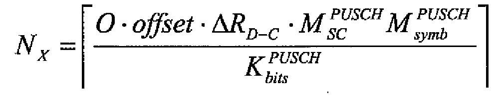
본 발명의 일 실시예에 따라, 제어 데이터의 적어도 일부, 예를 들어, ACK/NACK 메시지들은 빔포밍 또는 송신 다이버시티 전송을 이용하여 송신될 수 있는 반면, 데이터 트래픽은 공간 멀티플렉싱을 사용하여 송신될 수 있다. 사실, 이것은 채널 랭크가 1이라는 가정으로 ACK/NACK가 송신되고 채널 랭크가 1보다 더 높다는 가정으로 데이터 트래픽이 송신됨을 의미한다. 식(1)은 제어 메시지 타입 및 트래픽 데이터에 대해 상이한 랭크들이 결정되는 경우에 공간 멀티플렉싱을 고려하도록 수정될 수 있다. 식(1)은 트래픽 데이터와 해당 제어 메시지 필드의 랭크들의 수 간의 비율을 정의하는 업링크-랭크 특정 파라미터 ![]()
![]()
![]()
![]()
수정 없이, 올바른 개수의 심볼들 또는 서브-캐리어들이 상이한 랭크들 때문에 제어 메시지 필드에 할당되지 않을 것이다. 제어 메시지 필드에 대한 빔포밍 또는 송신 다이버시티를 이용하기 위하여, 동일한 제어 메시지 심볼이 모든 공간 스트림들에서 동일한 서브-캐리어를 점유하도록 바람직하게 동일한 서브-캐리어들이 공간 스트림들에서의 제어 메시지 필드에 할당된다. 그 다음, 송신기에서 빔포밍을 수행하는 신호 프로세서는 목적하는 빔의 방향에 기초하여 결정된 계수와 상기 심볼을 곱한다. 자연적으로 역 연산(reverse operation)이 상기 심볼의 수신을 가능하게 하기 위해 수신기에서 수행되고, 즉, 수신기에서 빔포밍을 수행하는 신호 프로세서는 다수의 안테나들로부터 수신된 신호 스트림들을 결정된 공간 가중치에 기초하여 결정된 계수와 곱하며, 상이한 스트림들의 동일한 서브-캐리어들 상에서 송신된 심볼들이 결합된다.Without modification, the correct number of symbols or sub-carriers will not be assigned to the control message field because of the different ranks. In order to use beamforming or transmit diversity for the control message field, preferably the same sub-carriers are assigned to the control message field in the spatial streams so that the same control message symbol occupies the same sub-carrier in all spatial streams. do. The signal processor performing beamforming at the transmitter then multiplies the symbol by a coefficient determined based on the direction of the desired beam. Naturally a reverse operation is performed at the receiver to enable the reception of the symbol, ie a signal processor performing beamforming at the receiver based on the determined spatial weights of the signal streams received from the multiple antennas. Multiplied by the determined coefficient, and the symbols transmitted on the same sub-carriers of different streams are combined.
도 7은 목적하는 공간 채널로 스트림을 지향시키기 위하여 ACK/NACK 메시지들이 빔포밍 기술을 사용하여 단일 공간 송신 스트림을 통해 송신기로부터 수신기로 전송되는 이러한 실시예를 도시한다. 즉, 동일한 ACK/NACK 메시지가 송신기의 양쪽 안테나 엘리먼트들로부터 송신되고, 그러한 방향은 당업계에 공지된 바와 같이, 상이한 안테나들로부터 송신된 신호들을 위상-조정함으로써 제어된다. 대응하는 위상 조정은 수신된 신호들을 가중하기 위하여 수신기에서 수행되고, 그리하여 ACK/NACK를 주로 전송하는 공간 방향을 증폭시킨다. 데이터 트래픽은 더 높은 데이터 레이트들을 달성하기 위하여 공간 멀티플렉싱을 사용함으로써 송신되고, 상이한 데이터가 상이한 송신/수신 분기들 및 안테나들을 통해 송신/수신된다. 송신기 및 수신기에서, 멀티-안테나 전송은 그러한 목적을 위해 설계된 디지털 신호 프로세서들(700 및 702)에 의해 제어된다. 7 illustrates this embodiment where ACK / NACK messages are sent from the transmitter to the receiver over a single spatial transmission stream using beamforming techniques to direct the stream to the desired spatial channel. That is, the same ACK / NACK message is transmitted from both antenna elements of the transmitter, and the direction is controlled by phase-adjusting signals transmitted from different antennas, as known in the art. Corresponding phase adjustment is performed at the receiver to weight the received signals, thus amplifying the spatial direction in which ACK / NACK is mainly transmitted. Data traffic is transmitted by using spatial multiplexing to achieve higher data rates, and different data is transmitted / received through different transmit / receive branches and antennas. In the transmitter and receiver, multi-antenna transmission is controlled by
업링크 송신 방식이 OFDM일 때, 빔포밍, 송신 다이버시티, 및 공간 멀티플렉싱 간의 선택은 서브-캐리어 레벨 상에서 이루어질 수 있다. 그러한 경우에, 전술한 바와 같이, 동일한 심볼들이 송신기 내 각각의 송신 분기에서 동일한 서브-캐리어들에 맵핑되는 것이 선호된다. 업링크 송신 방식이 SC-FDMA일 때, 빔포밍, 송신 다이버시티 및 공간 멀티플렉싱 간의 선택은 SC-FDMA 심볼 레벨 상에서 이루어질 수 있는데, 그 이유는 각각의 서브-캐리어가 전체 주파수 스펙트럼을 점유하기 때문이다. 빔포밍, 송신 다이버시티 및 공간 멀티플렉싱 간의 선택의 분석(resolution)은 한 시점에서, 예를 들어, 일 시간 슬롯 또는 서브-프레임 동안 각각의 SC-FDMA 심볼에 대해 또는 복수 개의 SC-FDMA 심볼들에 대해 이루어질 수 있다. 만약 SC-FDMA 심볼이 높은 신뢰도를 요구하는 제어 메시지를 운반한다면, SC-FDMA 심볼은 빔포밍 또는 송신 다이버시티를 사용하여 송신될 수 있고, 동일한 데이터가 송신기의 모든 안테나 분기들로부터 송신되고 수신기의 모든 안테나 분기들을 통해 수신된다. 그 다음, 인터리빙 패턴 결정 및 서브-캐리어들로의 심볼들의 맵핑은 모든 송신/수신 분기들에 대해 동일하게 이루어진다. 반면, 만약 SC-FDMA 심볼이 높은 신뢰도를 요구하지 않으면서 정보를 운반한다면, SC-FDMA 심볼은 공간 멀티플렉싱을 사용하여 송신될 수 있고, 즉, 상이한 정보를 운반하는 다수의 SC-FDMA 심볼들은 상이한 공간 스트림들을 통해 동시에 송신될 수 있다.When the uplink transmission scheme is OFDM, the choice between beamforming, transmit diversity, and spatial multiplexing may be made on the sub-carrier level. In that case, as mentioned above, it is preferred that the same symbols are mapped to the same sub-carriers in each transmission branch in the transmitter. When the uplink transmission scheme is SC-FDMA, the choice between beamforming, transmit diversity and spatial multiplexing can be made on the SC-FDMA symbol level, because each sub-carrier occupies the entire frequency spectrum. . The resolution of the selection between beamforming, transmit diversity and spatial multiplexing is determined at one point in time, for example, for each SC-FDMA symbol or for a plurality of SC-FDMA symbols for one time slot or sub-frame. Can be made for. If the SC-FDMA symbol carries a control message that requires high reliability, the SC-FDMA symbol can be transmitted using beamforming or transmit diversity, and the same data is transmitted from all antenna branches of the transmitter and the receiver's It is received over all antenna branches. Then, the interleaving pattern determination and the mapping of the symbols of the sub-carriers ¡� are made identical for all transmit / receive branches. On the other hand, if an SC-FDMA symbol carries information without requiring high reliability, the SC-FDMA symbol may be transmitted using spatial multiplexing, i.e., multiple SC-FDMA symbols carrying different information are different. Can be transmitted simultaneously over the spatial streams.
제어 메시지들의 송신에의 빔포밍의 활용은 전형적으로 수신기로부터의 채널 속성들에 대한 피드백 정보를 요구한다. 피드백 정보가 이용가능하지 않을 때, 본 발명의 일 실시예는 결정적인 제어 정보의 송신의 신뢰도를 개선하기 위하여, 개방-루프 멀티-안테나 송신 다이버시티 방식, 예를 들어, 공간-시간 블록 코딩, 프리코딩 벡터 스위칭, 주파수-선택 송신 다이버시티, 또는 크거나 작은 지연을 가진 주기적 지연을 사용하여 제어 메시지 필드들의 적어도 일부를 송신하는 것이다. 앞서 열거된 개방 루프 송신 다이버시티 방식들의 구현은 당업계의 기술자에게 자명하고, 전술한 실시예들의 상당한 변형들을 요구하지 않는다. 데이터 트래픽은 더 높은 레이트로 데이터 트래픽을 송신하기 위하여 공간 멀티플렉싱을 사용하여 송신될 수 있다.The use of beamforming in the transmission of control messages typically requires feedback information on channel attributes from the receiver. When feedback information is not available, one embodiment of the present invention provides an open-loop multi-antenna transmit diversity scheme, e.g., space-time block coding, free, to improve the reliability of transmission of critical control information. Transmitting at least some of the control message fields using coding vector switching, frequency-selective transmit diversity, or periodic delays with large or small delays. The implementation of the open loop transmit diversity schemes listed above is apparent to those skilled in the art and does not require significant variations of the embodiments described above. Data traffic can be transmitted using spatial multiplexing to transmit the data traffic at a higher rate.
전술한 바와 같이, 본 발명의 실시예들은 송신기(사용자 단말) 및 수신기(기지국)에서 수행될 수 있다. 사실, 상기 실시예들은 전형적으로 사용자 단말 또는 기지국에 포함된 프로세서 또는 대응 장치에 의해 수행된다. 프로세서는 선택된 업링크 송신 방식에서 제어 메시지들의 송신 성능을 최적화하기 위하여 선택된 업링크 송신 방식에 따라 제어 메시지 필드들을 PUSCH 자원들에 할당하도록 구성된다. 상기 장치는 도 7에 도시된 바와 같이, 프로세서(700, 702)일 수 있다. 업링크 송신에 어떠한 멀티-안테나 전송도 이용되지 않는 경우에, 사용자 단말의 프로세서(700)는 그것이 멀티-안테나 신호 프로세싱을 수행하지 않는다는 견지에서 단순화된다. 프로세서는 다수의 물리적 신호 프로세싱 유닛들에 의해 구현된 논리 컴포넌트일 수 있다. 용어 '프로세서'는 데이터를 프로세싱할 수 있는 디바이스를 지칭한다. 프로세서는 요구된 기능을 구현하는 전자 회로, 및/또는 요구된 기능을 구현하는 컴퓨터 프로그램을 실행하는 마이크로프로세서를 포함할 수 있다. 상기 구현을 설계할 때, 당업자는 예를 들어, 상기 장치의 크기 및 전력 소모, 필요한 프로세싱 능력, 제조 비용들 및 제조량에 대해 설정된 요구조건들을 고려할 것이다. 프로세서는 논리 컴포넌트들, 표준 집적회로들, 마이크로프로세서(들), 및/또는 주문형 집적 회로(ASIC)들을 포함할 수 있다. As described above, embodiments of the present invention may be performed at a transmitter (user terminal) and a receiver (base station). In fact, the above embodiments are typically performed by a processor or corresponding device included in a user terminal or base station. The processor is configured to assign control message fields to PUSCH resources according to the selected uplink transmission scheme to optimize transmission performance of control messages in the selected uplink transmission scheme. The device may be a
마이크로프로세서는 집적 회로 상에서 중앙 프로세싱 유닛(CPU)의 기능들을 구현한다. CPU는 프로그램 명령들을 포함하는 컴퓨터 프로그램을 실행하는 논리 머신이다. 프로그램 명령들은 C, 자바 등과 같은 상위-레벨 프로그래밍 언어, 또는 기계 언어 또는 어셈블러와 같은 하위-레벨 프로그래밍 언어일 수 있는 프로그래밍 언어를 사용하여 컴퓨터 프로그램으로서 코딩될 수 있다. CPU는 레지스터들, 산술 논리 유닛(ALU), 및 제어 유닛의 세트를 포함할 수 있다. 제어 유닛은 프로그램 메모리로부터 CPU로 전달된 프로그램 명령들의 시퀀스에 의해 제어된다. 제어 유닛은 기본 연산들을 위한 다수 개의 마이크로명령들을 포함할 수 있다. 마이크로명령들의 구현은 CPU 설계에 따라 변화할 수 있다. 마이크로프로세서는 또한 컴퓨터 프로그램에 시스템 서비스들을 제공할 수 있는 운영 시스템(임베디드 시스템의 전용 운영 시스템, 또는 실시간 운영 시스템)을 가질 수 있다. The microprocessor implements the functions of a central processing unit (CPU) on integrated circuits. The CPU is a logical machine that executes a computer program containing program instructions. Program instructions may be coded as computer programs using a programming language that may be a high-level programming language such as C, Java, or the like, or a lower-level programming language such as a machine language or assembler. The CPU may include a set of registers, an arithmetic logic unit (ALU), and a control unit. The control unit is controlled by a sequence of program instructions transferred from the program memory to the CPU. The control unit may comprise a plurality of microinstructions for basic operations. The implementation of microinstructions may vary depending on the CPU design. The microprocessor may also have an operating system (a dedicated operating system of an embedded system, or a real time operating system) capable of providing system services to a computer program.
본 발명은 앞서 정의된 셀룰러 또는 이동 통신 시스템에 적용가능할 뿐만 아니라, 다른 적절한 통신 시스템들에도 적용가능하다. 사용된 프로토콜들, 이동 통신 시스템들의 규격들, 그들의 네트워크 엘리먼트들 및 가입자 단말들은 급격히 발전한다. 그러한 발전은 전술한 실시예들에 대한 가외의 변경들을 요구할 수도 있다. 따라서, 모든 단어들 및 표현들은 폭넓게 해석되어야 하고 이들은 실시예를 제한하기 위해서가 아니라 실시예를 예시하도록 의도된다. 기술이 진보함에 따라, 본 발명의 개념이 여러 다양한 방식들로 구현될 수 있음이 당업자에게 자명할 것이다. 본 발명 및 그 실시예들은 전술한 예들에 제한되는 것이 아니라, 청구항들의 범위 내에서 변화할 수 있다.The present invention is not only applicable to the cellular or mobile communication system defined above, but also to other suitable communication systems. The protocols used, the specifications of mobile communication systems, their network elements and subscriber terminals evolve rapidly. Such development may require additional changes to the embodiments described above. Accordingly, all words and expressions should be interpreted broadly and they are intended to illustrate the embodiments, not to limit the embodiments. As technology advances, it will be apparent to those skilled in the art that the concept of the present invention may be implemented in a variety of ways. The invention and its embodiments are not limited to the examples described above, but may vary within the scope of the claims.
Claims (29)
상기 사용자 단말의 물리적 업링크 공유 트래픽 채널 자원들을 결정하는 단계;
상기 선택된 업링크 송신 방식에서 제어 메시지들의 송신 성능을 최적화하기 위하여 상기 선택된 업링크 송신 방식에 따라 상기 물리적 업링크 공유 트래픽 채널의 자원들로 제어 메시지 필드들을 할당하는 단계; 및
상기 선택된 업링크 송신 방식이 단일 캐리어 주파수 분할 다중 액세스일 때 상기 사용자 단말의 상기 물리적 업링크 공유 트래픽 채널 자원들의 에지들에서 상기 제어 메시지 필드들을 로컬화하는 단계
를 포함하는,
방법.Selecting an uplink transmission scheme for the user terminal of the cellular communication system;
Determining physical uplink shared traffic channel resources of the user terminal;
Allocating control message fields to resources of the physical uplink shared traffic channel according to the selected uplink transmission scheme to optimize transmission performance of control messages in the selected uplink transmission scheme; And
Localizing the control message fields at the edges of the physical uplink shared traffic channel resources of the user terminal when the selected uplink transmission scheme is single carrier frequency division multiple access
/ RTI >
Way.
상기 선택된 업링크 송신 방식이 직교 주파수 분할 멀티플렉싱일 때, 각각의 제어 메시지의 심볼들을 상기 사용자 단말의 상기 물리적 업링크 공유 트래픽 채널 자원들의 주파수 도메인에 걸쳐 분배하는 단계
를 더 포함하는,
방법.The method of claim 1,
When the selected uplink transmission scheme is orthogonal frequency division multiplexing, distributing symbols of each control message over the frequency domain of the physical uplink shared traffic channel resources of the user terminal;
≪ / RTI >
Way.
상기 분배는 각각의 제어 메시지 필드의 제어 심볼들을 상기 제어 심볼들 간의 주파수-간격으로 심볼 블록의 주파수 자원 엘리먼트들에 맵핑하는 것을 더 포함하고, 상기 간격은 상기 제어 메시지 필드의 상기 제어 심볼들 간의 상기 제어 메시지 필드의 상기 제어 심볼들이 아닌 심볼들의 개수를 정의하기 위해 각각의 제어 메시지 필드에 대해 선택된 반복 계수에 의해 정의되고, 상기 심볼 블록은 정보 엘리먼트들로서 복수 개의 심볼들을 운반하는,
방법.3. The method of claim 2,
The distribution further includes mapping control symbols of each control message field to frequency resource elements of a symbol block at a frequency-interval between the control symbols, wherein the interval is the between the control symbols of the control message field. Defined by a repetition coefficient selected for each control message field to define the number of non-control symbols of the control message field, the symbol block carrying a plurality of symbols as information elements,
Way.
상기 분배는 주파수 다이버시티를 달성하기 위하여 각각의 제어 메시지의 제어 심볼들을 연속적인 심볼 블록들에서의 상이한 주파수 자원 엘리먼트들로 맵핑하는 것을 더 포함하는,
방법.The method of claim 3,
The distribution further includes mapping control symbols of each control message to different frequency resource elements in consecutive symbol blocks to achieve frequency diversity,
Way.
상기 분배는 각각의 제어 메시지 필드의 제어 심볼들을 심볼 블록들 및 상기 제어 메시지의 송신을 위해 이용가능한 상기 심볼 블록들의 주파수 자원 엘리먼트들에 걸쳐 균일하게 분배하는 것을 더 포함하는,
방법.5. The method according to any one of claims 2 to 4,
The distribution further comprises uniformly distributing control symbols of each control message field across symbol blocks and frequency resource elements of the symbol blocks available for transmission of the control message,
Way.
상기 분배는 각각의 제어 메시지 필드의 상기 제어 심볼들을 심볼 블록들, 상기 제어 메시지의 송신을 위해 이용가능한 상기 심볼 블록들의 주파수 자원 엘리먼트들, 및 상기 선택된 업링크 송신 방식이 업링크에서 공간 멀티플렉싱 송신을 이용할 때의 복수 개의 공간 송신 스트림들에 걸쳐 균일하게 분배하는 것을 더 포함하는,
방법.The method of claim 5,
The distribution may include the control symbols in each control message field in symbol blocks, the frequency resource elements of the symbol blocks available for transmission of the control message, and the selected uplink transmission scheme for spatial multiplexing transmission in the uplink. And evenly distributed over the plurality of spatial transmission streams when using,
Way.
상이한 송신 전력 값들을 심볼 블록 내 적어도 하나의 제어 메시지 필드 및 트래픽 데이터 필드에 할당하는 단계를 더 포함하는,
방법.5. The method according to any one of claims 2 to 4,
Assigning different transmit power values to at least one control message field and a traffic data field in a symbol block,
Way.
상기 제어 메시지 필드에서 송신될 비트들의 개수, 상기 물리적 업링크 공유 트래픽 채널의 자원들에서 송신될 비트들의 총 수, 심볼 블록 내의 서브 캐리어들의 개수, 서브-프레임 당 심볼 블록들의 개수, 및 상기 제어 메시지 필드에서 전달된 트래픽 데이터와 제어 데이터의 목적하는 수신 품질들 간의 오프셋을 정의하는 품질 오프셋에 기초하여 상기 물리적 업링크 공유 트래픽 채널의 자원들에서 주어진 제어 메시지 필드에 할당될 제어 심볼들의 개수를 결정하는 단계;
상기 결정된 제어 심볼들의 개수에 기초하여 선택된 채널 코드로 상기 제어 심볼들을 코딩하는 단계; 및
상기 선택된 업링크 송신 방식에 따라 상기 제어 메시지 필드들의 상기 코딩된 제어 심볼들을 상기 심볼 블록들의 주파수 자원 엘리먼트들에 맵핑하는 단계
를 더 포함하는,
방법.5. The method according to any one of claims 1 to 4,
The number of bits to be transmitted in the control message field, the total number of bits to be transmitted in resources of the physical uplink shared traffic channel, the number of subcarriers in a symbol block, the number of symbol blocks per sub-frame, and the control message Determining the number of control symbols to be assigned to a given control message field in resources of the physical uplink shared traffic channel based on a quality offset defining an offset between the desired received qualities of the traffic data and the control data delivered in the field. step;
Coding the control symbols with a channel code selected based on the determined number of control symbols; And
Mapping the coded control symbols of the control message fields to frequency resource elements of the symbol blocks in accordance with the selected uplink transmission scheme.
≪ / RTI >
Way.
상기 제어 메시지 필드의 랭크(rank)가 트래픽 데이터의 랭크보다 더 낮을 때 상기 제어 메시지 필드의 크기의 감소를 보상하기 위하여, 상기 선택된 업링크 송신 방식이 업링크에서 공간 멀티플렉싱 송신을 이용할 때 상기 제어 메시지 필드 및 상기 트래픽 데이터에 대해 선택된 멀티경로 채널 랭크들 간의 차이에 기초하여 상기 물리적 업링크 공유 트래픽 채널의 자원들에서 주어진 제어 메시지 필드로 할당될 제어 심볼들의 개수를 결정하는 단계를 더 포함하는,
방법.9. The method of claim 8,
The control message when the selected uplink transmission scheme uses spatial multiplexing transmission in the uplink to compensate for the reduction in the size of the control message field when the rank of the control message field is lower than the rank of traffic data. Determining the number of control symbols to be assigned to a given control message field in resources of the physical uplink shared traffic channel based on the difference between the field and the multipath channel ranks selected for the traffic data;
Way.
상기 선택된 업링크 송신 방식이 업링크에서 공간 멀티플렉싱 송신을 이용할 때 멀티-스트림 공간 멀티플렉싱을 이용하여 적어도 데이터 트래픽 필드들을 송신하고 단일-스트림 빔포밍(beamforming) 멀티-안테나 송신 또는 전송 다이버시티(diversity) 멀티-안테나 송신을 이용하여 적어도 하나의 제어 메시지 필드를 송신하는 단계를 더 포함하는,
방법.5. The method according to any one of claims 1 to 4,
When the selected uplink transmission scheme uses spatial multiplexing transmission in the uplink, it transmits at least data traffic fields using multi-stream spatial multiplexing and transmits single-stream beamforming multi-antenna transmission or transmit diversity. Transmitting at least one control message field using multi-antenna transmission,
Way.
상기 선택된 업링크 송신 방식이 업링크에서 공간 멀티플렉싱 송신을 이용할 때 멀티-스트림 공간 멀티플렉싱을 사용하여 적어도 데이터 트래픽 필드들을 송신하고 개방-루프 멀티-안테나 송신 다이버시티를 사용하여 적어도 하나의 제어 메시지 필드를 송신하는 단계를 더 포함하는,
방법.5. The method according to any one of claims 1 to 4,
When the selected uplink transmission scheme uses spatial multiplexing transmission in the uplink, transmit at least data traffic fields using multi-stream spatial multiplexing and generate at least one control message field using open-loop multi-antenna transmit diversity. Further comprising transmitting;
Way.
상이한 안테나 엘리먼트들과 연관된 복수 개의 신호 분기들에 상기 제어 메시지 필드들의 동일한 로컬화를 적용하는 단계를 더 포함하는,
방법.The method of claim 1,
Applying the same localization of the control message fields to a plurality of signal branches associated with different antenna elements,
Way.
장치.Selecting the uplink transmission scheme for the user terminal of the cellular communication system, determining the physical uplink shared traffic channel resources of the user terminal, and optimizing the transmission performance of control messages in the selected uplink transmission scheme. Assign control message fields to resources of the physical uplink shared traffic channel according to a link transmission scheme, and wherein the physical uplink shared traffic channel resources of the user terminal when the selected uplink transmission scheme is single carrier frequency division multiple access A processor configured to localize the control message fields at the edges of the
Device.
상기 프로세서는 상기 선택된 업링크 송신 방식이 직교 주파수 분할 멀티플렉싱일 때, 각각의 제어 메시지의 심볼들을 상기 사용자 단말의 상기 물리적 업링크 공유 트래픽 채널 자원들의 주파수 도메인에 걸쳐 분배하도록 추가로 구성되는,
장치.15. The method of claim 14,
The processor is further configured to distribute symbols of each control message over the frequency domain of the physical uplink shared traffic channel resources of the user terminal when the selected uplink transmission scheme is orthogonal frequency division multiplexing;
Device.
상기 프로세서는 각각의 제어 메시지 필드의 제어 심볼들을 제어 심볼들 간의 동일한 주파수-간격으로 심볼 블록의 서브 캐리어들에 맵핑하도록 추가로 구성되고, 상기 간격은 상기 제어 메시지 필드의 상기 제어 심볼들 간의 상기 제어 메시지 필드의 상기 제어 심볼들이 아닌 심볼들의 개수를 정의하기 위해 각각의 제어 메시지 필드에 대해 선택된 반복 계수에 의해 정의되고, 상기 심볼 블록은 정보 엘리먼트들로서 복수 개의 심볼들을 운반하는,
장치.16. The method of claim 15,
The processor is further configured to map control symbols of each control message field to subcarriers of a symbol block at the same frequency-interval between control symbols, the interval being the control between the control symbols of the control message field. Defined by a repetition coefficient selected for each control message field to define the number of symbols that are not the control symbols of the message field, wherein the symbol block carries a plurality of symbols as information elements,
Device.
상기 프로세서는 주파수 다이버시티를 달성하기 위하여 각각의 제어 메시지의 제어 심볼들을 연속적인 심볼 블록들에서의 상이한 주파수 자원 엘리먼트들에 맵핑하도록 추가로 구성되는,
장치.17. The method of claim 16,
The processor is further configured to map the control symbols of each control message to different frequency resource elements in successive symbol blocks to achieve frequency diversity,
Device.
상기 프로세서는 각각의 제어 메시지 필드의 제어 심볼들을 심볼 블록들 및 상기 제어 메시지의 송신을 위해 이용가능한 심볼 블록들의 주파수 자원 엘리먼트들에 걸쳐 균일하게 분배하도록 추가로 구성되는,
장치.18. The method according to any one of claims 15 to 17,
The processor is further configured to uniformly distribute the control symbols of each control message field across symbol blocks and frequency resource elements of symbol blocks available for transmission of the control message,
Device.
상기 프로세서는 각각의 제어 메시지의 상기 제어 심볼들을 심볼 블록들, 상기 제어 메시지의 송신을 위해 이용가능한 상기 심볼 블록들의 주파수 자원 엘리먼트들, 및 상기 선택된 업링크 송신 방식이 업링크에서 공간 멀티플렉싱 송신을 이용할 때의 복수 개의 공간 송신 스트림들에 걸쳐 균일하게 분배하도록 추가로 구성되는,
장치.19. The method of claim 18,
The processor uses the control symbols of each control message in symbol blocks, the frequency resource elements of the symbol blocks available for transmission of the control message, and the selected uplink transmission scheme uses spatial multiplexing transmission in the uplink. Further configured to distribute evenly across the plurality of spatial transmission streams at a time,
Device.
상기 프로세서는 상이한 송신 전력 값들을 심볼 블록 내 적어도 하나의 제어 메시지 필드 및 트래픽 데이터 필드로 할당하도록 추가로 구성되는,
장치.18. The method according to any one of claims 15 to 17,
The processor is further configured to assign different transmit power values to at least one control message field and a traffic data field in a symbol block,
Device.
상기 프로세서는:
상기 제어 메시지 필드에서 송신될 비트들의 개수, 상기 물리적 업링크 공유 트래픽 채널의 자원들에서 송신될 비트들의 총 수, 심볼 블록 내의 서브 캐리어들의 개수, 서브-프레임 당 심볼 블록들의 개수, 및 상기 제어 메시지 필드에서 전달된 트래픽 데이터와 제어 데이터의 목적하는 수신 품질들 간의 오프셋을 정의하는 품질 오프셋에 기초하여 상기 물리적 업링크 공유 트래픽 채널의 자원들에서 주어진 제어 메시지 필드로 할당될 제어 심볼들의 개수를 결정하고;
상기 결정된 제어 심볼들의 개수에 기초하여 선택된 채널 코드로 상기 제어 심볼들을 코딩하며; 그리고
상기 선택된 업링크 송신 방식에 따라 상기 제어 메시지 필드들의 상기 제어 심볼들을 상기 심볼 블록들의 주파수 자원 엘리먼트들에 맵핑하도록
추가로 구성되는,
장치.18. The method according to any one of claims 14 to 17,
The processor comprising:
The number of bits to be transmitted in the control message field, the total number of bits to be transmitted in resources of the physical uplink shared traffic channel, the number of subcarriers in a symbol block, the number of symbol blocks per sub-frame, and the control message Determine the number of control symbols to be assigned to a given control message field in the resources of the physical uplink shared traffic channel based on a quality offset defining an offset between the desired received qualities of the traffic data and the control data delivered in the field; ;
Code the control symbols with a channel code selected based on the determined number of control symbols; And
To map the control symbols of the control message fields to frequency resource elements of the symbol blocks according to the selected uplink transmission scheme.
In addition,
Device.
상기 프로세서는, 상기 제어 메시지 필드의 랭크가 상기 트래픽 데이터의 랭크보다 더 낮을 때 상기 제어 메시지 필드의 크기의 감소를 보상하기 위하여, 상기 선택된 업링크 송신 방식이 업링크에서 공간 멀티플렉싱 송신을 이용할 때 상기 제어 메시지 필드 및 상기 트래픽 데이터에 대해 선택된 멀티경로 채널 랭크들 간의 차이에 기초하여 상기 물리적 업링크 공유 트래픽 채널의 자원들에서 주어진 제어 메시지 필드로 할당될 제어 심볼들의 개수를 결정하도록 추가로 구성되는,
장치.The method of claim 21,
The processor is further configured to compensate for the reduction in the size of the control message field when the rank of the control message field is lower than the rank of the traffic data, when the selected uplink transmission scheme uses spatial multiplexing transmission in the uplink. And determine a number of control symbols to be assigned to a given control message field in resources of the physical uplink shared traffic channel based on a difference between a control message field and multipath channel ranks selected for the traffic data.
Device.
상기 프로세서는 상기 선택된 업링크 송신 방식이 업링크에서 공간 멀티플렉싱 송신을 이용할 때 멀티-스트림 공간 멀티플렉싱을 이용하여 적어도 데이터 트래픽 필드들을 송신하고 단일-스트림 빔포밍 멀티-안테나 송신 또는 전송 다이버시티 멀티-안테나 송신을 이용하여 적어도 하나의 제어 메시지 필드를 전달하도록 추가로 구성되는,
장치.18. The method according to any one of claims 14 to 17,
The processor transmits at least data traffic fields using multi-stream spatial multiplexing when the selected uplink transmission scheme uses spatial multiplexing transmission in the uplink, and transmits at least data traffic fields and transmits a single-stream beamforming multi-antenna transmission or transmit diversity multi-antenna. Further configured to convey at least one control message field using a transmission,
Device.
상기 프로세서는 상기 선택된 업링크 송신 방식이 업링크에서 공간 멀티플렉싱 송신을 이용할 때 멀티-스트림 공간 멀티플렉싱을 이용하여 적어도 데이터 트래픽 필드들을 송신하고 개방-루프 멀티-안테나 송신 다이버시티를 이용하여 적어도 하나의 제어 메시지 필드를 송신하도록 추가로 구성되는,
장치.18. The method according to any one of claims 14 to 17,
The processor transmits at least data traffic fields using multi-stream spatial multiplexing and uses at least one control using open-loop multi-antenna transmit diversity when the selected uplink transmission scheme uses spatial multiplexing transmission in the uplink. Further configured to send a message field,
Device.
상기 사용자 단말의 물리적 업링크 공유 트래픽 채널 자원들을 결정하기 위한 수단;
상기 선택된 업링크 송신 방식에서 제어 메시지들의 송신 성능을 최적화하기 위하여 상기 선택된 업링크 송신 방식에 따라 상기 물리적 업링크 공유 트래픽 채널의 자원들에 제어 메시지 필드들을 할당하기 위한 수단; 및
상기 선택된 업링크 송신 방식이 단일 캐리어 주파수 분할 다중 액세스일 때 상기 사용자 단말의 상기 물리적 업링크 공유 트래픽 채널 자원들의 에지들에서 상기 제어 메시지 필드들을 로컬화하기 위한 수단
을 포함하는,
장치.Means for selecting an uplink transmission scheme for a user terminal in a cellular communication system;
Means for determining physical uplink shared traffic channel resources of the user terminal;
Means for assigning control message fields to resources of the physical uplink shared traffic channel according to the selected uplink transmission scheme to optimize transmission performance of control messages in the selected uplink transmission scheme; And
Means for localizing the control message fields at the edges of the physical uplink shared traffic channel resources of the user terminal when the selected uplink transmission scheme is single carrier frequency division multiple access
Including,
Device.
컴퓨터 판독가능한 매체.Comprising program instructions for executing the method according to any one of claims 1 to 4 when loaded into the device,
Computer readable medium.
Applications Claiming Priority (1)
| Application Number | Priority Date | Filing Date | Title |
|---|---|---|---|
| PCT/EP2008/067002 WO2010066280A1 (en) | 2008-12-08 | 2008-12-08 | Uplink control signaling in cellular telecommunication system |
Publications (2)
| Publication Number | Publication Date |
|---|---|
| KR20110099727A KR20110099727A (en) | 2011-09-08 |
| KR101324670B1 true KR101324670B1 (en) | 2013-11-04 |
Family
ID=41055335
Family Applications (1)
| Application Number | Title | Priority Date | Filing Date |
|---|---|---|---|
| KR1020117015858A Active KR101324670B1 (en) | 2008-12-08 | 2008-12-08 | Uplink control signaling in cellular telecommunication system |
Country Status (7)
| Country | Link |
|---|---|
| US (8) | US8830927B2 (en) |
| EP (4) | EP3570615B1 (en) |
| JP (1) | JP5385990B2 (en) |
| KR (1) | KR101324670B1 (en) |
| CN (3) | CN108964859B (en) |
| HU (2) | HUE032502T2 (en) |
| WO (1) | WO2010066280A1 (en) |
Families Citing this family (61)
| Publication number | Priority date | Publication date | Assignee | Title |
|---|---|---|---|---|
| US9246541B2 (en) | 2008-02-01 | 2016-01-26 | Qualcomm Incorporated | UTRAN enhancements for the support of inter-cell interference cancellation |
| US8223808B2 (en) * | 2008-02-05 | 2012-07-17 | Texas Instruments Incorporated | Data and control multiplexing in PUSCH in wireless networks |
| JP5239677B2 (en) * | 2008-09-18 | 2013-07-17 | 富士通株式会社 | COMMUNICATION DEVICE, BASE STATION DEVICE, AND COMMUNICATION METHOD |
| KR101530717B1 (en) * | 2009-01-08 | 2015-06-23 | 엘지전자 주식회사 | Method of transmitting control signal in wireless communication system |
| EP3264833B1 (en) | 2009-02-25 | 2019-01-02 | LG Electronics, Inc. | Method and device for controlling transmission power in uplink transmission |
| JP5497738B2 (en) * | 2009-03-16 | 2014-05-21 | パナソニック株式会社 | Transmitting apparatus and transmitting method |
| AR075864A1 (en) * | 2009-03-17 | 2011-05-04 | Interdigital Patent Holdings | METHOD AND APPLIANCE FOR POWER CONTROL ASCENDING IN MULTIPLE INPUTS MULTIPLE OUTPUTS |
| US9402193B2 (en) | 2009-03-19 | 2016-07-26 | Qualcomm Incorporated | Systems, apparatus and methods for interference management in wireless networks |
| KR20130018095A (en) * | 2009-04-14 | 2013-02-20 | 노오텔 네트웍스 리미티드 | Transmitting particular control information on an uplink traffic channel on a repeated basis |
| KR101301017B1 (en) * | 2009-04-28 | 2013-08-29 | 알까뗄 루슨트 | Transmitter with multiple antennas and data transmission method in the transmitter with multiple antennas |
| US8560696B2 (en) | 2009-04-28 | 2013-10-15 | Intel Corporation | Transmission of advanced-MAP information elements in mobile networks |
| JP5555325B2 (en) | 2009-10-02 | 2014-07-23 | インターデイジタル パテント ホールディングス インコーポレイテッド | Power control for devices with multiple antennas |
| DK2526643T3 (en) * | 2010-01-18 | 2018-08-13 | Ericsson Telefon Ab L M | Radio base station and user device and methods therein |
| KR101809955B1 (en) | 2010-01-18 | 2017-12-18 | 엘지전자 주식회사 | A method and an apparatus for providing channel quality information in a wireless communication system |
| US20110243079A1 (en) * | 2010-03-18 | 2011-10-06 | Texas Instruments Incorporated | Transmission Modes and Signaling for Uplink MIMO Support or Single TB Dual-Layer Transmission in LTE Uplink |
| US8582638B2 (en) * | 2010-04-30 | 2013-11-12 | Blackberry Limited | System and method for channel state feedback in carrier aggregation |
| CN102244631B (en) * | 2010-05-11 | 2014-12-17 | 华为技术有限公司 | Central subcarrier configuring method and device |
| CN101932116B (en) * | 2010-08-09 | 2015-08-12 | 中兴通讯股份有限公司 | A kind of method and subscriber equipment selecting Physical Uplink Shared Channel |
| US9014287B2 (en) | 2010-08-24 | 2015-04-21 | Qualcomm Incorporated | Open loop MIMO mode for LTE-A uplink |
| US8660057B2 (en) * | 2010-08-26 | 2014-02-25 | Golba, Llc | Method and system for distributed communication |
| WO2012057480A2 (en) * | 2010-10-27 | 2012-05-03 | 엘지전자 주식회사 | Method for transmitting control information in a wireless communication system, and device therefor |
| CN102130741B (en) * | 2010-11-09 | 2013-09-25 | 华为技术有限公司 | Method for transmitting channel quality information, base station and user equipment |
| CN103701559B (en) * | 2010-11-09 | 2017-09-19 | 华为技术有限公司 | A kind of transmission method of channel quality information, base station and user equipment |
| JP5677691B2 (en) * | 2011-01-27 | 2015-02-25 | 日本放送協会 | Video signal transmission system |
| GB2487909B8 (en) | 2011-02-04 | 2015-01-21 | Sca Ipla Holdings Inc | Telecommunications method and system |
| US9357505B2 (en) | 2011-12-26 | 2016-05-31 | Kt Corporation | Processing digital signal |
| US9485737B2 (en) * | 2011-12-26 | 2016-11-01 | Kt Corporation | Controlling radio units to transmitting signal with different transmission power |
| TWI474648B (en) * | 2012-01-03 | 2015-02-21 | Realtek Semiconductor Corp | Radio-frequency (rf) transmitting method and rf transmission system using the same |
| KR101944796B1 (en) | 2012-01-17 | 2019-04-17 | 삼성전자주식회사 | Method and apparatus for tracking uplink beams in beam-formed wireless communications system |
| JP6044901B2 (en) * | 2012-05-11 | 2016-12-14 | サン パテント トラスト | Wireless communication terminal device, wireless communication method, and integrated circuit |
| WO2013177793A1 (en) * | 2012-06-01 | 2013-12-05 | 华为技术有限公司 | Method and device for realizing feedback information repeat under multi-flow transmission |
| CN104322100B (en) * | 2012-06-11 | 2018-05-18 | 华为技术有限公司 | Uplink data transmission method and device |
| US10616827B2 (en) * | 2012-07-10 | 2020-04-07 | Huawei Technologies Co., Ltd. | System and method for dynamically configurable air interfaces |
| JP6093120B2 (en) * | 2012-07-13 | 2017-03-08 | シャープ株式会社 | Mobile station apparatus, base station apparatus, and communication method |
| JP6216039B2 (en) * | 2013-05-15 | 2017-10-18 | 華為技術有限公司Huawei Technologies Co.,Ltd. | Signal transmission method, apparatus, communication system, terminal, and base station |
| KR101927289B1 (en) * | 2013-09-26 | 2018-12-10 | 후지쯔 가부시끼가이샤 | Base station, mobile station, wireless communication system, and wireless communication method |
| ES2764216T3 (en) * | 2013-12-03 | 2020-06-02 | Lg Electronics Inc | Methods and devices for transmitting uplink in wireless access system that supports machine-type communication |
| US9735919B2 (en) * | 2014-05-09 | 2017-08-15 | Qualcomm Incorporated | Updates to MU-MIMO rate adaptation algorithm |
| US10368361B2 (en) * | 2014-08-01 | 2019-07-30 | Empire Technology Development Llc | Adaptive communication resource allocation in a wireless network |
| CN105491665B (en) * | 2014-09-15 | 2019-07-23 | 中兴通讯股份有限公司 | Pilot frequency configuration method and device |
| US10396873B2 (en) * | 2014-09-24 | 2019-08-27 | Mediatek Inc. | Control signaling in a beamforming system |
| US9622241B2 (en) * | 2014-09-26 | 2017-04-11 | Alcatel Lucent | Method and apparatus for preventing message collision |
| US10312950B2 (en) * | 2014-10-03 | 2019-06-04 | Interdigital Patent Holdings, Inc. | Systems and methods for multiuser interleaving and modulation |
| EP3214779A4 (en) | 2014-10-28 | 2018-08-08 | Sony Corporation | Communication control device, wireless communication device, communication control method, wireless communication method and program |
| WO2016179805A1 (en) * | 2015-05-13 | 2016-11-17 | 华为技术有限公司 | Data transmission method and apparatus |
| KR102455190B1 (en) | 2016-02-04 | 2022-10-17 | 엘지전자 주식회사 | Method for mapping, transmitting, or receiving uplink control information in wireless communication system and device for same |
| US10057910B2 (en) * | 2016-02-11 | 2018-08-21 | Microsoft Technology Licensing, Llc | Multiplexed unequal error protection for wireless networks |
| US10887070B2 (en) * | 2016-03-09 | 2021-01-05 | Lg Electronics Inc. | Method for receiving multicast signal in wireless communication system and apparatus therefor |
| CN109076392B (en) * | 2016-05-03 | 2022-02-01 | Lg 电子株式会社 | Method for transmitting and receiving signal in wireless LAN system and apparatus therefor |
| CN109479269B (en) * | 2016-07-19 | 2024-07-12 | 日本电气株式会社 | Method and apparatus for performing communication |
| US11363572B2 (en) * | 2016-08-01 | 2022-06-14 | Qualcomm Incorporated | Uplink channel dynamic waveform switching |
| US10355760B2 (en) * | 2016-08-12 | 2019-07-16 | Qualcomm Incorporated | Techniques for small cyclic delay diversity in new radio |
| CN115190460A (en) * | 2016-09-28 | 2022-10-14 | Idac控股公司 | Control channel for new radio |
| KR20190080905A (en) | 2016-11-03 | 2019-07-08 | 광동 오포 모바일 텔레커뮤니케이션즈 코포레이션 리미티드 | Method and apparatus for uplink signal transmission |
| KR102367153B1 (en) | 2017-05-02 | 2022-02-24 | 삼성전자 주식회사 | Method and apparatus for controlling power of uplink in mobile communication system |
| US11382048B2 (en) | 2018-05-22 | 2022-07-05 | Qualcomm Incorporated | Multiplexing solutions in dual connectivity |
| US11997719B2 (en) * | 2018-09-26 | 2024-05-28 | Huawei Technologies Co., Ltd. | System and method for communications using supplementary uplink |
| US11251914B2 (en) * | 2019-05-10 | 2022-02-15 | Qualcomm Incorporated | Flexible single carrier waveforms |
| WO2021088034A1 (en) * | 2019-11-08 | 2021-05-14 | 华为技术有限公司 | Communication method and apparatus |
| EP4186297A4 (en) * | 2020-07-31 | 2023-09-20 | Huawei Technologies Co., Ltd. | Eht-sig detection with various diversity schemes |
| US20230093484A1 (en) * | 2021-09-23 | 2023-03-23 | Apple Inc. | Systems and methods for de-correlating coded signals in dual port transmissions |
Citations (1)
| Publication number | Priority date | Publication date | Assignee | Title |
|---|---|---|---|---|
| US20080165873A1 (en) * | 2007-01-10 | 2008-07-10 | Motorola, Inc. | Method and apparatus for transmission of uplink control signaling and user data in a single carrier orthogonal frequency division multiplexing communication system |
Family Cites Families (40)
| Publication number | Priority date | Publication date | Assignee | Title |
|---|---|---|---|---|
| CN1149771C (en) * | 2001-01-04 | 2004-05-12 | 华为技术有限公司 | A transmission method and encoding device based on turbo code hybrid automatic repeat request |
| US6873606B2 (en) * | 2002-10-16 | 2005-03-29 | Qualcomm, Incorporated | Rate adaptive transmission scheme for MIMO systems |
| KR100507519B1 (en) * | 2002-12-13 | 2005-08-17 | 한국전자통신연구원 | Method and Apparatus for Signal Constitution for Downlink of OFDMA Based Cellular Systems |
| KR100991780B1 (en) * | 2003-11-10 | 2010-11-03 | 엘지전자 주식회사 | Transmitting / receiving signal processing method in multi-input / multi-output system |
| US7706347B2 (en) * | 2003-05-15 | 2010-04-27 | Lg Electronics Inc. | Signal processing apparatus and method using multi-output mobile communication system |
| CN1886925B (en) * | 2003-09-25 | 2010-12-22 | 高通股份有限公司 | Layered Coding with Multiple Antennas in Wireless Communication Systems |
| US7724838B2 (en) * | 2003-09-25 | 2010-05-25 | Qualcomm Incorporated | Hierarchical coding with multiple antennas in a wireless communication system |
| CN1271806C (en) * | 2003-10-31 | 2006-08-23 | 大唐移动通信设备有限公司 | Transmitting set and receiving set of multiple antenna communication system under time division duplexing mode, and method |
| US8457152B2 (en) | 2004-07-16 | 2013-06-04 | Qualcomm Incorporated | Multiple modulation schemes in single rate layering wireless communication systems |
| US7715806B2 (en) | 2004-10-06 | 2010-05-11 | Broadcom Corporation | Method and system for diversity processing including using dedicated pilot method for closed loop |
| WO2006102771A1 (en) * | 2005-03-30 | 2006-10-05 | Nortel Networks Limited | Methods and systems for ofdm using code division multiplexing |
| CN101297500B (en) * | 2005-10-28 | 2015-08-19 | 皇家飞利浦电子股份有限公司 | Utilize the multi-antenna transmission of variable diversity gain |
| CN100589368C (en) * | 2006-01-19 | 2010-02-10 | 中兴通讯股份有限公司 | Realization Method of Downlink Physical Layer Control Channel of Orthogonal Frequency Division Multiplexing System |
| US9130791B2 (en) * | 2006-03-20 | 2015-09-08 | Qualcomm Incorporated | Uplink channel estimation using a signaling channel |
| CN100571064C (en) * | 2006-04-07 | 2009-12-16 | 中兴通讯股份有限公司 | Downlink transmission method for realizing multiple input and multiple output |
| WO2007124566A1 (en) * | 2006-04-28 | 2007-11-08 | Nortel Networks Limited | Adaptive transmission systems and methods |
| US9143288B2 (en) | 2006-07-24 | 2015-09-22 | Qualcomm Incorporated | Variable control channel for a wireless communication system |
| JP2008042547A (en) | 2006-08-07 | 2008-02-21 | Fujitsu Ltd | Mobile communication system, base station, terminal device, and transmission control method |
| WO2008018468A1 (en) | 2006-08-08 | 2008-02-14 | Panasonic Corporation | Multiantenna radio transmitting apparatus and multiantenna radio transmitting method |
| JP5006001B2 (en) * | 2006-08-22 | 2012-08-22 | 株式会社エヌ・ティ・ティ・ドコモ | Downlink MIMO transmission control method and base station apparatus |
| US8363606B2 (en) * | 2006-09-05 | 2013-01-29 | Qualcomm Incorporated | Method and apparatus for data and control multiplexing |
| CN101150343B (en) * | 2006-09-20 | 2011-08-24 | 华为技术有限公司 | A MIMO mobile communication method and system |
| CN101150555A (en) * | 2006-09-22 | 2008-03-26 | 华为技术有限公司 | Encoding method and device and decoding method and device |
| WO2008039034A2 (en) * | 2006-09-29 | 2008-04-03 | Lg Electronics Inc. | Methods for allocating resources to uplink control channel |
| CN101212245A (en) * | 2006-12-31 | 2008-07-02 | 华为技术有限公司 | Multi-input multi-output transmission method, system and device |
| US8305999B2 (en) | 2007-01-05 | 2012-11-06 | Ravi Palanki | Resource allocation and mapping in a wireless communication system |
| CN101222304B (en) * | 2007-01-09 | 2013-02-06 | 北京三星通信技术研究有限公司 | Device and method for transmitting HARQ ACK/NACK |
| KR101071690B1 (en) * | 2007-02-05 | 2011-10-11 | 삼성전자주식회사 | Apparatus and method for selecting tranmission mode in multi-antenna system |
| JP2008193414A (en) | 2007-02-05 | 2008-08-21 | Nec Corp | Wireless communication system, data transmission method for uplink thereof, base station device, and mobile station device |
| US8351530B2 (en) * | 2007-02-16 | 2013-01-08 | Interdigital Technology Corporation | Method and apparatus for transmitting control signaling for MIMO transmission |
| KR100913090B1 (en) * | 2007-06-13 | 2009-08-21 | 엘지전자 주식회사 | A method for transmitting spread-signal in a communication system |
| US8467367B2 (en) * | 2007-08-06 | 2013-06-18 | Qualcomm Incorporated | Multiplexing and transmission of traffic data and control information in a wireless communication system |
| US8503375B2 (en) * | 2007-08-13 | 2013-08-06 | Qualcomm Incorporated | Coding and multiplexing of control information in a wireless communication system |
| US8739013B2 (en) * | 2007-09-28 | 2014-05-27 | Lg Electronics Inc. | Method for detecting control information in wireless communication system |
| US20090116589A1 (en) * | 2007-11-01 | 2009-05-07 | Renesas Technology Corporation | Performance-based link adaptation techniques |
| EP2760235B1 (en) * | 2007-11-05 | 2018-05-16 | Apple Inc. | Methods and systems for resource allocation |
| US8154983B2 (en) * | 2008-03-25 | 2012-04-10 | Samsung Electronics Co., Ltd. | System and method for the placement of rank information in a physical uplink shared channel |
| US8451778B2 (en) * | 2008-04-30 | 2013-05-28 | Lg Electronics Inc. | Method and apparatus for transmitting control signal in radio communication system |
| US9370021B2 (en) * | 2008-07-31 | 2016-06-14 | Google Technology Holdings LLC | Interference reduction for terminals operating on neighboring bands in wireless communication systems |
| KR101646249B1 (en) * | 2008-08-11 | 2016-08-16 | 엘지전자 주식회사 | Method and apparatus of transmitting information in wireless communication system |
-
2008
- 2008-12-08 KR KR1020117015858A patent/KR101324670B1/en active Active
- 2008-12-08 CN CN201810629055.7A patent/CN108964859B/en active Active
- 2008-12-08 EP EP19183404.3A patent/EP3570615B1/en active Active
- 2008-12-08 HU HUE08875423A patent/HUE032502T2/en unknown
- 2008-12-08 WO PCT/EP2008/067002 patent/WO2010066280A1/en not_active Ceased
- 2008-12-08 HU HUE16195590A patent/HUE16195590T2/en unknown
- 2008-12-08 EP EP21155710.3A patent/EP3836699B1/en active Active
- 2008-12-08 US US13/133,213 patent/US8830927B2/en active Active
- 2008-12-08 EP EP16195590.1A patent/EP3154300B1/en active Active
- 2008-12-08 EP EP08875423.9A patent/EP2374317B1/en active Active
- 2008-12-08 CN CN200880132786.5A patent/CN102308653B/en active Active
- 2008-12-08 JP JP2011539902A patent/JP5385990B2/en active Active
- 2008-12-08 CN CN201711079098.4A patent/CN107819560B/en active Active
-
2014
- 2014-04-07 US US14/246,537 patent/US9490879B2/en active Active
-
2016
- 2016-10-13 US US15/292,682 patent/US10172119B2/en active Active
-
2018
- 2018-12-31 US US16/236,853 patent/US11153854B2/en active Active
-
2021
- 2021-10-19 US US17/504,728 patent/US11627565B2/en active Active
-
2023
- 2023-04-11 US US18/298,655 patent/US12069669B2/en active Active
-
2024
- 2024-08-19 US US18/808,913 patent/US20240414718A1/en active Pending
- 2024-10-10 US US18/911,481 patent/US12402134B2/en active Active
Patent Citations (1)
| Publication number | Priority date | Publication date | Assignee | Title |
|---|---|---|---|---|
| US20080165873A1 (en) * | 2007-01-10 | 2008-07-10 | Motorola, Inc. | Method and apparatus for transmission of uplink control signaling and user data in a single carrier orthogonal frequency division multiplexing communication system |
Also Published As
Similar Documents
| Publication | Publication Date | Title |
|---|---|---|
| KR101324670B1 (en) | Uplink control signaling in cellular telecommunication system | |
| KR101455727B1 (en) | Base Station Device, User Device and Method Used in Mobile Communication System | |
| KR20110031928A (en) | In a system in which a single user MIO based on multiple codewords is used in uplink transmission, a method of PHICH allocation and reference signal generation | |
| JP5738377B2 (en) | Uplink control signaling in cellular telephone communication systems | |
| JP7393455B2 (en) | Uplink control signaling in cellular telephone communication systems | |
| CN104683083B (en) | For the method and apparatus in cellular telecommunication system | |
| JP6868594B2 (en) | Uplink control signaling in cellular telephone communication systems | |
| JP2016189597A (en) | Uplink control signaling in cellular phone communication system | |
| JP2015156711A (en) | Uplink control signaling in cellular telecommunication system |
Legal Events
| Date | Code | Title | Description |
|---|---|---|---|
| A201 | Request for examination | ||
| PA0105 | International application |
St.27 status event code: A-0-1-A10-A15-nap-PA0105 |
|
| PA0201 | Request for examination |
St.27 status event code: A-1-2-D10-D11-exm-PA0201 |
|
| P11-X000 | Amendment of application requested |
St.27 status event code: A-2-2-P10-P11-nap-X000 |
|
| P13-X000 | Application amended |
St.27 status event code: A-2-2-P10-P13-nap-X000 |
|
| R15-X000 | Change to inventor requested |
St.27 status event code: A-3-3-R10-R15-oth-X000 |
|
| R16-X000 | Change to inventor recorded |
St.27 status event code: A-3-3-R10-R16-oth-X000 |
|
| PG1501 | Laying open of application |
St.27 status event code: A-1-1-Q10-Q12-nap-PG1501 |
|
| R17-X000 | Change to representative recorded |
St.27 status event code: A-3-3-R10-R17-oth-X000 |
|
| E902 | Notification of reason for refusal | ||
| PE0902 | Notice of grounds for rejection |
St.27 status event code: A-1-2-D10-D21-exm-PE0902 |
|
| E13-X000 | Pre-grant limitation requested |
St.27 status event code: A-2-3-E10-E13-lim-X000 |
|
| P11-X000 | Amendment of application requested |
St.27 status event code: A-2-2-P10-P11-nap-X000 |
|
| P13-X000 | Application amended |
St.27 status event code: A-2-2-P10-P13-nap-X000 |
|
| E701 | Decision to grant or registration of patent right | ||
| PE0701 | Decision of registration |
St.27 status event code: A-1-2-D10-D22-exm-PE0701 |
|
| GRNT | Written decision to grant | ||
| PR0701 | Registration of establishment |
St.27 status event code: A-2-4-F10-F11-exm-PR0701 |
|
| PR1002 | Payment of registration fee |
St.27 status event code: A-2-2-U10-U12-oth-PR1002 Fee payment year number: 1 |
|
| PG1601 | Publication of registration |
St.27 status event code: A-4-4-Q10-Q13-nap-PG1601 |
|
| PN2301 | Change of applicant |
St.27 status event code: A-5-5-R10-R13-asn-PN2301 St.27 status event code: A-5-5-R10-R11-asn-PN2301 |
|
| PN2301 | Change of applicant |
St.27 status event code: A-5-5-R10-R11-asn-PN2301 |
|
| PN2301 | Change of applicant |
St.27 status event code: A-5-5-R10-R14-asn-PN2301 |
|
| FPAY | Annual fee payment |
Payment date: 20160929 Year of fee payment: 4 |
|
| PR1001 | Payment of annual fee |
St.27 status event code: A-4-4-U10-U11-oth-PR1001 Fee payment year number: 4 |
|
| PR1001 | Payment of annual fee |
St.27 status event code: A-4-4-U10-U11-oth-PR1001 Fee payment year number: 5 |
|
| PR1001 | Payment of annual fee |
St.27 status event code: A-4-4-U10-U11-oth-PR1001 Fee payment year number: 6 |
|
| PR1001 | Payment of annual fee |
St.27 status event code: A-4-4-U10-U11-oth-PR1001 Fee payment year number: 7 |
|
| R18-X000 | Changes to party contact information recorded |
St.27 status event code: A-5-5-R10-R18-oth-X000 |
|
| PR1001 | Payment of annual fee |
St.27 status event code: A-4-4-U10-U11-oth-PR1001 Fee payment year number: 8 |
|
| PR1001 | Payment of annual fee |
St.27 status event code: A-4-4-U10-U11-oth-PR1001 Fee payment year number: 9 |
|
| PR1001 | Payment of annual fee |
St.27 status event code: A-4-4-U10-U11-oth-PR1001 Fee payment year number: 10 |
|
| P22-X000 | Classification modified |
St.27 status event code: A-4-4-P10-P22-nap-X000 |
|
| P22-X000 | Classification modified |
St.27 status event code: A-4-4-P10-P22-nap-X000 |
|
| P22-X000 | Classification modified |
St.27 status event code: A-4-4-P10-P22-nap-X000 |
|
| PR1001 | Payment of annual fee |
St.27 status event code: A-4-4-U10-U11-oth-PR1001 Fee payment year number: 11 |
|
| P22-X000 | Classification modified |
St.27 status event code: A-4-4-P10-P22-nap-X000 |
|
| PR1001 | Payment of annual fee |
St.27 status event code: A-4-4-U10-U11-oth-PR1001 Fee payment year number: 12 |
|
| PR1001 | Payment of annual fee |
St.27 status event code: A-4-4-U10-U11-oth-PR1001 Fee payment year number: 13 |
|
| U11 | Full renewal or maintenance fee paid |
Free format text: ST27 STATUS EVENT CODE: A-4-4-U10-U11-OTH-PR1001 (AS PROVIDED BY THE NATIONAL OFFICE) Year of fee payment: 13 |