KR101644881B1 - Apparatus and metheod for positioing a user equipment - Google Patents
Apparatus and metheod for positioing a user equipment Download PDFInfo
- Publication number
- KR101644881B1 KR101644881B1 KR1020100024715A KR20100024715A KR101644881B1 KR 101644881 B1 KR101644881 B1 KR 101644881B1 KR 1020100024715 A KR1020100024715 A KR 1020100024715A KR 20100024715 A KR20100024715 A KR 20100024715A KR 101644881 B1 KR101644881 B1 KR 101644881B1
- Authority
- KR
- South Korea
- Prior art keywords
- user equipment
- positioning
- reference signal
- ofdm symbol
- subframe
- Prior art date
- Legal status (The legal status is an assumption and is not a legal conclusion. Google has not performed a legal analysis and makes no representation as to the accuracy of the status listed.)
- Active
Links
Images


Classifications
-
- G—PHYSICS
- G01—MEASURING; TESTING
- G01S—RADIO DIRECTION-FINDING; RADIO NAVIGATION; DETERMINING DISTANCE OR VELOCITY BY USE OF RADIO WAVES; LOCATING OR PRESENCE-DETECTING BY USE OF THE REFLECTION OR RERADIATION OF RADIO WAVES; ANALOGOUS ARRANGEMENTS USING OTHER WAVES
- G01S5/00—Position-fixing by co-ordinating two or more direction or position line determinations; Position-fixing by co-ordinating two or more distance determinations
- G01S5/02—Position-fixing by co-ordinating two or more direction or position line determinations; Position-fixing by co-ordinating two or more distance determinations using radio waves
- G01S5/10—Position of receiver fixed by co-ordinating a plurality of position lines defined by path-difference measurements, e.g. omega or decca systems
-
- H—ELECTRICITY
- H04—ELECTRIC COMMUNICATION TECHNIQUE
- H04W—WIRELESS COMMUNICATION NETWORKS
- H04W64/00—Locating users or terminals or network equipment for network management purposes, e.g. mobility management
-
- G—PHYSICS
- G01—MEASURING; TESTING
- G01S—RADIO DIRECTION-FINDING; RADIO NAVIGATION; DETERMINING DISTANCE OR VELOCITY BY USE OF RADIO WAVES; LOCATING OR PRESENCE-DETECTING BY USE OF THE REFLECTION OR RERADIATION OF RADIO WAVES; ANALOGOUS ARRANGEMENTS USING OTHER WAVES
- G01S1/00—Beacons or beacon systems transmitting signals having a characteristic or characteristics capable of being detected by non-directional receivers and defining directions, positions, or position lines fixed relatively to the beacon transmitters; Receivers co-operating therewith
- G01S1/02—Beacons or beacon systems transmitting signals having a characteristic or characteristics capable of being detected by non-directional receivers and defining directions, positions, or position lines fixed relatively to the beacon transmitters; Receivers co-operating therewith using radio waves
- G01S1/04—Details
- G01S1/042—Transmitters
-
- G—PHYSICS
- G01—MEASURING; TESTING
- G01S—RADIO DIRECTION-FINDING; RADIO NAVIGATION; DETERMINING DISTANCE OR VELOCITY BY USE OF RADIO WAVES; LOCATING OR PRESENCE-DETECTING BY USE OF THE REFLECTION OR RERADIATION OF RADIO WAVES; ANALOGOUS ARRANGEMENTS USING OTHER WAVES
- G01S1/00—Beacons or beacon systems transmitting signals having a characteristic or characteristics capable of being detected by non-directional receivers and defining directions, positions, or position lines fixed relatively to the beacon transmitters; Receivers co-operating therewith
- G01S1/02—Beacons or beacon systems transmitting signals having a characteristic or characteristics capable of being detected by non-directional receivers and defining directions, positions, or position lines fixed relatively to the beacon transmitters; Receivers co-operating therewith using radio waves
- G01S1/08—Systems for determining direction or position line
- G01S1/20—Systems for determining direction or position line using a comparison of transit time of synchronised signals transmitted from non-directional antennas or antenna systems spaced apart, i.e. path-difference systems
-
- G—PHYSICS
- G01—MEASURING; TESTING
- G01S—RADIO DIRECTION-FINDING; RADIO NAVIGATION; DETERMINING DISTANCE OR VELOCITY BY USE OF RADIO WAVES; LOCATING OR PRESENCE-DETECTING BY USE OF THE REFLECTION OR RERADIATION OF RADIO WAVES; ANALOGOUS ARRANGEMENTS USING OTHER WAVES
- G01S5/00—Position-fixing by co-ordinating two or more direction or position line determinations; Position-fixing by co-ordinating two or more distance determinations
- G01S5/02—Position-fixing by co-ordinating two or more direction or position line determinations; Position-fixing by co-ordinating two or more distance determinations using radio waves
- G01S5/06—Position of source determined by co-ordinating a plurality of position lines defined by path-difference measurements
-
- H—ELECTRICITY
- H04—ELECTRIC COMMUNICATION TECHNIQUE
- H04L—TRANSMISSION OF DIGITAL INFORMATION, e.g. TELEGRAPHIC COMMUNICATION
- H04L27/00—Modulated-carrier systems
- H04L27/26—Systems using multi-frequency codes
-
- H—ELECTRICITY
- H04—ELECTRIC COMMUNICATION TECHNIQUE
- H04L—TRANSMISSION OF DIGITAL INFORMATION, e.g. TELEGRAPHIC COMMUNICATION
- H04L27/00—Modulated-carrier systems
- H04L27/26—Systems using multi-frequency codes
- H04L27/2601—Multicarrier modulation systems
-
- H—ELECTRICITY
- H04—ELECTRIC COMMUNICATION TECHNIQUE
- H04W—WIRELESS COMMUNICATION NETWORKS
- H04W4/00—Services specially adapted for wireless communication networks; Facilities therefor
- H04W4/02—Services making use of location information
Landscapes
- Engineering & Computer Science (AREA)
- Computer Networks & Wireless Communication (AREA)
- Physics & Mathematics (AREA)
- General Physics & Mathematics (AREA)
- Radar, Positioning & Navigation (AREA)
- Remote Sensing (AREA)
- Signal Processing (AREA)
- Mobile Radio Communication Systems (AREA)
- Radio Transmission System (AREA)
Abstract
본 발명은 무선 이동 통신 시스템에 있어서, 사용자 기기의 위치 결정 방법에 관한 것이다. 상기 방법은 복수개의 기지국으로부터 소정 주기로 사용자 기기의 위치 결정을 위한 기준 신호(Reference Signal)를 포함하는 사용자 기기 위치 결정 용 서브프레임을 수신하는 단계와; 상기 수신한 서브프레임에 포함된 상기 사용자 기기의 위치 결정을 위한 기준 신호를 이용하여 상기 서브프레임의 TOA(Time Of Arrival)을 측정하는 단계를 포함하고, 상기 사용자 기기의 위치 결정을 위한 기준 신호의 패턴은 6x6 크기의 대각(diagonal) 모행렬(mother matrix)을 네 번 반복시켜 생성되고, 상기 기준 신호의 패턴은 상기 서브프레임의 OFDM 심볼 상에 매핑(mapping)되고, 공통 기준 신호(Common Reference Signal)가 전송되는 OFDM 심볼 상에 존재하는 상기 사용자 기기의 위치 결정을 위한 기준 신호는 천공된다. The present invention relates to a positioning method of a user equipment in a wireless mobile communication system. The method includes: receiving a user equipment positioning subframe including a reference signal for positioning a user equipment at predetermined intervals from a plurality of base stations; And measuring a TOA (Time Of Arrival) of the subframe using a reference signal for positioning the user equipment included in the received subframe, The pattern is generated by repeating a 6x6 diagonal mother matrix four times. The pattern of the reference signal is mapped onto an OFDM symbol of the subframe, and a common reference signal The reference signal for positioning the user equipment existing on the OFDM symbol to which the pilot signal is transmitted is punctured.
Description
본 발명은 무선 이동 통신 시스템에 있어서, 사용자 기기의 위치를 결정하기 위한 방법 및 이를 수행하기 위한 장치에 관한 것이다. The present invention relates to a method for determining a position of a user equipment in a wireless mobile communication system and an apparatus for performing the same.
LTELTE 물리 구조 Physical structure
3GPP(3rd Generation Project Partnership) LTE(Long Term Evolution)는 FDD (Frequency Division Duplex)에 적용 가능한 타입 1 (type 1) 무선 프레임 구조 (Radio Frame Structure)와 TDD (Time Division Duplex)에 적용 가능한 타입 2의 무선 프레임 구조 (Radio Frame Structure)를 지원한다.3GPP (3 rd Generation Project Partnership) LTE (Long Term Evolution) is a
도 1은 타입 1 무선 프레임의 구조를 도시한다. 타입 1 무선 프레임은 10개의 서브프레임으로 구성되며, 1개의 서브프레임은 2개의 슬롯(Slot)으로 구성된다. 1 shows the structure of a
도 2는 타입 2 무선 프레임의 구조를 도시한다. 타입 2 무선 프레임은 2개의 해프 프레임 (half frame)으로 구성되며, 각 해프 프레임은 5개의 서브프레임과 DwPTS (Downlink Pilot Time Slot), 보호구간(Guard Period; GP), UpPTS (Uplink Pilot Time Slot)로 구성되며, 이 중 1개의 서브프레임은 2개의 슬롯으로 구성된다. DwPTS는 단말에서의 초기 셀 탐색, 동기화 또는 채널 추정에 사용된다. UpPTS는 기지국에서의 채널 추정과 단말의 상향 전송 동기를 맞추는 데 사용된다. 보호구간은 상향링크와 하향링크 사이에 하향링크 신호의 다중경로 지연으로 인해 상향링크에서 생기는 간섭을 제거하기 위한 구간이다. 즉, 무선 프레임의 타입에 관계 없이 1개의 서브프레임은 2개의 슬롯으로 구성된다.Fig. 2 shows the structure of a
도 3은 LTE 하향링크의 슬롯 구조를 나타낸다. 상기 도 3에 도시된 바와 같이 각 슬롯(slot)에서 전송되는 신호는 ![]()
![]()
![]()
![]()
![]()
![]()
![]()
![]()
![]()
![]()
![]()
![]()
도 4는 LTE 상향링크 슬롯 구조를 나타낸다. 상기 도 8에 도시된 바와 같이 각 슬롯에서 전송되는 신호는 ![]()
![]()
![]()
![]()
![]()
![]()
![]()
![]()
![]()
![]()
![]()
![]()
자원 요소(Resource Element)는 상기 상향링크 슬롯과 하향링크 슬롯 내에서 인덱스 (a, b)로 정의되는 자원 단위로 1개의 부반송파와 1개의 OFDM심볼을 나타낸다. 여기서, a는 주파수 축 상의 인덱스이고, b은 시간 축 상의 인덱스이다.A resource element represents one subcarrier and one OFDM symbol in resource units defined by indexes (a, b) in the uplink slot and the downlink slot. Where a is the index on the frequency axis and b is the index on the time axis.
도 5는 하향링크 서브프레임의 구조를 나타내는 도면이다. 상기 도 5에서 하나의 서브프레임 안에서 첫 번째 슬롯의 앞 부분에 위치한 최대 3개의 OFDM 심볼은 제어 채널에 할당된 제어 영역에 대응한다. 나머지 OFDM 심볼들은 물리 하향링크 공유 채널(Physical Downlink Shared Channel; PDSCH)에 할당된 데이터 영역에 대응한다. 3GPP LTE 에서 사용되는 하향링크 제어 채널의 예로는 PCFICH(Physical Control Format Indicator Channel), PDCCH(Physical Downlink Control Channel)과 PHICH(Physical Hybrid ARQ Indicator Channel) 등이 있다.5 is a diagram showing a structure of a downlink sub-frame. In FIG. 5, a maximum of three OFDM symbols located in a front portion of a first slot in one subframe corresponds to a control region allocated to a control channel. The remaining OFDM symbols correspond to a data area allocated to a Physical Downlink Shared Channel (PDSCH). Examples of the downlink control channel used in the 3GPP LTE include a Physical Control Format Indicator Channel (PCFICH), a Physical Downlink Control Channel (PDCCH), and a Physical Hybrid ARQ Indicator Channel (PHICH).
채널 추정Channel estimation
무선통신 시스템 환경에서는 다중경로 시간지연으로 인하여 페이딩(fading)이 발생하게 된다. 페이딩으로 인한 급격한 환경변화에 의하여 생기는 신호의 왜곡을 보상하여 전송신호를 복원하는 과정을 채널 추정이라고 한다. 채널 추정을 위해서 일반적으로 송신 측과 수신 측이 상호간에 알고 있는 신호를 이용하여 채널 추정을 수행하게 된다. 상기 송신 측과 수신 측이 모두 알고 있는 신호를 파일럿 신호(pilot signal) 혹은 기준 신호(Reference Signal, 이하 RS라 하기로 한다)라고 한다.In a wireless communication system environment, fading occurs due to multipath time delay. The process of recovering a transmission signal by compensating for signal distortion caused by a sudden change in the environment due to fading is called channel estimation. For channel estimation, channel estimation is generally performed using a signal known between the transmitting side and the receiving side. A signal known to both the transmitting side and the receiving side is referred to as a pilot signal or a reference signal (hereinafter referred to as RS).
직교주파수분할 전송방식을 사용하는 무선통신 시스템에서, 기준 신호는 모든 부반송파에 할당하는 방식과 데이터 부반송파 사이에 할당하는 방식이 있다.In a wireless communication system using an orthogonal frequency division transmission method, there are a method of allocating a reference signal to all sub-carriers and a method of allocating a reference signal to data sub-carriers.
채널추정 성능의 이득을 얻기 위하여 프리앰블(preamble) 신호와 같이 기준 신호만으로 이루어진 심볼을 이용한다. 이를 사용할 경우 일반적으로 기준 신호의 밀도가 높기 때문에, 데이터 부반송파 사이에 기준 신호를 할당하는 방식에 비하여 채널추정 성능이 개선될 수 있다. 그러나 데이터의 전송량이 감소되기 때문에 데이터의 전송량을 증대시키기 위해서는 데이터 부반송파 사이에 기준 신호를 할당하는 방식을 사용하게 된다. 이러한 방법을 사용할 경우 기준 신호의 밀도가 감소하기 때문에 채널추정 성능의 열화가 발생하게 되고 이를 최소화할 수 있는 적절한 배치가 요구된다.In order to obtain the gain of the channel estimation performance, a symbol consisting of only a reference signal such as a preamble signal is used. Since the density of the reference signal is generally high when this is used, the channel estimation performance can be improved as compared with a method of allocating a reference signal between data subcarriers. However, since the amount of data to be transmitted is reduced, a method of allocating a reference signal between data subcarriers is used in order to increase the data transmission amount. When this method is used, the density of the reference signal is decreased, so that deterioration of the channel estimation performance occurs and a proper arrangement is required to minimize the deterioration.
수신기는 다음과 같은 과정으로 기준 신호를 이용하여 채널 추정을 수행한다. 수신기는 기준 신호의 정보를 알고 있기 때문에 수신된 신호로부터 수신기와 송신기 사이의 채널 정보를 추정한다. 수신기는 추정된 채널 정보 값을 이용하여 송신기에서 보낸 데이터를 정확하게 복조(demodulation)할 수 있다.The receiver performs channel estimation using the reference signal in the following procedure. Since the receiver knows the information of the reference signal, it estimates the channel information between the receiver and the transmitter from the received signal. The receiver can accurately demodulate the data sent from the transmitter using the estimated channel information value.
송신기에서 보내는 기준 신호를 ![]()
![]()
![]()
![]()
![]()
![]()
![]()
![]()
![]()
![]()
![]()
![]()
![]()
![]()
![]()
![]()
![]()
![]()
이때 기준 신호 ![]()
![]()
![]()
![]()
![]()
![]()
![]()
![]()
![]()
![]()
![]()
![]()
33 GPPGPP LTELTE 하향링크 시스템에서의 단말기 전용 기준 신호 할당 방식 Terminal-specific reference signal allocation scheme in downlink system
상기에서 설명한 3GPP LTE가 지원하는 무선 프레임 구조 중에서 FDD에 적용 가능한 무선 프레임의 구조를 자세히 살펴보면, 10msec 동안의 시간에 한 개의 프레임이 전송되는데 이 프레임은 10개의 서브 프레임으로 구성된다. 하나의 서브프레임을 1msec 동안의 시간에 전송된다.Among the radio frame structures supported by the 3GPP LTE described above, a structure of a radio frame applicable to the FDD will be described in detail. One frame is transmitted at a time of 10 msec, which is composed of 10 subframes. One subframe is transmitted at a time of 1 msec.
한 개의 서브프레임은 14개 혹은 12개의 OFDM(Orthogonal Frequency Division Multiplexing)심볼로 구성되며 한 개의 OFDM심볼에서 부반송파의 개수는 128, 256, 512, 1024, 1536, 2048 중의 하나로 선정되어 사용된다.One subframe is composed of 14 or 12 orthogonal frequency division multiplexing (OFDM) symbols, and the number of subcarriers in one OFDM symbol is selected as one of 128, 256, 512, 1024, 1536 and 2048.
도 7은 1TTI(Transmission Time Interval)가 14개의 OFDM 심볼을 갖는 표준 순환전치(normal Cyclic Prefix; normal CP)를 사용하는 서브프레임에 있어서 단말기 전용(user specific)의 하향링크 기준 신호 구조를 도시한 도면이다. 상기 도 7에서 R5는 단말기 전용의 기준 신호를 나타내며 ![]()
![]()
도 8은 1TTI가 12개의 OFDM심볼을 가지는 확장 순환 전치(extended Cyclic Prefix; extended CP)를 사용하는 서브프레임에 있어서, 단말기 전용의 하향링크 기준 신호의 구조를 도시한 도면이다.FIG. 8 is a diagram illustrating a structure of a downlink reference signal dedicated to a terminal in a subframe using an extended Cyclic Prefix (CP) with 1 TTI having 12 OFDM symbols.
도 9 내지 도 11은 1TTI가 14개의 OFDM 심볼을 갖는 경우 각각 1, 2, 4개의 송신 안테나를 갖는 시스템을 위한 단말기 공통의 하향링크 기준 신호의 구조를 도시한 도면이다. 상기 도 9내지 도 11에서, R0는 송신안테나 0에 대한 파일럿 심볼을 나타내며, R1은 송신안테나 1, R2는 송신안테나 2 그리고 R3는 송신안테나 3에 대한 파일럿 심볼을 가리킨다. 각 송신안테나의 파일럿 심볼이 사용된 부반송파에는 파일럿 심볼을 전송하는 송신안테나를 제외한 다른 모든 송신안테나와의 간섭을 없애기 위해 신호를 전송하지 않는다.9 to 11 are diagrams showing the structure of a downlink reference signal common to a terminal for a system having 1, 2, and 4 transmit antennas, respectively, when one TTI has 14 OFDM symbols. In FIG. 9 to FIG. 11, R0 denotes a pilot symbol for
상기 도 7과 도 8은 단말기 전용의 하향링크 기준 신호의 구조로서 상기 도 9내지 도 11의 단말기 공통의 하향링크 기준 신호와 동시에 사용될 수 있다. 예를 들면, 제어정보가 전송되는 첫 번째 슬롯의 OFDM 심볼 0, 1, 2번에서는 상기 도 9내지 도 11의 단말기 공통의 하향링크 기준 신호를 사용하고, 나머지 OFDM 심볼에서는 단말기 전용의 하향링크 기준 신호를 사용 할 수 있다.7 and 8 can be used simultaneously with downlink reference signals common to the terminals of FIGS. 9 to 11, as a structure of a downlink reference signal dedicated for a terminal. For example, in the
또한, 미리 정의된 시퀀스(예, Pseudo-random (PN), m-sequence 등)를 셀 별 하향링크 기준 신호에 곱하여 전송함으로써 수신기에서 인접 셀로부터 수신되는 파일럿 심볼의 신호의 간섭을 감소시켜 채널추정 성능을 향상시킬 수 있다. PN 시퀀스는 하나의 서브프레임내의 OFDM 심볼단위로 적용되며, PN 시퀀스는 셀 ID와 서브프레임 번호 그리고 OFDM심볼 위치, 단말기의 ID에 따라 다르게 적용될 수 있다.In addition, by multiplying a pre-defined sequence (e.g., pseudo-random (PN), m-sequence, etc.) by a cell-by-cell DL reference signal, the receiver reduces interference of a pilot symbol signal received from a neighbor cell, Performance can be improved. The PN sequence is applied for each OFDM symbol in one subframe, and the PN sequence can be applied differently depending on the cell ID, the subframe number, the OFDM symbol position, and the terminal ID.
하나의 일례로, 상기 도 9의 1Tx 파일럿 심볼의 구조의 경우 파일럿 심볼을 포함하는 특정 OFDM 심볼에 하나의 송신안테나의 파일럿 심볼이 2개 사용되고 있음을 알 수 있다. 3GPP LTE 시스템의 경우 여러 종류의 대역폭으로 구성된 시스템이 있는데 그 종류는 6RB(Resource Block) 내지 110 RB이다. 따라서, 파일럿 심볼을 포함하는 하나의 OFDM심볼에 1개의 송신안테나의 파일럿 심볼의 개수는 ![]()
![]()
![]()
![]()
![]()
![]()
![]()
![]()

위의 수학식 1에서 ![]()
![]()
![]()
![]()

상기 수학식 3에서, ![]()
![]()
상기 설명된 단말기 전용의 하향링크 기준 신호의 구조는 1개의 데이터 스트림(data stream)만 전송할 수 있으며, 단순 확장이 불가능하므로 다수의 스트림을 전송할 수 없다. 따라서, 단말기 전용의 하향링크 기준 신호의 구조는 다수의 데이터 스트림을 전송할 수 있도록 확장이 필요하다.The structure of the downlink reference signal dedicated to the terminal described above can transmit only one data stream and can not be simply extended, so that a plurality of streams can not be transmitted. Therefore, the structure of the downlink reference signal dedicated for the terminal needs to be extended to transmit a plurality of data streams.
사용자 기기 위치 결정 방법(How to determine user equipment location ( UserUser EquipmentEquipment positioningpositioning methodmethod ))
사용자 기기 위치 결정은 최근 실제 생활에서 다양한 어플리케이션(application)으로 인해 여러 오퍼레이션으로부터 그 필요성이 증가하고 있다. 사용자 기기 위치 결정 방법 중 널리 알려진 방법은 크게 GPS 기반(Global Positioning System based) 방식과 지상 위치결정 기반(Terrestrial positioning based) 방식으로 분류할 수 있다.User equipment location is increasingly needed from various operations due to various applications in real life in recent years. Among the methods of determining the location of a user equipment, widely known methods are classified into GPS (Global Positioning System) based method and terrestrial positioning based method.
GPS 기반 방식은 위성을 이용하여 사용자 기기의 위치를 측정하는 방식이다. 상기 GPS 기반 방식은 최소 4개 이상의 위성으로부터의 수신 신호가 필요하고, 실내 환경에서는 사용하지 못하는 단점이 있다.The GPS-based method is a method of measuring the position of a user equipment using a satellite. The GPS-based scheme requires a received signal from at least four satellites, and can not be used in an indoor environment.
한편, 지상 위치 결정 기반 방식은 기지국들로부터의 신호의 시간 격차(timing difference)를 이용하여 사용자 기기의 위치를 측정하는 방법이다. 상기 지상 위치 결정 기반 방식은 최소 3개의 기지국으로부터의 수신 신호가 필요하다. 상기 지상 위치 결정 기반 방식은 GPS 기반 방식에 비해 위치 추정 성능이 떨어지나, 거의 모든 환경에서 사용할 수 있다. 상기 지상 위치 결정 기반 방식은 주로 동기 신호(synchronization signal)나 기준 신호(reference signal)를 이용하여 사용자 기기의 위치를 추정한다. 상기 지상 위치 결정 기반 방식은 표준 별로 다음과 같은 용어로 정의된다.On the other hand, the terrestrial positioning based method is a method of measuring a position of a user equipment using a timing difference of signals from base stations. The terrestrial positioning based scheme requires a received signal from at least three base stations. The terrestrial positioning based method has a lower estimation performance than the GPS based method, but can be used in almost all environments. The terrestrial positioning based method mainly estimates the position of the user equipment by using a synchronization signal or a reference signal. The above ground positioning based method is defined by the following terms in terms of standards.
UTRAN(UMTS Terrestrial Radio Access Network)에서는 OTDOA(Observed Time Difference Of Arrival)로 정의되고, GERAN(GSM/EDGE Radio Access Network)에서는 E-OTD(Enhanced Observed Time Difference)로 정의되며, CDMA2000에서는 AFLT (Advanced Forward Link Trilateration)으로 정의된다.(Enhanced Observed Time Difference) in the GERAN (GSM / EDGE Radio Access Network), and Advanced Forward Time Difference (AFLT) in the CDMA2000. In the UTRAN, the UTRAN is defined as Observed Time Difference Of Arrival (OTDOA) Link Trilateration).
도 12는 3GPP 표준에서 사용되고 있는 지상 위치 결정 기반 방식의 일종인 하향링크 OTDOA 의 예를 도시한 도면이다. 현재 사용자 기기는 현재 서빙 셀(current serving cell)에서 전송되는 서브프레임을 기준으로 기준 클럭(reference clock)을 수행하기 때문에 이웃 셀(neighboring cell)들로부터 수신되는 신호들은 서로 다른 TDOA를 가지고 수신되게 된다. 이때, 상기 TDOA는 사용자 기기의 위치 결정 용 신호를 이용하여 측정될 수 있기 때문에, RSTD(Reference Signal Time Difference)로 명명될 수 있다.12 is a diagram illustrating an example of a downlink OTDOA, which is a type of terrestrial positioning based scheme used in the 3GPP standard. Since the current user equipment performs a reference clock based on a subframe transmitted in a current serving cell, signals received from neighboring cells are received with different TDOAs . At this time, since the TDOA can be measured using the positioning signal of the user equipment, it can be named RSTD (Reference Signal Time Difference).
도 13은 OTDOA를 이용한 사용자 기기의 위치 결정 방법의 예를 도시한 도면이다. 사용자 기기의 위치는 테일러 급수 확장(Taylor series expansion)을 이용한 선형 방정식(linearlized equation)을 풀어서 계산될 수가 있다(Y. Chan and K. Ho, "A simple and efficient estimator for hyperbolic location", IEEE Trans. Signal Processing, vol. 42, pp. 1905-1915, Aug. 1994 참고).13 is a diagram showing an example of a method of positioning a user equipment using OTDOA. The position of the user equipment can be calculated by solving a linearized equation using the Taylor series expansion (Y. Chan and K. Ho, "A simple and efficient estimator for hyperbolic location", IEEE Trans. Signal Processing, vol. 42, pp. 1905-1915, Aug. 1994).
상기에서 언급한 사용자 기기 위치 결정 방법은 통상적으로 공통 기준 신호(Common Reference Signal: CRS) 혹은 동기 신호(Primary Synchronization Signal/Secondary Synchronization Signal: PSS/SSS)를 통해 수행될 수 있으나 상기 CRS 또는 PSS/SSS만으로는 우수한 성능 및 오퍼레이터의 조건(requirement)를 만족시키기 어렵다.The above-described user equipment location method may be performed through a common reference signal (CRS) or a primary synchronization signal / secondary synchronization signal (PSS / SSS), but the CRS or the PSS / It is difficult to satisfy excellent performance and operator's requirement.
따라서, LCS((Location Service)를 위한 측정용 기준 신호의 도입이 필요하다. 여기서, 가로 방향은 OFDM 심볼 인덱스(index) 일 수 있고, 세로 축은 주파수 인덱스 혹은 부반송파 인덱스일 수 있다.Therefore, it is necessary to introduce a measurement reference signal for LCS (Location Service). Here, the horizontal direction may be an OFDM symbol index, and the vertical axis may be a frequency index or a subcarrier index.
도 14와 도 15는 OTDOA 용 LCS를 위한 RS를 포함하는 서브프레임의 구조를 도시한 도면이다. 상기 도 14는 표준 순환 전치의 경우이고, 상기 도 15는 확장 순환 전치의 경우이다. 상기 도 14와 도 15에서, E-IPDL(Evolved-Idle Period Downlink) RS는 LCS를 위한 RS에 해당한다. 상기 LCS를 위한 RS는 PRS(Positioning Reference Signal)로 명명될 수 있다.14 and 15 are diagrams showing the structure of a subframe including an RS for an LCS for OTDOA. FIG. 14 shows a case of the standard circulation transposition, and FIG. 15 shows the case of the extended circulation transposition. 14 and 15, the Evolved-Idle Period Downlink (E-IPDL) RS corresponds to the RS for the LCS. The RS for the LCS may be named PRS (Positioning Reference Signal).
상기 도 14와 도 15에서, 가로 축은 OFDM 심볼 인덱스일 수 있고, 세로 축은 주파수 인덱스 또는 부반송파 인덱스일 수 있다. 상기 도 14와 도 15에 도시된 바와 같이 E-IPDL RS는 하나의 셀 입장에서 대각 행렬(diagonal matrix) 형태를 가진다. 상기 E-IPDL RS는 한 서브프레임 내에서 골고루 퍼트리는 구조로 이루어져 있다. 즉, 한 서브프레임 내에서 E-IPDL RS의 원소를(element)를 합칠 경우 전체 자원 요소 내에서 빠짐없이 전송되는 형태이다. 이때, 일정 자원 단위(주파수x심볼)에만 E-IPDL RS를 전송할 수 있고, 혹은 전 대역에 걸쳐서 E-IPDL RS를 골고루 전송할 수가 있다. 14 and 15, the horizontal axis may be an OFDM symbol index, and the vertical axis may be a frequency index or a subcarrier index. As shown in FIGS. 14 and 15, the E-IPDL RS has a diagonal matrix form in a single cell. The E-IPDL RS has a structure for evenly spreading within one subframe. That is, when an element of E-IPDL RS is added in one subframe, it is transmitted without fail in the entire resource element. At this time, it is possible to transmit E-IPDL RS only to a predetermined resource unit (frequency x symbol), or to transmit E-IPDL RS evenly over all bands.
다른 셀에서는, E-IPDL RS를 주파수 축으로 하나씩 순환 천이(circular shift)시켜서 전송될 수 있다. 이 경우, 사용자 기기(Use Equipment) 입장에서 볼 때, 두 셀에서 전송하는 E-IPDL RS가 완전히 동기가 맞아서 수신되는 경우에 셀 간 충돌 없이 사용자 기기의 위치 측정을 수행할 수 있다. 즉, 셀 간에 E-IPDL RS의 패턴은 상이하게 구성하여 셀 간 RS 신호의 충돌 없이 사용자 기기의 위치 측정을 수행할 수 있다. 이때, 충돌이라 함은 두 셀에서 전송하는 서브프레임 상의 동일한 시간 및 주파수 자원 상에 동일한 RS 신호의 패턴이 위치하여 서로 간섭하는 경우를 의미한다.In another cell, the E-IPDL RS can be transmitted by circularly shifting the E-IP DL RS one by one along the frequency axis. In this case, when the E-IPDL RS transmitted from the two cells is completely received in synchronization with the user equipment, it is possible to perform the position measurement of the UE without collision between cells. That is, the patterns of the E-IPDL RSs may be configured differently between the cells to perform the position measurement of the user equipment without collision of the inter-cell RS signals. In this case, collision refers to a case where the same RS signal patterns are located on the same time and frequency resources on the subframe transmitted by two cells and interfere with each other.
상기 종래 기술에서 언급한 사용자 기기 위치 결정 방법은 동기 신호 또는 CRS를 이용하여 수행될 수 있다. 사용자 기기의 위치 결정 추정의 오차 정도는 전송되는 동기 신호 또는 기준 신호가 차지하고 있는 대역(bandwidth)에 비례한다. 다시 말하면, 시간 분해능(timing resolution)은 통상적으로 대역이 증가할수록 높아지게 된다. 따라서, 크게 다음의 두 단계를 통해 RS 측정을 수행한다.The user equipment location method described in the related art may be performed using a synchronization signal or CRS. The error of the position estimation of the user equipment is proportional to the bandwidth of the synchronous signal or reference signal to be transmitted. In other words, the timing resolution is typically increased as the bandwidth increases. Therefore, the RS measurement is carried out largely through the following two steps.
(1) 동기 신호를 통해 심볼 시간 획득(symbol timing acquisition)을 수행하는 제1 단계.(1) a first step of performing a symbol timing acquisition through a synchronization signal;
(2) RS를 통한 시간을 분석(time resolution)하는 제2단계.(2) Second step of time resolution through RS.
하지만, 사용자 기기가 서빙 셀(serving cell)에 매우 가까이 위치한 경우, 서빙 셀의 강한 전력(power)으로 인하여 이웃 셀(neighbor cell)의 신호가 ADC(Analog to Digital Converter)의 양자화(quantization)의 입도(granularity) 범위 이하로 수신되어 사용자 기기가 이웃 셀의 신호를 인식하지 못하는 문제가 발생할 수 있다. 즉, 가청성(hearability)의 문제가 발생할 수 있다.However, when the user equipment is located very close to the serving cell, due to the strong power of the serving cell, the signal of the neighboring cell becomes the size of the quantization of the ADC (Analog to Digital Converter) the user equipment may not be able to recognize the signal of the neighboring cell because it is received below the granularity range. That is, a problem of hearability may occur.
이와 같은 문제를 해결하기 위하여, UTRA 표준은 서빙 셀의 모든 채널의 전송을 중단시키는 IPDL(Idle Periods DownLink) 이라는 기술을 제공하고 있다. 일반적인 미사용 기간(idle period)의 빈도는 매 100ms 당 1 슬롯(약 667us) 이다 (즉, 약 0.7%). 이 기간 동안 사용자 기기는 서빙 셀의 신호가 같은 주파수 대역 에서 매우 강하게 수신되는 경우라 할지라도, 이웃 셀의 파일럿 신호를 수신할 수가 있다. 또한, 서빙 셀의 신호 역시 제1 베스트 이웃 셀 신호의 미사용 기간(idle period)을 통해 보다 정확하게 측정할 수 있다.To solve this problem, the UTRA standard provides a technology called Idle Periods Downlink (IPDL) that stops transmission of all channels of a serving cell. The frequency of a typical idle period is one slot per 100ms (about 667us) (ie, about 0.7%). During this period, the user equipment can receive the pilot signal of the neighboring cell even if the signal of the serving cell is received very strongly in the same frequency band. Also, the signal of the serving cell can be more accurately measured through the idle period of the first best neighbor cell signal.
하지만, 이러한 경우라고 할지라도 종래의 동기 신호 및 CRS(Commoon Reference Signal)/DRS(Dedicated Reference Signal)은 다른 사용자 기기들을 위해 전송하여야 하는 신호이므로, 상기 신호들을 전송하는 경우에 사용자 기기의 위치 측정 성능이 저하되는 문제가 발생할 수 있다.However, even in such a case, since the conventional synchronous signal and the CRS (Commands Reference Signal) / DRS (Dedicated Reference Signal) are signals to be transmitted for other user equipments, May be deteriorated.
또한, 상기 도 14 및 도 15와 같은 구조에서는 다중 셀로부터 수신된 LCS RS 신호들이 수신 동기가 틀어져서 수신될 수 있다.14 and 15, the LCS RS signals received from multiple cells can be received with a different reception synchronization.
도 16은 다중 셀로부터 수신된 LCS RS 신호들이 수신 동기가 틀어져서 수신된 상태를 설명하는 도면이다. 상기 도 16과 같이 수신 동기가 틀어져서 수신될 경우, 대각(diagonal) 구조는 모든 셀의 RS가 충돌할 위험이 커진다. 상기 도 16에서, 표준 순환 전치(normal Cyclic Prefix)의 경우를 가정하여 셀 A와 셀 B가 서로 다른 RS 패턴으로 전송하고 사용자 기기 측에서 한 OFDM 심볼만큼 오프셋이 발생하여 수신될 경우 RS 신호 간에 충돌이 발생할 수 있다. 이 경우 모든 RE에서 충돌이 발생하여 서로 다른 시퀀스를 사용한다고 하더라도 측정 성능이 저하되는 문제가 발생한다.FIG. 16 is a diagram for explaining a state in which LCS RS signals received from multiple cells are received with a reception synchronization error. When the reception synchronization is changed and received as shown in FIG. 16, the diagonal structure increases the risk of the RS of all the cells colliding with each other. In FIG. 16, assuming a case of a normal cyclic prefix, when a cell A and a cell B transmit in different RS patterns and an offset is generated by an OFDM symbol on the user equipment side, Can occur. In this case, a collision occurs in all REs, and even if different sequences are used, the measurement performance deteriorates.
이와 같은 문제는 LCS RS만의 문제는 아니며, 일반적인 RS와 CoMP(Coordinated Multi-Point) RS에도 발생할 수 있는 문제이다.This problem is not only a problem of LCS RS, but also a problem that may occur in general RS and co-ordinated multi-point (CoMP) RS.
본 발명이 해결하고자 하는 과제는 다중 셀로부터 수신된 RS 신호들이 수신 동기가 틀어져서 수신되는 경우 RS 신호들이 충돌을 방지할 수 있는 RS 구조를 제공하는 것이다. SUMMARY OF THE INVENTION It is an object of the present invention to provide an RS structure in which RS signals received from multiple cells can be prevented from colliding with each other when receiving signals are received with a different receiving synchronization.
본 발명에서 이루고자 하는 기술적 과제들은 이상에서 언급한 기술적 과제들로 제한되지 않으며, 언급하지 않은 또 다른 기술적 과제들은 아래의 기재로부터 본 발명이 속하는 기술분야에서 통상의 지식을 가진 자에게 명확하게 이해될 수 있을 것이다.It is to be understood that both the foregoing general description and the following detailed description are exemplary and explanatory and are not restrictive of the invention, unless further departing from the spirit and scope of the invention as defined by the appended claims. It will be possible.
상기 과제를 해결하기 위한 본 발명의 일 양상에 따른, 무선 이동 통신 시스템에 있어서, 사용자 기기의 위치 결정 방법은 복수개의 기지국으로부터 소정 주기로 사용자 기기의 위치 결정을 위한 기준 신호(Reference Signal)를 포함하는 복수 개의 사용자 기기 위치 결정 용 서브프레임을 수신하는 단계와; 상기 수신한 복수개의 서브프레임에 포함된 상기 사용자 기기의 위치 결정을 위한 기준 신호간의 시간 차(Reference Signal Time Difference; RSTD)를 이용하여 상기 사용자 기기의 위치를 결정하는 단계를 포함하고, 상기 사용자 기기의 위치 결정을 위한 기준 신호의 패턴은 6x6 크기의 대각(diagonal) 모행렬(mother matrix)을 네 번 반복시켜 생성되고, 상기 기준 신호의 패턴은 상기 서브프레임의 OFDM 심볼 상에 매핑(mapping)되고, 공통 기준 신호(Common Reference Signal)가 전송되는 OFDM 심볼 상에 존재하는 상기 사용자 기기의 위치 결정을 위한 기준 신호는 천공된다. According to an aspect of the present invention, there is provided a method of positioning a user equipment (UE) in a wireless mobile communication system, the method comprising: receiving a reference signal for positioning a user equipment Receiving a plurality of user equipment positioning subframes; And determining a position of the user equipment using a reference signal time difference (RSTD) between reference signals for positioning the user equipment included in the plurality of received subframes, A pattern of a reference signal for position determination is generated by repeating a 6x6 diagonal mother matrix four times and the pattern of the reference signal is mapped onto an OFDM symbol of the subframe , A reference signal for positioning the user equipment existing on an OFDM symbol through which a common reference signal is transmitted is punctured.
상기 모행렬은 코스타스(Costas) 어레이를 이용하여 생성될 수 있다. The mother matrix may be generated using a Costas array.
상기 서브프레임에 있어서, 표준 순환 전치의 경우에, 시간 인덱스가 제일 작은 OFDM 심볼을 0번째 OFDM 심볼이라 할 때, 상기 0번째 OFDM 심볼부터 최대 3개의 OFDM 심볼이 하향링크 제어채널을 위해 사용되고, 3번째 이하의 OFDM 심볼은 상기 사용자 기기의 위치 결정을 위한 기준 신호의 패턴을 위해 사용될 수 있다. In the case of the standard cyclic prefix, if the OFDM symbol having the smallest time index is the 0th OFDM symbol in the subframe, up to three OFDM symbols starting from the 0th OFDM symbol are used for the downlink control channel, and 3 Th OFDM symbols may be used for a pattern of reference signals for positioning the user equipment.
상기 서브프레임에 있어서, 확장 순환 전치의 경우에, 시간 인덱스가 제일 작은 OFDM 심볼을 0번째 OFDM 심볼이라 할 때, 상기 0번째 OFDM 심볼부터 최대 3개의 OFDM 심볼이 하향링크 제어채널을 위해 사용되고 4번째 이하의 OFDM심볼이 상기 사용자 기기의 위치 결정을 위한 기준 신호의 패턴을 위해 사용될 수 있다. In the case of the extended cyclic prefix, in the subframe, when an OFDM symbol having the smallest time index is a 0th OFDM symbol, a maximum of 3 OFDM symbols starting from the 0th OFDM symbol are used for a downlink control channel, The following OFDM symbols may be used for the pattern of reference signals for positioning of the user equipment.
상기 사용자 기기의 위치 결정을 위한 기준 신호의 패턴은 셀 별로 순환 천이(shift)되어 사용될 수 있다. The pattern of the reference signal for positioning the user equipment may be used by being shifted for each cell.
본 발명의 다른 양상에 따른, 무선 이동 통신 시스템에 있어서, 사용자 기기의 위치 결정 방법은 복수개의 기지국으로부터 소정 주기로 사용자 기기의 위치 결정을 위한 기준 신호(Reference Signal)를 포함하는 복수개의 사용자 기기 위치 결정 용 서브프레임을 수신하는 단계와; 상기 수신한 복수개의 서브프레임에 포함된 상기 사용자 기기의 위치 결정을 위한 기준 신호간의 시간 차(Reference Signal Time Difference; RSTD)를 이용하여 상기 사용자 기기의 위치를 결정하는 단계를 포함하고, 상기 기준 신호 패턴은 모행렬(mother matrix)로부터 생성되고, 상기 모행렬의 적어도 하나 이상의 열 또는 행은 천공될 수 있다. According to another aspect of the present invention, in a wireless mobile communication system, a method of positioning a user equipment includes: determining a plurality of user equipment positions including a reference signal for positioning a user equipment at predetermined intervals from a plurality of base stations; Receiving a subframe for a subframe; And determining a position of the user equipment using a reference signal time difference (RSTD) between reference signals for positioning the user equipment included in the plurality of received subframes, The pattern may be generated from a mother matrix, and at least one column or row of the mother matrix may be punctured.
상기 모행렬은 상기 서브프레임이 표준 순환 전치의 경우에, 0, 2, 5, 9번째 열이 천공되고, 상기 서브프레임이 확장 순환 전치의 경우에, 0, 1, 2, 3, 6, 9번째 열이 천공될 수 있다.The mother matrix is configured such that 0, 2, 5, and 9 th rows are punctured when the subframe is a standard cyclic prefix, and 0, 1, 2, 3, 6, 9 The second row can be drilled.
상기 모행렬의 열 또는 행의 순환 천이(circular shift)를 통해 생성될 수 있다. May be generated through a circular shift of columns or rows of the mother matrix.
상기 모행렬은 코스타스 어레이(Costas array)를 이용하여 생성될 수 있다.The mother matrix may be generated using a Costas array.
상기 모행렬은 상기 서브프레임의 부반송파의 개수보다 크기가 작고, 상기 모행렬을 순환천이한 행렬로부터 상기 복수의 기지국의 각각에서 전송되는 서브프레임에 포함된 상기 기준신호 패턴이 생성될 수 있다.The parent matrix may be smaller than the number of subcarriers of the subframe and the reference signal pattern included in a subframe transmitted from each of the plurality of base stations may be generated from a matrix in which the mother matrix is cyclic-shifted.
본 발명의 또 다른 양상에 따른 무선 이동 통신 시스템에 있어서, 사용자 기기는 복수개의 기지국으로부터 소정 주기로 사용자 기기의 위치 결정을 위한 기준 신호(Reference Signal)를 포함하는 복수개의 사용자 기기 위치 결정 용 서브프레임을 수신하는 수신부와; 상기 수신부에 전기적으로 연결되고, 상기 수신한 복수개의 서브프레임에 포함된 상기 사용자 기기의 위치 결정을 위한 기준 신호간의 시간 차(Reference Signal Time Differrence; RSTD)를 이용하여 상기 사용자 기기의 위치를 결정하는 처리부를 포함하고, 상기 사용자 기기의 위치 결정을 위한 기준 신호의 패턴은 6x6 크기의 대각(diagonal) 모행렬(mother matrix)을 네 번 반복시켜 생성되고, 상기 기준 신호의 패턴은 상기 서브프레임의 OFDM 심볼 상에 매핑(mapping)되고, 공통 기준 신호(Common Reference Signal)가 전송되는 OFDM 심볼 상에 존재하는 상기 사용자 기기의 위치 결정을 위한 기준 신호는 천공될 수 있다.In a wireless mobile communication system according to another aspect of the present invention, a user equipment includes a plurality of user equipment positioning subframes including a reference signal for positioning a user equipment at predetermined intervals from a plurality of base stations, A receiving unit for receiving the data; A position of the user equipment is determined using a reference signal time difference (RSTD) between the reference signals for positioning the user equipment included in the plurality of subframes, which are electrically connected to the receiving unit Wherein the pattern of the reference signal for positioning the user equipment is generated by repeating a 6x6 diagonal mother matrix four times, and the pattern of the reference signal is generated by OFDM Symbol, and a reference signal for positioning the user equipment existing on an OFDM symbol to which a common reference signal is transmitted may be punctured.
상기 모행렬은 코스타스(Costas) 어레이를 이용하여 생성될 수 있다.The mother matrix may be generated using a Costas array.
상기 서브프레임에 있어서, 표준 순환 전치의 경우에, 시간 인덱스가 제일 작은 OFDM 심볼을 0번째 OFDM 심볼이라 할 때, 상기 0번째 OFDM 심볼부터 최대 3개의 OFDM 심볼이 하향링크 제어채널을 위해 사용되고 3번째 이하의 OFDM 심볼은 상기 사용자 기기의 위치 결정을 위한 기준 신호의 패턴을 위해 사용될 수 있다. In the case of the standard cyclic prefix in the subframe, when an OFDM symbol having the smallest time index is a 0th OFDM symbol, a maximum of 3 OFDM symbols starting from the 0th OFDM symbol are used for a downlink control channel, The following OFDM symbols may be used for a pattern of reference signals for positioning the user equipment.
상기 서브프레임에 있어서, 확장 순환 전치의 경우에, 시간 인덱스가 제일 작은 OFDM 심볼을 0번째 OFDM 심볼이라 할 때, 상기 0번째 OFDM 심볼부터 최대 3개의 OFDM 심볼이 하향링크 제어채널을 위해 사용되고 4번째 이하의 OFDM심볼이 상기 사용자 기기의 위치 결정을 위한 기준 신호의 패턴을 위해 사용될 수 있다.In the case of the extended cyclic prefix, in the subframe, when an OFDM symbol having the smallest time index is a 0th OFDM symbol, a maximum of 3 OFDM symbols starting from the 0th OFDM symbol are used for a downlink control channel, The following OFDM symbols may be used for the pattern of reference signals for positioning of the user equipment.
상기 사용자 기기의 위치 결정을 위한 기준 신호의 패턴은 셀 별로 순환 천이(shift)되어 사용될 수 있다.The pattern of the reference signal for positioning the user equipment may be used by being shifted for each cell.
본 발명의 실시예에 따르면, 서로 다른 셀로부터 사용자 기기의 위치를 결정하기 위하여 수신하는 기준 신호들의 동기가 틀어져서 수신되는 경우에도 원활하게 사용자 기기의 위치를 결정할 수 있다. According to the embodiment of the present invention, the position of the user equipment can be smoothly determined even if the synchronization of the reference signals to be received is received in a wrong manner in order to determine the position of the user equipment from different cells.
본 발명에서 얻을 수 있는 효과는 이상에서 언급한 효과들로 제한되지 않으며, 언급하지 않은 또 다른 효과들은 아래의 기재로부터 본 발명이 속하는 기술분야에서 통상의 지식을 가진 자에게 명확하게 이해될 수 있을 것이다.The effects obtained by the present invention are not limited to the above-mentioned effects, and other effects not mentioned can be clearly understood by those skilled in the art from the following description will be.
도 1은 타입 1 무선 프레임의 구조를 도시한다.
도 2는 타입 2 무선 프레임의 구조를 도시한다.
도 3은 LTE 하향링크의 슬롯 구조를 나타낸다.
도 4는 LTE 상향링크 슬롯 구조를 나타낸다.
도 5는 하향링크 서브프레임의 구조를 나타내는 도면이다.
도 6은 일반적인 다중 안테나(MIMO) 통신 시스템의 구성도이다.
도 7은 1TTI(Transmission Time Interval)가 14개의 OFDM 심볼을 갖는 표준 순환전치(normal Cyclic Prefix; normal CP)를 사용하는 서브프레임에 있어서 단말기 전용의 하향링크 기준 신호 구조를 도시한 도면이다.
도 8은 1TTI가 12개의 OFDM심볼을 가지는 확장 순환 전치를 사용하는 서브프레임에 있어서, 단말기 전용의 하향링크 기준 신호의 구조를 도시한 도면이다.
도 9 내지 도 11은 1TTI가 14개의 OFDM 심볼을 갖는 경우 각각, 1, 2, 4개의 송신 안테나를 갖는 시스템을 위한 단말기 공통의 하향링크 기준 신호의 구조를 도시한 도면이다.
도 12는 3GPP 표준에서 사용되고 있는 지상 위치 결정 기반 방식의 일종인 하향링크 OTDOA 의 예를 도시한 도면이다.
도 13은 OTDOA를 이용한 사용자 기기의 위치 결정 방법의 예를 도시한 도면이다.
도 14와 도 15는 OTDOA 용 LCS를 위한 RS를 포함하는 서브프레임의 구조를 도시한 도면이다.
도 16은 다중 셀로부터 수신된 LCS RS의 수신 동기가 틀어져서 수신된 상태를 설명하는 도면이다.
도 17은 N=6인 경우에, 코스타스 어레이를 이용한 재사용 설계에 의한 행렬의 패턴을 도시한 도면이다.
도 18은 상기 도 17의 코스타스 어레이 패턴에 셀 ID를 할당한 결과를 도시한 도면이다.
도 19와 도 20은 도 18에 도시된 코스타스 어레이를 순환 천이하거나 퍼뮤테이션한 일례를 도시한 도면이다.
도 21은 N=10인 경우에, 코스타스 어레이에 의한 재사용 설계(reuse planing)에 의한 행렬에 셀 ID를 할당한 결과를 도시한 도면이다.
도 22는 표준 순환 전치의 경우에, N=12에 의해 생성된 셀ID/심볼 모듈로에 기초한 모행렬에서 천공되는 열을 도시한 도면이다.
도 23은 N=12에 의해 생성된 셀ID/심볼 모듈로에 기초한 모행렬을 서브프레임에 적용한 경우를 나타낸다.
도 24는 MBSFN 서브프레임에 N=12인 모행열을 적용한 예를 도시한 도면이다.
도 25는 표준 순환 전치의 경우에, 상기 도 22에 도시된 행렬을 오른쪽으로 2만큼 순환 천이한 결과를 도시한 도면이다.
도 26은 확장 순환 전치의 경우에, 상기 도 22에 도시된 행렬을 오른쪽으로 3만큼 순환 천이한 결과를 도시한 도면이다.
도 27은 상기 도 25의 행렬과 상기 도 26의 행렬을 각각 서브프레임에 적용하고, 천공을 수행한 결과를 도시한 도면이다.
도 28은 상기 도 25의 행렬을 MBSFN 서브프레임에 적용하고, 천공을 수행한 결과를 도시한 도면이다.
도 29는 표준 순환 전치의 경우에 N=12의 모행렬의 첫 번째 열을 서브프레임의 맨 마지막 CRS 심볼에 맞추어 천공을 수행하는 예를 도시한 도면이다.
도 30은 MBSFN 서브프레임에서, N=12의 모행렬의 첫 번째 열을 서브프레임의 맨 마지막 CRS 심볼에 맞추어 천공을 수행하는 예를 도시한 도면이다.
도 31은 N=12의 코스타스 어레이의 일례를 도시한 도면이다.
도 32는 상기 도 31의 코스타스 어레이를 서브프레임에 적용한 경우를 도시한 도면이다.
도 33은 상기 도 31의 코스타스 어레이를 MBSFN 서브프레임에 적용한 경우를 도시한 도면이다.
도 34는 표준 순환 전치의 경우에, N=6의 코스타스 기반 모행렬을 서브프레임에 적용하고, 천공을 수행한 일례를 도시한 도면이다.
도 35는 확장 순환전치의 경우에, N=6의 코스타스 기반 모행렬을 서브프레임에 적용하고, 천공을 수행한 일례를 도시한 도면이다.
도 36은 본 발명의 일 실시예에 따른 N=6의 코스타스 기반 모행렬을 서브프레임에 적용하고, 천공을 수행한 일례를 도시한 도면이다.
도 37은 본 발명의 일 실시예에 따른 N=6의 코스타스 기반 모행렬을 서브프레임에 적용하고, 천공을 수행한 일례를 도시한 도면이다.
도 38은 본 발명의 일 실시예에 따른 N=6의 셀ID/심볼 모듈로 기반 모행렬을 서브프레임에 적용하고 천공을 수행한 일례를 도시한 도면이다.
도 39는 본 발명의 일 실시예에 따른, 코스타스 어레이에 기반한 모행렬의 적어도 하나 이상의 열 또는 행이 반복되어 확장되는 형태를 도시한 도면이다.
도 40은 본 발명의 일 실시예에 따른, 셀ID/심볼 모듈로에 기반한 모행렬의 적어도 하나 이상의 열 또는 행이 반복되어 확장되는 형태를 도시한 도면이다.
도 41은 본 발명의 일 실시예에 따른, 코스타스 어레이를 이용한 미러링 매핑의 결과를 도시한 도면이다.
도 42는 주파수 재사용 6에 대한 본 발명의 일 실시예에 따른 PRS 패턴을 도시한 도면이다.
도 43은 시스템 대역에 따른 위치 결정의 성능을 도시한 도면이다.
도 44는 시변 PRS 패턴에 있어서 위치 결정 성능을 나타낸 도면이다.
도 45는 직교 주파수 재사용 6과 직교 시간 재사용 6에 대한 위치 결정의 성능을 도시한 도면이다.
도 46은 이상적인 시점 가정에 있어서, 서로 다른 PRS 패턴에 대한 성능 비교의 결과를 나타낸다.
도 47은 실질적인 시점 가정에서 서로 다른 PRS 패턴에 대한 성능 비교의 결과를 나타낸다.
도 48는 기지국과 사용자 기기에 적용 가능하고 본 발명의 방법을 수행할 수 있는 디바이스의 구성을 나타내는 블록도이다.1 shows the structure of a
Fig. 2 shows the structure of a
3 shows a slot structure of an LTE downlink.
4 shows an LTE uplink slot structure.
5 is a diagram showing a structure of a downlink sub-frame.
6 is a block diagram of a general multi-antenna (MIMO) communication system.
7 is a diagram illustrating a downlink reference signal structure dedicated to a terminal in a subframe using a normal cyclic prefix (normal CP) with a TTI (Transmission Time Interval) having 14 OFDM symbols.
FIG. 8 is a diagram illustrating a structure of a downlink reference signal dedicated to a terminal in a subframe in which 1 TTI uses an extended cyclic prefix having 12 OFDM symbols.
9 to 11 are diagrams showing a structure of a downlink reference signal common to a terminal for a system having 1, 2, and 4 transmit antennas, respectively, when one TTI has 14 OFDM symbols.
12 is a diagram illustrating an example of a downlink OTDOA, which is a type of terrestrial positioning based scheme used in the 3GPP standard.
13 is a diagram showing an example of a method of positioning a user equipment using OTDOA.
14 and 15 are diagrams showing the structure of a subframe including an RS for an LCS for OTDOA.
16 is a diagram for explaining a state in which the reception synchronization of the LCS RS received from multiple cells is changed and received.
17 is a diagram showing a pattern of a matrix by a reuse design using a Costas array when N = 6.
18 is a diagram showing a result of assigning a cell ID to the Costas array pattern of FIG.
Figs. 19 and 20 are views showing an example of circulating transition or permutation of the Costas array shown in Fig.
FIG. 21 is a diagram showing a result of assigning a cell ID to a matrix by reuse design by a Costas array when N = 10. FIG.
22 is a diagram showing a column that is punctured in a parent matrix based on a cell ID / symbol modulo generated by N = 12 in the case of a standard cyclic prefix.
23 shows a case where a mother matrix based on a cell ID / symbol module generated by N = 12 is applied to a subframe.
FIG. 24 is a diagram showing an example of applying a mother sequence having N = 12 to an MBSFN subframe.
FIG. 25 is a diagram showing a result of circulating transition of the matrix shown in FIG. 22 to the right in the case of the standard cyclic prefix.
FIG. 26 is a diagram showing a result of cyclically shifting the matrix shown in FIG. 22 to the right by 3 in the case of extended cyclic permutation.
FIG. 27 is a diagram showing the result of applying puncturing by applying the matrix of FIG. 25 and the matrix of FIG. 26 to subframes, respectively.
FIG. 28 is a diagram showing a result of applying the matrix of FIG. 25 to an MBSFN sub-frame and performing puncturing.
29 is a diagram illustrating an example of performing puncturing by aligning the first column of the mother matrix of N = 12 in the case of the standard cyclic prefix to the last CRS symbol of the subframe.
30 shows an example of performing puncturing by aligning the first column of the mother matrix of N = 12 in the MBSFN subframe with the last CRS symbol of the subframe.
31 is a diagram showing an example of a Costas array of N = 12.
32 is a diagram showing a case where the Costas array of FIG. 31 is applied to a subframe.
FIG. 33 is a diagram showing a case where the costas array of FIG. 31 is applied to an MBSFN sub-frame.
FIG. 34 is a diagram showing an example in which a Costas-based mother matrix of N = 6 is applied to a subframe and puncturing is performed in the case of a standard cyclic prefix.
FIG. 35 is a diagram showing an example of applying a Costas-based mother matrix of N = 6 to a subframe and performing puncturing in the case of extended cyclic permutation; FIG.
FIG. 36 is a diagram illustrating an example of applying a Costas-based mother matrix of N = 6 according to an embodiment of the present invention to a subframe and performing puncturing.
FIG. 37 is a diagram illustrating an example of applying a Costas-based mother matrix of N = 6 to a subframe according to an embodiment of the present invention and performing puncturing.
FIG. 38 is a diagram illustrating an example of applying a seeding matrix based on a cell ID / symbol module of N = 6 according to an embodiment of the present invention to a subframe and performing puncturing.
FIG. 39 is a diagram illustrating a form in which at least one column or row of a mother matrix based on a Costas array is repeatedly expanded according to an embodiment of the present invention. FIG.
40 is a diagram illustrating a form in which at least one column or row of a parent matrix based on a cell ID / symbol module is repeatedly expanded according to an embodiment of the present invention.
41 is a diagram illustrating a result of a mirroring mapping using a Costas array according to an embodiment of the present invention.
42 is a diagram illustrating a PRS pattern according to an embodiment of the present invention for
Fig. 43 is a diagram showing the performance of positioning according to the system band.
44 is a diagram showing the positioning performance in the time-varying PRS pattern.
45 shows the performance of the positioning for the
Figure 46 shows the results of performance comparisons for different PRS patterns, assuming an ideal point of view.
Figure 47 shows the results of performance comparisons for different PRS patterns in a real-time assumption.
48 is a block diagram illustrating a configuration of a device applicable to a base station and a user equipment and capable of performing the method of the present invention.
이하 본 발명에 따른 바람직한 실시형태들을 첨부된 도면을 참조하여 상세하게 설명한다. 첨부된 도면과 함께 이하에 개시되는 상세한 설명은 본 발명의 예시적인 실시형태를 설명하고자 하는 것이며, 본 발명이 실시될 수 있는 유일한 실시형태를 나타내고자 하는 것이 아니다. 이하의 상세한 설명은 본 발명의 완전한 이해를 돕기 위해 구체적인 세부사항을 포함한다. 그러나, 당업자는 본 발명이 이러한 구체적 세부사항 없이도 실시될 수 있음을 알 것이다. 예를 들어, 이하의 설명에서 일정 용어를 중심으로 설명하나, 이들 용어에 한정될 필요는 없으며 임의의 용어로서 지칭되는 경우에도 동일한 의미를 나타낼 수 있다. 또한, 본 명세서 전체에서 동일하거나 유사한 구성요소에 대해서는 동일한 도면 부호를 사용하여 설명한다. Hereinafter, preferred embodiments according to the present invention will be described in detail with reference to the accompanying drawings. The detailed description set forth below in conjunction with the appended drawings is intended to illustrate exemplary embodiments of the invention and is not intended to represent the only embodiments in which the invention may be practiced. The following detailed description includes specific details for a better understanding of the present invention. However, those skilled in the art will appreciate that the present invention may be practiced without these specific details. For example, in the following description, certain terms are mainly described, but they need not be limited to these terms, and they may have the same meaning when they are referred to as arbitrary terms. Further, the same or similar elements throughout the present specification will be described using the same reference numerals.
명세서 전체에서, 어떤 부분이 어떤 구성요소를 "포함"한다고 할 때, 이는 특별히 반대되는 기재가 없는 한 다른 구성요소를 제외하는 것이 아니라 다른 구성요소를 더 포함할 수 있는 것을 의미한다. 또한, 명세서에 기재된 "…유닛", "…부" 등의 용어는 적어도 하나의 기능이나 동작을 처리하는 단위를 의미하며, 이는 하드웨어나 소프트웨어 또는 하드웨어 및 소프트웨어의 결합으로 구현될 수 있다.Throughout the specification, when an element is referred to as "comprising ", it means that it can include other elements as well, without excluding other elements unless specifically stated otherwise. Also, the terms "unit," " part, "and the like, which are described in the specification, refer to a unit for processing at least one function or operation, and may be implemented by hardware or software or a combination of hardware and software.
본 발명에서는 상기 과제를 해결하기 사용자 기기의 위치 결정을 위한 기준 신호(Reference Signal; RS)의 매핑(mapping)을 나타내는 소정의 모행렬(mother matrix)을 기초로 일정한 구간 내에(예를 들어, 서브프레임 또는 1 자원 블록) 상기 RS가 전송되도록 상기 모행렬을 확장하거나 일정한 구간 내에서 모행렬을 기초로 기준 신호를 매핑시키는 방법을 제안하기로 한다.In order to solve the above problem, the present invention proposes a method for determining a position of a user equipment (UE) within a predetermined interval (e.g., a sub-base station) based on a predetermined mother matrix representing a mapping of a reference signal Frame or one resource block), a method of mapping the reference signal based on the parent matrix within a predetermined interval or by extending the parent matrix is proposed.
특히, 본 발명에서는 다음과 같은 형태의 RS의 구조를 제안하기로 한다.In particular, the present invention proposes a structure of an RS of the following form.
(1) 모행렬의 적어도 두 개 이상의 열(column) 혹은 행(row)의 순서가 바뀌어 확장되는 형태(1) At least two columns or rows of the mother matrix are changed in order to be expanded
(2) 모행렬의 적어도 하나 이상의 열 또는 행을 천공(puncturing)하는 형태 (2) a form in which at least one column or row of the parent matrix is punctured
본 형태는 모행렬의 적어도 두 개 이상의 열 또는 행의 순서가 바뀌어 확장되는 형태를 포함한다. This form includes a form in which at least two rows or columns of the mother matrix are expanded and changed in order.
(3) 모행렬의 적어도 하나 이상의 열 또는 행이 반복되어 확장되는 형태 (3) a form in which at least one column or row of the parent matrix is repeatedly expanded
본 형태는 모행렬의 적어도 두 개 이상의 열 또는 행의 순서가 바뀌어 확장되는 형태를 포함한다. This form includes a form in which at least two rows or columns of the mother matrix are expanded and changed in order.
(4) 기존의 RS 또는 공존하는 다른 종류의 RS(예를 들어, CRS 또는 DRS(Dedicated Reference Signal)를 고려하여 상기 다른 종류의 RS의 주파수 재사용(frequency reuse)을 모행렬의 적어도 하나의 열 또는 행에 해당되도록 배치하는 형태(4) The frequency reuse of the different types of RSs may be determined by considering at least one row or column of the parent row, considering the existing RSs or other types of coexisting RSs (e.g., CRS or DRS (Dedicated Reference Signal) Arranged in a row
본 형태는 나머지 열과 행은 순환 천이(circular shift)의 형태로 매핑될 수 있다. In this embodiment, the remaining columns and rows may be mapped in the form of a circular shift.
(5) 기존의 RS 혹은 공존하는 다른 종류의 RS(예를 들어, CRS 또는 DRS)를 고려하여 적어도 하나 이상의 열을 다른 종류의 RS 주변에 반복하여 배치하는 형태(5) A mode in which at least one row is repeatedly arranged around other types of RS considering existing RSs or other types of coexisting RSs (for example, CRS or DRS)
본 발명에서는 1)코스타스 어레이(Costas array)에 기반한 모행렬과 2)셀 ID/심볼 모듈로(symbol modular)에 기반한 모행렬을 가정하기로 한다. 하지만, 본 발명은 다음의 모행렬에 국한되는 것은 아니며 다양한 모행렬을 기초로 할 수 있다.In the present invention, a mother matrix based on 1) a Costas array and 2) a mother matrix based on a cell ID / symbol modulus are assumed. However, the present invention is not limited to the following mother matrix, but may be based on various mother matrixes.
이하, 상기 1)코스타스 어레이에 기반한 모행렬과 2)셀 ID/심볼 모듈로에 기반한 모행렬에 대하여 각각 설명하기로 한다. Hereinafter, a description will be made of the mother matrix based on the 1) cost array and the mother matrix based on the cell ID / symbol module, respectively.
1) 코스타스(Costas) 에레이(array) 기반한 모행렬1) Cost matrix array based matrix
코스타스 어레이를 만든 존 P. 코스타스(John P. Costas)의 이름을 딴 코스타스 어레이는 기하학적으로 n x n 체커판(checkerboard)의 눈(square)에 놓여 있는 n개의 지점(point)들의 한 세트로 간주될 수 있다. 따라서, 각 행 또는 열은 단 하나의 지점을 포함하고, 점(dot)들의 각 쌍 사이의 모든 n(n1-)/2 변위 행렬(displacement matrix)들은 구별된다. 이는 이상적인 'thumbtack auto-ambiguity function'으로 귀착되고, 소나(sonar) 또는 레이더(rader)와 같은 분야에서 유용하게 사용된다.The Costas array, named after John P. Costas, who made the Costas array, can be regarded as a set of n points that lie geometrically on the square of the nxn checkerboard. have. Thus, each row or column contains only one point, and all n (n1 -) / 2 displacement matrices between each pair of dots are distinguished. This results in an ideal 'thumbtack auto-ambiguity function' and is useful in areas such as sonar or radar.
코스타스 어레이는 n x n 숫자 어레이로 표현이 가능하다. 이때 각 엔트리는 한 지점에 대해서 1이거나 한 지점이 없는 경우에는 0이다. 이진 행렬로 해석하면, 숫자 어레이는 각 열과 행이 각 행과 열에서 단 한 지점만을 포함하는 제한 요소를 포함하기 때문에, 퍼뮤테이션(permutation) 행렬이 될 수 있다. 따라서, 임의의 n에 대한 코스타스 행렬은 n차 퍼뮤테이션 행렬의 부분집합(subset)이다.Costas arrays can be represented by n x n number arrays. Where each entry is 1 for one point or 0 if there is no point. As interpreted as a binary matrix, a numeric array can be a permutation matrix, since each column and row contains a constraint element that contains only one point in each row and column. Thus, the costas matrix for any n is a subset of the n-th permutation matrix.
웰치(Welch)-코스타스 어레이 또는 웰치 어레이는 다음과 같은 방법을 이용하여 생성된다. 웰치-코스타스 어레이는 프라임 번호 p의 원시근 g를 취하고, 어레이 Ai,j = 1에 의해 어레이 A를 정의하고 그렇지 않은 경우에는 0으로 정의함으로써 구성된다. 그 결과는 p-1 크기의 코스타스 행렬이다.A Welch-Costas array or Welch array is created using the following method. The Welch-Costas array is constructed by taking the primitive root g of prime number p and defining array A by array Ai, j = 1, and otherwise defining it as zero. The result is a costas matrix of p-1 size.
예를 들어, 3은 5의 원시근(primitive root)이다. 이때 다음과 같음 모듈로 연산을 이용하여 코스타스 퍼뮤테이션을 구할 수 있다.For example, 3 is a primitive root of 5. At this time, the costas permutation can be obtained by using the following module operation.
3^1 = 3 3 ^ 1 = 3
3^2 = 9 = 4 (mod 5) 3 ^ 2 = 9 = 4 (mod 5)
3^3 = 27 = 2 (mod 5) 3 ^ 3 = 27 = 2 (mod 5)
3^4 = 81 = 1 (mod 5) 3 ^ 4 = 81 = 1 (mod 5)
따라서, [3,4,2,1]이 코스타스 퍼뮤테이션(permutation)이다. 보다 상세하게 설명하면, 이것은 지수 웰치(Welch) 어레이에 해당하며, 상기 어레이의 트랜스포지션은 대수적(logarithmic) 웰치 어레이에 해당한다.Thus, [3, 4, 2, 1] is a costas permutation. More specifically, this corresponds to an exponential Welch array, and the transposition of the array corresponds to a logarithmic Welch array.
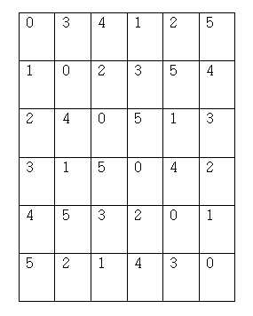
도 17은 N=6인 경우에, 코스타스 어레이를 이용한 재사용 설계에 의한 행렬의 패턴을 도시한 도면이다. 즉, 상기 도 17은 6x6 코스타스 어레이 패턴을 나타낸다. 도 18은 상기 도 17의 코스타스 어레이 패턴에 셀 ID를 할당한 결과를 도시한 도면이다. 또한, 상기 도 18에 도시된 코스타스 어레이의 특정 열을 순환 천이하거나 퍼뮤테이션 하는 것도 가능하다. 도 19와 도 20은 도 18에 도시된 코스타스 어레이를 순환 천이하거나 퍼뮤테이션한 일례를 도시한 도면이다.17 is a diagram showing a pattern of a matrix by a reuse design using a Costas array when N = 6. That is, FIG. 17 shows a 6x6 costas array pattern. 18 is a diagram showing a result of assigning a cell ID to the Costas array pattern of FIG. It is also possible to circulate or perform permutation of a specific column of the Costas array shown in FIG. Figs. 19 and 20 are views showing an example of circulating transition or permutation of the Costas array shown in Fig.
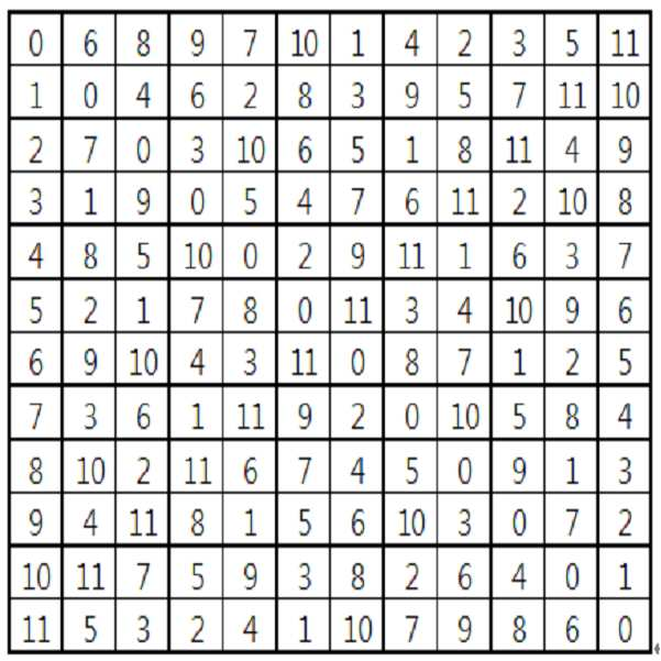
또한, 상기에서 설명한 방법을 이용하여, N=10인 경우로 확장할 수 있다. 도 21은 N=10인 경우에, 코스타스 어레이에 의한 재사용 설계(reuse planning)에 의한 행렬에 셀 ID를 할당한 결과를 도시한 도면이다. Further, by using the above-described method, the case of N = 10 can be extended. 21 is a diagram showing a result of assigning a cell ID to a matrix by reuse planning by the Costas array when N = 10.
한편, 이하 셀 ID/심볼 모듈로(symbol modular)에 기반한 모행렬을 설명하기로 한다.Hereinafter, the matrix matrix based on the cell ID / symbol moduler will be described.
2) 셀 ID/심볼 모듈로(symbol modular)에 기반한 모행렬2) a mother matrix based on cell ID / symbol moduler
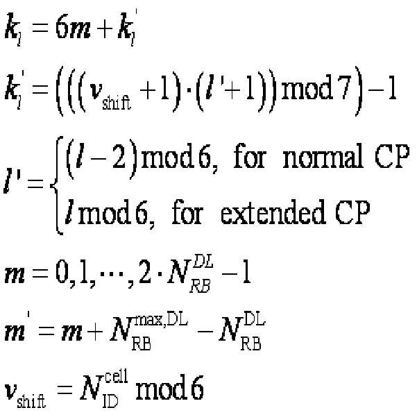
셀 ID/심볼 모듈로(symbol modular)에 기반한 모행렬은 다음의 수학식 4를 이용하여 생성할 수 있다. The mother matrix based on the cell ID / symbol modular can be generated using Equation (4) below.

상기 수학식 4에서, Nsym은 한 서브프레임 내에서의 OFDM 심볼의 개수일 수 있고, nsubblock은 특정 범위 내에서 NxN 행렬의 개수일 수 있다. 여기서, 서브프레임 단위로 서브블록이 생성되면 nsubblock은 서브프레임 인덱스인 nSF일 수 있다. 또한, nSF는 모든 서브프레임에 대해 동일한 값을 가질 수 있으나, 본 발명에서는 다른 값을 갖는 것을 가정하였다. 또한 Np는 N보다 큰 정수 중 가장 작은 소수(prime number)일 수 있다. In Equation (4), N sym may be the number of OFDM symbols in one subframe, and n subblock may be the number of NxN matrices within a specific range. Here, when the sub-blocks are created in subframe n subblock may be in the n sub-frame SF index. Also, n SF may have the same value for all subframes, but it is assumed that the present invention has different values. Also, Np may be the smallest prime number among integers greater than N. [
또한, am은 셀 ID의 함수일 수 있다. Also, a m may be a function of the cell ID.
여기서, 셀 ID는 재사용된 셀 ID일 수 있다. 예를 들어, 셀 ID의 개수가 504개일 때, 본 발명에 적용하는 셀 ID는 N개의 재사용을 적용하였을 때 m=mod(n_cellid, N)으로 나타낼 수 있다.Here, the cell ID may be a reused cell ID. For example, when the number of cell IDs is 504, the cell ID applied to the present invention can be expressed as m = mod (n_cellid, N) when N reuse is applied.
이때, nsubblock 값은 특정 단위에 따른 호핑 패턴(hopping pattern)을 지정하는 것으로서, nSF뿐만 아니라 셀 ID와 함께 연계되어 정의될 수 있다. 예를 들어, nsubblock= nSF+셀 ID와 같이 지정하여, 서브프레임 단위로 RS 패턴이 셀 ID와 연계되어 호핑될 수 있다. At this time, n subblock The value specifies a hopping pattern according to a specific unit, and may be defined in conjunction with n SF as well as cell ID. For example, n subblock = n SF + cell ID, and the RS pattern may be hopped in association with the cell ID in units of subframes.
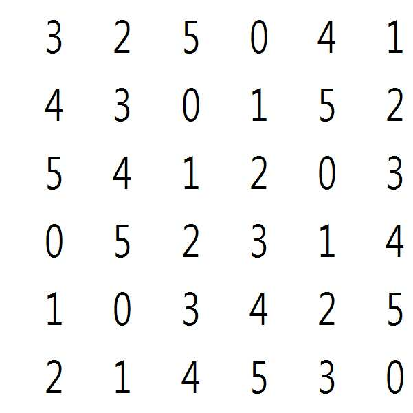
N=6인 경우의 일례는 다음의 수학식 5의 행렬과 같다.An example of the case where N = 6 is the same as the matrix of the following equation (5).
또한, N=10인 경우의 일례는 다음의 수학식 6의 행렬과 같다.An example of the case where N = 10 is the same as the matrix of the following equation (6).

또한, N=12인 경우의 일례는 다음의 수학식 7의 행렬과 같다.An example of the case where N = 12 is the same as the matrix of the following equation (7).
상기 1)에서 설명한 바와 마찬가지로, 본 경우에도 상기 행렬을 순환 천이 또는 퍼뮤테이션하여 모행렬을 생성하는 것이 가능하다. In the same manner as described in 1) above, it is also possible to generate a matrix by cyclically shifting or permutating the matrix.
이하에서는, 상기에서 설명한 모행렬을 기초로 상기에서 언급한 RS 패턴의 생성에 대하여 자세하게 설명하기로 한다.Hereinafter, the generation of the above-mentioned RS pattern will be described in detail based on the above-described mother matrix.
우선, (1) 모행렬의 적어도 두 개 이상의 열(column) 혹은 행(row)의 순서가 바뀌어 확장되는 형태는 상기에서 설명한 순환 천이 또는 퍼뮤테이션을 통해 열 또는 행의 순서가 바뀌는 형태에 해당한다. 이때, 제어 채널 영역은 3개의 OFDM 심볼로 가정하였으나, 반드시 3개로 제한되는 것은 아니다.First, (1) a form in which the order of at least two columns or rows of the mother matrix is changed is equivalent to a form in which the order of columns or rows is changed through the above-described cyclic transition or permutation . At this time, although the control channel region is assumed to be three OFDM symbols, it is not necessarily limited to three.
(2) 모행렬의 적어도 하나 이상의 열 또는 행을 천공(puncturing)하는 형태 (2) a form in which at least one column or row of the parent matrix is punctured
하나의 자원 블록(resource block)과 하나의 서브프레임 단위로 RS 패턴이 설계된다고 가정했을 때, 생성되는 모행렬의 크기는 시간 자원과 주파수 자원 중에서 큰 것을 기준으로 설계될 수 있다. 즉, 하나의 RB는 12개의 부반송파(subcarrier)로 이루어지고, 하나의 서브프레임은 제어 영역(control region) 및 CRS를 제외하고, 표준 순환 전치의 경우, 8개의 OFDM 심볼이고, 확장 순환 전치의 경우 6개의 OFDM 심볼이다. 따라서, N=12로 하여 설계할 수가 있다. 이 경우, 재사용에 의한 이득을 극대화할 수 있다.Assuming that an RS pattern is designed for one resource block and one subframe unit, the size of the generated matrix may be designed based on a time resource or a frequency resource, which is a larger one. In other words, one RB is composed of 12 subcarriers, one subframe is 8 OFDM symbols in the case of the standard cyclic prefix excluding the control region and the CRS, and in the case of the extended cyclic prefix Six OFDM symbols. Therefore, N = 12 can be designed. In this case, the gain due to reuse can be maximized.
또는, 생성되는 모행렬의 크기는 시간 자원과 주파수 자원 중에서 작은 것을 기준으로 설계될 수 있다. 예를 들어, 하나의 RB는 12개의 부반송파로 이루어지고, 하나의 서브프레임은 표준 순환 전치의 경우, 8개의 OFDM 심볼, 확장 순환 전치의 경우, 6개의 OFDM 심볼이다. 따라서, N=6으로 하여 설계할 수가 있다. 이 경우, 한 서브프레임에서는 비어있는 부반송파가 없으므로 시간 동기(timing synchronization) 시 다중 피크(multiple peak)에 의한 모호함(ambiguity)을 제거할 수 있다. Alternatively, the size of the generated mother matrix may be designed based on a small one among a time resource and a frequency resource. For example, one RB is composed of 12 subcarriers, one subframe is 8 OFDM symbols for standard cyclic permutation, and 6 OFDM symbols for extended cyclic permutation. Therefore, N = 6 can be designed. In this case, since there is no empty subcarrier in one subframe, ambiguity due to multiple peaks can be eliminated in timing synchronization.
이하에서는 상기 코스타스 어레이 기반 및 셀 ID/심볼 모듈로 기반에 기초하여 설명하기로 한다. 다만, 경우에 따라서, 설명의 용이함을 위하여, 어느 하나에 대해서면 설명하기로 한다. Hereinafter, the description will be made on the basis of the Costas array based and the cell ID / symbol module based. However, in some cases, for ease of explanation, any one will be described in detail.
먼저, N=12에 의해 생성된 모행렬을 이용하는 방법을 설명하기로 한다. First, a method of using the mother matrix generated by N = 12 will be described.
도 22는 표준 순환 전치의 경우에, N=12에 의해 생성된 셀ID/심볼 모듈로에 기초한 모행렬에서 천공되는 열을 도시한 도면이다. 또한, 도 23은 N=12에 의해 생성된 셀 ID/심볼 모듈로에 기초한 모행렬을 서브프레임에 적용한 경우를 나타낸다. 상기 도 23에서 좌측은 표준 순환 전치의 경우에 해당하고, 우측은 확장 순환 전치의 경우에 해당한다. 상기 도 23에서, 표준 순환 전치의 경우에는 0, 2, 5, 9번째 열이 천공되고, 확장 순환 전치의 경우에는 0, 1, 2, 3, 6, 9가 천공된다. 이때, 천공되는 열은 셀 고유의 RS가 위치하는 영역 또는 제어 채널이 위치하는 영역이다.22 is a diagram showing a column that is punctured in a parent matrix based on a cell ID / symbol modulo generated by N = 12 in the case of a standard cyclic prefix. FIG. 23 shows a case where a mother matrix based on the cell ID / symbol module generated by N = 12 is applied to a subframe. The left side in FIG. 23 corresponds to the case of standard circulation transposition, and the right side corresponds to the case of extended circulation transposition. In FIG. 23, 0, 2, 5, and 9 columns are punctured in the case of the standard cyclic prefix, and 0, 1, 2, 3, 6, and 9 are punctured in the case of the extended cyclic prefix. At this time, the row to be punctured is a region in which the RS unique to the cell or a control channel is located.
이때, 마지막 열은 마지막 OFDM 심볼에 매핑되도록 구성한다. At this time, the last column is configured to be mapped to the last OFDM symbol.
한편, 도 24는 MBSFN(Multimedia Broadcast Single Frequency Network) 서브프레임에 N=12인 모행열을 적용한 예를 도시한 도면이다. 상기 도 24에서 0, 1번째 열이 천공된다. Meanwhile, FIG. 24 is a diagram showing an example of applying a matrix sequence with N = 12 to a MBSFN (subframe). In FIG. 24, the 0th and 1 st columns are punctured.
또는 CRS를 혹은 CRS를 같이 PRS와 사용될 것을 고려하여 천공 시 시간 영역에서 다중 피크가 존재하지 않도록 설계할 수 있다. Considering that CRS or CRS is used together with PRS, it can be designed so that multiple peaks do not exist in the time domain during puncture.
특별히 CRS의 재사용 패턴을 고려하여 순환 천이와 함께 천공을 수행할 수 있다. 예를 들어, CRS의 재사용 패턴은 1 Tx의 경우, [0,1,2,3,4,5,0,1,2,3,4,5]T 이므로 이는 상기 셀 ID/심볼 모듈로 기반 모행렬에서 첫 번째 열(column 0)에 해당한다. 따라서, 첫 번째 열을 CRS 위치에 일치시키고 그것을 천공할 수 있다. 일례로 제어 채널 영역을 제외한 CRS 중 첫 번째 CRS 심볼(nsym=4)위치에 모행렬의 첫 번째 열을 일치시키기 위해 오른쪽으로 2만큼 순환 천이(cyclic shift)를 적용하고 해당 CRS 위치에서 천공을 수행할 수 있다. In particular, it is possible to perform perforation with cyclic transitions taking into account the reuse pattern of CRS. For example, the reuse pattern of CRS is [0, 1, 2, 3, 4, 5, 0, 2, 3, 4, 5] T in the case of 1 Tx, This corresponds to the first column (column 0) in the parent matrix. Thus, the first row can be matched to the CRS position and punctured. For example, a cyclic shift of 2 is applied to the right of the first row of the mother matrix to match the first CRS symbol (n sym = 4) of the CRS excluding the control channel region, and puncturing at the corresponding CRS position Can be performed.
도 25는 표준 순환 전치의 경우에, 상기 도 22에 도시된 행렬을 오른쪽으로 2만큼 순환 천이한 결과를 도시한 도면이다. FIG. 25 is a diagram showing a result of circulating transition of the matrix shown in FIG. 22 to the right in the case of the standard cyclic prefix.
도 26은 확장 순환 전치의 경우에, 상기 도 22에 도시된 행렬을 오른쪽으로 3만큼 순환 천이한 결과를 도시한 도면이다. FIG. 26 is a diagram showing a result of cyclically shifting the matrix shown in FIG. 22 to the right by 3 in the case of extended cyclic permutation.
도 27은 상기 도 25의 행렬과 상기 도 26의 행렬을 각각 서브프레임에 적용하고, 천공을 수행한 결과를 도시한 도면이다. 상기 도 27의 좌측은 확장 순환 전치의 경우에 해당하고, 상기 도 27의 우측은 확장 순환 전치의 경우에 해당한다.FIG. 27 is a diagram showing the result of applying puncturing by applying the matrix of FIG. 25 and the matrix of FIG. 26 to subframes, respectively. The left side of FIG. 27 corresponds to the case of extended circulation transposition, and the right side of FIG. 27 corresponds to the case of the extended circulation transposition.
또한, 도 28은 상기 도 25의 행렬을 MBSFN 서브프레임에 적용하고, 천공을 수행한 결과를 도시한 도면이다.28 is a diagram showing the result of applying the matrix of FIG. 25 to MBSFN subframe and performing puncturing.
상기 도 25 내지 도 28과 같이, 상기 모행렬에 순환 천이를 수행하여 서브프레임에 적용하는 것이 가능하다. As shown in FIGS. 25 to 28, it is possible to apply cyclic shift to the mother matrix and apply it to a sub-frame.
또는, [0,1,2,...]T 의 첫 번재 열(column 0)을 서브프레임의 맨 마지막 CRS심볼 위치에 맞추어 천공할 수 있다. 도 29는 표준 순환 전치의 경우에 N=12의 모행렬의 첫 번째 열을 서브프레임의 맨 마지막 CRS 심볼에 맞추어 천공을 수행하는 예를 도시한 도면이다. 또한, 도 30은 MBSFN 서브프레임에서, N=12의 모행렬의 첫 번째 열을 서브프레임의 맨 마지막 CRS 심볼에 맞추어 천공을 수행하는 예를 도시한 도면이다. Alternatively, puncturing can be performed by aligning the first column (column 0) of [0,1,2, ...] T to the last CRS symbol position of the subframe. 29 is a diagram illustrating an example of performing puncturing by aligning the first column of the mother matrix of N = 12 in the case of the standard cyclic prefix to the last CRS symbol of the subframe. 30 is a diagram showing an example of performing puncturing by aligning the first row of the mother matrix of N = 12 in the MBSFN subframe with the last CRS symbol of the subframe.
한편, 코스타스 어레이에 기초한 모행렬을 생성하는 방법을 설명하기로 한다. On the other hand, a method for generating a mother matrix based on the Costas array will be described.
도 31은 N=12의 코스타스 어레이의 일례를 도시한 도면이다. N=12의 코스타스 어레이는 여러 종류가 가능하지만 도 31을 예로 든다. 도 32는 상기 도 31의 코스타스 어레이를 서브프레임에 적용한 경우를 도시한 도면이다. 상기 도 32의 좌측에 도시된 서브프레임은 표준 순환전치의 경우에 해당하고, 우측에 도시된 서브프레임은 확장 순환전치의 경우에 해당한다. 또한, 도 33은 상기 도 31의 코스타스 어레이를 MBSFN 서브프레임에 적용한 경우를 도시한 도면이다.31 is a diagram showing an example of a Costas array of N = 12. A variety of kinds of costas arrays of N = 12 are possible, but FIG. 31 is exemplified. 32 is a diagram showing a case where the Costas array of FIG. 31 is applied to a subframe. The subframe shown on the left side of FIG. 32 corresponds to the case of the standard cyclic prefix, and the subframe shown on the right corresponds to the case of the extended cyclic prefix. 33 is a diagram showing a case where the costas array of FIG. 31 is applied to an MBSFN sub-frame.
한편, N=12의 모행렬은 N=6으로부터 생성된 모행렬을 확장하고, 천공을 수행하여 생성할 수 있다. 이때, N=6의 모행렬을 서브프레임에 맞게 확장하는 것을 제외하고는 나머지는 상기에서 설명한 내용과 유사하다.On the other hand, the mother matrix with N = 12 can be generated by extending the mother matrix generated from N = 6 and performing perforation. At this time, the remainder is similar to the above description except that the mother matrix of N = 6 is expanded to fit the subframe.
먼저, N=6을 기반으로 생성된 코스타스 기반 모행렬(도 17과 도 18 참조)에 의해 확장된 형태를 설명한다. 여기서, CRS의 재사용 (0,1,2...). (3,4,5,...)에 상응하는 열만이 천공되도록 사전에 미리 퍼뮤테이션시킬 수 있다. 이때, 적절한 열을 섞어서 매핑할 수 있다. First, an expanded form is described by a Costas-based mother matrix (see FIGS. 17 and 18) generated based on N = 6. Here, reuse of CRS (0, 1, 2 ...). It is possible to pre-perform permutation so that only the column corresponding to the columns (3, 4, 5, ...) is perforated. At this time, appropriate heat can be mixed and mapped.
아래의 수학식 8는 코스타스 기반 모행렬의 일례를 나타낸다.Equation (8) below shows an example of a Costas-based mother matrix.
상기 수학식 8의 모행렬을 확장하여 서브프레임에 적용할 수 있다. 도 34는 표준 순환 전치의 경우에, N=6의 코스타스 기반 모행렬을 서브프레임에 적용하고, 천공을 수행한 일례를 도시한 도면이다. 또한, 도 35는 확장 순환전치의 경우에, N=6의 코스타스 기반 모행렬을 서브프레임에 적용하고, 천공을 수행한 일례를 도시한 도면이다. The parent matrix of Equation (8) can be extended and applied to the subframe. FIG. 34 is a diagram showing an example in which a Costas-based mother matrix of N = 6 is applied to a subframe and puncturing is performed in the case of a standard cyclic prefix. FIG. 35 is a diagram showing an example of applying a Costas-based mother matrix of N = 6 to a subframe and performing puncturing in the case of extended cyclic permutation.
한편, 상기 수학식 8의 모행렬에 적절한 열 및 행의 퍼뮤테이션을 적용하는 것이 가능하다. 도 36은 본 발명의 일 실시예에 따른 N=6의 코스타스 기반 모행렬을 서브프레임에 적용하고, 천공을 수행한 일례를 도시한 도면이다. 상기 도 36의 좌측은 표준 순환 전치에 해당하고, 우측은 확장 순환 전치에 해당한다. Meanwhile, it is possible to apply the permutation of the column and the row to the mother matrix of Equation (8). FIG. 36 is a diagram illustrating an example of applying a Costas-based mother matrix of N = 6 according to an embodiment of the present invention to a subframe and performing puncturing. The left side of FIG. 36 corresponds to the standard circulation transposition, and the right side corresponds to the extended circulation transposition.
또한, 천공 되었을 때에 셀 ID 번호가 전 주파수 대역에 골고루 퍼지게 하는 것을 고려하여 모행렬을 서브프레임 상에 매핑할 수 있다. 도 37은 본 발명의 일 실시예에 따른 N=6의 코스타스 기반 모행렬을 서브프레임에 적용하고, 천공을 수행한 일례를 도시한 도면이다. 도 37에서 좌측에 도시된 서브프레임은 표준 순환 전치의 경우에 해당하고, 우측에 도시된 서브프레임은 확장 순환 전치의 경우에 해당한다.In addition, the parent matrix can be mapped on the subframe in consideration of spreading the cell ID number evenly across the entire frequency band when punctured. FIG. 37 is a diagram illustrating an example of applying a Costas-based mother matrix of N = 6 to a subframe according to an embodiment of the present invention and performing puncturing. The subframe shown on the left in Fig. 37 corresponds to the case of the standard cyclic prefix, and the subframe shown on the right corresponds to the case of the extended cyclic prefix.
한편, 셀ID/심볼 모듈로에 기초한 모행렬을 서브프레임 상에 적용할 수 있다. 도 38은 본 발명의 일 실시예에 따른 N=6의 셀ID/심볼 모듈로 기반 모행렬을 서브프레임에 적용하고 천공을 수행한 일례를 도시한 도면이다. 상기 도 38에서 좌측의 서브프레임은 표준 순환 전치의 경우에 해당하고, 우측의 서브프레임은 확장 순환 전치의 경우에 해당한다.On the other hand, a mother matrix based on the cell ID / symbol module can be applied on the subframe. FIG. 38 is a diagram illustrating an example of applying a seeding matrix based on a cell ID / symbol module of N = 6 according to an embodiment of the present invention to a subframe and performing puncturing. The left subframe in FIG. 38 corresponds to the case of the standard cyclic prefix, and the right subframe corresponds to the case of the extended cyclic prefix.
(3) 모행렬의 적어도 하나 이상의 열 또는 행이 반복되어 확장되는 형태 (3) a form in which at least one column or row of the parent matrix is repeatedly expanded
본 경우는 모행렬의 적어도 두 개 이상의 열 또는 행의 순서가 바뀌어 확장되는 형태를 포함한다. In this case, at least two rows or columns of the mother matrix include a form in which the order of the rows is changed.
이 방법은 주어진 자원보다 작은 모행렬을 확장함에 있어서, CRS와의 간섭 및 동기 시 다중 피크(multiple peak)를 제거(서브프레임에서 빈 부반송파가 없어야 함)하기 위한 요소들을 고려하여 확장하는 것이다. 이때, CRS 좌우 심볼에 CRS와 동일한 재사용 패턴(reuse pattern)의 열이 있으면 CRS와 PA-RS 간 간섭 문제를 해결할 수 있다. 도 39는 본 발명의 일 실시예에 따른, 코스타스 어레이에 기반한 모행렬의 적어도 하나 이상의 열 또는 행이 반복되어 확장되는 형태를 도시한 도면이다. 또한, 도 40은 본 발명의 일 실시예에 따른, 셀ID/심볼 모듈로에 기반한 모행렬의 적어도 하나 이상의 열 또는 행이 반복되어 확장되는 형태를 도시한 도면이다. This method is to extend the consideration of the factors to eliminate interference with CRS and multiple peaks in synchronization (there should be no empty subcarriers in the subframe) in extending the mother matrix smaller than a given resource. In this case, if there is a row of reuse patterns in the left and right CRS symbols as in CRS, the interference problem between CRS and PA-RS can be solved. FIG. 39 is a diagram illustrating a form in which at least one column or row of a mother matrix based on a Costas array is repeatedly expanded according to an embodiment of the present invention. FIG. 40 is a diagram illustrating a form in which at least one column or row of a parent matrix based on a cell ID / symbol module is repeatedly expanded according to an embodiment of the present invention.
(4) 미러링 매핑(mirroring mapping) (4) Mirroring mapping
주어진 자원 보다 작은 N의 모행렬을 확장함에 있어서 미러링 형태를 이용하여 확장할 수가 있다. 다시 말하면, N의 모행렬을 반복시킬 때 반복되는 경계에서 반사되어 대칭되도록 매핑할 수 있다. 단순 반복을 통하여 확장을 할 경우에는 충돌하는 패턴이 동일한 반면, 반사를 통한 확장은 충돌을 다른 부반송파로 랜덤화(randomization)시킬 수 있다. 또한, 주파수 영역으로 확장하는 경우에는 상반부의 행렬의 매핑 순서의 역순으로 매핑할 수 있다. 도 41은 본 발명의 일 실시예에 따른, 코스타스 어레이를 이용한 미러링 매핑의 결과를 도시한 도면이다. 상기 도 41에서 좌측의 서브프레임은 표준 순환 전치의 경우에 해당하고, 우측은 확장 순환 전치의 경우에 해당한다. In expanding the mother matrix of N smaller than a given resource, we can extend it using the mirroring form. In other words, when the parent matrix of N is repeated, it can be mapped so as to be reflected at the repeated boundary and symmetric. In the case of expansion through simple repetition, the colliding pattern is the same, while the expansion through reflection can randomize the collision to the other subcarriers. In the case of extending to the frequency domain, mapping can be performed in the reverse order of the mapping order of the upper half matrices. 41 is a diagram illustrating a result of a mirroring mapping using a Costas array according to an embodiment of the present invention. The left subframe in FIG. 41 corresponds to the case of the standard cyclic prefix and the right side corresponds to the case of the extended cyclic prefix.
한편, 사용자 기기의 위치 추정을 위한 PRS 패턴은 다음과 같이 생성할 수 있다. 주파수 재사용이 6인 영우에, 슬롯 ![]()
![]()
![]()
![]()
![]()
![]()
상기 수학식 9에서, ![]()
![]()
![]()
![]()
![]()
![]()
도 42는 주파수 재사용 6에 대한 본 발명의 일 실시예에 따른 PRS 패턴을 도시한 도면이다. 42 is a diagram illustrating a PRS pattern according to an embodiment of the present invention for
한편, 상기 PRS 패턴의 성능을 시뮬레이션하기 위한 내용을 설명하면 다음과 같다. A description will now be made of a method for simulating the performance of the PRS pattern.
기본 시뮬레이션 파라미터들은 다음의 표 1에 나타난 바와 같다. CRS와 PRS가 함께 사용될 수 있을지라도, 순수한 PRS 성능의 관점에서 서로 다른 제안들을 비교하기 위하여 PRS만이 위치 결정에 사용된다. Es/Iot와 RSRP(Reference Signal Received Power)가 각 셀에 대한 가청성(hearibility)를 측정하기 위하여 사용자 기기 측에서 측정된다. Es는 원하는 신호의 신호 에너지(energy), It는 간섭 신호의 파워 스펙트럴 밀도(power spectral density)로서 통상적으로는 SINR이라고도 불린다.The basic simulation parameters are shown in Table 1 below. Although CRS and PRS can be used together, only the PRS is used for positioning to compare different proposals in terms of pure PRS performance. Es / Iot and Reference Signal Received Power (RSRP) are measured at the user equipment side to measure the hearing for each cell. Es is the signal energy of the desired signal, and It is the power spectral density of the interference signal, commonly referred to as SINR.
(2) Practical timing assumption: 10km (for all cases)(1) Ideal timing assumption: around ideal timing (for comparison of different PRS patterns)
(2) Practical timing assumption: 10 km (for all cases)
측정 결과가 문턱 값을 만족시키면, 감지된 셀에 대하여 추정된 시점의 정확성을 연구하기 위하여 리플리카 기반(replica_based) 시점 측정이 수행된다. 위치 결정의 성능은 가청성과 추정된 시점의 정확성에 의존한다. 시점의 정확성은 PRS 패턴 및 시퀀스의 자동 상관(auto correlation) 또는 크로스 상관(cross correlation)에 의존한다. 반면, 가청성은 시간 및 주파수 재사용에 의존한다. 서로 다른 PRS 패턴으로부터 자동상관 프로파일의 영향을 연구하기 위하여, 시점 관측 창(timing search window)에 의존하는 두 가지 가정을 고려하기로 한다. If the measurement result meets the threshold, a replica-based point-of-view measurement is performed to study the accuracy of the estimated time for the sensed cell. The performance of the positioning depends on the audibility and the accuracy of the estimated time. The accuracy of the viewpoint depends on the auto correlation or cross correlation of the PRS pattern and sequence. On the other hand, audibility depends on time and frequency reuse. To study the effect of autocorrelation profiles from different PRS patterns, two assumptions will be considered, depending on the timing search window.
1) 이상적인 시점 가정1) Assuming an ideal point
시점 측정은 가장 빠른 경로에 대응하는 이상적인 시점 위치 부근에서 수행된다. PRS 패턴 때문에 자동 상관 특성을 거의 반영할 수 없다. 위치 결정의 성능은 가청성에 주로 의존할 것이다. The point of view measurement is performed near the ideal point of view corresponding to the fastest path. The PRS pattern can hardly reflect the autocorrelation property. The performance of the positioning will depend mainly on audibility.
2) 실질적인 시점 가정2) Assume a real-time point
시점 관측 창(timing search window)은 10km까지이다. 위치 결정의 성능은 시점 정확성에 있어서, 자동 상관 성능에 의해 부분적으로 영향을 받는다. 따라서, 위치 결정의 성능은 PRS 패턴에 대하여 가청성과 시점 정확성 모두에 영향을 줄 것이다.The timing search window is up to 10 km. The performance of positioning is partially influenced by the auto-correlation performance in viewpoint accuracy. Thus, the performance of the positioning will affect both audibility and viewpoint accuracy for the PRS pattern.
상기 내용에 따르면, PDCCH 심볼의 가능한 개수는 시스템 대역이 3Mhz 이상인 경우에는 3개이고, 3Mhz 미만인 경우에는 4개이다. 이 경우에, 위치 결정 성능을 저하시키지 않기 위하여 사용자 기기의 동작은 2가지가 존재한다. 첫 번째는 사용자 기기는 항상 최대 PDCCH 심볼을 가정하는 것이고 두 번째는 PDCCH 심볼의 개수에 대한 관련 파라미터가 사용자 기기에게 시그널링(signaling)되는 것이다. 상기 첫 번째는 PRS 패턴을 설계하는 것이 명확한 반면, 상기 두 번째는 시그널링을 위한 추가적인 오버헤드가 필요하다. 또한, 성능의 이득에 있어서 상기 두 번째는 명확하지 않다. 따라서, 상기 첫 번째가 PRS 패턴 설계를 위해 유리하다. 따라서, ![]()
![]()
![]()
![]()
하지만, 상기 도 42에 도시된 바와 같이, 상기와 같이 시스템 대역에 따라, PDCCH 심볼의 개수를 변경하는 것이 아니라, PRS가 전송 될 때, PDCCH는 항상 3개로 하고, 표준 순환 전치의 경우에, PRS는 4번째(시간 축 상에서 가장 빠른 OFDM심볼부터 0, 1, 2 ,...로 번호를 부여하였을 때) OFDM심볼부터 전송되도록 구성하고, 확장 순환 전치의 경우에, 4번째 OFDM 심볼에는 CRS가 전송되므로 PRS는 4번째 OFDM 심볼에서 천공되어 5번째 OFDM 심볼부터 전송되도록 구성될 수 있다. However, as shown in FIG. 42, when the PRS is transmitted instead of changing the number of PDCCH symbols according to the system band, the PDCCH is always set to 3. In the case of the standard cyclic prefix, the PRS Is configured to be transmitted from an OFDM symbol at a fourth time (when a number is assigned from the earliest OFDM symbol on the time axis to 0, 1, 2, ...), and in the case of the extended cyclic prefix, a CRS The PRS may be punctured in the fourth OFDM symbol and transmitted from the fifth OFDM symbol.
한편, PDCCH를 위한 심볼의 개수는 최대 3개로 구성하고 나머지 심볼에 대해서 PRS를 전송하는 것이 가능하다. 또한, CRS가 전송되는 OFDM 심볼에 대해서는 PRS는 천공하여 구성할 수 있다. On the other hand, it is possible to configure up to three symbols for the PDCCH and to transmit PRS for the remaining symbols. In addition, the PRS can be constructed by puncturing the OFDM symbol through which the CRS is transmitted.
한편, PCI와 PRS-ID와의 관계를 설명하기로 한다.On the other hand, the relationship between PCI and PRS-ID will be described.
현재의 이웃 셀의 측정과 기존 시스템(예를 들어, LTE Rel-8)의 보고는 PCI에 기초하여 수행된다. 또한, PCI의 개수는 유효한 셀 ID 플래닝을 고려하여 결정된다. PRS-ID를 위한 셀 플래닝이 필요하기 때문에, PCI와 PRS-ID는 일대일 관계를 갖는 것이 당연하다. 또한, 위치 보고에 있어서 기존 시스템과 같은 동일한 포맷을 재사용할 수 있다.The measurement of the current neighbor cell and the reporting of the legacy system (e.g., LTE Rel-8) are performed based on PCI. Also, the number of PCIs is determined in consideration of effective cell ID planning. Since cell planning for PRS-ID is required, it is natural that PCI and PRS-ID have a one-to-one relationship. It is also possible to reuse the same format as existing systems in location reporting.
최근, LCS(Location Service)는 이종의(heterogeneous) 망 내에서 PCI 충돌(collision)과 혼동(confusion)의 문제를 지적하고 있다. PCI 충돌의 확률은 셀을 위해 사용할 수 있는 PCI의 개수에 의존한다. HeNB/CGS 셀에 할당되는 PCI의 개수가 배치(deployment)에 의존한다는 사실 때문에, 충돌의 확률은 사소한 문제가 아닐 수 있다.In recent years, LCS (location service) has pointed out the problem of PCI collision and confusion in a heterogeneous network. The probability of a PCI conflict depends on the number of PCIs available for the cell. Because of the fact that the number of PCIs allocated to the HeNB / CGS cells depends on the deployment, the probability of collision may not be a minor problem.
그러나, PCI 충돌과 관련하여, 시스템 레벨에서, 0~50개의 PCI를 저장해두면, 충돌 확률은 그렇게 놓지 않다. 또한, 충돌 확률은 네트워크 기반 메커니즘에 의해 더욱 줄어들 수 있다. 하향링크 및 상향링크 물리 채널인 PCI에 기초하여 전송되기 때문에, PCI 확장 없이 PRS-ID를 확장하는 경우에, 다른 물리 채널에 있어서, PCI 충돌은 다시 발생한다.However, with regard to PCI conflicts, if you save between 0 and 50 PCIs at the system level, the probability of collision is not so set. In addition, the collision probability can be further reduced by network-based mechanisms. The PCI collision occurs again on another physical channel when the PRS-ID is extended without PCI expansion since it is transmitted based on the PCI, which is a downlink and uplink physical channel.
결론적으로, PCI 범위가 확장되지 않는 한, PRS-ID 확장은 근본적인 해결책은 아니다. In conclusion, PRS-ID extension is not a fundamental solution unless the PCI range is extended.
PCI 혼동의 문제와 관련하여, 예를 들어, 사용자 기기가 글로벌 셀 ID를 보고할 수 있을 것이다. With respect to the problem of PCI confusion, for example, the user equipment may be able to report the global cell ID.
이러한 관점에서, 먼저, PCI 충돌의 문제에 대한 심각성을 명확하게 하는 것이 필요하다. 또한, PRS-ID 확장이 좋은 해결책은 아니다. From this perspective, first, it is necessary to clarify the severity of the PCI conflict problem. In addition, PRS-ID extension is not a good solution.
PCI와 PRS-ID 사이에 일대일 관계를 제안한다. 더 큰 대역은 시간 분해능(time resolution)을 증가시킴으로써, 위치 결정의 성능을 향상시킨다는 것은 명백하다. 도 43은 시스템 대역에 따른 위치 결정의 성능을 도시한 도면이다. 상기 도 43에 도시된 바와 같이, 시스템 대역을 10Mhz까지 제한하는 것이 타당한 것으로 보인다.We propose a one-to-one relationship between PCI and PRS-ID. It is clear that the larger bands increase the time resolution, thereby improving the positioning performance. Fig. 43 is a diagram showing the performance of positioning according to the system band. As shown in FIG. 43, it seems reasonable to limit the system band to 10 MHz.
한편, PRS 패턴을 위한 새스템 대역을 10Mhz(1.4Mhz, 3Mhz, 5Mhz, 10Mhz)까지로 하는 것을 제안한다. On the other hand, it is proposed to set the new stem band for PRS pattern to 10Mhz (1.4Mhz, 3Mhz, 5Mhz, 10Mhz).
서로 다른 서브프레임 사이에서 PRS 패턴을 시변(time varying)할 수 잇다. 시변 PRS 패턴과 비시변(non time-varying) PRS 패턴은 트레이디 오프(trade-off)관계가 있다. 시변 PRS 패턴은 위치 결정 성능을 향상시킬 것으로 예상되지만, 서브프레임 번호를 통지하기 위한 추가적인 시그널링이 필요하다. It is possible to time vary the PRS pattern between different subframes. The time-varying PRS pattern and the non-time-varying PRS pattern have a trade-off relationship. The time varying PRS pattern is expected to improve the positioning performance, but requires additional signaling to notify the subframe number.
도 44는 시변 PRS 패턴에 있어서 위치 결정 성능을 나타낸 도면이다. 비시변 PRS 패턴과 비교할 때, 연속적인 서브프레임 상에서 시변 PRS 패턴의 평균의 성능이 좋다는 것을 알 수 있다. 그러나, 성능 이득은 추가적인 시그널링 오버헤드를 고려할 때, 그리 크지 않은 것으로 보인다. 44 is a diagram showing the positioning performance in the time-varying PRS pattern. It can be seen that the average performance of the time-varying PRS pattern is good over consecutive subframes when compared to the non-time-varying PRS pattern. However, the performance gain does not seem to be significant considering the additional signaling overhead.
또한, 성능과 추가적인 성능 사이의 트레이드 오프(trade-off)를 고려할 때, 비시변 PRS 패턴이 바람직하다.Also, when considering the trade-off between performance and additional performance, a non-time-varying PRS pattern is preferred.
주파수와 시간 재사용 접근 사이에는 트레이드 오프 관계가 있다. 도 45는 직교 주파수 재사용 6과 직교 시간 재사용 6에 대한 위치 결정의 성능을 도시한 도면이다. OFDM 심볼 내에서 모든 부반송파들은 시간 재사용 내에서 점유되는 것을 알 수 있다. 낮은 에너지로 인하여 시간 재사용의 성능은 주파수 재사용의 성능 보다 좋지 않지만, 위치 결정의 수렴(convergence)은 복수의 서브프레임 축적(accumulation)에 의해 서로 유사한 수준까지 향상될 수 있다.There is a tradeoff relationship between frequency and time reuse approaches. 45 shows the performance of the positioning for the
따라서, 직교 주파수 재사용이 직교 시간 재사용 보다 바람직하다.Therefore, orthogonal frequency reuse is preferable to orthogonal time reuse.
이하, PRS 패턴을 비교하기로 한다.Hereinafter, the PRS patterns will be compared.
우선, 두 개의 카테고리를 설명한다.First, we explain two categories.
(1) 직교 재사용(Orthogonal reuse) 기반(1) Orthogonal reuse based
서로 다른 PRS 패턴은 직교 시간 또는 주파수 천이(shift)에 의해 생성된다.Different PRS patterns are generated by orthogonal time or frequency shifts.
패턴의 개수는 시간 또는 주파수 재사용에 대응한다. 예를 들어, 재사용 6인 경우에, 6개의 서로 다른 PRS 패턴이 존재한다.The number of patterns corresponds to time or frequency reuse. For example, in the case of
복잡도 감소 스킴(complexity reduction scheme)이 가능하다.A complexity reduction scheme is possible.
다중 피크는 서브프레임 상에서 빈 부반송파가 없게 함으로써 제거될 수 있다.Multiple peaks can be removed by eliminating empty subcarriers on the subframe.
A사, B사, C사, D사 및 E사 등이 제안하고 있다.A company, B company, C company, D company and E company propose.
(2) 부분 재사용(Fractional reuse) 기반(2) Fractional reuse based
서로 다른 PRS 패턴은 직교 또는 유사-직교(quasi-orthogonal) 시간 및/또는 주파수 천이에 의해 생성된다.The different PRS patterns are generated by orthogonal or quasi-orthogonal time and / or frequency transitions.
패턴의 개수는 시간 및/또는 주파수 재사용에 대응한다. 예를 들어, 세 개의 PDCCH 심볼을 가장할 때, 표준 순환 전치의 경우에, 96(12x8)개의 서로 다른 PRS 패턴이 존재한다.The number of patterns corresponds to time and / or frequency reuse. For example, when impersonating three PDCCH symbols, there are 96 (12x8) different PRS patterns in the case of a standard cyclic prefix.
복잡도는 서로 다른 PRS 패턴에 의해 감소될 수 있다.The complexity can be reduced by different PRS patterns.
부분 재사용은 각 셀로부터 PRS 전송의 확률을 제어함으로써 수행될 수 있다.Partial reuse can be performed by controlling the probability of PRS transmission from each cell.
서브프레임 내의 빈 부반송파 때문에 다중 피크 또는 나쁜 자동 상관 프로파일이 존재하게 된다. 이와 같은 특성은 매우 낮은 SINR 레벨에서 수행되는 이웃 셀 측정에 있어서 매우 중요하다.There are multiple peaks or bad autocorrelation profiles due to empty subcarriers in the subframe. This property is very important for neighbor cell measurements performed at very low SINR levels.
F사, G사, H사 등이 제안하고 있다.F company, G company, H company suggest.
상기 제안 중에서, 위치 결정 성능을 조사하기로 한다. 서로 다른 PRS 패턴에 대해서 서로 다른 변조 시퀀스를 적용한다. 계산을 위하여, PRS 패턴에 의존하는 서로 다른 RS 부스팅을 고려한다. 이때 부스팅 레벨은 한 OFDM 심볼에서 전송 에너지를 서로 동등하게 하기 위함이다. 부스팅 레벨은 다음과 같다.Among the proposals, the positioning performance will be examined. Different modulation sequences are applied for different PRS patterns. For computation, consider different RS boosting depending on the PRS pattern. At this time, the boosting level is to equalize the transmission energy in one OFDM symbol. The level of boosting is:
(1) A사, E사: 6dB(1) A company, E company: 6dB
(2) F사, G사: 9dB(2) F company, G company: 9dB
(3) B사: 3dB(3) Company B: 3dB
도 46은 이상적인 시점 가정에 있어서, 서로 다른 PRS 패턴에 대한 성능 비교의 결과를 나타낸다. 상기 도 46에 의할 때, 좁은 시점 측정 창 때문에, 서로 다른 패턴에 대한 시점 정확도는 서로 다르지 않다.Figure 46 shows the results of performance comparisons for different PRS patterns, assuming an ideal point of view. 46, the viewpoint accuracy for the different patterns is not different from each other due to the narrow viewpoint measurement window.
B사의 패턴의 경우, 낮은 심볼 에너지(한 서브프레임에 두 개의 OFDM 심볼)때문에 위치 결정 정확도가 다른 회사에 비해 낮다. 그러나, 한 셀에서 주어진 자원 요소(Resource Element; RE)에 대한 간섭은 셀 ID 플래닝이 적용된 경우에 완화된다.For pattern B, positioning accuracy is lower than for other companies because of low symbol energy (two OFDM symbols in one subframe). However, interference to a given Resource Element (RE) in one cell is mitigated when cell ID planning is applied.
부분 재사용 기반 패턴으로부터의 가청성은 더 큰 주파수 재사용 12 때문에 약간 더 낫다. The audibility from the partial reuse based pattern is slightly better due to the
이상적인 시점 가정은 서로 다른 PRS 패턴으로부터 자동 상관 프로파일의 특성을 반영할 수 없다. The ideal point assumption can not reflect the characteristics of the autocorrelation profile from different PRS patterns.
도 47은 실질적인 시점 가정에서 서로 다른 PRS 패턴에 대한 성능 비교의 결과를 나타낸다.Figure 47 shows the results of performance comparisons for different PRS patterns in a real-time assumption.
상기 도 47에 의할 때, 직교 재사용 기반 패턴(A사, E사)은 더 나은 자동 상관 프로파일(서브프레임 내에 빈 부반송파가 없음)때문에 가장 좋은 성능을 보이는 것이 명백하다. B사의 패턴은, 빈 부반송파와 시간 재사용으로 인한 낮은 에너지를 갖는 자동 상관 프로파일 때문에 가장 성능이 나쁘다. A사의 패턴은, 특정 셀 내에서, 직교 PRS 패턴은 서로 다른 전파 지연(propagation delay)을 가진 모든 PRS 요소에 대하여 이웃 셀의 PRS 패턴과 충돌할 것 같다. Referring to FIG. 47, it is apparent that the orthogonal reuse-based pattern (company A, company E) shows the best performance because of a better autocorrelation profile (there are no empty subcarriers in the subframe). Pattern B has the worst performance due to autocorrelation profiles with low energy due to empty subcarriers and time reuse. The pattern of the A company is likely to collide with the PRS pattern of the neighboring cell for all the PRS elements having different propagation delays in a certain cell.
부분 재사용 기반 패턴(F사, G사, H사)의 위치결정 성능은 나쁜 자동 상관 프로파일 때문에 직교 재사용 기반 패턴보다 나쁘다.The positioning performance of partial reuse based patterns (F, G, H) is worse than orthogonal reuse based patterns due to poor autocorrelation profiles.
상기 중에서, 설계가 CRS와 PRS 사이의 충돌을 고려하여 수행되었기 때문에, Among the above, since the design was performed in consideration of the collision between the CRS and the PRS,
F사의 패턴이 가장 좋은 위치결정 성능을 보인다.F pattern shows the best positioning performance.
제안들은 서로 다른 널 부반송파의 위치를 갖기 때문에, 자동 상관 프로파일은 널 부반송파에 의존한다.Since the proposals have different positions of null subcarriers, the autocorrelation profile depends on the null subcarriers.
Es/Iot 문턱값은 패턴으로부터 오경보율(false alarm rate)에 따라서 결정될 때, 가청성은 실질적으로 증가하지 않을 것이다. When the Es / Iot threshold is determined according to the false alarm rate from the pattern, the audibility will not substantially increase.
실질적인 시점 가정은 서로 다른 PRS 패턴으로부터 유효하게 자동 상관 프로파일에 영향을 줄 수 있다. The real-time assumption can effectively influence the autocorrelation profile from different PRS patterns.
도 48는 기지국과 사용자 기기에 적용 가능하고 상기에서 설명한 방법을 수행할 수 있는 디바이스의 구성을 나타내는 블록도이다. 도 17에 도시된 바와 같이, 디바이스(100)는 처리 유닛(101), 메모리 유닛(102), RF(Radio Frequency) 유닛(103), 디스플레이 유닛(1044)과 사용자 인터페이스 유닛(105)을 포함한다. 물리 인터페이스 프로토콜의 계층은 상기 처리 유닛(101)에서 수행된다. 상기 처리 유닛(101)은 제어 플레인(plane)과 사용자 플레인(plane)을 제공한다. 각 계층의 기능은 처리 유닛(101)에서 수행될 수 있다. 상기 처리 유닛(101)은 상기에서 설명한 본 발명의 실시예를 수행할 수 있다. 구체적으로 설명하면, 상기 처리 유닛(101)은 사용자 기기 위치 결정용 서브프레임을 생성하거나 상기 서브프레임을 수신하여 사용자 기기의 위치를 결정하는 기능을 수행할 수 있다. 메모리 유닛(102)은 처리 유닛(011)과 전기적으로 연결되어 있고, 오퍼레이팅 시스템(operating system), 응용 프로그램(application) 및 일반 파일을 저장하고 있다. 만약 상기 디바이스(100)가 사용자 기기라면, 디스플레이 유닛(104)은 다양한 정보를 표시할 수 있으며, 공지의 LCD(Liquid Crystal Display), OLED(Organic Light Emitting Diode)등을 이용하여 구현될 수 있다. 사용자 인터페이스 유닛(105)은 키패드, 터치 스크린 등과 같은 공지의 사용자 인터페이스와 결합하여 구성될 수 있다. RF 유닛(103)은 처리 유닛(101)과 전기적으로 연결되어 있고, 무선 신호를 전송하거나 수신한다.48 is a block diagram illustrating a configuration of a device applicable to a base station and a user equipment and capable of performing the above-described method. 17, the
이상에서 설명된 실시예들은 본 발명의 구성요소들과 특징들이 소정 형태로 결합된 것들이다. 각 구성요소 또는 특징은 별도의 명시적 언급이 없는 한 선택적인 것으로 고려되어야 한다. 각 구성요소 또는 특징은 다른 구성요소나 특징과 결합되지 않은 형태로 실시될 수 있다. 또한, 일부 구성요소들 및/또는 특징들을 결합하여 본 발명의 실시예를 구성하는 것도 가능하다. 본 발명의 실시예들에서 설명되는 동작들의 순서는 변경될 수 있다. 어느 실시예의 일부 구성이나 특징은 다른 실시예에 포함될 수 있고, 또는 다른 실시예의 대응하는 구성 또는 특징과 교체될 수 있다. 특허청구범위에서 명시적인 인용 관계가 있지 않은 청구항들을 결합하여 실시예를 구성하거나 출원 후의 보정에 의해 새로운 청구항으로 포함시킬 수 있음은 자명하다.The embodiments described above are those in which the elements and features of the present invention are combined in a predetermined form. Each component or feature shall be considered optional unless otherwise expressly stated. Each component or feature may be implemented in a form that is not combined with other components or features. It is also possible to construct embodiments of the present invention by combining some of the elements and / or features. The order of the operations described in the embodiments of the present invention may be changed. Some configurations or features of certain embodiments may be included in other embodiments, or may be replaced with corresponding configurations or features of other embodiments. It is clear that the claims that are not expressly cited in the claims may be combined to form an embodiment or be included in a new claim by an amendment after the application.
본 발명에서 사용자 기기(User Equipment; UE)는 이동 단말(MS: Mobile Station), SS(Subscriber Station), MSS(Mobile Subscriber Station) 또는 단말(Mobile Terminal) 등의 용어로 대체될 수 있다.In the present invention, a user equipment (UE) can be replaced with a mobile station (MS), a subscriber station (SS), a mobile subscriber station (MSS) or a mobile terminal.
한편, 본 발명의 UE로는 PDA(Personal Digital Assistant), 셀룰러폰, PCS(Personal Communication Service)폰, GSM(Global System for Mobile)폰, WCDMA(Wideband CDMA)폰, MBS(Mobile Broadband System)폰 등이 이용될 수 있다.Meanwhile, the UE of the present invention includes a PDA (Personal Digital Assistant), a cellular phone, a PCS (Personal Communication Service) phone, a GSM (Global System for Mobile) phone, a WCDMA (Wideband CDMA) Can be used.
본 발명의 실시예들은 다양한 수단을 통해 구현될 수 있다. 예를 들어, 본 발명의 실시예들은 하드웨어, 펌웨어(firmware), 소프트웨어 또는 그것들의 결합 등에 의해 구현될 수 있다.Embodiments of the present invention may be implemented by various means. For example, embodiments of the present invention may be implemented by hardware, firmware, software, or a combination thereof.
하드웨어에 의한 구현의 경우, 본 발명의 실시예들에 따른 방법은 하나 또는 그 이상의 ASICs(application specific integrated circuits), DSPs(digital signal processors), DSPDs(digital signal processing devices), PLDs(programmable logic devices), FPGAs(field programmable gate arrays), 프로세서, 콘트롤러, 마이크로 콘트롤러, 마이크로 프로세서 등에 의해 구현될 수 있다.For a hardware implementation, the method according to embodiments of the present invention may be implemented in one or more application specific integrated circuits (ASICs), digital signal processors (DSPs), digital signal processing devices (DSPDs), programmable logic devices (PLDs) , Field programmable gate arrays (FPGAs), processors, controllers, microcontrollers, microprocessors, and the like.
펌웨어나 소프트웨어에 의한 구현의 경우, 본 발명의 실시예들에 따른 방법은 이상에서 설명된 기능 또는 동작들을 수행하는 모듈, 절차 또는 함수 등의 형태로 구현될 수 있다. 소프트웨어 코드는 메모리 유닛에 저장되어 프로세서에 의해 구동될 수 있다. 상기 메모리 유닛은 상기 프로세서 내부 또는 외부에 위치하여, 이미 공지된 다양한 수단에 의해 상기 프로세서와 데이터를 주고 받을 수 있다.In the case of an implementation by firmware or software, the method according to embodiments of the present invention may be implemented in the form of a module, a procedure or a function for performing the functions or operations described above. The software code can be stored in a memory unit and driven by the processor. The memory unit may be located inside or outside the processor, and may exchange data with the processor by various well-known means.
본 발명은 본 발명의 정신 및 필수적 특징을 벗어나지 않는 범위에서 다른 특정한 형태로 구체화될 수 있다. 따라서, 상기의 상세한 설명은 모든 면에서 제한적으로 해석되어서는 안되고 예시적인 것으로 고려되어야 한다. 본 발명의 범위는 첨부된 청구항의 합리적 해석에 의해 결정되어야 하고, 본 발명의 등가적 범위 내에서의 모든 변경은 본 발명의 범위에 포함된다. 또한, 특허청구범위에서 명시적인 인용 관계가 있지 않은 청구항들을 결합하여 실시예를 구성하거나 출원 후의 보정에 의해 새로운 청구항으로 포함시킬 수 있다.The present invention may be embodied in other specific forms without departing from the spirit or essential characteristics thereof. Accordingly, the foregoing detailed description should not be construed in a limiting sense in all respects, but should be considered as illustrative. The scope of the present invention should be determined by rational interpretation of the appended claims, and all changes within the scope of equivalents of the present invention are included in the scope of the present invention. In addition, claims that do not have an explicit citation in the claims may be combined to form an embodiment or included in a new claim by amendment after the application.
본 발명은 무선 이동 통신 시스템의 단말기, 기지국, 또는 기타 다른 장비에 사용될 수 있다.The present invention can be used in a terminal, a base station, or other equipment of a wireless mobile communication system.
Claims (15)
복수개의 기지국으로부터 소정 주기로 사용자 기기의 위치 결정을 위한 기준 신호(Reference Signal)를 포함하는 복수 개의 사용자 기기 위치 결정 용 서브프레임을 수신하는 단계와;
상기 수신한 복수개의 서브프레임에 포함된 상기 사용자 기기의 위치 결정을 위한 기준 신호간의 시간 차(Reference Signal Time Difference; RSTD)를 이용하여 상기 사용자 기기의 위치를 결정하는 단계를 포함하고,
상기 사용자 기기의 위치 결정을 위한 기준 신호의 패턴은 6x6 크기의 대각(diagonal) 모행렬(mother matrix)을 네 번 반복시켜 생성되고, 상기 기준 신호의 패턴은 상기 서브프레임의 OFDM 심볼 상에 매핑(mapping)되고, 공통 기준 신호(Common Reference Signal)가 전송되는 OFDM 심볼 상에 존재하는 상기 사용자 기기의 위치 결정을 위한 기준 신호는 천공되고,
시간 인덱스가 제일 작은 OFDM 심볼을 0번째 OFDM 심볼이라 할 때, 상기 0번째 OFDM 심볼, 1번째 OFDM 심볼 및 2번째 OFDM 심볼에서는 PDCCH(physical downlink control channel)가 실제로 전송되는지 여부에 관계 없이 상기 사용자 기기의 위치 결정을 위한 기준 신호는 맵핑되지 않고,
상기 사용자 기기의 위치 결정을 위한 기준 신호의 시작 OFDM 심볼은, 상기 서브프레임에 표준 순환 전치(normal cyclic prefix)가 사용되는지 아니면 확장 순환 전치(extended cyclic prefix)가 사용되는지 여부에 따라서 결정되는,사용자 기기의 위치 결정 방법.A method for positioning a user equipment in a wireless mobile communication system,
Receiving a plurality of user equipment positioning subframes including a reference signal for positioning a user equipment at predetermined intervals from a plurality of base stations;
And determining a position of the user equipment using a reference signal time difference (RSTD) between reference signals for positioning the user equipment included in the plurality of received subframes,
The reference signal pattern for positioning the user equipment is generated by repeating a 6x6 diagonal mother matrix four times and the pattern of the reference signal is mapped onto an OFDM symbol of the subframe a reference signal for positioning the user equipment existing on an OFDM symbol through which a common reference signal is transmitted is punctured,
The OFDM symbol having the smallest time index is referred to as a 0th OFDM symbol. In the 0th OFDM symbol, the 1 st OFDM symbol, and the 2 nd OFDM symbol, regardless of whether a physical downlink control channel (PDCCH) The reference signal for the positioning of the signal is not mapped,
Wherein the starting OFDM symbol of the reference signal for positioning the user equipment is determined based on whether a normal cyclic prefix or an extended cyclic prefix is used in the subframe, A method of positioning a device.
상기 서브프레임에 상기 표준 순환 전치가 사용되는 경우, 3번째 이하의 OFDM 심볼은 상기 사용자 기기의 위치 결정을 위한 기준 신호의 패턴을 위해 사용되는,
사용자 기기의 위치 결정 방법.The method according to claim 1,
When the standard cyclic prefix is used for the subframe, the OFDM symbol of the third or lower order is used for a pattern of a reference signal for positioning the user equipment,
A method of positioning a user equipment.
상기 서브프레임에 상기 확장 순환 전치가 사용되는 경우, 4번째 이하의 OFDM심볼이 상기 사용자 기기의 위치 결정을 위한 기준 신호의 패턴을 위해 사용되는,
사용자 기기의 위치 결정 방법.The method according to claim 1,
Wherein when the extended cyclic prefix is used in the subframe, a fourth or less OFDM symbol is used for a pattern of reference signals for positioning the user equipment,
A method of positioning a user equipment.
상기 사용자 기기의 위치 결정을 위한 기준 신호의 패턴은 셀 별로 순환 천이(shift)되어 사용되는,
사용자 기기의 위치 결정 방법.The method according to claim 1,
Wherein a pattern of a reference signal for positioning the user equipment is cyclically shifted for each cell,
A method of positioning a user equipment.
복수개의 기지국으로부터 소정 주기로 사용자 기기의 위치 결정을 위한 기준 신호(Reference Signal)를 포함하는 복수개의 사용자 기기 위치 결정 용 서브프레임을 수신하는 단계와;
상기 수신한 복수개의 서브프레임에 포함된 상기 사용자 기기의 위치 결정을 위한 기준 신호간의 시간 차(Reference Signal Time Difference; RSTD)를 이용하여 상기 사용자 기기의 위치를 결정하는 단계를 포함하고,
공통 기준 신호(Common Reference Signal)가 전송되는 OFDM 심볼 상에는 상기 사용자 기기의 위치 결정을 위한 기준 신호가 맵핑되지 않으며,
시간 인덱스가 제일 작은 OFDM 심볼을 0번째 OFDM 심볼이라 할 때, 상기 0번째 OFDM 심볼, 1번째 OFDM 심볼 및 2번째 OFDM 심볼에서는 PDCCH(physical downlink control channel)가 실제로 전송되는지 여부에 관계 없이 상기 사용자 기기의 위치 결정을 위한 기준 신호는 맵핑되지 않고,
상기 사용자 기기의 위치 결정을 위한 기준 신호의 시작 OFDM 심볼은, 상기 서브프레임에 표준 순환 전치(normal cyclic prefix)가 사용되는지 아니면 확장 순환 전치(extended cyclic prefix)가 사용되는지 여부에 따라서 결정되는
사용자 기기의 위치 결정 방법.A method for positioning a user equipment in a wireless mobile communication system,
Receiving a plurality of user equipment positioning subframes including a reference signal for positioning a user equipment at predetermined intervals from a plurality of base stations;
And determining a position of the user equipment using a reference signal time difference (RSTD) between reference signals for positioning the user equipment included in the plurality of received subframes,
A reference signal for positioning the user equipment is not mapped on an OFDM symbol through which a common reference signal is transmitted,
The OFDM symbol having the smallest time index is referred to as a 0th OFDM symbol. In the 0th OFDM symbol, the 1 st OFDM symbol, and the 2 nd OFDM symbol, regardless of whether a physical downlink control channel (PDCCH) The reference signal for the positioning of the signal is not mapped,
The starting OFDM symbol of the reference signal for positioning the user equipment is determined according to whether a normal cyclic prefix or an extended cyclic prefix is used in the subframe
A method of positioning a user equipment.
상기 서브프레임이 상기 표준 순환 전치를 사용하는 경우, 상기 사용자 기기의 위치 결정을 위한 기준 신호는 0, 2, 5, 9번째 열에서 맵핑되지 않고,
상기 서브프레임이 상기 확장 순환 전치를 사용하는 경우, 상기 사용자 기기의 위치 결정을 위한 기준 신호는 0, 1, 2, 3, 6, 9번째 열에서 맵핑되지 않는,
사용자 기기의 위치 결정 방법.The method according to claim 6,
If the subframe uses the standard cyclic prefix, the reference signal for positioning the user equipment is not mapped in columns 0, 2, 5, and 9,
Wherein when the subframe uses the extended cyclic prefix, the reference signal for positioning the user equipment is not mapped in the 0, 1, 2, 3, 6,
A method of positioning a user equipment.
상기 사용자 기기의 위치 결정을 위한 기준 신호의 패턴은 순환 천이(circular shift)를 통해 생성되는,
사용자 기기의 위치 결정 방법.The method according to claim 6,
Wherein the pattern of the reference signal for positioning the user equipment is generated through a circular shift,
A method of positioning a user equipment.
복수개의 기지국으로부터 소정 주기로 사용자 기기의 위치 결정을 위한 기준 신호(Reference Signal)를 포함하는 복수개의 사용자 기기 위치 결정 용 서브프레임을 수신하는 수신부와;
상기 수신부에 전기적으로 연결되고, 상기 수신한 복수개의 서브프레임에 포함된 상기 사용자 기기의 위치 결정을 위한 기준 신호간의 시간 차(Reference Signal Time Differrence; RSTD)를 이용하여 상기 사용자 기기의 위치를 결정하는 처리부를 포함하고,
공통 기준 신호(Common Reference Signal)가 전송되는 OFDM 심볼 상에서는 상기 사용자 기기의 위치 결정을 위한 기준 신호가 맵핑되지 않고,
시간 인덱스가 제일 작은 OFDM 심볼을 0번째 OFDM 심볼이라 할 때, 상기 0번째 OFDM 심볼, 1번째 OFDM 심볼 및 2번째 OFDM 심볼에서는 PDCCH(physical downlink control channel)가 실제로 전송되는지 여부에 관계 없이 상기 사용자 기기의 위치 결정을 위한 기준 신호는 맵핑되지 않고,
상기 사용자 기기의 위치 결정을 위한 기준 신호의 시작 OFDM 심볼은, 상기 서브프레임에 표준 순환 전치(normal cyclic prefix)가 사용되는지 아니면 확장 순환 전치(extended cyclic prefix)가 사용되는지 여부에 따라서 결정되는,
사용자 기기.In a wireless mobile communication system, a user equipment
A receiver for receiving a plurality of user equipment positioning subframes including a reference signal for positioning a user equipment at predetermined intervals from a plurality of base stations;
The position of the user equipment is determined using a reference signal time difference (RSTD) between the reference signals for positioning the user equipment, which are electrically connected to the receiver and included in the received plurality of subframes Processing unit,
A reference signal for positioning the user equipment is not mapped on an OFDM symbol through which a common reference signal is transmitted,
The OFDM symbol having the smallest time index is referred to as a 0th OFDM symbol. In the 0th OFDM symbol, the 1 st OFDM symbol, and the 2 nd OFDM symbol, regardless of whether a physical downlink control channel (PDCCH) The reference signal for the positioning of the signal is not mapped,
Wherein the starting OFDM symbol of the reference signal for positioning the user equipment is determined according to whether a normal cyclic prefix or an extended cyclic prefix is used in the subframe.
User device.
상기 서브프레임에 상기 표준 순환 전치가 사용되는 경우에, 3번째 이하의 OFDM 심볼은 상기 사용자 기기의 위치 결정을 위한 기준 신호의 패턴을 위해 사용되는,
사용자 기기.12. The method of claim 11,
Wherein when the standard cyclic prefix is used in the subframe, a third or less OFDM symbol is used for a pattern of a reference signal for positioning the user equipment,
User device.
상기 서브프레임에 상기 확장 순환 전치가 사용되는 경우에, 4번째 이하의 OFDM심볼이 상기 사용자 기기의 위치 결정을 위한 기준 신호의 패턴을 위해 사용되는,
사용자 기기.12. The method of claim 11,
Wherein when the extended cyclic prefix is used in the subframe, a fourth or less OFDM symbol is used for a pattern of reference signals for positioning the user equipment,
User device.
상기 사용자 기기의 위치 결정을 위한 기준 신호의 패턴은 셀 별로 순환 천이(shift)되어 사용되는,
사용자 기기.12. The method of claim 11,
Wherein a pattern of a reference signal for positioning the user equipment is cyclically shifted for each cell,
User device.
Priority Applications (8)
| Application Number | Priority Date | Filing Date | Title |
|---|---|---|---|
| US13/260,243 US8862157B2 (en) | 2009-04-10 | 2010-04-08 | Method for determining position of user equipment and apparatus for performing same in wireless mobile communication system |
| JP2012504618A JP5722873B2 (en) | 2009-04-10 | 2010-04-08 | Method and apparatus for positioning user equipment in wireless mobile communication system |
| CN201410448808.6A CN104158785B (en) | 2009-04-10 | 2010-04-08 | Method for determining the position of user equipment in mobile radio system |
| EP10761881A EP2418897A4 (en) | 2009-04-10 | 2010-04-08 | METHOD FOR DETERMINING THE POSITION OF A USER DEVICE AND DEVICE FOR CARRYING OUT THIS METHOD IN A WIRELESS COMMUNICATION SYSTEM |
| PCT/KR2010/002163 WO2010117220A2 (en) | 2009-04-10 | 2010-04-08 | Method for determining position of user equipment and apparatus for performing same in wireless mobile communication system |
| CN201080016101.8A CN102388660B (en) | 2009-04-10 | 2010-04-08 | Method for determining the location of user equipment in a wireless mobile communication system and an apparatus for performing the method |
| US14/478,985 US9544725B2 (en) | 2009-04-10 | 2014-09-05 | Method for determining position of user equipment and apparatus for performing same in wireless mobile communication system |
| JP2015058109A JP6027164B2 (en) | 2009-04-10 | 2015-03-20 | Method and apparatus for positioning user equipment in wireless mobile communication system |
Applications Claiming Priority (4)
| Application Number | Priority Date | Filing Date | Title |
|---|---|---|---|
| US16835609P | 2009-04-10 | 2009-04-10 | |
| US61/168,356 | 2009-04-10 | ||
| US21940309P | 2009-06-23 | 2009-06-23 | |
| US61/219,403 | 2009-06-23 |
Related Child Applications (1)
| Application Number | Title | Priority Date | Filing Date |
|---|---|---|---|
| KR1020160091961A Division KR101691840B1 (en) | 2009-04-10 | 2016-07-20 | Apparatus and metheod for receiving a reference signal |
Publications (2)
| Publication Number | Publication Date |
|---|---|
| KR20100113023A KR20100113023A (en) | 2010-10-20 |
| KR101644881B1 true KR101644881B1 (en) | 2016-08-03 |
Family
ID=43132772
Family Applications (2)
| Application Number | Title | Priority Date | Filing Date |
|---|---|---|---|
| KR1020100024715A Active KR101644881B1 (en) | 2009-04-10 | 2010-03-19 | Apparatus and metheod for positioing a user equipment |
| KR1020160091961A Active KR101691840B1 (en) | 2009-04-10 | 2016-07-20 | Apparatus and metheod for receiving a reference signal |
Family Applications After (1)
| Application Number | Title | Priority Date | Filing Date |
|---|---|---|---|
| KR1020160091961A Active KR101691840B1 (en) | 2009-04-10 | 2016-07-20 | Apparatus and metheod for receiving a reference signal |
Country Status (6)
| Country | Link |
|---|---|
| US (2) | US8862157B2 (en) |
| EP (1) | EP2418897A4 (en) |
| JP (2) | JP5722873B2 (en) |
| KR (2) | KR101644881B1 (en) |
| CN (2) | CN104158785B (en) |
| WO (1) | WO2010117220A2 (en) |
Families Citing this family (65)
| Publication number | Priority date | Publication date | Assignee | Title |
|---|---|---|---|---|
| KR101449766B1 (en) * | 2008-04-23 | 2014-10-14 | 엘지전자 주식회사 | Communication method according to TDD method |
| US8982851B2 (en) * | 2009-01-06 | 2015-03-17 | Qualcomm Incorporated | Hearability improvements for reference signals |
| US8983479B2 (en) * | 2009-04-28 | 2015-03-17 | Electronics And Telecommunications Research Institute | Method for transmitting dedicated reference signal, and method for receiving dedicated reference signal |
| US9491615B2 (en) * | 2009-06-10 | 2016-11-08 | Telefonaktiebolaget Lm Ericsson (Publ) | Detection of collisions of radio coverage cell identifiers |
| SG178359A1 (en) | 2009-08-13 | 2012-03-29 | Interdigital Patent Holdings | Method and apparatus for supporting positioning measurements |
| CN102035777B (en) * | 2009-09-24 | 2014-03-12 | 中兴通讯股份有限公司 | Processing method and system and configuration method for demodulation pilot frequency, base station and user equipment |
| US9277523B2 (en) * | 2009-11-05 | 2016-03-01 | Qualcomm Incorporated | Method and apparatus for assisted positioning in a wireless communication system |
| US8660072B2 (en) * | 2010-01-18 | 2014-02-25 | Telefonaktiebolaget L M Ericsson (Publ) | Methods and apparatus for improved reference signal correlation characteristics |
| KR20120053941A (en) * | 2010-11-17 | 2012-05-29 | 엘지전자 주식회사 | Method and apparatus ofpositioning in a wireless communication system |
| JP5796085B2 (en) * | 2010-12-14 | 2015-10-21 | エルジー エレクトロニクス インコーポレイティド | Method for measuring terminal location |
| CN103430605A (en) * | 2011-03-07 | 2013-12-04 | 英特尔公司 | Grouped machine-to-machine communications |
| CN103430615B (en) * | 2011-03-25 | 2016-11-02 | 北京新岸线移动多媒体技术有限公司 | Wireless communication system and communication means thereof |
| JP2014522974A (en) * | 2011-06-28 | 2014-09-08 | ネクストナヴ,エルエルシー | Wide-area positioning system and method |
| CN103139905B (en) | 2011-11-29 | 2016-07-13 | 华为技术有限公司 | The method and apparatus that subscriber equipment is positioned |
| US9144065B2 (en) * | 2011-12-16 | 2015-09-22 | Samsung Electronics Co., Ltd | Communication support for low capability devices |
| US9131389B2 (en) * | 2012-02-28 | 2015-09-08 | Qualcomm Incorporated | Connected mode gap measurement for LTE TDD |
| WO2013137930A1 (en) | 2012-03-13 | 2013-09-19 | Empire Technology Development Llc | Determining the position of a mobile device in an indoor environment |
| CN102647389B (en) * | 2012-04-10 | 2015-08-05 | 华为技术有限公司 | Observe to arrive in digital and process relevant method and apparatus |
| US9661508B2 (en) * | 2012-05-14 | 2017-05-23 | Telefonaktiebolaget L M Ericsson (Publ) | Methods and apparatus for determining a signal estimate by scaling |
| CN103517314A (en) * | 2012-06-27 | 2014-01-15 | 华为技术有限公司 | Wireless resource management method, base station and terminal thereof |
| US9274210B2 (en) | 2012-10-19 | 2016-03-01 | Qualcomm Incorporated | Indoor radio ranging based on a subset of subcarriers employed by orthogonal frequency division multiplexing (OFDM) |
| CN103945426B (en) * | 2013-01-22 | 2017-06-23 | 展讯通信(上海)有限公司 | A kind of control method of LTE mobile terminal |
| US9380445B2 (en) * | 2013-04-19 | 2016-06-28 | Apple Inc. | Device and method for discovery channel hopping scheme |
| WO2016076644A1 (en) * | 2014-11-12 | 2016-05-19 | 한양대학교 산학협력단 | Method and apparatus for transmitting positioning reference signal |
| KR102479882B1 (en) | 2014-11-12 | 2022-12-22 | 한양대학교 산학협력단 | Methods for transmitting a Positioning reference signal and Apparatus thereof |
| WO2016122761A1 (en) * | 2015-01-26 | 2016-08-04 | Intel IP Corporation | Device and method to improve horizontal and vertical positioning accuracy |
| KR102517847B1 (en) * | 2015-01-26 | 2023-04-04 | 애플 인크. | Otdoa (observed time difference of arrival) positioning enhancement by using heterogeneous reference signals |
| US10104658B2 (en) * | 2015-06-12 | 2018-10-16 | Asustek Computer Inc. | Method and apparatus for delivery of control signaling in a wireless communication system |
| US10749778B2 (en) * | 2015-07-28 | 2020-08-18 | Acorn Technologies, Inc. | Communication system determining time of arrival using matching pursuit |
| CN107925496B (en) | 2015-08-25 | 2019-09-17 | Lg 电子株式会社 | The method and apparatus of reference signal used for positioning is measured in a wireless communication system |
| US10334546B2 (en) * | 2015-08-31 | 2019-06-25 | Qualcomm Incorporated | Synchronization signaling coordination for co-existence on a shared communication medium |
| KR102341280B1 (en) * | 2015-10-08 | 2021-12-21 | 삼성전자주식회사 | Communication device and control method thereof |
| WO2017062958A1 (en) * | 2015-10-09 | 2017-04-13 | Zte Corporation | Method for transmitting a quantized value in a communication system |
| CN106714100A (en) * | 2015-11-18 | 2017-05-24 | 中兴通讯股份有限公司 | Terminal locating method and device |
| CN105472735B (en) * | 2015-12-10 | 2018-08-21 | 成都希盟泰克科技发展有限公司 | A kind of time delay evaluated error compensation method based on the positioning of the mobile terminals LTE |
| US10727970B2 (en) * | 2016-05-13 | 2020-07-28 | Telefonaktiebolaget Lm Ericsson (Publ) | Methods and user equipment, radio transmitter and network node for managing positioning reference signals |
| US10750385B2 (en) * | 2016-08-01 | 2020-08-18 | Nokia Technologies Oy | Methods and apparatuses relating to V2X communication |
| JP6848048B2 (en) * | 2016-08-11 | 2021-03-24 | ソニーモバイルコミュニケーションズ株式会社 | Positioning of mobile devices |
| EP4213550A1 (en) * | 2016-08-12 | 2023-07-19 | Sony Group Corporation | Location server, infrastructure equipment, communications device and methods |
| US10595332B2 (en) * | 2016-09-30 | 2020-03-17 | Qualcomm Incorporated | Aligning slots allocated to extended cyclic prefix symbols with slots allocated to normal cyclic prefix symbols |
| US10484959B2 (en) * | 2017-07-31 | 2019-11-19 | Qualcomm Incorporated | Positioning techniques in wireless communication systems |
| US10736074B2 (en) | 2017-07-31 | 2020-08-04 | Qualcomm Incorporated | Systems and methods to facilitate location determination by beamforming of a positioning reference signal |
| US10469217B2 (en) * | 2018-04-06 | 2019-11-05 | Qualcomm Incorporated | Disentangled orthogonal frequency division multiplexing for navigation and positioning signals |
| RU2681955C1 (en) * | 2018-07-16 | 2019-03-14 | Общество с ограниченной ответственностью "НРТБ-Система" (ООО "НРТБ-С") | Method of determining coordinates of moving object |
| RU2682317C1 (en) * | 2018-07-16 | 2019-03-19 | Общество с ограниченной ответственностью "НРТБ-Система" (ООО "НРТБ-С") | Method of determining coordinates of moving object |
| RU2686068C1 (en) * | 2018-09-18 | 2019-04-24 | Общество с ограниченной ответственностью "НРТБ-Система" (ООО "НРТБ-С") | Method of determining coordinates of moving object |
| RU2686070C1 (en) * | 2018-09-18 | 2019-04-24 | Общество с ограниченной ответственностью "НРТБ-Система" (ООО "НРТБ-С") | Method of determining coordinates of moving object |
| RU2687057C1 (en) * | 2018-10-30 | 2019-05-07 | Акционерное общество "Национальное РадиоТехническое Бюро" (АО "НРТБ") | Method of determining coordinates of a moving object |
| RU2687059C1 (en) * | 2018-10-30 | 2019-05-07 | Акционерное общество "Национальное РадиоТехническое Бюро" (АО "НРТБ") | Range determination method |
| RU2687056C1 (en) * | 2018-10-30 | 2019-05-07 | Акционерное общество "Национальное РадиоТехническое Бюро" (АО "НРТБ") | Method of determining coordinates of a moving object |
| US12273286B2 (en) | 2019-01-21 | 2025-04-08 | Qualcomm Incorporated | Bandwidth part operation and downlink or uplink positioning reference signal scheme |
| RU2695805C1 (en) * | 2019-01-23 | 2019-07-29 | Акционерное общество "Национальное РадиоТехническое Бюро" (АО "НРТБ") | Method of determining coordinates of a moving object along ranges |
| RU2695807C1 (en) * | 2019-01-23 | 2019-07-29 | Акционерное общество "Национальное Радио Техническое Бюро" (АО "НРТБ") | Method of determining coordinates of a moving object along ranges |
| US11777764B2 (en) | 2019-03-28 | 2023-10-03 | Qualcomm Incorporated | Sounding reference signal waveform design for wireless communications |
| US11239967B2 (en) | 2019-05-02 | 2022-02-01 | Qualcomm Incorporated | Patterns for reference signals used for positioning in a wireless communications system |
| US11082183B2 (en) * | 2019-09-16 | 2021-08-03 | Qualcomm Incorporated | Comb shift design |
| CN112637780B (en) * | 2019-10-09 | 2025-05-23 | 香港理工大学 | An effective position tracking system in exhibition environments |
| RU2718618C1 (en) * | 2019-11-25 | 2020-04-09 | Акционерное общество "Национальное РадиоТехническое Бюро (АО "НРТБ") | Method of determining, based on measured relative ranges of coordinates of a radio-frequency source |
| RU2718593C1 (en) * | 2019-11-25 | 2020-04-08 | Акционерное общество "Национальное РадиоТехническое Бюро" (АО "НРТБ") | Method of determining, based on measured relative distances of coordinates of an object |
| CN110896537B (en) * | 2019-12-19 | 2023-07-28 | 武汉虹信科技发展有限责任公司 | Communication management and control method and device |
| RU2722617C1 (en) * | 2019-12-26 | 2020-06-02 | Акционерное общество "Национальное РадиоТехническое Бюро" (АО "НРТБ") | Method of determining, based on measured relative ranges of coordinates of a radio-frequency source |
| RU2723986C1 (en) * | 2019-12-26 | 2020-06-18 | Акционерное общество "Национальное РадиоТехническое Бюро" (АО "НРТБ") | Method of determining, coordinates of an object based on measured relative distances |
| CN115088203B (en) * | 2020-02-18 | 2025-06-13 | 高通股份有限公司 | Multiport measurement feedback |
| US11678211B2 (en) * | 2021-04-28 | 2023-06-13 | Qualcomm Incorporated | Partial measurement of reference signal for positioning resource |
| CN120834980A (en) * | 2024-04-24 | 2025-10-24 | 华为技术有限公司 | Communication method and device |
Citations (3)
| Publication number | Priority date | Publication date | Assignee | Title |
|---|---|---|---|---|
| US20050136845A1 (en) | 2003-09-22 | 2005-06-23 | Fujitsu Limited | Method and apparatus for location determination using mini-beacons |
| US20050288033A1 (en) | 2004-06-15 | 2005-12-29 | Mcnew Justin P | System and method for location determination |
| KR100625431B1 (en) | 1999-12-18 | 2006-09-18 | 주식회사 케이티 | Terminal positioning device and method in wireless communication network |
Family Cites Families (18)
| Publication number | Priority date | Publication date | Assignee | Title |
|---|---|---|---|---|
| KR101065687B1 (en) * | 2004-06-10 | 2011-09-19 | 엘지전자 주식회사 | A Time Synchronization Acquisition Method Applied to an OFM Radio Communication System |
| KR101075660B1 (en) * | 2005-01-28 | 2011-10-21 | 삼성전자주식회사 | Method and apparatus for measuring location of a mobile station in a mobile communication system |
| CN101512998B (en) * | 2006-09-11 | 2013-05-01 | 艾利森电话股份有限公司 | Method and device for detecting pilot pattern |
| US7797000B2 (en) | 2006-12-01 | 2010-09-14 | Trueposition, Inc. | System for automatically determining cell transmitter parameters to facilitate the location of wireless devices |
| US20080261623A1 (en) | 2007-04-18 | 2008-10-23 | Kamran Etemad | Techniques to enhance location estimation in an ofdma based system |
| CN101389118B (en) * | 2007-09-10 | 2012-06-27 | 电信科学技术研究院 | Positioning method and system of mobile terminal |
| US8218663B2 (en) * | 2008-07-29 | 2012-07-10 | Texas Instruments Incorporated | Reference signal resource allocation for single user MIMO |
| US8428018B2 (en) * | 2008-09-26 | 2013-04-23 | Lg Electronics Inc. | Method of transmitting reference signals in a wireless communication having multiple antennas |
| US8103287B2 (en) * | 2008-09-30 | 2012-01-24 | Apple Inc. | Methods and apparatus for resolving wireless signal components |
| WO2010055420A2 (en) * | 2008-11-13 | 2010-05-20 | Nortel Networks Limited | Reduced complexity channel estimation for uplink receiver |
| US8982851B2 (en) * | 2009-01-06 | 2015-03-17 | Qualcomm Incorporated | Hearability improvements for reference signals |
| KR101593702B1 (en) * | 2009-03-22 | 2016-02-15 | 엘지전자 주식회사 | Method and apparatus for reference signal in wireless communication system |
| US8730925B2 (en) | 2009-04-09 | 2014-05-20 | Motorola Mobility Llc | Method and apparatus for generating reference signals for accurate time-difference of arrival estimation |
| EP2418511A1 (en) * | 2009-04-10 | 2012-02-15 | Pantech Co., Ltd. | Method for generating signal pattern using modulus or sequence, and device thereof |
| KR101738162B1 (en) * | 2009-04-10 | 2017-05-22 | 엘지전자 주식회사 | Method and apparatus of transmitting positioning reference signal in wireless communication system |
| EP2446679B1 (en) * | 2009-06-24 | 2017-03-22 | IDTP Holdings, Inc. | Methods and arrangements in a cellular network for supporting positioning |
| US9119036B2 (en) * | 2010-05-10 | 2015-08-25 | Telefonaktiebolaget L M Ericsson (Publ) | Enhanced measurement gap configuration support for positioning |
| WO2011142715A1 (en) * | 2010-05-10 | 2011-11-17 | Telefonaktiebolaget Lm Ericsson (Publ) | Methods and apparatus for measurement configuration support |
-
2010
- 2010-03-19 KR KR1020100024715A patent/KR101644881B1/en active Active
- 2010-04-08 CN CN201410448808.6A patent/CN104158785B/en active Active
- 2010-04-08 WO PCT/KR2010/002163 patent/WO2010117220A2/en not_active Ceased
- 2010-04-08 JP JP2012504618A patent/JP5722873B2/en active Active
- 2010-04-08 CN CN201080016101.8A patent/CN102388660B/en active Active
- 2010-04-08 EP EP10761881A patent/EP2418897A4/en not_active Ceased
- 2010-04-08 US US13/260,243 patent/US8862157B2/en active Active
-
2014
- 2014-09-05 US US14/478,985 patent/US9544725B2/en active Active
-
2015
- 2015-03-20 JP JP2015058109A patent/JP6027164B2/en active Active
-
2016
- 2016-07-20 KR KR1020160091961A patent/KR101691840B1/en active Active
Patent Citations (3)
| Publication number | Priority date | Publication date | Assignee | Title |
|---|---|---|---|---|
| KR100625431B1 (en) | 1999-12-18 | 2006-09-18 | 주식회사 케이티 | Terminal positioning device and method in wireless communication network |
| US20050136845A1 (en) | 2003-09-22 | 2005-06-23 | Fujitsu Limited | Method and apparatus for location determination using mini-beacons |
| US20050288033A1 (en) | 2004-06-15 | 2005-12-29 | Mcnew Justin P | System and method for location determination |
Also Published As
| Publication number | Publication date |
|---|---|
| JP2015164305A (en) | 2015-09-10 |
| CN102388660A (en) | 2012-03-21 |
| US9544725B2 (en) | 2017-01-10 |
| CN104158785A (en) | 2014-11-19 |
| US20140376397A1 (en) | 2014-12-25 |
| JP2012523738A (en) | 2012-10-04 |
| CN104158785B (en) | 2018-01-16 |
| KR101691840B1 (en) | 2017-01-02 |
| EP2418897A2 (en) | 2012-02-15 |
| WO2010117220A3 (en) | 2011-01-20 |
| EP2418897A4 (en) | 2012-10-24 |
| WO2010117220A2 (en) | 2010-10-14 |
| JP6027164B2 (en) | 2016-11-16 |
| JP5722873B2 (en) | 2015-05-27 |
| KR20100113023A (en) | 2010-10-20 |
| US20120040691A1 (en) | 2012-02-16 |
| CN102388660B (en) | 2014-10-08 |
| KR20160102927A (en) | 2016-08-31 |
| US8862157B2 (en) | 2014-10-14 |
Similar Documents
| Publication | Publication Date | Title |
|---|---|---|
| KR101691840B1 (en) | Apparatus and metheod for receiving a reference signal | |
| US10411930B2 (en) | Method and apparatus for transmitting positioning reference signal in wireless communication system | |
| US10004057B2 (en) | Method for performing OTDOA-related operation in wireless communication system | |
| CN102362473B (en) | Method and apparatus for transmitting a reference signal in a wireless communication system | |
| KR101703860B1 (en) | Apparatus and metheod for positioing a user equipment | |
| EP4579265A2 (en) | Systems and methods for positioning reference signal staggering configuration | |
| EP4492884A2 (en) | Beam group reporting for new radio positioning | |
| US20110124347A1 (en) | Method And Apparatus for UE Positioning in LTE Networks | |
| KR102470553B1 (en) | Methods for transmitting and receiving the PRS and Apparatuses thereof | |
| KR20110050576A (en) | Method and apparatus for transmitting reference signal in wireless communication system | |
| KR20110019693A (en) | In a wireless mobile communication system, a method and apparatus for transmitting a signal for position estimation of a user equipment | |
| KR20100110733A (en) | Apparatus and metheod for positioing a user equipment |
Legal Events
| Date | Code | Title | Description |
|---|---|---|---|
| PA0109 | Patent application |
Patent event code: PA01091R01D Comment text: Patent Application Patent event date: 20100319 |
|
| PG1501 | Laying open of application | ||
| A201 | Request for examination | ||
| PA0201 | Request for examination |
Patent event code: PA02012R01D Patent event date: 20141219 Comment text: Request for Examination of Application Patent event code: PA02011R01I Patent event date: 20100319 Comment text: Patent Application |
|
| PE0902 | Notice of grounds for rejection |
Comment text: Notification of reason for refusal Patent event date: 20160215 Patent event code: PE09021S01D |
|
| E701 | Decision to grant or registration of patent right | ||
| PE0701 | Decision of registration |
Patent event code: PE07011S01D Comment text: Decision to Grant Registration Patent event date: 20160426 |
|
| A107 | Divisional application of patent | ||
| PA0107 | Divisional application |
Comment text: Divisional Application of Patent Patent event date: 20160720 Patent event code: PA01071R01D |
|
| GRNT | Written decision to grant | ||
| PR0701 | Registration of establishment |
Comment text: Registration of Establishment Patent event date: 20160727 Patent event code: PR07011E01D |
|
| PR1002 | Payment of registration fee |
Payment date: 20160728 End annual number: 3 Start annual number: 1 |
|
| PG1601 | Publication of registration | ||
| PR1001 | Payment of annual fee |
Payment date: 20190614 Start annual number: 4 End annual number: 4 |
|
| PR1001 | Payment of annual fee |
Payment date: 20200612 Start annual number: 5 End annual number: 5 |
|
| PR1001 | Payment of annual fee |
Payment date: 20210609 Start annual number: 6 End annual number: 6 |
|
| PR1001 | Payment of annual fee |
Payment date: 20220609 Start annual number: 7 End annual number: 7 |
|
| PR1001 | Payment of annual fee |
Payment date: 20250610 Start annual number: 10 End annual number: 10 |