KR101636588B1 - Intraocular lens with photosensitizer and method for modifying the refractive index of the lens - Google Patents
Intraocular lens with photosensitizer and method for modifying the refractive index of the lens Download PDFInfo
- Publication number
- KR101636588B1 KR101636588B1 KR1020107025854A KR20107025854A KR101636588B1 KR 101636588 B1 KR101636588 B1 KR 101636588B1 KR 1020107025854 A KR1020107025854 A KR 1020107025854A KR 20107025854 A KR20107025854 A KR 20107025854A KR 101636588 B1 KR101636588 B1 KR 101636588B1
- Authority
- KR
- South Korea
- Prior art keywords
- lens
- optical
- refractive index
- polymer material
- laser
- Prior art date
- Legal status (The legal status is an assumption and is not a legal conclusion. Google has not performed a legal analysis and makes no representation as to the accuracy of the status listed.)
- Active
Links
- 238000000034 method Methods 0.000 title claims abstract description 65
- 239000003504 photosensitizing agent Substances 0.000 title claims description 43
- 230000003287 optical effect Effects 0.000 claims abstract description 142
- 239000000178 monomer Substances 0.000 claims abstract description 80
- 239000002861 polymer material Substances 0.000 claims abstract description 75
- 230000008859 change Effects 0.000 claims abstract description 74
- 230000001678 irradiating effect Effects 0.000 claims abstract description 7
- 239000000017 hydrogel Substances 0.000 claims description 76
- NIXOWILDQLNWCW-UHFFFAOYSA-M Acrylate Chemical compound [O-]C(=O)C=C NIXOWILDQLNWCW-UHFFFAOYSA-M 0.000 claims description 58
- 229920000642 polymer Polymers 0.000 claims description 39
- 239000000203 mixture Substances 0.000 claims description 29
- 229920001296 polysiloxane Polymers 0.000 claims description 23
- 229920001577 copolymer Polymers 0.000 claims description 18
- 125000003118 aryl group Chemical group 0.000 claims description 17
- 239000006185 dispersion Substances 0.000 claims description 13
- 238000001356 surgical procedure Methods 0.000 claims description 11
- 125000001997 phenyl group Chemical group [H]C1=C([H])C([H])=C(*)C([H])=C1[H] 0.000 claims description 10
- 229920001519 homopolymer Polymers 0.000 claims description 7
- 125000001797 benzyl group Chemical group [H]C1=C([H])C([H])=C(C([H])=C1[H])C([H])([H])* 0.000 claims description 6
- 125000002496 methyl group Chemical group [H]C([H])([H])* 0.000 claims description 5
- 125000000094 2-phenylethyl group Chemical group [H]C1=C([H])C([H])=C(C([H])=C1[H])C([H])([H])C([H])([H])* 0.000 claims description 4
- XUIMIQQOPSSXEZ-UHFFFAOYSA-N Silicon Chemical compound [Si] XUIMIQQOPSSXEZ-UHFFFAOYSA-N 0.000 claims description 3
- 239000003795 chemical substances by application Substances 0.000 claims description 3
- 125000000524 functional group Chemical group 0.000 claims description 3
- 229910052710 silicon Inorganic materials 0.000 claims description 3
- 239000010703 silicon Substances 0.000 claims description 3
- 125000001424 substituent group Chemical group 0.000 claims description 3
- 229910052760 oxygen Inorganic materials 0.000 claims description 2
- 229920002338 polyhydroxyethylmethacrylate Polymers 0.000 claims description 2
- 229920002379 silicone rubber Polymers 0.000 claims description 2
- 229910052717 sulfur Inorganic materials 0.000 claims description 2
- 238000004519 manufacturing process Methods 0.000 abstract description 9
- 238000005286 illumination Methods 0.000 abstract description 5
- 239000000463 material Substances 0.000 description 157
- XLYOFNOQVPJJNP-UHFFFAOYSA-N water Substances O XLYOFNOQVPJJNP-UHFFFAOYSA-N 0.000 description 29
- -1 2-phenoxyethyl Chemical group 0.000 description 25
- 239000000243 solution Substances 0.000 description 17
- AFYCEAFSNDLKSX-UHFFFAOYSA-N coumarin 460 Chemical compound CC1=CC(=O)OC2=CC(N(CC)CC)=CC=C21 AFYCEAFSNDLKSX-UHFFFAOYSA-N 0.000 description 16
- 238000001000 micrograph Methods 0.000 description 15
- 238000010521 absorption reaction Methods 0.000 description 14
- 230000004438 eyesight Effects 0.000 description 13
- 229920002818 (Hydroxyethyl)methacrylate Polymers 0.000 description 12
- WOBHKFSMXKNTIM-UHFFFAOYSA-N Hydroxyethyl methacrylate Chemical compound CC(=C)C(=O)OCCO WOBHKFSMXKNTIM-UHFFFAOYSA-N 0.000 description 12
- 238000012937 correction Methods 0.000 description 12
- 230000004075 alteration Effects 0.000 description 11
- GNBHRKFJIUUOQI-UHFFFAOYSA-N fluorescein Chemical compound O1C(=O)C2=CC=CC=C2C21C1=CC=C(O)C=C1OC1=CC(O)=CC=C21 GNBHRKFJIUUOQI-UHFFFAOYSA-N 0.000 description 11
- 238000006116 polymerization reaction Methods 0.000 description 10
- 238000000411 transmission spectrum Methods 0.000 description 9
- DBCAQXHNJOFNGC-UHFFFAOYSA-N 4-bromo-1,1,1-trifluorobutane Chemical compound FC(F)(F)CCCBr DBCAQXHNJOFNGC-UHFFFAOYSA-N 0.000 description 8
- 125000000217 alkyl group Chemical group 0.000 description 8
- 238000004132 cross linking Methods 0.000 description 8
- STVZJERGLQHEKB-UHFFFAOYSA-N ethylene glycol dimethacrylate Substances CC(=C)C(=O)OCCOC(=O)C(C)=C STVZJERGLQHEKB-UHFFFAOYSA-N 0.000 description 8
- 239000011521 glass Substances 0.000 description 8
- 238000005259 measurement Methods 0.000 description 8
- 229920000307 polymer substrate Polymers 0.000 description 8
- 239000003999 initiator Substances 0.000 description 7
- 230000005855 radiation Effects 0.000 description 7
- RZVINYQDSSQUKO-UHFFFAOYSA-N 2-phenoxyethyl prop-2-enoate Chemical compound C=CC(=O)OCCOC1=CC=CC=C1 RZVINYQDSSQUKO-UHFFFAOYSA-N 0.000 description 6
- VVQNEPGJFQJSBK-UHFFFAOYSA-N Methyl methacrylate Chemical compound COC(=O)C(C)=C VVQNEPGJFQJSBK-UHFFFAOYSA-N 0.000 description 6
- VYPSYNLAJGMNEJ-UHFFFAOYSA-N Silicium dioxide Chemical compound O=[Si]=O VYPSYNLAJGMNEJ-UHFFFAOYSA-N 0.000 description 6
- 150000001875 compounds Chemical class 0.000 description 6
- 239000003431 cross linking reagent Substances 0.000 description 6
- IDGUHHHQCWSQLU-UHFFFAOYSA-N ethanol;hydrate Chemical compound O.CCO IDGUHHHQCWSQLU-UHFFFAOYSA-N 0.000 description 6
- 238000002474 experimental method Methods 0.000 description 6
- 230000008569 process Effects 0.000 description 6
- NIXOWILDQLNWCW-UHFFFAOYSA-N 2-Propenoic acid Natural products OC(=O)C=C NIXOWILDQLNWCW-UHFFFAOYSA-N 0.000 description 5
- LFQSCWFLJHTTHZ-UHFFFAOYSA-N Ethanol Chemical compound CCO LFQSCWFLJHTTHZ-UHFFFAOYSA-N 0.000 description 5
- 230000003247 decreasing effect Effects 0.000 description 5
- 229920002120 photoresistant polymer Polymers 0.000 description 5
- 239000002904 solvent Substances 0.000 description 5
- 230000007704 transition Effects 0.000 description 5
- OZAIFHULBGXAKX-UHFFFAOYSA-N 2-(2-cyanopropan-2-yldiazenyl)-2-methylpropanenitrile Chemical compound N#CC(C)(C)N=NC(C)(C)C#N OZAIFHULBGXAKX-UHFFFAOYSA-N 0.000 description 4
- WHNWPMSKXPGLAX-UHFFFAOYSA-N N-Vinyl-2-pyrrolidone Chemical compound C=CN1CCCC1=O WHNWPMSKXPGLAX-UHFFFAOYSA-N 0.000 description 4
- 150000001252 acrylic acid derivatives Chemical class 0.000 description 4
- ZYGHJZDHTFUPRJ-UHFFFAOYSA-N coumarin Chemical compound C1=CC=C2OC(=O)C=CC2=C1 ZYGHJZDHTFUPRJ-UHFFFAOYSA-N 0.000 description 4
- 230000000694 effects Effects 0.000 description 4
- 238000007654 immersion Methods 0.000 description 4
- 0 *=C(c1ccccc11)OC11c(ccc(O)c2)c2OC2C=CC=CC12 Chemical compound *=C(c1ccccc11)OC11c(ccc(O)c2)c2OC2C=CC=CC12 0.000 description 3
- OZAIFHULBGXAKX-VAWYXSNFSA-N AIBN Substances N#CC(C)(C)\N=N\C(C)(C)C#N OZAIFHULBGXAKX-VAWYXSNFSA-N 0.000 description 3
- 208000002177 Cataract Diseases 0.000 description 3
- 239000004594 Masterbatch (MB) Substances 0.000 description 3
- 238000004590 computer program Methods 0.000 description 3
- 230000007423 decrease Effects 0.000 description 3
- 238000009826 distribution Methods 0.000 description 3
- 238000009472 formulation Methods 0.000 description 3
- 229910052739 hydrogen Inorganic materials 0.000 description 3
- 239000001257 hydrogen Substances 0.000 description 3
- 125000004435 hydrogen atom Chemical group [H]* 0.000 description 3
- 238000002513 implantation Methods 0.000 description 3
- 238000010348 incorporation Methods 0.000 description 3
- 239000011159 matrix material Substances 0.000 description 3
- 238000001208 nuclear magnetic resonance pulse sequence Methods 0.000 description 3
- 239000012744 reinforcing agent Substances 0.000 description 3
- 230000029663 wound healing Effects 0.000 description 3
- NOBYOEQUFMGXBP-UHFFFAOYSA-N (4-tert-butylcyclohexyl) (4-tert-butylcyclohexyl)oxycarbonyloxy carbonate Chemical compound C1CC(C(C)(C)C)CCC1OC(=O)OOC(=O)OC1CCC(C(C)(C)C)CC1 NOBYOEQUFMGXBP-UHFFFAOYSA-N 0.000 description 2
- SMZOUWXMTYCWNB-UHFFFAOYSA-N 2-(2-methoxy-5-methylphenyl)ethanamine Chemical compound COC1=CC=C(C)C=C1CCN SMZOUWXMTYCWNB-UHFFFAOYSA-N 0.000 description 2
- 125000000954 2-hydroxyethyl group Chemical group [H]C([*])([H])C([H])([H])O[H] 0.000 description 2
- ILZXXGLGJZQLTR-UHFFFAOYSA-N 2-phenylethyl 2-methylprop-2-enoate Chemical compound CC(=C)C(=O)OCCC1=CC=CC=C1 ILZXXGLGJZQLTR-UHFFFAOYSA-N 0.000 description 2
- KUDUQBURMYMBIJ-UHFFFAOYSA-N 2-prop-2-enoyloxyethyl prop-2-enoate Chemical compound C=CC(=O)OCCOC(=O)C=C KUDUQBURMYMBIJ-UHFFFAOYSA-N 0.000 description 2
- QOXOZONBQWIKDA-UHFFFAOYSA-N 3-hydroxypropyl Chemical group [CH2]CCO QOXOZONBQWIKDA-UHFFFAOYSA-N 0.000 description 2
- FUZBHJQVXIIAJB-UHFFFAOYSA-N FC(=C(OC(C(F)(F)F)(F)F)C(C(C(C(C(C(C(C(F)(F)F)(F)F)(F)F)(F)F)(F)F)(F)F)(F)F)(F)F)C(F)(F)F Chemical group FC(=C(OC(C(F)(F)F)(F)F)C(C(C(C(C(C(C(C(F)(F)F)(F)F)(F)F)(F)F)(F)F)(F)F)(F)F)(F)F)C(F)(F)F FUZBHJQVXIIAJB-UHFFFAOYSA-N 0.000 description 2
- CERQOIWHTDAKMF-UHFFFAOYSA-M Methacrylate Chemical compound CC(=C)C([O-])=O CERQOIWHTDAKMF-UHFFFAOYSA-M 0.000 description 2
- PPBRXRYQALVLMV-UHFFFAOYSA-N Styrene Chemical compound C=CC1=CC=CC=C1 PPBRXRYQALVLMV-UHFFFAOYSA-N 0.000 description 2
- GWEVSGVZZGPLCZ-UHFFFAOYSA-N Titan oxide Chemical compound O=[Ti]=O GWEVSGVZZGPLCZ-UHFFFAOYSA-N 0.000 description 2
- 238000009825 accumulation Methods 0.000 description 2
- 239000012965 benzophenone Substances 0.000 description 2
- 230000000903 blocking effect Effects 0.000 description 2
- 238000003763 carbonization Methods 0.000 description 2
- 230000015556 catabolic process Effects 0.000 description 2
- 229960000956 coumarin Drugs 0.000 description 2
- 235000001671 coumarin Nutrition 0.000 description 2
- 230000006735 deficit Effects 0.000 description 2
- 125000004386 diacrylate group Chemical group 0.000 description 2
- 238000010586 diagram Methods 0.000 description 2
- KPUWHANPEXNPJT-UHFFFAOYSA-N disiloxane Chemical class [SiH3]O[SiH3] KPUWHANPEXNPJT-UHFFFAOYSA-N 0.000 description 2
- SUPCQIBBMFXVTL-UHFFFAOYSA-N ethyl 2-methylprop-2-enoate Chemical compound CCOC(=O)C(C)=C SUPCQIBBMFXVTL-UHFFFAOYSA-N 0.000 description 2
- 125000001495 ethyl group Chemical group [H]C([H])([H])C([H])([H])* 0.000 description 2
- NIHNNTQXNPWCJQ-UHFFFAOYSA-N fluorene Chemical compound C1=CC=C2CC3=CC=CC=C3C2=C1 NIHNNTQXNPWCJQ-UHFFFAOYSA-N 0.000 description 2
- 238000010438 heat treatment Methods 0.000 description 2
- 230000036571 hydration Effects 0.000 description 2
- 238000006703 hydration reaction Methods 0.000 description 2
- 238000003384 imaging method Methods 0.000 description 2
- 150000002734 metacrylic acid derivatives Chemical class 0.000 description 2
- 238000005459 micromachining Methods 0.000 description 2
- 238000012986 modification Methods 0.000 description 2
- 230000004048 modification Effects 0.000 description 2
- 239000003960 organic solvent Substances 0.000 description 2
- 125000001037 p-tolyl group Chemical group [H]C1=C([H])C(=C([H])C([H])=C1*)C([H])([H])[H] 0.000 description 2
- 230000000737 periodic effect Effects 0.000 description 2
- 238000002360 preparation method Methods 0.000 description 2
- 150000003254 radicals Chemical class 0.000 description 2
- 208000014733 refractive error Diseases 0.000 description 2
- 210000001525 retina Anatomy 0.000 description 2
- 238000000926 separation method Methods 0.000 description 2
- 239000000377 silicon dioxide Substances 0.000 description 2
- 239000000126 substance Substances 0.000 description 2
- 125000000391 vinyl group Chemical group [H]C([*])=C([H])[H] 0.000 description 2
- 230000004304 visual acuity Effects 0.000 description 2
- QJVFGKGOBVWBFI-UHFFFAOYSA-N (2-hexylphenyl) 2-methylprop-2-eneperoxoate Chemical compound CCCCCCC1=CC=CC=C1OOC(=O)C(C)=C QJVFGKGOBVWBFI-UHFFFAOYSA-N 0.000 description 1
- YZKWZGWPAHAZDU-UHFFFAOYSA-N (2-hexylphenyl) prop-2-eneperoxoate Chemical compound CCCCCCC1=CC=CC=C1OOC(=O)C=C YZKWZGWPAHAZDU-UHFFFAOYSA-N 0.000 description 1
- AOUAMFARIYTDLK-UHFFFAOYSA-N (4-methylphenyl) 2-methylprop-2-enoate Chemical compound CC(=C)C(=O)OC1=CC=C(C)C=C1 AOUAMFARIYTDLK-UHFFFAOYSA-N 0.000 description 1
- ZALFZMYXGFDRIW-UHFFFAOYSA-N (4-methylphenyl)methyl 2-methylprop-2-enoate Chemical compound CC(=C)C(=O)OCC1=CC=C(C)C=C1 ZALFZMYXGFDRIW-UHFFFAOYSA-N 0.000 description 1
- JZUCDZZFJRODNS-UHFFFAOYSA-N (4-tert-butyl-2-hydroxycyclohexyl) 2-methylprop-2-enoate Chemical compound CC(=C)C(=O)OC1CCC(C(C)(C)C)CC1O JZUCDZZFJRODNS-UHFFFAOYSA-N 0.000 description 1
- IGGDKDTUCAWDAN-UHFFFAOYSA-N 1-vinylnaphthalene Chemical compound C1=CC=C2C(C=C)=CC=CC2=C1 IGGDKDTUCAWDAN-UHFFFAOYSA-N 0.000 description 1
- JJBFVQSGPLGDNX-UHFFFAOYSA-N 2-(2-methylprop-2-enoyloxy)propyl 2-methylprop-2-enoate Chemical compound CC(=C)C(=O)OC(C)COC(=O)C(C)=C JJBFVQSGPLGDNX-UHFFFAOYSA-N 0.000 description 1
- GOXQRTZXKQZDDN-UHFFFAOYSA-N 2-Ethylhexyl acrylate Chemical compound CCCCC(CC)COC(=O)C=C GOXQRTZXKQZDDN-UHFFFAOYSA-N 0.000 description 1
- CFVWNXQPGQOHRJ-UHFFFAOYSA-N 2-methylpropyl prop-2-enoate Chemical compound CC(C)COC(=O)C=C CFVWNXQPGQOHRJ-UHFFFAOYSA-N 0.000 description 1
- HPSGLFKWHYAKSF-UHFFFAOYSA-N 2-phenylethyl prop-2-enoate Chemical compound C=CC(=O)OCCC1=CC=CC=C1 HPSGLFKWHYAKSF-UHFFFAOYSA-N 0.000 description 1
- UURVHRGPGCBHIC-UHFFFAOYSA-N 3-(ethenoxycarbonylamino)propanoic acid 4-[[[[[[[[[[[[[[[[[[[[[[[[[[[4-ethenoxycarbonyloxybutyl(dimethyl)silyl]oxy-dimethylsilyl]oxy-dimethylsilyl]oxy-dimethylsilyl]oxy-dimethylsilyl]oxy-dimethylsilyl]oxy-dimethylsilyl]oxy-dimethylsilyl]oxy-dimethylsilyl]oxy-dimethylsilyl]oxy-dimethylsilyl]oxy-dimethylsilyl]oxy-dimethylsilyl]oxy-dimethylsilyl]oxy-dimethylsilyl]oxy-dimethylsilyl]oxy-dimethylsilyl]oxy-dimethylsilyl]oxy-dimethylsilyl]oxy-dimethylsilyl]oxy-dimethylsilyl]oxy-dimethylsilyl]oxy-dimethylsilyl]oxy-dimethylsilyl]oxy-dimethylsilyl]oxy-dimethylsilyl]oxy-dimethylsilyl]butyl ethenyl carbonate 1-ethenylpyrrolidin-2-one ethenyl N-[3-tris(trimethylsilyloxy)silylpropyl]carbamate Chemical compound C=CN1CCCC1=O.OC(=O)CCNC(=O)OC=C.C[Si](C)(C)O[Si](CCCNC(=O)OC=C)(O[Si](C)(C)C)O[Si](C)(C)C.C[Si](C)(CCCCOC(=O)OC=C)O[Si](C)(C)O[Si](C)(C)O[Si](C)(C)O[Si](C)(C)O[Si](C)(C)O[Si](C)(C)O[Si](C)(C)O[Si](C)(C)O[Si](C)(C)O[Si](C)(C)O[Si](C)(C)O[Si](C)(C)O[Si](C)(C)O[Si](C)(C)O[Si](C)(C)O[Si](C)(C)O[Si](C)(C)O[Si](C)(C)O[Si](C)(C)O[Si](C)(C)O[Si](C)(C)O[Si](C)(C)O[Si](C)(C)O[Si](C)(C)O[Si](C)(C)O[Si](C)(C)CCCCOC(=O)OC=C UURVHRGPGCBHIC-UHFFFAOYSA-N 0.000 description 1
- ZVYGIPWYVVJFRW-UHFFFAOYSA-N 3-methylbutyl prop-2-enoate Chemical compound CC(C)CCOC(=O)C=C ZVYGIPWYVVJFRW-UHFFFAOYSA-N 0.000 description 1
- DXPPIEDUBFUSEZ-UHFFFAOYSA-N 6-methylheptyl prop-2-enoate Chemical compound CC(C)CCCCCOC(=O)C=C DXPPIEDUBFUSEZ-UHFFFAOYSA-N 0.000 description 1
- LVGFPWDANALGOY-UHFFFAOYSA-N 8-methylnonyl prop-2-enoate Chemical compound CC(C)CCCCCCCOC(=O)C=C LVGFPWDANALGOY-UHFFFAOYSA-N 0.000 description 1
- HRPVXLWXLXDGHG-UHFFFAOYSA-N Acrylamide Chemical compound NC(=O)C=C HRPVXLWXLXDGHG-UHFFFAOYSA-N 0.000 description 1
- BCYUXEPIGHBHOG-UHFFFAOYSA-N CCc(cc12)ccc1SC1C=CC=CC1C2=O Chemical compound CCc(cc12)ccc1SC1C=CC=CC1C2=O BCYUXEPIGHBHOG-UHFFFAOYSA-N 0.000 description 1
- OKTJSMMVPCPJKN-UHFFFAOYSA-N Carbon Chemical compound [C] OKTJSMMVPCPJKN-UHFFFAOYSA-N 0.000 description 1
- VGGSQFUCUMXWEO-UHFFFAOYSA-N Ethene Chemical group C=C VGGSQFUCUMXWEO-UHFFFAOYSA-N 0.000 description 1
- 239000005977 Ethylene Substances 0.000 description 1
- PXGOKWXKJXAPGV-UHFFFAOYSA-N Fluorine Chemical compound FF PXGOKWXKJXAPGV-UHFFFAOYSA-N 0.000 description 1
- CERQOIWHTDAKMF-UHFFFAOYSA-N Methacrylic acid Chemical compound CC(=C)C(O)=O CERQOIWHTDAKMF-UHFFFAOYSA-N 0.000 description 1
- 238000004497 NIR spectroscopy Methods 0.000 description 1
- 206010036346 Posterior capsule opacification Diseases 0.000 description 1
- 229910009372 YVO4 Inorganic materials 0.000 description 1
- HCHKCACWOHOZIP-UHFFFAOYSA-N Zinc Chemical compound [Zn] HCHKCACWOHOZIP-UHFFFAOYSA-N 0.000 description 1
- 229920006397 acrylic thermoplastic Polymers 0.000 description 1
- 238000004220 aggregation Methods 0.000 description 1
- 230000002776 aggregation Effects 0.000 description 1
- 150000001298 alcohols Chemical class 0.000 description 1
- 150000001335 aliphatic alkanes Chemical class 0.000 description 1
- 125000003342 alkenyl group Chemical group 0.000 description 1
- 238000004458 analytical method Methods 0.000 description 1
- 239000007864 aqueous solution Substances 0.000 description 1
- 238000003491 array Methods 0.000 description 1
- 201000009310 astigmatism Diseases 0.000 description 1
- 230000002238 attenuated effect Effects 0.000 description 1
- 229920005601 base polymer Polymers 0.000 description 1
- RWCCWEUUXYIKHB-UHFFFAOYSA-N benzophenone Chemical compound C=1C=CC=CC=1C(=O)C1=CC=CC=C1 RWCCWEUUXYIKHB-UHFFFAOYSA-N 0.000 description 1
- AOJOEFVRHOZDFN-UHFFFAOYSA-N benzyl 2-methylprop-2-enoate Chemical compound CC(=C)C(=O)OCC1=CC=CC=C1 AOJOEFVRHOZDFN-UHFFFAOYSA-N 0.000 description 1
- 239000013590 bulk material Substances 0.000 description 1
- CQEYYJKEWSMYFG-UHFFFAOYSA-N butyl acrylate Chemical compound CCCCOC(=O)C=C CQEYYJKEWSMYFG-UHFFFAOYSA-N 0.000 description 1
- 229910052799 carbon Inorganic materials 0.000 description 1
- 125000004432 carbon atom Chemical group C* 0.000 description 1
- 125000003178 carboxy group Chemical group [H]OC(*)=O 0.000 description 1
- 239000003054 catalyst Substances 0.000 description 1
- 238000006243 chemical reaction Methods 0.000 description 1
- 238000004040 coloring Methods 0.000 description 1
- 238000004891 communication Methods 0.000 description 1
- 230000003750 conditioning effect Effects 0.000 description 1
- 238000007334 copolymerization reaction Methods 0.000 description 1
- 239000013078 crystal Substances 0.000 description 1
- 125000002704 decyl group Chemical group [H]C([H])([H])C([H])([H])C([H])([H])C([H])([H])C([H])([H])C([H])([H])C([H])([H])C([H])([H])C([H])([H])C([H])([H])* 0.000 description 1
- FWLDHHJLVGRRHD-UHFFFAOYSA-N decyl prop-2-enoate Chemical compound CCCCCCCCCCOC(=O)C=C FWLDHHJLVGRRHD-UHFFFAOYSA-N 0.000 description 1
- 230000001934 delay Effects 0.000 description 1
- 238000013461 design Methods 0.000 description 1
- 238000001514 detection method Methods 0.000 description 1
- 238000009792 diffusion process Methods 0.000 description 1
- 150000002148 esters Chemical group 0.000 description 1
- LYCAIKOWRPUZTN-UHFFFAOYSA-N ethylene glycol Natural products OCCO LYCAIKOWRPUZTN-UHFFFAOYSA-N 0.000 description 1
- 230000005284 excitation Effects 0.000 description 1
- 229910052731 fluorine Inorganic materials 0.000 description 1
- 239000011737 fluorine Substances 0.000 description 1
- 239000003574 free electron Substances 0.000 description 1
- 239000000499 gel Substances 0.000 description 1
- 238000004442 gravimetric analysis Methods 0.000 description 1
- 125000003187 heptyl group Chemical group [H]C([*])([H])C([H])([H])C([H])([H])C([H])([H])C([H])([H])C([H])([H])C([H])([H])[H] 0.000 description 1
- 125000004051 hexyl group Chemical group [H]C([H])([H])C([H])([H])C([H])([H])C([H])([H])C([H])([H])C([H])([H])* 0.000 description 1
- LNMQRPPRQDGUDR-UHFFFAOYSA-N hexyl prop-2-enoate Chemical compound CCCCCCOC(=O)C=C LNMQRPPRQDGUDR-UHFFFAOYSA-N 0.000 description 1
- 229930195733 hydrocarbon Natural products 0.000 description 1
- 150000002430 hydrocarbons Chemical class 0.000 description 1
- 229920001477 hydrophilic polymer Polymers 0.000 description 1
- 230000002209 hydrophobic effect Effects 0.000 description 1
- 229920001600 hydrophobic polymer Polymers 0.000 description 1
- WGCNASOHLSPBMP-UHFFFAOYSA-N hydroxyacetaldehyde Natural products OCC=O WGCNASOHLSPBMP-UHFFFAOYSA-N 0.000 description 1
- 125000002768 hydroxyalkyl group Chemical group 0.000 description 1
- 238000003780 insertion Methods 0.000 description 1
- 230000037431 insertion Effects 0.000 description 1
- 230000000670 limiting effect Effects 0.000 description 1
- 125000005647 linker group Chemical group 0.000 description 1
- 238000001459 lithography Methods 0.000 description 1
- 230000007246 mechanism Effects 0.000 description 1
- 238000012544 monitoring process Methods 0.000 description 1
- 125000004108 n-butyl group Chemical group [H]C([H])([H])C([H])([H])C([H])([H])C([H])([H])* 0.000 description 1
- YRVUCYWJQFRCOB-UHFFFAOYSA-N n-butylprop-2-enamide Chemical compound CCCCNC(=O)C=C YRVUCYWJQFRCOB-UHFFFAOYSA-N 0.000 description 1
- SWPMNMYLORDLJE-UHFFFAOYSA-N n-ethylprop-2-enamide Chemical compound CCNC(=O)C=C SWPMNMYLORDLJE-UHFFFAOYSA-N 0.000 description 1
- 125000001280 n-hexyl group Chemical group C(CCCCC)* 0.000 description 1
- YPHQUSNPXDGUHL-UHFFFAOYSA-N n-methylprop-2-enamide Chemical compound CNC(=O)C=C YPHQUSNPXDGUHL-UHFFFAOYSA-N 0.000 description 1
- WDFKEEALECCKTJ-UHFFFAOYSA-N n-propylprop-2-enamide Chemical compound CCCNC(=O)C=C WDFKEEALECCKTJ-UHFFFAOYSA-N 0.000 description 1
- KKFHAJHLJHVUDM-UHFFFAOYSA-N n-vinylcarbazole Chemical compound C1=CC=C2N(C=C)C3=CC=CC=C3C2=C1 KKFHAJHLJHVUDM-UHFFFAOYSA-N 0.000 description 1
- 125000001624 naphthyl group Chemical group 0.000 description 1
- 125000001400 nonyl group Chemical group [H]C([*])([H])C([H])([H])C([H])([H])C([H])([H])C([H])([H])C([H])([H])C([H])([H])C([H])([H])C([H])([H])[H] 0.000 description 1
- 229940065472 octyl acrylate Drugs 0.000 description 1
- 125000002347 octyl group Chemical group [H]C([*])([H])C([H])([H])C([H])([H])C([H])([H])C([H])([H])C([H])([H])C([H])([H])C([H])([H])[H] 0.000 description 1
- ANISOHQJBAQUQP-UHFFFAOYSA-N octyl prop-2-enoate Chemical compound CCCCCCCCOC(=O)C=C ANISOHQJBAQUQP-UHFFFAOYSA-N 0.000 description 1
- 230000005693 optoelectronics Effects 0.000 description 1
- SOWBFZRMHSNYGE-UHFFFAOYSA-N oxamic acid Chemical compound NC(=O)C(O)=O SOWBFZRMHSNYGE-UHFFFAOYSA-N 0.000 description 1
- 125000001147 pentyl group Chemical group C(CCCC)* 0.000 description 1
- 230000002093 peripheral effect Effects 0.000 description 1
- 150000002978 peroxides Chemical class 0.000 description 1
- 150000004978 peroxycarbonates Chemical class 0.000 description 1
- QIWKUEJZZCOPFV-UHFFFAOYSA-N phenyl 2-methylprop-2-enoate Chemical compound CC(=C)C(=O)OC1=CC=CC=C1 QIWKUEJZZCOPFV-UHFFFAOYSA-N 0.000 description 1
- 229920003229 poly(methyl methacrylate) Polymers 0.000 description 1
- 229920000058 polyacrylate Polymers 0.000 description 1
- 229920001223 polyethylene glycol Polymers 0.000 description 1
- 230000000379 polymerizing effect Effects 0.000 description 1
- 230000002980 postoperative effect Effects 0.000 description 1
- 230000002829 reductive effect Effects 0.000 description 1
- 230000001105 regulatory effect Effects 0.000 description 1
- 238000007614 solvation Methods 0.000 description 1
- 230000003595 spectral effect Effects 0.000 description 1
- 238000001228 spectrum Methods 0.000 description 1
- 238000003892 spreading Methods 0.000 description 1
- 230000007480 spreading Effects 0.000 description 1
- 125000004079 stearyl group Chemical group [H]C([*])([H])C([H])([H])C([H])([H])C([H])([H])C([H])([H])C([H])([H])C([H])([H])C([H])([H])C([H])([H])C([H])([H])C([H])([H])C([H])([H])C([H])([H])C([H])([H])C([H])([H])C([H])([H])C([H])([H])C([H])([H])[H] 0.000 description 1
- 125000000547 substituted alkyl group Chemical group 0.000 description 1
- 125000003107 substituted aryl group Chemical group 0.000 description 1
- 238000006467 substitution reaction Methods 0.000 description 1
- 239000000758 substrate Substances 0.000 description 1
- 150000005846 sugar alcohols Polymers 0.000 description 1
- 239000013589 supplement Substances 0.000 description 1
- ISXSCDLOGDJUNJ-UHFFFAOYSA-N tert-butyl prop-2-enoate Chemical compound CC(C)(C)OC(=O)C=C ISXSCDLOGDJUNJ-UHFFFAOYSA-N 0.000 description 1
- 238000012360 testing method Methods 0.000 description 1
- 230000008646 thermal stress Effects 0.000 description 1
- 230000036962 time dependent Effects 0.000 description 1
- 238000012546 transfer Methods 0.000 description 1
- 238000002834 transmittance Methods 0.000 description 1
- 125000000026 trimethylsilyl group Chemical group [H]C([H])([H])[Si]([*])(C([H])([H])[H])C([H])([H])[H] 0.000 description 1
- 229920002554 vinyl polymer Polymers 0.000 description 1
- 239000011701 zinc Substances 0.000 description 1
- 229910052725 zinc Inorganic materials 0.000 description 1
Images


Classifications
-
- A—HUMAN NECESSITIES
- A61—MEDICAL OR VETERINARY SCIENCE; HYGIENE
- A61F—FILTERS IMPLANTABLE INTO BLOOD VESSELS; PROSTHESES; DEVICES PROVIDING PATENCY TO, OR PREVENTING COLLAPSING OF, TUBULAR STRUCTURES OF THE BODY, e.g. STENTS; ORTHOPAEDIC, NURSING OR CONTRACEPTIVE DEVICES; FOMENTATION; TREATMENT OR PROTECTION OF EYES OR EARS; BANDAGES, DRESSINGS OR ABSORBENT PADS; FIRST-AID KITS
- A61F9/00—Methods or devices for treatment of the eyes; Devices for putting in contact-lenses; Devices to correct squinting; Apparatus to guide the blind; Protective devices for the eyes, carried on the body or in the hand
- A61F9/007—Methods or devices for eye surgery
- A61F9/008—Methods or devices for eye surgery using laser
- A61F9/00802—Methods or devices for eye surgery using laser for photoablation
- A61F9/00804—Refractive treatments
-
- A—HUMAN NECESSITIES
- A61—MEDICAL OR VETERINARY SCIENCE; HYGIENE
- A61F—FILTERS IMPLANTABLE INTO BLOOD VESSELS; PROSTHESES; DEVICES PROVIDING PATENCY TO, OR PREVENTING COLLAPSING OF, TUBULAR STRUCTURES OF THE BODY, e.g. STENTS; ORTHOPAEDIC, NURSING OR CONTRACEPTIVE DEVICES; FOMENTATION; TREATMENT OR PROTECTION OF EYES OR EARS; BANDAGES, DRESSINGS OR ABSORBENT PADS; FIRST-AID KITS
- A61F2/00—Filters implantable into blood vessels; Prostheses, i.e. artificial substitutes or replacements for parts of the body; Appliances for connecting them with the body; Devices providing patency to, or preventing collapsing of, tubular structures of the body, e.g. stents
- A61F2/02—Prostheses implantable into the body
- A61F2/14—Eye parts, e.g. lenses or corneal implants; Artificial eyes
- A61F2/145—Corneal inlays, onlays, or lenses for refractive correction
- A61F2/1451—Inlays or onlays
-
- A—HUMAN NECESSITIES
- A61—MEDICAL OR VETERINARY SCIENCE; HYGIENE
- A61F—FILTERS IMPLANTABLE INTO BLOOD VESSELS; PROSTHESES; DEVICES PROVIDING PATENCY TO, OR PREVENTING COLLAPSING OF, TUBULAR STRUCTURES OF THE BODY, e.g. STENTS; ORTHOPAEDIC, NURSING OR CONTRACEPTIVE DEVICES; FOMENTATION; TREATMENT OR PROTECTION OF EYES OR EARS; BANDAGES, DRESSINGS OR ABSORBENT PADS; FIRST-AID KITS
- A61F2/00—Filters implantable into blood vessels; Prostheses, i.e. artificial substitutes or replacements for parts of the body; Appliances for connecting them with the body; Devices providing patency to, or preventing collapsing of, tubular structures of the body, e.g. stents
- A61F2/02—Prostheses implantable into the body
- A61F2/14—Eye parts, e.g. lenses or corneal implants; Artificial eyes
- A61F2/16—Intraocular lenses
- A61F2/1613—Intraocular lenses having special lens configurations, e.g. multipart lenses; having particular optical properties, e.g. pseudo-accommodative lenses, lenses having aberration corrections, diffractive lenses, lenses for variably absorbing electromagnetic radiation, lenses having variable focus
- A61F2/1624—Intraocular lenses having special lens configurations, e.g. multipart lenses; having particular optical properties, e.g. pseudo-accommodative lenses, lenses having aberration corrections, diffractive lenses, lenses for variably absorbing electromagnetic radiation, lenses having variable focus having adjustable focus; power activated variable focus means, e.g. mechanically or electrically by the ciliary muscle or from the outside
- A61F2/1627—Intraocular lenses having special lens configurations, e.g. multipart lenses; having particular optical properties, e.g. pseudo-accommodative lenses, lenses having aberration corrections, diffractive lenses, lenses for variably absorbing electromagnetic radiation, lenses having variable focus having adjustable focus; power activated variable focus means, e.g. mechanically or electrically by the ciliary muscle or from the outside for changing index of refraction, e.g. by external means or by tilting
-
- A—HUMAN NECESSITIES
- A61—MEDICAL OR VETERINARY SCIENCE; HYGIENE
- A61L—METHODS OR APPARATUS FOR STERILISING MATERIALS OR OBJECTS IN GENERAL; DISINFECTION, STERILISATION OR DEODORISATION OF AIR; CHEMICAL ASPECTS OF BANDAGES, DRESSINGS, ABSORBENT PADS OR SURGICAL ARTICLES; MATERIALS FOR BANDAGES, DRESSINGS, ABSORBENT PADS OR SURGICAL ARTICLES
- A61L27/00—Materials for grafts or prostheses or for coating grafts or prostheses
- A61L27/14—Macromolecular materials
- A61L27/18—Macromolecular materials obtained otherwise than by reactions only involving carbon-to-carbon unsaturated bonds
-
- A—HUMAN NECESSITIES
- A61—MEDICAL OR VETERINARY SCIENCE; HYGIENE
- A61L—METHODS OR APPARATUS FOR STERILISING MATERIALS OR OBJECTS IN GENERAL; DISINFECTION, STERILISATION OR DEODORISATION OF AIR; CHEMICAL ASPECTS OF BANDAGES, DRESSINGS, ABSORBENT PADS OR SURGICAL ARTICLES; MATERIALS FOR BANDAGES, DRESSINGS, ABSORBENT PADS OR SURGICAL ARTICLES
- A61L27/00—Materials for grafts or prostheses or for coating grafts or prostheses
- A61L27/50—Materials characterised by their function or physical properties, e.g. injectable or lubricating compositions, shape-memory materials, surface modified materials
- A61L27/52—Hydrogels or hydrocolloids
-
- B—PERFORMING OPERATIONS; TRANSPORTING
- B29—WORKING OF PLASTICS; WORKING OF SUBSTANCES IN A PLASTIC STATE IN GENERAL
- B29C—SHAPING OR JOINING OF PLASTICS; SHAPING OF MATERIAL IN A PLASTIC STATE, NOT OTHERWISE PROVIDED FOR; AFTER-TREATMENT OF THE SHAPED PRODUCTS, e.g. REPAIRING
- B29C71/00—After-treatment of articles without altering their shape; Apparatus therefor
- B29C71/04—After-treatment of articles without altering their shape; Apparatus therefor by wave energy or particle radiation, e.g. for curing or vulcanising preformed articles
-
- B—PERFORMING OPERATIONS; TRANSPORTING
- B29—WORKING OF PLASTICS; WORKING OF SUBSTANCES IN A PLASTIC STATE IN GENERAL
- B29D—PRODUCING PARTICULAR ARTICLES FROM PLASTICS OR FROM SUBSTANCES IN A PLASTIC STATE
- B29D11/00—Producing optical elements, e.g. lenses or prisms
-
- B—PERFORMING OPERATIONS; TRANSPORTING
- B29—WORKING OF PLASTICS; WORKING OF SUBSTANCES IN A PLASTIC STATE IN GENERAL
- B29D—PRODUCING PARTICULAR ARTICLES FROM PLASTICS OR FROM SUBSTANCES IN A PLASTIC STATE
- B29D11/00—Producing optical elements, e.g. lenses or prisms
- B29D11/00009—Production of simple or compound lenses
- B29D11/00432—Auxiliary operations, e.g. machines for filling the moulds
- B29D11/00461—Adjusting the refractive index, e.g. after implanting
-
- B—PERFORMING OPERATIONS; TRANSPORTING
- B29—WORKING OF PLASTICS; WORKING OF SUBSTANCES IN A PLASTIC STATE IN GENERAL
- B29D—PRODUCING PARTICULAR ARTICLES FROM PLASTICS OR FROM SUBSTANCES IN A PLASTIC STATE
- B29D11/00—Producing optical elements, e.g. lenses or prisms
- B29D11/02—Artificial eyes from organic plastic material
- B29D11/023—Implants for natural eyes
-
- G—PHYSICS
- G02—OPTICS
- G02B—OPTICAL ELEMENTS, SYSTEMS OR APPARATUS
- G02B1/00—Optical elements characterised by the material of which they are made; Optical coatings for optical elements
- G02B1/10—Optical coatings produced by application to, or surface treatment of, optical elements
- G02B1/12—Optical coatings produced by application to, or surface treatment of, optical elements by surface treatment, e.g. by irradiation
-
- A—HUMAN NECESSITIES
- A61—MEDICAL OR VETERINARY SCIENCE; HYGIENE
- A61F—FILTERS IMPLANTABLE INTO BLOOD VESSELS; PROSTHESES; DEVICES PROVIDING PATENCY TO, OR PREVENTING COLLAPSING OF, TUBULAR STRUCTURES OF THE BODY, e.g. STENTS; ORTHOPAEDIC, NURSING OR CONTRACEPTIVE DEVICES; FOMENTATION; TREATMENT OR PROTECTION OF EYES OR EARS; BANDAGES, DRESSINGS OR ABSORBENT PADS; FIRST-AID KITS
- A61F2/00—Filters implantable into blood vessels; Prostheses, i.e. artificial substitutes or replacements for parts of the body; Appliances for connecting them with the body; Devices providing patency to, or preventing collapsing of, tubular structures of the body, e.g. stents
- A61F2/02—Prostheses implantable into the body
- A61F2/14—Eye parts, e.g. lenses or corneal implants; Artificial eyes
- A61F2/16—Intraocular lenses
- A61F2/1613—Intraocular lenses having special lens configurations, e.g. multipart lenses; having particular optical properties, e.g. pseudo-accommodative lenses, lenses having aberration corrections, diffractive lenses, lenses for variably absorbing electromagnetic radiation, lenses having variable focus
- A61F2/1624—Intraocular lenses having special lens configurations, e.g. multipart lenses; having particular optical properties, e.g. pseudo-accommodative lenses, lenses having aberration corrections, diffractive lenses, lenses for variably absorbing electromagnetic radiation, lenses having variable focus having adjustable focus; power activated variable focus means, e.g. mechanically or electrically by the ciliary muscle or from the outside
- A61F2/1635—Intraocular lenses having special lens configurations, e.g. multipart lenses; having particular optical properties, e.g. pseudo-accommodative lenses, lenses having aberration corrections, diffractive lenses, lenses for variably absorbing electromagnetic radiation, lenses having variable focus having adjustable focus; power activated variable focus means, e.g. mechanically or electrically by the ciliary muscle or from the outside for changing shape
-
- A—HUMAN NECESSITIES
- A61—MEDICAL OR VETERINARY SCIENCE; HYGIENE
- A61L—METHODS OR APPARATUS FOR STERILISING MATERIALS OR OBJECTS IN GENERAL; DISINFECTION, STERILISATION OR DEODORISATION OF AIR; CHEMICAL ASPECTS OF BANDAGES, DRESSINGS, ABSORBENT PADS OR SURGICAL ARTICLES; MATERIALS FOR BANDAGES, DRESSINGS, ABSORBENT PADS OR SURGICAL ARTICLES
- A61L2430/00—Materials or treatment for tissue regeneration
- A61L2430/16—Materials or treatment for tissue regeneration for reconstruction of eye parts, e.g. intraocular lens, cornea
-
- G—PHYSICS
- G02—OPTICS
- G02C—SPECTACLES; SUNGLASSES OR GOGGLES INSOFAR AS THEY HAVE THE SAME FEATURES AS SPECTACLES; CONTACT LENSES
- G02C2202/00—Generic optical aspects applicable to one or more of the subgroups of G02C7/00
- G02C2202/14—Photorefractive lens material
Landscapes
- Health & Medical Sciences (AREA)
- Ophthalmology & Optometry (AREA)
- Engineering & Computer Science (AREA)
- Life Sciences & Earth Sciences (AREA)
- Veterinary Medicine (AREA)
- Public Health (AREA)
- General Health & Medical Sciences (AREA)
- Animal Behavior & Ethology (AREA)
- Transplantation (AREA)
- Oral & Maxillofacial Surgery (AREA)
- Chemical & Material Sciences (AREA)
- Heart & Thoracic Surgery (AREA)
- Biomedical Technology (AREA)
- Vascular Medicine (AREA)
- Cardiology (AREA)
- Medicinal Chemistry (AREA)
- Epidemiology (AREA)
- Dermatology (AREA)
- Mechanical Engineering (AREA)
- Manufacturing & Machinery (AREA)
- Physics & Mathematics (AREA)
- Optics & Photonics (AREA)
- Dispersion Chemistry (AREA)
- Surgery (AREA)
- Nuclear Medicine, Radiotherapy & Molecular Imaging (AREA)
- Chemical Kinetics & Catalysis (AREA)
- General Physics & Mathematics (AREA)
- Prostheses (AREA)
- Materials For Medical Uses (AREA)
- Eyeglasses (AREA)
Abstract
레이저로부터 빛이 조사되어 굴절 구조가 생성된 소정의 영역을 가지는 광학 중합체 물질을 포함하는 안내 렌즈가 제공된다. 굴절 구조는 산란 손실이 거의 또는 전혀 없이 렌즈의 조사된 영역 내에 굴절률 변화가 있음을 특징으로 한다. 굴절 구조 생성을 촉진하기 위해, 광학 중합체 물질을 10 GM 이상의 이광자 횡단면을 가지고 광관능기를 갖는 하나 이상의 단량체로부터 제조된다. 또, 본 발명은 사람 눈에 안내 렌즈를 수술로 삽입하기 전에 안내 렌즈의 굴절률을 개질하는 방법에 관한 것이다. 기술된 조사 방법은 안내 렌즈에 굴절 구조를 생성하는 제조 환경에서 이용된다. 이 방법은 용매화된 안내 렌즈의 소정의 영역에 레이저로부터 빛을 조사하여 굴절 구조를 생성하는 것을 포함한다. There is provided an information lens including an optical polymer material having a predetermined region in which a light is irradiated from a laser to generate a refraction structure. The refractive structure is characterized by a refractive index change in the irradiated region of the lens with little or no scattering loss. To facilitate the creation of a refractive structure, the optical polymer material is prepared from one or more monomers having optical functionality with two-photon cross-sections of at least 10 GM. The present invention also relates to a method for modifying the refractive index of an intraocular lens before inserting the intraocular lens into the human eye. The described illumination method is used in a manufacturing environment to create a refractive structure in the guide lens. The method includes irradiating light from a laser to a predetermined area of the solvated guide lens to produce a refracting structure.
Description
본 발명은 레이저를 이용해서 광학 중합체 물질을 포함하는 안내 렌즈의 굴절률을 개질하는 방법 및 이렇게 하여 얻은 안내 렌즈에 관한 것이다.The present invention relates to a method of modifying the refractive index of a guide lens comprising an optical polymer material using a laser and to the guide lens thus obtained.
일반적으로, 두 종류의 안내 렌즈가 있다. 한 종류는 보통 백내장 수정체를 대체하기 위해 눈의 천연 수정체를 대체한다. 다른 한 종류는 현존 수정체를 보충하는 데 이용되어 영구 교정 렌즈 기능을 한다. 이러한 종류의 렌즈(유수정체 안내 렌즈(phakic IOL))라고 불림)는 전방 또는 후방에 이식되어 눈의 굴절률을 교정한다. 이식할 렌즈의 굴절력, 즉 무한대에서 시작하는 빛으로부터 망막에 맺히는 초점은 각 환자의 안구 길이 및 각막 곡률의 수술 전 측정에 기초하여 결정한다. 수술 전 측정은 수술 후 환자가 시력 교정을 필요로 한다 하더라도 거의 필요로 하지 않게 하는 바램으로 수행한다. 불행하게도, 측정 오차, 가변적인 렌즈 위치지정 또는 상처 치유 때문에, 백내장 수술을 받은 대부분의 환자는 수술 후 어떤 형태로든 시력 교정 없이는 최적의 시력을 누리지 못할 것이다. 브랜저(Brandser) 등의 문헌(Acta. Opthalmol. Scand. 75:162-165(1997)); 오시카(Oshika) 등의 문헌(J. Cataract Refract. Surg. 24:509-514(1998))을 참조한다. 현존하는 IOL의 굴절력은 대표적으로 눈을 가로질러서 고정되기 때문에, 많은 환자는 수술 후 교정 렌즈, 예를 들어 안경 또는 콘택트렌즈를 필요로 할 것이다.Generally, there are two kinds of guide lenses. One type usually replaces the natural lens of the eye to replace the cataractous lens. The other type is used to supplement the existing lens to function as a permanent correction lens. This type of lens (called a phakic IOL) is implanted forward or backward to correct the refractive index of the eye. The refractive power of the lens to be implanted, that is, the focus on the retina from light beginning at infinity, is determined based on preoperative measurements of eye length and corneal curvature of each patient. Preoperative measurements are performed with the desire that the patient should have little or no need for vision correction after surgery. Unfortunately, because of measurement errors, variable lens positioning, or wound healing, most patients who undergo cataract surgery will not have optimal vision without any form of post-operative correction. Brandser et al., Acta. Opthalmol. Scand. 75: 162-165 (1997)); See Oshika et al., J. Cataract Refract. Surg. 24: 509-514 (1998). Since the refractive power of an existing IOL is typically fixed across the eye, many patients will require a corrective lens, e.g., glasses or contact lenses, after surgery.
미국 특허 6,450,642(이하, 칼호운(Calhoun) 특허라고 부름)는 (i) 제 1 중합체 기질 및 (ii) 자극 유도 중합을 할 수 있는 굴절 변조 조성물(RMC)를 포함한다고 기재된 빛에 의해 조정될 수 있는 렌즈를 기술한다. 언급된 바와 같이, 기술된 렌즈의 일부가 충분한 강도의 빛에 노출될 때, RMC는 제 2 중합체 기질을 생성한다. 이 방법으로부터, 빛에 의해 조정되는 굴절력 개질 렌즈가 얻어진다고 기재되어 있다.U.S. Patent 6,450,642 (hereinafter referred to as the Calhoun patent) is directed to a composition comprising (i) a first polymer substrate and (ii) a refractive modulating composition (RMC) capable of stimulus induced polymerization Describe the lens. As noted, when a portion of the described lens is exposed to light of sufficient intensity, RMC produces a second polymeric substrate. From this method, it is described that a refractive power modifying lens adjusted by light is obtained.
칼호운 특허에 기술된 바와 같이, 제 1 중합체 기질 및 RMC는 RMC를 포함하는 성분이 제 1 중합체 기질 내에서 확산할 수 있도록 선택된다. 다시 말해서, 느슨한 제 1 중합체 기질은 더 큰 RMC 성분과 짝을 이루는 경향이 있고, 조밀한 제 1 중합체 기질은 더 작은 RMC 성분과 짝을 이루는 경향이 있다. 적당한 에너지원(예: 열 또는 빛)에 노출될 때, RMC는 대표적으로 광학 소자의 노출 영역에서 제 2 중합체 기질을 생성한다. 노출 후, 시간이 지남에 따라 비노출 영역의 RMC가 노출 영역으로 이동한다. 노출 영역으로 이동하는 RMC의 양은 시간 의존적이고 조절가능하다고 기재되어 있다. 충분한 시간이 허락되면, RMC 성분이 재평형화되어 렌즈 물질(즉, 노출 영역을 포함한 제 1 중합체 기질) 전체에 걸쳐서 재분포될 것이다. 그 영역이 에너지원에 재노출될 때, 그 영역으로 이동한 RMC가 중합하여 제 2 중합체 기질의 생성을 증가시킨다. 이 과정(노출 및 뒤이어 적당한 시간 간격 후 확산하도록 두는 것)은 광학 소자의 노출 영역이 요망되는 성질(예: 굴절력, 굴절률 또는 모양)에 이를 때까지 반복할 수 있다. 이어서, 전체 광학 소자를 에너지원에 노출하여 렌즈 물질에 남은 RMC를 중합시킴으로써 요망되는 렌즈 성질을 "잠근다". 전체적으로, 렌즈의 굴절력은 RMC의 이동 및 뒤이은 중합(들)으로 인한 모양 변화에 의해 변한다. As described in Karl Hohn patent, the first polymer substrate and RMC are selected such that the components comprising the RMC can diffuse within the first polymer substrate. In other words, the loose first polymer substrate tends to pair with the larger RMC component, and the dense first polymer substrate tends to pair with the smaller RMC component. When exposed to a suitable energy source (e.g., heat or light), the RMC typically produces a second polymer matrix in the exposed areas of the optical element. After exposure, the RMC in the unexposed area moves to the exposed area over time. The amount of RMC migrating to the exposed area is described as being time dependent and adjustable. If sufficient time is allowed, the RMC components will be re-equilibrated and redistributed throughout the lens material (i.e., the first polymer substrate including the exposed areas). When the region is re-exposed to an energy source, the RMC migrating to that region polymerizes to increase the production of the second polymer substrate. This process (exposure and subsequent spreading after a suitable time interval) can be repeated until the exposed area of the optical element reaches the desired properties (e.g., refractive power, refractive index, or shape). Then, the entire optical element is exposed to an energy source to "lock " the desired lens properties by polymerizing the RMC remaining in the lens material. Overall, the refractive power of the lens changes due to the movement of RMC and subsequent shape changes due to polymerization (s).
칼호운 방법의 한가지 명백한 불리한 점은 고객 맞춤 안내 렌즈를 실제로 제공하는 데 걸리는 시간이다. 예를 들어, RMC가 이미 노출된 조사된 영역으로 이동하는 데 수일 또는 아마도 1 주일쯤 걸릴 수 있다. 따라서, 칼호운 방법은 고객 맞춤 안내 렌즈 제조에는 허용될 수 없다.One obvious disadvantage of the Carl Hohn method is the time it takes to actually provide a customized guide lens. For example, it may take a few days or perhaps a week for the RMC to move to an already exposed area. Therefore, the Carl Hohun method can not be allowed to manufacture customized guide lenses.
미국 특허 7,105,110은 칼호운 특허에 기술된 빛에 의해 조정될 수 있는 렌즈에 적당한 양의 방사선을 적당한 패턴으로 조사하는 방법 및 기기를 기술한다. 이 방법은 개질 방사선 공급원을 이 방사선이 렌즈에 패턴으로 충돌하도록 정렬하고, 충돌하는 방사선의 양을 조절하는 것을 포함한다고 기재되어 있다. 충돌하는 방사선의 양은 조사 강도 및 기간을 조절함으로써 조절한다.U.S. Patent No. 7,105,110 describes a method and apparatus for irradiating an appropriate amount of radiation to a lens that can be adjusted by the light described in the Carl Hohn patent, in an appropriate pattern. The method is described to include modifying the source of the modifying radiation to align the radiation in a pattern on the lens and to adjust the amount of the impinging radiation. The amount of colliding radiation is controlled by adjusting the intensity and duration of the irradiation.
백내장 수술 후 환자의 시력을 개선하는 새로운 물질 및 방법이 여전히 필요하다. 따라서, 수술에 의한 렌즈 이식 전 뿐만 아니라 수술 후 교정시에 렌즈 물질의 굴절률 변화에 의해 굴절력을 개질할 수 있는 안내 렌즈가 필요하다. 또, 안과 공동체는 가변 거리에서 환자의 시력을 개선하기 위해 연장된 피사계 심도 또는 다초점 방식(modality)을 환자에게 제공하는 IOL에도 관심이 있다.New materials and methods are needed to improve the patient's vision after cataract surgery. Therefore, it is necessary to provide an intraocular lens capable of modifying the refractive power by the refractive index change of the lens material not only before the lens implantation by operation but also after the operation. The ophthalmic community is also interested in IOLs that provide extended depth of field or modality to the patient to improve the patient's vision at varying distances.
발명의 요약SUMMARY OF THE INVENTION
본 발명은 레이저로부터 빛이 조사되어 굴절 구조가 생성된 소정의 영역을 가지는 광학 중합체 물질을 포함하는 안내 렌즈에 관한 것이다. 굴절 구조는 산란 손실이 거의 또는 전혀 없이 렌즈의 조사된 영역 내에서 굴절률 변화가 있음을 특징으로 한다. 조사는 중합체 물질의 소정의 영역을 레이저로 스캐닝함으로써 수행된다. 굴절 구조의 생성을 촉진하기 위해, 광학 중합체 물질은 10 GM 이상의 이광자 횡단면을 가지고 광관능기를 가지는 하나 이상의 단량체로부터 제조된다. The present invention relates to an information lens comprising an optical polymer material having a predetermined area in which a refractive structure is generated by irradiation of light from a laser. The refractive structure is characterized by a refractive index change in the irradiated region of the lens with little or no scattering loss. The irradiation is carried out by scanning a predetermined area of the polymer material with a laser. To facilitate the creation of a refractive structure, the optical polymer material is prepared from one or more monomers having optical functionality with two-photon cross-sections of 10 GM or more.
한 경우에서, 조사된 영역은 포지티브 또는 네가티브 렌즈 요소 형태의 3차원 굴절 구조에 의해 한정된다.In one case, the irradiated region is defined by a three-dimensional refractive structure in the form of a positive or negative lens element.
또, 본 발명은 사람 눈에 안내 렌즈를 수술에 의해 삽입하기 전에 안내 렌즈의 굴절률을 개질하는 방법에 관한 것이다. 기술된 조사 방법은 안내 렌즈에 굴절 구조를 생성하는 제조 환경에서 이용된다. 이 방법은 용매화된 안내 렌즈의 소정의 영역에 레이저로부터 600 ㎚ 내지 900 ㎚의 파장을 가지는 빛을 조사하여 굴절 구조를 생성하는 것을 포함한다. 굴절 구조는 산란 손실이 거의 또는 전혀 없이 렌즈의 조사된 영역 내에서 굴절률 변화가 있음을 특징으로 한다. The present invention also relates to a method for modifying the refractive index of a guide lens before inserting the guide lens into the human eye by surgery. The described illumination method is used in a manufacturing environment to create a refractive structure in the guide lens. The method comprises irradiating a predetermined area of the solvated guide lens with light having a wavelength of 600 nm to 900 nm from a laser to produce a refractive structure. The refractive structure is characterized by a refractive index change in the irradiated region of the lens with little or no scattering loss.
굴절 구조의 생성을 촉진하기 위해, 광학 중합체 물질은 감광제를 포함한다. 한 경우에서는, 광학 중합체 물질이 10 GM 이상의 이광자 횡단면을 가지고 광관능기를 가지는 하나 이상의 단량체로부터 제조된다. 다른 한 경우에서는, 광학 중합체 물질에 10 GM 이상의 이광자 횡단면을 가지는 감광제가 용액 도핑된다.To facilitate the creation of a refractive structure, the optical polymer material comprises a photosensitizer. In one case, the optical polymer material is prepared from one or more monomers having optical functionality with two-photon cross-sections above 10 GM. In another case, the photosensitizer having a two-photon cross-section greater than or equal to 10 GM is solution doped in the optical polymer material.
본 발명은 첨부 도면을 고려하여 다음 설명으로부터 더 잘 이해될 것이다. 그러나, 각 도면이 본 발명을 추가로 예시하고 기술하기 위해 제공된 것이고 청구된 발명을 더 제한하려는 의도가 없음을 명백히 이해해야 한다.
도 1a는 레이저 조사에 의해 생성된 광학 중합체 물질에 묘화된 선 격자의 현미경 사진.
도 1b는 도 1a의 현미경 사진의 개략도.
도 2a는 레이저 조사에 의해 생성된 광학 중합체 물질의 다른 한 선 격자와 직교해서 그 위에 묘화된 선 격자의 현미경 사진.
도 2b는 도 2b의 현미경 사진의 개략도.
도 3a는 레이저 조사에 의해 생성된 광학 중합체 물질에 에칭된 실린더 배열의 현미경 사진.
도 3b는 도 3a의 현미경 사진의 개략도.
도 4a는 레이저 조사에 의해 생성된 광학 중합체 물질의 다른 한 실린더 배열(20x20)과 약간 단을 지어서 그 위에 에칭된 한 실린더 배열(20x20)의 현미경 사진.
도 4b는 도 4a의 현미경 사진의 개략도.
도 5는 레이저 조사에 의해 생성될 수 있는 광학 중합체 물질의 3차원 구조의 개략도.
도 6은 광학 중합체 물질에 볼록, 평면 또는 오목 구조를 생성하여 포지티브 또는 네가티브 교정을 얻은 것을 나타낸 개략도.
도 7은 도 1 내지 4, 9, 10 및 12에 나타낸 구조의 묘화에 이용된 레이저 및 광학 시스템의 개략도.
도 8a는 감광제가 없는 수화된 아크레오스(등록상표)(Akreos®) IOL의 투과 스펙트럼.
도 8b는 17 중량%의 쿠마린-1을 함유하는 용액이 도핑된 수화된 아크레오스(등록상표) IOL의 투과 스펙트럼.
도 9a는 50 ㎛/초의 스캔 속도 및 160 mW의 평균 출력으로 미세기계가공된 감광제가 없는 수화된 아크레오스(등록상표) IOL의 위상 대비 사진.
도 9b는 50 ㎛/초의 스캔 속도 및 160 mW의 평균 출력으로 미세기계가공된 17 중량% 쿠마린-1을 함유하는 용액이 도핑된 수화된 아크레오스(등록상표) IOL의 위상 대비 사진.
도 10a는 1 ㎜/초의 스캔 속도 및 160 mW의 평균 출력으로 미세기계가공된 17 중량% 쿠마린-1을 함유하는 용액이 도핑된 수화된 아크레오스(등록상표) IOL의 위상 대비 사진.
도 10b는 1 ㎜/초의 스캔 속도 및 60 mW의 평균 출력으로 미세기계가공된 17 중량% 쿠마린-1을 함유하는 용액이 도핑된 수화된 아크레오스(등록상표) IOL의 위상 대비 사진.
도 11a는 감광제가 없는 수화된 퓨어 비전(등록상표)(Pure Vision®) 실리콘 히드로겔의 투과 스펙트럼.
도 11b는 0.17 중량% 플루오레세인이 도핑된 수화된 퓨어 비전(등록상표) 실리콘 히드로겔의 투과 스펙트럼.
도 12a는 0.5 ㎛/초의 스캔 속도 및 60 mW의 평균 출력으로 미세기계가공된 감광제가 없는 수화된 퓨어 비전(등록상표) 실리콘 히드로겔의 위상 대비 사진.
도 12b는 5.0 ㎛/초의 스캔 속도 및 60 mW의 평균 출력으로 미세기계가공된 0.17 중량% 플루오레세인이 도핑된 수화된 퓨어 비전(등록상표) 실리콘 히드로겔의 위상 대비 사진.
도 13은 발라필콘(balafilcon) A 필름(플루오레세인 및 쿠마린-1이 도핑되지 않은 것 및 도핑된 것)의 굴절률 변화 대 스캔 속도의 플롯.
도 14는 실시예 5의 히드로겔 물질의 투과 스펙트럼.
도 15는 실시예 5의 히드로겔 물질에 대해 상이한 스캔 속도에서 측정된 굴절률 변화의 플롯.
도 16a 및 16b는 실시예 5A 및 5E의 히드로겔 물질에 대해 각각 1.5 nJ 및 2 nJ의 평균 펄스 에너지로 다양한 파장에서 측정된 굴절률 변화의 플롯.
도 17은 실시예 5A 및 5E의 히드로겔 물질에 대해 1.5 nJ의 평균 펄스 에너지 및 1 ㎜/초의 스캔 속도로 다양한 파장에서 측정된 굴절률 변화의 플롯.
도 18은 가변 함수율을 가지는 히드로겔 물질에 대해 측정된 굴절률 변화의 플롯.
도 19는 가변 함수율을 가지는 히드로겔 물질에 대해 다양한 파장에서 측정된 굴절률 변화의 플롯.The invention will be better understood from the following description in view of the accompanying drawings. However, it should be clearly understood that each drawing is provided to further illustrate and describe the present invention and is not intended to further limit the claimed invention.
FIG. 1A is a photomicrograph of a line grating drawn on an optical polymer material produced by laser irradiation. FIG.
Figure 1b is a schematic view of the micrograph of Figure 1a.
2A is a photomicrograph of a line grating drawn orthogonal to another line grating of an optical polymer material produced by laser irradiation.
Figure 2b is a schematic view of the micrograph of Figure 2b.
Figure 3a is a micrograph of a cylinder array etched into an optical polymer material produced by laser irradiation.
Figure 3b is a schematic view of the micrograph of Figure 3a.
Figure 4a is a micrograph of a cylinder array (20x20) etched on top with a slightly different array of 20x20 of the optical polymer material produced by laser irradiation.
Figure 4b is a schematic view of the micrograph of Figure 4a.
5 is a schematic view of a three-dimensional structure of an optical polymer material that can be produced by laser irradiation.
Figure 6 is a schematic diagram showing that a positive or negative calibration is obtained by creating a convex, planar or concave structure in the optical polymer material.
7 is a schematic diagram of the laser and optical system used in imaging the structure shown in Figs. 1 to 4, 9, 10 and 12. Fig.
8A is a transmission spectrum of a hydrated Acreos (R) (Akreos (R)) IOL without photosensitizer.
8B is a transmission spectrum of a hydrated Acraose (TM) IOL doped with a solution containing 17% by weight coumarin-1.
9A is a phase contrast photograph of a hydrated Acreos (R) IOL micromachined photosensitizer with a scan rate of 50 microns / sec and an average power of 160 mW.
FIG. 9B is a phase contrast photograph of a hydrated Acreos (R) IOL doped with a solution containing 17% by weight coumarin-1 micro-machined at a scan rate of 50 μm / sec and an average power of 160 mW.
FIG. 10A is a phase contrast photograph of a solution-doped hydrated Acreos (R) IOL micromachined 17% by weight coumarin-1 at a scan rate of 1 mm / sec and an average power of 160 mW.
FIG. 10B is a phase contrast photograph of a hydrated Acreos (R) IOL doped with a solution containing 17% by weight coumarin-1 micro-machined at a scan rate of 1 mm / sec and an average power of 60 mW.
11A is a transmission spectrum of a hydrated Pure Vision (R) Silicone Hydrogel without a photosensitizer.
11B is a transmission spectrum of 0.17 wt% fluorescein-doped hydrated PURE VISE (R) silicone hydrogel.
Figure 12a is a phase contrast photograph of a hydrated Pure Vision (R) Silicone Hydrogel without micromachined photosensitizer with a scan rate of 0.5 [mu] m / sec and an average power of 60 mW.
Figure 12B is a phase contrast photograph of 0.17 wt% fluororesin doped hydrated Pure Vision (R) silicon hydrogel that is micromachined at a scan rate of 5.0 [mu] m / sec and an average power of 60 mW.
Figure 13 is a plot of the change in refractive index versus scan rate of a balafilcon A film (undoped and doped with fluorescein and coumarin-1).
14 is a transmission spectrum of the hydrogel material of Example 5. Fig.
15 is a plot of the change in refractive index measured at different scan rates for the hydrogel material of Example 5;
16A and 16B are plots of refractive index changes measured at various wavelengths with an average pulse energy of 1.5 nJ and 2 nJ, respectively, for the hydrogel material of Examples 5A and 5E.
17 is a plot of the refractive index changes measured at various wavelengths with an average pulse energy of 1.5 nJ for the hydrogel material of Examples 5A and 5E and a scan rate of 1 mm / sec.
18 is a plot of measured refractive index change for a hydrogel material having variable moisture content.
19 is a plot of refractive index change measured at various wavelengths for a hydrogel material having a variable moisture content.
발명의 상세한 설명DETAILED DESCRIPTION OF THE INVENTION
충분한 에너지를 갖는 매우 짧은 레이저 펄스를 이용해서 용매화된 광학 중합체 물질에 조사하면, 조사된 영역(즉, 초점 부피) 내에서의 빛의 강도가 광자의 비선형 흡수(대표적으로, 다광자 흡수)를 일으켜서 초점 부피 내에서 물질의 굴절률 변화를 일으킨다. 게다가, 초점 부피 바로 밖에 있는 물질의 부분은 레이저 빛에 의해 최소한으로 영향을 받는다. 실험에 이용되는 펨토초 레이저 펄스 시퀀스는 높은 반복률, 예를 들어 80 MHz로 작동하고, 따라서, 열 확산 시간(>0.1 μs)이 인접 레이저 펄스 사이 간격(~11 ns)보다 훨씬 더 길다. 이러한 조건 하에서, 흡수된 레이저 에너지는 초점 부피 내에 축적해서 국소 온도를 증가시킬 수 있다. 본 발명자들은 이러한 열 메카니즘이 용매화된 광학 중합체 물질 내에 레이저 유도 굴절 구조 생성에 역할을 할 것이라고 믿는다. 중합체 물질에 용매, 예를 들어 물 또는 유기 용매, 예를 들어 알콜의 존재는 매우 중요하고 굴절 구조 생성에 깊은 영향을 미치는 것으로 믿어진다.Irradiation of the solvated optical polymer material using very short laser pulses of sufficient energy will cause the intensity of the light within the illuminated region (i.e., the focal volume) to attenuate the nonlinear absorption (typically, multiphoton absorption) of the photon Thereby causing a change in the refractive index of the material within the focal volume. In addition, the portion of the material just outside the focus volume is minimally affected by laser light. The femtosecond laser pulse sequence used in the experiment operates at a high repetition rate, for example 80 MHz, and thus the thermal diffusion time (> 0.1 μs) is much longer than the interval between adjacent laser pulses (~ 11 ns). Under these conditions, the absorbed laser energy can accumulate within the focal volume and increase the local temperature. The present inventors believe that this thermal mechanism will play a role in creating a laser-induced refractive structure within the solvated optical polymer material. The presence of a solvent such as water or an organic solvent, such as an alcohol, in the polymer material is very important and is believed to have a profound effect on the production of the refractory structure.
따라서, 본 발명은 감광제를 포함하는 광학 중합체 물질의 굴절률을 개질하는 방법에 관한 것이다. 이 방법은 용매화된 광학 중합체 물질의 선택된 영역에 레이저를 조사하는 것을 포함한다. 조사된 영역은 산란 손실을 거의 또는 전혀 나타내지 않고, 이것은 초점 부피 내에 생성된 굴절 구조가 위상 대비 증강 없이는 적당한 배율 하에서 뚜렷이 보이지 않는다는 것을 의미한다. 다시 말해서, 굴절 구조는 어떠한 형태의 영상 증강 없이는 사람 눈에 실질적으로 투명하다.Accordingly, the present invention relates to a method of modifying the refractive index of an optical polymer material comprising a photosensitizer. The method includes irradiating a laser to selected areas of the solvated optical polymer material. The irradiated region exhibits little or no scattering loss, which means that the refractive structure created within the focal volume is not clearly visible under moderate magnification without phase contrast enhancement. In other words, the refractive structure is substantially transparent to the human eye without any form of imaging enhancement.
굴절 구조의 생성을 촉진하기 위해, 광학 중합체 물질은 감광제를 포함한다. 감광제의 존재는 감광제가 없는 기본 중합체 물질에 비해 더 큰 스캔 속도 및 낮은 평균 레이저 출력을 이용해서 굴절 구조를 생성할 수 있게 한다. 예를 들어, 감광제의 존재는 물질에 감광제가 존재하지 않는 경우의 스캔 속도보다 50 배 이상 더 큰, 또는 100 배 이상 더 큰 값으로 스캔 속도를 설정할 수 있게 하고, 게다가, 조사된 영역에서 관찰되는 물질의 굴절률 변화의 점에서 유사한 굴절 구조를 제공할 수 있게 한다. 별법으로, 중합체 물질 중의 감광제는 물질에 감광제가 없는 경우의 평균 레이저 출력보다 적어도 2 배 더 작은, 바람직하게는 4 배 더 작은 값으로 레이저 출력을 설정할 수 있게 하고, 게다가, 유사한 굴절 구조를 제공할 수 있게 한다. 간략히 말하면, 더 큰 다광자 흡수 횡단면을 가지는 감광제가 더 큰 효율로 빛 방사(광자)를 포획한 후 그 에너지를 광학 중합체 물질에 초점 부피 내에 전달하는 것으로 믿어진다. 이어서, 전달된 에너지는 결국 굴절 구조를 생성하고, 조사된 영역(즉, 초점 부피)에서 물질의 굴절률 변화가 관찰된다.To facilitate the creation of a refractive structure, the optical polymer material comprises a photosensitizer. The presence of a photosensitizer makes it possible to create a refraction structure using a larger scan speed and a lower average laser power than a base polymer material without a photosensitizer. For example, the presence of a photosensitizer allows the scan rate to be set to a value that is at least 50 times greater, or at least 100 times greater than the scan rate in the absence of the photosensitizer in the material, Allowing a similar refractive structure to be provided in terms of refractive index change of the material. Alternatively, the photosensitizer in the polymeric material allows the laser power to be set at a value at least two times less, preferably four times less than the average laser power in the absence of a photosensitizer in the material, and furthermore provides a similar refractive structure I will. Briefly, it is believed that a photosensitizer having a larger multiphoton absorption cross section captures light radiation (photons) with greater efficiency and then transfers that energy into the optical polymer material in a focused volume. Subsequently, the transferred energy eventually creates a refractive structure, and a change in the refractive index of the material at the irradiated region (i.e., the focal volume) is observed.
굴절 구조는 렌즈의 피사계 심도를 증강하거나 또는 가변 굴절력의 선택된 영역을 생성하여 특정 환자의 요구에 맞게 렌즈를 고객 맞춤하도록 설계될 수 있다. 별법으로, 굴절 구조는 다초점 렌즈를 생성하도록 설계될 수 있다.The refractive structure may be designed to enhance the depth of field of the lens or create a selected area of variable refractive power to customize the lens to meet the needs of a particular patient. Alternatively, the refractive structure can be designed to produce a multifocal lens.
현재까지는, 가변적 구면수차 보상을 이용하는 60X 0.70 NA 올림푸스 LUCPlanFLN 긴 작동 거리 현미경 대물렌즈를 이용해 왔다. 다음 방정식이 나타내는 바와 같이, 국소 순간 온도는 펄스 강도 및 TPA 계수 크기에 의존한다. 순전히 굴절 특성만을 가지는, 즉 흡수 또는 산란이 일어나지 않는 물질의 광학적 개질을 생성하기 위해서는, 중합체 물질의 광학적 손상, 즉 관찰되는 탐(스코칭) 또는 탄화를 피하는 것이 꼭 필요하다. 이러한 물질 또는 광학적 손상은 임계 자유 전자 밀도를 초과하는 여기 강도에 의해 일어날 수 있다.Up to now, we have used a 60X 0.70 NA Olympus LUCPlanFLN long working distance microscope objective with variable spherical aberration compensation. As the following equation indicates, the local instantaneous temperature depends on the pulse strength and the TPA coefficient magnitude. In order to produce an optical modification of a material that has only refractive properties, i. E. Absorptive or non-scattering, it is essential to avoid optical damage of the polymer material, i. E. Such material or optical damage may be caused by excitation strength exceeding the critical free electron density.

적정한 양의 물을 함유하는 히드로겔 중합체의 경우, 광학적 파괴 문턱값이 실리카 유리에서보다 훨씬 더 낮다. 이러한 파괴 문턱값은 히드로겔 중합체가 견딜 수 있는 펄스 에너지(많은 경우에서, 약 0.1 nJ 내지 10 nJ)를 제한하고, 게다가, 초점 부피 내에서 관찰되는 굴절률 변화를 제공한다. 본원에 기술된 조사 방법 및 조건은 훨씬 더 큰 펄스 에너지 및 훨씬 더 큰 온도 증가(수천 켈빈)가 관찰되는 실리카에서의 펨토초 레이저 미세기계가공 연구에서 보고된 것과 매우 상이하다. 에스.엠. 이튼(S.M. Eaton) 등의 문헌("Heat accumulation effects in femtosecond laser-written waveguides with variable repetition rate", Opt. Express 2005, 13, 4708-16)을 참조한다. 또, 물의 비열 상수 Cp가 실리카 유리의 비열 상수(Cp= 840 JK-1㎏-1)보다 훨씬 더 크므로, 히드로겔 중합체 물질에 물의 존재가 초점 부피 내에서 온도 증가를 완화하는 것이라고 믿어진다.In the case of hydrogel polymers containing an adequate amount of water, the optical breakdown threshold is much lower than in silica glass. This fracture threshold limits the pulse energy (in many cases, about 0.1 nJ to 10 nJ) that the hydrogel polymer can withstand, and additionally provides a change in refractive index that is observed within the focal volume. The irradiation methods and conditions described herein are very different from those reported in femtosecond laser micro-machining studies in silica where much larger pulse energies and much larger temperature increases (in thousands of Kelvin) are observed. S. M. See SM Eaton et al. ("Heat accumulation effects in femtosecond laser-written waveguides with variable repetition rate", Opt. Express 2005, 13, 4708-16). It is also believed that the presence of water in the hydrogel polymer material mitigates the increase in temperature within the focal volume, since the specific heat coefficient C p of water is much greater than the specific heat constant of silica glass (C p = 840 JK -1 kg -1 ) Loses.
마찬가지로, 소수성 단량체 또는 실리콘 단량체/거대 단량체로 제조된 광학 중합체 물질, 즉 수성 환경에서 인식할 수 있는 양의 물을 흡수하지 않는 광학 물질은 유기 용매, 예를 들어 알콜 또는 C6-C18 알칸의 존재 하에서 유사한 열 처리를 겪을 수 있다. 이 경우, 중합체 물질은 소정의 영역 내에 충분한 양의 용매를 흡수하여 초점 부피 내에서 온도 증가를 완화한다. Likewise, optical polymeric materials made from hydrophobic monomers or silicone monomers / macromonomers, that is, optical materials that do not absorb water in an appreciable amount in an aqueous environment, can be used in organic solvents such as alcohols or C 6 -C 18 alkanes Can undergo similar heat treatment in the presence. In this case, the polymeric material absorbs a sufficient amount of solvent within the predetermined area to alleviate the temperature increase within the focal volume.
"용매화된"이라는 용어는 레이저로 조사될 중합체 물질의 적어도 소정의 영역에서 용매 함입에 의해 팽윤된 광학 중합체 물질을 의미한다. 많은 경우에서, 중합체 물질은 그 물질의 건조 중량 기준으로 10 중량% 내지 40 중량%의 용매 함량을 제공하도록 충분한 용매를 흡수할 것이다.The term "solvated" means an optical polymer material swollen by solvent incorporation in at least some regions of the polymeric material to be irradiated with the laser. In many cases, the polymeric material will absorb sufficient solvent to provide a solvent content of 10% to 40% by weight, based on the dry weight of the material.
주어진 강도 수준에서 에너지 흡수를 증가시키는 다른 한 방법은 광학 중합체 물질에 감광제를 도핑하고 감광제의 이광자 전이 근처에서 짧은 펄스 레이저를 튜닝함으로써 비선형 흡수 계수 β를 증가시키는 것이다. Another way to increase energy absorption at a given intensity level is to increase the nonlinear absorption coefficient beta by doping the optical polymer material with a photosensitizer and tuning the short pulse laser near the two-photon transition of the photosensitizer.
이와 관련해서, 본 발명자들은 중합불능 감광제 또는 중합가능 감광제가 도핑된 광학 물질을 제조하였다. 중합불능 감광제가 도핑되는 전자의 경우, 본 발명자들은 감광제를 함유하는 용액을 제조해서 광학 중합체 물질을 이 용액과 접촉하게 두었고, 이렇게 함으로써, 감광제가 중합체의 중합체 기질 안에 혼입된다. 감광제는 10 GM 이상의 이광자 횡단면을 가질 것이다. 중합가능 감광제가 도핑되는 후자의 경우, 본 발명자들은 단량체 혼합물에 광관능기(발색단)를 함유하는 단량체, 예를 들어 플루오레세인 기반 단량체를 이용하였고, 이렇게 함으로써, 발색단이 중합체 기질의 일부가 된다. 마찬가지로, 중합가능 감광제는 광관능기를 가질 것이고, 이렇게 함으로써 단량체는 10 GM 이상의 이광자 횡단면을 가진다.In this connection, the present inventors have made optical materials doped with a polymerizable photoresist or a polymerizable photoresist. In the case of an electron to which a non-polymerizable photosensitizer is doped, the present inventors have prepared a solution containing a photosensitizer to leave the optical polymer material in contact with the solution, thereby incorporating the photosensitizer into the polymer substrate of the polymer. The photosensitizer will have a two-photon cross-section greater than 10 GM. In the latter case where a polymerizable photoresist is doped, we used monomers containing a photofunctional group (chromophore), such as fluororesin-based monomers, in the monomer mixture, thereby making the chromophore part of the polymer matrix. Likewise, the polymerizable photoresist will have an optical functional group, whereby the monomer has a two-photon cross-section of 10 GM or more.
물론, 통상의 기술을 가진 자는 중합가능 감광제를 이용해서 제조된 광학 중합체 물질에 도핑하는 데에 중합불능 감광제를 함유하는 용액을 쉽게 이용할 수 있음을 인식할 것이다. 또, 두 감광제의 발색 실체는 동일하거나 또는 상이할 수 있음을 이해해야 한다.Of course, those of ordinary skill in the art will recognize that solutions containing non-polymerizable photosensitizers can readily be used to dope optical polymeric materials prepared using polymerizable photosensitive agents. It is to be understood that the coloring entities of the two photosensitizers may be the same or different.
본 발명자들의 연구는 용액 도핑에 의해 또는 중합가능 감광제 이용에 의해 감광제를 광학 중합체 물질에 도핑함으로써 국소 온도 증가가 중합체의 전이점에 이를 수 있음을 밝혔다. 이 전이점에 이르는 목표는 요망되는 굴절률 변화를 제공하고, 게다가, 강도의 안전한 최저 한도를 히드로겔 물질의 손상 문턱값 수준 아래로 유지한다. 본 발명자들이 조사 방법에 이용하는 높은 반복률의 펄스 시퀀스 때문에, 축적된 초점 온도 증가가 하나의 레이저 펄스에 의해 유도되는 온도 증가보다 훨씬 더 클 수 있다. 축적된 온도는 흡수된 출력 및 소산된 출력이 동적 균형을 이룰 때까지 증가한다. The present inventors' work has revealed that local temperature increase can reach the transition point of the polymer by doping the photosensitizer into the optical polymer material by solution doping or by using a polymerizable photosensitizer. The goal to reach this transition point is to provide the desired refractive index change and, furthermore, to keep the safe minimum level of intensity below the damage threshold level of the hydrogel material. Because of the high repetition rate pulse sequence that we use in the illumination method, the accumulated focus temperature increase can be much larger than the temperature increase induced by one laser pulse. The accumulated temperature increases until the absorbed output and the dissipated output are in dynamic balance.
히드로겔 중합체의 경우, 국소 온도가 전이 온도를 초과하기 때문에, 중합체 망상구조 내에 열에 의해 유도된 추가 가교가 굴절률 변화를 발생할 수 있다. 온도 증가가 제 2 문턱값, 즉 전이 온도보다 약간 더 높은 온도를 초과하면, 중합체가 열분해적으로 분해되고, 탄화된 잔분 및 수포가 관찰된다. 다시 말해서, 그 물질은 햇빛이 비치는 날에 돋보기로 종이에 구멍을 스코칭하거나 또는 태우는 것처럼 눈에 보이는 광학적 손상(스코칭)을 나타낸다. In the case of hydrogel polymers, additional cross-linking induced by heat within the polymer network can result in a refractive index change because the local temperature exceeds the transition temperature. If the temperature increase exceeds a second threshold, a temperature slightly higher than the transition temperature, the polymer decomposes pyrolytically, and carbonized residues and blisters are observed. In other words, the material exhibits visible optical impairment (scorching) as if scorching or burning a hole in paper with a magnifying glass on a sunny day.
본원에 기술된 본 발명자들의 연구로부터 얻은 결과로서, 용매화된 중합체에서 광학적 손상 없이 요망되는 굴절률 변화가 유도될 수 있도록 하기 위해서는 다음 실험 매개변수, 예를 들어 레이저 반복률, 레이저 파장 및 펄스 에너지, 물질의 TPA 계수 및 용매화 백분율, 예를 들어 히드로겔 물질이라면 함수 백분율을 각각 고려해야 한다.As a result of the studies of the present inventors described herein, in order to allow the desired refractive index change to be induced in the solvated polymer without optical impairment, the following experimental parameters such as laser repetition rate, laser wavelength and pulse energy, TPA < / RTI > and solvation percentages, e. G., Hydrogel materials, should be considered, respectively.
레이저의 펄스 에너지 및 평균 출력, 및 조사되는 영역이 스캐닝되는 속도는 조사되는 중합체 물질의 종류, 요망되는 굴절률 변화 정도, 및 물질 내에 생성하고자 하는 굴절 구조의 종류에 부분적으로 의존할 것이다. 또, 선택되는 펄스 에너지는 물질에 구조를 묘화하는 레이저의 스캔 속도 및 평균 출력에 의존할 것이다. 대표적으로, 더 큰 스캔 속도 및 더 낮은 레이저 출력의 경우에는 더 큰 펄스 에너지가 필요할 것이다. 예를 들어, 일부 물질은 0.05 nJ 내지 100 nJ, 0.05 nJ 내지 50 nJ, 또는 0.2 nJ 내지 10 nJ의 펄스 에너지를 요구할 것이다.The pulse energy and average power of the laser, and the rate at which the irradiated region is scanned, will depend in part on the type of polymer material being irradiated, the desired degree of refractive index change, and the type of refraction structure desired to be created within the material. Again, the selected pulse energy will depend on the scan speed and average power of the laser drawing the structure onto the material. Typically, a larger pulse energy will be needed for larger scan speeds and lower laser power. For example, some materials will require from 0.05 nJ to 100 nJ, from 0.05 nJ to 50 nJ, or from 0.2 nJ to 10 nJ of pulse energy.
위에서 언급된 펄스 에너지 내에서는, 광학 중합체 물질이 0.1 ㎜/초 이상, 0.1 ㎜/초 내지 10 ㎜/초, 또는 0.4 ㎜/초 내지 4 ㎜/초의 스캔 속도로 조사될 수 있다.Within the above-mentioned pulse energies, the optical polymer material can be irradiated at a scan rate of 0.1 mm / second, 0.1 mm / second to 10 mm / second, or 0.4 mm / second to 4 mm / second.
위에서 언급된 펄스 에너지 및 스캔 속도 내에서는, 조사 방법에 이용되는 평균 레이저 출력이 10 mW 내지 400 mW, 10 mW 내지 300 mW, 또는 40 mW 내지 220 mW이다.Within the above-mentioned pulse energy and scan speed, the average laser power used in the irradiation method is 10 mW to 400 mW, 10 mW to 300 mW, or 40 mW to 220 mW.
한 실시태양에서, 평균 펄스 에너지는 0.2 nJ 내지 10 nJ이고, 평균 레이저 출력은 40 mW 내지 220 mW이다. 또, 레이저는 650 ㎚ 내지 950 ㎚의 파장 내에서 작동한다. 언급된 레이저 작동 출력 내에서는, 광학 히드로겔 중합체 물질이 0.4 ㎜/초 내지 4 ㎜/초의 스캔 속도로 조사된다.In one embodiment, the average pulse energy is from 0.2 nJ to 10 nJ and the average laser power is from 40 mW to 220 mW. Further, the laser operates within a wavelength of 650 nm to 950 nm. Within the mentioned laser actuation output, the optical hydrogel polymer material is irradiated at a scan rate of 0.4 mm / sec to 4 mm / sec.
감광제는 600 - 1000 ㎚의 스펙트럼 범위에서 고유 선형 흡수가 있다 하더라도 거의 없는 발색단을 포함할 것이다. 감광제는 기술된 굴절 구조의 생성에 필요한 이광자 흡수의 광효율을 증강시키기 위해 광학 중합체 물질에 존재한다. 특히 관심을 끄는 감광제는 다음 화합물을 포함하지만, 이에 제한되지 않는다. 하기 화합물은 전형적인 것에 불과하다.The photosensitizer will contain a chromophore with little or no intrinsic linear absorption in the spectral range of 600-1000 nm. The photosensitizer is present in the optical polymer material to enhance the light efficiency of the two-photon absorption required for the creation of the described refractive structures. Photosensitive agents of particular interest include, but are not limited to, the following compounds. The following compounds are typical.

실시예 부분에서 더 상세히 기술하는 바와 같이, 현재 바슈 앤 롬(Bausch & Lomb)에서 판매하는 시판 IOL 물질인 아크레오스(등록상표)에 본원에 기술된 방법에 따라서 레이저가 조사된다. 미세기계가공 방법을 이용해서 감광제가 없는 아크레오스(등록상표) IOL 및 17 중량% 쿠마린-1을 함유하는 용액이 도핑된 아크레오스(등록상표) IOL에 굴절 구조를 생성한다. 조사 실험은 건조한 물질 및 용매화된 물질로 수행한다. 수화된 물질에만 굴절 구조가 생성된다. As described in more detail in the Examples section, a laser is irradiated according to the method described herein for the commercially available IOL material Arcores (TM) currently marketed by Bausch & Lomb. A microstructural method is used to create a refraction structure in the Acraos (R) IOL doped with a solution containing acrylic acid IOL without photo sensitizer and 17% by weight coumarin-1. The irradiation test is carried out with a dry substance and a solvated substance. Only the hydrated material produces a refractive structure.
간략히 말하면, 측정된 굴절률 변화의 크기는 주어진 스캔 속도 및 평균 레이저 출력에서 쿠마린으로 용액 도핑되지 않은 아크레오스(등록상표) IOL보다 쿠마린 용액이 도핑된 아크레오스(등록상표) IOL에서가 10 배 이상 더 크다. 놀랍게도, 160 mW의 평균 레이저 출력에서 1 ㎜/초로 스캔 속도를 증가시키는 것은 0.02 내지 0.03의 굴절률 변화를 가지는 굴절 구조(선 격자)를 제공한다. 게다가, 레이저 출력을 60 mW로 감소시키면 약 0.005의 굴절률 변화를 가지는 굴절 구조를 제공한다. Briefly, the magnitude of the measured refractive index change is greater than 10-fold in the Arreos (R) IOL doped with coumarin solution than the Arreos (R) IOL not solution doped with coumarin at a given scan rate and average laser power Big. Surprisingly, increasing the scan speed to 1 mm / second at an average laser power of 160 mW provides a refractive structure (line grating) with a refractive index variation of 0.02 to 0.03. In addition, reducing the laser power to 60 mW provides a refractive structure with a refractive index change of about 0.005.
다른 한 실시태양에서는, 중합체 단량체 혼합물에 플루오레세인 단량체(0.17 중량%)를 첨가함으로써 발라필콘 A 실리콘 히드로겔을 제조한다. 이어서, 중합가능 플루오레세인이 도핑된 발라필콘 A에 본원에 기술된 방법에 따라서 레이저 빛을 조사한다. 또한, 기술된 조사 방법은 감광제가 없는 실리콘 히드로겔 및 0.17 중량% 플루오레세인이 도핑된 실리콘 히드로겔에서 수행된다. 또한, 실험은 건조한 물질 및 용매화된(수화된) 물질로 수행하고, 또한, 수화된 물질에만 굴절 구조가 생성된다.In another embodiment, Ballacycone A silicone hydrogel is prepared by adding a fluorene monomer (0.17 wt%) to the polymeric monomer mixture. The polymerizable fluorescein-doped Balacilcon A is then irradiated with laser light according to the method described herein. In addition, the described irradiation method is carried out in silicone hydrogel free of photosensitizer and silicone hydrogel doped with 0.17% by weight of fluorescein. In addition, the experiment is carried out with a dry material and a solvated (hydrated) material, and also a refraction structure is produced only in the hydrated material.
간략히 말해서, 측정된 굴절률 변화의 크기는 60 mW의 평균 레이저 출력에서 감광제가 없는 발라필콘 A에서보다 0.17 중량% 플루오레세인이 도핑된 발라필콘 A 실리콘 히드로겔에서가 10 배 이상 더 크다. 이러한 10 배 차이의 굴절률 변화는 심지어 감광제가 도핑된 물질에서의 스캔 속도 10 배 증가와 함께 관찰된다 - 도핑되지 않은 물질에서는 0.5 ㎛/초이고, 감광제가 도핑된 물질에서는 5.0 ㎛/초이다.Briefly, the magnitude of the measured refractive index change is at least 10 times greater in a 0.17 wt% fluororesin-doped Balaklon A silicone hydrogel than in a photosensitizer-free Balakilcon A at an average laser output of 60 mW. This 10-fold difference in refractive index change is observed with a 10-fold increase in scan speed even with the photosensitizer-doped material - 0.5 μm / sec for undoped material and 5.0 μm / sec for photosensitizer-doped material.
일부 경우에서, 기술된 굴절 구조의 생성은 펄스 피크 출력이 광학 중합체 물질의 비선형 흡수 문턱값을 초과할 정도로 충분히 강하도록 펄스 폭이 보존되어야 하는 것을 필요로 한다. 그러나, 초점조절 대물렌즈(들)의 유리는 유리의 포지티스 분산 때문에 펄스 폭을 상당히 증가시킨다. 보상 기법을 이용해서 초점조절 대물렌즈에 의해 도입되는 포지티브 분산을 보상할 수 있는 상응하는 음분산을 제공한다. 따라서, 보상 기법을 이용해서 초점조절 대물렌즈(들)에 의해 도입되는 포지티브 분산을 교정할 수 있다. 보상 기법은 둘 이상의 프리즘과 하나 이상의 거울, 둘 이상의 회절 격자, 처프(chirped) 거울 및 초점조절 대물렌즈에 의해 도입되는 포지티브 분산을 보상하는 분산 보상 거울로 이루어지는 군으로부터 선택된 광학적 배치를 포함할 수 있다. In some cases, the generation of the described refractive structures requires that the pulse width be preserved such that the pulse peak output is strong enough to exceed the non-linear absorption threshold of the optical polymer material. However, the glass of the focus adjustment objective (s) significantly increases the pulse width due to the positivity distribution of the glass. Compensation technique to provide a corresponding sound dispersion that can compensate for the positive dispersion introduced by the focusing objective. Thus, the compensation technique can be used to calibrate the positive dispersion introduced by the focus adjustment objective lens (s). The compensation technique may include an optical arrangement selected from the group consisting of at least two prisms and at least one mirror, at least two diffraction gratings, a chirped mirror, and a dispersion compensating mirror compensating for the positive dispersion introduced by the focusing objective .
한 실시태양에서, 보상 기법은 하나 이상의 프리즘, 많은 경우에서 둘 이상의 프리즘, 및 초점조절 대물렌즈의 포지티브 분산을 보상하는 하나 이상의 거울을 포함한다. 다른 한 실시태양에서, 보상 기법은 초점조절 대물렌즈의 포지티브 분산을 보상하는 둘 이상의 격자를 포함한다. 프리즘, 격자 및/또는 거울의 어떠한 조합도 보상 기법에 이용될 수 있다.In one embodiment, the compensation technique includes one or more prisms, two or more prisms in many cases, and one or more mirrors to compensate for the positive dispersion of the focus adjustment objective. In another embodiment, the compensation scheme comprises two or more gratings that compensate for the positive dispersion of the focus control objective. Any combination of prisms, gratings, and / or mirrors may be used in the compensation technique.
레이저는 가시광선 내지 근적외선 범위의 파장을 가지는 빛을 생성할 것이다. 다양한 실시태양에서, 레이저의 파장은 600 ㎚ 내지 900 ㎚의 범위이다. 한 특정 실시태양에서, 레이저는 펌핑되는 Ti:사파이어 레이저이다. 이러한 레이저 시스템은 약 800 ㎚의 파장을 가지는 빛을 생성할 것이다. 레이저는 초점에서 피크 강도가 1013 W/㎠ 초과일 것이다. 때로는, 초점에서 1014 W/㎠ 초과 또는 1015 W/㎠ 초과의 피크 강도를 가지는 레이저를 제공하는 것이 유리할 수 있다.The laser will produce light with wavelengths in the visible to near infrared range. In various embodiments, the wavelength of the laser ranges from 600 nm to 900 nm. In one particular embodiment, the laser is a pumped Ti: sapphire laser. Such a laser system will produce light having a wavelength of about 800 nm. The laser will have a peak intensity in focus above 1013 W / cm2. Sometimes, it may be advantageous to provide a laser with a peak intensity above 1014 W / cm 2 at the focus or above 1015 W / cm 2.
광학 중합체 물질에 굴절 구조를 생성하는 능력은 환자의 눈에 안내 렌즈를 수술에 의해 이식하기 전에 안내 렌즈의 굴절률을 개질하는 중요한 기회를 제공한다. 수술 전에 안구 수술의는 수술 후 미미한 시력 교정만 필요하도록 하는 바램으로 각 환자의 시력 교정 요구를 기초로 하여 안내 렌즈의 필요한 굴절력 배율을 결정한다. 물론, 렌즈의 광학적 부분의 현존 고정 굴절력 및 구형 디자인 때문에 이러한 포지티브 결과를 얻을 가능성은 매우 적다. 예를 들어, 수술의는 고객 맞춤 안내 렌즈가 상업적으로 입수가능하지 않기 때문에 난시를 교정할 수 없다. 기술된 조사 방법은 각 환자의 시력 교정에 기초한 고객 맞춤 렌즈를 제공한다.The ability to create a refractive structure in an optical polymer material provides an important opportunity to modify the refractive index of the guide lens before implanting the guide lens into the eye of the patient by surgery. Prior to surgery, the eye surgeon desires that only minor visual acuity correction is required after surgery, and the required power of the eye lens is determined based on the patient's visual acuity requirement. Of course, the likelihood of obtaining such a positive result is very small due to the existing fixed refractive power and spherical design of the optical portion of the lens. For example, surgeons can not correct astigmatism because customized guide lenses are not commercially available. The described survey method provides a custom lens based on each patient's vision correction.
예를 들어, 선택된 굴절력(환자의 안구 요건에 따라서 달라짐)의 기본 렌즈에서부터 시작해서, 소정의 영역 내에서 렌즈의 굴절력을 조정할 수 있다. 본질적으로, 안내 렌즈는 콘택트렌즈 또는 안경처럼 환자의 눈의 굴절 이상을 개별적으로 교정하는 기능을 할 것이다. For example, the refractive power of the lens can be adjusted within a predetermined area, starting from the basic lens of the selected refractive power (which depends on the patient's eye requirements). In essence, the guide lens will function to individually correct the refractive error of the patient ' s eye, such as a contact lens or an eyeglass.
추가로, 이식된 렌즈의 굴절률은 렌즈의 소정의 영역에 조사함으로써 조정될 수 있다. 따라서, 수술전 측정 오차, 이식하는 동안의 가변적 렌즈 위치지정 및 상처 치유(수차)에 기인하는 수술 후 굴절 이상이 현장에서 교정되거나 또는 미세 튜닝될 수 있다.Further, the refractive index of the implanted lens can be adjusted by irradiating a predetermined area of the lens. Therefore, pre-operative measurement errors, variable lens position designations during implantation, and post-surgical refractive errors due to wound healing (aberrations) can be corrected or fine-tuned in the field.
예를 들어, 백내장 수술은 대표적으로 각 눈의 천연 수정체를 안내 렌즈로 대체하는 것을 필요로 한다. 안내 렌즈 삽입 후, 수술의는 수술로 인한 수차를 교정할 수 있거나, 또는 안내 렌즈의 미미한 오배치를 교정할 수 있다. 수술 후 및 상처 치유 시간 후, 환자는 수술의에게 다시 가서 안내 렌즈의 선택된 영역이 조사되게 할 것이다. 이러한 조사된 영역은 포지티브 굴절률 변화를 겪을 것이고, 이것은 수차를 교정할 뿐만 아니라 시력 교정을 위한 환자의 요구를 교정할 것이다. 일부 경우에서, 수술의는 한쪽 눈의 안내 렌즈를 거리와 관련해서 조정할 수 있고, 반대쪽 눈의 안내 렌즈를 읽기와 관련해서 조정할 수 있을 것이다.For example, cataract surgery typically requires replacing the natural lens of each eye with a guide lens. After insertion of the guide lens, the surgeon can correct the aberration caused by the surgery, or correct a slight misplacement of the guide lens. After the operation and after the wound healing time, the patient will go back to the surgeon to have the selected area of the guide lens illuminated. These irradiated areas will undergo a change in positive refractive index, which will not only correct the aberrations, but also correct the patient's needs for vision correction. In some cases, the surgeon can adjust the guide lens of one eye with respect to distance, and adjust the guide lens of the opposite eye with respect to reading.
대표적으로, 광학 히드로겔 중합체 물질의 조사된 부분은 약 0.01 이상의 포지티브 굴절률 변화를 나타낼 것이다. 한 실시태양에서, 이 영역의 굴절률은 약 0.03 이상 증가할 것이다. 사실상, 본 출원인은 수화된 아크레오스(등록상표) IOL 물질에서 약 0.06의 포지티브 굴절률 변화를 측정하였다. 예를 들어, 기술된 조사 방법은 0.01 내지 0.06의 포지티브 굴절률 변화를 허용할 수 있다. Typically, the irradiated portion of the optical hydrogel polymer material will exhibit a positive refractive index change of at least about 0.01. In one embodiment, the refractive index of this region will increase by at least about 0.03. In fact, Applicants measured a positive refractive index change of about 0.06 in the hydrated Acreos (R) IOL material. For example, the described illumination method may allow a positive refractive index change of 0.01 to 0.06.
당업계 통상의 기술을 가진 자는 본원에 기술된 방법이 칼호운 특허에 기술된 바와 같이 반응하지 않는 단량체(굴절 변조 조성물)와 함께 광학 물질을 캐스팅한 후 레이저 조사하여 추가 중합 화학을 촉진하는 것에 의해서가 아니라, 오히려, 이미 완전 중합된 광학 물질에 굴절률 변화를 일으킴으로써 물질의 굴절 성질을 개질한다는 것을 이해할 것이다. "완전 중합된"이라는 용어가 이 방법에 이용되는 광학 물질을 특성화하는 데 이용될 때, 그 용어는 광학 물질이 95% 이상 중합된 것임을 의미한다. 중합된 광학 물질의 완전성을 측정하는 한가지 방법은 근적외선 분광법을 이용하는 것이고, 이것은 물질의 비닐 함량을 정성적으로 결정하는 데 이용된다. 또, 간단한 중량측정 중량 분석도 이용될 수 있다. Those of ordinary skill in the art will recognize that by following the process described herein, the optical material is cast with a monomer (refraction modifying composition) that does not react as described in the Karl Hohn patent, followed by laser irradiation to promote further polymerization chemistry Rather, rather it modifies the refractive properties of the material by causing a refractive index change in the already fully polymerized optical material. When the term "fully polymerized" is used to characterize the optical material used in the method, the term means that the optical material is polymerized by 95% or more. One way to measure the integrity of the polymerized optical material is to use near-infrared spectroscopy, which is used to qualitatively determine the vinyl content of the material. A simple gravimetric gravimetric analysis can also be used.
광학 중합체 물질의 조사된 영역은 2차원 또는 3차원 구조로 한정될 수 있다. 2차원 또는 3차원 구조는 불연속 실린더 배열을 포함할 수 있다. 별법으로, 2차원 또는 3차원 구조는 일련의 선(격자) 또는 실린더 배열 및 일련의 선의 조합을 포함할 수 있다. 게다가, 2차원 또는 3차원 구조는 각각 면적 또는 부피 충전된 구조를 포함할 수 있다. 이러한 면적 또는 부피 충전된 구조는 중합체 물질의 선택된 영역에 레이저를 연속 스캐닝함으로써 생성된다.The irradiated areas of the optical polymer material can be limited to two-dimensional or three-dimensional structures. The two-dimensional or three-dimensional structure may include a discrete cylinder array. Alternatively, the two-dimensional or three-dimensional structure may comprise a series of lines (gratings) or a combination of a cylinder array and a series of lines. In addition, the two-dimensional or three-dimensional structures may each include an area or volume filled structure. This area or volume filled structure is created by continuously scanning the laser at selected areas of the polymeric material.
또, 문헌(R. Menon 등, Proc. SPIE, Vol. 5751, 330-339 (2005년 5월); Materials Today, p.26 (2005년 2월))에 기술된 대역-플레이트-배열 리소그래피 방법에 의해 나노미터 크기 구조도 생성할 수 있다.The band-plate-array lithography method described in the literature (R. Menon et al., Proc. SPIE, Vol. 5751, 330-339 (May 2005); Materials Today, p. 26 (February 2005) Lt; RTI ID = 0.0 > nanometer < / RTI >
한 실시태양에서, 3차원 굴절 구조는 포지티브 또는 네가티브 렌즈 요소 형태이다. 이들 구조의 광학적 영향을 최적화하기 위해서는, 포지티브 또는 네가티브 렌즈 요소가 안내 렌즈의 전면으로부터 300 ㎛ 이내의 렌즈의 부피에 배치된다.In one embodiment, the three-dimensional refractive structure is in the form of a positive or negative lens element. In order to optimize the optical effect of these structures, positive or negative lens elements are arranged in the volume of the lens within 300 [mu] m from the front of the guide lens.
한 실시태양에서, 안내 렌즈의 조사된 영역은 2차원 평면에 0.2 ㎛ 내지 3 ㎛의 폭, 바람직하게는 0.6 ㎛ 내지 1.5 ㎛의 폭, 및 0.4 ㎛ 내지 8 ㎛의 높이, 바람직하게는 1.0 ㎛ 내지 4 ㎛의 높이(높이는 레이저 빛의 방향에 대해 평행인 물질의 z 방향에서 측정됨)를 가지는 일련의 선에 의해 한정된다. 예를 들어, 각각의 선이 요망되는 길이, 약 0.8 ㎛ 내지 약 1.5 ㎛의 폭, 및 약 2 ㎛ 내지 5 ㎛의 높이를 가지는 다수의 선을 포함하는 선 격자를 생성할 수 있다. 선들은 1.0 ㎛(0.5 ㎛ 간격) 정도로 조금 분리될 수 있고, 선은 몇 개이든 얼마든지 물질에 혼입될 수 있다. 게다가, 격자는 선택된 어떠한 깊이(z-방향)에도 위치할 수 있고, 선 격자는 몇 개이든 얼마든지 물질 내에 다양한 깊이에 생성될 수 있다.In one embodiment, the illuminated area of the guide lens has a width in the two-dimensional plane of 0.2 占 퐉 to 3 占 퐉, preferably 0.6 占 퐉 to 1.5 占 퐉, and a height of 0.4 占 퐉 to 8 占 퐉, And a height of 4 占 퐉 (the height is measured in the z direction of the material parallel to the direction of the laser light). For example, a line grating may be generated that includes a plurality of lines, each line having a desired length, a width of about 0.8 占 퐉 to about 1.5 占 퐉, and a height of about 2 占 퐉 to 5 占 퐉. The lines may be slightly separated to about 1.0 μm (0.5 μm spacing), and any number of lines may be incorporated into the material. In addition, the lattice can be located at any selected depth (z-direction), and any number of line grids can be created at various depths within the material.
도 1a는 광학 물질에 묘화된 20 개의 선을 포함하는 선 격자의 대비 배경을 가지는 현미경 사진이다. 도 1b는 도 1a의 현미경 사진의 개략도이다. 각 선은 길이가 약 100 ㎛이고, 폭이 약 1 ㎛이고, 선 간격이 약 5 ㎛이다. 선은 약 3 ㎛의 높이를 가지고, 물질 내에 물질의 상부 표면으로부터 약 100 ㎛의 거리에 묘화된다. 선 격자를 나타내는 유사한 현미경 사진이 물질의 상부 표면으로부터 약 200 ㎛ 내지 약 400 ㎛의 거리에서 얻어지고, 이렇게 함으로써, 광학 물질 내에 어떠한 선택된 깊이에도 구조를 묘화할 수 있음을 입증한다.FIG. 1A is a micrograph having a contrast background of a line grating containing twenty lines drawn on an optical material. FIG. Figure 1b is a schematic view of the microscope photograph of Figure 1a. Each line has a length of about 100 탆, a width of about 1 탆, and a line spacing of about 5 탆. The line has a height of about 3 microns and is imaged at a distance of about 100 microns from the top surface of the material within the material. A similar photomicrograph representing a line grid is obtained at a distance of about 200 [mu] m to about 400 [mu] m from the top surface of the material, thereby demonstrating that the structure can be imaged at any selected depth in the optical material.
도 2a는 다른 한 선 격자와 직교해서 그 위에 묘화된 한 선 격자의 대비 배경을 가지는 현미경 사진이다. 도 2b는 도 2a의 현미경 사진의 개략도이다. 각 격자는 상기 도 1에 대해 기술한 것과 유사한 치수의 구조를 가진다. 한 선 격자는 물질 내에 약 100 ㎛인 곳에 위치하고, 다른 한 선 격자는 약 10 ㎛의 중심선 격자 간격으로 물질 내에 약 110 ㎛인 곳에 위치한다. 또한, 이러한 선 구조는 각각 약 3 ㎛의 높이(깊이)를 가진다.FIG. 2A is a micrograph showing a contrast background of a line grid perpendicular to another line grid. Figure 2b is a schematic view of the micrograph of Figure 2a. Each lattice has a structure of a dimension similar to that described above with reference to Fig. One line grating is located at about 100 μm in the material and the other line grating is located at about 110 μm in the material at a center line spacing of about 10 μm. Also, these line structures each have a height (depth) of about 3 탆.
도 3a는 광학 물질 내에 생성된 실린더 배열의 대비 배경의 현미경 사진이다. 도 3b는 도 3a의 현미경 사진의 개략도이다. 각 실린더는 약 1 ㎛의 직경 및 약 3 ㎛의 높이를 가진다. 실린더는 약 5 ㎛씩 분리된다. 실린더는 물질 내에 물질의 상부 표면으로부터 약 100 ㎛의 거리에 생성된다.3A is a micrograph of the contrast background of the cylinder arrays created in the optical material. Figure 3b is a schematic view of the micrograph of Figure 3a. Each cylinder has a diameter of about 1 占 퐉 and a height of about 3 占 퐉. The cylinder is separated by about 5 탆. The cylinder is created at a distance of about 100 [mu] m from the top surface of the material in the material.
도 4a는 다른 한 실린더 배열(20x20)에 대해 약간 단을 지어서 그 위에 생성된 한 실린더 배열(20x20)의 대비 배경을 가지는 현미경 사진다. 도 4b는 도 4a의 현미경 사진의 개략도이다. 각 실린더는 상기 도 3에 대해 기술한 것과 유사한 치수의 구조를 가진다. 한 배열은 물질 내에 약 100 ㎛인 곳에 위치하고, 다른 한 배열은 약 5 ㎛의 중심선 간격으로 물질 내에 약 105 ㎛인 곳에 위치한다. 각 실린더는 약 3 ㎛의 높이(깊이)를 가진다.4A is a micrograph having a contrasting background of a cylinder array 20x20 created on top of another cylinder array 20x20. Figure 4b is a schematic view of the micrograph of Figure 4a. Each cylinder has a structure of a dimension similar to that described above with reference to Fig. One array is located at about 100 μm in the material, and the other is located at about 105 μm in the material at a center line spacing of about 5 μm. Each cylinder has a height (depth) of about 3 mu m.
면적 충전된 또는 부피 충전된 2차원 또는 3차원 구조는 광학 중합체 물질의 소정의 영역 위에 레이저를 연속 스캐닝함으로써 생성될 수 있다. 한 면적 세그먼트에 펨토초 펄스의 조밀하게 집속된 빔을 반복적으로 스캐닝함으로써 광학 중합체 물질의 부피 내부에 굴절형 광학 소자를 미세기계가공할 수 있다. 도 5에 나타낸 바와 같은 구형, 비구형, 토로이드형 또는 실린더형 모양을 가지는 3차원 모양 렌즈를 제조하기 위해, 세그먼트의 면적을 스캔의 깊이에 따라 상응하게 변화시킬 수 있다. 굴절률 변화가 포지티브(+0.02 내지 +0.06)일지라도, 이 굴절 교정 렌즈는 볼록, 평면 또는 오목의 다양한 조합으로 제조되어서 도 6에 나타낸 바와 같은 포지티브 교정 또는 네가티브 교정을 얻을 수 있다. 하나의 렌즈로서 작용하도록 하기 위해 소자는 상이한 평면에 개별적으로 묘화되어 수직으로 쌓일 수 있다. 요망되는 대로 추가의 교정 층을 묘화할 수 있다.An area-filled or bulk-filled two-dimensional or three-dimensional structure can be created by continuously scanning the laser over a predetermined area of the optical polymer material. By repeatedly scanning a densely focused beam of femtosecond pulses over an area segment, the refractive optical element can be micromachined within the volume of optical polymer material. In order to manufacture a three-dimensional shape lens having a spherical shape, a non-spherical shape, a toroid shape, or a cylindrical shape as shown in Fig. 5, the area of the segment can be correspondingly changed according to the depth of the scan. Even if the change in the refractive index is positive (+0.02 to +0.06), this refractive-correction lens can be manufactured in various combinations of convex, plane, or concave to obtain positive correction or negative correction as shown in Fig. In order to act as a single lens element can be imaged separately and stacked vertically on different planes. An additional calibration layer can be drawn as desired.
굴절 구조의 현미경 사진이 나타내는 바와 같이, 면적 충전된 또는 부피 충전된 2차원 또는 3차원 구조는 격자 선 패턴, 실린더 및 방사상 패턴을 광학 물질에 생성할 수 있지만, 본원에 기술된 조사 방법을 이용해서 다른 광학 특징을 생성하는 것도 가능하다. 예를 들어, 물질 내에 불연속 점 또는 반점에 레이저 빔을 향하게 함으로써 도트(예: 나노미터 범위의 치수를 가짐)의 배열을 생성할 수 있다. 이러한 한 배열이 실질적으로 한 평면에 배열될 수 있거나 또는 여러 개의 이러한 배열이 물질 내에 상이한 깊이에 생성될 수 있다. 이렇게 개질된 물질은 빛이 도트에 의해 실질적으로 산란되지 않을 때 유리하게 유용할 수 있다.As shown by the micrographs of the refractive structures, an area-filled or bulk-filled two-dimensional or three-dimensional structure can produce a grating pattern, a cylinder and a radial pattern on the optical material, It is also possible to create other optical features. For example, an array of dots (e.g., having dimensions in the nanometer range) can be created by directing a laser beam at discontinuous points or spots within the material. Such an arrangement may be arranged substantially in one plane, or several such arrangements may be created at different depths in the material. Such modified materials may be advantageously useful when the light is not substantially scattered by the dots.
한 실시태양에서, 굴절 구조는 안내 렌즈의 전면 상부에 근접해서 생성된다. 예를 들어, 렌즈의 전면으로부터 300 ㎛ 부피 또는 100 ㎛ 부피 내에 포지티브 또는 네가티브 렌즈 요소(3차원)가 생성된다. "전면"이라는 용어는 사람 눈의 전방과 대면하는 렌즈의 표면이다.In one embodiment, the refractive structure is created close to the top of the front of the guide lens. For example, a positive or negative lens element (three-dimensional) is generated within the 300 [mu] m volume or 100 [mu] m volume from the front of the lens. The term "front" is the surface of the lens facing the front of the human eye.
광학 물질을 Optical material 개질하기Modifying 위한 레이저 및 광학적 구성 Laser and optical configuration
광학 중합체 물질에 레이저를 조사하여 선택된 영역에서 물질의 굴절률을 개질하기 위한 레이저 시스템 (10)의 비제한적 실시태양이 도 7에 나타나 있다. 레이저원은 4W의 주파수 배가된 Nd:YVO4 레이저 (14)에 의해 펌핑되는 커-렌즈(Kerr-lens) 모드 잠금 Ti:사파이어 레이저 (12)(캡테인-머네인 랩스(Kapteyn-Murnane Labs), 미국 콜로라도 보울더)를 포함한다. 이 레이저는 800 ㎚의 파장에서 300 mW 평균 출력, 30 fs 펄스 폭 및 93 MHz 반복률의 펄스를 생성한다. 광행로의 거울 및 프리즘으로부터의 반사력 손실 및 특히 대물렌즈 (20)의 굴절력 손실로부터의 반사력 손실이 있기 때문에, 물질의 대물렌즈 초점에서 측정된 평균 레이저 출력은 약 120 mW이고, 이것은 펨토초 레이저의 펄스 에너지가 약 1.3 nJ임을 나타낸다.A non-limiting embodiment of a
대물렌즈 초점에서 제한된 레이저 펄스 에너지 때문에, 펄스 피크 출력이 물질의 비선형 흡수 문턱값을 초과할 정도로 충분히 강하도록 펄스 폭이 보존되어야 한다. 초점조절 대물렌즈 내부의 많은 양의 유리는 유리 내부에서의 포지티브 분산으로 인해 펄스 폭을 상당히 증가시키기 때문에, 보상 기법을 이용해서 초점조절 대물렌즈에 의해 도입된 포지티브 분산을 보상하는 음의 분산을 제공한다. 두 개의 SF10 프리즘 (24) 및 (28) 및 하나의 종말 거울 (32)가 2-패스 1-프리즘-쌍 구성을 생성한다. 본 발명자들은 광행로 내의 현미경 대물렌즈 및 다른 광학체의 분산을 보상하기 위해 프리즘 사이에 37.5 ㎝의 분리 거리를 이용하였다.Because of the limited laser pulse energy at the objective lens focus, the pulse width must be preserved such that the pulse peak output is strong enough to exceed the nonlinear absorption threshold of the material. Since a large amount of glass inside the focus control objective significantly increases the pulse width due to the positive dispersion in the glass, compensation techniques are used to provide a negative dispersion compensating for the positive dispersion introduced by the focus control objective do. Two
제3차 조화성분 생성을 이용하는 동일선상의 자기상관기 (40)을 이용해서 대물렌즈 초점에서 펄스 폭을 측정한다. 낮은 NA 또는 높은 NA를 가지는 대물렌즈의 자기상관 측정에 제2차 및 제3차 조화성분 생성이 모두 이용된다. 본 발명자들은 제3차 표면 조화성분 생성(THG) 자기상관의 간단성, 높은 신호 대 잡음 비, 및 제2차 조화성분 생성(SHG) 결정이 보통 도입하는 물질 분산의 결여 때문에 높은 개구수를 가지는 대물렌즈의 초점에서 펄스 폭을 특성화하는 데에 제3차 표면 조화성분 생성 자기상관을 선택하였다. THG 신호는 공기와 통상의 커버 슬립 (42)(코닝 번호(Corning No.) 0211 아연 티타니아 유리)의 계면에서 생성되고, 광전자 증배관 (44) 및 잠금 증폭기 (46)으로 측정한다. 한 조의 상이한 높은 개구수를 가지는 대물렌즈를 이용해서 두 프리즘 사이의 분리 거리 및 삽입된 유리의 양을 조심스럽게 조정함으로써, 본 발명자들은 변환이 제한된 27-fs 기간 펄스를 선택했고, 이것은 60X 0.70NA 올림푸스 LUCPlanFLN 긴 작동 거리 대물렌즈 (48)에 의해 집속된 다.The pulse width is measured at the objective lens focus by using the
레이저 빔은 레이저 캐비티로부터 나간 후 공간적으로 발산하기 때문에, 레이저 빔이 대물렌즈 개구를 최적으로 충전할 수 있도록 레이저 빔의 치수를 조정하기 위해 광행로에 오목거울 쌍 (50) 및 (52)를 추가한다. 3D 100 ㎚ 해상도 DC 서보 모터 스테이지 (54)(뉴포트(Newport) VP-25XA 선형 스테이지) 및 2D 0.7 ㎚ 해상도 피에조 나노위치지정 스테이지(PI P-622.2CD 피에조 스테이지)가 샘플을 지지하고 위치시키는 스캐닝 플랫폼으로서 컴퓨터 (56)에 의해 조절되고 프로그래밍된다. 서보 스테이지는 DC 서보-모터를 가지고, 따라서 그것은 인접 단계 사이를 원활하게 움직일 수 있다. 1 ms 시간 해상도를 가지는 컴퓨터에 의해 조절되는 광학 셔터를 시스템에 설치하여 레이저 노출 시간을 정확하게 조절한다. 맞춤형 컴퓨터 프로그램을 이용하는 경우, 광학 셔터를 스캐닝 스테이지로 작동해서 상이한 위치 및 깊이 및 상이한 레이저 노출 시간에서 상이한 스캐닝 속도로 물질 내에 상이한 패턴을 미세기계가공할 수 있다. 추가로, 이 과정을 실시간으로 모니터링하기 위해 모니터 (62)와 함께 CCD 카메라 (58)이 대물렌즈 (20) 옆에서 이용된다. The concave mirror pairs 50 and 52 are added to the optical path to adjust the dimensions of the laser beam so that the laser beam can optimally charge the objective lens aperture, since the laser beam spatially diverges after leaving the laser cavity. do. A
상기 방법 및 광학 장치는 사람 눈에 안내 렌즈를 수술로 이식한 후 안내 렌즈의 굴절률을 개질하는 데 이용될 수 있다.The method and the optical device can be used to modify the refractive index of the guide lens after implantation of the guide lens into the human eye.
따라서, 본 발명은 수술 절차에 기인하는 수차를 확인하고 측정하는 것을 포함하는 방법에 관한 것이다. 일단 안과학 분야에 잘 알려진 방법을 이용해서 수차가 확인되고 정량화되면, 이 정보는 컴퓨터에 의해 처리된다. 물론, 각 환자의 필요한 시력 교정과 관련된 정보도 또한 확인되고 결정될 수 있고, 이 정보도 또한 컴퓨터로 처리될 수 있다. 수차 측정에 이용되는 많은 상업적으로 입수가능한 진단 시스템이 있다. 예를 들어, 오늘날 이용되는 흔한 파면 센서는 스키머(Schemer) 디스크, 샥 하트만(Shack Hartmann) 파면 센서, 하트만 스크린, 및 피조(Fizeau) 및 트위만-그린(Twymann-Green) 간섭계를 기반으로 한다. 샥-하트만 파면 측정 시스템은 당업계에 알려져 있고, 미국 특허 5,849,006, 6,261,220, 6,271,914 및 6,270,221에 부분적으로 기술되어 있다. 이러한 시스템은 눈의 망막을 조명하여 반사된 파면을 측정함으로써 작동한다.Accordingly, the present invention relates to a method comprising identifying and measuring aberrations resulting from an operative procedure. Once aberrations are identified and quantified using well known methods in ophthalmology, this information is processed by a computer. Of course, information related to the required vision correction of each patient can also be identified and determined, and this information can also be processed by a computer. There are many commercially available diagnostic systems used for aberration measurements. For example, common wavefront sensors used today are based on a Schemer disk, a Shack Hartmann wavefront sensor, a Hartman screen, and a Fizeau and Twymann-Green interferometer. The 샥-Hartmann wavefront measurement system is known in the art and is described in part in U.S. Patent Nos. 5,849,006, 6,261,220, 6,271,914 and 6,270,221. This system works by illuminating the retina of the eye and measuring the reflected wavefront.
일단 수차가 확인되고 정량화되면, 컴퓨터 프로그램이 이 수차를 교정하거나 또는 환자에게 시력 교정을 제공하기 위해 렌즈 물질에 묘화될 광학 구조의 위치 및 모양을 결정한다. 이러한 컴퓨터 프로그램은 당업계 통상의 기술을 가진 자에게 잘 알려져 있다. 컴퓨터가 레이저-광학 시스템과 소통하여 렌즈의 선택된 영역에 0.05 nJ 내지 1000 nJ의 펄스 에너지를 가지는 레이저를 조사한다.Once aberrations are identified and quantified, a computer program determines the position and shape of the optical structure to be imaged on the lens material to correct this aberration or provide a vision correction to the patient. Such computer programs are well known to those of ordinary skill in the art. The computer is in communication with the laser-optical system to irradiate a selected area of the lens with a laser having a pulse energy of 0.05 nJ to 1000 nJ.
광학 중합체 물질Optical polymer material
본원에 기술된 방법에 따라서 레이저가 조사될 수 있는 광학 중합체 물질은 중합체 렌즈 분야의 통상의 기술을 가진 자, 특히 안내 렌즈 제조에 이용되는 광학 중합체 물질에 대해 잘 아는 당업계 통상의 기술을 가진 자에게 알려진 어떠한 광학 중합체 물질도 될 수 있다. 이러한 물질의 비제한적 예는 광학 중합체 물질, 예를 들어 실록시 함유 중합체, 아크릴, 친수성 또는 소수성 중합체 또는 그의 공중합체의 제조에 이용되는 것을 포함한다.The optical polymer material to which the laser can be irradiated in accordance with the method described herein is one having ordinary skill in the art of polymer lenses, particularly those skilled in the art familiar with optical polymer materials used in the manufacture of guide lenses Any optical polymeric material known to the person skilled in the art. Non-limiting examples of such materials include optical polymeric materials such as those used in the manufacture of siloxane-containing polymers, acrylics, hydrophilic or hydrophobic polymers or copolymers thereof.
굴절 구조의 생성은 광학 실리콘 히드로겔 중합체 또는 광학 비-실리콘 히드로겔 중합체의 선택된 뚜렷한 영역에서 굴절률을 개질하는 데 특히 적합하다. "히드로겔"이라는 용어는 총 수화된 중량을 기준으로 10 중량% 초과의 물을 흡수할 수 있는 광학 중합체 물질을 의미한다. 사실상, 광학 히드로겔 중합체 물질 중 많은 물질이 15% 초과 또는 20% 초과의 함수율을 가질 것이다. 예를 들어, 광학 히드로겔 중합체 물질 중 많은 물질이 15% 내지 60% 또는 15% 내지 40%의 함수율을 가질 것이다.The generation of a refractive structure is particularly suitable for modifying the refractive index in selected distinct regions of an optical silicone hydrogel polymer or an optical non-silicone hydrogel polymer. The term "hydrogel" refers to an optical polymer material capable of absorbing more than 10% by weight of water based on the total hydrated weight. In fact, many of the materials in the optical hydrogel polymer material will have a water content of greater than 15% or greater than 20%. For example, many materials in optical hydrogel polymer materials will have a water content of 15% to 60% or 15% to 40%.
광학 중합체 물질은 충분한 광학 투명도를 가지고, 약 1.40 이상, 바람직하게는 1.48 이상의 상대적으로 높은 굴절률을 가질 것이다. 또, 이들 물질 중 많은 물질이 약 80% 이상의 상대적으로 높은 신장률을 갖는 특징이 있다.The optical polymer material will have sufficient optical clarity and will have a relatively high refractive index of at least about 1.40, preferably at least 1.48. Also, many of these materials are characterized by a relative high elongation of about 80% or greater.
한 실시태양에서, 광학 중합체 물질은 3종 이상의 단량체 성분으로부터의 공중합체로서 제조된다. 제 1 단량체 성분은 공중합체에 60 중량% 이상의 양으로 존재하고, 그의 단독중합체는 1.50 이상, 바람직하게는 1.52 이상 또는 1.54 이상의 굴절률을 가질 것이다. 제 2 단량체 성분은 공중합체에 3 중량% 내지 20 중량% 또는 3 중량% 내지 10 중량%의 양으로 존재한다. 제 1 단량체 성분 및 제 2 단량체 성분은 함께 공중합체의 70 중량% 이상을 나타낸다. "단독중합체"라는 용어는 각 단량체 성분으로부터 실질적으로 전부 유래된 중합체를 의미한다. 통상적으로 있는 일이지만, 단독중합체의 생성을 촉진하기 위해서는 미량의 촉매, 개시제 및 기타 등등이 포함될 수 있다.In one embodiment, the optical polymer material is prepared as a copolymer from three or more monomer components. The first monomer component will be present in the copolymer in an amount of at least 60 wt%, and the homopolymer will have a refractive index of at least 1.50, preferably at least 1.52, or at least 1.54. The second monomer component is present in the copolymer in an amount of from 3% by weight to 20% by weight or from 3% by weight to 10% by weight. The first monomer component and the second monomer component together represent at least 70% by weight of the copolymer. The term "homopolymer" means a polymer substantially entirely derived from each monomer component. As is conventional, minor catalysts, initiators, and the like may be included to facilitate the production of the homopolymer.
특히 유용한 제 1 단량체 성분은 스티렌, 비닐 카르바졸, 비닐 나프탈렌, 벤질(메트)아크릴레이트, 페닐(메트)아크릴레이트, 나프틸(메트)아크릴레이트, 2-페녹시에틸(메트)아크릴레이트, 2,3-디브로모프로필-(메트)아크릴레이트 및 이들의 혼합물을 포함한다. 특히 유용한 제 2 단량체 성분은 n-부틸(메트)아크릴레이트, n-헥실(메트)아크릴레이트, 2-에틸헥실-(메트)아크릴레이트, 2-에톡시에틸(메트)아크릴레이트, 2,3-디브로모프로필(메트)아크릴레이트, 1,1-디히드로퍼플루오로부틸(메트)아크릴레이트 및 이들의 혼합물을 포함한다.Particularly useful first monomer components include styrene, vinylcarbazole, vinylnaphthalene, benzyl (meth) acrylate, phenyl (meth) acrylate, naphthyl (meth) acrylate, 2-phenoxyethyl , 3-dibromopropyl- (meth) acrylate, and mixtures thereof. Particularly useful second monomer components are n-butyl (meth) acrylate, n-hexyl (meth) acrylate, 2-ethylhexyl (meth) acrylate, 2-ethoxyethyl -Dibromopropyl (meth) acrylate, 1,1-dihydropafluorobutyl (meth) acrylate, and mixtures thereof.
공중합체는 친수성 단량체 성분으로부터 유래되는 제 4 단량체 성분을 더 포함할 수 있다. 친수성 성분은 공중합체의 2 중량% 내지 30 중량%의 양으로 존재한다. 친수성 성분은 바람직하게는 공중합체의 약 20 중량% 미만의 양으로 존재한다. 약 10 중량% 이상의 친수성 단량체 성분을 포함하는 공중합체는 수성 환경에 놓이면 히드로겔을 생성하는 경향이 있다. "친수성 단량체 성분"이라는 용어는 히드로겔 생성 단독중합체, 즉 수용액과 접촉해서 놓이면 단독중합체 중량 기준으로 25% 이상의 물과 회합되는 단독중합체를 생성하는 화합물을 의미한다.The copolymer may further comprise a fourth monomer component derived from a hydrophilic monomer component. The hydrophilic component is present in an amount of from 2% to 30% by weight of the copolymer. The hydrophilic component is preferably present in an amount of less than about 20% by weight of the copolymer. Copolymers containing at least about 10% by weight of a hydrophilic monomer component tend to produce hydrogels when placed in an aqueous environment. The term "hydrophilic monomer component" means a hydrogel-forming homopolymer, i.e., a compound that, when placed in contact with an aqueous solution, produces a homopolymer that is associated with at least 25% water by weight of the homopolymer.
유용한 친수성 단량체 성분의 구체적인 예는 N-비닐 피롤리돈; 히드록시알킬 (메트)아크릴레이트, 예를 들어 2-히드록시에틸 (메트)아크릴레이트, 3-히드록시프로필 (메트)아크릴레이트, 3-히드록시프로필 (메트)아크릴레이트, 4-히드록시부틸 (메트)아크릴레이트, 2,3-디히드록시프로필 (메트)아크릴레이트 및 기타 등등; 아크릴아미드; N-알킬 아크릴아미드, 예를 들어 N-메틸 아크릴아미드, N-에틸 아크릴아미드, N-프로필 아크릴아미드, N-부틸 아크릴아미드 및 기타 등등; 아크릴산; 메타크릴산; 및 기타 등등 및 이들의 어떠한 혼합물도 포함한다.Specific examples of useful hydrophilic monomer components include N-vinyl pyrrolidone; Hydroxyalkyl (meth) acrylates such as 2-hydroxyethyl (meth) acrylate, 3-hydroxypropyl (meth) acrylate, 3-hydroxypropyl (meth) acrylate, (Meth) acrylate, 2,3-dihydroxypropyl (meth) acrylate, and the like; Acrylamide; N-alkyl acrylamides such as N-methyl acrylamide, N-ethyl acrylamide, N-propylacrylamide, N-butyl acrylamide and the like; Acrylic acid; Methacrylic acid; And the like, and any mixtures thereof.
광학 중합체 물질은 적어도 제 1 단량체 성분 또는 제 2 단량체 성분과 가교를 생성할 수 있는 가교 성분을 포함할 것이다. 바람직하게는, 가교 성분은 다관능성이고, 제 1 단량체 성분 및 제 2 단량체 성분 둘 모두와 화학적으로 반응할 수 있다. 종종, 가교 성분은 제 1 단량체 성분 및 제 2 단량체 성분의 양에 비해 미량으로 존재한다. 바람직하게는, 가교 성분은 공중합체에 공중합체의 약 1 중량% 미만의 양으로 존재한다. 유용한 가교 성분의 예는 에틸렌 글리콜 디메타크릴레이트, 프로필렌 글리콜 디메타크릴레이트, 에틸렌 글리콜 디아크릴레이트 및 기타 등등 및 이들의 혼합물을 포함한다.The optical polymer material will comprise at least a first monomer component or a crosslinking component capable of forming a crosslink with the second monomer component. Preferably, the cross-linking component is multifunctional and can react chemically with both the first monomer component and the second monomer component. Often, the crosslinking component is present in minor amounts relative to the amounts of the first monomer component and the second monomer component. Preferably, the crosslinking component is present in the copolymer in an amount less than about 1% by weight of the copolymer. Examples of useful crosslinking components include ethylene glycol dimethacrylate, propylene glycol dimethacrylate, ethylene glycol diacrylate, and the like, and mixtures thereof.
한 실시태양에서, 광학 중합체 물질은 하기 화학식을 가지는 하나 이상의 방향족 (메트)아크릴레이트 단량체 및 가교 성분으로부터 제조될 수 있다:In one embodiment, the optical polymer material can be prepared from one or more aromatic (meth) acrylate monomers and crosslinking components having the formula:

여기서, R은 H 또는 CH3이고; m은 0 내지 10으로부터 선택된 정수이고; Y는 존재하지 않거나 또는 O, S 또는 NR(여기서, R은 H, CH3, C2-C6알킬, 이소-OC3H7, 페닐 또는 벤질임)이고; Ar은 치환되지 않거나 또는 H, CH3, C2H5, n-C3H7, 이소-C3H7, OCH3, C6H11, Cl, Br, 페닐 또는 벤질로 치환될 수 있는 임의의 방향족 고리, 예를 들어 페닐이다. Wherein, R is H or CH 3, and; m is an integer selected from 0 to 10; Y is absent or O, S or NR (wherein, R is H, CH 3, C 2 -C 6 alkyl, iso -OC 3 H 7, phenyl or benzyl), and; Ar is optionally substituted or H, CH 3, C 2 H 5, nC 3 H 7, iso -C 3 H 7, OCH 3, C 6 H 11, Cl, Br, any of which may be substituted with phenyl or benzyl Aromatic rings such as phenyl.
다른 한 실시태양에서, 광학 중합체 물질은 하기 화학식을 가지는 하나 이상의 방향족 (메트)아크릴레이트 단량체 및 가교 성분으로부터 제조될 수 있다.In another embodiment, the optical polymer material may be prepared from one or more aromatic (meth) acrylate monomers and crosslinking components having the formula:
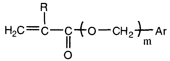
여기서, R은 H 또는 CH3이고; m은 0 내지 6으로부터 선택된 정수이고; Ar은 치환되지 않거나 또는 H, CH3, C2H5, n-C3H7, 이소-C3H7, OCH3, OH, C(O)OH로 치환될 수 있는 임의의 방향족 고리, 예를 들어 페닐이다. Wherein, R is H or CH 3, and; m is an integer selected from 0 to 6; Ar is optionally substituted or H, CH 3, C 2 H 5, nC 3 H 7, iso -C 3 H 7, OCH 3, OH, C (O) any aromatic ring which may be substituted by OH, e. Lt; / RTI >
전형적인 방향족 (메트)아크릴레이트 단량체는 2-에틸페녹시 (메트)아크릴레이트, 2-에틸티오페닐 (메트)아크릴레이트, 2-에틸아미노페닐 (메트)아크릴레이트, 페닐-(메트)아크릴레이트, 벤질 (메트)아크릴레이트, 2-페닐에틸 (메트)아크릴레이트, 3-페닐프로필-(메트)아크릴레이트, 4-페닐부틸(메트)아크릴레이트, 4-메틸페닐 (메트)아크릴레이트, 4-메틸벤질 (메트)아크릴레이트, 2,2-메틸페닐에틸 (메트)아크릴레이트, 2,3-메틸페닐에틸 (메트)아크릴레이트, 2,4-메틸페닐에틸 (메트)아크릴레이트, 2-(4-프로필페닐)에틸 (메트)아크릴레이트, 2-(4-(1-메틸에틸)페닐)에틸 메타크릴레이트, 2-(4-메톡시페닐)에틸 메타크릴레이트 및 기타 등등을 포함하지만, 이에 제한되지 않는다. "(메트)아크릴레이트"라는 용어는 아크릴레이트 또는 메타크릴레이트 중합가능 관능기를 가지는 단량체를 의미한다.Typical aromatic (meth) acrylate monomers include 2-ethylphenoxy (meth) acrylate, 2-ethylthiophenyl (meth) acrylate, 2- ethylaminophenyl (meth) (Meth) acrylate, 4-methylphenyl (meth) acrylate, 4-methylphenyl (meth) acrylate, Benzyl (meth) acrylate, 2,2-methylphenylethyl (meth) acrylate, 2,3-methylphenylethyl (meth) acrylate, But are not limited to, ethyl (meth) acrylate, 2- (4- (1-methylethyl) phenyl) ethyl methacrylate, 2- (4-methoxyphenyl) ethyl methacrylate, . The term "(meth) acrylate" means a monomer having an acrylate or methacrylate polymerizable functional group.
일반적으로, 광학 중합체 물질이 상기 화학식에 의해 정의된 방향족 아크릴레이트 및 방향족 메타크릴레이트 둘 모두로 제조되는 경우, 그 물질은 일반적으로 아릴 메타크릴레이트 에스테르 잔기의 몰 백분율보다 더 큰 몰 백분율의 아릴 아크릴레이트 에스테르 잔기를 포함할 것이다. 아릴 아크릴레이트 단량체가 중합체의 약 60 몰% 내지 약 90 몰%를 구성하고, 한편, 아릴 메타크릴레이트 단량체가 중합체의 약 5 몰% 내지 약 40 몰%를 구성하는 것이 바람직하다. 가장 바람직한 것은 약 60 - 70 몰%의 2-페닐에틸 아크릴레이트 및 약 30 - 40 몰%의 2-페닐에틸 메타크릴레이트를 포함하는 중합체이다.Generally, when the optical polymer material is made of both aromatic acrylate and aromatic methacrylate as defined by the above formula, the material will generally have a mole percentage greater than the mole percent of aryl methacrylate ester residues, Lt; / RTI > ester moiety. It is preferred that the aryl acrylate monomer constitutes from about 60 mole percent to about 90 mole percent of the polymer while the aryl methacrylate monomer constitutes from about 5 mole percent to about 40 mole percent of the polymer. Most preferred is a polymer comprising about 60 to 70 mole percent 2-phenylethyl acrylate and about 30 to 40 mole percent 2-phenylethyl methacrylate.
다른 한 실시태양에서, 광학 중합체 물질은 5 중량% 내지 15 중량%의 완전 수화된(평형) 함수율을 가질 것이고, 이것은 또한 기술된 열 응력에 뒤따르는 탁도를 최소화하는 것을 도울 뿐만 아니라 생체 내에서 수포 생성을 최소화하는 것을 돕는다. 요망되는 함수율을 달성하기 위해, 본 출원인은 중합가능 조성물에 화학식 G-D-Ar(여기서, Ar은 친수성 치환체를 가지는 C6-C14 방향족 기임)을 가지는 친수성 방향족 단량체를 포함할 수 있다는 것을 발견하였다. D는 2가 연결기이고, G는 중합가능 에틸렌 부위이다.In another embodiment, the optical polymer material will have a fully hydrated (equilibrium) moisture content of 5 wt% to 15 wt%, which not only helps to minimize turbidity following the described thermal stresses, It helps to minimize the generation. To achieve the desired water content, Applicants have discovered that the polymerizable composition can comprise a hydrophilic aromatic monomer having the formula GD-Ar, wherein Ar is a C 6 -C 14 aromatic group with a hydrophilic substituent. D is a divalent linking group, and G is a polymerizable ethylene moiety.
한 특별한 친수성 방향족 단량체는 하기 화학식으로 나타내어진다.One particular hydrophilic aromatic monomer is represented by the following formula.

(여기서, R은 수소 또는 CH3이고; D는 직쇄 또는 분지쇄 C1-C10 탄화수소로 이루어지는 군으로부터 선택된 2가 기이고, E는 카르복시, 카르복스아미드 및 1가 및 다가 알콜 치환체로 이루어지는 군으로부터 선택된다. 전형적인 친수성 치환체는 -COOH, -CH2-, CH2OH, -(CHOH)2CH2OH, -CH2-CHOH-CH2OH, 폴리(알킬렌 글리콜), -C(O)O-NH2 및 -C(O)-N(CH3)2를 포함하지만, 이에 제한되지 않는다.(Wherein R is hydrogen or CH 3 ; D is a divalent group selected from the group consisting of straight or branched C 1 -C 10 hydrocarbons, E is a group consisting of carboxy, carboxamide and monohydric and polyhydric alcohol substituents Typical hydrophilic substituents include, but are not limited to, -COOH, -CH 2 -, CH 2 OH, - (CHOH) 2 CH 2 OH, -CH 2 -CHOH-CH 2 OH, poly (alkylene glycol) ) O-NH 2, and -C (O) -N (including CH 3) 2, but is not limited to this.
전형적인 친수성 방향족 단량체는 하기 화학식으로 나타내어진다:Typical hydrophilic aromatic monomers are represented by the formula:

(여기서, R은 수소 또는 CH3이고, R1은 -C(O)O-NH2 또는 -C(O)-N(CH3)2임)Wherein R is hydrogen or CH 3 and R 1 is -C (O) O-NH 2 or -C (O) -N (CH 3 ) 2 .
다른 한 실시태양에서, 광학 중합체 물질은 5 - 25 중량%의 양으로 존재하는 제 1 아릴 단량체 성분; 30 내지 70 중량%의 양으로 존재하는 제 2 단량체 성분인 2-히드록시에틸 (메트)아크릴레이트; 및 5 내지 45 중량%의 메틸 (메트)아크릴레이트, 에틸 (메트)아크릴레이트, 프로필 (메트)아크릴레이트, 부틸 (메트)아크릴레이트, 펜틸 (메트)아크릴레이트, 헥실 (메트)아크릴레이트, 헵틸 (메트)아크릴레이트, 노닐 (메트)아크릴레이트, 스테아릴 (메트)아크릴레이트, 옥틸 (메트)아크릴레이트, 데실 (메트)아크릴레이트, 라우릴 (메트)아크릴레이트, 펜타데실 (메트)아크릴레이트, 및 2-에틸헥실 (메트)아크릴레이트로 이루어지는 군으로부터 선택되는 다른 알킬 (메트)아크릴레이트로부터 제조된다. 알킬 (메트)아크릴레이트 중에서, 1 내지 3 개의 탄소 원자를 가지는 알킬기를 함유하는 것이 바람직하다.In another embodiment, the optical polymer material comprises a first aryl monomer component present in an amount of from 5 to 25% by weight; 2-hydroxyethyl (meth) acrylate as a second monomer component present in an amount of 30 to 70% by weight; (Meth) acrylate, pentyl (meth) acrylate, hexyl (meth) acrylate, heptyl (meth) acrylate, (Meth) acrylate, nonyl (meth) acrylate, stearyl (meth) acrylate, octyl (meth) acrylate, decyl (Meth) acrylate, and 2-ethylhexyl (meth) acrylate. Of the alkyl (meth) acrylates, those containing an alkyl group having 1 to 3 carbon atoms are preferred.
전형적인 아릴 단량체 성분은 에틸렌 글리콜 페닐 에테르 아크릴레이트(EGPEA), 폴리(에틸렌 글리콜 페닐 에테르 아크릴레이트)(폴리EGPEA), 페닐 메타크릴레이트, 2-에틸페녹시 메타크릴레이트, 2-에틸페녹시 아크릴레이트, 헥실페녹시 메타크릴레이트, 헥실페녹시 아크릴레이트, 벤질 메타크릴레이트, 2-페닐에틸 메타크릴레이트, 4-메틸페닐 메타크릴레이트, 4-메틸벤질 메타크릴레이트, 2,2-메틸페닐에틸 메타크릴레이트, 2,3-메틸페닐에틸 메타크릴레이트, 2,4-메틸페닐에틸 메타크릴레이트, 2-(4-프로필페닐)에틸 메타크릴레이트, 2-(4-(1-메틸에틸)페닐)에틸 메타크릴레이트, 2-(4-메톡시페닐)에틸 메타크릴레이트, 2-(4-시클로헥실페닐)에틸 메타크릴레이트, 2-(2-클로로페닐)에틸 메타크릴레이트, 2-(3-클로로페닐)에틸 메타크릴레이트, 2-(4-클로로페닐)에틸 메타크릴레이트, 2-(4-브로모페닐)에틸 메타크릴레이트, 2-(3-페닐페닐)에틸 메타크릴레이트, 2-(4-페닐페닐)에틸 메타크릴레이트, 2-(4-벤질페닐)에틸 메타크릴레이트, 및 기타 등등을 포함하고, 상응하는 메타크릴레이트 및 아크릴레이트를 포함하고, 이들의 혼합물을 포함한다. EGPEA 및 폴리EGPEA가 더 바람직한 제 1 단량체 성분 중 2 개이다.Typical aryl monomer components include ethylene glycol phenyl ether acrylate (EGPEA), poly (ethylene glycol phenyl ether acrylate) (poly EGPEA), phenyl methacrylate, 2-ethyl phenoxy methacrylate, 2-ethyl phenoxy acrylate , Hexylphenoxy methacrylate, hexylphenoxy acrylate, benzyl methacrylate, 2-phenylethyl methacrylate, 4-methylphenyl methacrylate, 4-methylbenzyl methacrylate, 2,2- Methylphenyl ethyl methacrylate, 2- (4-propylphenyl) ethyl methacrylate, 2- (4- (1-methylethyl) 2- (4-methoxyphenyl) ethyl methacrylate, 2- (4-cyclohexylphenyl) ethyl methacrylate, 2- Phenyl) ethyl methacrylate, 2- (4-chlorophenyl) ethyl methane 2- (4-bromophenyl) ethyl methacrylate, 2- (4-phenylphenyl) ethyl methacrylate, 2- ) Ethyl methacrylate, and the like, and includes corresponding methacrylates and acrylates, and mixtures thereof. EGPEA and poly EGPEA are two of the more preferred first monomer components.
다른 한 실시태양에서, 광학 중합체 물질은 약 90 중량%의 N-비닐피롤리돈(NVP) 및 약 10 중량%의 4-t-부틸-2-히드록시시클로헥실 메타크릴레이트를 포함하는 친수성 아크릴로부터 제조된다. 이 메타크릴레이트 히드로겔은 높은 백분율의 NVP 때문에 약 80 중량%의 물을 흡수할 수 있다. 수화될 때, 그의 굴절률은 물의 굴절률에 매우 가깝다. 관심을 끄는 다른 한 친수성 아크릴은 약 0.9 중량%의 에틸렌 글리콜 디메타크릴레이트("EGDMA")와 가교된 폴리(2-히드록시에틸 메타크릴레이트)인 HEMA B라고 불리는 것이다. 이 HEMA-히드로겔은 약 37 중량%의 물을 흡수할 수 있다.In another embodiment, the optical polymer material comprises a hydrophilic acrylic polymer comprising about 90% by weight of N-vinylpyrrolidone (NVP) and about 10% by weight of 4-t-butyl-2-hydroxycyclohexyl methacrylate . This methacrylate hydrogel can absorb about 80% by weight of water due to a high percentage of NVP. When hydrated, its refractive index is very close to the refractive index of water. Another hydrophilic acrylate of interest is what is referred to as HEMA B, which is about 0.9 wt% ethylene glycol dimethacrylate ("EGDMA") and crosslinked poly (2-hydroxyethyl methacrylate). The HEMA-hydrogel is capable of absorbing about 37% by weight of water.
관심을 끄는 한 특별한 친수성 아크릴 물질은 바슈 앤 롬이 아크레오스(등록상표)라는 상표명으로 시장에서 판매하는 상업적으로 입수가능한 IOL을 기반으로 한다. 이 아크릴 물질은 약 80 중량%의 HEMA 및 20 중량%의 MMA를 포함한다.One particular hydrophilic acrylic material of interest is based on a commercially available IOL marketed by BASF and ROM under the trade name ARCREOS (R). This acrylic material comprises about 80 wt% HEMA and 20 wt% MMA.
또, 광학 중합체 물질은 퍼플루오로옥틸에틸옥시프로필렌 (메트)아크릴레이트, 2-페닐에틸 (메트)아크릴레이트, 하기 화학식을 가지는 알킬 (메트)아크릴레이트 단량체 및 가교 단량체를 포함하는 특정 단량체 혼합물을 공중합함으로써 제조할 수 있다.The optical polymer material may also include a specific monomer mixture comprising perfluorooctylethyloxypropylene (meth) acrylate, 2-phenylethyl (meth) acrylate, alkyl (meth) acrylate monomers having the formula: Can be produced by copolymerization.

여기서, R은 수소 또는 메틸이고, R1은 직쇄 또는 분지쇄 C4-C12 알킬기이다. 알킬 (메트)아크릴레이트 단량체의 전형적인 목록은 n-부틸 아크릴레이트, 이소부틸 아크릴레이트, 이소아밀 아크릴레이트, 헥실 아크릴레이트, 2-에틸헥실 아크릴레이트, 옥틸 아크릴레이트, 이소옥틸 아크릴레이트, 데실 아크릴레이트, 이소데실 아크릴레이트 및 기타 등등을 포함한다.Wherein R is hydrogen or methyl and R < 1 > is a straight or branched C 4 -C 12 alkyl group. A typical list of alkyl (meth) acrylate monomers is n-butyl acrylate, isobutyl acrylate, isoamyl acrylate, hexyl acrylate, 2-ethylhexyl acrylate, octyl acrylate, isooctyl acrylate, decyl acrylate , Isodecyl acrylate, and the like.
퍼플루오로옥틸에틸옥시프로필렌 (메트)아크릴레이트는 5 중량% 내지 20 중량%의 양으로 존재하고, 2-페닐에틸 (메트)아크릴레이트는 40 중량% 내지 60 중량%의 양으로 존재하고, 알킬 (메트)아크릴레이트 단량체는 30 중량% 내지 50 중량%의 양으로 존재하고, 가교제는 0.5 중량% 내지 4 중량%의 양으로 존재한다.Perfluorooctylethyloxypropylene (meth) acrylate is present in an amount of 5 to 20 wt%, 2-phenylethyl (meth) acrylate is present in an amount of 40 to 60 wt%, and the alkyl (Meth) acrylate monomer is present in an amount of 30 wt% to 50 wt%, and the crosslinking agent is present in an amount of 0.5 wt% to 4 wt%.
또, 광학 중합체 물질은 12 내지 18 몰%의 화학식 R4R5-SiO의 아릴 치환 실록산 단위를 함유하는 중합체를 포함하는 보강된 가교된 실리콘 엘라스토머로부터 제조될 수 있다. 이 화학식에서, R4 및 R5는 동일하거나 또는 상이하고, 페닐, 모노-저급 알킬 치환 페닐기 또는 디-저급 알킬 치환 페닐기를 나타낸다. 바람직하게는, R4 및 R5는 페닐이다. The optical polymer material may also be prepared from a reinforced crosslinked silicone elastomer comprising a polymer containing from 12 to 18 mole percent of aryl substituted siloxane units of the formula R 4 R 5 -SiO. In this formula, R 4 and R 5 are the same or different and represent a phenyl, a mono-lower alkyl substituted phenyl group or a di-lower alkyl substituted phenyl group. Preferably, R 4 and R 5 are phenyl.
중합체는 화학식 R1R2R3-SiO5(여기서, R1 및 R2는 알킬, 아릴 또는 치환된 알킬 또는 치환된 아릴기이고, R1 및 R2는 동일하거나 또는 상이할 수 있음)의 실록산 단위를 함유하는 말단 차단 부위를 가진다. 말단 블록킹 실록산 단위의 R3기는 알케닐기이다. 바람직하게는, 말단 차단 부위는 디메틸비닐 실록산 단위이다.The polymer may be of the formula R 1 R 2 R 3 -SiO 5 wherein R 1 and R 2 are alkyl, aryl or substituted alkyl or substituted aryl groups and R 1 and R 2 may be the same or different Lt; RTI ID = 0.0 > siloxane < / RTI > units. The R 3 group of the terminal blocking siloxane unit is an alkenyl group. Preferably, the terminal blocking moiety is a dimethylvinylsiloxane unit.
중합체의 나머지 부분은 화학식 R6R7-SiO(여기서, R6 및 R7은 동일 또는 상이하고, 메틸 또는 에틸기임)의 디알킬 실록산 단위로 이루어지고, 중합체는 100 내지 2000의 중합도를 가진다. 바람직하게는, R6 및 R7은 둘 모두 메틸이고, 중합도는 약 250이다.The remainder of the polymer consists of dialkylsiloxane units of the formula R 6 R 7 -SiO wherein R 6 and R 7 are the same or different and are methyl or ethyl groups, and the polymer has a degree of polymerization of from 100 to 2000. Preferably, R < 6 > and R < 7 > are both methyl and have a degree of polymerization of about 250.
트리메틸 실릴로 처리된 실리카 보강제가 중합체에 중합체 100 부 당 보강제 약 15 내지 45 부의 중량비로 미세 분산된다. 바람직하게는, 공중합체 100 부 당 보강제 약 27 부가 있다.The trimethylsilyl-treated silica reinforcing agent is finely dispersed in the polymer at a weight ratio of about 15 to 45 parts of the reinforcing agent per 100 parts of the polymer. Preferably, there are about 27 reinforcing agents per 100 parts of the copolymer.
광학 중합체 성분은 가교제를 포함할 것이다. 본 발명의 공중합체 물질을 생성하는 데 유용한 공중합가능 가교제(들)는 하나 초과의 불포화기를 가지는 말단이 에틸렌성 불포화된 어떠한 화합물도 포함한다. 바람직하게는, 가교제는 디아크릴레이트 또는 디메타크릴레이트를 포함한다. 또, 가교제는 둘 이상의 (메트)아크릴레이트 및/또는 비닐기를 가지는 화합물을 포함할 수 있다. 특히 바람직한 가교제는 디아크릴레이트 화합물을 포함한다. The optical polymer component will comprise a crosslinking agent. The copolymerizable cross-linking agent (s) useful for producing the copolymer material of the present invention includes any ethylenically unsaturated compound having one or more unsaturated groups. Preferably, the crosslinking agent comprises diacrylate or dimethacrylate. In addition, the crosslinking agent may include a compound having two or more (meth) acrylates and / or vinyl groups. Particularly preferred crosslinking agents include diacrylate compounds.
광학 중합체 물질은 각 단량체 성분으로부터 일반적인 통상의 중합 방법에 의해 제조된다. 선택된 양의 단량체들의 중합 혼합물을 제조하고, 통상의 열적 자유 라디칼 개시제를 첨가한다. 혼합물을 적당한 모양의 금형에 도입하여 광학 물질을 생성하고, 온화하게 가열함으로써 중합을 개시한다. 대표적인 열적 자유 라디칼 개시제는 퍼옥시드, 예를 들어 벤조페논 퍼옥시드, 퍼옥시카르보네이트, 예를 들어 비스-(4-t-부틸시클로헥실)퍼옥시디카르보네이트, 아조니트릴, 예를 들어 아조비스이소부티로니트릴 및 기타 등등을 포함한다. 바람직한 개시제는 비스-(4-t-부틸시클로헥실)퍼옥시디카르보네이트(PERK)이다. 별법으로, 단량체는 이들 아크릴 단량체의 중합을 단독으로 개시할 수 있는 파장의 화학 방사선에 대해 투명한 금형을 이용함으로써 광중합될 수 있다. 중합을 촉진하기 위해 통상의 광개시제 화합물, 예를 들어 벤조페논형 광개시제도 도입될 수 있다.The optical polymer material is prepared from each monomer component by conventional customary polymerization methods. A polymerization mixture of the selected amount of monomers is prepared, and a conventional thermally free radical initiator is added. The mixture is introduced into a mold of an appropriate shape to produce an optical material, and the polymerization is initiated by gentle heating. Exemplary thermally free radical initiators include peroxides such as benzophenone peroxide, peroxycarbonates such as bis- (4-t-butylcyclohexyl) peroxydicarbonate, azonitriles such as azo Bisisobutylonitrile, and the like. A preferred initiator is bis- (4-t-butylcyclohexyl) peroxydicarbonate (PERK). Alternatively, the monomers can be photopolymerized by using a transparent mold for actinic radiation at a wavelength that can initiate polymerization of these acrylic monomers alone. Conventional photoinitiator compounds such as benzophenone type photoinitiators may also be introduced to facilitate polymerization.
본 발명의 특정 실시태양을 앞에서 기술하였지만, 당업계 숙련자는 특허 청구 범위에 정의된 본 발명의 정신 및 범위에서 벗어남이 없이 많은 동등물, 변경, 치환 및 변화를 가할 수 있음을 인식할 것이다.Although specific embodiments of the invention have been described above, those skilled in the art will recognize that many equivalents, changes, substitutions and changes can be made without departing from the spirit and scope of the invention as defined in the claims.
실시예Example
실시예 1. 17% 쿠마린-1을 가지는 아크레오스(등록상표) IOL의 제조 Example 1. Preparation of Acreos (R) IOL with 17% coumarin-1
2.5 g의 쿠마린-1 염료를 10 ㎖의 에탄올 및 5 ㎖의 물을 함유하는 에탄올-물 혼합물에 용해하였다. 아크레오스 샘플의 건조 중량을 기록하였다. 샘플을 순수한 물에서 수화하여 질량을 기록하였다. 수화 단계 후, 일정 질량에 도달할 때까지 샘플을 쿠마린-1 염료를 함유하는 에탄올-물 혼합물에 침지하였다. 염료 용액에 침지한 후의 질량을 기록하였다. 도핑된 염료의 질량은 용액에 침지한 후의 질량과 건조 질량 사이의 차에 에탄올-물 용액 중의 염료의 질량 농도를 곱해서 계산하였다. 도핑된 염료의 백분율은 건조 질량에 대한 도핑된 쿠마린-1 염료의 질량의 비에 100을 곱해서 계산하였다.2.5 g of coumarin-1 dye was dissolved in an ethanol-water mixture containing 10 ml of ethanol and 5 ml of water. The dry weight of the acreos sample was recorded. The sample was hydrated in pure water and the mass recorded. After the hydration step, the sample was immersed in an ethanol-water mixture containing coumarin-1 dye until a constant mass was reached. The mass after immersion in the dye solution was recorded. The mass of the doped dye was calculated by multiplying the difference between the mass and the dry mass after immersion in the solution by the mass concentration of the dye in the ethanol-water solution. The percentage of the doped dye was calculated by multiplying the ratio of the mass of the doped coumarin-1 dye to the dry mass by 100.
실시예 2. 아크레오스(등록상표) IOL 물질에 구조 생성 Example 2. Creation of a structure in an Acreos (R) IOL material
기술된 광학 시스템을 이용해서 광학 물질의 선택된 영역에 선 구조를 생성하였다. 실험은 감광제를 갖는 아크레오스(등록상표) IOL 물질 및 감광제가 없는 아크레오스(등록상표) IOL 물질로 수행하였다. 아크레오스(등록상표) IOL 물질은 약 80 중량%의 HEMA 및 20 중량%의 MMA를 포함하고, 상기한 유사한 방법 조건을 이용해서 약 26%의 함수율을 가진다.The optical system described was used to create line structures in selected areas of the optical material. The experiment was carried out with an Acreos (R) IOL material with a photosensitizer and an Acreos (R) IOL material without a photosensitizer. The Acreos (R) IOL material comprises about 80 wt% HEMA and 20 wt% MMA and has a water content of about 26% using similar process conditions as described above.
수화된 샘플을 스캐닝 플랫폼에 수평으로 탑재하고, 펨토초 레이저 빔을 높은 개구수를 가지는 대물렌즈를 통해 아래 방향으로 수직으로 향하게 하고, 도 7에 나타낸 바와 같이 벌크 물질의 내부에 샘플의 상부 표면으로부터 약 100 ㎛의 깊이에 집속하였다. 레이저 빔에 대해 수직인 X-Y 평면에 0.4 ㎛/초의 스캐닝 속도로 주기적 격자 구조를 생성하였다. 올림푸스 BX51 모델 현미경을 이용해서 이들 세 물질 내부에 생성된 격자를 관찰하였다.The hydrated sample is horizontally mounted on a scanning platform and the femtosecond laser beam is directed vertically downward through an objective lens having a high numerical aperture and is moved from the upper surface of the sample to the inside of the bulk material And focused at a depth of 100 mu m. A periodic lattice structure was created at a scanning rate of 0.4 μm / sec in the X-Y plane perpendicular to the laser beam. The lattices generated in these three materials were observed using an Olympus BX51 model microscope.
현미경 사진은 샘플 내부에 5 ㎛ 간격을 가지는 주기적으로 평행한 격자를 보여주었다. 격자는 명시야 현미경으로는 보기 어려웠고, 이것은 이 격자가 낮은 산란을 나타낸다는 것을 가리킨다. 격자의 폭은 약 1 ㎛이었고, 이것은 칼날 방법(knife-edge method)을 이용해서 측정한 2.5 ㎛의 레이저 초점 직경보다 상당히 작다. 따라서, 이 과정에서 열 축적이 있을지라도, 개질된 영역은 여전히 레이저 조사 초점 부피 내에 있다. The micrographs showed periodically parallel gratings with 5 μm spacing inside the sample. The lattice was difficult to see with a bright field microscope, indicating that this lattice exhibits low scattering. The width of the grating was about 1 micrometer, which is significantly smaller than the laser focal diameter of 2.5 micrometers measured using the knife-edge method. Thus, even though there is heat accumulation in this process, the modified area is still within the laser irradiation focus volume.
조사된 물질의 횡단면은 격자의 횡단면이 레이저 빔의 방향으로 배향되는 장축을 가지는 타원임을 나타냈고, 이것은 이 방향으로 더 큰 레이저 강도 분포가 있었다는 것을 가리킨다. 대물렌즈의 커버슬립 교정을 조심스럽게 조정함으로써, 이 구면수차를 최소화할 수 있다.The cross-section of the irradiated material indicated that the cross-section of the lattice was an ellipse having a long axis oriented in the direction of the laser beam, indicating that there was a larger laser intensity distribution in this direction. By carefully adjusting the cover slip correction of the objective lens, this spherical aberration can be minimized.
도 8a 및 8b에서 나타내는 바와 같이, 아크레오스(등록상표) IOL에 쿠마린-1의 혼입은 아크레오스(등록상표) IOL 물질의 투과 스펙트럼에 약 50 ㎚의 적색 천이를 제공하였다. 쿠마린-1을 가지는 아크레오스(등록상표) IOL 물질은 400 ㎚ 및 약 425 ㎚에서 상대적으로 상당한 흡수 프로파일을 가지고, 반면, 감광제가 없는 아크레오스(등록상표) IOL 물질은 이 파장에서 본질적으로 투명하다.As shown in Figures 8a and 8b, the incorporation of coumarin-1 in the Acreos (R) IOL provided a red shift of about 50 nm in the transmission spectrum of the Acreos (R) IOL material. The Acreos (R) IOL material with coumarin-1 has a relatively significant absorption profile at 400 nm and about 425 nm, whereas the Acreos (R) IOL material without the photosensitizer is essentially transparent at this wavelength .
도 9a 및 9b는 물질 내에 상부 조사 표면으로부터 약 200 ㎛의 깊이에 미세기계가공된 굴절 구조를 가지는 아크레오스(등록상표) IOL 물질의 위상 대비 사진이다. 조사 방법은 160 mW의 평균 출력 및 50 ㎛/초의 스캔 속도로 수행하였다. 도 9a에 나타낸 바와 같이, 감광제가 없는 아크레오스(등록상표) IOL 물질에 미세기계가공된 굴절 구조는 △RI가 <<0.005(구조의 볼 수 있는 검출 한계)로서 굴절률 변화를 제공한다 하더라도 거의 제공하지 않는다. 사실상, 위상 대비 증강을 한 경우조차도 물질 내의 굴절 구조를 보기가 매우 어렵다. 대조적으로, 도 9b에 나타낸 바와 같이, 동일한 출력 및 스캔 속도로 17% 쿠마린-1을 가지는 아크레오스(등록상표) IOL 물질에 미세기계가공된 굴절 구조는 △RI가 >0.06으로서 매우 상당한 굴절률 변화를 제공한다. 위상 대비 증강으로 굴절 구조가 뚜렷하게 보인다.Figures 9a and 9b are phase contrast photographs of an Arreos (R) IOL material having a refracting structure micromachined at a depth of about 200 [mu] m from the top irradiated surface in the material. The irradiation method was performed with an average power of 160 mW and a scan speed of 50 m / sec. As shown in FIG. 9A, the refractory structure micromachined into the acrylic-free IOL material without a photoresist provides almost no refractivity even though Δ RI provides a refractive index change of << 0.005 (visible detection limit of the structure) I never do that. In fact, even with phase contrast enhancement, it is very difficult to see the refractive structure in the material. In contrast, as shown in FIG. 9B, the refracting structure micromachined to an Arreos (R) IOL material having 17% coumarin-1 at the same output and scan rate exhibited a very significant refractive index change as? RI > 0.06 to provide. The refraction structure is apparent due to the phase contrast enhancement.
도 10a 및 도 10b는 미세기계가공된 구조의 굴절력 차가 스캔 속도 및 레이저 출력을 기초로 얼마나 변할 수 있는가를 나타낸다. 더 중요한 것은, 도 10a는 1 ㎜/초의 스캔 속도로 17% 쿠마린-1을 갖는 아크레오스(등록상표) IOL 물질에 약 0.02 내지 0.3의 △RI를 가지는 굴절 구조를 생성할 수 있다는 것을 보여준다. 이것은 감광제가 없는 아크레오스(등록상표) IOL 물질에 유사한 굴절 구조를 생성하기 위해서는 약 10 ㎛/초로 스캐닝해야하기 때문에 매우 놀랍고 흥분시키는 결과이다. 쿠마린-1의 존재는 스캔 속도를 거의 100 배 증가시킬 수 있게 한다. 게다가, 상대적으로 낮은 레이저 출력, 즉 60 mW로도, 약 0.005의 △RI를 가지는 굴절 구조를 여전히 생성할 수 있다.10A and 10B show how the difference in refractive power of the micromachined structure can vary based on the scan speed and the laser output. More importantly, FIG. 10A shows that an Arreos.RTM. IOL material with 17% coumarin-1 at a scan rate of 1 mm / sec can produce a refractive structure with a DELTA RI of about 0.02 to 0.3. This is a surprising and exciting result because it requires scanning at about 10 [mu] m / second to produce a refracting structure similar to the acrylic-free IOL material without the photosensitizer. The presence of coumarin-1 allows a nearly 100-fold increase in scan speed. In addition, a relatively low laser power, i.e. 60 mW, can still produce a refractive structure with a DELTA RI of about 0.005.
실시예 3. 0.07 중량% 플루오레세인을 가지는 퓨어 비전(등록상표)(Pure Vision®) 실리콘 히드로겔의 제조 Example 3. Preparation of Pure Vision (R) Silicone Hydrogel with 0.07 wt% Fluorescein
0.25 g의 플루오레세인 염료를 50 ㎖의 에탄올 및 50 ㎖의 물을 함유하는 에탄올-물 혼합물에 용해하였다. 퓨어 비전 샘플의 건조 중량을 기록하였다. 샘플을 순수한 물에서 수화하고, 질량을 기록하였다. 수화 단계 후, 샘플을 일정 질량에 도달할 때까지 플루오레세인 염료를 함유하는 에탄올-물 혼합물에 침지하였다. 염료 용액에 침지한 후의 질량을 기록하였다. 도핑된 염료의 질량은 용액에 침지한 후의 질량과 에탄올-물 용액 중의 염료의 질량 농도를 곱한 건조 질량 사이의 차로서 계산하였다. 도핑된 염료의 백분율은 건조 질량에 대한 도핑된 플루오레세인 염료 질량의 비에 100을 곱함으로써 계산하였다.0.25 g of the fluorescein dye was dissolved in an ethanol-water mixture containing 50 ml of ethanol and 50 ml of water. The dry weight of the pure vision sample was recorded. The sample was hydrated in pure water and the mass recorded. After the hydration step, the sample was immersed in an ethanol-water mixture containing the fluorescein dye until a constant mass was reached. The mass after immersion in the dye solution was recorded. The mass of the doped dye was calculated as the difference between the mass after immersion in the solution and the dry mass multiplied by the mass concentration of the dye in the ethanol-water solution. The percentage of the doped dye was calculated by multiplying the ratio of the doped fluorousine dye mass to the dry mass by 100.
실시예 4. 발라필콘 A 실리콘 히드로겔에 구조 생성 Example 4. Balacilcon A Silicon hydrogel < RTI ID = 0.0 >
실시예 2에 기술된 광학 시스템을 이용해서 수화된 발라필콘 A(퓨어 비전(등록상표)) 실리콘 히드로겔 물질의 선택된 영역에 선 구조를 생성하였다. 감광제인 플루오레세인을 갖는 경우의 실험과 플루오레세인이 없는 경우의 실험을 수행하였다.A linear structure was created in a selected region of the Balacilcon A (Pure Vision TM) silicone hydrogel material hydrated using the optical system described in Example 2. [ Experiments were conducted in the case of fluorescein, which is a photosensitizer, and in the case of fluorescein, in the absence of fluorescein.
도 11a 및 도 11b에 나타낸 바와 같이, 발라필콘 A 실리콘 히드로겔에 플루오레세인 혼입은 투과 스펙트럼에서 150 ㎚ 이상의 적색 이동을 제공하였다. 플루오레세인을 갖는 발라필콘 A 실리콘 히드로겔은 500 ㎚에서 상대적으로 상당한 흡수 프로파일을 가졌고(도 12b), 반면, 감광제가 없는 실리콘 히드로겔은 이 파장에서 본질적으로 투명하다(도 12a).As shown in FIGS. 11A and 11B, the incorporation of fluorescein in the Balakrone A silicone hydrogel gave a red shift of 150 nm or more in the transmission spectrum. The Balaculcone A silicone hydrogel with fluororesin had a relatively significant absorption profile at 500 nm (Fig. 12b), whereas the silicone-free gel without photosensitizer was essentially transparent at this wavelength (Fig. 12a).
도 12a는 상부 조사 표면으로부터 약 200 ㎛의 깊이에 미세기계가공된 발라필콘 A 실리콘 히드로겔의 위상 대비 사진이다. 조사 방법은 60 mW 및 0.5 ㎛/초의 스캔 속도로 수행하였다. 도 12a에 나타낸 바와 같이, 감광제가 없는 발라필콘 A 실리콘 히드로겔에 미세기계가공된 굴절 구조는 △RI가 <<0.005(구조의 볼 수 있는 검출 한계)로서 굴절률 변화를 제공한다 하더라도 거의 제공하지 않는다. 사실상, 위상 대비 증강을 한 경우조차도 물질 내의 굴절 구조를 보기가 매우 어렵다. 대조적으로, 도 12b에 나타낸 바와 같이, 동일한 출력 및 5.0 ㎛/초의 스캔 속도(도핑되지 않은 발라필콘 A에 비해 10 배 증가)로 0.17 중량% 플루오레세인을 가지는 발라필콘 A 실리콘 히드로겔에 미세기계가공된 굴절 구조는 △RI가 약 0.02 내지 0.03으로 매우 상당한 굴절률 변화를 제공하였다. 위상 대비 증강으로 굴절 구조가 뚜렷이 눈에 보였다. 게다가, 상대적으로 낮은 레이저 출력, 즉 60 mW로도, 1 ㎜/초의 스캔 속도로 약 0.01의 △RI를 가지는 굴절 구조를 여전히 생성할 수 있었다.12A is a phase contrast photograph of a Balaklein A silicone hydrogel micro-machined to a depth of about 200 [mu] m from the top irradiated surface. The irradiation method was carried out at a scanning speed of 60 mW and 0.5 m / sec. As shown in FIG. 12A, the refractory structure micromachined into the Balakrone A silicone hydrogel without photosensitizer provides little, if any, of the refractive index change as < RTI ID = 0.0 > . In fact, even with phase contrast enhancement, it is very difficult to see the refractive structure in the material. In contrast, as shown in Fig. 12B, a Balaklein A silicone hydrogel having the same power and 0.17 wt% fluorescein with a scan rate of 5.0 [mu] m / sec (10-fold increase relative to undoped Balakilcon A) The processed refractive structures provided a very significant change in refractive index with? RI of about 0.02 to 0.03. The refraction structure was clearly visible due to the phase contrast enhancement. In addition, a relatively low laser power, i.e. 60 mW, was still able to produce a refractive structure with a DELTA RI of about 0.01 at a scan rate of 1 mm / sec.
도핑되지 않거나 또는 플루오레세인 또는 쿠마린-1이 도핑된 발라필콘 A 물질에서 굴절률 변화 대 스캔 속도를 나타내는 플롯이 제공된다. 이 플롯은 감광제가 도핑된 히드로겔 물질에서 광 조정 영향의 상당한 증강을 입증하였다. 물질의 도핑은 물질을 통하는 레이저의 스캔 속도를 거의 100 배 정도 증가시켜, 즉 물질에 굴절 구조를 생성하여, 물질 내에서 대등한 굴절률 개질을 달성할 수 있게 한다.Plots showing the change in refractive index versus scan rate in a Balakilcon A material that is not doped or doped with fluorescein or coumarin-1 are provided. This plot demonstrated a significant enhancement of light conditioning effects in the photosensitizer doped hydrogel material. Doping of the material increases the scan speed of the laser through the material by nearly a factor of 100, that is, it creates a refraction structure in the material, thereby achieving a comparable refractive index modification in the material.
실시예 2 및 4에서, 굴절 구조(선 격자)는 이 격자에 632.8 ㎚의 파장을 가지는 비편광 He-Ne 레이저 빔을 집속하고 회절 패턴을 모니터링함으로써 연구하였다. 회절각은 하기 회절 방정식과 양호한 일치를 나타내었다.In Examples 2 and 4, the refraction structure (line grating) was studied by focusing a non-polarized He-Ne laser beam having a wavelength of 632.8 nm in this grating and monitoring the diffraction pattern. The diffraction angles showed good agreement with the following diffraction equation.
![]()
![]()
여기서, m은 회절 차수이고, λ는 입사 레이저 빔의 파장이며, 여기서는 632.8 ㎚이고, d는 격자 주기이다.Here, m is the diffraction order,? Is the wavelength of the incident laser beam, here 632.8 nm, and d is the grating period.
격자의 회절 효율을 측정할 수 있고, 효율은 굴절률 변화의 함수이기 때문에, 그것을 이용해서 레이저 조사 영역에서의 굴절률 변화를 계산할 수 있다. 격자를 위상 격자라고 볼 때, 그의 투과도 함수는 다음과 같이 나타낼 수 있다:Since the diffraction efficiency of the grating can be measured and the efficiency is a function of the refractive index change, it is possible to calculate the refractive index change in the laser irradiation area. Taking the lattice as a phase lattice, its transmittance function can be expressed as:
![]()
![]()
여기서, a는 격자 선 폭이고, d는 홈 간격이고, φ 2 및 φ 1 은 각각 선 및 주변 영역을 통하는 위상 지연으로서, 
![]()
![]()
![]()
![]()
이어서, 격자 회절 패턴의 강도 분포는 다음과 같다:Then, the intensity distribution of the grating diffraction pattern is as follows:
![]()
![]()
이 식으로부터, 0차(I0), 1차(I1) 및 2차(I2) 회절 빛의 강도는 다음과 같다:From this equation, the intensity of the 0th order (I0), the 1st order (I1), and the 2nd order (I2) diffracted light is as follows:

1차, 2차 및 0차 회절 차수의 빛 강도를 비교함으로써, 격자 선 내의 굴절률 변화를 결정할 수 있다. 도 3은 PV2526-164에서 격자의 0차 회절 차수에 대한 1차 회절 차수 및 2차 회절 차수의 강도 비가 각각 0.1374 및 0.0842이고, 분석에 의해 결정되는 상응하는 굴절률 변화가 약 0.06임을 나타낸다. 동일한 방법을 이용해서, 본 발명자들은 RD1817 및 HEMA B에서의 평균 굴절률 변화가 0.05 ± 0.0005 및 0.03 ± 0.0005임을 결정하였다. 따라서, 초고속 레이저를 물질에 적용함으로써 물질의 굴절률이 개질될 수 있다는 것이 입증되었다.By comparing the light intensities of the first, second and 0th order diffraction orders, it is possible to determine the refractive index change in the grating line. FIG. 3 shows that the intensity ratios of the first order diffraction order and the second order diffraction order to the 0th order diffraction order of the grating in PV2526-164 are 0.1374 and 0.0842, respectively, and the corresponding refractive index change determined by analysis is about 0.06. Using the same method, the present inventors determined that the average refractive index change in RD1817 and HEMA B was 0.05 0.0005 and 0.03 0.0005. Thus, it has been demonstrated that the refractive index of a material can be modified by applying an ultrafast laser to the material.
실시예Example 5 5
다음 실시예에서는 690 ㎚ 내지 1040 ㎚의 튜닝가능 파장 범위에서 100 fs의 펄스 폭 및 80 MHz의 반복률의 펄스를 생성하는 커-렌즈 모드 잠금 Ti:사파이어 레이저(마이타이(MaiTai) HP, 뉴포트(Newport)로부터 입수함)를 이용하는 펨토초 레이저 발진기를 이용하였다. 실험에서는, 대물렌즈의 초점에서 평균 레이저 출력을 가변 감쇠기에 의해 감쇠하고 조정하였고, 히드로겔 중합체에서 총 광학 손상을 피하기 위해 160 mW(2 nJ 펄스 에너지) 미만으로 설정하였다. 100 ㎚ 해상도를 가지는 3 개의 뉴포트 VP-25XA 선형 서보 스테이지가 컴퓨터에 의해 조절되고 프로그래밍될 수 있는 3D 매끄러운 스캐닝 플랫폼을 생성하였다. 초점조절 대물렌즈는 구면수차를 정밀하게 교정할 수 있고 물질 표면 아래의 상이한 깊이에 거의 회절 제한된 레이저 초점을 생성할 수 있는 60X 0.70NA 올림푸스 LUCPlanFLN 긴 작동 거리 대물렌즈였다. In the following example, a Kerr lens mode lock Ti: sapphire laser (MaiTai HP, Newport, NJ) producing a pulse of 100 fs and a repetition rate of 80 MHz in the tunable wavelength range of 690 nm to 1040 nm Newport, Ill.) Was used as a femtosecond laser oscillator. In the experiment, the average laser power at the focus of the objective was attenuated and adjusted by a variable attenuator and set to less than 160 mW (2 nJ pulse energy) to avoid total optical damage in the hydrogel polymer. Three Newport VP-25XA Linear Servo Stages with 100 nm resolution have been created for computer-controlled, 3-D smooth scanning platforms. The focus adjustment objective was a 60X 0.70NA Olympus LUCPlanFLN long working distance objective capable of precisely correcting spherical aberration and producing a diffraction limited laser focus at different depths below the material surface.
레이저 펄스 조사 시퀀스 동안, 광학 히드로겔 중합체 물질을 두 커버 슬립 사이의 샌드위치 구조로 수성 환경 내에서 유지시켰고 스캐닝 플랫폼 상에 수평으로 탑재하였다. 펨토초 레이저 펄스를 초점조절 대물렌즈를 통해 히드로겔 샘플 내부에 수직으로 집속시켰다. 상이한 중합체 히드로겔 및 상이한 평균 레이저 출력과 함께 0.4 ㎛/초 내지 4 ㎜/초의 상이한 수평 스캐닝 속도를 이용하였다. CCD 카메라를 이용해서 조사 과정을 모니터링하여 플라즈마 조명을 검출하였고, 이는 레이저 유도 물질 파괴의 개시를 나타냈다. 레이저 조사 후, 물질을 제거해서 보정된 올림푸스 BX51 현미경 하에서 상이한 모드로 관찰하였다. 조사된 영역의 굴절률 변화를 문헌(L. Ding 등, "Large refractive index change in silicone-based and non-silicone-based hydrogel polymers induced by femtosecond laser micro-machining," Opt. Express 2006, 14, 11901-11909)에 기술된 바와 같은 격자 실험에 의해 또는 보정된 미분 간섭 대비(DIC) 모드 현미경에 의해 측정하였다.During the laser pulse irradiation sequence, the optical hydrogel polymer material was held in an aqueous environment with a sandwich structure between two cover slips and horizontally mounted on a scanning platform. The femtosecond laser pulse was focused vertically into the hydrogel sample through the focusing objective. Different horizontal scanning speeds of 0.4 [mu] m / sec to 4 mm / sec were used with different polymer hydrogels and different average laser powers. The irradiation process was monitored using a CCD camera to detect plasma illumination, which indicated the onset of laser induced breakdown. After laser irradiation, the material was removed and observed under different modes under a calibrated Olympus BX51 microscope. The refractive index change of the irradiated region can be measured by the method described in L. Ding et al., &Quot; Large refractive index change in silicone-based and non-silicone-based hydrogel polymers induced by femtosecond laser micro-machining, Opt.
실시예Example 5A 내지 5D 5A to 5D
히드록시에틸 메타크릴레이트(HEMA), 메틸메타크릴레이트(MMA), 에틸렌 글리콜 디메타크릴레이트(EGDMA) 및 가변 농도의 플루오레세인-메타크릴레이트(플루오-MA)를 포함하는 광학 히드로겔 중합체 물질을 제조해서 표 1에 요약하였다. 83.7 중량%의 HEMA, 13.7 중량%의 MMA, 0.51 중량%의 EGDMA 및 0.1 중량%의 AIBN 개시제를 함유하는 단량체 마스터배치를 제조하였다. 적당한 양의 플루오르-MA를 개별 단량체 제제에 첨가해서 표 1에 실린 언급된 중량%의 플루오르-MA를 가지는 단량체 혼합물을 제공하였다. 단량체 혼합물을 당업계에 잘 알려진 방법에 따라서 중합하고, 700 ㎛ 두께의 편평 필름 형태로 경화하였다.An optical hydrogel polymer comprising hydroxyethyl methacrylate (HEMA), methyl methacrylate (MMA), ethylene glycol dimethacrylate (EGDMA) and variable concentrations of fluorescein-methacrylate (fluoro-MA) The materials were prepared and summarized in Table 1. A monomer master batch containing 83.7 wt.% HEMA, 13.7 wt.% MMA, 0.51 wt.% EGDMA and 0.1 wt.% AIBN initiator was prepared. A suitable amount of fluoro-MA was added to the individual monomer formulations to provide a monomer mixture having the stated weight percent fluoro-MA listed in Table 1. The monomer mixture was polymerized according to methods well known in the art and cured in the form of a flat film of 700 m thickness.
HEMA 기반 히드로겔 중합체는 약 28 중량%의 함수율 및 1.44의 평균 굴절률을 가졌다. 통상적으로 오션 옵틱스(Ocean Optics) HR4000 분광기를 이용해서 투과 스펙트럼을 측정하였다.The HEMA based hydrogel polymer had a moisture content of about 28 weight percent and an average refractive index of 1.44. Transmission spectra were typically measured using an Ocean Optics HR4000 spectrometer.

도 14는 감광제가 도핑되지 않은 히드로겔 물질 뿐만 아니라 상이한 플루오르-MA로 도핑된 거의 동일한 히드로겔 물질의 투과 스펙트럼을 나타낸다. 나타낸 바와 같이, 약 350 ㎚ 내지 약 450 ㎚에 중심을 둔 흡수 피크가 플루오르-MA 농도가 증가함에 따라 증가하였다. 플루오르-MA가 도핑된 히드로겔 물질은 각각 도핑 농도가 높은 경우에서 약간의 산란 손실이 있었지만 근적외 영역에서 투명하였다.Figure 14 shows the transmission spectra of almost the same hydrogel material doped with different fluorine-MA as well as the non-doped hydrogel material. As shown, the absorption peak centered at about 350 nm to about 450 nm increased as the fluorine-MA concentration increased. The fluoro-MA doped hydrogel material was slightly transparent in the near infrared region, although there was some scattering loss at high doping concentrations.
HEMA 기반 히드로겔 물질 각각을 800 ㎚ 및 120 mW의 평균 출력으로 펨토초 펄스 시퀀스로 미세기계가공(조사)하였다. 대표적으로, 상이한 스캐닝 속도에서 물질의 상부 표면 아래 ~100 - 150 ㎛인 곳에 수평 주기적 격자가 묘화되었다. 상이한 스캐닝 속도에서 굴절률 변화를 각 물질에 대해 측정하고 도 15에 나타내었다. 스캐닝 속도가 증가함에 따라 굴절률 변화 정도가 감소하였다. 예를 들어, 도핑되지 않은 물질에서 가장 큰 굴절률 변화는 3 ㎛/초의 스캔 속도에서 약 0.03±0.005이었다. 스캐닝 속도가 2 ㎛/초 미만인 경우, 도핑되지 않은 물질에서 탄소 손상 반점이 관찰되었다. 또, 스캐닝 속도가 증가함에 따라 굴절률 변화 정도가 감소하였다. 10 ㎛/초 초과의 스캐닝 속도에서는, 굴절률 변화가 너무 작아서 본 실험으로는 측정할 수 없었다(<0.005).Each HEMA-based hydrogel material was micromachined (irradiated) with a femtosecond pulse sequence at an average power of 800 nm and 120 mW. Typically, a horizontal periodic grating was drawn at ~ 100-150 [mu] m below the top surface of the material at different scanning speeds. The refractive index change at different scanning speeds was measured for each material and is shown in FIG. As the scanning speed increased, the degree of change in refractive index decreased. For example, the largest change in refractive index in undoped material was about 0.03 +/- 0.005 at a scan rate of 3 mu m / sec. When the scanning speed was less than 2 탆 / second, a carbon damage spot was observed in the undoped material. Also, as the scanning speed increased, the degree of change in refractive index decreased. At scanning speeds greater than 10 μm / second, the change in refractive index was too small to be measured in this experiment (<0.005).
대조적으로, 도핑된 히드로겔 물질의 경우, 축적된 열에 의해 유도된다고 믿어지는 물질의 광학적 손상(탄화)를 피하기 위해 스캐닝 속도를 상당히 증가시킬 필요가 있었다. 0.0625% 플루오-MA를 가지는 실시예 5B의 경우, 물질의 탄화 손상을 피하기 위해서는 40 ㎛/초 이상의 스캐닝 속도가 필요하였다. 0.5% 플루오-MA를 가지는 실시예 5E의 경우, 500 ㎛/초의 스캐닝 속도에서조차도 물질 내에 손상의 증거인 작은 반점이 관찰될 것이다. 또, 600 ㎛/초의 스캐닝 속도에서 실시예 5E의 조사에서는, 0.085±0.005의 굴절률 변화를 측정하였다.In contrast, in the case of the doped hydrogel material, it was necessary to significantly increase the scanning speed to avoid optical damage (carbonization) of the material believed to be induced by the accumulated heat. For Example 5B with 0.0625% fluoro-MA, a scanning speed of 40 [mu] m / sec or more was required to avoid carbonization damage of the material. For Example 5E with 0.5% fluoro-MA, even at scanning speeds of 500 [mu] m / sec, small spots will be observed which are evidence of damage in the material. The refractive index change of 0.085 +/- 0.005 was measured in the irradiation of Example 5E at a scanning speed of 600 mu m / sec.
일반적으로, 일정한 스캔 속도에서는 플루오르-MA 도핑 농도가 감소함에 따라 굴절률 변화 정도가 감소하였다. 예를 들어, 1 ㎜/초의 스캐닝 속도에서, 0.5% 및 0.0625% 플루오르-도핑된 물질에 대해 측정된 굴절률 변화는 각각 0.065±0.005 및 0.005±0.002이었다. 사실상, 0.5% 플루오-MA 물질의 경우, 4 ㎜/초의 스캐닝 속도에서 0.025±0.005의 굴절률 변화를 얻었다. 이러한 결과는 플루오-MA가 중합체 망상구조 내에 공중합되는 경우, 히드로겔 중합체 내의 비선형 흡수가 크게 증가할 수 있음을 나타낸다.Generally, at a constant scan rate, the degree of change in refractive index decreases as the fluorine-MA doping concentration decreases. For example, at a scanning rate of 1 mm / sec, the measured refractive index changes for 0.5% and 0.0625% fluorine-doped materials were 0.065 0.005 and 0.005 0.002, respectively. In fact, for a 0.5% fluoro-MA material, a refractive index change of 0.025 +/- 0.005 was obtained at a scanning speed of 4 mm / sec. These results indicate that non-linear absorption in the hydrogel polymer can be greatly increased when fluoro-MA is copolymerized within the polymer network.
도핑되지 않은 물질보다 1000x 더 빠른 스캐닝 속도에서 큰 굴절률 변화를 관찰할 수 있었다. 실시예 5의 히드로겔 물질 중의 플루오르-MA 농도가 너무 높을 경우, 즉, 3 중량% 초과일 경우, 히드로겔 중합체 망상구조 내에 응집체(산란 중심)가 생성되는 것이 보이기 시작했다. 따라서, 실시예 5의 HEMA 기반 물질의 경우, 플루오르-MA 농도는 약 0.05 중량% 내지 약 2 중량%, 또는 0.1 중량% 내지 약 1.5 중량%이다. 요약하면, 중합체 히드로겔 중의 광감제 단량체 플루오르-MA의 농도가 증가할 때, 상당히 더 큰 스캔 속도에서조차도 초점 부피 내에서 상응하는 굴절률 변화 정도의 증가를 관찰하였다(도 15).A large refractive index change was observed at a scanning speed 1000x faster than the undoped material. When the concentration of fluorine-MA in the hydrogel material of Example 5 was too high, that is, when it was more than 3% by weight, aggregation (scattering center) began to appear in the hydrogel polymer network. Thus, for the HEMA-based material of Example 5, the fluorine-MA concentration is from about 0.05 wt% to about 2 wt%, or from 0.1 wt% to about 1.5 wt%. In summary, when the concentration of the photosensitizer monomer fluoro-MA in the polymeric hydrogel was increased, an increase in the degree of corresponding change in refractive index within the focal volume was observed even at significantly higher scan speeds (FIG. 15).
도 16a 및 16b는 상이한 두 펄스 에너지 (a) 1.5 nJ(120 mW 평균 출력) 및 (b) 2 nJ(160 mW 평균 출력)을 이용한 실시예 5A(도핑되지 않음) 및 실시예 5E(0.5% 플루오-MA)의 실험 연구를 요약한다. 두 히드로겔 물질에서, 펨토초 레이저가 튜닝되어 일정 스캔 속도로 더 긴 파장에서 작동할 때 굴절률 변화 정도가 감소하였다. 실시예 5A의 경우, 모든 레이저 파장에 대해 굴절률 변화 정도가 0.01 미만이었다. 펄스 에너지를 증가시키거나 또는 스캔 속도를 감소시키는 시도는 광학적 손상만을 초래하였다. 850 ㎚보다 더 긴 모든 파장에 대해, 실시예 5A에서는 스캔 속도가 100 ㎛/초보다 큰 경우조차도 어느 펄스 에너지에서도 굴절률 변화가 관찰되지 않았다. 이 파장 영역에서 더 높은 펄스 에너지 및 더 느린 스캔 속도도 시험하였지만, 굴절률 변화는 없고 광학적 손상만 관찰되었다. 대조적으로, 실시예 5E에서는 상당히 큰 굴절률 변화가 측정되었다. 추가로, 감광제가 도핑된 물질에 의해 제공된 비선형 흡수 증강 때문에, 더 짧은 파장에서 물질 손상이 관찰되었다. 예를 들어, 2 ㎜/초의 스캔 속도 및 1.5 nJ의 펄스 에너지에서조차도, 775 ㎚ 미만의 파장에서 어느 정도의 광학적 손상이 관찰되었다.Figures 16A and 16B show the results of a comparison between Example 5A (undoped) and Example 5E (0.5% fluorine) using two different pulse energies (a) 1.5 nJ (120 mW average power) and (b) 2 nJ -MA) is summarized. In both hydrogel materials, the femtosecond laser was tuned to reduce the degree of change in refractive index when operating at longer wavelengths at a constant scan rate. In the case of Example 5A, the degree of change in refractive index was less than 0.01 for all the laser wavelengths. Attempts to increase the pulse energy or to decrease the scan rate resulted in only optical damage. For all wavelengths longer than 850 nm, in Example 5A, no change in refractive index was observed at any pulse energy even when the scan speed was greater than 100 [mu] m / second. Higher pulse energy and slower scan speed in this wavelength range were also tested, but no refractive index change and only optical damage was observed. In contrast, in Example 5E, a considerably large change in refractive index was measured. Additionally, due to the nonlinear absorption enhancement provided by the photosensitizer doped material, material damage was observed at shorter wavelengths. For example, even at a scanning speed of 2 mm / sec and a pulse energy of 1.5 nJ, some optical damage was observed at wavelengths below 775 nm.
더 긴 파장(800 ㎚ 초과)에서 실시예 5E의 조사는 물질의 초점 부피 내에서 상대적으로 큰 굴절률 변화를 초래하였다. 도 16a는 900 ㎚의 파장에서 0.5 ㎜/초의 스캔 속도로 물질의 초점 부피 내에서 0.06의 굴절률 변화를 달성할 수 있음을 나타낸다. 또, 평균 레이저 펄스 에너지를 1.5 nJ에서부터 2.0 nJ로 증가시킴으로써, 훨씬 더 큰 굴절률 변화를 달성할 수 있었지만, 어느 정도의 광학적 손상이 관찰되었다. 도 16a 및 16b의 데이터 및 플롯의 비교는 1.5 nJ에서부터 2 nJ로의 펄스 에너지 증가가 900 ㎚의 파장 및 0.5 ㎜/초의 스캔 속도에서 광학적 손상을 일으킨다는 것을 나타낸다. 또, 스캔 속도가 1 ㎜/초로 증가하면, 매우 작은 굴절률 변화(약 0.005 정도)가 관찰됨을 관찰하였다.The irradiation of Example 5E at longer wavelengths (greater than 800 nm) resulted in relatively large refractive index changes within the focal volume of the material. 16A shows that a refractive index change of 0.06 within the focal volume of the material can be achieved at a scanning speed of 0.5 mm / sec at a wavelength of 900 nm. Also, by increasing the average laser pulse energy from 1.5 nJ to 2.0 nJ, a much larger refractive index change could be achieved, but some optical damage was observed. A comparison of the data and plots in Figures 16A and 16B shows that an increase in pulse energy from 1.5 nJ to 2 nJ causes optical damage at a wavelength of 900 nm and a scan rate of 0.5 mm / sec. It was also observed that a very small change in refractive index (about 0.005) was observed when the scan speed was increased to 1 mm / sec.
초점 부피 내에서의 굴절률 변화에 관해 파장 의존성을 더 연구하기 위해, 700 ㎚ 내지 1000 ㎚의 파장 범위에서 가변 스캔 속도 및 1.5 nJ의 평균 펄스 에너지로 실시예 5A 내지 5E에 조사하였다. 각 히드로겔 물질에 대해서, 굴절률 변화 정도는 레이저 파장이 증가함에 따라 감소하였고, 플루오르-MA 농도가 증가함에 따라 증가하였다. 도 17은 1 ㎜/초의 스캔 속도에서 실시예 5E의 데이터 및 플롯을 나타낸다. 도 17의 데이터는 그것이 히드로겔 물질에 굴절 구조를 생성할 수 있고 게다가 물질에 어떠한 중요한 광학적 손상(산란 특징)을 생성하는 것으로부터 안전한 작동 거리를 유지하는 작업 매개 변수의 윈도우를 제안하기 때문에 매우 도움이 된다. 실시예 5D 및 5E의 경우, 850 ㎚ 및 900 ㎚에서의 조사는 광학적 손상으로부터 안전한 작동 거리를 제공하고, 게다가, 주어진 스캔 속도 및 평균 레이저 출력에서 상당한 인식가능한 굴절률 변화, 즉, 각각 0.01 내지 0.04의 굴절률 변화를 제공한다 - 실시예 5E의 경우에는 오히려 950 ㎚에서 인식가능한 굴절률 변화를 볼 수 있다.To further investigate the wavelength dependence of refractive index changes in the focal volume, Examples 5A to 5E were examined with variable scan speeds in the wavelength range of 700 nm to 1000 nm and average pulse energy of 1.5 nJ. For each hydrogel material, the degree of refractive index change decreased with increasing laser wavelength and increased with increasing fluorine-MA concentration. Figure 17 shows the data and plots of Example 5E at a scan rate of 1 mm / sec. The data in Figure 17 is very helpful because it suggests a window of working parameters that can create a refractive structure in the hydrogel material and yet maintain a safe working distance from producing any significant optical damage (scattering characteristic) to the material . In the case of Examples 5D and 5E, irradiation at 850 nm and 900 nm provides a safe working distance from optical damage, and furthermore, a considerable recognizable refractive index change at a given scan speed and average laser power, i. E., 0.01 to 0.04 A change in refractive index that is recognizable at 950 nm is obtained in the case of Example 5E.
이미 언급한 바와 같이, 본 발명자들은 수화된 히드로겔 물질의 경우처럼 중합체 기질 내에 물의 존재가 초점 부피 내에서 관찰되는 굴절률 변화를 생성함에 있어서 결정적인 역할을 한다고 믿는다. 따라서, 본 발명자들은 실시예 5B 내지 5E의 히드로겔 물질 뿐만 아니라 유사한 조성을 갖지만 함수율이 감소된 물질의 굴절률 변화 정도에 미치는 물 농도의 영향을 연구하였다. 68.6 중량%의 HEMA, 28.9 중량%의 MMA, 0.51 중량%의 EGDMA 및 0.1 중량%의 AIBN 개시제를 함유하는 단량체 마스터 배치를 제조하였다. 적당한 양의 플루오르-MA를 개별 단량체 제제에 첨가해서 표 2에 실린 언급된 중량%의 플루오르-MA를 가지는 단량체 혼합물을 제공하였다. 단량체 혼합물을 당업계에 잘 알려진 방법에 따라서 중합하고, 700 ㎛ 두께의 편평 필름 형태로 경화하였다. 실시예 6의 히드로겔 중합체는 21% 함수율을 가졌다.As already mentioned, the inventors believe that the presence of water in the polymer matrix, as in the case of hydrated hydrogel materials, plays a crucial role in producing the refractive index changes observed within the focal volume. Therefore, the present inventors have studied not only the hydrogel material of Examples 5B to 5E but also the effect of water concentration on the degree of change of refractive index of a material having a similar composition but reduced water content. A monomer master batch containing 68.6 wt.% HEMA, 28.9 wt.% MMA, 0.51 wt.% EGDMA and 0.1 wt.% AIBN initiator was prepared. A suitable amount of fluoro-MA was added to the individual monomer formulations to provide a monomer mixture having the stated weight percent fluoro-MA listed in Table 2. The monomer mixture was polymerized according to methods well known in the art and cured in the form of a flat film of 700 m thickness. The hydrogel polymer of Example 6 had a moisture content of 21%.
마찬가지로, 실시예 7의 히드로겔 물질을 49.0 중량%의 HEMA, 48.4 중량%의 MMA, 0.51 중량%의 EGDMA 및 0.1 중량%의 AIBN 개시제를 함유하는 단량체 마스터 배치로부터 제조하였다. 적당한 양의 플루오르-MA를 개별 단량체 제제에 첨가해서 표 2에 실린 언급된 중량%의 플루오르-MA를 가지는 단량체 혼합물을 제공하였다. 단량체 혼합물을 당업계에 잘 알려진 방법에 따라서 중합하고, 700 ㎛ 두께의 편평 필름 형태로 경화하였다. 실시예 7의 히드로겔 중합체는 12% 함수율을 가졌다.Likewise, the hydrogel material of Example 7 was prepared from a monomer masterbatch containing 49.0 wt% HEMA, 48.4 wt% MMA, 0.51 wt% EGDMA and 0.1 wt% AIBN initiator. A suitable amount of fluoro-MA was added to the individual monomer formulations to provide a monomer mixture having the stated weight percent fluoro-MA listed in Table 2. The monomer mixture was polymerized according to methods well known in the art and cured in the form of a flat film of 700 m thickness. The hydrogel polymer of Example 7 had a water content of 12%.

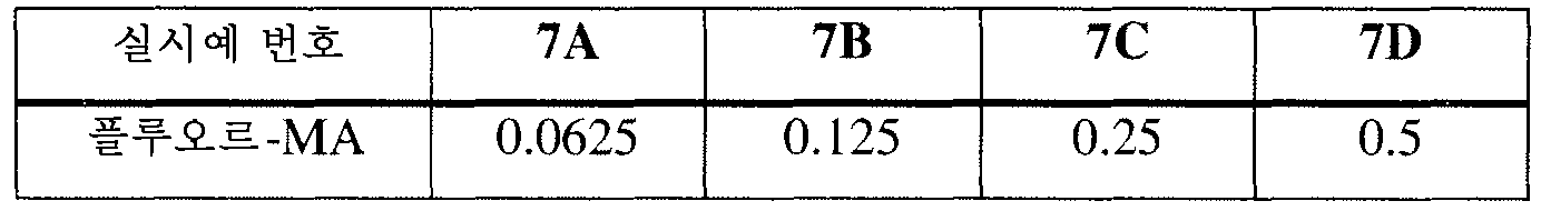
나타낸 바와 같이, 각 조의 실시예 5 내지 7의 물질은 다양한 농도의 감광제 플루오-MA를 가졌다. 도 18은 800 ㎚의 조사 파장, 1.5 nJ의 평균 펄스 에너지, 및 1 ㎜/초의 스캔 속도에서의 이들 히드로겔 물질의 굴절률 변화를 나타낸다. 또한, 이 데이터 및 플롯은 매우 중요한 정보를 제공한다. 나타낸 바와 같이, 감광제가 도핑된 히드로겔 물질 모두에서 물 농도가 감소함에 따라 굴절률 변화 정도가 감소하였다. 본 발명자들은 히드로겔의 국소적 함수율이 물질의 열역학적 성질, 예를 들어 비열, 열용량 등 뿐만 아니라 물질 밀도에 영향을 미친다고 믿는다. 약 28%의 가장 많은 함수율을 가지는 실시예 5의 히드로겔에서 가장 큰 굴절률 변화를 얻었다. 더 중요한 것은, 상대적으로 더 높은 함수율을 갖는 히드로겔이 물질에 광학적 손상을 주지 않으면서 굴절 구조를 생성하는 가장 큰 안전 작동 거리를 제공한다는 것이다.As indicated, the materials of Examples 5 to 7 of each group had various concentrations of the photosensitizer fluoro-MA. Figure 18 shows the refractive index change of these hydrogel materials at a scan wavelength of 800 nm, an average pulse energy of 1.5 nJ, and a scan rate of 1 mm / sec. In addition, this data and plots provide very important information. As shown, the degree of change in refractive index decreased as the water concentration decreased in all of the photosensitizer-doped hydrogel material. The present inventors believe that the local water content of the hydrogel affects the material densities as well as the thermodynamic properties of the material, for example, specific heat, heat capacity, and the like. The largest refractive index change was obtained in the hydrogel of Example 5 having the highest water content of about 28%. More importantly, a hydrogel with a relatively higher water content provides the largest safe working distance to create a refractive structure without causing optical damage to the material.
또, 본 발명자들은 각각 0.5% 플루오르-MA를 갖지만 상이한 함수율을 가지는 실시예 5E, 실시예 6D 및 실시예 7D의 히드로겔 물질의 파장 의존성을 연구하였다. 도 19를 참조한다. 흥미롭게도, 어떠한 광학적 손상도 없이 상대적으로 큰 굴절률 변화(0.02 초과)가 1.5 nJ의 평균 펄스 에너지에서 실시예 5E에서만 관찰되었다. 그러나, 본 발명자들이 이 연구에서 1 ㎜/초의 상대적으로 빠른 스캔 속도를 이용하였다는 점도 주목하여야 한다. 나타낸 바와 같이, 레이저 파장이 약 750 ㎚ 미만인 경우에는, 광학적 손상만 관찰되었다. 레이저 펄스가 800 ㎚ 초과의 파장에서 작동하는 경우, 실시예 7의 히드로겔 물질(12% 함수율)에서는 굴절률 변화는 관찰되지 않고 광학적 손상이 관찰되었다. 실시예 6의 히드로겔 물질(21% 함수율)에서는, 조사 파장이 약 875 ㎚인 경우 광학적 손상 없이 0.01의 굴절률 변화가 관찰되었다. We also studied the wavelength dependence of the hydrogel materials of Examples 5E, 6D and 7D, each having 0.5% fluoro-MA but with different water contents. See FIG. Interestingly, a relatively large change in refractive index (in excess of 0.02) without any optical damage was observed only in Example 5E at an average pulse energy of 1.5 nJ. However, it should also be noted that the present inventors used a relatively fast scan rate of 1 mm / sec in this study. As shown, when the laser wavelength was less than about 750 nm, only optical damage was observed. When the laser pulse was operated at a wavelength of more than 800 nm, no change in refractive index was observed in the hydrogel material (12% water content) of Example 7, and optical damage was observed. In the hydrogel material (21% water content) of Example 6, a refractive index change of 0.01 was observed without optical damage when the irradiation wavelength was about 875 nm.
종합해 보면, 본 발명자들의 연구는 광학 중합체 물질에 기술된 굴절 구조를 생성하기 위한 최적의 조사 조건을 제안한다.Taken together, our work suggests optimal irradiation conditions for producing the refractive structures described in optical polymer materials.
Claims (23)
상기 굴절 구조는 영상 증강 없이 사람 눈에 투명하며,
상기 안내 렌즈는 10 GM 이상의 이광자 횡단면을 갖는 감광제를 포함하는 광학 중합체 물질을 포함하고,
상기 광학 중합체 물질은 광학 중합체 실리콘 히드로겔 또는 광학 중합체 비-실리콘 히드로겔이며,
상기 조사는 펄스 에너지 0.05 nJ 내지 100 nJ, 평균 레이저 출력 10 mW 내지 400 mW, 스캔 속도 0.1 mm/초 이상인 펄스 레이저로 수행되는 것인, 방법.Irradiating the focused and scanned light with a wavelength of 600 nm to 900 nm from the laser to a predetermined area of the solvated guide lens to produce a refractive structure characterized by a refractive index change in the irradiated area of the lens A method of modifying the refractive index of an intraocular lens prior to inserting the intraocular lens by surgery,
The refractive structure is transparent to the human eye without image enhancement,
Said guide lens comprising an optical polymer material comprising a photosensitizer having a two-photon cross-section of at least 10 GM,
The optical polymer material is an optical polymeric silicone hydrogel or an optical polymer non-silicone hydrogel,
Wherein the irradiation is performed with a pulse laser having a pulse energy of 0.05 nJ to 100 nJ, an average laser power of 10 mW to 400 mW, and a scan speed of 0.1 mm / sec or more.
상기 광학 중합체 물질은 광학 중합체 실리콘 히드로겔 또는 광학 중합체 비-실리콘 히드로겔이고, 레이저로부터 600 ㎚ 내지 900 ㎚의 파장을 가지는 빛이 조사되어 굴절 구조가 생성될 때 광효율을 증강시키고 10 GM 이상의 이광자 횡단면을 갖는 감광제를 포함하는 것인, 안내 렌즈.An information lens comprising an optical polymer material and including an irradiated region that forms a refractive and translucent refractive structure in the human eye without image enhancement,
The optical polymer material is an optical polymeric silicone hydrogel or an optical polymer non-silicon hydrogel, wherein light having a wavelength of 600 nm to 900 nm is irradiated from the laser to enhance the light efficiency when a refractive structure is generated, And a light-sensitive agent having a light-shielding property.

(여기서, R은 H 또는 CH3이고; m은 0 내지 10으로부터 선택된 정수이고; Y는 존재하지 않거나 또는 O, S 또는 NR(여기서, R은 H, CH3, C2-C6알킬, 이소-OC3H7, 페닐 또는 벤질임)이고; Ar은 치환되지 않거나 또는 CH3, C2H5, n-C3H7, 이소-C3H7, OCH3, C6H11, Cl, Br, 페닐 또는 벤질로 치환될 수 있는 임의의 방향족 고리임). The information lens according to claim 11 or 12, wherein the optical polymer material is made from at least one aromatic (meth) acrylate monomer having the following formula:
Wherein R is H or CH 3 , m is an integer selected from 0 to 10, Y is absent or O, S or NR, wherein R is H, CH 3 , C 2 -C 6 alkyl, iso -OC 3 H 7 , phenyl or benzyl, Ar is unsubstituted or substituted by one or more substituents selected from the group consisting of CH 3 , C 2 H 5 , nC 3 H 7 , iso-C 3 H 7 , OCH 3 , C 6 H 11 , Cl, Br , Phenyl or benzyl).
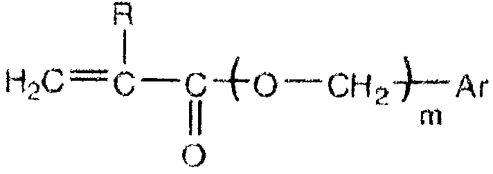
(여기서, R은 H 또는 CH3이고; m은 0 내지 6으로부터 선택된 정수이고; Ar은 치환되지 않거나 또는 CH3, C2H5, n-C3H7, 이소-C3H7, OCH3, OH 또는 C(O)OH로 치환될 수 있는 임의의 방향족 고리임). The information lens according to claim 11 or 12, wherein the optical polymer material is made from at least one aromatic (meth) acrylate monomer having the following formula:
(Wherein, R is H or CH 3, and; m is an integer selected from 0 to 6; Ar is optionally substituted or a CH 3, C 2 H 5, nC 3 H 7, iso -C 3 H 7, OCH 3, OH or C (O) OH).
제 1 단량체 성분이 공중합체에 60 중량% 이상의 양으로 존재하고 그의 단일중합체가 1.5 이상의 굴절률을 가지고,
제 2 단량체 성분이 공중합체에 3% 내지 20%의 양으로 존재하고,
제 1 단량체 성분 및 제 2 단량체 성분이 함께 공중합체의 70 중량% 이상을 나타내고,
임의로는, 친수성 단량체 성분으로부터 유래된 제 4 단량체 성분이 공중합체의 2 중량% 내지 30 중량%의 양으로 존재하는 것인,
안내 렌즈.13. A method according to claim 11 or 12, wherein the optical polymer material is prepared as a copolymer from three or more monomer components,
Wherein the first monomer component is present in the copolymer in an amount of at least 60 wt% and the homopolymer thereof has a refractive index of at least 1.5,
The second monomer component is present in the copolymer in an amount of 3% to 20%
The first monomer component and the second monomer component together representing at least 70% by weight of the copolymer,
Optionally, a fourth monomer component derived from the hydrophilic monomer component is present in an amount of from 2% to 30% by weight of the copolymer.
Guide lens.
Applications Claiming Priority (4)
| Application Number | Priority Date | Filing Date | Title |
|---|---|---|---|
| US5422508P | 2008-05-19 | 2008-05-19 | |
| US61/054,225 | 2008-05-19 | ||
| US12/380,892 | 2009-03-04 | ||
| US12/380,892 US9060847B2 (en) | 2008-05-19 | 2009-03-04 | Optical hydrogel material with photosensitizer and method for modifying the refractive index |
Related Child Applications (1)
| Application Number | Title | Priority Date | Filing Date |
|---|---|---|---|
| KR1020167017365A Division KR101761079B1 (en) | 2008-05-19 | 2009-05-18 | Intraocular lens with photosensitizer and method for modifying the refractive index of the lens |
Publications (2)
| Publication Number | Publication Date |
|---|---|
| KR20110020231A KR20110020231A (en) | 2011-03-02 |
| KR101636588B1 true KR101636588B1 (en) | 2016-07-05 |
Family
ID=41316898
Family Applications (2)
| Application Number | Title | Priority Date | Filing Date |
|---|---|---|---|
| KR1020107025854A Active KR101636588B1 (en) | 2008-05-19 | 2009-05-18 | Intraocular lens with photosensitizer and method for modifying the refractive index of the lens |
| KR1020167017365A Active KR101761079B1 (en) | 2008-05-19 | 2009-05-18 | Intraocular lens with photosensitizer and method for modifying the refractive index of the lens |
Family Applications After (1)
| Application Number | Title | Priority Date | Filing Date |
|---|---|---|---|
| KR1020167017365A Active KR101761079B1 (en) | 2008-05-19 | 2009-05-18 | Intraocular lens with photosensitizer and method for modifying the refractive index of the lens |
Country Status (11)
| Country | Link |
|---|---|
| US (2) | US9060847B2 (en) |
| EP (1) | EP2326285B1 (en) |
| JP (1) | JP5243600B2 (en) |
| KR (2) | KR101636588B1 (en) |
| CN (1) | CN102065795B (en) |
| AT (1) | ATE545388T1 (en) |
| AU (1) | AU2009249242B2 (en) |
| CA (1) | CA2724960C (en) |
| ES (1) | ES2379582T3 (en) |
| PL (1) | PL2326285T3 (en) |
| WO (1) | WO2009143054A2 (en) |
Families Citing this family (82)
| Publication number | Priority date | Publication date | Assignee | Title |
|---|---|---|---|---|
| US7628810B2 (en) | 2003-05-28 | 2009-12-08 | Acufocus, Inc. | Mask configured to maintain nutrient transport without producing visible diffraction patterns |
| US20080001320A1 (en) * | 2006-06-28 | 2008-01-03 | Knox Wayne H | Optical Material and Method for Modifying the Refractive Index |
| US7789910B2 (en) * | 2006-06-28 | 2010-09-07 | Bausch & Lomb Incorporated | Optical material and method for modifying the refractive index |
| US9545340B1 (en) | 2007-06-26 | 2017-01-17 | University Of Rochester | Multi-photon absorption for femtosecond micromachining and refractive index modification of tissues |
| WO2009070438A1 (en) * | 2007-11-30 | 2009-06-04 | Bausch & Lomb Incorporated | Optical material and method for modifying the refractive index |
| WO2009124231A1 (en) * | 2008-04-04 | 2009-10-08 | Battelle Memorial Institute | Adjustable intraocular lens |
| US10018853B2 (en) | 2008-04-04 | 2018-07-10 | Battelle Memorial Institute | Methods of altering the refractive index of materials |
| US10254562B2 (en) | 2008-04-04 | 2019-04-09 | Battelle Memorial Institute | Methods for tailoring the refractive index of lenses |
| US9060847B2 (en) * | 2008-05-19 | 2015-06-23 | University Of Rochester | Optical hydrogel material with photosensitizer and method for modifying the refractive index |
| US10004593B2 (en) | 2009-08-13 | 2018-06-26 | Acufocus, Inc. | Intraocular lens with elastic mask |
| EP3290003B1 (en) | 2009-08-13 | 2023-12-13 | AcuFocus, Inc. | Method of manufacturing masked intraocular implants and lenses |
| EP2363426A1 (en) * | 2010-02-26 | 2011-09-07 | Université de Liège | Organic compositions for repeatedly adjustable optical elements and such elements. |
| EP2542183A4 (en) * | 2010-03-04 | 2014-04-30 | Perfect Ip Llc | System for forming and modifying lenses and lenses formed thereby |
| KR101250995B1 (en) | 2010-12-20 | 2013-04-04 | 예기훈 | Contact lens comprising vinylanisole and manufacturing method thereof |
| US10813791B2 (en) | 2011-06-02 | 2020-10-27 | University Of Rochester | Method for modifying the refractive index of ocular tissues and applications thereof |
| US9144491B2 (en) | 2011-06-02 | 2015-09-29 | University Of Rochester | Method for modifying the refractive index of an optical material |
| US8852274B2 (en) | 2011-06-24 | 2014-10-07 | Advanced Vision Science, Inc. | Composite ophthalmic devices and methods with incident light modifying properties |
| CA2857306C (en) | 2011-12-02 | 2017-07-25 | Acufocus, Inc. | Ocular mask having selective spectral transmission |
| JP6010352B2 (en) * | 2012-06-07 | 2016-10-19 | 株式会社オートネットワーク技術研究所 | Curing sensitizer, photocuring material, cured product and wire harness material |
| US9925621B2 (en) | 2012-11-14 | 2018-03-27 | Perfect Ip, Llp | Intraocular lens (IOL) fabrication system and method |
| US9023257B2 (en) * | 2012-11-14 | 2015-05-05 | Perfect Ip, Llc | Hydrophilicity alteration system and method |
| ES2587555T3 (en) * | 2012-11-14 | 2016-10-25 | Wavelight Gmbh | Laser pulse focus |
| MX364518B (en) | 2013-01-15 | 2019-04-30 | Medicem Inst S R O | Bioanalogic intraocular lens. |
| US10441676B2 (en) | 2013-01-15 | 2019-10-15 | Medicem Institute s.r.o. | Light-adjustable hydrogel and bioanalogic intraocular lens |
| US9241787B2 (en) * | 2013-02-13 | 2016-01-26 | Sifi Medtech Srl | Intraocular lens with a proofed surface |
| US9204962B2 (en) | 2013-03-13 | 2015-12-08 | Acufocus, Inc. | In situ adjustable optical mask |
| US9427922B2 (en) | 2013-03-14 | 2016-08-30 | Acufocus, Inc. | Process for manufacturing an intraocular lens with an embedded mask |
| CA2906338A1 (en) | 2013-03-15 | 2014-09-25 | Amo Wavefront Sciences, Llc | Non-invasive refractive treatment using nanoparticles |
| WO2015006274A1 (en) * | 2013-07-08 | 2015-01-15 | University Of Rochester | High numerical aperture optomechanical scanner for layered gradient index microlenses, methods, and applications |
| US9827088B2 (en) | 2013-09-12 | 2017-11-28 | Battelle Memorial Institute | Methods of altering the refractive index of materials |
| CA2922260C (en) * | 2013-10-09 | 2019-08-20 | Wavelight Gmbh | Apparatus for dissecting an eye for the introduction of a photosensitizer |
| JP6442521B2 (en) * | 2014-03-13 | 2018-12-19 | カリフォルニア インスティチュート オブ テクノロジー | Light-guided deformable hydrogels and their use in optical devices |
| BR112017004765B1 (en) | 2014-09-09 | 2022-08-23 | Staar Surgical Company | LENS CONFIGURED FOR IMPLANTATION IN A HUMAN EYE |
| US12127934B2 (en) | 2014-09-09 | 2024-10-29 | Staar Surgical Company | Method of Providing Modified Monovision to a Subject with a First Lens and a Second Lens |
| EP3220859B8 (en) | 2014-11-19 | 2020-06-10 | AcuFocus, Inc. | Fracturable mask for treating presbyopia |
| EP3067015B1 (en) * | 2015-03-10 | 2018-06-06 | Consejo Superior De Investigaciones Científicas | Photochemically induced engagement of intraocular implants |
| US9475149B1 (en) * | 2015-04-24 | 2016-10-25 | Testrake Aviation, Inc. | Optical device and method of making same |
| WO2016183424A1 (en) | 2015-05-14 | 2016-11-17 | California Institute Of Technology | Light adjustable intraocular lenses using upconverting nanop articles and near infrared (nir) light |
| CN106366241B (en) * | 2015-07-23 | 2019-10-08 | 爱博诺德(北京)医疗科技有限公司 | Ophthalmic materials and application thereof with fluorescent characteristic |
| CN106362215A (en) * | 2015-07-23 | 2017-02-01 | 爱博诺德(北京)医疗科技有限公司 | Intraocular lens for preventing and treating after cataract, and preparation method thereof |
| CN106620893B (en) * | 2015-07-23 | 2021-07-30 | 爱博诺德(北京)医疗科技股份有限公司 | Materials for ocular disease phototherapy |
| US10687935B2 (en) | 2015-10-05 | 2020-06-23 | Acufocus, Inc. | Methods of molding intraocular lenses |
| CN106729975B (en) * | 2015-11-19 | 2020-04-14 | 爱博诺德(北京)医疗科技股份有限公司 | Material for producing artificial lens |
| CN108431676B (en) | 2015-11-24 | 2022-01-04 | 阿库福库斯公司 | Toric small-aperture intraocular lens with extended depth of focus |
| WO2017106321A1 (en) | 2015-12-15 | 2017-06-22 | University Of Rochester | Refractive corrector incorporating a continuous central phase zone and peripheral phase discontinuities |
| AU2017229594B2 (en) | 2016-03-09 | 2022-06-16 | Staar Surgical Company | Ophthalmic implants with extended depth of field and enhanced distance visual acuity |
| US10196470B2 (en) * | 2016-05-16 | 2019-02-05 | Benz Research And Development Corp. | Hydrophobic intraocular lens |
| BR112018076401A2 (en) * | 2016-06-23 | 2019-04-09 | Medicem Inst S R O | covalently cross-linked hydrogel, implants using it, lightweight, bioanalytical, adjustable hydrogel intraocular lenses and methods for making such adjustments |
| CN108288679B (en) * | 2017-01-10 | 2019-11-26 | 昆山国显光电有限公司 | Display panel and the method for improving display panel Newton's ring |
| US10932901B2 (en) | 2017-02-10 | 2021-03-02 | University Of Rochester | Vision correction with laser refractive index changes |
| WO2018182946A1 (en) | 2017-03-31 | 2018-10-04 | University Of Rochester | Beam multiplexer for writing refractive index changes in optical materials |
| DE102017112087B4 (en) | 2017-06-01 | 2025-10-16 | Carl Zeiss Meditec Ag | Artificial eye lens with laser-generated birefringent structure and method for producing an artificial eye lens |
| DE102017112085A1 (en) | 2017-06-01 | 2018-12-06 | Carl Zeiss Meditec Ag | Artificial eye lens with medicament depot formed therein and method for making an artificial eye lens |
| DE102017112086B4 (en) | 2017-06-01 | 2026-01-29 | Carl Zeiss Meditec Ag | Artificial eye lens with diffractive grid structure and method for manufacturing an artificial eye lens |
| US10765777B2 (en) | 2017-06-28 | 2020-09-08 | California Institute Of Technology | Light adjustable intraocular lenses using upconverting core-shell nanoparticles and near infrared (NIR) light |
| US11845143B2 (en) * | 2017-07-07 | 2023-12-19 | University Of Rochester | Optical design for a two-degree-of-freedom scanning system with a curved sample plane |
| KR102675398B1 (en) | 2018-01-26 | 2024-06-17 | 유니버시티 오브 로체스터 | Refractive Shaping Laser Writing Process Control |
| US11154424B2 (en) | 2018-04-06 | 2021-10-26 | Amo Development, Llc | Methods and systems for changing a refractive property of an implantable intraocular lens |
| WO2019217471A1 (en) | 2018-05-09 | 2019-11-14 | Acufocus, Inc. | Intraocular implant with removable optic |
| US11369515B2 (en) | 2018-05-14 | 2022-06-28 | University Of Rochester | Vision correction with laser refractive index changes |
| EP3837571B1 (en) | 2018-08-17 | 2023-08-02 | Staar Surgical Company | Polymeric composition exhibiting nanogradient of refractive index |
| US11678975B2 (en) | 2019-04-05 | 2023-06-20 | Amo Groningen B.V. | Systems and methods for treating ocular disease with an intraocular lens and refractive index writing |
| US12377622B2 (en) | 2019-04-05 | 2025-08-05 | Amo Groningen B.V. | Systems and methods for vergence matching with an optical profile and using refractive index writing |
| US11944574B2 (en) | 2019-04-05 | 2024-04-02 | Amo Groningen B.V. | Systems and methods for multiple layer intraocular lens and using refractive index writing |
| US11583388B2 (en) | 2019-04-05 | 2023-02-21 | Amo Groningen B.V. | Systems and methods for spectacle independence using refractive index writing with an intraocular lens |
| US11529230B2 (en) | 2019-04-05 | 2022-12-20 | Amo Groningen B.V. | Systems and methods for correcting power of an intraocular lens using refractive index writing |
| US11583389B2 (en) | 2019-04-05 | 2023-02-21 | Amo Groningen B.V. | Systems and methods for correcting photic phenomenon from an intraocular lens and using refractive index writing |
| US11564839B2 (en) | 2019-04-05 | 2023-01-31 | Amo Groningen B.V. | Systems and methods for vergence matching of an intraocular lens with refractive index writing |
| US12357509B2 (en) | 2019-04-05 | 2025-07-15 | Amo Groningen B.V. | Systems and methods for improving vision from an intraocular lens in an incorrect position and using refractive index writing |
| CN121059340A (en) | 2019-07-19 | 2025-12-05 | 克莱里奥视觉股份有限公司 | Treatment of Myopia Progression |
| US12245972B2 (en) | 2020-02-21 | 2025-03-11 | Wavefront Dynamics, Inc. | System and methods for customizing an intraocular lens using a wavefront aberrometer |
| AU2021306293A1 (en) | 2020-07-08 | 2023-02-02 | Clerio Vision, Inc. | Optimized multifocal wavefronts for presbyopia correction |
| CN116261437B (en) | 2020-08-25 | 2025-11-07 | 克莱里奥视觉股份有限公司 | Subsurface optical structures with enhanced refractive index value distribution |
| CA3234381A1 (en) | 2021-10-04 | 2023-04-13 | Staar Surgical Company | Ophthalmic implants for correcting vision with a tunable optic, and methods of manufacture and use |
| TWI789057B (en) * | 2021-10-19 | 2023-01-01 | 艾克夏醫療儀器股份有限公司 | Method and apparatus for generating ultraviolet spot used in cross-linking reaction |
| US20250041049A1 (en) | 2021-12-06 | 2025-02-06 | University Of Rochester | Thin large-diameter optics foldable intraocular lens |
| WO2023177740A1 (en) | 2022-03-18 | 2023-09-21 | Clerio Vision, Inc. | Myopia control treatments |
| WO2023244662A1 (en) | 2022-06-14 | 2023-12-21 | University Of Rochester | Spatio-temporal-angular beam multiplexer for writing refractive index changes in optical materials |
| WO2024220762A1 (en) | 2023-04-21 | 2024-10-24 | University Of Rochester | Optical devices based on nanostructured surfaces in hydrogels using nonlinear absorption |
| WO2025014734A1 (en) | 2023-07-07 | 2025-01-16 | University Of Rochester | High speed laser induced refractive index change writing in optical materials |
| WO2025042726A1 (en) * | 2023-08-18 | 2025-02-27 | University Of Rochester | Laser induced refractive index change writing in non-hydrated hydrogels |
| WO2025085626A1 (en) | 2023-10-20 | 2025-04-24 | University Of Rochester | Laser induced refractive index change method and ophtalmic product treated by said method |
Citations (4)
| Publication number | Priority date | Publication date | Assignee | Title |
|---|---|---|---|---|
| JP2001147301A (en) * | 1999-11-22 | 2001-05-29 | Tri Chemical Laboratory Inc | Optical element and method for producing the same |
| JP2007501794A (en) | 2003-08-08 | 2007-02-01 | カルホーン ビジョン | Lens that can be adjusted by light that can be changed in power after manufacturing by multiphoton process |
| WO2007137102A2 (en) * | 2006-05-18 | 2007-11-29 | 3M Innovative Properties Company | Process for making light guides with extraction structures and light guides produced thereby |
| US20080001320A1 (en) * | 2006-06-28 | 2008-01-03 | Knox Wayne H | Optical Material and Method for Modifying the Refractive Index |
Family Cites Families (57)
| Publication number | Priority date | Publication date | Assignee | Title |
|---|---|---|---|---|
| US2725377A (en) * | 1952-03-01 | 1955-11-29 | American Cyanamid Co | Ice colors of the azole series |
| US3959281A (en) * | 1968-01-19 | 1976-05-25 | Cassella Farbwerke Mainkur Aktiengesellschaft | Piperazino substituted coumarin derivatives |
| US4907586A (en) * | 1988-03-31 | 1990-03-13 | Intelligent Surgical Lasers | Method for reshaping the eye |
| JP2604849B2 (en) * | 1989-03-29 | 1997-04-30 | 株式会社メニコン | Composition for forming intraocular lens |
| US5220359A (en) * | 1990-07-24 | 1993-06-15 | Johnson & Johnson Vision Products, Inc. | Lens design method and resulting aspheric lens |
| US20040015236A1 (en) * | 1991-11-18 | 2004-01-22 | Sarfarazi Faezeh M. | Sarfarazi elliptical accommodative intraocular lens for small incision surgery |
| EP0575885B1 (en) | 1992-06-17 | 1998-02-04 | Nitto Denko Corporation | Process for producing polymerization or crosslinking rate-distributed article and process for producing lens, lens array or waveguide using the process |
| US6489589B1 (en) * | 1994-02-07 | 2002-12-03 | Board Of Regents, University Of Nebraska-Lincoln | Femtosecond laser utilization methods and apparatus and method for producing nanoparticles |
| US5849006A (en) * | 1994-04-25 | 1998-12-15 | Autonomous Technologies Corporation | Laser sculpting method and system |
| US5964748A (en) * | 1995-10-20 | 1999-10-12 | Peyman; Gholam A. | Intrastromal corneal modification |
| US7655002B2 (en) * | 1996-03-21 | 2010-02-02 | Second Sight Laser Technologies, Inc. | Lenticular refractive surgery of presbyopia, other refractive errors, and cataract retardation |
| JP3321548B2 (en) * | 1996-06-17 | 2002-09-03 | 株式会社日立製作所 | Photosensitive polyimide precursor composition and pattern forming method using the same |
| US6271914B1 (en) * | 1996-11-25 | 2001-08-07 | Autonomous Technologies Corporation | Objective measurement and correction of optical systems using wavefront analysis |
| US6849671B2 (en) * | 1998-03-02 | 2005-02-01 | Johnson & Johnson Vision Care, Inc. | Contact lenses |
| US6776932B1 (en) * | 1998-06-12 | 2004-08-17 | Getronics Wang Co. Llc | Polymeric optical articles |
| JP3599276B2 (en) * | 1998-08-19 | 2004-12-08 | オートナマス・テクノロジーズ・コーポレーション | A device for measuring the visual impairment of the human eye |
| US6197057B1 (en) * | 1998-10-27 | 2001-03-06 | Gholam A. Peyman | Lens conversion system for teledioptic or difractive configurations |
| US20030128336A1 (en) * | 2001-12-28 | 2003-07-10 | Jethmalani Jagdish M. | Customized lenses |
| US6450642B1 (en) | 1999-01-12 | 2002-09-17 | California Institute Of Technology | Lenses capable of post-fabrication power modification |
| US7281795B2 (en) * | 1999-01-12 | 2007-10-16 | Calhoun Vision, Inc. | Light adjustable multifocal lenses |
| JP4473364B2 (en) * | 1999-06-03 | 2010-06-02 | Jsr株式会社 | Photocurable resin composition and optical member |
| US6770728B2 (en) * | 1999-06-30 | 2004-08-03 | Menicon Co., Ltd. | Process for preparing ocular lens with urethane compound and process for preparing urethane compound for medical instruments |
| DE19955836C1 (en) * | 1999-11-19 | 2001-05-17 | Norbert Hampp | Ophthalmic implant |
| EP1266256B1 (en) | 2000-03-20 | 2006-06-21 | California Institute of Technology | Application of wavefront sensor to lenses capable of post-fabrication power modification |
| DE60103597T2 (en) * | 2000-03-22 | 2005-06-09 | Menicon Co., Ltd., Nagoya | MATERIAL FOR AN OKULAR LENS |
| ATE392176T1 (en) * | 2000-09-26 | 2008-05-15 | Calhoun Vision Inc | PERFORMANCE ADJUSTMENT FOR ADJUSTABLE LENS |
| EP1325380A2 (en) * | 2000-10-11 | 2003-07-09 | Calhoun Vision, Inc. | Light adjustable aberration conjugator |
| US6813082B2 (en) * | 2000-11-27 | 2004-11-02 | Ophthonix, Inc. | Wavefront aberrator and method of manufacturing |
| JP4565754B2 (en) | 2001-02-26 | 2010-10-20 | 日東電工株式会社 | Plastic structure |
| US20050182489A1 (en) | 2001-04-27 | 2005-08-18 | Peyman Gholam A. | Intraocular lens adapted for adjustment via laser after implantation |
| US20030052311A1 (en) * | 2001-07-06 | 2003-03-20 | Yoshio Inagaki | Two-photon absorption composition |
| WO2003023395A1 (en) * | 2001-09-12 | 2003-03-20 | Microbar Systems, Inc. | Enhanced detection of metal plating additives |
| JP4794089B2 (en) * | 2001-09-17 | 2011-10-12 | 株式会社メニコン | Marking method for ophthalmic lens |
| FR2830253B1 (en) * | 2001-09-28 | 2005-02-04 | Air Liquide | NOVEL PROCESS FOR THE PREPARATION OF C-FUNCTIONALIZED NITROGEN MACROCYCLES AND NOVEL INTERMEDIATES OBTAINED |
| US20030208189A1 (en) | 2001-10-19 | 2003-11-06 | Payman Gholam A. | Integrated system for correction of vision of the human eye |
| US7241009B2 (en) | 2001-11-21 | 2007-07-10 | Calhoun Vision, Inc. | Crosslinking of silicones presence of functionalized silicones |
| US7237893B2 (en) * | 2001-12-28 | 2007-07-03 | Chang Shiao H | Light adjustable lenses capable of post-fabrication power modification via multi-photon processes |
| US7322694B2 (en) * | 2002-09-06 | 2008-01-29 | Synergeyes, Inc. | Hybrid contact lens system and method |
| JP3987787B2 (en) * | 2002-11-25 | 2007-10-10 | 日東電工株式会社 | Manufacturing method of three-dimensional polyimide optical waveguide |
| JP2006523130A (en) * | 2003-03-06 | 2006-10-12 | ジョン エイチ. シャダック, | Compatible optical lens and manufacturing method |
| US7341599B1 (en) * | 2003-04-09 | 2008-03-11 | Minu, Llc | Intraocular lens for correcting presbyopia |
| FR2853965B1 (en) * | 2003-04-15 | 2006-09-15 | Commissariat Energie Atomique | METHOD FOR SCREENING THE OPERATIVE CONDITIONS OF A CHEMICAL COUPLING REACTION AND KITS FOR CARRYING OUT SAID METHOD |
| US20040235974A1 (en) * | 2003-05-21 | 2004-11-25 | Lai Shui T. | Apparatus and method for curing of UV-protected UV-curable monomer and polymer mixtures |
| US7351241B2 (en) * | 2003-06-02 | 2008-04-01 | Carl Zeiss Meditec Ag | Method and apparatus for precision working of material |
| US20050046794A1 (en) * | 2003-06-17 | 2005-03-03 | Silvestrini Thomas A. | Method and apparatus for aligning a mask with the visual axis of an eye |
| JP4217886B2 (en) * | 2003-06-25 | 2009-02-04 | Jsr株式会社 | Radiation sensitive refractive index changing composition, pattern forming method and optical material |
| JP4417675B2 (en) * | 2003-09-11 | 2010-02-17 | 富士フイルム株式会社 | Multiphoton absorbing medium and exposure method using the same |
| US20080262610A1 (en) * | 2007-04-20 | 2008-10-23 | Alan Lang | Biomechanical design of intracorneal inlays |
| JP4436737B2 (en) * | 2004-09-10 | 2010-03-24 | 富士フイルム株式会社 | Two-photon absorption decoloring material, two-photon absorption refractive index modulation material, two-photon absorption polymerization material, two-photon absorption polymerization method, and three-dimensional optical recording material |
| US20060135952A1 (en) * | 2004-12-21 | 2006-06-22 | Curatu Eugene O | Corrective intraocular lens and associated methods |
| US8690942B2 (en) * | 2005-05-13 | 2014-04-08 | Akkolens International B.V. | Intra-ocular artificial lens for iris-driven accommodation |
| DE102005045540A1 (en) * | 2005-09-23 | 2007-03-29 | Hampp, Norbert, Prof. Dr. | intraocular lens |
| US20070100443A1 (en) * | 2005-10-27 | 2007-05-03 | Peyman Gholam A | Intraocular lens adapted for accommodation via electrical signals |
| US8113651B2 (en) * | 2006-03-20 | 2012-02-14 | High Performance Optics, Inc. | High performance corneal inlay |
| US7789910B2 (en) * | 2006-06-28 | 2010-09-07 | Bausch & Lomb Incorporated | Optical material and method for modifying the refractive index |
| US9060847B2 (en) * | 2008-05-19 | 2015-06-23 | University Of Rochester | Optical hydrogel material with photosensitizer and method for modifying the refractive index |
| TW201138744A (en) * | 2010-03-31 | 2011-11-16 | Alcon Inc | Adjustable intraocular lens system |
-
2009
- 2009-03-04 US US12/380,892 patent/US9060847B2/en active Active
- 2009-05-18 CN CN200980118220.1A patent/CN102065795B/en active Active
- 2009-05-18 EP EP09751282A patent/EP2326285B1/en active Active
- 2009-05-18 AU AU2009249242A patent/AU2009249242B2/en not_active Ceased
- 2009-05-18 KR KR1020107025854A patent/KR101636588B1/en active Active
- 2009-05-18 CA CA2724960A patent/CA2724960C/en active Active
- 2009-05-18 AT AT09751282T patent/ATE545388T1/en active
- 2009-05-18 PL PL09751282T patent/PL2326285T3/en unknown
- 2009-05-18 WO PCT/US2009/044335 patent/WO2009143054A2/en not_active Ceased
- 2009-05-18 ES ES09751282T patent/ES2379582T3/en active Active
- 2009-05-18 KR KR1020167017365A patent/KR101761079B1/en active Active
- 2009-05-18 JP JP2011510617A patent/JP5243600B2/en active Active
-
2012
- 2012-09-27 US US13/628,785 patent/US8901190B2/en active Active
Patent Citations (4)
| Publication number | Priority date | Publication date | Assignee | Title |
|---|---|---|---|---|
| JP2001147301A (en) * | 1999-11-22 | 2001-05-29 | Tri Chemical Laboratory Inc | Optical element and method for producing the same |
| JP2007501794A (en) | 2003-08-08 | 2007-02-01 | カルホーン ビジョン | Lens that can be adjusted by light that can be changed in power after manufacturing by multiphoton process |
| WO2007137102A2 (en) * | 2006-05-18 | 2007-11-29 | 3M Innovative Properties Company | Process for making light guides with extraction structures and light guides produced thereby |
| US20080001320A1 (en) * | 2006-06-28 | 2008-01-03 | Knox Wayne H | Optical Material and Method for Modifying the Refractive Index |
Also Published As
| Publication number | Publication date |
|---|---|
| WO2009143054A2 (en) | 2009-11-26 |
| WO2009143054A8 (en) | 2011-03-03 |
| EP2326285A2 (en) | 2011-06-01 |
| US8901190B2 (en) | 2014-12-02 |
| HK1154479A1 (en) | 2012-04-27 |
| JP2011520561A (en) | 2011-07-21 |
| KR20110020231A (en) | 2011-03-02 |
| US9060847B2 (en) | 2015-06-23 |
| AU2009249242B2 (en) | 2013-07-18 |
| US20090287306A1 (en) | 2009-11-19 |
| CN102065795B (en) | 2014-09-10 |
| ATE545388T1 (en) | 2012-03-15 |
| CA2724960C (en) | 2013-01-08 |
| PL2326285T3 (en) | 2012-07-31 |
| JP5243600B2 (en) | 2013-07-24 |
| KR101761079B1 (en) | 2017-07-24 |
| EP2326285B1 (en) | 2012-02-15 |
| ES2379582T3 (en) | 2012-04-27 |
| CA2724960A1 (en) | 2009-11-26 |
| KR20160079154A (en) | 2016-07-05 |
| CN102065795A (en) | 2011-05-18 |
| AU2009249242A1 (en) | 2009-11-26 |
| WO2009143054A3 (en) | 2010-01-28 |
| US20130268072A1 (en) | 2013-10-10 |
Similar Documents
| Publication | Publication Date | Title |
|---|---|---|
| KR101636588B1 (en) | Intraocular lens with photosensitizer and method for modifying the refractive index of the lens | |
| US10649115B2 (en) | Method for modifying the refractive index of an optical material and resulting optical vision component | |
| JP5385136B2 (en) | Optical material and method of modifying the refractive index | |
| HK1154479B (en) | Intraocular lens with photosensitizer and method for modifying the refractive index of the lens |
Legal Events
| Date | Code | Title | Description |
|---|---|---|---|
| PA0105 | International application |
Patent event date: 20101118 Patent event code: PA01051R01D Comment text: International Patent Application |
|
| PG1501 | Laying open of application | ||
| A201 | Request for examination | ||
| PA0201 | Request for examination |
Patent event code: PA02012R01D Patent event date: 20140513 Comment text: Request for Examination of Application |
|
| E902 | Notification of reason for refusal | ||
| PE0902 | Notice of grounds for rejection |
Comment text: Notification of reason for refusal Patent event date: 20151028 Patent event code: PE09021S01D |
|
| N231 | Notification of change of applicant | ||
| PN2301 | Change of applicant |
Patent event date: 20160226 Comment text: Notification of Change of Applicant Patent event code: PN23011R01D |
|
| E701 | Decision to grant or registration of patent right | ||
| PE0701 | Decision of registration |
Patent event code: PE07011S01D Comment text: Decision to Grant Registration Patent event date: 20160329 |
|
| A107 | Divisional application of patent | ||
| PA0104 | Divisional application for international application |
Comment text: Divisional Application for International Patent Patent event code: PA01041R01D Patent event date: 20160628 |
|
| GRNT | Written decision to grant | ||
| PR0701 | Registration of establishment |
Comment text: Registration of Establishment Patent event date: 20160629 Patent event code: PR07011E01D |
|
| PR1002 | Payment of registration fee |
Payment date: 20160629 End annual number: 3 Start annual number: 1 |
|
| PG1601 | Publication of registration | ||
| PR1001 | Payment of annual fee |
Payment date: 20200617 Start annual number: 5 End annual number: 5 |
|
| PR1001 | Payment of annual fee |
Payment date: 20230614 Start annual number: 8 End annual number: 8 |