BR112017004765B1 - LENS CONFIGURED FOR IMPLANTATION IN A HUMAN EYE - Google Patents
LENS CONFIGURED FOR IMPLANTATION IN A HUMAN EYE Download PDFInfo
- Publication number
- BR112017004765B1 BR112017004765B1 BR112017004765-9A BR112017004765A BR112017004765B1 BR 112017004765 B1 BR112017004765 B1 BR 112017004765B1 BR 112017004765 A BR112017004765 A BR 112017004765A BR 112017004765 B1 BR112017004765 B1 BR 112017004765B1
- Authority
- BR
- Brazil
- Prior art keywords
- lens
- optic
- optical axis
- aspherical
- fact
- Prior art date
Links
- 238000002513 implantation Methods 0.000 title claims abstract description 26
- 230000003287 optical effect Effects 0.000 claims abstract description 122
- 239000012780 transparent material Substances 0.000 claims description 25
- 238000006073 displacement reaction Methods 0.000 claims description 10
- 239000000463 material Substances 0.000 abstract description 22
- 230000004304 visual acuity Effects 0.000 abstract description 15
- 239000007943 implant Substances 0.000 abstract description 11
- 210000000695 crystalline len Anatomy 0.000 description 293
- 239000003518 caustics Substances 0.000 description 33
- 238000012546 transfer Methods 0.000 description 27
- 230000004438 eyesight Effects 0.000 description 24
- 230000007704 transition Effects 0.000 description 19
- 210000001747 pupil Anatomy 0.000 description 14
- 238000013461 design Methods 0.000 description 13
- 102000008186 Collagen Human genes 0.000 description 12
- 108010035532 Collagen Proteins 0.000 description 12
- 229920001436 collagen Polymers 0.000 description 12
- 210000001525 retina Anatomy 0.000 description 11
- 210000004087 cornea Anatomy 0.000 description 10
- 238000000034 method Methods 0.000 description 10
- 230000005499 meniscus Effects 0.000 description 9
- 201000009310 astigmatism Diseases 0.000 description 8
- 230000035945 sensitivity Effects 0.000 description 8
- 208000001491 myopia Diseases 0.000 description 7
- 230000004379 myopia Effects 0.000 description 7
- 201000010041 presbyopia Diseases 0.000 description 7
- 238000013442 quality metrics Methods 0.000 description 7
- 238000012937 correction Methods 0.000 description 6
- 238000009795 derivation Methods 0.000 description 6
- 238000009826 distribution Methods 0.000 description 6
- 208000002177 Cataract Diseases 0.000 description 5
- 230000004305 hyperopia Effects 0.000 description 5
- 201000006318 hyperopia Diseases 0.000 description 5
- 230000008901 benefit Effects 0.000 description 4
- 238000010586 diagram Methods 0.000 description 4
- 238000005259 measurement Methods 0.000 description 4
- 239000000155 melt Substances 0.000 description 4
- 102000016359 Fibronectins Human genes 0.000 description 3
- 108010067306 Fibronectins Proteins 0.000 description 3
- 239000011521 glass Substances 0.000 description 3
- 239000000017 hydrogel Substances 0.000 description 3
- 230000002209 hydrophobic effect Effects 0.000 description 3
- 229920001296 polysiloxane Polymers 0.000 description 3
- 238000004088 simulation Methods 0.000 description 3
- 229920002818 (Hydroxyethyl)methacrylate Polymers 0.000 description 2
- WOBHKFSMXKNTIM-UHFFFAOYSA-N Hydroxyethyl methacrylate Chemical compound CC(=C)C(=O)OCCO WOBHKFSMXKNTIM-UHFFFAOYSA-N 0.000 description 2
- 206010020675 Hypermetropia Diseases 0.000 description 2
- NIXOWILDQLNWCW-UHFFFAOYSA-N acrylic acid group Chemical group C(C=C)(=O)O NIXOWILDQLNWCW-UHFFFAOYSA-N 0.000 description 2
- 230000000694 effects Effects 0.000 description 2
- 239000000203 mixture Substances 0.000 description 2
- 238000005457 optimization Methods 0.000 description 2
- 102000004169 proteins and genes Human genes 0.000 description 2
- 108090000623 proteins and genes Proteins 0.000 description 2
- 238000002604 ultrasonography Methods 0.000 description 2
- 208000010201 Exanthema Diseases 0.000 description 1
- 230000004308 accommodation Effects 0.000 description 1
- 229920006397 acrylic thermoplastic Polymers 0.000 description 1
- 230000003667 anti-reflective effect Effects 0.000 description 1
- 238000013459 approach Methods 0.000 description 1
- 230000003190 augmentative effect Effects 0.000 description 1
- 229920000249 biocompatible polymer Polymers 0.000 description 1
- 210000004556 brain Anatomy 0.000 description 1
- 230000008859 change Effects 0.000 description 1
- 239000011248 coating agent Substances 0.000 description 1
- 238000000576 coating method Methods 0.000 description 1
- 230000001276 controlling effect Effects 0.000 description 1
- 230000002596 correlated effect Effects 0.000 description 1
- 230000000875 corresponding effect Effects 0.000 description 1
- 238000011161 development Methods 0.000 description 1
- 238000007516 diamond turning Methods 0.000 description 1
- 230000009977 dual effect Effects 0.000 description 1
- 238000011156 evaluation Methods 0.000 description 1
- 201000005884 exanthem Diseases 0.000 description 1
- 208000030533 eye disease Diseases 0.000 description 1
- 238000009432 framing Methods 0.000 description 1
- 230000004313 glare Effects 0.000 description 1
- 125000001475 halogen functional group Chemical group 0.000 description 1
- 230000004371 high visual acuity Effects 0.000 description 1
- 230000036571 hydration Effects 0.000 description 1
- 238000006703 hydration reaction Methods 0.000 description 1
- 238000005286 illumination Methods 0.000 description 1
- 230000006872 improvement Effects 0.000 description 1
- 238000011065 in-situ storage Methods 0.000 description 1
- 230000002401 inhibitory effect Effects 0.000 description 1
- 238000002430 laser surgery Methods 0.000 description 1
- 238000012986 modification Methods 0.000 description 1
- 230000004048 modification Effects 0.000 description 1
- 238000000465 moulding Methods 0.000 description 1
- 230000004297 night vision Effects 0.000 description 1
- 210000001328 optic nerve Anatomy 0.000 description 1
- 229920003229 poly(methyl methacrylate) Polymers 0.000 description 1
- 239000002861 polymer material Substances 0.000 description 1
- 230000002980 postoperative effect Effects 0.000 description 1
- 238000004321 preservation Methods 0.000 description 1
- 230000008569 process Effects 0.000 description 1
- 230000001902 propagating effect Effects 0.000 description 1
- 206010037844 rash Diseases 0.000 description 1
- 230000004044 response Effects 0.000 description 1
- 230000004043 responsiveness Effects 0.000 description 1
- 230000004256 retinal image Effects 0.000 description 1
- 239000000126 substance Substances 0.000 description 1
- 238000001356 surgical procedure Methods 0.000 description 1
- ISXSCDLOGDJUNJ-UHFFFAOYSA-N tert-butyl prop-2-enoate Chemical compound CC(C)(C)OC(=O)C=C ISXSCDLOGDJUNJ-UHFFFAOYSA-N 0.000 description 1
- 230000000699 topical effect Effects 0.000 description 1
- XLYOFNOQVPJJNP-UHFFFAOYSA-N water Substances O XLYOFNOQVPJJNP-UHFFFAOYSA-N 0.000 description 1
Images


Classifications
-
- A—HUMAN NECESSITIES
- A61—MEDICAL OR VETERINARY SCIENCE; HYGIENE
- A61F—FILTERS IMPLANTABLE INTO BLOOD VESSELS; PROSTHESES; DEVICES PROVIDING PATENCY TO, OR PREVENTING COLLAPSING OF, TUBULAR STRUCTURES OF THE BODY, e.g. STENTS; ORTHOPAEDIC, NURSING OR CONTRACEPTIVE DEVICES; FOMENTATION; TREATMENT OR PROTECTION OF EYES OR EARS; BANDAGES, DRESSINGS OR ABSORBENT PADS; FIRST-AID KITS
- A61F2/00—Filters implantable into blood vessels; Prostheses, i.e. artificial substitutes or replacements for parts of the body; Appliances for connecting them with the body; Devices providing patency to, or preventing collapsing of, tubular structures of the body, e.g. stents
- A61F2/02—Prostheses implantable into the body
- A61F2/14—Eye parts, e.g. lenses or corneal implants; Artificial eyes
- A61F2/16—Intraocular lenses
- A61F2/1613—Intraocular lenses having special lens configurations, e.g. multipart lenses; having particular optical properties, e.g. pseudo-accommodative lenses, lenses having aberration corrections, diffractive lenses, lenses for variably absorbing electromagnetic radiation, lenses having variable focus
- A61F2/1637—Correcting aberrations caused by inhomogeneities; correcting intrinsic aberrations, e.g. of the cornea, of the surface of the natural lens, aspheric, cylindrical, toric lenses
- A61F2/164—Aspheric lenses
-
- A—HUMAN NECESSITIES
- A61—MEDICAL OR VETERINARY SCIENCE; HYGIENE
- A61F—FILTERS IMPLANTABLE INTO BLOOD VESSELS; PROSTHESES; DEVICES PROVIDING PATENCY TO, OR PREVENTING COLLAPSING OF, TUBULAR STRUCTURES OF THE BODY, e.g. STENTS; ORTHOPAEDIC, NURSING OR CONTRACEPTIVE DEVICES; FOMENTATION; TREATMENT OR PROTECTION OF EYES OR EARS; BANDAGES, DRESSINGS OR ABSORBENT PADS; FIRST-AID KITS
- A61F2/00—Filters implantable into blood vessels; Prostheses, i.e. artificial substitutes or replacements for parts of the body; Appliances for connecting them with the body; Devices providing patency to, or preventing collapsing of, tubular structures of the body, e.g. stents
- A61F2/02—Prostheses implantable into the body
- A61F2/14—Eye parts, e.g. lenses or corneal implants; Artificial eyes
- A61F2/16—Intraocular lenses
- A61F2/1602—Corrective lenses for use in addition to the natural lenses of the eyes or for pseudo-phakic eyes
-
- A—HUMAN NECESSITIES
- A61—MEDICAL OR VETERINARY SCIENCE; HYGIENE
- A61F—FILTERS IMPLANTABLE INTO BLOOD VESSELS; PROSTHESES; DEVICES PROVIDING PATENCY TO, OR PREVENTING COLLAPSING OF, TUBULAR STRUCTURES OF THE BODY, e.g. STENTS; ORTHOPAEDIC, NURSING OR CONTRACEPTIVE DEVICES; FOMENTATION; TREATMENT OR PROTECTION OF EYES OR EARS; BANDAGES, DRESSINGS OR ABSORBENT PADS; FIRST-AID KITS
- A61F2/00—Filters implantable into blood vessels; Prostheses, i.e. artificial substitutes or replacements for parts of the body; Appliances for connecting them with the body; Devices providing patency to, or preventing collapsing of, tubular structures of the body, e.g. stents
- A61F2/02—Prostheses implantable into the body
- A61F2/14—Eye parts, e.g. lenses or corneal implants; Artificial eyes
- A61F2/16—Intraocular lenses
- A61F2/1613—Intraocular lenses having special lens configurations, e.g. multipart lenses; having particular optical properties, e.g. pseudo-accommodative lenses, lenses having aberration corrections, diffractive lenses, lenses for variably absorbing electromagnetic radiation, lenses having variable focus
- A61F2/1616—Pseudo-accommodative, e.g. multifocal or enabling monovision
- A61F2/1618—Multifocal lenses
-
- A—HUMAN NECESSITIES
- A61—MEDICAL OR VETERINARY SCIENCE; HYGIENE
- A61F—FILTERS IMPLANTABLE INTO BLOOD VESSELS; PROSTHESES; DEVICES PROVIDING PATENCY TO, OR PREVENTING COLLAPSING OF, TUBULAR STRUCTURES OF THE BODY, e.g. STENTS; ORTHOPAEDIC, NURSING OR CONTRACEPTIVE DEVICES; FOMENTATION; TREATMENT OR PROTECTION OF EYES OR EARS; BANDAGES, DRESSINGS OR ABSORBENT PADS; FIRST-AID KITS
- A61F2/00—Filters implantable into blood vessels; Prostheses, i.e. artificial substitutes or replacements for parts of the body; Appliances for connecting them with the body; Devices providing patency to, or preventing collapsing of, tubular structures of the body, e.g. stents
- A61F2/02—Prostheses implantable into the body
- A61F2/14—Eye parts, e.g. lenses or corneal implants; Artificial eyes
- A61F2/16—Intraocular lenses
- A61F2/1613—Intraocular lenses having special lens configurations, e.g. multipart lenses; having particular optical properties, e.g. pseudo-accommodative lenses, lenses having aberration corrections, diffractive lenses, lenses for variably absorbing electromagnetic radiation, lenses having variable focus
- A61F2/1616—Pseudo-accommodative, e.g. multifocal or enabling monovision
- A61F2/1621—Pseudo-accommodative, e.g. multifocal or enabling monovision enabling correction for monovision
-
- A—HUMAN NECESSITIES
- A61—MEDICAL OR VETERINARY SCIENCE; HYGIENE
- A61F—FILTERS IMPLANTABLE INTO BLOOD VESSELS; PROSTHESES; DEVICES PROVIDING PATENCY TO, OR PREVENTING COLLAPSING OF, TUBULAR STRUCTURES OF THE BODY, e.g. STENTS; ORTHOPAEDIC, NURSING OR CONTRACEPTIVE DEVICES; FOMENTATION; TREATMENT OR PROTECTION OF EYES OR EARS; BANDAGES, DRESSINGS OR ABSORBENT PADS; FIRST-AID KITS
- A61F2/00—Filters implantable into blood vessels; Prostheses, i.e. artificial substitutes or replacements for parts of the body; Appliances for connecting them with the body; Devices providing patency to, or preventing collapsing of, tubular structures of the body, e.g. stents
- A61F2/02—Prostheses implantable into the body
- A61F2/14—Eye parts, e.g. lenses or corneal implants; Artificial eyes
- A61F2/16—Intraocular lenses
- A61F2/1613—Intraocular lenses having special lens configurations, e.g. multipart lenses; having particular optical properties, e.g. pseudo-accommodative lenses, lenses having aberration corrections, diffractive lenses, lenses for variably absorbing electromagnetic radiation, lenses having variable focus
- A61F2/1637—Correcting aberrations caused by inhomogeneities; correcting intrinsic aberrations, e.g. of the cornea, of the surface of the natural lens, aspheric, cylindrical, toric lenses
- A61F2/1643—Cylindrical lenses
-
- A—HUMAN NECESSITIES
- A61—MEDICAL OR VETERINARY SCIENCE; HYGIENE
- A61F—FILTERS IMPLANTABLE INTO BLOOD VESSELS; PROSTHESES; DEVICES PROVIDING PATENCY TO, OR PREVENTING COLLAPSING OF, TUBULAR STRUCTURES OF THE BODY, e.g. STENTS; ORTHOPAEDIC, NURSING OR CONTRACEPTIVE DEVICES; FOMENTATION; TREATMENT OR PROTECTION OF EYES OR EARS; BANDAGES, DRESSINGS OR ABSORBENT PADS; FIRST-AID KITS
- A61F2/00—Filters implantable into blood vessels; Prostheses, i.e. artificial substitutes or replacements for parts of the body; Appliances for connecting them with the body; Devices providing patency to, or preventing collapsing of, tubular structures of the body, e.g. stents
- A61F2/02—Prostheses implantable into the body
- A61F2/14—Eye parts, e.g. lenses or corneal implants; Artificial eyes
- A61F2/16—Intraocular lenses
- A61F2/1613—Intraocular lenses having special lens configurations, e.g. multipart lenses; having particular optical properties, e.g. pseudo-accommodative lenses, lenses having aberration corrections, diffractive lenses, lenses for variably absorbing electromagnetic radiation, lenses having variable focus
- A61F2/1637—Correcting aberrations caused by inhomogeneities; correcting intrinsic aberrations, e.g. of the cornea, of the surface of the natural lens, aspheric, cylindrical, toric lenses
- A61F2/1645—Toric lenses
-
- A—HUMAN NECESSITIES
- A61—MEDICAL OR VETERINARY SCIENCE; HYGIENE
- A61L—METHODS OR APPARATUS FOR STERILISING MATERIALS OR OBJECTS IN GENERAL; DISINFECTION, STERILISATION OR DEODORISATION OF AIR; CHEMICAL ASPECTS OF BANDAGES, DRESSINGS, ABSORBENT PADS OR SURGICAL ARTICLES; MATERIALS FOR BANDAGES, DRESSINGS, ABSORBENT PADS OR SURGICAL ARTICLES
- A61L27/00—Materials for grafts or prostheses or for coating grafts or prostheses
- A61L27/14—Macromolecular materials
-
- G—PHYSICS
- G02—OPTICS
- G02C—SPECTACLES; SUNGLASSES OR GOGGLES INSOFAR AS THEY HAVE THE SAME FEATURES AS SPECTACLES; CONTACT LENSES
- G02C7/00—Optical parts
- G02C7/02—Lenses; Lens systems ; Methods of designing lenses
- G02C7/024—Methods of designing ophthalmic lenses
- G02C7/028—Special mathematical design techniques
-
- A—HUMAN NECESSITIES
- A61—MEDICAL OR VETERINARY SCIENCE; HYGIENE
- A61F—FILTERS IMPLANTABLE INTO BLOOD VESSELS; PROSTHESES; DEVICES PROVIDING PATENCY TO, OR PREVENTING COLLAPSING OF, TUBULAR STRUCTURES OF THE BODY, e.g. STENTS; ORTHOPAEDIC, NURSING OR CONTRACEPTIVE DEVICES; FOMENTATION; TREATMENT OR PROTECTION OF EYES OR EARS; BANDAGES, DRESSINGS OR ABSORBENT PADS; FIRST-AID KITS
- A61F2/00—Filters implantable into blood vessels; Prostheses, i.e. artificial substitutes or replacements for parts of the body; Appliances for connecting them with the body; Devices providing patency to, or preventing collapsing of, tubular structures of the body, e.g. stents
- A61F2/02—Prostheses implantable into the body
- A61F2/14—Eye parts, e.g. lenses or corneal implants; Artificial eyes
- A61F2/16—Intraocular lenses
- A61F2002/1681—Intraocular lenses having supporting structure for lens, e.g. haptics
Landscapes
- Health & Medical Sciences (AREA)
- Ophthalmology & Optometry (AREA)
- General Health & Medical Sciences (AREA)
- Life Sciences & Earth Sciences (AREA)
- Veterinary Medicine (AREA)
- Oral & Maxillofacial Surgery (AREA)
- Transplantation (AREA)
- Public Health (AREA)
- Animal Behavior & Ethology (AREA)
- Biomedical Technology (AREA)
- Vascular Medicine (AREA)
- Heart & Thoracic Surgery (AREA)
- Engineering & Computer Science (AREA)
- Cardiology (AREA)
- Physics & Mathematics (AREA)
- Medicinal Chemistry (AREA)
- Dermatology (AREA)
- Epidemiology (AREA)
- Chemical & Material Sciences (AREA)
- Mathematical Physics (AREA)
- General Physics & Mathematics (AREA)
- Optics & Photonics (AREA)
- Prostheses (AREA)
- Eyeglasses (AREA)
Abstract
IMPLANTES OFTÁLMICOS COM PROFUNDIDADE ESTENDIDA DE CAMPO E ACUIDADE VISUAL DE DISTÂNCIA MELHORADA. Uma lente configurada para implantação em um olho de um humano pode incluir uma óptica incluindo material transparente. A óptica pode ter uma superfície anterior e uma superfície posterior. A superfície anterior pode ser convexa e a superfície posterior pode ser côncava de modo que a óptica é em forma de menisco. Cada da superfície anterior convexa e a superfície posterior côncava tem um vértice de superfície. A óptica pode ter um eixo óptico através dos vértices de superfície e uma espessura ao longo do eixo óptico que é entre cerca de 100-700 micrômetros. A lente pode também incluir porções hápticas dispostas sobre a óptica para fixar a óptica no olho quando implantada no mesmo. As superfícies anterior e posterior podem incluir superfícies asféricas.OPHTHALMIC IMPLANTS WITH EXTENDED DEPTH OF FIELD AND IMPROVED DISTANCE VISUAL ACUITY. A lens configured for implantation in a human eye may include optics including clear material. The optic may have a front surface and a back surface. The anterior surface may be convex and the posterior surface may be concave so that the optic is meniscus-shaped. Each of the convex anterior surface and the concave posterior surface has a surface vertex. The optics may have an optical axis through the surface vertices and a thickness along the optical axis that is between about 100-700 micrometers. The lens may also include haptic portions disposed over the optic to secure the optic in the eye when implanted therein. Front and back surfaces can include aspherical surfaces.
Description
[001]Este pedido reivindica o benefício de prioridade do Pedido Provisório U.S. N° 62/048135, Pedido Provisório U.S. N° 62/048705, e Pedido Provisório U.S. N° 62/149481 depositados respectivamente em 9 de setembro de 2014, 10 de setembro de 2014 e 17 de abril de 2015. As divulgações todas de cada dos pedidos anteriores estão aqui expressamente incorporadas por referência.[001]This order claims the priority benefit of the U.S. Interim Order. No. 62/048135, U.S. Interim Application No. 62/048705, and Provisional Request U.S. No. 62/149481 filed September 9, 2014, September 10, 2014 and April 17, 2015 respectively. The disclosures of all of each of the foregoing applications are expressly incorporated herein by reference.
[002]Esta divulgação diz respeito a implantes oftálmicos, por exemplo, a implantes oftálmicos com profundidade estendida de campo.[002]This disclosure pertains to ophthalmic implants, for example, ophthalmic implants with extended depth of field.
[003]Figura 1 é uma ilustração esquemática do olho humano. Como mostrado na Figura 1, o olho humano 100 inclui uma córnea 110, uma íris 115, uma lente cristalina natural 120 e uma retina 130. A luz entra no olho 100 através da córnea 110 e em direção à pupila, que é a abertura no centro da íris 115. A íris 115 e a pupila ajudam a regular a quantidade de luz que entra no olho 100. Em condições de iluminação intensa, a íris 115 fecha a pupila para deixar entrar menos luz, enquanto em condições de iluminação escuras, a íris 115 abre a luz Aluno para deixar entrar mais luz. Posterior à íris 115 é uma lente do cristalino natural 120. A córnea 110 e o cristalino 120 refratam e focalizam a luz para a retina 130. Em um olho 100 com uma acuidade visual de 20/20, a lente cristalina 120 foca a luz para a parte de trás do olho sobre a retina 130. A retina 130 detecta a luz e produz impulsos eléctricos, que são enviados através do nervo óptico 140 para o cérebro. Quando o olho não foca corretamente a luz, as lentes corretivas e/ou artificiais foram usadas.[003]Figure 1 is a schematic illustration of the human eye. As shown in Figure 1, the
[004]Algumas modalidades aqui descritas incluem uma lente configurada para implantação em um olho de um ser humano. A lente pode incluir uma óptica que compreende material transparente. A lente pode também incluir porções hápticas dispostas em torno da óptica para fixar a óptica no olho quando implantada no mesmo. A óptica pode incluir uma superfície anterior e uma superfície posterior. A superfície anterior pode ser convexa e a superfície posterior pode ser côncava, de modo que a óptica é em forma de menisco. Cada superfície convexa anterior e a superfície posterior côncava podem ter um vértice superficial. A óptica pode ter um eixo óptico através dos vértices superficiais. Em várias modalidades, uma espessura ao longo do eixo óptico pode estar entre cerca de 100-700 micrômetros (ou qualquer intervalo formado por qualquer um dos valores nesta faixa). Além disso, as superfícies anterior e posterior podem compreender superfícies asféricas.[004]Some embodiments described herein include a lens configured for implantation in a human eye. The lens may include optics comprising transparent material. The lens may also include haptic portions disposed around the optic to secure the optic in the eye when implanted therein. The optics may include a front surface and a back surface. The anterior surface can be convex and the posterior surface can be concave, so the optic is meniscus-shaped. Each convex anterior surface and concave posterior surface can have a surface apex. The optics may have an optical axis through the surface vertices. In various embodiments, a thickness along the optical axis can be between about 100-700 micrometers (or any range formed by any of the values in this range). Furthermore, the anterior and posterior surfaces may comprise aspherical surfaces.
[005]Algumas modalidades aqui descritas incluem uma lente configurada para implantação em um olho de um ser humano. A lente pode incluir uma óptica que compreende material transparente. A lente também pode incluir pelo menos uma háptica disposta em relação à óptica para fixar a óptica no olho quando implantado no mesmo. A óptica pode ter uma superfície anterior e uma superfície posterior. A superfície anterior pode ser convexa e a superfície posterior pode ser côncava, de modo que a óptica é em forma de menisco. Cada superfície convexa anterior e a superfície posterior côncava podem ter um vértice superficial. A óptica pode ter um eixo óptico através dos vértices superficiais. Em várias modalidades, as superfícies anterior e posterior podem compreender superfícies asféricas. A superfície anterior pode ter uma forma asférica que compreende um deslocamento cônico ou bicônico por perturbações compreendendo uma função de ordem superior asférica de distância radial a partir do eixo óptico.[005]Some embodiments described herein include a lens configured for implantation in a human eye. The lens may include optics comprising transparent material. The lens may also include at least one haptic disposed relative to the optic to secure the optic in the eye when implanted therein. The optic may have a front surface and a back surface. The anterior surface can be convex and the posterior surface can be concave, so the optic is meniscus-shaped. Each convex anterior surface and concave posterior surface can have a surface apex. The optics may have an optical axis through the surface vertices. In various embodiments, the anterior and posterior surfaces may comprise aspherical surfaces. The anterior surface may have an aspherical shape comprising a conical or biconical displacement by perturbations comprising an aspherical higher order function of radial distance from the optical axis.
[006]Em algumas de tais modalidades, a função de ordem superior asférica podem incluir, pelo menos, uma ordem mesmo termo, a2nr2n, em que n é um número inteiro e a2n é um coeficiente e r é a distância radial a partir do eixo óptico. Por exemplo, a função de ordem superior asférica pode incluir um termo de segunda ordem, a2r2, onde a2 é um coeficiente e r é a distância radial a partir do eixo óptico. Como outro exemplo, a função de ordem superior asférica pode incluir uma quarta termo fim, a4r4, em que a4 é um coeficiente e r é a distância radial a partir do eixo óptico. A função de ordem superior asférica pode também incluir um termo de ordem sexta, a6r6, em que a6 é um coeficiente e r é a distância radial a partir do eixo óptico. Além disso, a função de ordem superior asférica pode incluir um termo de ordem oitavo, a8r8 em que a8 é um coeficiente e r é a distância radial a partir do eixo óptico. Em algumas modalidades da lente, a óptica pode ter uma espessura ao longo do eixo óptico que está entre cerca de 100-700 micrômetros (ou qualquer intervalo formado por qualquer um dos valores nesta faixa). Em várias modalidades, a superfície anterior tem uma forma asférica que compreende um deslocamento bicônico pelas perturbações.[006] In some such embodiments, the higher-order aspherical function may include at least one same-order term, a2nr2n, where n is an integer and a2n is a coefficient and r is the radial distance from the optical axis. . For example, the higher-order aspherical function may include a second-order term, a2r2, where a2 is a coefficient and r is the radial distance from the optical axis. As another example, the aspherical higher order function may include a fourth term term, a4r4, where a4 is a coefficient and r is the radial distance from the optical axis. The aspherical higher order function may also include a sixth order term, a6r6, where a6 is a coefficient and r is the radial distance from the optical axis. Furthermore, the aspherical higher order function may include an eighth order term, a8r8 where a8 is a coefficient and r is the radial distance from the optical axis. In some lens embodiments, the optics may have a thickness along the optical axis that is between about 100-700 micrometers (or any range formed by any of the values in this range). In various embodiments, the anterior surface has an aspherical shape that comprises a biconic displacement by the perturbations.
[007]Algumas modalidades aqui descritas incluem uma lente configurada para implantação em um olho de um ser humano. A lente pode incluir uma óptica que compreende material transparente. A lente pode também incluir pelo menos uma háptica disposta em relação à óptica no olho quando implantado no mesmo. A óptica pode ter uma superfície anterior e uma superfície posterior. A superfície anterior pode ser convexa e a superfície posterior pode ser côncava, de modo que a óptica é em forma de menisco. Cada superfície convexa anterior e a superfície posterior côncava podem ter um vértice superficial. A óptica pode ter um eixo óptico através dos vértices superficiais. Em várias modalidades, as superfícies anterior e posterior podem compreender superfícies asféricas. A superfície posterior pode ter uma forma asférica que compreende um deslocamento cônico ou bicônico por perturbações compreendendo uma função de ordem superior asférica de distância radial a partir do eixo óptico. Em várias modalidades, a superfície posterior tem uma forma asférica que compreende um deslocamento bicônico pelas perturbações.[007]Some embodiments described here include a lens configured for implantation in a human eye. The lens may include optics comprising transparent material. The lens may also include at least one haptic disposed relative to the optics in the eye when implanted therein. The optic may have a front surface and a back surface. The anterior surface can be convex and the posterior surface can be concave, so the optic is meniscus-shaped. Each convex anterior surface and concave posterior surface can have a surface apex. The optics may have an optical axis through the surface vertices. In various embodiments, the anterior and posterior surfaces may comprise aspherical surfaces. The back surface may have an aspherical shape comprising a conical or biconical displacement by perturbations comprising an aspherical higher order function of radial distance from the optical axis. In various embodiments, the back surface has an aspherical shape that comprises a biconic displacement by the perturbations.
[008]Algumas modalidades aqui descritas incluem uma lente configurada para implantação em um olho de um ser humano. A lente pode incluir uma óptica que compreende material transparente. A óptica pode ter uma superfície anterior e uma superfície posterior. A superfície anterior pode compreender uma superfície asférica. As superfícies anterior e posterior também podem ser moldadas para proporcionar valores médios da função de transferência de modulação (MTF) que estão entre 0,1 e 0,4 a 100 linhas por milímetro para pelo menos 90% das vergências dos objetos na faixa de 0 a 2,5 Dioptria (D) quando a óptica é introduzida no olho humano com um tamanho de abertura de dimensão de abertura de 2 a 6 milímetros, 3 a 6 milímetros ou 4 a 6 milímetros (por exemplo, o tamanho de abertura pode ser 2 mm, 3 mm, 4 mm, 6 mm, qualquer valor dentro dessas faixas, ou qualquer intervalo formado por tais valores). Os valores médios de MTF podem compreender valores de MTF a 100 linhas por milímetro integrados nos comprimentos de onda entre cerca de 400 a 700 nm ponderados pela função de luminosidade fotópica para objetos em eixo.[008]Some embodiments described here include a lens configured for implantation in a human eye. The lens may include optics comprising transparent material. The optic may have a front surface and a back surface. The front surface may comprise an aspherical surface. The front and back surfaces can also be shaped to provide average modulation transfer function (MTF) values that are between 0.1 and 0.4 at 100 lines per millimeter for at least 90% of object vergence in the range of 0 at 2.5 Diopter (D) when the optic is introduced into the human eye with an aperture size of 2 to 6 millimeters, 3 to 6 millimeters, or 4 to 6 millimeters (for example, the aperture size can be 2 mm, 3 mm, 4 mm, 6 mm, any value within these ranges, or any range formed by such values). Average MTF values may comprise MTF values at 100 lines per millimeter integrated at wavelengths between about 400 to 700 nm weighted by the photopic luminosity function for on-axis objects.
[009]Em várias modalidades, o olho humano compreende uma lente cristalina e os valores da função de transferência de modulação média são fornecidos quando a óptica é inserida anterior da lente cristalina. Em várias outras modalidades, o olho humano exclui uma lente cristalina e os valores da função de transferência de modulação são proporcionados quando a óptica é inserida no lugar da lente cristalina. A lente pode ainda compreender porções hápticas. Além disso, a óptica pode ter um eixo óptico e uma espessura através do eixo óptico que está entre cerca de 100700 micrômetros (ou qualquer intervalo formado por qualquer um dos valores nesta faixa).[009] In various embodiments, the human eye comprises a crystalline lens and the values of the average modulation transfer function are provided when the optic is inserted anterior to the crystalline lens. In various other embodiments, the human eye excludes a crystalline lens and modulation transfer function values are provided when optics are inserted in place of the crystalline lens. The lens may further comprise haptic portions. In addition, optics can have an optical axis and a thickness across the optical axis that is between about 100,700 micrometers (or any range formed by any of the values in this range).
[010]Algumas modalidades aqui descritas incluem uma lente configurada para implantação em um olho de um ser humano. A lente pode incluir uma óptica que compreende material transparente. A óptica pode ter uma superfície anterior e uma superfície posterior. A superfície anterior pode compreender uma superfície asférica. As superfícies anterior e posterior também podem ser moldadas para proporcionar valores médios da função de transferência de modulação (MTF) que estão entre 0,1 e 0,4 a 100 linhas por milímetro para pelo menos 90% das vergências dos objetos na faixa de 0 a 2,5 Dioptria (D) quando a óptica é inserida em um olho modelo com um tamanho de abertura de 2 a 6 milímetros, 3 a 6 milímetros ou 4 a 6 milímetros (por exemplo, o tamanho da abertura pode ser 2 mm, 3 mm, 4 mm, 6 mm, qualquer Valor dentro dessas faixas, ou qualquer faixa formada por esses valores). Os valores médios de MTF podem compreender valores de MTF a 100 linhas por milímetro integrados nos comprimentos de onda entre cerca de 400 a 700 nm ponderados pela função de luminosidade fotópica para objetos em eixo.[010]Some modalities described here include a lens configured for implantation in a human eye. The lens may include optics comprising transparent material. The optic may have a front surface and a back surface. The front surface may comprise an aspherical surface. The front and back surfaces can also be shaped to provide average modulation transfer function (MTF) values that are between 0.1 and 0.4 at 100 lines per millimeter for at least 90% of object vergence in the range of 0 to 2.5 Diopter (D) when the optic is inserted into a model eye with an aperture size of 2 to 6 millimeters, 3 to 6 millimeters, or 4 to 6 millimeters (for example, the aperture size may be 2 mm, 3mm, 4mm, 6mm, any Value within these ranges, or any range formed by these values). Average MTF values may comprise MTF values at 100 lines per millimeter integrated at wavelengths between about 400 to 700 nm weighted by the photopic luminosity function for on-axis objects.
[011]O modelo de olho pode compreender um modelo de olho Liou-Brennan. Alternativamente, o olho modelo pode compreender um olho do modelo Badal. Além disso, o olho do modelo pode compreender um olho do modelo do Arizona ou um olho do modelo de Indiana. Podem ser utilizados outros olhos de modelo padronizados ou equivalentes.[011]The eye model may comprise a Liou-Brennan eye model. Alternatively, the model eye may comprise a Badal model eye. Furthermore, the model eye may comprise an Arizona model eye or an Indiana model eye. Other standardized or equivalent model eyes may be used.
[012]Em algumas modalidades, os valores da função de transferência de modulação podem ser fornecidos quando a óptica é inserida no modelo de olho em uma configuração fáquica. Em algumas outras modalidades, os valores da função de transferência de modulação podem ser proporcionados quando a óptica é inserida no olho modelo em uma configuração afáquica. A lente pode ainda compreender porções hápticas. Além disso, a óptica pode ter um eixo óptico e uma espessura através do eixo óptico que está entre cerca de 100-700 micrômetros (ou qualquer intervalo formado por qualquer um dos valores nesta faixa).[012] In some embodiments, modulation transfer function values can be provided when optics are inserted into the eye model in a phakic configuration. In some other embodiments, modulation transfer function values may be provided when the optic is inserted into the model eye in an aphakic configuration. The lens may further comprise haptic portions. In addition, optics can have an optical axis and a thickness across the optical axis that is between about 100-700 micrometers (or any range formed by any of the values in this range).
[013]Algumas modalidades aqui descritas incluem uma lente configurada para implantação em um olho de um ser humano. A lente pode incluir uma óptica que compreende material transparente. A óptica pode ter uma superfície anterior e uma superfície posterior e uma pupila de saída. A superfície anterior pode compreender uma superfície asférica. As superfícies anterior e posterior podem ter uma forma para proporcionar um perfil de alimentação radial, caracterizado por Φ (r) = a + br2 + cr4 + dr6 + er8 para frente de onda na pupila de saída da óptica para uma convergência objeto de 0 a 2,5 Dioptria (D) onde r é a distância radial de um eixo óptico que se estende através dos vértices superficiais nas superfícies anterior e posterior e a, b, c, d e e são coeficientes.[013]Some modalities described here include a lens configured for implantation in a human eye. The lens may include optics comprising transparent material. The optic may have an anterior surface and a posterior surface and an exit pupil. The front surface may comprise an aspherical surface. The anterior and posterior surfaces can be shaped to provide a radial feed profile, characterized by Φ(r) = a + br2 + cr4 + dr6 + er8 for wavefront at the optic's exit pupil for an object convergence from 0 to 2.5 Diopter (D) where r is the radial distance from an optical axis that extends through the surface vertices on the anterior and posterior surfaces and a, b, c, d and e are coefficients.
[014]Algumas modalidades aqui descritas incluem uma lente configurada para implantação em um olho de um ser humano. A lente pode incluir uma óptica que compreende material transparente. A lente também pode incluir pelo menos uma háptica disposta em relação à óptica para fixar a óptica no olho quando implantado no mesmo. A óptica pode incluir uma superfície anterior e uma superfície posterior. Cada uma das superfícies anterior e posterior pode ter um vértice de superfície. A óptica pode ter um eixo óptico através dos vértices superficiais. A espessura ao longo do eixo óptico pode ser entre cerca de 100-400 micrômetros (ou qualquer intervalo formado por qualquer um dos valores nesta faixa). Além disso, pelo menos uma das superfícies anterior e posterior pode compreender superfícies asféricas. Em al-gumas modalidades, a superfície anterior pode ser convexa. Além disso, a superfície posterior pode ser côncava.[014]Some modalities described here include a lens configured for implantation in a human eye. The lens may include optics comprising transparent material. The lens may also include at least one haptic disposed relative to the optic to secure the optic in the eye when implanted therein. The optics may include a front surface and a back surface. Each of the front and back surfaces can have a surface vertex. The optics may have an optical axis through the surface vertices. The thickness along the optical axis can be between about 100-400 micrometers (or any range formed by any of the values in this range). Furthermore, at least one of the front and rear surfaces may comprise aspherical surfaces. In some embodiments, the anterior surface may be convex. Furthermore, the back surface may be concave.
[015]Algumas modalidades aqui descritas incluem uma lente configurada para implantação em um olho de um ser humano. A lente pode incluir uma óptica que compreende material transparente. A lente também pode incluir pelo menos uma háptica disposta em relação à óptica para fixar a óptica no olho quando implantada no mesmo. A óptica pode incluir uma superfície anterior e uma superfície posterior. Cada uma das superfícies anterior e posterior pode ter um vértice de superfície. A óptica pode ter um eixo óptico através dos vértices superficiais. Pelo menos uma das superfícies anterior e posterior pode compreender uma superfície asférica incluindo perturbações compreendendo uma função de ordem superior asférica de distância radial do eixo óptico e pelo menos uma das superfícies pode ter uma forma asférica que compreende um bicônico. Em algumas modalidades, a superfície anterior pode ser convexa. Além disso, a superfície posterior pode ser côncava.[015]Some modalities described here include a lens configured for implantation in a human eye. The lens may include optics comprising transparent material. The lens may also include at least one haptic disposed relative to the optic to secure the optic in the eye when implanted therein. The optics may include a front surface and a back surface. Each of the front and back surfaces can have a surface vertex. The optics may have an optical axis through the surface vertices. At least one of the front and rear surfaces may comprise an aspherical surface including perturbations comprising a higher order aspherical function of radial distance from the optical axis and at least one of the surfaces may have an aspherical shape comprising a biconic. In some embodiments, the anterior surface may be convex. Furthermore, the back surface may be concave.
[016]Algumas modalidades aqui descritas incluem uma lente configurada para implantação em um olho de um ser humano. A lente pode incluir uma óptica que compreende material transparente. A lente pode também incluir porções hápticas dispostas em torno da óptica para fixar a óptica no olho quando implantada na mesma. A óptica pode incluir uma superfície anterior e uma superfície posterior. Cada uma das superfícies anterior e posterior pode ter um vértice superficial. A óptica pode ter um eixo óptico através dos vértices superficiais. A espessura ao longo do eixo óptico pode estar entre cerca de 100-700 micrômetros (ou qualquer intervalo formado por qualquer um dos valores nesta faixa). Além disso, as superfícies anterior e posterior podem compreender superfícies asféricas.[016]Some modalities described here include a lens configured for implantation in a human eye. The lens may include optics comprising transparent material. The lens may also include haptic portions disposed around the optic to secure the optic in the eye when implanted therein. The optics may include a front surface and a back surface. Each of the anterior and posterior surfaces can have a surface vertex. The optics may have an optical axis through the surface vertices. The thickness along the optical axis can be between about 100-700 micrometers (or any range formed by any of the values in this range). Furthermore, the anterior and posterior surfaces may comprise aspherical surfaces.
[017]Algumas modalidades aqui descritas incluem uma lente configurada para implantação em um olho de um ser humano. A lente pode incluir uma óptica que compreende material transparente. A lente também pode incluir pelo menos uma háptica disposta em relação à óptica para fixar a óptica no olho quando implantado no mesmo. A óptica pode incluir uma superfície anterior e uma superfície posterior. Cada uma das superfícies anterior e posterior pode ter um vértice superficial. A óptica pode ter um eixo óptico através dos vértices superficiais. Pelo menos uma das superfícies anterior e posterior pode compreender uma superfície asférica que compreende um deslocamento cônico ou bicônico por perturbações compreendendo uma função de ordem superior asférica de distância radial do eixo óptico.[017]Some modalities described here include a lens configured for implantation in a human eye. The lens may include optics comprising transparent material. The lens may also include at least one haptic disposed relative to the optic to secure the optic in the eye when implanted therein. The optics may include a front surface and a back surface. Each of the anterior and posterior surfaces can have a surface vertex. The optics may have an optical axis through the surface vertices. At least one of the front and rear surfaces may comprise an aspherical surface comprising a conical or biconical perturbation displacement comprising an aspherical higher order function of radial distance from the optical axis.
[018]Em várias modalidades da lente aqui descrito compreendendo um material transparente, o material transparente pode compreender colâmero. O transparente pode incluir silicone, acrílicos ou hidrogéis. O material transparente pode com- preender material hidrófobo ou hidrofílico.[018] In various embodiments of the lens described herein comprising a transparent material, the transparent material may comprise collamer. The clear can include silicones, acrylics or hydrogels. The transparent material may comprise hydrophobic or hydrophilic material.
[019]Em várias modalidades da lente aqui descrito, a superfície anterior pode ser rotacionalmente simétrica. A superfície anterior pode ter uma forma que inclui um termo cônico ou bicônico. A superfície anterior pode ter uma forma que inclui um termo cônico ou bicônico e termos de perturbação de ordem superior asféricos. Em algumas modalidades da lente, a superfície posterior pode ter uma forma que inclui um termo cônico ou bicônico. O termo cônico ou bicônico pode ter uma constante cônica com uma magnitude maior que zero. Por exemplo, o termo cônico ou bicônico pode ter uma constante cônica com uma magnitude de pelo menos um. Como outro exemplo, o termo cônico ou bicônico pode ter uma constante cônica com uma magnitude de pelo menos dez.[019] In various embodiments of the lens described here, the anterior surface may be rotationally symmetrical. The anterior surface may have a shape that includes a conical or biconical end. The anterior surface may have a shape that includes a conical or biconical term and aspherical higher order perturbation terms. In some lens embodiments, the back surface may have a shape that includes a conical or biconic terminus. The term conical or biconic may have a conic constant with a magnitude greater than zero. For example, the term conical or biconic may have a conic constant with a magnitude of at least one. As another example, the term conical or biconic may have a conic constant with a magnitude of at least ten.
[020]Em várias modalidades da lente aqui descrito, a superfície posterior pode ser rotacionalmente não-simétrico. A superfície posterior pode ter curvatura diferente ao longo de direções diferentes através do eixo óptico da óptica. Por exemplo, a superfície posterior pode ter curvatura diferente ao longo de direções ortogonais através do eixo óptico da óptica. A forma da superfície posterior pode incluir um ter-mo bicônico. O termo bicônico pode ter uma constante cônica com uma magnitude maior que zero. Por exemplo, o termo bicônico pode ter uma constante cônica com uma magnitude de pelo menos uma. Como outro exemplo, o termo cônico ou bicôni- co pode ter uma constante cônica com uma magnitude de pelo menos dez. Em várias modalidades da lente aqui descrita, a óptica pode ter uma espessura ao longo do eixo óptico entre 100-400 micrômetros. Por exemplo, a espessura ao longo do eixo óptico pode estar entre 100-300 micrômetros, entre 100-200 micrômetros, entre 200-300 micrômetros, entre 300-400 micrômetros, ou qualquer faixa formada por qualquer um dos valores nestes intervalos.[020] In various embodiments of the lens described here, the posterior surface may be rotationally non-symmetrical. The back surface may have different curvature along different directions through the optic's optical axis. For example, the back surface may have different curvature along orthogonal directions through the optic's optical axis. The shape of the back surface may include a biconic term. The biconic term can have a conic constant with a magnitude greater than zero. For example, the biconic term may have a conic constant with a magnitude of at least one. As another example, the term conical or biconic may have a conic constant with a magnitude of at least ten. In various embodiments of the lens described herein, the optics may have a thickness along the optical axis of between 100-400 micrometers. For example, the thickness along the optical axis can be between 100-300 micrometers, between 100-200 micrometers, between 200-300 micrometers, between 300-400 micrometers, or any range formed by any of the values in these ranges.
[021]Em várias modalidades da lente aqui descrito, as superfícies anterior e posterior da lente pode ser moldada para fornecer valores médios da função de transferência de modulação (MTF) que se situam entre 0,1 e 0,4 a 100 linhas por milímetro para, pelo menos, 90% de O objeto verifica-se dentro do intervalo de 0 a 2,5 Dioptria (D) quando a óptica é inserida em um olho de modelo com uma dimensão de abertura de 2 a 6 milímetros, 3 a 6 milímetros ou 4 a 6 milímetros (por exemplo, o tamanho de abertura pode ser 2 mm, 3 mm, 4 mm, 6 mm, qualquer valor dentro destes intervalos, ou qualquer intervalo formado por tais valores). Os valores médios de MTF podem compreender valores de MTF a 100 linhas por milímetro integrados nos comprimentos de onda entre cerca de 400 a 700 nm ponderados pela função de luminosidade fotópica para objetos em eixo. O olho modelo pode compreender um olho modelo Liou-Brennan, um olho modelo Badal, um olho modelo Arizona, um olho modelo Indiana, ou qualquer olho padronizado ou modelo equivalente.[021] In various embodiments of the lens described herein, the anterior and posterior surfaces of the lens can be shaped to provide average values of the modulation transfer function (MTF) that range between 0.1 and 0.4 at 100 lines per millimeter. to at least 90% of The object verifies within the range of 0 to 2.5 Diopter (D) when the optic is inserted into a model eye with an aperture dimension of 2 to 6 millimeters, 3 to 6 millimeters millimeters or 4 to 6 millimeters (for example, the aperture size can be 2 mm, 3 mm, 4 mm, 6 mm, any value within these ranges, or any range formed by such values). Average MTF values may comprise MTF values at 100 lines per millimeter integrated at wavelengths between about 400 to 700 nm weighted by the photopic luminosity function for on-axis objects. The model eye may comprise a Liou-Brennan model eye, a Badal model eye, an Arizona model eye, an Indiana model eye, or any standardized eye or equivalent model.
[022]Em algumas de tais modalidades, as superfícies anterior e posterior da lente são moldadas para fornecer valores médios da função de transferência de modulação (MTF) que se situam entre 0,1 e 0,4 a 100 linhas por milímetro para, pelo menos, 95% ou 98% de vergências de objeto dentro da faixa de 0 a 2,5 Dioptrias (D).[022] In some such embodiments, the anterior and posterior surfaces of the lens are shaped to provide average values of the modulation transfer function (MTF) that are between 0.1 and 0.4 to 100 lines per millimeter for at least minus 95% or 98% object vergence within the range of 0 to 2.5 Dioptres (D).
[023]Em várias modalidades da lente aqui descrito, as superfícies anterior e posterior podem ter uma forma para fornecer funções de transferência de modulação (MTF) sem inversão de fase de pelo menos 90% das convergências objeto dentro da faixa de 0 a 2,5 dioptria (D) quando a óptica é inserida no olho do modelo. Em algumas dessas modalidades, as superfícies anterior e posterior são moldadas para pro-porcionar funções de transferência de modulação (MTF) sem inversão de fase para pelo menos 95%, 98%, 99% ou 100% das vergências dos objetos na faixa de 0 a 2,5 Dioptria (D) quando a referida óptica é inserida no olho do modelo.[023] In various embodiments of the lens described here, the anterior and posterior surfaces can be shaped to provide modulation transfer functions (MTF) without phase inversion of at least 90% of object convergences within the range of 0 to 2, 5 diopter (D) when the optic is inserted into the model's eye. In some of these embodiments, the anterior and posterior surfaces are shaped to provide phase-inverted modulation transfer functions (MTF) for at least 95%, 98%, 99%, or 100% of object vergence in the range of 0 at 2.5 Dioptre (D) when said optic is inserted into the model's eye.
[024]Em várias modalidades da lente aqui descrito, a superfície anterior pode ter um raio de curvatura compreendido entre 0 e 1 mm, entre 1 x 10 -6 a 1 x 10 -3 mm, ou entre 5 x 10⁻⁶ a 5 x 10⁻⁴ mm. A superfície anterior pode ter uma constante cônica entre -1 x 10 6 a -100, ou entre -3 x 10⁵ a 5 x 10⁻². A superfície posterior pode ter um raio de curvatura, Ry, entre 0 e 20 mm. A superfície posterior pode ter um raio de curvatura, Rx, entre 0 e 20 mm. A superfície posterior pode ter uma constante cônica, ky entre -20 a 20 mm. A superfície posterior pode ter uma constante cônica, kx, entre -25 a 0 mm.[024] In various embodiments of the lens described herein, the anterior surface may have a radius of curvature between 0 and 1 mm, between 1 x 10 -6 to 1 x 10 -3 mm, or between 5 x 10 -6 to 5 x 10⁻⁴ mm. The anterior surface can have a conic constant between -1 x 10 6 to -100, or between -3 x 10⁵ to 5 x 10 -2. The back surface may have a radius of curvature, Ry, between 0 and 20 mm. The back surface may have a radius of curvature, Rx, between 0 and 20 mm. The posterior surface may have a conic constant, ky, between -20 to 20 mm. The back surface may have a conic constant, kx, between -25 to 0 mm.
[025]Em algumas modalidades da lente aqui descrito, a lente pode ser configurada para ser descartado anterior da lente natural do olho. Em algumas outras modalidades da lente, a lente pode ser configurada para ser disposta na bolsa capsular.[025] In some embodiments of the lens described here, the lens may be configured to be dropped anterior to the eye's natural lens. In some other embodiments of the lens, the lens may be configured to be disposed in the capsular pouch.
[026]Algumas modalidades aqui descritas incluem um método de implantação de lente de qualquer uma das modalidades da lente. O método pode incluir a formação de uma abertura no tecido do olho e a inserção da lente anterior da lente natural do olho. Certas modalidades aqui descritas incluem também um método que inclui a formação de uma abertura no tecido do olho e a inserção da lente na bolsa capsular.[026]Some embodiments described herein include a lens implantation method of any of the lens embodiments. The method may include forming an opening in the tissue of the eye and inserting the anterior lens of the eye's natural lens. Certain embodiments described herein also include a method that includes forming an opening in the tissue of the eye and inserting the lens into the capsular pouch.
[027]Em várias modalidades da lente aqui descrito, o elemento tico pode ter uma espessura ao longo do eixo óptico, que está entre cerca de 700 micrômetros - 4 milímetros. Por exemplo, a espessura ao longo do eixo óptico pode estar entre cerca de 700 micrômetros - 3 milímetros, entre cerca de 700 micrômetros - 2 milímetros, entre cerca de 700 micrômetros - 1 milímetro, ou qualquer faixa formada por qualquer um dos valores nestes intervalos.[027] In various embodiments of the lens described herein, the optical element may have a thickness along the optical axis that is between about 700 micrometers - 4 millimeters. For example, the thickness along the optical axis can be between about 700 micrometers - 3 millimeters, between about 700 micrometers - 2 millimeters, between about 700 micrometers - 1 millimeter, or any range formed by any of the values in these ranges. .
[028]Algumas modalidades aqui descritas incluem um par de lente configurado para implantação em um par de olhos esquerdo e direito de um ser humano. O par de lentes inclui uma primeira lente. A primeira lente pode incluir uma óptica compreendendo material transparente. A óptica da primeira lente pode ter uma superfície anterior e uma superfície posterior. A superfície anterior pode incluir uma superfície asférica. As superfícies anterior e posterior da primeira lente podem ser moldadas para proporcionar valores médios da função de transferência de modulação (MTF) que estão entre 0,1 e 0,4 a 100 linhas por milímetro para pelo menos 90% das vergências do objeto na faixa de 0 a 2,0 Dioptria Ou 0 a 2,5 Dioptria (D) quando a óptica da primeira lente é inserida em um olho modelo com uma dimensão de abertura de 2 a 6 milímetros, 3 a 6 milímetros ou 4 a 6 milímetros (por exemplo, o tamanho de abertura pode ser 2 mm, 3 mm, 4 mm, 6 mm, qualquer valor dentro destas faixas, ou qualquer intervalo formado por tais valores). Os valores médios de MTF da primeira lente podem compreender valores de MTF a 100 linhas por milímetro inte-grados nos comprimentos de onda entre cerca de 400 a 700 nm ponderados pela função de luminosidade fotópica para objetos em eixo.[028] Some modalities described here include a pair of lenses configured for implantation in a pair of left and right eyes of a human. The lens pair includes a first lens. The first lens may include an optic comprising transparent material. The optics of the first lens may have a front surface and a back surface. The anterior surface may include an aspherical surface. The front and back surfaces of the first lens can be molded to provide average modulation transfer function (MTF) values that are between 0.1 and 0.4 to 100 lines per millimeter for at least 90% of the object vergence in the range. from 0 to 2.0 Dioptre Or 0 to 2.5 Dioptre (D) when the first lens optic is inserted into a model eye with an aperture dimension of 2 to 6 millimeters, 3 to 6 millimeters, or 4 to 6 millimeters ( for example, the aperture size may be 2mm, 3mm, 4mm, 6mm, any value within these ranges, or any range formed by such values). The average MTF values of the first lens may comprise MTF values at 100 lines per millimeter integrated at wavelengths between about 400 to 700 nm weighted by the photopic luminosity function for on-axis objects.
[029]O par de lentes inclui também uma segunda lente. A segunda lente pode incluir uma óptica compreendendo material transparente. A óptica da segunda lente pode ter uma superfície anterior e uma superfície posterior. A superfície anterior pode incluir uma superfície asférica. As superfícies anterior e posterior da segunda lente podem ser moldadas para proporcionar valores médios da função de transferência de modulação (MTF) que estão entre 0,1 e 0,4 a 100 linhas por milímetro para pelo menos 90% das vergências dos objetos na faixa de -2,0 a 0 Dioptria ou - 2,5 a 0 Dioptria (D) quando a óptica da segunda lente é inserida em um olho modelo com um tamanho de abertura de 2 a 6 milímetros, 3 a 6 milímetros ou 4 a 6 milímetros (por exemplo, o tamanho de abertura pode ser 2 mm, 3 mm, 4 mm, 6 mm, qualquer valor dentro destes intervalos, ou qualquer intervalo formado por tais valores). Os valores médios de MTF da segunda lente podem compreender valores MTF a 100 linhas por milímetro integrados nos comprimentos de onda entre cerca de 400 a 700 nm ponderados pela função de luminosidade fotópica para objetos em eixo.[029]The pair of lenses also includes a second lens. The second lens may include an optic comprising transparent material. The optics of the second lens may have a front surface and a rear surface. The anterior surface may include an aspherical surface. The front and back surfaces of the second lens can be molded to provide average modulation transfer function (MTF) values that are between 0.1 and 0.4 to 100 lines per millimeter for at least 90% of the vergence of objects in the range. from -2.0 to 0 Dioptre or -2.5 to 0 Dioptre (D) when the second lens optic is inserted into a model eye with an aperture size of 2 to 6 millimeters, 3 to 6 millimeters, or 4 to 6 millimeters (for example, the aperture size can be 2mm, 3mm, 4mm, 6mm, any value within these ranges, or any range formed by such values). The average MTF values of the second lens may comprise MTF values at 100 lines per millimeter integrated at wavelengths between about 400 to 700 nm weighted by the photopic luminosity function for on-axis objects.
[030]O modelo de olho pode compreender um modelo de olho Liou-Brennan. Alternativamente, o olho modelo pode compreender um olho do modelo Badal. Além disso, o olho do modelo pode compreender um olho do modelo do Arizona ou um olho do modelo de Indiana. Podem ser utilizados outros olhos de modelo padronizados ou equivalentes.[030]The eye model may comprise a Liou-Brennan eye model. Alternatively, the model eye may comprise a Badal model eye. Furthermore, the model eye may comprise an Arizona model eye or an Indiana model eye. Other standardized or equivalent model eyes may be used.
[031]Em várias modalidades do par de lentes, podem ser fornecidos os valores da função de transferência de modulação da primeira ou segunda lente quando a óptica da primeira ou da segunda lente é inserida no modelo de olho em uma configuração fáquica. Em várias outras modalidades, os valores de função de transferência de modulação da primeira ou segunda lente podem ser proporcionados quando a óptica da primeira ou segunda lente é inserida no olho modelo em uma configuração afáquica.[031] In various embodiments of the lens pair, the values of the modulation transfer function of the first or second lens can be provided when the optics of the first or second lens are inserted into the eye model in a phakic configuration. In various other embodiments, the modulation transfer function values of the first or second lens may be provided when the optics of the first or second lens are inserted into the model eye in an aphakic configuration.
[032]Em várias modalidades do par de lentes, a primeira ou a segunda lente pode ainda compreender porções hápticas. A óptica da primeira ou segunda lente pode ter um eixo óptico e uma espessura através do eixo óptico que está entre cerca de 100-700 micrômetros . Noutras modalidades, a óptica da primeira ou segunda lente pode ter um eixo óptico e uma espessura através do eixo óptico que está entre cerca de 700 micrômetros - 4 milímetros. Em algumas destas modalidades, a espessura ao longo do eixo óptico pode estar entre cerca de 700 micrômetros - 3 milímetros, entre cerca de 700 micrômetros - 2 milímetros, entre cerca de 700 micrômetros - 1 milímetro, ou qualquer faixa formada por qualquer um dos valores nestes intervalos.[032] In various embodiments of the lens pair, the first or second lens may further comprise haptic portions. The optics of the first or second lens may have an optical axis and a thickness across the optical axis that is between about 100-700 micrometers. In other embodiments, the optics of the first or second lens may have an optical axis and a thickness across the optical axis that is between about 700 micrometers - 4 millimeters. In some of these embodiments, the thickness along the optical axis may be between about 700 micrometers - 3 millimeters, between about 700 micrometers - 2 millimeters, between about 700 micrometers - 1 millimeter, or any range formed by any of these values. in these intervals.
[033]Em várias modalidades do par de lentes, as superfícies anterior e posterior da primeira lente podem ser moldadas para fornecer valores médios da função de transferência de modulação (MTF) que se situam entre 0,1 e 0,4 a 100 linhas por milímetro para, pelo menos, 95% ou 98% das vergências objeto dentro do intervalo de 0 a 2,5 Dioptria (D).[033] In various embodiments of the pair of lenses, the anterior and posterior surfaces of the first lens can be shaped to provide average values of the modulation transfer function (MTF) that are between 0.1 and 0.4 to 100 lines per millimeter for at least 95% or 98% of object vergence within the range of 0 to 2.5 Dioptre (D).
[034]Em várias modalidades do par de lentes, as superfícies anterior e posterior da segunda lente podem ser moldadas para fornecer valores médios da função de transferência de modulação (MTF) que se situam entre 0,1 e 0,4 a 100 linhas por milímetro para, pelo menos, 95% ou 98% das vergências objeto dentro da faixa de - 2,5 a 0 dioptria (D).[034] In various embodiments of the lens pair, the anterior and posterior surfaces of the second lens can be shaped to provide average values of the modulation transfer function (MTF) that are between 0.1 and 0.4 to 100 lines per millimeter for at least 95% or 98% of object vergence within the range of -2.5 to 0 diopter (D).
[035]Em várias modalidades do par de lentes, as superfícies anterior e posterior da primeira lente podem ser moldadas para fornecer funções de transferência de modulação (MTF) sem inversão de fase de, pelo menos, 90%, 95%, 98%, 99%, ou 100 % das vergências dos objetos no intervalo de 0 a 2,5 Dioptria (D) quando a referida óptica é inserida no olho do modelo.[035] In various embodiments of the lens pair, the anterior and posterior surfaces of the first lens can be molded to provide modulation transfer functions (MTF) without phase inversion of at least 90%, 95%, 98%, 99%, or 100% of the vergence of objects in the range of 0 to 2.5 Dioptre (D) when said optic is inserted in the model's eye.
[036]Em várias modalidades do par de lentes, as superfícies anterior e posterior da segunda lente podem ser moldadas para fornecer funções de transferência de modulação (MTF) sem inversão de fase de, pelo menos, 90%, 95%, 98%, 99%, ou 100% das vergências do objeto dentro da faixa de -2,5 a 0 dioptria (D) quando a referida óptica é inserida no olho do modelo.[036] In various embodiments of the lens pair, the anterior and posterior surfaces of the second lens can be molded to provide modulation transfer functions (MTF) without phase inversion of at least 90%, 95%, 98%, 99%, or 100% of the object vergence within the range of -2.5 to 0 diopter (D) when said optic is inserted into the model's eye.
[037]Algumas modalidades aqui descritas incluem uma lente configurada para implantação em um olho de um ser humano. A lente pode incluir uma óptica que compreende material transparente. A óptica pode ter uma superfície anterior e uma superfície posterior. Cada uma das superfícies anterior e posterior pode ter um vértice superficial. A óptica pode ter um eixo óptico através dos vértices superficiais. Pelo menos uma das superfícies anterior e posterior pode compreender uma superfície que tem uma primeira porção e uma segunda porção. A primeira porção pode ser disposta centralmente em torno do eixo óptico. A segunda porção pode envolver a primeira porção e pode ter um perfil de superfície diferente da primeira porção. A primeira porção pode ser configurada para proporcionar uma profundidade de campo prolongada. A segunda porção pode ser configurada para proporcionar uma métrica de qualidade de visão melhorada à distância em comparação com a primeira porção.[037]Some embodiments described herein include a lens configured for implantation in a human eye. The lens may include optics comprising transparent material. The optic may have a front surface and a back surface. Each of the anterior and posterior surfaces can have a surface vertex. The optics may have an optical axis through the surface vertices. At least one of the front and rear surfaces may comprise a surface having a first portion and a second portion. The first portion may be centrally disposed about the optical axis. The second portion may surround the first portion and may have a different surface profile than the first portion. The first portion can be configured to provide an extended depth of field. The second portion may be configured to provide an improved distance vision quality metric compared to the first portion.
[038]Em algumas de tais modalidades, a distância entre objetos pode compreender infinito até 2 metros ou distância pode compreender convergência 0 D. Em várias modalidades da lente, a lente pode ainda compreender uma terceira porção que circunda a segunda porção. A terceira porção pode ter um perfil de superfície diferente da segunda porção. Em algumas modalidades, a terceira porção pode ter um perfil de superfície semelhante à primeira porção. A segunda porção pode ser configurada para proporcionar uma métrica de qualidade de visão melhorada à distância em comparação com a terceira porção. Por exemplo, a métrica de qualidade de visão aumentada pode ser uma função de transferência de modulação, uma sensibilidade de contraste, uma sua derivação, ou uma combinação dos mesmos. Em algumas modalidades, a primeira porção pode ter uma forma que compreende um envelope cônico, bicônico ou biasférico deslocado por perturbações do envelope compreendendo uma função de ordem superior asférica de distância radial a partir do eixo óptico.[038] In some of such embodiments, the distance between objects may comprise infinity up to 2 meters or distance may comprise 0 D convergence. In various embodiments of the lens, the lens may further comprise a third portion surrounding the second portion. The third portion may have a different surface profile than the second portion. In some embodiments, the third portion may have a similar surface profile to the first portion. The second portion may be configured to provide an improved distance vision quality metric compared to the third portion. For example, the Augmented Vision Quality metric can be a modulation transfer function, a contrast sensitivity, a derivation thereof, or a combination thereof. In some embodiments, the first portion may have a shape that comprises a conical, biconical, or bispherical envelope displaced by envelope perturbations comprising a higher-order aspherical function of radial distance from the optical axis.
[039]Algumas modalidades aqui descritas incluem uma lente configurada para implantação em um olho de um ser humano. A lente pode incluir uma óptica que compreende material transparente. A óptica pode ter uma superfície anterior e uma superfície posterior. Cada uma das superfícies anterior e posterior pode ter um vértice superficial. A óptica pode ter um eixo óptico através dos vértices superficiais. Pelo menos uma das superfícies anterior e posterior pode compreender uma superfície que tem uma primeira porção e uma segunda porção. A primeira porção pode ter uma forma que compreende um envelope cônico, bicônico ou biasférico deslocado por perturbações em relação ao envelope compreendendo uma função de ordem superior asférica de distância radial do eixo óptico. A segunda porção pode ter uma forma que compreende um envelope cônico, bicônico ou biasférico não deslocado por perturbações do envelope compreendendo uma função de ordem superior asfé- rica de distância radial do eixo óptico.[039]Some embodiments described herein include a lens configured for implantation in a human eye. The lens may include optics comprising transparent material. The optic may have a front surface and a back surface. Each of the anterior and posterior surfaces can have a surface vertex. The optics may have an optical axis through the surface vertices. At least one of the front and rear surfaces may comprise a surface having a first portion and a second portion. The first portion may have a shape comprising a conical, biconical or biasspherical envelope displaced by perturbations with respect to the envelope comprising an aspherical higher order function of radial distance from the optical axis. The second portion may have a shape that comprises a conical, biconical or biasspherical envelope not displaced by envelope perturbations comprising an aspherical higher order function of radial distance from the optical axis.
[040]Em várias modalidades da lente, a primeira parte pode ser disposta centralmente sobre o eixo óptico. A segunda porção pode envolver a referida primei- ra porção. Em algumas modalidades, a lente pode incluir uma terceira porção que circunda a segunda porção. A terceira porção pode ter uma forma que compreende um envelope cônico, bicônico ou biasférico deslocado por perturbações em relação ao envelope compreendendo uma função de ordem superior asférica de distância radial a partir do eixo óptico. Em algumas destas modalidades, a terceira porção pode ter substancialmente o mesmo envelope cônico, bicônico ou biasférico, deslocado por perturbações em relação ao envelope compreendendo uma função de ordem superior asférica de distância radial do eixo óptico como a primeira porção.[040] In various lens embodiments, the first part can be arranged centrally on the optical axis. The second portion may surround said first portion. In some embodiments, the lens may include a third portion that surrounds the second portion. The third portion may have a shape comprising a conical, biconical or biasspherical envelope displaced by perturbations with respect to the envelope comprising an aspherical higher order function of radial distance from the optical axis. In some of these embodiments, the third portion may have substantially the same conical, biconical or bispherical envelope, displaced by perturbations with respect to the envelope comprising a higher order aspherical function of radial distance from the optical axis as the first portion.
[041]Algumas modalidades aqui descritas incluem uma lente configurada para implantação em um olho de um ser humano. A lente pode incluir uma óptica que compreende material transparente. A óptica pode ter uma superfície anterior e uma superfície posterior. Cada uma das superfícies anterior e posterior pode ter um vértice superficial. A óptica pode ter um eixo óptico através dos vértices superficiais. Pelo menos uma das superfícies anterior e posterior pode compreender uma superfície que tem uma primeira porção e uma segunda porção. A primeira porção pode ser disposta centralmente em torno do eixo óptico. A segunda porção pode envolver a primeira porção. A primeira porção pode ter um controle de anomalia asférica mais elevado que proporciona uma profundidade de campo prolongada em relação à segunda porção.[041]Some embodiments described herein include a lens configured for implantation in a human eye. The lens may include optics comprising transparent material. The optic may have a front surface and a back surface. Each of the anterior and posterior surfaces can have a surface vertex. The optics may have an optical axis through the surface vertices. At least one of the front and rear surfaces may comprise a surface having a first portion and a second portion. The first portion may be centrally disposed about the optical axis. The second portion may enclose the first portion. The first portion may have a higher aspherical anomaly control that provides an extended depth of field over the second portion.
[042]Em várias modalidades, a lente pode incluir uma terceira porção circundante da segunda porção. A terceira porção pode ter um controle de anomalia asfé- rica mais elevado que proporciona uma profundidade de campo prolongada em relação à segunda porção. A terceira porção pode ter substancialmente o mesmo controle de anomalia asférica que a primeira porção. A primeira porção pode ter uma forma que compreende um envelope cônico, bicônico ou biasférico deslocado por perturbações do envelope compreendendo uma função de ordem superior asférica de distância radial do eixo óptico.[042] In various embodiments, the lens may include a third portion surrounding the second portion. The third portion can have a higher aspherical anomaly control that provides an extended depth of field over the second portion. The third portion may have substantially the same aspheric anomaly control as the first portion. The first portion may have a shape comprising a conical, biconical or biasspherical envelope displaced by envelope perturbations comprising an aspherical higher order function of radial distance from the optical axis.
[043]Em várias modalidades da lente que tem uma terceira porção, a terceira parte pode ter uma forma que compreende um envelope cônico, bicônico, ou biasfé- rico compensado por perturbações do envelope que compreende uma função de ordem superior asférica da distância radial a partir do eixo óptico.[043] In various embodiments of the lens having a third portion, the third portion may have a shape comprising a conical, biconical, or biasspheric envelope compensated for envelope perturbations comprising an aspherical higher-order function of the radial distance to from the optical axis.
[044]Em várias modalidades da lente que tem uma forma que compreende um deslocamento por perturbações do envelope compreendendo função de ordem superior asférica da distância radial a partir do eixo óptico do envelope cônico, bicô- nico, ou biasférico, a asférica função de ordem superior podem incluir, pelo menos uma ordem mesmo termo, a2nr2n, em que n é um número inteiro e a2n é um coeficiente e r é a distância radial a partir do eixo óptico. Por exemplo, a função de ordem superior asférica pode incluir um termo de segunda ordem, a2r2, onde a2 é um coeficiente e r é a distância radial a partir do eixo óptico. Como outro exemplo, a função de ordem superior asférica pode incluir uma quarta termo fim, a4r4, em que a4 é um coeficiente e r é a distância radial a partir do eixo óptico. A função de ordem superior asférica pode também incluir um termo de ordem sexta, a6r6, em que a6 é um coeficiente e r é a distância radial a partir do eixo óptico. Além disso, a função de ordem superior asférica pode incluir um termo de ordem oitavo, a8r8 em que a8 é um coeficiente e r é a distância radial a partir do eixo óptico.[044] In various embodiments of the lens having a shape comprising a perturbation shift of the envelope comprising aspherical higher order function of the radial distance from the optical axis of the conical, biconic, or biasspherical envelope, the aspherical order function higher may include at least one order of the same term, a2nr2n, where n is an integer and a2n is a coefficient and r is the radial distance from the optical axis. For example, the higher-order aspherical function may include a second-order term, a2r2, where a2 is a coefficient and r is the radial distance from the optical axis. As another example, the aspherical higher order function may include a fourth term term, a4r4, where a4 is a coefficient and r is the radial distance from the optical axis. The aspherical higher order function may also include a sixth order term, a6r6, where a6 is a coefficient and r is the radial distance from the optical axis. Furthermore, the aspherical higher order function may include an eighth order term, a8r8 where a8 is a coefficient and r is the radial distance from the optical axis.
[045]Em várias modalidades da lente que tem uma primeira e segunda porção, a lente pode ainda compreender uma porção de transição proporcionando uma transição suave sem descontinuidade entre a primeira e segunda porções. A porção de transição pode ter uma distância entre os raios interior e exterior na faixa de cerca de 0,1-1 mm. A primeira porção pode ter um diâmetro máximo da seção transversal na faixa de cerca de 2,5-4,5 mm. Por exemplo, a primeira porção pode ter um diâmetro máximo de seção transversal de cerca de 3,75 mm. A segunda porção pode ter uma distância entre os raios interior e exterior na faixa de cerca de 1 - 3,5 mm. Em algumas modalidades, a segunda porção pode ter uma distância entre raios inte- rior e exterior na faixa de cerca de 0,25-1,5 mm.[045] In various embodiments of the lens having a first and second portion, the lens may further comprise a transition portion providing a smooth seamless transition between the first and second portions. The transition portion may have a distance between the inner and outer radii in the range of about 0.1-1 mm. The first portion may have a maximum cross-sectional diameter in the range of about 2.5-4.5 mm. For example, the first portion may have a maximum cross-sectional diameter of about 3.75 mm. The second portion may have a distance between the inner and outer radii in the range of about 1 - 3.5 mm. In some embodiments, the second portion may have a distance between inner and outer radii in the range of about 0.25-1.5 mm.
[046]Em várias modalidades da lente, a óptica pode ter uma espessura ao longo do eixo óptico, que está na faixa de cerca de 100-700 micrômetros (ou qualquer intervalo formado por qualquer um dos valores nesta faixa). Alternativamente, a óptica pode ter uma espessura ao longo do eixo óptico, que está na faixa de cerca de 700 micrômetros a 4 milímetros (ou qualquer intervalo formado por qualquer um dos valores nesta faixa). Em várias modalidades, a lente também pode incluir pelo menos uma háptica disposta com respeito à óptica para afixar a óptica no olho quando nele implantado. Em algumas modalidades, a superfície anterior pode compreender a superfície ter a primeira e segunda porções. A superfície posterior pode compreender uma forma tendo um envelope bicônico.[046] In various lens embodiments, the optics may have a thickness along the optical axis, which is in the range of about 100-700 micrometers (or any range formed by any of the values in this range). Alternatively, the optics may have a thickness along the optical axis, which is in the range of about 700 micrometers to 4 millimeters (or any range formed by any of the values in this range). In various embodiments, the lens may also include at least one haptic arranged with respect to the optic to affix the optic to the eye when implanted therein. In some embodiments, the front surface may comprise the surface having first and second portions. The back surface may comprise a shape having a biconical envelope.
[047]Algumas modalidades aqui descritas incluem uma lente configurada para implantação em um olho de um ser humano. A lente pode incluir uma óptica que compreende material transparente. A óptica pode ter uma superfície anterior e uma superfície posterior. Cada uma superfície anterior e a superfície posterior pode ter um vértice de superfície. A óptica pode ter um eixo óptico através dos vértices de superfície. Pelo menos uma das superfícies anterior e posterior pode compreender uma superfície que tem uma primeira porção e uma segunda porção. A primeira porção pode ser disposta centralmente em torno do eixo óptico. A segunda porção pode envolver a primeira porção. A primeira porção pode ser configurada para proporcionar uma profundidade de campo estendida. A segunda porção pode ser configurada para proporcionar uma distância de focagem monofocal.[047]Some embodiments described herein include a lens configured for implantation in a human eye. The lens may include optics comprising transparent material. The optic may have a front surface and a back surface. A front surface and a back surface each can have a surface vertex. The optics may have an optical axis through the surface vertices. At least one of the front and rear surfaces may comprise a surface having a first portion and a second portion. The first portion may be centrally disposed about the optical axis. The second portion may enclose the first portion. The first portion can be configured to provide an extended depth of field. The second portion can be configured to provide a monofocal focusing distance.
[048]Em algumas dessas modalidades, a lente pode ainda compreender uma terceira porção circundante da segunda porção. A terceira parte pode ser configurado para proporcionar uma profundidade de campo estendida. A primeira porção pode ter uma forma que compreende um envelope cônico, bicônico, ou biasférico compensado por perturbações em relação ao envelope, compreendendo uma fun- ção de ordem superior asférica da distância radial a partir do eixo óptico. Além disso, a terceira parte pode ter uma forma que compreende um envelope cônico, bicônico, ou biasférico compensado por perturbações em relação ao envelope, compreendendo uma função de ordem superior asférica da distância radial a partir do eixo óptico.[048] In some such embodiments, the lens may further comprise a third portion surrounding the second portion. The third part can be configured to provide an extended depth of field. The first portion may have a shape comprising a conical, biconical, or bias-spherical envelope compensated for perturbations with respect to the envelope, comprising a higher-order aspherical function of the radial distance from the optical axis. Furthermore, the third part may have a shape that comprises a conical, biconical, or bias-spherical envelope compensated for perturbations with respect to the envelope, comprising an aspherical higher-order function of the radial distance from the optical axis.
[049]Em várias modalidades da lente que tem uma primeira e segunda partes, cada uma da primeira e segunda porções pode ter uma cáustica. A segunda porção pode ter uma constante cônica de modo que a cáustica da segunda porção de funde-se suavemente com a cáustica da primeira porção. Em alguns exemplos, a cáustica da segunda porção de mistura mais suavemente com a cáustica da primeira parte do que se a segunda porção compreende uma superfície asférica. Em várias modalidades da lente que tem uma terceira porção, a segunda e terceira porções pode ter uma cáustica. A segunda porção pode ter uma constante cônica de modo que a cáustica da segunda porção de funde-se suavemente com a cáustica da ter-ceira porção. Em alguns exemplos, a cáustica da segunda porção de mistura mais suavemente com a cáustica da terceira porção que se a segunda porção compreende uma superfície asférica.[049] In various embodiments of the lens having a first and second portion, each of the first and second portions may have a caustic. The second portion may have a conical constant so that the caustic of the second portion melts smoothly with the caustic of the first portion. In some examples, the caustic from the second portion mixes more smoothly with the caustic from the first portion than if the second portion comprises an aspherical surface. In various embodiments of the lens having a third portion, the second and third portions may have a caustic. The second portion may have a conical constant so that the caustic of the second portion melts smoothly with the caustic of the third portion. In some examples, the caustic from the second portion mixes more smoothly with the caustic from the third portion than if the second portion comprises an aspherical surface.
[050]Em certas modalidades da lente que tem uma primeira e segunda porções, a superfície anterior pode ser convexa. A superfície posterior pode ser côncava. Por exemplo, a superfície anterior pode ser convexa e a superfície posterior pode ser côncava de tal modo que a óptica é em forma de menisco. Em várias outras modalidades, a superfície posterior pode ser convexa. Em algumas modalidades, a superfície anterior pode ser côncava. Além disso, em várias modalidades da lente que tem uma primeira e segunda porções, a segunda porção pode ter uma forma que compreende um envelope cônico, bicônico, ou biasférico não compensado por perturbações do envelope que compreende uma função de ordem superior asférica da distância radial a partir do eixo óptico.[050] In certain embodiments of the lens having a first and second portion, the anterior surface may be convex. The posterior surface may be concave. For example, the anterior surface may be convex and the posterior surface may be concave such that the optic is meniscus-shaped. In various other embodiments, the back surface may be convex. In some embodiments, the anterior surface may be concave. Furthermore, in various embodiments of the lens having a first and second portion, the second portion may have a shape that comprises a conical, biconical, or biasspherical envelope not compensated for envelope perturbations that comprises a higher-order aspherical function of the radial distance. from the optical axis.
[051]A Figura 1 é uma ilustração esquemática do olho humano.[051]Figure 1 is a schematic illustration of the human eye.
[052]Figura 2 é uma lente de exemplo de acordo com certas modalidades aqui descritas.[052] Figure 2 is an example lens according to certain embodiments described herein.
[053]A Figura 3A é um ultrassom de um exemplo da lente 200, de acordo com certas modalidades aqui descritas implantado no olho. A Figura 3B é a vista lateral em corte transversal da lente de exemplo mostrada na Figura 2.[053] Figure 3A is an ultrasound of an
[054]A Figura 4 é uma representação esquemática da vista lateral em corte transversal da óptica da lente representada na Figura 2.[054] Figure 4 is a schematic representation of the cross-sectional side view of the lens optics shown in Figure 2.
[055]A Figura 5A é uma vista esquemática de um exemplo de óptica de menisco positivo.[055] Figure 5A is a schematic view of an example of a positive meniscus optic.
[056]A Figura 5B é uma vista esquemática de um exemplo de óptica de menisco negativo.[056] Figure 5B is a schematic view of an example of negative meniscus optics.
[057]A Figura 6A ilustra esquematicamente a profundidade de campo no espaço objeto e a profundidade de foco no espaço de imagem.[057]Figure 6A schematically illustrates the depth of field in the object space and the depth of focus in the image space.
[058]Figura 6B ilustra esquematicamente imagem cáustica e círculo de confusão.[058]Figure 6B schematically illustrates caustic image and circle of confusion.
[059]Figura 6C ilustra esquematicamente as curvas de desfocagem de uma lente asférica padrão e um olho hiperfocal idealizado.[059]Figure 6C schematically illustrates the defocus curves of a standard aspherical lens and an idealized hyperfocal eye.
[060]A Figura 6D ilustra esquematicamente um exemplo de modelo para avaliar e conceber uma lente de acordo com certas modalidades aqui descritas.[060] Figure 6D schematically illustrates an example of a model to evaluate and design a lens according to certain modalities described herein.
[061]As Figuras 7A-7B são diagramas esquemáticos de um exemplo de superfície anterior e/ou uma superfície posterior de uma óptica tendo uma primeira parte configurada para proporcionar a profundidade de campo estendida, e uma segun-da parte configurada para proporcionar distância melhorada acuidade visual.[061] Figures 7A-7B are schematic diagrams of an example of a front surface and/or a rear surface of an optic having a first part configured to provide extended depth of field, and a second part configured to provide improved distance. visual acuity.
[062]As figuras 8A-8B são diagramas esquemáticos para uma outra superfície exemplo anterior e/ou uma superfície posterior de uma óptica tendo uma primeira parte configurada para proporcionar a profundidade de campo estendida, e uma se- gunda parte configurada para proporcionar distância melhorada acuidade visual.[062] Figures 8A-8B are schematic diagrams for another example front surface and/or a back surface of an optic having a first part configured to provide extended depth of field, and a second part configured to provide improved distance. visual acuity.
[063]Problemas de visão, como miopia (miopia), hipermetropia (clarividência) e astigmatismo, foram corrigidos usando óculos e lentes de contato. As técnicas cirúrgicas, por exemplo, laser assistida in situ de keratomileusis (LASIK), se tornaram mais comuns para ajudar a resolver o inconveniente de óculos e lentes de contato. Em LASIK, é usado um laser para cortar uma aba na córnea para aceder ao tecido subjacente, e para alterar a forma da córnea. Além disso, uma lente intraocular (LIO) foi utilizado para ajudar no tratamento de miopia e catarata (opacificação do cristalino natural do olho), substituindo a lente natural de uma lente pseudofáquica configurada para ser fixada no interior da bolsa capsular.[063]Vision problems such as myopia (nearsightedness), farsightedness (clairvoyance) and astigmatism have been corrected using glasses and contact lenses. Surgical techniques, for example laser assisted in situ keratomileusis (LASIK), have become more common to help resolve the inconvenience of eyeglasses and contact lenses. In LASIK, a laser is used to cut a flap in the cornea to access the underlying tissue, and to change the shape of the cornea. In addition, an intraocular lens (IOL) was used to help treat myopia and cataract (clouding of the eye's natural lens) by replacing the natural lens with a pseudophakic lens configured to be fixed inside the capsular bag.
[064]Outra solução para tratar imperfeições da acuidade visual é com LIOs fáquicas. LIOs fáquicas são lentes transparentes implantadas no interior do olho sem a remoção da lente cristalina natural. Consequentemente, a LIO fáquica em conjunto com a córnea e a lente cristalina fornece potência óptica para formação de imagem de um objeto, sobre a retina. (Em contraste, as LIOs pseudofáquicas, que são as lentes implantadas no interior do olho para substituir a lente natural, por exemplo, depois da remoção da lente natural nebuloso para tratar as cataratas como acima descrito.) Implantação de uma LIO fáquica podem ser empregues para corrigir a miopia, hipermetropia, bem como astigmatismo, libertando um paciente a partir do in-conveniente de óculos e lentes de contatos. LIO fáquica também pode ser removida, trazendo a ótica do olho de volta para uma condição natural, ou substituída para abordar novas necessidades de correção de visão ou a valorização do olho.[064]Another solution to treat visual acuity imperfections is with phakic IOLs. Phakic IOLs are clear lenses implanted inside the eye without removing the natural crystalline lens. Consequently, the phakic IOL in conjunction with the cornea and the crystalline lens provides optical power to image an object on the retina. (In contrast, pseudophakic IOLs, which are lenses implanted inside the eye to replace the natural lens, for example after removal of the cloudy natural lens to treat cataracts as described above.) Implantation of a phakic IOL may be employed. to correct nearsightedness, farsightedness as well as astigmatism, freeing a patient from the inconvenience of eyeglasses and contact lenses. Phakic IOL can also be removed, bringing the eye's optics back to a natural condition, or replaced to address new vision correction needs or eye enhancement.
[065]Com a idade, as pessoas desenvolvem presbiopia (a incapacidade de focar objetos próximos), que tem sido abordada com óculos de leitura, a fim de fornecer o poder de refração adicional perdida quando acomodação para objetos próximos não é atingível. As lentes de contato multifocais e lentes intraoculares, que fornecem focos discretos para visão de perto e de longe, também têm sido utilizados, mas as perdas na sensibilidade ao contraste e a presença de imagens fantasmas coaxiais no campo de visão do paciente tendo feito a aceitação de tais soluções limitadas.[065] With age, people develop presbyopia (the inability to focus on nearby objects), which has been addressed with reading glasses in order to provide additional refractive power lost when accommodation to nearby objects is not attainable. Multifocal contact lenses and intraocular lenses, which provide discrete foci for near and far vision, have also been used, but losses in contrast sensitivity and the presence of coaxial ghost images in the patient's field of view have made acceptance. of such limited solutions.
[066]Algumas modalidades aqui descritas podem vantajosamente proporcionar implantes oftálmicos para correção da visão de, incluindo, mas não se limitando a, miopia, hipermetropia, astigmatismo, cataratas, e/ou presbiopia com profundidade de campo prolongado e melhorado a acuidade visual. Em várias modalidades, os implantes oftálmicos incluem uma lente configurada para implantação em um olho de um paciente, por exemplo, um ser humano. Estas lentes são particularmente úteis para o tratamento de presbiopia e aparecimento de presbiopia em populações de meia-idade.[066]Some modalities described herein may advantageously provide ophthalmic implants for correction of vision of, including, but not limited to, myopia, hyperopia, astigmatism, cataracts, and/or presbyopia with extended depth of field and improved visual acuity. In various embodiments, the ophthalmic implants include a lens configured for implantation in an eye of a patient, for example, a human. These lenses are particularly useful for treating presbyopia and the onset of presbyopia in middle-aged populations.
[067]Algumas modalidades podem incluir implantes de lentes fáquicas, onde a lente pode ser implantada em frente da lente do cristalino natural de 120, tal como entre a córnea e a íris 110 115. Outras modalidades estão configuradas para serem colocadas entre a íris 115 e lente cristalina natural 120. Alguns exemplos de modalidades incluem lentes para o tratamento de miopia, hipermetropia, astigmatismo e/ou presbiopia.[067]Some embodiments may include phakic lens implants, where the lens may be implanted in front of the lens of the 120's natural lens, such as between the cornea and the
[068]Algumas outras modalidades podem incluir uma lente pseudofáquica implantado no interior do olho, por exemplo, na bolsa capsular, depois da remoção da lente cristalina 120. Como discutido acima, uma lente pseudofáquica pode ser utilizada para o tratamento de cataratas, bem como para fornecer correção refrativa.[068]Some other modalities may include a pseudophakic lens implanted inside the eye, for example in the capsular bag, after removal of the
[069]Figura 2 é um exemplo da lente 200 de acordo com várias modalidades aqui descritas. A lente 200 pode incluir uma zona óptica ou óptica 201. A óptica 201 transmite e concentra-se, por exemplo, refrata, a luz recebida pela lente 200. Como será descrito em maior pormenor aqui, o elemento tico 201 pode compreender uma forma da superfície de uma ou mais superfícies da óptica 201 concebido para refra- tar e focalizar a luz e aumentar a profundidade de campo e acuidade visual. Por exemplo, em algumas modalidades, as formas de superfície das superfícies da óptica 201 pode ser concebido de tal modo que a óptica 201 pode focar a luz continuamente em alta acuidade visual, por exemplo, 20/20 de visão, para uma ampla faixa de convergência de objetos (por exemplo, , convergências dentro da faixa de, pelo menos, cerca de 0 a cerca de 2,5 dioptria, em algumas implementações de, pelo menos, cerca de 0 dioptria para, pelo menos, cerca de 1,8, 1,9, 2,0,2.1, 2.2, 2.3, 2.4, 2,5, 2.6., 2.7, 2.8, 2.9, ou 3,0 dioptrias ou, eventualmente, de pelo menos cerca de 0,1, 0,2, 0,3, 0,4, 0,5, 0,6, ou 0,7 dioptria para, pelo menos, cerca de 2,5 2,6, 2,7, 2,8, 2,9, ou 3,0 dioptrias), sobre a retina para aumentar a profundidade de campo. Além disso, em algumas modalidades, as formas de superfície das superfícies da óptica 201 pode ser concebido de tal modo que as imagens são substancialmente coaxiais e de magnitude substancialmente semelhantes para reduzir a presença de imagens fantasmas. As formas de superfície das superfícies da óptica 201 pode ser concebido de tal modo que as imagens são substancialmente coaxiais e de magnitude substancialmente semelhantes para reduzir a presença de imagens fantasmas. As formas de superfície das superfícies da óptica 201 podem ser concebidas de tal modo que as imagens são substancialmente coaxiais e de magnitude substancialmente semelhantes para reduzir a presença de imagens fantasmas.[069] Figure 2 is an example of
[070]Como se mostra na Figura 2, o exemplo de lente 200 pode também incluir uma háptica 205. Em algumas modalidades, a háptica 205 pode incluir um ou mais hápticas ou porções hápticas 205A, 205B, 205C, e 205d para estabilizar a lente e em colocar a lente 200 para o olho. Por exemplo, na Figura 2, as porções hápticas 205a, 205b, 205c, e 205d são dispostas em torno da óptica 201 para afixar a óptica 201 no olho quando nele implantado. Em várias modalidades, a lente e, em particular, as hápticas são configurados para serem implantadas no exterior da bolsa capsular, por exemplo, transmitir a lente natural como para um projeto de LIO fáquica. Como discutido acima, o implante de LIO fáquica pode ser configurada para implantação entre a íris e a lente natural. Consequentemente, em determinadas modalidades, a háptica 205 é abobadada tal modo que a óptica 201 é disposta ao longo de um eixo óptico central do olho a uma localização anterior da localização de pontos de contato entre as porções hápticas 205a-205d. A configuração aumenta a folga entre a óptica 201 e a lente natural do olho em um fáquica, que lente natural flexiona quando o olho acomoda. Em alguns casos, a háptica 205 está configurada para proporcionar uma folga mínima para a lente natural quando implantado que reduzir, minimizar ou impedir o contato entre a superfície anterior da lente natural e uma superfície posterior da óptica 201. Com alguns materiais, o contato entre óptica 201 e a superfície anterior da lente natural é permitida. Em algumas modalidades, a lente 200 pode ser implantado entre a pupila ou a abertura do diafragma 115, e, quando no lugar, as porções hápticas 205a, 205b, 205c, e 205d podem ser colocadas sob a íris 115. Embora a háptica 205 mostrada na Figura 2 inclui quatro porções hápticas 205a, 205b, 205c, e 205d na forma de porções de canto prolongadas, a forma, ta-manho e número das hápticas ou porções hápticas não são particularmente limitados.[070] As shown in Figure 2, the
[071]Em várias implementações, por exemplo, a lente é configurada para implantação dentro da bolsa capsular depois da remoção da lente natural. Essa lente pseudofáquica pode ter hápticas que têm uma forma, tamanho e/ou o número adequado para proporcionar a colocação segura e orientação dentro da bolsa capsular após o implante. A Figura 3A é um ultrassom de um exemplo da lente 200, de acordo com certas modalidades aqui descritas implantado no olho.[071] In various implementations, for example, the lens is configured for implantation into the capsular bag after removal of the natural lens. Such a pseudophakic lens may have haptics that are of an appropriate shape, size, and/or number to provide secure placement and guidance within the capsular pouch after implantation. Figure 3A is an ultrasound of an
[072]A óptica 201 pode incluir um material transparente. Por exemplo, o material transparente pode incluir um material de copolímero de colágeno, um hidrogel, um silicone, e/ou um acrílico. Em algumas modalidades, o material transparente pode incluir um material hidrofóbico. Em outras modalidades, o material transparente pode incluir um material hidrofílico. Outros materiais conhecidos ou ainda a serem desenvolvidas pode ser utilizado para a óptica 201.[072] The optic 201 may include a transparent material. For example, the transparent material may include a collagen copolymer material, a hydrogel, a silicone, and/or an acrylic. In some embodiments, the transparent material may include a hydrophobic material. In other embodiments, the transparent material may include a hydrophilic material. Other materials known or yet to be developed can be used for the 201 optics.
[073]Em certas modalidades, a óptica 201 pode, vantajosamente, incluir um material de copolímero de colágeno, por exemplo, semelhante ao material utilizado na Collamer® LIOs por STAAR® Surgical Company em Monrovia, Califórnia. Um material de exemplo copolímero de colágeno é o metacrilato de hidroxietila (HEMA)/porcino por colágeno material baseado em polímero biocompatível. Uma vez que os materiais de copolímeros de colágeno podem ter características semelhantes ao do cristalino humano, certas modalidades da lente aqui descrito pode realizar opticamente semelhante à da lente natural. Por exemplo, em algumas modalidades, devido às propriedades antirreflexo e teor de água de cerca de 40%, uma lente 200 feita com um material de copolímero de colágeno pode transmitir luz semelhante à da lente natural do cristalino humano. Menos luz pode ser refletida dentro do olho, levando a mais nítida visão, mais claro, e menos ocorrências de brilho, halos, ou má visão noturna comparação com lentes feitas com outros materiais de lentes.[073] In certain embodiments, the optic 201 may advantageously include a collagen copolymer material, for example, similar to the material used in Collamer® IOLs by STAAR® Surgical Company in Monrovia, California. An example collagen copolymer material is hydroxyethyl methacrylate (HEMA)/porcine collagen based biocompatible polymer material. Since collagen copolymer materials can have characteristics similar to that of the human lens, certain embodiments of the lens described herein can perform optically similar to the natural lens. For example, in some embodiments, due to anti-reflective properties and about 40% water content, a
[074]Em algumas modalidades da lente 200 feita com um material de copo- límero de colágeno, a lente 200 pode ser flexível, permitindo a fácil implantação no interior do olho. Além disso, porque os materiais de copolímeros de colágeno são feitos com colágeno, várias modalidades da lente 200 são biocompatíveis com o olho. Em algumas modalidades, a lente 200 pode atrair fibronectina, uma substância encontrada naturalmente no olho. Uma camada de fibronectina podem formar em torno da lente 200, inibindo a adesão de células brancas para a lente 200. O revestimento de fibronectina pode ajudar a evitar que a lente 200 de ser identificado como um objeto estranho. Além disso, como o colágeno que contém, várias modalidades da lente 200 pode transportar uma carga negativa ligeira. Desde que as proteínas no olho também carregam uma carga negativa, uma vez que estas duas forças negati- vas atendem ao longo da borda da lente 200, a repulsão de cargas pode ajudar a afastar as proteínas da lente 200. Como tal, a lente 200 pode, naturalmente, manter- se limpa e clara.[074] In some embodiments of the
[075]Além disso, em algumas modalidades, a lente 200 pode incluir um blo- queador (UV) ultravioleta. Tal bloqueador pode ajudar a prevenir prejudiciais raios UVA e UVB de entrar no olho. Consequentemente, certas modalidades podem ajudar a prevenir o desenvolvimento de desordens oculares relacionadas UV.[075] In addition, in some embodiments, the
[076]Em algumas modalidades, a háptica 205 (ou uma ou mais das porções hápticas 205a, 205b, 205c, e 205d) pode também ser feita do mesmo material que a óptica 201. Por exemplo, a háptica 205 pode ser feita de um copolímero de coláge- no, um hidrogel, um silicone, e/ou um acrílico. Em algumas modalidades, a háptica 205 pode incluir um material hidrofóbico. Em outras modalidades, a háptica 205 pode incluir um material hidrofílico. Outros materiais conhecidos ou ainda a serem desenvolvidos, também podem ser utilizados para a háptica 205.[076] In some embodiments, haptic 205 (or one or more of
[077]A lente 200 pode ser fabricada por torneamento com diamante, moldagem ou outras técnicas conhecidas na técnica, ou ainda a serem desenvolvidas. Em algumas modalidades da lente de 200 fabricada com um material copolímero de co- lágeno, a lente 200 pode ser maquinado em um estado seco, seguida por hidratação para estabilizar a lente 200. Uma abordagem semelhante pode ser utilizada para outros materiais também.[077] The
[078]A Figura 3B é a vista lateral em corte transversal do exemplo da lente 200 mostrada na Figura 2; e A Figura 4 é uma representação esquemática da vista lateral em corte transversal da óptica 201 da lente óptica 200. A 201 tem uma superfície anterior 201a e 201b de uma superfície posterior. A óptica 201 também tem um centro através da qual o eixo óptico da lente passa e uma espessura Tc no centro ao longo do eixo óptico. O eixo óptico passa através dos vértices da superfície das superfícies anterior e posterior 201a, 201b. O tamanho exato da óptica 201 pode de pender do tamanho da pupila do paciente, o material da lente 200, e a prescrição do paciente. Em algumas modalidades, por exemplo, para lentes fáquicas, a espessura no centro Tc da óptica 201 pode ser feita relativamente fina. Por exemplo, a espessura no centro Tc da óptica 201 pode ser de cerca de 100 a cerca de 700 micrômetros, cerca de 100 a cerca de 600 micrômetros, cerca de 100 a cerca de 500 micrômetros, cerca de 100 a cerca de 400 micrômetros, cerca de 100 a cerca de 300 micrômetros, ou sobre 100 a cerca de 200 micrômetros, de tal modo que a lente 200 pode ser relativamente imperceptível para o paciente e para os outros. Lentes mais finas também simplificar o processo de inserção da lente, através do tecido do olho, por exemplo, córnea. Por exemplo, o elemento tico pode ter uma espessura ao longo do eixo óptico de cerca de 110, 115, 120, 130, 140, ou 150 a cerca de 200, 300, ou 400 micrômetros, quaisquer valores entre qualquer destas espessuras, ou quaisquer intervalos formados pela qualquer destas espessuras. A espessura no centro Tc da óptica 201 pode, assim, ser qualquer espessura entre os valores acima mencionados, por exemplo, a espessura em intervalos de entre qualquer um dos seguintes: a 100 micrômetros, 110 micrômetros, 115 micrômetros, 120 micrômetros, 130 micrô- metros, 140 micrômetros, 150 micrômetros, 200 micrômetros, 250 micrômetros, 300 micrômetros, 350 micrômetros, 400 micrômetros, 450 micrômetros, 500 micrômetros, 550 micrômetros, 600 micrômetros, 650 micrômetros, ou 700 micrômetros ou 700 micrômetros ou 700 micrômetros.[078] Figure 3B is the cross-sectional side view of the
[079]Em algumas outras modalidades, por exemplo, para lentes pseudofá- quicas onde a lente 201 substitui a lente cristalina natural, a espessura no centro t c da óptica 201 pode ser mais espessa do que aqueles para lentes fáquicas, por exemplo, cerca de 700 micrômetros a cerca de 4 mm, cerca de 700 micrômetros a cerca de 3 mm, cerca de 700 micrômetros a cerca de 2 mm, a cerca de 700 micrô- metros a cerca de 1 mm, em qualquer valor entre estes intervalos, ou quaisquer intervalos formados por qualquer um dos valores nestas faixas. Por exemplo, a espes- sura no centro t c da óptica 201 pode ser de cerca de 700 micrômetros, de cerca de 800 micrômetros, de cerca de 900 micrômetros, cerca de 1 milímetro, cerca de 1,5 milímetros, cerca de 2 milímetros, cerca de 2,5 milímetros, de cerca de 3 milímetros, de cerca de 3,5 milímetros, ou cerca de 4 milímetros ou intervalos entre as mesmas. Contudo, mesmo para lentes pseudofáquicas a lente pode empregar espessuras menores, Tc, por exemplo, espessuras entre cerca de 300 micrômetros a 700 mi- crômetros, por exemplo, a 300 micrômetros, 400 micrômetros, 500 micrômetros, 600 micrômetros ou 700 micrômetros ou quaisquer intervalos entre as mesmas, tais como 300 a 400 micrômetros, de 400 a 500 micrômetros, de 500 a 600 micrômetros.[079] In some other embodiments, for example for pseudophakic lenses where the
[080]De acordo com certas modalidades aqui descritas, a superfície anterior é convexa 201a e 201b da superfície posterior é côncava de tal modo que a óptica 201 é em forma de menisco. As Figuras 5A e 5B são vistas laterais exemplo transversal em corte da óptica 201 estar em forma de menisco. Uma óptica em forma de menisco 201 pode ser bastante vantajosa quando utilizada, por exemplo, em uma lente fáquica. Por exemplo, quando implantados atrás (ou posterior) da íris e em frente do (ou anterior) a lente natural, uma superfície anterior 201a da óptica 201, que é convexa pode ajudar a evitar assaduras da íris adjacente a essa superfície 201a, e um 201b superfície posterior da óptica 201a que é côncava pode ajudar a evitar danos para a lente natural adjacente a essa superfície 201b, o que pode resultar em, por exemplo, cataratas.[080] In accordance with certain embodiments described herein, the anterior surface is convex 201a and the
[081]A óptica em forma de menisco pode ser descrito como positivo ou negativo. Como mostrado na Figura 5A, um menisco positivo óptica 301 tem uma superfície curva convexa mais acentuada do que a 301a 301b superfície côncava, e tem uma espessura maior no centro Tc (através do qual passa o eixo óptico) do que na borda Te. Em contraste, como mostrado na Figura 5B, uma óptica de menisco negativo 401 tem uma superfície curva côncava 401b mais íngreme do que a super-fície convexa 401a, e tem uma espessura maior na t extremidade e que no centro Tc. Em certas modalidades, uma óptica de menisco positivo pode ser utilizada para tratar a hipermetropia, enquanto em outras modalidades, uma óptica de menisco negativo pode ser usada para tratar a miopia.[081] Meniscus-shaped optics can be described as positive or negative. As shown in Figure 5A, an optical
[082]Em várias modalidades, a óptica 201 é em forma não menisco. Por exemplo, em algumas modalidades, a superfície anterior 201a é substancialmente plana e a superfície posterior 201b é côncava de tal modo que a óptica 201 é plano- côncava. Em outras modalidades, tanto a superfície anterior 201a e 201b da superfície posterior côncava são tais que a óptica 201 é bicôncava. Noutras modalidades, a superfície anterior é convexa 201a e 201b da superfície posterior é substancialmente plana de modo que a óptica 201 é plano-convexa. Em ainda outras modalidades, tanto a superfície anterior 201a e 201b da superfície posterior é convexa de tal modo que a óptica 201 é biconvexa.[082] In various embodiments, the optic 201 is non-meniscus shaped. For example, in some embodiments, the
[083]Em certas modalidades, a superfície anterior 201a e/ou 201b a superfície posterior da óptica 201 pode incluir superfícies asféricas. Por exemplo, a superfície anterior 201a e/ou 201b a superfície posterior da óptica 201 pode incluir uma forma de superfície que não é uma parte de uma esfera. Em várias modalidades, a superfície anterior 201a e/ou 201b da superfície posterior pode ser rotacionalmente simétrica. Por exemplo, o perfil da superfície ou queda da forma asférica pode incluir, pelo menos, um termo cônico. O termo cônico pode ser descrito como:
[084]Em algumas modalidades, a forma asférica pode incluir um deslocamento por perturbações cônicas compreendendo, por exemplo, uma função de ordem superior da distância radial a partir do vértice de superfície. Assim, a retração da forma asférica pode incluir o termo cônico e uma função de ordem superior da distância radial a partir do vértice de superfície. A função de ordem superior pode descrever as perturbações asféricas do termo cônico. Em algumas modalidades, a função de ordem superior pode incluir, pelo menos, uma ordem mesmo termo a2nr2n, em que n é um número inteiro, a2n é um coeficiente, e r é a distância radial a partir do vértice de superfície. Por exemplo, a forma asférica pode ser descrito utilizando o termo cônico e os termos polinomiais mesmo potência (por exemplo, descreve mesmo uma esfera):
[085]Como pode ser visto na equação exemplo (2), a função de ordem superior pode incluir, pelo menos, um termo de segunda ordem (a2r2), um termo de quarta ordem (a4r4), um termo de sexta ordem (a6r6), e/ou um termo de oitava ordem (a8r8). Em algumas modalidades, a função de ordem superior pode incluir um ou mais termos de ordem ímpar. Por exemplo, a função de ordem superior pode incluir apenas termos de ordem ímpar ou uma combinação de termos de ordem pares e ímpares.[085]As can be seen in equation example (2), the higher-order function can include at least one second-order term (a2r2), a fourth-order term (a4r4), a sixth-order term (a6r6 ), and/or an eighth-order term (a8r8). In some embodiments, the higher-order function may include one or more odd-order terms. For example, the higher-order function can include only odd-order terms or a combination of even and odd-order terms.
[086]Como também se mostra na equação (2), a forma da superfície pode depender da cônico constante k. Se a constante cônica k = 0, então é a superfície asférica. Assim, em algumas modalidades, k tem uma magnitude de pelo menos zero, de tal modo que | k | > 0. Em algumas modalidades, k tem uma magnitude maior do que zero, de tal modo que | k | > 0. Em várias modalidades, k tem uma magnitude de pelo menos um, de tal forma que | k | > 1. Em algumas modalidades, | k | >2, | k | > 3, | k | > 5, | k | > 7, ou | k | > 10. Por exemplo, k < -1, k < -2, k < -3, k < -5, k < -7, k < -10. Em várias modalidades, portanto, a superfície tem uma forma de uma hipérbole. No entanto, em certas modalidades, a magnitude da constante cônica pode ser menor do que um, por exemplo, 0 < | k | < 1, | k | > 7, ou | k | > 10. Por exemplo, k < - 1, k < -2, k < -3, k < -5, k < -7, k < -10. Em várias modalidades, portanto, a superfície tem uma forma de uma hipérbole. No entanto, em certas modalidades, a magnitude da constante cônica pode ser menor do que um, por exemplo, 0 < | k | < 1, | k | > 7, ou | k | > 10. Por exemplo, k < -1, k < -2, k < -3, k < -5, k < -7, k < -10. Em várias mo-dalidades, portanto, a superfície tem uma forma de uma hipérbole. No entanto, em certas modalidades, a magnitude da constante cônica pode ser menor do que um, por exemplo, 0 < | k | < 1.k < -7, k < -10. Em várias modalidades, portanto, a superfície tem uma forma de uma hipérbole. No entanto, em certas modalidades, a magnitude da constante cônica pode ser menor do que um, por exemplo, 0 < | k | < 1, k < - 7, k < -10. Em várias modalidades, portanto, a superfície tem uma forma de uma hipérbole. No entanto, em certas modalidades, a magnitude da constante cônica pode ser menor do que um, por exemplo, 0 < | k | < 1.[086]As also shown in equation (2), the shape of the surface may depend on the conic constant k. If the conic constant k = 0, then it is the aspherical surface. Thus, in some embodiments, k has a magnitude of at least zero, such that | k | > 0. In some embodiments, k has a magnitude greater than zero, such that | k | > 0. In various embodiments, k has a magnitude of at least one, such that | k | > 1. In some modalities, | k | >2, | k | > 3, | k | > 5, | k | > 7, or | k | > 10. For example, k < -1, k < -2, k < -3, k < -5, k < -7, k < -10. In various embodiments, therefore, the surface has the shape of a hyperbola. However, in certain embodiments, the magnitude of the conic constant may be less than one, eg 0 < | k | < 1, | k | > 7, or | k | > 10. For example, k < - 1, k < -2, k < -3, k < -5, k < -7, k < -10. In various embodiments, therefore, the surface has the shape of a hyperbola. However, in certain embodiments, the magnitude of the conic constant may be less than one, eg 0 < | k | < 1, | k | > 7, or | k | > 10. For example, k < -1, k < -2, k < -3, k < -5, k < -7, k < -10. In various modalities, therefore, the surface has the shape of a hyperbola. However, in certain embodiments, the magnitude of the conic constant may be less than one, eg 0 < | k | < 1.k < -7, k < -10. In various embodiments, therefore, the surface has the shape of a hyperbola. However, in certain embodiments, the magnitude of the conic constant may be less than one, eg 0 < | k | < 1, k < - 7, k < -10. In various embodiments, therefore, the surface has the shape of a hyperbola. However, in certain embodiments, the magnitude of the conic constant may be less than one, eg 0 < | k | < 1.
[087]Em várias modalidades, a superfície anterior 201a e/ou 201b da superfície posterior pode ser rotacionalmente simétrica e não têm curvatura diferente ao longo de direções diferentes através do centro e/ou eixo óptico da óptica 201. Por exemplo, a superfície anterior 201a e/ou a superfície posterior 201b podem ter diferente curvatura ao longo de direções ortogonais através do centro da óptica 201. Nalguns destes enquadramentos, pode ser vantajoso para o tratamento do astigmatismo, onde correção ao longo de diferentes sentidos (meridianos) pode ser desejada.[087] In various embodiments, the
[088]Em algumas modalidades, o afundamento da superfície rotacionalmen- te simétrica não pode incluir, pelo menos, um termo bicônico. Uma superfície bicôni- ca pode ser semelhante a uma superfície toroidal com a constante cônica k e raio diferente das direções x e y. O termo bicônico pode ser descrito como: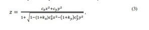
[089]Em algumas modalidades, a forma asférica pode incluir o deslocamento por perturbações que compreendem uma função de ordem superior da distância radial a partir do vértice de superfície bicônica. Assim, semelhante à equação (2), a retração da forma asférica pode incluir o termo bicônico e uma função de ordem superior. A função de ordem superior pode incluir pelo menos um termo mesmo fim, por exemplo, pelo menos um termo de segunda ordem (a2r2), um termo de quarta ordem (a4r4), um termo de sexta ordem (a6r6), e/ou um termo de oitava ordem (a8r8). Por exemplo, semelhante à equação (2), a função de ordem superior pode ser a2r2 + a4r4 + a6r6 + a8r8 +[089] In some embodiments, the aspheric shape may include displacement by perturbations comprising a higher-order function of the radial distance from the vertex of the biconic surface. Thus, similar to equation (2), the aspherical form shrinkage may include the biconic term and a higher-order function. The higher-order function may include at least one same-order term, for example, at least one second-order term (a2r2), a fourth-order term (a4r4), a sixth-order term (a6r6), and/or a eighth order term (a8r8). For example, similar to equation (2), the higher order function might be a2r2 + a4r4 + a6r6 + a8r8 +
[090]Em algumas modalidades, a função de ordem superior pode incluir um ou mais termos de ordem ímpar. Por exemplo, a função de ordem superior pode incluir apenas termos de ordem ímpar ou uma combinação de termos de ordem pares e ímpares.[090] In some embodiments, the higher-order function may include one or more odd-order terms. For example, the higher-order function can include only odd-order terms or a combination of even and odd-order terms.
[091]Assim, tal como aqui descrito, a superfície anterior 201a e/ou o 201b superfície posterior da óptica 201 pode ter uma forma que inclui um termo cônico (com ou sem uma função de ordem superior) ou um termo bicônico (com ou sem uma função de ordem superior).[091]Thus, as described herein, the
[092]Um exemplo para correção da visão para a presbiopia e/ou astigmatismo inclui uma superfície anterior 201a e uma superfície posterior 201b ambos com uma superfície asférica. A superfície asférica da 201a superfície anterior tem uma forma que inclui um termo cônico compensado por perturbações compreendendo segundo, quarto, sexto, e termos de ordem oitavo; e a superfície asférica 201b da superfície posterior tem uma forma que inclui um termo bicônico. O afundamento da 201a exemplo superfície anterior asférica pode ser dado como:
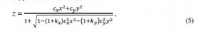
[093]Outros exemplos são possíveis. Em certas modalidades, a forma particular (por exemplo, a curvatura da superfície anterior, a curvatura da superfície posterior, constantes cônicas, coeficientes da função de ordem superior, etc.) da óptica 201 pode depender de prescrição do paciente.[093]Other examples are possible. In certain embodiments, the particular shape (e.g., anterior surface curvature, posterior surface curvature, conic constants, higher-order coefficients of function, etc.) of the optic 201 may depend on the patient's prescription.
[094]Como alguns exemplos, para as lentes que têm um poder de dioptria nominal entre cerca de -18 D a cerca de 6 D esférica com 0 a cerca de 2 D cilíndrico, com 0 a cerca de 3 D cilíndrico, ou com 0 a cerca de 4 D cilíndrico, o a seguir os parâmetros de concepção exemplo não limitativo, pode ser utilizado em certas modalidades. O raio R da superfície anterior (por exemplo, o inverso da curvatura) pode estar compreendida entre cerca de -100 mm a cerca de 100 mm, cerca de -50 mm a cerca de 50 mm, cerca de -10 mm a cerca de 10 mm, ou cerca de -5 mm a cerca de 5 mm. Em alguns exemplos, R da superfície anterior pode ser entre cerca de -1 mm a cerca de 1 mm ou 0 a cerca de 1 mm. Por exemplo, o raio da superfície anterior pode ser entre 0 a cerca de 1 x 10⁻² mm, entre cerca de 1 x 10⁻⁷ mm a cerca de 5 x 10⁻³ mm, entre cerca de 1 x 10⁻⁶ mm a cerca de 1 x 10⁻³ mm, ou entre cerca de 5 x 10⁻⁶ mm a cerca de 5 x 10⁻⁴ mm.[094] As some examples, for lenses that have a nominal diopter power between about -18 D to about 6 D spherical with 0 to about 2 D cylindrical, with 0 to about 3 D cylindrical, or with 0 the about 4D cylindrical, the following non-limiting example design parameters, may be used in certain embodiments. The radius R of the anterior surface (e.g. the inverse of the curvature) can be from about -100 mm to about 100 mm, about -50 mm to about 50 mm, about -10 mm to about 10 mm. mm, or about -5 mm to about 5 mm. In some examples, R of the anterior surface can be between about -1 mm to about 1 mm or 0 to about 1 mm. For example, the radius of the anterior surface can be between 0 to about 1 x 10⁻² mm, between about 1 x 10⁻⁷ mm to about 5 x 10⁻³ mm, between about 1 x 10⁻⁶ mm to about 1 x 10⁻³ mm, or between about 5 x 10⁻⁶ mm to about 5 x 10⁻⁴ mm.
[095]Tal como aqui descrito, em várias modalidades, k da superfície anterior pode ter uma magnitude maior do que zero tal que | k | > 0. Em algumas modalidades, k tem uma magnitude de pelo menos um, de tal forma que | k | > 1. Em algumas modalidades, | k | > 2, | k | > 3, | k | > 5, | k | > 7, ou | k | > 10. Por exemplo, k < -1, k < -2, k < -3, k < -5, k < -7, k < -10. Em algumas modalidades, K << -10. Por exemplo, em algumas modalidades, K pode ser entre cerca de -1 x 10 6 a -100, entre cerca de -5 x 10⁵ a cerca de -5 x 10⁴, ou entre cerca de -3 x 10⁵ a cerca de -2 x 10⁵ ou entre cerca de -3 x 10⁵ a cerca de -2 x 10⁵ ou entre cerca de -3 x 10⁵ a cerca de -2 x 10⁵.[095] As described herein, in various embodiments, k of the anterior surface may have a magnitude greater than zero such that | k | > 0. In some embodiments, k has a magnitude of at least one, such that | k | > 1. In some modalities, | k | > 2, | k | > 3, | k | > 5, | k | > 7, or | k | > 10. For example, k < -1, k < -2, k < -3, k < -5, k < -7, k < -10. In some modalities, K << -10. For example, in some embodiments, K can be between about -1 x 10 6 to -100, between about -5 x 10 5 to about -5 x 10 4 , or between about -3 x 10 5 to about -2 x 10⁵ or from about -3 x 10⁵ to about -2 x 10⁵ or from about -3 x 10⁵ to about -2 x 10⁵.
[096]Consequentemente, em diversas modalidades da magnitude da razão entre a constante cônica da superfície anterior e o raio de curvatura da superfície anterior pode ser entre 104 e 1014, entre 106e 1012, entre 108 e 1011, entre 109 e 1011, entre 108 e 1010, entre 10 9e 1010, em diversas modalidades.[096] Consequently, in various modalities the magnitude of the ratio between the conic constant of the anterior surface and the radius of curvature of the anterior surface can be between 104 and 1014, between 106 and 1012, between 108 and 1011, between 109 and 1011, between 108 and 1010, between 10 9 and 1010, in different modalities.
[097]O coeficiente de 2 para o termo de segunda ordem da superfície anterior em diversas modalidades pode ser entre 0 a cerca de 1. Por exemplo, um 2 pode ser entre 0 a cerca de 0,5, entre cerca de 0,001 a cerca de 0,3, ou entre cerca de 0,005 a cerca de 0,2.[097] The coefficient of 2 for the second order term of the anterior surface in various embodiments can be between 0 to about 1. For example, a 2 can be between 0 to about 0.5, between about 0.001 to about 0.001 to about from 0.3, or from about 0.005 to about 0.2.
[098]O coeficiente a4 para o quarto termo fim da superfície anterior em diversas modalidades pode estar entre cerca de -1 e 0. Por exemplo, a4 pode estar entre cerca de -0,1 a 0, entre cerca de -0,05 até cerca de -1 x 10⁻⁴, ou entre cerca de -0,01 até cerca de -1 x 10⁻³.[098]The coefficient a4 for the fourth end term of the front surface in various embodiments can be between about -1 and 0. For example, a4 can be between about -0.1 to 0, between about -0.05 to about -1 x 10 -4, or from about -0.01 to about -1 x 10 -3.
[099]O coeficiente a6 para o termo sexta ordem da superfície anterior em diversas modalidades pode ser entre 0 a cerca de 1. Por exemplo, a6 pode ser entre 0 a cerca de 0,1, entre 0 a cerca de 0,01, ou entre cerca de 0,0001 a cerca de 0,001.[099]The coefficient a6 for the sixth order term of the anterior surface in various embodiments can be between 0 to about 1. For example, a6 can be between 0 to about 0.1, between 0 to about 0.01, or from about 0.0001 to about 0.001.
[0100]Além disso, o coeficiente de a8 para o termo de oitava ordem da superfície anterior em diversas modalidades pode estar entre cerca de -1 e 0. Por exemplo, a8 pode estar compreendido entre cerca de -0,001 a 0, entre cerca de - 0,0005 0, ou entre cerca de 0 -0,0001.[0100]Furthermore, the coefficient of a8 for the eighth order term of the anterior surface in various embodiments can be between about -1 and 0. For example, a8 can be between about -0.001 to 0, between about -1 and 0. - 0.0005 0, or between about 0 -0.0001.
[0101]Além disso, para as lentes terem um poder dióptrico nominal entre cerca de -18 D a cerca de 6 D cilíndrico com 0 a cerca de 2 D cilíndrico, com 0 a cerca de 3 D cilíndrico, ou com 0 a cerca de 4 D cilíndrico, os seguintes parâmetros de projeto de exemplo não limitantes podem ser usados em certas modalidades para a superfície posterior. O raio Ry da superfície posterior na direção Y (por exemplo, o inverso da curvatura na direção y) pode situar-se entre 0 a cerca de 20 mm. Por exemplo, o raio Ry da superfície posterior pode ser entre 0 a cerca de 15 mm, entre cerca de 2 mm a cerca de 13 mm, ou entre cerca de 3 mm a cerca de 14 mm, ou entre cerca de 4 mm a cerca de 10 mm.[0101]Further, for lenses to have a nominal dioptric power between about -18D to about 6D cylindrical with 0 to about 2D cylindrical, with 0 to about 3D cylindrical, or with 0 to about 2D cylindrical 4D cylindrical, the following non-limiting example design parameters can be used in certain embodiments for the back surface. The radius Ry of the back surface in the Y direction (eg, the inverse of curvature in the y direction) can be from 0 to about 20 mm. For example, the radius Ry of the back surface can be from 0 to about 15 mm, from about 2 mm to about 13 mm, or from about 3 mm to about 14 mm, or from about 4 mm to about 14 mm. of 10 mm.
[0102]Em várias modalidades, ky da superfície posterior pode estar entre cerca de -20 a cerca de 20, entre cerca de -18 a cerca de 15, ou entre cerca de -15 a cerca de 5. Em algumas de tais modalidades, ky da superfície posterior não tem necessariamente uma magnitude de pelo menos uma. Por exemplo, ky pode estar entre cerca de -1 e cerca de 1. Em várias modalidades, | ky | é maior do que zero.[0102] In various embodiments, back surface ky can be between about -20 to about 20, between about -18 to about 15, or between about -15 to about 5. In some such embodiments, ky of the back surface does not necessarily have a magnitude of at least one. For example, ky can be between about -1 and about 1. In various embodiments, | ky | is greater than zero.
[0103]O raio R X da superfície posterior na direção de X (por exemplo, o inverso da curvatura na direção X) pode situar-se entre 0 a cerca de 20 mm. Por exemplo, o raio da superfície posterior pode ser entre 0 a cerca de 15 mm, entre 0 a cerca de 12 mm, ou entre 0 e cerca de 10 mm.[0103]The R X radius of the back surface in the X direction (for example, the inverse of the curvature in the X direction) can be from 0 to about 20 mm. For example, the radius of the back surface can be between 0 to about 15 mm, between 0 to about 12 mm, or between 0 and about 10 mm.
[0104]Em várias modalidades, kx da superfície posterior pode estar entre cerca de -25 a 0, entre cerca de -20 a 0, entre cerca de -18 a 0, entre cerca de -17,5 a 0, ou entre cerca de -15,5 a 0. Em várias modalidades, | kx | é maior do que zero.[0104] In various embodiments, kx of the back surface can be between about -25 to 0, between about -20 to 0, between about -18 to 0, between about -17.5 to 0, or between about from -15.5 to 0. In various modalities, | kx | is greater than zero.
[0105]Embora os parâmetros exemplo de projeto de R, k, a2 , a4, a6, e a8 para lentes que têm dado poder dióptrico nominal acima foram dadas para a superfície anterior e os parâmetros exemplo de projeto de Ry , ky , Rx , e kx foram dadas para a face posterior, as faixas de valores para R, k, a2 , a4, a6, e a8 podem ser usados para a superfície posterior, e as faixas de valores para Ry , ky ,R x e kx pode ser utilizada para a superfície anterior. Além disso, embora a superfície anterior incluídos os termos de ordem superior de perturbação asférica (por exemplo, a2, a4, a6, e a8), os termos de ordem superior de perturbação asférica (por exemplo, a2, a4, a6, e a8) pode ser usado para a face posterior, em vez de na superfície anterior ou para ambas as superfícies anterior e posterior. Qualquer um ou mais dos valores nestas faixas podem ser usados em qualquer um destes modelos, e kx pode ser utilizado para a superfície anterior. Além disso, embora a superfície anterior incluídos os termos de ordem superior de perturbação asférica (por exemplo, a2, a4, a6, e a8), os termos de ordem superior de perturbação asférica (por exemplo, a2, a4, a6, e a8) podem ser usados para a face posterior, em vez de na superfície anterior ou para ambas as superfícies anterior e posterior. Qualquer um ou mais dos valores nestas faixas podem ser usados em qualquer um destes modelos, e kx pode ser utilizado para a superfície anterior. Além disso, embora a superfície anterior incluídos os termos de ordem superior de perturbação asférica (por exemplo, a2, a4, a6, e a8), os termos de ordem superior de perturbação asférica (por exemplo, a2, a4, a6, e a8) pode ser usado para a face posterior, em vez de na superfície anterior ou para ambas as superfícies anterior e posterior. Qualquer um ou mais dos valores nestas faixas podem ser usados em qualquer um destes modelos. Embora a superfície anterior incluídos os termos de ordem superior de perturbação asférica (por exemplo, a2, a4, a6, e a8), os termos de ordem superior de perturbação asférica (por exemplo, a2, a4, a6, e a8 ) pode ser usado para a face posterior, em vez de na superfície anterior ou para ambas as superfícies anterior e posterior. Qualquer um ou mais dos valores nestas faixas podem ser usados em qualquer um destes modelos. Embora a superfície anterior incluídos os termos de ordem superior de perturbação asférica (por exemplo, a2, a4, a6, e a8 ), os termos de ordem superior de perturbação asférica (por exemplo, a2, a4, a6, e a8 ) pode ser usado para a face posterior, em vez de na superfície anterior ou para ambas as superfícies anterior e posterior. Qualquer um ou mais dos valores nestas faixas podem ser usados em qualquer um destes modelos, os termos de ordem superior de perturbação asférica (por exemplo, a2, a4, a6, e a8 ) pode ser usado para a face posterior, em vez de na superfície anterior ou para ambas as superfícies anterior e posterior. Qualquer um ou mais dos valores nestas faixas podem ser usados em qualquer um destes modelos, os termos de ordem superior de perturbação asférica (por exemplo, a2, a4, a6, e a8 ) pode ser usado para a face posterior, em vez de na superfície anterior ou para ambas as superfícies anterior e posterior. Qualquer um ou mais dos valores nestas faixas podem ser usados em qualquer um destes modelos.[0105]Although example design parameters of R, k, a2 , a4, a6, and a8 for lenses that have given nominal dioptric power above were given for the anterior surface and example design parameters of Ry , ky , Rx , and kx were given for the back surface, the ranges of values for R, k, a2 , a4, a6, and a8 can be used for the back surface, and the ranges of values for Ry , ky ,R x and kx can be used to the front surface. Furthermore, although the anterior surface included the higher-order aspherical perturbation terms (e.g., a2, a4, a6, and a8), the higher-order aspherical perturbation terms (e.g., a2, a4, a6, and a8 ) can be used for the back face instead of the front surface or for both the front and back surfaces. Any one or more of the values in these ranges can be used in any of these models, and kx can be used for the anterior surface. Furthermore, although the anterior surface included the higher-order aspherical perturbation terms (e.g., a2, a4, a6, and a8), the higher-order aspherical perturbation terms (e.g., a2, a4, a6, and a8 ) can be used for the back face instead of the front surface or for both the front and back surfaces. Any one or more of the values in these ranges can be used in any of these models, and kx can be used for the anterior surface. Furthermore, although the anterior surface included the higher-order aspherical perturbation terms (e.g., a2, a4, a6, and a8), the higher-order aspherical perturbation terms (e.g., a2, a4, a6, and a8 ) can be used for the back face instead of the front surface or for both the front and back surfaces. Any one or more of the values in these ranges can be used in any of these models. Although the anterior surface included the higher-order aspherical perturbation terms (e.g., a2, a4, a6, and a8), the higher-order aspherical perturbation terms (e.g., a2, a4, a6, and a8) can be used for the back face instead of the front surface or for both the front and back surfaces. Any one or more of the values in these ranges can be used in any of these models. Although the anterior surface included the higher-order aspherical perturbation terms (e.g., a2, a4, a6, and a8), the higher-order aspherical perturbation terms (e.g., a2, a4, a6, and a8) can be used for the back face instead of the front surface or for both the front and back surfaces. Any one or more of the values in these ranges can be used in any of these models, the higher order aspherical perturbation terms (e.g. a2, a4, a6, and a8 ) can be used for the back face rather than the anterior surface or for both anterior and posterior surfaces. Any one or more of the values in these ranges can be used in any of these models, the higher order aspherical perturbation terms (e.g. a2, a4, a6, and a8 ) can be used for the back face rather than the anterior surface or for both anterior and posterior surfaces. Any one or more of the values in these ranges can be used in any of these models.
[0106]Além disso, tal como aqui descrita, a forma particular de várias modalidades pode ser concebida para aumentar a profundidade de campo e para aumentar a acuidade visual. Como mostrado na Figura 6A, a profundidade de campo pode ser descrita como a distância em frente de e para além do sujeito no espaço objeto que parece estar em foco. A profundidade de foco pode ser descrita como uma medida de como existe maior distância por trás da lente no espaço de imagem, em que a imagem vai permanecer no foco. Para aumentar a profundidade de campo, a forma da superfície da superfície anterior 201a e/ou a forma da superfície da 201b superfície posterior da óptica 201 pode ser tal que, para uma vasta faixa de convergências objeto, os raios de luz estão focados na retina ou suficientemente próximo à mesma. Para aumentar a acuidade visual e reduzir fantasmas, a forma da superfície anterio201a r e/ou a forma da superfície posterior 201b da óptica 201 pode também ser tal que as imagens de um objeto no eixo são substancialmente no eixo e de grandeza semelhante umas com as outras.[0106]Furthermore, as described herein, the particular shape of various embodiments can be designed to increase depth of field and to increase visual acuity. As shown in Figure 6A, depth of field can be described as the distance in front of and beyond the subject in object space that appears to be in focus. Depth of focus can be described as a measure of how far there is behind the lens in image space, where the image will remain in focus. To increase the depth of field, the surface shape of the
[0107]Em alguns destes enquadramentos, a imagem cáustica pode ser esculpida para a faixa de convergência de cerca de 0 a cerca de 2,5 dioptrias ou mais, embora este intervalo pode ser maior ou menor. Como mostrado na Figura 6B, em algumas modalidades, a imagem cáustica pode ser descrita como o envelope produzido por uma grelha de feixes de luz, e o círculo de confusão pode ser descrito como um ponto óptico causada por um cone de raios de luz a partir de uma lente não chegando a um foco perfeito quando a imagem de um ponto de origem. Assim, a imagem cáustica pode ser esculpida de tal modo que o círculo de confusão é substanci-almente estável tendo um tamanho semelhante a uma faixa de posições longitudinais ao longo do eixo óptico e relativamente pequena. O projeto pode sacrificar o tamanho do círculo de confusão em algumas posições longitudinais ao longo do eixo óptico para permitir que o círculo de confusão a ser maiores para suas posições lon- gitudinais com o resultado líquido da prestação círculos de confusão com tamanho semelhante ao longo de um intervalo de posições longitudinais ao longo do eixo óptico.[0107] In some of these framings, the caustic image may be sculpted to the convergence range of about 0 to about 2.5 diopters or more, although this range may be greater or lesser. As shown in Figure 6B, in some embodiments, the caustic image can be described as the envelope produced by a grid of light beams, and the circle of confusion can be described as an optical point caused by a cone of light rays from of a lens not reaching perfect focus when the image from a point of origin. Thus, the caustic image can be sculpted such that the circle of confusion is substantially stable having a size similar to a range of longitudinal positions along the optical axis and relatively small. The design may sacrifice the size of the circle of confusion at some longitudinal positions along the optical axis to allow the circle of confusion to be larger for its longitudinal positions with the net result of providing similarly sized circles of confusion along a range of longitudinal positions along the optical axis.
[0108]Em certas modalidades, a forma da superfície da 201a superfície anterior e/ou a forma da superfície da superfície posterior 201b pode ser determinada de tal modo que a imagem cáustica é esculpida em torno do plano hiperfocal do olho. Em algumas modalidades, a distância hiperfocal pode ser descrita como a distância de focagem, que coloca o círculo máximo permitido de confusão no infinito, ou a distância de focagem que produz a maior profundidade de campo. Consequentemente, em determinadas modalidades, para aumentar a profundidade de campo, a forma da superfície da superfície anterior 201a e/ou a forma da superfície da 201b superfície posterior da óptica 200 pode ser tal que os raios de luz são reorientados à distância hiperfocal.[0108] In certain embodiments, the surface shape of the
[0109]Em várias modalidades, a forma da superfície da superfície anterior 201a e/ou a forma da superfície da 201b superfície posterior da óptica 201 pode ser avaliada e concebido utilizando as curvas de desfocagem da lente. Uma curva de desfocagem pode representar a resposta de um parâmetro de qualidade de imagem da retina, tais como o contraste, como uma função de diferentes convergências. Um objeto no infinito tem uma convergência de 0 dioptrias. Figura 6C ilustra as curvas de desfocagem de uma lente asférica padrão e um olho hiperfocal idealizado. Como mostrado na figura, embora o contraste pode diminuir (devido à preservação das áreas sob as curvas), o olho hiperfocal idealizado tem um contraste estáveis ou sensivelmente estáveis (por exemplo, semelhantes ou substancialmente constante) para uma faixa de convergências.[0109] In various embodiments, the surface shape of the
[0110]Em certas modalidades, a forma da superfície da superfície anterior 201a e/ou a forma da superfície da 201b superfície posterior da óptica 201 pode ser avaliada e/ou concebidos utilizando o modelo de olho Liou-Brennan, tais como sob Distância melhor corrigida acuidade Visual (BCDVA) condições. A Figura 6D ilustra uma vista esquemática de uma lente fáquica exemplar de acordo com certas modalidades aqui descritas modelados com o modelo de olho Liou-Brennan. Como mostrado na Figura 6D, a lente 200 pode ser posicionado entre a íris 515 e em frente da lente de cristalino "natural" 520 no modelo. Como também é mostrado na Figura 6D, o modelo pode simular os raios de luz que entram no olho através da córnea 500 510, a lente 200 e a lente cristalina "natural" 520 e em direção à retina 530.O modelo pode ser usado para os comprimentos de onda entre policromáticas na faixa de cerca de 400 nanômetros a cerca de 700 nanômetros. O modelo também pode ser utilizado com um perfil de índice de lente dupla de gradiente (por exemplo, para modelar o astigmatismo). Lentes pseudofáquicas de acordo com certas modalidades aqui descritas também podem ser modeladas com o modelo de olho Liou-Brennan com a lente posicionada no lugar da lente cristalina "natural" 520.[0110]In certain embodiments, the surface shape of the
[0111]Outros modelos conhecidos na especialidade ou ainda a serem desenvolvidos, também pode ser usado. Por exemplo, a forma da superfície da superfície anterior 201a e/ou a forma da superfície da 201b superfície posterior da óptica 201 pode também ser avaliada e/ou concebidos utilizando um modelo de olho Badal, um modelo de olho Arizona (Universidade de modelo Arizona), um modelo de olho Indiana (modelo de Universidade de Indiana), um olho modelo ISO ou qualquer padronizado ou equivalente modelo de olho. Além disso, as simulações podem ser realizadas utilizando o traçado de raios e/ou software de desenho conhecido na técnica, ou ainda a serem desenvolvidas. Como um exemplo de software, software de projeto ZEMAX por ZEMAX, LLC, em Redmond, Washington pode ser usado para algumas modalidades. As limitações físicas do ambiente, por exemplo, a colocação da LIO anterior para a lente natural são úteis para a realização de simulações para um projeto de lente fáquica. Tais simulações podem avaliar simultaneamente desempenho (por exemplo, RMS erro de frente de onda em toda a pupila completa) para múltiplas convergências um incluem as contribuições das diferentes convergências em uma função de mérito que é otimizado. Várias frentes de onda são, assim, avaliadas em uníssono para se chegar a um projeto equilibrado que fornece círculos de tamanho substancialmente similar, de confusão através de uma série de posições ao longo do eixo óptico. Variando o tamanho da pupila para diferentes convergências também podem ser empregues. Várias frentes de onda são, assim, avaliadas em uníssono para se chegar a um projeto equilibrado que fornece círculos de tamanho substancialmente similar, de confusão através de uma série de posições ao longo do eixo óptico. Variando o tamanho da pupila para diferentes convergências também podem ser empregues. Várias frentes de onda são, assim, avaliadas em uníssono para se chegar a um projeto equilibrado que fornece círculos de tamanho substancialmente similar, de confusão através de uma série de posições ao longo do eixo óptico. Variação do tamanho da pupila para diferentes convergências também pode ser empregue.[0111]Other models known in the art or still to be developed, can also be used. For example, the surface shape of the
[0112]Em certas modalidades, a forma da superfície da superfície anterior 201a e/ou a forma da superfície da 201b superfície posterior da óptica 201 pode ser vantajosamente avaliada e concebido de tal modo que, para os comprimentos de onda visíveis, a luz de um objeto no eixo está centrada substancialmente no eixo, com magnitude substancialmente semelhante, e substancialmente na retina dentro da faixa de, pelo menos, cerca de 0 dioptria a cerca de 2,5 dioptria. Ao controlar as diferentes ordens de anomalia asférica (por exemplo, que podem ser correlacionados com os termos de ordem asféricas mais elevados na equação (2)) para atingir um tamanho substancialmente similar seções transversais da cáustica para diferentes posições longitudinais ao longo do eixo óptico perto da retina , e incluindo o balanceamento tórico e de correção (por exemplo, o termo bicônico na equação (3)), quando necessário, para tratar pacientes com astigmatismo, o perfil de energia radial da lente 200 pode ser descrita como:
[0113]Para descrever o desempenho da lente 200, a função de transferência de modulação (MTF) pode ser utilizada em algumas modalidades. Por exemplo, o MTF pode descrever a capacidade da lente 200 para transferir contraste em uma resolução específica do objeto para a imagem. Em várias modalidades da lente 200, superfície anterior 201a e a superfície posterior 201b podem ser moldadas para fornecer valores de MTF para comprimentos de onda entre a faixa de cerca de 400 na- nômetros a cerca de 700 nanômetros (ponderado por distribuições fotópicas, esco- tópicas e/ou mesópicas) que estão entre cerca de 0,1 e cerca de 0,4 a frequências espaciais de cerca de 100 pares de linhas por milímetro (por exemplo, 20/20) para, pelo menos, cerca de 90%, pelo menos cerca de 95%, pelo menos cerca de 97%, pelo menos cerca de 98%,ou, pelo menos, cerca de 99% das convergências objeto dentro da faixa de, pelo menos, cerca de 0 dioptria para cerca de 2,0, 2,1, 2,2, 2,3, 2,4 ou 2,5 dioptria (ou a cerca de 2,6, 2,7, 2,8, 2,9, 3,0), quando a óptica 201 é inserida dentro de um olho. Por exemplo, o olho pode ser um olho humano tendo um diâmetro de abertura de, pelo menos, cerca de 2 milímetros, pelo menos, cerca de 3 milímetros, pelo menos, cerca de 4 milímetros, por exemplo, 2 a 6 milímetros, de 3 a 6 milímetros, ou 4 a 6 milímetro. Os valores MTF podem, assim, ser de 0,1, 0,2, 0,3, ou 0,4 ou qualquer faixa entre estas. Além disso, em várias implementações, as superfícies anterior e posterior são moldadas para fornecer funções de transferência de modulação sem inversão de fase de, pelo menos, 90%, 95%, ou 97%, até 98%, 99%, ou 100% dos convergências objetos dentro na faixa de 0 D a 2,5 D (ou, alternativamente, a 2,0, 2,1, 2,2, 2,3, 2,4, 2,6, 2,7,2,8, 2,9, ou 3,0 dioptria), quando a referida óptica é inserida em um modelo de olho tendo um tamanho de abertura de 2 a 6 milímetros, de 3 a 6 milímetros, ou 4 a 6 milímetros. Em algumas modalidades, quando o olho humano inclui uma lente cristalina, tais valores de MTF pode ser fornecida quando a óptica 201 é inserido anterior da lente cristalina. Em outras modalidades, quando o olho humano exclui uma lente cristalina, tais valores de MTF pode ser fornecida quando a óptica 201 é inserido no lugar da lente cristalina. Os valores MTF pode compreender valores médios MTF e pode ser calculado pela integração ao longo da faixa de comprimentos de onda, que é ponderado por qualquer uma das distribuições fotópicas, escotópicas, mesópicas ou suas combinações, ou de 4 a 6 milímetros. Em algumas modalidades, quando o olho humano inclui uma lente cristalina, tais valores de MTF pode ser fornecida quando a óptica 201 é inserido anterior da lente cristalina. Em outras modalidades, quando o olho humano exclui uma lente cristalina, tais valores de MTF pode ser fornecida quando a óptica 201 é inserido no lugar da lente cristalina. Os valores MTF pode compreender valores médios MTF e pode ser calculado pela integração ao longo da faixa de comprimentos de onda, que é ponderado por qualquer uma das distribuições fotópicas, escotópicas, mesópicas ou suas combinações, ou de 4 a 6 milímetros. Em algumas modalidades, quando o olho humano inclui uma lente cristalina, tais valores de MTF pode ser fornecida quando a óptica 201 é inserido anterior da lente cristalina. Em outras modalidades, quando o olho humano exclui uma lente cristalina, tais valores de MTF pode ser fornecida quando a óptica 201 é inserido no lugar da lente cristalina. Os valores MTF pode compreender valores médios MTF e pode ser calculado pela integração ao longo da faixa de comprimentos de onda, que é ponderado por qualquer uma das distribuições fotópicas, escotópicas, mesópicas ou suas combinações. Tais valores de MTF podem ser fornecidos quando a óptica 201 é inserida no lugar da lente cris- talina. Os valores MTF podem compreender valores médios de MTF e podem ser calculados pela integração ao longo da faixa de comprimentos de onda, que é ponderada por qualquer uma das distribuições fotópicas, escotópicas, mesópicas ou suas combinações. Tais valores de MTF podem ser fornecidos quando a óptica 201 é inserida no lugar da lente cristalina. Os valores MTF podem compreender valores médios de MTF e podem ser calculados pela integração ao longo da faixa de com-primentos de onda, que é ponderada por qualquer uma das distribuições fotópicas, escotópicas, mesópicas ou suas combinações.[0113]To describe the performance of the 200 lens, the modulation transfer function (MTF) may be used in some embodiments. For example, the MTF may describe the ability of the
[0114]Como outros exemplos, o olho pode ser um modelo de olho (por exemplo, olho modelo Liou-Brennan, Badal, Arizona, Indiana, ISO ou qualquer modelo de olho padronizado ou equivalente) que modela o olho humano em oposição a um olho humano si. Por exemplo, o modelo de olho em algumas modalidades também pode incluir um modelo de olho de Liou-Brennan. Em algumas modalidades, esses valores de MTF podem ser fornecidos quando a óptica 201 é inserida no modelo de olho em uma configuração fáquica. Em outras modalidades, esses valores de MTF podem ser fornecidos quando a óptica 201 é inserida em uma configuração pseudofáquica.[0114]As other examples, the eye can be an eye model (e.g. Liou-Brennan, Badal, Arizona, Indiana, ISO model eye or any standardized eye model or equivalent) that models the human eye as opposed to a human eye yes. For example, the eye model in some modalities may also include a Liou-Brennan eye model. In some embodiments, these MTF values may be provided when the optic 201 is inserted into the eye model in a phakic configuration. In other embodiments, these MTF values may be provided when the optic 201 is inserted in a pseudophakic configuration.
[0115]Várias implementações aqui descritas compreendem uma única lente de refração que pode ser implantada no olho, por exemplo, posterior da córnea. Em certas modalidades, a lente de refração é configurada para ser implantada entre a íris e a lente natural. Em outras implementações, a lente de refração é configurada para ser implantada na bolsa capsular depois da remoção da lente natural. Em várias implementações, a lente de refração não é uma lente difrativa e é desprovido de uma rede de difração sobre as suas superfícies. Em várias implementações, a lente de refração não tem focos discretos espaçados. As superfícies anterior e posterior, por exemplo, são moldadas de modo a não produzir focos discretos onde a luz é focada ao longo do eixo óptico O da lente que estão espaçadas entre si por regiões onde a luz é substancialmente menos focada como fornecida em lentes multifocais convencionais. Tal concepção multifocal com focos discretos ter vários picos de energia concentrada ou de densidade de energia em diferentes locais no eixo óptico.[0115] Various implementations described herein comprise a single refractive lens that can be implanted in the eye, e.g. posterior cornea. In certain embodiments, the refracting lens is configured to be implanted between the iris and the natural lens. In other implementations, the refracting lens is configured to be implanted in the capsular bag after the natural lens is removed. In various implementations, the refractive lens is not a diffractive lens and is devoid of a diffraction grating on its surfaces. In various implementations, the refraction lens does not have discretely spaced foci. The anterior and posterior surfaces, for example, are shaped so as not to produce discrete foci where light is focused along the optical axis O of the lens that are spaced apart by regions where light is substantially less focused as provided in multifocal lenses. conventional. Such a multifocal design with discrete foci will have multiple peaks of concentrated energy or energy density at different locations on the optical axis.
[0116]Várias implementações aqui descritas podem fornecer tratamento para início precoce e progressão da presbiopia, sem necessidade de cirurgia a laser ou óculos de leitura. Implementações podem fornecer cerca de 2,0D de perto, bem como a visualização intermediária. A profundidade de campo para a faixa acima de 2 D para uma abertura de 5,0 mm pode ser fornecida.[0116] Various implementations described here can provide treatment for early onset and progression of presbyopia without the need for laser surgery or reading glasses. Implementations can provide about 2.0D up close as well as the intermediate view. Depth of field for the range above 2D for a 5.0mm aperture can be provided.
[0117]Diversas modalidades podem ser empregues para proporcionar soluções de monovisão modificada. Por exemplo, uma primeira lente pode ser prevista que tem uma profundidade prolongada de foco para convergências objeto acima de 0 a 2,0 D ou mais de 0 a 2,5 D e segunda lente pode ser prevista que tem uma profundidade prolongada de foco para convergências de objeto sobre -2,0 a 0 D ou mais de -2,5 a 0 D. Estas respectivas lentes podem ser implantadas no paciente dominante e não dominante, respectivamente. Um paciente pode, então, ser fornecido com profundidade de campo alargado que é diferente para cada um do olho esquerdo e direito. No entanto, a profundidade total do campo é maior do que a fornecida por uma das primeiras ou segundas lentes ao longo. Os detalhes de concepção de tais lentes podem de outra forma ser semelhantes aos discutidos acima.[0117] Various modalities can be employed to provide modified monovision solutions. For example, a first lens may be envisioned that has an extended depth of focus for object convergences above 0 to 2.0 D or greater than 0 to 2.5 D and a second lens may be envisioned that has an extended depth of focus for object convergences over -2.0 to 0 D or more than -2.5 to 0 D. These respective lenses can be implanted in the dominant and non-dominant patient, respectively. A patient can then be provided with an extended depth of field that is different for each of the left and right eyes. However, the total depth of field is greater than that provided by one of the first or second lenses along. The design details of such lenses may otherwise be similar to those discussed above.
[0118]Tal como aqui descrito, incluem várias modalidades de uma lente com a profundidade de campo estendida. Por exemplo, com referência a lente 200 aqui descrito (por exemplo, como mostrado nas Figuras 2-4), a lente 200 pode incluir uma óptica 201 que tem uma superfície anterior 201a e/ou 201b de uma superfície posterior que tem uma forma concebida para aumentar a profundidade de campo. Em certas modalidades, a superfície anterior e/ou a superfície posterior da óptica também pode incluir uma porção concebida para melhorar a visão à distância (por exemplo, melhorar a acuidade visual à distância) e ainda fornecem profundidade de campo estendida.[0118]As described herein, include various embodiments of a lens with extended depth of field. For example, with reference to the
[0119]As Figuras 7A-7B são diagramas esquemáticos de um exemplo de superfície anterior e/ou uma superfície posterior de um tal óptica. A superfície anterior e a superfície posterior podem ter um vértice de superfície. A óptica pode ter um eixo óptico através dos vértices de superfície. A superfície anterior e/ou uma superfície posterior da óptica exemplo 700 pode incluir uma superfície que tem uma primeira porção 701 e uma segunda parte 702. A primeira parte 701 pode ser configurada para proporcionar a profundidade de campo estendida e a segunda porção 702 pode ser configurado para fornecer a correção da distância monofocal e focalização. Referindo-se as curvas de desfocagem mostrado na Figura 6C, a primeira porção 701 pode ter uma curva de desfocagem semelhante em forma à da curva de desfocagem hiperfocal "ideal", e a segunda porção 702 pode ter uma curva de desfocagem semelhante em forma à da (monofocal) da lente asférica padrão. Consequentemente, a primeira parte 701 pode ser configurada para proporcionar a profundidade de campo estendida, e a segunda parte 702 pode ser configurado para fornecer a visão à distância melhorados ou distância da acuidade visual. Por exemplo, a primeira parte 701 configurada para proporcionar uma profundidade de campo estendida pode fornecer quase igual acuidade visual, ou, pelo menos, mais do que para a segunda parte 702, ao longo de um intervalo de focagem (por exemplo, longe ou distância, in-termediário, perto), enquanto a segunda porção 702 pode proporcionar uma visão métrica de qualidade melhorada para a distância em relação à primeira porção 701. A visão métrica de qualidade aumentada pode ser uma figura de mérito para os objetos à distância (por exemplo, no ou perto 0,0 D). Objetos entre infinito e 2 metros (por exemplo, o infinito a 2 metros, o infinito para 3 metros, o infinito até 4 metros, o infinito até 5 metros, o infinito até 6 metros, o infinito até 7 metros, o infinito até 8 metros, o infinito até 9 metros, o infinito a 10 metros, ou quaisquer faixas entre qualquer uma destas faixas) são distância consideradas. A figura de mérito pode ser uma fun- ção de transferência de modulação (MTF), uma sensibilidade de contraste (CS), o contraste, uma derivação dos mesmos, ou uma combinação dos mesmos. Outros indicadores também podem ser utilizados para caracterizar a qualidade da imagem na distância de foco (o que corresponde à potência de base ou potência rotulada da lente) ou para objetos distantes. Em alguns casos, a visão métrica de qualidade aumentada pode ser um valor mais elevado para a segunda porção 702 do que para a primeira porção 701.infinito até 4 metros, o infinito até 5 metros, o infinito até 6 metros, o infinito até 7 metros, o infinito até 8 metros, o infinito até 9 metros, infinidade 10 metros, ou quaisquer varia entre qualquer uma dessas faixas) são considerados distância. A figura de mérito pode ser uma função de transferência de modulação (MTF), uma sensibilidade de contraste (CS), o contraste, uma derivação dos mesmos, ou uma combinação dos mesmos. Outros indicadores também podem ser utilizados para caracterizar a qualidade da imagem no foco distância (o que corresponde à potência de base ou potência rotulada da lente) ou para objetos distantes. Em alguns casos, a visão métrica de qualidade aumentada pode ser um valor mais elevado para a segunda porção 702 do que para a primeira porção 701.infinito até 4 metros, o infinito até 5 metros, o infinito até 6 metros, o infinito até 7 metros, o infinito até 8 metros, o infinito até 9 metros, infinidade 10 metros, ou quaisquer varia entre qualquer uma dessas faixas) são considerados distância. A figura de mérito pode ser uma função de transferência de modulação (MTF), uma sensibilidade de contraste (CS), o contraste, uma derivação dos mesmos, ou uma combinação dos mesmos. Outros indicadores também podem ser utilizados para caracterizar a qualidade da imagem no foco distância (o que corresponde à potência de base ou potência rotulada da lente) ou para objetos distantes. Em alguns casos, a visão métrica de qualidade aumentada pode ser um valor mais elevado para a segunda porção 702 do que para a primeira porção 701 ou quaisquer faixas entre em qualquer um desses intervalos de distância) são considerados. A figura de mérito pode ser uma função de transferência de modulação (MTF), uma sensibilidade de contraste (CS), o contraste, uma derivação dos mesmos, ou uma combinação dos mesmos. Outros indicadores também podem ser utilizados para caracterizar a qualidade da imagem no foco distância (o que corresponde à potência de base ou potência rotulada da lente) ou para objetos distantes. Em alguns casos, a visão métrica de qualidade aumentada pode ser um valor mais elevado para a segunda porção 702 do que para a primeira porção 701.ou quaisquer faixas entre em qualquer um desses intervalos de distância) são considerados. A figura de mérito pode ser uma função de transferência de modulação (MTF), uma sensibilidade de contraste (CS), o contraste, uma derivação dos mesmos, ou uma combinação dos mesmos. Outros indicadores também podem ser utilizados para caracterizar a qualidade da imagem no foco distância (o que corresponde à potência de base ou potência rotulada da lente) ou para objetos distantes. Em alguns casos, a visão métrica de qualidade aumentada pode ser um valor mais elevado para a segunda porção 702 do que para a primeira porção 701.Outros indicadores também podem ser utilizados para caracterizar a qualidade da imagem no foco distância (o que corresponde à potência de base ou potência rotulada da lente) ou para objetos distantes. Em alguns casos, a visão métrica de qualidade aumentada pode ser um valor mais elevado para a segunda porção 702 do que para a primeira porção 701.Outros indicadores também podem ser utilizados para caracterizar a qualidade da imagem no foco distância (o que corresponde à potência de base ou potência rotulada da lente) ou para objetos distantes. Em alguns casos, a visão métrica de qualidade aumentada pode ser um valor mais elevado para a segunda porção 702 do que para a primeira porção 701.[0119] Figures 7A-7B are schematic diagrams of an example of a front surface and/or a back surface of such an optic. The front surface and the back surface can have a surface vertex. The optics may have an optical axis through the surface vertices. The front surface and/or a rear surface of the
[0120]Figura 7B ilustra como os raios que passam através da segunda porção 702 estão focados no foco visão à distância (rotulada como 0). (Como mencionado acima, este foco a visão à distância corresponde à potência de base, potência rotulada, ou poder de distância da lente.) Em contraste, os raios que passam através da primeira forma porção 701 de uma cáustica de diâmetro quase constante através de focos longe (0), intermediário (1), e perto (2) em oposição a um único foco nos planos de distância (0), intermediário (1) ou próximo (2) proporcionando deste modo uma profundidade de campo estendida.[0120]Figure 7B illustrates how the rays passing through the
[0121]Como se mostra nas Figuras 7A-7B, a primeira porção 701 pode ser disposta centralmente no interior da óptica 700.Em alguns casos, a primeira parte está disposta centralmente sobre o eixo óptico. A primeira parte 701 pode ter um diâmetro da seção transversal na faixa de cerca de 2,5-4,5 mm (por exemplo, 2,5 mm, 2,75 mm, 3,0 mm, 3,25 mm, 3,5 mm, 3,75 mm, 4,0 mm, 4,25 mm, 4,5 mm, ou quaisquer faixas entre qualquer um destes tamanhos). Os tamanhos maiores ou menores podem também ser possíveis. A primeira parte 701 pode ter um perfil de superfície, tal como aqui descrita com respeito a óptica 201 para proporcionar a pro-fundidade de campo estendida. Por exemplo, a primeira porção 701 pode introduzir anomalia asférica para proporcionar a profundidade de campo estendida. Em alguns exemplos, tal como aqui descrito, a primeira porção 701 pode ter uma forma que compreende uma cônica ou um deslocamento por perturbações do envelope, compreendendo uma função de ordem superior asférica da distância radial a partir do eixo óptico do envelope bicônico. A equação (2) descreve uma forma de exemplo, usando um termo cônico e os termos polinomiais mesmo movidos. Outros exemplos e combinações são possíveis. Por exemplo, a primeira porção 701 pode ter uma forma que compreende um envelope biasférico. O envelope biasférico pode incluir duas seções transversais asféricas em duas direções ortogonais. Em alguns casos, o envelope biasférico pode ser compensado por perturbações que compreendem uma função de ordem superior asférica da distância radial a partir do eixo óptico. Outros exemplos e combinações são possíveis. Por exemplo, a primeira porção 701 pode ter uma forma que compreende um envelope biasférico. O envelope biasférico pode incluir duas seções transversais asféricas em duas direções ortogonais. Em alguns casos, o envelope biasférico pode ser compensado por perturbações que compreendem uma função de ordem superior asférica da distância radial a partir do eixo óptico. Outros exemplos e combinações são possíveis. Por exemplo, a primeira porção 701 pode ter uma forma que compreende um envelope biasférico. O envelope biasférico pode incluir duas seções transversais asféricas em duas direções ortogonais. Em alguns casos, o envelope biasférico pode ser compensado por perturbações que compreendem uma função de ordem superior asférica da distância radial a partir do eixo óptico.[0121] As shown in Figures 7A-7B, the
[0122]A segunda porção 702 pode envolver a primeira parte 701. A segunda parte 702 pode estender-se desde a primeira porção 701 para o fim da óptica 700. Consequentemente, em alguns exemplos, a largura da segunda porção 702 pode ser a distância entre a periferia exterior da primeira parte 701 à borda da óptica 700. Por exemplo, a segunda porção 702 pode ter uma largura (por exemplo, uma distância entre os raios interno e externo) na faixa de cerca de 1,0-3,5 mm (por exemplo, 1,0 mm, 1,25 mm, 1,5 mm, 1,75 mm, 2,0 mm, 2,25 mm, 2,5 mm, 2,75 mm, 3,0 mm, 3,25 mm, 3,5 mm ou quaisquer faixas entre qualquer um destes tamanhos). Tamanhos fora destes limites são também possíveis.[0122]The
[0123]A segunda porção 702 pode ter um perfil de superfície diferente do que a primeira porção 701. A primeira porção 701 pode ter maior controle anomalia asférica que fornece uma profundidade de campo prolongado do que a segunda porção 702. Em alguns casos, a segunda porção 702 pode ter substancialmente nenhum controle anomalia asférica ou pelo menos nenhum controle anomalia que fornece prorrogado profundidade de foco. Por exemplo, a segunda porção 702 pode ter uma forma que compreende um envelope cônico, bicônico, ou biasférico não compensado por perturbações que compreende uma função de ordem superior asférica da distância radial a partir do eixo óptico. Em alguns casos, a segunda porção pode ter uma forma que é asférica.[0123]The
[0124]A segunda parte 702 pode permitir um maior controle dos raios marginais do sistema de tal forma que uma percentagem mais elevada dos raios que se propagam através desta parte está focada na retina potencialmente proporcionando maior contraste ou melhorou a qualidade da visão, como medida por outras métricas para objetos a uma distância tal como no infinito, em comparação com a primeira porção (por exemplo, para poder distância ou potência rotulada de cerca de 6 até - 18 D). Isso permite que um foco mais definido para a distância (possivelmente um ponto inferior no plano da distância para os objetos à distância), e ainda fornece a profundidade de campo estendida fornecida pela primeira porção 701. Assim, a segunda porção 702 pode aumentar a qualidade de visão de distância de responsivi- dade, a criação de uma melhoria na focagem objetos a uma distância. Esta visão melhorada de distância pode ser percebida pelo paciente como um aumento nos indicadores de "positivo" favorecido pelo cérebro, por exemplo, a sensibilidade ao contraste (CS).[0124]The
[0125]Além disso, como a primeira porção 701 está configurado para proporcionar uma profundidade de campo estendida, pode fornecer acuidade visual quase igual ou visão, ou, pelo menos, mais do que a segunda porção 702, ao longo de um intervalo de focagem (ou para uma faixa de distâncias de objetos). O tamanho do ponto, de frente de onda da lente, e a qualidade (por exemplo, tal como medido por uma figura de mérito, tais como MTF ou CS) a uma distância, intermédia, e perto de pontos são substancialmente semelhantes. No entanto, este atributo pode criar dificuldades em avaliar o poder da lente usando metrologia padrão. Avaliação clínica pós-operatória de um paciente usando métodos de metrologia Gaussiana clássicos também pode ser um desafio. Qualquer número de pontos focais poderia ser rotulado e encontrado para ser uma potência de base válido (por exemplo, a distância ou a etiqueta de energia). Em certas modalidades, a segunda porção 702 dirigindo um anel de raios marginais para um local da distância de focagem pode fornecer uma medição repetida de forma mais estreita correspondendo a distância do poder. Da mesma forma, a segunda porção 702 pode proporcionar um benefício na determinação da potência de base clássica da lente implantada ou não implantada, e pode contribuir para a capacidade de medir com precisão a potência da lente usando os métodos da indústria de metrologia padrão. Assim, certas modalidades aqui descritas podem permitir a medição padronizada de uma lente com a profundidade de campo estendida, incluindo, mas não se limitando a, potência negativa, potência positiva, tóricas, ou qualquer combinação deles. A segunda porção 702 pode proporcionar um benefício na determinação da potência de base clássica da lente implantada ou não implantada, e pode contribuir para a capacidade de medir com precisão a potência da lente usando os métodos da indústria de metrologia padrão. Assim, certas modalidades aqui descritas podem permitir a medição padronizada de uma lente com a profundidade de campo estendida, incluindo, mas não se limitando a, potência negativa, potência positiva, tóricas, ou qualquer combinação deles. A segunda porção 702 pode proporcionar um benefício na determinação da potência de base clássica da lente implantada ou não implantada, e pode contribuir para a capacidade de medir com precisão a potência da lente usando os métodos da indústria de me-trologia padrão. Assim, certas modalidades aqui descritas podem permitir a medição padronizada de uma lente com a profundidade de campo estendida, incluindo, mas não se limitando a, potência negativa, potência positiva, tóricas, ou qualquer combinação deles.[0125]Furthermore, as the
[0126]Em várias modalidades aqui descritas, a primeira porção 701 pode permitir o uso de diferentes ordens de anomalia asférica e de uma curva de base cônica, bicônica, ou biasférica, a fim de equilibrar toda a frente de onda em cada um dos seus pontos perto da saída pupila do olho implantado, e a segunda porção 702 pode permitir a visão à distância reforçada e/ou a distância monofocal do foco e para o uso da metrologia padrão.[0126] In various embodiments described here, the
[0127]Em várias modalidades, a superfície anterior e/ou a superfície posterior da óptica 700 pode incluir outras porções. Por exemplo, a superfície anterior e/ou a superfície posterior da óptica 700 pode ainda incluir uma porção de transição (não mostrada) proporcionando uma transição suave sem descontinuidade entre a primeira porção 701 e a segunda porção 702. A porção de transição pode também permitir otimização de frente de onda adicional. Em algumas modalidades, a porção de transição pode ter uma largura (por exemplo, a distância entre o raio interior e o raio exterior) na faixa de cerca de 0 a 1 mm (por exemplo, 0 mm, 0,1 mm, 0,2 mm, 0,3 mm, 0,4 mm, 0,5 mm, 0,6 milímetros, 0,7 mm, 0,8 milímetros, 0,9 mm, 1,0 milímetros, ou quaisquer faixas entre qualquer um destes tamanhos). Os valores fora destes intervalos, também são possíveis. Em alguns casos, a transição entre as curvaturas da primeira porção 701 e da segunda porção 702 pode ser lisa o suficiente para que nenhuma região de transição é desejada.[0127] In various embodiments, the front surface and/or the back surface of the optic 700 may include other portions. For example, the front surface and/or the back surface of the optic 700 may further include a transition portion (not shown) providing a smooth, seamless transition between the
[0128]As figuras 8A-8B são diagramas esquemáticos para uma outra superfície exemplo anterior e/ou uma superfície posterior de uma óptica tendo uma primeira parte configurada para proporcionar a profundidade de campo estendida, e uma segunda parte configurada para proporcionar distância melhorada acuidade visual. Neste exemplo, a superfície anterior e/ou a superfície posterior da óptica 700 pode incluir uma primeira porção 701 e uma segunda porção 702 como nas Figuras 7A- 7B. Tal como mostrado nas Figuras 8A-8B, a superfície anterior e/ou a superfície posterior da óptica 700 pode também incluir uma terceira parte 703 em torno da segunda porção 702. Em algumas de tais modalidades, a primeira porção 701 pode ter um corte transversal máximo diâmetro na faixa de cerca de 2,5-4,5 mm (por exemplo, 2,5 mm, 2,75 mm, 3,0 mm, 3,25 mm, 3,5 mm, 3,75 mm, 4,0 mm, 4,25 mm, 4,5 mm ou quaisquer intervalos entre qualquer um desses tamanhos). A segunda porção 702 pode ser descrita como uma coroa circular com uma largura entre os raios interno e externo na faixa de cerca de 0,25-1,5 mm (por exemplo, 0,25 mm, 0,5 mm, 0,75 mm, 1,0 mm, 1,25 mm, 1,5 mm, ou os intervalos entre quaisquer desses tamanhos). Além disso, a terceira parte 703 pode estender-se desde a segunda porção 702 para o fim da óptica 700. Consequentemente, em alguns exemplos, a largura da terceira porção 703 pode ser a distância entre a periferia exterior da segunda parte 702 para a extremidade da óptica 700. Por exemplo, a terceira parte 703 pode ter uma largura (por exemplo, a distância entre os raios interno e externo) na faixa de cerca de 0,53,5 mm (por exemplo, 0,5 mm, 0,75 mm, 1,0 mm, 1,25 mm, 1,5 mm, 1,75 mm; 2,0 mm, 2,25 mm, 2,5 mm, 2,75 mm, 3,0 mm, 3,5 mm, ou quaisquer faixas entre qualquer um destes tamanhos). Os valores fora destes intervalos, também são possíveis.[0128] Figures 8A-8B are schematic diagrams for another example front surface and/or a back surface of an optic having a first part configured to provide extended depth of field, and a second part configured to provide improved distance visual acuity. . In this example, the front surface and/or the rear surface of
[0129]Figura 8B ilustra como os raios que passam através da segunda porção 702 estão focados no foco visão à distância (rotulada como 0). Em contraste, os raios que passa através da primeira porção 701 e a terceira parte 703 do foco continuamente através dos focos distante (0), intermediário (1), e próximo (2) proporcionando deste modo uma profundidade de campo estendido. Como discutido acima, os raios que passa através da primeira porção 701 e terceira parte 703 de forma de uma cáustica tendo quase constante a seção transversal ou diâmetro de feixe nos planos distante (0), intermediário (1), e próximo (2). Este diâmetro do feixe, no entanto, pode ser potencialmente maior do que o tamanho do ponto de foco no plano de imagem distante (0) formado por os raios que se propagam unicamente através da segunda porção 702.[0129]Figure 8B illustrates how the rays passing through the
[0130]A terceira parte 703 pode ter um perfil de superfície diferente do que o segundo perfil 702. Por exemplo, a terceira parte 703 pode ter maior controle contra anomalia asférica que fornece uma profundidade de campo prolongado do que a segunda porção 702. Em alguns exemplos, a terceira porção 703 pode ter uma forma que compreende um envelope cônico, bicônico, ou biasférico compensado por perturbações que compreende uma função de ordem superior asférica da distância radial a partir do eixo óptico.[0130]The
[0131]Em algumas modalidades, a terceira porção 703 pode ter um perfil de superfície semelhante e/ou substancialmente o mesmo controle de anomalia asféri- ca, como a primeira porção 701. Por exemplo, a terceira porção 703 pode ter substancialmente sido compensada por perturbações em relação ao envelope, compreendendo uma função de ordem superior asférica da distância radial a partir do eixo óptico como a primeira porção do mesmo envelope cônico, bicônico ou biasférico.[0131] In some embodiments, the
[0132]Como aqui descrito, a primeira porção 701 e/ou a terceira parte 703 pode ter uma forma que compreende um, bicônico, envelope biasférico cônico compensado por perturbações compreendendo uma função de ordem superior asférica da distância radial a partir do eixo óptico. Em várias modalidades, a função de ordem superior asférica podem incluir, pelo menos, uma ordem mesmo termo, a2nr2n, onde n é um número inteiro e a2n é um coeficiente e r é a distância radial a partir do eixo óptico. Por exemplo, a função de ordem superior asférica pode incluir um termo de segunda ordem, a2r2, onde a2 é um coeficiente e r é a distância radial a partir do eixo óptico. A função de ordem superior asférica pode incluir uma quarta termo fim, a4r4, em que a4 é um coeficiente e r é a distância radial a partir do eixo óptico. A função de ordem superior asférica pode também incluir um termo de sexta ordem, a6r6 onde a6 é um coeficiente e r é a distância radial a partir do eixo óptico. A função de ordem superior asférica pode ainda incluir um termo de oitava ordem, a8r8, onde a8 é um coeficiente e r é a distância radial a partir do eixo óptico. A função de ordem superior asférica pode incluir qualquer combinação destes termos de ordem superior e, possivelmente, mais termos.[0132] As described herein, the
[0133]Em várias modalidades, a superfície anterior e/ou a superfície posterior da óptica 700 pode ainda incluir uma porção de transição (não mostrada) proporcionando uma transição suave sem descontinuidade entre a segunda porção 702 e a terceira porção 703. A porção de transição também pode permitir a otimização de frente de onda adicional. Em algumas modalidades, a porção de transição pode ter uma largura (por exemplo, a distância entre o raio interior e o raio exterior) na faixa de cerca de 0 a 1 mm (por exemplo, 0 mm, 0,1 mm, 0,2 mm, 0,3 mm, 0,4 mm, 0,5 mm, 0,6 mm, 0,7 mm, 0,8 mm, 0,9 mm, 1,0 mm, ou quaisquer faixas entre qualquer um destes tamanhos). Dimensões fora destes limites são também possíveis. Em alguns casos, a transição entre as curvaturas da segunda porção 702 e a terceira parte 703 pode ser lisa o suficiente para que nenhuma região de transição é desejada.[0133] In various embodiments, the front surface and/or the back surface of the optic 700 may further include a transition portion (not shown) providing a smooth, seamless transition between the
[0134]Em algumas modalidades, a cáustica da segunda porção 702 pode ser esculpida para se misturar sem problemas (ou para proporcionar uma transição suave) com a cáustica da primeira porção 701 e/ou a cáustica da terceira parte 703. Por exemplo, como mostrado na Figura 8B, o envelope inferior cáustico da segunda porção 702 não pode misturar-se suavemente com o envelope inferior cáustico da terceira porção de 703 (por exemplo, ver a descontinuidade perto do cruzamento de cáusticos). Consequentemente, em algumas modalidades, para proporcionar uma transição cáustica suave, a constante cônica do envelope cônico, bicônico, ou bias- férico da segunda porção 702 pode ser tal que se misturar mais suave com a cáustica da primeira porção 701 e/ou a cáustica de a terceira porção de 703 (por exemplo, para caber mais firmemente com o envelope do raio da primeira porção 701 e/ou para se adaptar mais estreitamente com o envelope do raio da terceira parte 703). Por exemplo, em algumas modalidades, a segunda porção 702 pode ter uma cons-tante cônica de modo a que a cáustica da segunda porção 702 funde-se suavemente com a cáustica da primeira porção 701, por exemplo, mais facilmente do que se a segunda porção compreende uma superfície asférica. Além disso, em algumas modalidades, a segunda porção 702 pode ter uma constante cônica de modo a que a cáustica da segunda porção 702 funde-se suavemente com a cáustica da terceira porção 703, por exemplo, mais facilmente do que se a segunda porção compreende uma superfície asférica. Por ter uma transição mais suave de cáustica, um ligeiro desalinhamento na colocação cirúrgica dos implantes pode ser esperado para produzir um efeito menos visível na visão do paciente. Além disso, com uma transição suave cáustica, fantasmas sobrepostos podem potencialmente ser reduzidos.[0134]In some embodiments, the caustic from the
[0135]As várias divulgações em relação à óptica 201 aqui descrito pode também aplicar-se a várias modalidades das Figuras 7A-8B. Por exemplo, certas modalidades das Figuras 7A-8B pode ser utilizada para implantes de lentes fáquicas ou pseudofáquicas tal como aqui descrito. Em modalidades utilizadas para implantes de lentes fáquicas, a óptica 700 pode ter uma espessura ao longo do eixo óptico que é de cerca de 100-700 micrômetros, cerca de 100 a cerca de 600 micrômetros, cerca de 100 a cerca de 500 micrômetros, cerca de 100 a cerca de 400 micrômetros a cerca de 100 a cerca de 300 micrômetros, ou cerca de 100 a cerca de 200 micrômetros (por exemplo, a 100 micrômetros, 200 micrômetros, 300 micrômetros, 400 micrôme- tros, 500 micrômetros, 600 micrômetros, 700 micrômetros, qualquer valor entre essas faixas, ou qualquer intervalo formado por tais valores ). Em modalidades de implantes de lente pseudofáquica, a espessura ao longo do eixo óptico pode ser de cerca de 700 micrômetros a cerca de 4 mm, a cerca de 700 micrômetros a cerca de 3 mm, cerca de 700 micrômetros a cerca de 2 mm, a cerca de 700 micrômetros a cerca de 1 mm, qualquer valor entre essas faixas, ou qualquer intervalo formado por quaisquer valores nestas faixas. Como outro exemplo, várias modalidades das Figuras 7A-8B pode ser usado em uma lente que compreende pelo menos uma háptica disposta com respeito à óptica 700 para afixar a óptica 700 no olho quando nele implantado. Além disso, em alguns casos, a primeira porção 701 pode estar sobre a superfície anterior da óptica, e a segunda porção 702 pode estar sobre a superfície posterior da óptica. Do mesmo modo, em alguns casos, a primeira porção 701 pode estar sobre a superfície posterior da óptica, e a segunda parte 702 pode ser na su-perfície anterior da óptica, cerca de 700 micrômetros a cerca de 2 mm, a cerca de 700 micrômetros a cerca de 1 mm, em qualquer valor entre estes intervalos, ou qualquer intervalo formado por quaisquer valores nestas faixas. Como outro exemplo, várias modalidades das Figuras 7A-8B pode ser usado em uma lente que compreende pelo menos uma háptica disposta com respeito à óptica 700 para afixar a óptica 700 no olho quando nele implantado. Além disso, em alguns casos, a primeira porção 701 pode estar sobre a superfície anterior da óptica, e a segunda porção 702 pode estar sobre a superfície posterior da óptica. Do mesmo modo, em alguns casos, a primeira porção 701 pode estar sobre a superfície posterior da óptica, e a segunda parte 702 pode ser na superfície anterior da óptica, cerca de 700 micrômetros a cerca de 2 mm, a cerca de 700 micrômetros a cerca de 1 mm, em qualquer valor entre estes intervalos, ou qualquer intervalo formado por quaisquer valores nestas faixas. Como outro exemplo, várias modalidades das Figuras 7A-8B pode ser usado em uma lente que compreende pelo menos uma háptica disposta com respeito à óptica 700 para afixar a óptica 700 no olho quando nele implantado. Além disso, em alguns casos, a primeira porção 701 pode estar sobre a superfície anterior da óptica, e a segunda porção 702 pode estar sobre a superfície posterior da óptica. Do mesmo modo, em alguns casos, a primeira porção 701 pode estar sobre a superfície posterior da óptica, e a segunda parte 702 pode ser na superfície anterior da óptica. Como outro exemplo, várias modalidades das Figuras 7A-8B pode ser usado em uma lente que compreende pelo menos uma háptica disposta com respeito à óptica 700 para afixar a óptica 700 no olho quando nele implantado. Além disso, em alguns casos, a primeira porção 701 pode estar sobre a superfície anterior da óptica, e a segunda porção 702 pode estar sobre a superfície posterior da óptica. Do mesmo modo, em alguns casos, a primeira porção 701 pode estar sobre a superfície posterior da óptica, e a segunda parte 702 pode ser na superfície anterior da óptica. Como outro exemplo, várias modalidades das Figuras 7A-8B pode ser usado em uma lente que compreende pelo menos uma háptica disposta com respeito à óptica 700 para afixar a óptica 700 no olho quando nele implantado. Além disso, em alguns casos, a primeira porção 701 pode estar sobre a superfície anterior da óptica, e a segunda porção 702 pode estar sobre a superfície posterior da óptica. Do mesmo modo, em alguns casos, a primeira porção 701 pode estar sobre a superfície posterior da óptica, e a segunda parte 702 pode ser na superfície anterior da óptica, e a segunda porção 702 pode estar sobre a superfície posterior da óptica. Do mesmo modo, em alguns casos, a primeira porção 701 pode estar sobre a superfície posterior da óptica, e a segunda parte 702 pode ser na superfície anterior da óptica, e a segunda porção 702 pode estar sobre a superfície posterior da óptica. Do mesmo modo, em alguns casos, a primeira porção 701 pode estar sobre a superfície posterior da óptica, e a segunda parte 702 pode estar na superfície anterior da óptica.[0135] The various disclosures regarding the
[0136]Os termos "cerca" e "substancialmente", como aqui utilizado representam uma quantidade igual ou perto da quantidade indicada (por exemplo, uma quantidade que ainda desempenha uma função desejada ou consegue um resultado de-sejado). Por exemplo, salvo indicação em contrário, os termos "cerca" e "substancialmente" pode se referir a uma quantidade que está dentro (por exemplo, acima ou abaixo) 10%, no prazo (por exemplo, acima ou abaixo) 5% de, no prazo (por exemplo, acima ou abaixo) de 1% de, dentro (por exemplo, acima ou abaixo) de 0,1%, ou dentro (por exemplo, acima ou abaixo) de 0,01% da quantidade indicada.[0136] The terms "about" and "substantially" as used herein represent an amount equal to or close to the indicated amount (e.g., an amount that still performs a desired function or achieves a desired result). For example, unless otherwise noted, the terms "about" and "substantially" may refer to an amount that is within (for example, above or below) 10%, within (for example, above or below) 5% of , within (eg above or below) 1% of, within (eg above or below) 0.1%, or within (eg above or below) 0.01% of the indicated amount.
[0137]Diversas modalidades da presente invenção foram aqui descritas. Embora esta invenção tenha sido descrita com referência a estas modalidades específicas, as descrições se destinam a ser ilustrativas da invenção e não se destinam a ser limitativas. Várias modificações e aplicações podem ocorrer aos peritos na arte sem afastamento do verdadeiro espírito e âmbito da invenção.[0137] Various embodiments of the present invention have been described herein. While this invention has been described with reference to these specific embodiments, the descriptions are intended to be illustrative of the invention and are not intended to be limiting. Various modifications and applications may occur to those skilled in the art without departing from the true spirit and scope of the invention.
Claims (23)
Applications Claiming Priority (7)
| Application Number | Priority Date | Filing Date | Title |
|---|---|---|---|
| US201462048135P | 2014-09-09 | 2014-09-09 | |
| US62/048,135 | 2014-09-09 | ||
| US201462048705P | 2014-09-10 | 2014-09-10 | |
| US62/048,705 | 2014-09-10 | ||
| US201562149481P | 2015-04-17 | 2015-04-17 | |
| US62/149,481 | 2015-04-17 | ||
| PCT/US2015/048961 WO2016040331A1 (en) | 2014-09-09 | 2015-09-08 | Ophthalmic implants with extended depth of field and enhanced distance visual acuity |
Publications (2)
| Publication Number | Publication Date |
|---|---|
| BR112017004765A2 BR112017004765A2 (en) | 2017-12-05 |
| BR112017004765B1 true BR112017004765B1 (en) | 2022-08-23 |
Family
ID=55459481
Family Applications (1)
| Application Number | Title | Priority Date | Filing Date |
|---|---|---|---|
| BR112017004765-9A BR112017004765B1 (en) | 2014-09-09 | 2015-09-08 | LENS CONFIGURED FOR IMPLANTATION IN A HUMAN EYE |
Country Status (11)
| Country | Link |
|---|---|
| US (2) | US10485655B2 (en) |
| EP (2) | EP3191022B1 (en) |
| JP (4) | JP6572311B2 (en) |
| KR (3) | KR102171529B1 (en) |
| CN (2) | CN111265331B (en) |
| AU (2) | AU2015315342B2 (en) |
| BR (1) | BR112017004765B1 (en) |
| CA (2) | CA3141468C (en) |
| ES (1) | ES2914102T3 (en) |
| SG (2) | SG10202008006QA (en) |
| WO (1) | WO2016040331A1 (en) |
Families Citing this family (28)
| Publication number | Priority date | Publication date | Assignee | Title |
|---|---|---|---|---|
| BR112017004765B1 (en) | 2014-09-09 | 2022-08-23 | Staar Surgical Company | LENS CONFIGURED FOR IMPLANTATION IN A HUMAN EYE |
| US12127934B2 (en) | 2014-09-09 | 2024-10-29 | Staar Surgical Company | Method of Providing Modified Monovision to a Subject with a First Lens and a Second Lens |
| US11696823B2 (en) | 2015-04-14 | 2023-07-11 | Z Optics, Inc. | High definition and extended depth of field intraocular lens |
| US11547554B2 (en) | 2015-04-14 | 2023-01-10 | Z Optics, Inc. | High definition and extended depth of field intraocular lens |
| US11083566B2 (en) | 2016-02-29 | 2021-08-10 | Alcon Inc. | Ophthalmic lens having an extended depth of focus |
| US9968440B2 (en) * | 2016-02-29 | 2018-05-15 | Novartis Ag | Ophthalmic lens having an extended depth of focus |
| AU2017229594B2 (en) * | 2016-03-09 | 2022-06-16 | Staar Surgical Company | Ophthalmic implants with extended depth of field and enhanced distance visual acuity |
| FR3072020B1 (en) * | 2017-10-05 | 2019-11-08 | Cristalens Industrie | ASSEMBLY CONSISTING OF A PAIR OF MULTIFOCAL OCULAR IMPLANTS |
| EP3740159A1 (en) * | 2018-01-16 | 2020-11-25 | Sav-Iol Sa | Ophthalmic assembly for implantation in an anterior chamber of an eye of a patient and method for accommodating the vision of the patient |
| JP7250108B2 (en) * | 2018-07-13 | 2023-03-31 | アイブライト メディカル テクノロジー (ペキン) カンパニー リミテッド | Intraocular lens and manufacturing method thereof |
| EP3837571B1 (en) | 2018-08-17 | 2023-08-02 | Staar Surgical Company | Polymeric composition exhibiting nanogradient of refractive index |
| WO2020076154A1 (en) * | 2018-10-08 | 2020-04-16 | Akkolens International B.V. | Accommodating intraocular lens with combination of variable aberrations for extension of depth of field |
| WO2020179332A1 (en) * | 2019-03-06 | 2020-09-10 | 株式会社ニデック | Intraocular lens and method of manufacturing same |
| EP3942995B1 (en) | 2019-03-19 | 2023-11-08 | Topcon Corporation | Slit lamp microscope |
| CN113873968A (en) * | 2019-04-10 | 2021-12-31 | Z光学股份有限公司 | High definition and extended depth of field intraocular lens |
| US20200383775A1 (en) * | 2019-06-07 | 2020-12-10 | Voptica, S.L | Intraocular lens and methods for optimization of depth of focus and the image quality in the periphery of the visual field |
| WO2021007377A1 (en) * | 2019-07-09 | 2021-01-14 | Aaren Scientific Inc. | Intraocular lens designs for optimal clinical outcome |
| BE1027570B1 (en) * | 2019-09-11 | 2021-04-06 | Physiol Sa | Intraocular lens with extended depth of field |
| US12245972B2 (en) | 2020-02-21 | 2025-03-11 | Wavefront Dynamics, Inc. | System and methods for customizing an intraocular lens using a wavefront aberrometer |
| IT202000012721A1 (en) * | 2020-05-28 | 2021-11-28 | Sifi Spa | LENS FOR OPHTHALMIC USE |
| CN114077069A (en) * | 2020-08-14 | 2022-02-22 | 亨泰光学股份有限公司 | Multi-arc multi-segment cornea molding contact lens positioning structure and method |
| CN113040976B (en) * | 2021-03-04 | 2022-06-28 | 天津世纪康泰生物医学工程有限公司 | Ultrathin zero-spherical-aberration implantable myopia lens |
| US12343081B2 (en) | 2021-05-19 | 2025-07-01 | Wavefront Dynamics, Inc. | Optical aberrometer systems for customizing intraocular lens |
| US12458536B2 (en) | 2021-05-19 | 2025-11-04 | Wavefront Dynamics, Inc. | Methods for customizing intraocular lens using an optical aberrometer |
| CA3234381A1 (en) | 2021-10-04 | 2023-04-13 | Staar Surgical Company | Ophthalmic implants for correcting vision with a tunable optic, and methods of manufacture and use |
| CN114911070B (en) * | 2022-04-29 | 2023-10-03 | 麦得科科技有限公司 | Ophthalmic lenses for preventing the progression of myopia and glasses using the same |
| EP4626362A1 (en) * | 2022-12-02 | 2025-10-08 | Aaren Scientific, Inc. | Augmented monofocal ophthalmic lens with micro-wavefront perturbation |
| CN115844587B (en) * | 2022-12-08 | 2023-10-31 | 无锡蕾明视康科技有限公司 | Intraocular lens with extended focal depth type posterior chamber and lens and preparation method thereof |
Family Cites Families (312)
| Publication number | Priority date | Publication date | Assignee | Title |
|---|---|---|---|---|
| US4525043A (en) | 1977-11-11 | 1985-06-25 | Leonard Bronstein | Contact lens |
| US4529657A (en) | 1978-05-30 | 1985-07-16 | Ppg Industries, Inc. | Method for lowering the surface energy of glass |
| US4199231A (en) | 1978-08-21 | 1980-04-22 | Evans Carl H | Hydrogel contact lens |
| US4373225A (en) | 1979-07-06 | 1983-02-15 | Friedrich Wilh. Schwing, Gmbh | Piping valve with a housing for the transfer of a wiper insertable in conduits that supply pressurized viscous material, preferably concrete |
| EP0064812B1 (en) | 1981-04-29 | 1985-08-14 | Pilkington P.E. Limited | Artificial eye lenses |
| US4504982A (en) | 1982-08-05 | 1985-03-19 | Optical Radiation Corporation | Aspheric intraocular lens |
| US4640595A (en) | 1984-05-02 | 1987-02-03 | David Volk | Aspheric contact lens |
| US4787904A (en) | 1984-07-06 | 1988-11-29 | Severin Sanford L | Hydrophillic intraocular lens |
| US4681102A (en) | 1985-09-11 | 1987-07-21 | Bartell Michael T | Apparatus and method for insertion of an intra-ocular lens |
| US4752123A (en) | 1985-11-19 | 1988-06-21 | University Optical Products Co. | Concentric bifocal contact lens with two distance power regions |
| DE3665216D1 (en) | 1985-11-21 | 1989-09-28 | Werner Fiala | Process for raising the temperature of catalysts and device for performing the process |
| US4990582A (en) | 1986-07-18 | 1991-02-05 | Salamone Joseph C | Fluorine containing soft contact lens hydrogels |
| US4710193A (en) | 1986-08-18 | 1987-12-01 | David Volk | Accommodating intraocular lens and lens series and method of lens selection |
| US4731079A (en) | 1986-11-26 | 1988-03-15 | Kingston Technologies, Inc. | Intraocular lenses |
| AU594233B2 (en) | 1987-04-10 | 1990-03-01 | University Of Florida | Improved ocular implants and methods for their manufacture |
| AU3238593A (en) | 1987-05-20 | 1994-07-04 | Frederick A. Dr. Hauber | Intraocular achromatic lens |
| US4769035A (en) | 1987-06-02 | 1988-09-06 | Kelman Charles D | Artificial lens and the method for implanting such lens |
| US4835189A (en) | 1987-06-05 | 1989-05-30 | G. D. Searle & Co. | Phenolic thioalkylamides as inhibitors of 5-lipoxygenase |
| US4769033A (en) | 1987-07-02 | 1988-09-06 | Nordan Lee T | Intraocular multifocal lens |
| US7192444B2 (en) | 1987-08-24 | 2007-03-20 | Advanced Medical Optics, Inc. | Aspheric soft lens |
| US5001009A (en) | 1987-09-02 | 1991-03-19 | Sterilization Technical Services, Inc. | Lubricious hydrophilic composite coated on substrates |
| US4834750A (en) | 1987-09-17 | 1989-05-30 | Ioptex Research, Inc. | Deformable-elastic intraocular lens |
| US4981342A (en) | 1987-09-24 | 1991-01-01 | Allergan Inc. | Multifocal birefringent lens system |
| IL85860A (en) | 1988-03-24 | 1992-06-21 | Amir Cohen | Contact lens |
| US5073021A (en) | 1989-03-17 | 1991-12-17 | Environmental Research Institute Of Michigan | Bifocal ophthalmic lens constructed from birefringent material |
| FR2647227B1 (en) | 1989-05-19 | 1991-08-23 | Essilor Int | OPTICAL COMPONENT, SUCH AS AN INTRAOCULAR IMPLANT OR CONTACT LENS, SUITABLE FOR CORRECTING THE VISION OF AN INDIVIDUAL |
| RU2033165C1 (en) | 1989-10-13 | 1995-04-20 | Межотраслевой научно-технический комплекс "Микрохирургия глаза" | Process for manufacture of plastic material from collagen |
| ATE117810T1 (en) | 1990-03-15 | 1995-02-15 | Werner Fiala | USE OF A MULTIFOCAL BIBRIFFERENT LENS WITH ADJUSTED BIrefringence. |
| US5476514A (en) | 1990-04-27 | 1995-12-19 | Cumming; J. Stuart | Accommodating intraocular lens |
| US5437647A (en) | 1990-05-09 | 1995-08-01 | Safety Syringes, Inc. | Disposable self-shielding aspirating syringe |
| FR2664678B1 (en) | 1990-07-10 | 1993-06-25 | Cricket Sa | CATALYTIC BURNER. |
| US5229797A (en) | 1990-08-08 | 1993-07-20 | Minnesota Mining And Manufacturing Company | Multifocal diffractive ophthalmic lenses |
| US5260727A (en) | 1990-10-22 | 1993-11-09 | Oksman Henry C | Wide depth of focus intraocular and contact lenses |
| JP2724931B2 (en) | 1990-11-07 | 1998-03-09 | ネッスル エス エー | Copolymer and intraocular lens using the copolymer |
| US5290892A (en) | 1990-11-07 | 1994-03-01 | Nestle S.A. | Flexible intraocular lenses made from high refractive index polymers |
| US5217491A (en) | 1990-12-27 | 1993-06-08 | American Cyanamid Company | Composite intraocular lens |
| EP0503111A1 (en) | 1991-03-13 | 1992-09-16 | Toyohiko Kashiwagi | Aspherical lens, method of producing the lens and apparatus for producing the lens |
| US5198844A (en) | 1991-07-10 | 1993-03-30 | Johnson & Johnson Vision Products, Inc. | Segmented multifocal contact lens |
| US5245366A (en) | 1991-10-31 | 1993-09-14 | Svochak Jan B | Bifocal contact lens and method of making same |
| SK377492A3 (en) | 1992-01-28 | 1995-05-10 | Johnson & Johnson Vision Prod | Multifocal refracting lens and method of its manufacture |
| DE59304449D1 (en) | 1992-04-03 | 1996-12-19 | Adatomed Pharma Chiron | Intraocular lens set |
| US5620450A (en) | 1992-09-30 | 1997-04-15 | Staar Surgical Company, Inc. | Transverse hinged deformable intraocular lens injecting apparatus |
| US5499987A (en) | 1992-09-30 | 1996-03-19 | Staar Surgical Company | Deformable intraocular lens cartridge |
| JP3664444B2 (en) | 1992-09-30 | 2005-06-29 | スター・サージカル・カンパニー | Intraocular lens insertion system |
| US5616148A (en) | 1992-09-30 | 1997-04-01 | Staar Surgical Company, Inc. | Transverse hinged deformable intraocular lens injecting apparatus |
| US5331073A (en) | 1992-11-09 | 1994-07-19 | Allergan, Inc. | Polymeric compositions and intraocular lenses made from same |
| US5822091A (en) | 1993-02-22 | 1998-10-13 | Baker; Kenneth M. | Extreme depth-of-field optical lens and holographic projector system for its production |
| US5771088A (en) | 1993-03-27 | 1998-06-23 | Pilkington Barnes Hind, Inc. | Contact lens designed to accommodate and correct for the effects of presbyopia |
| RU2033114C1 (en) | 1993-04-22 | 1995-04-20 | Межотраслевой научно-технический комплекс "Микрохирургия глаза" | Artificial crystalline lens |
| ATE190336T1 (en) | 1993-04-30 | 2000-03-15 | Alcon Lab Inc | METHOD FOR REDUCING THE STICKNESS OF SOFT ACRYLIC POLYMERS |
| US5329363A (en) | 1993-06-15 | 1994-07-12 | U. S. Precision Lens Incorporated | Projection lens systems having reduced spherochromatism |
| US5603774A (en) | 1993-09-27 | 1997-02-18 | Alcon Laboratories, Inc. | Method for reducing tackiness of soft acrylic polymers |
| US5436678A (en) | 1993-09-30 | 1995-07-25 | Wilmington Partners L.P. | Aspheric multifocal contact lens |
| JPH07184989A (en) | 1993-12-28 | 1995-07-25 | Kuraray Co Ltd | Hemocompatible medical polymeric materials and medical materials |
| WO1995025288A1 (en) | 1994-03-17 | 1995-09-21 | Bifocon Optics Forschungs- Und Entwicklungsgmbh | Zoned lens |
| US5517260A (en) | 1994-03-28 | 1996-05-14 | Vari-Site, Inc. | Ophthalmic lens having a progressive multifocal zone and method of manufacturing same |
| US5523316A (en) | 1994-06-23 | 1996-06-04 | Alcon Laboratories, Inc. | Intraocular irrigating solution containing agent for controlling IOP |
| US5661218A (en) | 1994-07-22 | 1997-08-26 | Staar Surgical Company, Inc. | Biocompatible optically transparent polymeric material based upon collagen and method of making |
| US5654388A (en) | 1994-07-22 | 1997-08-05 | Staar Surgical Company, Inc. | Biocompatible optically transparent polymeric material based upon collagen and method of making |
| US5654363A (en) | 1994-07-22 | 1997-08-05 | Staar Surgical Company, Inc. | Biocompatible optically transparent polymeric material based upon collagen and method of making |
| US5910537A (en) | 1994-07-22 | 1999-06-08 | Staar Surgical Company Inc. | Biocompatible, optically transparent, ultraviolet light absorbing, polymeric material based upon collagen and method of making |
| US5654349A (en) | 1994-07-22 | 1997-08-05 | Staar Surgical Company, Inc. | Biocompatible optically transparent polymeric material based upon collagen and method of making |
| CA2201936C (en) | 1994-10-06 | 2006-12-19 | Vladimir Feingold | Intraocular contact lens and method of implantation |
| US5574518A (en) | 1995-01-10 | 1996-11-12 | Les Laboratoires Opti-Centre Inc. | System incorporation two different sphero-non-spherical contact lenses for correcting presbytia |
| JP2967093B2 (en) | 1995-02-23 | 1999-10-25 | ホーヤ株式会社 | Flexible intraocular lens |
| FR2731081B1 (en) | 1995-02-27 | 1997-04-11 | Essilor Int | PROCESS FOR OBTAINING A TRANSPARENT ARTICLE WITH A REFRACTION INDEX |
| US6165490A (en) | 1996-04-05 | 2000-12-26 | Staar Surgical Ag | Biological material, method of preparing such materials, uses thereof and products made therefrom |
| US5715031A (en) | 1995-05-04 | 1998-02-03 | Johnson & Johnson Vision Products, Inc. | Concentric aspheric multifocal lens designs |
| HUP9601126A3 (en) | 1995-05-04 | 1999-10-28 | Johnson & Johnson Vision Prod | Concentric, aspheric, multifocal lens |
| IL118065A0 (en) | 1995-05-04 | 1996-08-04 | Johnson & Johnson Vision Prod | Aspheric toric lens designs |
| US5684560A (en) | 1995-05-04 | 1997-11-04 | Johnson & Johnson Vision Products, Inc. | Concentric ring single vision lens designs |
| US5929969A (en) | 1995-05-04 | 1999-07-27 | Johnson & Johnson Vision Products, Inc. | Multifocal ophthalmic lens |
| WO1996039106A1 (en) | 1995-06-06 | 1996-12-12 | Scientific Optics, Inc. | Asymmetric bifocal intraocular lens |
| PT774983E (en) | 1995-06-07 | 2003-03-31 | Alcon Lab Inc | IMPROVED MATERIALS FOR OPHTHALMIC LENSES WITH HIGH REFRACTION INDEX |
| US6045578A (en) | 1995-11-28 | 2000-04-04 | Queensland University Of Technology | Optical treatment method |
| RU2089198C1 (en) | 1995-11-30 | 1997-09-10 | Межотраслевой научно-технический комплекс "Микрохирургия глаза" | Method of preparing biomaterial for using in ophthalmology |
| US6150472A (en) | 1995-12-22 | 2000-11-21 | Holland Biomaterials Group B.V. | Multi-functional site containing polymers, and applications thereof |
| US5702440A (en) | 1996-01-26 | 1997-12-30 | Allergan | Multifocal ophthalmic lens for dim-lighting conditions |
| FR2744908B1 (en) | 1996-02-20 | 1998-06-12 | W K Et Associes | MYOPIC INTRAOCULAR IMPLANT |
| KR100497280B1 (en) | 1996-02-29 | 2005-07-01 | 미네소타 마이닝 앤드 매뉴팩춰링 캄파니 | An optical film with co-continuous phases |
| FR2745711B1 (en) | 1996-03-05 | 1998-05-07 | Ioltechnologie Production | FLEXIBLE IMPLANT FORMING INTRAOCULAR LENS FOR POSTERIOR CHAMBER |
| US5717049A (en) | 1996-03-25 | 1998-02-10 | Pharmacia Iovision, Inc. | High refractive index hydrogels prepared from polymers and copolymers of N-benzyl-N-methylacrylamide |
| US5864378A (en) | 1996-05-21 | 1999-01-26 | Allergan | Enhanced monofocal IOL or contact lens |
| US5913989A (en) | 1996-07-08 | 1999-06-22 | Alcan International Limited | Process for producing aluminum alloy can body stock |
| US5716364A (en) | 1996-07-10 | 1998-02-10 | Allergan | IOL insertion apparatus and method for making and using same |
| US5859685A (en) | 1996-07-18 | 1999-01-12 | Innotech, Inc. | Achromatic ophthalmic lenses |
| US5922821A (en) | 1996-08-09 | 1999-07-13 | Alcon Laboratories, Inc. | Ophthalmic lens polymers |
| US5843186A (en) | 1996-12-20 | 1998-12-01 | Implemed, Inc. | Intraocular lens with antimicrobial activity |
| US5766245A (en) | 1996-12-30 | 1998-06-16 | Staar Surgical, Ag | Intraocular lens for correcting moderate to severe hypermetropia |
| US5947975A (en) | 1997-03-07 | 1999-09-07 | Canon Staar Co., Inc. | Inserting device for deformable intraocular lens |
| US5843188A (en) | 1997-10-20 | 1998-12-01 | Henry H. McDonald | Accommodative lens implantation |
| US6148862A (en) | 1998-03-27 | 2000-11-21 | Applied Power Inc. | Solenoid valve coil pack |
| US6088322A (en) | 1998-05-07 | 2000-07-11 | Broome; Barry G. | Single objective lens for use with CD or DVD optical disks |
| US6036891A (en) | 1998-05-11 | 2000-03-14 | Pharmacia & Upjohn | Polymerizable hydrophilic ultraviolet light absorbing monomers |
| WO2000008516A1 (en) | 1998-08-06 | 2000-02-17 | Lett John B W | Multifocal aspheric lens |
| US6120148A (en) | 1998-10-05 | 2000-09-19 | Bifocon Optics Gmbh | Diffractive lens |
| US6241766B1 (en) | 1998-10-29 | 2001-06-05 | Allergan Sales, Inc. | Intraocular lenses made from polymeric compositions |
| US6245106B1 (en) | 1998-10-29 | 2001-06-12 | Allergan Sales, Inc. | Intraocular lenses made from polymeric compositions and monomers useful in said compositions |
| US6238975B1 (en) | 1998-11-25 | 2001-05-29 | Advanced Micro Devices, Inc. | Method for improving electrostatic discharge (ESD) robustness |
| US6210005B1 (en) | 1999-02-04 | 2001-04-03 | Valdemar Portney | Multifocal ophthalmic lens with reduced halo size |
| AU3739100A (en) | 1999-03-12 | 2000-09-28 | Bausch & Lomb Incorporated | Multifocal lens article |
| US6203973B1 (en) | 1999-03-25 | 2001-03-20 | Eastman Kodak Company | Polymer latexes with core-shell morphology |
| US6488708B2 (en) | 1999-04-09 | 2002-12-03 | Faezeh Sarfarazi | Open chamber, elliptical, accommodative intraocular lens system |
| US6179420B1 (en) | 1999-04-21 | 2001-01-30 | Johnson & Johnson Vision Products, Inc. | Multifocal ophthalmic lenses |
| US6790232B1 (en) | 1999-04-30 | 2004-09-14 | Advanced Medical Optics, Inc. | Multifocal phakic intraocular lens |
| US20060238702A1 (en) | 1999-04-30 | 2006-10-26 | Advanced Medical Optics, Inc. | Ophthalmic lens combinations |
| US20030060881A1 (en) | 1999-04-30 | 2003-03-27 | Advanced Medical Optics, Inc. | Intraocular lens combinations |
| US6386357B1 (en) | 1999-07-12 | 2002-05-14 | Hoya Healthcare Corporation | Soft intraocular lens-folding device and storage case |
| US6536899B1 (en) | 1999-07-14 | 2003-03-25 | Bifocon Optics Gmbh | Multifocal lens exhibiting diffractive and refractive powers |
| US6451056B1 (en) | 1999-08-09 | 2002-09-17 | J. Stuart Cumming | Lens for increased depth of focus |
| US6271281B1 (en) | 1999-08-26 | 2001-08-07 | Medennium, Inc. | Homopolymers containing stable elasticity inducing crosslinkers and ocular implants made therefrom |
| FR2803921B1 (en) | 2000-01-14 | 2002-04-05 | Essilor Int | SET OF TWO OPHTHALMIC LENSES, RANGE AND METHOD FOR CONSTITUTING SUCH A GAME |
| BR0109416A (en) | 2000-03-24 | 2002-12-10 | Novartis Ag | Polymers |
| US6398809B1 (en) | 2000-04-12 | 2002-06-04 | Bausch & Lomb Incorporated | Intraocular lens |
| US6547822B1 (en) | 2000-05-03 | 2003-04-15 | Advanced Medical Optics, Inc. | Opthalmic lens systems |
| US6537317B1 (en) | 2000-05-03 | 2003-03-25 | Advanced Medical Optics, Inc. | Binocular lens systems |
| US6609793B2 (en) | 2000-05-23 | 2003-08-26 | Pharmacia Groningen Bv | Methods of obtaining ophthalmic lenses providing the eye with reduced aberrations |
| EP2332495B1 (en) | 2000-05-23 | 2014-04-23 | AMO Groningen B.V. | Methods of obtaining ophthalmic lenses providing the eye with reduced aberrations |
| US6506212B2 (en) | 2000-07-07 | 2003-01-14 | Medennium, Inc. | Anatomically compatible posterior chamber phakic refractive lenses |
| US7178918B2 (en) | 2000-09-08 | 2007-02-20 | Griffin Richard A | Ophthalmic lenses with induced aperture and redundant power regions |
| US6474814B1 (en) | 2000-09-08 | 2002-11-05 | Florida Optical Engineering, Inc | Multifocal ophthalmic lens with induced aperture |
| US6957891B2 (en) | 2000-09-29 | 2005-10-25 | Fiala Werner J | Ophthalmic lens with surface structures |
| AU2001296567B2 (en) * | 2000-10-10 | 2006-07-06 | University Of Rochester | Determination of ocular refraction from wavefront aberration data |
| US6500181B1 (en) | 2000-10-17 | 2002-12-31 | Valdemar Portney | Instrument for folding and inserting anterior chamber intraocular lenses |
| US7152975B2 (en) | 2000-11-10 | 2006-12-26 | Cooper Vision, Inc. | Junctionless ophthalmic lenses and methods for making same |
| US20010044657A1 (en) | 2000-11-30 | 2001-11-22 | Kellan Robert E. | Phakic or aphakic intraocular lens assembly |
| SE0004829D0 (en) | 2000-12-22 | 2000-12-22 | Pharmacia Groningen Bv | Methods of obtaining ophthalmic lenses providing the eye with reduced aberrations |
| US20020120330A1 (en) | 2001-02-27 | 2002-08-29 | Galin Miles A. | Refractive anterior chamber intraocular implant |
| US6576012B2 (en) | 2001-03-28 | 2003-06-10 | Advanced Medical Optics, Inc. | Binocular lens systems |
| SE0101293D0 (en) | 2001-04-11 | 2001-04-11 | Pharmacia Groningen Bv | Technical field of the invention |
| US20030014107A1 (en) * | 2001-06-28 | 2003-01-16 | Michael Reynard | Multifocal phakic intraocular lens |
| US6533416B1 (en) | 2001-07-20 | 2003-03-18 | Ocular Sciences, Inc. | Contact or intraocular lens and method for its preparation |
| US6520638B1 (en) | 2001-08-14 | 2003-02-18 | Johnson & Johnson Vision Care, Inc. | Methods for designing multifocal ophthalmic lenses |
| DE60230173D1 (en) | 2001-10-19 | 2009-01-15 | Bausch & Lomb | presbyopia |
| US20030097177A1 (en) | 2001-11-21 | 2003-05-22 | Tran Son Trung | Posterior chamber phakic lens |
| JP4009185B2 (en) | 2001-11-30 | 2007-11-14 | 株式会社メニコン | How to make contact lenses |
| FR2833154B1 (en) | 2001-12-12 | 2004-11-19 | Ioltechnologie Production | CASSETTE AND FLEXIBLE INTRAOCULAR LENS INJECTOR AND METHOD FOR INJECTING SUCH LENSES |
| US20030187505A1 (en) | 2002-03-29 | 2003-10-02 | Xiugao Liao | Accommodating intraocular lens with textured haptics |
| US7008979B2 (en) | 2002-04-30 | 2006-03-07 | Hydromer, Inc. | Coating composition for multiple hydrophilic applications |
| EP1513477A1 (en) | 2002-05-31 | 2005-03-16 | Carl Zeiss Meditec AG | Method for controlling a device for treating the human eye |
| US6737448B2 (en) | 2002-06-03 | 2004-05-18 | Staar Surgical Company | High refractive index, optically clear and soft hydrophobic acrylamide copolymers |
| FR2841767B1 (en) | 2002-07-03 | 2005-04-22 | Ioltechnologie Production | ACCOMMODATE INTRAOCULAR LENS |
| US20040087963A1 (en) | 2002-08-07 | 2004-05-06 | Alexei Ossipov | Medical device having increased lubricity |
| US20040059343A1 (en) | 2002-09-25 | 2004-03-25 | Kevin Shearer | Novel enhanced system for intraocular lens insertion |
| JP2004121433A (en) | 2002-09-30 | 2004-04-22 | Nidek Co Ltd | Intraocular lens |
| AU2003276034A1 (en) | 2002-10-04 | 2004-05-04 | Carl Zeiss Ag | Method for production of a lens and lens produced thus |
| US6709103B1 (en) | 2002-10-31 | 2004-03-23 | Johnson & Johnson Vision Care, Inc. | Methods for designing multifocal ophthalmic lenses |
| US7381221B2 (en) | 2002-11-08 | 2008-06-03 | Advanced Medical Optics, Inc. | Multi-zonal monofocal intraocular lens for correcting optical aberrations |
| SE0203564D0 (en) | 2002-11-29 | 2002-11-29 | Pharmacia Groningen Bv | Multifocal opthalmic lens |
| FR2848182B1 (en) | 2002-12-04 | 2006-02-03 | Eurocrystal | METHOD AND DEVICE FOR STERILE PACKAGING OF A SOFT HYDROPHILIC INTRAOCULAR LENS READY FOR USE |
| US8911086B2 (en) | 2002-12-06 | 2014-12-16 | Amo Manufacturing Usa, Llc | Compound modulation transfer function for laser surgery and other optical applications |
| DE10258332A1 (en) | 2002-12-12 | 2004-07-08 | Rodenstock Gmbh | Pair of spectacle lenses |
| US7036931B2 (en) | 2003-01-29 | 2006-05-02 | Novartis Ag | Ophthalmic lenses |
| US6802606B2 (en) | 2003-02-04 | 2004-10-12 | Johnson & Johnson Vision Care, Inc. | Multifocal contact lens pairs |
| WO2004090611A2 (en) * | 2003-03-31 | 2004-10-21 | Bausch & Lomb Incorporated | Intraocular lens and method for reducing aberrations in an ocular system |
| JP4611288B2 (en) | 2003-04-18 | 2011-01-12 | ヴィズイクス・インコーポレーテッド | System and method for correcting higher order aberrations in laser refractive surgery |
| US6923539B2 (en) | 2003-05-12 | 2005-08-02 | Alcon, Inc. | Aspheric lenses |
| DE10325841A1 (en) | 2003-06-06 | 2004-12-30 | Acritec Gmbh | intraocular lens |
| JP2005002377A (en) | 2003-06-10 | 2005-01-06 | Osaka Prefecture | Method for forming diamond-like carbon film |
| ATE527570T1 (en) | 2003-06-30 | 2011-10-15 | Werner Fiala | INTRAOCULAR LENS OR CONTACT LENSES WITH LARGE DEPTH OF FOCUS |
| US20050027354A1 (en) | 2003-07-28 | 2005-02-03 | Advanced Medical Optics, Inc. | Primary and supplemental intraocular lens |
| US7780678B2 (en) | 2003-08-13 | 2010-08-24 | Bausch & Lomb Incorporated | Thermal treatment to improve intraocular lens inserter lubricity |
| JP2005062965A (en) | 2003-08-19 | 2005-03-10 | Fuji Photo Film Co Ltd | Management computer in album creating system and computer for requesting image |
| US7422604B2 (en) | 2003-08-28 | 2008-09-09 | Bausch & Lomb Incorporated | Preloaded IOL injector |
| US6899425B2 (en) | 2003-10-28 | 2005-05-31 | Johnson & Johnson Vision Care, Inc. | Multifocal ophthalmic lenses |
| US7503655B2 (en) | 2003-11-19 | 2009-03-17 | Vision Crc Limited | Methods and apparatuses for altering relative curvature of field and positions of peripheral, off-axis focal positions |
| BRPI0418034A (en) | 2003-12-23 | 2007-04-17 | Advanced Medical Optics Inc | lymphatic, biocompatible coatings for medical devices |
| US7645300B2 (en) | 2004-02-02 | 2010-01-12 | Visiogen, Inc. | Injector for intraocular lens system |
| US7458976B2 (en) | 2005-03-02 | 2008-12-02 | Advanced Medical Optics, Inc. | Devices and methods for storing, loading, and delivering an intraocular lens |
| BE1015950A3 (en) | 2004-03-15 | 2005-12-06 | Physiol | Intraocular implant. |
| US20110218623A1 (en) | 2004-04-30 | 2011-09-08 | Jon Dishler | Small Diameter Inlays |
| FR2869794B1 (en) | 2004-05-06 | 2007-04-06 | Contactologie Appliquee Lca Sa | PACKAGING DEVICE FOR INTRAOCULAR LENS INJECTOR. |
| US7341345B2 (en) | 2004-07-19 | 2008-03-11 | Massachusetts Eye & Ear Infirmary | Ocular wavefront-correction profiling |
| US7157538B2 (en) | 2004-08-13 | 2007-01-02 | Alcon, Inc. | Covalently-bound, hydrophilic coating compositions for surgical implants |
| US7061693B2 (en) | 2004-08-16 | 2006-06-13 | Xceed Imaging Ltd. | Optical method and system for extended depth of focus |
| US20080086208A1 (en) | 2004-08-24 | 2008-04-10 | Nordan T Lee | Foldable Intraocular Lens With Adaptable Haptics |
| CN101039635A (en) | 2004-08-24 | 2007-09-19 | 视觉隔膜技术股份有限公司 | Foldable intraocular lens with adaptable haptics |
| AU2005319678B2 (en) | 2004-10-25 | 2011-06-30 | Johnson & Johnson Surgical Vision, Inc. | Ophthalmic lens with multiple phase plates |
| US7188949B2 (en) | 2004-10-25 | 2007-03-13 | Advanced Medical Optics, Inc. | Ophthalmic lens with multiple phase plates |
| US7455691B2 (en) | 2004-11-03 | 2008-11-25 | Biovision, Ag | Intraocular and intracorneal refractive lenses |
| ITTO20040825A1 (en) | 2004-11-23 | 2005-02-23 | Cogliati Alvaro | ARTIFICIAL LENSES IN PARTICULAR CONTACT LENSES OR INTRA-OCULAR LENSES FOR THE CORRECTION OF THE PRESBYOPIA EVENTUALLY ASSOCIATED WITH OTHER VISUAL DEFECTS, AND THEIR MANUFACTURING METHOD |
| US20060116764A1 (en) * | 2004-12-01 | 2006-06-01 | Simpson Michael J | Apodized aspheric diffractive lenses |
| US20060116763A1 (en) | 2004-12-01 | 2006-06-01 | Simpson Michael J | Contrast-enhancing aspheric intraocular lens |
| US7325927B2 (en) | 2005-01-11 | 2008-02-05 | The University Of Houston | Method of filtering data for the objective classification of eyes |
| TWI410696B (en) | 2005-02-15 | 2013-10-01 | Univ Queensland | Lens control of myopla |
| DE102005013558A1 (en) | 2005-03-23 | 2006-09-28 | Carl Zeiss Meditec Ag | Method and device for increasing the depth of focus of an optical system |
| DK1753373T3 (en) | 2005-04-05 | 2008-08-18 | Alcon Inc | Intraocular lens |
| US7857848B2 (en) | 2005-05-05 | 2010-12-28 | Key Medical Technologies, Inc. | Infinite refractive index gradient (IRIG) polymers for ocular implant and contact lens applications |
| US7073906B1 (en) | 2005-05-12 | 2006-07-11 | Valdemar Portney | Aspherical diffractive ophthalmic lens |
| US7261412B2 (en) | 2005-06-30 | 2007-08-28 | Visx, Incorporated | Presbyopia correction through negative high-order spherical aberration |
| US20070050023A1 (en) | 2005-08-29 | 2007-03-01 | Bausch & Lomb Incorporated | Preloaded injector for intraocular lenses and methods of making and using |
| BE1016898A3 (en) | 2005-12-19 | 2007-09-04 | Physiol | Posterior chamber intraocular implant for capsular bag of patient`s eye, has cylindrical optical part with optical axis, and tabs with outer cylinder having cylindrical axis, where optical axis and cylindrical axis are not coaxial |
| WO2007082268A2 (en) | 2006-01-12 | 2007-07-19 | Institute For Eye Research | Method and apparatus for controlling peripheral image position for reducing progression of myopia |
| US20070168027A1 (en) * | 2006-01-13 | 2007-07-19 | Brady Daniel G | Accommodating diffractive intraocular lens |
| US20070168028A1 (en) | 2006-01-18 | 2007-07-19 | Alcon Manufacturing, Ltd. | Posterior chamber phakic intraocular lens |
| WO2007130734A2 (en) | 2006-03-03 | 2007-11-15 | C. R. Bard, Inc. | Antimicrobial coating |
| DE102006021521A1 (en) * | 2006-05-05 | 2007-11-08 | Carl Zeiss Meditec Ag | Aspherical artificial eye lens and method for the construction of such |
| US20070258143A1 (en) | 2006-05-08 | 2007-11-08 | Valdemar Portney | Aspheric multifocal diffractive ophthalmic lens |
| WO2007137100A2 (en) | 2006-05-16 | 2007-11-29 | Ophthonix, Inc. | High-order aberration correction for optimization of human visual function |
| US7879089B2 (en) * | 2006-05-17 | 2011-02-01 | Alcon, Inc. | Correction of higher order aberrations in intraocular lenses |
| CN101073519B (en) | 2006-05-18 | 2013-03-20 | 视达日本有限公司 | Insertion device for intraocular lens |
| US7918886B2 (en) | 2006-05-25 | 2011-04-05 | Visioncare Ophthalmic Technologies Inc. | Double insertion intraocular implant |
| US20070282438A1 (en) | 2006-05-31 | 2007-12-06 | Xin Hong | Intraocular lenses with enhanced off-axis visual performance |
| US7789910B2 (en) | 2006-06-28 | 2010-09-07 | Bausch & Lomb Incorporated | Optical material and method for modifying the refractive index |
| AR062067A1 (en) * | 2006-07-17 | 2008-10-15 | Novartis Ag | TORICAS CONTACT LENSES WITH CONTROLLED OPTICAL POWER PROFILE |
| US20080027537A1 (en) | 2006-07-26 | 2008-01-31 | Calhoun Vision, Inc. | Method for improved retinal safety using the light adjustable lens (LAL) |
| US8114095B2 (en) | 2006-11-10 | 2012-02-14 | Bausch & Lomb Incorporated | Intraocular lens injection apparatus and method |
| EP2097898A1 (en) | 2006-11-27 | 2009-09-09 | Koninklijke Philips Electronics N.V. | Lens system for scanning device |
| CA2672997C (en) | 2006-12-19 | 2016-07-12 | Novartis Ag | Premium vision ophthalmic lenses |
| WO2008080464A1 (en) | 2006-12-22 | 2008-07-10 | Dr. Schmidt Intraocularlinsen Gmbh | Intraocular lens |
| DE102007057122A1 (en) | 2006-12-22 | 2008-06-26 | Dr. Schmidt Intraocularlinsen Gmbh | Intraocular lens for implantation in eye, particularly human eye, has lens, which has optical axis, anterior optical surface that is transverse to optical axis, and posterior optical surface that is opposite to anterior optical surface |
| US8580228B2 (en) | 2006-12-27 | 2013-11-12 | Chevron U.S.A. Inc. | Treatment of cold start engine exhaust |
| BRPI0806505A2 (en) * | 2007-01-11 | 2014-04-22 | Alcon Res Ltd | ALTERNATIVE OPTICS: MIXING AND ADJUSTING OPTICAL PROPERTIES TO MAXIMIZE BENEFITS OF BINOCULAR VISION |
| US9522061B2 (en) | 2007-02-15 | 2016-12-20 | Novartis Ag | Lens delivery system |
| US20080225409A1 (en) | 2007-03-12 | 2008-09-18 | Christopher Carl Alexay | Wide Band Achromatic Visible to Near-Infrared Lens Design |
| US8617147B2 (en) | 2007-06-26 | 2013-12-31 | University Of Rochester | Method for modifying the refractive index of ocular tissues |
| WO2009003107A1 (en) | 2007-06-26 | 2008-12-31 | Bausch & Lomb Incorporated | Method for modifying the refractive index of ocular tissues |
| US9545340B1 (en) | 2007-06-26 | 2017-01-17 | University Of Rochester | Multi-photon absorption for femtosecond micromachining and refractive index modification of tissues |
| TWI487516B (en) | 2007-08-22 | 2015-06-11 | Novartis Ag | Presbyopic treatment system |
| US9216080B2 (en) | 2007-08-27 | 2015-12-22 | Amo Groningen B.V. | Toric lens with decreased sensitivity to cylinder power and rotation and method of using the same |
| US20090062911A1 (en) | 2007-08-27 | 2009-03-05 | Amo Groningen Bv | Multizonal lens with extended depth of focus |
| US8974526B2 (en) | 2007-08-27 | 2015-03-10 | Amo Groningen B.V. | Multizonal lens with extended depth of focus |
| US8740978B2 (en) | 2007-08-27 | 2014-06-03 | Amo Regional Holdings | Intraocular lens having extended depth of focus |
| US8747466B2 (en) | 2007-08-27 | 2014-06-10 | Amo Groningen, B.V. | Intraocular lens having extended depth of focus |
| US7625086B2 (en) * | 2007-08-28 | 2009-12-01 | Johnson & Johnson Vision Care, Inc. | Method of designing multifocal contact lenses |
| US20090059163A1 (en) | 2007-08-30 | 2009-03-05 | Pinto Candido D | Ophthalmic Lens Having Selected Spherochromatic Control and Methods |
| US8216629B2 (en) | 2007-10-29 | 2012-07-10 | Advanced Vision Science, Inc. | Lubricious intraocular lens insertion device |
| WO2009076500A1 (en) | 2007-12-11 | 2009-06-18 | Bausch & Lomb Incorporated | Method and apparatus for providing eye optical systems with extended depths of field |
| US9724190B2 (en) | 2007-12-13 | 2017-08-08 | Amo Groningen B.V. | Customized multifocal ophthalmic lens |
| AU2009214036B2 (en) | 2008-02-15 | 2014-04-17 | Amo Regional Holdings | System, ophthalmic lens, and method for extending depth of focus |
| US10254562B2 (en) | 2008-04-04 | 2019-04-09 | Battelle Memorial Institute | Methods for tailoring the refractive index of lenses |
| WO2015038620A2 (en) | 2013-09-12 | 2015-03-19 | Battelle Memorial Institute | Methods for tailoring the refractive index of lenses |
| EP2283392B1 (en) | 2008-04-24 | 2023-06-07 | AMO Regional Holdings | Diffractive lens exhibiting enhanced optical performance |
| US7871162B2 (en) | 2008-04-24 | 2011-01-18 | Amo Groningen B.V. | Diffractive multifocal lens having radially varying light distribution |
| US8231219B2 (en) | 2008-04-24 | 2012-07-31 | Amo Groningen B.V. | Diffractive lens exhibiting enhanced optical performance |
| US8167940B2 (en) | 2008-05-06 | 2012-05-01 | Novartis Ag | Aspheric toric intraocular lens |
| US8932314B2 (en) | 2008-05-09 | 2015-01-13 | Lifescan Scotland Limited | Prime and fire lancing device with contacting bias drive and method |
| US8862447B2 (en) | 2010-04-30 | 2014-10-14 | Amo Groningen B.V. | Apparatus, system and method for predictive modeling to design, evaluate and optimize ophthalmic lenses |
| CA2731817A1 (en) * | 2008-05-13 | 2009-11-19 | Amo Regional Holdings | Intraocular lens having extended depth of focus |
| US9060847B2 (en) | 2008-05-19 | 2015-06-23 | University Of Rochester | Optical hydrogel material with photosensitizer and method for modifying the refractive index |
| CN102099729B (en) | 2008-07-15 | 2014-06-18 | 爱尔康公司 | Extended depth of focus (EDOF) lens using pupil dynamics to increase pseudoaccommodation |
| US20100188636A1 (en) | 2008-07-30 | 2010-07-29 | Pinto Candido D | Multifocal ophthalmic lens having reduced ghosting |
| US20100079723A1 (en) | 2008-10-01 | 2010-04-01 | Kingston Amanda C | Toric Ophthalimc Lenses Having Selected Spherical Aberration Characteristics |
| US8292953B2 (en) | 2008-10-20 | 2012-10-23 | Amo Groningen B.V. | Multifocal intraocular lens |
| US8771348B2 (en) | 2008-10-20 | 2014-07-08 | Abbott Medical Optics Inc. | Multifocal intraocular lens |
| TWI455734B (en) | 2008-11-20 | 2014-10-11 | Alcon Res Ltd | Intraocular lens delivery device having a cartridge with an internal coating |
| WO2010062972A1 (en) | 2008-11-26 | 2010-06-03 | Anew Optics, Inc. | Intraocular lens optic |
| EP2358306B1 (en) | 2008-12-18 | 2013-10-23 | Novartis AG | Intraocular lens with extended depth of focus |
| US8960901B2 (en) * | 2009-02-02 | 2015-02-24 | Johnson & Johnson Vision Care, Inc. | Myopia control ophthalmic lenses |
| CA2753639C (en) * | 2009-03-05 | 2016-08-16 | Amo Regional Holdings | Multizonal lens with enhanced performance |
| WO2010105678A1 (en) | 2009-03-18 | 2010-09-23 | Ophthalmo Pharma Ag | Device for holding folding and injecting an intraocular lens |
| WO2010135685A1 (en) | 2009-05-22 | 2010-11-25 | Abbott Medical Optics Inc. | Ophthalmic lenses with enhanced surface and methods of fabrication thereof |
| GB2468367B (en) | 2009-05-27 | 2011-02-16 | See Again Europ Ltd | Intraocular lens systems and methods |
| JP5247597B2 (en) | 2009-06-03 | 2013-07-24 | 株式会社シード | Wettable hydrogel contact lens and manufacturing method thereof |
| GB2472872B (en) | 2009-08-18 | 2014-12-31 | Carl Zeiss Meditec Sas | Holding device for an intraocular lens, packaging and transport means for an intraocular lens and injector device for an intraocular lens. |
| KR101030689B1 (en) | 2009-08-26 | 2011-04-22 | 장세창 | Injector for inserting the lens into the eye after cataract procedure |
| EP2363426A1 (en) | 2010-02-26 | 2011-09-07 | Université de Liège | Organic compositions for repeatedly adjustable optical elements and such elements. |
| WO2011135685A1 (en) | 2010-04-28 | 2011-11-03 | 三菱電機株式会社 | Electric movable body |
| EP2577388A1 (en) * | 2010-06-01 | 2013-04-10 | Elenza, Inc. | Implantable ophthalmic device with an aspheric lens |
| US9301833B2 (en) | 2012-04-20 | 2016-04-05 | Staar Surgical Company | Pre-loaded injector for use with intraocular lens |
| US10736732B2 (en) | 2010-06-21 | 2020-08-11 | James Stuart Cumming | Intraocular lens with longitudinally rigid plate haptic |
| US20130211515A1 (en) | 2010-06-25 | 2013-08-15 | Elenza, Inc | Implantable ophthalmic devices with circularly asymmetric optic and methods |
| NL2005182C2 (en) | 2010-07-30 | 2012-01-31 | Oculentis B V | Intraocular lens injector system. |
| US20160058554A1 (en) | 2010-08-24 | 2016-03-03 | Abbott Medical Optics Inc. | Advanced pushrod and pushrod assembly features |
| JP2014503274A (en) | 2010-12-15 | 2014-02-13 | ノバルティス アーゲー | Aspherical optical lens and related optical system and forming method |
| EP2651334B1 (en) | 2010-12-17 | 2018-06-20 | Abbott Medical Optics Inc. | Ophthalmic lens, and its manufacturing method, having at least one rotationally asymmetric diffractive structure |
| US9931200B2 (en) | 2010-12-17 | 2018-04-03 | Amo Groningen B.V. | Ophthalmic devices, systems, and methods for optimizing peripheral vision |
| US8894204B2 (en) | 2010-12-17 | 2014-11-25 | Abbott Medical Optics Inc. | Ophthalmic lens, systems and methods having at least one rotationally asymmetric diffractive structure |
| WO2012085917A1 (en) | 2010-12-23 | 2012-06-28 | Xceed Imaging Ltd. | Toric ophthalmic lens having extended depth of focus |
| CN102106764B (en) | 2011-01-14 | 2014-03-05 | 爱博诺德(北京)医疗科技有限公司 | Intraocular lens (IOL) retainer and method for implanting IOL into head |
| CN202086618U (en) | 2011-01-14 | 2011-12-28 | 爱博诺德(北京)医疗科技有限公司 | Intraocular lens maintainer and pre-installed intraocular lens implanting device |
| US9144491B2 (en) | 2011-06-02 | 2015-09-29 | University Of Rochester | Method for modifying the refractive index of an optical material |
| JP6041401B2 (en) * | 2011-08-04 | 2016-12-07 | グラハム バレット | Method and apparatus including extended depth of focus intraocular lens |
| AU2012298703B2 (en) | 2011-08-24 | 2017-05-11 | Amo Groningen B.V. | Ophthalmic devices, systems, and methods for optimizing peripheral vision |
| US10874505B2 (en) | 2011-09-16 | 2020-12-29 | Rxsight, Inc. | Using the light adjustable lens (LAL) to increase the depth of focus by inducing targeted amounts of asphericity |
| DE102011114752A1 (en) | 2011-09-29 | 2013-04-04 | Carl Zeiss Ag | Lens with an extended focus area |
| US9855136B2 (en) | 2012-01-19 | 2018-01-02 | Eyebright Medical Technology (Beijing) Co., Ltd. | Posterior chamber intraocular lens |
| TWI588560B (en) | 2012-04-05 | 2017-06-21 | 布萊恩荷登視覺協會 | Lens, device, method and system for refractive error |
| EP2838471B1 (en) | 2012-04-20 | 2016-03-02 | Vijay Gulati | Pre-loaded injector for use with intraocular lens |
| US9823493B2 (en) | 2012-08-30 | 2017-11-21 | Johnson & Johnson Vision Care, Inc. | Compliant dynamic translation zones for contact lenses |
| AU2013308109B2 (en) | 2012-08-31 | 2018-04-19 | Amo Groningen B.V. | Multi-ring lens, systems and methods for extended depth of focus |
| US9201250B2 (en) | 2012-10-17 | 2015-12-01 | Brien Holden Vision Institute | Lenses, devices, methods and systems for refractive error |
| TWI600418B (en) | 2012-10-17 | 2017-10-01 | 布萊恩荷登視覺協會 | Lens, device, method and system for refractive error |
| CA2890859A1 (en) | 2012-11-09 | 2014-05-15 | Staar Surgical Company | Free-form progressive multifocal refractive lens for cataract and refractive surgery |
| CA2877203A1 (en) | 2012-12-04 | 2014-06-12 | Amo Groningen B.V. | Lenses, systems and methods for providing binocular customized treatments to correct presbyopia |
| EP2934382B1 (en) | 2012-12-21 | 2021-08-11 | Johnson & Johnson Surgical Vision, Inc. | Accommodating intraocular lens providing progressive power change |
| US20160198942A1 (en) | 2012-12-31 | 2016-07-14 | Amo Development, Llc | Vergence weighting systems and methods for treatment of presbyopia and other vision conditions |
| EP2983618B1 (en) | 2013-04-10 | 2019-04-17 | Dave, Jagrat Natavar | Phakic lens device with openings and concentric annular zones |
| US9636216B2 (en) | 2013-04-19 | 2017-05-02 | Staar Surgical Company | Injector cartridge with improved lubricity |
| SG2013035662A (en) | 2013-05-08 | 2014-12-30 | Menicon Singapore Pte Ltd | Systems and methods for printing on a contact lens |
| GB201314428D0 (en) | 2013-08-12 | 2013-09-25 | Qureshi M A | Intraocular lens system and method |
| US9827088B2 (en) | 2013-09-12 | 2017-11-28 | Battelle Memorial Institute | Methods of altering the refractive index of materials |
| CN106714731B (en) | 2014-04-21 | 2019-09-27 | 阿莫格罗宁根私营有限公司 | Ophthalmic devices, systems and methods for improving peripheral vision |
| AU2015277207B2 (en) | 2014-06-19 | 2018-03-29 | Omega Ophthalmics Llc | Prosthetic capsular devices, systems, and methods |
| US20160038277A1 (en) | 2014-08-11 | 2016-02-11 | Amo Development, Llc | Optical Surface Systems and Methods for Treatment of Presbyopia and Other Vision Conditions |
| US9733493B2 (en) | 2014-08-29 | 2017-08-15 | Johnson & Johnson Vision Care, Inc. | Lens system for presbyopes with inter-eye vision disparity limits |
| WO2016035055A1 (en) | 2014-09-05 | 2016-03-10 | Hoya Corporation | Wide depth of focus vortex intraocular lenses and associated methods |
| BR112017004765B1 (en) | 2014-09-09 | 2022-08-23 | Staar Surgical Company | LENS CONFIGURED FOR IMPLANTATION IN A HUMAN EYE |
| AU2015315178A1 (en) | 2014-09-09 | 2017-03-30 | Staar Surgical Company | Intraocular lens with central hole for improved fluid flow and minimized light scattering |
| US20190076242A1 (en) | 2017-09-08 | 2019-03-14 | Candido Dionisio Pinto | Methods of providing extended depth of field and/or enhanced distance visual acuity |
| ES2529267B1 (en) | 2014-09-25 | 2015-12-18 | Sergio Oscar Luque | Multifocal intraocular lens with extended depth of field |
| US10265163B2 (en) | 2014-12-27 | 2019-04-23 | Jitander Dudee | Accommodating intraocular lens assembly |
| WO2016145068A1 (en) | 2015-03-09 | 2016-09-15 | Charles Deboer | Intraocular lens with enhanced depth of focus and reduced aberration |
| US10285807B2 (en) | 2015-04-14 | 2019-05-14 | Z Optics LLC | High definition and extended depth of field intraocular lens |
| KR20180034320A (en) | 2015-05-01 | 2018-04-04 | 메디? 압쌜믹 (씨와이) 리미티드 | Method and apparatus for optimizing visual acuity through customization of spherical aberration of the eye |
| JP2018524045A (en) | 2015-05-26 | 2018-08-30 | スター サージカル カンパニー | Axial movement controlled posterior chamber type fake kick intraocular lens |
| US10624735B2 (en) | 2016-02-09 | 2020-04-21 | Amo Groningen B.V. | Progressive power intraocular lens, and methods of use and manufacture |
| US9968440B2 (en) | 2016-02-29 | 2018-05-15 | Novartis Ag | Ophthalmic lens having an extended depth of focus |
| AU2017229594B2 (en) | 2016-03-09 | 2022-06-16 | Staar Surgical Company | Ophthalmic implants with extended depth of field and enhanced distance visual acuity |
| US10859857B2 (en) | 2016-03-22 | 2020-12-08 | Johnson & Johnson Vision Care, Inc. | Pulsed plus lens designs for myopia control, enhanced depth of focus and presbyopia correction |
| US11045309B2 (en) | 2016-05-05 | 2021-06-29 | The Regents Of The University Of Colorado | Intraocular lens designs for improved stability |
| EP3837571B1 (en) | 2018-08-17 | 2023-08-02 | Staar Surgical Company | Polymeric composition exhibiting nanogradient of refractive index |
-
2015
- 2015-09-08 BR BR112017004765-9A patent/BR112017004765B1/en active IP Right Grant
- 2015-09-08 EP EP15839905.5A patent/EP3191022B1/en active Active
- 2015-09-08 WO PCT/US2015/048961 patent/WO2016040331A1/en not_active Ceased
- 2015-09-08 SG SG10202008006QA patent/SG10202008006QA/en unknown
- 2015-09-08 EP EP22160749.2A patent/EP4029475A1/en not_active Withdrawn
- 2015-09-08 CN CN202010102022.4A patent/CN111265331B/en active Active
- 2015-09-08 KR KR1020207004513A patent/KR102171529B1/en active Active
- 2015-09-08 KR KR1020177008995A patent/KR102080980B1/en active Active
- 2015-09-08 KR KR1020207030195A patent/KR102249250B1/en active Active
- 2015-09-08 AU AU2015315342A patent/AU2015315342B2/en active Active
- 2015-09-08 ES ES15839905T patent/ES2914102T3/en active Active
- 2015-09-08 CA CA3141468A patent/CA3141468C/en active Active
- 2015-09-08 US US14/848,082 patent/US10485655B2/en active Active
- 2015-09-08 SG SG11201707589SA patent/SG11201707589SA/en unknown
- 2015-09-08 CN CN201580060912.0A patent/CN107072779B/en active Active
- 2015-09-08 CA CA2960503A patent/CA2960503C/en active Active
- 2015-09-08 JP JP2017533166A patent/JP6572311B2/en active Active
-
2019
- 2019-08-09 JP JP2019146997A patent/JP6783358B2/en active Active
- 2019-11-25 US US16/693,860 patent/US12232952B2/en active Active
-
2020
- 2020-02-28 AU AU2020201473A patent/AU2020201473B2/en active Active
- 2020-10-21 JP JP2020176479A patent/JP7048698B2/en active Active
-
2022
- 2022-03-24 JP JP2022047675A patent/JP2022091869A/en active Pending
Also Published As
Similar Documents
| Publication | Publication Date | Title |
|---|---|---|
| AU2020201473B2 (en) | Ophthalmic implants with extended depth of field and enhanced distance visual acuity | |
| AU2018226512B2 (en) | Methods of providing extended depth of field and/or enhanced distance visual acuity | |
| EP3426476B1 (en) | Ophthalmic implants with extended depth of field and enhanced distance visual acuity | |
| US20250073020A1 (en) | Ophthalmic lenses with first and second portions | |
| HK40028448A (en) | Ophthalmic implants with extended depth of field and enhanced distance visual acuity | |
| HK40028448B (en) | Ophthalmic implants with extended depth of field and enhanced distance visual acuity | |
| HK1262100B (en) | Ophthalmic implants with extended depth of field and enhanced distance visual acuity | |
| HK1241686B (en) | Ophthalmic implants with extended depth of field and enhanced distance visual acuity |
Legal Events
| Date | Code | Title | Description |
|---|---|---|---|
| B06U | Preliminary requirement: requests with searches performed by other patent offices: procedure suspended [chapter 6.21 patent gazette] | ||
| B06A | Patent application procedure suspended [chapter 6.1 patent gazette] | ||
| B09A | Decision: intention to grant [chapter 9.1 patent gazette] | ||
| B16A | Patent or certificate of addition of invention granted [chapter 16.1 patent gazette] |
Free format text: PRAZO DE VALIDADE: 20 (VINTE) ANOS CONTADOS A PARTIR DE 08/09/2015, OBSERVADAS AS CONDICOES LEGAIS |