KR101605990B1 - Inverter vector driving system and method for estimating capacitance using the same - Google Patents
Inverter vector driving system and method for estimating capacitance using the same Download PDFInfo
- Publication number
- KR101605990B1 KR101605990B1 KR1020150041422A KR20150041422A KR101605990B1 KR 101605990 B1 KR101605990 B1 KR 101605990B1 KR 1020150041422 A KR1020150041422 A KR 1020150041422A KR 20150041422 A KR20150041422 A KR 20150041422A KR 101605990 B1 KR101605990 B1 KR 101605990B1
- Authority
- KR
- South Korea
- Prior art keywords
- axis
- current
- capacitor
- motor
- voltage
- Prior art date
- Legal status (The legal status is an assumption and is not a legal conclusion. Google has not performed a legal analysis and makes no representation as to the accuracy of the status listed.)
- Expired - Fee Related
Links
Images


Classifications
-
- G—PHYSICS
- G01—MEASURING; TESTING
- G01R—MEASURING ELECTRIC VARIABLES; MEASURING MAGNETIC VARIABLES
- G01R27/00—Arrangements for measuring resistance, reactance, impedance, or electric characteristics derived therefrom
- G01R27/02—Measuring real or complex resistance, reactance, impedance, or other two-pole characteristics derived therefrom, e.g. time constant
- G01R27/26—Measuring inductance or capacitance; Measuring quality factor, e.g. by using the resonance method; Measuring loss factor; Measuring dielectric constants ; Measuring impedance or related variables
- G01R27/2605—Measuring capacitance
-
- H—ELECTRICITY
- H02—GENERATION; CONVERSION OR DISTRIBUTION OF ELECTRIC POWER
- H02P—CONTROL OR REGULATION OF ELECTRIC MOTORS, ELECTRIC GENERATORS OR DYNAMO-ELECTRIC CONVERTERS; CONTROLLING TRANSFORMERS, REACTORS OR CHOKE COILS
- H02P21/00—Arrangements or methods for the control of electric machines by vector control, e.g. by control of field orientation
- H02P21/36—Arrangements for braking or slowing; Four quadrant control
-
- G—PHYSICS
- G01—MEASURING; TESTING
- G01R—MEASURING ELECTRIC VARIABLES; MEASURING MAGNETIC VARIABLES
- G01R19/00—Arrangements for measuring currents or voltages or for indicating presence or sign thereof
- G01R19/10—Measuring sum, difference or ratio
-
- G—PHYSICS
- G01—MEASURING; TESTING
- G01R—MEASURING ELECTRIC VARIABLES; MEASURING MAGNETIC VARIABLES
- G01R27/00—Arrangements for measuring resistance, reactance, impedance, or electric characteristics derived therefrom
- G01R27/02—Measuring real or complex resistance, reactance, impedance, or other two-pole characteristics derived therefrom, e.g. time constant
- G01R27/26—Measuring inductance or capacitance; Measuring quality factor, e.g. by using the resonance method; Measuring loss factor; Measuring dielectric constants ; Measuring impedance or related variables
- G01R27/2617—Measuring dielectric properties, e.g. constants
- G01R27/2623—Measuring-systems or electronic circuits
-
- H—ELECTRICITY
- H02—GENERATION; CONVERSION OR DISTRIBUTION OF ELECTRIC POWER
- H02M—APPARATUS FOR CONVERSION BETWEEN AC AND AC, BETWEEN AC AND DC, OR BETWEEN DC AND DC, AND FOR USE WITH MAINS OR SIMILAR POWER SUPPLY SYSTEMS; CONVERSION OF DC OR AC INPUT POWER INTO SURGE OUTPUT POWER; CONTROL OR REGULATION THEREOF
- H02M1/00—Details of apparatus for conversion
- H02M1/14—Arrangements for reducing ripples from DC input or output
-
- H—ELECTRICITY
- H02—GENERATION; CONVERSION OR DISTRIBUTION OF ELECTRIC POWER
- H02M—APPARATUS FOR CONVERSION BETWEEN AC AND AC, BETWEEN AC AND DC, OR BETWEEN DC AND DC, AND FOR USE WITH MAINS OR SIMILAR POWER SUPPLY SYSTEMS; CONVERSION OF DC OR AC INPUT POWER INTO SURGE OUTPUT POWER; CONTROL OR REGULATION THEREOF
- H02M7/00—Conversion of AC power input into DC power output; Conversion of DC power input into AC power output
- H02M7/42—Conversion of DC power input into AC power output without possibility of reversal
- H02M7/44—Conversion of DC power input into AC power output without possibility of reversal by static converters
- H02M7/48—Conversion of DC power input into AC power output without possibility of reversal by static converters using discharge tubes with control electrode or semiconductor devices with control electrode
- H02M7/53—Conversion of DC power input into AC power output without possibility of reversal by static converters using discharge tubes with control electrode or semiconductor devices with control electrode using devices of a triode or transistor type requiring continuous application of a control signal
- H02M7/537—Conversion of DC power input into AC power output without possibility of reversal by static converters using discharge tubes with control electrode or semiconductor devices with control electrode using devices of a triode or transistor type requiring continuous application of a control signal using semiconductor devices only, e.g. single switched pulse inverters
- H02M7/5387—Conversion of DC power input into AC power output without possibility of reversal by static converters using discharge tubes with control electrode or semiconductor devices with control electrode using devices of a triode or transistor type requiring continuous application of a control signal using semiconductor devices only, e.g. single switched pulse inverters in a bridge configuration
Landscapes
- Engineering & Computer Science (AREA)
- Power Engineering (AREA)
- Physics & Mathematics (AREA)
- General Physics & Mathematics (AREA)
- Control Of Ac Motors In General (AREA)
Abstract
본 발명은, 3상 전원의 정류된 직류 전압을 충전하는 커패시터 및 상기 직류 전압을 3상의 교류 전압으로 변환하여 유도 전동기의 모터에 인가하는 PWM 인버터를 포함하는 인버터 벡터 구동 시스템에서의 커패시터 용량 추정 방법에 있어서, 상기 유도 전동기의 모터를 회생 모드로 동작시키는 단계와, 상기 모터에 대한 d-q 좌표계의 d축 전류 지령 및 상기 모터에서 획득한 d축 직류 전류를 통하여 d축 전압 지령을 생성하고, q축 전류 지령, 상기 모터에서 획득한 q축 직류 전류, 기 설정된 교류 성분이 포함된 q축 전류 지령 및 상기 모터에서 획득한 q축 교류 전류를 통하여 q축 전압 지령을 생성하는 단계와, 상기 d축 전압 지령 및 상기 q축 전압 지령을 이용하여 상기 PWM 인버터의 펄스를 조절하는 단계, 및 상기 커패시터 상에서 상기 교류 성분이 포함되어 발생하는 직류 링크 전압 및 직류 링크 전류를 이용하여 상기 커패시터의 용량을 추정하는 단계를 포함하는 인버터 벡터 구동 시스템에서의 커패시터 용량 추정 방법을 제공한다.
상기 커패시터 용량 추정 방법에 따르면, 하드웨어의 추가적인 설비 없이 전동기 운전 중에 소프트웨어적으로 직류 링크 커패시터의 용량을 추정할 수 있는 이점을 제공한다. 따라서 커패시터가 고장나기 전에 그 교체 시기를 사전에 판단할 수 있으며 커패시터 용량 추정의 정확도를 높일 수 있다. The present invention relates to a capacitor capacity estimation method in an inverter vector drive system including a capacitor for charging a rectified DC voltage of a three-phase power supply and a PWM inverter for converting the DC voltage into an AC voltage of three phases and applying the AC voltage to a motor of the induction motor And generating a d-axis voltage command through the d-axis current command of the dq coordinate system for the motor and the d-axis direct current obtained by the motor, wherein the q-axis Generating a q-axis voltage command through a q-axis current command obtained by the motor, a q-axis direct current obtained by the motor, a q-axis current command including a q- Adjusting the pulse of the PWM inverter using the q-axis voltage command and the q-axis voltage command, Using a raw DC link voltage and the DC link current to provide a capacitor-amount estimation method for a vector inverter drive system comprising the step of estimating the capacity of the capacitor.
According to the capacitor capacity estimating method, the capacity of the DC link capacitor can be estimated by software during operation of the motor without additional hardware. Therefore, it is possible to determine beforehand the replacement timing before the failure of the capacitor, and the accuracy of the capacitor capacity estimation can be improved.
Description
본 발명은 인버터 벡터 구동 시스템 및 그것을 이용한 커패시터 용량 추정 방법에 관한 것으로서, 보다 상세하게는 PWM 인버터를 가지는 전력 변환 장치에서 직류 링크 커패시터의 열화 상태를 추정할 수 있는 인버터 벡터 구동 시스템 및 그것을 이용한 커패시터 용량 추정 방법에 관한 것이다.The present invention relates to an inverter vector drive system and a capacitor capacity estimating method using the same, and more particularly, to an inverter vector drive system capable of estimating the deterioration state of a DC link capacitor in a power inverter having a PWM inverter, and a capacitor capacity Estimation method.
일반적으로 교류 전동기 구동 시스템의 고장 유형 중에서 직류링크 커패시터의 고장은 큰 비중을 차지한다. 직류링크 커패시터는 노화 효과로 인해 정전용량이 감소하고 등가 직렬 저항(ESR)이 증가하는 특징이 있다. 정전용량이 초기값으로부터 20% 이상 감소하면 커패시터의 수명이 다한 것으로 간주된다. 따라서 전동기 구동 시스템에서의 직류링크 커패시터의 용량 추정 기법은 전력 변환 장치의 유지, 관리를 위해 필수적이다.Generally, the failure of the DC link capacitor among the fault types of the AC motor driving system occupies a large proportion. DC link capacitors are characterized by decreasing capacitance due to aging effects and increasing equivalent series resistance (ESR). If the capacitance is reduced by more than 20% from the initial value, the lifetime of the capacitor is considered to be exhausted. Therefore, the DC link capacitor capacity estimation technique in the motor drive system is essential for the maintenance and management of the power inverter.
커패시터의 용량을 알아내는 가장 일반적인 방법은 오프라인 측정기법이다. 그런데 이 방법은 전력 변환 장치로부터 커패시터를 분리해낸 후 RLC 미터를 이용하여 용량을 측정해야 하기 때문에, 계측을 위해서는 시스템 동작을 중단해야 하고 커패시터를 시스템으로부터 분리해야 하는 문제가 있다. The most common way to determine the capacitance of a capacitor is offline measurement. However, since this method needs to measure the capacitance using the RLC meter after separating the capacitor from the power conversion device, there is a problem that the system operation must be stopped and the capacitor must be disconnected from the system for measurement.
오프라인 측정기법과는 달리 온라인 추정기법은 전동기의 구동 중에도 추정이 가능하다. 온라인 추정기법에는 몇 가지 예시가 존재한다. 그 중에서 가변속 드라이브 시스템에서 커패시터의 파라미터 추정 기법은 모터가 정지하고 있을 경우 커패시터의 전압이 방전하는 상태에서 변동하는 전류 및 평균 전압을 측정하여 커패시터의 용량을 추정하는 방법과, 모터가 정지하고 있을 경우 커패시터에서의 전압과 적분된 전류 측정치를 이용하여 커패시터의 용량을 추정하는 방법이 있다. Unlike the off-line measuring method, the on-line estimation method can be estimated during the operation of the motor. There are several examples of on-line estimation techniques. Among them, a method of estimating a parameter of a capacitor in a variable speed drive system includes a method of estimating a capacity of a capacitor by measuring a current and an average voltage varying in a state where a voltage of the capacitor is discharged when the motor is stopped, There is a method of estimating the capacitance of a capacitor using the voltage at the capacitor and the integrated current measurement.
이외에도 브러시 없는 직류전동기 시스템에서 모터의 속도가 감속되는 동안 커패시터의 파라미터를 추정하는 기법이 제시된 바 있다. 이 경우 정전용량의 계산은 추정 프로세스 중 단 한 번만 수행되기 때문에 추정 신뢰성이 떨어진다는 문제가 있다. 또한 전동기의 정상동작 동안 커패시터의 전류와 전압의 리플 성분을 이용한 추정 기법이 항공분야에서 사용된 바 있으나, 이 방식은 직류 링크에 추가적인 전류 센서가 필요하다는 단점이 있다. In addition, a technique for estimating the parameters of a capacitor while the speed of the motor is decelerated in a brushless DC motor system has been proposed. In this case, since the calculation of the capacitance is performed only once during the estimation process, there is a problem that the estimation reliability is lowered. The estimation method using the ripple component of the capacitor current and voltage during the normal operation of the motor has been used in the aeronautical field, but this method has a disadvantage in that an additional current sensor is needed for the DC link.
본 발명의 배경이 되는 기술은 한국공개특허 제2014-013730호(2014.02.05 공개)에 개시된 바 있다.The technique which is the background of the present invention is disclosed in Korean Patent Laid-Open Publication No. 2014-013730 (published on Feb. 21, 2014).
본 발명은 하드웨어의 추가적인 설비 없이 소프트웨어적으로 직류 링크 커패시터의 용량을 추정할 수 있는 인버터 벡터 구동 시스템 및 그것을 이용한 커패시터 용량 추정 방법을 제공하는데 목적이 있다.It is an object of the present invention to provide an inverter vector drive system capable of estimating the capacity of a DC link capacitor by software without additional hardware, and a capacitor capacity estimation method using the same.
본 발명은, 3상 전원의 정류된 직류 전압을 충전하는 커패시터 및 상기 직류 전압을 3상의 교류 전압으로 변환하여 유도 전동기의 모터에 인가하는 PWM 인버터를 포함하는 인버터 벡터 구동 시스템에서의 커패시터 용량 추정 방법에 있어서, 상기 유도 전동기의 모터를 회생 모드로 동작시키는 단계와, 상기 모터에 대한 d-q 좌표계의 d축 전류 지령 및 상기 모터에서 획득한 d축 직류 전류를 통하여 d축 전압 지령을 생성하고, q축 전류 지령, 상기 모터에서 획득한 q축 직류 전류, 기 설정된 교류 성분이 포함된 q축 전류 지령 및 상기 모터에서 획득한 q축 교류 전류를 통하여 q축 전압 지령을 생성하는 단계와, 상기 d축 전압 지령 및 상기 q축 전압 지령을 이용하여 상기 PWM 인버터의 펄스를 조절하는 단계, 및 상기 커패시터 상에서 상기 교류 성분이 포함되어 발생하는 직류 링크 전압 및 직류 링크 전류를 이용하여 상기 커패시터의 용량을 추정하는 단계를 포함하는 인버터 벡터 구동 시스템에서의 커패시터 용량 추정 방법을 제공한다.The present invention relates to a capacitor capacity estimation method in an inverter vector drive system including a capacitor for charging a rectified DC voltage of a three-phase power supply and a PWM inverter for converting the DC voltage into an AC voltage of three phases and applying the AC voltage to a motor of the induction motor And generating a d-axis voltage command through the d-axis current command of the dq coordinate system for the motor and the d-axis direct current obtained by the motor, wherein the q-axis Generating a q-axis voltage command through a q-axis current command obtained by the motor, a q-axis direct current obtained by the motor, a q-axis current command including a q- Adjusting the pulse of the PWM inverter using the q-axis voltage command and the q-axis voltage command, Using a raw DC link voltage and the DC link current to provide a capacitor-amount estimation method for a vector inverter drive system comprising the step of estimating the capacity of the capacitor.
여기서, 상기 q축 교류 전류 및 상기 q축 직류 전류는, 상기 모터의 동작 시에 얻은 상기 d-q 좌표계 상의 상기 모터의 q축 전류를 대역 통과 필터(BPF) 및 대역 저지 필터(BSF)에 각각 통과시켜 획득할 수 있다.Here, the q-axis alternating current and the q-axis direct current pass the q-axis current of the motor on the dq coordinate system obtained at the time of operation of the motor to the band-pass filter (BPF) and the band-stop filter (BSF) Can be obtained.
또한, 상기 d축 전압 지령 및 상기 q축 전압 지령을 생성하는 단계는, 상기 d축 전류 지령에 상기 d축 직류 전류를 차감한 값을 비례 적분 제어하여 상기 d축 전압 지령을 생성하고, 상기 q축 전류 지령에 상기 q축 직류 전류를 차감한 값을 비례 적분 제어한 결과와, 상기 교류 성분이 포함된 q축 전류 지령에 상기 q축 교류 전류를 차감한 값을 비례 공진 제어한 결과를 합산하여 상기 q축 전압 지령을 생성할 수 있다.The generating of the d-axis voltage command and the q-axis voltage command may include generating the d-axis voltage command by proportionally and integrally controlling a value obtained by subtracting the d-axis direct current from the d-axis current command, A result obtained by proportional-integral-controlling a value obtained by subtracting the q-axis DC current from an axis current command and a q-axis current command including the AC component minus the q-axis alternating current are subjected to proportional- The q-axis voltage command can be generated.
또한, 상기 직류 링크 전류(idc , cal)는 아래의 수학식에 의해 계산될 수 있다.Also, the DC link current (i dc , cal ) can be calculated by the following equation.

여기서, Tsa, Tsb, Tsc는 각각 상기 PWM 인버터에 포함된 상단의 3개의 스위치에 대한 게이팅 시간, ia, ib, ic는 상기 모터의 3상에서 측정되는 상전류, 상기 Ts는 샘플링 시간을 나타낸다.Here, T sa, T sb, T sc is the gating time for each of the three switches at the top that is included in the PWM inverter, i a, i b, i c is the phase current, wherein T s is measured in three of the motors Represents the sampling time.
또한, 상기 커패시터의 용량을 추정하는 단계는, RLS 알고리즘(Recursive least square algorithm)을 이용하여 오차 비용 함수가 최소가 되도록 상기 커패시터의 용량을 추정할 수 있다.The estimating of the capacitance of the capacitor may estimate the capacitance of the capacitor using an RLS algorithm (Recursive least square algorithm) to minimize the error cost function.

여기서, e2(n)는 오차 비용 함수, BPF[·]는 대역 통과 필터(BPF)를 통과한 출력 값, idc는 상기 직류 링크 전류, vdc는 상기 직류 링크 전압, ![]()
![]()
또한, 상기 커패시터의 추정 용량은 다음의 수학식을 통하여 갱신될 수 있다.Further, the estimated capacity of the capacitor can be updated through the following equation.

여기서, μ(n)은 게인 보정 값이다.Here, μ (n) is a gain correction value.
그리고, 본 발명은 3상 전원의 정류된 직류 전압을 충전하는 커패시터와, 상기 직류 전압을 3상의 교류 전압으로 변환하여 유도 전동기의 모터에 인가하는 PWM 인버터와, 상기 모터의 회생 모드 동작 시, 상기 모터에 대한 d-q 좌표계의 d축 전류 지령 및 상기 모터에서 획득한 d축 직류 전류를 통하여 d축 전압 지령을 생성하고, q축 전류 지령, 상기 모터에서 획득한 q축 직류 전류, 기 설정된 교류 성분이 포함된 q축 전류 지령 및 상기 모터에서 획득한 q축 교류 전류를 통하여 q축 전압 지령을 생성하는 연산부와, 상기 d축 전압 지령 및 상기 q축 전압 지령을 이용하여 상기 PWM 인버터의 펄스를 조절하는 펄스 조절부, 및 상기 커패시터 상에서 상기 교류 성분이 포함되어 발생하는 직류 링크 전압 및 직류 링크 전류를 이용하여 상기 커패시터의 용량을 추정하는 추정부를 포함하는 커패시터 용량 추정을 위한 인버터 벡터 구동 시스템을 제공한다.The present invention also provides a motor control apparatus for a motor, comprising: a capacitor for charging a rectified DC voltage of a three-phase power supply; a PWM inverter for converting the DC voltage into an AC voltage of three phases and applying the AC voltage to a motor of the induction motor; A d-axis voltage command is generated through a d-axis current command of the dq coordinate system for the motor and a d-axis direct current obtained by the motor, and a q-axis current command, a q- Axis voltage command and a q-axis voltage command generated by the motor, and a q-axis voltage command generator for generating a q-axis voltage command using the q-axis voltage command and the q- And a DC link voltage and a DC link current generated by including the AC component on the capacitor to estimate the capacitance of the capacitor It provides a vector inverter drive system for a capacitor, including the estimated amount estimation portion.
본 발명에 따른 인버터 벡터 구동 시스템 및 그것을 이용한 커패시터 용량 추정 방법에 따르면, 하드웨어의 추가적인 설비 없이 전동기 운전 중에 소프트웨어적으로 직류 링크 커패시터의 용량을 추정할 수 있는 이점을 제공한다. 따라서 커패시터가 고장나기 전에 그 교체 시기를 사전에 판단할 수 있으며 커패시터 용량 추정의 정확도를 높일 수 있다. According to the inverter vector driving system and the capacitor capacity estimating method using the same according to the present invention, it is possible to estimate the capacity of the DC link capacitor by software during the operation of the motor without any additional hardware. Therefore, it is possible to determine beforehand the replacement timing before the failure of the capacitor, and the accuracy of the capacitor capacity estimation can be improved.
도 1은 본 발명의 실시예에 따른 커패시터 용량 추정을 위한 인버터 벡터 구동 시스템을 나타낸 도면이다.
도 2는 본 발명의 실시예에서 유도 전동기의 제어 성능을 나타낸 도면이다.
도 3은 본 발명의 실시예에서 유도 전동기가 회생 모드로 동작하는 구간에서의 직류 링크의 전압과 전류, 그리고 이를 이용한 커패시터 용량의 추정 결과를 나타낸 도면이다.
도 4는 도 2에서 모터 감속 구간을 확대한 파형을 나타낸 도면이다.
도 5는 본 발명의 실시예에서 직류 링크 전압과 전류의 신호 처리 결과를 나타낸 도면이다.1 is a diagram illustrating an inverter vector drive system for estimating capacitor capacity according to an embodiment of the present invention.
2 is a diagram showing control performance of an induction motor in an embodiment of the present invention.
FIG. 3 is a diagram illustrating estimation results of a voltage and current of a DC link in a section where the induction motor operates in the regenerative mode and a capacitor capacity using the DC link in the embodiment of the present invention.
FIG. 4 is a view showing a waveform in which the motor deceleration section is enlarged in FIG. 2. FIG.
5 is a diagram showing signal processing results of a DC link voltage and current in an embodiment of the present invention.
그러면 첨부한 도면을 참고로 하여 본 발명의 실시예에 대하여 본 발명이 속하는 기술 분야에서 통상의 지식을 가진 자가 용이하게 실시할 수 있도록 상세히 설명한다. 그러나 본 발명은 여러 가지 상이한 형태로 구현될 수 있으며 여기에서 설명하는 실시 예에 한정되지 않는다. 그리고 도면에서 본 발명을 명확하게 설명하기 위해서 설명과 관계없는 부분은 생략하였으며, 명세서 전체를 통하여 유사한 부분에 대해서는 유사한 도면 부호를 붙였다. Hereinafter, embodiments of the present invention will be described in detail with reference to the accompanying drawings so that those skilled in the art can easily carry out the present invention. The present invention may, however, be embodied in many different forms and should not be construed as limited to the embodiments set forth herein. In order to clearly illustrate the present invention, parts not related to the description are omitted, and similar parts are denoted by like reference characters throughout the specification.
명세서 전체에서, 어떤 부분이 다른 부분과 "연결"되어 있다고 할 때, 이는 "직접적으로 연결"되어 있는 경우뿐 아니라, 그 중간에 다른 소자를 사이에 두고 "전기적으로 연결"되어 있는 경우도 포함한다. 또한 어떤 부분이 어떤 구성요소를 "포함"한다고 할 때, 이는 특별히 반대되는 기재가 없는 한 다른 구성요소를 제외하는 것이 아니라 다른 구성요소를 더 포함할 수 있는 것을 의미한다. Throughout the specification, when a part is referred to as being "connected" to another part, it includes not only "directly connected" but also "electrically connected" with another part in between . Also, when an element is referred to as "comprising ", it means that it can include other elements as well, without departing from the other elements unless specifically stated otherwise.
도 1은 본 발명의 실시예에 따른 커패시터 용량 추정을 위한 인버터 벡터 구동 시스템을 나타낸 도면이다. 도 1을 참조하면, 본 발명의 실시예에 따른 인버터 벡터 구동 시스템(100)은 정류기(110), 직류 링크 커패시터(120), PWM 인버터(130), 연산부(140), 펄스 조절부(150), 추정부(160)를 포함한다.1 is a diagram illustrating an inverter vector drive system for estimating capacitor capacity according to an embodiment of the present invention. 1, an inverter
정류기(110)는 복수의 다이오드를 포함하여 구성되며, 3상 전원으로부터 입력되는 3상의 교류 전원을 직류 전압으로 정류한다. 직류 링크 커패시터(120)는 정류기(110)에서 정류된 직류 전압을 전기적으로 축적하는 역할을 한다. The
PWM 인버터(130)는 커패시터(120)에 접속되어 상기 직류 전압을 PWM(Pulse Width Modulation) 스위칭을 통해 3상의 교류 전압으로 변환하여 유도 전동기의 모터에 인가(공급)한다. PWM 인버터(130)는 6개의 스위칭 소자와 6개의 다이오드를 이용한 3상 풀 브릿지 결선 형태를 가진다.The
유도 전동기(IM;Induction Motor)는 PWM 스위칭에 따라 공급되는 교류 전압에 대응하는 속도로 동작하게 된다. 엔코더(encoder)와 같은 위치 센서를 이용하여 얻은 유도 전동기 모터의 속도(ωr)를 적분하면 위치(θ값 관련)를 추정할 수 있고, 이러한 위치를 이용하여 모터에 대한 abc축 좌표계를 d-q축 회전좌표계로 변환할 수 있다.The induction motor (IM) operates at a speed corresponding to the alternating voltage supplied according to PWM switching. By integrating the speed (ω r ) of the induction motor obtained by using a position sensor such as an encoder, the position (related to the θ value) can be estimated. Using this position, the abc axis coordinate system for the motor can be estimated on the dq axis It can be converted into a rotational coordinate system.
d-q축 좌표계에서 d축은 자속(flux) 성분과 관련되고 q축은 토크(torque) 성분과 관련된다. 이를 통해 자속 성분 전류와 토크 성분 전류를 분리할 수 있다. 모터의 위치 측정과 abc축 좌표계를 d-q축 좌표계로 변환하는 구체적인 구성 및 원리는 기 공지된 사항으로서 더욱 상세한 설명은 생략한다.In the d-q axis coordinate system, the d-axis is associated with the flux component and the q-axis is associated with the torque component. Thus, flux component current and torque component current can be separated. The detailed configuration and principle of converting the position measurement of the motor and the abc axis coordinate system into the d-q axis coordinate system are well known and will not be described in detail.
본 발명의 실시예에서, 커패시터(120)의 용량 추정을 위해서는, 유도 전동기의 모터가 회생 모드(Regeneration Mode)로 동작해야 한다. 회생 모드(모터의 감속 구간)에서는 직류 링크 단이 정류기(110)로부터 격리된다. 그 이유는 다음과 같다.In the embodiment of the present invention, in order to estimate the capacity of the
모터의 감속 시 회생되는 에너지는 직류 링크의 전압을 상승시키게 되고 그에 따른 전위차로 인하여 정류기(110)의 다이오드에 역 바이어스가 걸리면서, 3상 전원 소스에서 직류 링크로 전력이 공급(유지)되지 않는 상태가 된다. 결론적으로 3상 전원과 커패시터(120)가 서로 분리된 상태가 된다. 따라서 유도 전동기를 회생 모드로 동작시키면 커패시터(120)를 물리적으로 분리하지 않고 용량을 추정할 수 있다.The energy regenerated at the time of deceleration of the motor increases the voltage of the DC link and the reverse bias is applied to the diode of the
회생 모드에서의 유도 전동기의 동작을 상세히 설명하면 다음과 같다. 도 1에는 직류 링크 단에서의 전력 관계가 도시되어 있다. 전력의 손실이 없다는 가정 하에서, 전력 관계는 수학식 1과 같이 정리될 수 있다.The operation of the induction motor in the regenerative mode will be described in detail as follows. FIG. 1 shows a power relationship at a DC link stage. Under the assumption that there is no loss of power, the power relationship can be summarized as Equation (1).

여기서, p1과 p2는 직류 링크의 입력 전력과 출력 전력이며, pcap은 직류 링크에 있는 커패시터(120)의 전력이다. C는 커패시터(120)의 용량이며, vdc는 직류 링크의 전압 즉, 커패시터(120)의 전압을 나타낸다.Where p 1 and p 2 are the input power and output power of the DC link, and p cap is the power of the
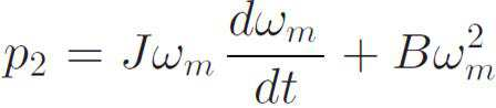
직류 링크의 출력 전력 p2는 전력 변환부의 손실을 무시할 경우 수학식 2와 같이 전동기의 입력 전력 pm으로 나타낼 수 있다.The output power p 2 of the DC link can be represented by the input power p m of the motor as shown in Equation (2) when the loss of the power converter is neglected.

여기서 J는 관성, ωm은 모터의 속도, B는 마찰 계수, Pload는 모터에 대한 부하 전력이다. Where J is inertia, ω m is the motor speed, B is the friction coefficient, and P load is the load power for the motor.
회생 모드(모터의 감속 구간)로 동작하는 커패시터 파라미터의 추정 기간 동안 부하에 의한 손실이 0(무부하 조건)이라고 가정하면, 수학식 2는 수학식 3으로 정리될 수 있다.Assuming that the loss due to the load during the estimation period of the capacitor parameter operating in the regenerative mode (deceleration section of the motor) is 0 (no-load condition), equation (2) can be summarized in equation (3).
모터의 감속 구간에서는 직류 링크의 커패시터가 충전되면서 직류 링크의 전압이 상승하게 되어 전위차로 인해 정류기(110)와 전기적으로 분리되는 상태가 된다. 그러면 커패시터의 전류는 모터 전류와 인버터 스위칭 상태로부터 재구성될 수 있다.In the decelerating section of the motor, the capacitor of the DC link is charged, and the voltage of the DC link rises, so that the DC link is electrically separated from the
본 발명의 실시예는 유도 전동기의 벡터 제어를 위해, 속도 제어와 전류 제어를 포함하는 d-q 좌표계 상의 직렬형(캐스케이드) 제어 구조를 채택하고 있다. 직류 링크의 커패시터 용량을 추정하는 동안에는 모터에 일정한 감속 비가 설정된다.The embodiment of the present invention adopts a series type (cascade) control structure on a dq coordinate system including a speed control and a current control for vector control of an induction motor. During the estimation of the capacitor capacity of the DC link, a constant deceleration ratio is set to the motor.
회생 모드 동작에서는 ac 전원으로부터 직류 링크에 어떠한 전력도 흐르지 않게 된다. 따라서, p1=0이 되고, 결과적으로 p2=-pcap이 된다. 수학식 1에 p1=0을 대입하여 수학식 3과 조합하면 아래의 수학식 4와 같이 정리된다.In the regenerative mode operation, no power flows from the ac power source to the DC link. Thus, p 1 = 0, resulting in p 2 = -p cap . When p 1 = 0 is substituted into Equation (1) and combined with Equation (3), the following Equation (4) is obtained.

수학식 4를 참조하면, 모터의 감속 비는 관성(J)과 마찰 계수(B), 직류 링크의 커패시터 용량(C) 및 전압(vdc)에 의해 결정되는 것을 알 수 있다.Referring to Equation (4), it can be seen that the deceleration ratio of the motor is determined by the inertia J and the friction coefficient B, the capacitor capacity C of the DC link, and the voltage v dc .
본 발명의 실시예는 유도 전동기의 벡터 제어시 동기좌표계의 q축에 교류성분을 주입하면 직류링크 전압에 교류 성분의 전압과 전류가 나타나게 되며, 이를 이용하여 커패시턴스를 추정한다. In the embodiment of the present invention, when an AC component is injected into the q-axis of the synchronous coordinate system during vector control of the induction motor, the voltage and current of the AC component appear in the DC link voltage, and the capacitance is estimated using the AC component voltage and current.
즉, 본 발명의 실시예는 직류링크 내에 교류 전압과 전류 리플 성분을 생성하기 위하여, 전동기의 q축 고정자 전류 지령치에 교류 전류 성분을 인가한다. 이와 같이 q축 전류에 교류 성분이 주입되면 직류 링크의 전압과 전류에 리플(ripple)이 발생한다.That is, an embodiment of the present invention applies an alternating current component to the q-axis stator current command value of the motor in order to generate an AC voltage and a current ripple component in the DC link. When the AC component is injected into the q-axis current, a ripple occurs in the voltage and current of the DC link.
교류 성분이 포함된 전류 지령치는 수학식 5와 같은 형태를 가진다.The current command value including the AC component has the form of Equation (5).
![]()
![]()
여기서, Iinj 및 finj는 주입되는 전류의 크기 및 주파수를 나타낸다. 이와 같은 교류 성분의 전류는 커패시터의 용량 추정에 사용된다. Where I inj and f inj represent the magnitude and frequency of the injected current. The current of such an AC component is used for capacity estimation of the capacitor.
수학식 5에서 위첨자 *는 지령 값(추종해야 하는 값)을 의미하는데, 상기와 같이 교류 성분이 주입된 q축 전류 지령 값을 나타낸다. 실제 모터에서 측정되는 q축 전류는 수학식 5의 지령 형태와 같이 교류 성분이 포함된 전류 신호 형태를 가질 수 있다.In Equation (5), a superscript * denotes a command value (a value to be followed), which represents a q-axis current command value injected with an AC component as described above. The q-axis current measured in the actual motor may have the form of a current signal including an AC component as shown in the formula (5).
본 발명의 실시예에서는 Iinj=3A, finj=30Hz를 사용하므로 수학식 5는 수학식 6의 형태로 정리될 수 있다.In the embodiment of the present invention, I inj = 3 A and f inj = 30 Hz are used, so that Equation (5) can be summarized as Equation (6).

이하에서는 상기의 내용을 바탕으로 본 발명의 실시예에 따른 인버터 벡터 구동 시스템을 이용한 커패시터 용량 추정 방법을 상세히 설명한다.Hereinafter, a method of estimating the capacitance of a capacitor using the inverter vector driving system according to an embodiment of the present invention will be described in detail with reference to the above description.
먼저 인버터 벡터 구동 시스템(100)은 유도 전동기의 모터를 감속시켜서 회생 모드로 동작시킨다. 예를 들어 유도 전동기를 195 rad/s2으로 일정하게 감속시킨다.First, the inverter
이러한 모터의 회생 모드(모터의 감속 구간) 동작 시에, 연산부(140)는 모터에 대한 d-q 좌표계의 d축 전류 지령(i* dse) 및 상기 모터에서 획득한 d축 직류 전류(idse)를 통하여 d축 전압 지령(v* dse)을 생성한다. 또한, 연산부(140)는 q축 전류 지령(i* qse _ dc), 상기 모터에서 획득한 q축 직류 전류(iqse _ dc), 기 설정된 교류 성분이 포함된 q축 전류 지령(i* qse _ inj) 및 상기 모터에서 획득한 q축 교류 전류(iqse _ inj)를 통하여 q축 전압 지령(v* qse)을 생성한다. In operation of the regenerative mode (motor deceleration section) of such a motor, the
이를 도 1을 참조로 하여 더욱 상세히 설명하면 다음과 같다. 연산부(140)는 d-q 좌표계의 d축 전류 지령(i* dse=5A)에 모터에서 획득한 d축 직류 전류(idse)를 차감한 값을 비례 적분(PI;Proportional Integral) 제어하여 d축 전압 지령(v* dse)을 생성한다. 여기서, d축 직류 전류(idse)는 d-q 좌표계에서 얻은 dq축 전류 값인 idase로부터 분리하여 얻을 수 있다.This will be described in more detail with reference to FIG. The
또한, 연산부(140)는 d-q 좌표계의 q축 전류 지령(i* qse _ dc)에 상기 모터에서 획득한 q축 직류 전류(iqse _ dc)를 차감한 값을 비례 적분(PI) 제어한 결과와, 교류 성분이 포함된 q축 전류 지령(i* qse _ inj)에 상기 q축 교류 전류(iqse _ inj)를 차감한 값을 비례 공진(PR;Proportional Resonant) 제어한 결과를 서로 합산(Σ)하여 상기 q축 전압 지령(v* qse)을 생성한다. Further, the
여기서, 본 발명의 실시예는 q축에 교류 전류 지령에 의한 제어 정보가 합산되는 것을 알 수 있다. 즉, q축 전류의 경우 직류 성분뿐만 아니라 교류 성분을 더욱 추종하도록 제어하고 이를 통해 직류 링크에 교류 성분이 나타나도록 한다.Here, in the embodiment of the present invention, it can be seen that the control information based on the alternating current command is added to the q-axis. That is, in the case of the q-axis current, not only the direct current component but also the alternating current component is controlled so as to follow it, so that the alternating current component appears on the direct current link.
상기 q축 전압 지령(v* qse)을 연산하는데 사용되는 q축 전류 지령(i* qse _ dc)은 모터의 속도(ωr)를 대역 저지 필터(BSF)에 통과시켜 리플을 제거한 값(ωr_ bsf)을 속도 지령(ω* r)에서 차감한 결과를 비례 적분(PI)하는 것을 통해 얻는다. 또한 q축 직류 전류(iqse_dc)은 d-q 좌표계 상에서의 모터의 q축 전류(dq축 전류 값인 idqse 중에서 q축의 iqse 성분)를 대역 저지 필터(BSF)에 통과시켜 얻은 직류 성분 값이다.The q-axis voltage command (v * qse) the q-axis current command used for calculating a (i * qse _ dc) is the value remove the ripple passes the speed (ω r) of the motor to the band stop filter (BSF) (ω the results obtained by subtracting the bsf r_) in a speed command (ω * r) through the proportional integral (PI). The q-axis direct current (i qse_dc ) is a DC component value obtained by passing the q-axis current of the motor on the dq coordinate system (the iqse component of the q-axis among the i dqse , the dq axis current value) through the band-stop filter (BSF).
또한, 교류 성분이 포함된 q축 전류 지령(i* qse _ inj)은 앞서 수학식 5에 나타낸 I* inj를 나타낸다. 그리고, q축 교류 전류(iqse _ inj)는 d-q 좌표계 상에서의 모터의 q축 전류(iqse 성분)를 대역 통과 필터(BPF)에 통과시켜 얻은 값이다. 이러한 대역 통과 필터(BPF)는 전류의 주파수 성분을 통과시킨다.In addition, q-axis current command containing the alternating current component (i * qse _ inj) shows an earlier I * inj shown in equation (5). The q-axis alternating current (i qse _ inj ) is a value obtained by passing the q-axis current (i qse component) of the motor on the dq coordinate system through the band-pass filter (BPF). This band-pass filter (BPF) passes the frequency component of the current.
본 발명의 실시예에서 q축 전류 제어를 위한 대역 통과 필터(BPF)와 대역 저지 필터(BSF)의 절점 주파수는 30Hz를 사용하였다. 이러한 각각의 필터는 소프트웨어적으로 구현 가능하다. 이상과 같이 각각의 지령 전류를 이용한 제어를 통하여 dq축 전압 지령이 연산 및 출력될 수 있다. In the embodiment of the present invention, the node frequency of the band-pass filter (BPF) and the band-stop filter (BSF) for q-axis current control is 30 Hz. Each of these filters can be implemented in software. As described above, the dq-axis voltage command can be calculated and output through control using each command current.
dq축의 전압 지령이 연산되면, 펄스 조절부(150)는 연산된 d축 전압 지령(v* dse) 및 q축 전압 지령(v* qse)을 이용하여 PWM 인버터(130)의 펄스를 조절한다. 더 상세하게는, 도 1과 같이 dq축 전압 지령을 역 dq 변환(T-1)하여 3상 전압 지령을 PWM 인버터(130)에 인가할 수 있으며 이를 통해 스위칭을 조절할 수 있다.dq axis is calculated, the
여기서, 추정부(160)는 앞서의 교류 성분의 주입에 따라, 커패시터(120) 상에서 상기의 교류 성분이 포함되어 발생하는 직류 링크 전압(vdc) 및 직류 링크 전류(idc , cal)를 이용하여, 커패시터(120)의 용량을 추정할 수 있다.Here, the estimating
여기서, 직류 링크 전압(vdc)은 직류 링크에서 측정 가능하며, 직류 링크 전류(idc , cal)는 아래의 수학식 7을 통하여 계산될 수 있다.Here, the DC link voltage (v dc ) is measurable in the DC link, and the DC link current (i dc , cal ) can be calculated by the following equation (7).

여기서, Tsa, Tsb, Tsc는 각각 상기 PWM 인버터에 포함된 6개의 스위치 중에서 상단의 3개의 스위치에 대한 게이팅 시간, ia, ib, ic는 상기 모터의 3상에서 측정되는 상전류, 상기 Ts는 샘플링 시간을 나타낸다. 게이팅 시간은 스위치가 켜지는 시간을 의미한다.Here, T sa , T sb , and T sc are the gating times for the upper three switches among the six switches included in the PWM inverter, i a , i b , and i c are the phase currents measured at three phases of the motor, The T s represents the sampling time. The gating time is the time when the switch is turned on.
이와 같이 직류 링크 전류(idc , cal)는 스위칭 상태에 따른 수식을 이용하여 계산될 수 있는 값다. 물론 앞서 p1=0이고 p2=-pcap에 의해, icap=-idc , cal가 될 것이다.As described above, the DC link current (i dc , cal ) is a value that can be calculated using an equation according to the switching state. Of course, with p 1 = 0 and p 2 = -p cap earlier, i cap = -i dc , cal .
추정부(160)가 직류 링크 단의 직류 링크 전압(vdc) 및 직류 링크 전류(idc , cal)를 이용하여 커패시터(120)의 용량을 추정하는 방법은 다음과 같다. A method of estimating the capacity of the
먼저, 전류와 커패시터 전압 사이의 관계를 수학식 8와 같이 나타낼 수 있다. First, the relationship between the current and the capacitor voltage can be expressed by Equation (8).

여기서 i는 icap을 의미하고 v는 vdc를 의미한다. 부하가 없다고 가정하고, 수학식 8을 본 발명의 실시예에 따른 커패시터(120)에 적용하면 수학식 9와 같다. Where i means i cap and v means v dc . Assuming no load, Equation (8) can be applied to the

여기서, idc는 직류 링크 전류이고, vdc는 커패시터 전압이다. 수학식 9의 idc에 수학식 7에서 구한 idc , cal 값을 대입하면 된다. idc와 vdc는 본 발명의 실시예에서 계산 또는 측정으로 알 수 있는 값이며 C의 값은 미지의 값이 된다.Where i dc is the dc link current and v dc is the capacitor voltage. The i dc in equation (9) obtained in Equation 7 i dc, cal Value. i dc and v dc are values that can be found by calculation or measurement in the embodiment of the present invention, and the value of C is an unknown value.
수학식 9를 대역 통과 필터(BPF)에 통과한 값은 아래의 수학식 10과 같이 나타낼 수 있다.A value obtained by passing Equation (9) through the band-pass filter (BPF) can be expressed by Equation (10) below.

여기서 물론, BPF[·]는 대역 통과 필터(BPF)를 통과한 출력 값을 나타낸다. BPF는 직류 링크 전압과 전류를 필터링한다. 여기서 idc는 앞서와 같이 idc , cal 값을 의미한다. Here, of course, BPF [.] Represents an output value passed through the band-pass filter (BPF). The BPF filters the DC link voltage and current. Here, i dc is i dc , cal Lt; / RTI >
본 발명의 실시예에서 추정부(160)는 RLS 알고리즘(Recursive least square algorithm)을 이용하여 아래 수학식 11에 개시된 오차 비용 함수가 최소가 되도록 커패시터(120)의 용량을 추정한다.In the embodiment of the present invention, the

여기서, e2(n)는 오차 비용 함수, BPF[·]는 대역 통과 필터(BPF)를 통과한 출력 값, idc는 직류 링크 전류로서 idc , cal 값, vdc는 직류 링크 전압, ![]()
![]()
이때, 커패시터 추정 용량 ![]()
![]()
![]()
![]()

여기서, μ(n)은 게인 보정 값으로서, 본 발명의 실시예는 실험에 의해 얻어진 7.5×10⁻⁸ 값을 사용할 수 있다.Here, μ (n) is the gain correction value, and the embodiment of the present invention can use the value of 7.5 × 10 -8 obtained by the experiment.
이하에서는 본 발명의 실시예에 따른 커패시터 용량 추정 방법의 성능 및 효과를 확인하기 위하여 3kW의 유도 전동기 구동 시스템에서 본 발명의 실시예를 적용한 결과를 설명한다.Hereinafter, results of applying the embodiment of the present invention to a 3 kW induction motor drive system will be described in order to confirm the performance and effect of the capacitor capacity estimation method according to the embodiment of the present invention.
도 2는 본 발명의 실시예에서 유도 전동기의 제어 성능을 나타낸 도면이다. 도 2의 경우 전동기는 1500rpm에서 시간에 따라 임의 감속 비로 감속되고 있는 상태이다. 2 is a diagram showing control performance of an induction motor in an embodiment of the present invention. In the case of FIG. 2, the electric motor is in a state of decelerating at an arbitrary deceleration rate with time at 1500 rpm.
우선, 도 2의 (a)는 모터의 속도(ω)를 나타낸다. 모터의 속도(ωr)는 지령 값(ω* r)을 따르고 있다. 도 2의 (b)는 전동기의 d축 전류(idse)이며 감속 구간에서 리플이 발생한 것을 알 수 있다. 도 2의 (c)는 전동기 q축 전류의 직류 성분(Iqse _ dc)을 나타내는데 모터 감속 구간에서는 회생 모드가 되어 전류는 음의 값을 가진다. 감속 전과 후의 전류는 모터의 관성에 의해 나타나는 값이다. 도 2의 (d)는 전동기 q축 전류의 교류 성분(Iqse _ inj)을 나타내는데, PR 제어기를 통해 지령값(I* qse_inj)에 추종하도록 잘 제어되고 있음을 확인할 수 있다.First, FIG. 2 (a) shows the speed () of the motor. The speed of the motor r follows the command value r * . Fig. 2 (b) shows the d-axis current (i dse ) of the motor and ripple is generated in the deceleration section. Fig. (C) 2 is the regenerative mode, the motor deceleration section for indicating a direct current component of the motor q-axis current (I qse _ dc) current has a negative value. The current before and after deceleration is a value represented by the inertia of the motor. FIG. 2 (d) shows the AC component (I qse _ inj ) of the motor q-axis current. It can be confirmed that the control is well controlled to follow the command value (I * qse_inj ) through the PR controller.
도 3은 본 발명의 실시예에서 유도 전동기가 회생 모드로 동작하는 구간에서의 직류 링크의 전압과 전류, 그리고 이를 이용한 커패시터 용량의 추정 결과를 나타낸 도면이다. 본 발명의 실시예는 모터가 감속하는 구간(회생 모드)에서 커패시터 용량을 추정하며 도 3은 해당 구간을 Estimation duration으로 표시하고 있다. FIG. 3 is a diagram illustrating estimation results of a voltage and current of a DC link in a section where the induction motor operates in the regenerative mode and a capacitor capacity using the DC link in the embodiment of the present invention. The embodiment of the present invention estimates the capacity of the capacitor in a period during which the motor decelerates (regenerative mode), and FIG. 3 shows the corresponding interval as an estimation duration.
도 3의 (a)는 직류 링크 전압(Vdc)으로서, 회생 모드에서 직류 전압이 증가한 것을 알 수 있으며 주입된 리플 전압 또한 확인할 수 있다. 도 3의 (b)는 3상 전원에서 다이오드 정류기(110)로 입력되는 a상 전류(ia)를 나타낸다. 회생 구간에서는 3상 전원에서 직류 링크 쪽으로 전력이 전달되지 않는 것을 확인할 수 있다.3 (a) is a DC link voltage (V dc ). It can be seen that the DC voltage increases in the regenerative mode, and the injected ripple voltage can also be confirmed. 3 (b) shows the a-phase current (i a ) input to the
도 3의 (c)는 회생 모드(모터 감속 구간)에서 계산된 직류 링크의 전류(idc , cal)이다. 이러한 직류 링크 전류는 수학식 7과 같이 유도 전동기의 3상 전류와 인버터의 스위치 상태를 이용하여 계산되었다. 3C is a current (i dc , cal ) of the DC link calculated in the regenerative mode (motor deceleration section). The DC link current is calculated using the three-phase current of the induction motor and the switch state of the inverter as shown in Equation (7).
도 3의 (d)는 (a)의 직류 링크 전압(vdc)과 (c)의 직류 링크 전류(idc , cal)를 이용하여 수학식 12를 통해 추정한 커패시터의 용량을 나타낸다. 그 결과 커패시터 용량은 731.4uF로 추정되었다. 추정 오차는 0.91%로 나타났다.FIG. 3 (d) shows the capacitance of the capacitor estimated by Equation (12) using the DC link voltage (v dc ) of (a) and the DC link current (i dc , cal ) of (c). As a result, the capacitance of the capacitor was estimated to be 731.4uF. The estimation error was 0.91%.
도 4는 도 2에서 모터 감속 구간을 확대한 파형을 나타낸 도면이다. 도 4의 (a)는 모터의 속도 지령치(ω* r), 속도 측정값(ωr), 그리고 대역 저지필터(BSF)를 통과한 속도 측정값(ωbsf)을 알 수 있다. 속도 측정값(ωr)은 속도 지령치(ω* r)를 추종하여 감소하고 있으며, BSF를 통과한 속도 측정값(ωbsf)은 속도 측정값(ωr)에서 리플이 제거된 것을 알 수 있다.FIG. 4 is a view showing a waveform in which the motor deceleration section is enlarged in FIG. 2. FIG. 4 (a) shows the speed command value? * R of the motor, the speed measurement value? R , and the speed measurement value? Bsf passing through the band stop filter BSF. The speed measurement value ω r decreases following the speed command value ω * r , and the speed measurement value ω bsf passing through the BSF shows that the ripple is removed from the speed measurement value ω r .
도 4의 (b)는 전동기의 d축 전류(idse)이며 지령 값(i* dse)을 추종하고 있다. 도 4의 (c)는 전동기 q축 전류의 직류 성분(Iqse _ dc)이 그 지령 값(I* qse _ dc)을 추종하고 있다. 도 4의 (d)는 전동기 q축 전류에 주입된 교류 성분의 지령치(I* qse_inj)와 측정치(Iqse _ inj)로서 측정치는 지령치를 추종하고 있다.4 (b) is a d-axis current (i dse ) of the electric motor and follows the command value (i * dse ). In Fig. 4 (c) are the DC components of the motor q-axis current (I dc _ qse) the tracking of the command value (I * qse _ dc). In Fig. 4 (d) are the following measurement reference value as reference value (I * qse_inj) and the measured value (I qse _ inj) of the AC component it is injected into the q-axis current to the motor.
도 5는 본 발명의 실시예에서 직류 링크 전압과 전류의 신호 처리 결과를 나타낸 도면이다. 도 5의 (a)는 계산된 커패시터 전류(icap _ cal=idc , cal)와 실제 측정된 커패시터 전류(icap _ mea)를 나타낸다. 계산된 전류 값은 실제 전류 값과 유사함을 확인할 수 있다.5 is a diagram showing signal processing results of a DC link voltage and current in an embodiment of the present invention. Figure 5 (a) shows the calculated capacitor current (i cap _ cal = i dc , cal) and the actual measured capacitor current (i cap _ mea). It can be seen that the calculated current value is similar to the actual current value.
도 5의 (b)는 직류 링크에서 30Hz의 리플을 가지는 전압을 나타낸다. 도 5의 (c)와 (d)는 각각 대역 통과 필터(BPF)에 의해 필터링된 30Hz의 리플을 가진 직류 전압과 직류 링크 전류의 파형을 나타낸다. FIG. 5 (b) shows a voltage having a ripple of 30 Hz in a DC link. 5C and 5D show the waveforms of the DC voltage and the DC link current having the 30 Hz ripple filtered by the band-pass filter (BPF), respectively.
본 발명의 실시예에 따르면, 모터의 회생 작동 시에 정류기로부터 격리되는 직류 링크의 전압은 증가하게 되며, 커패시터의 전류는 고정자 전류와 인버터의 스위칭 시간으로부터 측정이 된다. 모터 고정자의 q축 전류에 교류 성분을 주입하면 교류 성분의 전류 및 전압이 직류 링크의 커패시터에 나타나게 되며, 해당 전류 및 전압을 적용한 RLS 알고리즘을 통해 커패시터 용량을 정확하게 추정할 수 있다.According to the embodiment of the present invention, the voltage of the DC link isolated from the rectifier during the regenerative operation of the motor is increased, and the current of the capacitor is measured from the stator current and the switching time of the inverter. When the AC component is injected into the q-axis current of the motor stator, the AC current and voltage appear on the capacitor of the DC link. The capacitor capacity can be accurately estimated through the RLS algorithm using the current and voltage.
이상과 같은 본 발명의 실시예에 따른 커패시터 용량 추정 방법은 산업용 전동기 구동 시스템을 위한 직류 링크 추정 기법으로 사용될 수 있으며, 하드웨어의 추가없이 단순히 소프트웨어의 추가만으로 커패시터의 열화 상태를 온라인(on-line)으로 낮은 추정 오차로 추정 가능하다. 또한, 파라미터 추정을 통해 커패시터가 고장나기 전에 그 교체 시기를 사전에 판단할 수 있어, 커패시터 노화에 따른 인버터의 고장을 미리 예방할 수 있다.The capacitor capacity estimation method according to an embodiment of the present invention can be used as a DC link estimation technique for an industrial motor drive system and it is possible to provide a method of estimating the capacitance of a capacitor by simply adding software without on- , Which can be estimated with a low estimation error. Further, it is possible to determine beforehand the replacing timing before the capacitor fails due to the parameter estimation, and it is possible to prevent the inverter from being damaged due to the aging of the capacitor in advance.
본 발명은 도면에 도시된 실시예를 참고로 설명되었으나 이는 예시적인 것에 불과하며, 본 기술 분야의 통상의 지식을 가진 자라면 이로부터 다양한 변형 및 균등한 다른 실시예가 가능하다는 점을 이해할 것이다. 따라서, 본 발명의 진정한 기술적 보호 범위는 첨부된 특허청구범위의 기술적 사상에 의하여 정해져야 할 것이다.While the present invention has been described with reference to exemplary embodiments, it is to be understood that the invention is not limited to the disclosed exemplary embodiments, but, on the contrary, is intended to cover various modifications and equivalent arrangements included within the spirit and scope of the appended claims. Accordingly, the true scope of the present invention should be determined by the technical idea of the appended claims.
100: 인버터 벡터 구동 시스템 110: 정류기
120: 커패시터 130: PWM 인버터
140: 연산부 150: 펄스 조절부
160: 추정부100: inverter vector drive system 110: rectifier
120: Capacitor 130: PWM inverter
140: Operation unit 150:
160:
Claims (12)
상기 유도 전동기의 모터를 회생 모드로 동작시키는 단계;
상기 모터에 대한 d-q 좌표계의 d축 전류 지령 및 상기 모터에서 획득한 d축 직류 전류를 통하여 d축 전압 지령을 생성하고, q축 전류 지령, 상기 모터에서 획득한 q축 직류 전류, 기 설정된 교류 성분이 포함된 q축 전류 지령 및 상기 모터에서 획득한 q축 교류 전류를 통하여 q축 전압 지령을 생성하는 단계;
상기 d축 전압 지령 및 상기 q축 전압 지령을 이용하여 상기 PWM 인버터의 펄스를 조절하는 단계; 및
상기 커패시터 상에서 상기 교류 성분이 포함되어 발생하는 직류 링크 전압 및 직류 링크 전류를 이용하여 상기 커패시터의 용량을 추정하는 단계를 포함하는 인버터 벡터 구동 시스템에서의 커패시터 용량 추정 방법.1. A capacitor capacity estimating method in an inverter vector drive system including a capacitor for charging a rectified DC voltage of a three-phase power supply, and a PWM inverter for converting the DC voltage into an AC voltage of three phases and applying the AC voltage to a motor of the induction motor,
Operating the motor of the induction motor in a regenerative mode;
A q-axis current command obtained by the q-axis current command, a q-axis direct current obtained by the motor, a predetermined ac component, and a d-axis current command obtained by the motor, Generating a q-axis voltage command through a q-axis current command including the q-axis current command and the q-axis ac current acquired by the motor;
Adjusting a pulse of the PWM inverter using the d-axis voltage command and the q-axis voltage command; And
And estimating a capacitance of the capacitor using a DC link voltage and a DC link current generated by including the AC component on the capacitor.
상기 q축 교류 전류 및 상기 q축 직류 전류는,
상기 모터의 동작 시에 얻은 상기 d-q 좌표계 상의 상기 모터의 q축 전류를 대역 통과 필터(BPF) 및 대역 저지 필터(BSF)에 각각 통과시켜 획득한 인버터 벡터 구동 시스템에서의 커패시터 용량 추정 방법.The method according to claim 1,
Wherein the q-axis alternating current and the q-
And the q-axis current of the motor on the dq coordinate system obtained at the time of operation of the motor is passed through a band-pass filter (BPF) and a band-stop filter (BSF), respectively.
상기 d축 전압 지령 및 상기 q축 전압 지령을 생성하는 단계는,
상기 d축 전류 지령에 상기 d축 직류 전류를 차감한 값을 비례 적분 제어하여 상기 d축 전압 지령을 생성하고,
상기 q축 전류 지령에 상기 q축 직류 전류를 차감한 값을 비례 적분 제어한 결과와, 상기 교류 성분이 포함된 q축 전류 지령에 상기 q축 교류 전류를 차감한 값을 비례 공진 제어한 결과를 합산하여 상기 q축 전압 지령을 생성하는 인버터 벡터 구동 시스템에서의 커패시터 용량 추정 방법.The method according to claim 1 or 2,
Wherein the step of generating the d-axis voltage command and the q-
A d-axis voltage command is generated by proportionally and integrally controlling a value obtained by subtracting the d-axis direct current from the d-axis current command,
The result obtained by proportionally integrating the q-axis current command minus the q-axis DC current and the q-axis current command including the AC current minus the q-axis ac current are subjected to proportional resonance control Wherein the q-axis voltage command is generated by adding the q-axis voltage command to the q-axis voltage command.
상기 직류 링크 전류(idc , cal)는 아래의 수학식에 의해 계산되는 인버터 벡터 구동 시스템에서의 커패시터 용량 추정 방법:

여기서, Tsa, Tsb, Tsc는 각각 상기 PWM 인버터에 포함된 상단의 3개의 스위치에 대한 게이팅 시간, ia, ib, ic는 상기 모터의 3상에서 측정되는 상전류, 상기 Ts는 샘플링 시간을 나타낸다.The method according to claim 1,
Wherein the DC link current (i dc , cal ) is calculated by the following equation:
Here, T sa, T sb, T sc is the gating time for each of the three switches at the top that is included in the PWM inverter, i a, i b, i c is the phase current, wherein T s is measured in three of the motors Represents the sampling time.
상기 커패시터의 용량을 추정하는 단계는,
RLS 알고리즘(Recursive least square algorithm)을 이용하여 오차 비용 함수가 최소가 되도록 상기 커패시터의 용량을 추정하는 인버터 벡터 구동 시스템에서의 커패시터 용량 추정 방법:

여기서, e2(n)는 오차 비용 함수, BPF[·]는 대역 통과 필터(BPF)를 통과한 출력 값, idc는 상기 직류 링크 전류, vdc는 상기 직류 링크 전압,
Wherein the step of estimating the capacity of the capacitor comprises:
A capacitor capacity estimation method in an inverter vector drive system for estimating a capacity of a capacitor such that an error cost function is minimized by using an RLS algorithm (Recursive least square algorithm)
Here, e 2 (n) is the error cost function, BPF [·] is the output value, i dc has passed through the band pass filter (BPF) is the DC link current, v dc is the DC link voltage,
상기 커패시터의 추정 용량은 다음의 수학식을 통하여 갱신되는 인버터 벡터 구동 시스템에서의 커패시터 용량 추정 방법:

여기서, μ(n)은 게인 보정 값이다.The method of claim 5,
Wherein the estimated capacity of the capacitor is updated through the following equation:
Here, μ (n) is a gain correction value.
상기 직류 전압을 3상의 교류 전압으로 변환하여 유도 전동기의 모터에 인가하는 PWM 인버터;
상기 모터의 회생 모드 동작 시, 상기 모터에 대한 d-q 좌표계의 d축 전류 지령 및 상기 모터에서 획득한 d축 직류 전류를 통하여 d축 전압 지령을 생성하고, q축 전류 지령, 상기 모터에서 획득한 q축 직류 전류, 기 설정된 교류 성분이 포함된 q축 전류 지령 및 상기 모터에서 획득한 q축 교류 전류를 통하여 q축 전압 지령을 생성하는 연산부;
상기 d축 전압 지령 및 상기 q축 전압 지령을 이용하여 상기 PWM 인버터의 펄스를 조절하는 펄스 조절부; 및
상기 커패시터 상에서 상기 교류 성분이 포함되어 발생하는 직류 링크 전압 및 직류 링크 전류를 이용하여 상기 커패시터의 용량을 추정하는 추정부를 포함하는 커패시터 용량 추정을 위한 인버터 벡터 구동 시스템.A capacitor charging the rectified DC voltage of the three-phase power supply;
A PWM inverter for converting the DC voltage into an AC voltage of three phases and applying the AC voltage to the motor of the induction motor;
A d-axis voltage command is generated through a d-axis current command of the dq coordinate system for the motor and a d-axis direct current obtained by the motor, and a q-axis current command and q A q-axis voltage command including a direct current, a q-axis current command including a predetermined q-axis current, and a q-axis q-axis current obtained by the motor;
A pulse regulator for regulating a pulse of the PWM inverter using the d-axis voltage command and the q-axis voltage command; And
And an estimator for estimating a capacitance of the capacitor using a DC link voltage and a DC link current generated by including the AC component on the capacitor.
상기 q축 교류 전류 및 상기 q축 직류 전류는,
상기 모터의 동작 시에 얻은 상기 d-q 좌표계 상의 상기 모터의 q축 전류를 대역 통과 필터(BPF) 및 대역 저지 필터(BSF)에 각각 통과시켜 획득한 커패시터 용량 추정을 위한 인버터 벡터 구동 시스템.The method of claim 7,
Wherein the q-axis alternating current and the q-
And the q-axis current of the motor on the dq coordinate system obtained at the time of operation of the motor is passed through a band-pass filter (BPF) and a band-stop filter (BSF), respectively.
상기 연산부는,
상기 d축 전류 지령에 상기 d축 직류 전류를 차감한 값을 비례 적분 제어하여 상기 d축 전압 지령을 생성하고,
상기 q축 전류 지령에 상기 q축 직류 전류를 차감한 값을 비례 적분 제어한 결과와, 상기 교류 성분이 포함된 q축 전류 지령에 상기 q축 교류 전류를 차감한 값을 비례 공진 제어한 결과를 합산하여 상기 q축 전압 지령을 생성하는 커패시터 용량 추정을 위한 인버터 벡터 구동 시스템.The method according to claim 7 or 8,
The operation unit,
A d-axis voltage command is generated by proportionally and integrally controlling a value obtained by subtracting the d-axis direct current from the d-axis current command,
The result obtained by proportionally integrating the q-axis current command minus the q-axis DC current and the q-axis current command including the AC current minus the q-axis ac current are subjected to proportional resonance control And the inverter vector drive system for estimating capacitor capacity to generate the q-axis voltage command.
상기 직류 링크 전류(idc , cal)는 아래의 수학식에 의해 계산되는 커패시터 용량 추정을 위한 인버터 벡터 구동 시스템:

여기서, Tsa, Tsb, Tsc는 각각 상기 PWM 인버터에 포함된 상단의 3개의 스위치에 대한 게이팅 시간, ia, ib, ic는 상기 모터의 3상에서 측정되는 상전류, 상기 Ts는 샘플링 시간을 나타낸다.The method of claim 7,
Wherein the DC link current (i dc , cal ) is an inverter vector drive system for capacitor capacity estimation calculated by the following equation:
Here, T sa, T sb, T sc is the gating time for each of the three switches at the top that is included in the PWM inverter, i a, i b, i c is the phase current, wherein T s is measured in three of the motors Represents the sampling time.
상기 추정부는,
RLS 알고리즘(Recursive least square algorithm)을 이용하여 오차 비용 함수가 최소가 되도록 상기 커패시터의 용량을 추정하는 커패시터 용량 추정을 위한 인버터 벡터 구동 시스템:

여기서, e2(n)는 오차 비용 함수, BPF[·]는 대역 통과 필터(BPF)를 통과한 출력 값, idc는 상기 직류 링크 전류, vdc는 상기 직류 링크 전압,
Wherein the estimating unit comprises:
An inverter vector drive system for estimating a capacity of a capacitor by estimating a capacity of the capacitor such that an error cost function is minimized by using an RLS algorithm (Recursive least square algorithm)
Here, e 2 (n) is the error cost function, BPF [·] is the output value, i dc has passed through the band pass filter (BPF) is the DC link current, v dc is the DC link voltage,
상기 커패시터의 추정 용량은 다음의 수학식을 통하여 갱신되는 커패시터 용량 추정을 위한 인버터 벡터 구동 시스템:

여기서, μ(n)은 게인 보정 값이다.The method of claim 11,
Wherein the estimated capacity of the capacitor is updated through the following equation:
Here, μ (n) is a gain correction value.
Priority Applications (2)
| Application Number | Priority Date | Filing Date | Title |
|---|---|---|---|
| KR1020150041422A KR101605990B1 (en) | 2015-03-25 | 2015-03-25 | Inverter vector driving system and method for estimating capacitance using the same |
| US15/080,587 US9722523B2 (en) | 2015-03-25 | 2016-03-25 | Inverter vector driving system and method for estimating capacitance using the same |
Applications Claiming Priority (1)
| Application Number | Priority Date | Filing Date | Title |
|---|---|---|---|
| KR1020150041422A KR101605990B1 (en) | 2015-03-25 | 2015-03-25 | Inverter vector driving system and method for estimating capacitance using the same |
Publications (1)
| Publication Number | Publication Date |
|---|---|
| KR101605990B1 true KR101605990B1 (en) | 2016-03-23 |
Family
ID=55645423
Family Applications (1)
| Application Number | Title | Priority Date | Filing Date |
|---|---|---|---|
| KR1020150041422A Expired - Fee Related KR101605990B1 (en) | 2015-03-25 | 2015-03-25 | Inverter vector driving system and method for estimating capacitance using the same |
Country Status (2)
| Country | Link |
|---|---|
| US (1) | US9722523B2 (en) |
| KR (1) | KR101605990B1 (en) |
Cited By (5)
| Publication number | Priority date | Publication date | Assignee | Title |
|---|---|---|---|---|
| EP3223023A1 (en) * | 2016-03-24 | 2017-09-27 | ABB Technology Oy | Method and apparatus for estimating capacitance of dc link |
| CN115963316A (en) * | 2022-11-21 | 2023-04-14 | 中国科学院合肥物质科学研究院 | An interharmonic detection method, device and medium |
| KR20240029710A (en) * | 2022-08-26 | 2024-03-06 | 국민대학교산학협력단 | Electronic device for estimating the capacitance of a dc(direct current) link capacitor included in a driving inverter system in on-line and operation thereof |
| DE102024111256B3 (en) | 2024-04-22 | 2025-10-09 | Ebm-Papst Mulfingen Gmbh & Co. Kg | Motor control circuit and method for monitoring at least one intermediate circuit capacitor of the motor control circuit |
| US12451719B2 (en) | 2020-10-06 | 2025-10-21 | Lg Energy Solution, Ltd. | Battery pack, battery system and precharge method |
Families Citing this family (15)
| Publication number | Priority date | Publication date | Assignee | Title |
|---|---|---|---|---|
| US10218277B2 (en) * | 2016-02-22 | 2019-02-26 | The Boeing Company | Adaptable high efficiency power inverter system |
| JP6632936B2 (en) * | 2016-06-07 | 2020-01-22 | 三菱電機株式会社 | Elevator control device |
| TWI626459B (en) * | 2016-08-17 | 2018-06-11 | 財團法人工業技術研究院 | Sensorless measurement method and device for filter capacitor current by using a state observer |
| KR102441606B1 (en) * | 2017-05-25 | 2022-09-07 | 현대모비스 주식회사 | System and method for controlling motor and |
| CN109387701B (en) * | 2017-08-02 | 2021-03-19 | 台达电子工业股份有限公司 | Three-phase converter device and capacitance estimation method |
| US10295581B2 (en) | 2017-10-13 | 2019-05-21 | Deere & Company | Voltage sensor-less position detection in an active front end |
| US10270327B1 (en) * | 2017-10-13 | 2019-04-23 | Deere & Company | Voltage sensor-less position detection in an active front end |
| CN109104114A (en) * | 2018-08-10 | 2018-12-28 | 南京轨道交通系统工程有限公司 | A kind of three-phase converter method based on PI and Repetitive controller parallel connection |
| US11159112B2 (en) | 2018-11-30 | 2021-10-26 | The Trustees Of Columbia University In The City Of New York | Systems and methods for high performance filtering techniques for sensorless direct position and speed estimation |
| CN109900029B (en) * | 2019-03-19 | 2021-05-28 | 海信(广东)空调有限公司 | Compressor control system and method therefor |
| EP3715879B1 (en) * | 2019-03-26 | 2021-03-10 | Mitsubishi Electric R&D Centre Europe B.V. | Non-intrusive esr/c estimation method for dc bus capacitor ageing detection in power converters |
| DE102019119868B3 (en) * | 2019-07-23 | 2020-11-05 | Danfoss Power Electronics A/S | Method for determining a rectifier stage output current and / or line-side currents of a frequency converter |
| CN111914394B (en) * | 2020-06-29 | 2023-01-03 | 哈尔滨工程大学 | Super capacitor parameter online estimation method based on double least square method |
| CN116325469B (en) * | 2021-09-30 | 2025-09-23 | 宁德时代新能源科技股份有限公司 | A method and device for suppressing grid voltage imbalance |
| GB202212285D0 (en) | 2022-08-24 | 2022-10-05 | Rolls Royce Plc | Circuitry and methods for monitoring power conversion circuitry |
Citations (2)
| Publication number | Priority date | Publication date | Assignee | Title |
|---|---|---|---|---|
| JP2005027379A (en) | 2003-06-30 | 2005-01-27 | Honda Motor Co Ltd | Motor drive device |
| JP2011217526A (en) | 2010-03-31 | 2011-10-27 | Aisin Aw Co Ltd | Motor control device |
Family Cites Families (25)
| Publication number | Priority date | Publication date | Assignee | Title |
|---|---|---|---|---|
| AU2001274396A1 (en) * | 2000-05-23 | 2001-12-03 | Vestas Wind Systems A/S | Variable speed wind turbine having a matrix converter |
| US6784634B2 (en) * | 2001-09-14 | 2004-08-31 | Edwin A. Sweo | Brushless doubly-fed induction machine control |
| US6758440B1 (en) * | 2003-03-21 | 2004-07-06 | Curtiss-Wright Electro-Mechanical Corporation | Electromagnetic aircraft arrestor system |
| US7176648B2 (en) * | 2004-05-18 | 2007-02-13 | Husky Injection Molding Systems Ltd. | Energy management apparatus and method for injection molding systems |
| JP4589093B2 (en) * | 2004-12-10 | 2010-12-01 | 日立オートモティブシステムズ株式会社 | Synchronous motor driving apparatus and method |
| US7511385B2 (en) * | 2005-11-11 | 2009-03-31 | Converteam Ltd | Power converters |
| KR100668118B1 (en) * | 2005-12-30 | 2007-01-16 | 한국전기연구원 | Power converter and power conversion method for winding type induction generator control |
| JP4736871B2 (en) * | 2006-03-10 | 2011-07-27 | 株式会社日立製作所 | Power converter for secondary excitation power generation system |
| EP2159910A1 (en) * | 2008-08-29 | 2010-03-03 | Vestas Wind Systems A/S | Direct power and stator flux vector control of a generator for wind energy conversion system |
| US7940537B2 (en) * | 2008-12-31 | 2011-05-10 | Teco-Westinghouse Motor Company | Partial regeneration in a multi-level power inverter |
| KR101227708B1 (en) * | 2009-03-25 | 2013-01-29 | 미쓰비시덴키 가부시키가이샤 | Ac electric vehicle control device |
| US8248039B2 (en) * | 2009-06-30 | 2012-08-21 | Vestas Wind Systems A/S | Control system for an electrical generator and method for controlling an electrical generator |
| US8395336B2 (en) * | 2010-07-29 | 2013-03-12 | National Taipei University Of Technology | Control system of three phase induction motor driver and field weakening control method thereof |
| EP2506422B1 (en) * | 2011-03-28 | 2019-02-13 | GE Energy Power Conversion Technology Limited | Circuits for dc energy stores |
| DE102011076722B4 (en) * | 2011-05-30 | 2019-11-07 | Robert Bosch Gmbh | Method for current detection in a multiphase machine |
| US8816625B2 (en) * | 2011-10-27 | 2014-08-26 | Rockwell Automation Technologies, Inc. | Integrated regenerative AC drive with solid state precharging |
| US8860335B2 (en) * | 2011-11-14 | 2014-10-14 | Rockwell Automation Technologies, Inc. | System for managing DC link switching harmonics |
| US8796982B2 (en) * | 2011-12-15 | 2014-08-05 | Eaton Corporation | System and method for detecting phase loss and diagnosing DC link capacitor health in an adjustable speed drive |
| KR101621994B1 (en) * | 2011-12-30 | 2016-05-17 | 엘에스산전 주식회사 | Control apparatus for regenerative medium voltage inverter |
| JP5664589B2 (en) * | 2012-04-20 | 2015-02-04 | 株式会社安川電機 | Power regeneration converter and power converter |
| WO2013183118A1 (en) * | 2012-06-05 | 2013-12-12 | 三菱電機株式会社 | Electric motor control device |
| KR101327591B1 (en) * | 2012-07-02 | 2013-11-12 | 엘에스산전 주식회사 | Apparatus for diagnosing dc link capacitor of inverter |
| KR101667833B1 (en) | 2012-07-26 | 2016-10-19 | 엘에스산전 주식회사 | Apparatus for estimating capacitance of dc-link capacitor in inverter |
| US9461556B2 (en) * | 2013-10-25 | 2016-10-04 | Rhombus Energy Solutions, Inc. | Stable regenerative bi-directional cell for bridge power inverters |
| US9966874B2 (en) * | 2014-01-15 | 2018-05-08 | Virginia Tech Intellectual Properties, Inc. | Power-cell switching-cycle capacitor voltage control for modular multi-level converters |
-
2015
- 2015-03-25 KR KR1020150041422A patent/KR101605990B1/en not_active Expired - Fee Related
-
2016
- 2016-03-25 US US15/080,587 patent/US9722523B2/en active Active
Patent Citations (2)
| Publication number | Priority date | Publication date | Assignee | Title |
|---|---|---|---|---|
| JP2005027379A (en) | 2003-06-30 | 2005-01-27 | Honda Motor Co Ltd | Motor drive device |
| JP2011217526A (en) | 2010-03-31 | 2011-10-27 | Aisin Aw Co Ltd | Motor control device |
Cited By (8)
| Publication number | Priority date | Publication date | Assignee | Title |
|---|---|---|---|---|
| EP3223023A1 (en) * | 2016-03-24 | 2017-09-27 | ABB Technology Oy | Method and apparatus for estimating capacitance of dc link |
| CN107404237A (en) * | 2016-03-24 | 2017-11-28 | Abb技术有限公司 | Method and apparatus for estimating DC link capacitances |
| US12451719B2 (en) | 2020-10-06 | 2025-10-21 | Lg Energy Solution, Ltd. | Battery pack, battery system and precharge method |
| KR20240029710A (en) * | 2022-08-26 | 2024-03-06 | 국민대학교산학협력단 | Electronic device for estimating the capacitance of a dc(direct current) link capacitor included in a driving inverter system in on-line and operation thereof |
| KR102702841B1 (en) | 2022-08-26 | 2024-09-05 | 국민대학교산학협력단 | Electronic device for estimating the capacitance of a dc(direct current) link capacitor included in a driving inverter system in on-line and operation thereof |
| CN115963316A (en) * | 2022-11-21 | 2023-04-14 | 中国科学院合肥物质科学研究院 | An interharmonic detection method, device and medium |
| CN115963316B (en) * | 2022-11-21 | 2023-10-20 | 中国科学院合肥物质科学研究院 | Inter-harmonic detection method, device and medium |
| DE102024111256B3 (en) | 2024-04-22 | 2025-10-09 | Ebm-Papst Mulfingen Gmbh & Co. Kg | Motor control circuit and method for monitoring at least one intermediate circuit capacitor of the motor control circuit |
Also Published As
| Publication number | Publication date |
|---|---|
| US20160282392A1 (en) | 2016-09-29 |
| US9722523B2 (en) | 2017-08-01 |
Similar Documents
| Publication | Publication Date | Title |
|---|---|---|
| KR101605990B1 (en) | Inverter vector driving system and method for estimating capacitance using the same | |
| CN112292809B (en) | Driving device, driving system and driving method for permanent magnet synchronous motor | |
| US8947838B2 (en) | Overcurrent fault detection device for electrical drive control system | |
| CN203675027U (en) | Motor control without sensor | |
| AU2009309187B2 (en) | Power conversion device | |
| JP4022630B2 (en) | Power conversion control device, power conversion control method, and program for power conversion control | |
| RU2533167C1 (en) | Inverter installation and method for inverter installation control method | |
| US9281772B2 (en) | Controller for power converter | |
| EP2757670A1 (en) | Method and apparatus for controlling power converter with inverter output filter | |
| US20130207579A1 (en) | Method and system for estimating electrical angular speed of a permanent magnet machine | |
| EP3033288B1 (en) | Elevator braking in a battery powered elevator system | |
| JP2015208143A (en) | Motor drive device | |
| EP3110000B1 (en) | Control device | |
| US20220077795A1 (en) | Motor control device | |
| CN103378719A (en) | Controller for inverter circuit, inverter, and method for operating an inverter | |
| US9057334B2 (en) | Vehicle, and control method for vehicle | |
| US8810168B2 (en) | Rotating machine controller | |
| KR20180129148A (en) | System and method for controlling motor and | |
| JP5955209B2 (en) | Failure detection device for power conversion system | |
| Kolli et al. | Analysis of different operating modes of PMSM during regeneration with uncontrolled rectifier | |
| KR20120064411A (en) | Apparatus for controlling a brushless dc motor | |
| KR101804339B1 (en) | Motor driving apparatus and home appliance including the same | |
| EP4016831B1 (en) | Sensorloss control of a motor by variable frequency signal injection | |
| Nguyen et al. | Estimation of ESR in the DC-link capacitors of AC motor drive systems with a front-end diode rectifier | |
| JP2019170057A (en) | Motor control device |
Legal Events
| Date | Code | Title | Description |
|---|---|---|---|
| PA0109 | Patent application |
St.27 status event code: A-0-1-A10-A12-nap-PA0109 |
|
| PA0201 | Request for examination |
St.27 status event code: A-1-2-D10-D11-exm-PA0201 |
|
| D13-X000 | Search requested |
St.27 status event code: A-1-2-D10-D13-srh-X000 |
|
| D14-X000 | Search report completed |
St.27 status event code: A-1-2-D10-D14-srh-X000 |
|
| E701 | Decision to grant or registration of patent right | ||
| PE0701 | Decision of registration |
St.27 status event code: A-1-2-D10-D22-exm-PE0701 |
|
| GRNT | Written decision to grant | ||
| PR0701 | Registration of establishment |
St.27 status event code: A-2-4-F10-F11-exm-PR0701 |
|
| PR1002 | Payment of registration fee |
Fee payment year number: 1 St.27 status event code: A-2-2-U10-U11-oth-PR1002 |
|
| PG1601 | Publication of registration |
St.27 status event code: A-4-4-Q10-Q13-nap-PG1601 |
|
| PN2301 | Change of applicant |
St.27 status event code: A-5-5-R10-R11-asn-PN2301 St.27 status event code: A-5-5-R10-R13-asn-PN2301 |
|
| P22-X000 | Classification modified |
St.27 status event code: A-4-4-P10-P22-nap-X000 |
|
| FPAY | Annual fee payment |
Payment date: 20190304 Year of fee payment: 4 |
|
| PR1001 | Payment of annual fee |
Fee payment year number: 4 St.27 status event code: A-4-4-U10-U11-oth-PR1001 |
|
| R18-X000 | Changes to party contact information recorded |
St.27 status event code: A-5-5-R10-R18-oth-X000 |
|
| FPAY | Annual fee payment |
Payment date: 20200113 Year of fee payment: 5 |
|
| PR1001 | Payment of annual fee |
Fee payment year number: 5 St.27 status event code: A-4-4-U10-U11-oth-PR1001 |
|
| R18-X000 | Changes to party contact information recorded |
St.27 status event code: A-5-5-R10-R18-oth-X000 |
|
| PR1001 | Payment of annual fee |
Fee payment year number: 6 St.27 status event code: A-4-4-U10-U11-oth-PR1001 |
|
| PR1001 | Payment of annual fee |
Fee payment year number: 7 St.27 status event code: A-4-4-U10-U11-oth-PR1001 |
|
| R18-X000 | Changes to party contact information recorded |
St.27 status event code: A-5-5-R10-R18-oth-X000 |
|
| PR1001 | Payment of annual fee |
Fee payment year number: 8 St.27 status event code: A-4-4-U10-U11-oth-PR1001 |
|
| PC1903 | Unpaid annual fee |
Not in force date: 20240318 Payment event data comment text: Termination Category : DEFAULT_OF_REGISTRATION_FEE St.27 status event code: A-4-4-U10-U13-oth-PC1903 |
|
| PC1903 | Unpaid annual fee |
Ip right cessation event data comment text: Termination Category : DEFAULT_OF_REGISTRATION_FEE Not in force date: 20240318 St.27 status event code: N-4-6-H10-H13-oth-PC1903 |
|
| R18-X000 | Changes to party contact information recorded |
St.27 status event code: A-5-5-R10-R18-oth-X000 |