KR101502842B1 - Resilient pad composite and process for making same - Google Patents
Resilient pad composite and process for making same Download PDFInfo
- Publication number
- KR101502842B1 KR101502842B1 KR1020117009542A KR20117009542A KR101502842B1 KR 101502842 B1 KR101502842 B1 KR 101502842B1 KR 1020117009542 A KR1020117009542 A KR 1020117009542A KR 20117009542 A KR20117009542 A KR 20117009542A KR 101502842 B1 KR101502842 B1 KR 101502842B1
- Authority
- KR
- South Korea
- Prior art keywords
- elastic
- sheet
- stiffener
- elements
- cut
- Prior art date
- Legal status (The legal status is an assumption and is not a legal conclusion. Google has not performed a legal analysis and makes no representation as to the accuracy of the status listed.)
- Expired - Fee Related
Links
Images


Classifications
-
- B—PERFORMING OPERATIONS; TRANSPORTING
- B32—LAYERED PRODUCTS
- B32B—LAYERED PRODUCTS, i.e. PRODUCTS BUILT-UP OF STRATA OF FLAT OR NON-FLAT, e.g. CELLULAR OR HONEYCOMB, FORM
- B32B37/00—Methods or apparatus for laminating, e.g. by curing or by ultrasonic bonding
- B32B37/12—Methods or apparatus for laminating, e.g. by curing or by ultrasonic bonding characterised by using adhesives
- B32B37/1284—Application of adhesive
-
- A—HUMAN NECESSITIES
- A41—WEARING APPAREL
- A41D—OUTERWEAR; PROTECTIVE GARMENTS; ACCESSORIES
- A41D13/00—Professional, industrial or sporting protective garments, e.g. surgeons' gowns or garments protecting against blows or punches
-
- B—PERFORMING OPERATIONS; TRANSPORTING
- B32—LAYERED PRODUCTS
- B32B—LAYERED PRODUCTS, i.e. PRODUCTS BUILT-UP OF STRATA OF FLAT OR NON-FLAT, e.g. CELLULAR OR HONEYCOMB, FORM
- B32B38/00—Ancillary operations in connection with laminating processes
- B32B38/10—Removing layers, or parts of layers, mechanically or chemically
-
- A—HUMAN NECESSITIES
- A41—WEARING APPAREL
- A41D—OUTERWEAR; PROTECTIVE GARMENTS; ACCESSORIES
- A41D31/00—Materials specially adapted for outerwear
- A41D31/04—Materials specially adapted for outerwear characterised by special function or use
- A41D31/28—Shock absorbing
- A41D31/285—Shock absorbing using layered materials
-
- B—PERFORMING OPERATIONS; TRANSPORTING
- B32—LAYERED PRODUCTS
- B32B—LAYERED PRODUCTS, i.e. PRODUCTS BUILT-UP OF STRATA OF FLAT OR NON-FLAT, e.g. CELLULAR OR HONEYCOMB, FORM
- B32B21/00—Layered products comprising a layer of wood, e.g. wood board, veneer, wood particle board
- B32B21/10—Next to a fibrous or filamentary layer
-
- B—PERFORMING OPERATIONS; TRANSPORTING
- B32—LAYERED PRODUCTS
- B32B—LAYERED PRODUCTS, i.e. PRODUCTS BUILT-UP OF STRATA OF FLAT OR NON-FLAT, e.g. CELLULAR OR HONEYCOMB, FORM
- B32B25/00—Layered products comprising a layer of natural or synthetic rubber
- B32B25/04—Layered products comprising a layer of natural or synthetic rubber comprising rubber as the main or only constituent of a layer, which is next to another layer of the same or of a different material
-
- B—PERFORMING OPERATIONS; TRANSPORTING
- B32—LAYERED PRODUCTS
- B32B—LAYERED PRODUCTS, i.e. PRODUCTS BUILT-UP OF STRATA OF FLAT OR NON-FLAT, e.g. CELLULAR OR HONEYCOMB, FORM
- B32B25/00—Layered products comprising a layer of natural or synthetic rubber
- B32B25/20—Layered products comprising a layer of natural or synthetic rubber comprising silicone rubber
-
- B—PERFORMING OPERATIONS; TRANSPORTING
- B32—LAYERED PRODUCTS
- B32B—LAYERED PRODUCTS, i.e. PRODUCTS BUILT-UP OF STRATA OF FLAT OR NON-FLAT, e.g. CELLULAR OR HONEYCOMB, FORM
- B32B27/00—Layered products comprising a layer of synthetic resin
- B32B27/06—Layered products comprising a layer of synthetic resin as the main or only constituent of a layer, which is next to another layer of the same or of a different material
-
- B—PERFORMING OPERATIONS; TRANSPORTING
- B32—LAYERED PRODUCTS
- B32B—LAYERED PRODUCTS, i.e. PRODUCTS BUILT-UP OF STRATA OF FLAT OR NON-FLAT, e.g. CELLULAR OR HONEYCOMB, FORM
- B32B27/00—Layered products comprising a layer of synthetic resin
- B32B27/12—Layered products comprising a layer of synthetic resin next to a fibrous or filamentary layer
-
- B—PERFORMING OPERATIONS; TRANSPORTING
- B32—LAYERED PRODUCTS
- B32B—LAYERED PRODUCTS, i.e. PRODUCTS BUILT-UP OF STRATA OF FLAT OR NON-FLAT, e.g. CELLULAR OR HONEYCOMB, FORM
- B32B3/00—Layered products comprising a layer with external or internal discontinuities or unevennesses, or a layer of non-planar shape; Layered products comprising a layer having particular features of form
- B32B3/02—Layered products comprising a layer with external or internal discontinuities or unevennesses, or a layer of non-planar shape; Layered products comprising a layer having particular features of form characterised by features of form at particular places, e.g. in edge regions
- B32B3/08—Layered products comprising a layer with external or internal discontinuities or unevennesses, or a layer of non-planar shape; Layered products comprising a layer having particular features of form characterised by features of form at particular places, e.g. in edge regions characterised by added members at particular parts
-
- B—PERFORMING OPERATIONS; TRANSPORTING
- B32—LAYERED PRODUCTS
- B32B—LAYERED PRODUCTS, i.e. PRODUCTS BUILT-UP OF STRATA OF FLAT OR NON-FLAT, e.g. CELLULAR OR HONEYCOMB, FORM
- B32B3/00—Layered products comprising a layer with external or internal discontinuities or unevennesses, or a layer of non-planar shape; Layered products comprising a layer having particular features of form
- B32B3/10—Layered products comprising a layer with external or internal discontinuities or unevennesses, or a layer of non-planar shape; Layered products comprising a layer having particular features of form characterised by a discontinuous layer, i.e. formed of separate pieces of material
- B32B3/12—Layered products comprising a layer with external or internal discontinuities or unevennesses, or a layer of non-planar shape; Layered products comprising a layer having particular features of form characterised by a discontinuous layer, i.e. formed of separate pieces of material characterised by a layer of regularly- arranged cells, e.g. a honeycomb structure
-
- B—PERFORMING OPERATIONS; TRANSPORTING
- B32—LAYERED PRODUCTS
- B32B—LAYERED PRODUCTS, i.e. PRODUCTS BUILT-UP OF STRATA OF FLAT OR NON-FLAT, e.g. CELLULAR OR HONEYCOMB, FORM
- B32B3/00—Layered products comprising a layer with external or internal discontinuities or unevennesses, or a layer of non-planar shape; Layered products comprising a layer having particular features of form
- B32B3/10—Layered products comprising a layer with external or internal discontinuities or unevennesses, or a layer of non-planar shape; Layered products comprising a layer having particular features of form characterised by a discontinuous layer, i.e. formed of separate pieces of material
- B32B3/18—Layered products comprising a layer with external or internal discontinuities or unevennesses, or a layer of non-planar shape; Layered products comprising a layer having particular features of form characterised by a discontinuous layer, i.e. formed of separate pieces of material characterised by an internal layer formed of separate pieces of material which are juxtaposed side-by-side
-
- B—PERFORMING OPERATIONS; TRANSPORTING
- B32—LAYERED PRODUCTS
- B32B—LAYERED PRODUCTS, i.e. PRODUCTS BUILT-UP OF STRATA OF FLAT OR NON-FLAT, e.g. CELLULAR OR HONEYCOMB, FORM
- B32B3/00—Layered products comprising a layer with external or internal discontinuities or unevennesses, or a layer of non-planar shape; Layered products comprising a layer having particular features of form
- B32B3/26—Layered products comprising a layer with external or internal discontinuities or unevennesses, or a layer of non-planar shape; Layered products comprising a layer having particular features of form characterised by a particular shape of the outline of the cross-section of a continuous layer; characterised by a layer with cavities or internal voids ; characterised by an apertured layer
- B32B3/266—Layered products comprising a layer with external or internal discontinuities or unevennesses, or a layer of non-planar shape; Layered products comprising a layer having particular features of form characterised by a particular shape of the outline of the cross-section of a continuous layer; characterised by a layer with cavities or internal voids ; characterised by an apertured layer characterised by an apertured layer, the apertures going through the whole thickness of the layer, e.g. expanded metal, perforated layer, slit layer regular cells B32B3/12
-
- B—PERFORMING OPERATIONS; TRANSPORTING
- B32—LAYERED PRODUCTS
- B32B—LAYERED PRODUCTS, i.e. PRODUCTS BUILT-UP OF STRATA OF FLAT OR NON-FLAT, e.g. CELLULAR OR HONEYCOMB, FORM
- B32B5/00—Layered products characterised by the non- homogeneity or physical structure, i.e. comprising a fibrous, filamentary, particulate or foam layer; Layered products characterised by having a layer differing constitutionally or physically in different parts
- B32B5/18—Layered products characterised by the non- homogeneity or physical structure, i.e. comprising a fibrous, filamentary, particulate or foam layer; Layered products characterised by having a layer differing constitutionally or physically in different parts characterised by features of a layer of foamed material
-
- B—PERFORMING OPERATIONS; TRANSPORTING
- B32—LAYERED PRODUCTS
- B32B—LAYERED PRODUCTS, i.e. PRODUCTS BUILT-UP OF STRATA OF FLAT OR NON-FLAT, e.g. CELLULAR OR HONEYCOMB, FORM
- B32B5/00—Layered products characterised by the non- homogeneity or physical structure, i.e. comprising a fibrous, filamentary, particulate or foam layer; Layered products characterised by having a layer differing constitutionally or physically in different parts
- B32B5/22—Layered products characterised by the non- homogeneity or physical structure, i.e. comprising a fibrous, filamentary, particulate or foam layer; Layered products characterised by having a layer differing constitutionally or physically in different parts characterised by the presence of two or more layers which are next to each other and are fibrous, filamentary, formed of particles or foamed
- B32B5/24—Layered products characterised by the non- homogeneity or physical structure, i.e. comprising a fibrous, filamentary, particulate or foam layer; Layered products characterised by having a layer differing constitutionally or physically in different parts characterised by the presence of two or more layers which are next to each other and are fibrous, filamentary, formed of particles or foamed one layer being a fibrous or filamentary layer
- B32B5/26—Layered products characterised by the non- homogeneity or physical structure, i.e. comprising a fibrous, filamentary, particulate or foam layer; Layered products characterised by having a layer differing constitutionally or physically in different parts characterised by the presence of two or more layers which are next to each other and are fibrous, filamentary, formed of particles or foamed one layer being a fibrous or filamentary layer another layer next to it also being fibrous or filamentary
-
- B—PERFORMING OPERATIONS; TRANSPORTING
- B32—LAYERED PRODUCTS
- B32B—LAYERED PRODUCTS, i.e. PRODUCTS BUILT-UP OF STRATA OF FLAT OR NON-FLAT, e.g. CELLULAR OR HONEYCOMB, FORM
- B32B7/00—Layered products characterised by the relation between layers; Layered products characterised by the relative orientation of features between layers, or by the relative values of a measurable parameter between layers, i.e. products comprising layers having different physical, chemical or physicochemical properties; Layered products characterised by the interconnection of layers
- B32B7/04—Interconnection of layers
- B32B7/12—Interconnection of layers using interposed adhesives or interposed materials with bonding properties
-
- B—PERFORMING OPERATIONS; TRANSPORTING
- B32—LAYERED PRODUCTS
- B32B—LAYERED PRODUCTS, i.e. PRODUCTS BUILT-UP OF STRATA OF FLAT OR NON-FLAT, e.g. CELLULAR OR HONEYCOMB, FORM
- B32B9/00—Layered products comprising a layer of a particular substance not covered by groups B32B11/00 - B32B29/00
- B32B9/02—Layered products comprising a layer of a particular substance not covered by groups B32B11/00 - B32B29/00 comprising animal or vegetable substances, e.g. cork, bamboo, starch
- B32B9/025—Layered products comprising a layer of a particular substance not covered by groups B32B11/00 - B32B29/00 comprising animal or vegetable substances, e.g. cork, bamboo, starch comprising leather
-
- B—PERFORMING OPERATIONS; TRANSPORTING
- B32—LAYERED PRODUCTS
- B32B—LAYERED PRODUCTS, i.e. PRODUCTS BUILT-UP OF STRATA OF FLAT OR NON-FLAT, e.g. CELLULAR OR HONEYCOMB, FORM
- B32B9/00—Layered products comprising a layer of a particular substance not covered by groups B32B11/00 - B32B29/00
- B32B9/04—Layered products comprising a layer of a particular substance not covered by groups B32B11/00 - B32B29/00 comprising such particular substance as the main or only constituent of a layer, which is next to another layer of the same or of a different material
-
- A—HUMAN NECESSITIES
- A63—SPORTS; GAMES; AMUSEMENTS
- A63B—APPARATUS FOR PHYSICAL TRAINING, GYMNASTICS, SWIMMING, CLIMBING, OR FENCING; BALL GAMES; TRAINING EQUIPMENT
- A63B71/00—Games or sports accessories not covered in groups A63B1/00 - A63B69/00
- A63B71/08—Body-protectors for players or sportsmen, i.e. body-protecting accessories affording protection of body parts against blows or collisions
-
- B—PERFORMING OPERATIONS; TRANSPORTING
- B32—LAYERED PRODUCTS
- B32B—LAYERED PRODUCTS, i.e. PRODUCTS BUILT-UP OF STRATA OF FLAT OR NON-FLAT, e.g. CELLULAR OR HONEYCOMB, FORM
- B32B38/00—Ancillary operations in connection with laminating processes
- B32B38/04—Punching, slitting or perforating
- B32B2038/047—Perforating
-
- B—PERFORMING OPERATIONS; TRANSPORTING
- B32—LAYERED PRODUCTS
- B32B—LAYERED PRODUCTS, i.e. PRODUCTS BUILT-UP OF STRATA OF FLAT OR NON-FLAT, e.g. CELLULAR OR HONEYCOMB, FORM
- B32B2266/00—Composition of foam
- B32B2266/02—Organic
- B32B2266/0214—Materials belonging to B32B27/00
- B32B2266/0221—Vinyl resin
- B32B2266/0228—Aromatic vinyl resin, e.g. styrenic (co)polymers
-
- B—PERFORMING OPERATIONS; TRANSPORTING
- B32—LAYERED PRODUCTS
- B32B—LAYERED PRODUCTS, i.e. PRODUCTS BUILT-UP OF STRATA OF FLAT OR NON-FLAT, e.g. CELLULAR OR HONEYCOMB, FORM
- B32B2266/00—Composition of foam
- B32B2266/02—Organic
- B32B2266/0214—Materials belonging to B32B27/00
- B32B2266/025—Polyolefin
-
- B—PERFORMING OPERATIONS; TRANSPORTING
- B32—LAYERED PRODUCTS
- B32B—LAYERED PRODUCTS, i.e. PRODUCTS BUILT-UP OF STRATA OF FLAT OR NON-FLAT, e.g. CELLULAR OR HONEYCOMB, FORM
- B32B2305/00—Condition, form or state of the layers or laminate
- B32B2305/10—Fibres of continuous length
- B32B2305/18—Fabrics, textiles
-
- B—PERFORMING OPERATIONS; TRANSPORTING
- B32—LAYERED PRODUCTS
- B32B—LAYERED PRODUCTS, i.e. PRODUCTS BUILT-UP OF STRATA OF FLAT OR NON-FLAT, e.g. CELLULAR OR HONEYCOMB, FORM
- B32B2307/00—Properties of the layers or laminate
- B32B2307/50—Properties of the layers or laminate having particular mechanical properties
- B32B2307/558—Impact strength, toughness
-
- B—PERFORMING OPERATIONS; TRANSPORTING
- B32—LAYERED PRODUCTS
- B32B—LAYERED PRODUCTS, i.e. PRODUCTS BUILT-UP OF STRATA OF FLAT OR NON-FLAT, e.g. CELLULAR OR HONEYCOMB, FORM
- B32B2437/00—Clothing
-
- B—PERFORMING OPERATIONS; TRANSPORTING
- B32—LAYERED PRODUCTS
- B32B—LAYERED PRODUCTS, i.e. PRODUCTS BUILT-UP OF STRATA OF FLAT OR NON-FLAT, e.g. CELLULAR OR HONEYCOMB, FORM
- B32B2571/00—Protective equipment
-
- B—PERFORMING OPERATIONS; TRANSPORTING
- B32—LAYERED PRODUCTS
- B32B—LAYERED PRODUCTS, i.e. PRODUCTS BUILT-UP OF STRATA OF FLAT OR NON-FLAT, e.g. CELLULAR OR HONEYCOMB, FORM
- B32B37/00—Methods or apparatus for laminating, e.g. by curing or by ultrasonic bonding
- B32B37/12—Methods or apparatus for laminating, e.g. by curing or by ultrasonic bonding characterised by using adhesives
- B32B37/1207—Heat-activated adhesive
-
- B—PERFORMING OPERATIONS; TRANSPORTING
- B32—LAYERED PRODUCTS
- B32B—LAYERED PRODUCTS, i.e. PRODUCTS BUILT-UP OF STRATA OF FLAT OR NON-FLAT, e.g. CELLULAR OR HONEYCOMB, FORM
- B32B38/00—Ancillary operations in connection with laminating processes
- B32B38/0004—Cutting, tearing or severing, e.g. bursting; Cutter details
-
- Y—GENERAL TAGGING OF NEW TECHNOLOGICAL DEVELOPMENTS; GENERAL TAGGING OF CROSS-SECTIONAL TECHNOLOGIES SPANNING OVER SEVERAL SECTIONS OF THE IPC; TECHNICAL SUBJECTS COVERED BY FORMER USPC CROSS-REFERENCE ART COLLECTIONS [XRACs] AND DIGESTS
- Y10—TECHNICAL SUBJECTS COVERED BY FORMER USPC
- Y10T—TECHNICAL SUBJECTS COVERED BY FORMER US CLASSIFICATION
- Y10T156/00—Adhesive bonding and miscellaneous chemical manufacture
- Y10T156/10—Methods of surface bonding and/or assembly therefor
- Y10T156/1052—Methods of surface bonding and/or assembly therefor with cutting, punching, tearing or severing
- Y10T156/1062—Prior to assembly
- Y10T156/1074—Separate cutting of separate sheets or webs
-
- Y—GENERAL TAGGING OF NEW TECHNOLOGICAL DEVELOPMENTS; GENERAL TAGGING OF CROSS-SECTIONAL TECHNOLOGIES SPANNING OVER SEVERAL SECTIONS OF THE IPC; TECHNICAL SUBJECTS COVERED BY FORMER USPC CROSS-REFERENCE ART COLLECTIONS [XRACs] AND DIGESTS
- Y10—TECHNICAL SUBJECTS COVERED BY FORMER USPC
- Y10T—TECHNICAL SUBJECTS COVERED BY FORMER US CLASSIFICATION
- Y10T156/00—Adhesive bonding and miscellaneous chemical manufacture
- Y10T156/10—Methods of surface bonding and/or assembly therefor
- Y10T156/1052—Methods of surface bonding and/or assembly therefor with cutting, punching, tearing or severing
- Y10T156/1062—Prior to assembly
- Y10T156/1075—Prior to assembly of plural laminae from single stock and assembling to each other or to additional lamina
- Y10T156/1077—Applying plural cut laminae to single face of additional lamina
-
- Y—GENERAL TAGGING OF NEW TECHNOLOGICAL DEVELOPMENTS; GENERAL TAGGING OF CROSS-SECTIONAL TECHNOLOGIES SPANNING OVER SEVERAL SECTIONS OF THE IPC; TECHNICAL SUBJECTS COVERED BY FORMER USPC CROSS-REFERENCE ART COLLECTIONS [XRACs] AND DIGESTS
- Y10—TECHNICAL SUBJECTS COVERED BY FORMER USPC
- Y10T—TECHNICAL SUBJECTS COVERED BY FORMER US CLASSIFICATION
- Y10T156/00—Adhesive bonding and miscellaneous chemical manufacture
- Y10T156/10—Methods of surface bonding and/or assembly therefor
- Y10T156/1052—Methods of surface bonding and/or assembly therefor with cutting, punching, tearing or severing
- Y10T156/108—Flash, trim or excess removal
-
- Y—GENERAL TAGGING OF NEW TECHNOLOGICAL DEVELOPMENTS; GENERAL TAGGING OF CROSS-SECTIONAL TECHNOLOGIES SPANNING OVER SEVERAL SECTIONS OF THE IPC; TECHNICAL SUBJECTS COVERED BY FORMER USPC CROSS-REFERENCE ART COLLECTIONS [XRACs] AND DIGESTS
- Y10—TECHNICAL SUBJECTS COVERED BY FORMER USPC
- Y10T—TECHNICAL SUBJECTS COVERED BY FORMER US CLASSIFICATION
- Y10T156/00—Adhesive bonding and miscellaneous chemical manufacture
- Y10T156/10—Methods of surface bonding and/or assembly therefor
- Y10T156/1089—Methods of surface bonding and/or assembly therefor of discrete laminae to single face of additional lamina
- Y10T156/1092—All laminae planar and face to face
- Y10T156/1093—All laminae planar and face to face with covering of discrete laminae with additional lamina
-
- Y—GENERAL TAGGING OF NEW TECHNOLOGICAL DEVELOPMENTS; GENERAL TAGGING OF CROSS-SECTIONAL TECHNOLOGIES SPANNING OVER SEVERAL SECTIONS OF THE IPC; TECHNICAL SUBJECTS COVERED BY FORMER USPC CROSS-REFERENCE ART COLLECTIONS [XRACs] AND DIGESTS
- Y10—TECHNICAL SUBJECTS COVERED BY FORMER USPC
- Y10T—TECHNICAL SUBJECTS COVERED BY FORMER US CLASSIFICATION
- Y10T428/00—Stock material or miscellaneous articles
- Y10T428/13—Hollow or container type article [e.g., tube, vase, etc.]
-
- Y—GENERAL TAGGING OF NEW TECHNOLOGICAL DEVELOPMENTS; GENERAL TAGGING OF CROSS-SECTIONAL TECHNOLOGIES SPANNING OVER SEVERAL SECTIONS OF THE IPC; TECHNICAL SUBJECTS COVERED BY FORMER USPC CROSS-REFERENCE ART COLLECTIONS [XRACs] AND DIGESTS
- Y10—TECHNICAL SUBJECTS COVERED BY FORMER USPC
- Y10T—TECHNICAL SUBJECTS COVERED BY FORMER US CLASSIFICATION
- Y10T428/00—Stock material or miscellaneous articles
- Y10T428/24—Structurally defined web or sheet [e.g., overall dimension, etc.]
- Y10T428/24273—Structurally defined web or sheet [e.g., overall dimension, etc.] including aperture
- Y10T428/24322—Composite web or sheet
- Y10T428/24331—Composite web or sheet including nonapertured component
-
- Y—GENERAL TAGGING OF NEW TECHNOLOGICAL DEVELOPMENTS; GENERAL TAGGING OF CROSS-SECTIONAL TECHNOLOGIES SPANNING OVER SEVERAL SECTIONS OF THE IPC; TECHNICAL SUBJECTS COVERED BY FORMER USPC CROSS-REFERENCE ART COLLECTIONS [XRACs] AND DIGESTS
- Y10—TECHNICAL SUBJECTS COVERED BY FORMER USPC
- Y10T—TECHNICAL SUBJECTS COVERED BY FORMER US CLASSIFICATION
- Y10T428/00—Stock material or miscellaneous articles
- Y10T428/24—Structurally defined web or sheet [e.g., overall dimension, etc.]
- Y10T428/24802—Discontinuous or differential coating, impregnation or bond [e.g., artwork, printing, retouched photograph, etc.]
- Y10T428/24851—Intermediate layer is discontinuous or differential
Landscapes
- Engineering & Computer Science (AREA)
- Textile Engineering (AREA)
- Mechanical Engineering (AREA)
- Health & Medical Sciences (AREA)
- General Health & Medical Sciences (AREA)
- Physical Education & Sports Medicine (AREA)
- Ceramic Engineering (AREA)
- Life Sciences & Earth Sciences (AREA)
- Wood Science & Technology (AREA)
- Professional, Industrial, Or Sporting Protective Garments (AREA)
- Laminated Bodies (AREA)
- Lining Or Joining Of Plastics Or The Like (AREA)
- Buffer Packaging (AREA)
- Casting Or Compression Moulding Of Plastics Or The Like (AREA)
- Moulding By Coating Moulds (AREA)
Abstract
본 출원은 적어도 하나의 보강 구조물에 결합되는 복수의 이산되고 이격된 탄성 요소에 접합된 기질을 포함하는 복합 패드 구조물을 제공한다.The present application provides a composite pad structure comprising a substrate bonded to a plurality of discrete spaced elastic elements coupled to at least one reinforcing structure.
Description
본 발명은 2008년 11월 24일자에 출원된 미국 가출원 특허 제61/200,188호에 대한 우선권을 주장하고, 그 내용의 전체는 본 명세서에 참조로서 통합된다. 본 발명은 2008년 12월 8일자에 출원된 미국 가출원 특허 제61/120,758호에 대한 우선권도 주장하고, 그 내용의 전체는 본 명세서에 참조로서 통합된다. 또한, 본 발명은 2009년 1월 15일자에 출원된 미국 가출원 특허 제61/145,009호에 대한 우선권을 주장하고, 그 내용의 전체는 본 명세서에 참조로서 통합된다.The present application claims priority to U.S. Provisional Patent Application No. 61 / 200,188, filed November 24, 2008, the entire contents of which are incorporated herein by reference. The present invention also claims priority to U.S. Provisional Patent Application No. 61 / 120,758, filed December 8, 2008, the entire contents of which are incorporated herein by reference. The present invention also claims priority to U.S. Provisional Patent Application Serial No. 61 / 145,009, filed January 15, 2009, the entire contents of which are incorporated herein by reference.
본 발명은 복합재에 관한 것이다. 상기 복합재는 복수의 이산되고 이격된 요소 중 적어도 하나의 층과 상기 요소를 둘러싸는 하나 이상의 보강 구조물, 및 상기 요소를 포함하는 각 측의 층과 상기 요소를 둘러싸는 보강 구조물을 접촉시키는 시팅 구조물 중 적어도 하나의 층을 포함한다. 또한, 본 발명은 탄성 패드 복합재의 제조 방법에 관한 것이다.The present invention relates to a composite material. Wherein the composite material comprises at least one layer of a plurality of discrete and spaced apart elements and at least one reinforcing structure surrounding the element and a seating structure for contacting a layer on each side comprising the element and a reinforcing structure surrounding the element, At least one layer. The present invention also relates to a method of making an elastic pad composite.
방호재는 스포츠 및 다른 활동에서 타박상, 좌상, 상처, 찰과상 및 외상성 손상으로부터 사람을 보호하기 위하여 사람들에 의해 종종 사용된다. 본 발명은 탄성 방호재 및 어깨와 흉부 패드, 허벅지와 다리 패드, 팔꿈치 패드, 정강이 보호대, 헬멧, 야구 흉부 보호구, 자전거 안장, 차량용 좌석, 의자, 운반용 가방끈, 스포츠 브래지어 등과 같은 제품에서 사용하기 위한 방호재의 제조 방법에 관한 것이다. 이러한 방호재는 전술한 바와 같은 제품에서 이용될 수 있다.Disinfectants are often used by people to protect people from bruises, sediments, wounds, abrasions and traumatic injuries in sports and other activities. The present invention relates to an article of manufacture for use in products such as resilient protective materials and shoulder and chest pads, thighs and leg pads, elbow pads, shin guards, helmets, baseball chest protectors, bicycle saddles, vehicle seats, chairs, And a manufacturing method of the shielding material. Such a sealant can be used in products as described above.
일반적으로, 패딩재는 야구, 아이스 하키, 라크로스, 축구, 농구 등과 같은 여러 스포츠 활동에서 사용된다. 충격으로부터의 보호는 운동 선수에게 매우 바람직하다. 그러나, 방호 패딩재는 운동복 이외의 응용분야에서 이용될 수 있다. 단지 예로서, 방호 패딩재는 헤드기어, 방탄복, 신발, 쌕(sack), 가방과 배낭용 패딩 안감, 좌석의 패딩, 및 경량이며 유연하고 통기성이 있는 충격 흡수를 위한 곳에서 사용하는 다른 장비들에서 필요한 신체 부위를 보호하기 위하여 바람직하게 이용된다. 본 기술의 이점은 바람직한 실시예의 상세한 설명 및 도면을 고려하여 더 쉽게 이해될 수 있을 것이다.In general, padding materials are used in a variety of sports activities such as baseball, ice hockey, lacrosse, football, basketball, and the like. Protection from impact is highly desirable for athletes. However, protective padding materials can be used in applications other than sportswear. By way of example only, the protective padding material may be used in other devices used for headgear, body armor, shoes, sacks, padded lining for bags and backpacks, seat padding, and lightweight, It is preferably used to protect the necessary body parts. The advantages of the present technology will be more readily understood in view of the detailed description and drawings of the preferred embodiments.
미국 특허 제4,513,449호에는 인클로저(enclosure) 내에서 외부 인클로저로 공기를 제어되게 전달하여 충격을 흡수하는 충격 흡수 운동 장비가 제안되어 있다. 개방-셀 발포재는 고갈시킬 수 있는 공기의 리저버로서 역할을 하는데 이용된다. 그러나, 이러한 특허문헌에는 본 발명에서 제시한 바와 같은 발포 복합 패딩이 제안되어 있지 않다.U.S. Patent No. 4,513,449 proposes a shock absorbing exercise device in which air is controlled to be delivered to an external enclosure in an enclosure to absorb the shock. The open-cell foam material is used to serve as a reservoir of air that can be depleted. However, such patent literature does not propose a foam composite padding as proposed in the present invention.
미국 특허 제6,743,325호에는 유연하며 신축성 있는 기질에 접합되는 탄성 요소를 포함하는 유연성 재료가 제안되어 있다. 그러나, 이러한 특허문헌에는 어떠한 보강재 격자도 제시되어 있지 않다.U.S. Patent No. 6,743,325 discloses a flexible material comprising an elastic element that is bonded to a flexible, stretchable substrate. However, no stiffener grid is shown in these patent documents.
미국 특허 제7,235,291호에는 압축 강도 및 낮은 탄성 굽힘 모듈을 갖는 확장형 열가소성 수지 발포재가 제안되어 있다. 그러나, 이러한 특허문헌에는 발포재를 보강하는 어떠한 구조도 제시되어 있지 않다.U.S. Patent No. 7,235,291 proposes an expandable thermoplastic foam material having a compressive strength and a low elastic bending module. However, such a patent document does not disclose any structure for reinforcing the foamed material.
미국 특허 제5,435,765호에는 미끄럼 방지 패딩 시스템을 포함하는 서핑보드 패드가 제안되어 있다. 복수의 패드 부재는 서핑보드에 위치된다. 그러나, 이러한 특허문헌에는 이러한 서핑보드와 함께 이용되는 어떠한 보강 요소도 없다.U.S. Patent No. 5,435,765 proposes a surfboard pad comprising a non-slip padding system. A plurality of pad members are located on the surfboard. However, there is no reinforcing element used with such a surfboard in this patent document.
미국 특허 제6,519,781호에는 인체의 관절과 같은 관절 영역을 보호하기 위한 에너지 흡수 방호 패드가 제안되어 있다. 그러나, 이러한 특허문헌에는 어떠한 보강 구조도 제시되어 있지 않다.U.S. Patent No. 6,519,781 proposes an energy absorbing protective pad for protecting the joint region, such as the joints of the human body. However, no reinforcing structure is disclosed in these patent documents.
미국 특허 제5,766,720호에는 진동 발생 장치의 부품에 부착되는 충격에 의해 야기된 진동을 흡수하는 엘라스토머 흡수체가 제안되어 있다. 그러나, 이러한 특허문헌에는 어떠한 보강 구조도 제시되어 있지 않다.U.S. Patent No. 5,766,720 proposes an elastomeric absorber that absorbs vibrations caused by impact applied to parts of a vibration generator. However, no reinforcing structure is disclosed in these patent documents.
미국 특허 제5,052,053호에는 단열을 제공하는 습식 잠수복 또는 건식 잠수복과 같은 수중 활동용 탄성 의복이 제안되어 있다. 이러한 의복은 의복의 탄성을 증가시키기 위하여 깊은 치수의 홈을 갖는 신축성 영역을 포함한다. 그러나, 이러한 특허문헌에는 보강 구조물과 함께 둘러 싸여진 어떠한 탄성 요소도 제시되어 있지 않다.U.S. Patent No. 5,052,053 proposes an underwater active elastic garment such as a wet wet suit or dry wet suit that provides insulation. The garment includes a stretchable region having a deep dimension of grooves to increase the elasticity of the garment. However, none of these patent documents disclose any elastic elements enclosed with the reinforcing structure.
미국 특허 제5,836,027호에는 다른 구조물에 의해 둘러싸여진 발포 요소를 갖는 공기-발포 매트릭스 어셈블리를 포함하는 일체형 매트릭스 베딩 시스템(integrated matrix bedding system)이 제안되어 있다. 그러나, 이러한 특허문헌에는 본 발명의 패딩 기술과 관계없는 베딩 시스템을 다루고 있다.U.S. Patent No. 5,836,027 proposes an integrated matrix bedding system comprising an air-foam matrix assembly having a foam element surrounded by another structure. However, these patent documents deal with a bedding system that is not related to the padding technique of the present invention.
본 발명은 탄성 패드 복합재 및 탄성 패드 복합재의 제조 방법을 제공한다. 또한, 본 발명은 탄성 방호재 및 어깨와 흉부 패드, 허벅지와 다리 패드, 팔꿈치 패드, 정강이 보호대, 헬멧, 야구 흉부 보호구, 자전거 안장, 차량용 좌석, 의자, 운반용 가방끈, 스포츠 브래지어 등과 같은 제품에서 사용하기 위한 방호재의 제조 방법을 제공한다.The present invention provides a method of making an elastic pad composite and an elastic pad composite. The present invention is also applicable to products such as elastic damping materials and shoulder and chest pads, thighs and leg pads, elbow pads, shin guards, helmets, baseball chest protectors, bicycle saddles, vehicle seats, chairs, carrying laces and sports bra The present invention provides a method of manufacturing a shielding material.
일 관점에 따르면, 본 발명은 적어도 하나의 보강 구조물에 결합되는 복수의 이산되고 이격된 탄성 요소에 접합된 기질을 포함하는 복합 패드 구조물을 제공한다. 상기 보강 구조물은 보강재 격자를 포함할 수 있다. 상기 하나 이상의 보강재 격자는 적어도 일부의 탄성 요소를 결합시킬 수 있다. 선택적으로, 적어도 하나의 보강재 격자는 모든 탄성 요소를 결합시킬 수 있고, 부가적인 보강재 격자는 탄성 요소의 일부를 결합시킬 수 있다. 상기 탄성 요소의 대향 측면에 제2 기질이 접합될 수 있다. 상기 보강 구조물에 결합되는 탄성 요소는 제1 기질과 제2 기질 사이에 위치될 수 있다.According to one aspect, the present invention provides a composite pad structure comprising a substrate bonded to a plurality of discrete spaced elastic elements coupled to at least one reinforcing structure. The reinforcing structure may include a stiffener grid. The at least one stiffener grid may engage at least a portion of the resilient elements. Optionally, the at least one stiffener grid may engage all the elastic elements, and the additional stiffener grid may engage a portion of the elastic elements. A second substrate may be bonded to opposite sides of the elastic element. An elastic element coupled to the reinforcing structure may be positioned between the first substrate and the second substrate.
다른 관점에서, 본 발명은 전술한 복합재를 포함하는 의복을 제공한다. 상기 의복은 운동복 또는 운동 안전복일 수 있지만, 헤드기어 및 방탄복 같은 산업적 또는 군사적 장비를 포함할 수 있다. 신발, 쌕, 가방 및 배낭용 패드 안감, 좌석 패드, 및 신체를 보호하기 위하여 경량, 유연성, 및 통기성을 갖는 충격 흡수를 위한 다른 사용물이 본 발명의 복합재와 함께 사용하는데 고려되기도 한다.In another aspect, the present invention provides a garment comprising a composite as described above. The garment may be a sportswear or an exercise safety fit, but may include industrial or military equipment such as headgear and body armor. Other uses for lightweight, flexible, and breathable shock absorbing to protect the pads lining, seat pads, and body for shoes, sacks, bags and backpacks may also be considered for use with the composites of the present invention.
또 다른 관점에서, 본 발명은 (i) 제1 넓은 재료에 복수의 이산되고 이격된 탄성 요소를 장착하고; (ii) 적어도 탄성 요소의 일부를 적어도 하나의 보강 구조물과 결합시키고; (iii) 상기 제1 넓은 재료 반대편의 탄성 요소에 제2 넓은 재료를 장착시켜서 복합 구조물을 형성하는 것을 포함하고, 상기 적어도 하나의 보강 구조물은 복합 구조물에서 제1 넓은 재료와 제2 넓은 재료 사이에 위치되는 탄성 쿠션으로서 사용하기 위한 복합 구조물의 제조 방법을 제공한다.In yet another aspect, the present invention provides a method of making a composite material, comprising: (i) mounting a plurality of discrete spaced elastic elements on a first broad material; (ii) engaging at least a portion of the elastic element with at least one reinforcing structure; (iii) attaching a second broad material to an elastic element opposite the first broad material to form a composite structure, wherein the at least one reinforcing structure is formed between the first broad material and the second broad material in the composite structure The present invention provides a method of manufacturing a composite structure for use as an elastic cushion to be positioned.
적어도 탄성 요소의 일부를 보강 구조물과 결합시키는 것은 상기 탄성 요소를 제1 보강재 격자와 결합시키는 것 및 적어도 탄성 요소의 일부를 제2 보강재 격자와 선택적으로 결합시키는 것을 포함한다. 또한, 상기 제1 및 제2 보강재 격자는 복합 구조물에서 제1 넓은 재료와 제2 넓은 재료 사이에 위치될 수 있다. 탄성재 시트를 복수의 탄성 요소 및 상기 복수의 탄성 요소를 패턴으로 유지하는 부가적인 탄성재를 포함하는 컷팅된 탄성재 시트로 컷팅하기 위하여 커터가 이용될 수 있다. 상기 커터는 복수의 컷팅 요소를 포함하고, 바이어싱 재료(biasing material)를 포함하는 공간을 각각 형성하고, 컷팅 요소가 대응하는 탄성 요소를 컷팅하는데 사용된 후에 상기 바이어싱 재료는 상기 공간으로부터 떨어진 대응하는 탄성 요소를 가압할 수 있다. 적어도 탄성 요소의 일부를 보강 구조물과 결합시키는 것은 상기 제1 넓은 재료에 복수의 탄성 요소를 장착시키기 전이나 후에 발생할 수 있다. 상기 보강 구조물은 복수의 홀을 포함하는 보강재 격자이고, 적어도 탄성 요소의 일부를 보강 구조물과 결합시키는 것은 복수의 탄성 요소를 컷팅된 탄성재 시트의 외부로 및 상기 보강재 격자에서의 복수의 홀로 푸싱하는 것을 포함한다. 상기 복수의 탄성 요소를 제1 넓은 재료나 제2 넓은 재료의 각각에, 또는 상기 제1 및 제2 넓은 재료 모두에 장착하는데 접착재가 사용될 수 있다. 상기 접착재는 가열 압반에 의해 활성화되는 가열 활성화 접착재일 수 있다.Coupling at least a portion of the resilient element with the reinforcing structure includes engaging the resilient element with the first stiffener lattice and selectively engaging at least a portion of the resilient element with the second stiffener lattice. In addition, the first and second stiffener grids may be positioned between the first broad material and the second broad material in the composite structure. A cutter can be used to cut the elastic sheet into a cut sheet of elastic material comprising a plurality of elastic elements and an additional elastic material that holds the plurality of elastic elements in a pattern. Wherein the cutter comprises a plurality of cutting elements, each forming a space comprising a biasing material, and after the cutting element is used to cut the corresponding elastic element, It is possible to pressurize the elastic element. Coupling at least a portion of the elastic element with the reinforcing structure may occur before or after mounting the plurality of elastic elements to the first broad material. Wherein the reinforcing structure is a stiffener lattice comprising a plurality of holes, and engaging at least a portion of the resilient element with the stiffening structure pushes the plurality of resilient elements outwardly of the cut elastomeric sheet and into a plurality of holes in the stiffener lattice . An adhesive may be used to mount the plurality of elastic elements on each of the first wide material or the second wide material, or on both the first and second wide materials. The adhesive may be a heat activated adhesive which is activated by a heating platen.
또 다른 관점에서, 본 발명은 (a) 대향 측면을 갖는 탄성재 시트를 제공하고; (b) 상기 탄성재 시트의 어느 하나의 측면 또는 양 측면에 접착재를 적용하고; (c) 표면 및 소정 패턴으로 상기 표면으로부터 연장되는 복수의 컷팅 요소를 갖는 커터를 제공하고; (d) 상기 탄성재 시트에 대해 상기 커터를 가압하여, 복수의 탄성 요소 및 여분의 탄성재를 포함하는 컷팅된 탄성재 시트를 형성하고; (e) 상기 컷팅된 탄성재 시트로부터 상기 커터를 빼내고; (f) 적어도 하나의 보강재 시트를 제공하고; (g) 상기 보강재 시트에 대해 상기 탄성재를 컷팅하는데 사용된 반드시 동일한 커터일 필요가 없는 커터를 가압하여, 복수의 보강 요소 및 하나 이상의 보강재 격자를 포함하는 컷팅된 보강재 시트를 형성하고; (h) 상기 컷팅된 보강재 시트로부터 상기 커터를 빼내고; (i) 상기 보강 요소로부터 보강재 격자를 분리해서, 상기 보강재 격자는 보강 요소가 사용될 경우에 보강재를 통해 복수의 홀과 함께 남겨지고; (j) 상기 복수의 탄성 요소가 보강재 격자에서 복수의 홀 위에 위치되도록 상기 보강재 격자의 상부에 컷팅된 탄성재 시트를 위치시켜서 상기 컷팅된 탄성재 시트를 정렬시키고; (k) 상기 컷팅된 탄성재 시트에서 탄성 요소의 패턴에 대응하는 패턴을 형성하는 복수의 푸쉬 요소를 갖는 푸셔를 제공하고; (l) 상기 복수의 푸쉬 요소를 복수의 탄성 요소와 정렬시켜서 상기 컷팅된 탄성재 시트의 외부로 탄성 요소를 푸쉬하기 위하여 상기 푸셔를 이용하여, 상기 복수의 탄성 요소는 보강재 격자에서 복수의 홀로 푸쉬되어, 상기 적어도 하나의 보강재 격자에 의해 적어도 부분적으로 둘러싸여진 복수의 탄성 요소를 포함하는 탄성재 어셈블리를 형성하고; (m) 가열-활성된 접착재가 탄성재의 측면에 적용되는 경우, 상기 탄성재 어셈블리를 가열 압반의 옆에 위치시키고; (n) 상기 탄성재 어셈블리의 일 측면에 제1 직물 시트인 메쉬 기질을 위치시키고, 상기 (m) 및 (n)은 선택적으로 순서가 바뀔 수 있고; (o) 상기 복수의 탄성 요소에서의 접착재를 활성화시키기 위하여 상기 제1 직물 시트인 메쉬 기질을 가열 압반으로 가열하여, 상기 제1 직물 시트인 메쉬 기질은 복합재를 형성하기 위하여 상기 복수의 탄성 요소에 접착되는 것을 포함하는 탄성 쿠션으로서 사용하기 위한 복합 구조물의 제조 방법을 제공한다.In another aspect, the present invention provides a method of manufacturing an elastic sheet, comprising: (a) providing an elastic sheet having opposite sides; (b) applying an adhesive to either one side or both sides of the elastic sheet; (c) providing a cutter having a surface and a plurality of cutting elements extending from the surface in a predetermined pattern; (d) pressing the cutter against the elastic material sheet to form a cut elastic material sheet including a plurality of elastic elements and an extra elastic material; (e) removing the cutter from the cut sheet of elastic material; (f) providing at least one stiffener sheet; (g) pressing a cutter that is not necessarily the same cutter used to cut the elastic material against the stiffener sheet to form a cut stiffener sheet including a plurality of stiffening elements and at least one stiffener grid; (h) removing the cutter from the cut stiffener sheet; (i) separating the stiffener grid from the stiffener element so that the stiffener grid remains with the plurality of holes through the stiffener when the stiffening element is used; (j) aligning the cut elastic material sheet by positioning the cut elastic material sheet on the reinforcing material grid so that the plurality of elastic elements are positioned on the plurality of holes in the reinforcing material grid; (k) providing a pusher having a plurality of push elements forming a pattern corresponding to a pattern of elastic elements in the cut sheet of elastomer material; (1) using the pusher to align the plurality of push elements with a plurality of elastic elements to push the elastic elements out of the cut sheet of elastic material, the plurality of elastic elements are arranged in a plurality of holes Thereby forming an elastic reassembly comprising a plurality of elastic elements at least partially surrounded by said at least one stiffener grid; (m) when the heat-activated adhesive is applied to the side surface of the elastic material, positioning the elastic material assembly next to the heating plate; (n) placing a mesh substrate as a first fabric sheet on one side of the elastic reassembly, wherein (m) and (n) may optionally be reversed; (o) heating the mesh substrate, which is the first fabric sheet, with a hot platen to activate the adhesive material in the plurality of elastic elements, wherein the mesh substrate, which is the first fabric sheet, Wherein the composite cushion is made of an elastic cushion.
본 발명은 다른 실시예를 제공하기도 하고, 상기 (p)에서, 상기 탄성 요소에 접합되는 제1 직물 시트인 메쉬 기질을 발생시키기 위하여 상기 보강재 격자를 선택적으로 제거한다. 대안으로, 상기 보강재 시트는 상기 (g) 내지 (o)를 이용하여 가동될 수 있는 수개의 보강재 격자를 생성하기 위하여 프리-컷(pre-cut)될 수 있고, 대안적인 상기 (p)에서, 일부의 보강재 격자는 상기 탄성 요소에 접합되는 제1 직물 시트인 메쉬 기질을 발생시키기 위하여 제거될 수 있거나 소비재로서 버려질 수 있고, 상기 탄성 요소의 일부만이 적어도 하나의 보강재 격자에 의해 둘러싸여진다. 또한, 상기 (g) 내지 (i)에 대한 대안으로서, 상기 보강재 격자는 위에서 이용되는 단계 없이 수단에 의한 간단한 컷팅으로 생성될 수 있어서, 상기 보강재 격자는 보강 요소가 사용될 경우에 보강재를 통해 복수의 홀과 함께 남겨지고, 상기 격자의 홀이 탄성 요소 주변에 끼워지도록 상기 탄성 요소와 조합된다.The present invention also provides another embodiment wherein, in (p), the stiffener grid is selectively removed to generate a mesh substrate that is a first fabric sheet bonded to the elastic element. Alternatively, the stiffener sheet can be pre-cut to produce several stiffener grids that can be operated using (g) to (o), and in the alternative (p) above, Some of the stiffener lattices may be removed or discarded as a consumer material to generate a mesh substrate which is a first fabric sheet bonded to the elastic elements and only a portion of the elastic elements are surrounded by at least one stiffener lattice. Also, as an alternative to (g) to (i) above, the stiffener grid can be created with simple cuts by means without the steps used above, so that the stiffener grid can be made of a plurality of Is left with the hole, and the hole of the grating is combined with the elastic element to fit around the elastic element.
본 발명은 (q) 상기 탄성재 어셈블리의 대향 측면에 제2 직물 시트인 메쉬 기질을 위치시키고; (r) 상기 대향 측면에서 복수의 탄성 요소에서의 접착재를 활성화시키기 위하여 상기 제2 직물 시트인 메쉬 기질을 가열 압반으로 가열하여, 상기 제2 직물 시트인 메쉬 기질은 상기 대향 측면에서의 복수의 탄성 요소에 접착되는 것을 포함하는 다른 실시예를 제공하기도 한다. (Q) positioning a mesh substrate, which is a second fabric sheet, on opposite sides of the elastic reassembly; (r) heating the mesh substrate, which is the second fabric sheet, with a hot platen to activate the adhesive material in the plurality of elastic elements at the opposite side, the mesh substrate being a second fabric sheet having a plurality of resilient Other embodiments are also provided which include being bonded to the element.
또한, 대안적으로 본 발명은 다음의 단계: (p) 상기 탄성재 어셈블리의 대향 측면에 제2 직물 시트인 메쉬 기질을 위치시키고; (q) 상기 대향 측면에서 복수의 탄성 요소에서의 접착재를 활성화시키기 위하여 상기 제2 직물 시트인 메쉬 기질을 가열 압반으로 가열하여, 상기 제2 직물 시트인 메쉬 기질은 상기 대향 측면에서의 복수의 탄성 요소에 접착되는 것을 포함할 수 있다.Alternatively, the present invention also includes the steps of: (p) positioning a mesh substrate, which is a second fabric sheet, on opposite sides of the elastic reassembly; (q) heating the mesh substrate, which is the second fabric sheet, with a hot platen to activate the adhesive material in the plurality of elastic elements at the opposite side, the mesh substrate being a second fabric sheet having a plurality of resilient To the element.
또 다른 관점에서, 본 발명은 (a) 대향 측면을 갖는 탄성재 시트를 제공하고; (b) 상기 탄성재 시트의 어느 하나의 측면 또는 양 측면에 접착재를 적용하고; (c) 표면 및 소정 패턴으로 상기 표면으로부터 연장되는 복수의 컷팅 요소를 갖는 커터를 제공하고; (d) 상기 탄성재 시트에 대해 상기 커터를 가압하여, 복수의 탄성 요소 및 여분의 탄성재를 포함하는 컷팅된 탄성재 시트를 형성하고; (e) 상기 컷팅된 탄성재 시트로부터 상기 커터를 빼내고; (f) 상기 컷팅된 탄성재 시트의 제1 측면에서의 상기 여분의 탄성재로부터 접착층을 제거해서 상기 탄성 요소에 접착층을 남겨두고; (g) 상기 컷팅된 탄성재 시트의 제1 측면에 제1 직물인 메쉬 기질을 접합시켜서 상기 제1 기질에 대하여 탄성 요소 사이의 접합을 발생시키고; (h) 상기 컷팅된 탄성재 시트로부터 여분의 탄성재를 분리하여 상기 제1 기질에 접합되는 복수의 탄성 요소를 남겨두는 것을 포함하는 탄성 쿠션으로서 사용하기 위한 복합 구조물의 제조 방법을 제공한다.In another aspect, the present invention provides a method of manufacturing an elastic sheet, comprising: (a) providing an elastic sheet having opposite sides; (b) applying an adhesive to either one side or both sides of the elastic sheet; (c) providing a cutter having a surface and a plurality of cutting elements extending from the surface in a predetermined pattern; (d) pressing the cutter against the elastic material sheet to form a cut elastic material sheet including a plurality of elastic elements and an extra elastic material; (e) removing the cutter from the cut sheet of elastic material; (f) removing the adhesive layer from the excess elastic material on the first side of the cut elastic material sheet to leave an adhesive layer on the elastic element; (g) bonding a mesh substrate, which is a first fabric, to the first side of the cut elastomeric sheet to create a bond between the elastic elements with respect to the first substrate; (h) separating the excess elastic material from the cut elastic material sheet to leave a plurality of elastic elements bonded to the first substrate.
전술한 공정은 부가적인 단계인 (i) 상기 탄성재 어셈블리의 제2 측면에 제2 직물 시트인 메쉬 기질을 위치시키고; (j) 상기 제2 측면에서 복수의 탄성 요소에서의 접착재를 활성화시키기 위하여 상기 제2 직물 시트인 메쉬 기질을 가열 압반으로 가열하여, 상기 제2 직물 시트인 메쉬 기질은 상기 제2 측면에서의 복수의 탄성 요소에 접착되는 것을 선택적으로 포함할 수 있다.The process described above includes the additional steps of: (i) placing a mesh substrate, which is a second fabric sheet, on a second side of the elastic reassembly; (j) heating the mesh substrate, which is the second fabric sheet, with a hot platen to activate the adhesive material in the plurality of elastic elements in the second aspect, wherein the mesh substrate, which is the second fabric sheet, To the elastic element of the first component.
대안으로, 전술한 공정은 부가적인 단계인 (i) 보강재 시트를 제공하고; (j) 상기 보강재 시트에 대해 커터를 가압하여, 복수의 보강 요소 및 적어도 하나의 부분적이거나 완전한 보강재 격자를 포함하는 컷팅된 보강재 시트를 형성하고; (k) 상기 컷팅된 보강재 시트로부터 상기 커터를 빼내고; (l) 상기 보강 요소로부터 보강재 격자를 분리하여, 상기 보강재 격자는 보강 요소가 사용될 보강재를 통해 복수의 홀과 함께 남겨지고; (m) 상기 (h)에서 상기 탄성 요소에 적어도 하나의 부분적이거나 완전한 보강재 격자를 결합시키는 것을 포함할 수 있다.Alternatively, the process described above may include (i) providing an additional step of a stiffener sheet; (j) pressing the cutter against the stiffener sheet to form a cut stiffener sheet including a plurality of stiffening elements and at least one partial or complete stiffener grid; (k) removing the cutter from the cut stiffener sheet; (l) separating the reinforcing element grid from the reinforcing element, wherein the reinforcing element grid is left with a plurality of holes through a stiffener to which the reinforcing element is to be used; (m) joining at least one partial or complete stiffener grid to the elastic element in (h).
선택적으로, 적어도 하나의 부분적이거나 완전한 보강재 격자를 상기 (m)에서 설명된 바와 같은 상기 (h)에서의 탄성 요소에 결합시킨 후에, 적어도 하나의 부분적인 보강재 격자가 제거되어 상기 탄성 요소에 결합된 적어도 하나의 부분적인 보강재 격자를 남겨둔다.Optionally, after at least one partial or complete stiffener grid has been bonded to the elastic elements in (h) as described in (m) above, at least one partial stiffener grid is removed to form the Leaving at least one partial stiffener grid.
선택적으로, 전술한 방법은 다음의 부가적인 단계인 (n) 상기 탄성재 어셈블리의 제2 측면에 제2 직물 시트인 메쉬 기질을 위치시키고; (o) 상기 제2 측면에서 복수의 탄성 요소에서의 접착재를 활성화시키기 위하여 상기 제2 직물 시트인 메쉬 기질을 가열 압반으로 가열하여, 상기 제2 직물 시트인 메쉬 기질은 복합재를 형성하기 위하여 상기 복수의 탄성 요소에 접착되는 것을 포함할 수 있고, 상기 적어도 하나의 부분적이거나 완전한 보강재 격자는 상기 제1 직물 시트인 메쉬 기질과 제2 직물 시트인 메쉬 기질 사이에 위치된다.Optionally, the method further comprises the following additional steps: (n) positioning a mesh substrate, which is a second fabric sheet, on a second side of the elastic reassembly; (o) heating the mesh substrate, which is the second fabric sheet, with a hot platen to activate the adhesive material in the plurality of elastic elements in the second aspect, wherein the mesh substrate, which is the second fabric sheet, Wherein the at least one partial or complete stiffener grid is positioned between the mesh substrate that is the first fabric sheet and the mesh substrate that is the second fabric sheet.
또 다른 관점에서, 본 발명은 (a) 대향 측면을 갖는 탄성재 시트를 제공하고; (b) 상기 탄성재 시트의 어느 하나의 측면 또는 양 측면에 접착재를 적용하고; (c) 표면 및 소정 패턴으로 상기 표면으로부터 연장되는 복수의 컷팅 요소를 갖는 커터를 제공하고; (d) 상기 탄성재 시트에 대해 상기 커터를 가압하여, 복수의 탄성 요소 및 여분의 탄성재를 포함하는 컷팅된 탄성재 시트를 형성하고; (e) 상기 컷팅된 탄성재 시트로부터 상기 커터를 빼내고; (f) 상기 탄성 요소만이 임의의 다른 기질에 접합하는 것이 자유롭도록 패턴을 갖는 기질의 차단 시트로 상기 여분의 탄성재를 커버하고; (g) 상기 컷팅된 탄성재 시트의 제1 측면에 제1 직물인 메쉬 기질을 접합시켜서 상기 제1 기질에 대하여 탄성 요소 사이의 접합을 발생시키고; (h) 상기 컷팅된 탄성재 시트로부터 여분의 탄성재를 분리하여 상기 제1 기질에 접합되는 복수의 탄성 요소를 남겨두는 것을 포함하는 탄성 쿠션으로서 사용하기 위한 복합 구조물의 제조 방법을 제공한다.In another aspect, the present invention provides a method of manufacturing an elastic sheet, comprising: (a) providing an elastic sheet having opposite sides; (b) applying an adhesive to either one side or both sides of the elastic sheet; (c) providing a cutter having a surface and a plurality of cutting elements extending from the surface in a predetermined pattern; (d) pressing the cutter against the elastic material sheet to form a cut elastic material sheet including a plurality of elastic elements and an extra elastic material; (e) removing the cutter from the cut sheet of elastic material; (f) covering the extra elastic material with a barrier sheet of a substrate having a pattern such that only the elastic elements are free to bond to any other substrate; (g) bonding a mesh substrate, which is a first fabric, to the first side of the cut elastomeric sheet to create a bond between the elastic elements with respect to the first substrate; (h) separating the excess elastic material from the cut elastic material sheet to leave a plurality of elastic elements bonded to the first substrate.
또 다른 관점에서, 본 발명은 (a) 대향 측면을 갖는 탄성재 시트를 제공하고; (b) 표면 및 소정 패턴으로 상기 표면으로부터 연장되는 복수의 컷팅 요소를 갖는 커터를 제공하고; (c) 상기 탄성재 시트에 대해 상기 커터를 가압하여, 복수의 탄성 요소 및 여분의 탄성재를 포함하는 컷팅된 탄성재 시트를 형성하고; (d) 상기 컷팅된 탄성재 시트로부터 상기 커터를 빼내고; (e) 탄성 요소를 접착재로 선택적으로 코팅하고; (f) 상기 컷팅된 탄성재 시트의 제1 측면에 제1 직물인 메쉬 기질을 접합시켜서 상기 제1 기질에 대하여 탄성 요소 사이의 접합을 발생시키고; (h) 상기 컷팅된 탄성재 시트로부터 여분의 탄성재를 분리하여 상기 제1 기질에 접합되는 복수의 탄성 요소를 남겨두는 것을 포함하는 탄성 쿠션으로서 사용하기 위한 복합 구조물의 제조 방법을 제공한다.In another aspect, the present invention provides a method of manufacturing an elastic sheet, comprising: (a) providing an elastic sheet having opposite sides; (b) providing a cutter having a surface and a plurality of cutting elements extending from the surface in a predetermined pattern; (c) pressing the cutter against the elastic material sheet to form a cut elastic material sheet including a plurality of elastic elements and an extra elastic material; (d) removing the cutter from the cut sheet of elastic material; (e) selectively coating an elastic element with an adhesive; (f) bonding a mesh substrate, which is a first fabric, to the first side of the cut elastomer sheet to create a bond between the elastic elements with respect to the first substrate; (h) separating the excess elastic material from the cut elastic material sheet to leave a plurality of elastic elements bonded to the first substrate.
본 발명의 이러한 목적 및 다른 목적은 첨부된 도면 및 청구범위를 포함하는 다음의 설명으로부터 보다 확실히 이해될 수 있을 것이다.These and other objects of the present invention will become more apparent from the following description, taken in conjunction with the accompanying drawings and the appended claims.
본 발명에 따른 탄성 패드 복합재 및 탄성 패드 복합재의 제조 방법에 의하면, 탄성 방호재 및 어깨와 흉부 패드, 허벅지와 다리 패드, 팔꿈치 패드, 정강이 보호대, 헬멧, 야구 흉부 보호구, 자전거 안장, 차량용 좌석, 의자, 운반용 가방끈, 스포츠 브래지어 등과 같은 제품에 적용되어 신체를 보호할 수 있다.According to the method of manufacturing the elastic pad composite material and the elastic pad composite material according to the present invention, the elastic material and the shoulder and chest pad, the thigh and the leg pad, the elbow pad, the shin guards, the helmet, the baseball chest protector, the bicycle saddle, , Bag lanyard, sports bra, etc., to protect the body.
본 발명은 아래에 주어진 상세한 설명 및 도해로서 주어진 첨부된 도면으로부터 보다 완전히 이해될 수 있을 것이지만, 본 발명이 이에 한정되는 것은 아니다.
도 1은 하의에서 사용되는 탄성 패드 복합재의 적용을 나타낸 도면이다.
도 2는 탄성 요소, 부분적인 보강 격자부 및 지지부를 포함하는 탄성 패드 어셈블리의 분해도이다.
도 3은 탄성 요소, 부분적인 보강 격자부 및 지지부를 포함하는 탄성 패드 어셈블리를 부분적으로 절단해서 나타낸 도면이다.
도 4는 탄성 요소, 부분적인 보강 격자부 및 지지부를 포함하는 탄성 패드 어셈블리의 측면도이다.
도 5는 탄성 요소, 완전한 보강 격자부 및 지지부를 포함하는 탄성 패드 어셈블리의 분해도이다.
도 6은 탄성 요소, 완전한 보강 격자부 및 지지부를 포함하는 탄성 패드 어셈블리를 부분적으로 절단해서 나타낸 도면이다.
도 7은 탄성 요소, 완전한 보강 격자부 및 지지부를 포함하는 탄성 패드 어셈블리의 측면도이다.
도 8은 탄성 요소, 완전한 및 부분적인 보강 격자부, 및 지지부를 포함하는 탄성 패드 어셈블리의 분해도이다.
도 9는 탄성 요소, 완전한 및 부분적인 보강 격자부 및 지지부를 포함하는 탄성 패드 어셈블리를 부분적으로 절단해서 나타낸 도면이다.
도 10은 탄성 요소, 완전한 및 부분적인 보강 격자부 및 지지부를 포함하는 탄성 패드 어셈블리의 측면도이다.
도 11은 본 발명의 일 실시예에 따른 탄성 요소가 원뿔 형상인 것을 나타낸 도면이다.
도 12는 본 발명의 일 실시예에 따른 탄성 요소가 파여진 중심부를 갖는 실린더 형상인 것을 나타낸 도면이다.
도 13a 내지 13d는 탄성 어셈블리가 보강 격자부에 의해 둘러싸여진 탄성 어셈블리의 단면도로서, 탄성 요소는 도 13a의 실린더와 같은 형상; 도 13b의 원뿔과 같은 형상; 도 13c의 수축된 단부 섹션을 갖는 실린더 형상; 및 도 13d의 몸체의 중간 근처가 수축된 실린더 형상이다.
도 14는 커터와 작업대 사이에 위치된 탄성재 시트를 나타낸 분해도 및 사시도이다.
도 15는 작업대에서 커터 아래에 위치된 탄성재 시트를 나타낸 측단면도이다.
도 16은 작업대에서 탄성재 시트를 컷팅하는 커터를 나타낸 측단면도이다.
도 17은 커터와 작업대 사이에 위치된 컷팅된 탄성재 시트를 나타낸 측단면도이다.
도 18은 작업대에서 커터 아래에 위치된 보강재 시트를 나타낸 측단면도이다.
도 19는 작업대에서 보강재 시트를 컷팅하는 커터를 나타낸 측단면도이다.
도 20은 커터와 작업대 사이에 위치된 컷팅된 보강재 시트를 나타낸 측단면도이다.
도 21은 보강재 격자를 형성하기 위하여 컷팅된 보강재 시트로부터 제거되는 보강 요소를 나타낸 측단면도이다.
도 22는 보강재 격자를 나타낸 사시도이다.
도 23은 푸셔와 다이 사이에 위치된 컷팅된 탄성재 시트와 보강재 격자를 나타낸 분해도 및 사시도이다.
도 24는 다이에서 푸셔 아래에 위치된 컷팅된 탄성재 시트와 보강재 격자를 나타낸 측단면도이다.
도 25는 탄성재 어셈블리를 형성하기 위하여 컷팅된 탄성재 시트로부터 보강재 격자로 탄성 요소를 푸싱하는 푸셔를 나타낸 측단면도이다.
도 26은 다이에서의 탄성재 어셈블리를 나타낸 측단면도이다.
도 27은 다이로부터 제거된 탄성재 어셈블리를 나타낸 측단면도이다.
도 28은 작업대와 가열 압반 사이에 위치된 탄성재 어셈블리 및 넓게 퍼진 직물인 메쉬재를 나타낸 측단면도이다.
도 29는 가열 압반으로 형성되는 제1 복합재의 측단면도이다.
도 30은 제1 복합재의 측단면도이다.
도 31은 제1 복합재로부터 형성된 제2 복합재의 측단면도이다.
도 32는 작업대와 가열 압반 사이에 위치된 제2 복합재 및 넓게 퍼진 직물인 메쉬재를 나타낸 측단면도이다.
도 33은 가열 압반을 이용하여 제2 복합재로부터 형성되는 제3 복합재의 측단면도이다.
도 34는 제3 복합재의 측단면도이다.
도 35는 작업대와 가열 압반 사이에 위치된 제2 복합재, 보강재 격자, 및 넓게 퍼진 직물인 메쉬재를 나타낸 측단면도이다.
도 36은 가열 압반으로 제4 복합재를 형성하는 중간 단계를 나타낸 측단면도이다.
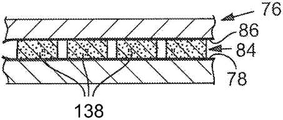
도 37은 가열 압반으로 형성되는 제4 복합재의 측단면도이다.
도 38은 부분적인 보강을 나타낸 제4 복합재의 측단면도이다.
도 39는 작업대와 가열 압반 사이에 위치된 제4 복합재 및 넓게 퍼진 직물인 메쉬재를 나타낸 측단면도이다.
도 40은 가열 압반으로 형성되는 제5 복합재의 측단면도이다.
도 41은 제5 복합재의 측단면도이다.
도 42는 작업대와 가열 압반 사이에 위치된 제1 복합재, 보강재 격자, 및 넓게 퍼진 직물인 메쉬재를 나타낸 측단면도이다.
도 43은 가열 압반으로 형성되는 제6 복합재의 측단면도이다.
도 44는 완전한 보강을 나타낸 제6 복합재의 측단면도이다.
도 45는 탄성재 중 여분의 탄성재 부분으로부터 접착층의 제거인 "필링 오프"를 나타낸 도면이다.
도 46은 작업대와 가열 압반 사이에 위치된 컷팅된 탄성재 및 넓게 퍼진 직물인 메쉬재를 나타낸 측단면도이다.
도 47은 가열 압반으로 형성되는 탄성재/기질 복합재의 측단면도이다.
도 48은 제2 복합재의 측단면도이다.
도 49는 제2 복합재로부터 형성된 제1 복합재의 측단면도이다.
도 50은 작업대와 가열 압반 사이에 위치된 제2 복합재 및 넓게 퍼진 직물인 메쉬재를 나타낸 측단면도이다.
도 51은 가열 압반을 이용하여 제2 복합재로부터 형성되는 제3 복합재를 나타낸 측단면도이다.
도 52는 제3 복합재의 측단면도이다.
도 53은 작업대와 가열 압반 사이에 위치된 제2 복합재, 보강재 격자, 및 넓게 퍼진 직물인 메쉬재를 나타낸 측단면도이다.
도 54는 가열 압반으로 제4 복합재를 형성하는 중간 단계를 나타낸 측단면도이다.
도 55는 가열 압반으로 형성되는 제4 복합재의 측단면도이다.
도 56은 제4 복합재의 측단면도이다.
도 57은 작업대와 가열 압반 사이에 위치된 제1 복합재, 보강재 격자, 및 넓게 퍼진 직물인 메쉬재를 나타낸 측단면도이다.
도 58은 가열 압반으로 형성되는 제6 복합재의 측단면도이다.
도 59는 제6 복합재의 측단면도이다.
도 60은 탄성재의 제1 측면에 접착재로 코팅되는 컷팅된 탄성재 시트를 나타낸 사시도이다.
도 61은 탄성 요소에서만 탄성재의 제1 측면에 접착재로 코팅되는 컷팅된 탄성재 시트를 나타낸 사시도이다.
도 62는 탄성 요소의 제1 측면이 직물인 메쉬재 및 여분의 탄성재에 접착되는 제2 복합재의 형성이 제거된 것을 나타낸 사시도이다.
도 63은 제2 복합재의 사시도이다.
도 64는 제2 복합재와 부분적인 보강재 격자가 함께 끼워지는 것을 나타낸 사시도이다.
도 65는 제2 복합재에 부분적인 보강재 격자가 끼워진 것을 나타낸 사시도이다.
도 66은 제2 복합재에 부분적인 보강재 격자가 끼워진 것을 나타낸 측면/사시도이다.
도 67은 제2 복합재와 완전한 보강재 격자가 함께 끼워지는 것을 나타낸 사시도이다.
도 68은 제2 복합재에 완전한 보강재 격자가 끼워진 것을 나타낸 사시도이다.
도 69는 제2 복합재에 완전한 및 부분적인 보강재 격자가 끼워진 것을 나타낸 사시도이다.
도 70은 제2 복합재에 완전한 및 부분적인 보강재 격자가 끼워진 것을 나타낸 측면/사시도이다.
도 71은 탄성 요소의 제2 측면에 직물인 메쉬재를 접착시킴으로써 제4 복합재를 형성하는 것을 나타낸 사시도로서, 탄성 요소와 보강재 격자는 직물인 메쉬재 층들 사이에 샌드위치된다.BRIEF DESCRIPTION OF THE DRAWINGS The invention will be more fully understood from the accompanying drawings, given by way of explanation and illustration given below, but the invention is not limited thereto.
FIG. 1 is a view showing an application of an elastic pad composite material used underneath.
2 is an exploded view of an elastic pad assembly including an elastic element, a partial reinforcing grating, and a support.
Figure 3 is a partially cut away view of an elastic pad assembly including an elastic element, a partial reinforcing grid, and a support.
4 is a side view of an elastic pad assembly including an elastic element, a partial reinforcing grating and a support.
5 is an exploded view of an elastic pad assembly including an elastic element, a full reinforcement grid, and a support.
Figure 6 is a partially cut away view of an elastic pad assembly including an elastic element, a full reinforcement grid, and a support.
Figure 7 is a side view of an elastic pad assembly including an elastic element, a full reinforcement grid, and a support.
8 is an exploded view of an elastic pad assembly including an elastic element, a complete and partial reinforcement grid, and a support.
Figure 9 is a partially cut away view of an elastic pad assembly including an elastic element, a full and partial reinforcement grid, and a support.
10 is a side view of an elastic pad assembly including an elastic element, a complete and partial reinforcement grid, and a support.
11 is a view showing that the elastic element according to an embodiment of the present invention has a conical shape.
12 is a view showing that the elastic element according to the embodiment of the present invention is in the shape of a cylinder having a center part that is broken.
Figures 13A-13D are cross-sectional views of an elastic assembly in which the elastic assembly is surrounded by a reinforcing grid portion, the elastic element having the same shape as the cylinder of Figure 13A; 13B; A cylinder shape having a contracted end section of Figure 13c; And a cylinder shape in which the vicinity of the center of the body of Fig. 13D is contracted.
14 is an exploded view and a perspective view showing the elastic sheet positioned between the cutter and the workbench.
15 is a side cross-sectional view showing an elastic material sheet positioned below the cutter in the workbench.
16 is a side cross-sectional view showing a cutter for cutting the elastic sheet in the work table.
17 is a side cross-sectional view showing a cut elastic material sheet positioned between the cutter and the workbench.
18 is a side cross-sectional view showing a stiffener sheet positioned below the cutter in the workbench.
19 is a side cross-sectional view showing a cutter for cutting a reinforcing sheet in a work table.
20 is a side sectional view showing a cut stiffener sheet positioned between the cutter and the workbench;
21 is a side cross-sectional view showing a reinforcing element removed from a cut stiffener sheet to form a stiffener grid;
22 is a perspective view showing a reinforcing material grid.
23 is an exploded view and a perspective view showing a cut elastic material sheet and a reinforcement grid disposed between the pusher and the die.
24 is a side cross-sectional view showing the cut elastic material sheet and the stiffener grid positioned below the pusher in the die;
25 is a side cross-sectional view showing a pusher pushing an elastic element from a cut elastic material sheet to a stiffener grid to form an elastic reassembly.
26 is a side cross-sectional view showing an elastic reassembly in a die.
Figure 27 is a side cross-sectional view of an elastic reassembly removed from a die.
28 is a side cross-sectional view of an elastic reassembly positioned between a work bench and a heating platen and a mesh material that is a wider spread fabric.
29 is a side cross-sectional view of the first composite material formed by the heating platen.
30 is a side cross-sectional view of the first composite.
31 is a side cross-sectional view of a second composite material formed from a first composite material;
32 is a side cross-sectional view of a second composite material positioned between a work bench and a heating platen and a mesh material that is a wider spread fabric.
33 is a side cross-sectional view of a third composite material formed from the second composite material using a heating platen.
34 is a side cross-sectional view of the third composite.
35 is a side cross-sectional view showing a second composite material positioned between a work platform and a heating platen, a stiffener grid, and a mesh material that is a wider spread fabric.
36 is a side sectional view showing an intermediate step of forming the fourth composite material by the heating platen.
37 is a side cross-sectional view of a fourth composite material formed by a heating platen;
38 is a side cross-sectional view of a fourth composite showing partial reinforcement.
39 is a side cross-sectional view showing a fourth composite material positioned between a work bench and a heating platen and a mesh material that is a wider spread fabric.
40 is a side cross-sectional view of a fifth composite material formed by a heating platen.
41 is a side sectional view of the fifth composite.
42 is a side cross-sectional view of a first composite material positioned between a work table and a heating platen, a stiffener grid, and a mesh material that is a wider spread fabric.
43 is a side cross-sectional view of a sixth composite material formed by a heating platen.
44 is a side cross-sectional view of a sixth composite material showing complete reinforcement.
45 is a view showing "filling off ", which is the removal of the adhesive layer from the excess elastic material portion in the elastic material.
46 is a side cross-sectional view showing a cut elastic material and a mesh material which is a wider spread fabric positioned between the work table and the heating platen.
47 is a side cross-sectional view of an elastic material / matrix composite formed from a hot platen.
48 is a side sectional view of the second composite.
49 is a side cross-sectional view of a first composite material formed from a second composite material;
50 is a side cross-sectional view showing a second composite material positioned between a work bench and a heating platen and a mesh material that is a wider spread fabric.
51 is a side sectional view showing a third composite material formed from the second composite material by using a heating platen.
52 is a side sectional view of the third composite.
53 is a side cross-sectional view showing a second composite material positioned between a work platform and a hot platen, a stiffener grid, and a mesh material that is a wider spread fabric.
54 is a side sectional view showing an intermediate step of forming a fourth composite material by a heating platen;
55 is a side sectional view of a fourth composite material formed by a heating platen;
56 is a side cross-sectional view of the fourth composite material.
57 is a side cross-sectional view showing a first composite material positioned between a work platform and a heating platen, a stiffener grid, and a mesh material that is a wider spread fabric.
58 is a side cross-sectional view of the sixth composite material formed by the heating platen.
59 is a side sectional view of the sixth composite.
60 is a perspective view showing a cut elastic material sheet coated with an adhesive on the first side of the elastic material;
61 is a perspective view showing a cut elastic material sheet coated with an adhesive on the first side of the elastic material only in the elastic element.
62 is a perspective view showing that the formation of the second composite material bonded to the mesh material and the extra elastic material where the first side of the elastic element is the fabric is removed.
63 is a perspective view of the second composite.
Fig. 64 is a perspective view showing that the second composite material and the partial reinforcing material grid are sandwiched together. Fig.
65 is a perspective view showing that a partial reinforcing material grid is sandwiched in the second composite material.
66 is a side / perspective view showing a partial stiffener grid fitted in the second composite.
67 is a perspective view showing that the second composite and the complete stiffener grid are sandwiched together.
68 is a perspective view showing that a complete reinforcing material grid is sandwiched in the second composite material.
69 is a perspective view showing a complete and partial stiffener grid fitted in the second composite.
Figure 70 is a side / perspective view showing the complete and partial stiffener grid sandwiched in the second composite.
71 is a perspective view illustrating forming a fourth composite material by adhering a mesh material, which is a fabric, to a second side of the elastic element, wherein the elastic element and the reinforcement material grid are sandwiched between the mesh material layers that are the fabric.
본 발명에서 "하나" 및 "하나의"는 단일의 대상체 및 복수의 대상체 모두를 나타내는데 이용된다.In the present invention, "one" and "one" are used to denote both a single object and a plurality of objects.
일 관점에서, 탄성 요소의 구성은 발포재, 러버재, 엘라스토머, 플라스틱 등(이러한 재료의 조합을 포함함)과 같은 일부 유형의 탄성재를 포함할 수 있으나, 이에 제한되는 것은 아니다. 기능상, 탄성재는 이루어진 탄성재의 유형 및 재료에 따라 충격에 대한 쿠션으로서 작용할 수 있거나, 또는 단열을 제공할 수 있다.In one aspect, the construction of the elastic element may include, but is not limited to, some types of elastic material such as foams, rubber materials, elastomers, plastics, and the like (including combinations of such materials). Functionally, the resilient material can act as a cushion against impact, or can provide insulation, depending on the type and material of the resilient material made.
탄성 요소의 형상은 보강 구조물에 의해 강화될 수 있는 한, 임의의 형태일 수 있다. 도면에 나타낸 탄성 요소가 단면으로 봤을 때 실린더 형상으로 나타냈을 지라도, 복수의 탄성 요소 또는 탄성 요소의 바람직한 서브셋(subset)이 선택된 보강 격자(lattice)(들)에 의해 강화될 수 있는 한, 각 탄성 요소는 다른 탄성 요소와 같거나 또는 다른 형상을 가질 수 있다. 상기 탄성 요소는, 일반적으로 실린더 형상일 것이나, 블록 형상, 원뿔 구조, 테이퍼진 실린더 구조나 테이퍼진 블록 구조, 또는 요소 보강 구조물이 실린더나 블록 형상의 수축된 중간 부분을 접촉시키는 요소 보강 구조물에 의해 더 "움켜질 수 있는(grabbing)" 수축된 중간 섹션을 갖는 실린더, 원뿔이나 블록 형상과 같은 다른 규칙적 및 비규칙적인 형상으로 이루어질 수 있으며, 그러나 이에 제한되는 것은 아니다. 이러한 다양한 형상을 형성할 수 있는 것은 이해될 수 있을 것이고, 각 컷팅 요소는 대응하는 탄성 요소의 바람직한 형상에 대응하는 형상을 가질 것이다.The shape of the resilient element can be of any shape as long as it can be reinforced by the reinforcing structure. As long as the preferred subset of the plurality of elastic elements or elastic elements can be reinforced by the selected reinforcing lattice (s), even though the elastic elements shown in the figures are shown in a cylinder shape when viewed in cross section, An element may have the same or different shape as another elastic element. The elastic element may be generally cylindrical, but may be in the form of a block, a cone, a tapered cylinder, a tapered block, or an element reinforcing structure contacting the shrunk intermediate portion of the cylinder or block But are not limited to, cylinders having a more "grabbing" shrunk intermediate section, or other regular and irregular shapes such as cones or block shapes. It will be understood that these various shapes can be formed, and each cutting element will have a shape corresponding to the desired shape of the corresponding elastic element.
탄성 요소의 크기 및 형상의 모든 변형 방식은 본 발명에서 고려될 수 있다. 탄성 요소의 높이는 복합재에서 변화될 수 있다는 것을 주목해야 한다. 예를 들어, 상기 높이는 특히 큰 충격이 예상되는 영역에서 크게 될 수 있다. 다시 말해서, 탄성 요소의 높이뿐만 아니라 그 결과에 의한 복합 패드가 균일하게 될 필요는 없다. 높이의 가변성은 심미적일 수 있거나, 또는 물리적 기능으로서 역할을 할 수 있다. 탄성 요소의 형상을 고려하면, 본 발명에서 예시된 형상은 상부 평면에서 봤을 때 계란형 및 원형의 탄성 요소를 포함할지라도, 아령 형상, 다른 비규칙적인 형상 또는 바람직하게 생각될 수 있는 여러 형상의 조합을 포함하는 3각형, 4각형, 5각형, 6각형, 7각형 등과 같은 다양한 다각형 형상의 다른 디자인이 본 발명 내에서 고려될 수 있다. 이러한 형상은 단일의 복합재 내에서 그리고 어떤 상황에서 균일하게 될 필요가 없고, 탄성 요소의 여러 상이한 형상 및 크기가 이용될 수 있다. 탄성 요소 형상의 가변성 및 서로 간의 관계에서 탄성 요소들에 얼마나 가깝게 이격되거나 또는 탄성 요소들에 얼마나 빽빽하거나 헐겁게 위치되는지가 어셈블리의 신축성 및 통기성에 영향을 줄 수 있다는 것을 이해하여야 한다.All variations of the size and shape of the elastic element can be considered in the present invention. It should be noted that the height of the elastic element can vary in the composite. For example, the height can be large especially in areas where a large impact is expected. In other words, the height of the elastic elements as well as the resultant composite pad need not be uniform. Variability in height can be aesthetic, or can serve as a physical function. Considering the shape of the elastic elements, although the shape illustrated in the present invention includes oval and circular elastic elements as viewed from the top plane, it is possible to use a combination of dumbbell shapes, other irregular shapes, Other designs of various polygonal shapes, such as triangular, tetragonal, pentagonal, hexagonal, hexagonal, etc., may be considered within the present invention. This shape need not be uniform in a single composite and under certain circumstances, and different shapes and sizes of elastic elements can be used. It should be appreciated that the variability of the elastic element shape and how closely spaced or resiliently spaced or loosely positioned the elastic elements in relation to each other can affect the stretchability and breathability of the assembly.
다른 관점에서, 요소 보강 구조물은 그 사용에 따라, 발포재, 네오프렌, 천연이나 합성 가죽, 플라스틱, 러버재(라텍스 및 실리콘을 포함하나, 이에 한정되는 것은 아님), 또는 합성 섬유를 포함하는 여러 상이한 재료로 이루어질 수 있다. 본 발명의 일 관점에서, 보강 구조물은 복합재의 사용에 따라 시팅 구조물(sheeting structure)과 다른 재료로 이루어질 수 있다. 예를 들어, 상기 요소 보강 구조물이 시팅 구조물에 비해 신축성이 없고 안정적인 것이 바람직한 경우, 상기 보강 구조물 및 시팅 구조물용 재료는 이러한 특성의 결과에 따라 선택되어야 한다. 예를 들어, 이러한 상황의 예는 최적의 쿠션이 각진 영역에 대한 안정적인 요소의 배치를 통해 각진 팔꿈치나 무릎에 제공될 수 있도록, 시팅 구조물은 유연할 수 있지만 상기 요소 및 요소 보강 구조물은 유연할 수 없는 팔꿈치나 무릎 패드에서 발생한다.In another aspect, the urethane reinforcement structure may be fabricated from a variety of different materials including, but not limited to, foam materials, neoprene, natural or synthetic leather, plastics, rubber materials (including but not limited to latex and silicone) Material. In one aspect of the present invention, the reinforcing structure may be made of a material different from the sheeting structure depending on the use of the composite. For example, if it is desired that the urethane reinforcing structure is not stretchable and stable compared to the seating structure, then the reinforcing structure and the material for the seating structure should be selected according to the result of this property. For example, an example of such a situation is that the seating structure may be flexible, so that the optimal cushion can be provided to the angled elbow or knee through the placement of a stable element for the angled region, It occurs in elbow or knee pad without.
상기 요소 보강 구조물은 그 환경 내에서 보강 구조물의 이동을 억제하는 단단한 발포재, 가죽, 러버재, 또는 플라스틱 시트와 같은 단단한 재료일 수 있으나, 이에 한정되는 것은 아니다.The urethane reinforcing structure may be, but is not limited to, a rigid foam such as a rigid foaming material, leather, rubber material, or a plastic sheet that inhibits movement of the reinforcing structure in its environment.
한편, 상기 보강 구조물이 탄성재보다 더 신축성이 있는 것이 바람직한 경우, 더 신축가능한 재료가 요소 보강재로 선택될 수 있다. 바람직한 신축성을 발생시키기 위해 선택되는 재료가 당업자에게 이용될 수 있는 것을 이해하여야 한다.On the other hand, when it is desired that the reinforcing structure is more elastic than the elastic material, a more stretchable material can be selected as the urea reinforcement. It should be understood that the materials chosen to produce the desired stretchability can be utilized by those skilled in the art.
상기 요소 보강 구조물은 평편하거나 커브형의 형상일 수 있다. 상기 요소 보강 구조물용 재료는 흡수성, 통기성, 신축성, 또는 인장 강도를 증가시키거나 감소시키기 위하여 조정될 수 있다. 상기 요소 보강 구조물은 통기성, 신축성, 및 공기 순환을 증가나 감소시키기 위하여 홀 또는 개구부를 포함할 수 있다. 상기 요소 보강 구조물에 대한 특성 방식은 본 발명의 범위 내에서 고려된다.The element reinforcing structure may have a flat or curved shape. The material for the urethane reinforcing structure may be adjusted to increase or decrease the absorbency, breathability, stretchability, or tensile strength. The element reinforcing structure may include holes or openings to increase or decrease air permeability, stretchability, and air circulation. The manner of characterization for the element reinforcing structure is contemplated within the scope of the present invention.
보강재 격자 또는 보강 부재로 나타낸 다른 것을 고려하면, 수개의 격자들이 함께 이용될 수 있다. 일부는 동일한 평면에서 다른 격자들과 상호 연결하거나, 또는 공통의 탄성 요소에 대한 결합을 통해 상이한 평면에서 격자들에 대하여 상호 연결하는 등 서로의 상부에 적층될 수 있다. 본 발명에서는 소정 형상의 격자를 예시하고 있지만, 물리적, 기능적 또는 심미적 목적의 다양한 격자 형상이 고려된다. 예를 들어, 컷-아웃 및 그 밖의 여러 형상 및 크기를 갖는 격자가 본 발명 내에서 고려된다. 실제, 고려될 수 있는 임의의 형상은 탄성 요소로 이루어질 수 있고, 격자형 보강 구조물이 본 발명의 복합 패드에서 이용될 수 있다.Considering the stiffener lattice or the other represented by the stiffening member, several gratings can be used together. Some may be stacked on top of each other, such as interconnecting with other gratings in the same plane, or interconnecting to the gratings in different planes through bonding to common elastic elements. Although a lattice of a predetermined shape is exemplified in the present invention, various lattice shapes for physical, functional or aesthetic purposes are considered. For example, a grating with cut-out and various other shapes and sizes is contemplated within the present invention. In practice, any shape that may be considered may consist of elastic elements, and a lattice-like reinforcing structure may be used in the composite pad of the present invention.
본 발명의 다른 관점에서, 상기 시팅 구조물은, 일반적으로 천연이나 합성 섬유일 수 있는 직물로 구성될 수 있다. 대안으로, 상기 시팅 구조물은 유연하거나 휘어지는 플라스틱, 라텍스, 실리콘이나 다른 러버재, 또는 어셈블리에 대하여 통기성 및 신축성을 부여하는 합성 섬유로 이루어진 것일 수 있다.In another aspect of the invention, the seating structure can be composed of a fabric, which can be generally natural or synthetic fibers. Alternatively, the seating structure may be made of flexible or flexible plastic, latex, silicone or other rubber material, or synthetic fibers that impart breathability and stretchability to the assembly.
구체적인 실시예에서, 본 발명은, 다른 것들 중에서 방호복, 헤드기어, 운동복, 방탄복 및 신체를 보호하는 것이 아니라 패딩에 대하여 경량, 통기, 신축, 충격 흡수가 필요한 그 밖의 다른 곳에서 사용하기 위한 방호 패드 구성에 대하여 제공한다. 신발, 가방, 배낭, 쌕, 좌석, 및 좌석 쿠션은 본 발명의 복합 패드와의 조합으로부터 얻을 수 있는 여러 제품 중 일부이다. 본 발명의 발포 패드는 도면에 도시된 바람직한 실시예에 따라 구성된다.In a specific embodiment, the present invention is not limited to protecting the protective garment, head gear, sportswear, body armor, and body among others, but may be used for other applications requiring light weight, ventilation, Configuration. Shoes, bags, backpacks, sacks, seats, and seat cushions are some of the many products that can be obtained from combination with the composite pad of the present invention. The foam pad of the present invention is constructed in accordance with the preferred embodiment shown in the drawings.
본 발명의 탄성 또는 발포 패드의 일반적인 적용은 도 1에 도시되어 있고, 대표적인 하의(undergarment)가 도면부호 10으로 나타나 있으며, 이는 축구, 야구, 농구 등의 운동선수들이 사용하는 유형일 수 있다. 상기 하의는 본 발명에 따른 발포 패드의 하나의 예시적인 사용을 나타내기 위해 도시한 것이고, 하의에만 배치되는 본 발명의 발포 패드의 제한적인 적용을 의도하지 않는다. 본 발명의 패드는 영구적으로 배치될 수 있거나 또는 충격력으로부터 보호하기 위한 착용자의 바람직한 대상에 대하여 리버서블 부착(reversible attachment)으로 배치될 수 있다. 이러한 리버서블 부착은 지퍼, 벨크로 등에 의해 수행될 수 있으나, 이에 한정되는 것은 아니다. 도 1을 참조하면, 상기 하의인 의복은 허리와 히프 주위에 끼워지기 위한 상부(12), 및 허벅지를 따라 대략 중간에서 하방향으로 연장되는 다리부(14, 16)를 포함한다. 상기 하의는 신체에 대하여 압축을 제공하도록 적절한 재료로 구성되어, 운동 활동 동안에 피로와 변형을 최소화하는데 도움을 준다. 상기 하의에 장착되어 도시된 것은 도면부호 18로 나타낸 히프 패드, 도면부호 20으로 나타낸 허벅지 패드와 같은 방호 패드이다. 상기 하의에서의 히프와 허벅지 패드는 일반적으로 사용되도록 제공되고, 도 1은 본 발명의 발포 패드가 일반적으로 배치되는 것을 보여주기 위하여 단순히 제공한 것이다. 물론, 발포 패드는 엉덩이 및 서혜부 영역에서와 같은 하의의 다른 영역에 배치될 수 있으나, 이에 한정되는 것은 아니다. 또한, 발포 패드는 헬멧, 배낭 안감, 장비 안감, 신발, 좌석, 등에 배치될 수 있다.A typical application of the elastic or foam pads of the present invention is shown in FIG. 1, with an exemplary undergarment indicated at 10, which may be of the type used by athletes such as football, baseball, basketball and the like. The bottom is shown to illustrate one exemplary use of the foam pad according to the present invention and is not intended to be a limiting application of the foam pad of the present invention disposed underneath. The pads of the present invention may be permanently disposed or disposed in a reversible attachment to the wearer ' s preferred subject for protection against impact forces. Such a reversible attachment can be performed by a zipper, a velcro or the like, but is not limited thereto. Referring to Fig. 1, the lower garment includes an
본 발명의 복합재는 기질, 복수의 이산되고 이격된 탄성 요소나 발포 요소, 및 선택된 탄성이나 발포 요소를 둘러싸기 위한 보강 구조물이나 격자를 포함하는 적층된 구조물, 및 직물인 메쉬재 중 적어도 상부층(upper layer)을 포함한다. 이러한 발포 패드 또는 바람직한 구성의 "패키지"는 전술한 바와 같이 다수의 적용 분야에서 일체로 적용될 수 있다.The composite material of the present invention comprises a matrix, a laminate structure comprising a reinforcing structure or grid for surrounding a substrate, a plurality of discrete and spaced elastic or foam elements, and a selected elastic or foam element, and at least a top layer. Such a foam pad or "package" of the preferred configuration may be applied in any of a number of applications as described above.
부분적인 보강을 갖는 탄성 패드 복합재Elastic pad composite with partial reinforcement
편의상, 이하 본 발명의 요소를 포함하는 탄성 패드 복합재를 구체적인 실시예에서 "발포 패드"로 나타낼 것이다. 본 발명에서 "발포 패드"로 설명하면, 본 발명은 "발포재"에 제한되지 않고 다른 재료가 이용될 수 있으며, 더 나아가 본 발명은 "패드"에 필수적으로 제한되는 것이 아니라 다른 복합재의 사용이 본 발명에서 고려되며, 예를 들어 팔꿈치 및 무릎 보호대 및 보호구, 정강이 보호대, 어깨 보호대 및 보호구, 및 운동선수용 흉부 보호구; 운동 매트; 배낭용 등 부위 패널, 어깨 끈, 및 역도 벨트용 패딩; 헬멧 및 모자 안감, 머리 보호구; 방탄복용 안감; 신발 중간창, 신발 구두창, 신발 내부 안감, 및 경량, 통기, 신축, 윤곽, 유연성 방호 쿠션을 필요로 하는 다른 적용에서의 사용도 고려된다. 도 2에 도시된 바와 같이, 부분적인 보강을 갖는 발포 패드가 분해도로서 도시되어 있다. 상기 발포 패드는 도면부호 22로 나타낸 직물인 메쉬재의 상부층, 및 발포 요소 중 선택된 하나를 캡쳐하기 때문에 "케이지(cage)"로서 여겨질 수 있는 중간인 부분적인 보강 부재(24)를 포함한다. 직물인 메쉬재의 기질은 도면부호 26으로 나타내고 있고, 복수의 이산되고 이격된 발포 요소는 도면부호 28로 나타내고 있다. 본 예에서 상기 발포 요소는 단면으로 선택적인 원형 또는 계란형으로 도시되어 있고, 선택적으로 실린더 형태일 수 있다.For convenience, the elastic pad composites comprising the elements of the present invention will hereinafter be referred to as "foam pads" in specific embodiments. In the context of the present invention, the term " foam pad "means that the present invention is not limited to a " pad" For example, elbow and knee guards and protectors, shin guards, shoulder guards and guards, and athletic thoracic guards; Exercise mats; Padding for backpacks, back panels, shoulder straps, and weightlifting belts; Helmet and hat lining, head protection; Armor lining; Use in other applications where a shoe midsole, shoe shoe, shoe lining, and lightweight, vented, stretched, contoured, flexible protective cushions are also considered. As shown in Figure 2, a foam pad with partial reinforcement is shown as an exploded view. The foam pad includes an upper layer of mesh material, which is a fabric denoted by
상기 발포 패드는, EVA, PE, 네오프렌, 또는 다른 발포 재료와 같은 적절한 발포재로 이루어질 수 있다. 도 2의 분해도에서, 상기 발포 요소의 상면은 노출되고, 하면은 기질(26)의 상면에 대한 적층 공정에서 적합한 접착재에 의해 선택적으로 적절하게 접합된다. 도면부호 28a로 나타낸 바와 같은 발포 요소의 상면에는 적절한 가열이 적용됨에 따라 메쉬재(22)에 적층될 수 있는 접착재가 제공되기도 한다.The foam pad may be made of a suitable foamed material, such as EVA, PE, neoprene, or other foamed material. In the exploded view of FIG. 2, the upper surface of the foam element is exposed and the lower surface is selectively suitably bonded by a suitable adhesive in a lamination process to the upper surface of the
부분적인 보강 부재나 격자(24)는 기질(26)에서의 탄성이나 발포 요소(28)에 의해 점유된 영역보다 작은 단면 영역을 갖게 치수화된다. 보강 부재(24)에는 복수의 개구부가 제공되고, 이때 원형의 개구부(30)는 발포 요소(28)의 직경보다 큰 직경을 갖게 치수화된다.The partial reinforcement members or
도시된 바와 같이, 보강 부재(24)는 기질(26)에서의 발포 요소(28)에 의해 점유된 영역의 폭 및 길이보다 작은 폭(W) 및 길이(L)를 갖게 치수화된다. 어셈블리에서, 보강 부재(24)는, 도 3에 도시된 바와 같이 발포 요소(28)의 넓은 영역 위에 배치되어, 발포 요소의 소정 부분이 보강 부재(24)의 대응 구멍 내에 국한되고, 상기 발포 요소의 나머지 부분은 구속받지 않고 유지된다.As shown, the stiffening
도 3에 도시된 바와 같이, 보강 부재(24)에 의해 구속되지 않는 발포 요소(28)의 외부 열이 있다. 이는 4-4 라인에 따른 단면인 도 4에 의해 더 명확히 알 수 있고, 보강 부재(24)가 발포 요소(28) 중 정렬된 하나 위에 하방향으로 위치되는 경우, 각 발포 요소의 일부는 보강 부재(24)의 상면 위로 연장된다. 발포 요소(28)의 외부 열은 보강 부재(24)에 의해 구속되지 않는다. 또한 도 4에 도시된 바와 같이, 상기 복합재는 발포 요소(28)의 상면에 접착되는 상부층(22)을 포함하는 샌드위치 구성이다. 상면(22)은 적층 공정에서 발포 요소에 접착되고; 전술한 바와 같이, 기질(26)은 또한 적층 공정에 의해 발포 요소의 하면에 접착된다.As shown in Fig. 3, there is an external column of
전술한 바와 같은 구성에서, 부분적인 보강 부재의 포함은 복합 발포 패드가 방호를 위해 이용되는 경우에 확실한 이점을 제공한다. 도 2 내지 4에 대략 직사각형인 부분적인 보강 부재(24)를 구비한 대략 직사각형 구성을 갖는 발포 패드를 도시하였지만, 상기 발포 패드의 특정 배치에 따라, 원형, 장방형, 3각형 등과 같은 다른 구성이 쉽게 제공될 수 있는 것을 인식하여야 한다. 예를 들어, 상기 복합 발포 패드가 허벅지나 히프에 위치되면, 팔꿈치, 무릎, 정강이, 또는 신체의 다른 부위를 보호하기 위해, 헤드기어에 위치된 경우와 다른 구성을 가질 수 있다. 전술한 바와 같은 부분적인 보강에 의해 복합 발포 패드는 여러 중요한 이점을 제공할 수 있다. 먼저, 상기 보강 부재에 의해 커버될 구체적 영역을 지정하면 상기 보강 부재의 외측인 직물의 발포 요소는 신장되는 대로 직물과 함께 이동하게 된다. 이러한 신축성은 다리, 팔, 또는 복합 발포 패드가 제공된 모든 부위와 같은 신체 부위의 이동에 따라 발생할 수 있다. 상기 보강 부재 내에 캡쳐된 발포 요소는 당연히 상기 보강 부재의 외측의 발포 요소만큼 신축되는 대로 거의 이동하지 않을 것이다. 상기 보강 부재는 부가적인 충격 흡수성을 제공하기도 한다. 도 4에 도시된 바와 같이, 상기 발포 요소(28)의 일부는 보강 부재의 상면 위로 선택적으로 연장하도록 상기 보강 부재(24)는 치수화된다. 이에 의해 상기 발포 요소는 충격에 따라 압축될 수 있지만, 이러한 압축은 보강 부재의 표면에 의해 하방향으로 제한된다. 그러나, 상기 탄성 요소의 높이는 변화될 수 있고, 상기 보강 부재의 상면 위로 연장되는 높이에 제한되지 않는다. 상기 보강 부재는 적은 탄성재로 구성될 수 있어서, 강화된 충격 흡수 효과를 제공한다. 보강 부재(24)에 제공된 구멍(30)은 선택적으로 발포 요소(28)보다 큰 직경으로 치수화될 수 있고, 이에 따라 복합 발포 패드에 관련된 구멍(30) 내에서 각 발포 요소의 일부의 동작이 있다. 이러한 직경의 큰 차이에 의해 더 많은 공기가 패드 내에서 순환하고, 그 결과 패드는 큰 유연성 및 향상된 순환인 "통기성"을 갖는다.In the configuration described above, the inclusion of the partial reinforcing member provides a definite advantage when the composite foam pad is used for protection. Although Figures 2 to 4 illustrate a foam pad having a generally rectangular configuration with a partial reinforcing
따라서, 전술한 설명으로부터, 상기 부분적인 보강 부재(24)는 복합 발포 패드가 여전히 신축되는 동안에 추가적인 방호를 제공한다는 것을 보여줄 수 있다. 이러한 구성에서, 보강 부재(24)는 구체적인 사용 및 관절이 필요한 부위에서 다른 영역이 신축될 수 있는 동안에 주어진 영역을 보호하도록 디자인될 수 있다는 인식할 수 있다. 통기성의 조합은 보강 부재로 커버되지 않는 영역에 의해 보장될 수 있고, 상기 보강 부재 그 자체는 향상된 절연처리를 제공할 수 있다. 또한, 도면부호 28로 나타낸 바와 같은 발포 요소 및 보강 부재(24)에는 발포 패드의 특정 적용에 따라, 순환을 향상시킬 수 있게 전체를 통해 연장되는 보어가 적절하게 제공될 수 있다.Thus, from the above description, the
도 2에 특별히 도시하지는 않았지만, 다수의 보강 부재나 격자가 발포 요소 중 하나를 캡쳐하도록 선택된 위치에 제공될 수 있다. 전술한 바와 같으며 특히 도 4에 도시된 바와 같이, 보강 격자는 상부층(22)과 보강 격자의 상부 표면 사이에 순환의 영역을 제공하는 것을 알 수 있다. 본질적으로, 공기 챔버가 제공되고, 이러한 순환은 쾌적함을 위해 중요할 수 있다. 또한, 상기 발포 요소는 먼저 충격을 흡수하고, 그 다음에 상기 발포 요소가 감압됨에 따라 보강 부재가 충격을 더 흡수하여 충격으로부터의 에너지를 더 흡수한다. 상기 보강 부재는 그 내에 캡쳐된 발포 요소를 대략 균일한 위치에서 유지하기도 한다. 이는 신체의 소정 영역을 보호하는데 중요할 수 있고; 발포 패드의 일부는 이동을 수용하도록 신축될 수 있지만, 상기 보강 부재 내에 캡쳐된 발포 요소는 보호되고자 하는 신체 부위에 대하여 대략 균일한 방향을 유지한다.Although not specifically shown in Fig. 2, a plurality of reinforcing members or gratings may be provided at selected positions to capture one of the foaming elements. As described above, and particularly as shown in Fig. 4, it can be seen that the reinforcing lattice provides an area of circulation between the
또한, 상기 보강 부재는 보강 부재 내에 캡쳐된 발포 요소에 대한 손상을 방지하는데 도움을 줄 것이고; 예를 들어, 임의의 유형의 충격에 의해 발포 요소가 서로를 향해 압축될 수 있어서 상기 발포 요소에 손상을 발생시킬 수 있다. 제 위치에서의 보강 부재를 갖는, 상기 보강 부재 내에 캡쳐된 발포 요소는 이격되어 떨어져서 유지되고, 이에 의하여 완전한 상태 및 착용을 향상시킬 수 있다.Further, the reinforcing member will help prevent damage to the foam element captured in the reinforcing member; For example, any type of impact can cause the foam elements to compress toward one another, causing damage to the foam elements. The foam element captured in the reinforcing member, with the reinforcing member in place, is spaced apart and held, thereby improving the integrity and wear.
완전한 보강을 갖는 탄성 패드 복합재Elastic pad composite with full reinforcement
본 발명은 완전한 보강이 있는 복합 발포 패드 및 도 5의 분해도에서 나타낸 구성을 고려하기도 한다. 구체적으로, 도면부호 25로 나타낸 중간의 완전한 보강 부재나 케이지에는 복합 구조물에서 발포 요소(28)를 보강 부재 내에 수용하도록 정렬하기 위한 구멍이 제공된다. 선택적으로 완전히 적층된 발포 패드가 도 6 및 도 7에 도시되어 있고, 상기 발포 요소는 선택적으로 보강 부재(25)의 표면 위로 연장되고, 직물(22)은 복합 구성을 제공하도록 적절하게 적층된다. 그러나, 상기 탄성 요소의 높이는 변화될 수 있고, 상기 보강 부재의 상면 위로 연장되는 높이에 제한되지 않는다. "부분적인(partial)" 또는 "완전한(full)" 보강 부재 사이의 차이는 발포 요소의 수 및 보강 부재의 구체적인 윤관이나 구성에 따라 모호할 수 있다는 것을 인식하여야 한다. 예를 들어, 도 6에는 모든 발포 요소를 대략 캡쳐하는 것을 고려한 완전한 보강 부재를 도시하고 있지만, 보강 부재는 보강 부재(24, 25) 사이인 중간 크기로 구성될 수 있다. 필요에 따라 그리고 보호가 필요함에 따라, 보강 부재는 상대적인 치수로 될 수 있다. 물론, 도 6에 도시된 바와 같은 완전한 보강 부재를 갖는 직물의 신축성은 부분적인 보강 부재를 도시한 도 3에 나타낸 직물의 성능으로부터 상당히 제한된다. (부분적이든 완전하든 간에) 보강 부재는 공유된 탄성 요소에 대하여 다른 보강 부재에 의한 결합을 통해 다른 보강 부재와 링크될 수 있다. 예를 들어, 탄성 시트에 나란하게 위치된 보강 부재들은 탄성 패드에 위치된 보강 부재에 대하여 공통인 탄성 요소에 적층한 보강 격자를 결합시킴으로써 보강 부재 위에 적층된 다른 보강 격자를 아래에 위치시켜 함께 더 안정적으로 링크될 수 있다.The present invention contemplates composite foam pads with full reinforcement and configurations shown in the exploded view of Fig. Specifically, an intermediate complete reinforcement member or cage, designated at 25, is provided with an aperture for aligning the
부분적인 및 완전한 보강을 갖는 탄성 패드 복합재Elastic pad composite with partial and complete reinforcement
도 8에 나타낸 바와 같이, "적층된(staked)" 부분적인 및 완전한 보강을 갖는 발포 패드가 분해도에 도시되어 있다. 상기 발포 패드는 도면부호 22로 나타낸 직물인 메쉬재의 상부층, 및 부분적인 보강 부재(24) 및 완전한 보강 부재(25)와 같은 두 개의 중간 부재를 포함한다. 도 9 및 10의 복합 구조물에 나타낸 바와 같이, 보강 부재(24)는 보강 부재(25)의 상부에 장착되고, 중첩된 영역에서 발포 요소(28)의 압축성은 크게 감소된다. 보강 부재(24)가 위치하지 않는 보강 부재(25) 위에 영역이 있으며, 인접한 발포 요소의 압축이 더 유지되지만, 상기 보강 부재의 "적층된" 배열은 충격을 보호하기 위한 더 향상된 영역을 제공한다. 상기 보강 부재의 상대적인 크기에 따라, 메쉬인 직물의 윤곽 영역이 신축성을 계속 제공하게 하는 "부분적인" 케이지의 적층된 구성일 수 있다. 이는 도시된 다수의 적층된 보강 부재의 구성이 제공될 수 있는 구성 및 조합의 여러 유형일 수 있다는 점이다. 게다가, 적층 개념을 갖는, 상기 복합 발포 패드의 부분은 다른 부분이 부분적인 보강 부재를 가질 수 있는 동안에 적층된 보강 부재로 강화될 수 있다. 주변과 디자인의 선택은 원하는 바에 따른 보강 및 안정성을 갖는 발포 패드를 요구에 맞출 수 있다. 도 11은 발포 요소의 다른 유형의 구성을 도시한 것이고, 이 경우에 원뿔 구성은 보강 부재가 그 위에 수용될 수 있게 하지만, 통기성을 위한 공기의 공간을 더 제공하게 한다. 또한, 통기성은 도 12에 나타낸 발포 요소의 구성, 즉 상부 직물(22)과 하부 기질(26) 사이에 통기성이 제공되도록 각 발포 요소를 통해 보어가 선택적으로 구성될 수 있는 구성에 의해 향상된다.As shown in Fig. 8, foam pads with "staked" partial and complete reinforcement are shown in exploded view. The foam pad comprises an upper layer of mesh material, which is a fabric denoted by
도 13a 내지 13d는 케이지 구성에서 이용될 수 있는 발포 요소의 상이한 구성의 예를 도시한 것이다. 도 13a는 긴 발포 요소를 도시한 것이고, 화살표는 케이지가 충격 또는 충격의 완화에 의해 발생되는 이동을 가질 수 있다는 것을 나타낸 것이다. 도 13b는 긴 원뿔형 발포 요소를 도시한 것이고, 도 13c는 넓은 베이스부가 형성된 발포 요소를 도시한 것이다. 도 13d는 기질의 상면 근처 또는 상부층의 인접한 하면보다는 오히려 탄성 또는 발포 요소의 상부와 하면 사이의 케이지 중간을 국한시킬 수 있게 서로를 향하는 한 쌍의 원뿔대를 도시한 것이다.Figures 13a-13d illustrate examples of different configurations of foam elements that may be used in a cage configuration. Figure 13a shows the long foaming element, and the arrows indicate that the cage can have movement caused by shock or shock mitigation. FIG. 13B shows a long conical foam element, and FIG. 13C shows a foam element having a wide base portion. Figure 13d shows a pair of frusto-cones facing each other so as to confine the middle of the cage between the upper and lower sides of the resilient or foaming element, rather than near the upper surface of the substrate or the adjacent lower surface of the upper layer.
도 4에서, 부분적인 보강 부재(24)가 기질(26)에 대하여 배치되어 도시된 것을 알 수 있을 것이다. 그러나, 상기 탄성 요소에 대한 보강 부재의 높이에 따라, 상부층(22)과 기질(26) 사이의 "지글(jiggle)" 또는 "플로트(float)"인 탄성 요소에 결합되는 동안에 상기 보강 부재가 수직이나 수평으로 이동할 수 있다는 것을 인식하여야 한다. 상기 탄성 요소의 높이가 더 높다면 더 많은 "플로트" 또는 "지글"이 있다. 이도 물론, 발포 요소의 구성, 발포 요소와 보강 부재의 개구부 사이의 상대적인 마찰력, 및 발생하는 경우에 충격 정도 및 충격력에 따라 좌우된다. 유사하게, 도 7은 기질(26)에 대하여 위치되는 완전한 보강 부재(25)를 도시하고 있지만, 상기 보강 부재는 상부층(22)과 기질(26) 사이에서 이동하거나 플로팅될 수 있다. 도 10에 나타낸 실시예에서, 부분적인 보강 부재(24)와 완전한 보강 부재(25)의 상대적인 두께에 따라, "적층된" 보강 부재의 플로팅 작용 또는 이동이 부분적이든 완전하든 단일의 보강 부재가 이용되는 경우보다 더 적은 정도로 제한될 수 있다.In Fig. 4, it will be seen that the
탄성 복합 패드를 제조하기 위한 제1 방법A first method for producing an elastic composite pad
또한, 본 발명은 도 1 내지 13에 나타낸 바와 같이, 보강이 없고, 부분적인 보강, 완전한 보강, 및 부분적 및 완전한 보강 모두를 갖는 복합 패드의 제조 방법에 관한 것이다. 예시적인 일 방법에서, 상기 방법은 대체로 다음의 공정을 포함한다.The present invention also relates to a method of making a composite pad having both reinforcement, partial reinforcement, complete reinforcement, and both partial and complete reinforcement, as shown in Figures 1-13. In an exemplary method, the method generally comprises the following steps.
(a) 대향 측면을 갖는 탄성재 시트를 제공하고;(a) providing an elastic sheet having opposite sides;
(b) 상기 탄성재 시트의 어느 하나의 측면 또는 양 측면에 접착재를 적용하고;(b) applying an adhesive to either one side or both sides of the elastic sheet;
(c) 표면 및 소정 패턴으로 상기 표면으로부터 연장되는 복수의 컷팅 요소를 갖는 제1 커터를 제공하고, 각 컷팅 요소는 내부 공간을 형성하는 형상을 갖고, 복수의 컷팅 요소는 복수의 컷팅 요소를 둘러싸는 인접한 공간 및 복수의 컷팅 요소 사이에 인접한 공간을 형성하기 위하여 서로 이격되고, 상기 내부 공간 및 인접한 공간은 선택적으로 바이어싱 재료로 충전되고;(c) providing a first cutter having a surface and a plurality of cutting elements extending from the surface in a predetermined pattern, each cutting element having a shape defining an interior space, wherein the plurality of cutting elements surround a plurality of cutting elements Are spaced apart from one another to form an adjacent space between the adjacent space and the plurality of cutting elements, the internal space and the adjacent space being optionally filled with a biasing material;
(d) 상기 탄성재 시트에 대해 제1 커터를 가압하여, 복수의 탄성 요소 및 여분의 탄성재를 포함하는 컷팅된 탄성재 시트를 형성하고, 각 탄성 요소는 대응하는 컷팅 요소의 내부 공간의 형상에 대응하는 형상을 갖고, 복수의 탄성 요소는 복수의 컷팅 요소의 소정 패턴에 대응하는 패턴을 형성하고, 상기 여분의 탄성재는 인접한 공간의 형상에 대응하는 형상을 갖고;(d) pressing the first cutter against the elastic material sheet to form a cut elastic material sheet including a plurality of elastic elements and an extra elastic material, wherein each elastic element has a shape of the inner space of the corresponding cutting element Wherein the plurality of elastic elements form a pattern corresponding to a predetermined pattern of the plurality of cutting elements, and the extra elastic material has a shape corresponding to the shape of the adjacent space;
(e) 상기 컷팅된 탄성재 시트로부터 제1 커터를 빼내고, 이에 의해 상기 바이어싱 재료는 복수의 탄성 요소 및 상기 복수의 컷팅 요소 내의 내부 공간과 상기 복수의 컷팅 요소를 둘러싸는 인접한 공간으로부터 떨어진 여분의 탄성재를 가압하여, 상기 여분의 탄성재에 의해 둘러싸여진 탄성 요소의 컷팅된 부분과 함께 컷팅된 탄성재 시트를 남겨두고;(e) withdrawing a first cutter from the cut sheet of elastomeric material, whereby the biasing material comprises a plurality of elastic elements and an extra space away from the inner space within the plurality of cutting elements and the adjacent space surrounding the plurality of cutting elements To leave the cut elastic material sheet with the cut portion of the elastic element surrounded by the extra elastic material;
(f) 단계 (g)-(i)에서 설명될 방법을 이용하여 선택적으로 가공될 수 있는 보강재 시트를 별도로 제공하지만, 적어도 하나의 보강 격자를 본 발명의 복합 패드를 형성하기 위하여 탄성 요소와 결합되어 얻을 수 있는 한, 보강 격자의 가공 방법은 다음의 단계를 수행하는 것에 제한되지 않고;(f) Separately providing a stiffener sheet that can be selectively processed using the method described in steps (g) - (i), but at least one reinforcing grid may be combined with the elastic elements to form the composite pad of the present invention As far as possible, the method of processing the reinforcing grid is not limited to performing the following steps;
(g) 상기 보강재 시트에 대해 제2 커터를 가압하여, 복수의 보강 요소 및 적어도 하나의 보강재 격자를 포함하는 컷팅된 보강재 시트를 형성하고, 각 보강 요소는 컷팅 요소의 소정 크기 및 형상에 대응하는 크기 및 형상을 갖고, 복수의 보강 요소는 복수의 컷팅 요소의 소정 패턴에 대응하는 패턴을 형성하고, 보강재 격자는 인접한 공간의 형상에 대응하는 형상을 갖고;(g) pressing the second cutter against the stiffener sheet to form a cut stiffener sheet including a plurality of stiffening elements and at least one stiffener grating, each stiffener element having a plurality of stiffener elements corresponding to a predetermined size and shape of the cutting element A plurality of reinforcing elements forming a pattern corresponding to a predetermined pattern of the plurality of cutting elements, the reinforcing element grating having a shape corresponding to the shape of the adjacent space;
(h) 상기 컷팅된 보강재 시트로부터 제2 커터를 빼내고, 이에 의해 상기 바이어싱 재료가 선택적으로 사용된 경우, 상기 바이어싱 재료는 복수의 보강 요소 및 상기 복수의 컷팅 요소 내의 내부 공간과 상기 복수의 컷팅 요소를 둘러싸는 인접한 공간으로부터 떨어진 보강재 격자를 가압하여, 상기 보강재 격자에 의해 선택적으로 둘러싸여진 보강 요소의 컷팅된 부분과 함께 컷팅된 보강재 시트를 남겨두고;(h) withdrawing a second cutter from the cut stiffener sheet, whereby, when the biasing material is selectively used, the biasing material comprises a plurality of reinforcing elements and an inner space within the plurality of cutting elements, Pressing a stiffener grid away from an adjacent space surrounding the cutting element to leave a cut stiffener sheet with the cut portion of the stiffening element selectively surrounded by the stiffener grid;
(i) 상기 보강 요소로부터 보강재 격자를 분리하고, 이에 의해 상기 보강재 격자는 보강 요소가 사용될 경우에 보강재를 통해 복수의 홀과 함께 남겨지고;(i) separating the stiffener grid from the reinforcing element, whereby the stiffener grid is left with a plurality of holes through the stiffener when the stiffening element is used;
(j) 그 내부에 형성된 복수의 개구부를 갖는 표면을 포함하는 다이를 제공하고, 상기 개구부를 둘러싸는 표면은 컷팅된 탄성재 시트에서 여분의 탄성재 형상 및 보강재 격자의 형상에 대략 대응하는 형상을 갖고, 적어도 복수의 개구부는 컷팅된 탄성재 시트에서 적어도 일부의 탄성 요소의 패턴에 대응하는 패턴을 형성하고;(j) a die having a surface having a plurality of openings formed therein, the surface surrounding the openings having a shape corresponding to the shape of the extra resilient material and the stiffener grid in the cut- Wherein at least a plurality of openings form a pattern corresponding to a pattern of at least a part of the elastic elements in the cut sheet of elastic material;
(k) 상기 보강재 격자에서 복수의 홀이 다이에서 복수의 개구부 위에 위치되도록 상기 다이에 적어도 하나의 보강재 격자를 위치시켜서 상기 보강재 격자를 정렬시키고;(k) aligning the stiffener grid by placing at least one stiffener grid on the die such that a plurality of holes in the stiffener grid are positioned over the plurality of openings in the die;
(l) 상기 복수의 탄성 요소가 보강재 격자에서 복수의 홀 위 및 다이에서 복수의 개구부 위에 위치되도록 상기 보강재 격자의 상부에 컷팅된 탄성재 시트를 위치시켜서 상기 컷팅된 탄성재 시트를 정렬시키고;(1) aligning the cut elastic material sheet by positioning the cut elastic material sheet on the reinforcing material grid so that the plurality of elastic elements are positioned on the plurality of holes in the reinforcing material grid and on the plurality of openings in the die;
(m) 상기 컷팅된 탄성재 시트에서 탄성 요소의 패턴에 대응하는 패턴을 형성하는 복수의 푸쉬 요소를 갖는 푸셔(pusher)를 제공하고;(m) providing a pusher having a plurality of push elements forming a pattern corresponding to a pattern of elastic elements in the cut sheet of elastomer material;
(n) 상기 복수의 푸쉬 요소를 복수의 탄성 요소와 정렬시켜서 상기 컷팅된 탄성재 시트의 외부로 탄성 요소를 푸쉬하기 위하여 상기 푸셔를 이용하고, 이에 의해 상기 복수의 탄성 요소는 적어도 하나의 보강재 격자에서 복수의 홀로 푸쉬되며 다른 것들은 다이에서 직접 복수의 개구부로 푸쉬되어, 적어도 하나의 보강재 격자에 의해 적어도 부분적으로 둘러싸여진 복수의 탄성 요소를 포함하는 탄성재 어셈블리를 형성하고;(n) using the pusher to align the plurality of push elements with a plurality of elastic elements to push the elastic elements out of the cut sheet of elastomeric material, whereby the plurality of elastic elements comprise at least one reinforcement grid The other being pushed directly into the plurality of openings in the die to form an elastic reassembly comprising a plurality of elastic elements at least partially surrounded by at least one stiffener grid;
(o) 가열-활성된 접착재가 탄성재의 측면에 적용되는 경우, 상기 다이로부터 탄성재 어셈블리를 제거해서 상기 탄성재 어셈블리를 가열 압반(heat platen) 아래에 위치시키고;(o) when the heat-activated adhesive is applied to the side of the elastic material, removing the elastic material assembly from the die to place the elastic material assembly under a heat platen;
(p) 상기 탄성재 어셈블리의 일 측면에 직물인 메쉬재 시트 또는 임의의 다른 적절한 재료를 위치시키고, 여기서 단계 (o) 및 (p)는 바뀔 수 있고;(p) placing a sheet of mesh material or any other suitable material on one side of the elastic reassembly, wherein steps (o) and (p) may be reversed;
(q) 상기 복수의 탄성 요소에서의 접착재를 활성화시키기 위하여 상기 직물인 메쉬재 시트 또는 임의의 다른 적절한 재료를 가열 압반으로 가열하고, 이에 의해 상기 직물인 메쉬재 시트 또는 임의의 다른 적절한 재료는 복수의 탄성 요소에 접착되어 복합재를 형성한다.(q) heating the mesh sheet or any other suitable material, which is the fabric, with a hot platen to activate the adhesive material in the plurality of elastic elements, whereby the mesh sheet or any other suitable material, To form a composite material.
사용된 접착재는 가열-활성화 유형에 제한될 필요가 없다. 다른 유형의 접착재가 사용될 수 있으며, 이는 가열-활성화 접착 라미네이트, 제거가능한 백킹을 갖는 두-측면 접착재 등을 포함하나, 이에 한정되는 것은 아니다.The adhesive used need not be limited to the heat-activated type. Other types of adhesives may be used including, but not limited to, heat-activated adhesive laminates, two-sided adhesives with removable backing, and the like.
복수의 탄성 요소에 접착시키기 위한 적절한 재료는 천연이나 합성 섬유, 메쉬, 유연하며 휘어지는 플라스틱, 라텍스, 실리콘, 또는 다른 러버재나 합성 섬유로 이루어진 재료를 포함할 수 있으나, 이에 한정되는 것은 아니다. 이하의 바람직한 실시예의 설명으로부터 명백하게 알 수 있는 바와 같이, 이러한 일반적인 공정은 탄성재에 의한 탄성 요소의 보강이 없는 복합 패드, 부분적인 보강, 완전한 보강, 및 부분적인 것과 완전한 보강 모두를 갖는 복합 패드를 포함하는 다양한 복합재를 형성하는데 이용될 수 있으나, 이에 한정되는 것은 아니다.Suitable materials for adhering to the plurality of elastic elements may include, but are not limited to, materials made of natural or synthetic fibers, mesh, flexible and curved plastic, latex, silicone, or other rubber or synthetic fibers. As can be clearly seen from the following description of the preferred embodiments, this general process involves the use of composite pads without reinforcement of elastic elements by elastic material, partial reinforcement, complete reinforcement, and composite pads with both partial and complete reinforcement But are not limited to, those described herein.
탄성 요소의 제조 방법Method of manufacturing elastic element
첨부된 도면을 참조하면, 도 14 내지 22는 컷팅된 탄성재 또는 보강재 시트를 형성하기 위하여 탄성재 또는 보강재 시트를 컷팅하기 위한 공정을 대체로 도시한 것이다. 도 14는 커터(112)와 작업대(114) 사이에 위치되는 탄성재 시트(110)를 도시한 것이다. 도 14에 나타낸 탄성재 시트는 컷팅되지 않은 시트로서 실선으로 나타내었고, 반면에 점선으로 나타낸 것은 후술할 방식으로 탄성재 시트가 커터에 의해 컷팅된 후에 어떻게 보이는 지를 도시한 것이다. 상기 탄성재 시트는 발포재, 러버재, 엘라스토머, 플라스틱 등(이들의 조합을 포함함)과 같은 재료로 이루어질 수 있고, 제1 측면(116) 및 상기 제1 측면의 반대인 제2 측면(118)을 포함한다. 상기 재료는 방호 장비를 위해 효과적인 패드로 만들 수 있는 다양한 특성에 따라 선택될 수 있다. 예를 들면, 상기 재료는 충격에 대한 탄성, 단열 특성, 통기성, 무게, 제조 사용의 용이함, 또는 임의의 다른 바람직한 특성에 기초하여 선택될 수 있다.Referring to the attached drawings, Figs. 14 to 22 generally show a process for cutting an elastic material or a stiffener sheet to form a cut elastic material or a stiffener sheet. Fig. 14 shows an
제조 공정의 초기 단계로서, 컷팅에 앞서, 접착재가 탄성재 시트(110)의 제1 측면(116) 및/또는 제2 측면(118)에 적용될 수 있고, 바람직한 실시예에서는 접착재가 양 측면에 적용된다. 스프레이-접착, 롤-접착, 라미네이트, 두-측면 접착 등을 포함하는 접착재를 적용하기 위한 임의의 적절한 수단이 사용될 수 있다. 유사하게, 가열-활성화 접착재나 라미네이트, 제거가능한 백킹을 갖는 두-측면 접착재 등을 포함하는 임의의 적절한 접착재가 사용될 수 있다.As an initial step in the manufacturing process, prior to cutting, an adhesive may be applied to the
상기 탄성재에 접착재가 적용된 후, 상기 탄성재는 커터(112)와 같은 커터를 이용하여 바람직한 소정의 방식으로 컷팅될 수 있다. 상기 커터는 다양한 컷팅 에지와 다른 구조물을 지지하기 위한 컷팅 면(120)을 포함한다. 상기 컷팅 면은 평면인 탄성 및 보강재, 또는 유연하며 테이블이나 다른 작업대와 같은 평면에서 커터 아래에 평면 형상으로 구성되는 탄성 및 보강재를 컷팅하는데 사용하기 위해 대략 평면일 수 있다. 대안으로 또는 부가적으로, 상기 컷팅 면은 비규칙적인 형상인 탄성이나 보강재, 또는 유연하며 비규칙적인 형상 면에서 커터 아래에 비규칙적인 형상으로 구성되는 탄성이나 보강재를 컷팅하기 위해 비규칙적인 형상일 수 있다. 예를 들어, 도 14에 도시된 바와 같이, 상기 커터는 평면의 작업대(114)에 위치된 유연한 탄성 및 보강재를 컷팅하는데 사용하기 위해 평면일 수 있고, 상기 작업대는 동작되는 동안에 컷팅 에지가 둔해지는 것을 방지하거나 막는 내구성을 갖는 탄성 오버레이(122)를 부가적으로 포함할 수 있다. 예를 들어, 상기 오버레이는 동작되는 동안에 컷팅 에지가 둔해지는 것을 방지하거나 막는 플라스틱, 나일론, 러버, 또는 임의의 다른 재료로 이루어질 수 있다.After the adhesive is applied to the elastic material, the elastic material may be cut in a desired predetermined manner using a cutter such as the
도 14 내지 20에 도시된 바와 같이, 상기 커터(112)는 탄성 및 보강재를 컷팅하기 위한 다양한 컷팅 에지를 포함할 수 있다. 예를 들어, 도 14에 도시된 바와 같이, 상기 커터는 컷팅 면(120)으로부터 연장되며 바운더리(boundary)를 정하는 주연 컷팅 에지(123)를 포함할 수 있다. 상기 주연 컷팅 에지는 결합 및 컷팅 재료를 위해 사용되는 단부에서 날카로울 수 있으며, 주연 컷팅 에지에 의해 형성된 바운더리의 형상에 대응하는 바람직한 가장자리를 갖는 형상으로 재료를 컷팅하기 위하여 날카로울 수 있다.As shown in FIGS. 14 through 20, the
도 14 내지 20에 도시된 바와 같이, 상기 커터(112)는 미리 선택된 패턴을 형성하기 위하여 컷팅 면으로부터 연장되는 복수의 컷팅 요소(124)를 포함할 수도 있고, 각 컷팅 요소는 결합 및 컷팅 재료를 위해 사용되는 단부에서 날카로울 수 있다. 상기 컷팅 요소는 주연 컷팅 에지(123)에 의해 형성되는 바운더리 내에 위치될 수 있지만, 임의의 가능한 컷팅 요소의 구성이 제공될 수 있다. 각 컷팅 요소는 컷팅 재료의 바람직한 형상에 대응하는 내부 공간(126)을 형성하기 위한 형상이다. 예를 들어, 컷팅 요소는 재료를 실린더 형상의 요소로 컷팅하기 위하여 대략 실린더 형상일 수 있거나, 또는 재료를 비규칙적인 형상으로 컷팅하기 위하여 비규칙적인 형상을 가질 수 있다. 상기 컷팅 요소는 컷팅 요소 사이에 공간을 형성하기 위하여 서로 이격될 수 있다. 예를 들어, 주연 컷팅 에지 및 상기 주연 컷팅 에지에 의해 형성된 바운더리 내에 패턴으로 위치된 복수의 컷팅 요소 모두를 갖는 실시예에서, 상기 주연 컷팅 에지와 컷팅 요소는 복수의 컷팅 요소를 둘러싸며 바운더리 내에 있는 인접한 공간(128)을 형성할 수 있다.As shown in Figures 14-20, the
상기 내부 공간(126) 및/또는 인접한 공간(128)은 바이어싱 재료(130)로 충전될 수 있어서, 상기 내부 공간 및 인접한 공간으로부터 탄성재 및/또는 보강재의 컷팅된 부분의 제거를 용이하게 한다. 일부 실시예에서, 상기 내부 공간 및 인접한 공간 모두는 바이어싱 재료로 충전될 수 있어서, 그러한 공간으로부터 컷팅된 부분의 제거를 용이하게 하고, 보다 상세히 후술될 바와 같이 컷팅된 재료의 다양한 부분을 유지하는데 용이하게 한다. 일부 실시예에서, 상기 내부 공간 또는 인접한 공간 각각은 바이어싱 재료로 충전될 것이어서, 그러한 공간으로부터 컷팅된 부분의 제거를 용이하게 하지만, 임의의 바이어싱 재료를 갖지 않는 공간 내에서는 컷팅된 부분을 유지시키게 된다. 상기 바이어싱 재료는 발포재, 러버재, 엘라스토머, 플라스틱 등을 단독으로 또는 조합으로 포함하는 탄성재일 수 있고, 컷팅될 재료와 다를바 없는 탄성을 가질 수 있다. 일부 실시예에서, 상기 바이어싱 재료는 컷팅될 재료보다 많은 탄성을 가질 것이어서, 상기 바이어싱 재료를 포함하는 공간으로부터 컷팅된 재료의 바이어싱을 용이하게 한다.The
상기 커터에서 사용된 바이어싱 재료는 컷팅 요소 및/또는 주연 컷팅 에지에 의해 형성된 내부 공간 및 인접한 공간의 외부로 컷팅된 재료를 바이어싱하는 임의의 적절한 탄성재로 이루어질 수 있다. 상기 바이어싱 재료는 탄성재, 보강재, 또는 둘 모두보다 적은 탄성을 가질 수 있다. 적절한 바이어싱 재료의 선택은 적은 실험이 필요하게 되어, 이는 당업자의 능력 내에 있게 된다.The biasing material used in the cutter may consist of an inner space formed by the cutting element and / or the peripheral cutting edge and any suitable resilient material biasing the cut material out of the adjacent space. The biasing material may have less elasticity than the resilient material, the stiffener, or both. Selection of an appropriate biasing material will require less experimentation, which is within the ability of one skilled in the art.
탄성재 컷팅 공정에서 사용된 바이어싱 재료는 컷팅이 이루어짐에 따라 컷팅된 탄성 요소를 가압하도록 작용하는 임의의 재료나 메커니즘을 포함할 수 있고, 이에 따라 상기 탄성 요소 및 여분의 탄성재는 컷팅된 시트에 함께 있게 되어 분리되지 않는다. 이러한 바이어싱 재료의 예로는 러버 또는 스프링 메커니즘을 포함할 수 있으나, 이에 한정되는 것은 아니다.The biasing material used in the elastic re-cutting process may include any material or mechanism that acts to press the cut elastic element as the cut is made so that the elastic element and the extra elastic material are applied to the cut sheet They do not separate. Examples of such biasing materials may include, but are not limited to, rubber or spring mechanisms.
도 14 및 15에 도시된 바와 같이, 상기 탄성재 시트(110)는 작업대와 커터(112) 사이의 방호 오버레이(122)에서와 같은 작업대(114)에 위치된다. 도 14 및 16에 도시된 바와 같이, 그 다음에 상기 커터는 탄성재 시트에 대하여 가압한다. 이에 의하여, (도 14에 도시된 주연 컷팅 에지(123) 및/또는 도 14 및 16에 도시된 복수의 컷팅 요소(124)와 같은) 상기 커터의 컷팅 에지 및 (내부 공간(126) 및/또는 인접한 공간(128)에서의) 바이어싱 재료(130)가 탄성재 시트를 결합시겨서 압축시킨다. 이 압축 공정 동안에, 상기 바이어싱 재료는 또한 압축될 수 있다. 압력이 탄성재 시트에 대해 커터에 의해 증가됨에 따라, 상기 컷팅 에지는 재료를 컷팅하여, 복수의 탄성 요소(138) 및 여분의 탄성재(40)를 포함하는 컷팅된 탄성재 시트(136)를 형성한다. 각 탄성 요소는 제1 측면(42)과 이에 적용되는 접착재를 갖는 제2 측면(44), 및 대응하는 컷팅 요소의 내부 공간(126)의 형상에 대응하는 형상을 갖는다. 복수의 탄성 요소는 복수의 컷팅 요소의 소정 패턴에 대응하는 패턴을 형성한다. 상기 여분의 탄성재는 인접한 공간(128)의 형상에 대응하는 형상을 갖는다. 이와 같이, 인접한 공간의 외부 바운더리를 형성하는 주연 컷팅 에지(123)를 갖는 커터를 포함하는 실시예에서, 상기 여분의 탄성재는 주연 컷팅 에지에 의해 컷팅되는 가장자리(46)를 포함할 것이다(도 14 참조).14 and 15, the
상기 커터(112)의 컷팅 에지가 탄성재 시트를 완전히 컷팅한 후, 도 14 및 17에 도시된 바와 같이 상기 커터는 컷팅된 탄성재 시트(136)로부터 빼내어진다. 복수의 탄성 요소(138) 및 여분의 탄성재(40)를 포함하는 컷팅된 탄성재 시트(136)는 이러한 공정 동안에 감압된다. 상기 바이어싱 재료(130)도 감압되어, 복수의 탄성 요소 및 복수의 컷팅 요소(124) 내의 내부 공간(126)과 복수의 컷팅 요소(124)를 둘러싸는 인접한 공간(128)으로부터 떨어진 여분의 탄성재를 가압하여 상기 여분의 탄성재에 의해 둘러싸여진 탄성재의 컷팅된 부분을 갖는 컷팅된 탄성재 시트를 남겨둔다.After the cutting edge of the
보강재 격자의 제조 방법Manufacturing method of stiffener grid
도 18 내지 22에 도시된 바와 같이, 보강재 시트를 컷팅하기 위해서 탄성재에서와 같은 유사한 공정이 사용된다. 먼저, 보강재 시트(47)가 바람직한 특성에 기초하여 선택된다. 상기 보강재 시트는 발포재, 네오프렌, 천연 가죽, 합성 가죽, 플라스틱, 또는 러버재(라텍스, 실리콘, 합성 섬유 등 및 이들의 임의의 조합을 포함하나, 이에 한정되는 것은 아님)로 이루어질 수 있고, 상기 탄성재 시트와 다른 두께를 가질 수 있고, 상기 탄성재 시트와 같거나 다른 재료를 포함할 수 있고, 상기 탄성재와 같거나 다른 기능적인 특성을 가질 수 있다. 예를 들어, 상기 보강재는 탄성재와 다를 바 없는 탄성, 강성, 유연성, 신축성, 통기성 등을 가질 수 있다.As shown in Figs. 18-22, a similar process, such as in the resilient material, is used to cut the stiffener sheet. First, the
도 18에 도시된 바와 같이, 상기 보강재 시트(47)는 작업대와 커터(112) 사이의 방호 오버레이(122)와 같은 작업대(114)에 위치된다. 도 19에 도시된 바와 같이, 그 다음에 상기 보강재 시트를 결합시겨서 압축하기 위하여, 상기 커터는 (도 14에 도시된 주연 컷팅 에지(123) 및/또는 도 14 및 18에 도시된 복수의 컷팅 요소(124)와 같은) 커터의 컷팅 에지를 발생시키는 보강재 시트, 및 (내부 공간(126) 및/또는 인접한 공간(128)에서의) 상기 바이어싱 재료(130)에 대하여 가압된다. 전술한 바와 같이, 이러한 압축 공정 동안에, 상기 바이어싱 재료는 압축될 수도 있다. 상기 보강재 시트에서 커터에 의해 압력이 증가됨에 따라, 상기 컷팅 에지는 재료를 컷팅하여, 복수의 보강 요소(50) 및 탄성 요소가 제1 보강재 격자를 통해 끼워지는 것을 가능하게 하는 형상을 갖는 제1 보강재 격자(52)를 포함하는 컷팅된 보강재 시트(48)를 형성한다. 각 보강 요소는 대응하는 컷팅 요소의 내부 공간(126)의 형상에 대응하는 형상을 갖는다. 복수의 보강 요소는 복수의 컷팅 요소의 소정 패턴에 대응하는 패턴을 형성한다. 상기 제1 보강재 격자는 인접한 공간(128)의 형상에 대응하는 형상을 갖는다. 이와 같이, 인접한 공간의 외부 바운더리를 형성하는 주연 컷팅 에지(123)를 포함하는 실시예에서, 상기 제1 보강재 격자는 주연 컷팅 에지에 의해 컷팅된 가장자리(54)를 포함할 것이다(도 22 참조).18, the
일 실시예에서, 특정한 부분적인 보강 격자나 탄성재의 영역과 결합되는 경우, 하나의 주연 컷팅 에지 그 이상은 보강재 시트를 컷팅하기 위하여 커터에 통합될 수 있고, 이에 따라 상기 특정한 부분적인 보강 격자의 외주연부 또는 디자인은 커터의 주연 컷팅 에지 중 하나에 의해 형성되고, 동일한 부분적인 보강 격자의 부가적인 내주연부는 하나 이상의 나머지 주연 컷팅 에지에 의해 형성된다. 필요에 따라, 상기 보강재 시트에서 홀이 펀칭된 후, 그에 따라 보강재 격자는 적어도 하나의 탄성 요소에 결합되고, 상기 직물인 메쉬재나 임의의 다른 적절한 재료는 복합재를 형성하기 위하여 복수의 탄성 요소에 접착되고, 상기 탄성 요소와 결합되는 특정의 부분 격자는 특정한 부분적인 보강 격자의 바운더리를 형성하는 주연 에지를 따라 바람직하지 않은 보강재를 당기거나 제거함으로써 이루어질 수 있다. 따라서, 상기 특정한 부분적인 보강재 격자인 "부분적인 케이지(partial cage)"는 컷팅될 수 있으며 탄성재와 결합될 수 있다. 여러 개의 이러한 특정한 부분적인 보강 격자는 탄성 패드에 통합될 수 있고, 이에 따라 패드의 독특한 특성을 발생시킨다. 이러한 부분적이 보강 격자의 각각은 높이, 견고성, 탄성 등에서 상이한 특성을 가질 수 있다. 이러한 격자의 조합은 복합 패드에 독특한 기능을 부여한다.In one embodiment, more than one peripheral cutting edge can be incorporated into the cutter to cut the stiffener sheet, when combined with a particular partial stiffener grid or area of elastic material, so that the perimeter of the particular partial stiffener grid The edge or design is formed by one of the peripheral cutting edges of the cutter and the additional inner periphery of the same partial reinforcing grid is formed by one or more remaining peripheral cutting edges. If necessary, after the holes are punched in the stiffener sheet, the stiffener grid is thereby bonded to the at least one elastic element, and the mesh material or any other suitable material is bonded to the plurality of elastic elements to form the composite And a particular partial lattice associated with the elastic element can be achieved by pulling or removing an undesirable reinforcement along the peripheral edge forming the boundary of the particular partial reinforcement lattice. Thus, the specific partial stiffener grid, "partial cage ", can be cut and bonded to the resilient material. Several such specific partial reinforcement grids can be incorporated into the elastic pad, thereby creating a unique characteristic of the pad. Each of these partial reinforcing grids may have different properties in height, rigidity, elasticity, and the like. The combination of these gratings gives the composite pad a unique function.
상기 커터(112)의 컷팅 에지가 보강재 시트를 완전히 컷팅한 후, 도 20에 도시된 바와 같이 상기 커터는 컷팅된 보강재 시트(48)로부터 빼내어진다. 복수의 보강 요소(50) 및 제1 보강재 격자(52)를 포함하는 컷팅된 보강재 시트(48)는 이러한 공정 동안에 감압된다. 상기 바이어싱 재료(130)도 감압되어, 복수의 보강 요소 및 복수의 컷팅 요소(124) 내의 내부 공간(126)과 복수의 컷팅 요소(124)를 둘러싸는 인접한 공간(128)으로부터 떨어진 제1 보강재 격자를 가압하여 상기 제1 보강재 격자에 의해 선택적으로 둘러 싸여진 보강 요소의 컷팅된 부분을 갖는 컷팅된 보강재 시트를 남겨둔다. 상기 컷팅된 보강재 시트(48)는 보강 요소가 버려짐에 따라 임의의 보강 요소를 포함할 필요가 없고, 그러므로 상기 컷팅된 보강재 시트는 보강재 격자에 의해 둘러 싸여진 보강 요소를 의도적으로 보존하지 않는다.After the cutting edge of the
본 공정으로만 이루어진 완전한 및 부분적으로 강화된 복합재는 보강재로 이루어진 격자를 포함하고, 상기 커터에 의해 컷팅된 보강 요소를 이용하지 않는다는 것을 인식하여야 한다. 이와 같이, 도 21에 도시된 바와 같이, 상기 보강재 시트로부터 컷팅된 제1 보강재 격자(52)는 보강 요소(50) 및 남겨진 다른 임의의 보강재로부터 분리될 수 있고, 이에 의하여 그 자체에 의해 제1 보강재 격자를 남겨둘 수 있다. 따라서, 도 21-22에 도시된 나머지 제1 보강재 격자(52)는 보강 요소가 사용된 경우에 상기 보강재를 통해 복수의 홀(56)을 포함하고, 주연 컷팅 에지(123)에 의해 컷팅된 바와 같은 가장자리(54)를 포함할 수도 있다.It should be appreciated that the fully and partially reinforced composites made only by the present process comprise a grid of reinforcements and do not utilize the reinforcement elements cut by the cutter. 21, the
다이를 이용한 탄성 패드의 어셈블링Assemble elastic pads using die
상기 컷팅된 탄성재 시트(136)(복수의 탄성 요소(138) 및 여분의 탄성재(40)를 포함함) 및 제1 보강재 격자(52)를 형성한 후, 도 23-27에 도시된 공정에 따라, 상기 제1 보강재 격자는 다이(58) 및 푸셔(60)를 이용하여 탄성재 어셈블리를 형성하기 위하여 복수의 탄성 요소와 조립된다.After the cut sheet of elastic material 136 (including the plurality of
도 23에 도시된 바와 같이, 상기 다이(58)는 그 내부에 형성된 복수의 개구부(64)를 갖는 표면(62)을 포함하고, 상기 개구부를 둘러싸는 표면은 상기 컷팅된 탄성재 시트(136)에서 여분의 탄성재(40)의 형상에 대응하는 형상 및 제1 보강재 격자(52)의 형상에 대응하는 형상을 갖고, 상기 복수의 개구부는 컷팅된 탄성재 시트(136)에서 탄성 요소(138)의 패턴에 대응하는 패턴을 형성한다. 상기 푸셔는 푸싱 면(66) 및 상기 푸싱 면으로부터 연장되는 복수의 푸쉬 요소(68)를 포함하고, 컷팅된 탄성재 시트에서 탄성 요소의 패턴에 대응하는 패턴을 형성한다.23, the
도 24에 도시된 바와 같이, 상기 제1 보강재 격자에서의 복수의 홀(56)이 다이(58)에서의 복수의 개구부(64) 위에 위치되도록 상기 제1 보강재 격자(52)가 다이에 위치되어 정렬된다. 그 다음에, 상기 복수의 탄성 요소(138)가 제1 보강재 격자에서의 복수의 홀(56) 위 및 상기 다이에서의 복수의 개구부(64) 위에 위치되도록 상기 컷팅된 탄성재 시트(136)는 제1 보강재 격자의 상부에 위치되어 정렬된다. 마지막으로, 상기 푸셔(60)는 다이 위에 위치되고, 상기 복수의 푸쉬 요소가 복수의 탄성 요소(138)를 향하게 상기 탄성 요소와 정렬되도록 상기 보강재 격자, 상기 컷팅된 탄성재 시트, 및 상기 푸셔가 정렬된다.The
도 25에 도시된 바와 같이, 그 다음에 복수의 푸쉬 요소(68)가 복수의 탄성 요소(138)와 결합할 때까지 상기 푸셔(60)는 낮아지고, 이에 의하여 상기 탄성 요소는 제1 보강재 격자(52)에서 부분적으로 복수의 홀(56)이 있으며 상기 다이(58)에서 부분적으로 복수의 개구부(64)이 있는 위치로 상기 여분의 탄성재(40)의 외부를 누르게 된다. 이와 같이, 상기 복수의 탄성 요소의 컷팅된 부분은 제1 보강재 격자에 의해 적어도 부분적으로 둘러 싸여진다.25, the
도 26에 도시된 바와 같이, 상기 여분의 탄성재(40)는 다이로부터 제거되어 버려진다. 나머지 복수의 탄성 요소(138)와 보강재 격자(52)는 탄성재 어셈블리(70)를 형성하기 위하여 조립되고, 상기 복수의 탄성 요소의 제1 측면(116)은 탄성재 어셈블리의 제1 측면(72)을 형성하고, 상기 복수의 탄성 요소의 제2 측면(118)은 탄성재 어셈블리의 제1 측면 반대편의 탄성재 어셈블리의 제2 측면(74)을 형성한다. 도 27에 도시된 바와 같이, 그 다음에 상기 탄성재 어셈블리(70)는 다이(58)로부터 제거되어, 상기 탄성재 어셈블리는 다양한 복합재를 형성하기 위한 기질로서 사용될 수 있다.As shown in Fig. 26, the excess
도 28-44에는 전술한 바와 같은 탄성재 어셈블리(70)로부터 시작하여 복합재를 형성하기 위한 다양한 부가적인 공정이 도시되어 있고, 상기 탄성재 어셈블리(70)는 복수의 탄성 요소(138) 및 제1 보강재 격자(52)를 포함한다. 도 28-44에 도시된 단계에서는 상기 탄성 요소(138)가 그 표면에 접합되는 가열-활성화 접착재를 갖는 경우에 탄성재 어셈블리(70)로부터 복합재를 형성하기 위한 공정을 도시하고 있다. 상기 탄성 요소(138)가 대향하는 표면에 접합되는 상이한 유형의 접착재를 갖는 경우에 탄성재 어셈블리(70)로부터 대략 유사한 복합재를 조립하는데 유사한 방법이 사용될 수 있지만, 이러한 유사한 방법은 복합재의 다양한 요소를 함께 접합시키는데 가열을 적용할 필요가 없을 수 있다.28-44 illustrate various additional processes for forming a composite starting from an
도 28에 도시된 바와 같이, 상기 탄성재 어셈블리는 가열 압반(76) 아래의 표면에 위치된다. 제1 직물인 메쉬 시트가 복수의 탄성 요소의 제1 측면(116)을 접촉시키도록 제1 직물 시트인 메쉬재(78)는 탄성재 어셈블리의 제1 측면(72)에 위치된다. 도 29에 도시된 바와 같이, 상기 가열 압반이 제1 직물인 메쉬 시트를 접촉시킬 때까지 상기 가열 압반은 낮아지고, 이에 의하여 상기 제1 직물인 메쉬재와 탄성재 어셈블리의 제1 측면을 가열한다. 이는 복수의 탄성 요소의 제1 측면에서 접착재를 활성화시켜서, 상기 제1 직물인 메쉬재는 탄성재 어셈블리의 제1 측면에 접착되어 제1 복합재(80)를 형성한다. 도 30에 도시된 바와 같이, 그 다음에 제1 복합재는 다른 공정을 위해 가열 압반으로부터 제거된다. 대안적이며 부가적으로, 도 30에 도시된 상기 제1 복합재는 또 다른 공정이 필요없는 방호 패드로 사용될 수 있다.As shown in FIG. 28, the elastic reassembly is located on the surface under the
상기 제1 복합재(80)에서 제1 보강재 격자(52)가 접착되지 않거나 또는 복수의 탄성 요소(138)에 영구적으로 고정되지 않을 수 있는 것을 인식하여야 한다. 이와 같이, 상기 제1 보강재 격자는, 도 31에 도시된 바와 같이 복수의 탄성 요소로부터 쉽게 제거될 수 있어서, 복수의 탄성 요소의 제1 측면에 접착되는 제1 직물인 메쉬 시트(78)를 갖지만, 보강 격자는 완전히 없는 제2 복합재(82)를 형성한다. 상기 제2 복합재를 형성하기 위하여 상기 제1 보강재 격자가 복수의 탄성 요소로부터 제거된 후에, 상기 제1 직물인 메쉬 시트는 소정 패턴으로 복수의 탄성 요소를 대략 유지한다. 대안으로, 보강재 시트가 다수의 주연 컷팅 에지를 갖는 커터로 컷팅되면, 바람직하게 형성된 영역 외부의 여분의 재료는 "부분적인 케이지(partial cage)"를 남겨둔 채, 상기 보강재 시트로부터 제거될 수 있고, 이에 따라 제4 복합재를 발생시킨다.It should be appreciated that the
또 다른 복합재를 만드는데 상기 제2 복합재(82)가 기질로서 사용될 수 있다. 예를 들어, 도 32-34에 도시된 바와 같이, 상기 제2 복합재(82)는 제1 직물인 메쉬 시트(78) 및 보강재 격자가 전혀 없는 제2 직물인 메쉬 시트(86)에 의해 반대 측면에 샌드위치된 복수의 탄성 요소(138)를 포함하는 제3 복합재(84)를 만드는데 사용될 수 있다. 이러한 제3 복합재를 만들기 위해서, 상기 제2 복합재(82)는 탄성 요소의 제1 측면(116)과 가열 압반으로부터 떨어지게 향하는 제1 직물인 메쉬 시트(78), 및 가열 압반을 향하는 탄성 요소의 제2 측면(118)을 갖게 상기 가열 압반(76) 아래에 위치된다. 그 다음에 제2 직물인 메쉬 시트(86)가 탄성 요소의 제2 측면에 위치되어 복수의 탄성 요소의 제2 측면에서 접착재를 활성화시키기 위하여 가열 압반으로 가열되고, 이에 의하여 상기 제2 직물인 메쉬 시트는 복수의 탄성 요소의 제2 측면에 접착되어 제3 복합재(84)를 형성한다. 상기 제1 보강재 격자가 제2 직물인 메쉬 시트를 탄성 요소에 접착하기에 앞서 복수의 탄성 요소로부터 제거되기 때문에, 이러한 제3 복합재는 보강 격자가 완전히 없게 된다. 상기 제3 복합재는 방호 패드로서 사용될 수 있다.The second
도 35-38에 도시된 바와 같이, 한 쌍의 직물인 메쉬 시트(78, 86) 사이에 샌드위치된 복수의 탄성 요소(138), 및 복수의 탄성 요소의 서브셋만을 각각 둘러싸는 하나 이상의 보강재 격자(90)를 포함하는 제4 복합재(88)를 만드는데, 상기 제2 복합재(82)가 사용될 수도 있다. 이러한 경우, 복수의 탄성 요소의 서브셋만을 둘러쌀 것인 제2 보강재 격자(90)를 형성하기 위하여 상기 제1 복합재(80)로부터 제거된 제1 보강재 격자(52)(도 30-31 참조)는 바람직한 작은 형상으로 컷팅될 수 있다. 대안적이며 부가적으로, 제1 보강재 격자(52)보다 작은 하나 이상의 보강재 격자(90)가 전술한 보강재 격자를 컷팅하기 위한 일반적인 단계에 따라 스크래치로부터 이루어질 수 있다. 도 35-36에 도시된 바와 같이, 복수의 탄성 요소의 부분만이 격자 및 보강재 격자에 의해 강화되도록 하나 이상의 이러한 작은 보강재 격자(90)는 복수의 탄성 요소(138)의 바람직한 서브셋에 대하여 가압될 수 있다. 도 36-38에 도시된 바와 같이, 상기 탄성 요소의 바람직한 서브셋에 대하여 작은 보강재 격자를 가압한 후에, 제4 복합재(88)를 형성하기 위하여 탄성 요소의 제2 측면(118)에 제2 직물인 메쉬 시트(86)를 접착하는데 가열 압반(76)이 사용될 수 있다.As shown in FIGS. 35-38, a plurality of
도 30에 도시된 제1 복합재(80)가 다른 복합재를 만드는데 기질로서 사용될 수도 있다. 예를 들어, 도 39-41에 도시된 바와 같이, 상기 제1 복합재(80)는 직물인 메쉬 시트(78, 86)에 의해 반대 측면에 샌드위치되며 제1 보강재 격자(52)에 의해 둘러싸여지는 복수의 탄성 요소(138)를 포함하는 제5 복합재(92)를 만드는데 사용될 수 있다. 이러한 제5 복합재를 만들기 위해서, 상기 제1 복합재는 탄성 요소의 제1 측면(116)과 가열 압반(76)으로부터 떨어지게 향하는 제1 직물인 메쉬 시트(78), 및 가열 압반을 향하는 탄성 요소의 제2 측면을 갖게 상기 가열 압반 아래에 위치된다. 그 다음에 제2 직물인 메쉬 시트(86)가 탄성 요소의 제2 측면(118)에 위치되어 복수의 탄성 요소의 제2 측면에서 접착재를 활성화시키기 위하여 가열 압반으로 가열되고, 이에 의하여 상기 제2 직물인 메쉬재는 복수의 탄성 요소의 제2 측면에 접착되어 제5 복합재(92)를 형성한다. 상기 제1 보강 격자(52)가 제2 직물인 메쉬 시트를 탄성 요소에 접착하기에 앞서 복수의 탄성 요소(138)로부터 제거되지 않기 때문에, 이러한 제5 복합재는 복수의 탄성 요소를 완전히 둘러싸는 보강 격자를 포함한다.The first composite 80 shown in Fig. 30 may be used as a substrate for making other composites. For example, as shown in FIGS. 39-41, the first
도 42-44에 도시된 바와 같이, 모든 탄성 요소가 제1 보강재 격자(52)에 의해 둘러싸여지는 경우에 직물인 메쉬 시트(78, 86)에 의해 반대편 측면에 샌드위치된 복수의 탄성 요소(138)를 포함하는 제6 복합재(94)를 만드는데 제1 복합재(80)가 사용될 수도 있고, 상기 탄성 요소의 하나 이상의 서브셋은 하나 이상의 제2 작은 보강재 격자(90)에 의해 둘러싸여진다. 이러한 제6 복합재를 만들기 위해서, 제1 여분의 탄성재(52)보다 작은 하나 이상의 보강재 격자(90)가 전술한 일반적인 단계에 따라 스크래치 또는 분리되게 미리 디자인될 수 있는 기존의 격자로부터 주어진 조각으로부터 이루어질 수 있다. 이때, 각각의 작은 격자만이 서브셋을 둘러싸도록 상기 작은 보강재 격자(들)는 탄성 요소(138)의 임의의 바람직한 서브셋(들)에 대하여 가압될 수 있다. 상기 탄성 요소의 바람직한 서브셋(들)에 대하여 작은 보강재 격자(들)를 가압한 후에, 전술한 방식으로 제1 직물인 메쉬 시트(78)에 접착된 측면의 반대편의 탄성 요소의 측면에 제2 직물인 메쉬 시트(86)를 접착하는데 가열 압반(76)이 사용될 수 있다. 이에 의하여, 방호 패드로서 사용될 수 있는 제6 복합재(94)가 형성된다. 또한, 다수의 작은 보강재 격자가 탄성 요소의 서브셋에 적층될 수 있다.As shown in Figures 42-44, a plurality of
다른 실시예에서, 상기 탄성 요소가 푸셔(60)로 푸싱되는 경우에 상기 탄성 요소가 직물인 메쉬 또는 임의의 다른 적절한 재료에 접촉하고 직접 접합하도록 직물인 메쉬의 층 또는 임의의 다른 적절한 재료가 다이에 위치될 수 있다.In another embodiment, a layer of a mesh or any other suitable material, which is a fabric, is brought into contact with the mesh or any other suitable material when the elastic element is pushed by the
탄성 복합 패드를 제조하기 위한 제2 방법A second method for producing an elastic composite pad
보강이 없고, 부분적인 보강, 완전한 보강, 및 부분적 및 완전한 보강 모두를 갖는 다양한 복합 패드를 제조하기 위한 다른 방법은 대체로 다음의 공정을 포함한다.Other methods for making various composite pads with no reinforcement, partial reinforcement, complete reinforcement, and both partial and complete reinforcement generally include the following steps.
(a) 대향 측면을 갖는 탄성재 시트를 제공하고;(a) providing an elastic sheet having opposite sides;
(b) 상기 탄성재 시트의 어느 하나의 측면 또는 양 측면에 접착재를 적용하고;(b) applying an adhesive to either one side or both sides of the elastic sheet;
(c) 표면 및 소정 패턴으로 상기 표면으로부터 연장되는 복수의 컷팅 요소를 갖는 제1 커터를 제공하고, 각 컷팅 요소는 내부 공간을 형성하는 형상을 갖고, 복수의 컷팅 요소는 복수의 컷팅 요소를 둘러싸는 인접한 공간 및 복수의 컷팅 요소 사이에 인접한 공간을 형성하기 위하여 서로 이격되고, 상기 내부 공간 및 인접한 공간은 바이어싱 재료로 충전되고;(c) providing a first cutter having a surface and a plurality of cutting elements extending from the surface in a predetermined pattern, each cutting element having a shape defining an interior space, wherein the plurality of cutting elements surround a plurality of cutting elements Are spaced apart from one another to form an adjacent space between adjacent spaces and a plurality of cutting elements, the internal space and the adjacent space being filled with a biasing material;
(d) 상기 탄성재 시트에 대해 제1 커터를 가압하여, 복수의 탄성 요소 및 여분의 탄성재를 포함하는 컷팅된 탄성재 시트를 형성하고, 각 탄성 요소는 대응하는 컷팅 요소의 내부 공간의 형상에 대응하는 형상을 갖고, 복수의 탄성 요소는 복수의 컷팅 요소의 소정 패턴에 대응하는 패턴을 형성하고, 상기 여분의 탄성재는 인접한 공간의 형상에 대응하는 형상을 갖고;(d) pressing the first cutter against the elastic material sheet to form a cut elastic material sheet including a plurality of elastic elements and an extra elastic material, wherein each elastic element has a shape of the inner space of the corresponding cutting element Wherein the plurality of elastic elements form a pattern corresponding to a predetermined pattern of the plurality of cutting elements, and the extra elastic material has a shape corresponding to the shape of the adjacent space;
(e) 상기 컷팅된 탄성재 시트로부터 제1 커터를 빼내고, 이에 의해 상기 바이어싱 재료는 복수의 탄성 요소 및 상기 복수의 컷팅 요소 내의 내부 공간과 상기 복수의 컷팅 요소를 둘러싸는 인접한 공간으로부터 떨어진 여분의 탄성재를 가압하여, 상기 여분의 탄성재에 의해 둘러싸여진 탄성 요소의 컷팅된 부분과 함께 컷팅된 탄성재 시트를 남겨두고;(e) withdrawing a first cutter from the cut sheet of elastomeric material, whereby the biasing material comprises a plurality of elastic elements and an extra space away from the inner space within the plurality of cutting elements and the adjacent space surrounding the plurality of cutting elements To leave the cut elastic material sheet with the cut portion of the elastic element surrounded by the extra elastic material;
(f) 다음의 방법을 이용하여 선택적으로 가공될 수 있는 보강재 시트를 제공하지만, 적어도 하나의 보강 격자를 본 발명의 복합 패드를 형성하기 위하여 탄성 요소와 결합되어 얻을 수 있는 한, 보강 격자의 가공 방법은 다음의 단계를 수행하는 것에 제한되지 않고;(f) Providing a stiffener sheet that can be selectively machined using the following method, but as long as at least one reinforcing grating can be obtained in combination with the elastic elements to form the composite pad of the present invention, The method is not limited to performing the following steps;
(g) 상기 보강재 시트에 대해 제2 커터를 가압하여, 복수의 보강 요소 및 적어도 하나의 보강재 격자를 포함하는 컷팅된 보강재 시트를 형성하고, 각 보강 요소는 컷팅 요소의 소정 크기 및 형상에 대응하는 크기 및 형상을 갖고, 복수의 보강 요소는 복수의 컷팅 요소의 소정 패턴에 대응하는 패턴을 형성하고, 보강재 격자는 인접한 공간의 형상에 대응하는 형상을 갖고;(g) pressing the second cutter against the stiffener sheet to form a cut stiffener sheet including a plurality of stiffening elements and at least one stiffener grating, each stiffener element having a plurality of stiffener elements corresponding to a predetermined size and shape of the cutting element A plurality of reinforcing elements forming a pattern corresponding to a predetermined pattern of the plurality of cutting elements, the reinforcing element grating having a shape corresponding to the shape of the adjacent space;
(h) 상기 컷팅된 보강재 시트로부터 제2 커터를 빼내고, 이에 의해 상기 바이어싱 재료가 선택적으로 사용된 경우, 상기 바이어싱 재료는 복수의 보강 요소 및 상기 복수의 컷팅 요소 내의 내부 공간과 상기 복수의 컷팅 요소를 둘러싸는 인접한 공간으로부터 떨어진 보강재 격자를 가압하여, 상기 보강재 격자에 의해 선택적으로 둘러싸여진 보강 요소의 컷팅된 부분과 함께 컷팅된 보강재 시트를 남겨두고;(h) withdrawing a second cutter from the cut stiffener sheet, whereby, when the biasing material is selectively used, the biasing material comprises a plurality of reinforcing elements and an inner space within the plurality of cutting elements, Pressing a stiffener grid away from an adjacent space surrounding the cutting element to leave a cut stiffener sheet with the cut portion of the stiffening element selectively surrounded by the stiffener grid;
(i) 상기 보강 요소로부터 보강재 격자를 분리하고, 이에 의해 상기 보강재 격자는 보강 요소가 사용될 경우에 보강재를 통해 복수의 홀과 함께 남겨지고;(i) separating the stiffener grid from the reinforcing element, whereby the stiffener grid is left with a plurality of holes through the stiffener when the stiffening element is used;
(j) 상기 컷팅된 탄성재 시트의 제1 측면에서 여분의 탄성재로부터 접착층을 제거하여 상기 탄성 요소에 접착재를 남겨두고;(j) removing the adhesive layer from the excess elastic material at the first side of the cut elastic material sheet to leave the adhesive material on the elastic element;
(k) 가열-활성된 접착재가 탄성 요소의 제1 측면에 적용된 경우, 가열 압반으로 탄성재를 선택적으로 접촉시킴으로써 제1 기질에 대하여 탄성 요소 사이의 접합을 발생시키는 상기 컷팅된 탄성재 시트의 제1 측면에 직물인 메쉬와 같은 제1 기질을 접합시키고;(k) applying a heat-activated adhesive to the first side of the elastomeric element, the elastomeric material having a first side and a second side, Bonding a first substrate, such as a mesh, to one side of the fabric;
(l) 상기 컷팅된 탄성재 시트로부터 여분의 탄성재를 분리시켜서 상기 제1 기질에 접합되는 복수의 탄성 요소를 남겨두고;(l) separating the excess elastic material from the cut elastic material sheet to leave a plurality of elastic elements bonded to the first substrate;
(m) 상기 복합재를 형성하기 위하여 복수의 탄성 요소에 보강재 격자의 홀을 결합시키고;(m) engaging a plurality of elastic elements with a hole in the stiffener grid to form the composite material;
(n) 상기 탄성재의 제2 측면에서 복수의 탄성 요소가 제2 기질에 접합되도록 상기 탄성재의 제2 측면에 직물인 메쉬재 시트 또는 임의의 다른 적절한 재료와 같은 제2 기질을 위치시키고;(n) positioning a second substrate, such as a mesh sheet or any other suitable material, on the second side of the elastic material such that a plurality of elastic elements are bonded to the second substrate at a second side of the elastic material;
(o) 상기 탄성재의 제2 측면에서 복수의 탄성 요소에서의 접착재를 활성화시키기 위하여 상기 제2 직물인 메쉬재 시트 기질 또는 임의의 다른 적절한 재료를 가열 압반으로 가열하고, 이에 의해 가열-활성된 접착재가 탄성재의 제2 측면에 적용된 경우, 상기 제2 직물인 메쉬재 시트 또는 임의의 다른 적절한 재료는 복수의 탄성 요소에 접착되어 복합재를 형성한다.(o) heating the mesh sheet sheet substrate or any other suitable material, which is the second fabric, with a hot platen to activate the adhesive material in the plurality of elastic elements in the second side of the elastic material, Is applied to the second side of the elastic material, the second fabric, the mesh sheet or any other suitable material, is bonded to the plurality of elastic elements to form the composite.
사용된 접착재는 가열-활성화 유형에 제한될 필요가 없다는 것을 이해할 수 있을 것이다. 다른 유형의 접착재가 사용될 수 있으며, 이는 가열-활성화 접착 라미네이트, 제거가능한 백킹을 갖는 두-측면 접착재 등을 포함하나, 이에 한정되는 것은 아니다.It will be appreciated that the adhesive used need not be limited to the heat-activated type. Other types of adhesives may be used including, but not limited to, heat-activated adhesive laminates, two-sided adhesives with removable backing, and the like.
복수의 탄성 요소가 접착되는 기질을 위한 적절한 재료는 천연이나 합성 섬유, 메쉬, 유연하며 휘어지는 플라스틱, 라텍스, 실리콘, 또는 다른 러버재나 합성 섬유로 이루어진 재료를 포함할 수 있으나, 이에 한정되는 것은 아니다.Suitable materials for the substrate to which a plurality of elastic elements are bonded may include, but are not limited to, materials made of natural or synthetic fibers, mesh, flexible and curved plastic, latex, silicone, or other rubber or synthetic fibers.
이하의 바람직한 실시예의 설명으로부터 명백하게 알 수 있는 바와 같이, 이러한 일반적인 공정은 탄성재에 의한 탄성 요소의 보강이 없는 복합 패드, 부분적인 보강, 완전한 보강, 및 부분적인 것과 완전한 보강 모두를 갖는 복합 패드를 포함하는 다양한 복합재를 형성하는데 이용될 수 있으나, 이에 한정되는 것은 아니다.As can be clearly seen from the following description of the preferred embodiments, this general process involves the use of composite pads without reinforcement of elastic elements by elastic material, partial reinforcement, complete reinforcement, and composite pads with both partial and complete reinforcement But are not limited to, those described herein.
상기 접착층은 컷팅된 탄성재 시트 중 일 측면 또는 양 측면에 적옹될 수 있다는 것을 이해할 수도 있을 것이다. 상기 보강재 격자와 제1 기질 사이의 영구적인 접합을 원한다면, 격자부를 포함하는 보강재는 어느 하나의 측면 또는 양 측면에 접착층으로 선택적으로 코팅될 수도 있다.It will be appreciated that the adhesive layer may be applied to one side or both sides of the cut elastic sheet. The stiffener comprising the lattice portion may optionally be coated with an adhesive layer on either side or both sides, if it is desired to permanently bond the stiffener lattice to the first substrate.
상기 탄성재가 단일의 연속적인 보강재 격자에 고정될 수 있는 상이한 유형의 재료나 컬러로 구성될 수 있는 구조로 고려될 수도 있다. 반대로, 수개의 보강재 격자가 단일의 연속적인 재료의 탄성재를 고정하는데 이용될 수 있다. 또한, 여러 유형의 탄성재가 함께 링크되어 수개의 상이한 유형의 보강재 격자와 함께 조립될 수 있다.It may be considered a structure in which the elastic material can be composed of different types of materials or colors that can be fixed to a single continuous stiffener grid. Conversely, several stiffener grids can be used to secure the elastomeric material of a single continuous material. In addition, various types of elastomeric materials can be linked together and assembled with several different types of stiffener grids.
상기 탄성재의 컷팅은 위에서 설명되었다. 그러나, 탄성 복합 패드를 제조하기 위한 제2 방법에서 사용하기 위한 목적을 위해, 상기 탄성 요소는 다이에서 "푸쉬 아웃(pushed out)"이 되어서는 안된다.Cutting of the elastic material has been described above. However, for the purpose of use in a second method for making an elastic composite pad, the elastic element should not be "pushed out" in the die.
상기 보강재 격자는 탄성 복합 패드를 제조하기 위한 제2 방법에서 사용하기 위해 전술한 바와 같이 이루어질 수 있다. 대안으로, 상기 보강재 격자는 커터로 탄성재를 간단히 컷팅함으로써 이루어질 수 있다.The stiffener grid may be made as described above for use in a second method for making an elastic composite pad. Alternatively, the stiffener grid can be achieved by simply cutting the elastic material with a cutter.
다이의 사용이 필요없는 패드 복합재의 어셈블링Assembly of pad composite that does not require the use of a die
상기 컷팅된 탄성재 시트(136)(복수의 탄성 요소(138) 및 여분의 탄성재(40)를 포함함) 및 제1 보강재 격자(52)를 형성한 후, 상기 복수의 탄성 요소(138)는 제1 직물인 메쉬 시트 "기질"(78)에 접합된다. 상기 여분의 탄성재는 제거된다. 그 다음에, 상기 제1 보강재 격자는 복수의 탄성 요소와 조립되어, 도 46-49, 및 62-68에 도시된 공정에 따라 상기 탄성 요소의 그룹에 상기 제1 보강재 격자(52)를 끼움으로써 탄성재 어셈블리를 형성한다. 도 14에 도시된 바와 같이, 상기 컷팅된 탄성재는 제1 측면(116) 및 제2 측면(118)을 포함한다. 적어도 하나의 표면이 접착재에 의해 코팅된다.After forming the cut elastic sheet 136 (including the plurality of
본 발명의 일 실시예에서, 상기 여분의 탄성재에서의 접착재는 제거된다. 이러한 제거는 다양한 방식으로 수행될 수 있다. 일 관점에서, 상기 여분의 탄성재를 코팅하는 접착층은 상기 탄성 요소에만 접합되는 접착층의 뒤에 남겨진 탄성재에서 "벗겨질(pulled off)" 수가 있다. 이러한 과정에 의해, 상기 탄성 요소(138)는 접착재로 코팅되고, 상기 여분의 탄성재(40)는 컷팅된 탄성재의 제1 측면(116)에 접착재로 코팅되지 않는다. 이는 도 45 및 60-61에 도시되어 있다. 본 발명의 구체적인 실시예에서, 상기 탄성재는 핫 용융 접착재나 EVA(에칠렌 비닐 아세테이트)에 적합한 필름 또는 유사한 유형의 플라스틱, 발포재나 러버재와 같은 가열 활성화 접착재로 미리-코팅된다.In one embodiment of the present invention, the adhesive material in the extra elastic material is removed. Such removal can be performed in various ways. In one aspect, the adhesive layer that coats the extra elastomeric material may be "pulled off " in the elastomeric material remaining behind the adhesive layer that is bonded only to the elastomeric element. By this process, the
상기 컷팅된 탄성재 시트의 탄성 요소만을 제1 기질에 근본적으로 접합하는 바람직한 상황에 대해 더 설명하기 위하여, 도 45 및 60-61에는 전체의 탄성재를 상기 탄성재를 컷팅하기 전에 접착재로 코팅하고, 그 후에 상기 여분의 탄성재 부분에만 접합된 접착재를 물리적 벗기거나 또는 화학적으로 용해시켜서, 상기 제1 기질에 접합되는 탄성 요소에서 접착재 뒤에 남겨지는 것을 도시한 것으로 예시적인 방법이 나타나 있다.To further illustrate the preferred situation in which only the elastic elements of the cut elastomeric sheet are essentially bonded to the first substrate, in Figures 45 and 60-61 the entire elastomeric material is coated with an adhesive before cutting the elastomeric material , Followed by physical stripping or chemically dissolving the adhesive bonded only to the extra elastomeric portion, leaving behind the adhesive in the elastic element bonded to the first substrate.
상기 탄성 요소를 선택적으로 코팅하는 다른 방법은 상기 탄성 요소에만 접착재를 직접 적용하거나 또는 활성화하기 위하여 마스크를 이용하는 것을 포함할 수 있으나, 이에 한정되는 것은 아니다. 예를 들어, 상기 탄성재의 전체 표면보다는 오히려 선택적으로 접착재를 적용하기 위하여 접착재는 여분의 탄성재(40)를 커버하는 마스크를 이용하여 상기 탄성 요소(138)에만 적용될 수 있다. 이는 접착재의 비용을 줄일 수 있다. 상기 접착재는 컷팅된 탄성재 시트, 또는 대안으로 미리-컷팅되지만 미리-마스크된 탄성재 시트에 적용될 수 있다.Other methods of selectively coating the elastic element may include, but are not limited to, using a mask to directly apply or activate the adhesive only to the elastic element. For example, the adhesive may be applied only to the
대안으로, 화학적으로 처리된 마스크는 상기 여분의 탄성재에서 접착재를 비활성화나 제거 또는 "에칭 아웃(etch out)"하는데 사용될 수도 있다. 또는, 상기 접착재로 코팅된 여분의 탄성재 부분은 상기 기질에 여분의 탄성재가 접착하는 것을 방지하기 위하여 제1 기질을 탄성 요소에 접촉시키기 전에 "커버"될 수 있다. 예를 들면, 상기 탄성 요소를 수용하기 위하여 컷팅된 홀을 갖는 왁스 페이퍼 시트가 정렬될 수 있다. 이러한 "차단(blocking)" 페이퍼는 라미네이션 동안에 상기 탄성재와 기질 사이에 놓여질 수 있어서, 상기 여분의 탄성재가 기질에 접착되는 것을 방지한다.Alternatively, the chemically treated mask may be used to deactivate or remove or "etch out " the adhesive in the extra resilient material. Alternatively, the excess portion of the resilient material coated with the adhesive may be "covered " prior to contacting the first substrate with the resilient element to prevent the extra resilient material from adhering to the substrate. For example, a wax paper sheet having cut holes to accommodate the elastic elements can be aligned. Such "blocking" paper can be placed between the elastic material and the substrate during lamination, thereby preventing the extra elastic material from adhering to the substrate.
직물인 메쉬와 같은 제1 기질(78)은 컷팅된 탄성재, 특히 접착 코팅된 탄성 요소(138)의 제1 측면(116)과 접촉되고, 상기 탄성 요소(138)와 기질(78) 사이의 접합이 발생된다. 상기 접합이 발생되면, 상기 제1 기질(78)에 접합된 제1 측면(116)의 탄성 요소(138) 및 접착재로 선택적으로 코팅된 탄성 요소의 제2 측면(44)을 남겨둔채, 상기 여분의 탄성재(40)는 탄성재로부터 제거된다. 이러한 복합 어셈블리를 본 명세서에서 제2 복합재(302)로 나타낸다(도 45-48 및 62-63).A
본 발명의 일 관점에서, 복수의 탄성 요소(138)가 제1 보강재 격자(52)에서의 복수의 홀(56)과 정렬되게 위치되도록 상기 제1 기질(78)에 접합된 복수의 탄성 요소(138)는 제1 보강재 격자(52)와 정렬된다(도 49 및 67-68). 다른 관점에서, 복수의 탄성 요소(138)가 제1 보강재 격자(52)에서의 복수의 홀(56)에 적어도 부분적으로 있는 위치에 복수의 탄성 요소(138)를 있게 한다. 이와 같이, 복수의 탄성 요소는 제1 보강재 격자에 의해 적어도 부분적으로 둘러 싸여진다.A plurality of
대안적이며 부가적으로, 상기 제2 보강재 격자가 복수의 탄성 요소의 서브셋만을 둘러싸도록 상기 제1 기질(78)에 접합된 복수의 탄성 요소(138)는 제2 보강재 격자(90)와 정렬될 수 있다(도 53 및 64-70).Alternatively, and additionally, a plurality of
상기 복수의 탄성 요소(138)와 보강재 격자(52)는 탄성재 어셈블리를 형성하도록 조립되고, 접착재로 코팅된 복수의 탄성 요소의 제1 측면(42)은 제1 기질에 접합되고, 상기 복수의 탄성 요소의 제2 측면(44)은 탄성재 어셈블리의 제1 측면과 반대되는 탄성재의 제2 측면을 형성한다(도 68). 상기 제2 측면(44)에서 복수의 탄성 요소는 탄성재 어셈블리의 제1 측면과 반대편의 제2 기질에 접합될 수 있다(도 56, 59, 및 71).Wherein the plurality of elastic elements (138) and the stiffener grid (52) are assembled to form an elastic reassembly, a first side (42) of a plurality of elastic elements coated with an adhesive is bonded to a first substrate, The
더 상세하게 탄성 복합 패드를 제조하기 위한 제2 방법을 이용하는 복합재 어셈블리A composite assembly using a second method for making an elastic composite pad in more detail
도 46-59는 더 상세하게 복합재를 형성하는 공정을 도시하고 있다. 도 46-59에 도시된 단계에서는 상기 탄성 요소(138)가 그 표면에 접합되는 가열-활성화 접착재를 갖는 경우에 복합재를 형성하기 위한 공정을 도시하고 있다. 상기 탄성 요소(138)가 여러 요소를 기질에 접합하기 위해 가열의 적용이 필요없는 접착재 유형으로 코팅되는 경우에 유사한 복합재를 조립하기 위하여 유사한 접착재가 사용될 수 있다.Figures 46-59 illustrate the process of forming a composite material in more detail. The steps shown in Figures 46-59 illustrate a process for forming a composite material when the
도 46에 도시된 바와 같이, 상기 탄성 요소(138)만이 탄성재의 제1 측면(116)에서 접착재로 코팅되는 컷팅된 탄성재 시트(136)는 가열 압반(76)의 옆 표면에 위치된다. 제1 직물 시트인 메쉬 기질이 접착재로 코팅된 복수의 탄성 요소의 제1 측면(42)과 접촉하도록 상기 제1 직물 시트인 메쉬 기질(78)의 재료는 탄성재의 제1 측면(116)에 위치된다. 전술한 바와 같이, 상기 여분의 탄성재(40)는 접착재로 코팅되지 않고, 또는 상기 여분의 탄성재 부분이 기질(78)에 접촉 또는 접합되는 것을 방지하는 재료로 상기 여분의 탄성재가 코팅될 수 있지만 커버될 수 있다. 도 47에 도시된 바와 같이, 가열 압반이 제1 직물 시트인 메쉬 기질을 접촉시킨 후에 가열될 때까지 가열 압반은 제1 직물 시트인 메쉬 기질(78)을 향해 이동되고, 또는 대안적이며 선택적으로 상기 가열 압반이 직물 시트인 메쉬 기질과 접촉하기 전에 미리-기열되어, 상기 제1 직물인 메쉬재 기질과 탄성재의 제1 측면(116)을 가열시킨다. 이는 복수의 탄성 요소의 제1 측면(42)에서 접착재를 활성화시키고, 이에 의하여 상기 제1 직물인 메쉬재 기질은 탄성재의 제1 측면(116)에 접착되어 탄성재/기질 복합재(300)를 형성한다(도 47).46, a cut
도 48에 도시된 바와 같이, 상기 탄성재/기질 복합재(300)는 그 다음에 또 다른 공정을 위해 가열 압반으로부터 제거된다. 도 48 및 62에 도시된 바와 같이, 상기 여분의 탄성재(40)는 탄성재/기질 복합재(300)로부터 제거되고, 이에 따라 탄성 요소에 접합된 기질을 포함하는 제2 복합재(302)를 발생시킨다. 대안적이며 부가적으로, 도 48 및 63에 도시된 제2 복합재(302)는 또 다른 공정이 필요없는 방호 패드로서 사용될 수 있다.As shown in FIG. 48, the elastomeric /
대안적으로 또는 부가적으로, 상기 제1 보강 격자의 홀은 복수의 탄성 요소(138)에 대하여 정렬되며 상기 제1 복합재(301)를 발생시키기 위하여 고정되거나 결합된다(도 49 및 67-68).Alternatively or additionally, the holes of the first reinforcing grating are aligned with respect to the plurality of
대안적으로 또는 부가적으로, 상기 제1 보강 격자의 홀이 복수의 탄성 요소(138)에 대하여 정렬되며 삽입되거나 결합된 후에, 상기 보강 격자는 제1 기질에 선택적으로 접착될 수 있고, 이에 따라 또 다른 공정이 필요없는 방호 패드로서 사용될 수 있는 복합재 유형을 발생시킨다.Alternatively or additionally, after the holes of the first reinforcing grating are aligned and inserted or joined to the plurality of
그러나, 상기 제1 복합재(301)에서 제1 보강재 격자(52)가 바람직하게 접착되지 않거나 또는 복수의 탄성 요소(138)에 영구적으로 고정되지 않을 수 있는 것을 인식하여야 한다. 이와 같이, 상기 제1 보강재 격자는 복수의 탄성 요소에 대하여 느슨하게 삽입되고, 고정되고, 결합되거나, 또는 끼워질 수 있다.It should be appreciated, however, that the
상기 제2 복합재(302)는 또 다른 복합재를 만드는데 사용될 수 있다. 예를 들어, 도 50-52에 도시된 바와 같이, 상기 제2 복합재(302)는 제1 직물 시트인 메쉬 기질(78) 및 보강재 격자가 없는 제2 직물 시트인 메쉬 기질(86)에 의해 반대 편에 샌드위치된 복수의 탄성 요소(138)를 포함하는 제3 복합재(303)를 만드는데 사용될 수 있다. 이러한 제3 복합재를 만들기 위해서, 상기 제2 복합재(302)는 탄성 요소의 제1 측면(42)과 가열 압반으로부터 떨어지게 향하는 제1 직물 시트인 메쉬 기질(78), 및 가열 압반을 향하는 탄성 요소의 제2 측면(44)을 갖게 상기 가열 압반(76)의 옆에 위치된다. 그 다음에 제2 직물 시트인 메쉬 기질(86)이 탄성 요소의 제2 측면에 위치되어 복수의 탄성 요소의 제2 측면에서 접착재를 활성화시키기 위하여 가열 압반으로 가열되고, 이에 의하여 상기 제2 직물 시트인 메쉬 기질은 복수의 탄성 요소의 제2 측면에 접착되어 여분의 탄성재나 보강재가 없는 제3 복합재(303)를 형성한다. 이러한 제3 복합재 유형도 또 다른 공정이 필요없는 방호 패드로서 사용될 수 있다.The second
도 53-56 및 64-66에 도시된 바와 같이, 한 쌍의 직물 시트인 메쉬 기질(78, 86) 사이에 샌드위치된 복수의 탄성 요소(138), 및 복수의 탄성 요소의 서브셋만을 둘러싸는 하나 이상의 보강재 격자(90)를 포함하는 제4 복합재(304)를 만드는데, 상기 제2 복합재(302)가 사용될 수도 있다. 이러한 경우, 복수의 탄성 요소의 서브셋만을 둘러쌀 것인 제2 보강재 격자(90)를 형성하기 위하여 상기 제1 보강재 격자는 바람직한 작은 형상으로 컷팅될 수 있다. 대안적이며 부가적으로, 제1 보강재 격자(52)보다 작은 하나 이상의 보강재 격자(90)가 전술한 보강재 격자를 컷팅하기 위한 일반적인 단계에 따라 스크래치로부터 이루어질 수 있다. 도 53-54 및 64-66에 도시된 바와 같이, 복수의 탄성 요소의 부분만이 격자 및 보강재 격자에 의해 강화되도록 하나 이상의 이러한 작은 보강재 격자(90)는 복수의 탄성 요소(138)의 바람직한 서브셋에 대하여 가압될 수 있다. 도 53-56, 64-66, 및 71에 도시된 바와 같이, 상기 탄성 요소의 바람직한 서브셋에 대하여 작은 보강재 격자를 가압한 후에, 제4 복합재(304)를 형성하기 위하여 탄성 요소의 제2 측면(118)에 제2 직물 시트인 메쉬 기질(86)을 접착하는데 가열 압반(76)이 사용될 수 있다.As shown in Figures 53-56 and 64-66, a plurality of
도 57-59, 69, 및 70에 도시된 바와 같이, 모든 탄성 요소가 제1 보강재 격자(52)에 의해 둘러싸여지는 경우에 직물 시트인 메쉬 기질(78, 86)에 의해 반대편 측면에 샌드위치된 복수의 탄성 요소(138)를 포함하는 제6 복합재(306)를 만드는데 제1 복합재(301)가 사용될 수도 있고, 상기 탄성 요소의 하나 이상의 서브셋은 하나 이상의 제2 작은 보강재 격자(90)에 의해 둘러싸여진다. 제6 복합재를 만들기 위해서, 제1 보강재 격자(52)보다 작은 하나 이상의 보강재 격자(90)가 전술한 일반적인 단계에 따라 스크래치로부터 이루어질 수 있다. 이때, 각각의 작은 격자만이 서브셋을 둘러싸도록 상기 작은 보강재 격자(들)는 탄성 요소(138)의 임의의 바람직한 서브셋(들)에 대하여 가압될 수 있다. 상기 탄성 요소의 바람직한 서브셋(들)에 대하여 작은 보강재 격자(들)를 가압한 후에, 전술한 방식으로 제1 직물 시트인 메쉬 기질(78)에 접착된 측면의 반대편의 탄성 요소의 측면에 제2 직물 시트인 메쉬 기질(86)을 접착하는데 가열 압반(76)이 사용될 수 있다. 이에 의하여, 방호 패드로서 사용될 수 있는 제6 복합재(306)가 형성된다. 또한, 다수의 작은 보강재 격자가 탄성 요소의 서브셋에 적층될 수 있다.As shown in FIGS. 57-59, 69 and 70, a plurality of sandwiched sandwiches on the opposite sides by the
본 발명의 다른 관점에서, 상기 직물인 메쉬 시트(78 및/또는 86)는 천연 섬유나 합성 섬유일 수 있다. 대안으로, 상기 시팅 구조물은 유연하거나 휘어지는 플라스틱, 라텍스, 실리콘, 또는 다른 러버재나 합성 섬유로 이루어진 재료일 수 있다.In another aspect of the invention, the
본 발명에서 제안된 방법의 다양한 구성요소는 임의의 적절한 재료로 이루어질 수 있으며 기능과 일관되는 임의의 크기 및 형상일 수 있다. 본 발명에서 제안되며 설명된 방법의 구체적인 실시예들은 다양한 변형의 가능성을 제한하는 것을 고려하지 않는다. 상세한 설명이나 청구항에서 식별 요소에 대해 사용된 제1, 제2, 또는 제3과 같은 서수는 상기 요소들 사이를 구별하는데 사용되고, 이러한 요소의 필요한 수 또는 제한된 수를 나타내는 것은 아니며, 달리 구체적으로 나타내지 않는 한 이러한 요소의 특정 위치나 순서를 나타내는 것은 아니다. 본 발명의 주제는 본 명세서에 기재된 모든 신규하고, 분명하지 않은 조합, 다양한 특징의 서브조합, 요소, 기능, 및/또는 특성 등을 포함한다. 본 실시예의 단일의 특징, 기능, 요소, 또는 특성은 반드시 필수적인 것이 아니다.The various components of the method proposed in the present invention can be of any suitable material and can be of any size and shape consistent with the function. The specific embodiments of the method proposed and described in the present invention do not consider limiting the possibilities of various variations. Ordinates such as the first, second, or third used in the description or claims in the identification element are used to distinguish between the elements and do not represent the necessary or limited number of such elements, It does not indicate the specific location or order of these elements. The subject matter of the present invention includes all novel and non-obvious combinations, subcombinations, elements, functions, and / or characteristics, etc. of the various features described herein. A single feature, function, element, or characteristic of the present embodiment is not necessarily essential.
본 발명은 본 명세서에 설명된 구체적인 실시예에 의한 범위에 제한되지 않는다. 실제로, 본 명세서에 설명된 것 외에 본 발명의 다양한 변형은 전술한 설명 및 첨부된 도면으로부터 당업자에 의해 명확히 알 수 있을 것이다. 이러한 변형은 첨부된 청구항의 범위 내에 속한다. 다음의 예들은 본 발명의 설명으로서 제공되는 것으로 제한을 의미하는 것은 아니다.The invention is not limited in scope by the specific embodiments described herein. Indeed, various modifications of the invention in addition to those described herein will be apparent to those skilled in the art from the foregoing description and accompanying drawings. Such variations are within the scope of the appended claims. The following examples are provided as illustrations of the invention and are not meant to be limiting.
당업자는 본 명세서에 구체적으로 설명된 본 발명의 구체적인 실시예들에 상당하며 이러한 설명은 단지 예시로서 이용한 것이라는 것을 인식하거나 알 수 있을 것이다. 이러한 상당성은 청구항의 범위 내에 포함된다.Those skilled in the art will recognize or appreciate that the description corresponds to the specific embodiments of the invention specifically described herein and that such description is used by way of example only. Such considerations are included within the scope of the claims.
삭제delete
Claims (47)
복수의 탄성 요소 사이의 이산된 공간에서 적어도 탄성 요소의 일부를 보강 구조물과 결합시키고;
상기 제1 넓은 재료 반대편의 탄성 요소에 제2 넓은 재료를 장착시켜서 복합 구조물을 형성하는 것을 포함하고,
상기 보강 구조물은 복합 구조물에서 상기 제1 넓은 재료와 제2 넓은 재료 사이에 위치되며,
상기 보강 구조물을 안정적(stable)인 것이며, 상기 탄성 요소는 탄성재 시트로 이루어진 것인,
탄성 쿠션으로서 사용하기 위한 복합 구조물의 제조 방법.Attaching a plurality of discrete spaced elastic elements to the first wider material;
Engaging at least a portion of the resilient element with the reinforcing structure in the discrete space between the plurality of resilient elements;
And mounting a second broad material to an elastic element opposite the first broad material to form a composite structure,
Wherein the reinforcing structure is located between the first broad material and the second broad material in the composite structure,
Wherein the reinforcing structure is stable and the elastic element is made of an elastic material sheet.
A method of manufacturing a composite structure for use as an elastic cushion.
(b) 상기 탄성재 시트의 어느 하나의 측면 또는 양 측면에 접착재를 적용하고;
(c) 표면 및 소정 패턴으로 상기 표면으로부터 연장되는 복수의 컷팅 요소를 갖는 제1 커터를 제공하고;
(d) 상기 탄성재 시트에 대해 상기 제1 커터를 가압하여, 복수의 탄성 요소 및 여분의 탄성재를 포함하는 컷팅된 탄성재 시트를 형성하고;
(e) 상기 컷팅된 탄성재 시트로부터 상기 제1 커터를 빼내고;
(f) 적어도 하나의 보강재 시트를 제공하고;
(g) 상기 보강재 시트에 대해 제2 커터를 선택적으로 가압하여, 복수의 보강 요소 및 보강재 격자를 포함하는 컷팅된 보강재 시트를 형성하고;
(h) 상기 컷팅된 보강재 시트로부터 상기 제2 커터를 빼내고;
(i) 상기 보강 요소로부터 적어도 하나의 보강재 격자를 분리해서, 상기 보강재 격자는 보강 요소가 사용되는 보강재를 통해 복수의 홀과 함께 남겨지고;
(j) 상기 복수의 탄성 요소가 상기 보강재 격자 내의 복수의 홀에 인접하게 위치되도록 상기 보강재 격자에 인접하게 컷팅된 탄성재 시트를 위치시켜서 상기 컷팅된 탄성재 시트를 정렬시키고;
(k) 상기 컷팅된 탄성재 시트에서 상기 탄성 요소의 패턴에 대응하는 패턴을 형성하는 복수의 푸쉬 요소를 갖는 푸셔를 제공하고;
(l) 상기 복수의 푸쉬 요소를 상기 복수의 탄성 요소와 정렬시키고 상기 적어도 하나의 컷팅된 탄성재 시트의 외부로 탄성 요소를 푸쉬하기 위하여 상기 푸셔를 이용하여, 상기 복수의 탄성 요소는 상기 보강재 격자 내의 복수의 홀로 푸쉬되어, 상기 적어도 하나의 보강재 격자에 의해 적어도 부분적으로 둘러싸여진 복수의 탄성 요소를 포함하는 탄성재 어셈블리를 형성하고;
(m) 상기 탄성재 어셈블리의 일 측면에 직물, 메쉬, 유연하며 휘어지는 플라스틱, 라텍스, 실리콘 또는 러버재, 또는 합성 섬유 기질인 제1 시트를 위치시키고;
(n) 가열-활성된 접착재가 탄성재의 일 측면에 적용되는 경우, 상기 탄성재 어셈블리를 가열 압반의 옆에 위치시키고, 상기 (m) 및 (n)은 선택적으로 순서가 바뀔 수 있고;
(o) 상기 복수의 탄성 요소에서의 접착재를 활성화시키기 위하여 상기 접착재를 가열 압반으로 가열하여, 직물, 메쉬, 유연하며 휘어지는 플라스틱, 라텍스, 실리콘 또는 러버재, 또는 합성 섬유 기질인 상기 제1 시트는 복합재를 형성하기 위하여 상기 복수의 탄성 요소에 접착되며, 상기 제 1 커터 및 상기 제 2 커터는 동일한 커터일 수 있는
것을 포함하는 탄성 쿠션으로서 사용하기 위한 복합 구조물의 제조 방법.(a) providing at least one sheet of elastomer material having opposite sides;
(b) applying an adhesive to either one side or both sides of the elastic sheet;
(c) providing a first cutter having a surface and a plurality of cutting elements extending from the surface in a predetermined pattern;
(d) pressing the first cutter against the elastic material sheet to form a cut elastic material sheet including a plurality of elastic elements and an extra elastic material;
(e) removing the first cutter from the cut sheet of elastic material;
(f) providing at least one stiffener sheet;
(g) selectively pressing a second cutter against the stiffener sheet to form a cut stiffener sheet including a plurality of reinforcing elements and a stiffener grid;
(h) withdrawing the second cutter from the cut stiffener sheet;
(i) separating at least one stiffener grid from the stiffener element, the stiffener grid being left with a plurality of holes through a stiffener in which the stiffening element is used;
(j) placing the elastomeric sheet cut adjacent to the stiffener grid so that the plurality of elastic elements are positioned adjacent to the plurality of holes in the stiffener grid, thereby aligning the cut elastomeric sheet;
(k) providing a pusher having a plurality of push elements forming a pattern corresponding to the pattern of the elastic elements in the cut sheet of elastic material;
(l) using the pusher to align the plurality of push elements with the plurality of elastic elements and push the elastic elements out of the at least one cut sheet of elastomeric material, Said plurality of elastic elements being pushed into a plurality of holes in said at least one reinforcing grid to form an elastic material assembly comprising a plurality of elastic elements at least partially surrounded by said at least one stiffener grid;
(m) placing a first sheet of fabric, mesh, flexible and curved plastic, latex, silicone or rubber material, or synthetic fiber substrate on one side of the elastic reassembly;
(n) when the heat-activated adhesive is applied to one side of the elastic material, the elastic material assembly is positioned next to the heating plate; (m) and (n) may optionally be reversed;
(o) heating the adhesive material to a hot platen to activate the adhesive material in the plurality of elastic elements, the first sheet being a fabric, a mesh, a flexible and curved plastic, a latex, a silicone or a rubber material, Wherein the first cutter and the second cutter are bonded to the plurality of elastic elements to form a composite material,
≪ RTI ID = 0.0 > 1. ≪ / RTI >
(q) 상기 탄성재 어셈블리의 대향 측면에 직물, 메쉬, 유연하며 휘어지는 플라스틱, 라텍스, 실리콘 또는 러버재, 또는 합성 섬유 기질인 제2 시트를 위치시키고;
(r) 상기 대향 측면에서 복수의 탄성 요소에서의 접착재를 활성화시키기 위하여 상기 접착재를 가열 압반으로 가열하여, 직물, 메쉬, 유연하며 휘어지는 플라스틱, 라텍스, 실리콘 또는 러버재, 또는 합성 섬유 기질인 상기 제2 시트는 상기 대향 측면에서의 상기 복수의 탄성 요소에 접착되는 것을 포함하는 방법.23. The method of claim 22,
(q) positioning a second sheet, which is a fabric, mesh, flexible and curved plastic, latex, silicone or rubber material, or synthetic fiber substrate, on opposite sides of the elastic reassembly;
(r) heating the adhesive material to a hot platen to activate the adhesive material in the plurality of elastic elements at the opposite side surface to form a web, a mesh, a flexible plastic material, a latex, a silicone or a rubber material, And the two sheets are bonded to the plurality of elastic elements on the opposite side.
(p) 상기 탄성재 어셈블리의 대향 측면에 직물, 메쉬, 유연하며 휘어지는 플라스틱, 라텍스, 실리콘 또는 러버재, 또는 합성 섬유 기질인 제2 시트를 위치시키고;
(q) 상기 대향 측면에서 복수의 탄성 요소에서의 접착재를 활성화시키기 위하여 상기 접착재를 가열 압반으로 가열하여, 직물, 메쉬, 유연하며 휘어지는 플라스틱, 라텍스, 실리콘 또는 러버재, 또는 합성 섬유 기질인 상기 제2 시트는 상기 대향 측면에서의 복수의 탄성 요소에 접착되는 것을 포함하는 방법.22. The method of claim 21,
(p) placing a second sheet, which is a fabric, mesh, flexible and bending plastic, latex, silicone or rubber material, or a synthetic fiber substrate, on opposite sides of the elastic reassembly;
(q) heating the adhesive material to a hot platen to activate the adhesive material in the plurality of elastic elements at the opposite side surface to form a web, a mesh, a flexible plastic material, a latex, a silicone or a rubber material, And the two sheets are bonded to a plurality of elastic elements on the opposite side.
(b) 상기 탄성재 시트의 어느 하나의 측면 또는 양 측면에 접착재를 적용하고;
(c) 표면 및 소정 패턴으로 상기 표면으로부터 연장되는 복수의 컷팅 요소를 갖는 커터를 제공하고;
(d) 상기 탄성재 시트에 대해 상기 커터를 가압하여, 복수의 이산되고 이격된 탄성 요소 및 여분의 탄성재를 포함하는 컷팅된 탄성재 시트를 형성하고;
(e) 상기 컷팅된 탄성재 시트로부터 상기 커터를 빼내고;
(f) 상기 컷팅된 탄성재 시트의 제1 측면에서의 상기 여분의 탄성재로부터 접착층을 제거해서 상기 복수의 이산되고 이격된 탄성 요소에 접착층을 남겨두고;
(g) 상기 컷팅된 탄성재 시트의 제1 측면에 직물, 메쉬, 유연하며 휘어지는 플라스틱, 라텍스, 실리콘 또는 러버재, 또는 합성 섬유 기질인 제1 시트를 접합시켜서 직물, 메쉬, 유연하며 휘어지는 플라스틱, 라텍스, 실리콘 또는 러버재, 또는 합성 섬유 기질인 상기 제1 시트에 대하여 탄성 요소 사이의 접합을 발생시키고;
(h) 상기 컷팅된 탄성재 시트로부터 상기 여분의 탄성재를 분리하여 직물, 메쉬, 유연하며 휘어지는 플라스틱, 라텍스, 실리콘 또는 러버재, 또는 합성 섬유 기질인 상기 제1 시트에 접합되는 상기 복수의 이산되고 이격된 탄성 요소를 남겨두는
것을 포함하는 탄성 쿠션으로서 사용하기 위한 복합 구조물의 제조 방법.(a) providing an elastic sheet having opposite sides;
(b) applying an adhesive to either one side or both sides of the elastic sheet;
(c) providing a cutter having a surface and a plurality of cutting elements extending from the surface in a predetermined pattern;
(d) pressing said cutter against said elastomeric sheet to form a cut elastomeric sheet comprising a plurality of discrete spaced elastomeric elements and an excess of elastomeric material;
(e) removing the cutter from the cut sheet of elastic material;
(f) removing the adhesive layer from the extra elastic material on the first side of the cut elastomeric sheet to leave an adhesive layer on the plurality of discrete spaced elastic elements;
(g) joining a first side of the cut elastic material sheet to a first side of a fabric, a mesh, a flexible and bending plastic, a latex, a silicone or a rubber material, or a synthetic fiber substrate to form a fabric, a mesh, Generating a bond between the elastic elements with respect to said first sheet being a latex, silicone or rubber material, or a synthetic fiber substrate;
(h) separating the excess elastomeric material from the cut elastomeric sheet to form the plurality of discrete elastomeric materials bonded to the first sheet, which is a fabric, mesh, flexible and flexible plastic, latex, silicone or rubber material, And leaving spaced elastic elements
≪ RTI ID = 0.0 > 1. ≪ / RTI >
(i) 상기 컷팅된 탄성재 시트의 제2 측면에 직물, 메쉬, 유연하며 휘어지는 플라스틱, 라텍스, 실리콘 또는 러버재, 또는 합성 섬유 기질인 제2 시트를 위치시키고;
(j) 상기 제2 측면에서 복수의 탄성 요소에서의 접착재를 활성화시키기 위하여 상기 접착재를 가열 압반으로 가열하여, 직물, 메쉬, 유연하며 휘어지는 플라스틱, 라텍스, 실리콘 또는 러버재, 또는 합성 섬유 기질인 상기 제2 시트는 상기 제2 측면에서의 상기 복수의 이산되고 이격된 탄성 요소에 접착되는 것을 포함하는 방법.26. The method of claim 25,
(i) placing a second sheet of fabric, mesh, flexible and curved plastic, latex, silicone or rubber material, or a synthetic fiber substrate on the second side of the cut elastic sheet;
(j) heating the adhesive in a heating platen to activate the adhesive material in the plurality of elastic elements in the second aspect to form a composite material comprising at least one of a fabric, a mesh, a flexible plastic, a latex, a silicone or a rubber material, And the second sheet comprises adhering to the plurality of discrete, spaced apart elastic elements at the second side.
(i) 보강재 시트를 제공하고;
(j) 상기 보강재 시트에 대해 상기 커터를 가압하여, 복수의 보강 요소 및 적어도 하나의 부분적이거나 완전한 보강재 격자를 포함하는 컷팅된 보강재 시트를 형성하고;
(k) 상기 컷팅된 보강재 시트로부터 상기 커터를 빼내고;
(l) 상기 보강 요소로부터 상기 보강재 격자를 분리하여, 상기 보강재 격자는 보강 요소가 사용되는 보강재를 통해 복수의 홀과 함께 남겨지고;
(m) 상기 (h)에서 상기 탄성 요소에 적어도 하나의 부분적이거나 완전한 보강재 격자를 결합시키는 것을 포함하는 방법.26. The method of claim 25,
(i) providing a stiffener sheet;
(j) pressing the cutter against the stiffener sheet to form a cut stiffener sheet including a plurality of stiffening elements and at least one partial or complete stiffener grid;
(k) removing the cutter from the cut stiffener sheet;
(l) separating the reinforcing element grid from the reinforcing element, the reinforcing element grid being left with a plurality of holes through a stiffener in which the reinforcing element is used;
(m) engaging at least one partial or complete stiffener grid to the elastic element in (h).
(n) 상기 컷팅된 탄성재 시트의 제2 측면에 직물, 메쉬, 유연하며 휘어지는 플라스틱, 라텍스, 실리콘 또는 러버재, 또는 합성 섬유 기질인 제2 시트를 위치시키고;
(o) 상기 제2 측면에서 상기 복수의 탄성 요소에서의 접착재를 활성화시키기 위하여 상기 접착재를 가열 압반으로 가열하여, 직물, 메쉬, 유연하며 휘어지는 플라스틱, 라텍스, 실리콘 또는 러버재, 또는 합성 섬유 기질인 상기 제2 시트는 복합재를 형성하기 위하여 상기 복수의 이산되고 이격된 탄성 요소에 접착되는 것을 포함하고, 상기 적어도 하나의 부분적이거나 완전한 보강재 격자는 직물, 메쉬, 유연하며 휘어지는 플라스틱, 라텍스, 실리콘 또는 러버재, 또는 합성 섬유 기질인 상기 제1 시트와 상기 제2 시트 사이에 위치되는 방법.28. The method of claim 27,
(n) placing a second sheet of fabric, mesh, flexible and curved plastic, latex, silicone or rubber material, or a synthetic fiber substrate on the second side of the cut elastic sheet;
(o) heating the adhesive in a heating platen to activate the adhesive material in the plurality of elastic elements in the second aspect and to form a plurality of elastic elements in the form of a fabric, a mesh, a flexible plastic, a latex, a silicone or a rubber material, Wherein the second sheet comprises adhering to the plurality of discrete and spaced apart elastic elements to form a composite material, wherein the at least one partial or complete stiffener grid is fabric, mesh, flexible and curved plastic, latex, Wherein said first sheet is positioned between said first sheet and said second sheet.
(b) 상기 탄성재 시트의 어느 하나의 측면 또는 양 측면에 접착재를 적용하고;
(c) 표면 및 소정 패턴으로 상기 표면으로부터 연장되는 복수의 컷팅 요소를 갖는 커터를 제공하고;
(d) 상기 탄성재 시트에 대해 상기 커터를 가압하여, 복수의 이산되고 이격된 탄성 요소 및 여분의 탄성재를 포함하는 컷팅된 탄성재 시트를 형성하고;
(e) 상기 컷팅된 탄성재 시트로부터 상기 커터를 빼내고;
(f) 패턴을 갖는 기질의 차단 시트로 상기 여분의 탄성재를 커버하고;
(g) 상기 컷팅된 탄성재 시트의 제1 측면에 직물, 메쉬, 유연하며 휘어지는 플라스틱, 라텍스, 실리콘 또는 러버재, 또는 합성 섬유 기질인 제1 시트를 접합시켜서 직물, 메쉬, 유연하며 휘어지는 플라스틱, 라텍스, 실리콘 또는 러버재, 또는 합성 섬유 기질인 상기 제1 시트에 대하여 상기 복수의 이산되고 이격된 탄성 요소 사이의 접합을 발생시키고;
(h) 상기 컷팅된 탄성재 시트로부터 여분의 탄성재를 분리하여 직물, 메쉬, 유연하며 휘어지는 플라스틱, 라텍스, 실리콘 또는 러버재, 또는 합성 섬유 기질인 상기 제1 시트에 접합되는 상기 복수의 이산되고 이격된 탄성 요소를 남겨두는 것을 포함하는 탄성 쿠션으로서 사용하기 위한 복합 구조물의 제조 방법.(a) providing an elastic sheet having opposite sides;
(b) applying an adhesive to either one side or both sides of the elastic sheet;
(c) providing a cutter having a surface and a plurality of cutting elements extending from the surface in a predetermined pattern;
(d) pressing said cutter against said elastomeric sheet to form a cut elastomeric sheet comprising a plurality of discrete spaced elastomeric elements and an excess of elastomeric material;
(e) removing the cutter from the cut sheet of elastic material;
(f) covering said extra elastic material with a barrier sheet of a substrate having a pattern;
(g) joining a first side of the cut elastic material sheet to a first side of a fabric, a mesh, a flexible and bending plastic, a latex, a silicone or a rubber material, or a synthetic fiber substrate to form a fabric, a mesh, Generating a bond between said plurality of discrete and spaced elastic elements with respect to said first sheet being a latex, silicone or rubber material, or a synthetic fiber substrate;
(h) separating the excess elastomeric material from the cut elastomeric sheet to form a plurality of discrete < RTI ID = 0.0 > discrete < / RTI > fibers that are bonded to the first sheet as a fabric, mesh, flexible flexing plastic, latex, silicone or rubber material, And leaving spaced elastic elements. ≪ Desc / Clms Page number 20 >
(b) 표면 및 소정 패턴으로 상기 표면으로부터 연장되는 복수의 컷팅 요소를 갖는 커터를 제공하고;
(c) 상기 탄성재 시트에 대해 상기 커터를 가압하여, 복수의 이산되고 이격된 탄성 요소 및 여분의 탄성재를 포함하는 컷팅된 탄성재 시트를 형성하고;
(d) 상기 컷팅된 탄성재 시트로부터 상기 커터를 빼내고;
(e) 탄성 요소를 접착재로 선택적으로 코팅하고;
(f) 상기 컷팅된 탄성재 시트의 제1 측면에 직물, 메쉬, 유연하며 휘어지는 플라스틱, 라텍스, 실리콘 또는 러버재, 또는 합성 섬유 기질인 제1 시트를 접합시켜서 직물, 메쉬, 유연하며 휘어지는 플라스틱, 라텍스, 실리콘 또는 러버재, 또는 합성 섬유 기질인 상기 제1 시트에 대하여 상기 복수의 이산되고 이격된 탄성 요소 사이의 접합을 발생시키고;
(h) 상기 컷팅된 탄성재 시트로부터 여분의 탄성재를 분리하여 직물, 메쉬, 유연하며 휘어지는 플라스틱, 라텍스, 실리콘 또는 러버재, 또는 합성 섬유 기질인 상기 제1 시트에 접합되는 상기 복수의 이산되고 이격된 탄성 요소를 남겨두는
것을 포함하는 탄성 쿠션으로서 사용하기 위한 복합 구조물의 제조 방법.(a) providing an elastic sheet having opposite sides;
(b) providing a cutter having a surface and a plurality of cutting elements extending from the surface in a predetermined pattern;
(c) pressing said cutter against said elastic material sheet to form a cut elastic material sheet comprising a plurality of discrete spaced elastic elements and an extra elastic material;
(d) removing the cutter from the cut sheet of elastic material;
(e) selectively coating an elastic element with an adhesive;
(f) bonding a first side of the cut elastic material sheet to a first side of a fabric, a mesh, a flexible and bending plastic, a latex, a silicone or a rubber material, or a synthetic fiber substrate to form a fabric, a mesh, Generating a bond between said plurality of discrete and spaced elastic elements with respect to said first sheet being a latex, silicone or rubber material, or a synthetic fiber substrate;
(h) separating the excess elastomeric material from the cut elastomeric sheet to form a plurality of discrete < RTI ID = 0.0 > discrete < / RTI > fibers that are bonded to the first sheet as a fabric, mesh, flexible flexing plastic, latex, silicone or rubber material, Leaving spaced elastic elements
≪ RTI ID = 0.0 > 1. ≪ / RTI >
(i) 적어도 하나의 보강재 시트를 제공하고;
(j) 상기 보강재 시트를 컷팅하여, 복수의 보강 요소 및 적어도 하나의 부분적이거나 완전한 보강재 격자를 포함하는 컷팅된 보강재 시트를 형성하고;
(k) 상기 (h)에서 상기 탄성 요소에 적어도 하나의 부분적이거나 완전한 보강재 격자를 결합시키는 것을 포함하는 방법.26. The method of claim 25,
(i) providing at least one stiffener sheet;
(j) cutting the stiffener sheet to form a cut stiffener sheet including a plurality of stiffening elements and at least one partial or complete stiffener grid;
(k) combining at least one partial or complete stiffener grid to the elastic element in (h).
상기 (f) 단계에서, 접착층을 제거하는 단계는, 상기 접착층을 벗기고(pull off), 상기 여분의 탄성재 부분에만 접합된 상기 접착재를 화학적으로 용해시키고, 상기 여분의 탄성재 부분을 화학적으로 처리된 마스크로 처리하거나 상기 여분의 탄성재 부분을 페이퍼로 차단(blocking)함으로써 수행되는, 방법.26. The method of claim 25,
In the step (f), the step of removing the adhesive layer may include: peeling off the adhesive layer, chemically dissolving the adhesive bonded to only the excess elastic material portion, chemically treating the excess elastic material portion Treated with a mask or by blocking the excess elastic material portion with paper.
Applications Claiming Priority (7)
| Application Number | Priority Date | Filing Date | Title |
|---|---|---|---|
| US20018808P | 2008-11-24 | 2008-11-24 | |
| US61/200,188 | 2008-11-24 | ||
| US12075808P | 2008-12-08 | 2008-12-08 | |
| US61/120,758 | 2008-12-08 | ||
| US14500909P | 2009-01-15 | 2009-01-15 | |
| US61/145,009 | 2009-01-15 | ||
| PCT/US2009/065699 WO2010060077A1 (en) | 2008-11-24 | 2009-11-24 | Resilient pad composite and process for making same |
Publications (2)
| Publication Number | Publication Date |
|---|---|
| KR20110100190A KR20110100190A (en) | 2011-09-09 |
| KR101502842B1 true KR101502842B1 (en) | 2015-03-16 |
Family
ID=42196550
Family Applications (1)
| Application Number | Title | Priority Date | Filing Date |
|---|---|---|---|
| KR1020117009542A Expired - Fee Related KR101502842B1 (en) | 2008-11-24 | 2009-11-24 | Resilient pad composite and process for making same |
Country Status (11)
| Country | Link |
|---|---|
| US (5) | US8980412B2 (en) |
| EP (1) | EP2361022A4 (en) |
| JP (3) | JP5458106B2 (en) |
| KR (1) | KR101502842B1 (en) |
| CN (2) | CN102292002B (en) |
| AU (1) | AU2009316330A1 (en) |
| BR (1) | BRPI0921192A2 (en) |
| CA (1) | CA2744519A1 (en) |
| MX (1) | MX2011005413A (en) |
| TW (1) | TW201026978A (en) |
| WO (1) | WO2010060077A1 (en) |
Families Citing this family (126)
| Publication number | Priority date | Publication date | Assignee | Title |
|---|---|---|---|---|
| GB0811480D0 (en) | 2008-06-23 | 2008-07-30 | Bcb Int Ltd | Articulated modular armour |
| US20100024089A1 (en) | 2008-08-01 | 2010-02-04 | Nike, Inc. | Apparel With Selectively Attachable And Detachable Elements |
| US10499694B2 (en) | 2008-08-01 | 2019-12-10 | Nike, Inc. | Apparel with selectively attachable and detachable elements |
| US9521870B2 (en) | 2008-08-01 | 2016-12-20 | Nike, Inc. | Article of apparel with detachably-secured attachment components |
| WO2012088189A1 (en) * | 2010-12-20 | 2012-06-28 | Applied Ft Composite Solutions Inc. | Resilient pad composite and process for making same without a die |
| CN102292002B (en) * | 2008-11-24 | 2016-03-23 | Ft复合材料应用解决方案公司 | Resilient pad composition and method of making the same |
| US20110189444A1 (en) * | 2009-03-09 | 2011-08-04 | Nike, Inc. | Material Element |
| US20110061154A1 (en) * | 2009-03-09 | 2011-03-17 | Nike, Inc. | Cushioning Elements For Apparel And Other Products |
| US8095996B2 (en) * | 2009-06-23 | 2012-01-17 | Nike, Inc. | Apparel incorporating a protective element |
| US9675122B2 (en) | 2009-06-23 | 2017-06-13 | Nike, Inc. | Apparel incorporating a protective element |
| US9149084B2 (en) | 2009-06-23 | 2015-10-06 | Nike, Inc. | Apparel incorporating a protective element and method for making |
| US8438669B2 (en) | 2009-06-23 | 2013-05-14 | Nike, Inc. | Apparel incorporating a protective element |
| US8062456B2 (en) * | 2009-07-10 | 2011-11-22 | Chun-Fu Kuo | Method for producing a buffer pad |
| GB2485319B (en) * | 2009-07-22 | 2013-11-13 | Nook Sleep Systems Llc | Systems, components and related methods |
| US20130142984A1 (en) * | 2009-09-11 | 2013-06-06 | Chun-Fu Kuo | Soft cushion structure |
| US8719965B2 (en) | 2009-09-24 | 2014-05-13 | Nike, Inc. | Apparel incorporating a protective element |
| US8438667B2 (en) * | 2009-09-24 | 2013-05-14 | Nike, Inc. | Apparel incorporating a protective element |
| US8298648B2 (en) * | 2010-02-22 | 2012-10-30 | Nike, Inc. | Pad elements for apparel and other products |
| US8425712B2 (en) | 2010-04-07 | 2013-04-23 | Nike, Inc. | Method of manufacturing cushioning elements for apparel and other products |
| US8702895B2 (en) * | 2010-04-07 | 2014-04-22 | Nike, Inc. | Cushioning elements for apparel and other products and methods of manufacturing the cushioning elements |
| KR101263209B1 (en) * | 2010-06-16 | 2013-05-10 | 박장원 | Manufacturing method of cross-linked foam product |
| US9463348B2 (en) | 2010-07-30 | 2016-10-11 | Sequence Llc | Yoga mat with support and traction |
| WO2012016116A2 (en) * | 2010-07-30 | 2012-02-02 | Bendigear Llc | Yoga mat with support and traction |
| US8512843B2 (en) | 2010-09-17 | 2013-08-20 | Richard B. Villata | Composite matrix and gel padding and method of manufacturing |
| US8561213B2 (en) | 2010-11-17 | 2013-10-22 | Bcb International Limited | Multi-paneled protective undergarment |
| TW201233556A (en) | 2010-11-24 | 2012-08-16 | Applied Ft Composite Solutions Inc | Composite cushioning material and jigless method for making the same |
| US9505203B2 (en) | 2010-11-30 | 2016-11-29 | Nike, Inc. | Method of manufacturing dye-sublimation printed elements |
| WO2012088545A2 (en) * | 2010-12-24 | 2012-06-28 | Applied Ft Composite Solutions Inc. | Variably-tensed composite cushioning material and method for making the same |
| WO2012091962A1 (en) * | 2010-12-29 | 2012-07-05 | Van Lear James | Composite gel and foam support pad and method for manufacturing same |
| US8955169B2 (en) * | 2011-02-09 | 2015-02-17 | 6D Helmets, Llc | Helmet omnidirectional energy management systems |
| US11324273B2 (en) | 2011-02-09 | 2022-05-10 | 6D Helmets, Llc | Omnidirectional energy management systems and methods |
| US10561192B2 (en) * | 2011-02-09 | 2020-02-18 | 6D Helmets, Llc | Omnidirectional energy management systems and methods |
| US11766085B2 (en) | 2011-02-09 | 2023-09-26 | 6D Helmets, Llc | Omnidirectional energy management systems and methods |
| US12336585B2 (en) | 2011-02-09 | 2025-06-24 | 6D Helmets, Llc | Omnidirectional energy management systems and methods |
| US8561214B2 (en) * | 2011-02-25 | 2013-10-22 | Nike, Inc. | Articles of apparel incorporating cushioning elements and methods of manufacturing the articles of apparel |
| US8764931B2 (en) | 2011-05-19 | 2014-07-01 | Nike, Inc. | Method of manufacturing cushioning elements for apparel and other products |
| US9516910B2 (en) | 2011-07-01 | 2016-12-13 | Intellectual Property Holdings, Llc | Helmet impact liner system |
| US20130025036A1 (en) | 2011-07-25 | 2013-01-31 | Nike, Inc. | Articles Of Apparel Incorporating Cushioning Elements |
| US9386812B2 (en) | 2011-07-25 | 2016-07-12 | Nike, Inc. | Articles of apparel incorporating cushioning elements |
| US10034498B2 (en) | 2011-07-25 | 2018-07-31 | Nike, Inc. | Articles of apparel incorporating cushioning elements |
| CN103988578B (en) | 2011-08-04 | 2017-07-21 | 3M创新有限公司 | The shielded barrier component in edge |
| JP2013057354A (en) * | 2011-09-08 | 2013-03-28 | Tokushu Iryo:Kk | Impact absorbing structure and method for manufacturing the same |
| WO2013130122A1 (en) * | 2012-03-01 | 2013-09-06 | 3M Innovative Properties Company | Continuous edge protected barrier assemblies |
| US10206437B2 (en) * | 2012-03-08 | 2019-02-19 | Nike, Inc. | Protective pad using a damping component |
| US10159295B2 (en) | 2012-03-08 | 2018-12-25 | Nike, Inc. | Protective pad using a damping component |
| KR20140142301A (en) * | 2012-03-19 | 2014-12-11 | 지-폼, 엘엘씨 | Protective impact absorbing structures with internal reinforcement and materials therefor |
| CN103372280A (en) * | 2012-04-18 | 2013-10-30 | 艾肯运动与健康公司 | Treadbelts comprising a specialized surface, treadmills including such treadbelts, and related methods |
| US9320311B2 (en) * | 2012-05-02 | 2016-04-26 | Intellectual Property Holdings, Llc | Helmet impact liner system |
| US9894953B2 (en) | 2012-10-04 | 2018-02-20 | Intellectual Property Holdings, Llc | Helmet retention system |
| US10271592B2 (en) * | 2013-03-13 | 2019-04-30 | Nike, Inc. | Monolithic protective article with flexible region |
| US9254409B2 (en) | 2013-03-14 | 2016-02-09 | Icon Health & Fitness, Inc. | Strength training apparatus with flywheel and related methods |
| JP6255472B2 (en) * | 2013-03-15 | 2017-12-27 | ナイキ イノベイト シーブイ | Protective pad using cushioning material |
| US9051169B2 (en) * | 2013-03-15 | 2015-06-09 | Edizone, Llc | Portable cushions including deformable wall members, and related methods |
| JP5645182B2 (en) * | 2013-04-21 | 2014-12-24 | 直人 大平 | Protective member and contact tool |
| US10350851B2 (en) * | 2013-07-23 | 2019-07-16 | Anomaly Action Sports S.R.L. | Composite element for protection devices of parts of the human body |
| KR200477337Y1 (en) * | 2013-09-02 | 2015-06-09 | 최태성 | Structure for clothes heat insulation layer forming |
| US20150119173A1 (en) * | 2013-10-09 | 2015-04-30 | Louis J. Yachimowicz | Lacrosse head ball stop pad |
| US20150101110A1 (en) * | 2013-10-10 | 2015-04-16 | Wilson Sporting Goods Co. | Protective padding assembly for a sports apparel article |
| EP3062650B1 (en) | 2013-10-28 | 2019-07-03 | Intellectual Property Holdings, LLC | Helmet retention system |
| US9427043B2 (en) | 2013-10-31 | 2016-08-30 | Nike, Inc. | Fluid-filled chamber with stitched tensile member |
| EP3623020B1 (en) | 2013-12-26 | 2024-05-01 | iFIT Inc. | Magnetic resistance mechanism in a cable machine |
| WO2015138339A1 (en) | 2014-03-10 | 2015-09-17 | Icon Health & Fitness, Inc. | Pressure sensor to quantify work |
| US9908027B2 (en) | 2014-04-22 | 2018-03-06 | Nike, Inc. | Article of apparel with dynamic padding system |
| CN106470739B (en) | 2014-06-09 | 2019-06-21 | 爱康保健健身有限公司 | Cable system incorporated into the treadmill |
| ES2722848T3 (en) * | 2014-07-25 | 2019-08-19 | X Tech Swiss Gmbh | Garment of textile clothing with at least one scratch protection zone occupied with protective elements and procedure for its production |
| US9918512B2 (en) | 2014-09-08 | 2018-03-20 | Sequence Llc | Footwear with support and traction |
| GB2530309A (en) | 2014-09-19 | 2016-03-23 | Strategic Sports Ltd | A triple layered compressible liner for impact protection |
| CN104473346B (en) * | 2014-12-05 | 2016-01-27 | 许瀚丹 | A kind of manufacturing method of sportswear protective pad and protective pad obtained by this method |
| US20160157628A1 (en) * | 2014-12-09 | 2016-06-09 | Indratech Llc | Multilayered cushion for mattress and furniture applications |
| KR101592794B1 (en) * | 2014-12-12 | 2016-02-12 | 현대자동차주식회사 | Crash pad |
| US10258828B2 (en) | 2015-01-16 | 2019-04-16 | Icon Health & Fitness, Inc. | Controls for an exercise device |
| GB2534887B (en) * | 2015-02-03 | 2017-03-29 | George Lloyd John | Protective eyewear |
| US10143266B2 (en) * | 2015-02-25 | 2018-12-04 | Nike, Inc. | Article of footwear with a lattice sole structure |
| US11871861B2 (en) * | 2015-03-09 | 2024-01-16 | Purple Innovation, Llc | Cushions comprising a non-slip elastomeric cushioning element |
| CN107427100B (en) | 2015-04-08 | 2020-06-30 | 耐克创新有限合伙公司 | Article and method of making the article having a cushioning assembly comprising an inner bladder member and an outer bladder member with cooperating features |
| WO2016164557A1 (en) * | 2015-04-08 | 2016-10-13 | Nike Innovate C.V. | Article with a cushioning assembly having inner and outer bladder elements and a reinforcement element and method of manufacturing an article |
| WO2016172169A1 (en) | 2015-04-21 | 2016-10-27 | Nike Innovate C.V. | Bladder element formed from three sheets and method of manufacturing a bladder element |
| US10512301B2 (en) * | 2015-08-06 | 2019-12-24 | Nike, Inc. | Cushioning assembly for an article of footwear |
| US10953305B2 (en) | 2015-08-26 | 2021-03-23 | Icon Health & Fitness, Inc. | Strength exercise mechanisms |
| US9999267B2 (en) * | 2015-10-13 | 2018-06-19 | Reebok International Limited | Articles of apparel including encapsulated insulation panels and methods of making the same |
| US10561894B2 (en) | 2016-03-18 | 2020-02-18 | Icon Health & Fitness, Inc. | Treadmill with removable supports |
| US10625137B2 (en) | 2016-03-18 | 2020-04-21 | Icon Health & Fitness, Inc. | Coordinated displays in an exercise device |
| US10493349B2 (en) | 2016-03-18 | 2019-12-03 | Icon Health & Fitness, Inc. | Display on exercise device |
| US10293211B2 (en) | 2016-03-18 | 2019-05-21 | Icon Health & Fitness, Inc. | Coordinated weight selection |
| US10272317B2 (en) | 2016-03-18 | 2019-04-30 | Icon Health & Fitness, Inc. | Lighted pace feature in a treadmill |
| DE102016107480B4 (en) | 2016-04-22 | 2018-01-04 | Christian-Albrechts-Universität Zu Kiel | Layer with variable strength |
| US10252109B2 (en) | 2016-05-13 | 2019-04-09 | Icon Health & Fitness, Inc. | Weight platform treadmill |
| TWM528085U (en) * | 2016-05-27 | 2016-09-11 | Grace Well Worldwide Ltd | Clothing with pad |
| US10471299B2 (en) | 2016-07-01 | 2019-11-12 | Icon Health & Fitness, Inc. | Systems and methods for cooling internal exercise equipment components |
| US10441844B2 (en) | 2016-07-01 | 2019-10-15 | Icon Health & Fitness, Inc. | Cooling systems and methods for exercise equipment |
| US10609968B2 (en) | 2016-08-17 | 2020-04-07 | Nike, Inc. | Garment having selected stretch zones |
| US10188157B2 (en) * | 2016-09-01 | 2019-01-29 | Ulysse Tschantret | Insulated athletic support garment |
| US10500473B2 (en) | 2016-10-10 | 2019-12-10 | Icon Health & Fitness, Inc. | Console positioning |
| US10376736B2 (en) | 2016-10-12 | 2019-08-13 | Icon Health & Fitness, Inc. | Cooling an exercise device during a dive motor runway condition |
| TWI646997B (en) | 2016-11-01 | 2019-01-11 | 美商愛康運動與健康公司 | Distance sensor for console positioning |
| US10661114B2 (en) | 2016-11-01 | 2020-05-26 | Icon Health & Fitness, Inc. | Body weight lift mechanism on treadmill |
| TWI680782B (en) | 2016-12-05 | 2020-01-01 | 美商愛康運動與健康公司 | Offsetting treadmill deck weight during operation |
| CN110167377B (en) * | 2016-12-06 | 2021-09-10 | 撞击科技有限公司 | Impact dissipation liner and method of making an impact dissipation liner |
| US10619296B2 (en) * | 2017-01-06 | 2020-04-14 | Under Armour, Inc. | Articles with embroidered sequins and methods of making |
| US10517271B2 (en) * | 2017-02-09 | 2019-12-31 | Eastwest International (Taiwan) Enterprises | Method of manufacturing an equine protective covering |
| US12133572B1 (en) | 2017-03-17 | 2024-11-05 | Under Armour, Inc. | Article of footwear |
| CN110461219B (en) | 2017-04-07 | 2022-11-15 | 托伊实验室公司 | Apparatus, method and system for biological monitoring for use in a toilet environment |
| US12440193B2 (en) | 2017-04-07 | 2025-10-14 | Toi Labs, Inc. | System, method and apparatus for forming machine learning sessions |
| US20180310719A1 (en) * | 2017-04-28 | 2018-11-01 | Hill-Rom Services, Inc. | Adaptable Mattress |
| CN114668221A (en) | 2017-05-23 | 2022-06-28 | 耐克创新有限合伙公司 | Dome midsole with staged compression stiffness |
| KR102328385B1 (en) | 2017-05-23 | 2021-11-18 | 나이키 이노베이트 씨.브이. | Midsole system with graded response |
| US11059249B2 (en) | 2017-06-19 | 2021-07-13 | Under Armour, Inc. | Footwear and method of formation |
| US20190045858A1 (en) * | 2017-08-11 | 2019-02-14 | TotalSim Ltd. | Improvements in or relating to fabrics |
| TWI744546B (en) | 2017-08-16 | 2021-11-01 | 美商愛康運動與健康公司 | Systems for providing torque resisting axial impact |
| US20190075860A1 (en) * | 2017-09-12 | 2019-03-14 | Christiana Ukoli | Protective top for weight training |
| CN107856328A (en) * | 2017-11-28 | 2018-03-30 | 南宁市迈尔斯科技有限公司 | A kind of leg guard manufacturing process and its system |
| US10729965B2 (en) | 2017-12-22 | 2020-08-04 | Icon Health & Fitness, Inc. | Audible belt guide in a treadmill |
| DE102018205457B4 (en) * | 2018-04-11 | 2024-03-14 | Adidas Ag | Shoe or clothing with an additively manufactured element |
| EP3883421A1 (en) * | 2018-11-20 | 2021-09-29 | Ecco Sko A/S | A 3d printed structure |
| DE102018009472A1 (en) * | 2018-12-03 | 2020-06-04 | Giesecke+Devrient Currency Technology Gmbh | Application and attachment of a certain number of individual elements on a substrate web |
| TWI870254B (en) | 2019-03-20 | 2025-01-11 | 美商黛寇公司 | Gas spring with overtravel pressure relief |
| US11766083B2 (en) * | 2019-03-25 | 2023-09-26 | Tianqi Technology Co (Ningbo) Ltd | Helmet |
| USD922692S1 (en) * | 2019-08-29 | 2021-06-15 | Gentex Corporation | Helmet pad |
| US20210059326A1 (en) | 2019-09-04 | 2021-03-04 | Dick's Sporting Goods, Inc. | Impact absorbing pad for garment, and garment including same |
| TWI752623B (en) * | 2019-09-13 | 2022-01-11 | 美商北面服飾公司 | Three-dimensional foam replacement |
| CN114901095A (en) | 2019-12-19 | 2022-08-12 | 耐克创新有限合伙公司 | Article of footwear and method of manufacture |
| US11470947B2 (en) | 2019-12-20 | 2022-10-18 | Nancy Linday | Convertible bag |
| CN113958635B (en) * | 2021-11-04 | 2023-07-25 | 常州百佳纺织科技有限公司 | Oxford anti-collision pad and preparation process thereof |
| US11766811B1 (en) | 2022-05-17 | 2023-09-26 | John Robert Larsen | Gel-foam body amalgamation system and method |
| US20240382820A1 (en) * | 2023-05-15 | 2024-11-21 | Viktor Sebastian CEOLIN | Guard assembly for protecting parts of a person's body and method of use thereof |
| US12251027B1 (en) | 2024-04-25 | 2025-03-18 | John Robert Larsen | Rotary drum system for formation of a gel infused pliant foam body |
Citations (4)
| Publication number | Priority date | Publication date | Assignee | Title |
|---|---|---|---|---|
| JPS50135412U (en) * | 1974-04-24 | 1975-11-07 | ||
| JPS5250977Y2 (en) * | 1973-02-28 | 1977-11-18 | ||
| US6743325B1 (en) * | 1999-07-13 | 2004-06-01 | Stirling Moulded Composites Limited | Flexible material |
| US20080282438A1 (en) * | 2007-04-12 | 2008-11-20 | Zine-Eddine Boutaghou | Protective wear having discrete reinforcing elements for improved mobility |
Family Cites Families (66)
| Publication number | Priority date | Publication date | Assignee | Title |
|---|---|---|---|---|
| US1922228A (en) | 1930-05-28 | 1933-08-15 | Harry C Crandall | Ventilated seat cushion |
| US2604642A (en) | 1950-06-19 | 1952-07-29 | Marco Company Inc | Foam rubber mattresses, cushions, seats, and the like |
| US2775998A (en) | 1953-07-08 | 1957-01-01 | Gen Latex & Chemical Corp | Cushions and method of making same |
| US2815515A (en) | 1955-08-17 | 1957-12-10 | Dayton Rubber Company | Cushions and method for manufacturing the same |
| US3020186A (en) | 1959-05-21 | 1962-02-06 | Lawrence Leonard | Laminating method and means for manufacturing synthetic resinous foam pads |
| US3285768A (en) | 1962-07-18 | 1966-11-15 | Deering Milliken Res Corp | Fabric coated with surface deformed foam |
| US3310819A (en) | 1965-10-18 | 1967-03-28 | Morrison Ben | Upholstery construction |
| US3876493A (en) | 1972-01-12 | 1975-04-08 | Sw Ind Inc | Foam product |
| US3857527A (en) | 1972-09-13 | 1974-12-31 | Extel Corp | Precision paper take-up device for high speed web feed printer |
| JPS50135412A (en) | 1974-04-16 | 1975-10-27 | ||
| BE859468A (en) | 1977-10-07 | 1978-04-07 | Poppe Willy | FOAM SPRING |
| US4330494A (en) | 1978-09-13 | 1982-05-18 | Sekisui Kagaku Kogyo Kabushiki Kaisha | Reinforced foamed resin structural material and process for manufacturing the same |
| US4272850A (en) | 1979-05-25 | 1981-06-16 | W. H. Brine Company | Body protective pads |
| CH652005A5 (en) * | 1981-12-31 | 1985-10-31 | Dierk Filmer | PROTECTIVE DEVICE. |
| US4534354A (en) | 1982-09-29 | 1985-08-13 | Universal Medical Products, Inc. | Bandage |
| US4513449A (en) | 1983-03-25 | 1985-04-30 | Donzis Byron A | Shock absorbing athletic equipment |
| US4686724A (en) | 1983-04-22 | 1987-08-18 | Bedford Peter H | Support pad for nonambulatory persons |
| US4862780A (en) * | 1988-02-29 | 1989-09-05 | United Technologies Corporation | Apparatus for cutting sheets of material |
| JPH0250253U (en) * | 1988-10-03 | 1990-04-09 | ||
| US5052053A (en) | 1988-12-05 | 1991-10-01 | O'neill, Inc. | Garment for aquatic activities having increased elasticity and method of making same |
| US5325537A (en) | 1991-07-26 | 1994-07-05 | Marion Sebastino T | Athletic safety jacket |
| US5360653A (en) | 1992-12-21 | 1994-11-01 | Ackley Robert E | Encapsulated foam pad |
| US5551082A (en) | 1993-01-11 | 1996-09-03 | Crash Pads, Inc. | Protective athletic pants having diagonal protect pads around hip, buttocks and thigh areas |
| US5766720A (en) | 1993-10-05 | 1998-06-16 | Toray Industries, Inc. | Impact vibration absorbers and devices that incorporated them |
| GB2288162B (en) | 1994-03-30 | 1997-11-26 | Harrison & Sons Ltd | Self-adhesive stamps |
| US5435765A (en) | 1994-08-30 | 1995-07-25 | Fletcher; Herbert E. | Surfboard pad |
| GB9426401D0 (en) | 1994-12-30 | 1995-03-01 | Contra Vision Ltd | Perforated adhesive assembly |
| EP0886479A1 (en) | 1996-03-15 | 1998-12-30 | The Procter & Gamble Company | Flexible lightweight protective pad |
| US5776579A (en) | 1996-03-28 | 1998-07-07 | The Boeing Company | Structural bonding with encapsulated foaming adhesive |
| US5782014A (en) | 1996-06-25 | 1998-07-21 | K-Swiss Inc. | Athletic shoe having spring cushioned midsole |
| US6018832A (en) | 1996-07-31 | 2000-02-01 | Graebe; Robert H. | Wraparound orthotic base composite adjustable cushion using same and method of measuring fit of the adjusted cushion to the user's shape |
| US5920439A (en) * | 1997-02-21 | 1999-07-06 | Storage Technology Corporation | Method for determining longitudinal position on a magnetic tape having an embedded position count field |
| US5836027A (en) | 1997-04-25 | 1998-11-17 | Leventhal; Robert D. | Integrated matrix bedding system |
| US6969548B1 (en) * | 1999-08-30 | 2005-11-29 | Goldfine Andrew A | Impact absorbing composite |
| AU2001277762A1 (en) | 2000-08-11 | 2002-02-25 | France Bed Co. Ltd. | Cushion and forming die for cushion |
| KR100395257B1 (en) | 2000-08-18 | 2003-08-21 | 유태우 | Manufacturing method for moxibusting implement of loess |
| EP1312465A1 (en) | 2000-08-25 | 2003-05-21 | Sekisui Chemical Co., Ltd. | Expandable thermoplastic resin molded product, method of producing expandable thermoplastic resin molded product and thermoplastic resin foam |
| US6347423B1 (en) | 2000-09-29 | 2002-02-19 | Sidhil Technology, Llc | Jacketed cushioning elements and assemblies thereof in mattresses and upholstery |
| CA2344208A1 (en) | 2001-04-30 | 2002-10-30 | Oxford Biomedica (Uk) Limited | Method |
| JP4032097B2 (en) | 2001-06-14 | 2008-01-16 | 隆正 阪本 | Garments, garment component parts, and methods for producing the same |
| US6519781B1 (en) | 2001-09-07 | 2003-02-18 | Salomon S.A. | Energy absorbing protective device that protects areas of articulation |
| US7575795B2 (en) | 2002-04-02 | 2009-08-18 | Seamless Alteratory Technologies, Inc (Satech) | Impact absorbing safety matting system with elastomeric sub-surface structure |
| US6848136B2 (en) | 2002-11-21 | 2005-02-01 | Teruo Sonobe | Bedding |
| US6829794B2 (en) | 2003-03-03 | 2004-12-14 | Ann B. Lenyo | Infant and child back head curve support pad |
| US6739008B1 (en) | 2003-08-15 | 2004-05-25 | Sharon Elaine Kindrick | Variable density therapeutic cushion |
| US7100216B2 (en) | 2003-10-15 | 2006-09-05 | Impact Innovative Products, Llc | Garment with energy dissipating conformable padding |
| US6854144B1 (en) | 2003-12-11 | 2005-02-15 | Samuel S. Mehring, Jr. | Therapeutic mattress system |
| US20050170935A1 (en) * | 2004-02-04 | 2005-08-04 | Karl Manser | Structure and method for increasing proprioceptive demands on foot, ankle and lower leg |
| WO2006036072A1 (en) * | 2004-09-27 | 2006-04-06 | Body Armour (1995) Limited | Impact resistant laminates |
| US7082623B2 (en) | 2004-09-28 | 2006-08-01 | Vital Spot, Inc. | Impact absorbing protective gear |
| KR100628850B1 (en) | 2004-11-03 | 2006-09-26 | 박기호 | Curved honeycomb structure manufacturing method |
| JP2006223832A (en) | 2005-01-21 | 2006-08-31 | Aisin Seiki Co Ltd | Cushion body |
| WO2006082595A1 (en) | 2005-02-02 | 2006-08-10 | Defence Research & Development Organisation | Lightweight structural composite for load bearing application |
| US20060199456A1 (en) * | 2005-03-04 | 2006-09-07 | Taylor David S | Flexible material and method of manufacturing the flexible material |
| FR2887174B1 (en) | 2005-06-15 | 2007-08-24 | Antoine Antoine | COMPOSITE PIECE SUCH AS A PANEL, COMPRISING AN ALVEOLAR STRUCTURE WITH A BEES NIDS |
| US7428764B2 (en) | 2005-08-29 | 2008-09-30 | Clark John D | Discrete orthoganol support system |
| US20070178282A1 (en) | 2006-02-01 | 2007-08-02 | Sierra Madre Marketing Group | Gripping surface having protrusions embedded with soft materials |
| CA2662177A1 (en) | 2006-08-29 | 2008-04-24 | Martin B. Rawls-Meehan | A foam spring mattress configured with variable firmness |
| GB0620110D0 (en) * | 2006-10-11 | 2006-11-22 | Stirling Moulded Composites Lt | A flexible,impact-resistant laminate and a method of manufacturing same |
| US20080113143A1 (en) | 2006-10-31 | 2008-05-15 | David Stirling Taylor | Flexible Material and Method of Manufacturing the Flexible Material |
| JP4555811B2 (en) * | 2006-10-31 | 2010-10-06 | 憲路 小山 | Hip protector |
| DE102007030339A1 (en) | 2007-06-29 | 2009-01-02 | Müller, Karl Wolfgang, Dipl.-Ing. | Building component and method of manufacture |
| CN101135132A (en) | 2007-09-24 | 2008-03-05 | 青岛科而泰环境控制技术有限公司 | Elastic bearing plate |
| GB2456659A (en) | 2008-01-22 | 2009-07-29 | Matthew Smyth | High structural strength sandwich panel |
| US7992226B2 (en) * | 2008-03-14 | 2011-08-09 | Nike, Inc. | Pad elements for apparel and other products |
| CN102292002B (en) * | 2008-11-24 | 2016-03-23 | Ft复合材料应用解决方案公司 | Resilient pad composition and method of making the same |
-
2009
- 2009-11-24 CN CN200980155329.2A patent/CN102292002B/en not_active Expired - Fee Related
- 2009-11-24 MX MX2011005413A patent/MX2011005413A/en not_active Application Discontinuation
- 2009-11-24 EP EP09828372.4A patent/EP2361022A4/en not_active Withdrawn
- 2009-11-24 CA CA2744519A patent/CA2744519A1/en not_active Abandoned
- 2009-11-24 WO PCT/US2009/065699 patent/WO2010060077A1/en not_active Ceased
- 2009-11-24 BR BRPI0921192A patent/BRPI0921192A2/en not_active IP Right Cessation
- 2009-11-24 KR KR1020117009542A patent/KR101502842B1/en not_active Expired - Fee Related
- 2009-11-24 JP JP2011537709A patent/JP5458106B2/en not_active Expired - Fee Related
- 2009-11-24 US US12/624,881 patent/US8980412B2/en active Active
- 2009-11-24 AU AU2009316330A patent/AU2009316330A1/en not_active Abandoned
- 2009-11-24 TW TW098139895A patent/TW201026978A/en unknown
- 2009-11-24 CN CN201510003908.2A patent/CN104608457B/en not_active Expired - Fee Related
-
2010
- 2010-04-12 US US12/758,285 patent/US8231756B2/en not_active Expired - Fee Related
- 2010-04-29 US US12/770,437 patent/US9155342B2/en active Active
- 2010-04-29 US US12/770,423 patent/US8956715B2/en active Active
- 2010-04-29 US US12/770,403 patent/US9604442B2/en active Active
-
2014
- 2014-01-10 JP JP2014003223A patent/JP5889343B2/en not_active Expired - Fee Related
-
2016
- 2016-02-16 JP JP2016026447A patent/JP6077150B2/en not_active Expired - Fee Related
Patent Citations (4)
| Publication number | Priority date | Publication date | Assignee | Title |
|---|---|---|---|---|
| JPS5250977Y2 (en) * | 1973-02-28 | 1977-11-18 | ||
| JPS50135412U (en) * | 1974-04-24 | 1975-11-07 | ||
| US6743325B1 (en) * | 1999-07-13 | 2004-06-01 | Stirling Moulded Composites Limited | Flexible material |
| US20080282438A1 (en) * | 2007-04-12 | 2008-11-20 | Zine-Eddine Boutaghou | Protective wear having discrete reinforcing elements for improved mobility |
Also Published As
| Publication number | Publication date |
|---|---|
| US8980412B2 (en) | 2015-03-17 |
| US20100206472A1 (en) | 2010-08-19 |
| AU2009316330A1 (en) | 2010-05-27 |
| US9604442B2 (en) | 2017-03-28 |
| WO2010060077A1 (en) | 2010-05-27 |
| US20100193117A1 (en) | 2010-08-05 |
| KR20110100190A (en) | 2011-09-09 |
| CN102292002B (en) | 2016-03-23 |
| US8956715B2 (en) | 2015-02-17 |
| EP2361022A4 (en) | 2013-04-10 |
| JP2012509790A (en) | 2012-04-26 |
| CN104608457B (en) | 2017-08-01 |
| CN104608457A (en) | 2015-05-13 |
| JP6077150B2 (en) | 2017-02-08 |
| US20100205722A1 (en) | 2010-08-19 |
| TW201026978A (en) | 2010-07-16 |
| CN102292002A (en) | 2011-12-21 |
| JP2016144939A (en) | 2016-08-12 |
| JP5889343B2 (en) | 2016-03-22 |
| US8231756B2 (en) | 2012-07-31 |
| MX2011005413A (en) | 2011-11-18 |
| JP2014111380A (en) | 2014-06-19 |
| EP2361022A1 (en) | 2011-08-31 |
| BRPI0921192A2 (en) | 2017-08-15 |
| US20100205716A1 (en) | 2010-08-19 |
| US9155342B2 (en) | 2015-10-13 |
| JP5458106B2 (en) | 2014-04-02 |
| US20100129573A1 (en) | 2010-05-27 |
| CA2744519A1 (en) | 2010-05-27 |
Similar Documents
| Publication | Publication Date | Title |
|---|---|---|
| KR101502842B1 (en) | Resilient pad composite and process for making same | |
| US10166746B2 (en) | Resilient pad composite and process for making same without a die | |
| EP2678150B1 (en) | Cushioning elements for apparel and other products and methods of manufacturing the cushioning elements | |
| EP2736364B1 (en) | Articles of apparel incorporating cushioning elements | |
| US20110189444A1 (en) | Material Element | |
| CN104245062B (en) | Items of Clothing Containing Cushioning Elements | |
| WO2018161162A1 (en) | Impact mitigating membrane |
Legal Events
| Date | Code | Title | Description |
|---|---|---|---|
| PA0105 | International application |
St.27 status event code: A-0-1-A10-A15-nap-PA0105 |
|
| P11-X000 | Amendment of application requested |
St.27 status event code: A-2-2-P10-P11-nap-X000 |
|
| P13-X000 | Application amended |
St.27 status event code: A-2-2-P10-P13-nap-X000 |
|
| AMND | Amendment | ||
| P11-X000 | Amendment of application requested |
St.27 status event code: A-2-2-P10-P11-nap-X000 |
|
| P13-X000 | Application amended |
St.27 status event code: A-2-2-P10-P13-nap-X000 |
|
| P11-X000 | Amendment of application requested |
St.27 status event code: A-2-2-P10-P11-nap-X000 |
|
| P13-X000 | Application amended |
St.27 status event code: A-2-2-P10-P13-nap-X000 |
|
| PG1501 | Laying open of application |
St.27 status event code: A-1-1-Q10-Q12-nap-PG1501 |
|
| A201 | Request for examination | ||
| AMND | Amendment | ||
| P11-X000 | Amendment of application requested |
St.27 status event code: A-2-2-P10-P11-nap-X000 |
|
| P13-X000 | Application amended |
St.27 status event code: A-2-2-P10-P13-nap-X000 |
|
| PA0201 | Request for examination |
St.27 status event code: A-1-2-D10-D11-exm-PA0201 |
|
| E902 | Notification of reason for refusal | ||
| PE0902 | Notice of grounds for rejection |
St.27 status event code: A-1-2-D10-D21-exm-PE0902 |
|
| T11-X000 | Administrative time limit extension requested |
St.27 status event code: U-3-3-T10-T11-oth-X000 |
|
| T11-X000 | Administrative time limit extension requested |
St.27 status event code: U-3-3-T10-T11-oth-X000 |
|
| T11-X000 | Administrative time limit extension requested |
St.27 status event code: U-3-3-T10-T11-oth-X000 |
|
| T11-X000 | Administrative time limit extension requested |
St.27 status event code: U-3-3-T10-T11-oth-X000 |
|
| AMND | Amendment | ||
| P11-X000 | Amendment of application requested |
St.27 status event code: A-2-2-P10-P11-nap-X000 |
|
| P13-X000 | Application amended |
St.27 status event code: A-2-2-P10-P13-nap-X000 |
|
| E902 | Notification of reason for refusal | ||
| PE0902 | Notice of grounds for rejection |
St.27 status event code: A-1-2-D10-D21-exm-PE0902 |
|
| T11-X000 | Administrative time limit extension requested |
St.27 status event code: U-3-3-T10-T11-oth-X000 |
|
| T11-X000 | Administrative time limit extension requested |
St.27 status event code: U-3-3-T10-T11-oth-X000 |
|
| T11-X000 | Administrative time limit extension requested |
St.27 status event code: U-3-3-T10-T11-oth-X000 |
|
| T11-X000 | Administrative time limit extension requested |
St.27 status event code: U-3-3-T10-T11-oth-X000 |
|
| P11-X000 | Amendment of application requested |
St.27 status event code: A-2-2-P10-P11-nap-X000 |
|
| P13-X000 | Application amended |
St.27 status event code: A-2-2-P10-P13-nap-X000 |
|
| AMND | Amendment | ||
| P11-X000 | Amendment of application requested |
St.27 status event code: A-2-2-P10-P11-nap-X000 |
|
| P13-X000 | Application amended |
St.27 status event code: A-2-2-P10-P13-nap-X000 |
|
| P11-X000 | Amendment of application requested |
St.27 status event code: A-2-2-P10-P11-nap-X000 |
|
| P13-X000 | Application amended |
St.27 status event code: A-2-2-P10-P13-nap-X000 |
|
| E601 | Decision to refuse application | ||
| PE0601 | Decision on rejection of patent |
St.27 status event code: N-2-6-B10-B15-exm-PE0601 |
|
| T11-X000 | Administrative time limit extension requested |
St.27 status event code: U-3-3-T10-T11-oth-X000 |
|
| AMND | Amendment | ||
| P11-X000 | Amendment of application requested |
St.27 status event code: A-2-2-P10-P11-nap-X000 |
|
| P13-X000 | Application amended |
St.27 status event code: A-2-2-P10-P13-nap-X000 |
|
| PX0901 | Re-examination |
St.27 status event code: A-2-3-E10-E12-rex-PX0901 |
|
| PX0701 | Decision of registration after re-examination |
St.27 status event code: A-3-4-F10-F13-rex-PX0701 |
|
| X701 | Decision to grant (after re-examination) | ||
| GRNT | Written decision to grant | ||
| PR0701 | Registration of establishment |
St.27 status event code: A-2-4-F10-F11-exm-PR0701 |
|
| PR1002 | Payment of registration fee |
St.27 status event code: A-2-2-U10-U12-oth-PR1002 Fee payment year number: 1 |
|
| PG1601 | Publication of registration |
St.27 status event code: A-4-4-Q10-Q13-nap-PG1601 |
|
| FPAY | Annual fee payment |
Payment date: 20180221 Year of fee payment: 4 |
|
| PR1001 | Payment of annual fee |
St.27 status event code: A-4-4-U10-U11-oth-PR1001 Fee payment year number: 4 |
|
| FPAY | Annual fee payment |
Payment date: 20190219 Year of fee payment: 5 |
|
| PR1001 | Payment of annual fee |
St.27 status event code: A-4-4-U10-U11-oth-PR1001 Fee payment year number: 5 |
|
| PR1001 | Payment of annual fee |
St.27 status event code: A-4-4-U10-U11-oth-PR1001 Fee payment year number: 6 |
|
| PR1001 | Payment of annual fee |
St.27 status event code: A-4-4-U10-U11-oth-PR1001 Fee payment year number: 7 |
|
| PC1903 | Unpaid annual fee |
St.27 status event code: A-4-4-U10-U13-oth-PC1903 Not in force date: 20220311 Payment event data comment text: Termination Category : DEFAULT_OF_REGISTRATION_FEE |
|
| PC1903 | Unpaid annual fee |
St.27 status event code: N-4-6-H10-H13-oth-PC1903 Ip right cessation event data comment text: Termination Category : DEFAULT_OF_REGISTRATION_FEE Not in force date: 20220311 |