KR101437086B1 - Semiconductor device, and display device and electronic device having the same - Google Patents
Semiconductor device, and display device and electronic device having the same Download PDFInfo
- Publication number
- KR101437086B1 KR101437086B1 KR1020137024994A KR20137024994A KR101437086B1 KR 101437086 B1 KR101437086 B1 KR 101437086B1 KR 1020137024994 A KR1020137024994 A KR 1020137024994A KR 20137024994 A KR20137024994 A KR 20137024994A KR 101437086 B1 KR101437086 B1 KR 101437086B1
- Authority
- KR
- South Korea
- Prior art keywords
- transistor
- terminal
- level
- potential
- electrically connected
- Prior art date
Links
- 239000004065 semiconductor Substances 0.000 title claims abstract description 130
- 239000003990 capacitor Substances 0.000 claims description 263
- 239000004973 liquid crystal related substance Substances 0.000 claims description 35
- 238000000034 method Methods 0.000 claims description 14
- 230000006866 deterioration Effects 0.000 abstract description 18
- 230000006870 function Effects 0.000 description 215
- 239000010408 film Substances 0.000 description 140
- 239000000758 substrate Substances 0.000 description 132
- 239000010410 layer Substances 0.000 description 131
- 239000000463 material Substances 0.000 description 74
- 238000007667 floating Methods 0.000 description 45
- 239000000872 buffer Substances 0.000 description 43
- 238000004519 manufacturing process Methods 0.000 description 38
- 230000002829 reductive effect Effects 0.000 description 35
- 239000011229 interlayer Substances 0.000 description 23
- 229910021417 amorphous silicon Inorganic materials 0.000 description 22
- 150000002894 organic compounds Chemical class 0.000 description 22
- 239000012212 insulator Substances 0.000 description 21
- 230000002093 peripheral effect Effects 0.000 description 21
- 239000011521 glass Substances 0.000 description 19
- 230000008878 coupling Effects 0.000 description 16
- 238000010168 coupling process Methods 0.000 description 16
- 238000005859 coupling reaction Methods 0.000 description 16
- 229910052751 metal Inorganic materials 0.000 description 16
- 239000002184 metal Substances 0.000 description 16
- 238000010586 diagram Methods 0.000 description 15
- 238000012545 processing Methods 0.000 description 15
- 238000007789 sealing Methods 0.000 description 15
- VYPSYNLAJGMNEJ-UHFFFAOYSA-N silicon dioxide Inorganic materials O=[Si]=O VYPSYNLAJGMNEJ-UHFFFAOYSA-N 0.000 description 14
- 239000003566 sealing material Substances 0.000 description 13
- 229910021420 polycrystalline silicon Inorganic materials 0.000 description 12
- 239000012535 impurity Substances 0.000 description 10
- 239000002585 base Substances 0.000 description 9
- 230000008859 change Effects 0.000 description 9
- 238000002347 injection Methods 0.000 description 9
- 239000007924 injection Substances 0.000 description 9
- XUIMIQQOPSSXEZ-UHFFFAOYSA-N Silicon Chemical compound [Si] XUIMIQQOPSSXEZ-UHFFFAOYSA-N 0.000 description 8
- 230000005540 biological transmission Effects 0.000 description 8
- 239000011575 calcium Substances 0.000 description 8
- 239000004033 plastic Substances 0.000 description 8
- 229920003023 plastic Polymers 0.000 description 8
- 229910052710 silicon Inorganic materials 0.000 description 8
- 239000010703 silicon Substances 0.000 description 8
- 229910052814 silicon oxide Inorganic materials 0.000 description 8
- 239000002356 single layer Substances 0.000 description 8
- XLOMVQKBTHCTTD-UHFFFAOYSA-N Zinc monoxide Chemical compound [Zn]=O XLOMVQKBTHCTTD-UHFFFAOYSA-N 0.000 description 7
- 229910052782 aluminium Inorganic materials 0.000 description 7
- 229910052791 calcium Inorganic materials 0.000 description 7
- -1 calcium nitride Chemical class 0.000 description 7
- 150000001875 compounds Chemical class 0.000 description 7
- AMGQUBHHOARCQH-UHFFFAOYSA-N indium;oxotin Chemical compound [In].[Sn]=O AMGQUBHHOARCQH-UHFFFAOYSA-N 0.000 description 7
- 229920005591 polysilicon Polymers 0.000 description 7
- 230000005236 sound signal Effects 0.000 description 7
- 239000010409 thin film Substances 0.000 description 7
- NRTOMJZYCJJWKI-UHFFFAOYSA-N Titanium nitride Chemical compound [Ti]#N NRTOMJZYCJJWKI-UHFFFAOYSA-N 0.000 description 6
- 229910045601 alloy Inorganic materials 0.000 description 6
- 239000000956 alloy Substances 0.000 description 6
- 229910052744 lithium Inorganic materials 0.000 description 6
- 230000007257 malfunction Effects 0.000 description 6
- 239000012788 optical film Substances 0.000 description 6
- BASFCYQUMIYNBI-UHFFFAOYSA-N platinum Substances [Pt] BASFCYQUMIYNBI-UHFFFAOYSA-N 0.000 description 6
- 239000010453 quartz Substances 0.000 description 6
- 238000002834 transmittance Methods 0.000 description 6
- 229910017073 AlLi Inorganic materials 0.000 description 5
- PIGFYZPCRLYGLF-UHFFFAOYSA-N Aluminum nitride Chemical compound [Al]#N PIGFYZPCRLYGLF-UHFFFAOYSA-N 0.000 description 5
- 229910017911 MgIn Inorganic materials 0.000 description 5
- 229910004298 SiO 2 Inorganic materials 0.000 description 5
- 239000000919 ceramic Substances 0.000 description 5
- 238000002425 crystallisation Methods 0.000 description 5
- AHLBNYSZXLDEJQ-FWEHEUNISA-N orlistat Chemical compound CCCCCCCCCCC[C@H](OC(=O)[C@H](CC(C)C)NC=O)C[C@@H]1OC(=O)[C@H]1CCCCCC AHLBNYSZXLDEJQ-FWEHEUNISA-N 0.000 description 5
- 238000002360 preparation method Methods 0.000 description 5
- LIVNPJMFVYWSIS-UHFFFAOYSA-N silicon monoxide Chemical compound [Si-]#[O+] LIVNPJMFVYWSIS-UHFFFAOYSA-N 0.000 description 5
- YVTHLONGBIQYBO-UHFFFAOYSA-N zinc indium(3+) oxygen(2-) Chemical compound [O--].[Zn++].[In+3] YVTHLONGBIQYBO-UHFFFAOYSA-N 0.000 description 5
- 229910052581 Si3N4 Inorganic materials 0.000 description 4
- NIXOWILDQLNWCW-UHFFFAOYSA-N acrylic acid group Chemical group C(C=C)(=O)O NIXOWILDQLNWCW-UHFFFAOYSA-N 0.000 description 4
- XAGFODPZIPBFFR-UHFFFAOYSA-N aluminium Chemical compound [Al] XAGFODPZIPBFFR-UHFFFAOYSA-N 0.000 description 4
- 239000013078 crystal Substances 0.000 description 4
- 230000003071 parasitic effect Effects 0.000 description 4
- HQVNEWCFYHHQES-UHFFFAOYSA-N silicon nitride Chemical compound N12[Si]34N5[Si]62N3[Si]51N64 HQVNEWCFYHHQES-UHFFFAOYSA-N 0.000 description 4
- 238000003079 width control Methods 0.000 description 4
- 239000011701 zinc Substances 0.000 description 4
- 239000004925 Acrylic resin Substances 0.000 description 3
- 229920000178 Acrylic resin Polymers 0.000 description 3
- IJGRMHOSHXDMSA-UHFFFAOYSA-N Atomic nitrogen Chemical compound N#N IJGRMHOSHXDMSA-UHFFFAOYSA-N 0.000 description 3
- UHOVQNZJYSORNB-UHFFFAOYSA-N Benzene Chemical group C1=CC=CC=C1 UHOVQNZJYSORNB-UHFFFAOYSA-N 0.000 description 3
- 239000007983 Tris buffer Substances 0.000 description 3
- 230000009471 action Effects 0.000 description 3
- 230000015556 catabolic process Effects 0.000 description 3
- 230000007423 decrease Effects 0.000 description 3
- 230000007547 defect Effects 0.000 description 3
- 238000005530 etching Methods 0.000 description 3
- 230000007274 generation of a signal involved in cell-cell signaling Effects 0.000 description 3
- 229910010272 inorganic material Inorganic materials 0.000 description 3
- 238000003475 lamination Methods 0.000 description 3
- 229910052757 nitrogen Inorganic materials 0.000 description 3
- 230000009467 reduction Effects 0.000 description 3
- 230000004044 response Effects 0.000 description 3
- 229910052709 silver Inorganic materials 0.000 description 3
- 239000011787 zinc oxide Substances 0.000 description 3
- UOCMXZLNHQBBOS-UHFFFAOYSA-N 2-(1,3-benzoxazol-2-yl)phenol zinc Chemical compound [Zn].Oc1ccccc1-c1nc2ccccc2o1.Oc1ccccc1-c1nc2ccccc2o1 UOCMXZLNHQBBOS-UHFFFAOYSA-N 0.000 description 2
- XKRFYHLGVUSROY-UHFFFAOYSA-N Argon Chemical compound [Ar] XKRFYHLGVUSROY-UHFFFAOYSA-N 0.000 description 2
- VYZAMTAEIAYCRO-UHFFFAOYSA-N Chromium Chemical compound [Cr] VYZAMTAEIAYCRO-UHFFFAOYSA-N 0.000 description 2
- UFVXQDWNSAGPHN-UHFFFAOYSA-K bis[(2-methylquinolin-8-yl)oxy]-(4-phenylphenoxy)alumane Chemical compound [Al+3].C1=CC=C([O-])C2=NC(C)=CC=C21.C1=CC=C([O-])C2=NC(C)=CC=C21.C1=CC([O-])=CC=C1C1=CC=CC=C1 UFVXQDWNSAGPHN-UHFFFAOYSA-K 0.000 description 2
- XJHCXCQVJFPJIK-UHFFFAOYSA-M caesium fluoride Chemical compound [F-].[Cs+] XJHCXCQVJFPJIK-UHFFFAOYSA-M 0.000 description 2
- WUKWITHWXAAZEY-UHFFFAOYSA-L calcium difluoride Chemical compound [F-].[F-].[Ca+2] WUKWITHWXAAZEY-UHFFFAOYSA-L 0.000 description 2
- 229910001634 calcium fluoride Inorganic materials 0.000 description 2
- 229910052804 chromium Inorganic materials 0.000 description 2
- 239000011651 chromium Substances 0.000 description 2
- 150000004696 coordination complex Chemical class 0.000 description 2
- 230000008025 crystallization Effects 0.000 description 2
- 239000011152 fibreglass Substances 0.000 description 2
- 239000007850 fluorescent dye Substances 0.000 description 2
- 230000006872 improvement Effects 0.000 description 2
- 150000002484 inorganic compounds Chemical class 0.000 description 2
- 229910052741 iridium Inorganic materials 0.000 description 2
- GKOZUEZYRPOHIO-UHFFFAOYSA-N iridium atom Chemical compound [Ir] GKOZUEZYRPOHIO-UHFFFAOYSA-N 0.000 description 2
- PQXKHYXIUOZZFA-UHFFFAOYSA-M lithium fluoride Chemical compound [Li+].[F-] PQXKHYXIUOZZFA-UHFFFAOYSA-M 0.000 description 2
- 239000011159 matrix material Substances 0.000 description 2
- 230000036961 partial effect Effects 0.000 description 2
- 229910052697 platinum Inorganic materials 0.000 description 2
- 229920000642 polymer Polymers 0.000 description 2
- 229920002620 polyvinyl fluoride Polymers 0.000 description 2
- 229910021332 silicide Inorganic materials 0.000 description 2
- FVBUAEGBCNSCDD-UHFFFAOYSA-N silicide(4-) Chemical compound [Si-4] FVBUAEGBCNSCDD-UHFFFAOYSA-N 0.000 description 2
- 230000003068 static effect Effects 0.000 description 2
- WFKWXMTUELFFGS-UHFFFAOYSA-N tungsten Chemical compound [W] WFKWXMTUELFFGS-UHFFFAOYSA-N 0.000 description 2
- 229910052721 tungsten Inorganic materials 0.000 description 2
- 239000010937 tungsten Substances 0.000 description 2
- 238000007740 vapor deposition Methods 0.000 description 2
- OYQCBJZGELKKPM-UHFFFAOYSA-N zinc indium(3+) oxygen(2-) Chemical compound [O-2].[Zn+2].[O-2].[In+3] OYQCBJZGELKKPM-UHFFFAOYSA-N 0.000 description 2
- POILWHVDKZOXJZ-ARJAWSKDSA-M (z)-4-oxopent-2-en-2-olate Chemical compound C\C([O-])=C\C(C)=O POILWHVDKZOXJZ-ARJAWSKDSA-M 0.000 description 1
- UHXOHPVVEHBKKT-UHFFFAOYSA-N 1-(2,2-diphenylethenyl)-4-[4-(2,2-diphenylethenyl)phenyl]benzene Chemical group C=1C=C(C=2C=CC(C=C(C=3C=CC=CC=3)C=3C=CC=CC=3)=CC=2)C=CC=1C=C(C=1C=CC=CC=1)C1=CC=CC=C1 UHXOHPVVEHBKKT-UHFFFAOYSA-N 0.000 description 1
- IYZMXHQDXZKNCY-UHFFFAOYSA-N 1-n,1-n-diphenyl-4-n,4-n-bis[4-(n-phenylanilino)phenyl]benzene-1,4-diamine Chemical compound C1=CC=CC=C1N(C=1C=CC(=CC=1)N(C=1C=CC(=CC=1)N(C=1C=CC=CC=1)C=1C=CC=CC=1)C=1C=CC(=CC=1)N(C=1C=CC=CC=1)C=1C=CC=CC=1)C1=CC=CC=C1 IYZMXHQDXZKNCY-UHFFFAOYSA-N 0.000 description 1
- 125000001637 1-naphthyl group Chemical group [H]C1=C([H])C([H])=C2C(*)=C([H])C([H])=C([H])C2=C1[H] 0.000 description 1
- CRGSMSNUTNRNQM-UHFFFAOYSA-N 2-(4-tert-butylphenyl)-1,3,4-oxadiazole Chemical compound C1=CC(C(C)(C)C)=CC=C1C1=NN=CO1 CRGSMSNUTNRNQM-UHFFFAOYSA-N 0.000 description 1
- FQJQNLKWTRGIEB-UHFFFAOYSA-N 2-(4-tert-butylphenyl)-5-[3-[5-(4-tert-butylphenyl)-1,3,4-oxadiazol-2-yl]phenyl]-1,3,4-oxadiazole Chemical compound C1=CC(C(C)(C)C)=CC=C1C1=NN=C(C=2C=C(C=CC=2)C=2OC(=NN=2)C=2C=CC(=CC=2)C(C)(C)C)O1 FQJQNLKWTRGIEB-UHFFFAOYSA-N 0.000 description 1
- POXIZPBFFUKMEQ-UHFFFAOYSA-N 2-cyanoethenylideneazanide Chemical group [N-]=C=[C+]C#N POXIZPBFFUKMEQ-UHFFFAOYSA-N 0.000 description 1
- HONWGFNQCPRRFM-UHFFFAOYSA-N 2-n-(3-methylphenyl)-1-n,1-n,2-n-triphenylbenzene-1,2-diamine Chemical compound CC1=CC=CC(N(C=2C=CC=CC=2)C=2C(=CC=CC=2)N(C=2C=CC=CC=2)C=2C=CC=CC=2)=C1 HONWGFNQCPRRFM-UHFFFAOYSA-N 0.000 description 1
- DHDHJYNTEFLIHY-UHFFFAOYSA-N 4,7-diphenyl-1,10-phenanthroline Chemical compound C1=CC=CC=C1C1=CC=NC2=C1C=CC1=C(C=3C=CC=CC=3)C=CN=C21 DHDHJYNTEFLIHY-UHFFFAOYSA-N 0.000 description 1
- VJWZNEHSPYBVES-UHFFFAOYSA-N 4-(4-ethylphenyl)-5-(4-phenylphenyl)-2H-triazole Chemical compound C(C)C1=CC=C(C=C1)C=1NN=NC=1C1=CC=C(C=C1)C1=CC=CC=C1 VJWZNEHSPYBVES-UHFFFAOYSA-N 0.000 description 1
- 229920002799 BoPET Polymers 0.000 description 1
- OKTJSMMVPCPJKN-UHFFFAOYSA-N Carbon Chemical compound [C] OKTJSMMVPCPJKN-UHFFFAOYSA-N 0.000 description 1
- 241000284156 Clerodendrum quadriloculare Species 0.000 description 1
- 201000005569 Gout Diseases 0.000 description 1
- WHXSMMKQMYFTQS-UHFFFAOYSA-N Lithium Chemical compound [Li] WHXSMMKQMYFTQS-UHFFFAOYSA-N 0.000 description 1
- 239000005041 Mylar™ Substances 0.000 description 1
- 229920001609 Poly(3,4-ethylenedioxythiophene) Polymers 0.000 description 1
- 239000004642 Polyimide Substances 0.000 description 1
- LEVVHYCKPQWKOP-UHFFFAOYSA-N [Si].[Ge] Chemical compound [Si].[Ge] LEVVHYCKPQWKOP-UHFFFAOYSA-N 0.000 description 1
- CUJRVFIICFDLGR-UHFFFAOYSA-N acetylacetonate Chemical compound CC(=O)[CH-]C(C)=O CUJRVFIICFDLGR-UHFFFAOYSA-N 0.000 description 1
- 125000005595 acetylacetonate group Chemical group 0.000 description 1
- 229910052783 alkali metal Inorganic materials 0.000 description 1
- 229910000272 alkali metal oxide Inorganic materials 0.000 description 1
- 150000001340 alkali metals Chemical class 0.000 description 1
- PNEYBMLMFCGWSK-UHFFFAOYSA-N aluminium oxide Inorganic materials [O-2].[O-2].[O-2].[Al+3].[Al+3] PNEYBMLMFCGWSK-UHFFFAOYSA-N 0.000 description 1
- 229910052786 argon Inorganic materials 0.000 description 1
- QVGXLLKOCUKJST-UHFFFAOYSA-N atomic oxygen Chemical compound [O] QVGXLLKOCUKJST-UHFFFAOYSA-N 0.000 description 1
- 230000004888 barrier function Effects 0.000 description 1
- 230000008901 benefit Effects 0.000 description 1
- QPNTVQDJTQUQFX-UHFFFAOYSA-N benzo[b][1,10]phenanthroline Chemical compound C1=CN=C2C3=NC4=CC=CC=C4C=C3C=CC2=C1 QPNTVQDJTQUQFX-UHFFFAOYSA-N 0.000 description 1
- WZJYKHNJTSNBHV-UHFFFAOYSA-N benzo[h]quinoline Chemical group C1=CN=C2C3=CC=CC=C3C=CC2=C1 WZJYKHNJTSNBHV-UHFFFAOYSA-N 0.000 description 1
- 229910052790 beryllium Inorganic materials 0.000 description 1
- ATBAMAFKBVZNFJ-UHFFFAOYSA-N beryllium atom Chemical compound [Be] ATBAMAFKBVZNFJ-UHFFFAOYSA-N 0.000 description 1
- 230000007175 bidirectional communication Effects 0.000 description 1
- 239000004305 biphenyl Substances 0.000 description 1
- 230000000903 blocking effect Effects 0.000 description 1
- 229910052799 carbon Inorganic materials 0.000 description 1
- 239000002041 carbon nanotube Substances 0.000 description 1
- 229910021393 carbon nanotube Inorganic materials 0.000 description 1
- 239000000969 carrier Substances 0.000 description 1
- 230000001413 cellular effect Effects 0.000 description 1
- 230000006854 communication Effects 0.000 description 1
- 238000004891 communication Methods 0.000 description 1
- 230000006835 compression Effects 0.000 description 1
- 238000007906 compression Methods 0.000 description 1
- XCJYREBRNVKWGJ-UHFFFAOYSA-N copper(II) phthalocyanine Chemical compound [Cu+2].C12=CC=CC=C2C(N=C2[N-]C(C3=CC=CC=C32)=N2)=NC1=NC([C]1C=CC=CC1=1)=NC=1N=C1[C]3C=CC=CC3=C2[N-]1 XCJYREBRNVKWGJ-UHFFFAOYSA-N 0.000 description 1
- 230000006378 damage Effects 0.000 description 1
- 238000006731 degradation reaction Methods 0.000 description 1
- 238000000151 deposition Methods 0.000 description 1
- 230000008021 deposition Effects 0.000 description 1
- 239000002019 doping agent Substances 0.000 description 1
- 230000005684 electric field Effects 0.000 description 1
- 238000005516 engineering process Methods 0.000 description 1
- 239000003822 epoxy resin Substances 0.000 description 1
- 230000005281 excited state Effects 0.000 description 1
- PCHJSUWPFVWCPO-UHFFFAOYSA-N gold Chemical compound [Au] PCHJSUWPFVWCPO-UHFFFAOYSA-N 0.000 description 1
- 229910052737 gold Inorganic materials 0.000 description 1
- 239000010931 gold Substances 0.000 description 1
- 230000020169 heat generation Effects 0.000 description 1
- RBTKNAXYKSUFRK-UHFFFAOYSA-N heliogen blue Chemical compound [Cu].[N-]1C2=C(C=CC=C3)C3=C1N=C([N-]1)C3=CC=CC=C3C1=NC([N-]1)=C(C=CC=C3)C3=C1N=C([N-]1)C3=CC=CC=C3C1=N2 RBTKNAXYKSUFRK-UHFFFAOYSA-N 0.000 description 1
- 239000011261 inert gas Substances 0.000 description 1
- 239000011147 inorganic material Substances 0.000 description 1
- 238000003780 insertion Methods 0.000 description 1
- 230000037431 insertion Effects 0.000 description 1
- 239000011810 insulating material Substances 0.000 description 1
- RTRAMYYYHJZWQK-UHFFFAOYSA-N iridium;2-phenylpyridine Chemical compound [Ir].C1=CC=CC=C1C1=CC=CC=N1 RTRAMYYYHJZWQK-UHFFFAOYSA-N 0.000 description 1
- 238000005499 laser crystallization Methods 0.000 description 1
- 239000002346 layers by function Substances 0.000 description 1
- FUJCRWPEOMXPAD-UHFFFAOYSA-N lithium oxide Chemical compound [Li+].[Li+].[O-2] FUJCRWPEOMXPAD-UHFFFAOYSA-N 0.000 description 1
- 229910001947 lithium oxide Inorganic materials 0.000 description 1
- 229910001507 metal halide Inorganic materials 0.000 description 1
- 150000005309 metal halides Chemical class 0.000 description 1
- 239000000203 mixture Substances 0.000 description 1
- 230000004048 modification Effects 0.000 description 1
- 238000012986 modification Methods 0.000 description 1
- DCZNSJVFOQPSRV-UHFFFAOYSA-N n,n-diphenyl-4-[4-(n-phenylanilino)phenyl]aniline Chemical group C1=CC=CC=C1N(C=1C=CC(=CC=1)C=1C=CC(=CC=1)N(C=1C=CC=CC=1)C=1C=CC=CC=1)C1=CC=CC=C1 DCZNSJVFOQPSRV-UHFFFAOYSA-N 0.000 description 1
- 239000011368 organic material Substances 0.000 description 1
- TWNQGVIAIRXVLR-UHFFFAOYSA-N oxo(oxoalumanyloxy)alumane Chemical compound O=[Al]O[Al]=O TWNQGVIAIRXVLR-UHFFFAOYSA-N 0.000 description 1
- 239000001301 oxygen Substances 0.000 description 1
- 229910052760 oxygen Inorganic materials 0.000 description 1
- 230000000737 periodic effect Effects 0.000 description 1
- 150000005041 phenanthrolines Chemical class 0.000 description 1
- IEQIEDJGQAUEQZ-UHFFFAOYSA-N phthalocyanine Chemical compound N1C(N=C2C3=CC=CC=C3C(N=C3C4=CC=CC=C4C(=N4)N3)=N2)=C(C=CC=C2)C2=C1N=C1C2=CC=CC=C2C4=N1 IEQIEDJGQAUEQZ-UHFFFAOYSA-N 0.000 description 1
- 229920000172 poly(styrenesulfonic acid) Polymers 0.000 description 1
- 229920000767 polyaniline Polymers 0.000 description 1
- 229920000647 polyepoxide Polymers 0.000 description 1
- 229920000728 polyester Polymers 0.000 description 1
- 229920001721 polyimide Polymers 0.000 description 1
- 229940005642 polystyrene sulfonic acid Drugs 0.000 description 1
- 230000001737 promoting effect Effects 0.000 description 1
- 230000006798 recombination Effects 0.000 description 1
- 238000005215 recombination Methods 0.000 description 1
- 230000000717 retained effect Effects 0.000 description 1
- 230000002441 reversible effect Effects 0.000 description 1
- 238000003860 storage Methods 0.000 description 1
- 239000000126 substance Substances 0.000 description 1
Images


Classifications
-
- G—PHYSICS
- G09—EDUCATION; CRYPTOGRAPHY; DISPLAY; ADVERTISING; SEALS
- G09G—ARRANGEMENTS OR CIRCUITS FOR CONTROL OF INDICATING DEVICES USING STATIC MEANS TO PRESENT VARIABLE INFORMATION
- G09G3/00—Control arrangements or circuits, of interest only in connection with visual indicators other than cathode-ray tubes
- G09G3/20—Control arrangements or circuits, of interest only in connection with visual indicators other than cathode-ray tubes for presentation of an assembly of a number of characters, e.g. a page, by composing the assembly by combination of individual elements arranged in a matrix no fixed position being assigned to or needed to be assigned to the individual characters or partial characters
- G09G3/34—Control arrangements or circuits, of interest only in connection with visual indicators other than cathode-ray tubes for presentation of an assembly of a number of characters, e.g. a page, by composing the assembly by combination of individual elements arranged in a matrix no fixed position being assigned to or needed to be assigned to the individual characters or partial characters by control of light from an independent source
- G09G3/36—Control arrangements or circuits, of interest only in connection with visual indicators other than cathode-ray tubes for presentation of an assembly of a number of characters, e.g. a page, by composing the assembly by combination of individual elements arranged in a matrix no fixed position being assigned to or needed to be assigned to the individual characters or partial characters by control of light from an independent source using liquid crystals
-
- H—ELECTRICITY
- H10—SEMICONDUCTOR DEVICES; ELECTRIC SOLID-STATE DEVICES NOT OTHERWISE PROVIDED FOR
- H10D—INORGANIC ELECTRIC SEMICONDUCTOR DEVICES
- H10D86/00—Integrated devices formed in or on insulating or conducting substrates, e.g. formed in silicon-on-insulator [SOI] substrates or on stainless steel or glass substrates
- H10D86/40—Integrated devices formed in or on insulating or conducting substrates, e.g. formed in silicon-on-insulator [SOI] substrates or on stainless steel or glass substrates characterised by multiple TFTs
- H10D86/60—Integrated devices formed in or on insulating or conducting substrates, e.g. formed in silicon-on-insulator [SOI] substrates or on stainless steel or glass substrates characterised by multiple TFTs wherein the TFTs are in active matrices
-
- G—PHYSICS
- G02—OPTICS
- G02F—OPTICAL DEVICES OR ARRANGEMENTS FOR THE CONTROL OF LIGHT BY MODIFICATION OF THE OPTICAL PROPERTIES OF THE MEDIA OF THE ELEMENTS INVOLVED THEREIN; NON-LINEAR OPTICS; FREQUENCY-CHANGING OF LIGHT; OPTICAL LOGIC ELEMENTS; OPTICAL ANALOGUE/DIGITAL CONVERTERS
- G02F1/00—Devices or arrangements for the control of the intensity, colour, phase, polarisation or direction of light arriving from an independent light source, e.g. switching, gating or modulating; Non-linear optics
- G02F1/01—Devices or arrangements for the control of the intensity, colour, phase, polarisation or direction of light arriving from an independent light source, e.g. switching, gating or modulating; Non-linear optics for the control of the intensity, phase, polarisation or colour
- G02F1/13—Devices or arrangements for the control of the intensity, colour, phase, polarisation or direction of light arriving from an independent light source, e.g. switching, gating or modulating; Non-linear optics for the control of the intensity, phase, polarisation or colour based on liquid crystals, e.g. single liquid crystal display cells
- G02F1/133—Constructional arrangements; Operation of liquid crystal cells; Circuit arrangements
- G02F1/136—Liquid crystal cells structurally associated with a semi-conducting layer or substrate, e.g. cells forming part of an integrated circuit
- G02F1/1362—Active matrix addressed cells
- G02F1/13624—Active matrix addressed cells having more than one switching element per pixel
-
- G—PHYSICS
- G09—EDUCATION; CRYPTOGRAPHY; DISPLAY; ADVERTISING; SEALS
- G09G—ARRANGEMENTS OR CIRCUITS FOR CONTROL OF INDICATING DEVICES USING STATIC MEANS TO PRESENT VARIABLE INFORMATION
- G09G3/00—Control arrangements or circuits, of interest only in connection with visual indicators other than cathode-ray tubes
- G09G3/20—Control arrangements or circuits, of interest only in connection with visual indicators other than cathode-ray tubes for presentation of an assembly of a number of characters, e.g. a page, by composing the assembly by combination of individual elements arranged in a matrix no fixed position being assigned to or needed to be assigned to the individual characters or partial characters
- G09G3/22—Control arrangements or circuits, of interest only in connection with visual indicators other than cathode-ray tubes for presentation of an assembly of a number of characters, e.g. a page, by composing the assembly by combination of individual elements arranged in a matrix no fixed position being assigned to or needed to be assigned to the individual characters or partial characters using controlled light sources
- G09G3/30—Control arrangements or circuits, of interest only in connection with visual indicators other than cathode-ray tubes for presentation of an assembly of a number of characters, e.g. a page, by composing the assembly by combination of individual elements arranged in a matrix no fixed position being assigned to or needed to be assigned to the individual characters or partial characters using controlled light sources using electroluminescent panels
- G09G3/32—Control arrangements or circuits, of interest only in connection with visual indicators other than cathode-ray tubes for presentation of an assembly of a number of characters, e.g. a page, by composing the assembly by combination of individual elements arranged in a matrix no fixed position being assigned to or needed to be assigned to the individual characters or partial characters using controlled light sources using electroluminescent panels semiconductive, e.g. using light-emitting diodes [LED]
- G09G3/3208—Control arrangements or circuits, of interest only in connection with visual indicators other than cathode-ray tubes for presentation of an assembly of a number of characters, e.g. a page, by composing the assembly by combination of individual elements arranged in a matrix no fixed position being assigned to or needed to be assigned to the individual characters or partial characters using controlled light sources using electroluminescent panels semiconductive, e.g. using light-emitting diodes [LED] organic, e.g. using organic light-emitting diodes [OLED]
- G09G3/3225—Control arrangements or circuits, of interest only in connection with visual indicators other than cathode-ray tubes for presentation of an assembly of a number of characters, e.g. a page, by composing the assembly by combination of individual elements arranged in a matrix no fixed position being assigned to or needed to be assigned to the individual characters or partial characters using controlled light sources using electroluminescent panels semiconductive, e.g. using light-emitting diodes [LED] organic, e.g. using organic light-emitting diodes [OLED] using an active matrix
- G09G3/3233—Control arrangements or circuits, of interest only in connection with visual indicators other than cathode-ray tubes for presentation of an assembly of a number of characters, e.g. a page, by composing the assembly by combination of individual elements arranged in a matrix no fixed position being assigned to or needed to be assigned to the individual characters or partial characters using controlled light sources using electroluminescent panels semiconductive, e.g. using light-emitting diodes [LED] organic, e.g. using organic light-emitting diodes [OLED] using an active matrix with pixel circuitry controlling the current through the light-emitting element
- G09G3/3241—Control arrangements or circuits, of interest only in connection with visual indicators other than cathode-ray tubes for presentation of an assembly of a number of characters, e.g. a page, by composing the assembly by combination of individual elements arranged in a matrix no fixed position being assigned to or needed to be assigned to the individual characters or partial characters using controlled light sources using electroluminescent panels semiconductive, e.g. using light-emitting diodes [LED] organic, e.g. using organic light-emitting diodes [OLED] using an active matrix with pixel circuitry controlling the current through the light-emitting element the current through the light-emitting element being set using a data current provided by the data driver, e.g. by using a two-transistor current mirror
- G09G3/325—Control arrangements or circuits, of interest only in connection with visual indicators other than cathode-ray tubes for presentation of an assembly of a number of characters, e.g. a page, by composing the assembly by combination of individual elements arranged in a matrix no fixed position being assigned to or needed to be assigned to the individual characters or partial characters using controlled light sources using electroluminescent panels semiconductive, e.g. using light-emitting diodes [LED] organic, e.g. using organic light-emitting diodes [OLED] using an active matrix with pixel circuitry controlling the current through the light-emitting element the current through the light-emitting element being set using a data current provided by the data driver, e.g. by using a two-transistor current mirror the data current flowing through the driving transistor during a setting phase, e.g. by using a switch for connecting the driving transistor to the data driver
-
- G—PHYSICS
- G09—EDUCATION; CRYPTOGRAPHY; DISPLAY; ADVERTISING; SEALS
- G09G—ARRANGEMENTS OR CIRCUITS FOR CONTROL OF INDICATING DEVICES USING STATIC MEANS TO PRESENT VARIABLE INFORMATION
- G09G3/00—Control arrangements or circuits, of interest only in connection with visual indicators other than cathode-ray tubes
- G09G3/20—Control arrangements or circuits, of interest only in connection with visual indicators other than cathode-ray tubes for presentation of an assembly of a number of characters, e.g. a page, by composing the assembly by combination of individual elements arranged in a matrix no fixed position being assigned to or needed to be assigned to the individual characters or partial characters
- G09G3/34—Control arrangements or circuits, of interest only in connection with visual indicators other than cathode-ray tubes for presentation of an assembly of a number of characters, e.g. a page, by composing the assembly by combination of individual elements arranged in a matrix no fixed position being assigned to or needed to be assigned to the individual characters or partial characters by control of light from an independent source
- G09G3/36—Control arrangements or circuits, of interest only in connection with visual indicators other than cathode-ray tubes for presentation of an assembly of a number of characters, e.g. a page, by composing the assembly by combination of individual elements arranged in a matrix no fixed position being assigned to or needed to be assigned to the individual characters or partial characters by control of light from an independent source using liquid crystals
- G09G3/3611—Control of matrices with row and column drivers
- G09G3/3674—Details of drivers for scan electrodes
-
- G—PHYSICS
- G11—INFORMATION STORAGE
- G11C—STATIC STORES
- G11C19/00—Digital stores in which the information is moved stepwise, e.g. shift registers
- G11C19/28—Digital stores in which the information is moved stepwise, e.g. shift registers using semiconductor elements
-
- G—PHYSICS
- G11—INFORMATION STORAGE
- G11C—STATIC STORES
- G11C19/00—Digital stores in which the information is moved stepwise, e.g. shift registers
- G11C19/28—Digital stores in which the information is moved stepwise, e.g. shift registers using semiconductor elements
- G11C19/287—Organisation of a multiplicity of shift registers
-
- H—ELECTRICITY
- H03—ELECTRONIC CIRCUITRY
- H03K—PULSE TECHNIQUE
- H03K19/00—Logic circuits, i.e. having at least two inputs acting on one output; Inverting circuits
- H03K19/003—Modifications for increasing the reliability for protection
-
- H—ELECTRICITY
- H03—ELECTRONIC CIRCUITRY
- H03K—PULSE TECHNIQUE
- H03K19/00—Logic circuits, i.e. having at least two inputs acting on one output; Inverting circuits
- H03K19/003—Modifications for increasing the reliability for protection
- H03K19/00369—Modifications for compensating variations of temperature, supply voltage or other physical parameters
-
- H—ELECTRICITY
- H03—ELECTRONIC CIRCUITRY
- H03K—PULSE TECHNIQUE
- H03K19/00—Logic circuits, i.e. having at least two inputs acting on one output; Inverting circuits
- H03K19/20—Logic circuits, i.e. having at least two inputs acting on one output; Inverting circuits characterised by logic function, e.g. AND, OR, NOR, NOT circuits
-
- H—ELECTRICITY
- H03—ELECTRONIC CIRCUITRY
- H03K—PULSE TECHNIQUE
- H03K3/00—Circuits for generating electric pulses; Monostable, bistable or multistable circuits
- H03K3/02—Generators characterised by the type of circuit or by the means used for producing pulses
- H03K3/353—Generators characterised by the type of circuit or by the means used for producing pulses by the use, as active elements, of field-effect transistors with internal or external positive feedback
- H03K3/356—Bistable circuits
- H03K3/356104—Bistable circuits using complementary field-effect transistors
-
- H—ELECTRICITY
- H10—SEMICONDUCTOR DEVICES; ELECTRIC SOLID-STATE DEVICES NOT OTHERWISE PROVIDED FOR
- H10D—INORGANIC ELECTRIC SEMICONDUCTOR DEVICES
- H10D86/00—Integrated devices formed in or on insulating or conducting substrates, e.g. formed in silicon-on-insulator [SOI] substrates or on stainless steel or glass substrates
- H10D86/40—Integrated devices formed in or on insulating or conducting substrates, e.g. formed in silicon-on-insulator [SOI] substrates or on stainless steel or glass substrates characterised by multiple TFTs
- H10D86/441—Interconnections, e.g. scanning lines
-
- G—PHYSICS
- G09—EDUCATION; CRYPTOGRAPHY; DISPLAY; ADVERTISING; SEALS
- G09G—ARRANGEMENTS OR CIRCUITS FOR CONTROL OF INDICATING DEVICES USING STATIC MEANS TO PRESENT VARIABLE INFORMATION
- G09G2300/00—Aspects of the constitution of display devices
- G09G2300/04—Structural and physical details of display devices
- G09G2300/0404—Matrix technologies
- G09G2300/0408—Integration of the drivers onto the display substrate
-
- G—PHYSICS
- G09—EDUCATION; CRYPTOGRAPHY; DISPLAY; ADVERTISING; SEALS
- G09G—ARRANGEMENTS OR CIRCUITS FOR CONTROL OF INDICATING DEVICES USING STATIC MEANS TO PRESENT VARIABLE INFORMATION
- G09G2300/00—Aspects of the constitution of display devices
- G09G2300/08—Active matrix structure, i.e. with use of active elements, inclusive of non-linear two terminal elements, in the pixels together with light emitting or modulating elements
- G09G2300/0809—Several active elements per pixel in active matrix panels
-
- G—PHYSICS
- G09—EDUCATION; CRYPTOGRAPHY; DISPLAY; ADVERTISING; SEALS
- G09G—ARRANGEMENTS OR CIRCUITS FOR CONTROL OF INDICATING DEVICES USING STATIC MEANS TO PRESENT VARIABLE INFORMATION
- G09G2310/00—Command of the display device
- G09G2310/02—Addressing, scanning or driving the display screen or processing steps related thereto
- G09G2310/0264—Details of driving circuits
- G09G2310/0286—Details of a shift registers arranged for use in a driving circuit
-
- G—PHYSICS
- G09—EDUCATION; CRYPTOGRAPHY; DISPLAY; ADVERTISING; SEALS
- G09G—ARRANGEMENTS OR CIRCUITS FOR CONTROL OF INDICATING DEVICES USING STATIC MEANS TO PRESENT VARIABLE INFORMATION
- G09G2310/00—Command of the display device
- G09G2310/02—Addressing, scanning or driving the display screen or processing steps related thereto
- G09G2310/0264—Details of driving circuits
- G09G2310/0289—Details of voltage level shifters arranged for use in a driving circuit
-
- G—PHYSICS
- G09—EDUCATION; CRYPTOGRAPHY; DISPLAY; ADVERTISING; SEALS
- G09G—ARRANGEMENTS OR CIRCUITS FOR CONTROL OF INDICATING DEVICES USING STATIC MEANS TO PRESENT VARIABLE INFORMATION
- G09G2310/00—Command of the display device
- G09G2310/02—Addressing, scanning or driving the display screen or processing steps related thereto
- G09G2310/0264—Details of driving circuits
- G09G2310/0297—Special arrangements with multiplexing or demultiplexing of display data in the drivers for data electrodes, in a pre-processing circuitry delivering display data to said drivers or in the matrix panel, e.g. multiplexing plural data signals to one D/A converter or demultiplexing the D/A converter output to multiple columns
-
- G—PHYSICS
- G09—EDUCATION; CRYPTOGRAPHY; DISPLAY; ADVERTISING; SEALS
- G09G—ARRANGEMENTS OR CIRCUITS FOR CONTROL OF INDICATING DEVICES USING STATIC MEANS TO PRESENT VARIABLE INFORMATION
- G09G2310/00—Command of the display device
- G09G2310/08—Details of timing specific for flat panels, other than clock recovery
-
- G—PHYSICS
- G09—EDUCATION; CRYPTOGRAPHY; DISPLAY; ADVERTISING; SEALS
- G09G—ARRANGEMENTS OR CIRCUITS FOR CONTROL OF INDICATING DEVICES USING STATIC MEANS TO PRESENT VARIABLE INFORMATION
- G09G2330/00—Aspects of power supply; Aspects of display protection and defect management
- G09G2330/02—Details of power systems and of start or stop of display operation
- G09G2330/021—Power management, e.g. power saving
-
- G—PHYSICS
- G09—EDUCATION; CRYPTOGRAPHY; DISPLAY; ADVERTISING; SEALS
- G09G—ARRANGEMENTS OR CIRCUITS FOR CONTROL OF INDICATING DEVICES USING STATIC MEANS TO PRESENT VARIABLE INFORMATION
- G09G3/00—Control arrangements or circuits, of interest only in connection with visual indicators other than cathode-ray tubes
- G09G3/20—Control arrangements or circuits, of interest only in connection with visual indicators other than cathode-ray tubes for presentation of an assembly of a number of characters, e.g. a page, by composing the assembly by combination of individual elements arranged in a matrix no fixed position being assigned to or needed to be assigned to the individual characters or partial characters
- G09G3/22—Control arrangements or circuits, of interest only in connection with visual indicators other than cathode-ray tubes for presentation of an assembly of a number of characters, e.g. a page, by composing the assembly by combination of individual elements arranged in a matrix no fixed position being assigned to or needed to be assigned to the individual characters or partial characters using controlled light sources
- G09G3/30—Control arrangements or circuits, of interest only in connection with visual indicators other than cathode-ray tubes for presentation of an assembly of a number of characters, e.g. a page, by composing the assembly by combination of individual elements arranged in a matrix no fixed position being assigned to or needed to be assigned to the individual characters or partial characters using controlled light sources using electroluminescent panels
- G09G3/32—Control arrangements or circuits, of interest only in connection with visual indicators other than cathode-ray tubes for presentation of an assembly of a number of characters, e.g. a page, by composing the assembly by combination of individual elements arranged in a matrix no fixed position being assigned to or needed to be assigned to the individual characters or partial characters using controlled light sources using electroluminescent panels semiconductive, e.g. using light-emitting diodes [LED]
- G09G3/3208—Control arrangements or circuits, of interest only in connection with visual indicators other than cathode-ray tubes for presentation of an assembly of a number of characters, e.g. a page, by composing the assembly by combination of individual elements arranged in a matrix no fixed position being assigned to or needed to be assigned to the individual characters or partial characters using controlled light sources using electroluminescent panels semiconductive, e.g. using light-emitting diodes [LED] organic, e.g. using organic light-emitting diodes [OLED]
- G09G3/3225—Control arrangements or circuits, of interest only in connection with visual indicators other than cathode-ray tubes for presentation of an assembly of a number of characters, e.g. a page, by composing the assembly by combination of individual elements arranged in a matrix no fixed position being assigned to or needed to be assigned to the individual characters or partial characters using controlled light sources using electroluminescent panels semiconductive, e.g. using light-emitting diodes [LED] organic, e.g. using organic light-emitting diodes [OLED] using an active matrix
- G09G3/3258—Control arrangements or circuits, of interest only in connection with visual indicators other than cathode-ray tubes for presentation of an assembly of a number of characters, e.g. a page, by composing the assembly by combination of individual elements arranged in a matrix no fixed position being assigned to or needed to be assigned to the individual characters or partial characters using controlled light sources using electroluminescent panels semiconductive, e.g. using light-emitting diodes [LED] organic, e.g. using organic light-emitting diodes [OLED] using an active matrix with pixel circuitry controlling the voltage across the light-emitting element
-
- G—PHYSICS
- G09—EDUCATION; CRYPTOGRAPHY; DISPLAY; ADVERTISING; SEALS
- G09G—ARRANGEMENTS OR CIRCUITS FOR CONTROL OF INDICATING DEVICES USING STATIC MEANS TO PRESENT VARIABLE INFORMATION
- G09G3/00—Control arrangements or circuits, of interest only in connection with visual indicators other than cathode-ray tubes
- G09G3/20—Control arrangements or circuits, of interest only in connection with visual indicators other than cathode-ray tubes for presentation of an assembly of a number of characters, e.g. a page, by composing the assembly by combination of individual elements arranged in a matrix no fixed position being assigned to or needed to be assigned to the individual characters or partial characters
- G09G3/22—Control arrangements or circuits, of interest only in connection with visual indicators other than cathode-ray tubes for presentation of an assembly of a number of characters, e.g. a page, by composing the assembly by combination of individual elements arranged in a matrix no fixed position being assigned to or needed to be assigned to the individual characters or partial characters using controlled light sources
- G09G3/30—Control arrangements or circuits, of interest only in connection with visual indicators other than cathode-ray tubes for presentation of an assembly of a number of characters, e.g. a page, by composing the assembly by combination of individual elements arranged in a matrix no fixed position being assigned to or needed to be assigned to the individual characters or partial characters using controlled light sources using electroluminescent panels
- G09G3/32—Control arrangements or circuits, of interest only in connection with visual indicators other than cathode-ray tubes for presentation of an assembly of a number of characters, e.g. a page, by composing the assembly by combination of individual elements arranged in a matrix no fixed position being assigned to or needed to be assigned to the individual characters or partial characters using controlled light sources using electroluminescent panels semiconductive, e.g. using light-emitting diodes [LED]
- G09G3/3208—Control arrangements or circuits, of interest only in connection with visual indicators other than cathode-ray tubes for presentation of an assembly of a number of characters, e.g. a page, by composing the assembly by combination of individual elements arranged in a matrix no fixed position being assigned to or needed to be assigned to the individual characters or partial characters using controlled light sources using electroluminescent panels semiconductive, e.g. using light-emitting diodes [LED] organic, e.g. using organic light-emitting diodes [OLED]
- G09G3/3266—Details of drivers for scan electrodes
-
- G—PHYSICS
- G09—EDUCATION; CRYPTOGRAPHY; DISPLAY; ADVERTISING; SEALS
- G09G—ARRANGEMENTS OR CIRCUITS FOR CONTROL OF INDICATING DEVICES USING STATIC MEANS TO PRESENT VARIABLE INFORMATION
- G09G3/00—Control arrangements or circuits, of interest only in connection with visual indicators other than cathode-ray tubes
- G09G3/20—Control arrangements or circuits, of interest only in connection with visual indicators other than cathode-ray tubes for presentation of an assembly of a number of characters, e.g. a page, by composing the assembly by combination of individual elements arranged in a matrix no fixed position being assigned to or needed to be assigned to the individual characters or partial characters
- G09G3/34—Control arrangements or circuits, of interest only in connection with visual indicators other than cathode-ray tubes for presentation of an assembly of a number of characters, e.g. a page, by composing the assembly by combination of individual elements arranged in a matrix no fixed position being assigned to or needed to be assigned to the individual characters or partial characters by control of light from an independent source
- G09G3/36—Control arrangements or circuits, of interest only in connection with visual indicators other than cathode-ray tubes for presentation of an assembly of a number of characters, e.g. a page, by composing the assembly by combination of individual elements arranged in a matrix no fixed position being assigned to or needed to be assigned to the individual characters or partial characters by control of light from an independent source using liquid crystals
- G09G3/3611—Control of matrices with row and column drivers
- G09G3/3674—Details of drivers for scan electrodes
- G09G3/3677—Details of drivers for scan electrodes suitable for active matrices only
-
- G—PHYSICS
- G09—EDUCATION; CRYPTOGRAPHY; DISPLAY; ADVERTISING; SEALS
- G09G—ARRANGEMENTS OR CIRCUITS FOR CONTROL OF INDICATING DEVICES USING STATIC MEANS TO PRESENT VARIABLE INFORMATION
- G09G3/00—Control arrangements or circuits, of interest only in connection with visual indicators other than cathode-ray tubes
- G09G3/20—Control arrangements or circuits, of interest only in connection with visual indicators other than cathode-ray tubes for presentation of an assembly of a number of characters, e.g. a page, by composing the assembly by combination of individual elements arranged in a matrix no fixed position being assigned to or needed to be assigned to the individual characters or partial characters
- G09G3/34—Control arrangements or circuits, of interest only in connection with visual indicators other than cathode-ray tubes for presentation of an assembly of a number of characters, e.g. a page, by composing the assembly by combination of individual elements arranged in a matrix no fixed position being assigned to or needed to be assigned to the individual characters or partial characters by control of light from an independent source
- G09G3/36—Control arrangements or circuits, of interest only in connection with visual indicators other than cathode-ray tubes for presentation of an assembly of a number of characters, e.g. a page, by composing the assembly by combination of individual elements arranged in a matrix no fixed position being assigned to or needed to be assigned to the individual characters or partial characters by control of light from an independent source using liquid crystals
- G09G3/3611—Control of matrices with row and column drivers
- G09G3/3696—Generation of voltages supplied to electrode drivers
Landscapes
- Engineering & Computer Science (AREA)
- Physics & Mathematics (AREA)
- Computer Hardware Design (AREA)
- General Physics & Mathematics (AREA)
- Theoretical Computer Science (AREA)
- Mathematical Physics (AREA)
- Chemical & Material Sciences (AREA)
- Crystallography & Structural Chemistry (AREA)
- Nonlinear Science (AREA)
- Computing Systems (AREA)
- General Engineering & Computer Science (AREA)
- Microelectronics & Electronic Packaging (AREA)
- Optics & Photonics (AREA)
- Control Of Indicators Other Than Cathode Ray Tubes (AREA)
- Shift Register Type Memory (AREA)
- Liquid Crystal Display Device Control (AREA)
- Logic Circuits (AREA)
- Control Of El Displays (AREA)
- Devices For Indicating Variable Information By Combining Individual Elements (AREA)
- Electronic Switches (AREA)
- Liquid Crystal (AREA)
Abstract
동작을 불안정하게 함이 없이 각 트랜지스터의 특성 열화를 억제할 수 있는 반도체장치를 제공하는 것을 과제로 한다. 비선택 기간에서, 트랜지스터가 일정 시간 간격으로 온(ON)으로 됨으로써, 시프트 레지스터 회로의 출력 단자에 전원 전위를 공급한다. 그리고, 시프트 레지스터 회로의 출력 단자에는 이 트랜지스터를 통하여 전원 전위가 공급된다. 이 트랜지스터는 비선택 기간에 항상 온으로 되지 않으므로, 이 트랜지스터의 스레시홀드 전압 시프트가 억제될 수 있다. 또한, 시프트 레지스터 회로의 출력 단자에는 이 트랜지스터를 통하여 일정 시간 간격으로 전원 전위가 공급된다. 따라서, 시프트 레지스터 회로는 출력 단자에서 노이즈가 발생하는 것을 억제할 수 있다.It is another object of the present invention to provide a semiconductor device capable of suppressing characteristic deterioration of each transistor without making operation unstable. In the non-selection period, the transistor is turned on at a predetermined time interval, thereby supplying the power supply potential to the output terminal of the shift register circuit. The power supply potential is supplied to the output terminal of the shift register circuit through this transistor. Since this transistor is not always turned on in the non-selection period, the threshold voltage shift of this transistor can be suppressed. Further, the power supply potential is supplied to the output terminal of the shift register circuit at predetermined time intervals via the transistor. Therefore, the shift register circuit can suppress the generation of noise at the output terminal.

Description
본 발명은 반도체장치에 관한 것이다. 특히, 본 발명은 트랜지스터를 사용하여 구성되는 시프트 레지스터에 관한 것이다. 또한, 본 발명은 반도체장치를 구비하는 표시장치, 및 이 표시장치를 구비하는 전자기기에 관한 것이다.The present invention relates to a semiconductor device. More particularly, the present invention relates to a shift register constructed using transistors. The present invention also relates to a display device having a semiconductor device and an electronic apparatus having the display device.
근년, 액정 텔레비젼 등의 대형 표시장치가 증가하기 때문에, 액정 표시장치나 발광장치 등의 표시장치가 활발하게 개발되고 있다. 특히, 절연체 위에 비정질 반도체에 의해 형성된 트랜지스터를 사용하여, 화소 회로, 및 시프트 레지스터 회로 등을 포함하는 구동회로(이하, 내부 회로라고 한다)를 동일 기판 위에 형성하는 기술은, 저소비전력화 및 저비용화에 크게 공헌하기 때문에, 활발하게 개발되고 있다. 절연체 위에 형성된 내부 회로는 FPC 등을 통하여 절연체 외측에 배치된 컨트롤러 IC 등(이하, 외부 회로라고 한다)에 접속되고, 그의 동작이 제어되고 있다.2. Description of the Related Art In recent years, large-sized display devices such as liquid crystal televisions have been increasingly developed, and display devices such as liquid crystal display devices and light emitting devices have been actively developed. Particularly, a technology for forming a driver circuit (hereinafter referred to as an internal circuit) on the same substrate including a pixel circuit and a shift register circuit by using a transistor formed by an amorphous semiconductor on an insulator is advantageous in terms of lower power consumption and lower cost Because it greatly contributes, it is being actively developed. An internal circuit formed on the insulator is connected to a controller IC (hereinafter referred to as an external circuit) arranged outside the insulator through an FPC or the like, and its operation is controlled.
또한, 절연체 위에 형성되는 내부 회로로서, 비정질 반도체로 된 트랜지스터를 사용하여 구성되는 시프트 레지스터 회로가 고안되었다(문헌 1: PCT 국제공고 95/31804호 공보 참조).Further, as a internal circuit formed on an insulator, a shift register circuit formed using a transistor made of an amorphous semiconductor has been devised (see Document 1: PCT International Publication No. 95/31804).
그러나, 시프트 레지스터 회로는 출력 단자가 플로팅(floating) 상태가 되는 기간을 가지기 때문에, 출력 단자에 노이즈(noise)가 발생하기 쉽다. 이 출력 단자에 발생한 노이즈에 때문에, 시프트 레지스터 회로의 오동작이 일어난다.However, since the shift register circuit has a period in which the output terminal becomes a floating state, noise tends to be generated in the output terminal. Due to the noise generated at the output terminal, a malfunction of the shift register circuit occurs.
상기 문제점을 해결하기 위해, 출력 단자가 플로팅 상태로 되지 않는 시프트 레지스터 회로가 고안되었다. 이 시프트 레지스터 회로는 소위 스태틱(static) 구동에 의해 동작한다(문헌 2: 일본국 공개특허공고 2004-78172호 공보 참조).In order to solve the above problem, a shift register circuit in which the output terminal is not brought into a floating state has been devised. This shift register circuit operates by so-called static driving (refer to Document 2: Japanese Unexamined Patent Application Publication No. 2004-78172).
문헌 2에 개시된 시프트 레지스터 회로는 스태틱 구동을 실현할 수 있다. 따라서, 이 시프트 레지스터 회로에서는 출력 단자가 플로팅 상태로 되지 않기 때문에, 출력 단자에 발생하는 노이즈를 줄일 수 있다.The shift register circuit disclosed in
상기 문헌 2에 개시된 시프트 레지스터 회로에서는, 그의 동작 기간이, 1 선택 신호를 출력하는 선택 기간과, 비선택 신호를 출력하는 비선택 기간으로 나누어져 있고, 이들 동작 기간 중 대부분의 기간이 비선택 기간이 된다. 비선택 기간에서는, 출력 단자에 트랜지스터를 통하여 저전위를 공급하고 있다. 즉, 이 출력 단자에 저전위를 공급하기 위한 트랜지스터는 시프트 레지스터 회로의 동작 기간 중 대부분의 기간에 온(ON)으로 되어 있다.In the shift register circuit disclosed in
비정질 반도체를 사용하여 제작되는 트랜지스터의 특성은, 그 트랜지스터가 온으로 되는 시간, 및 그 트랜지스터에 인가하는 전위에 따라 열화(劣化)하는 것으로 알려져 있다. 그 중에서도, 트랜지스터의 스레시홀드 전압이 상승하는 스레시홀드 전압 시프트(shift)는 트랜지스터의 특성이 열화할 때 현저하게 된다. 이 스레시홀드 전압 시프트가 시프트 레지스터 회로의 오동작의 큰 원인 중의 하나이다.The characteristics of a transistor fabricated using an amorphous semiconductor are known to deteriorate according to the time when the transistor is turned on and the potential applied to the transistor. Among them, the threshold voltage shift in which the threshold voltage of the transistor rises becomes conspicuous when the characteristics of the transistor deteriorate. This threshold voltage shift is one of the major causes of malfunction of the shift register circuit.
이와 같은 문제점을 감안하여, 본 발명은, 비선택 기간에서도 노이즈가 적고, 또한, 트랜지스터의 열화를 억제할 수 있는 시프트 레지스터 회로, 이 시프트 레지스터 회로를 구비하는 반도체장치 또는 표시장치, 및 이 표시장치를 구비하는 전자기기를 제공하는 것을 목적으로 한다.SUMMARY OF THE INVENTION In view of the above problems, it is an object of the present invention to provide a shift register circuit capable of suppressing deterioration of a transistor with less noise even in a non-selection period, a semiconductor device or display device including the shift register circuit, And an electronic apparatus including the electronic apparatus.
본 발명에서는, 반도체장치에 포함되는 트랜지스터가 항상 온으로 되는 것을 없애어, 이 트랜지스터의 특성 열화를 억제한다.In the present invention, the transistor included in the semiconductor device is prevented from being always turned on, thereby suppressing deterioration of characteristics of the transistor.
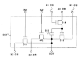
본 발명의 일 양태에 따른 반도체장치는, 제1 트랜지스터, 제2 트랜지스터, 제3 트랜지스터, 인버터, 제1 배선, 제2 배선, 및 제3 배선을 포함하고, 제1 트랜지스터의 제1 단자가 제1 배선에 전기적으로 접속되고, 제1 트랜지스터의 제2 단자가 제2 트랜지스터의 제2 단자에 전기적으로 접속되고, 제1 트랜지스터의 게이트 단자가 인버터의 제1 단자에 전기적으로 접속되고, 제2 트랜지스터의 제1 단자가 제2 배선에 전기적으로 접속되고, 제2 트랜지스터의 게이트 단자가 제3 트랜지스터의 제2 단자에 전기적으로 접속되고, 제3 트랜지스터의 제1 단자가 제3 배선에 전기적으로 접속되고, 제3 트랜지스터의 게이트 단자가 인버터의 제2 단자에 전기적으로 접속된다. A semiconductor device according to an embodiment of the present invention includes a first transistor, a second transistor, a third transistor, an inverter, a first wiring, a second wiring, and a third wiring, 1 wiring, the second terminal of the first transistor is electrically connected to the second terminal of the second transistor, the gate terminal of the first transistor is electrically connected to the first terminal of the inverter, The first terminal of the third transistor is electrically connected to the second wiring, the gate terminal of the second transistor is electrically connected to the second terminal of the third transistor, and the first terminal of the third transistor is electrically connected to the third wiring , And the gate terminal of the third transistor is electrically connected to the second terminal of the inverter.
본 발명의 일 양태에 따른 반도체장치는, 제1 트랜지스터, 제2 트랜지스터, 제3 트랜지스터, 제4 트랜지스터, 제5 트랜지스터, 제1 배선, 제2 배선, 제3 배선, 및 제4 배선을 포함하고, 제1 트랜지스터의 제1 단자가 제1 배선에 전기적으로 접속되고, 제1 트랜지스터의 제2 단자가 제2 트랜지스터의 제2 단자에 전기적으로 접속되고, 제1 트랜지스터의 게이트 단자가 제4 트랜지스터의 게이트 단자에 전기적으로 접속되고, 제2 트랜지스터의 제1 단자가 제2 배선에 전기적으로 접속되고, 제2 트랜지스터의 게이트 단자가 제3 트랜지스터의 제2 단자에 전기적으로 접속되고, 제3 트랜지스터의 제1 단자가 제3 배선에 전기적으로 접속되고, 제3 트랜지스터의 게이트 단자가 제4 트랜지스터의 제2 단자 및 제5 트랜지스터의 제2 단자에 전기적으로 접속되고, 제4 트랜지스터의 제1 단자가 제2 배선에 전기적으로 접속되고, 제5 트랜지스터의 제1 단자가 제4 배선에 전기적으로 접속되고, 제5 트랜지스터의 게이트 단자가 제4 배선에 전기적으로 접속된다. A semiconductor device according to an embodiment of the present invention includes a first transistor, a second transistor, a third transistor, a fourth transistor, a fifth transistor, a first wiring, a second wiring, a third wiring, and a fourth wiring The first terminal of the first transistor is electrically connected to the first wiring, the second terminal of the first transistor is electrically connected to the second terminal of the second transistor, and the gate terminal of the first transistor is connected to the second terminal of the fourth transistor The first terminal of the second transistor is electrically connected to the second wiring, the gate terminal of the second transistor is electrically connected to the second terminal of the third transistor, the third terminal of the third transistor is electrically connected to the gate terminal, The first terminal is electrically connected to the third wiring, the gate terminal of the third transistor is electrically connected to the second terminal of the fourth transistor and the second terminal of the fifth transistor, And of the first terminal is electrically connected to the second wiring, a first terminal of the fifth transistor is electrically connected to the fourth wiring, and a gate terminal of the fifth transistor is electrically connected to the fourth wiring.
본 발명의 일 양태에 따른 반도체장치는, 제1 트랜지스터, 제2 트랜지스터, 제3 트랜지스터, 제4 트랜지스터, 제5 트랜지스터, 제6 트랜지스터, 제1 배선, 제2 배선, 제3 배선, 제4 배선, 및 제5 배선을 포함하고, 제1 트랜지스터의 제1 단자가 제1 배선에 전기적으로 접속되고, 제1 트랜지스터의 제2 단자가 제2 트랜지스터의 제2 단자에 전기적으로 접속되고, 제1 트랜지스터의 게이트 단자가 제4 트랜지스터의 게이트 단자 및 제6 트랜지스터의 제2 단자에 전기적으로 접속되고, 제2 트랜지스터의 제1 단자가 제2 배선에 전기적으로 접속되고, 제2 트랜지스터의 게이트 단자가 제3 트랜지스터의 제2 단자에 전기적으로 접속되고, 제3 트랜지스터의 제1 단자가 제3 배선에 전기적으로 접속되고, 제3 트랜지스터의 게이트 단자가 제4 트랜지스터의 제2 단자 및 제5 트랜지스터의 제2 단자에 전기적으로 접속되고, 제4 트랜지스터의 제1 단자가 제2 배선에 전기적으로 접속되고, 제5 트랜지스터의 제1 단자가 제4 배선에 전기적으로 접속되고, 제5 트랜지스터의 게이트 단자가 제4 배선에 전기적으로 접속되고, 제6 트랜지스터의 제1 단자가 제4 배선에 전기적으로 접속되고, 제6 트랜지스터의 게이트 단자가 제5 배선에 전기적으로 접속되어 있다.A semiconductor device according to an embodiment of the present invention includes a first transistor, a second transistor, a third transistor, a fourth transistor, a fifth transistor, a sixth transistor, a first wiring, a second wiring, a third wiring, And a fifth wiring, wherein a first terminal of the first transistor is electrically connected to the first wiring, a second terminal of the first transistor is electrically connected to a second terminal of the second transistor, The gate terminal of the second transistor is electrically connected to the gate terminal of the fourth transistor and the second terminal of the sixth transistor, the first terminal of the second transistor is electrically connected to the second wiring, The first terminal of the third transistor is electrically connected to the third wiring, the gate terminal of the third transistor is electrically connected to the second terminal of the fourth transistor and the fifth transistor The first terminal of the fourth transistor is electrically connected to the second wiring, the first terminal of the fifth transistor is electrically connected to the fourth wiring, the gate of the fifth transistor is electrically connected to the second terminal of the fifth transistor, The terminal is electrically connected to the fourth wiring, the first terminal of the sixth transistor is electrically connected to the fourth wiring, and the gate terminal of the sixth transistor is electrically connected to the fifth wiring.
본 발명의 일 양태에 따른 반도체장치는, 제1 트랜지스터, 제2 트랜지스터, 제3 트랜지스터, 제4 트랜지스터, 제5 트랜지스터, 제6 트랜지스터, 제7 트랜지스터, 제1 배선, 제2 배선, 제3 배선, 제4 배선, 및 제5 배선을 포함하고, 제1 트랜지스터의 제1 단자가 제1 배선에 전기적으로 접속되고, 제1 트랜지스터의 제2 단자가 제2 트랜지스터의 제2 단자에 전기적으로 접속되고, 제1 트랜지스터의 게이트 단자가 제4 트랜지스터의 게이트 단자, 제6 트랜지스터의 제2 단자, 및 제7 트랜지스터의 제2 단자에 전기적으로 접속되고, 제2 트랜지스터의 제1 단자가 제2 배선에 전기적으로 접속되고, 제2 트랜지스터의 게이트 단자가 제3 트랜지스터의 제2 단자 및 제7 트랜지스터의 게이트 단자에 전기적으로 접속되고, 제3 트랜지스터의 제1 단자가 제3 배선에 전기적으로 접속되고, 제3 트랜지스터의 게이트 단자가 제4 트랜지스터의 제2 단자 및 제5 트랜지스터의 제2 단자에 전기적으로 접속되고, 제4 트랜지스터의 제1 단자가 제2 배선에 전기적으로 접속되고, 제5 트랜지스터의 제1 단자가 제4 배선에 전기적으로 접속되고, 제5 트랜지스터의 게이트 단자가 제4 배선에 전기적으로 접속되고, 제6 트랜지스터의 제1 단자가 제4 배선에 전기적으로 접속되고, 제6 트랜지스터의 게이트 단자가 제5 배선에 전기적으로 접속되고, 제7 트랜지스터의 제1 단자가 제2 배선에 전기적으로 접속되어 있다.A semiconductor device according to an embodiment of the present invention includes a first transistor, a second transistor, a third transistor, a fourth transistor, a fifth transistor, a sixth transistor, a seventh transistor, a first wiring, a second wiring, , A fourth wiring, and a fifth wiring, wherein a first terminal of the first transistor is electrically connected to the first wiring, a second terminal of the first transistor is electrically connected to a second terminal of the second transistor The gate terminal of the first transistor is electrically connected to the gate terminal of the fourth transistor, the second terminal of the sixth transistor and the second terminal of the seventh transistor, and the first terminal of the second transistor is electrically connected to the second wiring The gate terminal of the second transistor is electrically connected to the second terminal of the third transistor and the gate terminal of the seventh transistor and the first terminal of the third transistor is electrically connected to the third wiring The gate terminal of the third transistor is electrically connected to the second terminal of the fourth transistor and the second terminal of the fifth transistor, the first terminal of the fourth transistor is electrically connected to the second wiring, The first terminal of the sixth transistor is electrically connected to the fourth wiring, the gate terminal of the fifth transistor is electrically connected to the fourth wiring, the first terminal of the sixth transistor is electrically connected to the fourth wiring, Is electrically connected to the fifth wiring, and the first terminal of the seventh transistor is electrically connected to the second wiring.
본 발명의 일 양태에 따른 반도체장치는, 제1 트랜지스터, 제2 트랜지스터, 제3 트랜지스터, 제4 트랜지스터, 제5 트랜지스터, 제6 트랜지스터, 제7 트랜지스터, 제8 트랜지스터, 제1 배선, 제2 배선, 제3 배선, 제4 배선, 제5 배선, 및 제6 배선을 포함하고, 제1 트랜지스터의 제1 단자가 제1 배선에 전기적으로 접속되고, 제1 트랜지스터의 제2 단자가 제2 트랜지스터의 제2 단자에 전기적으로 접속되고, 제1 트랜지스터의 게이트 단자가 제4 트랜지스터의 게이트 단자, 제6 트랜지스터의 제2 단자, 제7 트랜지스터의 제2 단자, 및 제8 트랜지스터의 제2 단자에 전기적으로 접속되고, 제2 트랜지스터의 제1 단자가 제2 배선에 전기적으로 접속되고, 제2 트랜지스터의 게이트 단자가 제3 트랜지스터의 제2 단자 및 제7 트랜지스터의 게이트 단자에 전기적으로 접속되고, 제3 트랜지스터의 제1 단자가 제3 배선에 전기적으로 접속되고, 제3 트랜지스터의 게이트 단자가 제4 트랜지스터의 제2 단자 및 제5 트랜지스터의 제2 단자에 전기적으로 접속되고, 제4 트랜지스터의 제1 단자가 제2 배선에 전기적으로 접속되고, 제5 트랜지스터의 제1 단자가 제4 배선에 전기적으로 접속되고, 제5 트랜지스터의 게이트 단자가 제4 배선에 전기적으로 접속되고, 제6 트랜지스터의 제1 단자가 제4 배선에 전기적으로 접속되고, 제6 트랜지스터의 게이트 단자가 제5 배선에 전기적으로 접속되고, 제7 트랜지스터의 제1 단자가 제2 배선에 전기적으로 접속되고, 제8 트랜지스터의 제1 단자가 제2 배선에 전기적으로 접속되고, 제8 트랜지스터의 게이트 단자가 제6 배선에 전기적으로 접속되어 있다.A semiconductor device according to an embodiment of the present invention includes a first transistor, a second transistor, a third transistor, a fourth transistor, a fifth transistor, a sixth transistor, a seventh transistor, an eighth transistor, The first terminal of the first transistor is electrically connected to the first wiring, the second terminal of the first transistor is electrically connected to the second terminal of the second transistor, The gate terminal of the first transistor is electrically connected to the gate terminal of the fourth transistor, the second terminal of the sixth transistor, the second terminal of the seventh transistor, and the second terminal of the eighth transistor, The first terminal of the second transistor is electrically connected to the second wiring, the gate terminal of the second transistor is electrically connected to the second terminal of the third transistor and the gate terminal of the seventh transistor, The first terminal of the transistor is electrically connected to the third wiring, the gate terminal of the third transistor is electrically connected to the second terminal of the fourth transistor and the second terminal of the fifth transistor, The first terminal of the fifth transistor is electrically connected to the fourth wiring, the gate terminal of the fifth transistor is electrically connected to the fourth wiring, the first terminal of the sixth transistor is electrically connected to the second wiring, The gate terminal of the sixth transistor is electrically connected to the fifth wiring, the first terminal of the seventh transistor is electrically connected to the second wiring, the first terminal of the eighth transistor is electrically connected to the fourth wiring, Is electrically connected to the second wiring and the gate terminal of the eighth transistor is electrically connected to the sixth wiring.
또한, 본 발명에서, 상기 제4 트랜지스터의 채널 길이(L) 대 채널 폭(W)의 비(W/L)는 상기 제5 트랜지스터의 채널 길이(L) 대 채널 폭(W)의 비(W/L)의 10배 이상이어도 좋다.In the present invention, the ratio (W / L) of the channel length (L) to the channel width (W) of the fourth transistor is a ratio (W / L).
또한, 본 발명에서, 상기 제1 트랜지스터와 상기 제3 트랜지스터는 동일한 도전형을 가져도 좋다.In the present invention, the first transistor and the third transistor may have the same conductivity type.
또한, 본 발명에서, 상기 제1 트랜지스터와 상기 제4 트랜지스터는 n채널형 트랜지스터이어도 좋고, p채널형 트랜지스터이어도 좋다.In the present invention, the first transistor and the fourth transistor may be n-channel transistors or p-channel transistors.
또한, 본 발명에서, 상기 제1 트랜지스터의 제2 단자와 상기 제1 트랜지스터의 게이트 단자와의 사이에 전기적으로 접속된 커패시터가 제공되어 있어도 좋다.Further, in the present invention, a capacitor electrically connected between the second terminal of the first transistor and the gate terminal of the first transistor may be provided.
또한, 본 발명에서, 상기 커패시터 대신에, MOS 트랜지스터를 사용하여, 용량(커패시턴스)이 형성되어도 좋다.In the present invention, a capacitor (capacitance) may be formed by using a MOS transistor instead of the capacitor.
또한, 본 발명에서, 상기 커패시터는 제1 전극, 제2 전극, 및 제1 전극과 제2 전극 사이에 보유된 절연체를 포함하고, 상기 제1 전극은 반도체층이고, 상기 제2 전극은 게이트 배선층이고, 상기 절연체는 게이트 절연막이어도 좋다.Further, in the present invention, the capacitor includes a first electrode, a second electrode, and an insulator held between the first electrode and the second electrode, wherein the first electrode is a semiconductor layer, And the insulator may be a gate insulating film.
또한, 본 발명에서, 상기 제1 배선에는 클록 신호가 공급되고, 상기 제3 배선에는 상기 클록 신호와 위상이 180도 다른 반전된 클록 신호가 공급되어도 좋다.In the present invention, a clock signal may be supplied to the first interconnection, and an inverted clock signal whose phase is 180 degrees different from the clock signal may be supplied to the third interconnection.
본 발명의 일 양태에 따른 표시장치는 다수의 화소와 구동회로를 포함하고, 상기 다수의 화소 각각은 상기 구동회로에 의해 제어되고, 상기 구동회로는 다수의 트랜지스터와, 상기 다수의 트랜지스터 각각을 항상 온으로 되지 않게 하는 회로를 포함한다.A display device according to an embodiment of the present invention includes a plurality of pixels and a driving circuit, each of the plurality of pixels is controlled by the driving circuit, the driving circuit includes a plurality of transistors, And not to be turned on.
또한, 본 발명에서, 상기 구동회로는 상기 설명한 반도체장치를 포함하고 있어도 좋다.Further, in the present invention, the drive circuit may include the above-described semiconductor device.
또한, 본 발명에서, 상기 다수의 화소 각각은 적어도 하나의 트랜지스터를 포함하고, 상기 다수의 화소 각각에 포함되는 트랜지스터와, 상기 구동회로에 포함되는 트랜지스터는 동일한 도전형을 가져도 좋다.Also, in the present invention, each of the plurality of pixels includes at least one transistor, and the transistors included in each of the plurality of pixels and the transistors included in the driving circuit may have the same conductivity type.
또한, 본 발명에서, 상기 다수의 화소 각각과 상기 구동회로는 동일 기판 위에 형성되어도 좋다.Further, in the present invention, each of the plurality of pixels and the driver circuit may be formed over the same substrate.
또한, 본 발명의 표시장치는 전자기기에 적용될 수도 있다.Further, the display device of the present invention may be applied to an electronic apparatus.
상기와 같이, 본 발명에서는, 제2 트랜지스터 및 제7 트랜지스터를 항상 온으로 되지 않게 하기 위해, 제3 배선에 공급되는 신호에 의해, 제2 트랜지스터 및 제7 트랜지스터의 온 또는 오프를 제어하는 것이다.As described above, in the present invention, on / off control of the second transistor and the seventh transistor is controlled by a signal supplied to the third wiring so that the second transistor and the seventh transistor are not always turned on.
또한, 제1 트랜지스터가 온으로 된 때 제2 트랜지스터가 온으로 되지 않도록 하기 위해, 제1 트랜지스터의 게이트 단자를 인버터를 통하여 제2 트랜지스터의 게이트 단자에 접속함으로써, 제3 트랜지스터를 오프로 하고 있다. 제3 트랜지스터가 오프로 되기 전에 제2 트랜지스터가 오프로 되어 있으면, 제2 트랜지스터는 계속 오프로 된다. 따라서, 제1 배선과 제2 배선은 제1 트랜지스터 및 제2 트랜지스터를 통하여 도통하는 일은 없다.In order to prevent the second transistor from being turned on when the first transistor is turned on, the third transistor is turned off by connecting the gate terminal of the first transistor to the gate terminal of the second transistor through the inverter. If the second transistor is turned off before the third transistor is turned off, the second transistor is continuously turned off. Therefore, the first wiring and the second wiring do not conduct through the first transistor and the second transistor.
또한, 제1 트랜지스터가 온이고 제2 트랜지스터가 오프일 때, 제1 배선의 전위가 변화하면, 제1 트랜지스터의 제2 단자의 전위도 변화한다. 이때, 제1 트랜지스터의 게이트 단자가 플로팅 상태이면, 제1 트랜지스터의 게이트 단자의 전위는 커패시터의 용량 결합에 의해 동시에 변화한다. 여기서, 제1 트랜지스터의 게이트 단자의 전위가 제1 배선의 전위와 제1 트랜지스터의 스레시홀드 전압과의 합 이상 또는 이하의 값까지 변화하면, 제1 트랜지스터는 계속 온으로 된다. 이와 같이, 본 발명은, 제1 배선의 전위가 변화하여도, 제1 트랜지스터를 온으로 하여 제1 트랜지스터의 제1 단자와 제2 단자를 같은 전위로 하는 기능도 가진다.Further, when the potential of the first wiring changes when the first transistor is on and the second transistor is off, the potential of the second terminal of the first transistor also changes. At this time, when the gate terminal of the first transistor is in the floating state, the potential of the gate terminal of the first transistor is simultaneously changed by capacitive coupling of the capacitor. Here, when the potential of the gate terminal of the first transistor changes to a value equal to or greater than the sum of the potential of the first wiring and the threshold voltage of the first transistor, the first transistor remains on. As described above, the present invention also has a function of turning on the first transistor so that the first terminal and the second terminal of the first transistor have the same potential even if the potential of the first wiring changes.
또한, 본 명세서에 기재된 스위치는, 예를 들어, 전기적인 스위치, 또는 기계적인 스위치를 사용할 수 있다. 즉, 전류의 흐름을 제어할 수 있는 것이면 어느 소자라도 사용할 수 있어, 스위치가 특정의 것에 한정되지 않는다. 예를 들어, 트랜지스터이어도 좋고, 다이오드(예를 들어, PN 접합 다이오드, PIN 접합 다이오드, 쇼트키 다이오드(Schottky diode), 다이오드 접속의 트랜지스터 등)이어도 좋고, 그것들을 조합한 논리회로이어도 좋다. 따라서, 스위치로서 트랜지스터를 사용하는 경우, 그 트랜지스터는 단순한 스위치로서 동작하기 때문에, 그 트랜지스터의 극성(도전형)은 특별히 한정되지 않는다. 그러나, 오프 전류가 적은 것이 바람직한 경우, 오프 전류가 적은 극성의 트랜지스터를 사용하는 것이 바람직하다. 오프 전류가 적은 트랜지스터의 예로서는, LDD 영역을 가지는 트랜지스터, 멀티게이트 구조를 가지는 트랜지스터 등을 들 수 있다. 또한, 스위치로서 동작하는 트랜지스터의 소스 단자의 전위가 저전위측 전원(예를 들어, Vss, GND, 또는 0 V)에 가까운 상태의 경우는 n채널형 트랜지스터를 사용하고, 반대로, 소스 단자의 전위가 고전위측 전원(예를 들어, Vdd)에 가까운 상태의 경우는 p채널형 트랜지스터를 사용하는 것이 바람직하다. 왜냐하면, 트랜지스터의 게이트와 소스 사이의 전압의 절대값을 크게 할 수 있기 때문에, 스위치로서 기능시킬 때 동작시키기 쉽기 때문이다. 또한, n채널형 트랜지스터와 p채널형 트랜지스터 양쪽 모두를 사용하여, CMOS형 스위치로 하여도 좋다.Also, the switches described herein can use, for example, electrical switches or mechanical switches. That is, any element can be used as long as it can control the flow of current, and the switch is not limited to a specific one. For example, it may be a transistor, a diode (for example, a PN junction diode, a PIN junction diode, a Schottky diode, a diode-connected transistor, or the like), or a logic circuit combining them. Therefore, when a transistor is used as a switch, the transistor operates as a simple switch, so that the polarity (conductive type) of the transistor is not particularly limited. However, in the case where it is preferable that the off current is small, it is preferable to use a transistor of polarity with a small off current. Examples of the transistor having a small off current include a transistor having an LDD region, a transistor having a multi-gate structure, and the like. An n-channel transistor is used when the potential of the source terminal of the transistor operating as a switch is close to the low potential side power supply (for example, Vss, GND, or 0 V), and conversely, It is preferable to use a p-channel transistor in a state close to a high potential side power supply (for example, Vdd). This is because, since the absolute value of the voltage between the gate and the source of the transistor can be increased, it is easy to operate when it functions as a switch. Further, both of the n-channel transistor and the p-channel transistor may be used to form a CMOS-type switch.
또한, 본 발명에서는, "접속되어 있다" 라는 기재는, "전기적으로 접속되어 있다" 라는 기재와 동의(同義)이다. 따라서, 소자들 사이에 다른 소자나 스위치 가 개재되어 있어도 좋다.In the present invention, the description "connected" is synonymous with "electrically connected". Therefore, other elements or switches may be interposed between the elements.
또한, 표시소자, 표시소자를 가지는 장치인 표시장치, 발광소자, 및 발광소자를 가지는 장치인 발광장치는 다양한 형태를 이용할 수 있고, 다양한 소자를 포함할 수 있다. 예를 들어, EL 소자(예를 들어, 유기 EL 소자, 무기 EL 소자, 또는 유기물과 무기물 모두를 함유하는 EL 소자), 전자 방출 소자, 액정 소자, 전자 잉크 등, 전기 자기적 작용에 의해 콘트라스트가 변화하는 표시 매체를 적용할 수 있다. 또한, EL 소자를 사용한 표시장치로서는 EL 디스플레이가 있고, 전자 방출 소자를 사용한 표시장치로서는 전계 방출 디스플레이(FED)나 SED 방식 평면형 디스플레이(SED: Surface-conduction Electron-emitter Display) 등이 있고, 액정 소자를 사용한 표시장치로서는 액정 디스플레이가 있고, 전자 잉크를 사용한 표시장치로서는 전자 페이퍼가 있다.Further, the light emitting device, which is a display device, a display device which is an apparatus having a display element, a light emitting element, and an apparatus having a light emitting element, can take various forms and can include various elements. For example, it is preferable that the contrast is increased by an electromagnetism action such as an EL element (for example, an organic EL element, an inorganic EL element, or an EL element containing both organic and inorganic substances), an electron emitting element, A changing display medium can be applied. As a display device using an EL element, there is an EL display. As a display device using an electron-emitting device, a field emission display (FED) or a SED (Surface-conduction Electron-emitter Display) A liquid crystal display is used as a display device using an electronic ink, and an electronic paper is used as a display device using electronic ink.
또한, 본 발명에서, 적용될 수 있는 트랜지스터의 종류에 한정은 없고, 비정질 실리콘이나 다결정 실리콘으로 대표되는 비(非)단결정 반도체막을 사용한 박막 트랜지스터(TFT), 반도체 기판이나 SOI 기판을 사용하여 형성되는 트랜지스터, MOS형 트랜지스터, 접합형 트랜지스터, 바이폴러 트랜지스터, ZnO 또는 a-InGaZnO 등의 화합물 반도체를 사용한 트랜지스터, 유기 반도체나 카본 나노튜브를 사용한 트랜지스터, 그 외의 트랜지스터가 적용될 수 있다. 또한, 트랜지스터가 형성되는 기판의 종류에 한정은 없고, 단결정 기판, SOI 기판, 유리 기판, 플라스틱 기판 등 위에 트랜지스터를 배치할 수 있다.In addition, in the present invention, there is no limitation to the kind of transistor that can be applied, and a thin film transistor (TFT) using a non-single crystal semiconductor film typified by amorphous silicon or polycrystalline silicon, a transistor formed using a semiconductor substrate or an SOI substrate , A MOS transistor, a junction transistor, a bipolar transistor, a transistor using a compound semiconductor such as ZnO or a-InGaZnO, a transistor using an organic semiconductor or a carbon nanotube, or other transistors. In addition, the type of the substrate on which the transistor is formed is not limited, and the transistor can be disposed on a single crystal substrate, an SOI substrate, a glass substrate, a plastic substrate, or the like.
또한, 이미 설명한 바와 같이, 본 발명에서는 각종 타입의 트랜지스터가 사용될 수 있고, 그러한 트랜지스터는 각종 타입의 기판 위에 형성될 수도 있다. 따라서, 회로 전부가 유리 기판 위에 형성되어 있어도 좋고, 플라스틱 기판 위에 형성되어 있어도 좋고, 단결정 기판 위에 형성되어 있어도 좋고, SOI 기판 위에 형성되어 있어도 좋고, 임의의 다른 기판 위에 형성되어 있어도 좋다. 또는, 회로들의 일부가 어떤 기판 위에 형성되고, 회로들의 다른 일부가 다른 기판 위에 형성되어 있어도 좋다. 즉, 회로의 전부가 동일 기판 위에 형성되어 있지 않아도 좋다. 예를 들어, 회로의 일부는 유리 기판 위에 트랜지스터를 사용하여 형성하고, 회로의 다른 일부는 단결정 기판 위에 형성하고, 그 IC 칩을 COG(Chip On Glass)에 의해 유리 기판에 접속하여도 좋다. 또는, 그 IC 칩을 TAB(Tape Automated Bonding)나 인쇄 회로판을 사용하여 유리 기판에 접속하여도 좋다.Further, as already described, various types of transistors may be used in the present invention, and such transistors may be formed on various types of substrates. Therefore, the entire circuit may be formed on the glass substrate, on the plastic substrate, on the single crystal substrate, on the SOI substrate, or on any other substrate. Alternatively, a part of the circuits may be formed on one substrate, and another part of the circuits may be formed on another substrate. That is, not all of the circuits may be formed on the same substrate. For example, a part of a circuit may be formed on a glass substrate by using a transistor, another part of the circuit may be formed on a single crystal substrate, and the IC chip may be connected to a glass substrate by COG (Chip On Glass). Alternatively, the IC chip may be connected to a glass substrate by using TAB (Tape Automated Bonding) or a printed circuit board.
또한, 트랜지스터의 구성은 특별히 한정되는 것은 아니다. 예를 들어, 2개 이상의 게이트를 가지는 멀티게이트 구조를 사용하여도 좋고, 또한, 채널의 상하에 게이트 전극이 배치되어 있는 구조이어도 좋고, 채널 위에 게이트 전극이 배치되어 있는 구조이어도 좋고, 채널 아래에 게이트 전극이 배치되어 있는 구조이어도 좋고, 순 스태거 구조이어도 좋고, 역 스태거 구조이어도 좋고, 채널 영역이 다수의 영역으로 나누어져 있는 구조이어도 좋고, 나누어진 영역들이 병렬로 또는 직렬로 접속되어 있어는 구조이어도 좋고, 채널(또는 그의 일부)에 소스 전극이나 드레인 전극이 중첩되어 있어도 좋고, LDD(Lightly Doped Drain) 영역이 제공되어 있어도 좋다.The configuration of the transistor is not particularly limited. For example, a multi-gate structure having two or more gates may be used, or a structure in which gate electrodes are arranged above and below the channel, a structure in which a gate electrode is disposed on a channel, The structure may be a structure in which a gate electrode is disposed, a structure in which a channel region is divided into a plurality of regions, A source electrode or a drain electrode may be superimposed on a channel (or a part thereof), or an LDD (Lightly Doped Drain) region may be provided.
또한, 본 명세서에서는, 1 화소란, 화상의 최소 단위를 나타내는 것으로 한다. 따라서, R(적), G(녹), B(청)의 색 요소로 이루어지는 풀 컬러 표시장치의 경우에는, 1 화소란, R의 색 요소의 도트와, G의 색 요소의 도트와, B의 색 요소의 도트로 구성되는 것으로 한다.In this specification, one pixel means the minimum unit of an image. Therefore, in the case of a full color display device comprising R (red), G (green), and B (blue) color elements, one pixel is a dot of R color element, a dot of G color element, And the dot of the color component of the color component.
또한, 본 명세서에서, 화소들이 매트릭스로 배치되어 있다 라는 것은, 수직방향 줄무늬와 횡방향 줄무늬를 조합시킨 소위 격자 패턴으로 화소들이 배치되어 있는 경우 뿐만 아니라, 3색의 색 요소(예를 들어, RGB)로 풀 컬러 표시를 행하는 경우에 3개의 색 요소의 도트가 소위 델타 패턴으로 배치되어 있는 경우도 포함하는 것으로 한다. 또한, 색 요소의 도트마다 발광 영역의 크기가 달라도 좋다.In this specification, the fact that the pixels are arranged in a matrix is not limited to a case where pixels are arranged in a so-called grid pattern in which vertical stripe and traverse stripe are combined, In the case where full-color display is performed by using the three-color element, the dots of three color elements are arranged in a so-called delta pattern. The size of the light emitting region may be different for each dot of the color element.
트랜지스터란, 게이트, 드레인, 소스의 적어도 3개의 단자를 가지는 소자이고, 드레인 영역과 소스 영역 사이에 채널 영역을 가진다. 여기서, 트랜지스터의 소스 영역과 드레인 영역은 트랜지스터의 구조나 동작 조건 등에 따라 바뀌기 때문에, 어느 것이 소스 영역 또는 드레인 영역인지를 한정하는 것은 곤란하다. 따라서, 본 명세서에서는, 소스 영역 및 드레인 영역으로서 기능하는 영역들 중 한쪽 영역을 제1 단자라고 표기하고, 다른 한쪽 영역을 제2 단자라고 표기한다.A transistor is an element having at least three terminals of a gate, a drain, and a source, and has a channel region between the drain region and the source region. Here, since the source region and the drain region of the transistor change depending on the structure and operating conditions of the transistor, it is difficult to limit which is the source region or the drain region. Therefore, in this specification, one of the regions functioning as a source region and a drain region is referred to as a first terminal, and the other region is referred to as a second terminal.
또한, 본 명세서에서, 반도체장치란, 반도체소자(예를 들어, 트랜지스터 또는 다이오드)를 포함하는 회로를 가지는 장치를 말한다. 또한, 반도체 특성을 이용함으로써 기능할 수 있는 장치 전반이어도 좋다. 또한, 표시장치란, 기판 위에 형성된 액정 소자나 EL 소자 등의 표시 소자를 포함하는 다수의 화소가 그들 화소를 구동시키는 주변 구동회로와 동일 기판 위에 형성된 표시 패널 자체 뿐만 아니라, 거기에 플렉서블 인쇄 회로(FPC)나 프린트 배선판(PWB)이 부착된 것도 포함한다. 또한, 발광장치란, EL 소자나 FED에 사용하는 소자 등의 자기발광형 표시 소자를 사용하고 있는 표시장치를 말한다.Further, in this specification, a semiconductor device refers to a device having a circuit including a semiconductor element (for example, a transistor or a diode). Further, it may be the entire apparatus which can function by utilizing semiconductor characteristics. A display device is a device in which a plurality of pixels including a display element such as a liquid crystal element or an EL element formed on a substrate is not only a display panel itself formed on the same substrate as a peripheral drive circuit for driving the pixels, FPC) or a printed wiring board (PWB). The light-emitting device refers to a display device using a self-luminous display device such as an EL element or an element used for an FED.
본 발명의 반도체장치는 제3 배선에 공급되는 신호에 의해 온/오프가 제어되는 트랜지스터를 일정 시간 간격으로 온(ON)으로 할 수 있다. 이렇게 함으로써, 본 발명의 반도체장치를 사용한 시프트 레지스터 회로의 트랜지스터는 비선택 기간에 항상 온으로 되지 않으므로, 이 트랜지스터의 스레시홀드 전압 시프트가 억제될 수 있다. 또한, 본 발명의 반도체장치를 사용한 시프트 레지스터 회로의 출력 단자에는 이 트랜지스터를 통하여 일정 시간 간격으로 전원 전위가 공급된다. 따라서, 본 발명의 반도체장치를 사용한 시프트 레지스터 회로는 출력 단자에 발생하는 노이즈를 억제할 수 있다.In the semiconductor device of the present invention, the transistor whose ON / OFF is controlled by the signal supplied to the third wiring can be turned ON at a predetermined time interval. By doing so, the transistor of the shift register circuit using the semiconductor device of the present invention is not always turned on in the non-selection period, so that the threshold voltage shift of the transistor can be suppressed. Further, the power supply potential is supplied to the output terminal of the shift register circuit using the semiconductor device of the present invention at a predetermined time interval through the transistor. Therefore, the shift register circuit using the semiconductor device of the present invention can suppress the noise generated at the output terminal.
도 1은 실시형태 1을 나타내는 도면.
도 2는 실시형태 1을 나타내는 타이밍 차트.
도 3은 실시형태 1을 나타내는 도면.
도 4는 실시형태 1을 나타내는 도면.
도 5는 실시형태 1을 나타내는 도면.
도 6은 실시형태 1을 나타내는 도면.
도 7은 실시형태 1을 나타내는 도면.
도 8은 실시형태 1을 나타내는 도면.
도 9는 실시형태 1을 나타내는 도면.
도 10은 실시형태 1을 나타내는 도면.
도 11은 실시형태 1을 나타내는 도면.
도 12는 실시형태 1을 나타내는 타이밍 차트.
도 13은 실시형태 1을 나타내는 도면.
도 14는 실시형태 1을 나타내는 도면.
도 15는 실시형태 1을 나타내는 도면.
도 16은 실시형태 1을 나타내는 도면.
도 17은 실시형태 2를 나타내는 도면.
도 18은 실시형태 2를 나타내는 타이밍 차트.
도 19는 실시형태 2를 나타내는 타이밍 차트.
도 20은 실시형태 3을 나타내는 도면.
도 21은 실시형태 3을 나타내는 도면.
도 22는 실시형태 3을 나타내는 도면.
도 23은 실시형태 3을 나타내는 도면.
도 24는 실시형태 3을 나타내는 도면.
도 25는 실시형태 3을 나타내는 도면.
도 26은 실시형태 3을 나타내는 도면.
도 27은 실시형태 3을 나타내는 도면.
도 28은 실시형태 3을 나타내는 도면.
도 29는 실시형태 3을 나타내는 도면.
도 30은 실시형태 3을 나타내는 도면.
도 31은 실시형태 3을 나타내는 도면.
도 32는 실시형태 3을 나타내는 도면.
도 33은 실시형태 3을 나타내는 도면.
도 34는 실시형태 3을 나타내는 도면.
도 35는 실시형태 3을 나타내는 도면.
도 36은 실시형태 3을 나타내는 도면.
도 37은 실시형태 3을 나타내는 도면.
도 38은 실시형태 3을 나타내는 도면.
도 39는 실시형태 3을 나타내는 도면.
도 40은 실시형태 3을 나타내는 도면.
도 41은 실시형태 3을 나타내는 도면.
도 42는 실시형태 3을 나타내는 도면.
도 43은 실시형태 3을 나타내는 도면.
도 44는 실시형태 3을 나타내는 도면.
도 45는 실시형태 3을 나타내는 도면.
도 46은 실시형태 3을 나타내는 도면.
도 47은 실시형태 3을 나타내는 도면.
도 48은 실시형태 3을 나타내는 도면.
도 49는 실시형태 3을 나타내는 도면.
도 50은 실시형태 3을 나타내는 도면.
도 51은 실시형태 3을 나타내는 도면.
도 52는 실시형태 3을 나타내는 도면.
도 53은 실시형태 3을 나타내는 도면.
도 54는 실시형태 3을 나타내는 도면.
도 55는 실시형태 3을 나타내는 도면.
도 56은 실시형태 3을 나타내는 도면.
도 57은 실시형태 3을 나타내는 도면.
도 58은 실시형태 3을 나타내는 도면.
도 59는 실시형태 3을 나타내는 도면.
도 60은 실시형태 3을 나타내는 도면.
도 61은 실시형태 3을 나타내는 도면.
도 62는 실시형태 3을 나타내는 도면.
도 63은 실시형태 3을 나타내는 도면.
도 64는 실시형태 3을 나타내는 도면.
도 65는 실시형태 3을 나타내는 도면.
도 66은 실시형태 3을 나타내는 도면.
도 67은 실시형태 3을 나타내는 도면.
도 68은 실시형태 3을 나타내는 도면.
도 69는 실시형태 3을 나타내는 도면.
도 70은 실시형태 3을 나타내는 도면.
도 71은 실시형태 3을 나타내는 도면.
도 72는 실시형태 3을 나타내는 도면.
도 73은 실시형태 3을 나타내는 도면.
도 74는 실시형태 3을 나타내는 도면.
도 75는 실시형태 3을 나타내는 도면.
도 76은 실시형태 3을 나타내는 도면.
도 77은 실시형태 3을 나타내는 도면.
도 78은 실시형태 3을 나타내는 도면.
도 79는 실시형태 3을 나타내는 도면.
도 80은 실시형태 3을 나타내는 도면.
도 81은 실시형태 3을 나타내는 도면.
도 82는 실시형태 3을 나타내는 도면.
도 83은 실시형태 3을 나타내는 도면.
도 84는 실시형태 3을 나타내는 도면.
도 85는 실시형태 3을 나타내는 도면.
도 86은 실시형태 3을 나타내는 도면.
도 87은 실시형태 3을 나타내는 도면.
도 88은 실시형태 4를 나타내는 도면.
도 89는 실시형태 4를 나타내는 도면.
도 90은 실시형태 4를 나타내는 도면.
도 91은 실시형태 4를 나타내는 도면.
도 92는 실시예 1을 나타내는 도면.
도 93은 실시예 1을 나타내는 도면.
도 94는 실시예 1을 나타내는 도면.
도 95는 실시예 2를 나타내는 도면.
도 96은 실시예 3을 나타내는 도면.
도 97은 실시예 3을 나타내는 도면.
도 98은 실시예 3을 나타내는 도면.
도 99는 실시예 3을 나타내는 도면.
도 100(A) 및 도 100(B)는 실시예 4를 나타내는 도면.
도 101(A) 및 도 101(B)는 실시예 4를 나타내는 도면.
도 102(A) 및 도 102(B)는 실시예 4를 나타내는 도면.
도 103(A) 및 도 103(B)는 실시예 4를 나타내는 도면.
도 104(A)∼도 104(C)는 실시예 4를 나타내는 도면.
도 105는 실시예 4를 나타내는 도면.
도 106(A) 및 도 106(B)는 실시예 4를 나타내는 도면.
도 107(A) 및 도 107(B)는 실시예 4를 나타내는 도면.
도 108(A) 및 도 108(B)는 실시예 4를 나타내는 도면.
도 109(A) 및 도 109(B)는 실시예 4를 나타내는 도면.
도 110(A) 및 도 110(B)는 실시예 4를 나타내는 도면.
도 111(A) 및 도 111(B)는 실시예 4를 나타내는 도면.
도 112는 실시예 7을 나타내는 도면.
도 113은 실시예 7을 나타내는 도면.
도 114(A) 및 도 114(B)는 실시예 7을 나타내는 도면.
도 115(A) 및 도 115(B)는 실시예 7을 나타내는 도면.
도 116은 실시예 6을 나타내는 도면.
도 117(A)∼도 117(H)는 실시예 7을 나타내는 도면.
도 118은 실시예 3을 나타내는 도면.
도 119는 실시예 3을 나타내는 도면.
도 120은 실시예 3을 나타내는 도면.
도 121은 실시예 3을 나타내는 도면.
도 122는 실시형태 4를 나타내는 도면.
도 123은 실시형태 5를 나타내는 도면.
도 124는 실시형태 3을 나타내는 도면.
도 125는 실시형태 3을 나타내는 도면.BRIEF DESCRIPTION OF THE DRAWINGS Fig.
Fig. 2 is a timing
3 is a
4 is a
5 is a
6 is a
7 is a
8 is a
9 is a
10 is a
11 is a
12 is a timing chart showing the first embodiment.
13 is a
14 is a
15 is a
16 is a
17 is a
18 is a timing
19 is a timing
20 is a
21 is a
22 is a
23 is a
24 is a
25 is a
26 is a
27 is a
28 is a
29 is a
30 is a
31 is a
32 is a
33 is a
34 is a
35 is a
36 is a
37 is a
38 is a
39 is a
40 is a
41 is a
42 is a
43 is a
44 is a
45 is a
46 is a
47 is a
48 is a
49 is a
50 is a
51 is a
52 is a
53 shows
54 is a
55 is a
56 is a
57 is a
FIG. 58 is a
59 is a
60 is a
61 is a
62 is a
63 is a
64 is a
65 is a
66 is a
67 is a
68 is a
69 is a
70 is a
71 is a
72 is a
73 is a
74 is a
75 is a
76 is a
77 is a
78 is a
79 is a
80 is a
81 is a
82 is a
83 is a
84 is a
85 is a
86 is a
87 is a
88 is a
89 is a
90 is a
91 is a
92 is a
93 is a
94 is a
95 is a
FIG. 96 is a
97 is a
98 is a
99 is a
100 (A) and 100 (B) are
101 (A) and 101 (B) are
Fig. 102 (A) and Fig. 102 (B) are
FIG. 103 (A) and FIG. 103 (B) are
Figs. 104 (A) to 104 (C) illustrate a fourth embodiment. Fig.
105 is a
FIG. 106 (A) and FIG. 106 (B) are
FIG. 107 (A) and FIG. 107 (B) are
FIG. 108 (A) and FIG. 108 (B) are
FIG. 109 (A) and FIG. 109 (B) are
Figs. 110 (A) and 110 (B) are
Figs. 111 (A) and 111 (B) are
112 is a view showing Embodiment 7. Fig.
113 is a view showing Embodiment 7;
Figs. 114 (A) and 114 (B) are diagrams showing Embodiment 7; Fig.
115 (A) and 115 (B) are diagrams showing Embodiment 7;
116 is a
Figures 117 (A) to 117 (H) illustrate Embodiment 7;
118 is a
119 is a
120 is a
121 is a
122 is a
123 is a
124 is a
125 is a
이하, 본 발명을 실시형태 및 실시예에 의해 도면을 참조하여 설명한다. 그러나, 본 발명은 많은 다른 양태로 실시하는 것이 가능하고, 본 발명의 취지 및 그 범위로부터 벗어남이 없이 그의 형태 및 상세한 사항을 다양하게 변경할 수 있다는 것은 당업자라면 용이하게 이해할 수 있을 것이다. 따라서, 본 발명은 실시형태 및 실시예의 기재 내용에 한정하여 해석되는 것은 아니다.Hereinafter, the present invention will be described with reference to the drawings by way of embodiments and examples. It will be apparent, however, to one skilled in the art, that the present invention may be embodied in many different forms and that various changes in form and detail thereof may be made without departing from the spirit and scope of the invention. Therefore, the present invention is not construed as being limited to the description of the embodiments and examples.
[실시형태 1][Embodiment 1]
도 1은 본 발명의 시프트 레지스터 회로에 포함되는 플립플롭 회로(10)의 일 형태를 나타낸다. 본 발명의 시프트 레지스터 회로는 플립플롭 회로(10)를 다수 단(stage) 가지고 있다. 도 1에 나타내는 플립플롭 회로(10)는 트랜지스터(11), 트랜지스터(12), 트랜지스터(13), 트랜지스터(14), 트랜지스터(15), 트랜지스터(16), 트랜지스터(17), 트랜지스터(18), 및 2개의 전극을 가지는 커패시터(19)를 포함하고 있다. 그러나, 커패시터(19)는, 트랜지스터(12)의 게이트 용량이 커패시터(19)로서 사용할 수 있는 경우에는 반드시 필요하지는 않다.1 shows one form of the flip-
플립플롭 회로(10)에 나타내는 바와 같이, 트랜지스터(11)의 게이트 단자가 입력 단자(IN1)에 접속되고, 트랜지스터(11)의 제1 단자가 제1 전원에 접속되고, 트랜지스터(11)의 제2 단자가 트랜지스터(12)의 게이트 단자, 트랜지스터(14)의 제2 단자, 트랜지스터(15)의 게이트 단자, 트랜지스터(17)의 제2 단자, 및 커패시터(19)의 제2 전극에 접속되어 있다. 트랜지스터(15)의 제1 단자가 제2 전원에 접속되고, 트랜지스터(15)의 제2 단자가 트랜지스터(16)의 제2 단자 및 트랜지스터(18)의 게이트 단자에 접속되어 있다. 트랜지스터(16)의 게이트 단자 및 제1 단자가 제1 전원에 접속되어 있다. 트랜지스터(18)의 제1 단자가 입력 단자(IN3)에 접속되고, 트랜지스터(18)의 제2 단자가 트랜지스터(13)의 게이트 단자 및 트랜지스터(14)의 게이트 단자에 접속되어 있다. 트랜지스터(13)의 제1 단자가 제2 전원에 접속되고, 트랜지스터(13)의 제2 단자가 커패시터(19)의 제1 전극, 트랜지스터(12)의 제2 단자, 및 출력 단자(OUT)에 접속되어 있다. 트랜지스터(12)의 제1 단자가 입력 단자(IN2)에 접속되어 있다. 트랜지스터(14)의 제1 단자가 제2 전원에 접속되어 있다. 트랜지스터(17)의 게이트 단자가 입력 단자(IN4)에 접속되고, 트랜지스터(17)의 제1 단자가 제2 전원에 접속되어 있다.The gate terminal of the
또한, 플립플롭 회로(10)에서, 트랜지스터(11)의 제2 단자, 트랜지스터(12)의 게이트 단자, 트랜지스터(14)의 제2 단자, 트랜지스터(15)의 게이트 단자, 트랜지스터(17)의 제2 단자, 및 커패시터(19)의 제2 전극의 노드(node)를 N1로 나타낸다. 트랜지스터(15)의 제2 단자, 트랜지스터(16)의 제2 단자, 및 트랜지스터(18)의 게이트 단자의 노드를 N2로 나타낸다. 트랜지스터(13)의 게이트 단자, 트랜지스터(14)의 게이트 단자, 및 트랜지스터(18)의 제2 단자의 노드를 N3으로 나타낸다.In the flip-
또한, 제1 전원에는 전원 전위(VDD)가 공급되고, 제2 전원에는 전원 전위(VSS)가 공급된다. 제1 전원의 전원 전위(VDD)와 제2 전원의 전원 전위(VSS)와의 전위차(VDD-VSS)가 플립플롭 회로(10)의 전원 전압에 상당한다. 또한, 전원 전위(VDD)는 전원 전위(VSS)보다 높은 전위이다.Further, the power source potential VDD is supplied to the first power source, and the power source potential VSS is supplied to the second power source. The potential difference VDD-VSS between the power source potential VDD of the first power source and the power source potential VSS of the second power source corresponds to the power source voltage of the flip- The power source potential VDD is higher than the power source potential VSS.
또한, 입력 단자(IN1∼IN4) 각각에는 제어 신호가 공급된다. 또한, 출력 단자(OUT)는 출력 신호를 출력한다. 입력 단자(IN1)에는 전단(前段)의 플립플롭 회로(10)의 출력 신호가 제어 신호로서 공급된다. 입력 단자(IN4)에는 다음 단의 플립플롭 회로(10)의 출력 신호가 제어 신호로서 공급된다.Further, a control signal is supplied to each of the input terminals IN1 to IN4. The output terminal OUT outputs an output signal. An output signal of the flip-
또한, 트랜지스터(11∼18) 각각은 n채널형 트랜지스터이다. 그러나, 트랜지스터(11∼18) 각각은 p채널형 트랜지스터이어도 좋다.Each of the
다음에, 도 2에 나타내는 타이밍 차트를 사용하여, 도 1에 나타내는 플립플롭 회로(10)의 동작에 대하여 설명한다. 도 2는, 도 1에 나타낸 입력 단자(IN1∼IN4) 각각에 공급되는 제어 신호와, 출력 단자(OUT)로부터 출력되는 출력 신호와, 노드(N1∼N3)의 전위의 타이밍 차트를 나타내고 있다. 또한, 도 2에 나타내는 타이밍 차트는 편의상, 기간(T1∼T4)으로 분할되어 있다.Next, the operation of the flip-
또한, 기간(T4) 이후의 기간에서는, 기간(T3)과 기간(T4)을 순차로 반복한다. 또한, 도 2에서는, 기간(T1)을 선택 준비 기간이라고 정의하고, 기간(T2)을 선택 기간이라고 정의하고, 기간(T3) 및 기간(T4)을 비선택 기간이라고 정의한다. 즉, 하나의 선택 준비 기간과, 하나의 선택 기간과, 다수의 비선택 기간을 순차로 반복하고 있다.In the period after the period T4, the period T3 and the period T4 are repeated in order. 2, a period T1 is defined as a selective preparation period, a period T2 is defined as a selection period, and a period T3 and a period T4 are defined as a non-selection period. That is, one selection preparation period, one selection period, and a plurality of non-selection periods are sequentially repeated.
또한, 도 2에 나타내는 타이밍 차트에서는, 제어 신호 및 출력 신호 각각은 2개의 값을 가지고 있다. 즉, 이들 신호 각각은 디지털 신호이고, 디지털 신호의 전위들 중 하나는, 그 디지털 신호가 H 신호일 때는 제1 전원의 전원 전위와 같은 전위인 VDD(이하, 전위(VDD) 또는 H 레벨이라고도 한다)이고, 그 디지털 신호가 L 신호일 때는 제2 전원의 전원 전위와 같은 전위인 VSS(이하, 전위(VSS) 또는 L 레벨이라고도 한다)이다.Further, in the timing chart shown in Fig. 2, each of the control signal and the output signal has two values. That is, each of these signals is a digital signal, and one of the potentials of the digital signal is VDD (hereinafter also referred to as a potential (VDD) or H level) which is the same potential as the power source potential of the first power source when the digital signal is an H signal, (Hereinafter also referred to as a potential (VSS) or L level) which is the same potential as the power source potential of the second power source when the digital signal is an L signal.
또한, 도 3∼도 6은 각각 기간(T1)∼기간(T4)에서의 동작에 대응한 플립플롭 회로(10)의 접속 상태를 나타내고 있다.3 to 6 show connection states of the flip-
또한, 도 3∼도 6에서, 실선으로 나타낸 트랜지스터는 온(ON) 상태에 있는 것을 나타내고, 점선으로 나타낸 트랜지스터는 오프(OFF) 상태에 있는 것을 나타낸다. 실선으로 나타낸 배선은 전원 또는 입력 단자에 접속되어 있는 것을 나타내고, 점선으로 나타낸 배선은 전원 또는 입력 단자에 접속되어 있지 않은 것을 나타낸다.3 to 6, the transistor indicated by the solid line indicates the ON state, and the transistor indicated by the dotted line indicates the OFF state. The solid line indicates that the wiring is connected to the power source or the input terminal, and the wiring indicated by the dotted line indicates that it is not connected to the power source or the input terminal.
다음에, 도 3∼도 6을 사용하여, 각 기간마다의 동작에 대하여 설명한다.Next, the operation for each period will be described with reference to Figs. 3 to 6. Fig.
먼저, 기간(T1)에서의 플립플롭 회로(10)의 동작에 대하여 도 3을 사용하여 설명한다. 도 3은 기간(T1)에서의 플립플롭 회로(10)의 접속 상태를 나타내는 도면이다.First, the operation of the flip-
기간(T1)에서는, 입력 단자(IN1)는 H 레벨이 되어, 트랜지스터(11)가 온으로 된다. 입력 단자(IN4)는 L 레벨이 되어, 트랜지스터(17)가 오프로 된다. 노드(N3)는 후에 설명하는 기간(T3)에서 얻은 VSS로 유지되기 때문에, 트랜지스터(14)가 오프로 된다. 노드(N1)는 트랜지스터(11)를 통하여 제1 전원에 전기적으로 접속되고, 노드(N1)의 전위가 상승하여 Vn11이 된다. 노드(N1)가 Vn11이 되면, 트랜지스터(11)가 오프로 된다. 여기서, Vn11은 전원 전위(VDD)로부터 트랜지스터(11)의 스레시홀드 전압(Vth11)을 뺀 값(VDD-Vth11)이다. 또한, Vn11은 트랜지스터(12) 및 트랜지스터(15)를 온으로 할 수 있는 전위이다.In the period T1, the input terminal IN1 is at the H level, and the
노드(N1)의 전위가 Vn11이 되면, 트랜지스터(11)가 오프로 되고, 트랜지스터(12) 및 트랜지스터(15)가 온으로 된다. 노드(N2)는 트랜지스터(15)를 통하여 제2 전원에 전기적으로 접속되고, 트랜지스터(16)를 통하여 제1 전원에 전기적으로 접속되고, 노드(N2)의 전위가 상승하여 Vn21이 된다. 여기서, Vn21은 트랜지스터(16) 및 트랜지스터(15)의 동작점에 의해 결정된다. 또한, 트랜지스터(15)와 트랜지스터(16)는 그 2개의 트랜지스터를 사용하여 인버터를 구성한다. 따라서, 트랜지스터(15)의 게이트 단자(노드(N1))에 H 레벨의 신호가 입력된 때, 노드(N2)에는 L 레벨의 신호가 입력된다. 여기서, Vn21은 트랜지스터(18)를 오프로 할 수 있는 전위이다. 따라서, 입력 단자(IN3)가 H 레벨이어도 트랜지스터(18)가 오프이기 때문에, 노드(N3)는 VSS로 유지될 수 있다. 입력 단자(IN2)가 L 레벨이 되고 출력 단자(OUT)가 트랜지스터(12)를 통하여 입력 단자(IN2)에 전기적으로 접속되기 때문에, 출력 단자(OUT)의 전위는 VSS가 된다.When the potential of the node N1 becomes Vn11, the
노드(N2)의 전위가 Vn21이 되고 트랜지스터(18)가 오프이기 때문에, 노드(N3)는 VSS로 유지되고, 트랜지스터(13) 및 트랜지스터(14)는 오프로 된다.The potential of the node N2 becomes Vn21 and the
이상의 동작에 의해, 기간(T1)에서는, 트랜지스터(12)를 온으로 하고, 출력 단자(OUT)를 L 레벨로 한다. 또한, 트랜지스터(11)가 오프이므로, 노드(N1)를 플로팅(floating) 상태로 한다.By the above operation, in the period T1, the
다음에, 기간(T2)에서의 플립플롭 회로(10)의 동작에 대하여 도 4를 사용하여 설명한다. 도 4는 기간(T2)에서의 플립플롭 회로(10)의 접속 상태를 나타내는 도면이다.Next, the operation of the flip-
기간(T2)에서는, 입력 단자(IN1)는 L 레벨이 되고, 트랜지스터(11)는 오프이다. 입력 단자(IN4)는 L 레벨인 채이고, 트랜지스터(17)는 오프이다. 따라서, 노드(N1)는 기간(T1)에서부터 계속 플로팅 상태에 있어, 기간(T1)에서의 전위(Vn11)를 유지한다.In the period T2, the input terminal IN1 is at the L level, and the
노드(N1)의 전위는 Vn11로 유지되기 때문에, 트랜지스터(12)는 온이다. 그리고, 입력 단자(IN2)는 H 레벨이 된다. 그 다음, 출력 단자(OUT)가 트랜지스터(12)를 통하여 입력 단자(IN2)에 전기적으로 접속되기 때문에, 출력 단자(OUT)의 전위가 VSS로부터 상승한다. 노드(N1)의 전위는 커패시터(19)의 용량 결합에 의해 Vn12로 바뀌어, 트랜지스터(12)의 온 상태를 유지한다. 소위 부트스트랩(bootstrap) 동작이 행해진다. 그 결과, 출력 단자(OUT)의 전위는 입력 단자(IN2)의 전위인 VDD와 같은 전위까지 상승한다. 또한, Vn12는 전위(VDD)와 트랜지스터(12)의 스레시홀드 전압(Vth12)과의 합 이상의 값이다.Since the potential of the node N1 is held at Vn11, the
노드(N1)의 전위가 Vn12가 되어도, 트랜지스터(15)는 계속 온 상태에 있다. 따라서, 노드(N2)의 전위 및 노드(N3)의 전위는 기간(T1)일 때의 전위와 같은 전위가 된다.Even if the potential of the node N1 becomes Vn12, the
이상의 동작에 의해, 기간(T2)에서는, 부트스트랩 동작에 의해, 플로팅 상태의 노드(N1)의 전위를 상승시킴으로써, 트랜지스터(12)가 계속 온 상태로 된다. 따라서, 출력 단자(OUT)의 전위를 VDD로 하여, 출력 단자(OUT)를 H 레벨로 한다.By the above operation, in the period T2, the potential of the node N1 in the floating state is raised by the bootstrap operation, so that the
다음에, 기간(T3)에서의 플립플롭 회로(10)의 동작에 대하여 도 5를 사용하여 설명한다. 도 5는 기간(T3)에서의 플립플롭 회로(10)의 접속 상태를 나타내는 도면이다.Next, the operation of the flip-
기간(T3)에서는, 입력 단자(IN1)는 L 레벨인 채이고, 트랜지스터(11)는 오프이다. 입력 단자(IN4)는 H 레벨이 되어, 트랜지스터(17)를 온으로 한다. 그러면, 노드(N1)는 트랜지스터(17)를 통하여 제2 전원에 전기적으로 접속되어, 노드(N1)의 전위가 VSS가 된다.In the period T3, the input terminal IN1 is at the L level and the
노드(N1)의 전위는 VSS가 되어, 트랜지스터(12) 및 트랜지스터(15)를 오프로 한다. 노드(N2)는 트랜지스터(16)를 통하여 제1 전원에 전기적으로 접속되어 있으므로, 노드(N2)의 전위가 상승하여 Vn22가 된다. 여기서, Vn22는 전원 전위(VDD)로부터 트랜지스터(16)의 스레시홀드 전압(Vth16)을 뺀 값(VDD-Vth16)이다. 또한, Vn22는 트랜지스터(18)를 온으로 할 수 있는 전위이다.The potential of the node N1 becomes VSS, turning off the
노드(N2)의 전위가 Vn22가 되면, 트랜지스터(18)가 온으로 된다. 그리고, 입력 단자(IN3)는 H 레벨로 되어 있으므로, 노드(N3)는 트랜지스터(18)를 통하여 입력 단자(IN3)에 전기적으로 접속되고, 노드(N3)의 전위가 Vn31이 된다. 여기서, Vn31은 노드(N2)의 전위인 Vn22로부터 트랜지스터(18)의 스레시홀드 전압(Vth18)을 뺀 값(Vn22-Vth18)이다. 또한, Vn31은 전원 전위(VDD)로부터 트랜지스터(16)의 스레시홀드 전압(Vth16) 및 트랜지스터(18)의 스레시홀드 전압(Vth18)을 뺀 값(VDD-Vth16-Vth18)에 상당한다. 또한, Vn31은 트랜지스터(13) 및 트랜지스터(14)를 온으로 할 수 있는 전위이다.When the potential of the node N2 becomes Vn22, the
노드(N3)의 전위가 Vn31이 되면, 트랜지스터(13)가 온으로 된다. 그리고, 출력 단자(OUT)는 트랜지스터(13)를 통하여 제2 전원에 전기적으로 접속되어 있으므로, 출력 단자(OUT)의 전위가 VSS가 된다.When the potential of the node N3 becomes Vn31, the
이상의 동작에 의해, 기간(T3)에서는, 노드(N1)에 VSS가 공급되어, 트랜지스터(12) 및 트랜지스터(15)를 오프로 하고 있다. 또한, 노드(N3)를 H 레벨로 하여, 트랜지스터(13) 및 트랜지스터(14)를 온으로 하고 있다. 따라서, 출력 단자(OUT)의 전위를 VSS로 하여, 출력 단자(OUT)를 L 레벨로 하고 있다.In the period T3, VSS is supplied to the node N1 and the
다음에, 기간(T4)에서의 플립플롭 회로(10)의 동작에 대하여 도 6을 사용하여 설명한다. 도 6은 기간(T4)에서의 플립플롭 회로(10)의 접속 상태를 나타내는 도면이다.Next, the operation of the flip-
기간(T4)에서는, 입력 단자(IN3)는 L 레벨이 되고, 노드(N3)의 전위가 VSS가 된다. 따라서, 트랜지스터(13)와 트랜지스터(14)가 오프로 된다. 입력 단자(IN4)는 L 레벨이 되어, 트랜지스터(17)를 오프로 한다. 따라서, 노드(N1)는 플로팅 상태가 되고, 노드(N1)의 전위는 VSS로 유지된다.In the period T4, the input terminal IN3 becomes the L level and the potential of the node N3 becomes the VSS. Therefore, the
노드(N1)의 전위는 VSS인 채이므로, 트랜지스터(12)와 트랜지스터(15)는 계속 오프인 채이다. 따라서, 노드(N2)는 계속 Vn22인 채이고, 트랜지스터(18)가 계속 온인 채이다.Since the potential of the node N1 remains at VSS, the
트랜지스터(12) 및 트랜지스터(13)는 오프이기 때문에, 출력 단자(OUT)는 플로팅 상태가 된다. 따라서, 출력 단자(OUT)의 전위는 VSS로 유지된다.Since the
이상의 동작에 의해, 기간(T4)에서는, 출력 단자(OUT)의 전위가 VSS로 유지되어, 트랜지스터(13) 및 트랜지스터(14)를 오프로 할 수 있다. 이와 같이 트랜지스터(13) 및 트랜지스터(14)는 항상 온으로 되지 않기 때문에, 트랜지스터(13) 및 트랜지스터(14)의 특성 열화를 억제할 수 있다.By the above operation, in the period T4, the potential of the output terminal OUT is held at VSS, and the
기간(T1)∼기간(T4)의 관계에 대하여 설명한다. 기간(T1)의 다음 기간은 기간(T2)이고, 기간(T2)의 다음 기간은 기간(T3)이고, 기간(T3)의 다음 기간은 기간(T4)이다. 여기서, 기간(T4)의 다음 기간은 기간(T1) 또는 기간(T3)이다. 즉, 기간(T4)의 다음 기간은, 입력 단자(IN1)가 H 레벨이 되면 기간(T1)이 되고, 입력 단자(IN1)가 L 레벨인 채이면 기간(T3)이 된다. 또한, 기간(T3)이 기간(T4)의 다음 기간인 경우에는, 입력 단자(IN4)는 L 레벨인 채이고, 트랜지스터(17)는 계속 오프인 채이다.The relationship between the periods T1 to T4 will be described. The next period of the period T1 is the period T2 and the next period of the period T2 is the period T3 and the next period of the period T3 is the period T4. Here, the next period of the period T4 is the period T1 or the period T3. That is, the next period of the period T4 becomes the period T1 when the input terminal IN1 becomes the H level and the period T3 when the input terminal IN1 is the L level. When the period T3 is the next period of the period T4, the input terminal IN4 remains at the L level, and the
여기서, 트랜지스터(11∼18) 및 커패시터(19)의 기능에 대하여 이하에 설명한다.Here, the functions of the
트랜지스터(11)는, 입력 단자(IN1)에 공급되는 제어 신호에 따라, 제1 전원과 노드(N1)를 접속할지 접속하지 않을지를 선택하는 스위치로서의 기능을 가진다. 기간(T1)에서, 트랜지스터(11)는 노드(N1)에 전원 전위(VDD)를 공급하고, 노드(N1)의 전위가 Vn11이 되면 오프로 되는 기능을 가진다.The
또한, 트랜지스터(11)는 입력 단자(IN1)에 공급되는 제어 신호에 따라 노드(N1)를 플로팅 상태(부유 상태)로 하는 기능을 가진다. 기간(T1) 및 기간(T2)에서, 트랜지스터(11)는 노드(N1)의 전위가 Vn11 이상이 되면 오프로 되는 기능을 가진다.In addition, the
트랜지스터(12)는 노드(N1)의 전위에 따라, 입력 단자(IN2)와 출력 단자(OUT)를 접속할지 접속하지 않을지를 선택하는 스위치로서의 기능을 가진다. 기간(T1)에서, 트랜지스터(12)는 출력 단자(OUT)에 VSS를 공급하는 기능을 가진다. 기간(T2)에서, 트랜지스터(12)는 출력 단자(OUT)에 VDD를 공급하는 기능을 가진다.The
트랜지스터(13)는 노드(N3)의 전위에 따라, 제2 전원과 출력 단자(OUT)를 접속할지 접속하지 않을지를 선택하는 스위치로서의 기능을 가진다. 기간(T3)에서, 트랜지스터(13)는 출력 단자(OUT)에 전원 전위(VSS)를 공급하는 기능을 가진다.The
트랜지스터(14)는 노드(N3)의 전위에 따라, 제2 전원과 노드(N1)를 접속할지 접속하지 않을지를 선택하는 스위치로서의 기능을 가진다. 기간(T3)에서, 트랜지스터(14)는 노드(N1)에 전원 전위(VSS)를 공급하는 기능을 가진다.The
트랜지스터(15)는 노드(N1)의 전위에 따라, 제2 전원과 노드(N2)를 접속할지 접속하지 않을지를 선택하는 스위치로서의 기능을 가진다. 기간(T1) 및 기간(T2)에서, 트랜지스터(15)는 노드(N2)에 전원 전위(VSS)를 공급하는 기능을 가진다.The
트랜지스터(16)는, 입력 단자가 제1 전원에 접속되고 출력 단자가 노드(N2)에 접속된 다이오드로서의 기능을 가진다.The
트랜지스터(17)는 입력 단자(IN4)에 공급되는 제어 신호에 따라, 제2 전원과 노드(N1)를 접속할지 접속하지 않을지를 선택하는 스위치로서의 기능을 가진다. 기간(T2) 후의 기간(T3)에서, 트랜지스터(17)는 노드(N1)에 전원 전위(VSS)를 공급하는 기능을 가진다.The
트랜지스터(18)는 노드(N2)의 전위에 따라, 입력 단자(IN3)와 노드(N3)를 접속할지 접속하지 않을지를 선택하는 스위치로서의 기능을 가진다. 기간(T3)에서, 트랜지스터(18)는 노드(N3)에 VDD를 공급하는 기능을 가진다. 또한, 기간(T4)에서, 트랜지스터(18)는 노드(N3)에 VSS를 공급하는 기능을 가진다.The
커패시터(19)는 출력 단자(OUT)의 전위에 따라 노드(N1)의 전위를 변화시키는 기능을 가진다. 기간(T2)에서, 커패시터(19)는 출력 단자(OUT)의 전위의 상승에 의해 노드(N1)의 전위를 상승시키는 기능을 가진다.The
이와 같이, 도 1에 나타내는 플립플롭 회로(10)에서는, 트랜지스터(13) 및 트랜지스터(14)가 기간(T3)에서는 온으로 되고, 기간(T4)에서는 오프로 됨으로써, 트랜지스터(13) 및 트랜지스터(14)가 항상 온으로 되는 것을 피할 수 있다. 따라서, 트랜지스터(13) 및 트랜지스터(14)의 특성 열화가 억제될 수 있다. 따라서, 도 1에 나타내는 플립플롭 회로(10)에서는, 트랜지스터(13) 및 트랜지스터(14)의 특성 열화에 의한 오동작도 억제할 수 있다.In this way, in the flip-
또한, 트랜지스터(13) 및 트랜지스터(14)가 온으로 된 때, 전원 전위(VSS)가 출력 단자(OUT) 및 노드(N1)에 공급된다. 따라서, 도 1에 나타내는 플립플롭 회로(10)에서는, 일정 시간 간격으로 출력 단자(OUT) 및 노드(N1)에 전원 전위(VSS)를 공급할 수 있어, 출력 단자(OUT) 및 노드(N1)의 전위의 변동을 줄일 수 있다.Further, when the
또한, 도 1에 나타낸 플립플롭 회로(10)는 모두 n채널형 트랜지스터로 구성되어 있으므로, 반도체층으로서 아모르퍼스(amorphous) 실리콘을 사용할 수 있어, 제조 공정의 간략화를 도모할 수 있다. 따라서, 제조 비용의 삭감이나 제품 수율의 향상을 도모할 수 있다. 또한, 대형의 표시 패널을 작성하는 것도 가능하게 된다. 또한, 본 발명의 플립플롭 회로를 사용함으로써, 특성이 열화하기 쉬운 아모르퍼스 실리콘으로 된 트랜지스터를 사용하여도, 반도체장치의 수명을 길게 할 수 있다.In addition, since the flip-
또한, 기간(T1)∼기간(T4)에서, 각각 도 3∼도 6의 상태를 만족하도록 플립플롭 회로(10)에 트랜지스터 또는 스위치 등의 소자가 제공되어도 좋다.In the periods T1 to T4, elements such as transistors or switches may be provided in the flip-
또한, 커패시터(19)는 게이트 배선층과 반도체층을 사용하여 형성되는 것이 바람직하다. 게이트 배선층과 반도체층은 게이트 절연막을 사이에 두고 적층된다. 게이트 절연막의 막 두께는 층간막 등의 다른 절연층보다 매우 얇기 때문에, 커패시터는, 게이트 절연막을 절연체로서 사용하면 소면적 및 대용량이 된다.The
또한, 트랜지스터(15)의 사이즈(W/L)는 트랜지스터(16)의 사이즈보다 큰 것이 바람직하다. 여기서, W는 트랜지스터의 채널 폭을 나타내고, L은 트랜지스터의 채널 길이를 나타낸다. 트랜지스터(15)가 온으로 되는 경우, 노드(N2)의 전위는 트랜지스터(15)와 트랜지스터(16)의 동작점에 의해 결정된다. 즉, 트랜지스터(15)의 사이즈가 트랜지스터(16)의 사이즈보다 충분히 크지 않으면, 노드(N2)의 전위가 높아져, 트랜지스터(18)가 오프로 될 수 없게 된다. 따라서, 트랜지스터(18)를 오프로 하기 위해, 트랜지스터(15)의 사이즈는 트랜지스터(16)의 사이즈보다 충분히 크게 할 필요가 있다.It is preferable that the size (W / L) of the
또한, 트랜지스터(15)의 사이즈는 트랜지스터(16)의 사이즈의 4배 이상인 것이 바람직하고, 더 바람직하게는, 10배 이상이다. 전원 전압이 낮을 때는, 트랜지스터(15) 대 트랜지스터(16)의 사이즈 비는 4:1 정도이면 되지만, 전원 전압이 높게 되면, 그 사이즈 비는 10:1 정도일 필요가 있다.In addition, the size of the
여기서, 레벨 시프트 회로 등이 플립플롭 회로(10)의 출력 단자(OUT)에 접속되어 있는 경우는, 트랜지스터(15) 대 트랜지스터(16)의 사이즈 비는 4:1 이상이 바람직하다. 왜냐하면, 플립플롭 회로(10)의 출력 신호의 진폭 전압이 레벨 시프트 회로 등에 의해 증가하여, 플립플롭 회로(10)가 낮은 전원 전압에서 동작하는 경우가 많기 때문이다.Here, when a level shift circuit or the like is connected to the output terminal (OUT) of the flip-
또는, 레벨 시프트 회로 등이 플립플롭 회로(10)의 출력 단자(OUT)에 접속되어 있지 않은 경우는, 트랜지스터(15) 대 트랜지스터(16)의 사이즈 비는 10:1 이상이 바람직하다. 왜냐하면, 플립플롭 회로(10)의 출력 신호가 레벨 시프트하지 않고 어떠한 동작에 적용되어, 플립플롭 회로(10)가 높은 전원 전압에서 동작하는 경우가 많기 때문이다.Alternatively, when the level shift circuit or the like is not connected to the output terminal OUT of the flip-
또한, 전원 전위 및 제어 신호의 전위 각각은, 대상으로 하는 트랜지스터의 온/오프를 제어할 수 있다면, 어떠한 전위이어도 좋다.Further, the potential of the power source potential and the potential of the control signal may be any potential as long as they can control on / off of the target transistor.
예를 들어, 전원 전위(VDD)는 제어 신호의 H 레벨 전위보다 높아도 좋다. 왜냐하면, 노드(N3)의 전위가 Vn31(VDD-Vth16-Vth18)이어서, 전원 전위(VDD)가 높아지면 노드(N3)의 전위(Vn31)도 높아지기 때문이다. 따라서, 트랜지스터(13) 및 트랜지스터(14)의 스레시홀드 전압이 트랜지스터(13) 및 트랜지스터(14)의 특성 열화에 때문에 높아지더라도, 트랜지스터(13) 및 트랜지스터(14)는 확실히 온으로 될 수 있다.For example, the power supply potential VDD may be higher than the H level potential of the control signal. This is because the potential of the node N3 is Vn31 (VDD-Vth16-Vth18), and the potential Vn31 of the node N3 becomes higher as the power source potential VDD becomes higher. Thus,
또한, 전원 전위(VDD)는, 각 트랜지스터의 온/오프를 제어할 수 있다면, 제어 신호의 H 레벨 전위보다 낮아도 좋다.The power supply potential VDD may be lower than the H level potential of the control signal, as long as it can control on / off of each transistor.
또한, 커패시터(19)는, 트랜지스터(12)의 게이트 단자와 제2 단자와의 사이의 게이트 용량(기생 용량)이 충분히 크다면, 반드시 필요하지는 않다.The
예를 들어, 도 7의 플립플롭 회로(70)에서와 같이, 커패시터(19)를 접속하지 않아도 좋다. 따라서, 플립플롭 회로(70)의 소자수가 플립플롭 회로(10)의 소자수보다 하나 적게 되므로, 플립플롭 회로(70)에서는 각 소자를 고밀도로 배치할 수 있다.For example, as in the flip-
또한, 다른 예로서, 도 10의 플립플롭 회로(100)에서와 같이, 트랜지스터(101)를 사용하여 커패시터를 형성하여도 좋다. 왜냐하면, 트랜지스터(101)가 온일 때, 트랜지스터(101)의 게이트 용량이 커패시터로서 충분히 기능하기 때문이다.As another example, a capacitor may be formed by using the transistor 101 as in the flip-
또한, 기간(T1) 및 기간(T2)(부트스트랩 동작시)에서, 트랜지스터(101)는 온이기 때문에, 채널 영역이 트랜지스터(101)에 형성되어, 트랜지스터(101)가 커패시터로서 기능한다. 한편, 기간(T3) 및 기간(T4)(부트스트랩 동작을 하고 있지 않을 때)에서, 트랜지스터(101)는 오프이기 때문에, 채널 영역이 트랜지스터(101)에 형성되지 않으므로, 트랜지스터(101)는 커패시터로서 기능하지 않거나, 작은 커패시터로서 기능한다.In the periods T1 and T2 (bootstrap operation), since the transistor 101 is on, a channel region is formed in the transistor 101, and the transistor 101 functions as a capacitor. On the other hand, in the period T3 and the period T4 (when bootstrapping is not being performed), since the transistor 101 is off, the channel region is not formed in the transistor 101, Or functions as a small capacitor.
여기서, 앞에서 설명한 도 10의 플립플롭 회로(100)에서와 같이 트랜지스터(101)를 사용하여 커패시터를 형성함으로써, 트랜지스터(101)는 필요할 때(기간(T1) 및 기간(T2))만 커패시터로서 기능하고, 불필요한 때(기간(T3) 및 기간(T4))에는 커패시터로서 기능하지 않으므로, 플립플롭 회로(100)는 노드(N1) 및 출력 단자(OUT)의 전위의 변화에 기인하여 오동작하기 어려워진다.Here, by forming the capacitor using the transistor 101 as in the flip-
또한, 트랜지스터(101)는 트랜지스터(12)와 같은 극성을 가진다.Also, the transistor 101 has the same polarity as the
또한, 트랜지스터(11)의 제1 단자는, 노드(N1)를 플로팅 상태로 할 수 있다면, 기간(T1) 및 기간(T2)에서 어디에 접속되어도 좋다.The first terminal of the
예를 들어, 도 8의 플립플롭 회로(80)에서와 같이, 트랜지스터(11)의 제1 단자는 입력 단자(IN1)에 접속되어도 좋다. 왜냐하면, 트랜지스터(11)의 제1 단자가 입력 단자(IN1)에 접속되어도, 기간(T1) 및 기간(T2)에서 노드(N1)를 플로팅 상태로 할 수 있기 때문이다.For example, as in the flip-
또한, 도 1의 플립플롭 회로(10)에서, 입력 단자(IN1)의 전위가 변화하면, 트랜지스터(11)의 제1 단자와 게이트 단자와의 사이의 기생 용량에 의해 제1 전원에 노이즈가 발생한다. 또한, 트랜지스터(11)의 온/오프에 의해 제1 전원으로부터 노드(N1)에 전류가 공급되면, 그 전류에 기인한 전압 강하에 의해 제1 전원에 노이즈가 발생한다. 그러한 노이즈는 입력 단자(IN1)의 전위의 변화에 의해 발생한다.In the flip-
여기서, 앞에서 설명한 도 8의 플립플롭 회로(80)와 같이 접속함으로써, 앞에서 설명한 노이즈를 억제할 수 있다. 또한, 제1 전원에서의 노이즈가 억제됨으로써, 제1 전원을 사용하는 다른 회로가 안정적으로 동작할 수 있다.The above-described noise can be suppressed by connecting the flip-
또한, 제1 전원을 사용하는 다른 회로란, 플립플롭 회로(80)의 출력 단자(OUT)에 접속되는 인버터 회로, 레벨 시프트 회로, 래치 회로, 또는 PWC 회로 등에 상당한다.The other circuit using the first power supply corresponds to an inverter circuit, a level shift circuit, a latch circuit, a PWC circuit or the like connected to the output terminal OUT of the flip-
또한, 트랜지스터(16)는, 트랜지스터(15)와 함께 인버터 회로를 구성할 수 있다면 어떠한 소자라도 사용할 수 있다. 트랜지스터(16)는 반드시 정류성을 가질 필요는 없고, 전류가 흐르 전압이 발생하는 소자라면 어떠한 소자라도 사용할 수 있다.In addition, the
예를 들어, 도 9의 플립플롭 회로(90)에서와 같이, 트랜지스터(16) 대신에 저항 소자(레지스터)(91)를 접속하여도 좋다. 왜냐하면, 트랜지스터(16) 대신에 저항 소자(91)를 접속하여도, 저항 소자(91)와 트랜지스터(15)를 사용하여 인버터 회로를 구성할 수 있기 때문이다.For example, a resistance element (resistor) 91 may be connected instead of the
또한, 트랜지스터(15)가 오프일 때, 노드(N2)의 전위는 제1 전원의 전위와 같은 전위인 VDD가 된다. 또한, 이때의 노드(N3)의 전위는 전원 전위(VDD)로부터 트랜지스터(18)의 스레시홀드 전압(Vth18)을 뺀 값(VDD-Vth18)이 된다.Further, when the
여기서, 앞에서 설명한 도 9의 플립플롭 회로(90)에서와 같이 트랜지스터(16) 대신에 저항 소자(91)를 사용함으로써, 각 트랜지스터의 스레시홀드 전압이 특성 열화에 의해 높아지더라도, 노드(N2)의 전위는 VDD가 되고, 노드(N3)의 전위는 트랜지스터(18)의 스레시홀드 전압(Vth18)만큼 VDD보다 낮아질 뿐이므로, 트랜지스터(13) 및 트랜지스터(14)가 쉽게 온으로 될 수 있다.Here, by using the
또한, 입력 단자(IN1), 입력 단자(IN2), 입력 단자(IN3), 및 입력 단자(IN4) 각각에 제어 신호가 공급되지만, 본 발명이 반드시 이것에 한정되는 것은 아니다.Although the control signal is supplied to each of the input terminal IN1, the input terminal IN2, the input terminal IN3, and the input terminal IN4, the present invention is not necessarily limited to this.
예를 들어, 입력 단자(IN1), 입력 단자(IN2), 입력 단자(IN3), 및 입력 단자(IN4) 각각에 전원 전위(VDD)가 공급되어도 좋고, 전원 전위(VSS)가 공급되어도 좋고, 또는 다른 전위가 공급되어도 좋다.For example, the power supply potential VDD may be supplied to the input terminal IN1, the input terminal IN2, the input terminal IN3, and the input terminal IN4, respectively, or the power supply potential VSS may be supplied, Or another potential may be supplied.
또한, 트랜지스터(11)의 제1 단자 및 트랜지스터(16)의 제1 단자는 제1 전원에 접속되어 있지만, 본 발명이 반드시 이것에 한정되는 것은 아니다.The first terminal of the
예를 들어, 트랜지스터(11)의 제1 단자 및 트랜지스터(16)의 제1 단자는 각기 다른 전원에 접속되어도 좋다. 이때, 트랜지스터(16)의 제1 단자에 접속되는 전원의 전위는 트랜지스터(11)의 제1 단자에 접속되는 전원의 전위보다 높은 것이 바람직하다.For example, the first terminal of the
다른 예로서, 트랜지스터(11)의 제1 단자 및 트랜지스터(16)의 제1 단자 각각에 제어 신호가 공급되어도 좋다.As another example, a control signal may be supplied to the first terminal of the
또한, 트랜지스터(13)의 제1 단자, 트랜지스터(14)의 제1 단자, 및 트랜지스터(17)의 제1 단자는 제2 전원에 접속되어 있지만, 본 발명이 반드시 이것에 한정되는 것은 아니다.Although the first terminal of the
예를 들어, 트랜지스터(13)의 제1 단자, 트랜지스터(14)의 제1 단자, 및 트랜지스터(17)의 제1 단자는 각기 다른 전원에 접속되어도 좋다.For example, the first terminal of the
다른 예로서, 트랜지스터(13)의 제1 단자, 트랜지스터(14)의 제1 단자, 및 트랜지스터(17)의 제1 단자 각각에 제어 신호가 공급되어도 좋다.As another example, a control signal may be supplied to the first terminal of the
도 1에서 나타낸 플립플롭 회로(10)는 모두 n채널형 트랜지스터를 사용하여 구성하고 있지만, 모두 p채널형 트랜지스터를 사용하여 구성하여도 좋다. 여기서, 모두 p채널형 트랜지스터를 사용하여 구성한 경우의 플립플롭 회로를 도 11에 나타낸다.Although the flip-
도 11은, 본 발명의 시프트 레지스터 회로에 포함되는 플립플롭 회로(110)의 일 형태를 나타낸다. 본 발명의 시프트 레지스터 회로는 플립플롭 회로(110)를 다수 단 가지고 있다. 도 11에 나타내는 플립플롭 회로(110)는 트랜지스터(111), 트랜지스터(112), 트랜지스터(113), 트랜지스터(114), 트랜지스터(115), 트랜지스터(116), 트랜지스터(117), 트랜지스터(118), 및 2개의 전극을 가지는 커패시터(119)를 포함하고 있다. 그러나, 커패시터(119)는, 트랜지스터(112)의 게이트 용량으로 커패시터(119)를 대용할 수 있는 경우에는 반드시 필요한 것은 아니다.11 shows one form of the flip-
플립플롭 회로(110)에 나타내는 바와 같이, 트랜지스터(111)의 게이트 단자가 입력 단자(IN1)에 접속되고, 트랜지스터(111)의 제1 단자가 제1 전원에 접속되고, 트랜지스터(111)의 제2 단자가 트랜지스터(112)의 게이트 단자, 트랜지스터(114)의 제2 단자, 트랜지스터(115)의 게이트 단자, 트랜지스터(117)의 제2 단자, 및 커패시터(119)의 제2 전극에 접속되어 있다. 트랜지스터(115)의 제1 단자가 제2 전원에 접속되고, 트랜지스터(115)의 제2 단자가 트랜지스터(116)의 제2 단자 및 트랜지스터(118)의 게이트 단자에 접속되어 있다. 트랜지스터(116)의 게이트 단자 및 제1 단자가 제1 전원에 접속되어 있다. 트랜지스터(118)의 제1 단자가 입력 단자(IN3)에 접속되고, 트랜지스터(118)의 제2 단자가 트랜지스터(113)의 게이트 단자 및 트랜지스터(114)의 게이트 단자에 접속되어 있다. 트랜지스터(113)의 제1 단자가 제2 전원에 접속되고, 트랜지스터(113)의 제2 단자가 커패시터(119)의 제1 전극, 트랜지스터(112)의 제2 단자, 및 출력 단자(OUT)에 접속되어 있다. 트랜지스터(112)의 제1 단자가 입력 단자(IN2)에 접속되어 있다. 트랜지스터(114)의 제1 단자가 제2 전원에 접속되어 있다. 트랜지스터(117)의 게이트 단자가 입력 단자(IN4)에 접속되고, 트랜지스터(117)의 제1 단자가 제2 전원에 접속되어 있다.The gate terminal of the
또한, 플립플롭 회로(110)에서는, 트랜지스터(111)의 제2 단자, 트랜지스터(112)의 게이트 단자, 트랜지스터(114)의 제2 단자, 트랜지스터(115)의 게이트 단자, 트랜지스터(117)의 제2 단자, 및 커패시터(119)의 제2 전극의 노드를 N1로 나타낸다. 트랜지스터(115)의 제2 단자, 트랜지스터(116)의 제2 단자, 및 트랜지스터(118)의 게이트 단자의 노드를 N2로 나타낸다. 트랜지스터(113)의 게이트 단자, 트랜지스터(114)의 게이트 단자, 및 트랜지스터(118)의 제2 단자의 노드를 N3으로 나타낸다.In the flip-
또한, 제1 전원에는 전원 전위(VSS)가 공급되고, 제2 전원에는 전원 전위(VDD)가 공급된다. 제1 전원의 전원 전위(VSS)와 제2 전원의 전원 전위(VDD)와의 전위차(VDD-VSS)가, 플립플롭 회로(110)의 전원 전압에 상당한다. 또한, 전원 전위(VDD)는 전원 전위(VSS)보다 높은 전위이다.The power source potential VSS is supplied to the first power source and the power source potential VDD is supplied to the second power source. The potential difference VDD-VSS between the power source potential VSS of the first power source and the power source potential VDD of the second power source corresponds to the power source voltage of the flip- The power source potential VDD is higher than the power source potential VSS.
또한, 입력 단자(IN1∼IN4) 각각에는 제어 신호가 공급된다. 또한, 출력 단자(OUT)는 출력 신호를 출력한다. 입력 단자(IN1)에는 전단의 플립플롭 회로(110)의 출력 신호가 제어 신호로서 공급되고, 입력 단자(IN4)에는 다음 단의 플립플롭 회로(110)의 출력 신호가 제어 신호로서 공급된다.Further, a control signal is supplied to each of the input terminals IN1 to IN4. The output terminal OUT outputs an output signal. An output signal of the flip-
또한, 트랜지스터(111∼118) 각각은 p채널형 트랜지스터이다. 그러나, 트랜지스터(111∼118) 각각이 n채널형 트랜지스터이어도 좋다.Each of the
다음에, 도 12에 나타낸 타이밍 차트를 사용하여, 도 11에 나타낸 플립플롭 회로(110)의 동작에 대하여 설명한다. 도 12는, 도 11에 나타낸 입력 단자(IN1∼IN4) 각각에 공급되는 제어 신호와, 출력 단자(OUT)로부터 출력되는 출력 신호와, 노드(N1∼N3)의 전위의 타이밍 차트를 나타내고 있다. 또한, 제어 신호 및 출력 신호의 타이밍에 대해서는, H 레벨 및 L 레벨이, 플립플롭 회로가 모두 n채널형 트랜지스터로 구성되는 경우(도 1)의 것으로부터 반전되어 있다. 또한, 도 12에 나타낸 타이밍 차트는 편의상, 기간(T1)∼기간(T4)으로 나누어져 있다.Next, the operation of the flip-
또한, 기간(T4) 이후의 기간에서는, 기간(T3)과 기간(T4)이 순차로 반복하고 있다. 또한, 도 12에서, 기간(T1)을 선택 준비 기간이라고 정의하고, 기간(T2)을 선택 기간이라고 정의하고, 기간(T3) 및 기간(T4)을 비선택 기간이라고 정의한다. 즉, 하나의 선택 준비 기간과, 하나의 선택 기간과, 다수의 비선택 기간을 순차로 반복하고 있다.In the period after the period T4, the period T3 and the period T4 are repeated in sequence. 12, a period T1 is defined as a selective preparation period, a period T2 is defined as a selection period, and a period T3 and a period T4 are defined as a non-selection period. That is, one selection preparation period, one selection period, and a plurality of non-selection periods are sequentially repeated.
또한, 도 12에 나타낸 타이밍 차트에서는, 제어 신호와 출력 신호 각각이 2개 값을 가진 디지털 신호이다. 디지털 신호의 2개 값 중 하나는, 그 디지털 신호가 H 신호일 때 제2 전원의 전원 전위와 같은 전위인 VDD(이하, 전위(VDD) 또는 H 레벨이라고도 한다)이고, 디지털 신호의 2개 값 중 다른 하나는, 그 디지털 신호가 L 신호일 때 제1 전원의 전원 전위와 같은 전위인 VSS(이하, 전위(VSS) 또는 L 레벨이라고도 한다)이다.In the timing chart shown in Fig. 12, each of the control signal and the output signal is a digital signal having two values. One of the two values of the digital signal is VDD (hereinafter also referred to as a potential (VDD) or H level) which is the same potential as the power source potential of the second power source when the digital signal is an H signal, The other is VSS (hereinafter also referred to as a potential (VSS) or L level) which is the same potential as the power supply potential of the first power supply when the digital signal is an L signal.
다음에, 플립플롭 회로(110)의 각 기간마다의 동작에 대하여 설명한다.Next, the operation of each period of the flip-
먼저, 기간(T1)에서의 플립플롭 회로(110)의 동작에 대하여 설명한다.First, the operation of the flip-
기간(T1)에서는, 입력 단자(IN1)는 L 레벨이 되어 트랜지스터(111)를 온으로 하고, 입력 단자(IN4)는 H 레벨이 되어 트랜지스터(117)를 오프로 한다. 노드(N3)는 후에 설명하는 기간(T3)에서 얻은 VDD로 유지되기 때문에, 트랜지스터(114)는 오프로 된다. 노드(N1)는 트랜지스터(111)를 통하여 제1 전원에 전기적으로 접속되고, 노드(N1)의 전위가 낮아져 Vn11이 된다. 노드(N1)가 Vn11이 되면, 트랜지스터(111)가 오프로 된다. 여기서, Vn11은 전원 전위(VSS)와 트랜지스터(111)의 스레시홀드 전압(Vth111)의 절대값과의 합이 되는 값(VSS+│Vth111│)이다. 또한, Vn11은 트랜지스터(112) 및 트랜지스터(115)를 온으로 할 수 있는 전위이다.In the period T1, the input terminal IN1 is at the L level, the
노드(N1)의 전위가 Vn11이 되면, 트랜지스터(111)가 오프로 되고, 트랜지스터(112) 및 트랜지스터(115)가 온으로 된다. 노드(N2)는 트랜지스터(115)를 통하여 제2 전원에 전기적으로 접속되고, 트랜지스터(116)를 통하여 제1 전원에 전기적으로 접속되고, 노드(N2)의 전위가 Vn21이 된다. 여기서, Vn21은 트랜지스터(116)와 트랜지스터(115)의 동작점에 의해 결정된다. 또한, 트랜지스터(115)와 트랜지스터(116)는 그 2개의 트랜지스터를 사용한 인버터를 구성한다. 따라서, 트랜지스터(115)의 게이트 단자(노드(N1))에 L 레벨 신호가 입력된 때, 노드(N2)에는 H 레벨 신호가 입력된다. 여기서, Vn21은 트랜지스터(118)를 오프로 할 수 있는 전위이다. 따라서, 입력 단자(IN3)가 L 레벨이어도 트랜지스터(118)는 오프이기 때문에, 노드(N3)는 VDD로 유지될 수 있다. 입력 단자(IN2)는 H 레벨이 되고, 출력 단자(OUT)는 트랜지스터(112)를 통하여 입력 단자(IN2)에 전기적으로 접속되어 있으므로, 출력 단자(OUT)의 전위는 VDD가 된다.When the potential of the node N1 becomes Vn11, the
노드(N2)의 전위는 Vn21이 되고, 트랜지스터(118)가 오프이기 때문에, 노드(N3)는 VDD로 유지되고, 트랜지스터(113) 및 트랜지스터(114)가 오프로 된다.The potential of the node N2 becomes Vn21 and since the
이상의 동작에 의해, 기간(T1)에서는, 트랜지스터(112)가 온이고, 출력 단자(OUT)는 H 레벨로 하고 있다. 또한, 트랜지스터(111)가 오프이므로, 노드(N1)는 플로팅 상태로 하고 있다.In the period T1, the
다음에, 기간(T2)에서의 플립플롭 회로(110)의 동작에 대하여 설명한다.Next, the operation of the flip-
기간(T2)에서는, 입력 단자(IN1)는 H 레벨이 되고, 트랜지스터(111)는 오프이다. 입력 단자(IN4)는 H 레벨인 채이고, 트랜지스터(117)는 오프이다. 따라서, 노드(N1)는 기간(T1)에서부터 계속 플로팅 상태가 되어, 기간(T1)에서의 전위(Vn11)을 유지한다.In the period T2, the input terminal IN1 is at the H level, and the
노드(N1)의 전위는 Vn11로 유지되고 있기 때문에, 트랜지스터(112)는 온이다. 그리고, 입력 단자(IN2)는 H 레벨이 된다. 그러면, 출력 단자(OUT)는 트랜지스터(112)를 통하여 입력 단자(IN2)에 전기적으로 접속되기 때문에, 출력 단자(OUT)의 전위가 VDD로부터 감소한다. 노드(N1)의 전위는 커패시터(119)의 용량 결합에 의해 Vn12로 변화하여, 트랜지스터(112)의 온 상태를 계속 유지한다. 소위 부트스트랩 동작이 행해진다. 그 결과, 출력 단자(OUT)의 전위는 입력 단자(IN2)의 전위인 VSS와 동일한 전위까지 감소한다. 또한, Vn12는, 전위(VSS)로부터 트랜지스터(112)의 스레시홀드 전압(Vth112)의 절대값을 뺀 값(VSS-│Vth112│) 이하인 값이다. 입력 단자(IN2)는 L 레벨로 되어 있고, 출력 단자(OUT)는 트랜지스터(112)를 통하여 입력 단자(IN2)에 전기적으로 접속되어 있으므로, 출력 단자(OUT)의 전위는 VSS가 된다.Since the potential of the node N1 is held at Vn11, the
노드(N1)의 전위가 Vn12가 되어도, 트랜지스터(115)는 계속 온 상태에 있다. 따라서, 노드(N2)의 전위 및 노드(N3)의 전위는 기간(T1)에서와 동일한 전위가 된다.Even if the potential of the node N1 becomes Vn12, the
이상의 동작에 의해, 기간(T2)에서는, 부트스트랩 동작에 의해, 플로팅 상태의 노드(N1)의 전위를 낮춤으로써, 출력 단자(OUT)를 VSS로 하고 있다.In the period T2, the output terminal OUT is set to VSS by lowering the potential of the node N1 in the floating state by the bootstrap operation.
다음에, 기간(T3)에서의 플립플롭 회로(110)의 동작에 대하여 설명한다.Next, the operation of the flip-
기간(T3)에서는, 입력 단자(IN1)는 H 레벨인 채이고, 트랜지스터(111)는 오프이다. 입력 단자(IN4)는 L 레벨이 되어 트랜지스터(117)를 온으로 한다. 그러면, 노드(N1)는 트랜지스터(117)를 통하여 제2 전원에 전기적으로 접속되어, 노드(N1)의 전위가 VDD가 된다.In the period T3, the input terminal IN1 is held at the H level, and the
노드(N1)의 전위는 VDD가 되어, 트랜지스터(112) 및 트랜지스터(115)를 오프로 한다. 노드(N2)는 트랜지스터(116)를 통하여 제1 전원에 전기적으로 접속되어 있으므로, 노드(N2)의 전위가 감소하여 Vn22가 된다. 여기서, Vn22는, 전원 전위(VSS)와 트랜지스터(116)의 스레시홀드 전압(Vth116)의 절대값과의 합이 되는 값(VSS+│Vth116│)이다. 또한, Vn22는 트랜지스터(118)를 온으로 할 수 있는 전위이다.The potential of the node N1 becomes VDD, and the
노드(N2)의 전위가 Vn22가 되면, 트랜지스터(118)가 온으로 된다. 그리고, 입력 단자(IN3)는 L 레벨로 되어 있으므로, 노드(N3)는 트랜지스터(118)를 통하여 입력 단자(IN3)에 전기적으로 접속되고, 노드(N3)의 전위가 Vn31이 된다. 여기서, Vn31은, 노드(N2)의 전위인 Vn22와 트랜지스터(118)의 스레시홀드 전압(Vth118)의 절대값과의 합이 되는 값(Vn22+│Vth118│)이 된다. 또한, Vn31은, 전원 전위(VSS)와 트랜지스터(116)의 스레시홀드 전압(Vth116)의 절대값 및 트랜지스터(118)의 스레시홀드 전압(Vth118)의 절대값과의 합이 되는 값(VSS+│Vth116│+│Vth118│)에 상당한다. 또한, Vn31은 트랜지스터(113) 및 트랜지스터(114)를 온으로 할 수 있는 전압이다.When the potential of the node N2 becomes Vn22, the
노드(N3)의 전위가 Vn31이 되면, 트랜지스터(113)가 온으로 된다. 그리고, 출력 단자(OUT)는 트랜지스터(113)를 통하여 제2 전원에 전기적으로 접속되어 있으므로, 출력 단자(OUT)의 전위가 VDD가 된다.When the potential of the node N3 becomes Vn31, the
이상의 동작에 의해, 기간(T3)에서는, 노드(N1)에 VDD가 공급되어 트랜지스터(112) 및 트랜지스터(115)를 오프로 한다. 또한, 노드(N3)가 L 레벨로 되어 트랜지스터(113) 및 트랜지스터(114)를 온으로 한다. 따라서, 출력 단자(OUT)의 전위가 VDD로 되어, 출력 단자(OUT)가 H 레벨을 가진다.In the period T3, VDD is supplied to the node N1 to turn off the
다음에, 기간(T4)에서의 플립플롭 회로(110)의 동작에 대하여 설명한다.Next, the operation of the flip-
기간(T4)에서는, 입력 단자(IN3)는 H 레벨이 되고, 노드(N3)의 전위가 VDD가 된다. 따라서, 트랜지스터(113)와 트랜지스터(114)가 오프로 된다. 입력 단자(IN4)는 H 레벨이 되어 트랜지스터(117)를 오프로 한다. 따라서, 노드(N1)는 플로팅 상태가 되고, 노드(N1)의 전위는 VDD로 유지된다.In the period T4, the input terminal IN3 is at H level and the potential of the node N3 is at VDD. Therefore, the
노드(N1)의 전위는 VDD인 채이므로, 트랜지스터(112)와 트랜지스터(115)는 계속 오프인 채이다. 따라서, 노드(N2)는 Vn22인 채이고, 트랜지스터(118)는 계속 오프인 채이다.Since the potential of the node N1 remains at VDD, the
트랜지스터(112) 및 트랜지스터(113)는 오프이기 때문에, 출력 단자(OUT)는 플로팅 상태가 된다. 따라서, 출력 단자(OUT)의 전위는 VDD로 유지된다.Since the
이상의 동작에 의해, 기간(T4)에서는, 출력 단자(OUT)의 전위가 VDD로 유지되어 트랜지스터(113) 및 트랜지스터(114)를 오프로할 수 있다. 이와 같이 트랜지스터(113) 및 트랜지스터(114)는 항상 온이 되지 않기 때문에, 트랜지스터(113) 및 트랜지스터(114)의 특성 열화를 억제할 수 있다.By the above operation, in the period T4, the potential of the output terminal OUT is held at VDD, and the
기간(T1)∼기간(T4)의 관계에 대하여 설명한다. 기간(T1)의 다음 기간은 기간(T2)이고, 기간(T2)의 다음 기간은 기간(T3)이고, 기간(T3)의 다음 기간은 기간(T4)이다. 여기서, 기간(T4)의 다음 기간은 기간(T1) 또는 기간(T3)이다. 즉, 기간(T4)의 다음 기간은, 입력 단자(IN1)가 L 레벨이 되면 기간(T1)이 되고, 입력 단자(IN1)가 H 레벨인 채이면 기간(T3)이 된다. 또한, 기간(T3)이 기간(T4)의 다음 기간인 경우는, 입력 단자(IN4)는 H 레벨인 채이고, 트랜지스터(117)는 오프인 채이다.The relationship between the periods T1 to T4 will be described. The next period of the period T1 is the period T2 and the next period of the period T2 is the period T3 and the next period of the period T3 is the period T4. Here, the next period of the period T4 is the period T1 or the period T3. That is, the next period of the period T4 becomes the period T1 when the input terminal IN1 becomes the L level and the period T3 when the input terminal IN1 remains the H level. When the period T3 is the next period of the period T4, the input terminal IN4 is maintained at the H level and the
여기서, 트랜지스터(111)∼트랜지스터(118), 및 커패시터(119)는 각각 도 1에 나타낸 트랜지스터(11)∼트랜지스터(18), 및 커패시터(19)와 같은 기능을 가진다.Here, the
이와 같이, 도 11에 나타내는 플립플롭 회로(110)에서는, 트랜지스터(113), 및 트랜지스터(114)가 기간(T3)에서 온으로 되고, 기간(T4)에서 오프로 됨으로써, 트랜지스터(113) 및 트랜지스터(114)가 항상 온이 되는 것을 피할 수 있다. 따라서, 트랜지스터(113) 및 트랜지스터(114)의 특성 열화가 억제될 수 있다. 따라서, 도 11에 나타내는 플립플롭 회로(110)에서는, 트랜지스터(113) 및 트랜지스터(114)의 특성 열화에 기인한 오동작도 억제할 수 있다.As described above, in the flip-
또한, 트랜지스터(113) 및 트랜지스터(114)가 온으로 되면, 전원 전위(VDD)가 출력 단자(OUT) 및 노드(N1)에 공급된다. 따라서, 도 11에 나타내는 플립플롭 회로(110)에서는, 일정 시간 간격으로 출력 단자(OUT) 및 노드(N1)에 전원 전위(VDD)를 공급할 수 있어, 출력 단자(OUT) 및 노드(N1)의 전위의 변동을 줄일 수 있다.When the
또한, 도 11에 나타낸 플립플롭 회로(110)에서는, 반도체층에 폴리실리콘을 사용할 수 있어, 제조 공정의 간략화를 도모할 수 있다. 따라서, 제조 비용의 삭감 및 제품 수율의 향상을 도모할 수 있다. 또한, 폴리실리콘의 특성은 열화하기 어렵기 때문에, 반도체층에 아모르퍼스 실리콘을 사용한 경우보다, 반도체장치의 수명을 길게 할 수 있다. 또한, 본 발명의 플립플롭 회로를 사용함으로써, 반도체장치의 수명을 더욱 길게 할 수 있다. 또한, 폴리실리콘을 사용한 트랜지스터의 이동도가 높기 때문에, 플립플롭 회로(110)는 고속동작이 가능하게 된다.In the flip-
또한, 커패시터(119)는 게이트 배선층과 반도체층을 사용하여 형성되는 것이 바람직하다. 게이트 배선층과 반도체층은 게이트 절연막을 사이에 두고 적층되어 있다. 게이트 절연막의 막 두께는 층간막 등의 다른 절연층보다 매우 얇기 때문에, 커패시터는 게이트 절연막을 절연체로서 사용하면 소면적 및 대용량이 된다.Also, the
또한, 트랜지스터(115)의 사이즈(W/L)는 트랜지스터(116)의 사이즈보다 큰 것이 바람직하다. 여기서, W는 트랜지스터의 채널 폭을 나타내고, L은 트랜지스터의 채널 길이를 나타낸다. 트랜지스터(115)가 온일 때, 노드(N2)의 전위는 트랜지스터(115)와 트랜지스터(116)의 동작점에 의해 결정된다. 즉, 트랜지스터(115)의 사이즈가 트랜지스터(116)의 사이즈보다 충분히 크지 않으면, 노드(N2)의 전위가 높아져, 트랜지스터(118)가 오프로 될 수 없게 된다. 따라서, 트랜지스터(118)를 오프로 하기 위해, 트랜지스터(115)의 사이즈는 트랜지스터(116)의 사이즈보다 충분히 크게 할 필요가 있다.It is preferable that the size (W / L) of the
또한, 트랜지스터(115)의 사이즈는 트랜지스터(116)의 사이즈의 4배 이상인 것이 바람직하고, 더 바람직하게는 10배 이상이다. 전원 전압이 낮을 때는, 트랜지스터(115) 대 트랜지스터(116)의 사이즈 비는 4:1 정도이면 좋지만, 전원 전압이 높아지면, 트랜지스터(115) 대 트랜지스터(116)의 사이즈 비는 10:1 정도일 필요가 있다.In addition, the size of the
여기서, 레벨 시프트 회로 등이 플립플롭 회로(110)의 출력 단자(OUT)에 접속되어 있는 경우는, 트랜지스터(115) 대 트랜지스터(116)의 사이즈 비는 4:1 이상이 바람직하다. 왜냐하면, 플립플롭 회로(110)의 출력 신호의 진폭 전압이 레벨 시프트 회로 등에 의해 증가하여, 플립플롭 회로(110)가 낮은 전원 전압에서 동작하는 경우가 많기 때문이다.Here, when a level shift circuit or the like is connected to the output terminal (OUT) of the flip-
또는, 레벨 시프트 회로 등이 플립플롭 회로(110)의 출력 단자(OUT)에 접속되어 있지 않는 경우는, 트랜지스터(115) 대 트랜지스터(116)의 사이즈 비는 10:1 이상이 바람직하다. 왜냐하면, 플립플롭 회로(110)의 출력 신호는 레벨 시프트하지 않고 어떠한 동작에 적용되어, 플립플롭 회로(110)가 높은 전원 전압에서 동작하는 경우가 많기 때문이다.Alternatively, when the level shift circuit or the like is not connected to the output terminal OUT of the flip-
또한, 전원 전위 및 제어 신호의 전위 각각은, 대상으로 하는 트랜지스터의 온/오프를 제어할 수 있다면, 어떠한 전위이어도 좋다.Further, the potential of the power source potential and the potential of the control signal may be any potential as long as they can control on / off of the target transistor.
예를 들어, 전원 전위(VSS)는 제어 신호의 L 레벨 전위보다 낮은 전위이어도 좋다. 왜냐하면, 노드(N3)의 전위는 Vn31(VSS+│Vth16│+│Vth18│)이어서, 전원 전위(VSS)가 낮아지면, 노드(N3)의 전위(Vn31)도 낮아지기 때문이다. 따라서, 트랜지스터(113) 및 트랜지스터(114)의 스레시홀드 전압이 트랜지스터(113) 및 트랜지스터(114)의 특성 열화에 기인하여 낮아져도, 트랜지스터(113) 및 트랜지스터(114)는 확실하게 온으로 될 수 있다.For example, the power supply potential VSS may be lower than the L level potential of the control signal. This is because the potential of the node N3 is Vn31 (VSS + | Vth16 | + | Vth18 |), and when the power source potential VSS is lowered, the potential Vn31 of the node N3 is also lowered. Therefore, even if the threshold voltages of the
또한, 전원 전위(VSS)는, 각 트랜지스터의 온/오프를 제어할 수 있다면, 제어 신호의 L 레벨 전위보다 높은 전위이어도 좋다.The power source potential VSS may be higher than the L level potential of the control signal as long as it can control ON / OFF of each transistor.
또한, 커패시터(119)는, 트랜지스터(112)의 게이트 단자와 제2 단자 사이의 게이트 용량(기생 용량)이 충분히 크다면, 반드시 필요하지는 않다.The
예를 들어, 도 13의 플립플롭 회로(130)에서와 같이, 커패시터(119)를 접속하지 않아도 좋다. 따라서, 플립플롭 회로(130)의 소자수가 플립플롭 회로(110)의 소자수보다 하나 적게 되므로, 플립플롭 회로(130)에서는 각 소자를 고밀도로 배치할 수 있다.For example, as in the flip-flop circuit 130 of Fig. 13, the
또한, 다른 예로서, 도 16의 플립플롭 회로(160)에서와 같이, 트랜지스터(161)를 사용하여 커패시터를 형성하여도 좋다. 왜냐하면, 트랜지스터(161)가 온일 때, 트랜지스터(161)의 게이트 용량이 커패시터로서 충분히 기능하기 때문이다.As another example, a capacitor may be formed by using the
또한, 기간(T1) 및 기간(T2)(부트스트랩 동작시)에서는 트랜지스터(161)가 온이기 때문에, 채널 영역이 트랜지스터(161)에 형성되어, 트랜지스터(161)가 커패시터로서 기능한다. 한편, 기간(T3) 및 기간(T4)(부트스트랩 동작을 하고 있지 않을 때)에서는 트랜지스터(161)가 오프이기 때문에, 채널 영역이 트랜지스터(101)에 형성되지 않아서, 트랜지스터(161)는 커패시터로서 기능하지 않거나, 작은 커패시터로서 기능한다.In the periods T1 and T2 (bootstrap operation), since the
여기서, 앞에서 설명한 도 16의 플립플롭 회로(160)에서와 같이, 트랜지스터(161)를 사용하여 커패시터를 형성함으로써, 트랜지스터(161)는 필요할 때(기간(T1) 및 기간(T2))만 커패시터로서 기능하고, 불필요할 때(기간(T3) 및 기간(T4))에는 커패시터로서 기능하지 않으므로, 플립플롭 회로(160)는 노드(N1) 및 출력 단자(OUT)의 전위의 변화에 기인하여 오동작하기가 어렵게 된다.Here, by forming the capacitor using the
또한, 트랜지스터(161)는 트랜지스터(112)와 같은 극성을 가진다.Also, the
또한, 트랜지스터(111)의 제1 단자는 기간(T1) 및 기간(T2)에서, 노드(N1)를 플로팅 상태로 할 수 있다면, 어디에 접속되어도 좋다.The first terminal of the
예를 들어, 도 14의 플립플롭 회로(140)에서와 같이, 트랜지스터(111)의 제1 단자는 입력 단자(IN1)에 접속되어도 좋다. 왜냐하면, 트랜지스터(111)의 제1 단자가 입력 단자(IN1)에 접속되어도, 기간(T1) 및 기간(T2)에서 노드(N1)를 플로팅 상태로 할 수 있기 때문이다.For example, as in the flip-
또한, 도 11의 플립플롭 회로(110)에서, 입력 단자(IN1)의 전위가 변화하면, 트랜지스터(111)의 제1 단자와 게이트 단자와의 사이의 기생 용량에 의해 제1 전원에 노이즈가 발생한다. 또한, 트랜지스터(111)의 온/오프에 의해 제1 전원으로부터 노드(N1)에 전류가 공급되면, 그 전류에 기인한 전압 강하에 의해 제1 전원에 노이즈가 발생한다. 그러한 노이즈는 입력 단자(IN1)의 전위의 변화에 의해 발생한다.In the flip-
여기서, 앞에서 설명한 도 14의 플립플롭 회로(140)에서와 같이 접속함으로써, 앞에서 설명한 노이즈를 억제할 수 있다. 또한, 제1 전원의 노이즈가 억제됨으로써, 제1 전원을 사용하는 다른 회로가 안정적으로 동작할 수 있다.Here, by connecting as in the flip-
또한, 제1 전원을 사용하는 다른 회로란, 플립플롭 회로(140)의 출력 단자(OUT)에 접속되는 인버터 회로, 레벨 시프트 회로, 래치 회로, 또는 PWC 회로 등에 상당한다.The other circuit using the first power supply corresponds to an inverter circuit, a level shift circuit, a latch circuit, a PWC circuit or the like connected to the output terminal OUT of the flip-
또한, 트랜지스터(116)는 트랜지스터(115)와 함께 인버터 회로를 구성할 수 있다면 어떠한 소자라도 사용할 수 있다. 트랜지스터(116)는 반드시 정류성을 가질 필요는 없고, 전류가 흐르면 전압이 발생하는 소자라면 어떠한 소자라도 사용할 수 있다.In addition, the
예를 들어, 도 15의 플립플롭 회로(150)에서와 같이, 트랜지스터(116) 대신에 저항 소자(레지스터)(151)를 접속하여도 좋다. 왜냐하면, 트랜지스터(116) 대신에 저항 소자(151)를 접속하여도, 저항 소자(151)와 트랜지스터(115)를 사용하여 인버터 회로를 구성할 수 있기 때문이다.For example, a resistive element (resistor) 151 may be connected instead of the
또한, 트랜지스터(115)가 오프일 때, 노드(N2)의 전위는 제1 전원의 전위와 같은 전위인 VSS가 된다. 또한, 이때의 노드(N3)의 전위는, 전원 전위(VSS)와 트랜지스터(118)의 스레시홀드 전압(Vth118)의 절대값과의 합이 되는 값(VSS+│Vth118│)이 된다.Further, when the
여기서, 앞에서 설명한 도 15의 플립플롭 회로(150)에서와 같이, 트랜지스터(116) 대신에 저항 소자(151)를 사용함으로써, 각 트랜지스터의 스레시홀드 전압이 특성 열화에 기인하여 높아져도, 노드(N2)의 전위는 VSS가 되고, 노드(N3)의 전위는 트랜지스터(118)의 스레시홀드 전압(Vth118)만큼 VSS보다 높아질 뿐이므로, 트랜지스터(113) 및 트랜지스터(114)가 쉽게 온으로 될 수 있다.Here, by using the
또한, 입력 단자(IN1), 입력 단자(IN2), 입력 단자(IN3), 및 입력 단자(IN4) 각각에 제어 신호가 공급되지만, 본 발명이 반드시 이것에 한정되는 것은 아니다.Although the control signal is supplied to each of the input terminal IN1, the input terminal IN2, the input terminal IN3, and the input terminal IN4, the present invention is not necessarily limited to this.
예를 들어, 입력 단자(IN1), 입력 단자(IN2), 입력 단자(IN3), 및 입력 단자(IN4) 각각에 전원 전위(VDD)가 공급되어도 좋고, 전원 전위(VSS)가 공급되어도 좋고, 또는 다른 전위가 공급되어도 좋다.For example, the power supply potential VDD may be supplied to the input terminal IN1, the input terminal IN2, the input terminal IN3, and the input terminal IN4, respectively, or the power supply potential VSS may be supplied, Or another potential may be supplied.
또한, 트랜지스터(111)의 제1 단자 및 트랜지스터(116)의 제1 단자는 제1 전원에 접속되어 있지만, 본 발명이 반드시 이것에 한정되는 것은 아니다.Further, although the first terminal of the
예를 들어, 트랜지스터(111)의 제1 단자 및 트랜지스터(116)의 제1 단자는 각기 다른 전원에 접속되어도 좋다. 이때, 트랜지스터(116)의 제1 단자에 접속된 전원의 전위는 트랜지스터(111)의 제1 단자에 접속된 전원의 전위보다 높은 것이 바람직하다.For example, the first terminal of the
다른 예로서, 트랜지스터(111)의 제1 단자 및 트랜지스터(116)의 제1 단자 각각에 제어 신호가 공급되어도 좋다.As another example, a control signal may be supplied to the first terminal of the
또한, 트랜지스터(113)의 제1 단자, 트랜지스터(114)의 제1 단자, 및 트랜지스터(117)의 제1 단자는 제2 전원에 접속되어 있지만, 본 발명이 반드시 이것에 한정되는 것은 아니다.Although the first terminal of the
예를 들어, 트랜지스터(113)의 제1 단자, 트랜지스터(114)의 제1 단자, 및 트랜지스터(117)의 제1 단자는 각기 다른 전원에 접속되어도 좋다.For example, the first terminal of the
또한, 본 실시형태는 본 명세서 중의 다른 실시형태 및 실시예의 어떠한 기재와도 자유롭게 조합하여 실시될 수 있다. 즉, 비선택 기간에서, 본 발명의 시프트 레지스터 회로의 트랜지스터가 일정 시간 간격으로 온으로 됨으로써, 출력 단자에 전원 전위가 공급된다. 따라서, 시프트 레지스터 회로의 출력 단자에는 이 트랜지스터를 통하여 전원 전위가 공급된다. 이 트랜지스터는 비선택 기간에 항상 온으로 되지 않으므로, 이 트랜지스터의 스레시홀드 전압 시프트가 억제될 수 있다. 또한, 시프트 레지스터 회로의 출력 단자에는 이 트랜지스터를 통하여 일정 시간 간격으로 전원 전위가 공급된다. 따라서, 시프트 레지스터 회로는 출력 단자에서 노이즈가 발생하는 것을 억제할 수 있다.This embodiment can be freely combined with any description of other embodiments and examples of the present specification. That is, in the non-selection period, the transistors of the shift register circuit of the present invention are turned on at predetermined time intervals, thereby supplying the power supply potential to the output terminal. Therefore, the power supply potential is supplied to the output terminal of the shift register circuit through this transistor. Since this transistor is not always turned on in the non-selection period, the threshold voltage shift of this transistor can be suppressed. Further, the power supply potential is supplied to the output terminal of the shift register circuit at predetermined time intervals via the transistor. Therefore, the shift register circuit can suppress the generation of noise at the output terminal.
[실시형태 2][Embodiment 2]
본 실시형태에서는 본 발명의 시프트 레지스터 회로의 구성에 대하여 설명한다.In the present embodiment, the configuration of the shift register circuit of the present invention will be described.
도 17은 본 발명의 시프트 레지스터 회로의 일 형태를 나타낸다. 도 17에 나타내는 시프트 레지스터 회로는 다수의 플립플롭 회로(171), 제어 신호선(172), 제어 신호선(173), 및 제어 신호선(174)을 포함하고 있다.17 shows an embodiment of the shift register circuit of the present invention. The shift register circuit shown in Fig. 17 includes a plurality of flip-
도 17의 시프트 레지스터 회로에 나타내는 바와 같이, 각 플립플롭 회로(171)의 입력 단자(IN1)가 전단의 플립플롭 회로(171)의 출력 단자(OUT)에 접속되어 있다. 출력 단자(OUT)는 다음 단의 플립플롭 회로(171)의 입력 단자(IN1), 전단의 플립플롭 회로(171)의 입력 단자(IN4), 및 시프트 레지스터 회로의 출력 단자(SRout)에 접속되어 있다. 또한, 제1 단의 플립플롭 회로(171)의 입력 단자(IN1)는 제어 신호선(172)에 접속되어 있다. 또한, 최종 단의 플립플롭 회로(171)의 입력 단자(IN4)는 전원에 접속되어 있다. 홀수 단의 플립플롭 회로(171)에서는, 입력 단자(IN2)가 제어 신호선(173)에 접속되고, 입력 단자(IN3)가 제어 신호선(174)에 접속되어 있다. 한편, 짝수 단의 플립플롭 회로(171)에서는, 입력 단자(IN2)가 제어 신호선(174)에 접속되고, 입력 단자(IN3)가 제어 신호선(173)에 접속되어 있다.As shown in the shift register circuit of Fig. 17, the input terminal IN1 of each flip-
또한, 플립플롭 회로(171)로서는, 실시형태 1에서 나타낸 플립플롭 회로와 같은 것을 사용할 수 있다.As the flip-
또한, 플립플롭 회로(171)의 입력 단자(IN1∼IN4) 및 출력 단자(OUT)로서는, 실시형태 1에서 설명한 것과 같은 것을 사용할 수 있다.The input terminals IN1 to IN4 and the output terminal OUT of the flip-
또한, 본 발명의 시프트 레지스터 회로의 제1 단의 출력 단자(SRout)를 SRout1이라 표기하고, 제2 단의 출력 단자(SRout)를 SRout2라 표기하고, 제3 단의 출력 단자(SRout)를 SRout3이라 표기하고, 제4 단의 출력 단자(SRout)를 SRout4라 표기하고, n번째 단의 출력 단자(SRout)를 SRoutn이라 표기한다.The output terminal SRout1 of the first stage of the shift register circuit of the present invention is denoted by SRout1, the output terminal SRout of the second stage is denoted by SRout2, the output terminal SRout of the third stage is denoted by SRout3 The output terminal SRout of the fourth stage is denoted by SRout4, and the output terminal SRout of the nth stage is denoted by SRoutn.
또한, 플립플롭 회로(171)에서는, 편의상, 전원 및 전원선을 도시하지 않았다. 전원 및 전원선에는, 실시형태 1에서 설명한 제1 전원 및 제2 전원을 사용할 수 있다. 따라서, 제1 전원의 전원 전위(VDD)와 제2 전원의 전원 전위(VSS)와의 전위차(VDD-VSS)가 플립플롭 회로(171)의 전원 전압에 상당한다.In the flip-
또한, 제어 신호선(172)∼제어 신호선(174)에는, 각각 제어 신호(SSP), 제어 신호(CK), 제어 신호(CKB)가 공급된다. 또한, 시프트 레지스터 회로의 출력 단자(SRout1∼SRout4) 및 출력 단자(SRoutn)에는, 각각 제1 단∼제4 단 및 n번째 단의 플립플롭 회로(171)의 출력 신호가 공급된다.The
다음에, 도 18에 나타낸 타이밍 차트를 사용하여, 도 17에 나타낸 시프트 레지스터 회로의 동작에 대하여 설명한다. 도 18은, 제어 신호선(172∼174)에 각각 공급되는 제어 신호(SSP), 제어 신호(CK), 제어 신호(CKB)와, 출력 단자(SRout1∼SRout4) 및 출력 단자(SRoutn)의 출력 신호의 타이밍 차트를 나타내고 있다. 또한, 도 18에 나타내는 타이밍 차트는 편의상, 기간(T0)∼기간(T5), 기간(Tn), 및 기간(Tn+1)으로 나누어져 있다.Next, the operation of the shift register circuit shown in Fig. 17 will be described using the timing chart shown in Fig. 18 shows control signals SSP, control signals CK and control signals CKB supplied to the
또한, 도 18은 플립플롭 회로(171)의 트랜지스터로서 n채널형 트랜지스터를 사용한 경우의 타이밍 차트이다. 즉, 도 18은 플립플롭 회로(171)로서 도 1 및 도 7∼도 10에 나타낸 플립플롭 회로를 사용한 경우의 타이밍 차트이다.18 is a timing chart in the case where an n-channel transistor is used as the transistor of the flip-
또한, 도 18에 나타내는 타이밍 차트에서는, 제어 신호 및 출력 신호 각각이 실시형태 1과 같이 2개 값을 가지는 디지털 신호이다.In the timing chart shown in Fig. 18, each of the control signal and the output signal is a digital signal having two values as in the first embodiment.
도 17에 나타내는 시프트 레지스터 회로의 동작에 대하여 도 18을 참조하여 설명한다.The operation of the shift register circuit shown in Fig. 17 will be described with reference to Fig.
먼저, 기간(T0)에서의 시프트 레지스터 회로의 동작에 대하여 설명한다. 기간(T0)에서는, 제어 신호(SSP)가 H 레벨이 되고, 제어 신호(CK)가 L 레벨이 되고, 제어 신호(CKB)가 H 레벨이 된다.First, the operation of the shift register circuit in the period T0 will be described. In the period T0, the control signal SSP is at the H level, the control signal CK is at the L level, and the control signal CKB is at the H level.
제1 단의 플립플롭 회로(171)에서, 입력 단자(IN1)가 H 레벨이 되고, 입력 단자(IN2)가 L 레벨이 되고, 입력 단자(IN3)가 H 레벨이 되고, 입력 단자(IN4)가 L 레벨이 된다. 따라서, 출력 단자(OUT)는 L 레벨이 된다. 이 상태는, 도 2에 나타내는 기간(T1)에서의 타이밍 차트의 것과 같다.In the flip-
제1 단을 제외한 홀수 단의 플립플롭 회로(171)에서, 입력 단자(IN1)가 L 레벨이 되고, 입력 단자(IN2)가 L 레벨이 되고, 입력 단자(IN3)가 H 레벨이 되고, 입력 단자(IN4)가 L 레벨이 된다. 따라서, 출력 단자(OUT)는 L 레벨이 된다. 이 상태는 도 2에 나타내는 기간(T3)에서의 타이밍 차트의 것과 같다.The input terminal IN1 becomes L level, the input terminal IN2 becomes L level, the input terminal IN3 becomes H level in the flip-
짝수 단의 플립플롭 회로(171)에서, 입력 단자(IN1)가 L 레벨이 되고, 입력 단자(IN2)가 H 레벨이 되고, 입력 단자(IN3)가 L 레벨이 되고, 입력 단자(IN4)가 L 레벨이 된다. 따라서, 출력 단자(OUT)는 L 레벨이 된다. 이 상태는 도 2에 나타내는 기간(T4)에서의 타이밍 차트의 것과 같다.In the even-numbered stage flip-
이렇게 하여, 시프트 레지스터 회로의 모든 출력 단자(SRout)가 L 레벨이 된다.In this way, all the output terminals SRout of the shift register circuit become L level.
다음에, 기간(T1)에서의 시프트 레지스터 회로의 동작에 대하여 설명한다. 기간(T1)에서는, 제어 신호(SSP)가 L 레벨이 되고, 제어 신호(CK)가 H 레벨이 되고, 제어 신호(CKB)가 L 레벨이 된다.Next, the operation of the shift register circuit in the period T1 will be described. In the period T1, the control signal SSP is at the L level, the control signal CK is at the H level, and the control signal CKB is at the L level.
제1 단의 플립플롭 회로(171)에서, 입력 단자(IN1)가 L 레벨이 되고, 입력 단자(IN2)가 H 레벨이 되고, 입력 단자(IN3)가 L 레벨이 되고, 입력 단자(IN4)가 L 레벨인 채이다. 따라서, 출력 단자(OUT)는 H 레벨이 된다. 이 상태는 도 2에 나타내는 기간(T2)에서의 타이밍 차트의 것과 같다.In the flip-
제2 단의 플립플롭 회로(171)에서, 입력 단자(IN1)가 H 레벨이 되고, 입력 단자(IN2)가 L 레벨이 되고, 입력 단자(IN3)가 H 레벨이 되고, 입력 단자(IN4)가 L 레벨인 채이다. 따라서, 출력 단자(OUT)는 L 레벨인 채이다. 이 상태는 도 2에 나타내는 기간(T1)에서의 타이밍 차트의 것과 같다.In the flip-
제1 단을 제외한 홀수 단의 플립플롭 회로(171)에서, 입력 단자(IN1)가 L 레벨인 채이고, 입력 단자(IN2)가 H 레벨이 되고, 입력 단자(IN3)가 L 레벨이 되고, 입력 단자(IN4)가 L 레벨인 채이다. 따라서, 출력 단자(OUT)는 L 레벨인 채이다. 이 상태는 도 2에 나타내는 기간(T4)에서의 타이밍 차트의 것과 같다.In the flip-
제2 단을 제외한 짝수 단의 플립플롭 회로(171)에서, 입력 단자(IN1)가 L 레벨인 채이고, 입력 단자(IN2)가 L 레벨이 되고, 입력 단자(IN3)가 H 레벨이 되고, 입력 단자(IN4)가 L 레벨인 채이다. 따라서, 출력 단자(OUT)는 L 레벨인 채이다. 이 상태는 도 2에 나타내는 기간(T3)에서의 타이밍 차트의 것과 같다.The input terminal IN1 is maintained at the L level, the input terminal IN2 is at the L level, the input terminal IN3 is at the H level, and the input terminal IN2 is at the L level. In the flip-
이렇게 하여, 시프트 레지스터 회로의 출력 단자(SRout1)가 H 레벨이 되고, 다른 출력 단자(SRout)는 L 레벨인 채이다.Thus, the output terminal SRout1 of the shift register circuit becomes the H level, and the other output terminal SRout remains at the L level.
다음에, 기간(T2)에서의 시프트 레지스터 회로의 동작에 대하여 설명한다. 기간(T2)에서는, 제어 신호(SSP)가 L 레벨이 되고, 제어 신호(CK)가 L 레벨이 되고, 제어 신호(CKB)가 H 레벨이 된다.Next, the operation of the shift register circuit in the period T2 will be described. In the period T2, the control signal SSP becomes L level, the control signal CK becomes L level, and the control signal CKB becomes H level.
제1 단의 플립플롭 회로(171)에서, 입력 단자(IN1)가 L 레벨인 채이고, 입력 단자(IN2)가 L 레벨이 되고, 입력 단자(IN3)가 L 레벨이 되고, 입력 단자(IN4)가 H 레벨이 된다. 따라서, 출력 단자(OUT)는 L 레벨이 된다. 이 상태는 도 2에 나타내는 기간(T3)에서의 타이밍 차트의 것과 같다.The input terminal IN1 is at the L level, the input terminal IN2 is at the L level, the input terminal IN3 is at the L level, and the input terminal IN4 is at the L level. In the flip-
제2 단의 플립플롭 회로(171)에서, 입력 단자(IN1)가 L 레벨이 되고, 입력 단자(IN2)가 H 레벨이 되고, 입력 단자(IN3)가 L 레벨이 되고, 입력 단자(IN4)가 L 레벨인 채이다. 따라서, 출력 단자(OUT)는 H 레벨이 된다. 이 상태는 도 2에 나타내는 기간(T2)에서의 타이밍 차트의 것과 같다.In the flip-
제3 단의 플립플롭 회로(171)에서, 입력 단자(IN1)가 H 레벨이 되고, 입력 단자(IN2)가 L 레벨이 되고, 입력 단자(IN3)가 H 레벨이 되고, 입력 단자(IN4)가 L 레벨인 채이다. 따라서, 출력 단자(OUT)는 L 레벨인 채이다. 이 상태는 도 2에 나타내는 기간(T1)에서의 타이밍 차트의 것과 같다.In the flip-
제1 단 및 제3 단을 제외한 홀수 단의 플립플롭 회로(171)에서, 입력 단자(IN1)가 L 레벨인 채이고, 입력 단자(IN2)가 L 레벨이 되고, 입력 단자(IN3)가 H 레벨이 되고, 입력 단자(IN4)가 L 레벨인 채이다. 따라서, 출력 단자(OUT)는 L 레벨인 채이다. 이 상태는 도 2에 나타내는 기간(T3)에서의 타이밍 차트의 것과 같다.In the flip-
제2 단을 제외한 짝수 단의 플립플롭 회로(171)에서, 입력 단자(IN1)가 L 레벨인 채이고, 입력 단자(IN2)가 H 레벨이 되고, 입력 단자(IN3)가 L 레벨이 되고, 입력 단자(IN4)가 L 레벨인 채이다. 따라서, 출력 단자(OUT)는 L 레벨인 채이다. 이 상태는 도 2에 나타내는 기간(T4)에서의 타이밍 차트의 것과 같다.The input terminal IN1 is maintained at the L level, the input terminal IN2 is at the H level, the input terminal IN3 is at the L level, and the input terminal IN2 is at the L level. In the flip-
이렇게 하여, 시프트 레지스터 회로의 출력 단자(SRout1)가 L 레벨이 되고, 출력 단자(SRout2)가 H 레벨이 되고, 다른 출력 단자(SRout)는 L 레벨인 채이다.Thus, the output terminal SRout1 of the shift register circuit becomes the L level, the output terminal SRout2 becomes the H level, and the other output terminal SRout remains at the L level.
이후의 기간에서도 마찬가지로, 기간(T3)에서는 시프트 레지스터 회로의 출력 단자(SRout3)가 H 레벨이 되고, 기간(T4)에서는 시프트 레지스터 회로의 출력 단자(SRout4)가 H 레벨이 되고, 기간(T5)에서는 시프트 레지스터 회로의 제5 단의 출력 단자(SRout5)가 H 레벨이 되고, 기간(Tn)에서는 시프트 레지스터 회로의 n번째 단의 출력 단자(SRoutn)가 H 레벨이 된다. 이와 같이, 시프트 레지스터 회로의 출력 단자들은 1 기간만 순차로 H 레벨이 된다. 또한, 1 기간이란, 제어 신호(CK) 또는 제어 신호(CKB)의 반주기에 상당한다.During the period T3, the output terminal SRout3 of the shift register circuit becomes H level. In the period T4, the output terminal SRout4 of the shift register circuit becomes the H level, and in the period T5, The output terminal SRout5 of the fifth stage of the shift register circuit becomes H level and the output terminal SRoutn of the nth stage of the shift register circuit becomes H level in the period Tn. As described above, the output terminals of the shift register circuit sequentially become H level for only one period. The one period corresponds to a half period of the control signal CK or the control signal CKB.
이상의 동작에 의해, 도 17에 나타내는 시프트 레지스터 회로의 출력 단자(SRout)를 1단씩 H 레벨로 할 수 있다. 또한, 플립플롭 회로(171)로서, 실시형태 1에서 나타낸 플립플롭 회로를 사용함으로써, 도 17에 나타내는 플립플롭 회로는 트랜지스터의 특성 열화에 기인한 오동작을 일으키기 어렵고, 출력 신호의 노이즈가 적어진다.By the above operation, the output terminal SRout of the shift register circuit shown in Fig. 17 can be set to H level by one stage. Further, by using the flip-flop circuit shown in
도 18은 플립플롭 회로(171)의 트랜지스터가 n채널형 트랜지스터인 경우의 타이밍 차트를 나타내었지만, 도 19는 플립플롭 회로(171)의 트랜지스터가 p채널형 트랜지스터인 경우의 타이밍 차트를 나타낸다. 즉, 도 19는 플립플롭 회로(171)로서 도 11 및 도 13∼도 16에 나타낸 플립플롭 회로를 사용한 경우의 타이밍 차트이다.Fig. 18 shows a timing chart when the transistor of the flip-
다음에, 도 19에 나타내는 타이밍 차트를 사용하여, 도 17에 나타내는 시프트 레지스터 회로의 동작에 대하여 설명한다. 도 19는 도 17에 나타낸 제어 신호선(172∼174)에 각각 공급되는 제어 신호(SSP), 제어 신호(CK), 제어 신호(CKB)와, 출력 단자(SRout1∼SRout4) 및 출력 단자(SRoutn)의 출력 신호의 타이밍 차트를 나타내고 있다. 또한, 도 19에 나타내는 타이밍 차트는 편의상, 기간(T0)∼기간(T5), 기간(Tn), 및 기간(Tn+1)으로 나누어져 있다. 또한, 제어 신호 및 출력 신호의 타이밍에 대해서는, H 레벨 및 L 레벨이 플립플롭 회로(171)가 모두 n채널형 트랜지스터로 구성되는 경우(도 18)의 것으로부터 반전되어 있다.Next, the operation of the shift register circuit shown in Fig. 17 will be described using the timing chart shown in Fig. 19 shows the control signal SSP, the control signal CK and the control signal CKB supplied to the
또한, 도 19에 나타내는 타이밍 차트에서는, 제어 신호 및 출력 신호 각각이 실시형태 1과 같은 2개 값을 가지는 디지털 신호이다.In the timing chart shown in Fig. 19, each of the control signal and the output signal is a digital signal having two values as in the first embodiment.
도 17에 나타내는 시프트 레지스터 회로의 동작에 대하여 도 19를 참조하여 설명한다.The operation of the shift register circuit shown in Fig. 17 will be described with reference to Fig.
먼저, 기간(T0)에서의 시프트 레지스터 회로의 동작에 대하여 설명한다. 기간(T0)에서는, 제어 신호(SSP)가 L 레벨이 되고, 제어 신호(CK)가 H 레벨이 되고, 제어 신호(CKB)가 L 레벨이 된다.First, the operation of the shift register circuit in the period T0 will be described. In the period T0, the control signal SSP becomes the L level, the control signal CK becomes the H level, and the control signal CKB becomes the L level.
제1 단의 플립플롭 회로(171)에서, 입력 단자(IN1)가 L 레벨이 되고, 입력 단자(IN2)가 H 레벨이 되고, 입력 단자(IN3)가 L 레벨이 되고, 입력 단자(IN4)가 H 레벨이 된다. 따라서, 출력 단자(OUT)는 H 레벨이 된다. 이 상태는 도 12에 나타내는 기간(T1)에서의 타이밍 차트의 것과 같다.In the flip-
제1 단을 제외한 홀수 단의 플립플롭 회로(171)에서, 입력 단자(IN1)가 L 레벨이 되고, 입력 단자(IN2)가 H 레벨이 되고, 입력 단자(IN3)가 L 레벨이 되고, 입력 단자(IN4)가 H 레벨이 된다. 따라서, 출력 단자(OUT)는 H 레벨이 된다. 이 상태는 도 12에 나타내는 기간(T2)에서의 타이밍 차트의 것과 같다.In the flip-
짝수 단의 플립플롭 회로(171)에서, 입력 단자(IN1)가 H 레벨이 되고, 입력 단자(IN2)가 L 레벨이 되고, 입력 단자(IN3)가 H 레벨이 되고, 입력 단자(IN4)가 H 레벨이 된다. 따라서, 출력 단자(OUT)는 H 레벨이 된다. 이 상태는 도 12에 나타내는 기간(T4)에서의 타이밍 차트의 것과 같다.In the even-numbered stage flip-
이렇게 하여, 시프트 레지스터 회로의 모든 출력 단자(SRout)가 H 레벨이 된다.Thus, all the output terminals SRout of the shift register circuit become H level.
다음에, 기간(T1)에서의 시프트 레지스터 회로의 동작에 대하여 설명한다. 기간(T1)에서는, 제어 신호(SSP)가 H 레벨이 되고, 제어 신호(CK)가 L 레벨이 되고, 제어 신호(CKB)가 H 레벨이 된다.Next, the operation of the shift register circuit in the period T1 will be described. In the period T1, the control signal SSP is at the H level, the control signal CK is at the L level, and the control signal CKB is at the H level.
제1 단의 플립플롭 회로(171)에서, 입력 단자(IN1)가 H 레벨이 되고, 입력 단자(IN2)가 L 레벨이 되고, 입력 단자(IN3)가 H 레벨이 되고, 입력 단자(IN4)가 H 레벨인 채이다. 따라서, 출력 단자(OUT)는 L 레벨이 된다. 이 상태는 도 12에 나타내는 기간(T2)에서의 타이밍 차트의 것과 같다.In the flip-
제2 단의 플립플롭 회로(171)에서, 입력 단자(IN1)가 L 레벨이 되고, 입력 단자(IN2)가 H 레벨이 되고, 입력 단자(IN3)가 L 레벨이 되고, 입력 단자(IN4)가 H 레벨인 채이다. 따라서, 출력 단자(OUT)는 H 레벨인 채이다. 이 상태는 도 12에 나타내는 기간(T1)에서의 타이밍 차트의 것과 같다.In the flip-
제1 단을 제외한 홀수 단의 플립플롭 회로(171)에서, 입력 단자(IN1)가 H 레벨인 채이고, 입력 단자(IN2)가 L 레벨이 되고, 입력 단자(IN3)가 H 레벨이 되고, 입력 단자(IN4)가 H 레벨인 채이다. 따라서, 출력 단자(OUT)는 H 레벨인 채이다. 이 상태는 도 12에 나타내는 기간(T4)에서의 타이밍 차트의 것과 같다.In the flip-
제2 단을 제외한 짝수 단의 플립플롭 회로(171)에서, 입력 단자(IN1)가 H 레벨인 채이고, 입력 단자(IN2)가 H 레벨이 되고, 입력 단자(IN3)가 L 레벨이 되고, 입력 단자(IN4)가 H 레벨인 채이다. 따라서, 출력 단자(OUT)는 H 레벨인 채이다. 이 상태는 도 12에 나타내는 기간(T3)에서의 타이밍 차트의 것과 같다.The input terminal IN1 remains at the H level, the input terminal IN2 becomes the H level, the input terminal IN3 becomes the L level, and the input terminal IN2 is at the L level. In the flip-
이렇게 하여, 시프트 레지스터 회로의 출력 단자(SRout1)가 L 레벨이 되고, 다른 출력 단자(SRout)들은 H 레벨인 채이다.Thus, the output terminal SRout1 of the shift register circuit becomes L level, and the other output terminals SRout remain H level.
다음에, 기간(T2)에서의 시프트 레지스터 회로의 동작에 대하여 설명한다. 기간(T2)에서는, 제어 신호(SSP)가 H 레벨이 되고, 제어 신호(CK)가 H 레벨이 되고, 제어 신호(CKB)가 L 레벨이 된다.Next, the operation of the shift register circuit in the period T2 will be described. In the period T2, the control signal SSP is at the H level, the control signal CK is at the H level, and the control signal CKB is at the L level.
제1 단의 플립플롭 회로(171)에서, 입력 단자(IN1)가 H 레벨인 채이고, 입력 단자(IN2)가 H 레벨이 되고, 입력 단자(IN3)가 L 레벨이 되고, 입력 단자(IN4)가 L 레벨이 된다. 따라서, 출력 단자(OUT)는 H 레벨이 된다. 이 상태는 도 12에 나타내는 기간(T3)에서의 타이밍 차트의 것과 같다.The
제2 단의 플립플롭 회로(171)에서, 입력 단자(IN1)가 H 레벨이 되고, 입력 단자(IN2)가 L 레벨이 되고, 입력 단자(IN3)가 H 레벨이 되고, 입력 단자(IN4)가 H 레벨인 채이다. 따라서, 출력 단자(OUT)는 L 레벨이 된다. 이 상태는 도 12에 나타내는 기간(T2)에서의 타이밍 차트의 것과 같다.In the flip-
제3 단의 플립플롭 회로(171)에서, 입력 단자(IN1)가 L 레벨이 되고, 입력 단자(IN2)가 H 레벨이 되고, 입력 단자(IN3)가 L 레벨이 되고, 입력 단자(IN4)가 H 레벨인 채이다. 따라서, 출력 단자(OUT)는 H 레벨인 채이다. 이 상태는 도 12에 나타내는 기간(T1)에서의 타이밍 차트의 것과 같다.In the flip-
제1 단 및 제3 단을 제외한 홀수 단의 플립플롭 회로(171)에서, 입력 단자(IN1)가 H 레벨인 채이고, 입력 단자(IN2)가 H 레벨이 되고, 입력 단자(IN3)가 L 레벨이 되고, 입력 단자(IN4)가 H 레벨인 채이다. 따라서, 출력 단자(OUT)는 H 레벨인 채이다. 이 상태는 도 12에 나타내는 기간(T3)에서의 타이밍 차트의 것과 같다.In the flip-
제2 단을 제외한 짝수 단의 플립플롭 회로(171)에서, 입력 단자(IN1)가 H 레벨인 채이고, 입력 단자(IN2)가 L 레벨이 되고, 입력 단자(IN3)가 H 레벨이 되고, 입력 단자(IN4)가 H 레벨인 채이다. 따라서, 출력 단자(OUT)는 H 레벨인 채이다. 이 상태는 도 12에 나타내는 기간(T4)에서의 타이밍 차트의 것과 같다.The input terminal IN1 is maintained at the H level, the input terminal IN2 is brought into the L level, the input terminal IN3 is brought into the H level, and the input terminal IN2 is maintained at the H level. In the flip-
이렇게 하여, 시프트 레지스터 회로의 출력 단자(SRout1)가 H 레벨이 되고, 출력 단자(SRout2)가 L 레벨이 되고, 다른 출력 단자(SRout)들은 H 레벨인 채이다.Thus, the output terminal SRout1 of the shift register circuit becomes the H level, the output terminal SRout2 becomes the L level, and the other output terminals SRout remain at the H level.
이후의 기간에서도 마찬가지로, 기간(T3)에서는 시프트 레지스터 회로의 출력단자(SRout3)가 L 레벨이 되고, 기간(T4)에서는 시프트 레지스터 회로의 출력 단자(SRout4)가 L 레벨이 되고, 기간(T5)에서는 시프트 레지스터 회로의 제5 단의 출력 단자(SRout5)가 L 레벨이 되고, 기간(Tn)에서는 시프트 레지스터 회로의 n번째 단의 출력 단자(SRoutn)가 L 레벨이 된다. 이와 같이, 시프트 레지스터 회로의 출력 단자들은 1 기간만 순차로 L 레벨이 된다. 또한, 1 기간이란, 제어 신호(CK) 또는 제어 신호(CKB)의 반주기에 상당한다.During the period T3, the output terminal SRout3 of the shift register circuit becomes L level. In the period T4, the output terminal SRout4 of the shift register circuit becomes the L level, and in the period T5, The output terminal SRout5 of the fifth stage of the shift register circuit becomes the L level and the output terminal SRoutn of the nth stage of the shift register circuit becomes the L level in the period Tn. As described above, the output terminals of the shift register circuit are sequentially set to the L level for only one period. The one period corresponds to a half period of the control signal CK or the control signal CKB.
이상의 동작에 의해, 도 17에 나타내는 시프트 레지스터 회로의 출력 단자(SRout)를 1단씩 L 레벨로 할 수 있다. 또한, 플립플롭 회로(171)로서, 실시형태 1에서 나타낸 플립플롭 회로를 사용함으로써, 도 17에 나타내는 플립플롭 회로는 트랜지스터의 특성 열화에 기인한 오동작을 일으키기 어렵고, 출력 신호의 노이즈가 적어진다.By the above operation, the output terminals SRout of the shift register circuit shown in Fig. 17 can be set to the L level one stage at a time. Further, by using the flip-flop circuit shown in
또한, 플립플롭 회로(171)는, 제1 단부터 순차로 시프트 레지스터 회로의 출력 단자(SRout)들에 선택 신호를 공급할 수 있다면, 어떤 플립플롭 회로이어도 좋다.The flip-
또한, 플립플롭 회로(171)의 출력 단자(OUT)는 어떠한 소자 및 회로를 통하여서도 시프트 레지스터 회로의 출력 단자(SRout)에 접속될 수 있다. 어떠한 소자 및 회로란, 인버터 회로, 버퍼 회로, NAND 회로, NOR 회로, 트리스테이트(tristate) 버퍼 회로, PWC 회로 등의 논리회로, 스위치, 저항 소자, 커패시터, 다른 소자 등에 상당한다. 또한, 이들 소자 또는 회로를 조합시킴으로써, 다양한 회로를 구성할 수 있다.The output terminal OUT of the flip-
또한, 제어 신호선(172∼174) 각각에 제어 신호가 공급되지만, 본 발명이 반드시 이것에 한정되는 것은 아니다.Although control signals are supplied to each of the
예를 들어, 제어 신호선(172∼174) 각각에 전원 전위(VDD)가 공급되어도 좋고, 전원 전위(VSS)가 공급되어도 좋고, 또는 다른 전위가 공급되어도 좋다.For example, the power source potential VDD may be supplied to each of the
또한, 제어 신호선(173)에는 제어 신호(CK)가 공급되고, 제어 신호선(174)에는 제어 신호(CKB)가 공급되지만, 본 발명이 반드시 이것에 한정되는 것은 아니다.Although the control signal CK is supplied to the
예를 들어, 제어 신호선(173)에는 제어 신호(CK)를 공급하고, 제어 신호선(174)에는 인버터 회로를 통하여 제어 신호(CK)의 반전 신호를 공급하여도 좋다. 또는, 제어 신호선(173)에는 인버터 회로를 통하여 제어 신호(CKB)의 반전 신호를 공급하고, 제어 신호선(174)에는 제어 신호(CKB)를 공급하여도 좋다. 또한, 이 인버터 회로는 시프트 레지스터 회로와 동일 기판 위에 형성되는 것이 바람직하다.For example, the control signal CK may be supplied to the
또한, 최종 단의 플립플롭 회로(171)의 입력 단자(IN4)는 전원에 접속되어 있지만, 본 발명이 반드시 이것에 한정되는 것은 아니다.The input terminal IN4 of the final-stage flip-
예를 들어, 최종 단의 플립플롭 회로(171)의 입력 단자(IN4)는 제어 신호선(172∼174) 중의 어느 하나에 접속되어도 좋고, 다른 제어 신호에 접속되어도 좋고, 또는 다른 단의 플립플롭 회로(171)의 출력 단자(OUT)에 접속되어도 좋다.For example, the input terminal IN4 of the final-stage flip-
또한, 본 실시형태는 본 명세서 중의 다른 실시형태 및 실시예의 어떠한 기재와도 자유롭게 조합하여 실시될 수 있다. 즉, 비선택 기간에서, 본 발명의 시프트 레지스터 회로의 트랜지스터가 일정 시간 간격으로 온으로 됨으로써, 출력 단자에 전원 전위를 공급한다. 따라서, 시프트 레지스터 회로의 출력 단자에는 이 트랜지스터를 통하여 전원 전위가 공급된다. 이 트랜지스터는 비선택 기간에 항상 온으로 되지 않으므로, 이 트랜지스터의 스레시홀드 전압 시프트가 억제될 수 있다. 또한, 시프트 레지스터 회로의 출력 단자에는 이 트랜지스터를 통하여 일정 시간 간격으로 전원 전위가 공급된다. 따라서, 시프트 레지스터 회로는 출력 단자에서 노이즈가 발생하는 것을 억제할 수 있다.This embodiment can be freely combined with any description of other embodiments and examples of the present specification. That is, in the non-selection period, the transistors of the shift register circuit of the present invention are turned on at predetermined time intervals, thereby supplying the power supply potential to the output terminals. Therefore, the power supply potential is supplied to the output terminal of the shift register circuit through this transistor. Since this transistor is not always turned on in the non-selection period, the threshold voltage shift of this transistor can be suppressed. Further, the power supply potential is supplied to the output terminal of the shift register circuit at predetermined time intervals via the transistor. Therefore, the shift register circuit can suppress the generation of noise at the output terminal.
[실시형태 3][Embodiment 3]
본 실시형태에서는 구동회로의 일부로서, 실시형태 1에서 설명한 플립플롭 회로, 및 실시형태 2에서 설명한 시프트 레지스터 회로 등을 사용한 경우의 구성예에 대하여 설명한다.In the present embodiment, as a part of the driver circuit, a configuration example in which the flip-flop circuit described in the first embodiment and the shift register circuit described in the second embodiment are used will be described.
게이트 드라이버에 적용될 수 있는 구동회로의 구성예를 도 20∼도 27을 참조하여 설명한다. 그러나, 도 20∼도 27의 구동회로는 게이트 드라이버 뿐만 아니라, 어떠한 회로 구성에도 적용될 수 있다.An example of the configuration of a drive circuit that can be applied to a gate driver will be described with reference to Figs. However, the drive circuits shown in Figs. 20 to 27 can be applied to any circuit configuration as well as the gate driver.
도 20은 본 발명의 게이트 드라이버의 일 형태를 나타낸다. 본 발명의 게이트 드라이버는 시프트 레지스터 회로(200)와 버퍼 회로(201)를 포함하고 있다.20 shows an embodiment of the gate driver of the present invention. The gate driver of the present invention includes a shift register circuit (200) and a buffer circuit (201).
도 20의 게이트 드라이버에 나타내는 바와 같이, 시프트 레지스터 회로(200)의 출력 단자(SRout)가 버퍼 회로(201)를 통하여 게이트 드라이버의 출력 단자(GDout)에 접속되어 있다.The output terminal SRout of the
또한, 시프트 레지스터 회로(200)는 실시형태 2에서 설명한 것과 같은 것으로 한다.The
또한, 시프트 레지스터 회로(200)의 출력 단자(SRout1∼SRout4) 및 출력 단자(SRoutn)는 실시형태 2에서 설명한 것과 같은 것으로 한다.The output terminals SRout1 to SRout4 and the output terminal SRoutn of the
또한, 본 발명의 게이트 드라이버의 제1 단의 출력 단자(GDout)를 GDout1이라 표기하고, 제2 단의 출력 단자(GDout)를 GDout2라 표기하고, 제3 단의 출력 단자(GDout)를 GDout3이라 표기하고, n번째 단의 출력 단자(GDout)를 GDoutn이라 라 표기한다.The output terminal GDout of the first stage of the gate driver of the present invention is denoted by GDout1, the output terminal GDout of the second stage is denoted by GDout2 and the output terminal GDout of the third stage is denoted by GDout3 And the output terminal GDout of the n-th stage is denoted by GDoutn.
또한, 버퍼 회로(201)는 인버터 회로, 버퍼 회로, NAND 회로, NOR 회로, 트리스테이트 버퍼 회로, PWC 회로 등의 논리회로, 스위치, 저항 소자, 커패시터, 또는 다른 소자 등을 포함하고 있다. 또한, 이들 소자 및 회로를 조합하는 것에 의해, 다양한 회로를 구성할 수 있다.The
또한, 도 20의 게이트 드라이버에서는, 편의상, 전원선 및 제어 신호선을 나타내지 않았다.In the gate driver of Fig. 20, power supply lines and control signal lines are not shown for the sake of convenience.
또한, 시프트 레지스터 회로(200)가 n채널형 트랜지스터를 사용하여 구성되는 경우, 버퍼 회로(201)도 n채널형 트랜지스터를 사용하여 구성되는 것이 바람직하다. 시프트 레지스터 회로(200)가 p채널형 트랜지스터를 사용하여 구성되는 경우, 버퍼 회로(201)도 p채널형 트랜지스터를 사용하여 구성되는 것이 바람직하다.When the
또한, 시프트 레지스터 회로(200)가 n채널형 트랜지스터를 사용하여 구성되는 경우, 시프트 레지스터 회로(200)의 출력 신호는 도 18의 타이밍 차트의 것과 같다. 시프트 레지스터 회로(200)가 p채널형 트랜지스터를 사용하여 구성되는 경우, 시프트 레지스터 회로(200)의 출력 신호는 도 19의 타이밍 차트의 것과 같다.Further, when the
여기서, 버퍼 회로(201)의 구체적인 구성예에 대하여 설명한다. 도 21∼도 27은 버퍼 회로를 포함하는 게이트 드라이버의 구성예를 나타낸다. 그러나, 버퍼 회로(201)는 도 21∼도 27의 구성에 한정되는 것은 아니다.Here, a specific configuration example of the
도 21은, 본 발명의 버퍼 회로를 포함하는 게이트 드라이버의 일 형태를 구체적으로 나타낸다. 도 21의 게이트 드라이버는 시프트 레지스터 회로(200)와 버퍼 회로(210)를 포함하고 있다. 버퍼 회로(210)는 제1 단의 인버터 회로(211A)와, 제2 단의 인버터 회로(211B)를 가지고 있다.Fig. 21 specifically shows one form of the gate driver including the buffer circuit of the present invention. The gate driver of FIG. 21 includes a
도 21의 게이트 드라이버에 나타내는 바와 같이, 시프트 레지스터 회로(200)의 출력 단자(SRout)는 버퍼 회로(210)를 통하여 게이트 드라이버의 출력 단자(GDout)에 접속되어 있다.As shown in the gate driver of Fig. 21, the output terminal SRout of the
버퍼 회로(210)의 접속 관계에 대하여 설명한다. 인버터 회로(211A)의 입력 단자(IN)가 시프트 레지스터 회로(200)의 출력 단자(SRout)에 접속되고, 인버터 회로(211A)의 출력 단자(OUT)가 인버터 회로(211B)의 입력 단자(IN)에 접속되어 있다. 인버터 회로(211B)의 출력 단자(OUT)가 게이트 드라이버의 출력 단자(GDout)에 접속되어 있다. 즉, 버퍼 회로(210)에서, 2개의 인버터 회로(211A, 211B)가 각 단의 시프트 레지스터 회로(200)의 출력 단자(SRout)마다 직렬로 접속되어 있다.The connection relationship of the
출력 단자(SRout)가 H 레벨인 경우와 L 레벨인 경우에 있어서의 도 21의 게이트 드라이버의 동작에 대하여 각각 설명한다.The operation of the gate driver of Fig. 21 when the output terminal SRout is at the H level and at the L level is respectively described.
먼저, 출력 단자(SRout)가 H 레벨인 경우에 대하여 설명한다. 출력 단자(SRout)는 2개의 인버터 회로(211A, 211B)를 통하여 출력 단자(GDout)에 접속되어 있으므로, 출력 단자(GDout)가 H 레벨이 된다.First, the case where the output terminal SRout is at H level will be described. Since the output terminal SRout is connected to the output terminal GDout through the two
다음에, 출력 단자(SRout)가 L 레벨인 경우에 대하여 설명한다. 출력 단자(SRout)는 2개의 인버터 회로(211A, 211B)를 통하여 출력 단자(GDout)에 접속되어 있으므로, 출력 단자(GDout)가 L 레벨이 된다.Next, the case where the output terminal SRout is at L level will be described. Since the output terminal SRout is connected to the output terminal GDout via the two
이상의 동작에 의해, 출력 단자(SRout)가 H 레벨이 되면, 출력 단자(GDout)가 H 레벨이 된다. 또한, 출력 단자(SRout)가 L 레벨이 되면, 출력 단자(GDout)가 L 레벨이 된다.By the above operation, when the output terminal SRout becomes the H level, the output terminal GDout becomes the H level. Further, when the output terminal SRout becomes the L level, the output terminal GDout becomes the L level.
또한, 인버터 회로(211A, 211B)는 정류 작용을 가지므로, 출력 단자(SRout)의 노이즈가 게이트 드라이버의 출력 단자(GDout)에 영향을 주는 것을 억제할 수 있다.In addition, since the
또한, 버퍼 회로(210)에서 2개의 인버터 회로(211A, 211B)가 직렬로 접속되어 있지만, 다수의 인버터 회로(211)가 직렬로 접속되어 있어도 좋다. 예를 들어, 홀수개의 인버터 회로(211)가 직렬로 접속되어 있는 경우, 출력 단자(GDout)는 출력 단자(SRout)와 반대의 레벨이 된다. 짝수개의 인버터 회로(211)가 직렬로 접속되어 있는 경우, 출력 단자(GDout)는 출력 단자(SRout)와 같은 레벨이 된다.Although two
또한, 버퍼 회로(210)에서 2개의 인버터 회로(211A, 211B)가 직렬로 접속되어 있지만, 다수의 인버터 회로(211)가 병렬로 접속되어 있어도 좋다. 이렇게 하면, 인버터 회로(211A, 211B)의 전류 밀도가 작아지기 때문에, 인버터 회로(211A, 211B)를 구성하는 소자의 특성 열화가 억제될 수 있다.Although two
도 22는 본 발명의 버퍼 회로를 포함하는 게이트 드라이버의 다른 형태를 구체적으로 나타낸다. 도 22의 게이트 드라이버는 시프트 레지스터 회로(200), 버퍼 회로(220), 및 제어 신호선(222)을 포함하고 있다. 버퍼 회로(210)는 NAND 회로(221)를 가지고 있다.Fig. 22 specifically shows another form of the gate driver including the buffer circuit of the present invention. The gate driver of FIG. 22 includes a
도 22의 게이트 드라이버에 나타내는 바와 같이, 시프트 레지스터 회로(200)의 출력 단자(SRout)는 버퍼 회로(220)를 통하여 게이트 드라이버의 출력 단자(GDout)에 접속되어 있다.As shown in the gate driver of Fig. 22, the output terminal SRout of the
버퍼 회로(220)의 접속 관계에 대하여 설명한다. NAND 회로(221)의 입력 단자(IN1)가 제어 신호선(222)에 접속되고, NAND 회로(221)의 입력 단자(IN2)가 시프트 레지스터 회로(200)의 출력 단자(SRout)에 접속되고, NAND 회로(221)의 출력 단자(OUT)가 게이트 드라이버의 출력 단자(GDout)에 접속되어 있다.The connection relationship of the
또한, 제어 신호선(222)에는 인에이블(enable) 신호(En)가 공급된다. 인에이블 신호(En)는 디지털 신호이다.Also, an enable signal En is supplied to the
제어 신호선(222)이 H 레벨인 경우와 L 레벨인 경우, 출력 단자(SRout)가 H 레벨인 경우와 L 레벨인 경우에 있어서의 도 22의 게이트 드라이버의 동작에 대하여 각각 설명한다.The operation of the gate driver shown in Fig. 22 when the
먼저, 제어 신호선(222)이 H 레벨이고 출력 단자(SRout)가 H 레벨인 경우에 대하여 설명한다. NAND 회로(221)의 입력 단자(IN1)가 H 레벨이 되고, NAND 회로(221)의 입력 단자(IN2)가 H 레벨이 된다. 따라서, NAND 회로(221)의 출력 단자(OUT)는 L 레벨이 되므로, 게이트 드라이버의 출력 단자(GDout)가 L 레벨이 된다.First, the case where the
다음에, 제어 신호선(222)이 H 레벨이고 출력 단자(SRout)가 L 레벨인 경우에 대하여 설명한다. NAND 회로(221)의 입력 단자(IN1)가 H 레벨이 되고, NAND 회로(221)의 입력 단자(IN2)가 L 레벨이 된다. 따라서, NAND 회로(221)의 출력 단자(OUT)는 H 레벨이 되므로, 게이트 드라이버의 출력 단자(GDout)가 H 레벨이 된다.Next, a case where the
다음에, 제어 신호선(222)이 L 레벨이고 출력 단자(SRout)가 H 레벨인 경우에 대하여 설명한다. NAND 회로(221)의 입력 단자(IN1)가 L 레벨이 되고, NAND 회로(221)의 입력 단자(IN2)가 H 레벨이 된다. 따라서, NAND 회로(221)의 출력 단자(OUT)는 H 레벨이 되므로, 게이트 드라이버의 출력 단자(GDout)가 H 레벨이 된다.Next, a case where the
다음에, 제어 신호선(222)이 L 레벨이고 출력 단자(SRout)가 L 레벨인 경우에 대하여 설명한다. NAND 회로(221)의 입력 단자(IN1)가 L 레벨이 되고, NAND 회로(221)의 입력 단자(IN2)가 L 레벨이 된다. 따라서, NAND 회로(221)의 출력 단자(OUT)는 H 레벨이 되므로, 게이트 드라이버의 출력 단자(GDout)가 H 레벨이 된다.Next, a case where the
이상의 동작에 의해, 제어 신호선(222)이 H 레벨인 경우, 출력 단자(SRout)가 H 레벨일 때 게이트 드라이버의 출력 단자(GDout)는 L 레벨이 되고, 출력 단자(SRout)가 L 레벨일 때 게이트 드라이버의 출력 단자(GDout)는 H 레벨이 된다. 제어 신호선(222)이 L 레벨인 경우에는, 출력 단자(SRout)의 전위에 관계없이, 게이트 드라이버의 출력 단자(GDout)는 H 레벨이 된다.According to the above operation, when the
이와 같이, 게이트 드라이버의 출력 신호는 인에이블 신호(En)에 의해 임의로 변경될 수 있다. 도 22의 게이트 드라이버에서는, 소위 펄스폭 제어(PWC)를 행할 수 있다.As described above, the output signal of the gate driver can be arbitrarily changed by the enable signal En. In the gate driver of Fig. 22, so-called pulse width control (PWC) can be performed.
여기서, 펄스폭 제어는, 인에이블 신호(En)가 L 레벨일 때 출력 단자(SRout)의 전위에 관계없이 출력 단자(GDout)가 H 레벨이 되는 것을 이용하여 행해진다. 즉, 시프트 레지스터 회로(200)의 출력 신호가 어떤 L 레벨의 펄스폭(주기)을 가져도, 인에이블 신호(En)를 L 레벨로 함으로써, 그 출력 신호를 짧게 할 수 있다.Here, the pulse width control is performed by using the fact that the output terminal GDout becomes H level irrespective of the potential of the output terminal SRout when the enable signal En is at the L level. That is, even when the output signal of the
또한, NAND 회로(221)는 2개의 입력 단자를 가지고 있지만, 입력 단자들 중 어느 하나에 시프트 레지스터 회로(200)의 출력 신호가 공급된다면, NAND 회로(221)의 입력 단자의 수는 몇 개라도 좋다. NAND 회로(221)의 입력 단자가 다수이면, 버퍼 회로(220)는 보다 정확하게 게이트 드라이버의 출력 신호를 제어할 수 있다.If the output signal of the
또한, 도 24의 버퍼 회로(240)에서와 같이, 출력 단자(SRout)는 인버터 회로(211)를 통하여 NAND 회로(221)의 입력 단자(IN2)에 접속되어도 좋다. 이 경우, 제어 신호선(222)이 H 레벨인 경우, 출력 단자(SRout)가 H 레벨일 때, 게이트 드라이버의 출력 단자(GDout)는 H 레벨이 되고, 출력 단자(SRout)가 L 레벨일 때, 게이트 드라이버의 출력 단자(GDout)는 L 레벨이 된다. 제어 신호선(222)이 L 레벨인 경우는, 출력 단자(SRout)의 전위에 관계없이, 게이트 드라이버의 출력 단자(GDout)는 H 레벨이 된다.24, the output terminal SRout may be connected to the input terminal IN2 of the
또한, 도 26의 버퍼 회로(260)에서와 같이, NAND 회로(221)의 출력 단자(OUT)는 인버터 회로(211)를 통하여 게이트 드라이버의 출력 단자(GDout)에 접속되어 있어도 좋다. 이 경우, 제어 신호선(222)이 H 레벨인 경우, 출력 단자(SRout)가 H 레벨일 때, 게이트 드라이버의 출력 단자(GDout)는 H 레벨이 되고, 출력 단자(SRout)가 L 레벨일 때, 게이트 드라이버의 출력 단자(GDout)는 L 레벨이 된다. 제어 신호선(222)이 L 레벨인 경우는, 출력 단자(SRout)의 전위에 관계없이, 게이트 드라이버의 출력 단자(GDout)는 L 레벨이 된다.The output terminal OUT of the
또한, 제어 신호선(222)에는 인에이블 신호(En)가 공급되지만, 본 발명은 이것에 한정되는 것은 아니다.In addition, the enable signal En is supplied to the
예를 들어, 제어 신호선(222)에는 다른 제어 신호가 공급되어도 좋다.For example, another control signal may be supplied to the
다른 예로서, 제어 신호선(222)에는 전원이 공급되어도 좋다.As another example, the
도 23은 본 발명의 버퍼 회로를 포함하는 게이트 드라이버의 다른 형태를 구체적으로 나타낸다. 도 23의 게이트 드라이버는 시프트 레지스터 회로(200), 버퍼 회로(230), 및 제어 신호선(222)을 포함하고 있다. 버퍼 회로(230)는 NOR 회로(231)를 가지고 있다.Fig. 23 specifically shows another form of the gate driver including the buffer circuit of the present invention. The gate driver of FIG. 23 includes a
도 23의 게이트 드라이버에 나타내는 바와 같이, 시프트 레지스터 회로(200)의 출력 단자(SRout)는 버퍼 회로(230)를 통하여 게이트 드라이버의 출력 단자(GDout)에 접속되어 있다.As shown in the gate driver of Fig. 23, the output terminal SRout of the
버퍼 회로(230)의 접속 관계에 대하여 설명한다. NOR 회로(231)의 입력 단자(IN1)가 제어 신호선(222)에 접속되고, NOR 회로(231)의 입력 단자(IN2)가 시프트 레지스터 회로(200)의 출력 단자(SRout)에 접속되고, NOR 회로(231)의 출력 단자(OUT)가 게이트 드라이버의 출력 단자(GDout)에 접속되어 있다.The connection relationship of the
또한, 제어 신호선(222)에는 인에이블 신호(En)가 공급된다.The enable signal En is also supplied to the
제어 신호선(222)이 H 레벨인 경우와 L 레벨인 경우, 시프트 레지스터 회로(200)의 출력 단자(SRout)가 H 레벨인 경우와 L 레벨인 경우에 있어서의 도 23의 게이트 드라이버의 동작에 대하여 각각 설명한다.When the
먼저, 제어 신호선(222)이 H 레벨이고, 시프트 레지스터 회로(200)의 출력 단자(SRout)가 H 레벨인 경우에 대하여 설명한다. NOR 회로(231)의 입력 단자(IN1)가 H 레벨이 되고, NOR 회로(231)의 입력 단자(IN2)가 H 레벨이 된다. 따라서, NOR 회로의 출력 단자(OUT)는 L 레벨이 되므로, 게이트 드라이버의 출력 단자(GDout)가 L 레벨이 된다.First, the case where the
다음에, 제어 신호선(222)이 H 레벨이고, 시프트 레지스터 회로(200)의 출력 단자(SRout)가 L 레벨인 경우에 대하여 설명한다. NOR 회로(231)의 입력 단자(IN1)가 H 레벨이 되고, NOR 회로(231)의 입력 단자(IN2)가 L 레벨이 된다. 따라서, NOR 회로의 출력 단자(OUT)는 L 레벨이 되므로, 게이트 드라이버의 출력 단자(GDout)가 L 레벨이 된다.Next, a case where the
다음에, 제어 신호선(222)이 L 레벨이고, 시프트 레지스터 회로(200)의 출력 단자(SRout)가 H 레벨인 경우에 대하여 설명한다. NOR 회로(231)의 입력 단자(IN1)가 L 레벨이 되고, NOR 회로(231)의 입력 단자(IN2)가 H 레벨이 된다. 따라서, NOR 회로의 출력 단자(OUT)는 L 레벨이 되므로, 게이트 드라이버의 출력 단자(GDout)가 L 레벨이 된다.Next, a case where the
다음에, 제어 신호선(222)이 L 레벨이고, 시프트 레지스터 회로(200)의 출력 단자(SRout)가 L 레벨인 경우에 대하여 설명한다. NOR 회로(231)의 입력 단자(IN1)가 L 레벨이 되고, NOR 회로(231)의 입력 단자(IN2)가 L 레벨이 된다. 따라서, NOR 회로의 출력 단자(OUT)는 H 레벨이 되므로, 게이트 드라이버의 출력 단자(GDout)가 H 레벨이 된다.Next, a case where the
이상의 동작에 의해, 제어 신호선(222)이 H 레벨이면, 출력 단자(SRout)의 전위에 관계없이, 게이트 드라이버의 출력 단자(GDout)가 L 레벨이 된다. 제어 신호선(222)이 L 레벨이면, 출력 단자(SRout)가 H 레벨일 때, 게이트 드라이버의 출력 단자(GDout)가 L 레벨이 되고, 출력 단자(SRout)가 L 레벨일 때, 게이트 드라이버의 출력 단자(GDout)가 H 레벨이 된다.With the above operation, when the
이와 같이, 게이트 드라이버의 출력 단자(GDout)는 인에이블 신호(En)에 의해 임의로 변경될 수 있다. 도 23의 게이트 드라이버에서는, 소위 펄스폭 제어(PWC)를 행할 수 있다.As described above, the output terminal GDout of the gate driver can be arbitrarily changed by the enable signal En. In the gate driver of Fig. 23, so-called pulse width control (PWC) can be performed.
여기서, 펄스폭 제어는, 인에이블 신호(En)가 H 레벨일 때 출력 단자(SRout)의 전위에 관계없이 출력 단자(GDout)가 L 레벨이 되는 것을 이용하여 행한다. 즉, 시프트 레지스터 회로(200)의 출력 신호가 어떤 H 레벨 펄스폭(주기)을 가져도, 인에이블 신호(En)를 H 레벨로 함으로써, 그 출력 신호를 짧게 할 수 있다.Here, the pulse width control is performed by using the fact that the output terminal GDout becomes L level regardless of the potential of the output terminal SRout when the enable signal En is at the H level. That is, even when the output signal of the
또한, NOR 회로(231)는 2개의 입력 단자를 가지고 있지만, 입력 단자들 중 어느 하나에 시프트 레지스터 회로(200)의 출력 신호가 공급된다면, NOR 회로(231)의 입력 단자는 몇 개이어도 좋다. NOR 회로(231)의 입력 단자가 다수이면, 버퍼 회로(230)는 보다 정확하게 게이트 드라이버의 출력 신호를 제어할 수 있다.Although the NOR
또한, 도 25의 버퍼 회로(250)에서와 같이, 시프트 레지스터 회로(200)의 출력 단자(SRout)는 인버터 회로(211)를 통하여 NOR 회로(231)의 입력 단자(IN2)에 접속되어도 좋다. 이 경우, 제어 신호선(222)이 H 레벨이면, 출력 단자(SRout)의 전위에 관계없이 게이트 드라이버의 출력 단자(GDout)는 L 레벨이 된다. 제어 신호선(222)이 L 레벨이면, 출력 단자(SRout)가 H 레벨일 때 게이트 드라이버의 출력 단자(GDout)는 H 레벨이 되고, 출력 단자(SRout)가 L 레벨일 때 게이트 드라이버의 출력 단자(GDout)는 L 레벨이 된다.The output terminal SRout of the
또한, 도 27의 버퍼 회로(270)에서와 같이, NOR 회로(231)의 출력 단자(OUT)는 인버터 회로(211)를 통하여 게이트 드라이버의 출력 단자(GDout)에 접속되어도 좋다. 이 경우, 제어 신호선(222)이 H 레벨이면, 출력 단자(SRout)의 전위에 관계없이 게이트 드라이버의 출력 단자(GDout)는 H 레벨이 된다. 제어 신호선(222)이 L 레벨이면, 출력 단자(SRout)가 H 레벨일 때, 게이트 드라이버의 출력 단자(GDout)는 H 레벨이 되고, 출력 단자(SRout)가 L 레벨일 때, 게이트 드라이버의 출력 단자(GDout)는 L 레벨의 신호를 출력한다.The output terminal OUT of the NOR
여기서, 인버터 회로(211)에 적용할 수 있는 구성예에 대하여 설명한다.Here, a configuration example applicable to the
도 28은 인버터 회로(211)의 일 형태를 나타낸다. 도 28의 인버터 회로(280)는 트랜지스터(281) 및 트랜지스터(282)를 가지고 있다.Fig. 28 shows an embodiment of the
도 28의 인버터 회로(280)에 나타내는 바와 같이, 트랜지스터(281)의 제1 단자가 제2 전원에 접속되고, 트랜지스터(281)의 제2 단자가 트랜지스터(282)의 제2 단자 및 출력 단자(OUT)에 접속되고, 트랜지스터(281)의 게이트 단자가 입력 단자(IN)에 접속되어 있다. 트랜지스터(282)의 제1 단자가 제1 전원에 접속되고, 트랜지스터(282)의 게이트 단자가 제1 전원에 접속되어 있다.The first terminal of the
또한, 제1 전원에는 전원 전위(VDD)가 공급되고, 제2 전원에는 전원 전위(VSS)가 공급된다. 제1 전원의 전원 전위(VDD)와 제2 전원의 전원 전위(VSS)와의 전위차(VDD-VSS)가 인버터 회로(280)의 전원 전압에 상당한다. 또한, 전원 전위(VDD)는 전원 전위(VSS)보다 높은 전위이다.Further, the power source potential VDD is supplied to the first power source, and the power source potential VSS is supplied to the second power source. The potential difference (VDD-VSS) between the power source potential VDD of the first power source and the power source potential VSS of the second power source corresponds to the power source voltage of the
또한, 입력 단자(IN)에는 디지털 제어 신호가 공급된다. 또한, 출력 단자(OUT)는 출력 신호를 출력한다.Also, a digital control signal is supplied to the input terminal IN. The output terminal OUT outputs an output signal.
또한, 트랜지스터(281)와 트랜지스터(282) 각각은 n채널형 트랜지스터이다.Each of the
입력 단자(IN)가 H 레벨인 경우와 L 레벨인 경우에 있어서의 도 28의 인버터 회로(280)의 동작에 대하여 각각 설명한다.The operation of the
먼저, 입력 단자(IN)가 H 레벨인 경우에 대하여 설명한다. 입력 단자(IN)가 H 레벨이 되면, 트랜지스터(281)가 온으로 된다. 출력 단자(OUT)는 트랜지스터(281)를 통하여 제2 전원에 전기적으로 접속되고, 트랜지스터(282)를 통하여 제1 전원에 전기적으로 접속되어, 출력 단자(OUT)의 전위가 낮아진다. 이때의 출력 단자(OUT)의 전위는 트랜지스터(281)와 트랜지스터(282)의 동작점에 의해 결정되어, 출력 단자(OUT)가 L 레벨이 된다.First, the case where the input terminal IN is at H level will be described. When the input terminal IN becomes the H level, the
다음에, 입력 단자(IN)가 L 레벨인 경우에 대하여 설명한다. 입력 단자(IN)가 L 레벨이 되면, 트랜지스터(281)가 오프로 된다. 출력 단자(OUT)는 트랜지스터(282)를 통하여 제1 전원에 전기적으로 접속되고, 출력 단자(OUT)의 전위가 상승한다. 이때의 출력 단자(OUT)의 전위는 전원 전위(VDD)로부터 트랜지스터(282)의 스레시홀드 전압(Vth282)을 뺀 값(VDD-Vth282)이 되어, 출력 단자(OUT)가 H 레벨이 된다.Next, the case where the input terminal IN is at the L level will be described. When the input terminal IN becomes the L level, the
또한, 트랜지스터(282)는 정류성을 가지고 있을 필요는 없고, 전류가 흐르면 전압이 발생하는 소자라면 어떠한 소자라도 사용할 수 있다. 예를 들어, 도 32의 인버터 회로(320)에서와 같이, 트랜지스터(282) 대신에 저항 소자(321)를 접속하여도 좋다.Further, the
여기서, 트랜지스터(281) 및 트랜지스터(282)의 기능에 대하여 이하에 설명한다.Here, the functions of the
트랜지스터(281)는 입력 단자(IN)의 전위에 따라, 제2 전원과 출력 단자(OUT)를 접속할지 접속하지 않을지를 선택하는 스위치로서의 기능을 가진다. 입력 단자(IN)가 H 레벨일 때, 트랜지스터(281)는 출력 단자(OUT)에 전원 전위(VSS)를 공급하는 기능을 가진다.The
트랜지스터(282)는 다이오드로서의 기능을 가진다.The
도 29는 인버터 회로(211)의 다른 일 형태를 나타낸다. 도 29의 인버터 회로(290)는 트랜지스터(291), 트랜지스터(292), 트랜지스터(293), 및 2개의 전극을 가지는 커패시터(294)를 가지고 있다. 또한, 커패시터(294)는 반드시 필요하지는 않다.Fig. 29 shows another embodiment of the
도 29의 인버터 회로(290)에 나타내는 바와 같이, 트랜지스터(291)의 제1 단자가 제2 전원에 접속되고, 트랜지스터(291)의 제2 단자가 트랜지스터(292)의 제2 단자, 커패시터(294)의 제2 전극, 및 출력 단자(OUT)에 접속되고, 트랜지스터(291)의 게이트 단자가 입력 단자(IN)에 접속되어 있다. 트랜지스터(292)의 제1 단자가 제1 전원에 접속되고, 트랜지스터(292)의 게이트 단자가 트랜지스터(293)의 제2 단자 및 커패시터(294)의 제1 전극에 접속되어 있다. 트랜지스터(293)의 제1 단자가 제1 전원에 접속되고, 트랜지스터(293)의 게이트 단자가 제1 전원에 접속되어 있다.The first terminal of the
또한, 제1 전원, 제2 전원, 입력 단자(IN), 및 출력 단자(OUT)는 도 28의 것과 같은 것을 사용할 수 있다.The first power source, the second power source, the input terminal IN, and the output terminal OUT can be the same as those shown in Fig.
또한, 트랜지스터(291∼293) 각각은 n채널형 트랜지스터이다.Each of the
입력 단자(IN)가 H 레벨인 경우와 L 레벨인 경우에 있어서의 도 29의 인버터 회로(290)의 동작에 대하여 각각 설명한다.The operation of the
먼저, 입력 단자(IN)가 H 레벨인 경우에 대하여 설명한다. 입력 단자(IN)가 H 레벨이 되면, 트랜지스터(291)가 온으로 된다. 트랜지스터(292)의 게이트 단자의 전위는 전원 전위(VDD)로부터 트랜지스터(293)의 스레시홀드 전압(Vth293)을 뺀 값(VDD-Vth293)이 되어, 트랜지스터(292)는 온이 된다. 또한, 트랜지스터(292)의 게이트 단자는 플로팅 상태에 있다.First, the case where the input terminal IN is at H level will be described. When the input terminal IN becomes H level, the
따라서, 출력 단자(OUT)는 트랜지스터(291)를 통하여 제2 전원에 전기적으로 접속되고, 트랜지스터(292)를 통하여 제1 전원에 전기적으로 접속되어, 출력 단자(OUT)의 전위가 낮아진다. 이때의 출력 단자(OUT)의 전위는 트랜지스터(291)와 트랜지스터(292)의 동작점에 의해 결정되어, 출력 단자(OUT)가 L 레벨이 된다.Therefore, the output terminal OUT is electrically connected to the second power source through the
다음에, 입력 단자(IN)가 L 레벨인 경우에 대하여 설명한다. 입력 단자(IN)가 L 레벨이 되면, 트랜지스터(291)가 오프로 된다. 트랜지스터(292)의 게이트 단자의 전위는 전원 전위(VDD)로부터 트랜지스터(293)의 스레시홀드 전압(Vth293)을 뺀 값(VDD-Vth293)이 되어, 트랜지스터(292)는 온이 된다. 또한, 트랜지스터(292)의 게이트 단자는 플로팅 상태에 있다.Next, the case where the input terminal IN is at the L level will be described. When the input terminal IN becomes the L level, the
따라서, 출력 단자(OUT)는 트랜지스터(292)를 통하여 제1 전원에 전기적으로 접속되고, 출력 단자(OUT)의 전위가 상승한다. 트랜지스터(292)의 게이트 단자의 전위는 커패시터(294)의 용량 결합에 따라, 전원 전위(VDD)와 트랜지스터(292)의 스레시홀드 전압(Vth292)과의 합 이상의 값까지 상승하여, 트랜지스터(292)가 계속 온 상태에 있다. 소위 부트스트랩 동작이 행해진다. 따라서, 이때의 출력 단자(OUT)의 전위는 VDD가 되고, 출력 단자(OUT)가 H 레벨이 된다.Therefore, the output terminal OUT is electrically connected to the first power source through the
이와 같이, 도 29의 인버터 회로(290)에서는 부트스트랩 동작에 의해, 출력 단자(OUT)의 H 레벨 전위를 제1 전원의 전원 전위(VDD)까지 상승시킬 수 있다.Thus, in the
또한, 도 29의 인버터 회로(290)의 회로 구성은, 입력 단자(IN)가 L 레벨일 때 부트스트랩 동작을 행할 수 있다면, 도 29의 회로 구성에 한정되는 것은 아니다. 입력 단자(IN)가 H 레벨일 때는, 트랜지스터(292)의 게이트 단자에 전위가 공급되어도 좋다.The circuit configuration of the
예를 들어, 도 33의 인버터 회로(330)에서와 같이, 트랜지스터(331)를 추가하여도 좋다. 왜냐하면, 출력 단자(OUT)가 L 레벨일 때 출력 단자(OUT)의 전위를 VSS로 할 수 있기 때문이다. 즉, 입력 단자(IN)가 H 레벨일 때 트랜지스터(331)가 온으로 되기 때문에, 트랜지스터(292)의 게이트 단자가 L 레벨이 된다. 그리고, 트랜지스터(292)는 오프로 되어, 출력 단자(OUT)는 트랜지스터(291)를 통하여 제2 전원에만 전기적으로 접속된다.For example, as in the
또한, 트랜지스터(331)는 n채널형 트랜지스터이다.The
다른 예로서, 도 36의 인버터 회로(360)에서와 같이, 트랜지스터(293)의 제1 단자가 입력 단자(INb)에 접속되어도 좋다. 왜냐하면, 출력 단자(OUT)가 L 레벨일 때 출력 단자(OUT)의 전위를 VSS로 할 수 있기 때문이다. 즉, 입력 단자(IN)가 H 레벨일 때, 입력 단자(INb)가 L 레벨이 되기 때문에, 트랜지스터(292)의 게이트 단자가 L 레벨이 된다. 그리고, 트랜지스터(292)는 오프로 되어, 출력 단자(OUT)가 트랜지스터(291)를 통하여 제2 전원에만 전기적으로 접속된다.As another example, as in the
또한, 입력 단자(INb)에는 입력 단자(IN)의 신호의 반전 신호가 공급된다. 또한, 입력 단자(INb)에 공급되는 신호를 생성하는 방법에 대하여 설명한다.An inverted signal of the signal of the input terminal IN is supplied to the input terminal INb. A method of generating a signal supplied to the input terminal INb will be described.
예를 들어, 도 124에 나타내는 바와 같이, 입력 단자(INb)에는 입력 단자(IN)의 신호가 인버터 회로(1241)를 통하여 공급되어도 좋다. 또한, 인버터 회로(1241)로서, 도 28∼도 35에 나타낸 인버터 회로를 적용할 수 있다.For example, as shown in Fig. 124, a signal of the input terminal IN may be supplied to the input terminal INb through the
또한, 입력 단자(INb)에는 입력 단자(IN)의 신호의 반전 신호가 반드시 공급되는 것은 아니다. 이하에, 입력 신호(INb)에 공급되는 신호에 대하여 설명한다.The inverted signal of the signal of the input terminal IN is not necessarily supplied to the input terminal INb. Hereinafter, a signal supplied to the input signal INb will be described.
예를 들어, 입력 단자(IN)가 n번째 단의 출력 단자(SRoutn)에 접속되어 있는 경우, 입력 단자(INb)는 n-1번째 단의 출력 단자(SRoutn-1)에 접속되어도 좋다.For example, when the input terminal IN is connected to the output terminal SRoutn of the n-th stage, the input terminal INb may be connected to the output terminal SRoutn-1 of the (n-1) th stage.
다른 예로서, 입력 단자(IN)가 n번째 단의 출력 단자(SRoutn)에 접속되어 있는 경우, 입력 단자(INb)는 n+1번째 단의 출력 단자(SRoutn+1)에 접속되어도 좋다.As another example, when the input terminal IN is connected to the n-th stage output terminal SRoutn, the input terminal INb may be connected to the (n + 1) -th output
다른 예로서, 입력 단자(IN)가 n번째 단의 출력 단자(SRout)에 접속되어 있는 경우, 입력 단자(INb)는 n번째 단의 플립플롭 회로의 노드(N2)에 접속되어도 좋다. 왜냐하면, 비선택 기간에서, 플립플롭 회로의 노드(N2)의 전위는 출력 단자(SRout)의 전위와 반전 전위이므로, 플립플롭 회로의 노드(N2)의 전위는 반전 신호로서 이용될 수 있기 때문이다. 따라서, 인버터 회로(360)의 입력 단자(INb)에 플립플롭 회로의 노드(N2)의 전위를 공급함으로써, 반전 신호를 생성하기 위한 인버터 회로가 불필요하게 된다.As another example, when the input terminal IN is connected to the output terminal SRout of the n-th stage, the input terminal INb may be connected to the node N2 of the flip-flop circuit of the n-th stage. This is because, in the non-selection period, the potential of the node N2 of the flip-flop circuit can be used as the inverting signal since the potential of the node N2 of the flip-flop circuit is the potential of the output terminal SRout and the inverting potential . Therefore, by supplying the potential of the node N2 of the flip-flop circuit to the input terminal INb of the
다른 예로서, 입력 단자(INb)에 제어 신호(디지털값)이 공급되면, 도 36의 인버터 회로는 트리스테이트 버퍼 회로로서 동작할 수 있다. 왜냐하면, 입력 단자(IN)가 L 레벨이 되고, 입력 단자(INb)가 L 레벨이 되면, 트랜지스터(291) 및 트랜지스터(292)가 오프로 되어, 출력 단자(OUT)는 어느 전원에도 접속되지 않기 때문이다. 따라서, 인버터 회로(360)가 트리스테이트 버퍼 회로 또는 인버터 회로로서의 기능을 가질 수 있다.As another example, if a control signal (digital value) is supplied to the input terminal INb, the inverter circuit of Fig. 36 can operate as a tristate buffer circuit. This is because when the input terminal IN becomes the L level and the input terminal INb becomes the L level, the
이와 같이, 인버터 회로(360)의 입력 단자(INb)에는 다양한 방법으로 신호를 공급할 수 있다.In this manner, signals can be supplied to the input terminal INb of the
이하에, 도 29의 응용예에 대하여 더 설명한다.The application example of Fig. 29 will be further described below.
다른 예로서, 도 39의 인버터 회로(390)에서와 같이, 트랜지스터(293)의 제1 단자 및 게이트 단자가 입력 단자(INb)에 접속되고, 트랜지스터(391)가 추가되어도 좋다. 왜냐하면, 출력 단자(OUT)가 L 레벨일 때, 출력 단자(OUT)의 전위를 VSS로 할 수 있기 때문이다. 즉, 입력 단자(INb)가 L 레벨일 때, 트랜지스터(292)의 게이트 단자가 L 레벨이 된다. 그리고, 트랜지스터(292)는 오프로 되어, 출력 단자(OUT)는 트랜지스터(291)를 통하여 제2 전원에만 전기적으로 접속된다.As another example, the first terminal and the gate terminal of the
또한, 커패시터(294)로서는, 용량성을 가지는 소자라면 어떠한 소자라도 사용할 수 있다. 예를 들어, 도 30의 인버터 회로(300), 도 34의 인버터 회로(340), 도 37의 인버터 회로(370), 및 도 40의 인버터 회로(400)에서와 같이, 커패시터(294) 대신에 각각 트랜지스터(301), 트랜지스터(341), 트랜지스터(371), 트랜지스터(401)를 접속하여도 좋다.As the
또한, 커패시터(294)는, 트랜지스터(292)의 제2 단자와 게이트 단자와의 사이의 용량값이 충분히 크다면, 반드시 필요하지는 않다. 예를 들어, 도 31의 인버터 회로(310), 도 35의 인버터 회로(350), 도 38의 인버터 회로(380), 및 도 41의 인버터 회로(410)에서와 같이, 커패시터(294)를 접속하지 않아도 좋다.Also, the
여기서, 트랜지스터(291∼293), 트랜지스터(301), 트랜지스터(331), 트랜지스터(341), 및 커패시터(294)의 기능에 대하여 이하에 설명한다.Here, the functions of the
트랜지스터(291)는 입력 단자(IN)의 전위에 따라, 제2 전원과 출력 단자(OUT)를 접속할지 접속하지 않을지를 선택하는 스위치로서의 기능을 가진다. 입력 단자(IN)가 H 레벨일 때, 트랜지스터(291)는 출력 단자(OUT)에 전원 전위(VSS)를 공급하는 기능을 가진다.The
트랜지스터(292)는 제1 전원과 출력 단자(OUT)를 접속할지 접속하지 않을지를 선택하는 스위치로서의 기능을 가진다.The
트랜지스터(293)는 다이오드로서의 기능을 가진다. 또한, 트랜지스터(293)는 트랜지스터(292)의 게이트 단자를 플로팅 상태로 하는 기능을 가진다.The
트랜지스터(301)는 출력 단자(OUT)와 트랜지스터(292)의 게이트 단자와의 사이에 접속된 커패시터로서의 기능을 가진다. 입력 단자(IN)가 L 레벨일 때, 트랜지스터(301)는 트랜지스터(292)의 게이트 단자의 전위를 상승시키는 기능을 가진다.The
트랜지스터(331)는 입력 단자(IN)의 전위에 따라, 제2 전원과 트랜지스터(292)의 게이트 단자를 접속할지 접속하지 않을지를 선택하는 스위치로서의 기능을 가진다.The
트랜지스터(341)는 출력 단자(OUT)와 트랜지스터(292)의 게이트 단자와의 사이에 접속된 커패시터로서의 기능을 가진다. 입력 단자(IN)가 L 레벨일 때, 트랜지스터(341)는 출력 단자(OUT)의 전위의 상승에 의해, 트랜지스터(292)의 게이트 단자의 전위를 상승시키는 기능을 가진다.The
커패시터(294)는 출력 단자(OUT)의 전위에 따라 트랜지스터(292)의 게이트 단자의 전위를 변화시키기 위한 기능을 가진다. 입력 단자(IN)가 L 레벨일 때, 커패시터(294)는 출력 단자(OUT)의 전위의 상승에 의해 트랜지스터(292)의 게이트 단자의 전위를 상승시키는 기능을 가진다.The
이와 같이, 도 28∼도 41의 인버터 회로에서는, H 레벨의 신호를 출력할 때, 전원 전위(VDD)를 변경함으로써, 출력 단자(OUT)의 전위를 자유롭게 바꿀 수 있다. 즉, 도 28∼도 41의 인버터 회로는 인버터 회로로서 동작할 뿐만 아니라, 레벨 시프트 회로로도 동작할 수 있다.28 to 41, the potential of the output terminal OUT can be freely changed by changing the power supply potential VDD when outputting the H level signal. That is, the inverter circuits of Figs. 28 to 41 operate not only as an inverter circuit but also as a level shift circuit.
도 28∼도 41에서는 모두 n채널형 트랜지스터를 사용하여 구성된 인버터 회로들에 대하여 설명하였지만, 그 인버터 회로들이 모두 p채널형 트랜지스터를 사용하여 구성되어도 좋다. 여기서, 모두 p채널형 트랜지스터를 사용하여 구성된 인버터 회로를 도 58∼도 71에 나타낸다.In Figs. 28 to 41, inverter circuits constructed using n-channel transistors have been described. However, all of the inverter circuits may be configured using p-channel transistors. Here, an inverter circuit configured by using p-channel type transistors is shown in Figs. 58 to 71. Fig.
도 58은 인버터 회로(211)의 일 형태를 나타낸다. 도 58의 인버터 회로(580)는 트랜지스터(581)와 트랜지스터(582)를 가지고 있다.Fig. 58 shows an embodiment of the
도 58의 인버터 회로(580)에 나타내는 바와 같이, 트랜지스터(581)의 제1 단자가 제2 전원에 접속되고, 트랜지스터(581)의 제2 단자가 트랜지스터(582)의 제2 단자 및 출력 단자(OUT)에 접속되고, 트랜지스터(581)의 게이트 단자가 입력 단자(IN)에 접속되어 있다. 트랜지스터(582)의 제1 단자가 제1 전원에 접속되고, 트랜지스터(582)의 게이트 단자가 제1 전원에 접속되어 있다.The first terminal of the
또한, 제1 전원에는 전원 전위(VSS)가 공급되고, 제2 전원에는 전원 전위(VDD)가 공급된다. 제1 전원의 전원 전위(VSS)와 제2 전원의 전원 전위(VDD)와의 전위차(VDD-VSS)가 인버터 회로(580)의 전원 전압에 상당한다. 또한, 전원 전위(VDD)는 전원 전위(VSS)보다 높은 전위이다.The power source potential VSS is supplied to the first power source and the power source potential VDD is supplied to the second power source. The potential difference (VDD-VSS) between the power source potential VSS of the first power source and the power source potential VDD of the second power source corresponds to the power source voltage of the
또한, 입력 단자(IN)에는 디지털 제어 신호가 공급된다. 또한, 출력 단자(OUT)는 출력 신호를 출력한다.Also, a digital control signal is supplied to the input terminal IN. The output terminal OUT outputs an output signal.
또한, 트랜지스터(581)와 트랜지스터(582) 각각은 p채널형 트랜지스터이다.Each of the
입력 단자(IN)가 H 레벨인 경우와 L 레벨인 경우에 있어서의 도 58의 인버터 회로(580)의 동작에 대하여 각각 설명한다.The operation of the
먼저, 입력 단자(IN)가 H 레벨인 경우에 대하여 설명한다. 입력 단자(IN)가 H 레벨이 되면, 트랜지스터(581)가 오프로 된다. 출력 단자(OUT)는 트랜지스터(582)를 통하여 제1 전원에 전기적으로 접속되고, 출력 단자(OUT)의 전위가 낮아진다. 이때의 출력 단자(OUT)의 전위는 전원 전위(VSS)와 트랜지스터(582)의 스레시홀드 전압(Vth582)의 절대값과의 합이 되는 값(VSS+│Vth582│)이 되어, 출력 단자(OUT)가 L 레벨이 된다.First, the case where the input terminal IN is at H level will be described. When the input terminal IN becomes H level, the
다음에, 입력 단자(IN)가 L 레벨인 경우에 대하여 설명한다. 입력 단자(IN)가 L 레벨이 되면, 트랜지스터(581)가 온으로 된다. 출력 단자(OUT)는 트랜지스터(581)를 통하여 제2 전원에 전기적으로 접속되고, 트랜지스터(582)를 통하여 제1 전원에 전기적으로 접속되어, 출력 단자(OUT)의 전위가 상승한다. 이때의 출력 단자(OUT)의 전위는 트랜지스터(581)와 트랜지스터(582)의 동작점에 의해 결정되어, 출력 단자(OUT)가 H 레벨이 된다.Next, the case where the input terminal IN is at the L level will be described. When the input terminal IN becomes the L level, the
또한, 트랜지스터(582)는 정류성을 가지고 있을 필요는 없고, 전류가 흐르면 전압이 발생하는 소자라면 어떠한 소자라도 사용할 수 있다. 예를 들어, 도 62의 인버터 회로(620)에서와 같이, 트랜지스터(582) 대신에 저항 소자(621)를 접속하여도 좋다.The
여기서, 트랜지스터(581)와 트랜지스터(582)의 기능에 대하여 이하에 설명한다.Here, the functions of the
트랜지스터(581)는 입력 단자(IN)의 전위에 따라, 제2 전원과 출력 단자(OUT)를 접속할지 접속하지 않을지를 선택하는 스위치로서의 기능을 가진다. 입력 단자(IN)가 L 레벨일 때, 트랜지스터(581)는 출력 단자(OUT)에 전원 전위(VDD)를 공급하는 기능을 가진다.The
트랜지스터(582)는 다이오드로서의 기능을 가진다.The
도 59는 인버터 회로(211)의 다른 일 형태를 나타낸다. 도 59에 나타낸 인버터 회로(590)는 트랜지스터(591), 트랜지스터(592), 트랜지스터(593), 및 2개의 전극을 가지는 커패시터(594)를 가지고 있다. 또한, 커패시터(594)는 반드시 필요한 것은 아니다.Fig. 59 shows another form of the
도 59의 인버터 회로(590)에 나타내는 바와 같이, 트랜지스터(591)의 제1 단자가 제2 전원에 접속되고, 트랜지스터(591)의 제2 단자가 트랜지스터(592)의 제2 단자, 커패시터(594)의 제2 전극, 및 출력 단자(OUT)에 접속되고, 트랜지스터(591)의 게이트 단자가 입력 단자(IN)에 접속되어 있다. 트랜지스터(592)의 제1 단자가 제1 전원에 접속되고, 트랜지스터(592)의 게이트 단자가 트랜지스터(593)의 제2 단자, 및 커패시터(594)의 제1 전극에 접속되어 있다. 트랜지스터(593)의 제1 단자가 제1 전원에 접속되고, 트랜지스터(593)의 게이트 단자가 제1 전원에 접속되어 있다.The first terminal of the
또한, 제1 전원, 제2 전원, 입력 단자(IN), 및 출력 단자(OUT)는 도 58에 나타낸 것과 같은 것을 사용할 수 있다.The first power source, the second power source, the input terminal IN, and the output terminal OUT may be the same as those shown in Fig.
또한, 트랜지스터(591∼593) 각각은 p채널형 트랜지스터이다.Each of the
입력 단자(IN)가 H 레벨인 경우와 L 레벨인 경우에 있어서의 도 59의 인버터 회로(590)의 동작에 대하여 각각 설명한다.The operation of the
먼저, 입력 단자(IN)가 H 레벨인 경우에 대하여 설명한다. 입력 단자(IN)가 H 레벨이 되면, 트랜지스터(591)가 오프로 된다. 트랜지스터(592)의 게이트 단자의 전위는 전원 전위(VSS)와 트랜지스터(593)의 스레시홀드 전압(Vth593)의 절대값과의 합이 되는 값(VSS+│Vth593│)이 되어, 트랜지스터(592)가 온으로 된다. 또한, 트랜지스터(592)의 게이트 단자는 플로팅 상태로 된다.First, the case where the input terminal IN is at H level will be described. When the input terminal IN becomes H level, the
따라서, 출력 단자(OUT)는 트랜지스터(592)를 통하여 제1 전원에 전기적으로 접속되어, 출력 단자(OUT)의 전위가 낮아진다. 트랜지스터(592)의 게이트 단자의 전위는 커패시터(594)의 용량 결합에 따라, 전원 전위(VSS)로부터 트랜지스터(592)의 스레시홀드 전압(Vth592)의 절대값(│Vth592│)을 뺀 값(VSS-│Vth592│) 이하의 값까지 낮아지고, 트랜지스터(592)가 계속 온 상태에 있다. 소위 부트스트랩 동작이 행해진다. 따라서, 이때의 출력 단자(OUT)의 전위는 VSS가 되고, 출력 단자(OUT)가 L 레벨이 된다.Therefore, the output terminal OUT is electrically connected to the first power source through the
다음에, 입력 단자(IN)가 L 레벨인 경우에 대하여 설명한다. 입력 단자(IN)가 L 레벨이 되면, 트랜지스터(591)가 온으로 된다. 트랜지스터(592)의 게이트 단자의 전위는 전원 전위(VSS)와 트랜지스터(593)의 스레시홀드 전압의 절대값(│Vth593│)과의 합이 되는 값(VSS+│Vth593│)이 되어, 트랜지스터(592)가 온으로 된다. 또한, 트랜지스터(592)의 게이트 단자는 플로팅 상태로 된다.Next, the case where the input terminal IN is at the L level will be described. When the input terminal IN becomes the L level, the
따라서, 출력 단자(OUT)는 트랜지스터(591)를 통하여 제2 전원에 전기적으로 접속되고, 트랜지스터(592)를 통하여 제1 전원에 전기적으로 접속되고, 출력 단자(OUT)의 전위가 상승한다. 이때의 출력 단자(OUT)의 전위는 트랜지스터(591)와 트랜지스터(592)의 동작점에 의해 결정되어, 출력 단자(OUT)가 H 레벨이 된다.Therefore, the output terminal OUT is electrically connected to the second power source through the
이와 같이, 도 59의 인버터 회로(590)에서는 부트스트랩 동작에 의해, 출력 단자(OUT)의 L 레벨 전위를 제1 전원의 전원 전위(VSS)까지 낮출 수 있다.Thus, in the
또한, 도 59의 인버터 회로(590)의 회로 구성은 입력 단자(IN)가 H 레벨일 때 부트스트랩 동작을 행할 수 있다면, 도 59의 회로 구성에 한정되는 것은 아니다. 입력 단자(IN)가 L 레벨일 때, 트랜지스터(592)의 게이트 단자에 전위를 공급하여도 좋다.The circuit configuration of the
예를 들어, 도 63의 인버터 회로(630)에서와 같이, 트랜지스터(631)를 추가하여도 좋다. 왜냐하면, 출력 단자(OUT)가 H 레벨일 때, 출력 단자(OUT)의 전위를 VDD로 할 수 있기 때문이다. 즉, 입력 단자(IN)가 L 레벨일 때 트랜지스터(631)가 온으로 되기 때문에, 트랜지스터(592)의 게이트 단자가 H 레벨이 된다. 그리고, 트랜지스터(592)는 오프로 되어, 출력 단자(OUT)는 트랜지스터(591)를 통하여 제2 전원에만 전기적으로 접속된다.For example, as in the
또한, 트랜지스터(631)는 p채널형 트랜지스터이다.The
다른 예로서, 도 66의 인버터 회로(660)에서와 같이, 트랜지스터(593)의 제1 단자가 입력 단자(INb)에 접속되어도 좋다. 왜냐하면, 출력 단자(OUT)가 H 레벨일 때, 출력 단자(OUT)의 전위를 VDD로 할 수 있기 때문이다. 즉, 입력 단자(IN)가 L 레벨일 때, 입력 단자(INb)가 H 레벨이 되기 때문에, 트랜지스터(592)의 게이트 단자가 H 레벨이 된다. 그리고, 트랜지스터(592)는 오프로 되어, 출력 단자(OUT)는 트랜지스터(591)를 통하여 제2 전원에만 전기적으로 접속된다.As another example, the first terminal of the
또한, 입력 단자(INb)에는 입력 단자(IN)의 신호의 반전 신호가 공급된다. 또한, 그 입력 단자(INb)로서는 도 36의 입력 단자(INb)와 같은 것을 사용할 수 있다.An inverted signal of the signal of the input terminal IN is supplied to the input terminal INb. The input terminal INb may be the same as the input terminal INb of Fig.
예를 들어, 도 125에 나타내는 바와 같이, 입력 단자(INb)에는, 입력 단자(IN)에 입력되는 신호를 인버터 회로(1251)를 통하여 공급하여도 좋다. 또한, 인버터 회로(1251)로서는, 도 58∼도 65에 나타낸 인버터 회로를 적용할 수 있다.For example, as shown in Fig. 125, a signal input to the input terminal IN may be supplied to the input terminal INb through the
또한, 도 36은, 인버터 회로(360)가 입력 단자(INb)에 제어 신호를 공급함으로써 트리스테이트 버퍼 회로로도 기능하는 것을 나타낸다. 여기서, 도 66에 나타낸 인버터 회로(660)도 마찬가지로, 입력 단자(INb)에 제어 신호를 공급함으로써 트리스테이트 버퍼 회로로도 기능할 수 있다. 즉, 입력 단자(IN)가 H 레벨이 되고, 입력 단자(INb)가 H 레벨이 되면, 트랜지스터(591)와 트랜지스터(592)가 오프로 되어, 출력 단자(OUT)는 어느 전원에도 접속되지 않으므로, 인버터 회로(660)는 트리스테이트 버퍼 회로로서 기능할 수 있다.36 shows that the
이하에, 도 59의 응용예에 대하여 더 설명한다.The application example of Fig. 59 will be further described below.
다른 예로서, 도 69의 인버터 회로(690)에서와 같이, 트랜지스터(593)의 제1 단자 및 게이트 단자가 입력 단자(INb)에 접속되고, 트랜지스터(631)가 추가되어도 좋다. 왜냐하면, 출력 단자(OUT)가 H 레벨일 때, 출력 단자(OUT)의 전위를 VDD로 할 수 있기 때문이다. 즉, 입력 단자(INb)가 H 레벨일 때, 트랜지스터(592)의 게이트 단자가 H 레벨이 된다. 그리고, 트랜지스터(592)는 오프로 되어, 출력 단자(OUT)는 트랜지스터(591)를 통하여 제2 전원에만 전기적으로 접속된다.As another example, the first terminal and the gate terminal of the
또한, 커패시터(594)는, 용량성을 가지는 소자라면 어떠한 소자라도 사용할 수 있다. 예를 들어, 도 60의 인버터 회로(600), 도 64의 인버터 회로(640), 도 67의 인버터 회로(670), 및 도 70의 인버터 회로(700)에서와 같이, 커패시터(594) 대신에 각각 트랜지스터(601), 트랜지스터(641), 트랜지스터(671), 트랜지스터(701)를 접속하여도 좋다.Further, the
또한, 커패시터(594)는, 트랜지스터(592)의 제2 단자와 게이트 단자와의 사이의 용량값이 충분히 크다면, 반드시 필요하지는 않다. 예를 들어, 도 61의 인버터 회로(610), 도 65의 인버터 회로(650), 도 68의 인버터 회로(680), 및 도 71의 인버터 회로(710)에서와 같이, 커패시터(594)를 접속하지 않아도 좋다.The
여기서, 트랜지스터(591∼593), 트랜지스터(601), 트랜지스터(631), 트랜지스터(641), 및 커패시터(594)의 기능에 대하여 이하에 설명한다.Here, the functions of the
트랜지스터(591)는 입력 단자(IN)의 전위에 따라, 제2 전원과 출력 단자(OUT)를 접속할지 접속하지 않을지를 결정하는 스위치로서의 기능을 가진다. 입력 단자(IN)가 L 레벨일 때, 트랜지스터(591)는 출력 단자(OUT)에 전원 전위(VDD)를 공급하는 기능을 가진다.The
트랜지스터(592)는 제1 전원과 출력 단자(OUT)를 접속할지 접속하지 않을지를 결정하는 스위치로서의 기능을 가진다.The
트랜지스터(593)는 다이오드로서의 기능을 가진다. 또한, 트랜지스터(593)는 트랜지스터(592)의 게이트 단자를 플로팅 상태로 하는 기능을 가진다.The
트랜지스터(601)는 출력 단자(OUT)와 트랜지스터(592)의 게이트 단자와의 사이에 접속된 커패시터로서의 기능을 가진다. 입력 단자(IN)가 H 레벨일 때, 트랜지스터(601)는 트랜지스터(592)의 게이트 단자의 전위를 낮추는 기능을 가진다.The
트랜지스터(631)는 입력 단자(IN)의 전위에 따라, 제2 전원과 트랜지스터(592)의 게이트 단자를 접속할지 접속하지 않을지를 결정하는 스위치로서의 기능을 가진다. 입력 단자(IN)가 L 레벨일 때, 트랜지스터(631)는 트랜지스터(592)의 게이트 단자에 전원 전위(VDD)를 공급하는 기능을 가진다.The
트랜지스터(641)는 출력 단자(OUT)와 트랜지스터(592)의 게이트 단자와의 사이에 접속된 커패시터로서의 기능을 가진다. 입력 단자(IN)가 L 레벨일 때, 커패시터(594)는 출력 단자(OUT)의 전위의 하강에 의해, 트랜지스터(592)의 게이트 단자의 전위를 하강시키는 기능을 가진다.The
커패시터(594)는 출력 단자(OUT)의 전위에 따라 트랜지스터(592)의 게이트 단자의 전위를 변경하기 위한 기능을 가진다. 입력 단자(IN)가 H 레벨일 때, 커패시터(594)는 출력 단자(OUT)의 전위의 하강에 의해 트랜지스터(592)의 게이트 단자의 전위를 낮추는 기능을 가진다.The
이와 같이, 도 58∼도 71의 인버터 회로들은 L 레벨 신호를 출력할 때 전원 전위(VSS)를 변경함으로써 출력 단자(OUT)의 전위를 자유롭게 바꿀 수 있다. 즉, 도 58∼도 71의 인버터 회로들은 인버터 회로로서 동작할 뿐만 아니라, 레벨 시프트 회로로도 동작할 수 있다.As described above, the inverter circuits of Figs. 58 to 71 can freely change the potential of the output terminal OUT by changing the power supply potential VSS when outputting the L level signal. That is, the inverter circuits of Figs. 58 to 71 operate not only as an inverter circuit but also as a level shift circuit.
여기서, NAND 회로(221)에 적용할 수 있는 몇 몇 구성예에 대하여 설명한다.Here, some configuration examples applicable to the
도 42는 NAND 회로(221)의 일 형태를 나타낸다. 도 42의 NAND 회로(420)는 트랜지스터(421), 트랜지스터(422), 및 트랜지스터(423)를 가지고 있다.FIG. 42 shows a configuration of the
도 42의 NAND 회로(420)에 나타내는 바와 같이, 트랜지스터(421)의 제1 단자가 제2 전원에 접속되고, 트랜지스터(421)의 제2 단자가 트랜지스터(422)의 제1 단자에 접속되고, 트랜지스터(421)의 게이트 단자가 입력 단자(IN1)에 접속되어 있다. 트랜지스터(422)의 제2 단자가 트랜지스터(423)의 제1 단자 및 출력 단자(OUT)에 접속되고, 트랜지스터(422)의 게이트 단자가 입력 단자(IN2)에 접속되어 있다. 트랜지스터(423)의 제2 단자가 제1 전원에 접속되고, 트랜지스터(423)의 게이트 단자가 제1 전원에 접속되어 있다.42, the first terminal of the
또한, 제1 전원에는 전원 전위(VDD)가 공급되고, 제2 전원에는 전원 전위(VSS)가 공급된다. 제1 전원의 전원 전위(VDD)와 제2 전원의 전원 전위(VSS)와의 전위차(VDD-VSS)가 NAND 회로(420)의 전원 전압에 상당한다. 또한, 전원 전위(VDD)는 전원 전위(VSS)보다 높은 전위이다.Further, the power source potential VDD is supplied to the first power source, and the power source potential VSS is supplied to the second power source. The potential difference VDD-VSS between the power source potential VDD of the first power source and the power source potential VSS of the second power source corresponds to the power source voltage of the
또한, 입력 단자(IN1) 및 입력 단자(IN2) 각각에는 디지털 제어 신호가 공급된다. 또한, 출력 단자(OUT)는 출력 신호를 출력한다.A digital control signal is supplied to each of the input terminal IN1 and the input terminal IN2. The output terminal OUT outputs an output signal.
또한, 트랜지스터(421∼423) 각각은 n채널형 트랜지스터이다.Each of the
입력 단자(IN1)가 H 레벨인 경우와 L 레벨인 경우, 및 입력 단자(IN2)가 H 레벨인 경우와 L 레벨인 경우에 있어서의 도 42의 NAND 회로(420)의 동작에 대하여 각각 설명한다.The operation of the
먼저, 입력 단자(IN1)가 H 레벨이고, 입력 단자(IN2)가 H 레벨인 경우에 대하여 설명한다. 입력 단자(IN1)가 H 레벨이 되면, 트랜지스터(421)가 온으로 된다. 입력 단자(IN2)가 H 레벨이 되면, 트랜지스터(422)가 온으로 된다.First, the case where the input terminal IN1 is at H level and the input terminal IN2 is at H level will be described. When the input terminal IN1 becomes H level, the
따라서, 출력 단자(OUT)는 트랜지스터(421)와 트랜지스터(422)를 통하여 제2 전원에 전기적으로 접속되고, 트랜지스터(423)를 통하여 제1 전원에 전기적으로 접속되어, 출력 단자(OUT)의 전위가 낮아진다. 이때의 출력 단자(OUT)의 전위는 트랜지스터(421)와 트랜지스터(422)와 트랜지스터(423)의 동작점에 의해 결정되어, 출력 단자(OUT)는 L 레벨이 된다.The output terminal OUT is electrically connected to the second power source through the
다음에, 입력 단자(IN1)가 H 레벨이고, 입력 단자(IN2)가 L 레벨인 경우에 대하여 설명한다. 입력 단자(IN1)가 H 레벨이 되면, 트랜지스터(421)가 온으로 된다. 입력 단자(IN2)가 L 레벨이 되면, 트랜지스터(422)가 오프로 된다.Next, a case where the input terminal IN1 is at the H level and the input terminal IN2 is at the L level will be described. When the input terminal IN1 becomes H level, the
따라서, 출력 단자(OUT)는 트랜지스터(423)를 통하여 제1 전원에 전기적으로 접속되고, 출력 단자(OUT)의 전위가 상승한다. 이때의 출력 단자(OUT)의 전위는 전원 전위(VDD)로부터 트랜지스터(423)의 스레시홀드 전압(Vth423)을 뺀 값(VDD-Vth423)이 되어, 출력 단자(OUT)가 H 레벨이 된다.Therefore, the output terminal OUT is electrically connected to the first power source through the
다음에, 입력 단자(IN1)가 L 레벨이고, 입력 단자(IN2)가 H 레벨인 경우에 대하여 설명한다. 입력 단자(IN1)가 L 레벨이 되면, 트랜지스터(421)가 오프로 된다. 입력 단자(IN2)가 H 레벨이 되면, 트랜지스터(422)가 온으로 된다.Next, the case where the input terminal IN1 is at the L level and the input terminal IN2 is at the H level will be described. When the input terminal IN1 becomes the L level, the
따라서, 출력 단자(OUT)는 트랜지스터(423)를 통하여 제1 전원에 전기적으로 접속되고, 출력 단자(OUT)의 전위가 상승한다. 이때의 출력 단자(OUT)의 전위는 전원 전위(VDD)로부터 트랜지스터(423)의 스레시홀드 전압(Vth423)을 뺀 값(VDD-Vth423)이 되어, 출력 단자(OUT)가 H 레벨이 된다.Therefore, the output terminal OUT is electrically connected to the first power source through the
다음에, 입력 단자(IN1)가 L 레벨이고, 입력 단자(IN2)가 L 레벨인 경우에 대하여 설명한다. 입력 단자(IN1)가 L 레벨이 되면, 트랜지스터(421)가 오프로 된다. 입력 단자(IN2)가 L 레벨이 되면, 트랜지스터(422)가 오프로 된다.Next, a case where the input terminal IN1 is at the L level and the input terminal IN2 is at the L level will be described. When the input terminal IN1 becomes the L level, the
따라서, 출력 단자(OUT)는 트랜지스터(423)를 통하여 제1 전원에 전기적으로 접속되고, 출력 단자(OUT)의 전위가 상승한다. 이때의 출력 단자(OUT)의 전위는 전원 전위(VDD)로부터 트랜지스터(423)의 스레시홀드 전압(Vth423)을 뺀 값(VDD-Vth423)이 되어, 출력 단자(OUT)가 H 레벨이 된다.Therefore, the output terminal OUT is electrically connected to the first power source through the
또한, 트랜지스터(423)는 정류성을 가지고 있을 필요는 없고, 전류가 흐르면 전압이 발생하는 소자라면 어떠한 소자라도 사용할 수 있다. 예를 들어, 도 46의 NAND 회로(460)에서와 같이, 트랜지스터(423) 대신에 저항 소자(461)를 접속하여도 좋다.The
여기서, 트랜지스터(421∼423)의 기능에 대하여 이하에 설명한다.Here, the functions of the
트랜지스터(421)는 입력 단자(IN1)의 전위에 따라, 제2 전원과 트랜지스터(422)의 제1 단자를 접속할지 접속하지 않을지를 결정하는 스위치로서의 기능을 가진다.The
트랜지스터(422)는 입력 단자(IN2)의 전위에 따라, 트랜지스터(421)의 제2 단자와 출력 단자(OUT)를 접속할지 접속하지 않을지를 결정하는 스위치로서의 기능을 가진다.The
트랜지스터(423)는 다이오드로서의 기능을 가진다.The
도 43은 NAND 회로(221)의 다른 일 형태를 나타낸다. 도 43의 NAND 회로(430)는 트랜지스터(431), 트랜지스터(432), 트랜지스터(433), 트랜지스터(434), 및 커패시터(435)를 가지고 있다.FIG. 43 shows another embodiment of the
도 43의 NAND 회로(430)에 나타내는 바와 같이, 트랜지스터(431)의 제1 단자가 제2 전원에 접속되고, 트랜지스터(431)의 제2 단자가 트랜지스터(432)의 제1 단자에 접속되고, 트랜지스터(431)의 게이트 단자가 입력 단자(IN1)에 접속되어 있다. 트랜지스터(432)의 제2 단자가 트랜지스터(433)의 제2 단자, 커패시터(435)의 제2 전극, 및 출력 단자(OUT)에 접속되고, 트랜지스터(432)의 게이트 단자가 입력 단자(IN2)에 접속되어 있다. 트랜지스터(433)의 제1 단자가 제1 전원에 접속되고, 트랜지스터(433)의 게이트 단자가 트랜지스터(434)의 제2 단자 및 커패시터(435)의 제1 전극에 접속되어 있다. 트랜지스터(434)의 제1 단자가 제1 전원에 접속되고, 트랜지스터(434)의 게이트 단자가 제1 전원에 접속되어 있다.43, the first terminal of the
또한, 제1 전원, 제2 전원, 입력 단자(IN1), 입력 단자(IN2), 및 출력 단자(OUT)는 도 42에 나타낸 것과 같은 것을 사용할 수 있다.42 can be used as the first power source, the second power source, the input terminal IN1, the input terminal IN2, and the output terminal OUT.
또한, 트랜지스터(431∼434) 각각은 n채널형 트랜지스터이다.Each of the
입력 단자(IN1)가 H 레벨인 경우와 L 레벨인 경우, 및 입력 단자(IN2)가 H 레벨인 경우와 L 레벨인 경우에 있어서의 도 43의 NAND 회로(430)의 동작에 대하여 각각 설명한다.The operation of the
먼저, 입력 단자(IN)가 H 레벨이고, 입력 단자(IN2)가 H 레벨인 경우에 대하여 설명한다. 입력 단자(IN1)가 H 레벨이 되면, 트랜지스터(431)가 온으로 된다. 입력 단자(IN2)가 H 레벨이 되면, 트랜지스터(432)가 온으로 된다. 트랜지스터(433)의 게이트 단자의 전위는 전원 전위(VDD)로부터 트랜지스터(434)의 스레시홀드 전압(Vth434)을 뺀 값(VDD-Vth434)이 되어, 트랜지스터(433)가 온으로 된다.First, the case where the input terminal IN is at the H level and the input terminal IN2 is at the H level will be described. When the input terminal IN1 becomes H level, the
따라서, 출력 단자(OUT)는 트랜지스터(431)와 트랜지스터(432)를 통하여 제2 전원에 전기적으로 접속되고, 트랜지스터(433)를 통하여 제1 전원에 전기적으로 접속되어, 출력 단자(OUT)의 전위가 낮아진다. 이때의 출력 단자(OUT)의 전위는 트랜지스터(431)와 트랜지스터(432)와 트랜지스터(433)의 동작점에 의해 결정되어, 출력 단자(OUT)가 L 레벨이 된다.The output terminal OUT is electrically connected to the second power source through the
다음에, 입력 단자(IN1)가 H 레벨이고, 입력 단자(IN2)가 L 레벨인 경우에 대하여 설명한다. 입력 단자(IN1)가 H 레벨이 되면, 트랜지스터(431)가 온으로 된다. 입력 단자(IN2)가 L 레벨이 되면, 트랜지스터(432)가 오프로 된다. 트랜지스터(433)의 게이트 단자의 전위는 전원 전위(VDD)로부터 트랜지스터(434)의 스레시홀드 전압(Vth434)을 뺀 값(VDD-Vth434)이 되어, 트랜지스터(433)가 온으로 된다. 또한, 트랜지스터(433)의 게이트 단자는 플로팅 상태로 된다.Next, a case where the input terminal IN1 is at the H level and the input terminal IN2 is at the L level will be described. When the input terminal IN1 becomes H level, the
따라서, 출력 단자(OUT)는 트랜지스터(433)를 통하여 제1 전원에 전기적으로 접속되고, 출력 단자(OUT)의 전위가 상승한다. 트랜지스터(433)의 게이트 단자의 전위는 커패시터(435)의 용량 결합에 따라, 전원 전위(VDD)와 트랜지스터(433)의 스레시홀드 전압(Vth433)과의 합 이상의 값까지 상승하여, 트랜지스터(433)가 계속 온 상태에 있다. 소위 부트스트랩 동작이 행해진다. 이때의 출력 단자(OUT)의 전위는 VDD가 되어, 출력 단자(OUT)가 H 레벨이 된다.Therefore, the output terminal OUT is electrically connected to the first power source through the
다음에, 입력 단자(IN1)가 L 레벨이고, 입력 단자(IN2)가 H 레벨인 경우에 대하여 설명한다. 입력 단자(IN1)가 L 레벨이 되면, 트랜지스터(431)가 오프로 된다. 입력 단자(IN2)가 H 레벨이 되면, 트랜지스터(432)가 온으로 된다. 트랜지스터(433)의 게이트 단자의 전위는 전원 전위(VDD)로부터 트랜지스터(434)의 스레시홀드 전압(Vth434)을 뺀 값(VDD-Vth434)이 되어, 트랜지스터(433)가 온으로 된다. 또한, 트랜지스터(433)의 게이트 단자는 플로팅 상태로 된다.Next, the case where the input terminal IN1 is at the L level and the input terminal IN2 is at the H level will be described. When the input terminal IN1 becomes L level, the
따라서, 출력 단자(OUT)는 트랜지스터(433)를 통하여 제1 전원에 전기적으로 접속되고, 출력 단자(OUT)의 전위가 상승한다. 트랜지스터(433)의 게이트 단자의 전위는 커패시터(435)의 용량 결합에 따라, 전원 전위(VDD)와 트랜지스터(433)의 스레시홀드 전압(Vth433)과의 합 이상의 값까지 상승하여, 트랜지스터(433)가 계속 온 상태에 있다. 소위 부트스트랩 동작이 행해진다. 따라서, 이때의 출력 단자(OUT)의 전위는 VDD가 되어, 출력 단자(OUT)가 H 레벨이 된다.Therefore, the output terminal OUT is electrically connected to the first power source through the
다음에, 입력 단자(IN1)가 L 레벨이고, 입력 단자(IN2)가 L 레벨인 경우에 대하여 설명한다. 입력 단자(IN1)가 L 레벨이 되면, 트랜지스터(431)가 오프로 된다. 입력 단자(IN2)가 L 레벨이 되면, 트랜지스터(432)가 오프로 된다. 트랜지스터(433)의 게이트 단자의 전위는 전원 전위(VDD)로부터 트랜지스터(434)의 스레시홀드 전압(Vth434)을 뺀 값(VDD-Vth434)이 되어, 트랜지스터(433)가 온으로 된다. 또한, 트랜지스터(433)의 게이트 단자는 플로팅 상태로 된다.Next, a case where the input terminal IN1 is at the L level and the input terminal IN2 is at the L level will be described. When the input terminal IN1 becomes L level, the
따라서, 출력 단자(OUT)는 트랜지스터(433)를 통하여 제1 전원에 전기적으로 접속되고, 출력 단자(OUT)의 전위가 상승한다. 트랜지스터(433)의 게이트 단자의 전위는 커패시터(435)의 용량 결합에 따라, 전원 전위(VDD)와 트랜지스터(433)의 스레시홀드 전압(Vth433)과의 합 이상의 값까지 상승하여, 트랜지스터(433)가 계속 온 상태에 있다. 소위 부트스트랩 동작이 행해진다. 따라서, 이때의 출력 단자(OUT)의 전위는 VDD가 되어, 출력 단자(OUT)가 H 레벨이 된다.Therefore, the output terminal OUT is electrically connected to the first power source through the
이와 같이, 도 43의 NAND 회로(430)에서는 부트스트랩 동작에 의해, 출력 단자(OUT)의 H 레벨 전위를 제1 전원의 전원 전위(VDD)까지 상승시킬 수 있다.Thus, in the
또한, 도 43의 NAND 회로(430)의 회로 구성은. 입력 단자(IN1) 또는 입력 단자(IN2)가 L 레벨일 때 부트스트랩 동작을 행할 수 있다면, 도 43의 회로 구성에 한정되는 것은 아니다. 입력 단자(IN1) 및 입력 단자(IN2)가 H 레벨일 때, 트랜지스터(433)의 게이트 단자에 전위를 공급하여도 좋다.The circuit configuration of the
예를 들어, 도 47의 NAND 회로(470)에서와 같이, 트랜지스터(471)와 트랜지스터(472)를 추가하여도 좋다. 왜냐하면, 출력 단자(OUT)가 L 레벨일 때, 출력 단자(OUT)의 전위를 VSS로 할 수 있기 때문이다. 즉, 입력 단자(IN1) 및 입력 단자(IN2)가 H 레벨일 때, 트랜지스터(471) 및 트랜지스터(472)가 온으로 되기 때문에, 트랜지스터(433)의 게이트 단자가 L 레벨이 된다. 그리고, 트랜지스터(433)는 오프로 되어, 출력 단자(OUT)는 트랜지스터(431) 및 트랜지스터(432)를 통하여 제2 전원에만 전기적으로 접속된다.For example, as in the
또한, 트랜지스터(471) 및 트랜지스터(472)는 각각 n채널형 트랜지스터이다.The
또한, 커패시터(435)는 용량성을 가지는 소자라면 어떠한 소자라도 사용할 수 있다. 예를 들어, 도 44의 NAND 회로(440) 및 도 48의 NAND 회로(480)에서와 같이, 커패시터(435) 대신에 각각 트랜지스터(441) 및 트랜지스터(481)를 접속하여도 좋다.Also, the
또한, 커패시터(435)는, 트랜지스터(433)의 제2 단자와 게이트 단자와의 사이의 용량값이 충분히 크다면, 반드시 필요하지는 않다. 예를 들어, 도 45의 NAND 회로(450) 및 도 49의 NAND 회로(490)에서와 같이, 커패시터(435)를 접속하지 않아도 좋다.The
여기서, 트랜지스터(431∼434), 트랜지스터(441), 트랜지스터(471), 트랜지스터(472), 트랜지스터(481), 커패시터(435)의 기능에 대하여 이하에 설명한다.Here, the functions of the
트랜지스터(431)는 입력 단자(IN1)의 전위에 따라, 제2 전원과 트랜지스터(432)의 제1 단자를 접속할지 접속하지 않을지를 결정하는 스위치로서의 기능을 가진다.The
트랜지스터(432)는 입력 단자(IN2)의 전위에 따라, 트랜지스터(432)의 제2 단자와 출력 단자(OUT)를 접속할지 접속하지 않을지를 결정하는 스위치로서의 기능을 가진다.The
트랜지스터(433)는 제1 전원과 출력 단자(OUT)를 접속할지 접속하지 않을지를 결정하는 스위치로서의 기능을 가진다.The
트랜지스터(434)는 다이오드로서의 기능을 가진다. 또한, 트랜지스터(434)는 트랜지스터(433)의 게이트 단자를 플로팅 상태로 하는 기능을 가진다.The
트랜지스터(441)는 출력 단자(OUT)와 트랜지스터(433)의 게이트 단자와의 사이에 접속된 커패시터로서의 기능을 가진다. 입력 단자(IN1) 또는 입력 단자(IN2)가 L 레벨일 때, 트랜지스터(441)는 트랜지스터(433)의 게이트 단자의 전위를 상승시키는 기능을 가진다.The
트랜지스터(471)는 입력 단자(IN1)의 전위에 따라, 제2 전원과 트랜지스터(472)의 제1 단자를 접속할지 접속하지 않을지를 결정하는 스위치로서의 기능을 가진다.The
트랜지스터(472)는 입력 단자(IN2)의 전위에 따라, 트랜지스터(471)의 제1 단자와 트랜지스터(433)의 게이트 단자를 접속할지 접속하지 않을지를 결정하는 스위치로서의 기능을 가진다.The
트랜지스터(481)는 출력 단자(OUT)와 트랜지스터(433)의 게이트 단자와의 사이에 접속된 커패시터로서의 기능을 가진다. 입력 단자(IN1) 또는 입력 단자(IN2)가 L 레벨일 때, 트랜지스터(441)는 트랜지스터(433)의 게이트 단자의 전위를 상승시키는 기능을 가진다.The
커패시터(435)는 출력 단자(OUT)의 전위에 따라 트랜지스터(433)의 게이트 단자의 전위를 변경하기 위한 기능을 가진다. 입력 단자(IN1) 또는 입력 단자(IN2)가 L 레벨일 때, 커패시터(435)는 트랜지스터(433)의 게이트 단자의 전위를 상승시키는 기능을 가진다.The
이와 같이, 도 42∼도 49의 NAND 회로에서는, H 레벨 신호를 출력하는 경우 전원 전위(VDD)를 변경함으로써, 출력 단자(OUT)의 전위를 자유롭게 바꿀 수 있다. 즉, 도 42∼도 49의 NAND 회로는 인버터 회로로서 동작할 뿐만 아니라, 레벨 시프트 회로로도 동작할 수 있다.Thus, in the NAND circuit of Figs. 42 to 49, the potential of the output terminal OUT can be freely changed by changing the power supply potential VDD when outputting the H level signal. That is, the NAND circuits in FIGS. 42 to 49 operate not only as an inverter circuit but also as a level shift circuit.
도 42∼도 49에서는 모두 n채널형 트랜지스터를 사용하여 구성된 NAND 회로에 대하여 설명하였지만, NAND 회로는 모두 p채널형 트랜지스터를 사용하여 구성되어도 좋다. 여기서, 모두 p채널형 트랜지스터를 사용하여 구성된 NAND 회로를 도 80∼도 87에 나타낸다.In Figs. 42 to 49, the NAND circuits configured by using the n-channel transistors have been described. However, the NAND circuits may be all formed by using the p-channel transistors. Here, a NAND circuit constructed by using p-channel transistors is shown in Figs.
도 80은 NAND 회로(221)의 다른 일 형태를 나타낸다. 도 80의 NAND 회로(800)는 트랜지스터(801), 트랜지스터(802), 및 트랜지스터(803)를 가지고 있다.Fig. 80 shows another form of the
도 80의 NAND 회로(800)에 나타내는 바와 같이, 트랜지스터(801)의 제1 단자가 제2 전원에 접속되고, 트랜지스터(801)의 제2 단자가 트랜지스터(802)의 제2 단자, 트랜지스터(803)의 제2 단자, 및 출력 단자(OUT)에 접속되고, 트랜지스터(801)의 게이트 단자가 입력 단자(IN1)에 접속되어 있다. 트랜지스터(802)의 제1 단자가 제2 전원에 접속되고, 트랜지스터(802)의 게이트 단자가 입력 단자(IN2)에 접속되어 있다. 트랜지스터(803)의 제1 단자가 제1 전원에 접속되고, 트랜지스터(803)의 게이트 단자가 제1 전원에 접속되어 있다.The first terminal of the
또한, 제1 전원에는 전원 전위(VSS)가 공급되고, 제2 전원에는 전원 전위(VDD)가 공급된다. 제1 전원의 전원 전위(VSS)와 제2 전원의 전원 전위(VDD)와의 전위차(VDD-VSS)가 NAND 회로(800)의 전원 전압에 상당한다. 또한, 전원 전위(VDD)는 전원 전위(VSS)보다 높은 전위이다.The power source potential VSS is supplied to the first power source and the power source potential VDD is supplied to the second power source. The potential difference VDD-VSS between the power source potential VSS of the first power source and the power source potential VDD of the second power source corresponds to the power source voltage of the
또한, 입력 단자(IN1) 및 입력 단자(IN2) 각각에는 디지털 제어 신호가 공급된다. 또한, 출력 단자(OUT)는 출력 신호를 출력한다.A digital control signal is supplied to each of the input terminal IN1 and the input terminal IN2. The output terminal OUT outputs an output signal.
또한, 트랜지스터(801∼803) 각각은 p채널형 트랜지스터이다.Each of the
입력 단자(IN1)가 H 레벨인 경우와 L 레벨인 경우, 및 입력 단자(IN2)가 H 레벨인 경우와 L 레벨인 경우에 있어서의 도 80의 NAND 회로(800)의 동작에 대하여 각각 설명한다.The operation of the
먼저, 입력 단자(IN1)가 H 레벨이고, 입력 단자(IN2)가 H 레벨인 경우에 대하여 설명한다. 입력 단자(IN1)가 H 레벨이 되면, 트랜지스터(801)가 오프로 된다. 입력 단자(IN2)가 H 레벨이 되면, 트랜지스터(802)가 오프로 된다.First, the case where the input terminal IN1 is at H level and the input terminal IN2 is at H level will be described. When the input terminal IN1 becomes the H level, the
따라서, 출력 단자(OUT)는 트랜지스터(803)를 통하여 제1 전원에 전기적으로 접속되고, 출력 단자(OUT)의 전위가 낮아진다. 이때의 출력 단자(OUT)의 전위는 전원 전위(VSS)와 트랜지스터(803)의 스레시홀드 전압(Vth803)의 절대값과의 합이 되는 값(VSS+│Vth803│)이 되어, 출력 단자(OUT)가 L 레벨이 된다.Therefore, the output terminal OUT is electrically connected to the first power source through the
다음에, 입력 단자(IN1)가 H 레벨이고, 입력 단자(IN2)가 L 레벨인 경우에 대하여 설명한다. 입력 단자(IN1)가 H 레벨이 되면, 트랜지스터(801)가 오프로 된다. 입력 단자(IN2)가 L 레벨이 되면, 트랜지스터(802)가 온으로 된다.Next, a case where the input terminal IN1 is at the H level and the input terminal IN2 is at the L level will be described. When the input terminal IN1 becomes the H level, the
따라서, 출력 단자(OUT)는 트랜지스터(802)를 통하여 제2 전원에 전기적으로 접속되고, 트랜지스터(803)를 통하여 제1 전원에 전기적으로 접속되어, 출력 단자(OUT)의 전위가 상승한다. 이때의 출력 단자(OUT)의 전위는 트랜지스터(802)와 트랜지스터(803)의 동작점에 의해 결정되어, 출력 단자(OUT)가 H 레벨이 된다.Therefore, the output terminal OUT is electrically connected to the second power supply through the
다음에, 입력 단자(IN1)가 L 레벨이고, 입력 단자(IN2)가 H 레벨인 경우에 대하여 설명한다. 입력 단자(IN1)가 L 레벨이 되면, 트랜지스터(801)가 온으로 된다. 입력 단자(IN2)가 H 레벨이 되면, 트랜지스터(802)가 오프로 된다.Next, the case where the input terminal IN1 is at the L level and the input terminal IN2 is at the H level will be described. When the input terminal IN1 becomes L level, the
따라서, 출력 단자(OUT)는 트랜지스터(801)를 통하여 제2 전원에 전기적으로 접속되고, 트랜지스터(803)를 통하여 제1 전원에 전기적으로 접속되어, 출력 단자(OUT)의 전위가 상승한다. 이때의 출력 단자(OUT)의 전위는 트랜지스터(801)와 트랜지스터(803)의 동작점에 의해 결정되어, 출력 단자(OUT)가 H 레벨이 된다.Therefore, the output terminal OUT is electrically connected to the second power supply through the
다음에, 입력 단자(IN1)가 L 레벨이고, 입력 단자(IN2)가 L 레벨인 경우에 대하여 설명한다. 입력 단자(IN1)가 L 레벨이 되면, 트랜지스터(801)가 온으로 된다. 입력 단자(IN2)가 L 레벨이 되면, 트랜지스터(802)가 온으로 된다.Next, a case where the input terminal IN1 is at the L level and the input terminal IN2 is at the L level will be described. When the input terminal IN1 becomes L level, the
따라서, 출력 단자(OUT)는 트랜지스터(801)를 통하여 제2 전원에 전기적으로 접속되고, 트랜지스터(802)를 통하여 제2 전원에 전기적으로 접속되고, 트랜지스터(803)를 통하여 제1 전원에 전기적으로 접속되어, 출력 단자(OUT)의 전위가 상승한다. 이때의 출력 단자(OUT)의 전위는 트랜지스터(801)와 트랜지스터(802)와 트랜지스터(803)의 동작점에 의해 결정되어, 출력 단자(OUT)가 H 레벨이 된다.Therefore, the output terminal OUT is electrically connected to the second power supply through the
또한, 트랜지스터(803)는 정류성을 가지고 있을 필요는 없고, 전류가 흐르면 전압이 발생하는 소자라면 어떠한 소자라도 사용할 수 있다. 예를 들어, 도 84의 NAND 회로(840)에서와 같이, 트랜지스터(803) 대신에 저항 소자(841)를 접속하여도 좋다.The
여기서, 트랜지스터(801∼803)의 기능에 대하여 이하에 설명한다.Here, the functions of the
트랜지스터(801)는 입력 단자(IN1)의 전위에 따라, 제2 전원과 출력 단자(OUT)를 접속할지 접속하지 않을지를 결정하는 스위치로서의 기능을 가진다. 입력 단자(IN1)가 L 레벨일 때, 트랜지스터(801)는 출력 단자(OUT)에 전원 전위(VDD)를 공급하는 기능을 가진다.The
트랜지스터(802)는 입력 단자(IN2)의 전위에 따라, 제2 전원과 출력 단자(OUT)를 접속할지 접속하지 않을지를 결정하는 스위치로서의 기능을 가진다. 입력 단자(IN2)가 L 레벨일 때, 트랜지스터(802)는 출력 단자(OUT)에 전원 전위(VDD)를 공급하는 기능을 가진다.The
트랜지스터(803)는 다이오드로서의 기능을 가진다.The
도 81은 NAND 회로(221)의 다른 일 형태를 나타낸다. 도 81의 NAND 회로(810)는 트랜지스터(811), 트랜지스터(812), 트랜지스터(813), 트랜지스터(814), 및 커패시터(815)를 가지고 있다.Fig. 81 shows another embodiment of the
도 81의 NAND 회로(810)에 나타내는 바와 같이, 트랜지스터(811)의 제1 단자가 제2 전원에 접속되고, 트랜지스터(811)의 제2 단자가 트랜지스터(812)의 제2 단자, 트랜지스터(813)의 제2 단자, 커패시터(815)의 제1 전극에 접속되고, 트랜지스터(811)의 게이트 단자가 입력 단자(IN1)에 접속되어 있다. 트랜지스터(812)의 제1 단자가 제2 전원에 접속되고, 트랜지스터(812)의 게이트 단자가 입력 단자(IN2)에 접속되어 있다. 트랜지스터(813)의 제1 단자가 제1 전원에 접속되고, 트랜지스터(813)의 게이트 단자가 트랜지스터(814)의 제2 단자 및 커패시터(815)의 제2 전극에 접속되어 있다. 트랜지스터(814)의 제1 단자가 제1 전원에 접속되고, 트랜지스터(814)의 게이트 단자가 제1 전원에 접속되어 있다.The first terminal of the
또한, 제1 전원, 제2 전원, 입력 단자(IN1), 입력 단자(IN2), 및 출력 단자(OUT)는 도 80에 나타낸 것과 같은 것을 사용할 수 있다.80 can be used as the first power source, the second power source, the input terminal IN1, the input terminal IN2, and the output terminal OUT.
또한, 트랜지스터(811∼814) 각각은 p채널형 트랜지스터이다.Each of the
입력 단자(IN1)가 H 레벨인 경우와 L 레벨인 경우, 및 입력 단자(IN2)가 H 레벨인 경우와 L 레벨인 경우에 있어서의 도 81의 NAND 회로(810)의 동작에 대하여 각각 설명한다.The operation of the
먼저, 입력 단자(IN1)가 H 레벨이고, 입력 단자(IN2)가 H 레벨인 경우에 대하여 설명한다. 입력 단자(IN1)가 H 레벨이 되면, 트랜지스터(811)가 오프로 된다. 입력 단자(IN2)가 H 레벨이 되면, 트랜지스터(812)가 오프로 된다. 트랜지스터(813)의 게이트 단자의 전위는 전원 전위(VSS)와 트랜지스터(814)의 스레시홀드 전압(Vth814)의 절대값과의 합이 되는 값(VSS+│Vth(814)│)이 되어, 트랜지스터(813)가 온으로 된다. 또한, 트랜지스터(813)의 게이트 단자는 플로팅 상태로 된다.First, the case where the input terminal IN1 is at H level and the input terminal IN2 is at H level will be described. When the input terminal IN1 becomes H level, the
따라서, 출력 단자(OUT)는 트랜지스터(813)를 통하여 제1 전원에 전기적으로 접속되고, 출력 단자(OUT)의 전위가 낮아진다. 트랜지스터(813)의 게이트 단자의 전위는 커패시터(815)의 용량 결합에 따라, 전원 전위(VSS)로부터 트랜지스터(813)의 스레시홀드 전압(Vth813)의 절대값을 뺀 값(VSS-│Vth813│) 이하의 값까지 낮아져, 트랜지스터(813)가 계속 온 상태에 있다. 소위 부트스트랩 동작이 행해진다. 이때의 출력 단자(OUT)의 전위는 VSS가 되어, 출력 단자(OUT)가 L 레벨이 된다.Therefore, the output terminal OUT is electrically connected to the first power source through the
다음에, 입력 단자(IN)가 H 레벨이고, 입력 단자(IN2)가 L 레벨인 경우에 대하여 설명한다. 입력 단자(IN1)가 H 레벨이 되면, 트랜지스터(811)가 오프로 된다. 입력 단자(IN2)가 L 레벨이 되면, 트랜지스터(812)가 온으로 된다. 트랜지스터(813)의 게이트 단자의 전위는 전원 전위(VSS)와 트랜지스터(814)의 스레시홀드 전압(Vth814)의 절대값과의 합이 되는 값(Vss+│Vth814│)이 되어, 트랜지스터(813)가 온으로 된다. 또한, 트랜지스터(813)의 게이트 단자는 플로팅 상태로 된다.Next, a case where the input terminal IN is at the H level and the input terminal IN2 is at the L level will be described. When the input terminal IN1 becomes H level, the
따라서, 출력 단자(OUT)는 트랜지스터(812)를 통하여 제2 전원에 전기적으로 접속되고, 트랜지스터(813)를 통하여 제1 전원에 전기적으로 접속되어, 출력 단자(OUT)의 전위가 상승한다. 이때의 출력 단자(OUT)의 전위는 트랜지스터(812)와 트랜지스터(813)의 동작점에 의해 결정되어, 출력 단자(OUT)가 H 레벨이 된다.Therefore, the output terminal OUT is electrically connected to the second power supply via the
다음에, 입력 단자(IN)가 L 레벨이고, 입력 단자(IN2)가 H 레벨인 경우에 대하여 설명한다. 입력 단자(IN1)가 H 레벨이 되면, 트랜지스터(811)가 온로 된다. 입력 단자(IN2)가 H 레벨이 되면, 트랜지스터(812)가 오프로 된다. 트랜지스터(813)의 게이트 단자의 전위는 전원 전위(VSS)와 트랜지스터(814)의 스레시홀드 전압(Vth814)의 절대값과의 합이 되는 값(Vss+│Vth(814)│)이 되어, 트랜지스터(813)가 온으로 된다. 또한, 트랜지스터(813)의 게이트 단자는 플로팅 상태로 된다.Next, the case where the input terminal IN is at the L level and the input terminal IN2 is at the H level will be described. When the input terminal IN1 becomes H level, the
따라서, 출력 단자(OUT)는 트랜지스터(811)를 통하여 제2 전원에 전기적으로 접속되고, 트랜지스터(813)를 통하여 제1 전원에 전기적으로 접속되어, 출력 단자(OUT)의 전위가 상승한다. 이때의 출력 단자(OUT)의 전위는 트랜지스터(811)와 트랜지스터(813)의 동작점에 의해 결정되어, 출력 단자(OUT)가 H 레벨이 된다.Therefore, the output terminal OUT is electrically connected to the second power supply through the
다음에, 입력 단자(IN)가 L 레벨이고, 입력 단자(IN2)가 L 레벨인 경우에 대하여 설명한다. 입력 단자(IN1)가 L 레벨이 되면, 트랜지스터(811)가 온으로 된다. 입력 단자(IN2)가 L 레벨이 되면, 트랜지스터(812)가 온으로 된다. 트랜지스터(813)의 게이트 단자의 전위는 전원 전위(VSS)와 트랜지스터(814)의 스레시홀드 전압(Vth814)의 절대값과의 합이 되는 값(Vss+│Vth(814)│)이 되어, 트랜지스터(813)가 온으로 된다. 또한, 트랜지스터(813)의 게이트 단자는 플로팅 상태로 된다.Next, a case where the input terminal IN is at the L level and the input terminal IN2 is at the L level will be described. When the input terminal IN1 becomes L level, the
따라서, 출력 단자(OUT)는 트랜지스터(811)를 통하여 제2 전원에 전기적으로 접속되고, 트랜지스터(812)를 통하여 제2 전원에 전기적으로 접속되고, 트랜지스터(813)를 통하여 제1 전원에 전기적으로 접속되어, 출력 단자(OUT)의 전위가 상승한다. 이때의 출력 단자(OUT)의 전위는 트랜지스터(811)와 트랜지스터(812)와 트랜지스터(813)의 동작점에 의해 결정되어, 출력 단자(OUT)가 H 레벨이 된다.Thus, the output terminal OUT is electrically connected to the second power supply through the
이와 같이, 도 81의 NAND 회로(810)에서는 부트스트랩 동작에 의해, 출력 단자(OUT)의 L 레벨 전위를 제1 전원의 전원 전위(VSS)까지 낮출 수 있다.Thus, in the
또한, 도 81의 NAND 회로(810)의 회로 구성은, 입력 단자(IN1) 및 입력 단자(IN2)가 H 레벨일 때 부트스트랩 동작을 행할 수 있다면, 도 81의 회로 구성에 한정되는 것은 아니다. 입력 단자(IN1) 또는 입력 단자(IN2)가 L 레벨일 때, 트랜지스터(813)의 게이트 단자에 전위를 공급하여도 좋다.The circuit configuration of the
예를 들어, 도 85의 NAND 회로(850)에서와 같이, 트랜지스터(851) 및 트랜지스터(852)를 추가하여도 좋다. 왜냐하면, 출력 단자(OUT)가 H 레벨일 때 출력 단자(OUT)의 전위를 VDD로 할 수 있기 때문이다. 즉, 입력 단자(IN1) 또는 입력 단자(IN2)가 L 레벨일 때, 트랜지스터(851) 또는 트랜지스터(852)가 온으로 되기 때문에, 트랜지스터(813)의 게이트 단자가 H 레벨이 된다. 그리고, 트랜지스터(813)는 오프로 되어, 출력 단자(OUT)는 트랜지스터(811) 또는 트랜지스터(812)를 통하여 제2 전원에만 전기적으로 접속된다.For example, as in the
또한, 트랜지스터(851)와 트랜지스터(852) 각각은 p채널형 트랜지스터이다.Each of the
또한, 커패시터(815)는, 용량성을 가지는 소자라면 어떠한 소자라도 사용할 수 있다. 예를 들어, 도 82의 NAND 회로(820) 및 도 86의 NAND 회로(860)에서와 같이, 커패시터(815) 대신에 각각 트랜지스터(821)와 트랜지스터(861)를 접속하여도 좋다.Further, the
또한, 커패시터(815)는, 트랜지스터(813)의 제2 단자와 게이트 단자와의 사이의 용량값이 충분히 크다면, 반드시 필요하지는 않다. 예를 들어, 도 83의 NAND 회로(830) 및 도 87의 NAND 회로(870)에서와 같이, 커패시터(815)를 접속하지 않아도 좋다.The
여기서, 트랜지스터(811∼814), 트랜지스터(821), 트랜지스터(851), 트랜지스터(852), 트랜지스터(861), 커패시터(815)의 기능에 대하여 이하에 설명한다.Here, the functions of the
트랜지스터(811)는 입력 단자(IN1)의 전위에 따라, 제2 전원과 출력 단자(OUT)를 접속할지 접속하지 않을지를 결정하는 스위치로서의 기능을 가진다. 입력 단자(IN1)가 L 레벨일 때, 트랜지스터(811)는 출력 단자(OUT)에 전원 전위(VDD)를 공급하는 기능을 가진다.The
트랜지스터(812)는 입력 단자(IN2)의 전위에 따라, 제2 전원과 출력 단자(OUT)를 접속할지 접속하지 않을지를 결정하는 스위치의 기능을 가진다. 입력 단자(IN2)가 L 레벨일 때, 트랜지스터(812)는 출력 단자(OUT)에 전원 전위(VDD)를 공급하는 기능을 가진다.The
트랜지스터(813)는 제1 전원과 출력 단자(OUT)를 접속할지 접속하지 않을지를 결정하는 스위치로서의 기능을 가진다.The
트랜지스터(814)는 다이오드로서의 기능을 가진다. 또한, 트랜지스터(814)는 트랜지스터(813)의 게이트 단자를 플로팅 상태로 하는 기능을 가진다.The
트랜지스터(821)는 출력 단자(OUT)와 트랜지스터(813)의 게이트 단자와의 사이에 접속된 커패시터로서의 기능을 가진다. 입력 단자(IN1) 및 입력 단자(IN2)가 H 레벨일 때, 트랜지스터(821)는 트랜지스터(813)의 게이트 단자의 전위를 낮추는 기능을 가진다.The
트랜지스터(851)는 입력 단자(IN1)의 전위에 따라, 제2 전원과 트랜지스터(813)의 게이트 단자를 접속할지 접속하지 않을지를 결정하는 스위치로서의 기능을 가진다. 입력 단자(IN1)가 L 레벨일 때, 트랜지스터(851)는 트랜지스터(813)의 게이트 단자에 전원 전위(VDD)를 공급하는 기능을 가진다.The
트랜지스터(852)는 입력 단자(IN2)의 전위에 따라, 제2 전원과 트랜지스터(813)의 게이트 단자를 접속할지 접속하지 않을지를 결정하는 스위치로서의 기능을 가진다. 입력 단자(IN2)가 L 레벨일 때, 트랜지스터(852)는 트랜지스터(813)의 게이트 단자에 전원 전위(VDD)를 공급하는 기능을 가진다.The
트랜지스터(861)는 출력 단자(OUT)와 트랜지스터(813)의 게이트 단자와의 사이에 접속된 커패시터로서의 기능을 가진다. 입력 단자(IN1) 및 입력 단자(IN2)가 H 레벨일 때, 트랜지스터(861)는 트랜지스터(813)의 게이트 단자의 전위를 낮추는 기능을 가진다.The
커패시터(815)는 출력 단자(OUT)의 전위에 따라 트랜지스터(813)의 게이트 단자의 전위를 변경하기 위한 기능을 가진다. 입력 단자(IN1) 또는 입력 단자(IN2)가 H 레벨일 때, 커패시터(815)는 트랜지스터(813)의 게이트 단자의 전위를 낮추는 기능을 가진다.The
이와 같이, 도 81∼도 87의 NAND 회로에서는, L 레벨 신호를 출력할 때, 전원 전위(VSS)를 변경함으로써, 출력 단자(OUT)의 전위를 자유롭게 바꿀 수 있다. 즉, 도 81∼도 87의 NAND 회로는 NAND 회로로서 동작할 뿐만 아니라, 레벨 시프트 회로로도 동작할 수 있다.As described above, in the NAND circuit of Figs. 81 to 87, the potential of the output terminal OUT can be freely changed by changing the power source potential VSS when outputting the L level signal. That is, the NAND circuits in FIGS. 81 to 87 operate not only as NAND circuits, but also as level shift circuits.
여기서, NOR 회로(231)에 적용할 수 있는 몇 몇 구성예에 대하여 설명한다.Here, some configuration examples that can be applied to the NOR
도 50은 NOR 회로(231)의 일 형태를 나타낸다. 도 50의 NOR 회로(500)는 트랜지스터(501), 트랜지스터(502), 및 트랜지스터(503)를 가지고 있다.50 shows an embodiment of the NOR
도 50의 NOR 회로(500)에 나타내는 바와 같이, 트랜지스터(501)의 제1 단자가 제2 전원에 접속되고, 트랜지스터(501)의 제2 단자가 트랜지스터(502)의 제2 단자, 트랜지스터(503)의 제2 단자, 및 출력 단자(OUT)에 접속되고, 트랜지스터(501)의 게이트 단자가 입력 단자(IN1)에 접속되어 있다. 트랜지스터(502)의 제1 단자가 제2 전원에 접속되고, 트랜지스터(502)의 게이트 단자가 입력 단자(IN2)에 접속되어 있다. 트랜지스터(503)의 제1 단자가 제1 전원에 접속되고, 트랜지스터(503)의 게이트 단자가 제1 전원에 접속되어 있다.50, the first terminal of the
또한, 제1 전원에는 전원 전위(VDD)가 공급되고, 제2 전원에는 전원 전위(VSS)가 공급된다. 제1 전원의 전원 전위(VDD)와 제2 전원의 전원 전위(VSS)와의 전위차(VDD-VSS)가 NOR 회로(500)의 전원 전압에 상당한다. 또한, 전원 전위(VDD)는 전원 전위(VSS)보다 높은 전위이다.Further, the power source potential VDD is supplied to the first power source, and the power source potential VSS is supplied to the second power source. The potential difference VDD-VSS between the power source potential VDD of the first power source and the power source potential VSS of the second power source corresponds to the power source voltage of the NOR
또한, 입력 단자(IN1) 및 입력 단자(IN2) 각각에는 디지털 제어 신호가 공급된다. 또한, 출력 단자(OUT)는 출력 신호를 출력한다.A digital control signal is supplied to each of the input terminal IN1 and the input terminal IN2. The output terminal OUT outputs an output signal.
또한, 트랜지스터(501∼503) 각각은 n채널형 트랜지스터이다.Each of the
입력 단자(IN1)가 H 레벨인 경우와 L 레벨인 경우, 및 입력 단자(IN2)가 H 레벨인 경우와 L 레벨인 경우에 있어서의 도 50의 NOR 회로(500)의 동작에 대하여 각각 설명한다.The operation of the NOR
먼저, 입력 단자(IN1)가 H 레벨이고, 입력 단자(IN2)가 H 레벨인 경우에 대하여 설명한다. 입력 단자(IN1)가 H 레벨이 되면, 트랜지스터(501)가 온으로 된다. 입력 단자(IN2)가 H 레벨이 되면, 트랜지스터(502)가 온으로 된다.First, the case where the input terminal IN1 is at H level and the input terminal IN2 is at H level will be described. When the input terminal IN1 becomes H level, the
따라서, 출력 단자(OUT)는 트랜지스터(501) 및 트랜지스터(502)를 통하여 제2 전원에 전기적으로 접속되고, 트랜지스터(503)를 통하여 제1 전원에 전기적으로 접속되어, 출력 단자(OUT)의 전위가 낮아진다. 이때의 출력 단자(OUT)의 전위는 트랜지스터(501)와 트랜지스터(502)와 트랜지스터(503)의 동작점에 의해 결정되어, 출력 단자(OUT)가 L 레벨이 된다.The output terminal OUT is electrically connected to the second power source through the
다음에, 입력 단자(IN1)가 H 레벨이고, 입력 단자(IN2)가 L 레벨인 경우에 대하여 설명한다. 입력 단자(IN1)가 H 레벨이 되면, 트랜지스터(501)가 온으로 된다. 입력 단자(IN2)가 L 레벨이 되면, 트랜지스터(502)가 오프로 된다.Next, a case where the input terminal IN1 is at the H level and the input terminal IN2 is at the L level will be described. When the input terminal IN1 becomes H level, the
따라서, 출력 단자(OUT)는 트랜지스터(501)를 통하여 제2 전원에 전기적으로 접속되고, 트랜지스터(503)를 통하여 제1 전원에 전기적으로 접속되어, 출력 단자(OUT)의 전위가 낮아진다. 이때의 출력 단자(OUT)의 전위는 트랜지스터(501)와 트랜지스터(503)의 동작점에 의해 결정되어, 출력 단자(OUT)가 L 레벨이 된다.Therefore, the output terminal OUT is electrically connected to the second power source through the
다음에, 입력 단자(IN1)가 L 레벨이고, 입력 단자(IN2)가 H 레벨인 경우에 대하여 설명한다. 입력 단자(IN1)가 L 레벨이 되면, 트랜지스터(501)가 오프로 된다. 입력 단자(IN2)가 H 레벨이 되면, 트랜지스터(502)가 온으로 된다.Next, the case where the input terminal IN1 is at the L level and the input terminal IN2 is at the H level will be described. When the input terminal IN1 becomes the L level, the
따라서, 출력 단자(OUT)는 트랜지스터(502)를 통하여 제2 전원에 전기적으로 접속되고, 트랜지스터(503)를 통하여 제1 전원에 전기적으로 접속되어, 출력 단자(OUT)의 전위가 낮아진다. 이때의 출력 단자(OUT)의 전위는 트랜지스터(502)와 트랜지스터(503)의 동작점에 의해 결정되어, 출력 단자(OUT)가 L 레벨이 된다.Therefore, the output terminal OUT is electrically connected to the second power source through the
다음에, 입력 단자(IN1)가 L 레벨이고, 입력 단자(IN2)가 L 레벨인 경우에 대하여 설명한다. 입력 단자(IN1)가 L 레벨이 되면, 트랜지스터(501)가 오프로 된다. 입력 단자(IN2)가 L 레벨이 되면, 트랜지스터(502)가 오프로 된다.Next, a case where the input terminal IN1 is at the L level and the input terminal IN2 is at the L level will be described. When the input terminal IN1 becomes the L level, the
따라서, 출력 단자(OUT)는 트랜지스터(503)를 통하여 제1 전원에 전기적으로 접속되어, 출력 단자(OUT)의 전위가 상승한다. 이때의 출력 단자(OUT)의 전위는 전원 전위(VDD)로부터 트랜지스터(503)의 스레시홀드 전압(Vth503)을 뺀 값(VDD-Vth503)이 되어, 출력 단자(OUT)가 H 레벨이 된다.Therefore, the output terminal OUT is electrically connected to the first power source through the
또한, 트랜지스터(503)는 정류성을 가지고 있을 필요는 없고, 전류가 흐르면 전압이 발생하는 소자라면 어떠한 소자라도 사용할 수 있다. 예를 들어, 도 54의 NOR 회로(540)에서와 같이, 트랜지스터(503) 대신에 저항 소자(541)를 접속하여도 좋다.The
여기서, 트랜지스터(501∼503)의 기능에 대하여 이하에 설명한다.Here, the functions of the
트랜지스터(501)는 입력 단자(IN1)의 전위에 따라, 제2 전원과 출력 단자(OUT)를 접속할지 접속하지 않을지를 선택하는 스위치로서의 기능을 가진다.The
트랜지스터(502)는 입력 단자(IN2)의 전위에 따라, 제2 전원과 출력 단자(OUT)를 접속할지 접속하지 않을지를 선택하는 스위치로서의 기능을 가진다.The
트랜지스터(503)는 다이오드로서의 기능을 가진다.The
도 51은 NOR 회로(231)의 다른 일 형태를 나타낸다. 도 51의 NOR 회로(510)는 트랜지스터(511), 트랜지스터(512), 트랜지스터(513), 트랜지스터(514), 및 2개의 전극을 가지는 커패시터(515)를 가지고 있다.Fig. 51 shows another form of the NOR
도 51의 NOR 회로(510)에 나타내는 바와 같이, 트랜지스터(511)의 제1 단자가 제2 전원에 접속되고, 트랜지스터(511)의 제2 단자가 트랜지스터(512)의 제2 단자, 트랜지스터(513)의 제2 단자, 커패시터(515)의 제2 전극, 및 출력 단자(OUT)에 접속되고, 트랜지스터(511)의 게이트 단자가 입력 단자(IN1)에 접속되어 있다. 트랜지스터(512)의 제1 단자가 제2 전원에 접속되고, 트랜지스터(512)의 게이트 단자가 입력 단자(IN2)에 접속되어 있다. 트랜지스터(513)의 제1 단자가 제1 전원에 접속되고, 트랜지스터(513)의 게이트 단자가 트랜지스터(514)의 제2 단자 및 커패시터(515)의 제1 전극에 접속되어 있다. 트랜지스터(514)의 제1 단자가 제1 전원에 접속되고, 트랜지스터(514)의 게이트 단자가 제1 전원에 접속되어 있다.The first terminal of the
또한, 제1 전원, 제2 전원, 입력 단자(IN1), 입력 단자(IN2), 및 출력 단자(OUT)는 도 50의 것과 같은 것을 사용할 수 있다.50 can be used as the first power source, the second power source, the input terminal IN1, the input terminal IN2, and the output terminal OUT.
또한, 트랜지스터(511∼514) 각각은 n채널형 트랜지스터이다.Each of the
입력 단자(IN1)가 H 레벨인 경우와 L 레벨인 경우, 및 입력 단자(IN2)가 H 레벨인 경우와 L 레벨인 경우에 있어서의 도 51의 NOR 회로(510)의 동작에 대하여 각각 설명한다.The operation of the NOR
먼저, 입력 단자(IN)가 H 레벨이고, 입력 단자(IN2)가 H 레벨인 경우에 대하여 설명한다. 입력 단자(IN1)가 H 레벨이 되면, 트랜지스터(511)가 온으로 된다. 입력 단자(IN2)가 H 레벨이 되면, 트랜지스터(512)가 온으로 된다. 트랜지스터(513)의 게이트 단자의 전위는 전원 전위(VDD)로부터 트랜지스터(514)의 스레시홀드 전압(Vth514)을 뺀 값(VDD-Vth514)이 되고, 트랜지스터(513)가 온으로 된다. 또한, 트랜지스터(513)의 게이트 단자는 플로팅 상태로 된다.First, the case where the input terminal IN is at the H level and the input terminal IN2 is at the H level will be described. When the input terminal IN1 becomes the H level, the
따라서, 출력 단자(OUT)는 트랜지스터(511) 및 트랜지스터(512)를 통하여 제2 전원에 전기적으로 접속되고, 트랜지스터(513)를 통하여 제1 전원에 전기적으로 접속되어, 출력 단자(OUT)의 전위가 낮아진다. 이때의 출력 단자(OUT)의 전위는 트랜지스터(511)와 트랜지스터(512)와 트랜지스터(513)의 동작점에 의해 결정되어, 출력 단자(OUT)가 L 레벨이 된다.The output terminal OUT is electrically connected to the second power supply through the
다음에, 입력 단자(IN1)가 H 레벨이고, 입력 단자(IN2)가 L 레벨인 경우에 대하여 설명한다. 입력 단자(IN1)가 H 레벨이 되면, 트랜지스터(511)가 온으로 된다. 입력 단자(IN2)가 L 레벨이 되면, 트랜지스터(512)가 오프로 된다. 트랜지스터(513)의 게이트 단자의 전위는 전원 전위(VDD)로부터 트랜지스터(514)의 스레시홀드 전압(Vth514)을 뺀 값(VDD-Vth514)이 되고, 트랜지스터(513)가 온으로 된다. 또한, 트랜지스터(513)의 게이트 단자는 플로팅 상태로 된다.Next, a case where the input terminal IN1 is at the H level and the input terminal IN2 is at the L level will be described. When the input terminal IN1 becomes the H level, the
따라서, 출력 단자(OUT)는 트랜지스터(511)를 통하여 제2 전원에 전기적으로 접속되고, 트랜지스터(513)를 통하여 제1 전원에 전기적으로 접속되어, 출력 단자(OUT)의 전위가 낮아진다. 이때의 출력 단자(OUT)의 전위는 트랜지스터(511)와 트랜지스터(512)와 트랜지스터(513)의 동작점에 의해 결정되어, 출력 단자(OUT)가 L 레벨이 된다.Therefore, the output terminal OUT is electrically connected to the second power source through the
다음에, 입력 단자(IN)가 L 레벨이고, 입력 단자(IN2)가 H 레벨인 경우에 대하여 설명한다. 입력 단자(IN1)가 L 레벨이 되면, 트랜지스터(511)가 오프로 된다. 입력 단자(IN2)가 H 레벨이 되면, 트랜지스터(512)가 온으로 된다. 트랜지스터(513)의 게이트 단자의 전위는 전원 전위(VDD)로부터 트랜지스터(514)의 스레시홀드 전압(Vth514)을 뺀 값(VDD-Vth514)이 되고, 트랜지스터(513)가 온으로 된다. 또한, 트랜지스터(513)의 게이트 단자는 플로팅 상태로 된다.Next, the case where the input terminal IN is at the L level and the input terminal IN2 is at the H level will be described. When the input terminal IN1 becomes the L level, the
따라서, 출력 단자(OUT)는 트랜지스터(512)를 통하여 제2 전원에 전기적으로 접속되고, 트랜지스터(513)를 통하여 제1 전원에 전기적으로 접속되어, 출력 단자(OUT)의 전위가 낮아진다. 이때의 출력 단자(OUT)의 전위는 트랜지스터(511)와 트랜지스터(512)와 트랜지스터(513)의 동작점에 의해 결정되고, 출력 단자(OUT)가 L 레벨이 된다.Therefore, the output terminal OUT is electrically connected to the second power source through the
다음에, 입력 단자(IN)가 L 레벨이고, 입력 단자(IN2)가 L 레벨인 경우에 대하여 설명한다. 입력 단자(IN1)가 L 레벨이 되면, 트랜지스터(511)가 오프로 된다. 입력 단자(IN2)가 L 레벨이 되면, 트랜지스터(512)가 오프로 된다. 트랜지스터(513)의 게이트 단자의 전위는 전원 전위(VDD)로부터 트랜지스터(514)의 스레시홀드 전압(Vth514)을 뺀 값(VDD-Vth514)이 되고, 트랜지스터(513)가 온으로 된다. 또한, 트랜지스터(513)의 게이트 단자는 플로팅 상태로 된다.Next, a case where the input terminal IN is at the L level and the input terminal IN2 is at the L level will be described. When the input terminal IN1 becomes the L level, the
따라서, 출력 단자(OUT)는 트랜지스터(513)를 통하여 제1 전원에 전기적으로 접속되어, 출력 단자(OUT)의 전위가 상승한다. 트랜지스터(513)의 게이트 단자의 전위는 커패시터(515)의 용량 결합에 따라, 전원 전위(VDD)와 트랜지스터(513)의 스레시홀드 전압(Vth513)과의 합 이상의 값까지 상승하여, 트랜지스터(513)가 계속 온 상태에 있다. 소위 부트스트랩 동작이 행해진다. 이때의 출력 단자(OUT)의 전위는 VDD가 되고, 출력 단자(OUT)가 H 레벨이 된다.Therefore, the output terminal OUT is electrically connected to the first power source through the
이와 같이, 도 51의 NOR 회로(510)에서는 부트스트랩 동작에 의해, 출력 단자(OUT)의 전위를 H 레벨로부터 제1 전원의 전원 전위(VDD)까지 상승시킬 수 있다.Thus, in the NOR
또한, 도 51의 NOR 회로(510)는, 입력 단자(IN1) 및 입력 단자(IN2)가 L 레벨일 때 부트스트랩 동작을 행할 수 있다면, 도 51의 회로 구성에 한정되는 것은 아니다. 입력 단자(IN1) 또는 입력 단자(IN2)가 H 레벨일 때, 트랜지스터(513)의 게이트 단자에 전위를 공급하여도 좋다.The NOR
예를 들어, 도 55의 NOR 회로(550)와 같이, 트랜지스터(551)와 트랜지스터(552)를 추가하여도 좋다. 왜냐하면, 출력 단자(OUT)가 L 레벨일 때, 출력 단자(OUT)의 전위를 VSS로 할 수 있기 때문이다. 즉, 입력 단자(IN1)와 입력 단자(IN2) 중의 어느 한쪽 또는 양쪽 모두가 H 레벨일 때, 트랜지스터(551)와 트랜지스터(552) 중의 어느 한쪽 또는 양쪽 모두가 온으로 되므로, 트랜지스터(513)의 게이트 단자가 L 레벨이 되고, 이어서, 트랜지스터(513)가 오프로 되고, 출력 단자(OUT)는 트랜지스터(511)와 트랜지스터(512) 중의 어느 한쪽 또는 양쪽 모두를 통하여 제2 전원에만 전기적으로 접속되기 때문이다.For example, a
또한, 트랜지스터(551)와 트랜지스터(552) 각각은 n채널형 트랜지스터이다.Each of the
또한, 커패시터(515)는, 용량성을 가지는 소자라면 어떠한 소자라도 사용할 수 있다. 예를 들어, 도 52의 NOR 회로(520) 및 도 56의 NOR 회로(560)에서와 같이, 커패시터(515) 대신에, 각각 트랜지스터(521) 및 트랜지스터(561)를 접속하여도 좋다.Further, the
또한, 커패시터(515)는, 트랜지스터(513)의 제2 단자와 게이트 단자와의 사이의 용량값이 충분히 크다면, 반드시 필요하지는 않다. 예를 들어, 도 53의 NOR 회로(530) 및 도 57의 NOR 회로(570)에서와 같이, 커패시터(515)를 접속하지 않아도 좋다.The
여기서, 트랜지스터(511∼514), 트랜지스터(521), 트랜지스터(551), 트랜지스터(552), 트랜지스터(561), 커패시터(515)의 기능에 대하여 이하에 설명한다.Here, the functions of the
트랜지스터(511)는 입력 단자(IN1)의 전위에 따라, 제2 전원과 출력 단자(OUT)를 접속할지 접속하지 않을지를 선택하는 스위치로서의 기능을 가진다. 입력 단자(IN1)가 H 레벨일 때, 출력 단자(OUT)에 전원 전위(VSS)가 공급된다.The
트랜지스터(512)는 입력 단자(IN2)의 전위에 따라, 제2 전원과 출력 단자(OUT)를 접속할지 접속하지 않을지를 선택하는 스위치로서의 기능을 가진다. 입력 단자(IN2)가 H 레벨일 때, 출력 단자(OUT)에 전원 전위(VSS)가 공급된다.The
트랜지스터(513)는 제1 전원과 출력 단자(OUT)를 접속할지 접속하지 않을지를 선택하는 스위치로서의 기능을 가진다.The
트랜지스터(514)는 다이오드로서의 기능을 가진다. 또한, 트랜지스터(514)는 트랜지스터(513)의 게이트 단자를 플로팅 상태로 하는 기능을 가진다.The
트랜지스터(521)는 출력 단자(OUT)와 트랜지스터(513)의 게이트 단자와의 사이에 접속된 커패시터로서의 기능을 가진다. 입력 단자(IN1) 및 입력 단자(IN2)가 L 레벨일 때, 트랜지스터(521)는 트랜지스터(513)의 게이트 단자의 전위를 상승시키는 기능을 가진다.The
트랜지스터(551)는 입력 단자(IN1)의 전위에 따라, 제2 전원과 트랜지스터(513)의 게이트 단자를 접속할지 접속하지 않을지를 선택하는 스위치로서의 기능을 가진다. 입력 단자(IN1)가 H 레벨일 때, 트랜지스터(551)는 트랜지스터(513)의 게이트 단자에 전원 전위(VSS)를 공급하는 기능을 가진다.The
트랜지스터(552)는 입력 단자(IN2)의 전위에 따라, 제2 전원과 트랜지스터(513)의 게이트 단자를 접속할지 접속하지 않을지를 선택하는 스위치로서의 기능을 가진다. 입력 단자(IN2)가 H 레벨일 때, 트랜지스터(552)는 트랜지스터(513)의 게이트 단자에 전원 전위(VSS)를 공급하는 기능을 가진다.The
트랜지스터(561)는 출력 단자(OUT)와 트랜지스터(513)의 게이트 단자와의 사이에 접속된 커패시터로서의 기능을 가진다. 입력 단자(IN1) 및 입력 단자(IN2)가 L 레벨일 때, 트랜지스터(561)는 트랜지스터(513)의 게이트 단자의 전위를 상승시키는 기능을 가진다.The
커패시터(515)는 출력 단자(OUT)의 전위에 따라 트랜지스터(513)의 게이트 단자의 전위를 변경하기 위한 기능을 가진다. 입력 단자(IN1) 및 입력 단자(IN2)가 L 레벨일 때, 커패시터(515)는 트랜지스터(513)의 게이트 단자의 전위를 상승시키는 기능을 가진다.The
이와 같이, 도 50∼도 57의 NOR 회로에서는, H 레벨 신호를 출력할 때, 전원 전위(VDD)를 변경함으로써 출력 단자(OUT)의 전위를 자유롭게 바꿀 수 있다. 즉, 도 50∼도 57의 NOR 회로들 각각은 인버터 회로로서 동작할 뿐만 아니라, 레벨 시프트 회로로도 동작할 수 있다.As described above, in the NOR circuit of Figs. 50 to 57, when outputting the H level signal, the potential of the output terminal OUT can be freely changed by changing the power supply potential VDD. That is, each of the NOR circuits in FIGS. 50 to 57 not only operates as an inverter circuit but also can operate as a level shift circuit.
도 50∼도 57의 NOR 회로는 모두 n채널형 트랜지스터를 사용하여 구성되어 있는 경우에 대하여 설명하였지만, 모두 p채널형 트랜지스터를 사용하여 구성되어도 좋다. 여기서, 모두 p채널형 트랜지스터를 사용하여 구성된 경우의 인버터 회로를 도 72∼도 79에 나타낸다.Although the NOR circuits in Figs. 50 to 57 are all constructed using n-channel transistors, they may be all formed using p-channel transistors. 72 to 79 show inverter circuits in the case where they are all constructed using p-channel transistors.
도 72는 NOR 회로(231)의 다른 일 형태를 나타낸다. 도 72의 NOR 회로(720)는 트랜지스터(721), 트랜지스터(722), 및 트랜지스터(723)를 가지고 있다.Fig. 72 shows another form of the NOR
도 72의 NOR 회로(720)에 나타내는 바와 같이, 트랜지스터(721)의 제1 단자가 제2 전원에 접속되고, 트랜지스터(721)의 제2 단자가 트랜지스터(722)의 제1 단자에 접속되고, 트랜지스터(721)의 게이트 단자가 입력 단자(IN1)에 접속되어 있다. 트랜지스터(722)의 제2 단자가 트랜지스터(723)의 제2 단자 및 출력 단자(OUT)에 접속되고, 트랜지스터(722)의 게이트 단자가 입력 단자(IN2)에 접속되어 있다. 트랜지스터(723)의 제1 단자가 제1 전원에 접속되고, 트랜지스터(723)의 게이트 단자가 제1 전원에 접속되어 있다.72, the first terminal of the
또한, 제1 전원에는 전원 전위(VSS)가 공급되고, 제2 전원에는 전원 전위(VDD)가 공급된다. 제1 전원의 전원 전위(VSS)와 제2 전원의 전원 전위(VDD)와의 전위차(VDD-VSS)가, NOR 회로(720)의 전원 전압에 상당한다. 또한, 전원 전위(VDD)는 전원 전위(VSS)보다 높은 전위이다.The power source potential VSS is supplied to the first power source and the power source potential VDD is supplied to the second power source. The potential difference VDD-VSS between the power source potential VSS of the first power source and the power source potential VDD of the second power source corresponds to the power source voltage of the NOR
또한, 입력 단자(IN1) 및 입력 단자(IN2) 각각에는 제어 신호가 공급된다. 또한, 출력 단자(OUT)는 출력 신호를 출력한다.Further, control signals are supplied to the input terminal IN1 and the input terminal IN2, respectively. The output terminal OUT outputs an output signal.
또한, 트랜지스터(721∼723) 각각은 p채널형 트랜지스터이다.Each of the
입력 단자(IN1)가 H 레벨인 경우와 L 레벨인 경우, 및 입력 단자(IN2)가 H 레벨인 경우와 L 레벨인 경우에 있어서의 도 72의 NOR 회로(720)의 동작에 대하여각각 설명한다.The operation of the NOR
먼저, 입력 단자(IN1)가 H 레벨이고, 입력 단자(IN2)가 H 레벨인 경우에 대하여 설명한다. 입력 단자(IN1)가 H 레벨이 되면, 트랜지스터(721)가 오프로 된다. 입력 단자(IN2)가 H 레벨이 되면, 트랜지스터(722)가 오프로 된다.First, the case where the input terminal IN1 is at H level and the input terminal IN2 is at H level will be described. When the input terminal IN1 becomes H level, the
따라서, 출력 단자(OUT)는 트랜지스터(723)를 통하여 제1 전원에 전기적으로 접속되어, 출력 단자(OUT)의 전위가 낮아진다. 이때의 출력 단자(OUT)의 전위는 전원 전위(VSS)와 트랜지스터(723)의 스레시홀드 전압(Vth723)의 절대값과의 합이 되는 값(VSS+│Vth723│)이 되고, 출력 단자(OUT)가 L 레벨이 된다.Therefore, the output terminal OUT is electrically connected to the first power source through the
다음에, 입력 단자(IN1)가 H 레벨이고, 입력 단자(IN2)가 L 레벨인 경우에 대하여 설명한다. 입력 단자(IN1)가 H 레벨이 되면, 트랜지스터(721)가 오프로 된다. 입력 단자(IN2)가 L 레벨이 되면, 트랜지스터(722)가 온으로 된다.Next, a case where the input terminal IN1 is at the H level and the input terminal IN2 is at the L level will be described. When the input terminal IN1 becomes H level, the
따라서, 출력 단자(OUT)는 트랜지스터(723)를 통하여 제1 전원에 전기적으로 접속되어, 출력 단자(OUT)의 전위가 낮아진다. 이때의 출력 단자(OUT)의 전위는 전원 전위(VSS)와 트랜지스터(723)의 스레시홀드 전압(Vth723)의 절대값과의 합이 되는 값(VSS+│Vth723│)이 되고, 출력 단자(OUT)가 L 레벨이 된다.Therefore, the output terminal OUT is electrically connected to the first power source through the
다음에, 입력 단자(IN1)가 L 레벨이고, 입력 단자(IN2)가 H 레벨인 경우에 대하여 설명한다. 입력 단자(IN1)가 L 레벨이 되면, 트랜지스터(721)가 온으로 된다. 입력 단자(IN2)가 H 레벨이 되면, 트랜지스터(722)가 오프로 된다.Next, the case where the input terminal IN1 is at the L level and the input terminal IN2 is at the H level will be described. When the input terminal IN1 becomes L level, the
따라서, 출력 단자(OUT)는 트랜지스터(723)를 통하여 제1 전원에 전기적으로 접속되어, 출력 단자(OUT)의 전위가 낮아진다. 이때의 출력 단자(OUT)의 전위는 전원 전위(VSS)와 트랜지스터(723)의 스레시홀드 전압(Vth723)의 절대값과의 합이 되는 값(VSS+│Vth723│)이 되고, 출력 단자(OUT)가 L 레벨이 된다.Therefore, the output terminal OUT is electrically connected to the first power source through the
다음에, 입력 단자(IN1)가 L 레벨이고, 입력 단자(IN2)가 L 레벨인 경우에 대하여 설명한다. 입력 단자(IN1)가 L 레벨이 되면, 트랜지스터(721)가 온으로 된다. 입력 단자(IN2)가 L 레벨이 되면, 트랜지스터(722)가 온으로 된다.Next, a case where the input terminal IN1 is at the L level and the input terminal IN2 is at the L level will be described. When the input terminal IN1 becomes L level, the
따라서, 출력 단자(OUT)는 트랜지스터(721) 및 트랜지스터(722)를 통하여 제2 전원에 전기적으로 접속되고, 트랜지스터(723)를 통하여 제1 전원에 전기적으로 접속되어, 출력 단자(OUT)의 전위가 상승한다. 이때의 출력 단자(OUT)의 전위는 트랜지스터(721)와 트랜지스터(722)와 트랜지스터(723)의 동작점에 의해 결정되고, 출력 단자(OUT)가 H 레벨이 된다.The output terminal OUT is electrically connected to the second power supply through the
또한, 트랜지스터(723)는 정류성을 가지고 있을 필요는 없고, 전류가 흐르면 전압이 발생하는 소자라면 어떠한 소자라도 사용할 수 있다. 예를 들어, 도 76의 NOR 회로(760)와 같이, 트랜지스터(723) 대신에 저항 소자(761)를 접속하여도 좋다.Note that the
여기서, 트랜지스터(721∼723)의 기능에 대하여 이하에 설명한다.Here, the functions of the
트랜지스터(721)는 입력 단자(IN1)의 전위에 따라, 제2 전원과 트랜지스터(722)의 제1 단자를 접속할지 접속하지 않을지를 선택하는 스위치로서의 기능을 가진다.The
트랜지스터(722)는 입력 단자(IN2)의 전위에 따라, 트랜지스터(721)의 제2 단자와 출력 단자(OUT)를 접속할지 접속하지 않을지를 선택하는 스위치로서의 기능을 가진다.The
트랜지스터(723)는 다이오드로서의 기능을 가진다.The
도 73은 NOR 회로(231)의 다른 일 형태를 나타낸다. 도 73의 NOR 회로(730)는 트랜지스터(731), 트랜지스터(732), 트랜지스터(733), 트랜지스터(734), 및 2개의 전극을 가지는 커패시터(735)를 가지고 있다.Fig. 73 shows another form of the NOR
도 73의 NOR 회로(730)에 나타내는 바와 같이, 트랜지스터(731)의 제1 단자가 제2 전원에 접속되고, 트랜지스터(731)의 제2 단자가 트랜지스터(732)의 제1 단자에 접속되고, 트랜지스터(731)의 게이트 단자가 입력 단자(IN1)에 접속되어 있다. 트랜지스터(732)의 제2 단자가 트랜지스터(733)의 제2 단자, 커패시터(735)의 제2 전극, 및 출력 단자(OUT)에 접속되고, 트랜지스터(732)의 게이트 단자가 입력 단자(IN2)에 접속되어 있다. 트랜지스터(733)의 제1 단자가 제1 전원에 접속되고, 트랜지스터(733)의 게이트 단자가 트랜지스터(734)의 제2 단자 및 커패시터(735)의 제1 전극에 접속되어 있다. 트랜지스터(734)의 제1 단자가 제1 전원에 접속되고, 트랜지스터(734)의 게이트 단자가 제1 전원에 접속되어 있다.73, the first terminal of the
또한, 제1 전원, 제2 전원, 입력 단자(IN1), 입력 단자(IN2), 및 출력 단자(OUT)는 도 72에서의 것과 같은 것을 사용할 수 있다.72, the first power source, the second power source, the input terminal IN1, the input terminal IN2, and the output terminal OUT can be used.
또한, 트랜지스터(731∼734) 각각은 p채널형 트랜지스터이다.Each of the
입력 단자(IN1)가 H 레벨인 경우와 L 레벨인 경우, 및 입력 단자(IN2)가 H 레벨인 경우와 L 레벨인 경우에 있어서의 도 73의 NOR 회로(730)의 동작에 대하여 각각 설명한다.The operation of the NOR
먼저, 입력 단자(IN1)가 H 레벨이고, 입력 단자(IN2)가 H 레벨인 경우에 대하여 설명한다. 입력 단자(IN1)가 H 레벨이 되면, 트랜지스터(731)가 오프로 된다. 입력 단자(IN2)가 H 레벨이 되면, 트랜지스터(732)가 오프로 된다. 트랜지스터(733)의 게이트 단자의 전위는 전원 전위(VSS)와 트랜지스터(734)의 스레시홀드 전압(Vth734)의 절대값을 합한 값(VSS+│Vth734│)이 되고, 트랜지스터(733)가 온으로 된다. 또한, 트랜지스터(733)의 게이트 단자는 플로팅 상태로 된다.First, the case where the input terminal IN1 is at H level and the input terminal IN2 is at H level will be described. When the input terminal IN1 becomes H level, the
따라서, 출력 단자(OUT)는 트랜지스터(733)를 통하여 제1 전원에 전기적으로 접속되어, 출력 단자(OUT)의 전위가 낮아진다. 트랜지스터(733)의 게이트 단자의 전위는 커패시터(735)의 용량 결합에 따라, 전원 전위(VSS)로부터 트랜지스터(733)의 스레시홀드 전압(Vth733)의 절대값을 뺀 값(VSS-│Vth733│) 이하의 값까지 낮아지고, 트랜지스터(733)가 계속 온 상태에 있다. 소위 부트스트랩 동작이 행해진다. 이때의 출력 단자(OUT)의 전위는 VSS가 되고, 출력 단자(OUT)가 L 레벨이 된다.Therefore, the output terminal OUT is electrically connected to the first power supply through the
다음에, 입력 단자(IN1)가 H 레벨이고, 입력 단자(IN2)가 L 레벨인 경우에 대하여 설명한다. 입력 단자(IN1)가 H 레벨이 되면, 트랜지스터(731)가 오프로 된다. 입력 단자(IN2)가 L 레벨이 되면, 트랜지스터(732)가 온으로 된다. 트랜지스터(733)의 게이트 단자의 전위는 전원 전위(VSS)와 트랜지스터(734)의 스레시홀드 전압(Vth734)의 절대값과의 합이 되는 값(VSS+│Vth734│)이 되고, 트랜지스터(733)가 온으로 된다. 또한, 트랜지스터(733)의 게이트 단자는 플로팅 상태로 된다.Next, a case where the input terminal IN1 is at the H level and the input terminal IN2 is at the L level will be described. When the input terminal IN1 becomes H level, the
따라서, 출력 단자(OUT)는 트랜지스터(733)를 통하여 제1 전원에 전기적으로 접속되어, 출력 단자(OUT)의 전위가 낮아진다. 트랜지스터(733)의 게이트 단자의 전위는 커패시터(735)의 용량 결합에 따라, 전원 전위(VSS)로부터 트랜지스터(733)의 스레시홀드 전압(Vth733)의 절대값을 뺀 값(VSS-│Vth733│) 이하의 값까지 낮아지고, 트랜지스터(733)가 계속 온 상태에 있다. 소위 부트스트랩 동작이 행해진다. 이때의 출력 단자(OUT)의 전위는 VSS가 되고, 출력 단자(OUT)가 L 레벨이 된다.Therefore, the output terminal OUT is electrically connected to the first power supply through the
다음에, 입력 단자(IN1)가 L 레벨이고, 입력 단자(IN2)가 H 레벨인 경우에 대하여 설명한다. 입력 단자(IN1)가 L 레벨이 되면, 트랜지스터(731)가 온으로 된다. 입력 단자(IN2)가 H 레벨이 되면, 트랜지스터(732)가 오프로 된다. 트랜지스터(733)의 게이트 단자의 전위는 전원 전위(VSS)와 트랜지스터(734)의 스레시홀드 전압(Vth734)의 절대값과의 합이 되는 값(VSS+│Vth734│)이 되고, 트랜지스터(733)가 온으로 된다. 또한, 트랜지스터(733)의 게이트 단자는 플로팅 상태로 된다.Next, the case where the input terminal IN1 is at the L level and the input terminal IN2 is at the H level will be described. When the input terminal IN1 becomes the L level, the
따라서, 출력 단자(OUT)는 트랜지스터(733)를 통하여 제1 전원에 전기적으로 접속되어, 출력 단자(OUT)의 전위가 낮아진다. 트랜지스터(733)의 게이트 단자의 전위는 커패시터(735)의 용량 결합에 따라, 전원 전위(VSS)로부터 트랜지스터(733)의 스레시홀드 전압(Vth733)의 절대값을 뺀 값(VSS-│Vth733│) 이하의 값까지 낮아지고, 트랜지스터(733)가 계속 온 상태에 있다. 소위 부트스트랩 동작이 행해진다. 이때의 출력 단자(OUT)의 전위는 VSS가 되고, 출력 단자(OUT)가 L 레벨이 된다.Therefore, the output terminal OUT is electrically connected to the first power supply through the
다음에, 입력 단자(IN1)가 L 레벨이고, 입력 단자(IN2)가 L 레벨인 경우에 대하여 설명한다. 입력 단자(IN1)가 L 레벨이 되면, 트랜지스터(731)가 온으로 된다. 입력 단자(IN2)가 L 레벨이 되면, 트랜지스터(732)가 온으로 된다. 트랜지스터(733)의 게이트 단자의 전위는 전원 전위(VSS)와 트랜지스터(734)의 스레시홀드 전압(Vth734)의 절대값과의 합이 되는 값(VSS+│Vth734│)이 되고, 트랜지스터(733)가 온으로 된다. 또한, 트랜지스터(733)의 게이트 단자는 플로팅 상태로 된다.Next, a case where the input terminal IN1 is at the L level and the input terminal IN2 is at the L level will be described. When the input terminal IN1 becomes the L level, the
따라서, 출력 단자(OUT)는 트랜지스터(731) 및 트랜지스터(732)를 통하여 제2 전원에 전기적으로 접속되고, 트랜지스터(733)를 통하여 제1 전원에 전기적으로 접속되어, 출력 단자(OUT)의 전위가 상승한다. 이때의 출력 단자(OUT)의 전위는 트랜지스터(731)와 트랜지스터(732)와 트랜지스터(733)의 동작점에 의해 결정되고, 출력 단자(OUT)가 H 레벨이 된다.The output terminal OUT is electrically connected to the second power supply through the
이와 같이, 도 73의 NOR 회로(730)에서는 부트스트랩 동작에 의해, 출력 단자(OUT)의 전위를 L 레벨로부터 제1 전원의 전원 전위(VSS)까지 낮출 수 있다.Thus, in the NOR
또한, 도 73의 NOR 회로(730)는, 입력 단자(IN1) 또는 입력 단자(IN2)가 H 레벨일 때 부트스트랩 동작을 행할 수 있다면, 도 73의 회로 구성에 한정되는 것은 아니다. 입력 단자(IN1) 및 입력 단자(IN2)가 L 레벨일 때, 트랜지스터(733)의 게이트 단자에 전위를 공급하여도 좋다.The NOR
예를 들어, 도 77의 NOR 회로(770)에서와 같이, 트랜지스터(771)와 트랜지스터(772)를 추가하여도 좋다. 왜냐하면, 출력 단자(OUT)가 H 레벨일 때, 출력 단자(OUT)의 전위를 VDD로 할 수 있기 때문이다. 즉, 입력 단자(IN1) 및 입력 단자(IN2)가 L 레벨일 때, 트랜지스터(771)와 트랜지스터(772)가 온으로 되므로, 트랜지스터(733)의 게이트 단자가 H 레벨이 되고, 이어서, 트랜지스터(733)가 오프로 되고, 출력 단자(OUT)는 트랜지스터(731) 또는 트랜지스터(732)를 통하여 제2 전원에만 전기적으로 접속되기 때문이다.For example, as in the NOR
또한, 트랜지스터(771) 및 트랜지스터(772) 각각은 p채널형 트랜지스터이다.Each of the
또한, 커패시터(735)는, 용량성을 가지는 소자라면 어떠한 소자라도 사용할 수 있다. 예를 들어, 도 74의 NOR 회로(740) 및 도 78의 NAND 회로(780)에서와 같이, 커패시터(735) 대신에 트랜지스터(741) 및 트랜지스터(781) 각각을 접속하여도 좋다.Also, the
또한, 커패시터(735)는, 트랜지스터(733)의 제2 단자와 게이트 단자와의 사이의 용량값이 충분히 크다면, 반드시 필요하지는 않다. 예를 들어, 도 75의 NOR 회로(750) 및 도 79의 NOR 회로(790)에서와 같이, 커패시터(735)를 접속하지 않아도 좋다.Also, the
여기서, 트랜지스터(731∼734), 트랜지스터(741), 트랜지스터(771), 트랜지스터(772), 트랜지스터(781), 커패시터(735)의 기능에 대하여 이하에 설명한다.Here, the functions of the
트랜지스터(731)는 입력 단자(IN1)의 전위에 따라, 제2 전원과 트랜지스터(732)의 제1 단자를 접속할지 접속하지 않을지를 선택하는 스위치로서의 기능을 가진다.The
트랜지스터(732)는 입력 단자(IN2)의 전위에 따라, 트랜지스터(731)의 제2 단자와 출력 단자(OUT)를 선택하는 스위치로서의 기능을 가진다.The
트랜지스터(733)는 제1 전원과 출력 단자(OUT)를 접속할지 접속하지 않을지를 선택하는 스위치로서의 기능을 가진다.The
트랜지스터(734)는 다이오드로서의 기능을 가진다. 또한, 트랜지스터(734)는 트랜지스터(733)의 게이트 단자를 플로팅 상태로 하는 기능을 가진다.The
트랜지스터(741)는 출력 단자(OUT)와 트랜지스터(733)의 게이트 단자와의 사이에 접속된 커패시터로서의 기능을 가진다. 입력 단자(IN1)와 입력 단자(IN2) 중의 어느 한쪽 또는 양쪽 모두가 H 레벨일 때, 트랜지스터(741)는 트랜지스터(733)의 게이트 단자의 전위를 낮추는 기능을 가진다.The
트랜지스터(771)는 입력 단자(IN1)의 전위에 따라, 제2 전원과 트랜지스터(772)의 제1 단자와 접속할지 접속하지 않을지를 선택하는 스위치로서의 기능을 가진다.The
트랜지스터(772)는 입력 단자(IN2)의 전위에 따라, 트랜지스터(771)의 제1 단자와 트랜지스터(733)의 게이트 단자를 접속할지 접속하지 않을지를 선택하는 스위치로서의 기능을 가진다.The
트랜지스터(781)는 출력 단자(OUT)와 트랜지스터(733)의 게이트 단자와의 사이에 접속된 커패시터로서의 기능을 가진다. 입력 단자(IN1)와 입력 단자(IN2) 중의 어느 한쪽 또는 양쪽 모두가 H 레벨일 때, 트랜지스터(781)는 트랜지스터(733)의 게이트 단자의 전위를 낮추는 기능을 가진다.The
커패시터(735)는 출력 단자(OUT)의 전위에 따라, 트랜지스터(733)의 게이트 단자의 전위를 변경하기 위한 기능을 가진다. 입력 단자(IN1)와 입력 단자(IN2) 중의 어느 한쪽 또는 양쪽 모두가 L 레벨일 때, 커패시터(735)는 트랜지스터(733)의 게이트 단자의 전위를 낮추는 기능을 가진다.The
이와 같이, 도 73∼도 78의 NOR 회로에서는, L 레벨 신호를 출력할 때, 전원 전위(VSS)를 변경함으로써, 출력 단자(OUT)의 전위를 자유롭게 바꿀 수 있다. 즉, 도 73∼도 78의 NOR 회로들 각각은 인버터 회로로서 동작할 뿐만 아니라, 레벨 시프트 회로로도 동작할 수 있다.As described above, in the NOR circuit of Figs. 73 to 78, when the L level signal is output, the potential of the output terminal OUT can be freely changed by changing the power source potential VSS. That is, each of the NOR circuits shown in FIGS. 73 to 78 operates not only as an inverter circuit but also as a level shift circuit.
또한, 인버터 회로(211), NAND 회로(221), 및 NOR 회로(231)로서, 도 28∼도 87의 회로 구성을 사용하므로, 시프트 레지스터 회로(200)를 동작시키기 위한 마진(margin)이 커진다. 왜냐하면, 인버터 회로(211), NAND 회로(221), 및 NOR 회로(231)에서는 하나의 트랜지스터의 게이트 단자가 출력 단자(SRout)에 접속되어 있기 때문이다. 따라서, 출력 단자(SRout)의 부하 용량이 작아지기 때문에, 시프트 레지스터 회로(200)를 동작시키기 위한 마진을 크게 할 수 있다.28 to 87 are used as the
또한, 도 28∼도 87에 나타낸 인버터 회로, NAND 회로, 및 NOR 회로는 각각 동일한 극성의 트랜지스터들을 사용하여 구성되어 있다. 따라서, 이들 트랜지스터의 극성이 동일 기판 위의 다른 트랜지스터의 극성과 같으면, 제조 공정의 간략화를 도모할 수 있다. 따라서, 제조 비용의 삭감 및 제품 수율의 향상을 도모할 수 있다.The inverter circuit, the NAND circuit, and the NOR circuit shown in Figs. 28 to 87 are configured using transistors having the same polarity. Therefore, if the polarity of these transistors is the same as the polarity of the other transistors on the same substrate, the manufacturing process can be simplified. Therefore, the manufacturing cost can be reduced and the product yield can be improved.
또한, 도 28∼도 87에 나타낸 제1 전원 및 제2 전원에는 전원 전위(VDD) 또는 전원 전위(VSS)가 공급되지만, 본 발명이 반드시 이것에 한정되는 것은 아니다.The power supply potential VDD or the power supply potential VSS is supplied to the first power supply and the second power supply shown in Figs. 28 to 87, but the present invention is not necessarily limited to this.
예를 들어, 도 28∼도 87의 제1 전원 및 제2 전원 각각에 상이한 전위가 공급되어도 좋다.For example, different potentials may be supplied to the first power source and the second power source in Figs. 28 to 87, respectively.
다른 예로서, 도 28∼도 87의 제1 전원 및 제2 전원 각각에 제어 신호가 공급되어도 좋다.As another example, a control signal may be supplied to each of the first power source and the second power source in Figs.
또한, 도 28∼도 87의 입력 단자들 각각에 제어 신호가 공급되지만, 본 발명이 반드시 이것에 한정되는 것은 아니다.28 to 87, the present invention is not necessarily limited to these.
예를 들어, 도 28∼도 87의 입력 단자에 전원 전압이 공급되어도 좋다.For example, a power supply voltage may be supplied to the input terminals of Figs.
또한, 본 실시형태는 본 명세서 중의 다른 실시형태 및 실시예의 어떠한 기재와도 자유롭게 조합하여 실시될 수 있다. 즉, 비선택 기간에서, 본 발명의 시프트 레지스터 회로의 트랜지스터가 일정 시간 간격으로 온으로 됨으로써, 출력 단자에 전원 전위를 공급한다. 따라서, 시프트 레지스터 회로의 출력 단자는 이 트랜지스터를 통하여 전원 전위가 공급된다. 이 트랜지스터는 비선택 기간에 항상 온으로 되지 않으므로, 이 트랜지스터의 스레시홀드 전압 시프트가 억제될 수 있다. 또한, 시프트 레지스터 회로의 출력 단자에는 이 트랜지스터를 통하여 일정 시간 간격으로 전원 전위가 공급된다. 따라서, 이 시프트 레지스터 회로는 출력 단자에서 노이즈가 발생하는 것을 억제할 수 있다.This embodiment can be freely combined with any description of other embodiments and examples of the present specification. That is, in the non-selection period, the transistors of the shift register circuit of the present invention are turned on at predetermined time intervals, thereby supplying the power supply potential to the output terminals. Therefore, the output terminal of the shift register circuit is supplied with the power supply potential through this transistor. Since this transistor is not always turned on in the non-selection period, the threshold voltage shift of this transistor can be suppressed. Further, the power supply potential is supplied to the output terminal of the shift register circuit at predetermined time intervals via the transistor. Therefore, this shift register circuit can suppress the generation of noise at the output terminal.
[실시형태 4][Embodiment 4]
본 실시형태에서는, 실시형태 3에서 설명한 구동회로와는 다른 구성에 대하여 설명한다.In this embodiment, a structure different from that of the drive circuit described in
구동회로로서, 소스 드라이버에 적용할 수 있는 구성예를 도 88∼도 91을 참조하여 설명한다. 도 88∼도 91의 구동회로는 소스 드라이버 뿐만 아니라, 어떠한 회로 구성에도 적용될 수 있다.A configuration example that can be applied to the source driver as the drive circuit will be described with reference to Figs. 88 to 91. Fig. The drive circuits shown in Figs. 88 to 91 can be applied to any circuit configuration as well as the source driver.
도 88은 본 발명의 소스 드라이버의 일 형태를 나타낸다. 본 발명의 소스 드라이버는 시프트 레지스터 회로(880), 다수의 스위치(SW), 및 비디오 신호선(881)을 포함하고 있다.88 shows one form of the source driver of the present invention. The source driver of the present invention includes a
도 88의 소스 드라이버에 나타내는 바와 같이, 비디오 신호선(881)이 스위치(SW)의 제1 단자에 접속되고, 스위치(SW)의 제2 단자가 출력 단자(SDout)에 접속되어 있다. 스위치(SW)의 제어 단자는 시프트 레지스터 회로(880)의 출력 단자(SRout)에 접속되어 있다.88, the
또한, 시프트 레지스터 회로(880)는 실시형태 2에서 설명한 것과 마찬가지로 한다. 또한, 시프트 레지스터 회로(880)에는 실시형태 3에서 설명한 게이트 드라이버를 적용하여도 좋다.The
또한, 시프트 레지스터 회로(880)의 출력 단자(SRout1∼SRout4) 및 출력 단자(SRoutn)는 실시형태 2에서 설명한 것과 같은 것이어도 좋다.The output terminals SRout1 to SRout4 and the output terminal SRoutn of the
또한, 본 발명의 소스 드라이버의 제1 단의 출력 단자(SDout)를 출력 단자(SDout1)로 하고, 제2 단의 출력 단자(SDout)를 출력 단자(SDout2)로 하고, 제3 단의 출력 단자(SDout)를 출력 단자(SDout3)로 하고, n번째 단의 출력 단자(SDout)를 출력 단자(SDoutn)로 한다.The output terminal SDout1 of the first stage of the source driver of the present invention is used as the output terminal SDout1, the output terminal SDout of the second stage is used as the output terminal SDout2, The output terminal SDout is the output terminal SDout3 and the output terminal SDout of the nth stage is the output terminal SDoutn.
또한, 도 88의 소스 드라이버에서는, 편의상, 전원선 및 제어 신호선을 나타내지 않았다.In the source driver of Fig. 88, power supply lines and control signal lines are not shown for the sake of convenience.
또한, 시프트 레지스터 회로(880)가 n채널형 트랜지스터를 사용하여 구성되어는 경우, 시프트 레지스터 회로(880)의 출력 신호는 도 18의 타이밍 차트와 마찬가지이다. 시프트 레지스터 회로(880)가 p채널형 트랜지스터를 사용하여 구성되는 경우, 시프트 레지스터 회로(880)의 출력 신호는 도 19의 타이밍 차트와 마찬가지이다.When the
또한, 비디오 신호선(881)에는 비디오 신호가 공급된다. 비디오 신호는 전류이어도 좋고 전압이어도 좋고, 아날로그 신호이어도 좋고 디지털 신호이어도 좋다. 비디오 신호는 아날로그 전압인 것이 바람직하다. 왜냐하면, 많은 외부 회로는 액정 표시장치용의 것이 많기 때문이다. 즉, 비디오 신호가 아날로그 전압이면, 외부 회로로서 기존의 저렴한 회로를 사용할 수 있기 때문이다.The
시프트 레지스터 회로(880)의 출력 단자(SRout)가 H 레벨인 경우와 L 레벨인 경우에 있어서의 도 88의 소스 드라이버의 동작에 대하여 각각 설명한다.The operation of the source driver in Fig. 88 when the output terminal SRout of the
또한, 편의상, 도 88의 스위치(SW)는 제어 단자가 H 레벨일 때 온으로 되고, 제어 단자가 L 레벨일 때 오프로 되는 것으로 한다. 물론, 스위치(SW)는 제어 단자가 H 레벨일 때 오프로 되고, 제어 단자가 L 레벨일 때 온으로 되어도 좋다.For convenience, the switch SW in Fig. 88 is turned on when the control terminal is at the H level and turned off when the control terminal is at the L level. Of course, the switch SW may be turned off when the control terminal is at the H level and turned on when the control terminal is at the L level.
먼저, 출력 단자(SRout)가 H 레벨인 경우에 대하여 설명한다. 시프트 레지스터 회로의 출력 단자(SRout)가 H 레벨이 되면, 스위치(SW)가 온으로 된다. 스위치(SW)는 온으로 되면, 비디오 신호선(881)이 스위치(SW)를 통하여 소스 드라이버의 출력 단자(SRout)에 접속된다.First, the case where the output terminal SRout is at H level will be described. When the output terminal SRout of the shift register circuit becomes H level, the switch SW is turned on. When the switch SW is turned on, the
따라서, 소스 드라이버의 출력 단자(SDout)는 비디오 신호선(881)과 동일한 전위 또는 동일한 전류를 가지기 때문에, 소스 드라이버가 비디오 신호를 출력한다.Therefore, since the output terminal SDout of the source driver has the same potential or the same current as the
다음에, 출력 단자(SRout)가 L 레벨인 경우에 대하여 설명한다. 시프트 레지스터 회로의 출력 단자(SRout)가 L 레벨이 되면, 스위치(SW)가 오프로 된다. 스위치(SW)는 오프로 되면, 비디오 신호선(881)이 소스 드라이버의 출력 단자(SRout)에 접속되지 않게 된다.Next, the case where the output terminal SRout is at L level will be described. When the output terminal SRout of the shift register circuit becomes L level, the switch SW is turned off. When the switch SW is turned off, the
따라서, 소스 드라이버의 출력 단자(SDout)는 비디오 신호선(881)의 전위에 의해 영향을 받지 않게 되기 때문에, 소스 드라이버가 비디오 신호를 출력하지 않게 된다.Therefore, since the output terminal SDout of the source driver is not affected by the potential of the
실시형태 2에서 설명한 바와 같이, 시프트 레지스터 회로(880)가 n채널형 트랜지스터로 구성되는 경우, 시프트 레지스터 회로(880)는 출력 단자(SRout1)로부터 순차로 H 레벨이 된다. 즉, 도 88에 나타내는 스위치(SW)는 스위치(SW1)(제1 열의)로부터 순차로 온으로 되고, 소스 드라이버의 출력 단자(SDout)는 출력 단자(SDout1)(제1 열의)로부터 순차로 비디오 신호와 동일한 전위 또는 동일한 전류가 된다.As described in the second embodiment, when the
또한, 시프트 레지스터 회로(880)가 H 레벨의 신호를 출력할 때마다 비디오 신호는 바꿈으로써, 도 88에 나타내는 소스 드라이버가 출력 단자(SDout1)로부터 순차로 상이한 비디오 신호들을 출력할 수 있다.Further, by changing the video signal every time the
또한, 시프트 레지스터 회로(880)의 각 출력 단자(SRout)는 하나의 스위치를 제어하지만, 본 발명이 반드시 이것에 한정되는 것은 아니다. 시프트 레지스터 회로(880)의 각 출력 단자(SRout)가 다수의 스위치(SW)를 제어하여도 좋다. 그 경우, 비디오 신호선도 다수로 하고, 각각 스위치(SW)의 제1 단자에 접속하면 좋다.Each output terminal SRout of the
예를 들어, 도 89의 소스 드라이버에서와 같이, 시프트 레지스터 회로(880)의 하나의 출력 단자(SRout)가 3개의 스위치(SW)를 제어하여도 좋다. 왜냐하면, 3개의 스위치의 제1 단자에는 비디오 신호선(891), 비디오 신호선(892), 및 비디오 신호선(893)이 접속되어, 소스 드라이버의 3개의 출력 단자(SDout)가 동시에 비디오 신호를 출력할 수 있기 때문이다. 따라서, 시프트 레지스터 회로(880)의 동작 주파수를 낮게 할 수 있기 때문에, 시프트 레지스터 회로(880)의 소비전력이 억제된다.For example, as in the source driver of Fig. 89, one output terminal SRout of the
또한, 스위치(SW)로서는, 예를 들어, 전기적 스위치 또는 기계적 스위치를 사용할 수 있다. 즉, 전류의 흐름을 제어할 수 있는 것이라면 좋고, 특정의 것에 한정되지 않는다. 트랜지스터이어도 좋고, 다이오드이어도 좋고, 그것들을 조합한 논리회로이어도 좋다. 따라서, 스위치로서 트랜지스터를 사용하는 경우, 그 트랜지스터는 단순한 스위치로서 동작하기 때문에, 트랜지스터의 극성(도전형)은 특별히 한정되지 않는다. 그러나, 오프 전류가 적은 것이 바람직한 경우, 오프 전류가 적은 쪽의 극성을 가지는 트랜지스터를 사용하는 것이 바람직하다. 오프 전류가 적은 트랜지스터로서는, LDD 영역을 가지는 트랜지스터, 멀티게이트 구조를 가지는 트랜지스터 등이 있다. 또한, 스위치로서 동작하는 트랜지스터의 소스 단자의 전위가 저전위측 전원(Vss, GND, 0 V 등)에 가까운 상태에서 동작하는 경우는 n채널형 트랜지스터를 사용하는 것이 바람직하고, 반대로, 트랜지스터의 소스 단자의 전위가 고전위측 전원(Vdd 등)에 가까운 상태에서 동작하는 경우는 p채널형 트랜지스터를 사용하는 것이 바람직하다. 왜냐하면, 게이트-소스간 전압의 절대값을 크게 할 수 있기 때문에, 스위치로서 기능시킬 때 동작시키기 쉽기 때문이다. 또한, n채널형 트랜지스터와 p채널형 트랜지스터 모두를 사용하여, CMOS형 스위치로 하여도 좋다.As the switch SW, for example, an electric switch or a mechanical switch can be used. That is, as long as it can control the flow of current, it is not limited to a specific one. A transistor, a diode, or a logic circuit combining them. Therefore, when a transistor is used as a switch, since the transistor operates as a simple switch, the polarity (conductive type) of the transistor is not particularly limited. However, when it is desirable that the off current is small, it is preferable to use a transistor having a polarity with a small off current. As the transistor having a small off current, there are a transistor having an LDD region, a transistor having a multi-gate structure, and the like. In the case of operating in a state in which the potential of the source terminal of the transistor operating as a switch is close to the low potential side power supply (Vss, GND, 0 V, etc.), it is preferable to use an n-channel transistor. Conversely, It is preferable to use a p-channel transistor when operating in a state where the potential of the terminal is close to the high potential side power supply (Vdd or the like). This is because the absolute value of the gate-to-source voltage can be increased, and therefore, it is easy to operate when it functions as a switch. Further, both of the n-channel transistor and the p-channel transistor may be used as a CMOS-type switch.
예를 들어, 도 90의 소스 드라이버에서와 같이, 스위치(SW)로서 트랜지스터(901)를 접속하여도 좋다. 이 트랜지스터(901)는 시프트 레지스터 회로(880)에 의해 그의 온·오프가 제어된다. 트랜지스터(901)가 온으로 된 때, 소스 드라이버의 출력 단자(SDout)가 비디오 신호를 출력한다.For example, as in the case of the source driver in Fig. 90, the
또한, 트랜지스터(901)는 n채널형 트랜지스터이다.The
또한, 트랜지스터(901)는 시프트 레지스터 회로(880)의 출력 단자(SRout)의 전위에 따라, 비디오 신호선(881)과 소스 드라이버의 출력 단자(SDout)를 접속할지 접속하지 않을지를 선택하는 스위치로서의 기능을 가진다. 시프트 레지스터 회로(880)의 출력 단자(SRout)가 H 레벨일 때, 트랜지스터(901)는 소스 드라이버의 출력 단자(SDout)에 비디오 신호를 공급한다.The
또한, 이때의 시프트 레지스터 회로(880)는 n채널형 트랜지스터를 사용하여 구성되는 것이 바람직하다. 시프트 레지스터 회로(880)가 n채널형 트랜지스터를 사용하여 구성되면, 제조 공정의 간략화를 도모할 수 있다. 따라서, 제조 비용의 삭감 및 제품 수율의 향상을 도모할 수 있다.It is preferable that the
다른 예로서, 도 91의 소스 드라이버에서와 같이, 스위치(SW)로서 트랜지스터(911)를 접속하여도 좋다. 이 트랜지스터(911)는 시프트 레지스터 회로(880)에 의해 그의 온·오프가 제어되고 있다. 트랜지스터(911)가 온으로 된 때, 소스 드라이버 회로의 출력 단자(SDout)가 비디오 신호를 출력한다.As another example, the
또한, 트랜지스터(911)는 p채널형 트랜지스터이다.The
또한, 트랜지스터(911)는 시프트 레지스터 회로(880)의 출력 단자(SRout)의 전위에 따라, 비디오 신호선(881)과 소스 드라이버의 출력 단자(SDout)를 접속할지 접속하지 않을지를 선택하는 스위치로서의 기능을 가진다. 시프트 레지스터 회로(880)의 출력 단자(SRout)가 L 레벨일 때, 트랜지스터(911)는 소스 드라이버의 출력 단자(SDout)에 비디오 신호를 공급한다.The
또한, 이때의 시프트 레지스터 회로(880)는 p채널형 트랜지스터를 사용하여 구성되는 것이 바람직하다. 시프트 레지스터 회로(880)가 p채널형 트랜지스터를 사용하여 구성되면, 제조 공정의 간략화를 도모할 수 있다. 따라서, 제조 비용의 삭감 및 제품 수율의 향상을 도모할 수 있다.It is preferable that the
또한, 본 실시형태는 본 명세서 중의 다른 실시형태 및 실시예의 어떠한 기재와도 자유롭게 조합하여 실시될 수 있다. 즉, 비선택 기간에서, 본 발명의 시프트 레지스터 회로의 트랜지스터가 일정 시간 간격으로 온으로 되어, 출력 단자에 전원 전위를 공급한다. 따라서, 시프트 레지스터 회로의 출력 단자에는 이 트랜지스터를 통하여 전원 전위가 공급된다. 이 트랜지스터는 비선택 기간에 항상 온으로 되지 않기 때문에, 이 트랜지스터의 스레시홀드 전압 시프트가 억제될 수 있다. 또한, 시프트 레지스터 회로의 출력 단자에는 이 트랜지스터를 통하여 일정 시간 간격으로 전원 전위가 공급된다. 따라서, 시프트 레지스터 회로는 출력 단자에서 노이즈가 발생하는 것을 억제할 수 있다.This embodiment can be freely combined with any description of other embodiments and examples of the present specification. That is, in the non-selection period, the transistors of the shift register circuit of the present invention are turned on at predetermined time intervals to supply the power supply potential to the output terminal. Therefore, the power supply potential is supplied to the output terminal of the shift register circuit through this transistor. Since this transistor is not always turned on in the non-selection period, the threshold voltage shift of this transistor can be suppressed. Further, the power supply potential is supplied to the output terminal of the shift register circuit at predetermined time intervals via the transistor. Therefore, the shift register circuit can suppress the generation of noise at the output terminal.
[실시형태 5][Embodiment 5]
본 실시형태에서는, 실시형태 1에서 나타낸 플립플롭 회로의 레이아웃도를 설명한다.In this embodiment, a layout diagram of the flip-flop circuit shown in the first embodiment will be described.
도 1에 나타낸 플립플롭 회로(10)의 레이아웃도를 도 122에 나타낸다.FIG. 122 shows a layout of the flip-
도 122에 나타내는 플립플롭 회로의 레이아웃도는, 플립플롭 회로가 아모르퍼스 실리콘으로 된 트랜지스터를 사용하여 구성되는 경우를 나타낸다.The layout diagram of the flip-flop circuit shown in FIG. 122 shows a case where the flip-flop circuit is formed using a transistor made of amorphous silicon.
도 122의 플립플롭 회로는 전원선(12201), 제어선(12202), 제어선(12203), 제어선(12204), 제어선(12205), 전원선(12206), 출력 단자(12207), 트랜지스터(11), 트랜지스터(12), 트랜지스터(13), 트랜지스터(14), 트랜지스터(15), 트랜지스터(16), 트랜지스터(17), 및 트랜지스터(18)를 포함하고 있다.The flip-flop circuit of FIG. 122 includes a
또한, 부호 12208은 반도체층을 나타내고, 12209는 게이트 전극 및 게이트 배선층을 나타내고, 12210은 제2 배선층을 나타내고, 12211은 콘택트층을 나타낸다.
도 122에 나타내는 플립플롭 회로의 접속 관계에 대하여 설명한다. 플립플롭 회로(10)에 나타내는 바와 같이, 트랜지스터(11)의 게이트 단자가 입력 단자(IN1)에 접속되고, 트랜지스터(11)의 제1 단자가 제1 전원에 접속되고, 트랜지스터(11)의 제2 단자가 트랜지스터(12)의 게이트 단자, 트랜지스터(14)의 제2 단자, 트랜지스터(15)의 게이트 단자, 트랜지스터(17)의 제2 단자, 및 커패시터(19)의 제2 전극에 접속되어 있다. 트랜지스터(15)의 제1 단자가 제2 전원에 접속되고, 트랜지스터(15)의 제2 단자가 트랜지스터(16)의 제2 단자 및 트랜지스터(18)의 게이트 단자에 접속되어 있다. 트랜지스터(16)의 게이트 단자 및 제1 단자가 제1 전원에 접속되어 있다. 트랜지스터(18)의 제1 단자가 입력 단자(IN3)에 접속되고, 트랜지스터(18)의 제2 단자가 트랜지스터(13)의 게이트 단자 및 트랜지스터(14)의 게이트 단자에 접속되어 있다. 트랜지스터(13)의 제1 단자가 제2 전원에 접속되고, 트랜지스터(13)의 제2 단자가 커패시터(19)의 제1 전극, 트랜지스터(12)의 제2 단자, 및 출력 단자(OUT)에 접속되어 있다. 트랜지스터(12)의 제1 단자가 입력 단자(IN2)에 접속되어 있다. 트랜지스터(14)의 제1 단자가 제2 전원에 접속되어 있다. 트랜지스터(17)의 게이트 단자가 입력 단자(IN4)에 접속되고, 트랜지스터(17)의 제1 단자가 제2 전원에 접속되어 있다.The connection relationship of the flip-flop circuit shown in Fig. 122 will be described. The gate terminal of the
또한, 도 122의 트랜지스터(11∼18)는 도 1의 트랜지스터(11∼18)에 각각 대응한다. 도 122의 제어선(12204), 제어선(12202), 제어선(12203), 및 제어선(12205)은 도 1의 입력 단자(IN1)∼입력 단자(IN4)에 각각 대응한다. 출력 단자(12207)는 도 1의 출력 단자(OUT)에 대응한다.The
또한, 도 122의 플립플롭 회로의 레이아웃도에서, 트랜지스터(15)의 채널 영역의 형상이 U자형이다. 또한, 앞에서도 설명한 바와 같이, 트랜지스터(15)의 사이즈는 클 필요가 있다. 따라서, 도 122의 트랜지스터(15)와 같이, 채널 영역을 U자형으로 함으로써, 트랜지스터(15)를 소면적으로 하고, 또한, 트랜지스터(15)의 사이즈(또는 W/L비)를 크게 할 수 있다.In the layout diagram of the flip-flop circuit of Fig. 122, the channel region of the
또한, 제어선(12202) 및 제어선(12203)의 배선폭은 전원선(12201)의 것보다 크다. 또한, 도 122의 플립플롭 회로에서는, 제어선(12202) 및 제어선(12203)에 의해, 플립 플립플롭 회로에 전원선(12201)보다 많은 전류 또는 전압을 공급하고 있다. 따라서, 제어선(12202) 및 제어선(12203)의 배선폭이 크면, 제어선(12202) 및 제어선(12203)의 전압 강하의 영향을 작게 할 수 있다.The wiring width of the
또한, 도 122의 플립플롭 회로는 아모르퍼스 실리콘으로 된 트랜지스터를 사용하여 구성되어 있지만, 본 발명이 이것에 한정되는 것은 아니다.The flip-flop circuit in Fig. 122 is configured using a transistor made of amorphous silicon, but the present invention is not limited to this.
예를 들어, 도 123의 플립플롭 회로에서와 같이, 플립플롭 회로가 폴리실리콘으로 된 트랜지스터를 사용하여 구성되어도 좋다.For example, as in the flip-flop circuit of FIG. 123, the flip-flop circuit may be formed using a transistor made of polysilicon.
여기서, 플립플롭 회로가 폴리실리콘으로 된 트랜지스터를 사용하여 구성되는 경우에 대하여 설명한다.Here, a case where the flip-flop circuit is constituted by using a transistor made of polysilicon will be described.
도 123의 플립플롭 회로는 전원선(12201), 제어선(12202), 제어선(12203), 제어선(12204), 제어선(12205), 전원선(12206), 출력 단자(12207), 트랜지스터(11), 트랜지스터(12), 트랜지스터(13), 트랜지스터(14), 트랜지스터(15), 트랜지스터(16), 트랜지스터(17), 및 트랜지스터(18)를 포함하고 있다.The flip-flop circuit of FIG. 123 includes a
또한, 부호 12208은 반도체층을 나타내고, 12209는 게이트 전극 및 게이트 배선층을 나타내고, 12210은 제2 배선층을 나타내고, 12211은 콘택트층을 나타낸다.
도 123에 나타내는 플립플롭 회로의 접속 관계에 대하여 설명한다. 플립플롭 회로(10)에 나타내는 바와 같이, 트랜지스터(11)의 게이트 단자가 입력 단자(IN1)에 접속되고, 트랜지스터(11)의 제1 단자가 제1 전원에 접속되고, 트랜지스터(11)의 제2 단자가 트랜지스터(12)의 게이트 단자, 트랜지스터(14)의 제2 단자, 트랜지스터(15)의 게이트 단자, 트랜지스터(17)의 제2 단자, 및 커패시터(19)의 제2 전극에 접속되어 있다. 트랜지스터(15)의 제1 단자가 제2 전원에 접속되고, 트랜지스터(15)의 제2 단자가 트랜지스터(16)의 제2 단자 및 트랜지스터(18)의 게이트 단자에 접속되어 있다. 트랜지스터(16)의 게이트 단자 및 제1 단자가 제1 전원에 접속되어 있다. 트랜지스터(18)의 제1 단자가 입력 단자(IN3)에 접속되고, 트랜지스터(18)의 제2 단자가 트랜지스터(13)의 게이트 단자 및 트랜지스터(14)의 게이트 단자에 접속되어 있다. 트랜지스터(13)의 제1 단자가 제2 전원에 접속되고, 트랜지스터(13)의 제2 단자가 커패시터(19)의 제1 전극, 트랜지스터(12)의 제2 단자, 및 출력 단자(OUT)에 접속되어 있다. 트랜지스터(12)의 제1 단자가 입력 단자(IN2)에 접속되어 있다. 트랜지스터(14)의 제1 단자가 제2 전원에 접속되어 있다. 트랜지스터(17)의 게이트 단자가 입력 단자(IN4)에 접속되고, 트랜지스터(17)의 제1 단자가 제2 전원에 접속되어 있다.The connection relationship of the flip-flop circuit shown in FIG. 123 will be described. The gate terminal of the
또한, 전원선(12201), 제어선(12202), 제어선(12203), 제어선(12204), 제어선(12205), 전원선(12206), 출력 단자(12207), 트랜지스터(11), 트랜지스터(12), 트랜지스터(13), 트랜지스터(14), 트랜지스터(15), 트랜지스터(16), 트랜지스터(17), 및 트랜지스터(18)는 도 122의 것과 같은 것을 사용할 수 있다.The
또한, 반도체층(12208), 게이트 배선층(12209)(게이트 전극층), 제2 배선층(12210), 및 콘택트층(12211)은 도 122의 것과 같은 것을 사용할 수 있다.The
또한, 도 123의 플립플롭 회로의 레이아웃도에서, 트랜지스터(13)의 게이트 단자와 트랜지스터(14)의 게이트 단자가 제2 배선층(12210)을 통하여 서로 접속되어 있어, 게이트 배선층(12209)을 짧게 할 수 있다. 게이트 배선층(12209)이 길면, 반도체장치의 제조 공정에서, 게이트 배선층(12209)을 통하여 정전 파괴가 일어나기 쉬워진다는 것은 알려져 있다. 따라서, 트랜지스터(13)의 게이트 단자와 트랜지스터(14)의 게이트 단자를 제2 배선층(12210)을 통하여 서로 접속함으로써, 게이트 배선층(12209)을 통한 정전 파괴를 억제할 수 있다. 또한, 정전 파괴를 억제함으로써, 제품 수율의 향상, 생산성의 향상, 반도체장치의 장수명화 등의 이점이 얻어진다.The gate terminal of the
또한, 트랜지스터(15)는 다수의 채널 영역을 가지고 있다. 이와 같이, 채널 영역을 다수의 영역으로 분할함으로써, 트랜지스터(15)의 발열을 작게 할 수 있고, 트랜지스터(15)의 특성 열화를 억제할 수 있다.In addition, the
또한, 본 실시형태는 본 명세서 중의 다른 실시형태 및 실시예의 어떠한 기재와도 자유롭게 조합하여 실시될 수 있다. 즉, 비선택 기간에서, 본 발명의 시프트 레지스터 회로의 트랜지스터가 일정 시간 간격으로 온으로 됨으로써, 출력 단자에 전원 전위를 공급한다. 따라서, 시프트 레지스터 회로의 출력 단자에는 이 트랜지스터를 통하여 전원 전위가 공급된다. 이 트랜지스터는 비선택 기간에 항상 온으로 되지 않으므로, 이 트랜지스터의 스레시홀드 전압 시프트가 억제될 수 있다. 또한, 시프트 레지스터 회로의 출력 단자에는 이 트랜지스터를 통하여 일정 시간 간격으로 전원 전위가 공급된다. 따라서, 시프트 레지스터 회로는 출력 단자에서 노이즈가 발생하는 것을 억제할 수 있다.This embodiment can be freely combined with any description of other embodiments and examples of the present specification. That is, in the non-selection period, the transistors of the shift register circuit of the present invention are turned on at predetermined time intervals, thereby supplying the power supply potential to the output terminals. Therefore, the power supply potential is supplied to the output terminal of the shift register circuit through this transistor. Since this transistor is not always turned on in the non-selection period, the threshold voltage shift of this transistor can be suppressed. Further, the power supply potential is supplied to the output terminal of the shift register circuit at predetermined time intervals via the transistor. Therefore, the shift register circuit can suppress the generation of noise at the output terminal.
[실시예 1][Example 1]
본 실시예에서는, 표시장치, 게이트 드라이버, 및 소스 드라이버 등의 구성에 대하여 설명한다. 또한, 본 발명의 반도체장치는 게이트 드라이버 또는 소스 드라이버의 일부에 적용될 수 있다.In this embodiment, configurations of a display device, a gate driver, a source driver and the like will be described. Further, the semiconductor device of the present invention can be applied to a gate driver or a part of a source driver.
도 92는 본 발명을 적용한 표시장치의 일 형태를 나타낸다. 본 발명을 적용한 표시장치(920)는, 화소 영역(921), 게이트 드라이버(922), 제어 신호선(923), 및 FPC(926)를 가지고 있다. 화소 영역(921)은 화소를 가지고 있고, 화소는 표시 소자, 및 그 표시 소자를 제어하는 회로를 가지고 있다.Fig. 92 shows an embodiment of a display device to which the present invention is applied. A
도 92에서, FPC(926)가 제어 신호선(923) 및 소스 신호선(924)에 접속되어 있고, 게이트 드라이버(922)가 제어 신호선(923) 및 게이트 신호선(925)과 접속되어 있다.92, an
또한, 게이트 드라이버(922)는 실시형태 3에서 설명한 것과 같은 것을 사용할 수 있다.The
또한, 게이트 드라이버(922)의 수는 1개 이상이어도 좋다.The number of the
이미 설명한 바와 같이, 표시 소자를 가지는 장치인 표시장치, 또는 발광소자를 가지는 장치인 발광장치는 다양한 형태를 사용하거나, 다양한 소자를 가질 수 있다. 예를 들어, EL 소자(유기 EL 소자, 무기 EL 소자, 또는 유기물과 무기물을 포함하는 EL 소자), 전자 방출 소자, 액정 소자, 전자 잉크 등, 전기 또는 자기적 작용에 의해 콘트라스트가 변화하는 표시 매체를 적용할 수 있다. 또한, EL 소자를 사용한 표시장치로서는 EL 디스플레이가 있고, 전자 방출 소자를 사용한 표시장치로서는 전계 방출 디스플레이(FED)나 SED 방식 평면형 디스플레이(SED: Surface-conduction Electron-emitter Display) 등이 있고, 액정 소자를 사용한 표시장치로서는 액정 디스플레이가 있고, 전자 잉크를 사용한 표시장치로서는 전자 페이퍼가 있다.As described above, a display device which is a device having a display element, or a light emitting device which is a device having a light emitting element, can take various forms or can have various elements. For example, a display medium in which the contrast is changed by an electric or magnetic action, such as an EL element (an organic EL element, an inorganic EL element, or an EL element including an organic material and an inorganic material), an electron emitting element, a liquid crystal element, Can be applied. As a display device using an EL element, there is an EL display. As a display device using an electron-emitting device, a field emission display (FED) or a SED (Surface-conduction Electron-emitter Display) A liquid crystal display is used as a display device using an electronic ink, and an electronic paper is used as a display device using electronic ink.
표시장치(920)의 동작에 대하여 간단히 설명한다.The operation of the
게이트 드라이버(922)는 게이트 신호선(925)을 통하여, 화소 영역(921)에 선택 신호를 순차로 출력한다. 외부 회로가 FPC(926) 및 소스 신호선(924)을 통하여, 화소 영역(921)에 비디오 신호를 순차로 출력한다. 외부 회로는 도시하지 않았다. 화소 영역(921)에서는, 비디오 신호에 따라 광 상태를 제어함으로써, 화상이 표시된다.The
또한, 외부 회로로부터 제어 신호선(923)에 제어 신호가 공급되고, 그 제어 신호에 의해 게이트 드라이버(922)가 제어된다. 예를 들어, 제어 신호로서, 스타트 펄스, 클록 신호, 반전된 클록 신호 등이 사용된다.Further, a control signal is supplied to the
또한, 비디오 신호는 전압값의 입력이어도 좋고 전류값의 입력이어도 좋다. 예를 들어, 표시 소자로서 액정 소자를 사용하는 경우, 비디오 신호는 전압값의 입력인 것이 바람직하다. 왜냐하면, 액정 소자는 전계에 의해 액정 소자의 틸트(tilt)가 제어되어, 전압값을 가지는 비디오 신호에 의해 용이하게 제어될 수 있기 때문이다.The video signal may be an input of a voltage value or an input of a current value. For example, when a liquid crystal element is used as a display element, the video signal is preferably an input of a voltage value. This is because the tilt of the liquid crystal element is controlled by the electric field, and the liquid crystal element can be easily controlled by the video signal having the voltage value.
또한, 비디오 신호는 디지털값이어도 좋고 아날로그값이어도 좋다. 예를 들어, 표시 소자로서 액정 소자를 사용하는 경우, 비디오 신호는 아날로그값인 것이 바람직하다. 왜냐하면, 액정 소자의 응답 속도가 느려, 액정 소자가 1 프레임 기간에 한 번만 아날로그값의 비디오 신호를 공급함으로써 제어될 수 있기 때문이다.The video signal may be a digital value or an analog value. For example, when a liquid crystal element is used as the display element, the video signal is preferably an analog value. This is because the response speed of the liquid crystal element is slow and the liquid crystal element can be controlled by supplying the analog video signal only once in one frame period.
또한, FPC(926)는 하나의 FPC(926)로 구성되어 있지만, 본 발명이 반드시 이것에 한정되는 것은 아니다. FPC(926)는 다수의 FPC로 분할되어 있어도 좋다.Further, although the
예를 들어, 도 93의 표시장치(920)에서와 같이, FPC(926)가 3개로 분할되어 있어도 좋다. 왜냐하면, 표시장치가 큰 경우, 또는 FPC(926)와 표시장치(920)와의 접속수가 많은 경우에도, 기존의 FPC 및 기존의 FPC 압착 장치를 이용할 수 있음으로써, 제조 비용을 억제할 수 있기 때문이다. 또한, FPC(926)와 표시장치(920)와의 접속이 실패한 경우, 그 접속이 실패한 FPC(926)만 바꾸면 되기 때문에, 제조 비용을 억제할 수 있다.For example, as in the
또한, 비디오 신호는 어떤 회로 및 어떤 소자를 통해서도 화소 영역(921)에 출력될 수 있다.Further, the video signal can be output to the
예를 들어, 도 94에 나타낸 바와 같이, 비디오 신호는 신호선 제어 회로(941)를 통하여 화소 영역(921)에 출력되어도 좋다. 왜냐하면, 신호선 제어 회로(941)가 다양한 기능을 가지고 있다면, 외부 회로의 구성이 간단하게 되므로, 표시장치 전체로서의 비용이 저렴될 수 있기 때문이다. 또한, FPC(926)와 표시장치(920)와의 접속수가 대폭으로 적어질 수 있다.For example, as shown in Fig. 94, the video signal may be output to the
또한, 신호선 제어 회로(941)에는 제어 신호선(942)에 의해 비디오 신호와 제어 신호가 공급된다.A video signal and a control signal are supplied to the signal
이와 같이, 본 발명의 표시장치에는 다양한 구성을 적용할 수 있다.As described above, various configurations can be applied to the display device of the present invention.
또한, 본 실시예에서는, 다양한 표시장치의 구성을 나타내었지만, 본 발명의 표시장치의 구성은 이들 표시장치에 한정되는 것은 아니다.Although the configuration of various display devices is shown in this embodiment, the configuration of the display device of the present invention is not limited to these display devices.
또한, 본 실시예는 본 명세서 중의 다른 실시형태 및 실시예의 어떠한 기재와도 자유롭게 조합하여 실시될 수 있다. 즉, 비선택 기간에서, 트랜지스터가 일정 시간 간격으로 온으로 됨으로써, 본 발명의 시프트 레지스터 회로를 구비하는 게이트 드라이버 및 소스 드라이버가 출력 단자에 전원 전위를 공급한다. 따라서, 시프트 레지스터 회로의 출력 단자에는 이 트랜지스터를 통하여 전원 전위가 공급된다. 이 트랜지스터는 비선택 기간에 항상 온으로 되지 않기 때문에, 이 트랜지스터의 스레시홀드 전압 시프트가 억제될 수 있다. 또한, 시프트 레지스터 회로의 출력 단자에는 이 트랜지스터를 통하여 일정 시간 간격으로 전원 전위가 공급된다. 따라서, 시프트 레지스터 회로는 출력 단자에서 노이즈가 발생하는 것을 억제할 수 있다.Furthermore, the present embodiment can be freely combined with any description of the other embodiments and examples of the present specification. That is, in the non-selection period, the transistors are turned on at predetermined time intervals, so that the gate driver and the source driver including the shift register circuit of the present invention supply the power supply potential to the output terminal. Therefore, the power supply potential is supplied to the output terminal of the shift register circuit through this transistor. Since this transistor is not always turned on in the non-selection period, the threshold voltage shift of this transistor can be suppressed. Further, the power supply potential is supplied to the output terminal of the shift register circuit at predetermined time intervals via the transistor. Therefore, the shift register circuit can suppress the generation of noise at the output terminal.
[실시예 2][Example 2]
다음에, 실시예 1에서 설명한 신호선 제어 회로(941)의 구체적인 구성을 설명한다.Next, a specific configuration of the signal
또한, 신호선 제어 회로(941)로서, 실시형태 4에서 설명한 소스 드라이버를 적용할 수 있다.As the signal
도 95는, 실시형태 4에서 설명한 소스 드라이버와는 다른 신호선 제어 회로(941)의 일 형태를 나타낸다. 도 95의 신호선 제어 회로(950)는 다수의 스위치(SW)를 가지고 있다.95 shows one form of the signal
도 95에 나타내는 바와 같이, 비디오 신호선(954)이 스위치(SW1)의 제1 단자, 스위치(SW2)의 제1 단자, 및 스위치(SW3)의 제1 단자에 접속되어 있다. 스위치(SW1)의 제2 단자가 소스 신호선(955)에 접속되고, 스위치(SW2)의 제2 단자가 소스 신호선(956)에 접속되고, 스위치(SW3)의 제2 단자가 소스 신호선(957)에 접속되어 있다. 스위치(SW1)의 제어 단자는 제어 신호선(951)에 접속되고, 스위치(SW2)의 제어 단자는 제어 신호선(952)에 접속되고, 스위치(SW3)의 제어 단자는 제어 신호선(953)에 접속되어 있다. 또한, 비디오 신호선(954), 제어 신호선(951), 제어 신호선(952) 및 제어 신호선(953)은 FPC를 통하여 외부 회로에 접속되어 있다.As shown in Fig. 95, a
또한, 제어 신호선(951)에는 제어 신호 A가 공급되고, 제어 신호선(952)에는 제어 신호 B가 공급되고, 제어 신호선(953)에는 제어 신호 C가 공급된다. 비디오 신호선(954)에는 비디오 신호가 공급된다.A control signal A is supplied to the
이미 설명한 바와 같이, 스위치(SW1∼SW3)로서는, 예를 들어, 전기적인 스위치 또는 기계적인 스위치를 사용할 수 있다. 즉, 그 스위치는 전류의 흐름을 제어할 수 있는 것이면 되고, 특정의 것에 한정되는 것은 아니다. 트랜지스터이어도 좋고, 다이오드이어도 좋고, 그것들을 조합한 논리회로이어도 좋다. 따라서, 스위치로서 트랜지스터를 사용하는 경우, 그 트랜지스터는 단순한 스위치로서 동작하기 때문에, 트랜지스터의 극성(도전형)은 특별히 한정되지 않는다. 그러나, 오프 전류가 적은 것이 바람직한 경우, 오프 전류가 적은 쪽의 극성의 트랜지스터를 사용하는 것이 바람직하다. 오프 전류가 적은 트랜지스터로서는, LDD 영역을 가진 트랜지스터, 멀티게이트 구조를 가진 트랜지스터 등을 사용할 수 있다. 또한, 스위치로서 동작하는 트랜지스터의 소스 단자의 전위가 저전위측 전원(Vss, GND, 0 V 등)에 가까운 상태에서 동작하는 경우는 n채널형 트랜지스터을 사용하는 것이 바람직하고, 반대로, 트랜지스터의 소스 단자의 전위가 고전위측 전원(Vdd 등)에 가까운 상태에서 동작하는 경우는 p채널형 트랜지스터를 사용하는 것이 바람직하다. 왜냐하면, 트랜지스터는 그의 게이트-소스간 전압의 절대값을 크게 할 수 있기 때문에, 스위치로서 용이하게 기능할 수 있기 때문이다. 또한, n채널형 트랜지스터와 p채널형 트랜지스터 양쪽 모두를 사용하여 CMOS형 스위치로 하여도 좋다.As described above, for example, an electric switch or a mechanical switch can be used as the switches SW1 to SW3. That is, the switch may be any one capable of controlling the flow of current, and is not limited to a specific one. A transistor, a diode, or a logic circuit combining them. Therefore, when a transistor is used as a switch, since the transistor operates as a simple switch, the polarity (conductive type) of the transistor is not particularly limited. However, when it is desirable that the off current is small, it is preferable to use a transistor having a polarity with a small off current. As the transistor having a small off current, a transistor having an LDD region, a transistor having a multi-gate structure, or the like can be used. It is preferable to use an n-channel transistor in a state where the potential of the source terminal of the transistor operating as a switch is close to the low potential side power supply (Vss, GND, 0 V, etc.) It is preferable to use a p-channel transistor when operating in a state where the potential of the high-potential side power supply (Vdd or the like) is close to that of the high potential side power supply (Vdd or the like). This is because the transistor can easily function as a switch because it can increase the absolute value of its gate-source voltage. Further, both of the n-channel type transistor and the p-channel type transistor may be used as a CMOS type switch.
도 95의 신호선 제어 회로(950)의 동작에 대하여 설명한다.The operation of the signal
제어 신호 A, 제어 신호 B, 및 제어 신호 C는 스위치(SW1), 스위치(SW2), 및 스위치(SW3)를 순차로 온으로 하는 신호이다. 비디오 신호의 값은 스위치(SW1), 스위치(SW2), 및 스위치(SW3)의 온·오프 상태에 따라 변경된다.The control signal A, the control signal B, and the control signal C are signals for sequentially turning on the switch SW1, the switch SW2, and the switch SW3. The value of the video signal is changed depending on the ON / OFF states of the switch SW1, the switch SW2, and the switch SW3.
먼저, 스위치(SW1)가 제어 신호 A에 의해 온으로 된다. 이때, 스위치(SW2)가 제어 신호 B에 의해 오프로 되고, 스위치(SW3)가 제어 신호 C에 의해 오프로 된다. 따라서, 비디오 신호는 비디오 신호선(954) 및 스위치(SW1)를 통하여 소스 신호선(955)에 공급된다. 이때, 스위치(SW2) 및 스위치(SW3)는 오프이기 때문에, 비디오 신호가 소스 신호선(956) 및 소스 신호선(957)에는 공급되지 않는다.First, the switch SW1 is turned on by the control signal A. At this time, the switch SW2 is turned off by the control signal B, and the switch SW3 is turned off by the control signal C. Therefore, the video signal is supplied to the
다음에, 스위치(SW2)가 제어 신호 B에 의해 온으로 된다. 이때, 스위치(SW1)가 제어 신호 A에 의해 오프로 되고, 스위치(SW3)가 제어 신호 C에 의해 오프로 된다. 따라서, 비디오 신호는 비디오 신호선(954) 및 스위치(SW2)를 통하여 소스 신호선(956)에 공급된다. 이때, 스위치(SW1) 및 스위치(SW3)는 오프이기 때문에, 비디오 신호가 소스 신호선(955) 및 소스 신호선(957)에는 공급되지 않는다.Next, the switch SW2 is turned on by the control signal B. At this time, the switch SW1 is turned off by the control signal A, and the switch SW3 is turned off by the control signal C. Therefore, the video signal is supplied to the
다음에, 스위치(SW3)가 제어 신호 C에 의해 온으로 된다. 이때, 스위치(SW1)가 제어 신호 A에 의해 오프로 되고, 스위치(SW3)가 제어 신호 B에 의해 오프로 된다. 따라서, 비디오 신호는 비디오 신호선(954) 및 스위치(SW3)를 통하여 소스 신호선(957)에 공급된다. 이때, 스위치(SW1) 및 스위치(SW2)는 오프이기 때문에, 비디오 신호가 소스 신호선(955) 및 소스 신호선(956)에는 공급되지 않는다.Next, the switch SW3 is turned on by the control signal C. At this time, the switch SW1 is turned off by the control signal A, and the switch SW3 is turned off by the control signal B. Therefore, the video signal is supplied to the source signal line 957 via the
이상과 같은 동작에 의해, 비디오 신호는 하나의 비디오 신호선(954)을 사용하여 소스 신호선(955), 소스 신호선(956), 및 소스 신호선(957)의 3개 선에 공급된다. 즉, 비디오 신호선(954)의 수는 소스 신호선의 수의 1/3이 되기 때문에, FPC와 표시장치와의 접속수가 대폭으로 저감된다. 따라서, FPC와 표시장치와의 접속 실패의 확률이 대폭으로 작아진다.The video signal is supplied to the three lines of the
또한, 도 95의 신호선 제어 회로(950)는 3개의 스위치(SW)를 가지고 있지만, 본 발명이 이것에 한정되는 것은 아니다. 스위치(SW)는 제한되지 않는다. 제어 신호의 수는 스위치(SW)의 수에 대응하여 변경될 필요가 있다. 예를 들어, 스위치(SW)가 4개인 경우, 제어 신호는 4개로 한다.The signal
또한, 도 95의 신호선 제어 회로(950)는, 스위치(SW1∼SW3)가 모두 온을 되지 않는 기간을 가져도 좋다. 왜냐하면, 크로스토크 등의 화상 불량이 억제될 수 있기 때문이다. 즉, 새로운 비디오 신호가 소스 신호선에 공급되는 경우, 소스 신호선의 전위가 바로 변화하지는 않는다. 왜냐하면, 이전의 전위의 영향이 소스 신호선에 남아 있는 일이 있기 때문에, 크로스토크 등의 화상 불량이 발생하기 때문이다. 이 기간은 다음 행의 기입을 위한 준비 기간이다.The signal
또한, 제어 신호 A, 제어 신호 B, 및 제어 신호 C는 실시형태 2의 시프트 레지스터 회로에 의해 공급되어도 좋다. 이때, 시프트 레지스터 회로는 3개 이상의 플립플롭 회로를 포함한다. 시프트 레지스터 회로는 3개 이상의 플립플롭 회로, 5개 이하의 플립플롭 회로를 가지고 있는 것이 바람직하다.The control signal A, control signal B, and control signal C may be supplied by the shift register circuit of the second embodiment. At this time, the shift register circuit includes three or more flip-flop circuits. It is preferable that the shift register circuit has three or more flip-flop circuits and five or less flip-flop circuits.
또한, 표시장치(920)에서, 신호선 제어 회로(950)를 동일 기판 위에 형성함으로써, FPC와 표시장치(920)와의 접속수를 더 줄일 수 있다.Further, in the
이와 같이, 본 발명의 표시장치에는 다양한 신호선 제어 회로를 사용할 수 있다.As described above, various signal line control circuits can be used for the display device of the present invention.
또한, 본 실시예에서는, 다양한 신호선 제어 회로를 나타내었지만, 본 발명의 표시장치에 적용할 수 있는 신호선 제어 회로는 이들 신호선 제어 회로에 한정되는 것은 아니다.Although various signal line control circuits are shown in this embodiment, the signal line control circuit applicable to the display device of the present invention is not limited to these signal line control circuits.
또한, 본 실시예는 본 명세서 중의 다른 실시형태 및 실시예의 어떠한 기재와도 자유롭게 조합하여 실시될 수 있다. 즉, 비선택 기간에서, 트랜지스터가 일정 시간 간격으로 온으로 됨으로써, 본 발명의 시프트 레지스터 회로를 구비하는 신호선 제어 회로가 출력 단자에 전원 전위를 공급한다. 따라서, 시프트 레지스터 회로의 출력 단자에는 이 트랜지스터를 통하여 전원 전위가 공급된다. 이 트랜지스터는 비선택 기간에 항상 온으로 되지 않으므로, 이 트랜지스터의 스레시홀드 전압 시프트가 억제될 수 있다. 또한, 시프트 레지스터 회로의 출력 단자에는 이 트랜지스터를 통하여 일정 시간 간격으로 전원 전위가 공급된다. 따라서, 시프트 레지스터 회로는 출력 단자에서 노이즈가 발생하는 것을 억제할 수 있다.Furthermore, the present embodiment can be freely combined with any description of the other embodiments and examples of the present specification. That is, in the non-selection period, the transistor is turned on at a predetermined time interval, so that the signal line control circuit having the shift register circuit of the present invention supplies the power supply potential to the output terminal. Therefore, the power supply potential is supplied to the output terminal of the shift register circuit through this transistor. Since this transistor is not always turned on in the non-selection period, the threshold voltage shift of this transistor can be suppressed. Further, the power supply potential is supplied to the output terminal of the shift register circuit at predetermined time intervals via the transistor. Therefore, the shift register circuit can suppress the generation of noise at the output terminal.
[실시예 3][Example 3]
다음에, 실시예 1에서 설명한 화소의 구체적인 구성을 설명한다.Next, a specific configuration of the pixel described in the first embodiment will be described.
도 96는 화소의 일 형태를 나타낸다. 도 96의 화소(960)는 트랜지스터(961), 2개의 전극을 가진 액정 소자(962), 2개의 전극을 가진 커패시터(963)를 가지고 있다.96 shows a form of a pixel. A
도 96의 화소(960)에 나타내는 바와 같이, 트랜지스터(961)의 제1 단자가 소스 신호선(924)에 접속되고, 트랜지스터(961)의 제2 단자가 액정 소자(962)의 제1 전극 및 커패시터(963)의 제1 전극에 접속되고, 트랜지스터(961)의 게이트 단자가 게이트 신호선(925)에 접속되어 있다. 액정 소자(962)의 제2 전극이 대향 전극(964)이다. 커패시터(963)의 제2 전극이 공통선(965)에 접속되어 있다.The first terminal of the
또한, 소스 신호선(924)에는 비디오 신호가 공급되고, 게이트 신호선(925)에는 선택 신호가 공급된다. 또한, 소스 신호선(924) 및 게이트 신호선(925)은 실시예 1에서의 것과 같은 것을 사용할 수 있다.A video signal is supplied to the
또한, 공통선(965)에는 공통 전위가 공급되고, 대향 전극(964)에는 기판 전위가 공급된다. 공통 전위 및 기판 전위는 일정한 전위이다.A common potential is supplied to the
또한, 트랜지스터(961)는 n채널형 트랜지스터이다.The
게이트 신호선(925)에 선택 신호가 공급되는 경우(H 레벨)와 선택 신호가 공급되지 않는 경우(L 레벨)에 있어서의 도 96의 화소(960)의 동작에 대하여 각각 설명한다. 또한, 게이트 신호선(925)에 선택 신호가 공급되는 기간을 제1 기간이라 하고, 선택 신호가 공급되지 않는 기간을 제2 기간이라 한다.The operation of the
먼저, 제1 기간에 대하여 설명한다. 게이트 신호선(925)이 H 레벨이 되고, 트랜지스터(961)가 온으로 된다. 소스 신호선(924)은 액정 소자(962)의 제1 전극 및 커패시터(963)의 제1 전극에 전기적으로 접속되고, 액정 소자(962)의 제1 전극 및 커패시터(963)의 제1 전극의 전위가 소스 신호선(924)의 전위와 같은 전위가 된다.First, the first period will be described. The
여기서, 소스 신호선(924)의 전위는 비디오 신호에 대응한 전위이다.Here, the potential of the
액정 소자(962)의 광 투과율이 비디오 신호에 대응한 전위에 의해 결정된다. 커패시터(963)에는 비디오 신호에 대응한 전위가 보유된다.The light transmittance of the
다음에, 제2 기간에 대하여 설명한다. 게이트 신호선(925)이 L 레벨이 되고, 트랜지스터(961)가 오프로 된다. 소스 신호선(924)은 액정 소자(962)의 제1 전극 및 커패시터(963)의 제1 전극에 전기적으로 접속되지 않게 된다. 따라서, 이전에 입력된 비디오 신호에 대응한 전위가 액정 소자(962)의 제1 전극 및 커패시터(963)의 제1 전극의 전위로서 유지되기 때문에, 액정 소자(962)의 광 투과율도 유지된다.Next, the second period will be described. The
여기서, 트랜지스터(961) 및 커패시터(963)의 기능에 대하여 이하에 설명한다.Here, the functions of the
트랜지스터(961)는, 게이트 신호선(925)의 전위에 따라, 소스 신호선(924)을 액정 소자(962)의 제1 전극 및 커패시터(963)의 제1 전극에 접속할지 접속하지 않을지를 선택하는 스위치로서의 기능을 가진다. 제1 기간에서, 트랜지스터(961)는 화소(960)에 비디오 신호를 공급하는 기능을 가진다.The
커패시터(963)는 비디오 신호를 보유하는 기능을 가진다. 제1 기간에서, 비디오 신호가 커패시터(963)에 공급되고, 커패시터(963)는 비디오 신호를 보유하는 기능을 가진다. 제2 기간에서, 커패시터(963)는 다음의 제1 기간까지 비디오 신호를 보유하는 기능을 가진다.The
이와 같이, 화소(960)는 액티브 구동을 할 수 있다. 또한, 화소(960)와 동일 기판 위의 다른 트랜지스터가 n채널형 트랜지스터이면, 제조 공정의 간략화를 도모할 수 있다. 따라서, 제조 비용의 삭감 및 제품 수율의 향상을 도모할 수 있다.In this manner, the
또한, 커패시터(963)의 제2 전극은, 화소(960)의 동작 기간 중에 커패시터(963)의 제2 전극이 일정한 전위로 유지된면, 어디에 접속되어도 좋다. 예를 들어, 커패시터(963)의 제2 전극은 이전 행의 게이트 신호선(925)에 접속되도 좋다. 왜냐하면, 공통선(965)이 필요 없게 되어, 화소(960)의 개구율이 증대되기 때문이다.The second electrode of the
또한, 대향 전극(964)에는 일정한 전위가 공급되지만, 본 발명이 이것에 한정되는 것은 아니다. 예를 들어, 화소(960)가 반전 구동하는 경우, 대향 전극(964)의 전위는 반전 구동에 대응하여 변경되어도 좋다. 이때, 비디오 신호가 정(正)의 전위인 경우, 대향 전극(964)의 전위가 부(負)의 전위가 된다. 또한, 비디오 신호가 부의 전위인 경우, 대향 전극(964)의 전위가 정의 전위가 된다.Further, although a constant potential is supplied to the
도 96의 화소가 n채널형 트랜지스터를 사용하여 구성되어 있는 경우에 대하여 설명하였지만, p채널형 트랜지스터를 사용하여 구성되어도 좋다. 여기서, p채널형 트랜지스터를 사용하여 구성된 경우의 화소를 도 120에 나타낸다.Although the case where the pixel of Fig. 96 is configured by using an n-channel transistor has been described, it may be constituted by using a p-channel transistor. Here, the pixel when the p-channel transistor is used is shown in Fig.
도 120은 화소의 일 형태를 나타낸다. 도 120의 화소(1200)는 트랜지스터(1201), 2개의 전극을 가진 액정 소자(962), 2개의 전극을 가진 커패시터(963)를 가지고 있다.120 shows a form of a pixel. A
도 120의 화소(1200)에 나타내는 바와 같이, 트랜지스터(1201)의 제1 단자가 소스 신호선(924)에 접속되고, 트랜지스터(1201)의 제2 단자가 액정 소자(962)의 제1 전극 및 커패시터(963)의 제1 전극에 접속되고, 트랜지스터(1201)의 게이트 단자가 게이트 신호선(925)에 접속되어 있다. 액정 소자(962)의 제2 전극이 대향 전극(964)이다. 커패시터(963)의 제2 전극이 공통선(965)에 접속되어 있다.The first terminal of the
또한, 소스 신호선(924)에는 비디오 신호가 공급되고, 게이트 신호선(925)에는 선택 신호가 공급된다. 또한, 소스 신호선(924) 및 게이트 신호선(925)은 실시예 1에서의 것과 같은 것을 사용할 수 있다.A video signal is supplied to the
또한, 공통선(965)에는 공통 전위가 공급되고, 대향 전극(964)에는 기판 전위가 공급된다. 공통 전위와 기판 전위는 일정한 전위이다.A common potential is supplied to the
또한, 액정 소자(962), 커패시터(963), 대향 전극(964), 및 공통선(965)은 도 96의 것과 같은 것을 사용할 수 있다.The
또한, 트랜지스터(1201)는 p채널형 트랜지스터이다.The
게이트 신호선(925)에 선택 신호가 공급되는 경우(L 레벨)와 선택 신호가 공급되지 않는 경우(H 레벨)에 있어서의 도 120의 화소(1200)의 동작에 대하여 각각 설명한다. 또한, 게이트 신호선(925)에 선택 신호가 공급되는 기간을 제1 기간이라 하고, 선택 신호가 공급되지 않는 기간을 제2 기간이라 한다.The operation of the
먼저, 제1 기간에 대하여 설명한다. 게이트 신호선(925)이 L 레벨이 되고, 트랜지스터(1201)가 온으로 된다. 소스 신호선(924)은 액정 소자(962)의 제1 전극 및 커패시터(963)의 제1 전극에 전기적으로 접속되고, 액정 소자(962)의 제1 전극 및 커패시터(963)의 제1 전극의 전위가 소스 신호선(924)의 전위와 같은 전위가 된다.First, the first period will be described. The
여기서, 소스 신호선(924)의 전위는 비디오 신호에 대응한 전위이다.Here, the potential of the
액정 소자(962)의 광 투과율이 비디오 신호에 대응한 전위에 의해 결정된다. 커패시터(963)에는 비디오 신호에 대응한 전위가 보유된다.The light transmittance of the
다음에, 제2 기간에 대하여 설명한다. 게이트 신호선(925)이 H 레벨이 되고, 트랜지스터(1201)가 오프로 된다. 소스 신호선(924)은 액정 소자(962)의 제1 전극 및 커패시터(963)의 제1 전극에 전기적으로 접속되지 않게 된다. 따라서, 이전에 입력된 비디오 신호에 대응한 전위가 액정 소자(962)의 제1 전극 및 커패시터(963)의 제1 전극의 전위로서 유지되기 때문에, 액정 소자(962)의 광 투과율도 유지된다.Next, the second period will be described. The
여기서, 트랜지스터(1201) 및 커패시터(963)의 기능에 대하여 이하에 설명한다.Here, the functions of the
트랜지스터(1201)는, 게이트 신호선(925)의 전위에 따라, 소스 신호선(924)을 액정 소자(962)의 제1 단자 및 커패시터(963)의 제1 전극에 접속할지 접속하지 않을지를 선택하는 스위치로서의 기능을 가진다. 제1 기간에서, 트랜지스터(1201)는 화소(1200)에 비디오 신호를 공급하는 기능을 가진다.The
이와 같이, 화소(1200)는 액티브 구동을 할 수 있다. 또한, 화소(1200)와 동일 기판 위의 다른 트랜지스터가 p채널형 트랜지스터이면, 제조 공정의 간략화를 도모할 수 있다. 따라서, 제조 비용의 삭감 및 제품 수율의 향상을 도모할 수 있다.In this manner, the
또한, 커패시터(963)의 제2 전극은, 화소(1200)의 동작 기간 중에 커패시터(963)의 제2 전극이 일정한 전위로 유지된다면, 어디에 접속되어도 좋다. 예를 들어, 커패시터(963)의 제2 전극은 이전 행의 게이트 신호선(925)에 접속되어도 좋다. 왜냐하면, 공통선(965)이 필요 없게 되어, 화소(1200)의 개구율이 증대되기 때문이다.The second electrode of the
또한, 대향 전극(964)에는 일정한 전위가 공급되지만, 본 발명이 이것에 한정되는 것은 아니다. 예를 들어, 화소(1200)가 반전 구동하는 경우, 대향 전극(964)의 전위는 반전 구동에 대응하여 변경되어도 좋다. 이때, 비디오 신호가 정의 전위인 경우, 대향 전극(964)의 전위가 부의 전위가 된다. 또한, 비디오 신호가 부의 전위인 경우, 대향 전극(964)의 전위가 정의 전위가 된다.Further, although a constant potential is supplied to the
도 97은 화소의 다른 일 형태를 나타낸다. 도 97의 화소(970)는 트랜지스터(971), 트랜지스터(972), 2개의 전극을 가진 표시 소자(973), 및 2개의 전극을 가진 커패시터(974)를 가지고 있다.Figure 97 shows another form of the pixel. The
도 97의 화소(970)에 나타내는 바와 같이, 트랜지스터(971)의 제1 단자가 소스 신호선(924)에 접속되고, 트랜지스터(971)의 제2 단자가 트랜지스터(972)의 게이트 단자 및 커패시터(974)의 제1 전극에 접속되고, 트랜지스터(971)의 게이트 단자가 게이트 신호선(925)에 접속되어 있다. 커패시터(974)의 제2 전극이 전원선(976)에 접속되어 있다. 트랜지스터(972)의 제1 단자가 전원선(976)에 접속되고, 트랜지스터(972)의 제2 단자가 표시 소자(973)의 제1 전극에 접속되어 있다. 표시 소자(973)의 제2 전극은 공통 전극(975)이다.The first terminal of the
또한, 소스 신호선(924)에는 비디오 신호가 공급되고, 게이트 신호선(925)에는 선택 신호가 공급된다. 또한, 소스 신호선(924) 및 게이트 신호선(925)은 실시예 1에서의 것과 같은 것을 사용할 수 있다.A video signal is supplied to the
또한, 전원선(976)에는 양극(anode) 전위가 공급되고, 공통 전극(975)에는 음극(cathode) 전위가 공급된다. 또한, 양극 전위는 음극 전위보다 높은 전위이다.An anode potential is supplied to the
또한, 트랜지스터(971) 및 트랜지스터(972) 각각은 n채널형 트랜지스터이다.Each of the
게이트 신호선(925)에 선택 신호가 공급되는 경우(H 레벨)와 공급되지 않는 경우(L 레벨)에 있어서의 도 97의 화소(970)의 동작에 대하여 각각 설명한다. 또한, 게이트 신호선(925)에 선택 신호가 공급되는 기간을 제1 기간이라 하고, 선택 신호가 공급되지 않는 기간을 제2 기간이라 한다.The operation of the
먼저, 제1 기간에 대하여 설명한다. 게이트 신호선(925)이 H 레벨이 되고, 트랜지스터(971)가 온으로 된다. 소스 신호선(924)은 트랜지스터(972)의 게이트 단자 및 커패시터(974)의 제1 전극에 전기적으로 접속되고, 트랜지스터(972)의 게이트 단자 및 커패시터(974)의 제1 전극의 전위가 소스 신호선(924)의 전위와 같은 전위가 된다.First, the first period will be described. The
여기서, 소스 신호선(924)의 전위는 비디오 신호에 대응한 전위이다.Here, the potential of the
트랜지스터(972)의 전류값은 비디오 신호에 대응한 전위와 트랜지스터(972)의 제2 단자의 전위와의 전위차(Vgs)에 의해 결정되고, 트랜지스터(972)와 같은 전류가 표시 소자(973)에 흐른다. 이 경우, 트랜지스터(972)와 표시 소자(973)의 동작점은 포화 영역에 설정될 필요가 있다. 이렇게 하여, 비디오 신호에 의해, 표시 소자(973)의 전류값을 자유롭게 결정할 수 있다.The current value of the
또한, 트랜지스터(972)와 표시 소자(973)의 동작점이 선형 영역에 설정되는 경우, 표시 소자(973)의 제1 전극은 트랜지스터(972)를 통하여 전원선(976)에 전기적으로 접속되고, 전원선(976)의 전위와 대략 동일한 전압이 표시 소자(973)의 제1 전극에 인가된다. 또한, 트랜지스터(972)와 표시 소자(973)의 동작점을 선형 영역에 설정하는 것이 유리한데, 그 이유는, 트랜지스터(972)의 전류값이 트랜지스터(972)의 특성 편차 및 열화의 영향을 받지 않기 때문이다.The first electrode of the
다음에, 게이트 신호선(925)에 선택 신호가 공급되지 않는 경우에 대하여 설명한다. 게이트 신호선(925)이 L 레벨이 되고, 트랜지스터(971)가 오프로 된다. 소스 신호선(924)은 트랜지스터(972)의 제2 단자에 전기적으로 접속되지 않게 된다. 따라서, 이전에 입력된 비디오 신호에 대응한 전위가 트랜지스터(972)의 제2 단자의 전위로서 유지되기 때문에, 트랜지스터(972)의 Vgs는 그대로 유지된다. 따라서, 표시 소자(973)의 전류값도 그대로 유지된다.Next, a case where no selection signal is supplied to the
여기서, 트랜지스터(971), 트랜지스터(972), 및 커패시터(974)의 기능에 대하여 이하에 설명한다.Here, the functions of the
트랜지스터(971)는, 게이트 신호선(925)의 전위에 따라, 소스 신호선(924)을 트랜지스터(972)의 게이트 단자 및 커패시터(974)의 제1 전극에 접속할지 접속하지 않을지를 선택하는 스위치로서의 기능을 가진다. 제1 기간에서, 트랜지스터(971)는 화소(970)에 비디오 신호를 공급하는 기능을 가진다.The
트랜지스터(972)는, 트랜지스터(972)의 게이트 단자 및 커패시터(974)의 제1 전극의 전위에 따라, 표시 소자(973)에 전류 또는 전압을 공급하는 구동 트랜지스터로서의 기능을 가진다. 또한, 트랜지스터(972)와 표시 소자(973)의 동작점이 포화 영역에 설정되는 경우, 트랜지스터(972)는 표시 소자(973)에 전류를 공급하는 전류원으로서의 기능을 가진다. 또한, 트랜지스터(972)와 표시 소자(973)의 동작점이 선형 영역에 설정되는 경우에는, 트랜지스터(972)는 전원선(976)과 표시 소자(973)의 제1 전극을 접속할지 접속하지 않을지를 선택하는 스위치로서의 기능을 가진다.The
커패시터(974)는 비디오 신호를 보유하는 기능을 가진다. 제1 기간에서, 비디오 신호가 커패시터(974)에 공급되고, 커패시터(974)는 비디오 신호를 보유하는 기능을 가진다. 제2 기간에서, 커패시터(974)는 다음의 제1 기간까지 비디오 신호를 보유하는 기능을 가진다.The
이와 같이, 화소(970)는 액티브 구동을 할 수 있다. 또한, 화소(970)와 동일 기판 위의 다른 트랜지스터가 n채널형 트랜지스터이면, 제조 공정의 간략화를 도모할 수 있다. 따라서, 제조 비용의 삭감 및 제품 수율의 향상을 도모할 수 있다.In this way, the
또한, 커패시터(974)의 제2 전극은, 화소(970)의 동작 기간 중에 커패시터(974)의 제2 전극이 일정한 전위로 유자된다면, 어디에 접속되어도 좋다. 예를 들어, 커패시터(974)의 제2 전극이 이전 행의 게이트 신호선(925)에 접속되어도 좋다.The second electrode of the
다른 예로서, 도 98의 화소(980)에서와 같이, 커패시터(974)의 제2 전극이 트랜지스터(972)의 제2 단자에 접속되어도 좋다. 왜냐하면, 트랜지스터(972)의 게이트 단자의 전위는 트랜지스터(972)의 제2 단자의 전위의 변화에 따라 변화하므로, 보다 정확한 전류가 표시 소자에 공급되기 때문이다. 즉, 트랜지스터(972)의 제2 단자의 전위가 변동하면, 트랜지스터(972)의 게이트 단자의 전위는 커패시터(974)의 용량 결합에 따라 동시에 변동한다. 소위 부트스트랩 동작을 행한다.As another example, a second electrode of the
도 97의 화소는 모두 n채널형 트랜지스터를 사용하여 구성되어 있는 경우에 대하여 설명하였지만, 모두 p채널형 트랜지스터를 사용하여 구성되어도 좋다. 여기서, 모두 p채널형 트랜지스터를 사용하여 구성된 경우의 화소를 도 121에 나타낸다.Although the case where all of the pixels shown in FIG. 97 are configured by using the n-channel transistor, all the pixels may be formed using the p-channel transistor. Here, a pixel in the case where all of the p-channel transistors are used is shown in Fig.
도 121은 화소의 다른 일 형태를 나타낸다. 도 121의 화소(1210)는 트랜지스터(1211), 트랜지스터(1212), 2개의 전극을 가진 표시 소자(973), 및 2개의 전극을 가진 커패시터(974)를 가지고 있다.121 shows another form of the pixel. The
도 121의 화소(1210)에 나타내는 바와 같이, 트랜지스터(1211)의 제1 단자가 소스 신호선(924)에 접속되고, 트랜지스터(1211)의 제2 단자가 트랜지스터(1212)의 게이트 단자 및 커패시터(974)의 제1 전극에 접속되고, 트랜지스터(1211)의 게이트 단자가 게이트 신호선(925)에 접속되어 있다. 커패시터(974)의 제2 전극이 전원선(976)에 접속되어 있다. 트랜지스터(1212)의 제1 단자가 전원선(976)에 접속되고, 트랜지스터(1212)의 제2 단자가 표시 소자(973)의 제1 전극에 접속되어 있다. 표시 소자(973)의 제2 전극은 공통 전극(975)이다.The first terminal of the
또한, 소스 신호선(924)에는 비디오 신호가 공급되고, 게이트 신호선(925)에는 선택 신호가 공급된다. 또한, 소스 신호선(924) 및 게이트 신호선(925)은 실시예 1에서의 것과 같은 것을 사용할 수 있다.A video signal is supplied to the
또한, 전원선(976)에는 양극 전위가 공급되고, 공통 전극(975)에는 음극 전위가 공급된다. 또한, 양극 전위는 음극 전위보다 높은 전위이다.A positive electrode potential is supplied to the
또한, 표시 소자(973), 커패시터(974), 공통 전극(975), 및 전원선(976)은 도 97에서의 것과 같은 것을 사용할 수 있다.The
또한, 트랜지스터(1211) 및 트랜지스터(1212) 각각은 p채널형 트랜지스터이다.Each of the
게이트 신호선(925)에 선택 신호가 공급되는 경우(L 레벨)와 공급되지 않는 경우(H 레벨)에 있어서의 도 121의 화소(1210)의 동작에 대하여 각각 설명한다. 또한, 게이트 신호선(925)에 선택 신호가 공급되는 기간을 제1 기간이라 하고, 선택 신호가 공급되지 않는 기간을 제2 기간이라 한다.The operation of the
먼저, 제1 기간에 대하여 설명한다. 게이트 신호선(925)이 L 레벨이 되고, 트랜지스터(1211)가 온으로 된다. 소스 신호선(924)은 트랜지스터(1212)의 게이트 단자 및 커패시터(974)의 제1 전극에 전기적으로 접속되고, 트랜지스터(1212)의 게이트 단자 및 커패시터(974)의 제1 전극의 전위가 소스 신호선(924)의 전위와 같은 전위가 된다.First, the first period will be described. The
여기서, 소스 신호선(924)의 전위는 비디오 신호에 대응한 전위이다.Here, the potential of the
트랜지스터(1212)의 전류값은 비디오 신호에 대응한 전위와 전원선(976)의 전위와의 전위차(Vgs)에 의해 결정되고, 같은 전류가 표시 소자(973)에 흐른다. 이 경우, 트랜지스터(1212)와 표시 소자(973)의 동작점이 포화 영역에 설정될 필요가 있다. 이렇게 하여, 비디오 신호에 의해, 표시 소자(973)의 전류값이 자유롭게 결정될 수 있다.The current value of the
또한, 트랜지스터(1212)와 표시 소자(973)의 동작점이 선형 영역에 설정되는 경우, 표시 소자(973)의 제1 전극이 트랜지스터(1212)를 통하여 전원선(976)에 전기적으로 접속되어, 표시 소자(973)의 제1 전극의 전위가 인가된다. 또한, 트랜지스터(1212)와 표시 소자(973)의 동작점이 선형 영역에 설정되는 것이 유리한데, 그 이유는 트랜지스터(1212)의 전류값은 트랜지스터(1212)의 특성 편차 및 열화의 영향을 받지 않기 때문이다.When the operating point of the
다음에, 게이트 신호선(925)에 선택 신호가 공급되지 않는 경우에 대하여 설명한다. 게이트 신호선(925)이 H 레벨이 되고, 트랜지스터(1211)가 오프로 된다. 소스 신호선(924)은 트랜지스터(1212)의 제2 단자에 전기적으로 접속되지 않게 된다. 따라서, 이전에 입력된 비디오 신호에 대응한 전위가 트랜지스터(1212)의 제2 단자의 전위로서 유지되기 때문에, 트랜지스터(1212)의 Vgs는 그대로 유지된다. 따라서, 표시 소자(973)의 전류값도 그대로 유지된다.Next, a case where no selection signal is supplied to the
여기서, 트랜지스터(1211) 및 트랜지스터(1212)의 기능에 대하여 이하에 설명한다.Here, the functions of the
트랜지스터(1211)는, 게이트 신호선(925)의 전위에 따라, 소스 신호선(924)을 트랜지스터(1212)의 게이트 단자 및 커패시터(974)의 제1 단자에 접속할지 접속하지 않을지를 선택하는 스위치로서의 기능을 가진다. 제1 기간에서, 트랜지스터(1211)는 화소(1210)에 비디오 신호를 공급하는 기능을 가진다.The
트랜지스터(1212)는, 트랜지스터(1212)의 게이트 단자 및 커패시터(974)의 제2 전극의 전위에 따라, 표시 소자(973)에 전류 또는 전압을 공급하는 구동 트랜지스터로서의 기능을 가진다. 또한, 트랜지스터(1212)와 표시 소자(973)의 동작점이 포화 영역에 설정되는 경우, 트랜지스터(1212)는 표시 소자(973)에 전류를 공급하는 전류원으로서의 기능을 가진다. 또한, 트랜지스터(1212)와 표시 소자(973)의 동작점이 선형 영역에 설정되는 경우에는, 트랜지스터(1212)는 전원선(976)과 표시 소자(973)의 제1 전극을 접속할지 접속하지 않을지를 선택하는 스위치로서의 기능을 가진다.The
이와 같이, 화소(970)는 액티브 구동을 할 수 있다. 또한, 화소(970)와 동일 기판 위의 다른 트랜지스터가 n채널형 트랜지스터이면, 제조 공정의 간략화를 도모할 수 있다. 따라서, 제조 비용의 삭감 및 제품 수율의 향상을 도모할 수 있다.In this way, the
또한, 커패시터(974)의 제2 전극은, 화소(1210)의 동작 기간 중에 커패시터(974)의 제2 전극이 일정한 전위로 유지된다면, 어디에 접속되어도 좋다. 예를 들어, 커패시터(974)의 제2 전극은, 이전 행의 게이트 신호선(925)에 접속되어도 좋다.The second electrode of the
도 99는 화소의 다른 일 형태를 나타낸다. 도 99의 화소(990)는 트랜지스터(991), 트랜지스터(992), 트랜지스터(993), 2개의 전극을 가진 표시 소자(973), 2개의 전극을 가진 커패시터(994)를 가지고 있다.99 shows another form of the pixel. The pixel 990 in Fig. 99 has a
도 99의 화소(990)에 나타내는 바와 같이, 트랜지스터(991)의 제1 단자가 소스 신호선(924)에 접속되고, 트랜지스터(991)의 제2 단자가 트랜지스터(992)의 제2 단자, 커패시터(994)의 제1 전극, 및 표시 소자(973)의 제1 전극에 접속되어 있다. 트랜지스터(992)의 제1 단자가 전원선(995)에 접속되고, 트랜지스터(992)의 게이트 단자가 트랜지스터(993)의 제2 단자 및 커패시터(994)의 제2 전극에 접속되어 있다. 트랜지스터(993)의 제1 단자가 게이트 신호선(925)에 접속되고, 트랜지스터(993)의 게이트 단자가 전원선(995)에 접속되어 있다. 표시 소자(973)의 제2 전극은 공통 전극(975)이다.The first terminal of the
또한, 소스 신호선(924)에는 비디오 신호가 공급되고, 게이트 신호선(925)에는 선택 신호가 공급된다. 또한, 소스 신호선(924) 및 게이트 신호선(925)는 실시예 1에서의 것과 같은 것을 사용할 수 있다.A video signal is supplied to the
또한, 비디오 신호는 아날로그 전류이다.Also, the video signal is an analog current.
또한, 전원선(995)에는 제어 전위가 공급되고, 공통 전극에는 음극 전위가 공급된다. 또한, 제어 전위는 화소(990)의 동작에 의해 변화한다.A control potential is supplied to the
또한, 표시 소자(973) 및 공통 전극(975)은 도 97에서의 것과 같은 것을 사용할 수 있다.The
또한, 트랜지스터(991∼993) 각각은 n채널형 트랜지스터이다.Each of the
게이트 신호선(925)에 선택 신호가 공급되는 경우(H 레벨)와 공급되지 않는 경우(L 레벨)에 있어서의 도 99의 화소(990)의 동작에 대하여 각각 설명한다. 또한, 게이트 신호선(925)에 선택 신호가 공급되는 기간을 제1 기간이라 하고, 선택 신호가 공급되지 않은 기간을 제2 기간이라 한다.The operation of the pixel 990 in FIG. 99 when the selection signal is supplied to the gate signal line 925 (H level) and when the selection signal is not supplied (L level) will be described. A period during which the selection signal is supplied to the
먼저, 제1 기간에 대하여 설명한다. 게이트 신호선(925)이 H 레벨이 되고, 트랜지스터(991) 및 트랜지스터(993)가 온으로 된다. 트랜지스터(992)의 제1 단자와 게이트 단자가 트랜지스터(993)를 통하여 전기적으로 접속되고, 트랜지스터(992)는 다이오드 접속된다. 또한, 소스 신호선(924)은 트랜지스터(992)의 제2 단자, 커패시터(994)의 제1 전극, 및 표시 소자(973)의 제1 전극에 전기적으로 접속된다.First, the first period will be described. The
이때, 전원선(995)의 전위는, 표시 소자(973)의 제1 전극의 전위가 공통 전극(975)의 전위보다 낮은 전위가 되도록 설정된다.At this time, the potential of the
비디오 신호에 대해서는, 전원선(995)으로부터 트랜지스터(992) 및 트랜지스터(991)를 통하여 소스 신호선(924)에 흐르는 아날로그 전류를 화소(990)에 공급한다. 그리고, 트랜지스터(992)에는 비디오 신호와 같은 전류가 공급된다. 트랜지스터(992)는 다이오드 접속되어 있으므로, 커패시터(994)에는 그때의 트랜지스터(992)의 제1 단자와 게이트 단자와의 사이의 전압(Vgs)이 보유된다.An analog current flowing from the
또한, 표시 소자(973)의 제1 전극의 전위는 공통 전극의 전위보다 낮기 때문에, 표시 소자(973)가 발광하지 않는다.Further, since the potential of the first electrode of the
다음에, 제2 기간에 대하여 설명한다. 게이트 신호선(925)이 L 레벨이 되고, 트랜지스터(991) 및 트랜지스터(993)가 오프로 된다. 트랜지스터(992)의 제1 단자와 게이트 단자가 트랜지스터(993)를 통하여 전기적으로 접속되지 않게 되고, 트랜지스터(992)는 다이오드 접속되지 않게 된다. 또한, 소스 신호선(924)은 트랜지스터(992)의 제2 단자, 커패시터(994)의 제1 전극, 및 표시 소자(973)의 제1 전극에 전기적으로 접속되지 않게 된다.Next, the second period will be described. The
이때, 전원선(995)의 전위는 표시 소자(973)의 제1 전극의 전위가 공통 전극(975)의 전위보다 높은 전위가 되도록 설정된다.At this time, the potential of the
커패시터(994)에는, 트랜지스터(992)가 비디오 신호와 같은 전류를 공급하는 전압이 보유되어 있다. 전원선(995)의 전위가 상승하면, 커패시터(994)의 제1 전극의 전위도 상승한다. 여기서, 트랜지스터(992)의 게이트 단자의 전위는 커패시터(994)의 용량 결합에 의해 상승하고, 트랜지스터(992)의 Vgs는 그대로 유지된다. 따라서, 표시 소자(973)에는 비디오 신호와 같은 전류가 공급된다.The
여기서, 트랜지스터(991∼993), 및 커패시터(994)의 기능에 대하여 이하에 설명한다.Here, the functions of the
트랜지스터(991)는, 게이트 신호선(925)의 전위에 따라, 소스 신호선(924)을 트랜지스터(992)의 제2 단자, 커패시터(994)의 제1 전극, 및 표시 소자(973)의 제1 전극에 접속할지 접속하지 않을지를 선택하는 스위치로서의 기능을 가진다. 제1 기간에서, 트랜지스터(991)는 화소(990)에 비디오 신호를 공급하는 기능을 가진다.The
트랜지스터(992)는, 트랜지스터(992)의 게이트 단자, 트랜지스터(993)의 제2 단자, 및 커패시터(994)의 제2 전극의 전위에 따라, 표시 소자(973)에 전류를 공급하는 전류원으로서의 기능을 가진다.The
트랜지스터(993)는, 트랜지스터(992)의 제1 단자와 트랜지스터(992)의 게이트 단자를 접속할지 접속하지 않을지를 선택하는 스위치로서의 기능을 가진다. 제1 기간에서, 트랜지스터(993)는 트랜지스터(992)를 다이오드 접속으로 하는 기능을 가진다.The
커패시터(994)는, 표시 소자(973)의 제1 전극의 전위에 따라 트랜지스터(992)의 게이트 단자의 전위를 변경하는 기능을 가진다. 제2 기간에서, 커패시터(994)는 표시 소자(973)의 제1 전극의 전위를 상승시킴으로써 트랜지스터(992)의 게이트 단자의 전위를 상승시키는 기능을 가진다.The
이와 같이, 화소(990)는 액티브 구동을 할 수 있다. 또한, 화소(990)와 동일 기판 위의 다른 트랜지스터가 n채널형 트랜지스터이면, 제조 공정의 간략화를 도모할 수 있다. 따라서, 제조 비용의 삭감 및 제품 수율의 향상을 도모할 수 있다.In this manner, the pixel 990 can perform active driving. If the other transistor on the same substrate as the pixel 990 is an n-channel transistor, the manufacturing process can be simplified. Therefore, the manufacturing cost can be reduced and the product yield can be improved.
도 118은 화소의 다른 일 형태를 나타낸다. 도 118의 화소(1180)는 트랜지스터(1181), 트랜지스터(1182), 트랜지스터(1183), 트랜지스터(1184), 2개의 전극을 가진 표시 소자(973), 및 2개의 전극을 가진 커패시터(974)를 가지고 있다.Figure 118 shows another form of the pixel. The
도 118의 화소(1180)에 나타내는 바와 같이, 트랜지스터(1181)의 제1 단자가 소스 신호선(924)에 접속되고, 트랜지스터(1181)의 제2 단자가 트랜지스터(1182)의 제2 단자, 트랜지스터(1183)의 게이트 단자, 트랜지스터(1184)의 게이트 단자, 및 커패시터(974)의 제2 전극에 접속되고, 트랜지스터(1181)의 게이트 단자가 게이트 신호선(925)에 접속되어 있다. 트랜지스터(1182)의 제1 단자가 트랜지스터(1183)의 제1 단자에 접속되고, 트랜지스터(1182)의 게이트 단자가 게이트 신호선(925)에 접속되어 있다. 트랜지스터(1183)의 제2 단자가 트랜지스터(1184)의 제2 단자 및 표시 소자(973)의 제1 전극에 접속되어 있다. 트랜지스터(1184)의 제1 단자가 전원선(976)에 접속되어 있다. 커패시터(974)의 제2 전극이 전원선(976)에 접속되어 있다. 표시 소자(973)의 제2 전극은 공통 전극(975)이다.The first terminal of the
또한, 소스 신호선(924)에는 비디오 신호가 공급되고, 게이트 신호선(925)에는 선택 신호가 공급된다. 또한, 소스 신호선(924) 및 게이트 신호선(925)은 실시예 1에서의 것과 같은 것을 사용할 수 있다.A video signal is supplied to the
또한, 비디오 신호는 아날로그 전류이다.Also, the video signal is an analog current.
또한, 전원선(976)에는 양극 전위가 공급되고, 공통 전극(975)에는 음극 전위가 공급된다. 또한, 양극 전위는 음극 전위보다 높은 전위이다.A positive electrode potential is supplied to the
또한, 표시 소자(973), 공통 전극(975), 및 전원선(976)은 도 97에서와 것과 같은 것을 사용할 수 있다.The
또한, 트랜지스터(1181∼1184)는 각각 n채널형 트랜지스터이다.Each of the
게이트 신호선(925)에 선택 신호가 공급되는 경우(H 레벨)와 공급되지 않는 경우(L 레벨)에 있어서의 도 118의 화소(1180)의 동작에 대하여 각각 설명한다. 또한, 게이트 신호선(925)에 선택 신호가 공급되는 기간을 제1 기간이라 하고, 선택 신호가 공급되지 않는 기간을 제2 기간이라 한다.The operation of the
먼저, 제1 기간에 대하여 설명한다. 게이트 신호선(925)이 H 레벨이 되고, 트랜지스터(1181) 및 트랜지스터(1182)가 온으로 된다. 트랜지스터(1183)의 제1 단자와 게이트 단자가 트랜지스터(1182)를 통하여 전기적으로 접속되고, 트랜지스터(1183)가 다이오드 접속된다. 또한, 소스 신호선(924)은 트랜지스터(1182)의 제1 단자, 트랜지스터(1183)의 게이트 단자, 트랜지스터(1184)의 게이트 단자, 및 커패시터(974)의 제2 전극에 전기적으로 접속된다.First, the first period will be described. The
비디오 신호에 대해서는, 소스 신호선(924)으로부터 트랜지스터(1181), 트랜지스터(1182), 트랜지스터(1183), 및 표시 소자(973)를 통하여 공통 전극(975)에 흐르는 아날로그 전류를 화소(1180)에 공급한다. 그리고, 트랜지스터(1183)에는 비디오 신호와 같은 전류가 공급된다. 트랜지스터(1183)의 게이트 단자, 트랜지스터(1184)의 게이트 단자, 및 커패시터(974)의 제2 전극이 서로 접속되어 있으므로, 커패시터(974)의 제2 전극에는 그때의 트랜지스터(1183)의 게이트 단자의 전위가 보유된다.The analog current flowing from the
다음에, 제2 기간에 대하여 설명한다. 게이트 신호선(925)이 L 레벨이 되고, 트랜지스터(1181) 및 트랜지스터(1182)가 오프로 된다. 트랜지스터(1183)의 제1 단자와 게이트 단자가 트랜지스터(1182)를 통하여 전기적으로 접속되지 않게 된다. 또한, 소스 신호선(924)은 트랜지스터(1182)의 제1 단자, 트랜지스터(1183)의 게이트 단자, 트랜지스터(1184)의 게이트 단자, 및 커패시터(974)의 제2 전극에 전기적으로 접속되지 않게 된다.Next, the second period will be described. The
커패시터(974)에는 비디오 신호에 대응한 전위가 보유되어 있다. 즉, 트랜지스터(1183)의 게이트 단자의 전위는 제1 기간에 취득한 전위와 같다. 따라서, 트랜지스터(1184)의 게이트 단자의 전위도 커패시터(974)의 제2 전극의 전위와 같기 때문에, 트랜지스터(1184)는 표시 소자(973)에 비디오 신호에 대응한 전류를 공급할 수 있다.The potential corresponding to the video signal is held in the
여기서, 트랜지스터(1181∼1184)의 기능에 대하여 이하에 설명한다.Here, the functions of the
트랜지스터(1181)는, 게이트 신호선(925)의 전위에 따라, 소스 신호선(924)을 트랜지스터(1182)의 제1 단자, 트랜지스터(1183)의 게이트 단자, 트랜지스터(1184)의 게이트 단자, 및 커패시터(974)의 제2 전극에 접속할지 접속하지 않을지를 선택하는 스위치로서의 기능을 가진다. 제1 기간에서, 트랜지스터(1181)는 화소(1180)에 비디오 신호를 공급하는 기능을 가진다.The
트랜지스터(1182)는, 게이트 신호선(925)의 전위에 따라, 트랜지스터(1183)의 제1 단자와 트랜지스터(1183)의 게이트 단자를 접속할지 접속하지 않을지를 선택하는 스위치로서의 기능을 가진다. 제1 기간에서, 트랜지스터(1182)는 트랜지스터(1183)를 다이오드 접속하는 기능을 가진다.The
트랜지스터(1183)는, 비디오 신호에 따라, 표시 소자(973)의 제1 전극의 전위와 트랜지스터(1184)의 게이트 단자의 전위를 결정하는 기능을 가진다.The
트랜지스터(1184)는, 커패시터(974)의 제2 전극의 전위에 따라, 표시 소자(973)에 전류를 공급하는 전류원으로서의 기능을 가진다.The
이와 같이, 화소(1180)는 액티브 구동을 할 수 있다. 또한, 화소(1180)와 동일 기판 위의 다른 트랜지스터가 n채널형 트랜지스터이면, 제조 공정의 간략화를 도모할 수 있다. 따라서, 제조 비용의 삭감 및 제품 수율의 향상을 도모할 수 있다.In this manner, the
또한, 커패시터(974)의 제1 전극은, 화소(1180)의 동작 기간 중에 커패시터(974)의 제1 전극이 일정한 전위로 유지된다면, 어디에 접속되어도 좋다. 예를 들어, 커패시터(974)의 제1 전극은 이전 행의 게이트 신호선(925)에 접속되어도 좋다.The first electrode of the
다른 예로서, 도 119의 화소(1190)에서와 같이, 커패시터(974)의 제1 전극은 트랜지스터(1184)의 제2 단자에 접속되어도 좋다. 왜냐하면, 트랜지스터(1184)의 게이트 단자의 전위는 트랜지스터(1184)의 제2 단자의 전위의 변화에 따라 변화하므로, 보다 정확한 전류가 표시 소자에 공급되기 때문이다. 즉, 트랜지스터(1183)의 사이즈가 트랜지스터(1184)의 사이즈와 다르면, 표시 소자(973)에 공급되는 전류도 달라지기 때문에, 제1 기간에서의 표시 소자(973)의 제1 전극의 전위가 제2 기간에서의 그의 전위와 다르다. 따라서, 트랜지스터(1184)의 게이트 단자의 전위는 커패시터(974)의 용량 결합에 따라 동시에 변동한다. 소위 부트스트랩 동작을 행한다.As another example, as in
이와 같이, 본 발명의 표시장치에는 다양한 화소를 사용할 수 있다.As described above, various pixels can be used in the display device of the present invention.
또한, 본 실시예에서는 다양한 화소를 나타내었지만, 본 발명의 표시장치에 사용할 수 있는 화소는 이들 화소에 한정되는 것은 아니다.Although various pixels are shown in this embodiment, the pixels usable in the display device of the present invention are not limited to these pixels.
또한, 본 실시예는 본 명세서 중의 다른 실시형태 및 실시예의 어떠한 기재와도 자유롭게 조합하여 실시될 수 있다. 즉, 비선택 기간에서, 트랜지스터가 일정 시간 간격으로 온으로 됨으로써, 본 실시예에서 설명한 화소에 접속되는 본 발명의 시프트 레지스터 회로가 출력 단자에 전원 전위를 공급한다. 따라서, 시프트 레지스터 회로의 출력 단자에는 이 트랜지스터를 통하여 전원 전위가 공급된다. 이 트랜지스터는 비선택 기간에 항상 온으로 되지 않기 때문에, 이 트랜지스터의 스레시홀드 전압 시프트가 억제될 수 있다. 또한, 시프트 레지스터 회로의 출력 단자에는 이 트랜지스터를 통하여 일정 시간 간격으로 전원 전위가 공급된다. 따라서, 시프트 레지스터 회로는 출력 단자에서 노이즈가 발생하는 것을 억제할 수 있다.Furthermore, the present embodiment can be freely combined with any description of the other embodiments and examples of the present specification. That is, in the non-selection period, the transistors are turned on at predetermined time intervals, so that the shift register circuit of the present invention connected to the pixel described in this embodiment supplies the power supply potential to the output terminal. Therefore, the power supply potential is supplied to the output terminal of the shift register circuit through this transistor. Since this transistor is not always turned on in the non-selection period, the threshold voltage shift of this transistor can be suppressed. Further, the power supply potential is supplied to the output terminal of the shift register circuit at predetermined time intervals via the transistor. Therefore, the shift register circuit can suppress the generation of noise at the output terminal.
[실시예 4][Example 4]
본 실시예에서는 상기 실시예에서 나타낸 화소 구성을 가지는 표시 패널의 구성에 대하여 도 100(A) 및 도 100(B)를 사용하여 설명한다.In this embodiment, the structure of the display panel having the pixel structure shown in the above embodiment will be described with reference to Figs. 100 (A) and 100 (B).
도 100(A)는 표시 패널을 나타내는 상면도이고, 도 100(B)는 도 100(A)의 선 A-A'에 따른 단면도이다. 이 표시 패널은, 점선으로 나타낸 신호선 제어 회로(6701), 화소부(6702), 제1 게이트 드라이버(6703), 및 제2 게이트 드라이버(6706)를 포함한다. 또한, 이 표시 패널은 봉지(封止) 기판(6704)과 시일(seal)재(6705)로 포함하고, 시일재(6705)로 둘러싸인 내측은 공간(6707)으로 되어 있다.100 (A) is a top view showing a display panel, and Fig. 100 (B) is a cross-sectional view along a line A-A 'in Fig. 100 (A). This display panel includes a signal
또한, 배선(6708)은 제1 게이트 드라이버(6703), 제2 게이트 드라이버(6706) 및 신호선 제어 회로(6701)에 입력되는 신호를 전송하기 위한 배선이고, 외부 입력 단자로서 기능하는 FPC(6709)(Flexible Print Circuit)로부터 비디오 신호, 클록 신호, 스타트 신호 등을 받는다. FPC(6709)와 표시 패널과의 접속부 위에는 IC 칩(6719)(메모리 회로나, 버퍼 회로 등을 포함하는 반도체 칩)이 COG(Chip On Glass) 등에 의해 실장되어 있다. 또한, 여기서는 FPC만이 도시되어 있지만, 이 FPC에는 프린트 배선판(PWB)이 부착되어 있어도 좋다. 본 명세서에서의 표시장치란, 표시 패널 본체뿐만 아니라, 표시 패널 본체에 FPC 또는 PWB가 부착된 상태도 포함하는 것으로 하고, 또한, IC 칩 등이 실장된 표시 패널을 포함하는 것으로 한다.The
다음에, 단면 구조에 대하여 도 100(B)를 사용하여 설명한다. 기판(6710) 위에는, 화소부(6702)와 주변 구동회로(제1 게이트 드라이버(6703), 제2 게이트 드라이버(6706) 및 신호선 제어 회로(6701))가 형성되어 있지만, 여기서는 신호선 제어 회로(6701)와 화소부(6702)가 도시되어 있다.Next, the cross-sectional structure will be described with reference to Fig. 100 (B). The
또한, 신호선 제어 회로(6701)는 n채널형 트랜지스터(6720)나 n채널형 트랜지스터(6721)와 같은 단극성의 트랜지스터를 사용하여 구성된다. 또한, 화소 구성에는, 도 96∼도 99, 도 118, 및 도 119의 화소 구성 중 어느 것을 적용함으로써, 단극성의 트랜지스터를 사용하여 화소를 구성할 수 있다. 따라서, 주변 구동회로를 n채널형 트랜지스터로 구성하면, 단극성 표시 패널을 제작할 수 있다. 물론, 단극성의 트랜지스터뿐만 아니라 p채널형 트랜지스터도 사용하여 CMOS 회로를 형성하여도 좋다.Also, the signal
또한, n채널형 트랜지스터(6720) 및 n채널형 트랜지스터(6721)가 p채널형 트이었던 경우, 도 120이나 도 121의 화소 구성을 적용함으로써 단극성의 트랜지스터를 사용하여 화소를 구성할 수 있다. 따라서, 주변 구동회로를 p채널형 트랜지스터로 구성하면, 단극성 표시 패널을 작성할 수 있다. 물론, 단극성의 트랜지스터뿐만 아니라 n채널형 트랜지스터도 사용하여 CMOS 회로를 형성하여도 좋다.In the case where the n-
또한, 본 실시예에서는, 화소부와 동일 기판 위에 주변 구동회로를 일체로 형성한 표시 패널을 나타내지만, 반드시 그렇게 할 필요는 없고, 주변 구동회로의 전부 또는 일부를 IC 칩 등에 형성하고, 그 IC 칩을 COG 등으로 실장하여도 좋다. 그 경우, 구동회로는 단극성으로 할 필요가 없고, n채널형 트랜지스터와 p채널형 트랜지스터를 조합하여 사용할 수 있다.In this embodiment, although the display panel in which the peripheral driver circuit is integrally formed on the same substrate as the pixel portion is shown, it is not always necessary to do so, and all or a part of the peripheral driver circuit may be formed on an IC chip or the like, The chip may be mounted by COG or the like. In this case, the driver circuit does not need to have a single polarity, and an n-channel transistor and a p-channel transistor can be used in combination.
또한, 화소부(6702)는 트랜지스터(6711)와 트랜지스터(6712)를 가지고 있다. 또한, 트랜지스터(6712)의 소스 전극은 제1 전극(화소 전극(6713))에 접속되어 있다. 또한, 화소 전극(6713)의 단부를 덮도록 절연물(6714)이 형성되어 있다. 여기서는 절연물(6714)에 포지티브형의 감광성 아크릴 수지막을 사용한다.In addition, the
또한, 커버리지를 양호한 것으로 하기 위해, 절연물(6714)의 상단부 또는 하단부에 곡률을 가지는 곡면이 형성되도록 한다. 예를 들어, 절연물(6714)의 재료로서 포지티브형의 감광성 아크릴을 사용한 경우, 절연물(6714)의 상단부에만 곡률 반경(0.2 ㎛∼3 ㎛)을 가지는 곡면을 가지게 하는 것이 바람직하다. 또한, 절연물(6714)로서, 광에 의해 에천트에 불용해성이 되는 네거티브형의 감광성 아크릴, 또는 광에 의해 에천트에 용해성이 되는 포지티브형의 감광성 아크릴을 사용할 수 있다.Further, in order to make the coverage good, a curved surface having a curvature is formed at the upper end portion or the lower end portion of the
화소 전극(6713) 위에는, 유기 화합물을 함유하는 층(6716) 및 제2 전극(대향 전극(6717))이 형성되어 있다. 여기서, 양극으로서 기능하는 화소 전극(6713)에 사용하는 재료로서는, 일 함수가 큰 재료를 사용하는 것이 바람직하다. 예를 들어, ITO(인듐 주석 산화물)막, 인듐 아연 산화물(IZO)막, 질화티탄막, 크롬막, 텅스텐막, Zn막, Pt막 등의 단층막 외에, 질화티탄막과 알루미늄을 주성분으로 하는 막과의 적층, 질화티탄막과 알루미늄을 주성분으로 하는 막과 질화티탄막과의 3층 구조 등을 사용할 수 있다. 또한, 적층 구조의 경우, 배선으로서의 저항도 낮고, 양호한 오믹 콘택트(ohmic contact)를 취할 수 있고, 더욱 양극으로서 기능시킬 수 있다.On the
또한, 유기 화합물을 함유하는 층(6716)은, 증착 마스크를 사용한 증착법, 또는 잉크젯법에 의해 형성된다. 유기 화합물을 함유하는 층(6716)의 일부에, 원소 주기율표의 4족에 속하는 금속의 착체를 사용하고, 저분자계 재료 또는 고분자계 재료를 조합하여 사용하여도 좋다. 또한, 유기 화합물을 함유하는 층에 사용하는 재료로서는, 통상, 유기 화합물을 단층 또는 적층으로 하여 사용하는 경우가 많지만, 본 실시예에서는, 유기 화합물로 형성된 막의 일부에 무기 화합물을 사용하는 구성도 포함하는 것으로 한다. 또한, 공지의 삼중항 재료를 사용하는 것도 가능하다.Further, the
또한, 유기 화합물을 함유하는 층(6716) 위에 형성되는 대향 전극(6717)에 사용하는 재료로서는, 일 함수가 작은 재료(Al, Ag, Li, Ca, 또는 이들의 합금, 예를 들어, MgAg, MgIn, AlLi, 불화칼슘, 또는 질화칼슘)를 사용하면 좋다. 또한, 유기 화합물을 함유하는 층(6716)에서 생긴 광이 대향 전극(6717)을 투과하는 경우에는, 대향 전극(6717)(음극)으로서, 막 두께를 얇게 한 금속 박막과 투명 도전막(ITO(인듐 주석 산화물), 산화인듐 산화아연 합금(In2O3-ZnO), 산화아연(ZnO) 등으로 된)과의 적층을 사용하는 것이 좋다.Ag, Li, Ca, or an alloy thereof such as MgAg, Li, Ca, or a mixture thereof is used as the material for the
또한, 시일재(6705)로 봉지 기판(6704)을 기판(6710)에 부착시킴으로써, 기판(6710), 봉지 기판(6704), 및 시일재(6705)로 둘러싸인 공간(6707)에 발광소자(6718)가 제공된 구조로 된다. 또한, 공간(6707)에 불활성 기체(질소, 아르곤 등)뿐만 아니라 시일재(6705)가 충전되는 구성도 포함하는 것으로 한다.The space 6707 surrounded by the
또한, 시일재(6705)에는 에폭시계 수지를 사용하는 것이 바람직하다. 또한, 시일재의 재료는 수분이나 산소를 가능한 한 투과하지 않는 재료인 것이 바람직하다. 또한, 봉지 기판(6704)에 사용하는 재료로서, 유리 기판이나 석영 기판 외에, FRP(Fiberglass-Reinforced Plastics), PVF(폴리비닐 플루오라이드), 마일러, 폴리에스터 또는 아크릴 등으로 이루어지는 플라스틱 기판을 사용할 수 있다.The sealing
이상과 같이 하여, 본 발명의 화소 구성을 가지는 표시 패널을 얻을 수 있다. 또한, 상기한 구성은 일 예일 뿐이고, 본 발명의 표시 패널의 구성은 이것에 한정되지 않는다.Thus, a display panel having the pixel structure of the present invention can be obtained. Note that the above configuration is only an example, and the configuration of the display panel of the present invention is not limited to this.
도 100(A) 및 도 100(B)에 나타내는 바와 같이, 신호선 제어 회로(6701), 화소부(6702), 제1 게이트 드라이버(6703), 및 제2 게이트 드라이버(6706)를 동일 기판 위에 형성함으로써, 표시장치의 저비용화를 도모할 수 있다. 또한, 이 경우, 신호선 제어 회로(6701), 화소부(6702), 제1 게이트 드라이버(6703), 및 제2 게이트 드라이버(6706)에 단극성의 트랜지스터를 사용함으로써, 제작 공정의 간략화를 도모할 수 있으므로, 더욱 저비용화를 도모할 수 있다.100A and 100B, a signal
또한, 표시 패널의 구성은, 도 100(A)에 나타낸 바와 같이 신호선 제어 회로(6701), 화소부(6702), 제1 게이트 드라이버(6703), 및 제2 게이트 드라이버(6706)가 동일 기판 위에 형성된 구성에 한정되지 않고, 신호선 제어 회로(6701)에 상당하는 도 101(A)에 나타내는 신호선 제어 회로(6801)를 IC 칩 위에 형성하고, COG 등에 의해 표시 패널에 실장한 구성으로 하여도 좋다. 또한, 도 101(A)의 기판(6800), 화소부(6802), 제1 게이트 드라이버(6803), 제2 게이트 드라이버(6804), FPC(6805), IC 칩(6806), IC 칩(6807), 봉지 기판(6808), 및 시일재(6809)는 도 100(A)의 기판(6710), 화소부(6702), 제1 게이트 드라이버(6703), 제2 게이트 드라이버(6706), FPC(6709), IC 칩(6719), 봉지 기판(6704), 및 시일재(6705)에 각각 상당한다.100A, the signal
즉, 고속 동작이 요구되는 신호선 제어 회로만을, CMOS 등을 사용하여 IC 칩에 형성하여, 저소비전력화를 도모한다. 또한, IC 칩으로서 실리콘 웨이퍼 등으로 형성된 반도체 칩을 사용함으로써, 더욱 고속의 동작 및 저소비전력화를 도모할 수 있다.That is, only the signal line control circuit requiring high-speed operation is formed in the IC chip using CMOS or the like, thereby realizing low power consumption. Further, by using a semiconductor chip formed of a silicon wafer or the like as the IC chip, higher-speed operation and lower power consumption can be achieved.
그리고, 제1 게이트 드라이버(6803) 및 제2 게이트 드라이버(6804)를 화소부(6802)와 동일 기판 위에 형성함으로써, 저비용화를 도모할 수 있다. 그리고, 제1 게이트 드라이버(6803), 제2 게이트 드라이버(6804), 및 화소부(6802)에 단극성의 트랜지스터를 사용함으로써, 더욱 저비용화를 도모할 수 있다. 화소부(6802)에 포함되는 화소의 구성으로서는, 실시예 3에서 나타낸 화소를 적용할 수 있다.By forming the
이렇게 하여, 고정세한 표시장치의 저비용화를 도모할 수 있다. 또한, FPC(6805)와 기판(6800)과의 접속부에 기능 회로(메모리나 버퍼)를 포함하는 IC 칩을 실장함으로써, 기판 면적을 유효하게 이용할 수 있다.In this way, it is possible to reduce the cost of the display device with a high degree of accuracy. Further, by mounting an IC chip including a functional circuit (memory or buffer) on the connection portion between the
또한, 도 100(A)에 나타낸 신호선 제어 회로(6701), 제1 게이트 드라이버(6703), 및 제2 게이트 드라이버(6706)에 상당하는 도 101(B)의 신호선 제어 회로(6811), 제1 게이트 드라이버(6814), 및 제2 게이트 드라이버(6813)를 IC 칩 위에 형성하고, COG 등에 의해 표시 패널에 실장한 구성으로 하여도 좋다. 이 경우에는, 고정세한 표시장치의 저소비전력화를 도모할 수 있다. 따라서, 소비전력이 더욱 적은 표시장치로 얻기 위해서는, 화소부에 사용되는 트랜지스터의 반도체층에는 아모르퍼스 실리콘을 사용하는 것이 바람직하다. 또한, 도 101(B)의 기판(6810), 화소부(6812), FPC(6815), IC 칩(6816), IC 칩(6817), 봉지 기판(6818), 및 시일재(6819)는 도 100(A)의 기판(6710), 화소부(6702), FPC(6709), IC 칩(6719), 봉지 기판(6704), 및 시일재(6705)에 각각 상당한다.101B corresponding to the signal
또한, 화소부(6812)의 트랜지스터의 반도체층에 아모르퍼스 실리콘을 사용함으로써, 더욱 저비용화를 도모할 수 있다. 또한, 대형의 표시 패널을 제작하는 것도 가능하게 된다.Further, by using amorphous silicon for the semiconductor layer of the transistor of the
또한, 화소의 행 방향 및 열 방향에, 제2 게이트 드라이버, 제1 게이트 드라이버, 및 신호선 제어 회로를 제공하지 않아도 좋다. 예를 들어, 도 102(A)에 나타내는 바와 같이 IC 칩 위에 형성된 주변 구동회로(6901)가, 도 101(B)에 나타내는 제1 게이트 드라이버(6814), 제2 게이트 드라이버(6813), 및 신호선 제어 회로(6811)의 기능을 가지도록 하여도 좋다. 또한, 도 102(A)의 기판(6900), 화소부(6902), FPC(6904), IC 칩(6905), IC 칩(6906), 봉지 기판(6907), 및 시일재(6908)는 도 100(A)의 기판(6710), 화소부(6702), FPC(6709), IC 칩(6719), 봉지 기판(6704), 및 시일재(6705)에 각각 상당한다.It is not necessary to provide the second gate driver, the first gate driver, and the signal line control circuit in the row direction and the column direction of the pixels. For example, as shown in Fig. 102 (A), a
또한, 도 102(A)의 표시장치의 배선의 접속을 설명하는 모식도를 도 102(B)에 나타낸다. 이 표시장치는 기판(6910), 주변 구동회로(6911), 화소부(6912), FPC(6913), 및 FPC(6914)를 포함한다. FPC(6913)로부터 주변 구동회로(6911)에 외부로부터의 신호 및 전원 전위가 입력된다. 그리고, 주변 구동회로(6911)로부터의 출력은, 화소부(6912)에 포함되는 화소에 접속된 행 방향 및 열 방향의 배선에 입력된다.Fig. 102 (B) shows a schematic diagram for explaining connection of wirings of the display device of Fig. 102 (A). This display device includes a
또한, 도 103(A) 및 도 103(B)는 발광소자(6718)에 적용할 수 있는 발광소자의 예를 나타낸다. 즉, 상기 실시예들에서 나타낸 화소에 적용할 수 있는 발광소자의 구성에 대하여 도 103(A) 및 도 103(B)를 참조하여 설명한다.103 (A) and 103 (B) show examples of light emitting elements applicable to the
도 103(A)의 발광소자는, 기판(7001) 위에 양극(7002), 정공 주입 재료로 형성된 정공 주입층(7003), 정공 수송 재료로 형성된 정공 수송층(7004), 발광층(7005), 전자 수송 재료로 형성된 전자 수송층(7006), 전자 주입 재료로 형성된 전자 주입층(7007), 및 음극(7008)을 적층시킨 소자 구조이다. 여기서, 발광층(7005)은 일 종류의 발광재료만으로 형성되기도 하지만, 2 종류 이상의 재료로 형성되어도 좋다. 또한, 본 발명의 소자의 구조는 이 구조에 한정되는 것은 아니다.The light emitting device of Fig. 103A includes an
또한, 도 103(A)에 나타낸 각 기능층을 적층한 적층 구조 외에, 고분자 화합물을 사용하여 형성한 소자, 발광층에 삼중항 여기 상태로부터 복귀할 때 발광하는 삼중항 발광재료를 이용한 고효율 소자 등, 변형은 다방면에 걸친다. 이들 변형은, 정공 블록층에 의해 캐리어의 재결합 영역을 제어하여 발광 영역을 2개의 영역으로 분할함으로써 얻어지는 백색 발광소자 등에도 응용할 수 있다.In addition to the laminated structure in which the functional layers shown in FIG. 103 (A) are laminated, a device formed by using a polymer compound, a high efficiency device using a triplet light emitting material that emits light when returning from the triplet excited state, Deformation is diverse. These modifications can also be applied to a white light emitting device obtained by dividing the light emitting region into two regions by controlling the recombination region of carriers by the hole blocking layer.
도 103(A)에 나타내는 본 발명의 소자의 제작방법으로는, 먼저, 양극(7002)(ITO)을 가지는 기판(7001) 위에 정공 주입 재료, 정공 수송 재료, 및 발광재료를 순차로 퇴적한다. 다음에, 전자 수송 재료와 전자 주입 재료를 퇴적하고, 마지막으로 음극(7008)을 증착에 의해 형성한다.In the method of manufacturing the device of the present invention shown in FIG. 103A, first, a hole injecting material, a hole transporting material, and a light emitting material are sequentially deposited on a
다음에, 정공 주입 재료, 정공 수송 재료, 전자 수송 재료, 전자 주입 재료, 발광재료에 적합한 재료에 대하여 이하에 설명한다.Next, materials suitable for a hole injecting material, a hole transporting material, an electron transporting material, an electron injecting material, and a light emitting material will be described below.
정공 주입 재료로서는, 포르피린계 화합물, 프탈로시아닌(이하, "H2Pc"라고 기재한다), 구리 프탈로시아닌(이하 "CuPc"라고 기재한다) 등의 유기 화합물이 유용하다. 또한, 사용하는 정공 수송 재료보다 이온화 포텐셜의 값이 작고, 또한, 정공 수송 기능을 가지는 재료도 정공 주입 재료로서 사용할 수 있다. 도전성 고분자 화합물에 화학 도핑을 실시한 재료도 있고, 예를 들어, 폴리스티렌 술폰산(이하, "PSS"라고 기재한다)을 도핑한 폴리에틸렌 디옥시티오펜(이하, "PEDOT"라고 기재한다), 폴리아닐린 등을 들 수 있다. 또한, 절연성의 고분자 화합물도 양극의 평탄화의 점에서 유효하고, 폴리이미드(이하 "PI"라고 기재한다)도 자주 사용된다. 또한, 무기 화합물도 사용되고, 금이나 백금 등의 금속의 박막 뿐만 아니라, 산화알루미늄(이하, "알루미나"라고 기재한다)의 초박막 등이 있다.As the hole injecting material, organic compounds such as a porphyrin compound, phthalocyanine (hereinafter referred to as "H 2 Pc") and copper phthalocyanine (hereinafter referred to as "CuPc") are useful. In addition, a material having a smaller ionization potential value than the hole transporting material to be used and having a hole transporting function can also be used as a hole injecting material. (PEDOT) doped with polystyrenesulfonic acid (hereinafter referred to as "PSS "), polyaniline, and the like, which are doped with conductive dopant . Further, an insulating polymer compound is also effective in terms of planarization of the anode, and polyimide (hereinafter referred to as "PI") is frequently used. An inorganic compound is also used, and there is an ultra thin film of aluminum oxide (hereinafter referred to as "alumina") as well as a thin film of a metal such as gold or platinum.
정공 수송 재료로서 가장 널리 사용되고 있는 것은 방향족 아민계 화합물(즉, 벤젠 고리-질소의 결합을 가지는 화합물)이다. 정공 수송 재료로서 널리 사용되고 있는 재료로서는, 4,4'-비스(디페닐아미노)-비페닐(이하, "TAD"라고 기재한다), 그의 유도체인 4,4'-비스[N-(3-메틸페닐)-N-페닐-아미노]-비페닐(이하, "TPD"라고 기재한다), 4,4'-비스[N-(1-나프틸)-N-페닐-아미노]-비페닐(이하, "α-NPD"라고 기재한다)이 있고, 또한, 4,4',4''-트리스(N,N-디페닐-아미노)-트리페닐아민(이하, "TDATA"라고 기재한다), 4,4',4''-트리스[N-(3-메틸페닐)-N-페닐-아미노]-트리페닐아민(이하, "MTDATA"라고 기재한다) 등의 스타버스트형 방향족 아민 화합물을 들 수 있다.The most widely used hole transporting material is an aromatic amine compound (i.e., a compound having a benzene ring-nitrogen bond). As a material widely used as a hole transporting material, 4,4'-bis (diphenylamino) -biphenyl (hereinafter referred to as "TAD") and derivatives thereof, 4,4'-bis [N- Phenyl) -amino] -biphenyl (hereinafter referred to as "TPD"), 4,4'-bis [N- (1-naphthyl) (hereinafter referred to as "TDATA"), 4,4 ', 4 "-tris (N, N-diphenyl-amino) Starburst type aromatic amine compounds such as 4,4 ', 4 "-tris [N- (3-methylphenyl) -N-phenyl-amino] -triphenylamine (hereinafter referred to as" MTDATA " have.
전자 수송 재료로서는, 금속 착체가 자주 사용되고, Alq, BAlq, 트리스(4-메틸-8-퀴놀리놀라토)알루미늄(이하, "Almq"라고 기재한다), 비스(10-하이드록시벤조[h]-퀴놀리나토)베릴륨(이하, "Bebq"라고 기재한다) 등의 퀴놀린 골격 또는 벤조퀴놀린 골격을 가지는 금속 착체 등이 있다. 또한, 비스[2-(2-하이드록시페닐)-벤조옥사졸라토]아연(이하, "Zn(BOX)2"라고 기재한다), 비스[2-(2-하이드록시페닐)-벤조티아졸라토]아연(이하, "Zn(BTZ)2"라고 기재한다) 등의 옥사졸계 또는 티아졸계 배위자를 가지는 금속 착체도 있다. 또한, 금속 착체 이외에도, 2-(4-비페닐릴)-5-(4-tert-부틸페닐)-1,3,4-옥사디아졸(이하, "PBD"라고 기재한다), OXD-7 등의 옥사디아졸 유도체, TAZ, 3-(4-tert-부틸페닐)-4-(4-에틸페닐)-5-(4-비페닐릴)-2,3,4-트리아졸(이하, "p-EtTAZ"라고 기재한다) 등의 트리아졸 유도체, 바소페난트롤린(이하, "BPhen"라고 기재한다), BCP 등의 페난트롤린 유도체가 전자 수송성을 가진다.As the electron transporting material, a metal complex is frequently used, and Alq, BAlq, tris (4-methyl-8-quinolinolato) aluminum (hereinafter referred to as "Almq"), bis (10- -Quinolinato) beryllium (hereinafter referred to as "Bebq"), or a metal complex having a benzoquinoline skeleton. (Hereinafter referred to as "Zn (BOX) 2 "), bis [2- (2-hydroxyphenyl) -benzooxazolato] (Hereinafter referred to as " Zn (BTZ) 2 "), and the like. (4-tert-butylphenyl) -1,3,4-oxadiazole (hereinafter referred to as "PBD"), OXD-7 (4-ethylphenyl) -5- (4-biphenylyl) -2,3,4-triazole (hereinafter referred to as " (hereinafter referred to as " p-EtTAZ "), phenanthroline derivatives such as benzophenanthroline (hereinafter referred to as" BPhen "), and BCP have electron transportability.
전자 주입 재료로서는, 위에서 설명한 전자 수송 재료를 사용할 수 있다. 그 외에, 불화칼슘, 불화리튬, 불화세슘 등의 금속 할로겐화물이나, 산화리튬 등의 알칼리 금속 산화물과 같은 절연물의 초박막이 자주 사용된다. 또한, 리튬 아세틸 아세토네이트(이하, "Li(acac)"라고 기재한다)나, 8-퀴놀리놀라토-리튬(이하, "Liq"라고 기재한다) 등의 알칼리 금속 착체도 유효하다.As the electron injecting material, the above-described electron transporting material can be used. In addition, ultra-thin films of insulators such as metal halides such as calcium fluoride, lithium fluoride, and cesium fluoride, and alkali metal oxides such as lithium oxide are frequently used. An alkali metal complex such as lithium acetylacetonate (hereinafter referred to as "Li (acac)") or 8-quinolinolato-lithium (hereinafter referred to as "Liq") is also effective.
발광재료로서는, 앞에서 설명한 Alq, Almq, BeBq, BAlq, Zn(BOX)2, Zn(BTZ)2 등의 금속 착체 외에, 각종 형광 색소가 유효하다. 형광 색소로서는, 청색의 4,4'-비스(2,2-디페닐-비닐)-비페닐이나, 적등색의 4-(디시아노메틸렌)-2-메틸-6-(p-디메틸아미노스티릴)-4H-피란 등이 있다. 또한, 삼중항 발광재료도 가능하고, 백금 또는 이리듐을 중심 금속으로 하는 착체가 주체이다. 삼중항 발광재료로서, 트리스(2-페닐피리딘)이리듐, 비스(2-(4'-톨릴)피리디나토-N,C2')아세틸아세토나토 이리듐(이하 "acacIr(tpy)2"라고 기재한다), 2,3,7,8,12,13,17,18-옥타에틸-21H,23H-포르피린 백금 등이 알려져 있다.As the luminescent material, various fluorescent dyes are effective in addition to metal complexes such as Alq, Almq, BeBq, BAlq, Zn (BOX) 2 and Zn (BTZ) 2 described above . Examples of the fluorescent dye include 4,4'-bis (2,2-diphenyl-vinyl) -biphenyl in the blue color and 4- (dicyanomethylene) -2-methyl- Yl) -4H-pyran. A triplet light emitting material is also possible, and a complex mainly composed of platinum or iridium as a central metal is the main material. (2-phenylpyridine) iridium, bis (2- (4'-tolyl) pyridinate-N, C 2 ' ) acetylacetonato iridium (hereinafter referred to as "acacIr (tpy) 2 " Octaethyl-21H, 23H-porphyrinplatinum and the like are known.
이상에서 설명한 바와 같은 각 기능을 가지는 재료를 각각 조합하여 사용함으로써, 고신뢰성의 발광소자를 제작할 수 있다.By using each of the materials having the respective functions as described above in combination, a highly reliable light emitting device can be manufactured.
또한, 실시예 3에서 나타낸 표시 소자(973)로서, 도 103(B)에 나타내는 바와 같이 도 103(A)와는 반대의 순서로 층을 형성한 발광소자를 사용할 수 있다. 즉, 기판(7011) 위에, 음극(7018), 전자 주입 재료로 형성된 전자 주입층(7017), 전자 수송 재료로 형성된 전자 수송층(7016), 발광층(7015), 정공 수송 재료로 형성된 정공 수송층(7014), 정공 주입 재료로 형성된 정공 주입층(7013), 및 양극(7012)을 순차로 적층한 소자 구조이다.Note that, as the
또한, 발광소자의 양극과 음극 중의 적어도 한쪽이 발광을 취출하기 위해 투명할 필요가 있다. 그리고, 기판 위에 트랜지스터 및 발광소자를 형성하고, 기판의 반대측의 면으로부터 발광을 취출하는 상면 사출 구조, 기판측의 면으로부터 발광을 취출하는 하면 사출 구조, 및 기판측의 면과 기판의 반대측의 면으로부터 발광을 취출하는 양면 사출 구조의 발광소자가 있고, 본 발명의 화소 구성은 어느 사출 구조의 발광소자에도 적용할 수 있다.Further, at least one of the anode and the cathode of the light emitting element needs to be transparent in order to extract the light emission. In addition, a top emission structure for forming a transistor and a light emitting element on a substrate and emitting light from a surface on the opposite side of the substrate, a bottom emission structure for emitting light from the side of the substrate, And the pixel structure of the present invention can be applied to the light emitting element of any injection structure.
상면 사출 구조의 발광소자에 대하여 도 104(A)를 참조하여 설명한다.A light emitting element having a top emission structure will be described with reference to Fig. 104 (A).
기판(7100) 위에 구동용 TFT(7101)가 형성되고, 구동용 TFT(7101)의 소스 전극에 접하여 제1 전극(7102)이 형성되고, 그 위에, 유기 화합물을 함유하는 층(7103)과 제2 전극(7104)이 형성되어 있다.A driving
또한, 제1 전극(7102)은 발광소자의 양극이고, 제2 전극(7104)은 발광소자의 음극이다. 즉, 제1 전극(7102)과 제2 전극(7104) 사이에, 유기 화합물을 함유하는 층(7103)이 끼어진 영역이 발광소자가 된다.The
또한, 여기서, 양극으로서 기능하는 제1 전극(7102)에 사용하는 재료로서는, 일 함수가 큰 재료를 사용하는 것이 바람직하다. 예를 들어, 질화티탄막, 크롬막, 텅스텐막, Zn막, Pt막 등의 단층막, 질화티탄과 알루미늄을 주성분으로 하는 막과의 적층, 질화티탄막과 알루미늄을 주성분으로 하는 막과 질화티탄막과의 3층 구조 등을 사용할 수 있다. 또한, 적층 구조의 경우, 배선으로서의 저항도 낮고, 양호한 오믹 콘택트를 취할 수 있고, 더욱 양극으로서 기능시킬 수 있다. 광을 반사하는 금속막을 사용함으로써, 광을 투과시키지 않는 양극을 형성할 수 있다.Here, as the material used for the
또한, 음극으로서 기능하는 제2 전극(7104)에 사용하는 재료로서는, 일 함수가 작은 재료(Al, Ag, Li, Ca, 또는 이들의 합금, 예를 들어, MgAg, MgIn, AlLi, 불화칼슘, 또는 질화칼슘)으로 형성된 금속 박막과, 투명 도전막(ITO(인듐 주석 산화물), 인듐 아연 산화물(IZO), 산화아연(ZnO) 등으로 된)과의 적층을 사용하는 것이 좋다. 얇은 금속 박막과 투광성을 가지는 투명 도전막을 사용함으로써, 광을 투과시킬 수 있는 음극을 형성할 수 있다.Examples of the material used for the
이렇게 하여, 도 104(A)에서 화살표로 나타내는 바와 같이, 발광소자로부터의 광을 상면으로부터 취출할 수 있다. 즉, 도 100(A) 및 도 100(B)에 나타낸 표시 패널에 적용한 경우에는, 봉지 기판(6704)측으로 광이 사출하게 된다. 따라서, 상면 사출 구조의 발광소자를 표시장치에 사용하는 경우에는, 봉지 기판(6704)으로서, 투광성을 가지는 기판을 사용한다.In this way, light from the light emitting element can be taken out from the upper surface, as indicated by an arrow in Fig. 104 (A). That is, when applied to the display panel shown in Figs. 100 (A) and 100 (B), light is emitted toward the sealing
또한, 광학 필름을 제공하는 경우에는, 봉지 기판(6704)에 광학 필름을 제공하면 좋다.In the case of providing an optical film, an optical film may be provided on the sealing
또한, 제1 전극(7102)에는, 음극으로서 기능하고 일 함수가 작은, MgAg, MgIn, AlLi 등의 재료로 형성된 금속막을 사용할 수 있다. 그리고, 제2 전극(7104)에는, ITO(인듐 주석 산화물)막, 인듐 아연 산화물(IZO) 등의 투명 도전막을 사용할 수 있다. 따라서, 이 구성에 따르면, 상면 사출의 투과율을 높게 할 수 있다.A metal film formed of a material such as MgAg, MgIn, or AlLi that functions as a cathode and has a small work function can be used for the
또한, 하면 사출 구조의 발광소자에 대하여 도 104(B)를 참조하여 설명한다. 광 사출 구조 이외는 도 104(A)와 같은 구조의 발광소자이므로, 같은 부호를 사용하여 설명한다.A light emitting device having a bottom emission structure will be described with reference to Fig. 104 (B). 104 (A) except for the light emitting structure, and therefore, the same reference numerals will be used to describe the light emitting device.
여기서, 양극으로서 기능하는 제1 전극(7102)에 사용하는 재료로서는, 일 함수가 큰 재료를 사용하는 것이 바람직하다. 예를 들어, ITO(인듐 주석 산화물)막, 인듐 아연 산화물(IZO)막 등의 투명 도전막을 사용할 수 있다. 투광성을 가지는 투명 도전막을 사용함으로써, 광을 투과시킬 수 있는 양극을 형성할 수 있다.Here, as a material used for the
또한, 음극으로서 기능하는 제2 전극(7104)에 사용하는 재료로서는, 일 함수가 작은 재료(Al, Ag, Li, Ca, 또는 이들의 합금, 에를 들어, MgAg, MgIn, AlLi, 불화칼슘, 또는 Ca3N2)로 형성된 금속막을 사용할 수 있다. 광을 반사하는 금속막을 사용함으로써, 광이 투과하지 않는 음극을 형성할 수 있다.As the material used for the
이렇게 하여, 도 104(B)에서 화살표로 나타내는 바와 같이 발광소자로부터의 광을 하면으로부터 취출할 수 있다. 즉, 도 100(A) 및 도 100(B)의 표시 패널에 적용한 경우에는, 기판(6710)측으로 광이 사출하게 된다. 따라서, 하면 사출 구조의 발광소자를 표시장치에 사용하는 경우에는, 기판(6710)은 투광성을 가지는 기판을 사용한다.In this way, the light from the light emitting element can be taken out from the lower surface as indicated by an arrow in Fig. 104 (B). That is, when applied to the display panel of Figs. 100 (A) and 100 (B), light is emitted toward the
또한, 광학 필름을 제공하는 경우에는, 기판(6710)에 광학 필름을 제공하면 좋다.In the case of providing an optical film, an optical film may be provided on the
또한, 양면 사출 구조의 발광소자에 대하여 도 104(C)를 참조하여 설명한다. 광 사출 구조 이외는 도 104(A)와 같은 구조의 발광소자이기 때문에, 같은 부호를 사용하여 설명한다.A light emitting device having a double-sided emission structure will be described with reference to Fig. 104 (C). 104 (A) except for the light emitting structure, the same reference numerals will be used to describe the light emitting device.
여기서, 양극으로서 기능하는 제1 전극(7102)에 사용하는 재료로서는, 일 함수가 큰 재료를 사용하는 것이 바람직하다. 예를 들어, ITO(인듐 주석 산화물)막, 인듐 아연 산화물(IZO)막 등의 투명 도전막을 사용할 수 있다. 투광성을 가지는 투명 도전막을 사용함으로써, 광을 투과시킬 수 있는 양극을 형성할 수 있다.Here, as a material used for the
또한, 음극으로서 기능하는 제2 전극(7104)에 사용하는 재료로서는, 일 함수가 작은 재료(Al, Ag, Li, Ca, 또는 이들의 합금, 예를 들어, MgAg, MgIn, AlLi, 불화칼슘, 또는 질화칼슘)으로 형성된 금속 박막과, 투명 도전막(ITO(인듐 주석 산화물), 산화인듐 산화아연 합금(In2O3-ZnO), 산화아연(ZnO) 등)과의 적층을 사용하는 것이 좋다. 얇은 금속 박막과, 투광성을 가지는 투명 도전막을 사용함으로써 광을 투과시킬 수 있는 음극을 형성할 수 있다.Examples of the material used for the
이렇게 하여, 도 104(C)에서 화살표로 나타내는 바와 같이 발광소자로부터의 광을 양면으로부터 취출할 수 있다. 즉, 도 100(A) 및 도 100(B)의 표시 패널에 적용한 경우에는, 기판(6710)측과 봉지 기판(6704)측으로 광이 사출하게 된다. 따라서, 양면 사출 구조의 발광소자를 표시장치에 사용하는 경우에는, 기판(6710) 및 봉지 기판(6704) 모두에, 투광성을 가지는 기판을 사용한다.In this way, light from the light emitting element can be taken out from both surfaces as indicated by the arrow in Fig. 104 (C). That is, when applied to the display panel shown in Figs. 100 (A) and 100 (B), light is emitted toward the
또한, 광학 필름을 제공하는 경우에는 기판(6710) 및 봉지 기판(6704)의 양쪽에 광학 필름을 제공하면 좋다.In the case of providing an optical film, an optical film may be provided on both the
또한, 백색 발광소자와 컬러 필터를 사용하여 풀 컬러 표시를 실현하는 표시장치에도 본 발명을 적용하는 것이 가능하다.In addition, the present invention can be applied to a display device that realizes full-color display by using a white light emitting element and a color filter.
도 105에 나타내는 바와 같이, 기판(7200) 위에 하지막(7202)이 형성되고, 그 위에 구동용 TFT(7201)가 형성되고, 구동용 TFT(7201)의 소스 전극에 접하여 제1 전극(7203)이 형성되고, 그 위에, 유기 화합물을 함유하는 층(7204)과 제2 전극(7205)이 형성된다.105, a
또한, 제1 전극(7203)은 발광소자의 양극이고, 제2 전극(7205)은 발광소자의 음극이다. 즉, 제1 전극(7203)과 제2 전극(7205) 사이에, 유기 화합물을 함유하는 층(7204)이 끼어진 영역이 발광소자가 된다. 도 105의 구성에서는, 백색 광을 발광한다. 그리고, 발광소자의 상부에 적색 컬러 필터(7206R), 녹색 컬러 필터(7206G), 청색 컬러 필터(7206B)를 제공하여, 풀 컬러 표시를 행할 수 있다. 또한, 이들 컬러 필터를 분리하는 블랙 매트릭스(BM)(7207)가 제공되어 있다.The first electrode 7203 is an anode of the light emitting element, and the
상기한 발광소자의 구성은 조합하여 사용될 수 있고, 본 발명의 화소 구성을 가지는 표시장치에 적용될 수 있다. 또한, 상기한 표시 패널 및 발광소자의 구성은 예일 뿐이고, 본 발명의 화소 구성은 다른 구성의 표시장치에 적용할 수도 있음은 물론이다.The configuration of the light emitting device described above can be used in combination, and can be applied to a display device having the pixel configuration of the present invention. It is needless to say that the configuration of the display panel and the light emitting element is merely an example, and the pixel structure of the present invention can be applied to a display apparatus of another constitution.
다음에, 표시 패널의 화소부의 부분 단면도를 설명한다.Next, a partial sectional view of the pixel portion of the display panel will be described.
먼저, 트랜지스터의 반도체층에 결정성 반도체막(폴리실리콘(p-Si:H)막)을 사용한 경우에 대하여 도 106(A) 및 도 106(B)와 도 107(A) 및 도 107(B)를 사용하여 설명한다.106 (A) and 106 (B), 107 (A) and 107 (B) show the case of using a crystalline semiconductor film (a polysilicon ).
여기서, 반도체층은, 예를 들어, 공지의 성막법에 의해 기판 위에 아모르퍼스 실리콘(a-Si)막을 형성하여 얻어진다. 또한, 아모르퍼스 실리콘막에 한정되지 않고, 비정질 구조를 가지는 어떠한 반도체막(미(微)결정 반도체막을 포함한다)이라도 사용할 수 있다. 또한, 비정질 실리콘 게르마늄막 등의, 비정질 구조를 가지는 화합물 반도체막이어도 좋다.Here, the semiconductor layer is obtained by forming an amorphous silicon (a-Si) film on a substrate by, for example, a known film forming method. Further, any semiconductor film (including a microcrystalline semiconductor film) having an amorphous structure can be used instead of the amorphous silicon film. Further, it may be a compound semiconductor film having an amorphous structure such as an amorphous silicon germanium film.
그 다음, 아모르퍼스 실리콘막을, 레이저 결정화법이나, RTA나 퍼니스 어닐로를 사용한 열결정화법이나, 결정화를 조장하는 금속 원소를 사용한 열 결정화법 등에 의해 결정화시킨다. 물론, 그러한 결정화법들을 조합하여 행하여도 좋다.Then, the amorphous silicon film is crystallized by a laser crystallization method, a thermal crystallization method using RTA or a furnace anneal, a thermal crystallization method using a metal element for promoting crystallization, and the like. Of course, such crystallization methods may be combined.
상기한 결정화의 결과로, 비정질 반도체막의 일부에 결정화된 영역이 형성된다.As a result of the above crystallization, a crystallized region is formed in a part of the amorphous semiconductor film.
또한, 부분적으로 결정성이 높아진 결정성 반도체막을 소망의 형상으로 패터닝하여, 결정화된 영역으로부터 섬 형상의 반도체막을 형성한다. 이 반도체막을 트랜지스터의 반도체층으로서 사용한다.Further, a crystalline semiconductor film having a partially increased crystallinity is patterned into a desired shape to form an island-shaped semiconductor film from the crystallized region. This semiconductor film is used as a semiconductor layer of a transistor.
도 106(A)에 나타내는 바와 같이, 기판(26101) 위에 하지막(26102)이 형성되고, 그 위에 반도체층이 형성되어 있다. 반도체층은 구동 트랜지스터(26118)의 채널 형성 영역(26103), 및 소스 영역 또는 드레인 영역이 되는 불순물 영역(26105), 및 커패시터(26119)의 하부 전극이 되는 채널 형성 영역(26106), LDD 영역(26107) 및 불순물 영역(26108)을 가진다. 또한, 채널 형성 영역(26103) 및 채널 형성 영역(26106)에는 채널 도핑이 행해져도 좋다.As shown in Fig. 106 (A), a
기판으로는, 유리 기판, 석영 기판, 세라믹 기판, 플라스틱 기판 등을 사용할 수 있다. 또한, 하지막(26102)으로서는, 질화알루미늄(AlN), 산화규소(SiO2), 산화질화규소(SiOxNy) 등의 단층이나 이들의 적층을 사용할 수 있다.As the substrate, a glass substrate, a quartz substrate, a ceramic substrate, a plastic substrate, or the like can be used. As the
반도체층 위에는 게이트 절연막(26109)을 사이에 두고 게이트 전극(26110) 및 커패시터의 상부 전극(26111)이 형성되어 있다.On the semiconductor layer, a
구동 트랜지스터(26118) 및 커패시터(26119)를 덮도록 층간절연물(26112)이 형성되고, 층간절연물(26112) 위에 콘택트 홀을 통하여 불순물 영역(26105)과 접하도록 배선(26113)이 형성되어 있다. 배선(26113)에 접하여 화소 전극(26114)이 형성되고, 화소 전극(26114)의 단부 및 배선(26113)을 덮도록 제2 층간절연물(26115)이 형성되어 있다. 여기서는, 제2 층간절연물(26115)이 포지티브형의 감광성 아크릴 수지막을 사용하여 형성되어 있다. 그리고, 화소 전극(26114) 위에 유기 화합물을 함유하는 층(26116) 및 대향 전극(26117)이 형성되고, 화소 전극(26114)과 대향 전극(26117) 사이에 유기 화합물을 함유하는 층(26116)이 끼어진 영역에 발광소자(26120)가 형성되어 있다.An interlayer insulating
또한, 도 106(B)에 나타내는 바와 같이, 커패시터(26119)의 하부 전극의 일부를 구성하는 LDD 영역이 상부 전극(26111)과 겹치는 영역(26202)을 형성하여도 좋다. 또한, 도 106(A)와 공통되는 부분에 공통의 부호를 사용하고, 그의 설명은 생략한다.As shown in Fig. 106 (B), an LDD region constituting a part of the lower electrode of the
또한, 도 107(A)에 나타내는 바와 같이, 구동 트랜지스터(26118)의 불순물 영역(26105)과 접하는 배선(26113)과 같은 층에 형성된 제2 상부 전극(26301)을 가지고 있어도 좋다. 또한, 도 106(A)와 공통되는 부분에 공통의 부호를 사용하고, 그의 설명은 생략한다. 제2 상부 전극(26301)과 상부 전극(26111) 사이에 층간절연물(26112)을 끼워, 제2 커패시터를 구성하고 있다. 또한, 제2 상부 전극(26301)은 불순물 영역(26108)과 접하여 있기 때문에, 상부 전극(26111)과 채널 형성 영역(26106) 사이에 게이트 절연막(26109)이 끼어진 구성을 가지는 제1 커패시터와, 상부 전극(26111)과 제2 상부 전극(26301) 사이에 층간절연물(26112)이 끼어진 구성을 가지는 제2 커패시터가 병렬로 접속되어, 제1 커패시터와 제2 커패시터를 가지는 커패시터(26302)를 구성하고 있다. 이 커패시터(26302)의 용량은 제1 커패시터의 용량과 제2 커패시터의 용량을 합한 용량이기 때문에, 작은 면적으로 큰 용량의 커패시터를 형성할 수 있다. 즉, 본 발명의 화소 구성의 커패시터를 사용하면 개구율을 더욱 향상시킬 수 있다.It is also possible to have a second
또는, 도 107(B)에 나타내는 커패시터의 구성으로 하여도 좋다. 기판(27101) 위에 하지막(27102)이 형성되고, 그 위에 반도체층이 형성되어 있다. 반도체층은 구동 트랜지스터(27118)의 채널 형성 영역(27103), 및 소스 영역 또는 드레인 영역이 되는 불순물 영역(27105)을 포함한다. 또한, 채널 형성 영역(27103)에 채널 도핑이 행해져 있어도 좋다.Alternatively, the configuration of the capacitor shown in FIG. 107 (B) may be used. A
기판으로는, 유리 기판, 석영 기판, 세라믹 기판, 플라스틱 기판 등을 사용할 수 있다. 또한, 하지막(27102)으로서는, 질화알루미늄(AlN), 산화규소(SiO2), 산화질화규소(SiOxNy) 등의 단층이나 이들의 적층을 사용할 수 있다.As the substrate, a glass substrate, a quartz substrate, a ceramic substrate, a plastic substrate, or the like can be used. As the
반도체층 위에는 게이트 절연막(27106)을 사이에 두고 게이트 전극(27107) 및 제1 전극(27108)이 형성되어 있다.A
구동 트랜지스터(27118) 및 제1 전극(27108)을 덮도록 제1 층간절연물(27109)이 형성되고, 제1 층간절연물(27109) 위에 콘택트 홀을 통하여 불순물 영역(27105)과 접하도록 배선(27110)이 형성되어 있다. 또한, 배선(27110)과 같은 재료로 같은 층에 제2 전극(27111)이 형성되어 있다.A first
또한, 배선(27110) 및 제2 전극(27111)을 덮도록 제3 층간절연물(27112)이 형성되고, 제2 층간절연물(27112) 위에 콘택트 홀을 통하여 배선(27110)과 접하여 화소 전극(27113)이 형성되어 있다. 또한, 화소 전극(27113)과 같은 재료로 같은 층에 제3 전극(27114)이 형성되어 있다. 여기서, 제1 전극(27108), 제2 전극(27111), 및 제3 전극(27114)으로 커패시터(27119)가 형성된다.A third
화소 전극(27113)과 제3 전극(27114)의 단부를 덮도록 제3 층간절연물(27115)이 형성되고, 제3 층간절연물(27115) 및 제3 전극(27114) 위에, 유기 화합물을 함유하는 층(27116) 및 대향 전극(27117)이 형성되고, 화소 전극(27113)과 대향 전극(27117) 사이에 유기 화합물을 함유하는 층(27116)이 끼어진 영역에 발광소자(27120)가 형성되어 있다.A third
상기한 바와 같이, 결정성 반도체막을 반도체층에 사용한 트랜지스터의 구성의 예로서, 도 106(A) 및 도 106(B)와 도 107(A) 및 도 107(B)에 나타낸 구성을 들 수 있다. 또한, 도 106(A) 및 도 106(B)와 도 107(A) 및 도 107(B)에 나타낸 구성을 가지는 트랜지스터는 탑 게이트형 트랜지스터의 예이다. 즉, 트랜지스터는 p채널형 트랜지스터이어도 좋고 n채널형 트랜지스터이어도 좋다. n채널형 트랜지스터의 경우에는, LDD 영역은 게이트 전극과 겹치도록 형성되어도 좋고, 게이트 전극과 겹치지 않아도 좋고, 또는 LDD 영역의 일부가 게이트 전극과 겹치도록 형성되어도 좋다. 또한, 게이트 전극은 테이퍼 형상을 가져도 좋고, 게이트 전극의 테이퍼부의 하부에 LDD 영역이 자기정합적으로 형성되어 있어도 좋다. 또한, 게이트 전극의 수는 2개에 한정되지 않고, 3개 이상의 게이트 전극을 가지는 멀티게이트 구조이어도 좋고, 하나의 게이트 전극이어도 좋다.As described above, examples of the configuration of a transistor using a crystalline semiconductor film as a semiconductor layer include the configurations shown in Figs. 106 (A) and 106 (B) and 107 (A) and 107 . Note that the transistor having the structure shown in Figs. 106 (A), 106 (B), 107 (A) and 107 (B) is an example of a top gate type transistor. That is, the transistor may be a p-channel transistor or an n-channel transistor. In the case of an n-channel transistor, the LDD region may be formed so as to overlap with the gate electrode, or may not overlap with the gate electrode, or a part of the LDD region may overlap with the gate electrode. The gate electrode may have a tapered shape, and the LDD region may be formed under the tapered portion of the gate electrode in a self-aligning manner. The number of gate electrodes is not limited to two, and may be a multi-gate structure having three or more gate electrodes, or a single gate electrode.
본 발명의 화소에 포함되는 트랜지스터의 반도체층(채널 형성 영역, 소스 영역, 드레인 영역 등)에 결정성 반도체막을 사용함으로써, 예를 들어, 도 100(A) 및 도 100(B)의 화소부(6702)와 동일 기판 위에, 제1 게이트 드라이버(6703), 제2 게이트 드라이버(6706), 및 신호선 제어 회로(6701)를 형성하는 것이 용이하게 된다.The use of the crystalline semiconductor film in the semiconductor layer (channel forming region, source region, drain region, etc.) of the transistor included in the pixel of the present invention enables the pixel portion (for example, It is easy to form the
또한, 반도체층에 폴리실리콘(p-Si:H)을 사용하는 트랜지스터의 구성으로서, 도 108(A) 및 도 108(B) 각각은, 기판과 반도체층 사이에 게이트 전극이 끼어진 구조, 즉, 반도체층 아래에 게이트 전극이 위치하는 보텀 게이트 구조를 가지는 트랜지스터를 사용한 표시 패널의 부분 단면을 나타낸다.As a structure of a transistor using polysilicon (p-Si: H) as the semiconductor layer, each of Figs. 108A and 108B has a structure in which a gate electrode is interposed between the substrate and the semiconductor layer, that is, Sectional view of a display panel using a transistor having a bottom gate structure in which a gate electrode is located below a semiconductor layer.
기판(7501) 위에 하지막(7502)이 형성되어 있다. 또한, 하지막(7502) 위에 게이트 전극(7503)이 형성되어 있다. 또한, 게이트 전극과 같은 층에 같은 재료로 제1 전극(7504)이 형성되어 있다. 게이트 전극(7503)의 재료로서는, 인이 첨가된 다결정 실리콘을 사용할 수 있다. 다결정 실리콘 외에, 금속과 실리콘의 화합물인 실리사이드가 사용될 수도 있다.An
그리고, 게이트 전극(7503) 및 제1 전극(7504)을 덮도록 게이트 절연막(7505)이 형성되어 있다. 게이트 절연막(7505)으로서는, 산화규소막, 질화규소막 등이 사용된다.A
또한, 게이트 절연막(7505) 위에 반도체층이 형성되어 있다. 반도체층은 구동 트랜지스터(7522)의 채널 형성 영역(7506), LDD 영역(7507), 및 소스 영역 또는 드레인 영역이 되는 불순물 영역(7508), 및 커패시터(7523)의 제2 전극이 되는 채널 형성 영역(7509), LDD 영역(7510), 및 불순물 영역(7511)을 포함한다. 또한, 채널 형성 영역(7506) 및 채널 형성 영역(7509)에는 채널 도핑이 행해져 있어도 좋다.A semiconductor layer is formed on the
기판으로는, 유리 기판, 석영 기판, 세라믹 기판, 플라스틱 기판 등을 사용할 수 있다. 또한, 하지막(7502)으로서는, 질화알루미늄(AlN), 산화규소(SiO2), 산화질화규소(SiOxNy) 등의 단층이나 이들의 적층을 사용할 수 있다.As the substrate, a glass substrate, a quartz substrate, a ceramic substrate, a plastic substrate, or the like can be used. As the
반도체층을 덮도록 제1 층간절연물(7512)이 형성되고, 제1 층간절연물(7512) 위에 콘택트 홀을 통하여 불순물 영역(7508)과 접하도록 배선(7513)이 형성되어 있다. 또한, 배선(7513)과 같은 층에 같은 재료로 제3 전극(7514)이 형성되어 있다. 제1 전극(7504), 제2 전극, 제3 전극(7514)에 의해 커패시터(7523)가 구성되어 있다.A first
또한, 제1 층간절연물(7512)에는 개구부(7515)가 형성되어 있다. 구동 트랜지스터(7522), 커패시터(7523) 및 개구부(7515)를 덮도록 제2 층간절연물(7516)이 형성되고, 제2 층간절연물(7516) 위에 콘택트 홀을 통하여 화소 전극(7517)이 형성되어 있다. 그리고, 화소 전극(7517)의 단부를 덮도록 절연물(7518)이 형성되어 있다. 절연물(7518)로서는, 예를 들어, 포지티브형의 감광성 아크릴 수지막을 사용할 수 있다. 그리고, 화소 전극(7517) 위에, 유기 화합물을 함유하는 층(7519) 및 대향 전극(7520)이 형성되고, 화소 전극(7517)과 대향 전극(7520) 사이에 유기 화합물을 함유하는 층(7519)이 끼어진 영역에 발광소자(7521)가 형성되어 있다. 그리고, 발광소자(7521)의 하부에 개구부(7515)가 위치하고 있다. 즉, 발광소자(7521)로부터의 발광을 기판측으로부터 취출할 때, 개구부(7515)가 제공되어 있기 때문에 투과율이 향상될 수 있다.An
또한, 도 108(A)의 화소 전극(7517)과 같은 층에 같은 재료로 제4 전극(7524)을 형성한 도 108(B)에 나타낸 구성으로 하여도 좋다. 그러면, 제1 전극(7504), 제2 전극, 제3 전극(7514) 및 제4 전극(7524)에 의해 커패시터(7523)를 형성할 수 있다.108 (B) in which a
다음에, 트랜지스터의 반도체층에 아모르퍼스 실리콘(a-Si:H)막을 사용한 경우에 대하여 설명한다. 도 109(A) 및 도 109(B)는 탑 게이트형 트랜지스터의 경우를 나타내고, 도 110(A) 및 도 110(B)와 도 111(A) 및 도 111(B)는 보텀 게이트형 트랜지스터의 경우를 나타낸다.Next, a case where an amorphous silicon (a-Si: H) film is used for the semiconductor layer of the transistor will be described. 109A and 109B show the case of the top gate type transistor and FIGS. 110A and 110B, 111A and 111B show the case of the bottom gate type transistor Respectively.
도 109(A)는 반도체층에 아모르퍼스 실리콘을 사용한 순스태거 구조의 트랜지스터의 단면을 나타낸다. 기판(7601) 위에 하지막(7602)이 형성되어 있다. 또한, 하지막(7602) 위에 화소 전극(7603)이 형성되어 있다. 또한, 화소 전극(7603)과 같은 층에 같은 재료로 제1 전극(7604)이 형성되어 있다.109 (A) shows a cross section of a transistor of a staggered structure using amorphous silicon for a semiconductor layer. An
기판으로서는, 유리 기판, 석영 기판, 세라믹 기판, 플라스틱 기판 등을 사용할 수 있다. 또한, 하지막(7602)으로서는, 질화알루미늄(AlN), 산화규소(SiO2), 산화질화규소(SiOxNy) 등의 단층이나 이들의 적층을 사용할 수 있다.As the substrate, a glass substrate, a quartz substrate, a ceramic substrate, a plastic substrate, or the like can be used. As the
또한, 하지막(7602) 위에 배선(7605) 및 배선(7606)이 형성되고, 화소 전극(7603)의 단부가 배선(7605)으로 덮여 있다. 배선(7605) 및 배선(7606)의 상부에, n형의 도전형을 가지는 n형 반도체층(7607) 및 n형 반도체층(7608)이 각각 형성되어 있다. 또한, 배선(7605)과 배선(7606)의 사이에서 하지막(7602) 위에 반도체층(7609)이 형성되어 있다. 그리고, 반도체층(7609)의 일부는 n형 반도체층(7607) 및 n형 반도체층(7608) 위에까지 연장되어 있다. 또한, 이 반도체층은 아모르퍼스 실리콘(a-Si:H)막, 미(微)결정 반도체(μ-Si:H)막 등의 비(非)결정성 반도체막으로 형성되어 있다. 또한, 반도체층(7609) 위에 게이트 절연막(7610)이 형성되어 있다. 또한, 게이트 절연막(7610)과 같은 층에 같은 재료로 이루어지는 절연막(7611)이 제1 전극(7604) 위에도 형성되어 있다. 또한, 게이트 절연막(7610)으로서는 산화규소막이나 질화규소막 등이 사용된다.
또한, 게이트 절연막(7610) 위에 게이트 전극(7612)이 형성되어 있다. 또한, 게이트 전극과 같은 층에 같은 재료로 된 제2 전극(7613)이 절연막(7611)을 사이에 두고 제1 전극(7604) 위에 형성되어 있다. 제1 전극(7604)과 제2 전극(7613) 사이에 절연막(7611)이 끼어진 커패시터(7619)가 형성되어 있다. 또한, 화소 전극(7603)의 단부, 구동 트랜지스터(7618), 및 커패시터(7619)를 덮도록 층간절연물(7614)이 형성되어 있다.Further, a
층간절연물(7614) 및 그 층간절연물(7614)의 개구부에 위치하는 화소 전극(7603) 위에, 유기 화합물을 함유하는 층(7615) 및 대향 전극(7616)이 형성되어 있다. 화소 전극(7603)과 대향 전극(7616) 사이에 유기 화합물을 함유하는 층(7615)이 끼어진 영역에 발광소자(7617)가 형성된다.A
또한, 도 109(A)에 나타내는 제1 전극(7604) 대신에, 도 109(B)에 나타내는 바와 같은 제1 전극(7620)이 형성되어도 좋다. 제1 전극(7620)은 배선(7605) 및 배선(7606)과 같은 층에 같은 재료로 형성되어 있다.Instead of the
또한, 도 110(A) 및 도 110(B)는 반도체층에 아모르퍼스 실리콘을 사용한 보텀 게이트형 트랜지스터를 포함하는 표시 패널의 부분 단면을 나타낸다.110 (A) and 110 (B) show partial cross-sectional views of a display panel including a bottom gate transistor using amorphous silicon for a semiconductor layer.
기판(7701) 위에 하지막(7702)이 형성되어 있다. 또한, 하지막(7702) 위에 게이트 전극(7703)이 형성되어 있다. 또한, 게이트 전극과 같은 층에 같은 재료로 제1 전극(7704)이 형성되어 있다. 게이트 전극(7703)의 재료로서는, 인이 첨가된 다결정 실리콘을 사용할 수 있다. 다결정 실리콘 외에, 금속과 실리콘의 화합물인 실리사이드가 사용되어도 좋다.A
또한, 게이트 전극(7703) 및 제1 전극(7704)을 덮도록 게이트 절연막(7705)이 형성되어 있다. 게이트 절연막(7705)으로서는, 산화규소막이나 질화규소막 등이 사용된다.A
또한, 게이트 절연막(7705) 위에 반도체층(7706)이 형성되어 있다. 또한, 반도체층(7706)과 같은 층에 같은 재료로 반도체층(7707)이 형성되어 있다.Further, a
기판으로서는, 유리 기판, 석영 기판, 세라믹 기판, 플라스틱 기판 등을 사용할 수 있다. 또한, 하지막(7602)으로서는, 질화알루미늄(AlN), 산화규소(SiO2), 산화질화규소(SiOxNy) 등의 단층이나 이들의 적층을 사용할 수 있다.As the substrate, a glass substrate, a quartz substrate, a ceramic substrate, a plastic substrate, or the like can be used. As the
반도체층(7706) 위에는, n형의 도전성을 가지는 n형 반도체층(7708, 7709)이 형성되고, 반도체층(7707) 위에는 n형 반도체층(7710)이 형성되어 있다.On the
n형 반도체층(7708, 7709) 위에는 각각 배선(7711, 7712)이 형성되고, n형 반도체층(7710) 위에는, 배선(7711) 및 배선(7712)과 같은 층에 같은 재료로 이루어지는 도전층(7713)이 형성되어 있다.
반도체층(7707), n형 반도체층(7710) 및 도전층(7713)으로 제2 전극이 구성된다. 또한, 이 제2 전극과 제1 전극(7704) 사이에 게이트 절연막(7705)이 끼어진 구조의 커패시터(7720)가 형성되어 있다.The second electrode is composed of the
또한, 배선(7711)의 한쪽 단부는 연장되어 있고, 그 연장되어 있는 배선(7711)의 상부에 접하도록 화소 전극(7714)이 형성되어 있다.Further, one end of the
또한, 화소 전극(7714)의 단부, 구동 트랜지스터(7719) 및 커패시터(7720)를 덮도록 절연물(7715)이 형성되어 있다.An
화소 전극(7714) 및 절연물(7715) 위에는, 유기 화합물을 함유하는 층(7716) 및 대향 전극(7717)이 형성되어 있다. 화소 전극(7714)과 대향 전극(7717) 사이에 유기 화합물을 함유하는 층(7716)이 끼어진 영역에 발광소자(7718)가 형성된다.A
커패시터의 제2 전극의 일부가 되는 반도체층(7707) 및 n형 반도체층(7710)은 반드시 형성될 필요는 없다. 즉 제2 전극은 도전층(7713)으로 될 수 있으므로, 커패시터는 제1 전극(7704)과 도전층(7713) 사이에 게이트 절연막이 끼어진 구조를 가질 수도 있다.The
또한, 도 110(A)에서, 배선(7711)을 형성하기 전에 화소 전극(7714)을 형성하여, 도 110(B)에 나타내는 바와 같이, 화소 전극(7714)으로 이루어진 제2 전극(7721)과 제1 전극(7704) 사이에 게이트 절연막(7705)이 끼어진 구조를 가지는 커패시터(7720)를 형성할 수도 있다.110 (A), a
또한, 도 110(A) 및 도 110(B)는 역스태거형의 채널 에치(channel-etch) 구조의 트랜지스터를 나타내었지만, 채널 보호 구조의 트랜지스터이어도 좋다. 채널 보호 구조의 트랜지스터에 대하여 도 111(A) 및 도 111(B)를 참조하여 설명한다.110 (A) and 110 (B) show a transistor having a channel-etch structure of a reverse stagger type, but may also be a transistor of a channel protection structure. The transistor of the channel protection structure will be described with reference to Figs. 111 (A) and 111 (B).
도 111(A)에 나타내는 채널 보호 구조의 트랜지스터는, 반도체층(7706)의 채널이 형성될 영역 위에 에칭 마스크로서 기능하는 절연물(7801)이 제공되어 있는 점에서 도 110(A)에 나타낸 채널 에치 구조의 구동 트랜지스터(7719)와 다르다. 그 점 외의 다른 공통되는 부분에는 동일 부호를 사용하고 있다.The transistor of the channel protection structure shown in FIG. 111 (A) is different from the channel etching structure shown in FIG. 110 (A) in that an insulating
또한, 마찬가지로, 도 111(B)에 나타내는 채널 보호 구조의 트랜지스터는, 반도체층(7706)의 채널이 형성될 영역 위에 에칭 마스크로서 기능하는 절연물(7802)이 제공되어 있는 점에서 도 110(B)에 나타낸 채널 에치 구조의 구동 트랜지스터(7719)와 다르다. 그 점 외의 다른 공통되는 부분에는 동일 부호를 사용하고 있다.Similarly, in the transistor of the channel protection structure shown in FIG. 111B, since the insulating
본 발명의 화소에 포함되는 트랜지스터의 반도체층(채널 형성 영역, 소스 영역, 드레인 영역 등)으로서 비정질 반도체막을 사용함으로써, 제조 비용을 삭감할 수 있다. 예를 들어, 실시예 3에서 나타낸 화소 구성을 사용함으로써, 비정질 반도체막을 적용하는 것이 가능하다.By using an amorphous semiconductor film as the semiconductor layer (channel forming region, source region, drain region, etc.) of the transistor included in the pixel of the present invention, the manufacturing cost can be reduced. For example, by using the pixel structure shown in
또한, 본 발명의 화소 구성을 적용할 수 있는 트랜지스터의 구조 및 커패시터의 구조는 상기한 구성에 한정되지 않고, 다양한 구성의 트랜지스터 및 커패시터를 사용할 수 있다.Further, the structure of the transistor and the structure of the capacitor to which the pixel structure of the present invention can be applied are not limited to the above-described structure, and transistors and capacitors of various structures can be used.
또한, 본 실시예는 본 명세서 중의 다른 실시형태 및 실시예의 어떠한 기재와도 자유롭게 조합하여 실시될 수 있다. 즉, 비선택 기간에서, 트랜지스터가 일정 시간 간격으로 온으로 됨으로써, 본 실시예에서 나타낸 표시 패널에 접속되는 본 발명의 시프트 레지스터 회로가 출력 단자에 전원 전위를 공급한다. 따라서, 시프트 레지스터 회로의 출력 단자에는 이 트랜지스터를 통하여 전원 전위가 공급된다. 이 트랜지스터는 비선택 기간에 항상 온으로 되지 않으므로, 이 트랜지스터의 스레시홀드 전압 시프트가 억제될 수 있다. 또한, 시프트 레지스터 회로의 출력 단자에는 이 트랜지스터를 통하여 일정 시간 간격으로 전원 전위가 공급된다. 따라서, 시프트 레지스터 회로는 출력 단자에서 노이즈가 발생하는 것을 억제할 수 있다.Furthermore, the present embodiment can be freely combined with any description of the other embodiments and examples of the present specification. That is, in the non-selection period, the transistors are turned on at predetermined time intervals, so that the shift register circuit of the present invention connected to the display panel shown in this embodiment supplies the power supply potential to the output terminal. Therefore, the power supply potential is supplied to the output terminal of the shift register circuit through this transistor. Since this transistor is not always turned on in the non-selection period, the threshold voltage shift of this transistor can be suppressed. Further, the power supply potential is supplied to the output terminal of the shift register circuit at predetermined time intervals via the transistor. Therefore, the shift register circuit can suppress the generation of noise at the output terminal.
[실시예 5][Example 5]
본 발명의 표시장치는 다양한 전자기기에 적용될 수 있다. 구체적으로는 전자기기의 표시부에 적용될 수 있다. 그와 같은 전자기기로서, 비디오 카메라와 디지털 카메라 등의 카메라, 고글형 디스플레이, 내비게이션 시스템, 음향 재생장치(카 오디오, 오디오 컴포넌트 등), 컴퓨터, 게임기기, 휴대형 정보 단말기(모바일 컴퓨터, 휴대 전화기, 휴대형 게임기 또는 전자 서적 등), 기록 매체를 구비한 화상 재생장치(구체적으로는, DVD(Digital Versatile Disc) 등의 기록 매체를 재생하고 그 화상을 표시할 수 있는 디스플레이를 구비한 장치) 등을 들 수 있다.The display device of the present invention can be applied to various electronic apparatuses. Specifically, it can be applied to a display portion of an electronic apparatus. As such electronic devices, there are a camera such as a video camera and a digital camera, a goggle type display, a navigation system, a sound reproducing device (car audio, an audio component and the like), a computer, a game device, a portable information terminal A portable game machine or an electronic book), an image reproducing apparatus having a recording medium (specifically, a device having a display capable of reproducing a recording medium such as a DVD (Digital Versatile Disc) or the like and displaying the image) .
도 117(A)는, 케이스(84101), 지지대(84102), 표시부(84103) 등을 포함하는 디스플레이를 나타낸다. 본 발명의 화소 구성을 가지는 표시장치를 표시부(84103)에 사용할 수 있다. 또한, 이 디스플레이에는, 퍼스널 컴퓨터용, 텔레비전 방송 수신용, 광고 표시용 등의 모든 정보 표시용 표시장치가 포함된다. 본 발명의 화소 구성을 가지는 표시장치를 표시부(84103)에 사용한 디스플레이는 소비전력을 억제하면서, 표시 불량을 방지할 수 있다. 또한, 저비용화를 도모하는 것도 가능하다.117 (A) shows a display including a
근년, 디스플레이의 대형화의 요구가 높아지고 있다. 그리고, 디스플레이의 대형화에 따라, 가격의 상승이 문제가 되고 있다. 따라서, 제조 비용을 가능한 한 많이 삭감하고, 고품질의 제품을 가능한 한 저가격으로 제공하는 것이 과제가 된다.In recent years, there is a growing demand for larger displays. In addition, as the display becomes larger in size, an increase in price is a problem. Therefore, it is a challenge to reduce the manufacturing cost as much as possible and to provide a high-quality product at a low cost as much as possible.
예를 들어, 실시예 3에서 나타내는 화소 구성을 표시 패널의 화소부에 적용함으로써, 단극성의 트랜지스터를 사용하여 구성된 표시 패널을 제공할 수 있다. 따라서, 공정수를 줄여 제조 비용을 삭감할 수 있다.For example, by applying the pixel structure shown in
또한, 도 100(A)에 나타내는 바와 같이 화소부와 주변 구동회로를 동일 기판 위에 형성함으로써, 단극성의 트랜지스터로 이루어지는 회로를 사용하여 표시 패널을 형성할 수 있다.100 (A), a display panel can be formed by using a circuit composed of unipolar transistors by forming a pixel portion and a peripheral driver circuit on the same substrate.
또한, 화소부에 포함되는 회로의 트랜지스터의 반도체층에 비정질 반도체(예를 들어, 아모르퍼스 실리콘(a-Si:H))을 사용함으로써, 제조공정을 간략화하고, 더욱 비용 삭감을 도모할 수 있다. 이 경우에는, 도 101(B) 및 도 102(A)에 나타낸 바와 같이, 화소부의 주변의 구동회로를 IC 칩 위에 형성하고, COG 등으로 표시 패널에 실장하면 좋다. 이와 같이, 비정질 반도체를 사용함으로써, 디스플레이의 대형화가 용이하게 된다.Further, by using an amorphous semiconductor (for example, amorphous silicon (a-Si: H)) in the semiconductor layer of the transistor of the circuit included in the pixel portion, the manufacturing process can be simplified and the cost can be further reduced . In this case, as shown in Fig. 101 (B) and Fig. 102 (A), a driving circuit around the pixel portion may be formed on the IC chip and mounted on the display panel by COG or the like. As described above, by using an amorphous semiconductor, it becomes easy to increase the size of the display.
도 117(B)는, 본체(84201), 표시부(84202), 수상부(84203), 조작 키(84204), 외부 접속 포트(84205), 셔터(84206) 등을 포함하는 카메라를 나타낸다.117B shows a camera including a
근년, 디지털 카메라 등의 고성능화에 따라, 생산 경쟁이 격화(激化)하고 있다. 그리하여, 고성능의 제품을 가능한 한 저가격으로 제공하는 것이 중요하다. 본 발명의 화소 구성을 가지는 표시장치를 표시부(84202)에 사용한 디지털 카메라는 소비전력을 억제하면서, 표시 불량을 방지할 수 있다. 또한, 저비용화를 도모하는 것도 가능하다.In recent years, production competitiveness has intensified due to high performance of digital cameras and the like. Thus, it is important to provide a high-performance product at a low cost as much as possible. The digital camera using the display device having the pixel structure of the present invention as the
예를 들어, 실시예 3에서 나타내는 화소 구성을 화소부에 사용함으로써, 단극성의 트랜지스터로 화소부를 구성할 수 있다. 또한, 도 101(A)에 나타내는 바와 같이, 동작 속도가 높은 신호선 제어 회로를 IC 칩 위에 형성하고, 동작 속도가 비교적 낮은 게이트 드라이버를 화소부와 동일 기판 위에 단극성의 트랜지스터로 구성되는 회로로 형성함으로써, 고성능화를 실현하여, 저비용화를 도모할 수 있다. 또한, 화소부와, 화소부와 동일 기판 위에 형성되는 게이트 드라이버에 포함되는 트랜지스터의 반도체층에 아모르퍼스 실리콘과 같은 비정질 반도체를 사용함으로써 더욱 더 저비용화를 도모할 수 있다.For example, by using the pixel structure shown in
도 117(C)는, 본체(84301), 케이스(84302), 표시부(84303), 키보드(84304), 외부 접속 포트(84305), 포인팅 디바이스(84306) 등을 포함하는 컴퓨터를 나타낸다. 본 발명의 화소 구성을 가지는 표시장치를 표시부(84303)에 사용한 컴퓨터는 소비전력을 억제하면서, 표시 불량을 방지할 수 있다. 또한, 저비용화를 도모하는 것도 가능하다.117 (C) shows a computer including a
도 117(D)는, 본체(84401), 표시부(84402), 스위치(84403), 조작 키(84404), 적외선 포트(84405) 등을 포함하는 모바일 컴퓨터를 나타낸다. 본 발명의 화소 구성을 가지는 표시장치를 표시부(84402)에 사용한 모바일 컴퓨터는 소비전력을 억제하면서, 표시 불량을 방지할 수 있다. 또한, 저비용화를 도모하는 것도 가능하다.117D shows a mobile computer including a
도 117(E)는 기록 매체를 구비한 휴대형 화상 재생장치(구체적으로는, DVD 플레이어)를 나타내고, 이 화상 재생장치는 본체(84501), 케이스(84502), 표시부 A(84503), 표시부 B(84504), 기록 매체 판독부(84505), 조작 키(84506), 스피커부(84507) 등을 포함한다. 표시부 A(84503)는 주로 화상 정보를 표시하고, 표시부 B(84504)는 주로 문자 정보를 표시한다. 본 발명의 화소 구성을 가지는 표시장치를 표시부 A(84503) 및 표시부 B(84504)에 사용한 화상 재생장치는 소비전력을 억제하면서, 표시 불량을 방지할 수 있다. 또한, 저비용화를 도모하는 것도 가능하다.Fig. 117E shows a portable image reproducing apparatus (specifically, a DVD player) provided with a recording medium. The image reproducing apparatus includes a
도 117(F)는, 본체(84601), 표시부(84602), 이어폰(84603), 지지부(84604)를 포함하는 고글형 디스플레이를 나타낸다. 본 발명의 화소 구성을 가지는 표시장치를 표시부(84602)에 사용한 고글형 디스플레이는 소비전력을 억제하면서, 표시 불량을 방지할 수 있다. 또한, 저비용화를 도모하는 것도 가능하다.FIG. 117 (F) shows a goggle type display including a
도 117(G)는, 케이스(84701), 표시부(84702), 스피커부(84703), 조작 키(84704), 기억 매체 삽입부(84705) 등을 포함하는 휴대형 게임기를 나타낸다. 본 발명의 화소 구성을 가지는 표시장치를 표시부(84702)에 사용한 휴대형 게임기는 소비전력을 억제하면서, 표시 불량을 방지할 수 있다. 또한, 저비용화를 도모하는 것도 가능하다.FIG. 117 (G) shows a portable game machine including a
도 117(H)는 텔레비전 수상 기능을 가진 디지털 카메라를 나타내고, 이 디지털 카메라는 본체(84801), 표시부(84802), 조작 키(84803), 스피커(84804), 셔터(84805), 수상부(84806), 안테나(84807) 등을 포함한다. 본 발명의 화소 구성을 가지는 표시장치를 표시부(84802)에 사용한, 텔레비전 수상 기능을 가진 디지털 카메라는 소비전력을 억제하면서, 표시 불량을 방지할 수 있다. 또한, 화소의 개구율이 높고, 고정세한 표시가 가능하게 된다. 또한, 저비용화를 도모하는 것도 가능하다.117H shows a digital camera having a television winning function which includes a
예를 들어, 도 96∼도 99, 도 118, 및 도 119의 화소 구성을 화소부에 사용함으로써, 화소의 개구율을 증대시킬 수 있다. 구체적으로는, 발광소자를 구동하는 구동 트랜지스터에 n채널형 트랜지스터를 사용함으로써 개구율이 증대될 수 있다. 따라서, 고정세한 표시부를 가지는, 텔레비전 수상 기능을 가진 디지털 카메라가 제공될 수 있다.For example, by using the pixel structure shown in Figs. 96 to 99, 118, and 119 in the pixel portion, the aperture ratio of the pixel can be increased. Specifically, the aperture ratio can be increased by using an n-channel transistor as the driving transistor for driving the light emitting element. Therefore, a digital camera having a television winning function, which has a fixed number of display portions, can be provided.
텔레비전 수상 기능을 가진 디지털 카메라는 다기능화되고, 텔레비전 시청 등에 사용 빈도가 높아지는 한편, 1회 충전 당 배터리 수명을 길게 하는 것이 요구된다.A digital camera having a television winning function is made multifunctional, and the frequency of use for watching a television is increased, while it is required to extend the battery life per charge.
예를 들어, 도 101(B) 및 도 102(A)에 나타내는 바와 같이, 주변 구동회로를 IC 칩 위에 형성하고 CMOS 등을 사용함으로써, 저소비전력화를 도모하는 것이 가능하다.For example, as shown in Figs. 101 (B) and 102 (A), it is possible to reduce power consumption by forming a peripheral driving circuit on an IC chip and using a CMOS or the like.
이상과 같이, 본 발명은 각종 전자기기에 적용될 수 있다.As described above, the present invention can be applied to various electronic apparatuses.
또한, 본 실시예는 본 명세서 중의 다른 실시형태 및 실시예의 어떠한 기재와도 자유롭게 조합하여 실시될 수 있다. 즉, 비선택 기간에서, 트랜지스터가 일정 시간 간격으로 온으로 됨으로써, 본 실시예에서 기재한 전자기기에 접속되는 본 발명의 시프트 레지스터 회로가 출력 단자에 전원 전위를 공급한다. 따라서, 시프트 레지스터 회로의 출력 단자에는 이 트랜지스터를 통하여 전원 전위가 공급된다. 이 트랜지스터는 비선택 기간에 항상 온으로 되지 않으므로, 이 트랜지스터의 스레시홀드 전압 시프트가 억제될 수 있다. 또한, 시프트 레지스터 회로의 출력 단자에는 이 트랜지스터를 통하여 일정 시간 간격으로 전원 전위가 공급된다. 따라서, 시프트 레지스터 회로는 출력 단자에서 노이즈가 발생하는 것을 억제할 수 있다.Furthermore, the present embodiment can be freely combined with any description of the other embodiments and examples of the present specification. That is, in the non-selection period, the transistors are turned on at predetermined time intervals, so that the shift register circuit of the present invention connected to the electronic device described in this embodiment supplies the power source potential to the output terminal. Therefore, the power supply potential is supplied to the output terminal of the shift register circuit through this transistor. Since this transistor is not always turned on in the non-selection period, the threshold voltage shift of this transistor can be suppressed. Further, the power supply potential is supplied to the output terminal of the shift register circuit at predetermined time intervals via the transistor. Therefore, the shift register circuit can suppress the generation of noise at the output terminal.
[실시예 6][Example 6]
본 실시예에서, 본 발명의 화소 구성을 사용한 표시장치를 표시부에 가지는 휴대 전화기의 구성예에 대하여 도 116을 사용하여 설명한다.In this embodiment, a configuration example of a mobile phone having a display unit using the pixel structure of the present invention in a display unit will be described with reference to FIG.
표시 패널(8301)은 하우징(8330)에 착탈 가능하게 조립된다. 하우징(8330)의 형상 및 사이즈는 표시 패널(8301)의 사이즈에 맞추어 적절히 변경될 수 있다. 표시 패널(8301)을 고정한 하우징(8330)은 인쇄 회로 기판(8331)에 끼워져 모듈로서 조립된다.The
표시 패널(8301)은 FPC(8313)를 통하여 인쇄 회로 기판(8331)에 접속된다. 인쇄 회로 기판(8331) 위에는, 스피커(8332), 마이크로폰(8333), 송수신 회로(8334), CPU 및 컨트롤러 등을 포함하는 신호 처리 회로(8335)가 제공되어 있다. 이와 같은 모듈, 입력 유닛(8336), 배터리(8337), 및 안테나(8340)를 조합하여 케이스(8339)내에 수납한다. 표시 패널(8301)의 화소부는 케이스(8339)에 형성된 개구창으로부터 시인(視認)되도록 제공된다.The
표시 패널(8301)에서, 화소부와, 주변 구동회로의 일부(다수의 구동회로 중 동작 주파수가 낮은 구동회로)를 동일 기판 위에 트랜지스터를 사용하여 형성하고, 주변 구동회로의 일부(다수의 구동회로 중 동작 주파수가 높은 구동회로)를 IC 칩 위에 형성하고, 그 IC 칩을 COG(Chip On Glass)에 의해 표시 패널(8301)에 실장하여도 좋다. 또는, 그 IC 칩을 TAB(Tape Automated Bonding) 또는 인쇄 회로 기판을 사용하여 유리 기판에 접속하여도 좋다. 이와 같은 구성으로 함으로써, 표시장치의 저소비전력화를 도모하고, 휴대 전화기의 1회 충전 당 배터리 수명을 길게 할 수 있다. 또한, 휴대 전화기의 저비용화를 도모할 수 있다.In the
또한, 화소부에는, 상기 실시예들에서 나타낸 화소 구성을 적절히 적용할 수 있다.The pixel configuration shown in the above embodiments can be suitably applied to the pixel portion.
예를 들어, 실시예 3에서 나타내는 화소 구성 등을 적용함으로써, 제조 공정수를 삭감할 수 있다. 즉, 화소부 및 화소부와 동일 기판 위에 형성된 주변 구동회로를 단극성의 트랜지스터로 구성함으로써, 저비용화를 실현할 수 있다.For example, by applying the pixel configuration or the like shown in
또한, 더욱 소비전력의 저감을 도모하기 위해, 도 101(B) 및 도 102(A)에 나타내는 바와 같이, 기판 위에 트랜지스터를 사용하여 화소부를 형성하고, 모든 주변 구동회로를 IC 칩 위에 형성하고, 그 IC 칩을 COG(Chip On Glass) 등에 의해 표시 패널에 실장하여도 좋다.In order to further reduce the power consumption, as shown in Figs. 101 (B) and 102 (A), a pixel portion is formed on a substrate using transistors, all peripheral driver circuits are formed on the IC chip, And the IC chip may be mounted on a display panel by COG (Chip On Glass) or the like.
또한, 본 실시예에서 나타낸 구성은 휴대 전화기의 일례이고, 본 발명의 화소 구성은 이와 같은 구성의 휴대 전화기에 한정되지 않고, 다양한 구성의 휴대 전화기에도 적용될 수 있다.The configuration shown in this embodiment is an example of a portable telephone, and the pixel configuration of the present invention is not limited to the portable telephone having such a configuration, and can be applied to various configurations of the portable telephone.
또한, 본 실시예는 본 명세서 중의 다른 실시형태 및 실시예의 어떠한 기재와도 자유롭게 조합하여 실시될 수 있다. 즉, 비선택 기간에서, 트랜지스터가 일정 시간 간격으로 온으로 됨으로써, 본 실시예에서 기재한 휴대 전화기에 포함되는 본 발명의 시프트 레지스터 회로가 출력 단자에 전원 전위를 공급한다. 따라서, 시프트 레지스터 회로의 출력 단자에는 이 트랜지스터를 통하여 전원 전위가 공급된다. 이 트랜지스터는 비선택 기간에 항상 온으로 되지 않으므로, 이 트랜지스터의 스레시홀드 전압 시프트가 억제될 수 있다. 또한, 시프트 레지스터 회로의 출력 단자에는 이 트랜지스터를 통하여 일정 시간 간격으로 전원 전위가 공급된다. 따라서, 시프트 레지스터 회로는 출력 단자에서 노이즈가 발생하는 것을 억제할 수 있다.Furthermore, the present embodiment can be freely combined with any description of the other embodiments and examples of the present specification. That is, in the non-selection period, the transistors are turned on at predetermined time intervals, so that the shift register circuit of the present invention included in the cellular phone described in this embodiment supplies the power supply potential to the output terminal. Therefore, the power supply potential is supplied to the output terminal of the shift register circuit through this transistor. Since this transistor is not always turned on in the non-selection period, the threshold voltage shift of this transistor can be suppressed. Further, the power supply potential is supplied to the output terminal of the shift register circuit at predetermined time intervals via the transistor. Therefore, the shift register circuit can suppress the generation of noise at the output terminal.
[실시예 7][Example 7]
본 실시예에서는, 본 발명의 화소 구성을 사용한 표시장치를 표시부에 가지는 전자기기, 특히 EL 모듈을 구비하는 텔레비전 수상기의 구성예에 대하여 설명한다.In this embodiment, a configuration example of an electronic apparatus having a display unit using the pixel structure of the present invention as a display unit, in particular, a television receiver having an EL module will be described.
도 112는 표시 패널(7901)과 회로 기판(7911)을 조합한 EL 모듈을 나타내고 있다. 표시 패널(7901)은 화소부(7902), 주사선 구동회로(7903) 및 신호선 구동회로(7904)를 포함하고 있다. 회로 기판(7911) 위에는, 컨트롤 회로(7912), 신호 분할 회로(7913) 등이 형성되어 있다. 표시 패널(7901)과 회로 기판(7911)은 접속 배선(7914)에 의해 서로 접속되어 있다. 접속 배선으로서는, FPC 등을 사용할 수 있다.112 shows an EL module in which a
표시 패널(7901)에서, 화소부(7902)와 주변 구동회로의 일부(다수의 구동회로 중 동작 주파수가 낮은 구동회로)를 동일 기판 위에 트랜지스터를 사용하여 형성하고, 주변 구동회로의 일부(다수의 구동회로 중 동작 주파수가 높은 구동회로)를 IC 칩 위에 형성하고, 그 IC 칩을 COG(Chip On Glass) 등에 의해 표시 패널(7901)에 실장하면 좋다. 또는, 그 IC 칩을 TAB(Tape Automated Bonding) 또는 인쇄 회로 기판을 사용하여 표시 패널(7901)에 실장하여도 좋다.In the
또한, 화소부로서는, 상기 실시예들에서 나타낸 화소 구성을 적절히 적용할 수 있다.As the pixel portion, the pixel configuration shown in the above embodiments can be suitably applied.
예를 들어, 실시예 3에서 나타내는 화소 구성 등을 적용함으로써, 제조 공정수를 삭감할 수 있다. 즉, 화소부 및 화소부와 동일 기판 위에 형성된 주변 구동회로를 단극성의 트랜지스터로 구성함으로써, 저비용화를 실현할 수 있다.For example, by applying the pixel configuration or the like shown in
또한, 더욱 소비전력의 저감을 도모하기 위해, 유리 기판 위에 트랜지스터를 사용하여 화소부를 형성하고, 모든 주변 구동회로를 IC 칩 위에 형성하고, 그 IC 칩을 COG(Chip On Glass) 등에 의해 표시 패널에 실장하여도 좋다.In addition, in order to further reduce the power consumption, a pixel portion is formed on a glass substrate, all the peripheral driving circuits are formed on the IC chip, and the IC chip is mounted on a display panel by COG It may be mounted.
또한, 상기 실시예들의 도 96∼도 99, 도 118, 및 도 119에 나타낸 화소 구성을 적용함으로써, n채널형 트랜지스터만으로 화소를 구성할 수 있기 때문에, 비정질 반도체(예를 들어, 아모르퍼스 실리콘)를 트랜지스터의 반도체층에 적용하는 것이 가능하게 된다. 즉, 균일한 결정성 반도체막을 형성하는 것이 곤란한 대형의 표시장치의 제작이 가능하게 된다. 또한, 화소를 구성하는 트랜지스터의 반도체층에 비정질 반도체막을 사용함으로써, 제조 공정수를 삭감할 수 있어, 제조 비용의 삭감도 도모할 수 있다.In addition, by applying the pixel configuration shown in Figs. 96 to 99, 118, and 119 of the above embodiments, it is possible to form a pixel using only the n-channel transistor, Can be applied to the semiconductor layer of the transistor. That is, it becomes possible to manufacture a large-sized display device in which it is difficult to form a uniform crystalline semiconductor film. Further, by using an amorphous semiconductor film for the semiconductor layer of the transistor constituting the pixel, the number of manufacturing steps can be reduced, and the manufacturing cost can be reduced.
또한, 비정질 반도체막을 화소를 구성하는 트랜지스터의 반도체층에 적용하는 경우에는, 기판 위에 트랜지스터를 사용하여 화소부를 형성하고, 모든 주변 구동회로를 IC 칩 위에 형성하고, 그 IC 칩을 COG(Chip On Glass)에 의해 표시 패널에 실장하는 것이 바람직하다. 또한, 도 101(B)는, 기판 위에 화소부를 형성하고, 그 기판 위에, 주변 구동회로를 구비한 IC 칩을 COG 등에 의해 실장한 구성의 일례를 나타내고 있다.When the amorphous semiconductor film is applied to a semiconductor layer of a transistor constituting a pixel, a pixel portion is formed on the substrate using a transistor, all the peripheral driving circuits are formed on the IC chip, and the IC chip is made of COG To be mounted on the display panel. 101 (B) shows an example of a configuration in which a pixel portion is formed on a substrate, and an IC chip having a peripheral driver circuit is mounted on the substrate by COG or the like.
이 EL 모듈에 의해 EL 텔레비전 수상기를 완성시킬 수 있다. 도 113은, EL 텔레비전 수상기의 주요 구성을 나타내는 블록도이다. 튜너(8001)는 영상 신호와 음성 신호를 수신한다. 영상 신호는 영상 신호 증폭 회로(8002)와, 그 영상 신호 증폭 회로(8002)로부터 출력되는 신호를 적, 녹, 청의 각 색에 대응한 색 신호로 변환하는 영상 신호 처리 회로(8003)와, 그 영상 신호를 구동회로의 입력 사양으로 변환하는 컨트롤 회로(8012)에 의해 처리된다. 컨트롤 회로(8012)는 주사선측과 신호선측에 각각 신호를 출력한다. 디지털 구동하는 경우에는, 신호선측에 신호 분할 회로(8013)를 제공하여, 입력 디지털 신호를 m개의 신호로 분할하여 공급하는 구성으로 하여도 좋다.The EL television receiver can be completed by this EL module. 113 is a block diagram showing a main configuration of an EL television receiver; The
튜너(8001)로 수신한 신호 중 음성 신호는 음성 신호 증폭 회로(8004)에 보내지고, 그의 출력이 음성 신호 처리 회로(8005)를 거쳐 스피커(8007)에 공급된다. 제어 회로(8008)는 수신국(수신 주파수) 및 음량의 제어 데이터를 입력부(8009)로부터 받아, 튜너(8001) 및 음성 신호 처리 회로(8005)에 신호를 송출한다.Among the signals received by the
또한, 도 114(A)는 도 113과는 다른 형태의 EL 모듈을 조립한 텔레비전 수상기를 나타낸다. 도 114(A)에서, 표시 화면(8102)은 EL 모듈로 구성되어 있다. 또한, 스피커(8103), 조작 스위치(8104) 등이 하우징(8101) 내에 적절히 구비되어 있다.Fig. 114 (A) shows a television receiver in which an EL module different from that of Fig. 113 is assembled. In Fig. 114 (A), the
또한, 도 114(B)는 휴대형 무선 디스플레이를 구비한 텔레비전 수상기를 나타낸다. 케이스(8112)에는 배터리 및 신호 수신기가 내장되어 있고, 그 배터리에 의해 표시부(8113)와 스피커부(8117)를 구동시킨다. 배터리는 배터리 충전기(8110)에 의해 반복하여 충전될 수 있다. 또한, 배터리 충전기(8110)는 영상 신호를 송수신 하는 것이 가능하고, 그 영상 신호를 디스플레이의 신호 수신기에 송신할 수 있다. 케이스(8112)는 조작 키(8116)에 의해 제어된다. 또한, 도 114(B)에 나타내는 장치는, 조작 키(8116)를 조작함으로써 케이스(8112)로부터 배터리 충전기(8110)에 신호를 보내는 것도 가능하기 때문에, 영상 음성 쌍방향 통신 장치라고도 할 수 있다. 또한, 이 장치는, 조작 키(8116)를 조작함으로써 케이스(8112)로부터 배터리 충전기(8110)에 신호를 보내고, 배터리 충전기(8110)에 의해 송신할 수 있는 신호를 다른 전자기기에 수신시키는 것에 의해, 다른 전자기기의 통신 제어도 가능하기 때문에, 범용 원격 제어 장치라고도 할 수 있다. 본 발명은 표시부(8113)에 적용될 수 있다.Fig. 114 (B) shows a television receiver equipped with a portable wireless display. A battery and a signal receiver are built in the
도 115(A)는 표시 패널(8201)과 인쇄 배선 기판(8202)을 조합한 모듈을 나타내고 있다. 표시 패널(8201)은, 다수의 화소가 형성된 화소부(8203), 제1 게이트 드라이버(8204), 제2 게이트 드라이버(8205), 및 선택된 화소에 비디오 신호를 공급하는 신호선 구동회로(8206)를 구비하고 있다.115 (A) shows a module in which the
인쇄 배선 기판(8202)에는, 컨트롤러(8207), 중앙 처리 유닛(CPU)(8208), 메모리(8209), 전원 회로(8210), 음성 처리 회로(8211), 송수신 회로(8212) 등이 구비되어 있다. 인쇄 배선 기판(8202)은 FPC(플렉서블 인쇄 회로)(8213)를 통하여 표시 패널(8201)에 접속되어 있다. 인쇄 배선 기판(8202)은, 커패시터, 버퍼 회로 등을 설치하여, 전원 전압이나 신호에 노이즈가 실리거나, 신호의 상승이 둔해지거나 하는 것을 방지하는 구성으로 하여도 좋다. 또한, 컨트롤러(8207), 음성 처리 회로(8211), 메모리(8209), CPU(8208), 전원 회로(8210) 등은 COG(Chip On Glass) 방식을 사용하여 표시 패널(8201)에 실장될 수도 있다. COG 방식을 사용함으로써, 인쇄 배선 기판(8202)의 사이즈를 축소할 수 있다.The printed
인쇄 배선 기판(8202)에 구비된 인터페이스부(I/F부)(8214)를 통하여 각종 제어 신호의 입출력된다. 또한, 안테나와의 사이에서 신호의 송수신을 행하기 위한 안테나용 포트(8215)가 인쇄 배선 기판(8202)에 제공되어 있다.And various control signals are input and output through an interface (I / F)
도 115(B)는 도 115(A)에 나타낸 모듈의 블록도를 나타낸다. 이 모듈은, 메모리(8209)로서 VRAM(8216), DRAM(8217), 플래시 메모리(8218) 등을 포함하고 있다. VRAM(8216)에는, 패널에 표시하는 화상의 데이터가 가억되어 있고, DRAM(8217)에는, 화상 데이터 또는 음성 데이터가 가억되어 있고, 플래시 메모리(8218)에는 각종 프로그램이 기억되어 있다.FIG. 115 (B) shows a block diagram of the module shown in FIG. 115 (A). This module includes a
전원 회로(8210)는, 표시 패널(8201), 컨트롤러(8207), CPU(8208), 음성 처리 회로(8211), 메모리(8209), 송수신 회로(8212)를 동작시키는 전력을 공급한다. 또한, 패널의 사양에 따라서는, 전원 회로(8210)에 전류원이 구비되어 있는 경우도 있다.The
CPU(8208)는 제어 신호 생성 회로(8220), 디코더(8221), 레지스터(8222), 연산 회로(8223), RAM(8224), CPU(8208)용의 인터페이스(8219) 등을 가지고 있다. 인터페이스(8219)를 통하여 CPU(8208)에 입력된 각종 신호는 일단 레지스터(8222)에 보유된 후, 연산 회로(8223), 디코더(8221) 등에 입력된다. 연산 회로(8223)에서는, 입력된 신호에 의거하여 연산을 행하여, 각종 명령을 보내는 장소를 지정한다. 한편, 디코더(8221)에 입력된 신호는 디코드되고, 제어 신호 생성 회로(8220)에 입력된다. 제어 신호 생성 회로(8220)는 입력된 신호에 의거하여, 각종 명령을 포함하는 신호를 생성하고, 그 신호를, 연산 회로(8223)에 의해 지정된 장소, 구체적으로는, 메모리(8209), 송수신 회로(8212), 음성 처리 회로(8211), 컨트롤러(8207) 등에 보낸다.The
메모리(8209), 송수신 회로(8212), 음성 처리 회로(8211), 컨트롤러(8207)는 각각 받은 명령에 따라 동작한다. 이하, 그 동작에 대하여 간단히 설명한다.The
입력 수단(8225)으로부터 입력된 신호는, I/F부(8214)를 통하여 인쇄 배선 기판(8202)에 실장된 CPU(8208)에 보내진다. 제어 신호 생성 회로(8220)는 포인팅 디바이스나 키보드 등의 입력 유닛(8225)으로부터 보내진 신호에 따라, VRAM(8216)에 기억되어 있는 화상 데이터를 소정의 포맷으로 변환하고, 변환된 데이터를 컨트롤러(8207)에 송신한다.The signal input from the input means 8225 is sent to the
컨트롤러(8207)는, 패널의 사양에 맞추어, CPU(8208)로부터 보내진 화상 데이터를 포함하는 신호의 데이터 처리를 행하고, 그 신호를 표시 패널(8201)에 공급한다. 또한, 컨트롤러(8207)는, 전원 회로(8210)로부터 입력된 전원 전압이나 CPU(8208)로부터 입력된 각종 신호에 의거하여, Hsync 신호, Vsync 신호, 클록 신호(CLK), 교류 전압(AC Cont), 전환 신호(L/R)를 생성하고, 그 신호들을 표시 패널(8201)에 공급한다.The
송수신 회로(8212)에서는, 안테나(8228)에서 전파로서 송수신되는 신호가 처리된다. 구체적으로는, 송수신 회로(8212)는 아이솔레이터(isolator), 밴드 패스 필터, VCO(Voltage Controlled Oscillator), LPF(Low Pass Filter), 커플러, 발런(balun) 등의 고주파 회로를 포함하고 있다. 송수신 회로(8212)에서 송수신되는 신호 중 음성 정보를 포함하는 신호가 CPU(8208)로부터의 명령에 따라 음성 처리 회로(8211)에 보내진다.In the transmission /
CPU(8208)로부터의 명령에 따라 보내진 음성 정보를 포함하는 신호는 음성 처리 회로(8211)에서 음성 신호로 복조되어, 스피커(8227)에 보내진다. 또한, 마이크로폰(8226)으로부터 보내진 음성 신호는 음성 처리 회로(8211)에서 변조되어, CPU(8208)로부터의 명령에 따라 송수신 회로(8212)에 보내진다.The signal including the audio information sent in accordance with the instruction from the
컨트롤러(8207), CPU(8208), 전원 회로(8210), 음성 처리 회로(8211), 메모리(8209)는 본 실시예에 따른 패키지로서 실장될 수 있다.The
물론, 본 발명은 텔레비전 수상기에 한정되는 것은 아니고, 퍼스널 컴퓨터의 모니터를 비롯하여, 철도역이나 공항 등의 정보 표시반이나 가두의 광고 표시반 등 특히 대면적의 표시 매체로서 다양한 용도에 적용될 수 있다.Of course, the present invention is not limited to the television receiver, but can be applied to various applications such as a monitor of a personal computer, an information display panel such as a railroad station or an airport, or a display panel of a large area such as an advertising display panel of a street.
또한, 본 실시예는 본 명세서 중의 다른 실시형태 및 실시예의 어떠한 기재와도 자유롭게 조합하여 실시될 수 있다. 즉, 비선택 기간에서, 트랜지스터가 일정 시간 간격으로 온으로 됨으로써, 본 실시예에서 기재한 전자기기에 포함되는 본 발명의 시프트 레지스터 회로가 출력 단자에 전원 전위를 공급한다. 따라서, 시프트 레지스터 회로의 출력 단자에는 이 트랜지스터를 통하여 전원 전위가 공급된다. 이 트랜지스터는 비선택 기간에 항상 온으로 되지 않기 때문에, 이 트랜지스터의 스레시홀드 전압 시프트가 억제될 수 있다. 또한, 시프트 레지스터 회로의 출력 단자에는 이 트랜지스터를 통하여 일정 시간 간격으로 전원 전위가 공급된다. 따라서, 시프트 레지스터 회로는 출력 단자에서 노이즈가 발생하는 것을 억제할 수 있다.Furthermore, the present embodiment can be freely combined with any description of the other embodiments and examples of the present specification. That is, in the non-selection period, the transistors are turned on at predetermined time intervals, so that the shift register circuit of the present invention included in the electronic device described in this embodiment supplies the power source potential to the output terminal. Therefore, the power supply potential is supplied to the output terminal of the shift register circuit through this transistor. Since this transistor is not always turned on in the non-selection period, the threshold voltage shift of this transistor can be suppressed. Further, the power supply potential is supplied to the output terminal of the shift register circuit at predetermined time intervals via the transistor. Therefore, the shift register circuit can suppress the generation of noise at the output terminal.
Claims (23)
제1 트랜지스터;
제2 트랜지스터;
제1 소자; 및
제1 스위치를 포함하고,
상기 제1 트랜지스터의 소스 및 드레인 중 하나에 제1 전위가 공급되고,
상기 제1 트랜지스터의 상기 소스 및 상기 드레인 중 나머지 하나에 제1 신호가 출력되고,
상기 제2 트랜지스터의 소스 및 드레인 중 하나에 제2 신호가 공급되고,
상기 제2 트랜지스터의 상기 소스 및 상기 드레인 중 나머지 하나는 상기 제1 트랜지스터의 게이트에 전기적으로 접속되고,
상기 제1 소자의 제1 단자에 제3 신호가 공급되고,
상기 제1 소자의 제2 단자가 상기 제2 트랜지스터의 게이트에 전기적으로 접속되고,
상기 제1 전위는 상기 제1 스위치의 제1 단자에 공급되고,
상기 제1 스위치의 제2 단자는 상기 제2 트랜지스터의 상기 게이트에 전기적으로 접속되는, 반도체장치.A semiconductor device comprising:
A first transistor;
A second transistor;
A first element; And
A first switch,
A first potential is supplied to one of a source and a drain of the first transistor,
A first signal is output to the other one of the source and the drain of the first transistor,
A second signal is supplied to one of a source and a drain of the second transistor,
The other of the source and the drain of the second transistor is electrically connected to the gate of the first transistor,
A third signal is supplied to a first terminal of the first element,
A second terminal of the first element is electrically connected to a gate of the second transistor,
The first potential is supplied to the first terminal of the first switch,
And a second terminal of the first switch is electrically connected to the gate of the second transistor.
제1 트랜지스터;
제2 트랜지스터;
제3 트랜지스터;
제1 소자; 및
제1 스위치를 포함하고,
상기 제1 트랜지스터의 소스 및 드레인 중 하나에 제1 전위가 공급되고,
상기 제1 트랜지스터의 상기 소스 및 상기 드레인 중 나머지 하나에 제1 신호가 출력되고,
상기 제2 트랜지스터의 소스 및 드레인 중 하나에 제2 신호가 공급되고,
상기 제2 트랜지스터의 상기 소스 및 상기 드레인 중 나머지 하나는 상기 제1 트랜지스터의 게이트에 전기적으로 접속되고,
상기 제1 소자의 제1 단자에 제3 신호가 공급되고,
상기 제1 소자의 제2 단자가 상기 제2 트랜지스터의 게이트에 전기적으로 접속되고,
상기 제1 전위는 상기 제1 스위치의 제1 단자에 공급되고,
상기 제1 스위치의 제2 단자는 상기 제2 트랜지스터의 상기 게이트에 전기적으로 접속되고,
제2 전위 또는 제4 신호가 상기 제3 트랜지스터의 소스 및 드레인 중 하나에 공급되고,
상기 제3 트랜지스터의 상기 소스 및 상기 드레인 중 나머지 하나는 상기 제1 트랜지스터의 상기 소스 및 상기 드레인 중 상기 나머지 하나에 전기적으로 접속되는, 반도체장치.A semiconductor device comprising:
A first transistor;
A second transistor;
A third transistor;
A first element; And
A first switch,
A first potential is supplied to one of a source and a drain of the first transistor,
A first signal is output to the other one of the source and the drain of the first transistor,
A second signal is supplied to one of a source and a drain of the second transistor,
The other of the source and the drain of the second transistor is electrically connected to the gate of the first transistor,
A third signal is supplied to a first terminal of the first element,
A second terminal of the first element is electrically connected to a gate of the second transistor,
The first potential is supplied to the first terminal of the first switch,
A second terminal of the first switch is electrically connected to the gate of the second transistor,
A second potential or a fourth signal is supplied to one of a source and a drain of the third transistor,
And the other of the source and the drain of the third transistor is electrically connected to the other of the source and the drain of the first transistor.
제1 트랜지스터;
제2 트랜지스터;
제3 트랜지스터;
제4 트랜지스터;
제1 소자; 및
제1 스위치를 포함하고,
상기 제1 트랜지스터의 소스 및 드레인 중 하나에 제1 전위가 공급되고,
상기 제1 트랜지스터의 상기 소스 및 상기 드레인 중 나머지 하나에 제1 신호가 출력되고,
상기 제2 트랜지스터의 소스 및 드레인 중 하나에 제2 신호가 공급되고,
상기 제2 트랜지스터의 상기 소스 및 상기 드레인 중 나머지 하나는 상기 제1 트랜지스터의 게이트에 전기적으로 접속되고,
상기 제1 소자의 제1 단자에 제3 신호가 공급되고,
상기 제1 소자의 제2 단자가 상기 제2 트랜지스터의 게이트에 전기적으로 접속되고,
상기 제1 전위는 상기 제1 스위치의 제1 단자에 공급되고,
상기 제1 스위치의 제2 단자는 상기 제2 트랜지스터의 상기 게이트에 전기적으로 접속되고,
제2 전위가 상기 제3 트랜지스터의 소스 및 드레인 중 하나에 공급되고,
상기 제3 트랜지스터의 상기 소스 및 상기 드레인 중 나머지 하나는 상기 제1 트랜지스터의 상기 소스 및 상기 드레인 중 상기 나머지 하나에 전기적으로 접속되고,
상기 제2 전위는 상기 제4 트랜지스터의 소스 및 드레인 중 하나에 공급되고,
상기 제3 트랜지스터의 상기 소스 및 상기 드레인 중 상기 나머지 하나는 상기 제3 트랜지스터의 게이트에 전기적으로 접속되고,
제4 신호가 상기 제4 트랜지스터의 게이트에 공급되는, 반도체장치.A semiconductor device comprising:
A first transistor;
A second transistor;
A third transistor;
A fourth transistor;
A first element; And
A first switch,
A first potential is supplied to one of a source and a drain of the first transistor,
A first signal is output to the other one of the source and the drain of the first transistor,
A second signal is supplied to one of a source and a drain of the second transistor,
The other of the source and the drain of the second transistor is electrically connected to the gate of the first transistor,
A third signal is supplied to a first terminal of the first element,
A second terminal of the first element is electrically connected to a gate of the second transistor,
The first potential is supplied to the first terminal of the first switch,
A second terminal of the first switch is electrically connected to the gate of the second transistor,
A second potential is supplied to one of a source and a drain of the third transistor,
The other of the source and the drain of the third transistor is electrically connected to the other one of the source and the drain of the first transistor,
The second potential is supplied to one of a source and a drain of the fourth transistor,
The other of the source and the drain of the third transistor is electrically connected to the gate of the third transistor,
And a fourth signal is supplied to the gate of the fourth transistor.
제1 트랜지스터;
제2 트랜지스터;
제3 트랜지스터;
제4 트랜지스터;
제1 소자; 및
제1 스위치를 포함하고,
상기 제1 트랜지스터의 소스 및 드레인 중 하나에 제1 전위가 공급되고,
상기 제1 트랜지스터의 상기 소스 및 상기 드레인 중 나머지 하나에 제1 신호가 출력되고,
상기 제2 트랜지스터의 소스 및 드레인 중 하나에 제2 신호가 공급되고,
상기 제2 트랜지스터의 상기 소스 및 상기 드레인 중 나머지 하나는 상기 제1 트랜지스터의 게이트에 전기적으로 접속되고,
상기 제1 소자의 제1 단자에 제3 신호가 공급되고,
상기 제1 소자의 제2 단자가 상기 제2 트랜지스터의 게이트에 전기적으로 접속되고,
상기 제1 전위는 상기 제1 스위치의 제1 단자에 공급되고,
상기 제1 스위치의 제2 단자는 상기 제2 트랜지스터의 상기 게이트에 전기적으로 접속되고,
제4 신호가 상기 제3 트랜지스터의 소스 및 드레인 중 하나에 공급되고,
상기 제3 트랜지스터의 상기 소스 및 상기 드레인 중 나머지 하나는 상기 제1 트랜지스터의 상기 소스 및 상기 드레인 중 상기 나머지 하나에 전기적으로 접속되고,
제2 전위는 상기 제4 트랜지스터의 소스 및 드레인 중 하나에 공급되고,
상기 제3 트랜지스터의 상기 소스 및 상기 드레인 중 상기 나머지 하나는 상기 제3 트랜지스터의 게이트에 전기적으로 접속되고,
제5 신호가 상기 제4 트랜지스터의 게이트에 공급되는, 반도체장치.A semiconductor device comprising:
A first transistor;
A second transistor;
A third transistor;
A fourth transistor;
A first element; And
A first switch,
A first potential is supplied to one of a source and a drain of the first transistor,
A first signal is output to the other one of the source and the drain of the first transistor,
A second signal is supplied to one of a source and a drain of the second transistor,
The other of the source and the drain of the second transistor is electrically connected to the gate of the first transistor,
A third signal is supplied to a first terminal of the first element,
A second terminal of the first element is electrically connected to a gate of the second transistor,
The first potential is supplied to the first terminal of the first switch,
A second terminal of the first switch is electrically connected to the gate of the second transistor,
A fourth signal is supplied to one of a source and a drain of the third transistor,
The other of the source and the drain of the third transistor is electrically connected to the other one of the source and the drain of the first transistor,
A second potential is supplied to one of a source and a drain of the fourth transistor,
The other of the source and the drain of the third transistor is electrically connected to the gate of the third transistor,
And a fifth signal is supplied to the gate of the fourth transistor.
제5 트랜지스터를 더 포함하고,
상기 제1 전위는 상기 제5 트랜지스터의 소스 및 드레인 중 하나에 공급되고,
상기 제5 트랜지스터의 상기 소스 및 상기 드레인 중 나머지 하나는 상기 제3 트랜지스터의 상기 게이트에 전기적으로 접속되고,
상기 제5 트랜지스터의 게이트는 상기 제1 트랜지스터의 상기 게이트에 전기적으로 접속되는, 반도체장치.5. The method according to any one of claims 2 to 4,
Further comprising a fifth transistor,
The first potential is supplied to one of a source and a drain of the fifth transistor,
The other of the source and the drain of the fifth transistor is electrically connected to the gate of the third transistor,
And a gate of the fifth transistor is electrically connected to the gate of the first transistor.
제1 트랜지스터;
제2 트랜지스터;
제1 소자; 및
제1 스위치를 포함하고,
상기 제1 트랜지스터의 소스 및 드레인 중 하나는 제1 배선에 전기적으로 접속되고,
상기 제1 트랜지스터의 상기 소스 및 상기 드레인 중 나머지 하나는 제2 배선에 전기적으로 접속되고,
상기 제2 트랜지스터의 소스 및 드레인 중 하나는 제3 배선에 전기적으로 접속되고,
상기 제2 트랜지스터의 상기 소스 및 상기 드레인 중 나머지 하나는 상기 제1 트랜지스터의 게이트에 전기적으로 접속되고,
상기 제1 소자의 제1 단자는 제4 배선에 전기적으로 접속되고,
상기 제1 소자의 제2 단자는 상기 제2 트랜지스터의 게이트에 전기적으로 접속되고,
상기 제1 스위치의 제1 단자는 상기 제1 배선에 전기적으로 접속되고,
상기 제1 스위치의 제2 단자는 상기 제2 트랜지스터의 상기 게이트에 전기적으로 접속되고,
제1 전위가 상기 제1 배선에 전송되고,
제1 신호가 상기 제2 배선에 전송되고,
제2 신호가 상기 제3 배선에 전송되고,
제3 신호가 상기 제4 배선에 전송되는, 반도체장치.A semiconductor device comprising:
A first transistor;
A second transistor;
A first element; And
A first switch,
One of the source and the drain of the first transistor is electrically connected to the first wiring,
The other of the source and the drain of the first transistor is electrically connected to the second wiring,
One of the source and the drain of the second transistor is electrically connected to the third wiring,
The other of the source and the drain of the second transistor is electrically connected to the gate of the first transistor,
The first terminal of the first element is electrically connected to the fourth wiring,
The second terminal of the first element is electrically connected to the gate of the second transistor,
The first terminal of the first switch is electrically connected to the first wiring,
A second terminal of the first switch is electrically connected to the gate of the second transistor,
The first potential is transferred to the first wiring,
A first signal is transmitted to the second wiring,
A second signal is transmitted to the third wiring,
And a third signal is transmitted to the fourth wiring.
제1 트랜지스터;
제2 트랜지스터;
제3 트랜지스터;
제1 소자; 및
제1 스위치를 포함하고,
상기 제1 트랜지스터의 소스 및 드레인 중 하나는 제1 배선에 전기적으로 접속되고,
상기 제1 트랜지스터의 상기 소스 및 상기 드레인 중 나머지 하나는 제2 배선에 전기적으로 접속되고,
상기 제2 트랜지스터의 소스 및 드레인 중 하나는 제3 배선에 전기적으로 접속되고,
상기 제2 트랜지스터의 상기 소스 및 상기 드레인 중 나머지 하나는 상기 제1 트랜지스터의 게이트에 전기적으로 접속되고,
상기 제1 소자의 제1 단자는 제4 배선에 전기적으로 접속되고,
상기 제1 소자의 제2 단자는 상기 제2 트랜지스터의 게이트에 전기적으로 접속되고,
상기 제1 스위치의 제1 단자는 상기 제1 배선에 전기적으로 접속되고,
상기 제1 스위치의 제2 단자는 상기 제2 트랜지스터의 상기 게이트에 전기적으로 접속되고,
상기 제3 트랜지스터의 소스 및 드레인 중 하나는 제5 배선에 전기적으로 접속되고,
상기 제3 트랜지스터의 상기 소스 및 상기 드레인 중 나머지 하나는 상기 제2 배선에 전기적으로 접속되고,
제1 전위가 상기 제1 배선에 전송되고,
제1 신호가 상기 제2 배선에 전송되고,
제2 신호가 상기 제3 배선에 전송되고,
제3 신호가 상기 제4 배선에 전송되고,
제2 전위 또는 제4 신호가 상기 제5 배선에 전송되는, 반도체장치.A semiconductor device comprising:
A first transistor;
A second transistor;
A third transistor;
A first element; And
A first switch,
One of the source and the drain of the first transistor is electrically connected to the first wiring,
The other of the source and the drain of the first transistor is electrically connected to the second wiring,
One of the source and the drain of the second transistor is electrically connected to the third wiring,
The other of the source and the drain of the second transistor is electrically connected to the gate of the first transistor,
The first terminal of the first element is electrically connected to the fourth wiring,
The second terminal of the first element is electrically connected to the gate of the second transistor,
The first terminal of the first switch is electrically connected to the first wiring,
A second terminal of the first switch is electrically connected to the gate of the second transistor,
One of the source and the drain of the third transistor is electrically connected to the fifth wiring,
The other of the source and the drain of the third transistor is electrically connected to the second wiring,
The first potential is transferred to the first wiring,
A first signal is transmitted to the second wiring,
A second signal is transmitted to the third wiring,
A third signal is transmitted to the fourth wiring,
And a second potential or a fourth signal is transmitted to the fifth wiring.
제1 트랜지스터;
제2 트랜지스터;
제3 트랜지스터;
제4 트랜지스터;
제1 소자; 및
제1 스위치를 포함하고,
상기 제1 트랜지스터의 소스 및 드레인 중 하나는 제1 배선에 전기적으로 접속되고,
상기 제1 트랜지스터의 상기 소스 및 상기 드레인 중 나머지 하나는 제2 배선에 전기적으로 접속되고,
상기 제2 트랜지스터의 소스 및 드레인 중 하나는 제3 배선에 전기적으로 접속되고,
상기 제2 트랜지스터의 상기 소스 및 상기 드레인 중 나머지 하나는 상기 제1 트랜지스터의 게이트에 전기적으로 접속되고,
상기 제1 소자의 제1 단자는 제4 배선에 전기적으로 접속되고,
상기 제1 소자의 제2 단자는 상기 제2 트랜지스터의 게이트에 전기적으로 접속되고,
상기 제1 스위치의 제1 단자는 상기 제1 배선에 전기적으로 접속되고,
상기 제1 스위치의 제2 단자는 상기 제2 트랜지스터의 상기 게이트에 전기적으로 접속되고,
상기 제3 트랜지스터의 소스 및 드레인 중 하나는 제5 배선에 전기적으로 접속되고,
상기 제3 트랜지스터의 상기 소스 및 상기 드레인 중 나머지 하나는 상기 제2 배선에 전기적으로 접속되고,
상기 제4 트랜지스터의 소스 및 드레인 중 하나는 상기 제5 배선에 전기적으로 접속되고,
상기 제4 트랜지스터의 상기 소스 및 상기 드레인 중 나머지 하나는 상기 제3 트랜지스터의 게이트에 전기적으로 접속되고,
상기 제4 트랜지스터의 게이트는 제6 배선에 전기적으로 접속되고,
제1 전위가 상기 제1 배선에 전송되고,
제1 신호가 상기 제2 배선에 전송되고,
제2 신호가 상기 제3 배선에 전송되고,
제3 신호가 상기 제4 배선에 전송되고,
제2 전위가 상기 제5 배선에 전송되고,
제4 신호가 상기 제6 배선에 전송되는, 반도체장치.A semiconductor device comprising:
A first transistor;
A second transistor;
A third transistor;
A fourth transistor;
A first element; And
A first switch,
One of the source and the drain of the first transistor is electrically connected to the first wiring,
The other of the source and the drain of the first transistor is electrically connected to the second wiring,
One of the source and the drain of the second transistor is electrically connected to the third wiring,
The other of the source and the drain of the second transistor is electrically connected to the gate of the first transistor,
The first terminal of the first element is electrically connected to the fourth wiring,
The second terminal of the first element is electrically connected to the gate of the second transistor,
The first terminal of the first switch is electrically connected to the first wiring,
A second terminal of the first switch is electrically connected to the gate of the second transistor,
One of the source and the drain of the third transistor is electrically connected to the fifth wiring,
The other of the source and the drain of the third transistor is electrically connected to the second wiring,
One of a source and a drain of the fourth transistor is electrically connected to the fifth wiring,
The other of the source and the drain of the fourth transistor is electrically connected to the gate of the third transistor,
The gate of the fourth transistor is electrically connected to the sixth wiring,
The first potential is transferred to the first wiring,
A first signal is transmitted to the second wiring,
A second signal is transmitted to the third wiring,
A third signal is transmitted to the fourth wiring,
A second potential is transferred to the fifth wiring,
And a fourth signal is transmitted to the sixth wiring.
제1 트랜지스터;
제2 트랜지스터;
제3 트랜지스터;
제4 트랜지스터;
제1 소자; 및
제1 스위치를 포함하고,
상기 제1 트랜지스터의 소스 및 드레인 중 하나는 제1 배선에 전기적으로 접속되고,
상기 제1 트랜지스터의 상기 소스 및 상기 드레인 중 나머지 하나는 제2 배선에 전기적으로 접속되고,
상기 제2 트랜지스터의 소스 및 드레인 중 하나는 제3 배선에 전기적으로 접속되고,
상기 제2 트랜지스터의 상기 소스 및 상기 드레인 중 나머지 하나는 상기 제1 트랜지스터의 게이트에 전기적으로 접속되고,
상기 제1 소자의 제1 단자는 제4 배선에 전기적으로 접속되고,
상기 제1 소자의 제2 단자는 상기 제2 트랜지스터의 게이트에 전기적으로 접속되고,
상기 제1 스위치의 제1 단자는 상기 제1 배선에 전기적으로 접속되고,
상기 제1 스위치의 제2 단자는 상기 제2 트랜지스터의 상기 게이트에 전기적으로 접속되고,
상기 제3 트랜지스터의 소스 및 드레인 중 하나는 제5 배선에 전기적으로 접속되고,
상기 제3 트랜지스터의 상기 소스 및 상기 드레인 중 나머지 하나는 상기 제2 배선에 전기적으로 접속되고,
상기 제4 트랜지스터의 소스 및 드레인 중 하나는 제6 배선에 전기적으로 접속되고,
상기 제4 트랜지스터의 상기 소스 및 상기 드레인 중 나머지 하나는 상기 제3 트랜지스터의 게이트에 전기적으로 접속되고,
상기 제4 트랜지스터의 게이트는 제7 배선에 전기적으로 접속되고,
제1 전위가 상기 제1 배선에 전송되고,
제1 신호가 상기 제2 배선에 전송되고,
제2 신호가 상기 제3 배선에 전송되고,
제3 신호가 상기 제4 배선에 전송되고,
제4 신호가 상기 제5 배선에 전송되고,
제2 전위가 상기 제6 배선에 전송되고,
제5 신호가 상기 제7 배선에 전송되는, 반도체장치.A semiconductor device comprising:
A first transistor;
A second transistor;
A third transistor;
A fourth transistor;
A first element; And
A first switch,
One of the source and the drain of the first transistor is electrically connected to the first wiring,
The other of the source and the drain of the first transistor is electrically connected to the second wiring,
One of the source and the drain of the second transistor is electrically connected to the third wiring,
The other of the source and the drain of the second transistor is electrically connected to the gate of the first transistor,
The first terminal of the first element is electrically connected to the fourth wiring,
The second terminal of the first element is electrically connected to the gate of the second transistor,
The first terminal of the first switch is electrically connected to the first wiring,
A second terminal of the first switch is electrically connected to the gate of the second transistor,
One of the source and the drain of the third transistor is electrically connected to the fifth wiring,
The other of the source and the drain of the third transistor is electrically connected to the second wiring,
One of the source and the drain of the fourth transistor is electrically connected to the sixth wiring,
The other of the source and the drain of the fourth transistor is electrically connected to the gate of the third transistor,
The gate of the fourth transistor is electrically connected to the seventh wiring,
The first potential is transferred to the first wiring,
A first signal is transmitted to the second wiring,
A second signal is transmitted to the third wiring,
A third signal is transmitted to the fourth wiring,
A fourth signal is transmitted to the fifth wiring,
A second potential is transferred to the sixth wiring,
And a fifth signal is transmitted to the seventh wiring.
제5 트랜지스터를 더 포함하고,
상기 제5 트랜지스터의 소스 및 드레인 중 하나는 상기 제1 배선에 전기적으로 접속되고,
상기 제5 트랜지스터의 상기 소스 및 상기 드레인 중 나머지 하나는 상기 제3 트랜지스터의 상기 게이트에 전기적으로 접속되고,
상기 제5 트랜지스터의 게이트는 상기 제1 트랜지스터의 상기 게이트에 전기적으로 접속되는, 반도체장치.10. The method according to any one of claims 7 to 9,
Further comprising a fifth transistor,
One of a source and a drain of the fifth transistor is electrically connected to the first wiring,
The other of the source and the drain of the fifth transistor is electrically connected to the gate of the third transistor,
And a gate of the fifth transistor is electrically connected to the gate of the first transistor.
상기 제1 소자에 전류가 흐를 때, 상기 제1 소자는 전압을 발생시키고,
상기 제2 신호의 제3 전위가 상기 제1 트랜지스터의 상기 게이트에 인가될 때, 상기 제1 트랜지스터가 온되고,
상기 제2 신호의 제4 전위가 상기 제1 트랜지스터의 상기 게이트에 인가될 때, 상기 제1 트랜지스터가 오프되는, 반도체장치.The method according to any one of claims 1 to 4 and 6 to 9,
When a current flows through the first element, the first element generates a voltage,
When the third potential of the second signal is applied to the gate of the first transistor, the first transistor is turned on,
And when the fourth potential of the second signal is applied to the gate of the first transistor, the first transistor is turned off.
상기 제1 소자는 트랜지스터인, 반도체장치.The method according to any one of claims 1 to 4 and 6 to 9,
Wherein the first element is a transistor.
제1 트랜지스터;
제2 트랜지스터;
제3 트랜지스터;
제4 트랜지스터; 및
스위치를 포함하고,
상기 제1 트랜지스터의 소스 및 드레인 중 하나는 제1 배선에 전기적으로 접속되고,
상기 제1 트랜지스터의 상기 소스 및 상기 드레인 중 나머지 하나는 제2 배선에 전기적으로 접속되고,
상기 제2 트랜지스터의 소스 및 드레인 중 하나는 제3 배선에 전기적으로 접속되고,
상기 제2 트랜지스터의 상기 소스 및 상기 드레인 중 나머지 하나는 상기 제1 트랜지스터의 게이트에 전기적으로 접속되고,
상기 제3 트랜지스터의 소스 및 드레인 중 하나는 제4 배선에 전기적으로 접속되고,
상기 제3 트랜지스터의 상기 소스 및 상기 드레인 중 나머지 하나는 상기 제2 트랜지스터의 게이트에 전기적으로 접속되고,
상기 제4 트랜지스터의 소스 및 드레인 중 하나는 상기 제4 배선에 전기적으로 접속되고,
상기 제4 트랜지스터의 상기 소스 및 상기 드레인 중 나머지 하나는 상기 제2 배선에 전기적으로 접속되고,
상기 스위치의 제1 단자는 상기 제1 배선에 전기적으로 접속되고,
상기 스위치의 제2 단자는 상기 제2 트랜지스터의 상기 게이트에 전기적으로 접속되는, 반도체장치.A semiconductor device comprising:
A first transistor;
A second transistor;
A third transistor;
A fourth transistor; And
Switches,
One of the source and the drain of the first transistor is electrically connected to the first wiring,
The other of the source and the drain of the first transistor is electrically connected to the second wiring,
One of the source and the drain of the second transistor is electrically connected to the third wiring,
The other of the source and the drain of the second transistor is electrically connected to the gate of the first transistor,
One of the source and the drain of the third transistor is electrically connected to the fourth wiring,
The other of the source and the drain of the third transistor is electrically connected to the gate of the second transistor,
One of a source and a drain of the fourth transistor is electrically connected to the fourth wiring,
The other of the source and the drain of the fourth transistor is electrically connected to the second wiring,
A first terminal of the switch is electrically connected to the first wiring,
And a second terminal of the switch is electrically connected to the gate of the second transistor.
제1 트랜지스터;
제2 트랜지스터;
제3 트랜지스터;
제4 트랜지스터; 및
스위치를 포함하고,
상기 제1 트랜지스터의 소스 및 드레인 중 하나는 제1 배선에 전기적으로 접속되고,
상기 제1 트랜지스터의 상기 소스 및 상기 드레인 중 나머지 하나는 제2 배선에 전기적으로 접속되고,
상기 제2 트랜지스터의 소스 및 드레인 중 하나는 제3 배선에 전기적으로 접속되고,
상기 제2 트랜지스터의 상기 소스 및 상기 드레인 중 나머지 하나는 상기 제1 트랜지스터의 게이트에 전기적으로 접속되고,
상기 제3 트랜지스터의 소스 및 드레인 중 하나는 제4 배선에 전기적으로 접속되고,
상기 제3 트랜지스터의 상기 소스 및 상기 드레인 중 나머지 하나는 상기 제2 트랜지스터의 게이트에 전기적으로 접속되고,
상기 제4 트랜지스터의 소스 및 드레인 중 하나는 상기 제4 배선에 전기적으로 접속되고,
상기 제4 트랜지스터의 상기 소스 및 상기 드레인 중 나머지 하나는 상기 제2 배선에 전기적으로 접속되고,
상기 스위치의 제1 단자는 상기 제1 배선에 전기적으로 접속되고,
상기 스위치의 제2 단자는 상기 제2 트랜지스터의 상기 게이트에 전기적으로 접속되고,
신호가 상기 제3 배선에 공급되는, 반도체장치.A semiconductor device comprising:
A first transistor;
A second transistor;
A third transistor;
A fourth transistor; And
Switches,
One of the source and the drain of the first transistor is electrically connected to the first wiring,
The other of the source and the drain of the first transistor is electrically connected to the second wiring,
One of the source and the drain of the second transistor is electrically connected to the third wiring,
The other of the source and the drain of the second transistor is electrically connected to the gate of the first transistor,
One of the source and the drain of the third transistor is electrically connected to the fourth wiring,
The other of the source and the drain of the third transistor is electrically connected to the gate of the second transistor,
One of a source and a drain of the fourth transistor is electrically connected to the fourth wiring,
The other of the source and the drain of the fourth transistor is electrically connected to the second wiring,
A first terminal of the switch is electrically connected to the first wiring,
A second terminal of the switch is electrically connected to the gate of the second transistor,
And a signal is supplied to the third wiring.
제1 트랜지스터;
제2 트랜지스터;
제3 트랜지스터;
제4 트랜지스터; 및
스위치를 포함하고,
상기 제1 트랜지스터의 소스 및 드레인 중 하나는 제1 배선에 전기적으로 접속되고,
상기 제1 트랜지스터의 상기 소스 및 상기 드레인 중 나머지 하나는 제2 배선에 전기적으로 접속되고,
상기 제2 트랜지스터의 소스 및 드레인 중 하나는 제3 배선에 전기적으로 접속되고,
상기 제2 트랜지스터의 상기 소스 및 상기 드레인 중 나머지 하나는 상기 제1 트랜지스터의 게이트에 전기적으로 접속되고,
상기 제3 트랜지스터의 소스 및 드레인 중 하나는 제4 배선에 전기적으로 접속되고,
상기 제3 트랜지스터의 상기 소스 및 상기 드레인 중 나머지 하나는 상기 제2 트랜지스터의 게이트에 전기적으로 접속되고,
상기 제4 트랜지스터의 소스 및 드레인 중 하나는 상기 제4 배선에 전기적으로 접속되고,
상기 제4 트랜지스터의 상기 소스 및 상기 드레인 중 나머지 하나는 상기 제2 배선에 전기적으로 접속되고,
상기 스위치의 제1 단자는 상기 제1 배선에 전기적으로 접속되고,
상기 스위치의 제2 단자는 상기 제2 트랜지스터의 상기 게이트에 전기적으로 접속되고,
신호가 상기 제3 배선에 공급되고,
상기 신호의 제1 전위가 상기 제1 트랜지스터의 상기 게이트에 인가될 때, 상기 제1 트랜지스터가 온 되고,
상기 신호의 제2 전위가 상기 제1 트랜지스터의 상기 게이트에 인가될 때, 상기 제1 트랜지스터가 오프 되는, 반도체장치.A semiconductor device comprising:
A first transistor;
A second transistor;
A third transistor;
A fourth transistor; And
Switches,
One of the source and the drain of the first transistor is electrically connected to the first wiring,
The other of the source and the drain of the first transistor is electrically connected to the second wiring,
One of the source and the drain of the second transistor is electrically connected to the third wiring,
The other of the source and the drain of the second transistor is electrically connected to the gate of the first transistor,
One of the source and the drain of the third transistor is electrically connected to the fourth wiring,
The other of the source and the drain of the third transistor is electrically connected to the gate of the second transistor,
One of a source and a drain of the fourth transistor is electrically connected to the fourth wiring,
The other of the source and the drain of the fourth transistor is electrically connected to the second wiring,
A first terminal of the switch is electrically connected to the first wiring,
A second terminal of the switch is electrically connected to the gate of the second transistor,
A signal is supplied to the third wiring,
When the first potential of the signal is applied to the gate of the first transistor, the first transistor is turned on,
And when the second potential of the signal is applied to the gate of the first transistor, the first transistor is turned off.
커패시터를 더 포함하고,
상기 커패시터의 제1 단자는 상기 제4 트랜지스터의 게이트에 전기적으로 접속되고,
상기 커패시터의 제2 단자는 상기 제4 트랜지스터의 상기 소스 및 상기 드레인 중 상기 나머지 하나에 전기적으로 접속되는, 반도체장치.16. The method according to any one of claims 13 to 15,
Further comprising a capacitor,
A first terminal of the capacitor is electrically connected to a gate of the fourth transistor,
And a second terminal of the capacitor is electrically connected to the other one of the source and the drain of the fourth transistor.
상기 제3 트랜지스터의 게이트는 상기 제3 트랜지스터의 상기 소스 및 상기 드레인 중 상기 하나에 전기적으로 접속되는, 반도체장치.16. The method according to any one of claims 13 to 15,
And a gate of the third transistor is electrically connected to the one of the source and the drain of the third transistor.
제5 트랜지스터를 더 포함하고,
상기 제5 트랜지스터의 소스 및 드레인 중 하나는 상기 제5 배선에 전기적으로 접속되고,
상기 제5 트랜지스터의 상기 소스 및 상기 드레인 중 나머지 하나는 상기 제4 트랜지스터의 게이트에 전기적으로 접속되는, 반도체장치.16. The method according to any one of claims 13 to 15,
Further comprising a fifth transistor,
One of a source and a drain of the fifth transistor is electrically connected to the fifth wiring,
And the other of the source and the drain of the fifth transistor is electrically connected to the gate of the fourth transistor.
화소를 포함하고,
상기 화소는 표시 소자를 포함하고,
상기 화소는 상기 제1 트랜지스터의 상기 소스 및 상기 드레인 중 상기 나머지 하나에 전기적으로 접속되는, 표시장치.A semiconductor device according to any one of claims 1 to 4, 6 to 9, and 13 to 15;
Pixels,
Wherein the pixel includes a display element,
And the pixel is electrically connected to the other one of the source and the drain of the first transistor.
화소를 포함하고,
상기 화소는 발광소자를 포함하고,
상기 화소는 상기 제1 트랜지스터의 상기 소스 및 상기 드레인 중 상기 나머지 하나에 전기적으로 접속되는, 표시장치.A semiconductor device according to any one of claims 1 to 4, 6 to 9, and 13 to 15;
Pixels,
Wherein the pixel includes a light emitting element,
And the pixel is electrically connected to the other one of the source and the drain of the first transistor.
화소를 포함하고,
상기 화소는 액정 소자를 포함하고,
상기 화소는 상기 제1 트랜지스터의 상기 소스 및 상기 드레인 중 상기 나머지 하나에 전기적으로 접속되는, 표시장치.A semiconductor device according to any one of claims 1 to 4, 6 to 9, and 13 to 15;
Pixels,
Wherein the pixel includes a liquid crystal element,
And the pixel is electrically connected to the other one of the source and the drain of the first transistor.
플렉서블 인쇄 회로를 포함하는 표시 모듈.A semiconductor device according to any one of claims 1 to 4, 6 to 9, and 13 to 15;
A display module comprising a flexible printed circuit.
동작 스위치; 및
배터리 또는 스피커를 포함하는 전자 기기.A display module according to claim 22;
Operation switch; And
An electronic device comprising a battery or a speaker.
Applications Claiming Priority (3)
| Application Number | Priority Date | Filing Date | Title |
|---|---|---|---|
| JP2006001941 | 2006-01-07 | ||
| JPJP-P-2006-001941 | 2006-01-07 | ||
| PCT/JP2006/326348 WO2007080813A1 (en) | 2006-01-07 | 2006-12-26 | Semiconductor device, and display device and electronic device having the same |
Related Parent Applications (1)
| Application Number | Title | Priority Date | Filing Date |
|---|---|---|---|
| KR1020087018781A Division KR101424794B1 (en) | 2006-01-07 | 2006-12-26 | A semiconductor device, a display device having the semiconductor device, and an electronic device |
Publications (2)
| Publication Number | Publication Date |
|---|---|
| KR20130113535A KR20130113535A (en) | 2013-10-15 |
| KR101437086B1 true KR101437086B1 (en) | 2014-09-03 |
Family
ID=38256222
Family Applications (2)
| Application Number | Title | Priority Date | Filing Date |
|---|---|---|---|
| KR1020137024994A KR101437086B1 (en) | 2006-01-07 | 2006-12-26 | Semiconductor device, and display device and electronic device having the same |
| KR1020087018781A KR101424794B1 (en) | 2006-01-07 | 2006-12-26 | A semiconductor device, a display device having the semiconductor device, and an electronic device |
Family Applications After (1)
| Application Number | Title | Priority Date | Filing Date |
|---|---|---|---|
| KR1020087018781A KR101424794B1 (en) | 2006-01-07 | 2006-12-26 | A semiconductor device, a display device having the semiconductor device, and an electronic device |
Country Status (5)
| Country | Link |
|---|---|
| US (6) | US8742811B2 (en) |
| JP (6) | JP5371158B2 (en) |
| KR (2) | KR101437086B1 (en) |
| TW (4) | TWI480886B (en) |
| WO (1) | WO2007080813A1 (en) |
Families Citing this family (66)
| Publication number | Priority date | Publication date | Assignee | Title |
|---|---|---|---|---|
| KR101437086B1 (en) | 2006-01-07 | 2014-09-03 | 가부시키가이샤 한도오따이 에네루기 켄큐쇼 | Semiconductor device, and display device and electronic device having the same |
| US8330492B2 (en) | 2006-06-02 | 2012-12-11 | Semiconductor Energy Laboratory Co., Ltd. | Liquid crystal display device and electronic device |
| US8106400B2 (en) * | 2008-10-24 | 2012-01-31 | Semiconductor Energy Laboratory Co., Ltd. | Semiconductor device and method for manufacturing the same |
| EP2351088B1 (en) | 2008-10-24 | 2016-09-14 | Semiconductor Energy Laboratory Co, Ltd. | Semiconductor device and method for manufacturing the same |
| KR101432764B1 (en) * | 2008-11-13 | 2014-08-21 | 가부시키가이샤 한도오따이 에네루기 켄큐쇼 | Method for manufacturing semiconductor device |
| US8232947B2 (en) | 2008-11-14 | 2012-07-31 | Semiconductor Energy Laboratory Co., Ltd. | Liquid crystal display device |
| KR101901542B1 (en) | 2008-11-28 | 2018-09-21 | 가부시키가이샤 한도오따이 에네루기 켄큐쇼 | Semiconductor device, display device and electronic device including the same |
| TWI567723B (en) | 2009-01-16 | 2017-01-21 | 半導體能源研究所股份有限公司 | Liquid crystal display device and electronic device thereof |
| US9741309B2 (en) * | 2009-01-22 | 2017-08-22 | Semiconductor Energy Laboratory Co., Ltd. | Method for driving display device including first to fourth switches |
| US8872751B2 (en) * | 2009-03-26 | 2014-10-28 | Semiconductor Energy Laboratory Co., Ltd. | Liquid crystal display device having interconnected transistors and electronic device including the same |
| KR101752640B1 (en) | 2009-03-27 | 2017-06-30 | 가부시키가이샤 한도오따이 에네루기 켄큐쇼 | Semiconductor device |
| KR101476817B1 (en) | 2009-07-03 | 2014-12-26 | 가부시키가이샤 한도오따이 에네루기 켄큐쇼 | Display device including transistor and manufacturing method thereof |
| TWI626634B (en) | 2009-09-10 | 2018-06-11 | 半導體能源研究所股份有限公司 | Semiconductor device and display device |
| CN102024410B (en) | 2009-09-16 | 2014-10-22 | 株式会社半导体能源研究所 | Semiconductor device and electronic appliance |
| KR101833198B1 (en) | 2009-12-04 | 2018-03-02 | 가부시키가이샤 한도오따이 에네루기 켄큐쇼 | Display device and electronic device including the same |
| WO2011070929A1 (en) | 2009-12-11 | 2011-06-16 | Semiconductor Energy Laboratory Co., Ltd. | Semiconductor device and electronic device |
| KR101706292B1 (en) | 2010-03-02 | 2017-02-14 | 가부시키가이샤 한도오따이 에네루기 켄큐쇼 | Pulse signal output circuit and shift register |
| JP5587221B2 (en) * | 2011-02-15 | 2014-09-10 | 株式会社日立製作所 | Semiconductor device |
| JP5890234B2 (en) | 2011-04-15 | 2016-03-22 | 株式会社半導体エネルギー研究所 | Semiconductor device and driving method thereof |
| TWI587306B (en) | 2011-05-13 | 2017-06-11 | 半導體能源研究所股份有限公司 | Semiconductor device |
| US9466618B2 (en) | 2011-05-13 | 2016-10-11 | Semiconductor Energy Laboratory Co., Ltd. | Semiconductor device including two thin film transistors and method of manufacturing the same |
| US8878589B2 (en) * | 2011-06-30 | 2014-11-04 | Semiconductor Energy Laboratory Co., Ltd. | Semiconductor device and driving method thereof |
| TWI668839B (en) * | 2011-08-29 | 2019-08-11 | 日商半導體能源研究所股份有限公司 | Semiconductor device |
| KR101891590B1 (en) * | 2011-09-01 | 2018-08-27 | 삼성디스플레이 주식회사 | Gate driving circuit, display substrate having the same and method of manufacturing the display substrate |
| US8736315B2 (en) * | 2011-09-30 | 2014-05-27 | Semiconductor Energy Laboratory Co., Ltd. | Semiconductor device |
| JP6099372B2 (en) * | 2011-12-05 | 2017-03-22 | 株式会社半導体エネルギー研究所 | Semiconductor device and electronic equipment |
| JP2013130802A (en) | 2011-12-22 | 2013-07-04 | Semiconductor Energy Lab Co Ltd | Semiconductor device, image display device, storage device, and electronic apparatus |
| US8994439B2 (en) | 2012-04-19 | 2015-03-31 | Semiconductor Energy Laboratory Co., Ltd. | Semiconductor device, image display device, storage device, and electronic device |
| KR101939233B1 (en) * | 2012-05-11 | 2019-04-10 | 엘지디스플레이 주식회사 | Image display device and method of driving the same |
| US10838259B2 (en) * | 2012-05-16 | 2020-11-17 | Sharp Kabushiki Kaisha | Liquid crystal display |
| US9742378B2 (en) | 2012-06-29 | 2017-08-22 | Semiconductor Energy Laboratory Co., Ltd. | Pulse output circuit and semiconductor device |
| US8847634B1 (en) * | 2013-05-04 | 2014-09-30 | Texas Instruments Incorporated | High-speed unity-gain input buffer having improved linearity and stability with a low supply voltage |
| KR102081910B1 (en) | 2013-06-12 | 2020-02-27 | 삼성디스플레이 주식회사 | Capacitor, driving circuit comprising the capacitor, and display device comprising the driving circuit |
| CN103927996B (en) * | 2013-06-26 | 2016-12-28 | 上海中航光电子有限公司 | Shift register, gate driver circuit and display device |
| TW201503156A (en) | 2013-07-15 | 2015-01-16 | Zhi-Cheng Xiao | Semiconductor memory not requiring sensing amplifier |
| TWI646782B (en) * | 2014-04-11 | 2019-01-01 | 日商半導體能源研究所股份有限公司 | Holding circuit, driving method of holding circuit, and semiconductor device including holding circuit |
| US10199006B2 (en) * | 2014-04-24 | 2019-02-05 | Semiconductor Energy Laboratory Co., Ltd. | Semiconductor device, display module, and electronic device |
| US9735614B2 (en) * | 2014-05-18 | 2017-08-15 | Nxp Usa, Inc. | Supply-switching system |
| TWI500015B (en) * | 2014-06-20 | 2015-09-11 | Au Optronics Corp | Bi-direction circuit, gate driver and testing circuit utilizing the same |
| KR102397388B1 (en) * | 2014-07-24 | 2022-05-13 | 가부시키가이샤 한도오따이 에네루기 켄큐쇼 | Semiconductor device, display module, and electronic appliance |
| KR102230370B1 (en) * | 2014-08-06 | 2021-03-23 | 엘지디스플레이 주식회사 | Display Device |
| JP6521794B2 (en) | 2014-09-03 | 2019-05-29 | 株式会社半導体エネルギー研究所 | Semiconductor device and electronic device |
| CN104282279B (en) * | 2014-09-28 | 2016-09-28 | 京东方科技集团股份有限公司 | Shift register cell, shift register, gate driver circuit and display device |
| TWI544474B (en) | 2014-11-19 | 2016-08-01 | 友達光電股份有限公司 | Shift register |
| DE102015208273A1 (en) * | 2015-05-05 | 2016-11-10 | Siemens Aktiengesellschaft | Method and device for displaying a process occurrence of at least one railway safety device and railway safety system with such a device |
| US9666606B2 (en) * | 2015-08-21 | 2017-05-30 | Semiconductor Energy Laboratory Co., Ltd. | Semiconductor device and electronic device |
| JP6527436B2 (en) * | 2015-09-24 | 2019-06-05 | ルネサスエレクトロニクス株式会社 | Electronic device |
| US10297331B2 (en) | 2015-10-30 | 2019-05-21 | Semiconductor Energy Laboratory Co., Ltd. | Semiconductor device and electronic device |
| KR101888911B1 (en) * | 2015-12-02 | 2018-08-17 | 엘지디스플레이 주식회사 | Display device and printed circuit board for supplying voltage to the display device |
| CN105632446B (en) * | 2016-03-30 | 2019-10-18 | 京东方科技集团股份有限公司 | GOA unit and its driving method, GOA circuit, display device |
| KR102511947B1 (en) * | 2016-06-17 | 2023-03-21 | 삼성디스플레이 주식회사 | Stage and Organic Light Emitting Display Device Using the same |
| CN105976786B (en) * | 2016-07-21 | 2018-04-20 | 京东方科技集团股份有限公司 | Drive element of the grid and its driving method, gate driving circuit and display device |
| TWI625847B (en) * | 2016-09-09 | 2018-06-01 | 友達光電股份有限公司 | Pixel structure and its making method |
| JP6841099B2 (en) * | 2017-03-15 | 2021-03-10 | セイコーエプソン株式会社 | Semiconductor devices, light emission control circuits, and electronic devices |
| JP6904769B2 (en) * | 2017-04-20 | 2021-07-21 | 株式会社半導体エネルギー研究所 | Display device |
| CN107402464B (en) * | 2017-07-21 | 2019-12-24 | 惠科股份有限公司 | Electrostatic discharge circuit and display panel |
| CN108281123B (en) * | 2018-03-30 | 2020-03-10 | 京东方科技集团股份有限公司 | Shift register unit, gate drive circuit, display device and drive method |
| CN109192171A (en) * | 2018-10-24 | 2019-01-11 | 京东方科技集团股份有限公司 | Shift register cell and driving method, gate driving circuit, display device |
| WO2020089729A1 (en) * | 2018-11-02 | 2020-05-07 | 株式会社半導体エネルギー研究所 | Semiconductor device and electronic apparatus |
| KR102633064B1 (en) | 2018-11-12 | 2024-02-06 | 삼성디스플레이 주식회사 | Stage and emission control driver having the same |
| US11735134B2 (en) | 2019-02-05 | 2023-08-22 | Semiconductor Energy Laboratory Co., Ltd. | Display apparatus and electronic device |
| CN112086567A (en) | 2019-06-14 | 2020-12-15 | 株式会社半导体能源研究所 | Light-emitting device, light-emitting apparatus, electronic apparatus, and lighting apparatus |
| US11721267B2 (en) | 2019-11-20 | 2023-08-08 | Chengdu Boe Optoelectronics Technology Co., Ltd. | Display panel including common connection terminal connected to a plurality of transistors, method of manufacturing the same, and display device |
| CN111369948B (en) * | 2020-03-30 | 2022-02-15 | 昆山国显光电有限公司 | Shift register unit and control method thereof, gate drive circuit and display device |
| TWI730722B (en) * | 2020-04-14 | 2021-06-11 | 友達光電股份有限公司 | Driving device and display device |
| CN111796463B (en) * | 2020-07-13 | 2023-11-28 | Tcl华星光电技术有限公司 | display module |
Citations (2)
| Publication number | Priority date | Publication date | Assignee | Title |
|---|---|---|---|---|
| WO2004006435A1 (en) | 2002-07-09 | 2004-01-15 | Renesas Technology Corp. | Semiconductor integrated circuit device and semiconductor system using the same |
| US20060001637A1 (en) | 2004-06-30 | 2006-01-05 | Sang-Jin Pak | Shift register, display device having the same and method of driving the same |
Family Cites Families (59)
| Publication number | Priority date | Publication date | Assignee | Title |
|---|---|---|---|---|
| US3506851A (en) * | 1966-12-14 | 1970-04-14 | North American Rockwell | Field effect transistor driver using capacitor feedback |
| JPS58182196A (en) * | 1982-04-19 | 1983-10-25 | Sony Corp | Signal transmitting circuit |
| JP3189990B2 (en) | 1991-09-27 | 2001-07-16 | キヤノン株式会社 | Electronic circuit device |
| US5612563A (en) * | 1992-03-02 | 1997-03-18 | Motorola Inc. | Vertically stacked vertical transistors used to form vertical logic gate structures |
| JP2770647B2 (en) * | 1992-05-07 | 1998-07-02 | 日本電気株式会社 | Output circuit for electronic display device drive circuit |
| US5410583A (en) | 1993-10-28 | 1995-04-25 | Rca Thomson Licensing Corporation | Shift register useful as a select line scanner for a liquid crystal display |
| US5712653A (en) * | 1993-12-27 | 1998-01-27 | Sharp Kabushiki Kaisha | Image display scanning circuit with outputs from sequentially switched pulse signals |
| US5467026A (en) * | 1994-01-18 | 1995-11-14 | Hewlett-Packard Company | Pseudo-NMOS logic circuits with negligible static current during quiescent current testing |
| FR2720185B1 (en) | 1994-05-17 | 1996-07-05 | Thomson Lcd | Shift register using M.I.S. of the same polarity. |
| US5949398A (en) * | 1996-04-12 | 1999-09-07 | Thomson Multimedia S.A. | Select line driver for a display matrix with toggling backplane |
| KR100242244B1 (en) * | 1997-08-09 | 2000-02-01 | 구본준 | Scanning circuit |
| KR100438525B1 (en) | 1999-02-09 | 2004-07-03 | 엘지.필립스 엘시디 주식회사 | Shift Register Circuit |
| JP4181710B2 (en) | 1998-10-21 | 2008-11-19 | エルジー ディスプレイ カンパニー リミテッド | Shift register |
| KR100281336B1 (en) | 1998-10-21 | 2001-03-02 | 구본준 | Shift register circuit |
| TW543206B (en) | 1999-06-28 | 2003-07-21 | Semiconductor Energy Lab | EL display device and electronic device |
| JP4666722B2 (en) | 1999-06-28 | 2011-04-06 | 株式会社半導体エネルギー研究所 | EL display device and electronic device |
| TW538400B (en) * | 1999-11-01 | 2003-06-21 | Sharp Kk | Shift register and image display device |
| JP3873165B2 (en) | 2000-06-06 | 2007-01-24 | カシオ計算機株式会社 | Shift register and electronic device |
| US6611248B2 (en) | 2000-05-31 | 2003-08-26 | Casio Computer Co., Ltd. | Shift register and electronic apparatus |
| TW525139B (en) | 2001-02-13 | 2003-03-21 | Samsung Electronics Co Ltd | Shift register, liquid crystal display using the same and method for driving gate line and data line blocks thereof |
| KR100752602B1 (en) | 2001-02-13 | 2007-08-29 | 삼성전자주식회사 | Shift resister and liquid crystal display using the same |
| JP4761643B2 (en) | 2001-04-13 | 2011-08-31 | 東芝モバイルディスプレイ株式会社 | Shift register, drive circuit, electrode substrate, and flat display device |
| JP4785271B2 (en) | 2001-04-27 | 2011-10-05 | 株式会社半導体エネルギー研究所 | Liquid crystal display device, electronic equipment |
| JP4439761B2 (en) | 2001-05-11 | 2010-03-24 | 株式会社半導体エネルギー研究所 | Liquid crystal display device, electronic equipment |
| TW582005B (en) | 2001-05-29 | 2004-04-01 | Semiconductor Energy Lab | Pulse output circuit, shift register, and display device |
| US6788108B2 (en) | 2001-07-30 | 2004-09-07 | Semiconductor Energy Laboratory Co., Ltd. | Semiconductor device |
| JP4887585B2 (en) | 2001-08-24 | 2012-02-29 | パナソニック株式会社 | Display panel and information display device using the same |
| JP3699674B2 (en) * | 2001-11-28 | 2005-09-28 | 松下電器産業株式会社 | Signal transmission circuit, solid-state imaging device, camera, and display device |
| US20030052848A1 (en) | 2001-09-20 | 2003-03-20 | Matsushita Electric Industrial Co., Ltd | Signal transmission circuit, solid-state imaging device, camera and liquid crystal display |
| WO2003087921A2 (en) | 2002-04-08 | 2003-10-23 | Samsung Electronics Co., Ltd. | Liquid crystal display device |
| WO2003107314A2 (en) * | 2002-06-01 | 2003-12-24 | Samsung Electronics Co., Ltd. | Method of driving a shift register, a shift register, a liquid crystal display device having the shift register |
| TW564429B (en) * | 2002-08-08 | 2003-12-01 | Au Optronics Corp | Shift register circuit |
| TWI282081B (en) * | 2002-08-13 | 2007-06-01 | Au Optronics Corp | Shift register circuit |
| JP3764135B2 (en) * | 2002-10-31 | 2006-04-05 | Necエレクトロニクス株式会社 | Level shifter |
| JP4339103B2 (en) | 2002-12-25 | 2009-10-07 | 株式会社半導体エネルギー研究所 | Semiconductor device and display device |
| JP4425547B2 (en) | 2003-01-17 | 2010-03-03 | 株式会社半導体エネルギー研究所 | Pulse output circuit, shift register, and electronic device |
| KR100917009B1 (en) | 2003-02-10 | 2009-09-10 | 삼성전자주식회사 | Transistor driving method and shift register driving method and shift register for performing the same |
| KR100490623B1 (en) * | 2003-02-24 | 2005-05-17 | 삼성에스디아이 주식회사 | Buffer circuit and active matrix display device using the same |
| JPWO2004079910A1 (en) * | 2003-03-07 | 2006-06-08 | 住友電気工業株式会社 | Logical operation element and logical operation circuit using field emission type micro electron emitter |
| US7369111B2 (en) * | 2003-04-29 | 2008-05-06 | Samsung Electronics Co., Ltd. | Gate driving circuit and display apparatus having the same |
| KR100913303B1 (en) * | 2003-05-06 | 2009-08-26 | 삼성전자주식회사 | LCD Display |
| CN100353459C (en) * | 2003-06-04 | 2007-12-05 | 友达光电股份有限公司 | Shift register circuit |
| JP4043409B2 (en) * | 2003-06-17 | 2008-02-06 | 三菱電機株式会社 | Level conversion circuit |
| KR20050079718A (en) | 2004-02-06 | 2005-08-11 | 삼성전자주식회사 | Shift register and display apparatus including the same |
| KR101032945B1 (en) * | 2004-03-12 | 2011-05-09 | 삼성전자주식회사 | Shift register and display device including same |
| JP2005285168A (en) | 2004-03-29 | 2005-10-13 | Alps Electric Co Ltd | Shift register and liquid crystal driving circuit using the same |
| KR101023726B1 (en) * | 2004-03-31 | 2011-03-25 | 엘지디스플레이 주식회사 | Shift register |
| JP2006091845A (en) * | 2004-08-27 | 2006-04-06 | Seiko Epson Corp | Electro-optical device driving circuit and driving method thereof, and electro-optical device and electronic apparatus |
| KR101137880B1 (en) * | 2004-12-31 | 2012-04-20 | 엘지디스플레이 주식회사 | Shift Register And Method For Driving The Same |
| KR101107703B1 (en) * | 2005-05-26 | 2012-01-25 | 엘지디스플레이 주식회사 | Shift register |
| US7203264B2 (en) * | 2005-06-28 | 2007-04-10 | Wintek Corporation | High-stability shift circuit using amorphous silicon thin film transistors |
| KR100624114B1 (en) * | 2005-08-01 | 2006-09-15 | 삼성에스디아이 주식회사 | Scan driving device of organic light emitting device |
| JP5132884B2 (en) * | 2005-12-28 | 2013-01-30 | 三菱電機株式会社 | Shift register circuit and image display apparatus including the same |
| JP5164383B2 (en) * | 2006-01-07 | 2013-03-21 | 株式会社半導体エネルギー研究所 | Semiconductor device, display device, liquid crystal display device, display module, and electronic apparatus |
| KR101437086B1 (en) * | 2006-01-07 | 2014-09-03 | 가부시키가이샤 한도오따이 에네루기 켄큐쇼 | Semiconductor device, and display device and electronic device having the same |
| US8330492B2 (en) * | 2006-06-02 | 2012-12-11 | Semiconductor Energy Laboratory Co., Ltd. | Liquid crystal display device and electronic device |
| KR100748360B1 (en) * | 2006-08-08 | 2007-08-09 | 삼성에스디아이 주식회사 | Logic gate, scan driver and organic light emitting display using same |
| KR100748358B1 (en) * | 2006-08-08 | 2007-08-09 | 삼성에스디아이 주식회사 | A logic gate, a scan driver using the same, and an organic light emitting display |
| JP5079301B2 (en) * | 2006-10-26 | 2012-11-21 | 三菱電機株式会社 | Shift register circuit and image display apparatus including the same |
-
2006
- 2006-12-26 KR KR1020137024994A patent/KR101437086B1/en active IP Right Grant
- 2006-12-26 WO PCT/JP2006/326348 patent/WO2007080813A1/en active Application Filing
- 2006-12-26 KR KR1020087018781A patent/KR101424794B1/en active IP Right Grant
-
2007
- 2007-01-03 TW TW102143814A patent/TWI480886B/en active
- 2007-01-03 TW TW096100222A patent/TWI425522B/en active
- 2007-01-03 TW TW104105029A patent/TWI517178B/en active
- 2007-01-03 TW TW102143761A patent/TWI483267B/en active
- 2007-01-04 US US11/649,876 patent/US8742811B2/en active Active
-
2012
- 2012-04-02 JP JP2012083448A patent/JP5371158B2/en active Active
- 2012-08-29 JP JP2012188696A patent/JP5634457B2/en active Active
-
2013
- 2013-08-08 JP JP2013164725A patent/JP5371161B1/en active Active
- 2013-09-13 JP JP2013190249A patent/JP5629811B2/en active Active
- 2013-12-30 US US14/143,535 patent/US9406699B2/en active Active
-
2014
- 2014-03-27 JP JP2014066054A patent/JP5712310B2/en active Active
-
2015
- 2015-01-08 JP JP2015001970A patent/JP5808508B2/en active Active
-
2016
- 2016-07-28 US US15/222,378 patent/US10325932B2/en active Active
-
2019
- 2019-06-13 US US16/440,528 patent/US11133335B2/en active Active
-
2021
- 2021-09-16 US US17/476,748 patent/US11563037B2/en active Active
-
2022
- 2022-12-13 US US18/080,096 patent/US12027532B2/en active Active
Patent Citations (2)
| Publication number | Priority date | Publication date | Assignee | Title |
|---|---|---|---|---|
| WO2004006435A1 (en) | 2002-07-09 | 2004-01-15 | Renesas Technology Corp. | Semiconductor integrated circuit device and semiconductor system using the same |
| US20060001637A1 (en) | 2004-06-30 | 2006-01-05 | Sang-Jin Pak | Shift register, display device having the same and method of driving the same |
Also Published As
Similar Documents
| Publication | Publication Date | Title |
|---|---|---|
| US12027532B2 (en) | Semiconductor device, and display device and electronic device having the same | |
| JP5164383B2 (en) | Semiconductor device, display device, liquid crystal display device, display module, and electronic apparatus | |
| KR101391967B1 (en) | Display device and driving method thereof | |
| KR101239162B1 (en) | Display device and driving method thereof, semiconductor device, and electronic apparatus | |
| JP5057731B2 (en) | Display device, module, and electronic device | |
| KR20060101401A (en) | Semiconductor device, display device, driving method thereof, and electronic device | |
| JP5264014B2 (en) | Semiconductor device, display device and electronic apparatus |
Legal Events
| Date | Code | Title | Description |
|---|---|---|---|
| A107 | Divisional application of patent | ||
| A201 | Request for examination | ||
| PA0104 | Divisional application for international application |
Comment text: Divisional Application for International Patent Patent event code: PA01041R01D Patent event date: 20130923 |
|
| PA0201 | Request for examination | ||
| PG1501 | Laying open of application | ||
| E902 | Notification of reason for refusal | ||
| PE0902 | Notice of grounds for rejection |
Comment text: Notification of reason for refusal Patent event date: 20131219 Patent event code: PE09021S01D |
|
| E701 | Decision to grant or registration of patent right | ||
| PE0701 | Decision of registration |
Patent event code: PE07011S01D Comment text: Decision to Grant Registration Patent event date: 20140626 |
|
| GRNT | Written decision to grant | ||
| PR0701 | Registration of establishment |
Comment text: Registration of Establishment Patent event date: 20140827 Patent event code: PR07011E01D |
|
| PR1002 | Payment of registration fee |
Payment date: 20140827 End annual number: 3 Start annual number: 1 |
|
| PG1601 | Publication of registration | ||
| FPAY | Annual fee payment |
Payment date: 20170804 Year of fee payment: 4 |
|
| PR1001 | Payment of annual fee |
Payment date: 20170804 Start annual number: 4 End annual number: 4 |
|
| FPAY | Annual fee payment |
Payment date: 20180730 Year of fee payment: 5 |
|
| PR1001 | Payment of annual fee |
Payment date: 20180730 Start annual number: 5 End annual number: 5 |
|
| PR1001 | Payment of annual fee |
Payment date: 20200730 Start annual number: 7 End annual number: 7 |
|
| PR1001 | Payment of annual fee |
Payment date: 20210728 Start annual number: 8 End annual number: 8 |
|
| PR1001 | Payment of annual fee |
Payment date: 20220718 Start annual number: 9 End annual number: 9 |
|
| PR1001 | Payment of annual fee |
Payment date: 20230718 Start annual number: 10 End annual number: 10 |
|
| PR1001 | Payment of annual fee |
Payment date: 20240722 Start annual number: 11 End annual number: 11 |