KR101207613B1 - X-ray examining apparatus and x-ray examining method - Google Patents
X-ray examining apparatus and x-ray examining method Download PDFInfo
- Publication number
- KR101207613B1 KR101207613B1 KR1020107015123A KR20107015123A KR101207613B1 KR 101207613 B1 KR101207613 B1 KR 101207613B1 KR 1020107015123 A KR1020107015123 A KR 1020107015123A KR 20107015123 A KR20107015123 A KR 20107015123A KR 101207613 B1 KR101207613 B1 KR 101207613B1
- Authority
- KR
- South Korea
- Prior art keywords
- ray
- imaging
- inspection
- ray detector
- detector
- Prior art date
- Legal status (The legal status is an assumption and is not a legal conclusion. Google has not performed a legal analysis and makes no representation as to the accuracy of the status listed.)
- Expired - Fee Related
Links
Images


Classifications
-
- G—PHYSICS
- G01—MEASURING; TESTING
- G01N—INVESTIGATING OR ANALYSING MATERIALS BY DETERMINING THEIR CHEMICAL OR PHYSICAL PROPERTIES
- G01N23/00—Investigating or analysing materials by the use of wave or particle radiation, e.g. X-rays or neutrons, not covered by groups G01N3/00 – G01N17/00, G01N21/00 or G01N22/00
- G01N23/02—Investigating or analysing materials by the use of wave or particle radiation, e.g. X-rays or neutrons, not covered by groups G01N3/00 – G01N17/00, G01N21/00 or G01N22/00 by transmitting the radiation through the material
- G01N23/04—Investigating or analysing materials by the use of wave or particle radiation, e.g. X-rays or neutrons, not covered by groups G01N3/00 – G01N17/00, G01N21/00 or G01N22/00 by transmitting the radiation through the material and forming images of the material
- G01N23/046—Investigating or analysing materials by the use of wave or particle radiation, e.g. X-rays or neutrons, not covered by groups G01N3/00 – G01N17/00, G01N21/00 or G01N22/00 by transmitting the radiation through the material and forming images of the material using tomography, e.g. computed tomography [CT]
-
- A—HUMAN NECESSITIES
- A61—MEDICAL OR VETERINARY SCIENCE; HYGIENE
- A61B—DIAGNOSIS; SURGERY; IDENTIFICATION
- A61B6/00—Apparatus or devices for radiation diagnosis; Apparatus or devices for radiation diagnosis combined with radiation therapy equipment
- A61B6/46—Arrangements for interfacing with the operator or the patient
- A61B6/461—Displaying means of special interest
- A61B6/466—Displaying means of special interest adapted to display 3D data
-
- G—PHYSICS
- G01—MEASURING; TESTING
- G01T—MEASUREMENT OF NUCLEAR OR X-RADIATION
- G01T1/00—Measuring X-radiation, gamma radiation, corpuscular radiation, or cosmic radiation
- G01T1/29—Measurement performed on radiation beams, e.g. position or section of the beam; Measurement of spatial distribution of radiation
- G01T1/2914—Measurement of spatial distribution of radiation
- G01T1/2985—In depth localisation, e.g. using positron emitters; Tomographic imaging (longitudinal and transverse section imaging; apparatus for radiation diagnosis sequentially in different planes, steroscopic radiation diagnosis)
-
- G—PHYSICS
- G01—MEASURING; TESTING
- G01N—INVESTIGATING OR ANALYSING MATERIALS BY DETERMINING THEIR CHEMICAL OR PHYSICAL PROPERTIES
- G01N2223/00—Investigating materials by wave or particle radiation
- G01N2223/30—Accessories, mechanical or electrical features
- G01N2223/33—Accessories, mechanical or electrical features scanning, i.e. relative motion for measurement of successive object-parts
- G01N2223/3302—Accessories, mechanical or electrical features scanning, i.e. relative motion for measurement of successive object-parts object and detector fixed
-
- G—PHYSICS
- G01—MEASURING; TESTING
- G01N—INVESTIGATING OR ANALYSING MATERIALS BY DETERMINING THEIR CHEMICAL OR PHYSICAL PROPERTIES
- G01N2223/00—Investigating materials by wave or particle radiation
- G01N2223/40—Imaging
- G01N2223/419—Imaging computed tomograph
-
- G—PHYSICS
- G01—MEASURING; TESTING
- G01N—INVESTIGATING OR ANALYSING MATERIALS BY DETERMINING THEIR CHEMICAL OR PHYSICAL PROPERTIES
- G01N2223/00—Investigating materials by wave or particle radiation
- G01N2223/60—Specific applications or type of materials
- G01N2223/611—Specific applications or type of materials patterned objects; electronic devices
- G01N2223/6113—Specific applications or type of materials patterned objects; electronic devices printed circuit board [PCB]
Landscapes
- Health & Medical Sciences (AREA)
- Life Sciences & Earth Sciences (AREA)
- Engineering & Computer Science (AREA)
- Physics & Mathematics (AREA)
- Pathology (AREA)
- High Energy & Nuclear Physics (AREA)
- Radiology & Medical Imaging (AREA)
- Molecular Biology (AREA)
- Medical Informatics (AREA)
- Nuclear Medicine, Radiotherapy & Molecular Imaging (AREA)
- General Physics & Mathematics (AREA)
- General Health & Medical Sciences (AREA)
- Biomedical Technology (AREA)
- Heart & Thoracic Surgery (AREA)
- Analytical Chemistry (AREA)
- Human Computer Interaction (AREA)
- Biophysics (AREA)
- Theoretical Computer Science (AREA)
- Chemical & Material Sciences (AREA)
- Optics & Photonics (AREA)
- Immunology (AREA)
- Pulmonology (AREA)
- Biochemistry (AREA)
- Surgery (AREA)
- Animal Behavior & Ethology (AREA)
- Public Health (AREA)
- Veterinary Medicine (AREA)
- Spectroscopy & Molecular Physics (AREA)
- Analysing Materials By The Use Of Radiation (AREA)
Abstract
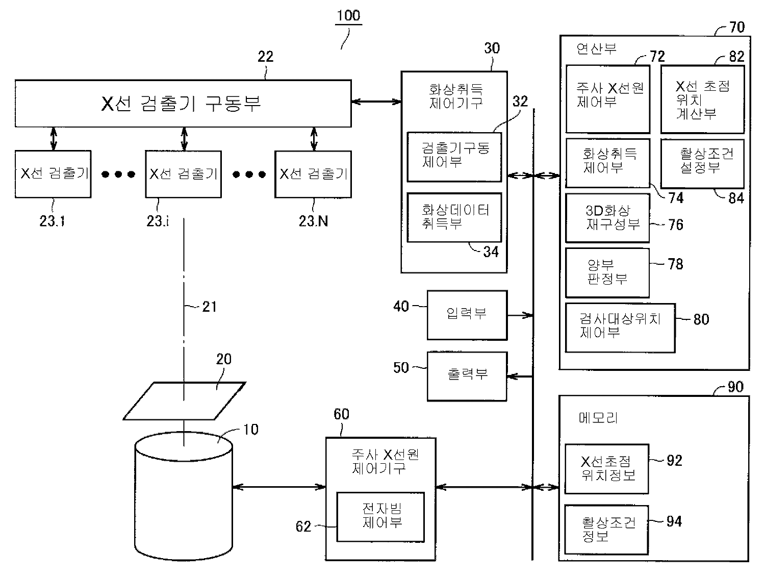
검사 대상물의 소정의 검사 에어리어를 고속으로 검사할 수 있는 X선 검사 장치를 제공한다. X선 검사 장치(100)는, X선을 출력하는 주사형 X선원(10)과, 복수의 X선 검출기(23)가 부착되고, 복수의 X선 검출기(23)를 독립적으로 구동 가능한 X선 검출기 구동부(22)와, X선 검출기 구동부(22)나 X선 검출기(23)로부터의 화상 데이터의 취득을 제어하기 위한 화상 취득 제어 기구(30)를 구비한다. 주사형 X선원(10)은, 각 X선 검출기(23)에 관해, X선이 검사 대상(20)의 소정의 검사 에어리어를 투과하여 각 X선 검출기(23)에 대해 입사하도록 설정된 X선의 방사의 기점 위치의 각각에, X선원의 X선 초점 위치를 이동시켜서 X선을 방사한다.
X선 검출기(23)의 일부에 관한 촬상과 다른 일부에 관한 촬상 위치로의 이동이 병행하여 교대로 실행된다. 화상 제어 취득 기구(30)는 X선 검출기(23)가 검출한 화상 데이터를 취득하고, 연산부(70)는 그 화상 데이터에 의거하여 검사 에어리어의 화상의 재구성을 행한다.An X-ray inspection apparatus capable of inspecting a predetermined inspection area of an inspection object at high speed. The X-ray inspection apparatus 100 includes an X-ray source 10 for outputting X-rays, a plurality of X-ray detectors 23 attached thereto, and an X-ray that can independently drive the plurality of X-ray detectors 23. The detector drive part 22 and the image acquisition control mechanism 30 for controlling acquisition of the image data from the X-ray detector drive part 22 and the X-ray detector 23 are provided. The scanning X-ray source 10 radiates X-rays set so that, with respect to each X-ray detector 23, the X-rays pass through a predetermined inspection area of the inspection object 20 and are incident on each X-ray detector 23. The X-rays are radiated by moving the X-ray focus position of the X-ray source to each of the starting point positions of.
Imaging with respect to a part of the X-ray detector 23 and movement to an imaging position with respect to another part are executed in parallel. The image control acquisition mechanism 30 acquires the image data detected by the X-ray detector 23, and the calculation unit 70 reconstructs the image of the inspection area based on the image data.
Description
본 발명은, X선 검사 방법 및 X선 검사 장치에 관한 것이다. 특히, X선 조사를 이용하여 대상물을 검사하기 위한 촬영 방법으로서, X선 검사 방법, X선 검사 장치에 적용할 수 있는 기술에 관한 것이다.
The present invention relates to an X-ray inspection method and an X-ray inspection apparatus. In particular, as a photographing method for inspecting an object using X-ray irradiation, it relates to an X-ray inspection method and a technique applicable to an X-ray inspection apparatus.
근래, 서브미크론의 미세 가공 기술에 의해 LSI(Large-Scale Integration)의 고집적화가 진전되어, 종래 복수의 패키지로 나누어져 있던 기능을 하나의 LSI에 쌓아 넣을 수가 있도록 되었다. 종래의 QFP(Quad Flat Package)나 PGA(Pin Grid Array)에서는, 원 패키지에 필요한 기능을 조립함에 의한 핀 수의 증가에 대응할 수 없게 되었기 때문에, 최근에는, 특히, BGA(Ball Grid Array)나 CSP(Chip Size Package) 패키지의 LSI가 사용된다. 또한, 휴대전화기 등의 초소형화가 필요한 것에서는, 핀 수가 그만큼 필요 없어도 BGA 패키지가 사용되고 있다.In recent years, the sub-micron micromachining technology has advanced the integration of large-scale integration (LSI), so that functions previously divided into a plurality of packages can be stacked in a single LSI. In conventional QFP (Quad Flat Package) or PGA (Pin Grid Array), it is impossible to cope with the increase in the number of pins by assembling the functions required for the original package, so in recent years, in particular, BGA (Ball Grid Array) or CSP (Chip Size Package) The LSI of the package is used. In addition, in the case where the miniaturization of a mobile phone or the like is required, the BGA package is used even if the number of pins is not required.
LSI의 BGA나 CSP 패키지는 초소형화에는 크게 공헌한 반면, 솔더 부분 등이 어셈블리 후에는 외관으로는 목에 보이지 않는다는 특징이 있다. 그래서, BGA나 CSP 패키지를 실장한 프린트 기판 등을 검사할 때는, 검사 대상품에 X선을 조사하고 얻어진 투시화상을 분석함으로써, 품질의 양부 판정이 행하여져 왔다.LSI's BGA and CSP packages have contributed significantly to miniaturization, while solder parts, etc., are invisible to the neck after assembly. Therefore, when inspecting a printed board or the like on which a BGA or CSP package is mounted, quality acceptance judgment has been made by analyzing X-rays obtained by inspecting a target product and X-rays obtained.
예를 들면, 특허 문헌 1에서는, 투과 X선을 검출하는데 X선 평면 검출기를 이용함응로써, 선명한 X선 화상을 얻을 수 있는 X선 단층면 검사 장치가 개시되어 있다.For example,
또한, 특허 문헌 2에서는, X선의 조사 각도를 임의로 선택하여 경사 3차원 X선 CT(Computed Tomography)에서의 화상의 재구성을 행하기 위한 방법이 개시되어 있다.In addition,
또한, 특허 문헌 3에서는, 평행 X선 검출 장치에서 취득한 X선 화상에 의거하여 2차원적인 검사를 실시하고, 경사 X선 검출 수단에서 취득한 X선 화상에 의거하여 3차원적인 검사를 행함으로써, 쌍방의 검사를 고속으로 행할 수 있는 X선 검사 장치가 개시되어 있다. 여기서는, 복수의 X선 화상에 의거하여 검사 대상품의 3차원 화상을 재구성하는 기술에 관해서도 언급이 있다. 재구성의 수법으로서는, 예를 들면, 「필터 보정 역투영법」이 들어져 있다.In
또한, 특허 문헌 4에서는, X선 단층 촬영 장치에 있어서, 단층 촬영을 행하기 위해 X선원에, 직선 궤도, 원궤도, 와류 궤도로 움직일 때에, 1개의 모터로 구동 가능한 기구가 개시되어 있다. 단, X선원을 이동시키는 것이 되기 때문에, X선원의 중량이 큰 것과, 1개의 모터에 의해 구동하는 설계로 되어 있어서 고속의 이동은 곤란하다. 또한, 1개의 촬상계에 있어서, 회전·직선·와류 이동의 3종류의 이동 모드를 실현하기 때문에, 복잡한 기구를 갖고 있고 이동 속도의 향상에는 많은 기구의 개량이 필요하므로, 메카의 고속화는 곤란하다.In addition,
또한, 일반적인 산업용 X선 투시 장치에서는, 검사 대상이 미소한 경우, 가능한 한 확대된 X선 투시상을 얻을 수 있는 것이 바람직하다. 그를 위해서는, X선의 발생 영역인 초점의 크기가 극히 작아야 한다. 그래서, 초점 치수가 수㎛이라는 투과형 X선원인 마이크로 포커스 X선원이 사용된다. 투시상의 화질의 향상을 위해 이와 같은 마이크로 포커스 X선원에 있어서, X선을 발생시키는 전자 빔 전류(X선원 전류)를 크게 하면, 타겟의 전자 충돌부(초점)의 발열에 의해 타겟이 국부적으로 용융하여 버리기 때문에, 허용되는 한계치(허용 부하)가 설정되는 것이 일반적이다. 특허 문헌 5에는, 이와 같은 허용 부하를 증대시키기 위해, 양극(타겟)이 회전하는 원판인 마이크로 포커스 X선원이 개시되어 있다.In addition, in general industrial X-ray see-through apparatus, when the inspection object is minute, it is desirable to be able to obtain an enlarged X-ray see-through image as much as possible. For that purpose, the size of the focal point, which is the generation area of the X-rays, must be extremely small. Thus, a microfocus X-ray source is used, which is a transmission X-ray source having a focal dimension of several μm. In such a microfocus X-ray source for improving image quality of the perspective image, when the electron beam current (X-ray source current) that generates X-rays is increased, the target is locally melted by the heat generation of the electron collision part (focus) of the target. In order to do so, it is common to set an allowable limit value (allowable load).
한편, 특허 문헌 6에는, X선원의 수명을 연장시키는 것 등을 목적으로 하여, 편향용 전자 코일을 이용하고, 간헐적으로 전자 빔을 디포커스함에 의해, 펄스 형상의 X선을 발생하는 것이 가능한 펄스 X선원이 개시되어 있다.On the other hand,
[X선 CT의 화상 재구성 수법][Image Reconstruction of X-ray CT]
상술한 바와 같이, X선 CT에서는, 대상물을 투과한 후, X선 검출기에서 검출된 관측치를 기초로, 적어도 대상물의 단면 화상을 재구성한다. 또한, 대상물 또는 대상물의 일부에 관해 3차원적인 X선의 흡수률의 분포를 얻을 수 있기 때문에, 결과적으로는, 대상물 또는 대상물의 일부의 임의의 단면 화상, 즉 X선 검출기의 수광면과 교차하는 면에 관한 화상을 재구성하는 것이 가능하다. 이와 같은 재구성 수법으로서는, 「해석적 수법」과 「반복적 수법」이 알려져 있다. 이하, 그와 같은 화상 재구성 수법에 관해, 간단히 정리한다.As described above, in the X-ray CT, after passing through the object, at least the cross-sectional image of the object is reconstructed based on the observation value detected by the X-ray detector. Further, since the distribution of the three-dimensional X-ray absorption ratio can be obtained with respect to the object or part of the object, as a result, any cross-sectional image of the object or part of the object, that is, the surface intersecting with the light receiving surface of the X-ray detector, is obtained. It is possible to reconstruct the related image. As such a reconstruction method, the "analytic method" and the "repetitive method" are known. Hereinafter, such an image reconstruction method will be briefly summarized.
(X선의 투영 데이터의 설명)(Explanation of projection data of X-ray)
도 57은, 화상 재구성 수법을 설명하기 위한 도면이다. X선 화상 재구성은, 검사 대상물의 외부로부터 조사한 X선이, 검사 대상물에 의해 얼마만큼 흡수(감쇠)되었는지를 복수의 각도로부터 계측함에 의해, 검사 대상물 내부의 X선 흡수 계수의 분포를 구하는 수법이다.57 is a diagram for explaining an image reconstruction method. X-ray image reconstruction is a method of obtaining the distribution of the X-ray absorption coefficient inside an inspection object by measuring how much X-rays irradiated from the outside of the inspection object are absorbed (damped) by the inspection object from a plurality of angles. .
또한, 이하에서는, X선원으로서는, 이른바 주사형 X선원을 이용하여 측정이 행하여지는 것으로 하여 설명을 행한다.In addition, below, as an X-ray source, it demonstrates that a measurement is performed using what is called a scanning X-ray source.
도 57을 참조하면, X선 검출기(Da)에 대응하는 X선 초점(Fa)으로부터 발하여진 X선은 검사 대상(도시 생략)을 투과하여 X선 검출기(Da)의 화소(Pa)에 도달한다. X선이 검사 대상을 투과함에 의해, X선량(X선 강도)은 검사 대상을 구성하는 부품 등의 각각이 갖는 고유한 X선 흡수 계수에 상당하는 분만큼 감쇠한다. X선 강도의 감쇠량은 검출기 화소(Pa)의 화소치로서 기록된다.Referring to FIG. 57, X-rays emitted from the X-ray focal point Fa corresponding to the X-ray detector Da pass through the inspection object (not shown) and reach the pixel Pa of the X-ray detector Da. . As the X-rays penetrate the inspection object, the X-ray dose (X-ray intensity) is attenuated by an amount corresponding to the inherent X-ray absorption coefficient of each of the components constituting the inspection object and the like. The amount of attenuation of the X-ray intensity is recorded as the pixel value of the detector pixel Pa.
X선 초점(Fa)으로부터 발하여지는 X선 강도를 I로 하고, X선 초점(Fa)으로부터 검출기 화소(Pa)까지의 X선이 통과한 경로를 t로 하고, 검사 대상에서의 X선 흡수 계수 분포를 f(x, y, z)로 하면, 검출기 화소(Pa)에 도달한 X선의 강도 Ia는 이하의 식 (1)로 표시된다.The X-ray intensity emitted from the X-ray focus Fa is I, the path through which the X-rays pass from the X-ray focus Fa to the detector pixel Pa is t, and the X-ray absorption coefficient at the inspection target is t. If the distribution is f (x, y, z), the intensity Ia of the X-rays reaching the detector pixel Pa is represented by the following equation (1).
![]()
![]()
이 식의 양변의 대수(對數)를 취하면, 경로(t)에 따른 X선 흡수 계수 분포가 이하의 식 (2)와 같이 선(線)적분치에 의해 표시된다. 이 X선 흡수 계수 분포를 X선 검출기에 의해 계측한 값을 투영 데이터라고 부른다. 즉 X선 검출기는 X선 감쇠량 분포(X선 강도 분포로 치환하여도 좋다)를 검출한다.Taking the logarithm of both sides of this equation, the X-ray absorption coefficient distribution along the path t is represented by the line integral as shown in the following equation (2). The value which measured this X-ray absorption coefficient distribution with the X-ray detector is called projection data. That is, the X-ray detector detects an X-ray attenuation distribution (may be replaced with an X-ray intensity distribution).

(해석적 수법(예를 들면, FBP법 : Filtered Back-Projection법 : 필터 보정 역투영법)의 설명)(Description of Analytical Techniques (e.g., FBP Method: Filtered Back-Projection Method: Filter Corrected Reverse Projection Method))
도 57에 도시하는 바와 같이, 해석적 수법을 사용함에 있어서는, 하나의 검사 대상물(또는 검사 대상물의 하나의 부분)에 대해, X선 검출기(Da)의 배치와는 다른 위치에 배치된 X선 검출기(Db)에 대해, 초점(Fb)으로부터 발하여저서 도달한 X선 강도(Ib)에 관한 투영 데이터를 검출한다. 이와 같은 투영 데이터를, 실제에서는, 하나의 검사 대상물(또는 검사 대상물의 하나의 부분)에 대해, 복수의 배치에 관해 검출함으로써, 이들의 투영 데이터로부터 검사 대상물의 단면 화상을 재구성하게 된다.As shown in Fig. 57, in using the analytical method, an X-ray detector disposed at a position different from the arrangement of the X-ray detector Da with respect to one inspection object (or one portion of the inspection object). For (Db), projection data relating to the X-ray intensity Ib reached from the focal point Fb and reached thereon is detected. In practice, such projection data is detected for a plurality of arrangements for one inspection object (or one portion of the inspection object), thereby reconstructing a cross-sectional image of the inspection object from these projection data.
도 58은, 도 57에 도시한 검사 대상물에 있어서의 시야(視野)(FOV), 시야(FOV)중의 재구성의 연산 대상의 재구성 화소(V), X선 초점(Fa, Fb) 및 X선 검출기(Da, Db)의 배치를 윗면에서 본 도면이다. 재구성 화소(V)의 부분을 투과한 X선은, X선 검출기(Da, Db)상에 상을 맺음 있어서, (초점으로부터 재구성 화소(V)까지의 거리) 대(對) (초점으로부터 X선 검출기까지의 거리)의 비에 응하여 확대된 상을 맺게 된다.Fig. 58 is a view (FOV) of the inspection object shown in Fig. 57, a reconstruction pixel (V), X-ray focal points (Fa, Fb) and an X-ray detector of the calculation target of reconstruction in the field of view (FOV). It is a figure which looked at arrangement | positioning of Da, Db from the upper surface. The X-rays passing through the portion of the reconstructed pixel V form an image on the X-ray detectors Da and Db so that the distance from the focus to the reconstructed pixel V is large versus the X-ray. The enlarged image is formed in response to the ratio of the distance to the detector).
Feldkamp 들은, 이 식 (2)를 기초로 3차원 화상 재구성을 행하기 위한 재구성 알고리즘을 제안하였다. 이 알고리즘(이른바 Feldkamp법)은 비특허 문헌 1에 나타나 있는 바와 같이, 공지 기술이기 때문에 여기서는 상세히 설명하지 않는다. 이하에서는 일반적인 수법의 하나인 필터 보정 역투영법에 관해 간단히 설명한다.Feldkamps have proposed a reconstruction algorithm for performing three-dimensional image reconstruction based on this equation (2). This algorithm (the so-called Feldkamp method) is a well-known technique, as shown in
투영 데이터로부터, X선이 통과한 경로(t)에 따라 투영 데이터를 가산하여 X선 흡수 계수 분포 f(x, y, z)를 구하는 조작을 역투영이라고 부른다. 단, 단순하게 투영 데이터를 가산하면 촬상계의 점 확산 함수에 의해 흐림이 생기기 때문에, 투영 데이터에 필터를 건다. 이 필터로는 예를 들면 Shepp-Logan 필터 등의 고주파 강조 필터가 사용된다. 필터를 거는 방향은, X선의 투과 경로의 방향에 대해 수직 방향이 바람직하다고 되어 있지만, Feldkamp법에서는 투영 데이터의 투과 경로의 방향이 전부 동일이라고 근사하여 필터링을 하고 있고, 검사 가능한 화상을 재구성할 수 있다.The operation of adding the projection data along the path t through which the X-rays pass from the projection data to obtain the X-ray absorption coefficient distribution f (x, y, z) is called reverse projection. However, simply adding the projection data causes blur due to the point spread function of the imaging system, so that a filter is applied to the projection data. As this filter, a high frequency emphasis filter, such as a Shepp-Logan filter, is used, for example. It is said that the direction in which the filter is applied is preferably perpendicular to the direction of the X-ray transmission path, but the Feldkamp method is filtering by approximating that the directions of the transmission path of the projection data are all the same, and can reconstruct the inspectable image. have.
이하에, 본 실시 형태에서의 화상 재구성의 순서를 나타낸다. 우선, X선 검출기(Da)의 검출기 화소(Pa)의 투영 데이터(pa)를 필터링한 값(pa')을 재구성 화소(V)의 화소치(v)에 가산한다. 또한, X선 검출기(Db)의 검출기 화소(Pb)의 투영 데이터(pb)를 필터링한 값(pb')을 재구성 화소(V)의 화소치(v)에 가산한다. 하면, v=pa'+pb'가 된다. 이 역투영 조작을 모든 X선 검출기 또는 일부의 X선 검출기에 대해 행함으로써, 최종적인 재구성 화소(V)의 화소치(v)는 이하의 식 (3)에 따라 표시된다.The procedure of image reconstruction in this embodiment is shown below. First, the value pa 'which filtered the projection data pa of the detector pixel Pa of the X-ray detector Da is added to the pixel value v of the reconstructed pixel V. FIG. Furthermore, the value pb 'which filtered the projection data pb of the detector pixel Pb of the X-ray detector Db is added to the pixel value v of the reconstructed pixel V. FIG. V = pa '+ pb'. By performing this reverse projection operation on all the X-ray detectors or some X-ray detectors, the pixel value v of the final reconstructed pixel V is represented by following formula (3).
![]()
![]()
이 조작을 재구성 영역(시야)(FOV) 내의 모든 재구성 화소(V)에 대해 행함에 의해, 검사 대상의 X선 흡수 계수 분포가 구되여저서 재구성 화상 데이터를 얻을 수 있다.By performing this operation on all the reconstructed pixels V in the reconstructed area (viewing area) FOV, the X-ray absorption coefficient distribution of the inspection object can be obtained, so that reconstructed image data can be obtained.
도 59는, 이와 같은 필터 보정 역투영법의 처리 순서를 도시하는 플로우 차트이다.Fig. 59 is a flowchart showing the processing procedure of such a filter correction reverse projection method.
도 59를 참조하면, 해석적 수법에서의 처리가 시작되면(S5002), 우선, 복수 촬상한 투영 데이터중에서 처리 대상이 되는 투영 데이터의 선택이 행하여진다(S5004). 다음에, 선택된 투영 데이터에 필터를 거는 처리를 행한다(S5006).Referring to Fig. 59, when the processing in the analytical method starts (S5002), first, projection data to be processed is selected from among the plurality of captured projection data (S5004). Next, a process of applying a filter to the selected projection data is performed (S5006).
또한, 재구성 시야(FOV)중의 미처리의 재구성 화소(V)를 선택하고(S5008), 재구성 화소(V)에 대응하는 검출기 화소를 구한다(S5010).Further, an unprocessed reconstructed pixel V in the reconstructed field of view FOV is selected (S5008), and a detector pixel corresponding to the reconstructed pixel V is obtained (S5010).
계속해서, 재구성 화소(V)에 필터링한 화소치를 가산하고(S5012), 모든 재구성 화소에 대해 가산을 행하였는지가 판단된다(S5014). 모든 재구성 화소에 대해 처리가Subsequently, the filtered pixel value is added to the reconstructed pixel V (S5012), and it is determined whether the addition has been performed for all the reconstructed pixels (S5014). For all reconstructed pixels
끝나지 않았으면, 처리는 스탭 S5008로 복귀하고, 종료하고 있으면, 처리는, 스탭 S5016으로 이행한다.If it is not finished, the process returns to the staff S5008, and if it is finished, the process shifts to the staff S5016.
스탭 S5016에서는, 모든 투영 데이터에 대해 처리를 행하였는지가 판단된다. 모든 투영 데이터에 대해 종료하지 않았으면, 처리는 스탭 S5004로 복귀한다. 한편, 모든 투영 데이터에 대해 종료하고 있으면, 재구성 화상 생성이 종료된다(S5018).In step S5016, it is determined whether the processing has been performed on all the projection data. If it has not finished all the projection data, the process returns to the step S5004. On the other hand, if it ends with all projection data, a reconstruction image generation is complete | finished (S5018).
(반복적 수법(SART)의 설명)(Description of Repetitive Techniques (SART))
반복적 수법에서는, 검사 대상의 X선 흡수 계수 분포 f(x, y, z)와 투영 데이터 ln(I/Ia)를 방정식이라고 간주하여 재구성하는 수법이다.In the iterative method, the X-ray absorption coefficient distribution f (x, y, z) and the projection data ln (I / Ia) of the inspection object are regarded as equations and reconstructed.
도 60은, 주사형 X선원을 이용한 경우의 반복적 수법에서의 처리의 개념을 도시하는 개념도이다. 한편, 도 61은, 도 60의 개념도를 윗면에서 본 상면도이다.Fig. 60 is a conceptual diagram showing the concept of processing in an iterative method when using a scanning X-ray source. 61 is the top view which looked at the conceptual diagram of FIG. 60 from the top.
이하에, 도 60 및 도 61을 참조하여, 반복적 수법으로 재구성하는 순서에 관해 설명한다. 재구성 화상의 화소치를 일렬로 나열한 벡터(ν)(벡터를 나타내기 위해 머리부에 →를 붙임 : 이하 텍스트 본문중에서는, 「ν」라고 기재한다)와, 투영 데이터를 일렬로 나열한 벡터(p)(벡터를 나타내기 위해 머리부에 →를 붙임 : 이하 텍스트 본문중에서는, 「p」라고 기재한다)를 이하의 식 (4) 및 식 (5)로 표시한다.Hereinafter, with reference to FIG. 60 and FIG. 61, the procedure to reconstruct by an iterative method is demonstrated. A vector ν having pixel values of the reconstructed image arranged in a line (with a heading to indicate the vector: in the text body below, ν is described) and a vector p arranged with the projection data in a line. (→ is attached to the head to represent the vector: In the text body below, "p" is represented) by the following formulas (4) and (5).
이하에서는, 예를 들면, 재구성 화소(V)의 값을 어느 값으로 가정한 때에 X선 초점(Fa)으로부터의 X선이 X선 검출기(Da)상에 맺어진다고 계산되는 화상에 관한 화소를 중간 투영 화소(Qa)로 하고, 실제로 X선 검출기(Da)상에서 관측된 화소를 검출기 화소(Pa)라고 부른다. X선 검출기(Db)에 관해서도, 각각, 중간 투영 화소(Qb), 검출기 화소(Pb)라고 부른다.In the following, for example, when the value of the reconstructed pixel V is assumed to be a certain value, the pixel relating to the image calculated as the X-ray from the X-ray focus Fa is formed on the X-ray detector Da is intermediate. A pixel observed as an projection pixel Qa and actually observed on the X-ray detector Da is called a detector pixel Pa. The X-ray detector Db is also called the intermediate projection pixel Qb and the detector pixel Pb, respectively.
반복적 수법에서는, 가정된 재구성 화소 벡터(ν)와 이에 대응하는 중간 투영 데이터 벡터(q)에 대해, 이하에 설명하는 바와 같이, 중간 투영 데이터 벡터(q)가, 실제로 측정된 검출기 화소치(Pa 또는 Pb)의 투영 데이터와 일치한다고 간주할 수 있을 때까지, 가정된 벡터(ν)를 갱신하는 반복 연산에 의해 해답(ν)을 구한다.In the iterative method, for the hypothesized reconstructed pixel vector v and the corresponding intermediate projection data vector q, as described below, the intermediate projection data vector q is the detector pixel value Pa actually measured. Alternatively, the solution v is obtained by an iterative operation of updating the assumed vector v until it can be considered to coincide with the projection data of Pb).

단, J는 재구성 영역(시야) 내의 화소 수, I는 투영 데이터의 화소 수이다. 또한, T는 전치(轉値)를 나타낸다. ν 라고 p를 관계짓는 투영 연산을 이하의 식 (6)의 I×J 계수 행렬로 나타낸다.However, J is the number of pixels in the reconstructed area (field of view), and I is the number of pixels of the projection data. In addition, T represents transposition. The projection operation relating ν and p is represented by the I × J coefficient matrix of Equation (6) below.

이 때, 반복적 수법에서의 화상 재구성은, 이하의 식 (7) 선형 방정식을 풀어서 ν를 구하는 문제로서 정식화할 수 있다.At this time, the image reconstruction in the iterative method can be formulated as a problem of solving the following equation (7) linear equation to obtain v.

즉, vj가 pi에 대한 기여(寄與)를 wij라고 한다. 또한, W는 재구성 화상의 화소치(ν)가 투영 데이터의 화소치(p)에 대해 어느 정도 기여하는지를 나타내고 있고, X선 초점과 X선 검출기의 기하학적 위치로부터 구할 수 있고, 검출 확률 또는 무게라고 불리는 일도 있다.In other words, the contribution of vj to pi is called wij. W represents how much the pixel value ν of the reconstructed image contributes to the pixel value p of the projection data, and W can be obtained from the X-ray focus and the geometric position of the X-ray detector. It is called.
반복적 수법에는, 방정식을 대수학적으로 푸는 수법이나 통계적인 잡음을 고려하는 수법 등이 고안되어 있지만, 이하에 일반적으로 사용되고 있는 대수학적 수법인 SART(Simultaneous Algebraic Reconstruction Technique)에 관해 설명한다. 상세는, 비특허 문헌 2에 기재되어 있다.In the iterative method, algebraically solved equations, methods that consider statistical noise, and the like are devised. Hereinafter, SART (Simultaneous Algebraic Reconstruction Technique), which is generally used, will be described. The details are described in
SART에서는, 최초에, 이하의 식 (8)로 표시되는 초기 재구성 화상(ν0)(벡터를 나타내기 위해 머리부에 →를 붙임 : 이하 텍스트 본문중에서는, 「ν0」라고 기재한다)를 가정한다.In SART, the initial reconstructed image ν 0 represented by Equation (8) below is first attached with a heading to indicate a vector: in the following text, "ν 0 " is described. Assume

초기 재구성 화상(ν0)은 전부 0의 데이터라도 좋고, CAD(Computer Aided Design) 데이터 등으로부터 취득한 데이터를 가정하여도 좋다.The initial reconstructed image ν 0 may be all zero data or may assume data acquired from computer-aided design (CAD) data or the like.
다음에, 투영 연산(W)을 이용하여 이하의 식 (9)로 표시되는 중간 투영 데이터(q0) (벡터를 나타내기 위해(때문에) 머리부에 →를 붙임 : 이하 텍스트 본문중에서는, 「q0」 라고 기재한다)를 생성한다.Next, using the projection operation W, the intermediate projection data q 0 represented by the following equation (9) is appended with a heading to represent a vector: q 0 ").

중간 투영 데이터(q0)의 생성은, 하나의 투영 데이터에 대해 행하여도 좋고, 복수의 투영 데이터에 대해 행하여도 좋다. 이하는 하나의 투영 데이터에 대해 행한 것으로 하여 설명한다.Generation of the intermediate projection data q 0 may be performed on one projection data or may be performed on a plurality of projection data. The following description assumes that one projection data is performed.
생성한 중간 투영 데이터(q0)와 X선 검출기로부터 취득된 투영 데이터(p)를 비교한다. 비교 방법은 차를 취하는 방법과고 나누는 방법이 있지만, SART에서는 차(p-q0)를 취한다.The generated intermediate projection data q 0 is compared with the projection data p acquired from the X-ray detector. There is a comparison method with a difference between taking a car and a difference, but in SART, a difference (pq 0 ) is taken.
초기 재구성 화상(ν0)을 갱신한다. 갱신에 이용하는 식(반복식)은 식 (10)과 같이 된다.The initial reconstructed image ν 0 is updated. The equation (repeat) used for the update is as shown in equation (10).

또한, 식 (10)중의 이하의 식 (11) 및 식 (12)는, 미리 계산하여 둠으로써 갱신의 계산 시간을 단축할 수 있다.In addition, the following calculation formula (11) and formula (12) in Formula (10) can be shortened by calculating beforehand the update calculation time.

상기한 계산에 의해 생성된 재구성 화상을 초기 화상으로서 대입하고, 동일한 처리를 복수회 반복시킴으로써 재구성 화상 데이터를 얻을 수 있다.The reconstructed image data can be obtained by substituting the reconstructed image generated by the above calculation as an initial image and repeating the same process a plurality of times.
도 62는, 반복적 수법의 처리를 설명하기 위한 플로우 차트이다.Fig. 62 is a flowchart for explaining processing of an iterative method.
도 62를 참조하면, 우선, 반복적 수법에 의한 처리가 시작되면(S5102), 계속해서, 초기 재구성 화상의 설정이 행하여진다(S5104). 상술한 바와 같이, 초기 재구성 화상으로서는, 예를 들면, 전부가 0의 값이라도 좋다. 다음에, 복수의 X선 검출기 위치에 대응하는 복수의 투영 데이터 중에서 처리 대상이 되는 투영 데이터를 선택한다(S5106).Referring to Fig. 62, first, when a process by an iterative method is started (S5102), the initial reconstructed image is subsequently set (S5104). As described above, the initial reconstructed image may be, for example, all zeros. Next, projection data to be processed is selected from the plurality of projection data corresponding to the plurality of X-ray detector positions (S5106).
중간 투영데이터를 생성한다. 중간 투영 데이터의 생성 방법은 상술한 바와 같다.(S5108).Generate intermediate projection data. The method of generating the intermediate projection data is as described above (S5108).
또한, 재구성 시야(FOV)중의 미처리의 재구성 화소(V)를 선택한다(S5110).In addition, an unprocessed reconstructed pixel V in the reconstructed field of view FOV is selected (S5110).
재구성 화소에 대응하는 검출기 화소를 구한다(S5112).A detector pixel corresponding to the reconstructed pixel is obtained (S5112).
반복식을 기초로, 재구성 화소(V)의 값을 갱신한다(S5114).Based on the iterative expression, the value of the reconstructed pixel V is updated (S5114).
다음에, 모든 재구성 화소에 대해 갱신을 행하였는지가 판단되고(S5116), 모든 재구성 화소에 대해 처리가 끝나지 않았으면, 처리는 스탭 S5110로 복귀하고, 종료하고 있으면, 처리는, 스탭 S5118로 이행한다.Next, it is determined whether or not the update has been performed for all the reconstructed pixels (S5116). If the processing has not been completed for all the reconstructed pixels, the process returns to the step S5110, and if the process ends, the process shifts to the step S5118. .
스탭 S5118에서는, 모든 투영 데이터에 대해 처리를 행하였는지가 판단된다. 모든 투영 데이터에 대해 종료하지 않았으면, 처리는 스탭 S5106로 복귀한다. 한편, 모든 투영 데이터에 대해 종료하고 있으면, 처리는 스탭 S5120으로 이행한다.In step S5118, it is determined whether the processing has been performed on all the projection data. If it has not finished all the projection data, the process returns to step S5106. On the other hand, if it is finished about all projection data, a process will transfer to step S5120.
스탭 S5120에서는, 규정의 반복 회수만 처리를 행하였는지가 판단되고, 반복하지 않았으면, 처리는 스탭 S5104로 복귀하여 현재의 재구성 화소치를 초기 재구성 화상으로서 채용하여 처리를 반복하고, 처리를 규정 회수만큼 반복하고 있으면, 재구성 화상 생성이 종료된다(S5022).In step S5120, it is determined whether the processing has been performed only for the specified number of repetitions. If not, the processing returns to step S5104, employs the current reconstructed pixel value as the initial reconstruction image, and repeats the processing. If it repeats, the reconstructed image generation ends (S5022).
이상과 같이 X선 검출기에 의해 취득된 투영 데이터로부터, 검사 대상물의 3차원 화상을 재구성할 수 있다.As described above, the three-dimensional image of the inspection object can be reconstructed from the projection data acquired by the X-ray detector.
단, 해석적 수법에서는, 필터링 처리를 X선 검출기의 각 화소에 대해 행하는 경우의 계산의 용이성 등의 이유로부터, 복수의 투영 데이터의 각각을 취득하기 위해, X선 검출기 및 초점과 대상물과의 상대 위치를 변경한 경우에도, X선의 초점과 X선 검출기와의 상대적인 배치는, 일정한 관계를 유지하는 것이 바람직하다. 환언하면, 초점으로부터 X선 검출기를 본 때에는, 예측되는 입체각 내의 대상물의 시야에 포함된 부분의 각도·대상물 내의 위치 등은 변화하여도, 초점과 X선 검출기와의 위치 관계는, 일정한 채인 것이 바람직하다. 게다가, 상기한 바와 같은 역투영법을 행함에 있어서는, 아티팩트 등의 저감을 위해서는, 복수의 투영 데이터는, 대상물의 시야에 포함된 부분에 관해, 등각도마다 취득된 것이 바람직하다.However, in the analytical method, in order to obtain each of the plurality of projection data from the reasons such as the ease of calculation in the case of performing the filtering process for each pixel of the X-ray detector, the relative of the X-ray detector, the focus and the object. Even when the position is changed, it is preferable that the relative arrangement of the focus of the X-rays and the X-ray detector maintains a constant relationship. In other words, when viewing the X-ray detector from the focal point, it is preferable that the positional relationship between the focal point and the X-ray detector remains constant even if the angle, the position in the object, and the like of the portion included in the object's field of view in the predicted solid angle change. Do. In addition, in performing the reverse projection as described above, in order to reduce artifacts and the like, it is preferable that a plurality of pieces of projection data are obtained for each isometric angle with respect to a portion included in the field of view of the object.
이에 대해, 반복적 수법에서는, 이와 같은 X선의 초점과 X선 검출기와의 상대적인 배치에, 이와 같은 제한은 없다.In contrast, in the iterative method, there is no such restriction on the relative arrangement of the focus of such X-rays and the X-ray detector.
특허 문헌 1 : 일본 특개2000-46760호 공보Patent Document 1: Japanese Patent Application Laid-Open No. 2000-46760
특허 문헌 2 : 일본 특개2003-344316호 공보Patent Document 2: Japanese Patent Application Laid-Open No. 2003-344316
특허 문헌 3 : 일본 특개2006-162335호 공보Patent Document 3: Japanese Patent Application Laid-Open No. 2006-162335
특허 문헌 4 : 일본 특공평5-86218호 공보Patent Document 4: Japanese Patent Application Laid-Open No. 5-86218
특허 문헌 5 : 일본 특개2001-273860호 공보Patent Document 5: Japanese Patent Application Laid-Open No. 2001-273860
특허 문헌 6 : 일본 특개2005-347174호 공보Patent Document 6: Japanese Patent Application Laid-Open No. 2005-347174
비특허 문헌 1 : L. A. Feldkamp, L. C. Davis and J. W. Kress, "Practical cone-beam algorithm", Jounrnal of the Optical Society of America. A, 612-619(1984)Non Patent Literature 1: L. A. Feldkamp, L. C. Davis and J. W. Kress, "Practical cone-beam algorithm", Jounrnal of the Optical Society of America. A, 612-619 (1984)
비특허 문헌 2 : A. H. Anderson and A. C. Kak, "SIMULTANEOUS ALGEBRAIC RECONSTRUCTIONTECHNIQUE(SART) : A SUPERIOR IMPLEMENTATION OF THE ART ALGORITHM", ULTRASONIC IMAGING 6, 81-94(1984)
Non-Patent Document 2: AH Anderson and AC Kak, "SIMULTANEOUS ALGEBRAIC RECONSTRUCTION TECHNIQUE (SART): A SUPERIOR IMPLEMENTATION OF THE ART ALGORITHM",
그러나, 공장의 인라인에서의 검사에서는, 제품의 전수 검사를 행하는 것이 필요해지기 때문에, 제조 효율의 관점에서는, X선 검사에 필요로 하는 시간을 단축하는 것이 필요해진다.However, in the in-line inspection of a factory, since it is necessary to perform a full inspection of a product, it is necessary to shorten the time required for X-ray inspection from a manufacturing efficiency viewpoint.
또한, 상술한 종래의 X선 검사에 관한 X선 촬영 기술에서는, 재구성할 수 있는 검사 에어리어의 면적을 크게 하면, 촬상 및 3D화(재구성) 연산에 시간을 필요로 한다. 예를 들면, 상술한 바와 같은 프린트 기판 등을 검사하기 위해서는, 그 검사 대상의 전체가 아니라, 복수의 특정한 부분의 화상dl 얻어지면 좋은 경우가 많다. 이와 같은 경우에 있어서, 검사 대상에 관해 검사를 하고 싶은 부분이 뜨문뜨문 떨어져 있는 형상으로 배치되어 있을 때에, 그 전체를 포함하는 면적(또는 체적)을 검사 대상으로 할 수 있는 X선 검출기를 준비하는 것은, 장치의 대형화나 연산 부하의 증가 등의 관점에서 효율적이 아니다.In addition, in the X-ray imaging technique related to the conventional X-ray inspection described above, when the area of the inspection area that can be reconfigured is increased, time is required for imaging and 3D (reconstruction) calculation. For example, in order to inspect the above-mentioned printed board etc., it is good in many cases to obtain the image dl of several specific part instead of the whole inspection object. In such a case, when an area to be inspected for an inspection object is arranged in a spaced apart shape, an X-ray detector capable of making an area (or volume) containing the whole thereof as an inspection object is prepared. This is not efficient from the standpoint of increasing the size of the device and increasing the computational load.
또한, 상술한 종래의 X선 검사에 관한 X선 촬영 기술에서는, 검사 에어리어를 변경시키는데 촬상계 또는 검사 대상 워크를 옮길 필요가 있어서, 가동부분이 증가한다. 이것은, 상술한 X선 검사에 필요로 하는 시간의 문제뿐만 아니라, 구동부분을 제조하기 위한 비용이나, 보수성, 신뢰성에도 관계가 있다. 예를 들면, 상술한 바와 같은 프린트 기판 등을 검사할 때에는, 검사의 대상이 되는 부분은, 스테이지에 놓여져 있는 프린트 기판의 일부인 경우가 많다. 게다가, 이와 같은 경우, 얻어지는 X선상을 확대상으로 하기 위해, X선 검출기는, 검사 대상으로부터 비교적 떨어진 위치를 구동되는 것이 되지만, 검사 대상이 되는 부분은, 미소 부분이기 때문에, 극히 고정밀도로 촬상계의 구동을 제어할 필요가 생긴다. 이 때문에, 촬상계의 구동 기구에 관해서는, 가능한 한 적은 자유도로, 필요한 화상의 촬상이 행하여저야 한다.In addition, in the X-ray imaging technique related to the conventional X-ray inspection described above, it is necessary to move the imaging system or the inspection target workpiece to change the inspection area, and the movable portion is increased. This is related not only to the problem of time required for the above-described X-ray inspection, but also to the cost, repairability, and reliability for manufacturing the drive portion. For example, when inspecting the above-mentioned printed boards, etc., the part to be tested is often a part of the printed boards placed on the stage. In addition, in such a case, in order to make the obtained X-ray image into an enlarged image, the X-ray detector is driven to a position relatively far from the inspection object, but since the portion to be inspected is a minute portion, the imaging system is extremely accurate. It is necessary to control the driving of the. For this reason, regarding the drive mechanism of an imaging system, imaging of a required image should be performed with as little freedom as possible.
따라서 검사 대상물의 소정의 검사 에어리어를 선택적으로 고속으로 검사할 수 있는 X선 검사 장치 및 이와 같은 X선 촬영 장치를 이용한 X선 검사 방법이 필요하게 되어 있다.Therefore, there is a need for an X-ray inspection apparatus capable of selectively inspecting a predetermined inspection area of an inspection object at high speed and an X-ray inspection method using such an X-ray imaging apparatus.
또한, 가동부분을 삭감하여, 저비용으로, 보수성이나 신뢰성에 우수한 X선 검사 장치 및 이와 같은 X선 촬영 장치를 이용한 X선 검사 방법이 필요하게 되어 있다.In addition, there is a need for an X-ray inspection apparatus which is excellent in water retention and reliability at low cost by reducing the movable portion, and an X-ray inspection method using such an X-ray imaging apparatus.
또한, 검사 대상물을 이동시키는 일 없고, 고속으로 검사 대상물의 복수의 부분을 검사하는 것이 가능한 X선 검사 장치 및 이와 같은 X선 촬영 장치를 이용한 X선 검사 방법이 필요하게 되어 있다.
Furthermore, there is a need for an X-ray inspection apparatus capable of inspecting a plurality of portions of an inspection object at high speed without moving the inspection object, and an X-ray inspection method using such an X-ray imaging apparatus.
한 실시의 형태에 따르면, 대상물의 검사 대상 영역을 투과한 X선을 복수의 검출면에서 촬상함에 의해, 검사 대상 영역의 상의 재구성 처리를 실행하기 위한 X선 검사 장치가 제공된다. 이 X선 검사 장치는, 복수의 검출면에서 촬상하기 위한, 검출면의 수보다도 적은 복수의 X선 검출기와, 복수의 X선 검출기중의 일부와 다른 일부를 독립적으로 이동시키는 검출기 구동부와, 검사 대상 영역을 투과한 X선이, 각각 검출면이 되는 복수의 촬상 위치로 이동한 복수의 X선 검출기에 입사하도록 대응시켜서 X선을 출력하는 X선 출력부와, X선 검사 장치의 동작의 제어를 행하는 제어부를 구비한다. 제어부는, 각 X선 검출기의 노광 타이밍과, 검출기 구동부를 제어하는 화상 취득 제어부와, X선 출력부를 제어하기 위한 X선 출력 제어부와, 복수의 검출면에서 촬상한, 검사 대상 영역을 투과한 X선의 강도 분포의 데이터에 의거하여, 검사 대상 영역의 상 데이터를 재구성하는 화상 재구성 처리부를 포함한다. 화상 취득 제어부 및 X선 출력 제어부는, 복수의 X선 검출기중의 일부를 복수의 촬상 위치중의 제 1의 위치에서 촬상시키는 처리와, 복수의 X선 검출기중의 다른 일부를 복수의 촬상 위치중의 제 1의 위치와는 다른 제 2의 위치로 이동시키는 처리를 병행하여 실행한다.According to one embodiment, an X-ray inspection apparatus for executing a reconstruction process on an image of an inspection subject region is provided by imaging X-rays passing through the inspection subject region of an object on a plurality of detection surfaces. The X-ray inspection apparatus includes a plurality of X-ray detectors smaller than the number of detection surfaces for imaging on a plurality of detection surfaces, a detector driver for independently moving some of the plurality of X-ray detectors, and other portions, and an inspection. X-ray output unit that outputs X-rays by correspondingly injecting X-rays passing through the target region into a plurality of X-ray detectors moved to a plurality of imaging positions serving as detection planes, respectively, and controlling the operation of the X-ray inspection apparatus It is provided with a control unit for performing. The control unit includes an X-rays passing through the inspection target region captured by a plurality of detection surfaces, an X-ray output control unit for controlling the exposure timing of each X-ray detector, an image acquisition control unit for controlling the detector driver, an X-ray output unit, and a plurality of detection surfaces. And an image reconstruction processing unit for reconstructing image data of the inspection subject region based on the data of the intensity distribution of the line. The image acquisition control unit and the X-ray output control unit perform processing for imaging a portion of the plurality of X-ray detectors at a first position among the plurality of imaging positions, and another portion of the plurality of X-ray detectors in the plurality of imaging positions. A process of moving to a second position different from the first position of is performed in parallel.
바람직하게는, 화상 취득 제어부 및 X선 출력 제어부는, 하나의 대상물의 검사 대상 영역에 관해, 화상 데이터의 재구성에 대해 미리 설정된 개수의 촬상 위치에서의 촬상을 복수회로 나누어서 행하기 위해, 복수의 X선 검출기중의 일부에 관해, 제 1의 위치에서 촬상시키는 처리 및 해당 촬상 후에 제 1의 위치와는 다른 다음의 제 1의 위치로 이동시키는 처리와, 복수의 X선 검출기중의 다른 일부에 관해, 일부를 제 1의 위치에서 촬상시키는 처리와 병행하여, 제 1의 위치, 다음의 제 1의 위치 및 이전의 제 2의 위치의 어느것과도 다른, 다음회의 촬상에 대응하는 제 2의 위치로 이동시키는 처리 및 일부를 다음의 제 1의 위치로 이동시키는 처리와 병행하여, 제 2의 위치에서 촬상시키는 처리를 실행시킨다.Preferably, the image acquisition control unit and the X-ray output control unit store a plurality of X images by dividing the imaging at a predetermined number of imaging positions with respect to the inspection target region of one object in a plurality of times. Regarding a part of the line detectors, a process of imaging at a first position, a process of moving to a next first position different from the first position after the imaging, and another part of the plurality of X-ray detectors To a second position corresponding to the next imaging, which is different from any of the first position, the next first position, and the previous second position, in parallel with the processing of imaging a portion at the first position. In parallel with the process of moving and the process of moving a part to the next 1st position, the process of imaging in a 2nd position is performed.
바람직하게는, X선 출력 제어부는, 복수의 검출면에 관해, X선이 검사 대상 영역을 투과하여 각 검출면에 대해 입사하도록 X선의 방사의 기점 위치의 각각을 설정하는 기점 설정부를 포함한다. X선 출력부는, 각 기점 위치에 X선원의 X선 초점 위치를 이동시켜서, X선을 발생시킨다.Preferably, the X-ray output control section includes a starting point setting section for setting each of the starting point positions of the X-ray radiation so that the X-rays penetrate the inspection target region and enter the respective detection surfaces with respect to the plurality of detection surfaces. The X-ray output unit generates an X-ray by moving the X-ray focus position of the X-ray source to each starting point position.
바람직하게는, X선 출력부는, X선원의 연속면인 타겟면상에 조사하는 전자 빔을 편향시킴으로써 X선원 초점 위치를 이동시킨다.Preferably, the X-ray output unit shifts the X-ray source focal position by deflecting an electron beam that is irradiated onto the target plane, which is a continuous plane of the X-ray source.
다른 실시의 형태에 따르면, 대상물의 검사 대상 영역을 투과한 X선을 복수의 검출면에서 촬상함에 의해, 검사 대상 영역의 상의 재구성 처리를 실행하기 위한 X선 검사 장치가 제공된다. 이 X선 검사 장치는, 복수의 검출면에서 촬상하기 위한, 검출면의 수보다도 적은 복수의 X선 검출기와, 복수의 X선 검출기의 일부를 소정의 1축 방향에 따라 이동시키는 1축 구동부와, 검사 대상 영역을 투과한 X선이, 각각 검출면이 되는 복수의 촬상 위치로 이동한 복수의 X선 검출기에 입사하도록 대응시켜서 X선을 출력하는 X선 출력부와, X선 검사 장치의 동작의 제어를 행하는 제어부를 구비한다. 제어부는, 각 X선 검출기의 노광 타이밍과, 검출기 구동부를 제어하는 화상 취득 제어부와, X선 출력부를 제어하기 위한 X선 출력 제어부와, 복수의 검출면에서 촬상한, 검사 대상 영역을 투과한 X선의 강도 분포의 데이터에 의거하여, 검사 대상 영역의 상 데이터를 재구성하는 화상 재구성 처리부를 포함한다.According to another embodiment, an X-ray inspection apparatus for executing the reconstruction processing on the image of the inspection subject region is provided by imaging X-rays passing through the inspection subject region of the object on a plurality of detection surfaces. The X-ray inspection apparatus includes a plurality of X-ray detectors smaller than the number of detection surfaces for imaging on a plurality of detection surfaces, a single-axis driving unit for moving a part of the plurality of X-ray detectors along a predetermined one axis direction; An X-ray output unit for outputting X-rays by correspondingly injecting X-rays passing through the inspection target region into a plurality of X-ray detectors moved to a plurality of imaging positions serving as detection planes, respectively, and operation of the X-ray inspection apparatus It is provided with a control unit for controlling the. The control unit includes an X-rays passing through the inspection target region captured by a plurality of detection surfaces, an X-ray output control unit for controlling the exposure timing of each X-ray detector, an image acquisition control unit for controlling the detector driver, an X-ray output unit, and a plurality of detection surfaces. And an image reconstruction processing unit for reconstructing image data of the inspection subject region based on the data of the intensity distribution of the line.
바람직하게는, 1축 구동부는, 복수의 X선 검출기를 소정의 평면 내에서 평행하게 이동시킨다.Preferably, the one-axis drive unit moves the plurality of X-ray detectors in parallel in a predetermined plane.
바람직하게는, 복수의 X선 검출기의 검출면은 각각 사각형 형상이다. 검출기 구동부는, 복수의 X선 검출기의 검출면의 일방단이, 각 촬상 위치에서 X선 출력부를 향하는 방향과 교차하도록, 복수의 X선 검출기를 자전(自轉)시키는 자전부를 포함한다.Preferably, the detection surfaces of the plurality of X-ray detectors are each rectangular in shape. The detector driving unit includes a magnetizing unit which rotates the plurality of X-ray detectors so that one end of the detection surface of the plurality of X-ray detectors crosses the direction toward the X-ray output unit at each imaging position.
바람직하게는, 화상 재구성 처리부는, 반복적 수법에 의해 검사 대상 영역의 화상 데이터를 재구성한다.Preferably, the image reconstruction processing unit reconstructs the image data of the inspection subject region by an iterative method.
바람직하게는, 화상 재구성 처리부는, 해석적 수법에 의해 검사 대상 영역의 화상 데이터를 재구성한다.Preferably, the image reconstruction processing unit reconstructs the image data of the inspection subject region by an analytical method.
다른 실시의 형태에 따르면, 대상물의 검사 대상 영역을 투과한 X선을 복수의 검출면에서 촬상함에 의해, 검사 대상 영역의 상의 재구성 처리를 실행하기 위한 X선 검사 장치가 제공된다. 이 X선 검사 장치는, 복수의 검출면에서 촬상하기 위한, 검출면의 수보다도 적은 복수의 X선 검출기와, 검사 대상 영역을 투과한 X선이, 각각 검출면이 되는 복수의 촬상 위치로 이동한 복수의 X선 검출기에 입사하도록 대응시켜서 X선을 출력하는 X선 출력부와, X선 검사 장치의 동작의 제어를 행하는 제어부를 구비한다. 제어부는, 각 X선 검출기의 노광 타이밍과, 검출기 구동부를 제어하는 화상 취득 제어부와, X선 출력부를 제어하기 위한 X선 출력 제어부와, 복수의 검출면에서 촬상한, 검사 대상 영역을 투과한 X선의 강도 분포의 데이터에 의거하여, 검사 대상 영역의 상 데이터를 재구성하는 화상 재구성 처리부를 포함한다. 화상 취득 제어부 및 X선 출력 제어부는, 복수의 X선 검출기중의 일부를 복수의 촬상 위치중의 제 1의 위치에서 촬상시키는 처리와, 복수의 X선 검출기중의 다른 일부를 복수의 촬상 위치중의 제 1의 위치와는 다른 제 2의 위치로 이동시키는 처리를 병행하여 실행한다. X선 출력부는, 촬상 위치에 배치되어 있는 복수의 X선 검출기중 동시에 촬상 상태로 되어 있는 복수의 X선 검출기에 대해, 각각 대응하는 복수의 X선 초점 위치로부터 X선을 발생시킨다. X선 검사 장치는, X선 출력부로부터의 X선이, 동시에 촬상 상태로 되어 있는 X선 검출기의 각각에 대해, 대응하는 X선 초점 위치로부터 검사 대상 영역을 투과하여 각 검출면에 대해 입사하는 X선은 투과하는 한편, 대응하지 않는 X선 초점 위치로부터의 X선은 차폐하는 차폐부재를 또한 구비한다.According to another embodiment, an X-ray inspection apparatus for executing the reconstruction processing on the image of the inspection subject region is provided by imaging X-rays passing through the inspection subject region of the object on a plurality of detection surfaces. In this X-ray inspection apparatus, a plurality of X-ray detectors smaller than the number of detection surfaces for imaging on a plurality of detection surfaces, and X-rays transmitted through the inspection target region are moved to a plurality of imaging positions, which become detection surfaces, respectively. An X-ray output part which outputs X-rays by making it correspond to incident to one some X-ray detector, and the control part which controls the operation | movement of an X-ray inspection apparatus are provided. The control unit includes an X-rays passing through the inspection target region captured by a plurality of detection surfaces, an X-ray output control unit for controlling the exposure timing of each X-ray detector, an image acquisition control unit for controlling the detector driver, an X-ray output unit, and a plurality of detection surfaces. And an image reconstruction processing unit for reconstructing image data of the inspection subject region based on the data of the intensity distribution of the line. The image acquisition control unit and the X-ray output control unit perform processing for imaging a portion of the plurality of X-ray detectors at a first position among the plurality of imaging positions, and another portion of the plurality of X-ray detectors in the plurality of imaging positions. A process of moving to a second position different from the first position of is performed in parallel. The X-ray output unit generates X-rays from a plurality of corresponding X-ray focal positions, respectively, for a plurality of X-ray detectors that are simultaneously in an image pickup state among a plurality of X-ray detectors arranged at the imaging position. The X-ray inspection apparatus is configured such that the X-rays from the X-ray output unit pass through the inspection target region from the corresponding X-ray focal position to each of the X-ray detectors which are simultaneously in the image pickup state and enter the respective detection surfaces. The X-rays are also provided with a shielding member that transmits, while the X-rays from the corresponding X-ray focal positions shield.
바람직하게는, X선 출력부는, X선원의 연속면인 타겟면상에 조사하는 전자 빔을 편향시킴으로써 X선원 초점 위치를 이동시킨다. X선 출력 제어부는, 동시에 노광 상태로 되어 있는 X선 검출기의 각각에 대해, X선이 시분할로 입사하도록, X선 출력부를 제어한다.Preferably, the X-ray output unit shifts the X-ray source focal position by deflecting an electron beam that is irradiated onto the target plane, which is a continuous plane of the X-ray source. The X-ray output control section controls the X-ray output section so that the X-rays are incidentally time-divided into each of the X-ray detectors which are in an exposure state at the same time.
다른 실시의 형태에 따르면, 대상물의 검사 대상 영역을 투과한 X선을 복수의 검출면에서 촬상함에 의해, 검사 대상 영역의 상의 재구성 처리를 실행하기 위한 X선 검사 장치가 제공된다. 이 X선 검사 장치는, 복수의 검출면에서 촬상하기 위한, 검출면의 수보다도 적은 복수의 X선 검출기와, 복수의 X선 검출기를 소정의 평면 내에서 평행하게 이동시키는 평행 구동부와, 검사 대상 영역을 투과한 X선이, 각각 검출면이 되는 복수의 촬상 위치로 이동한 복수의 X선 검출기에 입사하도록 대응시켜서 X선을 출력하는 X선 출력부와, X선 검사 장치의 동작의 제어를 행하는 제어부를 구비한다. 제어부는, 각 X선 검출기의 노광 타이밍과, 검출기 구동부를 제어하는 화상 취득 제어부와, X선 출력부를 제어하기 위한 X선 출력 제어부와, 복수의 검출면에서 촬상한, 검사 대상 영역을 투과한 X선의 강도 분포의 데이터에 의거하여, 검사 대상 영역의 상 데이터를 재구성하는 화상 재구성 처리부를 포함한다.According to another embodiment, an X-ray inspection apparatus for executing the reconstruction processing on the image of the inspection subject region is provided by imaging X-rays passing through the inspection subject region of the object on a plurality of detection surfaces. The X-ray inspection apparatus includes a plurality of X-ray detectors smaller than the number of detection surfaces for imaging on a plurality of detection surfaces, a parallel drive unit for moving the plurality of X-ray detectors in parallel in a predetermined plane, and an inspection object. X-ray output unit which outputs X-rays by correspondingly injecting X-rays passing through the area into a plurality of X-ray detectors moved to a plurality of imaging positions serving as detection planes, and controlling the operation of the X-ray inspection apparatus. It is provided with a control part to perform. The control unit includes an X-rays passing through the inspection target region captured by a plurality of detection surfaces, an X-ray output control unit for controlling the exposure timing of each X-ray detector, an image acquisition control unit for controlling the detector driver, an X-ray output unit, and a plurality of detection surfaces. And an image reconstruction processing unit for reconstructing image data of the inspection subject region based on the data of the intensity distribution of the line.
바람직하게는, 검출기 구동부는, 복수의 X선 검출기를 소정의 2축방향에 따라 각각 독립 이동시키는 2축 구동부를 포함한다.Preferably, the detector driver includes a two-axis driver that independently moves a plurality of X-ray detectors along a predetermined two-axis direction, respectively.
다른 실시의 형태에 따르면, 대상물의 검사 대상 영역을 투과한 X선을 복수의 검출면에 각각 대응하는 X선 검출기로 촬상함에 의해, 검사 대상 영역의 상의 재구성 처리를 실행하기 위한 X선 검사 방법이 제공된다. 이 X선 검사 방법은, 각 X선 검출기를 대응하는 검출면이 되는 촬상 위치에 독립적으로 이동시키는 스탭과, 검사 대상 영역을 투과한 X선이, 각각 복수의 촬상 위치로 이동한 복수의 X선 검출기에 입사하도록 X선을 출력하는 스탭과, 복수의 X선 검출기중의 일부를 복수의 촬상 위치중의 제 1의 위치에서 촬상시키는 처리와, 일부와는 다른 타의 일부를 복수의 촬상 위치중의 제 1의 위치와는 다른 제 2의 위치로 이동시키는 처리를 병행하여 실행하는 스탭과, 복수의 검출면에서 촬상한, 검사 대상 영역을 투과한 X선의 강도 분포의 데이터에 의거하여, 검사 대상 영역의 상 데이터를 재구성하는 스탭을 구비한다.According to another embodiment, the X-ray inspection method for executing the reconstruction processing on the image of the inspection target region by imaging the X-rays transmitted through the inspection target region of the object with an X-ray detector respectively corresponding to the plurality of detection surfaces. Is provided. This X-ray inspection method includes a plurality of X-rays in which a staff for independently moving each X-ray detector to an imaging position serving as a corresponding detection surface, and a plurality of X-rays in which X-rays transmitted through the inspection target region are moved to a plurality of imaging positions, respectively. A step of outputting X-rays to enter the detector, a process of imaging a portion of the plurality of X-ray detectors at a first position among the plurality of imaging positions, and a portion of another portion different from the portion of the plurality of imaging positions The inspection subject area based on the staff which performs the process which moves to a 2nd position different from a 1st position in parallel, and the data of the intensity distribution of the X-ray which permeate | transmitted the inspection object area imaged by the some detection surface. And a staff for reconstructing the phase data.
바람직하게는, 병행하여 실행하는 스탭은, 하나의 대상물의 검사 대상 영역에 관해, 화상 데이터의 재구성에 대해 미리 설정된 개수의 촬상 위치에서의 촬상을 복수회로 나누어서 행하기 위해, 복수의 X선 검출기중의 일부에 관해, 제 1의 위치에서 촬상시키는 처리 및 해당 촬영 후에 제 1의 위치와는 다른 다음의 제 1의 위치로 이동시키는 처리와, 복수의 X선 검출기중의 다른 일부에 관해, 일부를 제 1의 위치에서 촬상시키는 처리와 병행하여, 제 1의 위치, 다음의 제 1의 위치 및 이전의 제 2의 위치의 어느것과도 다른, 제 2의 위치로 이동시키는 처리 및 일부를 다음의 제 1의 위치로 이동시키는 처리와 병행하여, 제 2의 위치에서 촬상시키는 처리를 실행시키는 스탭을 포함한다.Preferably, the staff executed in parallel performs a plurality of X-ray detectors in order to perform imaging at a predetermined number of imaging positions for reconstruction of the image data in a plurality of times with respect to the inspection subject region of one object. With respect to a part of, a part of the processing for imaging at a first position and a process of moving to a next first position different from the first position after the shooting, and another part of the plurality of X-ray detectors, In parallel with the processing for imaging at the first position, the processing for moving the second position to a second position, which is different from any of the first position, the next first position, and the previous second position, and a portion of the next agent; In addition to the processing for moving to the first position, a step for executing the processing for imaging at the second position is included.
바람직하게는, X선을 출력하는 스탭은, X선원의 연속면인 타겟면상에 조사하는 전자 빔을 편향시킴으로써 X선원 초점 위치를 이동시키는 스탭을 포함한다.
Preferably, the staff for outputting the X-rays includes a staff for shifting the X-ray source focal position by deflecting an electron beam irradiated onto a target surface which is a continuous plane of the X-ray source.
본 발명에 관한 X선 검사 방법 및 X선 검사 장치에 의하면, 검사 대상물의 소정의 검사 에어리어를 선택적으로 고속으로 검사할 수 있다.According to the X-ray inspection method and the X-ray inspection apparatus according to the present invention, the predetermined inspection area of the inspection object can be selectively inspected at high speed.
또는, 본 발명에 관한 X선 검사 방법 및 X선 검사 장치에 의하면, 가동부분을 삭감하여, 저비용으로, 보수성이나 신뢰성에 우수한 X선 검사를 실행하는 것이 가능하다.Alternatively, according to the X-ray inspection method and the X-ray inspection apparatus according to the present invention, it is possible to reduce the movable portion and to perform X-ray inspection excellent in water retention and reliability at low cost.
또는, 본 발명에 관한 X선 검사 방법 및 X선 검사 장치에 의하면, 고속으로 검사 대상물의 복수의 부분을 검사하는 것이 가능하다.
Alternatively, according to the X-ray inspection method and the X-ray inspection apparatus according to the present invention, it is possible to inspect a plurality of portions of the inspection object at high speed.
도 1은 본 발명에 관한 X선 검사 장치(100)의 개략 블록도.
도 2는 주사형 X선원(10)의 구성을 도시하는 단면도.
도 3은 제 1의 이동 기구의 예를 도시하는 개념도.
도 4는 제 2의 이동 기구의 예를 도시하는 개념도.
도 5는 제 3의 이동 기구의 예를 도시하는 개념도.
도 6은 도 3 내지 도 5의 어느 하나의 이동 기구에 의한 재구성 화상 검사를 위한 검사 전체의 플로우 차트.
도 7은 도 6에서 설명한 플로우 차트에 따른 검사 전체의 타이밍 차트.
도 8은 도 6에서 설명한 1시야의 CT 촬상의 처리를 도시하는 플로우 차트.
도 9는 도 8에서 설명한 1시야의 CT 촬상의 처리에 있어서, 복수 방향에서 촬상을 행하는 처리의 타이밍 차트.
도 10은 실시의 형태 1의 X선 검사 장치(100)의 구성을 설명하기 위한 도면.
도 11a는 도 10에 도시한 X선 검사 장치(100)의 구성에 있어서, X선 검출기(23)와 주사형 X선원의 이동 궤적을 도시하는 상면도.
도 11b는 도 10에 도시한 X선 검사 장치(100)의 구성에 있어서, X선 검출기(23)와 주사형 X선원의 이동 궤적을 도시하는 상면도.
도 12는 실시의 형태 1의 X선 검사 장치(100)에 의한 재구성 화상 검사를 위한 검사 전체의 플로우 차트.
도 13은 도 12에 설명한 스탭 S310의 1시야의 CT 촬상의 플로우 차트.
도 14는 도 13에 도시한 검사 플로우에 있어서, 검사 시간에 따른 X선 검출기와 X선 초점 위치의 동작을 도시하는 타이밍 차트.
도 15는 실시의 형태 1의 변형예의 X선 검사 장치(102)의 구성을 설명하는 도면.
도 16은 도 15에 도시한 X선 검사 장치(102)의 구성에 있어서, X선 검출기(23)와 주사형 X선원의 이동 궤적을 도시하는 상면도.
도 17은 도 15에 도시한 X선 검사 장치(102)의 구성에 있어서, X선 검출기(23)와 주사형 X선원의 다른 이동 궤적을 도시하는 상면도.
도 18은 도 16 또는 도 17과 같이, X선 검출기(23)를 이동시켜서 검사할 때의 검사의 플로우 차트.
도 19는 도 18에 도시한 검사 플로우에 있어서, 검사 시간에 따른 X선 검출기와 X선 초점 위치의 동작을 도시하는 타이밍 차트.
도 20은 실시의 형태 2의 X선 검사 장치(104)의 구성을 설명하는 도면.
도 21은 차폐체(66)의 상면도.
도 22는 도 20에 도시한 X선 검사 장치(104)의 구성에 있어서, X선 검출기(23)와 고정초점형 X선원의 이동 궤적을 도시하는 상면도.
도 23은 도 20에 도시한 X선 검사 장치(104)의 구성에 있어서, X선 검출기(23)와 고정초점형 X선원의 다른 이동 궤적을 도시하는 상면도.
도 24는 도 22 또는 도 23과 같이, X선 검출기(23)를 이동시켜서 검사할 때의 검사의 플로우 차트를 도시하는 도면.
도 25는 도 24에 도시한 검사 플로우에 있어서, 검사 시간에 따른 X선 검출기와 X선 초점 위치의 동작을 도시하는 타이밍 차트.
도 26은 해석적 수법을 사용하여, 화상 재구성을 행하기 위해, 하나의 시야에 대한 CT 촬상에 의해 검사 영역으로 할 수 있는 영역을 설명하기 위한 개념도.
도 27은 시야(검사 대상)가 회전하는 종래의 촬상계의 타이밍 차트.
도 28은 1시야의 CT 촬상 시간에 관해 설명하는 도면.
도 29는 실시의 형태 3의 X선 검사 장치(106)의 구성을 설명하는 도면.
도 30은 도 29에 도시한 X선 검사 장치(106)의 구성에 있어서, X선 검출기(23)와 검사 대상의 시야의 이동 궤적을 도시하는 상면도.
도 31은 평행 이동 검출기를 이용한 촬상계의 CT 촬상 플로우 차트.
도 32는 평행 이동 X선 검출기를 이용한 촬상계의 검사 영역을 도시하는 개념도.
도 33은 평행 이동 X선 검출기를 이용한 촬상계의 타이밍 차트.
도 34는 4개의 검출기와 주사형 X선원을 사용한 촬상을 행하는 X선 검사 장치의 구성을 도시하는 도면.
도 35는 도 34에 도시하는 X선 검사 장치(900)의 CT 촬상 플로우 차트.
도 36은 도 35에 도시한 검사 플로우에 있어서, 검사 시간에 따른 X선 검출기와 X선 초점 위치의 동작을 도시하는 타이밍 차트.
도 37은 실시의 형태 4의 X선 검사 장치(110)의 구성을 설명하기 위한 블록도.
도 38a는 X선 검출기(23)로서 사용되는 검출기의 구성을 도시하는 개념도.
도 38b는 X선 검출기(23)로서 사용되는 검출기의 구성을 도시하는 개념도.
도 39는 도 37에 도시한 X선 검사 장치(110)의 구성에 있어서, X선 검출기(23)와 주사형 X선원의 이동 궤적을 도시하는 상면도.
도 40은 도 37에 도시한 X선 검사 장치(110)의 구성에 의한 1시야 촬상의 플로우 차트.
도 41은 4개의 X선 검출기(23.1 내지 23.4)를 사용한 때의 주사형 X선원 동작을 설명하기 위한 타이밍 차트.
도 42는 도 37에서 도시한 X선 검사 장치(110)로의 1시야 촬상의 타이밍 차트.
도 43a는 주사형 X선원의 구조를 도시하는 개념도.
도 43b는 주사형 X선원의 구조를 도시하는 개념도.
도 44는 실시의 형태 5의 X선 검사 장치(120)의 구성을 설명하기 위한 블록도.
도 45는 평행 이동 X선 검출기를 이용한 촬상계의 동작예를 도시하는 도면.
도 46은 도 44 및 도 45에서 설명한 촬상계의 1시야에 관한 검사의 처리의 플로우 차트.
도 47은 도 44 및 도 45에서 설명한 촬상계의 1시야에 관한 검사 타이밍 차트.
도 48은 도 44 및 도 45에서 설명한 촬상계의 검사 전체에 관한 검사 타이밍 차트.
도 49는 실시의 형태 5의 변형예의 X선 검사 장치(122)의 구성을 설명하는 도면.
도 50은 X선 검사 장치(122)의 평행 이동 X선 검출기를 이용한 촬상계의 동작예를 도시하는 도면.
도 51은 도 49 및 도 50에서 설명한 직선 이동 검출기를 이용한 촬상계의 1시야에 관한 검사의 처리의 플로우 차트.
도 52는 도 49 및 도 50에서 설명한 촬상계의 1시야에 관한 검사 타이밍 차트.
도 53은 실시의 형태 6의 X선 검사 장치(130)의 구성을 설명하는 도면.
도 54는 도 53에 도시한 X선 검사 장치(130)의 구성에 있어서, X선 검출기(23)와 주사형 X선원의 이동 궤적을 도시하는 상면도.
도 55는 도 53 및 도 54에서 설명한 직선 이동 검출기를 이용한 촬상계의 검사의 처리의 플로우 차트.
도 56은 도 53 및 도 54에서 설명한 촬상계에 의한 1시야에 관한 촬상의 검사 타이밍 차트.
도 57은 화상 재구성 수법을 설명하기 위한 도면.
도 58은 시야(FOV)중의 재구성의 연산 대상의 재구성 화소(V), X선 초점(Fa, Fb) 및 X선 검출기(Da, Db)의 배치를 윗면에서 본 도면.
도 59는 필터 보정 역투영법의 처리 순서를 도시하는 플로우 차트.
도 60은 주사형 X선원을 이용한 경우가 반복적 수법에서의 처리의 개념을 도시하는 개념도.
도 61은 도 60의 개념도를 윗면에서 본 상면도.
도 62는 반복적 수법의 처리를 설명하기 위한 플로우 차트.1 is a schematic block diagram of an
2 is a cross-sectional view showing the configuration of the
3 is a conceptual diagram illustrating an example of a first moving mechanism.
4 is a conceptual diagram illustrating an example of a second moving mechanism.
5 is a conceptual diagram illustrating an example of a third moving mechanism.
Fig. 6 is a flowchart of the entire inspection for reconstructed image inspection by any of the moving mechanisms of Figs.
7 is a timing chart of the entire inspection according to the flowchart described in FIG. 6.
FIG. 8 is a flowchart showing a process of CT imaging of one field of view explained in FIG. 6. FIG.
FIG. 9 is a timing chart of a process of performing imaging in a plurality of directions in the CT imaging processing of the one field of vision described in FIG. 8. FIG.
10 is a diagram for explaining the configuration of an
FIG. 11A is a top view showing the movement trajectories of the
FIG. 11B is a top view showing the movement trajectories of the
12 is a flowchart of the entire inspection for reconstructed image inspection by the
13 is a flowchart of CT imaging of one field of view of staff S310 described in FIG. 12.
FIG. 14 is a timing chart showing the operation of an X-ray detector and an X-ray focus position according to an inspection time in the inspection flow shown in FIG.
15 is a diagram illustrating a configuration of an
FIG. 16 is a top view showing the movement trajectory of the
FIG. 17 is a top view illustrating another movement trajectory of the
FIG. 18 is a flowchart of inspection when the
FIG. 19 is a timing chart showing the operation of an X-ray detector and an X-ray focus position according to an inspection time in the inspection flow shown in FIG. 18; FIG.
20 is a diagram illustrating a configuration of an
21 is a top view of the
FIG. 22 is a top view showing the movement trajectories of the
FIG. 23 is a top view showing another movement trajectory of the
FIG. 24 is a diagram showing a flowchart of inspection when the
FIG. 25 is a timing chart showing operations of an X-ray detector and an X-ray focus position according to inspection time in the inspection flow shown in FIG. 24; FIG.
Fig. 26 is a conceptual diagram for explaining an area that can be used as an inspection area by CT imaging of one field of view in order to perform image reconstruction using an analytical method.
27 is a timing chart of a conventional imaging system in which a visual field (inspection object) rotates.
28 is a diagram describing a CT imaging time of one field of view.
29 is a diagram illustrating a configuration of an
30 is a top view illustrating a movement trajectory of the
31 is a CT imaging flowchart of an imaging system using a parallel movement detector.
32 is a conceptual diagram showing an inspection region of an imaging system using a parallel moving X-ray detector.
33 is a timing chart of an imaging system using a parallel moving X-ray detector.
34 is a diagram illustrating a configuration of an X-ray inspection apparatus that performs imaging using four detectors and a scanning X-ray source.
35 is a CT imaging flowchart of the
36 is a timing chart showing the operation of an X-ray detector and an X-ray focus position with respect to an inspection time in the inspection flow shown in FIG. 35;
37 is a block diagram for explaining the configuration of an
38A is a conceptual diagram showing the configuration of a detector used as the
38B is a conceptual diagram illustrating the configuration of a detector used as the
FIG. 39 is a top view illustrating a movement trajectory of the
40 is a flowchart of 1-field imaging by the configuration of the
Fig. 41 is a timing chart for explaining scan type X-ray source operation when using four X-ray detectors 23.1 to 23.4.
FIG. 42 is a timing chart of one-field imaging with the
43A is a conceptual diagram showing the structure of a scanning X-ray source.
43B is a conceptual diagram showing the structure of a scanning X-ray source.
44 is a block diagram for explaining a configuration of an
45 is a diagram illustrating an operation example of an imaging system using a parallel moving X-ray detector.
46 is a flowchart of processing of inspection relating to one field of view of the imaging system described with reference to FIGS. 44 and 45.
47 is an inspection timing chart relating to one field of view of the imaging system described with reference to FIGS. 44 and 45.
48 is an inspection timing chart relating to the entire inspection of the imaging system described with reference to FIGS. 44 and 45.
FIG. 49 is a diagram illustrating a configuration of an
50 is a diagram illustrating an operation example of an imaging system using a parallel moving X-ray detector of the
FIG. 51 is a flowchart of processing of inspection relating to one field of view of the imaging system using the linear motion detector described with reference to FIGS. 49 and 50.
FIG. 52 is an inspection timing chart of a field of view of the imaging system described with reference to FIGS. 49 and 50.
53 is a diagram illustrating a configuration of an
FIG. 54 is a top view illustrating a movement trajectory of the
55 is a flowchart of a process of inspection of an imaging system using the linear motion detector described with reference to FIGS. 53 and 54.
FIG. 56 is an inspection timing chart of imaging with respect to one field of view by the imaging system described with reference to FIGS. 53 and 54.
Fig. 57 is a view for explaining an image reconstruction method.
Fig. 58 is a view of the arrangement of the reconstruction pixel V, the X-ray focal points Fa and Fb and the X-ray detectors Da and Db as the calculation target of the reconstruction in the field of view FOV, seen from above.
Fig. 59 is a flowchart showing the processing procedure of the filter correction reverse projection method;
Fig. 60 is a conceptual diagram showing the concept of processing in an iterative method when using a scanning X-ray source.
FIG. 61 is a top view of the conceptual diagram of FIG. 60 seen from above. FIG.
Fig. 62 is a flowchart for explaining processing of an iterative technique.
이하, 도면을 참조하면서 본 발명의 실시의 형태에 관해 설명한다. 이하의 설명에서는, 동일한 부품에는 동일한 부호를 붙이고 있다. 그들의 명칭 및 기능도 같다. 따라서 그들에 관해서는 상세한 설명은 반복하지 않는다.EMBODIMENT OF THE INVENTION Hereinafter, embodiment of this invention is described, referring drawings. In the following description, the same components are assigned the same reference numerals. Their names and functions are the same. Therefore, detailed description thereof will not be repeated.
[실시의 형태 1]
(1. 본 발명의 구성)(1.Configuration of the present invention)
도 1은, 본 발명에 관한 X선 검사 장치(100)의 개략 블록도이다.1 is a schematic block diagram of an
도 1을 참조하여, 본 발명에 관한 X선 검사 장치(100)에 관해 설명한다. 단, 이하에서 기재되어 있는 구성, 치수, 형상, 그 밖의 상대배치 등은, 특정적인 기재가 없는 한은, 본 발명의 범위를 그들만으로 한정하는 취지의 것은 아니다.With reference to FIG. 1, the
X선 검사 장치(100)는, 중심축을 축(21)으로 하여 X선을 출력하는 주사형 X선원(10)과, 복수의 X선 검출기(23.1 내지 23.N)가 부착되고, 후에 설명하는 바와 같이, 각 X선 검출기(23.1 내지 23.N)를 지정된 위치에 구동하기 위한 X선 검출기 구동부(22)를 구비한다. 또한, 주사형 X선원(10)과 X선 검출기(23.1 내지 23.N) 사이에는 검사 대상(20)이 배치된다. 또한, X선 검사 장치(100)는, X선 검출기 구동부(22)에 의한 각 X선 검출기(23.1 내지 23.N)의 구동이나 X선 검출기(23.1 내지 23.N)로부터의 화상 데이터의 취득을 제어하기 위한 화상 취득 제어 기구(30)와, 유저로부터의 지시 입력 등을 받아들이기 위한 입력부(40)와, 측정 결과 등을 외부에 출력하기 위한 출력부(50)를 구비한다. 또한, X선 검사 장치(100)는, 주사 X선원 제어 기구(60)와, 연산부(70)와, 메모리(90)를 또한 구비한다. 이와 같은 구성에 있어서, 연산부(70)는, 메모리(90)에 격납된 도시하지 않는 프로그램을 실행하여 각 부분을 제어하고, 또한, 소정의 연산 처리를 실시한다.The
주사형 X선원(10)은, 주사 X선원 제어 기구(60)에 의해 제어되고, 검사 대상(20)에 대해 X선을 조사한다.The
도 2는, 주사형 X선원(10)의 구성을 도시하는 단면도이다.2 is a cross-sectional view showing the configuration of the
도 2를 참조하면, 주사형 X선원(10)에서는, 전자 빔 제어부(62)에 의해 제어된 전자 총(19)으로부터, 텅스텐 등의 타겟(11)에 대해 전자 빔(16)이 조사된다. 그리고, 전자 빔(16)이 타겟에 충돌한 장소(X선 초점 위치(17))로부터 X선(18)가 발생하고, 방사(출력)된다. 또한, 전자 빔계는, 진공 용기(9)중에 수용되어 있다. 진공 용기(9)의 내부는, 진공 펌프(15)에 의해 진공에 유지되어 있고, 전자 총(19)으로부터 고압 전원(14)에 의해 가속된 전자 빔(16)이 발사된다.Referring to FIG. 2, in the
주사형 X선원(10)에서는, 전자 빔(16)은, 전자선 수속 코일(13)에 의해 수속된 후, 편향 요크(12)에 의해 전자 빔(16)을 편향함에 의해, 전자 빔(16)이 타겟(11)에 충돌하는 장소를 임의로 변경할 수 있다. 예를 들면, 편향 요크(12)에 의해 편향된 전자 빔(16a)은 타겟(11)에 충돌하고, X선 초점 위치(17a)로부터 X선(18a)가 출력된다. 또한, 마찬가지로, 편향 요크(12)에 의해 편향된 전자 빔(16b)은 타겟(11)에 충돌하고, X선 초점 위치(17b)로부터 X선(18b)이 출력된다. 또한, 특히 양해를 구하지 않는 경우는, 본원 발명에 있어서, 주사형 X선원(10)은 투과형이다. 또한, 후에 설명하는 바와 같이, 검사 대상물의 검사 대상 부분에 응하여 설정되는 X선의 방사의 기점이 되어야 할 위치(이하, 「X선의 방사의 기점 위치」라고 부른다)로부터 X선을 발생시킴에 있어서, 그 위치의 설정의 자유도를 높일 수 있도록, 링형상이 아니라, 연속면의 타겟인 것이 바람직하다. 또한, 이하의 설명에서는, 특히 위치를 구별하고 기재하지 않는 경우는, 총칭으로서, 단지 X선 초점 위치(17)로 나타낸다.In the
또한, X선 초점 위치를, 상술한 X선의 방사의 각 기점 위치로 이동시키는데는, 예를 들면, X선원 자체의 위치를, 그때마다, 기계적으로 이동시키는 것도 가능하다. 단, 도 2에 도시하는 바와 같은 구성이라면, X선 초점 위치를, X선의 방사의 기점 위치로 이동시킴에 있어서, 일정한 범위 내라면, X선원을 기계적으로 이동시키는 것을 필요로 하지 않아, 보수성이나 신뢰성에 우수한 X선 검사 장치를 실현할 수 있다. 또한, 후에 설명하는 바와 같이, X선원을 복수개 마련하여 두고, 기점 위치에 응하여, 전환하여 사용하는 것도 가능하다.In addition, in order to move the X-ray focal position to each starting position of the above-mentioned radiation of X-rays, for example, it is also possible to mechanically move the position of the X-ray source itself. However, if it is the structure as shown in FIG. 2, in moving a X-ray focal position to the starting position of the X-ray radiation, if it exists in a fixed range, it does not need to mechanically move an X-ray source, An X-ray inspection apparatus excellent in reliability can be realized. In addition, as will be described later, a plurality of X-ray sources may be provided and may be switched and used depending on the starting position.
환언하면, 「X선의 방사의 기점 위치」란, 촬상에 사용하는 X선 검출기(23.i)(i는, 1 내지 N중의 특정된 하나)의 공간적인 위치와, 검사 대상(20)의 검사 대상부의 공간적인 위치가 특정되면, 특정될 수 있는 공간적인 위치인 것을 의미하고, X선 초점 위치란, 실제로 X선이 출력되는 타겟상의 위치를 의미한다. 따라서 「X선의 방사의 기점 위치」에 X선 초점 위치를 갖고 가기 위해서는, 주사형 X선원에 의한 전자 빔의 주사에 의하는 것도 가능하고, 또는, X선원 그 자체를 기계적으로 이동시켜도 좋다.In other words, "the starting point position of X-ray radiation" means the spatial position of the X-ray detector 23.i (i is a specified one of 1 to N) and the
도 1로 되돌아와, 주사 X선원 제어 기구(60)는, 전자 빔의 출력을 제어하는 전자 빔 제어부(62)를 포함한다. 전자 빔 제어부(62)는, 연산부(70)로부터, X선 초점 위치, X선 에너지(관전압, 관전류)의 지정을 받는다. X선 에너지는, 검사 대상의 구성에 따라 다르다.Returning to FIG. 1, the scanning X-ray
검사 대상(20)은, 주사형 X선원(10)과 X선 검출기(23) 사이(이하, 「X선 검출기(23.1 내지 23.N)」를 총칭할 때는, 「X선 검출기(23)」라고 부른다)의 사이에 배치된다. 검사 대상(20)의 위치의 이동에 있서는, X-Y-Z 스테이지로 임의의 위치로 이동하도록 하여도 좋고, 벨트컨베이어와 같이 일방향로 이동함에 의해 검사를 위한 위치에 배치하도록 하여도 좋다. 또한, 검사 대상이 프린트 실장 기판과 같이 작은 경우, 위에서 설명한 바와 같이, 주사형 X선원(10)과 X선 검출기(23)는 고정이고 검사 대상을 이동시키는 것으로 하여도 좋지만, 유리 기판 등 검사 대상이 대면적이고, 검사 대상측을 임의로 이동시키는 것이 곤란한 경우는, 주사형 X선원(10)과 X선 검출기(23)의 상대적인 위치는 고정한 채로, 주사형 X선원(10) 및 X선 검출기(23)를 이동시켜도 좋다.The
X선 검출기(23)는, 주사형 X선원(10)으로부터 출력되고, 검사 대상(20)을 투과한 X선을 검출하여 화상화하는 2차원 X선 검출기이다. 예를 들면, CCD(Charge Coupled Device) 카메라, I.I.(Image Intensifier)관 등이다. 본원 발명에서는, X선 검출기 구동부(22)에 복수의 X선 검출기를 배치하기 때문에, 스페이스 효율이 좋은 FPD(플랫 패널 디텍터)가 바람직하다. 또한, 인라인 검사에서 사용할 수 있도록 고감도인 것이 바람직하고, CdTe를 사용한 직접 변환 방식의 FPD인 것이 특히 바람직하다.The
X선 검출기 구동부(22)의 구성의 상세에 관해서는, 후술한다.The detail of the structure of the X-ray
화상 취득 제어 기구(30)는, 연산부(70)에서 지정된 위치에 X선 검출기(23)를 이동시키도록 X선 검출기 구동부(22)를 제어하기 위한 검출기 구동 제어부(32)와, 연산부(70)로부터 지정된 X선 검출기(23)의 화상 데이터를 취득하기 위한 화상 데이터 취득부(34)를 포함한다. 또한, 연산부(70)로부터 화상 데이터를 취득한 것으로서 동시에 지정되는 X선 검출기는, 후에 설명하는 바와 같이 촬상의 상황에 의해, 1개인 경우와 복수가 있을 수 있다.The image acquisition control mechanism 30 includes a detector
X선 검출기 구동부(22)에 의해 구동된 X선 검출기(23)의 위치는 위치 센서(도시 생략)에 의해 알 수 있고, 검출기 구동 제어부(32)를 통하여 연산부(70)에 받아들일 수 있다.The position of the
또한, X선 검출기 구동부(22)는, 확대율을 조정하기 위해 상하로 승강할 수 있는 것이 바람직하다. 이 경우, X선 검출기 구동부(22)의 상하 방향의 위치를 센서(도시 생략)에 의해 알 수 있고, 검출기 구동 제어부(32)를 통하여 연산부(70)에 받아들일 수 있다.Moreover, it is preferable that the X-ray
입력부(40)는, 유저의 입력을 받아들이기 위한 조작 입력 기기이다.The
출력부(50)는, 연산부(70)에서 구성된 X선 화상 등을 표시하기 위한 디스플레이이다.The
즉, 유저는, 입력부(40)를 통하여 다양한 입력을 실행할 수 있고, 연산부(70)의 처리에 의해 얻어지는 여러가지의 연산 결과가 출력부(50)에 표시된다. 출력부(50)에 표시되는 화상은, 유저에 의한 육안의 양부 판정을 위해 출력되어도 좋고, 또는, 후에 설명하는 양부 판정부(78)의 양부 판정 결과로서 출력되어도 좋다.In other words, the user can execute various inputs through the
연산부(70)는, 주사 X선원 제어부(72)와, 화상 취득 제어부(74)와, 3D 화상 재구성부(76)와, 양부 판정부(78)와, 검사 대상 위치 제어부(80)와, X선 초점 위치 계산부(82)와, 촬상 조건 설정부(84)를 포함한다.The
주사 X선원 제어부(72)는, X선 초점 위치, X선 에너지를 결정되고, 주사 X선원 제어 기구(60)에 지령을 보낸다.The scanning X-ray
화상 취득 제어부(74)는, X선 검출기 구동부(22)에 의해 지정 위치까지 구동되는 X선 검출기(23)중, 화상을 취득하는 X선 검출기(23)를 결정되고, 화상 취득 제어 기구(30)에 지령을 보낸다. 또한, 화상 취득 제어 기구(30)로부터, 화상 데이터를 취득한다.The image
3D 화상 재구성부(76)는, 화상 취득 제어부(74)에 의해 취득된 복수의 화상 데이터로부터 3차원 데이터를 재구성한다.The 3D image reconstruction unit 76 reconstructs three-dimensional data from the plurality of image data acquired by the image
양부 판정부(78)는, 3D 화상 재구성부(76)에 의해 재구성된 3D의 화상 데이터 또는, 투시 데이터를 기초로 검사 대상의 양부을 판정한다. 예를 들면, 솔더볼의 형상을 인식하고, 해당 형상이 미리 정해진 허용 범위 내인지의 여부를 판정하는 등에 의해 양부 판정을 행한다. 또한, 양부 판정을 행하는 알고리즘, 또는, 알고리즘에의 입력 정보는, 검사 대상에 따라 다르기 때문에 촬상 조건 정보(94)로부터 입수한다.The
검사 대칭 위치 제어부(80)는, 검사 대상(20)을 이동시키는 기구(도시 생략), 예를 들면, 스테이지를 제어한다.The inspection symmetry
X선 초점 위치 계산부(82)는, 검사 대상물(20)이 있는 검사 에어리어를 검사할 때에, 그 검사 에어리어에 대한 X선 초점 위치나 조사각 등을 계산한다. 또한, 상세는 후술한다.The X-ray focus
촬상 조건 설정부(84)는, 검사 대상(20)에 응하여, 주사형 X선원(10)으로부터 X선을 출력할 때의 조건을 설정한다. 예를 들면, X선원에 대한 인가 전압, 촬상 시간 등이다.The imaging
메모리(90)는, X선 초점 위치 계산부(82)에 의해 계산된 X선 초점 위치가 격납되는 X선 초점 위치 정보(92)와, 촬상 조건 설정부(84)에 의해 설정된 촬상 조건이나, 양부 판정을 행하는 알고리즘에 관한 정보 등이 격납되는 촬상 조건 정보(94) 외에, 상술한 연산부(70)가 실행하는 각 기능을 실현하기 위한 프로그램을 포함한다. 또한, 메모리(90)는, 데이터를 축적할 수 있으면 좋고, RAM(Random Access Memory)이나 EEPROM(Electrically Erasable and Programmable Read-Only Memory)이나 HDD(Hard Disc Drive) 등의 기억 장치에 의해 구성된다.The
(X선 검출기 구동부(22)의 구성 1 : 검출기 독립 이동을 위한 구성)(
X선 검사 장치(100)에서는, (X선 검출기 수)<<(재구성에 필요한 촬상 매수)이다. 이것은, 통상은, FPD에 필요로 하는 비용의 관점에서, 필요한 촬상 매수분의 검출기를 한번에 마련하는 것이 현실적이 아니기 때문이다. 따라서 X선 검출기 수를 초과한 촬상을 행하는 시점에서, (X선 검출기)/(X선원(X선원))/(검사 대상을 실은 스테이지)를 기계적으로 이동시킬 필요가 있고, 이와 같은 기계적인 이동중은 촬상 처리를 행할 수가 없다.In the
이하에 설명하는 바와 같이 실시의 형태 1에 관한 X선 검사 장치(100)는, 시스템 전체의 고속화에 기여하지 않는 이 빈(空) 시간의 삭감을 가능하게 한다.As will be described below, the
(기계적인 이동에 의한 촬상 처리 시간의 로스의 문제점)(Problem of Loss of Image Processing Time by Mechanical Movement)
이하에서는, 실시의 형태 1에 관한 X선 검사 장치(100)의 구성 및 동작을 설명하는 전제로서, 다른 X선 검사 장치로서 상정 가능한 구성에 있어서, 촬상계 또는 검사 대상의 기계적인 이동을 가능하게 하는 이동 기구부분의 구성의 개략과 그 문제점에 관해, 설명하여 둔다.Hereinafter, as a premise explaining the structure and operation | movement of the
도 3은, 제 1의 이동 기구의 예를 도시하는 개념도이다. 도 3에서는, X선원(35)과 X선 검출기(36)가 고정이고, 시야(視野)(37)가 스테이지(38)에서 기계적으로 이동(회전)함으로써, 재구성에 필요한 복수의 촬상 매수를 얻는다.3 is a conceptual diagram illustrating an example of a first moving mechanism. In FIG. 3, the
도 4는, 제 2의 이동 기구의 예를 도시하는 개념도이다. 도 4에서는, X선 검출기(36)를 기계적으로 X-Y면 내에서 평행 이동하고, 또한 θ방향으로 회전함과 함께, 시야(37)(검사 대상의 검사 부분)도 X-Y면 내에서 평행 이동함으로써 재구성에 필요한 복수의 촬상 매수를 얻는다.4 is a conceptual diagram illustrating an example of a second moving mechanism. In Fig. 4, the
도 5는, 제 3의 이동 기구의 예를 도시하는 개념도이다. 도 5에서는, X선 검출기(36)를 기계적으로 θ방향으로 회전함과 함께, 시야(37)(검사 대상의 검사 부분)도 X-Y면 내에서 평행 이동함으로써 재구성에 필요한 복수의 촬상 매수를 얻는다.5 is a conceptual diagram illustrating an example of a third moving mechanism. In Fig. 5, the
이하에 상세하게 설명하는 바와 같이, 상기 도 3 내지 도 5의 어느 경우도 복수의 촬상 데이터를 얻기 위해서는, 촬상계 또는 검사 대상의 기계적인 이동이 발생하고, 이 이동중은 촬상을 할 수가 없기 때문에, 이 이동 시간이 시스템의 고속화를 방해한다.As described in detail below, in order to obtain a plurality of imaging data in any of the above FIGS. 3 to 5, mechanical movement of the imaging system or inspection object occurs, and during this movement, imaging cannot be performed. This travel time hinders the speed of the system.
도 6은, 도 3 내지 도 5의 어느 하나의 이동 기구를 재구성 화상 검사를 위한 검사 전체의 플로우 차트를 도시하는 도면이다.FIG. 6 is a diagram showing a flowchart of the entire inspection for reconstructed image inspection of any of the moving mechanisms of FIGS. 3 to 5.
도 6을 참조하면, 우선, 처리가 시작되면(S100), 검사 대상의 검사 부분(시야)을 촬상 가능한 위치로 이동한다(S102). 즉, 투시화상을 촬상하기 위해, 검사 대상을 실은 스테이지와 X선 검출기를 소정의 위치로 이동한다.Referring to Fig. 6, first, when the processing is started (S100), the inspection portion (field of view) to be inspected is moved to a position where an image can be picked up (S102). In other words, in order to capture the perspective image, the stage carrying the inspection object and the X-ray detector are moved to a predetermined position.
그리고 나서, 투시화상의 촬상을 행하고(S104), 투시화상을 검사하여, 취득한 투시화상으로부터 검사 대상의 시야(투시화상으로 촬상되어 있는 범위)의 양부 판정을 행한다(S106).Then, the perspective image is picked up (S104), the perspective image is examined, and the acceptance of the visual field (the range captured by the perspective image) of the inspection object is determined from the acquired perspective image (S106).
계속해서, 재구성 화상에 의한 검사가 필요한지의 여부를 판단한다(S108).Subsequently, it is determined whether or not inspection by a reconstructed image is necessary (S108).
재구성 화상에 의한 검사가 필요 없는 경우에는, 검사는 종료한다(S118).If the inspection by the reconstructed image is not necessary, the inspection ends (S118).
한편, 재구성 화상에 의한 검사가 필요한 경우는, 계속해서, 하나의 시야에 대한 CT 촬상을 행한다(S110). CT 촬상에서는, 검사 대상 내의 시야(재구성 영역 또는, 상기한 투시화상 촬상 범위와 같은 영역)를 복수의 방향에서 촬상한다.On the other hand, when the inspection by the reconstructed image is necessary, CT imaging of one field of vision is subsequently performed (S110). In CT imaging, the visual field (reconstruction area or the same area as the above-mentioned perspective image imaging range) in the inspection object is imaged in a plurality of directions.
다음에, 복수 방향의 촬상 화상으로부터 재구성 화상을 생성한다(S112). 계속해서, 재구성 화상에 의한 양부 판정을 행한다(S114).Next, a reconstructed image is generated from the picked-up images in plural directions (S112). Subsequently, the acceptance judgment by the reconstructed image is performed (S114).
또한, 전(全) 시야의 검사를 종료하였는지의 여부가 판단되고(S116), 종료하지 않은 경우는, 처리는, 스탭 S102로 복귀한다. 한편으로, 전 시야에 관해 검사가 종료되어 있으면, 본 검사는 종료한다(S118).In addition, it is determined whether or not the inspection of all the visual fields has been completed (S116), and when not finished, the process returns to the staff S102. On the other hand, if an inspection is complete | finished regarding all the visual fields, this inspection is complete | finished (S118).
도 7은, 도 6에서 설명한 플로우 차트에 따른 검사 전체의 타이밍 차트이다. 이하의 설명에서는, 검사 대상을 M개(예를 들면, 4개)의 시야로 분할하고, CT 촬상으로서 N매의 촬상을 행한다고 한다. 기호의 정의는 이하에 나타낸다.7 is a timing chart of the entire inspection according to the flowchart described in FIG. 6. In the following description, it is assumed that the inspection object is divided into M (for example, four) visual fields, and N images are taken as CT imaging. The definition of a symbol is shown below.
이 때, 검사 대상 전체를 촬상하는 시간을 Ti로 하고, 하나의 시야를 촬상하는 시간을 Tv로 하고, 기계적인 이동(스테이지·X선 검출기 등의 이동)에 필요로 하는 시간을 Tm으로 하고, 촬상(X선 검출기의 노광) 시간을 Ts로 한다.At this time, the time for imaging the entire inspection object is Ti, the time for imaging one field of view is Tv, and the time required for mechanical movement (movement of stage, X-ray detector, etc.) is Tm, The imaging (exposure of the X-ray detector) time is set to Ts.
도 7에 도시하는 바와 같이, 검사 대상 전체의 CT 촬상 시간(Ti)은, M개의 시야를 촬상하고, (M-1)회의 기계적인 이동 시간(Te)(시야의 이동 시간)의 합계이기 때문에, 이하의 식 (13)으로 표시된다.As shown in FIG. 7, since the CT imaging time Ti of the whole test object image | photographs M visual fields, since it is the sum total of (M-1) mechanical movement time Te (field movement time), And represented by the following formula (13).
Ti=MTv+(M-1)Te … (13)Ti = MTv + (M-1) Te... (13)
도 8은, 도 6에서 설명한 1시야의 CT 촬상의 처리를 도시하는 플로우 차트이다.FIG. 8 is a flowchart showing a process of CT imaging of one field of view explained in FIG. 6.
도 8을 참조하면, 1시야의 CT 촬상이 시작되면(S200), 우선, 촬상계 및/또는 검사 대상을 현재의 시야에 관한 촬상 위치로 이동한다(S202). 촬상 위치는, CAD 데이터 등의 설계 정보로부터 자동적으로 산출할 수 있다. 검사 대상은 스테이지에 실려저 있기 때문에, 스테이지의 이동 또는 회전과 함께 시야를 이동하는 것이 가능하다.Referring to FIG. 8, when CT imaging of one field of view starts (S200), first, the imaging system and / or the inspection object are moved to an imaging position with respect to the current field of view (S202). The imaging position can be computed automatically from design information, such as CAD data. Since the inspection object is mounted on the stage, it is possible to move the field of view with movement or rotation of the stage.
다음에, 검사 대상의 시야 부분을 촬상한다(S204). 검사 대상의 촬상 데이터는, X선원으로부터 X선을 조사하고, X선 검출기를 노광함으로써 얻어진다. 노광 시간은, 검사 대상의 사이즈나, X선원이 발생하는 X선의 강도로부터 미리 정하여 두는 것이 가능하다.Next, the visual field part of a test object is imaged (S204). The imaging data to be inspected is obtained by irradiating X-rays from an X-ray source and exposing an X-ray detector. The exposure time can be determined in advance from the size of the inspection target and the intensity of X-rays generated by the X-ray source.
계속해서, X선 검출기로 촬상한 화상 데이터를 연산부에 전송한다(S206). 즉, 촬상 화상 데이터를 재구성하기 위해, 재구성 처리를 행하는 연산부에 전송한다.Subsequently, the image data picked up by the X-ray detector is transferred to the calculation unit (S206). That is, in order to reconstruct the picked-up image data, it transfers to a calculation unit that performs reconstruction processing.
또한, 계속해서, 규정 매수 촬상하였는지가 판단된다(S208). 규정 매수는 검사를 하기 전에 CAD 데이터 등의 설계 정보로부터 정하여도 좋고, 작업자가 육안에 의해 판단하여도 좋다. 규정 매수에 달한 경우는, CT 촬상을 종료하고(S210), 화상 재구성 처리(도 6의 S112)를 행한다. 한편, 규정 매수에 달하지 않은 경우는, 처리는 스탭 S202로 복귀하여, 다음의 촬상 위치에서 시야를 촬상하기 위해, 재차, 촬상계 및/또는 검사 대상을 이동한다.Subsequently, it is determined whether the prescribed number of images have been captured (S208). The prescribed number of sheets may be determined from design information such as CAD data or the like may be determined by the naked eye before inspection. When the prescribed number of sheets is reached, CT imaging is terminated (S210), and image reconstruction processing (S112 in FIG. 6) is performed. On the other hand, if it does not reach the prescribed number of sheets, the process returns to the staff S202 and moves the imaging system and / or the inspection object again in order to capture the visual field at the next imaging position.
도 9는, 도 8에서 설명한 1시야의 CT 촬상의 처리에 있어서, 복수 방향에서 촬상을 행하는 처리의 타이밍 차트이다.9 is a timing chart of a process of performing imaging in a plurality of directions in the CT imaging processing of the one field of vision described in FIG. 8.
여기서는, 예를 들면, 도 5에 도시하는 바와 같은 구성에 있어서, 하나의 원(圓) 회전 기구에 부착된 X선 검출기가 S개 존재하고, 이것이 검출기 회전 기구에 의해 일체적으로 회전하는 것으로 한다. 단, 1회의 촬상에서는, 하나의 X선 검출기마다 촬상이 행하여지는 것으로 한다.Here, for example, in the configuration as shown in FIG. 5, there are S X-ray detectors attached to one circular rotating mechanism, and it is assumed that this is integrally rotated by the detector rotating mechanism. . However, in one imaging, imaging is performed for every one X-ray detector.
이 때, 도 9에 도시하는 바와 같이, X선 검출기에 의한 1시야의 CT 촬상 시간(Tv)은, N회의 촬상 시간(Ts)(도면중, S1, S2, … , SN로 나타낸다)과, 필요한 기계적인 이동 시간의 합계이기 때문에, 예를 들면, 이하의 식 (14)로 표시된다.At this time, as shown in FIG. 9, the CT imaging time Tv of one field of view by the X-ray detector is N imaging times Ts (indicated by S1, S2,..., SN) in the drawing, Since it is the sum total of the required mechanical movement time, it is represented by following formula (14), for example.
검출기가 S매인 경우 : Tv=NTs+(N/S-1)TmWhen detector is S-sheet: Tv = NTs + (N / S-1) Tm
검출기가 1매인 경우 : Tv=NTs+(N-1)Tm … (14)1 detector: Tv = NTs + (N-1) Tm... (14)
또한, 이 때, 촬상 화상의 데이터 전송은 기계적인 이동과 함께 행한다고 하였다. 예를 들면, 하나의 검출기를 이용하여 16매 촬상하고 싶은 경우는, Tv=16Ts+15Tm이 된다.At this time, data transfer of the captured image is performed with mechanical movement. For example, when 16 images are to be captured using one detector, Tv = 16Ts + 15Tm.
(실시의 형태 1의 X선 검사 장치(100)의 구성 및 동작)(Configuration and Operation of
이하, 실시의 형태 1의 X선 검사 장치(100)의 구성 및 동작에 관해 설명한다.Hereinafter, the structure and operation | movement of the
실시의 형태 1의 X선 검사 장치(100)에서는, 이하에 설명하는 바와 같이, 시야는, (촬상시에) 기계적으로 이동하지 않는다. 따라서, 복수의 각도의 촬상 데이터를 얻기 위해서는, X선 초점 위치와 X선 검출기 위치를 바꿀 필요가 있다.In the
X선 초점 위치의 고속 이동에는, 주사형 X선원을 이용한다. 또한, 후에 변형예에서 설명하는 바와 같이, 복수의 초점 고정형 X선원을 이용하여도 좋다. X선 검출기(23)의 위치 이동에 관해서는, 하기한 구성을 이용한다.A scanning X-ray source is used for the high speed movement of the X-ray focus position. As described later in the modification, a plurality of focal fixed X-ray sources may be used. As for the positional shift of the
1) X선 검출기(23)를 적어도 2개 이상 마련하고, 또한, 독립적으로 이동 가능하게 X선 검출기 구동부(22)를 구성한다.1) At least 2 or
2) X선 검출기(23.1)로의 촬상중에, 다른 X선 검출기(23.2)를 촬상 준비를 위해 소정의 위치로 이동시킨다.2) During imaging with the X-ray detector 23.1, another X-ray detector 23.2 is moved to a predetermined position in preparation for imaging.
이상에 의해, 촬상을 행할 때에는, X선 검출기(23.2)가 소정의 위치로 이동 완료이기 때문에, X선 초점 위치를 고속으로 이동시킴에 의해, 기계적인 이동의 헛된 시간을 삭감하는 것이 가능해진다.As described above, when the imaging is performed, since the X-ray detector 23.2 has completed the movement to the predetermined position, by moving the X-ray focus position at high speed, it is possible to reduce the wasteful time of mechanical movement.
도 10은, 실시의 형태 1의 X선 검사 장치(100)의 구성을 설명하기 위한 도면이다. 또한, 도 1과 동일 부분에는, 동일 부호를 붙이고 있고, 또한, X선 초점 위치의 제어, X선 검출기 위치의 제어, 검사 대상 위치의 제어 등에 직접 관계가 있는 부분중 설명에 필요한 부분을 발출하여 기재하고 있다.FIG. 10: is a figure for demonstrating the structure of the
도 10을 참조하면, X선 검출기 구동부(22)는, X선 검출기(23.1 및 23.2)를 각각, XYθ의 자유도로 구동 가능한 XYθ 동작 기구로 되어 있고, X선원(10)으로서는, 주사형 X선원이 사용되고 있다.Referring to FIG. 10, the X-ray
도 10에 도시한 구성에서는, 검사 대상의 위치를 옮기기 위해, 검사 대상 위치 구동 기구(1020)(예를 들면, X-Y스테이지)와, 검사 대상 위치 제어부(80)가 마련되어 있다.In the structure shown in FIG. 10, the inspection object position drive mechanism 1020 (for example, X-Y stage) and the inspection object position control
또한, 도 10에서는, 2개의 독립적으로 이동 가능한 X선 검출기를 사용하고 있지만, X선 검출기가 2개 이상 마련되어 있어도 좋다.In addition, although two independently movable X-ray detectors are used in FIG. 10, two or more X-ray detectors may be provided.
X선 검출기(23.1)와 X선 검출기(23.2)는, 독립적으로 X-Y-θ 동작이 가능하다. 또한, 후에 설명하는 바와 같이, X선 검출기(23)의 구동의 방법에 의해, θ회전의 기구는 반드시 마련되어 있지 않아도 상관없다.The X-ray detector 23.1 and the X-ray detector 23.2 can independently perform X-Y-θ operation. In addition, as will be described later, the mechanism of θ rotation may not necessarily be provided by the method of driving the
X선 검출기 구동부(22)는, 직교 타입의 2축의 로봇 암(22.1)과 회전축을 갖은 검출기 지지부(22.2)를 구비하고, X선 검출기(23)의 이동·회전을 행한다. 단, 이와 같은 X-Y방향의 이동 또는 X-Y평면 내에서의 θ회전을 가능하게 하는 구성이며, X선 검출기(23)의 이동에 대해 같은 기능을 갖는 것이라면, 이 이외의 기구를 이용하는 것도 가능하다.The
또한, 검사 대상의 시야(37)는, 연산부(70) 내의 검사 대상 위치 제어부(80)에 제어되는 검사 대상 위치 구동 기구(1020)에 의해, 상기 X선 검출기(23.1 또는 23.2)와는 독립적으로 X-Y 동작이 가능하다. 또한, 상술한 바와 같이, X선원(10)의 주사형 X선원은, X선 초점 위치(17)를 X선 타겟상의 임의의 위치로 고속으로 이동시키는 것이 가능하다.In addition, the
연산부(70)는, 검출기 구동 제어부(32), 화상 데이터 취득부(X선 검출기 컨트롤러)(34), 주사 X선원 제어 기구(60)에 명령을 보내고, 후에 설명하는 바와 같은 검사 처리를 위한 플로우 차트로 도시되는 프로그램을 실행한다. 또한, 입력부(40)로부터의 입력에 의해 검사 장치의 동작을 제어하고, 각 부분의 상태, 또는 검사 결과를 출력부(50)에서 출력할 수 있다.The calculating
검사 대상 위치 제어 기구(1020)는, 액추에이터와 검사 대상을 고정하는 기구를 구비하고, 검사 대상 위치 제어부(80)로부터의 명령에 의해 검사 대상을 이동시킨다.The inspection object
X선 검출기 구동부(22)는, 직교 타입의 2축의 로봇 암(22.1)과 회전축을 갖은 검출기 지지부(22.2)를 구비하고, 검출기 구동 제어부(32)를 통하여, 연산부(70)로부터의 명령에 의해 X선 검출기(23)를 지정된 위치로 이동시킨다. 또한, 검출기 구동 제어부(32)는, 그 시점에서의 X선 검출기(23)의 위치 정보를 연산부(70)에 보낸다.The
연산부(70)는, 검출기 구동 제어부(32)를 통한 명령에 의해 지시되는 타이밍에서 X선 투시화상의 취득과 촬상 데이터의 전송을 행한다.The
X선원(10)은, 주사 X선원 제어 기구(60)를 통한 연산부(70)로부터의 명령에 따라, 전자선을 발생시키고, 전자선 수속 코일(13) 및 편향 요크(12)에 의해 타겟상의 지정된 위치에 전자선을 수속시켜, X선 초점(17)을 고속으로 이동시킨다.The
도 11a 및 도 11b는, 도 10에 도시한 X선 검사 장치(100)의 구성에 있어서, X선 검출기(23)와 주사형 X선원의 이동 궤적을 도시하는 상면도로서 도시하는 도면이다.11A and 11B are diagrams as top views showing the movement trajectories of the
도 11a에 도시하는 동작예 1은, 도 10에 도시한 구성을 위에서 본 것이고, XYθ 동작에 의한 촬상 위치 이동을 나타내고 있고, 16장의 X선 투시화상을 등각도로 촬상하는 것을 상정한 동작예 1을 나타내는 것이다. 동작예 1은 Feldkamp 등에 의한 방법으로 대표되는 해석적 수법을 사용하는데 적합하다. 그것은, 상술한 바와 같이, 통상, 해석적 수법에서는 투영 데이터에 필터링 처리를 행하지만, 필터링 방향은 X선의 투과 경로의 방향에 대해 수직 방향이 바람직하다고 되어 있다. 그 때문에, 해석적 수법을 사용하기 위해서는, X선 검출기를 X선의 투과 경로에 대해 수직, 즉 X선 검출기를 시야를 향하여 촬상하는 것이 바람직하기 때문이다.The operation example 1 shown in FIG. 11A has seen the structure shown in FIG. 10 from the top, shows the imaging position movement by XY (theta) operation, and assumes the operation example 1 which image | photographs 16 X-ray perspective images at an isometric angle. To indicate. Operation Example 1 is suitable for using the analytical method represented by the method by Feldkamp et al. As mentioned above, although the analytical method performs a filtering process on projection data normally, it is said that the direction perpendicular | vertical to a direction of the transmission path of an X-ray is preferable for a filtering direction. Therefore, in order to use the analytical method, it is preferable to image the X-ray detector perpendicular to the transmission path of the X-ray, that is, the X-ray detector toward the field of view.
도 11b에 도시하는 동작예 2는, XY 동작에 의한 촬상 위치 이동을 나타내고 있고, 반복적 수법이나 토모신세시스 등의 재구성 수법을 사용하는데 적합하다. 반복적 수법이나 토모신세시스는 X선 검출기의 방향에 관계없이 재구성을 행할 수가 있기 때문이다. 이 동작의 경우, X선 검출기를 자전할 필요가 없기 때문에, X선 검출기 구동 기구를 더욱 간략화할 수 있고, X선 검출기 구동부(22)의 기구의 고속화, 보수성의 향상을 도모할 수 있다.The operation example 2 shown in FIG. 11B has shown the imaging position shift by XY operation, and is suitable for using reconstruction methods, such as an iterative method and a tomosynthesis. This is because the iterative method or tomosynthesis can be reconstructed regardless of the direction of the X-ray detector. In this operation, since the X-ray detector does not need to be rotated, the X-ray detector driving mechanism can be further simplified, and the mechanism of the X-ray
도 11a 및 도 11b에 도시한 동작예(이동 궤적)에 관해, 더욱 상세하게 설명하면, 이하와 같다.The operation example (movement trajectory) shown to FIG. 11A and FIG. 11B is demonstrated in more detail as follows.
X선 검출기(23.1)와 X선 검출기(23.2)가 독립적으로 동작할 수 있는 범위는 나뉘어져 있다.The range in which the X-ray detector 23.1 and the X-ray detector 23.2 can operate independently is divided.
도 11a 및 도 11b중의 위치(A1, B1)는 각각 X선 검출기(23.1 및 23.2)의 초기 위치로 한다. 위치(A1 내지 A8), 위치(B1 내지 B8)는 각각 화상 재구성에 필요한 투시화상을 취득하는 X선 검출기(23.1 및 23.2)의 위치로 한다.The positions A1 and B1 in FIGS. 11A and 11B are taken as initial positions of the X-ray detectors 23.1 and 23.2, respectively. The positions A1 to A8 and the positions B1 to B8 are respectively positions of the X-ray detectors 23.1 and 23.2 for acquiring the perspective images required for image reconstruction.
도 11a 및 도 11b에 도시한 동작예에서는, X선 검출기(23.1 및 23.2)는, 촬상계의 원점(原點)을 중심으로 한 일정 거리에서 이동한다. 그 결과, 촬상계를 위에서 본 경우, 각각 반원의 궤적을 갖는다.In the operation examples shown in Figs. 11A and 11B, the X-ray detectors 23.1 and 23.2 move at a constant distance around the origin of the imaging system. As a result, when the imaging system is viewed from above, each has a trajectory of a semicircle.
위치(a1, a2, a3, b1, b2)는 X선 타겟상의 초점 위치이고, 각각 X선 검출기 위치(A1, A2, A3, B1, B2)와 시야를 잇는 직선상에 위치하고 있다.The positions a1, a2, a3, b1 and b2 are the focal positions on the X-ray target and are located on a straight line connecting the X-ray detector positions A1, A2, A3, B1 and B2 with the field of view, respectively.
촬상을 시작할 때, X선 검출기(23.1 및 23.2)는 각각 위치(A1, B1)에서 정지하고 있는 것으로 한다.At the start of imaging, it is assumed that the X-ray detectors 23.1 and 23.2 are stopped at positions A1 and B1, respectively.
i) X선 초점 위치(a1)로부터 X선을 발생시키고, X선 검출기(23.1)(위치(A1))로 촬상을 행한다.i) X-rays are generated from the X-ray focal point a1, and imaging is performed at the X-ray detector 23.1 (position A1).
ⅱ) 뒤이어 X선 초점 위치(b1)로부터 X선을 발생시키고, X선 검출기(23.2)(위치(B1))로 촬상을 시작한다. 위치(B1)에서의 촬상중에, X선 검출기(23.1)가 미리 결정된 위치(A2)로 이동을 시작한다.Ii) Subsequently, X-rays are generated from the X-ray focus position b1, and imaging is started at the X-ray detector 23.2 (position B1). During imaging at position B1, the X-ray detector 23.1 starts to move to the predetermined position A2.
ⅲ) X선 검출기(23.2)(위치(B1))로의 촬상과 X선 검출기(23.1)의 이동이 완료되면, 곧바로 X선의 초점 위치를 위치(A2)로 이동시켜서, X선 검출기(23.1)(위치(A2))로 촬상을 행한다. 이 촬상중에, X선 검출기(23.2)는 미리 결정된 위치(B2)로 이동한다.Iii) After the imaging to the X-ray detector 23.2 (position B1) and the movement of the X-ray detector 23.1 are completed, the focus position of the X-rays is immediately moved to the position A2, whereby the X-ray detector 23.1 ( Imaging is performed at position A2). During this imaging, the X-ray detector 23.2 moves to the predetermined position B2.
이상을 반복함으로써, X선 검출기의 이동 시간에 수반하는 X선원의 중지 시간을 삭감하여 화상 재구성에 필요한 촬상 매수를 얻을 수 있다.By repeating the above, the stop time of the X-ray source accompanying the movement time of the X-ray detector can be reduced, and the number of images required for image reconstruction can be obtained.
도 12는, 실시의 형태 1의 X선 검사 장치(100)에 의한 재구성 화상 검사를 위한 검사 전체의 플로우 차트를 도시하는 도면이다.12 is a diagram showing a flowchart of the entire inspection for reconstructed image inspection by the
도 12를 참조하면, 우선, 처리가 시작되면(S300), 연산부(70)의 검사 대상 위치 제어부(80)로부터의 명령에 의해, 검사 대상 위치 제어 기구는, 검사 대상의 검사 부분(시야)를 촬상 가능한 위치로 이동한다(S302). 즉, 투시화상을 촬상하기 위해, 검사 대상을 실은 스테이지와 X선 검출기를 소정의 위치로 이동한다. 통상, 검사에서는, 검사 위치의 특정을 위해 광학 카메라(도시 생략)가 탑재되어 있기 때문에, 광학 카메라의 화상을 기초로 위치를 정하는 것이 가능하다. 그 밖의 방법으로서, 검사 대상의 CAD 데이터를 기초로 자동적으로 정하여도 좋고, 작업자가 육안으로 행하여도 좋다.Referring to FIG. 12, first, when the process is started (S300), the inspection target position control mechanism causes the inspection portion (field of view) to be inspected by an instruction from the inspection target
그리고 나서, 우선, 투시화상의 촬상을 행하고(S304), 연산부(70)의 양부 판정부(78)는, 투시화상을 검사하여, 취득한 투시화상으로부터 검사 대상의 시야(투시화상으로 촬상되어 있는 범위)의 양부 판정을 행한다(S306). 양부 판정 수법은, 다양한 수법이 제안되어 있고, 공지이기 때문에 여기서는 상세를 기술하지 않는다. 예를 들면, 가장 기본적인 검사로서는, 투시화상을 일정한 값으로 2치화하고, CAD 데이터 등의 설계 정보와 비교하여, 투시화상상의 소정의 위치에 부품이 있는지 없는지를 면적에 의해 판단한다.Then, first, a perspective image is picked up (S304), and the
계속해서, 연산부(70)는, 재구성 화상에 의한 검사가 필요한지의 여부를 판단한다(S308). 판단의 기준은, CAD 데이터 등의 설계 정보를 기초로 미리 설정하여 둘 수가 있고, 투시화상의 양부 판정 결과로부터 판단하는 것도 가능하다. 예를 들면, 실장 기판의 검사에 있어서, 편면에만 부품이 실장되어 있는 경우, 투시화상으로 양부 판정하는 것이 가능하기 때문에 재구성 화상에 의한 양부 판정을 행할 필요가 없는 경우도 있다.Subsequently, the calculating
연산부(70)는, 재구성 화상에 의한 검사가 필요 없는 경우에는, 검사를 종료시킨다(S318).When the inspection by the reconstructed image is not necessary, the
한편, 연산부(70)는, 재구성 화상에 의한 검사가 필요한 경우는, 계속해서, 하나의 시야에 대한 CT 촬상을 행하게 한다(S310). CT 촬상에서는, 검사 대상 내의 시야(재구성 영역 또는, 상기한 투시화상 촬상 범위와 같은 영역)를 복수의 방향에서 촬상한다. CT 촬상이 상세한 설명은, 후술한다.On the other hand, when the inspection by the reconstructed image is necessary, the
다음에, 연산부(70)의 3D 화상 재구성부(76)는, 복수 방향의 촬상 화상으로부터 재구성 화상을 생성한다(S312). 재구성 처리는, 다양한 방법이 제안되어 있고, 예를 들면, 상술한 Feldkamp법을 이용할 수 있다.Next, the 3D image reconstruction unit 76 of the
계속해서, 연산부(70)의 양부 판정부(78)는, 재구성 화상에 의한 양부 판정을 행한다(S314). 양부 판정의 방법은, 3차원 데이터를 직접 이용하는 방법이나 2차원 데이터(단층 화상), 1차원 데이터(프로파일)를 이용하는 등의 방법이 생각된다. 이들의 양부 판정 수법은 주지이기 때문에 검사 항목에 적합한 양부 판정 수법을 사용하면 좋고, 여기서는 상세한 설명은 반복하지 않는다. 이하에, 양부 판정의 한 예에 관해 설명한다. 우선, 3차원 재구성 화상에 일정한 값으로 2치화한다. CAD 데이터 등의 설계 정보로부터, 재구성 화상 내에서 부품(예를 들면, BGA의 솔더볼)이 있는 위치를 특정한다. 2치화 화상으로부터 부품이 있는 위치에 인접한 화소의 체적을 계산하고, 부품의 유무를 판단할 수 있다.Subsequently, the pass /
또한, 연산부(70)는, 전 시야의 검사를 종료하였는지의 여부를 판단하고(S316), 종료하지 않은 경우는, 처리를, 스탭 S102로 복귀시킨다. 한편으로, 연산부(70)는, 전 시야에 관해 검사가 종료되어 있으면, 본 검사를 종료시킨다(S318).In addition, the calculating
또한, 도 12중에서는, 투시화상과 재구성 화상으로 검사를 행하고 있지만, 투시화상에 의한 검사를 행하지 않고, 재구성 화상에 의한 검사만을 행하는 것도 가능하다. 단, 통상, 재구성 처리는 비교적 시간이 걸리기 때문에, 재구성 화상에 의한 검사 전에, 투시화상으로 양부 판정을 함으로써 전체의 검사 시간을 단축할 수 있다.In Fig. 12, the inspection is performed on the perspective image and the reconstructed image, but it is also possible to perform the inspection only on the reconstructed image without performing the inspection on the perspective image. However, since the reconstruction process usually takes a relatively long time, it is possible to shorten the entire inspection time by determining whether the reconstruction image is good or bad before the inspection by the reconstruction image.
도 13은, 도 12에 설명한 스탭 S310의 1시야의 CT 촬상의 플로우 차트를 도시하는 도면이다.FIG. 13: is a figure which shows the flowchart of CT imaging of 1 view of the staff S310 demonstrated in FIG.
또한, 도 14는, 도 13에 도시한 검사 플로우에 있어서, 검사 시간에 따른 X선 검출기와 X선 초점 위치의 동작을 도시하는 타이밍 차트이다.14 is a timing chart which shows the operation | movement of an X-ray detector and an X-ray focal position with respect to an inspection time in the inspection flow shown in FIG.
또한, 도 13에서, 플로우 차트가 3개로 분기된 부분에 관해서는, 왼쪽의 행은 X선원의 동작, 중앙의 행은 X선 검출기(23.1)의 동작, 오른쪽의 행은 X선 검출기(23.2)의 동작을 나타내고 있고, 횡방향으로 나열한 처리는 동시에 행하여지고 있는 것을 나타낸다.In addition, in FIG. 13, with respect to the part where the flowchart is divided into three, the row on the left shows the operation of the X-ray source, the row on the center shows the operation of the X-ray detector 23.1, and the row on the right shows the X-ray detector 23.2. Operation is shown, and the processing arranged in the lateral direction is performed at the same time.
이하, 도 13 및 도 14를 참조하면, 우선, 1시야의 CT 촬상 처리가 시작되면(S400), 연산부(70)는, 검사하고 싶은 시야를 적절한 위치로 이동시키기 위해 검사 대상을 이동시킨다. 또한, 연산부(70)는, X선 검출기(23)도, 초기 위치에, 이동하여 둔다. X선 검출기(23)의 위치나 검사 대상의 위치는, X선 검출기 구동부(22)나 검사 대상 위치 구동 기구(예를 들면, X-Y스테이지)에 탑재되어 있는 인코더를 이용하여 설정하여도 좋고, 범용적인 검출기(레이저 변위계 등)를 이용하여, 설정하여도 좋다.Hereinafter, referring to FIG. 13 and FIG. 14, first, when a CT imaging process of one field of view is started (S400), the calculating
계속해서, 연산부(70)는, X선 초점을 X선 검출기(23.1)에 대응하는 위치로 이동하여 X선을 조사하고(S402), X선 검출기(23.1)로 촬상한다(S412). X선 초점 위치의 설정은 상기한 방법이면 좋다. 촬상 시간(검출기의 노광 시간)은 미리 설정하여 두어도 좋고, 유저가 육안에 의해 소망하는 시간으로 설정할 수도 있다. 병행하여, 연산부(70)는, X선 검출기(23.2)를 다음의 촬상 위치로 이동시킴과 함께, X선 검출기(23.1)에 의한 촬상 데이터를, 3D 화상 재구성부(78)에서의 재구성 처리를 위해, 예를 들면, 메모리(90)에 전송한다(S422).Subsequently, the
다음에, 연산부(70)는, X선 초점을 X선 검출기(23.2)에 대응하는 위치로 이동하여 X선을 조사하고(S404), X선 검출기(23.2)로 촬상한다(S424). 병행하여, 연산부(70)는, X선 검출기(23.1)를 다음의 촬상 위치로 이동시킴과 함께, X선 검출기(23.2)에 의한 촬상 데이터를, 3D 화상 재구성부(78)에서의 재구성 처리를 위해, 메모리(90)에 전송한다(S414).Next, the calculating
계속해서, 연산부(70)는, 촬상이 규정 매수에 달하였는지를 판정한다(S430). 화상 재구성을 위한 규정 매수에 달하지 않았으면, 연산부(70)는, 처리를 스탭 S402, 412, 422로 복귀한다. 한편, 규정 매수에 달하였으면, 연산부(70)는, 1시야의 CT 촬상 처리를 종료하고(S432), 처리를 스탭 S312로 이행시킨다.Subsequently, the calculating
또한, 플로우 차트상에서는, 데이터 전송 후에 규정 매수 촬상하였는지의 판단을 행하고 있지만, 데이터 전송과 동시에 촬상 매수의 판단을 행하는 것이 바람직하다. 왜냐 하면, 데이터 전송에는, 예를 들면, 200㎳ 정도의 시간이 걸리기 때문에, 다음의 촬상 위치로의 이동이 늦어진다. 그 때문에, 촬상할 때마다 지연이 발생하게 되어 버린다. 이 지연 시간을 단축하여 고속화를 도모하기 위해, 데이터 전송을 행하면 동시에, 규정 매수의 판단과 검사 대상·X선 검출기의 이동을 행하는 것이 바람직하다.In addition, on the flowchart, it is determined whether the prescribed number of images has been taken after the data transfer, but it is preferable to determine the number of captured images simultaneously with the data transfer. This is because, for example, data transfer takes about 200 ms, so the movement to the next imaging position is delayed. As a result, a delay occurs every time the image is taken. In order to shorten this delay time and to speed up, it is preferable to determine the number of sheets and to move the inspection target / X-ray detector at the same time as data transmission is performed.
또한, 도 14에 도시하는 바와 같이, 실시의 형태 1의 촬상 방식을 이용한 경우, 1시야의 촬상 시간은, 이하의 식 (15) 및 식 (16)으로 표시할 수 있다.In addition, as shown in FIG. 14, when the imaging system of
Ts>Tm인 경우 : Tv=NTs … (15)When Ts> Tm: Tv = NTs... (15)
Ts<Tm인 경우 : Tv=Ts+(N-1)Tm … (16)When Ts <Tm: Tv = Ts + (N-1) Tm... (16)
또한, 각 기호의 의미는 이하와 같다.In addition, the meaning of each symbol is as follows.
N : 촬상 매수(X선 검출기의 수의 정수배)N: Number of images (integer multiple of the number of X-ray detectors)
Tv : 하나의 시야를 촬상하는 시간Tv: time to photograph one field of view
Tm : 이동 기구(스테이지·X선 검출기)가 이동하는 시간Tm: time that the moving mechanism (stage, X-ray detector) moves
Ts : 촬상(X선 검출기의 노광) 시간Ts: time of imaging (exposure of X-ray detector)
또한, 촬상 매수(N)에 관해서는, 이후의 설명을 알기 쉽도록 X선 검출기의 수의 정수배로 하고 있지만, 반드시 정수배로 한정되는 것은 아니다.In addition, about the imaging number N, although it is set as the integer multiple of the number of X-ray detectors for easy understanding of the following description, it is not necessarily limited to integer multiples.
도 14에서는, Ts<Tm인 경우를 나타내고 있다.In FIG. 14, the case where Ts <Tm is shown.
화상의 재구성에 필요한 투시화상의 촬상 매수를 16장으로 가정하고, 실시의 형태 1의 촬상 방식을 이용한 때, 재구성에 필요한 매수=16장의 화상을 얻기 위해 걸리는 시간은, Ts>Tm인 경우에는 16Ts, Ts<Tm인 경우에는 Ts+15Tm이 되고, 어느 경우에도, 도 9에서 설명한 방식을 이용하여 하나의 검출기를 사용한 경우의 (16Ts+15Tm)와 비교하여 촬상 시간을 단축하는 것이 가능하다.Assuming that the number of imaging images required for the reconstruction of the image is 16, and the imaging method of
또한, X선원의 X선의 강도가 향상, X선 검출기의 고감도화가 진전되면, 촬상에 필요한 X선 검출기의 노광 시간이 짧아진다. 따라서, 어느 X선 검출기 촬상중에, 다른 X선 검출기를 소정의 촬상 위치로 이동시키기 위해서는, 고속의 메커닉 기구가 필요해지고, 경우에 따라서는, 어느 X선 검출기의 촬상이 끝나도, X선 검출기의 이동이 완료되지 않은 경우가 있다.In addition, when the intensity of X-rays of the X-ray source is improved and the sensitivity of the X-ray detector is advanced, the exposure time of the X-ray detector required for imaging is shortened. Therefore, in order to move another X-ray detector to a predetermined imaging position during X-ray detector imaging, a high speed mechanism is required, and in some cases, even if imaging of any X-ray detector is completed, There is a case where the movement is not completed.
그러나, 어떻게 하더라도, 어느 X선 검출기 촬상 처리중에, 다른 X선 검출기를 소정의 촬상 위치로 이동 처리 또는 해당 이동시키는 X선 검출기의 촬상 데이터의 전송 처리를 병행하여 행함으로써, 전체로서의 처리 시간을 단축할 수 있다. 또한, 이와 같은 병행 처리를 1시야분의 처리 전체에서 반복하여 실행함으로써, 1시야분의 처리 시간을 단축할 수 있다.In any case, however, during any X-ray detector imaging process, the processing time as a whole is shortened by carrying out a process of moving another X-ray detector to a predetermined imaging position or transferring the imaging data of the X-ray detector that moves the image. can do. In addition, by performing such a parallel process repeatedly in the entire 1 hour field, the processing time of 1 hour field can be shortened.
[실시의 형태 1의 변형예][Modification of Embodiment 1]
도 15는, 실시의 형태 1의 변형예의 X선 검사 장치(102)의 구성을 설명하는 도면이다. X선 검사 장치(102)는, 직선 이동형의 X선 검출기와 X선원(10)으로서 주사형 X선원을 이용하고 있다.FIG. 15: is a figure explaining the structure of the
즉, X선 검사 장치(102)에 있어서, 3개의 X선 검출기(23.1, 23.2 및 23.3)는, 각각 독립적으로 Y이동 및 θ회전 가능하다. 도 15에서는, X선 검출기 지지부(22.3)가 자전 가능, 또한, 레일 위를 Y방향으로 이동 가능한 X선 검출기 구동부(22)의 동작 기구를 도시하고 있다. 단, 같은 기능을 갖는 것이면, 도 15에 도시하는 이외의 기구라도 문제 없다. 또한, 후에 설명하는 바와 같이, 자전 기구는 필수가 아니다.That is, in the
X선원(10)인 주사형 X선원은, X선 초점 위치를 X선 타겟상의 임의의 위치로 고속으로 이동시킬 수 있다.The scanning X-ray source, which is the
그 밖에, 도 1, 도 10과 동일 부분에는, 동일 부호를 붙이고 있다. 또한, 도 15에서도, X선 초점 위치의 제어, X선 검출기 위치의 제어, 검사 대상 위치의 제어 등에 직접 관계가 있는 부분중 설명에 필요한 부분을 발출하여 기재하고 있다.In addition, the same code | symbol is attached | subjected to the same part as FIG. In addition, also in FIG. 15, the part required for description is extracted and described among the parts which are directly related to control of an X-ray focus position, control of an X-ray detector position, control of an inspection object position, and the like.
도 15에서는, 3개의 독립적으로 이동 가능한 X선 검출기를 사용하고 있지만, X선 검출기의 개수로서는, 2개 이상이면 좋다. 또한, X선 검출기의 개수가 홀수인 경우에는, 이하에 설명하는 이점이 있기 때문에, X선 검출기가 3개 이상의 홀수개 마련되어 있는 것이 보다 바람직하다. 즉, 홀수개 X선 검출기를 마련함에 의해, 한가운데의 레일 위를 이동하는 X선 검출기로, 검사 대상을 바로위에서 촬상하는 것이 가능해진다. 이것은, 예를 들면, 도 12에서 설명한 플로우 차트에 따라 동작한 경우에, 투시화상을 촬영하는데 알맞다. 단, 검출기의 개수와 이동 기구의 개수를 최저한으로 억제한다는 점에서, 비용의 관점에서는, 3개가 바람직하다.In FIG. 15, three independently movable X-ray detectors are used, but the number of X-ray detectors may be two or more. In addition, when the number of X-ray detectors is odd, since there exists an advantage demonstrated below, it is more preferable that three or more odd-numbered X-ray detectors are provided. That is, by providing an odd number of X-ray detectors, it becomes possible to image an inspection object directly from the X-ray detector moving on the middle rail. This is suitable for capturing a perspective image, for example, when operating according to the flowchart described in FIG. However, from the viewpoint of cost, three is preferable from the point which suppresses the number of detectors and the number of moving mechanisms to the minimum.
도 15에 도시한 구성에서는, X선 검출기 구동부(22)는, 레일 위를 Y방향으로 X선 검출기를 이동 가능하고 자전축에 관해 자전 가능한 검출기 지지부(22.3)를 구비하여, X선 검출기(23)의 이동·회전을 행한다.In the structure shown in FIG. 15, the X-ray
또한, 도 10에 도시한 구성과 마찬가지로, 검사 대상의 시야는, 연산부(70) 내의 검사 대상 위치 제어부(80)에 제어되는 검사 대상 위치 구동 기구(1020)(검사 대상이 실려 있는 X-Y스테이지 등)에 의해, 검사 대상의 시야는, 상기 X선 검출기(23.1, 23.2 및 23.3)와는 독립적으로 X-Y 동작이 가능하다. 또한, 상술한 바와 같이, X선원(10)의 주사형 X선원은, X선 초점 위치(17)를 X선 타겟상의 임의의 위치로 고속으로 이동시키는 것이 가능하다.In addition, similarly to the configuration shown in FIG. 10, the inspection target field of view is the inspection target position drive mechanism 1020 (the XY stage on which the inspection target is loaded) controlled by the inspection target
연산부(70)는, 검출기 구동 제어부(32), 화상 데이터 취득부(X선 검출기 컨트롤러)(34), 주사 X선원 제어 기구(60)에 명령을 보내고, 후에 설명하는 바와 같은 검사 처리를 위한 플로우 차트로 도시되는 프로그램을 실행한다. 또한, 입력부(40)로부터의 입력에 의해 검사 장치의 동작을 제어하고, 각 부분의 상태, 또는 검사 결과를 출력부(50)에서 출력할 수 있다.The calculating
검사 대상 위치 제어 기구(1020)는, 액추에이터와 검사 대상을 고정하는 기구를 구비하고, 검사 대상 위치 제어부(80)로부터의 명령에 의해 검사 대상을 이동시킨다.The inspection object
X선 검출기 구동부(22)는, 검출기 구동 제어부(32)를 통하여, 연산부(70)로부터의 명령에 의해 X선 검출기(23)를 지정된 위치로 이동시킨다. 또한, 검출기 구동 제어부(32)는, 그 시점에서의 X선 검출기(23)의 위치 정보를 연산부(70)에 보낸다.The X-ray
연산부(70)는, 검출기 구동 제어부(32)를 통한 명령에 의해 지시되는 타이밍에서 X선 투시화상의 취득과 촬상 데이터의 전송을 행한다.The
X선원(10)은, 주사 X선원 제어 기구(60)를 통한 연산부(70)로부터의 명령에 따라, 전자선을 발생시키고, 전자선 수속 코일(13) 및 편향 요크(12)에 의해 타겟상의 지정된 위치에 전자선을 수속시키고, X선 초점(17)을 고속으로 이동시킨다.The
도 16은, 도 15에 도시한 X선 검사 장치(102)의 구성에 있어서, X선 검출기(23)와 주사형 X선원의 이동 궤적을 도시하는 상면도로서 도시하는 도면이다.FIG. 16: is a figure which shows as a top view which shows the movement trace of the
도 16에 도시하는 동작예 1은, 도 15의 구성을 위에서 본 것이고, 18장의 X선 투시화상을 다른 각도로 촬상하는 것을 상정한 동작예이다.The operation example 1 shown in FIG. 16 has seen the structure of FIG. 15 from the top, and is an example of operation which assumed the imaging of 18 X-ray see-through images from a different angle.
도 16에서는, 상술한 바와 같이, X선 검출기(23.1, 23.2 및 23.3)는, 각각 레일 위를 직선적으로 이동할 수 있는 기구를 갖는다. 또한, X선 검출기(23.1, 23.2 및 23.3)는, 각각 X선 검출기의 중심을 중심으로 하여 자전할 수 있는 회전 기구를 갖는다.In FIG. 16, as described above, the X-ray detectors 23.1, 23.2, and 23.3 each have a mechanism capable of linearly moving on the rail. The X-ray detectors 23.1, 23.2, and 23.3 each have a rotating mechanism capable of rotating around the center of the X-ray detector.
X선원(10)은, 주사형 X선원이다. 또한, X선 검출기(23)의 촬상 위치는, 도 16의 배치로 한정되는 것이 아니라, 등간격의 각도가 되도록 하여도 좋다. 또한, 촬상 매수는 18장으로 한정되는 것이 아니라, 검사 가능한 촬상 매수를 지정하면 좋다. 촬상 매수의 지정은, CAD 데이터 등의 설계 정보로부터 계산하여도 좋고, 작업자가 육안으로 정하여도 좋다.The
도 16에서, 위치(A1 내지 A6, B1 내지 B6, C1 내지 C6)는, 각각 화상 재구성에 필요한 투시화상을 취득하는 X선 검출기(23.1, 23.2 및 23.3)의 위치이다. 위치에 붙여진 1 내지 6의 번호는 촬상하는 순번을 의미하고 있고, 최초엔 A1의 위치에서 촬상하고, 최후로 A6의 위치에서 촬상한다.In Fig. 16, positions A1 to A6, B1 to B6, and C1 to C6 are positions of X-ray detectors 23.1, 23.2, and 23.3, respectively, for obtaining a perspective image necessary for image reconstruction. The
또한, 위치(a1, a2, b1, b2, c1, c2)는 X선 타겟상의 초점 위치이고, X선 검출기 위치가, 각각, 위치(A1, A2, B1, B2, C1, C2)에 있을 때에 대응한다.In addition, when the positions a1, a2, b1, b2, c1, and c2 are the focal positions on the X-ray target, and the X-ray detector positions are at positions A1, A2, B1, B2, C1, and C2, respectively, Corresponds.
도 16의 동작예 1은 Feldkamp의 방법으로 대표되는 해석적 수법을 사용하는데 적합하다. 도 11a의 경우와 마찬가지로, 통상, 해석적 수법에서는 투영 데이터에 필터링 처리를 행하는데, 필터링 방향은 X선의 투과 경로의 방향에 대해 수직 방향이 바람직하다고 되어 있다. 그 때문에, 해석적 수법을 사용하기 위해서는, X선 검출기를 X선의 투과 경로에 대해 수직, 즉 X선 검출기를 시야를 향하여 촬상하는 것이 바람직하기 때문이다.Operation Example 1 of FIG. 16 is suitable for using an analytical method represented by the method of Feldkamp. Similarly to the case of FIG. 11A, in the analytical method, filtering processing is performed on the projection data, but the filtering direction is preferably perpendicular to the direction of the X-ray transmission path. Therefore, in order to use the analytical method, it is preferable to image the X-ray detector perpendicular to the transmission path of the X-ray, that is, the X-ray detector toward the field of view.
도 17은, 도 15에 도시한 X선 검사 장치(102)의 구성에 있어서, X선 검출기(23)와 주사형 X선원의 다른 이동 궤적을 도시하는 상면도로서 도시하는 도면이다.FIG. 17: is a figure which shows as a top view which shows the other movement trace of the
도 17에 도시하는 동작예 2에서는, X선 검출기(23)는, 자전을 하지 않고, X-Y평면 내를 평행하게 이동하고 있다. 이와 같은 동작예 2는, 반복적 수법이나 토모신세시스 등의 재구성 수법을 사용하는데 적합하다. 반복적 수법이나 토모신세시스는 X선 검출기의 방향에 관계없이 재구성을 행할 수가 있기 때문이다.In operation example 2 shown in FIG. 17, the
이 동작의 경우, X선 검출기를 자전할 필요가 없기 때문에, X선 검출기 구동 기구를 더욱 간략화할 수 있고, 메커닉 기구의 고속화, 보수성의 향상을 도모할 수 있다.In this operation, since the X-ray detector does not need to be rotated, the X-ray detector driving mechanism can be further simplified, and the mechanical mechanism can be speeded up and the water retention can be improved.
도 18은, 도 16 또는 도 17과 같이, X선 검출기(23)를 이동시켜서 검사할 때의 검사의 플로우 차트를 도시하는 도면이다.FIG. 18: is a figure which shows the flowchart of the inspection at the time of moving and inspecting the
검사 전체의 플로우는, 도 12에 도시한 것과 마찬가지이기 때문에, 도 18에서는, 도 12의 스탭 S310의 1시야의 CT 촬상의 부분을 도시한다.Since the flow of the whole inspection is the same as that shown in FIG. 12, FIG. 18 shows a part of CT imaging of one field of view of staff S310 in FIG. 12.
도 12에 설명한 스탭 S310의 1시야의 CT 촬상의 플로우 차트를 도시하는 도면이다. 또한, 도 18 플로우 차트의 4개로 분기된 부분에 관해, 가장 왼쪽의 행은 X선원의 동작, 중앙 왼쪽의 행은 X선 검출기(23.1)의 동작, 중앙 오른쪽의 행은 X선 검출기(23.2)의 동작, 가장 오른쪽의 행은 X선 검출기(23.3)의 동작을 나타내고 있고, 횡방향으로 나열한 처리는 동시에 행하여지고 있는 것을 나타낸다.It is a figure which shows the flowchart of CT imaging of 1 view of the staff S310 demonstrated in FIG. In addition, with respect to the four branched portions of the flowchart of Fig. 18, the leftmost row is the operation of the X-ray source, the left column is the operation of the X-ray detector 23.1, and the right row of the center is the X-ray detector 23.2. The rightmost row indicates the operation of the X-ray detector 23.3, and indicates that the processing arranged in the lateral direction is performed at the same time.
또한, 도 19는, 도 18에 도시한 검사 플로우에 있어서, 검사 시간에 따른 X선 검출기와 X선 초점 위치의 동작을 도시하는 타이밍 차트이다.19 is a timing chart which shows the operation | movement of the X-ray detector and X-ray focal position with respect to an inspection time in the inspection flow shown in FIG.
이하, 도 18 및 도 19를 참조하면, 우선, 1시야의 CT 촬상 처리가 시작되면(S500), 연산부(70)는, 검사하고 싶은 시야를 적절한 위치로 이동시키기 위해 검사 대상을 이동시킨다. 또한, 연산부(70)는, X선 검출기(23)도, 초기 위치로, 이동하여 둔다. X선 검출기(23)의 위치나 검사 대상의 위치는, X선 검출기 구동부(22)나 검사 대상 위치 구동 기구(예를 들면, X-Y스테이지)에 탑재되어 있는 인코더를 이용하여 설정하여도 좋고, 범용적인 검출기(레이저 변위 계 등)를 이용하여, 설정하여도 좋다.18 and 19, first, when the CT imaging process of one field of view starts (S500), the
따라서 도 19의 타이밍 차트에서는, X선 검출기(23.1, 23.2 및 23.3)는, 각각, 초기 위치(A1, B1, C1)에 있는 상태로부터 스타트하는 것으로 한다.Therefore, in the timing chart of FIG. 19, it is assumed that the X-ray detectors 23.1, 23.2, and 23.3 start from the states at the initial positions A1, B1, and C1, respectively.
계속해서, 연산부(70)는, X선 초점을 X선 검출기(23.1)에 대응하는 위치로 이동하여 X선을 조사하고(S502), X선 검출기(23.1)로 촬상한다(S512). X선 초점 위치의 설정은 상기한 방법이면 좋다. 촬상 시간(X선 검출기의 노광 시간)의 설정은, 실시의 형태 1과 마찬가지이다.Subsequently, the
다음에, 연산부(70)는, X선 초점을 X선 검출기(23.1)를 3회 후에 촬상하는 위치까지 이동시킴과 함께, X선 검출기(23.1)에 의한 촬상 데이터를, 3D 화상 재구성부(78)에서의 재구성 처리를 위해, 예를 들면, 메모리(90)에 전송한다(S514).Next, the
병행하여, 연산부(70)는, X선 초점을 X선 검출기(23.2)에 대응하는 위치로 이동하여 X선을 조사하고(S504), X선 검출기(23.2)로 촬상한다(S524). 다음에, 연산부(70)는, X선 초점을 X선 검출기(23.2)를 다시 3회 후에 촬상하는 위치까지 이동시킴과 함께, X선 검출기(23.2)에 의한 촬상 데이터를, 3D 화상 재구성부(78)에서의 재구성 처리를 위해, 예를 들면, 메모리(90)에 전송한다(S526).In parallel, the
병행하여, 연산부(70)는, X선 초점을 X선 검출기(23.3)에 대응하는 위치로 이동하여 X선을 조사하고(S506), X선 검출기(23.3)로 촬상한다(S534).In parallel, the
연산부(70)는, 촬상이 규정 매수에 달하여 있는지의 여부를 판단하고(S540), 전달하지 않았으면, 처리를 스탭 S532로 복귀시킨다.The calculating
다음에, 연산부(70)는, X선 초점을 X선 검출기(23.3)를 다시 3회 후에 촬상하는 위치까지 이동시킴과 함께, X선 검출기(23.3)에 의한 촬상 데이터를, 3D 화상 재구성부(78)에서의 재구성 처리를 위해, 메모리(90)에 전송한다(S532).Next, the
이하, 마찬가지로 하여, 규정 매수의 촬상이 종료될 때까지, 처리가 반복된다.In the same manner, the process is repeated until the imaging of the specified number of sheets ends in the same manner.
또한, 최후로, X선 검출기(23.3)로의 촬상이 종료되면, X선 검출기(23.3)에 의한 촬상 데이터를, 3D 화상 재구성부(78)에서의 재구성 처리를 위해, 메모리(90)에 전송한다(S514).Finally, when the imaging with the X-ray detector 23.3 is finished, the imaging data by the X-ray detector 23.3 is transferred to the
연산부(70)는, 촬상한 매수가, 규정 매수에 달하였으면, 연산부(70)는, 1시야의 CT 촬상 처리를 종료하고(S542), 처리를 스탭 S312로 이행시킨다.When the number of images picked up reaches the prescribed number, the calculating
또한, 도 18의 플로우 차트상에서는, 플로의 설명의 편의상, 연산부(70)는, 데이터 전송 후에 규정 매수 촬상하였는지의 판단을 행하고 있는 것으로 기재하고 있지만, 실제에서는, 데이터 전송과 동시에 촬상 매수의 판단을 행하고 있다.In addition, on the flowchart of FIG. 18, for convenience of explanation of flow, it is described that the
또한, 도 19의 타이밍 차트에 도시되는 바와 같이, 촬상 시간과 검출기의 이동에 걸리는 시간을 각각 Ts, Tm으로 하면, 이하와 같이 된다.In addition, as shown in the timing chart of FIG. 19, when the imaging time and the time taken to move the detector are Ts and Tm, respectively, the following results are obtained.
2Ts=>Tm일 때 : Tv=NTsWhen 2Ts => Tm: Tv = NTs
2Ts<Tm일 때 : Tv=(N/3-1)(Ts+Tm)+3TsWhen 2Ts <Tm: Tv = (N / 3-1) (Ts + Tm) + 3Ts
또한, 각 기호의 의미는 이하와 같다.In addition, the meaning of each symbol is as follows.
N : 촬상 매수(X선 검출기의 수의 정수배)N: Number of images (integer multiple of the number of X-ray detectors)
Tv : 하나의 시야를 촬상하는 시간Tv: time to photograph one field of view
Tm : 이동 기구(스테이지·X선 검출기)가 이동하는 시간Tm: time that the moving mechanism (stage, X-ray detector) moves
Ts : 촬상(X선 검출기의 노광) 시간Ts: time of imaging (exposure of X-ray detector)
또한, 촬상 매수(N)에 관해서는, 이후의 설명을 알기 쉽도록 X선 검출기의 수의 정수배로 하고 있지만, 반드시 정수배로 한정되는 것은 아니다.In addition, about the imaging number N, although it is set as the integer multiple of the number of X-ray detectors for easy understanding of the following description, it is not necessarily limited to integer multiples.
여기서, 화상의 재구성에 필요한 투시화상의 촬상 매수를 18장으로 가정하고, 도 15에 도시한 X선 검사 장치(102)의 촬상 방식(3개의 X선 검출기를 교대로 사용)을 이용한 때, 재구성에 필요한 매수인 18장의 화상을 얻기 위해 걸리는 시간은, 2Ts>Tm인 경우에는 18Ts, 2Ts<Tm인 경우에는 8Ts+5Tm이 되고, 어느 경우에도, 하나의 검출기를 사용한 경우의 (16Ts+15Tm)와 비교하여 촬상 시간을 단축하는 것이 가능하다. 또한, 도 9에 도시한 방식에 있어서, 3개의 X선 검출기를 이용한 경우의 Tv=NTs+(N/S-1)Tm=18Ts+5Tm보다도 고속이다.Here, assuming that the number of images of the perspective images required for the reconstruction of the image is 18, and using the imaging method of the
실시의 형태 1의 변형예에서는, 실시의 형태 1과 마찬가지로, 촬상 시간의 단축에 있어서, 크게 무거운 X선원이 아니라, 비교적 고속으로 이동 가능한, X선 검출기와 검사 대상을 이동시킨다. 또한, 각 구성 요소의 이동을 직선이라는 간소한 기계적 기구로 함으로써, X선 검출기가 소정 위치까지 이동한 거리가 짧아지는데다가, 이동 속도가 커지기 때문에, 기계적인 이동 시간이 단축되고, 고속의 검사를 실현하는 것이 가능해진다.In the modification of
[실시의 형태 2][Embodiment Mode 2]
실시의 형태 1의 변형예의 X선 검사 장치(102)는, 직선 이동형의 X선 검출기와 X선원(10)으로서 주사형 X선원을 이용한 구성이였다.The
실시의 형태 2의 X선 검사 장치(104)는, X선원(10)으로서 주사형 X선원 대신에, 복수의 고정초점형의 X선원을 이용한다.The
도 20은, 이와 같은 실시의 형태 2의 X선 검사 장치(104)의 구성을 설명하는 도면이다.FIG. 20: is a figure explaining the structure of the
X선 검사 장치(104)에서는, X선 검출기(23)가, X선 검출기(23.1 내지 23.3)의 3개 마련되어 있는 것에 대응하여, X선원(10)으로서 3개의 고정초점형의 X선원이 마련되어 있다.In the
그리고, 이들 3개의 고정초점형의 X선원으로부터 동시에 검사 대상의 동일 시야에 대해 X선이 조사된다. 이 때에, 하나의 X선 검출기에 대해 X선을 입사시켜야 할 X선원으로부터의 X선이 다른 X선 검출기에 입사한 일이 없도록, 차폐체(66)가 마련됨과 함께, X선원의 제어를 위해서는, 주사 X선원 제어 기구(60) 대신에, X선원 제어 기구(64)가 마련되어 있다. X선원 제어 기구(64)는, 전자 빔의 편향 제어를 행하지 않고, 대신에, 3개의 X선원을 동시에 제어하는 점에서, 주사형 X선원 제어 기구(60)와 다르다.And X-rays are irradiated to the same visual field of a test subject simultaneously from these three fixed focus X-ray sources. At this time, the shielding
또한, 도 15의 X선 검사 장치(102)의 경우와 마찬가지로, X선 검출기가 5개 이상의 홀수개 마련되어 있어도 좋다. 홀수개 X선 검출기를 마련함에 의해, 한가운데의 레일 위를 이동한 X선 검출기로, 검사 대상을 바로위에서 촬상하는 것이 가능해진다. 이것은, 예를 들면, 도 12에서 설명한 플로우 차트에 따라 동작하는 경우에, 투시화상을 촬영하는데도 알맞다.In addition, as in the case of the
X선 검출기(23.1 내지 23.3)를 구동하는 기구에 관해서는, 기본적으로는, 도 15에서 설명한 실시의 형태 1의 변형예의 X선 검사 장치(102)와 마찬가지이다. 단, X선 검사 장치(104)에서는, 이하에 설명하는 바와 같이, X선 검출기(23.1 내지 23.3)의 이동의 상태가, 도 15에서 설명한 X선 검사 장치(102)와는 다르다.The mechanism for driving the X-ray detectors 23.1 to 23.3 is basically the same as the
다만, 실시의 형태 2의 X선 검사 장치(104)라도, 실시의 형태 1의 변형예의 X선 검사 장치(102)와 마찬가지로, 각 구성 요소의 이동을 직선이라는 간소한 기계적 기구로 함으로써, X선 검출기가 소정 위치까지 이동하는 거리가 짧아지는데다가, 이동 속도가 커지기 때문에, 기계적인 이동 시간이 단축되고, 고속의 검사를 실현하는 것이 가능해진다.However, even in the
도 21은, 차폐체(66)의 상면도이다. 상술한 바와 같이, X선 검출기(23)가 3개 마련되어 있는 것에 대응하여, 3개의 개구부(2110, 2120, 2130)가 마련되고, 또한, 3개의 X선원이 동시에 동작한 경우에, 하나의 X선 검출기에 대해 X선을 입사시켜야 할 X선원으로부터의 X선이, 다른 X선 검출기에 입사하는 일이 없는 위치에 설치된다.21 is a top view of the
차폐체(66)는 충분히 X선을 차폐하는 재질, 두께로 작성되어 있고, 납(鉛) 등이 바람직하다. X선 검출기는 직선 이동이기 때문에, 차폐체의 개구부는 사각형(또는 슬릿)이 된다. 또한, 차폐체(66)의 사이즈는, X선원(CA)의 X선이 X선 검출기(CC)에 들어가지 않을 정도의 크기이다. 차폐체(66)의 개구부의 사이즈는, X선원(CA)의 X선이 X선 검출기(23.1)에 충분히 들어가는 크기이지만, X선 검출기(23.2)에의 X선은 차폐되는 정도의 크기이다.The
도 22는, 도 20에 도시한 X선 검사 장치(104)의 구성에 있어서, X선 검출기(23)와 고정초점형 X선원의 이동 궤적을 도시하는 상면도로서 도시하는 도면이다.FIG. 22: is a figure which shows as a top view which shows the movement trace of the
도 22에 도시하는 동작예 1은, 도 20의 구성을 위에서 본 것이고, 18장의 X선 투시화상을 다른 각도로 촬상하는 것을 상정한 동작예이다.Operation Example 1 shown in FIG. 22 is a view illustrating the configuration of FIG. 20 from above, and is an operation example that assumes imaging of 18 X-ray perspective images at different angles.
도 22에서는, 상술한 바와 같이, X선 검출기(23.1, 23.2 및 23.3)는, 각각 레일 위를 직선적으로 이동할 수 있는 기구를 갖는다. 또한, X선 검출기(23.1, 23.2 및 23.3)는, 각각 X선 검출기의 중심을 중심으로 하여 자전할 수 있는 회전 기구를 갖는다.In FIG. 22, as described above, the X-ray detectors 23.1, 23.2, and 23.3 each have a mechanism capable of linearly moving on the rail. The X-ray detectors 23.1, 23.2, and 23.3 each have a rotating mechanism capable of rotating around the center of the X-ray detector.
상술한 바와 같이, X선원(10)은, 주사형 X선원이 아니라, 복수, 예를 들면 3개의 고정 초점의 X선원으로 이루어지는 촬상계이다.As described above, the
도 15의 X선 검사 장치(102)와는 달리, X선 검출기(23.1, 23.2 및 23.3)는, 일체적으로 직선 동작을 행한다.Unlike the
3개의 X선원으로부터의 X선에 의해, X선 검출기(23.1, 23.2 및 23.3)에 의해 동시 촬상된 후는, X선 검출기(23.1, 23.2 및 23.3)가 일체가 되어, 다음의 촬상 위치로 직선 이동을 행한다. 또한, 재구성 영역이 같게 되도록, X선 검출기(23.1, 23.2 및 23.3)와 동기시켜서 검사 대상을 위치(T1)로부터 위치(T6)까지 이동한다.After simultaneous imaging by X-ray detectors 23.1, 23.2, and 23.3 by X-rays from three X-ray sources, the X-ray detectors 23.1, 23.2, and 23.3 are integrated into a straight line to the next imaging position. Move. Also, the inspection object is moved from the position T1 to the position T6 in synchronization with the X-ray detectors 23.1, 23.2, and 23.3 so that the reconstruction area is the same.
또한, 촬상 매수는 18장으로 한정되는 것이 아니라, 검사 가능한 촬상 매수를 지정하면 좋다. 촬상 매수의 지정은, CAD 데이터 등의 설계 정보로부터 계산하여도 좋고, 작업자가 육안으로 정하여도 좋다.The number of captured images is not limited to 18, but it is sufficient to specify the number of inspectable images. The designation of the number of captured images may be calculated from design information such as CAD data, or may be determined visually by the operator.
도 22에서, 위치(A1 내지 A6, B1 내지 B6, C1 내지 C6)는, 각각 화상 재구성에 필요한 투시화상을 취득하는 X선 검출기(23.1, 23.2 및 23.3)의 위치이다. 위치에 붙여진 1 내지 6의 번호는 촬상하는 순번을 의미하고 있고, 최초엔 A1의 위치에서 촬상하고, 최후로 A6의 위치에서 촬상한다.In Fig. 22, positions A1 to A6, B1 to B6, and C1 to C6 are positions of X-ray detectors 23.1, 23.2, and 23.3, respectively, for obtaining a perspective image necessary for image reconstruction. The
또한, 위치(Sa, Sb, Sc)는 X선원(CA, CB, CC) 각각의 초점 위치이다.In addition, the positions Sa, Sb, and Sc are focal positions of the X-ray sources CA, CB, and CC, respectively.
도 22의 동작예 1도, 실시의 형태 1과 같은 이유로, Feldkamp의 방법으로 대표되는 해석적 수법을 사용하는데 적합하다.The operation example 1 of FIG. 22 is also suitable for using the analytical method represented by the method of Feldkamp for the same reason as the first embodiment.
도 23은, 도 20에 도시한 X선 검사 장치(104)의 구성에 있어서, X선 검출기(23)와 고정초점형 X선원의 다른 이동 궤적을 도시하는 상면도로서 도시하는 도면이다.FIG. 23: is a figure which shows as a top view which shows the other movement trace of the
도 23에 도시하는 동작예 2에서는, X선 검출기(23)는, 자전을 하지 않고, X-Y평면 내를 평행하게 이동하고 있다. 이와 같은 동작예 2는, 실시의 형태 1과 같은 이유로, 반복적 수법이나 토모신세시스 등의 재구성 수법을 사용하는데 적합하다.In operation example 2 shown in FIG. 23, the
이 동작의 경우, X선 검출기를 자전할 필요가 없기 때문에, X선 검출기 구동 기구를 더욱 간략화할 수 있고, 메커닉 기구의 고속화, 보수성의 향상을 도모할 수 있다.In this operation, since the X-ray detector does not need to be rotated, the X-ray detector driving mechanism can be further simplified, and the mechanical mechanism can be speeded up and the water retention can be improved.
또한, 여기서, X선 초점의 위치와 X선 검출기의 위치 관계에 관해 설명하여 둔다.Here, the relationship between the position of the X-ray focus and the position of the X-ray detector will be described.
CT 재구성한 시야의 중심을 원점으로 한 때, 시야의 중심부터 X선 초점까지의 거리를 Lf, 시야의 중심부터 X선 검출기의 중심까지의 거리를 Ls라고 하면, 이하의 관계식이 성립된다.When the center of the CT reconstructed field of view is the origin, if the distance from the center of the field of view to the X-ray focus is Lf and the distance from the center of the field of view to the center of the X-ray detector is Ls, the following relational expression is established.
Ls=-Lf×(M-1)Ls = -Lf × (M-1)
부호가 부(負)인 것은, 방향이 반대인 것을 나타낸다. 단, M은 확대율을 나타내고, 확대율은 이하의 식으로 표시된다.A negative sign indicates the opposite direction. However, M represents an enlargement ratio and the enlargement ratio is represented by the following formula | equation.
M=Hs/HoM = Hs / Ho
단, Hs는 X선 초점부터 X선 검출기까지의 높이, Ho는 X선 초점부터 시야의 중심까지의 높이를 나타낸다. 이 관계 자체는, 다른 실시의 형태라도 마찬가지로 성립된다.However, Hs represents the height from the X-ray focus to the X-ray detector, and Ho represents the height from the X-ray focus to the center of the field of view. This relationship itself is similarly established in other embodiments.
도 24는, 도 22 또는 도 23과 같이, X선 검출기(23)를 이동시켜서 검사할 때의 검사의 플로우 차트를 도시하는 도면이다.FIG. 24: is a figure which shows the flowchart of the inspection at the time of moving and inspecting the
여기서도, 검사 전체의 플로우는, 도 12에 도시한 것과 마찬가지이기 때문에, 도 24에서는, 도 12의 스탭 S310의 1시야의 CT 촬상의 부분을 도시한다.Here, since the flow of the whole inspection is the same as that shown in FIG. 12, in FIG. 24, the part of CT imaging of 1 view of the step S310 of FIG. 12 is shown.
따라서 도 24는, 도 12에 설명한 스탭 S310의 1시야의 CT 촬상의 플로우 차트를 도시하는 도면이다.Therefore, FIG. 24 is a figure which shows the flowchart of CT imaging of 1 view of the staff S310 demonstrated in FIG.
또한, 도 25는, 도 24에 도시한 검사 플로우에 있어서, 검사 시간에 따른 X선 검출기와 X선 초점 위치의 동작을 도시하는 타이밍 차트이다.25 is a timing chart showing the operation of the X-ray detector and the X-ray focus position according to the inspection time in the inspection flow shown in FIG. 24.
이하, 도 24 및 도 25를 참조하면, 우선, 1시야의 CT 촬상 처리가 시작되면(S600), 연산부(70)는, 검사하고 싶은 시야를 적절한 위치로 이동시키기 위해 검사 대상을 X-Y평면 내에서 이동시킨다. 또한, 연산부(70)는, X선 검출기(23.1, 23.2 및 23.3)도, 초기 위치로, 직선 이동시킨다(S602).Hereinafter, referring to FIGS. 24 and 25, first, when CT imaging processing of one field of sight begins (S600), the calculating
계속해서, 연산부(70)는, X선 초점(Fa, Fb, Fc)으로부터 X선을, X선 검출기(23.1, 23.2 및 23.3)의 각각에 동시에 조사하고, X선 검출기(23.1, 23.2 및 23.3)로 동시에 촬상한다(S604). 촬상 시간(X선 검출기의 노광 시간)은 미리 설정하여 두어도 좋고, 유저가 육안에 의해 소망하는 시간으로 설정할 수도 있다.Subsequently, the calculating
계속해서, 연산부(70)는, X선 검출기(23.1, 23.2 및 23.3)를 다음의 촬상 위치로 이동시킴과 함께, X선 검출기(23.1, 23.2 및 23.3)에 의한 촬상 데이터를, 3D 화상 재구성부(78)에서의 재구성 처리를 위해, 예를 들면, 메모리(90)에 전송한다(S606).Subsequently, the
다음에, 연산부(70)는, 촬상이 규정 매수에 달하였는지를 판정한다(S608). 화상 재구성을 위한 규정 매수에 달하지 않았으면, 연산부(70)는, 처리를 스탭 S602로 복귀한다. 한편, 규정 매수에 달하였으면, 연산부(70)는, 1시야의 CT 촬상 처리를 종료하고(S610), 처리를 스탭 S312로 이행시킨다.Next, the calculating
또한, 여기서도, 플로우 차트상에서는, 데이터 전송 후에 규정 매수 촬상하였는지의 판단을 행하고 있지만, 실시의 형태 1과 같은 이유로, 데이터 전송과 동시에 촬상 매수의 판단을 행하는 것이 바람직하다.Here, on the flowchart, it is determined whether the prescribed number of images has been taken after the data transfer, but for the same reason as in the first embodiment, it is preferable to determine the number of captured images simultaneously with the data transfer.
또한, 도 25에 도시하는 바와 같이, 실시의 형태 2의 촬상 방식을 이용한 경우의, 1시야의 촬상 시간에 관해 또한 설명한다.In addition, as shown in FIG. 25, the imaging time of one view when the imaging method of
일반적으로는, 이하의 식이 성립된다.In general, the following equations hold.
Tv=(N/S)Ts+(N/S―1)TtTv = (N / S) Ts + (N / S-1) Tt
기호의 정의는 이하에 나타낸다.The definition of a symbol is shown below.
Tv : 하나의 시야를 촬상하는 시간Tv: time to photograph one field of view
Tm : 동일 시야 내에서 촬상 위치(스테이지·X선 검출기)를 이동하는 시간Tm: time to move the imaging position (stage, X-ray detector) within the same field of view
Ts : 촬상(X선 검출기의 노광) 시간Ts: time of imaging (exposure of X-ray detector)
Tt : 촬상 데이터 전송 시간Tt: Image data transmission time
또한, X선 검출기를 직선 이동시킴에 의해, X선 검출기의 이동 시간은 단축되고, 시야의 이동 거리는 X선 검출기의 이동에 비하여 매우 짧기(확대율에 반비예하기 때문에 통상 10분의1 정도) 때문에, Tm<Tt로 한다.Also, by linearly moving the X-ray detector, the travel time of the X-ray detector is shortened, and the moving distance of the field of view is very short compared to the movement of the X-ray detector (usually about one tenth because it is inversely proportional to the enlargement ratio). , Tm <Tt.
이하의 설명에서는, 검사 대상을 M개(예를 들면, 4개)의 시야로 분할하고, CT 촬상으로서 18장의 촬상을 행한다고 한다.In the following description, it is assumed that the inspection target is divided into M (for example, four) visual fields, and 18 images are taken as CT imaging.
1시야의 CT 촬상 시간에 관해서는, 멀티 X선원의 경우, 한번의 촬상으로 동시에 3장의 촬상 화상을 취득할 수 있다. 그 때문에, 1시야의 CT 촬상 시간(Tv)은, 6회의 촬상을 행하고, 5회의 촬상 데이터 전송 시간의 합계이기 때문에, 이하의 식 (17)로 표시된다. 이 때, 촬상 화상의 데이터 전송은, X선 검출기(23) 및 검사 대상의 기계적인 이동과 동시에 행한다고 하였다.Regarding the CT imaging time of one field of view, in the case of a multi X-ray source, three captured images can be acquired simultaneously by one imaging. Therefore, since CT imaging time Tv of one field of vision is performed 6 times, and it is the sum total of 5 imaging data transfer times, it is represented by following formula (17). At this time, it is assumed that data transfer of the captured image is performed simultaneously with the mechanical movement of the
Tv=6Ts+5Tt … (17)Tv = 6Ts + 5Tt... (17)
따라서 상술한 하나의 검출기를 사용한 경우의 (16Ts+15Tm)와 비교하여 촬상 시간을 단축하는 것이 가능하다.Therefore, it is possible to shorten an imaging time compared with (16Ts + 15Tm) when using one detector mentioned above.
또한, X선원의 X선의 강도가 향상, X선 검출기의 고감도화가 진전되면, 촬상에 필요한 X선 검출기의 노광 시간이 짧아지기 때문에, CT 수법으로서는, Feldkamp의 방법이 아니라, 반복적 수법이 바람직한 점에 관해서는, 마찬가지이다.In addition, when the intensity of X-rays of the X-ray source is improved and the sensitivity of the X-ray detector is advanced, the exposure time of the X-ray detector required for imaging is shortened. Therefore, the CT method is not a Feldkamp method but an iterative method. As for the same.
[실시의 형태 3][Embodiment 3]
이상의 설명에서는, 실시의 형태 1 또는 실시의 형태 2에서, X선 검출기 구동부(22)의 구성에 의해, 주로, 하나의 시야에 대한 CT 촬상에서의 X선 검출기(23)와 검사 대상의 이동 시간의 관점에서, 검사 시간을 단축할 수 있는 효과에 관해 설명하였다.In the above description, in the first embodiment or the second embodiment, the movement time between the
다음에, 실시의 형태 3에서는, 동일한 검사 대상의 복수의 시야(검사 부분)에 대해, 검사를 순차적으로 행하는 경우의 검사 시간의 단축에 관해 설명한다.Next, in
(시야(검사 대상) 또는 X선 검출기가 회전하여 촬상하는 경우의 문제점)(Problem when visual field (inspection object) or X-ray detector rotates to image)
해석적 수법을 사용한 촬상계를 생각한 경우, X선 검출기의 방향은, 재구성을 위한 필터 처리의 관계로부터 재구성 영역의 중심으로 한 원궤도에 따른 것이 바람직하다.In the case of considering an imaging system using an analytical method, the direction of the X-ray detector is preferably in accordance with the circular trajectory centered on the reconstruction region from the relation of filter processing for reconstruction.
그 때문에, 복수 각도로부터의 촬상을 위한 X선 검출기의 이동에 관해서는, i) 재구성 부분을 중심으로 한 원궤도에서 이동하는, ⅱ) X-Y-θ 스테이지에서 이동하는 등이 생각된다. 이 때문에, 기구가 복잡하게 되고, X선 검출기나 스테이지의 이동의 고속화에서는 비용이 상대적으로 높아지는 경향에 있다.Therefore, regarding the movement of the X-ray detector for imaging from a plurality of angles, it is conceivable to i) move in an orbit around the reconstruction portion, ii) move in an X-Y-θ stage, or the like. For this reason, the mechanism becomes complicated, and the cost tends to be relatively high in the acceleration of the movement of the X-ray detector and the stage.
또한, 검사에 이용하는 단층 화상은 사각형인 것이 바람직하다. 왜냐하면, 검사 알고리즘은 화상이 사각형인 것을 전제로 하여 설계되고 있기 때문이다. 또한, 검사 대상은 한번의 CT 촬상으로 얻어지는 재구성 영역(시야)보다 넓기 때문에, 시야 분할을 행하여 복수 시야를 이어 합쳐서 넓은 영역으로 하기 때문에, 사각형의 시야를 이어 합함으로써 효율적으로 검사 대상을 포함할 수 있기 때문이다.Moreover, it is preferable that the tomographic image used for an inspection is a rectangle. This is because the inspection algorithm is designed on the premise that the image is rectangular. In addition, since the inspection target is wider than the reconstructed region (field of view) obtained by one CT imaging, a plurality of fields of vision are combined to form a wider area, so that the inspection object can be efficiently included by combining the rectangular fields of view. Because there is.
도 26은, 해석적 수법을 사용하여, 화상 재구성을 행하기 위해, 시야(검사 대상) 또는 X선 검출기(23.N)가 회전하여 촬상한 경우에 있어서, 하나의 시야에 대한 CT 촬상에 의해 검사 영역(2600)으로 할 수 있는 영역을 설명하기 위한 개념도이다.Fig. 26 is a CT image of one field of view in the case where the field of view (the inspection object) or the X-ray detector 23.N is imaged by rotating to perform image reconstruction using an analytical method. It is a conceptual diagram for demonstrating the area | region which can be used as the test | inspection area |
해석적 수법을 사용하여 재구성을 행하면 재구성 상이 있는 단면에 있어서, 검사에서 사용할 수 있는 영역은 원(圓)이 된다. 이것은, 예를 들면, 해석적 알고리즘에서는, 상술한 바와 같은 역투영이라고 불리는 수법을 사용하기 때문에, 각 촬상 위치에서 X선 검출기로 검출된 화상을 역투영하면, 유효하게 역투영되는 영역이 원이 되기 때문이다. 이 때, 해석적 수법으로 얻어진 원형의 재구성 영역(2610)으로부터 사각형 부분을 잘라내면, 하나의 시야 면적이 작아지고, 넓은 검사 영역을 검사하는데 시간을 필요로 한다.When the reconstruction is performed using an analytical method, the area that can be used in the inspection becomes a circle in the cross section with the reconstruction image. This is because, for example, the analytical algorithm uses a method called reverse projection as described above. Therefore, if the image detected by the X-ray detector is reversely projected at each imaging position, the area to be effectively reverse projected may be circled. Because it becomes. At this time, when the rectangular portion is cut out from the circular
재구성 영역(시야)의 형상은, X선 검출기로 촬상된 사각형의 화상이 겹쳐지는 부분이다. 시야(검사 대상)가 회전한 촬상계에서는, 사각형이 복수의 각도로부터 겹쳐지기 때문에 원형이 된다. 검사 알고리즘을 적용할 수 있는 영역이 사각형이기 때문에, 재구성 영역이 원형이면, 원 내부의 사각형 부분만이 검사 가능하고, 한번에 검사할 수 있는 범위는 원에 내접하는 사각형이 된다.The shape of a reconstruction area | region (viewing field) is a part which overlaps the rectangular image picked up by the X-ray detector. In an imaging system in which the field of view (inspection object) is rotated, the quadrangle is circular because it is overlapped from a plurality of angles. Since the area to which the inspection algorithm can be applied is a rectangle, if the reconstruction area is circular, only a rectangular portion inside the circle can be inspected, and the range to be inspected at once is a rectangle inscribed in the circle.
예를 들면, X선 검출기로 촬상할 수 있는 시야의 단면의 1변의 길이를 2L이라고 하면, 재구성된 영역은 반경이 L인 원이 된다. 이 원에 내접하는 정사각형은, 1변의 길이가 2L의 정사각형이 된다. 이 정사각형이 검사할 수 있는 영역이다. 따라서, 종래의 촬상계에 있어서의 검사 가능한 영역의 면적은, 2L2이 된다.For example, if the length of one side of the cross section of the visual field that can be imaged by the X-ray detector is 2L, the reconstructed area becomes a circle having a radius of L. The square inscribed to this circle has a square length of 2L. This square is the area to be inspected. Therefore, the area of the inspected area in the conventional image pickup system is, and the 2L 2.
그 때문에, 종래의 촬상계로 재구성한 화상은 X선 검출기로 촬상한 화상 데이터의 일부만을 이용하고 있는 것이 된다. 그 때문에, 하나의 시야의 크기가 작아지고, 많은 수의 시야를 촬상할 필요가 있다.Therefore, the image reconstructed with the conventional imaging system uses only a part of the image data picked up by the X-ray detector. Therefore, the size of one visual field becomes small and it is necessary to image a large number of visual fields.
또한, 인라인 검사를 위한 고속화라는 관점에서는, CT 촬상의 촬상 매수는 적을수록 고속화가 도모된다. 그러나, 해석적 수법에서는, 적은 촬상 매수인 경우, 아티팩트 등의 많은 노이즈가 발생하고, 검사에 사용하는 화상으로서는 부적절하다라는 문제가 있다.In addition, from the standpoint of the high speed for inline inspection, the smaller the number of images of CT imaging, the higher the speed. However, in the analytical method, when there are few imaging numbers, many noises, such as an artifact, generate | occur | produce, and there exists a problem that it is inappropriate as an image used for inspection.
여기서, 예를 들면, 도 3에 도시한 바와 같은 X선 검출기와 X선원의 배치에서, 즉, X선원과 X선 검출기가 고정이고, 시야가 기계적으로 이동(회전)함으로써, 재구성에 필요한 복수의 촬상 매수를 얻는 경우에는, 검사 전체에 필요로 하는 시간을 검토하면 이하와 같이 된다.Here, for example, in the arrangement of the X-ray detector and the X-ray source as shown in FIG. 3, that is, the X-ray source and the X-ray detector are fixed, and the field of view is mechanically moved (rotated), a plurality of necessary reconstructions are required. When obtaining the number of imaging images, the time required for the entire inspection is examined as follows.
도 27은, 시야(검사 대상)가 회전하는 종래의 촬상계의 타이밍 차트이다.27 is a timing chart of a conventional imaging system in which a visual field (inspection object) rotates.
또한, 검사 전체의 플로우는, 예를 들면, 도 6에서 설명한 것과 마찬가지이다.In addition, the flow of the whole inspection is the same as what was demonstrated in FIG. 6, for example.
이하의 설명에서는, 검사 대상을 M개(예를 들면, 4개)의 시야로 분할하고, CT 촬상으로서 N매의 촬상을 행한다고 한다. 기호에 관해서는, 상술한 정의와 마찬가지이다.In the following description, it is assumed that the inspection object is divided into M (for example, four) visual fields, and N images are taken as CT imaging. The symbols are the same as the above definitions.
검사 대상 전체의 CT 촬상 시간(Ti)은, M개의 시야를 촬상하고, (M-1)회의 메커닉 이동 시간의 합계이기 때문에, 다음의 식 (18)로 표시된다.CT imaging time Ti of the whole inspection object image | captures M field of view, and since it is the sum total of the (M-1) mechanical movement time, it is represented by following formula (18).
Ti=M(Tv+Te) … (18)Ti = M (Tv + Te)... (18)
다음에, 도 28은, 1시야의 CT 촬상 시간에 관해 설명하는 도면이다. 도 28을 참조하면, 1시야의 CT 촬상 시간(Tv)은, N회의 촬상을 행하고, N회의 메커닉 이동 시간의 합계이기 때문에, 이하의 식 (19)로 표시된다. 이 때, 촬상 화상의 데이터 전송은 메커닉 이동과 동시에 행한다고 하였다.Next, FIG. 28 is a figure explaining the CT imaging time of one view. Referring to FIG. 28, the CT imaging time Tv for one field of view is expressed by the following equation (19) because N imaging is performed and the total of N mechanical movement times is obtained. At this time, it is assumed that data transfer of the captured image is performed simultaneously with the mechanical movement.
Tv=NTs+(N-1)Tm … (19)Tv = NTs + (N−1) Tm... (19)
(실시의 형태 3의 X선 검사 장치(106)의 구성)(Configuration of
이하에 설명하는 바와 같이, 실시의 형태 3의 X선 검사 장치(106)에서는, 우선 제 1로, X선 검출기(23)를 평행 배치하고 나서, 반복적 수법을 사용함에 의해, X선 검출기의 원궤도의 제약을 벗어나, 고속화를 도모한다. 제 2로, X선 검사 장치(106)에서는, X선 검출기(23)를 평행 배치하고 나서, 반복적 수법을 사용함에 의해, 유효 사각형 영역을 크게 하여, 시야분할삭을 적게 함으로써 시스템의 고속화를 도모한다. 제 3으로는, 반복적 수법을 사용함에 의해, 적은 촬상 매수로부터도 고정밀의 재구성 화상을 생성함으로써, 시스템의 고속화를 도모하는 것이다.As will be described below, in the
즉, X선 검사 장치(106)에서는, X선 검출기(23)는 1개 이상으로, 검사 대상의 각 검사 영역(시야)로서 필요하게 되는 사각형 영역에 평행 배치된다. X선 검출기(23)는, X선 검출기의 검출면과 동일 평면 내를 평행 이동한다. 화상 재구성을 위한 재구성 수법은 반복적 수법을 사용한다고 하는 것이다.That is, in the
여기서, X선원(10)으로서의 X선원은, 주사형 X선원이 아니라도 좋다. 고정초점 X선원 1개라도 좋고, 복수의 X선원이라도 상관없다.Here, the X-ray source as the
도 29는, 이와 같은 실시의 형태 3의 X선 검사 장치(106)의 구성을 설명하는 도면이다.FIG. 29: is a figure explaining the structure of the
또한, 도 1과 동일 부분에는, 동일 부호를 붙이고 있고, 또한, X선 초점 위치의 제어, X선 검출기 위치의 제어, 검사 대상 위치의 제어 등에 직접 관계가 있는 부분중 설명에 필요한 부분을 발출하여 기재하고 있다.In addition, the same parts as those in Fig. 1 are denoted by the same reference numerals, and the parts necessary for explanation are extracted from the parts directly related to the control of the X-ray focus position, the control of the X-ray detector position, the control of the inspection target position, and the like. It is described.
도 29를 참조하면, X선 검출기 구동부(22)는, X선 검출기(23.1)를, X-Y평면 내에서 평행 구동 가능한 로봇 암을 구비하고 있다. 또한, 도 29의 예에서는, X선원(10)으로서는, 고정초점형 X선원이 사용되고 있다.Referring to FIG. 29, the X-ray
도 29에 도시한 구성에서는, 검사 대상의 위치를 X선 검출기(23.1)와는 독립적으로 X-Y평면 내에서 옮기기 위해, 검사 대상 위치 구동 기구(1020)(예를 들면, X-Y스테이지)와, 검사 대상 위치 제어부(80)가 마련되어 있다.In the structure shown in FIG. 29, the inspection object position drive mechanism 1020 (for example, XY stage) and an inspection object position are used to move the position of the inspection object within the XY plane independently of the X-ray detector 23.1. The
X선 검출기 구동부(22)는, 직교 타입의 2축의 로봇 암(22.1)과 검출기 지지부(22.2)를 구비하고, 검출기 구동 제어부(32)를 통하여, 연산부(70)로부터의 명령에 의해 X선 검출기(23)를 지정된 위치로 이동시킨다. 또한, 검출기 구동 제어부(32)는, 그 시점에서의 X선 검출기(23)의 위치 정보를 연산부(70)에 보낸다. 단, 이와 같은 X-Y방향의 이동을 가능하게 하는 구성이고, X선 검출기(23)의 이동에 대해 같은 기능을 갖는 것이라면, 이 이외의 기구를 이용하는 것도 가능하다.The
연산부(70)는, 검출기 구동 제어부(32), 화상 데이터 취득부(X선 검출기 컨트롤러)(34), 주사 X선원 제어 기구(60)에 명령을 보내고, 후에 설명하는 바와 같은 검사 처리를 위한 프로그램을 실행한다.The calculating
검사 대상 위치 구동 기구(1020)는, 액추에이터와 검사 대상을 고정하는 기구를 구비하고, 검사 대상 위치 제어부(80)로부터의 명령에 의해 검사 대상을 이동시킨다.The inspection object
연산부(70)는, 검출기 구동 제어부(32)를 통한 명령에 의해 지시되는 타이밍에서 X선 투시화상의 취득과 촬상 데이터의 전송을 행한다.The
도 30은, 도 29에 도시한 X선 검사 장치(106)의 구성에 있어서, X선 검출기(23)와 검사 대상의 시야의 이동 궤적을 도시하는 상면도로서 도시하는 도면이다.FIG. 30: is a figure which shows as a top view which shows the movement trace of the
도 30에 도시하는 동작예 1은, 도 29에 도시한 구성을 위에서 본 것이고, 16장의 X선 투시화상을 등각도로 촬상하는 것을 상정한 동작예를 나타내는 것이다. 이 동작예는, 상술한 바와 같이, 반복적 수법이나 토모신세시스 등의 재구성 수법을 사용하는데 적합하다. 이것은, 반복적 수법이나 토모신세시스는 X선 검출기의 방향에 관계없이 재구성을 행할 수가 있기 때문이다.The operation example 1 shown in FIG. 30 has seen the structure shown in FIG. 29 from the top, and shows the operation example which assumed the imaging of 16 X-ray see-through images at an isometric angle. This operation example is suitable for using a repetitive technique such as an iterative technique or tomosynthesis as described above. This is because iterative techniques and tomoxysynthesis can perform reconstruction regardless of the direction of the X-ray detector.
이 동작의 경우, X선 검출기(23)를 자전할 필요가 없기 때문에, X선 검출기 구동부(22)의 구성을 간략화할 수 있고, 메커닉 기구의 고속화, 보수성의 향상을 도모할 수도 있다.In this operation, since the
X선 검출기(23.1)는, X선원의 초점(17)을 원점으로 한 일정 거리에서 이동한다. 그 결과 촬상계를 위에서 본 경우, X선 검출기(23.1)의 중심의 궤적은 원이 된다.The X-ray detector 23.1 moves at a constant distance with the
도 30중에서, 위치(T1, T2)는 시야의 위치이고, 각각 X선 검출기 위치(S1, S2)에 대응하고 있다.In FIG. 30, positions T1 and T2 are positions of a visual field, and correspond to X-ray detector positions S1 and S2, respectively.
도 31은, 평행 이동 검출기를 이용한 촬상계의 CT 촬상 플로우 차트이다.31 is a CT imaging flow chart of an imaging system using a parallel movement detector.
여기서도, 검사 전체의 플로우는, 도 12에 도시한 것과 마찬가지이기 때문에, 도 31에서는, 도 12의 스탭 S310의 1시야의 CT 촬상의 부분을 도시한다.Here, since the flow of the whole inspection is the same as that shown in FIG. 12, in FIG. 31, the part of CT imaging of 1 view of the step S310 of FIG. 12 is shown.
따라서 도 31은, 도 12에 설명한 스탭 S310의 1시야의 CT 촬상의 플로우 차트를 도시하는 도면이다.Therefore, FIG. 31 is a figure which shows the flowchart of CT imaging of 1 view of the staff S310 demonstrated in FIG.
우선, 1시야의 CT 촬상 처리가 시작되면(S700), 연산부(70)는, 검사하고 싶은 시야를 적절한 위치로 이동시키기 위해 검사 대상을 X-Y평면 내에서 이동시킨다. 또한, 연산부(70)는, X선 검출기(23.1)도, 초기 위치에, 이동시킨다(S702). 촬상 위치는, CAD 데이터 등의 설계 정보로부터 자동적으로 산출할 수 있다. 검사 대상은 스테이지에 실려저 있기 때문에, 스테이지의 이동과 함께 시야를 이동하는 것이 가능하다.First, when the CT imaging process of one field of view starts (S700), the
계속해서, 연산부(70)는, X선 초점(17)으로부터 X선을, X선 검출기(23.1)에 조사하고, X선 검출기(23.1)로 촬상한다(S704). 촬상 시간(X선 검출기의 노광 시간)은 미리 설정하여 있어서도 좋고, 유저가 육안에 의해 소망하는 시간으로 설정할 수도 있다.Subsequently, the calculating
계속해서, 연산부(70)는, X선 검출기(23.1)를 다음의 촬상 위치로 이동시킴과 함께, X선 검출기(23.1)에 의한 촬상 데이터를, 3D 화상 재구성부(78)에서의 재구성 처리를 위해, 예를 들면, 메모리(90)에 전송한다(S706).Subsequently, the
다음에, 연산부(70)는, 촬상이 규정 매수에 달하였는지를 판정한다(S708). 규정 매수는 검사를 하기 전에 CAD 데이터 등의 설계 정보로부터 정하여도 좋고, 작업자가 육안에 의해 판단하여도 좋다. 화상 재구성을 위한 규정 매수에 달하지 않았으면, 연산부(70)는, 처리를 스탭 S702로 복귀한다. 한편, 규정 매수에 달하였으면, 연산부(70)는, 1시야의 CT 촬상 처리를 종료하고(S710), 처리를 스탭 S312로 이행시킨다.Next, the calculating
또한, 여기서도, 플로우 차트상에서는, 데이터 전송 후에 규정 매수 촬상하였는지의 판단을 행하고 있지만, 실시의 형태 1과 같은 이유로, 데이터 전송과 동시에 촬상 매수의 판단을 행하는 것이 바람직하다.Here, on the flowchart, it is determined whether the prescribed number of images has been taken after the data transfer, but for the same reason as in the first embodiment, it is preferable to determine the number of captured images simultaneously with the data transfer.
도 32는, 평행 이동 X선 검출기를 이용한 촬상계의 검사 영역을 도시하는 개념도이다.32 is a conceptual diagram illustrating an inspection area of an imaging system using a parallel moving X-ray detector.
재구성 영역(시야)(3210)의 형상은, 사각형의 X선 검출기(23.N)로 촬상된 화상이 겹쳐지는 부분이다. 도 26의 촬상계에서는, 사각형이 복수의 각도로부터 겹쳐지기 때문에 원형이 되지만, 도 32에서는, X선 검출기가 전부 동일 방향을 향하고 있기 때문에, 겹쳐지는 부분은 사각형이 된다.The shape of the reconstruction area (viewing area) 3210 is a portion where the image picked up by the rectangular X-ray detector 23.N overlaps. In the imaging system of FIG. 26, the quadrangles are circular because they overlap from a plurality of angles. In FIG. 32, since the X-ray detectors all face the same direction, the overlapping portions become quadrangles.
재구성 영역이 원형인 경우, 검사 알고리즘을 적용할 수 있는 영역이 사각형이기 때문에, 원 내부의 사각형 부분만이 사용 가능하고, 한번에 검사할 수 있는 범위가 작다. 한편, 도 32에 도시하는 경우, 재구성 영역(3210)는 사각형이기 때문에, 재구성 영역(3210) 내의 검사 가능한 범위가 비교적 넓다. 그 때문에, 총 촬상 매수를 적게 할 수 있기 때문에, 검사 시간을 단축하는 것이 가능해진다. 또한, 사각형을 간극 없이 나열하는 것은, 원형을 간극 없게 나열하는 것보다도 필요한 화상의 수가 적다. 즉, 총 촬상 매수가 적어지기 때문에, 검사 시간을 단축하는 것이 가능해진다.When the reconstruction area is circular, since the area to which the inspection algorithm can be applied is a rectangle, only a rectangular part inside the circle can be used, and the range that can be inspected at once is small. 32, since the
X선 검출기로 촬상할 수 있는 시야의 단면의 1변의 길이를 2L이라고 하면, 재구성되는 영역은 1변의 길이가 2L의 정사각형이 된다. 따라서, 도 32와 같이 검사 영역(3200)이 배치되는 경우, 검사 가능한 영역의 면적은 4L2이 된다. 도 26의 촬상계에서의 검사 가능한 영역의 면적은 2L2이였기 때문에, 1시야에 있어서 종래의 촬상계보다도 2배의 면적의 영역을 검사하는 것이 가능하다. 즉, 시야의 분할 개수를 반분으로 할 수 있다.If the length of one side of the cross section of the visual field which can be imaged by the X-ray detector is 2L, the area to be reconstructed has a square of 2L in length. Therefore, when the
상기한 효과는, X선 검출기가 평행 이동하면, 직선 이동라도, 복수의 X선 검출기라도 좋다. 물론, X선원이 고정초점 X선원이라도, 주사형 X선원이라도 좋다.Said effect may be linear movement or a some X-ray detector as long as an X-ray detector moves in parallel. Of course, the X-ray source may be a fixed-focus X-ray source or a scanning X-ray source.
도 33은, 평행 이동 X선 검출기를 이용한 촬상계의 타이밍 차트이다.33 is a timing chart of an imaging system using a parallel moving X-ray detector.
이하의 설명에서는, 촬상계에 있어서 검사 대상을 M개의 시야로 분할하고, CT 촬상으로서 N매의 촬상을 행한다고 한다. 기호의 정의는 상술한 바와 같다.In the following description, it is assumed that an inspection object is divided into M fields of view in the imaging system, and N images are taken as CT imaging. The definition of the symbol is as described above.
도 29의 X선 검사 장치(106)에서는, 도 26에서 설명한 바와 같은 촬상계에 대해, 시야의 분할 개수를 반분으로 할 수 있기 때문에, 시야의 수는 M/2가 된다.In the
검사 대상 전체의 CT 촬상 시간(Ti)은, M/2개의 시야를 촬상하고, M/2 회의 기계적 이동 시간의 합계이기 때문에, 식 (20)으로 표시된다.CT imaging time Ti of the whole inspection object image | photographs M / 2 visual field, and since it is the sum total of M / 2 mechanical movement time, it is represented by Formula (20).
Ti=M/2(Tv+Te) … (20)Ti = M / 2 (Tv + Te)... (20)
이상 설명한 바와 같이, 실시의 형태 3의 X선 검사 장치에서는, CT 재구성에 이용하는 촬상할 때에, X선 검출기가 이동하는 범위가 동일 평면 내에서 촬상되고, X선 검출기의 방향은 동일 방향이 된다. 그리고, X선 검출기 및 검사 대상(스테이지)의 이동 모드를 X-Y의 2축으로 한정함에 의해, 이동 수단의 기구를 간소화하고, 이동 속도의 고속화가 도모된다. 또한, X선 검출기와 검사 대상을 상대적으로 평행 이동시킴으로써, CT 재구성된 시야를 사각형으로 하고, 자동 검사에 유효한 범위를 넓힘에 의해, 자동 검사 시스템의 고속화가 도모된다.As described above, in the X-ray inspection apparatus according to the third embodiment, when imaging is used for CT reconstruction, the range in which the X-ray detector moves is captured in the same plane, and the direction of the X-ray detector is in the same direction. By limiting the movement modes of the X-ray detector and the inspection target (stage) to two axes of X-Y, the mechanism of the movement means is simplified and the movement speed is increased. In addition, by moving the X-ray detector and the inspection target relatively in parallel, the CT reconstructed field of view is made into a quadrangle, and the effective range for automatic inspection is widened, thereby speeding up the automatic inspection system.
[실시의 형태 4][Embodiment 4]
이상 설명한 실시의 형태 1 내지 3에서는, X선 검출기(23) 또는 검사 대상을 기계적으로 이동시키는 시간에 의한 검사 시간의 로스를 저감하는 것이 가능한 X선 검사 장치에 관해 설명하였다.In
실시의 형태 4에서는, X선원을 펄스 구동함에 의한 검사 시간의 단축에 관해 설명한다.In
즉, 고속 촬상을 행하기 위해서는 X선의 강도는 가능한 한 강한 편이 좋다. 그러나, X선 강도를 끝내기 위해 전자 빔의 전류를 크게 하면, 타겟이 전자 빔의 충돌에 의한 열 손상을 받는다. 그 때문에, 전자 빔의 전류를 크게 한 경우, 열 손상을 받을 우려가 있는 온도에 달할 때까지의 짧은 시간밖에 타겟에 전자 빔을 맞힐 수가 없다. 실시의 형태 4의 X선 검사 장치에서는, 이하에 설명하는 바와 같이, "복수의 X선 검출기"와 "초점주사형 X선원"을 이용하여, 열(熱) 과제를 해결하여 X선 강도를 올림에 의해 고속 촬상을 도모하는 것이다.That is, in order to perform high speed imaging, the intensity of X-rays should be as strong as possible. However, when the current of the electron beam is increased to end the X-ray intensity, the target is subjected to thermal damage due to the collision of the electron beam. Therefore, when the current of the electron beam is increased, the electron beam can be hit on the target only for a short time until it reaches a temperature that may cause thermal damage. In the X-ray inspection apparatus according to the fourth embodiment, as described below, a "multiple X-ray detector" and a "focal scan type X-ray source" are used to solve the thermal problem to raise the X-ray intensity. This allows high speed imaging.
(복수의 X선 검출기와 주사형 X선원을 이용하여 CT 촬상한 경우의 문제점)(Problems when CT imaging using multiple X-ray detectors and scanning X-ray sources)
이하에서는, 실시의 형태 4의 X선 검출 장치의 구성 및 동작을 설명하기 위한 전제로 하고, 복수의 X선 검출기와 주사형 X선원을 이용하여 CT 촬상한 경우의 문제점에 관해 설명한다.Hereinafter, on the premise for demonstrating the structure and operation | movement of the X-ray detection apparatus of
도 34는, 4개의 검출기와 주사형 X선원을 사용한 촬상을 행하는 X선 검사 장치의 구성을 도시하는 도면이다. 또한, 도 1과 동일 부분에는, 동일 부호를 붙이는 외에, 도 34에서는, 설명에 직접 필요해지는 부분 이외에 대해서는, 도시를 생략하고 있다.34 is a diagram illustrating a configuration of an X-ray inspection apparatus that performs imaging using four detectors and a scanning X-ray source. In addition, the same code | symbol is attached | subjected to the same part as FIG. 1, and illustration is abbreviate | omitted in FIG. 34 except the part which is needed for description directly.
도 34에 도시하는 X선 검사 장치(900)는, 주사형 X선원(10)과, 4개의 X선 검출기(23.1 내지 23.4)를 이용하여 구성된다.The
X선 검출기(23.1 내지 23.4)는, 검출기 구동 기구(22)에 고정되어 있다. 도 34에서는 16장의 촬상을 상정하고 있기 때문에, 검출기 구동 기구(22)는 촬상에 수반하여 위치(1)로부터 위치(4)까지 회전한다.The X-ray detectors 23.1 to 23.4 are fixed to the
검사 대상중의 시야(37)는, 검사 대상 위치 구동 기구(1020)에 의해, X선 검출기(23.1 내지 23.4), X선원과 독립적으로 X-Y이동이 가능하다. 도 34의 구성에서는, X선 초점을 주사함으로써 다른 각도로부터 하나의 시야에 X선을 조사할 수 있기 때문에, 검사 대상의 이동을 행하지 않고서 하나의 시야의 복수 방향에서의 투시화상을 촬상할 수 있다.The
촬상시의 동작으로서는, 이하와 같다.As an operation | movement at the time of imaging, it is as follows.
하나의 X선 검출기(23)로의 촬상중은, X선 초점 위치(17)를 이동시키지 않는다. 4개의 X선 검출기(23.1 내지 23.4)로 순차적으로 촬상하고, 그 때 X선 초점(17)은 각각의 검출기 중심과 시야 중심을 잇는 직선과 타겟이 교차하는 점에 위치한다.During imaging with one
4개의 X선 검출기(23.1 내지 23.4)로의 촬상이 종료되면, 검출기 구동부(22)에 의해, 4개 동시에 검출기 위치를 다음의 촬상 위치로 이동시킨다.When the imaging with the four X-ray detectors 23.1 to 23.4 is finished, the
도 35는, 도 34에 도시하는 X선 검사 장치(900)의 CT 촬상 플로우 차트이다.FIG. 35 is a CT imaging flow chart of the
여기서도, 검사 전체의 플로우는, 도 12에 도시한 것과 마찬가지이기 때문에, 도 35에서는, 도 12의 스탭 S310의 1시야의 CT 촬상의 부분을 도시한다.Here, the flow of the entire inspection is the same as that shown in FIG. 12, and therefore, FIG. 35 shows a part of CT imaging of one field of view of staff S310 in FIG. 12.
따라서 도 35는, 도 12에 설명한 스탭 S310의 1시야의 CT 촬상의 플로우 차트를 도시하는 도면이다.Therefore, FIG. 35 is a figure which shows the flowchart of CT imaging of 1 view of the staff S310 demonstrated in FIG.
또한, 도 36은, 도 35에 도시한 검사 플로우에 있어서, 검사 시간에 따른 X선 검출기와 X선 초점 위치의 동작을 도시하는 타이밍 차트이다.36 is a timing chart which shows the operation | movement of the X-ray detector and X-ray focal position with respect to an inspection time in the inspection flow shown in FIG.
이하, 도 35 및 도 36을 참조하면, 우선, 1시야의 CT 촬상 처리가 시작되면(S800), 연산부(70)는, 검사하고 싶은 시야를 적절한 위치로 이동시키기 위해 검사 대상을 X-Y평면 내에서 이동시킨다. 또한, 연산부(70)는, X선 검출기 구동 기구(22)도, 소정의 위치(이 때는, 위치(1))로 이동시켜, X선 초점(17)으로부터 X선을, X선 검출기(23.1)에 조사하고, X선 검출기(23.1)로 촬상한다(S802).35 and 36, first, when CT imaging processing of one field of sight begins (S800), the
다음에, 연산부(70)는, X선 초점(17)으로부터, X선을 X선 검출기(23.2)에 조사하고, X선 검출기(23.2)로 촬상한다(S804).Next, the calculating
다음에, 연산부(70)는, X선 초점(17)으로부터, X선을 X선 검출기(23.3)에 조사하고, X선 검출기(23.3)로 촬상한다(S806).Next, the calculating
다음에, 연산부(70)는, X선 초점(17)으로부터, X선을 X선 검출기(23.4)에 조사하고, X선 검출기(23.4)로 촬상한다(S808).Next, the calculating
계속해서, 연산부(70)는, X선 검출기(23.1 내지 23.4)에 의한 촬상 데이터를, 3D 화상 재구성부(78)에서의 재구성 처리를 위해, 예를 들면, 메모리(90)에 전송한다(S810).Subsequently, the
다음에, 연산부(70)는, 촬상이 규정 매수에 달하였는지를 판정한다(S812). 화상 재구성을 위한 규정 매수에 달하지 않았으면, 연산부(70)는, 처리를 스탭 S814로 이행한다. 한편, 규정 매수에 달하였으면, 연산부(70)는, 1시야의 CT 촬상 처리를 종료하고(S816), 처리를 스탭 S312로 이행시킨다.Next, the calculating
스탭 S814에서는, 연산부(70)는, X선 검출기 구동 기구(22)를, 다음의 소정의 위치(이 때는, 위치(2))로 이동시키고, 처리를 스탭 S802로 이행한다.In step S814, the calculating
이하, 스탭 S812에서, 규정 매수에 달하였다고 판단할 때까지, 스탭 S802 내지 S810 및 S814의 처리를 반복한다.Hereinafter, the processing of the staffs S802 to S810 and S814 is repeated until it is determined by the staff S812 that the prescribed number of sheets has been reached.
도 36의 1시야의 복수 방향 촬상 타이밍 차트를 참조하여, 검사 대상을 M개(예를 들면, 4개)의 시야로 분할하고, CT 촬상으로서 N매의 촬상을 행한다고 한다. 기호의 정의는 상술한 바와 같이 한다.With reference to the multi-directional imaging timing chart of one field of view of FIG. 36, it is assumed that the inspection target is divided into M (for example, four) visual fields, and N imaging is performed as CT imaging. The definition of the symbol is as described above.
이 때, 검사 대상 전체의 CT 촬상 시간(Ti)은, M개의 시야를 촬상하고, (M-1)회의 메커닉 이동 시간의 합계이기 때문에, 식 (21)로 표시된다.At this time, since CT imaging time Ti of the whole inspection object image | photographs M field of vision and is the sum total of the (M-1) mechanic movement time, it is represented by Formula (21).
Ti=MTv+(M-1)Tm … (21)Ti = MTv + (M−1) Tm... (21)
다음에, 1시야의 CT 촬상 시간에 관해 설명한다.Next, the CT imaging time of one field of view will be described.
1시야의 CT 촬상 시간(Tv)은, S개의 X선 검출기를 사용하여 N회의 촬상을 행하고, N/S 회의 이동을 행하기 때문에, 식 (22)로 표시된다. 이 때, 촬상 화상의 데이터 전송은 기계적인 이동과 동시에 행한다고 하였다.CT imaging time Tv of one field of view is represented by Formula (22) because N imaging is performed using S X-ray detectors and N / S movement is performed. At this time, data transfer of the captured image is performed simultaneously with mechanical movement.
Tv=NTs+(N/S-1)Tm … (22)Tv = NTs + (N / S-1) Tm... (22)
따라서, 도 34에 도시하는 종래의 방식에서 1시야를 다른 각도로부터 16장 촬상하기 위해 필요로 하는 시간(Tv)은, Tv=16Ts+3Tm이다.Therefore, in the conventional system shown in FIG. 34, the time Tv required for imaging 16 images of one field of view from another angle is Tv = 16Ts + 3Tm.
(실시의 형태 4의 X선 검사 장치(110)의 구성)(Configuration of
이하에 설명하는 바와 같이, 실시의 형태 4의 X선 검사 장치(110)에서는, 이하에 설명하는 구성을 갖음으로써, 촬상에 필요로 하는 시간을 단축한다.As explained below, in the
즉, 도 34에서 설명한 바와 같은 초점주사형 X선원을 사용한 촬상 방법은, X선 검출기의 기계적 이동 시간의 단축이라는 점에서는 효과가 있는 것이지만, 촬상의 고속화라는 관점에서는, 이하와 같은 개선의 여지가 있다.That is, the imaging method using the focal scan type X-ray source as described in FIG. 34 is effective in shortening the mechanical movement time of the X-ray detector, but from the viewpoint of speeding up imaging, there is room for improvement as follows. have.
i) 주사형 X선원은 고속으로 X선 초점 위치를 이동시킬 수 있다. 그러나, 하나의 대상 영역을 다른 각도로 촬상하기 위해서는, X선 검출기가 1개에서는, 충분히 그 특징을 살릴 수가 없다. 왜냐하면, X선 검출기의 기계적 이동에 X선 초점 이동보다도 훨씬 긴 시간을 필요로 하기 때문이다.i) The scanning X-ray source can move the X-ray focus position at high speed. However, in order to image one target area at a different angle, one X-ray detector cannot sufficiently utilize its characteristics. This is because the mechanical movement of the X-ray detector requires much longer time than the X-ray focus movement.
ⅱ) 한편으로, X선 검출기가 복수인 경우, 주사형 X선원으로 순번대로 X선 검출기의 촬상 데이터를 취득하는 방법은, 촬상에서 사용하고 있는 X선 검출기 이외의 X선 검출기는 가동하고 있지 않기 때문, 복수의 X선 검출기가 효과적으로 고속화에 기여하고 있다고는 할 수가 없다.Ii) On the other hand, in the case where there are a plurality of X-ray detectors, the method of acquiring the imaging data of the X-ray detector in sequence with the scanning X-ray source does not operate the X-ray detectors other than the X-ray detector used in imaging. For this reason, it cannot be said that a plurality of X-ray detectors effectively contribute to high speed.
ⅲ) X선 강도를 올리기 위해서는, 타겟 전류를 늘릴 필요가 있지만, 타겟이 열 손상을 받는다. 그 때문에, 큰 타겟 전류를 사용하는 경우는, 타겟의 온도 상승이 타겟이 손상되는 온도에 달하기 전에 초점을 이동시키는, 즉, 1점에의 조사 시간을 단축할 필요가 있다. 단지 이 경우, X선을 방사하고 있는 시간이 짧기 때문에, X선 검출기로 화상 데이터를 얻는데는 불충분한 선량(線量)이 된다.I) In order to increase the X-ray intensity, it is necessary to increase the target current, but the target is damaged by heat. Therefore, when using a large target current, it is necessary to shift the focus before the temperature rise of the target reaches the temperature at which the target is damaged, that is, shorten the irradiation time to one point. In this case, however, since the time for radiating the X-rays is short, the dose is insufficient for obtaining image data with the X-ray detector.
실시의 형태 4의 X선 검사 장치에서는, 도 34의 구성에서, 이하와 같은 점을 변경한다.In the X-ray inspection apparatus of
1) 타겟 전류를 늘린다.1) Increase the target current.
2) 복수의 X선 검출기를 동시에 사용한다.2) Use multiple X-ray detectors simultaneously.
3) 타겟상의 1개소에의 전자 빔 조사 시간을 단축한다.3) The electron beam irradiation time to one place on a target is shortened.
4) X선 검출기의 1회의 노광 시간 동안, 대응하는 X선 초점 위치에 복수회로 나누어서 강한 전자 빔을 조사한다.4) During one exposure time of the X-ray detector, a strong electron beam is irradiated by dividing the corresponding X-ray focus position into a plurality of times.
하나의 X선 초점 개소에 복수회로 나누어서 펄스적으로 전자 빔을 조사함으로써, 타겟상의 X선 빔이 조사되는 부분은, 전자 빔이 닿지 않는 시간 동안에 방열 냉각할 수 있다. 그 때문에, 일정 시간의 조사로 타겟이 손상되는 온도에 달할 정도로 강한 전자 빔에서도, 타겟 온도가 허용 범위의 시간 내에, 다음의 X선 초점 위치에 옮김으로써 사용할 수 있다. 또한, 복수의 X선 검출기를 동시에 촬상에 이용할 수 있기 때문에, 전체의 촬상 시간이 단축된다.By irradiating an electron beam pulsed by dividing into multiple X-ray focal spots in multiple times, the part to which the X-ray beam on a target is irradiated can heat-radiate and cool during the time which an electron beam does not reach. Therefore, even in the electron beam strong enough to reach the temperature which damages a target by irradiation of a fixed time, it can use by moving a target temperature to the next X-ray-focusing position within the time of an allowable range. In addition, since a plurality of X-ray detectors can be used for imaging at the same time, the overall imaging time is shortened.
도 37은, 실시의 형태 4의 X선 검사 장치(110)의 구성을 설명하기 위한 블록도이다.37 is a block diagram for explaining the configuration of the
도 37을 참조하면, X선 검사 장치(110)에서는, 4개의 X선 검출기(23.1 내지 23.4)는, 원형의 센서 베이스(22.6)상에 동일 원주상에서 90도의 각도마다 고정되어 있다. X선 검출기 구동부(22)에 의해 센서 베이스(22.6)가 소정 각도씩 회전함으로써, 도 34와 마찬가지로, 위치(1 내지 4)로 검출기 배치가 이동한다.Referring to FIG. 37, in the
또한, 후에 설명하는 바와 같이, 4개의 X선 검출기(23.1 내지 23.4)는, 동시에 액티브가 되고, X선의 센싱을 행하기 때문에, X선의 조사를 X선 초점이 각각 대응하는 검출기 방향만으로 제한하기 위해 차폐체(66)를 설치하고 있다.In addition, as will be described later, since the four X-ray detectors 23.1 to 23.4 become active at the same time and perform X-ray sensing, in order to limit X-ray irradiation to only the detector direction corresponding to the X-ray focus, respectively, The
그 밖에, 도 1과 동일한 구성 부분에는 동일한 부호를 붙이고 설명은 반복하지 않는다. 또한, 도 37에서도, 도 1의 구성에 있어서, 이후의 설명에 직접 관련되지 않는 부분에 관해서는, 도시를 생략하고 있다.In addition, the same code | symbol is attached | subjected to the same component part as FIG. 1, and description is not repeated. 37, in the structure of FIG. 1, illustration is abbreviate | omitted about the part which is not directly related to a following description.
또한, 도 37에서는, 4개의 X선 검출기가 서로의 위치 관계를 유지한 채로 동일원상을 이동하는 계를 상정하고 있지만, 각각의 검출기를 독립적으로 위치 제어할 수 있는 기구를 마련하여도 좋다. 또한, X선 검출기(23)의 매수는 4장 이상이라도 이하라도 상관없다. 마찬가지로, X선 초점 위치도 X선 검출기(23)의 개수에 응하여, 4개 이상이라도 이하라도 상관없다.In FIG. 37, four X-ray detectors assume a system that moves the same circle while maintaining the positional relationship with each other. However, a mechanism capable of independently controlling the position of each detector may be provided. In addition, the number of sheets of the
이하, 동작을 설명한다.The operation will be described below.
X선 검출기(23.1 내지 23.4)가 동시에 1회의 투시화상 촬영을 행하는 동안에, X선 초점은 각각의 X선 검출기에 대응한 초점 위치(a 내지 d)에서 복수회 정지한다.While the X-ray detectors 23.1 to 23.4 simultaneously perform one perspective image photographing, the X-ray focus is stopped a plurality of times at the focal positions a to d corresponding to the respective X-ray detectors.
X선 검출기(23)로의 촬상이 종료되면, X선 검출기 구동부(22)에 의해, 4개 동시에 X선 검출기 위치를 다음의 촬상 위치로 이동시킨다.When imaging with the
도 38a 및 도 38b는, X선 검출기(23)로서 사용되는 검출기의 구성을 도시하는 개념도이다.38A and 38B are conceptual diagrams showing the configuration of a detector used as the
X선 검출기(23)로서는, 도 38a에 도시하는 바와 같은 플랫 패널 검출기로 대표되는 전하 축적형의 X선 검출기, 또는, 도 38b에 도시하는 바와 같은 이메지 인텐시파이어를 사용할 수 있다. X선 검출기(23)는, 입사한 X선을 여러가지의 수법에 의해 전자로 변환하고, CCD(Charge Coupled Device)나 CMOS(Complementary Metal Oxide Semiconductor) 디바이스에 축적하는 기능에 의해 X선의 입사 위치를 기록한다.As the
전하의 축적 시간이 X선 검출기의 노광 시간이 되기 때문에, 한번의 노광 시간 동안의 조사선 양이 같으면, 연속적으로 입사한 X선에서도, 복수회 펄스적으로 조사된 X선이라도 동일한 출력(화상 데이터)를 취출할 수 있다. 이 특성에 의해, X선 검사 장치(110)의 검사 수법이 실현된다.Since the charge accumulation time becomes the exposure time of the X-ray detector, the same output (image data) even for X-rays irradiated with a plurality of pulses even in successive incident X-rays if the amount of radiation during one exposure time is the same. Can be taken out. By this characteristic, the inspection method of the
도 39는, 도 37에 도시한 X선 검사 장치(110)의 구성에 있어서, X선 검출기(23)와 주사형 X선원의 이동 궤적을 도시하는 상면도로서 도시하는 도면이다.FIG. 39: is a figure which shows as a top view which shows the movement trace of the
도 39에 도시하는 동작예는, 도 37의 구성을 위에서 본 것이고, 16장의 X선 투시화상을 다른 각도로 촬상하는 것을 상정한 동작예이다.The operation example shown in FIG. 39 is a view of the configuration of FIG. 37 from above, and is an operation example assuming imaging of 16 X-ray perspective images at different angles.
또한, 차폐체(66)나, X선 검출기 구동부(22)는 도시를 생략하고 있다.In addition, illustration of the
도 39를 참조하여, 하나의 시야를 촬상할 때에, X선 검출기(23.1 내지 23.4)가 이동하는 위치를 각각 A1 내지 A4, B1 내지 B4, C1 내지 C4, D1 내지 D4로 한다. 또한, X선 검출기 위치에 대응하는 X선 초점 위치를 a1, a2, b1, b2, c1, c2, d1, d2 등으로 나타내고 있다.Referring to FIG. 39, when imaging one field of view, the positions where the X-ray detectors 23.1 to 23.4 move are set to A1 to A4, B1 to B4, C1 to C4, and D1 to D4, respectively. The X-ray focal positions corresponding to the X-ray detector positions are indicated by a1, a2, b1, b2, c1, c2, d1, d2 and the like.
또한, X선 검출기 구동부(22)가 원형의 센서 베이스이기 때문에, 도 39에서는, X선 검출기(23)는, X선 검출기 구동부(22)의 회전축에 항상 같은 방향을 향하여 이동하고 있다. 그러나, 예를 들면, X선 검출기 구동부(22)를 2축의 로봇 암 등으로 구성하고, 화상 재구성 수법에 반복적 수법이나 토모신세시스 등을 이용한 경우는, 이동 평면의 XY 축에 대해 같은 방향을 유지한 채라도 좋다.In addition, since the
도 40은, 도 37에 도시한 X선 검사 장치(110)의 구성에 의한 1시야 촬상의 플로우 차트이다.40 is a flowchart of 1-field imaging by the configuration of the
또한, 이 플로우 차트로의 동작을 설명하는 전제로서, 이하의 것을 확인하여 둔다.In addition, the following is confirmed as a premise explaining the operation | movement to this flowchart.
1) 재구성 화상의 생성에는 복수가 다른 각도로 촬상한 시야의 X선 투시화상이 필요하다.1) Generation of a reconstructed image requires an X-ray perspective image of a field of view taken at a plurality of different angles.
2) 시야는 X선 검출기 회전 이동의 축상에 설치되어 있다.2) The field of view is located on the axis of X-ray detector rotational movement.
3) 2개 이상의 X선 검출기(23)(이 예에서는 4개)를 사용한다.3) Two or more X-ray detectors 23 (four in this example) are used.
4) X선 검출기는 각각의 상대적인 위치 관계를 유지한 채로, 원궤도상을 이동한다.4) The X-ray detector moves on the orbit while maintaining their relative positional relationship.
5) X선 검출기는, 촬상시에는 정지하고 있다.5) The X-ray detector is stopped at the time of imaging.
6) X선원에는, 고속으로 X선 초점 이동이 가능한 주사형 X선원을 사용한다.6) As the X-ray source, a scanning X-ray source capable of moving the X-ray focal point at high speed is used.
7) X선원에 대해서는, 위치를 고정한 차폐체(66)를 설치하고 있다.7) About the X-ray source, the
도 40을 참조하여, 연산부(70)가, 시야의 재구성 화상에 의한 검사가 필요하다고 판단하고, 1시야의 CT 촬상을 시작하면(S820), 연산부(70)로부터의 명령에 응하여, 모든 X선 검출기(23.1 내지 23.4)가 노광을 시작한다. 그와 동시에, 연산부(70)로부터의 명령에 응하여, 주사형 X선원은, X선 검출기(23.1 내지 23.4)의 각 위치에 대응한 복수 개소로부터 펄스 조사를 행한다. 촬상(노광)이 종료되면, 연산부(70)는, X선원에 조사를 정지시킨다(S822).Referring to FIG. 40, when the
계속해서, 연산부(70)로부터의 명령에 응하여, 모든 X선 검출기(23.1 내지 23.4)는 센서 베이스(22.6)의 회전축을 중심으로 하여, 원궤도상에서 위치를 이동한다. 이 때, X선 검출기(23)는 직전에 취득한 촬상 데이터를 연산부(70)를 통하여 메모리(90)에 전송하고, 전하를 방출함으로써, 재차 촬상이 가능한 상태가 된다(S824).Subsequently, in response to a command from the
계속해서, 연산부(70)는, 합계 촬상 매수가 규정 매수에 달하고 있는지를 판단하고, 규정 매수에 달할 때까지, 스탭 S822 내지 S824의 처리를 반복시킨다(S826).Subsequently, the
연산부(70)가, 규정 매수까지 촬상이 완료되었다고 판단하면, 촬상을 종료하고, 화상의 재구성 프로세스(S312)로 이행한다.When the calculating
도 41은, 4개의 X선 검출기(23.1 내지 23.4)를 사용한 때의 주사형 X선원 동작을 설명하기 위한 타이밍 차트이다.FIG. 41 is a timing chart for explaining the scanning X-ray source operation when four X-ray detectors 23.1 to 23.4 are used.
도 41에서는, X선 초점 위치를 이동시키는 시간은, 노광에 필요로 하는 시간과 비교하여 무시할 수 있을만큼 짧다.In FIG. 41, the time for moving the X-ray focus position is short enough to be negligible compared with the time required for exposure.
타이밍 차트(a)에 도시하는 바와 같이, 도 34에서 설명한 촬상 방법을 이용하여, 충분한 정보량의 투시화상 1장을 취득하기 위해 필요한 노광 시간과, 평형 온도에 달한 때에 내구 가능한 타겟 전류를 각각 Ts, I로 한다.As shown in the timing chart (a), by using the imaging method described with reference to Fig. 34, the exposure time required for acquiring one transparent image with a sufficient information amount and the target current that is durable when the equilibrium temperature is reached are respectively Ts, Let I be.
타이밍 차트(b)에 도시하는 바와 같이, X선의 강도는 타겟 전류에 비예하기 때문에, 타겟 전류(I)를 2배로 하면, 화상 취득에 필요한 시간(Ts)을 1/2Ts로 할 수 있다. 그러나, 강력한 전자 빔을 이용하는 것은 온도 상승에 의해 타겟 손상이 생기기 때문에, 실제로는, 타이밍 차트(b)에 도시하는 바와 같이 X선원을 사용할 수는 없다. 타겟의 온도는 전자 빔을 조사함으로써 상승하고, 일정 시간의 조사에 의해 평형 상태에 달한다. 이 때의 온도는 조사한 전자 빔의 전류량에 비예하기 때문에, 이 곤란함이 생긴다.As shown in the timing chart (b), since the intensity of the X-rays is proportional to the target current, when the target current I is doubled, the time Ts required for image acquisition can be 1 / 2Ts. However, using a strong electron beam causes target damage due to a rise in temperature, so in practice, it is not possible to use an X-ray source as shown in the timing chart (b). The temperature of the target rises by irradiating an electron beam, and reaches an equilibrium state by irradiation of a fixed time. This difficulty arises because the temperature at this time is proportional to the amount of current of the irradiated electron beam.
그래서, 타이밍 차트(c)에 도시하는 바와 같이, 타겟 온도가 평형에 달하기보다 훨씬 짧은 시간 간격으로 X선 초점 위치를 이동시킨다. 또한, 도 41에서, a란, 현재의 X선 검출기(23)의 위치에 대응하는 초점 위치(a1 내지 a4)중의 하나를 의미한다. 다른 b, c, d에 관해서도 마찬가지이다. 타이밍 차트(c)와 같은 펄스 형상으로 전자 빔을 흘리면, 타이밍 차트(b)의 상태에서는, 이용할 수 없는 대전류를 효과적으로 이용한 촬상이 가능해진다.Thus, as shown in the timing chart c, the X-ray focus position is moved at a time interval much shorter than the target temperature reaches equilibrium. In addition, in FIG. 41, a means one of the focal positions a1 to a4 corresponding to the position of the
타이밍 차트(c)와 같은 전자 빔의 구동을 행하는 경우, X선이 나와 있는 순간의 각 X선 초점 위치에서의 타겟 전류를 2I라고 하면, 타이밍 차트(a)의 예에서 4Ts 걸려서 X선 검출기(23.1 내지 23.4)에서 얻어진 것과 같은 정보량의 투시화상을 촬상하기 위해 필요한 노광 시간은 2Ts이다. X선 검출기(23.1 내지 23.4)의 합계 노광 시간은 타이밍 차트(b)의 예와 같게 되지만, 타겟의 손상 없이 촬상할 수 있다.In the case of driving the electron beam as in the timing chart (c), if the target current at each X-ray focal point at the instant of the X-ray is 2I, the X-ray detector (4Ts) takes 4Ts in the example of the timing chart (a). The exposure time required for imaging the perspective image of the information amount as obtained in 23.1 to 23.4) is 2Ts. The total exposure time of the X-ray detectors 23.1 to 23.4 becomes the same as the example of the timing chart b, but the imaging can be performed without damaging the target.
도 42는, 도 37에서 도시한 X선 검사 장치(110)에서의 1시야 촬상의 타이밍 차트이다.FIG. 42 is a timing chart of one-field imaging in the
도 42에 도시하는 바와 같이, 1시야의 촬상 시간은 식 (23)으로 표시할 수 있다. 촬상 매수(N)은 검출기의 수의 정수배로 한다.As shown in FIG. 42, the imaging time of one view can be expressed by equation (23). The imaging number N is made an integer multiple of the number of detectors.
Tv=(N/S)Tss+(N/S-1)Tss … (23)Tv = (N / S) Tss + (N / S-1) Tss... (23)
또한, 각 기호의 의미는 이하와 같다.In addition, the meaning of each symbol is as follows.
N : 촬상 매수(X선 검출기의 수의 정수배)N: Number of images (integer multiple of the number of X-ray detectors)
S : X선 검출기의 수S: number of X-ray detectors
Tv : 하나의 시야를 촬상하는 시간Tv: time to photograph one field of view
Tm : 메커닉(스테이지·X선 검출기)이 이동하는 시간Tm: time the mechanism (stage and X-ray detector) moves
Tss : S개의 X선 검출기의 동시 노광을 위한 촬상(X선 검출기의 노광) 시간Tss: Imaging (exposure of X-ray detector) time for simultaneous exposure of S X-ray detectors
또한, 촬상 매수(N)에 관해서는, 이후의 설명을 알기 쉽도록 X선 검출기의 수의 정수배로 하고 있지만, 반드시 정수배로 한정되는 것은 아니다.In addition, about the imaging number N, although it is set as the integer multiple of the number of X-ray detectors for easy understanding of the following description, it is not necessarily limited to integer multiples.
예를 들면, 화상의 재구성에 필요한 투시화상의 촬상 매수를 16장으로 가정하고, 도 37 내지 도 41에서 설명한 촬상 방식을 이용한 때, 재구성에 필요한 매수인 16장의 화상을 얻기 위해 걸리는 시간은, 4Tss+3Tm이 된다. Tss는 전술한 바와 같이, X선의 강도를 올릴 수 있기 때문에 4Ts>Tss가 된다. 따라서, 도 34에서 설명한 4개의 검출기를 사용한 경우의 (16Ts+3Tm)과 비교하여 촬상 시간을 단축할 수 있다.For example, assuming that the number of imaging images required for reconstruction of the image is 16, and using the imaging method described in Figs. 37 to 41, the time taken to obtain 16 images, which is the number of sheets necessary for reconstruction, is 4Tss +. 3Tm. As mentioned above, Tss becomes 4Ts > Tss because the intensity of X-rays can be increased. Therefore, the imaging time can be shortened as compared with (16Ts + 3Tm) when the four detectors described with reference to FIG. 34 are used.
도 43a 및 도 43b는, 주사형 X선원의 구조를 도시하는 개념도이다.43A and 43B are conceptual diagrams showing the structure of a scanning X-ray source.
도 43a는, 투과형 타겟 사용의 X선원의 내부 구성예이고, 도 43b는 반사형 타겟의 예를 도시하고 있다. 이하에 설명하는 바와 같이, 주사형 X선원이 이와 같은 구조임에 의해, 실시의 형태 4와 같은 동작이 가능해진다.Fig. 43A is an example of the internal configuration of an X-ray source using a transmission type target, and Fig. 43B shows an example of a reflection type target. As will be described below, since the scanning X-ray source has such a structure, the same operation as in the fourth embodiment can be achieved.
주사형 X선원에서는, 전자 총(4330)으로부터 방출된 전자 빔은, 그리드(4340)를 투과한 후, 수속 렌즈(4350)에 의해 전자 빔의 스폿 지름이 조여진다. 또한, 전자 빔은, 외부로부터 제어되는 편향기(4360)에 의해, X방향·Y방향에 구부러지고, X선 타겟상의 임의의 위치에 충돌한다(타겟(4310, 4320)에 충돌하는 전자 빔을 일반적으로 타겟 전류라고 부른다).In the scanning X-ray source, the electron beam emitted from the
이 때, X선 타겟에 충돌하는 전자 빔의 운동 에너지의 99%는 열이 되고, 약 1%가 제동 X선이 된다.At this time, 99% of the kinetic energy of the electron beam impinging on the X-ray target is heat, and about 1% is braking X-ray.
상술한 바와 같이, X선 타겟은, 투과형(도 43a)과 반사형(도 43b)이 있다. 투과형인 경우, 일반적으로 베릴륨이나 알루미늄의 위에 텅스텐이 증착된 것이다.As described above, the X-ray target has a transmission type (Fig. 43A) and a reflection type (Fig. 43B). In the transmission type, tungsten is generally deposited on beryllium or aluminum.
또한, X선 초점 이동중의 노광을 막기 위해, 전자 빔의 위치(X선 초점 위치)를 변경할 때는, 전자 빔을 정지시켜도 좋다. 예를 들면, 전자총의 그리드 전압을 제어함에 의해 전자 빔의 ON/OFF를 행한다.In addition, in order to prevent exposure during X-ray focus movement, the electron beam may be stopped when changing the position (X-ray focus position) of the electron beam. For example, the electron beam is turned ON / OFF by controlling the grid voltage of the electron gun.
[실시의 형태 5][Embodiment 5]
이상의 설명에서는, 검사 대상의 시야를 변경하는 경우는, 검사 대상을 검사 대상 위치 제어 기구에 의해 이동시키는 것으로 하여 설명하여 왔다.In the above description, when changing the visual field of the inspection object, the inspection object has been described as being moved by the inspection object position control mechanism.
단, 주사형 X선원을 사용하는 경우는, 일정 범위 내라면, X선 초점 위치(17)와 X선 검출기(23)의 상대적인 위치 관계의 조정에 의해, 검사 대상을 이동시키는 일 없이, 시야를 변경하는 것이 가능하다.However, when using a scanning X-ray source, if it is within a certain range, by adjusting the relative positional relationship between the X-ray
이 경우, 하나의 시야에 있어서 화상 재구성에 필요한 복수의 화상을 촬상할 때의 X선 타겟상의 초점의 궤적의 중심은, 타겟 중심으로부터 벗어난 것이 된다. 그래서, 이와 같은 CT 촬상을, 이하 이 명세서중에서는, 편심 CT 촬상라고 부르기로 한다.In this case, the center of the locus of the focal point on the X-ray target at the time of picking up a plurality of images required for image reconstruction in one field of view is out of the target center. Therefore, such CT imaging will be referred to as eccentric CT imaging in the following specification.
실시의 형태 5에서의 X선 검사 장치에서는, 이와 같은 편심 CT 촬상과 실시의 형태 1의 변형예에서 설명한 바와 같은 X선 검출기 구동부(22)를 조합시킨 구성으로 한다.In the X-ray inspection apparatus according to the fifth embodiment, such an eccentric CT imaging and the
즉, 일반적으로 는, CT 화상 재구성 영역보다도 검사 영역이 넓기 때문에, 검사 영역을 복수의 시야(1회의 CT 촬상에서의 재구성 영역)로 분할할 필요가 있다. 통상, 시야로부터 시야로의 이동은 검사 대상을 X-Y스테이지 등으로 기계적인 이동시킴으로써 실현되고 있다. 실시의 형태 5의 X선 검사 장치에서는, 시야로부터 시야로의 이동을 X선 초점 위치의 전자적 이동에 의한 모션레스로 실현함으로써 시스템의 고속화를 도모한다.That is, since the inspection area is generally larger than the CT image reconstruction area, it is necessary to divide the inspection area into a plurality of fields of view (reconstruction area in one CT imaging). Usually, the movement from the visual field to the visual field is realized by mechanically moving the inspection object to the X-Y stage or the like. In the X-ray inspection apparatus according to the fifth embodiment, the speed of the system is increased by realizing the movement from the visual field to the visual field by motionless by the electronic movement of the X-ray focus position.
그래서, 주사형 X선원을 이용하여, 전기적 제어에 의해 X선 초점 위치를 이동시킴으로써, 기계적인 이동을 없애고 고속으로 촬상 위치를 이동할 수 있다. 복수의 X선 검출기(23)를 미리 정위치에 배치함으로써 X선 검출기(23)의 기계적 이동 시간을 단축한다. 시야 이동을 X선 초점 위치의 이동만으로 행함으로써, 시야 이동을 고속으로 한다.Thus, by using the scanning X-ray source, by moving the X-ray focal position by electrical control, it is possible to eliminate the mechanical movement and move the imaging position at high speed. By arranging the plurality of
도 44는, 이와 같은 실시의 형태 5의 X선 검사 장치(120)의 구성을 설명하기 위한 블록도이다.FIG. 44 is a block diagram for explaining the configuration of the
단, X선 검사 장치(120)의 구성은, 이하에 설명하는 바와 같은 X선 검출기(23)의 위치의 이동 및 X선 초점(17)의 위치의 이동의 제어를 제외하고는, 도 10에서 설명한 X선 검사 장치(100)의 구성과 마찬가지이기 때문에, 그 구성에 관한 설명은 반복하지 않는다. 또한, 이하에 설명하는 바와 같이, X선 검출기(23)를 자전시키는 구성은, 본 실시의 형태에서는 필요하지 않고, X선 검출기(23)는, X-Y평면 내에서 평행하게 이동하는 것으로 한다.However, the configuration of the
도 45는, 평행 이동 X선 검출기를 이용한 촬상계의 동작예를 도시하는 도면이다.45 is a diagram illustrating an operation example of an imaging system using a parallel moving X-ray detector.
도 45에서는, 4개의 시야를 X선 검출기(23)나 검사 대상의 기계적인 이동 없이 재구성하는 예를 도시하고 있다. 도 45는, 도 44의 구성을 위에서 본 것이고, 8장의 투시화상을 등각도로 촬상하는 것을 상정한 동작예를 도시한 것이다.45 shows an example in which four visual fields are reconstructed without mechanical movement of the
도 45의 동작예는, 반복적 수법이나 토모신세시스 등의 재구성 수법을 사용하는데 적합하다. 반복적 수법이나 토모신세시스는 X선 검출기의 방향에 관계없이 재구성을 행할 수가 있기 때문이다. 이 동작의 경우, X선 검출기를 자전할 필요가 없기 때문에, X선 검출기 구동 기구를 더욱 간략화할 수 있고, 기계적인 기구의 고속화, 보수성의 향상을 도모할 수 있다.The operation example of FIG. 45 is suitable for using a repetitive technique such as an iterative technique or tomosynthesis. This is because the iterative method or tomosynthesis can be reconstructed regardless of the direction of the X-ray detector. In this operation, since the X-ray detector does not need to be rotated, the X-ray detector driving mechanism can be further simplified, and the mechanical mechanism can be speeded up and the water retention can be improved.
도 45와 같은 동작이 가능한 것은, X선 검출기(23.1)와 X선 검출기(23.2)가 독립적으로 동작할 수 있는 범위는 나뉘어져 있을 것이 필요하다.45, the range in which the X-ray detector 23.1 and the X-ray detector 23.2 can operate independently needs to be divided.
또한, 도 45에서는, 위치(A1, B1)는 각각 X선 검출기(23.1)와 X선 검출기(23.2)의 초기 위치로 한다. 위치(A1 내지 A4, B1 내지 B4)는 각각 화상 재구성에 필요한 투시화상을 취득하는 X선 검출기(23.1)와 X선 검출기(23.2)의 위치로 한다.45, positions A1 and B1 are taken as initial positions of the X-ray detector 23.1 and the X-ray detector 23.2, respectively. The positions A1 to A4 and B1 to B4 are positions of the X-ray detector 23.1 and the X-ray detector 23.2, respectively, for acquiring the perspective image required for image reconstruction.
도 45의 예에서는, X선 검출기(23.1)와 X선 검출기(23.2)는, 촬상계의 원점을 중심으로 한 일정 거리에서 이동한다. 그 결과 촬상계를 위에서 본 경우, 각각 반원의 궤적을 갖는다. 단, X선 검출기(23)의 이동은 원궤도로 한정되는 것이 아니다.In the example of FIG. 45, the X-ray detector 23.1 and the X-ray detector 23.2 move at a constant distance around the origin of the imaging system. As a result, when the imaging system is viewed from above, each has a trajectory of a semicircle. However, the movement of the
도 45에서, 위치(a1-1, a2-1, b1-1, b2-1)는 X선 타겟상의 초점 위치(17)이다. 초점 위치(a1-1)는, 시야(1)을 촬상할 때의 X선 검출기 위치(A1)에 대한 초점을 나타내고, 초점 위치(a2-1)는, 시야(2)를 촬상할 때의 X선 검출기 위치(A1)에 대한 초점을 나타낸다. 시야(1)를 촬상할 때에는, X선 검출기 위치(A1 내지 A4)에 응하여, 초점 위치(a1-1)로부터, 순차적으로, 초점 위치(a1-2, a1-3, a1-4)(도시 생략)를 타겟상의 도면중의 점선과 같은 원의 궤도상에 위치시키고, 마찬가지로, 초점 위치(a2-1)에 대해서도 마찬가지로, X선 검출기 위치(A1 내지 A4)에 응하여, 초점 위치(a2-1)로부터, 순차적으로, 초점 위치(a2-2, a2-3, a2-4)(도시 생략)를 타겟상의 도면중의 점선과 같은 원의 궤도상에 위치시킨다. 초점 위치(b1-1)는, 시야(1)를 촬상할 때의 X선 검출기 위치(B1)에 대한 초점을 나타내고, 초점 위치(b2-1)는, 시야(2)를 촬상할 때의 X선 검출기 위치(B1)에 대한 초점을 나타낸다. 초점 위치(b1-1) 및 초점 위치(b2-1)도 초점 위치(a1-1, a2-1)와 마찬가지로, X선 검출기 위치(B1 내지 B4)에 응하여, 타겟상에서 도면중의 점선과 같은 원의 궤도상의 다른 초점 위치로 이동한다.In Fig. 45, positions a1-1, a2-1, b1-1 and b2-1 are the
도 45와 같이 X선 검출기(23) 및 X선 초점 위치의 이동을 수반하는 검사의 전체적인 플로우는, 도 12에서 도시한 것과 마찬가지이다.As shown in FIG. 45, the overall flow of the inspection involving the movement of the
단, 실시의 형태 5의 X선 검사 장치(120)에서는, 2개째 이후의 시야에 관해서는, 시야의 이동의 시간이 단축된다. 왜냐하면, 하나의 시야에 관한 최후의 촬상을 시작하는 동시에, 또한쪽의 X선 검출기를 다음의 시야의 촬상 위치로 이동시켜 두기 때문이다. 이 때, 스테이지를 이동시킬 필요가 없도록 X선 초점 위치만을 변경하는 것으로 대응한다. 즉, 도 45의 동작예에서 도시한 바와 같이 시야에 의해, 촬상되는 각도가 다르도록 촬상한다. 단, 이와 같은 등간격이 아닌 촬상을 행하면 재구성 화상이 열화될 가능성이 있지만, 반복적 수법을 사용함으로써 열화를 경감하는 것이 가능하다.However, in the
도 46은, 도 44 및 도 45에서 설명한 촬상계의 1시야에 관한 검사의 처리의 플로우 차트이다.46 is a flowchart of processing of inspection relating to one field of view of the imaging system described with reference to FIGS. 44 and 45.
도 47은, 도 44 및 도 45에서 설명한 촬상계의 1시야에 관한 검사 타이밍 차트이다.47 is an inspection timing chart relating to one field of view of the imaging system described with reference to FIGS. 44 and 45.
이하, 도 46 및 도 47을 참조하여, 실시의 형태 5의 X선 검사 장치(120)의 1시야에 관한 검사 처리를 설명한다.Hereinafter, with reference to FIG. 46 and FIG. 47, the inspection process regarding 1 field of vision of the
우선, CT 촬상을 시작하기 전에, 시야(검사 대상), X선 검출기(23)는 소정의 초기 위치(A1, B1)에 있는 것으로 한다.First, before starting CT imaging, it is assumed that the visual field (inspection object) and the
1시야에 대한 CT 촬상이 시작되면(S900), 최초에, 연산부(70)는, X선 검출기(23.1)에서 검사 대상을 촬상시킨다(S902). 즉, 연산부(70)는, X선 초점을 X선 검출기(23.1)에 대응하는 위치(a1-1)로 이동하고 촬상한다. 또한, X선 초점의 이동은, 전자적으로 행하여지기 때문에 노광 시간이나 메커닉 이동 시간에 비하여 무시할 수 있을만큼 고속이다. 촬상(검출기의 노광) 시간은 미리 설정하여 두어도 좋고, 육안으로 임의의 시간으로 설정할 수도 있다. 검사 대상의 촬상 데이터는, X선원으로부터 X선을 조사하고, X선 검출기를 노광함으로써 얻어진다. 노광 시간은, 검사 대상의 사이즈나, X선원이 발생하는 X선의 강도로부터 미리 정하여 두는 것이 가능하다.When CT imaging of one field of view is started (S900), first, the
다음에, 연산부(70)는, X선 검출기(23.1)에서 촬상한 화상 데이터를 연산부(70)에 대해 전송시킨다(S906). 화상 취득 제어 기구(30)에 의해, 연산부(70)가 사용하는 메모리(90)에 촬상 데이터를 전송한다.Next, the calculating
이 데이터 전송과 병행하여, 연산부(70)는, 초점 위치(b1-1)에서 X선을 조사하고 X선 검출기(23.2)에서 검사 대상을 촬상하는(S904) 동시에 X선 검출기(23.1)를 다음의 촬상 위치로 이동한다(S906). X선 검출기(23.2)의 촬상은 상술한 X선 검출기(23.1)의 촬상과 마찬가지로 행한다. 또한, 이 때에 X선 검출기(23.2)로 촬상하기 위해, X선 초점(17)을 이동시킬 필요가 있지만, 다른 처리와 비교하여 고속이다. X선 검출기(23.1)의 다음의 촬상 위치(A2)는, 검사 전에 정하여 둘 필요가 있다. 통상, X선 검출기로 촬상하는 위치는 CAD 데이터 등의 설계 정보로 촬상 매수를 정할 때에, 정할 수 있다.In parallel with this data transfer, the
계속해서, 1시야에 관한 촬상의 규정 매수에 달하지 않은 경우(S910), 연산부(70)는, X선 검출기(23.2)로 촬상한 화상 데이터를 연산부(70)에 전송한다(S912). 이 데이터 전송과 병행하여, 연산부(70)는, 초점 위치(a1-2)에서 X선을 조사하고 X선 검출기(23.1)에서 검사 대상을 촬상하는(S910) 동시에 X선 검출기(23.2)를 다음의 촬상 위치(B2)로 이동시킨다(S912). 마찬가지로, 다음의 촬상 위치(B2)도, 검사 전에 정하여 둘 필요가 있다.Subsequently, when the prescribed number of images for one field of view is not reached (S910), the calculating
이하 마찬가지로 하여, X선 검출기(23.2)로의 촬상과 X선 검출기(23.1)로부터의 촬상 데이터의 전송 또는 X선 검출기(23.1)의 다음의 촬상 위치로의 이동을 병행하여 행하고, 또는, X선 검출기(23.1)로의 촬상과 X선 검출기(23.2)로부터의 촬상 데이터의 전송 또는 X선 검출기(23.2)의 다음의 촬상 위치로의 이동을 병행하여 행하는 것을, 촬상 매수가 규정 매수에 달할 때까지 반복한다. 이 점에서는, 도 14에서 설명한 실시의 형태 1의 동작과 기본적으로는 마찬가지이다.Similarly, the imaging to the X-ray detector 23.2 and the transfer of the imaging data from the X-ray detector 23.1 or the movement to the next imaging position of the X-ray detector 23.1 are performed in parallel, or the X-ray detector The imaging to (23.1) and the transfer of the imaging data from the X-ray detector 23.2 or the movement to the next imaging position of the X-ray detector 23.2 are repeated until the number of images reaches the specified number of sheets. . This is basically the same as the operation of the first embodiment described with reference to FIG. 14.
그리고, 규정 매수의 촬상이 완료되면(S908), 연산부(70)는, X선 검출기(23.2)로부터의 촬상 데이터의 전송과 X선 검출기(23.2)의 다음의 촬상 위치로의 이동을 행하고(S914), 1시야의 촬상 처리를 종료하고(S916), 처리를 스탭 S312로 이행시킨다.When imaging of the prescribed number of sheets is completed (S908), the
다음에, 도 47에서의 1시야의 CT 촬상에 필요로 하는 시간을 어림하면 이하와 같다.Next, the time required for CT imaging of one field of view in FIG. 47 is as follows.
Tv=(N/S-1)Tm+STsTv = (N / S-1) Tm + STs
각 처리의 시간을 하기와 같이 정의한다.The time of each treatment is defined as follows.
Tm : 메커닉(X선 검출기)이 이동하는 시간Tm: time the mechanism (X-ray detector) moves
Ts : 촬상(X선 검출기의 노광) 시간Ts: time of imaging (exposure of X-ray detector)
S개(예를 들면 2개)의 X선 검출기(23)에 의한 1시야의 CT 촬상 시간(Tv)은, N회의 촬상 시간과, N/S 회의 메커닉 이동 시간의 합계이다. 단, 각 처리의 걸리는 시간에 의해, Tv는 변화한다. 이하에서는, 일반적인 촬상 시간을 고려하여, Tm>Ts>>Tf(X선 초점의 이동 시간)(X선 초점은 타 처리와 비교하여 충분히 고속이기 때문에 무시할 수 있다)로서 계산을 행한다.The CT imaging time Tv of one field of view by the S (for example, two)
또한, X선 검출기가 2개인 경우에 관해 설명한다.The case of two X-ray detectors will also be described.
우선, X선 검출기(23.1)로 촬상하기 때문에, Ts의 시간이 걸린다. 다음에, X선 초점을 이동하기 때문에, Tf의 시간이 걸리지만, 동시에 X선 검출기(23.1)를 다음의 촬상 위치(A2)로 이동한다. X선 검출기(23.2)는 이미 소정 위치에 배치되어 있기 때문에, 이동 시간은 발생하지 않고 촬상할 수 있기 때문에, Ts의 시간이 걸린다. X선 검출기(23.2)로 촬상 후, X선 검출기(23.2)를 이동시킨다. 다음에, X선 검출기(23.1)로 촬상을 행하지만, 이동이 아직 종료하지 않았다. 이동이 종료된 것이, 촬상 시작으로부터 Ts+Tm 후가 되고, 위치(A2)에서 X선 검출기(23.1)의 촬상을 행한다. 다음에, X선 검출기(23.2)의 촬상을 행하지만 이동이 종료되어 있지 않기 때문, 촬상의 시작 시간은, Ts+Tm 후이다. X선 검출기(23.2)로 최초에 촬상을 시작한 것이, Ts 후이기 때문에, 1주기의 촬상 시간은 Tm이 된다. 따라서, 1주기의 촬상 시간(Tm)이 (N/2-1)회 있고, X선 검출기(23.1)의 최초의 촬상(A1) 시간(Ts)과 X선 초점 이동 시간(Tf)과 X선 검출기(23.2)의 최후의 촬상을 가산하면, 1시야의 CT 촬상 시간이 구해지고, 식 (24)로 표시된다.First, since imaging is performed with the X-ray detector 23.1, it takes time Ts. Next, since the X-ray focus is moved, it takes a time of Tf. At the same time, the X-ray detector 23.1 is moved to the next imaging position A2. Since the X-ray detector 23.2 is already disposed at a predetermined position, it takes a time of Ts because the moving time can be taken and no image can be taken. After imaging with the X-ray detector 23.2, the X-ray detector 23.2 is moved. Next, although imaging was performed with the X-ray detector 23.1, the movement was not finished yet. The movement ends after Ts + Tm from the start of imaging, and imaging of the X-ray detector 23.1 is performed at the position A2. Next, since the imaging of the X-ray detector 23.2 is performed, but the movement is not finished, the start time of imaging is after Ts + Tm. Since imaging is first started after the X-ray detector 23.2 is Ts, the imaging time in one cycle becomes Tm. Therefore, the imaging time Tm of one cycle is (N / 2-1) times, and the first imaging A1 time Ts, the X-ray focal shift time Tf, and the X-ray of the X-ray detector 23.1 are When the last imaging of the detector 23.2 is added, a CT imaging time of one field of view is obtained and is represented by equation (24).
Tv=(N/2-1)Tm+2Ts … (24)Tv = (N / 2-1) Tm + 2Ts... (24)
또한, 다음의 시야로의 이동 시간은, X선 검출기(23.1)가 다음의 시야의 촬상 위치로 이동한 시간으로부터, X선 검출기(23.2)의 촬상 시간(Ts)을 뺀 시간이 되기 때문에, 식 (25)로 표시된다.In addition, since the movement time to the next visual field becomes the time which the imaging time Ts of the X-ray detector 23.2 was subtracted from the time which the X-ray detector 23.1 moved to the imaging position of the next visual field, It is indicated by (25).
Te=Tm-Ts … (25)Te = Tm-Ts... (25)
도 48은, 도 44 및 도 45에서 설명한 촬상계의 검사 전체에 관한 검사 타이밍 차트이다.48 is an inspection timing chart relating to the entire inspection of the imaging system described with reference to FIGS. 44 and 45.
도 48에서는, 검사 대상을 M개(예를 들면, 4개)의 시야로 분할하고, CT 촬상으로서 N매의 촬상을 행한다고 한다. 기호의 정의는 이하에 나타낸다.In FIG. 48, it is assumed that the inspection subject is divided into M (for example, four) visual fields, and N imaging is performed as CT imaging. The definition of a symbol is shown below.
검사 대상 전체의 CT 촬상 시간(Ti)은, M개의 시야를 촬상하고, (M-1)회의 시야 이동 시간의 합계이기 때문에, 식 (26)으로 표시된다.Since CT imaging time Ti of the whole inspection object image | photographs M field of vision, and it is the sum total of the (M-1) visual field movement time, it is represented by Formula (26).
Ti=MTv+(M-1)Te … (26)Ti = MTv + (M-1) Te... (26)
단, 기호에 의미는 이하와 같다.However, the meanings of the symbols are as follows.
Ti : 검사 대상 전체를 촬상하는 시간Ti: time to image the entire inspection object
Tv : 하나의 시야를 촬상하는 시간Tv: time to photograph one field of view
Te : 시야의 이동 시간Te: travel time of sight
X선 검사 장치(120)에서는, 시야의 이동 시간(Te)은, 거의, 이동 시간(Tm)과 촬상 시간(Ts)과의 차가 되기 때문에, 이동 시간이 대폭적으로 단축된다.In the
[실시의 형태 5의 변형예][Modification of Embodiment 5]
도 49는, 실시의 형태 5의 변형예의 X선 검사 장치(122)의 구성을 설명하는 도면이다. X선 검사 장치(122)는, 직선 이동형의 X선 검출기와 X선원(10)으로서 주사형 X선원을 이용하고 있다.FIG. 49: is a figure explaining the structure of the
단, X선 검사 장치(122)의 구성은, 이하에 설명하는 바와 같은 X선 검출기(23)의 위치의 이동 및 X선 초점(17)의 위치의 이동의 제어를 제외하고는, 도 15에서 설명한 X선 검사 장치(102)의 구성과 마찬가지이기 때문에, 그 구성에 관한 설명은 반복하지 않는다. 또한, 이하에 설명하는 바와 같이, X선 검출기(23)를 자전시키는 구성은 본 실시의 형태의 변형예에서는, 필요하지 않고, X선 검출기(23)는, X-Y평면 내에서 평행하게 이동하는 것으로 한다.However, the structure of the
도 50은, X선 검사 장치(122)의 평행 이동 X선 검출기를 이용한 촬상계의 동작예를 도시하는 도면이다.FIG. 50: is a figure which shows the operation example of the imaging system which used the parallel moving X-ray detector of the
도 50에서는, 4개의 시야를 X선 검출기(23)나 검사 대상의 기계적인 이동 없이 재구성하는 예를 나타내고 있다. 도 50은, 도 49의 구성을 위에서 본 것이고, 9의 X선 투시화상을 등간격의 다른 거리에서 촬상하는 것을 상정한 동작예를 나타내고 있다.In FIG. 50, the four views are shown as an example of reconstruction without mechanical movement of the
X선 검출기의 위치(A1 내지 A3), 위치(B1 내지 B3), 위치(C1 내지 C3)는 각각 화상 재구성에 필요한 투시화상을 취득한 X선 검출기(23.1), X선 검출기(23.2) 및 X선 검출기(23.3)의 위치이다. 위치의 부호중 1 내지 3의 번호는 촬상하는 순번을 의미하고 있고, 최초엔 A1의 위치에서 촬상하고, 최후로 A3의 위치에서 촬상한다. 단, 촬상하는 순번은 이 대로가 아니라도 좋다.The positions A1 to A3, the positions B1 to B3, and the positions C1 to C3 of the X-ray detectors are X-ray detectors 23.1, X-ray detectors 23.2, and X-rays, respectively, which obtain a perspective image necessary for image reconstruction. Position of the detector 23.3. The
또한, X선 검출기의 위치(A1 내지 A3)에 대응하는 초점의 타겟상의 궤적은, 초점 궤적 1와 같은 직선이 되고, X선 검출기의 위치(B1 내지 B3)에 대응하는 초점의 타겟상의 궤적은, 초점 궤적 2와 같은 직선이 되고, X선 검출기의 위치(C1 내지 C3)에 대응하는 초점의 타겟상의 궤적은, 초점 궤적 3과 같은 직선이 된다.Further, the trajectory on the target of the focus corresponding to the positions A1 to A3 of the X-ray detector becomes a straight line as the
이와 같은 X선 검출기의 배치도, 역시, 반복적 수법이나 토모신세시스 등의 재구성 수법을 사용하는데 적합하다. 그리고, 이 동작의 경우, X선 검출기(23)를 자전할 필요가 없기 때문에, X선 검출기 구동부(22)를 간략화할 수 있고, 메커닉 기구의 고속화, 보수성의 향상을 도모할 수 있다.The arrangement of such an X-ray detector is also suitable for using a repetitive technique such as an iterative technique or tomosynthesis. In this operation, since the
도 51은, 도 49 및 도 50에서 설명한 직선 이동 검출기를 이용한 촬상계의 1시야에 관한 검사의 처리의 플로우 차트이다.FIG. 51 is a flowchart of processing of inspection relating to one field of view of the imaging system using the linear motion detector described with reference to FIGS. 49 and 50.
도 52는, 도 49 및 도 50에서 설명한 촬상계의 1시야에 관한 검사 타이밍 차트이다.52 is an inspection timing chart relating to one field of view of the imaging system described with reference to FIGS. 49 and 50.
이하, 도 51 및 도 52를 참조하여, 실시의 형태 5의 변형예의 X선 검사 장치(122)의 1시야에 관한 검사 처리를 설명한다.Hereinafter, with reference to FIG. 51 and FIG. 52, the inspection process regarding 1 view of the
우선, CT 촬상을 시작하기 전에, 시야(검사 대상), X선 검출기(23)는 소정의 초기 위치(A1, B1, C1)에 있는 것으로 한다.First, before starting CT imaging, it is assumed that the visual field (inspection object) and the
1시야에 대한 CT 촬상이 시작되면(S920), 최초에, 연산부(70)는, X선 검출기(23.1)에서 검사 대상을 촬상시킨다(S922). 즉, 연산부(70)는, X선 초점을 X선 검출기(23.1)에 대응하는 위치(a1-1)로 이동하고 촬상한다. 또한, X선 초점의 이동은, 전자적으로 행하여지기 때문에 노광 시간이나 메커닉 이동 시간에 비하여 무시할 수 있을만큼 고속이다. 촬상(검출기의 노광) 시간은 미리 설정하여 두어도 좋고, 육안으로 임의의 시간으로 설정할 수도 있다. 검사 대상의 촬상 데이터는, X선원으로부터 X선을 조사하고, X선 검출기를 노광함으로써 얻어진다. 노광 시간은, 검사 대상의 사이즈나, X선원이 발생하는 X선의 강도로부터 미리 정하여 두는 것이 가능하다.When CT imaging of one field of view is started (S920), first, the
다음에, 연산부(70)는, X선 검출기(23.1)로 촬상한 화상 데이터를 연산부(70)에 대해 전송시킨다(S926). 화상 취득 제어 기구(30)에 의해, 연산부(70)가 사용하는 메모리(90)에 촬상 데이터를 전송한다.Next, the calculating
이 데이터 전송과 병행하여, 연산부(70)는, 초점 위치(b1-1)에서 X선을 조사하고 X선 검출기(23.2)에서 검사 대상을 촬상하는(S924) 동시에 X선 검출기(23.1)를 다음의 촬상 위치(A2)로 이동한다(S926). X선 검출기(23.2)의 촬상은 상술한 X선 검출기(23.1)의 촬상과 마찬가지로 행한다. 또한, 이 때에 X선 검출기(23.2)로 촬상하기 때문에, X선 초점(17)을 이동시킬 필요가 있지만, 다른 처리와 비교하여 고속이다. X선 검출기(23.1)의 다음의 촬상 위치(A2)는, 검사 전에 정하여 둘 필요가 있다. 통상, X선 검출기로 촬상하는 위치는 CAD 데이터 등의 설계 정보로 촬상 매수를 정할 때에, 정할 수 있다.In parallel with this data transfer, the
다음에, 연산부(70)는, X선 검출기(23.2)로 촬상한 화상 데이터를 연산부(70)가 사용하는 메모리(90)에 전송한다(S930).Next, the calculating
이 데이터 전송과 병행하여, 연산부(70)는, 초점 위치(c1-1)에서 X선을 조사하고 X선 검출기(23.3)에서 검사 대상을 촬상하는(S928) 동시에 X선 검출기(23.2)를 다음의 촬상 위치(B2)로 이동한다(S930). X선 검출기(23.3)의 촬상도 상술한 X선 검출기(23.1)의 촬상과 마찬가지로 행한다.In parallel with this data transmission, the
계속해서, 1시야에 관한 촬상의 규정 매수에 달하지 않은 경우(S932), 연산부(70)는, X선 검출기(23.3)로 촬상한 화상 데이터를 연산부(70)에서 사용하는 메모리(90)에 전송한다(S936). 이 데이터 전송과 병행하여, 연산부(70)는, 초점 위치(a1-2)에서 X선을 조사하고 X선 검출기(23.1)에서 검사 대상을 촬상하는(S934) 동시에 X선 검출기(23.3)를 다음의 촬상 위치(C2)로 이동시킨다(S936). 마찬가지로, 다음의 촬상 위치(C2)도, 검사 전에 정하여 둘 필요가 있다.Subsequently, when the prescribed number of images for one field of view is not reached (S932), the
이하 마찬가지로 하여, X선 검출기(23.2)로의 촬상과 X선 검출기(23.1)로부터의 촬상 데이터의 전송 또는 X선 검출기(23.1)의 다음의 촬상 위치로의 이동을 병행하여 행하고, 또는, X선 검출기(23.3)로의 촬상과 X선 검출기(23.2)로부터의 촬상 데이터의 전송 또는 X선 검출기(23.2)의 다음의 촬상 위치로의 이동을 병행하여 행하고, 또는, X선 검출기(23.1)로의 촬상과 X선 검출기(23.3)로부터의 촬상 데이터의 전송 또는 X선 검출기(23.3)의 다음의 촬상 위치로의 이동을 병행하여 행하는 것을, 촬상 매수가 규정 매수에 달할 때까지 반복한다. 이 점에서는, 도 14에서 설명한 실시의 형태 1의 동작과 기본적으로는 마찬가지이다.Similarly, the imaging to the X-ray detector 23.2 and the transfer of the imaging data from the X-ray detector 23.1 or the movement to the next imaging position of the X-ray detector 23.1 are performed in parallel, or the X-ray detector Imaging to (23.3) and transfer of imaging data from the X-ray detector 23.2 or movement to the next imaging position of the X-ray detector 23.2, or imaging with the X-ray detector 23.1 and X The transfer of the imaging data from the line detector 23.3 or the movement of the X-ray detector 23.3 to the next imaging position is performed in parallel until the imaging number reaches the specified number. This is basically the same as the operation of the first embodiment described with reference to FIG. 14.
그리고, 규정 매수의 촬상이 완료되면(S932), 연산부(70)는, X선 검출기(23.3)로부터의 촬상 데이터의 전송과 X선 검출기(23.3)의 다음의 촬상 위치로의 이동을 행하고(S938), 1시야의 촬상 처리를 종료하고(S940), 처리를 스탭 S312로 이행시킨다.When the imaging of the prescribed number of images is completed (S932), the
다음에, 도 52와 같이 직선 이동 검출기를 이용한 촬상계로의 1시야의 CT 촬상에 필요로 하는 시간을 어림하면 이하와 같다.Next, as shown in FIG. 52, the time required for CT imaging of one field of view to the imaging system using the linear motion detector is as follows.
또한, 각 처리의 시간의 정의는, 상술한 바와 같다.In addition, the definition of the time of each process is as above-mentioned.
S개(예를 들면 3개)의 X선 검출기에 의한 1시야의 CT 촬상 시간(Tv)은, N회의 촬상 시간과, N/S회의 메커닉 이동 시간의 합계이다. 단, 각 처리의 걸리는 시간에 의해, Tv는 변화한다. 이하에서는, 일반적인 촬상 시간을 고려하여, 2Ts>Tm>>Tf(X선 초점의 이동은 타 처리와 비교하여 충분 고속이다)로 하여 계산을 행한다.The CT imaging time Tv of one field of view by S (e.g., three) X-ray detectors is the sum of N imaging time and N / S mechanical movement time. However, Tv changes with the time taken for each process. In the following, in consideration of the general imaging time, the calculation is performed as 2Ts> Tm >> Tf (movement of the X-ray focus is sufficiently high compared with other processing).
또한, 이하에서는, X선 검출기가 3개인 경우에 관해 설명한다.In addition, below, the case where three X-ray detectors are described is demonstrated.
우선 X선 검출기(23.1)로 촬상하기 때문에, Ts의 시간이 걸린다. 다음에, X선 초점을 이동하기 때문에, Tf의 시간이 걸리지만, 동시에 X선 검출기(23.1)를 다음의 촬상 위치(A2)로 이동한다. X선 검출기(23.2)는 이미 소정 위치에 배치되어 있기 때문에, 이동 시간은 발생하지 않고 촬상할 수 있기 때문에, Ts의 시간이 걸린다. X선 검출기(23.2)로 촬상 후, X선 검출기(23.2)를 이동시킨다. 다음에, X선 검출기(23.3)로 촬상한다. X선 검출기(23.3)는 이미 소정 위치에 배치되어 있기 때문에, 이동 시간은 발생하지 않고 촬상할 수 있기 때문에, Ts의 시간이 걸린다.First, since imaging is performed with the X-ray detector 23.1, it takes time Ts. Next, since the X-ray focus is moved, it takes a time of Tf. At the same time, the X-ray detector 23.1 is moved to the next imaging position A2. Since the X-ray detector 23.2 is already disposed at a predetermined position, it takes a time of Ts because the moving time can be taken and no image can be taken. After imaging with the X-ray detector 23.2, the X-ray detector 23.2 is moved. Next, the X-ray detector 23.3 captures an image. Since the
다음에, X선 검출기(23.1)에서 촬상을 행한다. 이미 이동은 완료하고 있기 때문에, 1주기의 촬상 시간은, 3Ts이다. 따라서, 1시야의 촬상 시간(Tv)은, 이하의 식으로 표시된다.Next, imaging is performed by the X-ray detector 23.1. Since the movement has already been completed, the imaging time for one cycle is 3Ts. Therefore, the imaging time Tv of one field of view is represented by the following formula | equation.
Tv=NTsTv = NTs
또한, 다음의 시야로의 이동 시간은, X선 초점의 이동 시간뿐이기 때문에, 이하의 식과 같이 된다.In addition, since the movement time to the next visual field is only the movement time of the X-ray focus, it becomes as follows.
Te=TfTe = Tf
따라서, 통상의 촬상보다도 고속의 촬상이 가능해진다.Therefore, imaging at a higher speed than normal imaging can be achieved.
[실시의 형태 6][Embodiment 6]
부품이 솔더링된 프린트 기판을 X선으로 검사할 때, 프린트 기판에는 BGA와 같은 재구성 화상에 의한 검사가 필요한 부품과, 투시화상만의 검사로 충분한 부품이 혼재하고 있기 때문에, 다음의 2종류의 방법으로 촬상이 가능한 X선 검사 장치가 바람직하다.When inspecting a printed circuit board with soldered parts by X-ray, the printed circuit board contains a component that requires inspection by a reconstructed image such as BGA, and a sufficient component for inspection of the perspective image alone. X-ray inspection apparatus capable of imaging is preferable.
1) 검사용 화상 재구성을 위해, 부품을 다른 복수의 방향에서 촬상할 수 있다.1) For inspection image reconstruction, parts can be picked up in different directions.
2) 검사물을 X선원의 바로위에 놓고서의 투시화상 촬상할 수 있다.2) Perspective images can be taken while the specimen is placed directly above the X-ray source.
그러나, 해석적 화상 재구성 수법에 적합한 X선 검출기의 배치는, 검사 대상의 수직축으로부터 일정 거리 떨어진 원궤도상이고, 수직 방향의 투시화상 검사에는 맞지 않는다. 그 때문에, 수직 방향의 투시화상 촬상과 투시화상 촬상의 양쪽을 가능하게 하는 장치는, X선 검출기를 X-Y이동으로 투시화상 촬상 위치로 이동시키는 기구를 갖던지, 또는 투시화상 촬상 전용의 X선 검출기를 추가로 배치할 필요가 있다.However, the arrangement of the X-ray detector suitable for the analytical image reconstruction method is a circular orbital image separated by a certain distance from the vertical axis of the inspection object, and is not suitable for the perspective image inspection in the vertical direction. Therefore, the apparatus which enables both the perspective image imaging and the perspective image imaging in the vertical direction has a mechanism for moving the X-ray detector to the perspective image imaging position by XY movement, or an X-ray detector dedicated to the perspective image imaging. You need to place additional.
단, X선 검출기를 X-Y이동으로 투시화상 촬상 위치로 이동시키는 기구를 갖는 경우에도, 이와 같은 이동 기구는, 기계적으로는 가능한 한 단순한 구성을 갖는 것이, 이동 정밀도, 보수 등의 관점에서는 바람직하다. 또한, 투시화상 촬상 전용의 X선 검출기를 마련하는 것에서는, 이 검출기 만큼의 비용이 더욱 필요하게 되어 버린다.However, even when it has a mechanism which moves an X-ray detector to a perspective image pick-up position by X-Y movement, it is preferable that such a movement mechanism has a structure as simple as possible mechanically from a viewpoint of movement precision, maintenance, etc. In addition, in providing an X-ray detector dedicated to the perspective image pickup, the cost as much as this detector is further required.
그래서, 이하에 설명하는 바와 같이, 실시의 형태 6의 X선 검사 장치에서는, 이하와 같은 구성을 갖는다.Therefore, as described below, the X-ray inspection apparatus of
i) 직선상에서, 독립적으로 X선 검출기의 위치를 이동시킬 수 있는 3개의 X선 검출기 이동 기구와 X선 검출기 이동 기구에 대응한 3개의 X선 검출기(검출기)를 설치한다. 또한, X선 검출기의 개수로서는, 2개 이상이면 좋다. 또한, X선 검출기의 개수가 홀수인 경우에는, 한가운데의 레일 위를 이동하는 X선 검출기로, 검사 대상을 바로위에서 촬상하는 것이 가능하다는 이점이 있기 때문에, X선 검출기가 3개 이상의 홀수개 마련되어 있는 것이 보다 바람직하다. 단, 검출기의 개수와 이동 기구의 개수를 최저한으로 억제한다는 점에서, 비용의 관점에서는, 3개가 바람직하다.i) Three X-ray detector moving mechanisms capable of independently moving the position of the X-ray detector and three X-ray detectors (detectors) corresponding to the X-ray detector moving mechanism are provided on a straight line. The number of X-ray detectors may be two or more. In addition, when the number of X-ray detectors is an odd number, since the X-ray detector moves on the rail in the middle, there is an advantage that it is possible to image an object to be inspected directly above, so that three or more odd X-ray detectors are provided. It is more preferable that there is. However, from the viewpoint of cost, three is preferable from the point which suppresses the number of detectors and the number of moving mechanisms to the minimum.
ⅱ) 3개의 X선 검출기 이동 기구 중의 하나는, X선 검출기를 X선원 및 검사 대상의 바로위에 위치시킬 수 있는 이동 기구에 설치한다.Ii) One of the three X-ray detector moving mechanisms is provided in a moving mechanism capable of positioning the X-ray detector directly above the X-ray source and the inspection object.
상술한 바와 같이, 홀수개 X선 검출기를 마련함에 의해, 한가운데의 레일 위를 이동하는 X선 검출기로, 검사 대상을 바로위에서 촬상하는 것이 가능해진다. 이것은, 예를 들면, 후에 설명하는 플로우 차트에 따라 동작하는 경우에, 재구성 화상에 의한 검사가 필요한지를 판단하기 위한 투시화상을 촬영하는데 알맞다.As described above, by providing an odd number of X-ray detectors, it becomes possible to image an inspection object directly from the X-ray detector moving on the middle rail. This is suitable for photographing a perspective image for determining whether inspection by a reconstructed image is necessary, for example, when operating according to a flowchart described later.
ⅲ) 촬상할 때, 중앙의 X선 검출기를 노광하고 있는 동안에, 노광하지 않는 양단의 X선 검출기를 다음의 촬상 위치로 이동시킨다. 또한, 양단의 2개의 X선 검출기를 노광하고 있는 동안에, 노광하지 않는 중앙의 X선 검출기를 다음의 촬상 위치로 이동시킨다.I) During imaging, while exposing the center X-ray detector, the X-ray detectors at both ends not exposed are moved to the next imaging position. In addition, while exposing the two X-ray detectors of both ends, the center X-ray detector which does not expose is moved to the next imaging position.
iv) 2개의 X선 검출기를 동시에 노광할 때에는, 2개의 검출기에 대응하는 위치에서 노광 시간에 대해 짧은 시간 간격으로 X선 초점을 시분할 조사(펄스 조사)시킨다.iv) When simultaneously exposing two X-ray detectors, X-ray focus is time-divided (pulse irradiation) at short time intervals with respect to the exposure time at positions corresponding to the two detectors.
v) 화상의 재구성의 수법으로서는, 반복적 수법, 또는 토모신세시스에 의한 화상 재구성을 행함으로써, 원궤도상이 아닌 (직선상의) 촬상 위치에서의 화상을 재구성에 이용한다.v) As a method of reconstructing an image, an image at an imaging position (linear) rather than a circular orbit is used for reconstruction by performing an image reconstruction by an iterative method or tomosynthesis.
이하, 실시의 형태 6의 X선 검사 장치의 구성 및 동작에 관해 설명한다.Hereinafter, the structure and operation | movement of the X-ray inspection apparatus of
도 53은, 실시의 형태 6의 X선 검사 장치(130)의 구성을 설명하는 도면이다. X선 검사 장치(130)는, 직선 이동형의 X선 검출기와 X선원(10)으로서 주사형 X선원을 이용하고 있다. 하나의 시야에 관해 촬상중의 검사 대상의 이동은 필요 없다.FIG. 53 is a diagram illustrating a configuration of the
또한, 후에 설명하는 바와 같이, X선원(10)을 펄스 동작시키기 위해, 도 21에 도시한 것과 마찬가지의 차폐체(66)가 설치되는 구성으로 되어 있다.In addition, as will be described later, in order to pulse the
도 21의 경우와 마찬가지로, 차폐체(66)는, 충분히 X선을 차폐하는 재질, 두께로 작성되어 있고, 납 등이 바람직하다. X선 검출기(23)는 직선 이동을 하기 때문에, 차폐체(66)의 개구부는 사각형(또는 슬릿)이 된다. 차폐체(66)의 사이즈는, X선 검출기(23.1)를 위한 초점 위치로부터의 X선이, X선 검출기(23.3)에 들어가지 않을 정도의 크기이다. 또한, 차폐체(66)의 개구부의 사이즈는, X선 검출기(23.1)를 위한 초점 위치로부터의 X선이, X선 검출기(23.1)에 충분히 들어가는 크기이지만, X선 검출기(23.2)에의 X선은 차폐될 정도의 크기이다. 이상의 차폐체(66)의 크기 및 그 개구부의 크기 관계는, 다른 X선 검출기(23.2 및 23.3)에 대해서도 마찬가지이다.As in the case of FIG. 21, the
검사 대상 영역, 확대율, X선 검출기의 사이즈에 적합한 슬릿형상의 차폐체(66)를 설치함으로써, 복수의 X선 검출기를 동시에 노광 상태로 하여 복수의 위치에서 X선을 방사한 경우에도, 검사 대상 영역의 특정한 각도로부터만의 X선 투시화상을 X선 초점과 검사 대상을 통과한 직선상에 설치한 X선 검출기(23)에서 취득할 수 있다.By providing a slit-shaped
차폐체(66)에 입사한 X선은 산란선(散亂線)을 발생시켜, 모든 X선 검출기(23)를 동시 노광·펄스 촬상한 때에는 촬상 화상의 열화를 유발할 가능성이 있다. 예를 들면, X선 검출기(23.1, 23.2 및 23.3)를 동시 노광한 경우, X선 검출기(23.1)를 향하여 조사한 X선의 산란선은, X선 검출기(23.2)에서의 촬상에 영향을 줄 가능성이 있다. 그래서, 후술하는 바와 같이, X선 검출기(23)를, 양단의 2개의 X선 검출기(23.1 및 23.3)와 중앙의 X선 검출기(23.2)로 노광 시간을 비키여서 동작시킴으로써, 촬상 시간은 같아도, 산란선의 영향을 억제한 촬상이 가능해진다.X-rays incident on the
단, X선 검사 장치(130)의 구성은, 이하에 설명하는 바와 같은 X선 검출기(23)의 위치의 이동, X선 초점(17)의 위치의 이동의 제어 및 X선원(10)의 펄스 동작의 제어를 제외하고 는, 도 15에서 설명한 X선 검사 장치(102)의 구성과 마찬가지이기 때문에, 그 구성에 관한 설명은 반복하지 않는다. 또한, 이하에 설명하는 바와 같이, X선 검출기(23)를 자전시키는 구성은 본 실시의 형태의 변형예에서는, 필요하지 않고, X선 검출기(23)는, X-Y평면 내에서 평행하게 이동하는 것으로 한다.However, the structure of the
도 54는, 도 53에 도시한 X선 검사 장치(130)의 구성에 있어서, X선 검출기(23)와 주사형 X선원의 이동 궤적을 도시하는 상면도로서 도시하는 도면이다.FIG. 54: is a figure which shows as a top view which shows the movement trace of the
도 54에서는, X선 검출기(23.1, 23.2 및 23.3)는, 각각 레일 위를 직선적으로 이동할 수 있는 기구를 갖는다.In Fig. 54, the X-ray detectors 23.1, 23.2 and 23.3 each have a mechanism capable of linearly moving on the rail.
X선원(10)은, 상술한 바와 같이, 주사형 X선원이다. 또한, X선 검출기(23)의 촬상 위치는, 도 54의 배치로 한정되는 것이 아니고, 또한, 촬상 매수는 18장으로 한정되는 것이 아니라, 검사 가능한 촬상 매수를 지정하면 좋다. 촬상 매수의 지정은, CAD 데이터 등의 설계 정보로부터 계산하여도 좋고, 작업자가 육안으로 정하여도 좋다.As described above, the
도 54에서, 위치(A1 내지 A6, B1 내지 B6, C1 내지 C6)는, 각각 화상 재구성에 필요한 투시화상을 취득하는 X선 검출기(23.1, 23.2 및 23.3)의 위치이다. 위치에 붙여진 1 내지 6의 번호는 촬상하는 순번을 의미하고 있고, 최초엔 A1의 위치에서 촬상하고, 최후로 A6의 위치에서 촬상한다.In Fig. 54, positions A1 to A6, B1 to B6, and C1 to C6 are positions of X-ray detectors 23.1, 23.2, and 23.3, respectively, for obtaining a perspective image necessary for image reconstruction. The
또한, 위치(a1, a2, b1, b2, c1, c2)는 X선 타겟상의 초점 위치이고, X선 검출기 위치가, 각각, 위치(A1, A2, B1, B2, C1, C2)에 있을 때에 대응한다.In addition, when the positions a1, a2, b1, b2, c1, and c2 are the focal positions on the X-ray target, and the X-ray detector positions are at positions A1, A2, B1, B2, C1, and C2, respectively, Corresponds.
또한, 상술한 바와 같이, 본 실시의 형태에서는, 양단의 X선 검출기(23.1 및 23.3)는 동기하여 이동한다. 한가운데의 X선 검출기(23.2)는 독립적으로 위치를 이동한다.As described above, in the present embodiment, the X-ray detectors 23.1 and 23.3 at both ends move in synchronization. The middle X-ray detector 23.2 independently moves its position.
도 54에 도시하는 동작예에서는, X선 검출기(23)는, 자전을 하지 않고, X-Y평면 내를 평행하게 이동하고 있다. 이와 같은 동작예는, 상술한 바와 같이, 반복적 수법이나 토모신세시스 등의 재구성 수법을 사용하는데 적합하다. 반복적 수법이나 토모신세시스는 X선 검출기의 방향에 관계없이 재구성을 행할 수가 있기 때문이다.In the operation example shown in FIG. 54, the
이 동작의 경우, X선 검출기를 자전할 필요가 없기 때문에, X선 검출기 구동 기구를 더욱 간략화할 수 있고, 메커닉 기구의 고속화, 보수성의 향상을 도모할 수 있다.In this operation, since the X-ray detector does not need to be rotated, the X-ray detector driving mechanism can be further simplified, and the mechanical mechanism can be speeded up and the water retention can be improved.
도 55는, 도 53 및 도 54에서 설명한 직선 이동 검출기를 이용한 촬상계의 검사의 처리의 플로우 차트이다.55 is a flowchart of a process of inspection of an imaging system using the linear motion detector described with reference to FIGS. 53 and 54.
도 56은, 도 53 및 도 54에서 설명한 촬상계에 의한 1시야에 관한 촬상의 검사 타이밍 차트이다.56 is an inspection timing chart of imaging with respect to one field of view by the imaging system described with reference to FIGS. 53 and 54.
이하, 도 55 및 도 56을 참조하여, 실시의 형태 6의 변형예의 X선 검사 장치(130)의 검사 처리를 설명한다.Hereinafter, with reference to FIG. 55 and FIG. 56, the inspection process of the
도 55를 참조하면, 우선, 검사를 시작하기 전에, 연산부(70)의 검사 대상 위치 제어부(80)로부터의 명령에 의해, 검사 대상 위치 제어 기구는, 검사 대상의 검사 부분(시야)을 X선원(10)의 X선 타겟의 중심을 통과하는 수직축상에 위치시킨 상태로 한 다음, X선 검출기(23.2)에 의한 촬상으로 검사를 시작하는 것으로 한다. 즉, 투시화상을 촬상하기 위해, 검사 대상을 실은 스테이지를 소정의 위치로, X선 검출기(23.2)를 초기 위치(B3과 B4의 중간 위치)로 각각 이동한다. 또한, X선 검출기(23.1와 23.3)는, 각각 초기 위치(A1와 C1)로 이동한다. 통상, 검사에서는, 검사 위치의 특정을 위해 광학 카메라(도시 생략)가 탑재되어 있기 때문에, 광학 카메라의 화상을 기초로 위치를 정하는 것이 가능하다. 그 밖의 방법으로서, 검사 대상의 CAD 데이터를 기초로 자동적으로 정하여도 좋고, 작업자가 육안으로 행하여도 좋다.Referring to Fig. 55, first, before starting the inspection, the inspection object position control mechanism causes the inspection portion (field of view) of the inspection object to be X-rayed by an instruction from the inspection object
검사 처리가 시작되면(S1000), 연산부(70)는, 검사의 시작 직후에 있어서, X선 초점의 바로위에 X선 검출기(23.2)를 위치시켜서 촬상을 행한다(S1002). 촬상된 화상 데이터는, 연산부(70)가 사용하는 메모리(90)에 전송되고(S1004), 이와 같이 하여 얻어진 X선 투시화상으로부터, 연산부(70)의 양부 판정부(78)는, 해당 부분의 화상 재구성 검사의 필요성을 판단한다(S1006). 여기서도, 필요성의 판정(양부 판정)의 수법은, 다양한 수법이 제안되어 있고, 이미 상술하였기 때문에, 여기서는 상세를 반복하지 않는다.When the inspection process starts (S1000), immediately after the inspection starts, the calculating
연산부(70)는, 재구성 화상에 의한 검사가 필요 없는 경우에는, 전 시야에 관해 검사가 종료되어 있다고 판단하면(S1036), 검사를 종료시킨다(S1040).When the inspection by the reconstructed image is not necessary, the
한편, 연산부(70)는, 재구성 화상에 의한 검사가 필요한 경우는, 계속해서, 하나의 시야에 대한 CT 촬상을 행하게 한다.On the other hand, when the inspection by the reconstructed image is necessary, the
도 55 및 도 56을 참조하면, 1시야에 대한 CT 촬상에서는, 검사 대상 내의 시야(재구성 영역 또는, 상기한 투시화상 촬상 범위와 같은 영역)를 복수의 방향에서 촬상한다.Referring to FIGS. 55 and 56, in CT imaging for one field of view, a field of view (a reconstructed region or an area equal to the above-mentioned perspective image imaging range) within the inspection object is imaged in a plurality of directions.
연산부(70)는, X선 초점을 양단의 X선 검출기(23.1 및 23.3)에 대응하는 위치로 시분할로 이동하여 X선을 조사하고, X선 검출기(23.1 및 23.3)로 촬상한다(S1010). 이 촬상과 병행하여, 연산부(70)는, X선 검출기(23.2)를 다음의 촬상 위치(B1)로 이동시킨다(S1020). 또한, 이 시점에서는, X선 검출기(23.2)에 관해서는, 이동을 행할 뿐이고, 촬상 데이터의 전송은 행하지 않는다.The
계속해서, 연산부(70)는, X선 검출기(23.1 및 23.3)에 의한 촬상 데이터를, 3D 화상 재구성부(78)에서의 재구성 처리를 위해, 예를 들면, 메모리(90)에 전송한다(S1012). 이것과 병행하여, 연산부(70)는, X선 초점을 X선 검출기(23.2)에 대응하는 위치로 이동하여 X선을 조사하고, X선 검출기(23.2)로 촬상한다(S1022).Subsequently, the
연산부(70)는, 1시야에 관한 규정 매수의 촬상이 종료되지 않았다고 판단한 경우는(S1030), 처리를 스탭 S1010 및 S1020로 복귀시킨다.When it is judged that imaging of the prescribed number of sheets regarding one field of view has not been completed (S1030), the
한편, 규정 매수에 달하였으면, 연산부(70)는, 1시야의 CT 촬상 처리를 종료하고(S1030), 처리를 스탭 S1032로 이행시킨다.On the other hand, if the specified number of sheets has been reached, the
또한, 플로우 차트상에서는, 데이터 전송 후에 규정 매수 촬상하였는지의 판단을 행하고 있지만, 데이터 전송과 동시에 촬상 매수의 판단을 행하는 것이 바람직하다. 왜냐하면, 데이터 전송에는, 예를 들면, 200㎳ 정도의 시간이 걸리기 때문에, 다음의 촬상 위치로의 이동이 늦어진다. 그 때문에, 촬상할 때마다 지연이 발생하게 되어 버린다. 이 지연 시간을 단축하고 고속화를 도모하기 위해, 데이터 전송을 행하는 동시에, 규정 매수의 판단과 검사 대상·X선 검출기의 이동을 행하는 것이 바람직하다.In addition, on the flowchart, it is determined whether the prescribed number of images has been taken after the data transfer, but it is preferable to determine the number of captured images simultaneously with the data transfer. Because the data transfer takes, for example, about 200 ms, the movement to the next imaging position is delayed. As a result, a delay occurs every time the image is taken. In order to shorten this delay time and to speed up, it is preferable to perform data transfer and to determine the number of specified sheets and to move the inspection target and the X-ray detector.
다음에, 연산부(70)의 3D 화상 재구성부(76)는, 스탭 S1032에서, 복수 방향의 촬상 화상으로부터 재구성 화상을 생성한다.Next, the 3D image reconstruction unit 76 of the
계속해서, 연산부(70)의 양부 판정부(78)는, 재구성 화상에 의한 양부 판정을 행한다(S1034). 여기서도, 양부 판정의 방법은, 상술한 바와 같이, 주지이기 때문에 검사 항목에 적합한 양부 판정 수법을 사용하면 좋고, 여기서는 상세한 설명은 반복하지 않는다.Subsequently, the pass /
또한, 연산부(70)는, 전 시야의 검사를 종료하였는지의 여부를 판단하고(S1036), 종료하지 않은 경우는, 시야를 다음의 위치로 이동함과 함께 X선 검출기(23)도 각각의 초기 위치로 복귀시키고(S1038), 처리를, 스탭 S1002로 복귀시킨다. 한편으로, 연산부(70)는, 전 시야에 관해 검사가 종료되어 있으면, 본 검사를 종료시킨다(S1040).Further, the
또한, 도 55중에서는, 투시화상과 재구성 화상으로 검사를 행하고 있지만, 투시화상에 의한 검사를 행하지 않고, 재구성 화상에 의한 검사만을 행하는 것도 가능하다. 단, 통상, 재구성 처리는 비교적 시간이 걸리기 때문에, 재구성 화상에 의한 검사 전에, 투시화상으로 양부 판정을 함으로써 전체의 검사 시간을 단축할 수 있다.In Fig. 55, the inspection is performed on the perspective image and the reconstructed image. However, only the inspection on the reconstructed image can be performed without performing the inspection on the perspective image. However, since the reconstruction process usually takes a relatively long time, it is possible to shorten the entire inspection time by determining whether the reconstruction image is good or bad before the inspection by the reconstruction image.
도 56에 도시하는 바와 같이, X선 검출기(23.1와 23.3)로 동시 노광하고, 그 사이에 X선 검출기(23.2)는 화상 재구성에 필요한 화상을 취득할 수 있는 촬상 위치로 이동한다. X선 검출기(23.1와 23.3)의 촬상과 X선 검출기(23.2)의 이동이 완료되면, 이번에는, X선 검출기(23.2)로 촬상을 시작하고, X선 검출기(23.1와 23.3)는 다음의 촬상 위치로 이동한다. 이들의 동작을 반복 행함으로써, 화상 재구성에 필요한 다른 각도로부터의 복수장의 투시화상을, X선원(10)의 비가동 시간·촬상 대상의 이동 없이 촬상할 수 있다.As shown in FIG. 56, it simultaneously exposes with the X-ray detectors 23.1 and 23.3, and the X-ray detector 23.2 moves to the imaging position which can acquire the image required for image reconstruction in the meantime. When the imaging of the X-ray detectors 23.1 and 23.3 and the movement of the X-ray detector 23.2 have been completed, imaging is started with the X-ray detector 23.2 this time, and the X-ray detectors 23.1 and 23.3 perform the next imaging. Go to location. By repeating these operations, multiple perspective images from different angles required for image reconstruction can be captured without moving the
1시야의 촬상 시간(Tv)은, 이하의 식으로 표시된다.The imaging time Tv of one field of view is represented by the following formula.
Ts>Tm인 경우 : Tv=2/3NTsIf Ts> Tm: Tv = 2 / 3NTs
Ts<Tm인 경우 : Tv=(N/3-1)(Ts+Tm)+2TsIf Ts <Tm: Tv = (N / 3-1) (Ts + Tm) + 2Ts
예로서, 18장의 촬상에 필요로 하는 시간은, Ts>Tm인 경우는 12Ts, Ts<Tm인 경우는 7Ts+5Tm이고, 촬상 시간을 대폭적으로 고속화할 수 있다.For example, the time required for 18 imagings is 12Ts when Ts> Tm, and 7Ts + 5Tm when Ts <Tm, and the imaging time can be significantly increased.
이상의 구성에 의해, 실시의 형태 6의 X선 검사 장치(130)에서는, 이하와 같은 효과의 적어도 하나 또는 그 조합을 이루는 것이 가능하다.By the above structure, in the
1) X선 검출기(23)가 각각 독립적으로 동작하고, X선 검출기(23) 내의 X선원(10)의 비가동 시간을 삭감할 수 있다.1) The
2) 타겟 전류를 크게 하고, 복수의 X선 검출기(23)를 동시에 노광함으로써, 강한 X선을 효율적으로 이용할 수 있다.2) By increasing the target current and exposing the plurality of
3) X선 검출기의 동작을 직선으로 한정함으로써, X선 검출기(23)의 이동 기구를 간소화할 수 있고, 이동을 고속화할 수 있다.3) By restricting the operation of the X-ray detector to a straight line, the moving mechanism of the
4) 같은 방향로 이동하는(평행하게 이동하는) X선 검출기(23)로 촬영한 사각형의 화상을, 반복적 화상 재구성 알고리즘을 이용하여 재구성함으로써, 광범위한 재구성 화상을 얻는다.4) A wide range of reconstructed images are obtained by reconstructing a rectangular image taken by the
5) 또한, 홀수개, 예를 들면, 3개의 X선 검출기중의 하나를 X선원(10)의 바로위를 통과하는 구조로 함으로써, 투시화상 촬영, 재구성 화상 촬영의 양쪽에 이용할 수 있다.5) In addition, an odd number, for example, one of three X-ray detectors can be used to directly pass through the
6) 또한, X선 검출기(23)가 3개인 경우, 중앙의 X선 검출기와 양단의 2개의 X선 검출기로 타이밍을 비키여서 노광시킴에 의해, 중앙 촬상시의 양단의 X선 검출기에의 산란 X선과, 양단 촬상시의 중앙의 X선 검출기에의 산란 X선에 의한 화상의 열화를 회피할 수 있다. 마찬가지의 효과는, 예를 들면, X선 검출기(23)가 5개 이상 홀수개 마련되어 있는 경우는, 중앙의 X선 검출기와 이것과 하나 걸러의 X선 검출기와, 나머지 X선 검출기로, 타이밍을 비키여서 노광시킴에 의해서도 이룰 수 있다.6) In addition, when there are three
금회 개시된 실시의 형태는 모든 점에서 예시이고 제한적인 것이 아니라고 생각하여야 할 것이다. 본 발명의 범위는 상기한 설명이 아니라 청구의 범위에 의해 나타나고, 청구의 범위와 균등한 의미 및 범위 내에서의 모든 변경이 포함되는 것이 의도된다.
It should be thought that embodiment disclosed this time is an illustration and restrictive at no points. The scope of the present invention is shown by above-described not description but Claim, and it is intended that the meaning of a Claim and equality and all the changes within a range are included.
10 : 주사형 X선원 11 : 타겟
12 : 편향 요크 13 : 전자선 수속 코일
14 : 고압 전원 15 : 진공 펌프
19 : 전자 총 16 : 전자 빔
17 : X선 초점 위치 18 : X선
20 : 검사 대상 22 : 센서 베이스
23 : X선 검출기 24 : 슬라이더
25 : X선 모듈 26 : X선 수광부
27 : 데이터 케이블 28 : 전원 케이블
29 : 데이터 처리부 30 : 화상 취득 제어 기구
32 : 검출기 구동 제어부 34 : 화상 데이터 취득부
40 : 입력부 50 : 출력부
60 : 주사 X선원 제어 기구 62 : 전자 빔 제어부
70 : 연산부 72 : 주사 X선원 제어부
74 : 화상 취득 제어부 76 : 3D 화상 재구성부
78 : 양부 판정부 80 : 검사 대상 위치 제어부
82 : X선 초점 위치 계산부 84 : 촬상 조건 설정부
90 : 메모리 92 : X선 초점 위치 정보
94 : 촬상 조건 정보 100 : X선 검사 장치10: scanning X-ray source 11: target
12: deflection yoke 13: electron beam convergence coil
14 high
19: electron gun 16: electron beam
17: X-ray focus position 18: X-ray
20: inspection target 22: sensor base
23: X-ray detector 24: Slider
25: X-ray module 26: X-ray light receiving unit
27: data cable 28: power cable
29: data processing unit 30: image acquisition control mechanism
32: detector driving control section 34: image data acquisition section
40: input unit 50: output unit
60 scanning X-ray
70: calculating unit 72: scanning X-ray source control unit
74: image acquisition control unit 76: 3D image reconstruction unit
78: pass / failure determination unit 80: inspection target position control unit
82: X-ray focus position calculation unit 84: Imaging condition setting unit
90: memory 92: X-ray focus position information
94: imaging condition information 100: X-ray inspection apparatus
Claims (16)
상기 복수의 검출면에서 촬상하기 위한, 검출면의 수보다도 적은 복수의 X선 검출기와,
상기 복수의 X선 검출기중의 일부와 다른 일부를 독립적으로 이동시키는 검출기 구동부와,
상기 검사 대상 영역을 투과한 X선이, 각각 상기 검출면이 되는 복수의 촬상 위치로 이동한 상기 복수의 X선 검출기에 입사하도록 대응시켜서 X선을 출력하는 X선 출력부와,
상기 X선 검사 장치의 동작의 제어를 행하는 제어부를 구비하고,
상기 제어부는,
각 상기 X선 검출기의 노광 타이밍과, 상기 검출기 구동부를 제어하는 화상 취득 제어부와,
상기 X선 출력부를 제어하기 위한 X선 출력 제어부와,
복수의 상기 검출면에서 촬상한, 상기 검사 대상 영역을 투과한 X선의 강도 분포의 데이터에 의거하여, 상기 검사 대상 영역의 화상 데이터를 재구성하는 화상 재구성 처리부를 포함하고,
상기 화상 취득 제어부 및 상기 X선 출력 제어부는,
상기 복수의 X선 검출기중의 상기 일부를 상기 복수의 촬상 위치중의 제 1의 위치에서 촬상시키는 처리와, 상기 복수의 X선 검출기중의 상기 다른 일부를 상기 복수의 촬상 위치중의 상기 제 1의 위치와는 다른 제 2의 위치로 이동시키는 처리를, 소정의 평면 내에서 병행하여 실행하는 것을 특징으로 하는 X선 검사 장치.In the X-ray inspection apparatus for performing a reconstruction process on the image of the inspection target region by imaging the X-rays transmitted through the inspection target region of the object on a plurality of detection surfaces,
A plurality of X-ray detectors smaller than the number of detection surfaces for imaging on the plurality of detection surfaces;
A detector driver for independently moving a part of the plurality of X-ray detectors with another part;
An X-ray output unit for outputting X-rays by making the X-rays transmitted through the inspection target region incident on the plurality of X-ray detectors respectively moved to the plurality of imaging positions serving as the detection surface;
A control unit for controlling the operation of the X-ray inspection apparatus,
The control unit,
An exposure timing of each of the X-ray detectors, an image acquisition control unit which controls the detector drive unit,
An X-ray output control unit for controlling the X-ray output unit;
An image reconstruction processing unit configured to reconstruct the image data of the inspection target region based on data of the intensity distribution of the X-rays transmitted through the inspection target region, captured by the plurality of detection surfaces,
The image acquisition control unit and the X-ray output control unit,
Processing for imaging the portion of the plurality of X-ray detectors at a first position in the plurality of imaging positions, and the first portion of the plurality of X-ray detectors in the plurality of imaging positions An X-ray inspection apparatus, characterized in that a process of moving to a second position different from the position of is performed in a predetermined plane in parallel.
상기 화상 취득 제어부 및 상기 X선 출력 제어부는,
하나의 상기 대상물의 검사 대상 영역에 관해, 상기 화상 데이터의 재구성에 대해 미리 설정된 개수의 상기 촬상 위치에서의 촬상을 복수회로 나누어서 행하기 위해,
상기 복수의 X선 검출기중의 상기 일부에 관해,
상기 제 1의 위치에서 촬상시키는 처리 및 해당 촬상 후에 상기 제 1의 위치와는 다른 다음의 제 1의 위치로 이동시키는 처리와,
상기 복수의 X선 검출기중의 상기 다른 일부에 관해,
상기 일부를 상기 제 1의 위치에서 촬상시키는 처리와 병행하여, 상기 제 1의 위치, 다음의 제 1의 위치 및 이전의 상기 제 2의 위치의 어느것과도 다른, 다음회의 촬상에 대응하는 상기 제 2의 위치로 이동시키는 처리 및 상기 일부를 상기 다음의 제 1의 위치로 이동시키는 처리와 병행하여, 상기 제 2의 위치에서 촬상시키는 처리를 실행시키는 것을 특징으로 하는 X선 검사 장치.The method of claim 1,
The image acquisition control unit and the X-ray output control unit,
In order to perform the imaging at the imaging position of the predetermined number of times about the reconstruction of the said image data about the inspection object area | region of one said object by dividing into multiple times,
Regarding the part of the plurality of X-ray detectors,
Processing for imaging at the first position, and processing for moving to the next first position different from the first position after the imaging;
Regarding the other part of the plurality of X-ray detectors,
The first corresponding to the next imaging, which is different from any of the first position, the next first position, and the previous second position, in parallel with the process of imaging the portion at the first position; An X-ray inspection apparatus characterized by executing a process of imaging at the second position in parallel with a process of moving to the second position and a process of moving the portion to the next first position.
상기 X선 출력 제어부는, 상기 복수의 검출면에 관해, 상기 X선이 상기 검사 대상 영역을 투과하여 각 상기 검출면에 대해 입사하도록 상기 X선의 방사의 기점 위치의 각각을 설정하는 기점 설정부를 포함하고,
상기 X선 출력부는, 각 상기 기점 위치로 X선원의 X선 초점 위치를 이동시켜서, 상기 X선을 발생시키는 것을 특징으로 하는 X선 검사 장치.The method of claim 1,
The X-ray output control section includes a starting point setting section for setting each of the starting point positions of radiation of the X-rays so that the X-rays penetrate the inspection target region and enter the respective detection surfaces with respect to the plurality of detection surfaces. and,
And the X-ray output unit generates the X-rays by moving the X-ray focal position of the X-ray source to each of the starting point positions.
상기 X선 출력부는, X선원의 연속면인 타겟면상에 조사하는 전자 빔을 편향시킴으로써 상기 X선원 초점 위치를 이동시키는 것을 특징으로 하는 X선 검사 장치.The method of claim 3,
And the X-ray output unit moves the X-ray source focal position by deflecting an electron beam irradiated onto a target surface which is a continuous surface of the X-ray source.
상기 검출기 구동부는, 상기 복수의 X선 검출기의 일부를 소정의 1축 방향에 따라 이동시키는 1축 구동부를 포함하는 것을 특징으로 하는 X선 검사 장치.The method of claim 1,
And the detector driving unit comprises a one-axis driving unit for moving a part of the plurality of X-ray detectors along a predetermined one axis direction.
상기 1축 구동부는, 상기 복수의 X선 검출기를 소정의 평면 내에서 평행하게 이동시키는 것을 특징으로 하는 X선 검사 장치.6. The method of claim 5,
And said one-axis drive unit moves said plurality of X-ray detectors in parallel in a predetermined plane.
상기 복수의 X선 검출기의 상기 검출면은 각각 사각형 형상이고,
상기 검출기 구동부는, 상기 복수의 X선 검출기의 상기 검출면의 한쪽 단이, 각 상기 촬상 위치에서 상기 X선 출력부로 향하는 방향과 교차하도록, 상기 복수의 X선 검출기를 자전시키는 자전부를 포함하는 것을 특징으로 하는 X선 검사 장치.The method according to claim 5 or 6,
The detection surfaces of the plurality of X-ray detectors are each rectangular in shape,
The detector driving unit includes a magnetizing unit which rotates the plurality of X-ray detectors so that one end of the detection surface of the plurality of X-ray detectors crosses a direction from the imaging position to the X-ray output unit. X-ray inspection apparatus, characterized in that.
화상 재구성 처리부는, 반복적 수법 또는 해석적 수법에 의해 상기 검사 대상 영역의 화상 데이터를 재구성하는 것을 특징으로 하는 X선 검사 장치.6. The method of claim 5,
And the image reconstruction processing unit reconstructs the image data of the inspection subject region by an iterative method or an analytical method.
상기 X선 출력부는, 상기 촬상 위치에 배치되어 있는 복수의 X선 검출기중 동시에 촬상 상태로 되어 있는 복수의 X선 검출기에 대해, 각각 대응하는 복수의 X선 초점 위치로부터 X선을 발생시키고,
상기 X선 검사장치는, 상기 X선 출력부로부터의 X선이, 상기 동시에 촬상 상태로 되어 있는 X선 검출기의 각각에 대해, 대응하는 X선 초점 위치로부터 상기 검사 대상 영역을 투과하여 각 상기 검출면에 대해 입사하는 X선은 투과하는 한편, 대응하지 않는 X선 초점 위치로부터의 X선은 차폐하는 차폐부재를 더 구비하는 것을 특징으로 하는 X선 검사 장치.The method of claim 1,
The X-ray output unit generates X-rays from a plurality of corresponding X-ray focal positions, respectively, for a plurality of X-ray detectors which are in an image capturing state simultaneously among a plurality of X-ray detectors arranged at the imaging position,
The X-ray inspection apparatus detects each of the X-ray output units through the inspection target region from a corresponding X-ray focus position for each of the X-ray detectors in which the X-ray detector is in the imaging state at the same time. And X-rays incident on the surface are further transmitted, while X-rays from non-corresponding X-ray focal positions further comprise a shielding member for shielding.
상기 X선 출력부는, X선원의 연속면인 타겟면상에 조사하는 전자 빔을 편향시킴으로써 상기 X선원 초점 위치를 이동시키고,
상기 X선 출력 제어부는, 상기 동시에 노광 상태로 되어 있는 X선 검출기의 각각에 대해, 상기 X선이 시분할로 입사하도록, 상기 X선 출력부를 제어하는 것을 특징으로 하는 X선 검사 장치.The method of claim 10,
The X-ray output unit shifts the X-ray source focal position by deflecting an electron beam irradiated onto a target surface which is a continuous plane of the X-ray source,
And the X-ray output control unit controls the X-ray output unit such that the X-rays are incidentally time-divided into each of the X-ray detectors in the exposure state at the same time.
상기 복수의 검출면에서 촬상하기 위한, 검출면의 수보다도 적은 복수의 X선 검출기와,
상기 복수의 X선 검출기를 소정의 평면 내에서 평행하게 이동시키는 평행 구동부와,
상기 검사 대상 영역을 투과한 X선이, 각각 상기 검출면이 되는 복수의 촬상 위치로 이동한 상기 복수의 X선 검출기에 입사하도록 대응시켜서 X선을 출력하는 X선 출력부와,
상기 X선 검사 장치의 동작의 제어를 행하는 제어부를 구비하고,
상기 제어부는,
각 상기 X선 검출기의 노광 타이밍과, 상기 평행 구동부를 제어하는 화상 취득 제어부와,
상기 X선 출력부를 제어하기 위한 X선 출력 제어부와,
복수의 상기 검출면에서 촬상한, 상기 검사 대상 영역을 투과한 X선의 강도 분포의 데이터에 의거하여, 상기 검사 대상 영역의 화상 데이터를 재구성하는 화상 재구성 처리부를 포함하는 것을 특징으로 하는 X선 검사 장치.In the X-ray inspection apparatus for performing a reconstruction process on the image of the inspection target region by imaging the X-rays transmitted through the inspection target region of the object on a plurality of detection surfaces,
A plurality of X-ray detectors smaller than the number of detection surfaces for imaging on the plurality of detection surfaces;
A parallel driver for moving the plurality of X-ray detectors in parallel in a predetermined plane;
An X-ray output unit for outputting X-rays by making the X-rays transmitted through the inspection target region incident on the plurality of X-ray detectors respectively moved to the plurality of imaging positions serving as the detection surface;
A control unit for controlling the operation of the X-ray inspection apparatus,
The control unit,
An image acquisition control unit for controlling the exposure timing of each of the X-ray detectors and the parallel drive unit;
An X-ray output control unit for controlling the X-ray output unit;
And an image reconstruction processing unit configured to reconstruct the image data of the inspection target region based on the data of the intensity distribution of the X-rays transmitted through the inspection target region, captured by the plurality of detection surfaces. .
상기 검출기 구동부는, 상기 복수의 X선 검출기를 소정의 2축방향에 따라 각각 독립 이동시키는 2축 구동부를 포함하는 것을 특징으로 하는 X선 검사 장치.The method of claim 1,
And the detector driving unit includes a two-axis driving unit for independently moving the plurality of X-ray detectors along a predetermined two-axis direction, respectively.
각 상기 X선 검출기를 대응하는 상기 검출면이 되는 촬상 위치에 독립적으로 이동시키는 스탭과,
상기 검사 대상 영역을 투과한 X선이, 각각 복수의 상기 촬상 위치로 이동한 복수의 상기 X선 검출기에 입사하도록 X선을 출력하는 스탭과,
상기 복수의 X선 검출기중의 일부를 상기 복수의 촬상 위치중의 제 1의 위치에서 촬상시키는 처리와, 상기 일부와는 다른 타의 일부를 상기 복수의 촬상 위치중의 상기 제 1의 위치와는 다른 제 2의 위치로 이동시키는 처리를, 소정의 평면 내에서 병행하여 실행하는 스탭과,
복수의 상기 검출면에서 촬상한, 상기 검사 대상 영역을 투과한 X선의 강도 분포의 데이터에 의거하여, 상기 검사 대상 영역의 화상 데이터를 재구성하는 스탭을 구비하는 것을 특징으로 하는 X선 검사 방법.In the X-ray inspection method for performing the reconstruction processing on the image of the inspection target region by imaging the X-rays transmitted through the inspection target region of the object with a plurality of X-ray detectors respectively corresponding to the plurality of detection surfaces,
A staff for independently moving each of the X-ray detectors to an imaging position serving as the corresponding detection surface;
A staff for outputting X-rays such that the X-rays passing through the inspection target region are incident on the plurality of X-ray detectors respectively moved to the plurality of imaging positions;
A process of imaging a portion of the plurality of X-ray detectors at a first position among the plurality of imaging positions, and a portion other than the portion is different from the first position in the plurality of imaging positions A staff that performs the processing for moving to the second position in parallel in a predetermined plane;
And a step of reconstructing the image data of the inspection target region based on the data of the intensity distribution of the X-rays transmitted through the inspection target region captured by the plurality of detection surfaces.
상기 병행하여 실행하는 스탭은, 하나의 상기 대상물의 검사 대상 영역에 관해, 상기 화상 데이터의 재구성에 대해 미리 설정된 개수의 상기 촬상 위치에서의 촬상을 복수회로 나누어서 행하기 위해,
상기 복수의 X선 검출기중의 상기 일부에 관해, 상기 제 1의 위치에서 촬상시키는 처리 및 해당 촬영 후에 상기 제 1의 위치와는 다른 다음의 제 1의 위치로 이동시키는 처리와,
상기 복수의 X선 검출기중의 상기 다른 일부에 관해, 상기 일부를 상기 제 1의 위치에서 촬상시키는 처리와 병행하여, 상기 제 1의 위치, 다음의 제 1의 위치 및 이전의 상기 제 2의 위치의 어느것과도 다른, 상기 제 2의 위치로 이동시키는 처리 및 상기 일부를 상기 다음의 제 1의 위치로 이동시키는 처리와 병행하여, 상기 제 2의 위치에서 촬상시키는 처리를 실행시키는 스탭을 포함하는 것을 특징으로 하는 X선 검사 방법.The method of claim 14,
The staff executed in parallel executes the imaging at the imaging position of a predetermined number for reconstruction of the image data, divided into a plurality of times, for the inspection subject region of one of the objects,
A process of imaging the portion of the plurality of X-ray detectors at the first position and a process of moving to a next first position different from the first position after the imaging;
With respect to the other part of the plurality of X-ray detectors, the first position, the next first position, and the previous second position, in parallel with a process of imaging the portion at the first position. And a step of executing a process of imaging at the second position in parallel with the process of moving to the second position and the process of moving the portion to the next first position, which is different from any of the above. X-ray inspection method, characterized in that.
상기 X선을 출력하는 스탭은, X선원의 연속면인 타겟면상에 조사하는 전자 빔을 편향시킴으로써 상기 X선원 초점 위치를 이동시키는 스탭을 포함하는 것을 특징으로 하는 X선 검사 방법.The method of claim 14,
And the step for outputting the X-rays includes a step for shifting the X-ray source focal position by deflecting an electron beam irradiated onto a target surface which is a continuous plane of the X-ray source.
Applications Claiming Priority (4)
| Application Number | Priority Date | Filing Date | Title |
|---|---|---|---|
| JPJP-P-2007-337572 | 2007-12-27 | ||
| JP2007337572A JP5167810B2 (en) | 2007-12-27 | 2007-12-27 | X-ray inspection equipment |
| JP2008065187A JP5167882B2 (en) | 2008-03-14 | 2008-03-14 | X-ray inspection apparatus and X-ray inspection method |
| JPJP-P-2008-065187 | 2008-03-14 |
Publications (2)
| Publication Number | Publication Date |
|---|---|
| KR20100101642A KR20100101642A (en) | 2010-09-17 |
| KR101207613B1 true KR101207613B1 (en) | 2012-12-04 |
Family
ID=40824295
Family Applications (1)
| Application Number | Title | Priority Date | Filing Date |
|---|---|---|---|
| KR1020107015123A Expired - Fee Related KR101207613B1 (en) | 2007-12-27 | 2008-12-25 | X-ray examining apparatus and x-ray examining method |
Country Status (5)
| Country | Link |
|---|---|
| US (1) | US8391581B2 (en) |
| EP (1) | EP2239560B1 (en) |
| KR (1) | KR101207613B1 (en) |
| CN (1) | CN101960296B (en) |
| WO (1) | WO2009084581A1 (en) |
Cited By (1)
| Publication number | Priority date | Publication date | Assignee | Title |
|---|---|---|---|---|
| KR101785459B1 (en) * | 2016-09-28 | 2017-11-06 | 한국원자력연구원 | Nondestructive inspection system |
Families Citing this family (60)
| Publication number | Priority date | Publication date | Assignee | Title |
|---|---|---|---|---|
| US9113839B2 (en) | 2003-04-25 | 2015-08-25 | Rapiscon Systems, Inc. | X-ray inspection system and method |
| US8837669B2 (en) | 2003-04-25 | 2014-09-16 | Rapiscan Systems, Inc. | X-ray scanning system |
| US7949101B2 (en) | 2005-12-16 | 2011-05-24 | Rapiscan Systems, Inc. | X-ray scanners and X-ray sources therefor |
| GB0525593D0 (en) | 2005-12-16 | 2006-01-25 | Cxr Ltd | X-ray tomography inspection systems |
| US8243876B2 (en) | 2003-04-25 | 2012-08-14 | Rapiscan Systems, Inc. | X-ray scanners |
| US8451974B2 (en) | 2003-04-25 | 2013-05-28 | Rapiscan Systems, Inc. | X-ray tomographic inspection system for the identification of specific target items |
| EP2331944B1 (en) | 2008-09-05 | 2014-03-12 | Optosecurity Inc. | Method and system for performing x-ray inspection of a liquid product at a security checkpoint |
| TWI394490B (en) * | 2008-09-10 | 2013-04-21 | Omron Tateisi Electronics Co | X-ray inspecting device and method for inspecting x ray |
| US8080791B2 (en) * | 2008-12-12 | 2011-12-20 | Fei Company | X-ray detector for electron microscope |
| WO2010145016A1 (en) * | 2009-06-15 | 2010-12-23 | Optosecurity Inc. | Method and apparatus for assessing the threat status of luggage |
| US8879791B2 (en) | 2009-07-31 | 2014-11-04 | Optosecurity Inc. | Method, apparatus and system for determining if a piece of luggage contains a liquid product |
| DE102010006774A1 (en) * | 2010-02-04 | 2011-08-04 | Siemens Aktiengesellschaft, 80333 | CT measurement with multiple x-ray sources |
| JP5350350B2 (en) * | 2010-10-19 | 2013-11-27 | セイコープレシジョン株式会社 | X-ray position measurement apparatus, position measurement method for X-ray position measurement apparatus, and position measurement program for X-ray position measurement apparatus |
| US9561008B2 (en) * | 2010-12-28 | 2017-02-07 | General Electric Company | Method of displaying image |
| US9478050B2 (en) * | 2011-01-06 | 2016-10-25 | Koninklijke Philips N.V. | Imaging system for imaging an object |
| GB2501661B (en) * | 2011-02-22 | 2017-04-12 | Rapiscan Systems Inc | X-ray inspection system and method |
| JP5782314B2 (en) | 2011-07-07 | 2015-09-24 | 浜松ホトニクス株式会社 | Biological measurement device and image creation method |
| JP5956730B2 (en) * | 2011-08-05 | 2016-07-27 | 株式会社日立ハイテクサイエンス | X-ray analysis apparatus and method |
| DE102011082878A1 (en) * | 2011-09-16 | 2013-03-21 | Siemens Aktiengesellschaft | X-ray detector of a grid-based phase-contrast X-ray device and method for operating a grid-based phase-contrast X-ray device |
| US10072800B1 (en) * | 2011-10-17 | 2018-09-11 | Redzone Robotics, Inc. | Graphically representing a condition of infrastructure |
| CN102506776A (en) * | 2011-11-23 | 2012-06-20 | 丹东奥龙射线仪器有限公司 | X ray hub automatic detecting device and control method thereof |
| CN102735700B (en) * | 2012-06-18 | 2014-08-06 | 天津三英精密仪器有限公司 | X-ray micro-imaging system |
| EP3011266B1 (en) * | 2013-06-17 | 2022-04-13 | Hexagon Metrology, Inc | Method and apparatus of measuring objects using selective imaging |
| US10265042B2 (en) | 2014-01-27 | 2019-04-23 | Epica International, Inc. | Radiological imaging device with improved functioning |
| WO2015112424A1 (en) * | 2014-01-27 | 2015-07-30 | Epica International, Inc. | Radiological imaging device with improved functioning |
| US9405990B2 (en) * | 2014-08-19 | 2016-08-02 | Morpho Detection, Llc | X-ray diffraction imaging system with signal aggregation across voxels containing objects and method of operating the same |
| JP6258845B2 (en) * | 2014-12-19 | 2018-01-10 | 株式会社日立ハイテクノロジーズ | X-ray inspection method and apparatus |
| WO2016170685A1 (en) | 2015-04-24 | 2016-10-27 | 株式会社ニコン | X-ray inspection device, x-ray inspection method, and method for manufacturing structure |
| US11029263B2 (en) * | 2015-12-09 | 2021-06-08 | Integrated-X, Inc. | Systems and methods for inspection using electromagnetic radiation |
| US11185294B2 (en) | 2016-02-26 | 2021-11-30 | The Trustees Of The University Of Pennsylvania | Super-resolution tomosynthesis imaging systems and methods |
| JP6780309B2 (en) | 2016-06-10 | 2020-11-04 | オムロン株式会社 | Inspection equipment |
| JP6665753B2 (en) * | 2016-10-17 | 2020-03-13 | 株式会社島津製作所 | X-ray inspection equipment |
| JP2018173374A (en) * | 2017-03-31 | 2018-11-08 | 松定プレシジョン株式会社 | X-ray inspection equipment |
| US10585206B2 (en) | 2017-09-06 | 2020-03-10 | Rapiscan Systems, Inc. | Method and system for a multi-view scanner |
| WO2019171169A1 (en) * | 2018-03-07 | 2019-09-12 | Ge Sensing & Inspection Technologies Gmbh | Wobble compensation for computed tomography applications |
| CN113574367B (en) * | 2019-06-07 | 2025-05-30 | 株式会社前川制作所 | Image processing device, image processing program and image processing method |
| US11212902B2 (en) | 2020-02-25 | 2021-12-28 | Rapiscan Systems, Inc. | Multiplexed drive systems and methods for a multi-emitter X-ray source |
| WO2021177491A1 (en) * | 2020-03-06 | 2021-09-10 | (주)자비스 | X-ray inspection apparatus having multi-path structure |
| JP6973536B2 (en) * | 2020-03-11 | 2021-12-01 | オムロン株式会社 | X-ray inspection equipment and X-ray inspection method |
| US12165827B2 (en) * | 2020-04-03 | 2024-12-10 | Hamamatsu Photonics K.K. | X-ray generation device |
| US12480892B2 (en) | 2020-12-07 | 2025-11-25 | Sigray, Inc. | High throughput 3D x-ray imaging system using a transmission x-ray source |
| CN116583744A (en) * | 2020-12-07 | 2023-08-11 | 斯格瑞公司 | High throughput 3D x-ray imaging system using transmitted x-ray source |
| DE112021006348T5 (en) * | 2020-12-07 | 2023-09-21 | Sigray, Inc. | HIGH-THROUGHPUT 3D X-RAY IMAGING SYSTEM USING A TRANSMISSION X-RAY SOURCE |
| JP7563304B2 (en) * | 2021-06-16 | 2024-10-08 | トヨタ自動車株式会社 | X-ray CT device and image generating method |
| CN115598719B (en) * | 2021-07-07 | 2024-06-07 | 同方威视技术股份有限公司 | Inspection system and method |
| CN115598715B (en) * | 2021-07-07 | 2024-10-15 | 同方威视技术股份有限公司 | Inspection system and method |
| US12426843B2 (en) * | 2021-08-23 | 2025-09-30 | Varex Imaging Corporation | Imaging system with wide x-ray beam and circumferentially arranged detection mechanism |
| WO2023168204A1 (en) | 2022-03-02 | 2023-09-07 | Sigray, Inc. | X-ray fluorescence system and x-ray source with electrically insulative target material |
| DE112023001408T5 (en) | 2022-03-15 | 2025-02-13 | Sigray, Inc. | SYSTEM AND METHOD FOR COMPACT LAMINOGRAPHY USING A MICROFOCUS TRANSMISSION X-RAY SOURCE AND A VARIABLE MAGNIFICATION X-RAY DETECTOR |
| JP2025515085A (en) | 2022-05-02 | 2025-05-13 | シグレイ、インコーポレイテッド | X-ray sequential array wavelength dispersive spectrometer |
| WO2024173256A1 (en) | 2023-02-16 | 2024-08-22 | Sigray, Inc. | X-ray detector system with at least two stacked flat bragg diffractors |
| CN121420189A (en) * | 2023-06-01 | 2026-01-27 | 拉皮斯坎控股公司 | Systems and methods for automatically generating synthetic X-ray scan data of objects in multiple orientations |
| KR102679145B1 (en) * | 2023-08-11 | 2024-06-28 | 테크밸리 주식회사 | 3d image reconstruction method and system using tomosynthesis |
| US12181423B1 (en) | 2023-09-07 | 2024-12-31 | Sigray, Inc. | Secondary image removal using high resolution x-ray transmission sources |
| KR102679089B1 (en) * | 2023-09-25 | 2024-06-27 | 테크밸리 주식회사 | X-ray inspection apparatus with scan speed improving function |
| KR102635148B1 (en) * | 2023-09-25 | 2024-02-08 | 테크밸리 주식회사 | Vision cam convergence type x-ray inspection apparatus |
| US12429437B2 (en) | 2023-11-07 | 2025-09-30 | Sigray, Inc. | System and method for x-ray absorption spectroscopy using spectral information from two orthogonal planes |
| WO2025151383A1 (en) | 2024-01-08 | 2025-07-17 | Sigray, Inc. | X-ray analysis system with focused x-ray beam and non-x-ray microscope |
| WO2025155719A1 (en) | 2024-01-18 | 2025-07-24 | Sigray, Inc. | Sequential array of x-ray imaging detectors |
| US12431256B2 (en) | 2024-02-15 | 2025-09-30 | Sigray, Inc. | System and method for generating a focused x-ray beam |
Citations (3)
| Publication number | Priority date | Publication date | Assignee | Title |
|---|---|---|---|---|
| JP2000217035A (en) * | 1999-01-21 | 2000-08-04 | Toshiba Corp | X-ray diagnostic device |
| JP2006116310A (en) * | 2004-10-20 | 2006-05-11 | Siemens Ag | Detector for computed tomography apparatus and computed tomography apparatus |
| JP2006162335A (en) * | 2004-12-03 | 2006-06-22 | Nagoya Electric Works Co Ltd | X-ray inspection apparatus, X-ray inspection method, and X-ray inspection program |
Family Cites Families (31)
| Publication number | Priority date | Publication date | Assignee | Title |
|---|---|---|---|---|
| DE2622177A1 (en) * | 1976-05-19 | 1977-12-01 | Philips Patentverwaltung | ARRANGEMENT FOR DETERMINING THE ABSORPTION OF RADIATION IN ONE PLANE OF A BODY |
| JPS56138268A (en) * | 1980-03-31 | 1981-10-28 | Shimadzu Corp | Radial fault photographing equipment for positron |
| JPH0586218A (en) | 1991-03-12 | 1993-04-06 | Kanto Auto Works Ltd | Method for modifying conductivity of resin molded product |
| JPH0855887A (en) | 1994-08-10 | 1996-02-27 | Toshiba Corp | Laminograph |
| DE19618749A1 (en) * | 1996-05-09 | 1997-11-13 | Siemens Ag | X=ray computer tomograph for human body investigation |
| US5757878A (en) * | 1996-08-16 | 1998-05-26 | Analogic Corporation | Detector arrangement for x-ray tomography system |
| JPH11133200A (en) | 1997-10-30 | 1999-05-21 | Nippon Telegr & Teleph Corp <Ntt> | X-ray scanning microscopy and microscope |
| JPH11326242A (en) | 1998-05-18 | 1999-11-26 | Matsushita Electric Ind Co Ltd | X-ray inspection equipment |
| JP2000046760A (en) | 1998-05-29 | 2000-02-18 | Shimadzu Corp | X-ray tomographic plane inspection system |
| TW418342B (en) * | 1999-02-02 | 2001-01-11 | Samsung Electronics Co Ltd | Sectional image photography system and method thereof |
| JP2001273860A (en) | 2000-03-28 | 2001-10-05 | Hitachi Medical Corp | Micro focus x-ray tube device |
| US6628745B1 (en) * | 2000-07-01 | 2003-09-30 | Martin Annis | Imaging with digital tomography and a rapidly moving x-ray source |
| JP4590702B2 (en) | 2000-08-31 | 2010-12-01 | パナソニック株式会社 | X-ray inspection equipment |
| US6748046B2 (en) * | 2000-12-06 | 2004-06-08 | Teradyne, Inc. | Off-center tomosynthesis |
| US20030012331A1 (en) * | 2001-06-19 | 2003-01-16 | Shinichi Kojima | Radiological imaging apparatus |
| JP4654551B2 (en) | 2001-08-27 | 2011-03-23 | 株式会社島津製作所 | CT equipment |
| JP3940579B2 (en) * | 2001-10-18 | 2007-07-04 | 株式会社東芝 | X-ray computed tomography system |
| US7085343B2 (en) * | 2001-10-18 | 2006-08-01 | Kabushiki Kaisha Toshiba | X-ray computed tomography apparatus |
| JP3888156B2 (en) * | 2001-12-26 | 2007-02-28 | 株式会社日立製作所 | Radiation inspection equipment |
| EP1347309A3 (en) * | 2002-03-20 | 2012-04-18 | Hitachi, Ltd. | Radiological imaging apparatus and method |
| JP4129572B2 (en) | 2002-05-27 | 2008-08-06 | 独立行政法人産業技術総合研究所 | Reconstruction method of tilted three-dimensional X-ray CT image |
| JP4314008B2 (en) * | 2002-10-01 | 2009-08-12 | 株式会社東芝 | X-ray CT scanner |
| US7010086B2 (en) * | 2004-01-15 | 2006-03-07 | Agilent Technologies, Inc. | Three-dimensional x-ray imaging system |
| JP2005241575A (en) * | 2004-02-27 | 2005-09-08 | Toshiba Corp | X-ray tomography apparatus and stereoscopic image forming apparatus |
| JP4429811B2 (en) | 2004-06-04 | 2010-03-10 | 浜松ホトニクス株式会社 | Pulse X-ray source |
| US7103138B2 (en) * | 2004-08-24 | 2006-09-05 | The Board Of Trustees Of The Leland Stanford Junior University | Sampling in volumetric computed tomography |
| US7194061B2 (en) * | 2004-09-14 | 2007-03-20 | Kabushiki Kaisha Toshiba | X-ray computer tomography apparatus |
| US7302033B2 (en) * | 2005-06-29 | 2007-11-27 | Accuray Incorporated | Imaging geometry for image-guided radiosurgery |
| JP4936687B2 (en) * | 2005-06-30 | 2012-05-23 | 株式会社東芝 | Multi-tube CT system |
| TWI394490B (en) * | 2008-09-10 | 2013-04-21 | Omron Tateisi Electronics Co | X-ray inspecting device and method for inspecting x ray |
| WO2010074030A1 (en) * | 2008-12-22 | 2010-07-01 | オムロン株式会社 | X-ray inspection method and x-ray inspection apparatus |
-
2008
- 2008-12-25 KR KR1020107015123A patent/KR101207613B1/en not_active Expired - Fee Related
- 2008-12-25 WO PCT/JP2008/073587 patent/WO2009084581A1/en not_active Ceased
- 2008-12-25 CN CN2008801276473A patent/CN101960296B/en active Active
- 2008-12-25 EP EP08868830.4A patent/EP2239560B1/en active Active
- 2008-12-25 US US12/810,773 patent/US8391581B2/en active Active
Patent Citations (3)
| Publication number | Priority date | Publication date | Assignee | Title |
|---|---|---|---|---|
| JP2000217035A (en) * | 1999-01-21 | 2000-08-04 | Toshiba Corp | X-ray diagnostic device |
| JP2006116310A (en) * | 2004-10-20 | 2006-05-11 | Siemens Ag | Detector for computed tomography apparatus and computed tomography apparatus |
| JP2006162335A (en) * | 2004-12-03 | 2006-06-22 | Nagoya Electric Works Co Ltd | X-ray inspection apparatus, X-ray inspection method, and X-ray inspection program |
Cited By (1)
| Publication number | Priority date | Publication date | Assignee | Title |
|---|---|---|---|---|
| KR101785459B1 (en) * | 2016-09-28 | 2017-11-06 | 한국원자력연구원 | Nondestructive inspection system |
Also Published As
| Publication number | Publication date |
|---|---|
| CN101960296B (en) | 2012-12-12 |
| EP2239560B1 (en) | 2020-04-22 |
| WO2009084581A1 (en) | 2009-07-09 |
| EP2239560A4 (en) | 2016-10-19 |
| KR20100101642A (en) | 2010-09-17 |
| US20100329532A1 (en) | 2010-12-30 |
| US8391581B2 (en) | 2013-03-05 |
| EP2239560A1 (en) | 2010-10-13 |
| CN101960296A (en) | 2011-01-26 |
Similar Documents
| Publication | Publication Date | Title |
|---|---|---|
| KR101207613B1 (en) | X-ray examining apparatus and x-ray examining method | |
| JP5104956B2 (en) | X-ray inspection apparatus and X-ray inspection method | |
| JP5104962B2 (en) | X-ray inspection method and X-ray inspection apparatus | |
| TWI852937B (en) | Super-resolution x-ray imaging method and apparatus | |
| JP5444718B2 (en) | Inspection method, inspection device, and inspection program | |
| CN101266217A (en) | X-ray inspection method and X-ray inspection device | |
| JP5167810B2 (en) | X-ray inspection equipment | |
| JP5580220B2 (en) | Radiation inspection apparatus and radiation inspection method | |
| JP5177236B2 (en) | X-ray inspection method and X-ray inspection apparatus | |
| JP5263204B2 (en) | X-ray inspection apparatus and X-ray inspection method | |
| JP5115574B2 (en) | X-ray inspection apparatus and X-ray inspection method | |
| JP5569061B2 (en) | X-ray inspection method, X-ray inspection apparatus and X-ray inspection program | |
| JP5167882B2 (en) | X-ray inspection apparatus and X-ray inspection method | |
| JP2009036575A (en) | X-ray inspection apparatus and X-ray inspection method |
Legal Events
| Date | Code | Title | Description |
|---|---|---|---|
| A201 | Request for examination | ||
| E13-X000 | Pre-grant limitation requested |
St.27 status event code: A-2-3-E10-E13-lim-X000 |
|
| P11-X000 | Amendment of application requested |
St.27 status event code: A-2-2-P10-P11-nap-X000 |
|
| P13-X000 | Application amended |
St.27 status event code: A-2-2-P10-P13-nap-X000 |
|
| PA0105 | International application |
St.27 status event code: A-0-1-A10-A15-nap-PA0105 |
|
| PA0201 | Request for examination |
St.27 status event code: A-1-2-D10-D11-exm-PA0201 |
|
| PG1501 | Laying open of application |
St.27 status event code: A-1-1-Q10-Q12-nap-PG1501 |
|
| PE0902 | Notice of grounds for rejection |
St.27 status event code: A-1-2-D10-D21-exm-PE0902 |
|
| T11-X000 | Administrative time limit extension requested |
St.27 status event code: U-3-3-T10-T11-oth-X000 |
|
| P11-X000 | Amendment of application requested |
St.27 status event code: A-2-2-P10-P11-nap-X000 |
|
| P13-X000 | Application amended |
St.27 status event code: A-2-2-P10-P13-nap-X000 |
|
| E701 | Decision to grant or registration of patent right | ||
| PE0701 | Decision of registration |
St.27 status event code: A-1-2-D10-D22-exm-PE0701 |
|
| GRNT | Written decision to grant | ||
| PR0701 | Registration of establishment |
St.27 status event code: A-2-4-F10-F11-exm-PR0701 |
|
| PR1002 | Payment of registration fee |
St.27 status event code: A-2-2-U10-U12-oth-PR1002 Fee payment year number: 1 |
|
| PG1601 | Publication of registration |
St.27 status event code: A-4-4-Q10-Q13-nap-PG1601 |
|
| LAPS | Lapse due to unpaid annual fee | ||
| PC1903 | Unpaid annual fee |
St.27 status event code: A-4-4-U10-U13-oth-PC1903 Not in force date: 20151128 Payment event data comment text: Termination Category : DEFAULT_OF_REGISTRATION_FEE |
|
| PC1903 | Unpaid annual fee |
St.27 status event code: N-4-6-H10-H13-oth-PC1903 Ip right cessation event data comment text: Termination Category : DEFAULT_OF_REGISTRATION_FEE Not in force date: 20151128 |
|
| P22-X000 | Classification modified |
St.27 status event code: A-4-4-P10-P22-nap-X000 |
|
| R18-X000 | Changes to party contact information recorded |
St.27 status event code: A-5-5-R10-R18-oth-X000 |