KR101202916B1 - Dirt removal system of the robot cleaner - Google Patents
Dirt removal system of the robot cleaner Download PDFInfo
- Publication number
- KR101202916B1 KR101202916B1 KR1020090098685A KR20090098685A KR101202916B1 KR 101202916 B1 KR101202916 B1 KR 101202916B1 KR 1020090098685 A KR1020090098685 A KR 1020090098685A KR 20090098685 A KR20090098685 A KR 20090098685A KR 101202916 B1 KR101202916 B1 KR 101202916B1
- Authority
- KR
- South Korea
- Prior art keywords
- dust
- pressure
- suction
- robot cleaner
- flow path
- Prior art date
- Legal status (The legal status is an assumption and is not a legal conclusion. Google has not performed a legal analysis and makes no representation as to the accuracy of the status listed.)
- Expired - Fee Related
Links
Images


Classifications
-
- A—HUMAN NECESSITIES
- A47—FURNITURE; DOMESTIC ARTICLES OR APPLIANCES; COFFEE MILLS; SPICE MILLS; SUCTION CLEANERS IN GENERAL
- A47L—DOMESTIC WASHING OR CLEANING; SUCTION CLEANERS IN GENERAL
- A47L9/00—Details or accessories of suction cleaners, e.g. mechanical means for controlling the suction or for effecting pulsating action; Storing devices specially adapted to suction cleaners or parts thereof; Carrying-vehicles specially adapted for suction cleaners
- A47L9/28—Installation of the electric equipment, e.g. adaptation or attachment to the suction cleaner; Controlling suction cleaners by electric means
-
- A—HUMAN NECESSITIES
- A47—FURNITURE; DOMESTIC ARTICLES OR APPLIANCES; COFFEE MILLS; SPICE MILLS; SUCTION CLEANERS IN GENERAL
- A47L—DOMESTIC WASHING OR CLEANING; SUCTION CLEANERS IN GENERAL
- A47L2201/00—Robotic cleaning machines, i.e. with automatic control of the travelling movement or the cleaning operation
- A47L2201/02—Docking stations; Docking operations
- A47L2201/024—Emptying dust or waste liquid containers
Landscapes
- Engineering & Computer Science (AREA)
- Mechanical Engineering (AREA)
- Electric Vacuum Cleaner (AREA)
Abstract
본 발명은 먼지를 적재할 수 있도록 로봇청소기의 내부에 마련된 저장부; 외부로부터 상기 저장부로 먼지를 흡입할 수 있도록 상기 저장부와 연통된 흡입유로; 일단이 상기 흡입유로와 만나도록 배치되고 타단이 상기 저장부와 연통된 압력제공유로; 상기 흡입유로와 압력제공유로가 만나는 부분에 인접하여 설치되며, 먼지 흡입모드에서 상기 흡입유로를 개방하고 압력제공유로를 폐쇄하며, 먼지 배출모드에서 상기 흡입유로를 폐쇄하고 압력제공유로를 개방하도록 상기 흡입유로와 압력제공유로 중 선택된 유로를 개폐 제어하는 개폐제어부; 상기 저장부에 적재된 먼지를 외부로 배출하는 배출유로; 및 상기 흡입유로와 압력제공유로가 만나는 부분에 인접하여 배치되는 것으로, 상기 먼지 흡입모드에는 상기 흡입유로에 흡입압력을 제공하고, 상기 먼지 배출모드에는 상기 압력제공유로에 배출압력을 제공하는 압력제공부를 구비하는 로봇청소기의 먼지 제거 시스템을 제공한다.
본 발명에 의한 로봇청소기의 먼지 제거 시스템은, 로봇청소기에 내장된 하나의 모터로 흡입압력과 배출압력을 선택적으로 공급이 가능한 장점이 있다.
로봇청소기, 도킹스테이션, 개폐제어, 흡입모드, 배출모드
The present invention provides a storage unit provided in the interior of the robot cleaner to load dust; A suction passage communicating with the reservoir to suck dust from the outside into the reservoir; A pressure sharing passage having one end arranged to meet the suction flow path and the other end communicating with the reservoir; It is installed adjacent to the portion where the suction flow path and the pressure sharing channel, the suction flow path is opened in the dust suction mode and the pressure sharing path is closed, and in the dust discharge mode to close the suction flow path and open the pressure sharing path An opening / closing control unit which controls opening and closing of a selected flow path between a suction flow path and a pressure-sharing flow path; A discharge passage for discharging dust loaded on the storage to the outside; And a pressure disposed to be adjacent to a portion where the suction flow path and the pressure sharing path meet, wherein the dust suction mode provides a suction pressure to the suction flow path, and the dust discharge mode provides a pressure to provide the discharge pressure to the pressure sharing path. Provided is a dust removal system for a robot cleaner having a portion.
Dust removal system of the robot cleaner according to the present invention, there is an advantage that can selectively supply the suction pressure and the discharge pressure to a motor built in the robot cleaner.
Robot cleaner, docking station, opening and closing control, suction mode, discharge mode
Description
본 발명은 로봇청소기의 먼지 제거 시스템에 관한 것으로, 로봇청소기의 먼지 제거 방식을 개선하여 보다 효과적이고 경제적으로 사용할 수 있는 로봇청소기의 먼지 제거 시스템에 관한 것이다.The present invention relates to a dust removal system of a robot cleaner, and more particularly, to a dust removal system of a robot cleaner that can be used more effectively and economically by improving a dust removal method of a robot cleaner.
청소기는 실내의 이물질을 제거하여 청결하게 하는 기구로서, 저부의 흡입력을 이용하여 이물질을 빨아들이는 진공청소기가 일반적으로 사용된다. 근래에는 사용자의 노동력 없이도 자동 주행 기능을 통해 스스로 이동하면서 바닥의 이물질을 제거하는 로봇청소기가 개발되고 있다.A vacuum cleaner is a mechanism for removing and cleaning foreign substances in a room, and a vacuum cleaner that sucks foreign substances by using suction power of a bottom is generally used. Recently, a robot cleaner has been developed to remove foreign substances on the floor while moving by itself through the automatic driving function without the labor of the user.
일반적으로 로봇청소기는 실내의 특정 장소에 위치되어 로봇청소기의 충전이나 로봇청소기 내에 저장된 먼지를 비우는 기능을 담당하는 도킹스테이션과 함께 하나의 시스템을 이루어 사용된다.In general, the robot cleaner is used in a system together with a docking station which is located at a specific place in the room and is responsible for charging the robot cleaner or emptying the dust stored in the robot cleaner.
이러한 로봇청소기 시스템은 로봇청소기와, 먼지의 흡입을 위한 흡입 유닛을 가지는 도킹 스테이션을 구비한다. 로봇청소기의 하부에는 먼지의 흡입을 위한 흡입구가 마련되고, 이 흡입구에는 먼지를 쓸 수 있도록 브러쉬가 회전 가능하도록 설치된다. 도킹 스테이션에는 로봇청소기가 올라설 수 있도록 경사면이 형성된 받 침대가 구비되고, 그 경사면의 일측에는 먼지의 흡입을 위한 흡입구가 마련된다. 따라서 로봇청소기가 경사면을 따라 올라와서 도킹 위치에 이르면 경사면의 흡입구와 로봇청소기의 흡입구가 서로 마주보게 되고, 이 때 흡입 유닛이 동작하여 로봇청소기 내에 저장된 먼지를 제거하게 된다.This robot cleaner system includes a docking station having a robot cleaner and a suction unit for suction of dust. The lower part of the robot cleaner is provided with a suction port for suctioning dust, and the suction port is installed to be rotatable so that the dust can be used. The docking station is provided with a base formed with an inclined surface so that the robot cleaner can stand, and one side of the inclined surface is provided with a suction port for suction of dust. Therefore, when the robot cleaner comes up along the inclined surface and reaches the docking position, the inlet of the inclined surface and the inlet of the robot cleaner face each other. At this time, the suction unit operates to remove dust stored in the robot cleaner.
하지만 상기와 같은 종래의 로봇청소기는 로봇청소기 내부에서 먼지를 흡입하는 흡입유닛이 구비되고, 상기 도킹스테이션에서 상기 로봇청소기의 먼지를 흡입할 때 사용하는 흡입유닛이 필요하여 제품의 부피가 크고, 제조비용과 제조시간이 증가되는 문제가 발생하였다. 또한, 상기 도킹스테이션에 마련되는 흡입유닛은 내부 먼지 저장부에 먼지가 일정량 이상 적재되는 경우, 흡입압력이 떨어져 상기 로봇청소기의 내부에 적재된 먼지를 원활히 흡입할 수 없는 문제를 내포하고 있다.However, the conventional robot cleaner is provided with a suction unit for sucking dust in the robot cleaner, and the suction unit used to suck the dust of the robot cleaner in the docking station requires a bulky product, There was a problem of increased cost and manufacturing time. In addition, the suction unit provided in the docking station includes a problem in that when the dust is loaded in the internal dust storage unit more than a predetermined amount, the suction pressure is lowered so that the dust loaded in the robot cleaner cannot be sucked smoothly.
본 발명은 로봇청소기의 먼지 제거 시스템에 관한 것으로, 상기 로봇청소기 내부에서 먼지를 흡입하는 흡입압력과, 저장된 먼지를 배출하는 배출압력을 모드 전환에 의해 하나의 송풍팬과 송풍모터로 사용할 수 있는 로봇청소기의 먼지 제거 시스템을 제공하는데 그 목적이 있다.The present invention relates to a dust removal system of a robot cleaner, wherein a suction pressure for sucking dust in the robot cleaner and a discharge pressure for discharging stored dust can be used as a blower fan and a blower motor by mode switching. Its purpose is to provide a dust removal system of a cleaner.
본 발명은 먼지를 적재할 수 있도록 로봇청소기의 내부에 마련된 저장부; 외부로부터 상기 저장부로 먼지를 흡입할 수 있도록 상기 저장부와 연통된 흡입유로; 일단이 상기 흡입유로와 만나도록 배치되고 타단이 상기 저장부와 연통된 압력제공유로; 상기 흡입유로와 압력제공유로가 만나는 부분에 인접하여 설치되며, 먼지 흡입모드에서 상기 흡입유로를 개방하고 압력제공유로를 폐쇄하며, 먼지 배출모드에서 상기 흡입유로를 폐쇄하고 압력제공유로를 개방하도록 상기 흡입유로와 압력제공유로 중 선택된 유로를 개폐 제어하는 개폐제어부; 상기 저장부에 적재된 먼지를 외부로 배출하는 배출유로; 및 상기 흡입유로와 압력제공유로가 만나는 부분에 인접하여 배치되는 것으로, 상기 먼지 흡입모드에는 상기 흡입유로에 흡입압력을 제공하고, 상기 먼지 배출모드에는 상기 압력제공유로에 배출압력을 제공하는 압력제공부를 구비하는 로봇청소기의 먼지 제거 시스템을 제공한다.The present invention provides a storage unit provided in the interior of the robot cleaner to load dust; A suction passage communicating with the reservoir to suck dust from the outside into the reservoir; A pressure sharing passage having one end arranged to meet the suction flow path and the other end communicating with the reservoir; It is installed adjacent to the portion where the suction flow path and the pressure sharing channel, the suction flow path is opened in the dust suction mode and the pressure sharing path is closed, and in the dust discharge mode to close the suction flow path and open the pressure sharing path An opening / closing control unit which controls opening and closing of a selected flow path between a suction flow path and a pressure-sharing flow path; A discharge passage for discharging dust loaded on the storage to the outside; And a pressure disposed to be adjacent to a portion where the suction flow path and the pressure sharing path meet, wherein the dust suction mode provides a suction pressure to the suction flow path, and the dust discharge mode provides a pressure to provide the discharge pressure to the pressure sharing path. Provided is a dust removal system for a robot cleaner having a portion.
여기서 상기 로봇청소기의 먼지 제거 시스템은, 상기 배출유로를 통해 상기 저장부로부터 배출된 먼지를 보관할 수 있도록 도킹스테이션에 설치되는 보관부; 상기 배출유로와 보관부가 상호 연통되도록 유로를 연결하는 연결부를 더 구비할 수 있다. The dust removal system of the robot cleaner, the storage unit is installed in the docking station to store the dust discharged from the storage through the discharge passage; The discharge passage and the storage unit may further include a connection portion for connecting the passage so as to communicate with each other.
상기 로봇청소기의 먼지 제거 시스템은, 상기 저장부 일측에 힌지 결합되어, 상기 배출모드일 때, 상기 저장부의 내측 방향으로 회동하여 상기 저장부를 개방하는 배출도어, 상기 배출도어와 슬라이드 접촉하고 상기 연결부의 일측에 힌지 결합되어, 상기 배출모드일 때, 상기 연결부의 내측 방향으로 회동하여 상기 저장부와 연결부를 연통시키는 유입도어를 더 구비할 수 있다.The dust removal system of the robot cleaner is hinged to one side of the storage unit, and in the discharge mode, the discharge door that rotates inwardly of the storage unit to open the storage unit, the sliding door is in contact with the discharge door, and the connection unit Hinge coupled to one side, when in the discharge mode, it may be further provided with an inlet door to rotate in the inward direction of the connecting portion to communicate with the storage and the connecting portion.
상기 배출도어는 상기 저장부의 일측을 개폐 가능하도록 힌지결합 되는 상판, 상기 상판으로부터 하측으로 소정간격 이격되어 나란히 배치되는 하판, 상기 상판과 하판의 단부를 연결하는 상판을 포함하여, 상기 로봇청소기가 도킹할 때, 상기 상판과 하판의 사이에 상기 연결부의 상측 선단이 삽입되어 상기 측판을 밀게 됨에 따라 상기 배출도어를 상기 저장부의 내측으로 회동시키고, 상기 하판은 상기 유입도어를 밀어서 상기 연결부 내측으로 회동시킬 수 있다.The discharge door includes a top plate hinged to open and close one side of the storage unit, a bottom plate disposed side by side at a predetermined interval from the top plate, and a top plate connecting end portions of the top plate and the bottom plate to be docked with the robot cleaner. When the upper end of the connecting portion is inserted between the upper plate and the lower plate to push the side plate to rotate the discharge door to the inside of the storage portion, the lower plate to rotate the inlet door to rotate inside the connecting portion. Can be.
상기 유입도어는 상기 배출도어와 접촉하는 상기 연결부의 상측 선단에 설치되어 마찰력을 감소시키는 적어도 하나 이상의 롤러를 포함할 수 있다.The inflow door may include at least one roller installed at an upper end of the connection part in contact with the discharge door to reduce frictional force.
상기 배출도어와 유입도어에는 각 도어의 내부 기밀을 유지하도록 탄성의 회전력을 제공하는 토션스프링이 더 구비될 수 있다.The discharge door and the inlet door may be further provided with a torsion spring to provide a rotational force of the elastic to maintain the internal airtightness of each door.
상기 개폐제어부는 상기 로봇청소기가 도킹스테이션에 도킹될 때, 먼지 흡입모드에서 배출모드로 전환될 수 있도록 제어할 수 있다.The opening and closing control unit may control to switch from the dust suction mode to the discharge mode when the robot cleaner is docked to the docking station.
상기 개폐제어부는 상기 흡입유로와 압력제공유로를 회전에 의해 선택적으로 개폐하는 차폐막, 상기 차폐막을 회전시키는 차폐모터를 포함할 수 있다.The opening and closing control unit may include a shielding film for selectively opening and closing the suction flow path and the pressure sharing path by a rotation, and a shielding motor for rotating the shielding film.
상기 차폐막은 상기 흡입유로와 압력제공유로가 만나는 단부에서 각 유로를 선택적으로 차폐하며 내접하도록 회전 궤적에 대응하는 곡면으로 형성될 수 있다.The shielding film may be formed to have a curved surface corresponding to a rotational trajectory so as to selectively shield and inscribe each flow path at an end where the suction flow path and the pressure sharing path meet.
상기 압력제공유로는 상기 저장부에 보관중인 먼지의 역류를 방지하기 위해 상기 압력제공부로부터 저장부를 향해서 소정각도 하측방향으로 경사지도록 형성될 수 있다.The pressure sharing path may be formed to be inclined downward by a predetermined angle from the pressure providing part toward the storage part in order to prevent backflow of the dust stored in the storage part.
상기 압력제공부는 송풍팬과 송풍모터를 포함하며, 상기 먼지 흡입모드와 먼지 배출모드 전환 시, 상기 송풍팬의 회전 방향을 선택적으로 전환하도록 제어할 수 있다. The pressure providing unit includes a blower fan and a blower motor, and when the dust suction mode and the dust discharge mode are switched, the pressure providing unit may be controlled to selectively switch the rotation direction of the blower fan.
본 발명에 의한 로봇청소기의 먼지 제거 시스템은,Dust removal system of the robot cleaner according to the present invention,
첫째, 로봇청소기에 내장된 하나의 모터로 흡입압력과 배출압력을 선택적으로 공급이 가능하다.First, it is possible to selectively supply suction pressure and discharge pressure with a motor built in the robot cleaner.
둘째, 도킹스테이션에 모터가 필요 없어 그 크기를 감소시킬 수 있는 효과가 있다.Second, there is no need for a motor in the docking station has the effect that can be reduced in size.
셋째, 로봇청소기가 도킹 시, 자동으로 양측 도어가 개방되고, 도어의 마찰력을 감소시켜 소음이 적게 발생하며, 도킹스테이션의 대용량 먼지의 역류를 방지할 수 있다.Third, when the robot cleaner is docked, both doors are automatically opened, noise is generated by reducing the friction force of the door, and the backflow of the large-capacity dust of the docking station can be prevented.
이하 첨부된 도면을 참조하면서 본 발명에 따른 바람직한 실시예를 상세히 설명하기로 한다. 이에 앞서, 본 명세서 및 청구범위에 사용된 용어나 단어는 통상적이거나 사전적인 의미로 한정해서 해석되어서는 아니 되며, 발명자는 그 자신의 발명을 가장 최선의 방법으로 설명하기 위해 용어의 개념을 적절하게 정의할 수 있다는 원칙에 입각하여, 본 발명의 기술적 사상에 부합하는 의미와 개념으로 해석되어야만 한다.Hereinafter, preferred embodiments of the present invention will be described in detail with reference to the accompanying drawings. Prior to this, terms and words used in the present specification and claims should not be construed as limited to ordinary or dictionary terms, and the inventor should appropriately interpret the concepts of the terms appropriately The present invention should be construed in accordance with the meaning and concept consistent with the technical idea of the present invention.
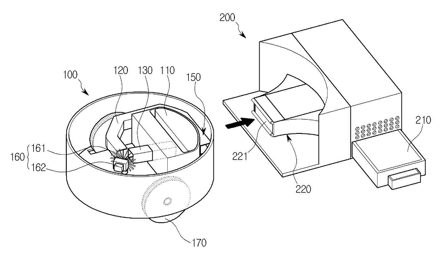
도 1은 본 발명의 실시예에 따른 로봇청소기의 사시도로서, 로봇청소기(100)와 도킹스테이션(200)의 개략적인 내부 구성이 도시되어 있다.1 is a perspective view of a robot cleaner according to an embodiment of the present invention, a schematic internal configuration of the
도면을 참조하면, 상기 로봇청소기(100)는 납작한 원통 형상을 갖는 본체의 내부 하측에 구동력을 전달하는 한 쌍의 바퀴(170)가 장착된다. 상기 본체의 하면에는 먼지를 흡입하는 흡입구(121)가 형성된다. 그리고 상기 흡입구(121)에 먼지를 공급할 수 있도록 바닥면과 마찰하며 회전하는 회전솔(122)이 배치된다. 상기 바퀴(170)에 구동력을 전달하는 구동모터(미도시)와 전기를 공급하는 충전배터리(미도시)가 구비됨은 물론이다.Referring to the drawings, the
그리고 상기 흡입구(121)의 상측에는 흡입된 먼지가 적재되는 저장부(110)가 마련된다. 상기 흡입구(121)와 연통되는 저장부(110)는 내부 하측에 먼지를 배출할 때 회동에 의해 개방되는 배출도어(111)가 마련되고, 상기 배출도어(111) 상측으로는 상기 저장부(110)에 흡입압력을 제공하는 흡입유로(120)가 연통되도록 배치된다.And the upper side of the
상기 흡입유로(120)의 일단은 상기 저장부(110)와 연통되되 흡입된 먼지가 유입되지 않도록 필터(125)가 설치될 수 있으며, 상기 흡입유로(120)의 타단에는 상기 흡입유로(120)에 흡입압력을 제공하는 압력제공부(160)가 마련된다.One end of the
도 2는 본 발명에 의한 개폐제어부(140)를 확대 도시하고, 도 3은 압력배출유로(150)의 설치위치를 도시한다. 2 shows an enlarged opening and
도 2를 참조하면, 상기 흡입유로(120)와 압력제공유로(130)가 만나는 부분에는 개폐제어부(140)와 압력제공부(160)가 배치된다. 상기 개폐제어부(140)는 상기 흡입유로(120)와 압력제공유로(130) 중 선택된 일 단부를 회전에 의해 선택적으로 개폐할 수 있도록 구비되는 차폐막(142)과, 상기 차폐막(142)을 회전시키는 차폐모터(143)를 포함한다. 상기 차폐막(142)은 상기 흡입유로(120)와 압력제공유로(130)가 만나는 단부에서 회동함에 따라 각 유로를 선택적으로 차폐하며 내접하도록 회전 궤적에 대응하는 곡면으로 형성된다.Referring to FIG. 2, an opening /
도 3을 참조하면, 상기 압력제공부(160)는 송풍팬(161)과 송풍모터(162)를 포함한다. 상기 압력제공부(160)는 상기 개폐제어부(140)가 개방하는 유로에 대응하여 상기 송풍팬(161)의 회전방향을 정방향 또는 역방향으로 전환하여 흡입 또는 배출모드로 제어한다. 따라서 상기 압력제공유로(130)가 닫히면 상기 흡입유로(120)에 흡입압력을 제공하고, 상기 흡입유로(120)가 닫히면 상기 압력제공유로(130)에 배출압력을 제공한다. 이때 상기 압력제공유로(130)는 상기 저장부(110)의 먼지가 역류하는 것을 방지하도록 상기 압력제공부(160)에서 상기 저장부(110) 방향으로 소정각도(??) 하측방향으로 경사지도록 형성된다.Referring to FIG. 3, the
도 4는 본 발명에 의한 도킹스테이션(200)의 연결부(220)를 도시하고, 도 5는 로봇청소기(100)의 배출도어(111)를 도시하며, 도 6은 배출도어(111)와 유입도 어(221)가 결합되는 상태를 도시한다. Figure 4 shows a
도 4 내지 6을 참조하면, 상기 도킹스테이션(200)은 상기 로봇청소기(100)의 배출유로(150)와 연통되는 유로인 연결부(220)가 구비되고, 상기 저장부(110)로부터 연통되어 배출되는 먼지를 보관할 수 있도록 보관부(210)가 마련된다.4 to 6, the
상기 로봇청소기(100)의 저장부(110) 일측에 힌지 결합되어 상기 배출모드일 때, 상기 저장부의 내측 방향으로 회동하여 상기 저장부(110)를 개방하는 배출도어(111)와, 상기 배출도어(111)와 슬라이드 접촉하고 상기 연결부(220)의 일측에 힌지 결합되어, 상기 배출모드일 때, 상기 연결부(220)의 내측 방향으로 회동하여 상기 저장부(110)와 연결부(220)를 연통시키는 유입도어(221)를 더 구비한다.When the hinge cleaner is coupled to one side of the
상기 배출도어(111)는 상기 저장부(110)의 일측을 개폐 가능하도록 힌지결합되어 상기 저장부의 내부 먼지를 밀폐하는 상판(114)과, 상기 상판(114)으로부터 하측으로 소정간격 이격되어 나란히 배치되는 하판(115)과, 상기 상판(114)과 하판(115)의 단부를 연결하는 측판(116)을 포함한다. 이때, 상기 상판(114)과 하판(115) 사이 소정간격은 상기 유입도어(221)가 회전하여 상기 연결부(220)의 상측 선단과 함께 삽입될 수 있는 정도의 두께에 해당된다. 그리고 상기 상판(114)과 하판(115)은 그 높이차가 발생할 수 있으며, 그 높이차는 상기 유입도어(221)가 상기 하판(115)과 접촉하여 각각 소정각도 먼저 회전될 수 있도록 형성되어, 일정 각도를 회전하면 상기 하판(115)의 상측 선단으로부터 상기 유입도어(221)를 개방상태로 배치하도록 형성된다. 따라서 상기 로봇청소기(100)가 도킹스테이션(200)에 도킹되면, 상기 유입도어(221)가 상기 상판(114)과 하판(115) 사이 간격으로 삽입되 어 각각 상기 저장부와 보관부의 내측 방향으로 회전하며 개방된다.The
상기 유입도어(221)는 장방형의 플레이트로 상기 도킹스테이션(200)에 형성되는 보관부(210) 일측을 외부로부터 밀폐시키되, 상기 배출도어(111)와 접촉하여 마찰을 감소시킬 수 있도록 상기 유입도어(221)의 상측 선단에 적어도 하나 이상의 롤러(222)를 포함한다. 그리고 상기 보관부(210)는 상기 로봇청소기(100) 내부에 마련되는 저장부(110) 보다 큰 저장공간을 형성하여 상기 로봇청소기(100)가 수차례에 걸쳐 포집한 먼지를 소정의 부피만큼 보관할 수 있다.The
상기 배출도어(111)와 유입도어(221)는 개방된 상태로부터 도킹이 해제되어 각 도어가 닫힐 때 탄성 회전력을 제공하도록 각 도어의 일단부에 토션스프링(113, 223)을 포함한다.The
이하 첨부된 도면을 참조하여 본 발명의 실시예에 따른 상기 로봇청소기(100)의 작동방법에 관해 설명한다.Hereinafter, a method of operating the
로봇청소기(100)는 작동 전에 도킹스테이션(200)에 위치한다. 상기 도킹스테이션(200)에서는 먼지의 배출뿐만 아니라 상기 로봇청소기(100)에 구동력을 제공하는 전기의 충전 또한 이루어진다. The
상기 로봇청소기(100)는 사용자에 의한 조작력 또는 기 설정된 예약시간에 따라서 청소를 시작한다. 먼저 상기 로봇청소기(100)는 상기 도킹스테이션(200)에서 도킹이 해제되기 전에 상기 개폐제어부(140)는 흡입유로(120)를 개방하고 압력제공유로(130)를 폐쇄하며 흡입모드로 전환된다. 그리고 상기 회전솔(122)이 회전하면서 상기 송풍팬(161)이 정방향으로 회전하게 되고, 흡입압력에 의해 상기 도킹 스테이션(200)에 남은 먼지 및 이물질을 수 초간 흡입한다. 보다 바람직하게는 약 5초간 상기 도킹스테이션(200)을 청소한다.The robot cleaner 100 starts cleaning according to a manipulation force by a user or a preset reservation time. First, the
도킹이 해제되면 상기 연결부(220)로부터 상기 배출유로(150)가 이탈되고, 상기 배출도어(111)와 유입도어(221)는 상기 로봇청소기(100)의 저장부(110)와 도킹스테이션(200)의 보관부(210)를 각각 밀폐하도록 회동하여 폐쇄된다. 그리고 상기 로봇청소기(100)는 여느 다른 로봇청소기(100)와 유사하게 청소 할 장소를 구석구석 이동하며 먼지를 흡입하게 된다.When the docking is released, the
청소가 끝난 후, 또는 상기 로봇청소기(100)의 저장부(110)에 먼지가 가득 차서 더 이상 청소가 불가능 한 경우, 상기 로봇청소기(100)는 상기 도킹스테이션(200)에 도킹한다. 그리고 도킹되는 과정에서 상기 상판(114)과 하판(115)의 사이에 상기 연결부의 상측 선단이 삽입되어 상기 상판(114)을 밀게 됨에 따라 상기 배출도어(111)를 상기 저장부의 내측으로 회동시키고, 상기 하판(115)은 상기 유입도어(221)를 밀어서 상기 연결부(220) 내측으로 회동시키게 된다. After cleaning, or when the
상기 배출유로(150)와 연결부(220)가 완전 결합되어 연통되면, 상기 로봇청소기(100)와 도킹스테이션(200)의 각 충전단자(미도시)가 맞닿아 충전이 시작된다. 그러면 소정의 시간이 경과된 후 상기 개폐제어부(140)가 작동된다. 보다 바람직하게는 약 5초 정도의 시간이 경과된 후 작동된다.When the
그러면 상기 개폐제어부(140)는 먼지 흡입모드에서 먼지 배출모드로 전환되고, 상기 차폐막(142)은 상기 압력제공유로(130)의 단부로부터 회전하여 상기 흡입유로(120)를 차단하게 된다. 그러면 상기 압력제공유로(130)가 개방되면서 상기 압 력제공부(160) 역시 먼지 배출모드로 전환되어 상기 송풍팬(161)을 역회전 시킨다. 이때 상기 저장부(110)에 적재된 먼지는 상기 연결부(220)를 지나 상기 보관부(210)로 이송되며, 상기 보관부(210)에 저장되는 먼지는 사용자가 먼지의 보관량을 확인하여 외부로 배출할 수 있다.Then, the opening and
또한, 상기 압력제공부(160)는 먼지 흡입모드의 경우 상기 흡입유로(120)를 개방하고 압력제공유로(130)가 닫히며, 먼지 배출모드의 경우 상기 흡입유로(120)를 닫고 압력제공유로(130)가 개방되도록 상기 흡입유로(120)와 압력제공유로(130) 중 선택된 유로를 개폐하도록 제어하여 먼지 흡입모드와 먼지 배출모드에서 한 개의 송풍모터(162)와 송풍팬(161)을 사용하여 흡입압력과 배출압력을 제어할 수 있다.In addition, the
그리고 상기 도킹스테이션(200)의 보관부(210)는 상기 도킹스테이션(200)의 내부에 송풍팬과 송풍모터를 따로 마련하고 그 흡입압력을 이용하여 상기 저장부(110)의 먼지를 흡입하지 않고, 상기 로봇청소기(100)의 배출압력을 사용하기 때문에 먼지가 보관부(210)에 일정량 채워져도 상기 보관부(210)로 배출되는 먼지의 이송 압력은 일정하게 유지된다.In addition, the
본 발명은 도면에 도시된 실시예를 참고로 설명되었으나 이는 예시적인 것에 불과하며, 본 기술 분야의 통상의 지식을 가진 자라면 이로부터 다양한 변형 및 균등한 다른 실시예가 가능하다는 점을 이해할 것이다. 따라서, 본 발명의 진정한 기술적 보호 범위는 첨부된 특허청구범위의 기술적 사상에 의하여 정해져야 할 것이다.While the present invention has been described with reference to exemplary embodiments, it is to be understood that the invention is not limited to the disclosed embodiments, but, on the contrary, is intended to cover various modifications and equivalent arrangements included within the spirit and scope of the appended claims. Accordingly, the true scope of the present invention should be determined by the technical idea of the appended claims.
도 1은 본 발명의 실시예에 따른 로봇청소기의 사시도이다.1 is a perspective view of a robot cleaner according to an embodiment of the present invention.
도 2는 도 1에 나타낸 개폐제어부의 부분확대도이다.FIG. 2 is a partially enlarged view of the opening and closing control unit shown in FIG. 1.
도 3은 도 1에 나타낸 압력제공유로의 사시도이다.3 is a perspective view of the pressure-sharing furnace shown in FIG. 1.
도 4는 도 1에 나타낸 연결부의 사시도이다.4 is a perspective view of the connecting portion shown in FIG. 1.
도 5는 도 1에 나타낸 배출도어의 사시도이다.5 is a perspective view of the discharge door shown in FIG.
도 6은 도 1에 나타낸 배출도어와 유입도어가 결합되는 상태를 도시하는 참고도이다.6 is a reference diagram showing a state in which the discharge door and the inlet door shown in FIG.
<도면의 주요 부분에 대한 간단한 설명><Brief description of the main parts of the drawing>
100 : 로봇청소기 110 : 저장부100: robot cleaner 110: storage unit
120 : 흡입유로 130 : 압력제공유로120: suction passage 130: pressure sharing
140 : 개폐제어부 150 : 배출유로140: opening and closing control unit 150: discharge passage
160 : 압력제공부 200 : 도킹스테이션160: pressure providing unit 200: docking station
210 : 보관부 220 : 연결부210: storage unit 220: connection unit
Claims (11)
Priority Applications (1)
| Application Number | Priority Date | Filing Date | Title |
|---|---|---|---|
| KR1020090098685A KR101202916B1 (en) | 2009-10-16 | 2009-10-16 | Dirt removal system of the robot cleaner |
Applications Claiming Priority (1)
| Application Number | Priority Date | Filing Date | Title |
|---|---|---|---|
| KR1020090098685A KR101202916B1 (en) | 2009-10-16 | 2009-10-16 | Dirt removal system of the robot cleaner |
Publications (2)
| Publication Number | Publication Date |
|---|---|
| KR20110041721A KR20110041721A (en) | 2011-04-22 |
| KR101202916B1 true KR101202916B1 (en) | 2012-11-19 |
Family
ID=44047530
Family Applications (1)
| Application Number | Title | Priority Date | Filing Date |
|---|---|---|---|
| KR1020090098685A Expired - Fee Related KR101202916B1 (en) | 2009-10-16 | 2009-10-16 | Dirt removal system of the robot cleaner |
Country Status (1)
| Country | Link |
|---|---|
| KR (1) | KR101202916B1 (en) |
Cited By (6)
| Publication number | Priority date | Publication date | Assignee | Title |
|---|---|---|---|---|
| US20200000301A1 (en) * | 2014-12-10 | 2020-01-02 | Irobot Corporation | Debris Evacuation for Cleaning Robots |
| US20210330167A1 (en) * | 2020-04-22 | 2021-10-28 | Omachron Intellectual Property Inc. | Robotic vacuum cleaner and docking station for a robotic vacuum cleaner |
| KR102370649B1 (en) | 2021-08-30 | 2022-03-07 | 이에스산업 주식회사 | Robotic cleaning system |
| WO2023043056A1 (en) * | 2021-09-16 | 2023-03-23 | 엘지전자 주식회사 | Cleaner, cleaner system, and control method of cleaner system |
| US11937764B2 (en) | 2020-08-07 | 2024-03-26 | Samsung Electronics Co., Ltd. | Cleaning device having vacuum cleaner and docking station |
| US12029379B2 (en) | 2020-04-22 | 2024-07-09 | Omachron Intellectual Property Inc. | Robotic vacuum cleaner with dirt enclosing member and method of using the same |
Families Citing this family (13)
| Publication number | Priority date | Publication date | Assignee | Title |
|---|---|---|---|---|
| CN108498025A (en) * | 2018-05-10 | 2018-09-07 | 深圳市宇辰智能科技有限公司 | A kind of garbage emission work station |
| US10952578B2 (en) * | 2018-07-20 | 2021-03-23 | Sharkninja Operating Llc | Robotic cleaner debris removal docking station |
| KR20200073966A (en) | 2018-12-14 | 2020-06-24 | 삼성전자주식회사 | Cleaning device having vacuum cleaner and docking station |
| CN110200558A (en) * | 2019-07-18 | 2019-09-06 | 珠海格力电器股份有限公司 | Cleaning device and dust box |
| CN110604512B (en) * | 2019-08-21 | 2021-04-20 | 深圳市无限动力发展有限公司 | Cleaning equipment, cleaning machine and dust collecting box thereof |
| CN110604513B (en) * | 2019-08-21 | 2021-03-16 | 深圳市无限动力发展有限公司 | Cleaning machine and cleaning system |
| CN111345752B (en) * | 2020-03-12 | 2022-05-03 | 深圳市银星智能科技股份有限公司 | Robot maintenance station and robot cleaning system |
| WO2021208598A1 (en) * | 2020-04-13 | 2021-10-21 | 追觅创新科技(苏州)有限公司 | Self-cleaning filtering apparatus, maintenance station, self-moving cleaning device and cleaning system |
| KR20220071810A (en) * | 2020-11-24 | 2022-05-31 | 삼성전자주식회사 | Cleaning device having robot cleaner and docking station and control method thereof |
| US11737625B2 (en) * | 2020-12-04 | 2023-08-29 | Omachron Intellectual Property Inc. | Evacuation station for a mobile floor cleaning robot |
| KR102808607B1 (en) * | 2021-06-16 | 2025-05-15 | 엘지전자 주식회사 | Cleaner station and cleaner system |
| CN215820787U (en) * | 2021-09-13 | 2022-02-15 | 美智纵横科技有限责任公司 | Dust collection box for cleaning equipment and cleaning equipment with dust collection box |
| CN115444313B (en) * | 2022-08-30 | 2026-01-09 | 安克创新科技股份有限公司 | A cleaning device and cleaning system |
Citations (2)
| Publication number | Priority date | Publication date | Assignee | Title |
|---|---|---|---|---|
| KR100233369B1 (en) | 1997-06-13 | 2000-01-15 | 윤덕하 | Vacuum cleaner with suction and blowing |
| JP2002300988A (en) | 2001-04-09 | 2002-10-15 | Matsushita Electric Ind Co Ltd | Electric vacuum cleaner |
-
2009
- 2009-10-16 KR KR1020090098685A patent/KR101202916B1/en not_active Expired - Fee Related
Patent Citations (2)
| Publication number | Priority date | Publication date | Assignee | Title |
|---|---|---|---|---|
| KR100233369B1 (en) | 1997-06-13 | 2000-01-15 | 윤덕하 | Vacuum cleaner with suction and blowing |
| JP2002300988A (en) | 2001-04-09 | 2002-10-15 | Matsushita Electric Ind Co Ltd | Electric vacuum cleaner |
Cited By (10)
| Publication number | Priority date | Publication date | Assignee | Title |
|---|---|---|---|---|
| US20200000301A1 (en) * | 2014-12-10 | 2020-01-02 | Irobot Corporation | Debris Evacuation for Cleaning Robots |
| US12004704B2 (en) * | 2014-12-10 | 2024-06-11 | Irobot Corporation | Debris evacuation for cleaning robots |
| US20210330167A1 (en) * | 2020-04-22 | 2021-10-28 | Omachron Intellectual Property Inc. | Robotic vacuum cleaner and docking station for a robotic vacuum cleaner |
| US11617488B2 (en) * | 2020-04-22 | 2023-04-04 | Omachron Intellectual Property Inc. | Robotic vacuum cleaner and docking station for a robotic vacuum cleaner |
| US11889962B2 (en) | 2020-04-22 | 2024-02-06 | Omachron Intellectual Property Inc. | Robotic vacuum cleaner and docking station for a robotic vacuum cleaner |
| US12029379B2 (en) | 2020-04-22 | 2024-07-09 | Omachron Intellectual Property Inc. | Robotic vacuum cleaner with dirt enclosing member and method of using the same |
| US12303096B2 (en) | 2020-04-22 | 2025-05-20 | Omachron Intellectual Property Inc. | Robotic vacuum cleaner with dirt enclosing member and method of using the same |
| US11937764B2 (en) | 2020-08-07 | 2024-03-26 | Samsung Electronics Co., Ltd. | Cleaning device having vacuum cleaner and docking station |
| KR102370649B1 (en) | 2021-08-30 | 2022-03-07 | 이에스산업 주식회사 | Robotic cleaning system |
| WO2023043056A1 (en) * | 2021-09-16 | 2023-03-23 | 엘지전자 주식회사 | Cleaner, cleaner system, and control method of cleaner system |
Also Published As
| Publication number | Publication date |
|---|---|
| KR20110041721A (en) | 2011-04-22 |
Similar Documents
| Publication | Publication Date | Title |
|---|---|---|
| KR101202916B1 (en) | Dirt removal system of the robot cleaner | |
| US12042118B2 (en) | Robot cleaner, station, and cleaning system | |
| US7891045B2 (en) | Robot cleaner system having robot cleaner and docking station | |
| JP7297981B2 (en) | discharge station | |
| KR101330735B1 (en) | Robot cleaner | |
| KR101330734B1 (en) | Robot cleaner system having robot cleaner and docking station | |
| KR20070074147A (en) | Cleaner system | |
| KR20070074146A (en) | Cleaner system | |
| KR20080087596A (en) | robotic vacuum | |
| KR20070099359A (en) | Robot cleaner system with robot cleaner and docking station | |
| CN102525335A (en) | Robot cleaner | |
| CN111904323B (en) | Dust deposition base and cleaning equipment assembly with same | |
| WO2023124082A1 (en) | Self-cleaning dust collection seats and dust collection system | |
| CN219206787U (en) | Surface cleaning device and cleaning system | |
| CN114468846B (en) | Charging station for sweeping robot, sweeping robot and combined cleaning system | |
| KR20070094288A (en) | Robot Vacuum Cleaner System | |
| CN119112058A (en) | Cleaning systems and cleaning robots | |
| WO2023124084A1 (en) | Self-cleaning maintenance station and self-cleaning system | |
| KR101256103B1 (en) | Robot cleaner system | |
| KR20070099763A (en) | Robot cleaner system with robot cleaner and docking station | |
| AU2021355989A1 (en) | Cleaner system | |
| KR100765208B1 (en) | Robot cleaner system with robot cleaner and docking station | |
| KR20070095558A (en) | Cleaner system improved docking structure of robot cleaner and docking station | |
| CN118490113A (en) | Surface cleaning devices and cleaning systems | |
| KR101292537B1 (en) | Robot cleaner |
Legal Events
| Date | Code | Title | Description |
|---|---|---|---|
| A201 | Request for examination | ||
| PA0109 | Patent application |
St.27 status event code: A-0-1-A10-A12-nap-PA0109 |
|
| PA0201 | Request for examination |
St.27 status event code: A-1-2-D10-D11-exm-PA0201 |
|
| D13-X000 | Search requested |
St.27 status event code: A-1-2-D10-D13-srh-X000 |
|
| D14-X000 | Search report completed |
St.27 status event code: A-1-2-D10-D14-srh-X000 |
|
| PG1501 | Laying open of application |
St.27 status event code: A-1-1-Q10-Q12-nap-PG1501 |
|
| P11-X000 | Amendment of application requested |
St.27 status event code: A-2-2-P10-P11-nap-X000 |
|
| P13-X000 | Application amended |
St.27 status event code: A-2-2-P10-P13-nap-X000 |
|
| E902 | Notification of reason for refusal | ||
| PE0902 | Notice of grounds for rejection |
St.27 status event code: A-1-2-D10-D21-exm-PE0902 |
|
| P11-X000 | Amendment of application requested |
St.27 status event code: A-2-2-P10-P11-nap-X000 |
|
| P13-X000 | Application amended |
St.27 status event code: A-2-2-P10-P13-nap-X000 |
|
| P11-X000 | Amendment of application requested |
St.27 status event code: A-2-2-P10-P11-nap-X000 |
|
| P13-X000 | Application amended |
St.27 status event code: A-2-2-P10-P13-nap-X000 |
|
| T11-X000 | Administrative time limit extension requested |
St.27 status event code: U-3-3-T10-T11-oth-X000 |
|
| E701 | Decision to grant or registration of patent right | ||
| PE0701 | Decision of registration |
St.27 status event code: A-1-2-D10-D22-exm-PE0701 |
|
| GRNT | Written decision to grant | ||
| PR0701 | Registration of establishment |
St.27 status event code: A-2-4-F10-F11-exm-PR0701 |
|
| PR1002 | Payment of registration fee |
St.27 status event code: A-2-2-U10-U11-oth-PR1002 Fee payment year number: 1 |
|
| PG1601 | Publication of registration |
St.27 status event code: A-4-4-Q10-Q13-nap-PG1601 |
|
| R18-X000 | Changes to party contact information recorded |
St.27 status event code: A-5-5-R10-R18-oth-X000 |
|
| PR1001 | Payment of annual fee |
St.27 status event code: A-4-4-U10-U11-oth-PR1001 Fee payment year number: 4 |
|
| FPAY | Annual fee payment |
Payment date: 20161004 Year of fee payment: 5 |
|
| PR1001 | Payment of annual fee |
St.27 status event code: A-4-4-U10-U11-oth-PR1001 Fee payment year number: 5 |
|
| P22-X000 | Classification modified |
St.27 status event code: A-4-4-P10-P22-nap-X000 |
|
| FPAY | Annual fee payment |
Payment date: 20171011 Year of fee payment: 6 |
|
| PR1001 | Payment of annual fee |
St.27 status event code: A-4-4-U10-U11-oth-PR1001 Fee payment year number: 6 |
|
| PR1001 | Payment of annual fee |
St.27 status event code: A-4-4-U10-U11-oth-PR1001 Fee payment year number: 7 |
|
| FPAY | Annual fee payment |
Payment date: 20200107 Year of fee payment: 8 |
|
| PR1001 | Payment of annual fee |
St.27 status event code: A-4-4-U10-U11-oth-PR1001 Fee payment year number: 8 |
|
| PN2301 | Change of applicant |
St.27 status event code: A-5-5-R10-R11-asn-PN2301 |
|
| PN2301 | Change of applicant |
St.27 status event code: A-5-5-R10-R14-asn-PN2301 |
|
| P14-X000 | Amendment of ip right document requested |
St.27 status event code: A-5-5-P10-P14-nap-X000 |
|
| P16-X000 | Ip right document amended |
St.27 status event code: A-5-5-P10-P16-nap-X000 |
|
| Q16-X000 | A copy of ip right certificate issued |
St.27 status event code: A-4-4-Q10-Q16-nap-X000 |
|
| PR1001 | Payment of annual fee |
St.27 status event code: A-4-4-U10-U11-oth-PR1001 Fee payment year number: 9 |
|
| PC1903 | Unpaid annual fee |
St.27 status event code: A-4-4-U10-U13-oth-PC1903 Not in force date: 20211114 Payment event data comment text: Termination Category : DEFAULT_OF_REGISTRATION_FEE |
|
| PC1903 | Unpaid annual fee |
St.27 status event code: N-4-6-H10-H13-oth-PC1903 Ip right cessation event data comment text: Termination Category : DEFAULT_OF_REGISTRATION_FEE Not in force date: 20211114 |
|
| R18-X000 | Changes to party contact information recorded |
St.27 status event code: A-5-5-R10-R18-oth-X000 |
|
| P22-X000 | Classification modified |
St.27 status event code: A-4-4-P10-P22-nap-X000 |