KR101103774B1 - A nitride semiconductor device having a recess gate edge structure and a method of manufacturing the same - Google Patents
A nitride semiconductor device having a recess gate edge structure and a method of manufacturing the same Download PDFInfo
- Publication number
- KR101103774B1 KR101103774B1 KR1020100024037A KR20100024037A KR101103774B1 KR 101103774 B1 KR101103774 B1 KR 101103774B1 KR 1020100024037 A KR1020100024037 A KR 1020100024037A KR 20100024037 A KR20100024037 A KR 20100024037A KR 101103774 B1 KR101103774 B1 KR 101103774B1
- Authority
- KR
- South Korea
- Prior art keywords
- layer
- nitride
- based semiconductor
- recess
- forming
- Prior art date
- Legal status (The legal status is an assumption and is not a legal conclusion. Google has not performed a legal analysis and makes no representation as to the accuracy of the status listed.)
- Active
Links
Images


Classifications
-
- H—ELECTRICITY
- H10—SEMICONDUCTOR DEVICES; ELECTRIC SOLID-STATE DEVICES NOT OTHERWISE PROVIDED FOR
- H10H—INORGANIC LIGHT-EMITTING SEMICONDUCTOR DEVICES HAVING POTENTIAL BARRIERS
- H10H20/00—Individual inorganic light-emitting semiconductor devices having potential barriers, e.g. light-emitting diodes [LED]
- H10H20/80—Constructional details
- H10H20/81—Bodies
- H10H20/815—Bodies having stress relaxation structures, e.g. buffer layers
-
- H—ELECTRICITY
- H10—SEMICONDUCTOR DEVICES; ELECTRIC SOLID-STATE DEVICES NOT OTHERWISE PROVIDED FOR
- H10H—INORGANIC LIGHT-EMITTING SEMICONDUCTOR DEVICES HAVING POTENTIAL BARRIERS
- H10H20/00—Individual inorganic light-emitting semiconductor devices having potential barriers, e.g. light-emitting diodes [LED]
- H10H20/80—Constructional details
- H10H20/81—Bodies
- H10H20/819—Bodies characterised by their shape, e.g. curved or truncated substrates
- H10H20/82—Roughened surfaces, e.g. at the interface between epitaxial layers
-
- H—ELECTRICITY
- H10—SEMICONDUCTOR DEVICES; ELECTRIC SOLID-STATE DEVICES NOT OTHERWISE PROVIDED FOR
- H10H—INORGANIC LIGHT-EMITTING SEMICONDUCTOR DEVICES HAVING POTENTIAL BARRIERS
- H10H20/00—Individual inorganic light-emitting semiconductor devices having potential barriers, e.g. light-emitting diodes [LED]
- H10H20/80—Constructional details
- H10H20/83—Electrodes
Landscapes
- Junction Field-Effect Transistors (AREA)
Abstract
본 발명에 따른 질화물계 반도체 소자는 질화물계 반도체 층, 상기 질화물계 반도체 층 상면의 일 측에 형성된 소스 전극, 상기 질화물계 반도체 층 상면의 타 측에 상기 소스 전극과 이격 형성된 드레인 전극, 및 상기 질화물계 반도체 층 상면에, 상기 소스 전극과 드레인 전극 사이에 형성된 게이트 전극을 포함하며, 상기 게이트 전극과 상기 드레인 전극 사이에서, 상기 게이트 전극의 일측 하부의 상기 질화물계 반도체 층에 리세스(recess)가 형성되는 것을 특징으로 하며, 본 발명에 따르면 전자 트랩이 감소하고, 표면 전계 감소효과로 인해 누설전류가 감소되고, 항복 전압이 증가되며, 동시에 순방향 전류-전압 특성이 유지되는 이점이 있다.According to the present invention, a nitride based semiconductor device includes a nitride based semiconductor layer, a source electrode formed on one side of an upper surface of the nitride based semiconductor layer, a drain electrode spaced apart from the source electrode on the other side of the nitride based semiconductor layer, and the nitride A gate electrode formed between the source electrode and the drain electrode on an upper surface of the semiconductor layer, and a recess is formed between the gate electrode and the drain electrode in the nitride-based semiconductor layer below one side of the gate electrode According to the present invention, the electron trap is reduced, the leakage current is reduced due to the surface electric field reduction effect, the breakdown voltage is increased, and at the same time, the forward current-voltage characteristics are maintained.
Description
본 발명은 질화물계 반도체 소자 및 그 제조 방법에 관한 것으로, 특히 질화물계 반도체 소자의 항복전압을 증가시킬 수 있는 반도체 소자 및 그 제조 방법에 관한 것이다.
BACKGROUND OF THE
최근 와이드 밴드-갭(wide band-gap) 물질인 질화갈륨(GaN), 탄화규소(SiC) 등이 전력용 전기시스템에서 각광받고 있다. 특히, GaN은 우수한 순방향 특성, 높은 항복 전계, 낮은 진성 캐리어 밀도 등 여타의 반도체 물질에 비해 우수한 물리적 특성을 가지고 있어 고전력 전기 시스템의 차세대 반도체 소자로 많이 연구되고 있다.Recently, wide band-gap materials, such as gallium nitride (GaN) and silicon carbide (SiC), have been in the spotlight in electric power systems. GaN, in particular, has excellent physical properties compared to other semiconductor materials such as excellent forward characteristics, high breakdown electric field, and low intrinsic carrier density.
GaN 물질 기반 반도체 소자로는 쇼트키 장벽 다이오드(Schottky barrier diode), 메탈 산화막 반도체 전계 효과 트랜지스터(Metal Oxide Semiconductor Field Effect Transistor, MOSFET), 메탈 반도체 전계 효과 트랜지스터(Metal Semiconductor Field Effect Transistor, MSFET), 고전자 이동도 트랜지스터(High Electron Mobility Transistor, HEMT) 등이 있다.GaN material-based semiconductor devices include Schottky barrier diodes, metal oxide semiconductor field effect transistors (MOSFETs), metal semiconductor field effect transistors (MSFETs), high Electron Mobility Transistors (HEMTs).
한편, AlGaN/GaN 헤테로 구조는 AlGaN과 GaN 사이의 전도대역(conduction band)의 불연속성 및 압전효과(piezoelectric effect)에 의한 높은 2차원 전자가스(2-Dimensional Electron Gas, 2DEG) 농도를 갖는다. 이에 따라, AlGaN/GaN 헤테로 구조 위에 제작되는 고전자 이동도 트랜지스터 및 쇼트키 장벽 다이오드는 높은 2차원 전자가스 농도(1013㎝-2) 및 높은 임계 전계를 가지므로 고전압 스위치 및 고주파 증폭기 분야에서 널리 연구되고 있다.Meanwhile, the AlGaN / GaN heterostructure has a high 2-Dimensional Electron Gas (2DEG) concentration due to the discontinuity of the conduction band between the AlGaN and GaN and the piezoelectric effect. Accordingly, high electron mobility transistors and Schottky barrier diodes fabricated on AlGaN / GaN heterostructures have high two-dimensional electron gas concentrations (10 13 cm -2 ) and high critical electric fields, making them widely used in high voltage switch and high frequency amplifier applications. Is being studied.
그러나, AlGaN/GaN 헤테로 구조 위에 제작되는 고전자 이동도 트랜지스터나 쇼트키 장벽 다이오드는 전자 트랩(electron trap)으로 인해 소자의 전기적 특성이 열화되는 문제점이 있다. 즉, 전계에 의하여 AlGaN/GaN 헤테로 구조의 전자 트랩에 전자가 주입(injection)되면 2DEG 채널공핍(depletion), 순방향전류 감소, 표면누설전류 증가 및 트래핑 효과(trapping effect) 등이 발생하며, 결국 GaN 소자의 전자 트랩은 소자의 전기적 특성에 악영향을 미친다.However, a high electron mobility transistor or a Schottky barrier diode fabricated on an AlGaN / GaN heterostructure has a problem in that electrical characteristics of the device are degraded due to an electron trap. In other words, when electrons are injected into an electron trap of an AlGaN / GaN hetero structure by an electric field, 2DEG channel depletion, forward current decrease, surface leakage current increase, and trapping effect occur. Electron traps on the device adversely affect the electrical properties of the device.
종래에, GaN 소자의 누설 전류를 억제하기 위한 방법으로 패시베이션(passivation), 고온 어닐링(annealing), 및 필드 플레이트(field plate)나 플로팅 게이트(floating gate)와 같은 전계 완화 구조가 있다. Conventionally, as a method for suppressing leakage current of GaN devices, there are passivation, high temperature annealing, and field relaxation structures such as field plates and floating gates.
패시베이션 방법은 증착된 절연막에 의해 전자의 주입현상을 방지하는 것이고, 고온 어닐링 공정은 비활성 기체 분위기에서 열처리를 수행하여 GaN 표면의 손상을 치유하는 것이다. 전계 완화 구조는 쇼트키 접합(Schottky contact) 모서리에 발생하는 전계 집중을 완화하여 누설 전류를 감소시킨다.
The passivation method is to prevent the injection of electrons by the deposited insulating film, the high temperature annealing process is to heat treatment in an inert gas atmosphere to heal the damage of the GaN surface. The field mitigation structure mitigates field concentrations occurring at the edges of Schottky contacts, reducing leakage currents.
한편, 리세스 게이트(recess gate) 구조란 트랜지스터에 있어서 소스(source) 전극 및 드레인(drain) 전극 사이의 반도체 층에 홈과 같은 리세스를 형성하는 구조이다. On the other hand, a recess gate structure is a structure in which a recess such as a groove is formed in a semiconductor layer between a source electrode and a drain electrode in a transistor.
근래의 반도체 소자는 미세화 및 고집적화 추세에 따라 반도체 소자를 형성함에 있어 트랜지스터의 채널길이가 점점 짧아지고, 채널길이가 짧아짐에 따라 리프레쉬 특성이 악화되는 등 여러 가지 문제점이 발생하게 되었다. 이러한 문제점을 해결하기 위해, 반도체 기판 내부에 형성된 리세스를 통하여 게이트를 형성한 리세스 채널을 갖는 트랜지스터 구조가 제안되었다. 이것은 트랜지스터의 채널이 형성될 영역에 리세스를 형성하여 유효 채널 길이를 증가시킴으로써, 실질적으로 소스와 드레인 사이의 거리를 넓혀 반도체 소자의 고집적화에 도움을 주는 구조이다.
In recent years, in forming semiconductor devices according to the trend of miniaturization and high integration, various problems have occurred such that the channel length of transistors becomes shorter and the refresh characteristics deteriorate as the channel length becomes shorter. In order to solve this problem, a transistor structure having a recess channel in which a gate is formed through a recess formed in a semiconductor substrate has been proposed. This is a structure that increases the effective channel length by forming a recess in a region where a channel of the transistor is to be formed, thereby substantially increasing the distance between the source and the drain, thereby contributing to high integration of the semiconductor device.
본 발명의 목적은 질화물계 반도체 소자의 누설전류를 감소시키고, 항복 전압을 증가시키면서, 동시에 순방향 전류-전압 특성이 유지되도록 게이트 전극의 하부 모서리 즉, 에지에 맞닿은 질화물계 반도체 층에 리세스를 형성한 리세스 게이트 에지 구조를 적용한 질화물계 반도체 소자 및 그 제조 방법을 제공함에 있다.
An object of the present invention is to form a recess in the nitride-based semiconductor layer abuts the lower edge of the gate electrode, that is, the edge, so as to reduce the leakage current of the nitride-based semiconductor device, increase the breakdown voltage, and at the same time maintain the forward current-voltage characteristics. The present invention provides a nitride based semiconductor device employing a recess gate edge structure and a method of manufacturing the same.
본 발명의 일 실시 예에 따른 질화물계 반도체 소자는, 질화물계 반도체 층, 상기 질화물계 반도체 층 상면의 일 측에 형성된 소스 전극, 상기 질화물계 반도체 층 상면의 타 측에 상기 소스 전극과 이격 형성된 드레인 전극, 및 상기 질화물계 반도체 층 상면에 상기 소스 전극과 드레인 전극 사이에 형성된 게이트 전극을 포함하며, 상기 게이트 전극과 상기 드레인 전극 사이에서, 상기 게이트 전극의 일측 하부의 상기 질화물계 반도체 층에 리세스(recess)가 형성되는 것을 특징으로 한다.In the nitride-based semiconductor device according to an embodiment of the present invention, a nitride-based semiconductor layer, a source electrode formed on one side of the upper surface of the nitride-based semiconductor layer, the drain formed spaced apart from the source electrode on the other side of the upper surface of the nitride-based semiconductor layer An electrode, and a gate electrode formed between the source electrode and the drain electrode on an upper surface of the nitride based semiconductor layer, and between the gate electrode and the drain electrode, a recess in the nitride based semiconductor layer below one side of the gate electrode (recess) is formed.
상기 실시 예에서 상기 질화물계 반도체 층은, 절연성의 기판, 상기 기판 상면에 형성되며 제1 질화물계 반도체의 에피구조를 성장시키기 위해 형성되는 결정핵 생성층, 상기 결정핵 생성층 상면에 형성되며 상기 제1 질화물계 반도체인 버퍼층, 및 상기 버퍼층 상면에 형성되며 상기 버퍼층과의 사이에 2차원 전자 가스층을 형성하고 제2 질화물계 반도체인 장벽층을 포함할 수 있다.
In the embodiment, the nitride-based semiconductor layer is formed on an insulating substrate, an upper surface of the substrate and a crystal nucleation layer formed to grow an epi structure of the first nitride-based semiconductor, and formed on the crystal nucleation layer. A buffer layer, which is a first nitride semiconductor, and a barrier layer, which is formed on an upper surface of the buffer layer, forms a two-dimensional electron gas layer between the buffer layer, and a second nitride semiconductor.
본 발명의 일 실시 예에 따른 질화물계 반도체 소자 제조 방법은, 질화물계 반도체 층을 형성하는 단계, 상기 질화물계 반도체 층 상면의 일 측에 소스 전극을 형성하는 단계, 상기 질화물계 반도체 층 상면의 타 측에 소스 전극과 이격 형성된 드레인 전극을 형성하는 단계, 상기 질화물계 반도체 층 상면에 상기 소스 전극과 드레인 전극 사이에 게이트 전극을 형성하는 단계, 및 상기 게이트 전극과 상기 드레인 전극 사이에서 상기 게이트 전극의 일측 하부의 상기 질화물계 반도체 층에 리세스(recess)를 형성하는 단계를 포함하는 것을 특징으로 한다.In the method of manufacturing a nitride-based semiconductor device according to an embodiment of the present invention, forming a nitride-based semiconductor layer, forming a source electrode on one side of the upper surface of the nitride-based semiconductor layer, the other surface of the nitride-based semiconductor layer Forming a drain electrode spaced apart from the source electrode on the side, forming a gate electrode between the source electrode and the drain electrode on an upper surface of the nitride based semiconductor layer, and between the gate electrode and the drain electrode Forming a recess (recess) in the nitride-based semiconductor layer on the lower side of one side.
상기 실시 예에서, 상기 질화물계 반도체 층을 형성하는 단계는, 절연성의 기판 상면에 제1 질화물계 반도체의 에피구조를 성장시키기 위한 결정핵 생성층을 형성하는 단계, 상기 결정핵 생성층의 상면에 상기 제1 질화물계 반도체인 버퍼층을 형성하는 단계, 상기 버퍼층의 상면에 상기 버퍼층과의 사이에 2차원 전자 가스층을 형성하고 제2 질화물계 반도체인 장벽층을 형성하는 단계, 및 상기 장벽층의 상면에 비의도적으로 도핑되는 캡층을 형성하는 단계를 포함할 수 있다.
In the above embodiment, the forming of the nitride based semiconductor layer may include forming a crystal nucleation layer for growing an epitaxial structure of the first nitride based semiconductor on an insulating substrate. Forming a buffer layer that is the first nitride semiconductor, forming a two-dimensional electron gas layer between the buffer layer and a barrier layer that is a second nitride semiconductor on the upper surface of the buffer layer, and an upper surface of the barrier layer Forming an unintentionally doped cap layer.
본 발명에 따른 질화물계 반도체 소자 및 그 제조 방법은 리세스 게이트 에지 구조를 적용함으로써 전자 트랩이 감소하고, 표면 전계 감소효과로 인해 누설전류가 감소되고, 항복 전압이 증가되며, 동시에 순방향 전류-전압 특성이 유지되는 이점이 있다.
The nitride-based semiconductor device and the method of manufacturing the same according to the present invention reduce the electron trap by applying the recess gate edge structure, reduce the leakage current due to the surface electric field reduction effect, increase the breakdown voltage, and at the same time, the forward current-voltage There is an advantage that the property is maintained.
도 1은 본 발명의 일 실시 예에 따른 리세스 게이트 에지 구조의 질화물계 반도체 소자의 단면도;
도 2 및 도 3은 본 발명에 따른 리세스 게이트 에지 구조의 질화물계 반도체 소자 제조 방법에 대한 실시 예들의 각 단계를 도시한 순서도;
도 4는 역방향 바이어스 인가 시 공핍 영역(depletion region)의 분포를 도시한 단면도;
도 5는 항복전압 특성을 도시한 도표;
도 6은 순방향 전류-전압 특성을 도시한 도표;
도 7은 전류-전압 특성을 도시한 도표;
도 8은 표면 전계 특성을 도시한 도표.1 is a cross-sectional view of a nitride based semiconductor device having a recess gate edge structure according to an embodiment of the present invention;
2 and 3 are flowcharts illustrating respective steps of a method of manufacturing a nitride-based semiconductor device having a recess gate edge structure according to the present invention;
4 is a cross-sectional view showing the distribution of depletion regions in reverse bias application;
5 is a chart showing breakdown voltage characteristics;
6 is a diagram showing forward current-voltage characteristics;
7 is a diagram showing current-voltage characteristics;
8 is a table showing surface electric field characteristics.
하기에서 본 발명을 설명함에 있어 관련된 공지 기능 또는 구성에 대한 구체적인 설명이 본 발명의 요지를 불필요하게 흐릴 수 있다고 판단되는 경우에는 그 상세한 설명을 생략할 것이다.In the following description of the present invention, detailed descriptions of well-known functions or configurations will be omitted if it is determined that the detailed description of the present invention may unnecessarily obscure the subject matter of the present invention.
이하에서는 본 발명에 따른 리세스 게이트 에지(recess gate edge) 구조의 질화물계 반도체 소자 및 방법에 대하여 도면을 참조하여 상세히 설명하도록 한다.
Hereinafter, a nitride based semiconductor device and a method of a recess gate edge structure according to the present invention will be described in detail with reference to the accompanying drawings.
도 1은 본 발명의 일 실시 예에 따른 리세스 게이트 에지 구조의 질화물계 반도체 소자의 단면도이다.1 is a cross-sectional view of a nitride based semiconductor device having a recess gate edge structure according to an embodiment of the present invention.
본 발명의 일 실시 예에 따른 리세스 게이트 에지 구조의 질화물계 반도체 소자는, 질화물계 반도체 층(101), 소스 전극(16), 드레인 전극(17) 및 게이트 전극(18)을 포함한다. 또한, 상기 실시 예에서 상기 질화물계 반도체 층(101)은 절연성의 기판(11), 결정핵 생성층(12), 버퍼층(13) 및 장벽층(14)을 포함할 수 있으며, 바람직하게는 도 1에 도시된 실시 예와 같이 캡층(15)을 더 포함할 수 있다.The nitride based semiconductor device having the recess gate edge structure according to the exemplary embodiment of the present invention includes a nitride based
상기 실시 예들에서 상기 게이트 전극(18)으로부터 상기 드레인 전극(17) 방향인 제1 방향으로 상기 게이트 전극(18)의 에지(edge)로부터 상기 질화물계 반도체 층(101)에 리세스(recess)가 형성되며, 상기 리세스는 상기 게이트 전극(18)과 상기 드레인 전극(17) 사이에서, 상기 게이트 전극(18)의 일측 하부의 상기 질화물계 반도체 층(101)에 형성된다.
In the embodiments, a recess is formed in the nitride based
도 1의 실시 예를 구체적으로 설명하면, 상기 절연성의 기판(11)은 절연성의 기판이지만 고저항성을 갖거나 n형 또는 p형으로 도핑될 수 있다. 예를 들면, 상기 기판(11)을 이루는 재료로는 4H 반절연성(semi-insulating) 실리콘 카바이드(silicon carbide)일 수 있다. 또한, 상기 기판(11)의 재료로서, 실리콘, 사파이어, 알루미늄 질화물, 알루미늄 갈륨 질화물, 갈륨 질화물, GaAs, ZnO 또는 InP 등을 사용하여 형성될 수 있다.
1, the
상기 결정핵 생성층(12)은 상기 기판(11)과 상기 기판의 상면에 형성되는 질화물계 반도체 사이의 결정 격자 부정합으로 인한 결함을 최소화하기 위해 사용하는 것으로서, 사용하는 기판 및 반도체의 종류에 따라 적절한 결정핵 생성층이 적용될 수 있다. 본 발명의 일 실시 예에 따르면 상기 결정핵 생성층(12)은 AlN으로 형성될 수 있다.
The
상기 제1질화물계 반도체인 버퍼층(13) 및 제2질화물계 반도체인 장벽층(14)은 AlGaN/GaN 층의 이종접합 구조(hetero structure)로 MOCVD(Metal Organic Chemical Vapor Deposition)를 통해 형성될 수 있다. 상기 버퍼층(13)은 철(Fe)이 도핑된 GaN으로 이루어질 수 있으며, 두께는 3㎛가 될 수 있다. 또한, 상기 장벽층(14)은 AlGaN으로 이루어질 수 있으며, 각 원소(Al, Ga 및 N)는 다양한 조성비로 이루어질 수 있으며, 바람직하게는 Al0 .26Ga0 .74N이 될 수 있고, 두께는 30㎚가 될 수 있다. 상기 GaN 버퍼층(13) 및 AlGaN 장벽층(14)은 다양한 증착 방법을 통해 형성될 수 있으며, 예를 들어 메탈 유기 화학 기상 증착 방법을 이용하여 형성될 수 있다.The first nitride-based
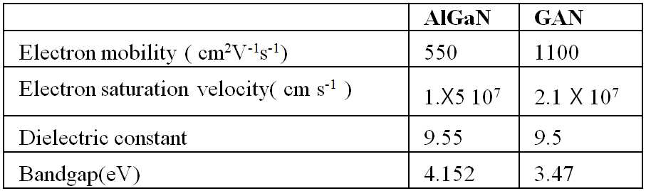
AlGaN은 GaN보다 밴드갭(band-gap)이 더 크며, 상기 실시 예에 따른, GaN 버퍼층(13)과 AlGaN 장벽층(14) 사이에는 2차원 전자 가스 농도를 갖는 채널이 형성된다. 상기 2차원 전자 가스층(13-1)은 높은 전자 이동도(mobility)를 갖고, 고주파수에서 매우 높은 상호전달컨덕턴스를 제공한다. AlGaN/GaN 웨이퍼는 ICP-RIE(Inductively Coupled Plasma-Reactive Ion Etching)를 사용하여 메사구조(mesa)를 형성할 수 있으며, 이는 소자 사이를 분리하는 역할을 한다.
AlGaN has a larger band-gap than GaN, and a channel having a two-dimensional electron gas concentration is formed between the
상기 캡층(15)은 항복전압(breakdown voltage) 및 표면 누설전류(leakage current) 특성을 개선하기 위한 에피택셜층으로, 상기 버퍼층(13) 및 장벽층(14)을 도핑하지 않는(undoped) 경우에 소자의 항복전압을 더 높일 수 있다. 본 발명의 일 실시 예에 따라 상기 장벽층(14)의 상면에 상기 캡층(15)을 형성할 수도 있지만, 상기 캡층(15)은 소자 응용분야에 따라서 설계되지 않을 수도 있다.
The
상기 소스 전극(16) 및 드레인 전극(17)의 패턴(pattern)은 사진 공정을 이용하여 형성할 수 있다. 본 발명의 일 실시 예에 따라, 상기 패턴 형성 후, GaN 웨이퍼를 NH4F:HF 30:1 용액에 30초 동안 담가 자연 산화막(native oxide)을 제거한다. 상기 패턴에 따라, 상기 장벽층(14) 또는 캡층(15)의 자연 산화막이 제거되어 노출된 위치에 전자-빔 증착기를 이용하여 오믹 메탈인 Ti/Al/Ni/Au를 각각 20/80/20/100 nm씩 증착한다. 오믹 메탈을 증착 후, 리프트-오프(lift-off)를 이용하여 오믹 접합을 형성한다. 상기 오믹 접합 형성 후, RTA 공정을 이용하여 어닐링 함으로써, 상기 소스 전극(16) 및 드레인 전극(17)을 형성할 수 있고, 바람직하게는 870℃의 온도 및 질소 분위기에서 30초 동안 어닐링 함으로써, 상기 소스 전극(16) 및 드레인 전극(17)을 형성할 수 있다.
Patterns of the
상기 게이트 전극(18)의 패턴은 사진 공정을 이용하여 형성할 수 있다. 본 발명의 일 실시 예에 따르면, 상기 패턴 형성 후, 쇼트키 접합으로 Ni/Au/Ni을 각각 30/150/30 nm씩 오믹 접합과 마찬가지로 전자-빔 증착기에 의해 증착하며 리프트-오프 공정에 의해 쇼트키 접합을 형성할 수 있다. 본 발명의 일 실시 예에 따르면, 상기 쇼트키 접합은 Ni 이외에 Pt, Ir, Pd, Mo 또는 Au 등 다른 금속으로도 구현될 수 있다. 쇼트키 접합 중 Pt는 높은 금속 일함수로 인해 높은 항복 전압 및 낮은 게이트 누설전류를 갖도록 하며, Mo은 높은 융점으로 인해 고온에서 안정된 동작이 가능하도록 하는 장점이 있다.
The pattern of the
상기 리세스(recess)는 상기 게이트 전극(18)과 상기 드레인 전극(17) 사이에서, 상기 게이트 전극(18)의 일측 하부의 상기 질화물계 반도체 층(101)에 형성된다. 상기 리세스의 깊이(Dr)는 상기 질화물계 반도체 층(101)의 상단부로부터 상기 질화물계 반도체 층(101)의 두께 방향으로의 거리를 나타낸다. 상기 리세스의 길이(Lr)는 상기 게이트 전극(18)의 에지로부터 상기 드레인 전극(17) 방향으로 상기 질화물계 반도체 층(101)에 형성된 리세스의 폭을 나타낸다.The recess is formed in the nitride based
여기에서, 상기 게이트 전극(18)의 에지란 상기 게이트 전극(18)과 상기 질화물계 반도체 층(101)이 접하는 면에서 상기 게이트 전극(18)의 모서리를 지칭한다.Here, an edge of the
본 발명의 일 실시 예에 따르면, 상기 리세스의 길이(Lr)는 상기 게이트 전극(18)과 상기 드레인 전극(17) 사이 거리의 9% 이상 11% 이하로 하며, 바람직하게는 10%로 한다. 상기 리세스의 깊이(Dr)는 상기 캡층(15)의 두께를 초과하여 상기 캡층(15)의 두께 및 상기 장벽층(14)의 두께의 합 미만이 되도록 한다. 즉, 상기 게이트 전극(18)과 상기 드레인 전극(17) 사이의 거리를 Lgd라고 하고, 상기 캡층(15)의 두께를 Dc, 상기 장벽층(14)의 두께를 Db라고 했을 때, 상기 리세스의 길이(Lr) 및 상기 리세스의 깊이(Dr)는 0.09×Lgd≤Lr≤0.11×Lgd 및 Dc<Dr<Dc+Db이 되도록 한다. According to one embodiment of the present invention, the length Lr of the recess is 9% or more and 11% or less of the distance between the
본 발명의 일 실시 예에 따르면, 구체적으로 상기 게이트 전극(18)과 상기 드레인 전극(17) 사이의 거리 Lgd=20㎛, 상기 캡층(15)의 두께 Dc=3㎚, 상기 장벽층(14)의 두께 Db=30㎚ 일 때, 상기 리세스의 길이 Lr=2㎛, 깊이 Dr=22㎚이다.According to an embodiment of the present invention, specifically, the distance Lgd = 20 μm between the
상기 리세스의 단면 형상은 다양하게 형성될 수 있다. 예를 들어, 상기 리세스의 길이 및 깊이를 일정하게 하여 직사각형 형상으로 형성될 수 있으며, 단면 모양이 "V"와 같은 형상의 슬레이티드(slated) 리세스로 형성될 수도 있다.The cross-sectional shape of the recess may be variously formed. For example, the length and depth of the recess may be constant to form a rectangular shape, and the cross-sectional shape may be formed as a slated recess having a shape such as "V".
상기 리세스는 에칭(etching) 공정을 통해 형성될 수 있으며, 다양한 종류의 에칭 공정을 이용할 수 있다. 예를 들어, 상기 에칭 공정은 KOH나 AZ400K을 이용한 습슥 에칭 공정이나, BCl/Cl2 gas를 이용한 플라즈마 에칭 공정을 통해 형성될 수 있다. 또한, 상기 질화물계 반도체 층(101)의 표면에 손상을 가한 후 KOH를 이용한 에칭 공정 등이 이용될 수 있다.The recess may be formed through an etching process, and various kinds of etching processes may be used. For example, the etching process may be formed through a wet etching process using KOH or AZ400K, or a plasma etching process using BCl / Cl 2 gas. In addition, an etching process using KOH may be used after damaging the surface of the nitride based
본 발명에 있어서, 상기 리세스의 형성에 따른 효과는 아래의 도 4 내지 도 8에서 설명하기로 한다.
In the present invention, the effect of the formation of the recess will be described in Figures 4 to 8 below.
본 발명의 일 실시 예에 따르면, 상기 질화물계 반도체 층(101) 상면에 상기 소스 전극(16), 드레인 전극(17) 및 게이트 전극(18)을 형성한 후, 산소 어닐링을 한다. 또는, 본 발명의 다른 실시 예에 따르면, 상기 게이트 전극(18)을 형성하기 전 산소 어닐링을 하는 것을 특징으로 한다. 산소 어닐링 공정은 퍼니스(furnace) 장비를 이용하여 이루어질 수 있으며, 250 내지 600℃에서 3분 내지 7분 동안 산소 분위기에서 실시할 수 있고, 바람직하게는 300℃에서 5분 동안 산소 분위기에서 실시할 수 있다.According to an embodiment of the present disclosure, the
본 발명에 따른 리세스 게이트 에지 구조의 질화물계 반도체 소자에 대해 산소 어닐링 공정을 함으로써 누설전류가 감소하고, 항복 전압이 증가하는 이점이 있다.
The oxygen annealing process is performed on the nitride-based semiconductor device of the recess gate edge structure according to the present invention to reduce the leakage current and increase the breakdown voltage.
본 발명의 일 실시 예에 따르면 리세스 게이트 에지 구조의 질화물계 반도체 소자는 AlGaN/GaN 고전자 이동도 트랜지스터에 적용 가능하지만, 다양한 GaN계 고전자 이동도 트랜지스터에 적용 가능하다. 예를 들어, 메탈 반도체 전계 효과 트랜지스터, AlGaN/GaN 헤테로 접합 웨이퍼의 상면에 형성된 수평형 GaN 쇼트키 장벽 다이오드 및 수직형 GaN 벌크(bulk) 쇼트키 장벽 다이오드 등 다양한 GaN계 소자에 적용 가능하다.
According to an exemplary embodiment, the nitride-based semiconductor device having the recess gate edge structure may be applied to an AlGaN / GaN high electron mobility transistor, but may be applied to various GaN-based high electron mobility transistors. For example, the present invention can be applied to various GaN-based devices such as a metal semiconductor field effect transistor, a horizontal GaN Schottky barrier diode and a vertical GaN bulk Schottky barrier diode formed on an upper surface of an AlGaN / GaN heterojunction wafer.
도 2 및 도 3은 본 발명에 따른 리세스 게이트 에지 구조의 질화물계 반도체 소자 제조 방법에 대한 실시 예들의 각 단계를 도시한 순서도이다.2 and 3 are flowcharts illustrating respective steps of a method of manufacturing a nitride-based semiconductor device having a recess gate edge structure according to the present invention.
먼저 도 2에 도시된 바와 같이, 본 발명의 일 실시 예에 따른 리세스 게이트 에지 구조의 질화물계 반도체 소자 제조 방법은, 질화물계 반도체 층 형성 단계(S21), 소스 전극 형성 단계(S22), 드레인 전극 형성 단계(S23), 게이트 전극 형성 단계(S24) 및 리세스 형성 단계(S25)를 포함한다.First, as shown in FIG. 2, the nitride-based semiconductor device manufacturing method of the recess gate edge structure according to the embodiment of the present invention, the nitride-based semiconductor layer forming step (S21), source electrode forming step (S22), drain An electrode forming step S23, a gate electrode forming step S24, and a recess forming step S25 are included.
또한, 도 3에 도시된 본 발명의 다른 실시 예에 따르면, 상기 도 2에 따른 실시 예에서 상기 질화물계 반도체 층 형성 단계(S21)는, 결정핵 생성층 형성 단계(S21-1), 버퍼층 형성 단계(S21-2), 장벽층 형성 단계(S21-3) 및 캡층 형성 단계(S21-4)를 포함한다.
In addition, according to another embodiment of the present invention illustrated in FIG. 3, in the embodiment according to FIG. 2, the nitride-based semiconductor layer forming step S21 may include a crystal nucleation layer forming step S21-1 and a buffer layer forming. Step S21-2, barrier layer forming step S21-3, and cap layer forming step S21-4 are included.
구체적으로, 먼저 상기 질화물계 반도체 층 형성 단계(S21)의 각 단계(S21-1 내지 S21-4)를 설명하기로 한다.Specifically, each step (S21-1 to S21-4) of the nitride-based semiconductor layer forming step (S21) will be described first.
상기 결정핵 생성층 형성 단계(S21-1)에서, 상기 결정핵 생성층을 절연성의 기판 상면에 형성한다. 상기 절연성의 기판은 절연성의 기판이지만 고저항성을 갖거나 n형 또는 p형으로 도핑될 수 있다. 예를 들면, 상기 기판을 이루는 재료로는 4H 반절연성 실리콘 카바이드일 수 있다. 또한, 상기 기판의 재료로서, 실리콘, 사파이어, 알루미늄 질화물, 알루미늄 갈륨 질화물, 갈륨 질화물, GaAs, ZnO 또는 InP 등을 사용하여 형성될 수 있다.In the crystal nucleation layer forming step (S21-1), the crystal nucleation layer is formed on an insulating substrate. The insulating substrate is an insulating substrate but may have high resistance or be doped with n-type or p-type. For example, the material constituting the substrate may be 4H semi-insulating silicon carbide. In addition, the material of the substrate may be formed using silicon, sapphire, aluminum nitride, aluminum gallium nitride, gallium nitride, GaAs, ZnO or InP.
상기 결정핵 생성층은 상기 기판과 상기 기판의 상면에 형성되는 질화물계 반도체 사이의 결정 격자 부정합으로 인한 결함을 최소화하기 위해 사용하는 것으로서, 사용하는 기판 및 반도체의 종류에 따라 적절한 결정핵 생성층이 적용될 수 있다. 본 발명의 일 실시 예에 따르면 상기 결정핵 생성층은 AlN으로 형성될 수 있다.
The crystal nucleation layer is used to minimize defects due to crystal lattice mismatch between the substrate and the nitride semiconductor formed on the upper surface of the substrate. Can be applied. According to an embodiment of the present invention, the crystal nucleation layer may be formed of AlN.
상기 버퍼층 형성 단계(S21-2) 및 장벽층 형성 단계(S21-3)에서, 상기 제1질화물계 반도체인 버퍼층 및 제2질화물계 반도체인 장벽층은 AlGaN/GaN 층의 이종접합 구조로 MOCVD를 통해 형성될 수 있다. 상기 버퍼층은 철이 도핑된 GaN으로 이루어질 수 있으며, 두께는 3㎛가 될 수 있다. 또한, 상기 장벽층은 AlGaN으로 이루어질 수 있으며, 각 원소(Al, Ga 및 N)는 다양한 조성비로 이루어질 수 있으며, 바람직하게는 Al0 .26Ga0 .74N이 될 수 있고, 두께는 30㎚가 될 수 있다. 상기 GaN 버퍼층 및 AlGaN 장벽층은 다양한 증착 방법을 통해 형성될 수 있으며, 예를 들어 메탈 유기 화학 기상 증착 방법을 이용하여 형성될 수 있다.In the buffer layer forming step (S21-2) and the barrier layer forming step (S21-3), the first nitride-based semiconductor buffer layer and the second nitride-based semiconductor barrier layer are MOCVD as a heterojunction structure of AlGaN / GaN layer. It can be formed through. The buffer layer may be formed of GaN doped with iron, and may have a thickness of 3 μm. In addition, the barrier layer may be formed of AlGaN, each element may be formed of (Al, Ga, and N) are in different ratio, preferably it may be the Al 0 .26 Ga 0 .74 N,
AlGaN은 GaN보다 밴드갭이 더 크며, 상기 실시 예에 따른, GaN 버퍼층과 AlGaN 장벽층 사이에는 2차원 전자 가스 농도를 갖는 채널이 형성된다. 상기 2차원 전자 가스층은 높은 전자 이동도를 갖고, 고주파수에서 매우 높은 상호전달컨덕턴스를 제공한다. AlGaN/GaN 웨이퍼는 ICP-RIE를 사용하여 메사구조를 형성할 수 있으며, 이는 소자 사이를 분리하는 역할을 한다.
AlGaN has a larger band gap than GaN, and according to the embodiment, a channel having a two-dimensional electron gas concentration is formed between the GaN buffer layer and the AlGaN barrier layer. The two-dimensional electron gas layer has high electron mobility and provides very high interconductance at high frequencies. AlGaN / GaN wafers can form mesa structures using ICP-RIE, which serves to separate the devices.
상기 캡층 형성 단계(S21-4)에서, 상기 캡층은 항복전압 및 표면 누설전류 특성을 개선하기 위한 에피택셜층으로, 상기 버퍼층 및 장벽층을 도핑하지 않는 경우에 소자의 항복전압을 더 높일 수 있다. 본 발명의 일 실시 예에 따라 상기 장벽층의 상면에 상기 캡층을 형성할 수도 있지만, 상기 캡층은 소자 응용분야에 따라서 설계되지 않을 수도 있다.
In the cap layer forming step (S21-4), the cap layer is an epitaxial layer for improving breakdown voltage and surface leakage current characteristics, and may further increase breakdown voltage of the device when the buffer layer and the barrier layer are not doped. . According to an embodiment of the present invention, the cap layer may be formed on the top surface of the barrier layer, but the cap layer may not be designed according to a device application.
상기 소스 전극 형성 단계(S22) 및 드레인 전극 형성 단계(S23)에서, 상기 소스 전극 및 드레인 전극의 패턴은 사진 공정을 이용하여 형성할 수 있다. 본 발명의 일 실시 예에 따라, 상기 패턴 형성 후, GaN 웨이퍼를 NH4F:HF 30:1 용액에 30초 동안 담가 자연 산화막을 제거한다. 상기 패턴에 따라, 상기 장벽층 또는 캡층의 자연 산화막이 제거되어 노출된 위치에 전자-빔 증착기를 이용하여 오믹 메탈인 Ti/Al/Ni/Au를 각각 20/80/20/100 nm씩 증착한다. 오믹 메탈을 증착 후, 리프트-오프를 이용하여 오믹 접합을 형성한다. 상기 오믹 접합 형성 후, RTA 공정을 이용하여 어닐링 함으로써, 상기 소스 전극 및 드레인 전극을 형성할 수 있고, 바람직하게는 870℃의 온도 및 질소 분위기에서 30초 동안 어닐링 함으로써, 상기 소스 전극 및 드레인 전극을 형성할 수 있다.
In the source electrode forming step (S22) and the drain electrode forming step (S23), the pattern of the source electrode and the drain electrode may be formed using a photo process. According to one embodiment of the present invention, after forming the pattern, the GaN wafer is immersed in NH 4 F: HF 30: 1 solution for 30 seconds to remove the native oxide film. According to the pattern, 20/80/20/100 nm of Ti / Al / Ni / Au, which is an ohmic metal, is deposited using an electron-beam evaporator in the exposed position by removing the natural oxide film of the barrier layer or the cap layer. . After depositing the ohmic metal, the lift-off is used to form the ohmic junction. After forming the ohmic junction, the source electrode and the drain electrode may be formed by annealing using an RTA process, and preferably, the source electrode and the drain electrode are annealed at a temperature of 870 ° C. and a nitrogen atmosphere for 30 seconds. Can be formed.
상기 게이트 전극 형성 단계(S24)에서, 상기 게이트 전극의 패턴은 사진 공정을 이용하여 형성할 수 있다. 본 발명의 일 실시 예에 따르면, 상기 패턴 형성 후, 쇼트키 접합으로 Ni/Au/Ni을 각각 30/150/30 nm씩 오믹 접합과 마찬가지로 전자-빔 증착기에 의해 증착하며 리프트-오프 공정에 의해 쇼트키 접합을 형성할 수 있다. 본 발명의 일 실시 예에 따르면, 상기 쇼트키 접합은 Ni 이외에 Pt, Ir, Pd, Mo 또는 Au 등 다른 금속으로도 구현될 수 있다. 쇼트키 접합 중 Pt는 높은 금속 일함수로 인해 높은 항복 전압 및 낮은 게이트 누설전류를 갖도록 하며, Mo은 높은 융점으로 인해 고온에서 안정된 동작이 가능하도록 하는 장점이 있다.
In the gate electrode forming step (S24), the pattern of the gate electrode may be formed using a photo process. According to an embodiment of the present invention, after forming the pattern, Ni / Au / Ni is deposited by Schottky junction by an electron-beam evaporator in the same manner as the ohmic junction by 30/150/30 nm, respectively, by a lift-off process. Schottky junctions can be formed. According to one embodiment of the present invention, the Schottky junction may be implemented with other metals such as Pt, Ir, Pd, Mo or Au in addition to Ni. During Schottky junction, Pt has high breakdown voltage and low gate leakage current due to high metal work function, and Mo has the advantage of allowing stable operation at high temperature due to high melting point.
상기 리세스 형성 단계(S25)에서, 상기 리세스는 상기 게이트 전극과 상기 드레인 전극 사이에서, 상기 게이트 전극의 일측 하부의 상기 질화물계 반도체 층에 형성된다. 상기 리세스의 깊이(Dr)는 상기 질화물계 반도체 층의 상단부로부터 상기 질화물계 반도체 층의 두께 방향으로의 거리를 나타낸다. 상기 리세스의 길이(Lr)는 상기 게이트 전극의 에지로부터 상기 드레인 전극 방향으로 상기 질화물계 반도체 층에 형성된 리세스의 폭을 나타낸다.In the recess forming step S25, the recess is formed in the nitride based semiconductor layer below one side of the gate electrode between the gate electrode and the drain electrode. The depth Dr of the recess represents a distance from an upper end of the nitride based semiconductor layer in the thickness direction of the nitride based semiconductor layer. The length Lr of the recess represents the width of the recess formed in the nitride based semiconductor layer from the edge of the gate electrode toward the drain electrode.
여기에서, 상기 게이트 전극의 에지란 상기 게이트 전극과 상기 질화물계 반도체 층이 접하는 면에서 상기 게이트 전극의 모서리를 지칭한다.Here, an edge of the gate electrode refers to an edge of the gate electrode at a surface where the gate electrode and the nitride based semiconductor layer contact.
본 발명의 일 실시 예에 따르면, 상기 리세스의 길이(Lr)는 상기 게이트 전극과 상기 드레인 전극 사이 거리의 9% 이상 11% 이하로 하며, 바람직하게는 10%로 한다. 상기 리세스의 깊이(Dr)는 상기 캡층의 두께를 초과하여 상기 캡층의 두께 및 상기 장벽층의 두께의 합 미만이 되도록 한다. 즉, 상기 게이트 전극과 상기 드레인 전극 사이의 거리를 Lgd라고 하고, 상기 캡층의 두께를 Dc, 상기 장벽층의 두께를 Db라고 했을 때, 상기 제1 길이(Lr) 및 상기 제1 깊이(Dr)는 0.09×Lgd≤Lr≤0.11×Lgd 및 Dc<Dr<Dc+Db이 되도록 한다. According to an embodiment of the present invention, the length Lr of the recess is 9% or more and 11% or less of the distance between the gate electrode and the drain electrode, preferably 10%. The depth Dr of the recess exceeds the thickness of the cap layer to be less than the sum of the thickness of the cap layer and the thickness of the barrier layer. That is, when the distance between the gate electrode and the drain electrode is Lgd, the thickness of the cap layer is Dc, and the thickness of the barrier layer is Db, the first length Lr and the first depth Dr. Is 0.09 × Lgd ≦ Lr ≦ 0.11 × Lgd and Dc <Dr <Dc + Db.
본 발명의 일 실시 예에 따르면, 구체적으로 상기 게이트 전극과 상기 드레인 전극 사이의 거리 Lgd=20㎛, 상기 캡층의 두께 Dc=3㎚, 상기 장벽층의 두께 Db=30㎚ 일 때, 상기 리세스의 길이 Lr=2㎛, 깊이 Dr=22㎚이다.According to one embodiment of the present invention, the recess Lgd is equal to 20 μm between the gate electrode and the drain electrode, the thickness Dc of the cap layer is 3 nm, and the thickness Db of the barrier layer is 30 nm. The length Lr is 2 µm and the depth Dr is 22 nm.
상기 리세스의 단면 형상은 다양하게 형성될 수 있다. 예를 들어, 상기 리세스의 길이 및 깊이를 일정하게 하여 직사각형 형상으로 형성될 수 있으며, 단면 모양이 "V"와 같은 형상의 슬레이티드 리세스로 형성될 수도 있다.The cross-sectional shape of the recess may be variously formed. For example, the length and depth of the recess may be constant, and may be formed in a rectangular shape, and the cross-sectional shape may be formed as a slit recess of a shape such as "V".
상기 리세스는 에칭 공정을 통해 형성될 수 있으며, 다양한 종류의 에칭 공정을 이용할 수 있다. 예를 들어, 상기 에칭 공정은 KOH나 AZ400K을 이용한 습슥 에칭 공정이나, BCl/Cl2 gas를 이용한 플라즈마 에칭 공정을 통해 형성될 수 있다. 또한, 상기 질화물계 반도체 층의 표면에 손상을 가한 후 KOH를 이용한 에칭 공정 등이 이용될 수 있다.The recess may be formed through an etching process, and various kinds of etching processes may be used. For example, the etching process may be formed through a wet etching process using KOH or AZ400K, or a plasma etching process using BCl / Cl 2 gas. In addition, an etching process using KOH may be used after damaging the surface of the nitride based semiconductor layer.
본 발명에 있어서, 상기 리세스의 형성에 따른 효과는 아래의 도 4 내지 도 8에서 설명하기로 한다.
In the present invention, the effect of the formation of the recess will be described in Figures 4 to 8 below.
본 발명의 일 실시 예에 따르면, 상기 질화물계 반도체 층 상면에 상기 소스 전극, 드레인 전극 및 게이트 전극을 형성한 후, 산소 어닐링을 한다. 또는, 본 발명의 다른 실시 예에 따르면, 상기 게이트 전극을 형성하기 전 산소 어닐링을 하는 것을 특징으로 한다. 산소 어닐링 공정은 퍼니스 장비를 이용하여 이루어질 수 있으며, 250 내지 600℃에서 3분 내지 7분 동안 산소 분위기에서 실시할 수 있고, 바람직하게는 300℃에서 5분 동안 산소 분위기에서 실시할 수 있다.According to an embodiment of the present disclosure, the source electrode, the drain electrode, and the gate electrode are formed on the nitride-based semiconductor layer, followed by oxygen annealing. Alternatively, according to another embodiment of the present invention, oxygen annealing is performed before forming the gate electrode. The oxygen annealing process may be performed using a furnace equipment, and may be performed at 250 to 600 ° C. for 3 to 7 minutes in an oxygen atmosphere, and preferably at 300 ° C. for 5 minutes in an oxygen atmosphere.
본 발명에 따른 리세스 게이트 에지 구조의 질화물계 반도체 소자 제조 방법에 대해 산소 어닐링 공정을 함으로써 누설전류가 감소하고, 항복 전압이 증가하는 이점이 있다.
The oxygen annealing process of the method for manufacturing the nitride-based semiconductor device having the recess gate edge structure according to the present invention has the advantage of reducing the leakage current and increasing the breakdown voltage.
본 발명의 일 실시 예에 따르면 리세스 게이트 에지 구조의 질화물계 반도체 소자는 AlGaN/GaN 고전자 이동도 트랜지스터에 적용 가능하지만, 다양한 GaN계 고전자 이동도 트랜지스터에 적용 가능하다. 예를 들어, 메탈 반도체 전계 효과 트랜지스터, AlGaN/GaN 헤테로 접합 웨이퍼의 상면에 형성된 수평형 GaN 쇼트키 장벽 다이오드 및 수직형 GaN 벌크 쇼트키 장벽 다이오드 등 다양한 GaN계 소자에 적용 가능하다.
According to an exemplary embodiment, the nitride-based semiconductor device having the recess gate edge structure may be applied to an AlGaN / GaN high electron mobility transistor, but may be applied to various GaN-based high electron mobility transistors. For example, the present invention can be applied to various GaN-based devices such as a metal semiconductor field effect transistor, a horizontal GaN Schottky barrier diode and a vertical GaN bulk Schottky barrier diode formed on an upper surface of an AlGaN / GaN heterojunction wafer.
도 4는 역방향 바이어스 인가 시 공핍 영역(depletion region)의 분포를 도시한 단면도이다.4 is a cross-sectional view illustrating a distribution of a depletion region when applying reverse bias.
도 4(a)는 종래 기술에 따른 질화물계 반도체 소자를 나타내며, 도 4(b)는 본 발명에 따른 질화물계 반도체 소자를 나타낸다. 도 4에 도시된 바와 같이, 상기 종래 기술 및 본 발명에 따른 질화물계 반도체 소자에 있어서, 게이트 전극의 폭은 3㎛, 상기 게이트 전극과 드레인 전극 사이의 거리 Lgd는 20㎛, 캡층의 두께는 3㎚, 장벽층의 두께는 30㎚, 버퍼층의 두께는 3㎛, 리세스의 깊이 Dr은 22㎚ 그리고, 리세스의 길이 Lr은 2㎛로 설정한 후 결과를 비교하도록 한다.Figure 4 (a) shows a nitride based semiconductor device according to the prior art, Figure 4 (b) shows a nitride based semiconductor device according to the present invention. As shown in FIG. 4, in the nitride semiconductor device according to the related art and the present invention, the gate electrode has a width of 3 μm, the distance Lgd between the gate electrode and the drain electrode is 20 μm, and the thickness of the cap layer is 3 μm. Nm, the thickness of the barrier layer is 30 nm, the thickness of the buffer layer is 3 mu m, the depth Dr of the recess is 22 nm, and the length Lr of the recess is set to 2 mu m, and the results are compared.
도 4(a) 및 도 4(b)에 도시된 질화물계 반도체 소자를 비교하면, 종래기술의 경우(도 4(a)) 본 발명(도 4(b))보다 공핍 영역(depletion region)이 보다 균일하게(uniformly) 분포한다는 것을 확인할 수 있다. 따라서, 본 발명에 따른 질화물계 반도체 소자는 전계 집중(electric field concentration) 현상이 감소한다. 게이트 에지 부분에서 전계 집중 현상이 감소하기 때문에, 최대 전계(electric field)가 감소하고 따라서, 항복 전압(breakdown voltage)이 감소하게 된다.
Comparing the nitride semiconductor devices shown in Figs. 4A and 4B, the depletion region is smaller than that of the present invention (Fig. 4A). It can be seen that the distribution is more uniformly (uniformly). Therefore, in the nitride-based semiconductor device according to the present invention, the electric field concentration phenomenon is reduced. Since the field concentration at the gate edge is reduced, the maximum electric field is reduced and thus the breakdown voltage is reduced.
도 5는 질화물계 반도체 소자의 항복전압 특성을 도시한 도표이다.5 is a chart showing breakdown voltage characteristics of a nitride semiconductor device.
도 5에 도시된 바와 같이 종래기술에 따른 반도체 소자의 경우(51) 항복 전압은 962V가 되며, 본 발명에 따른 반도체 소자의 경우(52) 항복 전압은 1160V로서 약 20.58%가 증가함을 확인할 수 있다.
As shown in FIG. 5, the breakdown voltage of the semiconductor device according to the
역방향 바이어스를 인가할 시, 종래 기술에 따른 반도체 소자는 게이트로부터 장벽층의 표면-상태(surface-state)에 발생하는 전자 트래핑(electron trapping)은 가상의 게이트 효과(virtual-gate effect)의 원인이 된다. 가상의 게이트 효과는 항복 전압 및 누설 전류 특성을 악화시킨다. 본 발명에 따른 질화물계 반도체 소자에서는, 게이트 에지 부분의 질화물계 반도체 층이 제거되기 때문에, 게이트로부터 질화물계 반도체 층의 표면에 발생하는 전자 트래핑 현상이 감소하고, 따라서 상기 가상의 게이트 효과 문제가 해결된다. 이로 인해 본 발명에 따른 질화물계 반도체 소자는 항복 전압이 증가한다.
In the application of reverse bias, the semiconductor device according to the related art is known that electron trapping occurring from the gate to the surface-state of the barrier layer is the cause of the virtual gate effect. do. The hypothetical gate effect worsens the breakdown voltage and leakage current characteristics. In the nitride-based semiconductor device according to the present invention, since the nitride-based semiconductor layer at the gate edge portion is removed, the electron trapping phenomenon occurring on the surface of the nitride-based semiconductor layer from the gate is reduced, thus solving the virtual gate effect problem. do. This increases the breakdown voltage of the nitride semiconductor device according to the present invention.
또한, 장벽층의 두께가 부분적으로 얇아지기 때문에 에칭된 영역 즉, 리세스 아래 부분에서 분극 영역(polarization field)이 완화되며, 표면-상태(surface-state)로부터 2DEG로의 전자 트래핑이 감소하여, 역방향 누설 전류가 감소한다. 블록킹 전압(blocking voltage)이 850V일 때, 종래 기술에 따른 질화물계 반도체 소자의 경우 10mA/mm 였지만, 본 발명에 따른 질화물계 반도체 소자의 경우 1mA/mm가 되어 우수한 특성을 보인다.
In addition, because the barrier layer is partially thinned, the polarization field is mitigated in the etched area, i.e., under the recess, and the electron trapping from the surface-state to the 2DEG is reduced, resulting in a reverse direction. Leakage current is reduced. When the blocking voltage is 850 V, the nitride semiconductor device according to the prior art is 10 mA / mm, but the nitride semiconductor device according to the present invention is 1 mA / mm, thereby showing excellent characteristics.
도 6은 질화물계 반도체 소자의 게이트 에지 부분에서 리세스 형성 전과 후의 순방향 전류-전압 특성을 비교한 도표이다. FIG. 6 is a diagram comparing forward current-voltage characteristics before and after formation of a recess in the gate edge portion of a nitride based semiconductor device.
도 6에 도시된 바와 같이, 게이트 바이어스가 1V일 때, 종래 기술에 따른 질화물계 반도체 소자의 경우 최대 드레인 전류는 503.37 mA/mm인데 반해, 본 발명에 따른 질화물계 반도체 소자의 경우 최대 드레인 전류는 463.17 mA/mm로 감소하는 것을 확인할 수 있다. 부분적으로 에칭된 장벽층에 의해, 본 발명의 경우 종래 기술에 비하여 약 90% 가까이 드레인 전류가 감소한다. 감소한 장벽층의 두께로 인해 2DEG 밀도가 감소하며, 이로써 역방향 누설 전류 특성이 개선된다.
As shown in FIG. 6, when the gate bias is 1 V, the maximum drain current is 503.37 mA / mm in the case of the nitride semiconductor device according to the prior art, whereas the maximum drain current is in the case of the nitride semiconductor device according to the present invention. You can see the decrease to 463.17 mA / mm. The partially etched barrier layer reduces drain current by about 90% in the case of the present invention compared to the prior art. The reduced thickness of the barrier layer reduces the 2DEG density, thereby improving reverse leakage current characteristics.
도 7은 질화물계 반도체 소자의 리세스 형성 전과 후의 전류-전압 특성을 도시한 도표이다. 7 is a diagram showing current-voltage characteristics before and after forming recesses of a nitride-based semiconductor device.
도 7에 도시된 바와 같이, 종래 기술의 경우 최대 트랜스컨덕턴스(transconductance)가 105.1 mS/mm 인데 반해, 본 발명의 경우 최대 트랜스컨덕턴스는 101.93 mS/mm로 감소한다. 또한, gm max 방법으로 측정한 문턱 전압(threshold voltage)의 경우, 종래 기술은 -3.9V인데 반해, 본 발명은 -4.1V로서 약 0.2V 만큼의 전압 이동이 발생한다. 에칭된 영역에 의해, 본 발명의 공핍 영역은 동일한 게이트 바이어스 상에서 2DEG에 쉽게 접근할 수 있다.
As shown in FIG. 7, the maximum transconductance is 105.1 mS / mm in the prior art, whereas the maximum transconductance is reduced to 101.93 mS / mm in the present invention. In addition, in the case of the threshold voltage measured by the g m max method, the conventional technique is -3.9V, whereas the present invention has a voltage shift of about 0.2V as -4.1V. By etched regions, the depletion regions of the present invention can easily access 2DEG on the same gate bias.
도 8은 표면 전계 특성을 모의 실험하여 도시한 도표이다.8 is a diagram illustrating a simulation of surface electric field characteristics.
도 8에 도시된 도표는 본 발명에 따른 질화물계 반도체 소자와 동일한 구조에 대해 ISE-TCAD 소프트웨어를 이용하여 전계 완화(electric field relaxation)에 대한 2차원 모의 실험 결과를 도시한 도표이다. 상기 모의 실험 결과값을 다음의 표 1에 나타낸다.
8 is a diagram showing the results of a two-dimensional simulation of electric field relaxation using the ISE-TCAD software for the same structure as the nitride-based semiconductor device according to the present invention. The simulation results are shown in Table 1 below.
상기 모의 실험에서는 리세스된 장벽층에 대하여, 게이트-드레인 전극 사이의 길이의 10%에 해당하는 길이로 장벽층에 20nm 깊이로 리세스를 설정했다. 분극 효과(polarization effect)를 고려하여 상기 리세스 영역 하에서 2DEG의 밀도를 변화시킬 수 있다. 리세스의 깊이를 20nm로 하면, 역방향 바이어스 인가 시 본 발명의 표면 전계는 완화되며, 최대 전계 강도는 도 8에 도시된 바와 같이 감소한다.
In the simulation, a recess was set to a depth of 20 nm in the barrier layer with a length corresponding to 10% of the length between the gate and drain electrodes for the recessed barrier layer. In consideration of the polarization effect, the density of the 2DEG may be changed under the recess region. If the depth of the recess is 20 nm, the surface electric field of the present invention is relaxed when applying reverse bias, and the maximum electric field strength is reduced as shown in FIG.
한편, 이상에서는 본 발명의 구체적인 실시 예에 관해 설명하였으나, 본 발명의 범위에서 벗어나지 않는 한도 내에서 여러 가지 변형이 가능함은 물론이다. 그러므로 본 발명의 범위는 설명된 실시 예에 국한되지 않으며, 후술하는 특허청구범위뿐만 아니라 이 특허청구범위와 균등한 것들에 의해 정해져야 한다.On the other hand, the above has been described with respect to specific embodiments of the present invention, of course, various modifications are possible without departing from the scope of the invention. Therefore, the scope of the present invention should not be limited to the described embodiments, but should be defined not only by the claims below, but also by those equivalent to the claims.
Claims (9)
상기 질화물계 반도체 층 상면의 일 측에 형성된 소스 전극;
상기 질화물계 반도체 층 상면의 타 측에 상기 소스 전극과 이격 형성된 드레인 전극; 및
상기 질화물계 반도체 층 상면에, 상기 소스 전극과 드레인 전극 사이에 형성된 게이트 전극을 포함하며,
상기 게이트 전극과 상기 드레인 전극 사이에서, 상기 게이트 전극의 일측 하부의 상기 질화물계 반도체 층에 리세스(recess)가 형성되며,
상기 리세스의 깊이는 상기 캡층의 두께를 초과하여 상기 캡층의 두께 및 상기 장벽층의 두께의 합 미만인 것을 특징으로 하는 질화물계 반도체 소자.
A nitride based semiconductor layer comprising a barrier layer which is a nitride based semiconductor and a cap layer formed of GaN on an upper surface of the barrier layer;
A source electrode formed on one side of an upper surface of the nitride based semiconductor layer;
A drain electrode spaced apart from the source electrode on the other side of the nitride-based semiconductor layer; And
A gate electrode formed between the source electrode and the drain electrode on an upper surface of the nitride based semiconductor layer,
Between the gate electrode and the drain electrode, a recess is formed in the nitride based semiconductor layer below one side of the gate electrode,
And the depth of the recess is greater than the thickness of the cap layer and less than the sum of the thickness of the cap layer and the thickness of the barrier layer.
상기 질화물계 반도체 층은,
절연성의 기판;
상기 기판 상면에 형성되며, 제1 질화물계 반도체의 에피구조를 성장시키기 위해 형성되는 결정핵 생성층;
상기 결정핵 생성층 상면에 형성되며, 상기 제1 질화물계 반도체인 버퍼층; 및
상기 버퍼층 상면에 형성되며, 상기 버퍼층과의 사이에 2차원 전자 가스층을 형성하고 제2 질화물계 반도체인 장벽층을 포함하는 것을 특징으로 하는 질화물계 반도체 소자.
The method of claim 1,
The nitride-based semiconductor layer,
An insulating substrate;
A crystal nucleation layer formed on an upper surface of the substrate and formed to grow an epi structure of the first nitride semiconductor;
A buffer layer formed on an upper surface of the crystal nucleation layer, the buffer layer being the first nitride semiconductor; And
And a barrier layer formed on an upper surface of the buffer layer and forming a two-dimensional electron gas layer between the buffer layer and a second nitride semiconductor layer.
상기 결정핵 생성층은 AlN으로 형성되고, 상기 버퍼층은 GaN으로 형성되며, 상기 장벽층은 AlGaN으로 형성되고,
상기 장벽층의 상면에 GaN으로 형성되는 캡층을 더 포함하는 것을 특징으로 하는 질화물계 반도체 소자.
The method of claim 2,
The crystal nucleation layer is formed of AlN, the buffer layer is formed of GaN, the barrier layer is formed of AlGaN,
The nitride-based semiconductor device further comprises a cap layer formed of GaN on the upper surface of the barrier layer.
상기 질화물계 반도체 층 상면의 일 측에 소스 전극을 형성하는 단계;
상기 질화물계 반도체 층 상면의 타 측에 소스 전극과 이격 형성된 드레인 전극을 형성하는 단계;
상기 질화물계 반도체 층 상면에 상기 소스 전극과 드레인 전극 사이에 게이트 전극을 형성하는 단계; 및
상기 게이트 전극과 상기 드레인 전극 사이에서, 상기 게이트 전극의 일측 하부의 상기 질화물계 반도체 층에 리세스(recess)를 형성하는 단계를 포함하며,
상기 리세스를 형성하는 단계는, 상기 리세스의 깊이가 상기 캡층의 두께를 초과하여 상기 캡층의 두게 및 상기 장벽층의 두께의 합 미만이 되도록 형성하는 것을 특징으로 하는 질화물계 반도체 소자 제조 방법.
Forming a nitride based semiconductor layer including a barrier layer which is a nitride based semiconductor and a cap layer formed of GaN on an upper surface of the barrier layer;
Forming a source electrode on one side of an upper surface of the nitride based semiconductor layer;
Forming a drain electrode spaced apart from the source electrode on the other side of the upper surface of the nitride based semiconductor layer;
Forming a gate electrode on the upper surface of the nitride based semiconductor layer between the source electrode and the drain electrode; And
Forming a recess between the gate electrode and the drain electrode in the nitride based semiconductor layer below one side of the gate electrode,
The forming of the recess may include forming the recess such that the depth of the recess exceeds the thickness of the cap layer to be less than the sum of the thickness of the cap layer and the thickness of the barrier layer.
상기 질화물계 반도체 층을 형성하는 단계는,
절연성의 기판 상면에 제1 질화물계 반도체의 에피구조를 성장시키기 위한 결정핵 생성층을 형성하는 단계;
상기 결정핵 생성층의 상면에 상기 제1 질화물계 반도체인 버퍼층을 형성하는 단계;
상기 버퍼층의 상면에 상기 버퍼층과의 사이에 2차원 전자 가스층을 형성하고 제2 질화물계 반도체인 장벽층을 형성하는 단계; 및
상기 장벽층의 상면에 캡층을 형성하는 단계를 포함하는 것을 특징으로 하는 질화물계 반도체 소자 제조 방법.
The method of claim 5,
Forming the nitride-based semiconductor layer,
Forming a crystal nucleation layer for growing an epi structure of the first nitride-based semiconductor on an insulating substrate;
Forming a buffer layer, which is the first nitride-based semiconductor, on the top surface of the crystal nucleation layer;
Forming a two-dimensional electron gas layer on the upper surface of the buffer layer between the buffer layer and forming a barrier layer which is a second nitride-based semiconductor; And
And forming a cap layer on the top surface of the barrier layer.
상기 리세스를 형성하는 단계 후,
산소 어닐링을 하는 단계를 더 포함하는 것을 특징으로 하는 질화물계 반도체 소자 제조 방법.
The method according to claim 5 or 6,
After forming the recess,
Nitride-based semiconductor device manufacturing method comprising the step of annealing oxygen.
상기 결정핵 생성층은 AlN으로 형성되고, 상기 버퍼층은 GaN으로 형성되며, 상기 장벽층은 AlGaN으로 형성되고, 상기 캡층은 GaN으로 형성되는 것을 특징으로 하는 질화물계 반도체 소자 제조 방법.
The method of claim 6,
Wherein the crystal nucleation layer is formed of AlN, the buffer layer is formed of GaN, the barrier layer is formed of AlGaN, and the cap layer is formed of GaN.
Priority Applications (1)
| Application Number | Priority Date | Filing Date | Title |
|---|---|---|---|
| KR1020100024037A KR101103774B1 (en) | 2010-03-18 | 2010-03-18 | A nitride semiconductor device having a recess gate edge structure and a method of manufacturing the same |
Applications Claiming Priority (1)
| Application Number | Priority Date | Filing Date | Title |
|---|---|---|---|
| KR1020100024037A KR101103774B1 (en) | 2010-03-18 | 2010-03-18 | A nitride semiconductor device having a recess gate edge structure and a method of manufacturing the same |
Publications (2)
| Publication Number | Publication Date |
|---|---|
| KR20110105032A KR20110105032A (en) | 2011-09-26 |
| KR101103774B1 true KR101103774B1 (en) | 2012-01-06 |
Family
ID=44955497
Family Applications (1)
| Application Number | Title | Priority Date | Filing Date |
|---|---|---|---|
| KR1020100024037A Active KR101103774B1 (en) | 2010-03-18 | 2010-03-18 | A nitride semiconductor device having a recess gate edge structure and a method of manufacturing the same |
Country Status (1)
| Country | Link |
|---|---|
| KR (1) | KR101103774B1 (en) |
Families Citing this family (6)
| Publication number | Priority date | Publication date | Assignee | Title |
|---|---|---|---|---|
| JP5790461B2 (en) | 2011-12-07 | 2015-10-07 | 富士通株式会社 | Compound semiconductor device and manufacturing method thereof |
| US8680535B2 (en) * | 2011-12-23 | 2014-03-25 | Taiwan Semiconductor Manufacturing Company, Ltd. | High electron mobility transistor structure with improved breakdown voltage performance |
| US9379102B2 (en) | 2012-07-19 | 2016-06-28 | Samsung Electronics Co., Ltd. | Nitride-based semiconductor device |
| KR101927409B1 (en) | 2012-08-07 | 2018-12-10 | 삼성전자주식회사 | High electron mobility transistor |
| WO2014043187A1 (en) * | 2012-09-11 | 2014-03-20 | University Of Florida Research Foundation, Incorporated | High electron mobility transistors having improved reliability |
| KR102841804B1 (en) * | 2022-07-29 | 2025-08-05 | 한국항공대학교산학협력단 | Normally-off semiconductor device and manufacturing thereof |
Citations (2)
| Publication number | Priority date | Publication date | Assignee | Title |
|---|---|---|---|---|
| JPS6461068A (en) * | 1987-09-01 | 1989-03-08 | Nec Corp | Field-effect transistor |
| KR20070092482A (en) * | 2006-03-10 | 2007-09-13 | 삼성전자주식회사 | Nitride-based semiconductor device and manufacturing method thereof |
-
2010
- 2010-03-18 KR KR1020100024037A patent/KR101103774B1/en active Active
Patent Citations (2)
| Publication number | Priority date | Publication date | Assignee | Title |
|---|---|---|---|---|
| JPS6461068A (en) * | 1987-09-01 | 1989-03-08 | Nec Corp | Field-effect transistor |
| KR20070092482A (en) * | 2006-03-10 | 2007-09-13 | 삼성전자주식회사 | Nitride-based semiconductor device and manufacturing method thereof |
Also Published As
| Publication number | Publication date |
|---|---|
| KR20110105032A (en) | 2011-09-26 |
Similar Documents
| Publication | Publication Date | Title |
|---|---|---|
| Nanjo et al. | AlGaN channel HEMT with extremely high breakdown voltage | |
| KR101124937B1 (en) | Cap layers and/or passivation layers for nitride-based transistors, transistor structures and methods of fabricating same | |
| US9590088B2 (en) | Current aperture vertical electron transistors with ammonia molecular beam epitaxy grown p-type gallium nitride as a current blocking layer | |
| KR101108344B1 (en) | Methods of fabricating nitride-based transistors with a cap layer and a recessed gate | |
| US8669589B2 (en) | Robust transistors with fluorine treatment | |
| US7170111B2 (en) | Nitride heterojunction transistors having charge-transfer induced energy barriers and methods of fabricating the same | |
| US7709859B2 (en) | Cap layers including aluminum nitride for nitride-based transistors | |
| US20150255547A1 (en) | III-Nitride High Electron Mobility Transistor Structures and Methods for Fabrication of Same | |
| US20150221727A1 (en) | Inverted P-Channel III-Nitride Field Effect Transistor with Hole Carriers in the Channel | |
| JP5190923B2 (en) | Nitride semiconductor transistor having GaN as channel layer and manufacturing method thereof | |
| CN104704608A (en) | Nitride semiconductor structure | |
| CN103426914A (en) | Heterojunction semiconductor device and manufacturing method | |
| US20240088284A1 (en) | High electron mobility transistor (hemt) with a back barrier layer | |
| KR101103774B1 (en) | A nitride semiconductor device having a recess gate edge structure and a method of manufacturing the same | |
| CN107958939A (en) | One kind nitridation Gallium base heterojunction Schottky diode structures | |
| CN112201689B (en) | Field effect transistor based on III-nitride heterojunction and preparation method thereof | |
| KR20110058332A (en) | Enhancement nitride semiconductor device using floating gate structure | |
| KR101457390B1 (en) | Method of manufacturing nitride semiconductor device | |
| KR101207701B1 (en) | GaN SEMICONDUCTOR DEVICE AND METHOD FOR FABRICATING THE SAME | |
| KR101291148B1 (en) | N-polar Nitride semiconductor device and method for manufacturing thereof | |
| CN107958931A (en) | One kind nitridation Gallium base heterojunctions field-effect transistor structure of resistance to breakdown | |
| KR101303592B1 (en) | Method for manufacturing nitride semiconductor device | |
| KR101402096B1 (en) | Nitride based semiconductor device employing tan-schottky contact and method for manufacturing thereof | |
| Shur et al. | Insulated gate nitride-based field effect transistors | |
| CN107958925A (en) | One kind nitridation Gallium base heterojunctions Schottky diode structure of resistance to breakdown |
Legal Events
| Date | Code | Title | Description |
|---|---|---|---|
| A201 | Request for examination | ||
| PA0109 | Patent application |
St.27 status event code: A-0-1-A10-A12-nap-PA0109 |
|
| PA0201 | Request for examination |
St.27 status event code: A-1-2-D10-D11-exm-PA0201 |
|
| D13-X000 | Search requested |
St.27 status event code: A-1-2-D10-D13-srh-X000 |
|
| D14-X000 | Search report completed |
St.27 status event code: A-1-2-D10-D14-srh-X000 |
|
| E902 | Notification of reason for refusal | ||
| PE0902 | Notice of grounds for rejection |
St.27 status event code: A-1-2-D10-D21-exm-PE0902 |
|
| E13-X000 | Pre-grant limitation requested |
St.27 status event code: A-2-3-E10-E13-lim-X000 |
|
| P11-X000 | Amendment of application requested |
St.27 status event code: A-2-2-P10-P11-nap-X000 |
|
| P13-X000 | Application amended |
St.27 status event code: A-2-2-P10-P13-nap-X000 |
|
| PG1501 | Laying open of application |
St.27 status event code: A-1-1-Q10-Q12-nap-PG1501 |
|
| E701 | Decision to grant or registration of patent right | ||
| PE0701 | Decision of registration |
St.27 status event code: A-1-2-D10-D22-exm-PE0701 |
|
| GRNT | Written decision to grant | ||
| PR0701 | Registration of establishment |
St.27 status event code: A-2-4-F10-F11-exm-PR0701 |
|
| PR1002 | Payment of registration fee |
St.27 status event code: A-2-2-U10-U11-oth-PR1002 Fee payment year number: 1 |
|
| PG1601 | Publication of registration |
St.27 status event code: A-4-4-Q10-Q13-nap-PG1601 |
|
| FPAY | Annual fee payment |
Payment date: 20141222 Year of fee payment: 4 |
|
| PR1001 | Payment of annual fee |
St.27 status event code: A-4-4-U10-U11-oth-PR1001 Fee payment year number: 4 |
|
| FPAY | Annual fee payment |
Payment date: 20160104 Year of fee payment: 5 |
|
| PR1001 | Payment of annual fee |
St.27 status event code: A-4-4-U10-U11-oth-PR1001 Fee payment year number: 5 |
|
| FPAY | Annual fee payment |
Payment date: 20170102 Year of fee payment: 6 |
|
| PR1001 | Payment of annual fee |
St.27 status event code: A-4-4-U10-U11-oth-PR1001 Fee payment year number: 6 |
|
| P22-X000 | Classification modified |
St.27 status event code: A-4-4-P10-P22-nap-X000 |
|
| PR1001 | Payment of annual fee |
St.27 status event code: A-4-4-U10-U11-oth-PR1001 Fee payment year number: 7 |
|
| FPAY | Annual fee payment |
Payment date: 20190102 Year of fee payment: 8 |
|
| PR1001 | Payment of annual fee |
St.27 status event code: A-4-4-U10-U11-oth-PR1001 Fee payment year number: 8 |
|
| PN2301 | Change of applicant |
St.27 status event code: A-5-5-R10-R13-asn-PN2301 St.27 status event code: A-5-5-R10-R11-asn-PN2301 |
|
| FPAY | Annual fee payment |
Payment date: 20200102 Year of fee payment: 9 |
|
| PR1001 | Payment of annual fee |
St.27 status event code: A-4-4-U10-U11-oth-PR1001 Fee payment year number: 9 |
|
| PR1001 | Payment of annual fee |
St.27 status event code: A-4-4-U10-U11-oth-PR1001 Fee payment year number: 10 |
|
| PR1001 | Payment of annual fee |
St.27 status event code: A-4-4-U10-U11-oth-PR1001 Fee payment year number: 11 |
|
| PR1001 | Payment of annual fee |
St.27 status event code: A-4-4-U10-U11-oth-PR1001 Fee payment year number: 12 |
|
| PR1001 | Payment of annual fee |
St.27 status event code: A-4-4-U10-U11-oth-PR1001 Fee payment year number: 13 |
|
| PR1001 | Payment of annual fee |
St.27 status event code: A-4-4-U10-U11-oth-PR1001 Fee payment year number: 14 |
|
| P22-X000 | Classification modified |
St.27 status event code: A-4-4-P10-P22-nap-X000 |
|
| PR1001 | Payment of annual fee |
St.27 status event code: A-4-4-U10-U11-oth-PR1001 Fee payment year number: 15 |
|
| U11 | Full renewal or maintenance fee paid |
Free format text: ST27 STATUS EVENT CODE: A-4-4-U10-U11-OTH-PR1001 (AS PROVIDED BY THE NATIONAL OFFICE) Year of fee payment: 15 |