KR101018016B1 - Substrate support unit, substrate processing apparatus and method using same - Google Patents
Substrate support unit, substrate processing apparatus and method using same Download PDFInfo
- Publication number
- KR101018016B1 KR101018016B1 KR1020080118106A KR20080118106A KR101018016B1 KR 101018016 B1 KR101018016 B1 KR 101018016B1 KR 1020080118106 A KR1020080118106 A KR 1020080118106A KR 20080118106 A KR20080118106 A KR 20080118106A KR 101018016 B1 KR101018016 B1 KR 101018016B1
- Authority
- KR
- South Korea
- Prior art keywords
- substrate
- light
- support plate
- light emitting
- support
- Prior art date
- Legal status (The legal status is an assumption and is not a legal conclusion. Google has not performed a legal analysis and makes no representation as to the accuracy of the status listed.)
- Active
Links
Images


Classifications
-
- H10P72/7606—
-
- H10P72/0402—
-
- H10P72/0606—
Landscapes
- Cleaning Or Drying Semiconductors (AREA)
Abstract
본 발명은 기판 지지 유닛과, 이를 이용한 기판 처리 장치 및 방법을 개시한 것으로서, 지지판의 상부에 배치된 발광 소자가 회전하는 지지판을 향해 광을 방출하고, 지지판에 설치된 광 전달부가 발광 소자에서 방출된 광을 지지판의 하부에 배치된 수광 소자로 전달하면서 지지판으로부터의 기판 이탈 여부를 감지하는 것을 특징으로 가진다.
이러한 특징에 의하면, 공정 진행 중 기판의 이탈 여부를 감지할 수 있으며, 이탈된 기판에 의한 기판 지지 유닛 및 바울 등의 주변 장치의 손상을 방지할 수 있는 기판 지지 유닛과, 이를 이용한 기판 처리 장치 및 방법을 제공할 수 있다.
지지판, 기판, 이탈, 발광 소자, 수광 소자, 광 전달부
The present invention discloses a substrate support unit and a substrate processing apparatus and method using the same, wherein the light emitting device disposed above the support plate emits light toward the rotating support plate, and the light transmitting unit provided on the support plate is emitted from the light emitting device. It is characterized by detecting whether the substrate is separated from the support plate while transmitting the light to the light receiving element disposed under the support plate.
According to this feature, it is possible to detect whether the substrate is removed during the process, the substrate support unit that can prevent damage to the substrate support unit and peripheral devices such as Paul due to the separated substrate, a substrate processing apparatus using the same and It may provide a method.
Support plate, substrate, separation, light emitting element, light receiving element, light transmission part
Description
본 발명은 반도체 제조 장치 및 방법에 관한 것으로서, 보다 상세하게는 공정 진행시 기판을 지지하는 기판 지지 유닛과, 이를 이용한 기판 처리 장치 및 방법에 관한 것이다.BACKGROUND OF THE
일반적으로 반도체 디바이스는 기판상에 여러 가지 물질을 박막 형태로 증착하고 이를 패터닝하여 제조된다. 이를 위하여 증착 공정, 사진 공정, 식각 공정 및 세정 공정 등 여러 단계의 서로 다른 공정들이 요구된다.Generally, semiconductor devices are manufactured by depositing and patterning various materials on a substrate in a thin film form. To this end, several different processes are required, such as a deposition process, a photographic process, an etching process and a cleaning process.
이들 공정 중 식각 공정은 기판상에 형성된 막질을 제거하는 공정이고, 세정 공정은 반도체 제조를 위한 각 단위 공정의 진행 후 기판 표면에 잔류하는 오염 물질을 제거하는 공정이다. 식각 공정 및 세정 공정은 공정 진행 방식에 따라 습식 방식과 건식 방식으로 분류되며, 습식 방식은 배치 타입의 방식과 스핀 타입의 방식으로 분류된다.Among these processes, the etching process is a process of removing film quality formed on the substrate, and the cleaning process is a process of removing contaminants remaining on the surface of the substrate after each unit process for semiconductor manufacturing. The etching process and the cleaning process are classified into a wet method and a dry method according to the process method, and the wet method is classified into a batch type method and a spin type method.
스핀 타입의 방식은 한 장의 기판을 처리할 수 있는 척 부재에 기판을 고정한 후, 기판을 회전시키면서 분사 노즐을 통해 기판에 약액 또는 탈이온수를 공급 하여, 원심력에 의해 약액 또는 탈이온수를 기판의 전면으로 퍼지게 함으로써 기판을 세정 처리하며, 기판의 세정 처리 후에는 건조 가스로 기판을 건조한다.In the spin type, the substrate is fixed to a chuck member capable of processing a single substrate, and then the chemical liquid or deionized water is supplied to the substrate through the spray nozzle while the substrate is rotated. The substrate is washed by being spread out, and the substrate is dried with dry gas after the substrate is washed.
본 발명은 공정 진행 중 기판 지지 유닛으로부터의 기판의 이탈을 감지할 수 있는 기판 지지 유닛과, 이를 이용한 기판 처리 장치 및 방법을 제공하기 위한 것이다.The present invention is to provide a substrate support unit that can detect the departure of the substrate from the substrate support unit during the process, and a substrate processing apparatus and method using the same.
본 발명의 목적은 여기에 제한되지 않으며, 언급되지 않은 또 다른 목적들은 아래의 기재로부터 당업자에게 명확하게 이해될 수 있을 것이다.The objects of the present invention are not limited thereto, and other objects not mentioned can be clearly understood by those skilled in the art from the following description.
상기한 과제를 달성하기 위하여 본 발명에 의한 기판 지지 유닛은 기판이 놓이는 지지판; 및 상기 지지판 상의 상기 기판의 유무를 검출하는 감지 부재를 포함하되, 상기 감지 부재는 상기 지지판의 상부에 배치되며, 상기 지지판의 상면을 향해 광을 방출하는 발광 소자; 상기 지지판의 하부에 배치되며, 광을 수광하는 수광 소자; 및 상기 지지판에 설치되며, 상기 발광 소자에서 방출된 상기 광을 상기 수광 소자로 전달하는 광 전달부를 포함하는 것을 특징으로 한다.In order to achieve the above object, a substrate support unit according to the present invention includes a support plate on which a substrate is placed; And a sensing member for detecting the presence or absence of the substrate on the supporting plate, wherein the sensing member is disposed above the supporting plate and emits light toward an upper surface of the supporting plate; A light receiving element disposed under the support plate and receiving light; And a light transmission part installed on the support plate and transmitting the light emitted from the light emitting device to the light receiving device.
상술한 바와 같은 구성을 가지는 본 발명에 의한 기판 지지 유닛에 있어서, 상기 광 전달부는 상기 발광 소자와 마주보도록 상기 지지판의 상면에 설치되는 제 1 광 전달 소자; 상기 수광 소자와 마주보도록 상기 지지판의 하면에 설치되는 제 2 광 전달 소자; 및 상기 제 1 광 전달 소자와 상기 제 2 광 전달 소자 간의 광 이동 경로를 제공하는 광 이동 모듈을 포함할 수 있다.A substrate support unit according to the present invention having the configuration as described above, wherein the light transmitting portion comprises: a first light transmitting element provided on an upper surface of the support plate so as to face the light emitting element; A second light transmitting element disposed on a lower surface of the support plate so as to face the light receiving element; And a light moving module that provides a light moving path between the first light transmitting element and the second light transmitting element.
상기 발광 소자는 방출되는 상기 광이 상기 지지판의 상면에 수직하도록 상 기 지지판 상면에 대해 수직한 방향으로 제공될 수 있다.The light emitting device may be provided in a direction perpendicular to the upper surface of the support plate so that the emitted light is perpendicular to the upper surface of the support plate.
상기 수광 소자는 수광되는 상기 광이 상기 지지판의 하면에 수직하도록 상기 지지판 하면에 대해 수직한 방향으로 제공될 수 있다.The light receiving element may be provided in a direction perpendicular to the lower surface of the support plate such that the light received is perpendicular to the lower surface of the support plate.
상기 발광 소자와 상기 수광 소자는 동일 연직선 상에 위치하지 않도록 제공될 수 있다.The light emitting element and the light receiving element may be provided not to be positioned on the same vertical line.
상기 광 이동 모듈은 광 섬유일 수 있다.The optical transfer module may be an optical fiber.
상기 지지판의 상면과 하면에는 상기 제 1 및 제 2 광 전달 소자가 삽입 설치되는 홈이 형성되고, 상기 각각의 홈은 투명한 내부식성 합성 수지 재질의 커버로 밀폐될 수 있다.Grooves in which the first and second light transmitting elements are inserted are formed on the upper and lower surfaces of the support plate, and each of the grooves may be sealed by a transparent corrosion-resistant synthetic resin cover.
상기한 과제를 달성하기 위하여 본 발명에 의한 기판 처리 장치는 내부에 기판 처리 공정이 진행되는 공간을 제공하는 용기; 상기 용기의 내측에 설치되며, 기판을 지지하는 기판 지지 유닛; 및 상기 기판 지지 유닛에 지지된 상기 기판으로 처리 유체를 공급하여 상기 기판을 처리하는 처리 유체 공급 유닛을 포함하되, 상기 기판 지지 유닛은 기판이 놓이는 지지판; 상기 지지판의 상부에 배치되며, 상기 지지판의 상면을 향해 광을 방출하는 발광 소자; 상기 지지판의 하부에 배치되며, 광을 수광하는 수광 소자; 및 상기 지지판에 설치되며, 상기 발광 소자에서 방출된 상기 광을 상기 수광 소자로 전달하는 광 전달부를 포함하는 것을 특징으로 한다.In order to achieve the above object, a substrate processing apparatus according to the present invention includes a container for providing a space in which a substrate processing process proceeds; A substrate support unit installed inside the container and supporting the substrate; And a processing fluid supply unit supplying a processing fluid to the substrate supported by the substrate support unit to process the substrate, wherein the substrate support unit comprises: a support plate on which the substrate is placed; A light emitting element disposed above the support plate and emitting light toward an upper surface of the support plate; A light receiving element disposed under the support plate and receiving light; And a light transmission part installed on the support plate and transmitting the light emitted from the light emitting device to the light receiving device.
상술한 바와 같은 구성을 가지는 본 발명에 의한 기판 처리 장치에 있어서, 상기 광 전달부는 상기 발광 소자와 마주보도록 상기 지지판의 상면에 설치되는 제 1 광 전달 소자; 상기 수광 소자와 마주보도록 상기 지지판의 하면에 설치되는 제 2 광 전달 소자; 및 상기 제 1 광 전달 소자와 상기 제 2 광 전달 소자 간의 광 이동 경로를 제공하는 광 이동 모듈을 포함할 수 있다.A substrate processing apparatus according to the present invention having the configuration as described above, wherein the light transmitting portion comprises: a first light transmitting element provided on an upper surface of the support plate so as to face the light emitting element; A second light transmitting element disposed on a lower surface of the support plate so as to face the light receiving element; And a light moving module that provides a light moving path between the first light transmitting element and the second light transmitting element.
상기 발광 소자는 방출되는 상기 광이 상기 지지판의 상면에 수직하도록 상기 지지판 상면에 대해 수직한 방향으로 제공되고, 상기 수광 소자는 수광되는 상기 광이 상기 지지판의 하면에 수직하도록 상기 지지판 하면에 대해 수직한 방향으로 제공될 수 있다.The light emitting element is provided in a direction perpendicular to the upper surface of the support plate such that the emitted light is perpendicular to the upper surface of the support plate, and the light receiving element is perpendicular to the lower surface of the support plate such that the light received is perpendicular to the lower surface of the support plate. It can be provided in one direction.
상기 발광 소자와 상기 수광 소자는 동일 연직선 상에 위치하지 않도록 제공될 수 있다.The light emitting element and the light receiving element may be provided not to be positioned on the same vertical line.
상기 광 이동 모듈은 광 섬유일 수 있다.The optical transfer module may be an optical fiber.
상기 지지판의 상면과 하면에는 상기 제 1 및 제 2 광 전달 소자가 삽입 설치되는 홈이 형성되고, 상기 각각의 홈은 투명한 내부식성 합성 수지 재질의 커버로 밀폐될 수 있다.Grooves in which the first and second light transmitting elements are inserted are formed on the upper and lower surfaces of the support plate, and each of the grooves may be sealed by a transparent corrosion-resistant synthetic resin cover.
상기한 과제를 달성하기 위하여 본 발명에 의한 기판 처리 방법은 기판을 지지판 상에 로딩하고, 상기 지지판의 회전에 의해 상기 기판을 회전시키면서 상기 기판에 대한 처리 공정을 진행하되, 상기 기판 처리 공정의 진행시 상기 기판의 상기 지지판으로부터의 이탈 여부를 감지하는 것을 특징으로 한다.In order to achieve the above object, the substrate processing method according to the present invention loads a substrate on a support plate, and proceeds the processing process for the substrate while rotating the substrate by the rotation of the support plate, but the progress of the substrate processing process. It is characterized in that for detecting the departure from the support plate of the substrate.
상술한 바와 같은 구성을 가지는 본 발명에 의한 기판 처리 방법에 있어서, 상기 기판의 이탈 여부 감지는 상기 지지판의 상부에 배치된 발광 소자가 회전하는 상기 지지판을 향해 광을 방출하고, 상기 지지판에 설치된 광 전달부가 상기 발광 소자에서 방출된 상기 광을 상기 지지판의 하부에 배치된 수광 소자로 전달하면서 진행될 수 있다.In the substrate processing method according to the present invention having the configuration as described above, the detection of the departure of the substrate emits light toward the support plate to rotate the light emitting element disposed on the support plate, the light installed on the support plate The transfer unit may proceed while transferring the light emitted from the light emitting element to the light receiving element disposed under the support plate.
상기 광 전달부는 상기 발광 소자와 마주보도록 상기 지지판의 상면에 설치되는 제 1 광 전달 소자; 상기 수광 소자와 마주보도록 상기 지지판의 하면에 설치되는 제 2 광 전달 소자; 및 상기 제 1 광 전달 소자와 상기 제 2 광 전달 소자 간의 광 이동 경로를 제공하는 광 이동 모듈을 포함할 수 있다.The first light transmitting element is provided on the upper surface of the support plate to face the light emitting element; A second light transmitting element disposed on a lower surface of the support plate so as to face the light receiving element; And a light moving module that provides a light moving path between the first light transmitting element and the second light transmitting element.
상기 발광 소자는 연속적으로 광을 방출하고, 상기 제 1 및 제 2 광 전달 소자는 상기 지지판의 회전에 의해 주기적으로 상기 발광 소자 및 상기 수광 소자와 마주보는 위치를 통과하면서 상기 광을 상기 수광 소자로 전달할 수 있다.The light emitting device continuously emits light, and the first and second light transmitting devices periodically pass the light to the light receiving device while passing through a position facing the light emitting device and the light receiving device by rotation of the support plate. I can deliver it.
단위 시간 당 상기 수광 소자로의 광 전달 회수가 단위 시간 당 상기 지지판의 회전 수와 동일하면, 알람을 발생할 수 있다.If the number of times of light transmission to the light receiving element per unit time is equal to the number of rotations of the support plate per unit time, an alarm may be generated.
본 발명에 의하면, 공정 진행 중 기판 지지 유닛으로부터의 기판의 이탈을 감지할 수 있다.According to the present invention, the detachment of the substrate from the substrate support unit can be detected during the process.
그리고 본 발명에 의하면, 기판의 이탈에 따른 기판 지지 유닛 및 바울의 손상을 방지할 수 있다.In addition, according to the present invention, it is possible to prevent damage to the substrate support unit and the Paul due to the detachment of the substrate.
이하 첨부된 도면을 참조하여 본 발명의 바람직한 실시 예에 따른 기판 지지 유닛과, 이를 이용한 기판 처리 장치 및 방법을 상세히 설명하기로 한다. 우선 각 도면의 구성 요소들에 참조 부호를 부가함에 있어서, 동일한 구성 요소들에 대해서는 비록 다른 도면상에 표시되더라도 가능한 한 동일한 부호를 가지도록 하고 있음 에 유의해야 한다. 또한, 본 발명을 설명함에 있어, 관련된 공지 구성 또는 기능에 대한 구체적인 설명이 본 발명의 요지를 흐릴 수 있다고 판단되는 경우에는 그 상세한 설명은 생략한다.Hereinafter, a substrate support unit, a substrate processing apparatus and a method using the same according to an exemplary embodiment of the present invention will be described in detail with reference to the accompanying drawings. First, in adding reference numerals to the components of each drawing, it should be noted that the same reference numerals have the same reference numerals as much as possible even if displayed on different drawings. In the following description of the present invention, a detailed description of known functions and configurations incorporated herein will be omitted when it may make the subject matter of the present invention rather unclear.
( 실시 예 )(Example)
본 실시 예에서는 기판을 세정하는 장치를 예로 들어 설명한다. 그러나 본 발명의 기술적 사상은 이에 한정되지 않으며, 매엽 방식으로 기판을 회전시키면서 공정을 진행하는 다양한 종류의 장치에 모두 적용될 수 있다.In this embodiment, an apparatus for cleaning a substrate will be described as an example. However, the technical idea of the present invention is not limited thereto, and the present invention may be applied to all kinds of apparatuses which process the substrate while rotating the substrate in a single sheet method.
도 1은 매엽식 기판 세정 설비의 레이아웃을 보여주는 도면이다. 도 1을 참조하면, 본 발명에 따른 매엽식 기판 세정 설비는 로딩/언로딩부(1), 캐리어 이송부(2), 캐리어 테이블(3), 기판 이송부(4), 그리고 세정 처리부(5)를 포함한다.1 shows the layout of a sheet type substrate cleaning facility. Referring to FIG. 1, a sheet type substrate cleaning apparatus according to the present invention includes a loading /
로딩/언로딩부(1)는 기판들이 수용된 캐리어(C)가 놓이는 인/아웃 포트(1-1)를 가진다. 로딩/언로딩부(1)에 인접하게 캐리어 이송부(2)가 배치되고, 캐리어 이송부(2)의 타 측 중앙부에는 기판 이송부(4)가 배치된다. 기판 이송부(4)는 캐리어 이송부(2)에 수직한 방향으로 형성된 이송 로봇(4-3) 이동용 통로(4-1)를 가진다. 통로(4-1)의 내측에는 통로(4-1)의 길이 방향을 따라 이송 가이드(4-2)가 설치되고, 이송 로봇(4-3)이 이송 가이드(4-2)에 의해 안내되어 통로(4-1)의 길이 방향을 따라 이동한다. 통로(4-1)의 양측에는 캐리어 테이블(3)과 세정 처리부(5)가 각각 배치된다. 세정 처리부(5)는 기판 이송부(4)의 통로(410) 양측에 나란하게 배치된 복수 개의 공정 챔버들(5a,5b,5c,5d)을 가진다. 기판 이송부(4), 캐리어 테이블(3) 및 세정 처리부(5)는 상층과 하층의 복층 구조로 배치될 수 있으며, 캐리어 이송부(2) 또한 복층 구조의 캐리어 테이블(3)에 대응하도록 복층 구조를 가질 수 있다. 그리고, 캐리어 이송부(2), 캐리어 테이블(3), 기판 이송부(4) 및 세정 처리부(5)의 상부에는 청정 공기를 공급하는 팬 필터 유닛(Fan Filter Unit)(미도시)이 각각 제공될 수 있다.The loading /
기판을 수용하는 캐리어(C)로는 전면 개방 일체식 포드(Front Open Unified Pod)와 같은 밀폐용 용기가 사용될 수 있다. 캐리어(C)는 오버헤드 트랜스퍼(Overhead Transfer), 오버헤드 컨베이어(Overhead Conveyor), 또는 자동 안내 차량(Automatic Guided Vehicle)과 같은 이송 수단(도시되지 않음)에 의해 로딩/언로딩부(1)의 인/아웃 포트(1-1) 상에 놓인다. 로딩/언로딩부(1)의 인/아웃 포트(1-1)에 놓인 캐리어(C)는 캐리어 이송부(2)에 의해 캐리어 테이블(3)로 이송된다. 기판 이송부(4)의 이송 로봇(4-3)은 캐리어 테이블(3)에 놓인 캐리어(C)로부터 세정 처리될 기판을 세정 처리부(5)의 공정 챔버들(5a,5b,5c,5d)로 이송하고, 공정 챔버들(5a,5b,5c,5d)에서는 기판의 세정 처리 공정이 진행된다. 세정 처리부(5)에서 세정 처리된 기판은 이송 로봇(4-3)에 의해 캐리어 테이블(3) 상의 캐리어(C)로 이송되며, 세정 처리된 기판들을 수용하는 캐리어(C)는 캐리어 이송부(2)에 의해 로딩/언로딩부(1)의 인/아웃 포트(1-1)에 놓인다.As the carrier C for accommodating the substrate, a hermetically sealed container such as a front open unified pod may be used. The carrier C may be connected to the loading / unloading
도 2는 도 1의 공정 챔버의 내부 구성을 보여주는 사시도이다. 도 2를 참조 하면, 공정 챔버의 내부에는 기판 지지 유닛(10), 용기(20) 및 기판 세정 수단(30,40,50)이 구비된다. 기판 지지 유닛(10)은 기판의 세정 공정 진행 중 기판(W)을 지지하며, 공정이 진행되는 동안 회전될 수 있다. 기판 지지 유닛(10)의 외측에는 공정에 사용된 약액들을 분리하여 회수하기 위한 용기(20)가 설치된다. 용기(20)의 둘레에는 기판을 세정하기 위한 기판 세정 수단(30,40,50)이 배치된다.FIG. 2 is a perspective view illustrating an internal configuration of the process chamber of FIG. 1. Referring to FIG. 2, a
기판 세정 수단(30,40,50)은 기판으로 약액을 공급하는 제 1 처리 유체 공급 부재(30), 기판으로 린스액 또는 건조 가스를 공급하는 제 2 처리 유체 공급 부재(40) 및 초음파 세정 부재(50)를 포함한다. The substrate cleaning means 30, 40, 50 includes a first processing
제 1 처리 유체 공급 부재(30)는 스캔 방식으로 직선 왕복 운동하며 기판상에 약액을 공급한다. 기판의 세정 공정에 사용되는 약액으로는 불산(HF), 황산(H3SO4), 질산(HNO3), 인산(H3PO4), 그리고 SC-1 용액(수산화암모늄(NH4OH), 과산화수소(H2O2) 및 물(H2O)의 혼합액)으로 이루어진 그룹에서 선택된 적어도 어느 하나가 사용될 수 있다. 제 1 처리 유체 공급 부재(30)는 적어도 하나 이상의 약액 공급 노즐(32)을 가지며, 기판 처리에 사용되는 약액의 종류에 따라 선택된 어느 하나의 약액 공급 노즐(32)을 이용하여 기판상에 약액을 공급한다. 약액 공급 노즐(32)은 이동 로드(34)와 픽업(Pick-up) 부재(36)의 구동에 의해 취사 선택된다. 수직 방향으로 설치된 이동 로드(34)는 구동부(미도시)에 의해 스캔 방향을 따라 직선 왕복 운동할 수 있으며, 또한 상하 방향으로도 운동이 가능하다. 이동 로 드(34)의 상하 이동에 의해 이동 로드(34)의 상단에 수평 방향으로 연결된 픽업 부재(36)가 상하 이동하고, 픽업 부재(36)는 선택된 어느 하나의 약액 공급 노즐(32)을 픽업한다. 픽업 부재(36)에 약액 공급 노즐(32)이 픽업된 상태에서 이동 로드(34)가 스캔 방향을 따라 이동하고, 약액 공급 노즐(32)은 기판상으로 약액을 공급한다. 이때, 기판 지지 유닛(10)의 회전에 의해 기판 지지 유닛(10)에 놓인 기판이 회전된다.The first processing
제 2 처리 유체 공급 부재(40)는 붐 스윙 방식으로 회전 운동하며 기판상에 린스액 또는 건조 가스를 공급한다. 린스액으로는 초순수(DIW:Deionized Water)가 사용될 수 있고, 건조 가스로는 이소프로필 알코올 가스(IPA:Isopropyl alcohol gas)가 사용될 수 있다. 제 2 처리 유체 공급 부재(40)는 수직하게 배치되며 기판 지지 유닛(10)을 향해 린스액 또는 건조 가스를 공급하는 노즐(42)을 가진다. 노즐(42)은 노즐 지지대(44)의 일단에 연결되고, 노즐 지지대(44)는 노즐(42)과 직각을 유지하도록 수평 방향으로 배치된다. 노즐 지지대(44)의 타 단에는 노즐 지지대(44)와 직각을 유지하도록 수직 방향으로 배치되며, 공정 진행시 또는 공정 전후에 노즐(42)을 이동시키는 이동 로드(46)가 결합된다. 그리고, 이동 로드(46)는 구동부(미도시)에 연결된다. 구동부(미도시)는 노즐(42)을 회전시키기 위한 모터일 수 있으며, 선택적으로 노즐(42)을 상하 방향으로 직선 이동시키기 위한 어셈블리일 수도 있다.The second processing
초음파 세정 부재(50)는 기판(W)상에 공급되는 약액에 초음파 진동을 인가하는 진동자(52)를 가진다. 진동자(52)는 수평 방향으로 배치된 지지대(54)의 일단에 연결된다. 지지대(54)의 타 단에는 지지대(54)와 직각을 유지하도록 수직 방향으로 배치되며, 공정 진행시 또는 공정 전후에 진동자(52)를 이동시키는 이동 로드(56)가 결합된다. 그리고, 이동 로드(56)는 구동부(미도시)에 연결된다. 구동부(미도시)는 진동자(52)를 회전시키기 위한 모터일 수 있으며, 선택적으로 진동자(52)를 상하 방향으로 직선 이동시키기 위한 어셈블리일 수도 있다. 기판상에 공급된 약액은 기판상의 오염 물질을 식각 또는 박리시키며, 이때 제 1 처리 유체 공급 부재(30)를 이용하여 약액에 초음파 진동을 인가한다. 약액에 인가된 초음파 진동은 약액과 기판(W)상의 오염 물질의 화학 반응을 촉진시켜 기판(W)상의 오염 물질의 제거 효율을 향상시킨다.The ultrasonic cleaning member 50 has a
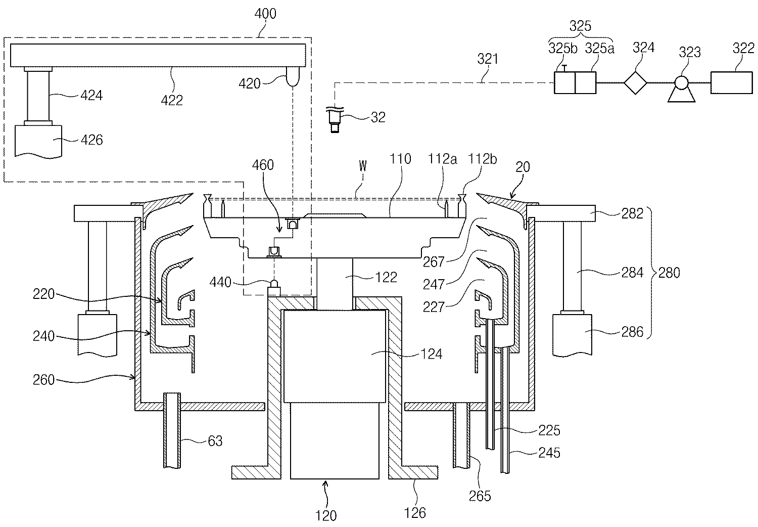
도 3은 도 2의 기판 지지 유닛(10)과 용기(20)의 구성 및 약액 공급 배관 계통을 보여주는 측단면도이다.3 is a side cross-sectional view showing the structure of the
도 2 및 도 3을 참조하면, 기판 지지 유닛(10)은 용기(20)의 내부 공간에 배치된다. 기판 지지 유닛(10)은 지지판(110)을 가진다. 지지판(110)의 상면에는 기판(W)을 지지하는 핀 부재들(112a,112b)이 결합된다. 지지 핀들(112a)은 기판(W)의 하면을 지지하고, 척킹 핀들(112b)은 기판(W)의 측면을 지지한다.2 and 3, the
지지판(110)은 구동 부재(120)에 의해 회전된다. 구동 부재(120)는 지지판(110)의 하면에 결합되는 구동 축(122)과, 구동 축(122)에 구동력을 제공하는 구동기(124)를 포함한다. 구동기(124)는 구동 축(122)에 회전력을 제공하는 모터일 수 있으며, 선택적으로 구동 축(122)을 상하 방향으로 직선 이동시키는 구동력을 제공할 수도 있다. 구동기(124)는 프레임(126)에 의해 지지된다.The
용기(20)는 내부에 상부가 개방되고 기판(W)이 처리되는 공간을 가지며, 공정에 사용된 약액들을 분리하여 회수할 수 있는 구조를 가진다. 이는 약액들의 재사용이 가능하게 한다. 용기(20)는 복수의 회수통들(220, 240, 260)을 가진다. 각각의 회수통(220, 240, 260)은 공정에 사용된 처리액들 중 서로 상이한 종류의 처리액을 회수한다. 본 실시 예에서 용기(20)는 3개의 회수통들을 가진다. 각각의 회수통들을 내부 회수통(220), 중간 회수통(240), 그리고 외부 회수통(260)이라 칭한다. The
내부 회수통(220)은 지지판(110)을 감싸는 환형의 링 형상으로 제공되고, 중간 회수통(240)은 내부 회수통(220)을 감싸는 환형의 링 형상으로 제공되며, 외부 회수통(260)은 중간 회수통(240)을 감싸는 환형의 링 형상으로 제공된다. 각각의 회수통(220, 240, 260)은 용기(20) 내에서 용기 내 공간과 통하는 유입구(227, 247, 267)를 가진다. 각각의 유입구(227, 247, 267)는 지지판(110)의 둘레에 링 형상으로 제공된다. 기판(W)으로 분사되어 공정에 사용된 약액들은 기판(W)의 회전으로 인한 원심력에 의해 유입구(227, 247, 267)를 통해 회수통(220, 240, 260)으로 유입된다. 외부 회수통(260)의 유입구(267)는 중간 회수통(240)의 유입구(247)의 수직 상부에 제공되고, 중간 회수통(240)의 유입구(247)는 내부 회수통(220)의 유입구(227)의 수직 상부에 제공된다.The
내부 회수통(220)의 바닥벽에는 배출관(225)이 결합되고, 중간 회수통(240) 의 바닥벽에는 배출관(245)이 결합되고, 외부 회수통(260)의 바닥벽에는 배출관(265)이 결합된다. 내부 회수통(220), 중간 회수통(240) 및 외부 회수통(260)을 통해 유입된 처리액은 배출관(225,245,265)을 통해 외부의 약액 재생을 위한 시스템으로 배출된다. 그리고 외부 회수통(260)의 바닥벽에는 배기관(263)이 결합되며, 내부 회수통(220), 중간 회수통(240) 및 외부 회수통(260)으로 유입된 가스는 배기관(263)을 통해 외부로 배기한다.The
승강 유닛(280)은 용기(20)를 상하 방향으로 직선 이동시킨다. 용기(20)가 상하로 이동됨에 따라 지지판(110)에 대한 용기(20)의 상대 높이가 변경된다. 승강 유닛(280)은 브라켓(282), 이동 축(284), 그리고 구동기(286)를 가진다. 브라켓(282)은 용기(20)의 외벽에 고정 설치되고, 브라켓(282)에는 구동기(286)에 의해 상하 방향으로 이동되는 이동 축(284)이 고정 결합된다. 기판(W)이 지지판(110)에 놓이거나, 지지판(110)으로부터 들어 올릴 때 지지판(110)이 용기(20)의 상부로 돌출되도록 용기(20)는 하강한다. 또한, 공정이 진행시에는 기판(W)에 공급된 처리액의 종류에 따라 처리액이 기설정된 회수통(220, 240, 260)으로 유입될 수 있도록 용기(20)의 높이가 조절된다.The
제 1 처리 유체 공급 부재(30)의 약액 공급 노즐(32)은 지지판(110)상에 놓인 기판의 상부 공간에서 스캔 방식으로 직선 왕복 운동하고, 기판으로 약액을 공급한다. 약액 공급 노즐(32)은 약액 공급 라인(321)에 의해 약액 공급원(322)에 연결된다. 약액 공급 라인(321)상에는 약액 공급원(322)으로부터 약액 공급 노 즐(321) 방향으로 펌프(323), 필터(324) 및 밸브(325)가 순차적으로 배치된다. 밸브(325)는 컷 오프 밸브(Cut-Off Valve, 325a)와 석백 밸브(Suckback Valve, 325b)를 가진다. 약액 공급원(322)으로부터 공급되는 약액은 펌프(323)에 의해 가압되고, 가압된 약액은 필터(324)를 거쳐 컷 오프 밸브(325a) 및 석백 밸브(325b)를 통과한 후, 약액 공급 노즐(32)을 통해 기판상에 토출된다. 컷 오프 밸브(325a)는 가압된 약액의 흐름을 온/오프(On/Off)하고, 석백 밸브(325b)는 약액 토출후 약액 공급 노즐(32)의 토출구(미도시) 끝단에 존재하는 일정량의 약액을 흡입하여 후퇴시킴으로써 약액의 흘림을 방지한다.The chemical
감지 부재(400)는 기판 처리 공정의 진행 중 기판의 지지판(110)으로부터의 이탈 여부를 감지한다. 감지 부재(400)는 발광 소자(420), 수광 소자(440), 그리고 광 전달부(460)를 포함한다. The sensing
발광 소자(420)는 지지판(110)의 상부에 배치되며, 지지판(110)의 상면을 향해 광을 방출한다. 발광 소자(420)는 광이 지지판(110)의 상면에 수직하게 방출되도록 지지판(110) 상면에 대해 수직하게 제공될 수 있다. 발광 소자(420)는 지지대(422)의 일단에 연결되고, 지지대(442)는 발광 소자(420)과 직각을 유지하도록 수평 방향으로 배치된다. 지지대(442)의 타 단에는 지지대(442)와 직각을 유지하도록 수직 방향으로 배치되는 수직 로드(424)가 결합된다. 수직 로드(424)는 고정될 수 있으며, 또한 구동부(426)에 의해 회전될 수도 있다.The
수광 소자(440)는 지지판(110)의 하부에 배치되며, 광을 수광한다. 수광 소 자(440)는 수광되는 광이 지지판(110)의 하면에 수직하도록 지지판(110) 하면에 대해 수직한 방향으로 제공될 수 있으며, 구동기(124)를 지지하는 프레임(126)에 설치될 수 있다.The
광 전달부(460)는 지지판(110)에 설치되며, 발광 소자(420)에서 방출된 광을 수광 소자(440)로 전달한다. 광 전달부(460)는 발광 소자(420)와 마주보도록 지지판(110)의 상면에 설치되는 제 1 광 전달 소자(461)와, 수광 소자(440)와 마주보도록 지지판(110)의 하면에 설치되는 제 2 광 전달 소자(462)를 가진다. 제 1 및 제 2 광 전달 소자(461,462)는 광 이동 모듈(463)에 의해 연결될 수 있다. 광 이동 모듈(463)은 광 섬유로 제공될 수 있으며, 제 1 광 전달 소자(461)와 제 2 광 전달 소자(462) 간의 광 이동 경로를 제공한다. The
제 1 및 제 2 광 전달 소자(461,462)는 동일 연직선 상에 위치할 수 있으며, 또한 도 3에 도시된 바와 같이, 동일 연직선 상에 위치하지 않도록 제공될 수도 있다. 제 1 및 제 2 광 전달 소자(461,462)가 동일 연직선 상에 위치하지 않도록 제공되면, 제 1 및 제 2 광 전달 소자(461,462)와 마주보도록 설치된 발광 소자(420)와 수광 소자(440)도 동일 연직선 상에 위치하지 않는다.The first and second
제 1 광 전달 소자(461)는 지지판(110)의 상면에 형성된 홈(110a)에 삽입 설치되고, 제 2 광 전달 소자(462)는 지지판(110)의 하면에 형성된 홈(110b)에 삽입 설치될 수 있다. 그리고, 제 1 및 제 2 광 전달 소자(461,462)가 삽입된 홈들(110a,100b)은 투명한 내부식성 합성 수지 재질의 커버들(464,465)로 밀폐될 수 있다. 커버들(464,465)은 기판 처리 공정의 진행 중 약액이 제 1 및 제 2 광 전달 소자들(461,462)로 침투하는 것을 방지한다. The first
도 4 및 도 5는 기판의 유무에 따른 감지 부재의 동작 상태를 보여주는 도면들이다. 도 4 및 도 5를 참조하면, 발광 소자(420)는 지지판(110)을 향해 광을 방출한다. 지지판(110)에 로딩된 기판(W)이 정상적으로 지지판(110) 상에 안착되어 있을 경우, 도 4에 도시된 바와 같이, 발광 소자(420)로부터 방출된 광은 기판(W)에 의해 반사되기 때문에, 수광 소자(440)로는 광이 수광되지 않는다.4 and 5 are views showing an operating state of the sensing member according to the presence or absence of a substrate. 4 and 5, the
이와 반대로, 지지판(110)에 로딩된 기판(W)이 지지판(110)으로부터 이탈된 경우, 도 5에 도시된 바와 같이, 발광 소자(420)로부터 방출된 광은 커버(464)를 통해 제 1 광 전달 소자(461)로 입사된다. 제 1 광 전달 소자(461)로 입사된은 광 이동 모듈(463)에 의해 제 2 광 전달 소자(462)로 전달된다. 제 2 광 전달 소자(462)로 전달된 광은 커버(465)를 통해 수광 소자(440)로 전달된다. 수광 소자(440)로 광이 전달되면, 제어부(미도시)는 기판(W)이 지지판(110)으로부터 이탈되었다고 판단하여, 알람을 발생할 수 있다.On the contrary, when the substrate W loaded on the
기판의 이탈 여부를 검출하는 과정을 보다 구체적으로 설명하면 다음과 같다. 발광 소자(420)는 지지판(110)을 향해 연속적으로 광을 방출하고, 지지판(110)은 회전된다. 지지판(110)이 회전되면, 도 6에 도시된 바와 같이, 지지판(110)에 구비된 제 1 및 제 2 광 전달 소자(461,462)가 회전하고, 제 1 및 제 2 광 전달 소자(461,462)는 360도 회전한 후 원 위치로 복귀하는 과정을 반복한다. 제 1 및 제 2 광 전달 소자(461,462)는 회전하는 동안 주기적으로 발광 소자(420) 및 수광 소 자(440)와 마주보는 위치를 통과하면서 발광 소자(420)에서 방출된 광을 수광 소자(440)로 전달한다. 수광 소자(440)로 광이 전달되는 주기(단위 시간당 수광 회수)가 지지판(110)의 회전 주기(단위 시간당 회전수)와 동일하면, 제어부(미도시)는 기판이 지지판(110)으로부터 이탈되었다고 판단하고, 알람을 발생할 수 있으며, 이와 동시에 지지판(110)을 회전시키는 구동기(124)의 동작을 정지시킬 수 있다.The process of detecting the departure of the substrate will be described in more detail as follows. The
이와 같은 방법에 의해, 공정 진행 중 회전하는 지지판(110)으로부터의 기판 이탈 여부를 확인할 수 있으며, 이를 통해 이탈된 기판에 의한 지지판(110)이나 용기(20) 등의 주변 장치의 손상을 방지할 수 있다.By such a method, it is possible to check whether the substrate is separated from the supporting
이상의 설명은 본 발명의 기술 사상을 예시적으로 설명한 것에 불과한 것으로서, 본 발명이 속하는 기술 분야에서 통상의 지식을 가진 자라면 본 발명의 본질적인 특성에서 벗어나지 않는 범위에서 다양한 수정 및 변형이 가능할 것이다. 따라서, 본 발명에 개시된 실시 예들은 본 발명의 기술 사상을 한정하기 위한 것이 아니라 설명하기 위한 것이고, 이러한 실시 예에 의하여 본 발명의 기술 사상의 범위가 한정되는 것은 아니다. 본 발명의 보호 범위는 아래의 청구범위에 의하여 해석되어야 하며, 그와 동등한 범위 내에 있는 모든 기술 사상은 본 발명의 권리범위에 포함되는 것으로 해석되어야 할 것이다.The foregoing description is merely illustrative of the technical idea of the present invention, and various changes and modifications may be made by those skilled in the art without departing from the essential characteristics of the present invention. Therefore, the embodiments disclosed in the present invention are not intended to limit the technical idea of the present invention but to describe the present invention, and the scope of the technical idea of the present invention is not limited by these embodiments. The protection scope of the present invention should be interpreted by the following claims, and all technical ideas within the equivalent scope should be interpreted as being included in the scope of the present invention.
이하에 설명된 도면들은 단지 예시의 목적을 위한 것이고, 본 발명의 범위를 제한하기 위한 것이 아니다.The drawings described below are for illustrative purposes only and are not intended to limit the scope of the invention.
도 1은 매엽식 기판 세정 설비의 레이아웃을 보여주는 도면이다.1 shows the layout of a sheet type substrate cleaning facility.
도 2는 도 1의 공정 챔버의 내부 구성을 보여주는 사시도이다.FIG. 2 is a perspective view illustrating an internal configuration of the process chamber of FIG. 1.
도 3은 도 2의 기판 지지 유닛와 용기의 구성 및 약액 공급 배관 계통을 보여주는 측단면도이다.3 is a side cross-sectional view showing the structure of the substrate supporting unit and the container of FIG. 2 and the chemical liquid supply piping system.
도 4 및 도 5는 기판의 유무에 따른 감지 부재의 동작 상태를 보여주는 도면들이다.4 and 5 are views showing an operating state of the sensing member according to the presence or absence of a substrate.
도 6은 도 5의 평면도이다.6 is a plan view of FIG. 5.
< 도면의 주요 부분에 대한 부호의 설명 ><Description of Symbols for Main Parts of Drawings>
110 : 지지판 400 : 감지 부재110: support plate 400: sensing member
420 : 발광 소자 440 : 수광 소자420: light emitting element 440: light receiving element
460 : 광 전달부 461, 462 : 광 전달 소자460:
463 : 광 이동 모듈 464,465 : 커버463: light transfer module 464,465: cover
Claims (19)
Priority Applications (1)
| Application Number | Priority Date | Filing Date | Title |
|---|---|---|---|
| KR1020080118106A KR101018016B1 (en) | 2008-11-26 | 2008-11-26 | Substrate support unit, substrate processing apparatus and method using same |
Applications Claiming Priority (1)
| Application Number | Priority Date | Filing Date | Title |
|---|---|---|---|
| KR1020080118106A KR101018016B1 (en) | 2008-11-26 | 2008-11-26 | Substrate support unit, substrate processing apparatus and method using same |
Publications (2)
| Publication Number | Publication Date |
|---|---|
| KR20100059360A KR20100059360A (en) | 2010-06-04 |
| KR101018016B1 true KR101018016B1 (en) | 2011-03-02 |
Family
ID=42360686
Family Applications (1)
| Application Number | Title | Priority Date | Filing Date |
|---|---|---|---|
| KR1020080118106A Active KR101018016B1 (en) | 2008-11-26 | 2008-11-26 | Substrate support unit, substrate processing apparatus and method using same |
Country Status (1)
| Country | Link |
|---|---|
| KR (1) | KR101018016B1 (en) |
Families Citing this family (10)
| Publication number | Priority date | Publication date | Assignee | Title |
|---|---|---|---|---|
| KR102685189B1 (en) | 2022-08-23 | 2024-07-16 | 엘에스이 주식회사 | Substrate cleaning apparatus |
| KR102702408B1 (en) | 2022-09-08 | 2024-09-04 | 엘에스이 주식회사 | Substrate cleaning apparatus |
| KR20240126197A (en) | 2023-02-13 | 2024-08-20 | 엘에스이 주식회사 | Substrate cleaning apparatus |
| KR102798182B1 (en) | 2023-05-23 | 2025-04-22 | 엘에스이 주식회사 | Substrate cleaning apparatus |
| KR102821310B1 (en) | 2023-10-26 | 2025-06-17 | 엘에스이 주식회사 | Substrate cleaning apparatus |
| KR102819139B1 (en) | 2023-11-10 | 2025-06-11 | 엘에스이 주식회사 | Substrate cleaning apparatus |
| KR102836608B1 (en) | 2024-02-01 | 2025-07-22 | 엘에스이 주식회사 | Substrate cleaning apparatus |
| KR102836609B1 (en) | 2024-02-07 | 2025-07-22 | 엘에스이 주식회사 | Substrate cleaning apparatus |
| KR20250165735A (en) | 2024-05-20 | 2025-11-27 | 엘에스이 주식회사 | Substrate cleaning apparatus |
| KR20250173106A (en) | 2024-06-03 | 2025-12-10 | 엘에스이 주식회사 | Substrate cleaning apparatus |
Citations (4)
| Publication number | Priority date | Publication date | Assignee | Title |
|---|---|---|---|---|
| JPH06150871A (en) * | 1992-11-11 | 1994-05-31 | Nissin Electric Co Ltd | Wafer floating detector |
| KR20060035225A (en) * | 2004-10-21 | 2006-04-26 | 삼성전자주식회사 | Semiconductor exposure apparatus having wafer centering unit |
| KR100695228B1 (en) * | 2005-09-08 | 2007-03-14 | 세메스 주식회사 | Substrate Processing Apparatus and Method |
| KR20080014169A (en) * | 2006-08-10 | 2008-02-14 | 동부일렉트로닉스 주식회사 | Electrostatic chuck wafer sensing structure |
-
2008
- 2008-11-26 KR KR1020080118106A patent/KR101018016B1/en active Active
Patent Citations (4)
| Publication number | Priority date | Publication date | Assignee | Title |
|---|---|---|---|---|
| JPH06150871A (en) * | 1992-11-11 | 1994-05-31 | Nissin Electric Co Ltd | Wafer floating detector |
| KR20060035225A (en) * | 2004-10-21 | 2006-04-26 | 삼성전자주식회사 | Semiconductor exposure apparatus having wafer centering unit |
| KR100695228B1 (en) * | 2005-09-08 | 2007-03-14 | 세메스 주식회사 | Substrate Processing Apparatus and Method |
| KR20080014169A (en) * | 2006-08-10 | 2008-02-14 | 동부일렉트로닉스 주식회사 | Electrostatic chuck wafer sensing structure |
Also Published As
| Publication number | Publication date |
|---|---|
| KR20100059360A (en) | 2010-06-04 |
Similar Documents
| Publication | Publication Date | Title |
|---|---|---|
| KR101018016B1 (en) | Substrate support unit, substrate processing apparatus and method using same | |
| KR102297377B1 (en) | Substrate treating apparatus | |
| CN112235927B (en) | A wafer destaticizing and cleaning device | |
| KR100850698B1 (en) | Substrate cleaning apparatus, substrate cleaning method, substrate processing system, and recorind medium | |
| JP5426301B2 (en) | Substrate processing equipment | |
| CN106816399B (en) | Substrate processing apparatus and method | |
| KR102435940B1 (en) | Substrate warping monitoring device, substrate warping monitoring method, substrate processing apparatus and substrate-type sensor | |
| KR20120015662A (en) | Substrate processing apparatus | |
| KR101080865B1 (en) | Method for treating substrate | |
| JP2004507102A (en) | Semiconductor wafer container cleaning equipment | |
| KR100912702B1 (en) | Apparatus and method for treating substrate | |
| KR100839912B1 (en) | Substrate Processing Apparatus and Method | |
| CN212696256U (en) | Wafer static electricity removing and cleaning device | |
| US20210066099A1 (en) | Apparatus and method for processing substrate | |
| KR20140071312A (en) | Apparatus for Processing Substrate | |
| KR101909476B1 (en) | Brush unit and Apparatus for treating substrate with the unit | |
| KR102193031B1 (en) | Apparatus and Method for treating substrate | |
| KR20120077516A (en) | Substrate processing apparatus | |
| KR20230099184A (en) | Apparatus for treating substrate | |
| KR20070092530A (en) | Single Sheet Substrates | |
| KR20180059243A (en) | Substrate treating apparatus and material for substrate treating apparatus | |
| KR20220132096A (en) | Substrate processing apparatus and substrate processing method | |
| KR100757848B1 (en) | Single Sheet Substrate Processing Equipment | |
| KR102685189B1 (en) | Substrate cleaning apparatus | |
| JP2001223195A (en) | Single wafer type substrate cleaning method, single wafer type substrate cleaning apparatus and substrate cleaning system |
Legal Events
| Date | Code | Title | Description |
|---|---|---|---|
| A201 | Request for examination | ||
| PA0109 | Patent application |
St.27 status event code: A-0-1-A10-A12-nap-PA0109 |
|
| PA0201 | Request for examination |
St.27 status event code: A-1-2-D10-D11-exm-PA0201 |
|
| R18-X000 | Changes to party contact information recorded |
St.27 status event code: A-3-3-R10-R18-oth-X000 |
|
| D13-X000 | Search requested |
St.27 status event code: A-1-2-D10-D13-srh-X000 |
|
| D14-X000 | Search report completed |
St.27 status event code: A-1-2-D10-D14-srh-X000 |
|
| PN2301 | Change of applicant |
St.27 status event code: A-3-3-R10-R13-asn-PN2301 St.27 status event code: A-3-3-R10-R11-asn-PN2301 |
|
| PG1501 | Laying open of application |
St.27 status event code: A-1-1-Q10-Q12-nap-PG1501 |
|
| E902 | Notification of reason for refusal | ||
| PE0902 | Notice of grounds for rejection |
St.27 status event code: A-1-2-D10-D21-exm-PE0902 |
|
| T11-X000 | Administrative time limit extension requested |
St.27 status event code: U-3-3-T10-T11-oth-X000 |
|
| E13-X000 | Pre-grant limitation requested |
St.27 status event code: A-2-3-E10-E13-lim-X000 |
|
| P11-X000 | Amendment of application requested |
St.27 status event code: A-2-2-P10-P11-nap-X000 |
|
| P13-X000 | Application amended |
St.27 status event code: A-2-2-P10-P13-nap-X000 |
|
| E701 | Decision to grant or registration of patent right | ||
| PE0701 | Decision of registration |
St.27 status event code: A-1-2-D10-D22-exm-PE0701 |
|
| GRNT | Written decision to grant | ||
| PR0701 | Registration of establishment |
St.27 status event code: A-2-4-F10-F11-exm-PR0701 |
|
| PR1002 | Payment of registration fee |
St.27 status event code: A-2-2-U10-U11-oth-PR1002 Fee payment year number: 1 |
|
| PG1601 | Publication of registration |
St.27 status event code: A-4-4-Q10-Q13-nap-PG1601 |
|
| R18-X000 | Changes to party contact information recorded |
St.27 status event code: A-5-5-R10-R18-oth-X000 |
|
| FPAY | Annual fee payment |
Payment date: 20140221 Year of fee payment: 4 |
|
| PR1001 | Payment of annual fee |
St.27 status event code: A-4-4-U10-U11-oth-PR1001 Fee payment year number: 4 |
|
| FPAY | Annual fee payment |
Payment date: 20150212 Year of fee payment: 5 |
|
| PR1001 | Payment of annual fee |
St.27 status event code: A-4-4-U10-U11-oth-PR1001 Fee payment year number: 5 |
|
| FPAY | Annual fee payment |
Payment date: 20160205 Year of fee payment: 6 |
|
| PR1001 | Payment of annual fee |
St.27 status event code: A-4-4-U10-U11-oth-PR1001 Fee payment year number: 6 |
|
| FPAY | Annual fee payment |
Payment date: 20170213 Year of fee payment: 7 |
|
| PR1001 | Payment of annual fee |
St.27 status event code: A-4-4-U10-U11-oth-PR1001 Fee payment year number: 7 |
|
| FPAY | Annual fee payment |
Payment date: 20180213 Year of fee payment: 8 |
|
| PR1001 | Payment of annual fee |
St.27 status event code: A-4-4-U10-U11-oth-PR1001 Fee payment year number: 8 |
|
| P22-X000 | Classification modified |
St.27 status event code: A-4-4-P10-P22-nap-X000 |
|
| FPAY | Annual fee payment |
Payment date: 20190220 Year of fee payment: 9 |
|
| PR1001 | Payment of annual fee |
St.27 status event code: A-4-4-U10-U11-oth-PR1001 Fee payment year number: 9 |
|
| FPAY | Annual fee payment |
Payment date: 20200212 Year of fee payment: 10 |
|
| PR1001 | Payment of annual fee |
St.27 status event code: A-4-4-U10-U11-oth-PR1001 Fee payment year number: 10 |
|
| PR1001 | Payment of annual fee |
St.27 status event code: A-4-4-U10-U11-oth-PR1001 Fee payment year number: 11 |
|
| PR1001 | Payment of annual fee |
St.27 status event code: A-4-4-U10-U11-oth-PR1001 Fee payment year number: 12 |
|
| PN2301 | Change of applicant |
St.27 status event code: A-5-5-R10-R13-asn-PN2301 St.27 status event code: A-5-5-R10-R11-asn-PN2301 |
|
| R18-X000 | Changes to party contact information recorded |
St.27 status event code: A-5-5-R10-R18-oth-X000 |
|
| PR1001 | Payment of annual fee |
St.27 status event code: A-4-4-U10-U11-oth-PR1001 Fee payment year number: 13 |
|
| PR1001 | Payment of annual fee |
St.27 status event code: A-4-4-U10-U11-oth-PR1001 Fee payment year number: 14 |
|
| PN2301 | Change of applicant |
St.27 status event code: A-5-5-R10-R13-asn-PN2301 St.27 status event code: A-5-5-R10-R11-asn-PN2301 |
|
| PR1001 | Payment of annual fee |
St.27 status event code: A-4-4-U10-U11-oth-PR1001 Fee payment year number: 15 |
|
| P22-X000 | Classification modified |
St.27 status event code: A-4-4-P10-P22-nap-X000 |
|
| PR1001 | Payment of annual fee |
St.27 status event code: A-4-4-U10-U11-oth-PR1001 Fee payment year number: 16 |