KR101012042B1 - LED lamp for headlight source - Google Patents
LED lamp for headlight source Download PDFInfo
- Publication number
- KR101012042B1 KR101012042B1 KR1020030079396A KR20030079396A KR101012042B1 KR 101012042 B1 KR101012042 B1 KR 101012042B1 KR 1020030079396 A KR1020030079396 A KR 1020030079396A KR 20030079396 A KR20030079396 A KR 20030079396A KR 101012042 B1 KR101012042 B1 KR 101012042B1
- Authority
- KR
- South Korea
- Prior art keywords
- light emitting
- led
- led light
- light
- shielding member
- Prior art date
- Legal status (The legal status is an assumption and is not a legal conclusion. Google has not performed a legal analysis and makes no representation as to the accuracy of the status listed.)
- Expired - Fee Related
Links
Images


Classifications
-
- H—ELECTRICITY
- H10—SEMICONDUCTOR DEVICES; ELECTRIC SOLID-STATE DEVICES NOT OTHERWISE PROVIDED FOR
- H10H—INORGANIC LIGHT-EMITTING SEMICONDUCTOR DEVICES HAVING POTENTIAL BARRIERS
- H10H20/00—Individual inorganic light-emitting semiconductor devices having potential barriers, e.g. light-emitting diodes [LED]
- H10H20/80—Constructional details
- H10H20/85—Packages
- H10H20/855—Optical field-shaping means, e.g. lenses
-
- F—MECHANICAL ENGINEERING; LIGHTING; HEATING; WEAPONS; BLASTING
- F21—LIGHTING
- F21K—NON-ELECTRIC LIGHT SOURCES USING LUMINESCENCE; LIGHT SOURCES USING ELECTROCHEMILUMINESCENCE; LIGHT SOURCES USING CHARGES OF COMBUSTIBLE MATERIAL; LIGHT SOURCES USING SEMICONDUCTOR DEVICES AS LIGHT-GENERATING ELEMENTS; LIGHT SOURCES NOT OTHERWISE PROVIDED FOR
- F21K9/00—Light sources using semiconductor devices as light-generating elements, e.g. using light-emitting diodes [LED] or lasers
-
- F—MECHANICAL ENGINEERING; LIGHTING; HEATING; WEAPONS; BLASTING
- F21—LIGHTING
- F21S—NON-PORTABLE LIGHTING DEVICES; SYSTEMS THEREOF; VEHICLE LIGHTING DEVICES SPECIALLY ADAPTED FOR VEHICLE EXTERIORS
- F21S41/00—Illuminating devices specially adapted for vehicle exteriors, e.g. headlamps
- F21S41/10—Illuminating devices specially adapted for vehicle exteriors, e.g. headlamps characterised by the light source
- F21S41/14—Illuminating devices specially adapted for vehicle exteriors, e.g. headlamps characterised by the light source characterised by the type of light source
- F21S41/16—Laser light sources
-
- F—MECHANICAL ENGINEERING; LIGHTING; HEATING; WEAPONS; BLASTING
- F21—LIGHTING
- F21S—NON-PORTABLE LIGHTING DEVICES; SYSTEMS THEREOF; VEHICLE LIGHTING DEVICES SPECIALLY ADAPTED FOR VEHICLE EXTERIORS
- F21S41/00—Illuminating devices specially adapted for vehicle exteriors, e.g. headlamps
- F21S41/10—Illuminating devices specially adapted for vehicle exteriors, e.g. headlamps characterised by the light source
- F21S41/14—Illuminating devices specially adapted for vehicle exteriors, e.g. headlamps characterised by the light source characterised by the type of light source
- F21S41/141—Light emitting diodes [LED]
-
- F—MECHANICAL ENGINEERING; LIGHTING; HEATING; WEAPONS; BLASTING
- F21—LIGHTING
- F21S—NON-PORTABLE LIGHTING DEVICES; SYSTEMS THEREOF; VEHICLE LIGHTING DEVICES SPECIALLY ADAPTED FOR VEHICLE EXTERIORS
- F21S41/00—Illuminating devices specially adapted for vehicle exteriors, e.g. headlamps
- F21S41/40—Illuminating devices specially adapted for vehicle exteriors, e.g. headlamps characterised by screens, non-reflecting members, light-shielding members or fixed shades
- F21S41/43—Illuminating devices specially adapted for vehicle exteriors, e.g. headlamps characterised by screens, non-reflecting members, light-shielding members or fixed shades characterised by the shape thereof
-
- F—MECHANICAL ENGINEERING; LIGHTING; HEATING; WEAPONS; BLASTING
- F21—LIGHTING
- F21Y—INDEXING SCHEME ASSOCIATED WITH SUBCLASSES F21K, F21L, F21S and F21V, RELATING TO THE FORM OR THE KIND OF THE LIGHT SOURCES OR OF THE COLOUR OF THE LIGHT EMITTED
- F21Y2115/00—Light-generating elements of semiconductor light sources
- F21Y2115/10—Light-emitting diodes [LED]
-
- H—ELECTRICITY
- H10—SEMICONDUCTOR DEVICES; ELECTRIC SOLID-STATE DEVICES NOT OTHERWISE PROVIDED FOR
- H10H—INORGANIC LIGHT-EMITTING SEMICONDUCTOR DEVICES HAVING POTENTIAL BARRIERS
- H10H20/00—Individual inorganic light-emitting semiconductor devices having potential barriers, e.g. light-emitting diodes [LED]
- H10H20/80—Constructional details
- H10H20/85—Packages
- H10H20/852—Encapsulations
-
- H—ELECTRICITY
- H10—SEMICONDUCTOR DEVICES; ELECTRIC SOLID-STATE DEVICES NOT OTHERWISE PROVIDED FOR
- H10H—INORGANIC LIGHT-EMITTING SEMICONDUCTOR DEVICES HAVING POTENTIAL BARRIERS
- H10H20/00—Individual inorganic light-emitting semiconductor devices having potential barriers, e.g. light-emitting diodes [LED]
- H10H20/80—Constructional details
- H10H20/85—Packages
- H10H20/855—Optical field-shaping means, e.g. lenses
- H10H20/856—Reflecting means
-
- H10W72/536—
-
- H10W72/5363—
-
- H10W72/5522—
-
- H10W74/00—
Landscapes
- Engineering & Computer Science (AREA)
- Physics & Mathematics (AREA)
- Optics & Photonics (AREA)
- General Engineering & Computer Science (AREA)
- Microelectronics & Electronic Packaging (AREA)
- Non-Portable Lighting Devices Or Systems Thereof (AREA)
- Led Device Packages (AREA)
- Led Devices (AREA)
Abstract
본 발명은 차량용 등구의 광원으로 사용되는 LED 램프에 관한 것이다.The present invention relates to an LED lamp used as a light source of a vehicle lamp.
백열전구 등 종래의 광원이 거의 전방위로 광을 발생시켰던 것에 비해, LED 램프는 한쪽으로만 광을 발생시키기 때문에, 종래의 전조등의 구성으로는 만족할만한 배광특성을 형성할 수 없다는 문제점이 있었다.Compared with conventional light sources such as incandescent lamps that generate light almost omnidirectionally, LED lamps generate light only on one side, and thus there is a problem in that the conventional headlight configuration does not provide satisfactory light distribution characteristics.
본 발명에 의해, 단색발광의 LED 발광부와, 상기 LED 발광부로부터의 광을 투영수단에 의해 조사방향으로 확대투영할 때 차량용 전조등에 적합한 배광특성이 얻어지는 형상으로 상기 LED 발광부의 일부를 덮는 차폐부재를 포함하여 구성되며, 상기 LED 발광부와 상기 차폐부재 중 적어도 하나는 상기 투영수단의 초점근방에 배치되는 것을 특징으로 하는 전조등 발광원 LED 램프로 함으로써, 투영 렌즈로 조사방향을 투영하는 것만으로 정확한 배광특성을 얻을 수 있다.According to the present invention, a shield for covering a portion of the LED light emitting part having a shape in which a light emitting characteristic suitable for a vehicle headlamp is obtained when the LED light emitting part of monochromatic light emission and the light from the LED light emitting part is projected in the irradiation direction by the projection means. And a member, wherein at least one of the LED light emitting portion and the shielding member is disposed near a focal point of the projection means, thereby only projecting the irradiation direction with the projection lens. Accurate light distribution characteristics can be obtained.
전조등, LED램프Headlights, LED Lamps
Description
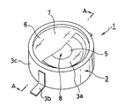
도 1은 본 발명에 따른 전조등 광원용 LED 램프의 실시예를 나타내는 사시도이다.1 is a perspective view showing an embodiment of an LED lamp for a headlamp light source according to the present invention.
도 2는 도 1의 A-A선에 따른 단면도이다.2 is a cross-sectional view taken along the line A-A of FIG.
도 3은 본 발명에 의해 얻어지는 교차 배광특성의 예를 나타내는 설명도이다.3 is an explanatory diagram showing an example of cross light distribution characteristics obtained by the present invention.
도 4는 본 발명에 따른 전조등 광원용 LED 램프를 투영렌즈와 조합시킬 때의 상태를 나타내는 설명도이다.4 is an explanatory diagram showing a state when the LED lamp for the headlamp light source according to the present invention is combined with the projection lens.
도 5는 본 발명에 따른 전조등 광원용 LED 램프의 차폐부재의 구성예를 나타내는 단면도이다. 5 is a cross-sectional view showing a configuration example of a shield member of the LED lamp for the headlamp light source according to the present invention.
도 6은 본 발명에 따른 전조등 광원용 LED 램프에서, 발광부와 차폐부재 사이의 거리와, 최대광도(상대치)와의 관계를 나타내는 그래프이다.6 is a graph showing the relationship between the distance between the light emitting portion and the shielding member and the maximum luminous intensity (relative value) in the LED lamp for the headlamp light source according to the present invention.
도 7은 투영렌즈에 발생하는 색수차의 예를 나타내는 설명도이다.7 is an explanatory diagram showing an example of chromatic aberration occurring in the projection lens.
도 8은 본 발명에 따른 전조등 광원용 LED 램프에서의 차폐부재의 다른 구성예를 나타내는 단면도이다.8 is a cross-sectional view showing another example of the configuration of a shielding member in the LED lamp for the headlamp light source according to the present invention.
도 9는 마찬가지로 본 발명에 따른 전조등 광원용 LED 램프에서의 차폐부재의 또 다른 구성예를 나타내는 단면도이다. 9 is a sectional view showing still another example of the configuration of the shielding member in the LED lamp for the headlamp light source according to the present invention.
도 10은 여러개의 전조등 광원용 LED 램프와 투영렌즈와의 조합으로 조명등을 구성할 때의 예를 나타내는 설명도이다.FIG. 10 is an explanatory diagram showing an example when a lighting lamp is configured by combining a plurality of LED lamps for headlamp light sources and a projection lens.
도 11은 여러개의 전조등 광원용 LED 램프와 투영렌즈를 조합할 때의 배광특성의 예를 나타내는 설명도이다.11 is an explanatory diagram showing an example of light distribution characteristics when combining a plurality of LED lamps for headlamp light sources and a projection lens.
도 12는 본 발명에 따른 전조등 광원용 LED 램프를 리플렉터(reflector)와 조합시킬 때의 상태를 나타내는 설명도이다.It is explanatory drawing which shows the state at the time of combining the LED lamp for headlight light sources which concerns on this invention with a reflector.
***도면의 주요 부분에 대한 부호의 설명****** Description of the symbols for the main parts of the drawings ***
1 : 전조등 광원용 LED 램프 2 : LED 칩1: LED lamp for headlight light source 2: LED chip
3 : 베이스 3a : 기대부(基臺部)3:
3b : 리드 프레임 3c : 절연층3b:
4 : 금속선 5 : 형광체4: metal wire 5: phosphor
6 : 창유리형상 부재 7 : 차폐부재6: window glass member 7: shielding member
7a : 톱니형상부 8 : 백색 LED 발광부7a: tooth shape portion 8: white LED light emitting portion
9 : 실리콘 겔 10 : 투영렌즈9: silicone gel 10: projection lens
11 : 리플렉터 12 : ITO 막11: reflector 12: ITO membrane
본 발명은 LED 램프에 관한 것으로, 구체적으로는 차량용 등구(燈具)의 광원으로 사용되는 LED 램프의 구성에 관한 것으로서, 전조등(헤드라이트), 보조전조등(안개등) 등 종래에는 채용되지 않았던 차량용 조명 전구의 광원으로서 채용하기 적합한 LED 램프의 구성에 관한 것이다.BACKGROUND OF THE
종래에 LED 램프를, 예를 들어 손전등 등 조명용 등구의 광원으로서 사용할 때에는, 대형 LED 칩을 대형 패키지에 수납하고, 예를 들어 수십~수백 밀리암페어의 전류를 인가하여 광량을 얻었다. 동시에, 대형 패키지로 함으로써, 점등시켰을 때 상기 LED 칩에서 발생하는 열을 상기 패키지를 경유하여 효과적으로 외부로 전도시켜 대기중 등으로 방열시킴으로써, 과열에 의한 상기 LED 칩의 열화 혹은 파손을 방지하였다(예를 들어, 일본특허공개 2000-150968호 공보(단락 0011~단락 0034, 도 1) 참조)Conventionally, when using an LED lamp as a light source for lighting fixtures, such as a flashlight, a large LED chip was accommodated in a large package, for example, the light quantity was applied by applying the electric current of tens-several hundred milliamps. At the same time, by making a large package, heat generated from the LED chip when turned on is effectively conducted to the outside via the package and radiated to the air, thereby preventing deterioration or damage of the LED chip due to overheating (Example For example, see Japanese Patent Application Laid-Open No. 2000-150968 (see paragraphs 0011 to 0034, FIG. 1).
하지만, LED 램프를 광원으로 하는 등구가 전조등 등의 차량용 등구인 경우에는, 전방으로 조사되는 광이 마주오는 차의 운전자에게 방해되지 않도록, 엄밀한 배광특성이 관계규격 등에 의해 설정되어 있으며, 또한, 전조등 등 등구측의 구성은 거의 전방위로 균등하게 광속을 방산시키는 백열전구 등을 상정하여 형성하고 있기 때문에, 한 방향으로 치우쳐 광을 방사하는 LED램프로 단순히 교환하는 것만으로는, 만족할만한 배광특성이 얻어지지 않는다는 문제가 있다.However, in the case where the lighting lamp using the LED lamp as a light source is a vehicle lighting lamp such as a headlamp, the rigid light distribution characteristic is set according to the related standard so that the light irradiated to the front does not interfere with the driver of the oncoming car. Since the configuration of the light bulb side is assumed to be incandescent lamps that dissipate the light beam evenly in almost all directions, it is possible to obtain satisfactory light distribution characteristics by simply replacing the lamp with an LED lamp that radiates light in one direction. There is a problem that you do not lose.
본 발명은 상술한 종래의 과제를 해결하기 위한 구체적인 수단으로서, 단색발광의 LED 발광부와, 상기 LED 발광부로부터의 광을 투영수단에 의해 조사방향으로 확대투영할 때 차량용 전조등에 적합한 배광특성이 얻어지는 형상으로 상기 LED 발광부의 일부를 덮는 차폐부재를 포함하여 구성되며, 상기 LED 발광부와 상기 차폐부재 중 적어도 하나는 상기 투영수단의 초점근방에 배치되는 것을 특징으로 하는 전조등 발광원 LED 램프를 제공함으로써, LED 램프를 광원으로 채용할 때에도 규정된 배광특성을 정확하면서 용이하게 얻을 수 있다.The present invention is a specific means for solving the above-described conventional problems, the light distribution characteristics suitable for vehicle headlights when the LED light emitting part of the monochromatic light emitting and the light from the LED light emitting part is enlarged in the irradiation direction by the projection means And a shielding member covering a portion of the LED light emitting part in a shape obtained, wherein at least one of the LED light emitting part and the shielding member is disposed near a focal point of the projection means. Thus, even when the LED lamp is employed as the light source, the prescribed light distribution characteristics can be obtained accurately and easily.
이어서, 본 발명을 도면에서 나타내는 실시예에 따라 상세히 설명한다. 도 1 및 도 2에 부호 1로 나타내는 것은 본 발명에 따른 전조등 광원용 LED 램프(이하, LED 램프(1)라고 한다)이며, 이 LED 램프(1)에서 LED 칩(2)은 베이스(3) 위에 마운트가 이루어져 있다.Next, this invention is demonstrated in detail according to the Example shown by drawing. 1 and 2 denote an LED lamp for a headlamp light source (hereinafter referred to as an LED lamp 1) according to the present invention, in which the
상기 베이스(3)에는 구리 등 열전도성이 뛰어난 금속부재로 형성된 기대부(3a)와 마찬가지로 금속부재로 형성되는 리드프레임(3b)이 설치되며, 상기 기대부(3a)와 리드프레임(3b)은 수지부재 등 절연성 부재로 형성된 절연층(3c)에 의해 절연이 이루어져 있다. 그리고, 상기 기대부(3a)에 마운트가 행해진 LED 칩(2)에 대해서는 금속선(4) 등에 의해 리드프레임(3b)과의 배선이 이루어지고, 외부로부터의 전력 공급에 의해 점등이 이루어지는 것이다.The
여기서, 상기 LED 칩(1)을 전조등의 광원용으로 채용했을 때의 필요조건에 대해서 생각해 보면, 등색으로는 백색 또는 황색의 단색이 규정색이며, 통상 백색이 채용되는 경우가 많지만, 현실적으로는 백색을 직접적으로 발광하는 LED 칩(2)은 존재하지 않으며, 백색광을 얻기 위해 형광체(5)를 병용하고 있다.Here, considering the requirements when the
그 제 1 방법으로서는, 청색발광의 LED 칩(2)과 파장변환부재로서의 황색발광의 형광체(5)를 조합하는 것으로, LED 칩(2)으로부터의 직사광인 청색광과, 상기 LED 칩(2)으로부터의 광에 의해 여기되는 형광체(5)로부터의 황색광이 혼합하여 백색광을 얻을 수 있다. 또한 제 2 방법으로는, 자외발광하는 LED 칩(2)과 적(R), 녹(G), 청(B)의 삼원색 발광하는 파장변환부재로서의 형광체(5)를 조합하는 것으로, 이 경우에는 LED 칩(2)으로부터의 직사광이 조사광으로서 사용되는 것이 아니라, 상기 형광체(5)로부터의 조사광을 LED 램프(1)의 조사광으로 사용한다. 더욱이, 도 2에서 보는 바와 같이, LED 칩(2)과 형광체(5)를 발광부(8) 내에 일체로 포함할 수도 있지만, LED 칩(2)으로 이루어진 발광부와 차폐부재(7) 사이에 발광부와 별개의 파장변환부재(도시되지 않음)를 설치하여 원하는 파장의 조사광을 얻는 구성도 가능하다.As the first method, a blue light-emitting
따라서, 본 발명은 상기 LED칩(2)과 형광체(5)를 조합한 백색 LED 발광부(8)를 전조등의 광원으로 하는 것이다. 한편, 뒤에 설명하겠지만, 예를 들어, 등색으로 황색이 요구되었을 경우에는, LED 칩(2)으로부터의 직사광을 그대로 광원색으로 채용할 수 있는데, 이 경우에도 본 발명은 실시가능하며, 그 경우에는 상기 백색 LED 발광부(8)를 LED 칩(2)으로 치환하면 된다.Therefore, in the present invention, the white LED
상기 LED 칩(2), 금속선(4), 형광체(5) 등은 기계적으로도 강도가 약하고 습도 등에 대한 내성도 충분하지 않기 때문에, 투명수지 등으로 형성된 렌즈형상 부재, 혹은 창유리형상 부재(도면은 창유리형상 부재(6)의 예를 나타낸다)로 덮여, 상기 기대부(3a)에서 외기에 대하여 밀폐상태가 되어, 상기 각 부위의 접촉에 의한 파손, 습도에 의한 열화 등을 방지하게 된다. 또한, 렌즈형상 부재 혹은 창유리형상 부재와 백색 LED 발광부(8) 사이는 불활성 가스, 실리콘 겔(여기서는 실리콘 겔(9)의 예를 나타낸다) 등으로 채우는 것이 바람직하다.Since the
더욱이, 본 발명의 LED 램프(1)는 차폐부재(7)를 설치하는 것이며, 이 차폐부재(7)는 상기 형광체(5)의 일부를 덮어, 예를 들어 이 형광체(5)로부터 방사되는 광을 투영렌즈 등으로 조사방향으로 투영했을 때, 예를 들어 교차용 배광형상 등 원하는 형상을 얻을 수 있다.Furthermore, the
따라서, 상기 창유리형상 부재(6)와 차폐부재(7)는 모두 형광체(5)보다 조사방향 전방에 존재하는 것이며, 창유리형상 부재(6)는 투명이고, 차폐부재(7)는 불투명이기 때문에, 설치하는 순서는 어느 것을 전방측에 설치하여도 좋고, 또한 예를 들어 상기 창유리형상 부재(6)의 앞뒤면을 이용하여, 불투명 도료에 의한 도장 혹은, 금속부재의 증착 등에 의해 차폐부재(7)를 형성하는 것도 가능하다.Therefore, both the
또한, 이 LED 램프(1)를 광원으로 채용하는 전등구가 적외선 암시장치(暗視裝置;나이트비젼)용 광원인 경우에는, 상기 차폐부재(7)는 적외선을 통과시키고, 가시광선을 차폐하는 가시광 차단 필터를 이용하면 좋다. 더욱이, 차폐부재(7)가 금속부재의 증착막인 경우, 산화에 의한 열화 등도 생각할 수 있으므로, 도 2에서 부호 12로 나타낸 바와 같이, SiO2막으로 덮어 보호하여도 좋다.In the case where the light bulb employing the
도 3에 부호 HB로 나타내는 것은, 좌측통행에서의 교차 배광의 예이며, 이 교차 배광(HB)에서는, 자신의 차의 중심선으로부터 우반부는 마주 오는 차의 운전자에게 방해되지 않도록 상향광을 일절 포함하지 않는 배광형상으로 되어 있는데, 좌반부는 길가에 있는 표식 등의 판독을 용이하게 하기 위하여, 엘보라고 불리는 좌측위 15°의 상향광을 발생하는 부분이 설치되어 있다.3 is an example of cross-distribution in the left-hand passage, and in this cross-distribution HB, the right half from the center line of one's own car does not include an upward beam so as not to disturb the driver of the oncoming car. It is in the shape of light distribution, but the left half is provided with a portion for generating upward light of 15 ° in the upper left, called elbow, in order to facilitate reading of roadside markings and the like.
본 발명에서는, 상기 형광체(5)의 상기 차폐부재(7)로 덮이지 않는 부분의 형상을 앞서 설명한 교차 배광(HB)과 서로 유사하게 하며, 그리고 이와 같이 하여 얻어진 형광체(5)의 형상을, 도 4에 나타내는 바와 같이 투영 렌즈(10)로 조사방향 (P)에 투영함으로써, 교차 배광(HB)이 얻어지게 되는 것이다. 또한, 상기 차폐부재(7)로 LED 칩(2)을 덮을 때에는, 원방시계를 확보하기 위하여 정면의 수평방향으로 최고휘도가 있도록 상기 LED 칩(2)은 최고휘도, 혹은 그것에 가까운 위치에서 덮는다.In the present invention, the shape of the portion of the
한편, 투영 렌즈(10)로 투영한 후에는 상하좌우가 반전되기 때문에, LED 램프(1)는 180°회전한 상태에서 전조등에 설치하여, 이 상태에서 투영렌즈(10)로 투영하면, 교차 배광(HB)으로서의 정립상이 얻어지게 된다. 또한, 상기 차폐부재(7)의 형상을 변경함으로써, 예를 들어, 엘보없는 배광형상 혹은 주행용 배광형상 등 자유로운 배광형상의 형성이 가능하다.On the other hand, the top, bottom, left, and right sides are reversed after projecting with the
여기서, 상기 차폐부재(7)에 대하여 더 설명하면, 이 차폐부재(7)는 LED 칩(2)으로부터의 광을 차폐하는 것이기 때문에, 반절을 덮으면 광량도 반이 되는 등 LED 칩(2)으로부터의 광량에 손실을 주는 것이다. 여기서, 발명자의 검토 결과로는, 상기 차폐부재(7)의 적어도 LED 칩(2)과 마주보는 측의 면 처리는, 투영후에 배광특성의 형상에 주는 영향이 경미하다는 것을 확인하였다.Here, the shielding
즉, 차폐부재(7)의 표면측(투영렌즈(10)측)에서 광을 반사하면 투영렌즈(10)에서 재투영되어 배광특성의 형상에 영향을 줄 우려가 높기 때문에 흑색 등으로 착 색한 무반사 처리가 바람직하지만, 이면측의 경우에는 경면처리를 하여 LED 칩(2)으로부터의 광을 반사하여도 LED 칩(2) 측으로 돌아갈 뿐이기 때문에, 형광체(5)와 차폐부재(7)의 경계 형상, 다시 말해 배광특성의 형상에는 실질적으로 영향을 주지 않는다.That is, when the light is reflected from the surface side (
그리고, 차폐부재(7)의 이면측에서 반사가 이루어진 광은 다시 형광체(5)안으로 돌아오기 때문에, 도 5에 나타내는 바와 같이, 차폐부재(7)의 이면을 경면처리하는 동시에, 형광체(5)가 덮이지 않은 방향을 향하여 반사광을 발생하는, 예를 들면, 톱니형상부(7a)등으로 해두면, 이에 의해 상기 형광체(5)는 더욱 밝기가 향상되게 된다. 즉, 차폐부재(7)의 이면측에 도달하는 광은, 조사광으로서 회수할 수 있게 되며, 발명자의 시험제작, 측정 결과에서는 15%이상의 광량 증가가 확인되었다.Since the light reflected by the back surface side of the shielding
또한, 동시에 행한 상기 차폐부재(7)에 대한 발명자의 검토 결과에서는, 배광특성의 형상을 보다 정확하게 얻기 위해서는 투영렌즈(10)의 초점을 차폐부재(7)에 맞추어 투영하는 것이 바람직하고, 또한 배광특성에 밝기를 얻고 싶을 때에는, 투영렌즈(10)의 초점을 백색 LED 발광부(8)(등색이 황색인 경우에는 LED 칩(2))에 맞추어 투영하는 것이 바람직하다. 따라서, LED 칩(2)과 차폐부재(7)가 근접하여 있으면 양자 모두를 투영렌즈의 초점 부근에 위치시킬 수 있으므로, 형상과 밝기 두 가지 면에서 모두 바람직하다. 양자의 간격은, 도 6에 도시된 발광부와 차폐부재(7) 사이의 거리와 최대광도(상대치)와의 관계를 나타낸 그래프에서 보는 바와 같이, 2mm이하로 하는 것이 바람직하며, 더욱이 1mm이하로 하면 보다 좋은 결과를 기대할 수 있다.In addition, according to the inventor's examination result of the said
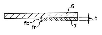
또한, 상술한 바와 같이, 차폐부재(7)에 의해 덮인 백색 LED 발광부(8)를 투영렌즈(10)로 투영하는 경우, 투영렌즈(10)에는 1장의 평철(平凸)렌즈 형상이 채용되는 경우가 많기 때문에, 도 7에 나타내는 바와 같이, 예를 들어 청색에 대한 초점(fb)을 발생하는 위치와 적색에 대한 초점(fr)을 발생하는 위치에 위치차가 있어, 이른바 색수차(色收差)를 일으키게 된다.In addition, as described above, when projecting the white LED
이 경우, 어느 한쪽에 근접하여 차폐부재(7)를 설치하면, 상기 교차 배광(HB)의 상기 차폐부재(7)의 형상이 투영되는 부분인 명암경계선(HL)(도 3 참조) 부분에 착색을 일으켜, 등색은 단색으로 한다는 규정을 만족시킬 수 없게 된다. 그 해결책으로는 도 8에 나타내는 바와 같이, 차폐판(7)의 판두께(t)를 예를 들어, 청색의 초점(fb)으로부터 적색의 초점(fr)에 이르는 두께로 하여, 투영된 명암경계선(HL) 위에 여러개의 색이 존재하게 하면, 혼합색은 백색에 가깝고 특정색을 느끼지 않게 할 수 있다.In this case, when the shielding
또는, 도 9에 나타내는 바와 같이, 얇은 차폐부재(7)를 적어도 2장 준비하여, 예를 들어, 창유리형상 부재(6)의 앞뒤면을 이용하여, 1장을 청색 초점(fb)의 위치에 설치하고, 다른 한장을 적색 초점(fr) 위치에 설치한다. 이와 같이 함으로써, 투영된 교차 배광(HB)의 명암경계선(HL)에서는, 거의 보색의 관계에 있는 청색과 적색이 혼색되어, 상기 두꺼운 차폐부재(7)의 예와 마찬가지로 특정 색을 느끼지 않게 할 수 있다.Alternatively, as shown in FIG. 9, at least two
한편, 상기 차폐부재(7)에 대해서 더욱 설명하면, 상기 투영렌즈(10)에서는 앞서 설명한 색수차(Chromatic aberration) 이외에도, 구면수차(Spherical aberration), 비점수차(Astigmatism), 비대칭 수차(Coma), 상면만곡(Field curva ture), 왜곡수차(Distortion) 등의 수차를 발생시키고, 상기 백색 LED 발광부(8)의 형상을 투영할 때에는, 이 수차들에 의해 형상의 왜곡 혹은 초점의 어긋남 등을 일으킨다.Meanwhile, the shielding
따라서, 상기 차폐부재(7)는 예를 들어 상면만곡에 대응하기 위해서는, 투영렌즈(10)의 초점면이 만곡되어 있는 것과 같은 형상으로 만곡시키면, 중심으로부터 좌우양단까지 세밀한 명암경계선(HL)이 얻어지게 된다(단, 구면수차, 비점수차, 코마의 영향은 없다고 했을 때). 또한, 왜곡수차 등 형상의 왜곡에 관여하는 수차에 대해서는, 투영된 후의 교차 배광(HB)이 원하는 형상이 되도록 차폐부재(7)측에서 수정하면 좋다.Therefore, when the shielding
이상, 어느 수차에 대해서도 차폐부재(7)를 두껍게하기, 만곡시키기, 변형시키기 등의 수단으로 대응할 수 있지만, 이러한 상세한 방법에 대해서는, 투영 렌즈(10)를 채용하는 이른바 프로젝터형 등구에서 이미 공지된 것이기 때문에, 여기에서는 그 이상의 상세한 설명은 생략한다.As mentioned above, although the shielding
도 10은 본 발명에 따른 LED 램프(1)를 광원으로서 채용한 전조등의 다른 실시예를 개략적으로 나타내는 것이다. 도 4에서 전조등(1)은 한개의 LED 램프(1)와 한개의 투영 렌즈(10)로 구성되어 있었다. 하지만, 상기 차폐부재(7)를 포함하는 백색 LED 발광부(8)는 형상면에서는 교차 배광(HB)의 규격을 만족시키지만, 조도 분포적으로는 중심조도가 부족하다는 등 규정을 만족하지 않는 경우가 있다.
10 schematically shows another embodiment of a headlamp employing the
여기서, 본 발명에서는 극히 작은 면적인 백색 LED 발광부(8)를 직접적으로 투영하는 것이기 때문에 투영 렌즈(10)도 소형이어도 좋고, 따라서 LED 램프(1)와 투영 렌즈(10)와의 조합을 여러개 준비하여도 충분히 전조등으로서 요구되는 칫수내로는 유지할 수 있다.Here, in the present invention, since the white LED
그래서, 본 실시예에서는, 한 개의 전조등용으로서, LED 램프(1)와 투영렌즈(10)의 조합 갯수를 예를 들어, 3조 등 여러 조 준비한다. 이 때, LED 램프(1)는 전 실시예와 동일하여도 좋지만, 투영렌즈(10)는 확대율이 도 4에서 사용한 것과 같은 제 1 투영렌즈(10a), 그보다 확대율이 작은 제 2 투영 렌즈(10b), 더욱 작은 제 3 투영렌즈(10c)의 3가지 종류가 준비되어, 모두가 동일 방향으로 투영되어 있다.Thus, in the present embodiment, for a headlamp, a combination of the number of combinations of the
도 11은 상기 구성으로 한 전조등에 의한 교차 배광(HBs)을 나타내는 것으로, 이 교차 배광(HBs)은 형상적으로는 전 실시예에서 얻은 교차 배광(HB)(도 3 참조)과 같지만, 제 1 투영렌즈(10a)로부터의 배광(Ha)과, 제 2 투영렌즈(10b)로부터의 배광(Hb)과, 제 3 투영렌즈(10c)로부터의 배광(Hc)이 중합되어 형성되어 있다.Fig. 11 shows the cross-distributed light beams (HBs) by the headlamps configured as described above. The cross-distributed light beams (HBs) are geometrically the same as the cross-distributed light beams (HB) obtained in the previous embodiment (see Fig. 3). Light distribution Ha from the
이와 같이 함으로써, 가장 확대율이 낮은 제 3 투영렌즈(10c)로부터의 배광(Hc)이 가장 밝고, 그 배광(Hc)이 교차 배광(HBs)의 중심부에 배치되어 있음으로써 차량의 정면 전방이 가장 밝게 조사되어, 먼쪽에 대한 시인성이 향상된다. 그리고, LED 램프(1)와 투영렌즈(10)의 조합 갯수, 각각의 투영렌즈(10c) 확대율을 조정하면 규격을 만족시킬 수 있다.In this way, the light distribution Hc from the
한편, 일반적으로 LED 램프(1)의 광량은 종래의 광원인 할로겐 전구, 메탈헬 라이드(Metal Hailde) 방전등에 비하여 적기 때문에, 이와 같이 여러개를 조합하여 광량을 늘리는 수단은 LED 램프(1)를 광원으로 하는 전조등을 실현하는 수단으로는 상당히 효과적이다.On the other hand, since the amount of light of the
또한, 상기 설명에서는 이해를 쉽게 하기 위하여, 거의 같은 형상의 배광의 확대율을 바꾼 것을 중합하여 최종적인 교차 배광을 얻고 있지만, 이는 최종적인 교차 배광의 형상을 적절히 분할한 것을 이어 맞추어 형성하여도 좋으며, 요는 최종적으로 규정을 만족하는 배광형상을 얻을 수 있으면 좋다는 것이다.In addition, in the above description, for the sake of easy understanding, polymerizing a change in the magnification of light distribution having substantially the same shape is polymerized to obtain final cross light distribution, but this may be formed by joining appropriately dividing the shape of the final cross light distribution. The point is that it is necessary to obtain a light distribution shape that finally satisfies the regulations.
도 12는 본 발명에 따른 LED 램프(1)를 사용하는 다른 투사방법의 예이며, 이전의 투사방법인 투영렌즈(10) 대신에, 이 예에서는 예를 들어 회전 포물면 등 초점을 가지는 리플렉터(11)를 사용하여 조사방향(P)으로 투영함으로써, 소정 배광형상으로 된 조사광을 얻도록 하고 있다.Fig. 12 is an example of another projection method using the
여기서, 반사광에 의해 투영상을 형성하는 리플렉터(11)를 사용하는 이 투영방법에서는 상기 LED 칩(2), 형광체(5), 차폐부재(7) 등을 리플렉터에 대칭시켜, 즉 조사방향(P)에 대하여 뒷쪽을 향하도록 설치하게 된다.Here, in this projection method using the
이 때, 상기 리플렉터(11)는 예를 들어 포물계의 자유곡면 여러개를 조합한 멀티리플렉터로 해두면, 교차 배광(HB) 형성시 자유도가 놓고, 또한 리플렉터 (11)에서는 원칙적으로 색수차를 일으키지 않기 때문에, 고품질의 교차 배광(HB)을 쉽게 얻을 수 있게 된다. 또한, 상기 투영렌즈의 경우와 마찬가지로 LED 램프(1)와 리플렉터(11)와의 조합을 여러개 사용하여 전조등을 구성하여도 좋다.At this time, if the
이상에서 설명한 바와 같이, 본 발명에 의해, 단색발광의 LED 발광부와, 상기 LED 발광부로부터의 광을 투영수단에 의해 조사방향으로 확대투영할 때 차량용 전조등에 적합한 배광특성이 얻어지는 형상으로 상기 LED 발광부의 일부를 덮는 차폐부재를 포함하여 구성되며, 상기 LED 발광부와 상기 차폐부재 중 적어도 하나는 상기 투영수단의 초점 방에 배치되는 것을 특징으로 하는 전조등 발광원 LED 램프로 함으로써, 고체구조인 전조등 광원용 LED 램프의 발광부의 형상을 투영렌즈, 혹은 리플렉터(reflector)에 의해 조사방향으로 확대투영한다는 매우 간편한 수단으로 정확한 특성의 배광형상을 얻을 수 있으며, 광원의 고체화에 의한 신뢰성의 향상과, 구성의 간소화에 의한 비용절감, 더욱이 소형화를 동시에 가능하게 한다는 매우 우수한 효과를 얻을 수 있다. As described above, according to the present invention, the LED light emitting portion having a monochromatic light and the light distribution characteristic suitable for a vehicle headlamp when projecting light from the LED light emitting portion in the irradiation direction by the projection means are obtained. And a shielding member covering a portion of the light emitting portion, wherein at least one of the LED light emitting portion and the shielding member is disposed in a focal room of the projection means. The light distribution shape of the light source of the light source LED lamp is projected by the projection lens or the reflector, which is a very simple means of obtaining a light distribution shape with accurate characteristics. It is possible to obtain a very good effect of reducing the cost and simplifying the size at the same time. All.
Claims (14)
Applications Claiming Priority (2)
| Application Number | Priority Date | Filing Date | Title |
|---|---|---|---|
| JPJP-P-2003-00169182 | 2003-06-13 | ||
| JP2003169182A JP4138586B2 (en) | 2003-06-13 | 2003-06-13 | LED lamp for light source and vehicle headlamp using the same |
Publications (2)
| Publication Number | Publication Date |
|---|---|
| KR20040107348A KR20040107348A (en) | 2004-12-20 |
| KR101012042B1 true KR101012042B1 (en) | 2011-01-31 |
Family
ID=33296901
Family Applications (1)
| Application Number | Title | Priority Date | Filing Date |
|---|---|---|---|
| KR1020030079396A Expired - Fee Related KR101012042B1 (en) | 2003-06-13 | 2003-11-11 | LED lamp for headlight source |
Country Status (5)
| Country | Link |
|---|---|
| US (4) | US7019334B2 (en) |
| EP (1) | EP1487025B1 (en) |
| JP (1) | JP4138586B2 (en) |
| KR (1) | KR101012042B1 (en) |
| CN (1) | CN100413100C (en) |
Families Citing this family (121)
| Publication number | Priority date | Publication date | Assignee | Title |
|---|---|---|---|---|
| JP4047185B2 (en) * | 2003-02-06 | 2008-02-13 | 株式会社小糸製作所 | Vehicle headlamp and light emitting module |
| JP4138586B2 (en) * | 2003-06-13 | 2008-08-27 | スタンレー電気株式会社 | LED lamp for light source and vehicle headlamp using the same |
| JP4024721B2 (en) * | 2003-06-20 | 2007-12-19 | 株式会社小糸製作所 | Vehicle lamp and light source module |
| JP4037337B2 (en) * | 2003-07-24 | 2008-01-23 | 株式会社小糸製作所 | Lamp unit and vehicle headlamp |
| JP4314911B2 (en) * | 2003-08-20 | 2009-08-19 | スタンレー電気株式会社 | Vehicle headlamp |
| JP4140042B2 (en) * | 2003-09-17 | 2008-08-27 | スタンレー電気株式会社 | LED light source device using phosphor and vehicle headlamp using LED light source device |
| JP4402425B2 (en) * | 2003-10-24 | 2010-01-20 | スタンレー電気株式会社 | Vehicle headlamp |
| FR2862424B1 (en) * | 2003-11-18 | 2006-10-20 | Valeo Electronique Sys Liaison | DEVICE FOR COOLING AN ELECTRICAL COMPONENT AND METHOD FOR MANUFACTURING THE SAME |
| TW200522387A (en) * | 2003-12-26 | 2005-07-01 | Ind Tech Res Inst | High-power LED planarization encapsulation structure |
| JP4360945B2 (en) * | 2004-03-10 | 2009-11-11 | シチズン電子株式会社 | Lighting device |
| JP4359195B2 (en) * | 2004-06-11 | 2009-11-04 | 株式会社東芝 | Semiconductor light emitting device, manufacturing method thereof, and semiconductor light emitting unit |
| US7329905B2 (en) * | 2004-06-30 | 2008-02-12 | Cree, Inc. | Chip-scale methods for packaging light emitting devices and chip-scale packaged light emitting devices |
| JP4599111B2 (en) * | 2004-07-30 | 2010-12-15 | スタンレー電気株式会社 | LED lamp for lamp light source |
| JP2006156668A (en) * | 2004-11-29 | 2006-06-15 | Nichia Chem Ind Ltd | Light emitting device and manufacturing method thereof |
| DE102004060475A1 (en) * | 2004-12-16 | 2006-07-06 | Hella Kgaa Hueck & Co. | Head light for vehicles has light-converting luminescent material is designed as light-converting luminescent coating which exhibits given contour and a defined irradiancy is generated on the light-converting luminescent material coating |
| KR100631901B1 (en) * | 2005-01-31 | 2006-10-11 | 삼성전기주식회사 | LED package frame and LED package employing the same |
| WO2006082537A1 (en) * | 2005-02-02 | 2006-08-10 | Philips Intellectual Property & Standards Gmbh | Light-source module and holder therefor |
| US7326062B2 (en) * | 2005-02-07 | 2008-02-05 | Avago Technologies Ecbu Ip Pte Ltd | System and method for increasing the surface mounting stability of a lamp |
| TWD118223S1 (en) * | 2005-03-31 | 2007-07-21 | 首爾半導體股份有限公司 | Light emitting diode (led) |
| TWD114618S1 (en) * | 2005-03-31 | 2006-12-21 | 首爾半導體股份有限公司 | Light emitting diode (led) |
| US7275839B2 (en) * | 2005-04-05 | 2007-10-02 | Osram Sylvania, Inc. | Three color LED bulb |
| JP4991173B2 (en) * | 2005-04-27 | 2012-08-01 | 京セラ株式会社 | Light-emitting element mounting substrate and light-emitting device using the same |
| TWI422044B (en) | 2005-06-30 | 2014-01-01 | 克立公司 | Wafer-scale method for packaging light-emitting device and light-emitting device packaged by wafer scale |
| KR100631992B1 (en) * | 2005-07-19 | 2006-10-09 | 삼성전기주식회사 | Side-emitting dual lens structure LED package |
| KR100629521B1 (en) * | 2005-07-29 | 2006-09-28 | 삼성전자주식회사 | LED package and manufacturing method thereof and LED array module using same |
| US20070045629A1 (en) * | 2005-07-29 | 2007-03-01 | Unity Opto Technology Co., Ltd. | White light LED |
| JP4945106B2 (en) * | 2005-09-08 | 2012-06-06 | スタンレー電気株式会社 | Semiconductor light emitting device |
| US20070102718A1 (en) * | 2005-11-07 | 2007-05-10 | Akira Takekuma | Lens in light emitting device |
| JP4703375B2 (en) * | 2005-11-08 | 2011-06-15 | 株式会社小糸製作所 | Interior lighting |
| US8039849B2 (en) * | 2005-11-23 | 2011-10-18 | Taiwan Oasis Technology Co., Ltd. | LED module |
| CN100531308C (en) * | 2005-12-02 | 2009-08-19 | 鸿富锦精密工业(深圳)有限公司 | Digit tode camera module group |
| US8044412B2 (en) | 2006-01-20 | 2011-10-25 | Taiwan Semiconductor Manufacturing Company, Ltd | Package for a light emitting element |
| KR101283182B1 (en) | 2006-01-26 | 2013-07-05 | 엘지이노텍 주식회사 | Package of light-emitting diode and manufacturing method thereof |
| JP4996101B2 (en) * | 2006-02-02 | 2012-08-08 | 新光電気工業株式会社 | Semiconductor device and manufacturing method of semiconductor device |
| US7892268B2 (en) * | 2006-03-23 | 2011-02-22 | Light Sciences Oncology, Inc. | PDT apparatus with high output LED for therapy and aiming |
| JP2007300069A (en) * | 2006-04-04 | 2007-11-15 | Toyoda Gosei Co Ltd | LIGHT EMITTING ELEMENT, LIGHT EMITTING DEVICE USING THE LIGHT EMITTING ELEMENT, AND METHOD FOR PRODUCING THE LIGHT EMITTING ELEMENT |
| KR100731678B1 (en) * | 2006-05-08 | 2007-06-22 | 서울반도체 주식회사 | Chip type light emitting diode package and light emitting device having the same |
| WO2007140651A1 (en) * | 2006-06-08 | 2007-12-13 | Hong-Yuan Technology Co., Ltd | Light emitting system, light emitting apparatus and forming method thereof |
| EP2067176B1 (en) | 2006-08-09 | 2015-04-01 | Panasonic Corporation | Light-emitting diode |
| US20080055065A1 (en) * | 2006-08-30 | 2008-03-06 | David Charles Feldmeier | Systems, devices, components and methods for controllably configuring the brightness of light emitted by an automotive LED illumination system |
| US20080055896A1 (en) * | 2006-08-30 | 2008-03-06 | David Charles Feldmeier | Systems, devices, components and methods for controllably configuring the color of light emitted by an automotive LED illumination system |
| US7686469B2 (en) | 2006-09-30 | 2010-03-30 | Ruud Lighting, Inc. | LED lighting fixture |
| US9222632B2 (en) | 2013-01-31 | 2015-12-29 | Cree, Inc. | LED lighting fixture |
| US9028087B2 (en) | 2006-09-30 | 2015-05-12 | Cree, Inc. | LED light fixture |
| US9212812B2 (en) | 2013-02-11 | 2015-12-15 | Cree, Inc. | LED light fixture with integrated light shielding |
| US20090086491A1 (en) | 2007-09-28 | 2009-04-02 | Ruud Lighting, Inc. | Aerodynamic LED Floodlight Fixture |
| WO2008043207A1 (en) * | 2006-10-08 | 2008-04-17 | Hong-Yuan Technology Co., Ltd. | Light emitting system, light emitting apparatus and forming method thereof |
| US7631986B2 (en) * | 2006-10-31 | 2009-12-15 | Koninklijke Philips Electronics, N.V. | Lighting device package |
| JP4823866B2 (en) * | 2006-11-13 | 2011-11-24 | 株式会社小糸製作所 | Light emitting module for vehicular lamp |
| US20080123340A1 (en) * | 2006-11-27 | 2008-05-29 | Mcclellan Thomas | Light device having LED illumination and electronic circuit board in an enclosure |
| JP4783718B2 (en) * | 2006-11-27 | 2011-09-28 | 新光電気工業株式会社 | Lighting device |
| JP4678364B2 (en) * | 2006-12-05 | 2011-04-27 | スタンレー電気株式会社 | Light source device and vehicle headlamp |
| US8092042B2 (en) | 2007-05-03 | 2012-01-10 | Ruud Lighting, Inc. | Shield member in LED apparatus |
| JP5150133B2 (en) * | 2007-05-08 | 2013-02-20 | スタンレー電気株式会社 | LED lamp for headlight light source |
| JP5044864B2 (en) * | 2007-08-08 | 2012-10-10 | スタンレー電気株式会社 | Projection lens for lamp and lamp using the projection lens for lamp |
| TW200915597A (en) * | 2007-09-17 | 2009-04-01 | Everlight Electronics Co Ltd | Light emitting diode device |
| JP5193546B2 (en) * | 2007-09-28 | 2013-05-08 | スタンレー電気株式会社 | Vehicle lighting |
| KR101336992B1 (en) | 2007-10-29 | 2013-12-04 | 삼성전자주식회사 | Semiconductor device using magnetic domain wall movement |
| JP5216362B2 (en) * | 2008-02-20 | 2013-06-19 | スタンレー電気株式会社 | LED light source unit |
| US7637630B2 (en) * | 2008-04-22 | 2009-12-29 | Ruud Lighting, Inc. | Integrated shield-gasket member in LED apparatus |
| KR101088910B1 (en) * | 2008-05-29 | 2011-12-07 | 삼성엘이디 주식회사 | LED package and manufacturing method thereof |
| JP5152502B2 (en) * | 2008-06-09 | 2013-02-27 | スタンレー電気株式会社 | Lamp |
| JP2010021261A (en) * | 2008-07-09 | 2010-01-28 | Toshiba Corp | Method of manufacturing optical semiconductor device, optical semiconductor device, and method of manufacturing optical semiconductor apparatus |
| US7891835B2 (en) | 2008-07-15 | 2011-02-22 | Ruud Lighting, Inc. | Light-directing apparatus with protected reflector-shield and lighting fixture utilizing same |
| AU2013205105B2 (en) * | 2008-07-15 | 2015-05-14 | Ideal Industries Lighting Llc | Light-directing apparatus with protected reflector-shield and lighting fixture utilizing same |
| US8188595B2 (en) * | 2008-08-13 | 2012-05-29 | Progressive Cooling Solutions, Inc. | Two-phase cooling for light-emitting devices |
| JP5284006B2 (en) * | 2008-08-25 | 2013-09-11 | シチズン電子株式会社 | Light emitting device |
| US20100132404A1 (en) * | 2008-12-03 | 2010-06-03 | Progressive Cooling Solutions, Inc. | Bonds and method for forming bonds for a two-phase cooling apparatus |
| DE112009004314T5 (en) * | 2009-02-16 | 2012-04-26 | Mitsubishi Electric Corp. | Lighting device for a headlight source |
| US20110316033A1 (en) * | 2009-03-05 | 2011-12-29 | Koito Manufacturing Co., Ltd. | Light emitting module, method of manufacturing the light emitting module, and lamp unit |
| US20100259947A1 (en) * | 2009-04-14 | 2010-10-14 | Dolan Robert A | Vehicle Light with Trademark Display |
| FR2948439B1 (en) | 2009-07-21 | 2011-08-05 | Valeo Vision | LIGHTING MODULE FOR A MOTOR VEHICLE PROJECTOR, AND PROJECTOR EQUIPPED WITH AT LEAST ONE SUCH MODULE. |
| AT508604B1 (en) * | 2009-07-31 | 2012-07-15 | Zizala Lichtsysteme Gmbh | LED MOTOR VEHICLE HEADLIGHT FOR GENERATING A DYNAMIC LIGHT DISTRIBUTION |
| US8378559B2 (en) * | 2009-08-20 | 2013-02-19 | Progressive Cooling Solutions, Inc. | LED bulb for high intensity discharge bulb replacement |
| US20110051413A1 (en) | 2009-08-25 | 2011-03-03 | Abl Ip Holding Llc | Optic shielding |
| KR100960099B1 (en) * | 2009-09-02 | 2010-05-31 | (주)칸델라 | Lens for light emitting diode package |
| JP5445923B2 (en) * | 2009-09-04 | 2014-03-19 | スタンレー電気株式会社 | Vehicle lighting |
| JP5506313B2 (en) * | 2009-09-30 | 2014-05-28 | スタンレー電気株式会社 | Light emitting diode light source for vehicle headlight |
| AU331025S (en) * | 2009-11-11 | 2010-05-26 | Koninl Philips Electronics Nv | LED module |
| USD643150S1 (en) * | 2009-11-20 | 2011-08-09 | Foxconn Technology Co., Ltd. | LED Lens |
| JP5397186B2 (en) * | 2009-11-24 | 2014-01-22 | スタンレー電気株式会社 | Vehicle lighting |
| USD622898S1 (en) * | 2009-12-02 | 2010-08-31 | Foxconn Technology Co., Ltd. | LED lens |
| USD625881S1 (en) * | 2009-12-02 | 2010-10-19 | Foxconn Technology Co., Ltd. | LED lens |
| USD620635S1 (en) * | 2009-12-10 | 2010-07-27 | Foxconn Technology Co., Ltd. | LED lens |
| USD622899S1 (en) * | 2010-01-05 | 2010-08-31 | Foxconn Technology Co., Ltd. | LED lens |
| USD631186S1 (en) * | 2010-01-15 | 2011-01-18 | Foxconn Technology Co., Ltd. | LED lens |
| FR2956468B1 (en) * | 2010-02-15 | 2015-07-10 | Valeo Vision | OPTICAL DEVICE, IN PARTICULAR FOR MOTOR VEHICLE |
| FR2956720B1 (en) * | 2010-02-19 | 2013-03-15 | Valeo Vision | OPTICAL SYSTEM OF A MOTOR VEHICLE |
| JP5518533B2 (en) * | 2010-03-12 | 2014-06-11 | 株式会社小糸製作所 | Vehicle headlamp and light emitting module for vehicle headlamp |
| KR101121745B1 (en) | 2010-03-31 | 2012-03-22 | (주)포인트엔지니어링 | Optical Element Device and Fabricating Method Thereof |
| USD643948S1 (en) * | 2010-04-27 | 2011-08-23 | Toshiba Lighting & Technology Corporation | Light emitting diode lamp |
| USD652537S1 (en) * | 2010-04-27 | 2012-01-17 | Toshiba Lighting & Technology Corporation | Light emitting diode lamp |
| WO2012006123A2 (en) * | 2010-06-28 | 2012-01-12 | Axlen Technologies, Inc. | Optical beam shaping and polarization selection on led with wavelength conversion |
| WO2012005684A1 (en) * | 2010-07-05 | 2012-01-12 | I3 Lab Pte Ltd | Transmissive optical member in automotive led headlamp |
| DE102010045403A1 (en) * | 2010-09-15 | 2012-03-15 | Osram Opto Semiconductors Gmbh | Optoelectronic component |
| DE102010041114A1 (en) * | 2010-09-21 | 2012-03-22 | Osram Ag | lighting device |
| DE102011086359A1 (en) * | 2011-11-15 | 2013-05-16 | Tridonic Gmbh & Co. Kg | LED module |
| US8816306B2 (en) | 2011-12-15 | 2014-08-26 | Battelle Memorial Institute | Infrared light device |
| EP2840302B1 (en) * | 2011-12-20 | 2019-01-30 | Stanley Electric Co., Ltd. | Light emitting device, vehicle light and vehicle |
| JP5950385B2 (en) * | 2012-01-25 | 2016-07-13 | 株式会社小糸製作所 | Vehicle headlamp |
| JP2013175334A (en) * | 2012-02-24 | 2013-09-05 | Stanley Electric Co Ltd | Vehicle lamp |
| AT512589B1 (en) * | 2012-03-12 | 2014-06-15 | Zizala Lichtsysteme Gmbh | Light guide element for a laser vehicle headlight and vehicle headlights |
| KR101405386B1 (en) * | 2012-06-18 | 2014-06-10 | 현대모비스 주식회사 | Lighting apparatus for vehicle |
| US10591124B2 (en) | 2012-08-30 | 2020-03-17 | Sabic Global Technologies B.V. | Heat dissipating system for a light, headlamp assembly comprising the same, and method of dissipating heat |
| DE102012221908A1 (en) * | 2012-11-29 | 2014-06-05 | Osram Gmbh | Light module for a vehicle light device with semiconductor light source |
| JP6089686B2 (en) * | 2012-12-25 | 2017-03-08 | 日亜化学工業株式会社 | Light emitting device |
| US9435519B2 (en) | 2013-01-31 | 2016-09-06 | Cree, Inc. | Light-fixture support assembly |
| KR20140130884A (en) * | 2013-05-02 | 2014-11-12 | 주식회사 포스코엘이디 | Optical semiconductor illuminating apparatus |
| KR102036096B1 (en) * | 2013-06-11 | 2019-10-24 | 현대모비스 주식회사 | Shade for Headlamp |
| JP6097166B2 (en) * | 2013-07-12 | 2017-03-15 | 株式会社エンプラス | Luminous flux control member, light emitting device, and illumination device |
| KR102310285B1 (en) * | 2014-10-30 | 2021-10-07 | 현대모비스 주식회사 | Lamp Apparatus Of Vehicle |
| US9939563B2 (en) * | 2015-07-15 | 2018-04-10 | Coelux S.R.L. | Sky-dome lighting system |
| DE102017110886A1 (en) * | 2017-05-18 | 2018-11-22 | Automotive Lighting Reutlingen Gmbh | Motor vehicle headlight with a light projector having microprojectors |
| KR102440521B1 (en) * | 2017-12-22 | 2022-09-06 | 현대자동차주식회사 | vehicle lamp unit |
| JP7231809B2 (en) * | 2018-06-05 | 2023-03-02 | 日亜化学工業株式会社 | light emitting device |
| CN110906189A (en) * | 2018-09-17 | 2020-03-24 | 光宝电子(广州)有限公司 | Lighting device |
| DE102018129989A1 (en) * | 2018-11-27 | 2020-05-28 | Bayerische Motoren Werke Aktiengesellschaft | Vehicle lamp and vehicle with it |
| CN113545171B (en) * | 2018-12-05 | 2025-01-28 | 亮锐有限责任公司 | Carrier base module for lighting module |
| DE102020100757A1 (en) | 2020-01-15 | 2021-07-15 | HELLA GmbH & Co. KGaA | Light unit for a lighting device of a vehicle with a semiconductor light source and with a protective device for the semiconductor light source |
| CN217131136U (en) * | 2021-09-23 | 2022-08-05 | 法雷奥照明湖北技术中心有限公司 | A lighting device and a motor vehicle |
| JPWO2024128323A1 (en) * | 2022-12-16 | 2024-06-20 |
Citations (3)
| Publication number | Priority date | Publication date | Assignee | Title |
|---|---|---|---|---|
| JP2001085777A (en) | 1999-09-09 | 2001-03-30 | Toshiba Corp | Light semiconductor device |
| US20010019486A1 (en) | 2000-03-01 | 2001-09-06 | Vincent Thominet | Illumination device for vehicle |
| JP2002094127A (en) | 2000-09-20 | 2002-03-29 | Sunx Ltd | Light emitting element and reflection type photoelectric sensor |
Family Cites Families (50)
| Publication number | Priority date | Publication date | Assignee | Title |
|---|---|---|---|---|
| JPS5114439B2 (en) | 1972-05-15 | 1976-05-10 | ||
| JPS59124179A (en) | 1982-12-29 | 1984-07-18 | Fujitsu Ltd | Light emitting diode device |
| JPH01120702A (en) * | 1987-11-05 | 1989-05-12 | Koito Mfg Co Ltd | Vehicle head light |
| JPH05226691A (en) | 1992-01-20 | 1993-09-03 | Nec Corp | Optical semiconductor device |
| JP2740931B2 (en) | 1992-12-29 | 1998-04-15 | 京セラ株式会社 | Image forming device |
| JP3207036B2 (en) * | 1994-02-15 | 2001-09-10 | 株式会社小糸製作所 | Optical design method of lamp using light emitting element |
| WO1997050132A1 (en) * | 1996-06-26 | 1997-12-31 | Siemens Aktiengesellschaft | Light-emitting semiconductor component with luminescence conversion element |
| DE19638667C2 (en) * | 1996-09-20 | 2001-05-17 | Osram Opto Semiconductors Gmbh | Mixed-color light-emitting semiconductor component with luminescence conversion element |
| US6613247B1 (en) * | 1996-09-20 | 2003-09-02 | Osram Opto Semiconductors Gmbh | Wavelength-converting casting composition and white light-emitting semiconductor component |
| JP3065263B2 (en) | 1996-12-27 | 2000-07-17 | 日亜化学工業株式会社 | Light emitting device and LED display using the same |
| JP3774021B2 (en) * | 1997-03-12 | 2006-05-10 | オムロン株式会社 | Vehicle separator |
| US6441943B1 (en) * | 1997-04-02 | 2002-08-27 | Gentex Corporation | Indicators and illuminators using a semiconductor radiation emitter package |
| JPH1187782A (en) * | 1997-09-03 | 1999-03-30 | Oki Electric Ind Co Ltd | Light emitting diode |
| US6204523B1 (en) | 1998-11-06 | 2001-03-20 | Lumileds Lighting, U.S., Llc | High stability optical encapsulation and packaging for light-emitting diodes in the green, blue, and near UV range |
| US6669866B1 (en) * | 1999-07-23 | 2003-12-30 | Patent-Treuhand-Gesellschaft Fuer Elektrische Gluehlampen Mbh | Luminous substance for a light source and light source associates therewith |
| US6504301B1 (en) | 1999-09-03 | 2003-01-07 | Lumileds Lighting, U.S., Llc | Non-incandescent lightbulb package using light emitting diodes |
| JP2001127346A (en) | 1999-10-22 | 2001-05-11 | Stanley Electric Co Ltd | Light emitting diode |
| JP2001196639A (en) | 2000-01-12 | 2001-07-19 | Sanyo Electric Co Ltd | LED light emitting device and method of manufacturing the same |
| JP2001210872A (en) | 2000-01-26 | 2001-08-03 | Sanyo Electric Co Ltd | Semiconductor light emitting device and method of manufacturing the same |
| JP2001345483A (en) | 2000-05-31 | 2001-12-14 | Toshiba Lighting & Technology Corp | Light emitting diode |
| US6639360B2 (en) * | 2001-01-31 | 2003-10-28 | Gentex Corporation | High power radiation emitter device and heat dissipating package for electronic components |
| JP3942371B2 (en) | 2001-03-26 | 2007-07-11 | 三洋電機株式会社 | White indicator |
| JP4789350B2 (en) | 2001-06-11 | 2011-10-12 | シチズン電子株式会社 | Manufacturing method of light emitting diode |
| JP4665205B2 (en) | 2001-07-16 | 2011-04-06 | スタンレー電気株式会社 | Linear light source for lamp |
| JP3948650B2 (en) * | 2001-10-09 | 2007-07-25 | アバゴ・テクノロジーズ・イーシービーユー・アイピー(シンガポール)プライベート・リミテッド | Light emitting diode and manufacturing method thereof |
| JP2003123520A (en) * | 2001-10-18 | 2003-04-25 | Koito Mfg Co Ltd | Projection type headlamp used for infrared light irradiating lamp |
| ITTO20020142A1 (en) * | 2002-02-19 | 2003-08-19 | Fraen Corp Srl | INTEGRATED PROJECTION UNIT, IN PARTICULAR FOR THE PROJECTION OF E-OR IMAGES OF LUMINOUS BEAMS WITH PERFORMANCE GEOMETRY. |
| US6943379B2 (en) * | 2002-04-04 | 2005-09-13 | Toyoda Gosei Co., Ltd. | Light emitting diode |
| JP4080780B2 (en) * | 2002-04-23 | 2008-04-23 | 株式会社小糸製作所 | Light source unit |
| DE20206833U1 (en) * | 2002-04-30 | 2002-07-18 | Automotive Lighting Reutlingen GmbH, 72762 Reutlingen | Fog or low beam headlights |
| JP3707688B2 (en) * | 2002-05-31 | 2005-10-19 | スタンレー電気株式会社 | Light emitting device and manufacturing method thereof |
| JP4360481B2 (en) * | 2002-07-10 | 2009-11-11 | 株式会社小糸製作所 | Vehicle lighting |
| JP2004047748A (en) * | 2002-07-12 | 2004-02-12 | Stanley Electric Co Ltd | Light emitting diode |
| JP2004063499A (en) | 2002-07-24 | 2004-02-26 | Ichikoh Ind Ltd | Vehicle lamp using LED as light source |
| JP4143732B2 (en) * | 2002-10-16 | 2008-09-03 | スタンレー電気株式会社 | In-vehicle wavelength converter |
| JP4294295B2 (en) * | 2002-11-06 | 2009-07-08 | 株式会社小糸製作所 | Vehicle headlamp |
| JP4071089B2 (en) * | 2002-11-06 | 2008-04-02 | 株式会社小糸製作所 | Vehicle headlamp |
| JP4040955B2 (en) * | 2002-11-06 | 2008-01-30 | 株式会社小糸製作所 | Vehicle headlamp and manufacturing method thereof |
| FR2849158B1 (en) * | 2002-12-20 | 2005-12-09 | Valeo Vision | LIGHTING MODULE FOR VEHICLE PROJECTOR |
| JP4083593B2 (en) * | 2003-02-13 | 2008-04-30 | 株式会社小糸製作所 | Vehicle headlamp |
| JP4369668B2 (en) * | 2003-02-13 | 2009-11-25 | 株式会社小糸製作所 | Vehicle headlamp |
| JP4018016B2 (en) | 2003-03-31 | 2007-12-05 | 株式会社小糸製作所 | Vehicle headlamp |
| JP2004311101A (en) * | 2003-04-03 | 2004-11-04 | Koito Mfg Co Ltd | Vehicle headlights and semiconductor light emitting devices |
| JP4102240B2 (en) | 2003-04-08 | 2008-06-18 | 株式会社小糸製作所 | Vehicle headlamp |
| JP4335621B2 (en) * | 2003-04-25 | 2009-09-30 | スタンレー電気株式会社 | Vehicle lighting |
| JP4138586B2 (en) * | 2003-06-13 | 2008-08-27 | スタンレー電気株式会社 | LED lamp for light source and vehicle headlamp using the same |
| JP4024721B2 (en) * | 2003-06-20 | 2007-12-19 | 株式会社小糸製作所 | Vehicle lamp and light source module |
| JP2005044698A (en) * | 2003-07-24 | 2005-02-17 | Koito Mfg Co Ltd | Vehicle lamp and light source module |
| JP4314911B2 (en) * | 2003-08-20 | 2009-08-19 | スタンレー電気株式会社 | Vehicle headlamp |
| EP1515368B1 (en) * | 2003-09-05 | 2019-12-25 | Nichia Corporation | Light equipment |
-
2003
- 2003-06-13 JP JP2003169182A patent/JP4138586B2/en not_active Expired - Fee Related
- 2003-09-16 US US10/662,374 patent/US7019334B2/en not_active Expired - Lifetime
- 2003-09-23 EP EP03021470.4A patent/EP1487025B1/en not_active Expired - Lifetime
- 2003-11-11 KR KR1020030079396A patent/KR101012042B1/en not_active Expired - Fee Related
- 2003-12-05 CN CNB2003101169894A patent/CN100413100C/en not_active Expired - Fee Related
-
2005
- 2005-11-22 US US11/283,932 patent/US7312477B2/en not_active Expired - Fee Related
-
2007
- 2007-12-24 US US11/964,003 patent/US7622748B2/en not_active Expired - Fee Related
-
2009
- 2009-11-23 US US12/624,391 patent/US8093613B2/en not_active Expired - Fee Related
Patent Citations (3)
| Publication number | Priority date | Publication date | Assignee | Title |
|---|---|---|---|---|
| JP2001085777A (en) | 1999-09-09 | 2001-03-30 | Toshiba Corp | Light semiconductor device |
| US20010019486A1 (en) | 2000-03-01 | 2001-09-06 | Vincent Thominet | Illumination device for vehicle |
| JP2002094127A (en) | 2000-09-20 | 2002-03-29 | Sunx Ltd | Light emitting element and reflection type photoelectric sensor |
Also Published As
| Publication number | Publication date |
|---|---|
| CN100413100C (en) | 2008-08-20 |
| US7622748B2 (en) | 2009-11-24 |
| US8093613B2 (en) | 2012-01-10 |
| US20100073951A1 (en) | 2010-03-25 |
| JP2005005193A (en) | 2005-01-06 |
| US20040251469A1 (en) | 2004-12-16 |
| EP1487025A2 (en) | 2004-12-15 |
| EP1487025A3 (en) | 2006-03-01 |
| KR20040107348A (en) | 2004-12-20 |
| US20060071222A1 (en) | 2006-04-06 |
| JP4138586B2 (en) | 2008-08-27 |
| CN1574402A (en) | 2005-02-02 |
| EP1487025B1 (en) | 2017-01-25 |
| US7019334B2 (en) | 2006-03-28 |
| US7312477B2 (en) | 2007-12-25 |
| US20080117646A1 (en) | 2008-05-22 |
Similar Documents
| Publication | Publication Date | Title |
|---|---|---|
| KR101012042B1 (en) | LED lamp for headlight source | |
| US8517581B2 (en) | Vehicle light with LED light source | |
| JP4047266B2 (en) | Lamp | |
| JP4526256B2 (en) | Light source module and lamp having the light source module | |
| KR100557719B1 (en) | Vehicular lamp | |
| US7131759B2 (en) | Vehicular lamp and light source module | |
| US7520645B2 (en) | Vehicular headlamp and car headlamp | |
| US20110085343A1 (en) | Vehicle light | |
| US7318662B2 (en) | Vehicular headlamp | |
| JP5446757B2 (en) | Vehicle lighting | |
| CN112368510B (en) | Vehicle lamp | |
| JP4471399B2 (en) | LED lamp | |
| JP4182126B2 (en) | Projection type LED lamp | |
| JP2014186897A (en) | Light source device, and front lamp for vehicle using the same | |
| JP5397174B2 (en) | Vehicle lighting | |
| JPH10199306A (en) | Projector type lamp | |
| JP2010114095A (en) | Light source module and luminaire having the same | |
| WO2019177051A1 (en) | Vehicle lamp | |
| JPWO2019082697A1 (en) | Vehicle lighting | |
| CN120176048A (en) | Dual light module, vehicle lamp and vehicle |
Legal Events
| Date | Code | Title | Description |
|---|---|---|---|
| PA0109 | Patent application |
St.27 status event code: A-0-1-A10-A12-nap-PA0109 |
|
| PG1501 | Laying open of application |
St.27 status event code: A-1-1-Q10-Q12-nap-PG1501 |
|
| A201 | Request for examination | ||
| PA0201 | Request for examination |
St.27 status event code: A-1-2-D10-D11-exm-PA0201 |
|
| P22-X000 | Classification modified |
St.27 status event code: A-2-2-P10-P22-nap-X000 |
|
| D13-X000 | Search requested |
St.27 status event code: A-1-2-D10-D13-srh-X000 |
|
| D14-X000 | Search report completed |
St.27 status event code: A-1-2-D10-D14-srh-X000 |
|
| E902 | Notification of reason for refusal | ||
| PE0902 | Notice of grounds for rejection |
St.27 status event code: A-1-2-D10-D21-exm-PE0902 |
|
| P11-X000 | Amendment of application requested |
St.27 status event code: A-2-2-P10-P11-nap-X000 |
|
| P13-X000 | Application amended |
St.27 status event code: A-2-2-P10-P13-nap-X000 |
|
| E701 | Decision to grant or registration of patent right | ||
| PE0701 | Decision of registration |
St.27 status event code: A-1-2-D10-D22-exm-PE0701 |
|
| GRNT | Written decision to grant | ||
| PR0701 | Registration of establishment |
St.27 status event code: A-2-4-F10-F11-exm-PR0701 |
|
| PR1002 | Payment of registration fee |
St.27 status event code: A-2-2-U10-U11-oth-PR1002 Fee payment year number: 1 |
|
| PG1601 | Publication of registration |
St.27 status event code: A-4-4-Q10-Q13-nap-PG1601 |
|
| FPAY | Annual fee payment |
Payment date: 20140107 Year of fee payment: 4 |
|
| PR1001 | Payment of annual fee |
St.27 status event code: A-4-4-U10-U11-oth-PR1001 Fee payment year number: 4 |
|
| FPAY | Annual fee payment |
Payment date: 20150105 Year of fee payment: 5 |
|
| PR1001 | Payment of annual fee |
St.27 status event code: A-4-4-U10-U11-oth-PR1001 Fee payment year number: 5 |
|
| FPAY | Annual fee payment |
Payment date: 20160104 Year of fee payment: 6 |
|
| PR1001 | Payment of annual fee |
St.27 status event code: A-4-4-U10-U11-oth-PR1001 Fee payment year number: 6 |
|
| FPAY | Annual fee payment |
Payment date: 20170102 Year of fee payment: 7 |
|
| PR1001 | Payment of annual fee |
St.27 status event code: A-4-4-U10-U11-oth-PR1001 Fee payment year number: 7 |
|
| FPAY | Annual fee payment |
Payment date: 20180103 Year of fee payment: 8 |
|
| PR1001 | Payment of annual fee |
St.27 status event code: A-4-4-U10-U11-oth-PR1001 Fee payment year number: 8 |
|
| FPAY | Annual fee payment |
Payment date: 20190103 Year of fee payment: 9 |
|
| PR1001 | Payment of annual fee |
St.27 status event code: A-4-4-U10-U11-oth-PR1001 Fee payment year number: 9 |
|
| FPAY | Annual fee payment |
Payment date: 20200103 Year of fee payment: 10 |
|
| PR1001 | Payment of annual fee |
St.27 status event code: A-4-4-U10-U11-oth-PR1001 Fee payment year number: 10 |
|
| PC1903 | Unpaid annual fee |
St.27 status event code: A-4-4-U10-U13-oth-PC1903 Not in force date: 20210126 Payment event data comment text: Termination Category : DEFAULT_OF_REGISTRATION_FEE |
|
| PC1903 | Unpaid annual fee |
St.27 status event code: N-4-6-H10-H13-oth-PC1903 Ip right cessation event data comment text: Termination Category : DEFAULT_OF_REGISTRATION_FEE Not in force date: 20210126 |
|
| P22-X000 | Classification modified |
St.27 status event code: A-4-4-P10-P22-nap-X000 |