KR100924739B1 - Display device and driving method - Google Patents
Display device and driving method Download PDFInfo
- Publication number
- KR100924739B1 KR100924739B1 KR1020047004178A KR20047004178A KR100924739B1 KR 100924739 B1 KR100924739 B1 KR 100924739B1 KR 1020047004178 A KR1020047004178 A KR 1020047004178A KR 20047004178 A KR20047004178 A KR 20047004178A KR 100924739 B1 KR100924739 B1 KR 100924739B1
- Authority
- KR
- South Korea
- Prior art keywords
- current
- transistor
- pixel
- current source
- terminal
- Prior art date
- Legal status (The legal status is an assumption and is not a legal conclusion. Google has not performed a legal analysis and makes no representation as to the accuracy of the status listed.)
- Expired - Fee Related
Links
Images


Classifications
-
- G—PHYSICS
- G09—EDUCATION; CRYPTOGRAPHY; DISPLAY; ADVERTISING; SEALS
- G09G—ARRANGEMENTS OR CIRCUITS FOR CONTROL OF INDICATING DEVICES USING STATIC MEANS TO PRESENT VARIABLE INFORMATION
- G09G3/00—Control arrangements or circuits, of interest only in connection with visual indicators other than cathode-ray tubes
- G09G3/20—Control arrangements or circuits, of interest only in connection with visual indicators other than cathode-ray tubes for presentation of an assembly of a number of characters, e.g. a page, by composing the assembly by combination of individual elements arranged in a matrix no fixed position being assigned to or needed to be assigned to the individual characters or partial characters
- G09G3/22—Control arrangements or circuits, of interest only in connection with visual indicators other than cathode-ray tubes for presentation of an assembly of a number of characters, e.g. a page, by composing the assembly by combination of individual elements arranged in a matrix no fixed position being assigned to or needed to be assigned to the individual characters or partial characters using controlled light sources
- G09G3/30—Control arrangements or circuits, of interest only in connection with visual indicators other than cathode-ray tubes for presentation of an assembly of a number of characters, e.g. a page, by composing the assembly by combination of individual elements arranged in a matrix no fixed position being assigned to or needed to be assigned to the individual characters or partial characters using controlled light sources using electroluminescent panels
- G09G3/32—Control arrangements or circuits, of interest only in connection with visual indicators other than cathode-ray tubes for presentation of an assembly of a number of characters, e.g. a page, by composing the assembly by combination of individual elements arranged in a matrix no fixed position being assigned to or needed to be assigned to the individual characters or partial characters using controlled light sources using electroluminescent panels semiconductive, e.g. using light-emitting diodes [LED]
- G09G3/3208—Control arrangements or circuits, of interest only in connection with visual indicators other than cathode-ray tubes for presentation of an assembly of a number of characters, e.g. a page, by composing the assembly by combination of individual elements arranged in a matrix no fixed position being assigned to or needed to be assigned to the individual characters or partial characters using controlled light sources using electroluminescent panels semiconductive, e.g. using light-emitting diodes [LED] organic, e.g. using organic light-emitting diodes [OLED]
- G09G3/3225—Control arrangements or circuits, of interest only in connection with visual indicators other than cathode-ray tubes for presentation of an assembly of a number of characters, e.g. a page, by composing the assembly by combination of individual elements arranged in a matrix no fixed position being assigned to or needed to be assigned to the individual characters or partial characters using controlled light sources using electroluminescent panels semiconductive, e.g. using light-emitting diodes [LED] organic, e.g. using organic light-emitting diodes [OLED] using an active matrix
-
- G—PHYSICS
- G09—EDUCATION; CRYPTOGRAPHY; DISPLAY; ADVERTISING; SEALS
- G09G—ARRANGEMENTS OR CIRCUITS FOR CONTROL OF INDICATING DEVICES USING STATIC MEANS TO PRESENT VARIABLE INFORMATION
- G09G5/00—Control arrangements or circuits for visual indicators common to cathode-ray tube indicators and other visual indicators
- G09G5/36—Control arrangements or circuits for visual indicators common to cathode-ray tube indicators and other visual indicators characterised by the display of a graphic pattern, e.g. using an all-points-addressable [APA] memory
- G09G5/39—Control of the bit-mapped memory
- G09G5/399—Control of the bit-mapped memory using two or more bit-mapped memories, the operations of which are switched in time, e.g. ping-pong buffers
-
- G—PHYSICS
- G09—EDUCATION; CRYPTOGRAPHY; DISPLAY; ADVERTISING; SEALS
- G09G—ARRANGEMENTS OR CIRCUITS FOR CONTROL OF INDICATING DEVICES USING STATIC MEANS TO PRESENT VARIABLE INFORMATION
- G09G3/00—Control arrangements or circuits, of interest only in connection with visual indicators other than cathode-ray tubes
- G09G3/20—Control arrangements or circuits, of interest only in connection with visual indicators other than cathode-ray tubes for presentation of an assembly of a number of characters, e.g. a page, by composing the assembly by combination of individual elements arranged in a matrix no fixed position being assigned to or needed to be assigned to the individual characters or partial characters
- G09G3/22—Control arrangements or circuits, of interest only in connection with visual indicators other than cathode-ray tubes for presentation of an assembly of a number of characters, e.g. a page, by composing the assembly by combination of individual elements arranged in a matrix no fixed position being assigned to or needed to be assigned to the individual characters or partial characters using controlled light sources
- G09G3/30—Control arrangements or circuits, of interest only in connection with visual indicators other than cathode-ray tubes for presentation of an assembly of a number of characters, e.g. a page, by composing the assembly by combination of individual elements arranged in a matrix no fixed position being assigned to or needed to be assigned to the individual characters or partial characters using controlled light sources using electroluminescent panels
- G09G3/32—Control arrangements or circuits, of interest only in connection with visual indicators other than cathode-ray tubes for presentation of an assembly of a number of characters, e.g. a page, by composing the assembly by combination of individual elements arranged in a matrix no fixed position being assigned to or needed to be assigned to the individual characters or partial characters using controlled light sources using electroluminescent panels semiconductive, e.g. using light-emitting diodes [LED]
- G09G3/3208—Control arrangements or circuits, of interest only in connection with visual indicators other than cathode-ray tubes for presentation of an assembly of a number of characters, e.g. a page, by composing the assembly by combination of individual elements arranged in a matrix no fixed position being assigned to or needed to be assigned to the individual characters or partial characters using controlled light sources using electroluminescent panels semiconductive, e.g. using light-emitting diodes [LED] organic, e.g. using organic light-emitting diodes [OLED]
- G09G3/3225—Control arrangements or circuits, of interest only in connection with visual indicators other than cathode-ray tubes for presentation of an assembly of a number of characters, e.g. a page, by composing the assembly by combination of individual elements arranged in a matrix no fixed position being assigned to or needed to be assigned to the individual characters or partial characters using controlled light sources using electroluminescent panels semiconductive, e.g. using light-emitting diodes [LED] organic, e.g. using organic light-emitting diodes [OLED] using an active matrix
- G09G3/3233—Control arrangements or circuits, of interest only in connection with visual indicators other than cathode-ray tubes for presentation of an assembly of a number of characters, e.g. a page, by composing the assembly by combination of individual elements arranged in a matrix no fixed position being assigned to or needed to be assigned to the individual characters or partial characters using controlled light sources using electroluminescent panels semiconductive, e.g. using light-emitting diodes [LED] organic, e.g. using organic light-emitting diodes [OLED] using an active matrix with pixel circuitry controlling the current through the light-emitting element
- G09G3/3241—Control arrangements or circuits, of interest only in connection with visual indicators other than cathode-ray tubes for presentation of an assembly of a number of characters, e.g. a page, by composing the assembly by combination of individual elements arranged in a matrix no fixed position being assigned to or needed to be assigned to the individual characters or partial characters using controlled light sources using electroluminescent panels semiconductive, e.g. using light-emitting diodes [LED] organic, e.g. using organic light-emitting diodes [OLED] using an active matrix with pixel circuitry controlling the current through the light-emitting element the current through the light-emitting element being set using a data current provided by the data driver, e.g. by using a two-transistor current mirror
-
- G—PHYSICS
- G09—EDUCATION; CRYPTOGRAPHY; DISPLAY; ADVERTISING; SEALS
- G09G—ARRANGEMENTS OR CIRCUITS FOR CONTROL OF INDICATING DEVICES USING STATIC MEANS TO PRESENT VARIABLE INFORMATION
- G09G3/00—Control arrangements or circuits, of interest only in connection with visual indicators other than cathode-ray tubes
- G09G3/20—Control arrangements or circuits, of interest only in connection with visual indicators other than cathode-ray tubes for presentation of an assembly of a number of characters, e.g. a page, by composing the assembly by combination of individual elements arranged in a matrix no fixed position being assigned to or needed to be assigned to the individual characters or partial characters
- G09G3/22—Control arrangements or circuits, of interest only in connection with visual indicators other than cathode-ray tubes for presentation of an assembly of a number of characters, e.g. a page, by composing the assembly by combination of individual elements arranged in a matrix no fixed position being assigned to or needed to be assigned to the individual characters or partial characters using controlled light sources
- G09G3/30—Control arrangements or circuits, of interest only in connection with visual indicators other than cathode-ray tubes for presentation of an assembly of a number of characters, e.g. a page, by composing the assembly by combination of individual elements arranged in a matrix no fixed position being assigned to or needed to be assigned to the individual characters or partial characters using controlled light sources using electroluminescent panels
- G09G3/32—Control arrangements or circuits, of interest only in connection with visual indicators other than cathode-ray tubes for presentation of an assembly of a number of characters, e.g. a page, by composing the assembly by combination of individual elements arranged in a matrix no fixed position being assigned to or needed to be assigned to the individual characters or partial characters using controlled light sources using electroluminescent panels semiconductive, e.g. using light-emitting diodes [LED]
- G09G3/3208—Control arrangements or circuits, of interest only in connection with visual indicators other than cathode-ray tubes for presentation of an assembly of a number of characters, e.g. a page, by composing the assembly by combination of individual elements arranged in a matrix no fixed position being assigned to or needed to be assigned to the individual characters or partial characters using controlled light sources using electroluminescent panels semiconductive, e.g. using light-emitting diodes [LED] organic, e.g. using organic light-emitting diodes [OLED]
- G09G3/3266—Details of drivers for scan electrodes
-
- G—PHYSICS
- G09—EDUCATION; CRYPTOGRAPHY; DISPLAY; ADVERTISING; SEALS
- G09G—ARRANGEMENTS OR CIRCUITS FOR CONTROL OF INDICATING DEVICES USING STATIC MEANS TO PRESENT VARIABLE INFORMATION
- G09G3/00—Control arrangements or circuits, of interest only in connection with visual indicators other than cathode-ray tubes
- G09G3/20—Control arrangements or circuits, of interest only in connection with visual indicators other than cathode-ray tubes for presentation of an assembly of a number of characters, e.g. a page, by composing the assembly by combination of individual elements arranged in a matrix no fixed position being assigned to or needed to be assigned to the individual characters or partial characters
- G09G3/22—Control arrangements or circuits, of interest only in connection with visual indicators other than cathode-ray tubes for presentation of an assembly of a number of characters, e.g. a page, by composing the assembly by combination of individual elements arranged in a matrix no fixed position being assigned to or needed to be assigned to the individual characters or partial characters using controlled light sources
- G09G3/30—Control arrangements or circuits, of interest only in connection with visual indicators other than cathode-ray tubes for presentation of an assembly of a number of characters, e.g. a page, by composing the assembly by combination of individual elements arranged in a matrix no fixed position being assigned to or needed to be assigned to the individual characters or partial characters using controlled light sources using electroluminescent panels
- G09G3/32—Control arrangements or circuits, of interest only in connection with visual indicators other than cathode-ray tubes for presentation of an assembly of a number of characters, e.g. a page, by composing the assembly by combination of individual elements arranged in a matrix no fixed position being assigned to or needed to be assigned to the individual characters or partial characters using controlled light sources using electroluminescent panels semiconductive, e.g. using light-emitting diodes [LED]
- G09G3/3208—Control arrangements or circuits, of interest only in connection with visual indicators other than cathode-ray tubes for presentation of an assembly of a number of characters, e.g. a page, by composing the assembly by combination of individual elements arranged in a matrix no fixed position being assigned to or needed to be assigned to the individual characters or partial characters using controlled light sources using electroluminescent panels semiconductive, e.g. using light-emitting diodes [LED] organic, e.g. using organic light-emitting diodes [OLED]
- G09G3/3275—Details of drivers for data electrodes
- G09G3/3283—Details of drivers for data electrodes in which the data driver supplies a variable data current for setting the current through, or the voltage across, the light-emitting elements
-
- G—PHYSICS
- G09—EDUCATION; CRYPTOGRAPHY; DISPLAY; ADVERTISING; SEALS
- G09G—ARRANGEMENTS OR CIRCUITS FOR CONTROL OF INDICATING DEVICES USING STATIC MEANS TO PRESENT VARIABLE INFORMATION
- G09G5/00—Control arrangements or circuits for visual indicators common to cathode-ray tube indicators and other visual indicators
- G09G5/003—Details of a display terminal, the details relating to the control arrangement of the display terminal and to the interfaces thereto
- G09G5/006—Details of the interface to the display terminal
- G09G5/008—Clock recovery
-
- G—PHYSICS
- G09—EDUCATION; CRYPTOGRAPHY; DISPLAY; ADVERTISING; SEALS
- G09G—ARRANGEMENTS OR CIRCUITS FOR CONTROL OF INDICATING DEVICES USING STATIC MEANS TO PRESENT VARIABLE INFORMATION
- G09G2300/00—Aspects of the constitution of display devices
- G09G2300/08—Active matrix structure, i.e. with use of active elements, inclusive of non-linear two terminal elements, in the pixels together with light emitting or modulating elements
- G09G2300/0809—Several active elements per pixel in active matrix panels
- G09G2300/0842—Several active elements per pixel in active matrix panels forming a memory circuit, e.g. a dynamic memory with one capacitor
- G09G2300/0861—Several active elements per pixel in active matrix panels forming a memory circuit, e.g. a dynamic memory with one capacitor with additional control of the display period without amending the charge stored in a pixel memory, e.g. by means of additional select electrodes
-
- G—PHYSICS
- G09—EDUCATION; CRYPTOGRAPHY; DISPLAY; ADVERTISING; SEALS
- G09G—ARRANGEMENTS OR CIRCUITS FOR CONTROL OF INDICATING DEVICES USING STATIC MEANS TO PRESENT VARIABLE INFORMATION
- G09G2360/00—Aspects of the architecture of display systems
- G09G2360/18—Use of a frame buffer in a display terminal, inclusive of the display panel
-
- G—PHYSICS
- G09—EDUCATION; CRYPTOGRAPHY; DISPLAY; ADVERTISING; SEALS
- G09G—ARRANGEMENTS OR CIRCUITS FOR CONTROL OF INDICATING DEVICES USING STATIC MEANS TO PRESENT VARIABLE INFORMATION
- G09G3/00—Control arrangements or circuits, of interest only in connection with visual indicators other than cathode-ray tubes
- G09G3/20—Control arrangements or circuits, of interest only in connection with visual indicators other than cathode-ray tubes for presentation of an assembly of a number of characters, e.g. a page, by composing the assembly by combination of individual elements arranged in a matrix no fixed position being assigned to or needed to be assigned to the individual characters or partial characters
- G09G3/2007—Display of intermediate tones
- G09G3/2018—Display of intermediate tones by time modulation using two or more time intervals
- G09G3/2022—Display of intermediate tones by time modulation using two or more time intervals using sub-frames
Landscapes
- Engineering & Computer Science (AREA)
- Physics & Mathematics (AREA)
- Computer Hardware Design (AREA)
- General Physics & Mathematics (AREA)
- Theoretical Computer Science (AREA)
- Control Of El Displays (AREA)
- Control Of Indicators Other Than Cathode Ray Tubes (AREA)
- Electroluminescent Light Sources (AREA)
- Devices For Indicating Variable Information By Combining Individual Elements (AREA)
Abstract
표시장치의 각 화소는 각각, 전류원회로와, 스위치부와, 발광소자를 갖는다. 발광소자와, 전류원회로와, 스위치부와는, 전원기준선과, 전원선의 사이에 직렬로 접속되어 있다. 디지털의 영상신호를 사용함으로써, 스위치부의 온·오프를 전환할 수 있다. 또한, 전류원회로를 흐르는 일정전류의 크기는, 화소 외부로부터 입력되는 제어신호에 의해 정해진다. 스위치부가 온상태인 경우는, 발광소자에는, 전류원회로에 의해 정해지는 일정전류가 흐르게 되어 발광한다. 그 결과, 발광소자를, 열화 등에 의한 전류특성의 변화에 의하지 않고 일정한 휘도로 발광시키는 것이 가능하고, 또한, 각 화소에의 신호의 기록속도가 빠르고, 정확한 계조가 표현가능하고, 또한, 저비용이고, 소형화가능한 표시장치 및 그 구동방법을 제공하는 것을 과제로 한다.Each pixel of the display device has a current source circuit, a switch section, and a light emitting element. The light emitting element, the current source circuit, and the switch section are connected in series between the power supply reference line and the power supply line. By using a digital video signal, the on / off of the switch section can be switched. In addition, the magnitude of the constant current flowing through the current source circuit is determined by a control signal input from the outside of the pixel. When the switch portion is in the ON state, a constant current determined by the current source circuit flows to the light emitting element and emits light. As a result, the light emitting element can be made to emit light at a constant luminance without changing the current characteristics due to deterioration or the like, the recording speed of the signal to each pixel is fast, accurate gradation can be expressed, and the cost is low. Another object is to provide a display device that can be miniaturized and a driving method thereof.
표시장치, 구동방법, 화소, 발광, 시야각, 매트릭스, 소자, 소스, 게이트, 드레인Display device, driving method, pixel, light emission, viewing angle, matrix, element, source, gate, drain
Description
본 발명은, 표시장치 및 그 구동방법에 관한 것이다. 특히, 화소마다 트랜지스터가 설치되고, 화소의 발광을 제어하는 액티브 매트릭스형의 표시장치 및 그 구동방법에 관한 것이다.
The present invention relates to a display device and a driving method thereof. In particular, a transistor is provided for each pixel, and relates to an active matrix display device for controlling light emission of a pixel and a driving method thereof.
화소마다 발광소자 및 발광소자의 발광을 제어하는 트랜지스터를 배치한 액티브 매트릭스형의 표시장치가 제안되어 있다. 발광소자란, 제1 전극과, 제2 전극을 갖고, 제1 전극과 제2 전극의 사이에 흐르는 전류량에 의해 휘도가 제어되는 소자를 나타낸다. 발광소자로서 OLED(Organic Light Emitting Diode) 소자를 사용한 표시장치(이하, OLED 표시장치라 표기함)가 주목되고 있다. OLED 표시장치는, 응답성에 뛰어나고, 저전압으로 동작하여, 또한 시야각이 넓은 등의 이점을 가지기 때문에, 차세대의 플랫패널 디스플레이로서 주목되고 있다.There is proposed an active matrix display device in which a light emitting element and a transistor for controlling light emission of the light emitting element are arranged for each pixel. The light emitting element refers to an element having a first electrode and a second electrode and whose luminance is controlled by the amount of current flowing between the first electrode and the second electrode. A display device (hereinafter referred to as OLED display device) using an OLED (Organic Light Emitting Diode) element is attracting attention as a light emitting device. OLED displays are attracting attention as next-generation flat panel displays because they are excellent in responsiveness, operate at low voltage, and have a wide viewing angle.
액티브 매트릭스형의 OLED 표시장치에 있어서, 각 화소에의 휘도정보의 기록을 전압신호로 행하는 수법과, 전류신호로 행하는 수법이 있다. 전자를 전압기록형, 후자를 전류기록형 아날로그 방식이라 부른다. 이들 구동방법에 대하여, 이하 에 예를 들어 설명한다.In an active matrix OLED display device, there are a method of recording luminance information to each pixel by a voltage signal and a method of performing a current signal. The former is called a voltage recording type and the latter is called a current recording type analog method. These driving methods are explained below with an example.
종래의 전압기록형의 OLED 표시장치의 화소의 구성예를 도 30에 나타낸다. 도 30에서, 각 화소 각각에 2개의 TFT(제1 TFT 및 제2 TFT)와, 용량소자와, OLED가 배치된다. 제1 TFT(이하, 선택 TFT라 표기함)(3001)의 게이트전극은, 게이트 신호선(3002)에 접속되고, 소스단자와 드레인단자의 한쪽의 단자는, 소스신호선(3003)에 접속되어 있다. 선택 TFT(3001)의 소스단자와 드레인단자의 다른쪽은, 제2 TFT(이하, 구동 TFT라 표기함)(3004)의 게이트전극 및 용량소자(이하, 유지용량이라 표기함)(3007)의 한쪽의 전극에 접속되어 있다. 유지용량(3007)의 다른쪽의 전극은, 전원선(3005)에 접속되어 있다. 구동 TFT(3004)의 소스단자와 드레인단자의 한쪽은, 전원선(3005)에 접속되고, 다른쪽은, OLED(3006)의 제1 전극(3006a)에 접속되어 있다. OLED(3006)의 제2 전극(3006b)은, 일정한 전위가 공급되어 있다. 여기서, OLED(3006)의 구동 TFT(3004)와 접속되어 있는 측의 전극, 요컨대 제1 전극(3006a)을 화소전극이라 부르고, 제2 전극(3006b)을 대향전극이라 부른다.30 shows an example of the structure of a pixel of a conventional voltage recording type OLED display. In Fig. 30, two TFTs (first TFT and second TFT), a capacitor, and an OLED are disposed in each pixel. The gate electrode of the first TFT (hereinafter referred to as the selection TFT) 3001 is connected to the
도 30에서, 선택 TFT(3001)를 n채널형 TFT, 구동 TFT(3004)를 p채널형 TFT, OLED의 제1 전극(3006a)을 양극, 제2 전극(3006b)을 음극으로 하고, 제2 전극(3006b)의 전위를 0(V)으로 한 경우의 구동방법에 대하여 이하에 설명한다.In Fig. 30, the selection TFT 3001 is an n-channel TFT, the driving
게이트 신호선(3002)에 신호가 입력되고, 도통상태가 된 선택 TFT3001에서, 소스신호선(3003)보다 신호전압이 입력된다. 소스신호선(3003)에 입력되는 신호전압에 의해, 유지용량(3007)에 전하가 축적된다. 유지용량(3007)에 유지된 전압에 따라, 전원선(3005)으로부터 구동 TFT(3004)의 소스·드레인 사이를 통해, OLED(3006)에 전류가 흘러 발광한다.A signal is inputted to the
도 30에 나타낸 구성의 화소를 갖는 전압기록형의 표시장치에는, 아날로그 방식과, 디지털방식의 2개의 구동방법이 있다. 이하, 이 2개의 방식을, 전압기록형 아날로그방식, 전압기록형 디지털방식이라 부른다.A voltage recording type display device having pixels having the configuration shown in FIG. 30 has two driving methods, an analog method and a digital method. Hereinafter, these two methods are referred to as a voltage recording type analog method and a voltage recording type digital method.
전압기록형 아날로그방식의 구동방법에서는, 각 화소의 구동 TFT(3004)의 게이트전압(게이트·소스 사이 전압)을 변화시킴으로써, 구동 TFT(3004)의 드레인전류를 변화시킨다. 이렇게 해서, OLED(3006)를 흐르는 전류를 변화시켜 휘도를 변화시키는 방식이다. 중간조를 표현하기 위해서는, 게이트전압에 대하여, 드레인전류의 변화가 큰 영역에서 구동 TFT(3004)를 동작시킨다.In the voltage recording type analog driving method, the drain current of the driving
전술한 전압기록형 아날로그 방식의 경우, 각 화소에 동일한 전위를 갖는 신호를 소스신호선(3003)으로부터 입력한 경우에, 구동 TFT(3004)의 전류특성의 변동에 의한 드레인전류의 변동을 수신하여, OLED(3006)를 흐르는 전류가 크게 변동한다는 문제가 있다. 구동 TFT(3004)의 전류특성의 변동은, 임계치전압이나 캐리어 이동도 등의 파라미터에 영향을 끼치고 있다. 그 일례로서 도 31을 사용하여, 구동 TFT(3004)의 임계치전압의 변동에 의한, 전류특성의 변동에 대하여 설명한다.In the above-described voltage recording type analog system, when a signal having the same potential at each pixel is input from the
도 31a는, 도 30에서의 구동 TFT(3004)와 OLED(3006)만을 나타낸 도면이다. 구동 TFT(3004)의 소스단자가 전원선(3005)에 접속되어 있다. 구동 TFT(3004)의 게이트전압을 도면에서 Vgs로 나타낸다. 또한, 구동 TFT(3004)의 드레인전류를 도면에서 화살표 Id로 나타낸다. 도 31b는, 구동 TFT(3004)의 게이트전압의 절대값 │Vgs│과 드레인전류 ld의 관계(전류특성)를 나타낸다. 3101a는, 구동 TFT(3004) 의 임계치전압의 절대값이 Vth1인 경우의, 게이트전압과 드레인전류의 관계를 나타내는 곡선이다. 한편, 3101b는, 구동 TFT의 임계치전압의 절대값이 Vth2인 경우의, 게이트전압과 드레인전류의 관계를 나타내는 곡선이다. 여기서, Vth1> Vth2이다. 도면에서 나타내는 동작영역(1)이, 전압기록형 아날로그 방식인 경우의 구동 TFT(3004)의 동작영역에 해당한다. 동작영역(1)에서 구동 TFT(3004)의 임계치가 변동하면, 게이트전압이 같은 Vgs1이어도 드레인전류가 ld1과 ld2로 되어 크게 다르다. 여기서, OLED(3006)의 휘도는, OLED(3006)를 흐르는 전류량에 비례하기 때문에, 임계치전압의 변동에 의해, OLED(3006)의 휘도는 변동한다.FIG. 31A is a diagram showing only the driving TFT 3004 and the OLED 3006 in FIG. 30. The source terminal of the driving TFT 3004 is connected to the
전술한 구동 TFT(3004)의 전류특성의 변동의 영향을 감소하기 위해, 전압기록형 디지털방식의 구동방법이 제안되어 있다. 전압기록형 디지털방식의 구동방법에서는, 각 화소의 OLED(3006)는 일정한 휘도로 발광/비발광의 2개의 상태가 선택된다. 이때, 도 30에서의 구동 TFT(3004)는, 각 화소의 전원선(3005)과 OLED(3006)의 화소전극(3006a)의 접속을 선택하는 스위치로서 동작한다. 전압기록형 디지털방식에 있어서, OLED(3006)가 발광하고 있을 때, 구동 TFT(3004)는, 소스·드레인 사이 전압 Vds의 절대값이 게이트전압 Vgs에서 임계치전압 Vth를 뺀 전압 Vgs_Vth의 절대값보다 작은 동작영역인 선형영역, 특히, 게이트전압의 절대값이 큰 영역에서 동작한다.In order to reduce the influence of the variation in the current characteristics of the above-described driving
도 31b에서, 전압기록형 디지털방식에서의 구동 TFT(3004)의 동작영역을 동작영역(2)으로 나타낸다. 동작영역(2)은, 선형영역으로, 이 영역에서 동작하는 구동 TFT(3004)는, 같은 게이트전압 Vgs2가 인가되어 있는 경우에, 임계치전압 등의 변동에 의한 드레인전류의 변동은 작고, 거의 일정한 전류 Id3을 흐르게 한다. 이 때문에, OLED(3006)를 흐르는 전류의 변동을 억제하고, 발광휘도의 변동을 억제할 수 있다.In Fig. 31B, the operation region of the driving
선형영역에서 동작하는 구동 TFT(3004)와, OLED(3006)와 각각 인가되는 전압의 관계를, 도 32를 사용하여 설명한다. 도 32a는, 설명을 위해, 도 30에서의 구동 TFT(3004)과 OLED(3006)만을 나타낸 도면이다. 여기서는, 구동 TFT(3004)의 소스단자가 전원선(3005)에 접속되어 있다. 구동 TFT(3004)의 소스·드레인 사이 전압을 Vds로 나타낸다. OLED(3006)의 음극과 양극 사이의 전압을 VOLED로 나타낸다. OLED(3006)를 흐르는 전류를 IOLED로 나타낸다. 전류 IOLED는, 구동 TFT(3004)의 드레인전류 Id와 같다. 전원선(3005)의 전위를 Vdd로 나타낸다. OLED(3006)의 대향전극의 전위는 0V로 한다. 도 32b에서, 3202a는, OLED(3006)의 VOLED와 IOLED의 관계를 나타내는 곡선이다. 또한, 3201은, 도 31b에서의 게이트전압이 Vgs2인 경우의 구동 TFT(3004)의 소스·드레인 사이 전압 Vds와 드레인전류 Id(IOLED)의 관계를 나타내는 곡선이다. 구동 TFT(3004) 및 OLED(3006)의 동작조건(동작점)은, 이 2개의 곡선의 교점에 의해 정해진다. 이때, 구동 TFT(3004)는 선형영역에서 동작하고 있기 때문에, 도면에서 나타내는 선형영역에서의 곡선 3201과 곡선 3202a의 교점 3203a가 동작점이 된다. 요컨대, OLED(3006)의 양극과 음극의 사이의 전압은 VA1로 전류는 IOLED1이 된다.
The relationship between the driving
한편, 전류기록형 아날로그 방식의 화소를 갖는 표시장치에서는, 각 화소에 신호선(소스신호선)보다 신호전류가 입력된다. 여기서 신호전류는, 비디오신호의 휘도정보에 선형에 대응하는 전류신호이다. 입력된 신호전류를 드레인전류로 하는 TFT의 게이트전압이, 용량부에 유지된다. 이렇게 해서 화소에는, 소스신호선보다 신호전류가 입력되어 없어진 후에도, 용량부에 의해 기억된 전류를 OLED에 계속 흐르게 한다. 이와 같이 소스신호선에 입력하는 신호전류를 변하게 하는 것으로 OLED에 흐르는 전류를 변화시켜, OLED의 발광휘도를 제어하여 계조를 표현한다.On the other hand, in the display device having the pixel of the current recording type analog system, the signal current is input to each pixel rather than the signal line (source signal line). Here, the signal current is a current signal corresponding to the linearity of the luminance information of the video signal. The gate voltage of the TFT whose input signal current is the drain current is held in the capacitor portion. In this way, the current stored by the capacitor portion continues to flow to the OLED even after the signal current is removed from the source signal line. By changing the signal current input to the source signal line as described above, the current flowing through the OLED is changed to control the light emission luminance of the OLED to express gray scales.
전류기록형 아날로그 방식의 화소의 예로서, 도 33에 「IDW 'OO p235:Active matrix Poly LED Displays」에 개시되어 있는 화소구조를 나타내고, 그 구동방법을 설명한다. 도 33에서, 화소는 OLED(3306), 선택 TFT(3301), 구동 TFT(3303), 용량소자(유지용량)(3305), 유지 TFT(3302), 발광 TFT(3304), 소스신호선(3307), 제1 게이트 신호선(3308), 제2 게이트 신호선(3309), 제3 게이트 신호선(3310), 전원선(3311)에 의해 구성된다.As an example of the pixel of the current recording type analog system, the pixel structure disclosed in " IDW 'OO p235: Active matrix Poly LED Displays " is shown in Fig. 33, and a driving method thereof will be described. 33, the pixel is composed of an
선택 TFT(3301)의 게이트전극은, 제1 게이트 신호선(3308)에 접속되어 있다. 선택 TFT(3301)의 소스단자와 드레인단자는, 한쪽은 소스신호선(3307)에 접속되고, 다른쪽은, 구동 TFT(3303)의 소스단자 또는 드레인단자, 유지 TFT(3302)의 소스단자 또는 드레인단자 및 발광 TFT(3304)의 소스단자 또는 드레인단자에 접속되어 있다. 유지 TFT(3302)의 소스단자와 드레인단자에서, 선택 TFT(3301)와 접속되어 있지 않은 측은, 유지용량(3305)의 한쪽의 전극 및 구동 TFT(3303)의 게이트전극에 접속되어 있다. 유지용량(3005)의 유지 TFT(3302)와 접속되어 있지 않은 측은, 전 원선(3311)에 접속되어 있다. 유지 TFT(3302)의 게이트전극은, 제2 게이트 신호선(3309)에 접속되어 있다. 구동 TFT(3303)의 소스단자와 드레인단자로, 선택 TFT(3301)과 접속되어 있지 않은 측은, 전원선(3311)에 접속되어 있다. 발광 TFT(3304)의 소스단자와 드레인단자에서, 선택 TFT(3301)와 접속되어 있지 않은 측은, OLED(3306)의 한쪽의 전극(3306a)과 접속되어 있다. 발광 TFT(3304)의 게이트전극은, 제3 게이트 신호선(3310)에 접속되어 있다. OLED(3306)의 다른쪽의 전극(3306b)은, 일정한 전위로 유지되고 있다. 이때 OLED(3306)의 2개의 전극 3306a 및 3306b 중, 발광 TFT(3304)에 접속되어 있는 측의 전극(3306a)을 화소전극이라 부르고, 다른쪽의 전극(3306b)을 대향전극이라 부른다.The gate electrode of the
도 33에 나타내는 구성의 화소에 있어서, 소스신호선에 입력하는 신호전류의 전류값은, 비디오 신호 입력전류원(3312)에 의해 제어되는 구성으로 한다. 이때 실제로는, 복수의 화소열에 대응하는 복수의 비디오 신호 입력전류원(3312)은, 소스신호선 구동회로의 일부에 해당한다. 여기서는, 선택TFT(3301), 유지 TFT(3302) 및 발광 TFT(3304)를 n채널형 TFT로 하고, 구동 TFT(3303)를 p채널형 TFT로 하며, 화소전극(3306a)을 양극으로 한 구성의 화소를 예로 나타낸다.In the pixel having the configuration shown in FIG. 33, the current value of the signal current input to the source signal line is controlled by the video signal input
도 33의 구성의 화소의 구동방법을 도 34 및 도 35를 사용하여 설명한다. 이때, 도 34에서 선택TFT(3301), 유지 TFT(3302) 및 발광 TFT(3304)는, 도통상태·비도통상태가 알기 쉽도록, 스위치로 표기하였다. 또한, (TA1)∼(TA4) 각각의 화소의 상태는, 도 35의 타이밍 차트에서의 기간 TA1∼TA4의 상태에 대응하고 있다.A driving method of the pixel in the configuration of FIG. 33 will be described with reference to FIGS. 34 and 35. At this time, in Fig. 34, the
도 35에서, G_1, G_2, G_3은 각각, 제1 게이트 신호선(3308), 제2 게이트 신호선(3309), 제3 게이트 신호선(3310)의 전위를 나타낸다. 또한, │Vgs│는, 구동 TFT(3303)의 게이트전압(게이트·소스 사이 전압)의 절대값이다. IOLED는, OLED(3306)를 흐르는 전류이다. IVideo는, 비디오 신호 입력전류원(3312)에 따라 정해진 전류값이다.In FIG. 35, G_1, G_2, and G_3 represent potentials of the first
기간 TA1에서, 제1 게이트 신호선(3308)에 입력된 신호에 의해, 선택 TFT(3301)가 도통상태가 되고, 또한 제2 게이트 신호선(3309)에 입력된 신호에 의해, 유지 TFT(3302)가 도통상태가 되면, 전원선(3311)이 구동 TFT(3303) 및 선택 TFT(3301)를 통해, 소스신호선(3307)과 접속된다. 소스신호선(3307)에는, 비디오 입력전류원(3312)에 의해 정해진 전류량 IVideo가 흐르기 때문에, 충분히 시간이 경과하여 정상상태가 되면, 구동 TFT(3303)의 드레인전류는 IVideo가 되고, 드레인전류 IVideo에 대응하는 게이트전압이, 유지용량(3005)에 유지된다. 이때, 발광 TFT(3304)는 비도통상태이다. 유지용량(3005)에 전압이 유지되고, 구동 TFT(3303)의 드레인전류가 IVideo에 정해진 후, 기간 TA2에서, 제2 게이트 신호선(3309)의 신호가 변화되고, 유지 TFT(3302)가 비도통상태가 된다.In the period TA1, the
다음에 기간 TA3에서, 제1 게이트 신호선(3308)의 신호가 변화되고, 선택 TFT(3301)가 비도통상태가 된다. 또한 기간 TA4에서, 제3 게이트 신호선(3310)에 입력된 신호에 의해, 발광 TFT(3304)가 도통상태로 하면, 신호전류 IVideo가 전원선(3311)보다 구동 TFT(3303)의 소스·드레인 사이를 통해 OLED(3306)에 입력 된다. 이렇게 해서, OLED(3306)는, 신호전류 IVideo에 따른 휘도로 발광한다.Next, in the period TA3, the signal of the first
기간 TA1∼TA4의 일련의 동작을 신호전류 IVideo의 기록동작이라 부른다. 그 때, 신호전류 IVideo를 아날로그적으로 변화시킴으로써, OLED(3306)의 휘도를 변화시켜, 계조를 표현한다.The series of operations in the periods TA1 to TA4 is called the recording operation of the signal current I Video . At that time, by changing the signal current I Video analogically, the luminance of the
이때 도 35의 타이밍 차트에 있어서, 기간 TA1에서는 구동용 TFT(3303)의 게이트전압의 절대값 │vgs│은, 시간의 경과와 동시에 증가하여, 드레인전류 IVideo에 대응하는 게이트전압을 유지하는 동작을 나타내고 있다. 이것은, 유지용량(3305)에 전하가 유지되어 있지 않은 상태로부터의 기록동작을 행하는 경우나, 직전의 기록동작에 있어서 유지된 구동 TFT(3303)의 게이트전압의 절대값 │vgs│이, 다음 기록동작에서, 비디오 신호 입력전류원(3312)에 의해 정해지는 소정의 드레인전류를 흐르게 할 때의 구동 TFT(3303)의 게이트전압의 절대값 │vgs│보다 작은 경우에 해당한다.At this time, in the timing chart of FIG. 35, in the period TA1, the absolute value | vgs | of the gate voltage of the
이것에 한정되지 않고, 직전의 기록동작에서 유지된 구동 TFT(3303)의 게이트전압의 절대값 │Vgs│이, 다음 기록동작에서 비디오 신호 입력전류원(3312)에 의해 정해지는 소정의 드레인전류를 흐르게 할 때의 구동 TFT(3303)의 게이트전압의 절대값 │Vgs│보다 큰 경우는, 기간 TA1에서는 구동용 TFT(3303)의 게이트전압의 절대값 │Vgs│은, 시간의 경과와 동시에 감소하여, 드레인전류 IVideo에 대응하는 게이트전압을 유지하는 동작이 된다.The present invention is not limited to this, and the absolute value | Vgs | of the gate voltage of the driving
상기한 바와 같이, 전류기록형 아날로그 방식의 표시장치로서는, 구동 TF T(3303)는 포화영역에서 동작한다. 구동 TFT(3303)의 드레인전류는, 소스신호선(3307)으로부터 입력되는 신호전류에 의해 정해지고 있다. 요컨대, 구동 TFT(3303)는, 임계치전압이나 이동도 등의 변동이 있어도, 일정한 드레인전류를 계속 흐르게 하도록 게이트전압이 자동적으로 변화된다.As described above, as the current recording type analog display device, the driving
다음에, 전류기록형 아날로그 방식의 화소의 다른 예로서, 도 29에 일본 특허공개 2001_147659 공보에 기재되어 있는 화소구조를 나타내고, 그 구동방법을 상세하게 설명한다. 도 29에서, 화소는 OLED(2906), 선택 TFT(2901), 구동 TFT(2903), 커렌트 TFT(2904), 용량소자(유지용량)(2905), 유지 TFT(2902), 소스신호선(2907), 제1 게이트 신호선(2908), 제2 게이트 신호선(2909), 전원선(2911)에 의해 구성된다. 선택 TFT(2901)의 게이트전극은, 제1 게이트 신호선(2908)에 접속되어 있다.Next, as another example of the pixel of the current recording type analog system, the pixel structure described in Japanese Patent Laid-Open No. 2001_147659 is shown in Fig. 29, and the driving method thereof will be described in detail. In Fig. 29, the pixel includes an
선택 TFT(2901)의 소스단자와 드레인단자는, 한쪽은 소스신호선(2907)에 접속되고, 다른쪽은, 커렌트 TFT(2904)의 소스단자 또는 드레인단자 및 유지 TFT(2902)의 소스단자 또는 드레인단자에 접속되어 있다. 커렌트 TFT(2904)의 소스단자와 드레인단자에서 선택 TFT(2901)와 접속되어 있지 않은 측은, 전원선(2911)에 접속되어 있다. 유지 TFT(2902)의 소스단자와 드레인단자에서, 선택 TFT(2901)와 접속되어 있지 않은 측은, 유지용량(2905)의 한쪽의 전극 및 구동 TFT(2903)의 게이트전극에 접속되어 있다. 유지용량(2905)의 다른쪽의 측은 전원선(2911)에 접속되어 있다. 유지 TFT(2902)의 게이트전극은, 제2 게이트 신호선(2909)에 접속되어 있다. 구동 TFT(2903)의 소스단자와 드레인단자의 한쪽은, 전원선(2911)에 접속 되고, 다른쪽은 OLED(2906)의 한쪽의 전극(2906a)과 접속되어 있다. LED(2906)의 다른쪽의 전극(2906b)은, 일정한 전위로 유지되어 있다. 이때, OLED(2906)의 구동 TFT(2903)에 접속되어 있는 측의 전극(2906a)을 화소전극이라 부르고, 다른쪽의 전극(2906b)을 대향전극이라 부른다.One of the source terminal and the drain terminal of the
도 29에 나타내는 구성의 화소에서, 소스신호선(2907)에 입력하는 신호전류의 전류값은, 비디오 신호 입력전류원(2912)에 의해 제어되는 구성으로 한다. 이때 실제로는, 복수의 화소열에 대응하는 복수의 비디오 신호 입력전류원(2912)은, 소스신호선 구동회로의 일부에 해당한다.In the pixel of the configuration shown in FIG. 29, the current value of the signal current input to the
도 29에서는, 선택 TFT(2901), 유지 TFT(2902)를 n채널형 TFT로 하고, 구동 TFT(2903), 커렌트 TFT(2904)를 p채널형 TFT로 구성하며, 화소전극(2906a)을 양극으로 한 구성의 화소를 예로 나타낸다. 여기서 간단화를 위해, 구동 TFT(2903)의 전류특성은, 커렌트 TFT(2904)의 전류특성과 같은 것으로 하여 생각한다. 도 29의 구성의 화소의 구동방법을 도 28 및 도 29를 사용하여 설명한다. 이때, 도 28에서 선택 TFT(2901) 및 유지 TFT(2902)는, 도통상태·비도통상태가 알기 쉽도록, 스위치로 표기하였다. 또한, (TA1)∼(TA3) 각각의 화소의 상태는, 도 27의 타이밍 차트에서의 기간 TA1∼TA3의 상태에 대응하고 있다.In Fig. 29, the
도 27에서, G_1, G_2는 각각, 제1 게이트 신호선(2908), 제2 게이트 신호선(2909)의 전위를 나타낸다. 또한, │vgs│는, 구동 TFT(2903)의 게이트전압(게이트·소스 사이 전압)의 절대값이다. IOLED는, OLED(2906)를 흐르는 전류를 나타 낸다. IVideo는, 비디오 신호 입력전류원(2912)에 의해 정해진 전류값이다.In FIG. 27, G_1 and G_2 represent potentials of the first
기간 TA1에서, 제1 게이트 신호선(2908)에 입력된 신호에 의해, 선택 TFT(2901)가 도통상태가 되고, 또한 제2 게이트 신호선(2909)에 입력된 신호에 의해 유지 TFT(2902)가 도통상태가 되면, 전원선(2911)이, 커렌트 TFT(2904), 유지 TFT(2902) 및 선택 TFT(2901)를 통해, 소스신호선(2907)과 접속된다. 소스신호선(2907)에는, 비디오 신호 입력전류원(2912)에 의해 정해진 전류량 IVideo가 흐르기 때문에, 정상상태로 하면 커렌트 TFT(2904)의 드레인전류는 IVideo가 되고, 그것에 대응하는 게이트전압이 유지용량(2905)에 유지된다.In the period TA1, the
유지용량(2905)에 전압이 유지되고, 커렌트 TFT(2904)의 드레인전류가 IVideo로 정해진 후, 기간 TA2에서, 제2 게이트 신호선(2909)의 신호가 변화되고, 유지 TFT(2902)가 비도통상태가 된다. 이때, 구동 TFT(2903)에는 IVideo의 드레인전류가 흐르고 있다. 이렇게 해서 신호전류 IVideo가, 전원선(2911)으로부터 구동 TFT(2903)를 통해 OLED(2906)에 입력된다. OLED(2906)는 신호전류 IVideo에 따른 휘도로 발광한다.After the voltage is held in the holding
다음에 기간 TA3에서, 제1 게이트 신호선(2908)의 신호가 변화되고, 선택 TFT(2901)가 비도통상태가 된다. 선택TFT(2901)가 비도통상태가 된 후에도, 신호전류 IVideo는 전원선(2911)으로부터 구동 TFT(2903)을 통해 OLED(2906)에 공급되어 OLED(2906)는 발광을 계속한다.
Next, in the period TA3, the signal of the first
기간 TA1∼TA3의 일련의 동작을 신호전류 IVideo의 기록동작이라 부른다. 그 때, 신호전류 IVideo를 아날로그적으로 변화시킴으로써, OLED(2906)의 휘도를 변화시켜, 계조를 표현한다.The series of operations in the periods TA1 to TA3 is called the recording operation of the signal current I Video . At that time, by changing the signal current I Video analogically, the luminance of the
상기한 바와 같은, 전류기록형 아날로그 방식의 표시장치에서는, 구동 TFT(2903)는 포화영역에서 동작한다. 구동 TFT(2903)의 드레인전류는, 소스신호선(2907)으로부터 입력되는 신호전류에 의해 정해지고 있다. 요컨대, 같은 화소 내의 구동 TFT(2903)와 커렌트 TFT(2904)의 전류특성이 갖추어져 있으면, 구동 TFT(2903)는, 임계치전압이나 이동도 등의 변동이 있어도, 일정한 드레인전류를 계속 흐르게 하도록 게이트전압이 자동적으로 변화된다.In the display device of the current recording type analog system as described above, the driving
OLED에 인가하는 전압과 흐르는 전류량의 관계(I-V 특성)는, 주위의 환경온도나, OLED의 열화 등의 영향에 따라 변화된다. 그 때문에, 종래의 전압기록형의 디지털방식으로 대표되는 구동 TFT를 선형영역에서 동작시키는 표시장치로서는, OLED의 양전극 사이에 일정한 전압을 인가하고 있는 경우라도, 실제로 흐르는 전류가 변화되는 것이 문제가 된다.The relationship between the voltage applied to the OLED and the amount of current flowing (the I-V characteristic) changes depending on the influence of the ambient environmental temperature, deterioration of the OLED, and the like. Therefore, as a display device for operating a driving TFT represented by a conventional voltage recording type digital system in a linear region, even when a constant voltage is applied between the two electrodes of the OLED, there is a problem that the current that actually flows changes. .
도 36에, 종래의 전압기록형으로 디지털방식의 구동방법을 사용하는 표시장치에 있어서, OLED의 I-V 특성이 열화 등에 의해 변화된 경우의 동작점의 변화에 대하여 나타낸다.36 shows a change in the operating point when the I-V characteristic of the OLED is changed due to deterioration or the like in a display device using a digital driving method with a conventional voltage recording type.
도 36a는, 도 30에서의 구동 TFT(3004)와 OLED(3006)만을 나타낸 도면이다. 여기서는, 구동 TFT(3004)의 소스단자가 전원선(3005)에 접속되어 있다. 구동 TFT(3004)의 소스·드레인 사이 전압을 Vds로 나타낸다. OLED(3006)의 음극과 양극 사이의 전압을 VOLED로 나타내고, 전류를 IOLED로 나타낸다. 전류 IOLED는, 구동 TFT(3004)의 드레인전류 Id와 같다. 전원선(3005)의 전위를 Vdd로 나타낸다. 또한, OLED(3006)의 대향전극의 전위는 0V로 한다.36A is a diagram showing only the driving
도 36b에서, 곡선 3202a는 열화 전의 OLED(3006)의 I-V 특성을 나타내고, 곡선 3202b는 열화 후의 I-V 특성을 나타낸다. 열화 전의 구동 TFT(3004) 및 OLED(3006)의 동작조건은, 곡선 3202a와 곡선 3201의 교점 3203a에서 정해진다. 열화 후의 구동 TFT(3004) 및 OLED(3006)의 동작조건은, 곡선 3202b와 곡선 3201의 교점 3203b에서 정해진다.In FIG. 36B,
발광상태를 선택된 화소에서 구동 TFT(3004)는, 도통상태가 되는 게이트전위가 입력되어 있다. 이때 OLED(3006)의 양전극 사이의 전압은 VA1이다. OLED(3006)가 열화하여, 그 I-V 특성이 변화되면, 동일한 게이트전압이 입력되어 있어도 동작점이 변화되어, OLED(3006)의 양전극 사이의 전압이 VA1과 거의 동일해도, 흐르는 전류가 IOLED로부터 IOLED2로 변화된다. 이렇게 해서, 각 화소의 OLED(3006)의 열화의 정도에 따라, OLED(3006)의 발광휘도가 변화된다.In the pixel where the light emitting state is selected, the driving potential of the driving
한편, 도 33이나 도 29에 나타낸 바와 같은 화소구성을 갖는, 종래의 전류기록형 아날로그 방식의 구동방법을 사용하는 표시장치에 있어서는, 일정전류를 OLED에 흐르게 함으로써 휘도를 표현한다. 이때의 OLED의 I-V 특성이, 열화 등에 의해 변화된 경우의 영향에 대하여 도 37을 사용하여 설명한다. 또, 도 33과 동일한 부 분은 동일한 부호를 사용하여 나타내고, 설명은 생략한다. 또한 도 33에서는, 발광TFT(3304)는 간단히 스위치라고 생각하여, 그 소스·드레인 사이 전압은 무시한다.On the other hand, in the display device using the conventional current recording type analog driving method having the pixel structure as shown in Figs. 33 and 29, luminance is expressed by flowing a constant current through the OLED. The effect when the I-V characteristic of OLED at this time changes by deterioration etc. is demonstrated using FIG. In addition, the same part as FIG. 33 is shown using the same code | symbol, and description is abbreviate | omitted. 33, the
도 37a는, 도 33에서의 구동 TFT(3303)와 OLED(3306)만을 나타낸 도면이다. 여기서는, 구동 TFT(3303)의 소스단자가 전원선(3305)에 접속되어 있다. 구동 TFT(3303)의 소스·드레인 사이 전압을 Vds로 나타낸다. OLED(3306)의 음극과 양극 사이의 전압을 VOLED로 나타낸다. OLED(3306)를 흐르는 전류를 IOLED로 나타낸다. 전류 IOLED는, 구동 TFT(3303)의 드레인전류 Id와 같다. 전원선(3305)의 전위를 Vdd로 나타낸다. 또한, OLED(3306)의 대향전극의 전위는, OV로 한다.FIG. 37A is a diagram showing only the driving
도 37b에서, 3701은, 구동 TFT(3303)의 소스·드레인 사이 전압과 드레인전류의 관계를 나타내는 곡선이다. 3702a는 열화하기 전의 OLED(3306)의 I-V 특성을 나타내는 곡선으로 하고, 3702b는 열화 후의 OLED(3306)의 I-V 특성으로 나타내는 곡선으로 한다. 열화 전의 구동 TFT(3303) 및 OLED(3306)의 동작조건은, 곡선 3702a와 곡선 3701의 교점 3203a에서 정해진다. 열화 후의 구동 TFT(3303) 및 OLED(3306)의 동작조건은, 곡선 3702b와 곡선 3701의 교점 3703b에서 정해진다.In FIG. 37B, 3701 is a curve showing the relationship between the voltage and the drain current between the source and the drain of the driving
전류기록형 아날로그 방식의 화소에서는, 구동 TFT(3303)는 포화영역에서 동작하고 있다. OLED(3306)의 열화 전후에 있어서, OLED(3306)의 양전극 사이의 전압은 VB1로부터 VB2로 변화되지만, OLED(3306)를 흐르는 전류는 거의 일정한 IOLED1
로 유지된다. 여기서 나타낸 OLED의 I-V 특성의 변화에 대응하는 구동 TFT 및 OLED의 동작조건의 변화는, 도 29에 나타낸 화소구성에서의, 구동 TFT(2903)와 OLED(2906)에 대해서도 동일하다.In the pixel of the current recording type analog system, the driving
그러나, 전류기록형 아날로그 방식의 구동방법에서는, 각 화소로 표시를 행할 때마다, 신호전류에 따른 전하를 각 화소의 용량부(유지용량)에 유지하여 바로잡을 필요가 있다. 이때, 신호전류가 작은 경우일 수록 배선의 교차용량 등이 원인이 되어, 화소에 신호를 기록할 때에, 유지용량에 소정의 전하를 유지하기 위한 시간이 길게 할 필요가 있기 때문에, 신호전류의 민첩한 기록이 곤란하다.However, in the current recording type analog driving method, it is necessary to maintain and correct the charge corresponding to the signal current in the capacitor portion (holding capacity) of each pixel every time the display is performed with each pixel. At this time, the smaller the signal current is, the more the cross capacitance of the wiring is caused, and when writing signals to the pixels, it is necessary to lengthen the time for maintaining a predetermined charge in the holding capacitor. Difficult to record.
또한, 신호전류가 작은 경우는, 신호전류의 기입이 행해지는 화소 이외의, 동일한 소스신호선에 접속된 복수의 화소에 의한 누설전류 등의 노이즈의 영향이 크고, 정확한 휘도로 화소를 발광시킬 수 없는 위험성이 높다.In addition, when the signal current is small, the influence of noise such as leakage current caused by a plurality of pixels connected to the same source signal line other than the pixel to which the signal current is written is large, and the pixel cannot emit light with accurate luminance. High risk
또한, 도 29에 나타낸 바와 같은 화소로 대표되는 커렌트미러회로를 갖는 화소구성에서는, 커렌트미러회로에서 게이트전극이 접속되는 1쌍의 TFT의 전류특성이 가지런하게 하지 않으면 안된다. 그러나 실제로는, 이들 쌍이 되는 TFT의 전류특성을 완전히 가지런히 하는 것은 어렵고 변동이 생긴다.Further, in the pixel configuration having the current mirror circuit represented by the pixel as shown in FIG. 29, the current characteristics of the pair of TFTs to which the gate electrodes are connected in the current mirror circuit must be aligned. In practice, however, it is difficult and completely varied to align the current characteristics of these paired TFTs.
여기서, 도 29에서 구동 TFT(2903)와 커렌트 TFT(2904)의 임계치를 각각 Vtha, Vthb로 한다. 이들 임계치가 변동하고, Vtha의 절대값 │Vtha│가 Vthb의 절대값 │Vthb│보다 작을 때, 블랙표시를 행하는 경우를 고찰한다. 커렌트 TFT(2903)를 흐르는 드레인전류는, 비디오 신호 입력전류원(2912)에 의해 정해진 전류값 IVIDEO에 해당하여 제로(0)이라고 한다. 그러나, 커렌트 TFT(2903)에 드레인전류가 흐르지 않아도, 유지용량(2905)에는, │Vthb│보다 약간 작은 정도의 전압 이 유지되어 있을 가능성이 있다. 여기서, │Vthb│>│Vtha│이기 때문에, 구동 TFT(2903)의 드레인전류는 제로가 아닐 가능성이 있다. 이렇게 해서, 블랙표시를 행하는 경우에 있어서도, 구동 TFT(2903)에 드레인전류가 흐르고, OLED(2906)가 발광해 버린다. 그 때문에, 콘트라스트가 저하한다고 하는 문제가 있다.Here, in Fig. 29, the thresholds of the driving
더욱이, 종래의 전류기록형 아날로그 방식의 표시장치에 있어서, 각 화소에 신호전류를 입력하는 비디오 신호 입력전류원은 각 화소열마다 설치되지만, 그것들 모든 전류특성을 가지런히 하고, 또한, 아날로그적으로 정확히 전류값을 변화시켜 제어해야 한다. 그 때문에, 다결정 반도체 박막을 사용한 트랜지스터로는, 전류특성이 갖추어진 비디오 신호 입력전류원을 제작하는 것은 곤란하다. 따라서, 비디오 신호 입력전류원은, IC 칩으로 제작된다. 한편, 화소가 형성되는 기판은, 비용 등의 면에서, 유리 등의 절연기판(절연표면을 갖는 기판) 상에 제작되는 것이 일반적이다. 그래서, IC 칩은 유리 등의 절연기판에 접착할 필요가 있다. 그 때문에 접착할 때에 필요하게 되는 면적이 크게 화소영역 주변의 테두리의 면적을 작게 할 수 없다는 문제가 있다.Further, in the conventional current recording type analog display device, the video signal input current source for inputting the signal current to each pixel is provided for each pixel column, but all of these current characteristics are aligned, and also analogically accurately. Control by changing the current value. Therefore, it is difficult to produce a video signal input current source having current characteristics with a transistor using a polycrystalline semiconductor thin film. Therefore, the video signal input current source is made of an IC chip. On the other hand, the substrate on which the pixel is formed is generally manufactured on an insulating substrate (substrate having an insulating surface) such as glass in view of cost. Therefore, the IC chip needs to be bonded to an insulating substrate such as glass. Therefore, there is a problem that the area required for bonding can not be largely reduced in the area around the pixel area.
그래서 본 발명은, 상기를 감안하여 제안된 것으로, 발광소자를, 열화 등에 의한 전류특성의 변화에 상관없이 일정한 휘도로 발광시키는 것이 가능하고, 또한, 각 화소에의 신호의 기록속도가 빠르고, 정확한 계조가 표현가능하며, 또한, 저비용으로, 소형화 가능한 표시장치 및 그 구동방법을 제공하는 것을 목적으로 한다.
Therefore, the present invention has been proposed in view of the above, and it is possible to emit light of a light emitting element at a constant luminance irrespective of a change in current characteristics due to deterioration or the like, and the writing speed of a signal to each pixel is fast and accurate. It is an object of the present invention to provide a display device and a driving method thereof, which can be expressed in gray scale and can be miniaturized at low cost.
(발명의 개시) (Initiation of invention)
본 발명에 관한 표시장치는, 화소를 포함하고, 제1 전류를 전압으로 변환하는 수단과, 변환된 상기 전압을 유지하는 수단과, 유지된 상기 전압을 제2 전류로 변환하는 수단과, 디지털의 영상신호에 의해, 상기 제2 전류를 발광소자에 흐르게 하는 수단을 갖는 것으로 이루어진다.A display device according to the present invention includes a pixel, means for converting a first current into a voltage, means for holding the converted voltage, means for converting the held voltage into a second current, and digital And a means for causing the second current to flow through the light emitting element by the video signal.
상기 유지된 상기 전압을 제2 전류로 변환하는 수단은, 상기 제1 전류와 전류값이 동일한 제2 전류, 또는, 상기 제1 전류와 전류값이 비례하는 제2 전류로 변환하는 수단인 것을 포함한다.The means for converting the retained voltage into a second current includes a second current having the same current value as the first current or a second current having a proportional proportion to the first current and the current value. do.
본 발명에 관한 표시장치는, 상기 디지털의 영상신호와는 다른 신호에 의해, 상기 제2 전류를 상기 발광소자에 흐르게 하지 않도록 하는 수단을 갖는 것을 포함한다.The display device according to the present invention includes a means for preventing the second current from flowing through the light emitting element by a signal different from the digital video signal.
또한, 본 발명은, 일정전류를 흐르게 하는 전류원회로와, 디지털의 영상신호에 의해 온·오프가 전환되는 스위치부를 갖는 화소를 포함하고, 발광소자의 발광을 제어하는 표시장치에 있어서, 상기 스위치부와 상기 전류원회로와 발광소자가 직렬로 접속되어 있는 것을 포함한다.In addition, the present invention includes a pixel having a current source circuit for allowing a constant current to flow, and a switch unit that is switched on and off by a digital video signal, the display unit for controlling light emission of the light emitting element, the switch unit And the current source circuit and the light emitting element are connected in series.
더욱이, 본 발명의 표시장치는, 제1 단자와 제2 단자를 갖고 상기 제1 단자와 상기 제2 단자 사이를 흐르는 전류를 일정하게 정하는 전류원회로와, 제3 단자와 제4 단자를 갖고 디지털의 영상신호에 의해 상기 제3 단자와 상기 제4 단자 사이의 도통상태·비도통상태를 전환하는 스위치부와, 전원선과, 전원기준선을 갖는 화소를 포함하고, 상기 제3 단자와 상기 제4 단자 사이의 도통상태가 선택되었을 때, 상기 제1 단자와 상기 제2 단자 사이를 흐르는 전류가 발광소자의 양극과 음극 사이에 흐르도록, 상기 전원선과 상기 전원기준선의 사이에, 상기 전류원회로, 상기 스위치부 및 상기 발광소자가 접속되어 있는 것을 포함한다.Furthermore, the display device of the present invention includes a current source circuit having a first terminal and a second terminal, the current source circuit constantly defining a current flowing between the first terminal and the second terminal, and having a third terminal and a fourth terminal. And a switch unit for switching the conduction state and non-conduction state between the third terminal and the fourth terminal by a video signal, a power supply line, and a pixel having a power reference line, between the third terminal and the fourth terminal. When the conduction state of is selected, between the power supply line and the power supply reference line, a current flowing between the first terminal and the second terminal flows between the anode and the cathode of the light emitting element, the current source circuit and the switch section. And the light emitting element is connected.
또한, 본 발명에 관한 표시장치는, 화소를 포함하고, 제1 전류를 제1 트랜지스터의 드레인전류로 하는 수단과, 상기 제1 트랜지스터의 게이트전압을 유지하는 수단과, 상기 게이트전압을 상기 제1 트랜지스터와 극성이 같은 제2 트랜지스터의 게이트전압으로 하는 수단과, 디지털의 영상신호에 의해, 상기 제2 트랜지스터의 드레인전류를 발광소자에 흐르게 하는 수단을 갖는 것으로 이루어진다.In addition, the display device according to the present invention includes a pixel, means for making a first current a drain current of a first transistor, means for holding a gate voltage of the first transistor, and a gate voltage for the first voltage. Means for setting the gate voltage of the second transistor having the same polarity as that of the transistor, and means for allowing the drain current of the second transistor to flow to the light emitting element by a digital video signal.
상기 표시장치에 있어서, 상기 제1 트랜지스터의 게이트 길이와 게이트 폭의 비는, 상기 제2 트랜지스터의 게이트 길이와 게이트 폭의 비와 다른 것과 동시에, 상기 제1 트랜지스터의 게이트전극과 드레인단자를 전기적으로 접속하는 수단을 갖는 것을 포함한다.In the display device, the ratio of the gate length and the gate width of the first transistor is different from the ratio of the gate length and the gate width of the second transistor, and the gate electrode and the drain terminal of the first transistor are electrically connected. It includes having a means for connecting.
또한, 상기 표시장치는, 상기 디지털의 영상신호와는 다른 신호에 의해, 상기 제2 트랜지스터의 드레인전류를 상기 발광소자에 흐르게 하지 않도록 하는 수단을 갖는 것을 포함한다.Further, the display device includes means for preventing the drain current of the second transistor from flowing through the light emitting element by a signal different from the digital video signal.
본 발명에 관한 표시장치는, 화소를 포함하고, 제1 전류를 트랜지스터에 입력하여 상기 트랜지스터의 드레인전류로 하는 수단과, 상기 트랜지스터의 게이트전압을 유지하는 수단과, 디지털의 영상신호에 의해 상기 트랜지스터의 소스·드레인단자 사이에 전압을 인가하여, 유지된 상기 게이트전압에 의해 정해지는 상기 트랜지스터의 드레인전류를 발광소자에 흐르게 하는 수단을 갖는 것으로 이루어진다.A display device according to the present invention includes a pixel, means for inputting a first current into a transistor to form a drain current of the transistor, a means for maintaining a gate voltage of the transistor, and a digital video signal for the transistor. And a means for applying a voltage between the source and the drain terminals of the transistor to allow the drain current of the transistor determined by the held gate voltage to flow to the light emitting element.
상기 표시장치는, 또한, 상기 트랜지스터의 게이트전극과 드레인단자를 전기 적으로 접속하는 수단을 갖는 것을 포함함과 동시에, 상기 디지털의 영상신호와는 다른 신호에 의해, 상기 트랜지스터의 드레인전류를 상기 발광소자에 흐르게 하지 않도록 하는 수단을 갖는 것을 포함한다.The display device further includes means for electrically connecting the gate electrode and the drain terminal of the transistor, and emits the drain current of the transistor by the signal different from the digital video signal. It includes having a means not to flow in the device.
상기 표시장치에 있어서, 상기 제1 전류는, 상기 디지털의 영상신호에 의해 변화하지 않는 것을 포함한다.In the display device, the first current does not change with the digital video signal.
상기 표시장치에 있어서, 상기 화소는, 해당 화소에의 상기 디지털의 영상신호의 입력을 선택하는 수단과, 상기 디지털의 영상신호를 유지하는 수단을 갖는 것을 포함한다.In the display device, the pixel includes means for selecting an input of the digital video signal to the pixel, and means for holding the digital video signal.
또한, 상기 표시장치는, 상기 화소를 복수 갖고, 상기 제1 전류의 전류값은, 복수의 상기 화소의 적어도 일부에서 동일한 것을 포함한다.In addition, the display device includes a plurality of the pixels, and a current value of the first current includes the same in at least some of the plurality of pixels.
더욱이, 본 발명의 표시장치는, 상기 화소에 일정한 전류를 입력하는 구동회로를 갖는 것을 포함한다.Furthermore, the display device of the present invention includes having a driving circuit for inputting a constant current to the pixel.
본 발명에 관한 표시장치의 구동방법은, 화소에 있어서, 입력된 제1 전류를 전압으로 변환하여, 변환된 상기 전압을 유지하는 제1 동작과, 입력된 디지털의 영상신호에 의해, 유지된 상기 전압을 제2 전류로 변환하고, 상기 제2 전류를 발광소자에 흐르게 하는 제2 동작을 행하는 것을 포함한다.A driving method of a display device according to the present invention is a pixel, in which a first operation of converting an input first current into a voltage to maintain the converted voltage, and the input operation being held by an input digital video signal. Converting the voltage into a second current, and performing a second operation of flowing the second current through the light emitting element.
상기 구동방법에 있어서, 상기 제2 동작은, 상기 화소에의 상기 디지털의 영상신호의 입력을 선택하고, 입력된 상기 디지털의 영상신호를 유지하는 동작을 포함하며, 상기 제1 동작과 상기 제2 동작과는 독립적으로 행해지는 것을 포함한다.In the driving method, the second operation includes selecting an input of the digital video signal to the pixel and holding the input digital video signal, wherein the first operation and the second operation are performed. It includes what is done independently of the operation.
상기 구동방법에 있어서, 1프레임기간에서의 상기 발광소자에 상기 제2 전류 가 흐르는 기간의 비율을 변화시킴으로써, 계조를 표현하는 것을 포함한다.The driving method includes expressing a gray scale by changing a ratio of a period in which the second current flows in the light emitting element in one frame period.
또한, 상기 구동방법은, 1프레임기간을 복수의 서브프레임기간으로 분할하고, 상기 복수의 서브프레임기간의 각각에 있어서, 상기 제2 동작을 행하고, 계조를 표현하는 것을 포함하며, 상기 복수의 서브프레임기간의 적어도 하나에 있어서, 상기 디지털의 영상신호와는 다른 신호에 의해 상기 제2 전류를 상기 발광소자에 흐르게 하지 않도록 한다, 비표시기간을 설치하는 것을 포함하고, 상기 비표시기간에 있어서 상기 제1 동작을 행하는 것을 포함한다.The driving method may include dividing one frame period into a plurality of subframe periods, performing the second operation and expressing a gray level in each of the plurality of subframe periods. In at least one of the frame periods, the second current is not caused to flow through the light emitting element by a signal different from the digital video signal. A non-display period is provided, and in the non-display period, Performing a first operation.
다음에, 상기에 개시한 본 발명에 관한 표시장치 및 그 구동장치를 도 1을 사용하여 설명한다.Next, a display device and a drive device thereof according to the present invention disclosed above will be described with reference to FIG.
도 1은, 본 발명의 표시장치의 화소의 구성을 나타내는 모식도이다. 본 발명의 표시장치의 각 화소는 전류원회로와 스위치부와 발광소자를 갖는다. 발광소자와 전류원회로와 스위치부와는, 전원기준선과 전원선의 사이에 직렬로 접속되어 있다. 이때, 전류원회로와는, 정해진 일정전류를 흐르게 하는 회로이라고 한다. 또한, 발광소자는 전류나 전압 등에 의해 상태를 제어하는 소자이면 어느 것이든 된다. 예로서는 EL 소자(특히, 유기재료를 사용한 것을 OLED 등이라 부름)나 FE(Field Emission) 소자 등을 들 수 있다. 이들 이외에도, 전류나 전압 등에 의해 상태를 제어하는 소자이면 본 발명에 적용하는 것이 가능하다.1 is a schematic diagram showing a configuration of a pixel of a display device of the present invention. Each pixel of the display device of the present invention has a current source circuit, a switch portion, and a light emitting element. The light emitting element, the current source circuit and the switch section are connected in series between the power supply reference line and the power supply line. At this time, the current source circuit is referred to as a circuit for passing a predetermined constant current. The light emitting element may be any element that controls a state by a current, a voltage, or the like. As an example, an EL element (especially what uses an organic material is called OLED etc.), a field emission (FE) element, etc. are mentioned. Besides these, as long as it is an element which controls a state by a current, a voltage, etc., it can apply to this invention.
OLED는, 양극과 음극과, 그 사이에 끼워진 유기화합물층 등을 갖는 구성이다. 양극과 음극이 각각 제1 전극 및 제2 전극에 대응하여, 이들 전극 사이에 전압을 인가함으로써 OLED는 발광한다. 유기화합물층은, 통상적 층구조이다. 대표적으 로는, 「정공수송층/발광층/전자수송층」이라 하는 적층구조를 들 수 있다. 그 밖에도, 양극 상에 정공주입층/정공수송층/발광층/전자수송층, 또는 정공주입층/정공수송층/발광층/전자수송층/전자주입층의 순서대로 적층하는 구조이어도 된다. 발광층에 대하여 형광성색소 등을 도핑해도 된다. 음극과 양극의 사이에 설치되는 모든 층을 총칭하여 유기화합물층이라 부른다. 따라서 전술한 정공주입층, 정공수송층, 발광층, 전자수송층, 전자주입층 등은, 모두 유기화합물층에 포함된다. 상기 구조가 되는 유기화합물층에, 1쌍의 전극(양극 및 음극)으로부터 소정의 전압을 걸면, 발광층에서 캐리어의 재결합이 발생하여 발광한다. 이때, OLED는, 일중항여기자로부터의 발광(형광)을 이용하는 것이나, 3중항여기자로부터의 발광(인광)을 이용하는 것이나, 어느 쪽이어도 된다.An OLED is a structure which has an anode, a cathode, and the organic compound layer etc. interposed between them. The OLED emits light by applying a voltage between these electrodes, the anode and the cathode corresponding to the first electrode and the second electrode, respectively. The organic compound layer has a conventional layer structure. Typically, a lamination structure called "hole transporting layer / light emitting layer / electron transporting layer" is mentioned. In addition, the structure may be laminated on the anode in order of a hole injection layer / hole transport layer / light emitting layer / electron transport layer or a hole injection layer / hole transport layer / light emitting layer / electron transport layer / electron injection layer. You may dope fluorescent dye etc. with respect to a light emitting layer. All layers provided between the cathode and the anode are collectively called an organic compound layer. Therefore, the above-described hole injection layer, hole transport layer, light emitting layer, electron transport layer, electron injection layer and the like are all included in the organic compound layer. When a predetermined voltage is applied from a pair of electrodes (anode and cathode) to the organic compound layer having the above structure, recombination of carriers occurs in the light emitting layer to emit light. In this case, the OLED may use either light emission from the singlet exciter (fluorescence), light emission from the triplet exciter (phosphorescence), or either.
도 1에서는, 전원기준선과 전원선과의 사이에, 발광소자, 스위치, 전류원회로의 순서대로 직렬로 접속된 구성을 대표로 나타낸다. 본 발명은 이것에 한정되지 않고, 예를 들면, 발광소자, 전류원회로, 스위치부의 순서대로 전원기준선과 전원선과의 사이에 직렬로 접속된 구성이어도 상관없다. 요컨대, 발광소자, 전류원회로, 스위치부는, 전원기준선과 전원선과의 사이에 직렬로 어떠한 순서대로 접속되어 있어도 된다. 더욱이, 스위치부는 복수설치되어도 된다. 예를 들면, 전원기준선과 전원선과의 사이에, 발광소자와, 제1 스위치부와 제2 스위치부와 전류원회로와가 직렬로 접속된 구성으로 할 수 있다. 또한, 스위치부는, 전류원회로와 그 일부를 공유한 구성이어도 된다. 요컨대, 전류원회로를 구성하는 소자의 일부를 스위치부로서 이용하는 구성이어도 된다. In FIG. 1, the structure connected in series between a power supply reference line and a power supply line in order of a light emitting element, a switch, and a current source circuit is shown as a representative figure. This invention is not limited to this, For example, it may be the structure connected in series between a power supply reference line and a power supply line in order of a light emitting element, a current source circuit, and a switch part. That is, the light emitting element, the current source circuit, and the switch section may be connected in any order in series between the power supply reference line and the power supply line. Furthermore, a plurality of switch portions may be provided. For example, the light emitting element, the first switch section, the second switch section, and the current source circuit are connected in series between the power supply reference line and the power supply line. The switch section may have a configuration in which a part of the switch is shared with the current source circuit. That is, the structure which uses a part of the element which comprises a current source circuit as a switch part may be sufficient.
디지털의 영상신호를 사용함으로써, 스위치부의 온·오프(도통·비도통)를 전환한다. 또한, 전류원회로를 흐르는 일정전류의 크기는, 화소 외부로부터 입력되는 제어신호에 의해 정해진다. 스위치부가 온상태인 경우는, 발광소자에는, 전류원회로에 의해 정해지는 일정전류가 흘러 발광한다. 스위치부가 오프상태인 경우, 발광소자에는 전류가 흐르지 않고 발광하지 않는다. 이와 같이, 스위치부의 온·오프를 영상신호에 의해 제어하여 계조를 표현한다.By using a digital video signal, the on / off (conduction / non-conduction) of the switch section is switched. In addition, the magnitude of the constant current flowing through the current source circuit is determined by a control signal input from the outside of the pixel. When the switch portion is in the ON state, a constant current determined by the current source circuit flows to the light emitting element to emit light. When the switch portion is in the off state, no current flows to the light emitting element and no light is emitted. In this way, the gray level is expressed by controlling the on / off of the switch section by the video signal.
복수의 스위치부를 설치한 경우, 그것들 복수의 스위치부 각각의 온·오프를 전환하는 신호는, 영상신호이어도, 그 밖의 임의의 신호이어도, 또한, 영상신호와 그 밖의 임의의 신호의 양쪽이어도 된다. 단, 복수의 스위치부 중 적어도 하나의 스위치부는, 영상신호에 의해 온·오프가 전환될 필요가 있다. 예를 들면, 전원기준선과 전원선과의 사이에, 발광소자와, 제1 스위치부와 제2 스위치부와 전류원회로와가 직렬로 접속된 구성인 경우, 제1 스위치부는, 영상신호에 의해 온·오프를 전환하고, 제2 스위치부는, 영상신호와는 다른 신호에 의해 온·오프가 전환되는 구성으로 할 수 있다. 또는, 제1 스위치부, 제2 스위치부가 모두, 영상신호에 의해 온·오프가 전환되는 구성으로 하는 것도 할 수 있다.In the case where a plurality of switch units are provided, the signal for switching on / off of each of the plurality of switch units may be a video signal, any other signal, or both a video signal and any other arbitrary signal. However, at least one of the plurality of switch units needs to be switched on and off by a video signal. For example, when the light emitting element, the first switch section, the second switch section, and the current source circuit are connected in series between the power supply reference line and the power supply line, the first switch section is turned on by the video signal. The switch can be switched off, and the second switch unit can be configured to be switched on and off by a signal different from the video signal. Alternatively, both the first switch unit and the second switch unit can be configured to be switched on and off by the video signal.
본 발명의 표시장치에서는, 스위치부를 구동하는 영상신호와는 별도로, 전류원회로를 흐르는 일정전류를 정하기 위한 제어신호를 입력한다. 제어신호로서는, 전압신호라도 전류신호라도 어느 쪽이어도 된다. 또한, 전류원회로에 제어신호를 입력하는 타이밍은, 임의로 정할 수 있다. 전류원회로로의 제어신호의 입력은, 스위치부에의 영상신호의 입력에 동기시켜 행해도 되고 비동기로 행해도 된다. In the display device of the present invention, a control signal for determining a constant current flowing through the current source circuit is input separately from the video signal for driving the switch section. The control signal may be either a voltage signal or a current signal. The timing for inputting the control signal to the current source circuit can be arbitrarily determined. The input of the control signal to the current source circuit may be performed in synchronization with the input of the video signal to the switch unit or may be performed asynchronously.
본 발명의 표시장치에서는, 화상표시를 행할 때에 발광소자에 흐르는 전류는 일정히 유지되기 때문에, 발광소자를 열화 등에 의한 전류특성의 변화에 상관없이 일정한 휘도로 발광시키는 것이 가능하다.In the display device of the present invention, the current flowing through the light emitting element is kept constant when performing image display, so that the light emitting element can emit light with a constant luminance irrespective of changes in current characteristics due to deterioration or the like.
본 발명의 표시장치에서는, 각 화소에 배치한 전류원회로를 흐르는 전류의 크기는, 영상신호와는 다른 신호에 의해 제어되고, 항상 일정하다. 또한, 디지털의 영상신호를 사용하여 스위치부를 구동하고, 발광소자에 일정전류를 흐르거나 흐르게 하지 않는지를 선택하여, 발광상태·비발광상태를 전환하고, 디지털방식으로 계조를 표현하는 점에 특징을 갖는다.In the display device of the present invention, the magnitude of the current flowing through the current source circuit arranged in each pixel is controlled by a signal different from the video signal and is always constant. In addition, the switch unit is driven by using a digital video signal, and whether or not a constant current flows in or out of the light emitting device is selected. Have
본 발명의 표시장치의 화소구성에서는, 영상신호에 의해 발광상태가 선택되지 않았던 화소에 있어서는, 스위치부에 의해 발광소자에 입력되는 전류는 완전히 차단되므로, 정확한 계조표현이 가능하다. 요컨대, 블랙을 표시시키고 싶은 데, 약간 발광해 버린다는 것을 피할 수 있다. 그 때문에, 콘트라스트 저하를 억제할 수 있다. 또한, 디지털의 영상신호로 스위치부의 온·오프상태를 선택함으로써, 각 화소의 발광상태 또는 비발광상태를 선택하기 위해, 화소에의 영상신호의 기록을 빠르게 할 수 있다.In the pixel configuration of the display device of the present invention, in the pixel in which the light emission state is not selected by the video signal, the current input to the light emitting element by the switch unit is completely blocked, so that accurate gradation can be expressed. In short, it is desired to display black, but it can be avoided that it is slightly emitted. Therefore, contrast fall can be suppressed. In addition, by selecting the on / off state of the switch section with a digital video signal, it is possible to speed up the recording of the video signal to the pixels in order to select the light emitting state or the non-light emitting state of each pixel.
종래의 전류기록형 아날로그 방식의 화소구성에서는, 화소에 입력하는 전류를 휘도에 따라 작게 해야 하고, 노이즈의 영향이 크다고 하는 문제가 있었다.In the conventional pixel structure of the current recording type analog system, there is a problem that the current input to the pixel must be made small in accordance with the luminance, and the influence of noise is large.
한편, 본 발명의 표시장치의 화소구성에서는, 전류원회로를 흐르는 일정전류의 전류값을 어느 정도 크게 설정하면, 노이즈의 영향을 감소할 수 있다.On the other hand, in the pixel configuration of the display device of the present invention, if the current value of the constant current flowing through the current source circuit is set to some extent, the influence of noise can be reduced.
또한, 종래의 전류기록형 아날로그 방식의 화소인 경우, 영상신호가 전류이 었다. 그 때문에, 영상정보를 재기록하기 위해서는, 반드시, 그 휘도에 맞춘 전류값으로, 화소가 유지하고 있는 영상정보를 재기록할 필요가 있었다. 그 경우, 프레임기간은 1/60초이므로, 그 시간 내에서 매프레임마다, 전체 화소의 영상정보를 재기록할 필요가 있었다. 그 때문에, 표시장치의 사양(예를 들면, 화소수 등)이 결정되면, 1화소당 결정된 시간 내에, 영상정보를 재기록하지 않으면 안되었다. 따라서, 특히 신호전류의 값이 작을 때, 배선의 부하(교차용량이나 배선저항 등)의 영향에 의해, 결정된 시간 내에 정확히 영상정보를 재기록하는 것이 곤란하게 되어 온다.In addition, in the case of the pixel of the conventional current recording type analog system, the video signal is current. Therefore, in order to rewrite the video information, it is necessary to rewrite the video information held by the pixel with the current value matched with the luminance. In that case, since the frame period is 1/60 second, it is necessary to rewrite the video information of all the pixels every frame within that time. Therefore, when the specification (for example, the number of pixels, etc.) of the display device is determined, the video information must be rewritten within the determined time per pixel. Therefore, especially when the value of the signal current is small, it is difficult to accurately rewrite the video information within the determined time due to the influence of the wiring load (cross capacitance, wiring resistance, etc.).
그러나, 본 발명에서는, 영상신호와는 별도로 제어신호를 입력하여, 화소의 전류원회로를 흐르는 전류값을 정한다. 그리고, 제어신호를 입력하는 타이밍이나, 입력하는 기간이나, 입력하는 주기는, 임의이다. 따라서, 종래의 경우와 같은 상태가 되는 것을 피하는 것을 할 수 있다.In the present invention, however, a control signal is input separately from the video signal to determine the current value flowing through the current source circuit of the pixel. The timing for inputting the control signal, the input period or the input period is arbitrary. Therefore, it can avoid to be in the same state as the conventional case.
더욱이, 종래의 전류기록형 아날로그 방식의 표시장치에서는, 각 화소에 배치된 전류원회로에 영상신호에 대응한 아날로그의 신호전류를 입력하기 위한 구동회로를 필요로 하였다. 이 구동회로는, 각 화소에 대하여 정확히 아날로그의 신호전류를 출력하는 것이 바람직하기 때문에, IC 칩으로 제작할 필요가 있었다. 그 때문에, 비용이 높고, 소형화가 어렵다고 한 문제가 있었다. 한편, 본 발명의 표시장치에서는 각 화소에 배치한 전류원회로를 흐르는 전류의 값을 영상신호를 만나 변화시키기 위한 구동회로를 필요로 하지 않는다. 요컨대, IC 칩으로 제작된 외부부착의 구동회로가 필요한 있어 구성이기 때문에, 저비용 및 소형화를 실현할 수 있 다.Moreover, the conventional current recording type analog display device requires a driving circuit for inputting an analog signal current corresponding to a video signal to a current source circuit arranged in each pixel. Since this drive circuit preferably outputs an analog signal current accurately to each pixel, it has to be manufactured with an IC chip. For this reason, there is a problem that the cost is high and miniaturization is difficult. On the other hand, the display device of the present invention does not require a drive circuit for changing the value of the current flowing through the current source circuit arranged in each pixel to meet the video signal. In other words, since an external drive circuit made of an IC chip is required, a low cost and a small size can be realized.
이렇게 해서, 발광소자를 열화 등에 의한 전류특성의 변화에 상관없이 일정한 휘도로 발광시키는 것이 가능하고, 또한, 각 화소에의 신호의 기록 속도가 빠르고, 정확한 계조가 표현가능하며, 또한, 저비용으로, 소형화가능한 표시장치 및 그 구동방법을 제공할 수 있다.
In this way, the light emitting element can be made to emit light at a constant luminance irrespective of changes in current characteristics due to deterioration or the like, and the writing speed of the signal to each pixel is fast, accurate gradation can be expressed, and at low cost, It is possible to provide a miniaturized display device and a driving method thereof.
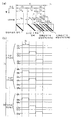
도 1은, 본 발명의 표시장치의 화소의 구동방법을 나타내는 모식도이다.1 is a schematic diagram showing a method of driving a pixel of the display device of the present invention.
도 2는, 본 발명의 표시장치를 사용한 표시시스템을 나타내는 도면이다.2 is a diagram showing a display system using the display device of the present invention.
도 3은, 본 발명의 표시장치의 화소의 구성을 나타내는 블록도이다.3 is a block diagram showing a configuration of a pixel of the display device of the present invention.
도 4는, 본 발명의 표시장치의 전류원회로의 회로도이다.4 is a circuit diagram of a current source circuit of the display device of the present invention.
도 5는, 본 발명의 표시장치의 화소부의 회로도이다.5 is a circuit diagram of a pixel portion of a display device of the present invention.
도 6은, 본 발명의 표시장치의 화소의 설정동작의 타이밍 차트를 나타내는 도면이다.6 is a diagram illustrating a timing chart of a pixel setting operation of the display device of the present invention.
도 7은, 본 발명의 표시장치의 화상표시동작의 타이밍 차트를 나타내는 도면이다.7 is a diagram illustrating a timing chart of an image display operation of the display device of the present invention.
도 8은, 본 발명의 표시장치의 기준전류 입력회로의 구성을 나타내는 블록도이다.8 is a block diagram showing the configuration of a reference current input circuit of the display device of the present invention.
도 9는, 본 발명의 표시장치의 기준전류 입력회로의 구성을 나타내는 회로도이다. 9 is a circuit diagram showing the configuration of a reference current input circuit of the display device of the present invention.
도 10은, 본 발명의 표시장치의 기준전류 입력회로의 동작을 나타내는 타이밍 차트를 나타내는 도면이다.10 is a timing chart showing the operation of the reference current input circuit of the display device of the present invention.
도 11은, 본 발명의 표시장치의 기준전류 입력회로의 동작방법을 나타내는 도면이다.11 is a diagram showing a method of operating a reference current input circuit of the display device of the present invention.
도 12는, 본 발명의 표시장치의 전류원회로의 회로도이다.12 is a circuit diagram of a current source circuit of the display device of the present invention.
도 13은, 본 발명의 표시장치의 스위치부의 회로도이다.13 is a circuit diagram of a switch unit of the display device of the present invention.
도 14는, 본 발명의 표시장치의 화소부의 회로도이다.14 is a circuit diagram of a pixel portion of a display device of the present invention.
도 15는, 본 발명의 표시장치의 화소의 설정동작의 타이밍 차트를 나타내는 도면이다.15 is a diagram illustrating a timing chart of a pixel setting operation of the display device of the present invention.
도 16은, 본 발명의 표시장치의 화상표시동작 및 그 타이밍 차트를 나타내는 도면이다.16 is a diagram showing an image display operation and a timing chart of the display device of the present invention.
도 17은, 본 발명의 표시장치의 전류원회로의 회로도이다.17 is a circuit diagram of a current source circuit of the display device of the present invention.
도 18은, 본 발명의 표시장치의 화소부의 회로도이다.18 is a circuit diagram of a pixel portion of a display device of the present invention.
도 19는, 본 발명의 표시장치의 화소의 설정동작의 타이밍 차트를 나타내는 도면이다.19 is a diagram illustrating a timing chart of a pixel setting operation of the display device of the present invention.
도 20은, 본 발명의 표시장치의 참조전류원회로의 전환회로의 구성을 나타내는 도면이다.20 is a diagram showing the configuration of a switching circuit of a reference current source circuit of the display device of the present invention.
도 21은, 발명의 표시장치의 전류원회로의 회로도이다.21 is a circuit diagram of a current source circuit of the display device of the invention.
도 22는, 본 발명의 표시장치의 화소부의 회로도이다.22 is a circuit diagram of a pixel portion of a display device of the present invention.
도 23은, 본 발명의 표시장치의 전류원회로의 회로도이다. Fig. 23 is a circuit diagram of a current source circuit of the display device of the present invention.
도 24는, 본 발명의 표시장치의 전류원회로의 회로도이다.24 is a circuit diagram of a current source circuit of the display device of the present invention.
도 25는, 본 발명의 표시장치의 전류원회로의 회로도이다.25 is a circuit diagram of a current source circuit of the display device of the present invention.
도 26은, 본 발명의 표시장치의 화소부의 회로도이다.Fig. 26 is a circuit diagram of a pixel portion of the display device of the present invention.
도 27은, 종래의 표시장치의 구동방법의 타이밍 차트를 나타내는 도면이다.27 is a diagram illustrating a timing chart of a conventional method for driving a display device.
도 28은, 종래의 표시장치의 구동방법을 나타내는 도면이다.28 is a diagram showing a driving method of a conventional display device.
도 29는, 종래의 표시장치의 화소의 회로도이다.29 is a circuit diagram of pixels of a conventional display device.
도 30은, 종래의 표시장치의 화소의 회로도이다.30 is a circuit diagram of pixels of a conventional display device.
도 31은, 종래의 표시장치의 구동트랜지스터의 동작영역을 나타내는 도면이다.Fig. 31 is a view showing an operating area of a drive transistor of a conventional display device.
도 32는, 종래의 표시장치의 구동트랜지스터의 동작점을 나타내는 도면이다.32 is a view showing an operating point of a drive transistor of a conventional display device.
도 33은, 종래의 표시장치의 화소의 회로도이다.33 is a circuit diagram of pixels of a conventional display device.
도 34는, 종래의 표시장치의 구동방법을 나타내는 도면이다.34 is a diagram showing a driving method of a conventional display device.
도 35는, 종래의 표시장치의 구동방법의 타이밍 차트를 나타내는 도면이다.35 is a diagram illustrating a timing chart of a conventional method for driving a display device.
도 36은, 종래의 표시장치의 발광소자의 열화에 의한 구동트랜지스터의 동작점의 변화를 나타내는 도면이다.Fig. 36 is a view showing the change of the operating point of the driving transistor due to deterioration of the light emitting element of the conventional display device.
도 37은, 종래의 표시장치의 발광소자의 열화에 의한 구동트랜지스터의 동작점의 변화를 나타내는 도면이다.Fig. 37 is a view showing the change of the operating point of the drive transistor due to deterioration of the light emitting element of the conventional display device.
도 38은, 본 발명의 표시장치의 전류원회로의 구성을 나타내는 도면이다.Fig. 38 is a diagram showing the configuration of the current source circuit of the display device of the present invention.
도 39는, 본 발명의 표시장치의 화소부의 구성을 나타내는 도면이다.39 is a diagram illustrating a configuration of a pixel portion of a display device of the present invention.
도 40은, 본 발명의 표시장치의 화상표시동작 및 그 타이밍 차트를 나타내는 도면이다.40 is a diagram illustrating an image display operation and a timing chart of the display device of the present invention.
도 41은, 본 발명의 표시장치의 전류원회로의 구성을 나타내는 도면이다.Fig. 41 is a diagram showing the configuration of the current source circuit of the display device of the present invention.
도 42는, 본 발명의 표시장치의 화소부의 구성을 나타내는 도면이다.42 is a diagram illustrating a configuration of a pixel portion of a display device of the present invention.
도 43은, 본 발명의 표시장치의 화소의 스위치부의 회로도이다.43 is a circuit diagram of a switch unit of a pixel of the display device of the present invention.
도 44는, 본 발명의 표시장치의 전류원회로의 구성을 나타내는 도면이다.44 is a diagram showing the configuration of a current source circuit of the display device of the present invention.
도 45는, 발명의 표시장치의 화소부의 구성을 나타내는 도면이다.45 is a diagram illustrating a configuration of a pixel portion of a display device of the invention.
도 46은, 본 발명의 표시장치를 응용한 전자기기를 나타내는 도면이다.46 is a diagram showing an electronic device to which the display device of the present invention is applied.
도 47은, 본 발명의 표시장치의 전류원회로의 구성을 나타내는 도면이다.Fig. 47 is a diagram showing the configuration of the current source circuit of the display device of the present invention.
도 48은, 본 발명의 표시장치의 화소부의 구성을 나타내는 도면이다.48 is a diagram illustrating a configuration of a pixel portion of a display device of the present invention.
도 49는, 본 발명의 표시장치의 구동방법의 타이밍 차트를 나타내는 도면이다.Fig. 49 is a diagram showing a timing chart of the method for driving the display device of the present invention.
도 50은, 본 발명의 표시장치의 화소부의 구성을 나타내는 도면이다.50 is a diagram illustrating a configuration of a pixel portion of a display device of the present invention.
도 51은, 본 발명의 표시장치의 화소부의 구성을 나타내는 도면이다.51 is a diagram illustrating a configuration of a pixel portion of a display device of the present invention.
도 52는, 본 발명의 표시장치의 화소부의 구성을 나타내는 도면이다.52 is a diagram illustrating a configuration of a pixel portion of a display device of the present invention.
도 53은, 본 발명의 표시장치의 화소부의 구성을 나타내는 도면이다.53 is a diagram illustrating a configuration of a pixel portion of a display device of the present invention.
도 54는, 본 발명의 표시장치의 신호선 구동회로의 구성을 나타내는 블록도이다.Fig. 54 is a block diagram showing the construction of a signal line driver circuit of the display device of the present invention.
도 55는, 본 발명의 표시장치의 신호선 구동회로의 구성을 나타내는 도면이다.55 is a diagram showing the configuration of a signal line driver circuit of the display device of the present invention.
도 56은, 본 발명의 표시장치의 주사선 구동회로의 구성을 나타내는 도면이 다.56 is a diagram showing the configuration of a scan line driver circuit of the display device of the present invention.
도 57은, 본 발명의 표시장치의 전류원회로의 구성을 나타내는 도면이다.Fig. 57 is a diagram showing the configuration of the current source circuit of the display device of the present invention.
도 58은, 본 발명의 표시장치의 전류원회로의 구성을 나타내는 도면이다.Fig. 58 is a diagram showing the structure of a current source circuit of the display device of the present invention.
도 59는, 본 발명의 표시장치의 화소의 설정동작을 나타내는 타이밍 차트를 나타내는 도면이다.Fig. 59 is a diagram showing a timing chart showing the pixel setting operation of the display device of the present invention.
도 60은, 본 발명의 표시장치의 주사선 구동회로의 구성을 나타내는 도면이다.60 is a diagram showing the configuration of a scan line driver circuit of the display device of the present invention.
도 61은, 본 발명의 표시장치의 화소의 상태를 나타내는 모식도이다.Fig. 61 is a schematic diagram showing a state of a pixel of the display device of the present invention.
도 62는, 본 발명의 표시장치의 화소의 상태를 나타내는 모식도이다.62 is a schematic diagram illustrating a state of a pixel of the display device of the present invention.
도 63은, 본 발명의 표시장치의 화소의 상태를 나타내는 모식도이다.Fig. 63 is a schematic diagram showing a state of a pixel of the display device of the present invention.
도 64는, 본 발명의 표시장치의 화소의 상태를 나타내는 모식도이다.64 is a schematic diagram illustrating a state of a pixel of the display device of the present invention.
도 65는, 본 발명의 표시장치의 화소의 상태를 나타내는 모식도이다.65 is a schematic diagram illustrating a state of a pixel of the display device of the present invention.
도 66은, 본 발명의 표시장치의 화소의 상태를 나타내는 모식도이다.66 is a schematic diagram illustrating a state of a pixel of the display device of the present invention.
도 67은, 본 발명의 표시장치의 화소의 전류원회로의 회로도이다.Fig. 67 is a circuit diagram of a current source circuit of a pixel of the display device of the present invention.
도 68은, 본 발명의 표시장치의 화소의 전류원회로의 회로도이다.Fig. 68 is a circuit diagram of a current source circuit of a pixel of the display device of the present invention.
도 69는, 본 발명의 표시장치의 화소의 전류원회로의 회로도이다.69 is a circuit diagram of a current source circuit of a pixel of the display device of the present invention.
도 70은, 본 발명의 표시장치의 화소의 전류원회로의 회로도이다.70 is a circuit diagram of a current source circuit of a pixel of the display device of the present invention.
도 71은, 본 발명의 표시장치의 화소의 전류원회로의 회로도이다.Fig. 71 is a circuit diagram of a current source circuit of a pixel of the display device of the present invention.
도 72는, 본 발명의 표시장치의 화소의 전류원회로의 회로도이다.Fig. 72 is a circuit diagram of a current source circuit of a pixel of the display device of the present invention.
도 73은, 본 발명의 표시장치의 화소의 구성을 나타내는 회로도이다. 73 is a circuit diagram showing a configuration of a pixel of a display device of the present invention.
도 74는, 본 발명의 표시장치의 화소의 구성을 나타내는 회로도이다.74 is a circuit diagram showing a configuration of a pixel of a display device of the present invention.
도 75는, 본 발명의 표시장치의 화소의 구성을 나타내는 회로도이다.75 is a circuit diagram showing a configuration of a pixel of a display device of the present invention.
도 76은, 본 발명의 표시장치의 화소의 구성을 나타내는 회로도이다.Fig. 76 is a circuit diagram showing the structure of a pixel of the display device of the present invention.
도 77은, 본 발명의 표시장치의 화소의 구성을 나타내는 회로도이다.77 is a circuit diagram showing a configuration of a pixel of a display device of the present invention.
도 78은, 본 발명의 표시장치의 화소의 구성을 나타내는 평면도 78a와 회로도 78b이다.78 is a plan view 78a and a circuit diagram 78b showing the structure of a pixel of the display device of the present invention.
도 79는, 본 발명의 표시장치의 화소의 구성을 나타내는 평면도 79a와 회로도 79b이다.
79 is a plan view 79a and a circuit diagram 79b showing the configuration of a pixel of the display device of the present invention.
(발명을 실시하기 위한 최선의 형태)(The best mode for carrying out the invention)
도 3a에, 본 발명의 표시장치의 화소의 구성의 모식도를 나타낸다. 도 3a에서, 각 화소(100)는, 주사선 G, 영상신호 입력선 S, 전원선 W, 스위치부(101), 전류원회로(102) 및 발광소자(106)에 의해 구성된다.3A, the schematic diagram of the structure of the pixel of the display apparatus of this invention is shown. In FIG. 3A, each
각 화소(100)에 있어서, 스위치부(101)는 단자 C 및 단자 D를 갖는다. 발광소자(106)의 화소전극(106a)은, 스위치부의 단자 D와 접속된다. 스위치부의 단자 C는, 전류원회로(102)의 단자 B와 접속된다. 전류원회로(102)의 단자 A는 전원선 W와 접속되어 있다. 전류원회로(102)는, 원 속에 화살표를 배치한 기호에 의해 모식적으로 나타낸다. 전류원회로(102)는 이 기호의 화살표의 방향, 요컨대 단자 A에서 단자 B의 방향에, 양(+)의 일정전류를 흐르게 하는 회로라고 한다. 단자 A 또는 단 자 B의 한쪽을 전류원회로(102)의 입력단자, 다른쪽을 전류원회로(102)의 출력단자라 부른다.In each
발광상태를 선택하는 신호가 영상신호 입력선 S로부터 입력된 화소(100)에서는, 스위치부(101)의 단자 C와 단자 D 사이가 도통상태가 된다. 이렇게 해서, 스위치부(101)의 단자 C와 단자 D 사이 및 전류원회로(102)의 단자 A와 단자 B 사이를 통해, 발광소자(106)의 화소전극(106a)과 전원선 w가 접속된다.In the
스위치부(101)는, 주사선 G로부터 입력되는 신호에 의해 영상신호 입력선 S 상의 영상신호의 화소에의 입력을 전환하는 제1 스위치와, 화소에 입력된 영상신호에 의해 온·오프가 전환되는 제2 스위치를 갖는다. 제2 스위치의 온·오프를 전환함으로써, 스위치부의 단자 C와 단자 D의 사이의 도통 및 비도통상태가 전환된다. 단자 C 또는 단자 D의 한쪽을 스위치부(101)의 입력단자, 다른쪽을 스위치부(101)의 출력단자라 부른다.The
발광소자(106)는, 화소전극(106a)에서 대향전극(106b)에, 또는 그 반대의 방향으로 전류를 흐르게 하고, 그 전류에 따라 휘도가 변화되는 소자를 나타낸다.The
도 3a에서는, 전류원회로(102)의 단자 A가 전원선 W에 접속되고, 단자 B가 스위치부(101)의 단자 C와 단자 D 사이를 통해, 발광소자(106)의 화소전극(106a)에 접속되어 있으므로, 발광소자(106)의 화소전극(106a)은 양극이 되고, 대향전극(106b)은 음극이 된다. 이때, 발광소자(106)의 대향전극(106b)에 공급되어 있는 전위 Vcom은, 전원선 W의 전위보다 낮게 설정되어 있다. 전위 Vcom은, 전원기준선(도시하지 않음)에 의해 공급되어 있다.
In FIG. 3A, the terminal A of the
한편, 전류원회로(102)의 단자 A가, 스위치부(101)의 단자 C에 접속되고, 단자 B가 전원선 W에 접속되는 구조로 해도 된다. 이때, 발광소자(106)의 화소전극(106a)은 음극이 되고, 대향전극(106b)은 양극이 된다. 발광소자(106)의 대향전극(106b)에 공급되어 있는 전위 Vcom은, 전원선 W의 전위보다 높게 설정되어 있다.In addition, the terminal A of the
또한, 전류원회로(102)와 스위치부(101)와 발광소자(106)의 접속순서는 임의로 해도 되므로, 예를 들면, 전류원회로(102)는, 스위치부(101)와 발광소자(106)의 사이에 배치되어 있어도 된다. 요컨대, 전류원회로(102)의 단자 B가 발광소자(106)의 화소전극(106a)과 접속되고, 전류원회로(102)의 단자 A가 스위치부(101)의 단자 D와 접속되며, 스위치부(101)의 단자 C가 전원선 W에 접속된 구조이어도 된다. 더욱이, 전류원회로(102)의 단자 A와 단자 B가 반전한 구조이어도 된다. 요컨대, 전류원회로(102)의 단자 A가 발광소자(106)의 화소전극(106a)과 접속되고, 전류원회로(102)의 단자 B가 스위치부(101)의 단자 D와 접속되며, 스위치부(101)의 단자 C가 전원선 W와 접속된 구성이어도 된다. 이 경우, 발광소자(106)의 화소전극(106a)은 음극이 되고, 대향전극은 106b는 양극이 된다. 이때, 발광소자(106)의 대향전극(106b)에 공급되어 있는 전위 Vcom은, 전원선 W의 전위보다 높게 설정되어 있다.In addition, since the order of connection between the
스위치부(101)에서, 단자 C와 단자 D의 사이가 도통상태로 된 화소(100)에서는, 전류원회로(102)에 의해 정해지는 일정전류가 발광소자(106)에 입력되고, 발광 소자(106)는 발광한다.In the
전류원회로(102)의 기본구조의 예를 도 3b 및 도 3c에 나타낸다. 각 화소의 전류원회로를 흐르는 일정전류가, 전류신호에 의해 정해지는 전류원회로의 예를 든다. 이러한 구성의 전류원회로를, 전류제어형 전류원회로라 부른다. 도 3b 및 도 3c에서 단자 A 및 단자 B는, 도 3a에서, 단자 A 및 단자 B에 대응한다.Examples of the basic structure of the
도 3b 및 도 3c에서, 전류원회로(102)는 트랜지스터(전류원 트랜지스터)(112)와 용량소자(전류원용량)(111)를 갖는다. 포화영역에서 동작하는 전류원 트랜지스터(112)의 드레인전류가, 화소의 외부로부터 입력된 일정전류(이하, 기준전류와 표기함)에 대응하는 일정전류(이하, 화소기준전류라 표기함)가 된다. 요컨대, 화소의 외부로부터 일정전류(기준전류)가 입력된다. 이때의 게이트전압 Vgs(이하, 화소대응 기준전압이라 표기함)가, 전류원용량(111)에 의해 유지되면, 전류원 트랜지스터(112)가 포화영역에서 동작하는 경우에는, 기준전류에 대응한 일정전류(화소기준전류)가 드레인전류로서 전류원 트랜지스터(112) 및 발광소자(106)에 흐른다. 이렇게 해서, 외부의 전류원보다 기준전류가 입력되어 없어진 후에도, 전류원 트랜지스터(112)는 소스·드레인 사이에 전압이 인가되면, 전류원용량(111)에 유지된 화소에 따라 기준전압에 따라 화소기준전류를 흐르게 한다. 이때, 전류원용량(111)은, 다른 트랜지스터의 게이트용량 등을 이용함으로써 생략하는 것도 가능하다.3B and 3C, the
각 화소에 배치된 전류원용량(111)에 있어서, 전류원 트랜지스터(112)가 화소기준전류를 흐르게 하는 데 필요한 게이트전압을 취득하여 유지하는 동작을, 화 소의 설정동작이라 부른다. 이때, 본 발명에서의 트랜지스터로서는, 박막트랜지스터(TFT)이어도, 단결정 트랜지스터 등의 트랜지스터이어도 어느 쪽이어도 된다.In the
또한, 유기물을 이용한 트랜지스터이어도 된다. 예를 들면, 단결정 트랜지스터로서는, SOI 기술을 사용하여 형성된 트랜지스터로 할 수 있다. 박막트랜지스터로서는, 활성층으로서 다결정 반도체를 사용한 것이어도, 비정질 반도체를 사용한 것이어도 된다. 예를 들면, 폴리실리콘을 사용한 TFT나, 아모르퍼스 실리콘을 사용한 TFT로 할 수 있다.Further, a transistor using an organic substance may be used. For example, the single crystal transistor can be a transistor formed by using an SOI technique. As the thin film transistor, a polycrystalline semiconductor may be used as the active layer, or an amorphous semiconductor may be used. For example, it can be set as TFT using polysilicon and TFT using amorphous silicon.
전류원회로(102)에 있어서, 전류원 트랜지스터(112)에 드레인전류가 흐르는 경우, 전류원용량(111)의 한쪽의 전극은 전류원 트랜지스터(112)의 게이트전극과 접속되고, 다른쪽(도면에서, 단자 A'로 나타냄)은 일정전위가 공급된다. 전류원용량(111)에 유지된 전하에 의해, 전류원 트랜지스터(112)의 게이트전극의 전위(게이트전위)가 보존된다. 여기서, 단자 A'의 전위와 전류원 트랜지스터(112)의 소스단자의 전위와는, 동일해도 되고 달라도 되지만, 전류원 트랜지스터에 화소기준전류가 흐를 때는 언제나, 각각의 단자의 사이의 전위차는, 같다고 한다. 이렇게 해서, 전류원 트랜지스터(112)에 화소기준전류가 흐를 때의 게이트전압 Vgs(화소대응 기준전압)는 유지된다. 포화영역에서 동작하는 트랜지스터에서는, 게이트전압 Vgs에 따라 드레인전류도 변화된다. 따라서, 소스단자의 전위가 변화되어도, 게이트전압 Vgs는 일정하도록, 단자 A'는 소스단자에 접속되어 있는 것이 바람직하다. 이때, 도 3b와 도 3c에서는, 전류원 트랜지스터(112)의 극성이 다르다. 도 3b에서는, 전류원 트랜지스터(112)는, p채널형으로, 도 3c에서는 n채널형이다.
In the
도 3a와 같이 접속되어 있는 경우에는, 전류원 트랜지스터(112)가 p채널형인 경우, 전류원 트랜지스터(112)는 소스단자로부터 드레인단자에 전류를 흐르게 한다. 또한, 전류원 트랜지스터(112)가 n채널형인 경우, 전류원 트랜지스터(112)의 드레인단자로부터 소스단자로 전류를 흐르게 한다. 따라서, 전류원 트랜지스터(112)가 p채널형인 경우, 전류원 트랜지스터(112)의 소스단자는 단자 A에 접속되고, 드레인단자는 단자 B에 접속된다. 한편, 전류원 트랜지스터(112)가 n채널형인 경우, 전류원 트랜지스터(112)의 드레인단자는 단자 A에 접속되고, 소스단자는 단자 B에 접속된다.When connected as shown in Fig. 3A, when the
화소기준전류를, 화소 외부로부터 입력되는 전류신호(기준전류)에 의해 제어하는 수단으로서는, 크게 나누어 2개의 방법이 있다.As means for controlling the pixel reference current by a current signal (reference current) input from outside the pixel, there are two methods.
하나는, 커렌트미러방식이라 명명한 방식이다. 커렌트미러회로는, 게이트전극이 전기적으로 접속된 1쌍의 트랜지스터를 갖고, 한쪽의 트랜지스터의 게이트전극과 드레인단자가 전기적으로 접속된 구성을 갖는다. 커렌트미러방식에서는, 커렌트미러회로를 구성하는 1쌍의 트랜지스터 중, 한쪽의 트랜지스터를 전류원 트랜지스터(112)로 하고, 다른쪽의 트랜지스터를 커렌트 트랜지스터로 한다. 커렌트 트랜지스터의 드레인단자와 게이트전극을 전기적으로 접속하여, 그 소스·드레인 사이에 기준전류를 입력하는 수법이다.One is called the current mirror method. The current mirror circuit has a pair of transistors in which gate electrodes are electrically connected, and has a configuration in which the gate electrode and the drain terminal of one transistor are electrically connected. In the current mirror system, one of the pair of transistors constituting the current mirror circuit is used as the
이미 하나는, 동일 트랜지스터방식이라 명명한 방식이다. 동일 트랜지스터방식은, 드레인단자와 게이트전극이 전기적으로 접속된 전류원 트랜지스터(112)의 소스·드레인 사이에, 기준전류를 직접입력하는 수법이다. 이때, 동일. 트랜지스터방 식의 변형으로서, 멀티게이트방식이라 부르는 것도 있다.One is already called the same transistor method. The same transistor method is a method of directly inputting a reference current between the source and the drain of the
커렌트미러방식을 사용하는 전류원회로를, 커렌트미러방식의 전류원회로라 부르고, 동일 트랜지스터방식을 사용하는 전류원회로를, 동일 트랜지스터방식의 전류원회로와 부르며, 멀티게이트방식을 사용하는 전류회로를 멀티게이트방식의 전류원회로라 부른다. 전류원회로(102)는, 일단, 기준전류를 입력하여 화소대응 기준전압을 전류원용량(111)으로 유지한다, 화소의 설정동작을 행한 후에는, 전류원용량(111)에 유지된 전하가 방전하지 않는 한, 다시 기준전류를 입력하는 동작을 필요로 하지 않는다.The current source circuit using the current mirror method is called the current source circuit using the current mirror method, the current source circuit using the same transistor method is called the current source circuit using the same transistor method, and the current circuit using the multi-gate method is multiplied. It is called a gate current source circuit. The
전류원용량(111)에 유지된 전하는, 실제로는, 누설전류의 영향이나 여러가지 노이즈에 의해 시간이 경과하면 변화해 버린다. 그래서, 정기적으로, 화소의 설정동작을 반복할 필요가 있다. 그러나, 일단, 화소의 설정동작을 행한 후에, 정기적으로 행하는 화소의 설정동작에서는, 누설전류에 의해 전류원용량(111)에 유지된 전하가 변화된 만큼만, 전하를 유지하여 바로 잡으면 된다. 그 때문에, 처음의 화소의 설정동작과 비교하여, 그 후 정기적으로 행하는 화소의 설정동작에 요하는 시간은 짧게 끝난다.The charge held in the
(실시형태 1)(Embodiment 1)
본 발명의 표시장치의 화소구성의 일예를 나타낸다. 각 화소에 배치한 전류원회로의 구성예를 도 4에 나타낸다. 이때, 도 4에서, 도 3과 동일한 부분은 동일한 부호를 사용하여 나타낸다. 도 4에서는 커렌트미러방식의 전류원회로의 예를 나타낸다. 전류원회로(102)는, 전류원용량(111), 전류원 트랜지스터(112), 커렌트 트 랜지스터(1405), 전류입력 트랜지스터(1403), 전류유지 트랜지스터(1404), 전류선 CL, 신호선 GN, 신호선 GH에 의해 구성된다. 전류원 트랜지스터(112)와 커렌트 트랜지스터(1405)는 1쌍으로 커렌트미러회로를 구성하므로, 극성은 같게 되어서는 안된다. 또한, 동일화소 내의 이들 2개의 트랜지스터의 전류특성은 같은 것이 바람직하다. 여기서 본 실시형태 1에서는, 간단화를 위해, 전류원 트랜지스터(112)와 커렌트 트랜지스터(1405)의 전류특성은 같다고 한다.An example of the pixel structure of the display device of the present invention is shown. 4 shows an example of the configuration of the current source circuit arranged in each pixel. At this time, in Fig. 4, the same parts as in Fig. 3 are represented using the same reference numerals. 4 shows an example of the current source circuit of the current mirror type. The
도 4에서, 전류원 트랜지스터(112) 및 커렌트 트랜지스터(1405)를, p채널형으로 한 예를 나타낸다. 이때, 전류원 트랜지스터(112) 및 커렌트 트랜지스터(1405)를 n채널형으로 하는 경우도, 도 3c에 나타낸 구조에 따라, 용이하게 응용할 수 있다. 그 경우의 예를 도 23에 나타낸다. 도 23에서 도 4와 동일한 부분은 동일한 부호를 사용하여 나타낸다. 도 23에서, 추가 트랜지스터 1801 및 1803은, 화소의 설정동작시에 전류원 트랜지스터(112)에 전류가 흐르는 것을 막기 위해 설치다. 요컨대, 화소의 설정동작시에는, 추가 트랜지스터 1801 및 1803은 비도통상태이다. 한편, 화상표시를 행할 때는 도통상태가 된다. 또한, 추가 트랜지스터 1802는, 화상표시를 행할 때에 커렌트 트랜지스터(1405)에 전류가 흐르는 것을 막기 위해 설치된다. 요컨대, 화소의 설정동작시에는, 추가 트랜지스터 1802는 도통상태이다. 한편, 화상표시를 행할 때는 비도통상태가 된다.4 shows an example in which the
이하, 도 4를 예로 설명한다. 전류입력 트랜지스터(1403), 전류유지 트랜지스터(1404)는 n채널형으로 하지만, 단순한 스위치로서 동작하기 때문에 p채널형으로 해도 상관없다.
4 will be described as an example. Although the
전류원 트랜지스터(112)의 게이트전극과 커렌트 트랜지스터(1405)의 게이트전극 및, 전류원용량(111)의 한쪽의 전극은 접속되어 있다. 또한, 전류원용량(111)의 다른쪽의 전극은, 전류원 트랜지스터(112)의 소스단자 및 커렌트 트랜지스터(1405)의 소스단자와 접속되고, 전류원회로(102)의 단자 A에 접속되어 있다. 커렌트 트랜지스터(1405)의 게이트전극과 드레인단자는, 전류유지 트랜지스터(1404)의 소스·드레인단자 사이를 통해, 접속되어 있다. 전류유지 트랜지스터(1404)의 게이트전극은, 신호선 GH에 접속되어 있다. 커렌트 트랜지스터(1405)의 드레인단자와 전류선 CL은, 전류입력 트랜지스터(1403)의 소스·드레인단자 사이를 통해 접속되어 있다. 전류입력 트랜지스터(1403)의 게이트전극은 신호선 GN에 접속되어 있다. 또한, 전류원 트랜지스터(112)의 드레인단자는 단자 B에 접속되어 있다.The gate electrode of the
이때 상기 구성에서, 전류입력 트랜지스터(1403)를, 커렌트 트랜지스터(1405)와 단자 A의 사이에 배치해도 된다. 요컨대, 커렌트 트랜지스터(1405)의 소스단자가 전류입력 트랜지스터(1403)의 소스·드레인단자 사이를 통해 단자 A에 접속되고, 커렌트 트랜지스터(1405)의 드레인단자가 전류선 CL에 접속된 구성이어도 된다.At this time, in the above configuration, the
또한, 상기 구성에서, 커렌트 트랜지스터(1405) 및 전류원 트랜지스터(112)의 게이트전극은, 전류입력 트랜지스터(1403)의 소스·드레인단자 사이를 통하지 않고, 전류선 CL에 접속되어 있어도 된다. 요컨대, 전류유지 트랜지스터(1404)의 소스단자 및 드레인단자의, 커렌트 트랜지스터(1405) 및 전류원 트랜지스터(112)의 게이트전극과 접속되어 있지 않은 측이, 전류선 CL에 직접접속되어 있는 구성이어도 된다. 그 경우, 전류선 CL의 전위를 조정함으로써, 전류유지 트랜지스터(1404)의 소스·드레인 사이 전압을 작게 할 수 있다. 그 결과, 전류유지 트랜지스터(1404)가 비도통상태일 때에, 전류유지 트랜지스터(1404)의 누설전류를 작게 할 수 있다. 이것에 한정되지 않고, 전류유지 트랜지스터(1404)는, 도통상태가 되었을 때에, 커렌트 트랜지스터(1405)의 게이트전극의 전위를 전류선 CL의 전위와 같게 하도록 접속되어 있으면 된다. 요컨대, 화소의 설정동작시에는 도 61a와 같이 되어, 발광시에는 도 61b와 같이 되어 있으면 된다. 요컨대, 그와 같이, 배선이나 스위치가 접속되어 있으면 된다. 따라서 도 67과 같이 되어 있어도 된다. 이때, 도 67에서, 도 4와 동일한 부분은 동일한 부호를 사용하여 나타내고, 설명은 생략한다.In the above configuration, the gate electrodes of the
다음에, 도 3a에서의 스위치부의 구성예를, 도 13에 나타낸다. 이때, 도 13에서, 도 3과 동일한 부분은 동일한 부호를 사용하여 나타낸다. 도 13에서, 스위치부(101)는 3개의 트랜지스터(선택 트랜지스터(301), 구동트랜지스터(302), 소거트랜지스터(304))와, 하나의 용량소자(유지용량(303))에 의해 구성된다. 유지용량(303)은, 트랜지스터의 게이트용량 등을 이용함으로써 생략하는 것도 가능하다.Next, the structural example of the switch part in FIG. 3A is shown in FIG. At this time, in Fig. 13, the same parts as in Fig. 3 are indicated using the same reference numerals. In Fig. 13, the
도 13에서는, 구동트랜지스터(302)를 p채널형으로 하고, 선택 트랜지스터(301) 및 소거트랜지스터(304)를 n채널형으로 하지만, 이 구성에 한정되지 않는다. 단순한 스위치로서 동작하므로, 선택트랜지스터(301), 구동트랜지스터(302), 소거트랜지스터(304)는, 각각 n채널형이어도 p채널형이어도 어느 쪽이어도 상관없다.In Fig. 13, the driving
이때, 구동트랜지스터(302)는, 포화영역에서 동작시켜도 된다. 구동트랜지스터(302)를 포화영역에서 동작시킴으로써, 구동트랜지스터(302)와, 직렬로 접속된 전류원회로의 전류원 트랜지스터(112)의 포화영역특성을 보충하는 것이 가능하다. 포화영역특성이란, 소스·드레인 사이 전압에 대하여 드레인전류가 일정히 유지되는 특성을 나타내는 것이다. 또한, 포화영역특성을 보충한다는 것은, 포화영역에서 동작하는 전류원 트랜지스터(112)에서도, 소스·드레인 사이 전압이 증가함에 따라 드레인전류가 증가하는 것을 억제하는 것을 의미한다. 이때, 상기 효과를 얻기 위해서는, 구동트랜지스터(302)와 전류원 트랜지스터(112)는 동극성이 아니면 안된다.At this time, the
상기한 포화영역특성을 보충하는 효과에 대하여 이하에 설명한다. 예를 들면, 전류원 트랜지스터(112)의 소스·드레인 사이 전압이 증가하는 경우에 주목한다. 전류원 트랜지스터(112)와 구동트랜지스터(302)는 직렬로 접속되어 있다. 따라서, 전류원 트랜지스터(112)의 소스·드레인 사이 전압의 변화에 의해, 구동트랜지스터(302)의 소스단자의 전위가 변화된다. 이렇게 해서 구동트랜지스터(302)의 소스·게이트 사이 전압의 절대값은 작아지면, 구동트랜지스터(302)의 I-V 곡선이 변화된다. 이 변화의 방향은 드레인전류가 감소하는 방향이다. 이렇게 해서, 구동트랜지스터(302)에 직렬로 접속된 전류원 트랜지스터(112)의 드레인전류는 감소한다. 마찬가지로, 전류원 트랜지스터(112)의 소스·드레인 사이 전압이 감소하면, 전류 원 트랜지스터(112)의 드레인전류는 증가한다. 이와 같이 하여, 전류원 트랜지스터(112)를 흐르는 전류를 일정히 유지하는 효과를 얻을 수 있다.The effect of supplementing the above saturation region characteristics will be described below. For example, attention is paid to the case where the voltage between the source and the drain of the
도 13의 스위치부의 구성에 대하여 이하에 상세히 설명한다. 선택 트랜지스터(301)의 게이트전극은, 주사선 G에 접속되어 있다. 선택 트랜지스터(301)의 소스단자와 드레인단자는, 한쪽은 영상신호 입력선 S에 접속되고, 다른쪽은, 구동트랜지스터(302)의 게이트전극에 접속되어 있다. 구동트랜지스터(302)의 소스단자와 드레인단자는, 한쪽은 단자 D에 접속되고, 다른쪽은 단자 C에 접속된다. 유지용량(303)의 한쪽의 전극은 구동트랜지스터(302)의 게이트전극에 접속되고, 다른쪽의 전극은 배선 Wco에 접속되어 있다. 소거트랜지스터(304)의 소스단자와 드레인단자는, 한쪽은 구동트랜지스터(302)의 게이트전극과 접속되고, 다른쪽은, 배선 Wco에 접속되어 있다. 소거트랜지스터(304)의 게이트전극은 소거용 신호선 RG에 접속되어 있다.The structure of the switch part of FIG. 13 is demonstrated in detail below. The gate electrode of the
이때, 소거트랜지스터(304)의 소스단자 및 드레인단자는, 상기 접속구조에 한정되지 않는다. 소거트랜지스터(304)를 도통상태로 함으로써, 유지용량(303)에 유지된 전하가 방출되도록 여러가지 접속구조로 하는 것이 가능하다. 요컨대, 소거트랜지스터(304)를 도통 또는 비도통시킴으로써, 구동트랜지스터(302)가 비도통이 되는 접속구조로 하면 된다.At this time, the source terminal and the drain terminal of the erasing
이어서, 도 13에 나타낸 스위치부와, 소거트랜지스터(304)의 배치의 방식이 다른 구성에 대하여 설명한다. 도 43a에 스위치부의 일례를 나타낸다. 도 13과 동 일한 부분은 동일한 부호를 사용하여 나타내고 설명은 생략한다. 도 43a에서는, 소거트랜지스터(304)를 발광소자에 입력되는 전류의 경로 상에 직렬로 배치하고, 소거트랜지스터(304)를 비도통상태로 함으로써, 강제적으로 발광소자에 전류가 흐르지 않도록 한다. 이 조건을 만족하면, 소거트랜지스터(304)는 어디에 배치해도 된다. 소거트랜지스터(304)를 비도통상태로 함으로써, 화소를 일률적으로 비발광의 상태로 할 수 있다.Next, a configuration in which the switch unit shown in Fig. 13 and the erase
도 43b에, 스위치부(101)의 다른 구성을 나타낸다. 도 43b에서는, 소거트랜지스터(304)의 소스·드레인단자 사이를 통해 구동트랜지스터(302)의 게이트전극에 소정의 전압을 인가하고, 구동트랜지스터(302)를 비도통상태로 하는 수법이다. 도 13과 동일한 부분은 동일한 부호를 사용하여 나타내고 설명은 생략한다. 이 예에서는, 소거트랜지스터(304)의 소스단자 또는 드레인단자의 한쪽은, 구동트랜지스터(302)의 게이트전극에 접속되고, 다른쪽은 배선 Wr에 접속된다. 배선 Wr의 전위를 적당히 정한다. 이렇게 해서, 배선 Wr의 전위가 소거트랜지스터(304)를 통해 구동트랜지스터(302)의 게이트전극에 입력되었을 때에, 구동트랜지스터(302)가 비도통상태가 되도록 한다.43B shows another configuration of the
또한, 도 43b에 나타내는 구성에서, 소거트랜지스터(304) 대신에 다이오드를 사용해도 된다. 이 구성을 도 43c에 나타낸다. 배선 Wr의 전위를 변화시켜, 다이오드(3040)의 2개의 전극 중, 구동트랜지스터(302)의 게이트전극에 접속되어 있지 않은 측의 전극의 전위를 변화시킨다. 이것에 의해, 구동트랜지스터(302)의 게이트전압을 변화시켜, 구동트랜지스터(302)를 비도통상태로 할 수 있다. 이때, 다이오드(3040)는 다이오드접속(게이트전극과 드레인단자와 전기적으로 접속)한 트랜지스터를 사용해도 된다. 이때, 트랜지스터로서는 n채널형이어도 p채널형이어도 된다. 이때, 배선 Wr 대신에 주사선 G를 사용해도 된다. 도 43d에, 도 43b에서 배선 Wr 대신에 주사선 G를 사용한 구성을 나타낸다. 이 경우, 주사선 G의 전위를 고려하여, 선택 트랜지스터(301)의 극성에 주의해야 한다.In the configuration shown in FIG. 43B, a diode may be used instead of the erase
전술한 구성의 전류원회로 및 스위치부를 갖는 화소에 대하여, 이하에 설명한다. 도 4에 나타내는 구성의 전류원회로(102)와, 도 13에 나타내는 구성의 스위치부(101)를 갖는 화소(100)가, x열 y행의 매트릭스형으로 배치한 화소영역의 일부의 회로도를 도 5에 나타낸다. 도 5에서, 제i(i는 자연수)행 j(j는 자연수)열, 제(i+1)행 j열, 제i행(j+1)열, 제(i+1)행 (j+1)열의 4화소만을 대표적으로 나타낸다. 도 4 및 도 13과 동일한 부분은 동일한 부호를 사용하여 나타내고 설명은 생략한다.The pixel which has the current source circuit and the switch part of the structure mentioned above is demonstrated below. A circuit diagram of a part of a pixel region in which a
이때, 제i행, 제(i+1)행 각각의 화소행에 대응하는, 주사선 G를 Gi, Gi+1, 소거용 신호선을 RGi, RGi+1, 신호선 GN을 GNi, GNi+1, 신호선 GH를 GHi, GHi+1이라 표기한다. 또한, 제j열, 제(j+1)열 각각의 화소열에 대응하는, 영상신호 입력선 S를 Sj, Sj+1, 전원선 W를 Wj, Wj+1, 전류선 CL을 CLj, CL j+1, 배선 Wco를 Wcoj, Wcoj+1이라 표기한다. 전류선 CLj, CLj+1에는, 화소영역 외부로부터 기준전류가 입력된다.At this time, the scanning line G corresponding to the pixel row of each of the i-th and (i + 1) -th rows is G i , G i + 1 , the erasing signal line is RG i , RG i + 1 , the signal line GN is GN i , GN i + 1 and signal line GH are denoted as GH i and GH i + 1 . Further, the video signal input lines S corresponding to the pixel columns of the jth column and the (j + 1) th columns are S j , S j + 1 , and the power supply line W is W j , W j + 1 , Write the current line CL as CL j , CL j + 1 and the wiring W co as W coj and W coj + 1 . The reference current is input to the current lines CL j and CL j + 1 from outside the pixel region.
도 5에서는, 발광소자의 화소전극을 양극으로 하여, 대향전극을 음극으로 한 구성에 관해서 나타냈다. 요컨대, 전류원회로의 단자 A가 전원선 W에 접속되고, 단 자 B가 스위치부(101)의 단자 C에 접속된 구성을 나타냈다. 그러나, 발광소자(106)의 화소전극을 음극으로 하고, 대향전극을 양극으로 한 구성의 표시장치에도, 본 실시형태 1의 구성을 용이하게 응용하는 것도 할 수 있다. 이하에 도 5에 나타낸 구성의 화소에서, 발광소자(106)의 화소전극을 음극으로 하고, 대향전극을 양극으로 바꾼 예를 도 26에 나타낸다. 이와 같이, 트랜지스터의 극성을 바꾸는 것만으로 용이하게 대응할 수 있다. 도 26에서, 도 5와 동일한 부분은 동일한 부호를 사용하여 나타내고, 설명은 생략한다. 도 5에서는 전류원 트랜지스터(112) 및 커렌트 트랜지스터(1405)는 p채널형으로 하였다. 한편 도 26에서는, 전류원 트랜지스터(112) 및 커렌트 트랜지스터(1405)를 n채널형으로 한다. 이렇게 해서, 흐르는 전류의 방향을 반대의 방향으로 할 수 있다. 이때, 도 26에서의 단자 A는 스위치부의 단자 C와 접속되고, 단자 B는 전원선 W와 접속된다.In FIG. 5, the structure which made the pixel electrode of a light emitting element an anode, and the counter electrode the cathode was shown. In other words, the configuration is shown in which the terminal A of the current source circuit is connected to the power supply line W, and the terminal B is connected to the terminal C of the
또한 도 5 및 도 26에서, 구동트랜지스터(302)는, 단순한 스위치로서 기능하므로, n채널형이어도 p채널형이어도 어느 쪽이어도 된다. 단, 구동트랜지스터(302)는, 그 소스단자의 전위가 고정된 상태로 동작하는 것이 바람직하다. 그 때문에, 도 5에 나타내는 바와 같은 발광소자(106)의 화소전극을 양극으로 하고, 대향전극을 음극으로 한 구성으로서는, 구동트랜지스터(302)는 p채널형인 쪽이 바람직하다. 한편, 도 26에 나타내는 바와 같은, 발광소자(106)의 화소전극을 음극으로 하고, 대향전극을 양극으로 한 구성에서는, 구동트랜지스터(302)는 n채널형인 쪽이 바람직하다.5 and 26, since the
이때, 도 5에서, 각 화소의 배선 Wco와 전원선 W와는, 동일한 전위로 유지되 어 있어도 되기 때문에, 공용할 수 있다. 또한, 다른 화소 사이의 배선 Wco끼리, 전원선 W끼리, 배선 Wco와 전원선 W도 공용할 수 있다. GNi와 GHi도 공용할 수 있다. 더욱이, 배선 Wco나 배선 Wj 대신에 다른 화소행의 주사선을 사용해도 된다. 이것은, 영상신호의 기록을 행하고 있지 않은 동안, 주사선의 전위가 일정한 전위로 유지되는 것을 이용하고 있다. 예를 들면 전원선 대신에, 1개 전의 화소행의 주사선 Gi-1을 사용해도 된다. 단지 이 경우, 주사선 G의 전위를 고려하여, 선택트랜지스터(301)의 극성에 주의해야 한다.At this time, in FIG. 5, since the wiring W co and the power supply line W of each pixel may be maintained at the same potential, they can be shared. The wirings W co , the power lines W, and the wires W co and the power lines W between the other pixels can also be shared. Can also be shared with GNi and GHi. Furthermore, instead of the wiring W co or the wiring W j , scanning lines of other pixel rows may be used. This utilizes the fact that the potential of the scanning line is kept at a constant potential while the video signal is not being recorded. For example, instead of the power supply line, the scanning line G i-1 of one previous pixel row may be used. In this case only, in consideration of the potential of the scanning line G, attention should be paid to the polarity of the
도 5에서는 도시하지 않지만, 주사선 G에 신호를 입력하는 구동회로(이하, 주사선 구동회로와 표기함)나, 소거용 신호선 RG에 신호를 입력하는 구동회로(이하, 소거용 신호선 구동회로와 표기함) 및 영상신호 입력선 S에 신호를 입력하는 구동회로(이하, 신호선 구동회로와 표기함)는, 공지한 구성의 전압신호 출력형의 구동회로를 자유롭게 사용할 수 있다. 또한, 그 밖의 신호선에 신호를 입력하는 구동회로도, 공지한 구성의 전압신호 출력형의 구동회로를 자유롭게 사용할 수 있다.Although not shown in Fig. 5, a driving circuit for inputting a signal to the scanning line G (hereinafter referred to as a scanning line driving circuit) or a driving circuit for inputting a signal to the erasing signal line RG (hereinafter referred to as an erasing signal line driving circuit) ) And a drive circuit for inputting a signal to the video signal input line S (hereinafter referred to as a signal line drive circuit) can freely use a drive circuit of a voltage signal output type having a known configuration. In addition, as a drive circuit for inputting a signal to other signal lines, a drive circuit of a voltage signal output type having a known configuration can be freely used.
전류선 CLj, CLj+1에 흐르는 기준전류를 정하기 위해서 기준전류 출력회로의 외부에 설치된 전류원회로(이하, 참조전류원회로라 표기함)를 모식적으로 404로 나타낸다. 하나의 참조전류원회로(404)로부터의 출력전류를 사용하여, 복수의 전류선 CL에 흐르는 기준전류를 정할 수 있다. 이렇게 해서, 각 전류선을 흐르는 전류의 변동을 억제하고, 모든 전류선을 흐르는 전류를 정확히 기준전류로 정할 수 있다.
In order to determine the reference current flowing through the current lines CL j and CL j + 1 , a current source circuit (hereinafter referred to as a reference current source circuit) provided outside the reference current output circuit is schematically represented by 404. The output current from one reference
이때 본 실시형태 1에서는, 모든 전류선 CL1∼CLx에 흐르는 기준전류를 정하는 참조전류원회로(404)를 공유한 예에 대하여 나타낸다. 참조전류원회로(404)에 의해 정해지는 전류를 사용하여, 각 전류선 CL1∼CLx에 기준전류를 출력하기 위한 회로를, 기준전류 출력회로라 부르고 도 5에서 405로 나타낸다.At this time, in the first embodiment, an example in which the reference
기준전류 출력회로(405)의 구성을 도 8에 나타낸다. 기준전류 출력회로(405)는, 시프트 레지스터 등의 펄스출력회로(711)를 갖는다. 펄스출력회로(711)로부터의 샘플링펄스가 입력되는 샘플링 펄스선(710_710x)이, 각 전류선(CL1∼CLx)에 대응하여 설치된다. 어떤 1개의 전류선 CLj에 대응하는 구성을 대표적으로 설명한다. 샘플링 펄스선 710_j의 신호가 입력되는 전류입력 스위치 701_j 및 전류원회로 700_j와, 샘플링 펄스선 710_j의 신호가 인버터 703_j를 통해 입력되는 전류출력 스위치 702_j가 설치된다. 전류원회로 700_j는, 전류입력 스위치 701_j를 통해 참조전류원회로(404)와 접속되고, 전류출력 스위치 702_j를 통해 전류선 CLj와 접속된다.The configuration of the reference
도 8에 나타내는 기준전류 출력회로(405)에서, 전류원회로(700_1∼700_x)의 구성을 구체적으로 나타낸 예를 도 9에 나타낸다. 도 9에서, 도 8과 동일한 부분은, 동일한 부호를 사용하여 나타낸다. 이때, 기준전류 출력회로(405)는, 도 8, 도 9와 같은 회로에는 한정되지 않는다. 전류원회로(700_1∼700_x)는 각각, 전류원 트랜지스터 720_j와, 전류원용량 721_j와, 전류유지 스위치 722_j를 갖는다. 전류원 트랜지스터 720_j는, 게이트전극과 소스단자가, 전류원용량 721_j를 통해 접속되고, 게이트전극과 드레인단자가, 전류입력 스위치 722_j를 통해 접속된다. 전류입 력 스위치 722_j에는, 샘플링 펄스선 710_j의 신호가 입력되어 있다. 전류원 트랜지스터 720_j의 소스단자는, 일정한 전위로 유지되고, 드레인단자는, 전류입력 스위치 701_j를 통해 참조전류원회로(404)와 접속되며, 또한, 전류출력 스위치 702_j를 통해 전류선 CLj와 접속되어 있다.In the reference
이때, 전류원용량 721_j의 전극의 한쪽이, 일정한 전위로 유지되고, 다른쪽이, 전류입력 스위치 701_j를 통해 참조전류원회로(404)와 접속되며, 또한, 전류출력 스위치 702_j를 통해 전류선 CLj와 접속된 구성이어도 된다.At this time, one of the electrodes of the current source capacity 721_j is maintained at a constant potential, and the other is connected to the reference
이때 도 9에서 전류원 트랜지스터 720_j는, n채널형이어도 p채널형이어도 어느 쪽이나 상관없다. 단, 전류원 트랜지스터 720_j는, 소스단자의 전위가 고정된 상태로 동작하는 것이 바람직하다. 그 때문에, 전류원회로 700_j에서 전류선 CLj쪽으로 전류가 흘러가는 경우는 전류원 트랜지스터 720_j는 p채널형인 것이 바람직하고, 전류선 CLj에서 전류원회로 700_j 쪽으로 전류가 흘러가는 경우는 전류원 트랜지스터 720_j는 n채널형이 바람직하다. 어느쪽의 극성이어도, 게이트·소스 사이에 전류원용량 721_j가 접속되어 있는 것이 바람직하다.At this time, the current source transistor 720_j may be either an n-channel type or a p-channel type in FIG. 9. However, it is preferable that the current source transistor 720_j operates with the potential of the source terminal fixed. Therefore, when current flows from the current source circuit 700_j toward the current line CL j , the current source transistor 720_j is preferably of the p-channel type, and when current flows from the current line CLj toward the current source circuit 700_j, the current source transistor 720_j is n-channel type This is preferred. In either polarity, the current source capacitance 721_j is preferably connected between the gate and the source.
도 9에 나타낸 구성의 기준전류 출력회로(405)의 구동방법에 대하여, 도 10 및 도 11을 사용하여 설명한다. 도 10은, 기준전류 출력회로(405)의 구동방법을 나타내는 타이밍 차트이다. 또한, 도 11은, 기준전류 출력회로(405)의 구동방법을 모식적으로 나타낸 도면이다. 이때, 도 10에서, 기간 TD1, 기간 TD2 각각일 때의 기준전류 출력회로(405)에서의 각 스위치(전류입력 스위치, 전류출력 스위치, 전류유지 스위치)의 온·오프의 상태를 모식적으로 나타낸 도면이, 도 11(TD1), 도 11(TD2)이다.A driving method of the reference
기간 TD1에서, 펄스출력회로(711)로부터 샘플링 펄스선 710_1에 펄스가 출력되면, 전류입력 스위치 701_1 및 전류유지 스위치 722_1이 온상태가 된다. 한쪽 전류출력 스위치 702_1은, 샘플링 펄스선 710_1에 출력된 신호가 인버터 703_1을 통해 입력되고, 오프의 상태이다. 이때, 참조전류원회로(404)에 의해 정해지는 기준전류가, 전류입력 스위치 701_1 및 전류유지 스위치 722_1을 통해, 전류원회로 700_1의 전류원용량 721_1에 입력된다. 또한, 이때 다른 샘플링 펄스선 710_2∼ 710_x에는, 펄스가 출력되어 있지 않다. 그 때문에, 전류입력 스위치 701_2∼701_x 및 전류유지 스위치 722_2∼722_x는, 오프의 상태이다. 한편, 전류출력 스위치 702_2∼702_x는, 온의 상태이다. 시간이 경과하면, 전류원회로 700_1의 전류원용량 721_1에 전하가 유지되고, 전류원 트랜지스터 720_1에, 기준전류가 흐른다. 도 10에서, 전류원용량 721_1의 양전극 사이에 유지된 전하량 즉 전압의 변화를 나타낸다.In the period TD1, when a pulse is output from the
이 후 기간 TD2가 시작된다. 기간 TD2에서 펄스출력회로(711)의 출력이 변화되고, 샘플링 펄스선 710_1에 펄스가 출력되어 없어진다. 그렇게 하면, 전류유지 스위치 722_1 및 전류입력 스위치 701_1이 오프의 상태가 되어, 전류출력 스위치 702_1이 온의 상태가 된다. 이렇게 해서, 전류선 CL1에는, 전류원 트랜지스터 720_1의 드레인전류가 흐르는 상태가 된다. 여기서 전류원 트랜지스터 720_1의 드레인전 류는, 전류원용량 721_1에 유지된 전하에 의해 정해진다. 따라서, 전류선 CL1을 흐르는 전류가 기준전류로 정해진다. 도 10에서, CL1∼CLx는, 전류선 CL1∼CL
x를 흐르는 전류를 나타낸다. 동시에 샘플링 펄스선 710_2에 펄스가 출력된다. 이렇게 해서, 전류원회로 700_2를 흐르는 전류를 기준전류로 정하는 동작이 시작된다. 동일한 동작을, 모든 샘플링 펄스선 710_1∼710_x에 대응하는 전류원회로 700_1∼700_x 에 대하여 행하고, 기간 TD1∼TDx가 종료한다. 이렇게 해서, 모든 전류선 CL1
∼CLx에 흐르는 전류가, 참조전류원회로(404)에 의해 결정된 기준전류로 정해진다.After this time period TD2 begins. In the period TD2, the output of the
여기서, 기준전류 출력회로(405)에 전류를 입력하고, 각 전류선 CL1∼CLx에 흐르는 전류를 기준전류에 정하는 동작을, 기준전류 출력회로(405)의 설정동작이라 부른다.Here, the operation of inputting the current into the reference
도 9에 나타낸 구성의 기준전류 출력회로(405)의 구성에서는, 일단, 참조전류원회로(404)에 의해, 각 전류원회로 700_1∼700_x에 흐르는 전류를 기준전류로 정한 후에는, 전류원용량 721_1∼721_x에 유지된 전하가 방전하지 않은 한, 각 전류원회로 700_1∼ 700_x를 흐르는 전류는 기준전류로 유지된다. 이때, 도 9와 같이 전류원회로 700의 부분이 동일 트랜지스터방식의 전류원회로인 경우는, 참조전류원회로(404)로부터 입력한 전류와, 각 전류선 CL을 흐르는 기준전류로는 크기가 같게 된다. 만약에 전류원회로 700의 부분이 커렌트미러방식이나 멀티게이트방식의 전류원인 경우는, 참조전류원회로(404)로부터 입력한 전류와 CL에 흐르는 기준전류로는 크기를 다르게 할 수 있다.
In the configuration of the reference
이때 도 10에서는, 전류원용량 721_1∼721_x에 전하가 유지되어 있지 않은 상태로부터, 기간 TD1∼TDx의 동작을 반복함으로써, 전류원 트랜지스터. 720_1∼720_x가 기준전류를 흐르게 하도록, 소정의 전하를 각 전류원용량 721_1~721_x에 유지시키는 수법을 나타냈다. 이 수법을 일괄기록방식이라 부른다.At this time, in Fig. 10, the current source transistor is repeated by repeating the operation of the periods TD 1 to TD x from the state where the charge is not held in the current source capacitances 721_1 to 721_x. A method of maintaining a predetermined charge in each of the current source capacitances 721_1 to 721_x so that 720_1 to 720_x flows the reference current has been described. This technique is called a batch recording method.
한편, 전류원용량 721_1∼721_x에 전하가 유지되어 있지 않은 상태로부터, 기간 TD1∼TDx까지의 동작을 반복하여, 조금씩 전류원용량 72_1∼721_x에 전하를 유지시키는 수법을 사용하는 것도 할 수 있다. 이 수법에서는, 기간 TD1∼TDx까지의 동작을 복수회 반복한 후, 처음으로, 전류원 트랜지스터 720_1∼ 720_x가 기준전류를 흐르게 하도록, 소정의 전하가 각 전류원용량 721_1∼721_x에 유지된다. 이 수법은 분할기록 방식이라 부른다. 분할기록 방식에 있어서, 각 전류원용량 721_1∼721_x가 전하를 유지하지 않은 상태로부터, 소정의 전하를 유지할 때까지, 기간 TD1∼TDx를 반복한 회수를 분할기록 방식의 분할수라 부른다.On the other hand, it is also possible to repeat the operation from the period TD 1 to TD x from the state in which the electric charges are not held in the current source capacitances 721_1 to 721_x, and to use the technique of gradually holding the electric charges in the current source capacitances 72_1 to 721_x. In this technique, after the operation from the period TD 1 to TD x is repeated a plurality of times, a predetermined charge is held in each current source capacitance 721_1 to 721_x so that the current source transistors 720_1 to 720_x flow a reference current for the first time. This technique is called a split recording method. In the divisional recording method, the number of times that the periods TD 1 to TD x are repeated from the state in which the current source capacities 721_1 to 721_x do not hold the charge until the predetermined charge is held is called the division number of the division write method.
분할기록 방식인 경우의 기간 TD1∼TDx에 각각에서의 각 스위치(전류입력 스위치 701_1∼701_x, 전류출력 스위치 702_1∼702_x, 전류유지 스위치 722_1∼722_x)의 상태는, 일괄기록 방식과 동일하다. 그러나, 분할기록 방식에 있어서 기간 TD1∼TDx를 1회 행하는 데 요하는 시간은, 일괄기록방식에 있어서 기간 TD1∼TDx를 행하는 데 요하는 시간과 비교하여 짧게 할 수 있다.The state of each switch (current input switches 701_1 to 701_x, current output switches 702_1 to 702_x, and current holding switches 722_1 to 722_x) in each of the periods TD 1 to TD x in the case of the divided recording method is the same as the batch recording method. . However, the time required for performing the periods TD 1 to TD x once in the divided recording method can be shortened compared with the time required to perform the periods TD 1 to TD x in the batch recording method.
이때, 기준전류 출력회로(405)의 설정동작은, 1프레임 기간에 몇번이라도 행 해도 되고, 수프레임 기간에서 1회 행해도 된다. 또한, 1수평기간에서 몇번이라도 행해도 되고, 몇번인지 수평기간을 반복할때 마다 1회 행해도 된다. 기준전류 출력회로(405)의 설정동작을 반복하는 간격은, 기준전류 출력회로가 갖는 전류원용량이 전하를 유지하기를 계속하는 능력에 따라, 임의로 선택할 수 있다.At this time, the setting operation of the reference
이때, 기준전류 출력회로(405)에 입력하는 기준전류는, 도 5, 도 8, 도 9, 도 11에 나타낸 바와 같이 참조전류원회로(404)로부터 입력하는 구성이어도 되고, 참조전류원회로(404)는 설치하지 않고, 표시장치의 외부로부터 입력한 일정전류를 전류로서 입력하는 구성이어도 된다. 혹은, 도 8이나 도 9의 전류원회로 700에 해당하는 전류원회로가 표시장치의 외부에 있어도 된다. 또한, 트랜지스터의 변동이 작은 경우는 기준전류 출력회로(405)에서의 각각의 전류근원회로 700에, 반드시 설정동작을 행하지 않아도 된다. 그러나 설정동작을 행하는 쪽이, 보다 정확한 전류값을 출력할 수 있다.At this time, the reference current input to the reference
다음에, 도 5에 나타낸 구성의 화소를 갖는 표시장치의 구동방법을 설명한다. 여기서, 실시형태 1의 구성의 화소에서는, 화상표시동작(스위치부의 구동동작)과, 전류원회로의 설정동작(화소의 설정동작)은, 비동기로 행할 수 있다. 요컨대, 스위치부의 단자 C와 단자 D가 도통·비도통상태에 상관없이, 화소의 설정동작을 행할 수 있다.Next, a driving method of a display device having pixels having the configuration shown in FIG. 5 will be described. Here, in the pixel of the configuration of
또한, 기준전류 출력회로(405)의 설정동작도, 화상표시동작이나 화소의 설정동작과 동기하여 행하는 것도 할 수 있고, 비동기로 행하는 것도 할 수 있다. 단, 도 9에 나타낸 바와 같은 기준전류 출력회로(405)의 설정동작은, 화소의 설정동작 을 행하고 있지 않은 기간에 행하는 것이 바람직하다. 왜냐하면, 도 9와 같은 기준전류 출력회로(405)로서는, 그 설정동작을 행하고 있는 한창 중에는, 전류선 CLj에 전류를 출력할 수 없기 때문이다. 그래서, 각 전류선 CLj에, 전류원회로 700을 2개 배치하면, 한쪽의 전류원회로가 전류선 CLj에 전류를 출력하는 동안에, 다른쪽의 전류원회로에 대하여 기준전류 출력회로(405)의 설정동작을 행할 수 있다. 그 때문에, 기준전류 출력회로(405)의 설정동작과 화소의 설정동작을 동시에 행할 수 있다. 혹은, 전류원회로 700_j의 회로로서, 커렌트미러회로를 사용하여, 커렌트미러회로를 구성하는 1쌍의 트랜지스터의 한쪽의 트랜지스터가 전류선 CLj에 전류를 출력하여, 이미 한쪽의 트랜지스터가 기준전류 출력회로(405)의 설정동작을 행하면, 기준전류 출력회로(405)의 설정동작과 화소의 설정동작을 동시에 행할 수 있다.The setting operation of the reference
간단화를 위해, 우선 화소의 설정동작과 화상표시동작을 따로따로 설명한다. 화상표시동작에 대하여, 도 7a, 도 7b의 타이밍 차트 및 도 5의 회로도를 사용하여 설명한다. 주사선 Gi에 신호가 입력되고, 제i행의 화소의 선택 트랜지스터(301)가 도통상태가 된다. 이때, 영상신호 입력선 S1∼Sx에 영상신호가 입력되고, 제i행의 각 화소에 영상신호가 입력된다. 그리고, 영상신호에 의해 구동트랜지스터(302)가 도통상태가 된 화소에 있어서, 단자 D와 단자 C가 도통상태가 된다. 구동트랜지스터(302)의 게이트전압은 유지용량(303)에 의해 유지된다. 요컨대, 구동트랜지스터(302)의 도통 또는 비도통상태는 유지된다. 또한 이때, 소거트랜지스터(304)는 비도통상태라고 한다. 이렇게 해서, 스위치부(101)의 단자 D와 단자 C 가 도통상태가 된 화소에 있어서는, 전류원회로(102)보다 화소기준전류가 발광소자(106)에 입력되어 발광한다.For simplicity, first, the setting operation of the pixel and the image display operation will be described separately. The image display operation will be described using the timing charts of Figs. 7A and 7B and the circuit diagram of Fig. 5. A signal is input to the scanning line G i , and the
이와 같이, 각 화소의 발광상태 및 비발광상태를 선택하고, 디지털방식에 의해 계조를 표현한다. 다계조화의 방법으로서는, 일정기간마다, 각 화소의 발광 또는 비발광상태가 선택되는 기간을 복수설정하고, 발광상태가 선택된 시간의 누계를 제어하는 계조방식(시간계조방식)이나, 1화소를 복수의 서브화소로 분할하고, 발광상태가 선택된 서브화소의 면적의 누계를 제어하는 계조방식(면적계조방식) 등을 사용할 수 있다. 또한, 공지의 수법을 사용할 수 있다. 여기서는, 다계조화의 수법으로서는 시간계조방식을 사용한다.In this way, the light emitting state and the non-light emitting state of each pixel are selected, and the gray scale is expressed by the digital method. As a multi-gradation method, a plurality of periods during which a light emitting or non-light emitting state of each pixel is selected are set at predetermined intervals, and a gradation method (time gradation method) for controlling the cumulative time of the selected light emission state or a plurality of pixels is provided. A gradation method (area gradation method) or the like which divides into sub-pixels and controls the accumulation of the area of the sub-pixels whose light emission state is selected can be used. Moreover, a well-known method can be used. Here, the time gradation method is used as a method of multi gradation.
여기서, 소거트랜지스터(304)를 도통상태로 함으로써, 유지용량(303)의 양전극의 전위를 같게 하고, 유지용량(303)에 유지된 전하를 방전함으로써, 구동트랜지스터(302)를 일률적으로 비도통상태로 할 수 있다. 이에 따라, 어떤 행의 화소에 영상신호를 입력하고 있는 한창 중이어도, 다른 행의 화소를 비발광상태로 할 수 있다. 이렇게 해서, 각 행의 화소의 발광기간을 임의로 설정할 수 있다.In this case, the erase
도 13에서 나타낸 구성의 스위치부는, 제1 스위치로서, 선택트랜지스터(301), 제2 스위치로서, 구동트랜지스터(302)를 갖고, 그 밖에 소거트랜지스터(304)를 갖는 구성이다. 소거트랜지스터(304)의 게이트전극은, 영상신호 입력선 S 및 주사선 G와는 다른 배선, 소거용 신호선 RG에 접속되어 있다. 이렇게 해서, 소거트랜지스터(304)는, 선택트랜지스터(301)나 구동트랜지스터(302)에 입력되는 신호에 상관없이, 소거용 신호선 RG에 입력된 신호에 따라, 도통·비도통상태 가 전환된다. 이렇게 해서, 제1 스위치나 제2 스위치의 상태에 상관없이, 스위치부의 단자 C와 단자 D 사이를 비도통상태로 할 수 있다. 이상이, 기본적인 화상표시동작이다.The switch part of the structure shown in FIG. 13 has the
다음에, 도 7에어서, 계조표시방법의 구체예로서, 시분할계조방식을 사용한 경우의 구동방법의 일례를 나타낸다. 1화면 분량의 화상을 표시하는 기간을, 1프레임기간 F라 부른다. 1프레임기간 F를 복수의 서브프레임기간 SF1∼SFn(n은 자연수)으로 분할한다.Next, Fig. 7 shows an example of a driving method in the case of using the time division gradation method as a specific example of the gradation display method. The period in which one screen of images is displayed is called one frame period F. FIG. One frame period F is divided into a plurality of subframe periods SF 1 to SF n (n is a natural number).
제1 서브프레임기간 SF1에서, 제1행의 주사선 G1이 선택되고, 주사선 G1에 게이트전극이 접속된 선택트랜지스터(301)는 도통상태가 된다. 여기서, 영상신호 입력선 S1∼Sx에 일제히 신호가 입력된다. 또한 이때, 소거트랜지스터(304)는, 비도통상태이다. 영상신호 입력선 S1∼Sx에 입력된 신호에 의해, 제1행의 각 화소의 구동트랜지스터(302)의 도통·비도통상태가 선택되고, 각 화소의 발광·비발광상태가 선택된다. 또한, 구동트랜지스터(302)의 게이트전압은, 유지용량(303)에 의해 유지된다. 여기서, 각 화소의 구동트랜지스터(302)의 도통·비도통상태를 선택하기 위해, 영상신호를 입력하는 것을, 화소에 영상신호를 기록한다고 표현하는 것으로 한다.In the first subframe period SF1, the scanning line G 1 of the first row is selected, and the
도통상태를 선택된 구동트랜지스터(302)는, 영상신호 입력선 S로부터 새로운 신호가 구동트랜지스터(302)의 게이트전극에 입력될 때까지, 또는, 유지용량(303)의 전하가 소거트랜지스터(304)에 의해 방전될 때까지, 도통상태가 유지된다. 발광 상태가 선택된 화소에 있어서, 스위치부의 단자 C와 단자 D의 사이가 도통상태가 되어, 전류원회로(102)로부터 화소기준전류가 발광소자(106)에 입력되어 발광한다. 그리고, 제1행의 화소의 영상신호의 기록동작이 종료하면 즉시, 제2행의 화소에 대응하는 주사선 G2가 선택되고, 제2행에 대응하는 화소에의 영상신호의 기록동작이 시작된다. 화소에의 영상신호의 기록동작은, 제1행의 화소의 동작과 동일하다.The driving
상기 동작을 모든 주사선 G1∼Gy에 대하여 반복하고, 모든 화소에 영상신호를 기록한다. 모든 화소에 영상신호를 기록하는 기간을, 어드레스 기간 Ta라 표기한다. 제m(m은, n 이하의 자연수)의 서브프레임기간 SFm에 대응하는 어드레스 기간을 Tam이라 표기한다.The above operation is repeated for all scan lines G 1 to G y , and video signals are recorded in all the pixels. The period in which video signals are recorded in all the pixels is referred to as the address period Ta. The address period corresponding to the subframe period SF m of m (m is a natural number of n or less) is denoted as Ta m .
영상신호가 기록된 화소행은, 각각 발광 또는 비발광상태가 선택되어 있다. 기록된 영상신호에 따라, 각 화소행의 각 화소가 발광 또는 비발광하는 기간을 표시기간 Ts라 표기한다. 동일한 서브프레임기간에 있어서, 각 화소행의 표시기간 Ts는, 타이밍은 다르지만 그 길이는 모두 동일하다. 제m(m은, n 이하의 자연수)의 서브프레임기간 SFm에 대응하는 표시기간을 Tsm이라 표기한다.In the pixel row in which the video signal is recorded, the light emitting or non-light emitting state is selected, respectively. In accordance with the recorded video signal, the period in which each pixel in each pixel row emits or not emits light is denoted by the display period Ts. In the same subframe period, the display period Ts of each pixel row has a different timing but the same length. The display period corresponding to the subframe period SF m of m (m is a natural number of n or less) is denoted as Ts m .
제1 서브프레임기간 SF1로부터 제k-1(k는 n보다 작은 자연수)의 서브프레임기간 SFk-1까지는, 표시기간 Ts는 어드레스기간 Ta보다 길게 설정되어 있다고 한다. 소정의 길이의 표시기간 Ts1 후, 제2 서브프레임기간 SF2가 시작된다. 이 후, 제2 서브프레임기간 SF2로부터 제k-1의 서브프레임기간 SFk-1에 대해서도, 제1 서브프레 임기간 SF1과 같이, 표시장치는 동작한다. 여기서, 복수의 화소행에 동시에 영상신호의 기록을 행할 수 없기 때문에, 각 서브프레임기간의 어드레스기간 Ta는 각각 중복하지 않도록 설정되어 있다.It is assumed that the display period Ts is set longer than the address period Ta from the first subframe period SF1 to the subframe period SF k-1 of k-1 (k is a natural number smaller than n). After the display period Ts 1 of the predetermined length, the second subframe period SF 2 starts. Thereafter, the second sub frame period even in the sub-frame period SF k-1 of the k-1 from the second SF, first, as the sub-frame periods SF 1, the display device operates. Here, since video signals cannot be simultaneously written to a plurality of pixel rows, the address period Ta of each subframe period is set so as not to overlap with each other.
한편, 제k의 서브프레임기간 SFk로부터 제n의 서브프레임기간 SFn은, 표시기간 Ts가 어드레스기간 Ta보다 짧게 설정되어 있다고 한다. 이하에, 제k의 서브프레임기간 SFk로부터 제n의 서브프레임기간 SFn까지의 표시장치의 구동방법을 상세히 설명한다.On the other hand, the sub-frame period of the n from the sub-frame period SF k of the k n is SF, and that the display period Ts is set to be shorter than the address period Ta. Hereinafter, a method of driving the display device from the kth subframe period SF k to the nth subframe period SF n will be described in detail.
제k의 서브프레임기간 SFk에서, 제1행의 주사선 G1이 선택되고, 주사선 G1에 게이트전극이 접속된 선택 트랜지스터(301)는 도통상태가 된다. 여기서, 영상신호 입력선 S1~Sx에 일제히 신호가 입력된다. 또한 이때, 소거트랜지스터(304)는, 비도통상태이다. 영상신호 입력선 S1∼Sx에 입력된 신호에 의해, 제1행의 각 화소의 구동트랜지스터(302)의 도통·비도통상태가 선택되고, 각 화소의 발광·비발광상태가 선택된다. 또한, 구동트랜지스터(302)의 게이트전압은, 유지용량(303)에 의해 유지된다. 발광상태가 선택된 화소에 있어서, 스위치부의 단자 C와 단자 D의 사이가 도통상태가 되어, 전류원회로(102)로부터 화소기준전류가 발광소자(106)에 입력되고, 발광소자(106)는 발광한다. 제1행의 화소의 영상신호의 기록동작이 종료하면, 다음에 제2행의 화소에 대응하는 주사선 G2가 선택되고, 제2행에 대응하는 화소에의 영상신호의 기록동작이 시작된다. 화소에의 영상신호의 기록동작은, 제1행의 화소의 동작과 동일하다.In the k-th subframe period SF k , the scanning line G 1 of the first row is selected, and the
상기 동작을 모든 주사선 G1∼Gy에 대하여 반복하여, 모든 화소에 영상신호를 기록어드레스 기간 Tak가 종료한다.The above operation is repeated for all the scanning lines G 1 to G y , and the recording address period Ta k ends the image signal in all the pixels.
상기한 제k의 서브프레임기간 SFk의 어드레스기간 Tak의 동작방법은, 제1 서브프레임기간 SF1로부터 제k-1의 서브프레임기간 SFk-1과 동일하다. 다른 것은, 어드레스기간 Tak가 종료하기 전에, 소거용 신호선 RG1 등의, 선택이 시작되는 것이다. 요컨대, 주사선 G1이 선택되고 나서, 소정의 기간(이 기간이 표시기간 Tsk에 해당함)이 경과한 후, 소거용 신호선 RG1이 선택된다. 그리고, 소거용 신호선 RG1∼RGy를 순서대로 선택하고, 각 화소행의 소거트랜지스터(304)를 순서대로 도통상태로 하여, 각 행의 화소를 순서대로 일률적으로 비발광상태로 한다. 모든 화소의 소거트랜지스터(304)를 도통상태로 하는 기간을, 리셋트기간 Tr이라 표기한다. 특히, 제p(p는, k 이상 n 이하의 자연수)의 서브프레임기간 SFp에 대응하는 리셋트기간을 Trp라 표기한다.Method of operation of the address period Ta k of sub-frames of the above-described first SF k is k, the first sub frame period is equal to the sub-frame period SF k-1 of the k-1 from the first SF. The other is that the selection of the erasing signal line RG 1 or the like is started before the address period Ta k ends. In other words, after the scanning line G 1 is selected, the predetermined signal period (this period corresponds to the display period Ts k ) has elapsed, and then the erasing signal line RG 1 is selected. Then, the erasing signal lines RG1 to RGy are selected in order, and the erasing
이와 같이, 어떤 행의 화소에 영상신호를 입력하고 있는 한창 중에도, 다른 행의 화소를 일률적으로 비발광상태로 할 수 있다. 이렇게 해서, 표시기간 Ts의 길이를 자유롭게 제어할 수 있다. 여기서, 어드레스기간 Tap의 길이와 리셋트기간 Trp의 길이는 동일한 것으로 한다. 요컨대, 영상신호를 기록할 때에 각 행을 순서대로 선택하는 속도와, 각 행의 화소를 순서대로 일률적으로 비발광체 상태로 할 때의 속도와는, 동일한 것으로 한다. 따라서, 동일한 서브프레임기간에 있어서, 각 행의 화소의 표시기간 Ts가 시작되는 타이밍은 다르지만, 그 길이는 전부 동일하다.In this way, even in the middle of inputting a video signal to pixels in one row, the pixels in the other row can be made non-emitting state uniformly. In this way, the length of the display period Ts can be freely controlled. Here, the length of the address period Ta p and the length of the reset period Tr p are assumed to be the same. In other words, the speed at which each row is sequentially selected when recording a video signal and the speed at which the pixels in each row are uniformly in the non-light emitting state are assumed to be the same. Therefore, in the same subframe period, the timing at which the display period Ts of the pixels in each row starts is different, but the lengths thereof are all the same.
각 화소행의 소거트랜지스터(304)를 도통상태로 함으로써, 각 화소행의 화소를 일률적으로 비발광상태로 하는 기간을, 비표시기간 Tus라 표기한다. 동일한 서브프레임기간에 있어서, 각 화소행의 비표시기간 Tus는, 타이밍은 다르지만 그 길이는 모두 동일하다. 특히, 제p의 서브프레임기간 SFp에 대응하는 비표시기간을 Tusp라 표기한다.By making the erasing
소정의 길이의 비표시기간을 Tusk 후, 제k+1의 서브프레임기간 SFk+1이 시작된다. 제k+1의 서브프레임기간 SFk+1로부터 제n의 서브프레임기간 SFn에 대하여, 제k의 서브프레임기간 SFk와 동일한 동작을 반복하고, 1프레임기간 F1이 종료한다. 여기서, 서브프레임기간 SF1∼SFn의, 어드레스기간 Ta1∼Tan의 길이는 모두 동일하다. 이상과 같이 표시장치를 동작시켜, 각 서브프레임기간 SF1∼SFn의 표시기간 Ts1 ∼Tsn의 길이를 적당히 정함으로써, 계조를 표현한다.After the non-display period of the predetermined length Tus k , the subframe period SF k + 1 of k + 1 starts. For the nth subframe period SF n from the k + 1th subframe period SF k + 1 , the same operation as that of the kth subframe period SF k is repeated, and one frame period F1 ends. Here, the lengths of the address periods Ta 1 to Ta n in the subframe periods SF 1 to SF n are all the same. As described above, the display device is operated to appropriately determine the length of the display period Ts 1 to Ts n of each subframe period SF 1 to SF n , thereby expressing the gray scale.
다음에, 표시기간 Ts1∼Tsn의 길이의 설정의 방식에 대하여 기술한다. 예를 들면, Ts1:TS2:····:Tsn-1:Tsn을 20:2-1 :····2-(n-2):2-(n-1)로 설정하면 2n 계조를 표현할 수 있다. 구체예로서 n=3인 경우에, 3비트의 영상신호를 입력하고, 8계조를 표현하는 예를 든다. 1프레임기간 F는, 3개의 서브프레임기간 SF1∼SF3으로 분할된다. 각각의 서브프레임기간의 표시기간의 길이의 비 Ts1:Ts2:Ts3은, 4:2:1로 할 수 있다. 어떤 화소에 있어서, 모든 서브프레임기간 SF1∼SF3으로 발광상태가 선택된 경우의 휘도를 100%로 하면, 제1 서브프레임기간 SF1만큼 발광상태가 선택된 경우는, 약 57%의 휘도가 표현된다. 한편, 제2 서브프레임기간 SF2만큼 발광상태가 선택된 경우는, 약 29%의 휘도가 표현된다.Next, the method of setting the length of the display period Ts 1 to Ts n will be described. For example, Ts 1 : TS 2 : ...: Ts n-1 : Ts n as 2 0 : 2 -1 : ... 2- (n-2) : 2- (n-1) If set, 2 n gradation can be expressed. As an example, when n = 3, the example which inputs a 3-bit video signal and expresses 8 gradations is given. One frame period F is divided into three subframe periods SF 1 to SF 3 . The ratio Ts 1 : Ts 2 : Ts 3 of the length of the display period in each subframe period can be 4: 2: 1. In certain pixel, if all of the subframe periods SF 1, the luminance in the case where the light-emitting state by ~SF 3 is selected to be 100% and when the first sub-frame periods SF 1 by the emission state is selected, the luminance of about 57% expressed do. On the other hand, when the light emission state is selected for the second subframe period SF 2 , approximately 29% of luminance is expressed.
이때 상기한 바와 같이, 1프레임기간 동안에, 영상신호의 비트수와 동일한 수의 서브프레임기간을 설치하고, 계조를 표현하는 수법에 한정되지 않는다. 예를 들면, 1프레임기간 중에, 영상신호가 있는 비트에 대응하는 신호에 따라, 발광상태·비발광상태가 선택되는 서브프레임기간을 복수설치할 수 있다. 요컨대, 1비트에 대응하는 표시기간을 복수의 서브프레임기간의 표시기간의 누계로 표현한다.At this time, as described above, the subframe periods equal to the number of bits of the video signal are provided in one frame period, and the method is not limited to the method of expressing the gray scale. For example, in one frame period, a plurality of subframe periods in which a light emission state and a non-light emission state are selected can be provided in accordance with a signal corresponding to a bit having a video signal. In other words, the display period corresponding to one bit is expressed as the sum of the display periods of the plurality of subframe periods.
특히, 영상신호의 상위비트에 대응하는 표시기간을, 복수의 서브프레임기간이 각각 갖는 표시기간의 누계로 표현하고, 그것들의 서브프레임기간을 불연속적으로 출현시킴으로써, 의사윤곽의 발생을 억제할 수 있다. 이때, 각 서브프레임기간의 표시기간 Ts의 길이의 설정의 방식은, 상기한 것에 한정되지 않고 공지의 모든 수법을 사용할 수 있다.In particular, the display periods corresponding to the upper bits of the video signal are expressed as cumulative display periods each of the plurality of subframe periods, and their subframe periods appear discontinuously, thereby suppressing the occurrence of pseudo contours. have. At this time, the method of setting the length of the display period Ts in each subframe period is not limited to the above, and any known technique can be used.
도 7에서는, 제1 서브프레임기간 SF1로부터 제n의 서브프레임기간 SFn이 순서대로 출현하는 구성으로 하였지만, 이것에 한정되지 않는다. 각 서브프레임기간 의 출현하는 순서는 임의로 정할 수 있다. 또한, 시분할계조방식 뿐만 아니라, 면적계조방식에 의해, 또한, 시분할계조방식과 면적계조방식과의 조합에 의해, 계조를 표현하는 것도 할 수 있다.In FIG. 7, the configuration in which the nth subframe period SF n appears in order from the first subframe period SF 1 is not limited thereto. The order of appearance of each subframe period can be arbitrarily determined. Not only the time division gradation method but also the area gradation method and the combination of the time division gradation method and the area gradation method can be expressed.
본 실시형태 1에서는, 표시기간 Ts를 어드레스기간 Ta보다 짧게 설정하는 서브프레임기간에 있어서만, 리셋트기간 Tr 및 비표시기간 Tus를 설치하는 구동방법을 나타내었지만 이것에 한정되지 않는다. 표시기간 Ts를 어드레스기간 Ta보다 길게 설정하는 서브프레임기간에서도, 리셋트기간 Tr 및 비표시기간 Tus를 설치하는 구동방법으로 하는 것도 할 수 있다.In the first embodiment, a driving method is provided in which the reset period Tr and the non-display period Tus are provided only in the sub frame period in which the display period Ts is set shorter than the address period Ta, but the present invention is not limited to this. Even in the subframe period in which the display period Ts is set longer than the address period Ta, the reset method Tr and the non-display period Tus may be provided as a driving method.
또한, 도 13에서는, 소거트랜지스터(304)를 도통상태로 함으로써, 유지용량(303)의 전하를 방전하는 구성을 나타내었지만, 이것에 한정되지 않는다. 소거트랜지스터(304)를 도통상태로 함으로써 유지용량(303)의 구동트랜지스터(302)의 게이트전극과 접속된 측의 전위를, 상승시키거나 또는 하강시키거나 하여, 구동트랜지스터(302)가 비도통상태가 되는 구성이면 된다. 요컨대, 소거트랜지스터(304)를 통해, 구동트랜지스터(302)의 게이트전극을, 구동트랜지스터(302)가 비도통상태가 되는 전위의 신호가 입력되는 배선과 접속한 구성이어도 된다.In addition, although the structure which discharges the electric charge of the
또한, 전술한 바와 같이 소거트랜지스터(304)를 도통상태로 함으로써, 유지용량(303)의 구동트랜지스터(302)의 게이트전극과 접속된 측의 전위를 변화시키는 타입의 구성이 아니라, 소거트랜지스터(304)를 구동트랜지스터(302)와 직렬로 접속하여, 소거트랜지스터(304)를 비도통상태로 함으로써 스위치부(101)의 단자 C와 단 자 D 사이를 비도통상태로 하고, 비표시기간으로 하는 구성이어도 된다.As described above, the erase
그 밖에, 도 43을 사용하여 설명한 스위치부를 오프하는 수법을 자유롭게 사용하여, 화소를 일률적으로 비발광의 상태로 하는 리셋트기간 및 비표시기간을 설치할 수 있다.In addition, a reset period and a non-display period for bringing the pixels into a non-emission state uniformly can be provided by freely using the technique of turning off the switch section described with reference to FIG. 43.
이때, 소거트랜지스터를 설치하지 않고, 화소를 일률적으로 비발광의 상태로 하는 리셋트기간 및 비표시기간을 설치하는 수법을 사용해도 된다.At this time, a method of providing reset periods and non-display periods in which the pixels are made in a non-emitting state uniformly may be used without providing the erase transistors.
그 제1 수법은, 유지용량의 구동트랜지스터의 게이트전극과 접속되어 있지 않은 측의 전극의 전위를 변화시킴으로써, 구동트랜지스터를 비도통상태로 하는 수법이다. 이 구성을 도 49에 나타낸다. 유지용량(303)의 구동트랜지스터(302)의 게이트전극과 접속되어 있지 않은 측의 전극은, 배선 Wco에 접속되어 있다. 배선 Wco의 신호를 변화시켜, 유지용량(303)의 한쪽의 전극의 전위를 변화시킨다. 그렇게 하면 유지용량(303)에 유지된 전하는 보존되기 때문에, 유지용량(303)의 다른쪽의 전극의 전위도 변화된다. 이렇게 해서, 구동트랜지스터(302)의 게이트전극의 전위를 변화시켜, 구동트랜지스터(302)를 비도통상태로 하는 것을 할 수 있다.The first method is a method of bringing the driving transistor into a non-conductive state by changing the potential of the electrode on the side not connected to the gate electrode of the driving capacitor of the storage capacitor. This configuration is shown in FIG. The electrode on the side of the
제2 수법은, 1개의 주사선이 선택되는 기간을 전반과 후반으로 분할한다. 전반(게이트 선택기간 전반이라 표기)에는, 영상신호를 입력하고, 후반(게이트 선택기간 후반이라 표기)에는, 소거신호를 입력하는 것을 특징으로 한다. 여기서, 소거신호와는, 구동트랜지스터의 게이트전극에 입력되었을 때에, 구동트랜지스터를 비도통상태로 하는 신호이라고 한다. 이렇게 해서, 기록기간보다 짧은 표시기간을 설정하는 것이 가능해진다. 이 수법의 상세에서, 표시장치 전체의 구성에 대하여 도 49b를 참조하여 설명한다. 표시장치는 매트릭스형으로 배치된 복수의 화소를 갖는 화소부(901)와, 화소부(901)에 신호를 입력하는 영상상신호 입력선 구동회로(902)와, 제1 주사선 구동회로(903A)와, 제2 주사선 구동회로(903B)와, 전환회로 904A와, 전환회로 904B를 갖는다. 제1 주사선 구동회로(903A)는, 게이트 선택기간 전반에 각 주사선 G에 신호를 출력하는 회로이다. 또한, 제2 주사선 구동회로(903B)는, 게이트 선택기간 후반에 각 주사선 G에 신호를 출력하는 회로이다. 전환회로 904A와 전환회로 904B에 의해, 제1 주사선 구동회로(903A)와 각 화소의 주사선 G와의 접속 또는, 제2 주사선 구동회로(903B)와 각 화소의 주사선 G와의 접속이 선택된다. 영상신호 입력선 구동회로(902)는, 게이트 선택기간 전반으로서는 영상신호를 출력한다. 한편, 게이트 선택기간 후반에서는 소거신호를 출력한다.The second technique divides the period during which one scan line is selected into the first half and the second half. A video signal is input in the first half (denoted by the first half of the gate selection period) and an erase signal is input in the second half (denoted by the second half of the gate selection period). Here, the erasing signal is referred to as a signal for bringing the driving transistor into a non-conductive state when it is input to the gate electrode of the driving transistor. In this way, it is possible to set a display period shorter than the recording period. In the detail of this method, the structure of the whole display apparatus is demonstrated with reference to FIG. 49B. The display device includes a
이어서, 상기 구성의 표시장치의 구동방법에 대하여 도 49c를 참조하여 설명한다. 이때, 도 7과 동일한 부분은 동일한 부호를 사용하여 나타내고 설명은 생략한다. 도 49c에서, 게이트 선택기간(991)은, 게이트 선택기간 전반(991A)과 게이트 선택기간 후반(991B)으로 분할된다. 903A에서, 제1 주사선 구동회로에 의해 각 주사선이 선택되고, 디지털의 영상신호가 입력된다. 903A의 조작을 행하는 기간은, 기록기간 Ta에 해당한다. 한편, 903B에서, 제2 주사선 구동회로에 의해 각 주사선이 선택되고, 소거신호가 입력된다. 903B의 조작을 행하는 기간은, 리셋트기간 Tr에 해당한다. 이렇게 해서, 어드레스기간 Ta보다 짧은 표시기간 Ts를 설정할 수 있다. 이때, 여기서는 게이트 선택기간 후반에 소거신호가 입력되어 있지만, 그 대신에 다음 서브프레임기간의 디지털의 영상신호를 입력해도 된다.
Next, a driving method of the display device having the above configuration will be described with reference to FIG. 49C. In this case, the same parts as in Fig. 7 are denoted by the same reference numerals and description thereof will be omitted. In Fig. 49C, the
제3 수법은, 발광소자의 대향전극의 전위를 변화시킴으로써, 비표시기간을 설치하는 수법이다. 요컨대, 표시기간은, 대향전극의 전위를 전원선의 전위와의 사이에 소정의 전위를 갖도록 설정한다. 한편, 비표시기간에서는, 대향전극의 전위를 전원선의 전위와 거의 동일한 전위로 설정한다. 그리고, 비표시기간에 전체 화소에 디지털의 영상신호를 입력한다. 요컨대, 그 때에 어드레스기간을 설치한다. 이렇게 해서, 화소에 입력된 디지털의 영상신호에 상관없이, 화소를 비발광의 상태로 할 수 있다.The third method is a method of providing a non-display period by changing the potential of the counter electrode of the light emitting element. That is, in the display period, the potential of the counter electrode is set to have a predetermined potential between the potential of the power supply line. On the other hand, in the non-display period, the potential of the counter electrode is set to a potential almost equal to that of the power supply line. Then, the digital video signal is inputted to all the pixels in the non-display period. In short, an address period is provided at that time. In this way, the pixel can be made non-emitting regardless of the digital video signal input to the pixel.
예를 들면, 대향전극이 모든 화소에 있어서 전기적으로 접속되어 있던 경우, 표시기간 Ts가 시작되는 것 타이밍 및 끝나는 타이밍은, 모든 화소에 있어서 동일하다. 소정의 길이의 표시기간 Ts 후, 발광소자(106)의 대향전극의 전위를 다시 전원선 W의 전위와 거의 같게 변화시킴으로써, 모든 화소를 일제히 비발광의 상태로 할 수 있다. 이렇게 해서, 비표시기간 Tus를 설치할 수 있다. 비표시기간 Tus의 타이밍은, 모든 화소에 있어서 동일하다. 이때, 다계조화가 그 정도 요구되지 않은 경우는(어드레스기간 Ta보다 짧은 표시기간 Ts가 필요하지 않은 경우), 모든 서브프레임기간에 있어서, 비표시기간 Tus를 설치하지 않은 구동방법이어도 된다. 이 구동방법을 사용하는 경우는, 소거트랜지스터는 필요하지 않다.For example, when the counter electrodes are electrically connected in all the pixels, the timing at which the display period Ts starts and the timing at which it ends are the same in all the pixels. After the display period Ts of the predetermined length, by changing the potential of the counter electrode of the
또한, 유지용량(303) 대신에, 구동트랜지스터(302)의 게이트전극의 기생용량을 적극적으로 이용하는 것도 가능하다. 마찬가지로, 전류원용량(111)을 배치하지 않고, 전류원 트랜지스터(112)나 커렌트 트랜지스터(1405)의 게이트전극의 기생용량을 이용해도 된다.
It is also possible to actively use the parasitic capacitance of the gate electrode of the driving
다음에 화소의 설정동작에 대하여 이하의 2개의 수법을 설명한다.Next, the following two methods will be described with respect to the pixel setting operation.
제1 수법에 대하여 도 6을 사용하여 설명한다. 도 6은, 도 5에 나타내는 각 화소에 배치된 전류원회로(102)의 설정동작(화소의 설정동작)을 나타내는 타이밍 차트이다. 여기서는, 표시장치의 전원을 넣은 후의 최초의 화소의 설정동작에 대하여 설명한다.The first method will be described with reference to FIG. 6. 6 is a timing chart showing a setting operation (pixel setting operation) of the
이때 화소의 설정동작을, 도 8 등에 나타내는 기준전류 출력회로(405)의 설정동작과 동기시켜 행하는 경우의 예를 든다. 여기서는, 기준전류 출력회로(405)는, 도 9에 나타낸 구성을 사용하여, 도 10에 나타낸 타이밍 차트를 참고로, 분할기록방식을 사용하여 동작시키는 경우를 예로 든다. 또한 간단화를 위해, 분할기록 방식의 분할수가, 2인 경우의 예를 나타낸다. 설명을 위해, 도 10에 나타낸 타이밍 차트와 동일한 동작을 하는 부분은, 동일한 부호를 사용하여 나타내고 설명은 생략한다.At this time, an example in which the pixel setting operation is performed in synchronization with the setting operation of the reference
도 6에서, 제i행의 화소의 설정동작을 행하는 기간을 SETi로 나타낸다. SETi에서, 제i행의 1열번째로부터 x열번째의 화소의 설정동작이 행해진다. 제i행의 1열번째로부터 x열번째의 화소의 설정동작을, 도 6에서, SETi의 (1) 및 (2)의 기간으로 나누어 설명한다.In Fig. 6, the period during which the setting operation of the pixels in the i < th > row is performed is indicated by SETi. In SETi, the setting operation of the pixels in the first to xth columns of the i < th > row is performed. The setting operation of the pixels in the first to xth columns of the i < th > row will be explained by dividing the periods of (1) and (2) of SETi in FIG.
처음에, SET1의 기간 (1)에서, 신호선 GN1 및 신호선 GH1에 입력된 신호에 의해, 도 5에 나타내는 제1행의 화소의 전류입력 트랜지스터(1403) 및 전류유지 트랜지스터(1404)가 도통상태가 된다. 이때, 기준전류 출력회로(405)는, 도 10에서 기간 TD1∼TDx에 나타낸 동작을 순서대로 행하고, 각 전류선 CL1∼CLx
에 흐르는 전류가 순서대로 정해진다. 이때, 전류 I0'이, 각 전류선 CL1∼CLx를 흐르도록 정해지는 것으로 한다. 이때 여기서는, 기준전류 출력회로(405)는, 분할기록 방식을 사용하여 설정동작이 행해진다고 하였다. 그 때문에, 기간 TD1∼TDx에 나타낸 동작을 1회 행하였던 것만으로, 충분히 설정동작이 행해지지 않는다. 그 때문에, 기준전류를 I0으로 하면, 전류값은 I0'<10이다. First, in the period (1) of SET1, the
다음에, 각 전류선 CL1∼CLx에 전류 I0'이 흐르게 된 후의, 각 화소의 전류원회로(102)의 동작에 대하여 설명한다. 예를 들면, 제1행 제j열의 화소인 경우, 기간 TDj가 종료하면, 전류선 CLj에 전류 I0'이 흐르도록 설정된다. 이렇게 해서, 제j열의 화소의 커렌트 트랜지스터(1405)에 전류 I0'이 흐른다. 여기서, 제1행의 화소의 커렌트 트랜지스터(1405)의 게이트전극과 드레인단자와는, 도통상태가 된 전류유지 트랜지스터(1404)를 통해 접속되어 있다. 그 때문에, 커렌트 트랜지스터(1405)는, 게이트·소스 사이 전압(게이트전압)과, 소스·드레인 사이 전압이 동일한 상태, 요컨대 포화영역에서 동작하여, 드레인전류를 흐르게 한다. 제1행 j열의 화소의 커렌트 트랜지스터(1405)를 흐르는 드레인전류는, 전류선 CLj를 흐르는 전류 I0'으로 정해진다. 이렇게 해서 전류원용량(111)은, 커렌트 트랜지스터(1405)가 전류 I0'을 흐르게 할 때의 게이트전압을 유지한다.
Next, the operation of the
기간 TD1∼TDx까지 종료하고, 전류선 CL에 흐르는 전류 I0'에 대응한 전하를 전류원용량 721_x가 유지하기가 끝나면, 기간 (2)로 들어간다. 기간 (2)에서, 신호선 GH1의 신호가 변화되고, 전류유지 트랜지스터(1404)가 비도통상태가 된다. 이에 따라, 제1행의 화소의 전류원용량(111)에, 전하가 유지된다.When the period TD 1 to TD x ends and the current source capacity 721_x finishes maintaining the electric charge corresponding to the current I 0 ′ flowing through the current line CL, it enters the period (2). In the period (2), the signal of the signal line GH 1 is changed, and the
이때, 도면에서 TQ1로 나타내는 기간은, 전류선 CLx로부터 제1행 x열의 화소의 전류원회로(102)의 커렌트 트랜지스터(1405)에 전류 I0'를 입력하고, 전류원용량(111)에 전하를 유지시키는 기간에 해당한다. 도면에서 TQ1로 나타내는 기간이, 커렌트 트랜지스터(1405)를 흐르는 전류가 정상상태가 되기 위해 요하는 시간보다 짧은 경우, 전류원용량(111)에 충분히 전하가 유지되지 않는다. 그러나, 여기서는 간단화를 위해, TQ1이 충분한 길이로 설정되어 있다고 한다.At this time, in the period indicated by TQ 1 , the current I 0 ′ is input from the current line CL x to the
이렇게 하여, 제1행의 각 화소의 설정동작이 행해진다. 여기서, 각 화소의 전류원회로(102)에서, 커렌트 트랜지스터(1405) 및 전류원 트랜지스터(112)의 게이트전극의 전위가 같다. 커렌트 트랜지스터(1405) 및 전류원 트랜지스터(112)의 소스단자의 전위가 같다. 또한, 커렌트 트랜지스터(1405)와 전류원 트랜지스터(112)의 전류특성이 같은 것이 바람직하다. 간단화를 위해, 여기서는, 커렌트 트랜지스터(1405)와 전류원 트랜지스터(112)의 전류특성이 같다고 한다. 그 때문에, 전류원회로(102)의 단자 A와 단자 B의 사이에 전압이 인가되면, 전류원 트랜지스터(112)에는, 커렌트 트랜지스터(1405)를 흐르는 전류 I0'에 따른 일정전류가 흐른다.
In this way, the setting operation of each pixel of the first row is performed. Here, in the
분할기록 방식의 기준전류 출력회로(405)를 사용하는 표시장치에서는, 표시장치의 전원을 넣은 후의 처음의 SET1에서의 전류선 CL1∼CLx를 흐르는 전류 I0
'은 기준전류에 만족하지 않는 값이다. 그 때문에 이 SET1 기간에서의 화소의 설정동작은 충분히 행해지지 않는다. 요컨대, 표시장치의 전원을 넣은 직후의 제1행의 화소의 설정동작으로서는, 제1행의 화소가 각각 갖는 전류원회로(102)의 전류원용량(111)에는, 기준전류에 대응하는 전압(화소대응 기준전압)을 유지할 수 없다.In the display device using the reference
다음에, SET2의 기간 (1)에서, 신호선 GN2 및 신호선 GH2에 입력된 신호에 의해, 제2행의 화소의 전류입력 트랜지스터(1403) 및 전류유지 트랜지스터(1404)가 도통상태가 된다. 이때 동시에 신호선 GN1에 입력되는 신호가 변화되고, 제1행의 화소의 전류입력 트랜지스터(1403)가 비도통상태가 된다. 이렇게 해서, 제1행의 화소의 커렌트 트랜지스터(1405) 및 전류원 트랜지스터(112)의 게이트전압은 유지된 채로, 전류선 CL1과 커렌트 트랜지스터(1405)의 접속이 절단된다.Next, in the period (1) of SET2, the
SET2의 기간 (1)에서, 기준전류 출력회로(405)는, 도 10에서 기간 TD1∼기간 TDx에 나타낸 동작을 순서대로 행하고, 각 전류선 CL1∼CLx에 흐르는 전류가 순서대로 정해진다. 이때, 먼저 SET1 기간의 기간 TD1∼TDx에서 행한 동작에 의해, 기준전류 출력회로(711)의 전류원용량 721_1∼ 721_x에는, 이미 어느 정도의 전하가 유지되어 있다. SET2의 기간 TD1∼TDx 하나의 동작을 행하면, 표시장치의 전원을 넣은 후, 기간 TD1∼TDx의 동작을 2회 반복하게 된다.In the period (1) of SET2, the reference
여기서는, 분할기록 방식의 분할수를 2라고 생각하고 있으므로, SET2에서의 기간 TD1∼TDx가 종료하면, 기준전류 출력회로(405)의 전류원용량 721_1∼721_x에는, 전류원 트랜지스터 720_1∼720_x가 기준전류 I0을 흐르게 하는 전하가 유지된다. 이렇게 해서, 각 전류선 CL1∼CLx를 흐르는 전류가 기준전류 I0으로 정해진다.Since the division number of the divided write method is considered to be 2, when the period TD 1 to TD x in SET2 is completed, the current source transistors 720_1 to 720_x are referenced to the current source capacitances 721_1 to 721_x of the reference
이렇게 해서, 표시장치의 전원을 넣은 후의 처음의 SET2에서, 기준전류 출력회로(405)에 의해 정해지는 전류선 CL1∼CLx를 흐르는 전류값이 기준전류 I0로 설정된다. 요컨대, 표시장치의 전원을 넣은 후의 처음의 SET2에서, 기준전류 출력회로(405)의 설정동작이 충분히 행해진다.In this way, in the first SET2 after the power supply of the display device is turned on, the current value flowing through the current lines CL 1 to CL x determined by the reference
다음에, 각 전류선 CL1∼CLx에 기준전류 I0이 흐르게 된 후의 각 화소의 전류원회로의 동작에 대하여 설명한다. 예를 들면, 제2행 제j열의 화소인 경우, 기간 TDj가 종료하면, 전류선 CLj에 기준전류 I0이 흐르도록 설정된다. 이렇게 해서, 제j열의 화소의 커렌트 트랜지스터(1405)에 기준전류 I0이 흐른다. 제2행의 화소의 커렌트 트랜지스터(1405)의 게이트전극과 드레인단자는, 도통상태가 된 전류유지 트랜지스터(1404)를 통해 접속되어 있다.Next, the operation of the current source circuit of each pixel after the reference current I 0 flows in each of the current lines CL 1 to CL x will be described. For example, in the case of the pixels in the second row j column, when the period TDj ends, the reference current I 0 is set to flow in the current line CL j . In this way, the reference current I 0 flows through the
그 때문에, 커렌트 트랜지스터(1405)는, 게이트·소스 사이 전압(게이트전압)과, 소스·드레인 사이 전압이 같은 상태, 요컨대 포화영역에서 동작하여 드레인전류를 흐르게 한다. 제2행 j열의 화소의 커렌트 트랜지스터(1405)를 흐르는 드 레인전류는, 전류선 CLj를 흐르는 기준전류 I0으로 정해진다. 이렇게 해서, 전류원용량(111)은, 커렌트 트랜지스터(1405)가 기준전류 I0을 흐르게 할 때의 게이트전압을 유지한다.Therefore, the
기간 TD1∼TDx까지 종료하여, 전류선 CL에 흐르는 기준전류 I0에 대응한 전하를 전류원용량 721_x가 유지하기가 끝나면, 기간 (2)으로 들어간다. 기간 (2)에서, 신호선 GH2의 신호가 변화되고, 전류유지 트랜지스터(1404)가 비도통상태가 된다. 이에 따라, 제2행의 화소의 전류원용량(111)에 전하가 유지된다.When the period TD1 to TDx ends and the current source capacity 721_x finishes maintaining the charge corresponding to the reference current I 0 flowing through the current line CL, the period enters into period (2). In the period (2), the signal of the signal line GH 2 is changed, and the
이때, 도면에서 TQ2로 나타내는 기간은, 전류선 CLx로부터 제2행 x열의 화소의 전류원회로(102)의 커렌트 트랜지스터(1405)에 기준전류를 입력하고, 전류원용량(111)에 전하를 유지시키는 기간에 해당한다. 도면에서 TQ2로 나타내는 기간이, 커렌트 트랜지스터(1405)를 흐르는 전류가 정상상태가 되기 위해 요하는 시간보다 짧은 경우, 전류원용량(111)에 충분히 전하가 유지되지 않는다. 요컨대, 화소의 설정동작이 충분히 행해지지 않는다. 여기서는 간단화를 위해, TQ2가 충분한 길이로 설정되어 있는 것으로 한다.At this time, in the period indicated by TQ 2 in the drawing, a reference current is input from the current line CL x to the
이렇게 하여, 제2행의 각 화소의 설정동작이 행해진다. 각 화소의 전류원회로(102)에서, 커렌트 트랜지스터(1405) 및 전류원 트랜지스터(112)의 게이트전극의 전위가 같다. 커렌트 트랜지스터(1405) 및 전류원 트랜지스터(112)의 소스단자의 전위가 같다. 또한, 커렌트 트랜지스터(1405)와 전류원 트랜지스터(112)의 전류특 성이 같은 것이 요망된다. 간단화를 위해, 커렌트 트랜지스터(1405)와 전류원 트랜지스터(112)의 전류특성이 같다고 한다. 그 때문에, 전류원회로(102)의 단자 A와 단자 B의 사이에 전압이 인가되면, 전류원 트랜지스터(112)의 소스·드레인 사이에는, 커렌트 트랜지스터(1405)를 흐르는 기준전류 I0에 따른 일정전류(화소기준전류)가 흐른다.In this way, the setting operation of each pixel of the second row is performed. In the
SET2가 종료하면, 신호선 GN2에 입력되는 신호가 변화되고, 제2행의 화소의 전류입력 트랜지스터(1403)가 비도통상태가 된다. 이렇게 해서, 제2행의 화소의 커렌트 트랜지스터(1405) 및 전류원 트랜지스터(112)의 게이트전압은 유지된 채로, 전류선 CL2와 커렌트 트랜지스터(1405)의 접속이 절단된다.When SET2 ends, the signal input to the signal line GN 2 is changed, and the
SET2와 동일한 동작을 모든 행에 대하여 반복한다. 단, 기준전류 출력회로(405)의 설정동작은, SET2에서 이미 종료하고 있다. 따라서, SET3 이후의 동작에서는, SETi의 기간 (1) 동안 계속적으로 전류선 CL1∼CLx 모두에 거의 기준전류와 동일한 전류가 흐르고 있다. 일단, 기준전류 출력회로(405)의 설정동작이 종료한 후에는, SETi의 기간 (1)이 시작되면 즉시, 제i행의 모든 화소의 전류원용량(111)에서 동시에, 화소대응 기준전압을 유지하는 동작이 행해진다.The same operation as for SET2 is repeated for all rows. However, the setting operation of the reference
이와 같이, SET2가 종료한 시점에서, 기준전류 출력회로(405)가 갖는 각 전류원용량 721_1∼ 721_x에는, 각 전류선 CL1∼CLx에 기준전류를 흐르게 하기 위한 전하가 유지되어 있다. 그 때문에, SET3 이후의 기간 TD1∼TDx에서는, 전류원용량 721_1∼721_x의 전하가 방전한 분량을 유지하여 바로 잡는 동작이 행해진다. SET2 이후는, 각 전류선 CL1∼CLx에 흐르는 전류는, 거의 기준전류로 정해지고, 화소의 설정동작은 충분히 행해진다(완료함).In this manner, at the time when SET2 is finished, the electric charges for flowing the reference current through the current lines CL 1 to CL x are held in the current source capacities 721_1 to 721_x of the reference
SET1∼SETy의 동작을 행하면, 화소설정의 제1 프레임기간이 종료한다. 또, 신호선 GN1∼GNy 및 신호선 GH1∼GHy를 모두 1회씩 선택하고, 모든 화소의 설정동작을 1가지 행하는 기간을, 화소설정의 1프레임기간이라 부른다.When the operations of SET1 to SETy are performed, the first frame period of pixel setting ends. Further, a period in which the signal lines GN 1 to GN y and the signal lines GH 1 to GH y are all selected once, and one setting operation for all the pixels is performed is called one frame period of pixel setting.
화소설정의 제1 프레임기간이 종료한 후, 화소설정의 제2 프레임기간이 시작된다. 화소설정의 제2 프레임기간에서도, 화소설정의 제1 프레임기간과 동일한 동작을 반복한다. 화소설정의 제1 프레임기간에서는, 제1행의 화소의 설정동작은 충분히 행해지지 않았다. 그러나, 화소설정의 제2 프레임기간에서는, 기준전류 출력회로(405)의 설정동작이 완료되어 있다. 그 때문에, 화소설정의 제2 프레임기간에서 SET1의 동작을 행함으로써, 제1행의 화소의 설정동작도 충분히 행할 수 있다. 이와 같이 하여, 모든 화소의 설정동작이 충분히 행해진다(완료함).After the first frame period of pixel setting ends, the second frame period of pixel setting begins. Even in the second frame period of pixel setting, the same operation as that of the first frame period of pixel setting is repeated. In the first frame period of pixel setting, the setting operation of the pixels in the first row has not been sufficiently performed. However, in the second frame period of pixel setting, the setting operation of the reference
이때, 도 6의 타이밍 차트에서는, 기준전류 출력회로(405)의 분할수는 2로 설정하였지만, 이것에 한정되지 않고, 임의의 수로 할 수 있다. 가령 분할수가 표시장치가 갖는 화소행의 수보다 큰 경우, 표시장치의 전원을 넣은 후 1회째(화소설정의 제1 프레임기간)의 화소의 설정동작은, 모든 화소행에서 충분히 행해지지 않는다. 그러나, 화소의 설정동작을 복수회 반복함으로써, 충분히 화소의 설정동작을 행할 수 있다. 또한, 화소설정의 제1 프레임기간에서는, 어떤 화소의 설정동작도 충분히 행해지지 않고, 화소설정의 제2 프레임기간 이후에서, 모든 화소의 설정동 작이 완료하도록 해도 된다.At this time, in the timing chart of FIG. 6, the number of divisions of the reference
예를 들면, 각 설정기간 SETi의 기간 (1)의 길이를 짧게 설정하고, SET1∼SETy의 동작을 복수회 행함으로써, 서서히 화소의 설정동작을 행하는 수법을 사용할 수 있다. 이때, 표시장치의 전원을 넣은 직후의 기준전류 출력회로(405)의 설정동작 및 화소의 설정동작은, 동시에 시작하는 예를 나타냈지만, 기준전류 출력회로(405)의 설정동작을 충분히 행한 후에 화소의 설정동작을 행해도 된다.For example, by setting the length of the period (1) of each set period SETi short and performing the operations of SET1 to SETy a plurality of times, a method of gradually setting the pixel can be used. At this time, the setting operation of the reference
일단, 화소의 설정동작을 완료한 후에는, 누설전류 등에 의해 전류원용량(111)에 유지된 전하가 감소한 분량을 충전하여 바로 잡기 위해, 화소의 설정동작을 행한다. 그 타이밍은, 전류원용량(111)의 방전의 속도 등에 의해 여러가지 형태가 생각된다. 이때, 일단, 화소의 설정동작을 완료한 후에 다시 행하는 화소의 설정동작에서는, 전류원용량(111)에 유지된 전하가 방전한 분량만큼 충전하면 되므로, 시작의 화소의 설정동작에 대하여, 그 이후의 화소의 설정동작은, 각 화소에 기준전류를 입력한 후, 정상상태가 되기까지의 시간이 짧게 끝난다. 따라서, 1회째의 화소의 설정동작에 대하여, 그 이후의 화소의 설정동작은, 신호선 GN, 신호선 GH에 신호를 입력하는 구동회로 및 기준전류 출력회로(405)의 구동주파수를 높게 설정하는 것도 가능하다.Once the setting operation of the pixel is completed, the setting operation of the pixel is performed in order to charge and correct the amount of the charge held in the
이어서, 화소의 설정동작의 제2 수법에 대하여, 도 15를 사용하여 설명한다. 도 15는, 도 5에 나타내는 각 화소에 배치된 전류원회로(102)의 설정동작(화소의 설정동작)을 나타내는 타이밍 차트이다. 도 15a에는, 화소의 설정동작과, 도 8 등에 나타내는 기준전류 출력회로(405)의 설정동작을, 1프레임기간의 전반과 후반에 서 행하는 경우의 예로 든다. 여기서는, 기준전류 출력회로(405)는, 도 9에 나타낸 구성을 사용하고, 도 10에 나타낸 타이밍 차트를 참고로 동작시키는 경우를 예로 든다. 이때, 도 10에 나타낸 타이밍 차트와 동일한 동작을 하는 부분은, 동일한 부호를 사용하여 나타내고 설명은 생략한다.Next, a second method of the pixel setting operation will be described with reference to FIG. 15. FIG. 15 is a timing chart showing a setting operation (pixel setting operation) of the
우선, 1프레임기간의 전반에서 기준전류 출력회로(405)는, 도 10에서 기간 TD1∼TDx에 나타낸 동작을 순서대로 행하고, 각 전류선 CL1∼CLx에 흐르는 전류가 순서대로 정해진다. 다음에, 1프레임기간의 후반에서의, 각 화소의 전류원회로(102)의 동작에 대하여, 제1행의 화소의 경우를 설명한다. 기준전류 출력회로(405)의 설정동작에 의해, 모든 전류선 CL은 기준전류가 흐르도록 설정되어 있다. 여기서, 제1행의 화소의 커렌트 트랜지스터(1405)의 게이트전극과 드레인단자와는, 도통상태가 된 전류유지 트랜지스터(1404)를 통해 접속되어 있다. 그 때문에, 커렌트 트랜지스터(1405)는, 게이트·소스 사이 전압(게이트전압)과, 소스·드레인 사이 전압이 같은 상태(포화영역)에서 동작하고, 드레인전류를 흐르게 한다. 제1행 j열의 화소의 커렌트 트랜지스터(1405)를 흐르는 드레인전류는, 전류선 CLj를 흐르는 기준전류로 정해진다. 이렇게 해서 전류원용량(111)은, 커렌트 트랜지스터(1405)가 기준전류를 흐르게 할 때의 게이트전압을 유지한다. 다음에, 신호선 GH1의 신호가 변화되고, 전류유지 트랜지스터(1404)가 비도통상태가 된다. 이에 따라, 제1행의 화소의 전류원용량(111)에 전하가 유지된다.First, in the first half of one frame period, the reference
이렇게 하여, 제1행의 각 화소의 설정동작이 행해진다. 각 화소의 전류원회 로(102)에서, 커렌트 트랜지스터(1405) 및 전류원 트랜지스터(112)의 게이트전극의 전위가 같고, 커렌트 트랜지스터(1405) 및 전류원 트랜지스터(112)의 소스단자의 전위가 같게 되어 있다. 또한, 커렌트 트랜지스터(1405)와 전류원 트랜지스터(112)의 전류특성이 같은 것이 요망된다. 간단화를 위해, 커렌트 트랜지스터(1405)와 전류원 트랜지스터(112)의 전류특성이 같다고 가정한다. 그 때문에, 전류원회로(102)의 단자 A와 단자 B의 사이에 전압이 인가되면, 전류원 트랜지스터(112)에는, 커렌트 트랜지스터(1405)에 흐른 기준전류에 따른 일정전류가 흐른다.In this way, the setting operation of each pixel of the first row is performed. In the
다음에, 신호선 GN2 및 신호선 GH2에 입력된 신호에 의해, 제2행의 화소의 전류입력 트랜지스터(1403) 및 전류유지 트랜지스터(1404)가 도통상태가 된다. 이때 동시에 신호선 GN1에 입력되는 신호가 변화되고, 제1행의 화소의 전류입력 트랜지스터(1403)가 비도통상태가 된다. 이렇게 해서, 제1행의 화소의 커렌트 트랜지스터(1405) 및 전류원 트랜지스터(112)의 게이트전압은 유지된 채로, 전류선 CL1과 커렌트 트랜지스터(1405)의 접속이 절단된다.Next, the
제2행의 화소에서도, 제1행일 때와 마찬가지로 화소의 설정동작이 행해진다. 그 다음에 제3행의 화소, 제4행의 화소와 순차 동일한 동작을 반복해 간다. 모든 행에서, 화소의 설정동작이 종료하면, 1프레임기간이 종료한다. 다음 프레임기간으로 들어가면, 마찬가지로 전반에 기준전류 출력회로(405)의 설정동작이 행해지고, 후반에 화소의 설정동작이 행해진다. 일단 화소의 설정동작을 완료한 후에는, 누설전류 등에 의해 전류원용량(111)에 유지된 전하가 감소한 분량을 충전하여 바로 잡 기 위해, 화소의 설정동작을 행한다. 그 타이밍은, 전류원용량(111)의 방전의 속도 등에 의해 여러가지 형태가 생각된다.In the pixel of the second row, the pixel setting operation is performed similarly to the case of the first row. Subsequently, the same operations as the pixels in the third row and the pixels in the fourth row are repeated. In all rows, when the pixel setting operation ends, one frame period ends. When entering the next frame period, the setting operation of the reference
마찬가지로, 일단, 기준전류 출력회로(405)의 설정동작이 행해진 후에는, 용량(721)에 유지된 전하가 감소한 분량을 충전하여 바로 잡기 위해 설정동작을 행한다. 타이밍은 여러가지로, 화소 및 기준전류 출력회로(405)의 설정동작은, 화상의 표시동작과는 완전히 무관계하게 동작시킬 수 있다. 도 7에서의 어드레스기간 Ta나 표시기간 Ts, 비표시기간 Tus와는 완전히 무관계하게 동작시킬 수 있다. 그 이유는, 화소 및 기준전류 출력회로(405)의 설정동작과 화상의 표시동작과는 서로의 동작에 영향을 주지 않기 때문이다. 따라서 도 15a 대신에, 도 15b와 같이 하여 설정동작을 행해도 된다. 도 15b에서는, 신호선 구동회로가 동작하고 있지 않은 기간에 기준전류 출력회로(405)의 설정동작을 행하고, 나머지 기간에 화소의 설정동작을 행하고 있다. 이와 같이, 완전히 임의의 회수와 타이밍으로 설정동작을 행하면 된다. 화소의 설정동작도 1행씩 순서대로 행할 필요는 없고, 기준전류 출력회로(405)의 설정동작도 1열씩 순서대로 행할 필요는 없다.Similarly, once the setting operation of the reference
이때, 전류유지 트랜지스터(1404)의 소스단자 및 드레인단자의 커렌트 트랜지스터(1405) 및 전류원 트랜지스터(112)의 게이트전극과 접속되어 있지 않은 측이 전류선 CL에 직접접속되어 있는 구성에서는, 모든 화소의 전류입력 트랜지스터(1403)가 비도통상태가 되었을 때의 전류선 CL에는, 일정전위가 얻어지는 구성으로 한다. 이 일정전위를, 표시장치가 갖는 복수의 화소에서, 그것들의 전류원용량(111)에 화소대응 기준전압을 유지하였을 때의 커렌트 트랜지스터(1405)의 게이트전위의 평균 정도로 설정한다. 이렇게 해서, 전류유지 트랜지스터(1404)의 소스·드레인단자 사이의 전압을 작게 하고, 전류유지 트랜지스터(1404)의 누설전류에 의한, 전류원용량(111)에 축적된 전하의 방전을 억제할 수 있다. 전류선 CL에 일정전위를 공급하는지 또는 기준전류를 흐르게 하는지의 전환은, 기준전류 출력회로(405)에서 행하는 구성으로 해도 된다.At this time, in the configuration in which the source and drain terminals of the
또한, 커렌트 트랜지스터(1405)의 게이트길이와 게이트 폭의 비에 대하여, 전류원 트랜지스터(112)의 게이트 길이와 게이트 폭의 비를 변화시킴으로써, 기준전류의 값에 대하여 화소기준전류의 값을 변화시키는 것도 가능하다. 예를 들면, 화소기준전류에 대하여 기준전류를 크게 설정하면, 화소의 설정동작에서 전류원용량(111)이 화소대응 기준전압을 유지할 때까지 필요한 시간을 단축할 수 있어, 노이즈의 영향을 감소할 수 있다.In addition, by changing the ratio of the gate length and the gate width of the
전류선 CL1∼CLx에 대응하는 각 화소의 발광소자의 특성에 맞추어, 복수의 다른 전류값의 기준전류를 정할 수 있다. 예를 들면, 적색발광, 녹색발광, 및 청색발광의 발광색이 다른 발광소자가 설치된 각 화소의 각각의 전류선 CL에 흐르는 기준전류의 전류값을 변경하여 설정하는 것도 할 수 있다. 이에 따라, 3색의 발광소자의 발광휘도의 밸런스를 잡을 수 있다. 3색의 발광휘도의 밸런스의 취득 쪽은, 점등기간의 길이를 전환함으로써 행해도 되고, 각 색에 대응한 화소에 입력하는 기준전류의 전류값을 전환하는 것과 조합해도 된다. 혹은 커렌트 트랜지스터(1405)와 전류원 트랜지스터(112)로, 게이트 길이와 게이트 폭의 비를, 색마다 변경해도 된다.
Reference currents of a plurality of different current values can be determined in accordance with the characteristics of the light emitting elements of the respective pixels corresponding to the current lines CL 1 to CL x . For example, it is also possible to change and set the current value of the reference current flowing in each current line CL of each pixel provided with light emitting elements having different light emission colors of red, green, and blue light emission. As a result, it is possible to balance the light emission luminances of the light emitting elements of three colors. The acquisition of the balance of the light emission luminances of the three colors may be performed by switching the length of the lighting period, or may be combined with switching the current value of the reference current input to the pixel corresponding to each color. Alternatively, the
이어서, 화상표시동작과 화소의 설정동작의 관련에 대하여 설명한다. 화상표시동작과 화소의 설정동작을 시작하는 타이밍은, 여러가지 형태가 생각된다.Next, the relationship between the image display operation and the pixel setting operation will be described. Various forms of timings for starting the image display operation and the pixel setting operation can be considered.
하나는, 표시장치의 전원을 넣은 후의 최초의 화상표시동작을, 일단, 모든 화소의 설정동작이 충분히 종료한 후에 행하는 수법이다. 이 경우, 처음의 화상표시동작으로부터, 영상신호에 의해 발광상태가 선택된 화소의 발광소자는, 소정의 휘도로 발광한다.One is a method of performing the first image display operation after the power supply of the display device is turned on once the setting operation of all the pixels is sufficiently completed. In this case, the light emitting element of the pixel whose light emission state is selected by the video signal from the first image display operation emits light at a predetermined luminance.
다른 수법은, 표시장치의 전원을 넣은 후의 최초의 화상표시동작을, 화소의 설정동작을 행하면서, 동시에 행하는 수법이다. 이 경우, 화소의 설정동작이 완료하기까지의 기간에 행해진 화상표시동작으로서는, 영상신호에 의해 발광상태가 선택된 화소의 발광소자의 발광휘도는, 소정의 휘도에 도달하지 않는다. 그 때문에, 정확한 계조표시는, 모든 화소의 설정동작이 충분히 행해진 후부터, 시작된다.Another method is a method of simultaneously performing the first image display operation after the power supply of the display device is turned on while performing the pixel setting operation. In this case, as the image display operation performed in the period until the pixel setting operation is completed, the light emission luminance of the light emitting element of the pixel whose light emission state is selected by the video signal does not reach a predetermined luminance. Therefore, accurate gradation display starts after the setting operation of all the pixels is sufficiently performed.
이때, 도 5에서 나타낸 화소부의 구성에서, 신호선 GN, 신호선 GH, 주사선 G, 소거용 신호선 RG 등은, 구동의 타이밍 등을 고려하여, 공유할 수 있다. 예를 들면, 신호선 GHi와 신호선 GNi를 공유할 수 있다. 이때, 전류유지 트랜지스터(1404)를 비도통상태로 하는 타이밍과 전류입력 트랜지스터(1403)를 비도통상태로 하는 타이밍이 완전히 동일하고, 화소의 설정동작 상 문제없다.At this time, in the configuration of the pixel portion shown in Fig. 5, the signal line GN, the signal line GH, the scanning line G, the erasing signal line RG, and the like can be shared in consideration of the timing of driving. For example, the signal line GH i and the signal line GN i can be shared. At this time, the timing at which the
(실시형태 2)(Embodiment 2)
본 실시형태에서는, 동일 트랜지스터방식의 전류원회로의 구성예를 도 12에. 나타낸다. 이때, 여기서는 실시형태 1과 다른 부분에 대하여 주로 설명하고, 중복하는 부분은 설명을 생략한다. 따라서, 도 12에서 도 3과 동일한 부분은 동일한 부 호를 사용하여 나타낸다.12 shows an example of the configuration of a current source circuit of the same transistor system. Indicates. At this time, the part different from
도 12에서, 전류원회로(102)는, 전류원용량(111), 전류원 트랜지스터(112), 전류입력 트랜지스터(203), 전류유지 트랜지스터(204), 전류정지 트랜지스터(205), 전류선 CL, 신호선 GN, 신호선 GH, 신호선 GS에 의해 구성된다. 전류원 트랜지스터(112)를 p채널형으로 한 예를 나타낸다. 이때, 전류원 트랜지스터(112)를 n채널형으로 하는 경우도, 도 3c에 나타낸 구조에 따라 용이하게 응용할 수 있다. 그 경우의 예를 도 24에 나타낸다. 이때, 도 12와 동일한 부분은 동일한 부호를 사용하여 나타낸다.In Fig. 12, the
또한, 도 12에서 전류입력 트랜지스터(203), 전류유지 트랜지스터(204), 전류정지 트랜지스터(205)는 n채널형으로 하지만, 단순한 스위치로서 동작하기 위해 p채널형이어도 상관없다. 단, 도 12에서, 전류유지 트랜지스터(204)가 전류원 트랜지스터(112)의 게이트와 드레인 사이에 접속되어 있는 경우는, 전류유지 트랜지스터(204)는 p채널형이 바람직하다. 그 이유는, n채널형으로 한 경우 단자 B의 전위가 대단히 낮아지는 경우를 생각할 수 있어, 그 때 전류유지 트랜지스터(204)의 소스전위도 낮아진다. 그 결과 전류유지 트랜지스터(204)가 비도통상태가 되기 어렵게 될 가능성이 있다. 이것에 대하여 전류유지 트랜지스터(204)를 p채널형으로 해 놓으면 그 염려는 없다.In addition, although the
전류원 트랜지스터(112)의 게이트전극과 전류원용량(111)의 한쪽의 전극은 접속되어 있다. 또한, 전류원용량(111)의 다른쪽의 전극은, 전류원 트랜지스터(112)의 소스단자와 접속되어 있다. 전류원 트랜지스터(112)의 소스단자 가 전류원회로(102)의 단자 A에 접속되어 있다. 전류원 트랜지스터(112)의 게이트전극과 드레인단자는, 전류유지 트랜지스터(204)의 소스·드레인단자 사이를 통해, 접속되어 있다. 전류유지 트랜지스터(204)의 게이트전극은, 신호선 GH에 접속되어 있다. 전류원 트랜지스터(112)의 드레인단자와 전류선 CL은, 전류입력 트랜지스터(203)의 소스·드레인단자 사이를 통해 접속되어 있다. 전류입력 트랜지스터(203)의 게이트전극은, 신호선 GN에 접속되어 있다. 또한, 전류원 트랜지스터(112)의 드레인단자는, 전류정지 트랜지스터(205)의 소스·드레인단자 사이를 통해 단자 B에 접속되어 있다. 전류정지 트랜지스터(205)의 게이트전극은, 신호선 GS에 접속되어 있다.The gate electrode of the
또한, 상기 구성에서, 전류원 트랜지스터(112)의 게이트전극은, 전류입력 트랜지스터(203)의 소스·드레인단자 사이를 통하지 않고, 전류선 CL에 접속되어 있어도 된다. 요컨대, 전류유지 트랜지스터(204)의 소스단자 및 드레인단자의, 전류원 트랜지스터(112)의 게이트전극과 접속되어 있지 않은 측이, 전류선 CL에 직접접속되어 있는 구성이어도 된다. 그 경우, 전류선 CL의 전위를 조정함으로써, 전류유지 트랜지스터(204)의 소스·드레인 사이 전압을 작게 할 수 있다. 그 결과, 전류유지 트랜지스터(204)가 비도통상태일 때에, 전류유지 트랜지스터(204)의 누설전류를 작게 할 수 있다. 이때, 이것에 한정되지 않고, 전류유지 트랜지스터(204)는, 도통상태가 되었을 때에, 전류원 트랜지스터(112)의 게이트전극의 전위를 전류선 CL의 전위와 같이 하도록 접속되어 있으면 된다. 요컨대, 화소의 설정동작시에는, 도 62a와 같이 되어, 발광시에는, 도 62b와 같이 되어 있으면 된다. 그와 같이, 배 선이나 스위치가 접속되어 있으면 된다. 따라서 전류원회로의 구성은, 도 72와 같이 되어 있어도 된다.In the above configuration, the gate electrode of the
이때, 전류유지 트랜지스터(204)의 소스단자 및 드레인단자의, 전류원 트랜지스터(112)의 게이트전극과 접속되어 있지 않은 측이, 전류선 CL에 직접접속되어 있는 구성에서는, 모든 화소의 전류입력 트랜지스터(203)가 비도통상태로 되었을 때의 전류선 CL에는, 일정전위가 공급되는 구성으로 한다. 이 일정전위를, 표시장치가 갖는 복수의 화소에 있어서, 그것들의 전류원용량(111)에 화소대응 기준전압을 유지하였을 때의, 전류원 트랜지스터(112)의 게이트전위의 평균정도로 설정한다. 이렇게 해서, 전류유지 트랜지스터(204)의 소스·드레인단자 사이의 전압을 작게 하여, 전류유지 트랜지스터(204)의 누설전류에 의한 전류원용량(111)에 축적된 전하의 방전을 억제할 수 있다.At this time, in the configuration in which the source terminal and the drain terminal of the
전류선 CL에, 일정전위를 공급하는지 또는 기준전류를 흐르게 하는지의 전환은, 기준전류 출력회로(405)에서 행하는 구성으로 해도 된다. 이때, 전류유지 트랜지스터(204)를 전류원 트랜지스터(112)의 게이트와 전류선 CL의 사이에서 접속하는 경우는, 전류유지 트랜지스터(204)의 극성은 어느 것이어도 된다. 전류유지 트랜지스터(204)를 n채널형으로 해도 전류선 CL의 전위가 너무 낮아지는 것은 없기 때문에, 전류유지 트랜지스터(204)가 비도통상태가 되기 어렵게 되는 것도 없다.It is good also as a structure performed by the reference
스위치부의 구성으로서는, 실시형태 1에서 설명한 것과 동일하고, 여러가지 구성을 사용할 수 있다. 일례로서는, 도 13에 나타낸 것과 동일한 구성으로 하여 설명은 생략한다.
As a structure of a switch part, it is the same as that demonstrated in
도 12에 나타낸 구성의 전류원회로(102)와, 도 13에 나타낸 구성의 스위치부(101)를 갖는 화소(100)가, 매트릭스형으로 배치한 화소영역의 일부의 회로도를, 도 14에 나타낸다. 도 14에서, 제i행 j열, 제(i+1)행 j열, 제i행 (j+1)열, 제(i+1)행 (j+1)열의 4화소만을 대표적으로 나타낸다. 도 12 및 도 13과 동일한 부분은, 동일한 부호를 사용하여 나타내고, 설명은 생략한다. 이때, 제i행, 제(i+1)행 각각의 화소행에 대응하는, 주사선을 Gi, Gi+1, 소거용 신호선을 RGi, RGi+1, 신호선 GN을 GNi, GNi+1, 신호선 GH를 GHi, GHi+1, 신호선 GS를 GSi, GSi+1이라 표기한다. 또한, 제j열, 제(j+1)열 각각의 화소열에 대응하는, 영상신호 입력선 S를 Sj, Sj+1, 전원선 W를 Wj, Wj+1, 전류선 CL을 CLj, CLj+1, 배선 Wco
를 Wcoj, Wcoj+1이라 표기한다. 전류선 CLj, CLj+1에는, 화소영역 외부로부터 기준전류가 입력된다.FIG. 14 shows a circuit diagram of a part of the pixel region in which the
발광소자(106)의 화소전극은 단자 D에 접속되고, 대향전극은 대향전위가 공급되어 있다. 도 14에서는, 발광소자의 화소전극을 양극으로 하고, 대향전극을 음극으로 한 구성에 대하여 나타냈다. 요컨대, 전류원회로의 단자 A가 전원선 W에 접속되고, 단자 B가 스위치부(101)의 단자 C에 접속된 구성을 나타냈다. 그러나, 발광소자(106)의 화소전극을 음극으로 하고, 대향전극을 양극으로 한 구성의 표시장치에도, 본 실시형태 2의 구성을 용이하게 응용하는 것도 할 수 있다. 이하에 도 14에 나타낸 구성의 화소에서, 발광소자(106)의 화소전극을 음극으로 하고, 대향전극을 양극에 바꾼 예를 도 50에 나타낸다. 도 50에서, 도 14와 동일한 부분은 동일한 부호를 사용하여 나타내고, 설명은 생략한다.
The pixel electrode of the
도 14에서는 전류원 트랜지스터(112)는 p채널형으로 하였다. 한편 도 50에서는, 전류원 트랜지스터(112)를 n채널형으로 한다. 이렇게 해서, 흐르는 전류의 방향을 반대의 방향으로 할 수 있다. 이때, 도 50에서의 단자 A는 스위치부의 단자 C와 접속되고, 단자 B는 전원선 W와 접속된다.In Fig. 14, the
또한 도 14 및 도 50에서, 구동트랜지스터(302)는, 단순한 스위치로서 기능하므로, n채널형이어도 p채널형이어도 어느 쪽이어도 된다. 단, 구동트랜지스터(302)는, 그 소스단자의 전위가 고정된 상태로 동작하는 것이 바람직하다. 그 때문에, 도 14에 나타내는 바와 같은 발광소자(106)의 화소전극을 양극으로 하고, 대향전극을 음극으로 한 구성에서는, 구동트랜지스터(302)는 p채널형인 쪽이 바람직하다. 한편, 도 50에 나타내는 바와 같은 발광소자(106)의 화소전극을 음극으로 하고, 대향전극을 양극으로 한 구성에서는, 구동트랜지스터(302)는 n채널형인 쪽이 바람직하다. 이때, 도 14에서, 각 화소의 배선 Wco와 전원선 W와는, 동일한 전위로 유지되어 있어도 되므로, 공용할 수 있다. 또한, 다른 화소 사이의 배선 Wco끼리, 전원선 W끼리, 배선 Wco와 전원선 W도 공용할 수 있다.14 and 50, since the
도 14에서 나타낸 화소부의 구성에서, 신호선 GN, 신호선 GH, 신호선 GS, 주사선 G, 소거용 신호선 RG 등은, 구동의 타이밍 등을 고려하여, 공유할 수 있다. 예를 들면, 신호선 GHi와 신호선 GNi를 공유할 수 있다. 이 경우, 전류입력 트랜지스터(203)를 비도통상태가 되는 타이밍과 전류유지 트랜지스터(204)를 비도통상태로 하는 타이밍이 완전히 동일하고, 화소의 설정동작 상, 문제없다. 다른 예로서 는, 신호선 GSj와 신호선 GNj를 공유할 수 있다. 이 경우, 전류입력 트랜지스터(203)의 극성과 다른 극성의 전류정지 트랜지스터(205)를 사용한다. 이렇게 해서, 전류입력 트랜지스터(203)의 게이트전극과 전류정지 트랜지스터(205)의 게이트전극에 동일한 신호를 입력하였을 때에, 한쪽의 트랜지스터를 도통상태로 하고, 다른쪽의 트랜지스터를 비도통상태로 할 수 있다. 더욱이, 소거용 신호선 RG와 신호선 GS도 공유할 수 있다.In the configuration of the pixel portion shown in FIG. 14, the signal line GN, the signal line GH, the signal line GS, the scanning line G, the erasing signal line RG, and the like can be shared in consideration of the timing of driving. For example, the signal line GH i and the signal line GN i can be shared. In this case, the timing at which the
더욱이, 배선 Wco나 배선 Wj 대신에 다른 화소행의 주사선을 사용해도 된다. 이것은, 영상신호의 기록을 행하고 있지 않은 동안, 주사선의 전위가 일정한 전위로 유지되는 것을 이용하고 있다. 예를 들면 전원선 대신에, 1개 전의 화소행의 주사선 Gi-1을 사용하고 있다. 단지 이 경우, 주사선 G의 전위를 고려하여, 선택 트랜지스터(301)의 극성에 주의해야 한다.Furthermore, instead of the wiring W co or the wiring W j , scanning lines of other pixel rows may be used. This utilizes the fact that the potential of the scanning line is kept at a constant potential while the video signal is not being recorded. For example, instead of the power supply line, the scanning line G i-1 of one previous pixel row is used. Only in this case, attention should be paid to the polarity of the
또한, 전류정지 트랜지스터(205)와 소거트랜지스터(304)를 하나로 정리하여, 어느 쪽인지 하나를 생략해도 된다. 화소의 설정동작일 때에는, 구동트랜지스터(302)나 발광소자(106)에 전류가 누설되어 버리면, 정확한 설정을 할 수 없다. 따라서, 화소의 설정동작일 때는, 전류정지 트랜지스터(205)를 비도통상태로 하는지, 구동트랜지스터(302)가 비도통상태가 되도록 소거트랜지스터(304)를 도통상태로 하는지 어느 쪽인지 하나를 행하면 된다. 물론 양쪽 행해도 된다. 한편, 비표시기간에서도 마찬가지로, 전류정지 트랜지스터(205)를 비도통상태로 하는지, 소거트랜지스터(304)를 도통상태로 하면 된다. 이상으로 것으로부터, 전류정 지 트랜지스터(205)가 소거트랜지스터(304)의 어느 쪽인지를 생략할 수 있다.In addition, the
이때, 전술한 구성의 스위치부나 전류원회로를 갖는 화소에 있어서, 각 배선을 공유하는 구체예를 도 73에 나타낸다. 도 73a∼73f에서, 신호선 GN과 신호선 GH는 공유되고, 배선 Wco와 전원선 W는 공유되어 있다. 또한, 전류정지 트랜지스터(205)를 생략한 구성이다. 특히, 도 73a에서는, 전류유지 트랜지스터(204)의 소스단자 또는 드레인단자로, 전류원용량(111)의 한쪽의 전극과 접속되어 있지 않은 측은, 전류선 CL에 직접접속되어 있다. 또한, 도 73b에서는, 소거트랜지스터(304)가 전류원 트랜지스터(112) 및 구동트랜지스터(302)와 직렬로 접속되어 있다. 도 73d에서는, 전원선 W가 스위치부(101)의 구동트랜지스터(302), 전류원회로(102)의 전류원 트랜지스터(112)를 순서대로 통해 발광소자(106)와 접속되는 구성이다. 이 구성에서는, 추가 트랜지스터(290)가 설치된다. 추가 트랜지스터(290)에 의해, 스위치부가 오프의 상태, 요컨대, 구동트랜지스터(302)가 비도통상태로 화소의 설정동작을 행할 수 있도록, 전원선 W와 전류원 트랜지스터(112)의 소스단자와가 접속된다. 도 73e에서는, 전류원 트랜지스터(112)를 n채널형으로 한 구성이다. 이때, 전류유지 트랜지스터(204)의 소스단자 또는 드레인단자로, 전류원용량(111)의 한쪽의 전극과 접속되어 있지 않은 측은, 전원선 W와 직접접속되어 있다. 도 73f에서는, 도 73d에서, 전류원 트랜지스터(112)를 n채널형으로 한 구성예이다. 이와 같이, 배선의 공유, 트랜지스터의 공유나 극성이나 위치, 스위치부와 전류원회로의 위치, 스위치부나 전류원회로 중의 구성 등을 여러가지로 변경하여, 더욱이, 그 조합하는 방법을 전환함으로써 용이하게 여러가지 회로를 실현할 수 있 다.At this time, Fig. 73 shows a specific example in which each wiring is shared in the pixel having the switch section and the current source circuit having the above-described configuration. 73A to 73F, the signal line GN and the signal line GH are shared, and the wiring W co and the power supply line W are shared. The
도 14에 나타낸 구성의 화소를 갖는 표시장치의 구동방법을 설명한다. 설명으로는 도 16을 사용한다. 이때, 기준전류 출력회로(405)나 참조전류원회로(404)의 구성 및 동작에 대해서는, 실시형태 1에서 설명한 것과 동일하다. 따라서, 설명은 생략한다.A driving method of a display device having pixels having the configuration shown in FIG. 14 will be described. 16 is used for description. At this time, the configuration and operation of the reference
우선 화상표시동작에 대해서는, 실시형태 1에서, 도 7을 사용하여 설명한 것과 동일하다. 다른 것은, 전류정지 트랜지스터(205)에 대한 동작이다. 만약에 전류정지 트랜지스터(205)가 존재하는 경우, 점등기간 동안에는, 전류정지 트랜지스터(205)는 도통상태로 되어 있지 않으면 안된다. 만약에 전류정지 트랜지스터(205)가 비도통상태로 되어 있으면, 가령 구동트랜지스터(302)가 도통상태이어도 발광소자에 전류가 흐르지 않게 되어 버리기 때문이다. 따라서 점등기간 동안은, 전류정지 트랜지스터(205)는 도통상태로 해 놓을 필요가 있다. 비점등기간 동안은 어느 쪽이어도 된다. 이상의 점을 제외하면 실시형태의 1과 동일하다. 따라서 자세한 설명은 생략한다.First, the image display operation is the same as that described in the first embodiment using FIG. 7. The other is the operation for the
다음에 화소의 설정동작에 대하여 기술한다. 실시형태 1에서 나타낸 바와 같이, 도 5에서 나타낸 구성의 표시장치, 요컨대 화소의 전류원회로로서 커렌트미러방식을 사용한 경우로서는, 화상표시동작과 화소의 설정동작은 비동기로 행할 수 있었다. 한편, 본 실시형태 2에서 도 14에서 나타낸 구성의 표시장치, 요컨대 화소의 전류원회로로서, 동일 트랜지스터방식을 사용한 경우에는, 화상표시동작과 화소의 설정동작과는 동기시켜 행하는 쪽이 바람직하다.
Next, the pixel setting operation will be described. As shown in
각 화소에 있어서 화소의 설정동작을 행할 때, 전류원용량(111)에 화소대응 기준전압을 유지하기 위해, 전류선 CL을 흐르는 기준전류가, 전류원 트랜지스터(112)의 드레인전류가 되는 상태를 설정해야 하였다. 따라서, 만약에 화소의 설정동작을 행하고 있는 동안에, 전류원 트랜지스터(112)를 흐르는 전류의 일부가 전류원회로(102)로부터 발광소자(106)에 흐르면, 전류원 트랜지스터(112)의 드레인전류가 전류선 CL을 흐르는 기준전류와는 다른 값이 되어, 정확하게 전류원용량(111)에 화소대응 기준전압을 유지할 수 없다. 이것을 막기 위해, 화소의 설정동작을 행하고 있는 동안은, 그 화소의 발광소자에 전류를 흐르게 하지 않도록 해야 한다.When performing the pixel setting operation in each pixel, in order to maintain the pixel-corresponding reference voltage in the
그 때문에, 화소의 설정동작을 행하고 있는 동안은, 화상의 표시를 행할 수 없다. 따라서, 화소의 설정동작은, 화상표시동작을 행하고 있지 않은 기간이나, 화상표시동작 중에 화상의 표시를 행하고 있지 않은 기간 등을 설정하여, 그 기간 동안에 행할 필요가 있다. 따라서, 화상표시동작과 화소의 설정동작은, 동기시켜 행하는 쪽이 바람직하다.Therefore, the image display cannot be performed while the pixel setting operation is being performed. Therefore, it is necessary to set the pixel setting operation during the period during which the image display operation is not performed, the period during which the image is not displayed during the image display operation, and the like. Therefore, it is preferable to perform the image display operation and the pixel setting operation in synchronization.
도 14에서 나타낸 구성의 표시장치에서는, 각 화소에 있어서, 전류원 트랜지스터(112)를 전류선 CL과 전기적으로 접속하고 있는 동안은, 전류정지 트랜지스터(205)가 비도통상태가 되도록 한다. 이렇게 해서, 스위치부의 단자 C와 단자 D 사이가 도통상태이어도, 발광소자(106)에는 전류가 입력되지 않은 상태로서, 정확하게 화소의 설정동작을 행하고 있다.In the display device having the configuration shown in FIG. 14, the
또는, 도 14에서 나타낸 구성의 표시장치에 있어서, 각 화소의 스위치부의 단자 C와 단자 D의 사이가, 요컨대 구동트랜지스터(302)가 비도통상태일 때만, 그 화소의 설정동작을 행해도 된다. 이 경우는, 전류정지 트랜지스터(205)를 설치할 필요는 없다. 요컨대, 전류원 트랜지스터(112)의 드레인단자가 직접, 단자 B에 접속되는 구성으로 좋다. 구동트랜지스터(302)를 비도통상태로 하기 위해서는, 소거트랜지스터(304)를 도통상태로 하는 등 하면 된다. 요컨대, 비점등기간 동안에만, 화소의 설정동작을 행하는 경우는, 전류정지 트랜지스터(205)를 설치할 필요는 없다.Alternatively, in the display device having the configuration shown in Fig. 14, the setting operation of the pixel may be performed only between the terminal C and the terminal D of the switch portion of each pixel, that is, when the driving
다음에, 화소의 설정동작을 언제 행하는지에 대하여, 예를 나타낸다. 크게 나누어, 2개 있다. 하나는, 표시기간 동안에 화소설정동작을 행하는 경우이다. 단 이 경우, 화소설정동작 중에는, 발광시키는 것은 할 수 없다. 따라서, 표시기간 동안에, 발광하지 않는 기간을 삽입하는 형태가 된다. 화소설정동작이 끝나도, 도 13의 유지용량(303)의 용량에 유지되어 있는 신호에 변화가 없으면, 신속하게, 표시동작을 재개시킬 수 있다. 이미 하나는, 화상표시동작에서의 비표시기간 Tus 중에, 화소의 설정동작을 행하는 수법이다. 이 경우는, 발광소자는 발광하고 있지 않으므로, 용이하게 화소설정동작을 행할 수 있다. 다음에, 화소설정동작에 관해서, 어느 정도의 기간에서 모든 화소의 설정동작을 완성시키는지에 대하여 기술한다. 예로서, 2개의 경우에 대하여 기술한다. 하나는, 1프레임기간 동안에, 모든 화소의 설정동작을 끝내는 경우이다. 이미 하나는, 1프레임기간 동안에, 1행 분량의 화소의 설정동작을 끝내는 경우이다. 이 경우는, 복수클레임 기간이 걸려 겨우 모든 화소의 설정동작을 끝내게 된다. 우선, 1개째인 경우에 대하여 자세히 기술한다.
Next, an example is given when the pixel setting operation is performed. It is largely divided and there are two. One is a case where the pixel setting operation is performed during the display period. In this case, however, light emission cannot be performed during the pixel setting operation. Therefore, a period of not emitting light is inserted during the display period. Even if the pixel setting operation is completed, if there is no change in the signal held in the capacitance of the holding
설명에는, 도 16의 타이밍 차트를 사용한다. 이때, 도 7의 타이밍 차트와 동일한 동작을 하는 기간은, 동일한 부호를 사용하여 나타낸다. 이때 간단화를 위해, 1프레임기간은 3개의 서브프레임기간 SF1∼SF3으로 분할되는 예를 사용한다. 또한, 서브프레임기간 SF3에서는, 어드레스기간 Ta3보다도 짧은 표시기간 Ts3을 설정할 필요가 있는 것으로 하고, 리셋트기간 Tr3 및 비표시기간 Tus3을 설치하는 구동방법을 예로 한다. 그리고, 비표시기간 Tus3에서, 화소의 설정동작을 행하는 것으로 한다.The timing chart of FIG. 16 is used for description. At this time, the period during which the same operation as the timing chart of FIG. 7 is performed using the same reference numeral. For the sake of simplicity, an example in which one frame period is divided into three subframe periods SF 1 to SF 3 is used. In the subframe period SF 3 , it is assumed that the display period Ts 3 shorter than the address period Ta 3 needs to be set, and a driving method in which the reset period Tr 3 and the non-display period Tus 3 is provided is taken as an example. In the non-display period Tus 3 , the pixel setting operation is performed.
도 16a에서, 제1 서브프레임기간 SF1 및 제2 서브프레임기간 SF2에서는, 비표시기간 Tus가 설치되어 있지 않기 때문에, 화소의 설정동작은 행해지지 않는다. 한편, 제3 서브프레임기간 SF3의 리셋트기간 Tr3이 시작되면 동시에, 제1행의 화소의 설정동작이 행해진다. 이때, k행번째의 화소의 설정동작을 행하는 기간을 SETk로 나타내는 것으로 한다. 그리고, SET1이 종료하면 SET가 시작되어, 제2행의 화소의 설정동작이 행해진다. SET1∼SETy가 종료하면, 화소의 설정동작이 모든 화소에 대하여 종료한다. 이렇게 해서, SET1∼SETy의 동작이 리셋트기간 Tr3 동안에 행해진다. 이후의 프레임기간이라도, 같은 동작을 반복해 가면 된다. 단, 매프레임기간마다 화소의 설정동작을 행할 필요는 없다. 화소의 전류원용량의 유지능력에 따라 결정하면 된다.In Fig. 16A, since the non-display period Tus is not provided in the first sub frame period SF 1 and the second sub frame period SF 2 , the pixel setting operation is not performed. On the other hand, when the third sub-frame period SF 3 of the reset period Tr 3 is started at the same time, setting operation is performed in the pixel in the first row. At this time, a period during which the setting operation of the k-th pixel is performed is represented by SETk. When SET1 ends, the SET starts, and the setting operation of the pixels in the second row is performed. When the SET1 to SETy ends, the pixel setting operation ends for all the pixels. In this manner, the operation is performed during the reset period Tr of SET1~SETy 3. In the subsequent frame period, the same operation may be repeated. However, it is not necessary to perform the pixel setting operation every frame period. What is necessary is just to determine according to the retention capability of the current source capacity of a pixel.
도 16b는, 도 16a에서의 제3 서브프레임기간 SF3의 리셋트기간의 동작을 상세히 나타낸 타이밍 차트이다. 도 16b의 화상표시동작에 나타내는 바와 같이, 리셋 트기간 Tr3에서의 소거용 신호선 RG1∼RGy의 주사에 동기하여, SET1∼SETy를 행할 수 있다. 이와 같이, 소거용 신호선 RG1∼RGy의 주사에 동기하여 SET1∼SETy를 행하는 경우, 도 14에 나타내는 신호선 GN1∼GNy, 신호선 GH1∼GHy 및 신호선 GS1∼GSy의 주파수를, 소거용 신호선 RG1∼RGy의 신호의 주파수를 같게 할 수 있다. 따라서, 이들 신호선(소거용 신호선 RG1∼RGy, 신호선 GN1∼GNy, 신호선 GH1∼GHy 및 신호선 GS1∼GSy)에 신호를 입력하는 구동회로의 모두 또는 일부를 공유하는 것이 가능해진다.FIG. 16B is a timing chart showing the operation of the reset period of the third subframe period SF 3 in FIG. 16A in detail. As shown in the image display operation in FIG. 16B, SET1 to SETy can be performed in synchronization with scanning of the erasing signal lines RG 1 to RG y in the reset period Tr 3 . In this way, when in synchronization with the scanning of the erasing signal line RG 1 ~RG y performing SET1~SETy, the frequency of the signal GN ~GN y 1, the signal line GH 1 ~GH y and the signal line GS 1 ~GS y shown in Fig. 14 The frequencies of the signals of the erasing signal lines RG 1 to RG y can be made the same. Therefore, sharing all or part of the driving circuit for inputting signals to these signal lines (erasing signal lines RG 1 to RG y , signal lines GN 1 to GN y , signal lines GH 1 to GH y and signal lines GS 1 to GS y ). It becomes possible.
여기서 도 16b에 나타낸 바와 같이, 소거용 신호선 RG1∼RGy의 주사에 동기하여 SET1∼SETy를 행하는 경우, 펄스출력회로 711이 출력하는 샘플링펄스의 주파수를, 화소의 영상신호 입력선 S1∼Sx에 신호를 입력하는 신호선 구동회로의 주파수와 같게 하는 것이 가능해진다. 이렇게 해서, 신호선 구동회로와 기준전류 출력회로(405)를, 일부 공유할 수 있다.As it is shown in Figure 16b, where, when in synchronization with the scanning of the erasing signal line RG 1 ~RG y performing SET1~SETy, the frequency of the sampling pulse to be 711, the output pulse output circuit, the video signal input to the pixel lines S 1 ~ It becomes possible to make it equal to the frequency of the signal line driver circuit which inputs a signal to S x . In this way, the signal line driver circuit and the reference
다음에, 1프레임기간 동안에, 1행 분량의 화소에 있어서, 화소의 설정동작을 행하는 경우에 대하여 설명한다. 설명에는, 도 40을 사용한다. 이때, 도 7의 타이밍 차트와 동일한 동작을 하는 기간은, 동일부호를 사용하여 나타낸다. 도 40a는, 제1 프레임기간 F1의 동작을 나타내는 타이밍 차트이다. 또한, 도 40b는, 제i 프레임기간 Fi의 동작을 나타내는 타이밍 차트이다.Next, the case where the pixel setting operation is performed for one row of pixels during one frame period will be described. 40 is used for description. At this time, the period during which the same operation as in the timing chart of FIG. 7 is indicated using the same reference numeral. 40A is a timing chart showing the operation of the first frame period F1. 40B is a timing chart showing the operation of the i-th frame period Fi.
도 40a에서, 제1 서브프레임기간 SF1 및 제2 서브프레임기간 SF2에서는, 비표시기간 Tus가 설치되어 있지 않기 때문에, 화소의 설정동작은 행해지지 않는다. 한편, 제3 서브프레임기간 SF3의 리셋트기간 Tr3이 시작되면 동시에, SET1이 시작되고, 제1행의 화소의 설정동작이 행해진다. 이렇게 해서, SET1의 동작이 제1행의 화소의 비표시기간 Tus1 중에 Tus1의 기간의 모두를 사용하여 행할 수 있다. 다음에, 제2 프레임기간 F2가 시작되고, 제2행의 화소의 설정동작이 행해진다. 이후, 마찬가지의 동작이 행해진다.In Fig. 40A, since the non-display period Tus is not provided in the first sub frame period SF 1 and the second sub frame period SF 2 , the pixel setting operation is not performed. On the other hand, if the third sub-frame period of the reset period Tr of the three SF 3 starts at the same time, the SET 1 is started and carried out the setting operation of the pixel in the first row. In this way, the operation of SET 1 can be performed using all of the period of Tus 1 in the non-display period Tus 1 of the pixels of the first row. Next, the second frame period F2 starts, and the setting operation of the pixels in the second row is performed. Thereafter, the same operation is performed.
예를 들면, 제i행의 화소의 화소의 설정동작을 행할 때의 동작을, 도 40b를 사용하여 설명한다. 제i행의 화소의 설정동작은, 제i의 프레임기간 Fi에서 행해진다. 제i의 프레임기간 Fi에서도 마찬가지로, 제1 서브프레임기간 SF1 및 제2 서브프레임기간 SF2에는, 비표시기간 Tus가 설치되지 않기 때문에, 화소의 설정동작은 행해지지 않는다. 한편, 제3 서브프레임기간 SF3의 리셋트기간 Tr3이 시작되고, 제i행의 화소의 비표시기간 Tusi가 시작되면 동시에, SETi가 시작되고, 제i행의 화소의 설정동작이 행해진다. 이렇게 해서, SETi의 동작이 제i행의 화소의 비표시기간 Tusi 중에 Tusi의 기간의 모두를 사용하여 행해진다. 제1 프레임기간 F1∼제y의 프레임기간 Fy가 종료하면, 모든 화소에 대하여, 화소의 설정동작이 끝난 것으로 된다. 이후의 프레임기간에서도, 동일한 동작을 반복해 가면 된다. 단, 매프레임기간마다 화소의 설정동작을 행할 필요는 없다. 화소의 전류원용량의 유지능력에 따라 결정하면 된다.For example, the operation at the time of performing the setting operation of the pixel of the pixel of the i-th row will be described with reference to FIG. 40B. The setting operation of the pixels in the i'th row is performed in the i'th frame period Fi. Similarly in the i th frame period Fi, since the non-display period Tus is not provided in the first sub frame period SF 1 and the second sub frame period SF 2 , the pixel setting operation is not performed. On the other hand, the third sub-frame period and the reset period Tr 3 of the SF 3 start, when the non-display period of the pixel of the i-th row Tus i are started at the same time, and SETi starts, and executes the setting operation of the pixel of the i-th row All. In this way, the operation of SETi is performed using all of the period of Tus i in the non-display period Tus i of the pixels in the i-th row. When the first frame period F1 to the y th frame period Fy ends, the pixel setting operation is completed for all the pixels. In the subsequent frame period, the same operation may be repeated. However, it is not necessary to perform the pixel setting operation every frame period. What is necessary is just to determine according to the retention capability of the current source capacity of a pixel.
이와 같이, 1프레임기간에 1행 분량의 화소의 설정동작을 행하는 경우, 화소 의 설정동작을 정확히 행할 수 있다는 장점이 있다. 요컨대, 화소의 설정동작을 행하는 기간이 길기 때문에, 충분히 설정동작을 행할 수 있다. 그 때문에, 기준전류의 크기가 작아도 정확히 설정동작을 행할 수 있다. 통상, 기준전류의 크기가 작으면, 배선의 교차용량 등을 충전하는 데 시간이 걸리기 때문에, 정확히 설정동작을 행하는 것이 어렵다. 그러나, 설정동작의 기간을 길게 하면, 정확히 설정동작을 행할 수 있게 된다. 만약에 1프레임기간에, 모든 행의 화소에 대하여 설정동작을 행하지 않으면 안되는 경우는, 1행 분량의 화소의 설정기간 짧아져 버린다. 따라서 정확히 설정하기 어렵게 된다. 만약에 실시형태 1과 같이, 화소의 전류원회로가 커렌트미러방식인 경우는, 기준전류의 크기를 크게 할 수 있으므로, 화소의 설정기간이 짧아도, 정확히 설정하기 쉽다. 한편, 본 실시형태와 같이, 화소의 전류원회로가 동일 트랜지스터방식인 경우는, 기준전류의 크기를 크게 할 수 없기 때문에, 정확히 설정하기 어렵다. 따라서 설정기간을 길게 하는 것은 유효하다. 이와 같이, 도 16이나 도 40에 나타낸 구동방법에 의해, 화소의 설정동작과 화상표시동작을 동기하여 행할 수 있다.As described above, when the setting operation of one row of pixels is performed in one frame period, there is an advantage that the setting operation of the pixels can be performed accurately. That is, since the period for performing the pixel setting operation is long, the setting operation can be sufficiently performed. Therefore, even if the magnitude of the reference current is small, the setting operation can be performed accurately. In general, when the magnitude of the reference current is small, it takes time to charge the cross capacitance of the wiring and the like, so that it is difficult to perform the setting operation correctly. However, if the period of the setting operation is lengthened, the setting operation can be performed correctly. If the setting operation has to be performed for all the pixels of a row in one frame period, the setting period of the pixels of one row is shortened. Therefore, it is difficult to set correctly. If the current source circuit of the pixel is the current mirror type as in the first embodiment, the magnitude of the reference current can be increased, so that even if the setting period of the pixel is short, it is easy to set correctly. On the other hand, when the current source circuit of the pixel is of the same transistor system as in the present embodiment, the magnitude of the reference current cannot be increased, so that it is difficult to accurately set it. Therefore, it is effective to lengthen the setting period. In this manner, the driving method shown in Figs. 16 and 40 can be performed in synchronization with the pixel setting operation and the image display operation.
이때, 도 16이나 도 40에서는, 1프레임기간의 하나의 서브프레임기간에 있어서만, 비표시기간을 설치할 때의 구동방법을 나타내었지만, 본 발명의 표시장치의 구동방법은 이것에 한정되지 않는다. 1프레임기간의 복수의 서브프레임기간에서 비표시기간을 설치할 때의 구동방법에 대해서도 응용할 수 있다. 이 경우, 1프레임기간의 복수의 서브프레임기간 모든 비표시기간 Tus에서, 화소의 설정동작을 행하는 구동방법이어도 된다. 또한, 1프레임기간의 복수의 서브프레임기간 중의 어느 하나 의 비표시기간 Tus에서만, 화소의 설정동작을 행하는 구동방법이어도 된다.16 and 40 show a driving method for providing a non-display period only in one subframe period of one frame period, but the driving method of the display device of the present invention is not limited to this. The present invention can also be applied to a driving method for providing a non-display period in a plurality of subframe periods of one frame period. In this case, the driving method for performing the pixel setting operation in all the non-display period Tus of the plurality of subframe periods in one frame period may be used. Further, the driving method may be used to perform the pixel setting operation only in the non-display period Tus in any one of the plurality of subframe periods in one frame period.
모든 화소의 설정동작이 일단 완료한 후의, 화소의 설정동작을 반복하는 타이밍은, 화소의 전류원회로가 갖는 전류원용량의 전하유지능력에 의해, 임의로 정할 수 있다. 요컨대, 수프레임기간 동안, 설정동작을 완전히 행하지 않는 기간이 있어도 된다.The timing of repeating the setting operation of the pixel after the setting operation of all the pixels is once completed can be arbitrarily determined by the charge holding capability of the current source capacitance of the current source circuit of the pixel. In short, there may be a period in which the setting operation is not performed completely for several frame periods.
여기서, 어떤 행의 화소의 설정동작의 수법에 대하여 간단히 기술한다. 예로서, 1행번째의 화소에 주목한다. 우선, 신호선 GN1 및 신호선 GH1에 입력된 신호에 의해, 도 14에 나타내는 제1행의 화소의 전류입력 트랜지스터(203) 및 전류유지 트랜지스터(204)가 도통상태가 된다. 이때, 신호선 GS1의 신호에 의해, 제1행의 화소의 전류정지 트랜지스터(205)는 비도통상태로 되어 있다. 이때, 만약에 전류정지 트랜지스터(205)가 없는 경우는, 소거트랜지스터(304)를 도통상태로 하는 것 등에 의해 구동트랜지스터(302)가 비도통상태가 되도록 해 두면 된다.Here, the method of setting operation of the pixels of a certain row will be briefly described. As an example, attention is paid to the first row of pixels. First, the
그리고, 전류선 CL에 기준전류가 흐른다. 이렇게 해서, 화소의 전류원 트랜지스터(112)에 기준전류가 흐른다. 여기서, 제1행의 화소의 전류원 트랜지스터(112)의 게이트전극과 드레인단자와는, 도통상태가 된 전류유지 트랜지스터(204)를 통해 접속되어 있다. 그 때문에, 전류원 트랜지스터(112)는, 게이트·소스 사이 전압(게이트전압)과, 소스·드레인 사이 전압이 같은 상태, 요컨대, 포화영역에서 동작하여, 드레인전류를 흐르게 한다. 제1행의 화소의 전류원 트랜지스터(112)를 흐르는 드레인전류는, 전류선 CL을 흐르는 기준전류로 정해진다. 이렇게 해서 전류원용량(111)은, 전류원 트랜지스터(112)가 기준전류를 흐르게 할 때의 게이트전압을 유지한다. 이 동안, 전류정지 트랜지스터(205)는 비도통상태이다. 따라서 기준전류가 누설되어 버리는 것은 없다.The reference current flows through the current line CL. In this way, the reference current flows through the
다음에 신호선 GH1의 신호가 변화되고, 전류유지 트랜지스터(204)가 비도통상태가 된다. 이에 따라, 제1행의 화소의 전류원용량(111)에, 전하가 유지된다. 이후, 신호선 GN1의 신호가 변화되어, 제1행의 화소의 전류입력 트랜지스터(203)가 비도통상태가 된다. 이렇게 해서, 제1행의 화소의 전류원 트랜지스터(112)는, 게이트전압이 유지된 채로, 전류선 CL1과의 접속이 절단된다. 이때, 그 후, 신호선 GS1의 신호가 변화되고, 전류정지 트랜지스터(205)는 도통상태가 되어도 되고 비도통상태 그대로도 된다. 점등기간 동안에 도통상태이면 된다.Next, the signal of the signal line GH 1 is changed, and the
이렇게 하여, 제1행의 각 화소의 설정동작이 행해진다. 이에 따라, 이후, 각 화소의 전류원회로(102)에 있어서, 단자 A와 단자 B의 사이에 전압이 인가되면, 전류원 트랜지스터(112)의 소스·드레인 사이에는, 기준전류와 동일한 크기의 전류가 흐르게 된다.In this way, the setting operation of each pixel of the first row is performed. Accordingly, in the
(실시형태 3)(Embodiment 3)
본 실시형태에서는 멀티게이트방식의 전류원회로에 대하여 설명한다. 이때, 여기서는 실시형태 1이나 실시형태 2와 다른 부분에 대하여 주로 설명하여 공통하는 부분의 설명은 생략한다.In this embodiment, a multi-gate type current source circuit will be described. In this case, the parts different from the first embodiment and the second embodiment will be mainly described, and description of the common parts will be omitted.
멀티게이트방식 1의 전류원회로의 구성에 관해서 도 57을 사용하여 설명한 다. 이때, 도 3과 동일한 부분은 동일한 부호를 사용하여 나타낸다. 멀티게이트방식 1의 전류원회로는, 전류원 트랜지스터(112)와 전류정지 트랜지스터(805)를 갖는다. 또한, 스위치로서 기능하는 전류입력 트랜지스터(803), 전류유지 트랜지스터(804)를 갖는다. 여기서, 전류원 트랜지스터(112), 전류정지 트랜지스터(805), 전류입력 트랜지스터(803), 전류유지 트랜지스터(804)는, p채널형이어도 n채널형이어도 된다. 단, 전류원 트랜지스터(112)와 전류정지 트랜지스터(805)는, 동일한 극성일 필요가 있다. 여기서는, 전류원 트랜지스터(112) 및 전류정지 트랜지스터(805)가 p채널형의 예를 나타낸다. 또한, 전류원 트랜지스터(112)와 전류정지 트랜지스터(805)는, 전류특성이 동일한 것이 요망된다. 더욱이, 전류원 트랜지스터(112)의 게이트전위를 유지하는 전류원용량(111)을 갖는다. 또한, 전류입력 트랜지스터(803)의 게이트전극에 신호를 입력하는 신호선 GN과, 전류유지 트랜지스터(804)의 게이트전극에 신호를 입력하는 신호선 GH를 갖는다. 더욱이, 제어신호가 입력되는 전류선 CL을 갖는다. 이때, 전류원용량(111)은, 트랜지스터의 게이트용량 등을 이용함으로써, 생략하는 것이 가능하다.The configuration of the current source circuit of the
전류원 트랜지스터(112)의 소스단자는, 단자 A와 접속되어 있다. 전류원 트랜지스터(112)의 게이트전극과 소스단자는, 전류원용량(111)을 통해 접속되어 있다. 전류원 트랜지스터(112)의 게이트전극은, 전류정지 트랜지스터(805)의 게이트전극과 접속되고, 전류유지 트랜지스터(804)를 통해 전류선 CL과 접속되어 있다. 전류원 트랜지스터(112)의 드레인단자는, 전류정지 트랜지스터(805)의 소스단자와 접속되고, 전류입력 트랜지스터(803)를 통해, 전류선 CL에 접속되어 있다. 전류정지 트랜지스터(805)의 드레인단자는, 단자 B에 접속되어 있다.The source terminal of the
이때, 도 57a에서, 전류유지 트랜지스터(804)의 배치를 변경하여, 도 57b에 나타내는 바와 같은 회로구성으로 해도 된다. 도 57b에서는, 전류유지 트랜지스터(804)는, 전류원 트랜지스터(112)의 게이트전극과 드레인단자의 사이에 접속되어 있다.At this time, in FIG. 57A, the arrangement of the
이어서 상기 멀티게이트방식 1의 전류원회로의 설정방법에 대하여 설명한다. 이때, 도 57a와 도 57b에서는, 그 설정동작은 동일하다. 여기서는 도 57a에 나타내는 회로를 예로, 그 설정동작에 대하여 설명한다. 설명에는 도 57c∼도 57f를 사용한다. 멀티게이트방식 1의 전류원회로에서는, 도 57c∼도 57f의 상태를 순서대로 거쳐 설정동작이 행해진다. 설명에서는 간단화를 위해, 전류입력 트랜지스터(803), 전류유지 트랜지스터(804)를 스위치로서 표기하였다. 여기서, 전류원회로를 설정하는 제어신호는 제어전류인 예를 나타낸다.Next, a method of setting the current source circuit of the
도 57c에 나타내는 기간 TD1에서, 전류입력 트랜지스터(803) 및 전류유지 트랜지스터(804)를 도통상태로 한다. 이때, 전류정지 트랜지스터(805)는 비도통상태이다. 이것은, 도통상태가 된 전류유지 트랜지스터(804) 및 전류입력 트랜지스터(803)에 의해, 전류정지 트랜지스터(805)의 소스단자와 게이트전극의 전위가 같게 유지되고 있기 때문이다. 요컨대 소스·게이트 사이 전압이 제로일 때에 비도통상태가 되는 트랜지스터를 전류정지 트랜지스터(805)에 사용하면, 기간 TD1에서 전류정지 트랜지스터(805)를 자동적으로 비도통상태로 할 수 있다. 이렇게 해 서, 도시한 경로로부터 전류가 흐르게 되어, 전류원용량(111)에 전하가 유지된다.In the period TD1 shown in FIG. 57C, the
도 57d에 나타내는 기간 TD2에서, 유지된 전하에 의해 전류원 트랜지스터(112)의 게이트·소스 사이 전압이 임계치전압 이상이 된다. 그렇게 하면, 전류원 트랜지스터(112)에 드레인전류가 흐른다.In the period TD2 shown in FIG. 57D, the held charge causes the voltage between the gate and the source of the
도 57e에 나타내는 기간 TD3에서, 충분히 시간이 경과하여 정상상태가 되면, 전류원 트랜지스터(112)의 드레인전류가 제어전류로 정해진다. 이렇게 해서, 제어전류를 드레인전류로 할 때의 게이트전압이 전류원용량(111)에 유지된다. 그 후, 전류유지 트랜지스터(804)가 비도통상태가 된다. 그렇게 하면, 전류원용량(111)에 유지된 전하가 전류정지 트랜지스터(805)의 게이트전극에도 분배된다. 이렇게 해서, 전류유지 트랜지스터(804)가 비도통상태가 됨과 동시에, 자동적으로 전류정지 트랜지스터(805)가 도통상태가 된다.In the period TD3 shown in FIG. 57E, when a sufficient time has elapsed and the steady state is reached, the drain current of the
도 57f에 나타내는 기간 TD4에서, 전류입력 트랜지스터(803)가 비도통상태가 된다. 이렇게 해서, 화소에 제어전류가 입력되어 없어진다. 이때, 전류유지 트랜지스터(804)를 비도통상태로 하는 타이밍은, 전류입력 트랜지스터(803)를 비도통상태로 하는 타이밍에 대하여, 빠르거나 또는 동시인 것이 바람직하다. 이것은, 전류원용량(111)에 유지된 전하를 방전시키지 않도록 하기 위해서이다. 기간 TD4 후, 단자 A와 단자 B의 사이에 전압이 인가되어 있는 경우, 전류원 트랜지스터(112) 및 전류정지 트랜지스터(805)를 통해, 일정한 전류가 출력된다. 요컨대, 전류원회로(102)가 제어전류를 출력할 때는, 전류원 트랜지스터(112)와 전류정지 트랜지스터(805)가, 하나의 멀티게이트형 트랜지스터와 같이 기능한다. 그 때문에, 입력하는 제어전류 즉 기준전류에 대하여, 출력하는 일정전류의 값을 작게 설정할 수 있다. 따라서, 기준전류를 크게 할 수 있기 때문에, 전류원회로의 설정동작을 빠르게 할 수 있다. 그 때문에, 전류정지 트랜지스터(805)와 전류원 트랜지스터(112)의 극성은 같다고 해야 한다. 또한, 전류정지 트랜지스터(805)와 전류원 트랜지스터(112)의 전류특성은 같다고 하는 것이 바람직하다. 이것은, 멀티게이트방식 1을 갖는 각 전류원회로(102)에서, 전류정지 트랜지스터(805)와 전류원 트랜지스터(112)의 특성이 다 같이 없는 경우, 출력전류에 변동을 생기기 위해서이다.In the period TD4 shown in FIG. 57F, the
이때, 멀티게이트방식 1의 전류원회로에서는, 전류정지 트랜지스터(805)뿐만 아니라, 제어전류가 입력되어 대응하는 게이트전압으로 변환하는 트랜지스터(전류원 트랜지스터(112))도 사용하여 전류원회로(102)로부터의 전류를 출력하고 있다. 한편, 실시형태 1에서 나타낸 커렌트미러방식의 전류원회로에서는, 제어전류가 입력되어 대응하는 게이트전압으로 변환하는 트랜지스터(커렌트 트랜지스터)와, 그 게이트전압을 드레인전류로 변환하는 트랜지스터(전류원 트랜지스터(112))가 완전히 별도이었다. 따라서, 커렌트미러방식의 전류원회로보다는, 멀티게이트방식 1의 전류원회로쪽이 트랜지스터의 전류특성변동이 전류원회로(102)의 출력전류에 주는 영향을 감소할 수 있다.At this time, in the current source circuit of the
멀티게이트방식 1의 전류원회로의 각 신호선은, 공유할 수 있다. 예를 들면, 전류입력 트랜지스터(803)와 전류유지 트랜지스터(804)는, 같은 타이밍으로 도통상태·비도통상태가 전환되면 동작상 문제없다. 그 때문에, 전류입력 트랜지스터(803)와 전류유지 트랜지스터(804)의 극성을 같다고 하고, 신호선 GH와 신호선 GN을 공유할 수 있다.Each signal line of the current source circuit of the
멀티게이트방식 1에서, 전류원회로의 부분은 화소의 설정동작시에는, 도 63a와 같이 되어, 발광시에는 도 63b와 같이 되어 있으면 된다. 요컨대, 그와 같이, 배선이나 스위치가 접속되어 있으면 된다. 예를 들면, 도 68과 같이 접속되어 있어도 된다.In the
이때, 전술한 구성의 스위치부나 전류원회로를 갖는 화소에 있어서, 각 배선을 공유하는 구체예를 도 74에 나타낸다. 도 74a∼74d에서, 신호선 GN과 신호선 GH는 공유되고, 배선 Wco와 전원선 W는 공유되어 있다. 특히, 도 74a에서는, 전류유지 트랜지스터(804)의 소스단자 또는 드레인단자로, 전류원용량(111)의 한쪽의 전극과 접속되어 있지 않은 측은 전류선 CL에 직접접속되어 있다. 또한, 소거트랜지스터(304)가 전류원 트랜지스터(112) 및 구동트랜지스터(302)와 직렬로 접속되어 있다. 도 74b에서는, 전류원 트랜지스터(112)의 소스단자와 전원선 W와의 접속을 선택하는 위치에, 소거트랜지스터(304)가 접속되어 있다. 도 74c에서는, 전원선 W가 스위치부(101), 전류원회로(102)를 순서대로 통해 발광소자(106)와 접속되는 구성이다. 이 구성으로서는 추가 트랜지스터(390)가 설치된다. 추가 트랜지스터(390)에 의해, 스위치부가 오프인 상태, 요컨대, 구동트랜지스터(302)가 비도통상태에 화소의 설정동작을 행할 수 있도록, 전원선 W와 전류원 트랜지스터(112)의 소스단자와가 접속된다. 도 74d에서는, 전류유지 트랜지스터(804)가, 전류원 트랜지스터(112)의 게이트·드레인 사이에서 접속되어 있다. 그리고, 소거트랜지스터(304)가, 유지용량(303)과 병렬로 접속되어 있다. 화소의 설정동작시에는, 구동트랜지스터(302)가 어떠한 상태에 있어도, 구동트랜지스터(302)쪽으로는 전류가 흐르지 않는다. 그것은, 전류정지 트랜지스터(805)의 게이트·소스 사이의 전압이 0이 되어, 자동적으로 전류정지 트랜지스터(805)가 오프상태로 되기 때문이다.At this time, Fig. 74 shows a specific example in which each wiring is shared in the pixel having the switch section and the current source circuit having the above-described configuration. 74A to 74D, the signal line GN and the signal line GH are shared, and the wiring W co and the power supply line W are shared. In particular, in Fig. 74A, the source terminal or the drain terminal of the
실시형태 1에서 나타내는 커렌트미러방식의 전류원회로에서는, 발광소자에 입력되는 신호는, 화소에 입력되는 제어전류를 소정의 배율로 증감한 전류이다. 그 때문에, 제어전류를 어느 정도 크게 설정하는 것이 가능해져, 각 화소의 전류원회로의 설정동작을 빠르게 행할 수 있다. 그러나, 전류원회로가 갖는 커렌트미러회로를 구성하는 트랜지스터의 전류특성이 변동하면, 화상표시가 변동하는 문제가 있다. 한편, 동일 트랜지스터방식의 전류원회로에서는, 발광소자에 입력되는 신호는, 화소에 입력되는 제어전류의 전류값과 같다. 여기서, 동일 트랜지스터방식의 전류원회로에서는, 제어전류가 입력되는 트랜지스터와, 발광소자에 전류를 출력하는 트랜지스터가 동일하다. 그 때문에, 트랜지스터의 전류특성의 변동에 의한 화상얼룩은 감소된다.In the current mirror circuit of the current mirror type according to the first embodiment, the signal input to the light emitting element is a current obtained by increasing or decreasing the control current input to the pixel at a predetermined magnification. Therefore, the control current can be set to some extent, and the setting operation of the current source circuit of each pixel can be performed quickly. However, when the current characteristics of the transistors constituting the current mirror circuit of the current source circuit vary, there is a problem that the image display fluctuates. On the other hand, in the current transistor circuit of the same transistor type, the signal input to the light emitting element is equal to the current value of the control current input to the pixel. Here, in the current transistor circuit of the same transistor type, the transistor to which the control current is input and the transistor to output the current to the light emitting element are the same. As a result, the image spot caused by the variation of the current characteristics of the transistor is reduced.
이것에 대하여 멀티게이트방식의 전류원회로에서는, 발광소자에 입력되는 신호는, 화소에 입력되는 제어전류를 소정의 배율로 증감한 전류이다. 그 때문에, 제어전류를 어느 정도 크게 설정하는 것이 가능해진다. 따라서, 각 화소의 전류원회로의 설정동작을 빠르게 행하는 것이 가능하다. 또한, 제어전류가 입력되는 트랜지스터와, 발광소자에 전류를 출력하는 트랜지스터의 일부를 공유하고 있기 때문에, 트랜지스터의 전류특성의 변동에 의한 화상얼룩은, 커렌트미러방식의 전류원회로와 비교하여 감소된다.On the other hand, in the multi-gate type current source circuit, the signal input to the light emitting element is a current obtained by increasing or decreasing the control current input to the pixel at a predetermined magnification. Therefore, the control current can be set to some extent. Therefore, it is possible to quickly perform the setting operation of the current source circuit of each pixel. In addition, since the transistor into which the control current is input and the part of the transistor which outputs the current to the light emitting element are shared, the image spot caused by the change in the current characteristic of the transistor is reduced in comparison with the current mirror circuit of the current mirror method. .
이어서, 멀티게이트방식의 전류원회로의 경우의 설정동작과, 스위치부의 동작과의 관련을 이하에 나타낸다. 멀티게이트방식의 전류원회로인 경우, 제어전류가 입력되는 동안은, 일정전류를 출력할 수 없다. 그 때문에, 스위치부의 동작과 전류원회로의 설정동작을 동기시켜 행할 필요가 생긴다. 예를 들면, 스위치부가 오프 상태일 때만, 전류원회로의 설정동작을 행하는 것이 가능하다. 요컨대, 동일 트랜지스터방식과 거의 동일하다. 따라서, 화상표시동작(스위치부의 구동동작)과, 전류원회로의 설정동작(화소의 설정동작)도, 동일 트랜지스터방식과 거의 동일하기 때문에, 설명은 생략한다.Next, the relationship between the setting operation in the case of the multi-gate current source circuit and the operation of the switch section is shown below. In the case of a multi-gate current source circuit, a constant current cannot be output while a control current is input. Therefore, it is necessary to perform the operation of the switch section in synchronization with the setting operation of the current source circuit. For example, it is possible to perform the setting operation of the current source circuit only when the switch section is in the OFF state. In short, it is almost the same as the same transistor method. Therefore, the image display operation (the driving operation of the switch section) and the setting operation of the current source circuit (the setting operation of the pixel) are also substantially the same as those of the same transistor method, and thus description thereof is omitted.
다음에 본 발명의 실시예를 기술하지만, 본 발명은 하기 실시예에 한정되는 것은 아니다.Next, although the Example of this invention is described, this invention is not limited to the following Example.
(실시예 1)(Example 1)
본 실시예에서는, 커렌트미러방식의 전류원회로를 갖는 화소구성으로서, 실시예 1에서, 도 4에서 나타낸 구성의 전류원회로와 다른 구성의 전류원회로를 사용한 화소구성의 예를 든다.In this embodiment, as a pixel structure having a current mirror circuit of a current mirror type, an example of a pixel structure using a current source circuit having a configuration different from that of the configuration shown in FIG.
각 화소에 배치한 전류원회로의 구성예를 도 17에 나타낸다. 이때, 도 17에서, 도 4와 동일한 부분은 동일한 부호를 사용하여 나타내고 설명은 생략한다. 도 17에서, 전류원회로(102)는, 전류원용량(111), 전류원 트랜지스터(112), 커렌트 트랜지스터(1405), 전류입력 트랜지스터(1403), 전류유지 트랜지스터(1404), 전류선 CL, 신호선 GN, 신호선 GH의 외에, 점순차 트랜지스터(2404)와 점순차선 CLP을 갖는다. 도 4와는, 점순차 트랜지스터(2404)를 추가한 부분이 다르다. 이때, 점순차 트랜지스터(2404)는 n채널형으로 하지만 단순한 스위치로서 동작하기 때문에 p채널형이어도 상관없다.17 shows an example of the configuration of a current source circuit arranged in each pixel. At this time, in Fig. 17, the same parts as in Fig. 4 are denoted by the same reference numerals and description thereof will be omitted. In Fig. 17, the
전류원 트랜지스터(112)의 게이트전극과 커렌트 트랜지스터(1405)의 게이트전극 및 전류원용량(111)의 한쪽의 전극은 접속되어 있다. 또한, 전류원용량(111)의 다른쪽의 전극은, 전류원 트랜지스터(112)의 소스단자 및 커렌트 트랜지스터(1405)의 소스단자와 접속되고, 전류원회로(102)의 단자 A에 접속되어 있다. 커렌트 트랜지스터(1405)의 게이트전극은, 그 드레인단자와 전류유지 트랜지스터(1404)의 소스·드레인단자 사이 및 점순차 트랜지스터(2404)의 소스·드레인단자 사이를 순서대로 통해 접속되어 있다. 전류유지 트랜지스터(1404)의 게이트전극은, 신호선 GH에 접속되어 있다. 점순차 트랜지스터(2404)의 게이트전극은 점순차선 CLP에 접속되어 있다. 커렌트 트랜지스터(1405)의 드레인단자와 전류선 CL은, 전류입력 트랜지스터(1403)의 소스·드레인단자 사이를 통해 접속되어 있다. 전류입력 트랜지스터(1403)의 게이트전극은, 신호선 GN에 접속되어 있다. 또한, 전류원 트랜지스터(112)의 드레인단자는, 단자 B에 접속되어 있다.The gate electrode of the
상기 구성에서, 전류입력 트랜지스터(1403)를 커렌트 트랜지스터(1405)와 단자 A의 사이에 배치해도 된다. 요컨대, 커렌트 트랜지스터(1405)의 소스단자가 전류입력 트랜지스터(1403)의 소스·드레인단자 사이를 통해 단자 A에 접속되고, 커렌트 트랜지스터(1405)의 드레인단자가 전류선 CL에 접속된 구성이어도 된다. 어떻 게 해도, 전류원회로의 부분은 화소의 설정동작시에는, 도 61a와 같이 되어, 발광시에는 도 61b와 같이 되어 있으면 된다.In the above configuration, the
상기 구성에서, 커렌트 트랜지스터(1405) 및 전류원 트랜지스터(112)의 게이트전극은, 전류입력 트랜지스터(1403)의 소스·드레인단자 사이를 통하지 않고, 전류선 CL에 접속되어 있어도 된다. 요컨대, 점순차 트랜지스터(2404)의 소스단자 및 드레인단자의, 전류유지 트랜지스터(1404)의 소스단자 또는 드레인단자와 접속되어 있지 않은 측이, 전류선 CL에 직접접속되어 있는 구성이어도 된다. 물론, 이것에 한정되지 않고 전류유지 트랜지스터(1404) 및 점순차 트랜지스터(2404)는, 그 양쪽 모두가 도통상태가 되었을 때에 커렌트 트랜지스터(1405)의 게이트전극의 전위를 전류선 CL의 전위와 같게 하도록 접속되어 있으면 된다.In the above configuration, the gate electrodes of the
또한, 전류유지 트랜지스터(1404)와 점순차 트랜지스터(2404)의 배치를 교체해도 된다. 요컨대, 커렌트 트랜지스터(1405)의 게이트전극은, 그 드레인단자와 전류유지 트랜지스터(1404)의 소스·드레인단자 사이 및 점순차 트랜지스터(2404)의 소스·드레인단자 사이를 순서대로 통해 접속되어 있는 구성이어도 되고, 커렌트 트랜지스터(1405)의 게이트전극은, 그 드레인단자와, 점순차 트랜지스터(2404)의 소스·드레인단자 사이 및 전류유지 트랜지스터(1404)의 소스·드레인단자 사이를 순서대로 통해 접속되어 있는 구성이어도 된다.In addition, the arrangement of the
도 17에서는 도 4에 대하여 점순차 트랜지스터(2404)를 추가하고 있어, 점순차 트랜지스터(2404)는, 전류유지 트랜지스터(1404)와 직렬로 접속된다. 이 구성에 의해, 전류원용량(111)은, 전류유지 트랜지스터(1404)와 점순차 트랜지스터(2404) 의 양쪽이 도통상태가 되지 않는 한 전하를 유지하게 된다. 이와 같이, 점순차 트랜지스터(2404)를 추가함으로써, 화소의 설정동작을 도 4의 선순차가 아니라 점순차로 할 수 있게 된다. 도 17에 나타내는 구성의 전류원회로(102)와, 도 13에 나타내는 구성의 스위치부(101)를 갖는 화소(100)가, x열 y행의 매트릭스형으로 배치한 화소영역의 일부의 회로도를 도 18에 나타낸다.In FIG. 17, a point
도 18에서, 제i(i는 자연수)행 j(j는 자연수)열, 제(i+1)행 j열, 제i행 (j+1)열, 제(i+1)행 (j+1)열의 4화소만을 대표적으로 나타낸다. 도 17 및 도 13과 동일한 부분은, 동일한 부호를 사용하여 나타내고 설명은 생략한다. 이때, 제i행, 제(i+1)행 각각의 화소행에 대응하는, 주사선 G를 Gi, Gi+1, 소거용 신호선을 RGi , RGi+1, 신호선 GN을 GNi, GNi+1, 신호선 GH를 GHi, GHi+1 이라 표기한다. 또한, 제j열, 제(j+1)열 각각의 화소열에 대응하는, 영상신호 입력선 S를 Sj, Sj+1, 전원선 W를 Wj, Wj+1, 전류선 CL을 CLj, CLj+1, 배선 Wco를 Wcoj, Wcoj+1, 점순차선 CLP를 CLPj, CLPj+1이라 표기한다. 전류선 CLj, CLj+1에는 화소영역 외부로부터 기준전류가 입력된다. In FIG. 18, the i (i is a natural number) row j (j is a natural number) column, the (i + 1) row j column, the i th row (j + 1) column, the (i + 1) row (j + 1) Only four pixels in a row are shown. The same parts as those in Figs. 17 and 13 are denoted by the same reference numerals and description thereof will be omitted. At this time, the scanning line G corresponding to the pixel row of each of the i-th and (i + 1) -th rows is G i , G i + 1 , the erasing signal line is RG i , RG i + 1 , the signal line GN is GN i , GN i + 1 and signal line GH are denoted as GH i and GH i + 1 . In addition, the video signal input lines S corresponding to the pixel columns of the jth column and the (j + 1) th column are S j , S j + 1 , and the power supply line W is W j , W j + 1 , and the current line CL. CL j , CL j + 1 , the wiring W co are denoted as W coj , W coj + 1 , and the dot- sequential CLP is denoted as CLP j and CLP j + 1 . Reference currents are input to the current lines CL j and CL j + 1 from outside the pixel region.
발광소자(106)의 화소전극은 단자 D에 접속되고, 대향전극은 대향전위가 공급되어 있다. 도 18에서는 발광소자의 화소전극을 양극으로 하고, 대향전극을 음극으로 한 구성에 대하여 나타냈다. 요컨대, 전류원회로의 단자 A가 전원선 W에 접속되고, 단자 B가 스위치부(101)의 단자 C에 접속된 구성을 나타냈다. 그러나, 발광소자(106)의 화소전극을 음극으로 하고, 대향전극을 양극으로 한 구성의 표시장치에도 본 실시예의 구성을 용이하게 응용하는 것도 할 수 있다.
The pixel electrode of the
전류선 CLj, CLj+1에 흐르는 기준전류를 정하기 위해 화소영역 외부에 설치된 전류원(이하, 참조전류원회로라 표기함)을 모식적으로 404로 나타낸다. 하나의 참조전류원회로(404)로부터의 출력전류를 사용하여, 각각의 전류선 CL에 기준전류가 흐르도록 할 수 있다. 이렇게 해서, 각 전류선을 흐르는 전류의 변동을 억제하여, 모든 전류선을 흐르는 전류를 정확히 기준전류로 정할 수 있다.A current source (hereinafter referred to as a reference current source circuit) provided outside the pixel region for determining the reference current flowing through the current lines CL j and CL j + 1 is schematically represented by 404. The output current from one reference
참조전류원회로(404)에 의해 정해지는 기준전류를, 각 전류선 CL1∼CLx에 입력하는 회로를, 전환회로라 부르고, 도 18에서 2405로 나타낸다. 전환회로 2405의 구성예를, 도 20에 나타낸다. 전환회로(2405)는, 펄스출력회로(2711)와, 샘플링 펄스선(2710_1∼2710_x)과, 스위치(2701_1∼2701_x)를 갖는다.A circuit for inputting the reference current determined by the reference
펄스출력회로(2711)로부터 출력되는 펄스(샘플링펄스)는, 샘플링 펄스선(2710_1∼2710_x)에 입력된다. 샘플링 펄스선(2710_1∼2710_x)에 입력된 신호에 의해, 스위치(2701_1∼2701_x)가 순서대로 온의 상태가 된다. 온의 상태의 스위치(2701_1∼2701_x)를 통해, 참조전류원회로(404)가 각 전류선 CL1~CLx와 접속된다. 이때 동시에, 샘플링펄스는 점순차선 CLP1∼CLPx에도 입력된다. 예를 들면, 제j의 샘플링 펄스선 2710_j에 입력된 샘플링펄스에 의해, 전류선 CLj와 참조전류원회로(404)가 접속되고, 동시에, 점순차선 CLPj에는, 샘플링펄스가 출력되어 있다.Pulses (sampling pulses) output from the
여기서, 점순차선 CLPj에 점순차 트랜지스터(2404)가 접속되어 있는 화소에서는, 점순차 트랜지스터(2404)가 도통상태일 때, 어떤 행의 신호선 GN과 GH에 입 력된 신호에 의해, 그 신호선 GN과 GH에 접속되어 있는 전류입력 트랜지스터(1403)와 전류유지 트랜지스터(1404)가 도통상태로 한다. 그렇게 하면, 전류유지 트랜지스터(1404)와 점순차 트랜지스터(2404)의 양쪽이 도통상태로 되어 있는 화소만큼, 전류원용량(111)에 신호를 입력할 수 있다. 이에 따라, 점순차에 의한 화소의 설정동작을 행할 수 있다.Here, in the pixel in which the point
도 19는, 도 18에 나타내는 각 화소에 배치된 전류원회로(102)의 설정동작(화소의 설정동작)을 나타내는 타이밍 차트이다. 도 19에서, 제i행의 화소의 설정동작을 행하는 기간을 SETi에서 나타낸다. SETi에서, 제i행의 1열번째로부터 x열번째의 화소의 설정동작이 행해진다. 그래서, 제i행의 1열번째로부터 x열번째의 화소의 설정동작을, 도 19에서, SETi의 (1) 및 (2)의 기간으로 나누어 설명한다.19 is a timing chart showing a setting operation (pixel setting operation) of the
SETi의 기간 (1)에서, 신호선 GNi 및 신호선 GHi에 입력된 신호에 의해, 도 18에 나타내는 제i행의 화소의 전류입력 트랜지스터(1403) 및 전류유지 트랜지스터(1404)가 도통상태가 된다. 그 후, 각 열의 CLP와 스위치(2701)가 1열씩 순차 선택되어 간다. 일례로서 j행번째, 요컨대, 제i행 j열의 화소의 설정동작을 설명한다. 여기서, SETi의 기간 (1)에서, 제i행 j열의 화소의 설정동작을 행하는 기간을 SET(i, j)로 나타낸다. SET(i, j)에서 전환회로(2405)에 의해, 전류선 CLi가 참조전류원회로(404)와 접속된다. 이렇게 해서 기준전류가 전류선 CLi를 흐른다. 동시에 전환회로(2405)로부터, 점순차선 CLPj에 입력된 신호에 의해, 점순차 트랜지스터(2404)는 도통상태가 된다. 도 19의 타이밍 차트에서, CLj로 나타내는 기간은, 전 류선 CLj와 참조전류원회로(404)가 접속되어 있는 기간을 나타내는 것으로 한다. 이렇게 해서, SET(i, j)에서는, 제i행 j열의 화소의 전류유지 트랜지스터(1404), 점순차 트랜지스터(2404), 전류입력 트랜지스터(1403)가 도통상태가 된다. 그 때문에, 제i행 j열의 화소의 커렌트 트랜지스터(1405)는, 게이트·소스 사이 전압(게이트전압)과, 소스·드레인 사이 전압이 같은 상태, 요컨대, 포화영역에서 동작하여 드레인전류를 흐르게 한다. 충분히 시간이 경과하여 정상상태로 하면, 전류원용량(111)에 신호가 축적되어 커렌트 트랜지스터(1405)를 흐르는 드레인전류는, 전류선 CLj를 흐르는 기준전류로 정해진다.In the period (1) of SETi, the
그 후, SET(i, j)가 종료하면, 제i행 j열의 화소의 점순차 트랜지스터는 비도통상태가 된다. 이렇게 해서 제i행 j열의 화소의 전류원용량(111)은, 커렌트 트랜지스터(1405)가 기준전류를 흐르게 할 때의 게이트전압을 유지한다. 이상의 동작을 1열씩 반복해 간다.After that, when the SET (i, j) ends, the dot sequential transistors of the pixels in the i th row j columns become non-conductive. In this way, the
SET(i, 1)∼SET(i, x)까지 종료하면, 제i행의 모든 화소의 전류원용량(111)에는, 전류선 CL에 흐르는 기준전류에 대응한 전하가 유지된다. 그 후, 기간 (2)으로 들어간다. 기간 (2)가 종료하면, 신호선 GNi 및 신호선 GHi의 신호가 변화되고, 제i행의 화소의 전류입력 트랜지스터(1403) 및 전류유지 트랜지스터(1404)가 비도통상태가 된다. 이때, 도 18에 나타낸 화소구성의 표시장치에 있어서, 전류유지 트랜지스터(1404)와 점순차 트랜지스터(2404)의 배치를 교체해도 된다고 하였다. 그러나, 도 18에 나타낸 화소구성의 표시장치를, 도 19에 나타낸 타이밍 차트에 따라 구동시키는 경우, 각 화소의 점순차 트랜지스터(2404)는, 전류유지 트랜지스터(1404)보다도 많이, 도통상태·비도통상태의 전환이 행해진다. 따라서, 전류원용량(111)에 유지된 전하에 영향을 주지 않도록, 도통상태·비도통상태의 전환이 적은 전류유지 트랜지스터(1404)쪽이, 전류원용량(111)과 접속되어 있는 구성이 바람직하다.When it is finished from SET (i, 1) to SET (i, x), the electric charge corresponding to the reference current flowing in the current line CL is held in the
(실시예 2)(Example 2)
본 실시예에서는, 동일 트랜지스터 방식의 전류원회로를 갖는 화소구성으로서, 실시형태 2에서, 도 12에서 나타낸 구성의 전류원회로와는 다른 구성의 전류원회로를 사용한 화소구성의 예를 든다.In this embodiment, as a pixel structure having a current source circuit of the same transistor type, an example of a pixel structure using a current source circuit having a configuration different from that of the current source circuit having the configuration shown in FIG.
처음에, 본 실시예의 전류원회로의 구성예를 도 21에 나타낸다. 이때, 도 21에서, 도 12와 동일한 부분은, 동일한 부호를 사용하여 나타낸다. 본 실시예도 실시예 1과 마찬가지로 점순차에 의한 화소의 설정동작을 행할 수 있도록 한 경우의 것이다.First, a structural example of the current source circuit of this embodiment is shown in FIG. At this time, in FIG. 21, the same part as FIG. 12 is shown using the same code | symbol. This embodiment is also the case where the setting operation of the pixels by the point sequence can be performed similarly to the first embodiment.
도 21에서, 전류원회로(102)는, 전류원용량(111), 전류원 트랜지스터(112), 전류입력 트랜지스터(203), 전류유지 트랜지스터(204), 전류정지 트랜지스터(205), 전류선 CL, 신호선 GN, 신호선 GH, 신호선 GS의 외에, 점순차 트랜지스터(208)와 점순차선 CLP를 갖는다. 도 12와는, 점순차 트랜지스터(208)를 추가한 부분이 다르다. 또한, 점순차 트랜지스터(208)는 n채널형으로 하지만, 단순한 스위치로서 동작하기 때문에 p채널형이어도 상관없다.In Fig. 21, the
전류원 트랜지스터(112)의 게이트전극과, 전류원용량(111)의 한쪽의 전극은 접속되어 있다. 또한, 전류원용량(111)의 다른쪽의 전극은, 전류원 트랜지스터(112)의 소스단자와 접속되어 있다. 전류원 트랜지스터(112)의 소스단자가 전류원회로(102)의 단자 A에 접속되어 있다.The gate electrode of the
전류원 트랜지스터(112)의 게이트전극은, 그 드레인단자와, 전류유지 트랜지스터(204)의 소스·드레인단자 사이 및 점순차 트랜지스터(208)의 소스·드레인단자 사이를 순서대로 통해, 접속되어 있다. 전류유지 트랜지스터(204)의 게이트전극은, 신호선 GH에 접속되어 있다. 점순차 트랜지스터(208)의 게이트전극은, 점순차선 CLP에 접속되어 있다. 전류원 트랜지스터(112)의 드레인단자와 전류선 CL은, 전류입력 트랜지스터(203)의 소스·드레인단자 사이를 통해 접속되어 있다. 전류입력 트랜지스터(203)의 게이트전극은, 신호선 GN에 접속되어 있다. 또한, 전류원 트랜지스터(112)의 드레인단자는, 전류정지 트랜지스터(205)의 소스·드레인단자 사이를 통해 단자 B에 접속되어 있다. 전류정지 트랜지스터(205)의 게이트전극은, 신호선 GS에 접속되어 있다.The gate electrode of the
또한, 상기 구성에서, 전류원 트랜지스터(112)의 게이트전극은, 전류입력 트랜지스터(203)의 소스·드레인단자 사이를 통하지 않고, 전류선 CL에 접속되어 있어도 된다. 요컨대, 점순차 트랜지스터(208)의 소스단자 및 드레인단자의, 전류유지 트랜지스터(204)의 소스 및 드레인단자와 접속되어 있지 않은 측이, 전류선 CL에 직접접속되어 있는 구성이어도 된다. 이때, 이것에 한정되지 않고, 전류유지 트랜지스터(204) 및 점순차 트랜지스터(208)는, 그 양쪽 모두가 도통상태가 되었을 때, 전류원 트랜지스터(112)의 게이트전극의 전위를 전류선 CL의 전위와 같이 하도 록 접속되어 있어도 된다.In the above configuration, the gate electrode of the
여기서, 전류유지 트랜지스터(204)와 점순차 트랜지스터(208)의 배치를 교체해도 된다. 전류원 트랜지스터(112)의 게이트전극은, 그 드레인단자와, 전류유지 트랜지스터(204)의 소스·드레인단자 사이 및 점순차 트랜지스터(208)의 소스·드레인단자 사이를 순서대로 통하여, 접속되어 있는 구성이어도 되고, 전류원 트랜지스터(112)의 게이트전극과 드레인단자가, 점순차 트랜지스터(208)의 소스·드레인단자 사이 및 전류유지 트랜지스터(204)의 소스·드레인단자 사이를 순서대로 통해, 접속되어 있는 구성이어도 된다.Here, the arrangement of the
요컨대, 도 21에서는, 도 12에 대하여 점순차 트랜지스터(208)를 추가하고 있고, 그것은, 전류유지 트랜지스터(204)와 직렬로 접속된다. 이와 같이 함으로써, 전류원용량(111)은, 전류유지 트랜지스터(204)와 점순차 트랜지스터(208)의 양쪽이 도통상태가 되지 않은 한 전하는 유지되게 된다. 이와 같이, 점순차 트랜지스터(208)를 추가함으로써, 화소의 설정동작을 도 12의 선순차가 아니라 점순차로 행할 수 있게 된다.In other words, in FIG. 21, a
도 21에 나타내는 구성의 전류원회로(102)와, 도 13에 나타내는 구성의 스위치부(101)를 갖는 화소(100)가, x열 y행의 매트릭스형으로 배치한 화소영역의 일부의 회로도를, 도 22에 나타낸다. 도 22에서, 제i행 j열, 제(i+1)행 j열, 제i행 (j+1)열, 제(i+1)행 (j+1)열의 4화소만을 대표적으로 나타낸다. 도 21 및 도 13과 동일한 부분은, 동일한 부호를 사용하여 나타내고 설명은 생략한다.A circuit diagram of a part of the pixel region in which the
이때, 제i행, 제(i+1)행 각각의 화소행에 대응하는, 주사선을 Gi, Gi+1, 소거 용 신호선을 RGi, RGi+1, 신호선 GN을 GNi, GNi+1, 신호선 GH를 GHi, GHi+1, 신호선 GS를 GSi, GSi+1이라 표기한다. 또한, 제j열, 제(j+1)열 각각의 화소열에 대응하는, 영상신호 입력선 S를 Sj, Sj+1, 전원선 W를 Wj, Wj+1, 전류선 CL을 CLj, CLj+1, 배선 Wco를 Wcoj, Wcoj+1, 점순차선 CLP를 CLPj, CLPj+1이라 표기한다. 전류선 CLj, CLj+1에는, 화소영역 외부로부터 기준전류가 입력된다.In this case, the scan lines corresponding to the pixel rows of the i th row and the (i + 1) th row are G i , G i + 1 , the erasing signal lines RG i , RG i + 1 , and the signal lines GN GN i , GN i + 1 , signal line GH is denoted as GH i , GH i + 1 , and signal line GS is denoted as GS i and GS i + 1 . In addition, the video signal input lines S corresponding to the pixel columns of the jth column and the (j + 1) th column are S j , S j + 1 , and the power supply line W is W j , W j + 1 , and the current line CL. CL j , CL j + 1 , and the wiring Wco are denoted as W coj , W coj + 1 , and the dot- sequential CLP is denoted as CLP j and CLP j + 1 . The reference current is input to the current lines CL j and CL j + 1 from outside the pixel region.
발광소자(106)의 화소전극은 단자 D에 접속되고, 대향전극은 대향전위가 공급되어 있다. 도 22에서는, 발광소자의 화소전극을 양극으로 하고, 대향전극을 음극으로 한 구성에 대하여 나타냈다. 요컨대, 전류원회로의 단자 A가 전원선 W에 접속되고, 단자 B가 스위치부(101)의 단자 C에 접속된 구성을 나타냈다. 그러나, 발광소자(106)의 화소전극을 음극으로 하여 대향전극을 양극으로 한 구성의 표시장치에도, 본 실시예의 구성을 용이하게 응용하는 것도 할 수 있다.The pixel electrode of the
전류선 CLj, CLj+1에 흐르는 기준전류를 정하기 위해 화소영역 외부에 설치된 전류원(이하, 참조전류원회로라 표기함)을, 모식적으로 404로 나타낸다. 1개의 참조전류원회로(404)로부터의 출력전류를 사용하여, 각각의 전류선 CL에 기준전류가 흐르도록 할 수 있다. 이렇게 해서, 각 전류선을 흐르는 전류의 변동을 억제하여, 모든 전류선을 흐르는 전류를 정확히 기준전류로 정할 수 있다. 참조전류원회로(404)에 의해 정해지는 기준전류를, 각 전류선 CL1∼CLx에 입력하는 회로를, 전환회로라 부르고, 도 22에서 2405로 나타낸다. 전환회로(2405)의 구성예 는, 실시예 1에서 도 20에 나타낸 것과 같은 구성으로 할 수 있다. 따라서, 전환회로(2405)의 구성 및 그 설정동작에 관한 설명은 생략한다.A current source (hereinafter referred to as a reference current source circuit) provided outside the pixel region to determine the reference current flowing through the current lines CL j and CL j + 1 is schematically represented by 404. The output current from one reference
이때, 도 22에 나타낸 화소구성의 표시장치에서, 전류유지 트랜지스터(204)와 점순차 트랜지스터(208)의 배치를 교체해도 된다. 그러나, 각 화소의 점순차 트랜지스터(208)는, 전류유지 트랜지스터(204)보다도 대부분, 도통상태·비도통상태의 전환이 행해지는 경우가 많다. 그 때는, 전류원용량(111)에 유지된 전하에 영향을 주지 않도록, 도통상태·비도통상태의 전환이 적은 전류유지 트랜지스터(204)쪽이, 전류원용량(111)과 접속되어 있는 구성이 바람직하다. 이때, 본 실시예에서는, 동일 트랜지스터방식의 전류원회로의 구성예를 나타냈지만, 멀티게이트방식의 전류원회로에도 적용할 수 있다. 즉, 도 57a, 57b에서, 전류유지 트랜지스터(804)와 직렬로, 점순차 트랜지스터를 배치하면 된다.At this time, in the display device of the pixel structure shown in Fig. 22, the arrangement of the
(실시예 3)(Example 3)
본 실시예에서는, 실시형태 2에서 도 14에서 나타낸 화소구성에 있어서, 전류선 CL과 신호선 S를 공유한 예를 나타낸다.In this embodiment, an example in which the current line CL and the signal line S are shared in the pixel configuration shown in FIG. 14 in
도 51은, 도 14에서 각 화소마다 전류선 CL과 신호선 S를 공유한 구성을 나타내는 회로도이다. 도 51에서, 도 14와 동일한 부분은 동일부호를 사용하여 나타내고, 설명은 생략한다. 도 51에서는 도 14와 다르고, 전류입력 트랜지스터(203)가, 신호선 및 전류선(도면에서, Sj, CLj라 표기함)과, 전류원 트랜지스터(112)의 드레인단자와의 사이에 접속되어 있다. 또한, 신호선 및 전류선(Sj, CLj)은, 기준전 류 출력회로(405)와, 신호선 구동회로(도시하지 않음)로부터 신호가 입력되어 있다. 신호선 및 전류선(Sj, CLj)과 기준전류 출력회로(405)와의 접속과, 신호선 및 전류선(Sj, CLj)과 신호선 구동회로와의 접속과는 전환된다.FIG. 51 is a circuit diagram showing a configuration in which the current line CL and the signal line S are shared for each pixel in FIG. 14. In Fig. 51, the same parts as in Fig. 14 are denoted by the same reference numerals, and description is omitted. In FIG. 51, the
도 51의 화소구성을 갖는 표시장치의 구동방법(화상표시동작 및 화소의 설정동작)은, 기본적으로는 실시예 2에서, 도 7, 도 16 및 도 40의 타이밍 차트를 사용하여 나타낸 방법과 동일하다.The driving method (image display operation and pixel setting operation) of the display device having the pixel structure of FIG. 51 is basically the same as that shown in the second embodiment using the timing charts of FIGS. 7, 16, and 40. Do.
그러나, 도 51에 나타내는 화소구성에서는, 각 화소마다 신호선 S와 전류선 CL을 공유하고 있기 때문에, 화소에 영상신호를 입력하고 있는 동안, 요컨대, 어드레스기간 Ta 동안은, 어떤 행의 화소의 설정동작도 행할 수 없다. 따라서, 본 실시예의 표시장치는, 어드레스기간 Ta보다 긴 표시기간 Ts를 갖는 서브프레임기간 SF 에서도, 비표시기간 Tus를 설치하는 구동방법을 사용한다. 그리고, 어드레스기간 Ta와 겹치지 않은 비표시기간 Tus에서, 화소의 설정동작을 행한다.However, in the pixel configuration shown in Fig. 51, since the signal line S and the current line CL are shared for each pixel, the setting operation of the pixels of a certain row during the address period Ta while inputting a video signal to the pixels, in other words, Can't be done. Therefore, the display device of this embodiment uses a driving method for providing a non-display period Tus even in the sub frame period SF having the display period Ts longer than the address period Ta. Then, in the non-display period Tus not overlapping with the address period Ta, the pixel setting operation is performed.
본 실시예에서 나타내는 도 51의 구성의 표시장치에서는, 각 화소마다 신호선과 전류선을 정리하여 1개로 할 수 있다. 이렇게 해서, 실시예 2에서 나타낸 도 14의 구성의 표시장치와 비교하여, 화소가 갖는 배선의 수를 감소하여 표시장치의 개구율을 상승시킬 수 있다. 이와 같이, 신호선 S와 전류선 CL을 하나로 합치는 것은, 다른 실시형태나 실시예에서도 적용할 수 있다.In the display device of the configuration shown in Fig. 51 shown in the present embodiment, one signal line and one current line can be collectively arranged for each pixel. In this way, as compared with the display device of the configuration of FIG. 14 shown in the second embodiment, the number of wirings of the pixels can be reduced to increase the aperture ratio of the display device. In this manner, the combination of the signal line S and the current line CL can be applied to other embodiments and examples.
(실시예 4)(Example 4)
본 실시예에서는, 커렌트미러방식의 전류원회로를 갖는 화소구성으로서, 실 시형태 1이나, 실시예 1에서 나타낸 구성의 전류원회로와는 다른 구성의 전류원회로를 사용한 화소구성의 예를 든다. 따라서 도 4와는 다른 부분에 대하여 주로 설명한다. 동일한 부분은 설명을 생략한다.In this embodiment, an example of a pixel configuration using a current source circuit having a configuration different from the
각 화소에 배치한 전류원회로의 구성예를, 도 38에 나타낸다. 이때, 도 38에서, 도 3과 동일한 부분은, 동일한 부호를 사용하여 나타낸다. 도 38에서, 전류원회로(102)는, 전류원용량(111), 전류원 트랜지스터(112), 커렌트 트랜지스터(1445), 전류입력 트랜지스터(1443), 전류유지 트랜지스터(1444), 전류선 CL, 신호선 GN, 신호선 GH에 의해 구성된다.38 shows an example of the configuration of the current source circuit arranged in each pixel. At this time, in FIG. 38, the same part as FIG. 3 is shown using the same code | symbol. In Fig. 38, the
전류원 트랜지스터(112)의 게이트전극은, 전류유지 트랜지스터(1444)의 소스·드레인단자 사이를 통해 커렌트 트랜지스터(1445)의 게이트전극과 접속되어 있다. 전류원 트랜지스터(112)의 게이트전극은, 전류원용량(111)의 한쪽의 전극과 접속되어 있다. 전류원용량(111)의 다른쪽의 전극은, 전류원 트랜지스터(112)의 소스단자 및 커렌트 트랜지스터(1445)의 소스단자와 접속되고, 전류원회로(102)의 단자 A에 접속되어 있다. 또한, 커렌트 트랜지스터(1445)의 게이트전극과 드레인단자와는 접속되어 있다. 전류유지 트랜지스터(1444)의 게이트전극은, 신호선 GH에 접속되어 있다. 커렌트 트랜지스터(1445)의 드레인단자와 전류선 CL은, 전류입력 트랜지스터(1443)의 소스·드레인단자 사이를 통해 접속되어 있다. 전류입력 트랜지스터(1443)의 게이트전극은, 신호선 GN에 접속되어 있다. 또한, 전류원 트랜지스터(112)의 드레인단자는 단자 B에 접속되어 있다.The gate electrode of the
이때, 상기 구성에서, 전류입력 트랜지스터(1443)를, 커렌트 트랜지스터(1445)와 단자 A의 사이에 배치해도 된다. 요컨대, 커렌트 트랜지스터(1445)의 소스단자가 전류입력 트랜지스터(1443)의 소스·드레인단자 사이를 통해 단자 A에 접속되고, 커렌트 트랜지스터(1445)의 드레인단자가 전류선 CL에 접속된 구성이어도 된다. 이와 같이, 도 38과 도 4와는, 커렌트 트랜지스터(1445)의 게이트와 드레인단자가 직렬로 이어져 있는지 어떤지, 및 전류원 트랜지스터(112)의 게이트와 커렌트 트랜지스터(1445)의 게이트가 직접접속되어 있는지 어떤지가 다르고, 그 이외는 동일하다. 요컨대, 전류원회로의 부분은 화소의 설정동작시에는, 도 61a와 같이 되어 발광시에는, 도 61b와 같이 되어 있으면 된다. 요컨대, 그와 같이, 배선이나 스위치가 접속되어 있으면 된다. 따라서, 도 70과 같이 되어 있어도 된다.At this time, in the above configuration, the
도 38에 나타내는 구성의 전류원회로(102)와, 도 13에 나타내는 구성의 스위치부(101)를 갖는 화소(100)가, x열 y행의 매트릭스형으로 배치한 화소영역의 일부의 회로도를 도 39에 나타낸다. 도 39에서, 제i(i는 자연수)행 j(j는 자연수)열, 제(i+1)행 j열, 제i행 (j+1)열, 제(i+1)행 (j+1)열의 4화소만을 대표적으로 나타낸다. 도 38 및 도 13과 동일한 부분은, 동일한 부호를 사용하여 나타내고, 설명은 생략한다.FIG. 38 shows a circuit diagram of a part of a pixel region in which a
이때, 제i행, 제(i+1)행 각각의 화소행에 대응하는, 주사선 G를 Gi, Gi+1, 소거용 신호선을 RGi, RGi+1, 신호선 GN을 GNi, GNi+1, 신호선 GH를 GHi, GHi+1이라 표기한다. 또한, 제j열, 제(j+1)열 각각의 화소열에 대응하는, 영상신호 입력선 S를 Sj, Sj+1, 전원선 W를 Wj, Wj+1, 전류선 CL을 CLj, CLj+1,배선 Wco를 Wcoj, Wcoj+1이라 표기한다. 전류선 CLj, CLj+1에는, 화소영역 외부로부터 기준전류가 입력된다. 또한, 발광소자(106)의 화소전극은 단자 D에 접속되고, 대향전극은 대향전위가 공급되어 있다.At this time, the scanning line G corresponding to the pixel row of each of the i-th and (i + 1) -th rows is G i , G i + 1 , the erasing signal line is RG i , RG i + 1 , the signal line GN is GN i , GN i + 1 and signal line GH are denoted as GH i and GH i + 1 . In addition, the video signal input lines S corresponding to the pixel columns of the jth column and the (j + 1) th column are S j , S j + 1 , and the power supply line W is W j , W j + 1 , and the current line CL. CL j , CL j + 1 and the wiring W co are denoted as W coj and W coj + 1 . The reference current is input to the current lines CL j and CL j + 1 from outside the pixel region. In addition, the pixel electrode of the
(실시예 5)(Example 5)
본 실시예에서는, 커렌트미러방식의 전류원회로를 갖는 화소구성으로서, 실시형태 1이나, 실시예 1, 실시예 4와는 다른 구성의 전류원회로를 사용한 화소구성의 예를 든다. 본 실시예에서는 실시예 4의 회로에 점순차 트랜지스터를 추가함으로써 화소의 설정동작을 점순차로 행하도록 한다. 따라서, 실시예 1이나 실시예 4와 동일한 부분은 설명을 생략한다.In this embodiment, as a pixel structure having a current source circuit of the current mirror type, an example of a pixel structure using a current source circuit having a structure different from that of the first embodiment, the first embodiment, or the fourth embodiment is given. In this embodiment, the dot setting transistors are added to the circuit of the fourth embodiment so that the pixel setting operation is performed in the point sequence. Therefore, the same parts as in Example 1 or Example 4 are omitted from the description.
각 화소에 배치한 전류원회로의 구성예를, 도 44에 나타낸다. 이때, 도 44에서, 도 38과 동일한 부분은, 동일한 부호를 사용하여 나타내고 설명은 생략한다. 도 44에서, 전류원회로(102)는, 전류원용량(111), 전류원 트랜지스터(112), 커렌트 트랜지스터(1445), 전류입력 트랜지스터(1443), 전류유지 트랜지스터(1444), 전류선 CL, 신호선 GN, 신호선 GH 외에, 점순차 트랜지스터(1448)와 점순차선 CLP를 갖는다. 또한, 점순차 트랜지스터(1448)는 n채널형으로 하지만, 단순한 스위치로서 동작하기 때문에 p채널형이어도 상관없다.44 shows an example of the configuration of a current source circuit arranged in each pixel. 44, the same part as FIG. 38 is shown using the same code | symbol, and description is abbreviate | omitted. In Fig. 44, the
전류원 트랜지스터(112)의 게이트전극은, 전류유지 트랜지스터(1444)의 소스·드레인단자 사이 및 점순차 트랜지스터(1448)의 소스·드레인단자 사이를 순서대 로 통해, 커렌트 트랜지스터(1445)의 게이트전극과 접속되어 있다. 전류유지 트랜지스터(1444)의 게이트전극은 신호선 GH에 접속되어 있다. 점순차 트랜지스터(1448)의 게이트전극은, 점순차선 CLP에 접속되어 있다. 전류원 트랜지스터(112)의 게이트전극은, 전류원용량(111)의 한쪽의 전극과 접속되어 있다. 또한, 커렌트 트랜지스터(1445)의 게이트전극과 드레인단자란(와는) 접속되어 있다. 전류원용량(111)의 다른쪽의 전극은, 전류원 트랜지스터(112)의 소스단자 및 커렌트 트랜지스터(1445)의 소스단자와 접속되고, 전류원회로(102)의 단자 A에 접속되어 있다. 또한, 전류원 트랜지스터(112)의 드레인단자는, 단자 B에 접속되어 있다. 커렌트 트랜지스터(1445)의 드레인단자와 전류선 CL은, 전류입력 트랜지스터(1443)의 소스·드레인단자 사이를 통해 접속되어 있다. 전류입력 트랜지스터(1443)의 게이트전극은, 신호선 GN에 접속되어 있다.The gate electrode of the
여기서, 전류유지 트랜지스터(1444)와 점순차 트랜지스터(1448)의 배치를 교체해도 된다. 커렌트 트랜지스터(1445)의 게이트전극과 전류원용량(111)이, 전류유지 트랜지스터(1444)의 소스·드레인단자 사이 및 점순차 트랜지스터(1448)의 소스·드레인단자 사이를 순서대로 통해, 접속되어 있는 구성이어도 되고, 커렌트 트랜지스터(1445)의 게이트전극과 전류원용량(111)이, 점순차 트랜지스터(1448)의 소스·드레인단자 사이 및 전류유지 트랜지스터(1444)의 소스·드레인단자 사이를 순서대로 통해, 접속되어 있는 구성이어도 된다.Here, the arrangement of the
도 44에 나타내는 구성의 전류원회로(102)와, 도 13에 나타내는 구성의 스위치부(101)를 갖는 화소(100)가, x열 y행의 매트릭스형으로 배치한 화소영역의 일부 의 회로도를 도 45에 나타낸다. 도 45에서, 제i(i는 자연수)행 j(j는 자연수)열, 제(i+1)행 j열, 제i행 (j+1)열, 제(i+1)행 (j+1)열의 화소의 4화소만을 대표적으로 나타낸다. 도 44 및 도 13과 동일한 부분은, 동일한 부호를 사용하여 나타내고 설명은 생략한다.A circuit diagram of a part of a pixel region in which a
이때, 제i행, 제(i+1)행 각각의 화소행에 대응하는, 주사선 G를 Gi, Gi+1, 소거용 신호선을 RGi, RGi+1, 신호선 GN을 GNi, GNi+1, 신호선 GH를 GHi, GHi+1이라 표기한다. 또한, 제j열, 제(j+1)열 각각의 화소열에 대응하는, 영상신호 입력선 S를 S, Sj+1, 전원선 W를 Wj, Wj+1, 전류선 CL을 CLj, CLj+1, 배선 Wco를 Wcoj, Wcoj+1, 점순차선 CLP를 CLPj, CLPj+1이라 표기한다. 전류선 CLj, CLj+1에는, 화소영역 외부로부터 기준전류가 입력된다. 또한, 발광소자(106)의 화소전극은, 단자 D에 접속되고, 대향전극은, 대향전위가 공급되어 있다.At this time, the scanning line G corresponding to the pixel row of each of the i-th and (i + 1) -th rows is G i , G i + 1 , the erasing signal line is RG i , RG i + 1 , the signal line GN is GN i , GN i + 1 and signal line GH are denoted as GH i and GH i + 1 . Further, the video signal input lines S corresponding to the pixel columns of the jth column and the (j + 1) th column are S and S j + 1 , the power supply line W is W j , W j + 1 , and the current line CL is CL. The j , CL j + 1 , the wiring W co are denoted by W coj , W coj + 1 , and the dot- sequential CLP is denoted by CLP j and CLP j + 1 . The reference current is input to the current lines CL j and CL j + 1 from outside the pixel region. The pixel electrode of the
(실시예 6)(Example 6)
본 실시예에서는, 동일 트랜지스터방식의 전류원회로를 갖는 화소구성에서, 실시예 2에서 나타낸 구성의 전류원회로와는 다른 구성의 전류원회로를 사용한 화소구성의 예를 든다. 따라서, 실시예 2와는 다른 부분에 대하여 주로 설명한다. 동일한 부분에 대해서는 설명을 생략한다.In this embodiment, an example of a pixel configuration using a current source circuit having a configuration different from that of the current source circuit having the configuration shown in
각 화소에 배치한 전류원회로의 구성예를, 도 41에 나타낸다. 이때, 도 41에서, 도 3과 동일한 부분은 동일한 부호를 사용하여 나타낸다. 도 41에서, 전류원회로(102)는, 전류원용량(111), 전류원 트랜지스터(112), 전류입력 트랜지스터(1483), 전류유지 트랜지스터(1484), 전류기준 트랜지스터(1488), 발광트랜지스터(1486), 전류선 CL, 신호선 GN, 신호선 GH, 신호선 GC, 신호선 GE, 전류기준선 SCL에 의해 구성된다.41 shows an example of the configuration of the current source circuit arranged in each pixel. At this time, in Fig. 41, the same parts as in Fig. 3 are represented by the same reference numerals. In FIG. 41, the
도 41에서, 전류원 트랜지스터(112)를 p채널형으로 한 예를 나타낸다. 이때, 전류원 트랜지스터(112)를 n채널형으로 하는 경우도, 도 3c에 나타낸 구조에 따라 용이하게 응용할 수 있다. 그 때의 회로도를 도 25에 나타낸다. 전류입력 트랜지스터(1483), 전류유지 트랜지스터(1484), 전류기준 트랜지스터(1488), 발광트랜지스터(1486)는 n채널형으로 하지만, 단순한 스위치로서 동작하기 때문에 p채널형이어도 상관없다.41 shows an example in which the
도 41에서, 전류원 트랜지스터(112)의 게이트전극과, 전류원용량(111)의 한쪽의 전극은 접속되어 있다. 또한, 전류원용량(111)의 다른쪽의 전극은, 전류원 트랜지스터(112)의 소스단자와 접속되어 있다. 또한, 전류원 트랜지스터(112)의 소스단자가, 발광트랜지스터(1486)의 소스·드레인단자 사이를 통해, 전류원회로(102)의 단자 A에 접속되어 있다.In FIG. 41, the gate electrode of the
전류원·트랜지스터(112)의 게이트전극과 드레인단자는, 전류유지 트랜지스터(1484)의 소스·드레인단자 사이를 통해, 접속되어 있다. 전류유지 트랜지스터(1484)의 게이트전극은, 신호선 GH에 접속되어 있다. 전류원 트랜지스터(112)의 드레인단자와 전류기준선 SCL은, 전류기준 트랜지스터(1488)의 소스·드레인단자 사이를 통해 접속되어 있다. 전류기준 트랜지스터(1488)의 게이트전극은, 신호선 GC에 접속되어 있다. 전류원 트랜지스터(112)의 소스단자와 전류 선(CL)은, 전류입력 트랜지스터(1483)의 소스·드레인단자 사이를 통해 접속되어 있다. 전류입력 트랜지스터(1483)의 게이트전극은, 신호선 GN에 접속되어 있다. 또한, 전류원 트랜지스터(112)의 드레인단자는, 단자 B에 접속되어 있다.The gate electrode and the drain terminal of the
또한, 상기 구성에서, 전류유지 트랜지스터(1484)의 소스단자 및 드레인단자의, 전류원 트랜지스터(112)의 게이트전극과 접속되어 있지 않은 측이, 전류기준선 SCL에 직접접속되어 있는 구성이어도 된다. 이때, 이것에 한정되지 않고, 전류유지 트랜지스터(1484)는, 도통상태가 되었을 때에, 전류원 트랜지스터(112)의 게이트전극의 전위를 전류기준선 SCL의 전위와 같게 하도록 접속되어 있으면 된다.In the above configuration, the side of the source terminal and the drain terminal of the
요컨대 도 65와 같이, 화소의 설정동작시에는 도 65a가 되고, 화상표시시에는 도 65b로 되어 있으면 된다. 요컨대, 그와 같이, 배선이나 스위치가 접속되어 있으면 된다. 따라서 도 71과 같이 되어 있어도 된다.In other words, as shown in FIG. 65, the pixel setting operation is shown in FIG. 65A, and in the image display, it should be FIG. 65B. In other words, the wiring and the switch may be connected as such. Therefore, it may be as shown in FIG.
또한, 전류원 트랜지스터(112)와 단자 B가 새로운 트랜지스터(여기서는, 전류정지 트랜지스터라 부름)를 통해 접속되는 구성이어도 된다. 이 트랜지스터는, 전류기준 트랜지스터(1488)가 도통상태시 비도통상태가 되어, 비도통상태시 도통상태가 된다. 또한 혹은, 전류기준 트랜지스터(1488)와 전류기준선 SCL을 생략해도 된다. 그 경우는, 화소의 설정동작시에는, 단자 B를 통해 발광소자(106)로 전류가 흘러가게 된다.The
다음에, 본 실시예의 스위치부의 구성에 대하여 기술한다. 스위치부의 구성으로서는, 실시예 1에서 도 13 등에 나타낸 것과 동일한 구성으로 하여 설명은 생략한다. 단, 소거트랜지스터(304)는, 다른 트랜지스터, 예를 들면, 발광트랜지스터(1486)나 전류정지 트랜지스터 등으로 겸용할 수 있다.Next, the configuration of the switch section of the present embodiment will be described. As a structure of a switch part, since it is the same structure as that shown in FIG. 13 etc. in Example 1, description is abbreviate | omitted. However, the erasing
도 41에 나타낸 구성의 전류원회로(102)와, 도 13에 나타낸 구성의 스위치부(101)를 갖는 화소(100)가, 매트릭스형으로 배치한 화소영역의 일부의 회로도를, 도 42에 나타낸다. 이때, 본 발명에서는, 도 1에서, 전류원회로와 스위치부의 접속을 교체해도 된다. 요컨대, 전원선과 스위치부(101)가 이어지고, 그것에 전류원회로(102)가 이어져 있어도 된다. 따라서, 도 41과 같이, 전원선-전류원회로-스위치부-발광소자라는 접속법뿐만 아니라, 예를 들면, 전원선-스위치부-전류원회로-발광소자라는 접속법으로 해도 된다.FIG. 42 shows a circuit diagram of a part of the pixel region in which the
도 42에서, 제i행 j열, 제(i+1)행 j열, 제i행 (j+1)열, 제(i+1)행 (j+1)열의 화소의 4화소만을 대표적으로 나타낸다. 도 41 및 도 13과 동일한 부분은, 동일한 부호를 사용하여 나타내고, 설명은 생략한다. 이때, 제i행, 제(i+1)행 각각의 화소행에 대응하는, 주사선을 Gi, Gi+1, 소거용 신호선을 RGi, RGi+1, 신호선 GN을 GNi, GNi+1, 신호선 GH를 GHi, GHi+1, 신호선 GC를 GCi, GCi+1 , 신호선 GE를 GEi, GEi+1이라 표기한다. 또한, 제j열, 제(j+1)열 각각의 화소열에 대응하는, 영상신호 입력선 S를 Sj, Sj+1, 전원선 W를 Wj, Wj+1, 전류선 CL을 CLj, CLj+1, 전류기준선 SCL을 SCLj, SCLj+1, 배선 Wco를 Wcoj, Wcoj+1이라 표기한다. 전류선 CL j, CLj+1에는, 화소영역 외부로부터 기준전류가 입력된다.In FIG. 42, only four pixels of the pixels in the i th row j columns, the (i + 1) th row j columns, the i th row (j + 1) columns, and the (i + 1) th row (j + 1) columns are representatively represented. Indicates. Parts identical to those in Figs. 41 and 13 are denoted by the same reference numerals, and description is omitted. In this case, the scan lines corresponding to the pixel rows of the i th row and the (i + 1) th row are G i , G i + 1 , the erasing signal lines RG i , RG i + 1 , and the signal lines GN GN i , GN i + 1 , signal line GH is expressed as GH i , GH i + 1 , signal line GC as GC i , GC i + 1 , and signal line GE as GE i and GEi + 1. In addition, the video signal input lines S corresponding to the pixel columns of the jth column and the (j + 1) th column are S j , S j + 1 , and the power supply line W is W j , W j + 1 , and the current line CL. Write CL j , CL j + 1 , and current reference line SCL as SCL j , SCL j + 1 , and wire W co as W coj and W coj + 1 . The reference current is input to the current lines CL j and CL j + 1 from outside the pixel region.
발광소자(106)의 화소전극은 단자 D에 접속되고, 대향전극은 대향전위가 공급되어 있다. 도 42에서는, 발광소자의 화소전극을 양극으로 하고, 대향전극을 음 극으로 한 구성에 대하여 나타냈다. 요컨대, 전류원회로의 단자 A가 전원선 W에 접속되고, 단자 B가 스위치부(101)의 단자 C에 접속된 구성을 나타냈다. 그러나, 발광소자(106)의 화소전극을 음극으로 하고, 대향전극을 양극으로 한 구성의 표시장치에도, 본 실시예의 구성을 용이하게 응용하는 것도 할 수 있다.The pixel electrode of the
또한 도 42에서, 구동트랜지스터(302)는, 단순한 스위치로서 기능하므로 n채널형이어도 p채널형이어도 어느 쪽이어도 된다. 단 구동트랜지스터(302)는, 그 소스단자의 전위가 고정된 상태로 동작하는 것이 바람직하다. 그 때문에, 도 42에 나타내는 바와 같은 발광소자(106)의 화소전극을 양극으로 하고, 대향전극을 음극으로 한 구성에서는, 구동트랜지스터(302)는 p채널형인 쪽이 바람직하다. 한편, 발광소자(106)의 화소전극을 음극으로 하고, 대향전극을 양극으로 한 구성에서는, 구동트랜지스터(302)는 n채널형인 쪽이 바람직하다. 이때, 도 42에서, 각 화소의 배선 Wco와 전원선 W와는, 동일한 전위로 유지되어 있어도 되므로, 공용할 수 있다. 또한, 다른 화소 사이의 배선 Wco끼리, 전원선 W끼리, 배선 Wco와 전원선 W도 공용할 수 있다.In Fig. 42, the
또한, 전류기준선 SCL은, 신호선이나 주사선과 같은 다른 배선과 공용함으로써, 삭제하는 것도 가능하다. 이때, 자기의 행의 배선이어도, 다른 행의 배선이어도, 어느 쪽이어도 된다. 요컨대, 전류기준선 SCL로서 사용하지 않을 때(화소의 설정동작을 행하고 있을 때)에, 예를 들면 펄스신호가 입력되는 경우가 있어도, 전류기준선 SCL로서 사용할 때(화소의 설정동작을 행하고 있을 때)에, 어떤 일정한 전 위에 있는 배선이면, 어떠한 배선이라도 공용할 수 있다.The current reference line SCL can also be deleted by sharing with other wirings such as signal lines and scanning lines. At this time, the wiring of one row, the wiring of another row, or either may be sufficient. That is, when not used as the current reference line SCL (when performing the pixel setting operation), for example, even when a pulse signal is input, when used as the current reference line SCL (when performing the pixel setting operation). For example, any wiring can be shared as long as it is a wiring that is at a certain electric potential.
이때, 전술한 구성의 스위치부나 전류원회로를 갖는 화소에 있어서, 각 배선을 공유하는 구체예를 도 76, 도 77에 나타낸다. 도 76a∼76d 및 도 77a∼77d에서, 신호선 GN과 신호선 GC은 공유되고, 배선 Wco와 전원선 W는 공유되어 있다. 또한, 발광트랜지스터(1486)는, 소거트랜지스터(304)를 사용함으로써 생략하고 있다. 특히, 도 76a에서는, 전류유지 트랜지스터(1484)의 소스단자 또는 드레인단자로, 전류원용량의 한쪽의 전극과 접속되어 있지 않은 측은, 전류기준선 SCL에 직접접속되어 있다. 소거트랜지스터(304)가 전류원 트랜지스터(112) 및 구동트랜지스터(302)와 직렬로 접속되어 있다. 도 76c에서는, 도 76a에 나타낸 구성과는, 전류기준 트랜지스터(1488) 및 전류입력 트랜지스터(1483)의 극성이 다르다. 이때, 신호선 GH도 신호선 GC 및 신호선 GN과 공유되어 있다. 도 76d에서는, 전원선 W가 스위치부(101), 전류원회로(102)를 순서대로 통해 발광소자(106)와 접속되는 구성이다. 도 77a에서는, 전류원 트랜지스터(112)는 n채널형이다. 도 77b에서는, 전류원 트랜지스터(112)는 n채널형으로, 전류유지 트랜지스터(1484)의 소스단자 또는 드레인단자로, 전류원용량(111)의 한쪽의 전극과 접속되어 있지 않은 측은, 전류선 CL에 직접접속되어 있다. 도 77c에서는, 도 77b에 나타낸 구성과는, 전류기준 트랜지스터(1488) 및 전류입력 트랜지스터(1483)의 극성이 다르다. 이때, 신호선 GH도 신호선 GC 및 신호선 GN과 공유되어 있다. 도 77d에서는, 전류기준선 SCL 대신에, 1개 전의 주사선 Gi_1을 사용하고 있다. 이와 같이, 배선의 공유, 트랜지스터의 공유나 극성이나 위치, 스위치부와 전류원회로의 위치, 스위치부나 전류원회로 중의 구성, 등을 여러가지로 변경하고, 더욱이, 그 조합하는 방법을 변경함으로써, 용이하게 여러가지 회로를 실현할 수 있다. 따라서, 도 76, 도 77의 회로예에 한정되지 않고, 여러가지 회로예를 구성할 수 있다.76 and 77 show specific examples in which the wirings are shared in the pixels having the switch section and the current source circuit having the above-described configuration. 76A to 76D and 77A to 77D, the signal line GN and the signal line GC are shared, and the wiring Wco and the power supply line W are shared. The light emitting transistor 1386 is omitted by using the erasing
기준전류 출력회로(405)나 참조전류원회로(404)에 관해서는, 실시예 1에서 설명한 것과 동일하므로 설명은 생략한다.Since the reference
도 42에 나타낸 구성의 화소를 갖는 표시장치의 구동방법을 설명한다. 화상표시동작에 대해서는 실시형태 1에서 도 7을 사용하여 설명한 것과 동일하다. 다른 것은, 발광트랜지스터(1486), 전류입력 트랜지스터(1483) 및 전류기준 트랜지스터(1488)에 대한 동작이다.A driving method of a display device having pixels having the structure shown in FIG. 42 will be described. The image display operation is the same as that described in the first embodiment using FIG. Others are operations for the
점등기간 동안은 발광트랜지스터(1486)가 도통상태가 되고, 전류입력 트랜지스터(1483)가 비도통상태로 되어 있다. 화소에의 설정기간 동안은 발광트랜지스터(1486)가 비도통상태가 되어 전류입력 트랜지스터(1483)가 도통상태로 되어 있다. 비점등기간 동안은(단지 화소의 설정기간 동안은 제외함), 전류입력 트랜지스터(1483)는 비도통상태로, 발광트랜지스터(1486)는 어느 쪽이어도 된다. 이때, 발광트랜지스터(1486)를 소거트랜지스터와 겸용으로 하고, 발광트랜지스터(1486)를 비도통상태로 해도 된다. 그리고, 전류기준 트랜지스터(1488)가 존재하는 경우는, 점등기간 동안에는 전류기준 트랜지스터(1488)는 비도통상태로 되어 있을 필요가 있다. 그 이유는 전류기준선 SCL 쪽에 전류가 흐르게 되어 버려, 발광소자에 흐르는 전류량이 변해 버리기 때문이다.
During the lighting period, the light emitting transistor 1386 is in a conducting state, and the
비점등기간 동안은 전류기준 트랜지스터(1488)의 상태는 도통해도 하지 않아도 된다. 단, 전류기준선 SCL과 발광소자(106)의 대향전극의 전압을 조정함으로써, 발광소자(106)에 역바이어스전압이 가하도록 할 수 있다.During the non-lighting period, the state of the
또한, 혹시 전류원 트랜지스터(112)와 단자 B의 사이에 새로운 트랜지스터(여기서는, 전류정지 트랜지스터라 부름)가 들어가 있는 경우는, 점등기간 중에는, 전류정지 트랜지스터는 도통상태로 해 놓아야 한다. 왜냐하면 비도통상태로 해 두면, 발광소자(106)에 전류가 흐르지 않기 때문이다. 또한, 화소의 설정기간 동안은 전류정지 트랜지스터는 비도통상태로 해 놓는다. 비점등기간 동안은, 전류정지 트랜지스터는 도통하고 있어도 없어도 어느 쪽이나 되지만 비도통상태로 함으로써, 소거트랜지스터와 겸용할 수 있는 이상의 점을 제외하면, 실시예 1과 동일하다.In addition, when a new transistor (here, called a current stop transistor) is inserted between the
다음에, 화소의 설정동작을 설명한다. 이것은, 실시예 2와 거의 동일하다. 예로서, 제i행의 화소에 설정동작이 행해진다고 한다. 전류선 CL에 기준전류 I0이 흐른다. 기준전류 I0은, 전류입력 트랜지스터(1483), 전류원 트랜지스터(112), 전류기준 트랜지스터(1488)가 도통상태가 되므로, 그것들을 통해, 전류선 CL과 전류기준선 SCL과의 사이를 흐른다. 또한, 이때 발광트랜지스터(1486)는 비도통상태로 되어 있다. 또한, 단자 B에 의해 우선은, 전류가 흐르지 않는 상태로 되어 있다고 한다. 혹은, 전류정지 트랜지스터가 있는 경우는 그것이 비도통상태가 되어, 단자 B보다 우선은 전류가 흐르지 않도록 한다. 이렇게 해서, 전류원 트랜지스터(112)에 기준전류 I0이 흐른다. 전류원 트랜지스터(112)의 게이트전극과 드레인단자와는, 도 통상태가 된 전류유지 트랜지스터(1484)를 통해 접속되어 있다. 그 때문에, 전류원 트랜지스터(112)는, 게이트·소스 사이 전압(게이트전압)과, 소스·드레인 사이 전압이 같은 상태, 요컨대, 포화영역에서 동작하여, 드레인전류를 흐르게 한다. 전류원 트랜지스터(112)를 흐르는 드레인전류는, 전류선 CL을 흐르는 기준전류 I0으로 정해진다. 이렇게 해서, 전류원용량(111)은, 전류원 트랜지스터(112)가 기준전류 I0을 흐르게 할 때의 게이트전압을 유지한다.Next, the setting operation of the pixel will be described. This is almost the same as in Example 2. As an example, it is assumed that the setting operation is performed on the pixels in the i th row. The reference current I 0 flows through the current line CL. The reference current I 0 flows between the current line CL and the current reference line SCL through them because the
이때, 전류기준선 SCL과 전류기준 트랜지스터(1488)가 없는 경우는, I0은 단자 B로부터 우선 흘러간다. 따라서, 그 경우는 발광소자(106)에 흘러 가게 된다. 만약에 장기간 흐르면 휘도에 영향을 줘 버리기 때문에 바람직하지 않다. 또한 I0이 발광소자(106)에 흐르면, 발광소자(106)의 전위를 변화시키는 데 많은 시간이 걸린다. 그 결과 화소의 설정동작에도 시간이 걸린다.At this time, when there is no current reference line SCL and
전류선 CL에 흐르는 기준전류 I0에 대응한 전하를 전류원용량(111)이 유지하기 끝나면, 신호선 GHi의 신호가 변화되어, 전류유지 트랜지스터(1484)가 비도통상태가 된다. 이에 따라, 화소의 전류원용량(111)에 전하가 유지된다. 이후, 신호선 GNi 및 신호선 GCi의 신호가 변화되고, 제i행의 화소의 전류입력 트랜지스터(1483) 및 전류기준 트랜지스터(1488)는 비도통상태가 된다. 이렇게 해서, 제i행의 화소의 전류원 트랜지스터(112)는, 게이트전압이 유지된 채로, 전류선 CL 및 전류기준선 SCL과의 접속이 절단된다. 또한 동시에, 신호선 GEi의 신호가 변화되고, 발광트랜지 스터(1486)는 도통상태가 된다.When the
이렇게 하여, 제i행의 각 화소의 설정동작이 행해진다. 그 후, 각 화소의 전류원회로(102)에 있어서, 단자 A와 단자 B의 사이에 전압이 인가되면, 전류원 트랜지스터(112)의 소스·드레인 사이에는, 기준전류(화소기준전류)가 흐른다.In this way, the setting operation of each pixel of the i-th row is performed. Thereafter, in the
이때, 도 42에서 나타낸 화소부의 구성에서, 신호선 GN, 신호선 GH, 신호선 GC, 신호선 GE, 주사선 G, 소거용 신호선 RG 등은, 구동의 타이밍 등을 고려하여 공유할 수 있다. 예를 들면 신호선 GHi와 신호선 GNi를 공유할 수 있다. 이 경우, 전류입력 트랜지스터(1483)를 비도통상태로 하는 타이밍과 전류유지 트랜지스터(1484)를 비도통상태로 하는 타이밍이 완전히 동일하고, 화소의 설정동작상 문제없다.At this time, in the configuration of the pixel portion shown in Fig. 42, the signal line GN, the signal line GH, the signal line GC, the signal line GE, the scanning line G, the erasing signal line RG, and the like can be shared in consideration of the driving timing and the like. For example, the signal line GH i and the signal line GN i can be shared. In this case, the timing at which the
다른 예로서는, 신호선 GEi와 신호선 GNi를 공유할 수 있다. 이 경우, 전류입력 트랜지스터(1483)의 극성과 다른 극성의 발광트랜지스터(1486)를 사용한다. 이렇게 해서, 전류입력 트랜지스터(1483)의 게이트전극과 발광트랜지스터(1486)의 게이트전극과 같은 신호를 입력하였을 때에, 한쪽의 트랜지스터를 도통상태로 하고, 다른쪽의 트랜지스터를 비도통상태로 할 수 있다. 또한, 전류정지 트랜지스터를 추가한 경우는, 그것과 전류기준 트랜지스터(1488)의 극성을 반대로 하여, 게이트전극끼리를 접속함으로써 배선을 공유할 수 있다.As another example, the signal line GE i and the signal line GN i may be shared. In this case, a light emitting transistor 1386 having a polarity different from that of the
(실시예 7)(Example 7)
멀티게이트방식 2의 전류원회로에 대하여 기술한다. 이때, 설명에는 도 58을 참조한다. 도 58a에서 도 3과 동일한 부분은 동일한 부호를 사용하여 나타낸다.The current source circuit of the
멀티게이트방식 2의 전류원회로의 구성요소에 대하여 설명한다. 멀티게이트방식 2의 전류원회로는, 전류원 트랜지스터(112)와 발광트랜지스터(886)를 갖는다. 또한, 스위치로서 기능하는 전류입력 트랜지스터(883), 전류유지 트랜지스터(884), 전류기준 트랜지스터(888)를 갖는다. 여기서, 전류원 트랜지스터(112), 발광트랜지스터(886), 전류입력 트랜지스터(883), 전류유지 트랜지스터(884), 전류기준 트랜지스터(888)는, p채널형이어도 n채널형이어도 된다. 단, 전류원 트랜지스터와 발광트랜지스터(886)는, 동일한 극성일 필요가 있다. 여기서는, 전류원 트랜지스터(112) 및 발광트랜지스터(886) n채널형의 예를 나타낸다. 전류원 트랜지스터(112)와 발광트랜지스터(886)는, 전류특성이 같은 것이 요망된다. 더욱이, 전류원 트랜지스터(112)의 게이트전위를 유지하는 전류원용량(111)을 갖는다. 또한, 전류입력 트랜지스터(883)의 게이트전극에 신호를 입력하는 신호선 GN과, 전류유지 트랜지스터(884)의 게이트전극에 신호를 입력하는 신호선 GH를 갖는다. 더욱이, 제어신호가 입력되는 전류선 CL과, 일정한 전위로 유지되는 전류기준선 SCL을 갖는다. 이때, 전류원용량(111)은, 트랜지스터의 게이트용량 등을 이용함으로써 생략하는 것이 가능하다.The components of the current source circuit of the
이들 구성요소의 접속관계를 설명한다. 전류원 트랜지스터(112)의 소스단자는 단자 B에 접속되어 있다. 전류원 트랜지스터(112)의 소스단자는, 전류기준 트랜지스터(888)를 통해 전류기준선 SCL에 접속되어 있다. 전류원 트랜지스터(112)의 드레인단자는, 발광트랜지스터(886)의 소스단자에 접속되어 있다. 전류원 트랜지스 터(112)의 드레인단자는, 전류입력 트랜지스터(883)를 통해 전류선 CL에 접속되어 있다. 전류원 트랜지스터(112)의 게이트전극과 소스단자는, 전류원용량(111)을 통해 접속되어 있다. 전류원 트랜지스터(112)의 게이트전극과 발광트랜지스터(886)의 게이트전극은 접속되고, 전류유지 트랜지스터(884)를 통해 전류선 CL과 접속되어 있다. 발광트랜지스터(886)의 드레인단자는, 단자 A에 접속되어 있다.The connection relationship of these components is demonstrated. The source terminal of the
이때, 도 58a에서, 전류유지 트랜지스터(884)의 배치를 변경하여, 도 58b에 나타내는 바와 같은 회로구성으로 해도 된다. 도 58b에서는, 전류유지 트랜지스터(884)는, 전류원 트랜지스터(112)의 게이트전극과 드레인단자의 사이에 접속되어 있다.At this time, in FIG. 58A, the arrangement of the
이어서, 상기 멀티게이트방식 2의 전류원회로의 설정방법에 대하여 설명한다. 이때 도 58a와 도 58b에서는, 그 설정동작은 동일하다. 여기서는 도 58a에 나타내는 회로를 예로, 그 설정동작에 대하여 설명한다. 설명에는 도 58c∼도 58f를 사용한다. 멀티게이트방식 2의 전류원회로에서는, 도 58c∼도 58f의 상태를 순서대로 거쳐 설정동작이 행해진다. 설명에서는 간단화를 위해, 전류입력 트랜지스터(883), 전류유지 트랜지스터(884), 전류기준 트랜지스터(888)를 스위치로서 표기하였다. 여기서, 전류원회로를 설정하는 제어신호는, 제어전류인 예를 나타낸다. 또한 도면에서, 전류가 흐르는 경로를 큰 화살표로 나타낸다.Next, a method of setting the current source circuit of the
도 58c에 나타내는 기간 TD1에서, 전류입력 트랜지스터(883), 전류유지 트랜지스터(884) 및 전류기준 트랜지스터(888)를 도통상태로 한다. 또한, 이때 발광. 트랜지스터(886)는 비도통상태이다. 이것은, 도통상태가 된 전류유지 트랜지스터(884) 및 전류입력 트랜지스터(883)에 의해, 발광트랜지스터(886)의 소스단자와 게이트전극의 전위가 같이 유지되고 있기 때문이다. 요컨대, 소스·게이트 사이 전압이 제로일 때 비도통상태가 되는 트랜지스터를 발광트랜지스터(886)로 사용하면, 기간 TD1에서 발광트랜지스터(886)를 자동적으로 비도통상태로 할 수 있다. 이렇게 해서, 도시한 경로로부터 전류가 흘러, 전류원용량(111)에 전하가 유지된다.In the period TD1 shown in Fig. 58C, the
도 58d에 나타내는 기간 TD2에서, 유지된 전하에 의해 전류원 트랜지스터(112)의 게이트·소스 사이 전압이 임계치전압 이상이 된다. 그렇게 하여, 전류원 트랜지스터(112)에 드레인전류가 흐른다.In the period TD2 shown in FIG. 58D, the held charge causes the gate-source voltage of the
도 58e에 나타내는 기간 TD3에서, 충분히 시간이 경과하여 정상상태가 되면, 전류원 트랜지스터(112)의 드레인전류가 제어전류로 정해진다. 이렇게 해서, 제어전류를 드레인전류로 할 때의 게이트전압이, 전류원용량(111)에 유지된다. 그 후, 전류유지 트랜지스터(884)가 비도통상태로 하면, 전류원용량(111)에 유지된 전하가 발광트랜지스터(886)의 게이트전극에도 분배된다. 이렇게 해서, 전류유지 트랜지스터(884)가 비도통상태로 됨과 동시에, 자동적으로 발광트랜지스터(886)가 도통상태가 된다.In the period TD3 shown in FIG. 58E, when the time has sufficiently reached the steady state, the drain current of the
도 58f에 나타내는 기간 TD4에서, 전류기준 트랜지스터(888) 및 전류입력 트랜지스터(883)가 비도통상태가 된다. 이렇게 해서, 화소에 제어전류가 입력되어 없어진다. 이때, 전류유지 트랜지스터(884)를 비도통상태로 하는 타이밍은, 전류입력 트랜지스터(883)를 비도통상태로 하는 타이밍에 비해, 빠르거나 또는 동시인 것이 바람직하다. 이것은, 전류원용량(111)에 유지된 전하를 방전시키지 않도록 하기 위해서이다. 기간 TD4 후, 단자 A와 단자 B의 사이의 전압이 인가되면, 전류원 트랜지스터(112) 및 발광트랜지스터(886)를 통해, 일정한 전류가 출력된다. 요컨대, 전류원회로(102)가 제어전류를 출력할 때는, 전류원 트랜지스터(112)와 발광트랜지스터(886)가, 하나의 멀티게이트형 트랜지스터와 같이 기능한다. 그 때문에, 입력하는 제어전류에 대하여, 출력하는 일정전류의 값을 작게 설정할 수 있다. 이렇게 해서, 전류원회로의 설정동작을 빠르게 할 수 있다. 그 때문에, 발광트랜지스터(886)와 전류원 트랜지스터(112)의 극성은 같다고 해야 한다. 발광트랜지스터(886)와 전류원 트랜지스터(112)의 전류특성은 같다고 하는 것이 바람직하다. 이것은, 멀티게이트방식 2를 갖는 각 전류원회로(102)에서, 발광트랜지스터(886)와 전류원 트랜지스터(112)의 특성이 갖추어지지 않는 경우, 출력전류에 변동을 생기게 하기 때문이다.In the period TD4 shown in FIG. 58F, the
이때, 멀티게이트방식 2의 전류원회로에서는, 제어전류가 입력되어 대응하는 게이트전압으로 변환하는 트랜지스터(전류원 트랜지스터(112))도 사용하여, 전류원회로(102)로부터의 전류를 출력하고 있다. 커렌트미러방식의 전류원회로에서는, 제어전류가 입력되어 대응하는 게이트전압으로 변환하는 트랜지스터(커렌트 트랜지스터)와, 그 게이트전압을 드레인전류로 변환하는 트랜지스터(전류원 트랜지스터)가 완전히 별도였다. 따라서, 커렌트미러방식의 전류원회로보다는, 트랜지스터의 전류특성변동이 전류원회로(102)의 출력전류에 주는 영향을 감소할 수 있다.At this time, in the current source circuit of the
이때, 설정동작일 때의 기간 TD1∼기간 TD3에서 단자 B에 전류를 흐르게 하 는 경우는, 전류기준선 SCL 및 전류기준 트랜지스터(888)는 필요하지 않다. 혹은, 전류기준선 SCL은, 주사선과 같은 다른 배선과 공용함에 의해, 삭제하는 것도 가능하다. 이때, 자행의 배선이어도 타행의 배선이어도 어느 쪽이어도 된다. 요컨대, 전류기준선 SCL로서 사용하지 않을 때(화소의 설정동작을 가 있지 않을 때)에, 예를 들면 펄스신호가 입력되는 경우가 있어도, 전류기준선 SCL로서 사용할 때(화소의 설정동작을 가 있을 때)에, 어떤 일정한 전위에 있는 배선이면 어떠한 배선이어도 공용할 수 있다.At this time, when the current flows to the terminal B in the period TD1 to the period TD3 during the setting operation, the current reference line SCL and the
멀티게이트방식 2의 전류원회로의 각 신호선은, 공유할 수 있다. 예를 들면, 전류입력 트랜지스터(883)와 전류유지 트랜지스터(884)는, 같은 타이밍으로 도통상태·비도통상태가 전환되면 동작상 문제없다. 그 때문에, 전류입력 트랜지스터(883)와 전류유지 트랜지스터(884)의 극성을 같다고 하고, 신호선 GH와 신호선 GN을 공유할 수 있다. 또한, 전류기준 트랜지스터(888)와 전류입력 트랜지스터(883)는, 같은 타이밍으로 도통상태·비도통상태가 전환되면 동작상 문제없다. 그 때문에, 전류기준 트랜지스터(888)와 전류입력 트랜지스터(883)의 극성을 같다고 하고, 신호선 GN과 신호선 GC를 공유할 수 있다.Each signal line of the current source circuit of the
멀티게이트방식 2에서, 전류원회로의 부분은 화소의 설정동작시에는, 도 64a와 같이 되어 발광시에는, 64b와 같이 되어 있으면 된다. 요컨대, 그와 같이, 배선이나 스위치가 접속되어 있으면 된다. 따라서, 도 69와 같이 되어 있어도 된다. 이때, 전술한 구성의 스위치부나 전류원회로를 갖는 화소에 있어서, 각 배선을 공유하는 구체예를 도 75에 나타낸다. 도 75a∼75d에서, 신호선 GN과 신호선 GC는 공유 되고, 배선 Wco와 전원선 W는 공유되어 있다. 특히, 도 75a에서는, 전류유지 트랜지스터(884)의 소스단자 또는 드레인단자로, 전류원용량(111)의 한쪽의 전극과 접속되어 있지 않은 측은, 전류선 CL에 직접접속되어 있다. 또한, 소거트랜지스터(304)가 전류원 트랜지스터(112) 및 구동트랜지스터(302)와 직렬로 접속되어 있다. 도 75b에서는, 전류원 트랜지스터(112)의 소스단자와 구동트랜지스터(302)의 소스단자 또는 드레인단자와의 접속을 선택하는 위치에, 소거트랜지스터(304)가 접속되어 있다. 도 75c에서는, 도 75b에 나타낸 구성과는, 전류입력 트랜지스터(883)와 전류기준 트랜지스터(888)의 극성이 다르다. 이때, 신호선 GH도 신호선 GC 및 신호선 GN과 공유되어 있다. 도 75d에서는, 전원선 W가 스위치부(101), 전류원회로(102)를 순서대로 통해 발광소자(106)와 접속되는 구성이다. 이때, 전류기준선 SCL의 전위를 조절함으로써, 전류기준 트랜지스터(888)가 온일 때, 발광소자(106)에 역바이어스전압을 가할 수 있다. 이와 같이, 배선의 공유, 트랜지스터의 공유나 극성이나 위치, 스위치부와 전류원회로의 위치, 스위치부나 전류원회로 중의 구성 등을 여러가지로 변경하여, 더욱이, 그 조합을 전환함으로써 용이하게 여러가지 회로를 실현할 수 있다.In the
실시예 1에서 나타낸 바와 같은 커렌트미러방식의 전류원회로에서는, 발광소자에 입력되는 신호는, 화소에 입력되는 제어전류를 소정의 배율로 증감한 전류이다. 그 때문에, 제어전류를 어느 정도 크게 설정하는 것이 가능해진다. 따라서, 각 화소의 전류원회로의 설정동작을 빠르게 행하는 것이 가능하다. 그러나, 전류원회로가 갖는 커렌트미러회로를 구성하는 트랜지스터의 전류특성이 변동하면, 화상표 시가 변동하는 문제가 있다.In the current mirror circuit of the current mirror type as shown in
한편, 동일 트랜지스터방식의 전류원회로에서는, 발광소자에 입력되는 신호는, 화소에 입력되는 제어전류의 전류값과 같다. 동일 트랜지스터방식의 전류원회로에서는, 제어전류가 입력되는 트랜지스터와, 발광소자에 전류를 출력하는 트랜지스터가 동일이다. 그 때문에, 트랜지스터의 전류특성의 변동에 의한 화상얼룩은 감소된다.On the other hand, in the current transistor circuit of the same transistor type, the signal input to the light emitting element is equal to the current value of the control current input to the pixel. In the current transistor circuit of the same transistor type, the transistor to which the control current is input and the transistor to output the current to the light emitting element are the same. As a result, the image spot caused by the variation of the current characteristics of the transistor is reduced.
이것에 비해 멀티게이트방식의 전류원회로에서는, 발광소자에 입력되는 신호는, 화소에 입력되는 제어전류를 소정의 배율로 증감한 전류이다. 그 때문에, 제어전류를 어느 정도 크게 설정하는 것이 가능해진다. 따라서, 각 화의 전류원회로의 설정동작을 빠르게 행하는 것이 가능하다. 또한, 제어전류가 입력되는 트랜지스터와, 발광소자에 전류를 출력하는 트랜지스터의 일부를 공유하고 있다. 그 때문에, 트랜지스터의 전류특성의 변동에 의한 화상얼룩은, 커렌트미러방식의 전류원회로와 비교하여 감소된다.On the other hand, in the multi-gate current source circuit, the signal input to the light emitting element is a current obtained by increasing or decreasing the control current input to the pixel at a predetermined magnification. Therefore, the control current can be set to some extent. Therefore, it is possible to quickly perform the setting operation of each current source circuit. In addition, the transistor to which the control current is input is shared with a part of the transistor which outputs a current to the light emitting element. Therefore, the image spot caused by the variation of the current characteristics of the transistor is reduced as compared with the current source circuit of the current mirror system.
이어서, 멀티게이트방식의 전류원회로의 경우의 설정동작과, 스위치부의 동작과의 관련을 이하에 나타낸다. 멀티게이트방식의 전류원회로인 경우, 제어전류가 입력되는 동안은, 일정전류를 출력할 수 없다. 그 때문에, 스위치부의 동작과 전류원회로의 설정동작을 동기시켜 행할 필요가 생긴다. 예를 들면, 스위치부가 오프인 상태에만, 전류원회로의 설정동작을 행하는 것이 가능하다. 요컨대, 동일 트랜지스터방식과 거의 동일하다. 따라서, 화상표시동작(스위치부의 구동동작)과, 전류원회로의 설정동작(화소의 설정동작)도, 동일 트랜지스터방식과 거의 동일하기 때문에 설명은 생략한다.Next, the relationship between the setting operation in the case of the multi-gate current source circuit and the operation of the switch section is shown below. In the case of a multi-gate current source circuit, a constant current cannot be output while a control current is input. Therefore, it is necessary to perform the operation of the switch section in synchronization with the setting operation of the current source circuit. For example, it is possible to perform the setting operation of the current source circuit only in a state where the switch section is off. In short, it is almost the same as the same transistor method. Therefore, the image display operation (the driving operation of the switch section) and the setting operation of the current source circuit (the operation of setting the pixels) are also substantially the same as those of the same transistor method, and thus description thereof is omitted.
(실시예 8)(Example 8)
본 실시예에서는, 동일 트랜지스터방식의 전류원회로를 갖는 화소구성으로서, 실시예 6에서 기술한 회로를 점순차 가능하게 한 경우에 대하여 설명한다. 따라서, 중복하는 부분의 설명을 생략한다.In the present embodiment, a case where the circuit described in the sixth embodiment is made point-sequential as a pixel structure having a current source circuit of the same transistor method is described. Therefore, description of overlapping parts is omitted.
각 화소에 배치한 전류원회로의 구성예를, 도 47에 나타낸다. 이때, 도 47에서, 도 41과 동일한 부분은, 동일한 부호를 사용하여 나타내고 설명은 생략한다. 도 47에서, 전류원회로(102)는, 전류원용량(111), 전류원 트랜지스터(112), 전류입력 트랜지스터(1483), 전류유지 트랜지스터(1484), 전류기준 트랜지스터(1488), 발광트랜지스터(1486), 전류선 CL, 신호선 GN, 신호선 GH, 신호선 GC, 신호선 GE, 전류기준선 SCL 외에, 점순차 트랜지스터(1490)와 점순차선 CLP를 갖는다. 또한, 점순차 트랜지스터(1490)는 n채널형으로 하지만, 단순한 스위치로서 동작하기 때문에 p채널형이어도 상관없다.47 shows an example of the configuration of the current source circuit arranged in each pixel. At this time, in FIG. 47, the same part as FIG. 41 is shown using the same code | symbol, and description is abbreviate | omitted. In Fig. 47, the
전류원 트랜지스터(112)의 게이트전극은, 전류원용량(111)의 한쪽의 전극은 접속되어 있다. 또한, 전류원용량(111)의 다른쪽의 전극은, 전류원 트랜지스터(112)의 소스단자와 접속되어 있다. 전류원 트랜지스터(112)의 소스단자가, 발광트랜지스터(1486)의 소스·드레인단자 사이를 통해, 전류원회로(102)의 단자 A에 접속되어 있다.One electrode of the
전류원 트랜지스터(112)의 게이트전극은, 그 드레인단자와, 전류유지 트랜지스터(1484)의 소스·드레인단자 사이 및 점순차 트랜지스터(1490)의 소스·드레인 단자 사이를 순서대로 통해, 접속되어 있다. 전류유지 트랜지스터(1484)의 게이트전극은, 신호선 GH에 접속되어 있다. 점순차 트랜지스터(1490)의 게이트전극은, 점순차선 CLP에 접속되어 있다. 전류원 트랜지스터(112)의 드레인단자와 전류기준선 SCL은, 전류기준 트랜지스터(1488)의 소스·드레인단자 사이를 통해 접속되어 있다. 전류기준 트랜지스터(1488)의 게이트전극은, 신호선 GC에 접속되어 있다. 전류원 트랜지스터(112)의 소스단자와 전류선 CL은, 전류입력 트랜지스터(1483)의 소스·드레인단자 사이를 통해 접속되어 있다. 전류입력 트랜지스터(1483)의 게이트전극은, 신호선 GN에 접속되어 있다. 또한, 전류원 트랜지스터(112)의 드레인단자는, 단자 B에 접속되어 있다.The gate electrode of the
상기 구성에서, 점순차 트랜지스터(1490)의 소스단자 및 드레인단자의 전류유지 트랜지스터(1484)의 소스 및 드레인단자와 접속되어 있지 않은 측이, 전류기준선 SCL에 직접접속된 구성이어도 된다. 물론, 이것에 한정되지 않고, 전류유지 트랜지스터(1484) 및 점순차 트랜지스터(1490)는, 그 양쪽 모두가 도통상태가 되었을 때에, 전류원 트랜지스터(112)의 게이트전극의 전위를 전류기준선 SCL의 전위와 같이 하도록 접속되어 있으면 된다.In the above configuration, the side that is not connected to the source and drain terminals of the
전류유지 트랜지스터(1484)와 점순차 트랜지스터(1490)의 배치를 교체해도 된다. 전류원용량(111)은, 전류유지 트랜지스터(1484)의 소스·드레인단자 사이 및 점순차 트랜지스터(1490)의 소스·드레인단자 사이를 순서대로 통해, 전류원 트랜지스터(112)의 드레인단자와 접속되어 있는 구성이어도 되고, 전류원용량(111)은, 점순차 트랜지스터(1490)의 소스·드레인단자 사이 및 전류유지 트랜지스터(1484) 의 소스·드레인단자 사이를 순서대로 통해, 전류원 트랜지스터(112)의 드레인단자와 접속되어 있는 구성이어도 된다.The arrangement of the
도 47에 나타내는 구성의 전류원회로(102)와, 도 13에 나타내는 구성의 스위치부(101)를 갖는 화소(100)가, x열 y행의 매트릭스형으로 배치한 화소영역의 일부의 회로도를 도 48에 나타낸다. 도 48에서, 제i행 j열, 제(i+1)행 j열, 제i행 (j+1)열, 제(i+1)행 (j+1)열의 4화소만을 대표적으로 나타낸다. 도 41 및 도 13과 동일한 부분은, 동일한 부호를 사용하여 나타내고, 설명은 생략한다.A circuit diagram of a part of a pixel region in which a
이때, 제i행, 제(i+1)행 각각의 화소행에 대응하는, 주사선을 Gi, Gi+1, 소거용 신호선을 RGi, RGi+1, 신호선 GN을 GNi, GNi+1, 신호선 GH를 GHi, GHi+1, 신호선 GC를 GCi, GCi+1, 신호선 GE를 GEi, GEi+1이라 표기한다. 또한, 제j열, 제(j+1)열 각각의 화소열에 대응하는, 영상신호 입력선 S를 Sj, Sj+1, 전원선 W를 Wj, Wj+1, 전류선 CL을 CLj, CLj+1, 전류기준선 SCL을 SCLj, SCLj+1, 배선 Wco
을 Wcoj, Wcoj+1, 점순차선 CLP를 CLPj, CLPj+1이라 표기한다. 전류선 CLj, CLj+1에는, 화소영역 외부로부터 기준전류가 입력된다. 106은 발광소자이다. 발광소자(106)의 화소전극은 단자 D에 접속되고, 대향전극은, 대향전위가 공급되어 있다. 이때, 본 실시예에서는, 동일 트랜지스터방식의 전류원회로의 구성예를 나타냈지만, 멀티게이트방식의 전류원회로에도 적용할 수 있다. 즉, 도 58a, 58b에서, 전류유지 트랜지스터(884)와 직렬로 점순차 트랜지스터를 배치하면 된다.
In this case, the scan lines corresponding to the pixel rows of the i th row and the (i + 1) th row are G i , G i + 1 , the erasing signal lines RG i , RG i + 1 , and the signal lines GN GN i , GN i + 1 , signal line GH is expressed as GH i , GH i + 1 , signal line GC as GC i , GC i + 1 , and signal line GE as GE i and GE i + 1 . In addition, the video signal input lines S corresponding to the pixel columns of the jth column and the (j + 1) th column are S j , S j + 1 , and the power supply line W is W j , W j + 1 , and the current line CL. CL j , CL j + 1 , the current reference line SCL is denoted as SCL j , SCL j + 1 , the wiring W co is denoted as W coj , W coj + 1 , and the point sequential lines CLP are denoted as CLP j and CLP j + 1 . The reference current is input to the current lines CL j and CL j + 1 from outside the pixel region. 106 is a light emitting element. The pixel electrode of the
(실시예 9)(Example 9)
본 실시예에서는, 실시예 2에서 도 14에서 나타낸 화소구성에 관하여, 각 화소의 전류원 트랜지스터(112)를 n채널형으로 구성한 예를 나타낸다. 여기서는, 발광소자(106)의 화소전극을 양극으로 하고, 대향전극을 음극으로 한 예를 나타낸다. 따라서 실시예 2와 중복하는 부분의 설명은 생략한다.In this embodiment, with respect to the pixel configuration shown in Fig. 14 in
도 52에, 본 실시예의 화소구성을 나타내는 회로도를 나타낸다. 이때, 도 52에서, 도 14와 동일한 부분은 동일한 부호를 사용하여 나타낸다. 도 52에서 전류원회로(102)는, 전류원용량(111), 전류원 트랜지스터(112), 전류입력 트랜지스터(203), 전류유지 트랜지스터(204), 전류정지 트랜지스터(205), 전류선 CL, 신호선 GN, 신호선 GH, 신호선 GS에 의해 구성된다.52 is a circuit diagram showing the pixel configuration of this embodiment. At this time, in Fig. 52, the same parts as in Fig. 14 are shown using the same reference numerals. In Fig. 52, the
전류원 트랜지스터(112)의 게이트전극과, 전류원용량(111)의 한쪽의 전극은 접속되어 있다. 또한, 전류원용량(111)의 다른쪽의 전극은, 전류원 트랜지스터(112)의 소스단자와 접속되어 있다. 전류원 트랜지스터(112)의 소스단자가 전류정지 트랜지스터(205)를 통해, 전류원회로(102)의 단자 B에 접속되어 있다. 전류정지 트랜지스터(205)의 게이트전극은, 신호선 GS에 접속되어 있다.The gate electrode of the
전류원 트랜지스터(112)의 게이트전극과 드레인단자는, 전류유지 트랜지스터(204)의 소스·드레인단자 사이를 통해, 접속되어 있다. 전류유지 트랜지스터(204)의 게이트전극은, 신호선 GH에 접속되어 있다. 전류원 트랜지스터(112)의 소스단자와 전류선 CL은, 전류입력 트랜지스터(203)의 소스·드레인단자 사이를 통해 접속되어 있다. 전류입력 트랜지스터(203)의 게이트전극은, 신호선 GN에 접속 되어 있다. 또한, 전류원 트랜지스터(112)의 드레인단자는, 단자 A에 접속되어 있다.The gate electrode and the drain terminal of the
이때 도 3에서 설명한 바와 같이, 전류원용량(111)의 접속처를 변경해도 된다. 요컨대, 화소에의 설정동작에 의해 전류원용량(111)의 유지한 Vgs와 실제로 발광할 때의 Vgs가 변하지 않도록 하면 된다. 그 때문에 일례로서는, 전류원 트랜지스터(112)의 게이트전극과 소스단자의 사이에 전류원용량(111)을 접속하면 된다. 요컨대, 전류원회로의 부분은 화소의 설정동작시에는, 도 66a와 같이 되어 발광시에는, 도 66b와 같이 되어 있으면 된다.At this time, as described in FIG. 3, the connection destination of the
도 52에서 스위치부(101)는, 실시예 1에서 도 13에서 나타낸 구성과 거의 동일하지만, 구동트랜지스터(302)도 n채널형으로 구성한 예를 나타냈다. 이와 같이, 본 실시예에서 도 52에서 나타낸 구성의 화소로서는, 화소를 구성하는 트랜지스터를 모두 n채널형으로 할 수 있다. 이와 같이, 단극성의 트랜지스터로 회로를 구성하면, 트랜지스터를 제작하는 데에서의 순서를 생략하여 비용을 저감하는 것이 가능해진다.In FIG. 52, although the
본 실시예는, 다른 실시형태 및 실시예와 자유롭게 조합하여 실시하는 것이 가능하다.This example can be implemented in any combination with any of the other embodiments and examples.
(실시예 10)(Example 10)
본 실시예에서는, 실시형태 1에서 도 5에서 나타낸 화소구성에 있어서, 각 화소에 배치한 커렌트 트랜지스터(1405)를 복수의 화소로 공유한 예를 나타낸다.In this embodiment, in the pixel configuration shown in Fig. 5 according to the first embodiment, an example in which the
도 53은, 본 실시예의 화소구성을 나타내는 회로도이다. 이때, 도 53에서 도 5와 동일한 부분은 동일한 부호를 사용하여 나타내고, 설명은 생략한다. 도 53에서, 제i행 j열의 화소와, 제(i+1)행 j열의 화소의 커렌트 트랜지스터(1405)를 공유하고 있다. 또한, 제i행 (j+1)열의 화소와, 제(i+1)행 (j+1)열의 화소의 커렌트 트랜지스터(1405)를 공유하고 있다.53 is a circuit diagram showing a pixel structure of the present embodiment. At this time, the same parts as in FIG. 5 in FIG. 53 are denoted by the same reference numerals, and description is omitted. In FIG. 53, the
도 53에서는, 2화소로 커렌트 트랜지스터(1405)를 공유한 예를 나타냈다. 이때, 이것에 한정되지 않고, 일반적으로, 복수의 화소로 커렌트 트랜지스터(1405)를 공유할 수 있다. 상기 구성에 의해, 1화소당 배치된 트랜지스터의 수 및 신호선의 수를 감할 수 있다. 이렇게 해서, 개구율이 높은 표시장치를 얻을 수 있다.In FIG. 53, an example in which the
본 실시예는, 다른 실시형태나 실시예와 자유롭게 조합하여 실시하는 것이 가능하다.This example can be implemented in any combination with any of the other embodiments or examples.
(실시예 11)(Example 11)
본 실시예에서는, 본 발명의 표시장치의 화소에 신호를 입력한다, 구동회로의 구성예를 나타낸다. 도 54는, 신호선 구동회로의 구성을 나타내는 블록도이다. 도 54에서 신호선 구동회로(5400)는, 시프트 레지스터(5401)와, 제1 래치회로(5402)와, 제2 래치회로(5403)에 의해 구성되어 있다. 시프트 레지스터(5401)의 출력한 샘플링펄스에 따라, 제1 래치회로(5402)는 영상신호 VD를 유지한다. 여기서, 제1 래치회로(5402)에 입력되는 영상신호 VD는, 표시장치에 입력된 디지털 비디오신호를, 시간분할 계조방식으로 표시를 행하기 위해 가공한 신호이다. 표시장치에 입력된 디지털 비디오신호는, 시분할계조 영상신호 처리회로(5410)에 의해 영상신호 VD로 변환되고, 신호선 구동회로(5400)의 제1 래 치회로(5402)에 입력된다. 제1 래치회로(5402)에, 1수평기간만큼의 영상신호 VD가 유지되면, 제2 래치회로(5403)에 래치펄스 LP가 입력된다. 이렇게 해서, 제2 래치회로(5403)는, 1수평기간만큼의 영상신호 VD를 일제히 유지하면서 동시에 각 화소의 영상신호 입력선 S로 출력한다.In this embodiment, a signal is input to a pixel of the display device of the present invention, and an example of the configuration of the driving circuit is shown. Fig. 54 is a block diagram showing the construction of a signal line driver circuit. In FIG. 54, the signal
이하에, 신호선 구동회로(5400)의 구성예를 도 55에 나타낸다. 이때, 도 55에서, 도 54와 동일한 부분은 동일한 부호를 사용하여 나타낸다. 여기서 도 55에서는, 제1열의 영상신호 입력선 S1에 대응하는, 제1 래치회로(5402)의 일부, 5402a와, 제2 래치회로(5403)의 일부, 5403a만을 대표로 나타낸다. 시프트 레지스터(5401)는, 복수의 클록트 인버터와, 인버터와, 스위치와, NAND 회로에 의해 구성되어 있다. 시프트 레지스터(5401)에는, 클록펄스 S_CLK 및 클록펄스 S_CLK의 극성이 반전한 반전클록펄스 S_CLKB, 스타트 펄스 S_SP, 주사방향 전환신호 L/R이 입력된다. 이렇게 해서, 시프트 레지스터(5401)는, 복수의 NAND 회로로부터 순서대로 시프트한 펄스(샘플링펄스)를 출력한다. 시프트 레지스터(5401)로부터 출력된 샘플링 펄스선은, 제1 래치회로(5402a)에 입력된다. 샘플링펄스가 입력되면, 제1 래치회로(5402a)는, 영상신호 VD를 유지한다. 제1 래치회로(5402)가 모든 영상신호 입력선 S에 입력하는 영상신호(1수평기간만큼의 영상신호) VD를 유지하면, 제2 래치회로(5403)에 래치펄스 LP 및 래치펄스 LP의 극성이 반전한 반전래치펄스 LPB가 입력된다. 이렇게 해서, 제2 래치회로(5403)는, 모든 영상신호 입력선 S에 일제히 영상신호 VD를 출력한다.A configuration example of the signal
도 56은, 주사선 구동회로의 구성예를 나타내는 회로도이다. 도 56에서, 주 사선 구동회로(3610)는, 복수의 클록트 인버터와, 인버터와, 스위치와, NAND 회로에 의해 구성되는 시프트 레지스터(3601)를 갖는다. 시프트 레지스터(3601)에는, 클록 펄스 G_CLK 및 클록 펄스 G_CLK의 극성이 반전한 반전클록 펄스 G_CLKB, 스타트 펄스 G_SP, 주사방향 전환신호 U/D가 입력된다. 이렇게 해서, 시프트 레지스터(3601)는, 복수의 NAND 회로로부터 순서대로 시프트한 펄스(샘플링펄스)를 출력한다. 샘플링펄스는, 버퍼를 통해, 주사선 G에 출력된다. 이렇게 해서, 주사선 G에 신호를 입력한다.56 is a circuit diagram illustrating a configuration example of a scan line driver circuit. In FIG. 56, the main
본 실시예에서는, 신호선 구동회로 및 주사선 구동회로는, 시프트 레지스터를 갖는 구성으로 하였지만, 디코더 등을 사용한 것이어도 된다. 이때, 본 발명의 표시장치의 구동회로로서는, 공지한 구성의 구동회로를 자유롭게 사용할 수 있다.In the present embodiment, the signal line driver circuit and the scan line driver circuit have a shift register, but a decoder or the like may be used. At this time, the drive circuit of a well-known structure can be used freely as a drive circuit of the display apparatus of this invention.
(실시예 12)(Example 12)
본 실시예에서는, 시간계조방식으로 표시동작을 행하는 경우의 화소의 설정동작의 일례를 나타낸다.In this embodiment, an example of the pixel setting operation in the case of performing the display operation by the time gradation method is shown.
리셋트기간에 있어서, 각 화소행을 순서대로 선택하고 비표시기간이 시작된다. 여기서, 주사선을 순서대로 선택하는 주파수와 동일한 주파수로, 각 화소행의 설정동작을 행할 수 있다. 예를 들면, 도 13에 나타낸 구성의 스위치부를 사용하는 경우에 주목한다. 주사선 G나 소거용 신호선 RG를 순서대로 선택하는 주파수와 동일한 주파수로, 각 화소행을 선택하여 화소의 설정동작을 행할 수 있다. 단, 1행 분량의 선택기간의 길이로서는, 화소의 설정동작을 충분히 행하는 것이 어려운 경우가 있다. 그 때는, 복수행 분량의 선택기간을 사용하여, 천천히 화소의 설정동작 을 행해도 된다. 천천히 화소의 설정동작을 행한다는 것은, 전류원회로가 갖는 전류원용량에, 소정의 전하를 축적하는 동작을 긴 시간을 걸어 행하는 것을 나타낸다.In the reset period, each pixel row is selected in sequence and a non-display period begins. Here, the setting operation for each pixel row can be performed at the same frequency as the frequency for sequentially selecting the scan lines. For example, attention is paid to the case of using the switch portion having the configuration shown in FIG. The pixel setting operation can be performed by selecting each pixel row at the same frequency as the scanning line G and the erasing signal line RG in order. However, as the length of one row selection period, it is sometimes difficult to sufficiently perform the pixel setting operation. In this case, the pixel setting operation may be performed slowly using a selection period of a plurality of rows. Performing the pixel setting operation slowly means performing a long time operation of accumulating a predetermined charge in the current source capacity of the current source circuit.
이와 같이, 복수행 분량의 선택기간을 사용하여, 또한, 리셋트기간에서의 소거용 신호선 RG 등을 선택하는 주파수와 같은 주파수를 사용하여, 각 행을 선택해 가기 때문에, 행을 띄엄띄엄 선택해 가게 된다. 따라서, 모든 행의 화소의 설정동작을 행하기 위해서는, 복수의 비표시기간에 있어서 설정동작을 행할 필요가 있다.In this manner, since each row is selected using a selection period of a plurality of rows and using a frequency equal to a frequency for selecting the erasing signal line RG or the like in the reset period, the rows are selected at random. . Therefore, in order to perform the setting operation of the pixels in all the rows, it is necessary to perform the setting operation in a plurality of non-display periods.
이어서, 상기 수법을 사용할 때의 표시장치의 구성 및 구동방법에 대하여 상세히 설명한다. 우선, 복수개의 주사선이 선택되는 기간과 동일한 길이의 기간을 사용하여, 1행의 화소의 설정동작을 행하는 구동방법에 대하여 도 59를 사용하여 설명한다. 도 59에서는 예로서, 10개의 주사선이 선택되는 기간에 1행의 화소의 설정동작을 행하는 타이밍 차트를 나타냈다.Next, the configuration and driving method of the display device when using the above method will be described in detail. First, a driving method for performing the setting operation for one pixel using a period equal to the period in which a plurality of scan lines are selected will be described with reference to FIG. In FIG. 59, a timing chart for performing setting operation of one row of pixels in a period in which ten scanning lines are selected is shown as an example.
도 59a에, 각 프레임기간에서의 각 행의 동작을 나타낸다. 이때, 실시형태 1에서 도 7에서 나타낸 타이밍 차트와 동일한 부분은, 동일한 부호를 사용하여 나타내고 설명은 생략한다. 여기서는, 1프레임기간을 3개의 서브프레임기간 SF1∼SF3으로 분할한 예를 나타냈다. 또, 서브프레임기간 SF2 및 SF3에서 각각, 비표시기간 Tus가 설정되는 구성으로 한다. 비표시기간 Tus 중에, 화소의 설정동작이 행해지는 (도면에서 기간 A 및 기간 B).59A shows the operation of each row in each frame period. At this time, the same part as the timing chart shown in FIG. 7 in
이어서, 기간 A 및 기간 B의 동작에 대하여, 상세히 설명한다. 설명으로는, 도 59b를 사용한다. 이때 도면에서는, 화소의 설정동작을 행하는 기간을, 신호선 GN이 선택되는 기간으로 나타냈다. 일반적으로, i(i는 자연수)행번째의 화소의 신호선 GN을 GNi로 나타냈다. 우선, 제1 프레임기간 F1의 기간 A에서, GN1, GN11, GN21,···로 띄엄띄엄 선택된다. 이렇게 해서, 1행번째, 1행번째, 11행번째, 21행번째···의 화소의 설정동작이 행해진다(기간 1). 이어서, 제1 프레임기간 F1의 기간 B에서, GN2, GN12, GN22,···가 선택된다. 이렇게 해서, 2행번째, 12행번째, 22행번째, ···의 화소의 설정동작이 행해진다(기간 2). 상기 동작을 5프레임기간 반복함으로써, 모든 화소의 설정동작이 대략 행해진다.Next, the operation of the period A and the period B will be described in detail. As an explanation, Fig. 59B is used. In this case, the period in which the pixel setting operation is performed is shown as the period in which the signal line GN is selected. In general, the signal line GN of the pixel of the i (i is a natural number) row is represented by GN i . First, in the period A of the first frame period F 1 , GN 1 , GN 11 , GN 21 ,. In this way, the setting operation of the pixels of the first row, the first row, the eleventh row, and the 21st row ... is performed (period 1). Next, in the period B of the first frame period F 1 , GN 2 , GN 12 , GN 22 ... Are selected. In this way, the setting operation of the pixels of the second row, the 12th row, the 22nd row, ... is performed (period 2). By repeating the above operation for 5 frames, the setting operation of all the pixels is performed substantially.
여기서, 1행의 화소의 설정동작에 사용할 수 있는 기간을 Tc라 표기한다. 상기 구동방법을 사용하는 경우, Tc를 주사선 G의 선택기간의 10배로 설정하는 것이 가능하다. 이렇게 해서, 1화소당 설정동작에 사용하는 시간을 길게 할 수 있어, 효율적으로 정확히 화소의 설정동작을 행할 수 있다. 이때, 대략 설정동작으로는 충분하지 않은 경우에, 상기 동작을 복수회 반복해도 된다. 이렇게 해서, 서서히 화소의 설정동작을 행해도 된다.Here, the period which can be used for the setting operation of the pixels in one row is denoted by Tc. In the case of using the above driving method, it is possible to set Tc to 10 times the selection period of the scanning line G. In this way, the time used for the setting operation per pixel can be lengthened, and the pixel setting operation can be performed efficiently and accurately. At this time, when the setting operation is not enough, the above operation may be repeated a plurality of times. In this way, the pixel setting operation may be performed gradually.
이어서, 상기 구동방법을 사용할 때의 구동회로의 구성에 대하여 설명한다. 설명에는, 도 60을 사용한다. 이때, 도 60에서는 신호선 GN에 신호를 입력하는 구동회로를 나타냈다. 그러나, 전류원회로가 갖는 그 밖의 신호선에 입력되는 신호에 대해서도 동일하다. 화소의 설정동작을 행하기 위한 구동회로의 구성예를 2개 든다. Next, the structure of the drive circuit at the time of using the said drive method is demonstrated. 60 is used for description. 60 shows a driving circuit for inputting a signal to the signal line GN. However, the same applies to signals input to other signal lines of the current source circuit. Two configuration examples of the driving circuit for performing the pixel setting operation are given.
제1예는, 시프트 레지스터의 출력을 전환 신호에 의해 전환하고, 신호선 GN에 출력하는 구성의 구동회로이다. 이 구동회로(설정동작용 구동회로)의 구성의 예를, 도 60a에 나타낸다. 설정동작용 구동회로(5801)는, 시프트 레지스터(5802)와, AND 회로와, 인버터회로(INV) 등에 의해 구성된다. 이때 여기서는, 시프트 레지스터(5802)의 펄스출력기간의 4배의 기간, 1개의 신호선 GN을 선택하는 구성의 구동회로를 예로 나타냈다. 설정동작용 구동회로(5801)의 동작에 대하여 설명한다. 시프트 레지스터(5802)의 출력은, 전환신호(5803)에 의해 선택되고, AND 회로를 통해 신호선 GN에 출력된다.The first example is a drive circuit having a configuration in which the output of the shift register is switched by a switching signal and output to the signal line GN. An example of the structure of this drive circuit (setting motion drive circuit) is shown in FIG. 60A. The setting motion driving circuit 5801 is composed of a
제2예는, 시프트 레지스터의 출력에 의해, 특정한 행을 선택하는 신호를 래치하는 구성의 구동회로이다. 이 구동회로(설정동작용 구동회로)의 구성의 예를 도 60b에 나타낸다. 설정동작용 구동회로(5811)는, 시프트 레지스터(5812)와, 래치 1회로(5813)와, 래치 2회로(5814)를 갖는다.The second example is a drive circuit having a configuration in which a signal for selecting a specific row is latched by the output of the shift register. An example of the structure of this drive circuit (setting motion drive circuit) is shown in FIG. 60B. The setting motion driving circuit 5811 has a
설정동작용 구동회로(5811)의 동작에 대하여 설명한다. 시프트 레지스터(5812)의 출력에 의해, 래치 1회로(5813)는 행선택신호(5815)를 순서대로 유지한다. 여기서, 행선택신호(5815)는 임의의 행을 선택하는 신호이다. 래치 1회로(5813)에 유지된 신호는, 래치신호(5816)에 의해 래치 2회로(5814)에 전송된다. 이렇게 해서, 특정한 신호선 GN에 신호가 입력된다. 이렇게 해서, 비표시기간에 있어서 전류원회로의 설정동작을 행할 수 있다.The operation of the set action driving circuit 5811 will be described. By the output of the
이때, 표시기간 동안만으로도, 커렌트미러방식의 전류원회로의 경우는, 설정동작을 행할 수 있다. 또한, 동일 트랜지스터방식의 전류원회로나 멀티게이트방식 의 전류원회로에서도, 표시기간을 일단 중단하여, 전류원회로의 설정동작을 행하고, 그 후, 표시기간을 재개하는 구동방법을 사용해도 된다.At this time, even during the display period, in the case of the current mirror circuit current source circuit, the setting operation can be performed. In the same transistor type current source circuit or multi-gate type current source circuit, the display period may be interrupted once, the setting operation of the current source circuit may be performed, and thereafter, a driving method may be used.
본 실시예는, 실시형태 1∼실시형태 3이나, 실시예 1∼실시예 11과 자유롭게 조합하여 실시하는 것이 가능하다.This example can be implemented in combination with any of the first to third embodiments and the first to eleventh embodiments.
(실시예 13)(Example 13)
본 실시예에서는, 화소의 설정동작에 관해서, 다른 실시예와는 다른 방법에 대하여 설명한다.In this embodiment, a method different from the other embodiments will be described with respect to the pixel setting operation.
실시형태 1 등에서는 화소 1행씩 선택하고, 화소의 설정동작을 행하고 있었다. 혹은, 띄엄띄엄 행을 선택하여, 화소의 설정동작을 행하고 있었다. 어떤 경우도, 어떤 행의 화소의 설정동작을 행하고 있는 동안은, 동시에 다른 행의 화소의 설정동작을 행하는 것은 없었다. 본 실시예에서는, 전술한 수법과는 다른 화소의 설정동작의 수법에 대하여 설명한다. 요컨대, 어떤 순간에서, 1개의 전류선을 사용하여, 동시에 복수의 화소에 대하여 화소의 설정동작을 행해도 된다. 그 경우, 각각의 화소의 전류원회로에는, 복수의 화소의 전류원회로에 의해 평균화된 전류가 흐르게 된다. 따라서, 전류가 입력되는 복수의 화소 사이에서, 그것들 화소의 전류원회로의 특성이 변동하면, 그 변동의 영향을 받아, 각 화소의 전류원회로가 각각 흐르도록 설정되는 전류값이 변동되어 버린다. 그러나, 복수의 화소에서 동시에 화소의 설정동작을 행하면, 1개의 전류선에 접속된 화소만큼, 그 전류선에 흐르게 하는 전류의 값을 크게 할 필요가 있다. 이와 같이, 전류선에 흐르는 전류값이 커지기 때문에, 화소의 설정동작을 신속하게 행할 수 있다. 이때, 동시에 화소의 설정 동작이 행해지는 행을, 중복시켜 행해도 된다. 예를 들면, 1행번째와 2행번째를 동시에 행하고, 2행번째와 3행번째를 동시에 행하며, 3행번째와 4행번째를 동시에 행하도록 중복시켜도 된다.In the first embodiment and the like, pixel by row is selected, and the pixel setting operation is performed. Alternatively, a spacing row was selected to perform the pixel setting operation. In either case, while the setting operation of the pixels of one row was performed, no setting operation of the pixels of another row was performed at the same time. In this embodiment, a method of setting operation of pixels different from the above-described method will be described. In short, at any moment, the pixel setting operation may be performed for a plurality of pixels at the same time by using one current line. In that case, the current averaged by the current source circuits of the plurality of pixels flows through the current source circuit of each pixel. Therefore, when the characteristics of the current source circuits of those pixels fluctuate among the plurality of pixels to which currents are input, the current values set to flow through the current source circuits of the respective pixels fluctuate under the influence of the fluctuations. However, when the pixel setting operation is performed in a plurality of pixels at the same time, it is necessary to increase the value of the current flowing in the current line by the pixel connected to one current line. In this way, the current value flowing through the current line increases, so that the pixel setting operation can be performed quickly. At this time, the rows in which the pixel setting operation is performed may be overlapped. For example, the first and second rows may be performed simultaneously, the second and third rows may be performed simultaneously, and the third and fourth rows may be simultaneously executed.
또한, 동시에 화소의 설정동작이 행해지는 행을, 어떤 임의의 시간마다, 변경해도 된다. 예를 들면, 어떤 때는, 더미행과 1행번째를 동시에 행하고, 2행번째와 3행번째를 동시에 행하며, 4행번째와 5행번째를 동시에 행한다고 하도록, 또한 다른 때에는, 1행번째와 2행번째를 동시에 행하고, 3행번째와 4행번째를 동시에 행하며, 5행번째와 6행번째를 동시에 행한다고 하도록 해도 된다. 이 수법에 의해, 특성의 변동을 시간적으로 평균화시킬 수 있다.In addition, you may change the row in which pixel setting operation | movement is performed simultaneously at arbitrary arbitrary time. For example, in some cases, the dummy row and the first row are simultaneously executed, the second row and the third row are simultaneously executed, and the fourth row and the fifth row are simultaneously executed, and at other times, the first row and the second row. The third row and the fourth row may be performed simultaneously, and the fifth row and the sixth row may be performed simultaneously. By this method, fluctuations in characteristics can be averaged in time.
이때, 본 실시예에 나타낸 화소의 설정동작의 수법은, 전류원회로의 구성에는 의존하지 않기 때문에, 모든 구성에 적용할 수 있다.At this time, the method of setting the pixel shown in the present embodiment does not depend on the configuration of the current source circuit, and can be applied to all configurations.
(실시예 14)(Example 14)
본 실시예에서는, 전류선에 관해서, 다른 실시예와는 다른 구성에 대하여 기술한다. 실시예 13을 생략하는 다른 실시예에서는, 1열 분량의 화소에는 1개의 전류선이 배치되어 있었다. 이 경우, 동시에는, 1개의 전류선에 대해 1개의 화소의 설정동작밖에 할 수 없지만, 1열 분량의 화소에 복수개의 전류선을 설치하도록 해도 된다.In this embodiment, a configuration different from the other embodiments will be described with respect to the current line. In another embodiment in which Example 13 is omitted, one current line is arranged in one column of pixels. In this case, only one pixel setting operation can be performed for one current line at the same time, but a plurality of current lines may be provided in one column of pixels.
예를 들면, 1개번째의 전류선에는, 짝수행번째의 화소가 접속되고, 2개번째의 전류선에는, 홀수행번째의 화소가 접속되도록 한다. 그렇게 하면, 짝수행번째와 기수행번째와, 동시에 2행 분량의 화소의 설정동작을 행할 수 있다. 따라서, 1화소 분량의 화소의 설정동작을 행하는 기간을 길게 하거나, 전체 화소의 화소의 설정동작을 행하는 기간을 짧게 할 수 있다.For example, the even-numbered pixels are connected to the first current line, and the odd-numbered pixels are connected to the second current line. By doing so, the setting operation of the pixels of two rows can be performed simultaneously with the even row and the odd row. Therefore, it is possible to lengthen the period for setting the pixel for one pixel or to shorten the period for setting the pixel for all the pixels.
그 외에도, 화면을 복수개 영역에 나누어, 그 영역의 화소에만 전류선이 접속되어 있도록 해도 된다. 그 결과, 동시에 복수행의 화소에 대하여, 화소의 설정동작을 행하는 것을 할 수 있다. 따라서, 1화소 분량의 화소의 설정동작을 행하는 기간을 길게 하거나, 전체 화소의 화소의 설정동작을 행하는 기간을 짧게 할 수 있게 된다.In addition, the screen may be divided into a plurality of areas so that the current line is connected only to the pixels of the area. As a result, the pixel setting operation can be performed for the pixels in the plurality of rows at the same time. Therefore, it is possible to lengthen the period for performing the setting operation of one pixel pixel or to shorten the period for performing the pixel setting operation of all the pixels.
예를 들면, 화면을 상하의 2개로 나누어, 상반부는, 그 위에 배치된 기준전류 출력회로와 접속된 전류선이 배치되어 있다. 하반부는, 그 밑에 배치된 기준전류 출력회로와 접속된 전류선이 배치되어 있다. 상반부의 화소에 배치된 전류선과 하반부의 화소에 배치된 전류선과는, 접속되어 있지 않다고 한다. 그 결과, 상반부의 화소와 하반부의 화소에서, 동시에 화소의 설정동작을 행하는 것을 할 수 있다.For example, the screen is divided into two upper and lower parts, and the upper half of the screen is provided with current lines connected to the reference current output circuit disposed thereon. In the lower half, a current line connected to the reference current output circuit disposed below is disposed. It is assumed that the current line arranged in the pixel in the upper half and the current line arranged in the pixel in the lower half are not connected. As a result, the pixel setting operation can be performed simultaneously with the pixels of the upper half and the pixels of the lower half.
이때, 본 실시예는, 전류원의 회로의 구성에는 의존하지 않기 때문에, 모든 구성에 적용할 수 있다.At this time, this embodiment can be applied to any configuration since it does not depend on the configuration of the circuit of the current source.
(실시예 15)(Example 15)
본 실시예에서는, 실시형태 2에서 도 73a에서 나타낸 구성의 화소를 실제로 제작한 예를 도 78에서 나타낸다. 도 78a에는, 화소를 실제로 제작하였을 때의 평면도를 나타낸다. 또한, 도 78b에는, 도 78a에 대응하는 회로도를 나타낸다. 이때, 도 73a와 동일한 부분은 동일한 부호를 사용하여 나타내고 설명은 생략한다. 또한, 도 78a에서 발광소자(106)로서, 화소전극만을 나타냈다. 도 78에서는, 소거트랜지 스터(304), 전류유지 트랜지스터(204) 및 전류유입 트랜지스터(203)는, 각각, 더블게이트형의 트랜지스터로 형성되어 있다.In the present embodiment, an example in which the pixel having the configuration shown in FIG. 73A is actually produced in the second embodiment is shown in FIG. 78. 78A shows a plan view when the pixel is actually manufactured. 78B shows a circuit diagram corresponding to FIG. 78A. At this time, the same parts as in FIG. 73A are denoted by the same reference numerals and description thereof will be omitted. 78A, only the pixel electrode is shown as the
(실시예 16)(Example 16)
본 실시예에서는, 실시형태 3에서 도 57a이나 도 57b에서 나타낸 구성의 전류원회로를 갖는 화소의 제작예를 도 79에 나타낸다. 도 79a에는, 화소의 평면도를 나타내고, 그것에 대응하는 등가회로도를 도 79b에 나타낸다. 이때, 도 74와 동일한 부분은 동일한 부호를 사용하여 나타내고 설명은 생략한다. 도 79에서는, 도 74a와 다르고, 소거트랜지스터(304)는, 유지용량(303)과 병렬로 접속되어 있다. 또한, 전류정지 트랜지스터(805)의 소스단자 또는 드레인단자 중, 구동트랜지스터(302)의 소스단자 또는 드레인단자와 접속되어 있지 않은 측은, 직접 전원선 W와 접속되어 있다.79 shows an example of fabrication of a pixel having a current source circuit having the structure shown in FIG. 57A or 57B in the third embodiment. 79A shows a plan view of the pixel, and an equivalent circuit diagram corresponding thereto is shown in FIG. 79B. At this time, the same parts as in Fig. 74 are denoted by the same reference numerals and description thereof will be omitted. In FIG. 79, the erase
(실시예 17)(Example 17)
본 실시예에서는, 본 발명의 표시장치에 있어서, 각 화소에 제어전류를 입력하는 구동회로의 구성에 대하여 설명한다. 각 화소에 입력하는 제어전류가 변동하면, 각 화소의 전류원회로가 출력하는 전류의 전류값도 변동해 버린다. 그 때문에, 각 전류선에 거의 일정한 제어전류를 출력하는 구성의 구동회로가 필요하게 된다. 그와 같은 구동회로의 예를 이하에 나타낸다. 예를 들면, 일본특원 2001-333462호, 특원 2001-333466호, 특원 2001-333470호, 특원 2001-335917호 또는 특원 2001-335918호에 나타내는 구성의 신호선 구동회로를 사용할 수 있다. 요컨대, 그 신호선 구동회로의 출력전류를 제어전류로서 각 화소에 입력할 수 있다. 본 발명의 표 시장치에 있어서, 상기한 신호선 구동회로를 적용함으로써, 각 화소에 거의 일정한 제어전류를 입력할 수 있다. 이렇게 해서, 화상의 휘도의 변동을 더욱 감소하는 것이 가능하다.In the present embodiment, the configuration of a drive circuit for inputting a control current to each pixel in the display device of the present invention will be described. When the control current input to each pixel changes, the current value of the current outputted by the current source circuit of each pixel also changes. Therefore, a drive circuit having a configuration that outputs a substantially constant control current to each current line is required. An example of such a driving circuit is shown below. For example, a signal line driver circuit having the configuration shown in Japanese Patent Application No. 2001-333462, Japanese Patent Application No. 2001-333466, Japanese Patent Application No. 2001-333470, Japanese Patent Application No. 2001-335917 or Japanese Patent Application No. 2001-335918 can be used. In other words, the output current of the signal line driver circuit can be input to each pixel as a control current. In the market value of the present invention, by applying the above-described signal line driver circuit, a substantially constant control current can be input to each pixel. In this way, it is possible to further reduce fluctuations in the brightness of the image.
본 실시시예는 다른 실시형태나 실시예와 자유롭게 조합하여 실시하는 것이 가능하다.This embodiment can be implemented in any combination with any of the other embodiments and examples.
(실시예 18)(Example 18)
본 실시예에서는, 본 발명을 응용한 표시시스템에 대하여 설명한다. 여기서 표시시스템이란, 표시장치에 입력되는 영상신호를 기억하는 메모리나, 표시장치의 각 구동회로에 입력하는 제어신호(클록펄스, 스타트 펄스 등)를 출력하는 회로, 그것들을 제어하는 컨트롤러 등을 포함하고 있다.In this embodiment, a display system to which the present invention is applied will be described. The display system includes a memory for storing video signals input to the display device, a circuit for outputting control signals (clock pulses, start pulses, etc.) input to each driving circuit of the display device, a controller for controlling them, and the like. Doing.
표시시스템의 예를 도 2에 나타낸다. 표시시스템은, 표시장치 외에, A/D 변환회로, 메모리 선택스위치 A, 메모리 선택스위치 B, 프레임 메모리 1, 프레임 메모리 2, 컨트롤러, 클록신호 발생회로, 전원발생회로를 갖는다.An example of a display system is shown in FIG. In addition to the display device, the display system includes an A / D conversion circuit, a memory selection switch A, a memory selection switch B, a
표시시스템의 동작에 대하여 설명한다. A/D 변환회로는, 표시시스템에 입력된 영상신호를 디지털의 영상신호로 변환한다. 프레임 메모리 1 또는 프레임 메모리 2는, 그 디지털의 영상신호가 기억된다. 여기서, 프레임 메모리 1 또는 프레임 메모리 2를 기간마다(1프레임기간마다, 서브프레임기간마다)로 구별지어 사용함으로써, 메모리에의 신호의 기록 및 메모리로부터의 신호의 판독에 여유를 갖게 할 수 있다. 여기서, 프레임 메모리 1 또는 프레임 메모리 2의 분리 사용은, 컨트롤러에 의해 메모리 선택스위치 A 및 메모리 선택스위치 B를 전환함으로써 행해진다. 또한, 클록발생회로는 컨트롤러로부터의 신호에 의해 클록신호 등을 발생시킨다. 전원발생회로는 컨트롤러로부터의 신호에 의해, 소정의 전원을 발생시킨다. 메모리로부터 판독된 신호, 클록신호, 전원 등은, FPC를 통해 표시장치에 입력된다.The operation of the display system will be described. The A / D conversion circuit converts the video signal input to the display system into a digital video signal. In the
이때, 본 발명을 응용한 표시시스템은, 도 2에 나타낸 구성에 한정되지 않고, 공지의 모든 구성의 표시시스템에 있어서 본 발명을 응용할 수 있다.At this time, the display system to which the present invention is applied is not limited to the configuration shown in FIG. 2, and the present invention can be applied to a display system of all known configurations.
본 실시예는, 다른 실시형태나 실시예와 자유롭게 조합하여 실시하는 것이 가능하다.This example can be implemented in any combination with any of the other embodiments or examples.
(실시예 19)(Example 19)
본 실시예에서는, 본 발명의 표시장치를 이용한 전자기기에 대하여 도 46을 사용하여 설명한다. 도 46a에 본 발명의 표시장치를 사용한 휴대정보단말의 모식도를 나타낸다. 휴대정보단말은, 본체(4601a), 조작스위치(4601b), 전원스위치(4601c), 안테나(4601d), 표시부(4601e), 외부입력포트(4601f)에 의해 구성되어 있다. 본 발명의 표시장치는, 표시부(4601e)로 사용할 수 있다. 도 46b에 본 발명의 표시장치를 사용한 퍼스널컴퓨터의 모식도를 나타낸다. 퍼스널 컴퓨터는, 본체(4602a), 외관 케이스(4602b), 표시부(4602c), 조작스위치(4602d), 전원스위치(4602e), 외부입력포트(4602f)에 의해 구성되어 있다. 본 발명의 표시장치는, 표시부(4602c)에 사용할 수 있다. 도 46c에 본 발명의 표시장치를 사용한 화상재생장치의 모식도를 나타낸다. 화상재생장치는, 본체(4603a), 외관 케이스(4603b), 기록매체(4603c), 표시부(4603d), 음성출력부(4603e), 조작스위치(4603f)에 의해 구성되어 있다. 본 발명의 표시장치는, 표시부(4603d)에 사용할 수 있다. 도 46d에 본 발명의 표시장치를 사용한 텔레비전의 모식도를 나타낸다. 텔레비전은, 본체(4604a), 외관 케이스(4604b), 표시부(4604c), 조작스위치(4604d)에 의해 구성되어 있다. 본 발명의 표시장치는, 표시부(4604c)에 사용할 수 있다. 도 46e에 본 발명의 표시장치를 사용한 헤드마운트 디스플레이의 모식도를 나타낸다. 헤드마운트 디스플레이는, 본체(4605a), 모니터부(4605b), 헤드부 고정밴드(4605c), 표시부(4605d), 광학계(4605e)에 의해 구성되어 있다. 본 발명의 표시장치는, 표시부(4605d)에 사용할 수 있다. 도 46f에 본 발명의 표시장치를 사용한 비디오 카메라의 모식도를 나타낸다. 비디오 카메라는, 본체(4606a), 외관 케이스(4606b), 접속부(4606c), 수상부(4606d), 접안부(4606e), 배터리(4606f), 음성입력부(4606g), 표시부(4606h)에 의해 구성되어 있다. 본 발명의 표시장치는, 표시부(4606h)로 사용할 수 있다.In the present embodiment, an electronic apparatus using the display device of the present invention will be described with reference to FIG. 46A shows a schematic diagram of a portable information terminal using the display device of the present invention. The portable information terminal is composed of a
본 발명은, 상기 응용전자기기에 한정되지 않고, 여러가지 전자기기에 응용할 수 있다. 본 실시예는, 실시형태 1∼실시형태 3 및 실시예 1∼실시예 18과 자유롭게 조합하여 실시하는 것이 가능하다.
The present invention is not limited to the above-mentioned application electronic devices, and can be applied to various electronic devices. This example can be implemented in combination with any of the first to third embodiments and the first to eighteenth embodiments.
본 발명의 표시장치의 각 화소는, 전류원회로와 스위치부와 발광소자를 갖는다. 발광소자와 전류원회로와 스위치부와는, 전원기준선과 전원선의 사이에 직렬로 접속되어 있다. 디지털의 영상신호를 사용함으로써, 스위치부의 온·오프를 전환한다. 또한, 전류원회로를 흐르는 일정전류의 크기는, 화소 외부로부터 입력되는 제 어신호에 의해 정해진다. 스위치부가 온상태인 경우는, 발광소자에는, 전류원회로에 의해 정해지는 일정전류가 흐르게 되어 발광한다. 스위치부가 오프상태인 경우, 발광소자에는, 전류가 흐르지 않고 발광하지 않는다. 이와 같이, 스위치부의 온·오프를 영상신호에 의해 제어하여 계조를 표현할 수 있다. 이렇게 하여, 발광소자의 열화 등에 의해 전류특성이 변화되어도, 일정한 휘도로 표현하는 것이 가능해져, 신호의 기록이 빠르고, 정확히 계조를 표현하는 것이 가능하고, 또한, 저비용으로, 소형화가능한 표시장치를 제공할 수 있다.Each pixel of the display device of the present invention has a current source circuit, a switch portion, and a light emitting element. The light emitting element, the current source circuit and the switch section are connected in series between the power supply reference line and the power supply line. By using a digital video signal, the switch section is switched on and off. In addition, the magnitude of the constant current flowing through the current source circuit is determined by a control signal input from the outside of the pixel. When the switch portion is in the ON state, a constant current determined by the current source circuit flows to the light emitting element and emits light. When the switch portion is in the off state, no current flows to the light emitting element and no light is emitted. In this way, the gray level can be expressed by controlling the on / off of the switch section by the video signal. In this way, even if the current characteristic is changed due to deterioration of the light emitting element, it is possible to express with a constant luminance, so that the recording of the signal is quick, the gray scale can be accurately represented, and the display device can be miniaturized at low cost. can do.
Claims (25)
Applications Claiming Priority (3)
| Application Number | Priority Date | Filing Date | Title |
|---|---|---|---|
| JP2001289983 | 2001-09-21 | ||
| JPJP-P-2001-00289983 | 2001-09-21 | ||
| PCT/JP2002/009354 WO2003027997A1 (en) | 2001-09-21 | 2002-09-12 | Display apparatus and its driving method |
Publications (2)
| Publication Number | Publication Date |
|---|---|
| KR20040039395A KR20040039395A (en) | 2004-05-10 |
| KR100924739B1 true KR100924739B1 (en) | 2009-11-05 |
Family
ID=19112391
Family Applications (1)
| Application Number | Title | Priority Date | Filing Date |
|---|---|---|---|
| KR1020047004178A Expired - Fee Related KR100924739B1 (en) | 2001-09-21 | 2002-09-12 | Display device and driving method |
Country Status (6)
| Country | Link |
|---|---|
| US (3) | US7138967B2 (en) |
| JP (11) | JP4197647B2 (en) |
| KR (1) | KR100924739B1 (en) |
| CN (3) | CN107230450A (en) |
| TW (1) | TW569176B (en) |
| WO (1) | WO2003027997A1 (en) |
Families Citing this family (222)
| Publication number | Priority date | Publication date | Assignee | Title |
|---|---|---|---|---|
| TW550530B (en) * | 2000-10-27 | 2003-09-01 | Semiconductor Energy Lab | Display device and method of driving the same |
| US7569849B2 (en) | 2001-02-16 | 2009-08-04 | Ignis Innovation Inc. | Pixel driver circuit and pixel circuit having the pixel driver circuit |
| JP2005517201A (en) * | 2001-06-08 | 2005-06-09 | トムソン ライセンシング ソシエテ アノニム | Reduction of LCOS column memory effects |
| KR100924739B1 (en) * | 2001-09-21 | 2009-11-05 | 가부시키가이샤 한도오따이 에네루기 켄큐쇼 | Display device and driving method |
| SG120075A1 (en) | 2001-09-21 | 2006-03-28 | Semiconductor Energy Lab | Semiconductor device |
| KR100940342B1 (en) * | 2001-11-13 | 2010-02-04 | 가부시키가이샤 한도오따이 에네루기 켄큐쇼 | Display device and driving method |
| CN1432984A (en) * | 2002-01-18 | 2003-07-30 | 株式会社半导体能源研究所 | Light emitting device |
| JP3989761B2 (en) * | 2002-04-09 | 2007-10-10 | 株式会社半導体エネルギー研究所 | Semiconductor display device |
| US7038239B2 (en) | 2002-04-09 | 2006-05-02 | Semiconductor Energy Laboratory Co., Ltd. | Semiconductor element and display device using the same |
| JP3989763B2 (en) * | 2002-04-15 | 2007-10-10 | 株式会社半導体エネルギー研究所 | Semiconductor display device |
| KR100968496B1 (en) * | 2002-04-15 | 2010-07-07 | 가부시키가이샤 한도오따이 에네루기 켄큐쇼 | Display device and manufacturing method |
| US7242021B2 (en) * | 2002-04-23 | 2007-07-10 | Semiconductor Energy Laboratory Co., Ltd. | Semiconductor device and display element using semiconductor device |
| TWI269248B (en) * | 2002-05-13 | 2006-12-21 | Semiconductor Energy Lab | Display device |
| TWI263339B (en) * | 2002-05-15 | 2006-10-01 | Semiconductor Energy Lab | Light emitting device and method for manufacturing the same |
| TWI345211B (en) * | 2002-05-17 | 2011-07-11 | Semiconductor Energy Lab | Display apparatus and driving method thereof |
| US7184034B2 (en) | 2002-05-17 | 2007-02-27 | Semiconductor Energy Laboratory Co., Ltd. | Display device |
| US7170479B2 (en) * | 2002-05-17 | 2007-01-30 | Semiconductor Energy Laboratory Co., Ltd. | Display device and driving method thereof |
| US7474285B2 (en) * | 2002-05-17 | 2009-01-06 | Semiconductor Energy Laboratory Co., Ltd. | Display apparatus and driving method thereof |
| JP4566523B2 (en) * | 2002-05-17 | 2010-10-20 | 株式会社半導体エネルギー研究所 | Display device |
| TWI360098B (en) * | 2002-05-17 | 2012-03-11 | Semiconductor Energy Lab | Display apparatus and driving method thereof |
| US7256421B2 (en) * | 2002-05-17 | 2007-08-14 | Semiconductor Energy Laboratory, Co., Ltd. | Display device having a structure for preventing the deterioration of a light emitting device |
| EP1388842B1 (en) | 2002-08-09 | 2013-10-02 | Semiconductor Energy Laboratory Co., Ltd. | Multi-window display device and method of driving the same |
| TWI318490B (en) * | 2002-08-30 | 2009-12-11 | Semiconductor Energy Lab | Current source circuit, display device using the same and driving method thereof |
| TW571281B (en) * | 2002-09-12 | 2004-01-11 | Au Optronics Corp | Driving circuit and method for a display device and display device therewith |
| TWI470607B (en) | 2002-11-29 | 2015-01-21 | Semiconductor Energy Lab | A current driving circuit and a display device using the same |
| JP4307830B2 (en) * | 2002-12-25 | 2009-08-05 | 株式会社半導体エネルギー研究所 | Image display device |
| CA2419704A1 (en) | 2003-02-24 | 2004-08-24 | Ignis Innovation Inc. | Method of manufacturing a pixel with organic light-emitting diode |
| CN1754316B (en) | 2003-02-28 | 2011-07-13 | 株式会社半导体能源研究所 | Semiconductor device and method for driving the same |
| CN102709478B (en) | 2003-03-26 | 2016-08-17 | 株式会社半导体能源研究所 | Light-emitting device |
| WO2004086344A1 (en) * | 2003-03-26 | 2004-10-07 | Semiconductor Energy Laboratory Co. Ltd. | Display device and drive method thereof |
| JP2004318093A (en) * | 2003-03-31 | 2004-11-11 | Sanyo Electric Co Ltd | Light emitting display, its driving method, electroluminescent display circuit, and electroluminescent display |
| JP2004317576A (en) * | 2003-04-11 | 2004-11-11 | Seiko Epson Corp | Driving circuit, driving method, electro-optical device, and electronic apparatus |
| JP2005128476A (en) * | 2003-04-17 | 2005-05-19 | Sanyo Electric Co Ltd | Display device |
| US7250720B2 (en) | 2003-04-25 | 2007-07-31 | Semiconductor Energy Laboratory Co., Ltd. | Display device |
| US7453427B2 (en) | 2003-05-09 | 2008-11-18 | Semiconductor Energy Laboratory Co., Ltd. | Semiconductor device and driving method thereof |
| US7928945B2 (en) | 2003-05-16 | 2011-04-19 | Semiconductor Energy Laboratory Co., Ltd. | Display device and driving method thereof |
| JP4755293B2 (en) * | 2003-05-16 | 2011-08-24 | 株式会社半導体エネルギー研究所 | LIGHT EMITTING DEVICE AND ELECTRONIC DEVICE |
| JP2004341353A (en) * | 2003-05-16 | 2004-12-02 | Toshiba Matsushita Display Technology Co Ltd | Active matrix type display device |
| JP4754772B2 (en) | 2003-05-16 | 2011-08-24 | 株式会社半導体エネルギー研究所 | LIGHT EMITTING DEVICE AND ELECTRONIC DEVICE USING THE LIGHT EMITTING DEVICE |
| JP4618986B2 (en) * | 2003-05-16 | 2011-01-26 | 株式会社半導体エネルギー研究所 | Display device |
| JP4583724B2 (en) * | 2003-05-16 | 2010-11-17 | 株式会社半導体エネルギー研究所 | Display device |
| JP4425574B2 (en) * | 2003-05-16 | 2010-03-03 | 株式会社半導体エネルギー研究所 | Element substrate and light emitting device |
| US7221095B2 (en) | 2003-06-16 | 2007-05-22 | Semiconductor Energy Laboratory Co., Ltd. | Light emitting device and method for fabricating light emitting device |
| JP4662698B2 (en) * | 2003-06-25 | 2011-03-30 | ルネサスエレクトロニクス株式会社 | Current source circuit and current setting method |
| US8552933B2 (en) | 2003-06-30 | 2013-10-08 | Semiconductor Energy Laboratory Co., Ltd. | Light emitting device and driving method of the same |
| JP4515051B2 (en) * | 2003-06-30 | 2010-07-28 | 株式会社半導体エネルギー研究所 | Element substrate and light emitting device |
| JP2005024690A (en) * | 2003-06-30 | 2005-01-27 | Fujitsu Hitachi Plasma Display Ltd | Display unit and driving method of display |
| KR100515351B1 (en) * | 2003-07-08 | 2005-09-15 | 삼성에스디아이 주식회사 | Display panel, light emitting display device using the panel and driving method thereof |
| CN1816836B (en) * | 2003-07-08 | 2011-09-07 | 株式会社半导体能源研究所 | Display device and driving method thereof |
| US7961160B2 (en) * | 2003-07-31 | 2011-06-14 | Semiconductor Energy Laboratory Co., Ltd. | Display device, a driving method of a display device, and a semiconductor integrated circuit incorporated in a display device |
| JP4889926B2 (en) * | 2003-07-31 | 2012-03-07 | 株式会社半導体エネルギー研究所 | Display device and driving method thereof |
| US7408195B2 (en) * | 2003-09-04 | 2008-08-05 | Cypress Semiconductor Corporation (Belgium) Bvba | Semiconductor pixel arrays with reduced sensitivity to defects |
| EP1671303B1 (en) | 2003-09-12 | 2014-08-27 | Semiconductor Energy Laboratory Co., Ltd. | Semiconductor device and driving method of the same |
| CA2443206A1 (en) | 2003-09-23 | 2005-03-23 | Ignis Innovation Inc. | Amoled display backplanes - pixel driver circuits, array architecture, and external compensation |
| JP4752177B2 (en) * | 2003-10-30 | 2011-08-17 | セイコーエプソン株式会社 | Display device drive circuit, display device drive method, electro-optical device, and electronic apparatus |
| JP4841831B2 (en) * | 2003-12-02 | 2011-12-21 | 株式会社半導体エネルギー研究所 | Display device and driving method thereof |
| US7683860B2 (en) | 2003-12-02 | 2010-03-23 | Semiconductor Energy Laboratory Co., Ltd. | Display device, driving method thereof, and element substrate |
| DE10360816A1 (en) * | 2003-12-23 | 2005-07-28 | Deutsche Thomson-Brandt Gmbh | Circuit and driving method for a light-emitting display |
| US7274350B2 (en) * | 2004-01-22 | 2007-09-25 | Au Optronics Corp. | Analog buffer for LTPS amLCD |
| US7446742B2 (en) | 2004-01-30 | 2008-11-04 | Semiconductor Energy Laboratory Co., Ltd. | Light emitting device |
| JP5099974B2 (en) * | 2004-01-30 | 2012-12-19 | 株式会社半導体エネルギー研究所 | Light emitting device |
| JP4583776B2 (en) * | 2004-02-13 | 2010-11-17 | 株式会社半導体エネルギー研究所 | Method for manufacturing display device |
| US7268498B2 (en) | 2004-04-28 | 2007-09-11 | Semiconductor Energy Laboratory Co., Ltd. | Display device |
| US8355015B2 (en) * | 2004-05-21 | 2013-01-15 | Semiconductor Energy Laboratory Co., Ltd. | Semiconductor device, display device and electronic device including a diode electrically connected to a signal line |
| JP4656870B2 (en) * | 2004-06-25 | 2011-03-23 | 株式会社半導体エネルギー研究所 | Semiconductor display device and electronic device |
| EP1610292B1 (en) | 2004-06-25 | 2016-06-15 | Semiconductor Energy Laboratory Co., Ltd. | Display device, driving method thereof and electronic device |
| JP5514389B2 (en) * | 2004-06-25 | 2014-06-04 | 株式会社半導体エネルギー研究所 | Semiconductor device and display device |
| CA2472671A1 (en) | 2004-06-29 | 2005-12-29 | Ignis Innovation Inc. | Voltage-programming scheme for current-driven amoled displays |
| US7332742B2 (en) | 2004-06-29 | 2008-02-19 | Semiconductor Energy Laboratory Co., Ltd. | Display device and electronic apparatus |
| JP4020106B2 (en) * | 2004-07-08 | 2007-12-12 | セイコーエプソン株式会社 | Pixel circuit, driving method thereof, electro-optical device, and electronic apparatus |
| US7105855B2 (en) * | 2004-09-20 | 2006-09-12 | Eastman Kodak Company | Providing driving current arrangement for OLED device |
| US20060076567A1 (en) * | 2004-09-24 | 2006-04-13 | Keisuke Miyagawa | Driving method of light emitting device |
| KR100701090B1 (en) * | 2004-11-12 | 2007-03-29 | 비오이 하이디스 테크놀로지 주식회사 | Gray scale implementation device of liquid crystal display |
| CA2490858A1 (en) | 2004-12-07 | 2006-06-07 | Ignis Innovation Inc. | Driving method for compensated voltage-programming of amoled displays |
| US9799246B2 (en) | 2011-05-20 | 2017-10-24 | Ignis Innovation Inc. | System and methods for extraction of threshold and mobility parameters in AMOLED displays |
| US10012678B2 (en) | 2004-12-15 | 2018-07-03 | Ignis Innovation Inc. | Method and system for programming, calibrating and/or compensating, and driving an LED display |
| US10013907B2 (en) | 2004-12-15 | 2018-07-03 | Ignis Innovation Inc. | Method and system for programming, calibrating and/or compensating, and driving an LED display |
| US20140111567A1 (en) | 2005-04-12 | 2014-04-24 | Ignis Innovation Inc. | System and method for compensation of non-uniformities in light emitting device displays |
| US9275579B2 (en) | 2004-12-15 | 2016-03-01 | Ignis Innovation Inc. | System and methods for extraction of threshold and mobility parameters in AMOLED displays |
| JP5128287B2 (en) | 2004-12-15 | 2013-01-23 | イグニス・イノベイション・インコーポレーテッド | Method and system for performing real-time calibration for display arrays |
| US8576217B2 (en) | 2011-05-20 | 2013-11-05 | Ignis Innovation Inc. | System and methods for extraction of threshold and mobility parameters in AMOLED displays |
| US9280933B2 (en) | 2004-12-15 | 2016-03-08 | Ignis Innovation Inc. | System and methods for extraction of threshold and mobility parameters in AMOLED displays |
| US9171500B2 (en) | 2011-05-20 | 2015-10-27 | Ignis Innovation Inc. | System and methods for extraction of parasitic parameters in AMOLED displays |
| KR100599657B1 (en) * | 2005-01-05 | 2006-07-12 | 삼성에스디아이 주식회사 | Display device and driving method thereof |
| CA2495726A1 (en) | 2005-01-28 | 2006-07-28 | Ignis Innovation Inc. | Locally referenced voltage programmed pixel for amoled displays |
| JP2006208743A (en) * | 2005-01-28 | 2006-08-10 | Sony Corp | Pixel circuit and display device |
| CA2496642A1 (en) | 2005-02-10 | 2006-08-10 | Ignis Innovation Inc. | Fast settling time driving method for organic light-emitting diode (oled) displays based on current programming |
| JP4986468B2 (en) * | 2005-03-11 | 2012-07-25 | 三洋電機株式会社 | Active matrix display device |
| TWI327720B (en) * | 2005-03-11 | 2010-07-21 | Sanyo Electric Co | Active matrix type display device and driving method thereof |
| JP2006251453A (en) * | 2005-03-11 | 2006-09-21 | Sanyo Electric Co Ltd | Active matrix type display device and method for driving the same |
| US8300031B2 (en) * | 2005-04-20 | 2012-10-30 | Semiconductor Energy Laboratory Co., Ltd. | Semiconductor device comprising transistor having gate and drain connected through a current-voltage conversion element |
| CN102663977B (en) | 2005-06-08 | 2015-11-18 | 伊格尼斯创新有限公司 | For driving the method and system of light emitting device display |
| US20070109284A1 (en) | 2005-08-12 | 2007-05-17 | Semiconductor Energy Laboratory Co., Ltd. | Display device |
| CA2518276A1 (en) | 2005-09-13 | 2007-03-13 | Ignis Innovation Inc. | Compensation technique for luminance degradation in electro-luminance devices |
| JP2007086349A (en) * | 2005-09-21 | 2007-04-05 | Tohoku Pioneer Corp | Device and method for driving light emitting display panel |
| JP2007093875A (en) * | 2005-09-28 | 2007-04-12 | Toshiba Matsushita Display Technology Co Ltd | Active matrix display device |
| JP5013697B2 (en) | 2005-10-19 | 2012-08-29 | 三洋電機株式会社 | Display device |
| US9269322B2 (en) | 2006-01-09 | 2016-02-23 | Ignis Innovation Inc. | Method and system for driving an active matrix display circuit |
| US9489891B2 (en) | 2006-01-09 | 2016-11-08 | Ignis Innovation Inc. | Method and system for driving an active matrix display circuit |
| CA2570898C (en) | 2006-01-09 | 2008-08-05 | Ignis Innovation Inc. | Method and system for driving an active matrix display circuit |
| JP5397219B2 (en) | 2006-04-19 | 2014-01-22 | イグニス・イノベーション・インコーポレイテッド | Stable drive scheme for active matrix display |
| TWI478134B (en) * | 2006-05-31 | 2015-03-21 | Semiconductor Energy Lab | Display device, driving method of display device, and electronic device |
| CA2556961A1 (en) | 2006-08-15 | 2008-02-15 | Ignis Innovation Inc. | Oled compensation technique based on oled capacitance |
| JP2008046377A (en) * | 2006-08-17 | 2008-02-28 | Sony Corp | Display device |
| US7742011B2 (en) * | 2006-10-31 | 2010-06-22 | Hewlett-Packard Development Company, L.P. | Image display system |
| JP5076679B2 (en) * | 2007-06-28 | 2012-11-21 | ソニー株式会社 | Solid-state imaging device and camera module |
| US20090101980A1 (en) * | 2007-10-19 | 2009-04-23 | International Business Machines Corporation | Method of fabricating a gate structure and the structure thereof |
| KR100893481B1 (en) * | 2007-11-08 | 2009-04-17 | 삼성모바일디스플레이주식회사 | Organic light emitting display device and driving method thereof |
| JP2009133913A (en) * | 2007-11-28 | 2009-06-18 | Sony Corp | Display device |
| CN104299566B (en) | 2008-04-18 | 2017-11-10 | 伊格尼斯创新公司 | System and driving method for light emitting device display |
| CA2637343A1 (en) | 2008-07-29 | 2010-01-29 | Ignis Innovation Inc. | Improving the display source driver |
| US8599222B2 (en) * | 2008-09-04 | 2013-12-03 | Seiko Epson Corporation | Method of driving pixel circuit, light emitting device, and electronic apparatus |
| JP5306762B2 (en) * | 2008-10-08 | 2013-10-02 | 株式会社ジャパンディスプレイウェスト | Electro-optical device and electronic apparatus |
| US9370075B2 (en) | 2008-12-09 | 2016-06-14 | Ignis Innovation Inc. | System and method for fast compensation programming of pixels in a display |
| US8130182B2 (en) * | 2008-12-18 | 2012-03-06 | Global Oled Technology Llc | Digital-drive electroluminescent display with aging compensation |
| TWI401663B (en) * | 2009-03-13 | 2013-07-11 | Au Optronics Corp | Display device with bi-directional voltage stabilizers |
| TWI406249B (en) * | 2009-06-02 | 2013-08-21 | Sitronix Technology Corp | Driving circuit for dot inversion of liquid crystals |
| US10319307B2 (en) | 2009-06-16 | 2019-06-11 | Ignis Innovation Inc. | Display system with compensation techniques and/or shared level resources |
| CA2688870A1 (en) | 2009-11-30 | 2011-05-30 | Ignis Innovation Inc. | Methode and techniques for improving display uniformity |
| CA2669367A1 (en) | 2009-06-16 | 2010-12-16 | Ignis Innovation Inc | Compensation technique for color shift in displays |
| US9311859B2 (en) | 2009-11-30 | 2016-04-12 | Ignis Innovation Inc. | Resetting cycle for aging compensation in AMOLED displays |
| US9384698B2 (en) | 2009-11-30 | 2016-07-05 | Ignis Innovation Inc. | System and methods for aging compensation in AMOLED displays |
| US8283967B2 (en) | 2009-11-12 | 2012-10-09 | Ignis Innovation Inc. | Stable current source for system integration to display substrate |
| US10996258B2 (en) | 2009-11-30 | 2021-05-04 | Ignis Innovation Inc. | Defect detection and correction of pixel circuits for AMOLED displays |
| US8803417B2 (en) | 2009-12-01 | 2014-08-12 | Ignis Innovation Inc. | High resolution pixel architecture |
| CA2687631A1 (en) | 2009-12-06 | 2011-06-06 | Ignis Innovation Inc | Low power driving scheme for display applications |
| KR101813460B1 (en) * | 2009-12-18 | 2017-12-29 | 가부시키가이샤 한도오따이 에네루기 켄큐쇼 | Semiconductor device |
| US10089921B2 (en) | 2010-02-04 | 2018-10-02 | Ignis Innovation Inc. | System and methods for extracting correlation curves for an organic light emitting device |
| US20140313111A1 (en) | 2010-02-04 | 2014-10-23 | Ignis Innovation Inc. | System and methods for extracting correlation curves for an organic light emitting device |
| US10176736B2 (en) | 2010-02-04 | 2019-01-08 | Ignis Innovation Inc. | System and methods for extracting correlation curves for an organic light emitting device |
| US10163401B2 (en) | 2010-02-04 | 2018-12-25 | Ignis Innovation Inc. | System and methods for extracting correlation curves for an organic light emitting device |
| CA2692097A1 (en) | 2010-02-04 | 2011-08-04 | Ignis Innovation Inc. | Extracting correlation curves for light emitting device |
| US9881532B2 (en) | 2010-02-04 | 2018-01-30 | Ignis Innovation Inc. | System and method for extracting correlation curves for an organic light emitting device |
| CA2696778A1 (en) | 2010-03-17 | 2011-09-17 | Ignis Innovation Inc. | Lifetime, uniformity, parameter extraction methods |
| KR101682690B1 (en) * | 2010-07-20 | 2016-12-07 | 삼성디스플레이 주식회사 | Pixel and Organic Light Emitting Display Device Using the same |
| KR101692367B1 (en) * | 2010-07-22 | 2017-01-04 | 삼성디스플레이 주식회사 | Pixel and Organic Light Emitting Display Device Using the Same |
| JP5244879B2 (en) * | 2010-09-24 | 2013-07-24 | 株式会社半導体エネルギー研究所 | Display device |
| US8907991B2 (en) | 2010-12-02 | 2014-12-09 | Ignis Innovation Inc. | System and methods for thermal compensation in AMOLED displays |
| EP2696569A4 (en) * | 2011-04-06 | 2014-07-16 | Neoviewkolon Co Ltd | SCREEN FOR DISPLAYING INFORMATION FOR AN OPTICAL DEVICE |
| US20140368491A1 (en) | 2013-03-08 | 2014-12-18 | Ignis Innovation Inc. | Pixel circuits for amoled displays |
| US9886899B2 (en) | 2011-05-17 | 2018-02-06 | Ignis Innovation Inc. | Pixel Circuits for AMOLED displays |
| US9606607B2 (en) | 2011-05-17 | 2017-03-28 | Ignis Innovation Inc. | Systems and methods for display systems with dynamic power control |
| EP2710578B1 (en) | 2011-05-17 | 2019-04-24 | Ignis Innovation Inc. | Systems and methods for display systems with dynamic power control |
| US9351368B2 (en) | 2013-03-08 | 2016-05-24 | Ignis Innovation Inc. | Pixel circuits for AMOLED displays |
| US9530349B2 (en) | 2011-05-20 | 2016-12-27 | Ignis Innovations Inc. | Charged-based compensation and parameter extraction in AMOLED displays |
| US9466240B2 (en) | 2011-05-26 | 2016-10-11 | Ignis Innovation Inc. | Adaptive feedback system for compensating for aging pixel areas with enhanced estimation speed |
| US9773439B2 (en) | 2011-05-27 | 2017-09-26 | Ignis Innovation Inc. | Systems and methods for aging compensation in AMOLED displays |
| EP2945147B1 (en) | 2011-05-28 | 2018-08-01 | Ignis Innovation Inc. | Method for fast compensation programming of pixels in a display |
| CN102867489B (en) * | 2011-07-08 | 2016-01-13 | 富泰华工业(深圳)有限公司 | Liquid crystal display and driving circuit thereof |
| US9070775B2 (en) | 2011-08-03 | 2015-06-30 | Ignis Innovations Inc. | Thin film transistor |
| US8901579B2 (en) | 2011-08-03 | 2014-12-02 | Ignis Innovation Inc. | Organic light emitting diode and method of manufacturing |
| US8743027B2 (en) * | 2011-08-30 | 2014-06-03 | E Ink Holdings Inc. | OLED driving circuit and method of the same used in display panel |
| JP5832399B2 (en) * | 2011-09-16 | 2015-12-16 | 株式会社半導体エネルギー研究所 | Light emitting device |
| JP5909731B2 (en) * | 2011-10-17 | 2016-04-27 | 株式会社Joled | Display device and control method thereof |
| JP5927484B2 (en) * | 2011-11-10 | 2016-06-01 | 株式会社Joled | Display device and control method thereof |
| US9385169B2 (en) | 2011-11-29 | 2016-07-05 | Ignis Innovation Inc. | Multi-functional active matrix organic light-emitting diode display |
| US9324268B2 (en) | 2013-03-15 | 2016-04-26 | Ignis Innovation Inc. | Amoled displays with multiple readout circuits |
| US10089924B2 (en) | 2011-11-29 | 2018-10-02 | Ignis Innovation Inc. | Structural and low-frequency non-uniformity compensation |
| US9294707B2 (en) * | 2012-01-31 | 2016-03-22 | Samsung Electronics Co., Ltd. | Television |
| US8937632B2 (en) | 2012-02-03 | 2015-01-20 | Ignis Innovation Inc. | Driving system for active-matrix displays |
| US9747834B2 (en) | 2012-05-11 | 2017-08-29 | Ignis Innovation Inc. | Pixel circuits including feedback capacitors and reset capacitors, and display systems therefore |
| US8922544B2 (en) | 2012-05-23 | 2014-12-30 | Ignis Innovation Inc. | Display systems with compensation for line propagation delay |
| KR20130136750A (en) * | 2012-06-05 | 2013-12-13 | 삼성디스플레이 주식회사 | Driving method of organic light emitting display device |
| JP2014038168A (en) | 2012-08-14 | 2014-02-27 | Samsung Display Co Ltd | Display device, electronic appliance, driving method, and driving circuit |
| US20140132649A1 (en) * | 2012-11-13 | 2014-05-15 | Pixtronix, Inc. | Subframe controlling circuits and methods for field sequential type digital display apparatus |
| JP6309533B2 (en) * | 2012-11-26 | 2018-04-11 | アイメック・ヴェーゼットウェーImec Vzw | Low power digital drive for active matrix displays. |
| JP2014109703A (en) | 2012-12-03 | 2014-06-12 | Samsung Display Co Ltd | Display device, and drive method |
| US9336717B2 (en) | 2012-12-11 | 2016-05-10 | Ignis Innovation Inc. | Pixel circuits for AMOLED displays |
| US9786223B2 (en) | 2012-12-11 | 2017-10-10 | Ignis Innovation Inc. | Pixel circuits for AMOLED displays |
| US9171504B2 (en) | 2013-01-14 | 2015-10-27 | Ignis Innovation Inc. | Driving scheme for emissive displays providing compensation for driving transistor variations |
| US9830857B2 (en) | 2013-01-14 | 2017-11-28 | Ignis Innovation Inc. | Cleaning common unwanted signals from pixel measurements in emissive displays |
| US9721505B2 (en) | 2013-03-08 | 2017-08-01 | Ignis Innovation Inc. | Pixel circuits for AMOLED displays |
| CA2894717A1 (en) | 2015-06-19 | 2016-12-19 | Ignis Innovation Inc. | Optoelectronic device characterization in array with shared sense line |
| EP3043338A1 (en) | 2013-03-14 | 2016-07-13 | Ignis Innovation Inc. | Re-interpolation with edge detection for extracting an aging pattern for amoled displays |
| DE112014001402T5 (en) | 2013-03-15 | 2016-01-28 | Ignis Innovation Inc. | Dynamic adjustment of touch resolutions of an Amoled display |
| WO2014174427A1 (en) | 2013-04-22 | 2014-10-30 | Ignis Innovation Inc. | Inspection system for oled display panels |
| US9437137B2 (en) | 2013-08-12 | 2016-09-06 | Ignis Innovation Inc. | Compensation accuracy |
| US20150076472A1 (en) * | 2013-09-13 | 2015-03-19 | Semiconductor Energy Laboratory Co., Ltd. | Light-emitting device, lighting device, and display device |
| CN104780653B (en) * | 2013-12-02 | 2017-05-03 | 立锜科技股份有限公司 | Light-emitting element control circuit and control method |
| US9741282B2 (en) | 2013-12-06 | 2017-08-22 | Ignis Innovation Inc. | OLED display system and method |
| US9761170B2 (en) | 2013-12-06 | 2017-09-12 | Ignis Innovation Inc. | Correction for localized phenomena in an image array |
| US9502653B2 (en) | 2013-12-25 | 2016-11-22 | Ignis Innovation Inc. | Electrode contacts |
| US10997901B2 (en) | 2014-02-28 | 2021-05-04 | Ignis Innovation Inc. | Display system |
| JP2015175921A (en) * | 2014-03-13 | 2015-10-05 | 株式会社ジャパンディスプレイ | display device |
| US10176752B2 (en) | 2014-03-24 | 2019-01-08 | Ignis Innovation Inc. | Integrated gate driver |
| US10192479B2 (en) | 2014-04-08 | 2019-01-29 | Ignis Innovation Inc. | Display system using system level resources to calculate compensation parameters for a display module in a portable device |
| KR20150142943A (en) * | 2014-06-12 | 2015-12-23 | 삼성디스플레이 주식회사 | Organic light emitting display device |
| CA2872563A1 (en) | 2014-11-28 | 2016-05-28 | Ignis Innovation Inc. | High pixel density array architecture |
| CA2873476A1 (en) | 2014-12-08 | 2016-06-08 | Ignis Innovation Inc. | Smart-pixel display architecture |
| JP6476449B2 (en) * | 2014-12-16 | 2019-03-06 | 株式会社Joled | Display panel and method of manufacturing display panel |
| CA2879462A1 (en) | 2015-01-23 | 2016-07-23 | Ignis Innovation Inc. | Compensation for color variation in emissive devices |
| CN104778917B (en) * | 2015-01-30 | 2017-12-19 | 京东方科技集团股份有限公司 | Pixel-driving circuit and its driving method and display device |
| CA2886862A1 (en) | 2015-04-01 | 2016-10-01 | Ignis Innovation Inc. | Adjusting display brightness for avoiding overheating and/or accelerated aging |
| CA2889870A1 (en) | 2015-05-04 | 2016-11-04 | Ignis Innovation Inc. | Optical feedback system |
| CA2892714A1 (en) | 2015-05-27 | 2016-11-27 | Ignis Innovation Inc | Memory bandwidth reduction in compensation system |
| CA2898282A1 (en) | 2015-07-24 | 2017-01-24 | Ignis Innovation Inc. | Hybrid calibration of current sources for current biased voltage progra mmed (cbvp) displays |
| US10657895B2 (en) | 2015-07-24 | 2020-05-19 | Ignis Innovation Inc. | Pixels and reference circuits and timing techniques |
| US10373554B2 (en) | 2015-07-24 | 2019-08-06 | Ignis Innovation Inc. | Pixels and reference circuits and timing techniques |
| CA2900170A1 (en) | 2015-08-07 | 2017-02-07 | Gholamreza Chaji | Calibration of pixel based on improved reference values |
| CA2908285A1 (en) | 2015-10-14 | 2017-04-14 | Ignis Innovation Inc. | Driver with multiple color pixel structure |
| CA2909813A1 (en) | 2015-10-26 | 2017-04-26 | Ignis Innovation Inc | High ppi pattern orientation |
| JP2017129749A (en) * | 2016-01-20 | 2017-07-27 | 株式会社ジャパンディスプレイ | Display device, electronic apparatus and display device control method |
| DE102017222059A1 (en) | 2016-12-06 | 2018-06-07 | Ignis Innovation Inc. | Pixel circuits for reducing hysteresis |
| US10255881B1 (en) * | 2016-12-16 | 2019-04-09 | Facebook Technologies, Llc | Production characterization of panel aging |
| US10909933B2 (en) * | 2016-12-22 | 2021-02-02 | Intel Corporation | Digital driver for displays |
| US20180182294A1 (en) * | 2016-12-22 | 2018-06-28 | Intel Corporation | Low power dissipation pixel for display |
| US10839771B2 (en) | 2016-12-22 | 2020-11-17 | Intel Corporation | Display driver |
| US10714018B2 (en) | 2017-05-17 | 2020-07-14 | Ignis Innovation Inc. | System and method for loading image correction data for displays |
| CN107093400B (en) * | 2017-05-22 | 2023-10-24 | 杭州视芯科技股份有限公司 | LED display device and driving method thereof |
| US11025899B2 (en) | 2017-08-11 | 2021-06-01 | Ignis Innovation Inc. | Optical correction systems and methods for correcting non-uniformity of emissive display devices |
| CN107731164B (en) * | 2017-10-31 | 2020-03-06 | 京东方科技集团股份有限公司 | Pixel driving circuit, driving method thereof and display device |
| US10971078B2 (en) | 2018-02-12 | 2021-04-06 | Ignis Innovation Inc. | Pixel measurement through data line |
| US11145251B2 (en) * | 2018-10-23 | 2021-10-12 | Innolux Corporation | Display device |
| CN113166935A (en) * | 2018-11-30 | 2021-07-23 | 朗姆研究公司 | Capacity enhancement with intermittent regulated sweep |
| CN110782854B (en) * | 2019-10-08 | 2020-09-08 | 深圳市华星光电半导体显示技术有限公司 | Electronic equipment and reading mode identification method thereof |
| CN111129003B (en) * | 2019-12-18 | 2022-07-29 | 重庆康佳光电技术研究院有限公司 | Crystal coated structure of electroluminescent device and display device |
| KR102733640B1 (en) * | 2019-12-26 | 2024-11-27 | 삼성디스플레이 주식회사 | Compensation method of display device |
| DE102020204708A1 (en) | 2020-04-14 | 2021-10-14 | OSRAM Opto Semiconductors Gesellschaft mit beschränkter Haftung | PICTURE ELEMENT AND METHOD OF OPERATING A PICTURE ELEMENT |
| JP2022041743A (en) * | 2020-09-01 | 2022-03-11 | 株式会社ジャパンディスプレイ | Light emitting device and method for driving light emitting device |
| CN114255689B (en) * | 2020-09-11 | 2023-03-17 | 成都辰显光电有限公司 | Pixel driving circuit, driving method thereof and display panel |
| TWI795902B (en) * | 2021-09-07 | 2023-03-11 | 友達光電股份有限公司 | Control circuit, display panel and pixel circuit driving method |
| US12482415B2 (en) | 2021-12-22 | 2025-11-25 | Semiconductor Energy Laboratory Co., Ltd. | Display apparatus and electronic device |
Citations (3)
| Publication number | Priority date | Publication date | Assignee | Title |
|---|---|---|---|---|
| WO1998048403A1 (en) * | 1997-04-23 | 1998-10-29 | Sarnoff Corporation | Active matrix light emitting diode pixel structure and method |
| JPH11282419A (en) | 1998-03-31 | 1999-10-15 | Nec Corp | Element driving device and method and image display device |
| JP2001042822A (en) | 1999-08-03 | 2001-02-16 | Pioneer Electronic Corp | Active matrix type display device |
Family Cites Families (64)
| Publication number | Priority date | Publication date | Assignee | Title |
|---|---|---|---|---|
| JPS62122488A (en) * | 1985-11-22 | 1987-06-03 | Toshiba Corp | X-ray machine |
| JPH0542488Y2 (en) | 1986-01-28 | 1993-10-26 | ||
| DE3924620A1 (en) | 1989-07-26 | 1991-01-31 | Hilti Ag | POWDER POWERED BOLT SETTING DEVICE |
| JPH06339148A (en) * | 1993-03-29 | 1994-12-06 | Hitachi Ltd | Color correction device, picture display device using the correction device, white balance adjustment system consisting of the display device, white balance adjustment method and color adjustment method |
| US5548238A (en) * | 1993-10-01 | 1996-08-20 | Cirrus Logic Inc. | Low power high speed CMOS current switching circuit |
| US5396133A (en) * | 1993-10-01 | 1995-03-07 | Cirrus Logic, Inc. | High speed CMOS current switching circuits |
| US5504444A (en) * | 1994-01-24 | 1996-04-02 | Arithmos, Inc. | Driver circuits with extended voltage range |
| JP3251466B2 (en) * | 1994-06-13 | 2002-01-28 | キヤノン株式会社 | Electron beam generator having a plurality of cold cathode elements, driving method thereof, and image forming apparatus using the same |
| US5714968A (en) | 1994-08-09 | 1998-02-03 | Nec Corporation | Current-dependent light-emitting element drive circuit for use in active matrix display device |
| JP2689916B2 (en) * | 1994-08-09 | 1997-12-10 | 日本電気株式会社 | Active matrix type current control type light emitting element drive circuit |
| JP3467334B2 (en) | 1994-10-31 | 2003-11-17 | Tdk株式会社 | Electroluminescence display device |
| JP3311246B2 (en) * | 1995-08-23 | 2002-08-05 | キヤノン株式会社 | Electron generating device, image display device, their driving circuit, and driving method |
| JP3219185B2 (en) * | 1995-08-23 | 2001-10-15 | キヤノン株式会社 | Electron generating device, image display device, their driving circuit, and driving method |
| US5952789A (en) * | 1997-04-14 | 1999-09-14 | Sarnoff Corporation | Active matrix organic light emitting diode (amoled) display pixel structure and data load/illuminate circuit therefor |
| US6229506B1 (en) * | 1997-04-23 | 2001-05-08 | Sarnoff Corporation | Active matrix light emitting diode pixel structure and concomitant method |
| JP3767877B2 (en) * | 1997-09-29 | 2006-04-19 | 三菱化学株式会社 | Active matrix light emitting diode pixel structure and method thereof |
| JPH11212493A (en) | 1998-01-29 | 1999-08-06 | Sharp Corp | Light emitting display |
| GB9812739D0 (en) * | 1998-06-12 | 1998-08-12 | Koninkl Philips Electronics Nv | Active matrix electroluminescent display devices |
| GB9812742D0 (en) | 1998-06-12 | 1998-08-12 | Philips Electronics Nv | Active matrix electroluminescent display devices |
| US6348906B1 (en) * | 1998-09-03 | 2002-02-19 | Sarnoff Corporation | Line scanning circuit for a dual-mode display |
| JP3315652B2 (en) * | 1998-09-07 | 2002-08-19 | キヤノン株式会社 | Current output circuit |
| JP3564347B2 (en) * | 1999-02-19 | 2004-09-08 | 株式会社東芝 | Display device driving circuit and liquid crystal display device |
| JP3635976B2 (en) | 1999-03-31 | 2005-04-06 | セイコーエプソン株式会社 | Electroluminescence display device |
| US6341275B1 (en) * | 1999-04-27 | 2002-01-22 | Winbond Electrnics Corp. | Programmable and expandable hamming neural network circuit |
| US6266000B1 (en) | 1999-04-30 | 2001-07-24 | Agilent Technologies, Inc. | Programmable LED driver pad |
| KR100296113B1 (en) * | 1999-06-03 | 2001-07-12 | 구본준, 론 위라하디락사 | ElectroLuminescent Display |
| JP4092857B2 (en) * | 1999-06-17 | 2008-05-28 | ソニー株式会社 | Image display device |
| US7379039B2 (en) * | 1999-07-14 | 2008-05-27 | Sony Corporation | Current drive circuit and display device using same pixel circuit, and drive method |
| EP1130565A4 (en) | 1999-07-14 | 2006-10-04 | Sony Corp | ATTACK CIRCUIT AND DISPLAY INCLUDING THE SAME, PIXEL CIRCUIT, AND ATTACK METHOD |
| JP2001109399A (en) | 1999-10-04 | 2001-04-20 | Sanyo Electric Co Ltd | Color display |
| JP3712104B2 (en) | 1999-11-16 | 2005-11-02 | パイオニア株式会社 | Matrix type display device and driving method thereof |
| JP2001147659A (en) * | 1999-11-18 | 2001-05-29 | Sony Corp | Display device |
| JP3368890B2 (en) * | 2000-02-03 | 2003-01-20 | 日亜化学工業株式会社 | Image display device and control method thereof |
| US6466189B1 (en) | 2000-03-29 | 2002-10-15 | Koninklijke Philips Electronics N.V. | Digitally controlled current integrator for reflective liquid crystal displays |
| TW502236B (en) * | 2000-06-06 | 2002-09-11 | Semiconductor Energy Lab | Display device |
| US6528951B2 (en) * | 2000-06-13 | 2003-03-04 | Semiconductor Energy Laboratory Co., Ltd. | Display device |
| JP4770001B2 (en) * | 2000-06-22 | 2011-09-07 | 日本テキサス・インスツルメンツ株式会社 | Driving circuit and voltage driver |
| ATE524804T1 (en) * | 2000-07-07 | 2011-09-15 | Seiko Epson Corp | CURRENT CONTROLLED ELECTRO-OPTICAL DEVICE, E.G. ELECTROLUMINescent DISPLAY, WITH COMPLEMENTARY CONTROL TRANSISTORS EFFECTIVE AGAINST CHANGES IN THRESHOLD VOLTAGE |
| WO2002005254A1 (en) * | 2000-07-07 | 2002-01-17 | Seiko Epson Corporation | Current sampling circuit for organic electroluminescent display |
| KR100710279B1 (en) * | 2000-07-15 | 2007-04-23 | 엘지.필립스 엘시디 주식회사 | Electro luminescence panel |
| US6411159B1 (en) * | 2000-07-21 | 2002-06-25 | Stmicroelectronics, Inc. | Circuit for controlling current levels in differential logic circuitry |
| US20040183769A1 (en) * | 2000-09-08 | 2004-09-23 | Earl Schreyer | Graphics digitizer |
| US6864863B2 (en) * | 2000-10-12 | 2005-03-08 | Seiko Epson Corporation | Driving circuit including organic electroluminescent element, electronic equipment, and electro-optical device |
| JP3618687B2 (en) * | 2001-01-10 | 2005-02-09 | シャープ株式会社 | Display device |
| US6753654B2 (en) * | 2001-02-21 | 2004-06-22 | Semiconductor Energy Laboratory Co., Ltd. | Light emitting device and electronic appliance |
| WO2002075713A1 (en) * | 2001-03-21 | 2002-09-26 | Canon Kabushiki Kaisha | Drive circuit for driving active-matrix light-emitting element |
| JPWO2002075710A1 (en) * | 2001-03-21 | 2004-07-08 | キヤノン株式会社 | Driver circuit for active matrix light emitting device |
| WO2002077958A1 (en) * | 2001-03-22 | 2002-10-03 | Canon Kabushiki Kaisha | Circuit for driving active-matrix light-emitting element |
| JP2002278497A (en) * | 2001-03-22 | 2002-09-27 | Canon Inc | Display panel and driving method thereof |
| US6661180B2 (en) * | 2001-03-22 | 2003-12-09 | Semiconductor Energy Laboratory Co., Ltd. | Light emitting device, driving method for the same and electronic apparatus |
| JP2002287664A (en) * | 2001-03-23 | 2002-10-04 | Canon Inc | Display panel and its driving method |
| JP2002287682A (en) * | 2001-03-23 | 2002-10-04 | Canon Inc | Display panel and its driving method |
| US6715728B2 (en) * | 2001-06-01 | 2004-04-06 | Peter Nielsen | Dumbbell support device and system for using the same |
| JP2003036054A (en) * | 2001-07-24 | 2003-02-07 | Toshiba Corp | Display device |
| JP3656580B2 (en) * | 2001-08-29 | 2005-06-08 | 日本電気株式会社 | Light emitting element driving circuit and light emitting display device using the same |
| KR100924739B1 (en) | 2001-09-21 | 2009-11-05 | 가부시키가이샤 한도오따이 에네루기 켄큐쇼 | Display device and driving method |
| US7365713B2 (en) * | 2001-10-24 | 2008-04-29 | Semiconductor Energy Laboratory Co., Ltd. | Semiconductor device and driving method thereof |
| SG110023A1 (en) * | 2002-03-01 | 2005-04-28 | Semiconductor Energy Lab | Display device, light emitting device, and electronic eqipment |
| US7474285B2 (en) * | 2002-05-17 | 2009-01-06 | Semiconductor Energy Laboratory Co., Ltd. | Display apparatus and driving method thereof |
| US7184034B2 (en) * | 2002-05-17 | 2007-02-27 | Semiconductor Energy Laboratory Co., Ltd. | Display device |
| US7170479B2 (en) * | 2002-05-17 | 2007-01-30 | Semiconductor Energy Laboratory Co., Ltd. | Display device and driving method thereof |
| TWI345211B (en) * | 2002-05-17 | 2011-07-11 | Semiconductor Energy Lab | Display apparatus and driving method thereof |
| TWI360098B (en) * | 2002-05-17 | 2012-03-11 | Semiconductor Energy Lab | Display apparatus and driving method thereof |
| JP4089289B2 (en) * | 2002-05-17 | 2008-05-28 | 株式会社日立製作所 | Image display device |
-
2002
- 2002-09-12 KR KR1020047004178A patent/KR100924739B1/en not_active Expired - Fee Related
- 2002-09-12 CN CN201710368905.8A patent/CN107230450A/en active Pending
- 2002-09-12 JP JP2003531449A patent/JP4197647B2/en not_active Expired - Fee Related
- 2002-09-12 CN CNA028184742A patent/CN1556976A/en active Pending
- 2002-09-12 CN CN201110245340.7A patent/CN102290005B/en not_active Expired - Fee Related
- 2002-09-12 WO PCT/JP2002/009354 patent/WO2003027997A1/en not_active Ceased
- 2002-09-18 US US10/245,711 patent/US7138967B2/en not_active Expired - Fee Related
- 2002-09-20 TW TW091121650A patent/TW569176B/en not_active IP Right Cessation
-
2006
- 2006-11-13 US US11/595,989 patent/US7859520B2/en not_active Expired - Fee Related
-
2008
- 2008-04-03 JP JP2008096888A patent/JP4917066B2/en not_active Expired - Fee Related
-
2010
- 2010-12-23 US US12/977,940 patent/US8599109B2/en not_active Expired - Fee Related
-
2011
- 2011-06-13 JP JP2011130851A patent/JP5683042B2/en not_active Expired - Fee Related
-
2013
- 2013-06-27 JP JP2013135323A patent/JP2013238868A/en not_active Withdrawn
-
2015
- 2015-02-16 JP JP2015027562A patent/JP2015129956A/en not_active Withdrawn
-
2016
- 2016-12-22 JP JP2016248856A patent/JP2017076143A/en not_active Withdrawn
-
2017
- 2017-12-21 JP JP2017244892A patent/JP2018087983A/en not_active Withdrawn
-
2018
- 2018-07-26 JP JP2018139992A patent/JP6675446B2/en not_active Expired - Lifetime
- 2018-12-17 JP JP2018235669A patent/JP2019074750A/en not_active Withdrawn
-
2019
- 2019-12-06 JP JP2019221531A patent/JP6815472B2/en not_active Expired - Lifetime
-
2020
- 2020-09-10 JP JP2020152022A patent/JP2021002060A/en not_active Withdrawn
Patent Citations (3)
| Publication number | Priority date | Publication date | Assignee | Title |
|---|---|---|---|---|
| WO1998048403A1 (en) * | 1997-04-23 | 1998-10-29 | Sarnoff Corporation | Active matrix light emitting diode pixel structure and method |
| JPH11282419A (en) | 1998-03-31 | 1999-10-15 | Nec Corp | Element driving device and method and image display device |
| JP2001042822A (en) | 1999-08-03 | 2001-02-16 | Pioneer Electronic Corp | Active matrix type display device |
Also Published As
| Publication number | Publication date |
|---|---|
| TW569176B (en) | 2004-01-01 |
| CN107230450A (en) | 2017-10-03 |
| JP5683042B2 (en) | 2015-03-11 |
| JP4197647B2 (en) | 2008-12-17 |
| JP2020060772A (en) | 2020-04-16 |
| JP2018200479A (en) | 2018-12-20 |
| US20070052635A1 (en) | 2007-03-08 |
| KR20040039395A (en) | 2004-05-10 |
| US7859520B2 (en) | 2010-12-28 |
| JP2008181159A (en) | 2008-08-07 |
| CN1556976A (en) | 2004-12-22 |
| US7138967B2 (en) | 2006-11-21 |
| JPWO2003027997A1 (en) | 2005-01-13 |
| JP2017076143A (en) | 2017-04-20 |
| US20030090447A1 (en) | 2003-05-15 |
| US20110134163A1 (en) | 2011-06-09 |
| CN102290005B (en) | 2017-06-20 |
| JP2021002060A (en) | 2021-01-07 |
| WO2003027997A1 (en) | 2003-04-03 |
| CN102290005A (en) | 2011-12-21 |
| US8599109B2 (en) | 2013-12-03 |
| JP2019074750A (en) | 2019-05-16 |
| JP2018087983A (en) | 2018-06-07 |
| JP2013238868A (en) | 2013-11-28 |
| JP6815472B2 (en) | 2021-01-20 |
| JP4917066B2 (en) | 2012-04-18 |
| JP2011232765A (en) | 2011-11-17 |
| JP6675446B2 (en) | 2020-04-01 |
| JP2015129956A (en) | 2015-07-16 |
Similar Documents
| Publication | Publication Date | Title |
|---|---|---|
| KR100924739B1 (en) | Display device and driving method | |
| KR100961627B1 (en) | Display device and driving method thereof | |
| CN100476927C (en) | Signal line drive circuit, light emitting device, and drive method thereof | |
| CN100416635C (en) | Signal line driving circuit, light emitting device and driving method thereof | |
| US9324249B2 (en) | Electroluminescent display panel with reduced power consumption | |
| KR101014633B1 (en) | Display device and driving method | |
| KR101034825B1 (en) | Current source circuit, display device using the current source circuit and driving method thereof | |
| US8274458B2 (en) | Method of driving light-emitting device | |
| US7330162B2 (en) | Method of driving a light emitting device and electronic equipment | |
| US20100085388A1 (en) | Active matrix display device | |
| JP2007025544A (en) | Display device |
Legal Events
| Date | Code | Title | Description |
|---|---|---|---|
| PA0105 | International application |
St.27 status event code: A-0-1-A10-A15-nap-PA0105 |
|
| PG1501 | Laying open of application |
St.27 status event code: A-1-1-Q10-Q12-nap-PG1501 |
|
| A201 | Request for examination | ||
| P11-X000 | Amendment of application requested |
St.27 status event code: A-2-2-P10-P11-nap-X000 |
|
| P13-X000 | Application amended |
St.27 status event code: A-2-2-P10-P13-nap-X000 |
|
| PA0201 | Request for examination |
St.27 status event code: A-1-2-D10-D11-exm-PA0201 |
|
| PN2301 | Change of applicant |
St.27 status event code: A-3-3-R10-R13-asn-PN2301 St.27 status event code: A-3-3-R10-R11-asn-PN2301 |
|
| E902 | Notification of reason for refusal | ||
| PE0902 | Notice of grounds for rejection |
St.27 status event code: A-1-2-D10-D21-exm-PE0902 |
|
| E13-X000 | Pre-grant limitation requested |
St.27 status event code: A-2-3-E10-E13-lim-X000 |
|
| P11-X000 | Amendment of application requested |
St.27 status event code: A-2-2-P10-P11-nap-X000 |
|
| P13-X000 | Application amended |
St.27 status event code: A-2-2-P10-P13-nap-X000 |
|
| R17-X000 | Change to representative recorded |
St.27 status event code: A-3-3-R10-R17-oth-X000 |
|
| E90F | Notification of reason for final refusal | ||
| PE0902 | Notice of grounds for rejection |
St.27 status event code: A-1-2-D10-D21-exm-PE0902 |
|
| P11-X000 | Amendment of application requested |
St.27 status event code: A-2-2-P10-P11-nap-X000 |
|
| P13-X000 | Application amended |
St.27 status event code: A-2-2-P10-P13-nap-X000 |
|
| E701 | Decision to grant or registration of patent right | ||
| PE0701 | Decision of registration |
St.27 status event code: A-1-2-D10-D22-exm-PE0701 |
|
| GRNT | Written decision to grant | ||
| PR0701 | Registration of establishment |
St.27 status event code: A-2-4-F10-F11-exm-PR0701 |
|
| PR1002 | Payment of registration fee |
St.27 status event code: A-2-2-U10-U12-oth-PR1002 Fee payment year number: 1 |
|
| PG1601 | Publication of registration |
St.27 status event code: A-4-4-Q10-Q13-nap-PG1601 |
|
| FPAY | Annual fee payment |
Payment date: 20120919 Year of fee payment: 4 |
|
| PR1001 | Payment of annual fee |
St.27 status event code: A-4-4-U10-U11-oth-PR1001 Fee payment year number: 4 |
|
| FPAY | Annual fee payment |
Payment date: 20130924 Year of fee payment: 5 |
|
| PR1001 | Payment of annual fee |
St.27 status event code: A-4-4-U10-U11-oth-PR1001 Fee payment year number: 5 |
|
| FPAY | Annual fee payment |
Payment date: 20140923 Year of fee payment: 6 |
|
| PR1001 | Payment of annual fee |
St.27 status event code: A-4-4-U10-U11-oth-PR1001 Fee payment year number: 6 |
|
| FPAY | Annual fee payment |
Payment date: 20151002 Year of fee payment: 7 |
|
| PR1001 | Payment of annual fee |
St.27 status event code: A-4-4-U10-U11-oth-PR1001 Fee payment year number: 7 |
|
| FPAY | Annual fee payment |
Payment date: 20160926 Year of fee payment: 8 |
|
| PR1001 | Payment of annual fee |
St.27 status event code: A-4-4-U10-U11-oth-PR1001 Fee payment year number: 8 |
|
| PR1001 | Payment of annual fee |
St.27 status event code: A-4-4-U10-U11-oth-PR1001 Fee payment year number: 9 |
|
| PR1001 | Payment of annual fee |
St.27 status event code: A-4-4-U10-U11-oth-PR1001 Fee payment year number: 10 |
|
| PR1001 | Payment of annual fee |
St.27 status event code: A-4-4-U10-U11-oth-PR1001 Fee payment year number: 11 |
|
| PC1903 | Unpaid annual fee |
St.27 status event code: A-4-4-U10-U13-oth-PC1903 Not in force date: 20201028 Payment event data comment text: Termination Category : DEFAULT_OF_REGISTRATION_FEE |
|
| PC1903 | Unpaid annual fee |
St.27 status event code: N-4-6-H10-H13-oth-PC1903 Ip right cessation event data comment text: Termination Category : DEFAULT_OF_REGISTRATION_FEE Not in force date: 20201028 |