KR100894560B1 - Optical cable connection device using telephone terminal box - Google Patents
Optical cable connection device using telephone terminal box Download PDFInfo
- Publication number
- KR100894560B1 KR100894560B1 KR1020070021389A KR20070021389A KR100894560B1 KR 100894560 B1 KR100894560 B1 KR 100894560B1 KR 1020070021389 A KR1020070021389 A KR 1020070021389A KR 20070021389 A KR20070021389 A KR 20070021389A KR 100894560 B1 KR100894560 B1 KR 100894560B1
- Authority
- KR
- South Korea
- Prior art keywords
- terminal box
- optical cable
- optical
- telephone
- panel
- Prior art date
- Legal status (The legal status is an assumption and is not a legal conclusion. Google has not performed a legal analysis and makes no representation as to the accuracy of the status listed.)
- Active
Links
Images


Classifications
-
- G—PHYSICS
- G02—OPTICS
- G02B—OPTICAL ELEMENTS, SYSTEMS OR APPARATUS
- G02B6/00—Light guides; Structural details of arrangements comprising light guides and other optical elements, e.g. couplings
- G02B6/44—Mechanical structures for providing tensile strength and external protection for fibres, e.g. optical transmission cables
- G02B6/4439—Auxiliary devices
- G02B6/444—Systems or boxes with surplus lengths
- G02B6/4441—Boxes
- G02B6/4446—Cable boxes, e.g. splicing boxes with two or more multi fibre cables
-
- G—PHYSICS
- G02—OPTICS
- G02B—OPTICAL ELEMENTS, SYSTEMS OR APPARATUS
- G02B6/00—Light guides; Structural details of arrangements comprising light guides and other optical elements, e.g. couplings
- G02B6/24—Coupling light guides
- G02B6/36—Mechanical coupling means
- G02B6/38—Mechanical coupling means having fibre to fibre mating means
- G02B6/3807—Dismountable connectors, i.e. comprising plugs
- G02B6/381—Dismountable connectors, i.e. comprising plugs of the ferrule type, e.g. fibre ends embedded in ferrules, connecting a pair of fibres
- G02B6/3825—Dismountable connectors, i.e. comprising plugs of the ferrule type, e.g. fibre ends embedded in ferrules, connecting a pair of fibres with an intermediate part, e.g. adapter, receptacle, linking two plugs
-
- G—PHYSICS
- G02—OPTICS
- G02B—OPTICAL ELEMENTS, SYSTEMS OR APPARATUS
- G02B6/00—Light guides; Structural details of arrangements comprising light guides and other optical elements, e.g. couplings
- G02B6/24—Coupling light guides
- G02B6/42—Coupling light guides with opto-electronic elements
- G02B6/4292—Coupling light guides with opto-electronic elements the light guide being disconnectable from the opto-electronic element, e.g. mutually self aligning arrangements
-
- G—PHYSICS
- G02—OPTICS
- G02B—OPTICAL ELEMENTS, SYSTEMS OR APPARATUS
- G02B6/00—Light guides; Structural details of arrangements comprising light guides and other optical elements, e.g. couplings
- G02B6/44—Mechanical structures for providing tensile strength and external protection for fibres, e.g. optical transmission cables
- G02B6/4401—Optical cables
- G02B6/4415—Cables for special applications
- G02B6/4416—Heterogeneous cables
-
- H—ELECTRICITY
- H02—GENERATION; CONVERSION OR DISTRIBUTION OF ELECTRIC POWER
- H02G—INSTALLATION OF ELECTRIC CABLES OR LINES, OR OF COMBINED OPTICAL AND ELECTRIC CABLES OR LINES
- H02G3/00—Installations of electric cables or lines or protective tubing therefor in or on buildings, equivalent structures or vehicles
- H02G3/02—Details
- H02G3/08—Distribution boxes; Connection or junction boxes
Landscapes
- Physics & Mathematics (AREA)
- General Physics & Mathematics (AREA)
- Optics & Photonics (AREA)
- Engineering & Computer Science (AREA)
- Architecture (AREA)
- Civil Engineering (AREA)
- Structural Engineering (AREA)
- Light Guides In General And Applications Therefor (AREA)
Abstract
본 발명은 전화 단자함에 광케이블의 접속 및 분기를 위한 단자함을 구성하는 전화단자함을 이용한 광케이블 연결 장치에 관한 것이다.The present invention relates to an optical cable connection device using a telephone terminal box constituting a terminal box for the connection and branching of the optical cable.
이 같은 본 발명은, 벽면 매립형의 전화단자함에 광케이블을 인입시 그 인입되는 광케이블을 고정하는 광단자함을 분리 가능하도록 전화단자함내에 내장시켜 구성한 것으로, 하나의 통신선로를 통해 전화선과 광케이블을 전화단자함으로 인입한 후 그 인입된 전화선과 광케이블을 전화단자함내에서 접속하고 이를 다시 가입자측으로 분배하여 종래 광 단자함을 벽면 외부에 설치함에 따른 관리상의 어려움을 개선함은 물론, 광케이블의 외부 노출시 발생하는 광케이블의 파손을 방지한 것이다.The present invention is a built-in telephone terminal box to detach the optical terminal box for fixing the incoming optical cable when the optical cable is inserted into the wall-mounted telephone terminal box, the telephone line and the optical cable to the telephone terminal through one communication line After entering, the incoming telephone line and the optical cable are connected in the telephone terminal box and distributed to the subscriber side, thereby improving the management difficulties caused by installing the conventional optical terminal box outside the wall, and of course, the optical cable It is to prevent breakage.
전화단자함, 광단자함, 광케이블, 트레이, Telephone box, optical box, optical cable, tray,
Description
도 1은 본 발명의 실시예로 트레이와 단자함베이스의 결합 사시도.1 is a perspective view of the tray and the terminal box base in the embodiment of the present invention.
도 2는 본 발명의 실시예로 트레이가 결합된 단자함베이스에 내부덮개를 결합시키는 상태의 분해도.Figure 2 is an exploded view of a state in which the inner cover is coupled to the terminal box base coupled tray in an embodiment of the present invention.
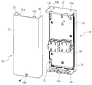
도 3은 본 발명의 실시예로 함체부에 단자함베이스와 트레이 및 내부덮개로 이루어진 광단자부가 결합된 상태도.3 is a state in which the optical terminal portion consisting of the terminal box base and the tray and the inner cover coupled to the housing in the embodiment of the present invention.
*도면의 주요 부분에 대한 부호의 설명** Description of the symbols for the main parts of the drawings *
10; 단자함베이스 11; 제 1 중앙패널10;
11d; 접속자슬리브 11e; 팬아웃 고정부11d; Connector sleeve 11e; Fanout fixture
12; 상측패널 13; 하측패널12;
20; 트레이 11c,22; 케이블가이드20; Trays 11c, 22; Cable Guide
23; 아답터 30; 내부덮개23;
31; 제 2 중앙패널 32; 좌측패널31; Second
33; 우측패널 100; 광단자부33;
200; 함체부 300; 커버부200;
본 발명은 전화 단자함에 광케이블의 접속 및 분기를 위한 광단자함을 구성하는 전화단자함을 이용한 광케이블 연결 장치에 관한 것으로서, 보다 상세하게는 기존 벽면 등에 매립되는 전화단자함내에 탈부착이 가능한 광단자함을 내장시켜 광케이블을 전화단자함내에 연결시킬 수 있도록 하는 전화단자함을 이용한 광케이블 연결장치에 관한 것이다.The present invention relates to an optical cable connection device using a telephone terminal box constituting an optical terminal box for connection and branching of an optical cable to a telephone terminal box, and more specifically, to an optical cable by embedding a detachable optical terminal box in a telephone terminal box embedded in an existing wall or the like. The present invention relates to an optical cable connecting apparatus using a telephone terminal box that can be connected to a telephone terminal box.
일반적으로 전화 단자함은, 전화국에서 나오는 국선과 가입자를 연결되는 가입자선을 서로 연결하여 주는 장치로서, 전주에 설치되거나, 경우에 따라서는 일반적인 벽면에 매립 형태로 그 설치가 이루어진다.In general, a telephone terminal box is a device that connects a trunk line from a telephone station and a subscriber line connecting a subscriber to each other, and is installed in a telephone pole or, in some cases, is installed in a buried form on a general wall.
즉, 상기 전화 단자함은 단독주택지의 경우에는 대부분이 전주에 설치가 이루어지지만, 공동주택지(예; 아파트)의 경우에는 주택내의 벽면에 매립된다.That is, the telephone terminal box is mostly installed in Jeonju in the case of single-family housing, but is buried in the wall of the house in the case of multi-family housing (eg, apartment).
이때, 상기 전화 단자함의 내부에는 복수 개의 국선 및 가입자선이 서로 연결될 수 있도록 구성되는데, 예를 들면 국선 및 가입자선을 서로 전기적으로 연결하는 복수 개의 접속핀이 설치된다.In this case, a plurality of trunk lines and subscriber lines may be connected to the inside of the telephone terminal box. For example, a plurality of connection pins are provided to electrically connect trunk lines and subscriber lines to each other.
한편, 광케이블과 전자장치들로 구성되는 광통신 시스템은 전화국에서 광가입자까지 많은 양의 음성 및 비음성 데이터 신호를 전달하여 주는 통신산업에 널리 사용되고 있으며, 광통신 선로를 형성하고 있는 광케이블은 다양한 유형의 광접속자재를 이용하여 상호 연결되거나 또는 광가입자 전송장치로 분기될 수 있도록 하 며, 이를 위해 광단자함을 사용한다.On the other hand, optical communication systems composed of optical cables and electronic devices are widely used in the telecommunications industry to transmit large amounts of voice and non-voice data signals from telephone stations to optical subscribers, and optical cables forming optical communication lines are various types of optical fibers. They can be interconnected or connected to optical subscriber transmissions using interconnection materials, and optical terminal boxes are used for this purpose.
즉, 상기 광단자함은 광 가입자측의 광 전송 선로에서 광케이블 내의 광섬유가 광 가입자측의 전송 장치와 상호 연결될 수 있도록 광 가입자에 분배를 위한 가입자 종단 장치의 하나로서, 이는 인입된 광케이블 내의 광섬유가 단심의 광 섬유 코드(또는 광 점퍼 코드)의 광섬유와 접속되어 근거리의 광 가입자 전송장치로 분배되며, 광 케이블내의 나머지 광섬유들은 광 접속된 후 광케이블 형태로 다시 인출됨으로써 장거리 광 가입자 전송장치로 재분배하는 것이다.That is, the optical terminal box is one of the subscriber end devices for distribution to the optical subscriber so that the optical fiber in the optical cable in the optical transmission line on the optical subscriber side can be interconnected with the transmission device on the optical subscriber side, which means that the optical fiber in the incoming optical cable is single core. Is connected to the optical fiber of the optical fiber cord (or optical jumper cord) of the optical fiber cord and is distributed to the optical subscriber transmitter in the short distance, and the remaining optical fibers in the optical cable are redistributed to the long-distance optical subscriber transmitter by being redrawn in the form of the optical cable after the optical connection is made. .
그러나, 종래의 광단자함은 종래 전화 단자함과 마찬가지로 단독주택지의 경우에는 대부분이 전주에 그 설치가 이루어지지만, 공동주택지(예; 아파트, 빌딩)의 경우에는 건물 내외벽에 매립되지 않고 외부 노출형으로 그 설치가 이루어지는 관계로 외부 충격에 영향을 받음은 물론, 쉽게 파손될 수 밖에 없는 등 그 관리에 상당한 어려움이 따랐다.However, the conventional optical terminal box, like the conventional telephone terminal box, is mostly installed in Jeonju in the case of single-family housing, but in the case of multi-unit housing (eg, apartments, buildings), it is not embedded in the inner and outer walls of the building, but is exposed externally. Due to the installation, the management was not only affected by external shocks, but also easily damaged.
즉, 종래에는 공동주택지의 벽면에 매립되는 전화 단자함에 광케이블이 인입되더라도 이를 고정하기 위한 부재들을 전혀 구성할 수 없었으며, 이에따라 종래에는 전화 단자함과 광 단자함을 각각 독립으로 설치하고 사용할 수 밖에 없고, 이는 곧 설치에 따른 비용은 물론, 그 관리에도 어려움이 따를 수 밖에 없는 것이다.That is, in the prior art, even if the optical cable is inserted into the telephone terminal box embedded in the wall of the apartment house, the members for fixing it could not be configured at all. Accordingly, the conventional telephone terminal box and the optical terminal box have to be independently installed and used, This means that the cost of installation, as well as the management will be difficult.
따라서, 본 발명은 상기와 같은 종래의 문제점을 해결하기 위해 안출된 것으로서, 벽면 매립형의 전화단자함에 광케이블을 인입시 그 인입되는 광케이블을 고정하는 광단자함을 분리 가능하도록 전화단자함내에 내장시켜 구성함으로써, 종래 광 단자함을 벽면 외부에 설치함에 따른 관리상의 어려움을 개선함은 물론, 광케이블의 외부 노출시 발생하는 광케이블의 파손을 방지하는 전화단자함을 이용한 광케이블 연결장치를 제공하려는데 그 목적이 있는 것이다.Accordingly, the present invention has been made to solve the above-mentioned problems, by incorporating in the telephone terminal box to detach the optical terminal box for fixing the incoming optical cable when the optical cable is inserted into the wall-mounted telephone terminal box, It is an object of the present invention to provide an optical cable connection device using a telephone terminal box that prevents damage of the optical cable generated when the optical cable is exposed to the outside of the optical cable as well as to improve management difficulties in installing the optical terminal box outside the wall.
상기 목적 달성을 위한 본 발명 전화단자함을 이용한 광케이블 연결 장치는,Optical cable connection device using the present invention telephone terminal box for achieving the above object,
통신선로를 통해 가입자측으로 분배되는 전화선과 광케이블이 인입되는 홀이 마련되고, 상기 전화선이 배선되는 전화단자부를 설치한 벽면 매립형의 함체부; 상기 함체부로 인입되는 전화선과 광케이블의 외부 노출을 차단하기 위해, 상기 함체부에 일단이 결합되어 열림/닫힘의 회전이 이루어지는 커버부; 및, 상기 함체부의 내부에 부착되고, 상기 함체부로 인입되어 가입자측으로 분배되는 광케이블을 연결 고정하도록 단자함베이스와 트레이 및 내부덮개를 포함하는 광단자부; 로 구성되는 것을 특징으로 한다.A wall recessed housing having a telephone line and an optical cable in which a telephone line is distributed to a subscriber through a communication line, and a telephone terminal unit to which the telephone line is wired; A cover part of which one end is coupled to the housing part to rotate the opening / closing to block external exposure of the telephone line and the optical cable introduced into the housing part; And an optical terminal part attached to the inside of the housing part and including a terminal box base, a tray, and an inner cover to connect and fix the optical cable drawn into the housing part and distributed to the subscriber side. Characterized in that consists of.
즉, 본 발명은 함체부내에 광단자부를 설치한 상태에서, 상기 함체부내에 전화선과 광케이블을 인입시킨 후, 다시 상기 광케이블을 광단자부로 인입함으로써, 상기 함체부를 덮는 커버부에 의해 광케이블의 외부 노출을 차단시키도록 한 것이며, 이는 기존 벽면 등에 설치되는 전화단자함을 활용하고자 함에 그 기술적 특징이 있는 것이다.That is, according to the present invention, the telephone line and the optical cable are introduced into the housing part in the state where the optical terminal part is installed in the housing part, and then the optical cable is introduced into the optical terminal part again, thereby preventing the external exposure of the optical cable by the cover part covering the housing part. It is intended to utilize the telephone terminal box installed on the existing wall, etc., which has its technical characteristics.
이하, 첨부된 도면에 의하여 본 발명의 실시예를 설명하면 다음과 같다.Hereinafter, embodiments of the present invention will be described with reference to the accompanying drawings.
도 1은 본 발명의 실시예로 트레이와 단자함베이스의 결합 사시도이고, 도 2는 본 발명의 실시예로 트레이가 결합된 단자함베이스에 내부덮개를 결합시키는 상 태의 분해도이며, 도 3은 본 발명의 실시예로 함체부에 단자함베이스와 트레이 및 내부덮개로 이루어진 광단자부가 결합된 상태도를 도시한 것이다.1 is an exploded perspective view of a tray and a terminal box base in an embodiment of the present invention, Figure 2 is an exploded view of the inner cover is coupled to the terminal box base coupled to the tray in an embodiment of the present invention, Figure 3 is By way of example, it shows a state diagram in which the optical terminal portion consisting of the terminal box base and the tray and the inner cover coupled to the enclosure.
도 1 내지 도 3을 참조하면, 본 발명의 실시예에 따른 전화단자함을 이용한 광케이블 연결장치는, 함체부(200), 커버부(300), 그리고 광단자부(100)를 포함한다.1 to 3, an optical cable connecting apparatus using a telephone terminal box according to an embodiment of the present invention includes a
상기 함체부(200)는 벽체 매립형으로 통신선로를 통해 가입자측으로 분배되는 전화선과 광케이블이 인입되는 홀(미도시)이 마련되는 일측 개구형이며, 그 내부면에는 전화선이 배선되는 전화단자부(미도시)가 설치되도록 구성되고, 상기 커버부(300)는 상기 함체부(200)에 회전 가능하게 결합되는 구조물로서 상기 함체부(200)의 내부에 대한 외부 노출을 차단하도록 구성된다.The
상기 광단자부(100)는 상기 함체부(200)내에 결합된 상태에서, 상기 함체부(200)로 인입되어 가입자측으로 분배되는 광케이블을 연결 고정하는 것으로, 단자함베이스(10), 트레이(20), 그리고 내부커버(30)를 포함한다.The
상기 단자함베이스(30)는 그 형상이 ⊂자형을 이루는 것으로, 제 1 중앙패널(11)과, 상기 제 1 중앙패널(11)의 상하측에서 연장되는 상하측의 패널(12)(13)로 구성된다.The
상기 제 1 중앙패널(11)에는 그 상하측에 각각 함체부(200)와의 결합을 위해 볼트 또는 스크류가 체결되는 고정홀(11a), 인입되는 광케이블을 고정하는 케이블고정대(11b) 및 다수의 케이블가이드(11c), 그리고 RN고정부 겸용의 접속자슬리브(11d) 및 팬아웃 고정부(11e)가 구성된다.The first
상기 상측의 패널(12)에는 함체부(200)로 인입된 광케이블이 단자함베이스(10)로 인입될 수 있도록 안내하는 인입홀(12a), 그리고 인입된 광케이블이 접속자슬리브(11d)에 의해 분리될 때 그 분기되는 광케이블을 인출하는 인출홀(12b)이 구성됨은 물론, 상기 내부덮개(30)의 상측부위가 끼움 결합될 수 있는 끼움홀(12c)이 구성된다.The
상기 하측의 패널(13)에는 내부덮개(30)와의 결합을 위한 보스부(13a)가 구성된다.The
상기 트레이(20)는 상기 단자함베이스(10)에 축(21)을 기준으로 회전이 가능하게 결합되는 것으로, 상기 단자함베이스(10)를 이루는 제 1 중앙패널(11)의 일면과 마주보는 면상에는 가장자리부위에 다수의 케이블가이드(22)가 구성되고, 반대면에는 아답터(23)가 구성되며, 상기 트레이(20)의 상측 일단에는 광케이블 입출구(24)가 구성된다.The
여기서, 상기 제 1 중앙패널(11)과 트레이(20)에 구성되는 케이블 가이드(11c)(22)는 광케이블의 허용 곡률범위내에서 그 굽어짐의 고정이 이루어지도록 소정의 간격을 두고 배열되는 구조를 이룬다.Here, the
그리고, 상기 내부커버(30)는 그 형상이 ㄷ자형으로, 상기 트레이(20)의 일면을 덮는 제 2 중앙패널(31) 및, 상기 제 2 중앙패널(31)로부터 좌우측으로 연장되어 상기 단자함베이스(10)의 양측부를 덮는 좌우측의 패널(32)(33)로 구성된다.In addition, the
상기 제 2 중앙패널(31)의 상측에는 상기 단자함베이스(10)를 이루는 상측의 패널(12)에 구성된 끼움홀(12c)에 끼움되는 끼움돌기(31a)가 구성되고, 하측에는 상기 단자함베이스(10)를 이루는 하측의 패널(13)에 구성된 보스(13a)에 볼트 또는 스크류 등의 체결수단이 체결될 수 있도록 안내하는 고정홀(31b)이 구성된다.An upper portion of the
이와같이 구성된 본 발명의 실시예에 대한 작용을 첨부된 도 1 내지 도 3을 참조하여 설명하면 다음과 같다.Referring to Figures 1 to 3 attached to the action of the embodiment of the present invention configured as described above are as follows.
먼저, 전화단자함의 함체부(200)에 덮개부(300)를 회전 가능하게 결합시킨 상태에서, 상기 함체부(200)를 벽면에 매립한 후, 상기 함체부(200)내에 전화선과 광케이블을 인입시킨다.First, in a state in which the
다음으로, 광단자부(100)는 단자함베이스(10)와 트레이(20) 및 내부덮개(30)를 포함하는 바, 상기 단자함베이스(10)를 이루는 제 1 중앙패널(11)의 일단에 축(21)을 기준으로 회전 가능하도록 트레이(20)를 결합시킨다.Next, the
다음으로, 상기 트레이(20)가 결합된 단자함베이스(10)에 RN고정부 겸용의 접속자슬리브(11d)와 팬아웃 고정부(11e)를 고정하는 한편, 상기 접속자슬리브(11d)와 팬아웃 고정부(11e)에 각각 RN본체와 팬아웃을 고정한다.Next, the RN fixing connector sleeve 11d and the fan-out fixing part 11e are fixed to the
이후, 상기 단자함베이스(10)를 이루는 제 1 중앙패널(11)에 마련된 고정홀(11a)로 볼트 또는 스크류와 같은 체결수단을 체결하여, 상기 단자함베이스(10)를 함체부(200)내에 결합시킨다.Thereafter, the fastening means such as bolts or screws are fastened to the
다음으로, 상기 함체부(200)내에 인입된 광케이블을, 상기 제 1 중앙패널(11)로부터 연장 구성되는 상측의 패널(12)에 마련된 인입홀(12a)을 통해 단자함베이스(10)내에 인입한 후, 상기 RN고정부 겸용의 접속자슬리브(11d)에 접속시킨다.Next, the optical cable introduced into the
여기서, 상기 인입홀(12a)을 통해 광케이블의 인입이 이루어질 때, 상기 인입되는 광케이블은 제 1 중앙패널(11)에 마련된 케이블고정대(11b)에 고정시킨 상태에서, 상기 접속자슬리브(11d)에 접속시킨다.Here, when the optical cable is introduced through the
다음으로, 상기 RN고정부 겸용의 접속자슬리브(11d)에 접속되어 고정되는 광케이블의 여장 부분을 굽어짐의 허용 곡률범위를 가지도록, 상기 제 1 중앙패널(11)의 가장자리부위에 형성되는 다수의 케이블 가이드(11c)에 여장 처리하는 한편, 상기 RN고정부 겸용의 접속자슬리브(11d)에 고정되는 RN본체로부터 분기되는 광케이블은 트레이(20)에 마련되는 케이블가이드(22)에 여장처리한다.Next, a plurality of edge portions of the
이후, 상기 트레이(20)의 타면에는 아답터(23)가 구성되는 바, 상기 아답터(23)에 커넥터를 끼우면, 전화선이 인입되는 상기 함체부(200)의 내부에는 가입자측으로 분배되는 광케이블의 고정이 완료되는 것이다.After that, the
다음으로, 상기 광케이블은 물론, 커넥터와 아답터가 외부로 노출되지 않도록, 상기 트레이(20)를 회전시켜, 상기 트레이(20)가 제 1 중앙패널(11)의 일면을 덮도록 한 후, 상기 트레이(20)에 의해 덮혀진 단자함베이스(10)에 내부덮개(30)를 결합시켜 고정한다.Next, the
즉, 상기 내부덮개(30)는 제 2 중앙패널(31)과 좌우측의 패널(32)(33)로 구성되어 있으므로, 상기 제 2 중앙패널(31)의 상측에 마련된 끼움돌기(31a)를 단자함베이스(10)의 상측 패널(12)에 마련된 끼움홀(12c)에 끼운 후, 상기 제 2 중앙패널(31)의 하측에 마련된 고정홀(31b)을 하측 패널(13)에 구성된 보스부(13a)에 밀착시킨다.That is, since the
다음으로, 상기 고정홀(31b)을 통해 보스부(13a)에 볼트 또는 스크류를 체결하면, 상기 내부덮개(30)의 제 2 중앙패널(31)과 그 좌우측의 패널(32)(33)이 단자함베이스(10)의 전방 및 좌우측을 덮게 되고, 이에따라 전화단자함을 이루는 함체부(200)내에 광단자부(100)의 결합이 완료되는 것이다.Next, when the bolt or screw is fastened to the
이때, 상기 함체부(200)의 개구부측을 회전형의 커버부(300)를 통해 밀폐시키면, 상기 광단자부(100)는 물론 이에 접속 고정이 이루어진 광케이블과 커넥터 및 아답터는 외부로 그 노출이 전혀 이루어지지 않게 되면서 보호될 수 있는 것이다.At this time, when the opening side of the
이상에서 설명한 바와같이 본 발명 전화단자함을 이용한 광케이블 연결장치는 벽면 매립형의 전화단자함에 광케이블을 인입시 그 인입되는 광케이블을 고정하는 광단자함을 분리 가능하도록 전화단자함내에 내장시킨 것으로, 하나의 통신선로를 통해 전화선과 광케이블을 전화단자함으로 인입한 후 그 인입된 전화선과 광케이블을 전화단자함내에서 접속하고 이를 다시 가입자측으로 분배하여 종래 광 단자함을 벽면 외부에 설치함에 따른 관리상의 어려움을 개선함은 물론, 광케이블의 외부 노출시 발생하는 광케이블의 파손을 방지하는 효과를 얻을 수 있는 것이다.As described above, the optical cable connection device using the telephone terminal box of the present invention is built in the telephone terminal box so that the optical terminal box for fixing the incoming optical cable when the optical cable is inserted into the wall-mounted telephone terminal box can be separated. After the telephone line and the optical cable are introduced into the telephone terminal, the telephone line and the optical cable are connected in the telephone terminal box and distributed to the subscriber side, thereby improving the management difficulties caused by installing the conventional optical terminal box outside the wall. The effect of preventing the breakage of the optical cable generated when the external exposure of the can be obtained.
본 발명은 상술한 특정의 바람직한 실시예에 한정되지 아니하며, 청구범위에서 청구하는 본 발명의 요지를 벗어남이 없이 당해 발명이 속하는 기술분야에서 통상의 지식을 가진 자라면 누구든지 다양한 변형 실시가 가능한 것은 물론이고, 그와같은 변경은 청구범위 기재의 범위내에 있게 된다.The present invention is not limited to the above-described specific preferred embodiments, and various modifications can be made by any person having ordinary skill in the art without departing from the gist of the present invention claimed in the claims. Of course, such changes will fall within the scope of the claims.
Claims (7)
Priority Applications (1)
| Application Number | Priority Date | Filing Date | Title |
|---|---|---|---|
| KR1020070021389A KR100894560B1 (en) | 2007-03-05 | 2007-03-05 | Optical cable connection device using telephone terminal box |
Applications Claiming Priority (1)
| Application Number | Priority Date | Filing Date | Title |
|---|---|---|---|
| KR1020070021389A KR100894560B1 (en) | 2007-03-05 | 2007-03-05 | Optical cable connection device using telephone terminal box |
Publications (2)
| Publication Number | Publication Date |
|---|---|
| KR20080081438A KR20080081438A (en) | 2008-09-10 |
| KR100894560B1 true KR100894560B1 (en) | 2009-04-24 |
Family
ID=40021120
Family Applications (1)
| Application Number | Title | Priority Date | Filing Date |
|---|---|---|---|
| KR1020070021389A Active KR100894560B1 (en) | 2007-03-05 | 2007-03-05 | Optical cable connection device using telephone terminal box |
Country Status (1)
| Country | Link |
|---|---|
| KR (1) | KR100894560B1 (en) |
Cited By (1)
| Publication number | Priority date | Publication date | Assignee | Title |
|---|---|---|---|---|
| KR200465035Y1 (en) | 2011-07-06 | 2013-02-15 | (주)유비쿼스 | Connection structure of optical cable for optical communication equipment |
Citations (3)
| Publication number | Priority date | Publication date | Assignee | Title |
|---|---|---|---|---|
| KR200261552Y1 (en) * | 2001-10-05 | 2002-01-24 | 주식회사 에이엔티 | A telecommunication terminal box having part for an optical cable |
| KR20020012817A (en) * | 2000-08-08 | 2002-02-20 | 강병창 | Optical fiber-power line integrated cable and wall-box and patch cable for connecting the same |
| KR20060132603A (en) * | 2003-11-17 | 2006-12-21 | 파이버 옵틱 네트워크 솔루션스 코퍼레이션 | Frames and related methods for optical fiber distribution and management |
-
2007
- 2007-03-05 KR KR1020070021389A patent/KR100894560B1/en active Active
Patent Citations (3)
| Publication number | Priority date | Publication date | Assignee | Title |
|---|---|---|---|---|
| KR20020012817A (en) * | 2000-08-08 | 2002-02-20 | 강병창 | Optical fiber-power line integrated cable and wall-box and patch cable for connecting the same |
| KR200261552Y1 (en) * | 2001-10-05 | 2002-01-24 | 주식회사 에이엔티 | A telecommunication terminal box having part for an optical cable |
| KR20060132603A (en) * | 2003-11-17 | 2006-12-21 | 파이버 옵틱 네트워크 솔루션스 코퍼레이션 | Frames and related methods for optical fiber distribution and management |
Cited By (1)
| Publication number | Priority date | Publication date | Assignee | Title |
|---|---|---|---|---|
| KR200465035Y1 (en) | 2011-07-06 | 2013-02-15 | (주)유비쿼스 | Connection structure of optical cable for optical communication equipment |
Also Published As
| Publication number | Publication date |
|---|---|
| KR20080081438A (en) | 2008-09-10 |
Similar Documents
| Publication | Publication Date | Title |
|---|---|---|
| US9343886B2 (en) | System and method for providing final drop in a living unit in a building | |
| CN101617253B (en) | Outlet device | |
| JP2010527463A (en) | Enclosure for optical fiber connection and wiring | |
| EP1730568B1 (en) | Network termination apparatus | |
| US20130016952A1 (en) | Fiber optic distribution device | |
| CN102692689A (en) | Optical fiber terminal box | |
| US20100202746A1 (en) | Fiber Optic Distribution Device and Fiber Optic Network Including the Same | |
| CN102792204A (en) | Terminal box with removable fiber management tray | |
| RU2558334C2 (en) | Conduit and cabling system with adhesive coating for communication media | |
| KR100894559B1 (en) | Optical cable connection device using telephone terminal box | |
| JP2009526514A (en) | Optical fiber loopback test system and method | |
| KR20150006712A (en) | Branching device for hybrid cable | |
| KR100894560B1 (en) | Optical cable connection device using telephone terminal box | |
| KR20090012698A (en) | Small connection point protection device and optical cable terminal box | |
| CN204758883U (en) | Multi -functional fiber optic distribution frame | |
| KR20180129442A (en) | Optical distribution box for small generation | |
| KR200261552Y1 (en) | A telecommunication terminal box having part for an optical cable | |
| WO2020245566A1 (en) | Fibre management enclosure | |
| JP5188187B2 (en) | Optical fiber wiring for installation in apartment buildings (MDU) and commercial buildings | |
| CN205067825U (en) | Install integrated box of ONU and EOC equipment simultaneously based on integration of three networks | |
| KR20120001323U (en) | Optical cable distribution box | |
| WO2024116109A1 (en) | Connector box and retaining formation | |
| CN210775941U (en) | Terminal type optical cable divides fine case | |
| KR101396314B1 (en) | Optical fiber distribution apparatus for syndicating lead-in | |
| KR20080002091A (en) | Optical Adapter Integrated Multicore Optical Cable |
Legal Events
| Date | Code | Title | Description |
|---|---|---|---|
| A201 | Request for examination | ||
| PA0109 | Patent application |
Patent event code: PA01091R01D Comment text: Patent Application Patent event date: 20070305 |
|
| PA0201 | Request for examination | ||
| E902 | Notification of reason for refusal | ||
| PE0902 | Notice of grounds for rejection |
Comment text: Notification of reason for refusal Patent event date: 20080804 Patent event code: PE09021S01D |
|
| PG1501 | Laying open of application | ||
| E701 | Decision to grant or registration of patent right | ||
| PE0701 | Decision of registration |
Patent event code: PE07011S01D Comment text: Decision to Grant Registration Patent event date: 20090120 |
|
| GRNT | Written decision to grant | ||
| PR0701 | Registration of establishment |
Comment text: Registration of Establishment Patent event date: 20090415 Patent event code: PR07011E01D |
|
| PR1002 | Payment of registration fee |
Payment date: 20090416 End annual number: 3 Start annual number: 1 |
|
| PG1601 | Publication of registration | ||
| PR1001 | Payment of annual fee |
Payment date: 20120416 Start annual number: 4 End annual number: 4 |
|
| FPAY | Annual fee payment |
Payment date: 20130412 Year of fee payment: 5 |
|
| PR1001 | Payment of annual fee |
Payment date: 20130412 Start annual number: 5 End annual number: 5 |
|
| FPAY | Annual fee payment |
Payment date: 20140421 Year of fee payment: 6 |
|
| PR1001 | Payment of annual fee |
Payment date: 20140421 Start annual number: 6 End annual number: 6 |
|
| FPAY | Annual fee payment |
Payment date: 20160414 Year of fee payment: 8 |
|
| PR1001 | Payment of annual fee |
Payment date: 20160414 Start annual number: 8 End annual number: 8 |
|
| FPAY | Annual fee payment |
Payment date: 20170404 Year of fee payment: 9 |
|
| PR1001 | Payment of annual fee |
Payment date: 20170404 Start annual number: 9 End annual number: 9 |
|
| FPAY | Annual fee payment |
Payment date: 20180410 Year of fee payment: 10 |
|
| PR1001 | Payment of annual fee |
Payment date: 20180410 Start annual number: 10 End annual number: 10 |
|
| FPAY | Annual fee payment |
Payment date: 20190327 Year of fee payment: 11 |
|
| PR1001 | Payment of annual fee |
Payment date: 20190327 Start annual number: 11 End annual number: 11 |
|
| PR1001 | Payment of annual fee |
Payment date: 20200407 Start annual number: 12 End annual number: 12 |
|
| PR1001 | Payment of annual fee |
Payment date: 20210420 Start annual number: 13 End annual number: 13 |
|
| PR1001 | Payment of annual fee |
Payment date: 20240308 Start annual number: 16 End annual number: 16 |
|
| PR1001 | Payment of annual fee |
Payment date: 20250408 Start annual number: 17 End annual number: 17 |