JP5188187B2 - Optical fiber wiring for installation in apartment buildings (MDU) and commercial buildings - Google Patents
Optical fiber wiring for installation in apartment buildings (MDU) and commercial buildings Download PDFInfo
- Publication number
- JP5188187B2 JP5188187B2 JP2008003852A JP2008003852A JP5188187B2 JP 5188187 B2 JP5188187 B2 JP 5188187B2 JP 2008003852 A JP2008003852 A JP 2008003852A JP 2008003852 A JP2008003852 A JP 2008003852A JP 5188187 B2 JP5188187 B2 JP 5188187B2
- Authority
- JP
- Japan
- Prior art keywords
- cable
- box
- fiber
- branch
- optical fiber
- Prior art date
- Legal status (The legal status is an assumption and is not a legal conclusion. Google has not performed a legal analysis and makes no representation as to the accuracy of the status listed.)
- Expired - Fee Related
Links
Images


Landscapes
- Light Guides In General And Applications Therefor (AREA)
- Electric Cable Installation (AREA)
Description
本発明は集合住宅(Multi−Dwelling Unit:MDU)建物および商業事務所ビルのユーザ向けに光ファイバケーブルを配備するためのシステムおよび技術に関する。 The present invention relates to systems and techniques for deploying fiber optic cables for users in multi-dwelling unit (MDU) buildings and commercial office buildings.
集合住宅(MDU)およびその他の加入者建物における光ファイバネットワークの配備には、壁面あるいはその他の建物構造に設置するように作られた、いわゆるケーブルドロップ箱を使用する必要がある。今日の業界慣行は、ネットワークプロバイダから来る光ファイバケーブルを受けるために箱の左側面にケーブル引き込み口を有し、かつプロバイダケーブルの対応するファイバと接続されるために建物の個々の加入者に関連付けられた多数のファイバが通される一つ以上の口を右側面有する箱を要求している。例えば、<www.corningcablesystems.com>の「コーニングケーブルシステムズ、壁面設置可能なコネクタハウジング」、および<www.adc.com/productsandservices/>の「ADCテレコミュニケーションズ、屋内ファイバ分配端子−顧客建物装置(CPE)」を参照のこと。また、米国オハイオ州エリリアのマルチリンク社から入手できる「壁面設置可能な光ファイバケーブル筐体系列」について述べている2007マルチリンクカタログ、Vol.24、第87頁乃至第94頁を参照のこと。
しかし、加入者建物で従来のケーブルドロップ箱を一人の作業者で設置することは、難しく時間を要しがちである。さらに、ケーブル性能を損なうことなく3インチ(76.2mm)より小さい曲げ直径に耐えられない旧型光ファイバケーブルを収容するための寸法となっている。したがって現在、手に入るドロップ箱はかなり大きく、多くの時間と労力を費やすことなく集合住宅およびその他の建物で光ファイバネットワークを広範囲に配備することには適していない。 However, it is difficult and time-consuming to install a conventional cable drop box by one worker in a subscriber building. Furthermore, it is dimensioned to accommodate older fiber optic cables that cannot withstand bending diameters smaller than 3 inches (76.2 mm) without compromising cable performance. Therefore, currently available drop boxes are quite large and are not suitable for widespread deployment of fiber optic networks in apartment buildings and other buildings without spending much time and effort.
さらに、今日の屋外ファイバ−ツー−ザ−ホーム(FTTH)配備においては、光ファイバネットワークサービスは光ファイバ分配とドロップケーブルの配列を経て住居までもたらされる。例えば、分配ケーブルのヘッドエンドは現場の分岐/接合箱で終端され、そこで分配ケーブルは中央事務所から来る中継ケーブルと接続する。そして、分配ケーブルは架空あるいは地下を通ってネットワークサービスを受ける住宅地まで届けられる。それぞれの住人に届くドロップケーブルは接続クロージャでの終端処理あるいは、例えばコーニングから販売されているいわゆるフレックスナップ(FlexNAP)端末などのネットワーク端末での接続により分配ケーブルと接続される。分配ケーブル中のファイバが中間地点で使われる時、それはネットワークの終端部に向かう「つなぎ綱」(tether)に、あるいは直接ドロップケーブルにつながれる。しかし、分配ケーブル中のそれぞれのファイバの残り部分は使われずに残り、「不使用」(dead)となる。したがって、たくさんの中間地点でドロップが要求されると、分配ケーブル中のファイバの半分は使われずに残るか、あるいは無駄になる。 Further, in today's outdoor fiber-to-the-home (FTTH) deployment, fiber optic network services are brought to residence via fiber optic distribution and drop cable arrangements. For example, the distribution cable head end is terminated at a branch / junction box in the field, where the distribution cable connects to a relay cable coming from a central office. Then, the distribution cable is delivered to a residential area that receives a network service through aerial or underground. The drop cable reaching each resident is connected to the distribution cable by termination at a connection closure or by connection at a network terminal such as a so-called FlexNAP terminal sold by Corning. When the fiber in the distribution cable is used at an intermediate point, it is connected to a “tether” towards the end of the network or directly to a drop cable. However, the remaining portion of each fiber in the distribution cable remains unused and becomes “dead”. Thus, if a drop is required at many intermediate points, half of the fiber in the distribution cable remains unused or wasted.
光ファイバネットワーク分配システムを集合住宅あるいは事務所ビルに導入する際には、別の問題が持ち上がる。例えば、コーニングのフレックスナップシステムは、ケーブル長に沿ったいろいろな点に、分配ケーブルからの上記「つなぎ綱」の工場での組込みを必要とする。屋外の架空ネットワークの場合には、「移動クレーン」(Cherry Picker)あるいは同様の昇降装置を使って任意の地点でつなぎ綱の処理が出来るので、つなぎ綱の処理はかなり簡単である。しかし、住宅あるいは商業事務所ビルの中では、一般的に分配ケーブルは建物のフロアの間の垂直なシャフトあるいは管路の内側を通されるライザケーブルの形である。ライザシャフトの寸法およびそこでの処理の方法は一般に建物毎に異なる。したがって、ケーブルが現存する建物のライザシャフトの中に配されると、光ファイバ分配ケーブルのつなぎ綱を処理することは不可能ではないにしても難しい。 Another problem arises when fiber optic network distribution systems are introduced into apartment buildings or office buildings. For example, Corning's FlexSnap system requires the factory integration of the “tether” from the distribution cable at various points along the cable length. In the case of an outdoor aerial network, tethering can be handled fairly easily because it can be processed at any point using a “mobile crane” or similar lifting device. However, in residential or commercial office buildings, distribution cables are typically in the form of riser cables that are routed inside the vertical shafts or conduits between the building floors. The dimensions of the riser shaft and the method of treatment there generally vary from building to building. Thus, once the cable is placed in the riser shaft of an existing building, it is difficult if not impossible to handle the tether of fiber optic distribution cable.
本発明によれば、集合住宅あるいは商業ビルの階にある提供予定住戸に光ファイバケーブルを配備するシステムは、ケーブルで配線されたファイバを終端するために建物内の分岐箱まで配線された屋外ケーブルの光ファイバを終端するために配された少なくともひとつの分岐箱を含む。分岐箱でその一端を終端された一本以上のライザケーブルは、建物シャフトを経て配線される。所与のライザケーブルは建物のひとつ以上の階の組の住戸に関連付けられたファイバを含む。それぞれのライザケーブルの他端は、組のそれぞれの階に関連付けられた統合箱で終端される。支線ケーブルが統合箱と組のそれぞれの階、あるいはひとつの階の対応する区画の間に配線される。対応する支線ケーブルを終端するために、ドロップ箱がそれぞれの階、あるいは対応する階の区画に設けられる。ドロップケーブルがドロップ箱と提供予定階、あるいは階の区画の住戸との間に配線される。 According to the present invention, a system for deploying an optical fiber cable to a planned residential unit on a floor of an apartment house or a commercial building is an outdoor cable routed to a branch box in the building to terminate the fiber routed by the cable. At least one branch box arranged to terminate the optical fiber. One or more riser cables terminated at one end of the branch box are routed through the building shaft. A given riser cable includes fibers associated with one or more sets of dwellings in a building. The other end of each riser cable is terminated with an integrated box associated with each floor of the set. A branch cable is routed between the integrated box and each floor of the set, or between corresponding sections of one floor. In order to terminate the corresponding branch cable, a drop box is provided on each floor or on a corresponding floor section. A drop cable is wired between the drop box and a dwelling unit on the planned floor or floor section.
本発明の他の観点によれば、集合住宅あるいは商業ビルの階にある提供予定住戸に光ファイバケーブルを配備する方法は、建物内の分岐箱までプロバイダケーブルを配線し、ケーブルで配線されたファイバを分岐箱で終端することを含む。一本以上のライザケーブルが分岐箱で一端を終端されて建物シャフトを経て配線されており、且つ所与のライザケーブルは建物の所定の階の住戸、あるいはひとつの階の異なる区画の住戸に関連付けられたファイバを含む。当該方法は、それぞれのライザケーブルの他端を対象階、あるいはひとつの階の対象区画に設けられる統合箱で終端すること、および統合箱と対象階あるいは対象区画との間に支線ケーブルを配線すること、さらに対象階あるいはひとつの階の対象区画にドロップ箱を設けドロップ箱で対応する支線ケーブルを終端することを含む。ドロップケーブルは、ドロップ箱と提供予定の階あるいは対象エリアの住戸との間に配線される。 According to another aspect of the present invention, a method of deploying an optical fiber cable to a planned dwelling unit on a floor of an apartment house or a commercial building is a method in which a provider cable is routed to a branch box in a building and the fiber routed by the cable is used. Including termination at a branch box. One or more riser cables are terminated at a branch box and wired through the building shaft, and a given riser cable is associated with a dwelling on a given floor of a building or a dwelling on a different section of a floor Fiber. In this method, the other end of each riser cable is terminated with an integrated box provided in the target floor or the target section of one floor, and a branch cable is wired between the integrated box and the target floor or target section. In addition, a drop box is provided in a target section or a target section of one floor, and a corresponding branch cable is terminated in the drop box. The drop cable is wired between the drop box and a dwelling unit in the floor or target area to be provided.
本発明のよりよい理解のために、添付の図面および請求の範囲とともに以下の議論により本発明の特徴や実施例を明らかにする。なお、これらの図面中の構成要素は必ずしも寸法通りではない。 For a better understanding of the present invention, features and embodiments of the present invention will become apparent from the following discussion taken in conjunction with the accompanying drawings and claims. In addition, the component in these drawings is not necessarily according to the dimension.
図1は本発明によるケーブルドロップ箱10の形式の光ファイバおよびケーブル処理装置の第一の実施例を示す。箱10は板金、および/あるいは限定されないがABSあるいはポリカーボネートのようなプラスチック材料で作られてよい。もし箱が加入者建物の外部に設置されるなら、公知の方法で箱の表面あるいは内部に防湿シール、ガスケットおよび類似のものが取り付けられてもよい。箱10には基盤12があり、開示の実施例では該基板は一般に正方形であり、それぞれの角に取付け穴14が形成され、各辺の長さが、例えば、約6.25インチ(158.75mm)である。
FIG. 1 shows a first embodiment of an optical fiber and cable processing apparatus in the form of a
箱10は基盤12の中央部から上に向かって軸方向に伸びる巻き枠部20も有する。巻き枠部20は外側の円筒壁22を含み、図1にその外側周辺が一部見える。壁22の外径は、ある長さの光ファイバケーブル(図示しない)が貯蔵あるいは保存のためにケーブルに対して規定される少なくとも最小の曲げ直径で巻き枠壁22に巻かれるために十分なだけある。例えば、OFSファイテル(Fitel)から入手できるAllwave Flex(登録商標)ファイバのケーブルを使うとき、巻き枠壁22の外径は約3.0インチ(76.2mm)あるいはそれ以下である。ケーブルの内側端部は、入口内に取り付けられた歪開放装置24によってほぼまっすぐな経路に支持された状態で巻き枠壁のケーブル入口に入る。装置24は図7から図9Bに関連して以下に記載されるが、装置24の位置で壁の外周に直角な線に沿い円筒壁22を通してケーブルの端部を導く。
The
ケーブルドロップ箱10には巻き枠部20の上方に配される連結用小部屋30もあって、それは周囲の側壁31を有している。図1の実施例において、小部屋30は設置者が外から小部屋30の内部に手を入れられるように作られ、配置された取り外し可能な蓋32と、35の位置で蓋に開閉式に取り付けられたコネクタ保護具あるいはカバー34とを有している。以下に説明されるように、連結用小部屋30は、小部屋30に入り巻き枠部位20に巻かれたケーブルから来る、あるいは小部屋の壁31の穴(図2および図3を参照)から来る第一の組の光ファイバと、図1のカバー34の下方に見えるコネクタ36でファイバが終端する他のケーブルの第二の組の光ファイバとを接続されることが可能な寸法に形成される。数多くの平らな指あるいはタブ38が小部屋の壁31の下部側端から外側に突き出すように形成され、基盤12に平行になっている。タブ38と基盤12とは、巻き取り枠の壁22に巻かれるケーブルの長さを基盤と連結用小部屋30との間の範囲に制限するようにいっしょに機能する。
The
図2は図1のドロップ箱10の断面正面図であり、図3は蓋32を取り除いて上から見た箱10の図である。連結用小部屋30は、小部屋の側壁31の切り欠き部41をふさぐように支えられているコネクタパネル40に特徴がある。多数の光コネクタアダプタ42がパネル40の対応する開口部の全体にわたって取り付けられ、そのアダプタ42はパネル40の外側面にある光ファイバコネクタ36をパネルの内側面にある対応するコネクタ44と結合するように作用する。好ましくは、パネル40は容易に取り外せて、かつ異なる種類のアダプタが取り付けられた同じ寸法の他のパネルと交換できるように側壁31に取り付けられる。例えば、パネル40は側壁の切り欠き部41の両端に形成された垂直の溝43に滑らせて出し入れしてもよい。所望のパネル40は、例えば、所定の配備で使われるケーブルコネクタの形式によってLC、SC、FC、ST、MPO、あるいはMPX型コネクタに適合するアダプタ42を有する多数の異なるパネルの中から選択されてよい。
2 is a cross-sectional front view of the
先に述べたように、連結用小部屋30に配線された光ファイバは巻き枠部20の上に巻かれたケーブルの内側端部から来てもよく、それは歪開放装置24を経て巻き枠の壁22を通り抜ける。そのような使い方の場合、ファイバは外側の円筒状の壁22と、壁48が外側の壁22の半径方向内側に形成される巻き枠部の内側円筒状の壁48との間に伸びる環状のファイバ配線領域46を通って配線される。歪開放装置24と環状のファイバ配線領域46の寸法は、それぞれの光ファイバが連結用小部屋30に入り、コネクタ44で終端する前のファイバに規定される値よりも小さい曲げ直径にならないように決められる。例えば、OFSファイテル(Fitel)から入手できるAllwaveFlex(登録商標)ファイバを使う場合、内側の壁48は0.7874インチ(20mm)くらいの外径でよく、ファイバ配線部46の平均直径はわずか約2.0インチ(50.8mm)でよい。
As previously mentioned, the optical fiber routed to the connecting
連結用小部屋30の側壁31は、そのファイバがコネクタ36により終端されるファイバと連結される外部の光ファイバケーブル、あるいはケーブル組立体(図示しない)を受け入れるために壁31の後ろ部分にケーブル入口あるいは通過口50(図2および3)も有している。あるいは、ケーブル入口50はその代わりのコネクタパネル40(図示しない)部分を通る大きな開口の形であってもよい。そのような使い方の場合、後ろの口50から入るケーブルのファイバは、あるとしてもわずかな曲げでコネクタ44のうちの対応するものに直接配線されてもよい。さらに、コネクタパネル40でのMPO型のような多心ファイバコネクタの使用は、箱10が統合箱として機能するように出来る。すなわち、集合住宅(MDU)の異なる階にある他の同様の箱から来る複数のケーブルは、異なる場所、例えばMDUの地階から箱に配線される1本のケーブルとMPOコネクタを介して接続するために連結用小箱30の後ろの口50から入ってもよいということである。図13および以下の関連する文章を参照のこと。もし使用されない場合は、後ろのケーブル入口50は栓52によって適切に塞がれる。
A
図4は図1の光ファイバケーブルドロップ箱の底面図である。円筒状の管60が中心軸通路62を持つように形成されている。管60は、図1に示すように、カバー蓋32の上面と同一平面になるようにカバー蓋32のすき間に合うようになされた管60の上端と、図4に見られるように管の通路62が基盤12の真下に開いている管の底端との間に軸方向に伸びている。管の通路62の軸は巻き枠部20の外側の円筒状の壁22の軸と一致している。開示される実施例において、管60は図2に見られるように内側の円筒状の壁48の上側の軸端をふさぐ壁63の中心を上下に伸びている。
FIG. 4 is a bottom view of the optical fiber cable drop box of FIG. A
管60の中心部通路62の直径は、好ましくは、ねじ回しの軸、ボルト、あるいはその他の繰出し心棒のような長細い道具が箱10が自由に回転できる軸として機能するように箱10の上あるいは下から通路を通して挿入されるために十分な太さである。この構造がMDUでのネットワーク配備に必要な時、一人の作業者が巻き枠部20に巻かれたケーブルを容易に繰出すことを可能にする。例えば、箱10がねじ回しの軸の周りに自由に回転するので、作業者は挿入したねじ回しの柄を片手に持ちながら、巻き枠部20から所望の長さのケーブルを引きだすためにもう片方の手を使うことが出来る。
The diameter of the
図5から図7は本発明による光ファイバケーブルのドロップ箱200の第二の実施例を示す。図1から図4の箱の構成要素と同じ、あるいは類似する箱200の構成要素は200だけ増えた対応する参照番号を有する。
5 to 7 show a second embodiment of a
箱200はコネクタガードあるいはカバー234のために一体化されたちょうつがい235がついた一体型のカバー蓋232を有する。さらに、連結用小部屋230の側壁231は、箱の基盤212に平行に小部屋230の真下で半径方向外側に伸びる連続した円盤状のフランジ204を有している。フランジ204と基盤212とはともに、円筒壁222の外側に巻かれる光ファイバケーブルの長さをフランジ204と基盤212の間の領域内に制限する役割を果たす。図1から4にある箱のように、ケーブルの内側端部は装置224の位置で壁222の外周に直角でほとんどまっすぐな経路で箱200の中の環状のファイバ配線領域246に入るように歪開放装置224によって導かれる。
また、図6に見られるように、ドロップ箱200の基盤212は巻き枠部220の底に、例えば、ねじ、あるいは環状のファイバ配線領域246の底につばを嵌め込み固定するように形成される他の留め具によって固定される分割片として形成される。
Further, as seen in FIG. 6, the
図8は図1のドロップ箱10の中に設けられた歪開放装置24に対応する歪開放装置224の拡大した透視図である。図9に見られるように、歪開放装置224は外側側壁224a、内側側壁224b、基盤壁224c、および天辺に取り付けられ装置の側壁224a、224bの間に伸びるカバー209を有する、一般にU字型断面のアーチ形の装置体208で構成される。
FIG. 8 is an enlarged perspective view of the
さらに図9Aに示されるように、外側の側壁224aは巻き枠部220の外側円筒状の壁222に巻かれた、例えばフラットリボン光ファイバケーブル260の内側端部を受けるために装置224の一端部に開口226を有している。装置224の反対側の端にある開口228はケーブルのそれぞれのファイバが装置から出て、好ましくはそれぞれのファイバが、例えば商業的に入手可能な900μmのスリーブで保護された後に箱200のファイバ配線領域246に入るようにする。
As further shown in FIG. 9A, the
ケーブル260およびそれぞれのファイバは、図9および9Aに見られるように装置224の側壁224cから上方に突き出す1組の平行な指あるいはガイド211によって装置の開口226、228の間のほぼまっすぐな経路を経て導かれる。ケーブル260の端部から外側の被覆が剥ぎ取られた後、ケーブルのファイバを取り巻きケーブルの補強あるいは強化材として機能する所定長のアラミドあるいはケブラー(登録商標)糸が巻かれ、エポキシあるいは他の適当な接着剤でガイド211に固定される。商業的に入手可能な保護スリーブ(例えば900μm)が個々のケーブルファイバのそれぞれにかぶせられ、スリーブをかぶせたファイバは装置の開口228から外へ導かれる。図9Bに示されるように、装置カバー209は適当な接着剤によって筐体208に固定され、組み立てられたケーブル歪開放装置224は巻き枠部220の外側の円筒状の壁222と内側の円筒状の壁248の間にあるケーブル入口225の内部にしっかりと固定される。
The
したがって、ケーブル260の内側端部とその個々のファイバとは壁のケーブル入口225を通って外側の円筒状壁222に対して直角に進み、箱200の環状のファイバ配線領域246に入る。ファイバを取り囲む糸は歪開放装置224のガイド211に固定されているので、ケーブルが巻き枠部の外側の円筒状壁222に巻きつけ、あるいは巻きほぐされる時にケーブル260に加えられる外力は、ファイバそのものへよりもむしろ装置224が固定されている壁222に移される。
Thus, the inner end of the
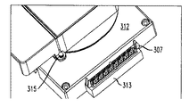
図10から図12は、本発明による光ファイバケーブルのドロップ箱300の第三の実施例を示す。図1から図4の箱の構成要素と同じ、あるいは類似する箱300の構成要素は300だけ増えた対応する参照番号を有する。箱300は基盤312内の一体型接合小部屋308、コネクタ取付け部313、および多数の保安用留め穴315を特徴とする。
10 to 12 show a third embodiment of a
接合用小部屋308
典型的なMDUドロップ箱の設置は箱から出て行く単心ファイバ用開口を有し、それぞれの開口は箱が設置される建物の関連する居住単位と関連付けられている。おのおのの居住単位から来る単心ファイバケーブルはしばしば終端するコネクタなしにドロップ箱に配線される。これらのケーブルの裸の端部はいろいろな方法でドロップ箱で終端される。例えば、片端処理したピッグテールファイバが接合スリーブが共通の空間に収納されるようにドロップ箱内で接合される。このためには、損傷を避け且つファイバのたるみを処理するために接合部を収納するための部屋あるいは小部屋を必要とする。別の方法としてピッグテールの機械的接合を含んでもよく、それは同様の部屋あるいは収納部を必要とする。それぞれの単心ファイバケーブルは現場施工可能なコネクタで直接終端処理されてもよく、それにより接合のための部屋の必要性がなくなる。
Joining
A typical MDU drop box installation has openings for single fiber exiting the box, each opening being associated with an associated living unit of the building in which the box is installed. Single fiber optic cables from each resident unit are often routed to drop boxes without terminating connectors. The bare ends of these cables can be terminated with drop boxes in a variety of ways. For example, one end-treated pigtail fiber is joined in a drop box so that the joining sleeve is housed in a common space. This requires a room or small room to house the joint to avoid damage and handle fiber sagging. Alternatively, a pigtail mechanical joint may be included, which requires a similar room or storage. Each single fiber cable may be terminated directly with a field installable connector, thereby eliminating the need for a room for bonding.
ドロップ箱300は基盤312の下に取り付けられ、あるいは形成された一体型接合用部屋あるいは小部屋308を有し、基盤の内側に取り付けられた接合用の受け皿309を含む。接合用の受け皿309は箱300の中に固定されるか、あるいは壁に直接取り付けられてもよい。いずれの場合でも、箱300は接合用小部屋308の上に設けられてよい。ピッグテールあるいは終端処理した端部は、基盤312の側壁に切り欠かれた対応するV字型切り欠き隙間311を通って小部屋の下部に出入りできる。
The
コネクタパーキングエリア313
コネクタパーキングエリアあるいは区画313は、終端処理したファイバ端部を使用しない間格納しておくことが出来る。区画313は、たくさんの異なる商業的に入手可能なコネクタパーキング片307から選択されたひとつ(例えばSC型)をその中に受け入れ固定するような寸法に作られている。この機構が箱300を置き換える必要性なしに将来異なる形式のコネクタの利用を可能にし、同時に設置者が取付けを先行することが出来る。
The connector parking area or
留め穴315
いくつかの留め穴、あるいは保安用の穴315がちょうつがいが付いたカバー蓋332の対応する足に形成される。留め穴315は最終ユーザが多くの閉鎖手段を講じることを可能にする。例えば、簡単に蓋を閉めておくために標準のプランジャ型外れ止め機構で一つの穴315が利用できる。他の穴315がワイヤ結び、閉鎖タグ、あるいは他の保安錠を取り付けるために利用できる。
Retaining
A number of retaining holes or
MDUあるいは商業建物への設置のための光ファイバケーブル布線
図13は本発明による集合住宅あるいは商業建物400に設置される光ファイバケーブル分配システムを示す。多数のドロップ箱、例えば図1から4の本発明の箱10が建物400内の対応する場所に設置される。ドロップ箱10は、例えば建物のそれぞれの階414の下がり天井412の上方に位置してもよい。個々の建物単位(例えば、アパートあるいは事務所)あるいは所定の階414、あるいは階414の規定された区画内に位置する建物単位に対応する光ファイバ416は、箱パネル40の外側側面のアダプタ42に接続されているコネクタ36で終端される。
Fiber Optic Cable Wiring for Installation in MDU or Commercial Building FIG. 13 shows a fiber optic cable distribution system installed in an apartment house or
それぞれのファイバ416は、例えば関連する階414の天井の上方にドロップ箱10まで配線されている支線ケーブル418の対応するファイバに接続される。ケーブル418は最初ドロップ箱10の巻き枠部20に巻かれ、その後その一部あるいは全てが、例えば建物400の地階420と屋根422との間に位置する「統合」箱として機能する他の箱10に配線するために巻きほぐされる。支線ケーブル418のファイバは、箱のコネクタパネル40の内側側面にあるアダプタ42に接続されるコネクタ44で終端される。
Each
統合箱10で、対応する建物の階あるいは階の指定区域のユーザに関連付けられたファイバを含む支線ケーブル418のそれぞれは開口50あるいは表面板の口を通り、後ろの経路を通って統合箱に入る。先に述べたように、それぞれの支線ケーブル418のファイバは、箱パネル40の内側側面の対応するアダプタ42と多心ファイバ列(MPO)コネクタを経由して接続するために、場合によっては少し曲げて統合箱の中に配線されてもよい。建物400内の全てのネットワークユーザを対象とする1本以上の主(あるいは「ライザ」)光ファイバケーブル424は、地階420にあるケーブル入口あるいは分岐箱426と、ライザケーブルファイバが多心ファイバコネクタ36を経て箱パネル40の外側側面のアダプタ42とその中で接続する対応する統合箱10との間の建物内ライザシャフトあるいは管路を通って配線される。外部のネットワークプロバイダのケーブル430は引込み箱426まで配線され、そこで終端され、ケーブル430のファイバは引込み箱426の中でそれぞれのライザケーブル424の対応するファイバと接続される。
In the
ここに開示されるさまざまなケーブル布線箱の構造は以下に述べる際立った特徴を有している。
1.OFSファイテルから入手可能で優れた曲げ特性を有するAllwaveFlex(登録商標)のような新しいタイプの光ファイバケーブルに適合する物理的に小さくなった寸法。
2.外部ケーブルの格納を可能にし、内部のファイバ配線を安全な曲げ限界以内に保持する軸方向の巻き枠部。
3.ねじ回しのような一般的な工具を使うことによって、巻き枠部の外側に巻かれたケーブルの繰出しを容易にする中心部貫通穴。
The various cable wiring box structures disclosed herein have the following distinguishing features.
1. Physically reduced dimensions that fit new types of fiber optic cables such as AllwaveFlex® that are available from OFS Fightel and have excellent bending properties.
2. An axial reel that allows the storage of external cables and keeps internal fiber wiring within safe bend limits.
3. A central through hole that facilitates the feeding of the cable wound outside the winding frame by using a common tool such as a screwdriver.
図13の光ファイバケーブル分配システムにおいて、対応する階、あるいは一つの階の特定の区画の住戸にそれぞれ関連付けられた多数のドロップ箱は、共通の統合箱で支線ケーブル418を経由して接続され、一方、統合箱はライザケーブル424を経由して建物400の地階420にある分岐箱426と接続される。好ましくはシステムはサイズを小さくし、システムの設置および配備を速めるためにそれぞれのライザケーブル424、および支線ケーブル418にMPO型のような多心ファイバアレイコネクタを使用する。あるいは、必要であればライザケーブル424と支線ケーブル418について単心ファイバコネクタの使用および/あるいは融着接続が行われてもよい。
In the fiber optic cable distribution system of FIG. 13, multiple drop boxes respectively associated with a corresponding floor or a dwelling unit of a specific section of one floor are connected via a
それぞれのライザケーブル424は最大のファイバ充填密度を与え、かつケーブル全体としてのサイズを最小にするために光ファイバリボンケーブルであることが好ましい。また、先に述べたように、ライザおよび支線ケーブル424、418は多心ファイバを一工程で接続できる多心ファイバアレイコネクタで終端されることが好ましい。多心ファイバアレイ型MPOコネクタは、シングルモードおよびマルチモードライザグレードのリボンケーブルと同様にOFSファイテルから商業ベースで入手可能である。
Each
図13のシステムは、ルースチューブ分配とドロップケーブル、およびオプティタップ(Optitap)コネクタを採用する既知の事前組立のFTTxシステムの場合に生じるファイバの浪費なしに、高層建物(例えば、7階、あるいはそれ以上)でのケーブルの素早い敷設を可能にする。本システムは、「ファイバ−ツー−ザ−フロア」(Fiber−To−The−Floor)、「ファイバ−ツー−ザ−プレミス」(Fiber−To−The−Premise)あるいは「ファイバツーザデスク」(Fiber−To−The−Desk)”用途など商業ベースのデータネットワークのために高層/中層建物でも使われる。 The system of FIG. 13 can be used for high-rise buildings (eg, 7 floors or higher) without the waste of fiber that occurs with known pre-assembled FTTx systems that employ loose tube distribution and drop cables, and Optitap connectors. This makes it possible to quickly lay cables. The system is “Fiber-To-The-Floor”, “Fiber-To-The-Premise” or “Fiber-to-The-Desk” (Fiber). -To-The-Desk) "is also used in high-rise / medium-rise buildings for commercial-based data networks.
高層建物での実施例
本発明のシステムは以下を備えることによって高層建物において配備されうる。
1.建物400のための外部の施設あるいはプロバイダケーブル430を終端し、建物内の住戸に関連付けられた個々のファイバ416それぞれがプロバイダケーブル430の対応するファイバと光学的に結合されるための信号を分岐する一つ以上の分岐箱426。
先に述べたように、好ましくは分岐箱426は建物400の地階420あるいはより低い階に位置する。
2.好ましくはリボンタイプで多心ファイバアレイ(MPO)コネクタで終端された一本以上の光ファイバライザケーブル424。
MPOコネクタを使う利点は、一本のリボンの全てのファイバがコネクタの共通のフェルール台に挿入されると一度に終端されるということである。それぞれのライザケーブル424は一つ以上の階の住戸、あるいは一つの階の特定の区域の住戸のために十分多くのファイバを有している。ライザケーブルのプロバイダ側端部は分岐箱426で終端され、ケーブルは対応する統合箱と接続するために建物400内のライザシャフトまたは管路を通って配線される。たくさんのライザケーブル424がケーブルそれぞれのコネクタで終端される場合には、ケーブルユニット(加入者)端に取り付けられたコネクタによる干渉なしにケーブルが束ねられ、かなり小さいシャフト開口を通していっしょに引っ張られるために、ケーブルそれぞれは異なる長さであることが好ましい。
3.N階それぞれに配備された統合箱。
ここでNは、例えば6より大きい。統合箱はユーティリティ設備部屋、あるいはその他の電気通信設備用のスペースに置かれてもよい。例えば、一つの階に12の住戸のある建物の場合、6本の12心ファイバリボンを持つ72心リボンファイバライザケーブルが終端される統合箱が6階毎に配備されてよい。それぞれの統合箱は、関連付けられたライザケーブル424をその箱が担当する各階、あるいは階の特定の区域との間に配線される支線ケーブル418と接続するためのアダプタ42を含む。
もし一つの階の多数の住戸がネットワークサービスを要求する(例えば、同じ階で60ファイバが終端される)ならば、その階は限定された区画に分割され、統合箱がその一つの階だけのために設置されてもよい。例えば、もしサービスが大きな設置面積を持つ建物(例えば全街区)に提供される場合、一つの統合箱が所定の階に設置され、全ての関連付けられた支線ケーブル、およびドロップ箱はその階の対応する区画の住戸にサービスを提供するために所定の階の高さに置かれるであろう。
4.それぞれの統合箱は建物400内の一つ以上の階の住戸、あるいは一つの階の限定された範囲の住戸を対称にする箱から配線される、関連付けられた支線ケーブル418を有している。
支線ケーブル418は住戸がケーブルの対象となっている階に位置する電気通信設備室から引き出してもよい。その部屋の上下に位置する階にある住戸を対称にするために、支線ケーブル418は設備室から配線されてライザシャフトに戻り、対応する階でシャフトから出る。例えば、それぞれ12戸ある6階建ての建物では、一連の12心ファイバ支線ケーブル418が統合箱に接続される。もし統合箱が階「N」にあるならば、6本の12心ファイバ支線ケーブルが階N−3、N−2、N−1、N、N+1、およびN+2に配線される。好ましくは支線ケーブルは統合箱のサイズを最小にするために小さな形状係数の多心ファイバアレイ(例えば、MPO)コネクタで終端される。それは、6個の12心ファイバMPO−MPOアダプタ42を持つ統合箱は、6個の12心ファイバMPOコネクタを72個の個々のLC型コネクタと適合させるように構成された箱よりもサイズがより小さくなるということである。また、もしMPO終端法が使われるなら、それぞれの支線ケーブル418は都合がよいことに終端の容易さのために単心リボンの形であってもよい。しかし、12心ルースファイバ、あるいは12心900μmバッファファイバを1個のMPOコネクタで終端することも可能である。
Example in a High-Rise Building The system of the present invention can be deployed in a high-rise building by providing:
1. Terminate the external facility or
As previously mentioned, the
2. One or more optical
The advantage of using an MPO connector is that all the fibers of a ribbon are terminated at once when inserted into the common ferrule base of the connector. Each
3. An integrated box deployed on each of the N floors.
Here, N is larger than 6, for example. The integrated box may be placed in a utility facility room or space for other telecommunications facilities. For example, in the case of a building having 12 dwelling units on one floor, an integrated box in which 72-fiber ribbon fiber riser cables having six 12-fiber ribbons are terminated may be provided every six floors. Each integrated box includes an
If multiple dwellings on one floor require network service (
4). Each integrated box has an associated
The
高層の実施例においては、各階は対応する支線ケーブル418を終端するために一つ以上の関連付けられたドロップ箱10を有し、所定の支線ケーブルのファイバはその階の住戸、あるいはその階の限定された区画の住戸に配線されるより小サイズの個々のケーブルおよび/あるいはファイバ416につながれる。適切なドロップ箱の例はここに開示される箱10である;しかし、支線ケーブル418が建物400の住戸に直接配線され、所定のケーブルの個々のファイバが個々のファイバに関連付けられた住戸の現場で取り出されることも可能である。
In high-rise embodiments, each floor has one or more associated
中層建物の実施例
本発明のシステムは以下を備えることによって中層建物において配備される。
1.建物400のための外部の施設あるいはプロバイダケーブル430を終端し、建物内の住戸に関連付けられた個々のファイバ416それぞれがプロバイダケーブル430の対応するファイバと光学的に結合されるために、信号を分岐する一つ以上の分岐箱426。先に述べたように、好ましくは分岐箱426は建物400の地階420あるいはより低い階に位置する。
2.好ましくは支線ケーブル418は多心ファイバアレイ(例えば、MPO型)コネクタによりそれぞれの端部で終端する。ケーブル418は地階420にある分岐箱426と建物400の各階(あるいは各階の電気通信設備室)との間で直接配線されてもよい。各階あるいは電気通信の接続ポイントで対応する支線ケーブル418が終端のために関連付けられたドロップ箱10に配線され、ケーブル418の対応するファイバがその階の個々の住戸に関連付けられたより小さなケーブルおよび/あるいはファイバ416にそのドロップ箱の中でつながれる。
Mid-rise Building Example The system of the present invention is deployed in a mid-rise building by comprising:
1. Terminate the external facility or
2. Preferably, the
本発明のシステムの利点は特に以下を含む。
1.迅速な配備。
好ましくはライザおよび支線ケーブル424、418は、前もってケーブルに取り付けられた、あるいは工場で組み立てられた多心ファイバアレイ(例えば、MPO)コネクタ付きで供給される。現状の配備では、終端のために融着接続がしばしば使われるが、それはコスト高であり、時間を費やす。MPOコネクタの使用は現場の設置面積と施工時間を最小にする。
2.ライザシャフト内での設置の容易さ。
このシステムは一般にライザシャフトが現代の電気通信の基幹施設設置の最適条件にはない古い住宅用建物に配備されてもよい。コンパクトな(例えば、リボン型)ライザケーブル424を使用することは配備に必要なライザケーブルのサイズと数を最小にし、統合箱の使用はライザケーブルがライザシャフトを出なければならない場所の数を少なくする役割を果たす。
3.無駄のないファイバ。
先に述べたフレックスナップ(FlexNAP)システムのような既存のケーブル分配システムはあらかじめ終端され、屋外現場での迅速な配備ができるように設計されている。住宅地での配備のために、通常ルースチューブ型屋外現場分配ケーブルが道路に隣接して柱上あるいは暗渠に配線される。ある間隔で何本かのファイバが分配ケーブルから外に引き出され、ネットワークアクセスポイント(NAP)終端箱、つまり分配ケーブルのファイバを個々のドロップケーブルファイバに接続する機器の中で終端される。アクセスポイントで外に引き出されるそれぞれのファイバは切断され、NAP箱の中で終端され、したがってケーブルの内部に残るファイバの下り方向部分は使われずに放置される、つまり信号を運ばない「不使用」(dead)ファイバとなる。こうしてどれほど多くの引き出しがどこで行われようと、分配ケーブルのファイバの半分ほどは設置後無駄になる。それに対して、本発明のシステムにおいては、ライザケーブル424の全てのファイバは、分岐箱426と統合箱の間で信号を伝送し、使える状態で残る。また、それぞれの階でドロップ箱10が使われるならば、統合箱とドロップ箱10との間で信号を伝送するそれぞれの支線ケーブル418の全てのファイバも同様に使える状態で残る。
The advantages of the system of the present invention include in particular:
1. Rapid deployment.
Preferably, the riser and
2. Easy installation within the riser shaft.
The system may be deployed in older residential buildings where riser shafts are generally not optimal for modern telecommunications infrastructure installations. Using a compact (eg, ribbon-type)
3. Fiber without waste.
Existing cable distribution systems, such as the FlexNAP system described above, are pre-terminated and are designed for rapid deployment in the field. For residential deployments, loose-tube outdoor field distribution cables are usually routed on pillars or in culverts adjacent to the road. At some intervals, several fibers are drawn out of the distribution cable and terminated in a network access point (NAP) termination box, the equipment that connects the distribution cable fibers to the individual drop cable fibers. Each fiber that is drawn out at the access point is cut and terminated in the NAP box, so that the downstream portion of the fiber that remains inside the cable is left unused, i.e. does not carry any signal. (Dead) fiber. Thus, no matter how many drawers are made, about half of the fiber in the distribution cable is wasted after installation. In contrast, in the system of the present invention, all the fibers of the
これまで述べたことは本発明の好ましい実施例を示しているが、いろいろな修正および変形が発明の精神および範囲から逸脱することなくなされ、かつ本発明は全てそのような修正および変形を以下の特許請求の範囲内に含むことが当業者には理解されるであろう。 Although the foregoing has shown preferred embodiments of the present invention, various modifications and variations can be made without departing from the spirit and scope of the invention, and the present invention is intended to alleviate such modifications and variations as described below. Those skilled in the art will appreciate that they are within the scope of the claims.
10、200、300 ケーブルドロップ箱、統合箱
12、212、312 基盤
20 巻き枠部
22 円筒壁
24、224 歪開放装置
30、230 連結用小部屋
32、232 カバー蓋
34 コネクタカバー
36、44 コネクタ
38 タブ
40 コネクタパネル
42 アダプタ
46、246 環状のファイバ配線領域
50 ケーブル入口
60 円筒状の管
204 フランジ
211 ガイド
260 ケーブル
308 一体型接合小部屋
309 接合用受け皿
313 コネクタ取付け部
315 保安用留め穴
400 建物
412 下がり天井
414 階
416 光ファイバ
418 支線ケーブル
420 地階
422 屋根
424 ライザケーブル
426 ドロップ箱
430 プロバイダケーブル
10, 200, 300 Cable drop box, integrated
Claims (13)
前記ケーブル入口部の付近にある少なくとも1つの分岐箱を含み、前記分岐箱が、前記ケーブル入口部から前記分岐箱まで配線される外部ケーブルの光ファイバを終端するように構成かつ配置され、終端された前記ファイバのそれぞれが前記集合住宅あるいは商業建物の住戸と対応し、さらに、
前記建物の前記ライザシャフトあるいは管路を通して配線された1本以上のライザケーブルを含み、前記ライザケーブルのうちの所定のライザケーブルは、前記建物の一つ以上の階に位置する住戸に施設する複数の第一の光ファイバを有し、前記第一の光ファイバの第一の端部は、前記所定のライザケーブルが施設される住戸に対応する前記外部ケーブルのファイバと連結するために前記分岐箱で終端されており、さらに、
前記所定のライザケーブルが施設される各階または複数の階の付近に設置された第一のケーブル分配箱または統合箱を含み、前記統合箱が、前記所定のライザケーブルの前記第一の光ファイバの第二の端部を終端するように、構成かつ配置されており、さらに、
複数の支線ケーブルを含み、前記支線ケーブルのそれぞれが、前記統合箱と、前記各階または前記複数の階との間又は一つの階の複数の規定された区画の決定された区画との間に配線され、前記支線ケーブルのそれぞれが、前記階の対応する組の住戸または前記一つの階の前記決定された区画の住戸に関連付けられた複数の第二の光ファイバを有し、前記第二の光ファイバの第一の端部は、前記所定のライザケーブルの対応する第一の光ファイバと連結するために統合箱で終端されており、さらに、
前記複数の階のそれぞれの階または前記一つの階の前記決定された区画の付近に設置された第二のケーブル分配箱またはドロップ箱を含み、前記ドロップ箱のそれぞれが、前記階の住戸又は前記一つの階の前記決定された区画の住戸に関連付けられた前記支線ケーブルの前記第二の光ファイバの第二の端部を終端するように構成かつ配置されており、さらに、
複数の光ファイバドロップケーブルを含み、前記複数の光ファイバドロップケーブルのそれぞれが、前記ドロップ箱と、前記階の関連付けられた住戸または前記階の前記決定された区画の関連付けられた住戸との間に配線され、前記光ファイバドロップケーブルのそれぞれの第一の端部が前記支線ケーブルの対応する第二の光ファイバの第二の端部と前記ドロップ箱で連結され、前記光ファイバドロップケーブルの第二の端部が、前記階の関連付けられた住戸または前記階の前記決定された区画の関連付けられた住戸の現場で終端され、
前記第一および第二のケーブル分配箱のそれぞれは、
側壁とコネクタパネルとを有する連結用小部屋を含み、前記コネクタパネルは、前記コネクタパネルの外部で前記所定のライザケーブルまたは光ファイバドロップケーブルのいずれかと関連する光ファイバコネクタを動作可能に接続するコネクタアダプタを有し、
前記所定のライザケーブルの前記第一の光ファイバの前記第二の端部が前記コネクタパネルの外側で前記コネクタアダプタと接続するときに、前記支線ケーブルの前記第二の光ファイバの前記第一の端部が前記コネクタパネルの内側で前記コネクタアダプタと接続できるように、前記連結用小部屋の前記側壁は前記支線ケーブルを受け取るポートを有し、前記システムはさらに、
前記連結用小部屋へ固定され、前記連結用小部屋の下に延在する巻き枠部を含み、前記巻き枠部は軸を有する第一の円筒壁を含み、前記第一の円筒壁は、前記第一の円筒壁の外周に巻き付けた所定の支線ケーブル長を支持する大きさであり、前記第一の円筒壁には、前記ケーブルの前記第二の光ファイバの前記第二の端部を含む前記所定の支線ケーブルの端部を受け入れるケーブル入口ポートが形成され、さらに、
前記箱を介して延在するよう支持される管を含み、前記管は、前記第一の円筒壁の前記軸と一致する軸通路を有し、前記軸通路は、前記支線ケーブルを前記箱の前記巻き枠部に巻き付けるとき又は前記巻き枠部から繰り出すときに前記箱が細長手段の周りを自由に回転するように、前記細長手段を受け入れるのに十分な幅であり、そして、
前記所定の支線ケーブルを前記第一の円筒壁に巻き付けたときに、前記コネクタパネルの前記内側で前記コネクタアダプタと接続するように前記支線ケーブルの前記第二の光ファイバの前記第二の端部が前記連結用小部屋内で配線されるよう、前記連結用小部屋と前記巻き枠部が構成されかつ配置される、システム。 A system for deploying fiber optic cable wiring installed in a dwelling unit on one or more floors of an apartment or commercial building having a cable entrance and a riser shaft or pipe line,
Including at least one branch box in the vicinity of the cable inlet, the branch box configured and arranged to terminate an optical fiber of an external cable routed from the cable inlet to the branch box, and terminated. Further, each of the fibers corresponds to a dwelling unit of the apartment house or commercial building, and
Including one or more riser cables wired through the riser shaft or pipeline of the building, and the predetermined riser cables of the riser cables are installed in a dwelling unit located on one or more floors of the building. A first end of the first optical fiber, wherein the first end of the first optical fiber is connected to the fiber of the external cable corresponding to the dwelling unit where the predetermined riser cable is installed. Terminated with
A first cable distribution box or an integration box installed near each floor or a plurality of floors where the predetermined riser cable is installed, and the integration box includes the first optical fiber of the predetermined riser cable; Configured and arranged to terminate the second end, and
A plurality of branch cables, each of the branch cables wired between the integrated box and each floor or the plurality of floors or a determined section of a plurality of defined sections of one floor Each of the branch cables has a plurality of second optical fibers associated with a corresponding set of dwelling units on the floor or a dwelling unit of the determined section on the one floor, and the second light The first end of the fiber is terminated with an integration box for coupling with a corresponding first optical fiber of the predetermined riser cable;
Each of the plurality of floors or a second cable distribution box or drop box installed near the determined section of the one floor, each of the drop boxes being a dwelling unit of the floor or the Constructed and arranged to terminate a second end of the second optical fiber of the branch cable associated with a dwelling unit of the determined section of one floor, and
A plurality of fiber optic drop cables, each of the plurality of fiber optic drop cables between the drop box and an associated dwelling unit of the floor or an associated dwelling unit of the determined section of the floor A first end of each of the optical fiber drop cables is connected to a second end of a corresponding second optical fiber of the branch cable by the drop box, and a second end of the optical fiber drop cable is connected. Is terminated at the site of the associated dwelling unit of the floor or the associated dwelling unit of the determined section of the floor;
Each of the first and second cable distribution boxes is
A connector chamber having a side wall and a connector panel, the connector panel operatively connecting an optical fiber connector associated with either the predetermined riser cable or the optical fiber drop cable outside the connector panel; Have an adapter,
When the second end of the first optical fiber of the predetermined riser cable is connected to the connector adapter outside the connector panel, the first optical fiber of the branch cable has the first optical fiber. The side wall of the connecting compartment has a port for receiving the branch cable so that an end can be connected to the connector adapter inside the connector panel, and the system further comprises:
The winding frame portion is fixed to the connecting small chamber and includes a winding frame portion extending under the connecting small chamber, the winding frame portion includes a first cylindrical wall having an axis, and the first cylindrical wall is It is sized to support a predetermined branch cable length wound around the outer periphery of the first cylindrical wall, and the first cylindrical wall is provided with the second end of the second optical fiber of the cable. A cable entry port is formed for receiving an end of the predetermined branch cable including, and
A tube supported to extend through the box, the tube having an axial passage that coincides with the axis of the first cylindrical wall, the axial passage connecting the branch cable to the box. Is wide enough to receive the elongate means such that the box is free to rotate around the elongate means when wrapped around or unwound from the reel section; and
When the predetermined branch cable is wound around the first cylindrical wall, the second end of the second optical fiber of the branch cable is connected to the connector adapter on the inner side of the connector panel. There to be wired in a small room for the coupling, the winding frame portion and the connecting small chamber is and arranged configuration, system.
Applications Claiming Priority (4)
| Application Number | Priority Date | Filing Date | Title |
|---|---|---|---|
| US88016907P | 2007-01-13 | 2007-01-13 | |
| US60/880169 | 2007-01-13 | ||
| US11/891553 | 2007-08-10 | ||
| US11/891,553 US7546018B2 (en) | 2007-01-13 | 2007-08-10 | Fiber optic cabling for multi-dwelling unit (MDU) and commercial building deployments |
Publications (2)
| Publication Number | Publication Date |
|---|---|
| JP2008171003A JP2008171003A (en) | 2008-07-24 |
| JP5188187B2 true JP5188187B2 (en) | 2013-04-24 |
Family
ID=39651118
Family Applications (1)
| Application Number | Title | Priority Date | Filing Date |
|---|---|---|---|
| JP2008003852A Expired - Fee Related JP5188187B2 (en) | 2007-01-13 | 2008-01-11 | Optical fiber wiring for installation in apartment buildings (MDU) and commercial buildings |
Country Status (3)
| Country | Link |
|---|---|
| JP (1) | JP5188187B2 (en) |
| HK (1) | HK1121811A1 (en) |
| SG (1) | SG144814A1 (en) |
Families Citing this family (1)
| Publication number | Priority date | Publication date | Assignee | Title |
|---|---|---|---|---|
| EP3902160B1 (en) | 2020-04-22 | 2024-11-06 | Fincantieri S.p.A. | Shipboard telecommunications network and ship comprising such telecommunications network |
Family Cites Families (14)
| Publication number | Priority date | Publication date | Assignee | Title |
|---|---|---|---|---|
| JPH0627882B2 (en) * | 1984-10-12 | 1994-04-13 | 住友電気工業株式会社 | Optical fiber cable hanger |
| FR2631323B1 (en) * | 1988-05-16 | 1991-08-30 | Commissariat Energie Atomique | REEL-WINDER FOR FIBER OPTIC CABLES |
| DE3841607C2 (en) * | 1988-12-08 | 1996-05-23 | Siemens Ag | Cassette for excess lengths of optical fibers in the splice area |
| US4976510B2 (en) * | 1989-11-20 | 1995-05-09 | Siecor Corp | Communication outlet |
| IT1254342B (en) * | 1992-04-30 | 1995-09-14 | REMOVABLE DEVICE WITH REMOVABLE SEMICONNECTORS, INTEGRATED INTO A PLASTIC CARD, FOR THE TERMINATION OF OPTICAL CABLE TAPES. | |
| JP3457206B2 (en) * | 1999-03-09 | 2003-10-14 | 大崎電気工業株式会社 | Optical fiber cable laying structure |
| JP2001143536A (en) * | 1999-11-11 | 2001-05-25 | Toyokuni Electric Cable Co Ltd | Information branch cable |
| JP4136229B2 (en) * | 1999-11-22 | 2008-08-20 | トヨクニ電線株式会社 | Wiring method of optical communication cable |
| JP2002228902A (en) * | 2000-12-01 | 2002-08-14 | Toyokuni Electric Cable Co Ltd | Wiring of optical fiber cable for building |
| US7206392B2 (en) * | 2003-02-12 | 2007-04-17 | Larry Fingler | Fiber optic premise wiring system |
| JP2004294866A (en) * | 2003-03-27 | 2004-10-21 | San Denkosha:Kk | Method for laying optical cables in apartment house and device for connecting optical cable |
| JP4268067B2 (en) * | 2004-02-19 | 2009-05-27 | エヌ・ティ・ティ・コミュニケーションズ株式会社 | Premise wiring method and premise network system |
| JP4110136B2 (en) * | 2004-12-10 | 2008-07-02 | 三菱電機ビルテクノサービス株式会社 | Optical transmission line in the building |
| JP4274376B2 (en) * | 2005-04-21 | 2009-06-03 | 矢崎総業株式会社 | Building with optical branch cable |
-
2008
- 2008-01-07 SG SG200800070-5A patent/SG144814A1/en unknown
- 2008-01-11 JP JP2008003852A patent/JP5188187B2/en not_active Expired - Fee Related
- 2008-11-27 HK HK08112954.1A patent/HK1121811A1/en not_active IP Right Cessation
Also Published As
| Publication number | Publication date |
|---|---|
| SG144814A1 (en) | 2008-08-28 |
| JP2008171003A (en) | 2008-07-24 |
| HK1121811A1 (en) | 2009-04-30 |
Similar Documents
| Publication | Publication Date | Title |
|---|---|---|
| USRE49385E1 (en) | Fiber optic cable distribution box | |
| US7546018B2 (en) | Fiber optic cabling for multi-dwelling unit (MDU) and commercial building deployments | |
| EP2216667B1 (en) | Fiber optic distribution device and fiber optic network including the same | |
| US7120347B2 (en) | Multi-port optical connection terminal | |
| US8295670B2 (en) | Low profile fiber drop point of entry system | |
| EP2527895B1 (en) | Fiber optic distribution device | |
| US10067310B2 (en) | Fiber optic drop cable assembly | |
| US10527811B2 (en) | Method of installing an optical fiber at user premises | |
| WO2009113112A1 (en) | Method of connecting user devices to optical fibre units contained in an optical cable | |
| US20250028135A1 (en) | System and deployment method for a fiber optic connector assembly having a blowable section and a non-blowable section | |
| US20090046985A1 (en) | Fiber Optic Enclosure Internal Cable Management | |
| CN101221272B (en) | Optical arrangement for multi-residence units and commercial building | |
| JP5188187B2 (en) | Optical fiber wiring for installation in apartment buildings (MDU) and commercial buildings | |
| JP5188230B2 (en) | Wall-mounted optical fiber and cable processing equipment | |
| US10215943B2 (en) | Deploying optical fibers within a multi-dwelling unit |
Legal Events
| Date | Code | Title | Description |
|---|---|---|---|
| A621 | Written request for application examination |
Free format text: JAPANESE INTERMEDIATE CODE: A621 Effective date: 20080516 |
|
| A977 | Report on retrieval |
Free format text: JAPANESE INTERMEDIATE CODE: A971007 Effective date: 20110117 |
|
| A131 | Notification of reasons for refusal |
Free format text: JAPANESE INTERMEDIATE CODE: A131 Effective date: 20110124 |
|
| A601 | Written request for extension of time |
Free format text: JAPANESE INTERMEDIATE CODE: A601 Effective date: 20110422 |
|
| A602 | Written permission of extension of time |
Free format text: JAPANESE INTERMEDIATE CODE: A602 Effective date: 20110427 |
|
| A521 | Written amendment |
Free format text: JAPANESE INTERMEDIATE CODE: A523 Effective date: 20110601 |
|
| A131 | Notification of reasons for refusal |
Free format text: JAPANESE INTERMEDIATE CODE: A131 Effective date: 20110719 |
|
| A521 | Written amendment |
Free format text: JAPANESE INTERMEDIATE CODE: A523 Effective date: 20111006 |
|
| A131 | Notification of reasons for refusal |
Free format text: JAPANESE INTERMEDIATE CODE: A131 Effective date: 20120906 |
|
| A521 | Written amendment |
Free format text: JAPANESE INTERMEDIATE CODE: A523 Effective date: 20121203 |
|
| TRDD | Decision of grant or rejection written | ||
| A01 | Written decision to grant a patent or to grant a registration (utility model) |
Free format text: JAPANESE INTERMEDIATE CODE: A01 Effective date: 20121225 |
|
| A61 | First payment of annual fees (during grant procedure) |
Free format text: JAPANESE INTERMEDIATE CODE: A61 Effective date: 20130122 |
|
| FPAY | Renewal fee payment (event date is renewal date of database) |
Free format text: PAYMENT UNTIL: 20160201 Year of fee payment: 3 |
|
| R150 | Certificate of patent or registration of utility model |
Free format text: JAPANESE INTERMEDIATE CODE: R150 |
|
| R250 | Receipt of annual fees |
Free format text: JAPANESE INTERMEDIATE CODE: R250 |
|
| R250 | Receipt of annual fees |
Free format text: JAPANESE INTERMEDIATE CODE: R250 |
|
| LAPS | Cancellation because of no payment of annual fees |